Contents lists available at ScienceDirect Structures journal homepage: www.elsevier.com/locate/structures Engineering Advance PropertiesandapplicationsofFRPinstrengtheningRCstructures:Areview Y.H. Mugahed Amran a,b,c, ⁎ , Rayed Alyousef a ,RaizalS.M.Rashid d , Hisham Alabduljabbar a , Chung-Chan Hung e a Department of Civil Engineering, College of Engineering, Prince Sattam Bin Abdulaziz University, 11942 Alkharj, Saudi Arabia b Dean office, Faculty of Science and Engineering, Al-hikma University, Sana'a, Yemen c Department of Civil Engineering, Faculty of Engineering, Amran University (AU), Quhal, Amran Province, Yemen d Department of Civil Engineering, Faculty of Engineering, University Putra Malaysia (UPM), 43400 Serdang, Selangor, Malaysia e Department of Civil Engineering, National Cheng Kung University, 1 University Rd, Tainan City 701, Taiwan ARTICLEINFO Keywords: Applications Aramid/Basalt/Glass/Carbon fiber reinforced polymer (AFRP, BFRP, GFRP, CFRP) Beams Columns Deterioration Fiber reinforced polymer (FRP) Joints Matrix Properties Rehabilitation Reinforced concrete structures Serviceability and strengthening structures ABSTRACT In civil and structural engineering, building structures with robust stability and durability using sustainable materialsischallenging.Thecurrenttechnologicalmeansandmaterialscannotdecreaseweight,enlargespans, orconstructslenderstructures,thusinspiringtheexplorationforvaluablecompositematerials.Fiberreinforced polymer (FRP) features high-strength and lightweight properties. Using FRP motivates civil engineers to strengthen existing RC structures and repair any deterioration. With FRP, a system that can resist natural dis- asters, such as earthquakes, strong storms, and floods, can be developed. However, deterioration of structures has become a critical issue in modern construction industries worldwide. This paper reviews the FRP design, matrix, material properties, applications, and serviceability performance. This literature review also aims to provideacomprehensiveinsightintotheintegratedapplicationsofFRPcompositematerialsforimprovingthe techniques of rehabilitation, comprising the applications toward the repair, strengthening, and retrofit of con- crete structures in the construction industry today. 1. Introduction The initial use of fiber reinforced polymer (FRP) was known as re- inforcement bars in 1975 particularly in Russia (Fig. 1)[1,2]. FRP is also recognized as fiber reinforced plastic, comprising materials that utilize either synthetic or natural fibers to automatically improve the stiffness and strength of a polymer model [2]. FRPs employed to strengthen and reinforce structures are enormously strong, rated 8 times robust than classical steel reinforcement bar [3]. Glass fiber re- inforcedpolymer(GFRP)isusedasprestressingtendonstostrengthena 9m-long,fastenedwoodbridge[4].Relevantinvestigationsontheuse ofFRPsasreinforcingbartosubstitutetheuseofsteelplatebondingfor bridgerestorationandstrengtheninginstigatedinEuropeinthe1980s. But in the United States, FRP composites were engaged for structural strengthening for approximately 25years [5]. During this period, FRP compositewasacceptedasamainstreamconstructionmaterialparallel with the sum of accomplished FRP strengthening projects. The use of FRPforstrengthening,rehabilitationandretrofittinghasattainedmore reputation among design consultants over traditional strengthening methods, such as setting up of supplementary structural steel frames and components [6]. FRP is mainly worked as interior reinforcement, for instance rebar, or exteriorly-bonded reinforcement to reinforce concrete, timber, steel and masonry structures [7].InJapan,FRPbars attained a significant support for the duration of the 1990s from the study on fascinatingly ascended train support structures [8]. FRP also has a unique tensile strength characteristic higher than that of steel hitherto weighs merely one quarter [1–8]. In 1996, the Japanese was the first team who announce the design guidelines for FRP in the strengthening of reinforced concrete (RC) structures [8,9]. Later, the use of FRP as a structural reinforcement has enlarged exponentially, andthedesignsupervisionandguidancewereauthoredbyofficialdoms worldwide [10,11]. Structural strengthening with exteriorly-attached FRPreinforcement,inparticular,withextra-highgivenstrengthcarbon fiber reinforced polymer (CFRP), has been proved by design codes for seismic advancements of structures for several years. For instance, the growth of economic and efficient approaches to repair, upgrade, strengthen or reinforce the current RC bridges has acknowledged sig- nificant interest recently [12,13]. The inspiration to strengthen an https://doi.org/10.1016/j.istruc.2018.09.008 Received 21 July 2018; Received in revised form 20 September 2018; Accepted 21 September 2018 ⁎ Corresponding author. E-mail address: [email protected] (Y.H. Mugahed Amran). Structures 16 (2018) 208–238 Available online 28 September 2018 2352-0124/ © 2018 Institution of Structural Engineers. Published by Elsevier Ltd. All rights reserved. T

Welcome message from author
This document is posted to help you gain knowledge. Please leave a comment to let me know what you think about it! Share it to your friends and learn new things together.
Transcript

Contents lists available at ScienceDirect
Structures
journal homepage: www.elsevier.com/locate/structures
Engineering Advance
Properties and applications of FRP in strengthening RC structures: A reviewY.H. Mugahed Amrana,b,c,⁎, Rayed Alyousefa, Raizal S.M. Rashidd, Hisham Alabduljabbara,Chung-Chan Hungea Department of Civil Engineering, College of Engineering, Prince Sattam Bin Abdulaziz University, 11942 Alkharj, Saudi ArabiabDean office, Faculty of Science and Engineering, Al-hikma University, Sana'a, Yemenc Department of Civil Engineering, Faculty of Engineering, Amran University (AU), Quhal, Amran Province, YemendDepartment of Civil Engineering, Faculty of Engineering, University Putra Malaysia (UPM), 43400 Serdang, Selangor, Malaysiae Department of Civil Engineering, National Cheng Kung University, 1 University Rd, Tainan City 701, Taiwan
A R T I C L E I N F O
Keywords:ApplicationsAramid/Basalt/Glass/Carbon fiber reinforcedpolymer (AFRP, BFRP, GFRP, CFRP)BeamsColumnsDeteriorationFiber reinforced polymer (FRP)JointsMatrixPropertiesRehabilitationReinforced concrete structuresServiceability and strengthening structures
A B S T R A C T
In civil and structural engineering, building structures with robust stability and durability using sustainablematerials is challenging. The current technological means and materials cannot decrease weight, enlarge spans,or construct slender structures, thus inspiring the exploration for valuable composite materials. Fiber reinforcedpolymer (FRP) features high-strength and lightweight properties. Using FRP motivates civil engineers tostrengthen existing RC structures and repair any deterioration. With FRP, a system that can resist natural dis-asters, such as earthquakes, strong storms, and floods, can be developed. However, deterioration of structureshas become a critical issue in modern construction industries worldwide. This paper reviews the FRP design,matrix, material properties, applications, and serviceability performance. This literature review also aims toprovide a comprehensive insight into the integrated applications of FRP composite materials for improving thetechniques of rehabilitation, comprising the applications toward the repair, strengthening, and retrofit of con-crete structures in the construction industry today.
1. Introduction
The initial use of fiber reinforced polymer (FRP) was known as re-inforcement bars in 1975 particularly in Russia (Fig. 1) [1,2]. FRP isalso recognized as fiber reinforced plastic, comprising materials thatutilize either synthetic or natural fibers to automatically improve thestiffness and strength of a polymer model [2]. FRPs employed tostrengthen and reinforce structures are enormously strong, rated 8times robust than classical steel reinforcement bar [3]. Glass fiber re-inforced polymer (GFRP) is used as prestressing tendons to strengthen a9m-long, fastened wood bridge [4]. Relevant investigations on the useof FRPs as reinforcing bar to substitute the use of steel plate bonding forbridge restoration and strengthening instigated in Europe in the 1980s.But in the United States, FRP composites were engaged for structuralstrengthening for approximately 25 years [5]. During this period, FRPcomposite was accepted as a mainstream construction material parallelwith the sum of accomplished FRP strengthening projects. The use ofFRP for strengthening, rehabilitation and retrofitting has attained morereputation among design consultants over traditional strengthening
methods, such as setting up of supplementary structural steel framesand components [6]. FRP is mainly worked as interior reinforcement,for instance rebar, or exteriorly-bonded reinforcement to reinforceconcrete, timber, steel and masonry structures [7]. In Japan, FRP barsattained a significant support for the duration of the 1990s from thestudy on fascinatingly ascended train support structures [8]. FRP alsohas a unique tensile strength characteristic higher than that of steelhitherto weighs merely one quarter [1–8]. In 1996, the Japanese wasthe first team who announce the design guidelines for FRP in thestrengthening of reinforced concrete (RC) structures [8,9]. Later, theuse of FRP as a structural reinforcement has enlarged exponentially,and the design supervision and guidance were authored by officialdomsworldwide [10,11]. Structural strengthening with exteriorly-attachedFRP reinforcement, in particular, with extra-high given strength carbonfiber reinforced polymer (CFRP), has been proved by design codes forseismic advancements of structures for several years. For instance, thegrowth of economic and efficient approaches to repair, upgrade,strengthen or reinforce the current RC bridges has acknowledged sig-nificant interest recently [12,13]. The inspiration to strengthen an
https://doi.org/10.1016/j.istruc.2018.09.008Received 21 July 2018; Received in revised form 20 September 2018; Accepted 21 September 2018
⁎ Corresponding author.E-mail address: [email protected] (Y.H. Mugahed Amran).
Structures 16 (2018) 208–238
Available online 28 September 20182352-0124/ © 2018 Institution of Structural Engineers. Published by Elsevier Ltd. All rights reserved.
T

existing RC bridge classically derives from only two sources: a need toupgrade the strength of the bridge to preserve pace with upsurges in theweight of design automobiles and a desire to overhaul deteriorationthat has resulted over years of serviceability [14–20]. The structuralimposed loading of elements may be increased via wrapping them withthe reinforcements of FRP [4,21,22]. However, FRP has raised itsmarket growth in recent years, and this market is expected to rapidlygrow in the forecasted period. This study is aimed to technically reviewthe FRP design, matrix, typical materials, and properties, such as im-pact, flexural, shear, and tensile strengths; strength-to-weight ratio;rigidity; electrical and thermal conductivity; and fatigue, corrosion, andfire resistance. This literature review also provides a comprehensiveinsight into the integrated applications of FRP composite materials forrepair, rehabilitating, retrofitting and strengthening RC structures inthe present construction industry.
2. Typical materials of FRP
The mutual FRP composite reinforcements utilized in civil en-gineering are made through a pultrusion technique from carbon fiber(to produce CFRP), glass fiber (to produce GFRP), basalt fiber (to pro-duce BFRP), and aramid fiber (to produce AFRP) [23,24]. E-GFRP is thecheapest material of all structural FRPs and is thus the greatest con-sumed [25]. Unlike E-GFRP, BFRP costs higher due to lack of manu-facturer capacity; however, its cost is reasonable given its superiorstrength to GFRP, alkalis resistance, and almost infinite resource [4].Fig. 2 illustrates the overall comparison between FRP materials andsteel reinforcements based on stress–strain behavior. AFRP is not apopular structural bar because of low compressive strength regardlessof fiber alignment direction and high charge [26,27]. Aramid fiber isthe best selection for ballistic-resistant fabrics since the fiber efficientlyengrosses effect [28]. CFRP has the uppermost strength between FRPmaterials and broadest variety of strengths [29]. The variety is as aresult of the source of carbon and production techniques. However,CFRP exhibited the highest resistance to fatigue and creep failure thanother FRP materials [30]. The high charge of CFRP is counted by itsgreat strength and resistance to fatigue and cyclic failures [31–33]. FRPmaterials are reviewed in detail in the subsequent subsections.
2.1. CFRP
Carbon fibers have diameters limited between 5 and 10 μm. Thefibers are comprised largely of carbon atoms that bond both in crystals,which are less or more aligned similar to the long axis of the fiber giventhat the crystal arrangement offers high strength-to-volume ratio[21,34]. CFRP is an enormously light and strong FRP that containscarbon fibers and possesses extremely high tensile strength andstrength-to-weight ratio (20% the mass of steel) (Table 1). CFRP alsohas an ultra-elastic modulus similar to steel, which is popular in theaerospace and infrastructure industries. The reinforcement of CFRPcomposite is carbon fiber that affords the strength, and the matrix isgenerally a polymer resin, for instance epoxy, that attaches the barstogether. Although CFRP can offer 50%–60% mass reduction compared
Fig. 1. Continuous development of FRP matrix composite from the early 1970s to present [2].
Fig. 2. Comparison of FRP materials with steel [4].
Table 1Typical properties of CFRP [37].
Trade name Tensile strength,(MPa)
Modulus of elasticity,(GPa)
Ultimate tensilestrain
CFRPV-rod 1596 120 0.013Aslan 2068 124 0.017Leadline 2250 147 0.015Nefmac 1200 100 0.012
Y.H. Mugahed Amran, et al. Structures 16 (2018) 208–238
209

with alike elements in steel, the cost is 2 to 10 times greater when thecosts of materials and processing are considered, as claimed by William[35]. ACI [5,23,36] reported that the creep strain for CFRP at 20 °C, andregular humidity rests under 0.01% after 3000 h at load stages of 80%of comparative ultimate strength. CFRP is developed to strengthen ex-isting RC structures, such as bridges, to avoid replacing constructionsthat function satisfactorily for many years [21].
2.2. GFRP
Glass fibers, which are also known as fiberglass and usually added at0.5%–2.0% by weight to the composite, are referred to as fiberglassreinforced plastic [38]. GFRP is a sort of plastic compound that pre-cisely uses glass fiber constituents to instinctively increase the stiffnessand strength of plastics [39–40] (Table 2). The resin affords a supple-mental protection to the fiber thanks to the interaction between dif-ferent materials [41]. GFRP has become a staple in the building in-dustry since the mid-1930s [42]. Properties of GFRP rely on the featuresof the type of polymer matrix, reinforcing fiber, fiber content, fiberorientation, and the bonding between fiber and matrix [43]. GFRP alsohas extremely high strength-to-weight ratio; low weights of 9.67 kg/m2
to 19.52 kg/m2; and resistance to salt water, chemical effect, and al-kaline environment. In addition, GFRP has a great thermal insulationproperty, excellent heat resistance, and low cost [44]. The increase inthe thickness of GFRP plates with>6.35mm increases the strengthassociated with anchorages provided at the ends of the plates by 40% to100% [45]. The creep strain of GFRP is approximately 0.3%–1% [46].Furthermore, GFRP is mostly used in the construction of secondarystructures, such as bridges, domes, and building frames or nonstructuralelements, such as masonry walls [47].
2.3. AFRP
Aramid fibers are artificial high-performance fibers with moleculesbranded by moderately stiff polymer chains and categorized as heat-resistant and strong synthetic fibers [48,49]. AFRP is one of the mostuseful fibers in textiles and fiber reinforced composites (Table 3). It hasstrong synthetic fibers, great strength and elastic modulus, heat re-sistance, 40% lesser density than GFRP, and slightly higher cost [50].AFRP absorbs moisture and remains sensitive during manufacturinguntil impregnated with a polymer matrix [51]. AFRP is a better optiongiven its high resistance to alkaline environments and more economicalthan CFRP reinforcing bars [51]. The breaking strength of AFRP at highloading rate is comparable and 40% higher than other FRP materials,resulting in only 13% reduction in strength after 100,000 cycles [48].
The creep strain of AFRP is 0.15%–1% [49]. AFRP is often used inconcrete structures [56], but the industries continue to restrict the useof AFRP in lightly loaded structures because aramid fibers own ex-tremely low compressive strength and high tensile strength [50].
2.4. BFRP
Basalt fibers are materials made from extremely fine fibers withnearly 10 and 20 μm in diameter. These materials are composed ofminerals such as plagioclase, pyroxene, and olivine [37,51,53]. BFRP isa new promising technology for the construction industry and an al-ternative to GFRP bars [54]. BFRP composite is one of polymeric ma-trixes that can assist improving rigidity, strength, matrix interface,thermal conductivity, and resistance to heat, chemical and physicalcorrosion [55]. BFRP is also recognized for it's a great tensile strength,elongation at fracture, and alkalis resistant in ultra-high concrete CFRPand GFRP [53,56,57] (Table 4). The modulus of elasticity of the BFRP ismainly relied on the chemical empathy and conformation of the singleBFRP fiber. Basalt is plentiful and encompasses equal to 33% of Earth'scrust [55]. The long-standing tie strength-preservation estimates of thebars after 50 years of serviceability in moist, dry, and moisture-satu-rated environs with mean yearly temperatures limited to 5 °C and 35 °Carray from 71% to 92% [58]. BFRP could reduce automobile body self-weight by 40%–60%. However, the charge of the whole process ispresently not economically feasible, and its cost is alike to that of GFRP[32]. Considering the advantages of basalt fiber, applicable applicationsexist in the production of basalt–epoxy compounds, which are alsofrivolous and feature robust load-bearing characteristics that are valu-able in weighty vehicle industries and strengthening materials forstructural RC members [37,55,58–60].
3. Matrix of FRP
The resin is the interaction agent of several composites of FRP and isalso recognized as matrix. The most typical resins are thermosettingand thermoplastic polymers [59]. The selection of resins during pro-duction process is crucial since the choice impacts the mechanicalcharacteristics of composites. Thermoplastic polymer is not applicableto be used for civil engineering resolutions on account of its low creepand thermal resistances. Though, thermosetting resins, for instancepolyesters, epoxies, and vinyl esters (Table 5), which are the utmostused resins, display suitable thermal constancy and resistance to che-mical and endure low creep and stress reduction, as prescribed by ISISDesign Manual 2007 [24,59] and revealed in Table 5. In addition, FRPsare composites that consist of fibers and matrix (Fig. 3) [61]. Fibers arethe elements that carry the applied loads, and the matrix guarantees theconsistency of the fibers, re-transition of applied loads to the fibers, anddefense of fibers from exterior environment [62].
3.1. Epoxy
Epoxy is any of the basic adhesive components or cured end pro-ducts of epoxy resins. It is commonly applied on the surface of thestrengthening area of RC elements with a little 1%–3% addition of acompound [20,66,67]. Epoxy typically requires extra remedial agent ata greatly high ratio of mastic to toughened, which is generally 1:1 or 2:1[67]. The main types of epoxies are non-glycidyl and glycidyl epoxy.Glycidyl epoxy resins are known as glycidyl ether, glycidyl ester orglycidyl amine, Non-glycidyl epoxy resins are either cycloaliphatic oraliphatic resins [64]. Epoxy is utilized efficiently as a bonding agent,sealing resin for moistening out mechanical textiles, and coating. Epoxyfeatures tremendous thin-film cure properties and demonstrates su-perior micro-cracking resistance to polyester resin. Epoxy also provides3.5% to 4.5% tensile protraction at failure [20]. For example, Sikadur330 (1.31 kg/L) comprises two components (A+B), namely, a liquidepoxy resin (white paste, A) and a hardener (gray paste, B) (Table 6)
Table 2Typical properties of GFRP [37].
Trade name Tensile strength,(MPa)
Modulus of elasticity,(GPa)
Ultimate tensilestrain
GFRPV-rod 710 46.4 0.015Aslan 690 40.8 0.017Nefmac 600 30 0.020
Table 3Typical properties of AFRP [37].
Trade name Modulus ofelasticity, (GPa)
Tensilestrength,(MPa)
Extension tobreak, (%)
Density, (g/cm3)
Kevlar 70–43 2.3–3.4 1.4–4 1.44–1.47Technora 70 3.3 4.3 1.39Twaron 79 3 3.3 1.44Heracron 123 2.8 2 1.44
Y.H. Mugahed Amran, et al. Structures 16 (2018) 208–238
210
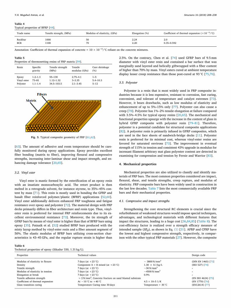
[63]. The amount of adhesive and room temperature should be care-fully monitored during epoxy applications. Epoxy provides excellentfiber bonding (matrix to fiber), improving flexural and compressivestrengths, increasing inter-laminar shear and impact strength, and en-hancing damage tolerance [20,65].
3.2. Vinyl ester
Vinyl ester is mastic formed by the esterification of an epoxy resinwith an insatiate monocarboxylic acid. The retort product is thenmelted in a retrograde solvent, for instance styrene, to 35%–45% con-tent by mass [71]. This resin is mostly used in bonding the GFRP andbasalt fiber reinforced polymer/plastic (BFRP) applications [52,60].Vinyl ester additionally delivers enhanced FRP toughness and fatigueresistance over epoxy and polyester [72]. The material design with FRPdecks primarily differs in fiber architecture and resin type. Thus, vinyl-ester resin is preferred for internal FRP reinforcements due to its ex-cellent environmental resistance [73]. Moreover, the tie strength ofGFRP bars by means of vinyl ester is higher than that of BFRP bars usingepoxy [35]. Patnaik et al. [52] studied BFRP bars produced with themisty layup method by vinyl-ester resin and a fiber amount segment of50%. The elastic modulus of BFRP bars utilizing cross-section char-acteristics is 43–45 GPa, and the regular rupture strain is higher than
2.5%. On the contrary, Chen et al. [74] used GFRP bars of 9.5mmdiameter with vinyl ester resin and contained a bar surface that wasmarginally sand layered and helically giftwrapped with a fiber contentof higher than 70% by mass. Vinyl esters cured at ambient temperaturedisplay lesser creep resistance than those post-cured at 93 °C [75,76].
3.3. Polyester
Polyester is a resin that is most widely used in FRP composite in-dustries because it is less expensive, resistant to corrosion, fast curing,convenient, and tolerant of temperature and catalyst extremes [73].However, it bears drawbacks, such as low modulus of elasticity andenhancement of up to 5%–15% only [77]. Polyester can also cause acreep [78]. Polyester has 1%–2% tensile elongation at failure comparedwith 3.5%–4.5% for typical epoxy resins [20,65]. The mechanical andfunctional properties upsurge with the increase in the content of glass inhybrid GFRP composite with polyester resin [79–81]. Therefore,polyester is a potential candidate for structural composite applications[82]. A polyester resin is primarily infused in GFRP composites, whichare used in the face sheets of sandwich-bridge decks [11]. Polyesterresin is preferred for its minimal cost, whereas vinyl-ester resins arefavored for saturated environs [73]. The improvement in eventualstrength of 115% in tension and consistent 43% upgrade in modulus forincessant filament arbitrary mat glass polyester content are detected inexamining for compression and tension by Fernie and Warrior [83].
4. Mechanical properties
Mechanical properties are also utilized to classify and identify ma-terials of FRP bars. The most common properties considered are impact,flexural, shear, and tensile strengths, creep rupture, and modulus ofelasticity. FRP composite bars have been widely used in construction inthe last few decades. Table 7 lists the most commercially available FRPbars and their mechanical properties.
4.1. Compressive and impact strengths
Strengthening the core structural RC elements is crucial since therefurbishment of weakened structures would impose special techniques,advantages, and technological materials with different features thatimpact the structures, leading to a huge cost [36,84,85] (Table 8). Thecost-efficiency factor is realized over a strength efficacy measure ofintended sample (SEff), as shown in Eq. (1) [31]. AFRP and CFRP havethe lowest and highest compressive strength, respectively, in compar-ison with the other typical FRP materials [27]. However, the composite
Table 4Typical properties of BFRP [44].
Trade name Tensile strength, (MPa) Modulus of elasticity, (GPa) Elongation (%) Coefficient of thermal expansion (×10−6/°C)
Rockbar 1000 50 2.24 2.0BCR 1100 70 2.20 0.35–0.592
Annotation: Coefficient of thermal expansion of concrete= 10×10−6/°C reliant on the concrete mixtures.
Table 5Properties of thermosetting resins of FRP matrix [59].
Resin Specificgravity
Tensile strength(MPa)
Tensilemodulus (GPa)
Cure shrinkage(%)
Epoxy 1.2–1.3 55–130 2.75–4.1 1–5Vinyl ester 73–81 1.12–1.32 3–3.35 5.4–10.3Polyster 1.1–1.4 34.5–103.5 2.1–3.45 5–12
Fig. 3. Typical composite geometry of FRP [61,62].
Table 6Technical properties of epoxy (Sikadur 330, 1.31 kg/L).
Properties Technical values Design code
Modulus of elasticity in flexure 7 days (at +23 °C) ~ 3800 N/mm2 (DIN EN 1465) [73]Density Component A+B mixed (at +23 °C) 1.30 ± 0.1 kg/L (ISO 527) [74]Tensile strength 7 days (at +23 °C) ~30 N/mm2 ⸗Modulus of elasticity in tension 7 days (at +23 °C) ~4500 N/mm2 ⸗Elongation at break 7 days (at +23 °C) 0.9% ⸗Tensile adhesion strength > 2N/mm2, Concrete fracture on sand blasted substrate (EN ISO 4624) [75]Coefficient of thermal expansion At −10 °C to +40 °C 4.5× 10⁻⁵ 1/K (EN 1770) [76]Glass transition curing Temperature Curing time 30 days Temperature+ 30 °C (EN12614) [77]
Y.H. Mugahed Amran, et al. Structures 16 (2018) 208–238
211

strength is high if basalt fibers are either positioned on the face orequipped by substitute layers within the composite as a sandwich form[55]. The compressive strength of epoxy-based composites is higherthan that of polyester-based composites, indicating that strength ofwhole the composites with and without fillers with polyester as matrixis less than that of the epoxy laminates [86].
=SE PT
Columns Concrete Confined FRP of Strength the in IncreaseColumns Concrete Confined FRP the of Cost
[31]ff
(1)
However, impact strength is a measure of the sum of energy that aFRP composite material that could be captivated before fracturingunder a high rate of deformation at a specific shock loading underimpact. The strength of a GFRP compound is condensed to 9.2% atambient temperature [87]. For example, Wu and Li [88] showed thatthe impact strength of samples slowly decreased from 45.0MPa to38.8MPa at ambient temperature and at 300 °C, respectively, ex-hibiting a 13.8% reduction in strength. It is also reported that thestrength of hollow columns wrapped with CFRP is improved by 66% (1layer) and 123% (3 layers) compared with that of the GFRP material,which only increased by 36% (1 layer) and 105% (3 layers) [84].However, that of the filled column that comprised of a circular hollowsection filled with concrete and wrapped with CFRP increased by 154%(3 layers) compared with 144% (3 layers) with that of GFRP. The in-terior moment of the column is increased, causing a reduction in thecompressive strength capacity [18]. Al-Sunna [7] found that the serviceload of beam wrapped with CFRP corresponds to a stress scale in theupper concrete fiber of about 40% of the compressive strength ofconcrete compared with the non-fibered sample. Through the ultra-highperformance fiber RC showed compressive strengths with values of atleast 115% larger than that of ultra-high performance concrete [89].Mastali and Dalvand [90] studied the use of 252 cylinders and cubesamples on the reinforcement of plain concrete using jacketing/U-wrapping method and reported an increase of approximately 31.10%,47.07%, and 65.10% in the impact compressive strength of samples
with recycled carbon fiber of 0.25%, 0.75%, and 1.25%, respectively. Inaddition, the compressive strength of sandwich structure strengthenedwith CFRP is approximately higher by 24.68% than that of none-strengthened samples [91]. Another marked fast upsurge in the strengthis obtained for the material with lengthy bars and high volumes ofCFRP/prepreg waste (PW), that is, 83% for PW and 80% for CFRP(long) [92]. The increase in fiber length found the maximum im-provement in the strength of nearly 3% in the sample [90]. However,the energy engrossed in breaking the test sample, indicating by theposition of sample, is restricted in the vice of the machine of testing.The notch of the sample faces the striker, and the root of the notch isunder a similar level with the parallel face of the vice, calibrating dialbounded to the testing machine [93]. Impact strength is equal to energyabsorbed (Joule capacity, J) by the pendulum hammer at the instanceof impact over the width of notched face (mm), which is multiplied bythe length below the notch in the pendulum hammer after breaking thespecimen (mm), as shown in Eq. (2) [94]. The thickness of FRP layerconsiderably affects the compressive strength of the strengthened con-crete element zone [29].
=×
Impact strength Energy absorbedin joulesWidth of notched face Length below the notch
kJ
/m [93, 94]2 (2)
4.2. Flexural strength
FRP reinforced members are generally over-reinforced, that is, theproportion of FRP bar to concrete is larger than the balanced ratio;hence, concrete crushing of the member controls the failure mode[6,36]. However, when the ratio of FRP reinforcement to concrete isless than the balanced ratio, the FRP rupture encounters a failure mode,which is not a preferred ductile failure mode [6,55]. The reductionfactor of flexural strength is limited between 0.55 and 0.65 in the basisof the ratio of proposed reinforcement to the neutral reinforcementratio because of the deficiency of ductility in FRP reinforced failuremodes [12]. The strength reduction factor for FRP rupture at failure is0.55. However, when the failure is by concrete devastating, the re-duction factor of flexural strength increased to 0.65, where the ratio ofthe neutral FRP reinforcement is smaller than 1.4 times the proposedreinforcement ratio [12]. The flexural strength section wrapped withCFRP evidently decreased with increasing delamination factor [95].However, the flexural strength of the FRP material is determined usingACI 440 similar to ACI 318 because FRP rebars do not yield similar tosteel bars [5,36,96]. The flexural aptitude of the reinforced sections ispractically supposed to be restricted by the rupture strain of the com-posite structures [21]. Certain studies investigated the variables andparameters influencing the flexural strength of the compounds, in-cluding the length of fiber, thermal treatments, binder content, and pre-
Table 7Mechanical properties of several classes of FRP materials [6].
Reinforcing material Yield strength (MPa) Density, (g/cm3) Tensile strength (MPa) Specific gravity Elastic modulus (GPa) Strain at break, %
Steel 500–500 7.75–8.05 – 7.8 (200) –Glass FRP 600–1400 2.11–2.70
2.15–2.701.28–2.61.39–1.45
480–1600 1.5–2.5 35–51 1.2–3.1Basalt FRP 1000–1600 1035–1650 2.7–2.89 45–59 1.6–3.0Aramid FRP 1700–2500 1720–2540 1.38–1.39 41–125 1.9–4.4
Carbon FRP 1755–3600 1.55–1.76 1720–3690 1.0–1.1 120–580 0.5–1.9
Annotation:
- Ultimate tensile strength, ffu- Tensile Modulus of Elasticity, Ef- Elongation at Break, εfu- The values of fiber volume fraction of FRPs are limited between 0.5 and 0.7.
CFRP and GFRP have a tensile elastic modulus of at least 124 GPa and 39.3 GPa, respectively.
Table 8Qualitative comparison of several fibers used in design of the composites [85].
Criterion Type of fiber used in composite
Carbon fibers Glass fibers Aramid fibers
Tensile strength Very good Very good Very goodCompressive strength Very good Inadequate GoodYoung's modulus Very good Good AdequateLong-term behavior Very good Good AdequateFatigue behavior Excellent Good AdequateBulk density Good Excellent AdequateAlkaline resistance Very good Good InadequatePrice $7.11–18.11/m2 $0.13–0.27/m2 $8–12/m2
Y.H. Mugahed Amran, et al. Structures 16 (2018) 208–238
212

activation of the fibers prior creation. For instance, the lengthiest fiberat 10,000 μm has the lengthiest distance between binder interactionpoints, causing in the feeblest composite [97] (Table 9). Park and Jang[98] presented carbon fibers, along with fibers of polyethylene (PE)within an epoxy form; to formulate a hybrid layered composite scheme.The hybrid-based composite is powerfully relied on the location of thefiber of reinforcement. Moreover, the placement of CFRP at the mar-ginal sheet delivers a great grade of flexural strength. The increase inrecycled CFRP fiber length in self-compacting concrete results in themaximum recorded increase in the flexural strength by almost 6%compared with that found in the constant fiber length [90]. Mastali andDalvand [90] claimed that increasing carbon fiber content (1.25%)improves flexural performance of the beams by 10% and 27.23% morethan the mean flexural strengths of 0.75% and 0.25% specimens, re-spectively. This study also reported that the flexural strength of re-inforcement of plain concrete beams increased by around 31.20%,50.93%, and 66.93% with recycled carbon fibers of 0.25%, 0.75%, and1.25%, respectively. Basalt fibers and polyvinyl alcohol (using ex-ternally bonded reinforcement (EBR) method) are used to providesubstantial backing and resist cracking, thereby increasing the breakrobustness of matrix and improving the flexural strength by nearly 27%at the yielding zone compared with that of control specimens [99].Another study developed flexural beam strengthened using a dubbedcarbon skin-basalt core composite and a basalt peel‑carbon core com-pound (EBR method). The results showed 245% and 32% increase inflexural modulus and flexural strength, respectively, of former compo-site compared with the later composite [100]. Using AFRP provides anexpressive magnitude of ductility for FRP-reinforced beams [101]. It isfound that the silica/polyester composites enriched the flexuralstrength from 115MPa to 156MPa at dry phase [102]. Besides, using atwin layer carbon–glass fiber composite system (using near surfacemounted (NSM) method) to strengthen RC beams increases the strengthcapacity by 114% on the strengthened beam compared with that ofreference control [103]. Carbon fiber exhibited a lower strain than glassfiber, and CFRP samples have less ductility than GFRP samples. Thecombination of glass fiber and PE fiber shows no destructive impact onthe flexural strength of the samples [104]. For flexural strengthening,the plates, tow sheets, and bars, are some of FRP reinforcement pro-ducts that used to bond the tension side of a concrete, timber, or evenmasonry, substrate with epoxy mastic. Strengthening of structuralflexural elements improved the load-bearing strength of up to 40%.
Thus, Eq. (3) is employed to compute the cross breaking strength offlexural strengthened members.
= WLBD
Cross breaking strength 1.5 , kN, [86],2 (3)
where
- W= loading, kN- B= breadth in mm- D= thickness, mm- L=span between supports, mm
4.3. Shear strength
The interpretation of shear strengthening of RC structures by meansof outwardly bonded FRP shields significantly relies on the bond per-formance at interaction between the FRP sheets, FRP jacket thickness,concrete substrates, number of layers, and epoxy materials with fibers[105–112]. The behavior should be parallel to the principal tensilestresses (Table 10) [11,113–115]. The increase in the amount ofmoisture absorbed on the epoxy leads to loss of desired shear strengthof the strengthened concrete element [116,117]. However, to resistshear forces, an FRP reinforced member must contain ties or stirrups,or, if not practical as in the situation of RC tanks, rely only on theconcrete resistance to shear loading [114]. RC design without shearreinforcing leads to deep sections where shear is critical [118]. Al-though a deep member may not initially be desired, it corresponds tothe upsurge in the cracking moment of the element [119]. A crackingmoment that is 25% larger than the applied service moment allows theuse of gross moment of inertia to compute deflections and the fullsection of the concrete member to resist shear loads [120]. The tensilestrengths of FRP rebar can be much greater compared to that of steel.Most FRP bars have significantly small modulus of elasticity or stiffness.Decreased stiffness indicates the necessity of deep members or addi-tional reinforcement to mitigate long-term deflections and limit crackwidths [118]. Shear strength design of FRP uses ACI 318 methods [96],whereas ACI 440 [36] does not allow for dowel action of FRP rebar toresist shear in comparison to ACI 318 that facilitates shear resistance ofsteel bars. Moreover, the textile is usually formulated to reveal a certainload–strain profile in its 45° directions, permitting the ideal impact tobeam shear strength [121]. However, the rosette strain gages exhibitedthat the sheet led to the beam shear strength after shear cracking. Thecontribution of shear of the FRP is obtained in the basis of the failuremodes, and the maximum strain is restricted to 0.004 for failure attri-butable to FRP rupture and 0.002 for attach perilous applications [119].The maximum recorded 45° strain reading for the sheet at beam sides is0.40% compared with its ultimate strain of 1.2% [121]. The ultimatestrengthening intervention in hollow concrete bridge column restoresits ductility, strength, and flexural shear strength ratio [122]. Certainstudies showed that the fiber shawl had a lower effect on filled columnsthan on hollow columns (Table 10). This effect is also notable in hollowcolumns, and GFRP is less effective than CFRP. Another study indicatedthat shear strength of the reinforced beams, which are supported usingCFRP sheets, is increased parallel with eventual stiffness and strength ofthe beam associated with that of the control beam and the condensedductility of the RC beams [86]. It is also reported that the shear strengthof GFRP composite decreases to 13% at the case when the temperatureis elevated to 200 °C [87]. Meanwhile, the influence of bucky paperinterleaves produced from carbon nano-fibers on inter-laminar me-chanical characteristics of CFRP (using embedded through-section(ETS) method), exhibiting 104% and 31% enhancement in mode IIfracture toughness and interlaminar shear strength, respectively [123].On the contrary, Han et al. [124] found that the concrete structuresstrengthened with polyfunctional epoxy resin and CFRP tendons withdifferent diameters (using near surface mounted (NSM) method) in-creased the shear strength by approximately 30%–40%. Investigation
Table 9Summary of previous studies on flexural tests.
Refs. Experimental parameters
[105] • Composite type• Anchorage at end of plate[106] - Composite type
- Shear span/depth ratio- Effect of pre-cracking- Surface preparation
[21] • Configuration of CFRP system• Fiber orientation[107] - Number of composite plates
- Anchorage at end of plates[108] • Anchorage technique at ends of plates[109] • Composite type
- Thickness and/or number of plies[110] • Number of plies• Effect of pre-cracking• Anchorage by wrapping with CFRP sheets[111] - External anchorage for CFRP plates (to control slip)[1] • Shear span to depth ratio• Plate end anchorage[112] - Existing reinforcement ratio
- Effect of composite area to steel ratio[26] • Placement of CFRP system• Anchorage with vertical sheets
Y.H. Mugahed Amran, et al. Structures 16 (2018) 208–238
213

Table10
SummaryofpreviousstudiesonRCsectionsstrengthenedbyCFRPandsteel.
Ref.
Typeoftest
Typeofloading
No.ofCFRP
layer
CFRP(plateor
sheet)
Bondlength
(mm)
CFRPmodulus
(GPa)
Eco-condition
Adhesive(modulus),MPa
[127]
Singlelapjointwithcircular
hollowsection
Static
5Sheet
23–126
230
–Araldite420,(1901)
[128]
Singlelapjointwithcircular
hollowsection
Static
1–5
Sheet
40–85
640
–Araldite420,(1901)
[129]
Singleshearpulltest
Static
1Plate
350
165
–Threetypes,(4013–10,793)
[20,130]
Singleshearpulltest
Static
1Plate
300–380
150
–Araldite420,Araldite2015,Sika30,Sika330(1830–11,250)
[131]
Singleshearpulltest
Static
1Plate
250
160
–Twotypes(4013–10,793)
[132]
Doubleshearpulltest
Static
3Sheet
40–80
240
–Araldite420(1901MPa)
[133]
Doubleshearpulltest
Static
1Plate
50–200
338
–SPSpabond,(3007)
[134]
Doubleshearpulltest
Static
1Plate
300
197
–Sikadur30,(4500)andSikadur330,(3800)
[135]
Doubleshearpulltest
Static
1Plate
30–250
479
–Araldite420(1901)andSikadur30(9282)
[136]
Doubleshearpulltest
Static
1Plate
500
195
–Sikadur30,(4500)
[25]
Singlelap,doubleshear,andT-
peeltest
Static
125–250
151
–Twtypesofepoxy,(1000)
[137]
Purebendingtest
Static
1Plate
203
155
–Twopartsepoxysystem(1240)
[19]
Doubleshearpulltest
Fatigue
1Plate
200
166and640
–Sikadur30,(2689)
[30]
Doubleshearpulltest
Fatigue
3Sheet
40–60
479
–Araldite420,(1901)
[138]
Doubleshearpulltest
Fatigue
1Plate
60112
–Araldite420,(1901)
[20]
Full-scalebridgegirders
Fatigue
1Plate
457
205
–PlexusMA555,(107)
[139–141]Doubleshearpulltest
Impact
1or3
Sheet
10–100
205
–MBracesaturant,(2229)
[142]
Pull-offtest
Impact
1or3
Sheet
–205
Subzero
Araldite420,(1901)andMBracesaturant(2229)
[143]
Doubleshearpulltest
Largedeformation3
Sheet
100and150
205
Temperature
Araldite420,(1901)
[144,145]
Doubleshearpulltest
cyclic
3Sheet
100
205
Elevatedtemperature
Araldite420,(2012);MBracesaturant(1482)andSikadur30,
(9515)
[144,146]
Doubleshearpulltest
Static
1or3
Sheet
20–150
205
Elevated
Araldite420(1901MPa)
[145]
Doubleshearpulltest
Static
3Sheet
100
205
Temperature
Araldite420,(2012);MBracesaturant(1482)andSikadur30,
(9515)
[147]
Doubleshearpulltest
Static
1or3
Sheet
20–100
640
Elevatedtemperature
Araldite420,(1901)
[148]
Four-pointbendingtest
Static
3Sheet
1800
230
Seawater
SikadurHex330,(50,350),SikadurHex306(44,900),andTyfo
SW-1,(62,500)
[15,194]
Doubleshearpulltest
Static
1Plate
200
418
Seawater
SPSpabond(2980)
[150]
Doubleshearpulltest
Static
3Sheet
100
205
Seawater
Araldite420,(1901)
[151]
Doubleshearpulltest
Static
1or3
Sheet
30–100
205
UVight
Araldite420,(1901)
Y.H. Mugahed Amran, et al. Structures 16 (2018) 208–238
214

reported that a sudden reduction in the shear strength may be occurwhen the BFRP composites are engrossed and matured under hot saltwater at 40 °C [125]. For shear strengthening, FRP reinforcements areglued to the external of the beams in a vertical U-shaped conformationas an exterior stirrup. Strengthening of shear walls, such as under-RCwalls and unreinforced masonry walls, can be achieved by bondingFRPs to either both or one sides on the wall in either a horizontal,vertical, or X pattern. However, the nominal shear strength is practi-cally calculated using Eq. (4) [126].
= +=
=
V V VV f bd
VA f d
s
[126]2
n s c
c c
cs y
(4)
where
- As=area of flexural reinforcement, mm2
- d=distance from extreme compression fiber to centroid of flexuralreinforcement, mm- b=width of beam, mm- s=horizontal spacing of shear reinforcement, mm- fy=yield stress of flexural or shear reinforcement, N/mm2
- fc' = concrete compressive strength, N/mm2
4.4. Tensile strength
FRPs are used for interior bar and strengthening of RC structuresthat utilize artificial fibers in a polymeric matrix to afford tremendoustensile strength parallel to the direction of fibers [127]. The fibers arealigned in a parallel, straight, and unceasing configuration within thematrix [43]. However, if radial bursting stresses become higher thanthe concrete tensile strength in the element, then cracks develop andthe bond between the concrete and bar is negatively influenced [59].These FRPs are rarely recognized in the community of civil engineeringas ultra-high-strength compounds and can be computed using Eq. (6).Tensile strength values of FRP fibers are commonly indicated de-pending on the matrix, the interface of section, moisture absorption,fiber orientation, and types of fibers [117]. For example, the tensilestrength increases with rising weight ratio of fiber by a certain volume[128]. However, CFRP fibers are reported to own greater tensilestrength and lesser weight compared with the other typical FRP fibers(Fig. 4) [90,128–154]. This condition leads to significant weight re-duction and enlarged span of prestressed structures [124] given thatCFRP is a purely elastic-brittle material [146]. Wu and Victor [81]fabricated a hybrid composite and bonded its interface by CFRP andengineered cementitious composite (ECC). At strain capacity of 1.7%,the tensile strength of ECC at room temperature was resulted of about4.9MPa. Thus, the tensile strength of ECC was improved from 3.5MPato 4.9MPa (by about 40%) in comparison with the mortar, meanwhile,the strain capacity enhanced from 0.011% to 1.7% (by 153 times). Theadhesive tensile strength of CFRP decreases with the adding of nanoclayat higher temperatures. For instance, the tensile strength of CFRP is
reduced by 13.9% after 744 h of exposure [155]. It is also reported thatthe decisive temperatures of CFRP tendons are 330 °C, and the residual88.7% tensile strength is at 100 °C. In addition, the tensile strengthshows a drop of approximately 21% from 75 °C to 100 °C, althoughnearly no change is seen when the temperature elevates from 25 °C to75 °C [157]. However, the basalt fibers have first-rate tensile strengthand protraction at break [88,89] (Table 18). Investigations inventedand improved the tensile strength of basalt/polypropylene composites(polypropylene-g-maleic anhydride (PP-g-MA) with chopped basalt fi-bers) [158], basalt/epoxy composites (tourmaline micro/nano particles(0.5–2 wt%)) [159] via the vacuum aided resin transform moldingmethod and basalt/vinyl ester composites (by modifying the basalt fibersurface via a silane precursor as a coupling agent [160]. These lami-nates of TM/basalt/epoxy display that the tensile strength upsurges by16%, while the increase of 153% and 27% is found for the flexuralmodulus and tensile strength, respectively [166]. Wu et al. [161] re-vealed that GFRP increased the tensile strength of hybrid FRP compo-site by 36% compared with the use of BFRP, which is 2.56% greaterthan that of polyparaphenylenl benzobisoxazole (PBO) composites.Other experimental outcomes showed that the impregnation of carbonfibers with neat epoxy or nanocomposite system lead to substantialgains in terms of tensile strength by approximately 57% and 58% andultimate strains by approximately 44% and 42% [162]. Studies onGFRP composites revealed that tensile and short beam strengths ofvinyl-ester composites are slightly affected, whereas the tensile strengthof polyester composites sharply drops by 80% [163]. However, usingMBrace saturant and Sikadur 30 epoxy reports a 40% reduction and46% upsurge in the eventual tensile strength of CFRP compound sam-ples, respectively [87]. Besides, the tensile strength of the GFRPpolyester-based composites and GFRP epoxy-based composites reduceby nearly 19.71% and 22.8% with wheat husk fillers and rice huskfillers, respectively [87]. This result resolved that the tensile strength ofGFRP in hybrid strengthening is more dispersed than that attained withmerely CFRP or GFRP strengthening [164].
=f WBD
Tensile strength, , kN, [86]fu (5)
whereffu= ultimate tensile strength of FRP, N/mm2.fy= yielding strength of steel, N/mm2.
4.5. Creep rupture
Understanding the limits of a fiber is a crucial feature whenchoosing the form of RC composite for structural elements to withstandlong-term loading [167]. Cyclic and continuous loading on FRP in ex-ceeding of its ability to endure those loads may inspire fatigue failure,long-term deflection, or creep rupture in the structural section [168]. Instructural elements; the stresses in FRP bars recommended to be lessthan the creep-rupture stress range to eradicate the deflections moti-vated by creep [169]. ACI [62,96] and other design codes[10,12,119,120,126] endorse a reduction factor to be applied for theFRP ultimate tensile strength to decrease fatigue and creep rupturefailures (Table 11). The reduction factors prescribed in the ACI codesfor carbon, aramid, and glass FRPs are revealed in the following section.A reduction factor for basalt FRP is also guided in the basis of thefindings of the research led by Anil [31] and Wang and Wu [168]. Wuet al. [167] reported that CFRP tendon has the greatest and poorestcreep rupture performances, exhibiting with its high and low cost,
Fig. 4. Factored FRP tensile strength [26,154,165].
Table 11Creep ruptures reduction factors [5,26].
Property GFRP BFRP AFRP CFRP
Creep-rupture stress limit, Ff,s 0.20 0.20 0.30 0.55
Y.H. Mugahed Amran, et al. Structures 16 (2018) 208–238
215

respectively. Ascione et al. [168–170] and Banibayat [171] reportedthat the creep test only sustains three hours of impact when the BFRPtendons are below a stress rate of< 70% and when creep rupture oc-curs on the tendons. The creep test can withstand 500 h when the stressscale decreases to 65%. Guohua et al. [166] tested carbon GFRP com-posite tendons and found that the creep rate is 19.05% when the levelof stress is 0.8 ffu, which is the ultimate tensile strength. The rate ofcreep is lower than 10% when the stress scale is lesser than 0.7 fu. Thus,the rate of creep lessens with the reduction in the level of stress.The creep rupture reduction factors considerably affect the usable
strength of the FRP system [26,171]. Fig. 5 displays the tensile strengthof several FRPs increased by the suitable creep reduction factors par-allel with the limit of standard stress of 80% of the yielding strength ofsteel. Carbon FRPs have larger usable strength that equals a condensedvolume of FRP for a specified application, which can balance the rise inmaterial and manpower costs [36,136].Creep of FRP materials are typically categorized into three different
zones, as depicted in the schematic in Fig. 6(b) [24,168]. The primarycreep zone may exist instantly after the first elastic strain, exhibitingthat the creep strain quickly rises with time [168]. The secondary creepzone is mainly significant for analysis due to that the structure willcontinue serviceable in this zone [172,173]. The tertiary zone accordswith noticeable material damage in the RC structure. Meanwhile, thetypical improvement of strains under continued loading with time, asrevealed in Fig. 6(a). The figure displays two profiles that signify twoclosely equal load heights of 43% and 45% (a). The primary creep zone,instantly after the first elastic strain, expecting to speedily grow withtime, does not occur for BFRP bars. The secondary creep zone of con-stant strain over a certain period obviously advanced, followed by8%–10% spear of strain at closely 32%–34% of the whole time to
failure. Another region marginally improved, but the tertiary zone forBFRP bars seemed over a tremendously short time period, and failure issudden beyond the tertiary zone. This figure illustrates that the creephistory of BFRP bars is faintly dissimilar from the ideal creep historyshown in Fig. 6(a).
4.6. Modulus of elasticity
The design of the elastic modulus is known by ACI 440.1R as themean modulus of a manufacturing lot [5,56,69]. Compared with con-ventional materials such as metals, FRP materials mandate distinctamendment in codes and standards because of their low ductility andmodulus [11]. The elastic modulus of the plate material is significantlyimperative when the plate is not prestressed before bonding since onlystiff plates can release the stresses in the standing interior steel re-inforcement [173]. However, due to differences in engineering prop-erties, this elastic modulus particularly showed marked variances in theextent and magnitude of cracking, extent of deflection, and failuremode [101]. The lowest modulus of elastic is attributed to GFRP andAFRP bars (Table 2), and the largest ones are exhibited by CFRP(Table 1) because they are sensitive to adhesive thickness of the test,epoxy matrices due to moisture absorption, fiber length, and the per-centage of fibers [97,103,116,117]. For example, SikaWrap 230C, atype of CFRP with nominal thickness equals to 0.131mm and a mod-ulus of elasticity equals to 234 GPa, equals 0.009 for either CFRP cou-pons due to the maximum elongation [175]. Likewise, the modulus andstrength of cement mixture are predicted to improve by 39% and 56%,respectively, with the addition of carbon fibers treated by silane [176].The glass/epoxy-based composite revealed a substantial improvementin the modulus and strength as the rates of strain are enlarged [177].However, synthetic fibers, largely polymeric fibers, typically have smallmodulus of elasticity. Meanwhile, basalt-epoxy-based composites pre-sented alike modulus to glass–epoxy-based composites [178]. The re-duction in elastic modulus of FRP rebars indicates to larger cracks,increase in steel cables and higher localized impacts in comparison withthose of steel RC beams, thus, this reduction can maintained by theaddition of bagasse fiber with glass fiber to the mix design [7,179–181].In addition, BFRP fibers have higher strength-to-weight ratio andmodulus of elasticity than GFRP fibers [23,180,182]. Hawileh et al.[183] studied that the elastic modulus of hybrid GFRP composite isreduced by nearly 28% when subjected to various temperatures limitedbetween 25 °C to 300 °C. The fatigue loading was found to reduce thebond strength between the high modulus of steel and CFRP by nearly30% to 20%, respectively [87]. The modulus increases by about8%–21% nearly linearly as the rate of strain of CFRP and epoxy com-posites increases under dynamic loading condition [139]. Other
Fig. 5. Comparison of tensile strength with creep reduction factor [6,23].
Fig. 6. Comparison of strain versus time [24].
Y.H. Mugahed Amran, et al. Structures 16 (2018) 208–238
216

experimental outcomes show that the impregnation of carbon fiberswith neat epoxy or nano-composite system led to significant gains interms of Young's modulus, which slightly increased by 6% and 8%,respectively, using the new matrices [173]. Moreover, using GFRP fiberis 80 to 160 times higher than those of the matrices, such as polyvinylchloride (PVC), polypropylene (PP), PE, phenolic, epoxy, and polyesterresin [153].
5. Physical properties
FRP composites kept growing at a remarkable rate because thesematerials are utilized with naturally circulating materials or engineeredproduced from more than one constituent substance with significantlyseveral physical properties, such as density, rigidity, strength-to-weightratio, and stiffness (Table 12), as detailed in the following subsections.
5.1. Density
Fiber constituent with low density and high strength, such ascarbon, basalt, boron and aramid, were purchased to please the highperformance tasks of air travel and space investigation in the 1960s and1970s [11]. Regardless of the benefits of natural fibers over ordinarymaterials such as low density and cost, they suffer from low processingtemperature [152]. The bulk density of the material is not an importantcriterion because the density of all fiber composites considered is lowerthan that of steel [34,85,174] (Tables 12 and 8). Cured composites withthe highest modulus and density are the strongest, and thermal treatingdrones away the binder, causing in a frailer composite with lesserdensity [97]. However, CFRP and GFRP are largely used for structuralapplications in aeronautics thanks to their high strength despite theirlow density [95]. CFRP has a relatively low density (1.6 g/cm3); thus,X-Ray radiation can easily get through, leading to comparatively highresolution and still providing acceptable contrast between delaminationand CFRP [95]. On the contrary, sheet basalt plastic is generally pro-duced with thickness (t) between 1.5 and 2.5 mm and density (ρ) be-tween 1360 and 1380 kg/m3 (one-third that of steel) [42]. The densityof warp yarn in basalt-epoxy composites is also greater than that inglass epoxy; thus, basalt-epoxy composites can reinforce structuralconcrete element and show even higher tensile strength [184,185].Besides, a synthetic thermoplastic fiber of PE terephthalate (PET) withhigh density PE (HDPE) is used to produce platform mooring ropes[52]. The adhesive has high adhesive paste, recognized as Sikadure-30,with an average viscosity material and have density of 1.31 kg/L for aresin blend associated with FRP materials for strengthening concretestructures [162]. Another composite was exhibited high paste strengthbetween the HDPE matrix and the basalt fiber [55]. It is also reportedthat the use of 58 wt% flax fiber reinforced polyethylene bio-compositesto reinforce HDPE is linearly showed a low density PE [186]. Also, theuse of short hemp fibers in HDPE can reduce the tensile modulus of allcomposites [187]. However, the density of any designed composite canbe computed theoretically using Eq. (6) [188].
= +
=
=
=
V V
V
V
V
[188]Relative volume of the fiber
Total volume of the laminateRelative volume of the matrixTotal volume of the laminate
,
c f f m m
f
m
cc exp
c (6)
where
- ρm= density of matrix- Vf= fiber volume fraction- Vm=matrix volume fraction- Vc=volume fraction of voids- ρc=density of composite laminate- ρf=density of fibers- ρexp=density of a composite laminate (ASTM-D792) [196]
5.2. Strength-to-weight ratio
FRP materials are mainly used to repair, overhaul and strengthenaging infrastructures affords a motivating alternative to conventionaltechniques because these materials have low density, which can pro-vide high strength-to-weight ratio [21]. This characteristic providesimportant functional and economic wealth, extending from strengthimprovement and mass reduction to durability characteristics, apartfrom its importance in transportation and many structural applications[50,190]. Also, FRP systems provide mobility to specialists to stratifythe strengthening technique on any curved, flat, or geometrically un-balanced surfaces due to their exceptional formability [113]. However,CFRP and GFRP have high strength-to-weight ratio, leading to three toseven times higher than steel and half that of aluminum; these materialsare also 80% lighter than steel. It is also reported that fiberglass is arobust, durable, and lightweight composite material [2,55]. Compositesand fiberglass have the greatest strength-to-weight ratio presented forelement production [11]. The increase in the ratio of fiber weight to anoptimum value and the bond with resin fabric resulted in superiormechanical characteristics. However, the extra addition of fiber ratioadversely affects the relative properties [153]. It is found that thecombination of sisal/carbon fiber hybrid composites with divergentfiber weight ratios through chemical resistance test (NaOH treatment)showed that hybrid composite does not resist the carbon tetra chloride[78]. In general, FRP composite has superior resistance property tochemical attack and chloride ion compared with steel bars[44,56,78,153,163,182,192–198]. Table 12 presents the weights ofaramid, carbon, and glass fibers. Aramid has strength-to-weight ratiolower than that found in carbon and glass fibers [5]. Carbon and aramidfibers have high strength-to-weight ratio when examined in the align-ment of the fibers direction. Meanwhile, glass has low strength-to-weight ratio and still moderately high, similar to carbon or aramid [2](Table 13) [188]. By contrast, basalt fibers have greater strength-to-weight ratio and elastic modulus than E-glass fibers [23,180]. Thestrength-to-weight ratio and density of FRP are clear features intransportation, handling, and insulation; these features reduce theweight of the concrete structures and any other relevant products.
Table 12Typical properties of different FRP materials [5].
Material Fiber strength, MPa Laminated strength, MPa Density of laminate g/cc Strength to weight ratio Material Young's modulus, GPa
GFRP 3450 1500 2.4–2.5 564 30–40CFRP 4127 1600 1.9–2.1 1013 125–181AFRP (Kevlar) 2757 1430 1.44 993 70.5–112.4BFRP 3792 1100 2.6–2.8 1000 70–90Epoxy – 12–40 1–1.15 28 3
Y.H. Mugahed Amran, et al. Structures 16 (2018) 208–238
217
5.3. Rigidity and stiffness
FRP composites are considered by specific strength and stiffness thatsurpasses that of the same metal structures [173]. Many researchersfound that FRP composites have a significant applicable use for severalcivil engineering applications, and they generally develop to becomethe first material between the other alternatives for rehabilitation andretrofit of RC structures given their high stiffness-to-weight ratio. FRPmaterial is preferable to other traditional materials [113]. However, theconcrete element stiffness or its yield load cannot easily be increasedunless large cross sections of these materials are used to participateconsiderably to the element load prior the steel yielding mode [156].The slope of the load-deflection curve in all zones is governed by thestiffness and rigidity of the samples. Therefore, the increase in deflec-tions indicates the retraction of stiffness given that damage is accruedwith load cycling [21]. The joints of FRP lattices control bond stiffnessand rigidity, thus affording a occasionally bonded strengthening systemin cases where nominal connection occurs between the cross-overpoints [191]. The composite materials with high rigidity, great stiffnessstructural fibers, and frivolous, such as boron, carbon, and aramid, havesignificant mechanical characteristics and durability than the compo-sites alone [11,114]. A large FRP cross section may not be economical
and may result in a brittle response of the element down to sudden de-bonding of the strengthening material from the concrete surface [121](Table 14). The bond strength measures the efficiency of the gripamong FRP bars and concrete, and the comparative slip between con-crete and FRP is 0.125mm at unrestricted end of the bar in a shear teston plain bars (Fig. 7).The pre-compression influence from reduction on the bar does not
impact the cracked stiffness, and thus, have no great effect in theoverall load-deflection behavior after cracking [193,194]. For instance,the toughness of the reference steel-reinforced beam is similar to that ofthe AFRP-reinforced beams before cracking. Yet, the toughness is nu-merous times greater than the corresponding reference values after thepost-cracking range [101,175]. It is also reported that the energy duc-tility of the CFRP-strengthened beam and GFRP is 2.6% and 33%, re-spectively, since the beam reinforcement that upsurges eventual loadcapacity significantly increases stiffness and rigidity and decreases de-flection [103]. In addition, the stiffness and strength of the GFRP epoxy-reinforced based composites are 18% higher than that of the BFRPepoxy-reinforced material [184]. On the contrary, the rigidity andstiffness of carbon fiber are twice that of aramid and five times that ofglass fiber [27]. Besides, the stiffness and strength of the natural FRPcomposites are mainly relied on fiber loading [153]. The compositesmade of PE fibers along with carbon fibers within an epoxy matrixresulted superior structural features of the hybrid-based composite re-lies largely on the alignment of the reinforcing fiber [98]. The strengthand stiffness of CFRP cables are close to that of steel [157,181].Moreover, the steel-FRC and the FRP grid are effective in increasing thetoughness of the steel deck plate by 47%, 9.45%, and 63.16% with a4mm-thick and 60mm-thick CFRP grid, respectively [188]. Further-more, the FRP bars stiffness exhibited insignificant changes as a resultof freeze-and-thaw (FT) exposure [23]. The decrease in stiffness is greatwhen the amount of moisture collected by the FRP composite specimenis large [116,117]. CFRP/GFPP shows a reduction of 42% in stiffnessfor the saturated condition when compared with the dry condition[196]. The mechanical properties of GFRP reinforcing bars, particularlythe strength and the stiffness of the composites under elevated tem-perature, reduced substantially due to the stiffness and strength of theresin lessened hastily when the temperature surpassed its glass trans-formation temperature [87].
Table 13Comparative chart of glass, aramid, and carbon fibers.
Properties Fibers
Glass Aramid Carbon
Cost $0.13–0.27/m2 $8–12/m2 $7.11–18.11/m2
Weight to strength ratio P E ETensile strength E E ECompressive strength G P EStiffness F G EFatigue resistance G-E E GAbrasion resistance F E FSanding/Machining E P EConductivity P P EHeat resistance E F EMoisture resistance G F GResin adhesion E F EChemical resistance E F E
Annotation; E=Excellent, G=Good, P=Poor, F= fair.
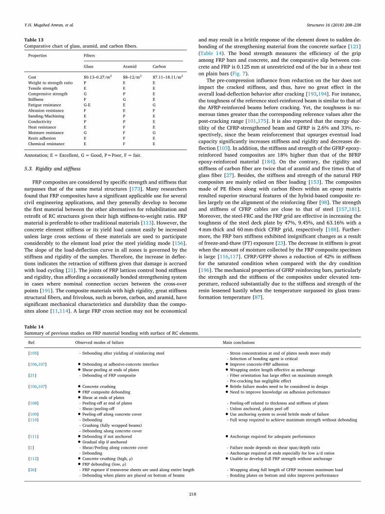
Table 14Summary of previous studies on FRP material bonding with surface of RC elements.
Ref. Observed modes of failure Main conclusions
[105] - Debonding after yielding of reinforcing steel - Stress concentration at end of plates needs more study- Selection of bonding agent is critical
[106,107] • Debonding at adhesive-concrete interface• Shear-peeling at ends of plates • Improve concrete-FRP adhesion• Wrapping entire length effective as anchorage[21] - Debonding of FRP composite - Fiber orientation has large effect on maximum strength
- Pre-cracking has negligible effect[106,107] • Concrete crushing• FRP composite debonding• Shear at ends of plates
• Brittle failure modes need to be considered in design• Need to improve knowledge on adhesion performance[108] - Peeling-off at end of plates
- Shear/peeling-off- Peeling-off related to thickness and stiffness of plates- Unless anchored, plates peel off
[109] • Peeling-off along concrete cover • Use anchoring system to avoid brittle mode of failure[110] - Debonding
- Crushing (fully wrapped beams)- Debonding along concrete cover
- Full wrap required to achieve maximum strength without debonding
[111] • Debonding if not anchored• Gradual slip if anchored • Anchorage required for adequate performance[1] - Shear/Peeling along concrete cover
- Debonding- Failure mode depends on shear span/depth ratio- Anchorage required at ends especially for low a/d ratios
[112] • Concrete crushing (high, ρ)• FRP debonding (low, ρ) • Unable to develop full FRP strength without anchorage[26] - FRP rupture if transverse sheets are used along entire length
- Debonding when plates are placed on bottom of beams- Wrapping along full length of CFRP increases maximum load- Bonding plates on bottom and sides improves performance
Y.H. Mugahed Amran, et al. Structures 16 (2018) 208–238
218

6. Durability properties
To consider the material durability, existing design codes classifyecological reduction factors for any FRP property that can be used inthe design. Therefore, durability properties such as corrosion and fa-tigue resistances, brittleness, and moisture content as well as specificgravity, water absorption, and fraction of fibers are scientifically re-viewed in the subsections.
6.1. Corrosion resistance
Reinforcements of FRP are initially utilized in RC structures thatentail a better corrosion resistance [11]. Using FRP composite materialsalso improves the enactment, condensed drag, used and enriched dur-ability and resistance of corrosion in RC structures. FRP structure alsorequires smaller work crews, lighter equipment, and lighter supportingstructures during installation. These advantages translate into betterengineered systems such as low stress applications that perform better,last long, cost-effective, and decrease long-term maintenance costswhen compared to steel material [50,157]. Thus, these materials arewidely used in engineering applications [197]. However, FRP is notrecommended in dealing with concentrations of corrosion resistance(90 °C to 15% concentration) beyond 50% (Table 15) [50]. Corrosionresistance is controlled by the laminate structure and the resins used. Awide variety of thermoset resins are available to satisfy a wide range ofservice requirements, such as polyester or vinyl ester resin, reinforce-ments (mat and fiberglass roving), and additives (UV inhibitors, pig-ments) [198,199]. Yang [37] introduced brominated epoxy vinyl-esterresins and E-glass that delivered fire retardancy in addition to corrosionresistance as a key requirement for FRP equipment in many civil,structural, and industrial applications. The results shown that basaltfibers have higher corrosion resistance and greater chemical durability,and could be used in a chemical environment for long-term service dueto these excellent features [182,198]. In addition, glass fibers understress are less sensitive to a corrosive environment [200]. However,corrosion resistant fiberglass panels can be manufactured in thicknesses
of 3.18mm to 31.75mm [199]. Investigations depressed using carbo-nation fillers in FRP composites envisioned for acid facility since thesefillers can increase infusion and diminish resistance to corrosion[182,199]. The resin-rich veil plies and the mat layers in the corrosionbarrier contain almost 90% and 70%–75wt% resins, respectively,creating an efficient boundaries for corrosion and permeation. A gelcoat with UV inhibitors can be applied to the exterior of the panelduring manufacturing to improve weathering characteristics.
6.2. Fatigue resistance
Structural element is designed to resist bending and straighten re-petitively; thereby it ultimately fails attributable to fatigue. For in-stance, CFRP is marginally critical to fatigue and inclines to fail cala-mitously without prior signs of distress, thus presenting low fatiguestrength values and acceptable damping characteristics compared withepoxy-based composites [117]. Pultruded rods based on carbon CFRPhave been progressively utilized in structural applications in severalengineering areas down to their outstanding properties, for examplelightweight and great fatigue resistance [208]. Meier [34,85,174]soaked CFRP composite in water to nearly 100% saturation. After 12million cycles, the first steel reinforcement failed due to fretting fatigue.Study exhibited the tensile fatigue performance of the hybrid-BFRP andhybrid-FRP based composites [161]. A 45% capacity drop is observeddue to fatigue load. Similarly, AFRP is more resistant to fatigue. How-ever, this material is susceptible to damage by ultraviolet radiation[23]. GFRP fibers have higher resistance to fatigue, relying on the setupand the type of glass, thereby indicating higher fatigue strength thanCFRP fibers [188]. Eq. (7) is used to reveal the best distribution fits offibers in FRP composites for the life of fatigue and the identical 95%confidence intervals based on previous research analysis [202].
=f xx
Lnx( ) 10.5987 2
( 4.202)0.7169
[202]2
(7)
The use of BFRP based on hybridization for fabrication of a long-
Fig. 7. Bar-pullout bond test apparatus [192].
Table 15Comparison of resistance to corrosion by several composites in corroded environs [76].
Material Dilute H2SO4 Conc. H2SO4 Dilute HCI Conc. HCI Dilute HNO3 Chloride Salts Dilute NaOH
FRP (laminate) N N N N N N NCarbon steel N N Y Y N Y NStain less N N Y Y N Y NHastelloy N N N N N N N
Annotation; Y (yes)=Corroded; N (no)=Unaffected.
Y.H. Mugahed Amran, et al. Structures 16 (2018) 208–238
219

span cable-based bridge of a 70mm-thick steel fiber, resulting that theimpact of fiber hybridization improves in the whole fatigue perfor-mance [203,204]. Another research reported no such reduction in bondstrength for samples with great modulus CFRP sheets at the case whenthe ratio of load is larger than 0.55, along with the total 10 million offatigue cycles [87]. The isophthalic and bisphenol fumarate resins areclassified the greatest fatigue resistance compared with the vinyl-esterresin [161,205,206]. The effective design of hybrid-CFRP laminatescomposite consisting of wave sheets and a tinny stainless steel plate wastested under tension loading [208]. The findings shown that the CFRPthickness and loading conditions are the main parameters influencingthe mode of failures and resistance to fatigue as well as the crackpropagation control depends on the number of layer of side bondedplates and its thickness [205]. Zheng X.H. et al. [206] examined thefatigue behavior of the carbon fiber laminate (CFL) border exposed tohumidity and temperature variations. The results exhibited that theaccepted temperature and RH negatively influenced the bond perfor-mance of CFL and the fatigue life reduced by a bigger stress level.However, the presence of resin can reduce the slip in pultruded FRPcomposites under fatigue loading [207]. Studies investigated the da-mage behavior of BFRP and FRP-strengthened RC composites tested tofatigue loading, and the results shown that the deflection of beam, thestrain can be computed with a high degree of accuracy and the crackingpattern and interfacial debonding are the key damage forms at the lowfatigue stress levels for BFRP [209,210]. Furthermore, the performanceof glass fiber based-reinforced GF/epoxy structures entrenched withshape memory alloy (SMA) under cyclic loadings [211]. However, thefindings displayed that the fatigue of SMA structures is twice greaterthan GF/epoxy composites due to the robustness of laminates of SMAcomposite.
6.3. Brittleness
Concrete is the most brittle material. However, polymers exhibitbrittleness and non-ductile properties. Thus, these materials cannotdisplay a continuous rate of strain protraction under the tensile test[177]. The FRP brittleness is deliberated when forecasting the perfor-mance of retrofitted elements [212]. This brittleness cannot permit thestress redistribution in RC elements, and hence, the ordinary designphilosophies are unacceptable for FRP RC members. The resin and re-inforcement are the two main constituents of the FRP structures [155].For instance, the thermosetting resin is generally very brittle [73,163].The properties are massively enriched by the addition of reinforcingfiber such as glass fiber, carbon, or aramid [46,48,59]. The issues ofbrittleness and weakness in the CFRP composites can be maintained bya hybridization method, that is, by swapping the sheets of the carbonfibers with flexible fibers [213]. Reportedly, the carbon composite la-minates can decrease its tensile strength with increasing modulus onaccount of the material brittleness at higher modulus can cause greatstress concentrations [50]. Thereby, the strain at rupture is highly lowerand the carbon fibers exhibited greater brittleness than glass fibers[95]. Study reported that the upsurge in brittleness of CFRP laminatesas the temperature is condensed [87]. UV photons result photo-oxida-tive reactions that adjust the vinyl-ester matrix and chemical compositeof polymers, causing in material weakening and contributing to ex-treme brittleness and likely micro-cracking [215]. Tetta et al. [216]reported that the configuration of two layers FRP-mortar system is moreefficient by almost 92% than when of a single FRP were used in U-wrapped formulation, but the breakability of the FRP-mortar systemstill persisted. This problem can be maintained by incorporation withother appropriate fibers.
6.4. Moisture content
The FRP mechanical and electrical properties are greatly significant;these features largely rely on the attendance of moisture in the
structures [217]. The moisture propagates parallel the GFRP rod, con-tributing to thermal failures [218]. The engrossed moisture approvalcontent (Mt) can be computed in line with its weight after exposure(wafter exposure) and before exposure (wbefore exposure), as presented in Eq.(8). Moisture content is recognized as the function of the square root oftime. The moisture saturation level (Mt) is roughly 0.77%, which isconsistent with the gravimetric practical results attained in the previousresearch [219].
=
×
Mw w
wMoisture content ( ), %
( ) ( )( )
100 [117]
tbefore exposure after exposure
after exposure
(8)
The carbon fiber volume fraction is 60%+1% for all materialsreported [116]. The diagrams show that the moisture absorption tendstoward an equilibrium value, which depends on the material. Themaximum moisture content of carbon fibers (CF, polyetheretherketone,and PEEK,), epoxy (EP), and resin is approximately 1.6 wt%, 2.5 wt%,and 0.3 wt%, respectively [123]. The specimens absorbed moisture, andthe curves reached the saturation level fast when the water temperatureis high [123]. For example, the elongation values of the 90% CFRPlaminate composite decreased with increasing moisture content[116,117]. Adams and Singh [220] suggested that the temperature ofFRPs decrease to 32 °C and 40 °C when the moisture content is 2% and1.6%, respectively. Investigations studied the acceptance level of BFRPcomposites engrossed in salt water and the impact of moisture capti-vation BFRP structures aged for 240 days [221,222]. The results ex-hibited that the Young's modulus and tensile strength of the compositereduced marginally. Sergio et al. [21] utilized CFRP composites toimprove the flexural capacity of RC beams subjected to moisture andenvironmental actions. After eight months of beam exposure, resultsshowed no negative impacts on the interaction between the surface andthe composite of the concrete. It is also reported that when the GFRPcomposites exposed to a moist environment with comparative moistureof 80% at 50 °C; the result of moisture relies on the type of compositeused. For example, the vinyl-ester-based composites and the modifiedpolyester-based composites have the greatest and worst valuablemoisture dispersion characteristics, respectively, and the epoxy-basedmaterials had tolerable absorption rates. However, these compositesprogressively engross higher moisture in a non-Fickian manner [217].
6.5. Specific gravity, water absorption, and fraction of fibers
FRP grating has almost two-thirds the specific gravity (SG) of alu-minum and nearly one-fourth that of steel [76]. PE fiber has a SG of0.97. Therefore, it is the merely reinforcing fiber found that is nimblerthan water, whereas flame-retardant resins have high SG [199]. Thehigh SG of FRP composites has the tendency to physically reduce per-meation. Furthermore, the SG design criterion is one of the mainparameters involved in the construction of a filament-wound layerthickness [68]. The SG is usually measured in line with Indian StandardIS: 10192-1982 [223]. The sample should be equipped for the test withaccuracy rate of 40 ± 1mm with similar thickness to that of the la-minate of 4mm. The sample is first weighed in air by swinging it withthe assistance of a filament restricted to the hook of the balance, andthen the weight (Wair) at air state is recorded Eq. (9). The weight (Wwet)is also noted by gauging the sample in fresh purified water. The sampleattains the water temperature by immersing it in water for sufficienttime. However, no air foams should twig to the sample.
= WW W
Specific gravity [217]air
air wet (9)
The absorption of water test was performed in line with IndianStandard IS: 1998–1962 [152]. A square test sample of 38−0.0+0.5 mmwas established. The sample weight was initially recorded in air (Wwet),and then the sample was engrossed in purified water for a retro of
Y.H. Mugahed Amran, et al. Structures 16 (2018) 208–238
220

24 ± 1 h. The sample was wiped appropriately and weighed withintwo minutes after removal from water. This weight was then recordedas (Wair), as shown in Eq. (10), as follows:
= ×W WW
Water absorption 100 [159]wet air
air (10)
The volume fraction of glass content (glass fibers) was found asstated by ASTM D2584-08 [217]. The test samples should be prepared.A dried ceramic pot is weighed (W1), and then weighed again togetherwith the sample (W2). Then, the pot with the sample is sited in a softenheater at a temperature of< 600 °C. When the carbonaceous materialvanished, the crucible is cooled to a room temperature, and thenweighed again with glass fibers left alone (W3). Finally, the glass con-tent is computed using Eq. (11), as follows:
= ×
=
W WW W
Ignition loss 100
Glass content 100 Ignition Loss [226]
2 3
2 1
(11)
Several studies reported that the whole composites revealed thesame volume fractions of fibers with the regular fractions limited be-tween 53%–57% with moderately slight scatter, with the exclusion ofthe high seed-glass/vinyl ester structure. The more seed-glass/vinylester structure samples had almost 11% greater volume fraction of fi-bers. However, the rate of moisture content depends on the volumefraction and diameters of fibers and hastily increases by increase thesum of FRP laminate layers (Table 16). The ECR (high seed)-glass/vinyl-ester composite specimens exhibited significantly higher volumefractions of fibers by approximately 66% than the other seven compo-site systems, between 53%–57%. The rates of moisture absorption andthe high moisture contents found from those samples are highly lowerthan the corresponding information for the other structure (Table 17).
7. Functional properties
The functional properties of the FRP composites are largely affectedby the choice of fiber. The selected fibers are required in the design forcomposite applications in industries, civil and structural engineering,compromising with metallic structures. The functional properties ofFRP composite materials include thermal and electrical conductivity,temperature effect, thermal expansion coefficient, and fire resistance, asreviewed in the subsections (Table 18).
7.1. Electrical and thermal conductivity
The thermal conductivity (merely 1/900 that of aluminum and 1/187 that of carbon steel) is obviously benefit at the processes ofpacking, using, or transferring liquids at higher temperature. Loss ofheat develops much smaller, and the hazard that hot apparatus foxes forlabors is condensed [83,206]. CFRP is an electrical insulation andconductive, while, GFRP and AFRP cannot connect electricity [224].AFRP is utilized for guy lines in broadcast towers. Although it is nottransmitting, it can engross water, and the water behaves electricity.Therefore, in such composite materials, a waterproof layer is used to theAFRP. Galvanic corrosion is an anxiety when it is in interaction withmetallic materials because carbon fibers do not conduct electricity[225]. The low thermal conductivity of inorganic polymer coatings also
greatly contributes to fire resistance [72]. Studies reported that the useof carbon nano-fiber (CNT)-coated alumina fibers and sic fibers in-creased the thermal conductivity by 200% and 50%, via the IR micro-scopy technique, respectively [233,227]. Liang et al. [228] developedCNT on carbon fibers using the 3-Omega technique and reported im-provements of 33% in thickness. Forty five boaters with carbon fiberpoles and masts have educated to isolate their aluminum hooks andnetworks to reduce corrosion. Veedu et al. [227] reported enhance-ments in the electrical conductivity on sic fibers with developments of440% and 360% in the through-thickness and in the in-plane directions,respectively. Besides, basalt fibers are used to replace asbestos as heatinsulators because of their weak thermal conductivity but having a highprotection against fire hazards [229,230].
7.2. Temperature effect
In general, the ecological degradation experiments on temperatureimpacts for FRP materials are restricted to a justly short period, gen-erally not exceeded five years [219]. Though, the predicted service lifeof infrastructures, for instance bridges surpasses 50 years where thelong-term performance of FRP structures cannot be effectively antici-pated [219]. In terms of the temperature effects, the mechanical per-formance significantly decreases when the test temperature approachesthe glass transformation temperature (Tg) of FRP composite materials[231]. In particular, the variation of the mechanical performance ofCFRP, GFRP, BFRP, and AFRP reinforcing bars subjected to low tem-peratures ranges from 100 °C to −200 °C, 0 °C to −100 °C, 75 °C to200 °C, and 25 °C to 180 °C, whereas the elevated temperatures rangefrom 200 °C to 600 °C, 23 °C to 315 °C, 200 °C to 800 °C, and 180 °C to482 °C [55–60,63,74–77,80–90,99–103,163,177,190,196,264]. Karb-hari et al. [232] exposed concrete cylinders reinforced with CFRP sheetsto 200 freeze-thaw (FT) cycles limits from 22.5 °C and−20 °C, re-sulting in a more sudden rupture between the concrete and reinforce-ment instead of control. Another research exposed 50 cylinders to 200and 100 FT cycles between 20 °C and−20 °C, respectively, at 70%comparative moistness. The results exhibited closely no impact on thevalues of connection strength, excluding for the bar of 19.1mm dia-meter that revealed 15% reduction after 200 cycles. Davalos et al. [233]contacted up to 30 FT at 60 °C and strengthened with CFRP and GFRPbars. The results showed that the bond strength condensed by around18% after contact. It is also reported that the RC beams reinforced withfive CFRP and two steel-prestressed bars tested under fatigue loading at−28 °C [234]. The main findings presented that at a low temperatureresulted a slip between the concrete and the bars at load with up to 90%of the eventual strength capacity of the RC beams. It is also found thatthe concrete cubes reinforced with FRP bars at different temperature(20, 70, 50, 100 °C) increased the micro-cracking in concrete and de-creased the ultimate tensile load with up to 16% in comparison with thecontrol as a result of the weakness of the FRP matrix under elevatedtemperature that instigated the bond failure [235,236]. Similarly, an-other experimental result exhibited a reduction in the bond strength ofFRP bar between 20% and 40% at 100 °C, 75% at 150 °C, and 90% at220 °C [237]. Besides, the cylinders fabricated with GFRP bars andexposed to 40 °C and 60 °C and left humid for 4months [238]. Thefindings showed 18% and 20% reduction in the bond strength whenexposed to 40 °C and 60 °C, respectively, attributable to the increase in
Table 16Fiber volume fraction corresponding to the number of laminate layers of CFRP/GFRP [85].
Property fiber type (laminate type number) Fiber volume fraction (%) Footnote
1 – Fiber type 1 is a hybrid composite of carbon/glass fibers2 70 Fiber type 2 is a hybrid carbon fiber/resin composites3 51 Fiber type 3 is a hybrid glass fiber/epoxy composites4 66 Fiber type 4 is a hybrid carbon fiber/vinyl ester composites5 70 Fiber type 5 is a hybrid glass/carbon fiber composites
Y.H. Mugahed Amran, et al. Structures 16 (2018) 208–238
221

the diameter of GFRP bars. Accordingly, the contact between tem-perature and moisture speeded the environmental deprivation on theFRP composites [219]. Moreover, it indicated that glass fibers havethermal insulating properties that are 10 times lower than that of basaltfibers. Temperatures beyond zero may cause alterations in mechanicalcharacteristics and generate further micro-cracks in FRP materials.Micro-cracking at low temperatures promotes the increase of waterabsorption at elevated temperatures while the transverse micro-crackincreases in the expansion of freezing water found in voids and cracks[88,124,144–150]. Such freezing exposures contribute to a materialdeprivation through increasing brittleness and reducing debonding[183,144–151,190,196]. The E-glass/vinyl ester and carbon-vinyl estercomposites at low temperature thermal cycling can cause a significantreduction of the structural properties FRP[156,157,161,183,190,196,220,236]. However, the possible contact tofire of the RC structures must also be deliberated during the stage ofdesign [157,161,183,236,237]. RC generally provides a great resistanceto fire at low cost. The use of flammable FRP materials is, consequently,problem that recommended to be considered extremely [33,88,126].All FRP composite materials are disposed to deprivation of mechanicalcharacteristics at elevated temperatures [146,150,183,220,134,237].
7.3. Coefficient of thermal expansion
The coefficient of thermal expansion (CTE) may be detrimentalwhen an FRP liner is used to a steel substrate and CTE value is twicethat of steel/carbon [199]. FRP bars have higher CTE than concrete in
the transverse direction (Table 19). In unidirectional structures, theCTE in the transverse direction is larger than that in the longitudinaldirections (Table 20) [126,220]. Gaitonde [239] reported that thethermal expansion coefficients of carbon fiber strengthened polyetherether ketone (PEEK) exhibited that the worst errors for modulus valuesare −1.4% at −100 °C and −2.3% for the PEEK material. Similarly,the CTE of epoxy composites perpendicular to the fibers is approxi-mately (60× 10−6) per °C; hence, the shear modulus is underestimatedby 2.9% at −100 °C. At high temperatures, the FRP bar entrenched inconcrete expands, causing higher radial bursting stresses than tensilestrength and thereby initiating cracks and negatively affecting the in-teraction between the concrete and the bar [59]. The crack mechanismarising from the limited tensile deformation capacity of concrete di-rectly influences aesthetics, stress transfer, and structure durability[5,6,30,36,238]. Differences in surface configurations and mechanicalproperties exist when traditional steel reinforcement is compared withFRP reinforcement. Therefore, differences in the cracking behavior suchas crack pattern, crack width, and crack spacing are expected[198,119]. However, after an initial linear elastic behavior of RC tiesand once the load causing first cracking is attained, cracks appearrandomly due to non-homogeneity of concrete [101,240]. At crackedsections, concrete stress drops to zero and strain compatibility is lost[59,238]. Stress is transferred from reinforcement to concrete and, atsome distance, the compatibility condition is recovered due to the ac-tion of bond forces. The required strain compatibility recovering dis-tance is short when the bond behavior between the two materials isexcellent [125,219,233]. During this crack creation stage, fresh cracksseem as the load is enlarged, thereby reducing the average crack spa-cing [11,21,114,174]. This behavior remains valid until the crackingstabilization load is attained [174]. From this point, no cracks can ap-pear, and the average crack spacing remains constant. An increase inload is obtained during the opening of the existing cracks [238]. AFRPand CRFP are resistant to high temperatures have no dissolving pointsand utilized for protecting fabrics and clothing near fire [27,48,51].Although GFRP is extremely resistant to elevated temperatures, it ul-timately melts [84,177]. Furthermore, CFRP and AFRP are used tomake protecting welding blankets, firefighting and hands while using aknife [26,27,45,101,241].
Table 17Volume fractions of fibers (%) and rate of water absorption for different fibers [217].
Material Volume fraction of fibers (%) Rate of water absorption, average value
1mm 2mm 4mm
E-glass/modified polyester 55.8 ± 5.4 15.1 8.65 4.54E-glass/epoxy 53.1 ± 4.4 4.07 2.02 1.59E-glass/vinyl ester 56.9 ± 3.5 3.74 1.95 1.18ECR (high seed)-glass/modified polyester 56.4 ± 5.4 11.9 11.96 7.34ECR (high seed)-glass/epoxy 55.4 ± 3.0 3.45 2.27 1.42ECR (high seed)-glass/vinylester 66.2 ± 2.5 2.29 1.38 0.86ECR (low seed)-glass/epoxy 55.9 ± 4.8 3.20 1.79 0.85ECR (low seed)-glass/vinylester 53.1 ± 4.8 4.12 2.33 0.94
Annotation: ECR-glass= E-glass with higher acid corrosion resistance.
Table 18Function properties of different FRP materials.
Properties BFRP GFRP CFRP
Thermal linear expansion coefficient,ppm/°C
8.0 2.9–4.5 0.05
Elongation at break, % 3.15 4.7–5.6 1.2Maximum application temperature,
(°C)982° 650° 1100°
Sustained operating temperature, (°C) 820° 480° 1000°Minimum operating temperature, (°C) 260° −60 −170°Thermal conductivity, (W/mK) 0.031–0.03 0.034–0.04 0.035–0.04Melting temperature, (°C) 1450° 1120° 1550°Vitrification conductivity, (°C) 1050° 600° 1300°–1670°Glow loss, (%) 1.91 0.32 1.75Filament diameter, (microns) 9–23 9–13 9–15Absorption of humidity (65%RAH),
(%)<0.1 < 0.1 < 0.1
Stability at tension (20 °C), (%) 100 100 100Stability at tension (200 °C), (%) 95 92 94Stability at tension (400 °C), (%) 82 52 80H2O, (%) 0.2 0.7 0.052n NaOH (Sodium Hydroxide), (%) 5.0 6.0 5.02n HCI (Hydrochloric acid), (%) 2.2 38.9 15.7
Annotation: Part per million/degree Celsius of temperature (ppm/°C); Watt permeter per kelvin (W/mK).
Table 19CTE of different FRP materials.
Coefficient of thermal expansion (×10−6/°C)
Direction Steel GFRP CFRP AFRP
Longitudinal 11.7 6 to 10 −1 to 0 −6 to −2Transverse 11.7 21 to 23 22 to 23 60 to 80
Y.H. Mugahed Amran, et al. Structures 16 (2018) 208–238
222

7.4. Fire resistance
Fire resistance is a major issue that results in the limited applicationof FRP materials. Thus, rejoinder under fire contact is a main anxiety asa consequence of the extensive applications of FRP strengthening in RCstructures, particularly in buildings, where fire resistance is one of theRC design requirements [242]. FRP is utilized as a material system thatmust gratify the requirements of the local design code to prove its firesafety [243]. The FRPs fire resistance can be enriched by means of fire-resistant polymers [242,244–246]. FRP materials must still exhibitsound behavior associated to high temperature, particularly predictedto the fire design given these considerable features, thereby leading tothe inactive protection of buildings in case of fire [244]. Reportedly, thefiberglass bars with thermoset resins are generally utilized in corrosionresistant coats, owning a low rate of flame when fire is sustained byoutdoor source [242–244]. Fire retardant thermoset resins classicallycomprise either bromine or halogens molecules [244–247]. All matrixresins, for instance polyesters, epoxies, and vinyl esters, used for FRPcomposites are classified as non-fire resistant materials. It is reportedthat the FRP-strengthened RC beam can stand> 3 h when expose tofire, exhibiting a low rate of fire resistance than that of an un-strengthened RC beam [242,245]. Another study revealed that whenthe FRP reinforcing system is secured with fire insulation of 25mmdiameter, the FRP-strengthened beam can stand>1 h 60min com-pared with that of an un-strengthened beam [28]. Qinghua et al. [126]reported the fire resistance of CFRP tendon with the matrix epoxy resin(transition temperature ranges from 90 °C to 110 °C). Therefore, thedisintegration of epoxy resin at elevated temperature leads to the re-duction of at least 50% of the ultimate strength followed by the failureof the CFRP tendon when the temperature exceeded 250 °C. Basalt fi-bers do not produce toxic substances when subjected to fire, therebyovercoming a serious drawback of conventional fibers [23]. The BFRPbars with different types of heat-resistant epoxy and vinyl resins canresist up to 100 °C is because of the impregnation and adequate cohe-sion between the basalt fibers and the heat-resisting resins [244]. Themechanical characteristics of FRPs weaken with elevating temperature.The maximum temperature is the glass transition temperature Tg of thematrix of polymer, presenting typically in the array of 65 °C to 120 °Cfor matrices utilized in infrastructure applications [37,54,242]. Thelongitudinal properties are considerably influenced by low tempera-tures compared with the transverse properties due to the anisotropy ofunidirectional FRP structures; therefore, the shear and transversestiffness and strength reduce quickly above Tg [242,243]. The depri-vation of the mechanical properties of FRPs at elevated temperature isnaturally ruled by the characteristics of the matrix polymer [242,243].Fig. 8 displays the temperature-dependent strength of carbon, aramidand glass fibers in the basis of the data reviewed from previous studies[197]. This figure advocates that carbon fibers are moderately un-responsive to high temperatures, while aramid and glass fibers experi-ence substantial weakening of strength at elevated temperature[124,197,246]. The relatively robust fire resistance of any RC beamsstrengthened with glass FRP can possibly accredited to the clear con-crete cover of 70mm that was afforted for the FRP bars. Several lit-erature reviews and theoretical studies have also been presented[156,157,161,183,190,196,220,236,242–247]. Table 21 presents thesummary of imperative comparison and rankings for steel and FRP,
particularly their practicality and durability properties. Furthermore, areview of the literature indicates that fire design guidelines for FRP-strengthened RC members in current codes and standards are extremelylimited.
8. Serviceability of FRP
Serviceability frequently governs the design of concrete elementsthat are internally strengthened with FRP reinforcements by reason ofthe hardened properties of FRP composite materials. Three main ser-viceability criteria, namely, crack width, deflection, and fatigue, shouldbe satisfied. These factors should be considered when the shearstrengthening application is being designed. The reasons are given inthe following subsections.
8.1. Crack width
The cracking phenomenon in FRP composites mainly depends onthe fiber type, fiber breaking, fiber surfaces, matrix debonding, matrixinterface, moisture content, and thermal cycles, which all contribute tomechanical degradation [198,212]. Corrosion crack propagation is also
Table 20Transverse and longitudinal CTE of prestressing steel tendons and CFRP tendons [124].
Property Units Leadline CFCC Prestressing steel
Longitudinal thermal expansion coefficient °C −0.9× 10⁻⁶ −0.5× 10⁻⁶ 11.7× 10⁻⁶
Transverse thermal expansion coefficient °C 27×10−6 21×10−6 11.7× 10⁻⁶
Relaxation ratio at room temperature % 2–3 0.5–1 8
Annotation: Carbon fiber composite cable (CFCC).
Fig. 8. Modification in FRP bond strength with temperature [197].
Table 21Imperative comparison and rankings for steel and FRP [188].
Property (parameter) Merit/advantage (rating)
FRP Steel
Strength/stiffness 4–5 4Weight 5 2Corrosion resistance/environmental durability 4–5 3Ease of field construction 5 3–4Ease of repair 4–5 3–5Fire 3–5 4Transportation/handling 5 3Toughness 4 4Acceptance 2–3 5Maintenance 5 3
Annotation: (1) Very Low, (2) Low, (3) Medium, (4) High, and (5) Very High.
Y.H. Mugahed Amran, et al. Structures 16 (2018) 208–238
223

associated to the toughness of the resin, fiber, and matrix used to bindthe FRP composites [198]. The toughness (Gc) of a composite is theamount the energy captivated per unit area of crack under Eq. (12)[50]. If the crack is solely promulgated straight over the toughness ofmatrix (Gc
m) and toughness of fibers (Gcf), then a simple rule-of-mix-
tures may be expected. However, if the length of the fibers is less thanlc, then the system will not fracture.
= +G f G f G [50]c f cf
m cm
(12)
where
- m=matrix- f=fiber- lc=critical fiber length, mm- ff= fraction volume of fibers- fm=fraction volume of fibers= 1− ff
Crack width is computed based on the same perception for FRPrebar because this parameter is for steel-reinforced members. However,the parameter is modified by a bond quality coefficient (kb) [5,6,23,36],as expressed in Eq. (15). The bond between FRP bars and concrete isgenerally lower than that of steel bars because of less prominent de-formations and long-term effect on crack widths, particularly in GFRPcomposite structures. The design recommends that the crack widthshould be increased by the bond quality coefficient (kb) equal to 1.4,except when a FRP bar manufacturer can prove by testing that the bondwith concrete results in a decreased bond quality coefficient [5]. Themaximum probable crack width (w) in mm is given by Eq. (13).
= +wfE
k d sCrack width, 22
[96]f
fb c
22
(13)
where
- β=is the ratio of the distance from the neutral axis to the extremetension fiber to the distance from the neutral axis to the centroid ofthe tensile reinforcement- dc=the concrete cover thickness measured from the center of theclosest reinforcing bar to the extreme tension fiber, mm- s= longitudinal bars spacing, mm
High aging temperatures that approach the glass transformationtemperature of samples can increase the structural performance bydepreciate the materials by prompting thermal cracks, which do notappear in the actual use of FRP structures [125,219,133]. Width ofcrack is usually smaller steel-RC beams than in in glass FRP-RC beamson account of the small modulus of elasticity of FRP bars [11,114].Reportedly, the short-fiber press shaped flanges can be disposed tocracking and an inappropriate for tough services [199]. It is also re-ported that the largest crack width in CFRP-reinforced and AFRP beamtested under cycling load, is greater than the reference values for steel-reinforced beams due to the decrease of their strength at a post-crackingvariety and the crack width should not exceeding 0.051mm [21,101].Meier [174] reinforced the flexural beam by using CFRP epoxy struc-tures with laminate of 2mm thickness, therefore, the finding shown areduction from 3.85mm to 2.58mm at nonlinear range. Salakawy andBenmokran [247] fabricated bridge deck slabs strengthened with FRPreinforcements. The results showed that the FRP reinforcement ratioincreased from 100% to 200% and the crack spacing decreased by 4%to 10% and 44% to 49% for slabs reinforced with carbon and glass FRPreinforcements, respectively. The measured crack widths for FRP-RCslabs and steel-RC structures are recorded within the permissible codeas 0.5 mm and (0.4 and 0.3 mm for interior and exterior exposures),respectively (ACI 440) [5].
8.2. Deflection
Serviceability problems, for instance deflections, mostly govern thedesign due to the low elastic modulus of FRP bars [51]. The deflectioncontrol of cracked RC elements relies on the effective moment of inertiaof the section (Ie), as prescribed in most the design codes [247]. Thistechnique is in the basis of the hypothesis that the moment–curvatureprofile of cracked FRP RC element residues elastic under the incrementof applied load, with a rigidity of flexural (Ec Icr), and the tensionhardening is insignificant [119]. Computation of the long-term deflec-tion is in the line ACI 318 [96]. In this approach, the applied unfactoredmoment surpasses the cracking moment (Mcr), and the moment of in-ertia is condensed by the diminished tension stiffening in FRP-re-inforced sections relative to that in steel-reinforced sections. The degreeof tension stiffening in the FRP-reinforced sections decreased with thevolume of reinforcing associated with the balanced reinforcing ratio[254]. For a one-way slab under flexural loading, the greatest deflectionis provided in Eq. (14).
= =PLE L
aL
aL
LL
LI24
3 4 8 , and 1 [119]maxc cr
g cr
g
3 3 3
(14)
where
- P=applied load, kN- L=span of the slab, mm- a=shear span- Lg=distance, mm; support to point where Ma=Mcr in simplysupported slabs- Lcr=Cracking length of the section, mm
This section presents the observation of common inclines in theload–deflection profile thru the testing of the reinforced samples. InFig. 9 and Table 22, Sergio et al. [21] analyzed that the samples in zoneA remain uncracked, whereas zone B parallels to the cracked concreteand linear performance of the FRP laminates and reinforcement. Thedeflection is governed by the volume of FRP composites and re-inforcement on the cross section [21]. However, zone C is measured bythe stiffness and strength of the FRP structures and the straw-hardeningstrength of the bars. The deflection curve in region C is large for thestrengthened element because of the stiffness of CFRP composites.Furthermore, Olofin and Liu and Nor et al. [181,248] found that whenthe tensile strength (3500–7000MPa) and elastic modulus(230–650 GPa) of CFRP are higher than those of steel, then the de-flection of structural members and the elongation at failure is improved
Fig. 9. Qualitative depiction of the load–deflection profile of the RC members[21].
Y.H. Mugahed Amran, et al. Structures 16 (2018) 208–238
224

in the range between 0.6% and 2.4%. For clarity, the restrictions indeflection of serviceability are forced on RC members to confirm theirstructural reliability under service load conditions. Under the samecondition, RC members strengthened with FRP reinforcements are re-sulted larger deformations than of those of steel-reinforced memberattributable to the low elastic modulus of the FRP rebars [249–252].
8.3. Fatigue
FRP is an excellent-performing material with high strength fatigueresistance, which is extensively and widely used in engineering appli-cations [197]. The material FRP composite elements experience pro-gressive deformation subjected to a constant load over a retro in aprocess known as creep, followed by fatigue failure mode [24]. Theknowledge obtained from investigation regarding the CFRP steel com-posite system may not be appropriate to the CFRP concrete compositeas a result of the distinguished variation between the fatigue failuremode and debonding mechanisms for connections and steel members[94]. Studies on the influence of fatigue on FRP-RC elements specifythat the fatigue failure mode restricts the volume of stress permitted onFRP rebar [30,87,135,138–143,150] (Table 23). Another study ex-amined the effect of fatigue loading at several load ratios that arrayfrom 0.15 to 0.55 on the interaction between CFRP and steel sheetswith nominal modulus (240 GPa–640 GPa). The findings exhibited thatthe decrease in bond strength for the nominal modulus CFRP sheet isalmost 20% to 30% (Fig. 10) [138,222]. The impact of fatigue loadingon joint rigidity decreases< 10% of the rigidity as a result of the ac-crued damage resulted by the increasing of fatigue loads.Investigations of BFRP and GFRP-RC composites under fatigue
loads, thus, the results showed 36% increase in modulus/tensilestrength of BFRP compared with the GFRP [161,203]. The BFRP rup-ture strain is also found 2.56% greater than that of PBO composites. It isalso reported that the AFRP composites exhibited higher resistance tofatigue, and isophthalic and bisphenol fumarate resins are known thelowest fatigue resistance compared to with those of the vinyl-ester resin[27,199]. Moreover, samples made from Araldite 420 and Sikadur 30showed no reduction in bond strength at temperatures less than −40 °C[30,87,130]. Meanwhile, the bond strength of MBrace saturant is re-ported deceasing by 40% when the temperatures released from 20 °C to−40 °C.
9. Design of FRP
Design loads on a RC structure are determined using the samemethods, whether reinforced using steel or high-strength FRP reinfor-cing bars [249]. Steel and FRP-RC members are analyzed using similarmethods to satisfy the strength and serviceability criteria, namely,factored moment, factored shear, crack width, and long-term deflection[5,12,250]. FRP is used mainly to strengthen existing RC structures, andthis process involves multiple assessments and requires a good sym-pathetic of the current RC structural circumstances along with the usematerials to overhaul the building before to FRP installation[23,251–254]. The applicability of FRP for a reinforcing project couldbe measured by sympathetic FRP, its features, and more significantly,its restrictions. For instance, GFRP is the toughest and greatest resistant
Table 22Typical behavior of specimens strengthened with different material properties[21].
Region Material behaviour
FRP Concrete Reinforcement
A Elastic Elastic Un-crackedB Elastic Elastic CrackedC Elastic Yielding Cracked
Table23
Summaryoftestsofbeamsunderfatigueloading.
Ref.
NumberofspecimensCrosssectionalshape
Failureparameters
CompositeType
Annotation
Numberofcycles
Modeoffailure
[21]
1Rectangular
480,000
Steelfracture
Hybrid(33%
carbon/67%
E-glass)
Sheet
Numberofcyclesindicatesfractureoffirstreinforcingbaralthoughcyclingwascontinued
[243]1
Tee
12,000,000
Steelfracture
CFRPSheet
After10.7×106cycles,testingwascontinuedinanenvironmentalchamberat40°Cand95%relative
humidity
[244]5
Rectangular
20,000
Steelyield
CFRPpultrudedplates
Control
732,600
Steelyield
Control
508,500
Steelfracture
Maximum
loadrepresentedthesamepercentageoftheultimateloadasforspecimen2
1,889,087
Steelfracture
Stressrangeinthereinforcementapproximatelyequaltothestressrangeofspecimen1
>11,968,200
Nofailure
–[245]6
Tee
150,000
Steelfracture
CFRPfabric
Stressrangeinthereinforcementapproximatelyequaltothestressrangeofspecimen1
2,000,000
CFRPfabric
rupture
Strengthenedafterapplying150,000cycles
1,800,000
CFRPfabric
rupture
Accumulationofdamagewascharacterisedbyalossofstiffnessintheload-deflectionplotsafter
differentnumbersofcycles
1,756,000
CFRPfabric
rupture
3,000,000
CFRPfabric
rupture
3,215,000
CFRPfabric
rupture
Y.H. Mugahed Amran, et al. Structures 16 (2018) 208–238
225

to twisting forces when polymer fibers are equivalent to the appliedforce and vice versa [8]. Fig. 11 illustrates the analysis and design ofFRP-strengthened RC members, for example beam, deck-slab, and plate-girder-bridge [255]. In FRP design, the moment–curvature profile of aRC section reinforced with FRP composites is computed by dividing thesection into horizontal portions and assigning precise material proper-ties to each portion [21]. The techniques utilized to measure the strainand stress in each portion and compute the identical curvature andmoment are labeled in Fig. 11. Interior force equilibrium is developedfor sequences of extreme concrete compressive strains. Curvature andmoment can be computed at each point identical to the extreme strainof concrete given to the extreme fiber under compression, as revealed inEq. (1). The method utilized to calculate curvature and moment of areinforced section is noticeable in the following steps [12,21]: (1) setthe supreme compression strain in the concrete (εc max) to a value be-tween the greatest usable concrete strain (εcu) and zero, (2) approx-imate the primal neutral axis location (h/2), (3) compute the strainshape based on the maximum compression fiber strain and the locationof the neutral axis and then calculate the identical interior stress ele-ments by means of the material prototypes approved, (4) inspectequilibrium in the horizontal direction via the interior stresses, (5)regulate the depth of neutral axis (c) until force equilibrium is attained,(6) measure the interior curvature and moment; and (7) upsurge (εc max)for the purpose of accuracy.However, the interior stress in each portion is computed at mid-
thickness and presumed constant throughout the portion. The dis-tribution of stress is estimated by sequences of squares with a depthequivalent to the potion thickness and height identical to the stresscomputed from the stress–strain profile [Eq. (2)]. The force envelop-ment from each portion is calculated with the cross section width at the
portion mid-plane (bi) and the portion thickness (t-portion). This en-velopment is showed for non-rectangular cross sections in Fig. 11. Theinterior force elements are timed by their distance to the neutral axis zito compute for the interior moment. Meanwhile, the curvature iscomputed by dividing the extreme compressive strain by the neutralaxis depth. In the last step, the model primarily estimates that CFRPcomposites residue connected to the surface of concrete [23]. Underthis assumption, the supreme stress that possibly established in CFRP isidentical to the stress of rupture fpu. The envelopment of CFRP com-posite to the complete tensile force develops zero when stress of ruptureis reached [21].
=M F Z [21]i i i (15)
=c
Ø [21],c max(16)
where
- h= overall depth of beam; ds=effective depth; b= the beamwidth; c=the neutral axis depth- εcu=concrete crushing stain; Acs=effective area of compressionsteel under compression- fc=concrete compressive strength; fsc=stress in compressive steel;fy=steel yield strength- As=effective area of steel under tension; Efrp= tensile elasticitymodulus of CFRP bar; Internal moment, kip-in; Ø=Curvature, 1/mm; Fi=Internal tensile, kip- zi=distance from internal force component to neutral axis, Fi, mm.
εc max=strain at the extreme compression fiber; c=neutral axisposition, mm; Afrp=effective area of CFRP rebars; εfrp=strain inCFRP bar; α1 and β1= compressive stress block parameters incompression zone of concrete
Furthermore, Table 24 shows the guidelines strategies of the FRP asproposed by various codes for strengthening RC structures at differentsituations such as flexure, shear, and column confinement. The table isbasically briefly presented the related parameters controlled the designstrategy of the FRP such the concrete strength, the quality of the con-crete surface, the glue line thickness, and the stiffness, the effectivebond length and width of the FRP sheets. It can also be used as a sampleguideline for engineers, researchers, and material producers and easethem to develop their understanding of FRP strengthening technology.
10. Strengthening techniques
Externally bonded reinforcement (EBR) and Near-surface mounted(NSM) strengthening approaches are the most common and lately uti-lized encouraging strengthening approaches for RC structures[223,256–258]. The NSM approach is performed through the followingsteps: (1) splits of 4–5mm width and 12–15mm depth are cut by a
Fig. 10. Fatigue damage zone [138].
Fig. 11. Internal stresses and forces in strengthened section [12,21,249,255].
Y.H. Mugahed Amran, et al. Structures 16 (2018) 208–238
226

Table24
GuidelinesstrategiesoftheFRPsheetsasproposedbyvariousstandardsforstrengtheningRCstructures.
Country
Europecountries
American
China
Canada
Australian
Japan
Italian
Nameofcode
Eurocode8-3
ACI440.2R
CECS146
CSAS806-02
HB305
JSCE-E541
CNR-DT200
Yearofpublishing
2004
2002
2003
2004
2008
2002
2004
TitleoftheFRPdesigncode/standard/guidelineCurrentlynoEurocodefor
FRPDesignofstructuresfor
earthquakeresistance–Part
3:Assessmentand
retrofittingofbuildings)
Guideforthedesign
andconstructionof
externallybondedFRP
systemsfor
strengtheningconcrete
structures
Technicalspecificationfor
strengtheningconcrete
structureswithcarbonfiber
reinforcedpolymerlaminate
Designand
constructionof
building
componentswith
fiber-reinforced
polymers
Designguideline
forRCstructures
retrofittedwith
FRPandmetal
plates:beamsand
slabs
JapaneseDesignand
constructionguidelines
forseismicretrofitof
existingreinforced
concretebuildings
Guideforthedesignand
constructionofexternally
bondedFRPsystemsfor
strengtheningexisting
structures.
Strengtheningof
RC structures
Technique
Shear
-EmbeddedThrough-Section
-NearSurfaceMounted(NSM)
Flexural
-NearSurfaceMounted(NSM)
-SteelFiber-ReinforcedConcrete(SFRCoverlay)
-ExternallyBondedReinforcement(EBR)
Column
confinement
-GeneticAlgorithm(GA)
-Jacketing(U-wrapping)
-Steelwirereinforcedpolymer(SWRP)
Effectivebondlengthofthe
FRPsheets,l
el e,
=E f
t
f ctm
4
Shouldbebetween40and
240mm
l e,=
nEft2330
0 0.58
Shouldnotbe
<200mm
l e,=
E ft f
cf c
2l e,=
nEft
f
2535
0 )0.58
l e,=
E ft f f c
l e,=0.7
E ft
f ctm
200mm(notincluding
sectioncutawayfrom
edge)
l e,=
E ft f
f ctm
2
Shouldnotbe<200mm
WidthoftheFRPsheets,w
f
K p=
+
wf s f
wf m
m
1.5
2
110
0
A f=
2nt fw
f50mm≤wf≤250mm
Af=
n ft fwf
wf=
d f–2L e
P max=
bE
tG
2f
ff
f
K p=1.06
+
wf b wf m
m
2
140
0
≥1.0
Theconcretestrength,MPa
Structuralgrade≥30MPa
Shouldbeatleast30MPa
Qualityoftheconcrete
surface
Requiredahighqualitysurface
Thegluelinethickness,mm
Upto2mm
2.0–2.3mm
Upto2mm
2–3mm
1–2mm
Upto2mm
ThicknessofFRP,
t f0.17–0.83mm
Ratioofstrength/stiffnessof
theFRPsheets
4–5
Annotation:E f=elasticmodulusofFRP,L e=effectivebondlength,f
c′=concretestrength,f
ck=characteristicstrengthofconcrete,f
ctm=meantensilestrengthofconcrete,n=numberoflayersofFRP,tf=thicknessof
FRP,d fandwf=effectivedepthandwidthofFR,respectively.s fisthespacingbetweenthecentrelineoftheFRPstrips,and
AfistheeffectiveareaoftheFRP,n fisthenumberofFRPlayer,Gf′′Young'smodulusofFRP,K p
FactorrelatedtothewidthofthebondofFRPsheet,P m
axmaximumloadofthesection,
b=widthofsectionsoffitinmm.
Y.H. Mugahed Amran, et al. Structures 16 (2018) 208–238
227

diamond knife cutter over the surfaces of concrete of the members to bereinforced, (2) the splits are gutted by compressed air, (3) CFRP layersare gutted by acetone, (4) epoxy resin is formed in line with providercommendations, (5) the splits are filled with the epoxy resin, (6) epoxyresin is used on the laminates surface, and (7) laminates are presentedinto the splits and the extra epoxy resin is removed. To use wet lay-upslices of a CFRP laminate by the EBR approach, research achieved thesubsequent processes [223,259–263]: (1) On the regions of the surfacesof beam where the slices of the laminate should be stuck, emery wasused to eliminate the superficial paste; (2) the remains were apart bycompressed air, (3) a layer of primer was used to normalize the surfaceof concrete and improve the strength capacity of the concrete substrate.Lastly, (4) the slices of the laminate were pasted using epoxy resin ontothe beam surfaces [264–266].
11. The bond characteristics of FRP
Bond FRP plate or sheet for strengthening and rehabilitation con-crete members is became more popular in civil and structural en-gineering fields due to the remarkable characteristics, such as anti-corrosion, and light weight, compared with the traditional strength-ening techniques [16–27,119,120,304,305]. However, the bondingwith the concrete is essential to the exterior reinforcement techniquefor either repairing or strengthening reinforced concrete (RC) elements.In most of strengthening cases, the bond of interface is critical intransforming stresses from the existing RC structures to the externallybonded FRP composites [223,256,257]. In structural RC system, sheetbonding has a superior potential for construction flaws, due to themixing of resins and the curing of FRP composites. The Japan ConcreteInstitute (JCI), Canada, and the Great Britain, recognized a technicalcommittee on retrofitting technology that concerned on the bondproperties between the existing RC structures and retrofitting materialsfor both glue bonding and overlapping retrofitting technologies [217].The current applications of the sheet bonding system include shearstrengthening, flexural strengthening, and column wrapping[113,121,219,271,272,293–295,306,308,311–315]. In the case ofcolumn wrapping, the failure of bond interface is not a main concerncompared to the fracture of FRP sheets is the major mode of failure[272,306,311,312,315]. Thus, it has been recently recommended thatFRP materials should be used with a high fracture strain capacity [3–5].However, for RC members strengthened with FRP sheets for shear andflexure; debonding of the FRP from concrete is governed the overall
structural failures [121,271]. In the flexure strengthening cases, thedebonding of FRP sheets from the concrete substrates are having morecomplex corresponded with several failure mechanisms unlike with theshear strengthening cases that are found in line with results obtained inpull-out shear bond tests and; respectively [273,277,278,317]. Toevade the mid-span debonding failure, the most design guidelines en-dorse limits on the strains in the FRP sheets because the mid-span de-bonding is always occurred due to the interaction of the concrete cover,the FRP sheets and the steel reinforcement. Through the results of thepull-out tests, it is reported that the concrete strength, the quality of theconcrete surface, the glue line thickness, and the stiffness, the bondlength and width of the FRP sheets are having a major impact on thebound strength of FRP composite system despite the diversity of re-inforcing materials used (i.e., carbon fiber, steel, and glass fiber com-posites), the different concrete compressive strengths [217]. Severalstudies reported that the stiffness of the FRP sheets (elastic mod-ulus× thickness) can lead to influence the bond strength[39–40,103,151,181]. For instance, it has been obtained that bondlayers with lower elastic moduli, but good stiffness, could contribute togreater interface bond strengths [97,116,117]. It is also found that thesheet width does not affect the moderate bond strength of interfaceswhen the width of sheets limited between 50mm to 200mm. It is re-ported that the bond strength increases as the sheet bond length is in-creased. Nevertheless, the effective bond lengths are varying con-siderably between 45mm and 275mm [217]. Moreover, the designguidelines of FRP for strengthening RC members with respect to localbond characteristics and the role of the interface bond characteristicson RC member behavior will be informative to engineers, researchers,and material producers and motivate them to advance their under-standing of FRP retrofitting and strengthening technology. Moreover, asummary of the bond strength equations as pre various design stan-dards and the commendations afforded by several scientists are given inTable 25.
12. Applications of FRP
Large-scale research projects undertaken in 1993 in the USA andCanada involving CFRP/GFRP composites confirmed the decision to usesuch materials in construction (Table 26) [256–267]. The USA is notonly the largest producer and user of FRP composites but also leads theworld's composite technology development and implementation.Nearly half of the world claim for FRPs exist in the US and account for4.2 billion in 2002 (Table 26 and Fig. 12). The US composite industry isexpanding despite the overall slow-down in the US economy in the pastcouple of years, and the FRP manufacturing is predicted to improve atyearly rate of 4% to 5% over the next five years (Fig. 12) [267]. The UShas higher than 13,000 services that process composites, hiring 236,000persons, and backing over 524 billion to the state's economy (Fig. 12).Reportedly, about half of the global demand for FRPs resides in theUnited States, accounting for 4.2 billion pounds in year 2002, but themain market share comprises almost 21% in construction, 32% intransportation, 12% in corrosion-resistant application, 10% in marinebusinesses, 10% in electronic industries, and the residual 0.6% is uti-lized in aerospace and aircraft industries, as indicated by SPI compositeassociation (Fig. 12) [268]. In civil engineering sector, the advancedapplication of composite materials has grown gradually because ofeconomic constraints, complex technique involves at substituting theadvanced composite systems instead of conventional structural systemsto [16,32,33,38]. The developing field of regenerated engineering, ar-ticulating the character of FRP structures in civil engineering, is sepa-rated into 1) rehabilitation, comprising the applications in the directionof overhaul RC structures and (2) new building with the entire FRPresolutions or novel composite FRP/concrete composites [269]. Theoperational efficiency of FRPs in the reintegration of existing RC sys-tems is also proved with large-scale structural investigation to retrofitand strengthen unreinforced and reinforced brickwork walls for seismic
Table 25Bond provisions as proposed by various standards for strengthening RC struc-tures.
Name of designcode
Related equation(bond strength)
Footnotes
ACI 440.2R-07ɛf = 0.41 fc
nEf tf )
–
CNR DT 200ɛf = 0.484 kp
fc fct
nEf tf ) Kp=1.06+
wfb
wfmm
2
1400
≥1.0
Concrete societyTR 55 ɛf = 0.5 kp
fct
Ef t f )
JSCE-E 541ɛf =
Gf
Ef t f )
Gf=interfacial fracture energytaken as 0.5 N/mm in absence oftest values
CECS-146 ɛf = kp fct(
nEf tflb
1
)
0.2 ) Kp=1.06+
wfbwfb
2
1.25
Annotation: kp retrofit geometry parameter (factor accounting for wf/w in de-sign), Gf interfacial fracture energy, fct concrete tensile strength, lb providedanchorage bond length.
Y.H. Mugahed Amran, et al. Structures 16 (2018) 208–238
228

loads [19,148,169]. However, FRP composites have been efficaciouslyutilized for the seismic upgrade of RC structures, including their in-terior and exterior structural elements due to its high resistance tocorrosion [13,17,18,122,270]. These composites comprise justifyingbrittle failure modes, such as shear failure of columns/beams; withstandbuckling of the longitudinal steel bars of confined column, shear failureof unconfined column–beam joints, and lap joint failure [106,271].These FRP systems upsurge the energy dissipation capacities and globaldisplacement of the RC structure and increase its global performance[189]. FRP composites are typically used for external strengthening andinternal bars (dowels, rebar, and post-tensioning tendons)[20,63,85,103,108,109,113–115,134]. Externally bonded or close-sur-face-mounted FRPs are commonly used for the structural rehabilitatingand overhaul of RC, timber, masonry, and steel structures[107,111,112,114,120,256,263]. FRPs utilized as internal reinforce-ment are included in roads, bridges, slopes, tunnels, and marine en-vironments [15,19,126,201,229]. Internal bar with FRPs grasps a spe-cific benefit in channel diaphragm walls, where steel bar damages thesurface of a channel boring machine. FRP bars are utilized in hospitals
as medical scanning device, such as magnetic resonance imaging, isapplied in Maglev railway bonds and constructions and based on a largeelectric motors since such bars are charismatically transparent[2,32,57,81,153,154,185,238]. Furthermore, structural repair withexteriorly bonded FRP bar, particularly with high strength carbon FRP,has been proved by codes for seismic upgrades of RC structures formany years [10,12,19,23,36,119]. The eccentric and axial loading ofcolumns could be improved by wrapping columns with FRP bars[115,121,197,268,269]. Besides, FRP composite system afford a usefultool to strengthen, repair and retrofit RC structures and are suitable forshear strengthening, flexural strengthening, confinement of column,and improvement of ductility, as all are reviewed in following subsec-tions.For a practical case study on the utilization of FRP in practice,
Kaitbay fence [267] is deemed one of the ancient places in Cairo con-structed from stones and utilized as small shops. The lintels utilized inthe front entrances of the shops were made of stones with shear keysand without mortar. Weakening of the joints between the stones andexcessive deflection of the lintels was reported and as a result one of the
Table 26FRP merits and suitability of applications [195].
Parameter FRP applications
FRP Application
Strength/stiffness Very high AerospaceHigh Marine, construction, pipes, bridges, reinforcing bars, automotive
Weight Very high Aerospace, marine, construction, pipes, bridges, reinforcing bars, automotiveCorrosion resistance/environmental durability Very high Marine, boat industry, construction industry, aerospace
High Automotive, leisurely applicationsEase of field construct High Buildings, bridges, pavements, kiln linings, wind mill blades, radomesEase of repair High Bridges, tunnels, underwater piles.Fire Very high Aerospace, marine, automotive, blast resistant FRP construction.
Medium Bridge decks, leisure products, marine boatsTransportation/handling Very high Shapes, bridge decks, components and assembled FRP systemsToughness and impact High Bullet proof vests, vandalism and graffiti proof walls.Acceptance Low Construction and aerospace industries
Low Offshore and fire resistant applicationsActual projects used FRP - Egyptian Museum in Cairo and Kaitbay Fence (Egypt)
- Bridge deck slab (Germany)- Brisbane City Council - Bowen Bridge (Queensland)- Melbourne Water – Maribyrnong and River Pipe Bridge - Melbourne Airport – Service Culverts, − Kororoit Creek Rd Bridge &Arden St Bridge (Victoria)- Main Roads WA - Greenough River Bridge (Western Australia)- Ouse River Bridge & Emu River Bridge (Tasmania)- Superstructure strengthening of Alaskan Way Viaduct bridges and WSDOT Evaluation Project (United State)
Aircaft/Aerospace,0.6%
Transportation, 31.6%
Construction, 20.8%
Marine, 10.1%
Appliance/Business equipment, 5.5%
Corrosion Resistance
equipment, 11.8%Electrical/Electronic
, 10.0%
Others, 3.3%
Consumer products, 6.3%
Fig. 12. Current markets and applications of FRP materials.
Y.H. Mugahed Amran, et al. Structures 16 (2018) 208–238
229

stones fell off. However, CFRP laminates were utilized as tension bars atthe bottom surface of the lintels. Holes were penetrated at the two endsof the lintel. Therefore, the CFRP laminates were strained by means of arotating device at the penetrated holes, while connected to the bottomface of the lintel and the area of CFRP laminates was formed to preservethe self-weight of the stone lintels. Another example is the bridge deckslab [214], the system was required strengthening to prevent cathodiccorrosion protection (Fig. 13). Smart-deck slab (carbon textile-re-inforced mortar, CTRM) consists of two layers of an epoxy-resin per-meated carbon grid in combination with a high-performance mortarand textile material for the strengthening. CTRM layer was installedbetween the surface of the road and the reinforced concrete bridge deckslab surface (Fig. 13a). It was also mounted in segments to gain knownsectors in the longitudinal direction in order to leak in the surface of theroad and to prevent the damage of the CTRM layer (Fig. 13b). However,the tendency of the damage depends on the traffic volume. The twoCTRM layers were made with carbon reinforcement of 35mm thick,installed at a distance of 15mm, and fitted with electrical attachmentsfor the monitoring. The system was also strengthened with a carbongrid with a 38mm mesh opening as well as epoxy-resin incorporatedwith carbon nanotubes, aiming to increase the electrical conductivity.However, on the basis of the test, the fatigue and ultimate capacity ofthe strengthened bridge deck slabs and beams were increased, due tothe use of the CTRM layers that offered an advanced method applied forstrengthening evaluates by integrating the benefits of light, glued CFRPstrips and the better bond features of an additional concrete layer.
12.1. Flexural strengthening
For flexural strengthening, FRP bar products, for instance plates,tow sheets, and rebars, are attached to the tension side of a masonry,concrete, and timber substrate with epoxy resin/fibers parallel to theprincipal stress alignment [11,103]. Consequently, numerous
researchers studied the use of diverse methods to eliminate debondingas a mode of failure due to the methods explained in Fig. 14. The use ofCFRP composites in the type of strips can provide a cost-effectivemethod for the flexural strengthening of deficient RC slabs [270]. Inflexural strengthening, these methods principally used 0° FRP fibers andincreased the load bearing strength of slabs up to 40% [21,121]. Be-sides, beams strengthened with FRP showed that the flexural strengthincreases by 36% to 57%, the flexural stiffness upsurges in the range of45 to 53%, and the flexural ductility and rigidity reduce as a result ofthe elastic behavior of FRP composite to tensile rupture and the da-maged degree [103,280]. The RC beams strengthened with CFRP sheetis identified to be liable to the premature, fragile, and enormously ad-verse failure [277,278], since the process avoids the entire applicationof the strength characteristics to the tensile of polymer. Some beamsstrengthened with CFRP sheet can fail by localized debonding ofstrengthening from its fastening region or regions with extreme con-centration of shearing and/or flexural cracks or by premature forms offailure [279]. Lately, the attention on the RC beams strengthening viaexteriorly bonded FRP composites was largely increased; this approachimproves the shear capabilities of RC beams [280–281]. Meanwhile,shear failure was reported to occur due to the influences of the ratio oflongitudinal tensile reinforcement [6], effective span to depth ratio[281–283,290], and the volume, orientation, spacing of CFRP strips[283]. Although considerable investigations have been directed onflexural strengthening of RC beams by using FRP materials, these stu-dies focused on the effect of the size and depth of the beam andthickness of concrete cover, the FRP thickness, width, and type on themodes of failure [293–295]. However, it is reported that the beam sizehas no such effect on the ductility and rigidity of the RC beamsstrengthened with CFRP sheets significantly and the incorporation ofGFRP and CFRP is improved by the ductility and rigidity through ad-justing the modulus ratio [171,296]. Meanwhile, the CFRP tensilestrength is less circulated in hybrid strengthening than in GFRP [103].
Fig. 13. a) Smart-deck Bridge; and (b) the location of sawn segment in a supporter slab [214].
Fig. 14. Flexural strengthening techniques (e.g., CFRP composites) [26,121,167].
Y.H. Mugahed Amran, et al. Structures 16 (2018) 208–238
230

Attari et al. [103] revealed the use of twin-layer CFRP–GFRP compositematerials to RC beams increased the strength capacity by 114% com-pared with the control beam, but increases by 84% and 72% comparedwith the reference beam as reported by [91] Mehmet and Zarringol[63], respectively. Similarly, the upsurge on flexural strength of RCbeams was reported by 38.86% for three CFRP layers, 46.6% for twolayers, and 15.5% for one layer compared to the control beam [84].But, the increase on flexural strength of the RC beams strengthenedwith GFRP sheets was by 45% and by 27% when the RC beamsstrengthened with BFRP sheets relying on the number of layers usedand the reduction of displacement is 53.6% [21,70]. However, the re-duction on the flexural strength capacity can be improved by the ad-dition of carbon fibers, PE fibers, fiber orientation and epoxy resins[98].
12.2. Shear strengthening
For shear strengthening, the design procedures of RC structures withexteriorly bounded FRP are found in quite a lot of documents[5,12,24,119,120]. For shear strengthening, FRP bars are attached tothe external of beams in a vertical U-shape formation as an exteriorstirrup [113,121,219,226,271]. The walls shear strengthening, for ex-ample under-RC, walls, and unreinforced masonry walls, could beachieved by warping FRPs to both or one sides on the wall in a vertical,horizontal, or x pattern (45°) [216,279]. Shear strengthening is com-pleted as very tinny edges with merely two or one sheets that are0.5–1.0 mm thick and attains substantial seismic enhancements, parti-cularly for a response of in-plane shear wall [297]. Existing epoxy resinsare robust; hence, surface failures commonly happen in the concrete, inparticular, at a weak joint in RC member that requires being shearstrengthened [269]. The EBR method is applied as continuous jacketingor strips. Three main formations of FRP strengthening, namely, U-wrapping, complete wrapping and side bonding (Fig. 15) [273]. Thecomplete wrapping of structural RC elements is recognized as the mosteffective method for FRP shear strengthening due to its feasibility at thepresence of some geometric restrictions [113]. Some studies were useddifferent methods on the strengthening of RC beams in shear under, forinstance exterior prestressed, bonded steel plate and fiber materials[282–291,298–300]. Externally applied FRP, comprising aramid,carbon, and glass fibers, have been widely used for shear and flexuralstrengthening of RC beams/columns [283–300]. Reportedly, the use ofCFRP for shear strengthening of RC beams showed an increase in theshear strength by 19%–122% attributed to the orientation of the FRP at45° and CFRP sheet, compared to the control beams [301,302]. Theshear strength of FRP-strengthened beams is generally computed by theaddition an individual elements of shear resistance from the concrete,FRP, and steel stirrups. It is reported that the use of U-wrap CFRP shearstrengthening system in RC beam is increased the shear capacity by50% for one CFRP layer [303] and 92% for two CFRP layers [268],accredited to the shear-span-to-depth ratio that limited to equal to 3or> 2. For example, RC beams of ratio of 1.5; CFRP shear strength-ening showed no such increasing in the shear strength. Another study
examined bridge desk slabs strengthened with CFRP bars with ratioshigher than the balanced reinforcement ratio, the shear strength ca-pacity was increased by 81% to 111% compared to the control slabs[247]. But the study on the influence of bucky paper interleaves formedfrom carbon nanofibers on the interlaminar hardened characteristics ofCFRP exhibited 31% and 104% enhancement in interlaminar shearstrength [123]. Liu et al. [222] studied the allowable level of BFRPcomposites absorbed in salt water for 240 days. The finding displays noreduction in shear strength of the BFRP composites even after 199 FT.However, a unexpected reduction in shear strength happened afterbeing immersed in hot salt water at 40 °C.
12.3. Column confinement and ductility improvement
FRP composites are a progressively suitable substitutive to steelreinforcement for RC structures, comprising cast in-situ and pre- andpost-tensioned bridges, columns, beams, precast concrete pipes, andother elements [18]. The FRP and steel reinforcement's performance,comprising resistance to corrosion, is illuminated on Table 15. Columnstructures also benefit from FRP reinforcement[18,84,197,255,274,275] (Table 27). The use of structures as originalreinforcement to strengthen other structures is specified increasingly bystructural design engineers in private and public construction industries[14,38,91]. Presently, column wrapping by FRP is a mutual solution inseismic retrofitting. This method, related with other conventionaljacketing choices, provides several advantages, for instance reversi-bility, ease of application, and great corrosion resistance. Besides, thistactic is approved in the retrofit of RC elements with numerous pur-poses, for example providing ductility, preventing bar buckling, in-creasing shear capacity, and enhancing hollow elements [257,268]. Theefficiency of FRP wrapping in lap splice areas for rectangular and cir-cular cross sections has been verified in numerous studies[110,257,268,269]. Moreover, many authors afforded analytical clar-ifications concerning the mechanisms involved the improvement in thebond between the concrete and the lap-spliced bars attributable towrapping, mainly to FRP wrapping [256,269] and provided furtherconfinement to the concrete by using FRP [1–15]. The main advantageof FRP is its orthotropic performance that restrains the bound betweenthe concrete and jacket in the axial direction; this performance con-tributes to the initially activation of its confinement [16–27,304,305].Investigations revealed that the ductility and strength of columns areenhanced by allocating the longitudinal bars around the core perimeterand reserving these bars with laterals, for instance ties and the smallervolumetric ratio of ties decreases the concrete core confinement and[306,307]. The larger volumetric ratio of tie flaws in concrete steadi-ness generates a weak zone between the concrete cover and the core[308]. Saatcioglu and Grim et al. [309] study the column strengthenedwith welded reinforcement grids; the results showed a shortage ofconfinement caused by ties and recommended to be improved by ex-panded welded wire mesh, metal mesh, ferrocement and FRP to restrainthe concrete core [310]. Thus, ferrocement is widely utilized in therepair, overhaul and rehabilitation of current concrete columns
Fig. 15. Shear strengthening [11].
Y.H. Mugahed Amran, et al. Structures 16 (2018) 208–238
231

[306,308,311–315]. Ho et al. [312] strengthened RC columns withupgraded ferrocement jackets, including wire mesh, and renderingmaterial. However, few studies considered hollow RC with CFRP con-finement compared with any section of solid column [269]. CFRPconfinement has been verified to improve the concrete ductility andstrength and delays the buckling of reinforcing bars and concrete coverspalling [268]. The uniform distribution of bars in mortar enhancesseveral engineering properties, for instance durability, ductility, in-plane strength, and the crack resistance. The application of CFRP con-finement does not increase the ductility of the hollow column but alsoavoids any slippage caused by insufficient overlapping. Kus and Hadi[274] compared the confinement of circular hollow RC column withCFRP sheets. The results found significant findings where reinforcedcolumns without CFRP confinement show brittle failure mechanism. Bycontrast, a more sustained, higher ultimate load and a larger axial de-flection are observed in CFRD. Another study led by Lignola [276]showed the initial point of buckling in compressive reinforcement with15% confinement of CFRP strength compared with the column withoutconfinement. Yeh and Mo [277] reported that the ductility factors ob-tained from their experiment ranged from 3.3 to 5.5, which is sufficientto sustain under seismic load. Pavese [13] discovered that CFRPstrengthening permitted the completion of 4.8% drift for concrete thatis crushed and bars that are buckled at the column base. This findingwas also proven by another experimental study regarding the seismicperformance of CFRP confinement that efficiently enhanced thestrength capacity of hollow RC columns [270,278]. Table 27 shows theextensive summary of the researcher's parameter. One, three, and fourCFRP layers were used to the hollow column section in previous re-search [14,262,267,270]. Ductility increases with the thickness of FRPjacket, restrains all shear cracks, and modifies the mode of failure of thesample from shear to flexure [14,275]. Lignola [275] conducted ex-periments on seven hollow prismatic columns, considering the effects ofFRP confinement. Results showed that using additional layers of FRPcan increase the ductility of columns and prevent shear cracking. Theperformance of circular hollow reinforce concrete columns is not jeo-pardized with a minimum two layers of wrapped CFRP [267]. More-over, a minimum of one layer of wrapped CFRP for hollow columnsection was used by several studies [16,17,40]. All such works reportedthat the performance of the CFRP-wrapped hollow section is enhancedeven when only one layer of CFRP is utilized. Kus and Hadi [274] alsostated that CFRP confinement in the loop direction can increase theductility and strength of a circular hollow RC column relative to thoseof the reference control. Hassan et al. [267] studied the effectiveness ofFRP laminates in enhancing the strength of uniaxially loaded high-strength concrete columns by increasing the flexural capacity by up to23% and 59% for small and large eccentricity-loaded specimens, re-spectively. Moreover, the use of ferrocement jackets including steelbars, in strengthening of circular and square RC columns were reportedto effectively improve the seismic performance [307,313–316].
13. Conclusion
FRP is a composite system composed of a matrix of polymerstrengthened with fibers, which are generally carbon, glass, basalt, oraramid. FRP composites have protracted as a substitute material toproduce reinforcing bars for RC structures because FRP reinforcementbars provide benefits, such as noncorrosive and nonconductive prop-erties, over steel reinforcement. Unique guidance on the constructionand engineering of RC structures strengthened with FRP bars is neededas a result of other changes in the mechanical and physical behaviors ofFRP composites against steel. This comprehensive literature reviewshows that the majority of investigations are limited to the evaluationof composite characteristics of FRP rather than the characteristics of itsmaterials and their influence on the strength and ductility of FRPcomposite matrix. The selection of FRP materials to strengthen anyconcrete structural element should consider its influences in terms ofTa
ble27
SummaryofparameterstudiesonCFRPstrengtheningconfinementofhollowRCbridgecolumns.
Ref.
Section
Dimensions,mm
CFRP
Loading(kN)
Materialsproperties(MPa)
Height
OuterDia.(D)/
dimension
InnerDia.(D)/
dimension
No.of
layer
Thickness
(mm)
Density(g/
m3 )
Tensile
strength
(MPa)
Wrappingposition
Axialload
Lateralload
Concrete
Long.reinf.
Transv.reinf.
[13]
Square
900&
1350
450×4501500&
300×300900&
20.165
1820
3000
Longitudinallywrapped
250&500
–33
670
Nodata
[14]
Circular&
square
3500
1500×1500
900×900
40.1375
–3480
Unidirectional3mup
thecolumn
3600&3900
–30
418&420
(64ϕ22)
413&420
(10ϕ@
200m)
[16]
Rectangular
1600
450×900
300×750
20.117
–3800
Wrappedspacedat
100mmalongheight
700
500
35450
450
[33]
Square
1600
450×450
300×300
20.117
–3800
Wrapped200mm&
100mmspaced
700
500
28435(40ϕ8)
440(2.6
ϕ)
[17]
Rectangular
1400
550×350
340×140
110.111
200
3750
Confined500mmtothe
bottomcolumn
480
72.32(min),
202.35(max)22.4
500(20ϕ10)500(6
ϕ@10)
[18]
Rectangular
1400&
2800
550×350
330×130
2&3
0.111
300
3972
Confined500mmtothe
bottomcolumn
909.6
1000
30.4
418,420
(20ϕ10)
413,420
(6ϕ@100)
[261]Circular&
square
300
150×300
106×106
20.165
200
1102
Wrappingposition
751–1563
–40
8mmsteel
rod
–
[197]Square
1000
120×80×8
140×80×8
3–
–3769
3436.1
–40
235
–
Y.H. Mugahed Amran, et al. Structures 16 (2018) 208–238
232

properties and long-term service and its reaction with the ecosystem.However, FRP composites obtained a great reputation worldwide; thus,global construction agencies have authored design and constructioncodes, in particular, for the use of FRP reinforcements as concrete rebar.This literature review aims to provide fundamental information re-ference on the basis of knowledge reviewed from global conductedstudies, simulation work, and practical applications of FRP reinforce-ment. This review guides researchers, designers, and manufacturersabout the latest developments in scientific research, particularly, in FRPcomposites, and the level of its performance for practical use.Moreover, this review is a continuation of research on resolving theirlimitations. However, the differences between the current review pa-pers on FRP in strengthening RC structures comprise basically of su-perficial discussions handling only few functions or properties with nodepth in any aspect. No existing study has touched the applications andproperties of FRP materials in a wide range and provided meaningfulguidelines for researchers, designers, and manufacturers. Meanwhile,this review mainly covers an extensive study on FRP design, matrix,material properties, applications, and serviceability performance. Theseliterature reviews provide a comprehensive insight into the integratedapplications of FRP composite materials for improving the rehabilita-tion techniques, comprising the applications for the repair, overhaul,strengthening, and retrofit of RC in the construction industry at present.The aforementioned review mainly intended to evaluate the current
material properties of FRP. However, this review is expanded to en-hance the FRP design matrix and combine two FRP materials to im-prove the techniques of rehabilitation, including strengthening, repair,and retrofit of structures. Moreover, the achievement of structural re-integration measures with innovative composite materials contributesto the advance of novel lightweight structural theories that utilize FRPcomposite materials to create novel structural RC composite systems.The use of FRP composites in the industries remains significantly ad-vanced over time. Thus, many methods remain under investigationbecause of their application to strengthen current RC structures. Thesubsequent are the recommendations for further studies. 1)Investigations on the fatigue performance of strengthened RC elementsare limited. 2) A literature review indicates that the fire design codesfor FRP-strengthened RC members in available standards and codes arelimited. 3) The effect of creep performance of the tendon of FRP on itslong-standing work capability should be studied. Therefore, the dur-ability and safety of the tendon in its typical service life can be con-firmed. The affiliation between stress level and creep rupture time isalso constructed based on the test data to expect the CFRP tendon ca-pacity in long-standing work. A wide image from previous study find-ings on the application schemes of advanced composites in civil en-gineering is afforded in this paper to illustrate the scope of currentgrowths and discover the practicality of upcoming applications in civilengineering sector. A prediction for the advanced composites applica-tion in civil engineering industries is produced by delineating criticaltechnical execution problems that should be determined prior to acomprehensive acceptance of civil engineering society.
Acknowledgment
The authors gratefully acknowledge the financial support by cor-poration of the Department of Civil Engineering, Faculty ofEngineering, Amran University, Yemen, Department of CivilEngineering, Universiti Putra Malaysia (UPM), Malaysia andDepartment of Civil Engineering, College of Engineering, Prince SattamBin Abdulaziz University, KSA, for this research.
References
[1] Garden HN, Hollaway LC. An experimental study of the influence of plate endanchorage of carbon fibre composite plates used to strengthen reinforced concretebeams. Compos Struct 1998;42(2):175–88.
[2] Hollaway LC. A review of the present and future utilisation of FRP composites inthe civil infrastructure with reference to their important in-service properties.Constr Build Mater 2010;24(12):2419–45.
[3] Gdoutos EE, Pilakoutas K, Rodopoulos CA. Failure analysis of industrial compositematerials. New York: McGraw-Hill Professional Engineering; 2000. p. 51–108.
[4] Taerwe Luc. Non-metallic (FRP) reinforcement for concrete structures. Proceedingsof the Second International RILEM Symposium vol. 29. CRC Press; 1995.
[5] ACI 440 1R-15. Guide for the design and construction of structural concrete re-inforced with FRP bars. Farmington Hills, MI: American Concrete Institute (ACI);2007.
[6] ACI 440 Part 6–8. Specification for carbon and glass fiber-reinforced polymer barmaterials for concrete reinforcement. Farmington Hills, MI: American ConcreteInstitute (ACI); 2008.
[7] Al-Sunna Raed, Pilakoutas Kypros, Hajirasouliha Iman, Guadagnini Maurizio.Deflection behaviour of FRP reinforced concrete beams and slabs: an experimentalinvestigation. Compos Part B Eng 2012;43(5):2125–34.
[8] Teng JG, Chen Jian-Fei, Smith Scott T, Lam L. FRP: strengthened RC structures.Front Phys 2002:266.
[9] Burgoyne C. FRP reinforcement in RC structures. Switzerland: InternationalFederation for Structural Concrete (FIB); 2007.
[10] Canadian Standards Association. Specification for fibre-reinforced polymers,(CAN/CSA S807-10). Mississauga, Ont, Rexdale, ON, Canada: Canadian StandardsAssociation; 2010. p. 27.
[11] Bakis CE, Bank LC, Brown V, Cosenza E, Davalos JF, Lesko JJ, et al. Fiber-re-inforced polymer composites for construction—state-of-the-art review. J ComposConstr 2002;6(2):73–87.
[12] Aashto L. Bridge design guide specifications for GFRP—reinforced concrete bridgedecks and traffic railings. Washington (DC): American Association of StateHighway and Transportation Officials; 2009.
[13] Calvi GM, Pavese A, Rasulo A, Bolognini D. Experimental and numerical studies onthe seismic response of RC hollow bridge piers. Bull Earthq Eng 2005;3(3):267–97.
[14] Cheng C-T, Mo Y, Yeh Y-K. Evaluation of as-built, retrofitted, and repaired shear-critical hollow bridge columns under earthquake-type loading. J Bridg Eng2005;10(5):520–9.
[15] Dawood M. Bond characteristic sand environmental durability of CFRP materialsfor strengthening steel bridges and structures Ph.D thesis Raleigh, NC: NorthCarolina State Univ.; 2008.
[16] Delgado Pedro, Rocha Patrício, Pedrosa João, Arêde António, Pouca Nelson Vila,Santos Miguel, et al. Retrofitting of bridge hollow piers with CFRP. Proceedings ofECCOMAS Thematic Conference Quot; Computational Methods in StructuralDynamics and Earthquake Engineering 2007.
[17] Dong ZH, Han Q, Du XL, Zhang DJ. Experimental study on seismic performance ofCFRP confined RC rectangular hollow section bridge piers. International efforts inlifeline earthquake engineering. 2014. p. 457–64.
[18] Han Qiang, Wen Jianian, Du Xiuli, Jia Junfeng. Experimental and numerical stu-dies on seismic behavior of hollow bridge columns retrofitted with carbon fiberreinforced polymer. J Reinf Plast Compos 2014;33(24):2214–27.
[19] Matta F. Bond between steel and CFRP laminates for rehabilitation of metallicbridges Master's thesis Padua, Italy: Faculty of Engineering, Univ. of Padua; 2003.
[20] Miller Trent C, Chajes Michael J, Mertz Dennis R, Hastings Jason N. Strengtheningof a steel bridge girder using CFRP plates. J Bridg Eng 2001;6(6):514–22.
[21] Breña Sergio F, Bramblett Regan M, Benouaich Michaël A, Wood Sharon L, KregerMichael E. Use of carbon fiber reinforced polymer composites to increase theflexural capacity of reinforced concrete beams. The University Of Texas at Austin;2001. Research Report no. 1776-1.
[22] Ning Huiming, Li Yuan, Hu Ning, Arai Masahiro, Takizawa Naoya, Liu Yaolu, et al.Experimental and numerical study on the improvement of interlaminar mechan-ical properties of Al/CFRP laminates. J Mater Process Technol 2015;216:79–88.
[23] Ammar MA. Bond durability of basalt fibre-reinforced polymers (BFRP) bars underfreeze-and-thaw conditions Ph.D thesis Dept. of Civil Engineering, UniversitéLaval; 2014. p. 125.
[24] Banibayat P, Patnaik A. Creep rupture performance of basalt fiber-reinforcedpolymer bars. J Aerosp Eng 2013;28(3):04014074.
[25] Brothers H. Glass fiber reinforced polymer (GFRP) rebar Aslan 100. Seward, Neb.2001.
[26] Davies Peter, Reaud Yvan, Dussud Loic, Woerther Patrice. Mechanical behaviourof HMPE and aramid fibre ropes for deep sea handling operations. Ocean Eng2011;38(17):2208–14.
[27] Sahu NP, et al. Study on aramid fibre and comparison with other composite ma-terials. Int J 2014;1:303–6.
[28] Palmieri A, Matthys S, Taerwe L. Experimental investigation on fire endurance ofinsulated concrete beams strengthened with near surface mounted FRP bar re-inforcement. Compos Part B Eng 2012;43(3):885–95.
[29] Zhou Jikai, Bi Fengtong, Wang Zhiqiang, Zhang Jian. Experimental investigationof size effect on mechanical properties of carbon fiber reinforced polymer (CFRP)confined concrete circular specimens. Constr Build Mater 2016;127:643–52.
[30] Liu H, Zhao X, Al-Mahaidi R. Effect of fatigue loading on bond strength betweenCFRP sheets and steel plates. Int J Struct Stab Dyn 2010;10(01):1–20.
[31] Abdelrahman K, El-Hacha R. Cost and ductility effectiveness of concrete columnsstrengthened with CFRP and SFRP sheets. Polymer 2014;6(5):1381–402.
[32] Das S. The cost of automotive polymer composites: a review and assessment ofDOE's lightweight materials composites research. Springfield, VA: AmericanDepartment of Energy; 2001. p. 1–47.
[33] Delgado Pedro, Arêde António, Vila Pouca Nelson, Rocha Patrício, Costa Aníbal,Delgado Raimundo. Retrofit of RC hollow piers with CFRP sheets. Compos Struct2012;94(4):1280–7.
Y.H. Mugahed Amran, et al. Structures 16 (2018) 208–238
233

[34] Meier U. Carbon fiber reinforced polymer cables: why? Why not? What if? Arab JSci Eng 2012;37(2):399–411.
[35] William F. Powers advanced materials and processes. 2000. p. 38–41.[36] ACI 440.6M-08. Specification for carbon and glass fiber-reinforced polymer bar
materials for concrete reinforcement. Farmington Hills, MI: American ConcreteInstitute (ACI); 2008. p. 6.
[37] Adhikari S. Mechanical properties and flexural applications of basalt fiber re-inforced polymer (BFRP) bars. University of Akron; 2009.
[38] Lubin G. Handbook of fiberglass and advanced plastics composites. RE KriegerPublishing Company; 1975.
[39] Callister WD. Materials science and engineering: An introduction. 7th ed. NewJersey: John Wiley and Sons; 2007.
[40] Ashby MF, Jones DRH. Engineering materials 2: an introduction to micro-structures, processing and design. 3th ed. Oxford: Elsevier's Science andTechnology; 2006. p. 239–305.
[41] Mitchell BS. An introduction to materials engineering and science for chemical andmaterials engineers. New Jersey: John Wiley and Sons; 2004.
[42] Seruti CA. Mechanical characterization and structural development of the pul-truded elements Ph.D thesis Universidade Federal do Rio de Janeiro; 2013. inPortuguese.
[43] Cabral-Fonseca S. Polymeric composite material reinforced with fibers used in civilengineering – Features and application. LNEC, Lisbon, Portuguese: Scientific andtechnical information; 2005.
[44] Landesmann A, Seruti CA, Batista EdM. Mechanical properties of glass fiber re-inforced polymers members for structural applications. Mater Res2015;18(6):1372–83.
[45] Saadatmanesh H, Ehsani MR. RC beams strengthened with GFRP plates. I: ex-perimental study. J Struct Eng 1991;117(11):3417–33.
[46] Ceroni Francesca, Cosenza Edoardo, Gaetano Manfredi, Pecce Marisa. Durabilityissues of FRP rebars in reinforced concrete members. Cem Concr Compos2006;28(10):857–68.
[47] Correia JPR. Pultruded glass fiber (GFRP). Application in GFRP composite beamsGFRP-concrete in construction Master thesis Instituto Superior Técnico,Portuguese; 2004.
[48] Wilfong R, Zimmerman J. Strength and durability characteristics of Kevlar aramidfiber. Journal of Applied Polymer Science: Applied Poymer Symposium 1977.
[49] Yuji Nakayama HN, Kanakubo Toshiyuki. Bond behabior between deformedaramid fiber-reinforced plastic reinforcement and concrete. The 14th WorldConference on Earthquake Engineering, 2008, Beijing, China 2008.
[50] Bagherpour S. Saleh Hosam El-Din M, editor. Fibre reinforced R composites. 2012.p. 167. Edited by.
[51] Sakurada R, Shimomura T, Maruyama K, Matsubara S. Bending behavior of RCbeam reinforced with braided aramid FRP bar. The 31st Conference on Our Worldin Concrete and Structures 2006.
[52] Subagia IDG Ary, Tijing Leonard D, Kim Yonjig, Kim Cheol Sang, Vista IV Felipe P,Ho Kyong Shon. Mechanical performance of multiscale basalt fiber–epoxy lami-nates containing tourmaline micro/nano-particles. Compos Part B Eng2014;58:611–7.
[53] Balea L, Dusserre G, Bernhart G. Mechanical behaviour of plain-knit reinforcedinjected composites: effect of inlay yarns and fibre type. Compos Part B Eng2014;56:20–9.
[54] Dhand Vivek, Mittal Garima, Rhee Kyong Yop, Park Soo-Jin, Hui David. A shortreview on basalt fiber reinforced polymer composites. Compos Part B Eng2015;73:166–80.
[55] Sarasini F, Tirillò J, Ferrante L, Valente M, Valente T, Lampani L, et al. Drop-weight impact behaviour of woven hybrid basalt–carbon/epoxy composites.Compos Part B Eng 2014;59:204–20.
[56] Deák T, Czigány T. Chemical composition and mechanical properties of basalt andglass fibers: a comparison. Text Res J 2009;79(7):645–51.
[57] Hassan Mohamed, Benmokrane Brahim, Elsafty Adel, Fam Amir. Bond durabilityof basalt-fiber-reinforced-polymer (BFRP) bars embedded in concrete in aggressiveenvironments. Compos Part B Eng 2016;106:262–72.
[58] Nacer R. Évaluation des propriétés physiques et mécaniques de laminés enmatériaux composites fabriqués par enroulement filamentaire Master thesisSherbrooke University; 2006.
[59] Gay Daniel. Materiaux composites. Paris. 3e edition Hermes; 1991. p. 564.[60] Önal MM. Strengthening reinforced concrete beams with CFRP and GFRP. Adv
Mater Sci Eng 2014:8. article ID 967964.[61] Teknomed Engineering Ltd. Quake wrap product catalog, I., Turkey. 2000.[62] Shokrieh MM, Omidi MJ. Tension behavior of unidirectional glass/epoxy com-
posites under different strain rates. Compos Struct 2009;88(4):595–601.[63] Din E. Adhesives. Determination of tensile lap-shear strength of bonded joint-
1465. 1994.[64] Standard, B. and B. ISO. Plastics—determination of tensile properties. Part 1.
1996. p. 521–7.[65] ISO, E. Paints and varnishes-pull off test for adhesion (ISO 4624: 2002). Brussels:
European Committee for Standardization; 2003.[66] BS EN 12615. Products and systems for the protection and repair of concrete
structures. Test Methods. Determination of the coefficient of thermal expansion.Standard British; 1998.
[67] BS EN 12614. Products and systems for the protection and repair of concretestructures–test methods–determination of glass transition temperatures of poly-mers. Standard British; 2004.
[68] Rotem M, Shvo Y. Addition of carboxylic acids to alkynes catalyzed by rutheniumcomplexes. Vinyl ester formation. Organometallics 1983;2(11):1689–91.
[69] El Refai, Ahmed Abed Farid, Altalmas Ahmad. Bond durability of basalt fibre-
reinforced polymer bars embedded in concrete under direct pullout conditions.American Society of Civil Engineers; 2014.
[70] Patnaik A, Banibayat P, Adhikari S, Robinson P. Mechanical properties of basaltfiber reinforced polymer bars manufactured using a wet layup method. Int Reviewof Civil Engineering (IRECE) 2012;3(5):412–7.
[71] Yang F. Fire-retardant carbon-fiber-reinforced thermoset composites. Novel FireRetardant Polymers and Composite Materials 2016:271.
[72] Boinard Eric, Pethrick Richard A, Dalzel-Job Jody, Macfarlane Colin J. Influence ofresin chemistry on water uptake and environmental ageing in glass fibre reinforcedcomposites-polyester and vinyl ester laminates. J Mater Sci 2000;35(8):1931–7.
[73] Chen Y, Davalos JF, Ray I. Durability prediction for GFRP reinforcing bars usingshort-term data of accelerated aging tests. J Compos Constr 2006;10(4):279–86.
[74] Plaseied A, Fatemi A. Tensile creep and deformation modeling of vinyl esterpolymer and its nanocomposite. J Reinf Plast Compos 2009;28(14):1775–88.
[75] Bradley SW, Puckett PM, Bradley WL, Sue HJ. Viscoelastic creep characteristics ofneat thermosets and thermosets reinforced with E-glass. J Compos Technol Res1998;20(1):51–8.
[76] Chikhradze N, Japaridze L, Abashidze G. Properties of basalt plastics and ofcomposites reinforced by hybrid fibers in operating conditions. Composites andtheir applications. InTech; 2012.
[77] Burgoyne C. Fibre reinforced polymers–strengths, weaknesses, opportunities andthreats. Proceedings of the 9th International Symposium on Fiber ReinforcedPolymer Reinforcement for Concrete Structures (FRPRCS-9), Sydney, Australia2009.
[78] Khanam P Noorunnisa, Abdul Khalil HPS, Jawaid M, Ramachandra Reddy G, SuryaNarayana C, Venkata Naidu S. Sisal/carbon fibre reinforced hybrid composites:tensile, flexural and chemical resistance properties. J Polym Environ2010;18(4):727–33.
[79] John K, Naidu SV. Tensile properties of unsaturated polyester-based sisal fi-ber–glass fiber hybrid composites. J Reinf Plast Compos 2004;23(17):1815–9.
[80] Idicula Maries, Boudenne Abderrahim, Umadevi L, Ibos Laurent, Candau Yves,Thomas Sabu. Thermophysical properties of natural fibre reinforced polyestercomposites. Compos Sci Technol 2006;66(15):2719–25.
[81] Kumar NM, Reddy GV, Naidu SV, Rani TS, Subha MCS. Mechanical properties ofcoir/glass fiber phenolic resin based composites. J Reinf Plast Compos2009;28(21):2605–13.
[82] Fernie R, Warrior N. Impact test rigs for high strain rate tensile and compressivetesting of composite materials. Strain 2002;38(2):69–73.
[83] ACI 440.3R-04. Guide test methods for fiber reinforced polymers (FRP) for re-inforcing or strength-ening concrete structures. Farmington Hills, MI: AmericanConcrete Institute (ACI); 2004.
[84] Zarringol M, Zarringol M. A comparative study on the efficiency of CFRP and GFRPin the improvement of compressive strength, acoustic impedance and bracing offilled and hollow concrete columns in different layers and ages. Journal ofSustainable Development 2016;9(5):110.
[85] Meier U, Kaiser H. Strengthening of structures with CFRP laminates. AdvancedComposites Materials in Civil Engineering Structures: ASCE; 1991.
[86] Dhawan V, Singh S, Singh I. Effect of natural fillers on mechanical properties ofGFRP composites. Journal of Composites 2013;1:8.
[87] Zhao Xiao-Ling, Yu Bai, Al-Mahaidi Riadh, Rizkalla Sami. Effect of dynamicloading and environmental conditions on the bond between CFRP and steel: state-of-the-art review. J Compos Constr 2013;18(3):A4013005.
[88] Wu C, Li VC. Thermal-mechanical behaviors of CFRP-ECC hybrid under elevatedtemperatures. Compos Part B Eng 2017;110:255–66.
[89] Hung C-C, Li H, Chen H-C. High-strength steel reinforced squat UHPFRC shearwalls: cyclic behavior and design implications. Eng Struct 2017;141:59–74.
[90] Mastali M, Dalvand A. The impact resistance and mechanical properties of self-compacting concrete reinforced with recycled CFRP pieces. Compos Part B Eng2016;92:360–76.
[91] Wu Qianqian, Li Ma, Linzhi Wu, Xiong Jian. A novel strengthening method forcarbon fiber composite lattice truss structures. Compos Struct 2016;153:585–92.
[92] Nguyen Hoang, Carvelli Valter, Fujii Toru, Okubo Kazuya. Cement mortar re-inforced with reclaimed carbon fibres, CFRP waste or prepreg carbon waste. ConstrBuild Mater 2016;126:321–31.
[93] Cantwell W, Morton J. The impact resistance of composite materials—a review.Composites 1991;22(5):347–62.
[94] Mallick PK. Fiber-reinforced composites: materials, manufacturing, and design.CRC press; 2007.
[95] Haeger Andreas, Schoen Georgeta, Lissek Fabian, Meinhard Dieter, KaufeldMichael, Schneider Gerhard, et al. Non-destructive detection of drilling-induceddelamination in CFRP and its effect on mechanical properties. ProcediaEngineering 2016;149:130–42.
[96] ACI 318. Building code requirements for structural concrete and commentary (ACI318). Farmington Hills, MI: American Concrete Institute (ACI); 2005.
[97] Andrews R, Grulke E. Mechanical properties of carbon fiber composites for en-vironmental applications. Washington, DC (United States): American ChemicalSociety; 1996.
[98] Park R, Jang J. Performance improvement of carbon fiber/polyethylene fiber hy-brid composites. J Mater Sci 1999;34(12):2903–10.
[99] Li W, Xu J. Mechanical properties of basalt fiber reinforced geopolymeric concreteunder impact loading. Mater Sci Eng 2009;505(1):178–86.
[100] Lim Jae Il, Rhee Kyong Yop, Kim Hyun Ju, Jung Dong Ho. Effect of stacking se-quence on the flexural and fracture properties of carbon/basalt/epoxy hybridcomposites. Carbon Letters 2014;15(2):125–8.
[101] Rashid M, Mansur M, Paramasivam P. Behavior of aramid fiber-reinforcedpolymer reinforced high strength concrete beams under bending. J Compos Constr
Y.H. Mugahed Amran, et al. Structures 16 (2018) 208–238
234

2005;9(2):117–27.[102] Vanderbilt BM, Clayton RE. Bonding of fibrous glass to elastomers. Rubber Chem
Technol 1965;38(2):379–86.[103] Attari N, Amziane S, Chemrouk M. Flexural strengthening of concrete beams using
CFRP, GFRP and hybrid FRP sheets. Constr Build Mater 2012;37:746–57.[104] Sharafeddin F, Alavi A, Talei Z. Flexural strength of glass and polyethylene fiber
combined with three different composites. J Dent 2013;14(1):13.[105] Ritchie Philip A, Thomas David A, Lu Le-Wu, Connelly Guy M. External re-
inforcement of concrete beams using fiber-reinforced plastics. ACI Struct J1990;88(4):490–500.
[106] Arduini M, Di Tommaso A, Nanni A. Brittle failure in FRP plate and sheet bondedbeams. ACI Struct J 1997;94(4):363–70.
[107] Arduini M, Nanni A. Parametric study of beams with externally bonded FRP re-inforcement. ACI Struct J 1997;94(5):493–501.
[108] He J, Pilakoutas K, Waldron P. CFRP plate strengthening of RC beams. Proceedingsof The Seventh International Conference on Structural Faults and Repair, 8 July1997, Vol. 2. 1997. Concrete and Composites.
[109] David E, Djelal C, Buyle-Bodin F. Repair and strengthening of reinforced concretebeams using composite materials. The 2nd International PhD Symposium in CivilEngineering, Budapest, Citeseer 1998.
[110] Gangarao HV, Vijay P. Bending behavior of concrete beams wrapped with carbonfabric. J Struct Eng 1998;124(1):3–10.
[111] Spadea G, Bencardino F, Swamy R. Structural behavior of composite RC beamswith externally bonded CFRP. J Compos Constr 1998;2(3):132–7.
[112] Ross C Allen, Jerome David M, Tedesco Joseph W, Hughes Mary L. Strengtheningof reinforced concrete beams with externally bonded composite laminates.Structural Journal 1999;96(2):212–20.
[113] Belarbi A, Acun B. FRP systems in shear strengthening of reinforced concretestructures. Procedia Engineering 2013;57:2–8.
[114] Bakis CE, Ganjehlou A, Kachlakev DI, Schupack M. Guide for the design andconstruction of externally bonded FRP systems for strengthening concrete struc-tures Reported by ACI Committee 1R-01, Farmington Hills, MI 2002.
[115] Nanni A, Bradford NM. FRP jacketed concrete under uniaxial compression. ConstrBuild Mater 1995;9(2):115–24.
[116] Selzer R, Friedrich K. Inluence of water up-take on interlaminar fracture propertiesof carbon fibre-reinforced polymer composites. J Mater Sci 1995;30(2):334–8.
[117] Selzer R, Friedrich K. Mechanical properties and failure behaviour of carbon fibre-reinforced polymer composites under the influence of moisture. Compos A: ApplSci Manuf 1997;28(6):595–604.
[118] Clarke J. Design guidance for strengthening concrete structures using fibre com-posite materials. Concrete 2001;35(1):16–8.
[119] CAN/CSA S806-02. Design and construction of building components with fiber-reinforced polymer. Rexdale, Ontario, Canada: C.S.A.; 2002.
[120] ISIS Design Manual 4. Strengthening reinforced concrete structures with ex-ternally-bonded fiber reinforced polymers, intelligent sensing for innovativestructures. Canada: Winnipeg; 2001.
[121] Grace NF, Ragheb WF, Abdel-Sayed G. Flexural and shear strengthening of con-crete beams using new triaxially braided ductile fabric. ACI Struct J2003;100(6):804–14.
[122] Lee Jae-Hoon, Choi Jin-Ho, Hwang Do-Kyu, Kwahk Im-Jong. Seismic performanceof circular hollow RC bridge columns. KSCE J Civ Eng 2015;19(5):1456–67.
[123] Khan SU, Kim J-K. Improved interlaminar shear properties of multiscale carbonfiber composites with bucky paper interleaves made from carbon nanofibers.Carbon 2012;50(14):5265–77.
[124] Han Q, Wang L, Xu J. Experimental research on mechanical properties of trans-verse enhanced and high-temperature-resistant CFRP tendons for prestressedstructure. Constr Build Mater 2015;98:864–74.
[125] Nasir V, Karimipour H, Taheri-Behrooz F, Shokrieh MM. Corrosion behaviour andcrack formation mechanism of basalt fibre in sulphuric acid. Corros Sci2012;64:1–7.
[126] American Association of State Highway and Transportation Officials (AASHTO1996). Standard specifications for highway bridges. 16th Edition 1996.Washington, D.C.
[127] Jiao H, Zhao X-L. CFRP strengthened butt-welded very high strength (VHS) cir-cular steel tubes. Thin-Walled Struct 2004;42(7):963–78.
[128] Fawzia S, Al-Mahaidi R, Zhao XL, Rizkalla S. Strengthening of circular hollow steeltubular sections using high modulus CFRP sheets. Constr Build Mater2007;21(4):839–45.
[129] Xia SH, Teng JG. Behaviorof FRP-to-steel bond joints. Proc., Int Symp on BondBehaviour of FRP in Structures (BBFS); Hong Kong, vol. 6. 2005. p. 419–26.
[130] Yu T, Fernando D, Teng JG, Zhao XL. Experimental study on CFRP-to-steel bondedinterfaces. Compos Part B Eng 2012;43(5):2279–89.
[131] Akbar I, Oehlers DJ, Ali MM. Derivation of the bond–slip characteristics for FRPplated steel members. J Constr Steel Res 2010;66(8):1047–56.
[132] Fawzia S, Al-Mahaidi R, Zhao XL. Experimental and finite element analysis of adouble lap shear connection between steel plates and CFRP. Compos Struct2006;75(1–4):156–62.
[133] Schnerch Dawood, Dawood M, Rizkalla S, Sumner E, Stanford K. Bond behavior ofCFRP strengthened steel structures. Adv Struct Eng 2006;9(6):805–17.
[134] Colombi P, Poggi C. Strengthening of tensile steel members and bolted joints usingadhesively bonded CFRP plates. Constr Build Mater 2006;20(1):22–33.
[135] Wu Chao, Zhao Xiaoling, Hui Duan Wen, Al-Mahaidi Riadh. Bond characteristicsbetween ultra high modulus CFRP laminates and steel. Thin-Walled Struct2012;51:147–57.
[136] Bocciarelli M, Colombi P. Elasto-plastic debonding strength of tensile steel/CFRPjoints. Eng Fract Mech 2012;85:59–72.
[137] Harries KA, Webb P. Experimental assessment of bonded FRP-to-steel interfaces.Proceedings of the Institution of Civil Engineers-Structures and Buildings2009;162(4):233–40.
[138] Wu Chao, Zhao Xiao Ling, Chiu Wing Kong, Al-Mahaidi Riadh, Duan Wen Hui.Effect of fatigue loading on the bond behaviour between UHM CFRP plates andsteel plates. Compos Part B Eng 2013;50:344–53.
[139] Al-Zubaidy H, Zhao X-L, Al-Mahaidi R. Mechanical characterisation of the dy-namic tensile properties of CFRP sheet and adhesive at medium strain rates.Compos Struct 2013;96:153–64.
[140] Al-Zubaidy H, Al-Mahaidi R, Zhao X-L. Finite element modelling of CFRP/steeldouble strap joints subjected to dynamic tensile loadings. Compos Struct2013;99:48–61.
[141] Al-Zubaidy H, Al-Mahaidi R, Zhao X-L. Experimental investigation of bond char-acteristics between CFRP fabrics and steel plate joints under impact tensile loads.Compos Struct 2012;94(2):510–8.
[142] Al-Zubaidy HA, Zhao X-L, Al-Mahaidi R. Experimental evaluation of the dynamicbond strength between CFRP sheets and steel under direct tensile loads. Int JAdhes Adhes 2013;40:89–102.
[143] Bai T, Zhao X, Al-Mahaidi R. Post-yielding behaviour of CFRP steel adhesive jointsunder static and cyclic loading. The 5th Interntaional Conference on Thin-WalledStructures 2008. p. 561–7.
[144] Al-Shawaf A, Zhao X-L. Adhesive rheology impact on wet lay-up CFRP/steel joints'behaviour under infrastructural subzero exposures. Compos Part B Eng2013;47:207–19.
[145] Al-Shawaf A, Al-Mahaidi R, Zhao X-L. Effect of elevated temperature on bondbehaviour of high modulus CFRP/steel double-strap joints. Aust J Struct Eng2009;10(1):63–74.
[146] Al-Shawaf A, Al-Mahaidi R, Zhao XL. Study on bond characteristics of CFRP/steeldouble-lap shear joints at subzero temperature exposure. Proceeding 3rdInternational Conference on FRP Compositesin Civil Engineering (CICE2006)Hong Kong: International Institute for FRP in Construction; 2006. p. 71–4.
[147] Liu H, Zhao XL, Bai Y, Singh R, Rizkalla S, Bandyopadhyay S. Bond tests of highmodulus CFRP/steel double-strap joints at elevated temperatures. Proc., 6th Int.CompositesConf.(ACUN-6): composite and Nano-composites in Civil, Off shoreand Mining Infrastructure Clayton, Australia: Monash Univ.; 2012. p. 139–45.
[148] Seica MV, Packer JA. FRP materials for the rehabilitation of tubular steel struc-tures, for underwater applications. Compos Struct 2007;80(3):440–50.
[149] Dawood M, Rizkalla S. Environmental durability of a CFRP system for strength-ening steel structures. Constr Build Mater 2010;24(9):1682–9.
[150] Nguyen Tien-Cuong, Bai Yu, Zhao Xiao-Ling, Al-Mahaidi Riadh. Durability ofsteel/CFRP double strap joints exposed to sea water, cyclic temperature and hu-midity. Compos Struct 2012;94(5):1834–45.
[151] Nguyen Tien-Cuong, Bai Yu, Zhao Xiao-Ling, Al-Mahaidi Riadh. Effects of ultra-violet radiation and associated elevated temperature on mechanical performanceof steel/CFRP double strap joints. Compos Struct 2012;94(12):3563–73.
[152] Indian Standards Institution (ISI:1998). Methods of test for thermosetting syn-thetic resin bonded laminated sheets. Department of Industries and Supplies,Institute of Technology; 1962.
[153] Ku H, Wang H, Pattarachaiyakoop N, Trada M. A review on the tensile propertiesof natural fiber reinforced polymer composites. Compos Part B Eng2011;42(4):856–73.
[154] Hensher DA. Fiber-reinforced-plastic (FRP) reinforcement for concrete structures:properties and applications. Vol. 42. Elsevier; 2016.
[155] Abdulla Aziz I, Razak Hashim Abdul, Salih Yassen Ali, Ali Muataz Ibrahim.Mechanical properties of sand modified resins used for bonding CFRP to concretesubstrates. International Journal of Sustainable Built Environment2016;5(2):517–25.
[156] Yu B, Kodur V. Effect of temperature on strength and stiffness properties of near-surface mounted FRP reinforcement. Compos Part B Eng 2014;58:510–7.
[157] Ou Y, Zhu D, Zhang H, Yao Y, Mobasher B, Huang L. Mechanical properties andfailure characteristics of CFRP under intermediate strain rates and varying tem-peratures. Compos Part B Eng 2016;95:123–36.
[158] Botev M, Betchev H, Bikiaris D, Panayiotou C. Mechanical properties and vis-coelastic behavior of basalt fiber-reinforced polypropylene. J Appl Polym Sci1999;74(3):523–31.
[159] Kanthraju B, Suresha B, Saini MS. Effect of type and filler loading on the staticmechanical properties of glass-basalt hybrid fabric reinforced epoxy composites.International journal of advances in production and mechanical engineering(IJAPME) 2015;1(5):60–70.
[160] Czigany T, Pölöskei K, Karger-Kocsis J. Fracture and failure behavior of basaltfiber mat-reinforced vinylester/epoxy hybrid resins as a function of resin com-position and fiber surface treatment. J Mater Sci 2005;40(21):5609–18.
[161] Wu Zhishen, Wang Xin, Iwashita Kentaro, Sasaki Takeshi, Hamaguchi Yasumasa.Tensile fatigue behaviour of FRP and hybrid FRP sheets. Compos Part B Eng2010;41(5):396–402.
[162] Di Ludovico Marco, Piscitelli Filomena, Prota Andrea, Lavorgna Marino,Mensitieri Giuseppe, Manfredi Gaetano. Improved mechanical properties of CFRPlaminates at elevated temperatures and freeze–thaw cycling. Constr Build Mater2012;31:273–83.
[163] Cabral-Fonseca S, Correia JR, Rodrigues MP, Branco FA. Artificial acceleratedageing of GFRP pultruded profiles made of polyester and vinylester resins: char-acterisation of physical–chemical and mechanical damage. Strain2012;48(2):162–73.
[164] Li LJ, Guo YC, Liu F, Bungey JH. Efficiency of hybrid FRP sheets in strengtheningconcrete beams. Repair and renovation of concrete structures. Proceedings of theInternational Conference held at the University of Dundee, Scotland, UK on 5–6
Y.H. Mugahed Amran, et al. Structures 16 (2018) 208–238
235

May Thomas Telford Publishing; 2005.[165] Prince Engineering, PLC. Characteristics and behaviors of fiber reinforced poly-
mers (FRPs) used for reinforcement and strengthening of structures. 2011.[166] Zhu GH, Cheng H, Deng ZP, Wang ZG. Creep behaviour analysis and creep rupture
prediction of carbon-glass fiber reinforced polymer tendon. Chem Eng Trans2015;46:463–8.
[167] Zhishen W, Xin W, Gang W. Advancement of structural safety and sustainabilitywith basalt fiber reinforced polymers. CICE2012. Rome 2012;13:15–29.
[168] Ascione L, Berardi VP, D'Aponte A. Creep phenomena in FRP materials. Mech ResCommun 2012;43:15–21.
[169] Ascione F, Berardi VP, Feo L, Giordano A. An experimental study on the long-termbehavior of CFRP pultruded laminates suitable to concrete structures rehabilita-tion. Compos Part B Eng 2008;39(7):1147–50.
[170] Ascione L, Berardi VP, D'Aponte A. A viscoelastic constitutive law for FRP mate-rials. International Journal for Computational Methods in Engineering Science andMechanics 2011;12(5):225–32.
[171] Banibayat P. Experimental investigation of the mechanical and creep ruptureproperties of basalt fiber reinforced polymer (BFRP) bars Ph.D thesis University ofAkron; 2011.
[172] Barbero E, Makkapati S, Tomblin J. Experimental determination of the compres-sive strength of pultruded structural shapes. Compos Sci Technol1999;59(13):2047–54.
[173] Findley W. Mechanism and mechanics of creep of plastics. SPE J1960;16(1):57–65.
[174] Meier U. Strengthening of structures using carbon fibre/epoxy composites. ConstrBuild Mater 1995;9(6):341–51.
[175] Katakalos K, Manos GC, Papakonstantinou CG. Comparison between carbon andsteel fiber reinforced polymers with or without anchorage. 6th CICE, Rome. 2012.
[176] Chung D. Cement reinforced with short carbon fibers: a multifunctional material.Compos Part B Eng 2000;31(6):511–26.
[177] Deshpande AB. Characterization of CFRP and GFRP composite materials at highstrain rate tensile loading. Wichita State University; 2006.
[178] Mertz DR. Application of fiber reinforced polymer composites to the highwayinfrastructure No. 503 Transportation Research Board; 2003.
[179] Tewari Maneesh, Singh VK, Gope PC, Arun K. Chaudhary Evaluation of mechan-ical properties of bagasse-glass fiber reinforced composite. J Mater Environ Sci2012;3(1):171–84.
[180] Ramakrishnan V, Panchalan R. A new construction material—non-corrosive basaltbar reinforced concrete. Special Publication 2005;229:253–70.
[181] Olofin I, Liu R. The application of carbon fibre reinforced polymer (CFRP) cablesin civil engineering structures. SSRG International Journal of Civil Engineering(SSRG-IJCE) 2015;2(7):5.
[182] Lopresto V, Leone C, De Iorio I. Mechanical characterisation of basalt fibre re-inforced plastic. Compos Part B Eng 2011;42(4):717–23.
[183] Hawileh Rami A, Abu-Obeidah Adi, Abdalla Jamal A, Al-Tamimi Adil.Temperature effect on the mechanical properties of carbon, glass and carbon–glassFRP laminates. Constr Build Mater 2015;75:342–8.
[184] Parnas R, Shaw MT, Liu Q. Basalt fiber reinforced polymer composites. 2007.[185] Li X, et al. The influence of fiber content on properties of injection molded flax
fiber-HDPE biocomposites. Can Biosyst Eng 2009;8(148):1–10.[186] Li X, Panigrahi S, Tabil L. A study on flax fiber-reinforced polyethylene bio-
composites. Appl Eng Agric 2009;25(4):525.[187] Facca AG, Kortschot MT, Yan N. Predicting the elastic modulus of natural fibre
reinforced thermoplastics. Compos A: Appl Sci Manuf 2006;37(10):1660–71.[188] Gangarao H, Vijay P. Feasibility review of FRP materials for structural applications
Report USA: West Virginia University; 2010. p. 116.[189] ASTM Committee D-20 on Plastics. Section D20. 70.01. Standard test methods for
density and specific gravity (relative density) of plastics by displacement.American Society for Testing and Materials; 1991.
[190] Ou Yunfu, Zhu Deju, Zhang Huaian, Huang Liang, Yao Yiming, Li Gaosheng, et al.Mechanical characterization of the tensile properties of glass fiber and its re-inforced polymer (GFRP) composite under varying strain rates and temperatures.Polymer 2016;8(5):196.
[191] Matthys S, Taerwe L. Concrete slabs reinforced with FRP grids. II: punching re-sistance. J Compos Constr 2000;4(3):154–61.
[192] Iketani J, Jinno Y. Adhesive properties of a carbon fiber blanket on to the concretesurfaces. Evolving Technologies for the Competitive Edge 1997;42:109–16.
[193] Bischoff P, Johnson R. Effect of shrinkage on short-term deflection of reinforcedconcrete beams and slabs. Special Publication 2007;246:167–80.
[194] Al-Sunna Raed Akram Saliba. Deflection behaviour of FRP reinforced concreteflexural members PhD thesis Sheffield, UK: The University of Sheffield; 2006.
[195] Fang Hai, Zou Fang, Liu Weiqing, Wu Chao, Bai Yu, Hui David. Mechanical per-formance of concrete pavement reinforced by CFRP grids for bridge deck appli-cations. Compos Part B Eng 2017;110:315–35.
[196] Katz Amnon, Berman Neta. Modeling the effect of high temperature on the bond ofFRP reinforcing bars to concrete. Cem. Concr. Compos. 2000;22(6):433–43.
[197] Bisby Luke A, Green Mark F, Kodur Venkatesh KR. Response to fire of concretestructures that incorporate FRP. Prog Struct Eng Mater 2005;7(3):136–49.
[198] Wei B, Cao H, Song S. Environmental resistance and mechanical performance ofbasalt and glass fibers. Mater Sci Eng 2010;527:4708–15.
[199] Reichhold. FRP material selection guide. An engineer's guide to FRP technology,R.I. 2009.
[200] Khennane Amar, Melchers Robert E. Durability of glass polymer composites sub-ject to stress corrosion. J Compos Constr 2003;7(2):109–17.
[201] Wang Xin, Wu Gang, Wu Zhishen, Dong Zhiqiang, Xie Qiong. Evaluation of pre-stressed basalt fiber and hybrid fiber reinforced polymer tendons under marine
environment. Mater Des 2014;64:721–8.[202] Pritchard G, Speake S. The use of water absorption kinetic data to predict laminate
property changes. Composites 1987;18(3):227–32.[203] Wang Xin, Wu Zhishen, Wu Gang, Zhu Hong, Zen Fanxing. Enhancement of basalt
FRP by hybridization for long-span cable-stayed bridge. Compos Part B Eng2013;44(1):184–92.
[204] Murakoshi J, Yanadori N, Ishii H. Research on steel fibre reinforced concretepavement for orthotropic steel deck as a countermeasure for fatigue. Stress2008;1:1–13.
[205] Liu Qiang, Ma Jingbo, Kang Lan, Sun Guangyong, Li Qing. An experimental studyon fatigue characteristics of CFRP-steel hybrid laminates. Mater Des2015;88:643–50.
[206] Zheng XH, Huang PY, Chen GM, Tan XM. Fatigue behavior of FRP–concrete bondunder hygrothermal environment. Constr Build Mater 2015;95:898–909.
[207] Zafari Behrouz, Qureshi Jawed, Mottram J Toby, Rusev Rusi. Static and fatigueperformance of resin injected bolts for a slip and fatigue resistant connection inFRP bridge engineering. Structure 2016;7:71–84.
[208] Yun Yanchun, Wu Yu-Fei, Tang Wai Ching. Performance of FRP bonding systemsunder fatigue loading. Eng Struct 2008;30(11):3129–40.
[209] Ferrier Emmanuel, Bigaud David, Clement JC, Hamelin P. Fatigue-loading effecton RC beams strengthened with externally bonded FRP. Constr Build Mater2011;25(2):539–46.
[210] Zhao Xing, Wang Xin, Wu Zhishen, Zhu Zhongguo. Fatigue behavior and failuremechanism of basalt FRP composites under long-term cyclic loads. Int J Fatigue2016;88:58–67.
[211] Wang Zhenqing, Xu Lidan, Sun Xiaoyu, Shi Mingfang, Liu Jingbiao. Fatigue be-havior of glass-fiber-reinforced epoxy composites embedded with shape memoryalloy wires. Compos Struct 2017;178:311–9.
[212] Wu Zhishen, Kim Yail J, Diab Hesham, Wang Xin. Recent developments in long-term performance of FRP composites and FRP-concrete interface. Adv Struct Eng2010;13(5):891–903.
[213] Paiva JMFD, Santos ADND, Rezende MC. Mechanical and morphological char-acterizations of carbon fiber fabric reinforced epoxy composites used in aero-nautical field. Mater Res 2009;12(3):367–74.
[214] Herbrand Martin, Adam Viviane, Classen Martin, Kueres Dominik, Hegger Josef.Strengthening of existing bridge structures for shear and bending with carbontextile-reinforced mortar. Materials 2017;10(9):1099.
[215] Ranby BG, Rabek JF. Photodegradation, photo-oxidation, and photostabilizationof polymers. New York: Wiley; 1975.
[216] Tetta ZC, Koutas LN, Bournas DA. Shear strengthening of full-scale RC T-beamsusing textile-reinforced mortar and textile-based anchors. Compos Part B Eng2016;95:225–39.
[217] Kumosa L, Benedikt B, Armentrout D, Kumosa M. Moisture absorption propertiesof unidirectional glass/polymer composites used in composite (non-ceramic) in-sulators. Compos A: Appl Sci Manuf 2004;35(9):1049–63.
[218] Liang X-d, Wang C-s, Fan J. Research on brittle fracture of FRP rods and the testmethod [J]. Power System Technology 2003;1:010.
[219] Jiang Xu, Kolstein Henk, Bijlaard Frans, Qiang Xuhong. Effects of hygrothermalaging on glass-fibre reinforced polymer laminates and adhesive of FRP compositebridge: moisture diffusion characteristics. Compos A: Appl Sci Manuf2014;57:49–58.
[220] Adams R, Singh M. Low temperature transitions in fibre reinforced polymers.Compos A: Appl Sci Manuf 2001;32(6):797–814.
[221] Fiore V, Scalici T, Di Bella G, Valenza A. A review on basalt fibre and its com-posites. Compos Part B Eng 2015;74:74–94.
[222] Liu Q, Montgomery S, Parnas RS, AM McDonnell. Investigation of basalt fibrecomposite aging behaviour for applications in transportation. Polym Compos2006;27(5):475–83.
[223] Indian Standards Institution (ISI:10195). General requirements for insulated aircargo containers. Department of Industries and Supplies, I.O.T.; 1982.
[224] ASTM D2584-08. Standard test method for ignition loss of cured reinforced resin.ASTM D2584-08. Philadelphia: W.C.P.A; 1994.
[225] Pozegic TR, Anguita JV, Hamerton I, Jayawardena KDGI, Chen JS, Stolojan V,et al. Multi-functional carbon fibre composites using carbon nanotubes as an al-ternative to polymer sizing. Sci Rep 2016;6.
[226] Yamamoto N, de Villoria RG, Wardle BL. Electrical and thermal property en-hancement of fiber-reinforced polymer laminate composites through controlledimplementation of multi-walled carbon nanotubes. Compos Sci Technol2012;72(16):2009–15.
[227] Veedu Vinod P, Cao Anyuan, Li Xuesong, Ma Kougen, Soldano Caterina, KarSwastik, et al. Multifunctional composites using reinforced laminae with carbon-nanotube forests. Nat Mater 2006;5(6):457–62.
[228] Liang J, Saha MC, Altan MC. Effect of carbon nanofibers on thermal conductivityof carbon fiber reinforced composites. Procedia Engineering 2013;56:814–20.
[229] Fiore V, Di Bella G, Valenza A. Glass–basalt/epoxy hybrid composites for marineapplications. Mater Des 2011;32(4):2091–9.
[230] Hao L, Yu W. Evaluation of thermal protective performance of basalt fiber non-woven fabrics. J Therm Anal Calorim 2010;100(2):551–5.
[231] Akay M, Mun SKA, Stanley A. Influence of moisture on the thermal and me-chanical properties of autoclaved and oven-cured Kevlar-49/epoxy laminates.Compos Sci Technol 1997;57(5):565–71.
[232] Karbhari V, Rivera J, Dutta P. Effect of short-term freeze-thaw cyclingon compo-site confined concrete. J Compos Constr 2000;4(4):191–7.
[233] Davalos JF, Chen Y, Ray I. Effect of FRP bar degradation on interface bond withhigh strength concrete. Cem Concr Compos 2008;30(8):722–30.
[234] Saiedi R, Fam A, Green MF. Behavior of CFRP-prestressed concrete beams under
Y.H. Mugahed Amran, et al. Structures 16 (2018) 208–238
236

high-cycle fatigue at low temperature. J Compos Constr 2010;15(4):482–9.[235] Galati Nestore, Nanni Antonio, Dharani Lokeswarappa R, Focacci Francesco,
Aiello Maria Antonietta. Thermal effects on bond between FRP rebars and con-crete. Compos A: Appl Sci Manuf 2006;37(8):1223–30.
[236] Abdalla H. Concrete cover requirements for FRP reinforced members in hot cli-mates. Compos Struct 2006;73(1):61–9.
[237] Katz A, Berman N, L.C. Bank. Effect of high temperature on bond strength of FRPrebars. J Compos Constr 1999;3(2):73–81.
[238] Muñoz Marta Baena. Study of bond behaviour between FRP reinforcement andconcrete PhD Thesis Universitat de Girona; 2011. p. 340.
[239] Gaitonde John Martin. Cryogenic properties of composites PhD thesis Departmentof Aerospace Engineering, University of Bristol; 1991.
[240] Li Hui, Xian Guijun, Lin Qi, Zhang Hui. Freeze–thaw resistance of unidirectional-fiber-reinforced epoxy composites. J Appl Polym Sci 2012;123(6):3781–8.
[241] Green MF. FRP repair of concrete structures: performance in cold regions. Int JMater Prod Technol 2006;28(1–2):160–77.
[242] Kodur V, Yu B. Rational approach for evaluating fire resistance of FRP-strength-ened concrete beams. J Compos Constr 2016;20(6):04016041.
[243] NFPA 285. Standard fire test method for evaluation of fire propagation char-acteristics of exterior non-load-bearing wall assemblies containing combustiblecomponents. Quincy, M., USA: National Fire Protection Association; 2012.
[244] Berardi Umberto, Meacham Brian J, Dembsey Nicholas A, You Young-Guen. Fireperformance assessment of a fiber reinforced polymer wall panel used in a singlefamily dwelling. Fire Technol 2014;50(6):1607–17.
[245] Kodur V, Yu B, Dwaikat M. A simplified approach for predicting temperature inreinforced concrete members exposed to standard fire. Fire Saf J 2013;56:39–51.
[246] Zhu Hong, Wu Gang, Zhang Lei, Zhang Jianfeng, Hui David. Experimental studyon the fire resistance of RC beams strengthened with near-surface-mounted high-Tg BFRP bars. Compos Part B Eng 2014;60:680–7.
[247] El-Salakawy E, Benmokrane B. Serviceability of concrete bridge deck slabs re-inforced with FRP composite bars. ACI Struct J 2004;101(5):727–36.
[248] Nor NM, Boestamam MHA, Yusof MA. Carbon fiber reinforced polymer (CFRP) asreinforcement for concrete beam. Journal of Emerging Technology and AdvancedEngineering 2013;3(2):6–10.
[249] Sim J, Park C. Characteristics of basalt fiber as a strengthening material for con-crete structures. Compos Part B Eng 2005;36(6):504–12.
[250] Intelligent Sensing for Innovative Structures (ISIS). Reinforcing concrete structureswith fibre reinforced polymers (FRPs) – ISIS design manual. Winnipeg, M.,Canada: ISIS; 2007.
[251] Chiew S, Yu Y, Lee C. Bond failure of steel beams strengthened with FRP lami-nates–part 1: model development. Compos Part B Eng 2011;42(5):1114–21.
[252] Grace Nabil F, Sayed GA, Soliman AK, Saleh KR. Strengthening reinforced concretebeams using fiber reinforced polymer (FRP) laminates. ACI Structural Journal-American Concrete Institute 1999;96(5):865–74.
[253] Kaiser H. Strengthening of reinforced concrete with epoxy-bonded carbon-fiberplastics MA Sc. Thesis Zurich, Switzerland: the Department of Civil andEnvironmental Engineering, ETH; 1989.
[254] Norris T, Saadatmanesh H, Ehsani MR. Shear and flexural strengthening of R/Cbeams with carbon fiber sheets. J Struct Eng 1997;123(7):903–11.
[255] Singh SB, Sivasubramanian Madappa VR, Reddy A Likhith, Prakash K Chandra,Nagarjuna K, Kiran A Hima. Performance of NSM-FRP RC beams in flexure andshear using locally developed CFRP rebars. International Journal of SustainableMaterials and Structural Systems 2012;1(1):42–67.
[256] Maurizio G, Kypros P, Iman H. Deflection prediction of FRP reinforced concretebeams. Advanced composites in construction 2009. ACIC 2009 - Proceedings ofthe 4th International Conference 2009.
[257] Deuring M. Post-strengthening of concrete structures with pretensioned advancedcomposites. Swiss Federal Laboratories for Materials Testing and Research(EMPA); 1993. p. 224. Research Report.
[258] Barnes RA, Mays GC. Fatigue performance of concrete beams strengthened withCFRP plates. J Compos Constr 1999;3(2):63–72.
[259] Shahawy M, Beitelman T. Flexural behavior of reinforced concrete beamsstrengthened with advanced composite materials. Society for the Advancement ofMaterial and Process Engineering, Covina, CA (United States) 1996;1:1015–25.
[260] Liang R, Gangarao H. Applications of fiber reinforced polymer composites.Polymer Composites III 2004:173–87.
[261] Polymer Composites III. Transportation infrastructure, defense and novel appli-cations of composites proceedings. Morgantown, WV: West Virginia University;2004. March 30–April 1.
[262] Das SC, Nizam MEH. Applications of fibber reinforced polymer composites (FRP)in civil engineering. International Journal of Advanced Structures andGeotechnical Engineering 2014;3(3):11.
[263] Seible F, et al. Seismic retrofit of RC columns with continuous carbon fiber jackets.J Compos Constr 1997;1(2):52–62.
[264] Giamundo Vincenzo, Lignola Gian Piero, Prota Andrea, Manfredi Gaetano.Analytical evaluation of FRP wrapping effectiveness in restraining reinforcementbar buckling. J Struct Eng 2014;140(7):04014043.
[265] Lima JL, Barros JA. Reliability analysis of shear strengthening externally bondedFRP models. Proceedings of the Institution of Civil Engineers-Structures andBuildings 2011;164(1):43–56.
[266] Pellegrino C, Vasic M. Assessment of design procedures for the use of externallybonded FRP composites in shear strengthening of reinforced concrete beams.Compos Part B Eng 2013;45(1):727–41.
[267] Hassan WM, Hodhod OA, Hilal MS, Bahnasaway HH. Behavior of eccentricallyloaded high strength concrete columns jacketed with FRP laminates. Constr BuildMater 2017;138:508–27.
[268] Jameel M, Sheikh MN, Hadi MN. Behaviour of circularized and FRP wrappedhollow concrete specimens under axial compressive load. Compos Struct2017;171:538–48.
[269] Hosny Abdel-Hady, Abdelrahman Amr. Applications of FRP projects in Egypt.IABSE Symposium International Association for Bridge and StructuralEngineering, Report, vol. 97. 2010. p. 51–8. no. 15.
[270] Van Den Einde L, Zhao L, Seible F. Use of FRP composites in civil structural ap-plications. Constr Build Mater 2003;17(6):389–403.
[271] Larbi A Si, Contamine R, Ferrier E, Hamelin P. Shear strengthening of RC beamswith textile reinforced concrete (TRC) plate. Constr Build Mater2010;24(10):1928–36.
[272] Tetta ZC, Koutas LN, Bournas DA. Textile-reinforced mortar (TRM) versus fiber-reinforced polymers (FRP) in shear strengthening of concrete beams. Compos PartB Eng 2015;77:338–48.
[273] Sas Gabriel, Täljsten Björn, Barros Joaquim, Lima João, Carolin Anders. Areavailable models reliable for predicting the FRP contribution to the shear re-sistance of RC beams? J Compos Constr 2009;13(6):514–34.
[274] Kus Y, Hadi MN. Comparative behaviour of hollow columns confined with FRPcomposites. Compos Struct 2010;93(1):198–205.
[275] Lignola Gian Piero, Prota Andrea, Manfredi Gaetano, Cosenza Edoardo.Deformability of reinforced concrete hollow columns confined with CFRP. ACIStruct J 2007;104(5):629.
[276] Tastani S, Pantazopoulou S. Reinforcement and concrete bond: state determina-tion along the development length. J Struct Eng 2012;139(9):1567–81.
[277] Barros Joaquim AO, Dias Salvador JE, Lima João LT. Efficacy of CFRP-basedtechniques for the flexural and shear strengthening of concrete beams. Cem ConcrCompos 2007;29(3):203–17.
[278] Ferrari VJ. Flexural strengthening of reinforced concrete beams with carbono fi-bers sheets PhD Thesis Federal University of Santa Catarina; 2002.
[279] Ferrari VJ, De Hanai JB. Flexural strengthening of reinforced concrete beams withcarbon fbers reinforced polymer (CFRP) sheet bonded to a transition layer of highperformance cement-based composite. IBRACON Structures and Materials Journal2012;5(5):596–626.
[280] Lu XZ, Chen JF, Ye LP, Teng JG, Rotter JM. RC beams shear-strengthened withFRP: stress distributions in the FRP reinforcement. Constr Build Mater2009;23:1154–544.
[281] Taljsten B, Elfgren L. Strengthening concrete beams for shear using CFRP-mate-rials: evaluation of different application methods. Compos Part B 2000;31:87–96.
[282] Jayaprakash J, Samad AAA, Abbasovich AA, Ali AM. Shear capacity of precrackedand non-precracked reinforced concrete shear beams with externally bonded bi-directional CFRP strips. Constr Build Mater 2008;22:1148–65.
[283] Bousselham A, Chaallal O. Effect of transverse steel and shear span on the per-formance of RC beams strengthened in shear with CFRP. Compos Part B2006;37:37–46.
[284] Barros JAO, Dias SJE. Near surface mounted CFRP laminates for shear strength-ening of concrete beams. Cem Concr Compos 2006;28:276–92.
[285] Lee HK, Cheong SH, Ha SIC, Lee CG. Behavior and performance of RC T-sectiondeep beams externally strengthened in shear with CFRP sheets. Compos Struct2011;93:911–22.
[286] Islam MR, Mansur MA, Maalej M. Shear strengthening of RC deep beams usingexternally bonded FRP systems. Cem Concr Compos 2005;27:413–20.
[287] Cladera A, Mari AR. Shear design procedure for reinforced normal and high-strength concrete beams using artificial neural networks. Part I: beams withoutstirrups. Eng Struct 2004;26:917–26.
[288] Khalifa A, Nanni A. Rehabilitation of rectangular simply supported RC beams withshear deficiencies using CFRP composites. Constr Build Mater 2002;16:135–46.
[289] Benjeddou O, Ouezdou MB, Bedday A. Damaged RC beams repaired by bonding ofCFRP laminates. Constr Build Mater 2007;21:1301–10.
[290] Esfahani MR, Kianoush MR, Tajari AR. Flexural behaviour of reinforced concretebeams strengthened by CFRP sheets. Eng Struct 2007;29:2428–44.
[291] Ceroni F. Experimental performances of RC beams strengthened with FRP mate-rials. Constr Build Mater 2010;24:1547–59.
[292] Dong JF, Wang QY, Qiu CC, He D. Experimental study on RC beams strengthenedwith CFRP sheets. Adv Mater Res 2011;213:548–52.
[293] Wang WW, Li G. Experimental study and analysis of RC beams strengthened withCFRP laminates under sustaining load. Int J Solids Struct 2006;43:1372–87.
[294] Ferrari Vladimir José, Souza João Bentode Hanai Rafael Alvesde. Flexuralstrengthening of reinforcement concrete beams using high performance fiber re-inforcement cement-based composite (HPFRCC) and carbon fiber reinforcedpolymers (CFRP). Constr Build Mater 2013;48:485–98.
[295] Campione G, Mangiavillano ML. Fibrous reinforced concrete beams in flexural:experimental investigation, analytical modeling and design considerations. EngStruct 2008;30:2970–80.
[296] Maalej M, Leong KS. Effect of beam size and FRP thickness on the interfacial shearstress concentration and failure mode of FRP-strengthened beams. Compos SciTechnol 2005;65:1148–58.
[297] Yeh Y-K, Mo Y. Shear retrofit of hollow bridge piers with carbon fiber-reinforcedpolymer sheets. J Compos Constr 2005;9(4):327–36.
[298] Robert Mathieu, Benmokrane Brahim. Behavior of GFRP reinforcing bars sub-jected to extreme temperatures. J Compos Constr 2009;14(4):353–60.
[299] Adhikary BB, Mutsuyoshi H. Shear strengthening of reinforced concrete beamsusing various techniques. Constr Build Mater 2006;20:366–73.
[300] Soleimani Sayed Mohamad, Banthia Nemkumar. Shear strengthening of RC beamsusing sprayed glass fiber reinforced polymer. Advances in Civil Engineering2012;1:20. Article ID635176.
[301] Abdel-Jaber MS, Walker PR, Hutchinson AR. Shear strengthening of reinforced
Y.H. Mugahed Amran, et al. Structures 16 (2018) 208–238
237

concrete beams using different configurations of externally bonded carbon fibrereinforced plates. Materials and Structures/Mat6riaux et Constructions2003;36:291–301.
[302] Bukhari IA, Vollum RL, Ahmad S, Sagaseta J. Shear strengthening of reinforcedconcrete beams with CFRP. Mag Concr Res 2010;62:65–77.
[303] Kim Y, Kevin Q, Satrom N, Garcia J, Sun W, Ghannoum WM, et al. Shearstrengthening of reinforced and prestressed concrete beams using carbon fiberreinforced polymer (cfrp) sheets and anchors. Texas Department of Transportationand the Federal Highway Administration; 2012. p. 325. Report No. FHWA/TX-12/0-6306-1.
[304] Ho JCM, Lam JYK, Kwan AKH. Effectiveness of adding confinement for ductilityimprovement of high-strength concrete columns. Eng Struct 2010;32:714–25.
[305] El-Kholy Ahmed M, Dahish Hany A. Improved confinement of reinforced concretecolumns. Ain Shams Eng J 2016;7(2):717–28.
[306] Sheikh SA. Effectiveness of rectangular ties as confinement steel in reinforcedconcrete columns PhD dissertation Canada: Department of Civil Engineering.University of Toronto; 1978.
[307] Mourad SM, Mi Shannag. Repair and strengthening of rein-forced concrete squarecolumns using ferrocement jackets. Can Cotter Compos 2012;34(2):288–94.
[308] Kumar PR, Oshima T, Mikami S. Ferrocement confinement of plain and reinforcedconcrete. Prog Struct Eng Mater 2004;6(4):241–51.
[309] Ni Saatcioglu, Grim M. Confinement of reinforced concrete columns with weldedreinforcement girds. ACI Struct 1999;96(1):29–39.
[310] Tavio Ksuma B, Suprobo P. Axial load behavior of concrete columns with weldedwire fabric as transverse reinforcement. Procedia Eng J 2011;14:2039–47.
[311] ACI Committee 549. Guide for the design, construction, and repair of ferrocement;ACI 549.1R-93. Detroit (Michigan. USA): ACI: 1993. Re-approved. 1999.
[312] Ho I, Lam E, Wu B, Wang Y. Monotonic behavior of reinforce concrete columnsconfined with high-performance ferrocement. J Struct Eng ASCE2013;139(4):574–83.
[313] Yaqub M, Bailey CG, Nedwell P, Khan QUZ, Javed I. Strength and stiffness of post-heated columns repaired with ferrocement and fiber reinforced polymer jackets. JCompos Part B: Eng 2013;44(1):200–11.
[314] Kaish ABMA, Alain MR, Jamil M, Zain MFM, Wahed MA. Improved ferrocementjacketin for restrengthening of square RC short column. J Constr Build Mater2012;36:228–37.
[315] GL Xiong, Wu XY, Li FF, Yan Z. Load carrying capacity and ductility of circularconcrete columns confined by ferrocement including steel bars. Constr Build Mater2011;25(5):226–38.
[316] Abdullah Takiguchi K. An investigation into the behavior and strength of re-inforced concrete columns strengthened with ferrocement jackets. Can ComeCompos 2003;25(2):233–342.
[317] Ueda Tamen, Dai Jianguo. Interface bond between FRP sheets and concrete sub-strates: properties, numerical modeling and roles in member behaviour. ProgStruct Eng Mater 2005;7(1):27–43.
Y.H. Mugahed Amran, et al. Structures 16 (2018) 208–238
238
Related Documents