Properties and Applications of Double-Skin Building Facades by Daniel M. M. Arons Bachelor of Architecture University of Minnesota, 1990 Submitted to the Department of Architecture in Partial Fulfillment of the Requirements for the Degree of Masters of Science in Building Technology at the Massachusetts Institute of Technology June 2000 © 1999 Massachusetts Institute of Technology All rights reserved Signature of Author........................................ .... . ............... .......... Department of Architecture 18 Mav 2000 Certified by.. ................... Leon R. Glicksman Professor of Building Technology and Mechanical Engineering A Thesis Supervisor A ccepted by ............................................ ... Stanford Anderson Professor of History and Architecture Chair, Department Committee on Graduate Students MASSACHUSETTS INSTITUTE OF TECHNOLOGY ROTCH. JUN 12 2000 LIBRARIES

Welcome message from author
This document is posted to help you gain knowledge. Please leave a comment to let me know what you think about it! Share it to your friends and learn new things together.
Transcript
Properties and Applications of Double-Skin Building Facades
by
Daniel M. M. Arons
Bachelor of Architecture
University of Minnesota, 1990
Submitted to the Department of Architecture in Partial Fulfillment of
the Requirements for the Degree of
Masters of Science in Building Technology
at the
Massachusetts Institute of Technology
June 2000
© 1999 Massachusetts Institute of Technology
All rights reserved
Signature of Author........................................ .... . ............... ..........
Department of Architecture
18 Mav 2000
Certified by.. ...................Leon R. Glicksman
Professor of Building Technology and Mechanical Engineering
A Thesis Supervisor
A ccepted by ............................................ ...
Stanford Anderson
Professor of History and Architecture
Chair, Department Committee on Graduate Students
MASSACHUSETTS INSTITUTEOF TECHNOLOGY
ROTCH. JUN 12 2000
LIBRARIES

2
Properties and Applications of Double-Skin Building Facades
by
DANIEL M. M. ARONS
Submitted to the Department of Architecture
on May 18, 2000 in Partial Fulfillment of the
Requirements for the Degree of Masters of Science in Building Technology
ABSTRACT
A new era of commercial buildings is emerging in Europe, driven by innovative designs inGermany, Britain and the Netherlands. Engineers and Architects are collaborating to designa new typology of buildings that are energy efficient, environmentally friendly, andarchitecturally sleek. The common elements are double-skin facades (DSF's) that employsun shading and air movement between inner and outer glass membranes. The double-skin or "airflow" fagade is tied to mechanical systems either physically with ducts or bysignificantly affecting the performance of those systems by reducing building loads. Ascompared to conventional fagade systems, DSF's are credited with providing a 30%reduction in energy consumption, providing for natural ventilation even in skyscrapers, andproviding valuable noise reduction. They also create a visually transparent architecture thatis impossible with conventional curtain wall facades with similar thermal properties.However, most building owners, architects and engineers do not have the language oranalytical tools to analyze the appropriateness of this technology to buildings of varyingoccupancies and configurations and in various climates.
Double-skin facades are defined and a typological system is proposed as a quick referencetool that will aid in understanding and communicating about the family of solutions that liewithin a family of technologies that fit the definition of DSF's. A series of case studiesexamines a range of DSF typologies and analyzes their goals, structure, and relativesuccess.
An analytical model is developed and described to provide a flexible tool for evaluatingenergy impacts of a wide range of double-skin fagade designs. A parametric analysissuggests how this model may be used as a design tool by emphasizing key properties ofDSF systems. The analysis and model is applied to the potential technology transfer toTokyo, Japan.
Thesis Supervisor: Leon R. GlicksmanTitle: Professor of Building Technology and Mechanical Engineering

4
Acknowledgment
This work would not have been possible without the generous support of Kawasaki Heavy
Industries. Their contribution is immeasurable.
I am grateful to Professor Leon Glicksman for his continual support, confidence and
dedication to my education. He has taught me not only the fundamentals that I sought but
also the strategic problem solving that are critical to their application.
Thanks also to the entire Building Technology faculty that has made my experience at MIT
continually challenging and rewarding.
I am grateful to the students of Building and Design Technology that have added
immeasurably to my experience through their insights, generosity and enthusiasm.
I cannot thank my family enough for believing in me, and for so generously giving me the
time, space, and encouragement to focus on this work. To my parents, grandparents and
siblings - biological, step and in-law - for their individual donations of love, thoughtfulness
and support through this and all previous challenges.
To Sarah, whose quiet support is incomparable and whose clear vision helped keep me
focused on the big picture.
Jacob: Daddy's home.

Please send any questions or comments on this report to the author at:
Properties and Applications of Double-Skin Facades
Table of Contents
1.0 Definition and Goals of Double-skin Building Envelopes ............................... 13
1.1 Technological context of double-skin facades ....................................................... 17
1 .2 G o a ls ........................................................................................................................ 1 9
2.0 Typologies .............................................................................................................. 29
2.1 Classification of double-skin facades................................................................... 29
2 .2 P rim ary identifiers............................................................................................... . . 30
2.3 S econdary identifiers .......................................................................................... . . 3 1
3.0 Case Studies...................................................................................................... 37
3.1 High-rise buildings: outside ventilated .......................... ..... 37
3.2 High-rise buildings: inside ventilated .... .......... .............. ........ 64
3.3 Low rise building - outside ventilated .............. ....... ....... ......... 69
3.4 Low rise building - inside ventilated ............................................... 73
4.0 Energy Implications ............................................................................................ 81
4.1 Existing calculation methodologies........................................................................81
4.2 A Simplified model for energy performance evaluation ........................................ 84
4 .3 D esired O utp ut ....................................................................................................... 12 6
4.4 Troubleshooting methodology ................................................................................ 130
4.5 Implications and Analysis of Design Parameters ....................... 140
5.0 Design Implications and Technology Transfer .................................................. 157
5.1 Aesthetics and day lighting ..................................... 157
Arons 7
5.2 The Effect of DSF and MEP system interdependency on loads.............................. 160
5.3 Policy, operating and life-cycle costs.... ............................ 166
5.4 Control systems ..................................................................................................... 167
5 .5 C lim a te ................................................................................................................... 1 7 0
5.6 Culture and economy.............................................................................................171
5.7 Building forms ........................................................................................................ 174
5.8 Construction sequences.... ... ....................... ................ 174
5.9 Integrated design ................................................................................................... 175
5.10 Applications to Tokyo, Japan . .......... . ..... ...... ...... . ................. 179
6.0 Conclusions and Future Visions.........................................................................187
7.0 Appendices...........................................................................................................189
7 .1 C o n ta c ts ................................................................................................................. 1 8 9
7.2 Thermal model data for verification ...... ........ ................... 195
8.0 Bibliography ......................................................................................................... 267
Properties and Applications of Double-Skin Facades
List of Figures
Figure 1: Noise reduction of various window systems 22
Figure 2 Veiling reflections at Helicon 25
Figure 3 Stadttor Dusseldorf 26
Figure 4: Ventilation strategies for double-skin facades 31
Figure 5 Operable exterior glass plates of double-skin facade for a bank in Munich 34
Figure 6 Debis building detail 35
Figure 7: Family of typologies 36
Figure 8 RWE Tower 38
Figure 9 RWE fish mouth air vent (left) and building section (right) 40
Figure 10 RWE airflow pattern [Detail 1997] 41
Figure 11 Pressure coefficients for RWE 46
Figure 12 Relative pressure regime due to northeast winds [Daniels 1994] 47
Figure 13 Midsection of RWE tower with distinctive mechanical floor 50
Figure 14 RWE facade and room control panel 50
Figure 15 Ingenhoven Overdiek model for Commerzbank 53
Figure 16 Commerzbank Floor Plan 54
Figure 17 Commerzbank Tower with winter gardens 55
Figure 18 individual windows at Commerzbank 56
Figure 19 Victoria Insurance overview 62
Figure 20 Victoria Insurance facade detail 63
Figure 21 ABN Amro exterior (at solid flaps) and interior (at transparent flaps) 66
Figure 22 View of Max Planck Gesselschaft 71
Figure 23 Max Planck Gesselschaft corridor-style cavity 72
Figure 24 New Parliament Building facade detail 73
Figure 25 New Parliament Building detail 75
Arons
Figure 26 Inland Revenue Building 79
Figure 27: Window system diagram 88
Figure 28: Model area definitions 89
Figure 29: Model convection, conduction and infrared radiation 90
Figure 30 Energy balance for cavity airflow 95
Figure 31 Surface conductance for surfaces with air movement 97
Figure 32 Comparison of Heat Transfer Models Airflow over Blinds 103
Figure 33 Heat transfer coefficient model effects on SHGC 104
Figure 34 Heat transfer coefficient models and blind temperature 104
Figure 35 Heat transfer coefficient models and U-value 105
Figure 36 Solar and infrared radiation models 105
Figure 37 Reflection of sunrays between blinds 107
Figure 38 Direct solar radiation: Fsol Definition 108
Figure 39 Division of blind into 4 "rays" 109
Figure 40 Direct solar radiation distribution 111
Figure 41 Blind geometry for direct solar "rays" 113
Figure 42 Configuration for "ray" bounces 116
Figure 43 Electrical analogies for infrared radiation 118
Figure 44 Geometries for blind view factors 120
Figure 45 View factors for glass and blinds 122
Figure 46: Moody Chart from Fox and McDonald 125
Figure 47 Comparison of model and simplified equations for U-value verification 131
Figure 48 Comparison of simplified calculations and worksheet model 132
Figure 49 Temperature distribution for temperature distribution verification 132
Figure 50 Cavity flow verification: temperature distribution 134
Figure 51 Cavity flow verification: Air and blind temperatures 134
Properties and Applications of Double-Skin Facades
Figure 52 Velocities in air cavities by iteration 136
Figure 53 the iterative process in low mass flow conditions 137
Figure 54 Relationship of buoyancy and forced convection 138
Figure 55 comparison of Hens and MIT nighttime U-values 139
Figure 56 Hens and MIT solar heat gain coefficients 140
Figure 57 Parametrics: Glass emissivity and SHGC 143
Figure 58 Parametrics: glass emissivity and U-Value 144
Figure 59 Parametrics: Blind angle and U-Value 144
Figure 60 Parametrics: Solar angle and SHGC 144
Figure 61 Effect of blind solar absorptivity and infrared emissivity on SHGC 145
Figure 62 Typical blinds by material properties 146
Figure 63 SHGC and related instantaneous heat gain 146
Figure 64 U-value comparisons of standard systems versus DSF 148
Figure 65 SHGC comparisons of standard systems versus DSF 149
Figure 66 SHGC of typical double-skin fagade with low-E coating 150
Figure 67 Comparison of systems with cavity flow model and Hens' model 151
Figure 68 SHGC and Tvis for standard and DSF systems 152
Figure 69 Debis Building site plan 159
Figure 70 Loads for narrow floor plate building 162
Figure 71 Loads for deep floor plate: 162
Figure 72 Loads for narrow floor plate 163
Figure 73 Loads for deep floor plate 163
Figure 74 Equilibrium distance for room and window ventilation 164
Figure 75 Air change rates based on fixed volumetric flow through facade 165
Figure 76 Comfort zone expansion for Rogers' building 173
Figure 77 Joseph Gartner & Co. headquarters Gundelfingen 177
Arons
Figure 78 Resultant properties for windows with various blind positions 183
Figure 79 Energy consumption based on hourly weather data 184
Figure 80 Hourly average energy consumption for typical month 184
Figure 81 Tokyo: winter conditions for interior ventilated fagade 186
Figure 82 Tokyo: Summer conditions for exterior ventilated fagade 186
Properties and Applications of Double-Skin Facades
1.0 Definition and Goals of Double-skin Building Envelopes
The building fagade mediates between interior and exterior thermal conditions. Its primary
goal is to provide a comfortable working environment for building occupants. This can be
achieved by allowing the passage of air, sunlight and energy when it is desirable and
blocking their passage when it is undesirable.
Internal heat loads such as computers, lighting and people are increasingly dominating
institutional and commercial buildings. Particularly in American-style buildings that have a
large ratio of floor area to fagade area and in moderate climates, the internal loads outweigh
external loads. In moderate and even in reasonably cold climates, cooling the occupied
space may be required for much of the year. To minimize the primary energy required for
cooling, these loads can be minimized at their source. Office buildings have increasingly
been clad in glass. This creates a problem because once solar radiation passes into the
building it is absorbed by the building fabric and re-radiated as high-frequency long wave,
infrared energy that does not pass back through the glass. Instead it heats the air by
convection in the occupied space making it difficult and costly to mitigate its negative
impacts.
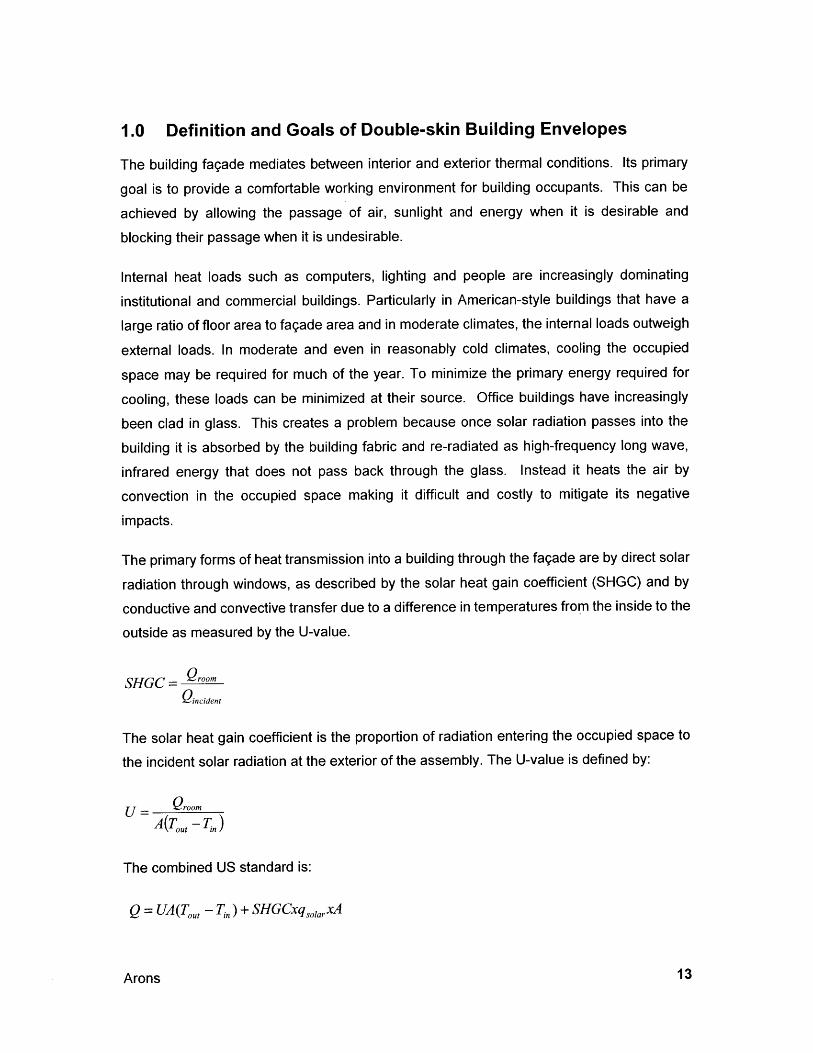
The primary forms of heat transmission into a building through the fagade are by direct solar
radiation through windows, as described by the solar heat gain coefficient (SHGC) and by
conductive and convective transfer due to a difference in temperatures from the inside to the
outside as measured by the U-value.
SHGC = Q'rmQincident
The solar heat gain coefficient is the proportion of radiation entering the occupied space to
the incident solar radiation at the exterior of the assembly. The U-value is defined by:
U = Qrm
A(T,, -7)
The combined US standard is:
Q = UA(Tou, - Tin) + SHGCxqsolarXA
Arons
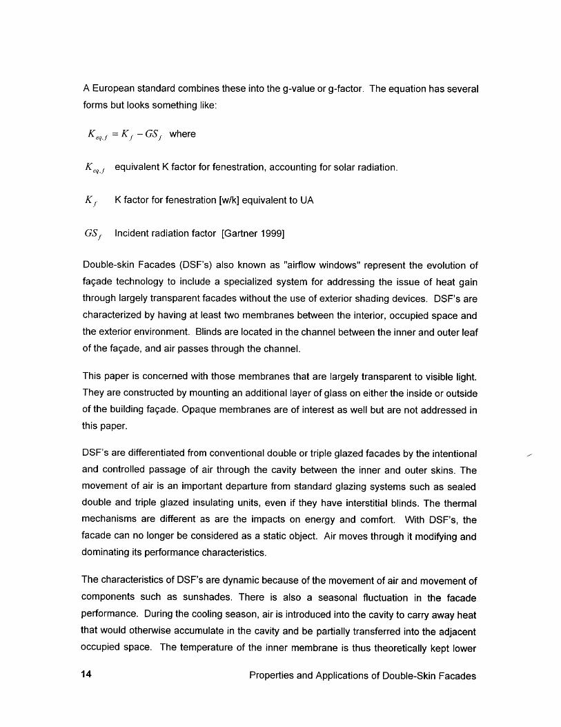
A European standard combines these into the g-value or g-factor. The equation has several
forms but looks something like:
Keqi =K - GS, where
Keqt equivalent K factor for fenestration, accounting for solar radiation.
Kf K factor for fenestration [w/k] equivalent to UA
GSf Incident radiation factor [Gartner 1999]
Double-skin Facades (DSF's) also known as "airflow windows" represent the evolution offagade technology to include a specialized system for addressing the issue of heat gainthrough largely transparent facades without the use of exterior shading devices. DSF's are
characterized by having at least two membranes between the interior, occupied space andthe exterior environment. Blinds are located in the channel between the inner and outer leafof the fagade, and air passes through the channel.
This paper is concerned with those membranes that are largely transparent to visible light.They are constructed by mounting an additional layer of glass on either the inside or outsideof the building fagade. Opaque membranes are of interest as well but are not addressed inthis paper.
DSF's are differentiated from conventional double or triple glazed facades by the intentionaland controlled passage of air through the cavity between the inner and outer skins. Themovement of air is an important departure from standard glazing systems such as sealeddouble and triple glazed insulating units, even if they have interstitial blinds. The thermalmechanisms are different as are the impacts on energy and comfort. With DSF's, thefacade can no longer be considered as a static object. Air moves through it modifying anddominating its performance characteristics.
The characteristics of DSF's are dynamic because of the movement of air and movement ofcomponents such as sunshades. There is also a seasonal fluctuation in the facadeperformance. During the cooling season, air is introduced into the cavity to carry away heatthat would otherwise accumulate in the cavity and be partially transferred into the adjacentoccupied space. The temperature of the inner membrane is thus theoretically kept lower
Properties and Applications of Double-Skin Facades
than without the airflow. This reduces the conduction, convection and radiation from the
inner pane to the occupied space within. The result is that less heat is transferred from the
outside to the inside, and less energy is required to cool the space. Building occupants are
meant to be more comfortable because the mean radiant temperature of the space is
reduced.
The double-skin window, with its Venetian blind, can be seen as a passivecooling device, easing the load on the chilled ceilings or other cooling meansand therefore saving energy. The blind is effectively external and stopsradiant heat before it can enter the building... the double-skin arrangementhas other benefits. As the sun warms the air in the cavity, the 'stack effect' isimproved, so that relatively cool air is drawn in at the sill at an ever faster rateas the temperature increases. Paradoxically, the heat of the sun thuscontributes to the cooling of the facade. [Davies et al 1997 P 158-159]
During the heating season there are two general scenarios: Scenario one has the system
closed, with no air moving through the cavity. The cavity is allowed to heat up, increasing
the temperature of the inner pane, and thereby reducing conductive, convective and radiant
losses. In the second scenario, warm air is introduced into the cavity from the interior to
warm the inner pane of glass and achieve the same results. The air is then ducted to the
building systems plant where it may be run through a heat exchanger to pre-heat the
incoming air. So far, it appears that no system has been developed that allows air to be
warmed in the cavity and then returned directly to the occupied space. This would eliminate
the transfer of the air all the way back to the plant. But would require local controls at the
fagade level. In situations where the air must be exhausted anyway as part of the fresh air
supply, transporting air to the plant is required anyway. Depending on the depth of the
building, the air volume being passed through the fagade may be similar to the fresh air
requirements of the space.
If air is being returned to the plant for heat recovery, there may be an energy penalty for
nighttime and other times that there is no solar radiation on the fagade because the air will
lose energy as it passes through the window cavity. This energy penalty will be felt by the
reduced stored energy arriving at the heat exchanger being used to preheat fresh outdoor
air.
Solar shading devices are placed between the inner and outer skins. Typically this is an
adjustable, horizontal Venetian blind that may be rotated and raised or lowered. During the
cooling season, solar heating is unwelcome and must be removed by the building plant. The
Arons
role of the shading device is to absorb or reflect unwanted solar radiation. Heat absorbed
by the sun-shading device can be removed by convection if air is moved along the surface
of the blinds and then removed from the cavity. The effectiveness of this heat removal is
evidenced by a reduced solar heat gain coefficient (SHGC or solar factor, SF). If in addition,the air that passes through the cavity is cooler than the outside air, then the difference in
temperature across the inner glazing will be reduced. This results in a lower heat flow
across the inner pane as evidenced by a reduced u-value. In this way, DSF's facades actas heat exchangers [Saelens 1998]. The shading device acts as a solar collector and the
captured heat may be controlled through the design of the fagade system, its airflow and
control.
During the heating season, some direct radiation will be desirable. Yet, it is still easy tooverheat the area adjacent to the window. Therefore control of the position and deploymentof the shading device is desirable. The SF can be adjusted by adjusting the blinds. The U-value will be improved if the blinds absorb some heat, thereby increasing the cavitytemperature and reducing the difference in temperature between the cavity and interior.
A lot has been made of the impact of DSF's. The RWE AG building in Essen, Germany was
touted as the first "pro-ecological high-rise [Pearson 1997]", and the Commerzbank buildingin Frankfurt am Main, Germany is said to use 30% less energy than a comparable traditionalhigh-rise buildings [Preston Web]. Perhaps the most common acclamation of the doublefagade system is that they are energy efficient, but there is more to the story. They havealso been installed for sound reduction, user control and comfort, noise reduction, pollutionavoidance, and nighttime security of operable windows. Other reasons include capital costsavings of reduced mechanical plant, and reduced dependence on artificial lighting.Architectural benefits include transparency, and a "high-tech" image. Perhaps the mostcompelling reason which explains the boom in use of DSF's in Germany is that windowsprotected by an additional pane of glass on the outside may be opened, even when thebuilding is subjected to high wind pressures, as is the case in high-rise buildings. Furthersupporting the use of this technology in high-rise buildings is that their use permits theactivation of semi-exterior sun shading in adverse (windy, polluted, and rainy) conditions.
Properties and Applications of Double-Skin Facades
1.1 Technological context of double-skin facades
In order to have a good perspective on double-skin facades and the problems that they are
designed to solve. Current trends in building technology began with the introduction of
curtain walls and massive glazing to commercial buildings starting at the beginning with the
industrial revolution and continuing through modernism with the increasing detachment of
buildings from their environment. Curtain walls in general grew out of the evolution of
structural systems from bearing masonry walls to steel and cast-in-place concrete
structures. The newer structural systems do not have integrated walls, rather they are
roughly post and beam structures that must be filled in with something that will moderate the
climate and control the elements so that inhabitants will be comfortable and productive.
Banham quotes Le Corbusier:
But now a house can be built of a few reinforced concrete posts... leavingtotal voids in between... What good is it, I ask, to fill this space up again,when it has been given to me empty? [Banham 1969 p. 154]
According to Banham, Le Corbusier soon struggled with the void that massive walls left
behind; how should sound be attenuated, and how should climate be controlled. For Cite de
Refuge, the Paris hostel, Le Corbusier devised a system called le mur neutralisant, the
neutralizing wall. It consisted of two layers of glass with tempered air circulating between,
but was not implemented on that project due to budgetary constraints. While the mur
neutralisant has been credited by Saelens and others with being the precursor to double-
skin walls [Saelens 1997 p.1], it is worth noting that an air system separate from the
conditioning system was envisioned that was meant to be a barrier between indoor and
outdoor environments. There is no mention of sunshades except that bris-soleil were
added at a later date to combat summer heat gain. The building was the first sealed
building in the Paris area, and had mechanical ventilation and heating. It was not
mechanically cooled, and overheated dramatically during the summer. It was designed for
three air changes per hour [Le Corbusier 1936]. Rather than being the first double-skin
fagade, this is truly an early version of the sealed, mechanically controlled building. Indeed,
Le Corbusier marveled at the lack of window operability. He speaks of America as a
powerful and progressive country that developed a modern skyscraper with a sign next to
each window stating:
Please do not open the windows so as not to disturb the proper functioning ofthe air conditioning. [Le Corbusier 1936 p. 20]
Arons
Le Corbusier expands on his desire for the machine building to control the new environment
regardless of local climate:
In the narrow space between the membranes (of the neutralizing wall) isblown scorching hot air, if in Moscow, iced air if in Dakar. Result, we controlthings so that the surface of the interior membrane holds 181C. And thereyou are! [Banham 1969, p.160].
Surely, this was not informed of the same spirit that would drive the Commerzbank away
from the sealed building. Yet, it may well have been an early precedent for the sealedactive facades. The flue-type double facades for low-rise buildings that have a cavity
sometimes spanning 3 to 4 stories took a preliminary step.
The first patent related to airflow windows was received by the EKONO Company in Sweden
in 1957. EKONO would build the first office building with airflow windows in 1967. Theintroduction of mass-produced active walls created a consciousness about the technology.
The Briarcliff House at Farnborough is the first widely publicized use of a double-skin
fagade. See [Hannay 1984]. It consists of a standard sealed office building with exterior
automatically controlled sunshades, and a second skin about a meter outside thesunshades. The cavity formed between the skins open to the outside at the bottom, and
connected to the air handling plant on the roof (three stories above). This building broke
ground on mediating solar loads and noise impacts for low-rise buildings. A US building wasalso published in the 1980's; the Hooker building in by Cannon Inc. developed the Briarcliffmodel by adding adjustment to the intake with controllable dampers.
The Commerzbank and RWE would take the next step by opening the inner walls such thatoccupants would have more control of their environment, breaking the seal on the envelopeso that natural ventilation would be possible again. Foster wrote about the Briarcliff House in1993, and clearly takes some inspiration from it. The two German towers use double
fagade systems to solve evolving programmatic concerns. Pushes architecture to new
paradigm. Foster is critical of architecture that seeks high levels of day light (as he does) but
overlooks the need to control glare, overheating and heat loss. [Foster 1994 p. 674]
Meanwhile, the Active Wall proponents (particularly in Belgium and the Netherlands) wouldturn Briarcliff inside out, putting the seal on the exterior, and ventilating indoor air throughthe fagade and up to the plant. While not extensively published in architectural journals,
Properties and Applications of Double-Skin Facades
they may well be recognized as they are applied to high profile buildings such as the ABN
Amro building by I. M. Pei.
1.1.1 Next generation
As the development of double-skin facades moves forward, some will be copying the
innovations that have come before while some will be making incremental innovations on
top of the basic innovations already implemented. In either case designers must understand
what goals are realistic for DSF's, and what configurations are available. In order to adopt
these facades or windows, one should first comprehend precedents, and the basic
thermodynamics that motive their design strategies. Only in this way can the next
generation of dynamic walls be contemplated.
1.2 Goals
1.2.1 Energy Savings and Ecological Responsibility
Intelligent facades achieve a significant reduction in emissions, and thus don'tcontribute to the greenhouse effect. Investment and operating costs are keptas low as possible [Campagno 1996].
Energy savings attributed to double-skin facades are achieved by minimizing solar loading
at the perimeter of buildings. Providing a low solar factor and low U-value minimizes cooling
load of adjacent spaces.
The Gartner Company claims that DSF's save natural resources by reducing energy
consumption during the operational life of the building [Gartner 1999]. However, there has
been no study published of the relationship of operational costs to construction/embodied
energy impacts. This is particularly important in the case of a high-rise building. High-rise
buildings provide certain efficiencies during their life at the urban scale because they provide
a density that can minimize transportation if walking and mass-transit are adopted. Of
course, in some large cities higher density leads merely to congestion, reliance on
automobiles, highways and parking structures, while mass-transit is shunned and
pedestrians are in peril. The use of the building carries certain transportation-related
burdens internally. The building is reliant on elevators that are energy intensive, and
unnecessary or used at occupant discretion in lower buildings. The shear difficulty of
maintaining and renovating tall buildings is much greater than for lower buildings.
Arons
1.2.2 Natural Ventilation
The surge of activity in designing double-skin facades that occurred in the mid 1990's can
be attributed to the mandate in Germany to provide natural ventilation in skyscrapers. Two
buildings competed to be the first naturally ventilated building (Commerzbank and RWE).
The DSF was the common solution for allowing windows to be operable in a windy zone,high above the Frankfurt townscape. The buffering effect of placing a fixed plane of glass
outside the operable window made this possible. Because other attributes were attached to
the system such as transparency, a high level of control and energy efficiency, natural
ventilation became the catalyst for the diffusion of DSF technology within the industry.
1.2.3 Cost Savings
Double-skin facades are significantly more expensive to install than conventional curtain
wall systems considering only the cost of the installed fagade. Most of the early
implementation has been in the form of prototypical designs requiring extensive research
and the development of unique extrusion dyes and numerous unique parts. Many of thedesigns were developed in parallel (such as the RWE and Commerzbank buildings) and didnot benefit from cross-fertilization of ideas due to both simultaneity of design and the race to
be labeled as the first innovator of the systems.
Additional installed costs for double-skin fagades above typical static fagade systems have
ranged significantly from 20 percent to perhaps 300% [Arons 1999]. It is not always possibleto obtain exact figures due to privacy concerns of the project owners. Examples of some ofthe costs will be discussed in chapter 3.0.
The incremental cost of airflow windows within largely solid walls would appear to be lesssignificant than for larger airflow facades because of the smaller area, and smaller movingparts. Facades that may come pre-assembled to the site will tend to be more cost effectivethan facades that require site assembly. Double-skins with the inner skin being something
other than glass may also be less costly; fabrics and flexible metallic screens may serve as
well as glass but at reduced cost. There will be functional and aesthetic differences,however.
A designer should consider costs and benefits on a project-wide capital basis as well as ona life-cycle basis rather than looking at capital costs for the fagade alone. Considerationshould be given to operations and maintenance budgets. It has been claimed that the use of
Properties and Applications of Double-Skin Facades
DSF's can reduce the initial construction cost of buildings [Saelens 1997 p.1]. By reducing
heating and cooling loads of the envelope at the source, the overall size of heating,
ventilation and air conditioning (HVAC) systems can be reduced. In certain climates,
particularly in mild European climates, the need for perimeter radiation may be eliminated as
well. Any savings here will depend on the building type and occupancy as well as the
meteorological zone. The actual up-front savings must also be part of a holistic design
process. See section 5.9 for more on integrated design. Savings of this type have not been
well documented to date, perhaps because they are difficult to trace to particular elements
(such as the fagade) in a complex building system.
While costs are quite exorbitant on certain high profile projects, there are buildings that use
reasonably detailed systems that, while still costly, should not be unreasonable additional
costs compared to the added value of the systems. Standard small-scale windows coupled
with separate interior unframed glass have been used to create double-skin systems from
low-cost, readily available components.
Even the sophisticated packaged systems have great potential to become cost effective. As
manufacturers hone their ability to design, test, and manufacture the systems the
uncertainty and risk associated with them will go down. As more projects utilize DSF's, the
mass production segment of the market will grow, thereby giving the manufacturers
economies of scale. Hence the installed costs will come down. A reduction in cost is
predicated upon timely adoption of the systems.
1.2.4 Sound Reduction
Sound reduction is a principal concern in urban environments. The concern is intensified by
the increased use of glazing that reflects sound. Ove Arup and Partners used a second skin
over a conventional sealed 30% glazed fagade for the Briarcliff House in Farnborough U.K.
Its location in a noisy urban setting was a driving force for the design choice of perhaps the
earliest double-skin fagade [Holmes 1994 p.3]. A more recent development at the Max
Planck Institute in Munich utilized a double-skin fagade in a noisy setting as well. In that
case however, both the inner and outer leaf of the fagade were operable, providing greater
potential to balance noise reduction with natural ventilation.
The degree of noise reduction varies with the specific details and operation of particular
double-skin facades. Data provided by Permasteelisa (see Figure 1), a manufacturer of
Arons

double-skin and conventional facades, indicates that the potential noise reduction is in the
order of 9 decibels (dB). The difference is nearly enough for the perception of the noise tobe halved, and more than enough for the difference to be "clearly perceptible" according toStein and Reynolds [Stein and Reynolds 1987 p. 1329].
Figure 1: Noise reduction of various window systems.facades.
Systems 1-3 are double-skin
1.2.5 User Control and Comfort:
Typically, designers must pay particular attention to the temperature of the inside surface ofglazing systems. This surface is a source of infrared radiation during the summer, and aheat sink during the winter. Inadequate HVAC and fagade design can lead to uncomfortableconditions, even when the air temperature of the space is within the comfort zone. DSF'sare said to help with this problem.
Saelens states "The surface temperature of the inner pane is leveled with the roomtemperature, improving the thermal comfort near the window [Saelens 1997 p.3]." Thisclaim is particular to inside-ventilated facades; because room temperature air is brought intothe window cavity, the inner surface of glass should be close to room temperature. Thefindings of this paper will call this into question. The blinds in the window cavity are solarcollectors by design. They are meant to collect incident radiation and are meant to dispatchit before it enters the occupied zone of the building. They also exchange energy via radiation
Properties and Applications of Double-Skin Facades
Noise Reduction
4540
35
o 30.1! 25-
S20~1515
e= 10
S50-
1. Actie 2.InterActive 3. Naturally 4. Shading 5.DoubleWall Wall Ventilated Wall glass
Walls
with the inner pane of glass and the glass may climb well above room temperatures,
particularly during the summer. Also, the higher the window or fagade, the greater this
effect will be felt because the difference in temperature between the blind and the air is
reduced. Saelens and Hens show that increasing the height of the window from 2.0 meters
to 2.4 meters increases the U-value from 0.44 to 0.48. They also indicate that the inner
surface may climb by 10 degrees Celsius when the incident solar radiation is 500 W/m2.
DSF's may indeed created better comfort conditions by controlling radiation and indoor air
temperatures. The radiation directly contacting occupants will be less when blinds are used.
However, it is doubtful that better glazing temperatures are to be credited with the increased
levels of comfort.
Control is closely linked to comfort. By providing occupants the ability to control light with
louvers or shades and the ability to control air movement and temperature with operable
windows, not only may comfort be enhanced, but the sense of well being that comes with
controlling one's environment is also nurtured. The degree of user control, which may or
may not coincide with improving actual comfort conditions or energy efficiency, must be
reconciled with building management control systems that may more rigidly control these
factors. The psychological benefit of varying the fagade may come in conflict with the sense
that one is occupying an automated machine that adjusts view, lighting, and thermal
conditions from a central source.
1.2.6 Occupant Productivity and Contact with the Environment
It has been estimated that wages and salaries can represent about 95 percent of all costs of
a typical office building [Ternoey, et al, 1984]. Certainly, in the commercial market, energy
consumption is probably only one tenth the cost of personnel. For this reason, owners will
be driven toward solutions that increase their return on investments made in people before
those that are made in infrastructure. But the two are linked.
Reduced sickness, absenteeism coupled with increased performance would more than
offset any increased initial costs or life cycle costs [Robbins, 1986] associated with providing
more workers visual access to windows [Franta and Anstead 2000]. Given current trends,
this will probably remain true in the US longer than it does in Europe because costs of
energy are externalized from accounting ledgers. The depletion of natural resources
including fossil fuels biological diversity and atmospheric and water quality are not translated
Arons
to the costs to operate buildings. So, for the near and perhaps distant future, energy costs
are probably less important than occupant productivity to the applicability of technology.
If a more comfortable, controllable and visually pleasing environment can be created, thenworkers may well be more productive.
"In 1969, in 'the Architecture of the Well-Tempered Environment', Reyner Banham spoke out
against the high energy requirement of artificial air conditioning systems and against the
separation of architecture from local climatic and regional conditions" [Campagno 1996].
1.2.7 Security
Many of the same building owners that can afford double-skin facades are drawn to high-end technologies and the high-tech image that they exude also have a practical concern for
the security of their premises. These are establishments that have a particularly high cost
associated with the personnel in their buildings. In Europe, these workers have demandedaccess to outdoor air and light. To have operable windows while maintaining security
requires that some measure be made to protect the accessibility of windows from theexterior.
DSF's offer a relatively unimposing manner for achieving security. Rather than protect
openings with bars or metal grating DSF's have a continuous sheet of glass with relativelysmall vents to allow for the entrance and exit of air. The result is a transparent barrier thatbreathes. Deep facades add a psychological level of security; there is a perception ofprotection that comes from having a thick fagade system. Just as a moat or wall give asense (and physical) protection, so does the fagade depth. Security was a chief concern forthe Max Planck Gesselschaft, so they went one step farther by incorporating both a DSFand a moat along the primary street fagade.
1.2.8 Aesthetics
Some double-skin facades and windows are very similar in composition to their traditional
counterparts. The facades are crafted of glass and aluminum and other than the requisite
addition of interstitial blinds to control solar radiation; they appear quite similar as well.
Properties and Applications of Double-Skin Facades
Transparency
Architects have been taking advantage of the sun shading ability of double-skin facades to
make their buildings more transparent; having sun shades to deploy, allows the use of
highly transparent glass because the glass does not need to reflect or absorb the radiation
on its own. The use of "white glass", having less iron than standard architectural glass,
changes the transparency to visible light from about 0.85 up to 0.90 for each pane. For a
three-pane system the overall visible light transparency goes from 61% up to nearly 73%.The quality of the light reflected and transmitted is also improved. Standard glass has a
greenish tinge to it, while the low-iron glass is whiter. This means that the psychological
impact of the window will be lessened.
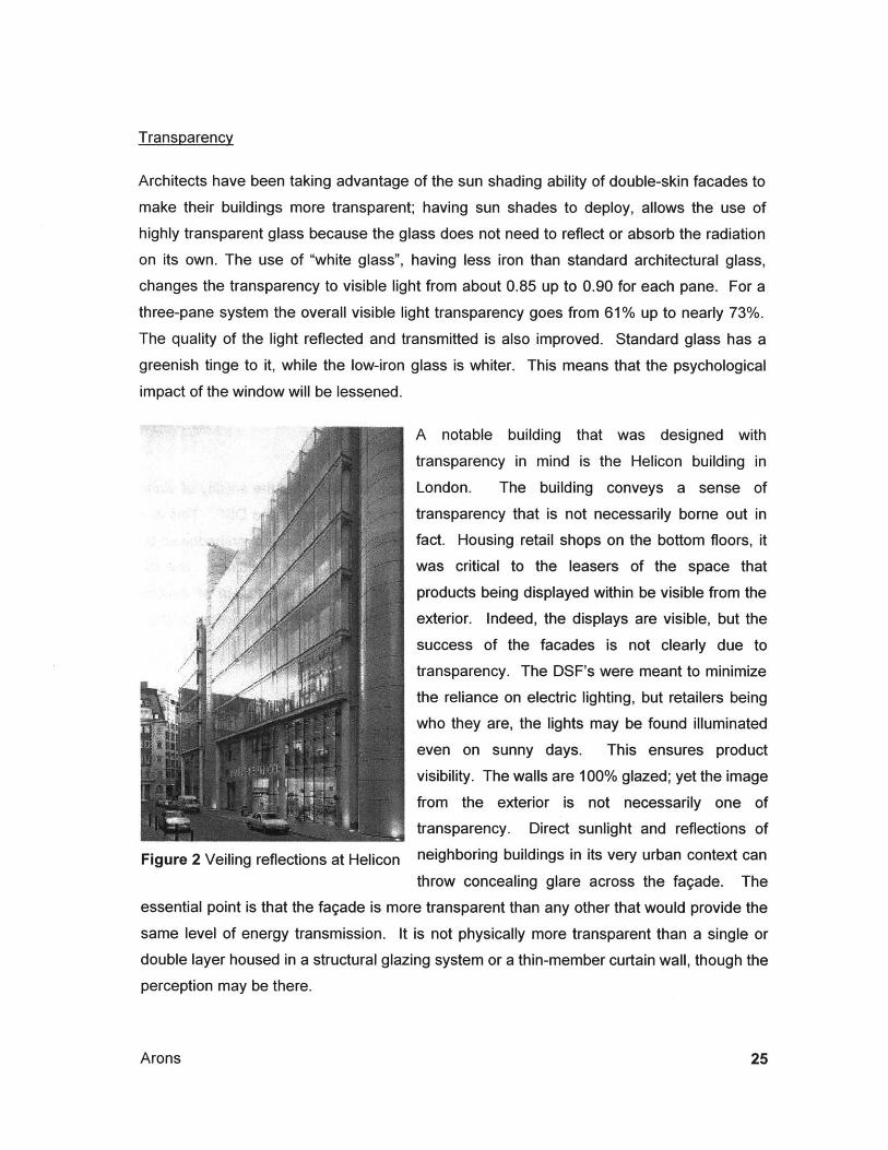
A notable building that was designed with
transparency in mind is the Helicon building in
London. The building conveys a sense of
transparency that is not necessarily borne out in
fact. Housing retail shops on the bottom floors, itwas critical to the leasers of the space that
products being displayed within be visible from the
exterior. Indeed, the displays are visible, but the
success of the facades is not clearly due to
transparency. The DSF's were meant to minimize
the reliance on electric lighting, but retailers being
who they are, the lights may be found illuminated
even on sunny days. This ensures product
visibility. The walls are 100% glazed; yet the image
from the exterior is not necessarily one of
transparency. Direct sunlight and reflections of
Figure 2 Veiling reflections at Helicon neighboring buildings in its very urban context can
throw concealing glare across the fagade. The
essential point is that the fagade is more transparent than any other that would provide the
same level of energy transmission. It is not physically more transparent than a single or
double layer housed in a structural glazing system or a thin-member curtain wall, though the
perception may be there.
Arons
Depth
Double-skin facades offer a tremendous design opportunity that no other building system
has offered before: depth. The thick walls of load-bearing masonry structures is tied toconveying massiveness. When punctured by windows, they tend to seem still heavier. To
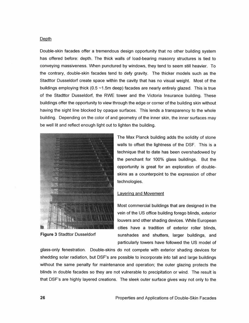
the contrary, double-skin facades tend to defy gravity. The thicker models such as theStadttor Dusseldorf create space within the cavity that has no visual weight. Most of the
buildings employing thick (0.5 -1.5m deep) facades are nearly entirely glazed. This is true
of the Stadttor Dusseldorf, the RWE tower and the Victoria Insurance building. These
buildings offer the opportunity to view through the edge or corner of the building skin without
having the sight line blocked by opaque surfaces. This lends a transparency to the whole
building. Depending on the color of and geometry of the inner skin, the inner surfaces may
be well lit and reflect enough light out to lighten the building.
The Max Planck building adds the solidity of stone
walls to offset the lightness of the DSF. This is a
technique that to date has been overshadowed bythe penchant for 100% glass buildings. But the
opportunity is great for an exploration of double-
skins as a counterpoint to the expression of other
technologies.
Layering and Movement
Most commercial buildings that are designed in the
vein of the US office building forego blinds, exterior
louvers and other shading devices. While European
cities have a tradition of exterior roller blinds,Figure 3 Stadttor Dusseldorf sunshades and shutters, larger buildings, and
particularly towers have followed the US model ofglass-only fenestration. Double-skins do not compete with exterior shading devices for
shedding solar radiation, but DSF's are possible to incorporate into tall and large buildingswithout the same penalty for maintenance and operation; the outer glazing protects theblinds in double facades so they are not vulnerable to precipitation or wind. The result isthat DSF's are highly layered creations. The sleek outer surface gives way not only to the
Properties and Applications of Double-Skin Facades
active workspace within but also to the subsequent layers of blinds and an inner layer of
glazing housed in it's own frame. In some cases, such as the RWE tower, there may be a
layer of shades within the inner glazing. These components of the system add to the visual
interest of the fagade and enhance the perception (and reality) of depth within the fagade.
Normally, the appearance of glazed walls varies frequently with changing interior and
exterior lighting conditions. This aspect is enhanced by the multiple layers and physical
depth of DSF's. In addition, DSF's physically change. Blinds go up and down, and rotate
from open to closed. Doors or windows within the inner and sometimes outer skin open and
close for natural ventilation. These variations add to the activity and excitement level of the
fagade making it a dynamic mechanism, changing with weather conditions, time of day, and
internal use a dramatic rather than static object in the urban landscape.
High-tech or ecological
DSF's are taking hold of the German and Dutch fagade markets. In some cases they are
being used for their efficient performance, but just as often it appears they are being chosen
for their high-tech look. These are not only high-cost but also high-style facades. Banks,
insurance companies and other high-profile institutions have used them extensively. These
are institutions that desire not only performance but also the appearance of performance
and desire to carry the environmental banner. This is not to say that the facades are not
performing well but that this performance may be secondary to the aesthetic message that
the facades brings. This means that some of these innovative owners are really follow-on
implementers of the technology; picking up the technology without necessarily doing the
elaborate design, modeling and testing that the earlier executors of the technology were
required to do. This may not have a dramatic impact on the functionality of the facades, but
in other cases it may.
Arons

28
2.0 Typologies
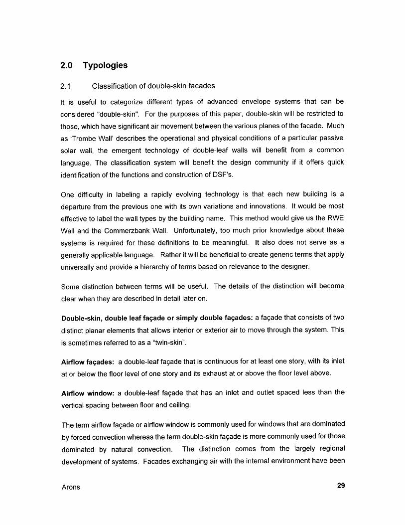
2.1 Classification of double-skin facades
It is useful to categorize different types of advanced envelope systems that can be
considered "double-skin". For the purposes of this paper, double-skin will be restricted to
those, which have significant air movement between the various planes of the facade. Much
as 'Trombe Wall' describes the operational and physical conditions of a particular passive
solar wall, the emergent technology of double-leaf walls will benefit from a common
language. The classification system will benefit the design community if it offers quick
identification of the functions and construction of DSF's.
One difficulty in labeling a rapidly evolving technology is that each new building is a
departure from the previous one with its own variations and innovations. It would be most
effective to label the wall types by the building name. This method would give us the RWE
Wall and the Commerzbank Wall. Unfortunately, too much prior knowledge about these
systems is required for these definitions to be meaningful. It also does not serve as a
generally applicable language. Rather it will be beneficial to create generic terms that apply
universally and provide a hierarchy of terms based on relevance to the designer.
Some distinction between terms will be useful. The details of the distinction will become
clear when they are described in detail later on.
Double-skin, double leaf fagade or simply double fagades: a fagade that consists of two
distinct planar elements that allows interior or exterior air to move through the system. This
is sometimes referred to as a "twin-skin".
Airflow fagades: a double-leaf fagade that is continuous for at least one story, with its inlet
at or below the floor level of one story and its exhaust at or above the floor level above.
Airflow window: a double-leaf fagade that has an inlet and outlet spaced less than the
vertical spacing between floor and ceiling.
The term airflow fagade or airflow window is commonly used for windows that are dominated
by forced convection whereas the term double-skin fagade is more commonly used for those
dominated by natural convection. The distinction comes from the largely regional
development of systems. Facades exchanging air with the internal environment have been
Arons
developed in the UK and the Netherlands and are termed "airflow facades (or windows)",and those exchanging air with the external environment have been developed in Germanyand are termed simply "double-skin facades" or, in the UK, "twin skins". For this paper, theterm "double-skin facades" has been used to describe airflow facades and windows in thegeneric sense.
2.2 Primary identifiers
Saelens and Hens identify three primary identifiers for DSF's: The nature of airflow (inlet and
exhaust same side, supply from exterior to interior, and exhaust from interior to exterior); thegeneration of airflow (natural or forced convection); and horizontal partition of the fagade
(window or fagade). These are valuable ways of distinguishing the type of fagade for
engineers [Saelens 1997 p.2]. However, to bridge the gap between engineering and
architecture, and more specifically between those with a detailed understanding of the
function of these systems and newcomers to the field, a more descriptive system isproposed.
There are two primary categories of double facades. The first, similar to Saelens and Hens,defines the way that air moves through the cavity between the skins. The second separatesmid-rise to high-rise buildings from low-rise buildings. The distinction is that mid-rise to high-rise buildings have restrictions on the operability of windows due to wind pressure (typicallyassociated with height above terrain).
2.2.1 Airflow Patterns
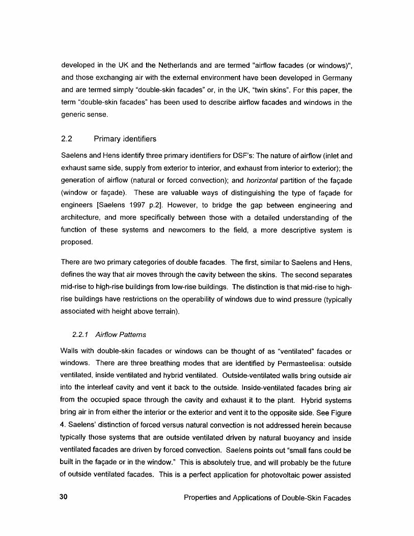
Walls with double-skin facades or windows can be thought of as "ventilated" facades orwindows. There are three breathing modes that are identified by Permasteelisa: outsideventilated, inside ventilated and hybrid ventilated. Outside-ventilated walls bring outside airinto the interleaf cavity and vent it back to the outside. Inside-ventilated facades bring airfrom the occupied space through the cavity and exhaust it to the plant. Hybrid systemsbring air in from either the interior or the exterior and vent it to the opposite side. See Figure4. Saelens' distinction of forced versus natural convection is not addressed herein becausetypically those systems that are outside ventilated driven by natural buoyancy and insideventilated facades are driven by forced convection. Saelens points out "small fans could bebuilt in the fagade or in the window." This is absolutely true, and will probably be the futureof outside ventilated facades. This is a perfect application for photovoltaic power assisted
Properties and Applications of Double-Skin Facades
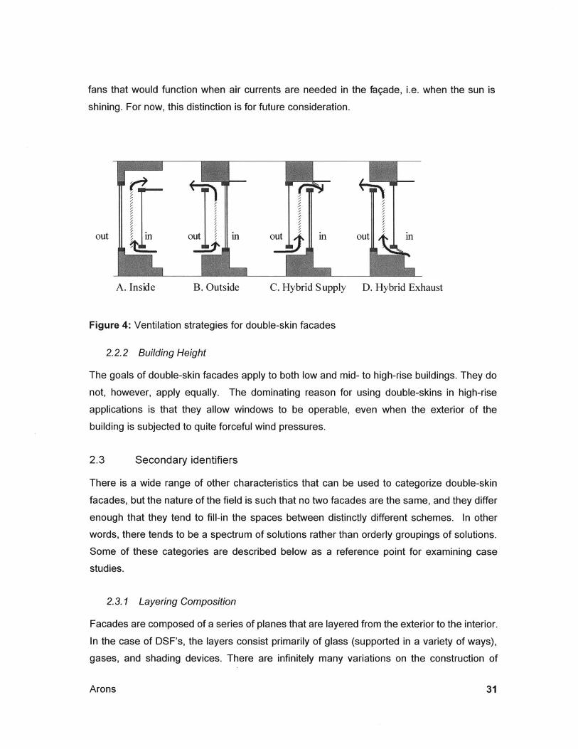
fans that would function when air currents are needed in the fagade, i.e. when the sun is
shining. For now, this distinction is for future consideration.
out i out out ' i out in
A. Inside B. Outside C. Hybrid Supply D. Hybrid Exhaust
Figure 4: Ventilation strategies for double-skin facades
2.2.2 Building Height
The goals of double-skin facades apply to both low and mid- to high-rise buildings. They do
not, however, apply equally. The dominating reason for using double-skins in high-rise
applications is that they allow windows to be operable, even when the exterior of the
building is subjected to quite forceful wind pressures.
2.3 Secondary identifiers
There is a wide range of other characteristics that can be used to categorize double-skin
facades, but the nature of the field is such that no two facades are the same, and they differ
enough that they tend to fill-in the spaces between distinctly different schemes. In other
words, there tends to be a spectrum of solutions rather than orderly groupings of solutions.
Some of these categories are described below as a reference point for examining case
studies.
2.3.1 Layering Composition
Facades are composed of a series of planes that are layered from the exterior to the interior.
In the case of DSF's, the layers consist primarily of glass (supported in a variety of ways),
gases, and shading devices. There are infinitely many variations on the construction of
Arons
I
these layers. For example, glass may be low-E coated, hardened, laminated, low iron
content, or fritted. Shading devices may be metal, plastic, painted or polished, perforated or
solid. Insulating glass may be filled with air, argon, krypton, or vacuum-sealed.
Usually the general arrangement of layers is closely tied to the air movement strategy. If the
fagade is outside ventilated, then there is usually a pane of single glass on the exterior, andinsulated glazing to the inside. The system is reversed for inside ventilated systems; theinsulating glazing is placed on the exterior, and a single, possibly unsealed, glass is located
to the interior of the air cavity.
2.3.2 Depth of Cavity
The range of cavity depths varies significantly. In existing buildings, the range tends to bebetween 200mm and 1400mm as measured face to face between the inner and outer skins.There are three predominant styles: The compact style is usually from about 200mm to500mm, the latter allowing enough space to allow for maintenance occupation of the cavityprimarily to accommodate cleaning of the surfaces within the cavity. The wide style istypically about 1m wide. This allows for the space to be used as a fire egress corridor.There are also architectural and day lighting implications. The third style is the expandedstyle that includes atrium spaces and buildings-within-buildings.
2.3.3 Horizontal Extent of Cavity (Length along the facade):
Cavities may be divided in relation to interior partitions. This extends the sound barrier ofthe partition to the outside face of the fagade. But this is not always the case. Where theinterior fagade has windows within opaque walls, the exterior skin may mirror that form,creating a "box window". In other cases, particularly in renovations where a second skin isapplied over an existing building, the inside may be a window, but the exterior skin may becontinuous glass. The cavity may be continuous as well. In a deep fagade with such anuninterrupted cavity a 'corridor fagade' is created. When it is intended to use the corridor asa walkway, the floor/ceiling may be either a grate, open to air movement, or closed, but thehorizontal length of the cavity must be uninterrupted.
2.3.4 Vertical Extent of Cavity:
The vertical extent of the cavity refers to the distance between air supply to the cavity, andultimate exhaust from the cavity, without intermediate interference such as a floor plane.
Properties and Applications of Double-Skin Facades
There may be operable windows or other vents along the height of the cavity. There are
multi-story facades that are referred to as "atria" if they are relatively wide or "flues" if they
are narrower. Among single story double facades there is an array of styles. If the cavity
extends for the full height of the story, it may be called a double-skin fagade. If it is only
partial height with spandrel panels or other windows between, then it may be called a
double-skin window. Practitioners that design and build inside-ventilated facades tend to call
them "airflow facades" or "airflow windows". Still, they are double-skin assemblies with air
moving between the skins.
2.3.5 Operability
The inner pane of double-skin facades tends to be operable. That is, it can be opened
either by occupants or by automated means. What you see when you open the window is
less certain. In some cases, the inner pane opens, giving full access to another, fixed pane
of glass and a narrow space that is ventilated through slots at the top and bottom. It may
also open onto an outer skin with its own operable "flaps", as is the case in the Max-Planck
Gesselschaft building in Munich. Another building in Munich uses exterior flaps to redefine
not only the function, but also the entire character of the building (see Figure 5).
The form (and operability) of the inner window is varied. Some options are tilt-turn windows
that may be inset windows or full height doors. There are also full height doors that slide or
pivot. An aspect of the relationship between window operability and comfort is not
addressed in the literature: There are serious implications of the functionality of windows on
the comfort conditions that are achieved within the room. Windows that open mostly at the
top (full height inward-tilting hopper windows) will tend to let in the hottest air from the cavity
if the air within the cavity is passing from the bottom to the top, collecting solar heat as it
goes. Doors that slide give access to the full height of the window, (but must be restricted if
occupants shouldn't have access to the cavity). Pivoting windows/doors provide a large
open area (either top and bottom or side to side). They may restrict sun shading options or
effectiveness. Consideration should also be given to possible impacts on usable space
within the building.
Arons
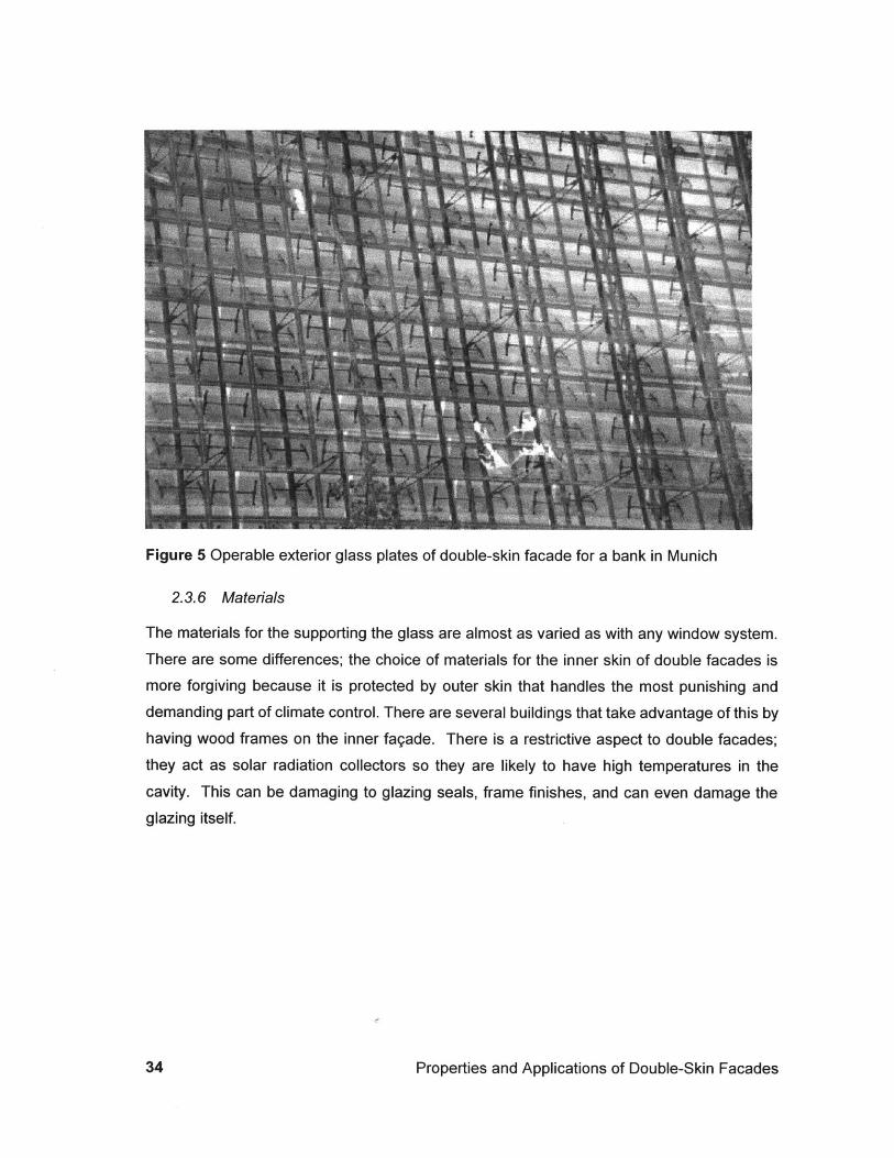
Figure 5 Operable exterior glass plates of double-skin facade for a bank in Munich
2.3.6 Materials
The materials for the supporting the glass are almost as varied as with any window system.
There are some differences; the choice of materials for the inner skin of double facades ismore forgiving because it is protected by outer skin that handles the most punishing anddemanding part of climate control. There are several buildings that take advantage of this byhaving wood frames on the inner fagade. There is a restrictive aspect to double facades;
they act as solar radiation collectors so they are likely to have high temperatures in the
cavity. This can be damaging to glazing seals, frame finishes, and can even damage theglazing itself.
Properties and Applications of Double-Skin Facades
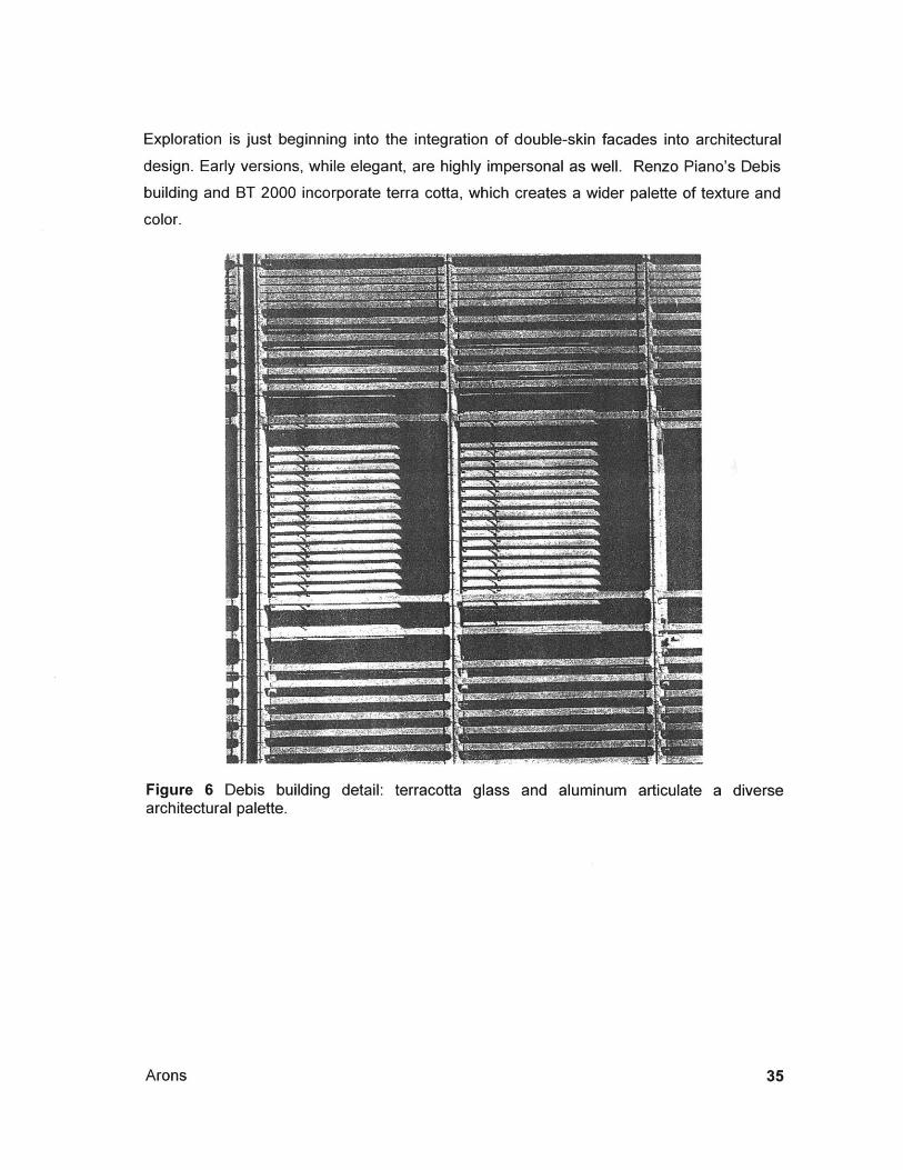
Exploration is just beginning into the integration of double-skin facades into architectural
design. Early versions, while elegant, are highly impersonal as well. Renzo Piano's Debis
building and BT 2000 incorporate terra cotta, which creates a wider palette of texture and
color.
Figure 6 Debis building detail: terracotta glass and aluminum articulate a diversearchitectural palette.
Arons
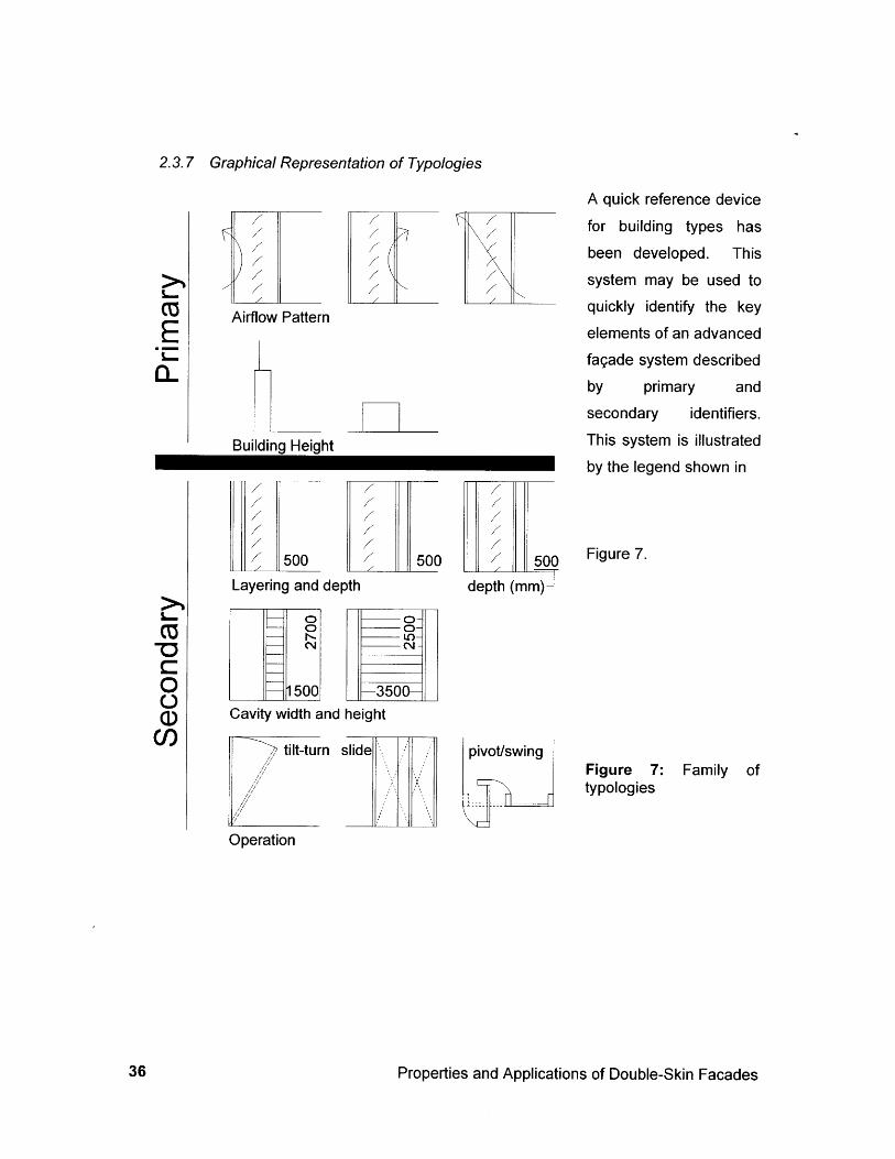
2.3.7 Graphical Representation of Typologies
Airflow Pattern
Building Height
A quick reference device
for building types has
been developed. This
system may be used to
quickly identify the keyelements of an advanced
fagade system described
by primary andsecondary identifiers.
This system is illustrated
by the legend shown in
Layering and depth depth (mm)
Cavity width and height
tilt-turn slide pivot/swing
Operation
Figure 7.
Figure 7: Family oftypologies
Properties and Applications of Double-Skin Facades
E0~
-O
0
C)
3.0 Case Studies
3.1 High-rise buildings: outside ventilated
In Germany, a race to create the first ecologically sensitive high rise in the world resulted in
the construction of two highly innovative structures, one for Commerzbank in Frankfurt, and
the other for RWE in Essen. Both of them include double-skin facades that are naturally
ventilated to the exterior.
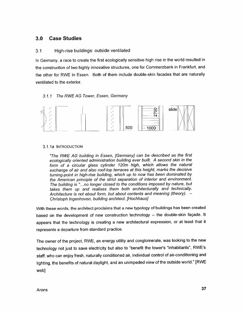
3.1.1 The RWE AG Tower, Essen, Germany
g) slide
500 -100\
3.1.1a INTRODUCTION
"The RWE AG building in Essen, [Germany] can be described as the firstecologically oriented administration building ever built. A second skin in theform of a circular glass cylinder 120m high, which allows the naturalexchange of air and also roof-top terraces at this height, marks the decisiveturning-point in high-rise building, which up to now has been dominated bythe American principle of the strict separation of interior and environment.The building is "...no longer closed to the conditions imposed by nature, buttakes them up and realises them both architecturally and technically.Architecture is not about form, but about contents and meaning (theory). --Christoph Ingenhoven, building architect. [Hochhaus]
With these words, the architect proclaims that a new typology of buildings has been created
based on the development of new construction technology -- the double-skin fagade. It
appears that the technology is creating a new architectural expression, or at least that it
represents a departure from standard practice.
The owner of the project, RWE, an energy utility and conglomerate, was looking to the new
technology not just to save electricity but also to "benefit the tower's "inhabitants", RWE's
staff, who can enjoy fresh, naturally conditioned air, individual control of air-conditioning and
lighting, the benefits of natural daylight, and an unimpeded view of the outside world." [RWE
web]
Arons
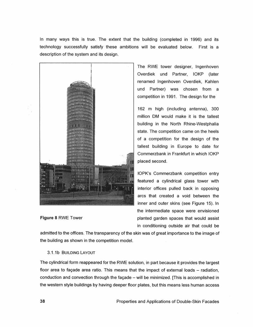
In many ways this is true. The extent that the building (completed in 1996) and its
technology successfully satisfy these ambitions will be evaluated below. First is adescription of the system and its design.
The RWE tower designer, Ingenhoven
Overdiek und Partner, IOKP (later
renamed Ingenhoven Overdiek, Kahlen
und Partner) was chosen from a
competition in 1991. The design for the
162 m high (including antenna), 300
million DM would make it is the tallest
building in the North Rhine-Westphalia
state. The competition came on the heels
of a competition for the design of the
tallest building in Europe to date for
Commerzbank in Frankfurt in which IOKP
placed second.
IOPK's Commerzbank competition entry
featured a cylindrical glass tower with
interior offices pulled back in opposing
arcs that created a void between the
inner and outer skins (see Figure 15). In
the intermediate space were envisionedFigure 8 RWE Tower planted garden spaces that would assist
in conditioning outside air that could beadmitted to the offices. The transparency of the skin was of great importance to the image ofthe building as shown in the competition model.
3.1.1b BUILDING LAYOUT
The cylindrical form reappeared for the RWE solution, in part because it provides the largest
floor area to fagade area ratio. This means that the impact of external loads - radiation,
conduction and convection through the fagade - will be minimized. [This is accomplished inthe western style buildings by having deeper floor plates, but this means less human access
Properties and Applications of Double-Skin Facades
to the fagade as well]. The diameter of the 30 story tall cylinder is 32m. "The modest size of
the floor-plate (about one-third the size of typical American 'developer specials') means that
this 30 story tower is not the hulking presence that skyscrapers often are [Pepchinski 1997]."
Limiting the depth of the building and maximizing the height of glazing at the perimeter also
means that natural daylight is available for most of the office space. Maximizing daylight is
beneficial both to the occupant's well being and because electric lighting will be used less. In,
terms of surface to volume ratio, wind pressure coefficients heat losses structural cost and
day lighting, the cylindrical form is claimed to be the "optimal form" [Detail 1997 p. 358] Of
course, it may be true that the form minimizes wind pressure and heat losses, but is it
equally clear that heat losses should be minimized? With internal loads of computers, this
may not always be the case. Also, this means that there is only an average amount of west
glass, perhaps not ideal compared to a typical passive building that faces north and south.
This seems to be an example of fitting the perceived performance to the design idea, rather
than the inverse. The simplicity of the form may imply incorrectly that there is simplicity in
the thermal and day lighting problem that is insensitive to cardinal directions.
Yet, the high envelope-to-occupant ratio increases the importance of the fagade and
emphasized the need to minimize summer heat gain and winter heat loss. The requirement
for natural ventilation and minimal electric light load further increased the demands on the
fagade.
The relationship between building envelope and floor plate is examined below in Section 5.2
below. Leaving exposed the bottom of the structural concrete slab above the ceiling plenum
also minimizes peak loads. The concrete absorbs some heat from the air to minimize
instantaneous loads before exhaust air is removed. But, nighttime ventilation for 'free
cooling' is apparently not practiced at RWE, so the potential of exposed concrete is not met
in the control sequence for this design. The design approach can be contrasted to the
almost single-minded approach that Michael Hopkins and Partners applied to the New
Parliament Building in London. There, nighttime ventilation is used and every square
centimeter of concrete surface is accounted for.
At the RWE tower, the core area on typical floors contains utility space such as mechanical
chases, bathrooms and storage and a conference room. A circular corridor separates the
core from perimeter offices leaving slightly wedge-shaped offices that are 5.85 meters deep
[Evans 1977]. The outer perimeter is completely glazed from below floor level to above the
Arons
ceiling level. The ceiling actually slopes upward toward the perimeter to allow more daylightinto the space.
Glazing in the corridor walls is intended to allow light to pass from the offices to the interior,but Evans feels that this is not enough to give one a connection to the outside world.Certainly he is correct to some degree. The Commerzbank is more successful with its(expensive) glass partition walls, but a degree of privacy within the offices is achieved at
RWE that is apparently valued by the corporate culture. Also, there is intentionally little lifewithin the core space. Activity is focused on the offices, the fagade and the views beyond.
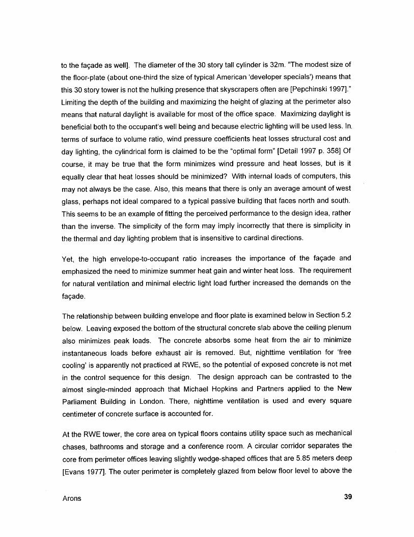
3.1.1c FAQADE COMPOSITION
Inner glass Outer glass -"Fish mouth' eRr T
anslucent shad
Figure 9 RWE fish mouth air vent (left) and building section (right)
The fagade consists of full height doors that are fully glazed with insulating glass set in analuminum frame. To open the door, one turns a crank to pull the door into the space. Once
it clears the face of the adjacent door, it can be slid to the side. During normal operatingconditions, the door opens just 15cm. The window can be opened fully for maintenance andcleaning.
Mounted 500 mm outside the first skin, is a second skin of approximately 12mm thicktoughened "OptiWhite glass" supported with stainless steel point supports and butt sealed.The cavities are divided with vertical glazing that is aligned with the axial office partitionwalls. These are adjustable so that, theoretically, walls can be moved to modify theconfiguration and sizes of offices. The glazing serves as a smoke and sound barrier. It alsoimpacts the movement and pressure of air that may conflict with other design aspects.
Properties and Applications of Double-Skin Facades
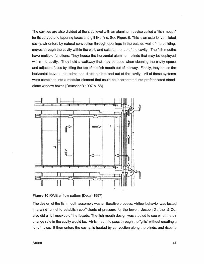
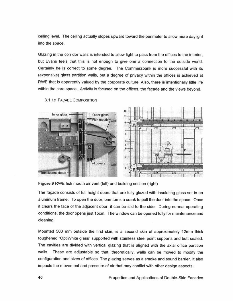
The cavities are also divided at the slab level with an aluminum device called a "fish mouth"
for its curved and tapering faces and gill-like fins. See Figure 9. This is an exterior ventilated
cavity; air enters by natural convection through openings in the outside wall of the building,moves through the cavity within the wall, and exits at the top of the cavity. The fish mouths
have multiple functions: They house the horizontal aluminum blinds that may be deployed
within the cavity. They hold a walkway that may be used when cleaning the cavity space
and adjacent faces by lifting the top of the fish mouth out of the way. Finally, they house the
horizontal louvers that admit and direct air into and out of the cavity. All of these systems
were combined into a modular element that could be incorporated into prefabricated stand-
alone window boxes [DeutscheB 1997 p. 58]
Figure 10 RWE airflow pattern [Detail 1997]
The design of the fish mouth assembly was an iterative process. Airflow behavior was tested
in a wind tunnel to establish coefficients of pressure for the tower. Joseph Gartner & Co.
also did a 1:1 mockup of the fagade. The fish mouth design was studied to see what the air
change rate in the cavity would be. Air is meant to pass through the "gills" without creating a
lot of noise. It then enters the cavity, is heated by convection along the blinds, and rises to
Arons
next level where it exits through another fish mouth. The inlets and outlets are offset alongthe face of the fagade to minimize re-entrainment of exhaust air by adjacent intake louvers.This means that window panels are grouped together. In the case that two panels aregrouped between vertical dividers, one will contain the intake and other will contain theexhaust. This implies a diagonal movement of air through the pair of panels. When threepanels are grouped, there will be two intakes and one exhaust or one intake and twoexhausts. A proponent of this system states that "diagonal through-ventilation [along thefagade] is guaranteed and there is no danger of a re-entry of stale air [Detail 1997 p.359]."The guaranty should surely be dependent on wind velocity and direction, for if inlet andoutlet are side by side, and the wind flows along the face of the building, it doesn't seemaltogether improbable that re-entrainment may take place. This doesn't imply that this is acritical flaw in the design, but that designers might be overstating the reliability and accuracyof their designs. The issue is more critical where contaminants are present in volumesgreater than are encountered in office buildings.
Ineffective cavity ventilation has not been addressed in the literature to date. Clearly therewill be dead zones in the cavity that will be prone to both overheating, and ineffectivethermal performance. Stagnant air will create hot zones during the cooling season that willincrease the conductive and radiant heat transfer through the inner glass panel. It will alsoincrease the temperature of the glass, increasing therefore, the mean radiant temperature ofthe space.
The impact of wind direction and velocity on the effectiveness of the cavity is largelyoverlooked in current literature and calculations. The effect of modest wind pressures isenough to overshadow any buoyancy effects. Therefore, typical calculations will tend toestimate incorrectly the cooling effects during the summer and the buffer effects during thewinter. The models also over simplify the degree to which airflows are one directional.Opening windows for ventilation will dramatically complicate the formulas.
3.1.1d MEP SYSTEMS
The high thermal performance of the fagade coupled with high transmittance of daylight ledto the minimization of cooling loads. The exposure of concrete mass in the beams and (tosome degree) ceiling aided in the reduction in cooling capacity of the central plant.
Properties and Applications of Double-Skin Facades
Cooling is supplied to the space via hydronic radiant panels in the ceiling. Heating is
supplied by hydronic fin tube radiation near the windows at floor level. Ventilation is provided
from diffusers in the ceiling. The air is apparently exhausted through the plenum and back to
the plant.
Lighting is arranged in rows of three recessed linear fluorescent lights running axially to the
center of each window. One additional daylight quality fluorescent down light is also
provided in each bay. There are no light sensors for dimming the lights. This means that the
building energy system does not fully take advantage of the extreme degree to which
daylight is transmitted by this fagade. The only way that an energy benefit is when
occupants think to turn off the electrical lighting all together or in banks.
A control panel mounted by the office doors has an acoustic warning system that advises
occupants to close exterior windows if winds or outside temperatures are too high. The
windows may also be controlled by "hand, by infrared or PC" [DeutscheB 1997 p. 58] See
Figure 14 below.
Opening or closing windows does not influence the controls for mechanical ventilation air
supply. Air is supplied at all times, at levels that supply minimum hygienic requirements.
According to several sources including the architect, the building can be naturally ventilated
(and 'aired') for 70% of the time.
The previously mentioned wind tunnel tests were essential in predicting the wind pressures
on the facade. While the wind speeds were measured as being above 8 m/s for only 230
operating hours (about 11 %) during the course of a year, this is a ground level
measurement. Velocities exceeded these measurements by 5% midway up the tower and
20% at a height of 11Om near the top occupied floor [Daniels 1994]. The wind tunnel
indicated that the pressure coefficients would be in the range of +1.0 to -2.3 (suction), and
that the maximum negative pressure would normally be offset from the incident wind by
approximately 80 to 90 degrees. There is some difficulty in modeling the internal forces that
result from such external wind forces, even if the wind is considered to be of static velocity
and direction; there are many variables for the interior as well. Doors may be opened or
closed and partitions may be rearranged over time. Additionally, assumptions must be made
regarding the interior skin window panels and the sunshade.
Arons
'Supporting air' [mechanically supplied air] is provided but that is considered 'belts andbraces' by the designer". The architect feels that there were extra safety factors in thebuilding due to owner concerns, and that his firm, IOKP would be trying to get away fromthis type of reaction on future projects [Hochhaus]. Beyond the unfortunate inclusion of thissystem in the building if indeed it is unnecessary, is the more unfortunate fact that theventilation air is always on whether needed or not. Cutting corners on the control of themechanical system may cost the owner even more than putting the system in the first place.That the system truly is "belts and braces" may be as much a question of the designer'soptimism as it is of fact. Natural ventilation or 'airing' is possible 70% of the time. Airingmeans a brief opening and closing of the window to let fresh air in. This would be donewhen it is too cold to leave the window open, but not so windy that it causes other problemssuch as disabling office doors from opening or scattering papers on the work surface(although the outside second skin is meant to protect against this). There is a culturalaspect to the potential success of the control system; Germans are accustomed to 'airing' ofspaces even when it is quite cold by American standards. The danger here is that thisinteraction between occupant and fagade may not translate to other cultural settings.
3.1.1e OPERABILITY OF WINDOWS
To predict performance, Gartner and HL-Technik modeled the building using the TRY03weather data from the Essen Muhnheilm station. There are times that in spite of thedamping effect of the second skin, winds will still sometimes be too strong to allow openingof the windows. They found a 60-70% open window possibility with a wind speed of 8.2 m/sas the maximum allowable speed. This created a 0.16m/s air speed in the room and a 0.50m/s air velocity at face of window and 0.6m/s in the cavity. This outside wind speed was setto result in a 10 Newtons opening force at the door to the corridor [Arons 1999 p.9].According to Daniels of the consulting firm HL-Technik, door-opening forces should notexceed 40N (4kg) for continued operation or an "intermittent" force of 60N. The "top" limit foroperability is a force of 100N. The box windows did very little to reduce the wind pressureon the office doors as compared to the 'double-skin' option. [Daniels 1998 p.159]
A further assumption was that no door closers would be used. Door closers wouldexponentially increase the door-closing force if the wind force were applied to the sideopposing the motion. Paradoxically forces on doors are less if all of the doors are typicallyclosed because cross ventilation is eliminated. The control sequence is therefore dependent
Properties and Applications of Double-Skin Facades
on occupants to regulate the airflow through their individual spaces by closing doors and
adjusting windows. The result is that when doors in offices with high positive air pressure on
the windward side are closed because the air velocity in the room is too high, then offices on
the leeward side may lose the source for their natural ventilation. From experiencing the
space in person, it would appear that the default scenario will probably be doors closed, and
one-sided ventilation rather than cross-ventilation.
3.1.1f Two SCENARIOS COMPARED: BOX-WINDOWAND DOUBLE FAQADE
HL-Technik describes the study of two facade models during the building design: The box
window (which was how the building was constructed) and the Perimeter double-Leaf
Facade. They differ in the degree to which there are vertical (glass) dividers separating one
segment of the cavity from the next. The box window scenario has dividers approximately
every 2m along the circumference of the facade. The double-leaf facade is divided only
twice for the entire circumference of the cylinder, so that there are two sectors in the facade
at each floor level. Air can then circulate along the perimeter of the building, leveling
pressure differentials. This reduction in pressure can be translated into a reduction in
pressure coefficient at the face of the inner skin of the building. The studies looked at the
number of air changes per hour that would result from given wind conditions if corridor doors
were held open.
Air Changes per Hour
It was found that air change rates would be lower for the box-type windows than for the
Double Fagade. A lower boundary for comfort was established at airflow velocities of
0.15m/s combined with air-change rates of 25 per hour. These conditions will occur
approximately 50% of the total operating period for box-type windows and 58% of the period
for the perimeter double fagade. These percentages represent worst-case conditions in
which windows and doors are open to maximize cross ventilation.
The reality is that doors are probably more often closed. Closing the doors leads to
drastically reduced exchange rates because ventilation becomes one-sided. Airflow,
theoretically, can be controlled by leaving doors open and throttling the flow by adjusting the
openness of the windows at the inner skin. But this works in theory only because occupants
control only their own windows and doors, and do not optimized the entire system. Thus,
Arons
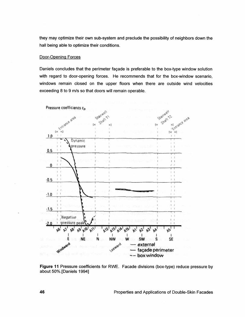
they may optimize their own sub-system and preclude the possibility of neighbors down thehall being able to optimize their conditions.
Door-Openinq Forces
Daniels concludes that the perimeter fagade is preferable to the box-type window solution
with regard to door-opening forces. He recommends that for the box-window scenario,
windows remain closed on the upper floors when there are outside wind velocities
exceeding 8 to 9 m/s so that doors will remain operable.
Pressure coefficients CA
Ntk Zj
b
.0
NE N NW W SW S SEexternalfagade perimeterbox window
Figure 11 Pressure coefficients forabout 50%.[Daniels 1994]
RWE. Facade divisions (box-type) reduce pressure by
Properties and Applications of Double-Skin Facades
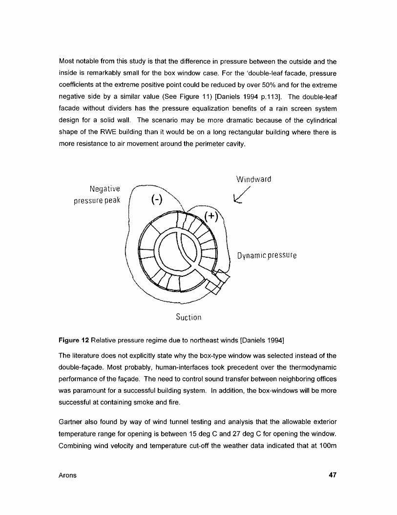
Most notable from this study is that the difference in pressure between the outside and theinside is remarkably small for the box window case. For the 'double-leaf facade, pressurecoefficients at the extreme positive point could be reduced by over 50% and for the extreme
negative side by a similar value (See Figure 11) [Daniels 1994 p.113]. The double-leaf
facade without dividers has the pressure equalization benefits of a rain screen system
design for a solid wall. The scenario may be more dramatic because of the cylindricalshape of the RWE building than it would be on a long rectangular building where there is
more resistance to air movement around the perimeter cavity.
WindwardNegative
pressure peak
( Dynamic pressu re
Suction
Figure 12 Relative pressure regime due to northeast winds [Daniels 1994]
The literature does not explicitly state why the box-type window was selected instead of the
double-fagade. Most probably, human-interfaces took precedent over the thermodynamic
performance of the fagade. The need to control sound transfer between neighboring offices
was paramount for a successful building system. In addition, the box-windows will be more
successful at containing smoke and fire.
Gartner also found by way of wind tunnel testing and analysis that the allowable exterior
temperature range for opening is between 15 deg C and 27 deg C for opening the window.
Combining wind velocity and temperature cut-off the weather data indicated that at 100m
Arons
above ground, the windows can be opened for a short period of time 69% of the time, andleft open for an extended period for 22% of the time. At 50 m above the ground thewindows can be opened for a short period of time 75% of the time, and left open for anextended period for 24% of the time [Arons 1999].
Cavity Temperatures
The temperature of the cavity is important both for the operability of the window and the heattransfer across the inner windowpane to the space and occupant. The solar shading devicemay be adjusted according to the incident radiation. HL-Technik simulated the conditionswithin the fagade for a (maximum) 320 C sunny July day. The temperatures within the box-type window and perimeter double-fagade are comparable. A northeast-facing envelopepeaked at 360C and a southwest-facing envelope peaked at 420C. When average winds areapplied, the perimeter double fagade has the ability to self-cool by dispersing heat within thecavity. In this case, while the northeast envelope peaked at 320C for both facades, thesouthwest envelope was in the range of 36.0 to 39.50C for the box-window and 33.5 to37.50C for the perimeter double fagade. This indicates that the box-window will imposehigher loads on the internal space and present a higher component to the mean radianttemperature. Further, it will impact the operability period of the window. The PerimeterDouble-Skin Fagade has the potential to create discomfort due to excessive air changerates because it allows less restriction on airflow paths. This, however, can be managed byclosing windows.
An annual simulation of the cavity temperatures indicates that the frequency that cavitytemperatures rise above 300C is greater for the box-type windows than the perimeterdouble-leaf fagade. The frequency varies by fagade, but tends to be 15 to 30% higher for thebox-type windows [Daniels 1994 p 121].
3.1.1g INTERDEPENDENT MECHANICAL SYSTEMS
Mechanical ventilation air is conditioned to approximately room temperature, but is notdesigned to provide heating or cooling to the space. The humidity of ventilation air can becontrolled according to a project manager for Hochtief the RWE-owned constructionmanager/facilities operator. The engineer also indicated that he believes ventilation air canalso be reheated in the local plenum by an electric heater prior to distributing the air to theroom. [Arons 1999]. This air is provided beginning at 4:00am to be 'ready' for occupation at
Properties and Applications of Double-Skin Facades
7:00am. Ventilation is turned off at night. There is no manual over ride. There is no
adjustment of air volumes; it is either on or off. Special zones for the conference rooms (in
the core) have higher supply air rates when they are activated. There appears to be no
'occupied/unoccupied' mode for rooms as was the case in the Commerzbank and Victoria
Insurance. There is an 'in-use' button at the conference rooms, though so that more fresh
air can be provided during meetings.
Nighttime set points are lower during the winter and higher during the summer. Heat from
used air is exhausted. 100% fresh outside air is supplied. A heat wheel is utilized for heat
exchange.
Cooling water is used for the radiant ceilings, but the architect (Webber) wasn't sure of the
chilling source or location, but it appears that outside air plus water from 'public water
supply' is used for cooling [Arons 1999 p. 17].
The mechanical plant has its own floor midway up the tower (see Figure 13). The wind
direction determines the side of the building that supply air is received and exhaust air is
ejected. The ductwork is configured so that the air can be taken in on the windward side of
the building and expelled on the leeward side. The location of the plant was selected for
several reasons. First, it allows the top floors of the tower, which have a symbolic power, to
be used for corporate executives and board members. There they enjoy the best views in
the city and outside terraces that are made habitable by the continuation of the outside skin
of the facade up past the terraces to buffer the wind. This enhances the architectural quality
of the tower as a transparent cylinder, something that may have been far more difficult if the
bulk of the mechanical plant was located at the top of the tower. Finally, Mr. Nagel states
that the mid-tower plant location is a preference to minimize the length of mechanical runs,
thereby making the system more efficient.
Arons
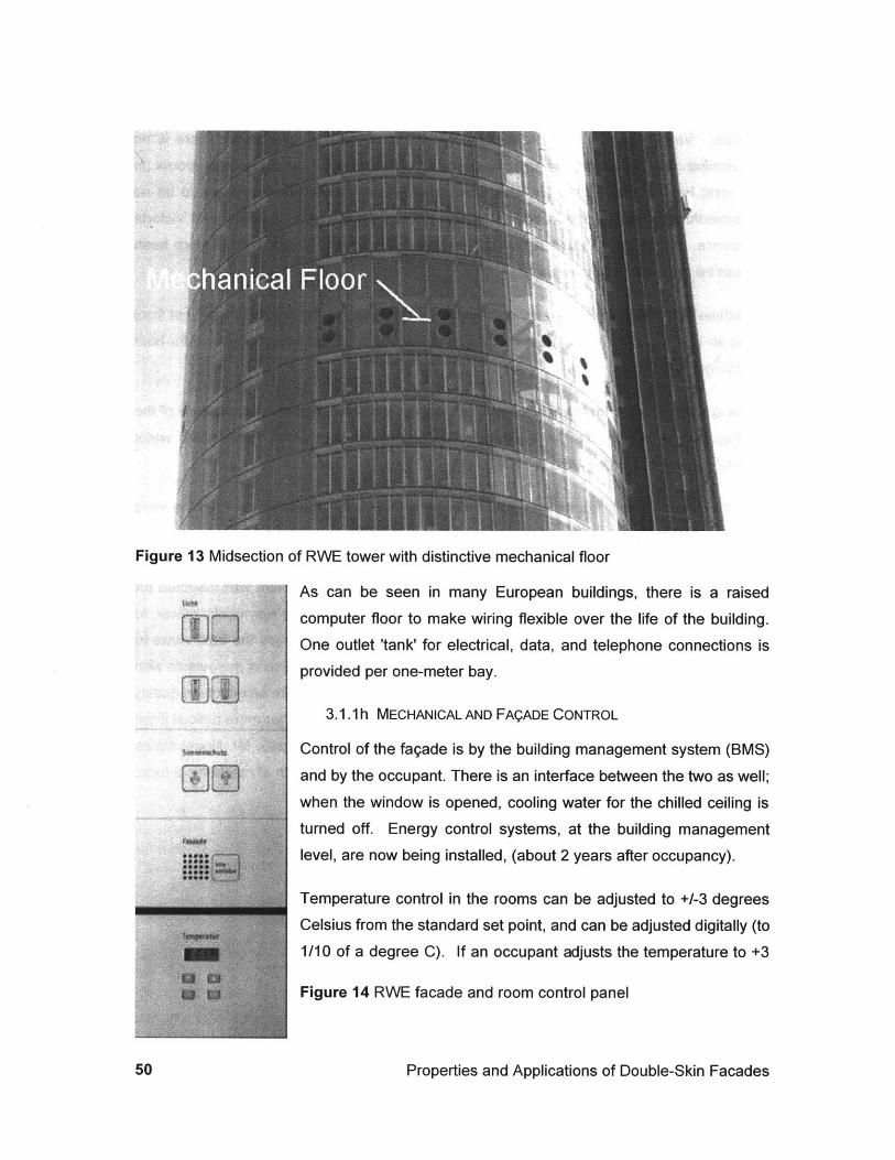
Figure 13 Midsection of RWE tower with distinctive mechanical floor
As can be seen in many European buildings, there is a raisedcomputer floor to make wiring flexible over the life of the building.
One outlet 'tank' for electrical, data, and telephone connections isprovided per one-meter bay.
3.1.1h MECHANICAL AND FAQADE CONTROL
Control of the fagade is by the building management system (BMS)
and by the occupant. There is an interface between the two as well;
when the window is opened, cooling water for the chilled ceiling is
turned off. Energy control systems, at the building management
level, are now being installed, (about 2 years after occupancy).
Temperature control in the rooms can be adjusted to +/-3 degrees
Celsius from the standard set point, and can be adjusted digitally (to
1/10 of a degree C). If an occupant adjusts the temperature to +3
Figure 14 RWE facade and room control panel
Properties and Applications of Double-Skin Facades
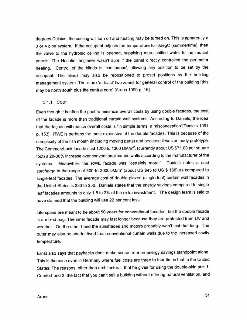
degrees Celsius, the cooling will turn off and heating may be turned on. This is apparently a
3 or 4 pipe system. If the occupant adjusts the temperature to -3degC (summertime), then
the valve to the hydronic ceiling is opened, supplying more chilled water to the radiant
panels. The Hochtief engineer wasn't sure if the panel directly controlled the perimeter
heating. Control of the blinds is 'continuous', allowing any position to be set by the
occupant. The blinds may also be repositioned to preset positions by the building
management system. There are 'at least' two zones for general control of the building [this
may be north south plus the central core] [Arons 1999 p. 16].
3.1.1i COST
Even though it is often the goal to minimize overall costs by using double facades, the cost
of the facade is more than traditional curtain wall systems. According to Daniels, the idea
that the fagade will reduce overall costs is "in simple terms, a misconception"[Daniels 1994
p. 153]. RWE is perhaps the most expensive of the double facades. This is because of the
complexity of the fish mouth (including moving parts) and because it was an early prototype.
The Commerzbank facade cost 1200 to 1300 DM/m 2, (currently about US $71.00 per square
foot) a 20-30% increase over conventional curtain walls according to the manufacturer of the
systems. Meanwhile, the RWE facade was "certainly more." Daniels notes a cost
surcharge in the range of 800 to 3000DM/m 2 (about US $45 to US $ 168) as compared to
single-leaf facades. The average cost of double-glazed (single-leaf) curtain wall facades in
the United States is $30 to $50. Daniels states that the energy savings compared to single
leaf facades amounts to only 1.5 to 2% of the extra investment. The design team is said to
have claimed that the building will use 22 per cent less
Life spans are meant to be about 50 years for conventional facades, but the double facade
is a mixed bag. The inner facade may last longer because they are protected from UV and
weather. On the other hand the sunshades and motors probably won't last that long. The
outer may also be shorter lived than conventional curtain walls due to the increased cavity
temperature.
Ernst also says that paybacks don't make sense from an energy savings standpoint alone.
This is the case even in Germany where fuel costs are three to four times that in the United
States. The reasons, other than architectural, that he gives for using the double-skin are: 1,
Comfort and 2, the fact that you can't sell a building without offering natural ventilation, and
Arons 51

in some locales or with tall buildings, the 'only way' to offer natural ventilation is with asecond skin.
It is not a forgone conclusion that double facades are the only solution to ventilation in high-rise buildings. The ABM Amro building in Amsterdam uses an interior ventilated fagade incombination with small (about 20 x 20 cm) ventilation flaps. See a further description of ABMAmro in section 3.2.1 below.
The architects of RWE argue that the additional costs of the fagade will have a very quickpayback period due to the energy savings they create. But independent testing has not yetbeen done, nor do we know over the long term whether such a complex fagade can bereadily maintained. Considering that back-up cooling and ventilation systems were alsoinstalled [although perhaps at smaller capacities] it is difficult to take this at face value.Additionally, the fagade and cooling system must both be taken into account.
3.1.1j MEASUREMENT
Researchers at the University of Dortmund say that the energy consumption is significantlyless than an 'ordinary fagade'. At the time of the author's visit to the building, the Dortmundresearchers had two temperature sensors (high and low) in the room, and an additional twopairs of temperature sensors in the cavity. Outside temperature, air changes in the room,and on/off conditions of the radiation were also being measured.
3.1.2 The Commerzbank Building
tilt-turn
200 1000-
3.1.2a INTRODUCTION
"The building, completed in 1997, has 63 stories and a height of 299 meters includingantenna. Revolutionary engineering and technology makes the office tower the world's firstecological skyscraper." [Frankfurt web]
Properties and Applications of Double-Skin Facades
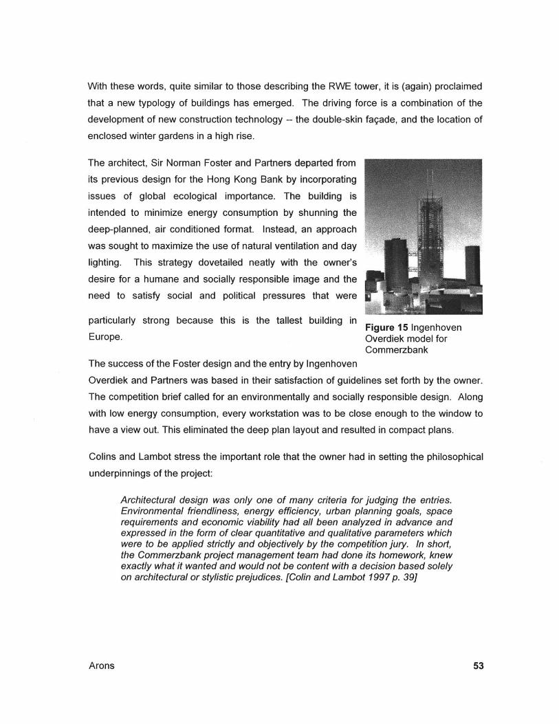
With these words, quite similar to those describing the RWE tower, it is (again) proclaimed
that a new typology of buildings has emerged. The driving force is a combination of the
development of new construction technology -- the double-skin fagade, and the location of
enclosed winter gardens in a high rise.
The architect, Sir Norman Foster and Partners departed from
its previous design for the Hong Kong Bank by incorporating
issues of global ecological importance. The building is
intended to minimize energy consumption by shunning the
deep-planned, air conditioned format. Instead, an approach
was sought to maximize the use of natural ventilation and day
lighting. This strategy dovetailed neatly with the owner's
desire for a humane and socially responsible image and the
need to satisfy social and political pressures that were
particularly strong because this is the tallest building in Figure 15 IngenhovenEurope. Overdiek model for
CommerzbankThe success of the Foster design and the entry by Ingenhoven
Overdiek and Partners was based in their satisfaction of guidelines set forth by the owner.
The competition brief called for an environmentally and socially responsible design. Along
with low energy consumption, every workstation was to be close enough to the window to
have a view out. This eliminated the deep plan layout and resulted in compact plans.
Colins and Lambot stress the important role that the owner had in setting the philosophical
underpinnings of the project:
Architectural design was only one of many criteria for judging the entries.Environmental friendliness, energy efficiency, urban planning goals, spacerequirements and economic viability had all been analyzed in advance andexpressed in the form of clear quantitative and qualitative parameters whichwere to be applied strictly and objectively by the competition jury. In short,the Commerzbank project management team had done its homework, knewexactly what it wanted and would not be content with a decision based solelyon architectural or stylistic prejudices. [Colin and Lambot 1997 p. 39]
Arons
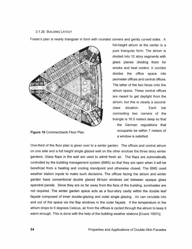
3.1.2b BUILDING LAYOUT
Foster's plan is nearly triangular in form with rounded corners and gently curved sides. A
full-height atrium at the center is a
pure triangular form. The atrium is
divided into 12 story segments with
glass planes dividing them for
smoke and heat control. A corridor
divides the office space into
perimeter offices and central offices.
The latter of the two faces onto the
atrium space. These central offices
are meant to get daylight from theatrium, but this is clearly a second-
class situation. Each bar
connecting two corners of the
triangle is 16.5 meters deep so that
the German regulations that
Figure 16 Commerzbank Floor Plan occupants be within 7 meters of
a window is satisfied.
One-third of the floor plan is given over to a winter garden. The offices and central atriumon one side and a full height single glazed wall on the other enclose the three story wintergardens. Glass flaps in the wall are used to admit fresh air. The flaps are automatically
controlled by the building management system (BMS) so that they are open when it will bebeneficial from a heating and cooling standpoint and otherwise closed. The BMS used
weather station inputs to make such decisions. The offices facing the atrium and winter
garden have conventional double glazed tilt-turn windows set between opaque glass
spandrel panels. Since they are so far away from the face of the building, sunshades arenot required. The winter garden space acts as a four-story cavity within the double leaffagade composed of inner double-glazing and outer single glazing. Air can circulate intoand out of the space via the flap windows in the outer fagade. If the temperature in theatrium drops to 5 degrees Celsius, air from the offices is cycled through the atrium to keep itwarm enough. This is done with the help of the building weather stations [Evans 1997c].
Properties and Applications of Double-Skin Facades
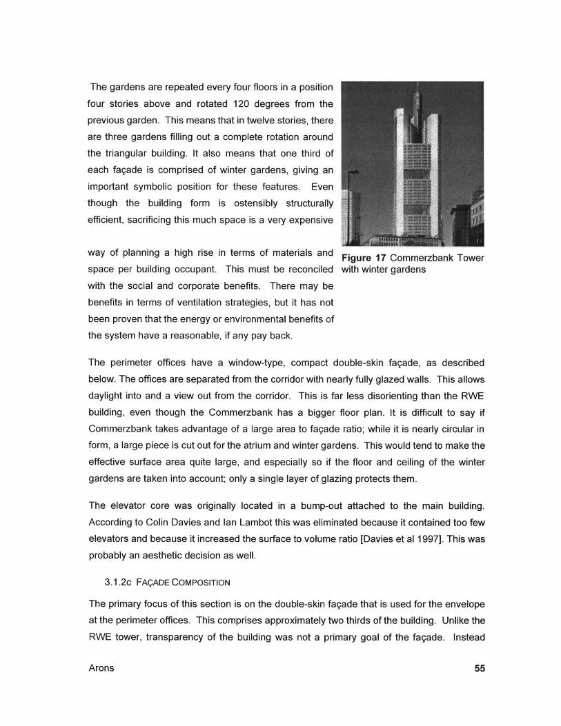
The gardens are repeated every four floors in a position
four stories above and rotated 120 degrees from the
previous garden. This means that in twelve stories, there
are three gardens filling out a complete rotation around
the triangular building. It also means that one third of
each fagade is comprised of winter gardens, giving an
important symbolic position for these features. Even
though the building form is ostensibly structurally
efficient, sacrificing this much space is a very expensive
way of planning a high rise in terms of materials and Figure 17 Commerzbank Towerspace per building occupant. This must be reconciled with winter gardens
with the social and corporate benefits. There may be
benefits in terms of ventilation strategies, but it has not
been proven that the energy or environmental benefits of
the system have a reasonable, if any pay back.
The perimeter offices have a window-type, compact double-skin fagade, as described
below. The offices are separated from the corridor with nearly fully glazed walls. This allows
daylight into and a view out from the corridor. This is far less disorienting than the RWE
building, even though the Commerzbank has a bigger floor plan. It is difficult to say if
Commerzbank takes advantage of a large area to fagade ratio; while it is nearly circular in
form, a large piece is cut out for the atrium and winter gardens. This would tend to make the
effective surface area quite large, and especially so if the floor and ceiling of the winter
gardens are taken into account; only a single layer of glazing protects them.
The elevator core was originally located in a bump-out attached to the main building.
According to Colin Davies and Ian Lambot this was eliminated because it contained too fewelevators and because it increased the surface to volume ratio [Davies et al 1997]. This was
probably an aesthetic decision as well.
3.1.2c FAQADE COMPOSITION
The primary focus of this section is on the double-skin fagade that is used for the envelope
at the perimeter offices. This comprises approximately two thirds of the building. Unlike the
RWE tower, transparency of the building was not a primary goal of the fagade. Instead
Arons
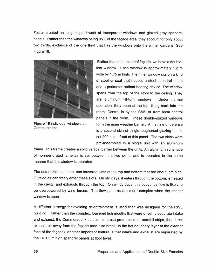
Foster created an elegant patchwork of transparent windows and glazed gray spandrel
panels. Rather than the windows being 95% of the fagade area, they account for only abouttwo thirds, exclusive of the one third that has the windows onto the winter gardens. SeeFigure 18.
Rather than a double-leaf fagade, we have a double-
leaf window. Each window is approximately 1.2 m
wide by 1.75 m high. The inner window sits on a kind
of stool or seat that houses a steel spandrel beam
and a perimeter radiant heating device. The window
spans from the top of the stool to the ceiling. They
are aluminum tilt-turn windows. Under normal
operation, they open at the top, tilting back into the
room. Control is by the BMS or from local control
panels in the room. These double-glazed windowsFigure 18 individual windows at form the main weather barrier. A first line of defenseCommerzbank
is a second skin of single toughened glazing that is
set 200mm in front of this panel. The two skins were
pre-assembled in a single unit with an aluminumframe. This frame creates a solid vertical barrier between the units. An aluminum sunshade
of non-perforated lamellae is set between the two skins, and is operated in the samemanner that the window is operated.
The outer skin has open, non-louvered slots at the top and bottom that are about cm high.Outside air can freely enter these slots. On still days, it enters through the bottom, is heatedin the cavity, and exhausts through the top. On windy days, this buoyancy flow is likely tobe overpowered by wind forces. The flow patterns are more complex when the interiorwindow is open.
A different strategy for avoiding re-entrainment is used than was designed for the RWE
building. Rather than the complex, louvered fish mouths that were offset to separate intakeand exhaust, the Commerzbank solution is to use protrusions, or aerofoil strips, that directexhaust air away from the fagade (and also break up the hot boundary layer at the exteriorface of the fagade). Another important feature is that intake and exhaust are separated bythe +/- 1.3 m high spandrel panels at floor level.
Properties and Applications of Double-Skin Facades
Designers placed a lot of emphasis on the design of RWE's fish mouth, and its ability to
direct, silence and maximize the effectiveness of air patterns. By contrast, the
Commerzbank is a simple opening in the curtain wall, with a stainless steel wire across it,
apparently to keep pigeons from taking up residence.
It is unclear to what degree RWE benefited from their study, or to what degree
Commerzbank could have done so. Guiding the air stream with some type of louver or
scoop (as in the case of Stadttor Dusseldorf) will make the air movement more efficient by
eliminating friction and eddies. A larger opening will allow more air to enter the cavity with
the potential to remove more solar heat gains. This can become a very expensive
proposition both in terms of the complexity of the element (see RWE detail in Figure 9) and
in terms of design and simulation time. Some uncertainties will remain. It is possible that
the lack of efficiency of air movement at the intake and exhaust of the cavity may be counter
balanced by increasing the heat exchange area. Creating more surface area for the
sunshades or selecting more absorptive materials may do this. See more discussion of this
topic in Section 4.5. Issues to look at include pressure loss coefficients of entrance/exit,
width of cavity (friction), angle of blind and heat transfer coefficient, etc).
Considering the effectiveness of the tilt-in window is interesting. It allows a reasonable
amount of open area, but forced airflow is directed toward the ceiling. Evans is critical of the
system, stating that the "bottom-hinged opening light is not ideal for fine ventilation control"
[Evans 1997c]. If the incoming air is cooler than the room air (when radiation is not heating
the cavity) then air will drop into the occupied space. There is a psychological handicap to
this functionality, though. Users cannot look out of the opened segment of the window
because it is too narrow in the occupied space, and it is also at the side of the window. This
may contradict the design intent to give occupants access to fresh air and a connection to
the environment.
3.1.2d OPERABILITY OF WINDOWS
Not only are occupants close to windows bathing them in daylight, but also the windows are
operable. This is perhaps the most significant aspect of the tower. Normally windows in
such buildings are not operable because of the high pressures associated with tall
structures. According to Herr Ernst at Joseph Gartner and company, the maximum wind
speed for opening the windows is 15 m/s. This is nearly twice the limit set for the RWE
tower, although the actual effectiveness of the window systems at design conditions is
Arons
unclear. When the outside conditions are too extreme to allow for opening windows, theyare automatically closed, and the air conditioning system is turned on. Ventilation air iscontinually on [Buchanan 1998 p. 36].
3.1.2e INTERDEPENDENT MECHANICAL SYSTEMS
As at RWE, Commerzbank is equipped with radiant panels in the ceiling for space cooling,
and perimeter radiation for space heating.
3.1.2f MECHANICAL AND FAQADE CONTROL
The maximum temperature inside is meant to be 270 C in offices. Set points are 20 0C
heating and for cooling, set points vary from 21 to 250C, on a sliding scale, depending onoutside temperature. When the outside temperature is at and below 26 degrees Celsius theset point is 21 degrees. From 26 to 320 C outside temperature, set points inside go from 21to 250 C. Office ventilation air is inactive for outside temperature between 2 to 220C.
For fresh air when the ventilation is off, occupants are relied upon to open their windowsbriefly to get a gust of fresh air. Radiant panels at the ceiling supply cooling, but no heating.Windows are closed automatically when winds exceed 15 m/s. Greater wind speedsoverpower the motors that operate the windows. On hot summer days, people can still openwindows. This introduces hot air into the room that must be conditioned by the ceiling.However, the ceiling panels are shut off when the windows are open, so the hot air remainsuntil one of three things happens; colder air from outside eventually replaces it, the air ismixed with corridor air, and cooled remotely within the building, or the window is closed andthe radiant panel extracts the heat. Ventilation in the corridors is always active.
Occupants control the temperature set point of their individual rooms. They may adjust thetemperature within a range from the building set point minus one degree Celsius up to thebuilding set point plus 3 degrees Celsius. A motion sensor, and in/out buttons on the roomcontrol panel allow the system to go into a stand-by mode.
The bank has implemented a program for communication between occupants and facilitymanagers to fine-tune the building controls. There is a kind of 'buddy system', by whicheach group of 200 occupants has a liaison to report to the facilities department tocommunicate issue relating to building maintenance, operation and user comfort. There areapproximately 1200 occupants in the building. There is also a "traffic light" system on the
Properties and Applications of Double-Skin Facades
control panel that tells users when it is okay or not okay to open windows. A red light
indicates that conditions are not appropriate to open windows.
Fluorescent lighting is banked. An exterior bank and an interior bank, each with two lights
are switched independently. The outer bank has a light sensor that dims the lights when
more than 500 lux is available on the work surface. The facilities personnel interviewed
believed that the windows can be opened for some period during 10 months out of the year.
Weather stations are located at each of the winter gardens and on the roof. When
summertime temperatures are 50 C colder outside than inside, the office windows are
automatically opened. When it is too hot out to open the windows for an extended time, the
windows are "rationed" to save energy. Occupants may open their windows for 1 hour in the
morning and 1 hour in the afternoon for fresh air. Otherwise they must remain closed.
Sunshades are controlled by a system that monitors incident radiation. If radiation levels
are high at 11 am, then the blinds are lowered, and set to at a 45-degree angle. The system
may check at other times as well, and could be programmed to check continuously.
Measured radiation with the blinds at 45 degrees was 29.2 W/m2 whereas with the blinds
open, the radiation was 120.1 W/m2 as measured at the inside surface of the inner pane of
glass.
Facility managers believe that the DeutscheBank uses 30% more energy than
Commerzbank. This would be interesting to verify because Gartner and Company installed
both facades. According to Gartner, DeutscheBank has an air-extract window system. It is
not clear what other factors could lead to such a difference in energy consumption.
DeutscheBank is probably an all-air system. This suggests that the biggest difference may
be the use of radiant panels rather than the use of one fagade system or the other. The
interdependency of systems is the critical aspect of obtaining benefits from DSF's and the
aspect that makes their evaluation so difficult.
3.1.2g ENERGY, ECONOMY AND ECOLOGY
Like RWE, Commerzbank is a top-notch building in terms of its materials, detailing and
systems. To provide a double-skin with operable, motor-driven windows and motor-driven
blinds in a highly monitored and controlled building is expensive to construct and to operate.
The Commerzbank fagade cost about 1200 to 1300 DM/m 2 (about US $71.00 per square
Arons
foot). The hope of the bank is that the 20-30% additional investment in the edifice pays offboth in increased staff productivity and in positive public relations for the owner of an"ecologically-aware, energy-saving and pollution-reducing" building. The motivation for thisdesire may come as much from the political pressures of the approval process as frominternal motivation. But Davies asks, "what could be better for the public image of acommercial company than a humane and socially responsible skyscraper that also happensto be the tallest building in Europe? [Colin and Lambot 1997 p.10]."
Unfortunately, this remains largely unproven. There is no documentation of this claim.Davies claim that the building begins a new phase in building design may be true in terms ofintent and awareness. Commerzbank (and RWE) are the first constructed skyscrapers totake these issues on in a series, integrated approach.
There are claims that the tower required only 90 percent of the cooling capacity and that ithas only 50 percent of the energy cost compared to a "fully air conditioned high-risebuilding" [Preston Web]. Architect Spencer de Grey with Foster and Partners hoped that thebuilding would save between 50% and 66% of the energy used in a comparable building[Davey 1997a p. 36]. The Commerzbank states that "thanks to all services provided by thebuilding management system, 30% less energy is used than in comparable traditional high-rise buildings [Commerzbank web]." Surely some of the credit for such savings must go tothe radiation-shedding double-skin windows. The challenge here is to compare internalloads to the radiation load, and to look at the capacity of radiant cooling. In fact, much of theeconomic feasibility may be owed to the radiant ceilings rather than the double fagade. Adetailed cost comparison here would include such implications as duct or plenum spacerequirements of the alternate systems.
3.1.2h MEASUREMENT AND EXPECTATIONS
The Commerzbank was designed to have an optimal U-value and minimal solar gain. Theuse of computational and physical models to predict the extent to which natural ventilation ofthe offices would be possible aided the design. The modeling results predicted that naturalventilation would be available for approximately 60% of the year [Buchanan 1998 p.36].Gartner predicted that an 800 w/m 2 incident radiation relates to a 10 deg C increase in cavitytemperature and concluded that this would be 'not too bad'. [Arons 1999]
Properties and Applications of Double-Skin Facades
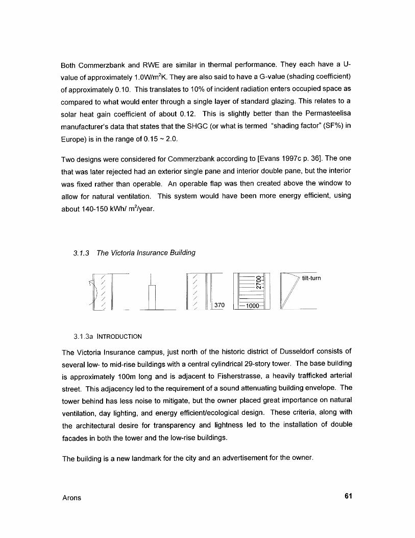
Both Commerzbank and RWE are similar in thermal performance. They each have a U-
value of approximately 1.0W/m2K. They are also said to have a G-value (shading coefficient)
of approximately 0.10. This translates to 10% of incident radiation enters occupied space as
compared to what would enter through a single layer of standard glazing. This relates to a
solar heat gain coefficient of about 0.12. This is slightly better than the Permasteelisa
manufacturer's data that states that the SHGC (or what is termed "shading factor" (SF%) in
Europe) is in the range of 0.15 - 2.0.
Two designs were considered for Commerzbank according to [Evans 1997c p. 36]. The one
that was later rejected had an exterior single pane and interior double pane, but the interior
was fixed rather than operable. An operable flap was then created above the window to
allow for natural ventilation. This system would have been more energy efficient, using
about 140-150 kWh/ m2/year.
3.1.3 The Victoria Insurance Building
tilt-turn
370: -1003.1.3a INTRODUCTION
The Victoria Insurance campus, just north of the historic district of Dusseldorf consists of
several low- to mid-rise buildings with a central cylindrical 29-story tower. The base building
is approximately 100m long and is adjacent to Fisherstrasse, a heavily trafficked arterial
street. This adjacency led to the requirement of a sound attenuating building envelope. The
tower behind has less noise to mitigate, but the owner placed great importance on natural
ventilation, day lighting, and energy efficient/ecological design. These criteria, along with
the architectural desire for transparency and lightness led to the installation of double
facades in both the tower and the low-rise buildings.
The building is a new landmark for the city and an advertisement for the owner.
Arons
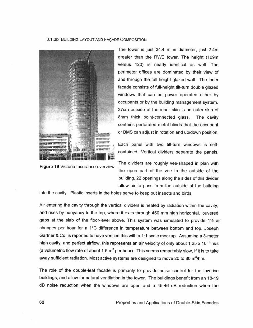
3.1.3b BUILDING LAYOUT AND FAQADE COMPOSITION
The tower is just 34.4 m in diameter, just 2.4m
greater than the RWE tower. The height (109m
versus 120) is nearly identical as well. The
perimeter offices are dominated by their view of
and through the full height glazed wall. The inner
facade consists of full-height tilt-turn double glazedwindows that can be power operated either by
E01i occupants or by the building management system.
37cm outside of the inner skin is an outer skin of
8mm thick point-connected glass. The cavity
contains perforated metal blinds that the occupant
or BMS can adjust in rotation and up/down position.
Each panel with two tilt-turn windows is self-
contained. Vertical dividers separate the panels.
Figure 19 Victoria Insurance overview The dividers are roughly vee-shaped in plan with
the open part of the vee to the outside of the
building. 22 openings along the sides of this divider
allow air to pass from the outside of the buildinginto the cavity. Plastic inserts in the holes serve to keep out insects and birds
Air entering the cavity through the vertical dividers is heated by radiation within the cavity,and rises by buoyancy to the top, where it exits through 450 mm high horizontal, louveredgaps at the slab of the floor-level above. This system was simulated to provide 1 % airchanges per hour for a 10C difference in temperature between bottom and top. JosephGartner & Co. is reported to have verified this with a 1:1 scale mockup. Assuming a 3-meterhigh cavity, and perfect airflow, this represents an air velocity of only about 1.25 x 10 -3 m/s(a volumetric flow rate of about 1.5 m3 per hour). This seems remarkably slow, if it is to takeaway sufficient radiation. Most active systems are designed to move 20 to 80 m3/hm.
The role of the double-leaf facade is primarily to provide noise control for the low-risebuildings, and allow for natural ventilation in the tower. The buildings benefit from an 18-19dB noise reduction when the windows are open and a 45-46 dB reduction when the
Properties and Applications of Double-Skin Facades
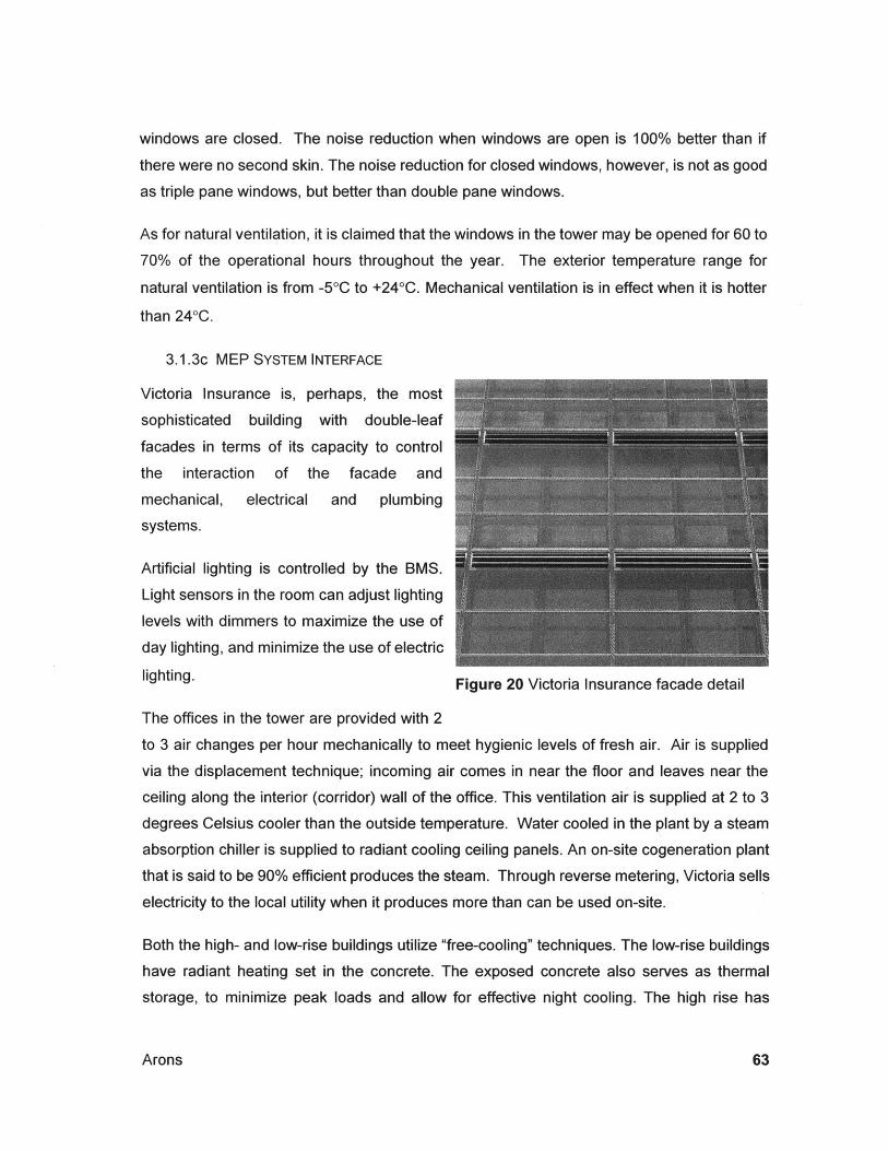
windows are closed. The noise reduction when windows are open is 100% better than if
there were no second skin. The noise reduction for closed windows, however, is not as good
as triple pane windows, but better than double pane windows.
As for natural ventilation, it is claimed that the windows in the tower may be opened for 60 to
70% of the operational hours throughout the year. The exterior temperature range for
natural ventilation is from -50C to +240C. Mechanical ventilation is in effect when it is hotter
than 240C.
3.1.3c MEP SYSTEM INTERFACE
Victoria Insurance is, perhaps, the most
sophisticated building with double-leaf
facades in terms of its capacity to control
the interaction of the facade and
mechanical, electrical and plumbing
systems.
Artificial lighting is controlled by the BMS.
Light sensors in the room can adjust lighting
levels with dimmers to maximize the use of
day lighting, and minimize the use of electric
lighting. Figure 20 Victoria Insurance facade detail
The offices in the tower are provided with 2
to 3 air changes per hour mechanically to meet hygienic levels of fresh air. Air is supplied
via the displacement technique; incoming air comes in near the floor and leaves near the
ceiling along the interior (corridor) wall of the office. This ventilation air is supplied at 2 to 3
degrees Celsius cooler than the outside temperature. Water cooled in the plant by a steam
absorption chiller is supplied to radiant cooling ceiling panels. An on-site cogeneration plant
that is said to be 90% efficient produces the steam. Through reverse metering, Victoria sells
electricity to the local utility when it produces more than can be used on-site.
Both the high- and low-rise buildings utilize "free-cooling" techniques. The low-rise buildings
have radiant heating set in the concrete. The exposed concrete also serves as thermal
storage, to minimize peak loads and allow for effective night cooling. The high rise has
Arons
I
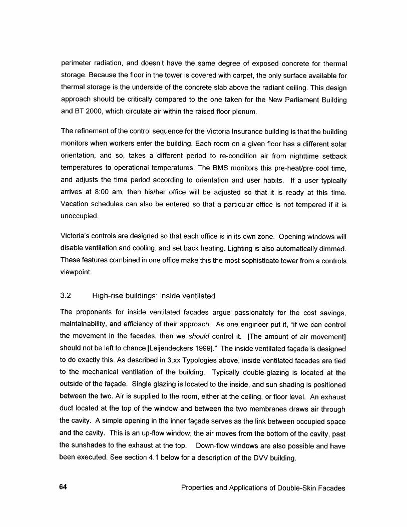
perimeter radiation, and doesn't have the same degree of exposed concrete for thermalstorage. Because the floor in the tower is covered with carpet, the only surface available forthermal storage is the underside of the concrete slab above the radiant ceiling. This designapproach should be critically compared to the one taken for the New Parliament Buildingand BT 2000, which circulate air within the raised floor plenum.
The refinement of the control sequence for the Victoria Insurance building is that the buildingmonitors when workers enter the building. Each room on a given floor has a different solarorientation, and so, takes a different period to re-condition air from nighttime setbacktemperatures to operational temperatures. The BMS monitors this pre-heat/pre-cool time,and adjusts the time period according to orientation and user habits. If a user typicallyarrives at 8:00 am, then his/her office will be adjusted so that it is ready at this time.Vacation schedules can also be entered so that a particular office is not tempered if it isunoccupied.
Victoria's controls are designed so that each office is in its own zone. Opening windows willdisable ventilation and cooling, and set back heating. Lighting is also automatically dimmed.These features combined in one office make this the most sophisticate tower from a controlsviewpoint.
3.2 High-rise buildings: inside ventilated
The proponents for inside ventilated facades argue passionately for the cost savings,maintainability, and efficiency of their approach. As one engineer put it, "if we can controlthe movement in the facades, then we should control it. [The amount of air movement]should not be left to chance [Leijendeckers 1999]." The inside ventilated fagade is designedto do exactly this. As described in 3.xx Typologies above, inside ventilated facades are tiedto the mechanical ventilation of the building. Typically double-glazing is located at theoutside of the fagade. Single glazing is located to the inside, and sun shading is positionedbetween the two. Air is supplied to the room, either at the ceiling, or floor level. An exhaustduct located at the top of the window and between the two membranes draws air throughthe cavity. A simple opening in the inner fagade serves as the link between occupied spaceand the cavity. This is an up-flow window; the air moves from the bottom of the cavity, pastthe sunshades to the exhaust at the top. Down-flow windows are also possible and havebeen executed. See section 4.1 below for a description of the DVV building.
Properties and Applications of Double-Skin Facades
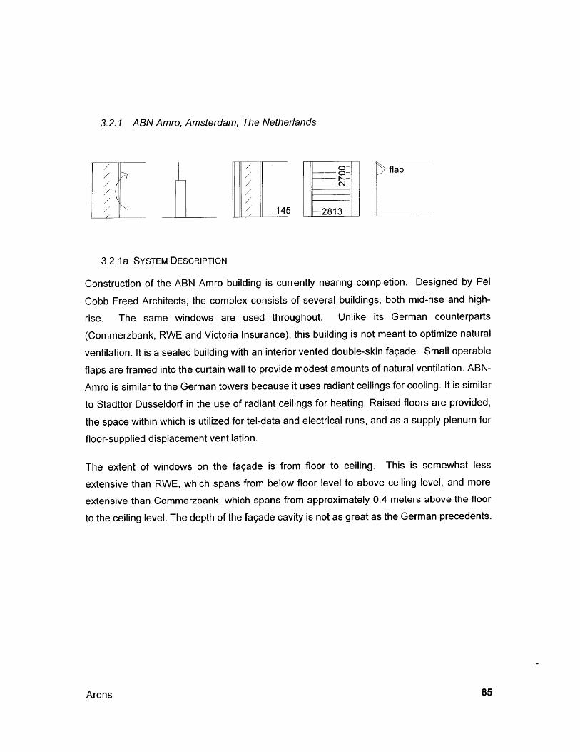
3.2.1 ABN Amro, Amsterdam, The Netherlands
3.2.1a SYSTEM DESCRIPTION
Construction of the ABN Amro building is currently nearing completion. Designed by Pei
Cobb Freed Architects, the complex consists of several buildings, both mid-rise and high-
rise. The same windows are used throughout. Unlike its German counterparts
(Commerzbank, RWE and Victoria Insurance), this building is not meant to optimize natural
ventilation. It is a sealed building with an interior vented double-skin fagade. Small operable
flaps are framed into the curtain wall to provide modest amounts of natural ventilation. ABN-
Amro is similar to the German towers because it uses radiant ceilings for cooling. It is similar
to Stadttor Dusseldorf in the use of radiant ceilings for heating. Raised floors are provided,
the space within which is utilized for tel-data and electrical runs, and as a supply plenum for
floor-supplied displacement ventilation.
The extent of windows on the fagade is from floor to ceiling. This is somewhat less
extensive than RWE, which spans from below floor level to above ceiling level, and more
extensive than Commerzbank, which spans from approximately 0.4 meters above the floor
to the ceiling level. The depth of the fagade cavity is not as great as the German precedents.
Arons
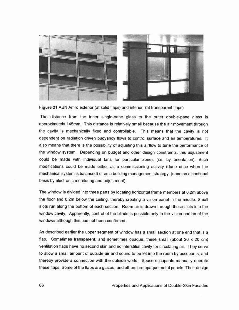
Figure 21 ABN Amro exterior (at solid flaps) and interior (at transparent flaps)
The distance from the inner single-pane glass to the outer double-pane glass isapproximately 145mm. This distance is relatively small because the air movement through
the cavity is mechanically fixed and controllable. This means that the cavity is notdependent on radiation driven buoyancy flows to control surface and air temperatures. Italso means that there is the possibility of adjusting this airflow to tune the performance ofthe window system. Depending on budget and other design constraints, this adjustment
could be made with individual fans for particular zones (i.e. by orientation). Such
modifications could be made either as a commissioning activity (done once when themechanical system is balanced) or as a building management strategy, (done on a continualbasis by electronic monitoring and adjustment).
The window is divided into three parts by locating horizontal frame members at 0.2m above
the floor and 0.2m below the ceiling, thereby creating a vision panel in the middle. Smallslots run along the bottom of each section. Room air is drawn through these slots into thewindow cavity. Apparently, control of the blinds is possible only in the vision portion of thewindows although this has not been confirmed.
As described earlier the upper segment of window has a small section at one end that is a
flap. Sometimes transparent, and sometimes opaque, these small (about 20 x 20 cm)
ventilation flaps have no second skin and no interstitial cavity for circulating air. They serveto allow a small amount of outside air and sound to be let into the room by occupants, andthereby provide a connection with the outside world. Space occupants manually operate
these flaps. Some of the flaps are glazed, and others are opaque metal panels. Their design
Properties and Applications of Double-Skin Facades
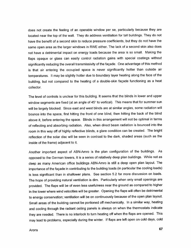
does not create the feeling of an operable window per se, particularly because they are
located near the top of the wall. They do address ventilation for tall buildings. They do not
have the benefit of a second skin to reduce pressure coefficients, but they do not have the
same open area as the larger windows in RWE either. The lack of a second skin also does
not have a detrimental impact on energy loads because the area is so small. Making the
flaps opaque or glass can easily control radiation gains with special coatings without
significantly reducing the overall transmissivity of the fagade. One advantage of this method
is that air entering the occupied space is never significantly hotter than outside air
temperatures. It may be slightly hotter due to boundary layer heating along the face of the
building, but not compared to the heating of a double-skin fagade functioning as a heat
collector.
The level of controls is unclear for this building. It seems that the blinds in lower and upper
window segments are fixed (at an angle of 450 to vertical). This means that for summer sun
will be largely blocked. Since east and west blinds are at similar angles, some radiation will
bounce into the space, first hitting the front of one blind, then hitting the back of the blind
above it, before entering the space. Blinds in this arrangement will not be optimal in terms
of reflecting and absorbing radiation. Also, when direct beam radiation is bounced into the
room in this way off of highly reflective blinds, a glare condition can be created. The bright
reflection of the solar disc will be seen in contrast to the dark, shaded areas (such as the
inside of the frame) adjacent to it.
Another important aspect of ABN-Amro is the plan configuration of the buildings. As
opposed to the German towers, it is a series of relatively deep plan buildings. While not as
deep as many American office buildings ABN-Amro is still a deep open plan layout. The
importance of the fagade in contributing to the building loads (in particular the cooling loads)
is less significant than in shallower plans. See section 5.2 for more discussion on loads.
The hope of providing natural ventilation is dim. Particularly when only small openings are
provided. The flaps will be of even less usefulness near the ground as compared to higher
in the tower where wind velocities will be greater. Opening the flaps will often be detrimental
to energy conservation; ventilation will be on continuously because of the open plan layout.
Small areas of the building cannot be portioned off mechanically. In a similar way, heating
and cooling through the radiant ceiling panels is always on when the thermostats indicate
they are needed. There is no interlock to turn heating off when the flaps are opened. This
may lead to problems, especially during the winter. If flaps are left open on cold days, cold
Arons
air may be drawn across the perimeter heating panels, and condensation could occur.Worst-case scenarios would have these panels freezing and bursting. The value of havingsome operation of the window may outweigh the risks to building energy and maintenance,but such risks must be assessed.
The chance of providing reasonable levels of natural day lighting to the inner reaches of theoffice is not particularly good. While the surfaces are somewhat reflective, no particular efforthas been made to bounce the light to where it is needed most. From an energy standpoint,this means that automatic dimming of the lights would not be of great use, except perhapsnear the perimeter. Even with a concerted effort, the occupied space is deep and so wouldbe difficult to light from the perimeter.
3.2.1b COST AND ENERGY IMPLICATIONS:
The cost of this system has not been disclosed at this time. However, analysis of the fagadeshows that only limited cost factors are involved in upgrading to this type of airflow window.The complexity of the window can be compared to a standard double- or triple-glazedcurtain wall. The ABN-Amro airflow window adds the inner pane of glass. This is simplyframed in aluminum that snaps easily in and out of the main frame. This allows formaintenance of the cavity in which is placed the sunshades. The slots at the bottom of eachframe require some additional labor, as do the slots at the top. Perhaps the greatest addedexpense is the connection of ductwork to the top of the window. The connections requiresome custom parts, and additional labor. This additional work may not be significant sincethe window exhaust will replace some or all of the standard exhaust diffusers.
In order to understand the accuracy of this assertion, one needs to look at the relativevolume of air that is moved to maintain the minimum of about 2.5 air changes per hour in theoccupied space. This volumetric airflow can then be compared to the volumetric flow that isrequired to make the window efficient. The latter is a variable concern because there is arelationship between cavity airflow, effective u-value of the window and fan power required.Consider that the cost effectiveness of the window is dependent on the relative volumes ofairflow. It is also dependent on the relative importance of solar radiation loads to the internalloads of the space.
Properties and Applications of Double-Skin Facades
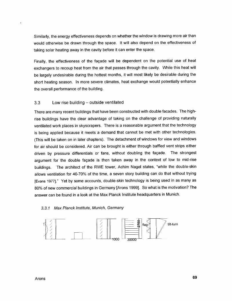
Similarly, the energy effectiveness depends on whether the window is drawing more air than
would otherwise be drawn through the space. It will also depend on the effectiveness of
taking solar heating away in the cavity before it can enter the space.
Finally, the effectiveness of the fagade will be dependent on the potential use of heat
exchangers to recoup heat from the air that passes through the cavity. While this heat will
be largely undesirable during the hottest months, it will most likely be desirable during the
short heating season. In more severe climates, heat exchange would potentially enhance
the overall performance of the building.
3.3 Low rise building - outside ventilated
There are many recent buildings that have been constructed with double facades. The high-
rise buildings have the clear advantage of taking on the challenge of providing naturally
ventilated work places in skyscrapers. There is a reasonable argument that the technology
is being applied because it meets a demand that cannot be met with other technologies.
(This will be taken on in later chapters). The detachment of windows for view and windows
for air should be considered. Air can be brought is either through baffled vent strips either
driven by pressure differentials or fans, without doubling the fagade. The strongest
argument for the double fagade is then taken away in the context of low to mid-rise
buildings. The architect of the RWE tower, Achim Nagel states, "while the double-skin
allows ventilation for 40-70% of the time, a seven story building can do that without trying
[Evans 1977]." Yet by some accounts, double-skin technology is being used in as many as
80% of new commercial buildings in Germany [Arons 1999]. So what is the motivation? The
answer can be found in a look at the Max Planck Institute headquarters in Munich.
3.3.1 Max Planck Institute, Munich, Germany
fa tilt-turn
- 0 L -j-30
Arons
3.3.1a INTRODUCTION
The building is located in Munich, at Marstallplatz, next to the Bavarian House of
Government. The architect, Mr. Post, felt the facade should have a large scale so thebuilding would appear as one 'big building' [Arons 1999]. A second concern was to mitigate
the effects of the building's noisy site (although it appears on-site to that environmental
noise is only a concern on one side). Thirdly, there was a desire to reduce solar heat gains.
All of these issues could be addressed with the double-skin facade. These factors pointedto the use of a deep double-skin fagade.
3.3.1b BUILDING AND FAQADE COMPOSITION
The five-story building is in the form of a U, with the open side to the south. A one-meter
deep double-skin begins one floor above ground level. This deep cavity is divided at eachfloor level by a solid smoke-tight platform. The outer skin is single-glazed with horizontal
aluminum dividers that incorporate open slots for the intake and discharge of air betweenthe external environment and the cavity. There is one floor/ceiling level member and twointermediate members per floor. In this way, each floor of glazing is divided into threesections. The upper section at each floor is comprised of two rows of awning-style operablewindows. These 'flap' open the outer skin to allow for more rapid and effective cooling of thecavity. The user can control them from a panel located near the door of each office.
Horizontal aluminum blinds are located at the inner edge of the meter-wide cavity. This is agood location for user control of light and view, but less desirable in terms of shedding heatgains. The inner insulated glazing unit has a low-e coating, and is comprised of full heighttilt-turn windows.
Properties and Applications of Double-Skin Facades
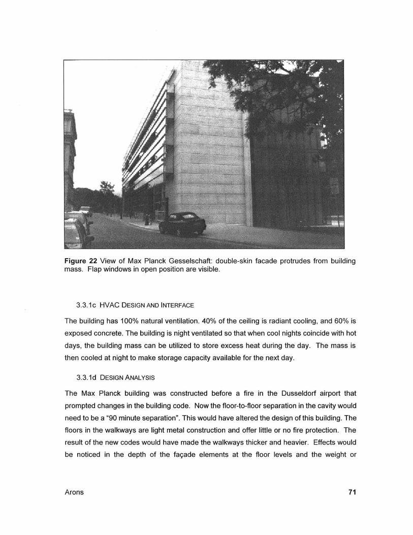
Figure 22 View of Max Planck Gesselschaft: double-skin facade protrudes from buildingmass. Flap windows in open position are visible.
3.3.1c HVAC DESIGN AND INTERFACE
The building has 100% natural ventilation. 40% of the ceiling is radiant cooling, and 60% is
exposed concrete. The building is night ventilated so that when cool nights coincide with hot
days, the building mass can be utilized to store excess heat during the day. The mass is
then cooled at night to make storage capacity available for the next day.
3.3.1d DESIGN ANALYSIS
The Max Planck building was constructed before a fire in the Dusseldorf airport that
prompted changes in the building code. Now the floor-to-floor separation in the cavity would
need to be a "90 minute separation". This would have altered the design of this building. The
floors in the walkways are light metal construction and offer little or no fire protection. The
result of the new codes would have made the walkways thicker and heavier. Effects would
be noticed in the depth of the fagade elements at the floor levels and the weight or
Arons
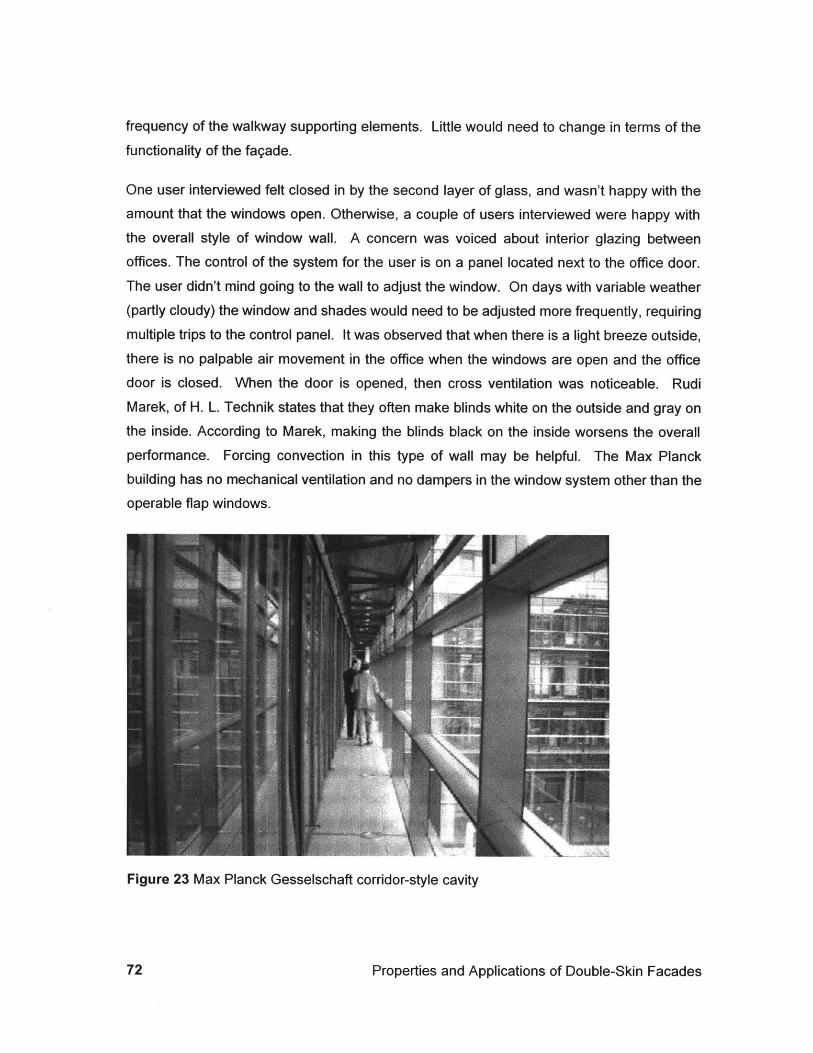
frequency of the walkway supporting elements. Little would need to change in terms of the
functionality of the fagade.
One user interviewed felt closed in by the second layer of glass, and wasn't happy with theamount that the windows open. Otherwise, a couple of users interviewed were happy withthe overall style of window wall. A concern was voiced about interior glazing between
offices. The control of the system for the user is on a panel located next to the office door.
The user didn't mind going to the wall to adjust the window. On days with variable weather
(partly cloudy) the window and shades would need to be adjusted more frequently, requiringmultiple trips to the control panel. It was observed that when there is a light breeze outside,there is no palpable air movement in the office when the windows are open and the officedoor is closed. When the door is opened, then cross ventilation was noticeable. Rudi
Marek, of H. L. Technik states that they often make blinds white on the outside and gray onthe inside. According to Marek, making the blinds black on the inside worsens the overallperformance. Forcing convection in this type of wall may be helpful. The Max Planckbuilding has no mechanical ventilation and no dampers in the window system other than theoperable flap windows.
Figure 23 Max Planck Gesselschaft corridor-style cavity
Properties and Applications of Double-Skin Facades
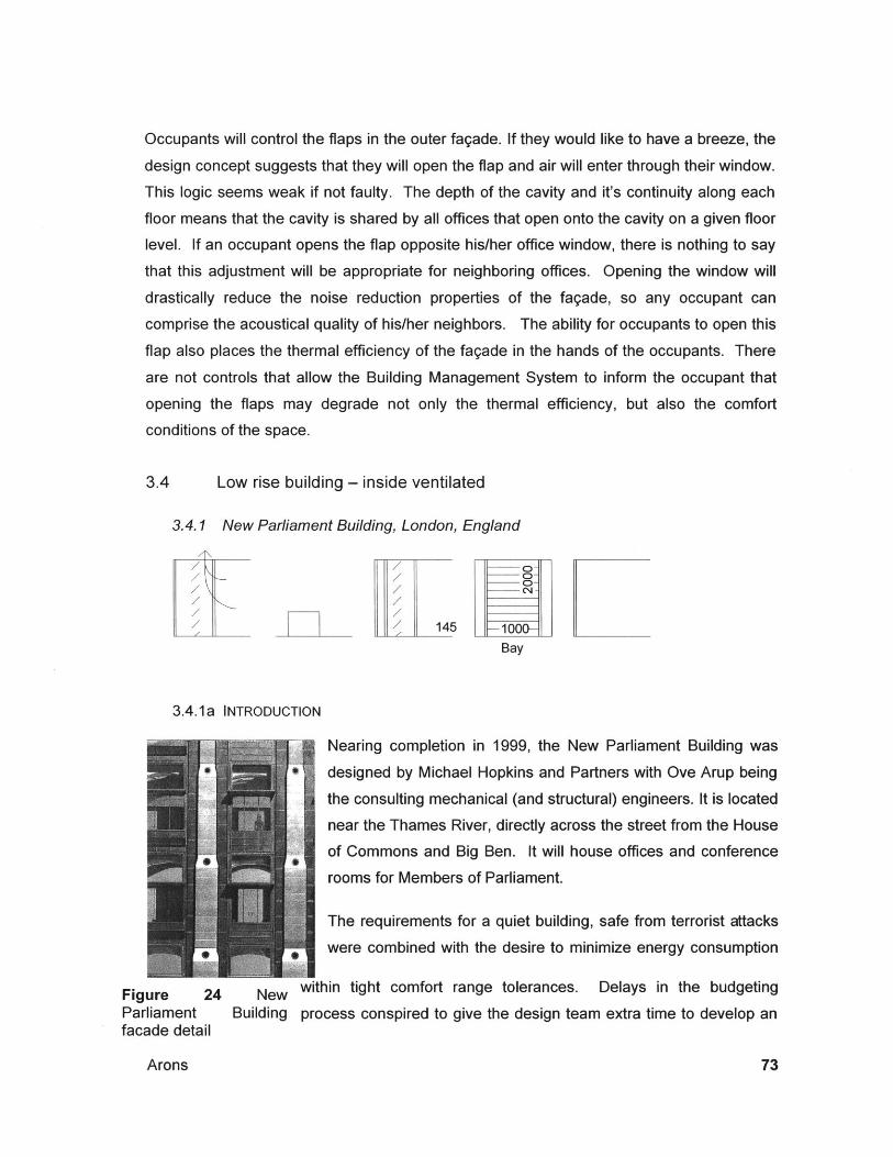
Occupants will control the flaps in the outer fagade. If they would like to have a breeze, the
design concept suggests that they will open the flap and air will enter through their window.
This logic seems weak if not faulty. The depth of the cavity and it's continuity along each
floor means that the cavity is shared by all offices that open onto the cavity on a given floor
level. If an occupant opens the flap opposite his/her office window, there is nothing to say
that this adjustment will be appropriate for neighboring offices. Opening the window will
drastically reduce the noise reduction properties of the fagade, so any occupant can
comprise the acoustical quality of his/her neighbors. The ability for occupants to open this
flap also places the thermal efficiency of the fagade in the hands of the occupants. There
are not controls that allow the Building Management System to inform the occupant that
opening the flaps may degrade not only the thermal efficiency, but also the comfort
conditions of the space.
3.4 Low rise building - inside ventilated
3.4.1 New Parliament Building, London, England
F / 145 16 I
Bay
3.4.1 a INTRODUCTION
Nearing completion in 1999, the New Parliament Building was
designed by Michael Hopkins and Partners with Ove Arup being
the consulting mechanical (and structural) engineers. It is located
near the Thames River, directly across the street from the House
of Commons and Big Ben. It will house offices and conference
rooms for Members of Parliament.
The requirements for a quiet building, safe from terrorist attacks
were combined with the desire to minimize energy consumption
Figure 24 New within tight comfort range tolerances. Delays in the budgetingParliament Building process conspired to give the design team extra time to develop anfacade detail
Arons
integrated approach to mechanical, structural and architectural design.
3.4.1 b BUILDING AND FAQADE COMPOSITION
The building is a seven story square donut with an interior glazed atrium. The architecturaldesign is a combination of solid masonry columns with bay windows between. The windowsare separated vertically with floor level spandrel panels.
The columnar load-bearing stone gets smaller as they go up in response to decreasingstructural loads. Ventilation air is supplied from roof level equipment down the fagade.Located to either side of the structural columns, these ducts get smaller as they go down inresponse to decreased aggregated loads. The windows then fill a uniform width betweenthese structural/mechanical elements. Due to architectural preference, the windows are inthe form of bays that punctuate human occupancy within the facade.
The windows are an integral part of the mechanical system. They consist of an outer leaf ofdouble-glazed insulating glass (that is meant to be literally "bomb-proof'). A cavity for airmovement and a shading device is to the inside of this membrane, and a simple inner paneof glass is placed to the inside of these elements. A light shelf separates the lower twothirds of the window from the upper third. Air is drawn into the cavity through gaps in theinner glass at the bottom of either segment of the window (See Figures and furtherdescription below).
3.4.1c MECHANICAL SYSTEM INTEGRATION
Chimneys at the top of the building have outside air intake vents at the bottom, and exhaustair vents at the top. The chimney also houses a heat recovery wheel consisting of rotatingwire meshes. This large thermal exchange wheel has an efficiency of 84%. The six-meterheight of the turret is designed to achieve separation of intake from exhaust. The two airstreams do not meet. A small amount of fresh air is used to purge, or clean out, theexchanger in between cycles. Fresh air is supplied down the fagade in the ducts along sidethe structural columns. The exhaust air returns up the fagade to the exterior of the supplyducts.
Properties and Applications of Double-Skin Facades
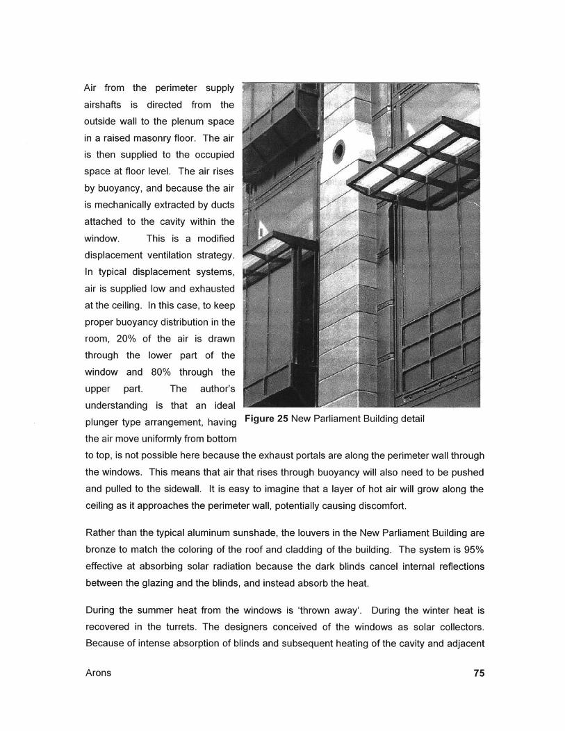
Air from the perimeter supply
airshafts is directed from the
outside wall to the plenum space
in a raised masonry floor. The air
is then supplied to the occupied
space at floor level. The air rises
by buoyancy, and because the air
is mechanically extracted by ducts
attached to the cavity within the
window. This is a modified
displacement ventilation strategy.
In typical displacement systems,air is supplied low and exhausted
at the ceiling. In this case, to keep
proper buoyancy distribution in the
room, 20% of the air is drawn
through the lower part of the
window and 80% through the
upper part. The author's
understanding is that an ideal
plunger type arrangement, having Figure 25 New Parliament Building detail
the air move uniformly from bottom
to top, is not possible here because the exhaust portals are along the perimeter wall through
the windows. This means that air that rises through buoyancy will also need to be pushed
and pulled to the sidewall. It is easy to imagine that a layer of hot air will grow along the
ceiling as it approaches the perimeter wall, potentially causing discomfort.
Rather than the typical aluminum sunshade, the louvers in the New Parliament Building are
bronze to match the coloring of the roof and cladding of the building. The system is 95%effective at absorbing solar radiation because the dark blinds cancel internal reflections
between the glazing and the blinds, and instead absorb the heat.
During the summer heat from the windows is 'thrown away'. During the winter heat is
recovered in the turrets. The designers conceived of the windows as solar collectors.
Because of intense absorption of blinds and subsequent heating of the cavity and adjacent
Arons
glass, the glazing system may fail due to overheating. Test panels in an early mockup
suffered from cracked glazing due to over heating. For this reason in the final configuration,there is a fail-safe position for the blind: They are stored at the bottom of the window (rather
than the top). In this way, if power fails and the fans cannot bring air through the cavity, the
blinds automatically drop out of the active portion of the window.
The energy impacts of the dark blinds may well be negative, particularly during the cooling
season. The inner glass surface is likely to be significantly higher than it would otherwise be
due to the absorption of the blinds resulting in high blind surface temperatures. To removethis heat would require significant airflow rates. Another option to increase the heat transfer
coefficient of the blinds would be to create more surface area (larger blinds or roughened
blinds). This would increase the effectiveness of a base level of air moving across theblinds.
The interior panel of the system consists of a simple pair of hinged glass doors with a gapleft at the bottom through which air from the room can enter the window. The hinge makesmaintenance and cleaning of the cavity easy. Airflow volumes are pre-set by sizing theorifices between the window sections and the ductwork. For calculation purposes, thewindow is considered as a duct with a given pressure loss. Frictional effects of the blinds areprobably not considered. There is an element of thermal buoyancy in the facade. Air ispushed through the system; the pressure is 10 Pa in the ducts at the roof on the exhaustside, and approximately 90 Pa resistance on the supply side. This is done with handcalculations and then put into the computer model of the overall design.
Cooling of the air is accomplished by using 13.4 degrees C ground water that is sent tocooling coils. (The gray water from the coils is used to flush the toilets or is dumped to theThames River about 100meters away). A tank holds the well water in a 'battery' tank forfuture use. Additional cooling is accomplished via night flushing of the building and coolingdown the mass of the building. Design efforts were focused on maximizing exposedmasonry. The raised floors allow air to pass between the top of the pre-cast floor slabs andthe bottom of the raised flooring. The bottoms of the pre-cast slabs are open to theoccupied space. In addition, a partition system was devised using exposed pre-castconcrete panels hung from the ceiling above. These were very expensive, and weretargeted for cost savings during the value-engineering process. However, the engineers
Properties and Applications of Double-Skin Facades
showed that the partitions could not be substituted with lightweight alternatives because the
mechanical system was dependent on the storage capacity in the partitions.
Heating is accomplished mainly via passive solar means with the help of the large amounts
of thermal mass. Radiant panels located on the inside face of the column supply additional
heating. Some space heating is supplied by tempered ventilation air, but this has a minimal
capacity.
An additional feature is the control of daylight. Perforated and corrugated aluminum
reflectors between two sheets of glass form light shelves located at the bottom of the upper
third of the window. The holes in the panels avoid the 'total obscurity' of solid reflectors.
This helps to alleviate the negative feeling that one is wearing a visor when looking out the
window. The glazing is meant to protect the aluminum, keeping it clean enough to bounce
light deep into the room. Site observations indicated that the light shelves served to
illuminate the ceiling adjacent to the window. Light colored surfaces, in general, help to
illuminate the entire space.
3.4.1d DESIGN ANALYSIS
Holistic Design
The New Parliament Building is an example of integrated, interdisciplinary design. The
architectural, structural and mechanical design have been integrated, and in an informal
way, co-optimized. The windows are an active part of the mechanical system, serving as
solar load control devices, mediating negative impacts and providing for redistribution of
heat via the heat recovery wheels. In particular, windows on the sunny side of the building
can collect heat that can be used to heat parts of the building that need heating while
avoiding the need for cooling and the potential for discomfort on the sunny side. The
ductwork also serves as part of the architectural finish on the exterior of the building. This is
most likely not cost effective, but it does successfully express the functionality of the building
for all to see. The building structure, consisting of pre-cast concrete slabs also serves as
an architectural and mechanical system. The exposed panels at the ceiling and beneath the
raised computer floor provide thermal mass to absorb excess heat from the occupied space.
The local (London) climate is also advantageous for nighttime cooling of the structure to
moderate diurnal swings. This combines with the impact of the DSF's to significantly reduce
the overall load that the conventional mechanical system must mitigate.
Arons
Appropriateness of DSF to Buildina Proaram
There is a dialogue between the effectiveness of the windows and their architectural appeal.
Hopkins uses the DSF's on every fagade of the building, facing all cardinal directions.Double facades are most effective in controlling direct solar light, so this choice is a bitironic. Even on the north face of the interior courtyard where direct sunlight may never
shine the DSF's are used. This indicates an overriding principal on the architect's part tohave a uniform building skin wrapping the building. It also muddies the reasoning behindhaving the ductwork exposed on the outside of the building -- it may be that the impetus
came first from the engineer's need to locate the ductwork combined with the architect's
desire to avoid interior shafts rather from an intent to express functionality on the fagade.Note that the Inland Revenue Building does have exposed stack ventilators. Both projects
exhibit an effective architectural resolution of mechanical elements on the fagade regardlessof the generating idea. Hopkins' earlier work at the Inland Revenue building exhibited asimilar approach to having repeated facades in al cardinal direction combined with anintegrated mechanical-architectural element. In this case the stair towers that double asstack ventilators. While DSF's are not used at the Inland Revenue buildings, the designapproach is a similar one.
Properties and Applications of Double-Skin Facades
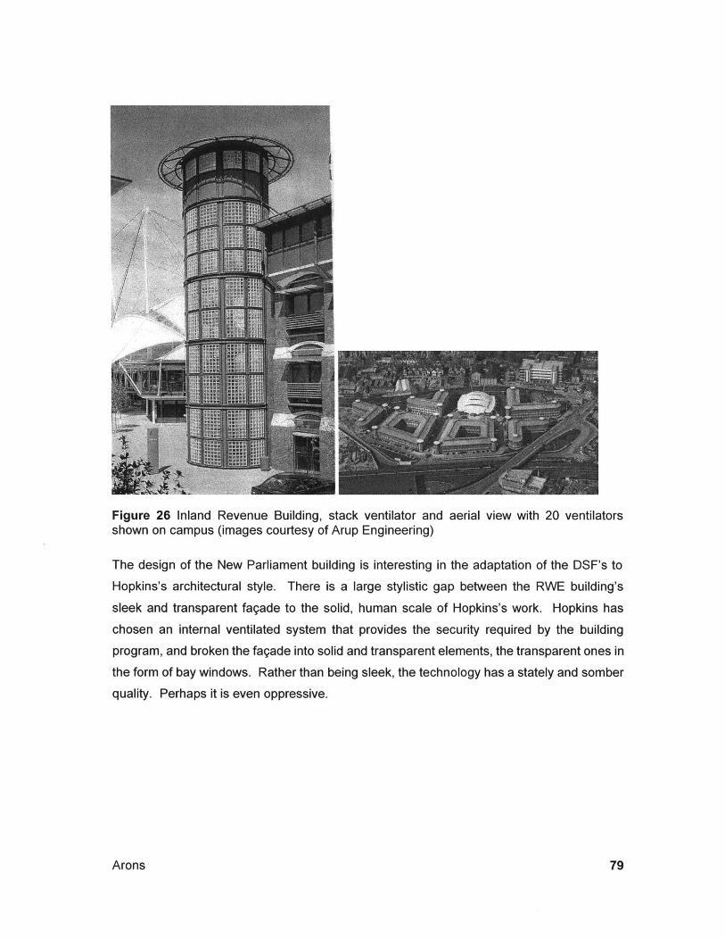
Figure 26 Inland Revenue Building, stack ventilator and aerial view with 20 ventilatorsshown on campus (images courtesy of Arup Engineering)
The design of the New Parliament building is interesting in the adaptation of the DSF's to
Hopkins's architectural style. There is a large stylistic gap between the RWE building's
sleek and transparent fagade to the solid, human scale of Hopkins's work. Hopkins has
chosen an internal ventilated system that provides the security required by the building
program, and broken the fagade into solid and transparent elements, the transparent ones in
the form of bay windows. Rather than being sleek, the technology has a stately and somber
quality. Perhaps it is even oppressive.
Arons

80
4.0 Energy Implications
The context for developing energy models is understood by considering the following quote:
The danger exists, of course, that spectacular structures will be erected in thename of solar, energy-saving, ecologically sustainable architecture, butwhich, in fact, do not meet these criteria. [Herzog 1996, p.19]
The creation of mathematical models for the prediction of performance is part of a two-step
process. The second would be measuring buildings to provide feedback for evaluating the
accuracy of the models. The combination of calculated techniques with intuitive and human
understanding is essential. This chapter describes the development of calculated
techniques. The previous chapter looked at the built forms, and the following chapter
considers the process more holistically.
4.1 Existing calculation methodologies
The literature encompasses various approaches to the problem, and it is beyond the scope
of this paper to summarize all of them. However, a synopsis of the leading papers is made
in this section so that the state of the science will be described.
Saelens and Hens have put together a series of useful papers on airflow windows that
consider theoretical calculations as well as site measurement and analysis and speculation
concerning system construction and performance. They set forth equations that separate
effects of solar radiation from the combined influences of convection and infrared radiation.
Their calculations show that effective U-values and Solar Heat Gain Coefficients are
inversely proportional to airflow through the window cavity. More particularly, they show that
both U-values and Solar Heat Gain Coefficients are reduced with decreasing effectiveness
by the airflow, approaching a minimum value asymptotically.
Their experimental work focused on the case study of the DVV Building in Brussels,
Belgium. The DVV is an unusually configuration for airflow windows. The air is ducted from
exhaust grills at the lighting armatures through the ceiling space to the window heads. It is
then down-fed through the window cavity that contains Venetian blinds and is exhausted
from the windowsill. This configuration is meant to be beneficial because it removes some
of the interior heat load component from the lights before it is introduced into the occupied
space. The authors show that this heat is lost in the plenum, possible near the window head
where insulation or thermal bridging introduce a cold source (heat sink), thereby cooling the
Arons
air before it is introduced into the windows. This configuration also suffers from the counter-flow of the buoyancy effect pushes air up from the sill to the head. In the end, the authorsfound that even though the window cavity heats up significantly, the temperature of theexhaust air is not significantly higher than room temperature, indicating that energy is notbeing removed from the window. In fact, the authors conclude, "The active window alwaysloses energy. This shows that heating the air while passing through the cavity in this case isfiction". The authors cite the need for heat absorption within the cavity. "Active envelopeswithout absorption do not collect solar energy nor have a good SHGC."
The authors have neither measured nor calculated the airflow volume within the cavity.They point out very clearly that, "...the performance of the window (e.g. the equivalent U-value or SHGC) should be distinguished from the overall performance (e.g. the overallenergy consumption)."
Yoon and Lee evaluate annual energy performance of a three-story building with a fullheight, double-skin facade containing a vertically continuous window cavity. The buildingalso has a ground-coupled heat exchanger, also referred to as a "cool tube". The"experimental" building is in Korea. The double-skin (DS) provides "integrated heating andits control logic is reported in a previous paper."
The authors modeled the building and systems using ESP-r (ESRU 1996). Korean weatherdata was loaded into the software. Cooling and heating loads were determined fromsensible and latent gains and losses from occupants, lighting and equipment. "However,energy consumption for fans, lighting and energy losses due to plant inefficiencies are notincluded here."
The DS consists of a single 6mm, tinted leaf. It appears that this is outside typical externalwindows that are double glazed units (6mm glass on either side of a 12mm air space).During the heating season, fresh air passes through the DS after being pre-heated by theground coupled heat exchanger. During the cooling season, the fresh air is pre-cooled bythe heat exchanger but bypasses the DS, and the DS cavity is simply vented at the top.
The report indicates that a 12% annual energy savings is achieved due to the DS systemcompared to not having the system. It is somewhat unclear whether this is relative to theheating season or the entire year.
Properties and Applications of Double-Skin Facades
The report by Wiart and Suvachittanont analyzes the use of airflow windows in tropical
climates by measuring windows in a small test chamber. The chamber can be fitted with
either standard or airflow windows. The authors also cite analysis of a 6 story building in
Thailand, equipped with airflow windows.
The study concludes that airflow windows are economical in the hotter localities such as
Singapore. In Thailand, triple glazed AFW are not economical. The authors recommend
doubling the inner glazing in climates that are hotter than Thailand's in order to minimize
gains to the conditioned space.
"In air-conditioned buildings, the heat absorbed by an internal blind increases the
temperature of the air in the channel and reduces its insulating effect." Rather than blind in
the window cavity, heat-absorbing (gray tinted) glass is used on the outside. The portion of
the heat that is retransmitted to the window cavity is evacuated with approximately 20 m3/h
airflow through the space.
The authors also conclude that the fan power used to evacuate the window cavity creates
an undesirable payback time of approximately 20 years.
Tanimoto and Kimura have investigated the possibility of replacing the inner light of a
traditional airflow window with a "roll screen". This study begins from the assumption that
airflow windows are highly energy efficient. The limiting aspect of these windows in Japan is
the cost of glass. The common window solution there, according to the authors, is single
glazed windows with a Venetian blind on the inside. The proposed solution involves a roll
screen that apparently has reasonably high air permeability. This permeability makes the
system relatively leaky - creating cold drafts during the winter, and unwanted heat during
the summer.
This article seems to be the only one that considers the stack effect numerically. The
authors are concerned with understanding the flow across the roll screen. Yet it seems that
the buoyancy effects should be considered in any vertical cavity with air flowing. Saelens
and Hens allude to this fact by suggesting that the DVV building should have reversed
airflow directions, but this was not considered in their calculations.
Tanimoto and Kimura have done both iterative numerical simulations using the finite
difference method, and physical experimental modeling. The authors note the difficulty of
Arons
creating truly accurate CFD calculations due to the variability of conditions includingconvective heat transfer coefficients, possible airflow short circuits near the ends of thedevice and local effects of the exhaust fan. Issues of workmanship are also of criticalimportance. [Tanimoto and Kimura 1997]
4.2 A Simplified model for energy performance evaluation
4.2.1 Reasoning for and Description of a Simplified Mathematical Model
Researchers have recently developed a handful of numerical tools to predict theperformance of various configurations of double-skin facades. Some reasonably holisticapproaches have been taken. The focus has been on determining the effective U-value andsolar heat gain coefficients of the windows.
The models that have been developed have remained as backup to individual papers. Theyare not accessible in the public domain. For this reason, a new model has been developedthat may be a stepping-stone to a public domain tool. This tool would have the potential tobe run either on a personal computer, or via the World Wide Web.
The end user is meant to be the designers of buildings incorporating double-skin facadesrather than researchers. This community of end users -- architects, engineers and students-- will have specific needs in terms of interface, level of complexity and output from theprogram.
The author has developed a simplified numerical model of a typical double-skin fagade.This model is intended to predict the energy performance of multiple types of double-skinfacades. The platform for development has been a spreadsheet utilizing iterative calculationmethods. The basic configuration for the window under study has a layer of insulatingglass on the exterior, an air cavity and a single interior layer of glass. An inlet is assumed atthe bottom, and an outlet at the top.
Two-dimensional heat transfer, neglecting edge effects are considered. The system isconsidered in the steady state condition, with constant temperatures throughout.Conduction and radiation are considered in the horizontal plane (one-dimensional) andconvection is considered in the vertical direction (also one-dimensional).
Properties and Applications of Double-Skin Facades
Solar Radiation:
* For the calculation of reflected and absorbed (and transmitted) solar energy at the
blinds, the true solar altitude is used in conjunction with blind angle and geometry to
determine passage of solar energy. Both diffuse and specular reflections are considered
and material properties of the blinds are input.
" For the purposes of calculating the quantity of solar energy transmission, it is assumed
that solar radiation will be converted to normal solar radiation prior to entry into the
model. The model takes normal radiation (perpendicular to the window) as its input in
W/m2. So if weather data is used to determine solar energy input, the solar azimuth,
altitude and direct normal (to the sun) radiation must be converted to direct normal (to
the fagade) radiation for the model. A separate spreadsheet has been developed to
facilitate this conversion.
Infrared Radiation:
* Infrared radiation is evaluated based on the surface temperatures and geometries of the
model.
Convection:
" Interior and exterior heat transfer coefficients may be input if desired, or defaults will be
used.
* Heat transfer coefficients within the double-glazing unit are calculated based on the
spacing of the glazing and the surface temperatures.
" The model for convection is one dimensional, and it is assumed that the air stream in the
two cavities do not mix with each other. Also, within each cavity the air is well-mixed,
constant temperature at each vertical tier.
* Heat transfer coefficients in the cavity are determined from correlations for forced
convection flow in a long channel with smooth walls.
Conduction:
* Conductivity of glass is based on input properties.
Arons
* Conductivity of blinds is ignored due to its relatively small impact on the overall energybalance and temperature distribution.
Gas conductivity:
e Gas conductivity is input as a constant term that is used in calculating the heat transfercoefficient within the air cavity. Gas-filled double glazed units (with argon, krypton etc. inplace of air) are not considered in this model.
The model may be adjusted in many ways. The airflow cavity may be opened to the interioror exterior and the flow rate of forced convection may be assigned. Alternatively, buoyancyin the cavities may be analyzed. The geometry of the window is flexible; the height andwidths of the cavities as well as the dimension and spacing of the blinds may be selected.The properties of all of the materials is also flexible: The reflectance, absorptivity, emissivityand transparency may all be adjusted, or selected from a fixed set of glass or blind typesimported from Lawrence Berkley Lab's Window 4.1 program.
The intent of the program is to virtually assemble a particular system by specifying thegeometrical and physical parameters of the window. The model will calculate the energybalances and provide results in terms of energy flow into the occupied space or ductwork.This data can be compared to building loads to evaluate the efficiency or cost effectivenessof various double-skin systems. Inside surface temperatures may be used to analyzeimpacts on comfort.
The design may be refined and optimized for specific conditions to minimize energyconsumption. Comparisons may be made to traditional static systems or to other dynamicsystems to evaluate selection criteria.
Cost is not part of the model, but may be incorporated in terms of basic cost of energycalculations. Cost of fabrication and installation is too dependent on idiosyncrasies of site,geography, economy and technical expertise.
Future enhancements may include:
e Weather data integration: Currently the properties determined may be used to input intoan energy analysis worksheet. Determining annual impacts on energy consumption is
Properties and Applications of Double-Skin Facades
essential to holistic design. Evaluating one instance in time is not sufficient for window
selection. Ideally, the window should be tested against hourly weather data.
" Building interaction: As with weather, the isolated effect of windows on energy
transmittance is not sufficient for window selection. Interactions with thermal mass,
electric lighting, perimeter radiation, and radiant hydronic heating and cooling must be
considered.
" Evaluation of condensation potential: Transferring the technology to climates other than
the climate for which they were originally designed (typically northern Europe), may
introduce new criteria such as condensation. Linking the model to weather data, and
being able to define interior air moisture content will allow the tool to warn its user when
condensation of moisture on the interior pane or in the interstitial cavity may be a
hazard.
* Input of gas-filled insulated glazing units
* Window frame and edge of glass analysis: The effects from conduction will be less
because of the expanded depth of the frame, but thermally breaking the frame is more
difficult for the same reason. Conduction may also be minimized in the case of bolted
glazing on the exterior, although this is difficult to achieve with double-glazing.
* The effective solar shading due to the depth of the frame considered as a light shelf and
fins because of its depth. This relative impact will depend on the frequency of frame
elements.
* Effects of inlet and outlet configurations
e Frictional effects of the entry region may have significant effects on buoyancy flows and
fan power
* Temperature variations of the cavity air stream, as it moves from the inside or outside
into the base of the cavity have been ignored so far. Saelens and Hens have done
some work with two-dimensional solid thermal modeling to evaluate this effect.
Additional work on the fluid dynamics of the entry region is required to evaluate the heat
transfer coefficients between air and frame.
Arons
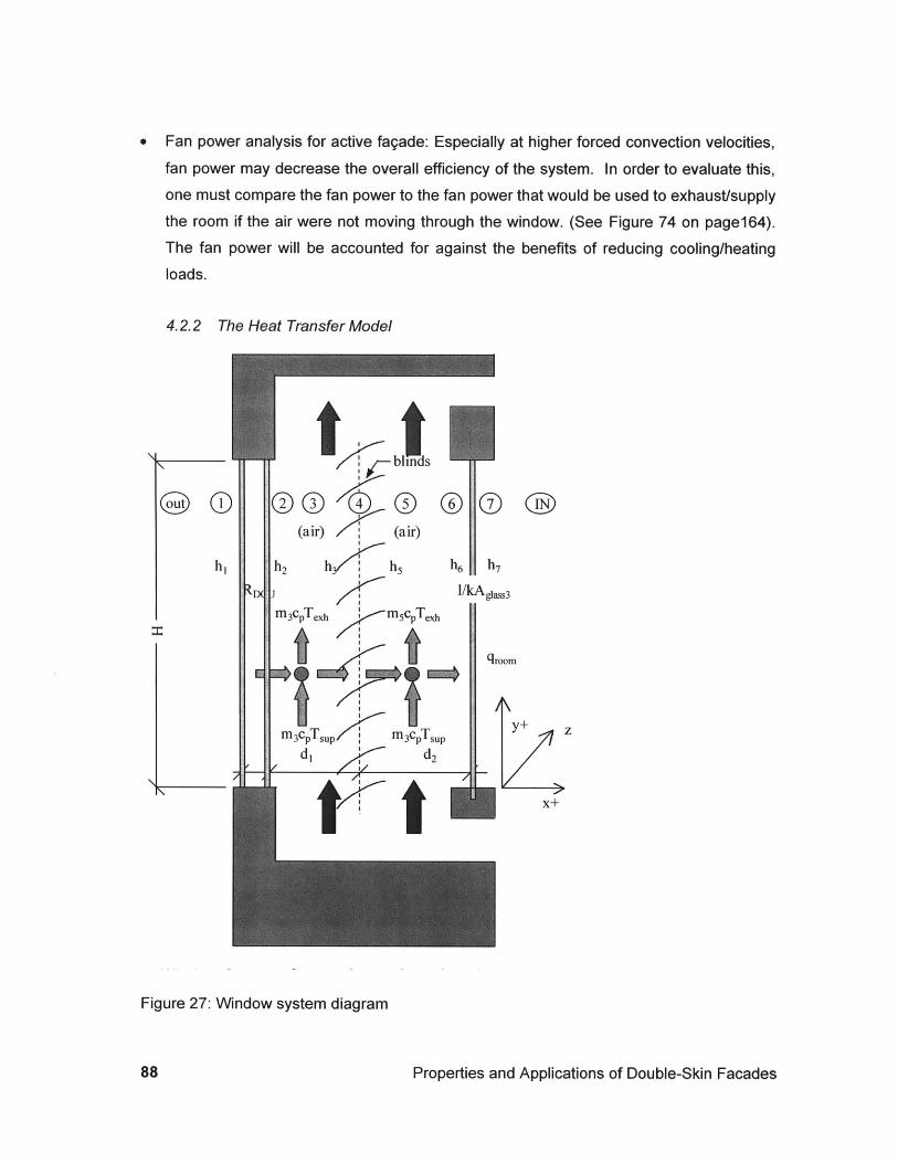
* Fan power analysis for active fagade: Especially at higher forced convection velocities,fan power may decrease the overall efficiency of the system. In order to evaluate this,one must compare the fan power to the fan power that would be used to exhaust/supplythe room if the air were not moving through the window. (See Figure 74 on page164).The fan power will be accounted for against the benefits of reducing cooling/heatingloads.
4.2.2 The Heat Transfer Model
Figure 27: Window system diagram
Properties and Applications of Double-Skin Facades
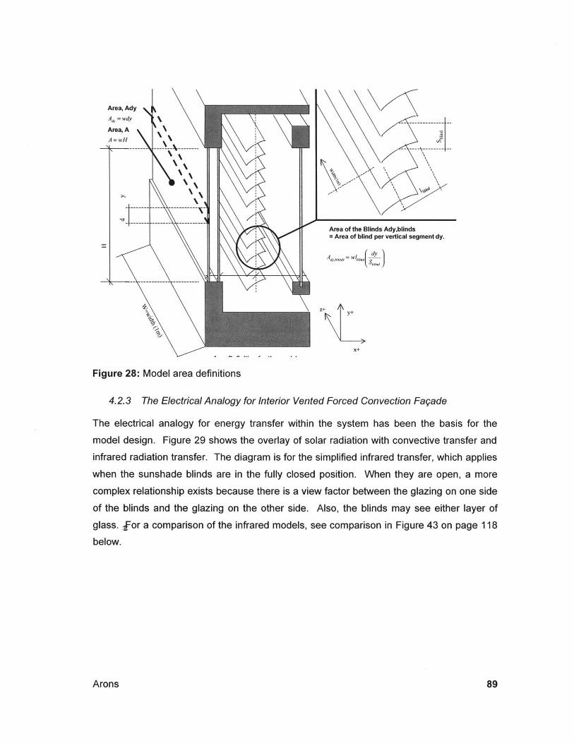
Area of the Blinds Ady,blinds= Area of blind per vertical segment dy.
Figure 28: Model area definitions
4.2.3 The Electrical Analogy for Interior Vented Forced Convection Fagade
The electrical analogy for energy transfer within the system has been the basis for the
model design. Figure 29 shows the overlay of solar radiation with convective transfer and
infrared radiation transfer. The diagram is for the simplified infrared transfer, which applies
when the sunshade blinds are in the fully closed position. When they are open, a more
complex relationship exists because there is a view factor between the glazing on one side
of the blinds and the glazing on the other side. Also, the blinds may see either layer of
glass. for a comparison of the infrared models, see comparison in Figure 43 on page 118below.
Arons
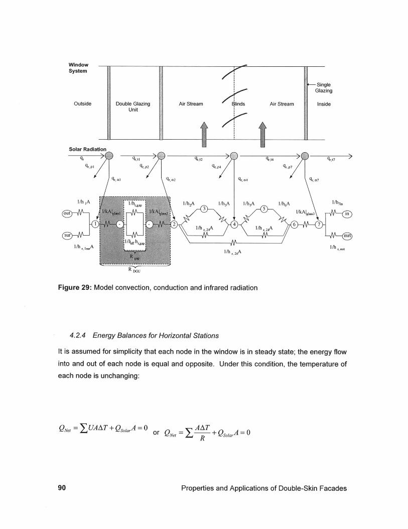
WindowSystem
Outside
- SingleGlazing
Inside
Figure 29: Model convection, conduction and infrared radiation
4.2.4 Energy Balances for Horizontal Stations
It is assumed for simplicity that each node in the window is in steady state; the energy flow
into and out of each node is equal and opposite. Under this condition, the temperature ofeach node is unchanging:
QNet = XUAAT + QsoIarA =0 or QNet R +QoiarA=OR
Properties and Applications of Double-Skin Facades
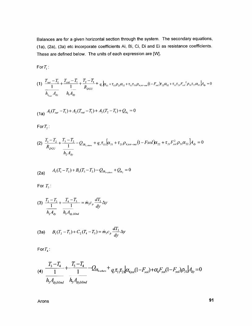
Balances are for a given horizontal section through the system. The secondary equations,
(1a), (2a), (3a) etc incorporate coefficients Ai, Bi, Ci, Di and Ei as resistance coefficients.
These are defined below. The units of each expression are [W].
ForT:
Sur ou + R + q, l 11 P 21a 1 2 +r11r 21P4,1oI-o(1 -F f 22 12 +r, T2 1 oP31 T220121 _____ DGU
h, A h1 A,
(1 ) TAT - T)+ A2( ,T) A2 -7) + Qa = 0(a) 2(, t =03(
ForT2
(2 T +I qT -To 2 +T F 2 pa =(2) 2 3IR2,orhers Ir 11 a 21 21P4 ot-o l(1 sol 2 21 slP31"22 =
RDGU 1 ,hs
(2a) A3(T -T2)+B,(T-T2 )-0R 2-owher Qa 2 =0
For T3:
)T-T T-T dT(3) 2 3+ 4 b n Ay
h2 A d, h Ay~ln
(3a) BI (T2 -T)+ C2(T4 -T3) = rh3c, 3 TAdy
ForT4:
T-T T -T
(4) 14 + 5 4 - Q'thers +rTl 21 [a4,tot sl) 4 o( olP 3 1 0
kAdy,b h Adblind 5dyblind
Arons
(4a) C2 (TC- T4 )- QR4_okers +Qa4
For T :
(5) T T +T -T
6 5.-dT
mc, Aydy
hSA dv h A,
(5a) C 3 (T4 - T5 )+ D,(T 6 - T5 ) h 5 c,
For T:
(6) 6 + 6 QIR6 -others
h1 /h6A kA (4) glass 3
= 0
(6a)
For T:
(7) m 7T -T Tna-T
+ 6 7 ,air 7 + q Is 21a31 +(1- Fo )(p 4,t,_,i )]A, = 011 TIja FO
h,.7 Ad, kIs, glass3 hA,
E, (T,, - T)+ D2 (T6- T)+ E2(Tn,a,,. -T7)+ Q)a, = 0(7a)
Solving for the temperatures at the indicated locations gives T in [0C]:
[oc
Properties and Applications of Double-Skin Facades
dT 5 Aydy
T, =(8)
A, T,,+ A2 TI, + A3T2 + QajA, + A2 + A3
AfT, + BT - QIR2 -okers Qa 2
A3 + B
C2TI +C 3T -QIR4-others + a4
2 +C
T6D,T + D2T7 - QR6oh,
DI +D 2
6D2T +ET, + n + Qa,T 2
D2+ E, + E2
The coefficients are defined in
Radiation Calculations" below:
A2] hr A,
A2 hlAdv
A3 = RDGU
BI=h2 Adv
B2 =unused
B 3 = unused
C, = unused
C 2 = hAyblind
C3 = h5 Ady blind
DI = h6 Adv
the following manner. For definitions of ai, see "Solar
kAdyglass3
E = 1h, Ad,
Arons
(10)
(11)
(12)

We may assume that the total mass flow through the window system is equal to the sum of
the flow through the channel on each side of the blind. rhTotal = rh3 + rh, (The flows
are prh3 and (1 - p)rh, where 0 p 1). This model assumes that there is no mass transfer
between the channels. This is probably not actually the case, but the generalization holdsfor cases where the temperature difference between the channels is relatively small:
~3
To understand how the temperature of the air changes as it rises (falls) through the channel,let Ay be the step-size of vertical increments (horizontal slices) through the window. The
model will divide the height of the window into 10 equal slices. Then the energy balance
dTindicated in equation (3) above may be solved for dydy
dT T-T T-T 1(13) d1 I- 3 1-7 3 or from (3a), [0C/m]
dy 1 1 thA cAy
dT_ B,(T -T3 )_C 2 (T4 -)(13a) -
dy rhcAy
dTSimilarly, solve equation (5) for dydy
dT T4 -T T -T5 1dy 1 1 th 5cAy
h5Ady h6A,
(14a) dT _ C i4 c T y+ DI(T -Tdy rh5cAy
Properties and Applications of Double-Skin Facades
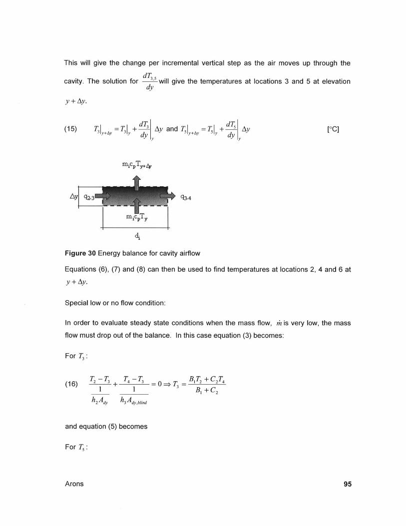
This will give the change per incremental vertical step as the air moves up through the
dTcavity. The solution for " will give the temperatures at locations 3 and 5 at elevation
dy
y + Ay.
[0C]dT dT
(15) T1 7 T + Ay and T = TI +5 Ayy+A Ydy V dy V
Sq34Ay y
m......T
Figure 30 Energy balance for cavity airflow
Equations (6), (7) and (8) can then be used to find temperatures at locations 2, 4 and 6 at
y + Ay.
Special low or no flow condition:
In order to evaluate steady state conditions when the mass flow, rh is very low, the mass
flow must drop out of the balance. In this case equation (3) becomes:
For T3 :
T -T T -T BT+C2T(16) 2 3 + 24 43 0 -> T3 = 4
1 1 B, +C2h 2 Ady hAy ,bind
and equation (5) becomes
For T:
Arons
m c TY4
(17) T = 0 > T =1 1 Di + C3
hAd,blind h6 Ad,
The area of the blind per horizontal section,
Ady,blind = (blind w) dy H = (blind W) dyblind blind
The area per horizontal section is:
Ady = wdy
The area of the window is simply:
A = wH
Adv blind is defined as:
The terms for this equation are defined in the glossary of terms.
4.2.5 Exterior and Interior Convection and Radiation
Heat transfer coefficients can be calculated. Calculation of the exterior heat from Newton'sLaw of Cooling:
4c = hut(Toutair - T) for the convection and
qrad isr (T, - sur) for the radiation, with
T,= Temperature of the surface. In this case T.
h=heff=
hout hrisu
where h,, must be assumed from a wide range of possible values dependant on air speed.
ASHRAE F27.3 and F2.3 give convective s at standard temperature and air velocity
Properties and Applications of Double-Skin Facades
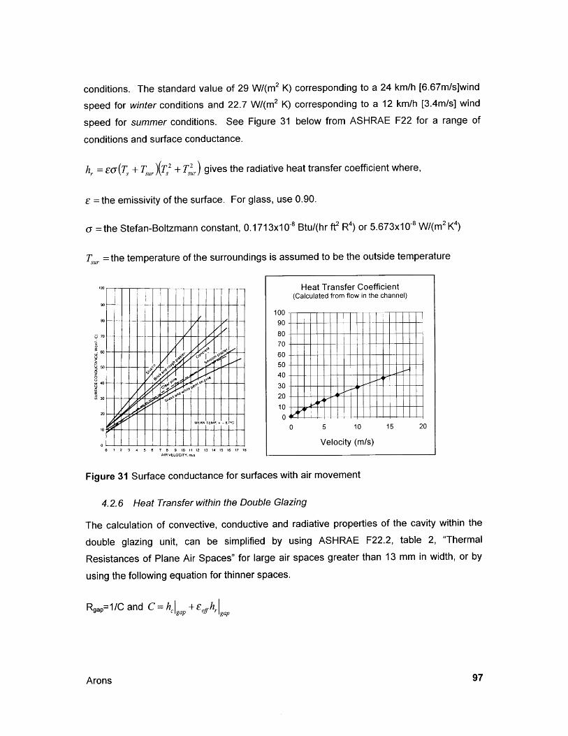
conditions. The standard value of 29 W/(m2 K) corresponding to a 24 km/h [6.67m/s]wind
speed for winter conditions and 22.7 W/(m 2 K) corresponding to a 12 km/h [3.4m/s] wind
speed for summer conditions. See Figure 31 below from ASHRAE F22 for a range of
conditions and surface conductance.
hr = ( +T,)(T7/ + T,) gives the radiative heat transfer coefficient where,
E =the emissivity of the surface. For glass, use 0.90.
a =the Stefan-Boltzmann constant, 0.1713x10⁻⁸ Btu/(hr ft2 R4) or 5.673x10⁻⁸ W/(m 2 K4)
Tur = the temperature of the surroundings is assumed to be the outside temperature
100 Heat Transfer Coefficient(Calculated from flow in the channel)
10
5 - -70 80 -
70.i60 .7
V (j 9 60 11 --
0 40
30
V30 2
0 1 2 3 4 5 6 7 8 9 10 11 12 13 14 15 16 17 18AIR VELOCITY, mjs
Figure 31 Surface conductance for surfaces with air movement
4.2.6 Heat Transfer within the Double Glazing
The calculation of convective, conductive and radiative properties of the cavity within the
double glazing unit, can be simplified by using ASHRAE F22.2, table 2, "Thermal
Resistances of Plane Air Spaces" for large air spaces greater than 13 mm in width, or by
using the following equation for thinner spaces.
Rgap= 1/C and C = h, gap + eijhrgap
Arons
15 200 5 10
Velocity (m/s)
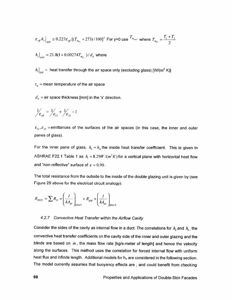
ef h, ~ 0.227. [(T, +273) /100]3 For y=0 use 'n"13 where T, =1 2If g(T 127 12 2
h gp = 21.8(1+ 0.00274T,12 ) /do where
gap = heat transfer through the air space only (excluding glass) [W/(m2 K)]
t= mean temperature of the air space
do= air space thickness [mm] in the 'x' direction.
-1 X 1 -1
E12,E22 =emittances of the surfaces of the air spaces (in this case,
panes of glass).
the inner and outer
For the inner pane of glass, h6 = hi,, the inside heat transfer coefficient. This is given in
ASHRAE F22.1 Table 1 as h, =8.29W/(m2K)for a vertical plane with horizontal heat flow
and "non-reflective" surface of e = 0.90 .
The total resistance from the outside to the inside of the double glazingFigure 29 above for the electrical circuit analogy):
RDGU = JR2 = f glass
unit is given by (see
+ Rgap + jglas 2
4.2.7 Convective Heat Transfer within the Airflow Cavity
Consider the sides of the cavity as internal flow in a duct. The correlations for h2 and h6 , the
convective heat transfer coefficients on the cavity side of the inner and outer glazing and theblinds are based on rh, the mass flow rate [kg/s-meter of length] and hence the velocityalong the surfaces. This method uses the correlation for forced internal flow with uniformheat flux and infinite length. Additional models for he are considered in the following section.The model currently assumes that buoyancy effects are , and could benefit from checking
Properties and Applications of Double-Skin Facades

the heat transfer coefficient of natural convction to evaluate it's relative effect.Mo
calculations for buoyance are shown in Section 4.2.12 below.
, = rl,/(p,,, d,) or with rh3 =ns 5 , V = 3+ 5 /[,pr -(d, + d2 )]with
Di =air velocity [m/s].
p =air density [kg/m 3].
d,= width of the given cavity[m] (assume 1 m of depth along the cavity).
Transition to turbulence occurs at
Rex = uex / v ~ 2,800
ReDHueDH
m mii
pdw pAc,
ue =free-stream velocity
v = viscosity
x =distance along the plate
AC, = diw area in cross section to flow
DH= 4 CS hydraulic diameter with perimeter, P = 2w for cavity flow.P
Pr = = = 0.69 This could be a table lookup value, but assuming constant Prandtl
number will not lead to significant error.
Arons
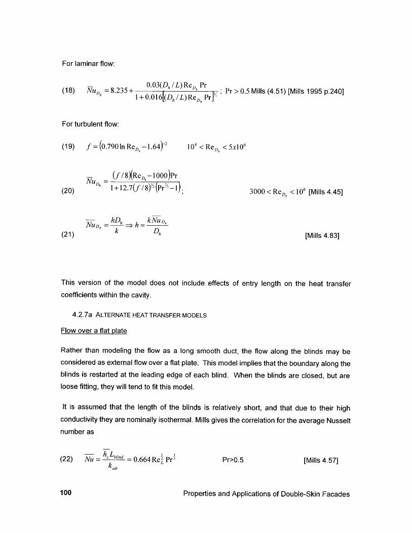
For laminar flow:
(18) NuD =8.235+0.03(Dh/L)ReD Pr
1+0.6DhL)ReD Pr >0.5 Mills (4.51) [Mills 1995 p.240]
For turbulent flow:
(19) f =(0.7901n ReD 1.642
(20)
(21)
N (f /8)(ReD - 1000)Pr
N" 1+12.7(f /8) 2 Pr 3 -1;
NuD, hDh hkNuk Dh
10 4 < ReD, < 5x10 6
3000 < ReD <106 [Mills 4.45]
[Mills 4.83]
This version of the model does not include effects of entry length on the heat transfercoefficients within the cavity.
4.2.7a ALTERNATE HEAT TRANSFER MODELS
Flow over a flat plate
Rather than modeling the flow as a long smooth duct, the flow along the blinds may beconsidered as external flow over a flat plate. This model implies that the boundary along theblinds is restarted at the leading edge of each blind. When the blinds are closed, but areloose fitting, they will tend to fit this model.
It is assumed that the length of the blinds is relatively short, and that due to their highconductivity they are nominally isothermal. Mills gives the correlation for the average Nusseltnumber as
h L I(22) Nu = k blind = 0.664 Re, PrI
air
Pr>0.5 [Mills 4.57]
Properties and Applications of Double-Skin Facades100
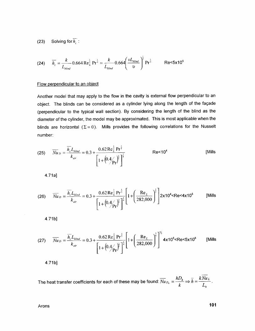
(23) Solving forh:
(24) h = k 0.664 ReI Pr = k 0.6 6 4 vL"" Pr Re<5x10 5
C blind Lblind
Flow perpendicular to an object
Another model that may apply to the flow in the cavity is external flow perpendicular to an
object. The blinds can be considered as a cylinder lying along the length of the fagade
(perpendicular to the typical wall section). By considering the length of the blind as the
diameter of the cylinder, the model may be approximated. This is most applicable when the
blinds are horizontal (I= 0). Mills provides the following correlations for the Nusselt
number:
(25) NUD _ hCLh""nd =0.3± 0.62Re Pr Re<10 4 [Millskair 1+ (0.4/ Y1
4.71a]
blin h = 0. R L Pr 00(26) NUD cblind 0.62Re P 1 ReL 2x10 4<Re<4x10 5 [Millska[ 2+ rY ] 282,000
air +(0-Pr
4.71b]
Pr
4.71 b]
hD - kNULThe heat transfer coefficients for each of these may be found: NuD, = > = L
Arons 101
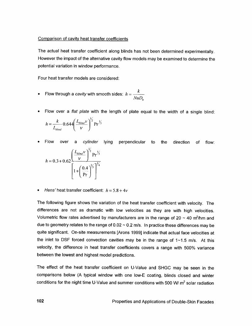
Comparison of cavity heat transfer coefficients
The actual heat transfer coefficient along blinds has not been determined experimentally.However the impact of the alternative cavity flow models may be examined to determine thepotential variation in window performance.
Four heat transfer models are considered:
ke Flow through a cavity with smooth sides: h =
NuDh
e Flow over a flat plate with the length of plate equal to the width of a single blind:
h k 0.644 blind V Prblind V
* Flow over a cylinder lying perpendicular to the direction of flow:
Lv 2Pr 3
h=0.3+0.62 V 2 114
+(0.4Pr
* Hens' heat transfer coefficient: h = 5.8 + 4v
The following figure shows the variation of the heat transfer coefficient with velocity. Thedifferences are not as dramatic with low velocities as they are with high velocities.Volumetric flow rates advertised by manufacturers are in the range of 20 - 40 m2/hm anddue to geometry relates to the range of 0.02 - 0.2 m/s. In practice these differences may bequite significant. On-site measurements [Arons 1999] indicate that actual face velocities atthe inlet to DSF forced convection cavities may be in the range of 1-1.5 m/s. At thisvelocity, the difference in heat transfer coefficients covers a range with 500% variancebetween the lowest and highest model predictions.
The effect of the heat transfer coefficient on U-Value and SHGC may be seen in thecomparisons below (A typical window with one low-E coating, blinds closed and winterconditions for the night time U-Value and summer conditions with 500 W/ m2 solar radiation
Properties and Applications of Double-Skin Facades102
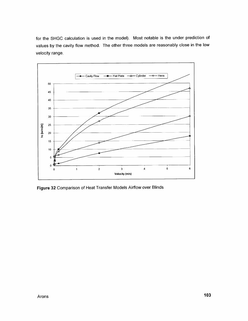
for the SHGC calculation is used in the model). Most notable is the under prediction of
values by the cavity flow method. The other three models are reasonably close in the low
velocity range.
Figure 32 Comparison of Heat Transfer Models Airflow over Blinds
Arons
-- Cavity Flow -- Flat Plate -ir- Cylinder --- Hens
50
45
40
35
30
25
200
15
10
5
00 1 2 3 4 5 6
Velocity (m/s)
103
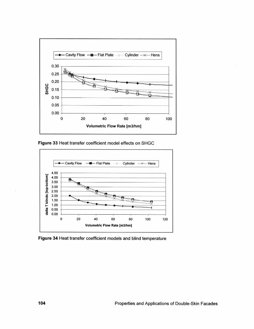
-+- Cavity Flow -m- Flat Plate .- Cylinder --- Hens
Figure 33 Heat transfer coefficient model effects on SHGC
--- Cavity Flow -U- Flat Plate Cylinder -X- Hens
4.50E 4.000Z 3.50
3.000 2.50
.~2.00 - 4h
S1.50,-1.00
ai 0.50
* 0.000 20 40 60 80 100 120
Volumetric Flow Rate [m3lhm]
Figure 34 Heat transfer coefficient models and blind temperature
Properties and Applications of Double-Skin Facades
0.30
0.25
0.20
0.15
0.10
0.05
0.000 20 40 60
Volumetric Flow Rate [m3/hm]100
104
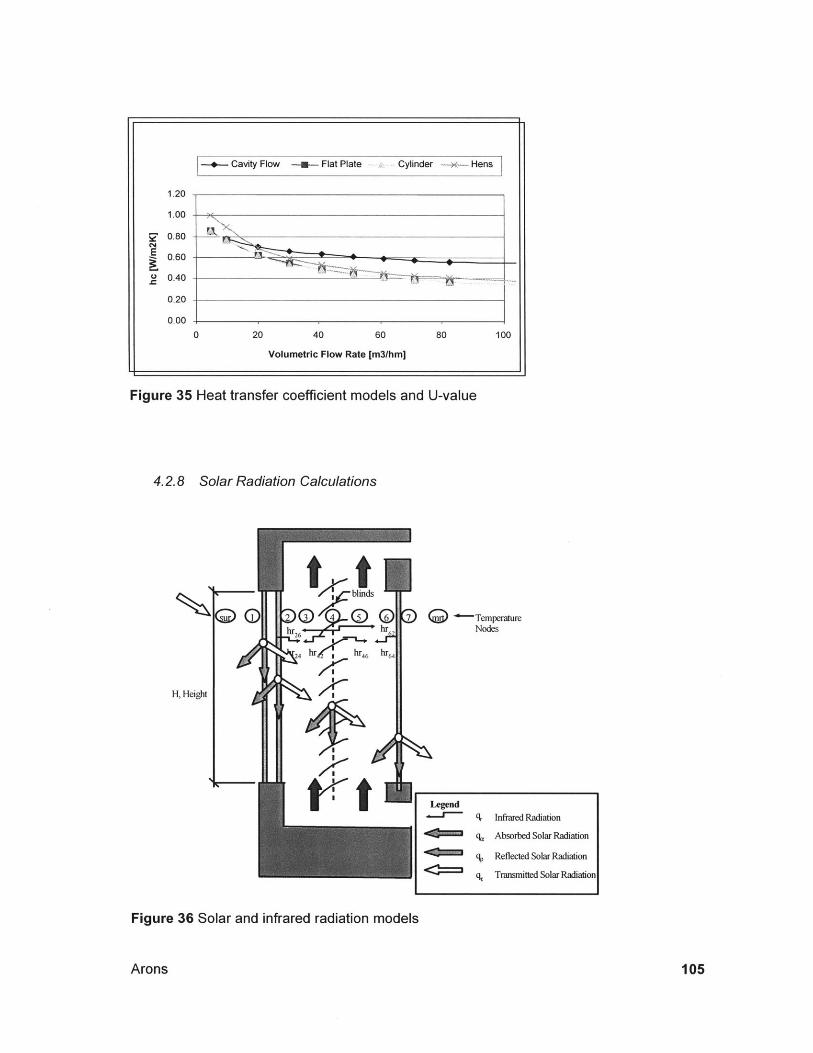
1.20
1.00 ys
S0.80C~4
0.40 -
0.20
0.00
0 20 40 60 80 100
Volumetric Flow Rate [m3/hm]
Figure 35 Heat transfer coefficient models and U-value
4.2.8 Solar Radiation Calculations
t tblinds
426h
24 hr (YrZ hr 64
AlI
7TemperatreNodes
LegendInfrared Radiation
q6 Absorbed Solar Radiation
q, Reflected Solar Radiation
q, Transmitted Solar Radiation
Figure 36 Solar and infrared radiation models
Arons
H, Height
I+-* Cavity Flow -M. Flat Plate Cylinder -- ~ HensI
105
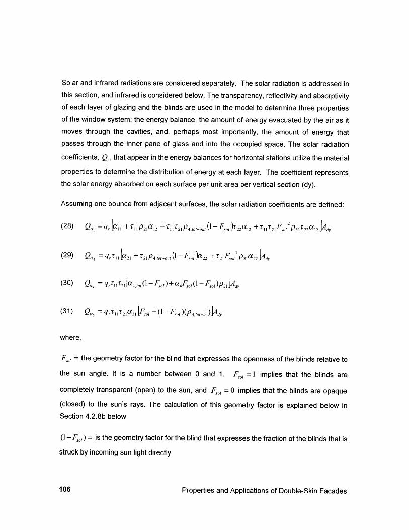
Solar and infrared radiations are considered separately. The solar radiation is addressed inthis section, and infrared is considered below. The transparency, reflectivity and absorptivityof each layer of glazing and the blinds are used in the model to determine three propertiesof the window system; the energy balance, the amount of energy evacuated by the air as itmoves through the cavities, and, perhaps most importantly, the amount of energy thatpasses through the inner pane of glass and into the occupied space. The solar radiation
coefficients, Q, that appear in the energy balances for horizontal stations utilize the material
properties to determine the distribution of energy at each layer. The coefficient representsthe solar energy absorbed on each surface per unit area per vertical section (dy).
Assuming one bounce from adjacent surfaces, the solar radiation coefficients are defined:
F2 I(28) Q , = q + [ P21a12 + 121P4tt,_, (I - Fol ,22an +TF,21 ps31 2A2 y
(29) Qa2 = qr 1 [a21 + T21p4 o-out (1 - F,, a"22 + r 2lFol2 p 3 a 22 dy
(30) Qa4 = qr, 1 21[a4 , 0(1 - F,)+ a4F 1 (1- F,)p3 Ady
(31) Qa7 = qr 11z21a31 [F + (1- F )( p4 ,tot-n )JAd,
where,
F, = the geometry factor for the blind that expresses the openness of the blinds relative to
the sun angle. It is a number between 0 and 1. F,, =1 implies that the blinds are
completely transparent (open) to the sun, and F0,, = 0 implies that the blinds are opaque
(closed) to the sun's rays. The calculation of this geometry factor is explained below inSection 4.2.8b below
(1- Fl) = is the geometry factor for the blind that expresses the fraction of the blinds that is
struck by incoming sun light directly.
Properties and Applications of Double-Skin Facades106
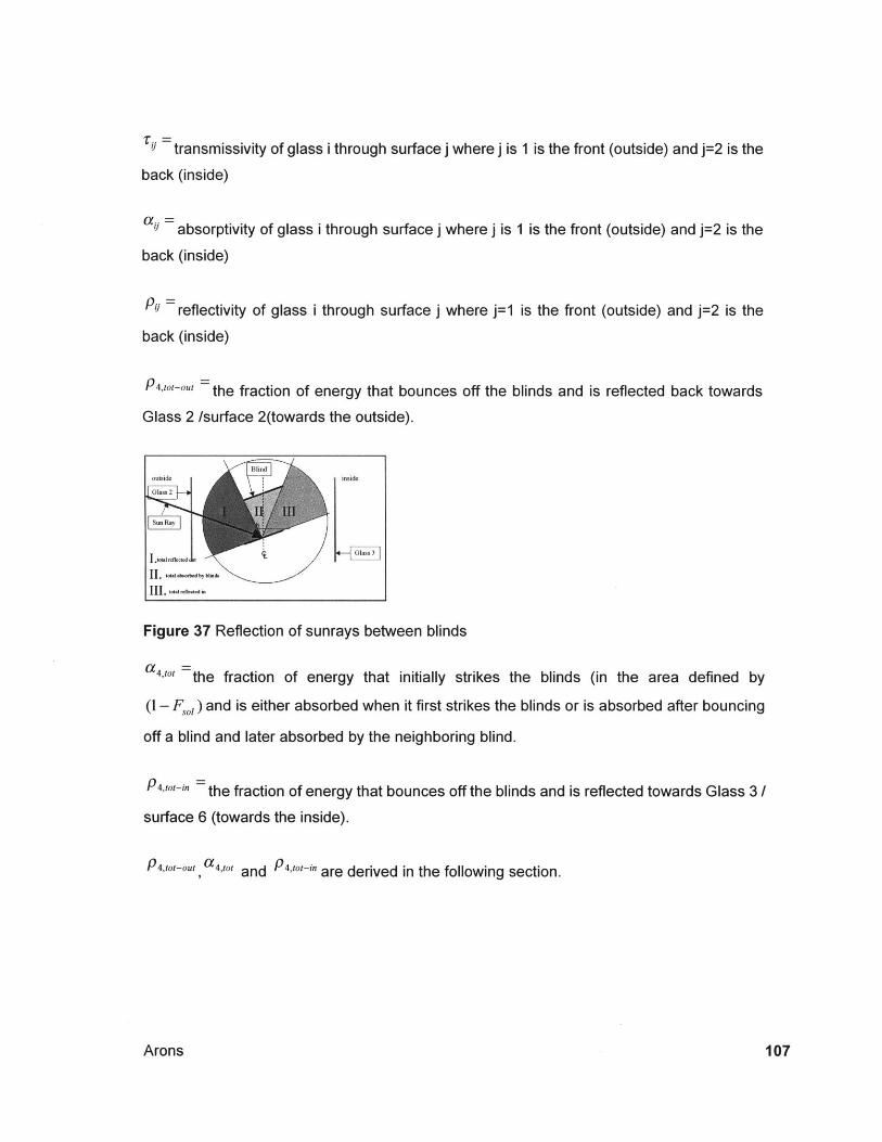
= transmissivity of glass i through surface j where j is 1 is the front (outside) and j=2 is the
back (inside)
a = absorptivity of glass i through surface j where j is 1 is the front (outside) and j=2 is the
back (inside)
= reflectivity of glass i through surface j where j=1 is the front (outside) and j=2 is the
back (inside)
- the fraction of energy that bounces off the blinds and is reflected back towards
Glass 2 /surface 2(towards the outside).
Blindoutside inside
s un Ray
I I . W A.~ ~ e bi. &
Figure 37 Reflection of sunrays between blinds
a4 ,,, =the fraction of energy that initially strikes the blinds (in the area defined by
(1- F,01) and is either absorbed when it first strikes the blinds or is absorbed after bouncing
off a blind and later absorbed by the neighboring blind.
-"4,ttin : the fraction of energy that bounces off the blinds and is reflected towards Glass 3/
surface 6 (towards the inside).
P4,tot-ou, a 4,'0 ' a 4 tot- nand are derived in the following section.
Arons 107
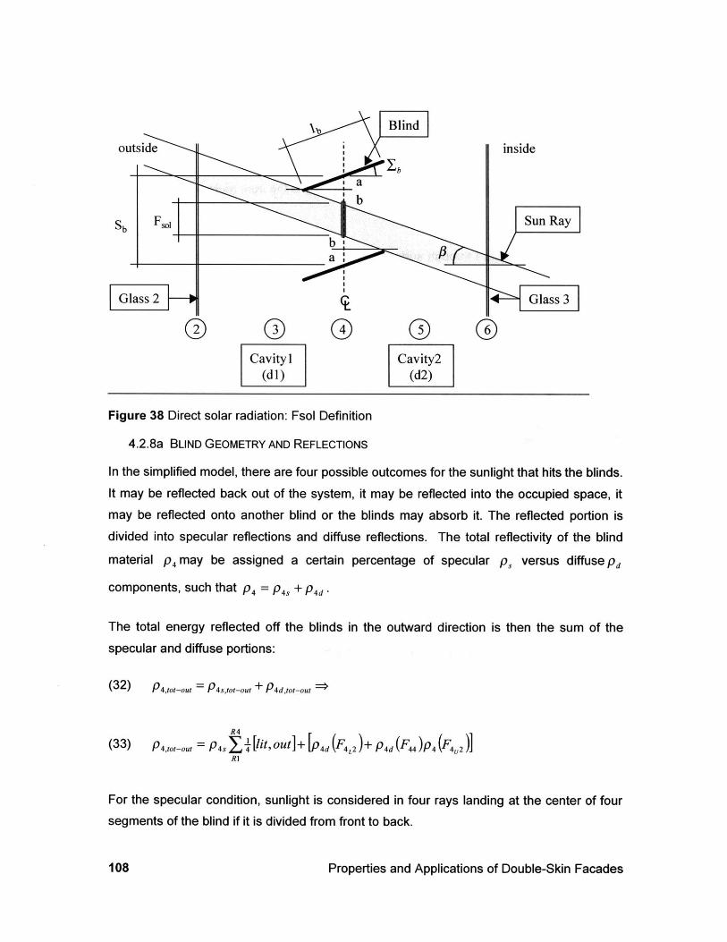
o 00 0 0Cavity 1 Cavity2
(dl) (d2)
Figure 38 Direct solar radiation: Fsol Definition
4.2.8a BLIND GEOMETRY AND REFLECTIONS
In the simplified model, there are four possible outcomes for the sunlight that hits the blinds.It may be reflected back out of the system, it may be reflected into the occupied space, itmay be reflected onto another blind or the blinds may absorb it. The reflected portion isdivided into specular reflections and diffuse reflections. The total reflectivity of the blind
material p4 may be assigned a certain percentage of specular p, versus diffuse Pd
components, such that P4 = P 4, + P4d .
The total energy reflected off the blinds in the outward direction is then the sum of the
specular and diffuse portions:
(32) P4,,0 ,-o, = P4,,ot-ot + P4 ,tot-ou
R4
(33) p.,o,_oz, = p4 ,$1 [lit,out]+ [(F 4 L2 ) + p 4d(F ) p 4 (F)R1
For the specular condition, sunlight is considered in four rays landing at the center of foursegments of the blind if it is divided from front to back.
Properties and Applications of Double-Skin Facades108
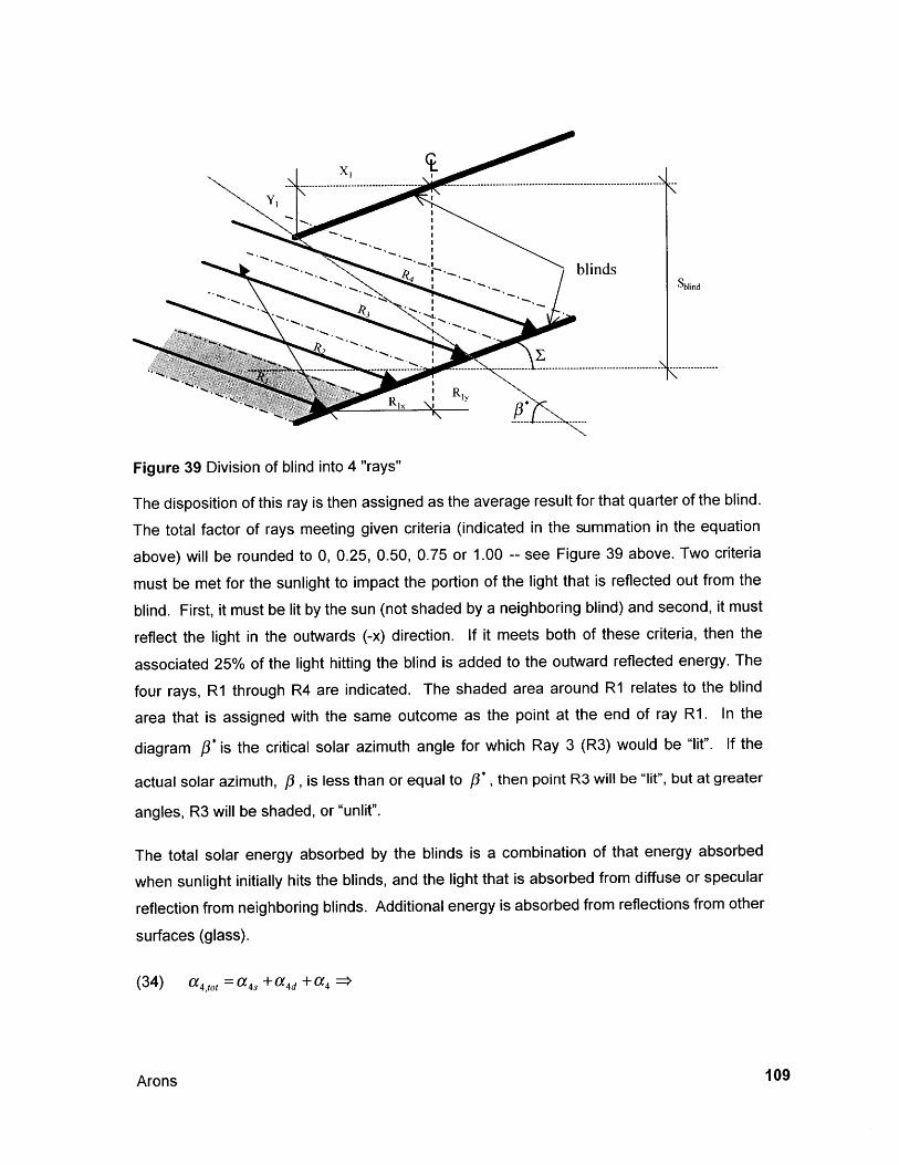
Figure 39 Division of blind into 4 "rays"
The disposition of this ray is then assigned as the average result for that quarter of the blind.
The total factor of rays meeting given criteria (indicated in the summation in the equation
above) will be rounded to 0, 0.25, 0.50, 0.75 or 1.00 -- see Figure 39 above. Two criteria
must be met for the sunlight to impact the portion of the light that is reflected out from the
blind. First, it must be lit by the sun (not shaded by a neighboring blind) and second, it must
reflect the light in the outwards (-x) direction. If it meets both of these criteria, then the
associated 25% of the light hitting the blind is added to the outward reflected energy. The
four rays, R1 through R4 are indicated. The shaded area around R1 relates to the blind
area that is assigned with the same outcome as the point at the end of ray R1. In the
diagram #3* is the critical solar azimuth angle for which Ray 3 (R3) would be "lit". If the
actual solar azimuth, p, is less than or equal to 8* , then point R3 will be "lit", but at greater
angles, R3 will be shaded, or "unlit".
The total solar energy absorbed by the blinds is a combination of that energy absorbed
when sunlight initially hits the blinds, and the light that is absorbed from diffuse or specular
reflection from neighboring blinds. Additional energy is absorbed from reflections from other
surfaces (glass).
(34) a4jot = a4 +a4d +a 4 >
Arons 109
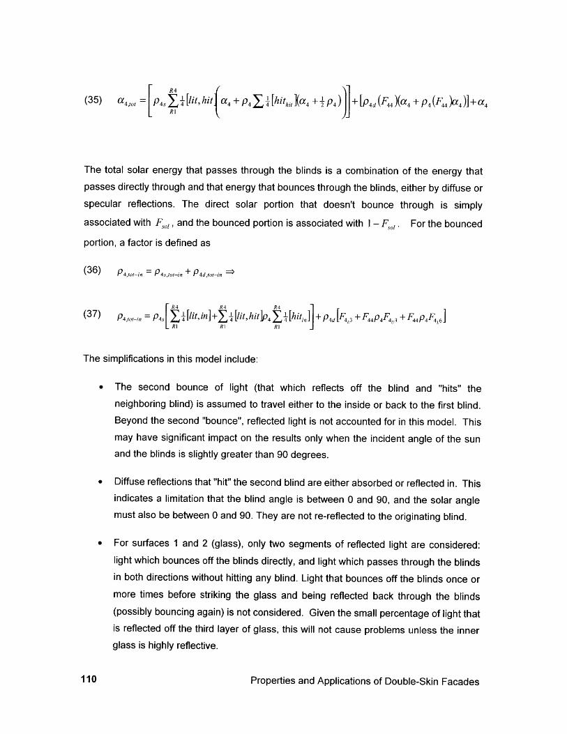
(35) a 4,, = P Y2I [lit, hit a + p4 [hhitkX, 4 + j p4 + M (F, )(az + p44 (F )a,)]+a4
The total solar energy that passes through the blinds is a combination of the energy thatpasses directly through and that energy that bounces through the blinds, either by diffuse orspecular reflections. The direct solar portion that doesn't bounce through is simply
associated with Fso, and the bounced portion is associated with I- F,,,. For the bounced
portion, a factor is defined as
(36) P4 ,t,,in = p, + P4d,,o,, j
(37 ) p4, ,t_, = p,, Y [lit, in]+ I- [lit,hitIP ]p [hin, +p4d[F, +F pF F~pFL, 4 4 R4 ±4,3 F44P4 4,3 ±F 44P4F4 ,6]RRIRI J
The simplifications in this model include:
* The second bounce of light (that which reflects off the blind and "hits" theneighboring blind) is assumed to travel either to the inside or back to the first blind.Beyond the second "bounce", reflected light is not accounted for in this model. Thismay have significant impact on the results only when the incident angle of the sunand the blinds is slightly greater than 90 degrees.
* Diffuse reflections that "hit" the second blind are either absorbed or reflected in. Thisindicates a limitation that the blind angle is between 0 and 90, and the solar anglemust also be between 0 and 90. They are not re-reflected to the originating blind.
* For surfaces 1 and 2 (glass), only two segments of reflected light are considered:light which bounces off the blinds directly, and light which passes through the blindsin both directions without hitting any blind. Light that bounces off the blinds once ormore times before striking the glass and being reflected back through the blinds(possibly bouncing again) is not considered. Given the small percentage of light thatis reflected off the third layer of glass, this will not cause problems unless the innerglass is highly reflective.
Properties and Applications of Double-Skin Facades110
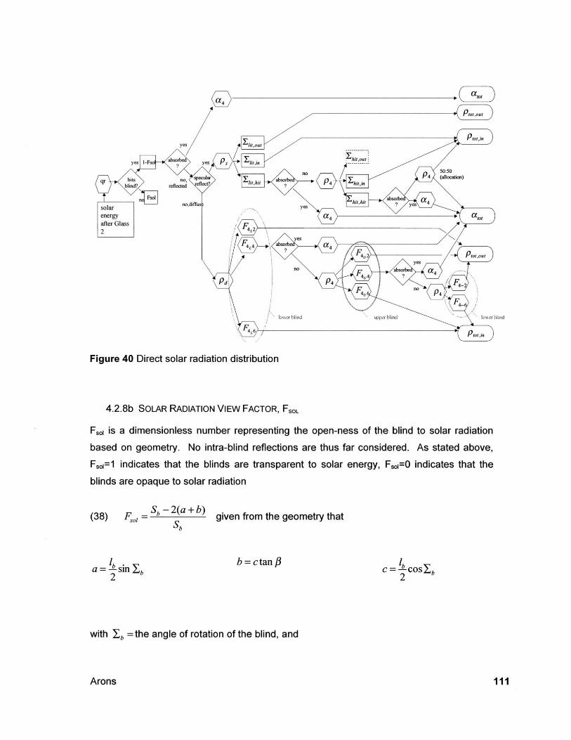
Figure 40 Direct solar radiation distribution
4.2.8b SOLAR RADIATION VIEW FACTOR, FSOL
F, is a dimensionless number representing the open-ness of the blind to solar radiation
based on geometry. No intra-blind reflections are thus far considered. As stated above,
Fr,=1 indicates that the blinds are transparent to solar energy, F.o1=0 indicates that the
blinds are opaque to solar radiation
= S -2(a+b)(38) F,1 = b given from the geometry that
a = -b-sm Xb2b = ctan P
C = L-coSEb2
with Xb =the angle of rotation of the blind, and
Arons 111
# =the solar azimuth, and
Sb =spacing between blinds in meters.
4.2.8c SPECULAR SOLAR REFLECTIONS FROM BLINDS
Some geometric relationships are useful in sorting out the pathways of specular reflectionsfrom the blinds. The following are illustrated in the diagram (Figure 41) below.
'' and RIX locate the point of incidence ("ray point") by x and y coordinates from the
centroid of the (lower) blind.
RIV th R.the vertical distance from the blind centerline to the Rayl intercept. ' are similar.
RIX =the horizontal distance from the blind centerline and the Rayl intercept. Ri are similar.
(39) R, = R -l sin I and R2, = R3 = - lbsinX
Properties and Applications of Double-Skin Facades112
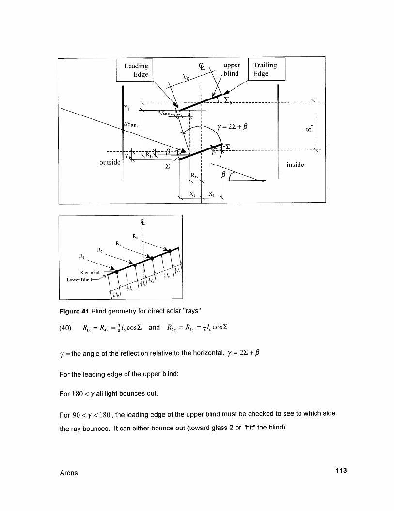
Figure 41 Blind geometry for direct solar "rays"
(40) R=R4 = cos and R =R -l, cos'(4)RX=Rx= 8 lb2O, 3 8b
y =the angle of the reflection relative to the horizontal. y = 21 #
For the leading edge of the upper blind:
For 180 < y all light bounces out.
For 90 < y < 180, the leading edge of the upper blind must be checked to see to which side
the ray bounces. It can either bounce out (toward glass 2 or "hit" the blind).
Arons 113

For 0 <,y < 90 light either hits or bounces in (it can not bounce out if the blind angle and sun
azimuth are within the limits of the model).
The coordinates of the travel distance from the ray point to the vertical elevation of theleading edge of the upper blind are:
AyRIL the vertical "travel distance" and LXRIL the horizontal "travel distance".
(41) AYRIL =Sb+ Ry - y, and AyR 2,L Sb + R2 , - y 1 while
(42) AyR 3,L = Sb - R4- y, and AyR 4 ,L - Sb R 4y - y 1
(43) AxRIL =AyRIL tan(y - 90) and for the other points, AxRi,L = AyRi,L tan(y - 90)
For the trailing edge of the upper blind:
RIT the vertical "travel distance" and RT the horizontal "travel distance".
(44) AyRT =Sb + RI, + y, and AyR 2,T Sb + R 2 + y, while
(45) AYR 3 ,T Sb - R4 v +y and AyR 4 ,T Sb - R4 y + y
(46) AxR,T - RI,T and for the other points, AxRi,Ttan yAyRi,T
tan y
To determine the direction that each ray bounces:
For 180< y, all light bounces out.
For 90 < y <180, there are two conditions:
For both R, (shown) and R2 (implied) :
(47) AXRIL + RX > X1 ="out" and AXR1,L + Rix < X =>"hit"
Properties and Applications of Double-Skin Facades114
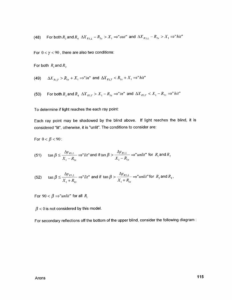
(48) For both R3and R4 AXR 3,L -R 3 x > X, ="out" and AXR 3,L - R 3x > X, ="hit"
For 0 < y < 90, there are also two conditions:
For both Ri and R2
(49) AXRIT > RI + X, ->"in" and AR1,T < RI + X, -1" hit"
(50) For both R3 and R 4 AXR3,T > Xi - R3x =>"in" and AXR3,T < X - R 3x -o"hit"
To determine if light reaches the each ray point:
Each ray point may be shadowed by the blind above. If light reaches the blind, it is
considered "lit", otherwise, it is "unlit". The conditions to consider are:
For 0< #<90:
(51) tan # AyR1L =>"lit"and if tan YR,L -="unlit" for R, an 2X - RX X1 -dR
(52) tan # R3,L =>"lit" and if tan #3XI +RX
> AyR3,L ="unlit" for R and R4X 1 +Ri
For 90 < P =>"unlit" for all R,
/3< 0 is not considered by this model.
For secondary reflections off the bottom of the upper blind, consider the following diagram:
Arons 115
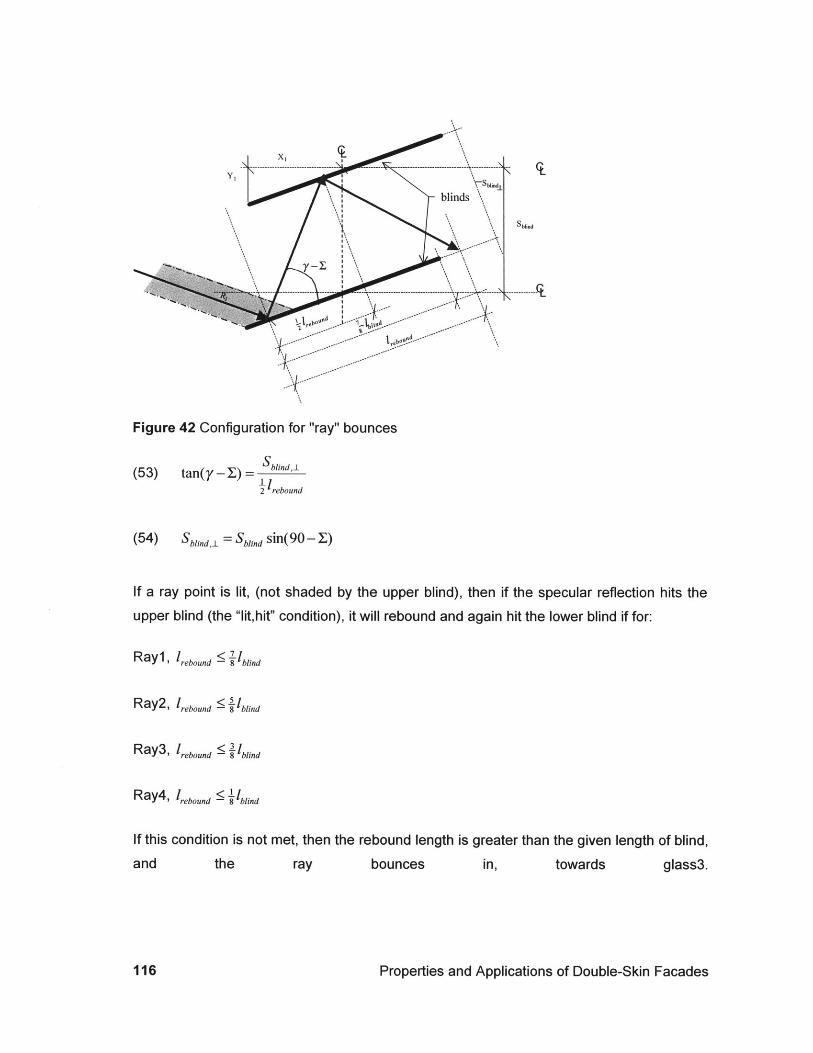
I %
ebo eO~el-
Figure 42 Configuration for "ray" bounces
(53) tan(y -X) = Sblindj
I2 rebound
(54) Sblfld = Sbld sin(90 - Y)
If a ray point is lit, (not shaded by the upper blind), then if the specular reflection hits the
upper blind (the "lit,hit" condition), it will rebound and again hit the lower blind if for:
R ay1,l,,,g 7 1,Ry1'rebound 8blind
R ay2, 1,,,, 11oi,Ra2 rebound 8blind
Ray3, rebound ,blind
R ay4, I,,,, 'bli,,d
If this condition is not
and the
met, then the rebound length is greater than the given length of blind,
ray bounces in, towards glass3.
Properties and Applications of Double-Skin Facades116
4.2.9 Infrared Radiation Heat Transfer
Coefficients for infrared radiation are defined for the inside and outside surfaces of the
system, in terms of the average temperature of the glass surface and the surface to which it
is emitting radiation:
(55) h =4" T3
1 1 6-+ -- 1
E62 Ei
(56) h, = 4-(T,, + 273)3 where Tm
Units are [W/m2K]
T +T= su I
For the cavity, the radiation circuit between three gray bodies is modeled as shown on the
left in (simplified for closed blinds). The circuit for four gray bodies where the emissivity,
area and temperature of rU and rL are equal is shown on the right. (used for open blinds):
117Arons
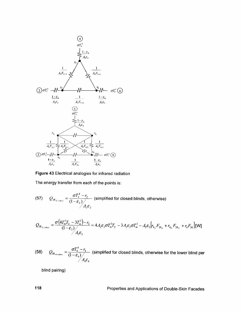
UT4
A2F2 _4 A4F4 _6
aT6 0I_E2 I IC
A282 A2F2 6 A6E6
G0
4E£4
<T 6
1-E,AF 6
I -E6
A6
Figure 43 Electrical analogies for infrared radiation
The energy transfer from each of the points is:
(57) QIR,2-other. 24 -
-(- E2)/ (simplified for closed blinds, otherwise)
a(4T T -3T ,,-r2QIR,2-orers 1 - = 4A2E2 7'T - 3A 2E2 o7T - A2 e2 4 24L + r F24 +roF2 6 r6',2-otheTs (1- r2
(58) QIR,4-oers - 4 (simplified for closed blinds, otherwise for the lower blind per
blind pairing)
Properties and Applications of Double-Skin Facades
@UT2
IA4F,,
118
a (4T3T -3T,,)-r T-A E +rFQIR,L4 -ohe E4T (1-c) T4 -
3 Ady,blind E4T Ady,blind 4 [r2F +rF + rF4 L
Ady,blindE4
and for the upper blind per blind pairing)
=(4T3T -)3T,-3,r -3GR4y -oiners __3 ybln 47T -T 3 Amdy,blind E4 lr2F4,2 + r4 Fu4 + r6F4~QIR,J E4 (1 A u A=,lflc 4AdybinEO*Tm 4 ~3dy blj,dE 4
- tvrF+~EL;L+6~
/AdyblnE4
and for the combination of upper and lower blind,
QIR,4ohers = QIR'4
L -others QIR,4U oIhe,
(59) QIR 6 6 (simplified for closed blinds, otherwise)0--6 E6
QIR.. 6 6T~ ) - 4A2E6oTT 6 - 3A 2E6uT," -4L 64L +Ur4 F +1IR6-others (I - E6 A 6AT L L U6 1+r 6
A2c6
The radiosity for each node is:
(60) r2 = E2UT24 + (1- E2 4 F 24 +r6 F 2 6] (simplified for closed blinds, otherwise)
r2 =E2C(4Tm3T2 -3T+(1-E2r 4LF24L +r F 24 U +r 6F 26]
(61) r4 =E4UT44 +(1-E 4 )[r2F4_2 +r6F4 _6] (simplified for closed blinds, otherwise)
rL= E4a(4TmT 4 -3T )+(1-c 4 )r2F2 +r 4F + r6 F4L6 ]for the lower blind per pair
Arons 119
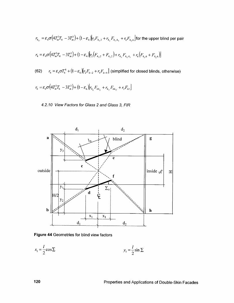
r4 =4 (4T T4 -3T )+(1- 4 ) 2F 2 +r4 Fg4 +r64 6]for the upper blind per pair
U 4TT - 3T,)+ (1 - 4 )('F4,2 + F>L 4),4 Ur =E4C(4 T.T4 - 3T.)+(1 -- 4 )r2(FU2+ F +~r F+r6(F + FL
(62) r = E6dT" + (1- E6 )[r2F6-2 + r4 FE_4] (simplified for closed blinds, otherwise)
6 =E6C(4 T;6 - 3T3 )+ (1 -- 6 )r 4 L F4 + 4 64 +r2F62
4.2.10 View Factors for Glass 2 and Glass 3, FIR
di d2
a VO blind g
Y3
e
outside inside yI I-
dH/2
Y2
b 'h
X1 XI
d d2
Figure 44 Geometries for blind view factors
x =--cosy22
y, =-sin2
Properties and Applications of Double-Skin Facades120

H S2
2 2
bd = (d, - x,)2 + y
fh = (d2 - x,32 + y
ac = (d, - x,)2 + y
eg= (d2 -x 1 2+y
=2 +y1 +X
+ x2]
fg = (d2 - x, )2 + + ) - 2
g= 2 +x,2 + + +y )2 )
1
da = (d, - x, 2 + +S + y,
fh = (d2 - x1 )2 + (Y)2
These geometries can be used with the following relationships to find the view factor for one
blind-to-blind space:
A 2 + Abdh +AachA2F2-bjh = 1
A 2F2-acegA2 + Aaceg + Abdeg
F2-bd +F- 6 +F2-a =12-cg , and combining this with the previous equations gives,
(63) F2 6 I gle
Aac+Ab e -Abdf -Aae=Aac +bdeg -Ab 2 Aaceg for one intra-blind slot, Sblind high or
2A2
Arons 121
-= C 2 - y,
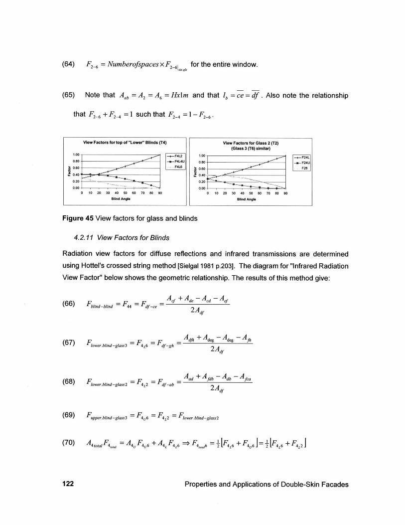
(64) F2-6 = Numberofspaces x F2-e for the entire window.
(65) Note that Aab = A2 = A6 = Hxlm and that lb = ce = df . Also note the relationship
that F2-6 + F2-4 =1 such that F2-4 =1-F2-6 -
Figure 45 View factors for glass and blinds
4.2.11 View Factors for Blinds
Radiation view factors for diffuse reflections and infrared transmissions are determinedusing Hottel's crossed string method [Sielgal 1981 p.203]. The diagram for "Infrared RadiationView Factor" below shows the geometric relationship. The results of this method give:
A, +A -A -A(66) Fbld _blind = F 44 = Fdf ce = de cd ef
2Adf
(67) Flower.blind-glass3 =F 4 L6 =F,_g -
(68) Fower.blind-glass2 =F4L2 =F -a _
Adi+ Adeg -Adeg - A
2Adf
Aad+ Afdb- Adb -Aca
2 Adf
(69) Fupper.bing-gass3 =F46 =F4 = Flower.blind-grass2
(70) AsotaF 4 = A4 F4 6 + A4L F4L => F4 6 = I Lo + F4 6 = 2 [FL + F4L
Properties and Applications of Double-Skin Facades
View Factors for top of "Lower" Blinds (T4)
1.00 -- F4120.80 -.- F4L4U
0.60-FL
n. 0.40
0 20
0.00 T0 10 20 30 40 50 60 70 80 90
Blind Angle
View Factors for Glass 2 (T2)(Glass 3 (T6) similar)
1.00 +F24L0.80 -a-F24U
0.602
,~0.40-
0.20
0.00 b0 10 20 30 40 50 60 70 80 90
Blind Angle
122
(71) F4, = [F4L6 + F46 = L (F4L6 + Fi
(72) F4 =1-F -Ft
4.2.12 Natural Convection: Buoyancy
The net force due to buoyancy created when there is a difference in temperature between
the top and bottom of the cavity is defined by the difference in density of air and by the
pressure loss due to friction at the ends and along the length of the cavity.
(73) FNet = (P + p- gH)As, - PAc, - pave gHA4
(74) FNet = (P- - Pave)gHA, = APNet cs cavity cs
(75) FNet =cavit s entrance + APeit As including entrance and exit effects.
First, we assume that the average temperature along the height of the cavity can be
assumed, then the pressure difference can be found:
(76) Tave -+ Pave : Patm = PaveRTave -> Pave - PatmRTave
P(77) T. -> p P Pp
R(T
(78) APNet o ~P Pave igH
Arons 123
Assuming laminar flow within the cavity, the following relates flow in the cavity to viscosityand pressure:
= 1 ~= -- I12p
APNet
H
3 _ APNetN - -t Qet and the velocity is then:'12pH 12pH
s ]where the properties of air are based on the average temperature as calculated by:
N
(81) Tave = NN
The velocity found in equation (80) above can be plugged into the heat balance equations tofind the resultant temperatures for the related mass flow.
The velocity is given by:
(82) v = = [mpA S
In many studies on the subject of airflow windows, the flow rate is given in m -mthat it is a flow rate per meter of fagade length along the building.calculated in the following manner:
(83) yrh 3600s
p.m h
This quantity can be
h-m
The assumption that the velocity produces laminar flows must be checked against
(84) Retranslam-turb
=10 5 (Fox and McDonald p. 360)LRG Please Check this assumption.
Properties and Applications of Double-Skin Facades
(79) -w
Q 2AP(80) Vave = d Net
A 12paveH
meaning
124

If the Reynolds number indicates turbulent flow, then the cavity can be modeled as a flow
through a smooth pipe with a hydraulic diameter and friction factor (the Blasius correlation):
0.316 e(85) f = smooth pipe assumes that ~ 0.000,001
Re0 25 D
Major head loss due to static pressure and shear is calculated as (from McQuiston and
Parker):
(86) i= fDH
4Acs or 2 Acs
0.3 16(87) f = R0 1
Re 02
-2V
2g
H ii2
f -where8d, g
DH = 4Acsw
and LRG Please check, if this is
(Equation 8.38 from Fox and McDonald)
(88) Re= H _)H
(89) AP = pg',
0.03
0.025
Transtionzone--441
103 2
I 1 111111 fillI ~LI III II
IIIIII~II
0.0080*006
0.004
0.002
0.001 90 *00080.00060.0004
0.0002
0.000,05
lill1 IlI i I i ~ li | ii I II I11 i i -1 I I I . -.. I iTti44 n-on0.00m
3 4 56 810* 2 3 4 56 810 2 3 456 81 2 3 456 810 8105
Reynolds number, Re = P V = 0.000,001 - y 0.000,005
Figure 46: Moody Chart from Fox and McDonald
Arons 125
- i
nflA
U.U10
1, . . ,, I I 1 0000i H i i i i i I . .. . I i i i i H i i I I .. , , I .. . - . . . .- - , - - -
tt.--': flow
L--L-t---
4.3 Desired Output
4.3.1a ROOM IMPACTS
y=H
(90) Qcavi room = qA = T7 T T" dy +y= +h7 h
W 2W] = 2 m =
IM
y=H H(TT H
q, Adydy - 1 Ay(lm) + I qrT1 r 2F 1 T3 Adf- + 0y=0 0
h7 hr7i
lK W 2I mQlm) + 2 m2
W/
/M2 -K
4.3.1b HVAC IMPACTS
The amount of energy exhausted from the window (to the duct, or outside) is:
(91) QDuct - i Cp i v=h y=0 3) = (yhz + fh1)C, (Tv=h Tv=0
4.3.1c EFFECTIVE U-VALUE
An effective U-value may be defined that represents the U-value that is experienced by theoccupied side of the fagade, disregarding the heat flow to the duct. The overall heat flow atsteady state is:
(92) Qcav,,,_out,,de + Qcavit_room + QDuct = 0 and the effective U-value can be defined as:
(93) Qcavitv-room =UeffAindodw(Tut - T n Ueff - "A'i'*dOW -
4.3.1d SOLAR HEAT GAIN COEFFICIENT
qwhole-window W
(94) SHGC- qroom - Aindow / M2
qincident qsolar-incident W
Properties and Applications of Double-Skin Facades126
4.3.2 Glossary of Terms
Term Description
Tur Temperature of surrounding surfaces including the sky.
Tu Temperature of outdoor air.
T2 Temperature of surface or location i (T3 and T are air temperatures)OC
T, Temperature of indoor air. C h, Convective heat transfer coefficient. W/(m2K)
Coefficient of radiation heat transfer from a to b
RDGU Resistance of double glass unit.
Resistance of air gap (including radiation and convection) within
double glass unit.
Absorbed solar radiation on surface i.
q,. Incident solar radiation normal to outside face of building.
a'Y -Absorptivity of surface i (for each layer of glass in the system)
in the direction j where j=1 for front, 2 for back. Dimensionless
-Reflectivity of surface i (for each layer of glass in the system)
in the direction j where j=1 for front, 2 for back. Dimensionless
-Transmissivity of surface i i(for each layer of glass in the system)
in the direction j where j=1 for front, 2 for back.
F,,, Configuration Factor of blinds relative to solar radiation
Dimensionless
Dimensionless
Arons
Units
0C
0C
RaP
W /(m 2K)
KIW
Qai
KIW
W/m 2
127
FR Configuration Factor of blinds relative to infrared radiation
a- Stefan-Boltzmann constant
Density of air
cP Specific heat of air
rhi Mass flow rate of channel i of air
k w-Conductivity of glass
/ ~-thickness of glass
'blind w-length of the blind (from front to back)
w -width of blind or window along fagade (z axis)
Sbld *-vertical center to center spacing of blinds
H -vertical extent (unimpeded height) of the window cavity.
Ay height of a control volume for an energy balance
A Aor .'
Ady,blind
Dimensionless
W /(m2K 4 )
kg/m 3
J / kgK
kg /s
W/mK
Cross-sectional area of vertical segment: Typically Az = 1 m deep by Ay high
m2
Area along length of blind per vertical segment Ay high mr2
do clear space between panes in double glazed unit mm
di clear space between face of glass 2 (T2) and centerline of blinds m
d2 clear space between centerline of blinds and face of glass 3 (T6) m
Properties and Applications of Double-Skin Facades128
E4 emissivity of blind material dimensionless
p4 reflectivity of blind material dimensionless
a 4 absorptivity of blind material dimensionless
1 4 angle of blinds degrees
forced or natural convection binary
v, or V velocity or (volumetric flow rate) of airflow in each side of the channel m/s
or (m3/hr.m)
vented from inside or outside binary
Arons 129

4.4 Troubleshooting methodology
The model has been tested extensively element-by-element to verify that it gives logical andreasonable results. Each element has been isolated in turn so that only those attributes ofthe model that relate to the particular aspect of interest will have a significant impact on theresults. Once isolated, the module of interest was then scrutinized and refined. Anyrequired changes were then made to the base model as well.
This troubleshooting methodology served to ensure that the model is working as designed.This verification is different from validating the model. The goal of validation is to comparethe analytical model to the physical world to show that the model is reasonably accurate.The verification process shows that the computational model works as intended, andmatches the mathematical relationships outlined in the simplified model (as described abovein this chapter). Verification includes the understanding that assumptions are made in thedefinition of the mathematical model that will be inherent in the tool results.
4.4.1 Temperature Difference Verification
To evaluate the U-value of the system, solar radiation is eliminated and mass flow isminimized. The driving force for the energy is then the difference in temperature betweenthe inside and outside of the window. To test that the model handles this heat transfereffectively, we compare the temperature distribution in the window given by the worksheetmodel to a simplified calculation. The inlet temperature is set to 19.3 as per the model ofSaelens and Hens [Saelens and Hens 1998]. The winter condition of outside temperature,Tout is 0 degrees Celsius, and indoor temperature Tin is 20 degrees Celsius. To focus onthe driving force of this temperature differential, the airflow is set as low as possible. Theairflow is mixed so that 90 % of the mass flow is to the outside cavity, (T3) and 10% is to theinner cavity (T5). The blind angle is 90 degrees (closed). The mass flow rate is 0.0009 kg/sper meter of fagade. The resultant velocities are v3=0.0135 m/s and v5=0.0035 m/s for theouter and inner cavities respectively.
The model runs into difficulty with evaluating very low mass flow rates (in the order of0.0005- 0.0008 kg/s) because the delta T in the channel is defined relative to the inverse ofthe mass flow rate (equations 13a and 15a):
Properties and Applications of Double-Skin Facades130
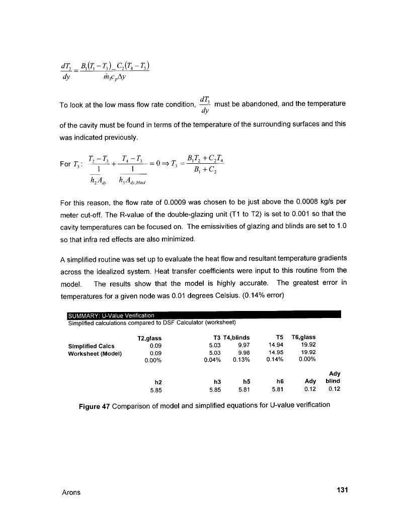
dT B,( - T3) C2 (T4 -T 3 )
dy rh3cAy
dTTo look at the low mass flow rate condition, 3 must be abandoned, and the temperature
dy
of the cavity must be found in terms of the temperature of the surrounding surfaces and this
was indicated previously.
T -T. T -T BT+C2T4ForT3 : 2 + 4 3 = > T3 12 24
3 1 1 + C2
h2 A dv h3 Avblind
For this reason, the flow rate of 0.0009 was chosen to be just above the 0.0008 kg/s per
meter cut-off. The R-value of the double-glazing unit (T1 to T2) is set to 0.001 so that the
cavity temperatures can be focused on. The emissivities of glazing and blinds are set to 1.0
so that infra red effects are also minimized.
A simplified routine was set up to evaluate the heat flow and resultant temperature gradients
across the idealized system. Heat transfer coefficients were input to this routine from the
model. The results show that the model is highly accurate. The greatest error in
temperatures for a given node was 0.01 degrees Celsius. (0.14% error)
A
SUMMARY: U-Value Verification
Simplified calculations compared to DSF Calculator (worksheet)
T2,glass T3 T4,blinds T5 T6,glassSimplified Calcs 0.09 5.03 9.97 14.94 19.92Worksheet (Model) 0.09 5.03 9.98 14.95 19.92
0.00% 0.04% 0.13% 0.14% 0.00%
Adyh2 h3 h5 h6 Ady blind
5.85 5.85 5.81 5.81 0.12 0.12
Figure 47 Comparison of model and simplified equations for U-value verification
131/Arons
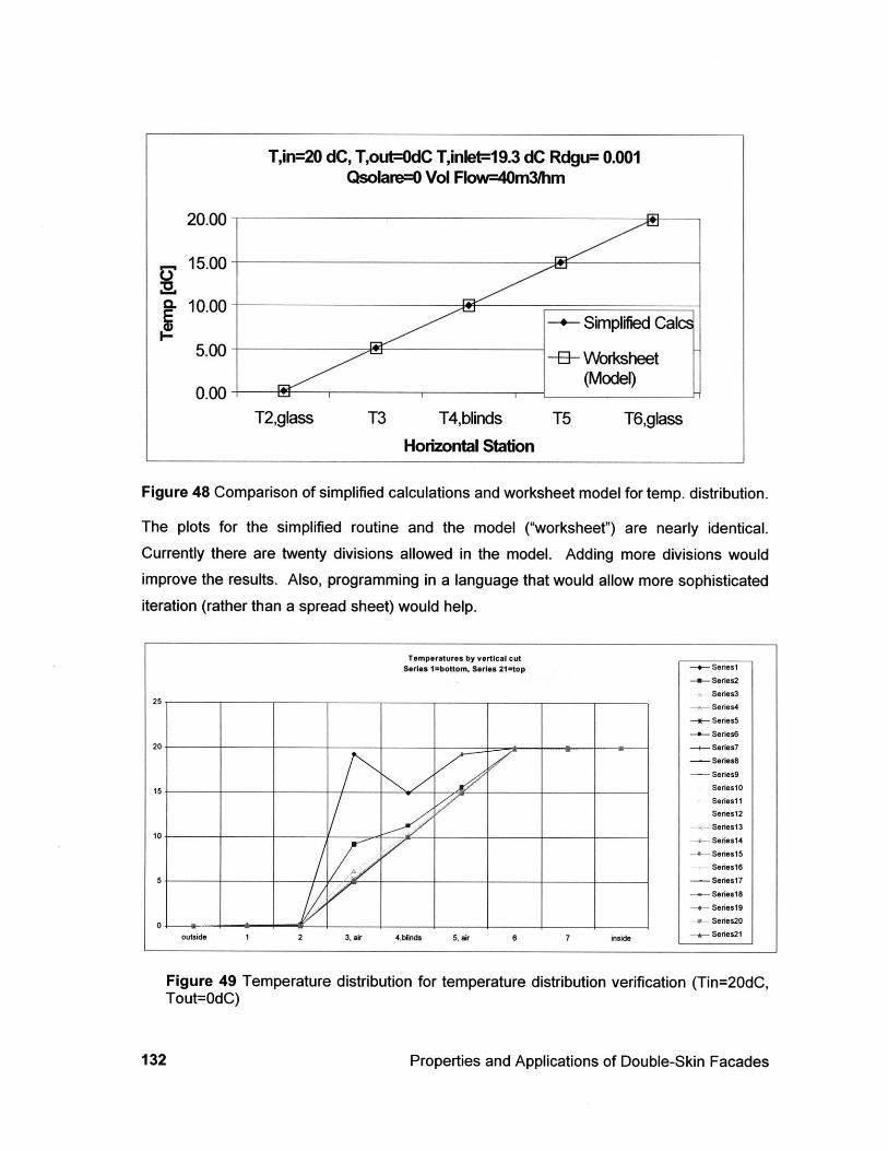
T,in=20 dC, Tout=OdC Tinlet=19.3 dC Rdgu= 0.001Qsolare=0 Vol Flow=4Om3/hm
T3 T4,blinds
Horizontal Station
-+- Simplified Calc
-1-- Worksheet(Model)
T5 T6,glass
Figure 48 Comparison of simplified calculations and worksheet model for temp. distribution.
The plots for the simplified routine and the model ("worksheet") are nearly identical.Currently there are twenty divisions allowed in the model. Adding more divisions wouldimprove the results. Also, programming in a language that would allow more sophisticatediteration (rather than a spread sheet) would help.
Temperatures by vertical cutSeries 1=bottom, Series 21=top --- Series1
--- Series2
Series325-
Series4
--- Series5
-0- Series6
20 .. . -+- Seres7
- Series8- Series9
15- Series1O
Seriesi1
Series12
Series1310 -- Series14
-4 Series15
Series16
5- Series17
Seriesl8
+- Series19
0- m-Series20outside 1 2 3, air 4,blinds 5, air 6 7 inside - Series21
Figure 49 Temperature distribution for temperature distribution verification (Tin=20dC,Tout=0dC)
Properties and Applications of Double-Skin Facades
20.00
15.00
10.00
5.00
0.00T2,glass
132
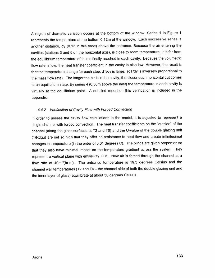
A region of dramatic variation occurs at the bottom of the window. Series 1 in Figure 1
represents the temperature at the bottom 0.12m of the window. Each successive series is
another distance, dy (0.12 in this case) above the entrance. Because the air entering the
cavities (stations 3 and 5 on the horizontal axis), is close to room temperature, it is far from
the equilibrium temperature of that is finally reached in each cavity. Because the volumetric
flow rate is low, the heat transfer coefficient in the cavity is also low. However, the result is
that the temperature change for each step, dT/dy is large. (dT/dy is inversely proportional to
the mass flow rate). The longer the air is in the cavity, the closer each horizontal cut comes
to an equilibrium state. By series 4 (0.36m above the inlet) the temperature in each cavity is
virtually at the equilibrium point. A detailed report on this verification is included in the
appendix.
4.4.2 Verification of Cavity Flow with Forced Convection
In order to assess the cavity flow calculations in the model, it is adjusted to represent a
single channel with forced convection. The heat transfer coefficients on the "outside" of the
channel (along the glass surfaces at T2 and T6) and the U-value of the double glazing unit
(1/Rdgu) are set so high that they offer no resistance to heat flow and create infinitesimal
changes in temperature (in the order of 0.01 degrees C). The blinds are given properties so
that they also have minimal impact on the temperature gradient across the system. They
represent a vertical plane with emissivity .001. Now air is forced through the channel at a
flow rate of 40m 3/(hr-m). The entrance temperature is 19.3 degrees Celsius and the
channel wall temperatures (T2 and T6 - the channel side of both the double glazing unit and
the inner layer of glass) equilibrate at about 30 degrees Celsius.
Arons 133
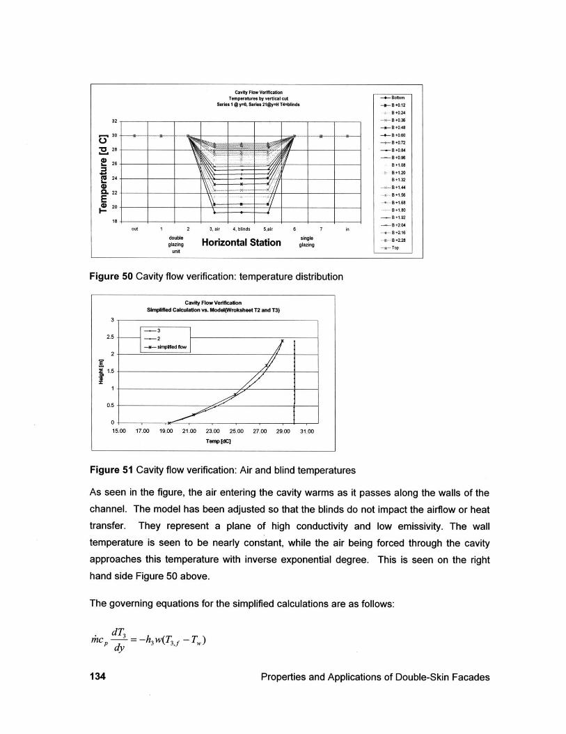
Figure 50 Cavity flow verification: temperature distribution
Cavity Flow VerificationSimplified Calculation vs. Model(Wroksheet T2 and T3)
3
-- 32.5 -- -2
-W smpifie flow
.5X
0.5
0
15.00 17.00 19.00 21.00 23.00 25.00 27.00 29.00 31.00
Temp [dC)
Figure 51 Cavity flow verification: Air and blind temperatures
As seen in the figure, the air entering the cavity warms as it passes along the walls of thechannel. The model has been adjusted so that the blinds do not impact the airflow or heattransfer. They represent a plane of high conductivity and low emissivity. The wall
temperature is seen to be nearly constant, while the air being forced through the cavity
approaches this temperature with inverse exponential degree. This is seen on the righthand side Figure 50 above.
The governing equations for the simplified calculations are as follows:
dT3dhc 3 = -h 3w(T 3 f -T,)dy
Properties and Applications of Double-Skin Facades
Cavity Flow VerificationTemperatures by vertical cut - Bottom
Series 1 a y=O, Series 21@y=H T4=blinds B+0.12B +0.24
32 -___ B___ +0.36_
30-a B +0.48
(~ -i-B+0.727- 0 28 -Ji.8
~2B -B .96
~ 28B +1.08
.0 B +1.201! 24 -Bl 132
0. 22 -+ +1.56E
20 B+1.0
18 ________ --B .2i04out 1 2 3, air 4, blinds 5,air 6 7 in
glen Horizontal Station ga'Tunit
134
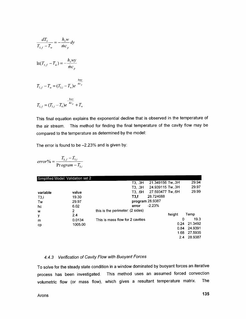
ln(Tf -Tn,)
T3,7 -T, = (T, - T)e
hwv
T3,f =(T3,i-T 4)e c" + T,
This final equation explains the exponential decline that is observed in the temperature of
the air stream. This method for finding the final temperature of the cavity flow may be
compared to the temperature as determined by the model:
The error is found to be -2.23% and is given by:
error% =Program - T
Simplified Model: Validation set 2
value19.3029.976.0222.40.01341005.00
T3, .3H 21.349156 Tw,.3HT3,.3H 24.939115 Tw,.3HT3, .6H 27.593477 Tw,.6HT3,f 28.724088program 28.9387error -2.23%
this is the perimeter: (2 sides)
This is mass flow for 2 cavities
29.9429.9729.99
height Temp0 19.3
0.24 21.34920.84 24.93911.68 27.59352.4 28.9387
4.4.3 Verification of Cavity Flow with Buoyant Forces
To solve for the steady state condition in a
process has been investigated. This
volumetric flow (or mass flow), which
window dominated by buoyant forces an iterative
method uses an assumed forced convection
gives a resultant temperature matrix. The
Arons
dT h~w d=- dy
T3,f - Tw c
h3 c
ljlcp
variableT3,iTwhcwymcp
135
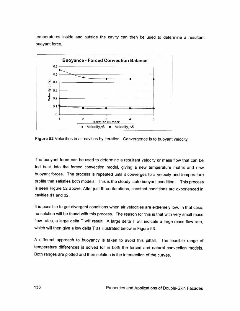
temperatures inside and outside the cavity can then be used to determine a resultantbuoyant force.
Figure 52 Velocities in air cavities by iteration. Convergence is to buoyant velocity.
The buoyant force can be used to determine a resultant velocity or mass flow that can befed back into the forced convection model, giving a new temperature matrix and newbuoyant forces. The process is repeated until it converges to a velocity and temperatureprofile that satisfies both models. This is the steady state buoyant condition. This processis seen Figure 52 above. After just three iterations, constant conditions are experienced incavities dl and d2.
It is possible to get divergent conditions when air velocities are extremely low. In that case,no solution will be found with this process. The reason for this is that with very small massflow rates, a large delta T will result. A large delta T will indicate a large mass flow rate,which will then give a low delta T as illustrated below in Figure 53.
A different approach to buoyancy is taken to avoid this pitfall. The feasible range oftemperature differences is solved for in both the forced and natural convection models.Both ranges are plotted and their solution is the intersection of the curves.
Properties and Applications of Double-Skin Facades
Buoyance - Forced Convection Balance0.6
0.5
2 0.4 -E
0.3 -
0.2
0.1
0-
1 2 3 4 5Iteration Number
-- Velocity,v3 -a- Velocity, v5
136
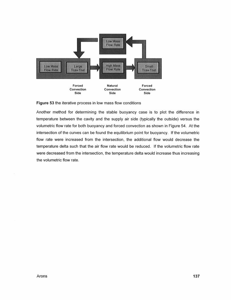
Forced Natural ForcedConvection Convection Convection
Side Side Side
Figure 53 the iterative process in low mass flow conditions
Another method for determining the stable buoyancy case is to plot the difference in
temperature between the cavity and the supply air side (typically the outside) versus the
volumetric flow rate for both buoyancy and forced convection as shown in Figure 54. At the
intersection of the curves can be found the equilibrium point for buoyancy. If the volumetric
flow rate were increased from the intersection, the additional flow would decrease the
temperature delta such that the air flow rate would be reduced. If the volumetric flow rate
were decreased from the intersection, the temperature delta would increase thus increasing
the volumetric flow rate.
Arons 137
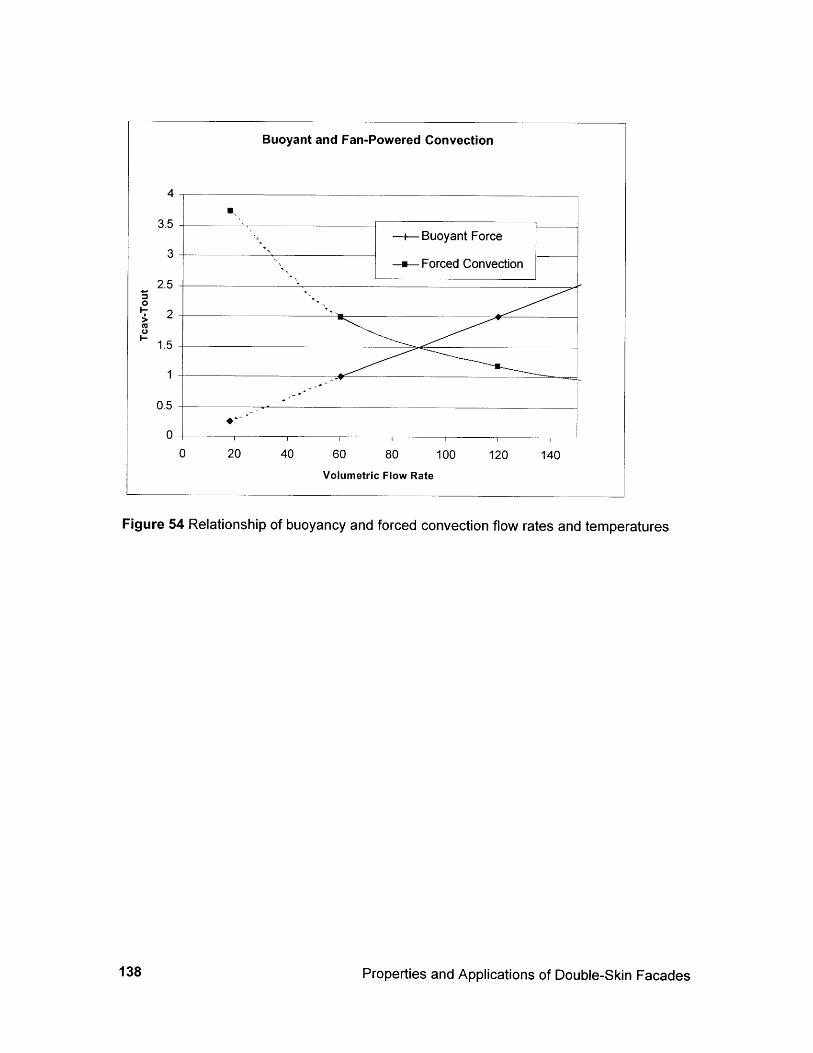
Buoyant and Fan-Powered Convection
4
3.5 ---+ Buoyant Force
3-- Forced Convection
2.50
2
1.5
1
0.5
00 20 40 60 80 100 120 140
Volumetric Flow Rate
Figure 54 Relationship of buoyancy and forced convection flow rates and temperatures
138 Properties and Applications of Double-Skin Facades
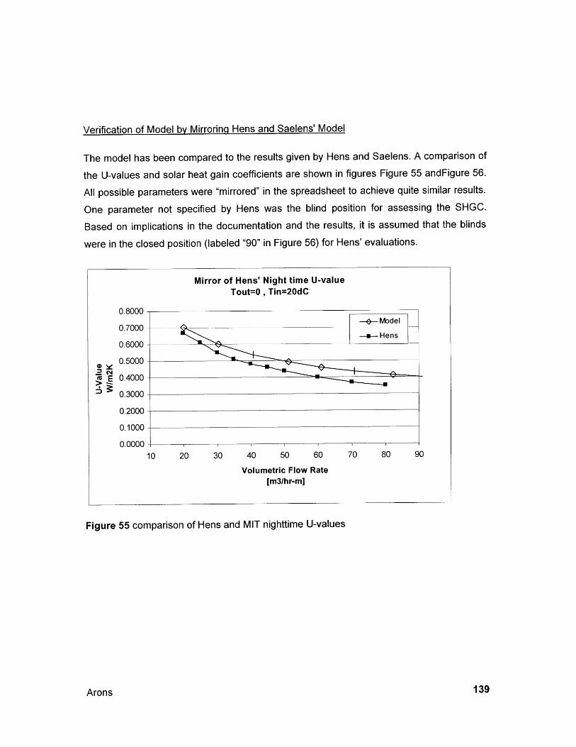
Verification of Model by Mirrorinq Hens and Saelens' Model
The model has been compared to the results given by Hens and Saelens. A comparison of
the U-values and solar heat gain coefficients are shown in figures Figure 55 andFigure 56.
All possible parameters were "mirrored" in the spreadsheet to achieve quite similar results.
One parameter not specified by Hens was the blind position for assessing the SHGC.
Based on implications in the documentation and the results, it is assumed that the blinds
were in the closed position (labeled "90" in Figure 56) for Hens' evaluations.
Figure 55 comparison of Hens and MIT nighttime U-values
Arons 139
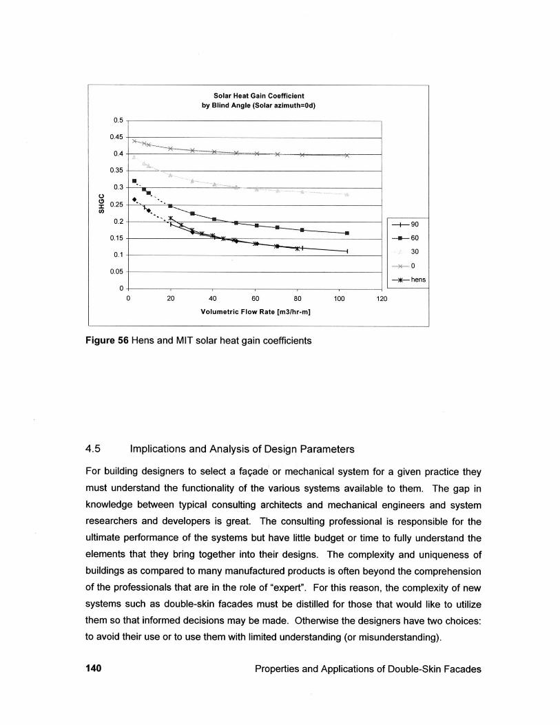
Solar Heat Gain Coefficientby Blind Angle (Solar azimuth=Od)
0.5
0.45
0.4
0.35
U0.3
0.25
0.2 90
0.15 60
0.1 30
-,-00.05
- hens0
0 20 40 60 80 100 120
Volumetric Flow Rate [m3/hr-m]
Figure 56 Hens and MIT solar heat gain coefficients
4.5 Implications and Analysis of Design Parameters
For building designers to select a fagade or mechanical system for a given practice they
must understand the functionality of the various systems available to them. The gap inknowledge between typical consulting architects and mechanical engineers and systemresearchers and developers is great. The consulting professional is responsible for the
ultimate performance of the systems but have little budget or time to fully understand the
elements that they bring together into their designs. The complexity and uniqueness ofbuildings as compared to many manufactured products is often beyond the comprehensionof the professionals that are in the role of "expert". For this reason, the complexity of newsystems such as double-skin facades must be distilled for those that would like to utilizethem so that informed decisions may be made. Otherwise the designers have two choices:to avoid their use or to use them with limited understanding (or misunderstanding).
Properties and Applications of Double-Skin Facades140
4.5.1 Parameters and Properties
The full complexity of the system is summarized so that it can then be distilled into
something useful. The simplified numerical model is useful in understanding that there are
many parameters for the design of double-skin fagade. A multitude of parameters must be
input in order to get results for the energy flows through the fagade. These include the
following:
e Spatial aspects
o The depth of the cavity
o The height of the window
o Forced or natural convection.
e Controls
o Individual control of blinds and
operable windows.* Glazing properties
o The emissivity, trans-missivity,
reflectivity and absorptivity of each
pane.
* Thermal and structural qualities of
frames (not included in the model)
* The location of mullions
* Blind properties
o Location dimensions
spacing.
o Emissivity, absorptivity
reflectivity of the material
and
and
o Building control
windows and fans.
of blinds,
* Interaction with other systems such as
mass storage and air supply/exhaust
(not included in the model)
* The configuration and inter-
relationship of other mechanical
components -- ducts, fans and
controls
. The overall color and visual reflectivity
of the system (not included in the
model)
* Air movement path
o Inlet to the inside or outside
The model is meant to be a preliminary aid in designing buildings with airflow facades. As
the list of parameters suggests, there is a large number of them to consider when setting out
Arons 141
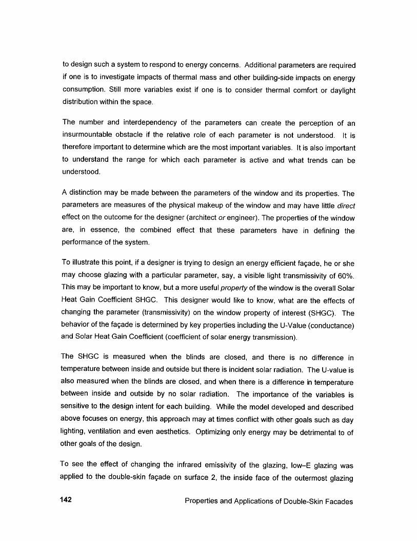
to design such a system to respond to energy concerns. Additional parameters are requiredif one is to investigate impacts of thermal mass and other building-side impacts on energyconsumption. Still more variables exist if one is to consider thermal comfort or daylightdistribution within the space.
The number and interdependency of the parameters can create the perception of aninsurmountable obstacle if the relative role of each parameter is not understood. It istherefore important to determine which are the most important variables. It is also importantto understand the range for which each parameter is active and what trends can beunderstood.
A distinction may be made between the parameters of the window and its properties. Theparameters are measures of the physical makeup of the window and may have little directeffect on the outcome for the designer (architect or engineer). The properties of the windoware, in essence, the combined effect that these parameters have in defining theperformance of the system.
To illustrate this point, if a designer is trying to design an energy efficient fagade, he or shemay choose glazing with a particular parameter, say, a visible light transmissivity of 60%.This may be important to know, but a more useful property of the window is the overall SolarHeat Gain Coefficient SHGC. This designer would like to know, what are the effects ofchanging the parameter (transmissivity) on the window property of interest (SHGC). Thebehavior of the fagade is determined by key properties including the U-Value (conductance)and Solar Heat Gain Coefficient (coefficient of solar energy transmission).
The SHGC is measured when the blinds are closed, and there is no difference intemperature between inside and outside but there is incident solar radiation. The U-value isalso measured when the blinds are closed, and when there is a difference in temperaturebetween inside and outside by no solar radiation. The importance of the variables issensitive to the design intent for each building. While the model developed and describedabove focuses on energy, this approach may at times conflict with other goals such as daylighting, ventilation and even aesthetics. Optimizing only energy may be detrimental to ofother goals of the design.
To see the effect of changing the infrared emissivity of the glazing, low-E glazing wasapplied to the double-skin fagade on surface 2, the inside face of the outermost glazing
Properties and Applications of Double-Skin Facades142
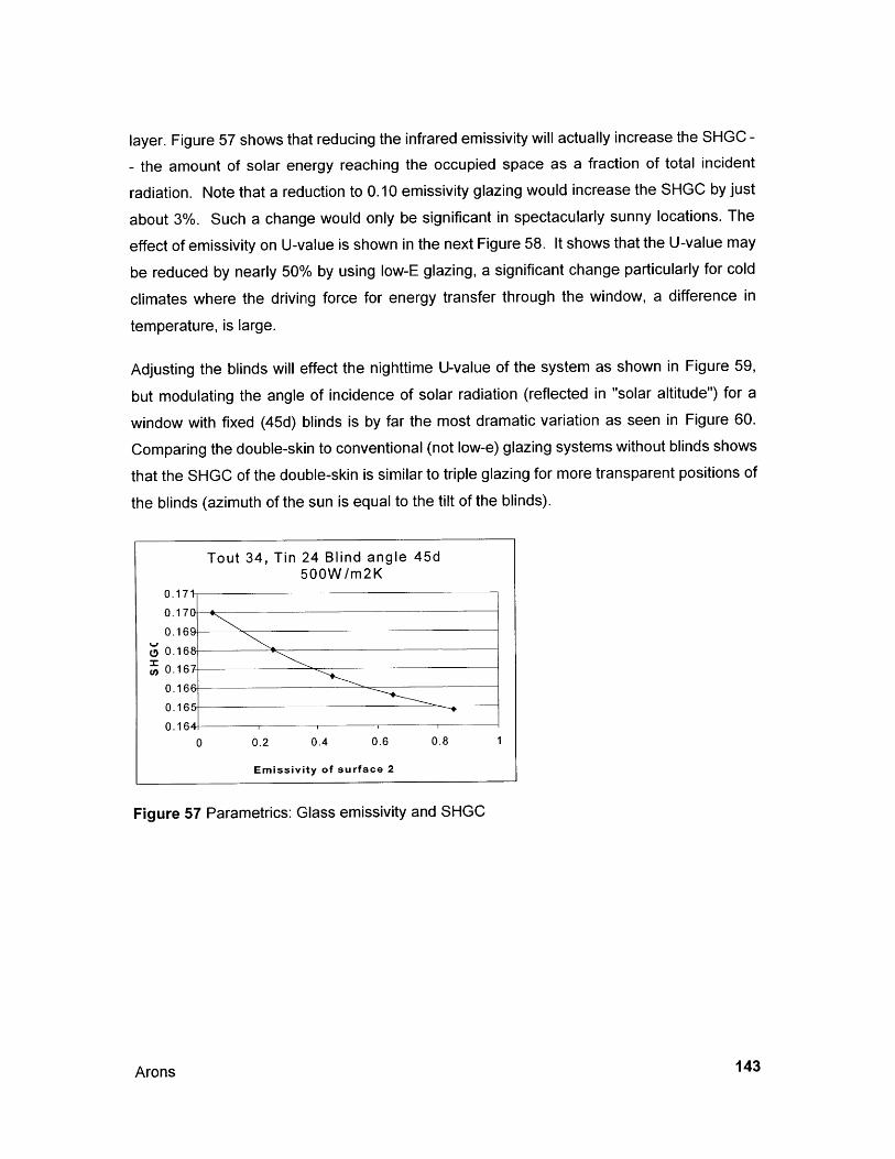
layer. Figure 57 shows that reducing the infrared emissivity will actually increase the SHGC -
- the amount of solar energy reaching the occupied space as a fraction of total incident
radiation. Note that a reduction to 0.10 emissivity glazing would increase the SHGC by just
about 3%. Such a change would only be significant in spectacularly sunny locations. The
effect of emissivity on U-value is shown in the next Figure 58. It shows that the U-value may
be reduced by nearly 50% by using low-E glazing, a significant change particularly for cold
climates where the driving force for energy transfer through the window, a difference in
temperature, is large.
Adjusting the blinds will effect the nighttime U-value of the system as shown in Figure 59,
but modulating the angle of incidence of solar radiation (reflected in "solar altitude") for a
window with fixed (45d) blinds is by far the most dramatic variation as seen in Figure 60.
Comparing the double-skin to conventional (not low-e) glazing systems without blinds shows
that the SHGC of the double-skin is similar to triple glazing for more transparent positions of
the blinds (azimuth of the sun is equal to the tilt of the blinds).
Tout 34, Tin 24 Blind angle 45d500W/m2K
0.171-
0.170
0.167
0.16C
un 0.167
0.1668
0.165
0.1640 0.2 0.4 0.6 0.8 1
Emissivity of surface 2
Figure 57 Parametrics: Glass emissivity and SHGC
Arons 143
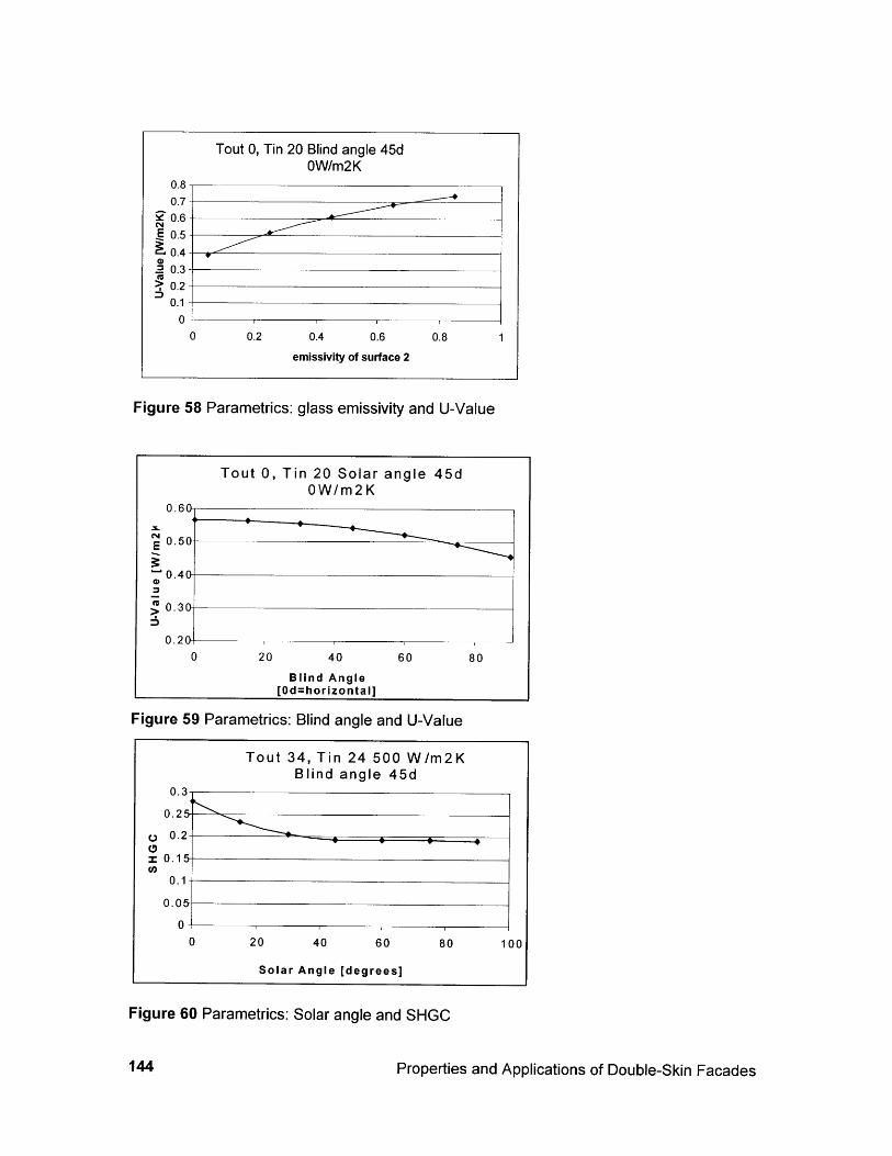
Figure 58 Parametrics: glass emissivity and U-Value
Tout 0, Tin 20 Solar angle 45dOW/m2K
0.60
0.50
0.40-
0.30
0.20-0 20 40 60 80
Blind Angle[Od=horizontal]
Figure 59 Parametrics: Blind angle and U-Value
Tout 34, Tin 24 500 W/m2KBlind angle 45d
0.3
0.25
0. 2 -
z 0.15
0.1
0.05
00 20 40 60 80 100
Solar Angle [degrees]
Figure 60 Parametrics: Solar angle and SHGC
144 Properties and Applications of Double-Skin Facades
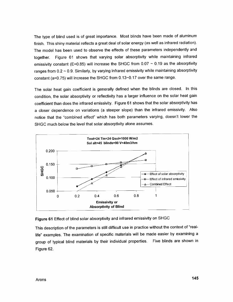
The type of blind used is of great importance. Most blinds have been made of aluminum
finish. This shiny material reflects a great deal of solar energy (as well as infrared radiation).
The model has been used to observe the effects of these parameters independently and
together. Figure 61 shows that varying solar absorptivity while maintaining infrared
emissivity constant (E=0.85) will increase the SHGC from 0.07 ~ 0.19 as the absorptivity
ranges from 0.2 ~ 0.9. Similarly, by varying infrared emissivity while maintaining absorptivity
constant (a=0.75) will increase the SHGC from 0.13-0.17 over the same range.
The solar heat gain coefficient is generally defined when the blinds are closed. In this
condition, the solar absorptivity or reflectivity has a larger influence on the solar heat gain
coefficient than does the infrared emissivity. Figure 61 shows that the solar absorptivity has
a closer dependence on variations (a steeper slope) than the infrared emissivity. Also
notice that the "combined effect" which has both parameters varying, doesn't lower the
SHGC much below the level that solar absorptivity alone assumes.
Tout=24 Tin=24 Qsol=1000 W/m2Sol alt=45 blinds=90 V=40m3/hm
0.200
0.150 -
Cn 0.100-+- Effect of solar absorptivity0.100Effect of infrared emissivity
0.050 Co mnIbined Effe ct
0.0500 0.2 0.4 0.6 0.8 1
Emissivity orAbsorptivity of Blind
Figure 61 Effect of blind solar absorptivity and infrared emissivity on SHGC
This description of the parameters is still difficult use in practice without the context of "real-
life" examples. The examination of specific materials will be made easier by examining a
group of typical blind materials by their individual properties. Five blinds are shown in
Figure 62.
Arons 145
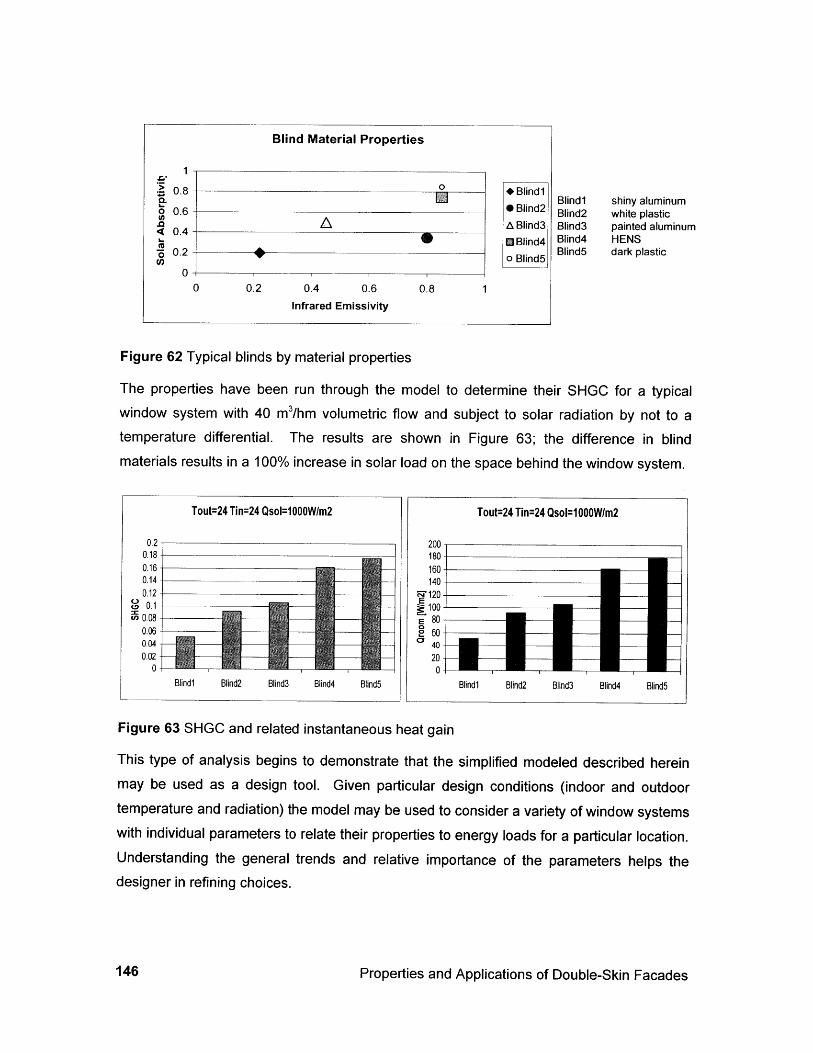
Blind Material Properties
Blind1Blind2Blind3Blind4Blind5
shiny aluminumwhite plasticpainted aluminumHENSdark plastic
Figure 62 Typical blinds by material properties
The properties have been run through the model to determine their SHGC for a typicalwindow system with 40 m3/hm volumetric flow and subject to solar radiation by not to atemperature differential. The results are shown in Figure 63; the difference in blindmaterials results in a 100% increase in solar load on the space behind the window system.
Figure 63 SHGC and related instantaneous heat gain
This type of analysis begins to demonstrate that the simplified modeled described hereinmay be used as a design tool. Given particular design conditions (indoor and outdoortemperature and radiation) the model may be used to consider a variety of window systemswith individual parameters to relate their properties to energy loads for a particular location.Understanding the general trends and relative importance of the parameters helps thedesigner in refining choices.
Properties and Applications of Double-Skin Facades
1
0.8 0 Blind1
0 0.6 0 Blind2A.4A Blind3
0 Blind4n0.2 0 Blind5
00 0.2 0.4 0.6 0.8 1
Infrared Emissivity
146
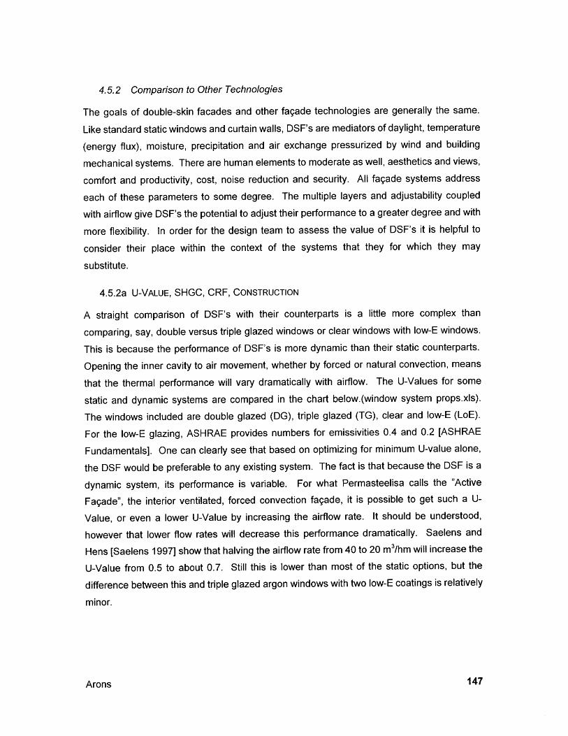
4.5.2 Comparison to Other Technologies
The goals of double-skin facades and other fagade technologies are generally the same.
Like standard static windows and curtain walls, DSF's are mediators of daylight, temperature
(energy flux), moisture, precipitation and air exchange pressurized by wind and building
mechanical systems. There are human elements to moderate as well, aesthetics and views,
comfort and productivity, cost, noise reduction and security. All fagade systems address
each of these parameters to some degree. The multiple layers and adjustability coupled
with airflow give DSF's the potential to adjust their performance to a greater degree and with
more flexibility. In order for the design team to assess the value of DSF's it is helpful to
consider their place within the context of the systems that they for which they may
substitute.
4.5.2a U-VALUE, SHGC, CRF, CONSTRUCTION
A straight comparison of DSF's with their counterparts is a little more complex than
comparing, say, double versus triple glazed windows or clear windows with low-E windows.
This is because the performance of DSF's is more dynamic than their static counterparts.
Opening the inner cavity to air movement, whether by forced or natural convection, means
that the thermal performance will vary dramatically with airflow. The U-Values for some
static and dynamic systems are compared in the chart below.(window system props.xs).
The windows included are double glazed (DG), triple glazed (TG), clear and low-E (LoE).
For the low-E glazing, ASHRAE provides numbers for emissivities 0.4 and 0.2 [ASHRAE
Fundamentals]. One can clearly see that based on optimizing for minimum U-value alone,
the DSF would be preferable to any existing system. The fact is that because the DSF is a
dynamic system, its performance is variable. For what Permasteelisa calls the "Active
Fagade", the interior ventilated, forced convection fagade, it is possible to get such a U-
Value, or even a lower U-Value by increasing the airflow rate. It should be understood,
however that lower flow rates will decrease this performance dramatically. Saelens and
Hens [Saelens 1997] show that halving the airflow rate from 40 to 20 m3/hm will increase the
U-Value from 0.5 to about 0.7. Still this is lower than most of the static options, but the
difference between this and triple glazed argon windows with two low-E coatings is relatively
minor.
Arons 147
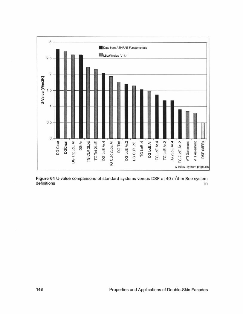
Data from ASHRAE Fundamentals
LBLJWindow V 4.12.5-
2-
1.5-
0.5-
0
M <- 0(90 < 00 <0 0 ~J ,
0 0 HR w 00H ~ 0
-w indow system props.xs
Figure 64 U-value comparisons of standard systems versus DSF at 40 m3/hm See systemdefinitions in
Properties and Applications of Double-Skin Facades148
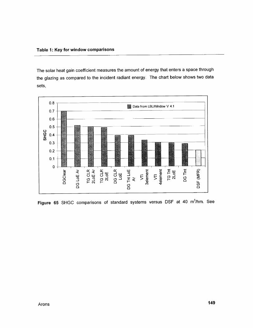
Table 1: Key for window comparisons
The solar heat gain coefficient measures the amount of energy that enters a space through
the glazing as compared to the incident radiant energy. The chart below shows two data
sets,
Figure 65 SHGC comparisons of standard systems versus DSF at 40 m3/hm. See
Arons 149
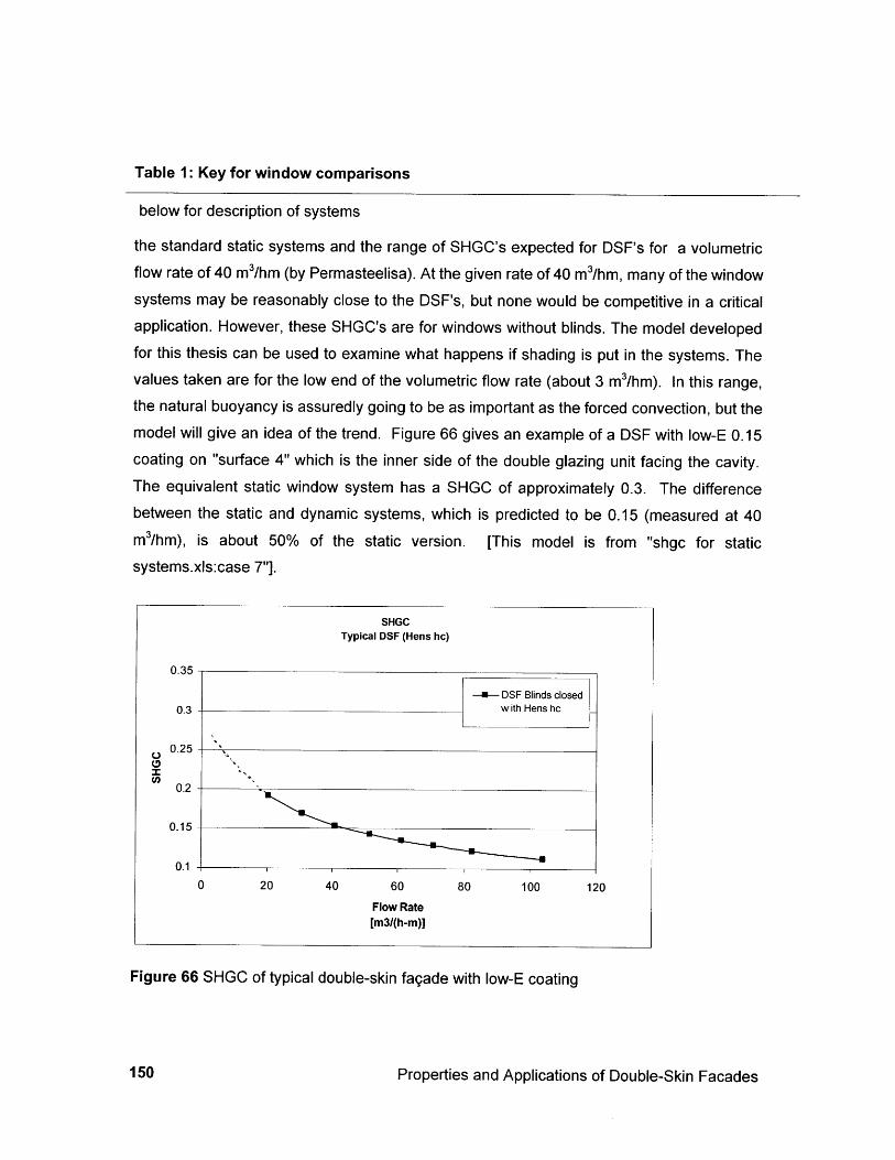
Table 1: Key for window comparisons
below for description of systems
the standard static systems and the range of SHGC's expected for DSF's for a volumetricflow rate of 40 m3/hm (by Permasteelisa). At the given rate of 40 m3/hm, many of the windowsystems may be reasonably close to the DSF's, but none would be competitive in a criticalapplication. However, these SHGC's are for windows without blinds. The model developedfor this thesis can be used to examine what happens if shading is put in the systems. Thevalues taken are for the low end of the volumetric flow rate (about 3 m3/hm). In this range,the natural buoyancy is assuredly going to be as important as the forced convection, but themodel will give an idea of the trend. Figure 66 gives an example of a DSF with low-E 0.15coating on "surface 4" which is the inner side of the double glazing unit facing the cavity.The equivalent static window system has a SHGC of approximately 0.3. The differencebetween the static and dynamic systems, which is predicted to be 0.15 (measured at 40m3/hm), is about 50% of the static version. [This model is from "shgc for staticsystems.xls:case 7"].
SHGCTypical DSF (Hens hc)
0.35
- DSF Blinds closed0.3 with Hens hc
0.25
0.2 '
0.15
0.1
0 20 40 60 80 100 120
Flow Rate[m3/(h-m)]
Figure 66 SHGC of typical double-skin fagade with low-E coating
Properties and Applications of Double-Skin Facades150
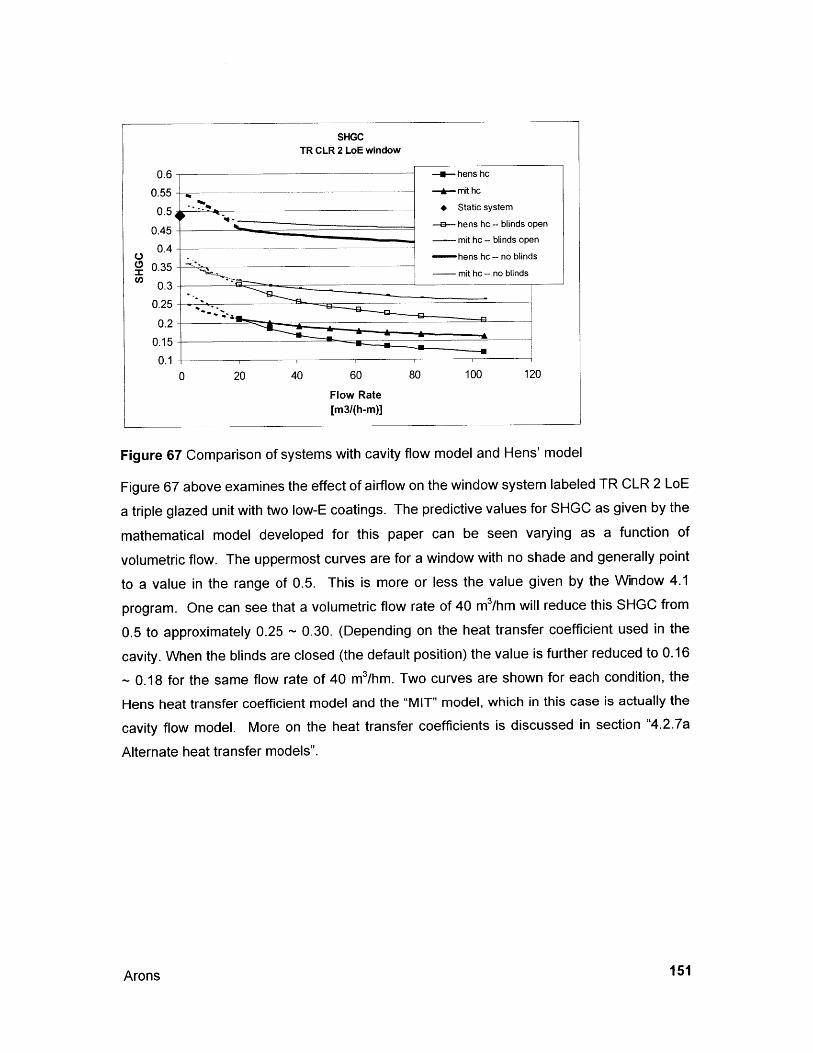
SHGCTR CLR 2 LoE window
0.6
0.55
0.5,
0.45
0.4
0.350.3
0.25
0.2
0.15
-4--hens hc
-*-mit hc
Static system
--- hens hc - blinds open- mit hc - blinds open
- hens hc - no blinds
mit hc -- no blinds
--0 20 40 60 80 100 120
Flow Rate[m3/(h-m)]
Figure 67 Comparison of systems with cavity flow model and Hens' model
Figure 67 above examines the effect of airflow on the window system labeled TR CLR 2 LoE
a triple glazed unit with two low-E coatings. The predictive values for SHGC as given by the
mathematical model developed for this paper can be seen varying as a function of
volumetric flow. The uppermost curves are for a window with no shade and generally point
to a value in the range of 0.5. This is more or less the value given by the Window 4.1
program. One can see that a volumetric flow rate of 40 m3/hm will reduce this SHGC from
0.5 to approximately 0.25 ~ 0.30. (Depending on the heat transfer coefficient used in the
cavity. When the blinds are closed (the default position) the value is further reduced to 0.16
~ 0.18 for the same flow rate of 40 m3/hm. Two curves are shown for each condition, the
Hens heat transfer coefficient model and the "MIT" model, which in this case is actually the
cavity flow model. More on the heat transfer coefficients is discussed in section "4.2.7a
Alternate heat transfer models".
Arons 151
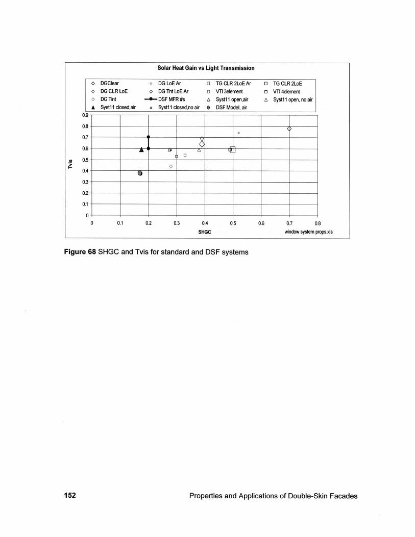
Figure 68 SHGC and Tvis for standard and DSF systems
Properties and Applications of Double-Skin Facades
Solar Heat Gain vs Light Transmission
0 DGCIear DG LoE Ar 0 TG CLR 2LoE Ar 0 TG CLR 2LoEo DG CLR LoE o DG Tnt LoE Ar o VT13element o Vl 4element0 DG Tint - DSF MFR #s A SystlI open,air A Syst1 1 open, no airA Syst11 closed,air a Systl losedno air * DSF Model, air
0.9
0.8-
00.7-
0.6 Al' j a ]
0.50
0.4_
0.3-
0.2-
0.1 _
0-
0 0.1 0.2 0.3 0.4 0.5 0.6 0.7 0.8SHGC window system props.ds
152
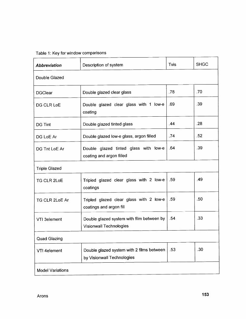
Table 1: Key for window comparisons
Abbreviation Description of system Tvis SHGC
Double Glazed
DGClear Double glazed clear glass .78 .70
DG CLR LoE Double glazed clear glass with 1 low-e .69 .39
coating
DG Tint Double glazed tinted glass .44 .28
DG LoE Ar Double glazed low-e glass, argon filled .74 .52
DG Tnt LoE Ar Double glazed tinted glass with low-e .64 .39
coating and argon filled
Triple Glazed
TG CLR 2LoE Tripled glazed clear glass with 2 low-e .59 .49
coatings
TG CLR 2LoE Ar Tripled glazed clear glass with 2 low-e .59 .50
coatings and argon fill
VTI 3element Double glazed system with film between by .54 .33
Visionwall Technologies
Quad Glazing
VTI 4element Double glazed system with 2 films between .53 .30
by Visionwall Technologies
Model Variations
Arons 153
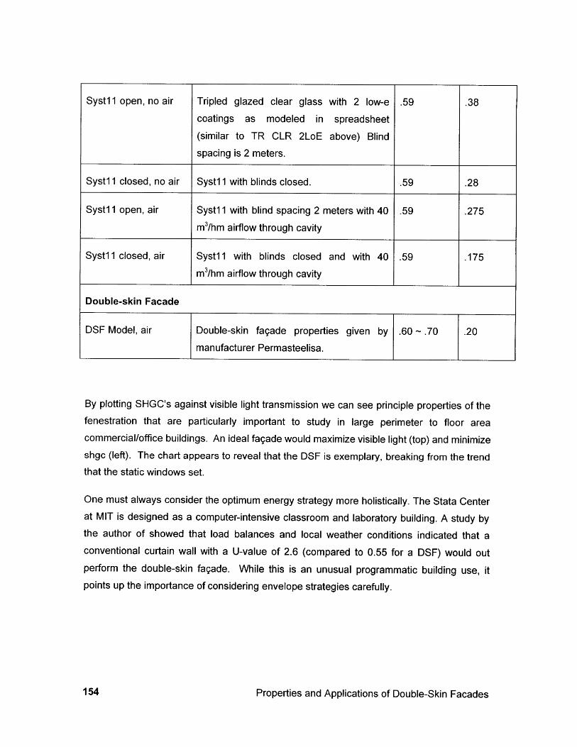
By plotting SHGC's against visible light transmission we can see principle properties of thefenestration that are particularly important to study in large perimeter to floor areacommercial/office buildings. An ideal fagade would maximize visible light (top) and minimizeshgc (left). The chart appears to reveal that the DSF is exemplary, breaking from the trendthat the static windows set.
One must always consider the optimum energy strategy more holistically. The Stata Centerat MIT is designed as a computer-intensive classroom and laboratory building. A study bythe author of showed that load balances and local weather conditions indicated that aconventional curtain wall with a U-value of 2.6 (compared to 0.55 for a DSF) would outperform the double-skin fagade. While this is an unusual programmatic building use, itpoints up the importance of considering envelope strategies carefully.
Properties and Applications of Double-Skin Facades
Syst1 1 open, no air Tripled glazed clear glass with 2 low-e .59 .38coatings as modeled in spreadsheet
(similar to TR CLR 2LoE above) Blindspacing is 2 meters.
Syst1 1 closed, no air Syst1 1 with blinds closed. .59 .28
Syst1 1 open, air Syst1 1 with blind spacing 2 meters with 40 .59 .275m3/hm airflow through cavity
Syst1 1 closed, air Syst 11 with blinds closed and with 40 .59 .175m3/hm airflow through cavity
Double-skin Facade
Double-skin fagade properties given bymanufacturer Permasteelisa.
DSF Model, air
154
4.5.2b SOLAR ARCHITECTURE TYPOLOGIES AND DESIGN APPROACH
Passive systems are fundamentally different from active space-heatingsystems in that most passive system components are part of the buildingitself. Therefore the design of passive systems takes place earlier in thearchitectural design process than does the design of active systems. [Kreiderand Keith 1982 p. 151]
Solar architecture is typified by the need for a holistic approach to design and the design
process that supports it. The importance of recognizing system interconnections is
paramount. A prime example is the consideration of thermal mass and adjustable systems.
The design of buildings with double-skin facades should be informed by this concept. The
use of the model should be taken within the context of broader goals than just energy.
4.5.3 Defining Value for Individual Properties
Value implies a human aspect to evaluating materials. We may value energy, daylight,
individual environmental control, global and local ecology, initial or maintenance costs. So
far we do not have a model that quantities value for architectural decisions. LEEDS is a
system that is under development that assigns value to issues of sustainability. It claims to
evaluate environmental impacts of building on a "whole building" perspective over the life of
a building, and to provide a "definitive standard for what constitutes a 'green building"' [US
Green Building Council 1999]. Unfortunately there is a long way to go in properly assigning
value to different attributes of a building. The system is meant to be a national (U.S)
system, but doesn't address the variety of building types and climatic zones, or the regional
differences in product availability. Can the utility that various properties of a building be
assigned in a rational manner? This is doubtful. LEEDS version 1.0 assumes implicitly that
environmental, energy and indoor air quality issues are independent of human occupancy.
Version 2.0 recognizes that human impacts of controlling lighting and ventilation are
valuable. This is a step in the right direction, but becomes less rational because the actual
performance of the building will no longer be certain; it will be subject to human whim. And
so it should be. While it is important for designers to be cognizant of the properties of
window systems, value judgments will eventually need to be made. The more data that is
on the table the better will be the quality of the decision, so designers should be comfortable
with the trends in parameters and their effects on achieving the goals of the design.
Arons 155

156
5.0 Design Implications and Technology Transfer
Designers face many challenges in adapting DSF technology to other contexts. Some work
has been carried out for projects outside Western Europe including a completed building for
NEC in Japan, a design for skyscraper by IOKP architects for Hong Kong, and two U.S.buildings. But what must be considered in order to transfer this technology? There is a
range of issues that is important to the success of any DSF project.
It is also important to understand that there is a limited understanding of existing projects in
their initial context. While there has been some analytical work done in recent years, it has
come late in the adaptation of DSF's to commercial buildings. In an article that was
published after the Commerzbank and RWE towers were both completed, one authorlamented that, "although extensive computer studies have been carried out, no-one knows
quite how the whole thing will work.. .The whole building will be extensively monitored in
use... it should also have many lessons to give to future buildings"[Davey 1997a p. 38].Yet, dissemination of information is not efficient, and many hold their knowledge as
proprietary.
Among the considerations that must be addressed are aesthetics, day lighting, interaction
with mechanical systems and loading, control systems, local climate, culture and economy,
and lifecycle impacts. Additionally, the project team structure plays a role in the potential
success of implementing new technological solutions.
5.1 Aesthetics and day lighting
5.1.1 Aesthetics
A leading architectural reason for using DSF's is to capitalize on their high-tech image of
transparency. The Helicon and RWE are two buildings whose partis are based on
maximizing transparency. The Helicon is meant to be sleek and to allow visual connection
between the city street and retail space within. RWE is meant to be an elegant cylinder-
within-a-cylinder. Neither is as successful as they might first seem. Transparency through
multiple layers of glass is highly dependent on the angle of light falling on the surface and
the relative brightness on either side of the fagade. Some of the projects, including RWE,
have low-iron glass that doesn't have the same familiar green tint that most commercial
Arons 157
buildings have. This is particularly the case with low-E coated glass. At RWE, the clearglass is made viable because of the shading capacity of the DSF.
Based on Norman Foster's other architectural masterpieces, it can be imagined that theCommerzbank building is meant to be very light and transparent. It has, however beencriticized as being to the contrary [Davey 1997a]. Perhaps, this is because of the enormousclear spans that allow the winter gardens to be very open and airy spaces that necessitatedeep spandrel panels and make floor-to-ceiling glass impossible. On the whole, this authorbelieves that the building succeeds at being light, if not airy. It doesn't however competewith RWE in being transparent. Further, the DSF does not aid in the transparency. In fact,the blinds tend to have the opposite effect.
One advantage of having the fixed-glass exterior of the DSF is architectural; the outside ofthe building tends to look uniform even when air and light control mechanisms are in avariety of configurations exist just behind the outer layer. This is particularly successful atthe Commerzbank because of its large scale, degree of opacity (about 40% of the wall isopaque spandrel glass), and distance of observation (the tower is not only high, but alsoshielded from close observation by the location of neighboring buildings). But this is notalways the case. Adjustable blinds that are close to the outer skin will be quite visible,particularly when illuminated by the sun. If the control regimen for a given fagade is notcentrally handled (rather than by users), then the look of the fagade will be varied ratherthan uniform. The desirability of uniformity versus organicism in the fagade is subjective, butthe designer must be aware that the DSF alone does not guarantee either trait. Kohlbeckerproposes a countervailing argument to the sleekness of RWE with the example of RenzoPiano's Daimler Benz tower in Potsdamer Platz, Berlin. The outer skin of this buildingconsists of small-scale glass panes on horizontal pivots. This louvered skin opens andcloses automatically, creating a "delicate and subtle" fagade that offsets the inner and outerfacades against each other, rather than trying to make the whole assembly transparent[Kohlbecker 1998 p. 40].
5.1.2 Day Light
Access to daylight is a critical element in holistic design. As previously mentioned, inGermany it is mandated that workers be within seven meters of a window. The result is
Properties and Applications of Double-Skin Facades158
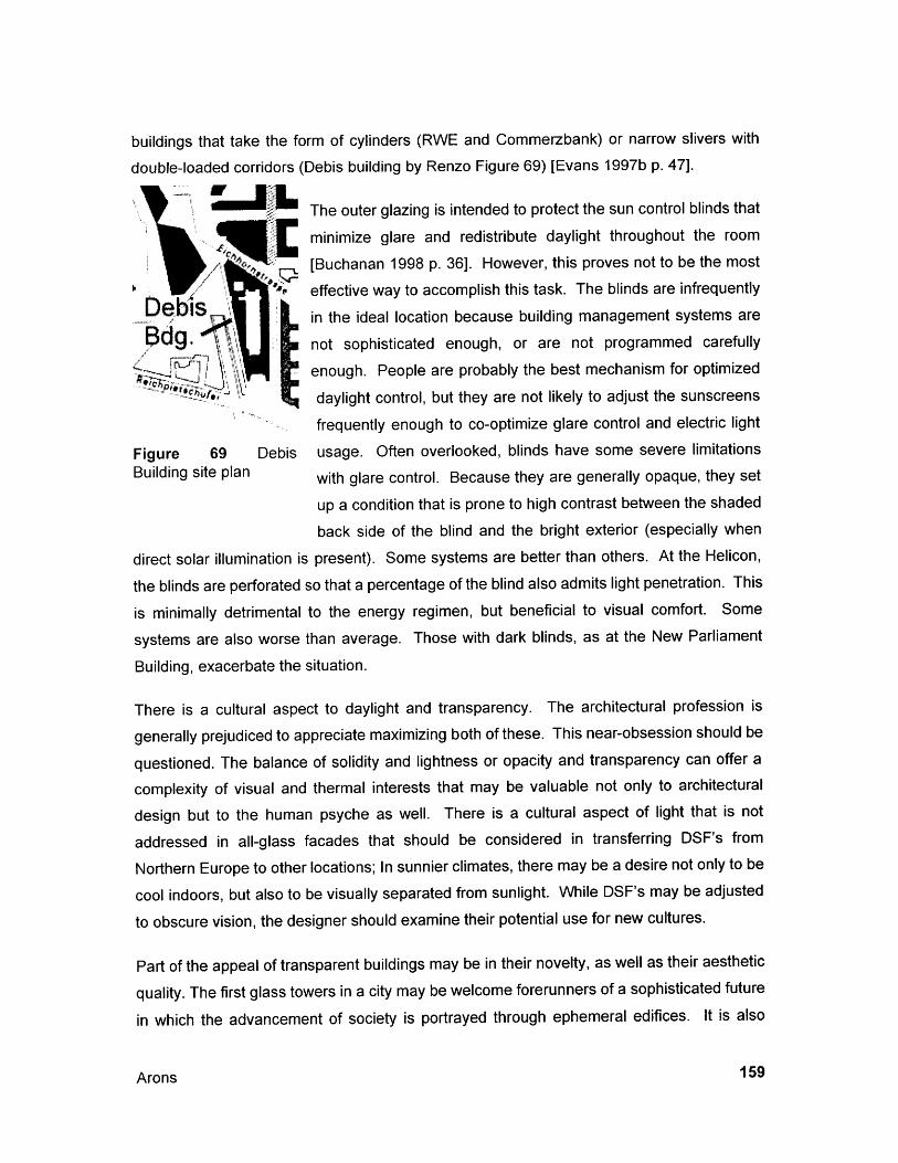
buildings that take the form of cylinders (RWE and Commerzbank) or narrow slivers with
double-loaded corridors (Debis building by Renzo Figure 69) [Evans 1997b p. 47].
The outer glazing is intended to protect the sun control blinds that
minimize glare and redistribute daylight throughout the room
[Buchanan 1998 p. 36]. However, this proves not to be the most
effective way to accomplish this task. The blinds are infrequently
in the ideal location because building management systems are
g, not sophisticated enough, or are not programmed carefully
enough. People are probably the best mechanism for optimized
daylight control, but they are not likely to adjust the sunscreens
frequently enough to co-optimize glare control and electric light
Figure 69 Debis usage. Often overlooked, blinds have some severe limitationsBuilding site plan with glare control. Because they are generally opaque, they set
up a condition that is prone to high contrast between the shaded
back side of the blind and the bright exterior (especially when
direct solar illumination is present). Some systems are better than others. At the Helicon,
the blinds are perforated so that a percentage of the blind also admits light penetration. This
is minimally detrimental to the energy regimen, but beneficial to visual comfort. Some
systems are also worse than average. Those with dark blinds, as at the New Parliament
Building, exacerbate the situation.
There is a cultural aspect to daylight and transparency. The architectural profession is
generally prejudiced to appreciate maximizing both of these. This near-obsession should be
questioned. The balance of solidity and lightness or opacity and transparency can offer a
complexity of visual and thermal interests that may be valuable not only to architectural
design but to the human psyche as well. There is a cultural aspect of light that is not
addressed in all-glass facades that should be considered in transferring DSF's from
Northern Europe to other locations; In sunnier climates, there may be a desire not only to be
cool indoors, but also to be visually separated from sunlight. While DSF's may be adjusted
to obscure vision, the designer should examine their potential use for new cultures.
Part of the appeal of transparent buildings may be in their novelty, as well as their aesthetic
quality. The first glass towers in a city may be welcome forerunners of a sophisticated future
in which the advancement of society is portrayed through ephemeral edifices. It is also
Arons 159

possible that they will be the harbinger of a world of hard surfaces, reflecting noise andvisually confusing light in an environment that has lost the tactile and grounding quality ofstone and brick. Designers should consider the use of double-skin facades judiciously.
Daylight should be used to offset the use of electric lighting. Dimmable fluorescent fixturesshould be used only to the extent that they are needed because sufficient daylight doesn'texist. Sophisticated building management systems can be designed to compare the energybenefits of admitting solar radiation and associated heat gain with using electrical lightingwith its internal heat gain. Otherwise, decisions will be made solely on intuition.
5.2 The Effect of DSF and MEP system interdependency on loads
Unlike typical static systems, double-skin facades tend to force designers to consider theinteraction of traditional architectural elements of the fagade with traditional mechanicalrequirements of space conditioning and human comfort. Many of the European models takea step away from designing mechanical systems to condition space and toward the goal ofconditioning people. The difference is in considering comfort conditions and occupied timesrather than conditioning all of the air in a building all of the time. A good example ofcapitalizing on the interdependency of high tech facades and HVAC systems is theCommerzbank. The load reduction of the facades is coupled with natural ventilation,nighttime "free cooling", and the moderating effects of the (enormous and costly) wintergardens. The chilled ceilings are made possible due to these reduced loads. The coolingcapacity of the hydronic ceilings is marginal unless solar loads are minimized. Thecombination of cold ceilings and natural ventilation means that the temperature of the ceilingis not as low as it would be if the building were sealed so the risk of condensation of hotmoist exterior air entering the operable windows and coming in contact with the ceilings isreduced. The externally ventilated facades at Commerzbank, RWE and Victoria Insuranceare not physically tied to the mechanical system with ducts as are ABN-Amro and others yettheir impacts on the design process is significant. The architectural design is dependant onthe functionality of the envelope system for its success. The entire space is formed by themechanical system: windows are load filters, ceilings are cooling elements, floors in otherbuildings are ventilation channels, and structure is a thermal storage device. Each member
Properties and Applications of Double-Skin Facades160
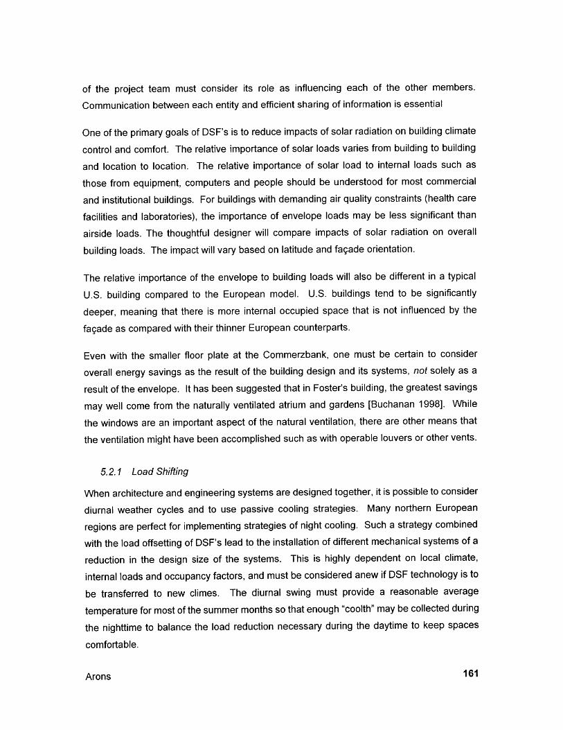
of the project team must consider its role as influencing each of the other members.
Communication between each entity and efficient sharing of information is essential
One of the primary goals of DSF's is to reduce impacts of solar radiation on building climate
control and comfort. The relative importance of solar loads varies from building to building
and location to location. The relative importance of solar load to internal loads such as
those from equipment, computers and people should be understood for most commercial
and institutional buildings. For buildings with demanding air quality constraints (health care
facilities and laboratories), the importance of envelope loads may be less significant than
airside loads. The thoughtful designer will compare impacts of solar radiation on overall
building loads. The impact will vary based on latitude and fagade orientation.
The relative importance of the envelope to building loads will also be different in a typical
U.S. building compared to the European model. U.S. buildings tend to be significantly
deeper, meaning that there is more internal occupied space that is not influenced by the
fagade as compared with their thinner European counterparts.
Even with the smaller floor plate at the Commerzbank, one must be certain to consider
overall energy savings as the result of the building design and its systems, not solely as a
result of the envelope. It has been suggested that in Foster's building, the greatest savings
may well come from the naturally ventilated atrium and gardens [Buchanan 1998]. While
the windows are an important aspect of the natural ventilation, there are other means that
the ventilation might have been accomplished such as with operable louvers or other vents.
5.2.1 Load Shifting
When architecture and engineering systems are designed together, it is possible to consider
diurnal weather cycles and to use passive cooling strategies. Many northern European
regions are perfect for implementing strategies of night cooling. Such a strategy combined
with the load offsetting of DSF's lead to the installation of different mechanical systems of a
reduction in the design size of the systems. This is highly dependent on local climate,
internal loads and occupancy factors, and must be considered anew if DSF technology is to
be transferred to new climes. The diurnal swing must provide a reasonable average
temperature for most of the summer months so that enough "coolth" may be collected during
the nighttime to balance the load reduction necessary during the daytime to keep spaces
comfortable.
Arons 161
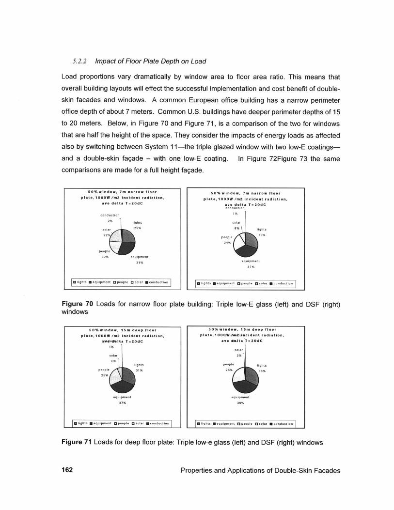
5.2.2 Impact of Floor Plate Depth on Load
Load proportions vary dramatically by window area to floor area ratio. This means that
overall building layouts will effect the successful implementation and cost benefit of double-skin facades and windows. A common European office building has a narrow perimeter
office depth of about 7 meters. Common U.S. buildings have deeper perimeter depths of 15to 20 meters. Below, in Figure 70 and Figure 71, is a comparison of the two for windows
that are half the height of the space. They consider the impacts of energy loads as affectedalso by switching between System 11-the triple glazed window with two low-E coatings-
and a double-skin fagade - with one low-E coating. In Figure 72Figure 73 the samecomparisons are made for a full height fagade.
[ F lights equipment O people [solar Mconduton
Figure 70 Loads for narrow floor platewindows
50%window, 15m deep floorplate,1000W /m2 incident radiation,
wdudtilta T=20dC1%
solar
6%lights
people 31%25%
equipment
37%
Elights U equipment [ people [ solar U conduction
50%window, 7m narrow floor
plate,1000W /m2 incident radiation,ave delta T=20dCconduction
1%
solar
8% lights
307%people
24%
equipment
37%
g lights * equipment [ people [ solar U conduction
building: Triple low-E glass (left) and
50%window, 15m deep floorplate, 1000:tihtmd2ikorncident radiation,
ave dslta =20dC
solar
2%
people lights
26% 33%
equipment
39%
F lights N equipment 0 people O solar U conduction
Figure 71 Loads for deep floor plate: Triple low-e glass (left) and DSF (right) windows
Properties and Applications of Double-Skin Facades
50%window, 7m narrow floorplate,1000W /m2 incident radiation,
ave delta T=20dC
conduction
2% lights
solar 25%
22
people
20% equipment
31%
DSF (right)
162
100%window, 7m narrow floor
plate, 1000W /m2 incident radiation,ave delta T=20dC
conduction ights20%
solar
36%mequipment
25%people
16%
M lights U equipment 0 people 0 solar U conduction 0 solar 0 conduction
Figure 72 Loads for narrow floor plate: Triple low-E glass (left) and DSF (right) facades.
Figure 73 Loads for deep floor plate: Triple low-E glass (left) and DSF (right) facades.
5.2.3 Volumetric Flow Rate and Fan Power
The relationship between ventilation or heating and cooling air supply to a room and the
volumetric airflow rate desired for the window system is important to understand. If the flow
through the window is equal to or less than the rate that is required for the room then there
is no penalty for fan power to move the air through the window, and no additional ductwork
required. If the flow rate desired for the windows is greater than the room flow rate, then
there will be additional fan power required to run the window system.
Figure 74 shows iso-air-change lines indicating the distance from the fagade at which the
requirements for the room at a given air change rate and the window flow rate are in
Arons 163
I tights N equipment 0 people
100%window, 7m narrow floor
plate,1000W /m2 incident radiation,ave delta T=20dC
conduction
1%
solar lights
15 28%
people
22%
equipment
34%
100% window, 15m deep floorplate,1000W /m2 incident radiation,
ave delta T=20dCconduction
1%
solarlights
11%29%
people
23%
equipment
36%
G lights U equipment O people 0 solar U conduction
100%window, 15m deep floorplate,1000W /m2 incident radiation,
conductionave delta T=20dC
0%
solar
4%
people lights32%
26%
equipment
38%
U lights R equipment 0 people 0 solar U conduction
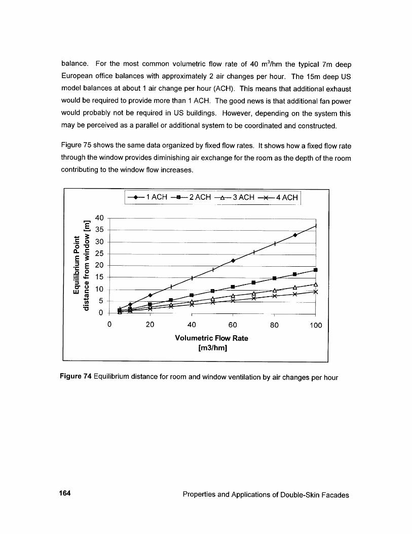
balance. For the most common volumetric flow rate of 40 m3/hm the typical 7m deepEuropean office balances with approximately 2 air changes per hour. The 15m deep USmodel balances at about 1 air change per hour (ACH). This means that additional exhaustwould be required to provide more than 1 ACH. The good news is that additional fan powerwould probably not be required in US buildings. However, depending on the system thismay be perceived as a parallel or additional system to be coordinated and constructed.
Figure 75 shows the same data organized by fixed flow rates. It shows how a fixed flow ratethrough the window provides diminishing air exchange for the room as the depth of the roomcontributing to the window flow increases.
-+-1 ACH --- 2 ACH -- 3 ACH 4 ACH
40E 35
.9 0 30
a- . 25E 20L. 15
10
0 20 40 60 80 100
Volumetric Flow Rate[m3/hm]
Figure 74 Equilibrium distance for room and window ventilation by air changes per hour
Properties and Applications of Double-Skin Facades164
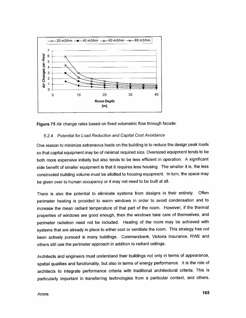
Figure 75 Air change rates based on fixed volumetric flow through facade.
5.2.4 Potential for Load Reduction and Capital Cost Avoidance
One reason to minimize extraneous loads on the building is to reduce the design peak loads
so that capital equipment may be of minimal required size. Oversized equipment tends to be
both more expensive initially but also tends to be less efficient in operation. A significant
side benefit of smaller equipment is that it requires less housing. The smaller it is, the less
constructed building volume must be allotted to housing equipment. In turn, the space may
be given over to human occupancy or it may not need to be built at all.
There is also the potential to eliminate systems from designs in their entirety. Often
perimeter heating is provided to warm windows in order to avoid condensation and to
increase the mean radiant temperature of that part of the room. However, if the thermal
properties of windows are good enough, then the windows take care of themselves, and
perimeter radiation need not be included. Heating of the room may be achieved with
systems that are already in place to either cool or ventilate the room. This strategy has not
been actively pursued in many buildings. Commerzbank, Victoria Insurance, RWE and
others still use the perimeter approach in addition to radiant ceilings.
Architects and engineers must understand their buildings not only in terms of appearance,
spatial qualities and functionality, but also in terms of energy performance. It is the role of
architects to integrate performance criteria with traditional architectural criteria. This is
particularly important in transferring technologies from a particular context, and others.
Arons 165
Architects must understand the basic relationships, of loads, building form and use, asoutlined in this section.
5.3 Policy, operating and life-cycle costs
The accounting and evaluation of building costs are slowly evolving to include operationaland maintenance costs of the building in addition to initial capital costs. As the constructionindustry adopts this approach, credit will be given to upfront costs that lead to cost savingsover the life and use of buildings. For building systems, the envelope is second only to thestructure in longevity. Facades therefore have the potential of providing reasonable afinancial payback over their life span. There appears to be an incentive to ask designprofessionals to study such options for the benefit of project owners.
In public forum, Alex Krieger, head of Harvard University School of Graduate Design, saidthat architects should not be told to design "green buildings", that they should be enticed bythe "fashion" of the day. He believes that such design will not happen in the U.S. until"energy costs are as high as they are in Europe" [Green Building Conference 2000].
Still, there is a significant up-front cost at present. "The cost of innovative curtain walls, withtheir controls and motors, can't yet be justified - even in high-energy-cost Europe - withouta design that optimizes thermal performance, lighting and [HVAC performance]" [Pepchinski1995]. Pepchinski writes that in Europe in general and in Germany particularly, the role ofgovernment in encouraging environmental design is significant. In that country, energy usestandards were reduced by 30% in 1995 and were slated to be a total of 50% by the year2000. In addition to this stick, grants and subsidies are available for the use of manyenvironmentally sensitive technologies.
Facades should be designed to last a long time, by minimizing internal condensation and byshedding rain so as to minimize water infiltration. Durable materials should be used thatminimize internal degradation. Glazing and spandrel panels should be easily replaced ifnew glass or photovoltaic technologies are developed during their useful life.
At the end of their life, they should be demountable. This means that they can be easilytaken down and separated into constituent parts that can be reused or recycled. Themodular design of some of the tall buildings was done for ease and speed in on-siteassembly. The same design may facilitate disassembly or changes, but that is not
Properties and Applications of Double-Skin Facades166
necessarily the case. The design of the Commerzbank modules is for sequential assembly
from bottom to top. The panels are interconnected in a fashion that will make replacement
of a single panel in a field of panels exceptionally difficult [Colin and Lambot 1997].
Ospelt has outlined an approach to life cycle assessment (LCA) for buildings. LCA
considers the entire impact of buildings from resource procurement through the life of the
building and decommissioning. He suggests that once a building is planned, and its location
set, designers have many considerations left to make. "A long-term perspective and
assumptions about the future of the building are necessary... the lifetime of different systems
has to correspond to the long-term scenario for the building [Ospelt 1999]. The use of
aluminum for curtain walls is clearly a high-embodied energy choice. However, it may make
sense in the context of commercial, and particularly high-rise commercial structures that
have difficult and costly maintenance concerns. The Stadttor is a remarkable exception to
this rule. The DSF is comprised of an outer layer of glass, and an inner layer of wood
frames. Wood is renewable and if it is provided from sustainably managed forests, can
encapsulate C02 for a period. Because it is protected from the weather, its maintenance is
less. A meter-plus wide cavity allows ready access to all surfaces for care over the life of
the building. Using an exterior skin of bolted glass rather than continuous frames will
dramatically reduce material consumption.
The use of glass is difficult to minimize, but should be considered as well. Suspended film
technologies may replace interstitial glass and provide comparable performance.
Local production and access to technologies and materials must be considered in light of life
cycle analysis. Rather than importing the actual materials to Tokyo, for instance, it may be
best to consider local or regional alternatives. Importing knowledge and applying it to
construction with local materials may be the best solution of all.
5.4 Control systems
Beyond the selection of systems, they must also be incorporated into the building as part of
an organism. Carefully designing the control system does this. This must be tested during
design, implemented during building commissioning, and refined and verified during
operations.
Arons 167
Static windows in U.S. commercial buildings are usually only controlled for glare and privacyby adjusting interior blinds or shades. Some windows in passive solar buildings areconsidered part of an overall strategy and have movable insulation or are operated moreactively. There is a history of interacting with windows more in residential buildings than incommercial buildings. People will adjust their windows to block summer heat and openthem to allow cool night air to enter. This is a practice that is arguably waning as homes arebecoming increasingly air-conditioned. Other cultures, and other times, there has beengreat interaction with and control of blinds. Exterior blinds, shutters and roll-screens are stillpopular in most hot locations, whereas the American southwest has grown up with airconditioning at the ready.
The incorporation of double-skin facades has the potential to reinvigorate the commercialsector in its acceptance of a varied envelope that requires attention so that it remains tunedto the cycles of weather, sunshine and noise. Two types of controls will need to be marriedto achieve the greatest success: user (occupant) control and centralized (buildingmanagement system) control.
5.4.1 User Control
Double-skin facades are equipped with options for the building occupant. They typicallycontain Venetian-style blinds that may be adjust by rotating the angle of the blind or byraising and lowering the blind. This control strategy is useful for controlling solar heat gain,view and privacy. The down side is that when the sun shines on blinds that are partiallyclosed, glare conditions may be created due to the vast difference between the brightness ofdaylight and the shaded back side of the blinds.
Translucent fabric shades are sometimes provided in addition to blinds. These roll downdevices provide uniform light conditions that do not have the same glare side effects.However, they are a binary response that is either in place or not. This is typically an add-on system. Some buildings use this blind in place of the inner layer of glass and instead ofthe Venetian blinds. The space between the outer glass and the roll down shade create acavity through which air is forced as part of an interior ventilated fagade. This system ismore economical than the typical system described in this paper, but will likely be lessefficient because of the proximity of the shade to the occupied space.
Properties and Applications of Double-Skin Facades168
Windows have a host of operation options from windows that tilt and turn to doors that pivot
or slide. These windows will have varying degrees of success at creating conditions for
ventilating the occupied space. Design consideration must be given to facilitate either
through or one-sided ventilation. The criteria for systems in hot climates will be more
demanding than in the moderate German climate, for example. The efficiency of tilt-turn
windows such as the ones in Commerzbank may not be appropriate where large volumes of
air movement are required. Either full-height openings or top and bottom opening windows
may be more appropriate.
Occupants control window elements as they see fit: to adjust lighting, view or perceived
thermal comfort. However, at times, these actions may be in direct contradiction of what is
best for energy performance or thermal conditions. For example, warm weather may entice
an occupant to open the window. This can provide psychological comfort by admitting a
breeze at the expense of letting hot air into the room that will add to the cooling load of air
conditioning. In high-rise buildings, opening windows can also create pressure differentials
that make opening doors or simply securing paperwork difficult.
Educating and informing occupants is valuable. Implementing a building-wide protocol for
window operation can help to guide window control toward sensible and beneficial results in
terms of the multi-faceted goals of building management. Sophisticated building
management sensors and controls are often worthwhile.
5.4.2 Building Management Systems and Interfaces
Commerzbank and other buildings have weather stations that detect outdoor conditions and
relay them to a central building management station. Digital connections to all motors and
pumps in the building allow the system or system operators to adjust blind and window
positions as well as ventilation, radiative cooling and heating, and lighting. Zones are
uniquely small; each room may be controlled individually.
A sophisticated algorithm is required to manage this system.
The building management system at Commerzbank is designed to continuously adjust the
Venetian blind blades via motor so that they will protect the building against solar
penetrations during the heat of summer and so that they will serve as light shelves during
the winter. It is not clear that the system is actually working in this manner. Rather it
Arons 169

appears that blinds have closed and open positions and that they are only readjusted about3 times per day (morning noon and night). This is indicative of the sensitivity of users toworking in an automated buildings; it can be distracting or even unnerving to work in a placethat is animated remotely by motors. This system might be improved by being able toprovide quiet motors capable of micro adjustments rather than the loud and grossadjustments that are (apparently) available with the current technology.
SOME QUESTIONS FOR THE BMS TO ANSWER
" Is the space occupied now, or when is it scheduled to be occupied?
" What are the exterior temperature, wind speed and velocity, and humidity?
e What is the incident solar radiation, intensity, altitude and azimuth?
e What is the prediction for temperatures over the next 24 hours?
Is daylight desirable? Is solar radiation gain useful? Compare to electrical load.
If the space is occupied, is electrical lighting required?
* Is room conditioning required?
* Do conditions exist for condensation on cooling panels? On window surfaces?
e Will natural ventilation be beneficial for comfort? Will it be beneficial for energyconsumption?
e What recommendations or requirements should be made to building occupants?
5.5 Climate
Humidity is one factor that will be critical to consider for its effects on comfort, need fordehumidification, and condensation control. Condensation control is an issue for passivedesign strategies (thermal mass) and radiant (hydronic) systems.
Mahadev Raman of Ove Arup and Partners is quoted as saying that, "You don't have thesummer humidity in many parts of Europe that is characteristic of much of the AmericanEast Midwest and South. You have to look at whether radiant cooling will be able to make
Properties and Applications of Double-Skin Facades170
enough of a temperature differential to work" [Russell 1995 p. 84]. The potential to use
radiant panels has been an important condition in the economic and energy planning of
buildings with DSF's. The DSF's can make the difference in reducing energy loads enough
to make the radiant panels feasible. Once the panels are feasible, the floor-to-floor height of
the buildings may be reduced from what they would need to be for all-air cooling systems.
It may even be a consideration on the more fundamental level of condensation within the
double-skin wall. Anecdotal information indicates that this has even been a problem in
some European buildings, and would more likely be a problem in US climates that are
particularly humid or cold.
Beyond the technical issues of condensation control, a designer must first consider the very
potential for using natural ventilation. It is plain to see that the number of hours that the
natural ventilation options will be desirable and effective in locations such as Pheonix,
Miami, and even Minneapolis may be far fewer than is found in London, Frankfurt and
Amsterdam.
5.6 Culture and economy
There is general consensus that European projects are more advanced than American
projects in terms of environmental sensitivity. Certainly there is a wider range of exemplary
work in Europe. Many ask why this may be.
Occupant requirements that pushed the implementation of DSF's in Germany, and leading
to the popularity of the systems do not exist in the US. European workers have demanded
access to daylight and outside air at a level not witnessed on this continent. Office workers
cannot be located more than 7 meters from a window [Evans 1997b p. 47]. However the
trajectories of issues like indoor air quality and human welfare may provide the impetus for
US markets to catch up on this issue. However, the dollar may continue to speak louder
than the people for some time. Deep-plan buildings will predominate when developers are
considering solely cost per square foot. Access to daylight is only beginning to be revived as
an important issue for American workers, and management is not yet sold on the economies
of worker satisfaction and productivity that is augmented by views, fresh air and comfort.
Arons 171
[The deep-plan American-style office building is] efficient only in relation toinitial capital costs and net-lettable-to-gross-floor-area ratios. But in terms ofthe far higher energy costs over the life of the building, and even more so interms of the health and happiness of the workers inside (whose slaries willaccount for very many times the capital [and maintenance] costs), suchbuildings are extremely inefficient [Buchanan 1998 p. 30].
Further, one of the strengths of DSF's is their ability to be controlled. Operable windows inopen office plan are an extreme challenge in trying to provide energy efficient comfort levels,and this is the predominant building typology in the US. "The windowless cubicle landscapesof American office buildings are virtually outlawed in Germany" [Pepchinski 1997 p. 148]The European office tower model has perimeter office cells that can be isolated by controlmechanisms. Part of the incentive for and success of the Commerzbank in the eyes of itsoccupants has been the perception of comfort that comes with the greater level of occupantcontrol that comes with operable windows [Buchanan 1998].
As advanced as the European market may seem, "ecologically based briefs [owner's projectdescriptions] are still the exception. Much depends on the client being able to persuadeenough commercial tenants to share in the dream "[Dawson 1997]. "Large buildings thatemploy environmentally responsible technologies are still the exception in most of theEurope today" [Pepchinski 1995 p. 70]. This trend seems to have reversed itself. Apersonal communiqu6 with European researchers indicated that as many as 40% of newbuildings in Germany are employing double-skin facades. Pepchinski also describes thatGerman federal guidelines have been increased in the past 5 years for daylight andinsulation, while government and utility subsidies are available for "solar" technologies.
While design aspects appear well coordinated in Europe, on large buildings, someconstruction contracts are on a fixed-price basis. This is similar to the guaranteed maximumprice contract used in the US, but in Europe it can give contractors even more power, andrender architects and their engineers as consultants to the general contractor. This was thestructure for the Commerzbank building. As a result, the original concept of having interior-vented extract air facades with a small single-skin ventilation flap was converted to exterior-vented double-skins without independent flap. The constructed fagade was simpler to buildand install, but reduced the potential for air intake in summer due to the preheating of air inthe ventilation cavity [Swenarton 1997 p. 34]. An overall energy comparison has not beenpublished.
Properties and Applications of Double-Skin Facades172
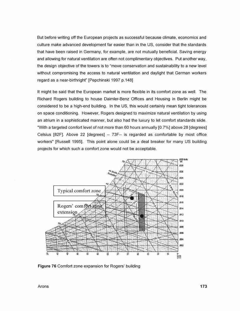
But before writing off the European projects as successful because climate, economics and
culture make advanced development far easier than in the US, consider that the standards
that have been raised in Germany, for example, are not mutually beneficial. Saving energy
and allowing for natural ventilation are often not complimentary objectives. Put another way,
the design objective of the towers is to "move conservation and sustainability to a new level
without compromising the access to natural ventilation and daylight that German workers
regard as a near-birthright" [Pepchinski 1997 p.148]
It might be said that the European market is more flexible in its comfort zone as well. The
Richard Rogers building to house Daimler-Benz Offices and Housing in Berlin might be
considered to be a high-end building. In the US, this would certainly mean tight tolerances
on space conditioning. However, Rogers designed to maximize natural ventilation by using
an atrium in a sophisticated manner, but also had the luxury to let comfort standards slide.
"With a targeted comfort level of not more than 60 hours annually [0.7%] above 28 [degrees]Celsius [82F]. Above 22 [degrees] -- 73F-- is regarded as comfortable by most office
workers" [Russell 1995]. This point alone could be a deal breaker for many US building
projects for which such a comfort zone would not be acceptable.
%ab
Typical comfort zone
Rogers' comfbextensign
M24
0'14
JD12
AMI
J002
Figure 76 Comfort zone expansion for Rogers' building
Arons 173
5.7 Building forms
5.7.1 Flexibility
One of the growing demands, particularly in the US market, is to provide the building ownerwith a structure that will work well at the time of occupancy, and that will be flexible enoughto accommodate changes to the programmatic requirements of building occupants.
In contrast to the US market, Germany has been characterized by have relatively uniformspace requirements with emphasis placed on individual offices or offices shared by two orthree individuals rather than open office plans [Evans 1997b p. 47]. This places differentrequirements on buildings that should be flexible over time.
Commerzbank is designed to be largely free of interior columns. The corners of thebuildings have massive columns that hold story-high Vierndeel trusses which span thelength from corner to corner of the building. This has dramatic aesthetic impacts includingmaking the building less transparent than it might otherwise have been, but the result is aflexible floor plan. The DSF windows are entirely repetitive and uniform and they are notinterconnected in any way. This means that reconfiguring the interior (glass and metal)partitions to make offices larger or smaller or to relocate them is rather easy. The controlsfor the windows are modular as well, so that there is little impediment to change. Thecombination of computer floors and modular ceilings and wall systems provides highfinishes with minimally intrusive renovation.
5.8 Construction sequences
The DSF designer will need to evaluate impacts on cost and schedule of the project. Thelong-term benefits of the DSF may be accompanied by reductions in the capitalexpenditures for HVAC plants, but the installation cost of the fagade is certain to be higherthan conventional facades. Not only is there more material involved, but there is also anexpectation that trades will have to interact. Not only will window manufacturers have tointeract with glaziers, but mechanical and electrical subs will be involved as well. HVACcontractors must duct the active windows and specialists must install controls (for all DSF's).The issue of whether to design for site-built or prefabricated will be far more complex thanwith traditional windows. The designer must consider the relationship between architectural,energy and contractibility aspects in selecting the DSF typology for a given project. The
Properties and Applications of Double-Skin Facades174
fragmentation of the construction industry in the US, and the segregation of trades and
professions means that each party will be looking to either shed risk or be rewarded with
profits for taking on risk.
Many designers have developed modular solutions. This is particularly the case in the
narrow to mid range windows such as the Commerzbank and RWE. It is also the case in
the Daimler Benz building by Piano. There, windows, glass louvers and terracotta cladding
articulate the fagade. Where possible, the pieces were pre-assembled into story high
elements that were shipped to the site as one piece [Kohlbecker 1998 p. 40].
All of this must be done within budgetary frameworks that typically focus on minimizing
capital expenditures even at to the detriment of operational and maintenance costs for the
lifetime of the building.
5.9 Integrated design
One must have an early start in the design sequence for buildings that will incorporate
double-skin facades because it is a serious intervention in the building layout. It is not
similar to switching glass type or frame types on a standard window system.
Active versions of DSF's (with forced convection) are different than conventional
architectural systems because they are physically and thermally tied to the mechanical
systems. Even for the passive systems, it is beneficial to consider these facades as an
important part of the mechanical system and overall energy and climate control strategy of
the building. Even when they are not physically attached to the HVAC system, attention
should be paid to their impacts by the design team. This is contrary to typical design
methods in the US that do not have strong interaction between architects and engineers. It
is even possible that, without proper study in a collaborative setting, the fagade may be a
detriment to the design.
In the US there is a preconception that using passive systems, or other non-standard
systems to replace now-standard mechanical systems proves "extremely expensive". This
was stated by Norman Kurtz, president of one of the most progressive building services
engineering firms in the US. [Russell 1995 p. 84]
The degree to which European design can be integrated is exemplified by the degree to
which systems are integrated in the RWE Tower. The radiant cooling is used as the finished
Arons 175
ceiling. The ceiling also houses a control panel incorporating two types of lights, light
sensor, smoke detector, sprinkler head and public address system [Pepchinski 1995 p. 73].Such well-coordinated services should be considered in contrast to typical US buildings thathave different face plates for each electrical service (lights, temp control, etc). Nagel, thearchitect of RWE stated in a personal conversation that he would like to push this evenfurther, intimating that the fagade should incorporate some of these functions as well aspower generation and other services.
It is instructive to consider the design and construction of the design offices for JosefGartner & Company, the renowned curtain wall manufacturer that created the DSF's for
Commerzbank RWE and other German buildings [Russell 1995 p. 75]. The building,completed by and published in 1995, (at about the time that the other buildings were beingconstructed), does not include DSF's. Certainly the company could have chosen anysystem for this two-story office building in Gundelfingen, Germany. Instead, they opted forthermally broken triple glazed gas-filled windows with external motorized louvers. Internalblinds also aid in glare control. The external location of the louvers may require moremaintenance than if they were in the interstitial space, but being just two stories abovegrade, this is easily and inexpensively accomplished.
Properties and Applications of Double-Skin Facades176
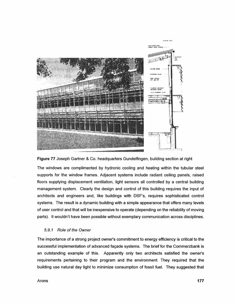
14.
Figure 77 Joseph Gartner & Co. headquarters Gundelfingen, building section at right
The windows are complimented by hydronic cooling and heating within the tubular steel
supports for the window frames. Adjacent systems include radiant ceiling panels, raised
floors supplying displacement ventilation, light sensors all controlled by a central building
management system. Clearly the design and control of this building requires the input of
architects and engineers and, like buildings with DSF's, requires sophisticated control
systems. The result is a dynamic building with a simple appearance that offers many levels
of user control and that will be inexpensive to operate (depending on the reliability of moving
parts). It wouldn't have been possible without exemplary communication across disciplines.
5.9.1 Role of the Owner
The importance of a strong project owner's commitment to energy efficiency is critical to the
successful implementation of advanced fagade systems. The brief for the Commerzbank is
an outstanding example of this. Apparently only two architects satisfied the owners
requirements pertaining to their program and the environment. They required that the
building use natural day light to minimize consumption of fossil fuel. They suggested that
Arons 177
occupants be in contact with plants and that individual control of office windows be provided
so that outdoor air would be available "even on the highest floors.[Davey 1997a]"
The role of the owner continues to be important through the life of the building; even after allof the design consultants have gone away. The operation of the building can make or breakthe success of energy and comfort systems. In the Max Planck building, utilizing naturalventilation on a warm day, the radiant heating of the atrium was on in spite of the alreadywarm conditions. This indicates that the building management system had not been properlycommissioned. Regarding the Commerzbank tower, Swenarton notes the following:
If the system is exploited to the full, there should be a projected 25-30%savings in energy use compared to standard buildings, plus a substantialimprovement in quality of life for the employees. If on the other hand thenatural ventilation option is regarded as an inconvenience it will simply be aresource wasted. [The effectiveness of the building systems] depends largelyon whether the client's commitment to eco-friendliness is more rhetorical orreal. [Swenarton 1997 p. 39]
Properties and Applications of Double-Skin Facades178
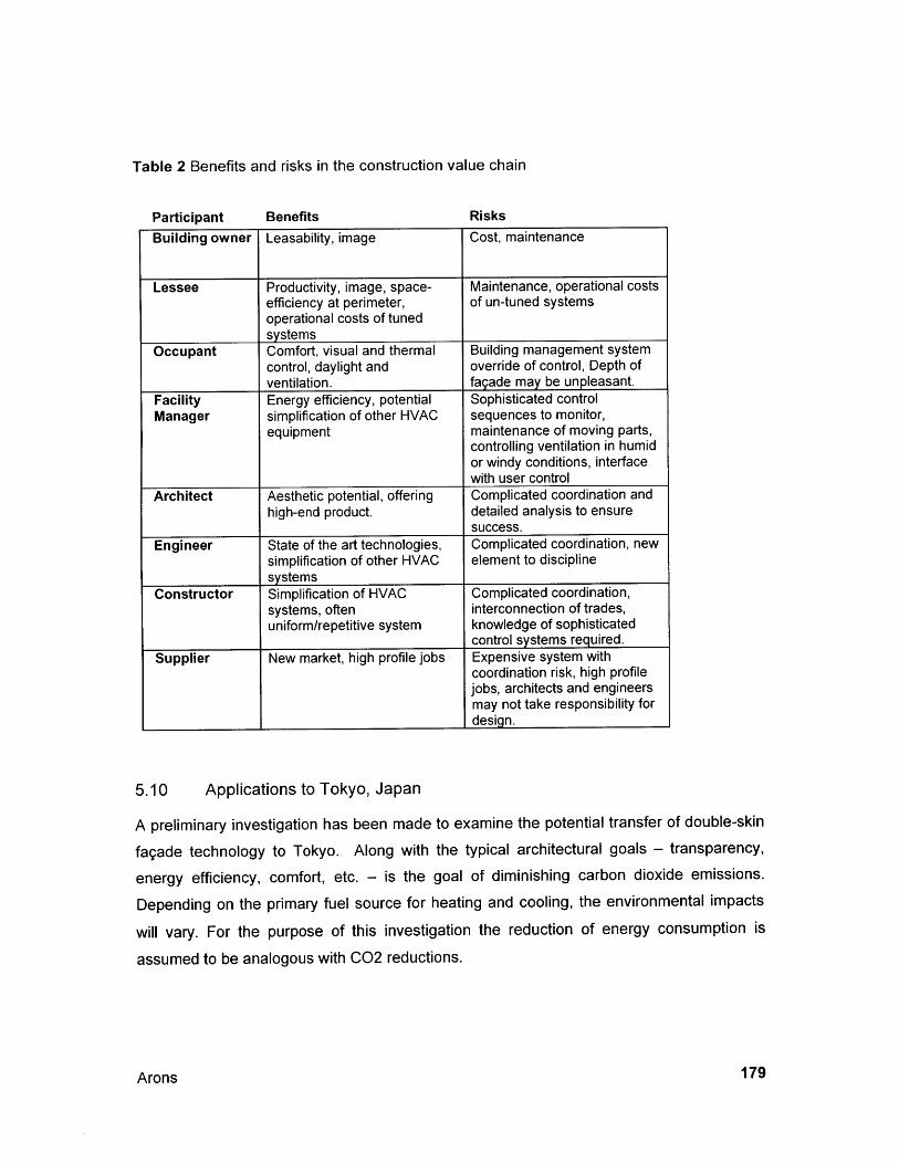
Table 2 Benefits and risks in the construction value chain
Participant Benefits RisksBuilding owner Leasability, image Cost, maintenance
Lessee Productivity, image, space- Maintenance, operational costsefficiency at perimeter, of un-tuned systemsoperational costs of tunedsystems
Occupant Comfort, visual and thermal Building management systemcontrol, daylight and override of control, Depth ofventilation. fagade may be unpleasant.
Facility Energy efficiency, potential Sophisticated controlManager simplification of other HVAC sequences to monitor,
equipment maintenance of moving parts,controlling ventilation in humidor windy conditions, interfacewith user control
Architect Aesthetic potential, offering Complicated coordination andhigh-end product. detailed analysis to ensure
success.Engineer State of the art technologies, Complicated coordination, new
simplification of other HVAC element to disciplinesystems
Constructor Simplification of HVAC Complicated coordination,systems, often interconnection of trades,uniform/repetitive system knowledge of sophisticated
control systems required.Supplier New market, high profile jobs Expensive system with
coordination risk, high profilejobs, architects and engineersmay not take responsibility fordesign.
5.10 Applications to Tokyo, Japan
A preliminary investigation has been made to examine the potential transfer of double-skin
fagade technology to Tokyo. Along with the typical architectural goals - transparency,
energy efficiency, comfort, etc. - is the goal of diminishing carbon dioxide emissions.
Depending on the primary fuel source for heating and cooling, the environmental impacts
will vary. For the purpose of this investigation the reduction of energy consumption is
assumed to be analogous with C02 reductions.
Arons 179
5.10.1 Energy Calculation Model
A simple energy model has been developed to complement the double-skin fagade
calculator that has been extensively described and used in this report. The energy modeluses typical hourly weather data for temperature, and radiation. This has been combinedwith solar altitude and azimuth data based on latitude to provide a reasonable approximationof the energy context of the project. A radiation conversion routine developed by the authortranslates the solar energy to incident solar energy normal to a given fagade orientation. Itmay be used for non-vertical facades, although the rest of the model would not necessarilysupport such a condition.
The direct normal radiation, coupled with the solar altitude and outdoor temperature is allthat is needed to calculate the external energy transfer through the window. The model doesnot consider composite walls containing windows within facades because the focus is on theenergy impact of the glazing system.
The dynamic nature of double-skin facades should be addressed so that the full advantageof being able to adjust blinds may be realized. While the SHGC is said to be around 0.15 -
0.20, this is always evaluated with the blinds closed. This is certainly not the position thatthe blinds will spend most of their time. Therefore, a reasonable, simplified controlsequence is modeled. The blind position is determined as shown in Table 3. The nighttime,non-occupied mode defaults the blinds to the closed (90 degree) angle. For daytime,occupied mode, there are two conditions considered - the difference is the weather theincident solar energy (Qsol) is greater or less than a given level (Qsol,critical). Qsol,critical isrelated to the minimum amount of solar radiation required to have sufficient day light in theoccupied space without using electric lighting. Above this level, the blinds may be closed tocut back on extra daylight. This is a simplification because thermal effects of the spaceshould also be considered, as should the energy impact of the lighting itself. Still, the simplecontrol sequence gives an estimate for energy that gives a reasonable comparison.
In a spreadsheet it would be difficult to tie this type of dynamic code for 8760 annual hoursto the iterative performance model, a different strategy is used: for each hour of the year,the energy calculation looks up the current solar angle and outdoor temperature given bythe weather data and the blind angle given by the control sequence in a table of valuespreviously prepared by with the performance model. Such a table is shown below in Table 4
Properties and Applications of Double-Skin Facades180

which gives five blind angle positions that can be used in more complex control sequences
than that indicated in the control sequence described.
Table 3 Basic blind control strategy
Blinds closed
shgc
Blinds 60
shgc
Blinds 45
shgc
Blinds 30
shgc
Blinds open
shgc0 0.1654 0.2197 0.2675 0.3211 0.4132
30 0.1654 0.1772 0.1936 0.2091 0.311945 0.1654 0.1772 0.1823 0.1978 0.233160 0.1654 0.1768 0.1819 0.1865 0.206590 0.1640 0.1760 0.1810 0.1857 0.1948
i Blinds closed Blinds 60 Blinds 45 Blinds 30 Blinds open
I U-Value U-Value U-Value U-Value U-Value1 0.75
10 0.5120 0.48
0 30 0.45o 40 0.43
Table 4 Window properties byoutside and solar altitude.
0.790.580.540.510.49
blind angle,
0.80 0.80 0.810.60 0.61 0.620.56 0.58 0.590.54 0.55 0.560.51 0.52 0.53
temperature difference between inside and
These values are then fed into a simple calculation, looking like this:
Q = Qsoia, (SHGC)A + UA(Tt - T)+ Qiernal
Arons
Condition Blind angle
Nighttime / not work hours Closed (90 degrees)
Day time and Qsol < Qsol,critical Open (0 degrees)
Day time and Qsol>Qsol, critical Semi-open (45 degrees)
I
181
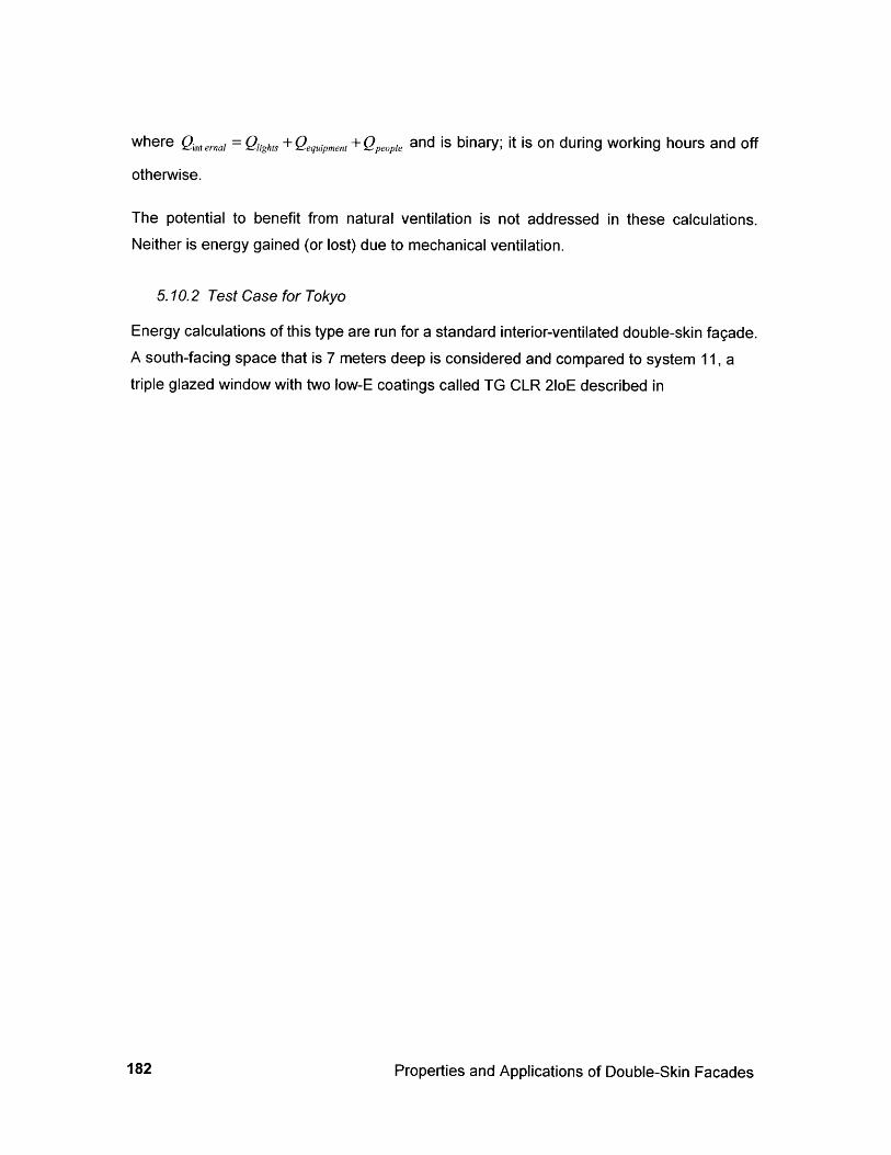
where Qinternal = Qlights +Qquipment+Qpp, and is binary; it is on during working hours and off
otherwise.
The potential to benefit from natural ventilation is not addressed in these calculations.Neither is energy gained (or lost) due to mechanical ventilation.
5.10.2 Test Case for Tokyo
Energy calculations of this type are run for a standard interior-ventilated double-skin fagade.A south-facing space that is 7 meters deep is considered and compared to system 11, atriple glazed window with two low-E coatings called TG CLR 21oE described in
Properties and Applications of Double-Skin Facades182
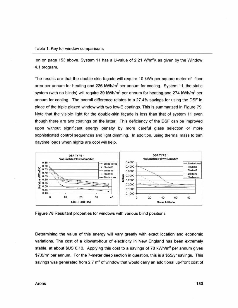
Table 1: Key for window comparisons
on on page 153 above. System 11 has a U-value of 2.21 W/m2K as given by the Window
4.1 program.
The results are that the double-skin fagade will require 10 kWh per square meter of floor
area per annum for heating and 226 kWh/m 2 per annum for cooling. System 11, the static
system (with no blinds) will require 39 kWh/m 2 per annum for heating and 274 kWh/m 2 per
annum for cooling. The overall difference relates to a 27.4% savings for using the DSF in
place of the triple glazed window with two low-E coatings. This is summarized in Figure 79.Note that the visible light for the double-skin fagade is less than that of system 11 even
though there are two coatings on the latter. This deficiency of the DSF can be improved
upon without significant energy penalty by more careful glass selection or more
sophisticated control sequences and light dimming. In addition, using thermal mass to trim
daytime loads when nights are cool will help.
Figure 78 Resultant properties for windows with various blind positions
Determining the value of this energy will vary greatly with exact location and economic
variations. The cost of a kilowatt-hour of electricity in New England has been extremely
stable, at about $US 0.10. Applying this cost to a savings of 78 kWh/m 2 per annum gives
$7.8/M 2 per annum. For the 7-meter deep section in question, this is a $55/yr savings. This
savings was generated from 2.7 m2 of window that would carry an additional up-front cost of
Arons
DSFTYPEVolumetric Flow=40m31hmn
0.85 -e- Blinds closed0.80 + Blinds 600.75 Blinds 45
-0.7 Blinds 300.60 -- Blinds opn
0.55
0.40
0 10 20 30 40
T,in - T,out (dC)
DSF TYPE IVolumetric Flow=40m3/hm
0.4500 - Blinds closed0.4000 - Blinds 60
0.3500 Blinds 45.. 30Blinds 30
03 Blinds open0.2500-
0.2000 -
0.1500
0.1000
0 20 40 60 80
Solar Altitude
183
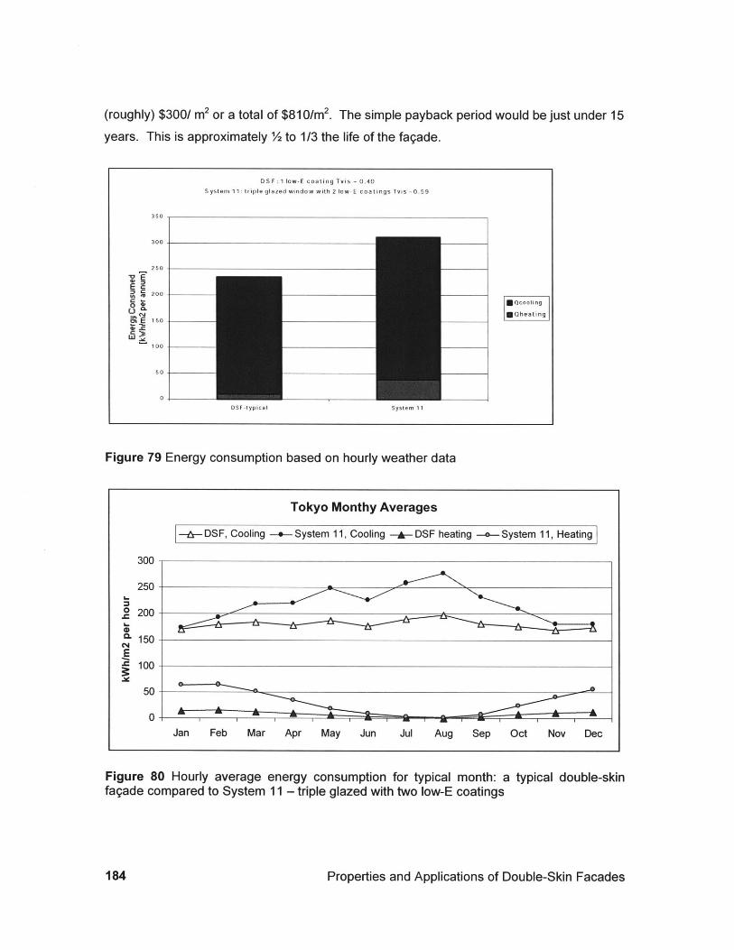
(roughly) $300/ m2 or a total of $81 0/m2. The simple payback period would be just under 15years. This is approximately 2 to 1/3 the life of the fagade.
DS F :1 low-E coating Tvis - 0.40
System 11: triple glazed window with 2 low-E coatings Tvis -0.59
350
300
250
200C r Qcooling
150 - *Qheating
100-
100
50
0
Figure 79 Energy consumption based on hourly weather data
Tokyo Monthy Averages
--- DSF, Cooling -.- System 11, Cooling -i- DSF heating --- System 11, Heating
300
250
o 200
150
E100-
0-Jan Feb Mar Apr May Jun Jul Aug Sep Oct Nov Dec
Figure 80 Hourly average energy consumption for typical month: a typical double-skinfagade compared to System 11 - triple glazed with two low-E coatings
Properties and Applications of Double-Skin Facades
DSF -typical System 11
184
Condensation
The Tokyo environs are relatively humid compared to Western Europe. The designer will be
concerned with the transfer of DSF's to this climate. For interior ventilated windows and
facades, tempered air is brought in contact with the inside face of the outer glazing unit
(usually a sealed unit). The potential for condensation exists during the winter, when the
inside air is warmer than outside air. A first order look will compare the dew point of 22
degree Celsius air at 50% humidity with the temperature of the inner face of the insulating
glass unit (the "critical surface"). The winter outdoor temperature Mean of Annual Extremes
from ASHRAE 1993 Fundamentals 24.20 gives a design temperature of-6 degrees Celsius.
This squares with the typical meteorological data that has -2 degrees Celsius for the
minimum annual temperature. A conservative temperature of -15 degrees Celsius is used
to test the window. This gives a critical surface (T2) temperature of 10.41 degrees Celsius.
This happens to be the dew point of the inside air. It can be concluded that this system is at
the very limit of feasibility for a window that will not have condensation in the cavity.
Changes to this system, such as allowing the humidity of the space to increase, or the set
point to be reduced will increase the risk of condensation. Summer conditions for this
system are not subject to condensation risk.
Using an exterior ventilated fagade changes the critical conditions for condensation.
The summertime design temperatures are dry-bulb 33 degrees Celsius and wet-bulb 27
degrees Celsius. This is corresponds to approximately 62 % relative humidity, and a dew
point of 25 degrees Celsius. A rough approximation may be made by adjusting the R-value
of the double-glazing unit between station points 1 and 3 to approximate a single layer of
glass. This gives a temperature on the critical surface (T6) of 27.5 degrees Celsius. This is
assuming the blinds are closed. If the blinds are open, the critical surface temperature
drops to 26.0 degrees Celsius, indicating again that the design is close to allowing for
condensation within the cavity. Neither situation implies that the design will not work, but
each deserves careful consideration.
Arons 185
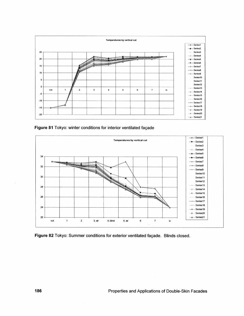
Figure 81 Tokyo: winter conditions for interior ventilated faqade
-+- Series1Temperatures by vertical cut Series2
Series3-- Series4
-*- Series534 -- Series6
-+- Series7
32- -_-------Series8
Series9SerieslO
30 Seriesi 1Series12Series1 3
28-_____ _____.... Series14
SeriesI526 Series16
Series17
214- Series18
Series19-e- Series20
22--- Series21out 1 2 3, air 4, blind 5, air 6 7 in
Figure 82 Tokyo: Summer conditions for exterior ventilated fagade. Blinds closed.
Properties and Applications of Double-Skin Facades
Temperatures by vertical cut
-+-- Series1
-*- Series2
25 Series3
2- Series420 - - --------- s-- Series5
-+ Series615 +__________ _____--- Series7
-Series810 --- Series9
Series1
0 Series11
SSeries12
0 Series3l
5- Series1lSeries15
0 Series16-15 1_____ 2_____ 3___ _ 4 5 6 7 in
--- Series17
---- Seriesl-- Series'19
20 _- Series20
*- Series2l
186
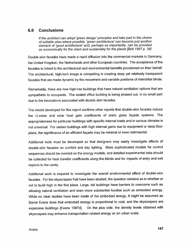
6.0 Conclusions
If the architect can adopt 'green design'principles and take part in the choiceof suitable sites where possible, 'green architecture' can become just anotherelement of 'good architecture' and, perhaps as importantly, can be providedas economically for the client and sustainably for the planet [Bolt 1997 p. 34]
Double-skin facades have made a rapid diffusion into the commercial markets in Germany,
the United Kingdom, the Netherlands and other European countries. The acceptance of the
facades is linked to the architectural and environmental benefits proclaimed on their behalf.
The architectural, high-tech image is compelling in creating deep yet relatively transparent
facades that are made dynamic by the movement and variable positions of interstitial blinds.
Remarkably, there are now high-rise buildings that have natural ventilation options that are
sympathetic to occupants. The sealed office building is being phased out, in no small part
due to the innovations associated with double-skin facades.
The model developed for this report confirms other reports that double-skin facades reduce
the U-value and solar heat gain coefficients of static glass fagade systems. The
appropriateness for particular buildings with specific internal loads and in various climates is
not universal. For certain buildings with high internal gains due to equipment or deep floor
plans, the significance of an efficient fagade may be minimal or even detrimental.
Additional tools must be developed so that designers may easily investigate effects of
double-skin facades on comfort and day lighting. More sophisticated models for control
sequences should be overlaid on the energy models, and detailed experimental data should
be collected for heat transfer coefficients along the blinds and for impacts of entry and exit
regions to the cavity.
Additional work is required to investigate the overall environmental effect of double-skin
facades. For the skyscrapers that have been studied, the question remains as to whether or
not to build high in the first place. Large, tall buildings have barriers to overcome such as
allowing natural ventilation and even more substantial hurdles such as embodied energy.
While no clear studies have been made of the embodied energy, it might be assumed as
Barrie Evans does that embodied energy is proportional to cost, and the skyscrapers are
expensive buildings [Evans 1997d]. On the plus side, the density levels obtained with
skyscrapers may enhance transportation related energy on an urban scale.
Arons 187
Appropriate application of the technology is still being explored. The Debis building byPiano represents the incorporation of preceding knowledge gained at Commerzbank, RWEand other tall buildings. It embodies the merging paths of innovation of both the double-skinfagade and Piano's own explorations with terracotta into one integrated architectural andtechnical expression. The evolution from here might be to look to cavities in front of opaquewalls similar to capture energy. This might involve incorporating photovoltaic panels oradapting the concept of the Trombe wall. This implies an opaque or combined transparentand opaque fagade that has air moving through interstitial cavities.
Often, when studying systems, engineers would like to optimize a system for a particularproperty such as low energy consumption. Particularly in the design of buildings, this isdifficult because of conflicting priorities such as optimizing daylight and minimizing solargain. Thus, co-optimizing is essential. The link between architects, engineers and facilitymanagers must be carefully managed to develop and use complicated control features thatdo not overwhelm users or the lack of management may render the advanced fagadesinefficient.
The use of diaphanous walls of double-skin facades must be made with careful attention toenergy impacts in parallel with human and urban sensitivities. They offer opportunities thatstatic walls do not offer but must be implemented with foresight of their potentialarchitectural, human, and environmental significance.
Properties and Applications of Double-Skin Facades188
7.0 Appendices
7.1 Contacts
Academic Contacts
* Saelens, Dirk, and Hens, Hugo(D.V.V. Building)Katholieke Universiteit LeuvenDepartment of Civil EngineeringLaboratory of Building PhysicsCelestijnenlaan 131B-3001 HeverleeBELGIUMTel. +32 (0) 16 32 17 67Fax. +32 (0) 1632 1980dirk.saelens(cbwk.kuleuven.ac.be
e Murray MilneMilne(aucla.eduUC Berkeley
* Pablo La Rocheplaroche(a2ucla.eduUC Berkeley
* Professor Leijendeckersprof.ir. P.H.H. LeijendeckersEindhoven UniversityE-mail: bwnetty(qbwk.tue.nlor i.m.d.bruijnabwk.tue.nlRoom: HG 11.79Telephone: +31 40 2473233Telefax: +31 40 2438595Bert Van De Linde Permasteelisa GM in HollandContact from Marc Zobec @ Permasteelisa(h fax) +31 485 514694(h) +31 485 516416climate facades like Schipol World Trade, Amsterdam
* Professor Victor Hanby(from M. Holmes @ Arup)Loughborough UniversityBuilding Services Engineering Research Grouphttp://info.lut.ac.uk/departments/cv/research/envsysenq/bserv.htmlv.i.hanby(@lboro.ac.ukV I Hanby BSc PhD CEng MInstE MCIBSEProfessor of Building Services Engineering
Arons 189
* CALPOLY PageCommerzbank Headquarters Buildinghttp://www.calpoly.edu/-wechen/commer-1.htmlhttp://www.calpoly.edu/-wechen/garden.html
* DortmundAll Members of Lehrstuhl Klimagrechte Architektur are acessible via Telephoneand Fax.The Numbers are relative to internal UniDo-Net,which is acessible by ++49-231-755.Fax: ++49-231-755-5423Professor: Prof. Helmut F. 0. Mullerhttp://www-klima.bauwesen.uni-dortmund.de/people/mueller.htmlProf. Dr. Dipl.-Ing. Helmut F. 0. MullerAdress: Baroper Str. 30144227 Dortmund
Professor Mueller,mueller&)klima.bauwesen.uni-dortmund.dephone: ++49-231-755-5837fax: ++49-231-755-5423Prof. Pasquay 0231/ 755 4690
C. NolteDipl.-Ing. Christoph NolteChair of Environmental Architecture/Lehrstuhl Klimagerechte ArchitekturProf. MuellerBaroper Str. 301D - 44227 Dortmund I Germanytel: 0231 / 755 5425 (h) 0231 / 755 5425fax: 0231 / 755 5423nickaklima.bauwesen.uni-dortmund.de
e Werner LangFakultat fur ArchitekturLehrstuhl fur Entwerfen und Baukonstruktion 11Professor Thomas HerzogRichard-Wagner-Str. 18 11Arcisstr.21 (Postanschrift)D-80333 Munchen
Tel 089/289-28698Fax 089/289-28675w.lanq(lrz.tu-muenchen.de
* ESP-rProfessor J A Clarkeemail: [email protected], Dept. of Mechanical Eng.
Properties and Applications of Double-Skin Facades190
phone: +44 141 548 3986University of Strathclydefax: +44 141 552 8513Glasgow G1 1XJ, UKhttp://www.strath.ac.uk/Departments/ESRU
Enqineerinq Firmse HL-Technik AG,
Rudy Marekeratende IngenieureWolfratshauser Strage 54D-81379 MunchenTelefon +49-89-724060Telefon +49-89-72406400Telefax +49-89-72406139vstcDhl-technik.de(Dr. Stoll is the team leader)
Rudi Marek rm(Dhl-technik.deKlaus Daniels (dachl-technik.de) :secretary Anja Bartsch (ab(Chl-technik.de)
* ARUPMichael Holmes michael.holmes(Darup.comTel 0171 465 3368 orfax 0171 465 3669
"David Richards" david.richardsaarup.comAndrew Hall -( andrew-j.halla-arup.com) Arup FagadeSee Finsbury Pavement, Glaxgow Wellcome, Triton Square."Jenny Banach-Bennett" jenny.banach-bennett(arup.comJenny Bennett PA to Andrew Hall
Alistair Guthrie - a mechanical engineer who has been involved in a few,notablyFinsbury Pavement with Shepard Robson.Arup #....+44 171 636 1531.
* Michael HolmesV I Hanby BSc PhD CEng MInstE MCIBSEProfessor of Building Services EngineeringGave contact to mailto:v.i.hanby(lboro.ac.uk
Architects* Foster and Partners
Riverside Three22 Hester RoadLondon SW1 1 4ANTel 0171 738 0455Fax 0171 738 1107/8Contact: Graham Phillips out til 6/8enquiriesafosterandpartners.com
* INGENHOVEN OVERDIEK und PARTNER
Arons 191
Mr. Michael Reis - Tel.: +49 (211) 30 10 11 33Achitekt Office IngenhovenMr. Michael Reis - Tel.: +49 (211) 30 10 11 33Kaistrasse 16AD-40221 DusseldorfPostfach 19 00 46D-401 10 DusseldorfTel 0211/ 3 01 01-01Fax 0211/3 01 01-31Fax Attention: Mr Jan Esche.tel+49 - 211 - 301 01133fax +49 - 211 - 301 0135
* Michael Hopkins and PartnersChris Bannister hopkins(adial.pipex.comMichael Hopkins & Partners plc27 Broadley TerraceLondon NW1 6LG UKTel: +44 (0)171 724 1751FAX: +44 (0)171 723 0932www.hopkins.co.uk/Site visit of NPB - site architect.
Manufacturers
e Josef Gartner & Co.Mr. Nistler (from Sven Ollmann @ Foster)Johann ErnstWerkstatten fur Stahl-UndMetalkonstuktionenPostfach 20/40D-89421 Gundelfingen Germanyphone +49 9073 84-0fax +49 90 73 84 21 00 in country dial 0907384...Mr. (Johann?) Ernst - Tel.: +49 (90 73) 84 24 50Gartner, in Gundelfingen, Germany
e PERMASTEELISAAmerican HeadquartersPERMASTEELISA USA INC.107 PHOENIX AVENUE - ENFIELD-CT 06083-1700Tel. 001-860-253 4485 / Fax 001-860-745 8534
* PERMASTEELISAMikkel Kristian KraghPERMASTEELISA SpA - Architectural ComponentsResearch & EngineeringConegliano Uno - Edf. QuaternarioVia Friuli, 10. 31020 San Vendemiano (TV) ItalyTel +39 0438 491204 Fax +39 0438 402031
Properties and Applications of Double-Skin Facades192
E-mail [email protected] www.permasteelisa.com.sg
* PERMASTEELISAMarc ZobecR&D DirtectorPermasteelisa Spa.Phone 39 438 491 1Fax 39 438 401 606zobec.ma(&permasteelisa.it
" PERMASTEELISAMassimo ColombanPresident
Building Related
* Commerzbank homepagehttp://www.commerzbank.com/zentrale/zentrale.htm#topic1http://www.commerzbank.com/
. Eurotheum FrankfurtProjektbOro im EurotheumNeue Mainzer Stralle 66-6860311 FranfurtMrs Rietzphone 0172/6618010
e Commerzbank Tower FranfurtKaiserstrae 16FrankfurtBuilding Manager of the Commerzbank TowerMr Muschelknautzphone 0049/69/13629527fax (00496913627760)[email protected]
* Main-Tower FranfurtNeue Mainzer Strasse / GallusstrasseFrankfurtMr Hecht (Gartner Company)phone 0171 /2348720
" Stadttor DcsseldorfEngel ProjektentwicklungStadttor 140219 D0sseldorfMr Engel, Mr CanessaSpoke with engel (6/16/1999)phone 0049 / 211 / 6000 6020
Arons 193
fax 0049/ 211 / 6000 6016information available at http://www.stadttor.de/and http://www.hsp.de/-wiegels/serien/stadttor.htm
* Victoria Insurance DusseldorfViktoria Platz 2DusseldorfMr Holthausenphone 0049/211 /49 34 812fax 0049/211/49 34 850
Mrs Deisingerphone 0049/211 /49 34 611building manager: Mr. Waldenmeasurements by Mueller @ Dortmund University
* [email protected] of RWE Building
* RWE Tower EssenOpernplatz 145128 EssenMr WeberProjekt...phone 0049 / 201 / 82 706 26fax 0049/201/22922 1measurements by Mueller, Pasquay
e RWE tower (DLZ-Stern) : Mr. K6hier[facilities Manager]e-mail: [email protected]. Till Pasquay (a member of U Dortmund chair) knows him very well.
* Dortmund:Siemens-GebaudeMarkische Strasse 8-1444135 Dortmundcontact Mr. Ortelt, tel.: 0171 3290135 (mobil)
* Dusseldorf:Torhausarchitect: Petzinka, Pink, Kahlen & PartnerCecilienallee 1740474 Dsseldorf
" Victoria Insurance BuildingBezirksregierung DUsseldorfMr. Cornelissen [tenant]Cecilienallee 240408 DusseldorfFax: +49 (0) 211 4752971
Properties and Applications of Double-Skin Facades194
7.2 Thermal model data for verification
The following sections include backup for the verification and validation of the simplified
model of heat transfer presented in Section 4.0 of this report. The following are included
* 7.2.1 Temperature Distribution Verification
* 7.2.2 Cavity Flow Verification
* 7.2.3 Buoyancy Verification
* 7.2.4 U-value Validation
* 7.2.5 SHGC Validation
Arons 195
7.2.1 Temperature Distribution Verification
The following is the backup for the model that compares temperature distribution through
the double-skin fagade cavity as driven by temperature difference without solar radiation.
Arons
196
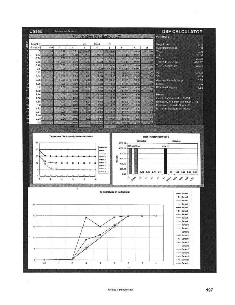
dl Blind d22 I A I m I -I I
height, y@bottom[
00.120.240.360.480.6
0.720.84
Temperature Distribution by Horizontal Station
-4-out
-2
-0-5-+-6
-7-in
1200.00
1000.00
800.00
600.00
400.00
200.00
0.00
Heat Transfer Coefficients
Convection
10
0 2 4 6 8 10
Temperatures by vertical cut
out 1 2 3 4 5 6 7 in
UValue Verification.xls
Radiation
21 2 ""- '
+Seiesl
-4-Seies2
-r Series3
-*-- Series4
-I- Series5
-4-Series6
-- SerIes7
- Series8
- Series9
SerieslO
Seriesli1
Seriesl2
- -Series13
*-Series14
SeiesIS
Seres16
- Series17
-Series18
0- Seies19
4- Series20
*-Series2
197
000.041000.00 1000.00
5.85 5.85 5.81 5.81 4.64 5.69 5.69 5.69 4.84

Tm hrad Tm hrad Tm hrad Tm hrad Tm hrad
assumptionsTm4-2 at y=O is T3=Tln noteTm6-4 at y=O is T5=TIn Tm go with y-1 rather than yTm7-4 at =0 is T5=TIn
Al A2 AS B, B, B, C, C, C, D, D2 El E2
198
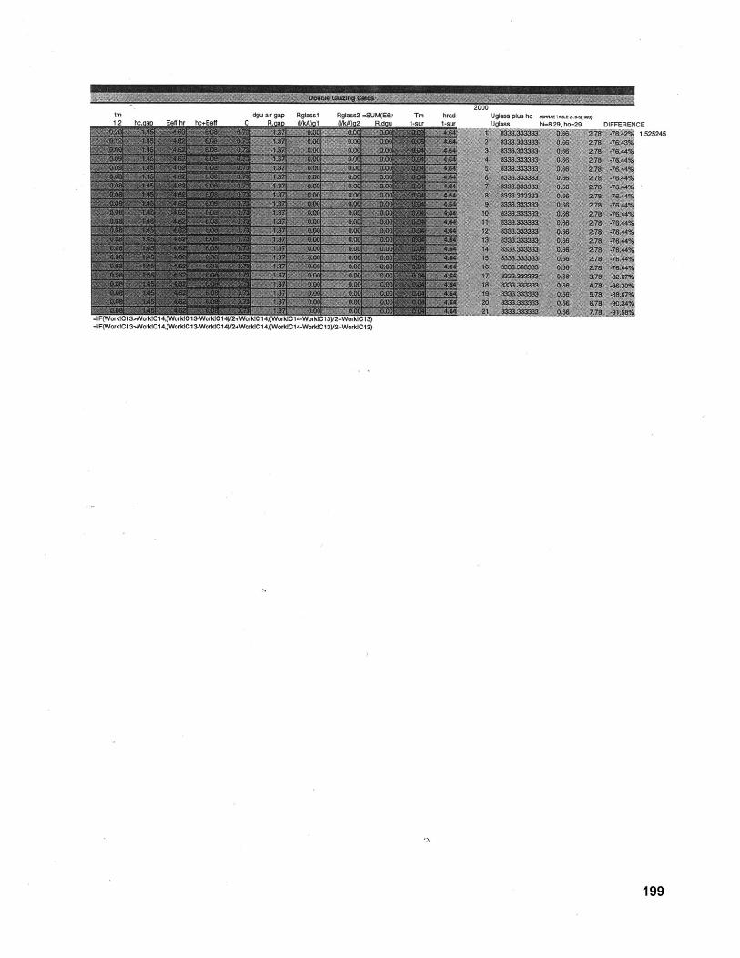
.3 .74bOPM
dgu air gap Rglassl Rglass2 -SUM(E6:1 Tm hrad Uglassplushc A%4wTA&E2?,"i9m
Uglass hi--8.29, ho=29 DIFFERENCE1.525245
=1 -tWOrK]t;ld>WOMU14.(VVOMt;IL4-WOMt;14YZ+WonCU14.(WCMG14-WOrKlCl3y2+WorlaGl3)=IF(WorkIC13>WorldCI4,(WorldCl3-WorktCl4y2+WorkIC14,(WorkIC14-WorldCl3y2+WorklC13)
199
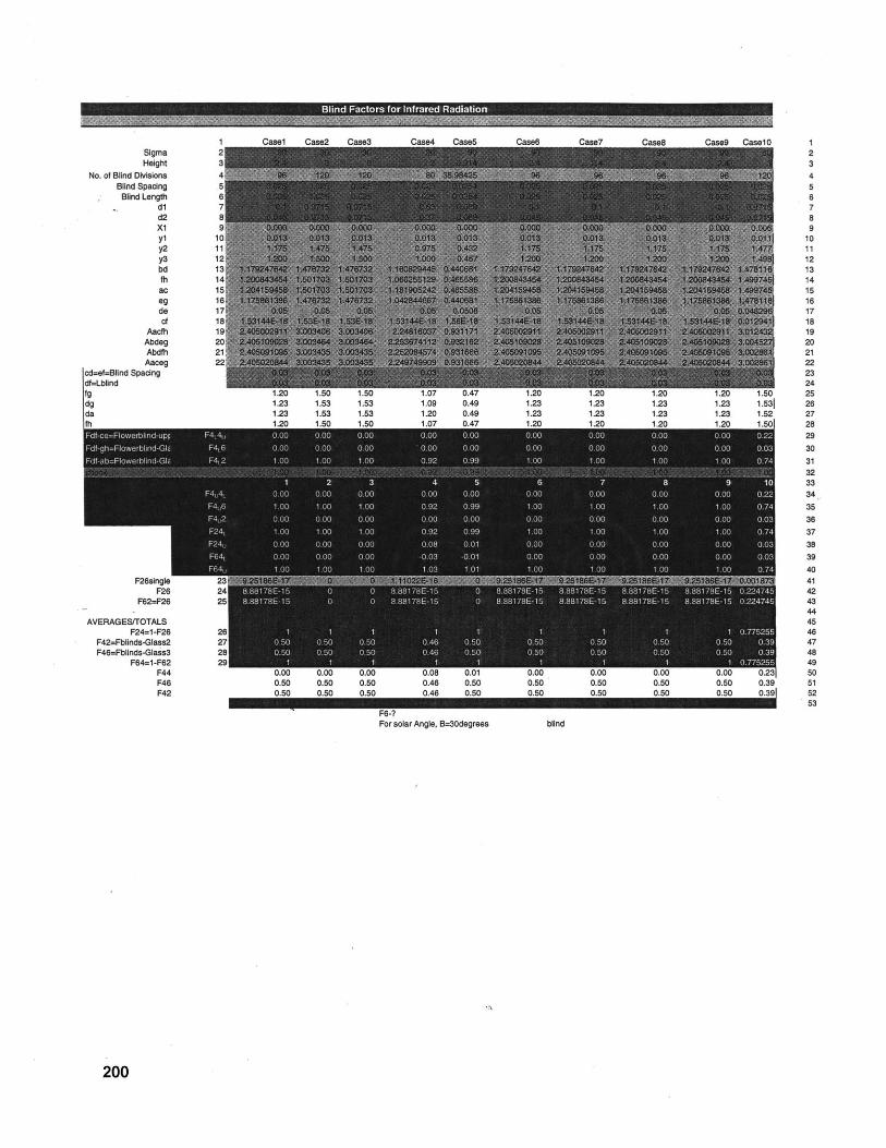
SigmaHeight
No. of Blind DIvisionsBlind Spacing
Blind Lengthdld2xlX1
y2y3bdfhacegdecf
AacfhAbdegAbdfhAaceg
cd=ef=Blind Spacingdf=Lblindfgdgda
1.2u 1.53 1.u 1.U9 u.49 1.4u1.23 1.53 1.53 1.09 0.49 1.231.23 1.53 1.53 1.20 0.49 1.231 5On 1 An i Krn I M7 n A7 1 51n
F6-?For solar Angle, B=30degrees blind
ase7 Case8 Case9 Case10 12345B789
101112131415161718192021222324
1.20 1.20 1.20 1.50 251.23 1.23 1.23 1.53! 28
100 10 00 074 3132
02 34.
1 00 000 000 74 35
1 0 0 1 0 74 37
4142
4445
1 1 0.75255 460 50 0 50 0 50 0 39 470 50 0 50 0 50 0.39 48
1 1 0.75255 490.00 0.00 0.00 0.23 500.50 0.50 0.50 0.39 510.50 0.50 0.50 0.39! 52
53
200
Blind Factors for Infrared Radiation n m9W 'V BOW
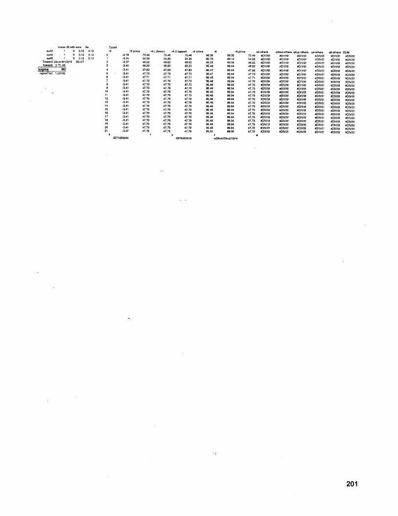
emiss IR refle area Assurf2 1 0 0.12 0.12surf4 1 0 0.12 0.12surf6 1 0 0.12 0.12
Tmean3 ((tout+tin)/2)^3 2E+07StefanB 5.7E-08
sigma 901sigmaTm3 1.29192
Case82 r 2 prime r4 L (!wer) r4 U (upper) r4 prime r6
-2.79 73.46 73.46 73.46 96.36-3.24 54.36 54.36 54.36 95.70-3.37 49.52 49.52 49.52 95.53
1 -3.40 48.20 48.20 48.20 95.48-3.41 47.83 47.83 47.83 95.47
. -3.41 47.73 47.73 47.73 95.47-3.41 47.71 47.71 47.71 95.46-3.41 47.70 47.70 47.70 96.46-3.41 47.70 47.70 47.70 95.46
1 -3.41 47.70 47.70 47.70 95.46I -3.41 47.70 47.70 47.70 95.46
-3.41 47.70 47.70 47.70 95.46-3.41 47.70 47.70 47.70 95.46
I -3.41 47.70 47.70 47.70 95.46-3.41 47.70 47.70 47.70 96.46-3.41 47.70 47.70 47.70 95.46-3.41 47.70 47.70 47.70 95.46-3.41 47.70 47.70 47.70 95.46
1 -3.41 47.70 47.70 47.70 95.461 -3.41 47.70 47.70 47.70 95.461 -3.41 47.70 47.70 47.70 95.46
-3.37 47.75 47.75 47.75 95.52St u v
5571658264 6876455416
r6 prime q2-others q4low-othes q4up-others q4-others q6-others SUM73.46 #DIV/o! #DIV/0! #D/O! #DIV/! #DIV/I #DV/o!54.36 #DV/O! #DIV/0! #DIV/0! #DIV/O! #DIV/o #D/!49.52 #DIV/O! #DIV/o! #DIV/0! #DIV/! #DIV/01 #DIV/o!48.20 #DIV/Of #DIV/o! #DiV/o! #DIV/O! #DIV/O! #DIV/o!47.83 #DN/O! #D/O! #DV/Of #DIV/O #DIV/O! #DN/f47.73 #DN/S #D/O! #DIV/01 #DIV/O! #DIV/o! #DIV/o!47.71 #DIV/0 #DIV/o #D/o #DV/O #DV/of #DIV/o!47.70 #DIV/Of #D!V/0 #DIV/01 #DIV/O! #DV/01 #DIV/0147.70 #DIV/O! #DIV/O! #DV/0f #DIV/Of #DIV/O! #DV/o!47.70 #DIV/O! #DIV/O! #DIV/Of #DV/0 #DIV/! #DNIV/O47.70 #DV/0I #DIV/o! #DIV/0 #DIV/O! #DIV/O #DIV/0!47.70 #DiV/O! #DIV/O! #DV/O! #DV/Of #DIV/O! #DIV/0!47.70 #DV/O! #DIV/0l #DIV/O! #DN/01 V #0W/Of #DV/O!47.70 #DIV/f! #DV/O! #DIV/O! #DV/01 #DV/o #DIV/O47.70 #DV/0! #DV/Of #DIV/Ol #DIV/0 #DIV/01 #DIV/!47.70 #DIV/0 #DV/o! #DIV/O! #DV/O! #DIV/01 #DIV/O47.70 #DIV/o! #DV/o! #DIV/ 0! #DV/o! #DIV/0! #DIV!47.70 #DIV/o #DIV/O! #DIV/O! #DIV/01 #DIV/O! #DIV/O!47.70 #DIV/01 #DIV/o! #DIV/0! #DIV/0! #DIV/O! #DIV/o!47.70 #DV/f! #DIV/0! #DV/01 #DIV/S! #DIV/01 #DIV/O47.70 #DIV/O! #DIV/01 #DIV/O! #DIV/f #DV/01 #DV/0!47.75 #DIV/01 #DIV/0! #DIV/O #DIV/o! #DIV/01 #DIV/!
w
99.3299.1099.0699.0499.0499.0499.0499.0499.0499.0499.0499.0499.0499.0499.0499.0499.0499.0499.0499.0499.0499.06
Work!06+273
201
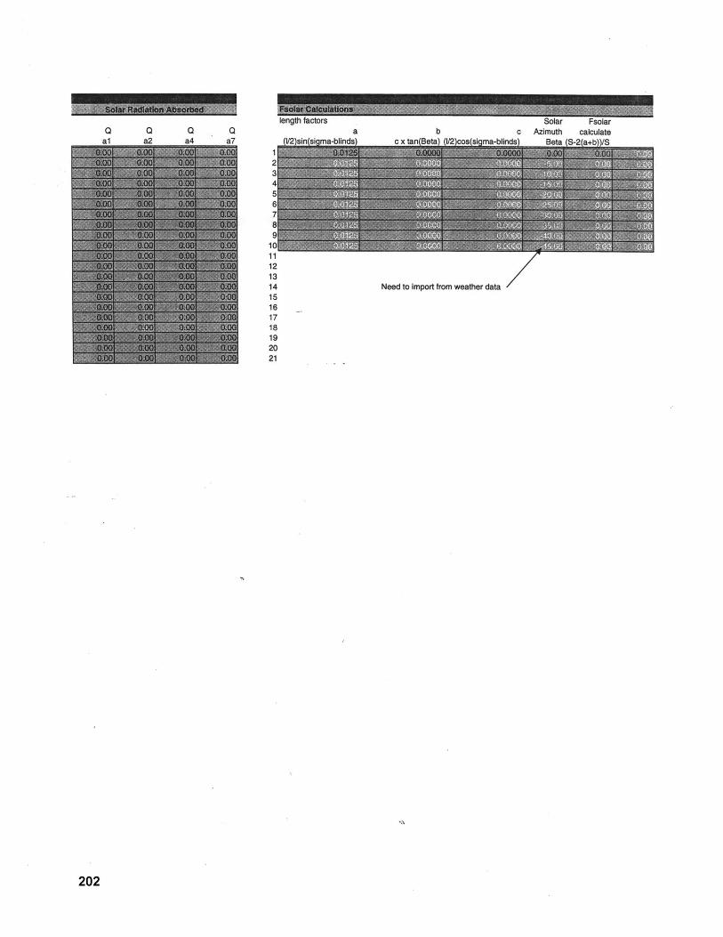
a Q QA2 A4 n7
a bbolar Fsolar
c Azimuth calculateA\ QM.a QOax\/
121314 Need to import from weather data
202
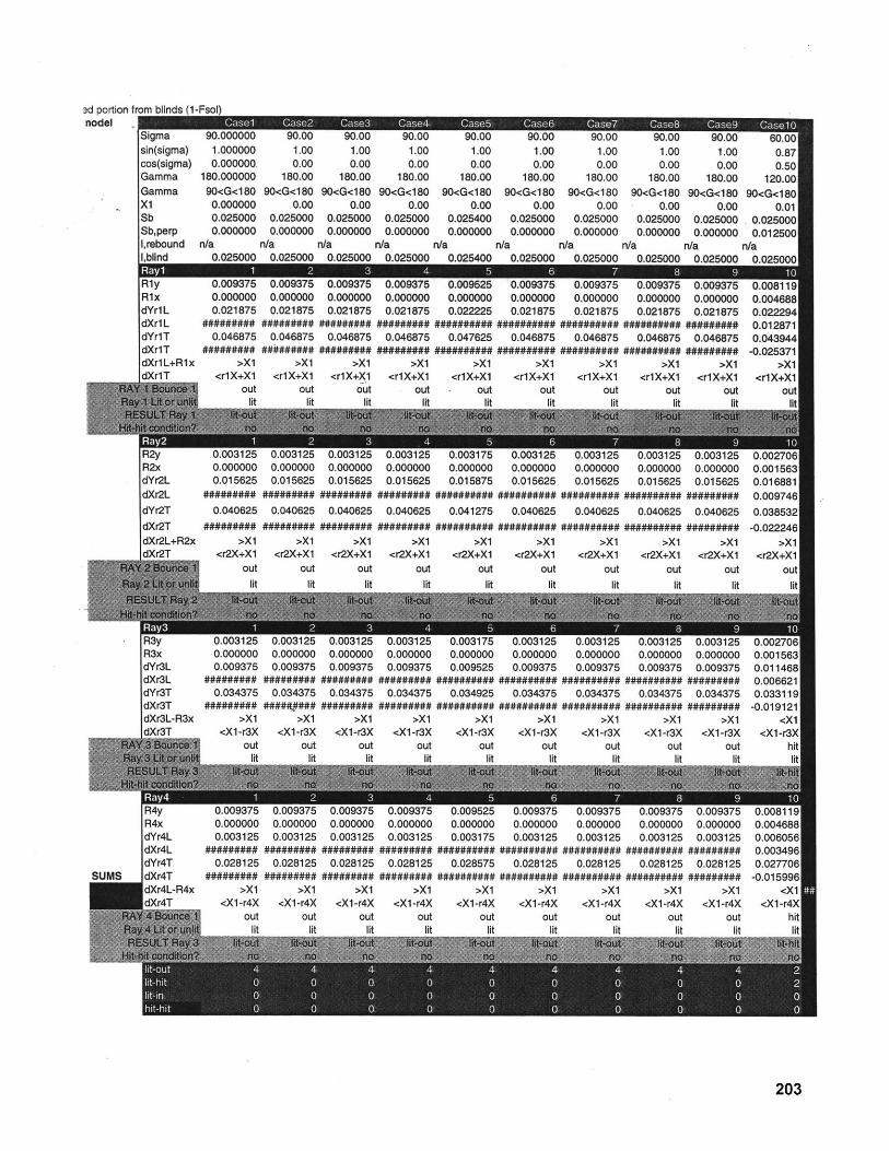
Wu.uuuuuu du.uu tu.uu Vu.uu1.000000 1.00 1.00 1.000.000000, 0.00 0.00 0.00
180.000000 180.00 180.00. 180.0090<G<180 90<G<180 90<G<180 90<G<1800.000000 0.00 0.00 0.000.025000 0.025000 0.025000 0.0250000.000000 0.000000 0.000000 0.000000
n/a n/a n/a n/an nonnn n nonnnn n noAnnn n nofnnn
0.009375 0.0093750.000000 0.0000000.021875 0.021875
######### #########0.046875 0.046875
######### #########>X1 >X1
<rlX+X1 <rlX+X1out out
lit lit
0.0000000.015625
0.040625
>X1<r2X+X1
outlit
0.0093750.0000000.021875
#########0.046875
>X1<rlX+X1
outlit
0.000000 0.0000000.015625 0.015625
######## #########0.040625 0.040625
######### #########>X1 >X1
<r2X+X1 <r2X+X1out out
lit lit
0.000000 0.0000000.009375 0.009375
######### #########0.034375 0.034375
######### #########>X1 >X1
<X1-r3X <X1-r3Xout out
lit lit
-..-- , -0.0000000.003125
0.028125#########
>X1<Xl-r4X
outlit
0.0000000.003125
0.028125#########
>X1<Xl-r4X
outlit
U.uO 140
0.0000000.009375
#########0.034375
#########>X1
<X1 -r3Xout
""
0.0000000.003125
0.028125#########
>X1<X1 -r4X
outlit
1.000.00
180.0090<G<180
0.000.0254000.000000
n/aA AOAAn
1.00 1.000.00 0.00
180.00 180.0090<G<180 90<G<180
0.00 0.000.025000 0.0250000.000000 0.000000
n/a n/aA nonAn n nornnn
0.009525 0.0093750.000000 0.0000000.022225 0.021875
########## ##########0.047625 0.046875
########## ##########>X1 >X1
<rlX+X1 <rlX+X1- out out
lit lit
0.0093750.0000000.021875
#########0.046875
#########>X1
<rlX+X1out
lit
10.0031250.0000000.015625
#########
0.040625
>X1<r2X+X1
outlit
0.0000000.021875
##########0.046875
##########>X1
<rlX+X1out
1.000.00
180.0090<G<180
0.000.0250000.000000
n/a
90.001.000.00
180.0090<G<180
0.000.0250000.000000
n/a
0.000000 0.0000000.021875 0.021875
########## #########0.046875 0.046875
########## #########>X1 >X1
<rlX+X1 <rlX+X1out out
0.003125 0.003125 0.0031250.000000 0.000000 0.0000000.015625 0.015625 0.015625
########## ########## ##########0.040625 0.040625 0.040625
########## ########## ##########>X1 >X1 >X1
<r2X+X1 <r2X+X1 <r2X+X1out out out
lit lit lit
0.000000 0.0000000.009375 0.009375
########## ##########0.034375 0.034375
########## ##########>X1 >X1
<X1-r3X <X1-r3Xout out
lit lit
0.0093750.0000000.003125
0.028125
>X1<Xl-r4X
out"'
0.0093750.0000000.003125
##########0.028125
##########
>X1<X1 -r4X
out"",
U.uuI I zo
0.0000000.009375
0.034375
>X1<Xl-r3X
out
0.0093750.0000000.003125
##########0.028125
>X1<X1-r4X
out
jigmasin(sigma)cos(sigma)GammaGammax1lSbSb,perp1,reboundI hind4
0.003125 0.0027060.000000 0.0015630.015625 0.016881
######### 0.0097460.040625 0.038532
######### -0.022246>X1 >X1
<r2X+X1 <r2X+X1out out
lit lit
u.Uus I zo0.0000000.009375
#########0.034375
#########>X1
<Xl-r3Xout
0.0093750.0000000.003125
#########
0.028125#########
>X1<Xl-r4X
outlit
u.uurrue0.0015610.01 146E0.0066210.03311G
-0.019121<X1
<X1-r3>hi
0.0081190.0046880.0060560.0034960.027706
-0.015996<X1
203
3d portion fnodel
0.870.50
120.0090<G<180
0.010.0250000.012500
n/a0.025000
0.0081190.0046880.0222940.0128710.043944-0.025371
>X1<rlX+X1
out
RlyR1xdYr1LdXr1LdYr1TdXr1TdXr1L+R1xAv,lr
R2xdYr2LdXr2LdYr2TdXr2TdXr2L+R2x
R3xdYr3LdXr3LdYr3TdXr3TdXr3L-R3x''--
R4xdYr4LdXr4LdYr4TdXr4TdXr4L-R4xIAvAT
0.0000000.015875
##########
0.041275##########
>X1<r2X+X1
outlit
0.0031750.0000000.009525
0.034925##########
>X1<X1-r3X
outlit
50.0095250.0000000.003175
0.028575##########
>X1<X1-r4X
outlit
0.0000000.009375
#########0.034375
#########>X1
<Xl-r3Xoutlit
120.0093750.0000000.003125
#########0.028125
#########>X1
<Xl-r4Xout
lit
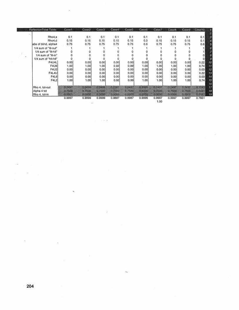
Rho4,s 0.1 0.1 0.1 0.1 0.1 0.1 0.1 0.1 0.1 0.1Rho4,d 0.15 0.15 0.15 0.15 0.15 0.3 0.15 0.15 0.15 0.1
abs of blind, alpha4 0.75 0.75 0.75 0.75 0.75 0.6 0.75 0.75 0.75 0.61/4 sum of "lit-out" 1 1 1 1 1 1 1 1 1 11/4 sum of "lit-hit" 0 0 0 0 0 0 0 0 0 11/4 sum of "lit-in" 0 0 0 0 0 0 0 0 0 C
1/4 sum of "hit-hit" 0 0 0 0 0 0 0 0 0 CF4U4L 0.00 0.00 0.00 0.00 0.00 0.00 0.00 0.00 0.00 0.22
F4U6 1.00 1.00 1.00 0.92 0.99 1.00 1.00 1.00 1.00 0.74F4U2 0.00 0.00 0.00 0.00 0.00 0.00 0.00 0.00 0.00 0.01
F4L4U 0.00 0.00 0.00 0.00 0.00 0.00 0.00 0.00 0.00 0.2F4L6 0.00 0.00 0.00 0.00 0.00 0.00 0.00 0.00 0.00 0.0%F4L2 1.00 1.00 1.00 0.92 0.99 1.00 1.00 1.00 1.00 0.74
Rho 4, tot-out I M M a ,E a M i ,EAlpha 4 totRho 4, tot-in
0.9999 0.9999 0. 0.9997 0.1.00
204
0.9997
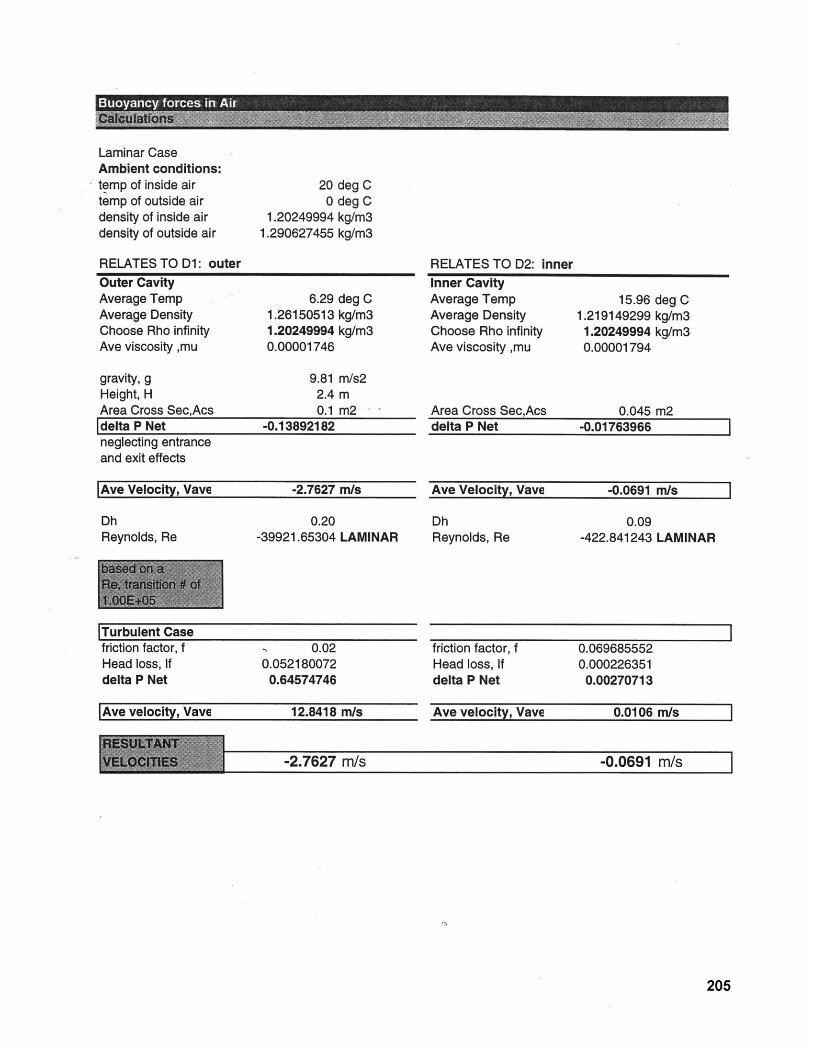
Laminar CaseAmbient conditions:temp of inside airtemp of outside airdensity of inside airdensity of outside air
200
1.202499941.290627455
RELATES TO D1: outerOuter CavityAverage Temp 6.29 deg CAverage Density 1.26150513 kg/m3Choose Rho infinity 1.20249994 kg/m3Ave viscosity ,mu 0.00001746
gravity, g 9.81 m/s2Height, H 2.4 mArea Cross Sec,Acs 0.1 m2delta P Net -0.13892182neglecting entranceand exit effects
Ave Velocity, Vave -2.7627 m/s
Dh 0.20Reynolds, Re -39921.65304 LAMINAR
Turbulent Casefriction factor, f 0.02Head loss, If 0.052180072delta P Net 0.64574746
Ave velocity, Vave 12.8418 m/s
RELATES TO D2: innerInner CavityAverage Temp 15.96 deg CAverage Density 1.219149299 kg/m3Choose Rho infinity 1.20249994 kg/m3Ave viscosity ,mu 0.00001794
Area Cross Sec,Acs 0.045 m2delta P Net -0.01763966
Ave Velocity, Vave -0.0691 m/s
Dh 0.09Reynolds, Re -422.841243 LAMINAR
friction factor, f 0.069685552Head loss, If 0.000226351delta P Net 0.00270713
Ave velocity, Vave 0.0106 m/s
-2.7627 m/s -0.0691 m/s
205
deg Cdeg Ckg/m3kg/m3
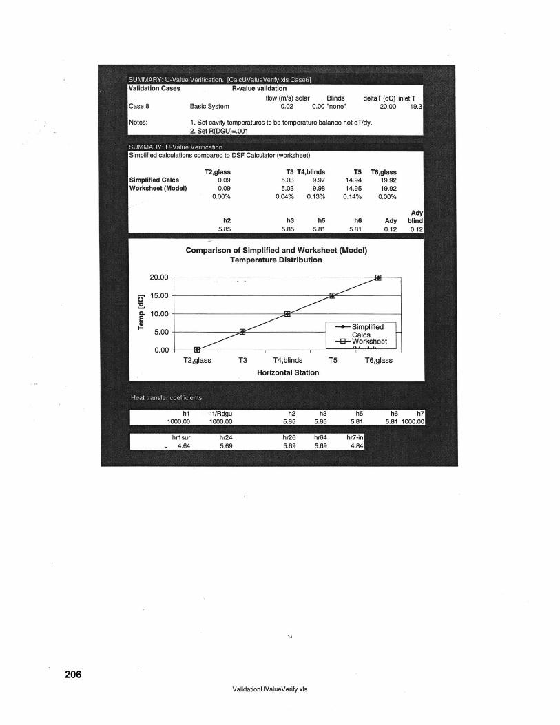
206ValidationUValueVerify.xls
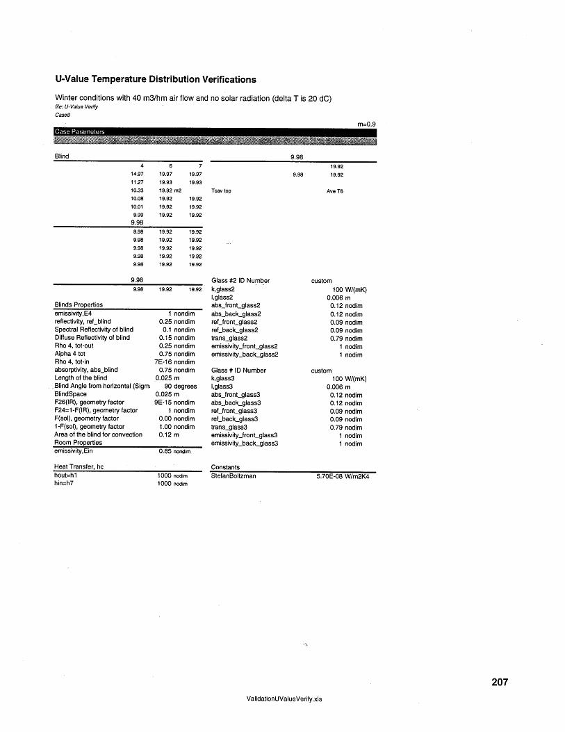
U-Value Temperature Distribution Verifications
Winter conditions with 40 m3/hm air flow and no solar radiation (delta T is 20 dC)file: U-Value Verify
Case8
m=0.9Case Parameters
Blind4 6 7
14.97 19.97 19.9711.27 19.93 19.9310.33 19.92 m2
10.08 19.92 19.9210.01 19.92 19.92
9.99 19.92 19.929.98
9.98 19.92 19.929.98 19.92 19.929.98 19.92 19.929.98 19.92 19.929.98 19.92 19.92
9.989.98 19.92 19.92
Blinds Propertiesemissivity,E4 1 nondimreflectivity, ref_blind 0.25 nondimSpectral Reflectivity of blind 0.1 nondimDiffuse Reflectivity of blind 0.15 nondimRho 4, tot-out 0.25 nondimAlpha 4 tot 0.75 nondimRho 4, tot-in 7E-16 nondimabsorptivity, abs -blind 0.75 nondimLength of the blind 0.025 m
-Blind Angle from horizontal (Sigm 90 degreesBlindSpace 0.025 mF26(IR), geometry factor 9E-15 nondimF24=1-F(IR), geometry factor 1 nondimF(sol), geometry factor 0.00 nondim1-F(sol), geometry factor 1.00 nondimArea of the blind for convection 0.12 mRoom Propertiesemissivity,Ein 0.85 nondim
Heat Transfer, hchout=h1hin=h7
1000 nodim1000 nodim
9.9819.92
9.98 19.92
Tcav top Ave T6
Glass #2 ID Numberk,glass2l,glass2absjfront-glass2abs.back-glass2ref-front-glass2reLback-glass2trans-glass2emissivityjront-glass2emissivity-backglass2
Glass # ID Numberk,glass31,glass3absfront-glass3abs-back-glass3ref_frontglass3ref.-back_glass3trans-glass3emissivity-front-glass3emissivity-back_glass3
ConstantsStefanBoltzman
custom100 W/(mK)
0.006 m0.12 nodim0.12 nodim0.09 nodim0.09 nodim0.79 nodim
1 nodim1 nodim
custom100 W/(mK)
0.006 m0.12 nodim0.12 nodim0.09 nodim0.09 nodim0.79 nodim
1 nodim1 nodim
5.70E-08 W/m2K4
ValidationUValueVerify.xls
207

U-Value Temperature Distribution Verifications
Winter conditions with 40 m3/hm air flow and no solar radiation (delta T is 20 dC)file: U-Value VerifyCase8
Case Parameters
Air PropertiesForced Ventilation? (yes/no)Inlet Sidespecific heat Cpconductivity,kmass flow rate, mrho, density of airvelocity, VDHPrkinematic viscosity,airReDLaminar NuDH
Turbulent NuDhUtilized Nudhhconv
0.000.000.000.000.000.000.000.000.000.000.000.000.000.000.000.00
Forced Ventilation? (yes/no)Inlet Sidespecific heat Cpconductivity,kmass flow rate, mrho, density of airvelocity, VDH
kinematic viscosity,airReDLaminar NuDHfTurbulent NuDhUtilized Nudhhconv
208
ValidationUValueVerify.xis
d2yesin
1005.000.030.001.200.000.090.690.00
18.888.252.16
410.148.255.81
7.2.2 Cavity Flow Verification
The following is the backup for the model that compares temperature distribution through
the double-skin fagade cavity as driven by forced convection through the cavity without
temperature difference between indoors and outdoors.
Arons 209
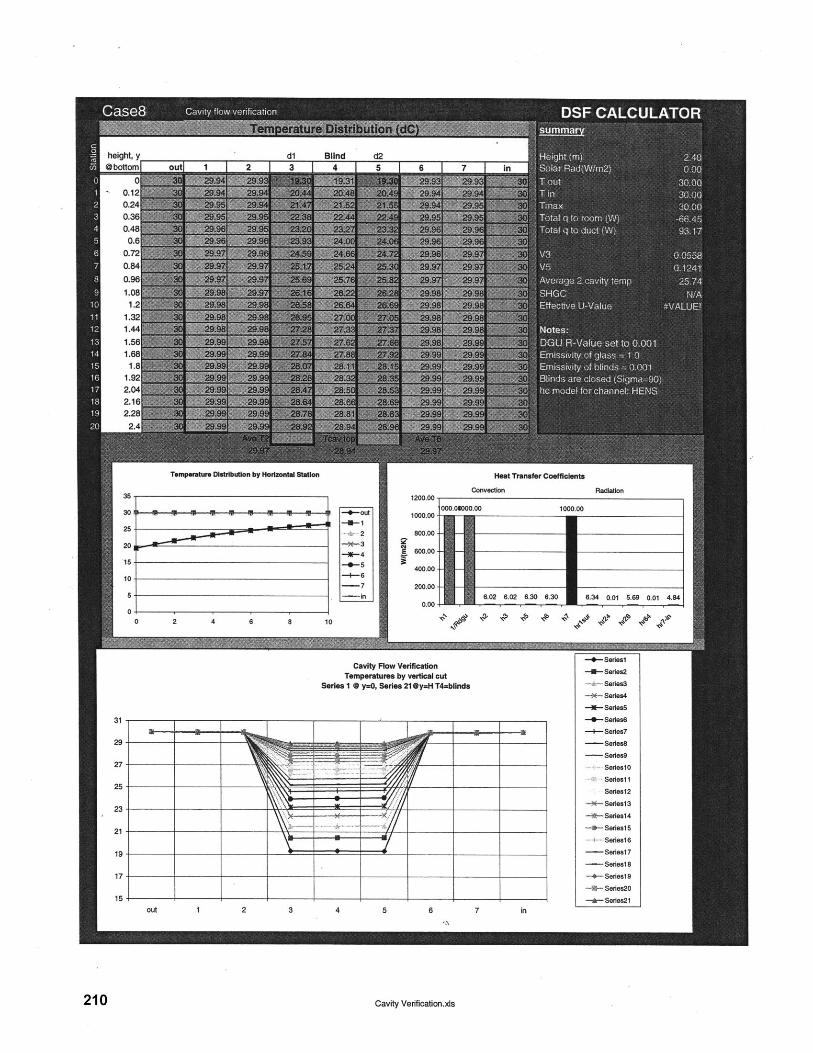
heat.Vdl Blind d21 0 1 12 I A I C I a 1 1
Temperature Distribution by Horizontal Station
2--Out
-- 7-in
Heat Transfer Coefficients
Convection Radiation
000.Oe00W.00 1000.00
1000.00-
800.00-
600.00-
400.00 -
6.02 6.02 6.30 6.30 6.34 0.01 5.69 0.01 4.840.00
0 2 4 6 8 10
Cavity Flow VerificationTemperatures by vertical cut
Series 1 0 y=0, Series 21@y=H T4=biinds
2 3
210
5 6
-- Seriesl
-3-Series2
Series3
-X- Series4
-0- SeriesS
-- Series
--- Series7
-Seres8
- -Sere89
Serieslo
Seriesl1
Series12
-*- Sedes13
-e--Series14
-4- Series15
. Seres16
- Seriesl7
- Series18
-+- Serilesl9
-~|- Series2O
-A- Series2l
Cavity Verfication.xls
0b0ttor
0.10.20.30.4
0.0.70.8
height, yd1 Blind d2
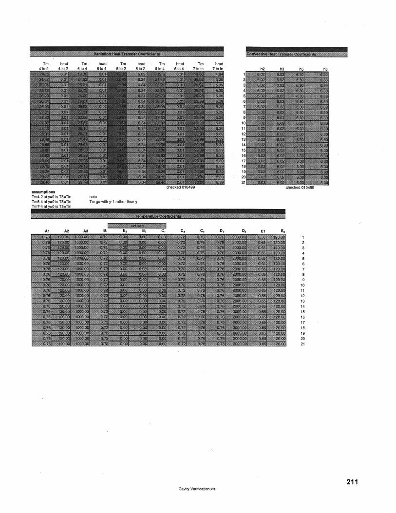
Tm hrad Tm hradAk.') A f-n3 Qt..A A*nA
Tm hrad Tm hrad Tm hrad#na Q3a 13 f-A 12 6-A '7 0.ni ;. 7 nf i
assumptionsTm4-2 at y=0 is T3=Tin noteTm6-4 at y=0 is T5=Ttn Tm go with y-1 rather than yTm7-4 at =0- is TS=Tin
Al A2 A3 B1 B2 B, C, C2 C, D, D2 El E,
23456789
101112131415161718192021
211Cavity Verificatlon.xts
e p
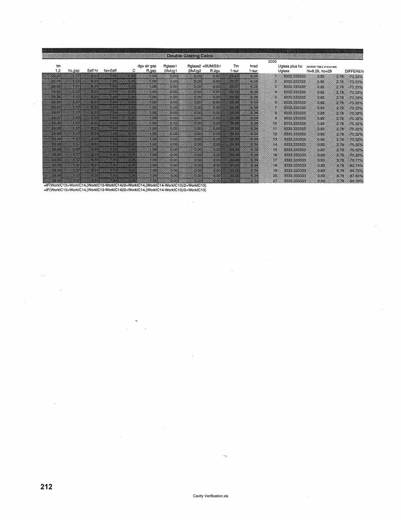
trn dgu air gap Rglaaal Rglaaa;2 =SUM(E6:4 TM hrad1,2 hc,gap Eeff hr hc+Eeff C R a 1/kA 1 likA 2 RAdU I1-aur I1-sur
=1IF(WorkIC1 3>WorkC1 4.(WorkICl 3-WorktC1 4)/2+WorkICl 4,(WorkIC1 4-WorklC1 3)/2+WorldCl 3)=IF(WorldCl3>WorkICl4,(WorkdC1-WorcIC14)/2+WorkiCl4,(WorkIC14-WorkIC3)2+WorkIC13)
212Cavity Vertficatlon.xla
Uglaaa piua he As4RAE TAaLE 27.6-6(1UeI InIn-c hi-R ->Q hn-00
gj, n03 N
WINER W IMUNNOWEEz"S,
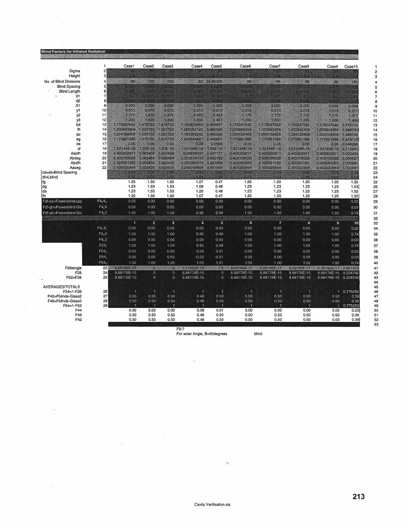
-n
m
N-)
w
5'
~
MO
O
oL
03
07
OO
O
CL
4-
O
O
CO
-
C.)
aO
C?,
,
02
OL
0c
-
O
O
O
-0 n
o oo
e)
r
(A C
W
-4
0'C
C
W
(
"-C
(DM
.E0 C
.) N
N
7,7- g C
LV
m
to gy,
NM
I
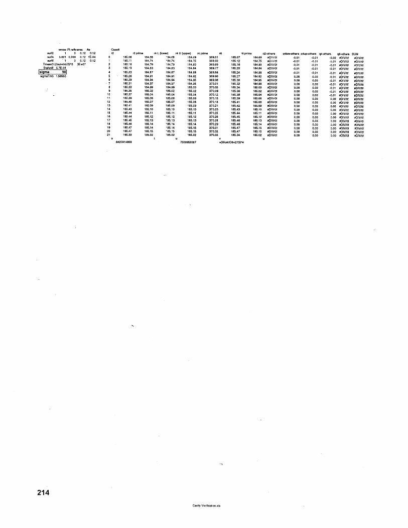
emissiR refle area Ae aesurf2 1 0 0.12 0.12 r2surf4 0.001 0.999 0.12 1E-04 0 155.08surf6 ~ 1 0 0.12 0.12 1 180.11
Tmean3 ((tout+in)/2)A3 3E+07 2 185.1fStefanB 5.7E-08 3 185.10
sigma 90 4 185.21tigmaTm3 1.58563 5 185.2(
5 .185.207 185.31
8 15.3K1
10 185.3611 185.3012 185.413 185.4114 185.415 185.2616 185.4417 188.4118 185.4419 185.420 185.421 185.39
8420914884
r2prime r4 L (lower) r4 U (upper) r4 prime re184.68 184.68 184.69 369.51184.74 184.74 184.75 369.60184.79 184.79 184.80 369.69184.83 184.83 184.84 369.77184.87 184.87 184.88 369.84184.91 184.91 184.92 369.90184.94 184.94 184.95 369.96184.97 184.97 184.98 370.01184.99 184.99 185.00 370.05185.02 185.02 185.02 370.09185.04 185.04 185.04 370.12185.06 185.06 185.06 370.15185.07 185.07 185.08 370.18180.09 185.09 185.09 370.21180.10 185.10 185.10 370.23185.11 185.11 185.11 370.25185.12 185.12 185.12 370.26185.13 185.13 185.13 370.28185.14 185.14 185.14 370.29185.14 185.14 185.15 370.31185.15 185.15 185.15 370.32185.02 185.02 185.02 370.05
u 3730095387 =
185.07185.12185.16185.20185.24185.27185.30185.32185.34185.36185.38185.39185.41185.42185.43185.44185.45185.46185.46185.47185.47185.34
Work!O6+273
r5 prime q2-others q4low-others q4up-others q4-others q6-others SUM184.69 #DIV/O! -0.01 -0.01 -0.02 #DIVO! 8DIV/O!184.75 #Div/0! -0.01 -0.01 -0.01 #1V/0! #DIV/OI184.80 #DIV/O! .0.01 -0.01 -0.01 #DIVOI 8DIVIO!184.84 #DIVI! -0.01 -0.01 -0.01 #DIVOI #DIV/0!184.88 #DIV/OI -0.01 -0.01 -0.01 #DIV!0111/0!184.92 #DIV/01 0.00 0.00 -0.01 #DIV/OI #010/01184.95 #DIV/0! 0.00 0.00 -0.01 #0/V/sI #010/0!184.98 #DIV/0! 0.00 0.00 -0.01 #D101 O0/Viol185.00 #DIV/0! 0.00 0.00 -0.01 #010/01 #010/01185.02 #DIV/0! 0.00 0.00 -0.01 #0/0/ #010/0!185.04 #DIV/O! 0.00 0.00 -0.01 #DIV/01 #01V/0185.06 #DIV/0! 0.00 0.00 0.00 #OIV/OI #010/01185.08 #DIV/0! 0.00 0.00 0.00 80/VIOl #OIV/01185.09 #DIV/0! 0.00 0.00 0.00 #D/V/0! 80/ol185.10 #DIV/O! 0.00 0.00 0.00 8CIV/0/ #0/V/S185.11 #DIV/01 0.00 0.00 0.00 #DIV/0! #D101/0185.12 #DIV/01 0.00 0.00 0.08 #010/0! 80101/0185.13 #DI/0! 0.00 000 0.00 #OIV/01 #010/01185.14 #DIV/0! 0.00 0.00 0.00 80101 80101185.15 #DIV/0! 0.00 0.00 0.00 #OIV/0 8010/01185.15 #DIV/0! 0.00 0.00 0.00 60101 Q0V/0l185.02 #DIV/0! 0.00 0.00 0.00 8010/SI #01V/0l
w
q)o-tesA4pohr q-tes q6ohr U
214
Cavity Verification.xls

Q Q - a c Azimuth calculate
Need to import from weather data
Cavity Verification.xis
12131415161718192021
215

Cavity Verification.xls
Diffuse Solar
216
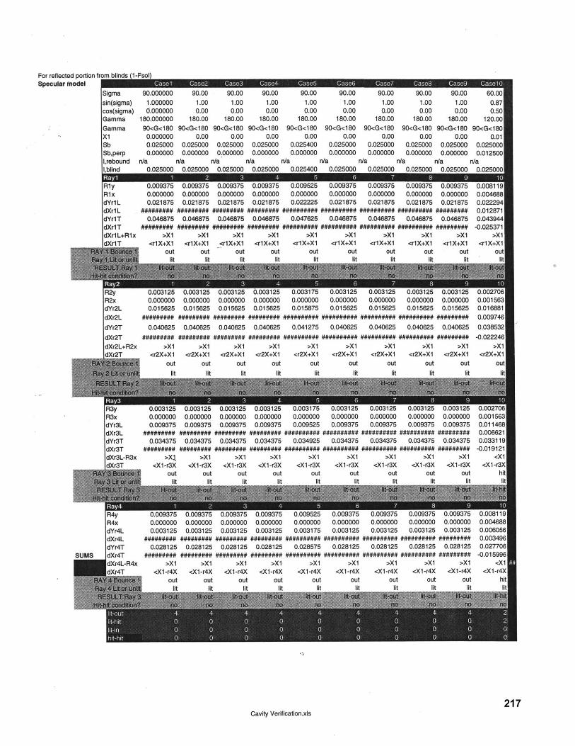
For reflected portionSpecular model
Cavity Verification.xls217
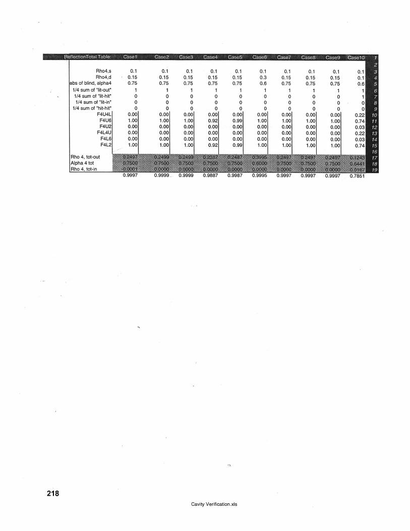
Rho4,s 0.1 0.1 0.1 0.1 0.1 0.1 0.1 0.1 0.1 0.1Rho4,d 0.15 0.15 0.15 0.15 0.15 0.3 0.15 0.15 0.15 0.1
abs of blind, alpha4 0.75 0.75 0.75 0.75 0.75 0.6 0.75 0.75 0.75 0.61/4 sum of "lit-out" 1 1 1 1 1 1 1 1 1 11/4 sum of "lit-hit" 0 0 0 0 0 0 0 0 0 11/4 sum of "lit-in" 0 0 0 0 0 0 0 0 0 0
1/4 sum of "hit-hit" 0 0 0 0 0 0 0 0 0 0F4U4L 0.00 0.00 0.00 0.00 0.00 0.00 0.00 0.00 0.00 0.22
F4U6 1.00 1.00 1.00 0.92 0.99 1.00 1.00 1.00 1.00 0.74F4U2 0.00 0.00 0.00 0.00 0.00 0.00 0.00 0.00 0.00 0.03
F4L4U 0.00 0.00 0.00 0.00 0.00 0.00 0.00 0.00 0.00 0.22F4L6 0.00 0.00 0.00 0.00 0.00 0.00 0.00 0.00 0.00 0.03F4L2 1.00 1.00 1.00 0.92 0.99 1.00 1.00 1.00 1.00 0.74
Rho 4, tot-outAlpha 4 totRho 4, tot-in
0.9999 0. 0.9995 0.9997 0
218Cavity Verification.xis
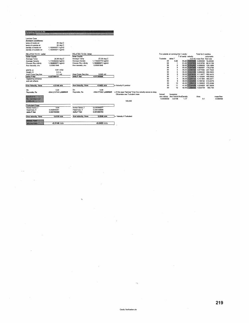
Laminar CaseAmbient condItIonertemp of inside airtor of outside airdensity of inside airdensity of outside air
30 deg C30 deg C
1.162800371 kg/m31.162800371 kg/m3
RELATES TO D1: outerOuter CavityAverag.Temp 26.99 dog CAverage Density 1.174432252 kg/m3Choose Rho ininity 1.16200371 kg/m3Ave viscosity .mu 0.00001846
gravity, g 9.81 m/82Height, H 2.4 mArea Cross SecAos 0.1 m2deleP Net -0.02736101neglecting entranceand exit effects
|Ave Velocity, Vov -0.5146 m/e
Dh 0.20Reynolds. Re -6540.210749 LAMINAR
|Turbulent Casefriction factor, f 0.04Head loss, If 0.002845201delta P Not 0.032780069
|Ave velocity, Vave 0.6150 re
RELATES TO D2: Innerinner CavityAverage Temp 27.08 dog CAverage Density 1.174040775 kgkn3Choose Rho infinity 1.162800271 kgItn3Ave viscosity .mu 0.00001848
Ave Velocity, Vave -0.0463 rm/ < Velocity if Laminar
Dh 0.09Reynolds, Re -259.077062 LAMINAR < N this says trinaer then the velocity above is okay.
Otherwise ase Turbulot case
100,000
friction factor, f 0.078764377Head loss, If 0.000109896delte P Net 0.001265704
Ave velocity, Vave 0.00 W/e < Velocity i Turbuent
For outside air coming into 1 cavity:T of cavity velocity
Toutside det T -0. 130 0.25 30.25S30 1 31.0030 2 32.0030 3 33.0030 4 34.0030 5 35.0030 a 36.0030 7 37.0030 a 38.0030 9 39.0030 10 40.0030 11 41.0030 12 42.001
forced buoyancyave velocy Ave Velocit AveDensity
0.055833 -0.5146 1.17
Total for 2 cavitiesvolumetric
mass flow flow rate0.005929 11.204320.019708 60.411390.039203 120.16860.051487 179.27980.077562 237.75280.096432 295.05650.114977 352.44150.133283 405.56520.151364 463.94710.169192 518.62760.186802 572.60680.204828 627.86090.222739 682.764
Area mass flow0.1 -0.060432
-0.5146 m/s -. 0453 m/s
219Cavity Verficadtin.xIs
Buavancy forcas in Air
111"IM-7-7-M
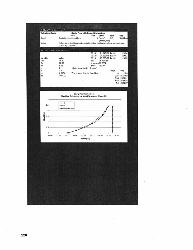
220
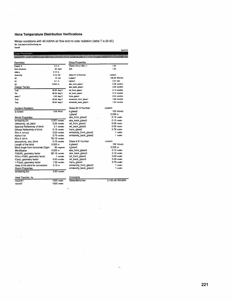
Hens Temperature Distribution Verifications
Winter conditions with 40 m3/hm air flow and no solar radiation (delta T is 20 dC)file: CalculatotCavFowVerfy.xsCase8
m=0.9Case Parameters
GeometryHeight, H 2.4 mNum divisions 20 eachdelta y 0.12 mArea,Ady 0.12 m2dO 15 mmd1 0.1 md2 0.045 mDesign TempsTout 30.00 deg CTin 30.00 deg Cdelta T 0.00 deg CTmrt 30.00 deg CTsur 30.00 deg C
Incident Radiationqr,incident 0.00 W/m2
Blinds Propertiesemissivity,E4reflectivity, ref blindSpectral Reflectivity of blindDiffuse Reflectivity of blindRho 4, tot-outAlpha 4 totRho 4, tot-inabsorptivity, abs-blindLength of the blindBlind Angle from horizontal (SigmBlindSpaceF26(IR), geometry factorF24=1-F(IR), geometry factorF(sol), geometry factor
-1-F(sol), geometry factorArea of the blind for convectionRoom Propertiesemissivity,Ein
Heat Transfer, hchout=hlhin=h7
0.001 nondim0.25 nondim
0.1 nondim0.15 nondim0.25 nondim0.75 nondim
7E-16 nondim0.75 nondim
0.025 m90 degrees
0.025 m9E-15 nondim
1 nondim0.00 nondim1.00 nondim0.12 m
0.85 nondim
1000 nodim1000 nodimr
Glass Properties1/Eetf=1/E12+1/E21-1Eeff
Glass #1 10 Numberk,glassllglass1abs.frontglasslabs-backglasslref_jrontglasslreftbackglass1transgtass1emisivityjront-glasslemissivity-backglassl
Glass #2 ID Numberk,glass2l,glass2abs~jrontglass2abs-back-glass2reLfrontglass2ref_back-glass2trans-glass2emissivityjront.glass2emissivity-backglass2
Glass # ID Numberk,glass3l,glass3absjfrontglass3abs-backglass3ref_frontglass3refbackglass3trans-glass3emissivity~jront-glass3emissivity-back-glass3
ConstantsStefanBoltzman
1.001.00
custom100.00 W/(mK)
0.01 mm0.26 nondim0.26 nondim0.19 nondim0.19 nondim0.55 nondim1.00 nondim1.00 nondim
custom100 W/(mK)
0.006 m0.12 nodim0.12 nodim0.09 nodim0.09 nodim0.79 nodim
1 nodim1 nodim
custom100 W/(mK)
0.006 m0.12 nodim0.12 nodim0.09 nodim0.09 nodim0.79 nodim
1 nodim1 nodim
5.70E-08 W/m2K4
221
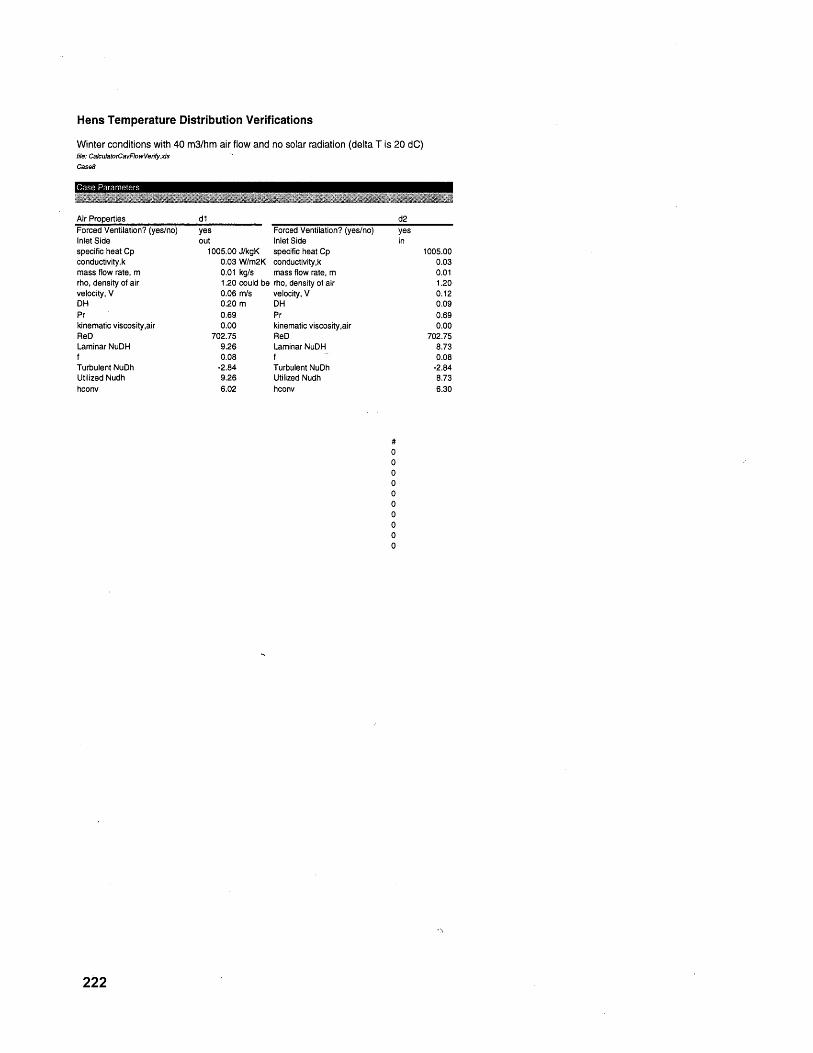
Hens Temperature Distribution Verifications
Winter conditions with 40 m3/hm air flow and no solar radiation (delta T is 20 dC)file: CalculatorCavFlowVeiy.xisCase8
Case Parameters
Air PropertiesForced Ventilation? (yes/no)Inlet Sidespecific heat Cpconductivity,kmass flow rate, mrho, density of airvelocity, V
kinematic viscosity,airReDLaminar NuDHfTurbulent NuDhUtilized Nudhhconv
dlyes Forced Ventilation? (yes/no)out Inlet Side
1005.00 J/kgK specific heat Cp0.03 W/m2K conductivity,k0.01 kg/s mass flow rate, m1.20 could be rho, density of air0.06 rn/s velocity, V0.20 m DH0.69 Pr0.00 kinematic viscositl
702.75 ReD9.26 Laminar NuDH0.08 f
-2.84 Turbulent NuDh9.26 Utilized Nudh6.02 hconv
,air
222
1005.000.030.011.200.120.090.690.00
702.758.730.08
-2.848.736.30
7.2.3 Buoyancy Verification
The following is the backup for the model that compares temperature distribution and
buoyant flow through the double-skin fagade cavity as driven by solar radiation difference
without a temperature between indoors and outdoors.
Arons 223

224
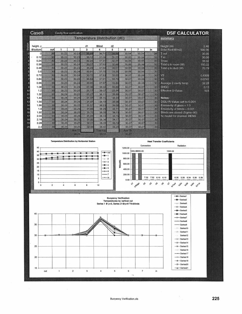
dl Blind d2I T 2 I 2 I A I A I A i 7
Temperature Distribution by Horizontal Station
--.- out
2-r- 3
-- 5- 6
-- in
01
0 2 4 6 8 10
Heat Transfer Coefficients
Convection
000.0000.00 1000.001000.00
800.00
600.00-
400.00-
200.00-
0.007.52 7.2 6.10 6.10 6.35 5.39 6.34 5.39 5.390.0011 1
Buoyancy VerificationTemperatures by vertical cut
Series 1 @y=0, Series 21 @y=H T4=blinds
Buoyancy Verification.xls
-+-Seriesl
-U-Series2
Series3
-- Series4
-l- Series5
-- Series--- Series7
- Seies8- Series9
SerieslO
-Seriesl1
Series12
-- Series13
-- Series14
--- Series15
Series16
- Seriesl7
- Series18
-+- Series19
-~4-- Series2O
-r- Series2l
225
height, y@bottom[
N N N N N N - -~
Radiation
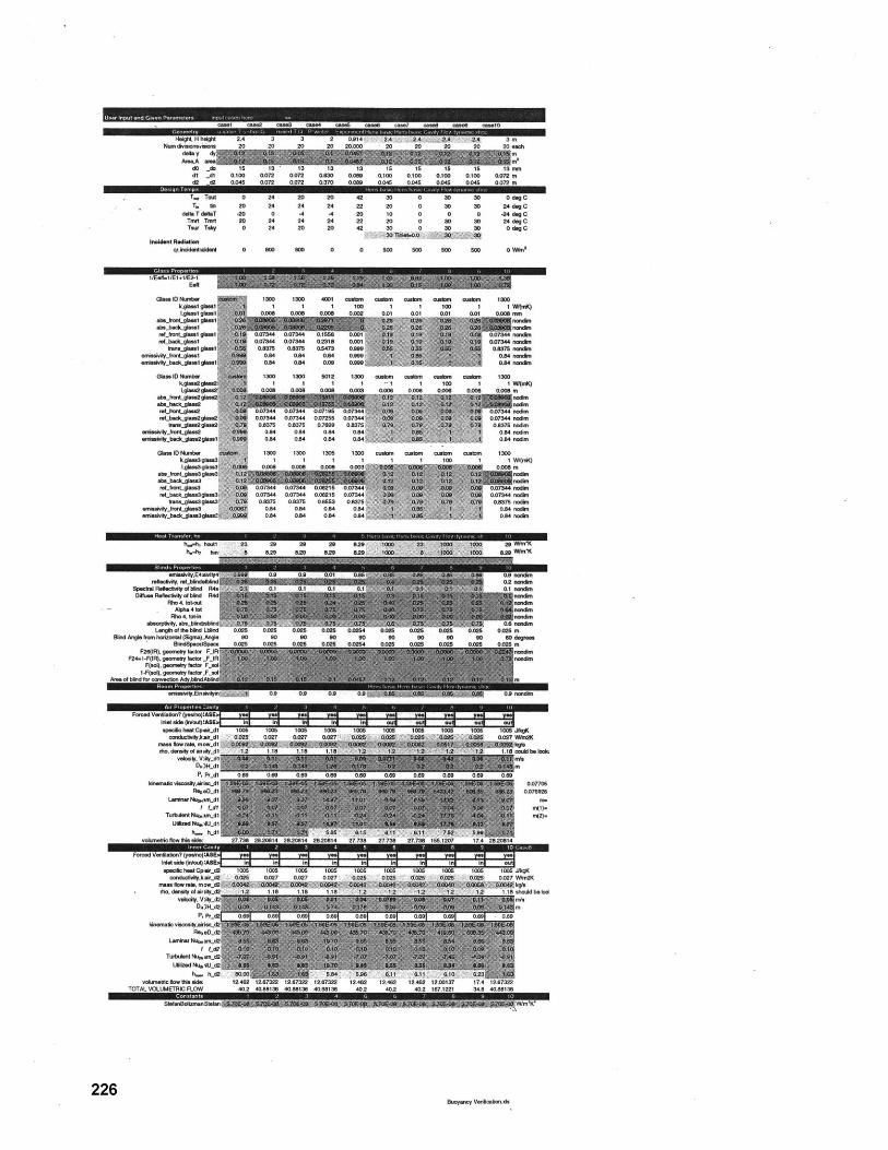
coolt case cassa os" cas5 c a case7 caseBl case ease10
Heig H heighl 2.4 3 3 2 0.914 24 24 14 2A 3 mNumdieionseiion 20 20 20 20 20.000 20 20 20 20 20 each
dellay dym SIi mAreaA ama m'
d0 _do is 13 13 13 13 15 15 15 15 13 midi _d1 0.100 0.072 0.072 0.0 0.089 0100 0.100 0.100 0.100 0.072 m
d2 .42 0.045 0.072 0.072 0170 0.069 0.04 0.045 0.045 0.045 0.072 m
T. Tout 0 24 20 20 42 30 0 30 3 0 dog CTM hn 20 24 24 24 22 20 0 30 30 24 dog C
delt T deT .20 0 -4 -4 20 10 0 0 0 -24 deg CTrit Test 20 24 24 24 22 20 0 30 30 24 dog CTer Tsky 0 24 20 20 42 30 0 30 3 0 dog C
invoident Radioqr,ncidenticident 0 800 500 0 0 500 500 500 00 0 mn'
1/Eell-1/E1+/E2-10Eel
Glass ID Number130 4D ~b jb adilO~m UM 10
abs_krotgklassglaabillbacitglass1lreLrvocaglaa 01724 007344 0106 0001aLbadcglasl 0s744 00744 02316 0.001
tran a gleesi 0.175 0.80 0.472 0.8800essiy frontlas04 0 014 o0t
emisivty_ba s g ls aal - 04 014 0.00 6
Gas. 10 Musher 1300 1300 002 1200 autos utos outs cubs 1200hka.slgla e I 1 1 1 -1 1 10 I lWIsrdC
0.006 0.006 0006 010 o.o0 0.006 010 0006 0.006 m
rMoeset.4ina0.007344 07 60.0setLbadclesogolawe 0.07344 0.07344 0.0720 0.07344 44
Ibuse-gtn02ole2 0.8375 0.8376 0.7 6 02070' . <07S nodeseeos iiit-rast-gaaes o 044 014 4 0 01 xP* 4 , 0.04 sodirs
am-*_ad 0 0.se .4
srrsinty.hed~sgW l 0.4 0.14 0 044d
Glass IDiesher 1300 100 1200 1200 cumbs ous ousrstrs 100h4aiw~glaee' 1 1 1 1 1 1 100 1 1Willi
he i.8 0 0.008 0.003 0..01 j
ceo roet- eee2 t 0.0734 0.07244 I021 007244 0acl eOmll M, 0.07344 0.0734 0.06210 0.07344 0 999
tram-aeasglass 1s 0.00 0.20 0.002 070s 0
a refVfymntllt5glas23 0.04 0.84 0.05 0.44 . D 0.8 roois
e effybacgla2glse2 0 0134 0134 005 0.074 0
sst fntls2 0000 0.84 0.84 0.S 054 -- 0- 0 5 0
Shed Ae8 oshenel(qsSge 82 2 82 82 MOD 8 600 , 2 80W 2 degree
B"mtdsp4Aoi~pi 000 '00 02 0.05 010 .0A 02S02 06 050
ar Vestlat-w (yslrcMr cre sl ss" el se el sd n el valn
s~ecflhel~ce.d1 106 00 106 106 00 105 10 5006 10 10 Wl(
P.741a 006 006 0.06 0.06s 0.0600 001 001 00Ddk19 t 0.0744 ndondm
035 4 0.37onndRho 4. t.4n"d
Tochidesl ab s sss 0.4 n 0d)m
comselo ir Ode W- sidAe 2770 2 9.01 26.0 282o1 2770 2770 2772 102 17. 280
apetoaidpe 2 100 106 100 100 100 106 10 1005 10 10 WimK)
BW5Sh10pamk 0.025 0027 0027 0.027 0024 01020 0.020 0.005 0000 0.007 m
cho.-F(M. +ely 12 12 t 1anodm
c ) e loos~ y osy 42_9ol
0 n 3 R 4i 00744nair
079 079 0,7 0.37 nodin
inj ~ ~ 02 Ii L" 0.84l g odm
m s Pci . 42ia s1 009 006 004 06 00 100 6 0 1 103 n000
Gft. I Nuerl o uf m 130*012 A 1300 13105 2 300 custo ,cust1z cu18m cuslome1III
k, . V*_aWs3gle
WierTivosietcscs 42070
1,glass3 1 glassM
bsntgase3 FsdesIn
UWledlsg4a42
cohcoeld IllowlheeSde. 127nmB 12.722 0.72 287201 2.382 7.3 14 2 71.748 1.127 17.4 26720
TOTAL ea V CpFLOW d 4025 100 126 100 102 40.2 102 1001 148 4061(K)
cwx.~kd 10 . o85 0.007 0.027 027 .02 0.003 05 C.B OM 0.027 m/r
ft ai o al 03i 2 1.18 1.8 11 21, T 201 1.1 noidb
vBny 12yV2 stiooaflnodm
PP-2 079 0.35 .8 0. 0.55 005 ,7 0.67 0.7967m .87 oi
lemieiy-bacltgassilt D9 .4 0 M 04 1 05 1 1 08 oi
hpia Rea hvt e i d 2 .84 5.. 0.1 I. 0.1 6.n1di
TOTA ngVhLU thT blinLbOin 0.2 40.823 40.823 40.823 40.2 0.02 0.2 1.0225 4.82 40.02138
Bln Snlefo toional Sima)ngl 0 0 90 9 0 0 90 9 0 0der
B2dp26pc .25 005 005 006 .24 005 005 .2 .2 .2F26(IR),wanc gemeryfala FlRn undm
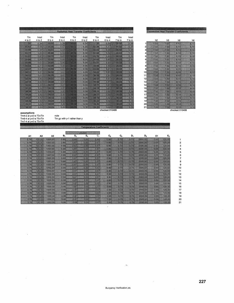
Tm hrad Tm hrad TmAin9 An RinS A AnA AtnM
assumptionsTm4-2 at y=0 is T3=Tin noteTm6-4 at y=0 is T5=Tin Tm go with y-1 rather thanTm7-4 at =0 Is T=Tn
Al A2 AS B1 B,
hrad Tm hrad Tm hradBto2 6to4 6to4 7toin 7toIn h2 h3 h5 h6
1234567
88
910
111
121314156
1718192021
checked 010499 checked 010499
y
B, C, C2 C3 D1 D2 E1l E,
1234
56789
10111213141516
18192021
227
Buoyancy Verification.xis
EIRS
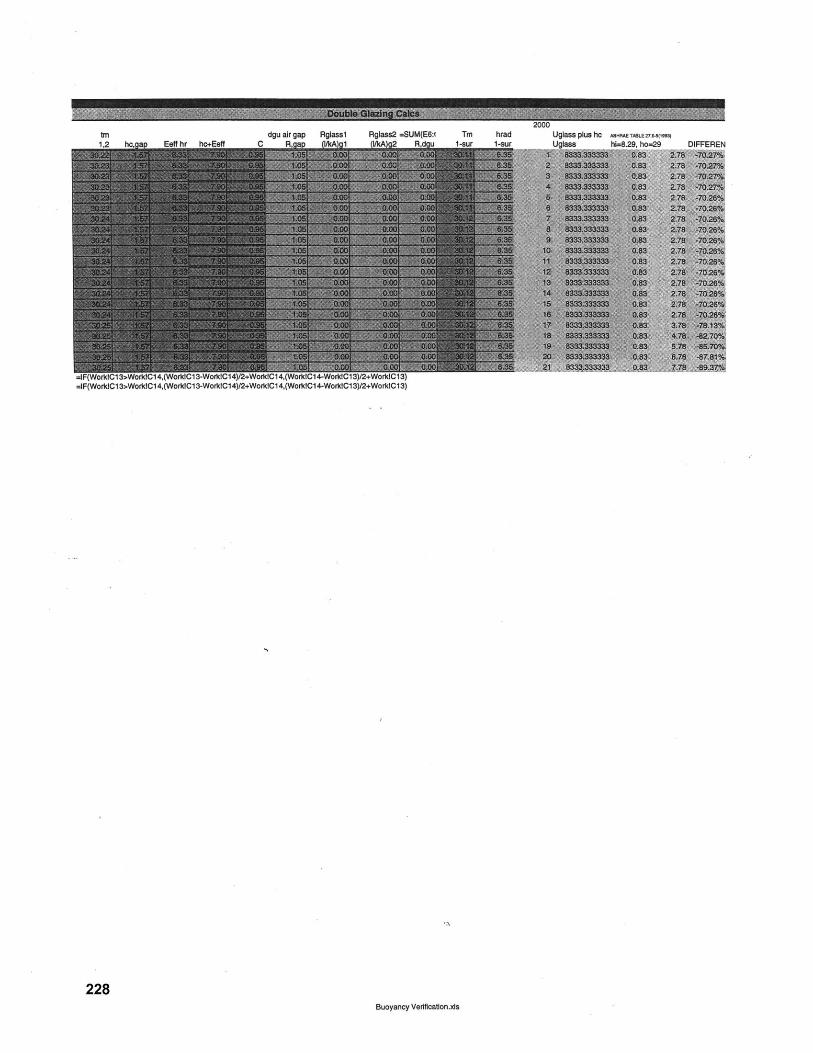
tndgu air gap Figlasal Rglass2 =-SUM(E6:f
=IF(WorkICl 3>WorkICl 4,(WorIC13-WorklC14)2+WorkIC14,(WorkIC 4-WorlICl3)/2.iWorklCl3)=IF(WorkICl 3>WorklCl 4,(WorkICl 3-WorkICl4)/2+WorkICl 4,(WoflcIC14-WorkICl 3)/2+WarkdC13)
228
TM hrad Uglass plus hc ABXRAETAsLEui(1993)
-4mar I-atir I Inimea ht5 ljo K-3
Buoyancy Veffcatlan.xls
va-mm, vzw , MINE QN-P

z
06
cuR
K
-6 A
O
f 0
ala
aa
Z
k.
C/)
CL
as
p P
C
l o
kd
1.1
-1
M c
n10
W
ca
ca
(a
6)
ca
ca
C-3
Z3 "
!I
t?
&
3 V
40 C
O -4
C
D C
A 0
- -
-8
W M
-4
0 M
-P
, 0
-4
0 0
-1,
0 0
co
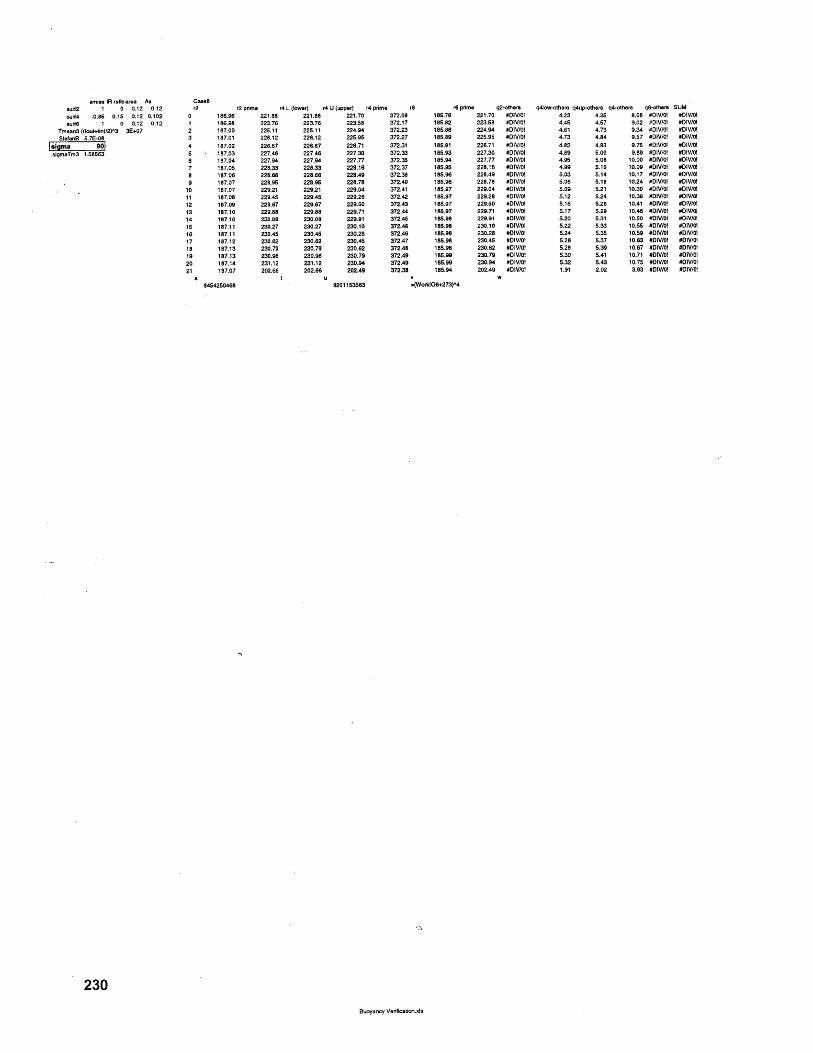
amiss IR refic area Assur42 1 0 0.12 0.12surf4 0.85 0.15 0.12 0.102surf6 - 1 0 0.12 0.12 1
Tmean3 ((tout+tin)/2)^3 3E+07 2StefanB 5.7E-08 3
algma 90 44sigmaTm3 1.58563 5
12 prime r4 L (lower) r4 U (upper) r4 prima r8 r6 prme q2-others qrflow-others qrtup-others q4-others qo-othera SUM186.96 221.88 221.88 221.70 372.08 180.76 221.70 6DIV/0' 4.23 4.35 8.08 40IVI01 #DIV/01186.98 223.76 223.76 223.08 372.17 188.82 223.08 601V/OE 4.4 4.07 9.02 #DIVIOI 601V/0187.00 220.11 225.11 224.04 372.23 180.86 224.94 #DIV/Ot 4.61 4.73 8.34 #DIV/0( #DIV/5I187.01 226.12 228.12 225.00 372.27 180.88 225.00 #DIV/O! 4.73 4.84 8.07 8DIV/0! #01V/0l187.02 228.87 226.87 228.71 372.31 180.81 228.71 #01V/0! 4.82 4.93 9.75 #01V/0l 60(V/0l187.03 227.46 227.44 227.30 372.33 185.93 227.30 #OIV/0I 4.89 5.00 9.89 #01V/0( #01V/O!157.04 227.94 227.94 227.77 372.30 185.84 227.77 SDIV/0! 4.80 5.06 10.00 8DIV/0I #DIV/0l187.00 228.33 228.33 228.16 372.37 180.0 228.18 8DIV/0! 4.08 5.10 10.09 #DIV/01 801V/0187.04 228.66 228.66 228.49 372.38 180.90 228.48 #DIV/0! 5.03 5.14 10.17 #DIV/OI 6DIV/0l187.07 228.80 228.80 228.78 372.80 180.96 228.78 DIV/0! 0.06 5.18 10.24 #DIV/01 #DiV/0l187.07 229.21 228.21 229.04 372.41 185.97 229.04 DIV/OI 5.09 0.21 10.30 #DIV/0I #D15/51187.08 220.80 229.40 229.28 372.42 180.97 229.28 DI5/0! 0.12 5.24 10.36 #DIV/01 60(5/01187.09 229.67 229.67 229.00 372.43 180.97 229.0 #DIV/01 5.1 0.26 10.41 #DIV/O! 60(5/0!187.10 229.88 229.88 229.71 372.44 185.97 229.71 #0150(01 5.17 0.29 10.46 #DIV/Of 60150/01187.10 230.08 230.08 229.91 372.40 180.98 229.91 80150/01 5.20 5.31 10.00 60150/01 #OIV/Ot187.11 230.27 230.27 230.10 372.46 185.98 230.15 60150/01 5.22 5.33 15.00 #0(50/5! #0(50/0!187.11 230.40 235.44 230.28 372.46 18.98 230.28 #0150/0! 0.24 0.30 15.59 #OIV/0! #0(50/0!187.12 230.62 230.62 230.44 372.47 188.98 230.40 80150/O! 5.26 5.37 10.53 #0(V(5! #DIV/01187.13 220.75 230.79 235.82 372.48 180.98 235.62 #0(V/01 5.28 5.39 10.67 60(50/0! 90)50/0!197.13 230.80 230.96 230.79 372.49 180.80 230.79 #DIV/0( 5.30 5.41 10.71 60150/0! 60150/0!187.14 231.12 231.12 230.04 372.49 1805.80 230.04 60(50/0! 5.22 5.43 15.75 60(50/0! #0150/0!187.07 202.66 202.86 202.49 372.38 185.04 202.49 DIV/0! 1.91 2.02 3.93 #DIV/0! #D1V/0!
845420468 9201153563 -(Wo84406+273(04
230Buoyancy Verification.xIs
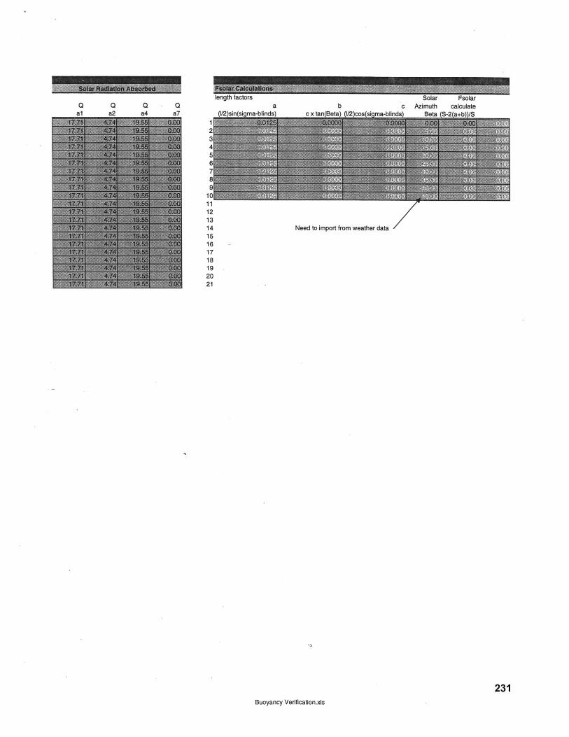
iengm Taciors bolar t-solarQ Q Q Q a b c Azimuth calculateal a2 a4 a7 (I/91ninktinmn-blindni r Y tantRnta\ tl/91enatinm-hlinea\ Rta 1coZn-h0-tc
121314 Need to import from weather data
231Buoyancy Verification.xls
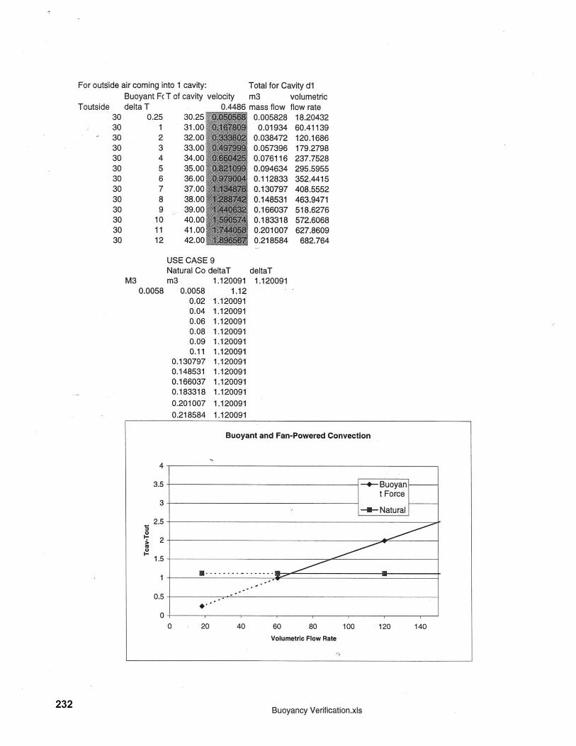
For outside air coming into 1 cavity:Buoyant FC T of cavity
Toutside delta T30 0.25 30.2530 1 31.0030 2 32.0030 3 33.0030 4 34.00'30 5 35.0030 6 36.0030 7 37.0030 8 38.0030 9 39.00130 10 40.00130 11 41.00130 12 42.00
Total for Cavity dlvelocity m3
0.4486 mass flow0.005828
0.019340.0384720.0573960.0761160.0946340.1128330.1307970.1485310.1660370.1833180.2010070.218584
volumetricflow rate
18.2043260.41139120.1686179.2798237.7528295.5955352.4415408.5552463.9471518.6276572.6068627.8609
682.764
USE CASE 9Natural Co deltaT deltaT
M3 m3 1.120091 1.1200910.0058 0.0058 1.12
0.02 1.1200910.04 1.1200910.06 1.1200910.08 1.1200910.09 1.1200910.11 1.120091
0.130797 1.1200910.148531 1.1200910.166037 1.1200910.183318 1.1200910.201007 1.1200910.218584 1.120091
Buoyancy Verification.xls
Buoyant and Fan-Powered Convection
4-
3.5- Buoyant Force
3- -- --Natural2.5--
1.5
0.5
00 20 40 60 80 100 120 140
Volumetric Flow Rate
232
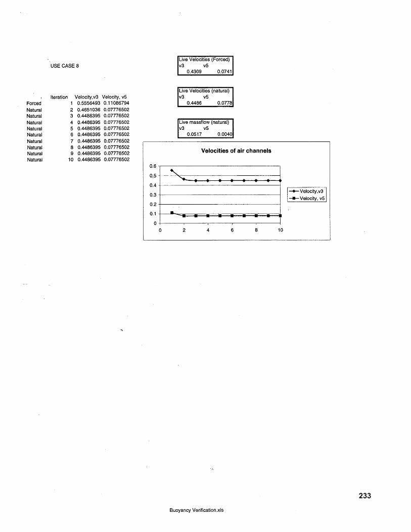
Live Velocities (Forced)1v3 v5v0.4309 V5 0.07411
Live Velocities (natural)v3 v5
0.4486 0.07781
Live massflow (natural)v3 v5
0.0517 0.00401
233
Buoyancy Verification.xls
USE CASE 8
ForcedNaturalNaturalNaturalNaturalNaturalNaturalNaturalNaturalNatural
Iteration12345678910
Velocity,v30.55564930.46510360.44863950.44863950.44863950.44863950.44863950.44863950.44863950.4486395
Velocity, v50.110867940.077765020.077765020.077765020.077765020.077765020.077765020.077765020.077765020.07776502
Velocities of air channels
-- Velocity,v3
-U-*Velocity, v5
0 2 4 6 8 iC

234
7.2.4 U-value Validation
The following is the backup for the comparison of the model predictions with [Saelens 1998]
for U-value.
235Arons
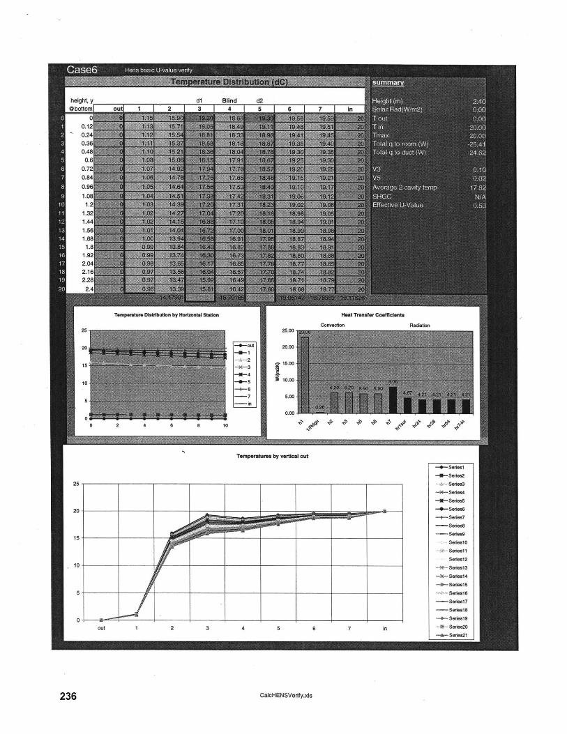
dl Blind d2I I~ 0 I I A I I I -
Temperature Diatributlon by Horizontal Station
25.00
Heat Transfer Coefficients
Convection
--- out 20.00
~ 15.00-X-3
-O-5 10.00-+-6-7 5.00-in
0.00-~ .v- ~ ''- ~ %'Y (
Temperatures by vertical cut
CalcHENSVerify.xis
height, y@bottom ao
00.120.240.360.480.6
Radiation
0 2
--- Seriesl
-4--Serie2
-A---SerIeS3
-- Series4
--- Series5
-- SerIS6
- Sere7Seies8
Seriea9
Seriesl
A- Seriesl1
SSeries12
-M- Series13
-*t Series14
-- SerieslS
Seriesl6
- Series17
- Serieal8
--- Seriesl9
-.- Series20
-d- Series2l
236
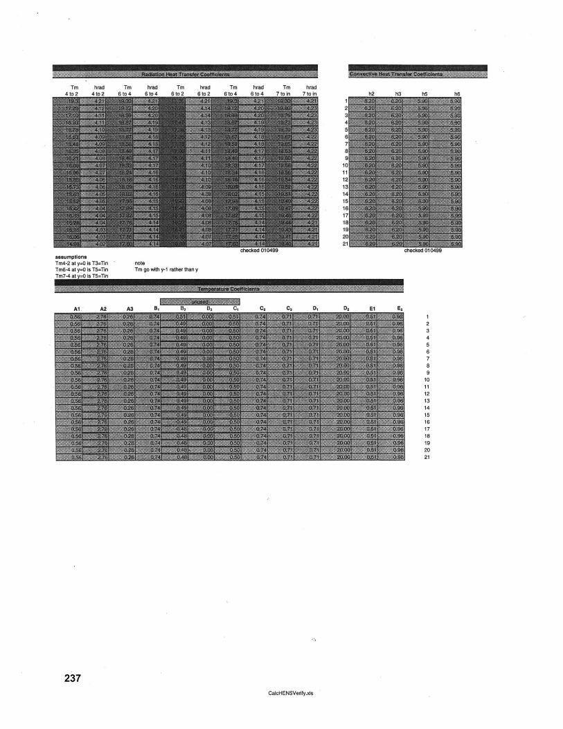
Tm hrad Tm hrad Tm hraddtn9 4in2 Atn4 Atn4 Rtn? Atn
Tm hrad Tm hradtn4 Atn4 7tnin 7inin
assumptionsTm4-2 at y=O Is T3=Tin noteTm6-4 at y=O is T5=TIn Tm go with y-1 rather than yTm7-4 at O is T5=Tin
237CalcHENSVerity.ds
rLM111- MR
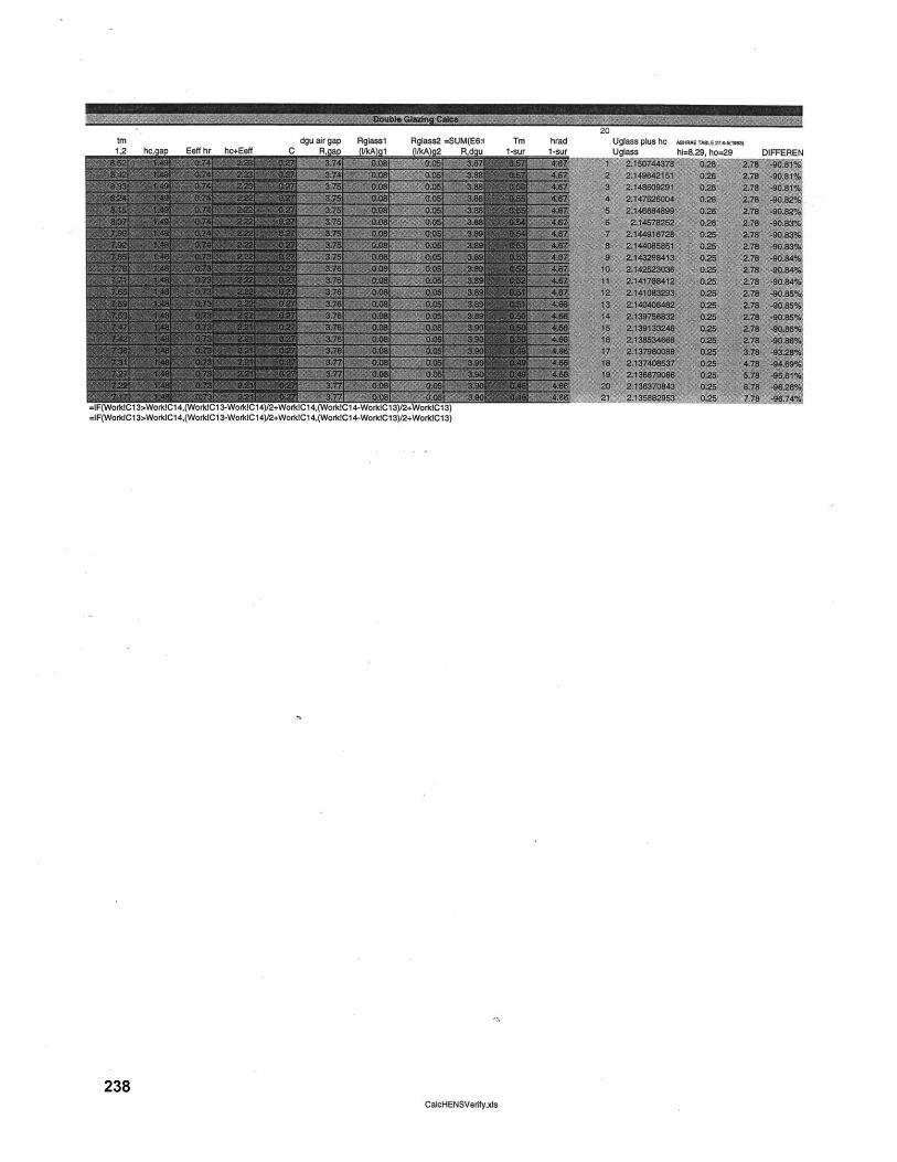
tm dgu air gap Rglaaal Rglaaa2 =-SUM(E6:1 TM hrad1,2 -hc, a Eeff hr hc+Eeff C R, a 1 1/kAg2__Rdgu 1-sur 1su
=IF(WorldCl3>WorkIC14,(WorkIC13-WorkICi4)/2+WorktC14,(WorkC14-WorkICl3)/2+WorkICl3)=IF(WorkICl 3>WorldC14,(WorkdCl3-WorklC14)12+WoiktC14,(WorkIC14-WorkICl3)/2+WoldCl3)
238CalcHENSVerify.xls
Uglasa; plus hc ABHRAE TABLE U7J4(l9M
Uglass hi=8.29. ho=29
,uLIM,

x O
w
00r
Cal
CD
C
cii~
~
wn
nw
.
a2
J
A~
a
wA
C
.,
a
CN
NN
to
N
N
Na r~
n-
040
cl0Jt
wIt
A
tt;A
N
-O
CO
14
-4
0
0i
*w
N4
K -~
0
Wco
-J
OC
CI(
"
0.
A
P3N
-0
0
W
A-0
W86
1a
;i
;i
O
C 4
0W
n
&W
W
.00
To F
W
CL
Mi
og, ga
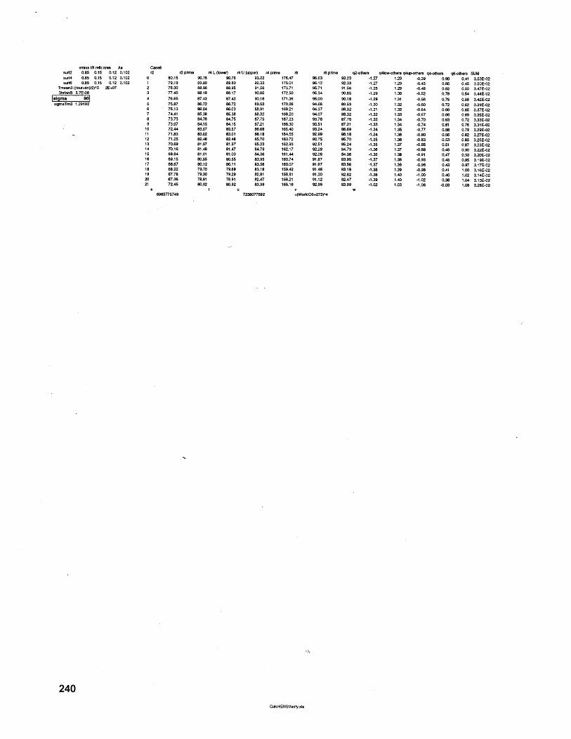
emiss IR rek area As Casessurf2 0.85 0.15 0.12 0.102 rsurf4 0.85 0.15 0.12 0.102 0surd6 0.85 0.15 0.12 0.102 1
Tmean3 ((tout+in)/2)^3 2E+07 2StoefanB 5.7E-08 3
sigma 90 4sigmaTm3 1.29192 5
Cae
101112131415161718192021
38
1696
80.1579.1978.3077.4576.6575.8775.1374.4173.7373.0772.4471.8371.2570.6970.1669.6469.1568.6768.2267.7867.3672.45
5775749
r2 prime r4 L (lower) r4 U (upper) r4 pnme 690.76 90.76 93.22 176.4789.80 89.80 92.33 175.0188.96 88.95 91.56 173.7188.18 88.17 90.85 172.5087.43 87.43 90.18 171.3686.72 86.72 89.53 170.2686.04 86.03 88.91 169.2180.38 85.38 88.32 166.2084.76 84.75 87.75 167.2384.15 84.10 87.21 186.3083.57 83.57 86.68 160.4383.02 83.01 86.18 164.5082.48 82.48 85.70 183.7281.97 81.97 85.23 1629381.48 81.47 84.79 162.1781.01 81.00 84.36 161.480.55 80.6 83.96 160.7480.12 80.11 83.56 160.0779.70 79.69 83.18 1084279.30 79.29 82.81 158.8178.91 78.91 82.47 158.2180.92 80.92 83.99 168.16
t u7238077682 0
96.6396.1295.7195.3495.0094.6894.3794.0793.7893.5193.2492.9992.7592.5192.2992.0891.8791.6791.4891.3091.1292.99
NorkfO6+273
r6 prime q2-others q4low-others q4up-others q4-others q6-others SUM93.23 -1.27 1.29 -0.39 0.90 0.41 3.53E-0292.33 -1.27 1.29 -0.43 0.85 0.45 3.50E-0291.56 -1.28 1.29 -0.48 0.82 0.50 3.47E-0290.85 -1.29 1.30 -0.52 0.78 0.54 3.44E-0290.18 -1.29 1.31 -0.56 0.75 0.58 3.42E-0289.53 -1.30 1.32 -0.60 0.72 0.62 3.39E-0288.92 -1.31 1.32 -0.64 0.69 0.65 3.37E-0288.32 -1.32 1.33 -0.67 0.66 0.69 3.35E-0287.76 -1.32 1.34 -0.70 0.63 0.72 3.33E-0287.21 -1.33 1.34 -0.74 0.61 0.76 3.31E-0286.69 -1.34 1.35 -0.77 0.58 0.79 3.29E-0286.18 -1.34 1.36 -0.80 0.56 0.82 3.27E-0285.70 -1.35 1.36 -0.83 0.53 0.85 3.25E-02895.24 -1.35 1.37 -0.85 0.51 0.87 3.23E-0284.79 -1.36 1.37 -0.88 0.49 0.90 3.22E-0284.36 -1.36 1.38 -0.91 0.47 0.93 3.20E-0283.95 -1.37 1.38 -0.93 0.45 0.95 3.19E-0283.86 -1.37 1.39 -0.96 0.43 0.97 3.17E-0283.18 -1.38 1.39 -0.98 0.41 1.00 3.16E-0282.82 -1.38 1.40 -1.00 0.40 1.02 3.14E-0282.47 -1.39 1.40 -1.02 0.38 1.04 3.13E-0283.99 -1.02 1.03 -1.06 -0.03 1.08 3.28E-02
W)^4
240CalcHENSVerify.xis
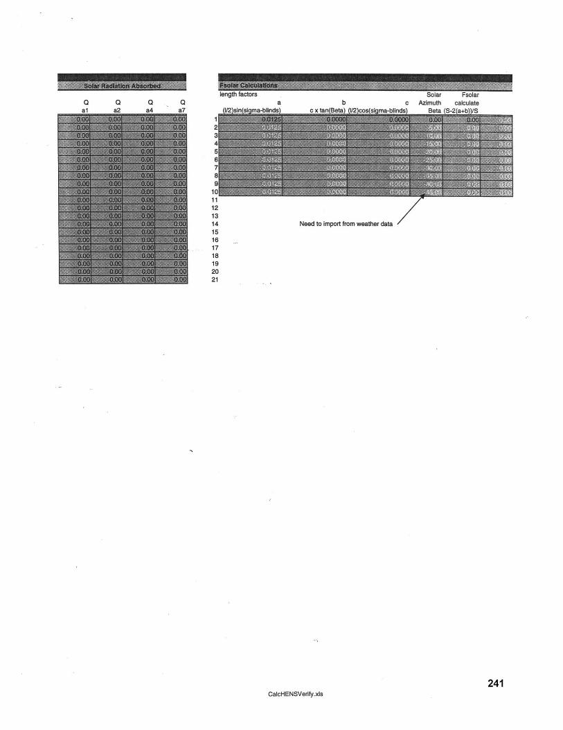
Solar Fsolarc Azimuth calculate
a\ naa O-+. h\/
Q Q 0 Q
Need to import from weather data
241CalcHENSVerify.xls

Diffuse EnSar
242CalcHENSVerify.xls

For reflected portionSpecular model
CalcHENSVerify.xis 243

Rho4,s 0.1Rho4,d 0.15
abs of blind, alpha4 0.751/4 sum of "lit-out" 11/4 sum of "lit-hit" 01/4 sum of "lit-in" 0
1/4 sum of "hit-hit" 0F4U4L 0.00
F4U6 1.00F4U2 0.00
F4L4U 0.00F4L6 0.00F4L_2 1.00
Rho 4, tot-outAlpha 4 totRho 4, tot-in
0.1 0.1 0.1 0.1 0.1 0.1 0.1 0.1 0.10.15 0.15 0.15 0.15 0.3 0.15 0.15 0.15 0.10.75 0.75 0.75 0.75 0.6 0.75 0.75 0.75 0.6
1 1 1 1 1 1 1 1 10 0 0 0 0 0 0 0 10 0 0 0 0 0 0 0 00 0 0 0 0 0 0 0 0
0.00 0.00 0.00 0.00 0.00 0.00 0.00 0.00 0.221.00 1.00 0.92 0.99 1.00 1.00 1.00 1.00 0.740.00 0.00 0.00 0.00 0.00 0.00 0.00 0.00 0.030.00 0.00 0.00 0.00 0.00 0.00 0.00 0.00 0.220.00 0.00 0.00 0.00 0.00 0.00 0.00 0.00 0.031.00 1.00 0.92 0.99 1.00 1.00 1.00 1.00 0.74
I~vW .
244CalcHENSVerify.xls
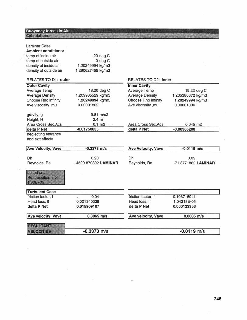
Laminar CaseAmbient conditions:temp of inside airtemp of outside airdensity of inside airdensity of outside air
RELATES TO D1: outer
20 deg C0 deg C
1.20249994 kg/m31.290627455 kg/m3
Outer CavityAverage Temp 18.20 deg CAverage Density 1.209935529 kg/m3Choose Rho infinity 1.20249994 kg/m3Ave viscosity ,mu 0.00001802
gravity, g 9.81 m/s2Height, H 2.4 mArea Cross Sec,Acs 0.1 m2 - -
delta P Net -0.01750635neglecting entranceand exit effects
|Ave Velocity, Vave -0.3373 m/s
Dh 0.20Reynolds, Re -4529.870392 LAMINAR
|Turbulent Casefriction factor, f 0.04Head loss, If 0.001340339delta P Net 0.015909107
|Ave velocity, Vave 0.3065 m/s
RELATES TO D2: innerInner CavityAverage Temp 19.22 deg CAverage Density 1.205380672 kg/m3Choose Rho infinity 1.20249994 kg/m3Ave viscosity ,mu 0.00001806
Area Cross Sec,Acs 0.045 m2delta P Net -0.00305208
Ave Velocity, Vave -0.0119 m/s
Dh 0.09Reynolds, Re -71.3771882 LAMINAR
friction factor, f 0.108716941Head loss, If 1.04318E-05delta P Net 0.000123353
Ave velocity, Vave 0.0005 m/s
-0.3373 m/s -0.0119 m/s
245
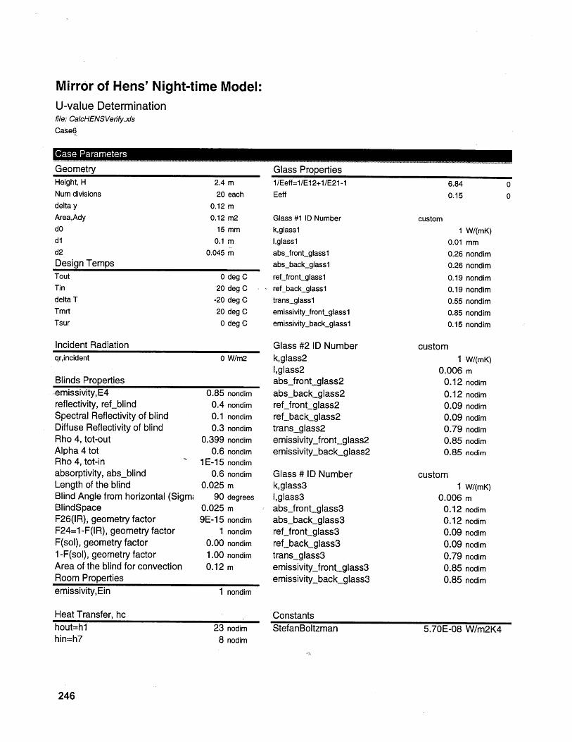
Mirror of Hens' Night-time Model:U-value Determinationfile: CalcHENSVerfify.xlsCase6
Case Parameters
GeometryHeight, H 2.4 mNum divisions 20 eachdelta y 0.12 mArea,Ady 0.12 m2dO 15 mmd1l 0.1 md2 0.045 mDesign TempsTout 0 deg CTin 20 degC -
delta T -20 deg CTmrt 20 deg CTsur 0 deg C
Incident Radiationqr,incident 0 W/m2
Blinds Propertiesemissivity,E4 0.85 nondimreflectivity, ref-blind 0.4 nondimSpectral Reflectivity of blind 0.1 nondimDiffuse Reflectivity of blind 0.3 nondimRho 4, tot-out 0.399 nondimAlpha 4 tot 0.6 nondimRho 4, tot-in 1E-15 nondimabsorptivity, abs.blind 0.6 nondimLength of the blind 0.025 mBlind Angle from horizontal (Sigm, 90 degreesBlindSpace 0.025 mF26(IR), geometry factor 9E-15 nondimF24=1 -F(IR), geometry factor 1 nondimF(sol), geometry factor 0.00 nondim1 -F(sol), geometry factor 1.00 nondimArea of the blind for convection 0.12 mRoom Propertiesemissivity,Ein 1 nondim
Heat Transfer, hchout=hlhin=h7
23 nodim8 nodim
Glass Properties1/Eeff=1/E12+1/E21-1Eeff
Glass #1 ID Numberk,glasslIglass1absjfront-glasslabs-back-glassl
ref-front-glass1- ref-back-glassl
trans-glasslemissivityjront-glasslemissivity-back-glass1
Glass #2 ID Numberk,glass21,glass2absfront.glass2absback-glass2ref_frontglass2refbackglass2trans-glass2emissivityjront-glass2emissivity-back_glass2
Glass # ID Numberk,glass3I,glass3absfront glass3absbackglass3reffrontglass3refback_glass3trans-glass3emissivity-front-glass3emissivity-back_glass3
ConstantsStefanBoltzman
6.84 00.15 0
custom
1 W/(mK)0.01 mm0.26 nondim0.26 nondim
0.190.190.550.85
nondimnondimnondimnondim
0.15 nondim
custom1
0.0060.120.120.090.090.790.850.85
custom1
0.0060.120.120.090.090.790.850.85
W/(mK)mnodim
nodimnodimnodimnodimnodimnodim
W/(mK)mnodimnodimnodimnodimnodimnodimnodim
5.70E-08 W/m2K4
246
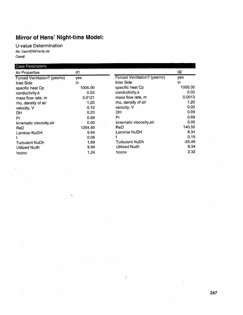
C ase Parameters
Air PropertiesForced Ventilation? (yes/no)Inlet Sidespecific heat Cpconductivity,kmass flow rate, mrho, density of airvelocity, VDHPrkinematic viscosity,airReDLaminar NuDHfTurbulent NuDhUtilized Nudhhconv
yesin
1005.000.03
0.01211.200.100.200.690.00
1264.959.940.061.899.941.24
Forced Ventilation? (yes/no)Inlet Sidespecific heat Cpconductivity,kmass flow rate, mrho, density of airvelocity, VDHPrkinematic viscosity,airReDLaminar NuDHfTurbulent NuDhUtilized Nudhhconv
d2yesin
1005.000.03
0.00131.200.020.090.690.00
140.558.340.19
-25.498.342.32
247
Mirror of Hens' Night-time Model:U-value Determinationfile: CalcHENSVerify.xIsCase6
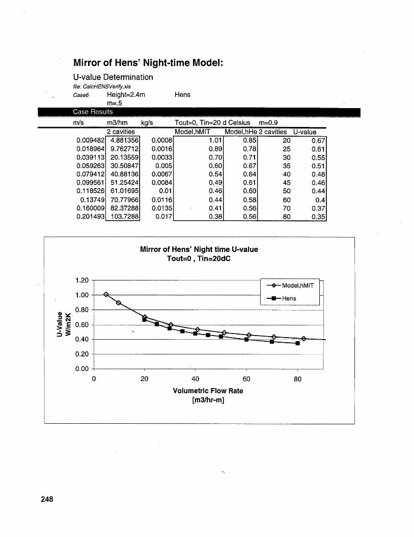
Mirror of Hens' Night-time Model:U-value Determinationfile: CalcHENSVerify.xlsCase6 Height=2.4m
m=.5
m3/hm kg/s2 cavities
4.8813569.76271220.1355930.5084740.8813651.2542461.0169570.7796682.37288103.7288
Tout=0, Tin=20 d Celsius m=0.9
0.00080.00160.0033
0.0050.00670.0084
0.010.01160.0135
0.017
Hens
m/s
0.0094820.0189640.0391130.0592630.0794120.0995610.1185260.13749
0.1600090.201493
1.01 0.85 20 0.670.89 0.78 25 0.610.70 0.71 30 0.550.60 0.67 35 0.510.54 0.64 40 0.480.49 0.61 45 0.460.46 0.60 50 0.440.44 0.58 60 0.40.41 0.56 70 0.370.38 0.56 80 0.35
Mirror of Hens' Night time U-valueTout=O , Tin=20dC
1.20
1.00-
0.80
g E 0.60
0.40-
0.20
0.00
0 20 40 60
Volumetric Flow Rate[m3/hr-m]
248
Case Results
Model,hMIT Model,hHe 2 cavities U-value
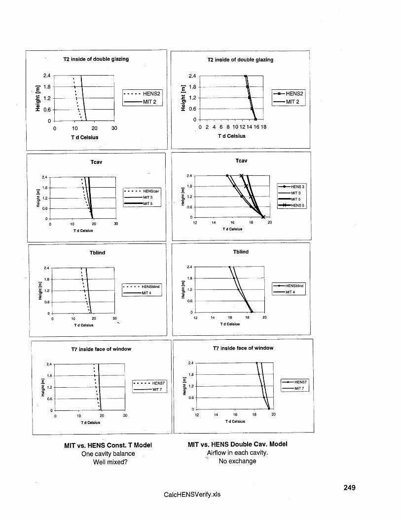
T2 inside of double glazing T2 inside of double glazing
2.4
1.8-U- HENS2
. 1.2- MIT 2
: 0.6
00 2 4 6 8 1012141618
T d Celsius
Tcav
MIT vs. HENS Const. T Model MIT vs. HENS Double Cav. ModelOne cavity balance
Well mixed?Airflow in each cavity.
No exchange
249CalcHENSVerify.xls
------ HENS2MIT 2
0 10 20
T d Celsius
Tcav
2.4
1.8--- -- -- HENScav
1.2-- - MIT3
MIT 50.6
00 10 20 30
T d Celsius
-- HENS 3-MIT 3
-MIT 5
HENS 5
18 2012 14 16
T d Celsius

250
7.2.5 SHGC Validation
The following is the backup for the comparison of the model predictions with [Saelens 1998]
for solar heat gain coefficient.
251Arons
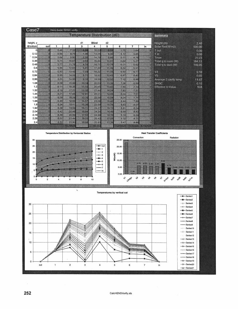
dl Blind d2outl 1 | 2 | 3 | 4 | 5 | A | 7 | In
Temperature Distribution by Horizontal Station
--- out
-li-4
-7
-In
25.00
20.00
Heat Transfer Coefficients
Convection
g 15.00
9 10.00
5.00
Temperatures by vertical cut
CalcHENSVerify.xs
height, y@bottom
00.120.240.360.480.6
0.720.840.961.08
Radiation
--- Seriesl
-- Series2
-- Series3
-- Series4
-E-Series5
-0--Series6
-+Sries7--- Sries8
Seris9
Seris10
Seris11
Series12
-K- Series13
-< Series14
-4-Series15
-,--Seris16--- Series17
Seriesl8
-Seriest
-- Series2o
- ArSara21
252

Tm hrad Tm hrad Tm hrad Tm hrad
assumptionsTm4-2 at y=O is T3=Tin noteTm6-4 at y=O is T5=TIn Tm go with y-1 rather than yTm7-4 at =0 Is T5=Tin
253CalcHENSVerfy.xIs
Mkllpl PIT-TM hrad

dgu air gap Figlassi Rglaaa2 =SUM(E6:( Tm hradC tIIIA~,.1 (I&A~,S) C A.... 4..,.
Uglaaa plus hc AS~flAETABLE27.#4lUa1
Uglasa hI=8.29. ho=29
=iI-(YvgnuLA i>wgncit.i4,~vvgnut.ius-yvOnqui 4)u+w0m1U14,1w0nc1u14-worKiLAa)I2+woncIuia)=IF(WorkICl 3>WorklCl4,(WorldCl3-WorkICl4)12+WorklCl4,(WorlclCl 4-WorkICi 3)/2+WorklCl 3)
254
CalcHENSVeuify.xla
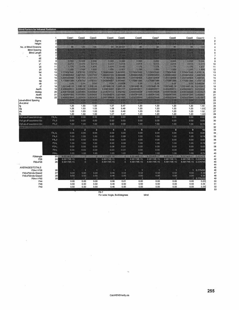
SigmaHeight
No. of Blind DivisionsBlind SpacingBlind Length
dld2x1y1y2y3bdfhac
dedcf
AacfhAbdegAbdfhAaceg
cd=ef=Blind Spacingdf=Lblindfgdgda
1.23 1.53 1.51.23 1.53 1.531.23 1.53 1.53
1.09 .491.09 0.491.20 0.49
1.23 1.23 1.231.23 1.23 1.23
ase9 Case10 123456789
101112131415161718192021222324
1.20 1.50 251.23 1.53| 261.23 1.52 271.20 1.50 28
29
303132
9 10 3334
353637383940414243444546474849
0.50 0.31 500.50 0.39 510.50 0.39| 52
F6-?For solar Angle, B=30degrees blind
255CalcHENSVerify.xIs
Blind Factors for Infrared Radiation7 g 7r MEMO
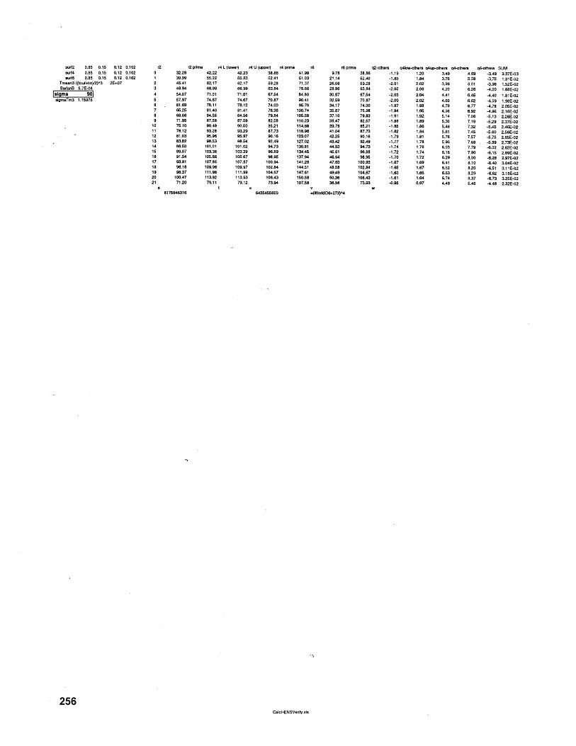
surf2 0.85 0.15 0.12 0.102 2 r2 prime r4 L (lower) r4 U (upper) r4 prime r6surf4 0.85 0.15 0.12 0.102 0 32.28 42.22 42.23 38.86 41.99surf6 0.85 0.15 0.12 0.102 1 39.99 55.22 55.23 52.41 61.03
Tmean3 ((tout+tin)/2)^3 2E+07 2 45.41 62.17 62.17 09.28 71.37SlefanB 5.7E-08 3 49.94 66.99 66.99 63.84 78.66
1si ma 90 4 54.07 71.01 71.01 67.54 84.80sigmaTm3 1.15975 5 57.97 74.67 74.67 70.87 90.41
8 . 61.69 78.11 78.12 74.00 95.707 65.25 81.40 81.41 76.98 100.748 68.66 84.55 84.58 79.84 100.589 71.95 87.58 87.59 82.08 110.23
10 75.10 90.49 90.50 85.21 114.6811 78.12 93.28 93.29 87.73 118.9612 81.03 95.96 95.97 90.16 123.0713 83.82 98.53 98.54 92.49 127.0214 86.50 101.01 101.02 94.73 130.8118 89.07 103.38 103.39 96.89 134.4516 91.54 105.66 105.67 98.95 137.9417 93.91 107.85 107.87 100.94 141.2918 96.18 109.96 109.97 102.84 144.5119 98.37 111.98 111.99 104.67 147.6120 100.47 113.92 113.93 106.43 150.5821 71.20 79.11 79.12 73.94 107.58
r6 prime q2-others q4low-others q4up-others q4-others q6-others SUM38.86 -1.19 1.20 3.49 4.69 -3.49 9.37E-0352.40 -1.83 1.84 3.76 5.59 -3.75 1.31E-0259.28 -2.01 2.02 3.99 0.01 -3.98 1.52E-0263.84 -2.05 2.06 4.20 6.26 -4.20 1.68E-0267.54 -2.03 2.04 4.41 6.45 -4.40 1.81E-0270.87 -2.00 2.02 4.60 6.62 -4.59 1.93E-0274.00 -1.97 1.98 4.79 6.77 -4.78 2.05E-0276.98 -1.94 1.95 4.96 6.92 -4.96 2.16E-0279.83 -1.91 1.92 5.14 7.06 -5.13 2.26E-0282.57 -1.88 1.89 5.30 7.19 -5.29 2.37E-0285.21 -1.85 1.86 5.46 7.32 -5.45 2.46E-0287.73 -1.82 1.84 5.61 7.45 -5.60 2.56E-0290.16 -1.79 1.81 5.76 7.57 -5.75 2.65E-0292.49 -1.77 1.78 5.90 7.68 -0.89 2.73E-0294.73 -1.74 1.76 6.03 7.79 -6.02 2.82E-0296.88 -1.72 1.74 6.16 7.90 -6.15 2.89E-0298.95 -1.70 1.72 6.29 8.00 -6.28 2.97E-02
100.93 -1.67 1.69 6.41 8.10 -6.40 3.04E-02102.84 -1.65 1.67 6.52 8.20 -6.51 3.11E-02104.67 -1.63 1.65 6.63 8.29 -6.62 3.18E-02106.43 -1.61 1.64 6.74 8.37 -6.73 3.25E-0273.93 -0.95 0.97 4.49 5.46 -4.48 2.32E-02
6175646316 6430455600 =(WorklO6+273)^4
256CalcHENSVerify.xls
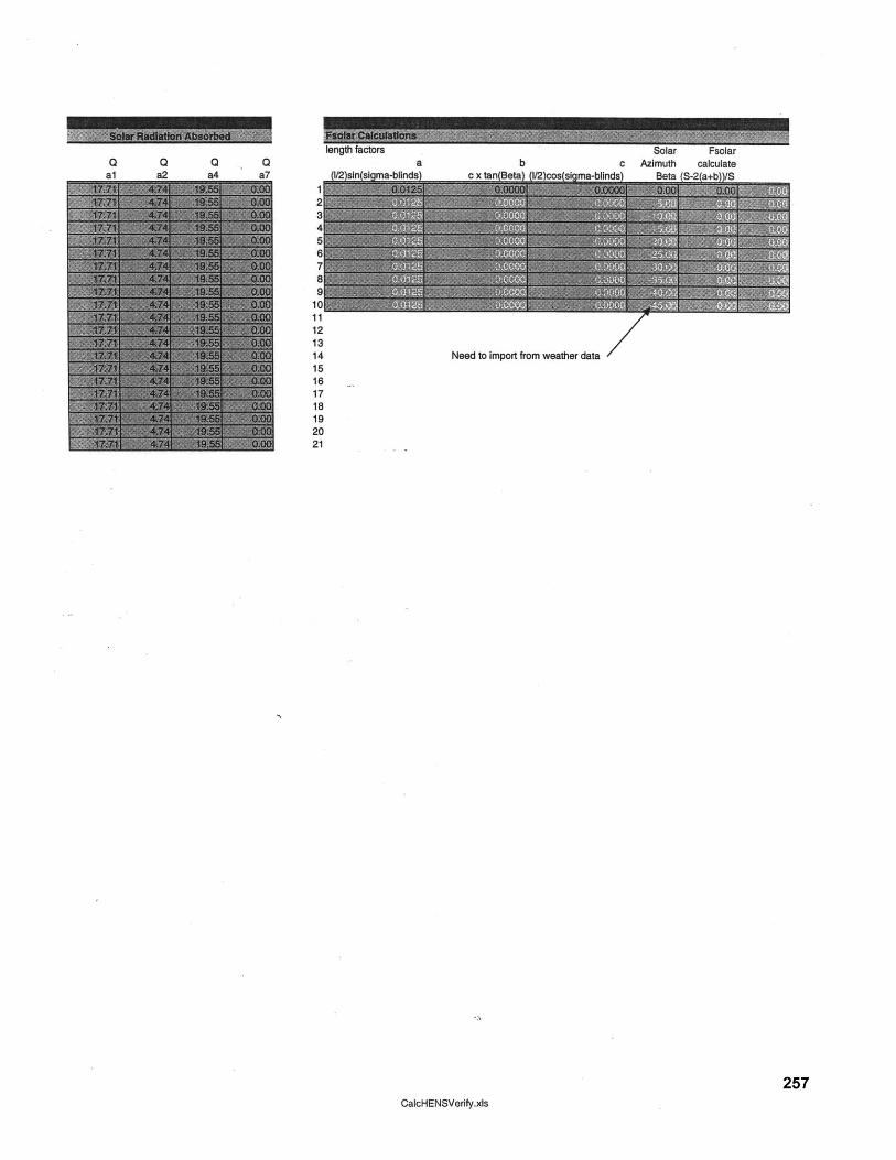
c Azimuth calculate_. nM+ 100-OlMs\\O
121314 Need to import from weather data15161718192021
257CalcHENSVerify.xis
Q Q Qa
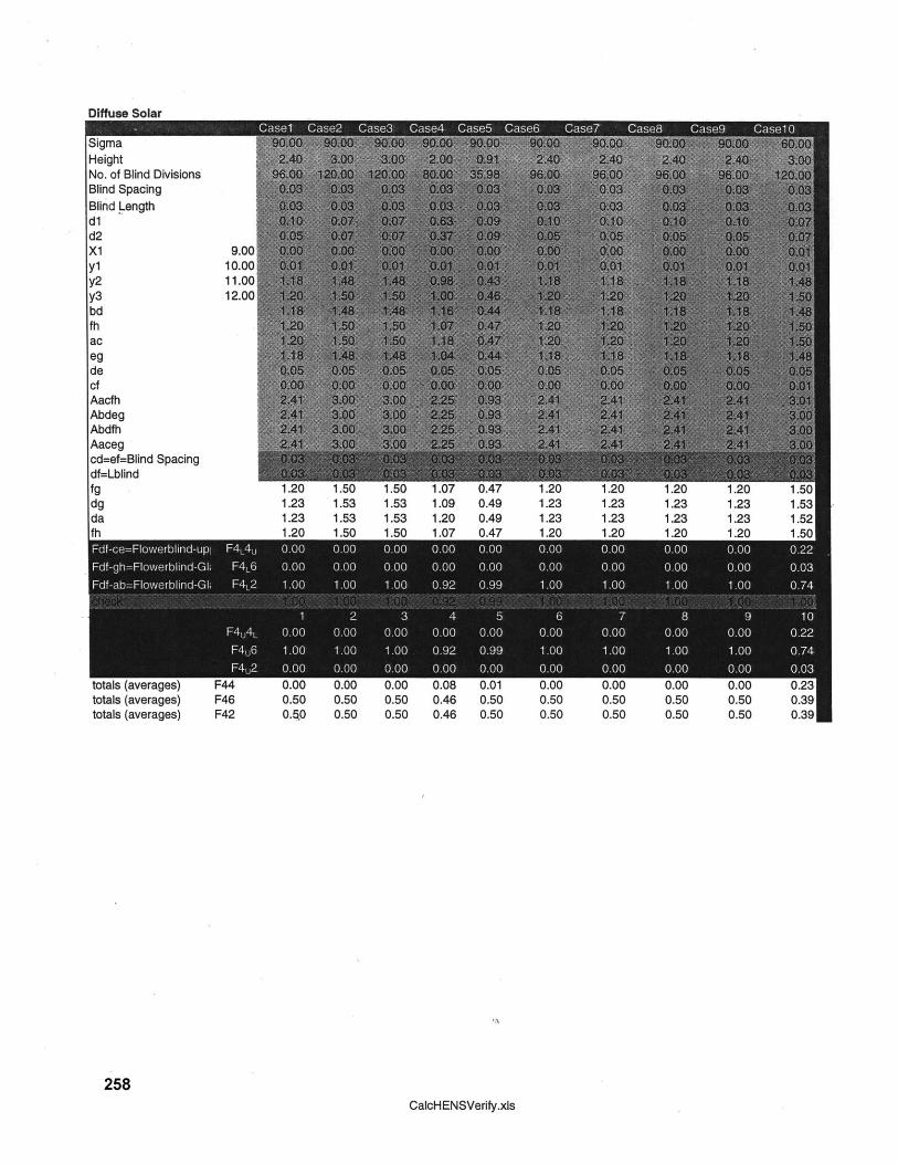
Diffuse Solar
258CalcHENSVerify.xls
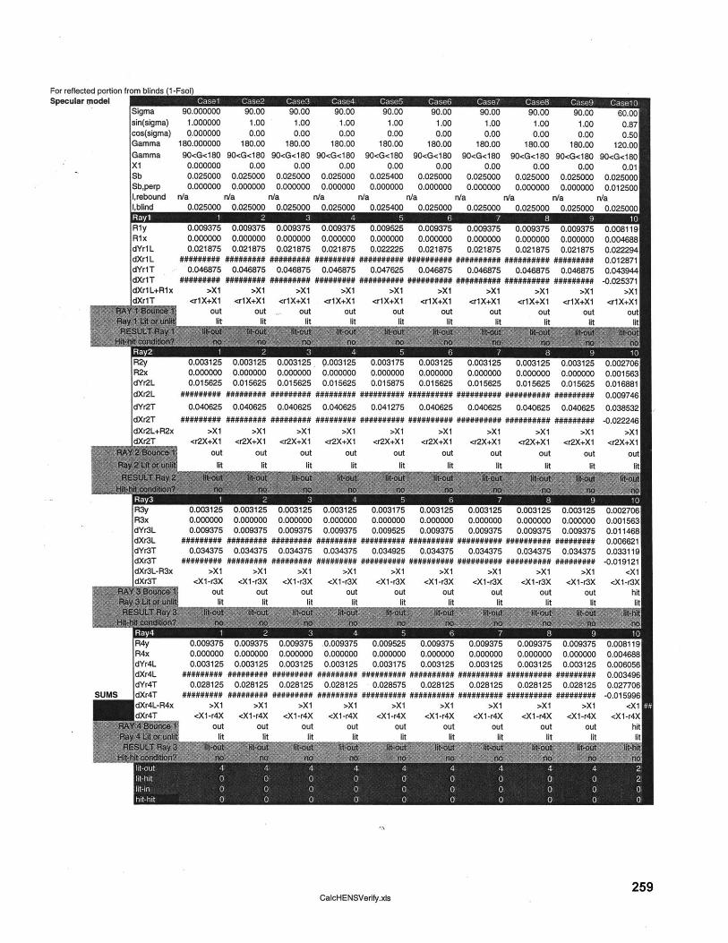
For reflected portion fiSpecular ktodel
CalcHENSVerify.xls259
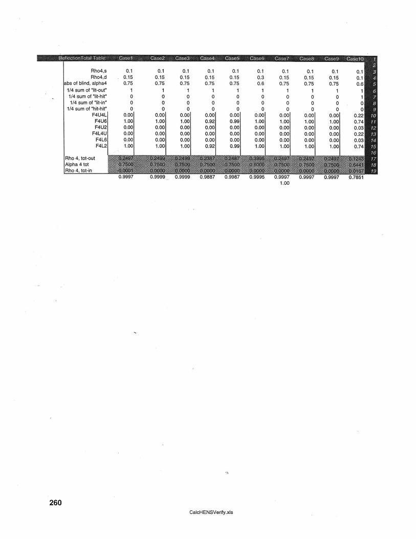
Rho4,s 0.1 0.1 0.1Rho4,d 0.15 0.15 0.15
abs of blind, alpha4 0.75 0.75 0.751/4 sum of "lit-out"1/4 sum of "lit-hit"1/4 sum of "lit-in"
1/4 sum of "hit-hit"F4U4L
F4U6F4U2
F4L4UF4L6F4L2
Rho 4, tot-outAlpha 4 totRho 4, tot-in
1 1 10 0 00 0 00 0 0
0.00 0.00 0.001.00 1.00 1.000.00 0.00 0.000.00 0.00 0.000.00 0.00 0.001.00 1.00 1.001
0.1 0.1 0.1 0.1 0.1 0.1 0.10.15 0.15 0.3 0.15 0.15 0.15 0.10.75 0.75 0.6 0.75 0.75 0.75 0.6
1 1 1 1 1 1 10 0 0 0 0 0 10 0 0 0 0 0 00 0 0 0 0 0 0
0.00 0.00 0.00 0.00 0.00 0.00 0.220.92 0.99 1.00 1.00 1.00 1.00 0.740.00 0.00 0.00 0.00 0.00 0.00 0.030.00 0.00 0.00 0.00 0.00 0.00 0.220.00 0.00 0.00 0.00 0.00 0.00 0.030.92 0.99 1.00 1.00 1.00 1.00 0.74
1.00
260CalcHENSVerify.xis

Laminar CaseAmbient conditions:temp of inside airtemp of outside airdensity of inside airdensity of outside air
RELATES TO D1: outer
0 deg C0 deg C
1.290627455 kg/m31.290627455 kg/m3
Outer CavityAverage Temp 10.96 deg CAverage Density 1.240620755 kg/m3Choose Rho infinity 1.290627455 kg/m3Ave viscosity ,mu 0.00001774
gravity, g 9.81 m/s2Height, H 2.4 mArea Cross Sec,Acs 0.1 m2delta P Net 0.117735773neglecting entranceand exit effects
Ave Velocity, Vave 2.3044 m/s
Dh 0.20Reynolds, Re 32231.2954 LAMINAR
Turbulent Casefriction factor, f - 0.02Head loss, If 0.038299629delta P Net 0.466125235
Ave velocity, Vave 9.1234 m/s
RELATES TO D2: InnerInner CavityAverage Temp 13.54 deg CAverage Density 1.229362068 kg/m3Choose Rho infinity 1.290627455 kg/m3Ave viscosity ,mu 0.00001786
Area Cross Sec,Acs 0.045 m2delta P Net 0.064909452
Ave Velocity, Vave 0.2555 m/s
Dh 0.09Reynolds, Re 1583.069177 LAMINAR
friction factor, f 0.050097045Head loss, If 0.002223156delta P Net 0.026811352
Ave velocity, Vave 0.1056 m/s
2.3044 m/s 0.2555 m/s
261
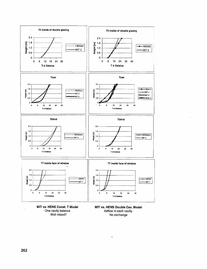
T2 inside of double glazing
2.4-
1.8...- ----- HENS2
.c 1.2 _ _
MIT 2z 0.6
00 6 12 18 24 30
T d Celsius
Tcav
2.4
1.8E- - - - - -HENScavS1.2 MIT3
m MIT 50.6-
0 -
0 6 12 18 24 30
T d Celsius
Tblind
2.4
1.8-
1.2--. - - - - -- HENSblindMIT 4
0.6
00 6 12 18 24 30
T d Celsius
T7 inside face of window
2.4
1.8
1.------- - -'HENS7:1C1.2- MIT 7
0.6
00 6 12 18 24 30
T d Celsius
MIT vs. HENS Const. T ModelOne cavity balance
Well mixed?
T2 inside of double glazing
2.4
1.82 -e-HENS2
.1.2-.g - MIT2z 0.6
0-0 8 16 24 32 40
T d Celsius
Tcav
2.4
. 1.8- -- HENS 3--- MIT 3
2 -MIT 5
0.6 HENS 5
0' 0 8 16 24 32 40
T d Celsius
Tblind
2.4
1.8
12 ---- HENSblind- - MIT 4
0.6
0 8 16 24 32 40
T d Celsius
T7 inside face of window
2.4
1.8A
1.2 -- HENS7-MIT 7
0.6
00 8 16 24 32 40
T d Celsius
MIT vs. HENS Double Cav. ModelAirflow in each cavity.
No exchange
262
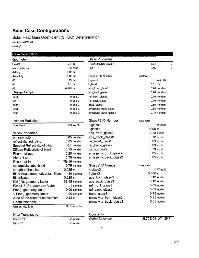
Base Case ConfigurationsSolar Heat Gain Coefficient (SHGC) Determinationfile: Calculator.xlscase: 2
Case Parameters
GeometryHeight, H 2.4 m
Num divisions 20 each
delta y 0.12 m
Area,Ady 0.12 m2dO 15mmdl 0.1 md2 0.045 mDesign TempsTout 0 deg CTin 0 deg Cdelta T 0 deg CTmrt 0 deg CTsur 0 deg C
Incident Radiationqr,incident 500 W/m2
Blinds Properties-emissivity,E4 0.85 nondimreflectivity, refblind 0.25 nondimSpectral Reflectivity of blind 0.1 nondimDiffuse Reflectivity of blind 0.15 nondimRho 4, tot-out 0.25 nondimAlpha 4 tot 0.75 nondimRho 4, tot-in 7E-16 nondimabsorptivity, absblind 0.75 nondimLength of the blind 0.025 mBlind Angle from horizontal (Sigm 90 degreesBlindSpace 0.025 mF26(IR), geometry factor 9E-15 nondimF24=1--F(IR), geometry factor 1 nondimF(sol), geometry factor 0.00 nondim1 -F(sol), geometry factor 1.00 nondimArea of the blind for convection 0.12 mRoom Propertiesemissivity,Ein 0.85 nondim
Heat Transfer, hchout=hl 23 nodimhin=h7
Glass Properties1/Eeff=1/E12+1/E21-1
Eeff
Glass #1 ID Numberk,glasslI,glasslabsjfront-glass1abs-back-glassl
reffront-glasslrefback_glassl
trans-glasslemissivityfront-glass1emissivity-back-glassl
Glass #2 ID Numberk,glass21,glass2absjfront-glass2abs-back-glass2reffront-glass2ref-back-glass2trans-glass2emissivityjront-glass2emissivity-back-glass2
Glass # ID Numberk,glass3I,glass3absjfront-glass3abs-back_glass3reffront-glass3ref-back_glass3trans-glass3emissivityjront-glass3emissivity-back-glass3
ConstantsStefanBoltzman
6.840.15
custom1 W/(mK)
0.01 mm0.26 nondim0.26 nondim
0.190.190.550.850.15
custom1
0.0060.120.120.090.090.790.850.85
custom1
0.0060.120.120.090.090.790.850.85
nondimnondimnondimnondimnondim
W/(mK)mnodim
nodimnodimnodimnodimnodimnodim
W/(mK)mnodimnodimnodimnodimnodimnodimnodim
5.70E-08 W/m2K48 nodim
263

Base Case ConfigurationsSolar Heat Gain Coefficient (SHGC) Determinationfile: Calculator.xlscase: 2
Case Parameters
Air Properties dlForced Ventilation? (yes/no)Inlet Sidespecific heat Cpconductivity,kmass flow rate, mrho, density of airvelocity, VDHPrkinematic viscosity,airReDLaminar NuDHfTurbulent NuDhUtilized Nudhhconv
yesin
1005.000.030.011.200.100.200.690.00
1264.959.940.061.899.946.20
Forced Ventilation? (yes/no)Inlet Sidespecific heat Cpconductivity,kmass flow rate, mrho, density of airvelocity, VDHPrkinematic viscosity,airReDLaminar NuDHfTurbulent NuDhUtilized Nudhhconv
264
d2yesin
1005.000.030.001.200.020.090.690.00
140.558.340.19
-25.498.345.90
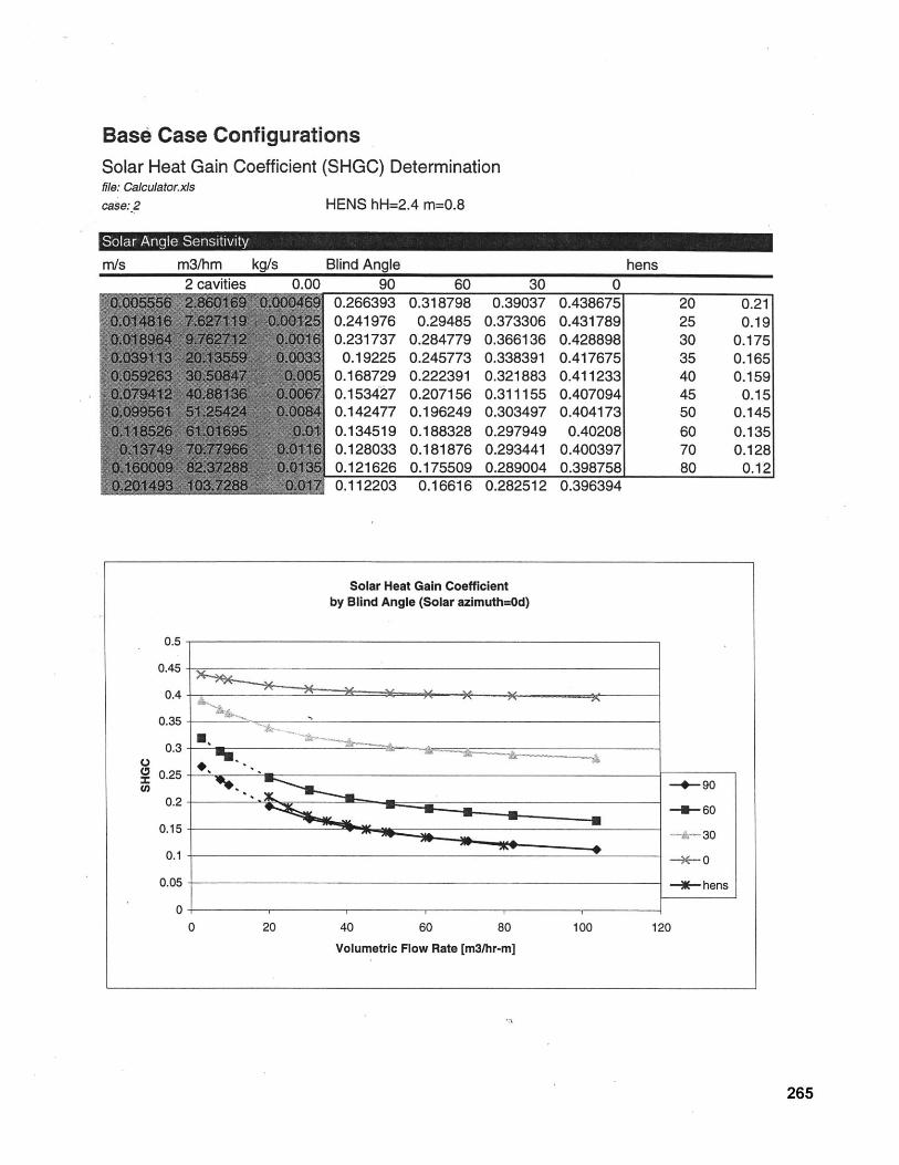
Base Case ConfigurationsSolar Heat Gain Coefficient (SHGC) Determinationfile: Calculator.xlscase: 2 HENS hH=2.4 m=0.8
Angle Sensitivity
rm/s m3/hm kg/s2 rnviting
Blind Angle000
0.2663930.2419760.231737
0.192250.1687290.1534270.1424770.1345190.1280330.121626
0.3187980.29485
0.2847790.2457730.2223910.2071560.1962490.1883280.1818760.175509
0.390370.3733060.3661360.3383910.3218830.3111550.3034970.2979490.2934410.289004
0.112203 0.16616 0.282512
hens
0.4386750.4317890.4288980.4176750.4112330.4070940.4041730.40208
0.4003970.3987580.396394
0.210.19
0.1750.1650.159
0.150.1450.1350.128
0.12
Solar Heat Gain Coefficientby Blind Angle (Solar azimuth=Od)
0.5-
0.45
0.4 -
0.35-
0.25 --
0.2 -- 60
0.15 -30
0.1 -*- 0
0.05 hens
00 20 40 60 80 100 120
Volumetric Flow Rate [m3/hr-m]
265

266
8.0 Bibliography
[Arons 1999]
[ASHRAE 1981]
[Banham 1969]
[Bolt 1997]
[Bolz and Tuve]
[Brandolini 1997]
[Buchanan 1998]
[Campagno 1996]
[Colin and Lambot
1997]
[Commerzbank web]
Arons, Daniel, Field Notes from discussions and site visits to
European buildings, architects and engineers, unpublished 1999.
ASHRAE Standard, Thermal Environmental Conditions for Human
Occupancy, ANSI/ASHRAE 55-1981, American Society of Heating,
Refrigerating and Air-conditioning Engineers, Inc., TJ223.T4.T44
1981
Banham, Reyner, The Architecture of the Well-Tempered
Environment, The Architectural Press, London, 1969, pp. 157-163.
Bolt, Ian Building Study; cost comment, The architect's Journal, April
1997.
Bolz, Ray E., and Tuve, George L., Handbook of tables for Applied
Engineering Science CRC Press, Florida, 1991.
Brandolini, Sebastiano, Buidling Blocks, World Architecture, Issue
No. 54, March 1997.
Buchanan, Peter, Reinventing the Skyscraper, A+U, Jan-March
1998 pp. 30-45.
Campagno, Andrea Intelligent Glass Facades, Birkhauser, ISBN 3-
7643-5547-6.
Davies, Colin, and Lambot, Ian, Commerzbank Frankfurt: Prototype
for an Ecological High-Rise, Watermark/Birkhauser, Surrey,
England, 1997. NA6245.G32.F733.1997.
Commerzbank website
http://www.commerzbank.com/zentrale/technik.htm
Arons 267

[Comstock 1987]
[Daniels 1994]
[Daniels 1998]
[Davey 1997]
[Davey 1997a]
[Davies et al 1997]
[Dawson, 1997]
[Detail 1997]
[Deutshe B. 1997]
[Evans 1977]
[Evans1997b]
[Evans1997c]
268
Comstock Center Integrates Heat Pumps, Air-Flow Windows in
Design Challenges, Energy Engineering, Vol. 84, No. 2, Feb.-Mar.
1987.
Daniels, Klaus, The Technology of Ecological Building: Basic
Principles and Measures, Examples and Ideas., Birkhauser, Boston,1994.
Daniels, Klaus, Low Tech, Light Tech, High Tech: Building in the
Information Age., Birkhauser, Boston, 1998.
Davey, Peter, Neat Regeneration, Architectural Review, July 1977,
p.. 60-63.
Davey, Peter, High Expectations, The Architectural Review, July
1997, p. 26-39.
Davies, Colin and Lambot, Ian, Commerzbank Frankfurt: Prototype
for an Ecological High-Rise, Watermak/Birkhauser, Surrey, England,
1997.
Dawson, Layla Walled Green City, Architectural Review, July 1997.
author?Hochhaus einer Bank in Frankfurt am Main Detail March
1997 pp. 349-368.
author?Hohenrausch und Hohenluft, Deutsche Bauzentung, April
1997 pp. 48-60.
Evans, Barrie, Through the glass cylinder, The Architects' Journal,
15 May 1997
Evans, Barrie, Offices for Changing Work, the Architects' Journal
May 1997 p. 47.
Evans, Barrie, Banking on Ventilation, The Architects' JournalPrpr 7 of '
Properties and Applications of Double-Skin Facades
Feb1997 p. 36.
[Evans1997d]
[Foster 1994]
[Frankfurt web]
[Franta and Anstead
2000]
[Gabirelsson 1977]
[Gartner 1999]
[Gefwert et al 1998]
[Green 1997]
[Herzog 1997]
[Herzog 1996]
[Hochhaus]
Evans, Barrie, Bank and Eco Park Compared, The Architects'
Journal Feb1997 p. 39.
Foster, Norman, Towards the Modern Vernacular, Detail, nr. 6, Vol.
33, December/January, 1993/1994, pp. 664-710, 725-728.
Frankfurt Towers web site: http://www.boomtown-
frankfurt.com/travel-quide/routen/route6/ eindex.shtml
Franta, Gregory and Anstead, Christine Daylighting Offers Great
Opportunities From
http://www.nwwda.orq/articles/desiqnlab daylightinqg.html 2000
Gabirelsson, Extract Air Window; a Key to Better Heat Economy in
Buildings, 10 th World Energy Conference, Istanbul, Turkey, 1977.
Gartner, Joseph & Company, Product literature.
Gefwert, Margareta and Sodergren, David, Annual Energy Loss
Through a Ventilated Window - A Method of Calculation., Swedish
Council for Building Research, 1981
Green, June, Eco Log DI Architectural Review July 1997 p.
Herzog, Peter, Energy-Efficient Operation of Commercial Buildings:
Redefining the Energy Manager's Job, McGraw-Hill, NY, 1997.
TJ163.5.B84.H52.1997. ISBN 0-07-028468-7
Herzog, Thomas, ed., Solar Energy in Architecture and Urban
Planning, Berlin, 1996.
Hochhaus RWE AG Essen, Ingenhoven Overdiek Kahlen und
Partner, Dusseldorf. Corporate brochure
Arons 269
[Holmes 1994] Holmes, M.J. Optimization of the Thermal Performance of
Mechanically and Naturally Ventilated Glazed Facades, World
Renewable Energy Congress, Reading, 1994.
[Hopkins web] Michael Hopkins and Associates web
http://www.hopkins.co.uk/hopkins/npb.html
site: NPB
[Hyatt 1997]
[Kohlbecker 1998]
[Kreider
1982]
Hyatt, P{aul, Narrow Objectives of Design and Build Architects'
Journal, 20 Feb 1997, p. 29
Kohlbecker, C., Potsdammer Review, Architectural Review Jan 1998
pp. 34-43.
and Kreith Kreider, Jan F., and Kreith, Frank, Solar Heating and Coo/ing: Active
and Passive Design, McGraw-Hill Book Co., NY 1982.
[Mills 1995]
[Ospelt 1999]
[Patrick et al 1993]
[Pearson, 1997]
[Pepchinski 1995]
Mills, Anthony F. Basic Heat and Mass Transfer, Irwin, Chicago,1995.
Ospelt, Christoph, A Framework for Sustainable Buildings: An
application to China, SMBT Thesis, MIT, 1999.
Patrick, Steven R., Patrick, Dale R., and Fardo, Stephen W., Energy
Conservation Guidebook, The Fairmont Press, GA 1993,TJ163.3.P381, 1993 ISBN 0-88173-154-4.
Pearson, James, Delicate Essen, Architectural Review, July 1997.,pp. 40-45.
Pepchinski, Mary, The Building Breathes, Architectural Record, Oct
1995 p. 70.
[Pepchinski 1997] Pepchinski, Mary, RIWE AG
Architectural Record, June 1997.
Hochhaus Essen, Germany,
Piano, Renzo Debis Building -- Potsdammer Platz Reconstruction,APpt a Aptn_AAonrs 400A nnf ubA_1an
Properties and Applications of Double-Skin Facades
[Piano 1998]
270
[Preston web]
A+U Jan-March 1998, pp. 104-120.
Roger Preston International,
http://www.rpreston.com/index.html
[Ripatti 1984]
[Russell, 1997]
[Russell, 1995]
[RWE web]
[Saelens 1997]
[Saelens 1998a]
[Saelens 1998b]
[Saelens 1998c]
Ripatti, H., Airflow Window System-Making Fenestration the Solution
Rather than the Problem, ASHRAE Trans., 84-18 (1984) 18.
Russell, James S., AIA, Office Buildings: The New Generation,
Architectural Record June 1997, p. 137.
Russell, James S., AIA, Atrium as Thermal Buffer and Motorized
sun Protection Architectural Record, Oct 1995pp. 74-85.
RWE web site: http://www.rwe.de/englisch/erleben/index.html
Saelens, Dirk, and Hens, Hugo, Case Study - Active Envelopes,
Report 2, Annex 32 Integral Building Envelope Performance
Assessment, Subtask B, International Energy Agency, Exco Energy
Conservation in Buildings and Community Systems Programme, no
date.
Saelens, Dirk, and Hens, Hugo, Active Envelopes - Essential in
Urban Areas?, 19 th Annual AIVC Conference, Oslo Norway, 28-30
September 1998.
Saelens, D., and Hens, H., Case Study: Active Envelopes - U-Value
and Solar Heat Gain Coefficient Performance, Report 3, Annex 32
Integral Building Envelope Performance Assessment, Subtask BK.U.
Leuven, Laboratory of Building Physics, International Energy
Agency, Exco Energy Conservation in Buildings and Community
Systems Programme, Copenhagen Meeting, 15-17 April 1998.
Saelens, D., and Hens, H., DVV Case Study - An Overview of
Measurements during Summer Conditions, Report 4, Annex 32
Integral Building Envelope Performance Assessment, Subtask B,
International Energy Agency, Exco Energy Conservation in Buildings
Arons
web site:
271
[Schneider et al 1997]
and Community Systems Programme, Fountainbleau Meeting, 26-28 October 1998.
Schneider, Sabine, and Leibundgut, Hanjurg, Commerzbank-
Zentrale in Frankfurt am Main -- Foster and Partners, Baumeister
May 1997, pp 18-.
[Sewanton 1998] Sewanton, Mark Towering Ambitions:
Architecture Today, April 1997, pp. 34-39.
Foster in Frankfurt,
[Sielgal 1981]
[Stein
1992]
Siegal, robert and Howell, John R., Thermal Radiation Heat
Transfer, 2nd ed., Hemisphere Publishing Corporation, NY,
1981. p. 203.
and Reynolds Stein, Benjamin and Reynolds, John S., Mechanical and Electrical
Equipment for Buildings, John Wiley & Sons, Inc. New York, 1992.
[Tamimoto and Kimura
1997]
[Turner 1996]
[US Green Building
Council 1999]
[Wiart 1998]
Tamimoto, Jun (School of Engineering Sciences, Kyushu University,Kasuga-Shi, Fukuoka, 816 Japan) and Kimura, Ken-Ichi
(Department of Architecture, School of Science and Engineering,Waseda University, Tokyo, Japan), Simulation Study on an Air Flow
Window System with an Integrated Roll Screen, Energy and
Buildings 26, 1997 pp. 317-325.
Turner, Nicola, Lyon's Heart, World Architecture, Issue No. 45, April
1996.
US Green Building Council, LEED Green Building System 1.0,
San Francisco, CA 1999 p.6.
Wiart, L.B., and Suvachittanont, S. Energy Technology Division,Asian Institute of Technology, PO Box 2754 Bangkok, Thailand,Performance and Economic Analysis of Air Flow Windows in a
Tropical Climate Energy Research, VOL 9, October -December,
1998, pp. 441-447.
Properties and Applications of Double-Skin Facades272
[Winter 1996] Winter, John, Double Exposure: The Helicon at Moorgate,
Architecture Today, V. 73 November 1996, p. 28-.
[Yoon 1997] Yoon, Jong H., and Lee, Euy J. (Passive Solar Research Team,
Korea Institute of Energy Research, Taejon, Korea) and Hensen,Jan (ESRU, The University of Strathclyde, Glasgow, UK), Integrated
Thermal Analysis of a Three Story Expiremental Building with a
Double-Skin and a Ground-Coupled Heat Exchanger., Solar
Engineering 1997, The 1997 International Solar Energy Conference,
27-30 April 1997, Washington, D.C., ASME (Barker TJ81O.C593
1997).
Arons 273
Related Documents