ALIGNMENT

Welcome message from author
This document is posted to help you gain knowledge. Please leave a comment to let me know what you think about it! Share it to your friends and learn new things together.
Transcript

ALIGNMENT

Shaft alignment is process of position two or more shafts that centre lines of rotating shafts, form a single line when the machines are working at normal. It is aligned to be given reasonable bearing reactions & bending moments at all conditions of ship loading & operation.
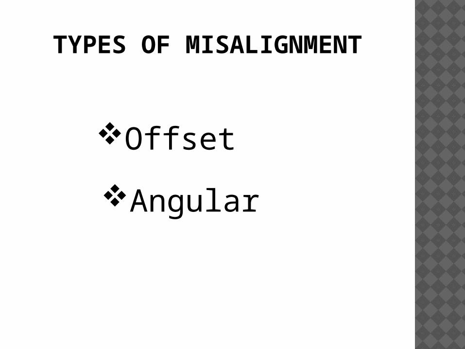
TYPES OF MISALIGNMENT
Offset
Angular
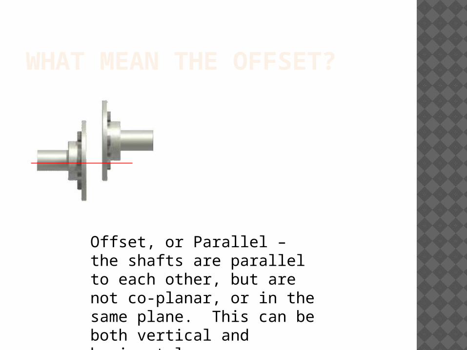
WHAT MEAN THE OFFSET?
Offset, or Parallel – the shafts are parallel to each other, but are not co-planar, or in the same plane. This can be both vertical and horizontal
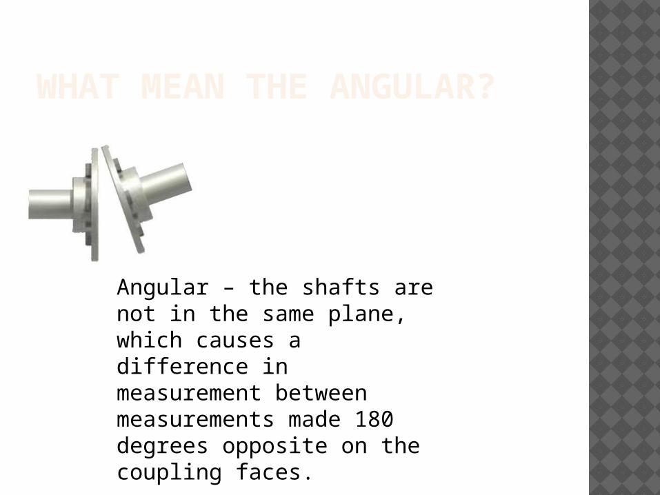
WHAT MEAN THE ANGULAR?
Angular – the shafts are not in the same plane, which causes a difference in measurement between measurements made 180 degrees opposite on the coupling faces.
HOW IS THE MISALIGN THE SHAFT?
Natural vibrations of the shafting or of its supports.
Destruction of the bronze sleeve of the propeller shaft.
Cracking or rupture of the propeller shaft or of the crankshaft.
Destruction or abnormal wear of the stern bearings of the shafting or of reduction gear bearings or of main engine bearings.

PROPELLER SHAFT ALIGNMENT METHOD

PIANO WIRE(PILGREM WIRE)
TELESCOPE
PIANO WIRE METHOD
A wire is used as a reference line. The wire is tensioned to standard amount by fixing at one end and having a weight over a pulley at the other end. Then distance from wire to bearings are measured, allowance being made for sagging of the wire.
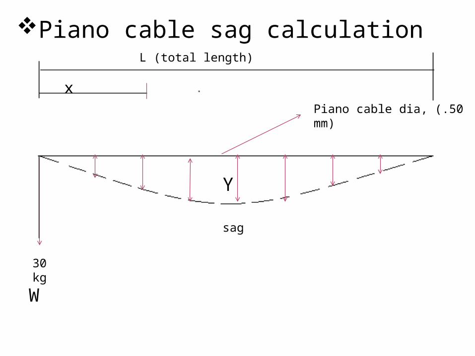
L (total length)
x
30 kg
sag
Piano cable dia, (.50 mm)
Piano cable sag calculation
Y
W
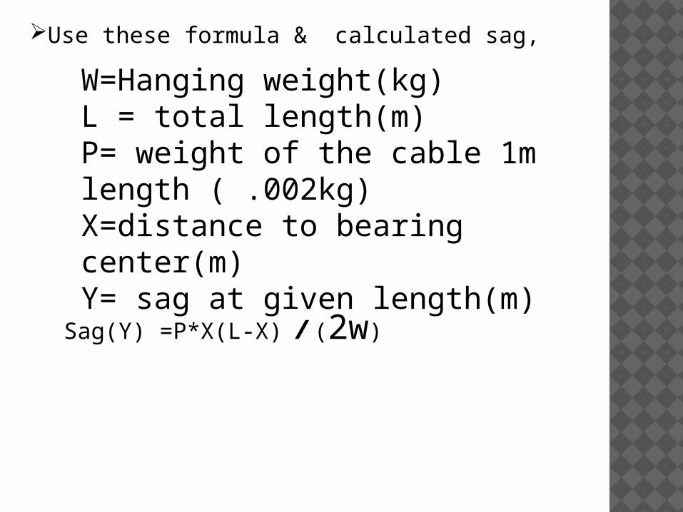
W=Hanging weight(kg)L = total length(m)P= weight of the cable 1m length ( .002kg)X=distance to bearing center(m)Y= sag at given length(m)
Sag(Y) =P*X(L-X) / (2w)
Use these formula & calculated sag,
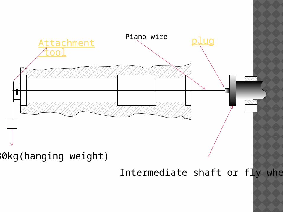
Attachment tool
plug
Intermediate shaft or fly wheel
Piano wire
30kg(hanging weight)
Alignment attachment should be fitted (welded) at the after end of the stern tube (at outside)Then the plug is fitted to the center of the flywheel or to the
center of the intermediate shaft.
After that, one end of the piano wire is fitted to the plug and then the wire is driven through the attachment and desired weight is hanged at the other end.
Piano wire is aligned to the after end of the stern tube using inside micrometer.
Then the distance from the wire to the stern tube inside surface is measured on port, starboard, and top and bottom directions. This is done for several places of the stern tube.
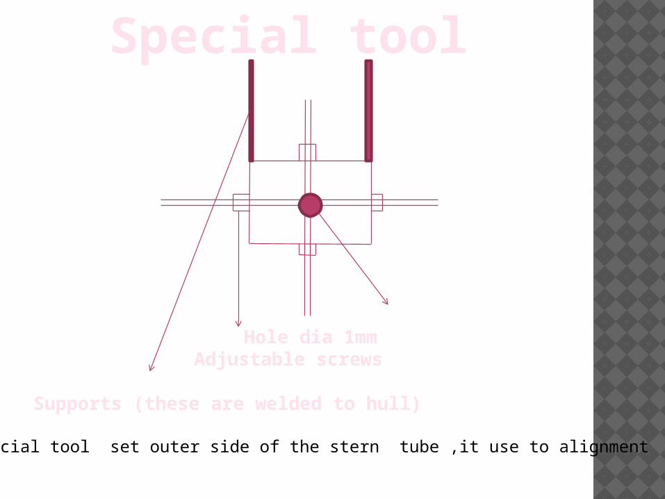
Special tool
Hole dia 1mmAdjustable screws
Supports (these are welded to hull)
These special tool set outer side of the stern tube ,it use to alignment piano wire.
Procedure for
alignment of
propeller shaft line
using micro
alignment telescope
The telescopic alignment commonly used for
intermediate shaft alignment & crank shaft
alignment .because it is accurate more than
piano wire alignment & easy to do.
Any type of alignments are wanted two fixed
center . In this alignment I get outer bush aft end
& inner bush forward end as the fixed point. It is
depend upon our requirement & placed.
`
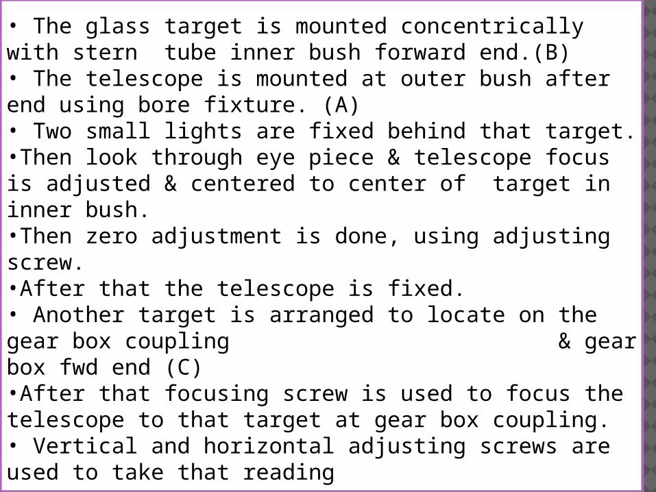
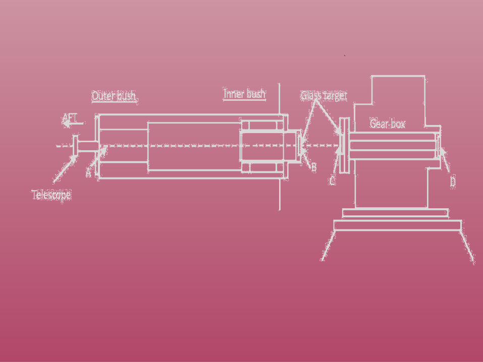
• The glass target is mounted concentrically with stern tube inner bush forward end.(B)• The telescope is mounted at outer bush after end using bore fixture. (A)• Two small lights are fixed behind that target. •Then look through eye piece & telescope focus is adjusted & centered to center of target in inner bush.•Then zero adjustment is done, using adjusting screw.•After that the telescope is fixed.• Another target is arranged to locate on the gear box coupling & gear box fwd end (C)•After that focusing screw is used to focus the telescope to that target at gear box coupling.• Vertical and horizontal adjusting screws are used to take that reading

Then , X – the gear box is adjusted from base with adjusting screw & center line of sight. Y – reconfirm that line of sight is passing through stern tube inner bush target.
• The telescope is focused to gear box forward end & the above steps are repeated.
Until, gear box forward end & after end comes to the line of sight.

THANK
YOU……..
Related Documents