1 Corresponding Author-AkshayUpare 1 , GajrajChoudhari 2 , SurajLolage 3 Available Online at-http://isroj.net/index.php?menu=is&type=1 Volume 01 Issue01 January 2016 Propeller Clock Display AkshayUpare 1 , GajrajChoudhari 2 , SurajLolage 3 Department of Electronics and Telecommunication Engineering, BRACT’s VIIT Pune India Email: - 1 [email protected] , 2 [email protected] , 3 [email protected] Abstract: Conventional methods of displaying some data to public are using LCD display and dot- matrix LED board. Propeller LED display is a kind of thing that project an image or time as if the images are floating in the air. The floating image is received because of slow response of human eye. Actually the floating images emerge by synchronizing LED'S blink to form an image at particular time and rate. The programming of microcontroller is using Assembly Language. This project consist two main circuit; motor controller circuit and LED circuit. 5Vdc will be used to supply the power for motor controller circuit. LED circuit consist of polymer battery will provide power to LED circuit. When AC motor is being rotated, the floating image will appear. The synchronization of AC motor speed and LED blink cause the image visible to human eyes. So the desired image such as real time clock, date or symbol can be programmed and displayed. Keywords: - AC Motor, IR sensor, LEDs, Microcontroller, POV 1. INTRODUCTION Propeller is a term associated with a rotating object in circular fashion. As this project needs to rotate the whole circuit assembly .So the term ‘Propeller’ is used. this project using bright light emitting diodes for displaying the images, characters, Symbols and clock on its assembly. That’s why this project is named as ‘PROPELLERCLOCK DISPLAY’. This concept is related to vision capability of human eye by which an afterimage is thought to persist for approximately 1/25th of a second. So, if someone is observing the images at a rate of 25 images per second, then they appear to be motion display. The best Example of this property is the red circle we observe when we rotate the incense stick in circle. This project was started with a simple principle we experience in our day to day life known as POV (Persistence of Vision) [4] . This is a phenomenon related to human eye, when 25 frames are moved fast per second we can’t judge a single image in between. A television is a common example; in which image is re- scanned every 25 times, thereby appear continuous. Fig1: Showing Digital clock Existing systems do employ POV concept, but to display each pixel, individual LED is used. This results in a large number of LEDs even for small sized displays. By using a propeller type display, LED count can be reduced. Made from scrap it can be used anywhere and everywhere and the most amazing fact about this display is its crystal clear display.

Welcome message from author
This document is posted to help you gain knowledge. Please leave a comment to let me know what you think about it! Share it to your friends and learn new things together.
Transcript

1 Corresponding Author-AkshayUpare1, GajrajChoudhari
2, SurajLolage
3
Available Online at-http://isroj.net/index.php?menu=is&type=1 Volume 01 Issue01 January 2016
Propeller Clock Display
AkshayUpare1, GajrajChoudhari2, SurajLolage3
Department of Electronics and Telecommunication Engineering,
BRACT’s VIIT Pune India
Email: - [email protected], [email protected],[email protected]
Abstract: Conventional methods of displaying some data to public are using LCD display and dot-matrix LED board. Propeller LED display is a kind of thing that project an image or time as if the images are floating in the air. The floating image is received because of slow response of human eye. Actually the floating images emerge by synchronizing LED'S blink to form an image at particular time and rate. The programming of microcontroller is using Assembly Language. This project consist two main circuit; motor controller circuit and LED circuit. 5Vdc will be used to supply the power for motor controller circuit. LED circuit consist of polymer battery will provide power to LED circuit. When AC motor is being rotated, the floating image will appear. The synchronization of AC motor speed and LED blink cause the image visible to human eyes. So the desired image such as real time clock, date or symbol can be programmed and displayed.
Keywords: - AC Motor, IR sensor, LEDs, Microcontroller, POV
1. INTRODUCTION Propeller is a term associated with a
rotating object in circular fashion. As this project needs to rotate the whole circuit assembly .So the term ‘Propeller’ is used. this project using bright light emitting diodes for displaying the images, characters, Symbols and clock on its assembly. That’s why this project is named as ‘PROPELLERCLOCK DISPLAY’.
This concept is related to vision capability of human eye by which an afterimage is thought to persist for approximately 1/25th of a second. So, if someone is observing the images at a rate of 25 images per second, then they appear to be motion display. The best
Example of this property is the red circle we observe when we rotate the incense stick in circle.
This project was started with a simple principle we experience in our day to day life known as POV (Persistence of Vision) [4]. This is a phenomenon related to human eye, when 25 frames are moved fast per second we can’t
judge a single image in between. A television is a common example; in which image is re-scanned every 25 times, thereby appear continuous.
Fig1: Showing Digital clock
Existing systems do employ POV concept, but to display each pixel, individual LED is used. This results in a large number of LEDs even for small sized displays. By using a propeller type display, LED count can be reduced. Made from scrap it can be used anywhere and everywhere and the most amazing fact about this display is its crystal clear display.

Cites as- Propeller Clock Display 2016
2 Corresponding Author-AkshayUpare1, GajrajChoudhari
2, SurajLolage
3
2. METHODOLOGY
Microcontroller AT89S52 has 4 input output port [2].Each port is of 8 pin. Port 1 and Port 2 is used for interfacing 16 LED’s RTC DS12C877 is connected to PORT0 of microcontroller. Photodiode [1] which is used as interrupt is connected to INT0 pin which is active low pin. Rechargeable battery is used for giving supply to controller. There is no physical connection between LED and photodiode.
Fig 2: Front view of ‘Rotating Display’
Fig 3: Top view of ‘Rotating Display’
Fig 4: The display unit of ‘Rotating Display’
I. PRINCIPLE OF OPERATION
When power is given to circuit assembly starts rotating. Whenever the photodiode receives the beam from the IR LED, it acts as interrupt to controller. As interrupt occurs program transfer to ISR. And write programme for which string we have to display to ISR [2]. ISR sends the series of data sequences to glow all the LEDs, one column at a time. But the human eye due to ‘Persistence of Vision’ cannot determine such a fast change and so the entire display is visible. For displaying real time, RTC is used which shows real time, date and day.
II. DISPLAYING A CHARACTER:
Fig 5: 5*8 matrix for single character
Here for displaying each character, say ‘A’ uses 5*8 matrixes. We can easily represent any alphanumeric character in 5*8 matrixes easily. Each column represents the combination of 8 Led’s. So for displaying ‘A’ we have to glow 1 to 6 LED’s and turn off 0 & 7th LED as shown in above figure. A LED’s are common anode give sequence ‘10000001’. Similarly for the next column desired sequence should be ‘10010000’.
3. BLOCK DIAGRAM :
Microcontroller AT89S52
This project is totally based on the microcontroller 8051 which is family of ATMEL. This is the heart of this project. It has 40 pin DIP package. It is easily available and has low cost.
Cites as- Propeller Clock Display 2016
3 Corresponding Author-AkshayUpare1, GajrajChoudhari
2, SurajLolage
3
Fig 6: Block diagram
IR Module:
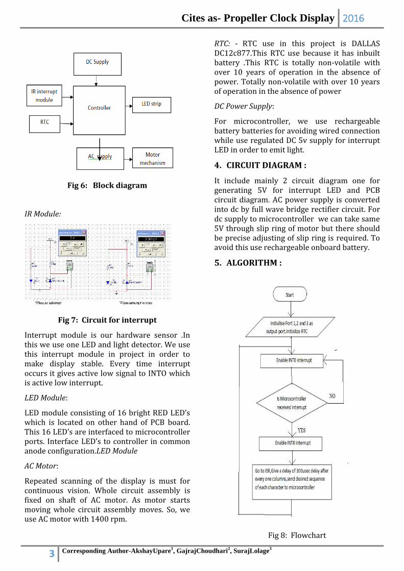
Fig 7: Circuit for interrupt
Interrupt module is our hardware sensor .In this we use one LED and light detector. We use this interrupt module in project in order to make display stable. Every time interrupt occurs it gives active low signal to INTO which is active low interrupt.
LED Module:
LED module consisting of 16 bright RED LED’s which is located on other hand of PCB board. This 16 LED’s are interfaced to microcontroller ports. Interface LED’s to controller in common anode configuration.LED Module
AC Motor:
Repeated scanning of the display is must for continuous vision. Whole circuit assembly is fixed on shaft of AC motor. As motor starts moving whole circuit assembly moves. So, we use AC motor with 1400 rpm.
RTC: - RTC use in this project is DALLAS DC12c877.This RTC use because it has inbuilt battery .This RTC is totally non-volatile with over 10 years of operation in the absence of power. Totally non-volatile with over 10 years of operation in the absence of power
DC Power Supply:
For microcontroller, we use rechargeable battery batteries for avoiding wired connection while use regulated DC 5v supply for interrupt LED in order to emit light.
4. CIRCUIT DIAGRAM :
It include mainly 2 circuit diagram one for generating 5V for interrupt LED and PCB circuit diagram. AC power supply is converted into dc by full wave bridge rectifier circuit. For dc supply to microcontroller we can take same 5V through slip ring of motor but there should be precise adjusting of slip ring is required. To avoid this use rechargeable onboard battery.
5. ALGORITHM :
Fig 8: Flowchart

Cites as- Propeller Clock Display 2016
4 Corresponding Author-AkshayUpare1, GajrajChoudhari
2, SurajLolage
3
6. RESULTS:
Interrupt Module Testing:
This Interrupter module testing is required for detecting exact position of wheel on which whole circuit assembly is mounted. 5v Supply is given to interrupt LED. Check voltage at detector. Input voltage at INTO without interrupt should be 5V and with interrupt it should be 0V.
AC Motor RPM Testing:
This is most important part for programming for clock. As rpm of motor changes, time required of 1 revolution changes. Due to change in time for 1 revolution, all delay calculations for programming changed.
Calculation:
Motor speed = 1000 RPM Time for one rotation = 60 milliseconds Radius =15cm Perimeter = 2*3.414*15 =94.25~95 Width of led = 0.5cm ( this indicated the
duration of led glow in terms of length of display)
Total num of columns(led’s) = 95/0.5 = 190
190 led = 60 milliseconds One led (column) time = 316 micro
seconds Columns for each letter = 6 Time for a letter = 6*316 = 1896 micro
seconds Length for letter = 6*0.5 = 3 Total letters = 205/3 = 68
So if change length of PCB, similarly other theoretical calculation going to change and we have to change delay accordingly.
Power Supply Module Testing: Power supply module was designed to provide 5V to interrupt module and ac supply to single phase ac motor. Check onboard output voltage of rechargeable battery. Directly AC supply is given to single phase motor and same supply is given to transformer and other circuit in order to convert it into DC.
7. DISPLAY GENERATED PATTERN:
Fig 9: Actual hardware
Fig 10: Showing real time clock
Fig 11: Showing real time date
Cites as- Propeller Clock Display 2016
5 Corresponding Author-AkshayUpare1, GajrajChoudhari
2, SurajLolage
3
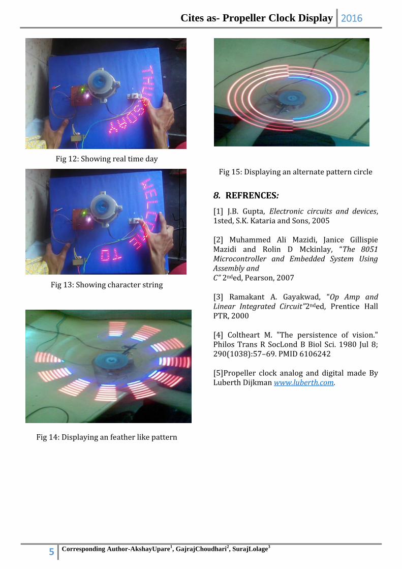
Fig 12: Showing real time day
Fig 13: Showing character string
Fig 14: Displaying an feather like pattern
Fig 15: Displaying an alternate pattern circle
8. REFRENCES:
[1] J.B. Gupta, Electronic circuits and devices, 1sted, S.K. Kataria and Sons, 2005 [2] Muhammed Ali Mazidi, Janice Gillispie Mazidi and Rolin D Mckinlay, “The 8051 Microcontroller and Embedded System Using Assembly and C” 2nded, Pearson, 2007 [3] Ramakant A. Gayakwad, “Op Amp and Linear Integrated Circuit”2nded, Prentice Hall PTR, 2000 [4] Coltheart M. "The persistence of vision." Philos Trans R SocLond B Biol Sci. 1980 Jul 8; 290(1038):57–69. PMID 6106242 [5]Propeller clock analog and digital made By Luberth Dijkman www.luberth.com.
Related Documents