Propane Catalog Table of Contents · First-Stage Regulators · Two-PSI Service Regulators · Second-Stage Regulators · Integral Two-Stage Regulators · Automatic Changeover Regulators & Changeover Manifold Assemblies · High Pressure Regulators · Commercial/Industrial Regulators · Internal Valves · Internal Valve Accessories · Globe and Angle Valves · Emergency Shutoff Valves · Back Check Valves · Excess Flow Valves · Relief Valves

Welcome message from author
This document is posted to help you gain knowledge. Please leave a comment to let me know what you think about it! Share it to your friends and learn new things together.
Transcript

Propane Catalog Table of Contents
· First-Stage Regulators
· Two-PSI Service Regulators
· Second-Stage Regulators
· Integral Two-Stage Regulators
· Automatic Changeover Regulators &Changeover Manifold Assemblies
· High Pressure Regulators
· Commercial/Industrial Regulators
· Internal Valves
· Internal Valve Accessories
· Globe and Angle Valves
· Emergency Shutoff Valves
· Back Check Valves
· Excess Flow Valves
· Relief Valves

First-Stage Regulators
· R312H Series
· R522H Series
H - 12
LP-Gas (Propane)
ProductsProducts
R312H Series First-Stage Regulators
HH
Introduction
The R312H Series First-Stage regulators aredesigned for use as the first regulator of aTwo-Stage regulation system on domesticapplications. With an overall length of only4.13-inches (105 mm), they fit easily underthe tank dome.
The unit is nonadjustable and virtually tamperproof. Outlet pressure remains at the factorynominal setting of 10 psig (0,69 bar). Theseunits contain a relief valve and a large vent.The spring case is color-coded red to easilyidentify the unit as a First-Stage regulator.
Maximum Allowable Inlet Pressure
250 psig (17,2 bar)
Outlet Pressure Setting
See Table 1
Temperature Capabilities
-20° to 150°F (-29° to 66°C)
Body Sizes and End Connection Styles
See Table 1
Additional Technical Data
For more technical information contactyour Fisher Distributor or refer to LP-31Equipment Buyer’s Guide.
FeaturesFeatures
• Compact• Overpressure Protection• Easy Identification• Tamper-Resistant• Molded Diaphragm• UL Listed
Figure 1. R312H Series First-Stage Regulator
Figure 2. Dimensions
4.13(105)
3.57(91)
INCHES(mm)
snoitacificepSrotalugeR.1elbaT
NOITCENNOCTELNI NOITCENNOCTELTUOERUSSERPTELTUO
GNITTESDEDULCNISEIROSSECCA
FOHUTBNIYTICAPACENAPORP
REBMUNREDRO
hcni-4/1
TPNFhcni-2/1)rab96,0(gisp01
elbatsujdanon
---
000,009
12-H213R
LOPM rotpada813M 22-H213R
LOPMelgnA rotpada543M 32-H213R
hcni-4/1 liatgip508K 42-H213R

H - 13
LP-Gas (Propane)
ProductsProducts
R522H Series First-Stage Regulators
HH
Introduction
The R522H Series First-Stage regulatorsare designed for use as the first regulator ofa Two-Stage regulation system on domesticapplications. This unit features the latestdesign in regulator technology and isconstructed using corrosion-resistant andwear-resistant materials.
A large 3/4-inch FNPT drip lip-vent reducesthe chance of blockage by freezing rain or sleetwhen properly installed with the vent pointingdown. The overall 6.1-inch (155 mm) profilemakes the R522H Series ideal for under-the-dome installations.
Maximum Allowable Inlet Pressure
250 psig (17,2 bar)
Outlet Pressure Range
See Table 1
Temperature Capabilities
-20° to 150°F (-29° to 66°C)
Body Sizes and End Connection Styles
See Table 1
Additional Technical Data
For more technical information contactyour Fisher Distributor or refer to LP-31Equipment Buyer’s Guide.
FeaturesFeatures
• Corrosion-Resistant• Improved Regulation• Overpressure Protection• Built-In Gauge Taps• Inlet Screen• UL Listed
Figure 1. R522H Series First-StageRegulator
Figure 2. R522H Series Sectional View
snoitacificepSrotalugeR.1elbaTERUSSERPTELTUO
GNITTESEGNARGNIRPS NOITCENNOCTELNI NOITCENNOCTELTUO
FOHUTBNIYTICAPACENAPORP
REBMUNREDRO
)rab43,0(gisp5gisp5.5ot5.2
)rab83,0ot71,0(TPNFhcni-2/1
TPNFhcni-2/1
000,001,1 KGB-H225R
)rab96,0(gisp01gisp5.01ot5.5
)rab27,0ot83,0(
TPNFhcni-2/1
000,005,2
JGB-H225R
LOPFJGH-H225R
AKJGH-H225R
)rab43,0(gisp5gisp5.5ot5.2
)rab83,0ot71,0( LOPFTPNFhcni-4/3
000,001,1 KGJ-H225R
)rab96,0(gisp01gisp5.01ot5.5
)rab27,0ot83,0(000,006,2
JGJ-H225R
TPNFhcni-4/3 JGD-H225R
Figure 3. Dimensions
FIRST-STAGEVENTORIENTATION
4.88(124)
5.06(129)
1.20 (30)
6.0 (152) NPT6.1 (155) POL
2.88(73)
2.0 (51)
3.69 (94) NPT3.81 (97) POL
INLET NPT OR POL
1/8-27 NPTINLET/OUTLETGAUGE TAPS
1/2-14 NPT3/4-14 NPT
INCHES(mm)

Two-PSI Service Regulators
· R312E Series
R522E Series·

H - 14
LP-Gas (Propane)
ProductsProducts
R312E Series 2-PSI Service Regulators
HH
Introduction
The R312E Series 2-PSI Service regulatorserves as an intermediate regulator after theFirst-Stage regulator. This regulator is designedfor Two-PSI LP-Gas regulator systems and islisted by Underwriter’s Laboratories. This unitreduces an inlet pressure of 10 PSIG (0,69 bar)to a nominal 2 PSIG (0,14 bar) outlet pressure.
The R312E Series typically supplies LP-Gasthrough corrugated stainless steel tubing(CSST) to a line regulator located inside thebuilding. A manifold can be used with CSSTfor routing to a line pressure regulatorsupplying approximately 11-inches w.c. toappliance regulators. The regulator is color-coded white to easily identify the unit as a2-PSI Service regulator.
Body Sizes and End Connection Styles
See Table 1
Temperature Capabilities
-20° to 150°F (-29° to 66°C)
FeaturesFeatures
• Compact• Overpressure Protection• Easy Identification• Tamper-Resistant• Inlet Screen• UL Listed
Figure 2. Dimensions
Operating Inlet Pressure
10 PSIG (0,69 bar)
Outlet Pressure Range
See Table 1
Additional Technical Data
For more technical information contactyour Fisher Distributor or refer to LP-31Equipment Buyer’s Guide.
Figure 3. Service Performance Curve
2.4
2.2
2
1.8
1.4
1.6
0,16
0,15
0,14
0,12
0,097
0,11
0 100,000 200,000 300,000 400,000
PS
IG
BA
R
BTUH, PROPANE
4.13(105)
3.57(91)
INCHES(mm)
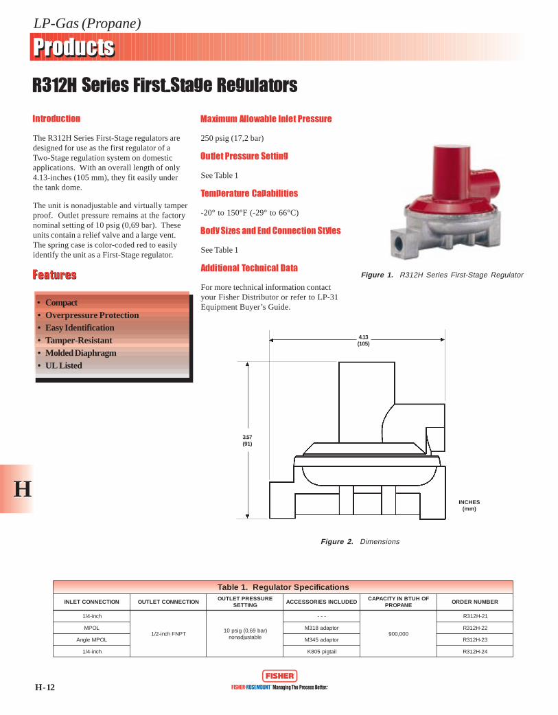
Figure 1. R312E Series 2-PSIService Regulator
snoitacificepSrotalugeR.1elbaTREBMUNEPYT ENAPORPHUTBNIYTICAPAC )1( TELTUOXTELNISNOITCENNOC EGNARTNEMTSUJDATELTUO GNITTESERUSSERPTELTUO
03-E213R 000,004 TPNFsehcni-2/1x4/1 elbatsujdanoN )rab41,0(gisp2lanimoN
.poord%02dnaerusserptelni)rab96,0(gisp01nodesabsiyticapaC.1
H - 20
LP-Gas (Propane)
ProductsProducts
R522E Series 2-PSI Service Regulators
HH
Introduction
The R522E Series regulator is designed forTwo-PSI LP-Gas regulator systems. This unitis installed downstream from a First-Stageregulator and reduces an inlet pressure of10 PSIG (0,69 bar) to a nominal 2 PSIG(0,14 bar) outlet pressure.
The R522E Series is designed for domesticapplications that supply LP-Gas throughcorrugated stainless steel tubing (CSST) to aline regulator located inside the building. Amanifold can be used with CSST for routing toa line regulator supplying approximately11-inches w.c. to appliance regulators. Theregulator is powder coat painted white toeasily identify it as a 2-PSI Service regulator.
Body Sizes and End Connection Styles
See Table 1
Temperature Capabilities
-20° to 150°F (-29° to 66°C)
FeaturesFeatures
• Improved Regulation• Overpressure Protection• Gauge Taps• Inlet Screen• UL Listed
Figure 2. Dimensions
Operating Inlet Pressure
10 PSIG (0,69 bar)
Outlet Pressure Range
See Table 1
Additional Technical Data
For more technical information contactyour Fisher Distributor or refer to BulletinLP-7: R522E.
Figure 3. Service Performance Curve
2.5
2.2
2.0
1.5
0.5
1.0
0,17
0,15
0,14
0,103
0,034
0,069
0 0.25 0.50 0.75 1.00
PS
IG
BA
R
M BTUH, PROPANE
4.13(105)
3.57(91)
INCHES(mm)
Figure 1. R522E Series 2-PSIService Regulator
snoitacificepSrotalugeR.1elbaTREBMUNEPYT ENAPORPHUTBNIYTICAPAC )1( TELTUOXTELNISNOITCENNOC GNITTESTNEMTSUJDATELTUO EGNARERUSSERPTELTUO
HCB-E225R 000,789 TPNFsehcni-2/1x2/1 )rab41,0(GISP2 )rab41,0(GISP2/1-2-1
HCD-E225R 000,420,1 TPNFsehcni-4/3x4/3 )rab41,0(GISP2 )rab41,0(GISP2/1-2-1
.poord%02dnaerusserptelni)rab96,0(GISP01nodesabsiyticapaC.1

Second-Stage Regulators
· R312 Series
· R422 Series
· R522 Series
· R552 Series
H - 15
LP-Gas (Propane)
ProductsProducts
R312 Series Second-Stage Regulators
HH
Introduction
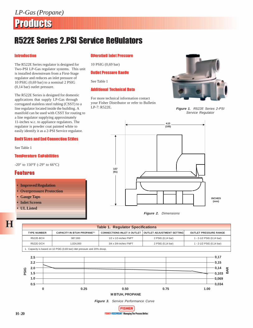
The R312 Series Second-Stage regulators aredesigned for propane gas regulator systemsand listed by Underwriter’s Laboratories. Thecompact design of the R312 Series allows theunit to be installed in convenient outdoorlocations and is less noticeable against thebuilding on Two-Stage systems.
Standard vent orientation on the R312 Seriesis over the inlet; other vent positions areavailable. Materials are designed to resistcorrosive environments and the molded fabric-reinforced diaphragm improves performance.
The spring case is color-coded green to easilyidentify the unit as a Second-Stage regulator.
Operating Inlet Pressure
10 psig (0,69 bar)
Outlet Pressure Range
See Table 1
Temperature Capabilities
-20° to 150°F (-29° to 66°C)
Body Sizes and End Connection Styles
See Table 1
Additional Technical Data
For more technical information contactyour Fisher Distributor or refer to LP-31Equipment Buyer’s Guide.FeaturesFeatures
• Compact• Overpressure Protection• Easy Identification• UL Listed• Performance Selected Materials
Figure 1. R312 Series Second-StageRegulator
Figure 2. Dimensions
4.13(105)
3.57(91)
INCHES(mm)
snoitacificepSrotalugeR.1elbaTERUSSERPTELTUO
GNITTESEGNARGNIRPS NOITCENNOCTELNI NOITCENNOCTELTUO
FOHUTBNIYTICAPACENAPORP
REBMUNREDRO
)rabm72(.c.wsehcni-11.c.wsehcni31ot2/1-9
)rabm23ot42(TPNFhcni-4/1 TPNFhcni-2/1 000,072 01-213R

H - 16
LP-Gas (Propane)
ProductsProducts
R422 Series Second-Stage Regulators
HH
Introduction
The R422 Series regulators, like all Second-Stage regulators, reduce the pressure from aFirst-Stage unit to 11-inches w.c. (27 mbar) indomestic installations. This unit is a highcapacity regulator for commercial, industrial,and large domestic installations and comeswith a large 1-inch FNPT drip-lip style vent.
Overpressure protection is provided by aninternal relief valve and a travel stop on theclosing cap. The R422 Series is compliantwith NFPA 58 requirements.
Operating Inlet Pressure
10 psig (0,69 bar)
Outlet Pressure Range
See Table 1
Temperature Capabilities
-20° to 150°F (-29° to 66°C)
Body Sizes and End Connection Styles
See Table 1
Additional Technical Data
For more technical information contactyour Fisher Distributor or refer to LP-31Equipment Buyer’s Guide.
FeaturesFeatures
• Corrosion-Resistant• Built-In Gauge Taps• 1-Inch Drip-Lip Vent• Improved Regulation• UL Listed
Figure 1. R422 Series Second-StageRegulator
Figure 2. Dimensions
INCHES(mm)
6.4 (163)DIAMETER
1-INCH NPTSCREENED VENT
3/4-INCH NPTSCREENED VENT
1/8-27 NPTINLET/OUTLETGAUGE TAPS
1/4-INCHMOUNTINGSCREWS
3.75(95)
5.75(146)
2.0 (51)
1.2 (30)
3/4-14 NPT
5.5(140)
snoitacificepSrotalugeR.1elbaTGNITTESERUSSERPTELTUO EGNARGNIRPS NOITCENNOCTELNI NOITCENNOCTELTUO ENAPORPFOHUTBNIYTICAPAC REBMUNREDRO
)rabm72(.c.wsehcni-11 )rabm23ot42(.c.wsehcni-31ot2/1-9 TPNFhcni-4/3 TPNFhcni-4/3 000,520,2 FDD-224R

H - 17
LP-Gas (Propane)
ProductsProducts
R522 Series Second-Stage Regulators
HH
Introduction
The R522 Series Second-Stage regulators arecompact, at 6.1-inches (155 mm), and aredesigned to serve typical domesticinstallations. Exclusive to Fisher products,the R522 Series is constructed of corrosion-resistant and wear-resistant materials. Easysystem checks can be made on these unitswhich have built-in gauge taps on both theupstream and downstream sides.
The regulators in this series are equipped foroverpressure protection with an internal reliefvalve and a travel stop on the closing cap.The R522 Series is compliant with NFPA 58requirements.
Operating Inlet Pressure
10 psig (0,69 bar)
Outlet Pressure Range
See Table 1
Temperature Capabilities
-20° to 150°F (-29° to 66°C)
Body Sizes and End Connection Styles
See Table 1
Additional Technical Data
For more technical information contactyour Fisher Distributor or refer to LP-31Equipment Buyer’s Guide.
FeaturesFeatures
• Corrosion-Resistant• Improved Regulation• Overpressure Protection• Gauge Taps• Inlet Screen• UL Listed
Figure 3. DimensionsFigure 2. R522 Series Sectional View
Figure 1. R522 Series Second-StageRegulator
5.32 (135)
4.88 (124)
5.06(129)
1.20 (30)
6.1 (155)3.69 (94)
2.0(51)
INCHES(mm)
snoitacificepSrotalugeR.1elbaTERUSSERPTELTUO
GNITTESEGNARGNIRPS NOITCENNOCTELNI NOITCENNOCTELTUO
FOHUTBNIYTICAPACENAPORP
REBMUNREDRO
.c.wsehcni-11)rabm72(
.c.wsehcni-31ot2/1-9)rabm23ot42(
TPNFhcni-2/1TPNFhcni-2/1 000,578 FCB-225R
TPNFhcni-4/3 000,573,1
FFC-225R
TPNFhcni-4/3 FFD-225R
TPNFhcni-2/1 AXGFC-225R

H - 18
LP-Gas (Propane)
ProductsProducts
R552 Series Second-Stage Regulators
HH
Introduction
The R552 Series Second-Stage regulatorsreduce the outlet pressure from a First-Stageregulator, usually 10 psig (0,69 bar), to burnerpressure, usually 11-inches w.c. (27 mbar).These regulators are designed for back mountinstallations, and feature the latest in regulatortechnology.
Like the R522 Series, the R552 Series iscorrosion-resistant and has built-in 1/8-inchtaps orificed to a Number 54 drill size on boththe upstream and downstream sides to allowfor easy gas system checks.
Operating Inlet Pressure
10 psig (0,69 bar)
Outlet Pressure Range
See Table 1
Temperature Capabilities
-20° to 150°F (-29° to 66°C)
Body Sizes and End Connection Styles
See Table 1
Additional Technical Data
For more technical information contactyour Fisher Distributor or refer to LP-31Equipment Buyer’s Guide.
FeaturesFeatures
• Corrosion-Resistant• Improved Regulation• Overpressure Protection• Built-In Gauge Taps• Inlet Screen• UL Listed
Figure 1. R552 Series Second-StageRegulator
Figure 2. Dimensions
3/4-14 NPTSCREENEDVENT
3/4-14 NPT1/8-27 NPTINLET/OUTLETGAUGE TAPS
3/4-14 NPT
1.70(43)
5.56(141)
2.0(51)
5.81(148)
5.32(135)4.88 (124)
snoitacificepSrotalugeR.1elbaTERUSSERPTELTUO
GNITTESEGNARGNIRPS NOITCENNOCTELNI NOITCENNOCTELTUO
FOHUTBNIYTICAPACENAPORP
REBMUNREDRO
.c.wsehcni-11)rabm72(
.c.wsehcni-31ot2/1-9)rabm23ot42(
TPNFhcni-4/3 TPNFhcni-4/3 000,001,1 FFD-255R

Integral Two-Stage Regulators
· R332 Series
· R532 Series

H - 19
LP-Gas (Propane)
ProductsProducts
R332 Series Integral Two-Stage Regulators
HH
Introduction
The R332 Series Integral Two-Stage regulatorcombines a First-Stage regulator and a Second-Stage regulator into one compact unit.Recommended for installations where pipingdistance is short, the R332 Series provides allthe advantages of Two-Stage regulation. Thecompact size makes it ideal for small domesticappliances and ASME tanks used onrecreational vehicles.
Constant performance is ensured by the useof a fabric-reinforced molded diaphragm. TheR332 Series meets the NFPA 58 coderequirements.
Maximum Allowable Inlet Pressure
250 psig (17,2 bar)
Outlet Pressure Range
See Table 1
Body Sizes and End Connection Styles
See Table 1
Temperature Capabilities
-20° to 150°F (-29° to 66°C)
Additional Technical Data
For more technical information contactyour Fisher Distributor or refer to LP-31Equipment Buyer’s Guide.
FeaturesFeatures
• Compact Size• Overpressure Protection• Adjustable Set Point• Built-In Gauge Tap• Stainless Steel Inlet Screen• UL Listed
Figure 1. R332 Series IntegralTwo-Stage Regulator
Figure 2. Dimensions
6.24(159)
2.52(64)
3.53(90)
INCHES(mm)
Figure 2. R332 Series Sectional View
snoitacificepSrotalugeR.1elbaTERUSSERPTELTUO
GNITTESEGNARGNIRPS NOITCENNOCTELNI NOITCENNOCTELTUO
FOHUTBNIYTICAPACENAPORP
REBMUNREDRO
)rabm72(.c.wsehcni-11.c.wsehcni31ot2/1-9
)rabm23ot42(TPNFhcni-4/1 TPNFhcni-8/3 000,572 14-233R

H - 21
LP-Gas (Propane)
ProductsProducts
R532 Series Integral Two-Stage Regulators
HH
Introduction
The R532 Series Integral Two-Stage regulatorsare recommended for mobile homes andaverage residential service where separation ofthe First- and Second-Stage regulators is notcost effective. These units offer a POLconnection for easy Single-Stage regulatorreplacement.
An Integral Two-Stage regulator like the R532Series reduces the possibility of water freezingin the propane gas flow in two ways: 1) byusing a larger orifice, and 2) by the increasedheat that can be transferred through the wallsof two regulators.
Maximum Allowable Inlet Pressure
250 psig (17,2 bar)
Outlet Pressure Range
See Table 1
Temperature Capabilities
-20° to 150°F (-29° to 66°C)
Body Sizes and End Connection Styles
See Table 1
Additional Technical Data
For more technical information contactyour Fisher Distributor or refer to LP-31Equipment Buyer’s Guide.
FeaturesFeatures
• POL Inlet Fitting• Economical• Built-In Gauge Taps• Stainless Steel Inlet Screen• Improved Regulation• UL Listed
Figure 1. R532 Series IntegralTwo-Stage Regulator
Figure 2. Dimensions
INCHES(mm)
1/8-27 NPTINLET/OUTLETGAUGE TAPS
2.0 (51)3.6(91) 5.9 (150) NPT
6.3 (160) POL
1.2(30)
5.1(130)
4.9 (124)DIAMETER
5.3 (135)DIAMETER
1/4-INCH FNPTINLET FITTING
snoitacificepSrotalugeR.1elbaTERUSSERPTELTUO
GNITTESEGNARGNIRPS NOITCENNOCTELNI NOITCENNOCTELTUO
FOHUTBNIYTICAPACENAPORP
REBMUNREDRO
.c.wsehcni-11)rabm72(
.c.wsehcni31ot2/1-9)rabm23ot42(
TPNFhcni-4/1TPNFhcni-2/1 000,586
FCB-235R
LOPF FCH-235R
TPNFhcni-4/1TPNFhcni-4/3 000,001,1
FFC-235R
LOPF FFJ-235R
Automatic Changeover Regulators &Changeover Manifold Assemblies
· 64SR/122 Series
· R110/21 Series
· R120/21 Series
· R422-CDFPA Series
· 749B/21 Series
· R962 Series
· R966 Series

Ordering Information - Changeover Regulators
CAPACITY BTU/HR.PROPANE
214,000
400,000
TYPE NUMBER*High Capacity Relief
R966/114R966/150R966/137R966/101R966/81
R966/121
R962/21
INLET CONNECTION
1/4 in. Inv. Flare
Male POL
1/4 in. Inv. Flare
OUTLETCONNECTION
3/8 in. FNPT1/2 in. FNPT
3/8 in. FNPT
1/2 in. FNPT
VENT STYLE
3/4 in. FNPT
INCLUDES
- - -- - -
Two K240 20in. PigtailsTwo K240 20in. Pigtails, P100A BracketTwo K240 20in. Pigtails,P129 BracketTwo K240 20in. Pigtails, P129, 803/61
Remote IndicatorR110 & R522
* Outlet pressure setting 11 in. WC.
Automatic Changeover Regulators
Remote IndicatorType 803 gives remote visual indication that the supply cylinderis empty and that the R966 is withdrawing gas from the reservecylinder. The indicator has 360 degree visibility and isweatherproof.
Type 803/61 - Indicator, bracket, screws, and 10-feet tubing
Type 803/21 - Indicator only
Type 803/5 - Mounting kit, includes bracket, screws, and 10-feetof tubing.
These regulators change from the supply cylinder (when gas isexhausted) to the reserve cylinder automatically. The R961, R962and R966 series are widely used on motor homes, recreationalvehicles and domestic installations because they maintain reliable,uninterrupted service.
Type R966 - Available with a variety of pigtails and mountingbrackets, the R966 has a built-in indicator to display when thechangeover is made. Remote visual indication is available for allR966s by using the Type 803.
Gas is withdrawn from the supply cylinder until pressure isreduced to approximately 6 psig. A spring then forces the camdownward, opening the other first-stage inlet fitting and allowinggas to enter the R966 from the reserve cylinder. When thechangeover (from supply to reserve cylinder) is made, the camactivates a red warning flag in the built-in indicator window toshow that the original supply cylinder is empty. The arrow on thechangeover knob can then be moved so that it points to the newsupply cylinder. The empty cylinder can now be refilled,becoming the reserve cylinder.
All R966s have the 3/4-inch FNPT “drip-lip” vent, makingadditional protection of the vent unnecessary except on mobileapplications where road splatter could block the vent. Highcapacity internal relief construction keeps appliance pressure at 2psig or below. An extension on the closing cap acts as a travel stopto open the internal relief valve under emergency conditions.
Type R962 - Type R110 automatic changeover manifold servesas the first-stage portion of the assembly, connecting to aconvential second-stage regulator which reduces the pressure to11 inches wc for the appliances.
Type R962 eliminates gas outage problems by switching from thenearly empty cylinder to the reserve cylinder automatically. Gas iswithdrawn from the supply cylinder until pressure reaches about7 psig. The changeover manifold then switches to the fullcylinder. A red warning flag appears in the built-in indicator toshow the changeover has taken place. Additional protection forthe vent may be required for Type R962 to prevent wheel sprayfrom blocking the vent with mud on mobile installations.
R966/114 or/150
R962/21
3218.1-14 3/30/98 3:35 PM Page 11
803/21 803/61

CAPACITY BTU/HR.PROPANE
1,000,000
1,250,000
TYPE NUMBER
R422-CDFPA
64SR/122
INLETCONNECTION
1/2-in. FNPT
1/2-in. FNPT
OUTLETCONNECTION
3/4-in. FNPT
1/2-in. FNPT
OUTLET PRESSURESETTING
11 in. WC
10 psig
MOUNTINGBRACKET
P100A- - -
OUTLETADJUSTMENT
RANGE
9-13 in. wc
5-20 psig
CAPACITY BTU/HR.PROPANE1
500,000
1,000,000
1,500,000
TYPE NUMBER
R110/21
R120/21
749B/21
INLET CONNECTION
1/4-in. Inv. Flare
1/4-in. FNPT
1/2-in. FNPT
OUTLET CONNECTION
1/4-in. FNPT
1/4-in. FNPT
1/2-in. FNPT
OUTLET PRESSURE SETTING
Reserve Setting
7 psig
30 psig
5 psig
Supply Setting
15 psig
45 psig
15 psig
1. Based on 100 psig inlet, reserve setting.
Automatic Changeover Regulators
Designed for large capacity multi-cylinder or tank installations,these regulators are used on such applications as bakeries, motels,restaurants, and grain dryers. The manifold portion of theassembly consists of two Type 64 regulators and a direct mountedType 803 indicator.
Type R422ÒCDFPA - For low pressure service. The second-stage
portion has the Ïdrip lipÓ vent feature and built-in travel stop toopen the internal relief valve.
Type 64SR/122 - For high pressure (pounds to pounds) servicewith the outlet pressure supplied by a Type 64SR that hasinternal relief protection.
Commercial Automatic Changeover Regulators
Changeover Manifold Assemblies
Type R110/21 - This manifold connects to the inlet of a domesticsecond-stage regulator, providing a complete automatic changeoverassembly. A built-in indicator gives indication of when thechangeover has taken place. The unit supplies an outlet pressureof approximately 15 psig (supply cylinder) and 7 psig (reservecylinder).
Type R120/21 - Composed of two 67 regulators and a special 0-60psig pressure gauge, the R120 delivers a 45 psig outlet pressureon supply and 30 psig on reserve. The gauge, which serves as thechangeover indicator, is painted red from 0-35 psig. When thedial reads in the 0-35 psig range, it indicates that the manifoldhas switched from the supply to the reserve cylinder.
Type 749B/21 - Large capacity changeover manifold forcommercial and industrial applications. It consists of two Type 64series regulators and a Type 803 direct indicator.
The assembly is used primarily in conjunction with either an R422or a 64SR regulator. The standard outlet setting is 15 psig(supply) and 5 psig (reserve).
Note: These units are intended for use with second stageregulators and/or separate relief devices which provide overpressure protection required by NFPA 58. Capacity of allthese changeover manifolds is dependent on the size of thesecond-stage regulator with which they are used. If themanifolds are used as final-stage (pounds to pounds), arelief valve is required in the downstream system.
R110/21 749B/21R120/21
R422-CDFPA 64SR/122
3218.1-14 3/30/98 3:36 PM Page 12

High Pressure Regulators
· 64 Series
· 67 Series

H - 22
LP-Gas (Propane)
ProductsProducts
64 Series High-Pressure Regulators
HH
Introduction
The 64 Series adjustable high-pressureregulators offer a wide range of availablepressure ranges. High-pressure regulatorsusually reduce tank pressure to anintermediate pressure for use by anotherregulator. They may be used as high-pressureregulators on distribution systems when usedin conjunction with First-Stage downstreamregulators.
When equipped with an integral relief valve(64SR Series), the regulator may be used as aFinal-Stage regulator on high-pressuresystems. It may also be used as a First-Stageregulator when set at 10 psig (0,69 bar) orless.
The 64KB Series has a special diaphragmprotector that makes it suitable for ammoniaservice. The 1/4-inch FNPT tapped andplugged side outlet can be used to install apressure gauge or a hydrostatic relief valve.
Maximum Allowable Inlet Pressure
250 psig (17,2 bar)
Outlet Pressure Range
See Tables 1 and 2
Temperature Capabilities
-20° to 150°F (-29° to 66°C)
Body Sizes and End Connection Styles
See Tables 1 and 2
Additional Technical Data
For more technical information contactyour Fisher Distributor or refer to LP-31Equipment Buyer’s Guide.
FeaturesFeatures
• Versatility• Body Side Connection• Easy Maintenance• UL Listed
Figure 1. 64 Series High-PressureRegulator
Figure 2. Dimensions Figure 3. 64 Series Sectional View
1/4-18 NPTSCREENED VENT
4.12(105)1/4-18 NPT
SIDE OUTLET
1/2-14 NPT
2.75(70)
1.56(40)
8.25(210)
MAXIMUM
INCHES(mm)
snoitacificepSrotalugeR.1elbaT
GNITTESERUSSERPTELTUO EGNARGNIRPSTELTUODNATELNI
SNOITCENNOCFOHUTBNIYTICAPAC
ENAPORPREBMUNREDRO
)rab96,0(gisp01 )rab0,1ot12,0(gisp51ot3
TPNFhcni-2/1
000,526,2 33/46
)rab4,1(gisp02 )rab4,2ot43,0(gisp53ot5 000,006,3 53/46
)rab8,2(gisp04 )rab1,4ot1,2(gisp06ot03 000,051,4 63/46
)rab4,3(gisp05 )rab9,6ot4,2(gisp001ot53 000,052,5 222/46
)rab96,0(gisp01 )rab0,1ot12,0(gisp51ot3 000,526,2 12/RS46
)rab0,1(gisp51 )rab4,1ot43,0(gisp02ot5 000,000,3 22/RS46
)rab4,1(gisp02 )rab4,2ot43,0(gisp53ot5 000,006,3 32/RS46
HH
H - 23
LP-Gas (Propane)
ProductsProducts
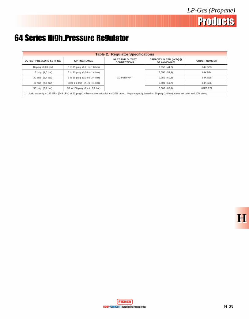
64 Series High-Pressure Regulator
snoitacificepSrotalugeR.2elbaT
GNITTESERUSSERPTELTUO EGNARGNIRPSTELTUODNATELNI
SNOITCENNOCm(HFCNIYTICAPAC 3 ))n(h/
AINOMMAFO )1( REBMUNREDRO
)rab96,0(gisp01 )rab0,1ot12,0(gisp51ot3
TPNFhcni-2/1
)2,44(056,1 33/BK46
)rab0,1(gisp51 )rab4,1ot43,0(gisp02ot5 )9,45(050,2 43/BK46
)rab4,1(gisp02 )rab4,2ot43,0(gisp53ot5 )3,06(052,2 53/BK46
)rab8,2(gisp04 )rab1,4ot1,2(gisp06ot03 )7,96(006,2 63/BK46
)rab4,3(gisp05 )rab9,6ot4,2(gisp001ot53 )4,88(003,3 222/BK46
.poord%02dnatnioptesevoba)rab4,1(gisp02nodesabyticapacropaV.poord%02dnatnioptesevoba)rab4,1(gisp02ta)HPL945(HPG541siyticapacdiuqiL.1

H - 24
LP-Gas (Propane)
ProductsProducts
67 Series High-Pressure Regulators
HH
Introduction
The 67 Series high-pressure regulators aresuitable for liquid or vapor service and areused on a variety of applications—burningtorches, heaters, flame cultivators, etc. Thecompact body design makes the 67 Seriesparticularly useful in installations with spacerestrictions.
The 67 Series is a basic regulator availablewith either wrench or handwheel adjustment.The 67G Series is highly accurate andeliminates the need for a pressure gauge onportable applications. Outlet pressure ispermanently calibrated on the spring case,allowing visual adjustment of the outletpressure setting. This unit is ideal for servicewhere gauge breakage has been a problem. The67Y Series, even more compact, can be orderedwith three different setpoints, and is suppliedwith a nonadjustable outlet setting and atamper-resistant spring case.
Maximum Allowable Inlet Pressure
250 psig (17,2 bar)
Outlet Pressure Range
See Table 1
Temperature Capabilities
-20° to 150°F (-29° to 66°C)
Body Sizes and End Connection Styles
See Table 1
Options
• Handwheel• Dial Cap Adjustment• Tamper-Resistant Spring Case
Additional Technical Data
For more technical information contactyour Fisher Distributor or refer to LP-31Equipment Buyer’s Guide.
Figure 1. 67 Series High-PressureRegulator (Wrench Adjustment)
Figure 3. Dimensions
Figure 2. 67 Series Sectional View
FeaturesFeatures
• Compact• Easy Maintenance• High Stability• UL Listed
4.56 (118)MAXIMUM WITHOUT
HANDWHEEL4.88 (125)
MAXIMUM WITHHANDWHEEL
0.75(19) 1.09
(28)
SIDE OUTLET TAPPED1/4 NPT
INCHES(mm)
HH
H - 25
LP-Gas (Propane)
ProductsProducts
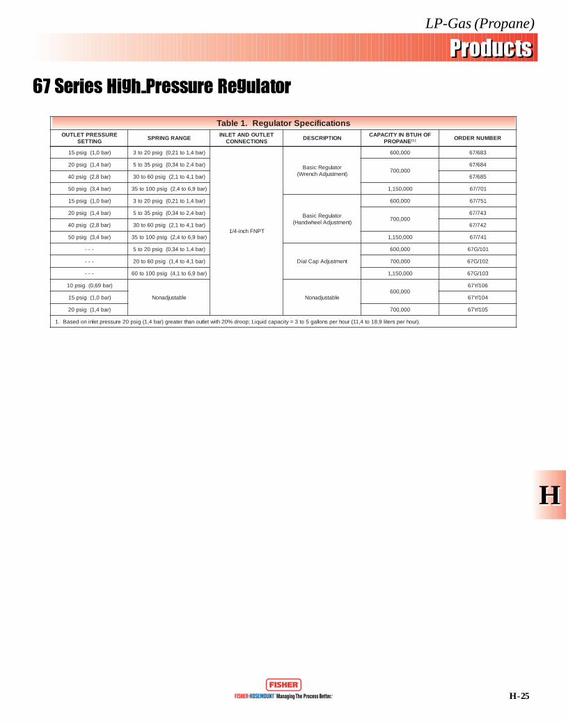
67 Series High-Pressure Regulator
snoitacificepSrotalugeR.1elbaTERUSSERPTELTUO
GNITTESEGNARGNIRPS
TELTUODNATELNISNOITCENNOC
NOITPIRCSEDFOHUTBNIYTICAPAC
ENAPORP )1( REBMUNREDRO
)rab0,1(gisp51 )rab4,1ot12,0(gisp02ot3
TPNFhcni-4/1
rotalugeRcisaB)tnemtsujdAhcnerW(
000,006 386/76
)rab4,1(gisp02 )rab4,2ot43,0(gisp53ot5000,007
486/76
)rab8,2(gisp04 )rab1,4ot1,2(gisp06ot03 586/76
)rab4,3(gisp05 )rab9,6ot4,2(gisp001ot53 000,051,1 107/76
)rab0,1(gisp51 )rab4,1ot12,0(gisp02ot3
rotalugeRcisaB)tnemtsujdAleehwdnaH(
000,006 157/76
)rab4,1(gisp02 )rab4,2ot43,0(gisp53ot5000,007
347/76
)rab8,2(gisp04 )rab1,4ot1,2(gisp06ot03 247/76
)rab4,3(gisp05 )rab9,6ot4,2(gisp001ot53 000,051,1 147/76
--- )rab4,1ot43,0(gisp02ot5
tnemtsujdApaClaiD
000,006 101/G76
--- )rab1,4ot4,1(gisp06ot02 000,007 201/G76
--- )rab9,6ot1,4(gisp001ot06 000,051,1 301/G76
)rab96,0(gisp01
elbatsujdanoN elbatsujdanoN000,006
601/Y76
)rab0,1(gisp51 401/Y76
)rab4,1(gisp02 000,007 501/Y76
.)ruohrepsretil9,81ot4,11(ruohrepsnollag5ot3=yticapacdiuqiL;poord%02htiwteltuonahtretaerg)rab4,1(gisp02erusserptelninodesaB.1

Commercial/Industrial Regulators
· 99 Series
· 133 Series
· 299 Series
· 627 Series
· 630 Series
· S102CL Series
· S202G Series
· S302G Series
H - 26
LP-Gas (Propane)
ProductsProducts
99 Series Commercial/Industrial Regulators
HH5.25(133)
1/2-14 NPT CONTROLCONNECTION
1/2-14 NPTALTERNATEPLUGGEDCONTROLCONNECTION
10.4(264)
12.25(311)
6.06(154)3.03
(77)
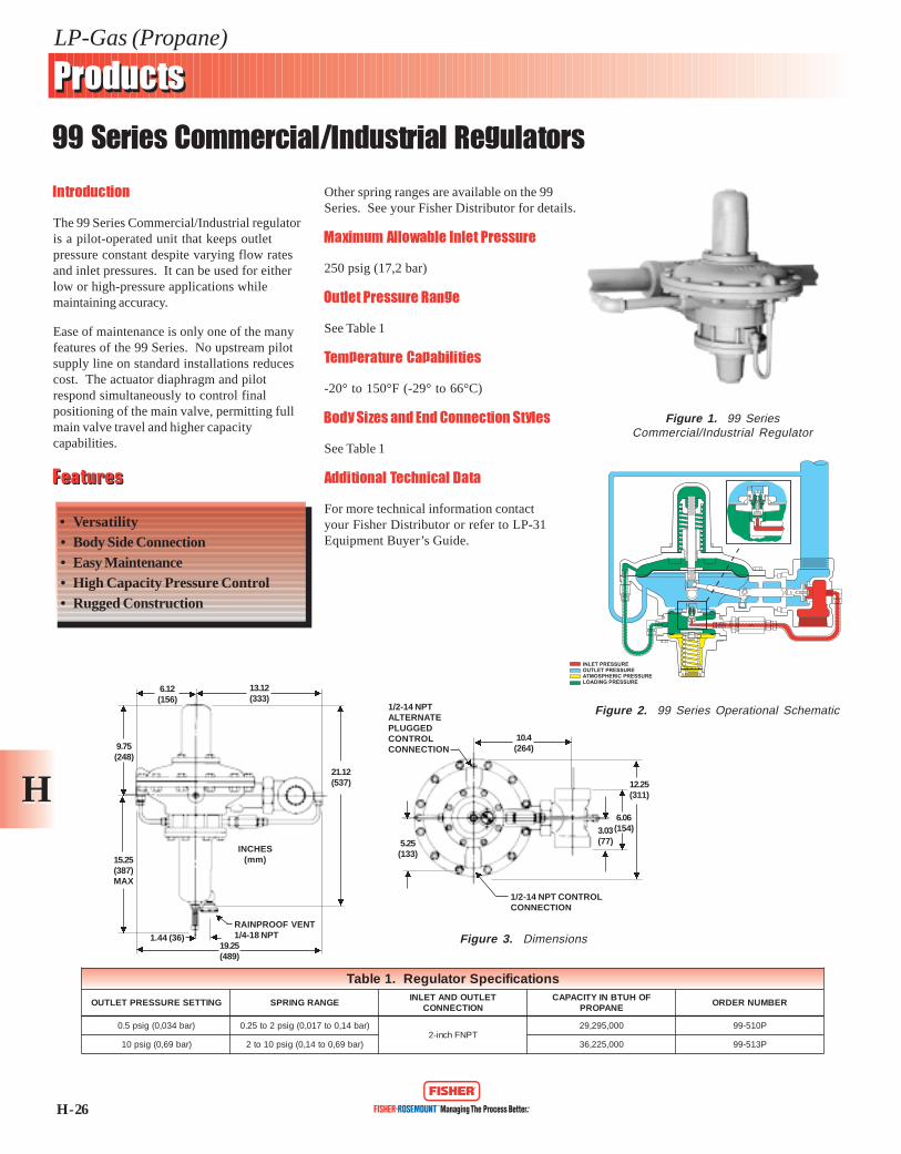
Introduction
The 99 Series Commercial/Industrial regulatoris a pilot-operated unit that keeps outletpressure constant despite varying flow ratesand inlet pressures. It can be used for eitherlow or high-pressure applications whilemaintaining accuracy.
Ease of maintenance is only one of the manyfeatures of the 99 Series. No upstream pilotsupply line on standard installations reducescost. The actuator diaphragm and pilotrespond simultaneously to control finalpositioning of the main valve, permitting fullmain valve travel and higher capacitycapabilities.
Other spring ranges are available on the 99Series. See your Fisher Distributor for details.
Maximum Allowable Inlet Pressure
250 psig (17,2 bar)
Outlet Pressure Range
See Table 1
Temperature Capabilities
-20° to 150°F (-29° to 66°C)
Body Sizes and End Connection Styles
See Table 1
Additional Technical Data
For more technical information contactyour Fisher Distributor or refer to LP-31Equipment Buyer’s Guide.
Figure 1. 99 SeriesCommercial/Industrial Regulator
Figure 3. Dimensions
Figure 2. 99 Series Operational Schematic
INLET PRESSUREOUTLET PRESSUREATMOSPHERIC PRESSURELOADING PRESSURE
FeaturesFeatures
• Versatility• Body Side Connection• Easy Maintenance• High Capacity Pressure Control• Rugged Construction
INCHES(mm)
6.12(156)
13.12(333)
21.12(537)
RAINPROOF VENT1/4-18 NPT
19.25(489)
1.44 (36)
15.25(387)MAX
9.75(248)
snoitacificepSrotalugeR.1elbaT
GNITTESERUSSERPTELTUO EGNARGNIRPSTELTUODNATELNI
NOITCENNOCFOHUTBNIYTICAPAC
ENAPORPREBMUNREDRO
)rab430,0(gisp5.0 )rab41,0ot710,0(gisp2ot52.0TPNFhcni-2
000,592,92 P015-99
)rab96,0(gisp01 )rab96,0ot41,0(gisp01ot2 000,522,63 P315-99

H - 27
LP-Gas (Propane)
ProductsProducts
133 Series Commercial/Industrial Regulators
HH
snoitacificepSrotalugeR.1elbaTEPYT NOITCENNOCTELTUODNATELNI EGNARERUSSERPTELTUO GNITTESERUSSERPTELTUO ENAPORPFOHUTBNIYTICAPAC )1( REBMUNREDRO
L331TPNFsehcni-2
)rabm8,44ot2,12(.c.wsehcni-81ot2/18 )rabm53(.c.wsehcni-41 000,578,07 4-L331
H331 )rab12,0ot01,0(gisp3ot5.1 )rab12,0(gisp3 000,051,66 1-H331
.poord%02htiwerusserpteltuonahtretaerg)rab4,1(gisp02erusserptelninodesaberaseiticapaC.1
Figure 1. 133 Series Regulator
Figure 3. 133L Series Operational Schematic
Introduction
The 133 Series direct-operated regulators areideal for industrial and commercialapplications supplying gas to furnaces,burners, and other appliances. A balancingsystem enables the regulator to control gaspressure accurately for maximum combustionefficiency despite varying inlet pressures.
Body Sizes and End Connection Styles
2-inch body, cast iron NPT female, cast ironANSI Class 125 FF flanged, steel NPT female,or steel ANSI Class 150 RF flanged.
Maximum Allowable Inlet Pressure
133L: 60 psig (4,1 bar)133H: 60 psig (4,1 bar)
Maximum Outlet Pressure
133L: 18-inches w. c. (44,8 mbar)
133H: 3 psig (0,21 bar)
Outlet Pressure Range
133L: 8-1/2 to 18-inches w.c.(21,2 mbar to 44,8 mbar)133H: 1.5 to 3 psig (0,10 to 0,21 bar)
Pressure Registration
External
Temperature Capabilities
-20° to 150°F (-29° to 66°C)
Additional Technical Data
For more technical information contactyour Fisher Distributor or refer to LP-31Equipment Buyer’s Guide.
FeaturesFeatures
• Bubble-Tight Shutoff• No Special Seat Adjustment
Required• Spring and Diaphragm Effects
Minimized• Easy Access to Trim Parts
Figure 2. Dimensions
13.38(399,9)
14.12(358,6)
5.00(127,0)
10.00(254,0)
4.38(111,3)
7.94(201,7)
1/8 NPTSCREENED VENT
3/4-INCH 14 NPTCONTROLCONNECTION
2 ANSI CLASS 125 FFFLANGES2 ANSI CLASS 150 RFFLANGES
5.00(127,0)
10.00(254,0)
2-INCHES11-1/2 NPT
INLET PRESSUREBOOSTPRESSUREOUTLET PRESSUREATMOSPHERIC PRESSURE

H - 28
LP-Gas (Propane)
ProductsProducts
299 Series Commercial/Industrial Regulators
HH
Introduction
The 299 Series is a high capacity, pressurecontrol regulator which uses a pilot to keepoutlet pressure constant despite varying flowrates and inlet pressures. This lightweight yetdependable regulator is used for applicationsfrom large commercial sites to smaller multi-dwelling establishments.
This is not an adaptation of existing regulatordesign; it is an all new design of integratedcases and internal registration ports. The 299Series is available with optional externalregistration for extremely accurate outletcontrol, a 2-inch flanged body, and cast iron orsteel body material.
Maximum Allowable Inlet Pressure
125 psig (8,6 bar)
Outlet Pressure Range
See Table 1
Temperature Capabilities
-20° to 150°F (-29° to 66°C)
Body Sizes and End Connection Styles
See Table 1
Additional Technical Data
For more technical informationcontact your Fisher Distributoror refer to LP-31 EquipmentBuyer’s Guide.
FeaturesFeatures
• Versatile• Compact Size• Easy Maintenance• High Capacity Pressure Control• Rugged Construction
Figure 1. 299 SeriesCommercial/Industrial Regulator
Figure 3. Dimensions
Figure 2. 299 Series Operational Schematic
snoitacificepSrotalugeR.1elbaTERUSSERPTELTUO
GNITTESEGNARGNIRPS
TELTUODNATELNISNOITCENNOC
EZISECIFIROFOHUTBNIYTICAPAC
ENAPORPREBMUNREDRO
.c.wsehcni-11)rabm72(
.c.wsehcni-02ot9)rabm05ot22(
TPNFsehcni-2/1-1
hcni-4/3
000,004,02 501-992
TPNFsehcni-2 000,004,02 601-992
gisp01)rab96,0(
gisp61ot6)rab1,1ot14,0(
TPNFsehcni-2/1-1 000,000,83 701-992
TPNFsehcni-2 000,000,83 801-992
INCHES(mm)
FILTEROPTION
PILOT SUPPLYFILTER REGULATOROPTION
6.12(155)
7.9(201)
7.6(193)
4.3(109)
4.9(124)
8.6(218)
12.1(307)
13.7(348)
5.8(147)
1/4-18 NPTCONTROL LINECONNECTION
1/2-14 NPT ALTERNATIVECONTROL LINECONNECTION1/4-18 NPT VENT
3.1(79)
DownstreamControlLine Pre-Piped
InletPressure
PilotInletFitting
INLET PRESSUREOUTLET PRESSURELOADING PRESSUREATMOSPHERIC PRESSURE

H - 29
LP-Gas (Propane)
ProductsProducts
627 Series Commercial/Industrial Regulators
HH
Introduction
The 627 Series commercial/industrial regulatoris a large capacity, high-pressure unit for usein conjunction with S302G or S202G Seriesregulators. It can also be used on Final-Stageservice. A 1805 Series relief valve isrecommended to prevent excessive build-up inthe downstream line.
The diaphragm case and/or regulator body onthe 627 Series can be rotated in any of fourpositions to allow installation in locationswith limited space.
Maximum Allowable Inlet Pressure
250 psig (17,2 bar)
Outlet Pressure Range
See Table 1
Temperature Capabilities
-20° to 150°F (-29° to 66°C)
Body Sizes and End Connection Styles
See Table 1
Additional Technical Data
For more technical information contactyour Fisher Distributor or refer to LP-31Equipment Buyer’s Guide.
Figure 1. 627 SeriesCommercial/Industrial Regulator
Figure 3. 627 Series Operational Schematic
FeaturesFeatures
• Rugged Construction• Field Adjustable• Easy Maintenance• UL Listed• Tight Shutoff Capability
INCHES(mm)
INLET PRESSUREOUTLET PRESSUREATMOSPHERIC PRESSURE
4.06(103)
1.0(25)6.5 (165)
5.2 (132)
9.56(243)
1.94(49)
4.25 (108)
Figure 2. Dimensions
snoitacificepSrotalugeR.1elbaTERUSSERPTELTUO
GNITTESEGNARGNIRPS
TELTUODNATELNINOITCENNOC
EZISECIFIROFOHUTBNIYTICAPAC
ENAPORPREBMUNREDRO
)rab96,0(gisp01gisp02ot5
)rab4,1ot43,0(
TPNFhcni-4/3 hcni-8/3 000,080,6 0185-726
TPNFhcni-4/3 hcni-2/1 000,557,01 0126-726
TPNFhcni-1 hcni-2/1 000,377,01 0177-726
H - 30
LP-Gas (Propane)
ProductsProducts
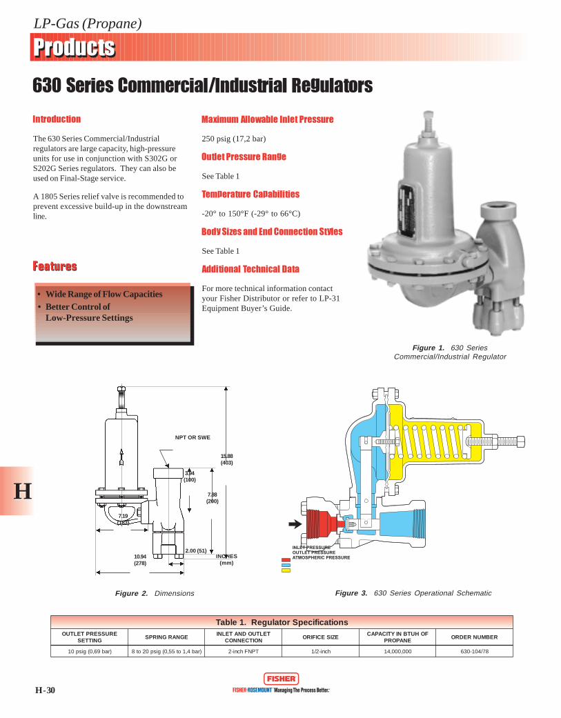
630 Series Commercial/Industrial Regulators
HH
Introduction
The 630 Series Commercial/Industrialregulators are large capacity, high-pressureunits for use in conjunction with S302G orS202G Series regulators. They can also beused on Final-Stage service.
A 1805 Series relief valve is recommended toprevent excessive build-up in the downstreamline.
Maximum Allowable Inlet Pressure
250 psig (17,2 bar)
Outlet Pressure Range
See Table 1
Temperature Capabilities
-20° to 150°F (-29° to 66°C)
Body Sizes and End Connection Styles
See Table 1
Additional Technical Data
For more technical information contactyour Fisher Distributor or refer to LP-31Equipment Buyer’s Guide.
Figure 1. 630 SeriesCommercial/Industrial Regulator
Figure 2. Dimensions Figure 3. 630 Series Operational Schematic
FeaturesFeatures
• Wide Range of Flow Capacities• Better Control of
Low-Pressure Settings
15.88(403)
7.88(200)
3.94(100)
7.19(183)
10.94(278)
NPT OR SWE
2.00 (51)INCHES
(mm)
INLET PRESSUREOUTLET PRESSUREATMOSPHERIC PRESSURE
snoitacificepSrotalugeR.1elbaTERUSSERPTELTUO
GNITTESEGNARGNIRPS
TELTUODNATELNINOITCENNOC
EZISECIFIROFOHUTBNIYTICAPAC
ENAPORPREBMUNREDRO
)rab96,0(gisp01 )rab4,1ot55,0(gisp02ot8 TPNFhcni-2 hcni-2/1 000,000,41 87/401-036
H - 31
LP-Gas (Propane)
ProductsProducts
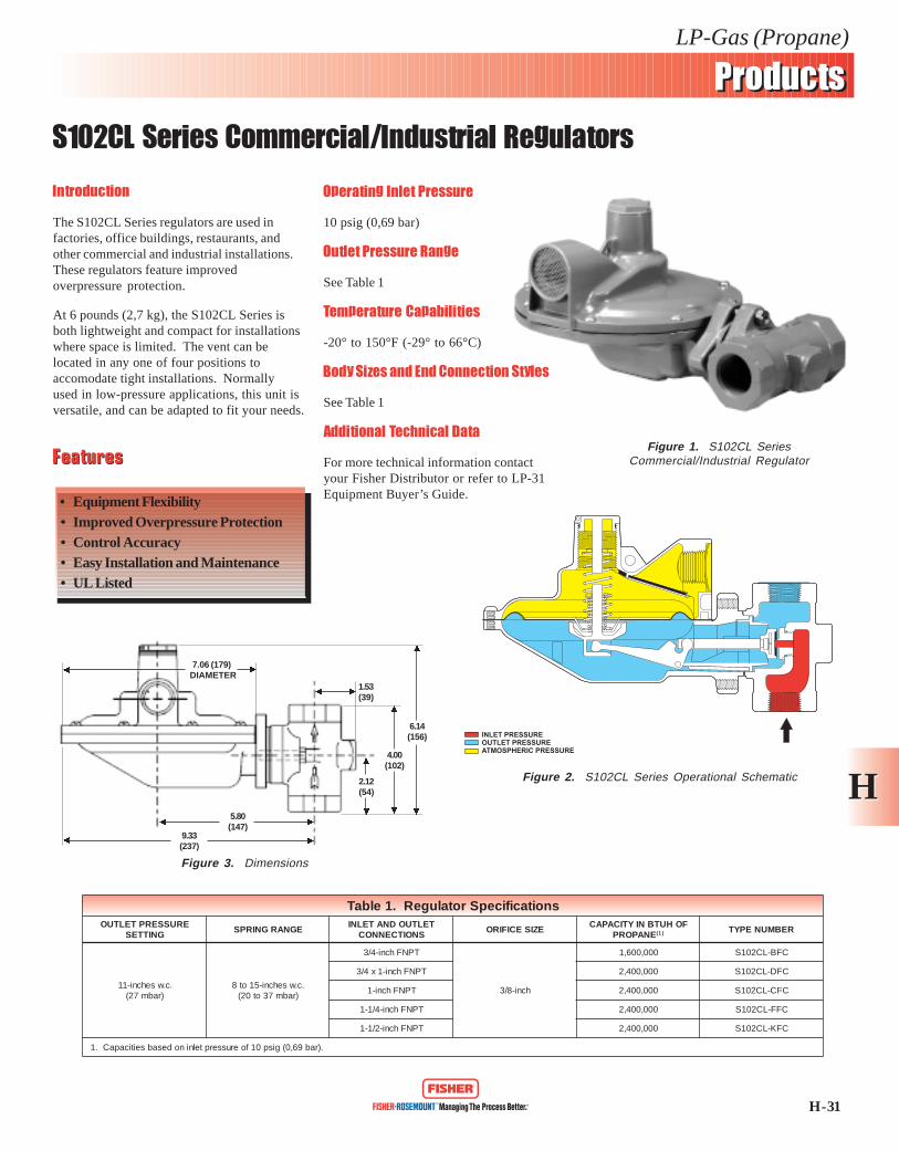
S102CL Series Commercial/Industrial Regulators
HH
Introduction
The S102CL Series regulators are used infactories, office buildings, restaurants, andother commercial and industrial installations.These regulators feature improvedoverpressure protection.
At 6 pounds (2,7 kg), the S102CL Series isboth lightweight and compact for installationswhere space is limited. The vent can belocated in any one of four positions toaccomodate tight installations. Normallyused in low-pressure applications, this unit isversatile, and can be adapted to fit your needs.
Operating Inlet Pressure
10 psig (0,69 bar)
Outlet Pressure Range
See Table 1
Temperature Capabilities
-20° to 150°F (-29° to 66°C)
Body Sizes and End Connection Styles
See Table 1
Additional Technical Data
For more technical information contactyour Fisher Distributor or refer to LP-31Equipment Buyer’s Guide.
FeaturesFeatures
• Equipment Flexibility• Improved Overpressure Protection• Control Accuracy• Easy Installation and Maintenance• UL Listed
Figure 1. S102CL SeriesCommercial/Industrial Regulator
Figure 3. Dimensions
Figure 2. S102CL Series Operational Schematic
snoitacificepSrotalugeR.1elbaTERUSSERPTELTUO
GNITTESEGNARGNIRPS
TELTUODNATELNISNOITCENNOC
EZISECIFIROFOHUTBNIYTICAPAC
ENAPORP )1( REBMUNEPYT
.c.wsehcni-11)rabm72(
.c.wsehcni-51ot8)rabm73ot02(
TPNFhcni-4/3
hcni-8/3
000,006,1 CFB-LC201S
TPNFhcni-1x4/3 000,004,2 CFD-LC201S
TPNFhcni-1 000,004,2 CFC-LC201S
TPNFhcni-4/1-1 000,004,2 CFF-LC201S
TPNFhcni-2/1-1 000,004,2 CFK-LC201S
.)rab96,0(gisp01foerusserptelninodesabseiticapaC.1
6.14(156)
4.00(102)
2.12(54)
1.53(39)
7.06 (179) DIAMETER
5.80(147)
9.33(237)
INLET PRESSUREOUTLET PRESSUREATMOSPHERIC PRESSURE
H - 32
LP-Gas (Propane)
ProductsProducts
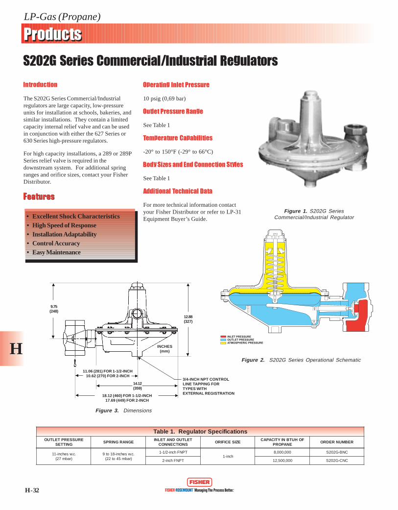
S202G Series Commercial/Industrial Regulators
HH
Introduction
The S202G Series Commercial/Industrialregulators are large capacity, low-pressureunits for installation at schools, bakeries, andsimilar installations. They contain a limitedcapacity internal relief valve and can be usedin conjunction with either the 627 Series or630 Series high-pressure regulators.
For high capacity installations, a 289 or 289PSeries relief valve is required in thedownstream system. For additional springranges and orifice sizes, contact your FisherDistributor.
Operating Inlet Pressure
10 psig (0,69 bar)
Outlet Pressure Range
See Table 1
Temperature Capabilities
-20° to 150°F (-29° to 66°C)
Body Sizes and End Connection Styles
See Table 1
Additional Technical Data
For more technical information contactyour Fisher Distributor or refer to LP-31Equipment Buyer’s Guide.
Figure 1. S202G SeriesCommercial/Industrial Regulator
Figure 3. Dimensions
Figure 2. S202G Series Operational Schematic
FeaturesFeatures
• Excellent Shock Characteristics• High Speed of Response• Installation Adaptability• Control Accuracy• Easy Maintenance
INCHES(mm)
INLET PRESSUREOUTLET PRESSUREATMOSPHERIC PRESSURE
3/4-INCH NPT CONTROLLINE TAPPING FORTYPES WITHEXTERNAL REGISTRATION18.12 (460) FOR 1-1/2-INCH
17.69 (449) FOR 2-INCH
11.06 (281) FOR 1-1/2-INCH10.62 (270) FOR 2-INCH
9.75(248)
12.88(327)
14.12(359)
snoitacificepSrotalugeR.1elbaTERUSSERPTELTUO
GNITTESEGNARGNIRPS
TELTUODNATELNISNOITCENNOC
EZISECIFIROFOHUTBNIYTICAPAC
ENAPORPREBMUNREDRO
.c.wsehcni-11)rabm72(
.c.wsehcni-81ot9)rabm54ot22(
TPNFhcni-2/1-1hcni-1
000,000,8 CNB-G202S
TPNFhcni-2 000,005,21 CNC-G202S

H - 33
LP-Gas (Propane)
ProductsProducts
S302G Series Commercial/Industrial Regulators
HH
Introduction
The S302G Series Commercial/Industrialregulators are large capacity, low-pressureunits for installation at schools, bakeries, andother similar installations. They contain alimited capacity, internal relief valve and canbe used in conjunction with either the 627Series or 630 Series high-pressure regulators.
For high capacity installations, a 289 Seriesrelief valve is required in the downstreamsystem. For additional spring ranges andorifice sizes, contact your Fisher Distributor.
Operating Inlet Pressure
10 psig (0,69 bar)
Outlet Pressure Range
See Table 2
Temperature Capabilities
-20° to 150°F (-29° to 66°C)
Body Sizes and End Connection Styles
See Table 2
Additional Technical Data
For more technical information contactyour Fisher Distributor or refer to LP-31Equipment Buyer’s Guide.
FeaturesFeatures
• Excellent Shock Characteristics• High Speed of Response• Installation Adaptability• Control Accuracy• Easy Maintenance
Figure 1. S302G SeriesCommercial/Industrial Regulator
Figure 2. S302G Series Operational Schematic
INLET PRESSUREOUTLET PRESSUREATMOSPHERIC PRESSURE
Figure 3. DimensionsINCHES
(mm)
A
B
D
E
7.73(196)
7.75 (197)DIAMETER
snoisnemiD.1elbaT
,EZISYDOBSEHCNI
)mm(SEHCNI,SNOISNEMID
A B D E
2/1-1,4/1-1 )411(5.4 )85(3.2 )451(50.6 )252(29.9
2 )421(88.4 )26(54.2 )651(61.6 )552(50.01
snoitacificepSrotalugeR.2elbaTERUSSERPTELTUO
GNITTESEGNARGNIRPS
TELTUODNATELNISNOITCENNOC
EZISECIFIROFOHUTBNIYTICAPAC
ENAPORPREBMUNREDRO
.c.wsehcni-11)rabm72(
.c.wsehcni-41ot6)rabm53ot51(
TPNFsehcni-4/1-1
hcni-4/3 000,215,5
CMF-G203S
TPNFsehcni-2/1-1 CMK-G203S
TPNFsehcni-2 CMS-G203S

Internal Valves
· C402 Series
· C403 Series
· C404 Series
· C407 Series
· C421 Series
· C427 Series
H - 34
LP-Gas (Propane)
ProductsProducts
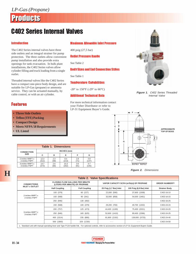
C402 Series Internal Valves
HH
Introduction
The C402 Series internal valves have threeside outlets and an integral strainer for pumpprotection. The three outlets allow convenientpump installation and also provide extraopenings for tank evacuation. In bulk plantinstallations, the C402 Series valves allowcylinder filling and truck loading from a singleoutlet.
Threaded internal valves like the C402 Serieshave a compact one-piece body design, and aresuitable for LP-Gas (propane) or ammoniaservice. They can be actuated manually, bycable control, or with an air cylinder.
Maximum Allowable Inlet Pressure
400 psig (27,5 bar)
Outlet Pressure Range
See Table 2
Body Sizes and End Connection Styles
See Table 1
Temperature Capabilities
-20° to 150°F (-29° to 66°C)
Additional Technical Data
For more technical information contactyour Fisher Distributor or refer toLP-31 Equipment Buyer’s Guide.
FeaturesFeatures
• Three Side Outlets• Teflon (TFE) Packing• Compact Design• Meets NFPA 58 Requirements• UL Listed
Figure 1. C402 Series ThreadedInternal Valve
Figure 2. Dimensions
DC
G
F
APPROXIMATETOP OF BOSS
E
snoitacificepSevlaV.2elbaT
SNOITCENNOCTELTUOxTELNI
ETUNIMREPSNOLLAGWOLFGNISOLCENAPORPFO)ETUNIMREPSRETIL(
ENAPORPFO))n(h/³m(HFCSYTICAPACROPAV REBMUNREDRO )1(
gnilpuoCflaH gnilpuoClluF telnI)raB7,1(gisP52 telnI)raB9,6(gisP001 ydoBreniartS
xTPNMsehcni-2TPNFsehcni-2
)973(001 )722(06 )095(000,22 )8001(006,73 01-61-204C
)865(051 )143(09 )858(000,23 )1641(005,45 51-61-204C
)649(052 )294(031 --- --- 52-61-204C
xTPNMsehcni-3TPNFsehcni-3
)865(051 )973(001 )387(002,92 )2331(007,94 51-42-204C
)757(002 )374(521 )0911(004,44 )1202(004,57 02-42-204C
)649(052 )526(561 )0141(006,25 )6932(004,98 52-42-204C
)4151(004 )098(532 )2912(008,18 )5273(000,931 04-42-204C
)3981(005 )0321(523 --- --- 05-42-204C
.ediuGsreyuBtnempiuqE13-PLfonoitcesseirosseccaotrefer,slortnoclanoitporoF.knilelbisuf431PepyTdnarevelgnitarepolaunamhtiwtinudradnatS.1
snoisnemiD.1elbaT
NOITCENNOCEZIS
(SEHCNI mm )
C D E F G
xTPNMsehcni-2TPNFsehcni-2
3.21)213(
3.2)85(
4.8)312(
8.2)17(
8.5)741(
xTPNMsehcni-3TPNFsehcni-3
7.41)373(
6.2)66(
3.01)262(
6.3)19(
7.5)541(

H - 35
LP-Gas (Propane)
ProductsProducts
C403 Series Internal Valves
HH
Introduction
The C403 Series flanged internal valvesare intended for special bobtail truckapplications where the pump must be loweredto clear the truck frame or other obstacles. Ashear section in the body permits the lowersection of the valve to shear off in the event ofan accident, leaving the critical shutoff partswithin the tank.
The C403 Series valves can be activatedmanually, by cable control, or by an aircylinder. These units have an internal screenfor pump protection which can be removed ifthe valve is used for filling.
Maximum Allowable Inlet Pressure
400 psig (27,5 bar)
Outlet Pressure Range
See Table 1
Temperature Capabilities
-20° to 150°F (-29° to 66°C)
Body Sizes and End Connection Styles
See Table 1
Additional Technical Data
For more technical information contactyour Fisher Distributor or refer to LP-31Equipment Buyer’s Guide.
FeaturesFeatures
• Internal Screen• Sturdy and Compact• Double Flange• Easy Maintenance• Meets NFPA 58 Requirements• UL Listed
Figure 1. C403 Series FlangedInternal Valve
Figure 2. C403-24 3-inch Dimensions
snoitacificepSevlaV.1elbaT
SEZISNOITCENNOCEGNALFWOLFGNISOLC
ETUNIMREPSNOLLAG)ETUNIMREPSRETIL(
ENAPORPFO
YTICAPACROPAVENAPORPFO))n(h/³m(HFCS
REBMUNREDRO
telnI teltuO telnI)raB7,1(gisP52 telnI)raB9,6(gisP001 egnalFelbuoD
FR003ssalCISNA,hcni-3deifidoM
)erobretemaidhcni-8/5-4(FR003ssalCISNA,hcni-3
)865(051 )986(007,52 )8611(006,34 051-42-304C
)757(002 )0101(007,73 )8171(001,46 002-42-304C
)649(052 )5511(001,34 )4691(003,37 052-42-304C
)4151(004 )4261(006,06 )0672(000,301 004-42-304C
5.62 (143)
5.33 (135) 3-INCH 300 RF ANSI CLASSFLANGE MODIFIED(4.62 DIA. BORE & 5.75 RF)
INCHES(mm)
H - 36
LP-Gas (Propane)
ProductsProducts
C404 Series Internal Valves
HH
Introduction
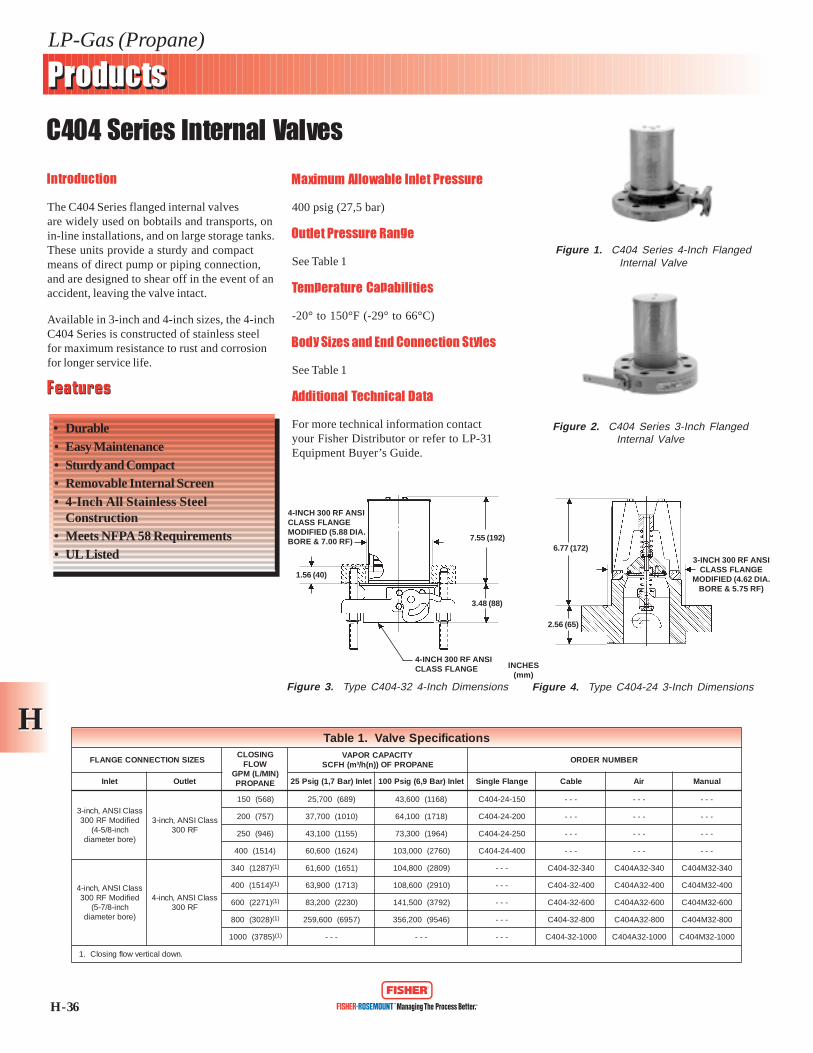
The C404 Series flanged internal valvesare widely used on bobtails and transports, onin-line installations, and on large storage tanks.These units provide a sturdy and compactmeans of direct pump or piping connection,and are designed to shear off in the event of anaccident, leaving the valve intact.
Available in 3-inch and 4-inch sizes, the 4-inchC404 Series is constructed of stainless steelfor maximum resistance to rust and corrosionfor longer service life.
Maximum Allowable Inlet Pressure
400 psig (27,5 bar)
Outlet Pressure Range
See Table 1
Temperature Capabilities
-20° to 150°F (-29° to 66°C)
Body Sizes and End Connection Styles
See Table 1
Additional Technical Data
For more technical information contactyour Fisher Distributor or refer to LP-31Equipment Buyer’s Guide.
FeaturesFeatures
• Durable• Easy Maintenance• Sturdy and Compact• Removable Internal Screen• 4-Inch All Stainless Steel
Construction• Meets NFPA 58 Requirements• UL Listed
Figure 1. C404 Series 4-Inch FlangedInternal Valve
Figure 4. Type C404-24 3-Inch Dimensions
INCHES(mm)
Figure 2. C404 Series 3-Inch FlangedInternal Valve
Figure 3. Type C404-32 4-Inch Dimensions
snoitacificepSevlaV.1elbaT
SEZISNOITCENNOCEGNALFGNISOLC
WOLF)NIM/L(MPG
ENAPORP
YTICAPACROPAVENAPORPFO))n(h/³m(HFCS
REBMUNREDRO
telnI teltuO telnI)raB7,1(gisP52 telnI)raB9,6(gisP001 egnalFelgniS elbaC riA launaM
ssalCISNA,hcni-3deifidoMFR003
hcni-8/5-4()erobretemaid
ssalCISNA,hcni-3FR003
)865(051 )986(007,52 )8611(006,34 051-42-404C --- --- ---
)757(002 )0101(007,73 )8171(001,46 002-42-404C --- --- ---
)649(052 )5511(001,34 )4691(003,37 052-42-404C --- --- ---
)4151(004 )4261(006,06 )0672(000,301 004-42-404C --- --- ---
ssalCISNA,hcni-4deifidoMFR003
hcni-8/7-5()erobretemaid
ssalCISNA,hcni-4FR003
)7821(043 )1( )1561(006,16 )9082(008,401 --- 043-23-404C 043-23A404C 043-23M404C
)4151(004 )1( )3171(009,36 )0192(006,801 --- 004-23-404C 004-23A404C 004-23M404C
)1722(006 )1( )0322(002,38 )2973(005,141 --- 006-23-404C 006-23A404C 006-23M404C
)8203(008 )1( )7596(006,952 )6459(002,653 --- 008-23-404C 008-23A404C 008-23M404C
)5873(0001 )1( --- --- --- 0001-23-404C 0001-23A404C 0001-23M404C
.nwodlacitrevwolfgnisolC.1
4-INCH 300 RF ANSICLASS FLANGEMODIFIED (5.88 DIA.BORE & 7.00 RF)
1.56 (40)
4-INCH 300 RF ANSICLASS FLANGE
3.48 (88)
7.55 (192)6.77 (172)
2.56 (65)
3-INCH 300 RF ANSICLASS FLANGE
MODIFIED (4.62 DIA.BORE & 5.75 RF)

H - 37
LP-Gas (Propane)
ProductsProducts
C407 Series Internal Valves
HH
Introduction
Threaded internal valves like the C407 Seriesare an excellent choice for vapor lines onbobtail trucks. They can also be used as amain valve on small capacity pumpingsystems, ammonia nurse tanks, and in-lineinstallations.
Maximum Allowable Inlet Pressure
400 psig (27,5 bar)
Outlet Pressure Range
See Table 1
Temperature Capabilities
-20° to 150°F (-29° to 66°C)
Body Sizes and End Connection Styles
See Table 1
Additional Technical Data
For more technical information contactyour Fisher Distributor or refer toLP-31 Equipment Buyer’s Guide.
Figure 1. C407 Series Internal Valve
Figure 2. Dimensions
FeaturesFeatures
• Excess Flow Closure• TFE Packing• Remote Release Available• Multiple Actuation• Meets NFPA 58 Requirements• UL Listed
INCHES(mm)5.90 (150)
CLOSED
1.86(47)
2.88(73)
70 DEGREESWING
1-1/4 - 11-1/2FNPT
snoitacificepSevlaV.1elbaT
TELNINOITCENNOC
TELTUONOITCENNOC
ETUNIMREPSNOLLAGWOLFGNISOLCENAPORPFO)ETUNIMREPSRETIL(
ENAPORPFO))n(h/³m(HFCSYTICAPACROPAV REBMUNREDRO
gnilpuoCflaH gnilpuoClluF telnI)raB7,1(gisP52 telnI)raB9,6(gisP001 ydoBthgiartS
TPNMhcni-4/1-1 TPNFhcni-4/1-1
)411(03 --- )051(0065 )942(0039 30-01-704C
)981(05 )231(53 )902(0087 )453(002,31 50-01-704C
)303(08 )642(56 )003(002,11 )515(002,91 80-01-704C

H - 38
LP-Gas (Propane)
ProductsProducts
C421 Series Internal Valves
HH
Introduction
The C421 Series internal valves are designedwith two outlets, bottom and side. The sideoutlet permits installing horizontal pipingimmediately adjacent to the tank without theneed for extra pipe fittings. Primary use forthe C421 Series is on bobtails and transports.
These units are designed as primary shutoffvalves and to reduce the chance ofuncontrolled product discharge in the eventof an accident. Like all Fisher threadedinternal valves, all C421 Series are suitablefor both LP-Gas (propane) and ammonia, andcomply with NFPA 58 requirements.
Maximum Allowable Inlet Pressure
400 psig (27,5 bar)
Outlet Pressure Range
See Table 1
Temperature Capabilities
-20° to 150°F (-29° to 66°C)
Body Sizes and End Connection Styles
See Table 1
Additional Technical Data
For more technical information contactyour Fisher Distributor or refer to LP-31Equipment Buyer’s Guide.
FeaturesFeatures
• Compact Design• Suitable for LP-Gas (Propane) or
Ammonia• Meets NFPA 58 Requirements• Teflon (TFE) Packing• UL Listed
Figure 1. C421 Series ThreadedInternal Valve
snoitacificepSevlaV.1elbaT
SNOITCENNOCTELTUOxTELNI
ETUNIMREPSNOLLAGWOLFGNISOLCENAPORPFO)ETUNIMREPSRETIL(
ENAPORPFO))n(h/³m(HFCSYTICAPACROPAV REBMUNREDRO )1(
gnilpuoCflaH gnilpuoClluF telnI)raB7,1(gisP52 telnI)raB9,6(gisP001 ydoBeeT
xTPNMsehcni-2TPNFsehcni-2
)873(001 )722(06 )095(000,22 )8001(006,73 01-61-124C
)865(051 )143(09 )858(000,23 )1641(005,45 51-61-124C
)649(052 )294(031 --- --- 52-61-124C
xTPNMsehcni-3TPNFsehcni-3
)865(051 )873(001 )387(002,92 )2331(007,94 51-42-124C
)757(002 )374(521 )0911(004,44 )1202(004,57 02-42-124C
)649(052 )526(561 )0141(006,25 )6932(004,98 52-42-124C
)4151(004 )988(532 )2912(008,18 )5273(000,931 04-42-124C
)3981(005 )0321(523 --- --- 05-42-124C
.ediuGsreyuBtnempiuqE13-PLfonoitcesseirosseccaotrefer,slortnoclanoitporoF.knilelbisuf431PepyTdnarevelgnitarepolaunamhtiwtinudradnatS.1

H - 39
LP-Gas (Propane)
ProductsProducts
C427 Series Internal Valves
HH
Introduction
The C427 Series internal valves areeconomical, compact valves with straight-through flow. They are suitable for LP-Gas(propane) or ammonia service, and specialconstruction is available for other compressedgases. Common installations include bobtail,transport, stationary tank, and in-line.
Body Sizes and End Connection Styles
See Table 2
Maximum Allowable Inlet Pressure
400 psig (27,5 bar)
Outlet Pressure Range
See Table 2
Temperature Capabilities
-20° to 150°F (-29° to 66°C)
Additional Technical Data
For more technical information contactyour Fisher Distributor or refer to LP-31Equipment Buyer’s Guide.
FeaturesFeatures
• Straight-Through Flow• Compact• Teflon (TFE) Packing• Meets NFPA 58 Requirements• UL Listed
Figure 1. C427 Series Internal Valve
Figure 2. Dimensions
A
B
C
D
F
E
APPROXIMATETOP OF BOSS
snoisnemiD.1elbaTYDOB,EZISSEHCNI
A B C D E F
)mm(sehcnI
2 )15(2 )75(52.2 )402(50.8 )601(81.4 )38(52.3 )311(64.4
3 )67(3 )37(68.2 )322(87.8 )401(90.4 )411(05.4 )031(21.5
snoitacificepSevlaV.2elbaT
SNOITCENNOCTELTUOxTELNI
ETUNIMREPSNOLLAGWOLFGNISOLCENAPORPFO)ETUNIMREPSRETIL(
ENAPORPFO))n(h/³m(HFCSYTICAPACROPAV REBMUNREDRO )1(
gnilpuoCflaH gnilpuoClluF telnI)raB7,1(gisP52 telnI)raB9,6(gisP001 ydoBthgiartS
xTPNMsehcni-2TPNFsehcni-2
)973(001 )722(06 )095(000,22 )8001(006,73 01-61-724C
)865(051 )143(09 )858(000,23 )1641(005,45 51-61-724C
)649(052 )294(031 --- --- 52-61-724C
xTPNMsehcni-3TPNFsehcni-3
)865(051 )973(001 )387(002,92 )2331(007,94 51-42-724C
)757(002 )374(521 )0911(004,44 )1202(004,57 02-42-724C
)649(052 )526(561 )0141(006,25 )6932(004,98 52-42-724C
)4151(004 )098(532 )2912(008,18 )5273(000,931 04-42-724C
)3981(005 )0321(523 --- --- 05-42-724C
.ediuGsreyuBtnempiuqE13-PLfonoitcesseirosseccaotrefer,slortnoclanoitporoF.knilelbisuf431PepyTdnarevelgnitarepolaunamhtiwtinudradnatS.1

Internal Valve Accessories
· P163A & P164A Series
· P312 Series
· P313 Series
· P314 Series
· P315 Series
· P326 Series
· P389 Series
· P650 Series

26
Cable Controls
Cable Control assemblies can be furnished to remotely open andclose all Fisher internal valves except the 4-inch flanged sizes. De-signed specifically to meet DOT MC-331 and NFPA 58 for bobtailsand transports, the cables can be trimmed to any length desired.
All fusible elements used in the cable controls melt atapproximately 212?F., meeting regulatory requirements.
Type P650 - Includes primary control, a 20-foot cable, Type P134fusible links, a return spring, and mounting hardware. Pulling thecontrol handle opens the internal valve; pushing the handle closesthe valve.
If just the primary control is needed, order Type P651 which doesnot include any accessories.
Type P163A & P164A - Auxiliary cable releases that allow theinternal valve to be closed up to 25-feet (P163A) or up to 50-feet(P164A) from the primary control point. The releases can be usedwith the P650 or with the P320 and P321 latch mechanisms.
Latch & Remote Releases
Threaded internal valves can be fitted with a latch and remoterelease mechanism that permits remote valve closure.
When the internal valve?s operating lever is manually opened, thelever can be latched in the open position by the latch/releasemechanism. The lever is released from a remote location bypulling on a cable attached to a pull ring, thus closing the valve.
A built-in fusible element in the latch/release melts if exposed tofire, allowing the operating lever to return to the closed position.That latch/release is easily installed in the field.
C404-32
P313
INTERNAL VALVE TYPE NUMBER
C402, C421, C427
P320
C407-10
P341, P342
Air Cylinders
All Fisher internal valves can be fitted with an air operatedcylinder for remote valve operation. When air pressure is appliedto the cylinder, it moves the cylinder rod and the internal valve?soperating lever, opening the valve. Upon loss of air pressure, thevalve?s operating lever immediately returns to the closed position.
Type P326 - Featuring spring return design, the P326 serieseliminates the need for an air return. The unique ìrolledî cylinderdiaphragm has a special seal that prevents air leakage andminimizes friction. A bellows covers the cylinder rod to keep mud,dirt, and foreign material off the rod. Operating temperaturerange for diaphragm= -65?F to 212?F.
Operating pressure for the cylinder is from 20 to 125 psig, and rec-ommended minimum pressure of 20 psig. Each assembly includesan operating handle, mounting bracket, and installation hardware.
Type P389 - Used with the Type C407-10 only. All necessaryhardware for installing the cylinder is included. Minimumpressure is 60 psig, maximum pressure is 250 psig.
C402, C421,or C427
P326-6
INTERNAL VALVE TYPE NUMBER
C407-10
P389
C404-32
P312
C404-24
P326-7
C403-24
P326-5
4-Inch Valve Accessories
Type P312 - Also available factory installed the cylinder attachesdirectly to the valve after removal of the cable operating lever.Included with each assembly is an operating lever and mountinghareware. A minimum operating pressure of 60 psig is required;maximum pressure rating of the cylinder is 250 psig.
Type P314 - Cable assembly attaches to the C404-32 operatinglever and can then be connected to either a Wheaton or Alleghenytype primary control. The assembly includes a 40-foot cable, aspecial bushing with a fusible element, and a clamp.
Type P315 - On manually actuated 4-inch valves (C404M32),this remote release handle allows the valve to be closed from aremote location. Cable linkage and mounting hardware are in-cluded. A C404M32 and two P315s complies with DOT MC-331.
Internal Valves
P650
P313
P320
P312
P326
P341
P315
Globe and Angle Valves
· N301, N310, & N350 Series
· N401, N410, & N450 Series

H - 50
LP-Gas (Propane)
ProductsProducts
N301, N310, and N350 Series Globe Valves
HH
Introduction
The N301 and N310 Series Globe Valves arewidely used at bulk plants to control gas flowin the piping system, at storage tanks, ontrucks and at pumps or compressors. Allunits have a 1/4-inch FNPT plugged boss inthe downstream side of the body. Ahydrostatic relief valve or a vent valve can beinstalled in this outlet.
The N310 Series features a ball bearing valvedisk for stronger connection to the stem toprotect the disk under back-flow conditions.The ball bearings also permit the valve disk to
stop rotating as soon as it touches the bodyseat, minimizing disk wear.
The N350 Series economy globe valves forLP-Gas service have many of the constructionfeatures of the N310 Series, the valves can besupplied in 1/2-inch and 3/4-inch sizes.Teflon (TFE) spring-loaded packing providesan effective seal against leakage within thevalve’s pressure range.
Maximum Allowable Inlet Pressure
400 psig (27,5 bar)
Temperature Capabilities
-20° to 150°F (-29° to 66°C)
Body Sizes and End Connection Styles
See Table 2
Additional Technical Data
For more technical information contactyour Fisher Distributor or refer to LP-31Equipment Buyer’s Guide.
FeaturesFeatures
• Heavy Duty Construction• Straight Through Flow• High Flow Capacity• Versatile• UL Listed
Figure 1. N310 Series Globe Valve(also Typical of N301 Series)
Figure 2. Dimensions
B
AOPENED
snoisnemiD.1elbaT013NEPYT 053NEPYT A B
TPNFsehcnI,eziSydoB )mm(sehcnI
--- 4/3dna2/1 )29(46.3 )69(87.3
4/3dna2/1 --- )821(40.5 )69(87.3
1 --- )821(40.5 )011(23.4
4/1-1 --- )281(81.7 )721(0.5
2/1-1 --- )281(81.7 )041(5.5
2 --- )191(5.7 )941(88.5
3 --- )843(27.31 )922(0.9
degnalF3 --- )843(27.31 )682(52.11
snoitacificepSevlaV.2elbaTNOITCENNOCTELNI NOITCENNOCTELTUO ECIVRES REBMUNREDRO
TPNFhcni-2/1 TPNFhcni-2/1
)enaporP(saG-PLainommAdna
40-103N
TPNFhcni-4/3 TPNFhcni-4/3 60-103N
TPNFhcni-1 TPNFhcni-1 80-103N
TPNFhcni-4/1-1 TPNFhcni-4/1-1 01-013N
TPNFhcni-2/1-1 TPNFhcni-2/1-1 21-013N
TPNFhcni-2 TPNFhcni-2 61-013N
TPNFhcni-3 TPNFhcni-3 42-013N
egnalFISNAhcni-3 egnalFISNAhcni-3 42-F013N
TPNFhcni-2/1 TPNFhcni-2/1saG-PL
40-053N
TPNFhcni-4/3 TPNFhcni-4/3 60-053N

H - 51
LP-Gas (Propane)
ProductsProducts
N401, N410, and N450 Series Angle Valves
HH
Introduction
The N401 and N410 Series angle valves arewidely used at bulk plants in a variety ofapplications. All units have a 1/4-inch FNPTplugged boss in the downstream side of thebody. Ranging in size from 1/2-inch to3-inches, these valves have spring-loadedTeflon (TFE) chevron packing for an effectiveseal against leakage.
Ball bearing valve disk construction used inthe N410 Series gives a stronger connection tothe stem for disk protection under back-flowconditions.
The N450 Series economy angle valves forLP-Gas service have many of the constructionfeatures of the N410 Series, the valves can besupplied in 1/2-inch and 3/4-inch sizes.Teflon (TFE) spring-loaded packing providesan effective seal against leakage within thevalves pressure range.
Maximum Allowable Inlet Pressure
400 psig (27,5 bar)
Temperature Capabilities
-20° to 150°F (-29° to 66°C)
Body Sizes and End Connection Styles
See Table 2
Additional Technical Data
For more technical information contactyour Fisher Distributor or refer to LP-31Equipment Buyer’s Guide.
FeaturesFeatures
• Heavy Duty Construction• Angle Connection• High Flow Capacity• Versatile• UL Listed
Figure 1. N410 Series Angle Valve(also Typical of N401 Series)
Figure 2. Dimensions
snoisnemiD.1elbaTTPNFSEHCNI,EZISYDOB )mm(SEHCNI
014NepyT 054NepyT )denepO(A B C
--- 4/3dna2/1 )431(62.5 )55(61.2 )84(88.1
4/3dna2/1 --- )281(81.7 )55(61.2 )84(88.1
1 --- )281(81.7 )35(70.2 )45(21.2
4/1-1 --- )132(1.9 )75(62.2 )75(42.2
2/1-1 --- )132(1.9 )07(57.2 )76(26.2
2 --- )652(80.01 )86(86.2 )37(88.2
3 --- )224(16.61 )201(0.4 )201(0.4
degnalF3 --- )974(68.81 )951(52.6 )951(52.6
B
C
A

Emergency Shutoff Valves
· N550 Series
· N560 Series

H - 40
LP-Gas (Propane)
ProductsProducts
N550 Series Emergency Shutoff Valves
HH
Introduction
Snappy Joe® N550 Series Emergency ShutoffValves (ESVs) are designed for in-lineinstallations, usually near a bulkhead. Thevalves provide a means of shutting off gas inthe event of a hose rupture or piping break atthe transfer area to avoid a large scale loss ofLP-Gas (propane) or ammonia.
These valves can be manually opened andclosed at the installed location or closedremotely by either cable or air. A remoteoperating actuator is also available.
While the ordinary cable can be used, the TypeP164B release assembly is available. Thisassembly uses cable housing (50 feet (15.2meters) in length) which does not requireelaborate guiding like uncovered cables.
Remote pneumatic closure is available withType P327D release. Pressure on theType P327D allows the valve to be latched inthe open position with manual closurepossible at the valve. Loss of pressure (30 to70 psig (2,7 to 4,8 bar) air, nitrogen, or CO
2)
permits the ESV to close. Operatingtemperatures range from -40° to 212°F(-40° to 100°C).
FeaturesFeatures
• High Flow Capacity• Ease of Operation• Cable Release• Pneumatic Operation• Rugged Construction• Fuseable Element• UL Listed
Figure 1. N550 Series EmergencyShutoff Valve
snoitacificepSevlaV.1elbaT
EZISYDOBENAPORPFO)ETUNIMREPSRETIL(ETUNIMREPSNOLLAGNIWOLF
SEIROSSECCA REBMUNREDRO)raB960,0(disP1 )raB41,0(disP2
TPNFhcni-4/1-1 )981(05 )482(57 esaeleRelbaCB461PesaeleRcitamuenPD723P
rednilyCriAC723PevlaVlortnoC59311T
01-055N
TPNFhcni-2 )482(57 )534(511 61-055N
TPNFhcni-3 )917(091 )1401(572 42-055N
Opening and closing of Snappy Joe ESVs froma remote location can be done by using theType P327C air cylinder. The cylinder opensthe valve when around 30 to 70 psig (2,7 to4,8 bar) (air or nitrogen) is applied.
Fisher makes available a small 3-way controlvalve (part number T11395 99012) forpneumatic ESV installation. This controlvalve can be used as primary control (open orclose the ESV) or an auxiliary remote release(close only).
Maximum Allowable Inlet Pressure
400 psig (27,5 bar)
Outlet Pressure Range
See Table 1
Temperature Capabilities
-20° to 150°F (-29° to 66°C)
Body Sizes and End Connection Styles
See Table 1
Additional Technical Data
For more technical information contactyour Fisher Distributor or refer to LP-31Equipment Buyer’s Guide.
HH
H - 41
LP-Gas (Propane)
ProductsProducts
N550 Series Emergency Shutoff Valves
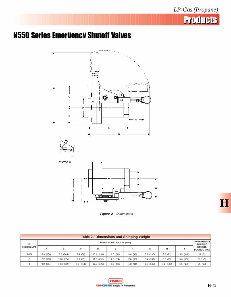
thgieWgnippihSdnasnoisnemiD.2elbaT
PTPNSEHCNI
)mm(SEHCNI,SNOISNEMID ETAMIXORPPAGNIPPIHS,THGIEW
)GK(SDNUOPA B C D E F G H J
4/1-1 )051(9.5 )442(6.9 )68(4.3 )462(4.01 )15(0.2 )19(6.3 )031(1.5 )28(2.3 )041(5.5 )5(11
2 )381(2.7 )452(0.01 )99(9.3 )592(6.11 )47(9.2 )66(6.2 )731(4.5 )98(5.3 )251(0.6 )9(5.02
3 )432(2.9 )962(6.01 )411(5.4 )823(9.21 )98(5.3 )13(2.1 )541(7.5 )701(2.4 )561(5.6 )61(53
A
G
A
H
P
VIEW A-A
J
P
D
C
E
A
B
F
Figure 2. Dimensions
H - 42
LP-Gas (Propane)
ProductsProducts
N560 Series Emergency Shutoff Valves
HH
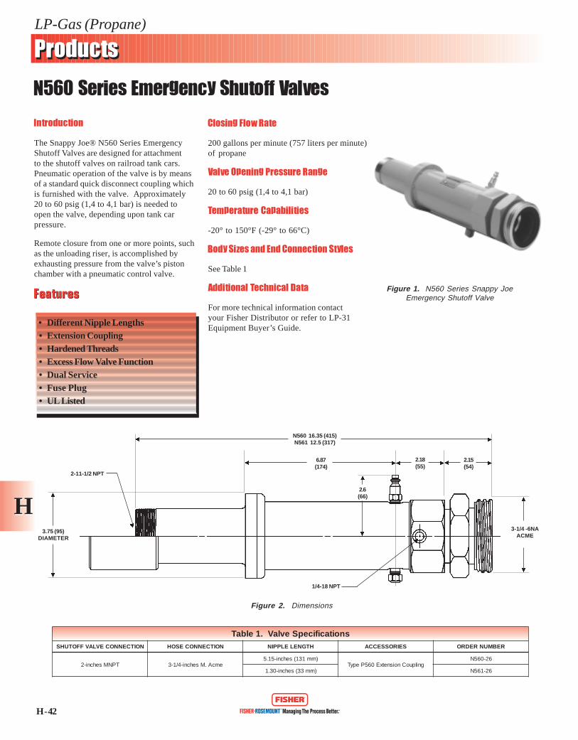
Introduction
The Snappy Joe® N560 Series EmergencyShutoff Valves are designed for attachmentto the shutoff valves on railroad tank cars.Pneumatic operation of the valve is by meansof a standard quick disconnect coupling whichis furnished with the valve. Approximately20 to 60 psig (1,4 to 4,1 bar) is needed toopen the valve, depending upon tank carpressure.
Remote closure from one or more points, suchas the unloading riser, is accomplished byexhausting pressure from the valve’s pistonchamber with a pneumatic control valve.
Closing Flow Rate
200 gallons per minute (757 liters per minute)of propane
Valve Opening Pressure Range
20 to 60 psig (1,4 to 4,1 bar)
Temperature Capabilities
-20° to 150°F (-29° to 66°C)
Body Sizes and End Connection Styles
See Table 1
Additional Technical Data
For more technical information contactyour Fisher Distributor or refer to LP-31Equipment Buyer’s Guide.
FeaturesFeatures
• Different Nipple Lengths• Extension Coupling• Hardened Threads• Excess Flow Valve Function• Dual Service• Fuse Plug• UL Listed
Figure 1. N560 Series Snappy JoeEmergency Shutoff Valve
Figure 2. Dimensions
snoitacificepSevlaV.1elbaTNOITCENNOCEVLAVFFOTUHS NOITCENNOCESOH HTGNELELPPIN SEIROSSECCA REBMUNREDRO
TPNMsehcni-2 emcA.Msehcni-4/1-3)mm131(sehcni-51.5
gnilpuoCnoisnetxE065PepyT62-065N
)mm33(sehcni-03.1 62-165N
3.75 (95)DIAMETER
2-11-1/2 NPT
N560 16.35 (415)N561 12.5 (317)
6.87(174)
2.18(55)
2.15(54)
3-1/4 -6NAACME
2.6(66)
1/4-18 NPT
Back Check Valves
· G100 Series
· G200 Series

Ductile Iron
32
Ordering Information - Back Check Valves
TYPE NUMBERPROPANE FLOW CAPACITYAT 10 PSIG DIFFERENTIAL
PRESSURE
21 gpm
55 gpm
150 gpm
150 gpm
250 gpm
160 gpm
250 gpm
137.5 gpm
750 gpm
254 gpm
254 gpm
SEATCONSTRUCTION
Metal-to-Metal
Soft Seat
CONTAINER OR INLETCONNECTION
3/4 in. MNPT
1 1/4 in. MNPT
2 in. MNPT
2 in. FNPT
3 in. MNPT
1 1/4 in. FNPT
2 in. FNPT
2 in. MNPT
3 in. FNPT
3 in. FNPT
3 in. MNPT
FlowIndicator
- - -
- - -
- - -
- - -
- - -
G201-10
G201-16
- - -
G201-24
- - -
- - -
Standard
- - -
- - -
- - -
- - -
- - -
G200-10
G200-16
- - -
G200-24
- - -
- - -
OUTLET CONNECTION
3/4 in. FNPT
1 1/4 in. FNPT
2 in. FNPT
2 in. FNPT
3 in. FNPT
1 1/4 in. FNPT
2 in. FNPT
2 in. MNPT &1 1/4 in. FNPT
3 in. FNPT
2 in. MNPT
3 in. MNPT & 2 in. MNPT
Brass
G100
G101
G102
G109
- - -
- - -
- - -
- - -
- - -
- - -
- - -
Steel
- - -
- - -
G112
- - -
G104
- - -
- - -
G105
- - -
G106
G107
Back Check Valves
Back check valves allow flow in only one direction and arenormally closed. They are installed in liquid filling connections onstationary storage tanks and bobtail delivery trucks and liquidtransfer lines.
G100 SeriesUsed mainly in tank inlet connections, these units are offered intwo styles of seat construction: metal-to-metal or soft seat. Thesoft seated construction is for the filling connection on bobtaildelivery trucks. Because the valve gives tight shutoff, piping onthe bobtail can be depressurized for maintenance or repairwithout leakage.
Type G109 was designed for in-line service at bulk plants withFNPT connections for easy installations.
G200 SeriesThe G200 series back check valves are specifically intended for
heavy-duty in-line service at the bulk plant?s transfer area. Thevalves are suitable for LP-gas or NH3 service.
Flow moves the spring loaded poppet to the open position as soonas pressure differential is created. When flow stops, the poppetcloses. A soft seat construction gives tight shutoff so that pipingcan be blown down for maintenance.
With a body designed to reduce flow resistance, flow capacity ishigh. The 2-inch body size gives 250 gpm propane at 10 psigdifferential pressure.
The G200 Series is built to stay on the job with all internal partsof plated steel or stainless steel.
Flow Indicator - Type G201 has a built-in flow indicatormechanism, see illustration, which can be used to replace sightflow indicators.
G200 & G201Pressure Rating - 400 psig WOGBody - Ductile iron
Internal Parts - Plated steel or stainless steel.Seat Disc - Synthetic rubber
Specifications
G100 SERIES
G109 G201G105 SERIES
G200 orG201

Excess Flow Valves
· F100 Series
· F110 Series
· F110A Series
· F130 Series
· F134 Series
· F138 Series
· F190 Series

33
Ordering Information-Excess Flow Valves
TYPENUMBER
F110F183F173F181
F110AF173AF138F202F170F100F101F102F105F106F107F130F131F132F133
F134
F135
F190F191F194F195F198F199
INLETCONNECTION
Male POL
Soft Nose Male POL
1/4 in. MNPTMale POL
3/4 in. MNPT
1 1/4 in. MNPT
2 in. MNPT
1 in. FNPT1 1/2 in. FNPT
2 in. FNPT
1 1/2 in. MNPT x1 in. FNPT
2 1/2 in. MNPT x1/2 in. FNPT
2 in. MNPT
3 in. MNPT
3 in. MNPT
Vapor SCFH
25 psig Inlet120335120335
120
377634
1,1842,0103,4596,3009,98218,51320,7965,28711,69419,87429,202
5,181
12,000
15,40018,80032,80050,65033,00049,500
100 psig Inlet204570204570
204
6411,1002,0123,4175,88010,63016,96731,46735,3498,98619,87733,87749,718
8,806
20,290
26,25032,00055,95086,35056,25084,350
MATERIAL
BrassBrassBrassBrassBrassBrassBrassBrassBrassBrassBrassBrassBrassBrassBrassBrassBrassBrassBrass
Brass
Brass
SteelSteelSteelSteelSteelSteel
APPLICATION
PortableService
In-Line
Tanks(Full or
Half Coupling)
In-Line
Tanks(Full or
Half Coupling)
Tanks*(Full or
Half Coupling)
OUTLETCONNECTION
9/16 in.-18 UNF LH
1/4 in. MNPT
9/16 in.-18 UNF LH1/4 in. MNPT1/4 in. MNPT
1/2 in. SAE Flare
3/4 in. FNPT
1 1/4 in. FNPT
2 in. FNPT
1 in. FNPT1 1/2 in. FNPT
2 in. FNPT
1 in. FNPT
1 1/2 in. FNPT
2 in. MNPT x1 1/4 in. FNPT
2 in. MNPT
3 in. MNPT x2 in. FNPT
U.L. RATED CLOSING FLOW, PROPANE(HORIZONTAL POSITION)
PSID
7.49.77.49.77.47.41.42.61.22.48.5
10.710.72.63.63.34.72.14.2
2.7
5.2
3.78.93.16.93.17.1
Liquid,GPM
0.71.50.71.5
0.7
1.81.96.68.420335585
100256095
155
28
60
80105165260165260
*LP-gas or NH3 service.
Excess Flow Valves
Excess flow check valves are intended to close upon excessivedischarge of vapor or liquid resulting from a break in the hose orpiping system. They are used to protect cylinder, tank, and pipingsystems, and the valves are available in a large variety of sizesand body configurations.
When flow exceeds the valve?s setting, the valve closes andremains closed until the system equalizes. A built-in equalizingpassage automatically opens the valve once pressure on both sidesof the poppet are equal. Valves larger than 1/2î NPT have a drillsize No. 60. Valves 1/2î and larger have a limited bypass tocomply with NFPA 58.
Note: A break or leak downstream of an excess flow valvethat does not allow a flow equal to the valve flow rating willnot actuate the valve and could cause a hazardous condition.For this reason, system operators should be familiar with theshutoff valves in the system so that necessary precautionscan be taken in an emergency.
Care must be taken to be sure the valve's closing flow ratingis less than the capacity of the LP-gas or NH3 system inwhich the valve is installed. Brass valves are not suitable forNH3 applications.
F190 SERIESF134 SERIES
F130 SERIES
F138
F100 SERIES
F110A SERIES
F110 SERIES

Relief Valves
Flush Mounted Relief Valves
· H721 Series
· H731 Series
Large Relief Valves
· H280 Series
· H5110 Series
Relief Valve Manifold
· H500 Series
Liquid Service Relief Valves
· 98H Series
Diaphragm Type Relief Valves
· 289H Series
· 1805 Series

HH
H - 48
LP-Gas (Propane)
ProductsProducts
Types H721 and H731 Flush Mounted Internal Relief Valves
Introduction
The Types H721 and H731 relief valves areinstalled in tanks, both stationary and mobile,as a means of preventing excessiveoverpressure. These units are used primarilyin trucks transporting LP-Gas (propane) orammonia. The stainless steel constructionincreases resistance to rust and corrosion, andmakes it easy to remove the valve from thetank for the required periodic testing.
The complete valve is secure inside the tankwith only the nameplate extending above thecoupling. A special installation wrench can beinserted into the valve socket to provide ameans of attaching a standard wrench.
Start-To-Discharge Setting
250 to 275 psig (17,2 to 19,0 bar)
Temperature Capabilities
-20° to 150°F (-29° to 66°C)
Container Connection Sizes
See Table 1
Additional Technical Data
For more technical information contactyour Fisher Distributor or refer to LP-31Equipment Buyer’s Guide. Figure 1. H721 and H731 Series Flush
Mounted Internal Relief Valve
Figure 2. Dimensions
FeaturesFeatures
• True Internal Design• Standard Spring Settings• Easy Maintenance• Nitrile Disk
snoisnemiD.1elbaT
EPYTYDOBA B C D
noitcennoC )mm(sehcnI
127Hhcni-2
TPN2/1-11)38(52.3 )713(5.21 )83(5.1
137Hhcni-3TPN8
)101(69.3 )924(9.61 )46(5.2
snoitacificepSevlaV.2elbaT
RENIATNOCNOITCENNOC
EGRAHCSID-OT-TRATS,GNITTES)RAB(GISP
RIAFO)n(m/³m(MFCSNIYTICAPACWOLF :OTPUAERAHTIWKNATROF PACEVITCETORP)DEDULCNI(
REBMUNREDRO.L.U EMSA .L.U
TPNMsehcni-2 )1(
)2,71(052 )3.99(5073 )4,98(5333 )sretemerauqs3,61(teeferauqs571
792P
052-127H
)3,81(562 )701(4893 )1,69(6853 )sretemerauqs7,71(teeferauqs091 562-127H
)0,91(572 )111(4514 )001(9373 --- 572-127H
TPNMsehcni-3 )2(
)2,71(052 )752(3759 )132(6168 )sretemerauqs7,15(teeferauqs755
892P
052-137H
)3,81(562 )672(113,01 )942(0829 )sretemerauqs6,75(teeferauqs026 562-137H
)0,91(572 )882(637,01 )952(3669 --- 572-137H
.hcnerwnoitallatsni)rabxehhcni-2/1-1(403PepyTredrO.1
.hcnerwnoitallatsni)rabxehhcni-2/1-2(503PepyTredrO.2
AB
C
D - HEXWRENCH

H - 49
LP-Gas (Propane)
ProductsProducts
H721 and H731 Series Flush Mounted Internal Relief Valves
HH
Introduction
The H721 and H731 Series relief valves areinstalled in tanks, both stationary and mobile,as a means of preventing excessiveoverpressure. These units are used primarilyin trucks transporting LP-Gas (propane) orammonia. The stainless steel constructionincreases resistance to rust and corrosion, andmakes it easy to remove the valve from thetank for the required periodic testing.
The complete valve is secure inside the tankwith only the nameplate extending above thecoupling. A special installation wrench can beinserted into the valve socket to provide ameans of attaching a standard wrench.
Start-To-Discharge Setting
250 psig (17,2 bar)265 psig (18,3 bar)275 psig (19,0 bar)
Temperature Capabilities
-20° to 150°F (-29° to 66°C)
Container Connection Sizes
See Table 2
Additional Technical Data
For more technical information contactyour Fisher Distributor or refer to LP-31Equipment Buyer’s Guide.
Figure 1. H721 and H731 Series FlushMounted Internal Relief Valve
Figure 2. Dimensions
FeaturesFeatures
• True Internal Design• Standard Spring Settings• Nitrile Disk• UL Listed
A
B
C
D - HEXWRENCH
snoisnemiD.1elbaT
EPYTYDOBA B C D
noitcennoC )mm(sehcnI
127Hhcni-2
TPN2/1-11)38(52.3 )713(5.21 )83(5.1
137Hhcni-3TPN8
)101(69.3 )924(9.61 )46(5.2
snoitacificepSevlaV.2elbaT
RENIATNOCNOITCENNOC
EGRAHCSID-OT-TRATS,GNITTES)RAB(GISP
RIAFO))n(m/³m(MFCSNIYTICAPACWOLF :OTPUAERAHTIWKNATROF PACEVITCETORP)DEDULCNI(
REBMUNREDROLU EMSA LU
TPNMsehcni-2 )1(
)2,71(052 )3.99(5073 )4,98(5333 )sretemerauqs3,61(teeferauqs571
792P
052-127H
)3,81(562 )701(4893 )1,69(6853 )sretemerauqs7,71(teeferauqs091 562-127H
)0,91(572 )111(4514 )001(9373 --- 572-127H
TPNMsehcni-3 )2(
)2,71(052 )752(3759 )132(6168 )sretemerauqs7,15(teeferauqs755
892P
052-137H
)3,81(562 )672(113,01 )942(0829 )sretemerauqs6,75(teeferauqs026 562-137H
)0,91(572 )882(637,01 )952(3669 --- 572-137H
.hcnerwnoitallatsni)rabxeh)mm83(hcni-2/1-1(403PepyTredrO.1
.hcnerwnoitallatsni)rabxeh)mm46(hcni-2/1-2(503PepyTredrO.2

HH
H - 49
LP-Gas (Propane)
ProductsProducts
H721 and H731 Series Flush Mounted Internal Relief Valves
Introduction
The H721 and H731 Series relief valves areinstalled in tanks, both stationary and mobile,as a means of preventing excessiveoverpressure. These units are used primarilyin trucks transporting LP-Gas (propane) orammonia. The stainless steel constructionincreases resistance to rust and corrosion, andmakes it easy to remove the valve from thetank for the required periodic testing.
The complete valve is secure inside the tankwith only the nameplate extending above thecoupling. A special installation wrench can beinserted into the valve socket to provide ameans of attaching a standard wrench.
Start-To-Discharge Setting
250 psig (17,2 bar)265 psig (18,3 bar)275 psig (19,0 bar)
Temperature Capabilities
-20° to 150°F (-29° to 66°C)
Container Connection Sizes
See Table 2
Additional Technical Data
For more technical information contactyour Fisher Distributor or refer to LP-31Equipment Buyer’s Guide.
Figure 1. H721 and H731 Series FlushMounted Internal Relief Valve
Figure 2. Dimensions
FeaturesFeatures
• True Internal Design• Standard Spring Settings• Nitrile Disk• UL Listed
snoisnemiD.1elbaT
EPYTYDOBA B C D
noitcennoC )mm(sehcnI
127Hhcni-2
TPN2/1-11)38(52.3 )713(5.21 )83(5.1
137Hhcni-3TPN8
)101(69.3 )924(9.61 )46(5.2
snoitacificepSevlaV.2elbaT
RENIATNOCNOITCENNOC
EGRAHCSID-OT-TRATS,GNITTES)RAB(GISP
RIAFO))n(m/³m(MFCSNIYTICAPACWOLF :OTPUAERAHTIWKNATROF PACEVITCETORP)DEDULCNI(
REBMUNREDROLU EMSA LU
TPNMsehcni-2 )1(
)2,71(052 )3.99(5073 )4,98(5333 )sretemerauqs3,61(teeferauqs571
792P
052-127H
)3,81(562 )701(4893 )1,69(6853 )sretemerauqs7,71(teeferauqs091 562-127H
)0,91(572 )111(4514 )001(9373 --- 572-127H
TPNMsehcni-3 )2(
)2,71(052 )752(3759 )132(6168 )sretemerauqs7,15(teeferauqs755
892P
052-137H
)3,81(562 )672(113,01 )942(0829 )sretemerauqs6,75(teeferauqs026 562-137H
)0,91(572 )882(637,01 )952(3669 --- 572-137H
.hcnerwnoitallatsni)rabxeh)mm83(hcni-2/1-1(403PepyTredrO.1
.hcnerwnoitallatsni)rabxeh)mm46(hcni-2/1-2(503PepyTredrO.2
A
B
C
D - HEXWRENCH
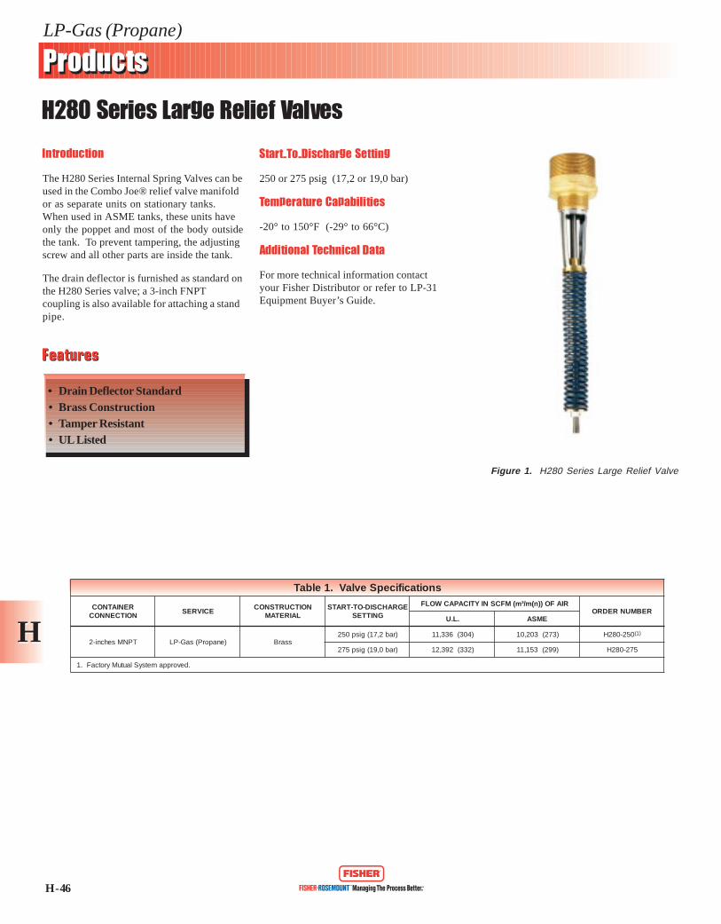
H - 46
LP-Gas (Propane)
ProductsProducts
H280 Series Large Relief Valves
HH
Introduction
The H280 Series Internal Spring Valves can beused in the Combo Joe® relief valve manifoldor as separate units on stationary tanks.When used in ASME tanks, these units haveonly the poppet and most of the body outsidethe tank. To prevent tampering, the adjustingscrew and all other parts are inside the tank.
The drain deflector is furnished as standard onthe H280 Series valve; a 3-inch FNPTcoupling is also available for attaching a standpipe.
Start-To-Discharge Setting
250 or 275 psig (17,2 or 19,0 bar)
Temperature Capabilities
-20° to 150°F (-29° to 66°C)
Additional Technical Data
For more technical information contactyour Fisher Distributor or refer to LP-31Equipment Buyer’s Guide.
FeaturesFeatures
• Drain Deflector Standard• Brass Construction• Tamper Resistant• UL Listed
Figure 1. H280 Series Large Relief Valve
snoitacificepSevlaV.1elbaT
RENIATNOCNOITCENNOC
ECIVRESNOITCURTSNOC
LAIRETAMEGRAHCSID-OT-TRATS
GNITTES
RIAFO))n(m/³m(MFCSNIYTICAPACWOLFREBMUNREDRO
.L.U EMSA
TPNMsehcni-2 )enaporP(saG-PL ssarB)rab2,71(gisp052 )403(633,11 )372(302,01 052-082H )1(
)rab0,91(gisp572 )233(293,21 )992(351,11 572-082H
.devorppametsySlautuMyrotcaF.1
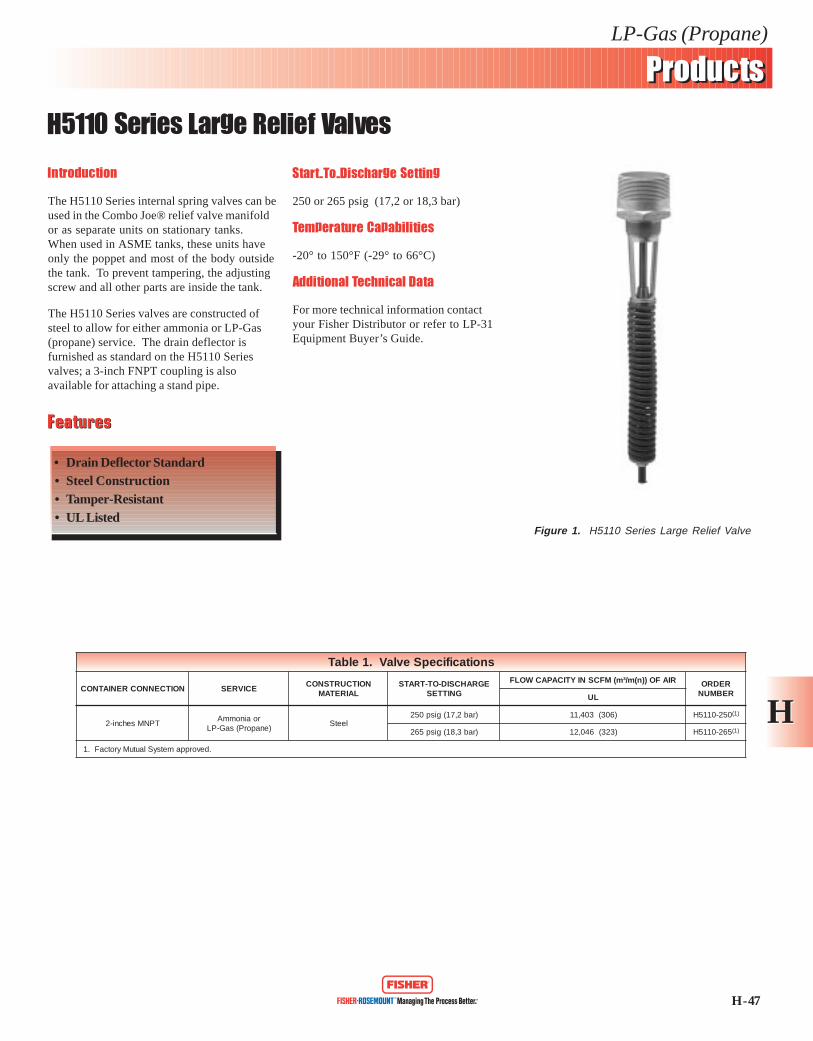
H - 47
LP-Gas (Propane)
ProductsProducts
H5110 Series Large Relief Valves
HH
Introduction
The H5110 Series internal spring valves can beused in the Combo Joe® relief valve manifoldor as separate units on stationary tanks.When used in ASME tanks, these units haveonly the poppet and most of the body outsidethe tank. To prevent tampering, the adjustingscrew and all other parts are inside the tank.
The H5110 Series valves are constructed ofsteel to allow for either ammonia or LP-Gas(propane) service. The drain deflector isfurnished as standard on the H5110 Seriesvalves; a 3-inch FNPT coupling is alsoavailable for attaching a stand pipe.
Start-To-Discharge Setting
250 or 265 psig (17,2 or 18,3 bar)
Temperature Capabilities
-20° to 150°F (-29° to 66°C)
Additional Technical Data
For more technical information contactyour Fisher Distributor or refer to LP-31Equipment Buyer’s Guide.
FeaturesFeatures
• Drain Deflector Standard• Steel Construction• Tamper-Resistant• UL Listed
Figure 1. H5110 Series Large Relief Valve
snoitacificepSevlaV.1elbaT
NOITCENNOCRENIATNOC ECIVRESNOITCURTSNOC
LAIRETAMEGRAHCSID-OT-TRATS
GNITTES
RIAFO))n(m/³m(MFCSNIYTICAPACWOLF REDROREBMUNLU
TPNMsehcni-2roainommA
)enaporP(saG-PLleetS
)rab2,71(gisp052 )603(304,11 052-0115H )1(
)rab3,81(gisp562 )323(640,21 562-0115H )1(
.devorppametsySlautuMyrotcaF.1

H - 48
LP-Gas (Propane)
ProductsProducts
H500 Series Relief Valve Manifold
HH
Introduction
The H500 Series Combo Joe® relief valvemanifold contains four standard style reliefvalves (either the H280 or H5110 Series)suitable for stationary storage tanks up to30,000 gallons (113 563 liters). Any one ofthe four relief valves can be removed forinspection or maintenance without productevacuation of the tank.
Two handles open and close the manifoldports. The handle direction points to theclosed port (relief valve). A built-in bleed inthe port shutoff mechanism permits a closedport to be quickly reopened.
The H500 Series manifold is available witheither brass or steel trim for LP-Gas (propane)or ammonia service.
Start-To-Discharge Setting
250 or 265 psig (17,2 or 18,3 bar)
Temperature Capabilities
-20° to 150°F (-29° to 66°C)
Tank Connection Sizes
See Table 1
Additional Technical Data
For more technical information contactyour Fisher Distributor or refer to LP-31Equipment Buyer’s Guide.
FeaturesFeatures
• Individual Valve MaintenanceWhile Keeping Tank in Service
• Flanged Connection• Can Only Remove One Valve at a Time• UL Listed
Figure 1. H500 Series Relief Valve Manifold
snoitacificepSdlofinaM.1elbaT
NOITCENNOCKNAT ECIVRESNOITCURTSNOC
LAIRETAM
EGRAHCSID-OT-TRATS,GNITTES)RAB(GISP
,RIAFO))n(m/³m(MFCSNIYTICAPACWOLFNEPOSTROP3HTIWDLOFINAMTROP-4 REBMUNREDRO
LU EMSA
ssalCISNAhcni-4egnalFFR003
)enaporP(saG-PL ssarB )2,71(052 )427(810,72 )656(584,42 052-005H )1(
ainommA leetS )3,81(562 )377(238,82 --- 562-105H
ssalCISNAhcni-3egnalFdeifidoMFR003
)enaporP(saG-PL ssarB )2,71(052 )427(810,72 )656(584,42 052-015H )1(
ainommA leetS )3,81(562 )377(238,82 --- 562-115H
.devorppametsySlautuMyrotcaF.1

H - 43
LP-Gas (Propane)
ProductsProducts
98H Series Relief Valves
HH
Introduction
The 98H Series are direct-operated reliefvalves for use on relief and backpressureapplications involving large liquid propanepumping systems and vaporizers. Internalpressure registration eliminates the need for acontrol line.
Maximum Relief (Inlet) Pressure
400 psig (27,5 bar)
Relief Pressure Range
See Table 2
Temperature Capabilities
-20° to 150°F (-29° to 66°C)
Body Sizes and End Connection Styles
See Table 2
Additional Technical Data
For more technical information contactyour Fisher Distributor or refer to LP-31Equipment Buyer’s Guide.
FeaturesFeatures
• Internal Registration• Direct-Operated• Compact
Figure 1. 98H Series Relief Valve
Figure 2. 98H Series Operational Schematic
Figure 3. Dimensions
INLET PRESSURE
OUTLET PRESSURE
ATMOSPHERIC PRESSURE/LOADING PRESSURE
COMP
snoisnemiD.1elbaT
,EZISYDOBSEHCNI
A B C D
)mm(sehcnI
2/1 )801(52.4 )22(88. )381(91.7 )801(52.4
4/3 )721(0.5 )23(52.1 )642(96.9 )451(60.6
1 )721(0.5 )23(52.1 )642(96.9 )451(60.6
snoitacificepSevlaV.2elbaTEZISYDOB
DNEDNANOITCENNOC
ELYTS
FEILERERUSSERP
,EGNAR)RAB(GISP
FEILERERUSSERP,GNITTES)RAB(GISP
TA)ETUNIMREPSRETIL(ETUNIMREPSNOLLAGNIYTICAPACFEILERENAPORPGNITTESFEILERREVOPUDLIUBERUSSERPGNIWOLLOF REBMUNREDRO
)raB43,0(gisP5 )raB96,0(gisP01 )raB4,1(gisP02 )raB1,2(gisP03 )raB4,3(gisP05
TPNFhcni-2/1)2,5ot7,1(57ot52 )4,3(05 )7,91(2.5 )3,03(0.8 )7,74(6.21 )6,36(8.61 )4,78(1.32 31-H89
)7,9ot8,4(041ot07 )9,6(001 )9,51(2.4 )6,72(3.7 )5,15(6.31 )7,27(2.91 )301(3.72 41-H89
TPNFhcni-4/3 )7,9ot8,4(041ot07 )9,6(001 )711(8.03 )581(0.94 )752(9.76 )203(8.97 )253(1.39 22-H89
TPNFhcni-1 )7,9ot8,4(041ot07 )9,6(001 )711(8.03 )581(0.94 )752(9.76 )203(8.97 )253(1.39 03-H89
A/2A
B
C
D
NPT
1/4 NPT

H - 44
LP-Gas (Propane)
ProductsProducts
289H Series Relief Valves
HH
Figure 1. 289H Series Relief Valve
Introduction
The 289H Series is a 2-inch spring-loadedrelief valve for a relief pressure range of7-inches w.c. to 10 psig (17 mbar to 0,69 bar).
This unit features a pitot tube booster toachieve the highest possible relief capacitywith a minimum buildup of system pressure.
The 289H Series is installed between largeSecond-Stage regulators (such as the S202G orS302G Series) and the burner to provide highcapacity relief. The large diaphragm in thesevalves gives extremely sensitive operation.
Maximum Relief (Inlet) Pressure
25 psig (1,7 bar)
Relief Adjustment Range
See Table 1
Temperature Capabilities
-20° to 150°F (-29° to 66°C)
Body Sizes and End Connection Styles
See Table 1
Additional Technical Data
For more technical information contactyour Fisher Distributor or refer to LP-31Equipment Buyer’s Guide.
FeaturesFeatures
• Throttling Type Relief• High Flow Rates• Small Size• Reliability Due to Simplicity
Figure 2. Dimensions Figure 3. 289H Series Sectional View
8.94(227)
7.12 (181)DIAMETER
2.12(54)
3.56(91)
INCHES(mm)
snoitacificepSevlaV.1elbaTDNEDNAEZISYDOBELYTSNOITCENNOC
GNITTESERUSSERPFEILER EGNARTNEMTSUJDAFEILER)RAB960,0(GISP1TAYTICAPACFEILERENAPORP
GNITTESFEILERREVOPUDLIUBERUSSERPREBMUNREDRO
TPNFsehcni-2 )rab10,0(gisp5.1 )rab61,0ot430,0(gisp52.2ot5.0 )h/³m592(hfcs000,11 2/H982
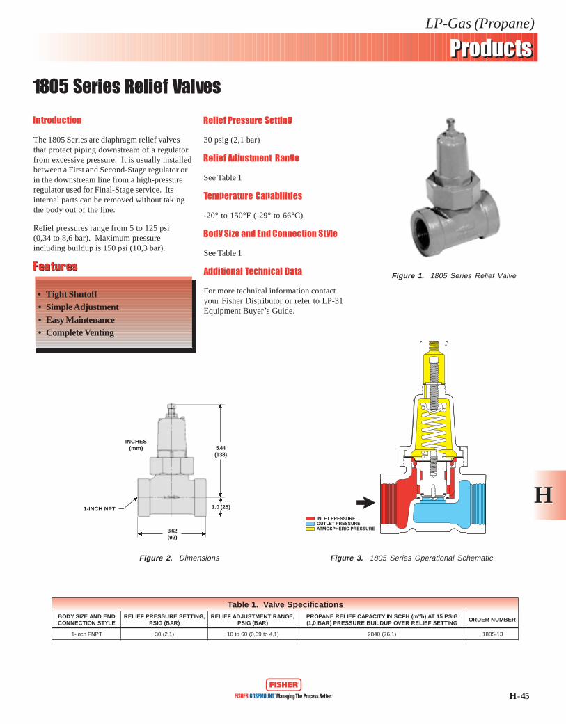
H - 45
LP-Gas (Propane)
1805 Series Relief Valves
ProductsProducts
HHINLET PRESSUREOUTLET PRESSUREATMOSPHERIC PRESSURE
Introduction
The 1805 Series are diaphragm relief valvesthat protect piping downstream of a regulatorfrom excessive pressure. It is usually installedbetween a First and Second-Stage regulator orin the downstream line from a high-pressureregulator used for Final-Stage service. Itsinternal parts can be removed without takingthe body out of the line.
Relief pressures range from 5 to 125 psi(0,34 to 8,6 bar). Maximum pressureincluding buildup is 150 psi (10,3 bar).
Relief Pressure Setting
30 psig (2,1 bar)
Relief Adjustment Range
See Table 1
Temperature Capabilities
-20° to 150°F (-29° to 66°C)
Body Size and End Connection Style
See Table 1
Additional Technical Data
For more technical information contactyour Fisher Distributor or refer to LP-31Equipment Buyer’s Guide.
FeaturesFeatures
• Tight Shutoff• Simple Adjustment• Easy Maintenance• Complete Venting
Figure 1. 1805 Series Relief Valve
Figure 2. Dimensions Figure 3. 1805 Series Operational Schematic
INCHES(mm)
1-INCH NPT
3.62(92)
5.44(138)
1.0 (25)
snoitacificepSevlaV.1elbaTDNEDNAEZISYDOBELYTSNOITCENNOC
,GNITTESERUSSERPFEILER)RAB(GISP
,EGNARTNEMTSUJDAFEILER)RAB(GISP
GISP51TA)h/³m(HFCSNIYTICAPACFEILERENAPORPGNITTESFEILERREVOPUDLIUBERUSSERP)RAB0,1(
REBMUNREDRO
TPNFhcni-1 )1,2(03 )1,4ot96,0(06ot01 )1,67(0482 31-5081
Related Documents