Propagation characteristics of wireless channels Lecture 2

Welcome message from author
This document is posted to help you gain knowledge. Please leave a comment to let me know what you think about it! Share it to your friends and learn new things together.
Transcript
Propagation characteristics of wireless channels
Lecture 2
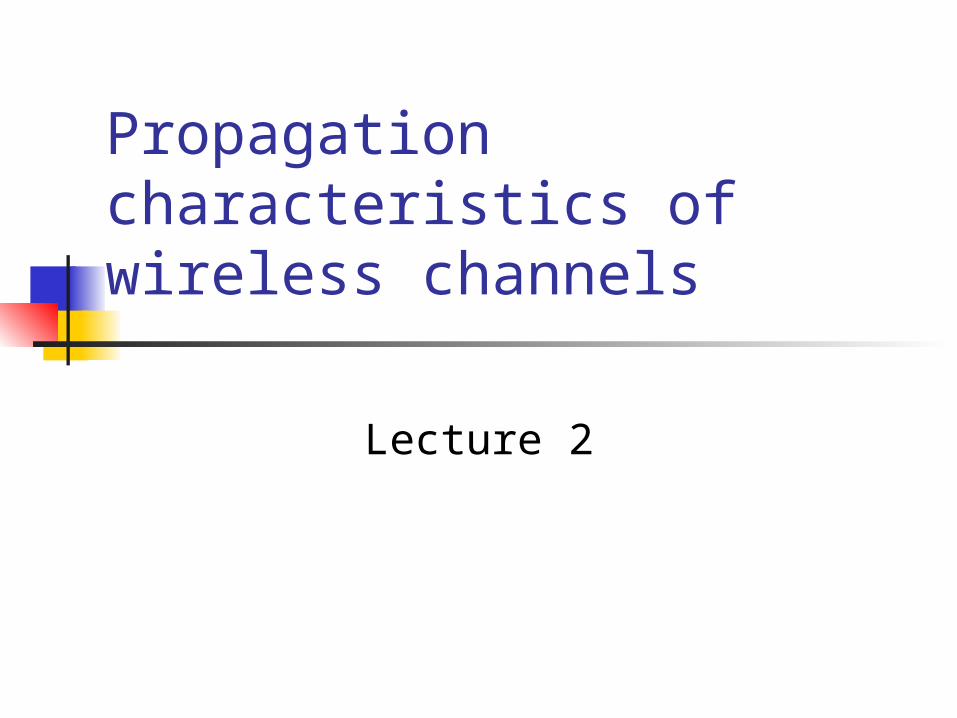
Introduction Attenuation is a major limitation on
performance of mobile systems If path is line of sight then signal loss may
not be severe In urban surroundings the path may be
indirect and signal would reach final destination after reflection, diffraction, refraction and scattering
LOS Wireless Transmission Impairments
Attenuation and attenuation distortion Free space loss Noise Atmospheric absorption Multipath Refraction
Other Impairments Atmospheric absorption – water vapor and
oxygen contribute to attenuation Multipath – obstacles reflect signals so that
multiple copies with varying delays are received
Refraction – bending of radio waves as they propagate through the atmosphere

Line of sight propagation
Introduction Most mobile transmissions are
characterize by these non-LOS conditions Reflection Diffraction Refraction Scattering
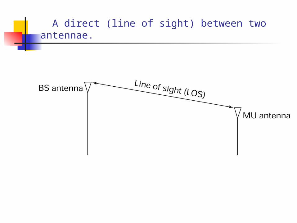
A direct (line of sight) between two antennae.
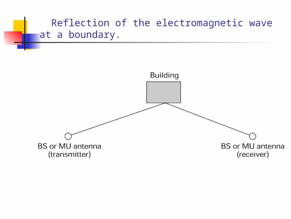
Reflection of the electromagnetic wave at a boundary.
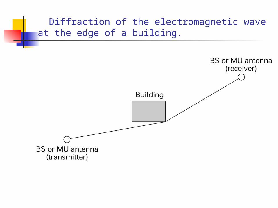
Diffraction of the electromagnetic wave at the edge of a building.
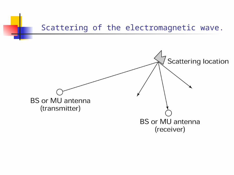
Scattering of the electromagnetic wave.

Most mobile communication systems are characterized by these N-LOS conditions: Reflection Diffraction Scattering
Free space propagation models are not suited to calculate the attenuation
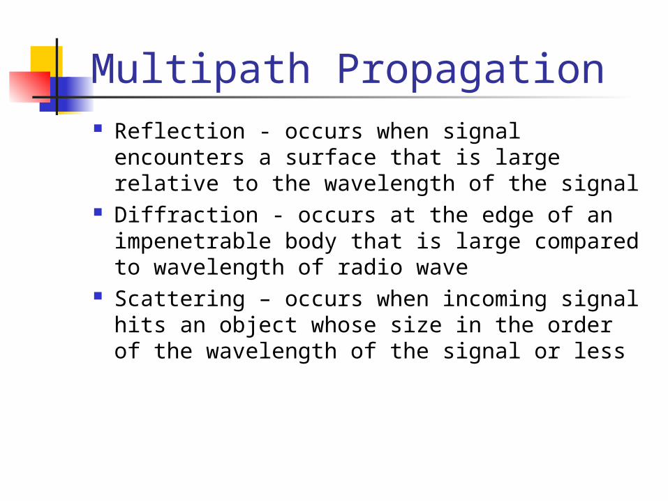
Multipath Propagation Reflection - occurs when signal encounters a
surface that is large relative to the wavelength of the signal
Diffraction - occurs at the edge of an impenetrable body that is large compared to wavelength of radio wave
Scattering – occurs when incoming signal hits an object whose size in the order of the wavelength of the signal or less
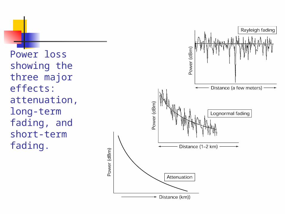
Power loss showing the three major effects: attenuation, long-term fading, and short-term fading.
Attenuation
Strength of signal falls off with distance over transmission medium
Attenuation factors for unguided media: Received signal must have sufficient strength so that
circuitry in the receiver can interpret the signal Signal must maintain a level sufficiently higher than
noise to be received without error Attenuation is greater at higher frequencies, causing
distortion
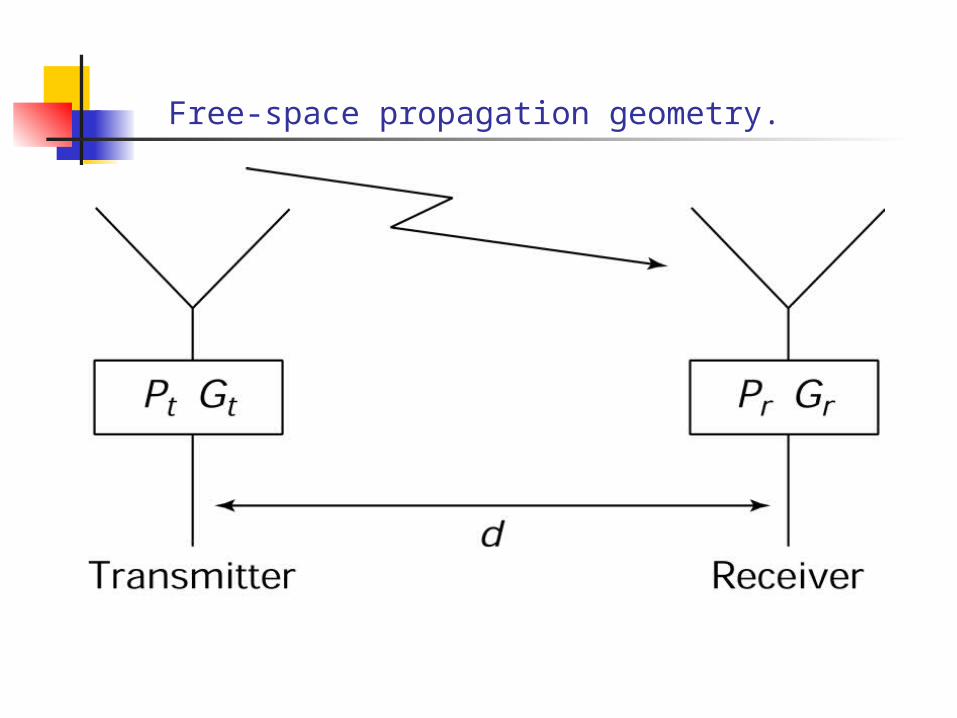
Free-space propagation geometry.
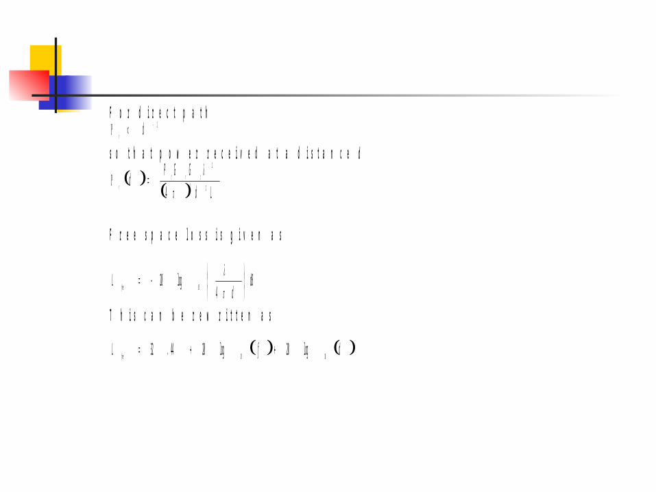
F o r d i r e c t p a t h2 dr
s o t h a t p o w e r r e c e i v e d a t a d i s t a n c e d
Ld
GGPd trt
r 22
2
4
F r e e s p a c e l o s s i s g i v e n a s
dBd
Lf ree
4log20
10
T h i s c a n b e r e w r i t t e n a s
dfLf ree 1010
log20log2044.32
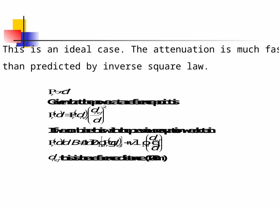
This is an ideal case. The attenuation is much faster
than predicted by inverse square law.
v
rd
Given that the power at a reference point is
2
d
ddd ref
refrr
If we combine this with the previous equation we obtain
d
dvddBmd ref
refrr 1010loglog10
refd this is the reference distance (100m)

Received power for different values of loss parameter v(v=2 corresponds to free space). Increased loss is seen as v goes up.
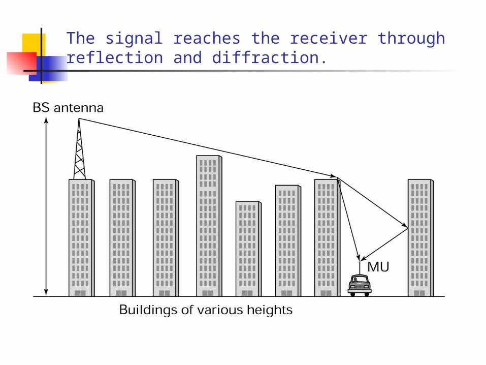
The signal reaches the receiver through reflection and diffraction.
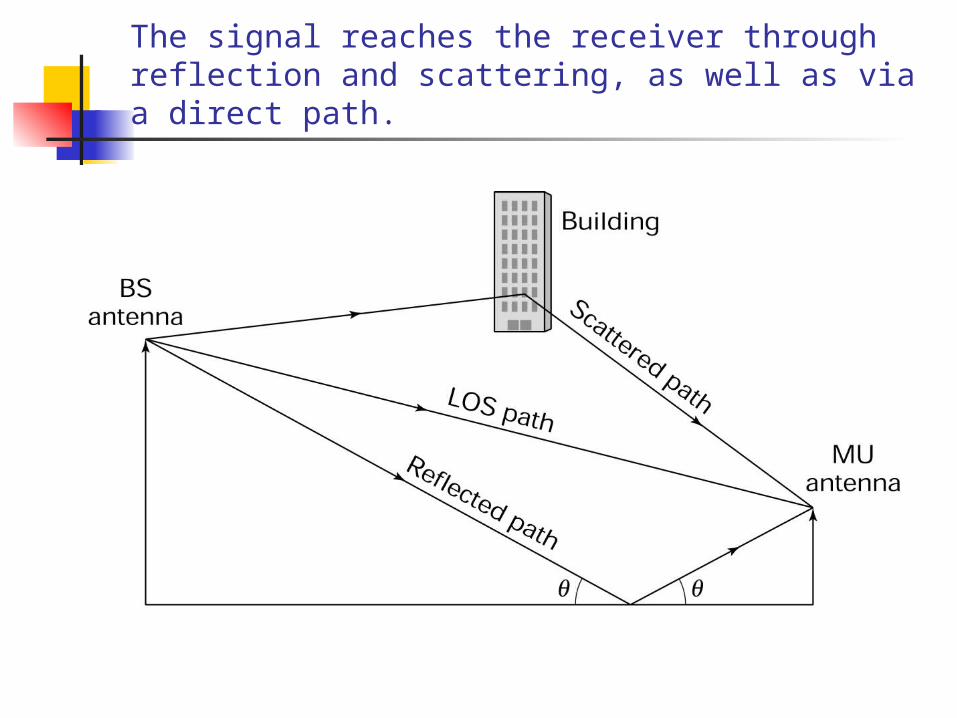
The signal reaches the receiver through reflection and scattering, as well as via a direct path.
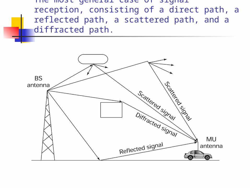
The most general case of signal reception, consisting of a direct path, a reflected path, a scattered path, and a diffracted path.

A number of models have been proposed to predict the
median loss. These models take into account the different
ways in which the signal can reach the receiver
Okumura Model : It is possible to calculate the
free space loss between any two points BS 200m MU 3m.
Correction factors are then added.
Loss Prediction Models
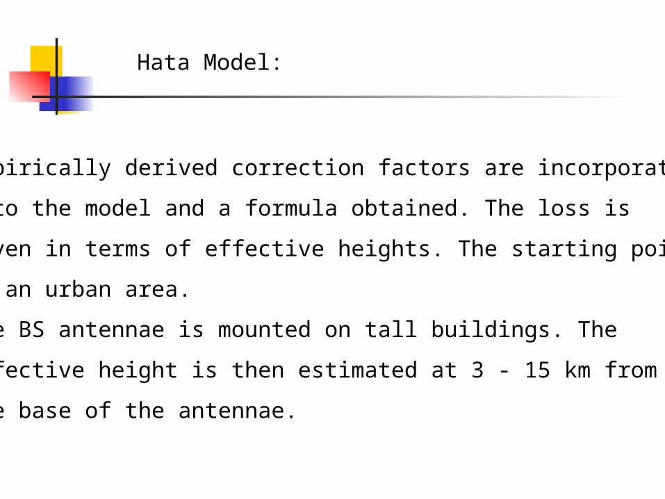
Hata Model:
Empirically derived correction factors are incorporated
into the model and a formula obtained. The loss is
given in terms of effective heights. The starting point
is an urban area.
The BS antennae is mounted on tall buildings. The
effective height is then estimated at 3 - 15 km from
the base of the antennae.
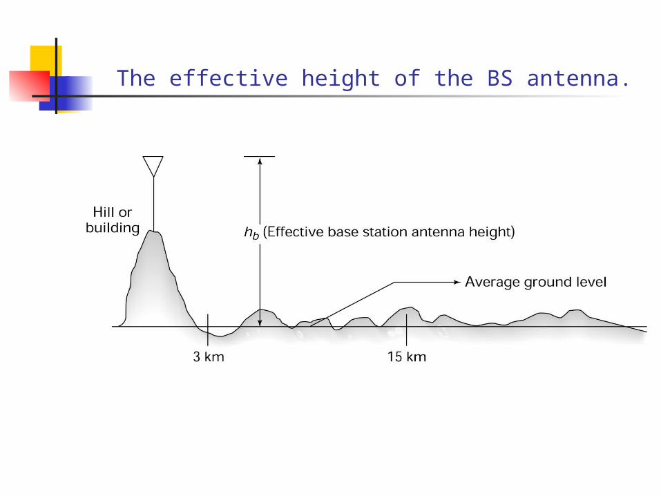
The effective height of the BS antenna.
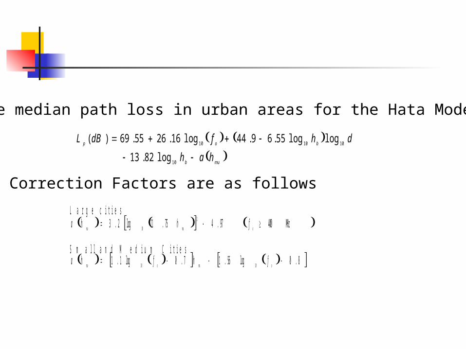
The median path loss in urban areas for the Hata Model is
mub
bop
hah
dhfdBL
10
101010
log82.13
loglog55.69.44log16.2655.69)(
Correction Factors are as follows
L a r g e c i t i e s MHz400 97.475.11log2.3
2
1 0
omumufhha
S m a l l a n d M e d i u m C i t i e s 8.0log56.17.0log1.1 1010 omuomu fhfha
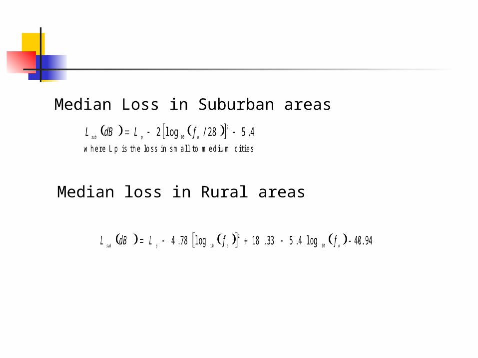
Median Loss in Suburban areas
4.528/log22
10
opsubfLdBL
w h e r e L p i s t h e l o s s i n s m a l l t o m e d i u m c i t i e s
Median loss in Rural areas
40.94-log 4.533.18log78.410
2
10 oopsubffLdBL
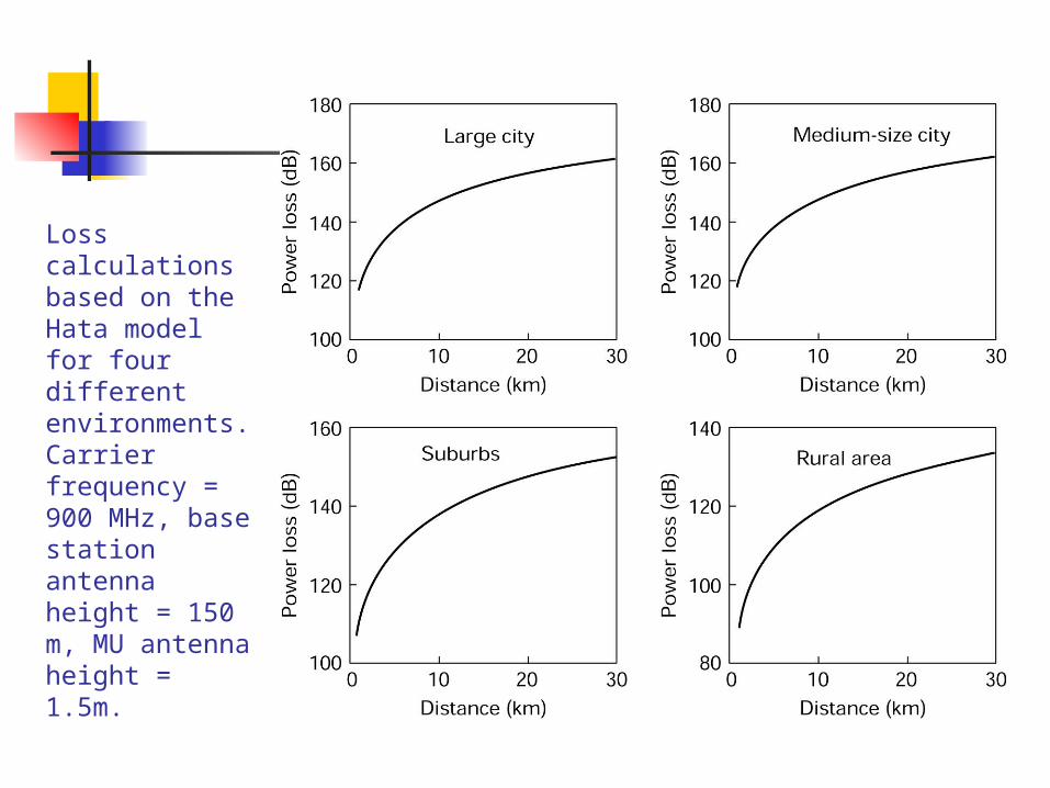
Loss calculations based on the Hata model for four different environments. Carrier frequency = 900 MHz, base station antenna height = 150 m, MU antenna height = 1.5m.
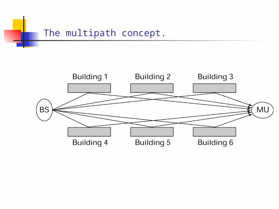
The multipath concept.
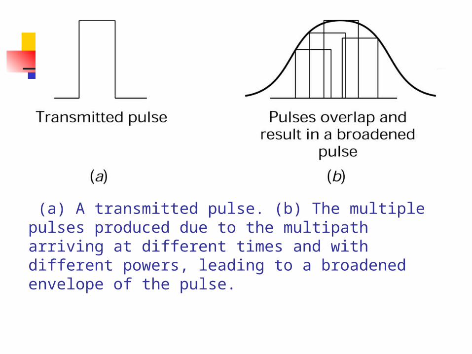
(a) A transmitted pulse. (b) The multiple pulses produced due to the multipath arriving at different times and with different powers, leading to a broadened envelope of the pulse.
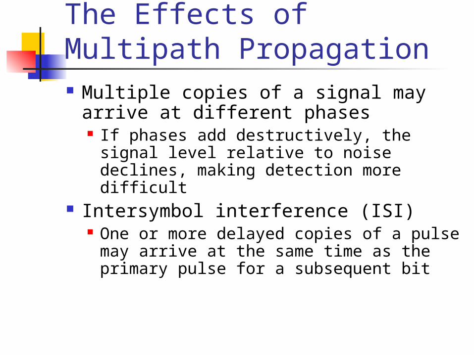
The Effects of Multipath Propagation Multiple copies of a signal may arrive at
different phases If phases add destructively, the signal level
relative to noise declines, making detection more difficult
Intersymbol interference (ISI) One or more delayed copies of a pulse may
arrive at the same time as the primary pulse for a subsequent bit
Decibels and Signal Strength
•Signal Strength is an important parameter in any transmission system
•Signal attenuation is compensated for by use of amplifiers
•Losses and gains are expressed in terms of decibel
•The decibel is a logarithmic ratio
•Attenuation itself occurs logarithmically
•This allows for easy addition and subtraction
in
out
dB P
PG
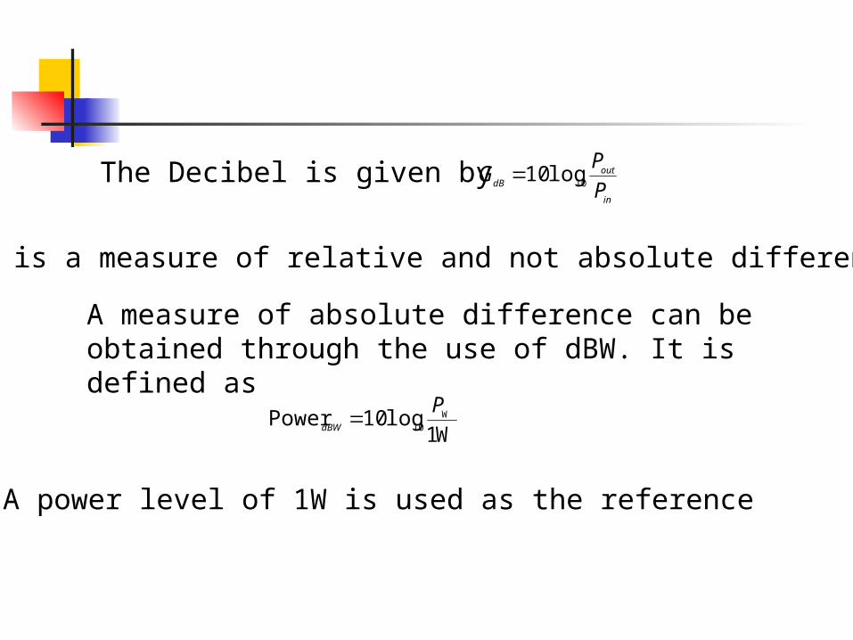
10log10The Decibel is given by
It is a measure of relative and not absolute difference
A measure of absolute difference can be obtained through the use of dBW. It is defined as
W1log10Power W
10
PdBW
A power level of 1W is used as the reference
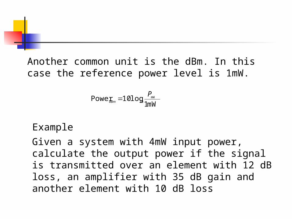
Another common unit is the dBm. In this case the reference power level is 1mW.
mW1log10Power mW
10
PdBm
Example
Given a system with 4mW input power, calculate the output power if the signal is transmitted over an element with 12 dB loss, an amplifier with 35 dB gain and another element with 10 dB loss
Related Documents