Projections and their transformations

Welcome message from author
This document is posted to help you gain knowledge. Please leave a comment to let me know what you think about it! Share it to your friends and learn new things together.
Transcript

Projections and their transformations

Projections and their transformations
We have looked at modeling 3-dimensional figures in a 3-dimensional
world.

Projections and their transformations
We have looked at modeling 3-dimensional figures in a 3-dimensional
world. The final image, however, will be displayed on a 2-
dimensional surface.

Projections and their transformations
We have looked at modeling 3-dimensional figures in a 3-dimensional
world. The final image, however, will be displayed on a 2-
dimensional surface.
The transformation from the 3-dimensional model space to the
2-dimensional viewing space is accomplished by projecting the
model onto the view or projection plane.
Here is where our “virtual camera” model offers a good analogy.
camera
scene
view plane
Modeling transforms position the model.

Projections and their transformations
We have looked at modeling 3-dimensional figures in a 3-dimensional
world. The final image, however, will be displayed on a 2-
dimensional surface.
The transformation from the 3-dimensional model space to the
2-dimensional viewing space is accomplished by projecting the
model onto the view or projection plane.
Here is where our “virtual camera” model offers a good analogy.
camera
scene
view plane
Modeling transforms position the model. Viewing transforms
position the camera.

Projections and their transformations
We have looked at modeling 3-dimensional figures in a 3-dimensional
world. The final image, however, will be displayed on a 2-
dimensional surface.
The transformation from the 3-dimensional model space to the
2-dimensional viewing space is accomplished by projecting the
model onto the view or projection plane.
Here is where our “virtual camera” model offers a good analogy.
camera
scene
view plane
Modeling transforms position the model. Viewing transforms
position the camera. Projection transforms control the type of
lens, the focal length, etc...
Things are really a bit different, however, because with com-
puter graphics we have rather more freedom than we have with
a camera.
1

There are two basic projections we will discuss — parallel projections
and perspective projections.

There are two basic projections we will discuss — parallel projections
and perspective projections.
Parallel projections

There are two basic projections we will discuss — parallel projections
and perspective projections.
Parallel projections
The basic property of a parallel projection is that features are
projected by parallel rays onto the viewing surface.

There are two basic projections we will discuss — parallel projections
and perspective projections.
Parallel projections
The basic property of a parallel projection is that features are
projected by parallel rays onto the viewing surface.

There are two basic projections we will discuss — parallel projections
and perspective projections.
Parallel projections
The basic property of a parallel projection is that features are
projected by parallel rays onto the viewing surface.
There are again two types of parallel projections

There are two basic projections we will discuss — parallel projections
and perspective projections.
Parallel projections
The basic property of a parallel projection is that features are
projected by parallel rays onto the viewing surface.
There are again two types of parallel projections — projec-
tions in which the projection is parallel to the normal of the
viewing surface are orthographic projections;

There are two basic projections we will discuss — parallel projections
and perspective projections.
Parallel projections
The basic property of a parallel projection is that features are
projected by parallel rays onto the viewing surface.
There are again two types of parallel projections — projec-
tions in which the projection is parallel to the normal of the
viewing surface are orthographic projections; projections where
the projection rays are not normal to the surface are oblique
projections.
2

A common set of orthographic projections are the front, side,
and top views typical of architectural plans.

A common set of orthographic projections are the front, side,
and top views typical of architectural plans. In this case the
projections are parallel to the model’s principal axes.

A common set of orthographic projections are the front, side,
and top views typical of architectural plans. In this case the
projections are parallel to the model’s principal axes.
Top viewFront view Side view

A common set of orthographic projections are the front, side,
and top views typical of architectural plans. In this case the
projections are parallel to the model’s principal axes.
Top viewFront view Side view
Orthographic projections preserve the distance along lines which
are parallel to the plane of projection.

A common set of orthographic projections are the front, side,
and top views typical of architectural plans. In this case the
projections are parallel to the model’s principal axes.
Top viewFront view Side view
Orthographic projections preserve the distance along lines which
are parallel to the plane of projection. Thus, one can take
measurements along such lines directly from their projections.
Also, lines which are parallel will be projected to parallel lines.
The isometric projection has the direction of projection at the
same angle to all three principal axes.
The isometric projection has the property that all 3 axes can
be measured on the same scale.

A common set of orthographic projections are the front, side,
and top views typical of architectural plans. In this case the
projections are parallel to the model’s principal axes.
Top viewFront view Side view
Orthographic projections preserve the distance along lines which
are parallel to the plane of projection. Thus, one can take
measurements along such lines directly from their projections.
Also, lines which are parallel will be projected to parallel lines.
The isometric projection has the direction of projection at the
same angle to all three principal axes.
The isometric projection has the property that all 3 axes can
be measured on the same scale. For an isometric projection of
cube, all projected lines have the same length.
3

Isometric projections are a special case of axonometric orthographic
projections.

Isometric projections are a special case of axonometric orthographic
projections. Such projections use projection planes that are
not normal to a principal axis.

Isometric projections are a special case of axonometric orthographic
projections. Such projections use projection planes that are
not normal to a principal axis. Axonometric orthographic pro-
jections give the illusion of perspective but do not exhibit true
perspective foreshortening, where the length of projected lines
are dependent upon their distance from the projection plane.
4

[From urlwww.kirupa.com/developer/isometric/perspective.htm]

[From urlwww.kirupa.com/developer/isometric/perspective.htm]
Such projections have been popular in video games for many
years.
5

Oblique projections
Oblique projections are the most general parallel views.

Oblique projections
Oblique projections are the most general parallel views. In an
oblique projection, the projectors make some arbitrary angle
with the projection plane.

Oblique projections
Oblique projections are the most general parallel views. In an
oblique projection, the projectors make some arbitrary angle
with the projection plane.

Oblique projections
Oblique projections are the most general parallel views. In an
oblique projection, the projectors make some arbitrary angle
with the projection plane.
These views are somewhat unnatural, but can be used to convey
more information than orthographic projections.

Oblique projections
Oblique projections are the most general parallel views. In an
oblique projection, the projectors make some arbitrary angle
with the projection plane.
These views are somewhat unnatural, but can be used to convey
more information than orthographic projections.
The human eye, and most other physical viewing devices, have
a lens fixed with respect to (and usually parallel to) the viewing
plane.

Oblique projections
Oblique projections are the most general parallel views. In an
oblique projection, the projectors make some arbitrary angle
with the projection plane.
These views are somewhat unnatural, but can be used to convey
more information than orthographic projections.
The human eye, and most other physical viewing devices, have
a lens fixed with respect to (and usually parallel to) the viewing
plane. This is what makes oblique projections seem unnatural.
6

Perspective projections

Perspective projections
In a perspective projection, the projecting rays are not parallel,
but instead pass through one or more vanishing points or points
at infinity.

Perspective projections
In a perspective projection, the projecting rays are not parallel,
but instead pass through one or more vanishing points or points
at infinity.

Perspective projections
In a perspective projection, the projecting rays are not parallel,
but instead pass through one or more vanishing points or points
at infinity.
Note that lines which are parallel in the model actually converge
in the “far distance.”

Perspective projections
In a perspective projection, the projecting rays are not parallel,
but instead pass through one or more vanishing points or points
at infinity.
Note that lines which are parallel in the model actually converge
in the “far distance.” This creates an illusion of depth in a 2-
dimensional figure.
7

Two point perspective would use 2 vanishing points, roughly
orthogonal to each other in the “model world.”

Two point perspective would use 2 vanishing points, roughly
orthogonal to each other in the “model world.” Three point
perspective would use 3 vanishing points.

Two point perspective would use 2 vanishing points, roughly
orthogonal to each other in the “model world.” Three point
perspective would use 3 vanishing points.

Two point perspective would use 2 vanishing points, roughly
orthogonal to each other in the “model world.” Three point
perspective would use 3 vanishing points.
[From www.csse.monash.edu.au/∼aland/notes]

Two point perspective would use 2 vanishing points, roughly
orthogonal to each other in the “model world.” Three point
perspective would use 3 vanishing points.
[From www.csse.monash.edu.au/∼aland/notes]
Note that OpenGL has no concept of the number of vanishing
points.

Two point perspective would use 2 vanishing points, roughly
orthogonal to each other in the “model world.” Three point
perspective would use 3 vanishing points.
[From www.csse.monash.edu.au/∼aland/notes]
Note that OpenGL has no concept of the number of vanishing
points. This is a notion from the worlds of classical art and
drafting.
In a perspective projection, we need to specify a point as the
center of projection;

Two point perspective would use 2 vanishing points, roughly
orthogonal to each other in the “model world.” Three point
perspective would use 3 vanishing points.
[From www.csse.monash.edu.au/∼aland/notes]
Note that OpenGL has no concept of the number of vanishing
points. This is a notion from the worlds of classical art and
drafting.
In a perspective projection, we need to specify a point as the
center of projection; for parallel projections we needed to spec-
ify a direction of projection.
8

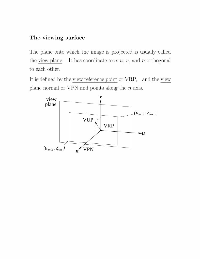
The viewing surface
The plane onto which the image is projected is usually called
the view plane.

The viewing surface
The plane onto which the image is projected is usually called
the view plane. It has coordinate axes u, v, and n orthogonal
to each other.

The viewing surface
The plane onto which the image is projected is usually called
the view plane. It has coordinate axes u, v, and n orthogonal
to each other.
It is defined by the view reference point or VRP,

The viewing surface
The plane onto which the image is projected is usually called
the view plane. It has coordinate axes u, v, and n orthogonal
to each other.
It is defined by the view reference point or VRP, and the view
plane normal or VPN and points along the n axis.
The viewing surface
The plane onto which the image is projected is usually called
the view plane. It has coordinate axes u, v, and n orthogonal
to each other.
It is defined by the view reference point or VRP, and the view
plane normal or VPN and points along the n axis.
(u ,v )
VRP
VPNn
u
v
VUP
viewplane
min min(u ,v )
max max
The view plane corresponds to the “film” in our virtual camera.
We also need to describe the orientation of the film or viewport
in the view plane.

The viewing surface
The plane onto which the image is projected is usually called
the view plane. It has coordinate axes u, v, and n orthogonal
to each other.
It is defined by the view reference point or VRP, and the view
plane normal or VPN and points along the n axis.
(u ,v )
VRP
VPNn
u
v
VUP
viewplane
min min(u ,v )
max max
The view plane corresponds to the “film” in our virtual camera.
We also need to describe the orientation of the film or viewport
in the view plane. This is done by specifying a vector called
the view up vector (VUP).

The viewing surface
The plane onto which the image is projected is usually called
the view plane. It has coordinate axes u, v, and n orthogonal
to each other.
It is defined by the view reference point or VRP, and the view
plane normal or VPN and points along the n axis.
(u ,v )
VRP
VPNn
u
v
VUP
viewplane
min min(u ,v )
max max
The view plane corresponds to the “film” in our virtual camera.
We also need to describe the orientation of the film or viewport
in the view plane. This is done by specifying a vector called
the view up vector (VUP). The projection of the VUP vector
defines the v axis in the plane.

The viewing surface
The plane onto which the image is projected is usually called
the view plane. It has coordinate axes u, v, and n orthogonal
to each other.
It is defined by the view reference point or VRP, and the view
plane normal or VPN and points along the n axis.
(u ,v )
VRP
VPNn
u
v
VUP
viewplane
min min(u ,v )
max max
The view plane corresponds to the “film” in our virtual camera.
We also need to describe the orientation of the film or viewport
in the view plane. This is done by specifying a vector called
the view up vector (VUP). The projection of the VUP vector
defines the v axis in the plane. This, in effect, orients the
camera.

The viewing surface
The plane onto which the image is projected is usually called
the view plane. It has coordinate axes u, v, and n orthogonal
to each other.
It is defined by the view reference point or VRP, and the view
plane normal or VPN and points along the n axis.
(u ,v )
VRP
VPNn
u
v
VUP
viewplane
min min(u ,v )
max max
The view plane corresponds to the “film” in our virtual camera.
We also need to describe the orientation of the film or viewport
in the view plane. This is done by specifying a vector called
the view up vector (VUP). The projection of the VUP vector
defines the v axis in the plane. This, in effect, orients the
camera. The u axis is perpendicular to v and n ( u = v×n ).
Defining minimum and maximum values of u and v determines
the viewport.
9
In many graphics systems, there are functions which set the
viewing parameters explicitly, using functions like:

In many graphics systems, there are functions which set the
viewing parameters explicitly, using functions like:
set_view_reference_point(x, y, z)

In many graphics systems, there are functions which set the
viewing parameters explicitly, using functions like:
set_view_reference_point(x, y, z)
set_view_plane_normal(nx, ny, nz)

In many graphics systems, there are functions which set the
viewing parameters explicitly, using functions like:
set_view_reference_point(x, y, z)
set_view_plane_normal(nx, ny, nz)
set_view_up(vx, vy, vz)

In many graphics systems, there are functions which set the
viewing parameters explicitly, using functions like:
set_view_reference_point(x, y, z)
set_view_plane_normal(nx, ny, nz)
set_view_up(vx, vy, vz)
In OpenGL, there is a convenient function which is rather more
direct, and uses the virtual camera model explicitly.

In many graphics systems, there are functions which set the
viewing parameters explicitly, using functions like:
set_view_reference_point(x, y, z)
set_view_plane_normal(nx, ny, nz)
set_view_up(vx, vy, vz)
In OpenGL, there is a convenient function which is rather more
direct, and uses the virtual camera model explicitly. Basically,
the position of the camera (or eye), and the position of the
object are specified.

In many graphics systems, there are functions which set the
viewing parameters explicitly, using functions like:
set_view_reference_point(x, y, z)
set_view_plane_normal(nx, ny, nz)
set_view_up(vx, vy, vz)
In OpenGL, there is a convenient function which is rather more
direct, and uses the virtual camera model explicitly. Basically,
the position of the camera (or eye), and the position of the
object are specified. These specify the VPN and VRP.

In many graphics systems, there are functions which set the
viewing parameters explicitly, using functions like:
set_view_reference_point(x, y, z)
set_view_plane_normal(nx, ny, nz)
set_view_up(vx, vy, vz)
In OpenGL, there is a convenient function which is rather more
direct, and uses the virtual camera model explicitly. Basically,
the position of the camera (or eye), and the position of the
object are specified. These specify the VPN and VRP. In
fact, these are specified in the MODELVIEW transformation.
The orientation of the camera also needs to be specified (VUP).
gluLookAt(eyex, eyey, eyez, atx, aty, atz, upx, upy,
upz)
eyex, eyey, and eyez specify the camera (or eye) position,
atx, aty, and atz specify the object center.
upx, upy, and upz specify VUP.
The glu.. functions are not OpenGL functions, but are part of
a standard library which forms part of most OpenGL systems.
(GLUT is another library which provides user interaction.)
The tutorial projection shows the use of the projection func-
tions for orthogonal and perspective transformations.
10

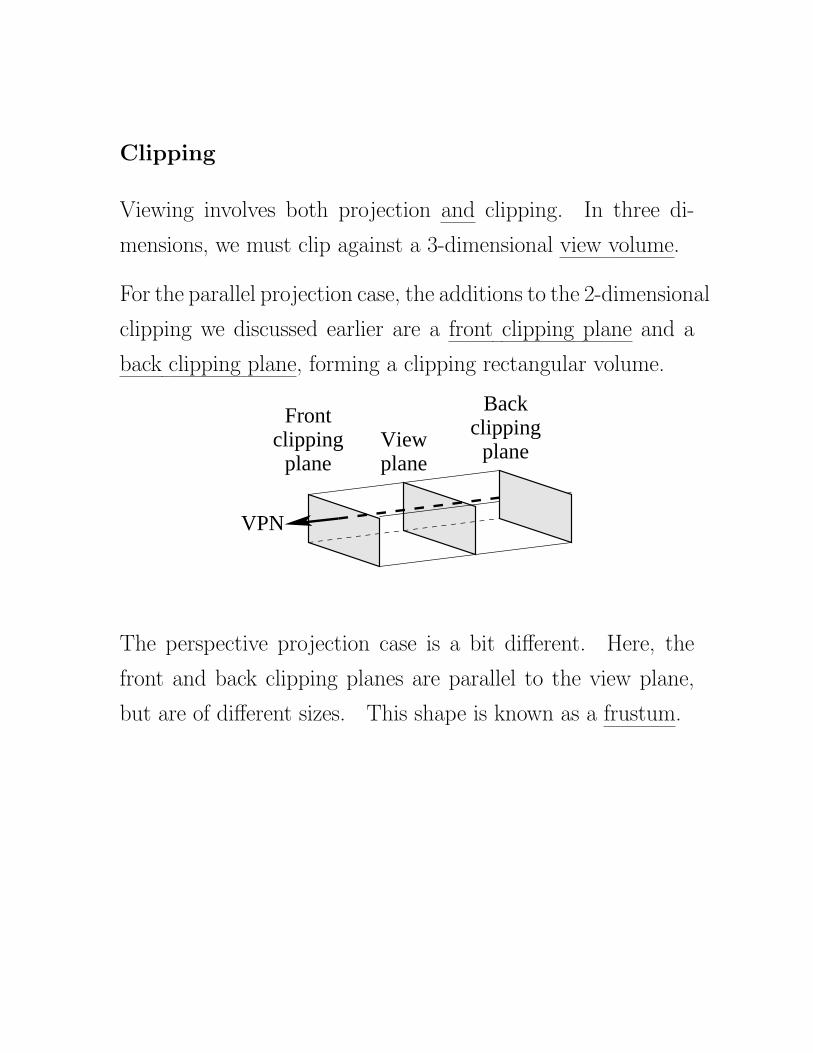
Clipping
Viewing involves both projection and clipping.

Clipping
Viewing involves both projection and clipping. In three di-
mensions, we must clip against a 3-dimensional view volume.

Clipping
Viewing involves both projection and clipping. In three di-
mensions, we must clip against a 3-dimensional view volume.
For the parallel projection case, the additions to the 2-dimensional
clipping we discussed earlier are a front clipping plane and a
back clipping plane, forming a clipping rectangular volume.
VPN
Backclipping
planeplaneclipping
Front
planeView
The perspective projection case is a bit different.

Clipping
Viewing involves both projection and clipping. In three di-
mensions, we must clip against a 3-dimensional view volume.
For the parallel projection case, the additions to the 2-dimensional
clipping we discussed earlier are a front clipping plane and a
back clipping plane, forming a clipping rectangular volume.
VPN
Backclipping
planeplaneclipping
Front
planeView
The perspective projection case is a bit different. Here, the
front and back clipping planes are parallel to the view plane,
but are of different sizes.
Clipping
Viewing involves both projection and clipping. In three di-
mensions, we must clip against a 3-dimensional view volume.
For the parallel projection case, the additions to the 2-dimensional
clipping we discussed earlier are a front clipping plane and a
back clipping plane, forming a clipping rectangular volume.
VPN
Backclipping
planeplaneclipping
Front
planeView
The perspective projection case is a bit different. Here, the
front and back clipping planes are parallel to the view plane,
but are of different sizes. This shape is known as a frustum.
clippingBack
planeclipping
Front
planeView
VPN
plane
11

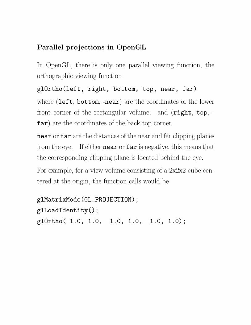
Parallel projections in OpenGL

Parallel projections in OpenGL
In OpenGL, there is only one parallel viewing function, the
orthographic viewing function

Parallel projections in OpenGL
In OpenGL, there is only one parallel viewing function, the
orthographic viewing function
glOrtho(left, right, bottom, top, near, far)

Parallel projections in OpenGL
In OpenGL, there is only one parallel viewing function, the
orthographic viewing function
glOrtho(left, right, bottom, top, near, far)
where (left, bottom, -near) are the coordinates of the lower
front corner of the rectangular volume,

Parallel projections in OpenGL
In OpenGL, there is only one parallel viewing function, the
orthographic viewing function
glOrtho(left, right, bottom, top, near, far)
where (left, bottom, -near) are the coordinates of the lower
front corner of the rectangular volume, and (right, top, -
far) are the coordinates of the back top corner.
near or far are the distances of the near and far clipping planes
from the eye.

Parallel projections in OpenGL
In OpenGL, there is only one parallel viewing function, the
orthographic viewing function
glOrtho(left, right, bottom, top, near, far)
where (left, bottom, -near) are the coordinates of the lower
front corner of the rectangular volume, and (right, top, -
far) are the coordinates of the back top corner.
near or far are the distances of the near and far clipping planes
from the eye. If either near or far is negative, this means that
the corresponding clipping plane is located behind the eye.
For example, for a view volume consisting of a 2x2x2 cube cen-
tered at the origin, the function calls would be
glMatrixMode(GL_PROJECTION);
glLoadIdentity();
glOrtho(-1.0, 1.0, -1.0, 1.0, -1.0, 1.0);
12

Perspective projections in OpenGL
There are two functions for perspective projections.

Perspective projections in OpenGL
There are two functions for perspective projections.
glFrustum(left, right, bottom, top, near, far)

Perspective projections in OpenGL
There are two functions for perspective projections.
glFrustum(left, right, bottom, top, near, far)
defines a frustum similar to the rectangular volume for glOrtho(..).

Perspective projections in OpenGL
There are two functions for perspective projections.
glFrustum(left, right, bottom, top, near, far)
defines a frustum similar to the rectangular volume for glOrtho(..).
lefttop
bottom
right
far
near

Perspective projections in OpenGL
There are two functions for perspective projections.
glFrustum(left, right, bottom, top, near, far)
defines a frustum similar to the rectangular volume for glOrtho(..).
lefttop
bottom
right
far
near
Note that near and far must be positive for glFrustum.

Perspective projections in OpenGL
There are two functions for perspective projections.
glFrustum(left, right, bottom, top, near, far)
defines a frustum similar to the rectangular volume for glOrtho(..).
lefttop
bottom
right
far
near
Note that near and far must be positive for glFrustum.
A typical use would be
glMatrixMode(GL_PROJECTION);
glLoadIdentity();
glFrustum(-1.0, 1.0, -1.0, 1.0, 1.0, 10.0);
Here the front clipping plane is (-1, -1, -1) to (1, 1, -1).

Perspective projections in OpenGL
There are two functions for perspective projections.
glFrustum(left, right, bottom, top, near, far)
defines a frustum similar to the rectangular volume for glOrtho(..).
lefttop
bottom
right
far
near
Note that near and far must be positive for glFrustum.
A typical use would be
glMatrixMode(GL_PROJECTION);
glLoadIdentity();
glFrustum(-1.0, 1.0, -1.0, 1.0, 1.0, 10.0);
Here the front clipping plane is (-1, -1, -1) to (1, 1, -1). The
rear clipping plane is 9 units beyond the front clipping plane
with corners (-10, -10, -10) to (10, 10, -10).
While conceptually easy, glFrustum() can be difficult to use.
13

An alternate way to determine the view volume is by specifying
an angular field (in the y direction, in this case),

An alternate way to determine the view volume is by specifying
an angular field (in the y direction, in this case), an aspect
ratio (width/height)

An alternate way to determine the view volume is by specifying
an angular field (in the y direction, in this case), an aspect
ratio (width/height) and the distance of the near and far clip-
ping planes.
An alternate way to determine the view volume is by specifying
an angular field (in the y direction, in this case), an aspect
ratio (width/height) and the distance of the near and far clip-
ping planes.
gluPerspective(fovy, aspect, near, far)

An alternate way to determine the view volume is by specifying
an angular field (in the y direction, in this case), an aspect
ratio (width/height) and the distance of the near and far clip-
ping planes.
gluPerspective(fovy, aspect, near, far)
wnear
far
fovy h

An alternate way to determine the view volume is by specifying
an angular field (in the y direction, in this case), an aspect
ratio (width/height) and the distance of the near and far clip-
ping planes.
gluPerspective(fovy, aspect, near, far)
wnear
far
fovy h
With this function, it is necessary to pick appropriate values for
the field of view, or the view looks distorted.
With both gluPerspective() and glFrustum() rotations
and translations can be applied to change the default orientation
of the viewing volume.
Without such transformations, the viewpoint remains at the
origin, with the line of sight along the negative z-axis.
The tutorial projection illustrates the use of gluPerspective().
14

Simple orthogonal projection

Simple orthogonal projection
Let us consider a projection onto a plane perpendicular to the
z-axis, at z = 0.

Simple orthogonal projection
Let us consider a projection onto a plane perpendicular to the
z-axis, at z = 0.
in this case, points retain their x and y values, and the equations
of projection are

Simple orthogonal projection
Let us consider a projection onto a plane perpendicular to the
z-axis, at z = 0.
in this case, points retain their x and y values, and the equations
of projection are
xp = x, yp = y, and zp = 0,

Simple orthogonal projection
Let us consider a projection onto a plane perpendicular to the
z-axis, at z = 0.
in this case, points retain their x and y values, and the equations
of projection are
xp = x, yp = y, and zp = 0,
In homogeneous coordinates,

Simple orthogonal projection
Let us consider a projection onto a plane perpendicular to the
z-axis, at z = 0.
in this case, points retain their x and y values, and the equations
of projection are
xp = x, yp = y, and zp = 0,
In homogeneous coordinates,
xp
yp
zp
1
=
1 0 0 0
0 1 0 0
0 0 0 0
0 0 0 1
·
x
y
z
1
We can use the transformation matrices to further modify this
projection matrix.
15

Simple perspective projection

Simple perspective projection
We will again consider the case where the projection is on a
plane on the z-axis, at a point (0, 0, zp)

Simple perspective projection
We will again consider the case where the projection is on a
plane on the z-axis, at a point (0, 0, zp)
(x,y,z)
p
y
z
x
(x,z)
z = −d
(a) (b)
x
z
p p
p(x ,−d)
(x ,y ,z )

Simple perspective projection
We will again consider the case where the projection is on a
plane on the z-axis, at a point (0, 0, zp)
(x,y,z)
p
y
z
x
(x,z)
z = −d
(a) (b)
x
z
p p
p(x ,−d)
(x ,y ,z )
Here, figure (b) is an orthogonal projection of (a) looking di-
rectly along the y axis.

Simple perspective projection
We will again consider the case where the projection is on a
plane on the z-axis, at a point (0, 0, zp)
(x,y,z)
p
y
z
x
(x,z)
z = −d
(a) (b)
x
z
p p
p(x ,−d)
(x ,y ,z )
Here, figure (b) is an orthogonal projection of (a) looking di-
rectly along the y axis.
By similar triangles, x/z = xp/d
Similarly, y/z = yp/d
So, xp =x
z/dand yp =
y
z/d
It is possible to find a matrix which accomplishes the perspective
projection on the z-axis.

Simple perspective projection
We will again consider the case where the projection is on a
plane on the z-axis, at a point (0, 0, zp)
(x,y,z)
p
y
z
x
(x,z)
z = −d
(a) (b)
x
z
p p
p(x ,−d)
(x ,y ,z )
Here, figure (b) is an orthogonal projection of (a) looking di-
rectly along the y axis.
By similar triangles, x/z = xp/d
Similarly, y/z = yp/d
So, xp =x
z/dand yp =
y
z/d
It is possible to find a matrix which accomplishes the perspective
projection on the z-axis. We must relax the condition that
W = 1 in our homogeneous coordinate system, however.
16

The transformation matrix

The transformation matrix
M =
1 0 0 0
0 1 0 0
0 0 −1 0
0 0 1/d 0

The transformation matrix
M =
1 0 0 0
0 1 0 0
0 0 −1 0
0 0 1/d 0
Transforms the point (x, y, z, 1) into (x, y,−z, z/d)

The transformation matrix
M =
1 0 0 0
0 1 0 0
0 0 −1 0
0 0 1/d 0
Transforms the point (x, y, z, 1) into (x, y,−z, z/d)
Homogenizing (i.e. dividing by W = z/d), gives

The transformation matrix
M =
1 0 0 0
0 1 0 0
0 0 −1 0
0 0 1/d 0
Transforms the point (x, y, z, 1) into (x, y,−z, z/d)
Homogenizing (i.e. dividing by W = z/d), gives
(x
z/d,
y
z/d,−d, 1)

The transformation matrix
M =
1 0 0 0
0 1 0 0
0 0 −1 0
0 0 1/d 0
Transforms the point (x, y, z, 1) into (x, y,−z, z/d)
Homogenizing (i.e. dividing by W = z/d), gives
(x
z/d,
y
z/d,−d, 1)
which is the required transformation.

The transformation matrix
M =
1 0 0 0
0 1 0 0
0 0 −1 0
0 0 1/d 0
Transforms the point (x, y, z, 1) into (x, y,−z, z/d)
Homogenizing (i.e. dividing by W = z/d), gives
(x
z/d,
y
z/d,−d, 1)
which is the required transformation.
All of our usual transformations (translation, rotation, scaling,
shearing) were affine, meaning that they preserved parallel lines.
This transformation is not affine, nor is it invertible — all points
along a projector map into the same point.
Again, it is possible to transform this matrix to project in an
arbitrary direction.
17

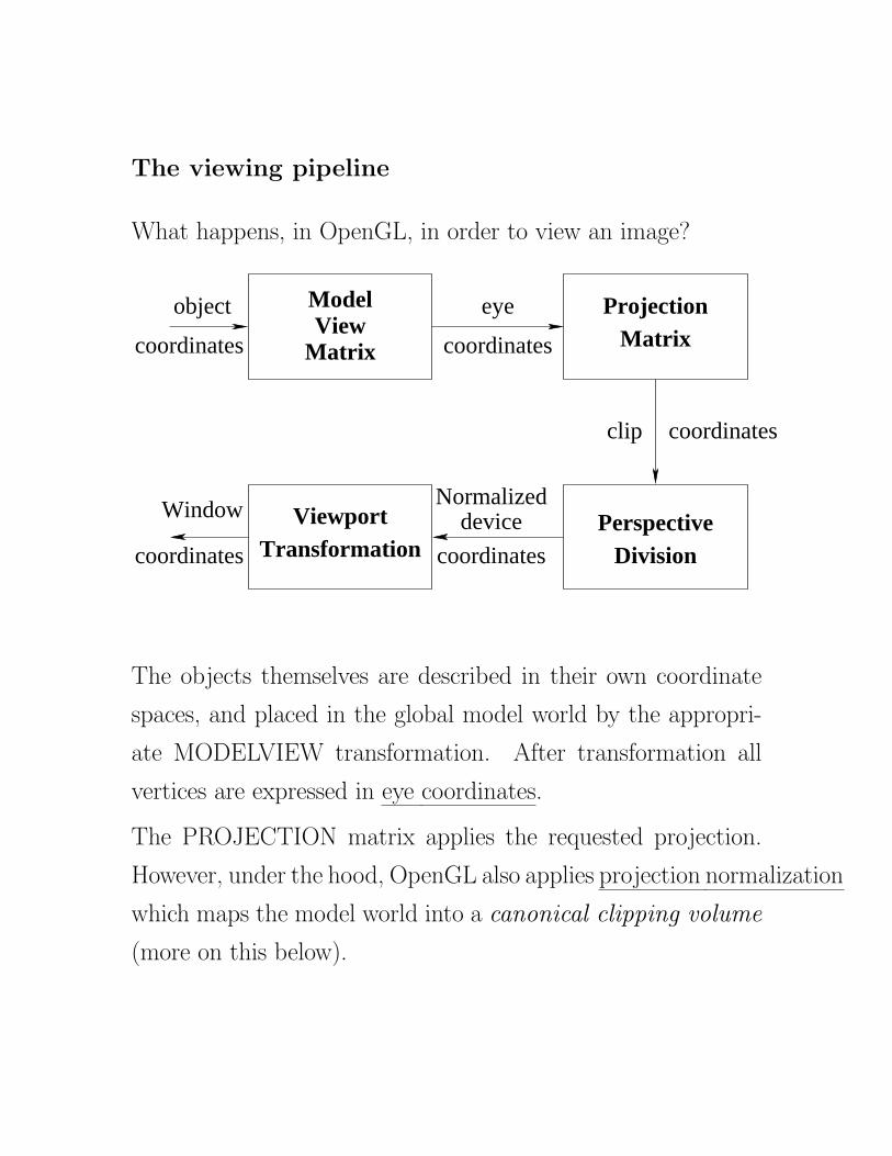
The viewing pipeline
What happens, in OpenGL, in order to view an image?

The viewing pipeline
What happens, in OpenGL, in order to view an image?
Perspective
eye
Normalizeddevice
coordinates
coordinates
coordinatesclip
object
coordinates
coordinates
Window ViewportTransformation
ModelView
Matrix
ProjectionMatrix
Division

The viewing pipeline
What happens, in OpenGL, in order to view an image?
Perspective
eye
Normalizeddevice
coordinates
coordinates
coordinatesclip
object
coordinates
coordinates
Window ViewportTransformation
ModelView
Matrix
ProjectionMatrix
Division
The objects themselves are described in their own coordinate
spaces, and placed in the global model world by the appropri-
ate MODELVIEW transformation.

The viewing pipeline
What happens, in OpenGL, in order to view an image?
Perspective
eye
Normalizeddevice
coordinates
coordinates
coordinatesclip
object
coordinates
coordinates
Window ViewportTransformation
ModelView
Matrix
ProjectionMatrix
Division
The objects themselves are described in their own coordinate
spaces, and placed in the global model world by the appropri-
ate MODELVIEW transformation. After transformation all
vertices are expressed in eye coordinates.
The PROJECTION matrix applies the requested projection.
However, under the hood, OpenGL also applies projection normalization
which maps the model world into a canonical clipping volume
(more on this below). After projection, vertices are expressed
in clip coordinates.
We saw above in “Simple perspective projection” that projec-
18

tion requires both multiplication by a transformation matrix
and a division step (a.k.a renormalization).

tion requires both multiplication by a transformation matrix
and a division step (a.k.a renormalization). Thus, perspective
division forms the third stage of the pipeline.

tion requires both multiplication by a transformation matrix
and a division step (a.k.a renormalization). Thus, perspective
division forms the third stage of the pipeline. After this stage
we have vertices in normalized device coordinates.
tion requires both multiplication by a transformation matrix
and a division step (a.k.a renormalization). Thus, perspective
division forms the third stage of the pipeline. After this stage
we have vertices in normalized device coordinates.
Finally, the viewport transformation maps the projected ver-
tices onto window coordinates.

tion requires both multiplication by a transformation matrix
and a division step (a.k.a renormalization). Thus, perspective
division forms the third stage of the pipeline. After this stage
we have vertices in normalized device coordinates.
Finally, the viewport transformation maps the projected ver-
tices onto window coordinates. Window coordinates are mea-
sured in units of pixels on the display, with the origin in the
lower-left corner.

tion requires both multiplication by a transformation matrix
and a division step (a.k.a renormalization). Thus, perspective
division forms the third stage of the pipeline. After this stage
we have vertices in normalized device coordinates.
Finally, the viewport transformation maps the projected ver-
tices onto window coordinates. Window coordinates are mea-
sured in units of pixels on the display, with the origin in the
lower-left corner. In fact, window coordinates maintain depth
information which is necessary for hidden surface removal.
Projection normalization?
Whatever view volume is specified by calls to glOrtho or glFrustum
(or gluPerspective), OpenGL transforms that volume into
the canonical view volume.

tion requires both multiplication by a transformation matrix
and a division step (a.k.a renormalization). Thus, perspective
division forms the third stage of the pipeline. After this stage
we have vertices in normalized device coordinates.
Finally, the viewport transformation maps the projected ver-
tices onto window coordinates. Window coordinates are mea-
sured in units of pixels on the display, with the origin in the
lower-left corner. In fact, window coordinates maintain depth
information which is necessary for hidden surface removal.
Projection normalization?
Whatever view volume is specified by calls to glOrtho or glFrustum
(or gluPerspective), OpenGL transforms that volume into
the canonical view volume. This volume is defined by planes
at x ± 1, y ± 1, and z ± 1.

tion requires both multiplication by a transformation matrix
and a division step (a.k.a renormalization). Thus, perspective
division forms the third stage of the pipeline. After this stage
we have vertices in normalized device coordinates.
Finally, the viewport transformation maps the projected ver-
tices onto window coordinates. Window coordinates are mea-
sured in units of pixels on the display, with the origin in the
lower-left corner. In fact, window coordinates maintain depth
information which is necessary for hidden surface removal.
Projection normalization?
Whatever view volume is specified by calls to glOrtho or glFrustum
(or gluPerspective), OpenGL transforms that volume into
the canonical view volume. This volume is defined by planes
at x ± 1, y ± 1, and z ± 1. The canonical view volume may
be generated directly as follows:
glMatrixMode(GL_PROJECTION);
glLoadIdentity();
glOrtho(-1.0, 1.0, -1.0, 1.0, -1.0, 1.0);
19

For a general orthographic projection, the projection normal-
ization does the following:

For a general orthographic projection, the projection normal-
ization does the following:

For a general orthographic projection, the projection normal-
ization does the following:
Perspective projections will also be converted to the same canon-
ical view volume.

For a general orthographic projection, the projection normal-
ization does the following:
Perspective projections will also be converted to the same canon-
ical view volume.

For a general orthographic projection, the projection normal-
ization does the following:
Perspective projections will also be converted to the same canon-
ical view volume.
where COP means centre of projection.

For a general orthographic projection, the projection normal-
ization does the following:
Perspective projections will also be converted to the same canon-
ical view volume.
where COP means centre of projection. On the left is a top-
down view of a cube within a frustum-shaped view volume.

For a general orthographic projection, the projection normal-
ization does the following:
Perspective projections will also be converted to the same canon-
ical view volume.
where COP means centre of projection. On the left is a top-
down view of a cube within a frustum-shaped view volume.
After projection normalization, the view volume has been made
canonical, and the cube has been appropriately distorted.
20

The purpose of projection normalization is to simplify clipping.

The purpose of projection normalization is to simplify clipping.
It is easier to transform primitives to the canonical viewing vol-
ume and then clip, than to clip them beforehand to an arbitrary
view volume.

The purpose of projection normalization is to simplify clipping.
It is easier to transform primitives to the canonical viewing vol-
ume and then clip, than to clip them beforehand to an arbitrary
view volume.
21

The planet.c example revisited...
Look at the display call below.

The planet.c example revisited...
Look at the display call below. What is the plane of the
planet’s travel about the sun?

The planet.c example revisited...
Look at the display call below. What is the plane of the
planet’s travel about the sun?
void display(void)
{
glClear (GL_COLOR_BUFFER_BIT);
glColor3f (1.0, 1.0, 1.0);
glPushMatrix();
glutWireSphere(1.0, 20, 16); /* draw sun */
glRotatef ((GLfloat) year, 0.0, 1.0, 0.0);
glTranslatef (2.0, 0.0, 0.0);
glRotatef ((GLfloat) day, 0.0, 1.0, 0.0);
glutWireSphere(0.2, 10, 8); /* draw smaller planet */
glPopMatrix();
glutSwapBuffers();
}
22

The reshape function below positions the eye within the xz
plane

The reshape function below positions the eye within the xz
plane
void reshape (int w, int h)
{
glViewport (0, 0, (GLsizei) w, (GLsizei) h);
glMatrixMode (GL_PROJECTION);
glLoadIdentity ();
gluPerspective(60.0, (GLfloat) w/(GLfloat) h, 1.0, 20.0);
glMatrixMode(GL_MODELVIEW);
glLoadIdentity();
gluLookAt (0.0, 0.0, 5.0, 0.0, 0.0, 0.0, 0.0, 1.0, 0.0);
}
Lets say that that we want to zoom in a little, so that when
year is either 0 or 180, the outside of the planet just touches
the window’s edge.
By examining the code in display we can see that, in eye
coordinates, the planetary system has a radius of 2.2 (extending
out to the planet’s outer edge).

The reshape function below positions the eye within the xz
plane
void reshape (int w, int h)
{
glViewport (0, 0, (GLsizei) w, (GLsizei) h);
glMatrixMode (GL_PROJECTION);
glLoadIdentity ();
gluPerspective(60.0, (GLfloat) w/(GLfloat) h, 1.0, 20.0);
glMatrixMode(GL_MODELVIEW);
glLoadIdentity();
gluLookAt (0.0, 0.0, 5.0, 0.0, 0.0, 0.0, 0.0, 1.0, 0.0);
}
Lets say that that we want to zoom in a little, so that when
year is either 0 or 180, the outside of the planet just touches
the window’s edge.
By examining the code in display we can see that, in eye
coordinates, the planetary system has a radius of 2.2 (extending
out to the planet’s outer edge). Examing the arguments to
gluLookAt we can see that the system is 5 units away from the
eye.

The reshape function below positions the eye within the xz
plane
void reshape (int w, int h)
{
glViewport (0, 0, (GLsizei) w, (GLsizei) h);
glMatrixMode (GL_PROJECTION);
glLoadIdentity ();
gluPerspective(60.0, (GLfloat) w/(GLfloat) h, 1.0, 20.0);
glMatrixMode(GL_MODELVIEW);
glLoadIdentity();
gluLookAt (0.0, 0.0, 5.0, 0.0, 0.0, 0.0, 0.0, 1.0, 0.0);
}
Lets say that that we want to zoom in a little, so that when
year is either 0 or 180, the outside of the planet just touches
the window’s edge.
By examining the code in display we can see that, in eye
coordinates, the planetary system has a radius of 2.2 (extending
out to the planet’s outer edge). Examing the arguments to
gluLookAt we can see that the system is 5 units away from the
eye. Simple trigonometry tells us that the horizontal field of
view, fovx, is
23

fovx = 2 tan−1(2.2/5)

fovx = 2 tan−1(2.2/5)
We define a variable aspect as follows

fovx = 2 tan−1(2.2/5)
We define a variable aspect as follows
aspect =width
height

fovx = 2 tan−1(2.2/5)
We define a variable aspect as follows
aspect =width
height
aspect =angular width
angular height

fovx = 2 tan−1(2.2/5)
We define a variable aspect as follows
aspect =width
height
aspect =angular width
angular height
aspect =fovx
fovy

fovx = 2 tan−1(2.2/5)
We define a variable aspect as follows
aspect =width
height
aspect =angular width
angular height
aspect =fovx
fovy
Therefore, we can find the required value of fovy as follows
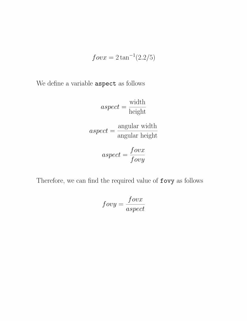
fovx = 2 tan−1(2.2/5)
We define a variable aspect as follows
aspect =width
height
aspect =angular width
angular height
aspect =fovx
fovy
Therefore, we can find the required value of fovy as follows
fovy =fovx
aspect

fovx = 2 tan−1(2.2/5)
We define a variable aspect as follows
aspect =width
height
aspect =angular width
angular height
aspect =fovx
fovy
Therefore, we can find the required value of fovy as follows
fovy =fovx
aspect
24

The following code for reshape implements this zoomed-in
view.

The following code for reshape implements this zoomed-in
view.
void reshape (int w, int h)
{
glViewport (0, 0, (GLsizei) w, (GLsizei) h);
glMatrixMode (GL_PROJECTION);
glLoadIdentity ();
double aspect = w / (GLfloat) h;
double fovx = 47.5; /* 2*arctan(2.2/5.0)=47.5 */
double fovy = fovx / aspect;
gluPerspective(fovy, aspect, 1.0, 20.0);
glMatrixMode(GL_MODELVIEW);
glLoadIdentity();
gluLookAt (0.0, 0.0, 5.0, 0.0, 0.0, 0.0, 0.0, 1.0, 0.0);
}
Note that when executing the example code (in planet2.c)
the planet is clipped out when close to the viewer.

The following code for reshape implements this zoomed-in
view.
void reshape (int w, int h)
{
glViewport (0, 0, (GLsizei) w, (GLsizei) h);
glMatrixMode (GL_PROJECTION);
glLoadIdentity ();
double aspect = w / (GLfloat) h;
double fovx = 47.5; /* 2*arctan(2.2/5.0)=47.5 */
double fovy = fovx / aspect;
gluPerspective(fovy, aspect, 1.0, 20.0);
glMatrixMode(GL_MODELVIEW);
glLoadIdentity();
gluLookAt (0.0, 0.0, 5.0, 0.0, 0.0, 0.0, 0.0, 1.0, 0.0);
}
Note that when executing the example code (in planet2.c)
the planet is clipped out when close to the viewer. Why is
this?
25
Related Documents


