Projection of Plane Prepared by Kasundra Chirag Sarvaiya Kishan Joshi Sarad Jivani Divyesh Guided By Prof. Ankur Tank Mechanical Engg. Dept. Darshan Institute of Engg. And Tech., Rajkot

Welcome message from author
This document is posted to help you gain knowledge. Please leave a comment to let me know what you think about it! Share it to your friends and learn new things together.
Transcript

Projection of Plane
Prepared byKasundra ChiragSarvaiya KishanJoshi SaradJivani Divyesh
Guided ByProf. Ankur TankMechanical Engg. Dept.Darshan Institute of Engg. And Tech., Rajkot

PROJECTIONS OF PLANES
In this topic various plane figures are the objects.
What will be given in the problem?
1. Description of the plane figure.2. It’s position with HP and VP.
In which manner it’s position with HP & VP will be described?
1.Inclination of it’s SURFACE with one of the reference planes will be given.2. Inclination of one of it’s EDGES with other reference plane will be given (Hence this will be a case of an object inclined to both reference Planes.)
To draw their projections means F.V, T.V. & S.V.
What is usually asked in the problem?
Study the illustration showing surface & side inclination given on next page.

HP
a 1
b 1
c 1
d 1
VPVP
a’
d’c’
b’
VP
a’ d’c’b’
For Fv
For
Tv
For F.V.
For
T.V
.
For
T.V
.
For F.V.
HP
a
b c
d
a1’
d1’ c1’
b1’
HP
a1
b1 c1
d1
CASE OF A RECTANGLE – OBSERVE AND NOTE ALL STEPS.
SURFACE PARALLEL TO HPPICTORIAL PRESENTATION
SURFACE INCLINED TO HPPICTORIAL PRESENTATION
ONE SMALL SIDE INCLINED TO VPPICTORIAL PRESENTATION
ORTHOGRAPHICTV-True Shape
FV- Line // to xy
ORTHOGRAPHICFV- Inclined to XY
TV- Reduced Shape
ORTHOGRAPHICFV- Apparent ShapeTV-Previous Shape
A B C

PROCEDURE OF SOLVING THE PROBLEM:IN THREE STEPS EACH PROBLEM CAN BE SOLVED:( As Shown In Previous Illustration )STEP 1. Assume suitable conditions & draw Fv & Tv of initial position. STEP 2. Now consider surface inclination & draw 2nd Fv & Tv.STEP 3. After this,consider side/edge inclination and draw 3rd ( final) Fv & Tv.
ASSUMPTIONS FOR INITIAL POSITION:(Initial Position means assuming surface // to HP or VP)1.If in problem surface is inclined to HP – assume it // HP Or If surface is inclined to VP – assume it // to VP 2. Now if surface is assumed // to HP- It’s TV will show True Shape. And If surface is assumed // to VP – It’s FV will show True Shape. 3. Hence begin with drawing TV or FV as True Shape.4. While drawing this True Shape – keep one side/edge ( which is making inclination) perpendicular to xy line ( similar to pair no. on previous page illustration ).
A
B
Now Complete STEP 2. By making surface inclined to the resp plane & project it’s other view.(Ref. 2nd pair on previous page illustration )
C
Now Complete STEP 3. By making side inclined to the resp plane & project it’s other view.(Ref. 3nd pair on previous page illustration )
APPLY SAME STEPS TO SOLVE NEXT ELEVEN PROBLEMS

X Y
a
b c
d
a’b’
c’d’
a1
b1 c1
d1
a1
b1
c1
d1
a’b’
d’c’ c’1 d’1
b’1 a’1450
300
Problem 1:Rectangle 30mm and 50mm sides is resting on HP on one small side which is 300 inclined to VP,while the surface of the plane makes 450 inclination with HP. Draw it’s projections.
Read problem and answer following questions1. Surface inclined to which plane? ------- HP
2. Assumption for initial position? ------// to HP 3. So which view will show True shape? --- TV
4. Which side will be vertical? ---One small side. Hence begin with TV, draw rectangle below X-Y
drawing one small side vertical.
Surface // to Hp Surface inclined to Hp
Side Inclined to Vp
Problem 2:A 300 – 600 set square of longest side100 mm long, is in VP and 300
inclinedto HP while it’s surface is 450
inclined to VP.Draw it’s projections
(Surface & Side inclinations directly given)
Read problem and answer following questions1 .Surface inclined to which plane? ------- VP2. Assumption for initial position? ------// to VP3. So which view will show True shape? --- FV4. Which side will be vertical? ------longest side.
c1
X Y300
450
a’1
b’1
c’1
a
c
a’
ab1
b’
b
a1b
c
a’1
b’1
c’1
c’
Hence begin with FV, draw triangle above X-Y keeping longest side vertical.
Surface // to Vp Surface inclined to Vp
side inclined to Hp

cc1
X Y450
a’1
b’1
c’1
a
c
a’
ab1
b’
b
a1b
a’1
b’1
c’1
c’
35
10
Problem 3:A 300 – 600 set square of longest side100 mm long is in VP and it’s surface450 inclined to VP. One end of longestside is 10 mm and other end is 35 mm above HP. Draw it’s projections
(Surface inclination directly given.Side inclination indirectly given)
Read problem and answer following questions1 .Surface inclined to which plane? ------- VP2. Assumption for initial position? ------// to VP3. So which view will show True shape? --- FV4. Which side will be vertical? ------longest side.
Hence begin with FV, draw triangle above X-Y
keeping longest side vertical.
First TWO steps are similar to previous problem.Note the manner in which side inclination is given.End A 35 mm above Hp & End B is 10 mm above Hp.So redraw 2nd Fv as final Fv placing these ends as said.
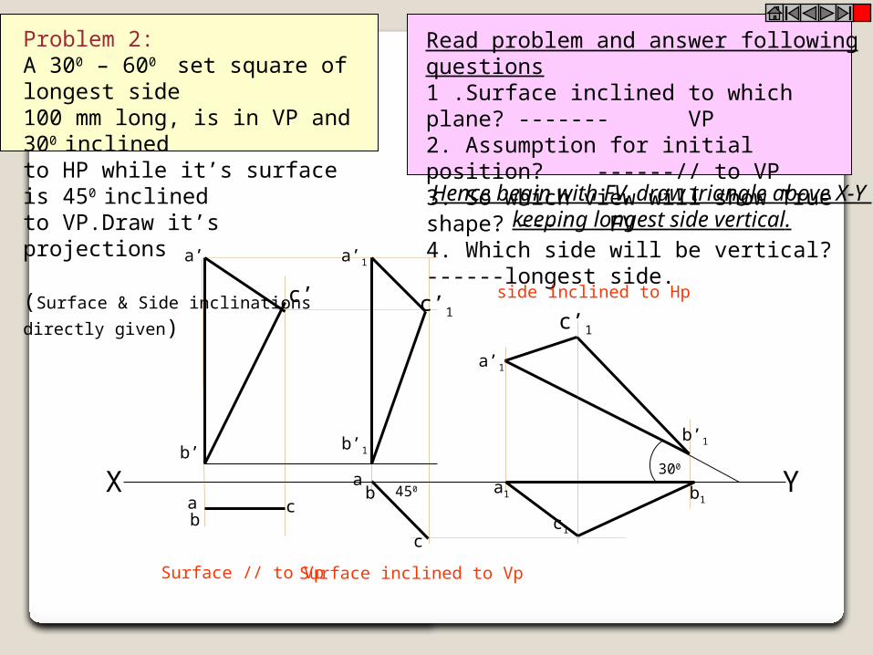
Read problem and answer following questions1. Surface inclined to which plane? ------- HP2. Assumption for initial position? ------ // to HP3. So which view will show True shape? --- TV4. Which side will be vertical? -------- any side. Hence begin with TV,draw pentagon below X-Y line, taking one side vertical.
Problem 4:A regular pentagon of 30 mm sides is resting on HP on one of it’s sides with it’s surface 450 inclined to HP.Draw it’s projections when the side in HP makes 300 angle with VP
a’b’ d’
b1
d
c1
a
c’e’
b
c
d1
b’1
a1
e’1 c’1
d’1
a1
b1
c1d1
d’
a’b’
c’e’
e1
e1
a’1X Y450
300e
SURFACE AND SIDE INCLINATIONSARE DIRECTLY GIVEN.

Problem 5:A regular pentagon of 30 mm sides is resting on HP on one of it’s sides while it’s oppositevertex (corner) is 30 mm above HP. Draw projections when side in HP is 300 inclined to VP.
Read problem and answer following questions1. Surface inclined to which plane? ------- HP2. Assumption for initial position? ------ // to HP3. So which view will show True shape? --- TV4. Which side will be vertical? --------any side. Hence begin with TV,draw pentagon below X-Y line, taking one side vertical.
b’
d’
a’
c’e’
a1
b1
c1d1
e1
b1
c1
d1
a1
e1
b’1
e’1 c’1
d’1
a’1X Ya’b’ d’c’e’
30
a
b
c
d
e
300
SURFACE INCLINATION INDIRECTLY GIVENSIDE INCLINATION DIRECTLY GIVEN:
ONLY CHANGE is the manner in which surface inclination is described:
One side on Hp & it’s opposite corner 30 mm above Hp.Hence redraw 1st Fv as a 2nd Fv making above arrangement.
Keep a’b’ on xy & d’ 30 mm above xy.

T L
a
d
c
b
a’ b’ d’ c’
X Ya’b’ d’
c’
a1
b1
d1
c1
a1
b1
d1
c1
450300 a’1
b’1c’1
d’1
a1
b1
d1
c1a
d
c
b
a’ b’ d’ c’a’
b’ d’c’
a1
b1
d1
c1
300
a’1
b’1c’1
d’1
Problem 8: A circle of 50 mm diameter is resting on Hp on end A of it’s diameter ACwhich is 300 inclined to Hp while it’s Tvis 450 inclined to Vp.Draw it’s projections.
Problem 9: A circle of 50 mm diameter is resting on Hp on end A of it’s diameter ACwhich is 300 inclined to Hp while it makes450 inclined to Vp. Draw it’s projections.
Read problem and answer following questions1. Surface inclined to which plane? ------- HP2. Assumption for initial position? ------ // to HP3. So which view will show True shape? --- TV4. Which diameter horizontal? ---------- AC Hence begin with TV,draw rhombus below X-Y line, taking longer diagonal // to X-Y
The difference in these two problems is in step 3 only.In problem no.8 inclination of Tv of that AC is given,It could be drawn directly as shown in 3rd step.While in no.9 angle of AC itself i.e. it’s TL, is given. Hence here angle of TL is taken,locus of c1
Is drawn and then LTV I.e. a1 c1 is marked and final TV was completed.Study illustration carefully.
Note the difference in construction of 3rd step
in both solutions.
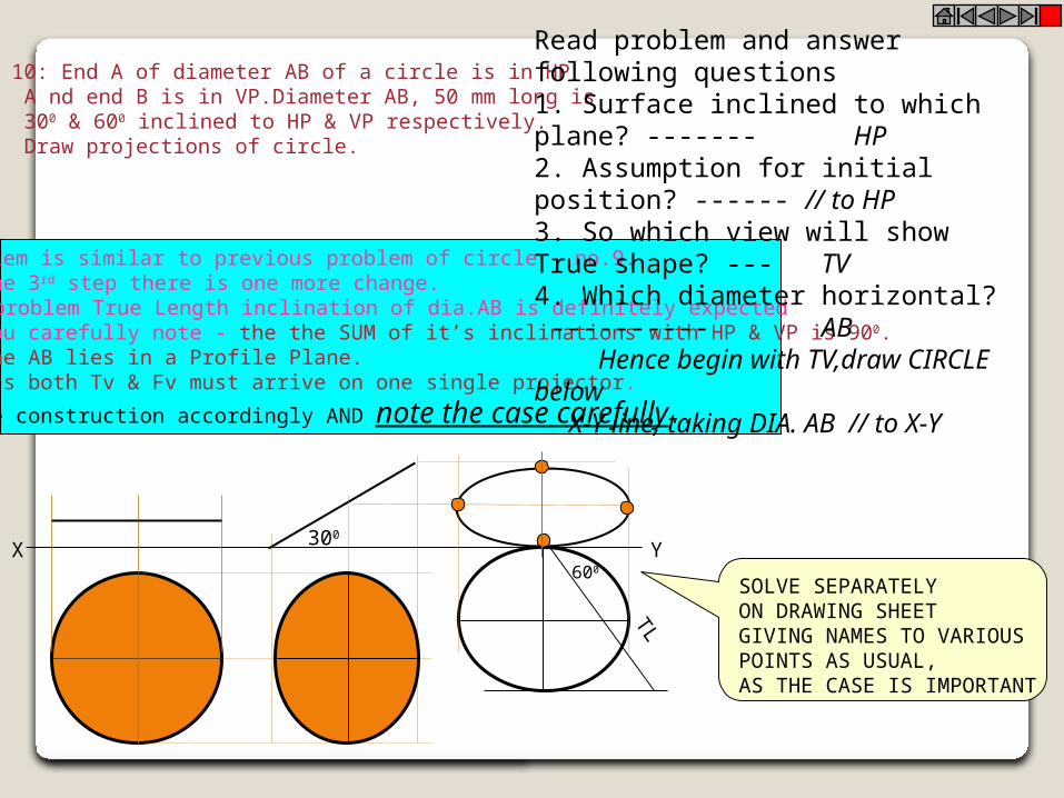
Problem 10: End A of diameter AB of a circle is in HP A nd end B is in VP.Diameter AB, 50 mm long is 300 & 600 inclined to HP & VP respectively. Draw projections of circle.
The problem is similar to previous problem of circle – no.9.But in the 3rd step there is one more change.Like 9th problem True Length inclination of dia.AB is definitely expected but if you carefully note - the the SUM of it’s inclinations with HP & VP is 900. Means Line AB lies in a Profile Plane.Hence it’s both Tv & Fv must arrive on one single projector.
So do the construction accordingly AND note the case carefully..
SOLVE SEPARATELYON DRAWING SHEETGIVING NAMES TO VARIOUSPOINTS AS USUAL, AS THE CASE IS IMPORTANT
TL
X Y300
600
Read problem and answer following questions1. Surface inclined to which plane? ------- HP2. Assumption for initial position? ------ // to HP3. So which view will show True shape? --- TV4. Which diameter horizontal? ---------- AB Hence begin with TV,draw CIRCLE below X-Y line, taking DIA. AB // to X-Y

As 3rd step redraw 2nd Tv keeping
side DE on xy line. Because it is in VP
as said in problem.
X Y
a
b
c
d
e
f
Problem 11:A hexagonal lamina has its one side in HP and Its apposite parallel side is 25mm above Hp andIn Vp. Draw it’s projections. Take side of hexagon 30 mm long.
ONLY CHANGE is the manner in which surface inclination is described:One side on Hp & it’s opposite side 25 mm above Hp.Hence redraw 1st Fv as a 2nd Fv making above arrangement.Keep a’b’ on xy & d’e’ 25 mm above xy.
25
f’ e’d’c’b’a’
f’
e’d’
c’
b’a’
a1
b1
c1
d1
e1
f1
c1’
b’1a’1
f’1
d’1e’1
f1
a1
c1
b1
d1e1
Read problem and answer following questions1. Surface inclined to which plane? ------- HP2. Assumption for initial position? ------ // to HP3. So which view will show True shape? --- TV4. Which diameter horizontal? ---------- AC Hence begin with TV,draw rhombus below X-Y line, taking longer diagonal // to X-Y
A B
C
H
H/3
G
X Y
a’
b’
c’
g’
b a,g c
b a,g c
450
a’1
c’1
b’1g’1
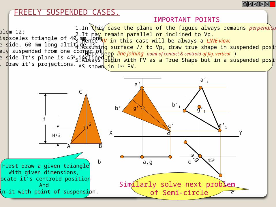
FREELY SUSPENDED CASES.
1.In this case the plane of the figure always remains perpendicular to Hp.2.It may remain parallel or inclined to Vp.3.Hence TV in this case will be always a LINE view.4.Assuming surface // to Vp, draw true shape in suspended position as FV. (Here keep line joining point of contact & centroid of fig. vertical ) 5.Always begin with FV as a True Shape but in a suspended position. AS shown in 1st FV.
IMPORTANT POINTS
Problem 12:An isosceles triangle of 40 mm long base side, 60 mm long altitude Isfreely suspended from one corner ofBase side.It’s plane is 450 inclined to Vp. Draw it’s projections.
Similarly solve next problem of Semi-circle
First draw a given triangleWith given dimensions,
Locate it’s centroid positionAnd
join it with point of suspension.

0.4
14
R
G
A
P
20 mm
CG
X Y
e’
c’
d’
b’
a’
p’
g’
b c a p,g d e
b c a p,g d e
Problem 13:A semicircle of 100 mm diameter is suspended from a point on its straight edge 30 mm from the midpoint of that edge so that the surface makes an angle of 450 with VP. Draw its projections.
First draw a given semicircleWith given diameter,
Locate it’s centroid positionAnd
join it with point of suspension.
1.In this case the plane of the figure always remains perpendicular to Hp.2.It may remain parallel or inclined to Vp.3.Hence TV in this case will be always a LINE view.4.Assuming surface // to Vp, draw true shape in suspended position as FV. (Here keep line joining point of contact & centroid of fig. vertical ) 5.Always begin with FV as a True Shape but in a suspended position. AS shown in 1st FV.
IMPORTANT POINTS

To determine true shape of plane figure when it’s projections are given.BY USING AUXILIARY PLANE METHOD
WHAT WILL BE THE PROBLEM?Description of final Fv & Tv will be given. You are supposed to determine true shape of that plane figure.
Follow the below given steps:1. Draw the given Fv & Tv as per the given information in problem.2. Then among all lines of Fv & Tv select a line showing True Length
(T.L.) (It’s other view must be // to xy)3. Draw x1-y1 perpendicular to this line showing T.L.4. Project view on x1-y1 ( it must be a line view)5. Draw x2-y2 // to this line view & project new view on it.
It will be the required answer i.e. True Shape.The facts you must know:-
If you carefully study and observe the solutions of all previous problems,You will find
IF ONE VIEW IS A LINE VIEW & THAT TOO PARALLEL TO XY LINE,THEN AND THEN IT’S OTHER VIEW WILL SHOW TRUE SHAPE:
NOW FINAL VIEWS ARE ALWAYS SOME SHAPE, NOT LINE VIEWS:SO APPLYING ABOVE METHOD:
WE FIRST CONVERT ONE VIEW IN INCLINED LINE VIEW .(By using x1y1 aux.plane)THEN BY MAKING IT // TO X2-Y2 WE GET TRUE SHAPE.
Study Next Four Cases

X Y
a
c
b
C’
b’
a’
10
15
15 TL
X1
Y1
C1
b1a1
a’1
b’1
c’1 TRUE SHAPE
900
X2
Y2
Problem 14 Tv is a triangle abc. Ab is 50 mm long, angle cab is 300 and angle cba is 650.a’b’c’ is a Fv. a’ is 25 mm, b’ is 40 mm and c’ is 10 mm above Hp respectively. Draw projectionsof that figure and find it’s true shape.
300 650
50 mm
As per the procedure-1.First draw Fv & Tv as per the data.2.In Tv line ab is // to xy hence it’s other view a’b’ is TL. So draw x1y1 perpendicular to it.3.Project view on x1y1. a) First draw projectors from a’b’ & c’ on x1y1. b) from xy take distances of a,b & c( Tv) mark on these projectors from x1y1. Name points a1b1 & c1. c) This line view is an Aux.Tv. Draw x2y2 // to this line view and project Aux. Fv on it. for that from x1y1 take distances of a’b’ & c’ and mark from x2y= on new projectors.4.Name points a’1 b’1 & c’1 and join them. This will be the required true shape.
ALWAYS FOR NEW FV TAKE DISTANCES OF PREVIOUS FV AND FOR NEW TV, DISTANCES
OF PREVIOUS TV
REMEMBER!!
x1
y1
c’1
b’1
a’1
x2
y2
b1
c1
d1TRUE SHAPE
90 0
c’
T L
X Y
a’
b’
b
ca
10
20
15
15
1’
140
5025
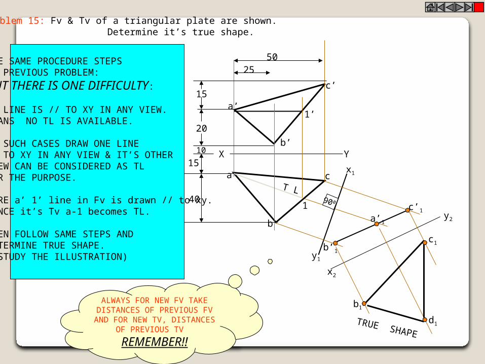
Problem 15: Fv & Tv of a triangular plate are shown. Determine it’s true shape.
USE SAME PROCEDURE STEPS OF PREVIOUS PROBLEM:
BUT THERE IS ONE DIFFICULTY:
NO LINE IS // TO XY IN ANY VIEW.MEANS NO TL IS AVAILABLE.
IN SUCH CASES DRAW ONE LINE // TO XY IN ANY VIEW & IT’S OTHER VIEW CAN BE CONSIDERED AS TLFOR THE PURPOSE.
HERE a’ 1’ line in Fv is drawn // to xy.HENCE it’s Tv a-1 becomes TL.
THEN FOLLOW SAME STEPS AND DETERMINE TRUE SHAPE. (STUDY THE ILLUSTRATION)
ALWAYS FOR NEW FV TAKE DISTANCES OF PREVIOUS FV AND FOR NEW TV, DISTANCES
OF PREVIOUS TV
REMEMBER!!

y1
X2
X1
a1c1
d1
b1
c’1
d’1
b’1
a’1
y2
TRUE SHAPEa
b
c
d YX
a’
d’
c’
b’
50 D.
50D
TL
PROBLEM 16: Fv & Tv both are circles of 50 mm diameter. Determine true shape of an elliptical plate.
ADOPT SAME PROCEDURE.a c is considered as line // to xy.Then a’c’ becomes TL for the purpose.Using steps properly true shape can beEasily determined.
Study the illustration.
ALWAYS, FOR NEW FV TAKE DISTANCES OF PREVIOUS FV AND
FOR NEW TV, DISTANCES OF PREVIOUS TV
REMEMBER!!
a
bc
d
e
a’
b’
e’
c’d’
a1
b1
e1 d1
c1
300X Y
X1
Y1
450
TRUE SHAPE
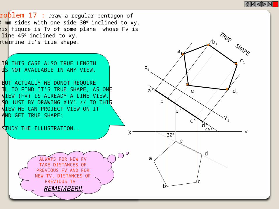
Problem 17 : Draw a regular pentagon of 30 mm sides with one side 300 inclined to xy.This figure is Tv of some plane whose Fv is A line 450 inclined to xy.Determine it’s true shape.
IN THIS CASE ALSO TRUE LENGTH IS NOT AVAILABLE IN ANY VIEW.
BUT ACTUALLY WE DONOT REQUIRE TL TO FIND IT’S TRUE SHAPE, AS ONE VIEW (FV) IS ALREADY A LINE VIEW.SO JUST BY DRAWING X1Y1 // TO THISVIEW WE CAN PROJECT VIEW ON ITAND GET TRUE SHAPE:
STUDY THE ILLUSTRATION..
ALWAYS FOR NEW FV TAKE DISTANCES OF
PREVIOUS FV AND FOR NEW TV, DISTANCES OF
PREVIOUS TV
REMEMBER!!

Thank You
Related Documents