Project X: Status, Strategy, Meeting Goals Steve Holmes SLAC Seminar May 19, 2011

Project X: Status, Strategy, Meeting Goals
Feb 25, 2016
Project X: Status, Strategy, Meeting Goals. Steve Holmes SLAC Seminar May 19, 2011. Outline. Strategic Context Project X Reference Design R&D Plan Status and Timeline Collaboration Status Project X website: http://projectx.fnal.gov. Fermilab Long Range Plan. - PowerPoint PPT Presentation
Welcome message from author
This document is posted to help you gain knowledge. Please leave a comment to let me know what you think about it! Share it to your friends and learn new things together.
Transcript

Project X: Status, Strategy, Meeting Goals
Steve HolmesSLAC Seminar
May 19, 2011

Outline
• Strategic Context
• Project X Reference Design
• R&D Plan
• Status and Timeline
• Collaboration Status
Project X website: http://projectx.fnal.gov
SLAC Seminar - S. Holmes Page 2

Fermilab Long Range Plan
Fermilab is the sole remaining U.S. laboratory providing facilities in support of accelerator-based Elementary Particle Physics. Fermilab is fully aligned with the strategy for U.S. EPP developed by HEPAP/P5.
ÞThe Fermilab strategy is to mount a world-leading program at the intensity frontier, while using this program as a bridge to an energy frontier facility
beyond LHC in the longer term.
Project X is the key element of this strategy
SLAC Seminar - S. Holmes Page 3

Mission Elements
• A neutrino beam for long baseline neutrino oscillation experiments– 2 MW proton source at 60-120 GeV
• High intensity, low energy protonsfor kaon, muon, and neutrino basedprecision experiments– Operations simultaneous with the
neutrino program
• A path toward a muon source forpossible future Neutrino Factory and/or a Muon Collider– Requires ~4 MW at ~5-15 GeV
• Possible missions beyond EPP– Standard Model Tests with nuclei and energy applications
SLAC Seminar - S. Holmes Page 4

Concept Evolution
• Three Project X configurations have been developed, in response to limitations identified at each step:
– Initial Configuration-1 (IC-1) • 8 GeV pulsed linac + Recycler/MI• Fully capable of supporting neutrino mission• Limited capabilities for rare processes
– Initial Configuration-2 (IC-2)• 2 GeV CW linac + 2-8 GeV RCS + Recycler/MI• Fully capable of supporting neutrino mission• 2 GeV too low for rare processes (Kaons)• Ineffective platform for Neutrino Factory or Muon Collider
– Reference Design• 3 GeV CW linac + 3-8 pulsed linac + Recycler/MI• Ameliorates above deficiencies
SLAC Seminar - S. Holmes Page 5
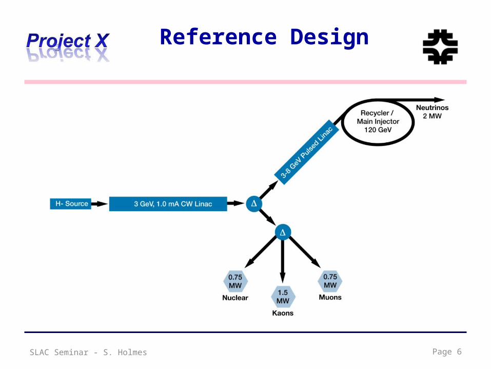
Reference Design
SLAC Seminar - S. Holmes Page 6
Reference Design Capabilities
• 3 GeV CW superconducting H- linac with 1 mA average beam current.– Flexible provision for variable beam structures to multiple users
• CW at time scales >1 msec, 10% DF at <1 msec– Supports rare processes programs at 3 GeV– Provision for 1 GeV extraction for nuclear energy program
• 3-8 GeV pulsed linac capable of delivering 300 kW at 8 GeV – Supports the neutrino program– Establishes a path toward a muon based facility
• Upgrades to the Recycler and Main Injector to provide ≥ 2 MW to the neutrino production target at 60-120 GeV.
Þ Utilization of a CW linac creates a facility that is unique in the world, with performance that cannot be matched in a synchrotron-based facility.
SLAC Seminar - S. Holmes 7

Functional Requirements
Requirement Description Value
L1 Delivered Beam Energy, maximum 3 GeV (kinetic)
L2 Delivered Beam Power at 3 GeV 3 MW
L3 Average Beam Current (averaged over >1 msec) 1 mA
L4 Maximum Beam Current (sustained for <1 msec) 5 mA
L5 The 3 GeV linac must be capable of delivering correctly formatted beam to a pulsed linac, for acceleration to 8 GeV
L6 Charge delivered to pulsed linac 26 mA-msec in < 0.75 sec
L7 Maximum Bunch Intensity 1.9 x 10 8
L8 Minimum Bunch Spacing 6.2 nsec (1/162.5 MHz)
L9 Bunch Length <50 psec (full-width half max)
L10 Bunch Pattern Programmable
L11 RF Duty Factor 100% (CW)
L12 RF Frequency 162.5 MHz and harmonics thereof
L13 3 GeV Beam Split Three-way
P1 Maximum Beam Energy 8 GeV
P2 The 3-8 GeV pulsed linac must be capable of delivering correctly formatted beam for injection into the Recycler Ring (or Main Injector).
P3 Charge to fill Main Injector/cycle 26 mA-msec in <0.75 sec
P4 Maximum beam power delivered to 8 GeV 300 kW
P5 Duty Factor (initial) < 4%
SLAC Seminar - S. Holmes 8

Functional RequirementsRequirement Description Value
M1 Delivered Beam Energy, maximum 120 GeVM2 Delivered Beam Energy, minimum 60 GeVM3 Minimum Injection Energy 6 GeVM4 Beam Power (60-120 GeV) > 2 MWM5 Beam Particles ProtonsM6 Beam Intensity 1.6 x 10 14 protons per pulseM7 Beam Pulse Length ~10 msecM8 Bunches per Pulse ~550M9 Bunch Spacing 18.8 nsec (1/53.1 MHz)
M10 Bunch Length <2 nsec (fullwidth half max)M11 Pulse Repetition Rate (120 GeV) 1.2 secM12 Pulse Repetition Rate (60 GeV) 0.75 secM13 Max Momentum Spread at extraction 2 x 10⁻³
I1 The 3 GeV and neutrino programs must operate simultaneously
I2 Residual Activation from Uncontrolled Beam Loss in areas requiring hands on maintenance.
<20 mrem/hour (average) <100 mrem/hour (peak) @ 1 ft
I3 Scheduled Maintenance Weeks/Year 8I4 3 GeV Linac Operational Reliability 90%I5 60-120 GeV Operational Reliability 85%I6 Facility Lifetime 40 years
U1 Provisions should be made to support an upgrade of the CW linac to support an average current of 4 mA.
U2 Provisions should be made to support an upgrade of the Main Injector to a delivered beam power of ~4 MW at 120 GeV.
U3 Provisions should be made to deliver CW proton beams as low as 1 GeV.U4 Provision should be made to support an upgrade to the CW linac such that it can accelerate Protons.U5 Provisions should be made to support an upgrade of the pulsed linac to support a duty factor or 10%. U6 Provisions should be made to support an upgrade of the CW linac to a 3.1 nsec bunch spacing.
SLAC Seminar - S. Holmes 9

Beam Configurations3 GeV Operating Scenario
SLAC Seminar - S. Holmes 10
1 msec period at 3 GeVMuon pulses (16e7) 81.25 MHz, 100 nsec @ 1MHz
700 kWKaon pulses (16e7) 20.3 MHz
1540 kWNuclear pulses (16e7) 10.15 MHz
770 kWSeparation scheme
Ion source and RFQ operate at 4.2 mA75% of bunches are chopped @ 2.5 MeV Þ maintain 1 mA over 1 msec
Transverse rf splitter0
2
4
6
8
10
12
14
16
18
0.0 0.1 0.3 0.4 0.5 0.6 0.7 0.9 1.0 1.1 1.2 1.4 1.5 1.6 1.7 1.9 2.0
Num
ber
of io
ns p
er b
unch
, (e7
)
Time, us

Page 11
Pulsed Linac
• The Reference Design utilizes a superconducting pulsed linac for acceleration from 3 to 8 GeV
• ILC style cavities and cryomodules– 1.3 GHZ, b=1.0– 28 cryomodules (@ 25 MV/m)
• ILC style rf system– 5 MW klystron– Up to four cryomodules per rf source
• Must deliver 26 mA-msec to the Recycler every 0.75 sec. Options:– 1 mA x 4.4 msec pulses at 10 Hz
• Six pulses required to load Recycler/Main Injector– 1 mA x 26 msec pulses at 10 Hz
• One pulse required to load Main Injector
SLAC Seminar - S. Holmes

Performance Goals
SLAC Seminar - S. Holmes
LinacParticle Type H-
Beam Kinetic Energy 3.0 GeVAverage Beam Current 1 mALinac pulse rate CWBeam Power 3000 kWBeam Power to 3 GeV program 2870 kW
Pulsed LinacParticle Type H-
Beam Kinetic Energy 8.0 GeVPulse rate 10 HzPulse Width 4.3 msecCycles to MI 6Particles per cycle to MI 2.61013
Beam Power to 8 GeV 340 kWMain Injector/Recycler
Beam Kinetic Energy (maximum) 120 GeVCycle time 1.4 secParticles per cycle 1.61014
Beam Power at 120 GeV 2200 kW
Page 12
simultaneous
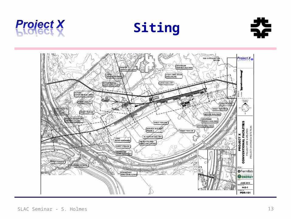
Siting
SLAC Seminar - S. Holmes 13
R&D Program
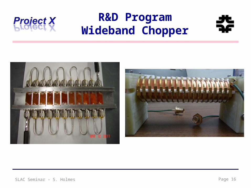
• The primary elements of the R&D program include:– Development of a wide-band chopper
• Capable of removing bunches in arbitrary patterns at a 162.5 MHz bunch rate
– Development of an H- injection system • Require between 4.4 – 26 msec injection period, depending on
pulsed linac operating scenario– Superconducting rf development
• Includes six different cavity types at three different frequencies• Emphasis is on Q0, rather than high gradient
– Typically 2E10, 15 MV/m (CW)– 1.0E10, 25 MV/m (pulsed)
• Includes appropriate rf sources• Includes development of partners
• Goal is to complete R&D phase by 2015
SLAC Seminar - S. Holmes Page 14

R&D ProgramWideband Chopper
• Approach– Four wideband kickers place at
180o in the 2.5 MeV MEBT• Helical or meander-stripline
travelling wave deflectors– Wideband amplifier
• Requirements– 1 nsec rise/fall time– 1 nsec flat top pulse duration– 50-200 Ω load impedance– >500 V pulse amplitude– >60 MHz average repetition rate
• Performance (simulation)– 0.16% beam loss with kicker off– 100% beam removal with kicker on
SLAC Seminar - S. Holmes Page 15
R&D ProgramWideband Chopper
SLAC Seminar - S. Holmes Page 16

R&D Program H- Injection
• RDR Configuration– Inject and accumulate into the Recycler with single turn transfer to MI – Injection charge 26 mA-ms (1 mA × 4.4 ms – 6 injections and 10 Hz)
• Optional configuration of interest– Inject 1 mA directly into the Main Injector in a single pulse over 26 ms, bypassing
the Recycler• Reduced complexity• Reduced linac energy, from 8 to 6 GeV
• Default technology Carbon Foil Charge Exchange (stationary foil)– Low beam current/long injections time creates many “parasitic” interactions, and
dominate the foil issues:• Foil heating, beam loss, emittance growth. (c.f. 1 mA 2300 turns)
– Number of parasitic hits determined by injection insertion design, number of injection turns, linac and ring emittance, painting algorithm, foil size and orientation.
– Issues appear manageable up to about 4.3 msec (400 turns).
SLAC Seminar - S. Holmes Page 17

R&D Program H- Injection
• Injection Stripping technologies (2300 turns)– Unique foil implementation designs-> moving, rotating, segmented– Laser Assisted Stripping (3 Step process)
• Laser Power Estimates
• Implementation Options– Direct illumination (advances in cryogenic laser amplifiers)– Build up cavity (low power laser but requires cavity in high radiation area)– Use higher wavelength (i.e. 2 mm) to reduce laser power by factor of 4 or 5
SLAC Seminar - S. Holmes Page 18
Laser parameters SNS Prj XWavelength [nm] 355 1064
Pulse length [ps] 30 28
Pulse freq. [Mhz] 400 325
Pulse duration [ms] 1 1 to 30
Rep rate [Hz] 60 10 to 1
Peak Power [MW] 0.39 5 to 10
Pulse Energy [mJ] 0.03 0.4 – 0.7
Power @pulse freq [kW]
12 130 - 230Estimates by T. Gorlov, SNS

SRF LinacTechnology Map
SLAC Seminar - S. Holmes
b=0.11 b=0.22 b=0.4 b=0.61 b=0.9
325 MHz2.5-160 MeV
b=1.0
1.3 GHz3-8 GeV
650 MHz0.16-3 GeV
Section Freq Energy (MeV) Cav/mag/CM Type
SSR0 (bG=0.11) 325 2.5-10 18 /18/1 SSR, solenoid
SSR1 (bG=0.22) 325 10-42 20/20/ 2 SSR, solenoid
SSR2 (bG=0.4) 325 42-160 40/20/4 SSR, solenoid
LB 650 (bG=0.61) 650 160-460 36 /24/6 5-cell elliptical, doublet
HB 650 (bG=0.9) 650 460-3000 160/40/20 5-cell elliptical, doublet
ILC 1.3 (bG=1.0) 1300 3000-8000 224 /28 /28 9-cell elliptical, quad
CW Pulsed
Page 19

3 GeV CW LinacBeam Dynamics at 1 mA
• 1 s beam envelopes– Transverse (upper)– Longitudinal (lower)
SLAC Seminar - S. Holmes Page 20

3 GeV CW LinacEnergy Gain per Cavity
• Based on 5-cell 650 MHz cavity– Crossover point ~450 - 500 MeV
b=0.61
b=0.9
SLAC Seminar - S. Holmes Page 21
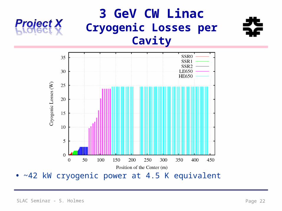
3 GeV CW LinacCryogenic Losses per Cavity
• ~42 kW cryogenic power at 4.5 K equivalent
SLAC Seminar - S. Holmes Page 22

SRF DevelopmentIntegrated ILC/ Project X Plan
Assemble Commission & Operate
InstallProcess & VTS
Dress & HTS
Design Procure
U.S. Fiscal Year
1.3 GHz CM1 (Type III+)
CM2 (Type III+) sw ap
CM3 (Type IV)2/3 CM
CM4 (Type IV) sw ap
CM5 (Type IV) sw ap
CM6 (Type IV+) CW Design
NML Extension Building Construction
NML Beam
CMTF Building
650 MHz Single Cell Design & Prototype
Five Cell Design & Prototype
CM650_1
325 MHzSSR0/SSR2 Design & Prototype
SSR1 Cavities in Fabrication (14)
CM325_1
Procurement (already in progress) Process & VTS/Dress/HTS
Design Procure 325 CM Parts 325 CM Ass'y
DesignOrder 650 Cav & CM
PartsProcess &
VTS/Dress/HTS650 CM Ass'y
Design (RF & Mechanical) all varieties of Spoke Reonators
Prototype (as required)
Process & Test(as required)
Install in CMTF
Design
Move injector/install beam components
Beam Available to RF Unit test except during installation periods (contingent upon cryogenic load/capacity)
Design Construction
Design CM1.3 GHz CW
Design Order Cav & CM Parts
FY14 FY15
Operate Complete RF
Unit @ Design Parameters
Omnibus Delay
CM Ass'y Install CM CM Test
Process & VTS/Dress/HTS CM Ass'y
2008 FY09 FY10 FY11 FY12 FY13
Page 23SLAC Seminar - S. Holmes

SLAC Seminar - S. Holmes
SRF DevelopmentCavity/ CM Status
• 1300 MHz– 88 nine-cell cavities ordered– ~ 44 received (16 from U.S. industry, AES)– ~ 30 processed and tested, 8 dressed– 1 CM built (DESY kit) + second under construction (U.S. procured)
• CM1 is now cold and rf testing is underway
• 650 MHz– MOU signed with Jlab for 2 single cell b =0.6 cavities – Order for six b = 0.9 single cell cavities in industry
• 325 MHz – 2 SSR1 b =0.22 cavities (Roark, Zannon) both VTS tested– 1 SSR1 dressed and under test at STF– 2 SSR1 being fabricated in India– 10 SSR1 ordered from Industry (Roark)
• Design work started on 325 and 650 MHz CM
Page 24

3 GeV CW LinacChoice of Cavity Parameters
• Identify maximum achievable surface (magnetic field) on basis of observed Q-slope “knee”
• Select cavity shape to maximizegradient (subject to physicalconstraints)
• Establish Q goal based on realistic extrapolation from current performance
– Goal: <25 W/cavity
• Optimize within (G, Q, T) space
(Initial) Performance Goals
Freq (MHz) Bpk(mT) G (MV/m) Q @T (K)325 60 15 1.4E10 2 650 72 16 1.7E10 2
Page 25SLAC Seminar - S. Holmes

SRF Development325 MHz
• SSR1 (b=0.22) cavity under development– Two prototypes assembled and tested – Both meet Project X specification at 2 K
• Preliminary designs for SSR0 and SSR2
SLAC Seminar - S. Holmes Page 26
SLAC Seminar - S. Holmes
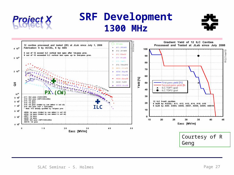
SRF Development1300 MHz
Page 27
Courtesy of R Geng
ILC
PX (CW)

28Final Assembly
HTSVTS
String Assembly MP9 Clean RoomVTS
1st U.S. built ILC/PX Cryomodule 1st Dressed Cavity
Cavity tuning machine
Fermilab SRF infrastructure
SLAC Seminar - S. Holmes
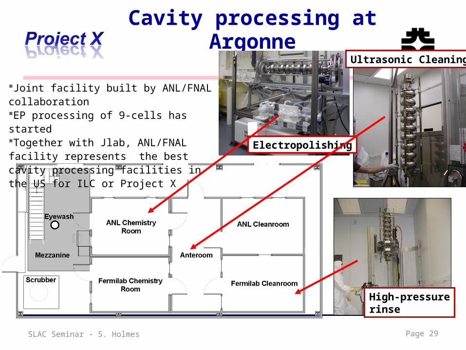
Cavity processing at Argonne
Electropolishing
High-pressurerinse
Ultrasonic Cleaning
Joint facility built by ANL/FNAL collaborationEP processing of 9-cells has startedTogether with Jlab, ANL/FNAL facility represents the best cavity processing facilities in the US for ILC or Project X
Page 29SLAC Seminar - S. Holmes

IB4 Tumbling Machine
• Multi-step process for elliptical cavities using multiple sets of media
• Current results represent an intermediate step towards a more complete process
• MUCH less infrastructure required
• Complete descriptions in prep for publication, presentation at TTC, SRF 2011
SLAC Seminar - S. Holmes Page 30
Test Facilities
• New Muon Lab (NML) facility under construction for ILC RF unit test– Three CM’s driven from a single rf source– 9 mA x 1 msec beam pulse– Large extension and supporting infrastructure under construction
• Refrigerator to support full duty factor operations• Horizontal test stands for all frequencies• Building extension for additional CM’s and beam diagnostic area
• The Meson Detector Building (MDB) Test Facility ultimately comprises:
– 2.5 – 10 MeV beam (p, H-): 1% duty factor, 3 msec pulse• 325 MHz superconducting spoke cavity beam tests• Chopper tests• H- beam instrumentation development
– Shielded enclosures and RF power systems for testing individual, jacketed 1.3 GHz, 650 MHz, and 325 MHz superconducting RF cavities
SLAC Seminar - S. Holmes Page 31
SLAC Seminar - S. Holmes Page 32
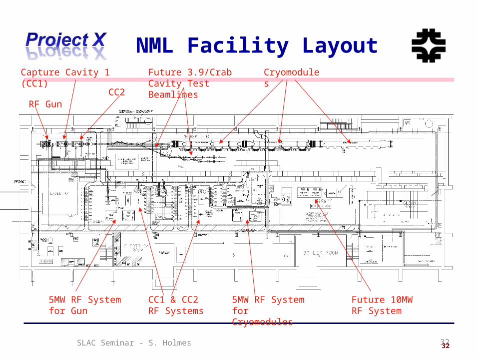
NML Facility Layout
32
CryomodulesCapture Cavity 1 (CC1)
5MW RF System for Gun
CC1 & CC2 RF Systems
RF Gun
5MW RF System for Cryomodules
Future 10MW RF System
CC2
Future 3.9/Crab Cavity Test Beamlines

SLAC Seminar - S. Holmes Page 33
ILCTA_NML Facility

FNAL Cryomodules
Cryomodule 1 built from DESY kit, Installed in NML
3.9 GHz CryomoduleDesigned/built at FNAL for DESYInstalled and Operating in FLASH
Cryomodule 2: cold mass parts from Europe in hand, accumulating the required 8 HTS tested cavities
Page 34SLAC Seminar - S. Holmes

SLAC Seminar - S. Holmes Page 35
Expansion of NML Facility
Existing NML Building
New Cryoplant & CM Test Facility(300 W Cryogenic Plant, Cryomodule Test Stands, 10 MW RF Test Area)
New Underground Tunnel Expansion
(Space for 6 Cryomodules (2 RF Units), AARD Test Beam Lines)
Funded by ARRA

Page 36
Future NML Complex
SLAC Seminar - S. Holmes
SLAC Seminar - S. Holmes
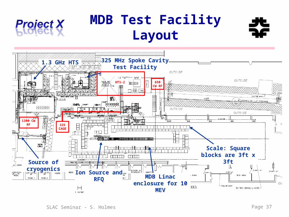
MDB Test Facility Layout
Page 37
325 MHz Spoke Cavity Test Facility
1.3 GHz HTS
MDB Linac enclosure for 10
MEV
Source of cryogenics Ion Source and
RFQ
Scale: Square blocks are 3ft x 3ft
650 CW RF
HTS-2
1300 CW RF 325
CAGE

MDB Test Facility325 MHz RFQ
Page 38SLAC Seminar - S. Holmes

MDB Test FacilitySix-Cavity Test
• Demonstrate use of high power RF vector modulators to control multiple RF cavities driven by a single high power klystron
– Summer 2011
Page 39SLAC Seminar - S. Holmes

13.4 m16.9 m
10.5 foot ceiling
MDB Long Term PlanChopper and 4-Cavity CM
2.4 m cryostat
0.5 m end
0.5 m end
0 m 10.5 m 14.2 m
18° spectrometer ~2.7 m length
Existing ion source and RFQ
10 m MEBT/CHOPPER
Actual absorber/shielding
With cryomodule need additional 3+ meters cave
length pending spectrometer line optics design
SLAC Seminar - S. Holmes Page 40
CD-0 Strategy/Status
• Requirements– Mission Needs Statement – approved by Director/Office of Science
• Includes a cost range and funding profile– Independent Cost Review – new requirement– CD-1 Plan– Mission Validation Independent Review
• DOE sponsored Intensity Frontier Physics Workshop: fall 2011
• Staging– Serious discussion of a staged approach. Building blocks:
• LBNE @ 2 MW (60-120 GeV)• Rare process program @ 3 MW (3 GeV)• Short baseline neutrinos (3-8 GeV)
– Motivated by desirability to reduce costs of initial steps• Reference Design: ~$1.8B• CW Linac: ~$1.2B• “Day-one” experimental program ~$0.2B
SLAC Seminar - S. Holmes Page 41

Collaboration Status
• Collaboration MOU for R&D phase:ANL ORNL/SNSBNL MSUCornell TJNAFFermilab SLAC LBNLILC/ART
• MOU/Addendum on development of High Intensity Proton Accelerators in place between Fermilab and Indian institutes:
BARC/Mumbai RRCAT/IndoreIUAC/Delhi VECC/Kolkota
• Currently working on defining strawman assignments for the construction phase– Reflects in R&D assignments
• Draft Collaboration Governance Plan– Discussion in Collaboration Council Meeting
Page 42SLAC Seminar - S. Holmes

Summary
• Project X is central to the U.S. strategy for accelerator based particle physics over the coming decades– World leading programs in neutrinos and rare processes;– Aligned with Muon Accelerators technology development;– Potential applications beyond elementary particle physics
• Reference Design established as preferred concept– 5 MW beam power available
• 3MW at 3 GeV for rare processes• 2 MW at 60-120 GeV for long baseline neutrinos
– CW linac is unique for this application, and offers capabilities that would be hard/impossible to duplicate in a synchrotron
– Configuration stable for more than a year
• R&D program underway with very significant investment in srf infrastructure and development
• DOE sponsored Physics Workshop this fall• Planning based on construction over the period FY16-20
Page 43SLAC Seminar - S. Holmes

SLAC Seminar - S. Holmes 44

Backup Slides
Page 45SLAC Seminar - S. Holmes

SLAC Seminar - S. Holmes Page 46

SLAC Seminar - S. Holmes Page 47

SLAC Seminar - S. Holmes Page 48

Configuration Evolution Physics Requirements
Proton Energy (kinetic)
Beam Power Beam Timing
Rare Muon decays 2-3 GeV >500 kW 1 kHz – 160 MHz
(g-2) measurement 8 GeV 20-50 kW 30- 100 Hz.
Rare Kaon decays 2.6 – 4 GeV >500 kW 20 – 160 MHz. (<50 psec pings)
Precision K0 studies 2.6 – 3 GeV > 100 mA (internal target)
20 – 160 MHz.(<50 psec pings)
Neutron and exotic nuclei EDMs
1.5-2.5 GeV >500 kW > 100 Hz
Page 49SLAC Seminar - S. Holmes

SLAC Seminar - S. Holmes Page 50
Phase-1 Layout of NML
50
Cryomodule-1 (CM1) (Type III+)
Capture Cavity 2 (CC2)
CC2 RF System5 MW RF System for CM1

Joint PX/NF/MC Strategy
• Project X shares many features with the proton driver required for a Neutrino Factory or Muon Collider– NF and MC require ~4 MW @
10 5 GeV– Primary issues are related to
beam “format”• NF wants proton beam on
target consolidated in a fewbunches; Muon Collider requiressingle bunch
– Project X linac is not capable ofdelivering this format
Þ It is inevitable that a new ring(s) will be required to produce the correct beam format for targeting.
SLAC Seminar - S. Holmes Page 51

RD&D PlanInstitutional Activities
Front End
Cav & CMs
RF Cryo Instru Cntrls MI/Recycler
Beam Trnspt
Accel Phys
Systm Integ
Test Facil
ANL X X X
BNL X
Cornell X X
Fermilab X X X X X X X X X X X
LBNL X X X
SNS X
MSU X ?
TJNAF X
SLAC X X X X X
ILC/ART X
BARC X X X X
IUAC X
RRCAT X X
VECC X
Page 52SLAC Seminar - S. Holmes

Page 53
CM1 moving to NML
SLAC Seminar - S. Holmes
Related Documents


