PROJECT SCOPING REPORT/ FINAL DESIGN REPORT September 2013 1 U.S. Department of Transportation Federal Highway Administration NEW YORK STATE DEPARTMENT OF TRANSPORTATION ANDREW M. CUOMO, Governor JOAN MCDONALD, Commissioner Bridge Replacement Project, P.I.N. 0229.40, BIN: 1049350 Carlls Straight Path over I-495 (Long Island Expressway) Town of Huntington Suffolk County

Welcome message from author
This document is posted to help you gain knowledge. Please leave a comment to let me know what you think about it! Share it to your friends and learn new things together.
Transcript
PROJECT SCOPING REPORT/ FINAL DESIGN REPORT
September 2013
1
U.S. Department of Transportation Federal Highway Administration
NEW YORK STATE DEPARTMENT OF TRANSPORTATION ANDREW M. CUOMO, Governor JOAN MCDONALD, Commissioner
Bridge Replacement Project, P.I.N. 0229.40, BIN: 1049350
Carlls Straight Path over I-495 (Long Island Expressway) Town of Huntington
Suffolk County

September 2013 Project Scoping Report/Final Design Report PIN 0229.40
The following table of approximate conversion factors provides the relationship between metric and U.S. Customary units for some of the more frequently used units in highway design. The table allows one to calculate the U.S. Customary Unit by multiplying the corresponding Metric Unit by the given factor.
Metric Unit x Factor = U.S. Customary Unit
Length
kilometer (km) x 0.621 = miles (mi)
meter (m) x 3.281 = feet (ft.)
Area hectare (ha) x 2.471 = acres (a)
square meter (m2) x 1.196 = square yards (sy)
square meter (m2) x 10.764 = square feet (sf)
Volume cubic meter (m3) x 1.308 = cubic yards (cy)
cubic meter (m3) x 35.315 = cubic feet (cf)
Speed kilometer per hour (km/h) x 0.621 = miles per hour (mph)
meter per second (m/s) x 3.281 = feet per second (ft/s)


September 2013 Project Scoping Report/Final Design Report PIN 0229.40
TABLE OF CONTENTS
COVER (Title / PIN / Location) METRIC TO U.S. CUSTOMARY UNIT CONVERSION TABLE (also on back cover) ............................ i PROJECT APPROVAL SHEET .............................................................................................................. ii LIST OF PREPARERS .......................................................................................................................... iii CHAPTER 1 – EXECUTIVE SUMMARY 1.1 Introduction ................................................................................................................................... 1-1 1.2 Purpose and Need ........................................................................................................................ 1-1 1.2.1 Where is the Project Located? ........................................................................................ 1-1 1.2.2 Why is the Project Needed? ............................................................................................ 1-2 1.2.3 What are the Objectives/Purposes of the Project?.......................................................... 1-2 1.3 What Alternative(s) is Being Considered? .................................................................................... 1-2 1.4 Environmental Review .................................................................................................................. 1-4 1.5 How will the Alternatives Affect the Environment? ....................................................................... 1-4 1.6 What are the Costs and Schedules? ............................................................................................ 1-5 1.7 Which Alternative is Preferred? .................................................................................................... 1-6 1.8 Who will decide which Alternative is Chosen and How Can I be Involved in this Decision? ....... 1-6 CHAPTER 2 – PROJECT INFORMATION 2.1 Local Plans for the Project Area ................................................................................................... 2-1 2.2 Abutting Highway Segments and Future Plans for Abutting Highway Segments ........................ 2-1 2.3 Transportation Conditions, Deficiencies and Engineering Considerations .................................. 2-1 2.3.1 Traffic and Safety and Maintenance Operations ................................................................ 2-1 2.3.1.1 Functional Classification and National Highway System (NHS) ............................ 2-1 2.3.1.2 Control of Access ................................................................................................... 2-2 2.3.1.3 Traffic Control Devices .......................................................................................... 2-2 2.3.1.4 Traffic Volumes ...................................................................................................... 2-2 2.3.1.5 Speeds ................................................................................................................... 2-3 2.3.1.6 Level of Service ..................................................................................................... 2-3 2.3.1.7 Work Zone Safety and Mobility .............................................................................. 2-3 2.3.1.8 Safety Considerations, Accident History and Analysis .......................................... 2-3 2.3.1.9 Ownership and Maintenance Jurisdiction .............................................................. 2-4 2.3.2 Multimodal ........................................................................................................................... 2-4 2.3.2.1 Pedestrians ............................................................................................................ 2-4 2.3.2.2 Bicyclists ................................................................................................................ 2-5 2.3.3 Infrastructure ....................................................................................................................... 2-5 2.3.3.1 Design Standards .................................................................................................. 2-5 2.3.3.2 Critical Design Elements ........................................................................................ 2-5 2.3.3.3 Other Design Parameters ...................................................................................... 2-6 2.3.3.4 Existing and Proposed Highway/Bridge Plan and Section .................................... 2-6 2.3.3.5 Non Standard/Non Conforming Features .............................................................. 2-6 2.3.3.6 Pavement and Shoulder Conditions ...................................................................... 2-6 2.3.3.7 Drainage Systems ................................................................................................. 2-7 2.3.3.8 Geotechnical .......................................................................................................... 2-7 2.3.3.9 Structures ............................................................................................................... 2-7 2.3.3.10 Hydraulics of Bridges and Culverts ..................................................................... 2-10 2.3.3.11 Utilities ................................................................................................................. 2-10 2.3.3.12 Guide Railing, Median Barriers and Impact Attenuators ..................................... 2-11 2.3.3.13 Right of Way ........................................................................................................ 2-11 2.3.3.14 Landscaping/Environmental Enhancement ......................................................... 2-11 2.4 Miscellaneous ............................................................................................................................. 2-11
iv
September 2013 Project Scoping Report/Final Design Report PIN 0229.40
v
CHAPTER 3 – SOCIAL, ECONOMIC AND ENVIRONMENTAL CONSIDERATIONS 3.1 National Environmental Policy Act (NEPA) .................................................................................. 3-1 3.2 State Environmental Quality Review Act (SEQRA) ...................................................................... 3-1 3.3 Additional Environmental Information ........................................................................................... 3-2
APPENDICES
A. Maps, Plans, Profiles & Typical Sections B. Environmental Information C. Traffic Information and Pedestrian Generator Checklist D. Public Information Plan
September 2013 Project Scoping Report/Final Design Report PIN 0229.40
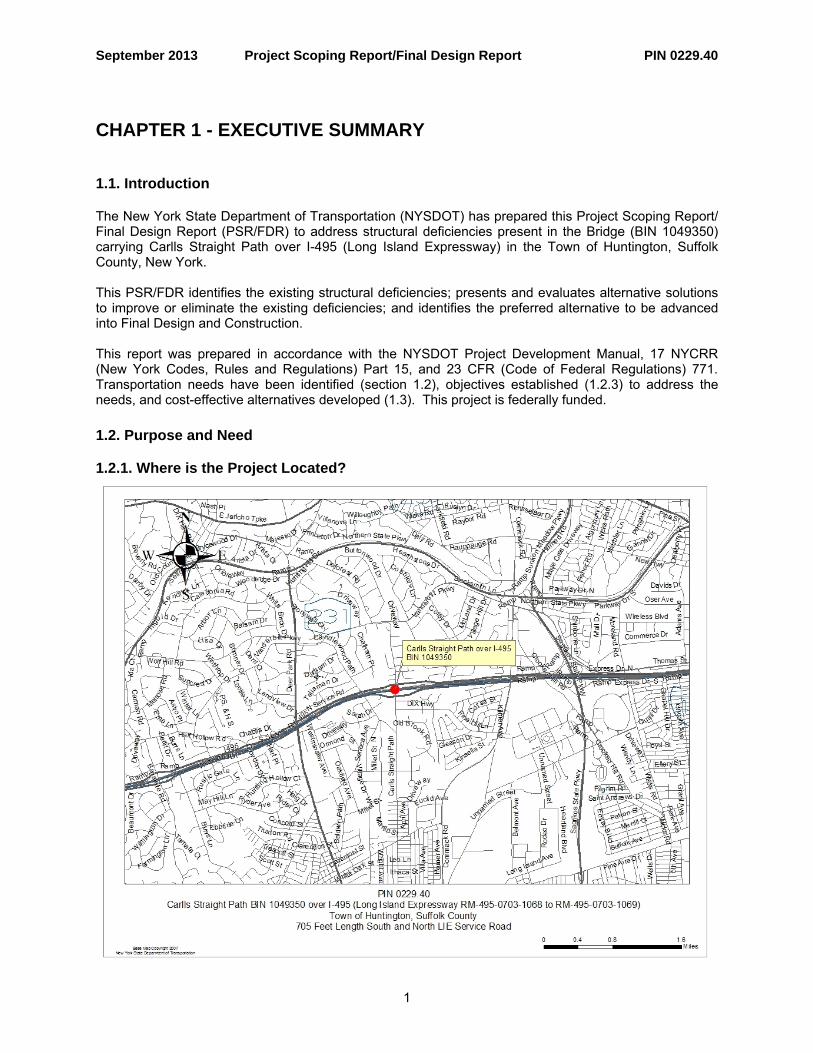
CHAPTER 1 - EXECUTIVE SUMMARY 1.1. Introduction The New York State Department of Transportation (NYSDOT) has prepared this Project Scoping Report/ Final Design Report (PSR/FDR) to address structural deficiencies present in the Bridge (BIN 1049350) carrying Carlls Straight Path over I-495 (Long Island Expressway) in the Town of Huntington, Suffolk County, New York. This PSR/FDR identifies the existing structural deficiencies; presents and evaluates alternative solutions to improve or eliminate the existing deficiencies; and identifies the preferred alternative to be advanced into Final Design and Construction. This report was prepared in accordance with the NYSDOT Project Development Manual, 17 NYCRR (New York Codes, Rules and Regulations) Part 15, and 23 CFR (Code of Federal Regulations) 771. Transportation needs have been identified (section 1.2), objectives established (1.2.3) to address the needs, and cost-effective alternatives developed (1.3). This project is federally funded. 1.2. Purpose and Need
1.2.1. Where is the Project Located?
1

September 2013 Project Scoping Report/Final Design Report PIN 0229.40
1.2.2. Why is the Project Needed? This project proposes to address structural deficiencies associated with normal deterioration, fatigue-prone special emphasis details, and impact damage. The structural deficiencies include the poor condition of the deck, deck joints, sidewalks, damaged and deteriorated girders, deteriorated and outdated bearings, and deteriorated pier caps with substructures inadequate to resist seismic forces. The stringers in the long center spans over the Long Island Expressway (LIE) have cover plates attached with transverse welds. Additionally, operational deficiencies exist with the structure involving inadequate bicycle accommodations on Carlls Straight Path, and a need for an increase in the span to accommodate increased horizontal clearance on the LIE for anticipated extension of the access ramps for the truck rest stops just east of the structure.
1.2.3. What are the Objectives/Purposes of the Project?
(1) Restore the bridge condition rating to 5, or greater, for at least 75 years using cost effective techniques to minimize the life cycle cost of maintenance and repair.
(2) Address the structural deficiencies of the girders, bearings, and deck. (3) Increase the minimum vertical clearance over the LIE to 14’-6” to prevent damage to primary and
secondary members from impacts, while optimizing beam depth. (4) Provide for standard horizontal and vertical clearances on the LIE for the anticipated future
extension of the deceleration and acceleration lanes for the truck rest stops east of the bridge. (5) Provide standard bicyclist and pedestrian accommodations along Carlls Straight Path.
1.3. What Alternative is Being Considered? Project alternatives were developed to meet the overall project objectives. A No Build or "No Action" Alternative is presented to establish a baseline of comparison for no remedial action. Alternative 1 - No Build The No Build Alternative will make no physical improvements to the bridge but will continue NYSDOT's current maintenance and repair efforts, addressing the most serious areas of deterioration while maintaining the bridge in a state of good repair. Critical structural deficiencies would remain unaddressed. This alternative will result in the continued deterioration of the bridge elements, especially the deck which will increase the likelihood of localized deck spalls and deterioration of the stay-in-place forms creating a hazard to traffic on the Long Island Expressway. The girders over the Long Island Expressway will continue to suffer impact damage due to the low vertical clearance. The existing substructures are in the same spatial location as the anticipated future extension of the LIE deceleration and acceleration lanes for the truck rest stops east of the bridge, and their retention would make the LIE deceleration and acceleration lane extensions impractical to construct. This alternative will not rectify the structural or operational deficiencies as outlined in the project objectives. The No Build Alternative was eliminated from further consideration because it will not meet the project objectives. Alternative 2 - Superstructure Replacement When this alternative was initially developed, it was prior to the realization that the project needed to accommodate the anticipated future extension of the LIE deceleration and acceleration lanes for the truck rest stops just east of the bridge. However, because the existing substructures would remain in the same
2

September 2013 Project Scoping Report/Final Design Report PIN 0229.40
spatial locations where the deceleration and acceleration lane extensions would be constructed, their retention would make the lane extensions impractical to construct, and as a result this alternative was eliminated from further consideration. Although discarded, it is still presented here to document its initial consideration. This alternative considered replacing the existing four-span superstructure. The existing superstructure would be demolished and removed. The new superstructure would be designed to accommodate the AASHTO HL-93 Live Load. Continuity of stringers at the center pier would be considered. This continuity would reduce the current seismic deficiency related to insufficient seat length and would reduce the possibility of span collapse in the longitudinal direction. The stringers at the abutments and the pier would be supported on the seat at the same level which would reduce the vulnerability to the loss of support related to the inadequate restraint in the transverse direction. The scope of work also included minor substructure repairs, new bearings, new bridge approach slabs, new median barriers and bridge railings and approach pavement reconstruction. This alternative would be expected to provide an additional 75 years of service life for the bridge structure provided that the substructures are rehabilitated periodically. The vertical clearance would be improved with this alternative, but may not provide the full clearance required to avoid all future collision damage. The proposed roadway section at the bridge would be the same as the existing roadway section. Since a new superstructure would be provided, the need for costly maintenance repairs associated with regular painting cycles would be significantly reduced. As stated earlier, since the existing substructures would be in the same spatial location as the anticipated future extension of the LIE deceleration and acceleration lanes, their retention would make the LIE deceleration and acceleration lane extensions impractical to construct. Also, since the existing bridge substructures do not meet current seismic standards, both significant retrofit and reconstruction to support a new wider bridge superstructure is also not practical, as better materials and attaining current design standards, and innovation of construction are all better-served by replacement of the existing bridge pier and abutment substructures for the current design load conditions. The cost for this alternative is $6.86M. This cost is 94% of the replacement cost. When the rehabilitation cost exceeds 85% of the replacement cost, bridge replacement is preferred. Although this alternative would address most of the structural deficiencies, it does not address all of the operational deficiencies or future needs, as described above and in the project objectives. The Superstructure Replacement Alternative was eliminated from further consideration. Alternative 3 – Bridge Replacement With this alternative, the bridge will be replaced with a two-span continuous superstructure to address the structural deficiencies associated with the deteriorated deck, girders, and bearings, along with other structural elements. The new deck will insure that the bridge remains serviceable for at least 75 years. A new deck will eliminate the need for a wearing surface replacement and costly maintenance repairs associated with eventual underside deck spalls as the stay-in-place forms fail due to corrosion. Further, elimination of the existing transverse deck joints will result in maintenance cost savings. This alternative will insure the bridge meets all modern requirements for seismic resistance. In addition, the new bridge will have increased roadway width to meet pedestrian and bicycle needs. Vertical clearances will be increased above the minimum to the desirable for interstates. By replacing the existing substructures and increasing the span length over the LIE, allowances can be made for the anticipated increase in length of acceleration and deceleration lanes for the truck rest stops just east of the bridge. The new bridge can be constructed on a slightly improved alignment which will conform to the
3
September 2013 Project Scoping Report/Final Design Report PIN 0229.40
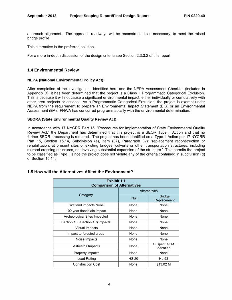
approach alignment. The approach roadways will be reconstructed, as necessary, to meet the raised bridge profile. This alternative is the preferred solution. For a more in-depth discussion of the design criteria see Section 2.3.3.2 of this report. 1.4 Environmental Review NEPA (National Environmental Policy Act): After completion of the investigations identified here and the NEPA Assessment Checklist (included in Appendix B), it has been determined that the project is a Class II Programmatic Categorical Exclusion. This is because it will not cause a significant environmental impact, either individually or cumulatively with other area projects or actions. As a Programmatic Categorical Exclusion, the project is exempt under NEPA from the requirement to prepare an Environmental Impact Statement (EIS) or an Environmental Assessment (EA). FHWA has concurred programmatically with the environmental determination. SEQRA (State Environmental Quality Review Act): In accordance with 17 NYCRR Part 15, “Procedures for Implementation of State Environmental Quality Review Act,” the Department has determined that this project is a SEQR Type II Action and that no further SEQR processing is required. The project has been identified as a Type II Action per 17 NYCRR Part 15, Section 15.14, Subdivision (e), Item (37), Paragraph (iv): ‘replacement reconstruction or rehabilitation, at present sites of existing bridges, culverts or other transportation structures, including railroad crossing structures, not involving substantial expansion of the structure.’ This permits the project to be classified as Type II since the project does not violate any of the criteria contained in subdivision (d) of Section 15.14. 1.5 How will the Alternatives Affect the Environment? Exhibit 1.1 Comparison of Alternatives Alternatives Category Bridge
Replacement Null
Wetland impacts None None None 100 year floodplain impact None None
Archeological Sites Impacted None None Section 106/Section 4(f) impacts None None
Visual Impacts None None Impact to forested areas None None Noise Impacts None None
Suspect ACM identified Asbestos Impacts None
Property impacts None None
Load Rating HS 20 HL 93 Construction Cost None $13.02 M
4

September 2013 Project Scoping Report/Final Design Report PIN 0229.40
Anticipated Permits/Certifications/Coordination:
Coordination • Coordination with Federal Highway Administration
Certifications
• NYS Department of Labor: Asbestos Variances; if determined to be necessary
Others • Construction Staging Permit • Town of Huntington Inspection Permit
1.6 What are the Costs & Schedules?
Exhibit 1.3 – Comparison of Alternatives’ Project Costs (in millions)
Bridge Replacement
Activities
Construction Costs
Bridge $7.26 Highway $0.72 SPDES Permit Compliance $0.00
Incidentals (10%) $0.80
Subtotal 1 $8.77 Contingency (15% at Design
Approval) $1.32
Subtotal 2 $10.08
Field Change Order $0.00
Subtotal 3 $10.08
Mobilization (4%) $0.40 Subtotal 4 $10.49 Design (8%) $0.84
Expected Award Amount (Inflate current costs/prices at
3%/yr. to midpoint of construction to arrive at $
amount to be entered here) See HDM 21.6.3.2 B
$0.64 Construction Inspection (10%) $1.05 ROW Costs $0
Total Alternative Costs $13.02
5

September 2013 Project Scoping Report/Final Design Report PIN 0229.40
Design Approval is scheduled for October 2013 with Construction scheduled to last 19 months beginning in April of 2014.
Exhibit 1.2 - Project Schedule
Activity Date Occurred/Tentative
Final RFQ Issuance 8/28/2013 Design Approval 10/16/2013
Final RFP Issuance 11/15/2013 Proposals Due 1/15/2014 Design-Build Notice to Proceed 4/15/2014
Construction Complete 11/10/2015 1.7 Which Alternative is Preferred? Only one feasible build alternative, Alternative 3 – Bridge Replacement, has been identified that meets the project objectives. A decision to enter final design will not be made until after the environmental determination and evaluation of the comments on the draft design approval document. 1.8 Who Will Decide Which Alternative is Chosen And How Can I Be Involved In This Decision? A Public Involvement Plan (PIP) has been prepared in accordance with the NYSDOT PDM. There may be a Public Information Meeting during the project design, if determined by NYSDOT to be of benefit to the public. A Public Hearing will not be required. Refer to Appendix D for the PIP. Notification letters will be sent to public officials and project stakeholders announcing the project. Meetings with Internal and External Stakeholders will be held, as needed.
Exhibit 1.4 Public Involvement Plan Schedule of Milestone Dates
Activity Date Occurred/Tentative
Notification letters sent to public officials TBD
Notification letters sent to project stakeholders TBD
Design-Build Notice to Proceed 4/15/2014
Public Information Meeting Summer 2014
6
September 2013 Project Scoping Report/Final Design Report PIN 0229.40
7
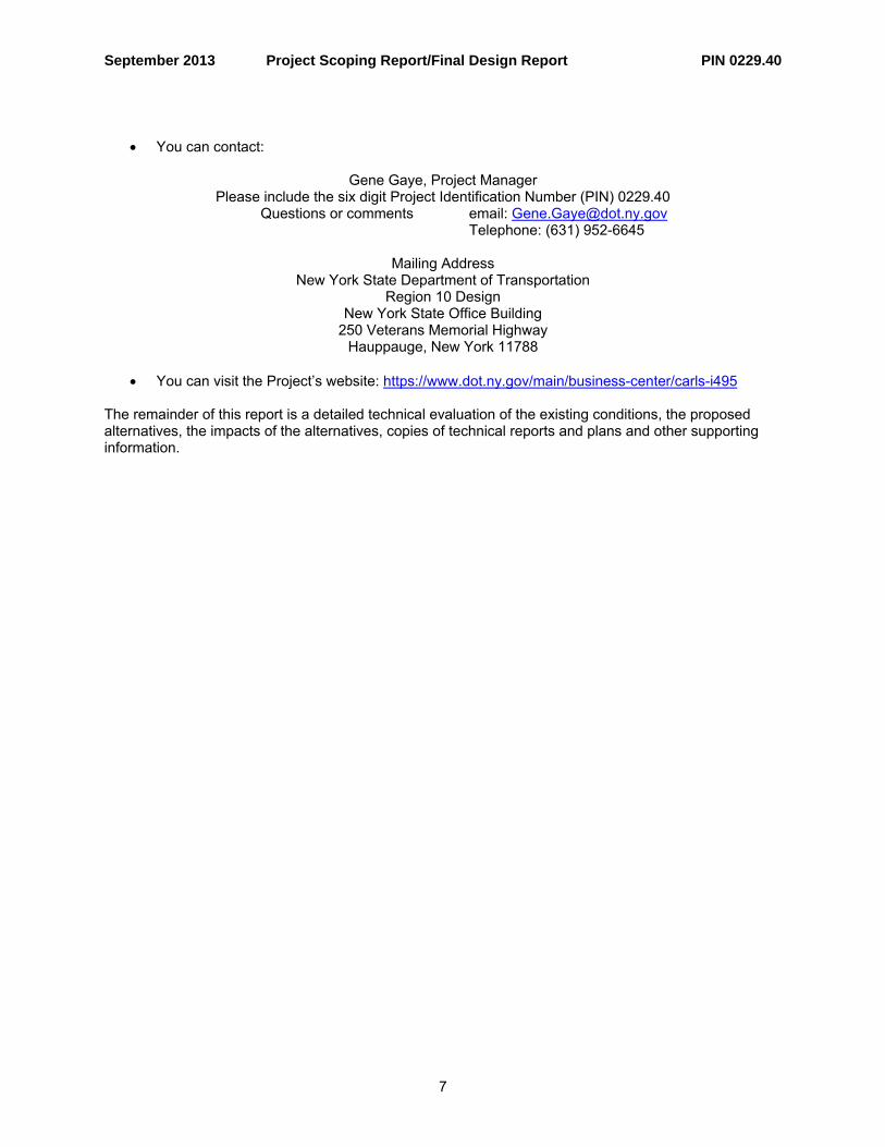
• You can contact:
Gene Gaye, Project Manager
Please include the six digit Project Identification Number (PIN) 0229.40 Questions or comments email: [email protected]
Telephone: (631) 952-6645
Mailing Address New York State Department of Transportation
Region 10 Design New York State Office Building
250 Veterans Memorial Highway Hauppauge, New York 11788
• You can visit the Project’s website: https://www.dot.ny.gov/main/business-center/carls-i495
The remainder of this report is a detailed technical evaluation of the existing conditions, the proposed alternatives, the impacts of the alternatives, copies of technical reports and plans and other supporting information.

September 2013 Project Scoping Report/Final Design Report PIN 0229.40
CHAPTER 2 – PROJECT INFORMATION 2.1 Local Plans for the Project Area This project is on the approved Transportation Improvement Program (TIP) as project No. 0229.40. The TIP must be amended to reflect a change in the project type from bridge rehabilitation to bridge replacement. The Regional Planning Group has reviewed the local master plan prepared for the Town of Huntington. This project is consistent with the local master plan. There are no approved developments planned within the project area that will impact traffic operations. 2.2. Abutting Highway Segments and Future Plans for Abutting Highway Segments Carlls Straight Path between the south Service Road and Thornwood Drive and consists of one travel lane in each direction and a right turn lane. It is curbed on both sides with varying lane and shoulder widths. At Thornwood Drive, the roadway section consists of two 10 ft travel lanes and 6 ft curbed shoulders. Carlls Straight Path between Sweet Water Court and the north Service Road consists of one travel lane in each direction and a right turn lane. The roadway is curbed southbound with no shoulder and northbound has a varying width uncurbed shoulder. At Sweet Water Court, the roadway section consists of two 10 ft travel lanes and 6 ft curbed shoulders. The alignment is generally straight and level. The Regional Planning Group has confirmed that there are no plans to reconstruct or widen this segment of Carlls Straight Path, or the adjoining segments, within the next 20 years. On the segment of the LIE where the Carlls Straight Path bridge crosses over it, a future project is anticipated that will extend the acceleration and deceleration lanes for the eastbound and westbound truck rest stops east of the bridge. These lanes currently begin/end just east of the bridge and have non-conforming lengths. It is anticipated they would be extended underneath the bridge to some point west of the bridge. 2.3 Transportation Conditions, Deficiencies and Engineering Considerations
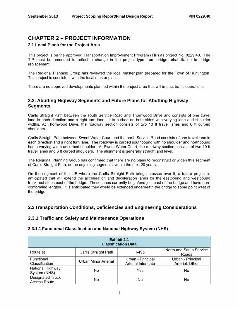
2.3.1 Traffic and Safety and Maintenance Operations 2.3.1.1 Functional Classification and National Highway System (NHS) –
Exhibit 2.1 Classification Data
North and South Service Roads Route(s) Carlls Straight Path I-495
Functional Classification Urban Minor Arterial Urban - Principal
Arterial Interstate Urban - Principal
Arterial, Other National Highway System (NHS) No Yes No
Designated Truck Access Route No No No
1
September 2013 Project Scoping Report/Final Design Report PIN 0229.40
Qualifying Highway No Yes No
Within 1.6 km of a Qualifying Highway Yes No Yes
Within the 4.9 m vertical clearance network No No No
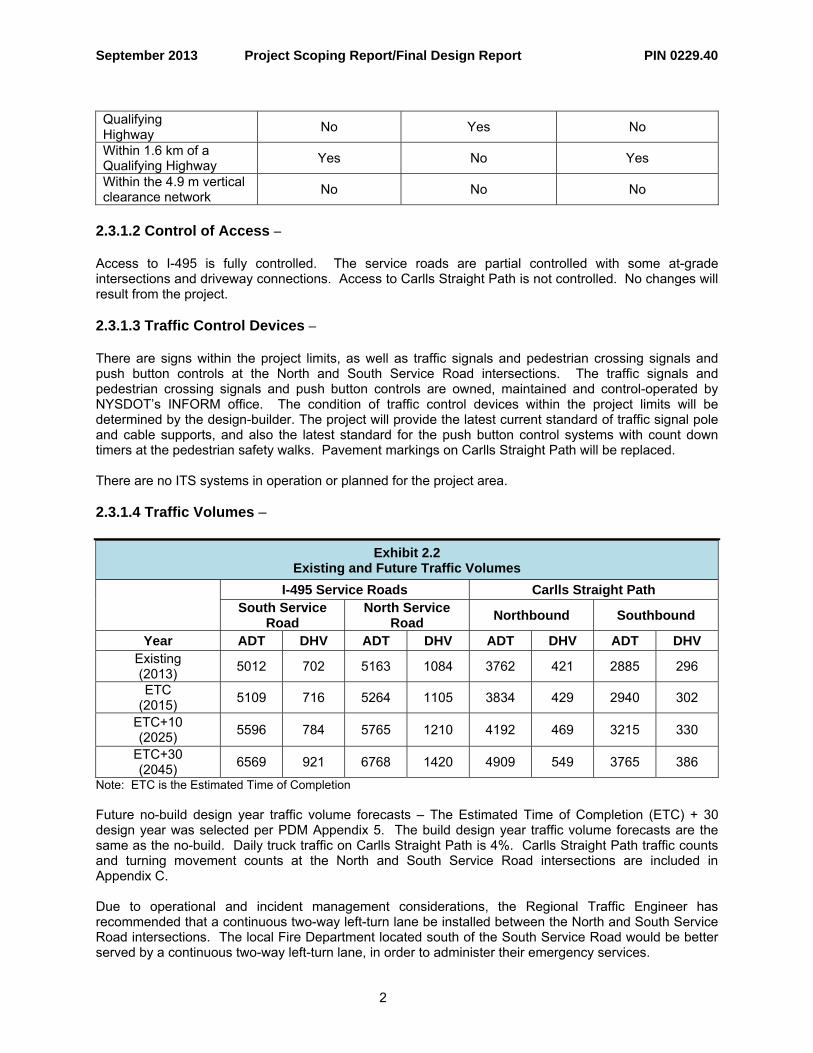
2.3.1.2 Control of Access – Access to I-495 is fully controlled. The service roads are partial controlled with some at-grade intersections and driveway connections. Access to Carlls Straight Path is not controlled. No changes will result from the project. 2.3.1.3 Traffic Control Devices – There are signs within the project limits, as well as traffic signals and pedestrian crossing signals and push button controls at the North and South Service Road intersections. The traffic signals and pedestrian crossing signals and push button controls are owned, maintained and control-operated by NYSDOT’s INFORM office. The condition of traffic control devices within the project limits will be determined by the design-builder. The project will provide the latest current standard of traffic signal pole and cable supports, and also the latest standard for the push button control systems with count down timers at the pedestrian safety walks. Pavement markings on Carlls Straight Path will be replaced. There are no ITS systems in operation or planned for the project area. 2.3.1.4 Traffic Volumes –
Exhibit 2.2 Existing and Future Traffic Volumes
I-495 Service Roads Carlls Straight Path
South Service Road
North Service Road Northbound Southbound
Year ADT DHV ADT DHV ADT DHV ADT DHV Existing (2013) 5012 702 5163 1084 3762 421 2885 296
ETC (2015) 5109 716 5264 1105 3834 429 2940 302
ETC+10 (2025) 5596 784 5765 1210 4192 469 3215 330
ETC+30 (2045) 6569 921 6768 1420 4909 549 3765 386
Note: ETC is the Estimated Time of Completion Future no-build design year traffic volume forecasts – The Estimated Time of Completion (ETC) + 30 design year was selected per PDM Appendix 5. The build design year traffic volume forecasts are the same as the no-build. Daily truck traffic on Carlls Straight Path is 4%. Carlls Straight Path traffic counts and turning movement counts at the North and South Service Road intersections are included in Appendix C. Due to operational and incident management considerations, the Regional Traffic Engineer has recommended that a continuous two-way left-turn lane be installed between the North and South Service Road intersections. The local Fire Department located south of the South Service Road would be better served by a continuous two-way left-turn lane, in order to administer their emergency services.
2

September 2013 Project Scoping Report/Final Design Report PIN 0229.40
2.3.1.5 Speeds –
Exhibit - 2.3 Speed Data
Route Carlls Straight Path Existing Speed Limit 30 mph
Operating Speed and Method Used for Measurement Spot Speed Study - 85th percentile speeds 41 mph SB and 37 mph NB
2.3.1.6 Level of Service The Regional Planning and Program Manager does not anticipate capacity improvements within 20 years. 2.3.1.7 Work Zone Safety & Mobility A. Work Zone Traffic Control Plan Two-way traffic will be maintained at all times via lane shifts onto the existing paved shoulder. No off-site detours will be required. Routes for emergency vehicles will be maintained and open during construction. The movement of pedestrians will be maintained during construction. The details for the work zone traffic control will be prepared and evaluated during final design. B. Special Provisions Due to the close proximity to residential homes and the ability to maintain traffic with acceptable delays during the daylight hours, night time construction will not be utilized. The use of time related provisions will be evaluated during final design. The work zone traffic control will need to be coordinated with local officials and residents. With a chance of vibration during construction that could cause cracking to home foundations, water district type water well heads, residential pools, cracks in home walls, etc., a Building Condition Survey, Report and Monitoring Plan will be required for residences and buildings in proximity to the project area. C. Significant Projects (per 23 CFR 630.1010) The Region has determined that the project is significant per 23 CFR 630.1010. A Transportation Management Plan (TMP) will be prepared for the project consistent with 23 CFR 630.1012. The TMP will consist of: • A Temporary Traffic Control (TTC) plan • A Transportation Operations (TO) component • A Public Information component (PI) 2.3.1.8 Safety Considerations, Accident History and Analysis Accident data from January 1, 2010 thru December 31, 2012 was analyzed in accordance with NYS Highway Design Manual Chapter 5. The accident rates for the intersection with the North Service Road and South Service Road is 0.078 accidents per million vehicle miles and 0.273 accidents per million vehicle miles respectively. Compared to the statewide accident rate for similar facilities, which is 0.24 accidents per million vehicle miles, the North Service Road intersection is below average and the South Service Road intersection is slightly above average. There are no high accident locations (HALs) within the study area.
3

September 2013 Project Scoping Report/Final Design Report PIN 0229.40
The predominate accident types are:
Exhibit 2.4 Collision Summary
Type of Collision Number Percentage Overtake 1 4 Fixed Object 10 43 RT Angle 6 26 Rear End 4 17 Right Turn Against 1 4 Other 1 4
An accident analysis including an accident summary and collision diagrams is in Appendix C. The crash experience is well below any threshold for consideration of enhancing existing or installing new traffic controls. Since the proposed project is not necessary to correct an existing or potential safety problem, the Regional Traffic and Safety Office has determined that consideration of accident countermeasures is not necessary. 2.3.1.9 Ownership and Maintenance Jurisdiction – NYSDOT owns the Carlls Straight Path bridge and is responsible for its maintenance, except for the bridge deck wearing surface. NYSDOT owns Carlls Straight Path between the North and South Service Roads and the Town of Huntington is responsible for its maintenance. NYSDOT owns and is responsible for maintenance within the right-of-way of the LIE. NYSDOT owns and provides snow and ice removal on the service roads adjacent to the LIE, while Suffolk County is responsible for all other maintenance. NYSDOT owns and maintains the two traffic signal and pedestrian cross walk push button control systems at the two service road intersections. The utilities carried on the bridge are owned and maintained by the respective utility providers. Under Highway Law (Section 340-d), the bridge deck wearing surface was required to be maintained by the Town of Huntington; however the Town has declined to provide that required maintenance. NYSDOT has since advised the Town that funds will be reduced from the CHIPS apportionments related to the cost of maintaining the wearing surface on bridges carrying Town of Huntington roads over the LIE. The project will result in no changes to the ownership and maintenance responsibilities, except that now NYSDOT will be responsible for maintaining the bridge deck wearing surface. 2.3.2 Multimodal 2.3.2.1 Pedestrians – Pedestrians are accommodated on the east side of Carlls Straight Path between the two service roads on concrete sidewalk from the north LIE Service Road intersection to 24 feet south of the bridge abutment, then from there to the south LIE Service Road intersection via paved shoulder. Pedestrians cross the two service roads at painted crosswalks with push button controls along the easterly side of Carlls Straight Path. There is concrete sidewalk on the west side of the bridge, but it does not extend to the north and south service road intersections. The project will provide for continuous pedestrian accommodation via concrete sidewalk along the east side of Carlls Straight Path between the north and south LIE Service Road intersections. Sidewalks will not be provided on the west side of Carlls Straight path. The crosswalks on the east side of intersections should be restriped, and given the proximity of the residential neighborhood to the Candlewood Middle
4
September 2013 Project Scoping Report/Final Design Report PIN 0229.40
School south of the bridge, pedestrian countdown timers should also be considered at the intersections to provide for pedestrian safety, and to support the Safe Routes to School Program objectives. A Pedestrian Generator Checklist is included in Appendix C. 2.3.2.2 Bicyclists – There is no bike path or bike lane currently on Carlls Straight Path; however, it is identified as a connecting route to the bicycle route on Vanderbilt Parkway. Currently, bicyclists share the roadway or use the varying width shoulder. The project will provide accommodation for bicyclists on the new 5 ft shoulders on both sides of Carlls Straight Path. 2.3.3 Infrastructure 2.3.3.1 Design Standards –
• NYSDOT Highway Design Manual Chapter 2 • NYSDOT Bridge Manual
2.3.3.2 Critical Design Elements
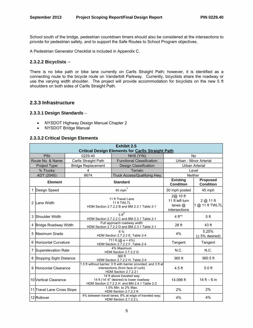
Exhibit 2.5 Critical Design Elements for Carlls Straight Path
PIN: 0229.40 NHS (Y/N): No Route No. & Name: Carlls Straight Path Functional Classification: Urban - Minor Arterial
Project Type: Bridge Replacement Design Classification: Urban Arterial % Trucks: 4 Terrain: Level
ADT (2045): 8674 Truck Access/Qualifying Hwy. Neither
Element Standard Existing Condition
Proposed Condition
1 Design Speed 45 mph1 30 mph posted 45 mph
2 Lane Width 11 ft Travel Lane
11 ft TWLTL HDM Section 2.7.2.2 B and BM 2.3.1 Table 2-1
2@ 10 ft 11 ft left turn
lanes @ intersections
2 @ 11 ft 1 @ 11 ft TWLTL
3 Shoulder Width 5 ft2 HDM Section 2.7.2.2 C and BM 2.3.1 Table 2-1 4 ft** 5 ft
4 Bridge Roadway Width Full approach roadway width HDM Section 2.7.2.2 D and BM 2.3.1 Table 2-1 28 ft 43 ft
5 Maximum Grade 6 % HDM Section 2.7.2.2 E, Table 2-4 4% 5.25%
(< 5% desired)
6 Horizontal Curvature 711 ft (@ e = 4%) HDM Section 2.7.2.2 F, Table 2-4 Tangent Tangent
7 Superelevation Rate 4% Maximum HDM Section 2.7.2.2 G N.C. N.C.
8 Stopping Sight Distance 360 ft HDM Section 2.7.2.2 H, Table 2-4 365 ft 360.5 ft
9 Horizontal Clearance 1.5 ft without barrier; 0 ft with barrier provided; and 3 ft at
intersections (from face of curb) HDM Section 2.7.2.2 l
4.5 ft 5.0 ft
10 Vertical Clearance 14 ft above traveled way
14 ft (14’-6” desired) to lower roadway HDM Section 2.7.2.2 H and BM 2.4.1 Table 2-2
14.096 ft 14 ft – 6 in
11 Travel Lane Cross Slope 1.5% Min. to 2% Max. HDM Section 2.7.2.2 K 2% 2%
12 Rollover 4% between travel lanes; 8% at edge of traveled way; HDM Section 2.7.2.2 L 4% 4%
5
September 2013 Project Scoping Report/Final Design Report PIN 0229.40
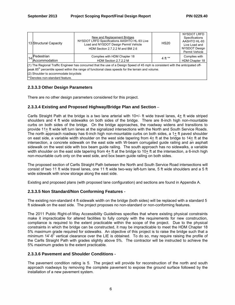
NYSDOT LRFD Specifications
AASHTO HL-93 Live Load and
NYSDOT Design Permit Vehicle
13 Structural Capacity
New and Replacement Bridges NYSDOT LRFD Specifications AASHTO HL-93 Live
Load and NYSDOT Design Permit Vehicle HDM Section 2.7.2.2 M and BM 2.6
HS20
14 Pedestrian Accommodation
Complies with HDM Chapter 18 HDM Section 2.7.2.2 M
4 ft ** Complies with HDM Chapter 18
(1) The Regional Traffic Engineer has concurred that the use of a Design Speed of 45 mph is consistent with the anticipated off-peak 85th percentile speed within the range of functional class speeds for the terrain and volume. (2) Shoulder to accommodate bicyclists
**Denotes non-standard feature.
2.3.3.3 Other Design Parameters
There are no other design parameters considered for this project. 2.3.3.4 Existing and Proposed Highway/Bridge Plan and Section – Carlls Straight Path at the bridge is a two lane arterial with 10+/- ft wide travel lanes, 4+ ft wide striped shoulders and 4 ft wide sidewalks on both sides of the bridge. There are 8-inch high non-mountable curbs on both sides of the bridge. On the bridge approaches, the roadway widens and transitions to provide 11+ ft wide left turn lanes at the signalized intersections with the North and South Service Roads. The north approach roadway has 6-inch high non-mountable curbs on both sides, a 1+ ft paved shoulder on east side, a variable width shoulder on the west side tapering from 4+ ft at the bridge to 14+ ft at the intersection, a concrete sidewalk on the east side with W-beam corrugated guide railing and an asphalt sidewalk on the west side with box beam guide railing. The south approach has no sidewalks, a variable width shoulder on the east side tapering from 4+ ft at the bridge to 10+ ft at the intersection, a 6-inch high non-mountable curb only on the west side, and box beam guide railing on both sides. The proposed section of Carlls Straight Path between the North and South Service Road intersections will consist of two 11 ft wide travel lanes, one 11 ft wide two-way left-turn lane, 5 ft wide shoulders and a 5 ft wide sidewalk with snow storage along the east side. Existing and proposed plans (with proposed lane configuration) and sections are found in Appendix A. 2.3.3.5 Non Standard/Non Conforming Features - The existing non-standard 4 ft sidewalk width on the bridge (both sides) will be replaced with a standard 5 ft sidewalk on the east side. The project proposes no non-standard or non-conforming features. The 2011 Public Right-of-Way Accessibility Guidelines specifies that where existing physical constraints make it impracticable for altered facilities to fully comply with the requirements for new construction, compliance is required to the extent practicable within the scope of the project. Due to the physical constraints in which the bridge can be constructed, it may be impracticable to meet the HDM Chapter 18 5% maximum grade required for sidewalks. An objective of this project is to raise the bridge such that a minimum 14’-6” vertical clearance over the LIE is obtained. To do so, may require raising the profile of the Carlls Straight Path with grades slightly above 5%. The contractor will be instructed to achieve the 5% maximum grades to the extent practicable. 2.3.3.6 Pavement and Shoulder Conditions - The pavement condition rating is 5. The project will provide for reconstruction of the north and south approach roadways by removing the complete pavement to expose the ground surface followed by the installation of a new pavement system.
6
September 2013 Project Scoping Report/Final Design Report PIN 0229.40
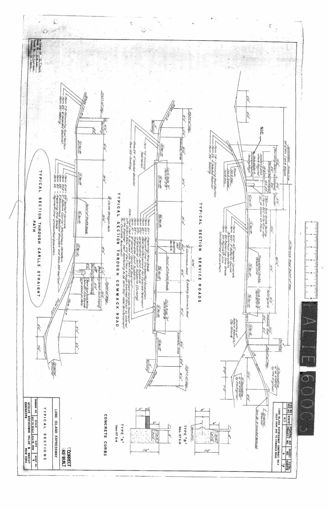
2.3.3.7 Drainage Systems - There are the four drainage catch basins with grates along the curb line in the each of the four bridge approach quadrants, just beyond the two bridge abutments. The east side and west side catch basins are connected together by a 15 inch diameter CMP culvert, then outlets to the LIE via 15 inch diameter CMP culvert from the west side catch basins to an underground drainage system that is parallel and well outside the bridge, and is under the LIE roadway where it eventually connects with the LIE retention basins located between the eastbound LIE roadway shoulder and the eastbound LIE service road. There is no anticipated impact to buried drainage systems for the LIE except where the local connection of the bridge approach catch basins lateral pipe within the abutment embankment side slope occurs and maybe locally impacted by relocation of these basins toward the replacement bridge carried roadway curb line position. Drainage will be designed as needed for the required storm runoff, making use of existing drainage systems in the approaches with any retrofit or repairs, and/or new drainage systems will be installed in the bridge approaches if current design standards and condition of the existing system makes that necessary. No bridge scupper systems will be placed on the bridge deck. 2.3.3.8 Geotechnical – There are no special geotechnical concerns with the soils or rock slopes within the project area. 2.3.3.9 Structures – Description: The bridge carrying Carlls Straight Path over I-495 (Long Island Expressway) is a four-span structure with an overall length of 229’-7 ½”and an out-to-out width of 39’-10”. The superstructure is comprised of 6 Rolled Steel WF Beams for the stringers with a reinforced concrete deck and a bituminous overlay in the travel lanes. The substructures are comprised of reinforced concrete cantilevered type abutments with U-wingwalls on spread footings and three multi-column piers each on a spread footing. There is a longitudinal expansion joint over each pier. The lengths and features crossed for each span are as follows:
• Span 1 and Span 4 are 35’ 11 1/16” long approach spans. • Span 2 is a 78’ 10 ⅝” long span crossing Eastbound I-495. • Span 3 is a 78’ 10 ⅝” long span crossing Westbound I-495.
This structure carries 8 ½” of 37 ½”-high four rail galvanized steel bridge rail, 4’ sidewalk with steel faced brush curb, and is striped for 4’-0” shoulder and a 10’-0” wide travel on each side of the centerline. In addition, there are four lighted Overhead Sign Structures (OSS), two for Eastbound LIE traffic and two for Westbound, supported by the fascia girders. The electric service for the OSS is provided via wooden poles at each end of the bridge. This project proposes to address structural deficiencies associated with normal deterioration and the low minimum vertical clearance of the bridge carrying Carlls Straight Path over I-495 (Long Island Expressway). This has led to increasingly costly repairs and inspections. It will also address operational deficiencies associated with left turn lanes and bicycle accommodations on the bridge and acceleration and deceleration lanes associated with a truck rest stop just east of the bridge. History – This bridge was built in 1963 under Contract No. FALIE 60-3. The bridge inventory does not have records of any major bridge rehabilitation work on this bridge. Past work on this structure includes:
• 1978 - D 95335 - Clean and paint • 1991 - D252949 - Repair and replace steel members • 1995 - D254006 - Bridge pier protection
7

September 2013 Project Scoping Report/Final Design Report PIN 0229.40
• 1997 - D256285 - Sandblast, clean and paint • 2000 - Straighten and repair Girder G-1 • 2008 - D260394 - Clean and paint
The structures’ primary members are rolled WF shape steel beams that were fabricated from ASTM A7 steel. The bridge has undergone general maintenance and some steel repairs for impact damage. The cover plate end welds at the bottom flange of stringers S2 thru S5 of spans 2 & 3 are fatigue prone details. Inspection & Deficiencies - According to the 2011 Biennial Inspection, the NYSDOT General Recommendation is 4 and the Computed Condition Rating is 4.266. An in-depth inspection of the structure was performed by HNTB Engineers in March 2012. The inspection was performed in accordance with the latest edition of NYSDOT Bridge Inspection Manual. A visual inspection was performed on both the top of the bridge deck and the underside. The underside of the deck Spans 1 to 4 shows 80% of the area exhibits signs of moderate to heavy deterioration of the galvanized metal pan stay-in-place forms. It appears that water is penetrating through the concrete deck causing deterioration of the stay-in-place forms. At Spans 1 thru 4, the asphalt wearing surface exhibits scattered small potholes, cracks, rutting and uneven and cracked asphalt patches. The asphalt patches are mostly near the abutments, pier joints and at center line of the bridge. The ride quality is poor. In the most recent biennial inspection, the structural deck for all spans was rated “3”. The stem walls of the abutments are in good condition with a few minor cracks. The back wall, bridge seat, and pedestals are all in good condition. Approach and bridge railing are rated 4 with some damage. The original plans indicate that aluminum bridge rail was specified for this bridge. The steel stringers are all in good condition with surface corrosion and pin point rusting in local areas with the exception of those areas on the stringers and diaphragms which show damage from impacts. In Span 2, stringer S1 at the first interior diaphragm has a 12" long full crack at the bottom portion of web. Stringer S1 is deformed due to heavy impact at the bottom flange between diaphragms D1 (first interior diaphragm) and D2 (second interior diaphragm) and is bent out of plane approximately 6" horizontally. In addition, due to the impact the first interior diaphragm is deformed and buckled. In Span 3, on the right side of right fascia girder there were two points of impact, causing gouges in the bottom web and cover plate. No cracks were detected at this point of impact. The bottom of the girder is displaced to the left between intermediate diaphragms to a maximum of approximately 1 ½" at point of impact. On the left side of the girder there is a vertical crack in bottom of the weld on both sides of the diaphragm connection plate. On the right side of right fascia girder, there were two points of impact, causing gouges in the cover plate. The existing steel sliding bearings are rated 4 but are showing deterioration due to corrosion. This type of bearing is no longer recommended for use on NYSDOT bridges. There are signs of water leakage on the pier cap due to the deteriorated joints over the piers. The pier columns/stems and the caps are in mostly in good condition except for few minor cracks and a localized spall area with exposed rebar on one pedestal. In Span 3, a section of the panel of the OSS that is attached to the right fascia stringer is bent at the bottom due to impact damage. The bottom of the middle vertical strut member is also bent. The sign structure is secure and the remaining sign structure support members are in good condition. Bridge inspection reports are on file and available.
8
September 2013 Project Scoping Report/Final Design Report PIN 0229.40
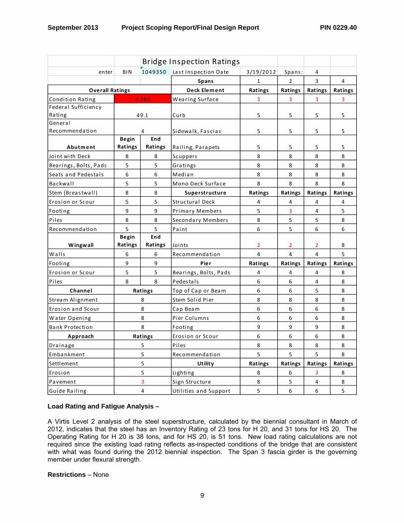
Bridge Inspection Ratingsenter BIN 1049350 Las t Inspection Date 3/19/2012 Spans : 4
Spans 1 2 3 4
Deck Element Ratings Ratings Ratings Ratings
Condi tion Rating Wearing Surface 3 3 3 3
3
2 2 2 8
3
3
Federa l Suffi c iency Rating Curb 5 5 5 5Genera l Recommendation Sidewa lk, Fascia s 5 5 5 5
AbutmentBegin Ratings
End Ratings Ra i l ing, Parapets 5 5 5 5
Joint with Deck 8 8 Scuppers 8 8 8 8
Bearings , Bol ts , Pads 5 5 Gra tings 8 8 8 8
Sea ts and Pedesta l s 6 6 Median 8 8 8 8
Backwa l l 5 5 Mono Deck Surface 8 8 8 8
Stem (Breas twa l l ) 8 8 Superstructure Ratings Ratings Ratings Ratings
Eros ion or Scour 5 5 Structura l Deck 4 4 4 4
Footing 9 9 Primary Members 5 4 5
Pi les 8 8 Secondary Members 8 5 5 8
Recommendation 5 5 Pa int 6 5 6 6
WingwallBegin Ratings
End Ratings Joints
Wa l l s 6 6 Recommendation 4 4 4 5
Footing 9 9 Pier Ratings Ratings Ratings Ratings
Eros ion or Scour 5 5 Bearings , Bol ts , Pads 4 4 4 8
Pi les 8 8 Pedes ta l s 6 6 4 8
Channel Top of Cap or Beam 6 6 5 8
Stream Al ignment Stem Sol id Pier 8 8 8 8
Eros ion and Scour Cap Beam 6 6 6 8
Water Opening Pier Columns 6 6 6 8
Bank Protection Footing 9 9 9 8
Approach Eros ion or Scour 6 6 6 8
Dra inage Pi les 8 8 8 8
Embankment Recommendation 5 5 5 8
Settlement Utility Ratings Ratings Ratings Ratings
Eros ion Lighting 8 6 8
Pavement Sign Structure 8 5 4 8
Guide Ra i l ing Uti l i ties and Support 5 6 6 5
5
4.266
49.1
4
Overall Ratings
Ratings
8
8
8
8
Ratings
5
5
5
4 Load Rating and Fatigue Analysis – A Virtis Level 2 analysis of the steel superstructure, calculated by the biennial consultant in March of 2012, indicates that the steel has an Inventory Rating of 23 tons for H 20, and 31 tons for HS 20. The Operating Rating for H 20 is 38 tons, and for HS 20, is 51 tons. New load rating calculations are not required since the existing load rating reflects as-inspected conditions of the bridge that are consistent with what was found during the 2012 biennial inspection. The Span 3 fascia girder is the governing member under flexural strength. Restrictions – None
9

September 2013 Project Scoping Report/Final Design Report PIN 0229.40
Waterway – None 2.3.3.10 Hydraulics of Bridges and Culverts – There are no bridge scuppers with down spouts. 15-inch diameter CMP culverts connect the east side and west side drainage catch basins at each end of the bridge, just beyond the two bridge abutments. From the west side catch basins, a 15-inch diameter CMP culvert outlets to the LIE. The bridge does not cross over any waterways within the project limits. Drainage will be designed as needed for the required storm runoff, making use of existing drainage systems in the approaches with any retrofit or repairs, and/or new drainage systems will be installed in the bridge approaches if current design standards and condition of the existing system makes that necessary. 2.3.3.11 Utilities – Continuity of all utility services will be maintained throughout the project’s construction duration.
Exhibit 2.6 Utilities
Owner Type Location Work to be Performed
Dix Hills Water 8 inch diameter buried water main
west of the bridge and parallel to bridge going
under the LIE none anticipated
LIPA overhead Electric power lines
west and overhead of the bridge relocation anticipated
LIPA sidewalk encased steel ducts (4 - 4 inch dia.)
for lighting in easterly sidewalk removed and replaced
Verizon sidewalk encased fiber ducts (6 - 3.5 inch dia.)
for Telephone in westerly sidewalk remove and replace
remove and re-install for new bridge mounted
signs INFORM conduit for bridge
mounted sign lighting along both sidewalk
fascias
replace with current standard ground
mounted highway light poles, per signed Utility
Agreement
Town of Huntington street lighting and bracket arms
in bridge approach, westerly side (lights
mounted to wood utility poles)
coordinate and insure no impact by installation of approach sidewalks,
curbs, or signal intersection poles with
footing, and/or pedestrian activated
signal control poles with footing.
National Grid & other private owner natural gas lines
along the LIE service road shoulders at the
proposed bridge approach work limits
Northville Industries Gas Transmission (high pressure)
along south shoulder of north LIE service road
running thru intersection protect and maintain
10

September 2013 Project Scoping Report/Final Design Report PIN 0229.40
11
2.3.3.12 Guide Railing, Median Barriers and Impact Attenuators Box beam guide railing runs along Carlls Straight Path on each side of the approaches from the service roads to the bridge, except for the east side of the north approach where there is W-beam corrugated guide railing. The project will replace all approach guide railing to current standards. Incidental reconstruction of the LIE center median and safety barrier systems affected by the bridge pier demolition and replacement with new pier substructure will be necessary. 2.3.3.13 Right of Way – Right of way acquisition is not required for this project. 2.3.3.14 Landscaping/Environmental Enhancement – There will be some localized removal by clearing and grubbing of trees and vegetation, along the bridge approach side sloped embankments as necessary to construct the wider replacement bridge and install the highway safety appurtenances (guide railings) and municipal operated and maintained road lighting that is also in the bridge approaches (along the westerly side). Some additional tree or shrub landscaping may be desirable as a visual buffer from the southerly located LIE drainage retention basin berms. The Regional Landscape Architect should be consulted before planting plans are developed. 2.4 Miscellaneous – NYS Smart Growth Public Infrastructure Policy Act (SGPIPA): Pursuant to ECL Article 6, this project is compliant with the New York State Smart Growth Public Infrastructure Policy Act (SGPIPA). This project has been determined to meet the relevant criteria, to the extent practicable, described in ECL Sec. 6-0107. Specifically, the project:
• improves existing infrastructure by replacing the Carlls Straight Path Bridge over I-495 to provide 14ft- 6 inch minimum vertical clearance, providing standard shoulder and sidewalk widths, extending center turn lane across bridge, and replacing pedestrian push button controlled crossing systems and traffic control systems at the North and South Service Roads
• is located in a developed area • provides mobility through transportation choices because the project improves bicycle and
pedestrian facilities to help promote public transit use and reduce automobile dependency • is consistent with local, county, regional and state plans
To the extent practicable this project has met the relevant criteria as described in ECL § 6-0107. The Smart Growth Screening Tool was used to assess the project’s consistency and alignment with relevant Smart Growth criteria; the tool was completed by the Region’s Planning and Program Management group on 8/23/2013 and reflects the current project scope. Railroads: There are no rail roads within the project limits and no at-grade crossings within 1 km that could impact traffic conditions. Parking: There are no areas regulated by parking restrictions within the project limits. Lighting: There is municipal street lighting within the highway limits along the west side of Carlls Straight Path. These lights are owned and maintained by the Town of Huntington. Coordination with the Town will be required during final design to determine lighting requirements and the need for any relocation.


September 2013 Project Scoping Report/Final Design Report PIN 0229.40
CHAPTER 3 – SOCIAL, ECONOMIC AND ENVIRONMENTAL CONSIDERATIONS Refer to the Environmental Checklist included in Appendix B for information on all environmental issues for which the project was screened. 3.1 National Environmental Policy Act (NEPA): The Department has determined that this project is a NEPA Class II, Programmatic Categorical Exclusion in accordance with 23 CFR 771.117d and the NEPA checklist. Class II actions that do not individually or cumulatively have a significant environmental effect are excluded from the requirement to prepare an Environmental Impact Statement (EIS) or an Environmental Assessment (EA). Refer to the attached NEPA Assessment Checklist and supplemental information in Appendix B. Programmatic Categorical Exclusions do not require FHWA’s concurrence.
3.2 State Environmental Quality Review Act (SEQRA) New York State Department of Transportation is the SEQRA lead agency as per 17 NYCRR Part 15 “Procedures for Implementation of State Environmental Quality Review Act”, Section 15.5. The Department has determined that this project is a SEQRA Type II Action in accordance with 17 NYCRR, Part 15. No further SEQRA processing is required. The project has been identified as a Type II action, per 17 NYCRR Section 15.14, Subdivision (e), Item 37, Paragraph (iv). This permits the project to be classified as Type II since the project does not violate any of the criteria contained in subdivision (d) of Section 15.14, and is of a scale and scope illustrated by the following:
replacement, reconstruction or rehabilitation, at present site or immediately adjacent thereto, of existing bridges, culverts or other transportation structures, including railroad crossing structures, not involving substantial expansion of the structure;
Specifically, the project does not include or result in: 1. The acquisition of an occupied dwelling or business structure; 2. Significant changes in passenger or vehicle traffic volumes, vehicle mix, local travel patterns or
access; 3. More than minor social, economic or environmental effects upon occupied dwelling units,
businesses, abutting properties or other established human activities; 4. Significant inconsistency with current plans or goals that have been adopted by local government
bodies; 5. Physical alteration of more than 1 ha (2.5 ac) of publicly owned or operated park land, recreational
area or designated open space; 6. An effect on a district, building, structure or site eligible for, or listed on, the National Register of
Historic Places; 7. More than minor alteration of, or adverse effect upon, any property, protected area, or natural or
man-made resource of national, State or local significance, including but not limited to:
1

September 2013 Project Scoping Report/Final Design Report PIN 0229.40
2
(i) Wetlands and associated areas; (ii) Floodplains; (iii) Prime or unique agricultural land; (iv) Agricultural districts, when more than one acre may be affected; (v) Water resources, including lakes, reservoirs, rivers and streams; (vi) Water supply sources; (vii) Designated wild, scenic and recreational rivers; (viii) Unique ecological, natural wooded or scenic areas; (ix) Rare, threatened or endangered species; (x) Any area designated as a critical environmental area; 8. Requirement for an indirect air source quality permit. 3.3 Additional Environmental Information – Endangered or Threatened Species According to the Department’s GIS information database, there are no Federally-protected, threatened, or endangered species located in or within ½ mile of the proposed project area. Furthermore there is no suitable habitat in the proposed work limits for the federally endangered species listed in the US Fish & Wildlife Service’s “County List” for Suffolk County. Invasive Species In conformance with Presidential Executive Order 13112 and NYSDOT EI 09-001, the project site has been screened for the presence of NYSDOT’s target invasive species. Each side of the bridge right-of-way comprises typical highway environment plant species dominated by a mix of native and non-native species, both planted and voluntary. The most prevalent tree species are Black cherry, Scarlet oak, Black locust, Norway maple, Autumn olive and crab apple. A few Red cedars, Japanese black pine, Tree-of-heaven and Willow oak were also noted. The shrub layer is minimal but includes mostly Multiflora rose and Japanese honeysuckle. The herbaceous/vine layer comprises mostly Poison ivy, Virginia creeper, English ivy and Oriental bittersweet. “Target” invasive species were not found during the field screening. Although many of the observed plant species are considered undesirable non-natives they are not target invasive plants and therefore will not be managed using specific NYSDOT specifications for removal and disposal. Replacement vegetation for the new bridge slopes shall only include plant species that are not listed on NYS regional invasive plant lists (i.e., LIISMA). Asbestos-Containing Materials An Asbestos Screening and Assessment of the impacted right-of-way and structures was performed by a NYS Department of Labor licensed firm using certified inspection staff. Asbestos-containing materials identified during this screening/assessment were sampled and positively analyzed for asbestos content; suspect asbestos-containing materials are presumed positive. The complete Asbestos Assessment Report dated August 2013 is available in the project file. All confirmed and presumed asbestos-containing materials impacted as part of the project work will be removed and disposed of in accordance with NYSDOT Standard Specification Section 210 and all applicable State and Federal Regulations
September 2013 Project Scoping Report/Final Design Report PIN 0229.40
APPENDICES


September 2013 Project Scoping Report/Final Design Report PIN 0229.40
APPENDIX A Plans, Profiles & Typical Sections


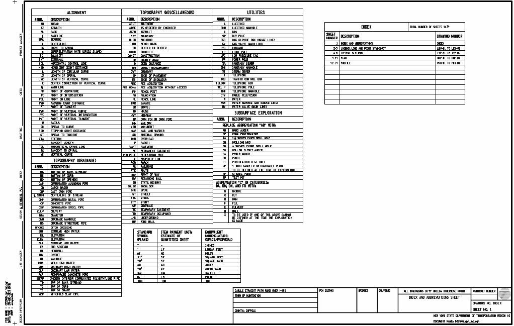
INDEX
INDEX AND ABBREVIATIONS
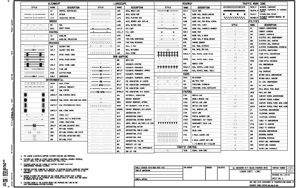
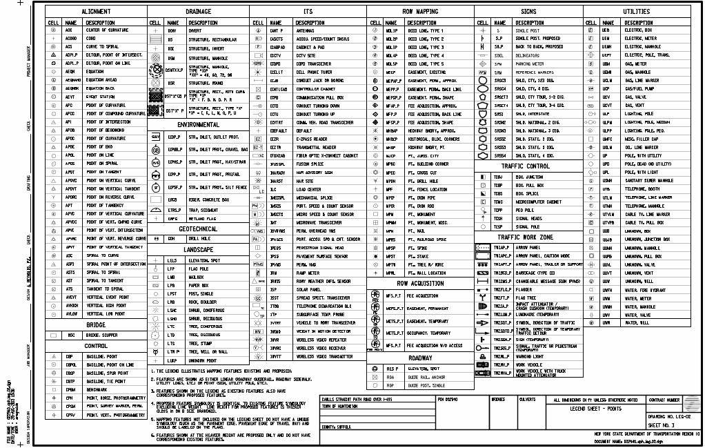
LEGEND, LINE AND POINT SYMBOLOGY
PLAN
TYPICAL SECTIONS
PROFILE
DESCRIPTION DRAWING NUMBERNUMBER
SHEET
LEG-01 TO LEG-02
INDEX
TYP-01 TO TYP-05
GNP-01 TO GNP-03
PRO-01 TO PRO-03
4-8
2-3
1
9-11
12-14
TOTAL NUMBER OF SHEETS 14 E
EMH
G
GP
GSB
GV
HYD
LP
LPG
PP
SA
SMH
ST
T
TCB
TELBOX
TEL P
TMH
CTV
W
WSB
WV
AHEAD
AZIMUTH
BACK
BASELINE
BEARING
CENTERLINE
CURVE TO SPIRAL
SUPERELEVATION RATE (CROSS SLOPE)
EQUALITY
EXTERNAL
HORIZONTAL CONTROL LINE
HEADLIGHT SIGHT DISTANCE
LENGTH OF CIRCULAR CURVE
LENGTH OF SPIRAL
LENGTH OF VERTICAL CURVE
CENTER CORRECTION OF VERTICAL CURVE
MAIN LINE
POINT OF CURVATURE
POINT OF INTERSECTION
POINT ON LINE
PASSING SIGHT DISTANCE
POINT OF TANGENT
POINT OF VERTICAL CURVE
POINT OF VERTICAL INTERSECTION
POINT OF VERTICAL TANGENT
RADIUS
SPIRAL TO CURVE
STOPPING SIGHT DISTANCE
SPIRAL TO TANGENT
STATION
TANGENT LENGTH
THEORETICAL GRADE LINE
TANGENT TO SPIRAL
VERTICAL CURVE
ELECTRIC
ELECTRIC MANHOLE
GAS
GUY POLE
GAS SERVICE BOX (HOUSE LINE)
GAS VALVE (MAIN LINE)
HYDRANT
LIGHT POLE
LOW PRESSURE GAS
POWER POLE
SANITARY SEWER
SANITARY MANHOLE
STORM SEWER
TELEPHONE
TRAFFIC CONTROL BOX
TELEPHONE BOX
TELEPHONE POLE
TELEPHONE MANHOLE
CABLE TELEVISION
WATER
WATER SERVICE BOX (HOUSE LINE)
WATER VALVE (MAIN LINE)
ALIGNMENT
SUBSURFACE EXPLORATION
HAND AUGER
DRILLING MUD
HOLLOW FLIGHT AUGER
POWER AUGER
PROBE
PERCOLATION TEST HOLE
TO BE DEFINED AT THE TIME OF EXPLORATION
SEISMIC POINT
TEST PIT
BRIDGE
CUT
DAM
FILL
CULVERT
WALL
AH
CP
DA
DM
DN
FH
PA
PH
PT
SP
B
C
D
F
K
W
X
IS MADE
BE DEFINED AT THE TIME THE EXPLORATION
TO BE USED IF ONE OF THE ABOVE CANNOT
ABUT
AOBE
ASPH
BDY
BLDG
BM
CC
CONC
CONST
CR
D
DM
DWY
EP
ES
FP
FD
FL
GAR
GR
HO
HWY
IP
MB
MON
N&W
OG
O/H
P
PAV’T
PE
PED POLE
p
POR
RR
RTE
ROW
FEE WO/A
ABUTMENT
AS ORDERED BY ENGINEER
ASPHALT
BOUNDARY
BUILDING
BENCH MARK
CENTER TO CENTER
CONCRETE
CONSTRUCTION
COUNTY ROAD
DEED DISTANCE
DIRECT MEASUREMENT
DRIVEWAY
EDGE OF PAVEMENT
EDGE OF SHOULDER
FENCE POST
FOUNDATION
FENCE LINE
GARAGE
GRAVEL
HOUSE
HIGHWAY
IRON PIN OR IRON PIPE
MAILBOX
MONUMENT
NAIL AND WASHER
ORIGINAL GROUND
OVERHEAD
PARCEL
PAVEMENT
PERMANENT EASEMENT
PEDESTRIAN POLE
PROPERTY LINE
PORCH
RAILROAD
ROUTE
RIGHT OF WAY
TOPOGRAPHY (MISCELLANEOUS)
RW
SH
SHLDR
RETAINING WALL
STATE HIGHWAY
SHOULDER
BOTTOM OF BANK (STREAM)
BOTTOM OF CURB
BOTTOM OF OPENING
CORRUGATED ALUMINUM PIPE
CATCH BASIN
CAST IRON PIPE
CENTERLINE OF STREAM
CORRUGATED METAL PIPE
CONCRETE PIPE
BB
BC
BO
CAP
CB
CIP
CMP
CP
CORRUGATED STEEL PIPE
CULVERT
DIAMETER
DRAINAGE MANHOLE
DRAINAGE STRUCTURE PIPE
DITCH CROSSING
EXTREME HIGH WATER
ELEVATION
ELEVATION
EXTREME LOW WATER
END SECTION
HEADWALL
INVERT
MANHOLE
MEAN HIGH WATER
ORDINARY HIGH WATER
ORDINARY LOW WATER
REINFORCED CONCRETE PIPE
TOP OF BANK (STREAM)
TOP OF CURB
TOP OF GRATE
VITRIFIED CLAY PIPE
CSP
CULV
DIA
DMH
DS
D’XING
EHW
EL
ELEV
ELW
ES
HW
INV
MH
MHW
OHW
OLW
RCP
TB
TC
TG
VCP
SPK
ST
STK
STY
SW
TE
TO
U/G
WW
SPIKE
STREET
STAKE
STORY
SIDEWALK
TEMPORARY EASEMENT
TEMPORARY OCCUPANCY
UNDERGROUND
WING WALL
AH
AZ
BK
b
BRG
c
CS
e
EQ
EXT
HCL
HSD
L
LS
LVC
E
f
PC
PI
POL
PSD
PT
PVC
PVI
PVT
R
SC
SSD
ST
STA
T
TGL
TS
VC
FEE ACQUISITION WITHOUT ACCESS
FEE FEE ACQUISITION
ABBR. DESCRIPTION
REPLACE ABBREVIATION "AB" WITH:
ABBR. DESCRIPTION
ABBR. DESCRIPTION ABBR. DESCRIPTION
ABBR. DESCRIPTION
UTILITIES
TOPOGRAPHY (DRAINAGE)
4 INCHES CASED DRILL HOLE
1 INCH SAMPLER (RETRACTABLE PLUG)
2� INCHES CASED DRILL HOLE
SICPP SMOOTH INTERIOR CORRUGATED POLYETHYLENE PIPE
STRMc
RP
TP
SQUARE FEET
GALLON
’
mi
lb LB
MI
(PLANS)
SYMBOL
STANDARD
(SPECS/PROPOSAL)
NOMENCLATURE:
EQUIVALENT
ftq
YDr CUBIC YARDCY
MILES
ACRES
LINEAR FEET
TON TON TON
GAL
POUND
GAL
SF
AC AC
QUANTITIES SHEET
ESTIMATE OF
ITEM PAYMENT UNIT:
28-
AU
G-2013 15:3
6
FIL
E
NA
ME
=
DA
TE/
TI
ME
=
US
ER
=areynolds
CONTRACT NUMBER
DRAWING NO.
SHEET NO.
NEW YORK STATE DEPARTMENT OF TRANSPORTATION REGION
BRIDGES CULVERTSPIN
JO
B
MA
NA
GE
RD
ESIG
N
SU
PE
RVIS
OR
DOCUMENT NAME:
COUNTY:
PR
OJ
EC
T
MA
NA
GE
RD
ESIG
ND
RA
FTIN
GC
HE
CK
CH
EC
K
ALL DIMENSIONS IN ft UNLESS OTHERWISE NOTED
" - INCHES
YDq SQUARE YARDSY
LF
CONE PENTROMETER
DA, DM, DN, AND FH WITH:
ABBREVIATION "C" IN CATEGORIES:
1
A.
RE
YN
OL
DS,
P.E.
022940_cph_in
d.d
gn
CARLLS STRAIGHT PATH ROAD OVER I-495
TOWN OF HUNTINGTON
022940
INDEX AND ABBREVIATIONS SHEET
INDEX
022940_cph_ind.dgn
10
14
SUFFOLK
6.
5.
4.
3.
2.
1.
28-
AU
G-2013 15:3
6
FIL
E
NA
ME
=
DA
TE/
TI
ME
=
US
ER
=areynolds
CONTRACT NUMBER
DRAWING NO.
SHEET NO.
NEW YORK STATE DEPARTMENT OF TRANSPORTATION REGION
BRIDGES CULVERTSPIN
JO
B
MA
NA
GE
RD
ESIG
N
SU
PE
RVIS
OR
DOCUMENT NAME:
COUNTY:
PR
OJ
EC
T
MA
NA
GE
RD
ESIG
ND
RA
FTIN
GC
HE
CK
CH
EC
K
ALL DIMENSIONS IN ft UNLESS OTHERWISE NOTED
HAVE CORRESPONDING EXISTING FEATURES.
FEATURES SHOWN AT THE HEAVIER WEIGHT ARE PROPOSED ONLY AND DO NOT
BE LABELED ON THE PLANS.
SYMBOLOGY (SUCH AS THE PAVEMENT EDGE, PAVEMENT EDGE OF TRAVEL WAY) AND SHOULD
MAPPING FEATURES NOT INCLUDED ON THE LEGEND SHEET DO NOT HAVE A UNIQUE
DRAWINGS).
LINE WEIGHT. LINE WEIGHT FOR PROPOSED FEATURES IS THICKER (0.015 in ON B SIZE
PROPOSED FEATURE SYMBOLOGY IS IDENTICAL TO EXISTING FEATURE SYMBOLOGY EXCLUDING
CORRESPONDING PROPOSED FEATURES.
FEATURES SHOWN ON THE LEGEND AS EXISTING FEATURES ALSO HAVE
UTILITY LINES, ETC.) OR POINT (SIGN, UTILITY POLE, ETC.).
FEATURES ARE SHOWN AS EITHER LINEAR (ROADWAY GUIDERAIL, ROADWAY SIDEWALK,
THE LEGEND ILLUSTRATES MAPPING FEATURES (EXISTING AND PROPOSED).
ALIGNMENT
CONTROL
DRAINAGE
ENVIRONMENTAL
LANDSCAPE
ROW MAPPING
STRIPING
TRAFFIC CONTROL
AC
AD_P
AT_P
CONTROL (CENTERLINE)
DETOUR
CB
CBPR
DCP
DCP_P
DDG_P
DDP_P
DDS_P
DFL_P
EBLHS
ECT
EDMC
CURTAIN, TURBIDITY
FLOW LINE
DITCH, STONE LINED
DITCH, PAVED INVERT
DITCH, GRASS LINED
CULVERT PIPE (DIR)
CULVERT PIPE
BASELINE
BASELINE, PROJECTION
SHEET PILING
EFNS
EFNV
EWAA_P
EWFS
EWM
EWS WETLAND, STATE
WETLAND, MITIGATION AREA
WETLAND, FEDERAL
WETLAND, ADJACENT AREA
FENCE, VEGETATION
FENCE, SILT
EDMEC_P
EDMPC_P
EDMSC_P
LABL
LAHR
LAPB
LAWA
LAWE
LFILL_P
LFNC
LTRC
LTRD
LWR
LWS
AREA, BRUSH LINE
AREA, HEDGE ROW
AREA, PLANTING BED
AREA, WATERS EDGE
FILL LIMIT
FENCE
TREE ROW, CONIFEROUS
WALL, RETAINING
TREE ROW, DECIDUOUS
WALL, STONE
MDL
MEE
HIGHWAY BOUNDARY
EASEMENT, EXISTING
DEED LINE
RG
RRPLS_P
RRPSS
RRSLS_P
BROKEN LINE
TCSW SIGNAL, SPAN WIRE
UC
TRANSITION CONTROL
SIGNS
SM
SSO
SSOC
MULTIPLE POST
STRUCTURE, OVERHEAD
RRS RUMBLE STRIP
DSSD SLOTTED DRAIN
STB*
EWF
STYLE NAME DESCRIPTION
BRIDGE
BR RAIL
BSHT
FENCE, SILT & VEGETATIONEFNSV
WETLAND, FEDERAL AND STATE
SBLB BILLBOARDS
STRUCTURE, OVHD. CANTILEVER
DESCRIPTIONNAMESTYLE
AREA, WOODED AREA OUTLINE
LWH WALL, H PILE
MEP_P EASEMENT, PERMANENT
MEPA_P EASEMENT, PERMANENT, APPROX.
MET_P EASEMENT, TEMPORARY
META_P EASEMENT. TEMPORARY, APPROX.
MF_P
MFA_P FEE ACQUISITION, APPROXIMATE
MFS_P FEE ACQUISITION, SHAPE
MHB
MHBA HIGHWAY BOUNDARY, APPROX.
MHBW HWY BOUNDARY, FACE OF WALL
MHBWOA HIGHWAY BOUNDARY, W/O ACCESS
MJC JURISDICTION, CITY
MJCY JURISDICTION, COUNTY
MJHD JURISDICTION, HISTORIC DISTRICT
MJLL JURIS., (GREAT, MILITARY) LOT LINE
MJN JURISDICTION, NATION
MJPB JURISDICTION, PUBLIC LANDS
MJS JURISDICTION, STATE
MJT JURISDICTION, TOWN
MJV JURISDICTION, VILLAGE
MPL PROPERTY LOT LINE
PROPERTY LOT LINE, APPROXIMATEMPLA
MSL SUB LOT LINE
ROADWAY
DESCRIPTIONNAMESTYLE
GUIDE RAIL, MISCELLANEOUS
RGB GUIDE RAIL, BOX BEAM
RGBM GUIDE RAIL, BOX BEAM, MEDIAN
RGC GUIDE RAIL, CABLE
RGCB GUIDE RAIL, CONCRETE BARRIER
GUIDE POST
RGW GUIDE RAIL, W BEAM
RGWM GUIDE RAIL, W BEAM, MEDIAN
RPB PARKING BUMPER
RRC RAIL ROAD, CATENARY
RRER RAIL ROAD, 3RD RAIL
RAIL, PHOTO, LARGE SCALE
RAIL, PHOTO, SMALL SCALE
RAIL, SURVEY, LARGE SCALE
RRSSS RAIL, SURVEY, SMALL SCALE
RGP_P
DOUBLE BROKEN LINESTDB*
STDL* DOTTED LINE LONG
STDS* DOTTED LINE SHORT
STFB* FULL BARRIER LINE
STH* HATCH LINE
STPB* PARTIAL BARRIER LINE
STRCT ROUNDABOUT, CAT TRACKS
STRYL ROUNDABOUT, YIELD LINE
STSB STOP BAR
SOLID, EDGE
X WALK, LADDER LINE
* = W (WHITE) OR Y (YELLOW)
CONDUIT, UNDERGROUND
UCH CONDUIT, HANGING
UCO CONDUIT, OVERHEAD
UE ELECTRIC LINE, UNDERGROUND
UEH ELECTRIC LINE, HANGING
UEO ELECTRIC LINE, OVERHEAD
UESS ELECTRIC, SUBSTATIONS
UFO FIBER OPTIC, UNDERGROUND
UFOH FIBER OPTIC, HANGING
UFOO FIBER OPTIC, OVERHEAD
UG GAS, UNDERGROUND
UGH GAS, HANGING
UGO GAS, OVERHEAD
UIC INFORM CABLE, UNDERGROUND
UICH INFORM CABLE, HANGING
OIL LINE, UNDERGROUNDUO
UOH OIL LINE, HANGING
UPBP POLE, BRACE, PUSH BRACE
POLE, GUY WIRE
USA
USAH SANITARY SEWER, HANGING
SANITARY SEWER, UNDERGROUND
UT TELEPHONE, UNDERGROUND
UTH TELEPHONE, HANGING
UTO TELEPHONE, OVERHEAD
UUU UNKNOWN, UNDERGROUND
UUH UNKNOWN, HANGING
UUO UNKNOWN, OVERHEAD
UW WATER LINE, UNDERGROUND
UWH WATER LINE, HANGING
UWO WATER LINE, OVERHEAD
UTILITIES
UETO ELECTRIC TRANSMISSION, OVERHEAD
USAF SANITARY SEWER, FORCE MAIN, UGND
USAFH SANITARY SEWER, FORCE MAIN, HANG
UTV
UTVH
UTVO
CABLE TV, UNDERGROUND
CABLE TV, HANGING
CABLE TV, OVERHEAD
FEE ACQUISITION, W/ ACCESS
BALE, STRAW
LCUT_P CUT LIMIT
STYLE NAME DESCRIPTION
UPGW
STSE*
RCZ_P
BARRIER, TEMPORARY
TRAFFIC WORK ZONE
TWZBT_P
CHANNELIZING DEVICETWZCD_P
TWZPMRC_P
TWZBTWL_P
MHA HISTORICAL, ACQUISITION
MFWOA_P FEE ACQUISITION, W/O ACCESS
CLEAR ZONE
UNDERDRAINDUD_P
STXLB X WALK, LADDER BAR LINE
EDMGSC_P
LIGHTS
BARRIER, TEMPORARY, W/ WARNING
COVERING
PAVEMENT MARKING REMOVAL OR
STXL
DAM, COFFER
DAM, EARTHEN CHECK
DAM, GRAVEL BAG/SAND BAG CHECK
DAM, PREFABRICATED CHECK
DAM, STONE CHECK
2
A.
RE
YN
OL
DS,
P.E.
CARLLS STRAIGHT PATH ROAD OVER I-495
TOWN OF HUNTINGTON
022940
LEG-01
10
LEGEND SHEET - LINES
022940_cph_le
g_01.d
gn
022940_cph_leg_01.dgn
SUFFOLK
CBP
CBPOL
CBSP
CBTP
ACC
ACOGO
ACS
AEQN
AEQNAHD
AEQNBK
AEVT
APC
APCC
API
APOB
APOC
APOE
APOL
APOS
APOT
APOVC
APOVT
APORC
APT
APVC
APVCC
APVI
APVRC
APVT
ASC
ASPI
ASTS
AVEVT
AVHIGH
AVLOW
CENTER OF CURVATURE
COGO
CURVE TO SPIRAL
EQUATION
EQUATION AHEAD
EQUATION BACK
EVENT STATION
SPIRAL TO CURVE
SPIRAL TO SPIRAL
SPIRAL TO TANGENT
TANGENT TO SPIRAL
ALIGNMENT
DINV
DS
BRIDGE, SCUPPER
STRUCTURE, RECTANGULAR
INVERT
TRAP, SEDIMENT
WETLAND FLAG
DRILL HOLE
ELEVATION, SPOT
FLAG POLE
MAILBOX
PAPER BOX
ROCK, BOULDER
SHRUB, CONIFEROUS
SHRUB, DECIDUOUS
TREE, CONIFEROUS
TREE, DECIDUOUS
TREE, STUMP
SINGLE POST
DELINEATORS
REFERENCE MARKERS
EWFG
GDH
LELS
LFP
LMB
LPB
LPST
LRB
LSHC
LSHD
LTC
LTD
LTS
LUKP
LANDSCAPE
GEOTECHNICAL
ENVIRONMENTAL
SDEL
SRM
SANTENNAS
CABINET & PAD
CCTV SITE
CDPD TRANSCEIVER
CELL PHONE TOWER
CONDUIT JACK OR BORING
CONTROLLER CABINET
COMMUNICATION PULL BOX
CONDUIT TURNING DOWN
CONDUIT TURNING UP
DEFAULT
TRANSMITTAL READER
FUSION SPLICE
HAR ADVISORY SIGN
HAR SITE
LOAD CENTER
MECHANICAL SPLICE
PEDESTRIAN SIGNAL HEAD
RAMP METER
SOLAR PANEL
WEIGHT IN MOTION DETECTOR
WIRELESS VIDEO REPEATER
WIRELESS VIDEO RECEIVER
WIRELESS VIDEO TRANSMITTER
PERM. OVERHEAD VMS
PERM. VMS
ACCOU. SPEED/COUNT SNSR.S
IANT P
IASCTS
ICABPAD
ICCTV
ICDPD
ICELLT
ICJB
ICNTLCAB
ICPB
ICTD
ICTU
ICVTRT
IEZR
IEZTR
IFOXCAB
IFUSSPL
IHARADV
IHARST
IMECSPL
IMSCS
IMSCTS
IMT
IOVHVMS
IPASCS
IPEDS
IPSS
IPVMS
IRM
IRWIS
ISP
ISST
ITDB
ITP
IVTRT
IWIMD
IWVR
IWVTT
IWVRC
ILC
ITS
GAS, METER
GAS, MANHOLE
GAS, LINE MARKER
GAS/FUEL PUMP
GAS, VALVE
GAS, VENT
LIGHTING, POLE
LIGHTING, POLE, MEDIAN
LIGHTING, POLE, PED.
MISC. FILLER CAP
OIL, LINE MARKER
TELEPHONE, LINE MARKER
TELEPHONE, MANHOLE
CABLE TV, LINE MARKER
CABLE TV, PULL BOX
UNKNOWN, MANHOLE
UNKNOWN, VALVE
WATER, FIRE HYDRANT
WATER, METER
WATER, MANHOLE
WATER, VALVE
WATER, WELL
UGM
UGMH
UGLM
UGP
UGV
UGVT
ULP
ULPM
ULPP
UMFC
UOLM
UP
UPD
UPL
USMH
UTB
UTLM
UTMH
UTVPB
UUJB
UUMH
UUVL
UWFH
UWM
UWMH
UWV
UWW
G
G
O
P
T
C
C
W
W
SPM PARKING METER
SPREAD SPECT. TRANSCEIVER
TELEPHONE DEMARCATION BLK
SUBSURFACE TEMP. PROBE
MICRO SPEED & COUNT SENSOR
A
B
UNKNOWN, JUNCTION BOX
UTVLM
POST, SINGLE
FP
S
T
W
UUB UNKNOWN, BOX
UUPB UNKNOWN, PULL BOX
UUVT UNKNOWN, VENT
U UUW UNKNOWN, WELL
PT., WALL LOCATION
PT., TREE W/ WIRE
PT., STAKE
PT., RAILROAD SPIKE
PT., SPIKE
PT., NAIL
PT., MONUMENT, MISC.
PT., MONUMENT
PT., IRON ROD
PT., IRON PIPE
PT., FENCE LOCATION
PT., DRILL HOLE
HISTORICAL, BLDG. CORNERS
HIGHWAY BNDRY., APPROX.
HIGHWAY BNDRY, PT.
EASEMENT, PERM., SHAPE
DEED LINE, TYPE 1
DEED LINE, TYPE 2
DEED LINE, TYPE 3
DEED LINE, TYPE 4
DEED LINE, TYPE 5
EASEMENT, EXISTING
EASEMENT, PERM., APPROX.
BOX, JUNCTION
BOX, PULL BOX
BOX, SPLICE
MICROCOMPUTER CABINET
PED POLE
SIGNAL HEADS
SIGNAL POLE
ROW MAPPING
MDL1P
MHBCP
MPCC
MPDH
MPF
MPIP
MPIR
MPM
MPMM
MPN
MPRS
MPSP
MPST
MPTW
MPWL
TRAFFIC CONTROL
TCMC
TCPP
TCSH
TCSP
C
ELECTRIC, BOX
ELECTRIC, METER
ELECTRIC, MANHOLE
ELECTRIC, POLE, TRANS.
UEB
UEM
UEMH
UEPT
E
E
E
MJCP PT., JURIS. CITY
PT., CROSS CUT
UTILITIES
EASEMENT, PERM., BACK LINEEASEMENT, PERM., BACK LINE
DSMTXX_P
1
2
3
4
5
MEPAP_P
EIOP_P
ETRS_P
ADPI_P
G
A
A
P
CDPD
C
C
IDEFAULT
EZ
EZ-T
XC
H
LC
PM
M
M
VMS
PA
PVMS
RM
RWIS
SS
TC
TP
WVR
V
V
CELL DESCRIPTION CELL CELL CELLDESCRIPTION DESCRIPTION DESCRIPTION
DETOUR, POINT OF INTERSECT.
DETOUR, POINT ON LINE
POINT OF CURVATURE
POINT OF INTERSECTION
POINT OF BEGINNING
POINT OF CURVATURE
POINT OF END
POINT ON LINE
POINT ON SPIRAL
POINT ON TANGENT
POINT ON VERTICAL CURVE
POINT ON VERTICAL TANGENT
POINT ON REVERSE CURVE
POINT OF TANGENCY
POINT OF VERTICAL CURVATURE
POINT OF VERT. INTERSECTION
POINT OF VERT. REVERSE CURVE
POINT OF VERTICAL TANGENCY
SPIRAL POINT OF INTERSECTION
VERTICAL EVENT POINT
VERTICAL HIGH POINT
BASELINE, POINT
BASELINE, POINT ON LINE
BSC
RISER, CONCRETE BOXERCB
LTW P TREE, WELL OR WALL
UNKNOWN POINT
SINGLE POST, PROPOSED
BACK TO BACK, PROPOSED
RFM
NAMENAME NAME NAME
SRSC3
SRSC4
SRSCT2
SRSCT4
SRSI
SRSN2
SRSN3
SRSS2
SRSS3
SRSS4
A
A
FEE ACQUISITION, SHAPE
A
MPBC PT., BUILDING CORNER
DESCRIPTIONNAMECELL
POLE, WITH UTILITY
POLE, DEAD (NO UTILITY)
POLE, WITH LIGHT
SANITARY SEWER MANHOLE
TELEPHONE, BOOTH
DSI STRUCTURE, INVERT
DSM STRUCTURE, MANHOLE
DSR STRUCTURE, ROUND
DST"X"CB P
STRUCTURE, RECT., TYPE "X"DST"X" P
CELL NAME DESCRIPTION
ROW ACQUISITION
MFS_P_T
PE
MEPS_P_T EASEMENT, PERMANENT
TE
METS_P_T EASEMENT, TEMPORARY
TO
METS_P_T OCCUPANCY, TEMPORARY
MFS_P_TFEE WO/A
P1
M1
M1
P1
M1
P1
M1
P1
M1
P1
FEE
FEE ACQUISITION
BRIDGE
CONTROL
TRAFFIC WORK ZONE
COMM. VEH. ROAD TRANSCEIVER
E-ZPASS READER
MICROWAVE TRANSCEIVER
PORT. ACCOU. SPD & CNT. SENSOR
VEHICLE TO RDWY TRANSCEIVER
PORT. SPEED & COUNT SENSOR
FIBER OPTIC X-CONNECT CABINET
PAVEMENT SURFACE SENSOR
RDWY WEATHER INFO. SENSOR
TWZBCD_P
GUIDE RAIL, ANCHOR
GUIDE POST, SINGLE
ROADWAY
RES P
RGA
RGP
ELEVATION, SPOT
SIGNS
TWZCMS_P CHANGEABLE MESSAGE SIGN (PVMS)
TWZFLG_P FLAGGER
TWZFT_P FLAG TREE
TWZIA_P
TWZSDT_P
TWZAP_P ARROW PANEL
TWZAPC_P ARROW PANEL, CAUTION MODE
TWZAPT_P ARROW PANEL, TRAILER OR SUPPORT
TWZWVA_P
SYMBOL, DIRECTION OF TRAFFIC
TWZSDTD_P
LUMINAIRE (TEMPORARY)
TWZSGN_P SIGN (TEMPORARY)
TWZSIG_P
TWZWL_P WARNING LIGHT
TWZWV_P WORK VEHICLE
BARRICADE (TYPE III)
TWZLUM_P
CPBM BENCHMARK
GB
SF
H/S
WIM
PRFB
CULV
POINT, HORIZ. PHOTOGRAMMETRY
POINT, SURVEY MARKER, PERM.
CPSV
CPSM
CPH
DRAINAGE
S_P
SB_P
28-
AU
G-2013 15:3
6
FIL
E
NA
ME
=
DA
TE/
TI
ME
=
US
ER
=areynolds
CONTRACT NUMBER
DRAWING NO.
SHEET NO.
NEW YORK STATE DEPARTMENT OF TRANSPORTATION REGION
BRIDGES CULVERTSPIN
JO
B
MA
NA
GE
RD
ESIG
N
SU
PE
RVIS
OR
DOCUMENT NAME:
COUNTY:
PR
OJ
EC
T
MA
NA
GE
RD
ESIG
ND
RA
FTIN
GC
HE
CK
CH
EC
K
ALL DIMENSIONS IN ft UNLESS OTHERWISE NOTED
ATS
AST
SHLD, INTERSTATE
SHLD, NATIONAL, 2 DIG.
SHLD, NATIONAL, 3 DIG.
SHLD, STATE, 2 DIG.
SHLD, STATE, 3 DIG.
SHLD, STATE, 4 DIG.
SHLD, CTY, 123 DIG.
SHLD, CTY, 4 DIG.
SHLD, CTY TOUR, 1-2 DIG.
SHLD, CTY TOUR, 3-4 DIG.
STR., INLET PROT., GRAVEL BAG
STR., INLET PROT., HAY/STRAW
STR., INLET PROT., PREFAB.
STR., INLET PROT., SILT FENCE
STR., INLET, OUTLET PROT.
"XX" = 48, 60, 72, 96
MDL2P
MDL3P
MDL4P
MDL5P
MEEP
MHBP
TCBJ
TCBP
TCBS
MEPP_P
MEPSP_P
MFAP_P
MFP_P
MFSP_P
EIPGB_P
EIPHS_P
EIPP_P
EIPSF_P
ADPL_P
POINT OF C0MPOUND CURVATURE
POINT OF VERT. CMPND CURVE
VERTICAL LOW POINT
BASELINE, SPUR POINT
BASELINE, TIE POINT
FEE ACQUISITION, BACK LINE
FEE ACQUISITION, APPROX.
MHBAP
TYPE "XX"
STRUCTURE, MANHOLE,
TYPE "X"
STRUCTURE, RECT., WITH CURB
"X" = I, K, L, M, O, P, U
"X" = F, G, N, O, P, R
FEE ACQUISITION W/O ACCESS
CRASH CUSHION (TEMPORARY)
IMPACT ATTENUATOR /
TRAFFIC DETOUR
SYMBOL, DIRECTION OF TEMPORARY
(TEMPORARY)
SIGNAL, TRAFFIC OR PEDESTRIAN
MOUNTED ATTENUATOR
WORK VEHICLE WITH TRUCK
POINT, VERT., PHOTOGRAMMETRY
v CORRESPONDING EXISTING FEATURES.
6. FEATURES SHOWN AT THE HEAVIER WEIGHT ARE PROPOSED ONLY AND DO NOT HAVE
v SHOULD BE LABELED ON THE PLANS.
v SYMBOLOGY (SUCH AS THE PAVEMENT EDGE, PAVEMENT EDGE OF TRAVEL WAY) AND
5. MAPPING FEATURES NOT INCLUDED ON THE LEGEND SHEET DO NOT HAVE A UNIQUE
v (0.015 in ON B SIZE DRAWINGS).
v EXCLUDING LINE WEIGHT. LINE WEIGHT FOR PROPOSED FEATURES IS THICKER
4. PROPOSED FEATURE SYMBOLOGY IS IDENTICAL TO EXISTING FEATURE SYMBOLOGY
v CORRESPONDING PROPOSED FEATURES.
3. FEATURES SHOWN ON THE LEGEND AS EXISTING FEATURES ALSO HAVE
v UTILITY LINES, ETC.) OR POINT (SIGN, UTILITY POLE, ETC.).
2. FEATURES ARE SHOWN AS EITHER LINEAR (ROADWAY GUIDERAIL, ROADWAY SIDEWALK,
1. THE LEGEND ILLUSTRATES MAPPING FEATURES (EXISTING AND PROPOSED).
3
A.
RE
YN
OL
DS,
P.E.
022940_cph_le
g_02.d
gn
CARLLS STRAIGHT PATH ROAD OVER I-495
TOWN OF HUNTINGTON
022940
LEGEND SHEET - POINTS
LEG-02
022940_cph_leg_02.dgn
10
SUFFOLK
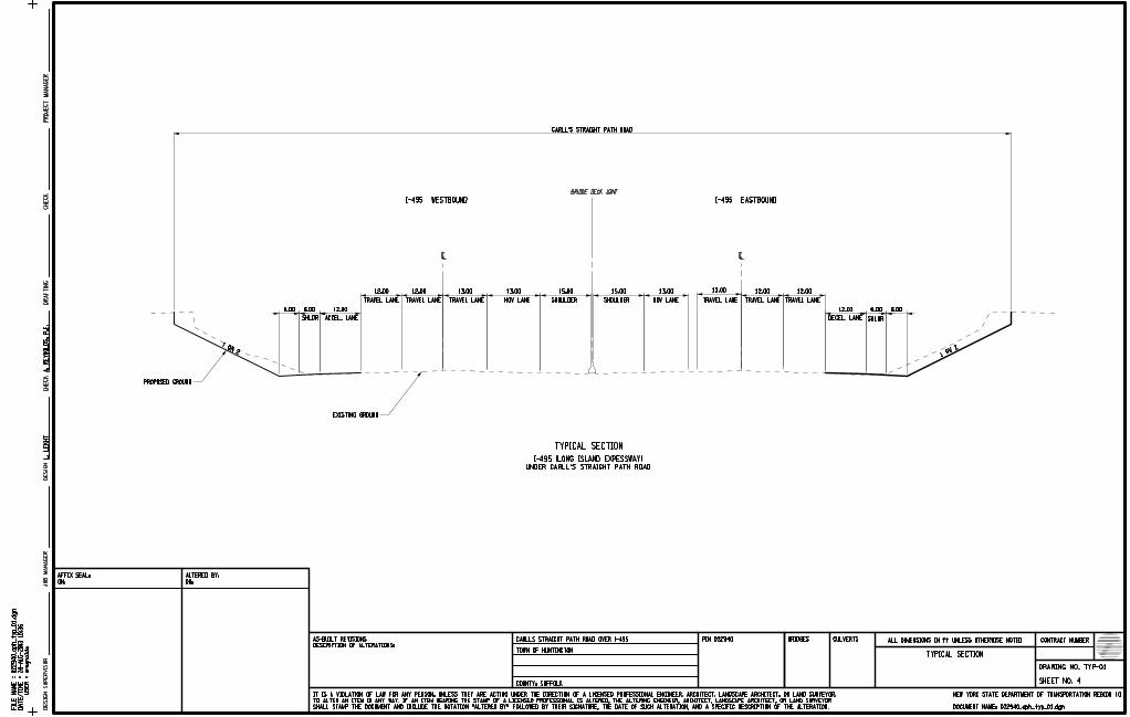
28-
AU
G-2013 15:3
6
areynolds
CONTRACT NUMBER
DRAWING NO.
SHEET NO.
NEW YORK STATE DEPARTMENT OF TRANSPORTATION REGION
BRIDGES CULVERTSPIN
JO
B
MA
NA
GE
RD
ESIG
N
SU
PE
RVIS
OR
DOCUMENT NAME:
COUNTY:
PR
OJ
EC
T
MA
NA
GE
RD
ESIG
ND
RA
FTIN
GC
HE
CK
CH
EC
K
DESCRIPTION OF ALTERATIONS:
AS-BUILT REVISIONS ALL DIMENSIONS IN ft UNLESS OTHERWISE NOTED
ON:
AFFIX SEAL:
FIL
E
NA
ME
=
US
ER
=
DA
TE/
TI
ME
=
ON:
ALTERED BY:
SHALL STAMP THE DOCUMENT AND INCLUDE THE NOTATION "ALTERED BY" FOLLOWED BY THEIR SIGNATURE, THE DATE OF SUCH ALTERATION, AND A SPECIFIC DESCRIPTION OF THE ALTERATION.
TO ALTER AN ITEM IN ANY WAY. IF AN ITEM BEARING THE STAMP OF A LICENSED PROFESSIONAL IS ALTERED, THE ALTERING ENGINEER, ARCHITECT, LANDSCAPE ARCHITECT, OR LAND SURVEYOR
IT IS A VIOLATION OF LAW FOR ANY PERSON, UNLESS THEY ARE ACTING UNDER THE DIRECTION OF A LICENSED PROFESSIONAL ENGINEER, ARCHITECT, LANDSCAPE ARCHITECT, OR LAND SURVEYOR,
4
12.006.00 12.00 6.00 6.006.00
1 ON
21 ON 2
TRAVEL LANE
12.00
TRAVEL LANE
12.00
TRAVEL LANE HOV LANE SHOULDER
15.00
SHOULDER HOV LANE TRAVEL LANE
12.00 12.00
TRAVEL LANE TRAVEL LANE
ACCEL. LANE DECEL. LANE SHLDRSHLDR
CL CL
13.00 13.0015.0013.0013.00
BRIDGE DECK JOINT
CARLL’S STRAIGHT PATH ROAD
I-495 WESTBOUND I-495 EASTBOUND
L.
LE
KH
T
CARLLS STRAIGHT PATH ROAD OVER I-495
TOWN OF HUNTINGTON
022940
TYP-01
10
UNDER CARLL’S STRAIGHT PATH ROAD
I-495 (LONG ISLAND EXPESSWAY)
TYPICAL SECTION
A.
RE
YN
OL
DS,
P.E.
EXISTING GROUND
PROPOSED GROUND
022940_cph_ty
p_01.d
gn
022940_cph_typ_01.dgn
TYPICAL SECTION
SUFFOLK

28-
AU
G-2013 15:3
6
areynolds
CONTRACT NUMBER
DRAWING NO.
SHEET NO.
NEW YORK STATE DEPARTMENT OF TRANSPORTATION REGION
BRIDGES CULVERTSPIN
JO
B
MA
NA
GE
RD
ESIG
N
SU
PE
RVIS
OR
DOCUMENT NAME:
COUNTY:
PR
OJ
EC
T
MA
NA
GE
RD
ESIG
ND
RA
FTIN
GC
HE
CK
CH
EC
K
DESCRIPTION OF ALTERATIONS:
AS-BUILT REVISIONS ALL DIMENSIONS IN ft UNLESS OTHERWISE NOTED
ON:
AFFIX SEAL:
FIL
E
NA
ME
=
US
ER
=
DA
TE/
TI
ME
=
ON:
ALTERED BY:
SHALL STAMP THE DOCUMENT AND INCLUDE THE NOTATION "ALTERED BY" FOLLOWED BY THEIR SIGNATURE, THE DATE OF SUCH ALTERATION, AND A SPECIFIC DESCRIPTION OF THE ALTERATION.
TO ALTER AN ITEM IN ANY WAY. IF AN ITEM BEARING THE STAMP OF A LICENSED PROFESSIONAL IS ALTERED, THE ALTERING ENGINEER, ARCHITECT, LANDSCAPE ARCHITECT, OR LAND SURVEYOR
IT IS A VIOLATION OF LAW FOR ANY PERSON, UNLESS THEY ARE ACTING UNDER THE DIRECTION OF A LICENSED PROFESSIONAL ENGINEER, ARCHITECT, LANDSCAPE ARCHITECT, OR LAND SURVEYOR,
5
CARLLS STRAIGHT PATH ROAD OVER I-495
TOWN OF HUNTINGTON
022940
TYP-02
10
TYPICAL SECTION
CARLL’S STRAIGHT PATH ROAD
NOT TO SCALE
TYPICAL SECTION
NOT TO SCALE
CARLL’S STRAIGHT PATH ROAD APPROACH
SIDEWALK
1:2 SLOPE
1:2 SLOPE
THRU WITH LEFT TURN LANE NORTHBOUND TRAVEL LANESOUTHBOUND TRAVEL LANESHOULDER SHOULDER
2.0’5.0’VARIES2.5’ 5.0’ 11.0’ 5.0’11.0’11.0’
SOUTHBOUND TRAVEL LANE THRU WITH LEFT TURN LANE NORTHBOUND TRAVEL LANE SHOULDER SIDEWALK
1.5’5.0’
SHOULDER
6"vCURB
6"vCURB
BARRIER
CONC.
2% 2%6%
52.0’
TOTAL PROPOSED BRIDGE WIDTH
2%6%
6%2%
2% 2%6%
A.
RE
YN
OL
DS,
P.E
022940_cph_ty
p_02.d
gn
022940_cph_typ_02.dgn
TYPICAL SECTION
OF CONSTRUCTION DOCUMENTS AND SITE CONSTRAINTS.
1. LANE, SNOW STORAGE AND SIDEWALK WIDTHS MAY CHANGE BASE ON DEVELOPMENT
NOTE:
STORAGE
SNOW
5.0’5.0’ 5.0’11.0’11.0’11.0’
SUFFOLK
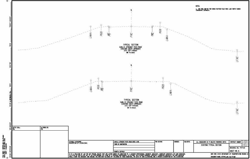
28-
AU
G-2013 15:3
6
areynolds
CONTRACT NUMBER
DRAWING NO.
SHEET NO.
NEW YORK STATE DEPARTMENT OF TRANSPORTATION REGION
BRIDGES CULVERTSPIN
JO
B
MA
NA
GE
RD
ESIG
N
SU
PE
RVIS
OR
DOCUMENT NAME:
COUNTY:
PR
OJ
EC
T
MA
NA
GE
RD
ESIG
ND
RA
FTIN
GC
HE
CK
CH
EC
K
DESCRIPTION OF ALTERATIONS:
AS-BUILT REVISIONS ALL DIMENSIONS IN ft UNLESS OTHERWISE NOTED
ON:
AFFIX SEAL:
FIL
E
NA
ME
=
US
ER
=
DA
TE/
TI
ME
=
ON:
ALTERED BY:
SHALL STAMP THE DOCUMENT AND INCLUDE THE NOTATION "ALTERED BY" FOLLOWED BY THEIR SIGNATURE, THE DATE OF SUCH ALTERATION, AND A SPECIFIC DESCRIPTION OF THE ALTERATION.
TO ALTER AN ITEM IN ANY WAY. IF AN ITEM BEARING THE STAMP OF A LICENSED PROFESSIONAL IS ALTERED, THE ALTERING ENGINEER, ARCHITECT, LANDSCAPE ARCHITECT, OR LAND SURVEYOR
IT IS A VIOLATION OF LAW FOR ANY PERSON, UNLESS THEY ARE ACTING UNDER THE DIRECTION OF A LICENSED PROFESSIONAL ENGINEER, ARCHITECT, LANDSCAPE ARCHITECT, OR LAND SURVEYOR,
6
A.
RE
YN
OL
DS,
P.E.
022940_cph_ty
p_03.d
gn
CARLLS STRAIGHT PATH ROAD OVER I-495
TOWN OF HUNTINGTON
022940
TYP-03
022940_cph_typ_03.dgn
10
PR
C
RC
PER
GB
RG
B
LA
WA
LF
NC
LA
WA
PR
C
LA
WA
RG
B
RC
PE
PE RC R
GB
LA
WA
LF
NC
TYPICAL SECTION
NOT TO SCALE
STA. CSP 4+40.83
EXISTING SOUTH APPROACH
CARLL’S STRAIGHT PATH ROAD
TYPICAL SECTION
NOT TO SCALE
STA. CSP 4+80.91
EXISTING SOUTH APPROACH
CARLL’S STRAIGHT PATH ROAD
THROUGHOUT APPROACH.
1. SEE DWG. GNP-02 FOR CROSS SECTION PLAN VIEW, LANE WIDTH VARIES
NOTES:
c
c
EXISTING TYPICAL SECTION
SUFFOLK

28-
AU
G-2013 15:3
6
areynolds
CONTRACT NUMBER
DRAWING NO.
SHEET NO.
NEW YORK STATE DEPARTMENT OF TRANSPORTATION REGION
BRIDGES CULVERTSPIN
JO
B
MA
NA
GE
RD
ESIG
N
SU
PE
RVIS
OR
DOCUMENT NAME:
COUNTY:
PR
OJ
EC
T
MA
NA
GE
RD
ESIG
ND
RA
FTIN
GC
HE
CK
CH
EC
K
DESCRIPTION OF ALTERATIONS:
AS-BUILT REVISIONS ALL DIMENSIONS IN ft UNLESS OTHERWISE NOTED
ON:
AFFIX SEAL:
FIL
E
NA
ME
=
US
ER
=
DA
TE/
TI
ME
=
ON:
ALTERED BY:
SHALL STAMP THE DOCUMENT AND INCLUDE THE NOTATION "ALTERED BY" FOLLOWED BY THEIR SIGNATURE, THE DATE OF SUCH ALTERATION, AND A SPECIFIC DESCRIPTION OF THE ALTERATION.
TO ALTER AN ITEM IN ANY WAY. IF AN ITEM BEARING THE STAMP OF A LICENSED PROFESSIONAL IS ALTERED, THE ALTERING ENGINEER, ARCHITECT, LANDSCAPE ARCHITECT, OR LAND SURVEYOR
IT IS A VIOLATION OF LAW FOR ANY PERSON, UNLESS THEY ARE ACTING UNDER THE DIRECTION OF A LICENSED PROFESSIONAL ENGINEER, ARCHITECT, LANDSCAPE ARCHITECT, OR LAND SURVEYOR,
7
A.
RE
YN
OL
DS,
P.E.
022940_cph_ty
p_04.d
gn
CARLLS STRAIGHT PATH ROAD OVER I-495
TOWN OF HUNTINGTON
022940
TYP-04
022940_cph_typ_04.dgn
10
EXISTING TYPICAL SECTION
LA
WA
RG
B
RC
PE
PR
C
PE RC R
GW
LA
WA
LA
WA R
GB
RC
PE
PR
C
PE RC R
GW
LA
WA
TYPICAL SECTION
NOT TO SCALE
STA. CSP 7+50.33
EXISTING NORTH APPROACH
CARLL’S STRAIGHT PATH ROAD
TYPICAL SECTION
NOT TO SCALE
STA. CSP 7+94.32
EXISTING NORTH APPROACH
CARLL’S STRAIGHT PATH ROAD
c
c
THROUGHOUT APPROACH.
1. SEE DWG. GNP-03 FOR CROSS SECTION PLAN VIEW, LANE WIDTH VARIES
NOTES:
SUFFOLK
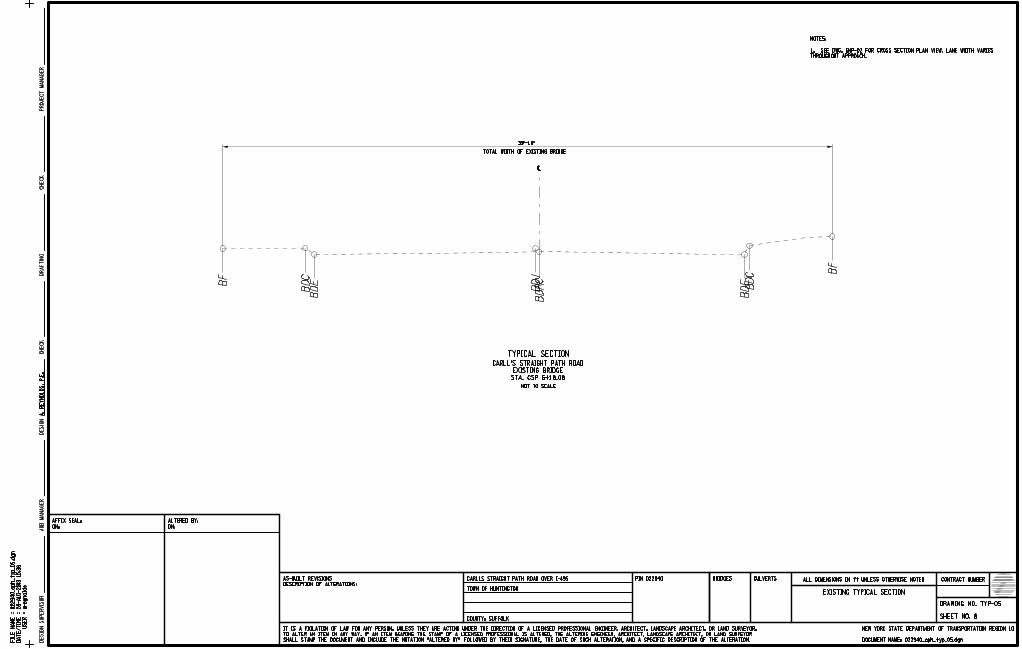
28-
AU
G-2013 15:3
6
areynolds
CONTRACT NUMBER
DRAWING NO.
SHEET NO.
NEW YORK STATE DEPARTMENT OF TRANSPORTATION REGION
BRIDGES CULVERTSPIN
JO
B
MA
NA
GE
RD
ESIG
N
SU
PE
RVIS
OR
DOCUMENT NAME:
COUNTY:
PR
OJ
EC
T
MA
NA
GE
RD
ESIG
ND
RA
FTIN
GC
HE
CK
CH
EC
K
DESCRIPTION OF ALTERATIONS:
AS-BUILT REVISIONS ALL DIMENSIONS IN ft UNLESS OTHERWISE NOTED
ON:
AFFIX SEAL:
FIL
E
NA
ME
=
US
ER
=
DA
TE/
TI
ME
=
ON:
ALTERED BY:
SHALL STAMP THE DOCUMENT AND INCLUDE THE NOTATION "ALTERED BY" FOLLOWED BY THEIR SIGNATURE, THE DATE OF SUCH ALTERATION, AND A SPECIFIC DESCRIPTION OF THE ALTERATION.
TO ALTER AN ITEM IN ANY WAY. IF AN ITEM BEARING THE STAMP OF A LICENSED PROFESSIONAL IS ALTERED, THE ALTERING ENGINEER, ARCHITECT, LANDSCAPE ARCHITECT, OR LAND SURVEYOR
IT IS A VIOLATION OF LAW FOR ANY PERSON, UNLESS THEY ARE ACTING UNDER THE DIRECTION OF A LICENSED PROFESSIONAL ENGINEER, ARCHITECT, LANDSCAPE ARCHITECT, OR LAND SURVEYOR,
8
022940_cph_ty
p_05.d
gn
022940_cph_typ_05.dgn
A.
RE
YN
OL
DS,
P.E.
CARLLS STRAIGHT PATH ROAD OVER I-495
TOWN OF HUNTINGTON
022940
EXISTING TYPICAL SECTION
TYP-05
10
BF
BD
CB
DE
BD
RC
BDJ
BD
CB
DE
BF
TYPICAL SECTION
NOT TO SCALE
THROUGHOUT APPROACH.
1. SEE DWG. GNP-02 FOR CROSS SECTION PLAN VIEW, LANE WIDTH VARIES
NOTES:
STA. CSP 6+18.08
EXISTING BRIDGE
CARLL’S STRAIGHT PATH ROAD
c
TOTAL WIDTH OF EXISTING BRIDGE
39’-10"
SUFFOLK
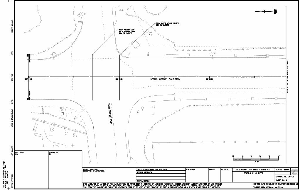
28-
AU
G-2013 15:3
6
areynolds
CONTRACT NUMBER
DRAWING NO.
SHEET NO.
NEW YORK STATE DEPARTMENT OF TRANSPORTATION REGION
BRIDGES CULVERTSPIN
JO
B
MA
NA
GE
RD
ESIG
N
SU
PE
RVIS
OR
DOCUMENT NAME:
COUNTY:
PR
OJ
EC
T
MA
NA
GE
RD
ESIG
ND
RA
FTIN
GC
HE
CK
CH
EC
K
DESCRIPTION OF ALTERATIONS:
AS-BUILT REVISIONS ALL DIMENSIONS IN ft UNLESS OTHERWISE NOTED
ON:
AFFIX SEAL:
FIL
E
NA
ME
=
US
ER
=
DA
TE/
TI
ME
=
ON:
ALTERED BY:
SHALL STAMP THE DOCUMENT AND INCLUDE THE NOTATION "ALTERED BY" FOLLOWED BY THEIR SIGNATURE, THE DATE OF SUCH ALTERATION, AND A SPECIFIC DESCRIPTION OF THE ALTERATION.
TO ALTER AN ITEM IN ANY WAY. IF AN ITEM BEARING THE STAMP OF A LICENSED PROFESSIONAL IS ALTERED, THE ALTERING ENGINEER, ARCHITECT, LANDSCAPE ARCHITECT, OR LAND SURVEYOR
IT IS A VIOLATION OF LAW FOR ANY PERSON, UNLESS THEY ARE ACTING UNDER THE DIRECTION OF A LICENSED PROFESSIONAL ENGINEER, ARCHITECT, LANDSCAPE ARCHITECT, OR LAND SURVEYOR,
9
0 10 20 30 40’10
1" = 20’
A.
RE
YN
OL
DS,
P.E.
022940_cph_gn
p_01.d
gn
CARLLS STRAIGHT PATH ROAD OVER I-495
TOWN OF HUNTINGTON
022940
GENERAL PLAN SHEET
GNP-01
022940_cph_gnp_01.dgn
10
MA
TC
H
TO
DW
G.
NO.
GN
P-02
ST
A.
CS
P 3
+85.0
0
SUFFOLK
GRID
NO
RT
H
CARLL’S STRAIGHT PATH ROAD
STA. CSP 2+00.55
BEGIN RAISING VERICAL PROFILE
SOUT
H SE
RVIC
E
ROAD
STA. CSP 1+70.55
BEGIN PAVEMENT WORK
BEGIN PROJECT LIMIT
CSP 1+00 CSP 2+00 CSP 3+00
CS
P 1
+00.0
0
PO
B
CS
P 1
+00.0
0
PI
CSP 1+00 CSP 2+00 CSP 3+00
CS
P 1
+00.0
0
PO
B
CS
P 1
+00.0
0
PI
GRID
NO
RT
H
CARLL’S STRAIGHT PATH ROAD
STA. CSP 2+00.55
BEGIN RAISING VERICAL PROFILE
SOUT
H SE
RVIC
E
ROAD
STA. CSP 1+70.55
BEGIN PAVEMENT WORK
BEGIN PROJECT LIMIT
TC
TC

28-
AU
G-2013 15:3
6
areynolds
CONTRACT NUMBER
DRAWING NO.
SHEET NO.
NEW YORK STATE DEPARTMENT OF TRANSPORTATION REGION
BRIDGES CULVERTSPIN
JO
B
MA
NA
GE
RD
ESIG
N
SU
PE
RVIS
OR
DOCUMENT NAME:
COUNTY:
PR
OJ
EC
T
MA
NA
GE
RD
ESIG
ND
RA
FTIN
GC
HE
CK
CH
EC
K
DESCRIPTION OF ALTERATIONS:
AS-BUILT REVISIONS ALL DIMENSIONS IN ft UNLESS OTHERWISE NOTED
ON:
AFFIX SEAL:
FIL
E
NA
ME
=
US
ER
=
DA
TE/
TI
ME
=
ON:
ALTERED BY:
SHALL STAMP THE DOCUMENT AND INCLUDE THE NOTATION "ALTERED BY" FOLLOWED BY THEIR SIGNATURE, THE DATE OF SUCH ALTERATION, AND A SPECIFIC DESCRIPTION OF THE ALTERATION.
TO ALTER AN ITEM IN ANY WAY. IF AN ITEM BEARING THE STAMP OF A LICENSED PROFESSIONAL IS ALTERED, THE ALTERING ENGINEER, ARCHITECT, LANDSCAPE ARCHITECT, OR LAND SURVEYOR
IT IS A VIOLATION OF LAW FOR ANY PERSON, UNLESS THEY ARE ACTING UNDER THE DIRECTION OF A LICENSED PROFESSIONAL ENGINEER, ARCHITECT, LANDSCAPE ARCHITECT, OR LAND SURVEYOR,
MA
TC
H
TO
DW
G.
NO.
GN
P-01
ST
A.
3+85.0
0
MA
TC
H
TO
DW
G.
NO.
GN
P-03
ST
A.
6+80.0
0
0 10 20 30 40’10
1" = 20’
A.
RE
YN
OL
DS,
P.E.
022940_cph_gn
p_02.d
gn
CARLLS STRAIGHT PATH ROAD OVER I-495
TOWN OF HUNTINGTON
022940
GENERAL PLAN SHEET
GNP-02
022940_cph_gnp_02.dgn
10
10SUFFOLK
GRID
NO
RT
H
CARLL’S STRAIGHT PATH ROAD
PROPOSED 6’ SHOULDER
EASTB
OUND
I-495 (LO
NG IS
LAND E
XPRESS
WAY)
WESTB
OUND
I-495 (LO
NG IS
LAND E
XPRESS
WAY)
STRAIGHT PATH ROAD (SEE TYP-01)
I-495 EASTBOUND UNDER CARLL’S
PROPOSED 12’ DECELERATION LANE
(SEE DWG. TYP-03)
TYPICAL SECTION STA. CSP 4+40.83
SOUTHERN APPROACH EXISTING
(SEE DWG. TYP-03)
TYPICAL SECTION STA. CSP 4+80.91
SOUTHERN APPROACH EXISTING(SEE DWG. TYP-05)
BRIDGE TYPICAL SECTION STA. CSP 6+18.08
CARLL’S STRAIGHT PATH ROAD EXISTING
CSP 4+00 CSP 5+00 CSP 6+00CSP 4+00 CSP 5+00 CSP 6+00
GRID
NO
RT
H
CARLL’S STRAIGHT PATH ROAD
PROPOSED 6’ SHOULDER
EASTB
OUND
I-495 (LO
NG IS
LAND E
XPRESS
WAY)
WESTB
OUND
I-495 (LO
NG IS
LAND E
XPRESS
WAY)
STRAIGHT PATH ROAD (SEE TYP-01)
I-495 EASTBOUND UNDER CARLL’S
PROPOSED 12’ DECELERATION LANE
(SEE DWG. TYP-03)
TYPICAL SECTION STA. CSP 4+40.83
SOUTHERN APPROACH EXISTING
(SEE DWG. TYP-03)
TYPICAL SECTION STA. CSP 4+80.91
SOUTHERN APPROACH EXISTING(SEE DWG. TYP-05)
BRIDGE TYPICAL SECTION STA. CSP 6+18.08
CARLL’S STRAIGHT PATH ROAD EXISTING
SCREENING
SCREENING
OH
OH
OH

28-
AU
G-2013 15:3
6
areynolds
CONTRACT NUMBER
DRAWING NO.
SHEET NO.
NEW YORK STATE DEPARTMENT OF TRANSPORTATION REGION
BRIDGES CULVERTSPIN
JO
B
MA
NA
GE
RD
ESIG
N
SU
PE
RVIS
OR
DOCUMENT NAME:
COUNTY:
PR
OJ
EC
T
MA
NA
GE
RD
ESIG
ND
RA
FTIN
GC
HE
CK
CH
EC
K
DESCRIPTION OF ALTERATIONS:
AS-BUILT REVISIONS ALL DIMENSIONS IN ft UNLESS OTHERWISE NOTED
ON:
AFFIX SEAL:
FIL
E
NA
ME
=
US
ER
=
DA
TE/
TI
ME
=
ON:
ALTERED BY:
SHALL STAMP THE DOCUMENT AND INCLUDE THE NOTATION "ALTERED BY" FOLLOWED BY THEIR SIGNATURE, THE DATE OF SUCH ALTERATION, AND A SPECIFIC DESCRIPTION OF THE ALTERATION.
TO ALTER AN ITEM IN ANY WAY. IF AN ITEM BEARING THE STAMP OF A LICENSED PROFESSIONAL IS ALTERED, THE ALTERING ENGINEER, ARCHITECT, LANDSCAPE ARCHITECT, OR LAND SURVEYOR
IT IS A VIOLATION OF LAW FOR ANY PERSON, UNLESS THEY ARE ACTING UNDER THE DIRECTION OF A LICENSED PROFESSIONAL ENGINEER, ARCHITECT, LANDSCAPE ARCHITECT, OR LAND SURVEYOR,
A.
RE
YN
OL
DS,
P.E.
022940_cph_gn
p_03.d
gn
CARLLS STRAIGHT PATH ROAD OVER I-495
TOWN OF HUNTINGTON
022940
GENERAL PLAN SHEET
GNP-03
022940_cph_gnp_03.dgn
10
0 10 20 30 40’10
1" = 20’
MA
TC
H
TO
DW
G.
NO.
GN
P-02
ST
A.
CS
P 6
+80.0
0
11SUFFOLK
GRID
NO
RT
H
CARLL’S STRAIGHT PATH ROAD
STA. CSP 9+05.93
TIE BACK INTO EXISTING
END VERTICAL PROFILE WORK
PROPOSED 6’ SHOULDER
NORT
H SE
RVIC
E
ROAD
STRAIGHT PATH ROAD (SEE TYP-01)
I-495 WESTBOUND UNDER CARLL’S
PROPOSED 12’ ACCELERATION LANE
(SEE DWG. TYP-04)
TYPICAL SECTION STA. CSP 7+50.33
NORTHERN APPROACH EXISTING
(SEE DWG. TYP-04)
TYPICAL SECTION STA. CSP 7+94.32
NORTHERN APPROACH EXISTING
STA. CSP 9+35.93
END PAVEMENT WORK
END OF PROJECT LIMIT
CSP 7+00 CSP 8+00 CSP 9+00CSP 7+00 CSP 8+00 CSP 9+00
GRID
NO
RT
H
CARLL’S STRAIGHT PATH ROAD
STA. CSP 9+05.93
TIE BACK INTO EXISTING
END VERTICAL PROFILE WORK
PROPOSED 6’ SHOULDER
NORT
H SE
RVIC
E
ROAD
STRAIGHT PATH ROAD (SEE TYP-01)
I-495 WESTBOUND UNDER CARLL’S
PROPOSED 12’ ACCELERATION LANE
(SEE DWG. TYP-04)
TYPICAL SECTION STA. CSP 7+50.33
NORTHERN APPROACH EXISTING
(SEE DWG. TYP-04)
TYPICAL SECTION STA. CSP 7+94.32
NORTHERN APPROACH EXISTING
STA. CSP 9+35.93
END PAVEMENT WORK
END OF PROJECT LIMIT
UB
UB
VALVE
TC
TC
OH
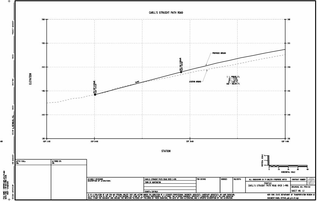
28-
AU
G-2013 15:3
6
areynolds
CONTRACT NUMBER
DRAWING NO.
SHEET NO.
NEW YORK STATE DEPARTMENT OF TRANSPORTATION REGION
BRIDGES CULVERTSPIN
JO
B
MA
NA
GE
RD
ESIG
N
SU
PE
RVIS
OR
DOCUMENT NAME:
COUNTY:
PR
OJ
EC
T
MA
NA
GE
RD
ESIG
ND
RA
FTIN
GC
HE
CK
CH
EC
K
DESCRIPTION OF ALTERATIONS:
AS-BUILT REVISIONS ALL DIMENSIONS IN ft UNLESS OTHERWISE NOTED
CARLL’S STRAIGHT PATH ROAD OVER I-495
ON:
AFFIX SEAL:
FIL
E
NA
ME
=
US
ER
=
DA
TE/
TI
ME
=
ON:
ALTERED BY:
SHALL STAMP THE DOCUMENT AND INCLUDE THE NOTATION "ALTERED BY" FOLLOWED BY THEIR SIGNATURE, THE DATE OF SUCH ALTERATION, AND A SPECIFIC DESCRIPTION OF THE ALTERATION.
TO ALTER AN ITEM IN ANY WAY. IF AN ITEM BEARING THE STAMP OF A LICENSED PROFESSIONAL IS ALTERED, THE ALTERING ENGINEER, ARCHITECT, LANDSCAPE ARCHITECT, OR LAND SURVEYOR
IT IS A VIOLATION OF LAW FOR ANY PERSON, UNLESS THEY ARE ACTING UNDER THE DIRECTION OF A LICENSED PROFESSIONAL ENGINEER, ARCHITECT, LANDSCAPE ARCHITECT, OR LAND SURVEYOR,
135
140
145
150
155
160160
135
140
145
150
155
160160
CSP 1+00 CSP 1+50 CSP 2+00 CSP 3+00 CSP 4+00
EL
EV
ATIO
N
STATION
PVI
CS
P 2
+00.5
5
EL
EV 144.2
4
PV
C
CS
P 2
+90.8
5
EL
EV 148.9
7
5.25%
L = 600.00 FT.
G1 = 5.25%
G2 = -4.72%
E= -7.48 FT.
SSD = 360.45 FT.
A.
RE
YN
OL
DS,
P.E.
022940_cph_pro
_01.d
gn
CARLLS STRAIGHT PATH ROAD OVER I-495
TOWN OF HUNTINGTON
022940
PRO-01
022940_cph_pro_01.dgn
10
CARLL’S STRAIGHT PATH ROAD
PROFILE
PROPOSED GROUND
EXISTING GROUND
0 10 20 30 40’
HORIZONTAL SCALE
01
2’
VE
RTIC
AL
SC
AL
E
12SUFFOLK

28-
AU
G-2013 15:3
6
areynolds
CONTRACT NUMBER
DRAWING NO.
SHEET NO.
NEW YORK STATE DEPARTMENT OF TRANSPORTATION REGION
BRIDGES CULVERTSPIN
JO
B
MA
NA
GE
RD
ESIG
N
SU
PE
RVIS
OR
DOCUMENT NAME:
COUNTY:
PR
OJ
EC
T
MA
NA
GE
RD
ESIG
ND
RA
FTIN
GC
HE
CK
CH
EC
K
DESCRIPTION OF ALTERATIONS:
AS-BUILT REVISIONS ALL DIMENSIONS IN ft UNLESS OTHERWISE NOTED
CARLL’S STRAIGHT PATH ROAD OVER I-495
ON:
AFFIX SEAL:
FIL
E
NA
ME
=
US
ER
=
DA
TE/
TI
ME
=
ON:
ALTERED BY:
SHALL STAMP THE DOCUMENT AND INCLUDE THE NOTATION "ALTERED BY" FOLLOWED BY THEIR SIGNATURE, THE DATE OF SUCH ALTERATION, AND A SPECIFIC DESCRIPTION OF THE ALTERATION.
TO ALTER AN ITEM IN ANY WAY. IF AN ITEM BEARING THE STAMP OF A LICENSED PROFESSIONAL IS ALTERED, THE ALTERING ENGINEER, ARCHITECT, LANDSCAPE ARCHITECT, OR LAND SURVEYOR
IT IS A VIOLATION OF LAW FOR ANY PERSON, UNLESS THEY ARE ACTING UNDER THE DIRECTION OF A LICENSED PROFESSIONAL ENGINEER, ARCHITECT, LANDSCAPE ARCHITECT, OR LAND SURVEYOR,
135
140
145
150
155
160160
135
140
145
150
155
160160
CSP 4+00 CSP 5+00 CSP 6+00 CSP 6+75
EL
EV
ATIO
N
STATION
PVI
CS
P 5
+90.8
5
EL
EV 164.7
1
HIG
H
CS
P 6
+06.6
2
EL
EV 157.2
5
CARLL’S STRAIGHT PATH ROAD
A.
RE
YN
OL
DS,
P.E.
022940_cph_pro
_02.d
gn
CARLLS STRAIGHT PATH ROAD OVER I-495
TOWN OF HUNTINGTON
022940
PROFILE
PRO-02
022940_cph_pro_02.dgn
10
0 10 20 30 40’
HORIZONTAL SCALE
01
2’
VE
RTIC
AL
SC
AL
E
I-495 (LONG ISLAND EXPRESSWAY)
EXISTING GROUND
PROPOSED GROUND
BIN 1049350
11.5" 9.5"
I-495
EA
ST
BO
UN
D
CE
NT
ER
LIN
E
I-495
WE
ST
BO
UN
D
CE
NT
ER
LIN
E
L = 600.000 FT.
G2 = -0.047
E= -7.475 FT.
SSD = 360.449 FT.
G1 = 0.052
PR
OP
OS
ED
ED
GE
OF
SH
OU
LD
ER
ST
A.
CS
P 5
+32.2
PR
OP
OS
ED
ED
GE
OF
DE
CE
L
LA
NE
ST
A.
CS
P 5
+38.2
13SUFFOLK

28-
AU
G-2013 15:3
6
areynolds
CONTRACT NUMBER
DRAWING NO.
SHEET NO.
NEW YORK STATE DEPARTMENT OF TRANSPORTATION REGION
BRIDGES CULVERTSPIN
JO
B
MA
NA
GE
RD
ESIG
N
SU
PE
RVIS
OR
DOCUMENT NAME:
COUNTY:
PR
OJ
EC
T
MA
NA
GE
RD
ESIG
ND
RA
FTIN
GC
HE
CK
CH
EC
K
DESCRIPTION OF ALTERATIONS:
AS-BUILT REVISIONS ALL DIMENSIONS IN ft UNLESS OTHERWISE NOTED
CARLL’S STRAIGHT PATH ROAD OVER I-495
ON:
AFFIX SEAL:
FIL
E
NA
ME
=
US
ER
=
DA
TE/
TI
ME
=
ON:
ALTERED BY:
SHALL STAMP THE DOCUMENT AND INCLUDE THE NOTATION "ALTERED BY" FOLLOWED BY THEIR SIGNATURE, THE DATE OF SUCH ALTERATION, AND A SPECIFIC DESCRIPTION OF THE ALTERATION.
TO ALTER AN ITEM IN ANY WAY. IF AN ITEM BEARING THE STAMP OF A LICENSED PROFESSIONAL IS ALTERED, THE ALTERING ENGINEER, ARCHITECT, LANDSCAPE ARCHITECT, OR LAND SURVEYOR
IT IS A VIOLATION OF LAW FOR ANY PERSON, UNLESS THEY ARE ACTING UNDER THE DIRECTION OF A LICENSED PROFESSIONAL ENGINEER, ARCHITECT, LANDSCAPE ARCHITECT, OR LAND SURVEYOR,
135
140
145
150
155
160160
135
140
145
150
155
160160
CSP 6+75 CSP 7+00 CSP 8+00 CSP 9+00 CSP 9+50
EL
EV
ATIO
N
STATION
PV
T
CS
P 0
+890.8
5
EL
EV 150.5
4
PVI
CS
P 9
+05.9
3
EL
EV 149.8
3
-0.05 L - 15.09 FT.
L = 600.000 FT.
G1 = 0.052
G2 = -0.047
E= -7.475 FT.
SSD = 360.449 FT.
CARLL’S STRAIGHT PATH ROAD
A.
RE
YN
OL
DS,
P.E.
022940_cph_pro
_03.d
gn
CARLLS STRAIGHT PATH ROAD OVER I-495
TOWN OF HUNTINGTON
022940
PROFILE
PRO-03
022940_cph_pro_03.dgn
10
0 10 20 30 40’
HORIZONTAL SCALE
01
2’
VE
RTIC
AL
SC
AL
E
EXISTING GROUND
PROPOSED GROUND
I-495 (LONG ISLAND EXPRESSWAY)
BIN 1049350
PR
OP
OS
ED
ED
GE
OF
AC
CE
L
LA
NE
ST
A.
CS
P 6
+98.5
PR
OP
OS
ED
ED
GE
OF
SH
OU
LD
ER
ST
A.
CS
P 7
+04.5
14SUFFOLK


September 2013 Project Scoping Report/Final Design Report PIN 0229.40
APPENDIX B Environmental Information


August 2013 PIN 0229.40
BIN 1049350 – Carlls Straight Path over LIE, Bridge Replacement
Social, Economic and Environmental Resources Checklist
PIN: 0ABP.09 TYPE FUNDING: Federal/State DESCRIPTION: BIN 1049350 – Carlls Straight Path over L.I. Expressway (I-495)
DATE: July 3, 2012 REVISION DATE:
TOWN: Huntington NEPA CLASS: 2 COUNTY: Suffolk SEQRA TYPE: 2
SOCIAL, ECONOMIC AND ENVIRONMENTAL CONSIDERATIONS
PRESENCE OR ANALYSIS NEEDED? IMPACT OR ISSUE?
YES NO YES NO
Social Land Use
Neighborhoods and Community Cohesion
General Social Groups
School Districts, Recreation Areas and Places of Worship
Economic Regional and Local Economies
Business Districts
Specific Business Impacts
Environmental Wetlands
Surface Waterbodies and Watercourses
Wild, Scenic, and Recreational Rivers
Navigable Waters
Floodplains
Coastal Resources
Aquifers, Wells, and Reservoirs
Stormwater Management
General Ecology and Wildlife Resources
Critical Environmental Areas
Historic and Cultural Resources
Parks and Recreational Resources
Visual Resources
Farmlands
Air Quality Analysis
Energy Analysis
Noise Analysis
Asbestos
Contaminated and Hazardous Materials
Construction Effects
Indirect (Secondary) Effects
Cumulative Effects

August 2013 PIN 0229.40
BIN 1049350 – Carlls Straight Path over LIE, Bridge Replacement
ANTICIPATED PERMITS
No Permits are anticipated.
Documentation for “Yes” Answers Identified Above Asbestos: The Regional Environmental Group reviewed current photos, the BIN folder and available as-built plans for this bridge. This information revealed that there appears to be some minor amounts of asbestos-containing materials (ACM) to be disturbed by the proposed project. However, the potential presence of ACM will not significantly affect the environment as the Department utilizes standard items and NYS Department of Labor-approved procedures for its’ safe removal. NYSDOT will perform a full asbestos survey, and if necessary collect samples to determine whether any additional asbestos–containing materials are present. After the Department reviews and approves the survey report, the D/B consultant will, as necessary, recommend the appropriate items and notes to be included in the construction phase.

August 2013 PIN 0229.40
BIN 1049350 – Carlls Straight Path over LIE, Bridge Replacement
NEPA ASSESSMENT CHECKLIST
Answer the following questions by checking YES or NO. I. THRESHOLD QUESTION YES NO 1. Does the project involve unusual circumstances as described in 23 CFR §771.117(b)? ____ __X__ M If YES, the project does not qualify as a Categorical Exclusion and an EA or EIS is required. You may STOP COMPLETING THE CHECKLIST. M If NO, go on. II. AUTOMATIC CATEGORICAL EXCLUSION YES NO 2. Is the project an action listed as an Automatic Categorical Exclusion in 23 CFR §771.117(c) (C List) and/or is the project an element-specific project classified by FHWA as a Categorical Exclusion on July 22, 1996? ____ __X__ M If YES to question 2, the project qualifies for a C List Categorical Exclusion. You may STOP COMPLETING THE CHECKLIST. The checklist should be included in the appendix of the Final Design Report (or Scope Summary Memorandum/Final Design Report). The CATEGORICAL EXCLUSION DETERMINATION memo is to be sent to the appropriate Main Office Design liaison unit with a copy of the Final Design Report (or Scope Summary Memorandum/Final Design Report). A copy of the CATEGORICAL EXCLUSION DETERMINATION memo must also be sent to the Office of Budget and Finance, Project and Letting Management, and others (see sample DETERMINATION memo attached). M If NO to question 2, go on. III. PROGRAMMATIC CATEGORICAL EXCLUSION YES NO 3. Is the project on new location or does it involve a change in the functional classification or added mainline capacity (add through-traffic lanes)? ____ __X__

August 2013 PIN 0229.40 YES NO 4. Is this a Type I project under 23 CFR 772, "Procedures for Abatement of Highway Traffic Noise and Construction"? ____ __X__ 5. If the project is located within the limits of a designated sole source aquifer area or the associated stream flow source area, is the drainage pattern altered? ____ __X__ 6. Does the project involve changes in travel patterns? ____ __X__ 7. Does the project involve the acquisition of more than minor amounts of temporary or permanent right-of-way (a minor amount of right-of-way is defined as not more than 10 percent of a parcel for parcels under 4 ha (10 acres) in size, 0.4 ha (1 acre) of a parcel 4 ha to 40.5 ha (10 to 100 acres) in size and 1 percent of a parcel for parcels greater than 40.5 ha (100 acres) in size? ____ __X__ 8. Does the project require a Section 4(f) evaluation and determination in accordance with the FHWA guidance? ____ __X__ 9. Does the project involve commercial or residential displacement? ____ __X__ 10. If Section 106 applies, does FHWA’s determination indicate an opinion of adverse effect? ____ __X__ 11. Does the project involve any work in wetlands requiring a Nationwide Wetland Permit #23? ____ __X__ 12. Does the project involve any work in wetlands requiring an individual Executive Order 11990 Wetland Finding? ____ __X__
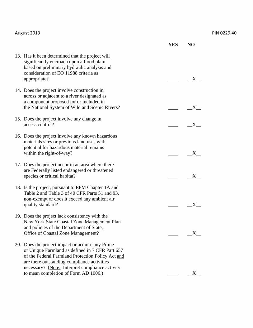
August 2013 PIN 0229.40 YES NO 13. Has it been determined that the project will significantly encroach upon a flood plain based on preliminary hydraulic analysis and consideration of EO 11988 criteria as appropriate? ____ __X__ 14. Does the project involve construction in, across or adjacent to a river designated as a component proposed for or included in the National System of Wild and Scenic Rivers? ____ __X__ 15. Does the project involve any change in access control? ____ __X__ 16. Does the project involve any known hazardous materials sites or previous land uses with potential for hazardous material remains within the right-of-way? ____ __X__ 17. Does the project occur in an area where there are Federally listed endangered or threatened species or critical habitat? ____ __X__ 18. Is the project, pursuant to EPM Chapter 1A and Table 2 and Table 3 of 40 CFR Parts 51 and 93, non-exempt or does it exceed any ambient air quality standard? ____ __X__ 19. Does the project lack consistency with the New York State Coastal Zone Management Plan and policies of the Department of State, Office of Coastal Zone Management? ____ __X__ 20. Does the project impact or acquire any Prime or Unique Farmland as defined in 7 CFR Part 657 of the Federal Farmland Protection Policy Act and are there outstanding compliance activities necessary? (Note: Interpret compliance activity to mean completion of Form AD 1006.) ____ __X__
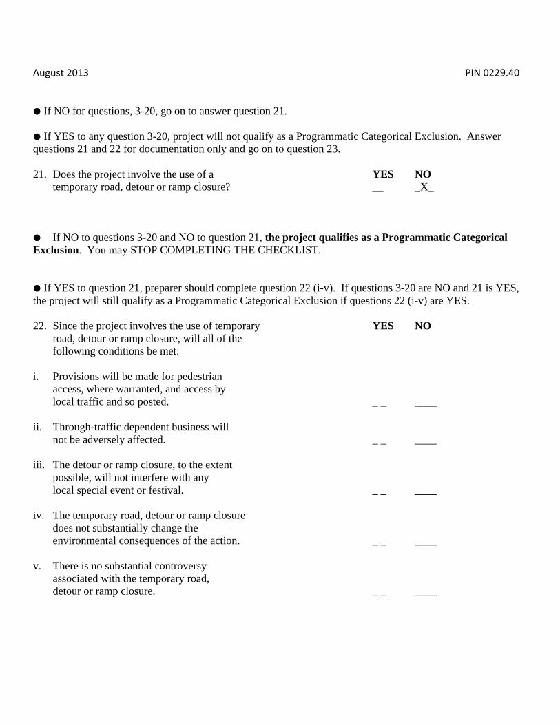
August 2013 PIN 0229.40 M If NO for questions, 3-20, go on to answer question 21. M If YES to any question 3-20, project will not qualify as a Programmatic Categorical Exclusion. Answer questions 21 and 22 for documentation only and go on to question 23. 21. Does the project involve the use of a YES NO temporary road, detour or ramp closure? __ _X_ M If NO to questions 3-20 and NO to question 21, the project qualifies as a Programmatic Categorical Exclusion. You may STOP COMPLETING THE CHECKLIST. M If YES to question 21, preparer should complete question 22 (i-v). If questions 3-20 are NO and 21 is YES, the project will still qualify as a Programmatic Categorical Exclusion if questions 22 (i-v) are YES. 22. Since the project involves the use of temporary YES NO road, detour or ramp closure, will all of the following conditions be met: i. Provisions will be made for pedestrian access, where warranted, and access by local traffic and so posted. _ _ ____ ii. Through-traffic dependent business will not be adversely affected. _ _ ____ iii. The detour or ramp closure, to the extent possible, will not interfere with any local special event or festival. _ _ ____ iv. The temporary road, detour or ramp closure does not substantially change the environmental consequences of the action. _ _ ____ v. There is no substantial controversy associated with the temporary road, detour or ramp closure. _ _ ____

August 2013 PIN 0229.40 M If questions 3-20 are NO, 21 is YES and 22 (i-v) are YES, the project qualifies for a Programmatic Categorical Exclusion. You may STOP COMPLETING THE CHECKLIST. M If questions 3-20 are NO, 21 is YES and any part of 22 is NO, go on to question 23. 23. Is the project section listed in 23 CFR YES NO §771.117(d) (D List) or is the project an action similar to those listed in 23 CFR §771.117(d)? ____ ____ For those questions which precluded a Programmatic Categorical Exclusion, documentation should be provided for any YES response to questions 3-20 or for a NO response to any part of questions 22 (i-v). This documentation, as well as the checklist, should be included in the Design Approval Document, i.e., Final Design Report, etc., to be submitted to the Main Office/FHWA Design liaison unit for submission to the FHWA Division for classification of the project as a D List Categorical Exclusion.


September 2013 Project Scoping Report/Final Design Report PIN 0229.40
APPENDIX C Traffic Information and Pedestrian
Generator Checklist


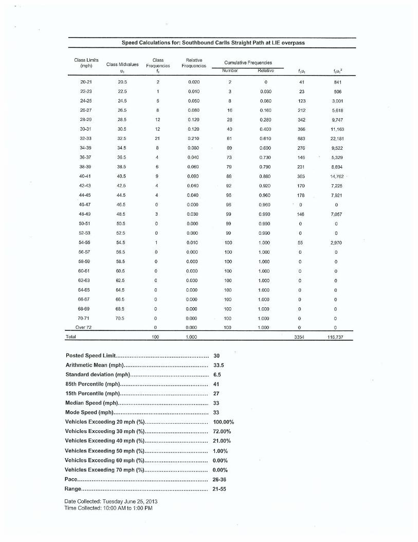

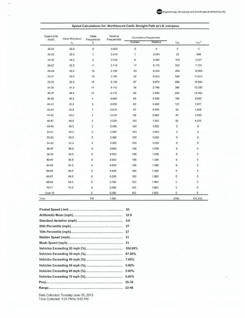

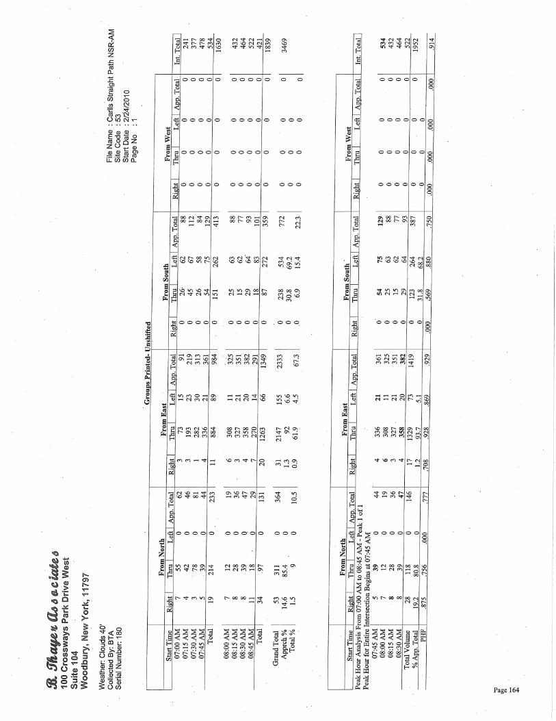


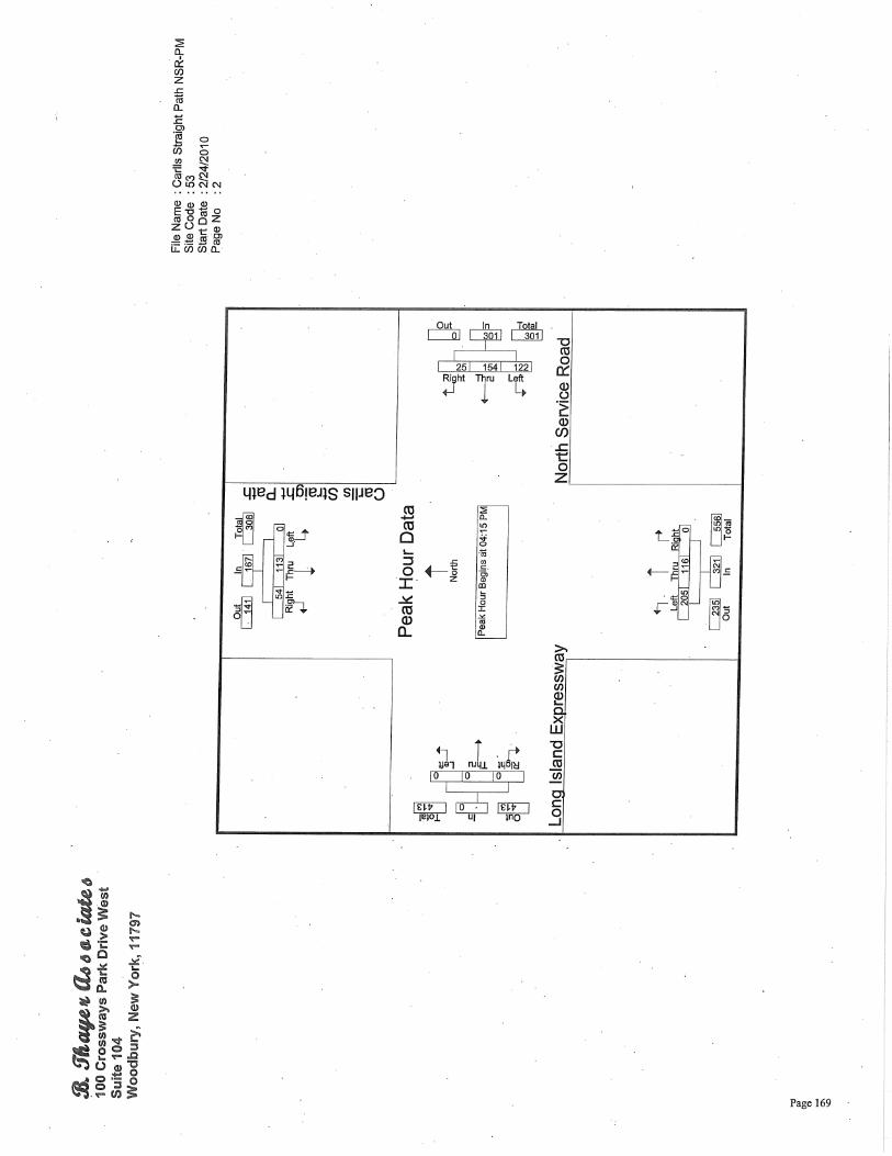


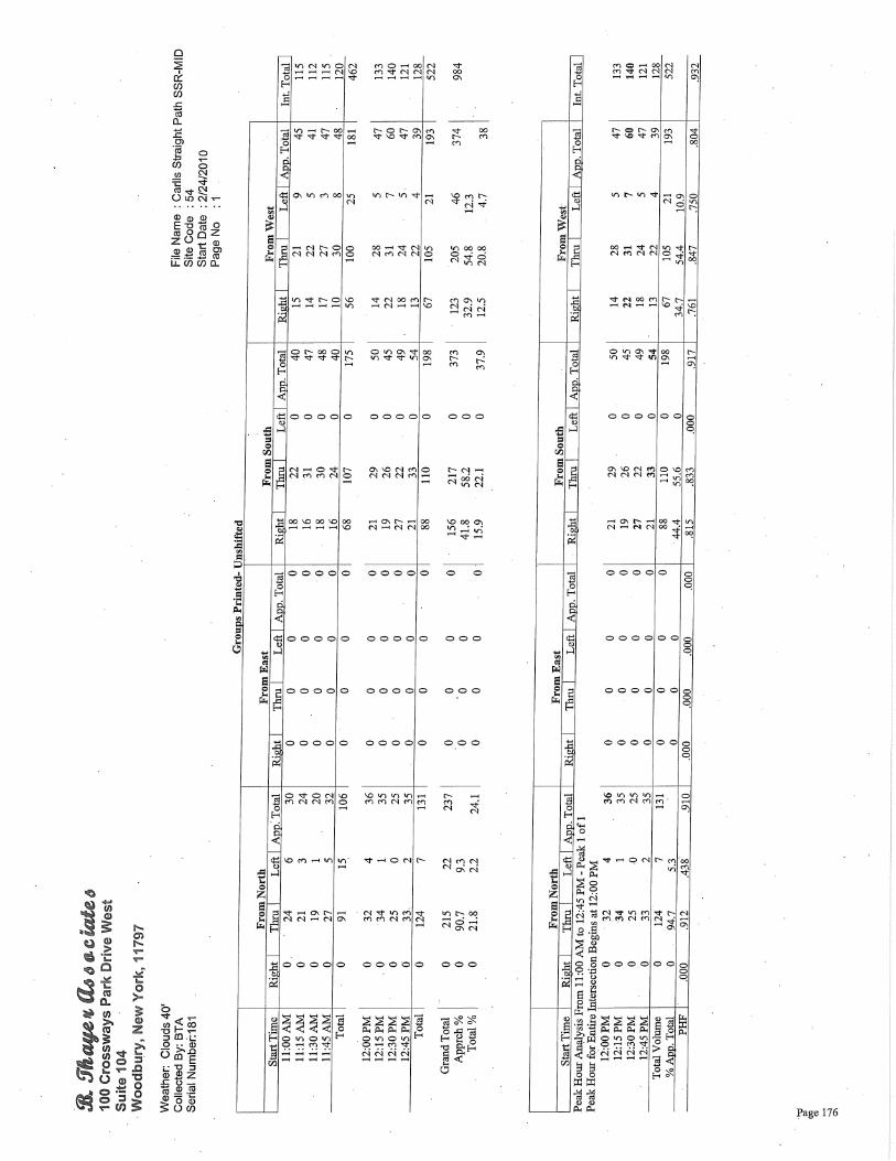
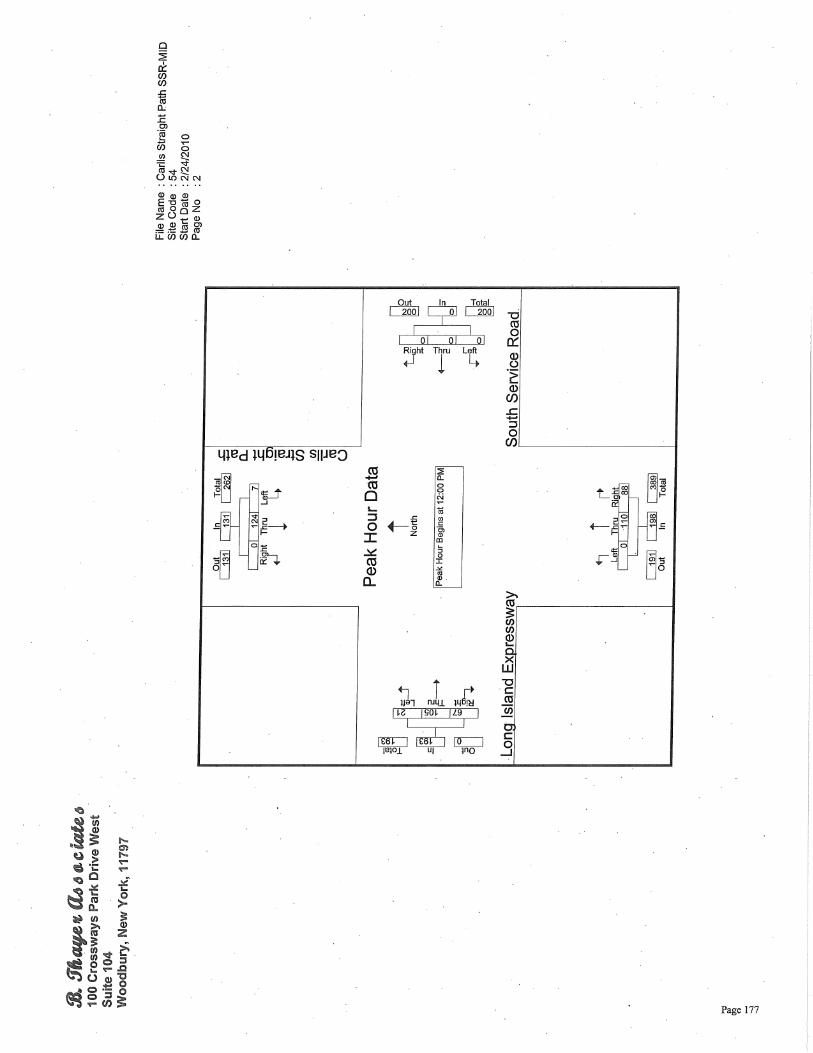


Stra ht llow
Carlls Straight Path at I495Latest 3 Years (Jan 1, 2010 ‐ Dec 31, 2012)
DMV Case #Case Year
DateMilitTim
ary e
Nuofmbe Veh
r AccideClass
nt ManColl
ner of ision
NSR SSRCStrP
arlls aight ath
IA
ntersewith
t ction NSR
Intw
At ersection ith SSR
Road Character
WeatherLight
ConditionsRoad Surface
Contributing Factors
Comments
33636948 2010 1/23/2010 0:35 2 PDO Overtake X Curve and Level
ClearDark Road Lighted
DryUnsafe Lane Change
33857131 2010 6/19/2010 5:09 1 PDO Fixed Object X Straight and Level
Clear Dawn Dry Fell Asleep Fence
33880112 2010 6/25/2010 10:50 2 PDO Right Angle X Unknown Clear Daylight DryDriver
Inattention
33900063 2010 7/12/2010 20:53 1 PDO Fixed Object X Curve and Level
Clear Daylight DryAlcohol
involvementMailbox, Tree
34079302 2010 11/16/2010 8:35 1 INJ Fixed Object X Straight and Level
Cloudy Daylight WetPavement Slippery
Tree
34122029 2010 12/1/2010 8:20 2 PDO Rear End X Straight and Level
Rain Daylight WetDriver
Inattention
33891499 2011 4/18/2011 18:00 2 INJ Right Angle X Straight and Level
Cloudy Daylight DryTraffic Control Disregarded
33919859 2011 4/16/2011 15:48 2 INJ Right Angle X Straight and Grade
Rain Daylight WetTraffic Control Disregarded
34083451 2011 9/26/2011 16:15 3 INJ Other X Unknown Unknown UnknownUnknow
nUnknown
34274128 2011 5/9/2011 8:20 2 INJ Rear End X Straight Following tooig and Grade
Clear Daylight DryFo ing too
close
34405701 2011 12/20/2011 14:48 2 PDO Right Angle X Straight and Level
Cloudy Daylight DryTraffic Control Disregarded
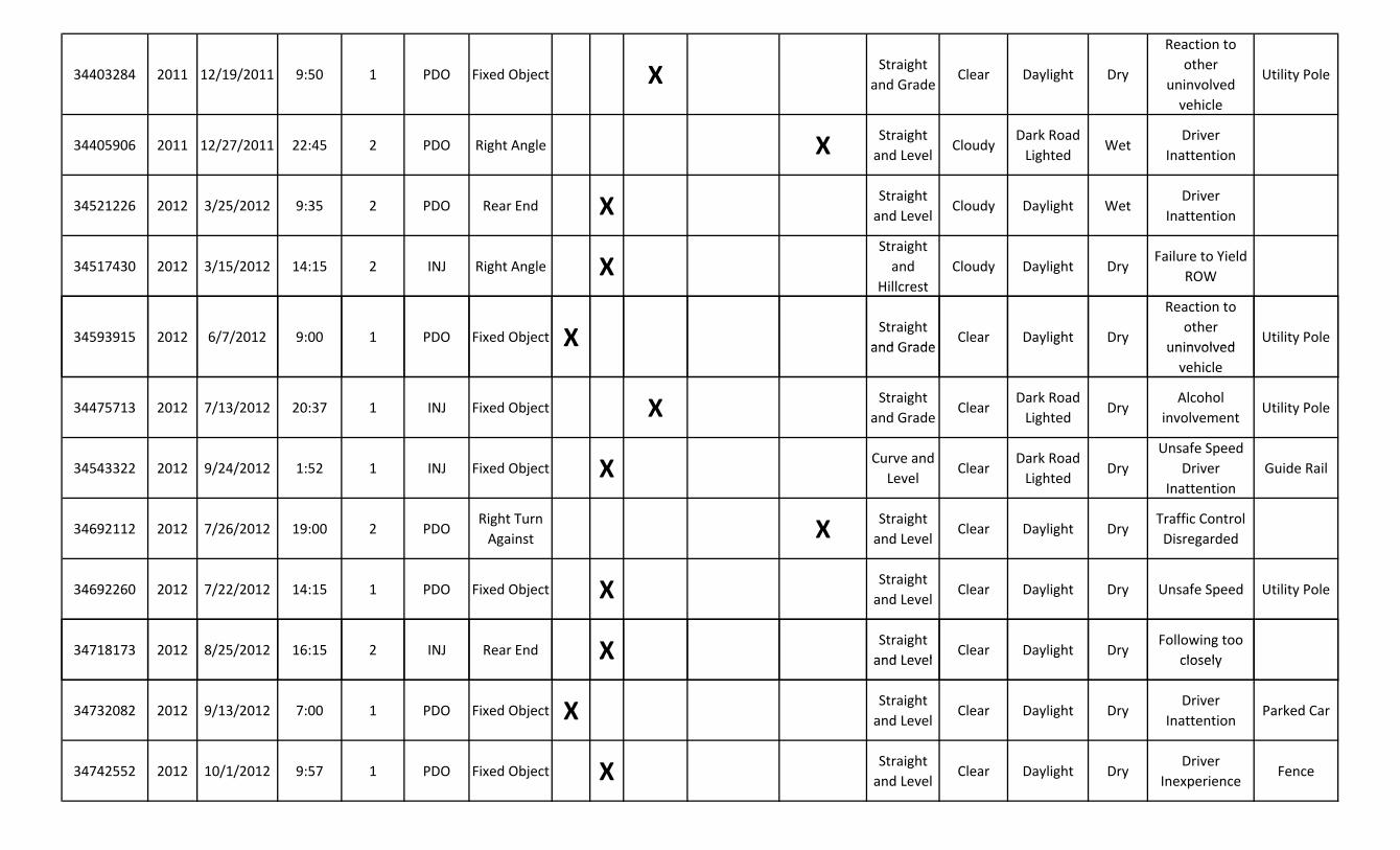
X and ey
uny
X and ly
ose y
34403284 2011 12/19/2011 9:50 1 PDO Fixed Object X Straight and Grade
Clear Daylight Dry
Reaction to other
uninvolved vehicle
Utility Pole
34405906 2011 12/27/2011 22:45 2 PDO Right Angle X Straight and Level
CloudyDark Road Lighted
WetDriver
Inattention
34521226 2012 3/25/2012 9:35 2 PDO Rear End X Straight and Level
Cloudy Daylight WetDriver
Inattention
34517430 2012 3/15/2012 14:15 2 INJ Right Angle XStraight and
HillcrestCloudy Daylight Dry
Failure to Yield ROW
34593915 2012 6/7/2012 9:00 1 PDO Fixed Objectj X Straight and Grade
Clear Daylight Dry
Reaction to other
uninvolvedUtility Pole
Grady g
involved vehicle
34475713 2012 7/13/2012 20:37 1 INJ Fixed Object X Straight and Grade
ClearDark Road Lighted
DryAlcohol
involvementUtility Pole
34543322 2012 9/24/2012 1:52 1 INJ Fixed Object X Curve and Level
ClearDark Road Lighted
DryUnsafe Speed
Driver Inattention
Guide Rail
34692112 2012 7/26/2012 19:00 2 PDORight Turn Against X Straight
and LevelClear Daylight Dry
Traffic Control Disregarded
34692260 2012 7/22/2012 14:15 1 PDO Fixed Object X Straight and Level
Clear Daylight Dry Unsafe Speed Utility Pole
34718173 2012 8/25// /2012 16:15 2 INJ Rear End X Straight and Level
Clear Daylight DryFollowing too
closely Levey g
cl l
34732082 2012 9/13/2012 7:00 1 PDO Fixed Object X Straight and Level
Clear Daylight DryDriver
InattentionParked Car
34742552 2012 10/1/2012 9:57 1 PDO Fixed Object X Straight and Level
Clear Daylight DryDriver
InexperienceFence
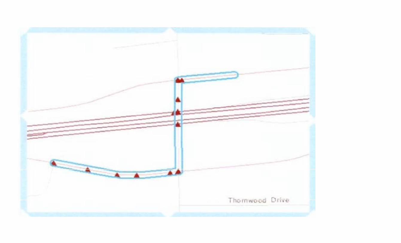
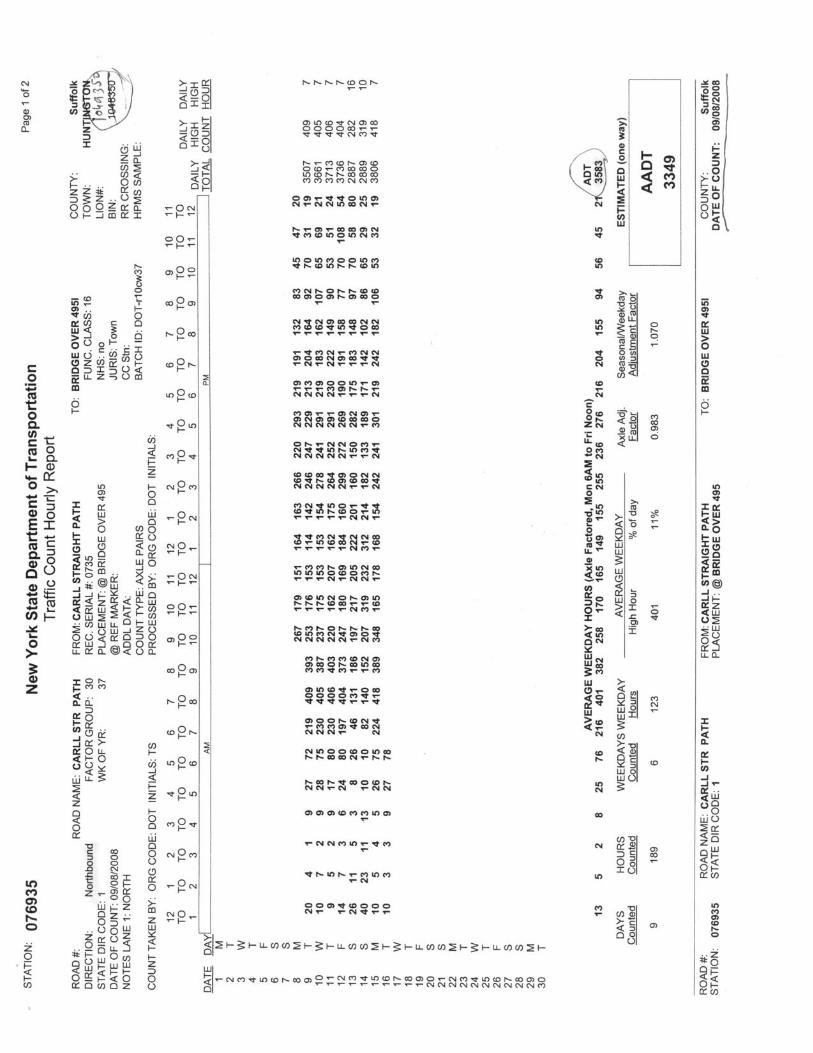
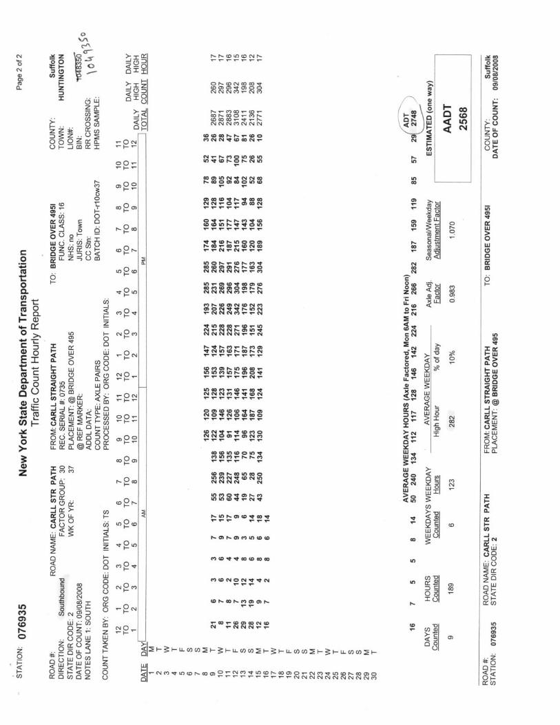

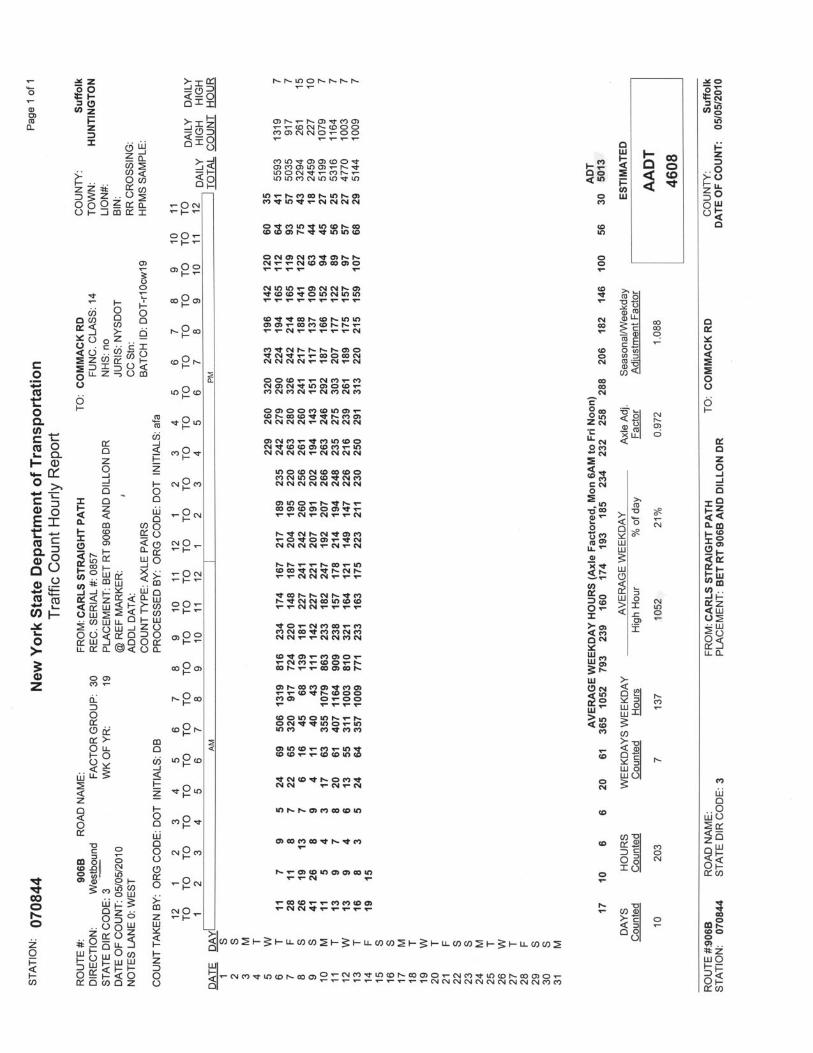
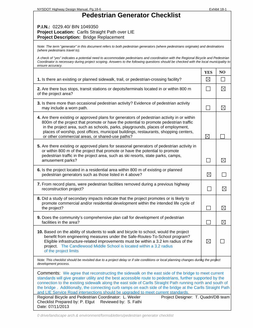
NYSDOT Highway Design Manual, Pg.18-6 Exhibit 18-1
Pedestrian Generator Checklist P.I.N.: 0229.40/ BIN 1049350 Project Location: Carlls Straight Path over LIE Project Description: Bridge Replacement Note: The term “generator” in this document refers to both pedestrian generators (where pedestrians originate) and destinations (where pedestrians travel to). A check of “yes” indicates a potential need to accommodate pedestrians and coordination with the Regional Bicycle and Pedestrian Coordinator is necessary during project scoping. Answers to the following questions should be checked with the local municipality to ensure accuracy. 1. Is there an existing or planned sidewalk, trail, or pedestrian-crossing facility? 2. Are there bus stops, transit stations or depots/terminals located in or within 800 m of the project area? 3. Is there more than occasional pedestrian activity? Evidence of pedestrian activity may include a worn path. 4. Are there existing or approved plans for generators of pedestrian activity in or within 800m of the project that promote or have the potential to promote pedestrian traffic in the project area, such as schools, parks, playgrounds, places of employment, places of worship, post offices, municipal buildings, restaurants, shopping centers, or other commercial areas, or shared-use paths? 5. Are there existing or approved plans for seasonal generators of pedestrian activity in or within 800 m of the project that promote or have the potential to promote pedestrian traffic in the project area, such as ski resorts, state parks, camps, amusement parks? 6. Is the project located in a residential area within 800 m of existing or planned pedestrian generators such as those listed in 4 above? 7. From record plans, were pedestrian facilities removed during a previous highway reconstruction project? 8. Did a study of secondary impacts indicate that the project promotes or is likely to promote commercial and/or residential development within the intended life cycle of the project? 9. Does the community’s comprehensive plan call for development of pedestrian facilities in the area? 10. Based on the ability of students to walk and bicycle to school, would the project benefit from engineering measures under the Safe-Routes-To-School program? Eligible infrastructure-related improvements must be within a 3.2 km radius of the project. The Candlewood Middle School is located within a 3.2 radius of the project limits Note: This checklist should be revisited due to a project delay or if site conditions or local planning changes during the project development process.
NOYES
Comments: We agree that reconstructing the sidewalk on the east side of the bridge to meet current standards will give greater utility and the best accessible route to pedestrians, further supported by the connection to the existing sidewalk along the east side of Carlls Straight Path running north and south of the bridge . Additionally, the connecting curb ramps on each side of the bridge at the Carlls Straight Path and LIE Service Road intersections should be upgraded to meet current standards. Regional Bicycle and Pedestrian Coordinator: L. Wexler Project Designer: T. Quadri/DB team Checklist Prepared by: P. Elgut Reviewed by: S. Fathi Date: 07/11/2013 0 drive/landscape arch.& environment/forms&letters/pedestrian generator checklist
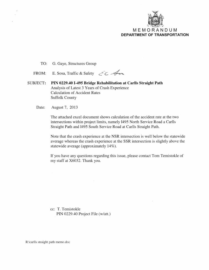


September 2013 Project Scoping Report/Final Design Report PIN 0229.40
APPENDIX D Public Information Plan
Public Involvement
Scope
The goal of the public involvement activities is inform the public and agency participants, and providing timely information throughout the design and construction process.
Standards
The Design-Builder shall perform the Public Involvement Plan support activities in accordance with the following Standard unless otherwise stipulated in the Project Requirement herein:
a) NYSDOT Project Development Manual: Appendix 2, Public Involvement Manual
Requirements
Public Outreach This contract is a product of the Departments goal to eliminate bridge structural deficiencies and improve the vertical clearance through the New York Works Program. The public outreach component is intended to foster a close working relationship with residents, land owners, community groups, local officials, educational institutions, businesses, etc.
Because the scope of this project is complex, the Design-Builder will have a subordinate role in public outreach to the Regional Public Involvement Coordinator (RPIC) and the Regional Public Information Officer (PIO) and will coordinate public information through the NYSDOT Construction QA Engineer. This will primarily have to do with notifying key stakeholders (road users, general public, area residences, educational institutions, emergency services, businesses, etc.) with road closure information, project milestones or construction related activities in proximity to adjacent homeowners.
This project has been identified as a New York Works Project through the Office of the Governor and is subject to various public information requirements. Coordination and advance notice, with the Regional Public Information Officer, is expected prior to opening the bridge to traffic.
Media Relations
Media Inquiries: All media inquiries, requests for interviews from local print or broadcast news media, trade magazines or other must be referred to the Regional Public Information Officer in the Regional Director's Office. The NYSDOT Construction QA Engineer, under direction of PIO, or the PIO will handle all requests.
Travel Advisories: Since most of the public information will be relative to work zone public information, reasonable advance notice of start of work, any lane closures, full road closures, etc. is expected to be given to the Regional Public Information Officer/Regional Director’s office via the NYSDOT Construction QA Engineer to allow for timely dissemination.
The Design-Builder shall support communications strategies by the Department that seek to inform affected road users, the general public, area residences and businesses, and appropriate public entities about the roadway closures, commuter alternatives, and any potential impacts on traffic.

The goal of these efforts is to keep the public informed, in advance whenever possible and in real-time, regarding Project actions that would affect road users, the general public, area residences and businesses, especially regarding roadway closures and possible travel alternatives. These activities, which would be consistent with the requirements of Project Requirements 17 – Work Zone Traffic Control and Access, will include Construction Bulletins on published by the Department, based on information provided by the Design-Builder, especially focused on traffic changes, higher-noise construction periods or locations, or other construction activities of potential concern to the public. The Design Builder will be responsible for the daily interaction with the affected homeowners and businesses with regards to but not limited to; security of their properties, utility services, night time operation, access to their properties, etc.
Written Materials Written materials will be created by DOT and disseminated electronically via e-mail distribution lists, the project web site and printed copies. Support by the Design-Builder to reproduce materials will be required. This will include providing background information for project specific on daily operations. This may include letters and/or flyer providing scheduled operations to the homeowners and businesses that may be impacted by the construction.
Public Information Meeting A public information meeting may be considered, with the Regional Directors approval in mid 2014 to offer an opportunity for the public at large to learn more about this and other ongoing highway projects in this area. Support by the Design-Builder to provide construction-related information will be required. Technical information about Design-Build process, schedule, or construction methods being used that may interest attendees, etc. may be incorporated. Coordination with the Regional Public Involvement Coordinator (RPIC) and NYSDOT Construction QA Engineer will be needed. A representative of the Design-Builder will be required to attend the meeting.
Related Documents


