PROPOSED 2 X 500 MW Pangasinan Coal Power Plant Project (PCPPP) KEPCO PHILIPPINES INC. (“KEPHILCO”) Brgys.Baquioen and Pangascasan, Sual, Pangasinan Project Description Report (PDR) 1 – 1 PROJECT DESCRIPTION Basic Project Information and Background A 2 x 500 MW Coal Power Plant is being proposed and be located in the Municipality of Sual, Province of Pangasinan by KEPCO Philippines Corp. (“KEPHILCO”) as the Private Sector Project Proponent. By way of a brief background, the originally-planned power plant proposal involved a 3x300 Circulating Fluidized Bed (CFB) Coal Power Plant at the same site. The original Proponent was Tans- Asia Oil and Energy Development Corporation (“TAOil”) . However, under a Memorandum of Agreement between TAOil and KEPCO, the Project was turned over to the latter. The original project has undergone the initial stages of EIS process with the submission of the EIS Draft Report and acceptance thereof by the EIAMD up through the second Review/Technical Screening when TAOil decided to turn over the project to KEPHILCO. KEPHILCO increased the power plant capacity to 2 x 500 MW and is utilizing the Advanced Ultra Supercritical Pulverized Coal Technology (AUSPCTinstead of the Circulating Fluidized Bed (CFB) Technology. The power plant site/location remains unchanged. The ash pond will, however, be located in another Barangay, i.e. Pangascasan. A new set of project information is accordingly provided in this EIS Report. The EIS Process will also formally start with compliances to DAO 2017-15 on “Public Participation”. Table PD-1. Project Fact Sheet/PD Summary ITEM Project Information Name of Project Proposed 2 x 500MW Pangasinan Coal Power Plant Project (PCPPP) Project Location Brgys. Baquioen and Pangascasan, Municipality of Sual, Pangasinan Nature of Project Coal Power Plant Project Size 2 x 500 MWe (Gross) Table PD-2. Project Proponent/EIA Preparer ITEM Project Information Project Proponent KEPCO Philippines, Inc. (“KEPHILCO”) Proponent Address and Contact Details 18th Floor, Citibank Tower, 8741, Paseo de Zobel Roxas St, Makati, 1200 Metro Manila Telephone No. 848-0231~39/45 loc 166 and 233 Email Address: [email protected] and [email protected] Responsible Officers Yoon, Sang Hun and Ron Benjamin Espino EIA Preparer Technotrix Consultancy Services Inc. (TCSI) Preparer Contact Persons Edgardo G. Alabastro Ph.D. Preparer Address and Contact Details Unit 305 FMSG Building, #9 Balete Dr. Cor. 3 rd St. QC 1101 Telephone No.: (02) 416-4625 Cellular No.: 09178255203 E-mail address: [email protected]

Welcome message from author
This document is posted to help you gain knowledge. Please leave a comment to let me know what you think about it! Share it to your friends and learn new things together.
Transcript

PROPOSED 2 X 500 MW Pangasinan Coal Power Plant Project (PCPPP) KEPCO PHILIPPINES INC. (“KEPHILCO”) Brgys.Baquioen and Pangascasan, Sual, Pangasinan
Project Description Report (PDR) 1 – 1
PROJECT DESCRIPTION Basic Project Information and Background A 2 x 500 MW Coal Power Plant is being proposed and be located in the Municipality of Sual, Province of Pangasinan by KEPCO Philippines Corp. (“KEPHILCO”) as the Private Sector Project Proponent. By way of a brief background, the originally-planned power plant proposal involved a 3x300 Circulating Fluidized Bed (CFB) Coal Power Plant at the same site. The original Proponent was Tans-Asia Oil and Energy Development Corporation (“TAOil”). However, under a Memorandum of Agreement between TAOil and KEPCO, the Project was turned over to the latter. The original project has undergone the initial stages of EIS process with the submission of the EIS Draft Report and acceptance thereof by the EIAMD up through the second Review/Technical Screening when TAOil decided to turn over the project to KEPHILCO. KEPHILCO increased the power plant capacity to 2 x 500 MW and is utilizing the Advanced Ultra Supercritical Pulverized Coal Technology (AUSPCTinstead of the Circulating Fluidized Bed (CFB) Technology. The power plant site/location remains unchanged. The ash pond will, however, be located in another Barangay, i.e. Pangascasan. A new set of project information is accordingly provided in this EIS Report. The EIS Process will also formally start with compliances to DAO 2017-15 on “Public Participation”.
Table PD-1. Project Fact Sheet/PD Summary
ITEM Project Information
Name of Project Proposed 2 x 500MW Pangasinan Coal Power Plant Project
(PCPPP)
Project Location Brgys. Baquioen and Pangascasan, Municipality of Sual,
Pangasinan
Nature of Project Coal Power Plant
Project Size 2 x 500 MWe (Gross)
Table PD-2. Project Proponent/EIA Preparer
ITEM Project Information
Project Proponent KEPCO Philippines, Inc. (“KEPHILCO”)
Proponent Address and Contact Details 18th Floor, Citibank Tower, 8741, Paseo de Zobel Roxas St, Makati, 1200 Metro Manila Telephone No. 848-0231~39/45 loc 166 and 233
Email Address: [email protected] and
Responsible Officers Yoon, Sang Hun and Ron Benjamin Espino
EIA Preparer Technotrix Consultancy Services Inc. (TCSI)
Preparer Contact Persons Edgardo G. Alabastro Ph.D.
Preparer Address and Contact Details Unit 305 FMSG Building, #9 Balete Dr. Cor. 3rd St. QC 1101
Telephone No.: (02) 416-4625
Cellular No.: 09178255203
E-mail address: [email protected]

PROPOSED 2 X 500 MW Pangasinan Coal Power Plant Project (PCPPP) KEPCO PHILIPPINES INC. (“KEPHILCO”) Brgys.Baquioen and Pangascasan, Sual, Pangasinan
Project Description Report (PDR) 1 – 2
1.1 Major Project Components These are shown in Table PD-3
Table PD-3. Major Project Components
Major Project Component Brief Description
Main Power Plant Facility
Ultra Supercritical Pulverized Coal Boiler
2x500 MWe Steam conditions at turbine inlet ≥240 bar, / ≥566 / =593˚C (Ultra-supercritical steam conditions) SOx < 200 mg/Nm3 @ 00 C 6 % excess O2 NOx < 200 mg/Nm3 CO < 547 mg/Nm3 Particulates < 30 mg/Nm3
PM2.5 < 13.5 mg/Nm3
Metallics: Pb, Hg, Cd, As. Compliant w Phl Standards
Coal Stockyard
Coal Yard: 42,000 m2 (300m x 140m) with 16m high loading Capacity=368,000 tonnes for 30 days Enclosed or equivalent type
Emergency Ash Pond
Ash Pond: 12,300 m2 (app.) with 10m high loading
PROPOSED 2 X 500 MW Pangasinan Coal Power Plant Project (PCPPP) KEPCO PHILIPPINES INC. (“KEPHILCO”) Brgys.Baquioen and Pangascasan, Sual, Pangasinan
Project Description Report (PDR) 1 – 3
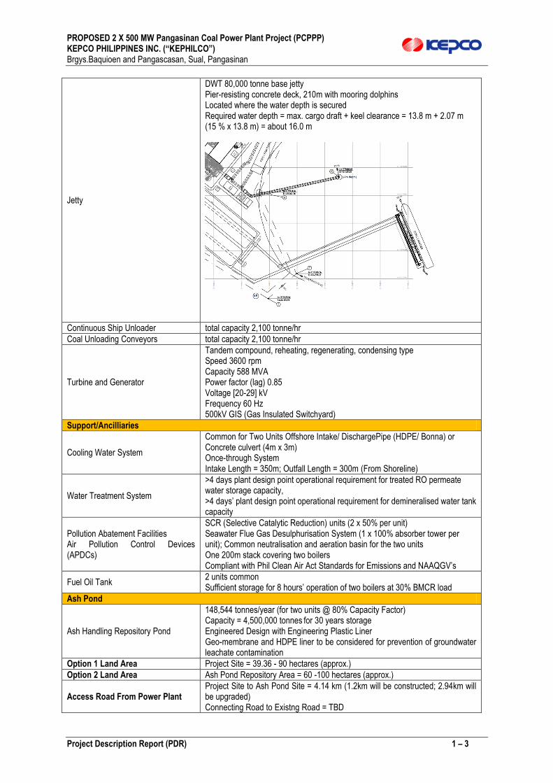
Jetty
DWT 80,000 tonne base jetty Pier-resisting concrete deck, 210m with mooring dolphins Located where the water depth is secured Required water depth = max. cargo draft + keel clearance = 13.8 m + 2.07 m (15 % x 13.8 m) = about 16.0 m
Continuous Ship Unloader total capacity 2,100 tonne/hr
Coal Unloading Conveyors total capacity 2,100 tonne/hr
Turbine and Generator
Tandem compound, reheating, regenerating, condensing type Speed 3600 rpm Capacity 588 MVA Power factor (lag) 0.85 Voltage [20-29] kV Frequency 60 Hz 500kV GIS (Gas Insulated Switchyard)
Support/Ancilliaries
Cooling Water System
Common for Two Units Offshore Intake/ DischargePipe (HDPE/ Bonna) or Concrete culvert (4m x 3m) Once-through System Intake Length = 350m; Outfall Length = 300m (From Shoreline)
Water Treatment System
>4 days plant design point operational requirement for treated RO permeate water storage capacity, >4 days’ plant design point operational requirement for demineralised water tank capacity
Pollution Abatement Facilities Air Pollution Control Devices (APDCs)
SCR (Selective Catalytic Reduction) units (2 x 50% per unit) Seawater Flue Gas Desulphurisation System (1 x 100% absorber tower per unit); Common neutralisation and aeration basin for the two units One 200m stack covering two boilers Compliant with Phil Clean Air Act Standards for Emissions and NAAQGV’s
Fuel Oil Tank 2 units common Sufficient storage for 8 hours’ operation of two boilers at 30% BMCR load
Ash Pond
Ash Handling Repository Pond
148,544 tonnes/year (for two units @ 80% Capacity Factor) Capacity = 4,500,000 tonnes for 30 years storage Engineered Design with Engineering Plastic Liner Geo-membrane and HDPE liner to be considered for prevention of groundwater leachate contamination
Option 1 Land Area Project Site = 39.36 - 90 hectares (approx.)
Option 2 Land Area Ash Pond Repository Area = 60 -100 hectares (approx.)
Access Road From Power Plant Project Site to Ash Pond Site = 4.14 km (1.2km will be constructed; 2.94km will be upgraded) Connecting Road to Existng Road = TBD

PROPOSED 2 X 500 MW Pangasinan Coal Power Plant Project (PCPPP) KEPCO PHILIPPINES INC. (“KEPHILCO”) Brgys.Baquioen and Pangascasan, Sual, Pangasinan
Project Description Report (PDR) 1 – 4
Project Location, Area and Description
The main power plant and major associated facilities will be located in Barangay Baquioen while
the supporting ash repository pond will be located in Barangay Pangascasan, both in the
Municipality of Sual.
Options for the Power Plant Site
Two (2) sites, shown in Figure PD-1 were considered.
Figure PD-1 Map of the Power Plant Site Options
Plate PD-1 shows photographs of the site options (Location B is on the right)
Plate PD-1 Photographs of the Site Options
Location A Location B

PROPOSED 2 X 500 MW Pangasinan Coal Power Plant Project (PCPPP) KEPCO PHILIPPINES INC. (“KEPHILCO”) Brgys.Baquioen and Pangascasan, Sual, Pangasinan
Project Description Report (PDR) 1 – 5
Table PD-4 summarizes the parameters used in the evaluation of the plant site.
Table PD-4 Summary matrix the site selection parameters
On the basis of the above factors, Site B is selected, shown in Figure PD-2 wherein also seen is
the proposed site of the Ash Pond, located in Barangay Pangascasan.
Figure PD-2. General Relative Location of Ashpond and Power Plant

PROPOSED 2 X 500 MW Pangasinan Coal Power Plant Project (PCPPP) KEPCO PHILIPPINES INC. (“KEPHILCO”) Brgys.Baquioen and Pangascasan, Sual, Pangasinan
Project Description Report (PDR) 1 – 0
ASH REPOSITORY POND
Figure PD-2A. Google Earth Map Showing the Location of the Power Plant and Ash Pond (Inset)
PROPOSED 2 X 500 MW Pangasinan Coal Power Plant Project (PCPPP) KEPCO PHILIPPINES INC. (“KEPHILCO”) Brgys.Baquioen and Pangascasan, Sual, Pangasinan
Project Description Report (PDR) 1 – 1
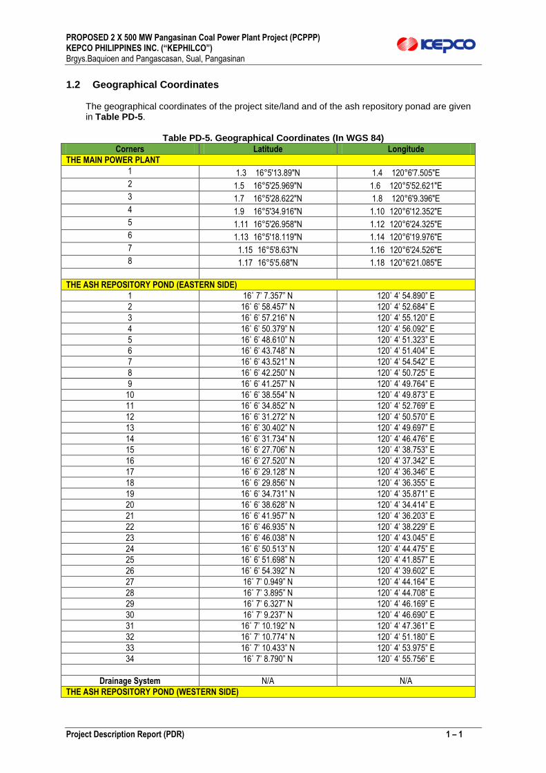
1.2 Geographical Coordinates
The geographical coordinates of the project site/land and of the ash repository ponad are given in Table PD-5.
Table PD-5. Geographical Coordinates (In WGS 84)
Corners Latitude Longitude
THE MAIN POWER PLANT
1 1.3 16°5'13.89"N 1.4 120°6'7.505"E
2 1.5 16°5'25.969"N 1.6 120°5'52.621"E
3 1.7 16°5'28.622"N 1.8 120°6'9.396"E
4 1.9 16°5'34.916"N 1.10 120°6'12.352"E
5 1.11 16°5'26.958"N 1.12 120°6'24.325"E
6 1.13 16°5'18.119"N 1.14 120°6'19.976"E
7 1.15 16°5'8.63"N 1.16 120°6'24.526"E
8 1.17 16°5'5.68"N 1.18 120°6'21.085"E
THE ASH REPOSITORY POND (EASTERN SIDE)
1 16˚ 7’ 7.357” N 120˚ 4’ 54.890” E
2 16˚ 6’ 58.457” N 120˚ 4’ 52.684” E
3 16˚ 6’ 57.216” N 120˚ 4’ 55.120” E
4 16˚ 6’ 50.379” N 120˚ 4’ 56.092” E
5 16˚ 6’ 48.610” N 120˚ 4’ 51.323” E
6 16˚ 6’ 43.748” N 120˚ 4’ 51.404” E
7 16˚ 6’ 43.521” N 120˚ 4’ 54.542” E
8 16˚ 6’ 42.250” N 120˚ 4’ 50.725” E
9 16˚ 6’ 41.257” N 120˚ 4’ 49.764” E
10 16˚ 6’ 38.554” N 120˚ 4’ 49.873” E
11 16˚ 6’ 34.852” N 120˚ 4’ 52.769” E
12 16˚ 6’ 31.272” N 120˚ 4’ 50.570” E
13 16˚ 6’ 30.402” N 120˚ 4’ 49.697” E
14 16˚ 6’ 31.734” N 120˚ 4’ 46.476” E
15 16˚ 6’ 27.706” N 120˚ 4’ 38.753” E
16 16˚ 6’ 27.520” N 120˚ 4’ 37.342” E
17 16˚ 6’ 29.128” N 120˚ 4’ 36.346” E
18 16˚ 6’ 29.856” N 120˚ 4’ 36.355” E
19 16˚ 6’ 34.731” N 120˚ 4’ 35.871” E
20 16˚ 6’ 38.628” N 120˚ 4’ 34.414” E
21 16˚ 6’ 41.957” N 120˚ 4’ 36.203” E
22 16˚ 6’ 46.935” N 120˚ 4’ 38.229” E
23 16˚ 6’ 46.038” N 120˚ 4’ 43.045” E
24 16˚ 6’ 50.513” N 120˚ 4’ 44.475” E
25 16˚ 6’ 51.698” N 120˚ 4’ 41.857” E
26 16˚ 6’ 54.392” N 120˚ 4’ 39.602” E
27 16˚ 7’ 0.949” N 120˚ 4’ 44.164” E
28 16˚ 7’ 3.895” N 120˚ 4’ 44.708” E
29 16˚ 7’ 6.327” N 120˚ 4’ 46.169” E
30 16˚ 7’ 9.237” N 120˚ 4’ 46.690” E
31 16˚ 7’ 10.192” N 120˚ 4’ 47.361” E
32 16˚ 7’ 10.774” N 120˚ 4’ 51.180” E
33 16˚ 7’ 10.433” N 120˚ 4’ 53.975” E
34 16˚ 7’ 8.790” N 120˚ 4’ 55.756” E
Drainage System N/A N/A
THE ASH REPOSITORY POND (WESTERN SIDE)

PROPOSED 2 X 500 MW Pangasinan Coal Power Plant Project (PCPPP) KEPCO PHILIPPINES INC. (“KEPHILCO”) Brgys.Baquioen and Pangascasan, Sual, Pangasinan
Project Description Report (PDR) 1 – 2
1 16˚ 6’ 28.220” N 120˚ 3’ 47.971” E
2 16˚ 6’ 33.164” N 120˚ 3’ 56.395” E
3 16˚ 6’ 33.262” N 120˚ 3’ 59.075” E
4 16˚ 6’ 34.852” N 120˚ 3’ 59.459” E
5 16˚ 6’ 34.775” N 120˚ 4’ 7.226” E
6 16˚ 6’ 35.536” N 120˚ 4’ 9.665” E
7 16˚ 6’ 38.222” N 120˚ 4’ 9.617” E
8 16˚ 6’ 41.094” N 120˚ 4’ 9.155” E
9 16˚ 6’ 42.040” N 120˚ 4’ 8.882” E
10 16˚ 6’ 41.822” N 120˚ 4’ 17.318” E
11 16˚ 6’ 42.050” N 120˚ 4’ 19.980” E
12 16˚ 6’ 38.038” N 120˚ 4’ 24.311” E
13 16˚ 6’ 28.059” N 120˚ 4’ 22.285” E
14 16˚ 6’ 28.676” N 120˚ 4’ 26.452” E
15 16˚ 6’ 28.278” N 120˚ 4’ 19.185” E
16 16˚ 6’ 28.224” N 120˚ 4’ 33.304” E
17 16˚ 6’ 28.228” N 120˚ 4’ 33.654” E
18 16˚ 6’ 24.604” N 120˚ 4’ 33.432” E
19 16˚ 6’ 24.045” N 120˚ 4’ 33.322” E
20 16˚ 6’ 24.216” N 120˚ 4’ 31.537” E
21 16˚ 6’ 21.155” N 120˚ 4’ 30.755” E
22 16˚ 6’ 18.668” N 120˚ 4’ 29.023” E
23 16˚ 6’ 16.373” N 120˚ 4’ 28.167” E
24 16˚ 6’ 17.981” N 120˚ 4’ 24.768” E
25 16˚ 6’ 18.561” N 120˚ 4’ 20.708” E
26 16˚ 6’ 19.233” N 120˚ 4’ 16.006” E
27 16˚ 6’ 24.372” N 120˚ 4’ 17.245” E
28 16˚ 6’ 22.801” N 120˚ 4’ 14.983” E
29 16˚ 6’ 20.530” N 120˚ 4’ 13.080” E
30 16˚ 6’ 20.894” N 120˚ 4’ 11.337” E
31 16˚ 6’ 20.980” N 120˚ 4’ 10.458” E
32 16˚ 6’ 14.842” N 120˚ 4’ 13.095” E
33 16˚ 6’ 14.066” N 120˚ 4’ 12.410” E
34 16˚ 6’ 13.594” N 120˚ 4’ 11.518” E
35 16˚ 6’ 23.284” N 120˚ 4’ 8.577” E
36 16˚ 6’ 20.909” N 120˚ 4’ 5.898” E
37 16˚ 6’ 13.570” N 120˚ 4’ 55.869” E
38 16˚ 6’ 20.755” N 120˚ 4’ 53.414” E
Drainage System N/A N/A
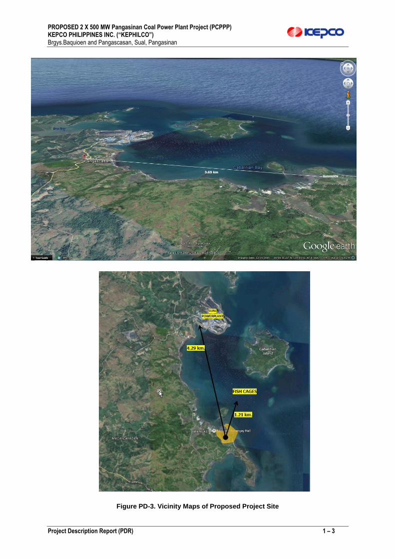
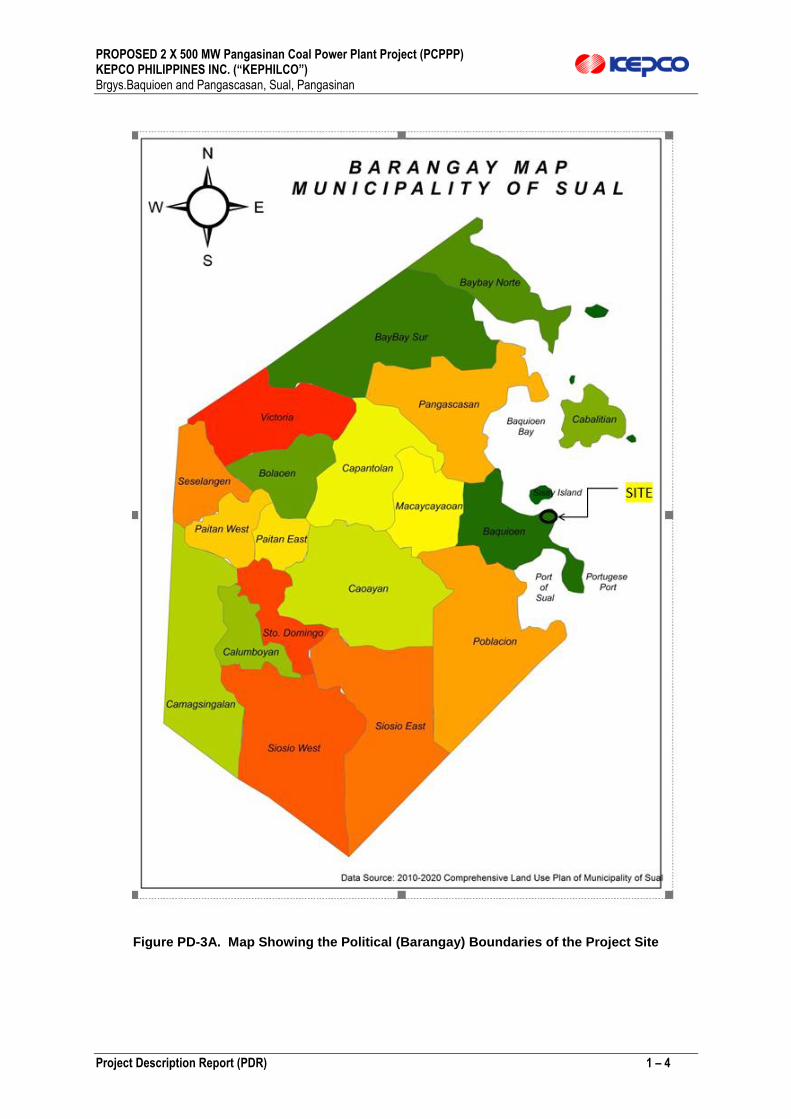
1.3 Maps showing sitio, barangay, municipality, province, region boundaries, vicinity, proposed buffers surrounding the areas
Figure PD-3 shows the vicinity map while Figures PD-3A shows the political boundaries of the
project site.
PROPOSED 2 X 500 MW Pangasinan Coal Power Plant Project (PCPPP) KEPCO PHILIPPINES INC. (“KEPHILCO”) Brgys.Baquioen and Pangascasan, Sual, Pangasinan
Project Description Report (PDR) 1 – 3
Figure PD-3. Vicinity Maps of Proposed Project Site
PROPOSED 2 X 500 MW Pangasinan Coal Power Plant Project (PCPPP) KEPCO PHILIPPINES INC. (“KEPHILCO”) Brgys.Baquioen and Pangascasan, Sual, Pangasinan
Project Description Report (PDR) 1 – 4
Figure PD-3A. Map Showing the Political (Barangay) Boundaries of the Project Site
PROPOSED 2 X 500 MW Pangasinan Coal Power Plant Project (PCPPP) KEPCO PHILIPPINES INC. (“KEPHILCO”) Brgys.Baquioen and Pangascasan, Sual, Pangasinan
Project Description Report (PDR) 1 – 5
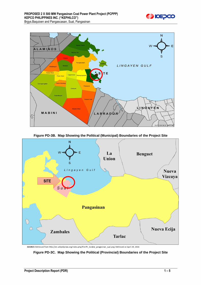
Figure PD-3B. Map Showing the Political (Municipal) Boundaries of the Project Site
Figure PD-3C. Map Showing the Political (Provincial) Boundaries of the Project Site
SITE

PROPOSED 2 X 500 MW Pangasinan Coal Power Plant Project (PCPPP) KEPCO PHILIPPINES INC. (“KEPHILCO”) Brgys.Baquioen and Pangascasan, Sual, Pangasinan
Project Description Report (PDR) 1 – 6
Figure PD-3D. Map Showing the Political (Regional) Boundaries of the Project Site
1.4 Accessibility
1.4.1 Accessibility Via Land and Sea
Land and sea transport will be required during the Construction Phase for the movement of people (construction personnel), light equipment, construction materials and miscellaneous materials. Transport of heavy equipment (e.g. dredging equipment) will be made via the sea during the Construction Phase. There is an available existing jetty approximately 1 km away from the Project Site which can be utilized until the completion of main access road to Project Site. Coal will be transported by sea during the Operations Phase. During the Operations Phase, land transport will be required for the movement of operations personnel and visitors, for the transport of miscellaneous materials (e.g. waste and water treatment chemicals; etc).

PROPOSED 2 X 500 MW Pangasinan Coal Power Plant Project (PCPPP) KEPCO PHILIPPINES INC. (“KEPHILCO”) Brgys.Baquioen and Pangascasan, Sual, Pangasinan
Project Description Report (PDR) 1 – 7
Figure PD-4 shows the way points by road and sea from outside the project site
Figure PD-4. Map Showing the Access Waypoints to the Project Site
1.4.2 Transport of Ash From the Power Plant to the Repository Pond
Figure PD-4 indicates the planned access road between the power plant and the ash repository pond.
From the power plant is an existing 2.94 km barangay road which will be upgraded and connected to this a new access road with length of approximately 1.2 km. This roads will traverse and connect the ash pond area and existing road currently utilized by the Existing Sual Power Plant. When completed it will serve as the permanent Main Access to the Project Site and External Ash Repository Pond.

PROPOSED 2 X 500 MW Pangasinan Coal Power Plant Project (PCPPP) KEPCO PHILIPPINES INC. (“KEPHILCO”) Brgys.Baquioen and Pangascasan, Sual, Pangasinan
Project Description Report (PDR) 1 – 8
Figure PD-5. Main Access Road to the Ash Pond and to the Power Plant
1.5 Primary & Secondary Impact Areas Rationale for selection primary & secondary impact areas
The guidelines provided by the Revised Procedural Manual relevant to MPSA 294-2009-III are used
for the delineation of the DIA and IIA, quoted below:
a) Direct impact area (DIA) is … the area where ALL project facilities are proposed to be
constructed/situated and where all operations are proposed to be undertaken. For most
projects, the DIA is equivalent to the total area applied for an ECC.
b) Indirect Impact Area (IIA) …an IIA can be the stretch of the river/s OUTSIDE the project
area but draining the project site which can potentially transport Total Suspended
Solids and other discharges from the project towards downstream communities.
c) …Further, the interphase/overlap of the biophysical DIA with socio-cultural environment
shall define the socio-cultural DIA after the EIA is completed…
The EIA study area will focus on the identified direct and indirect impact areas of the Project. The
direct impact area (“DIA”) is the 90-hectare project site and 100-hectare external ash pond area where
all the main project facilities are proposed to be located.
The DIAs covers -
PROPOSED 2 X 500 MW Pangasinan Coal Power Plant Project (PCPPP) KEPCO PHILIPPINES INC. (“KEPHILCO”) Brgys.Baquioen and Pangascasan, Sual, Pangasinan
Project Description Report (PDR) 1 – 9
The entire power plant site
Portion of the immediately fronting the project site at which will be located
The inlet cooling water piping system
The outlet cooling water piping system
The pier/jetty for unloading of coal and heavy equipment/materials
The entire ash pond site/land
The portion of the sea immediately fronting the ash pond
The access road between the power plant and the ash pond
The portion of the sea immediately adjacent to the access road
The informal settlers who may be directly affected
The IIAs include areas but outside the project boundaries that may be affected by the
project.
The external access roads
The residences and population centers adjacent to the power plant
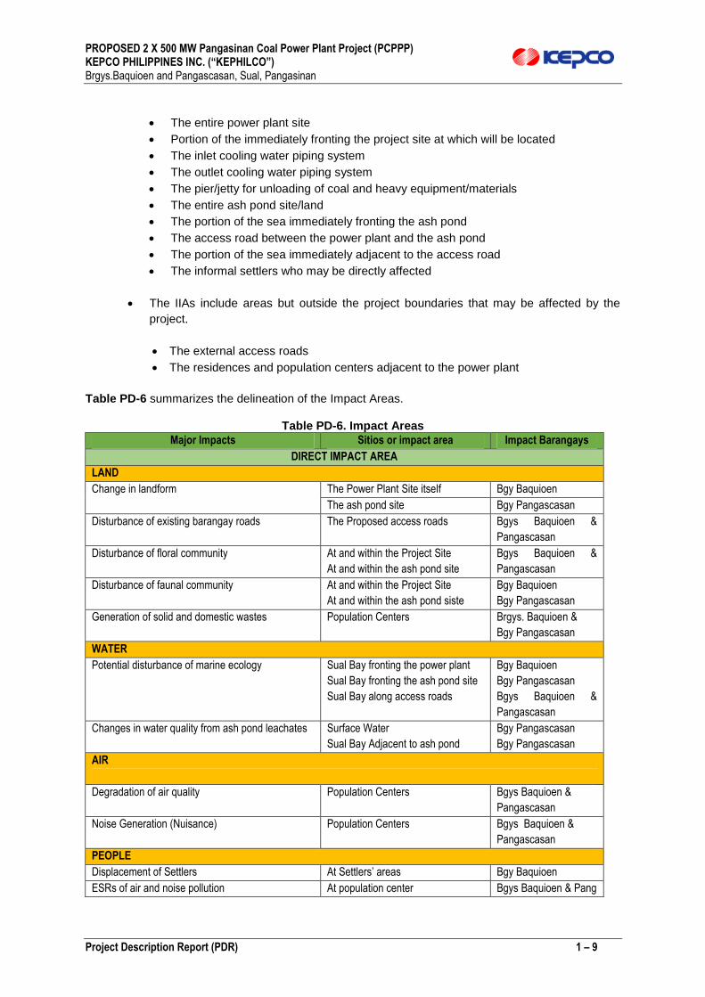
Table PD-6 summarizes the delineation of the Impact Areas.
Table PD-6. Impact Areas
Major Impacts Sitios or impact area Impact Barangays
DIRECT IMPACT AREA
LAND
Change in landform The Power Plant Site itself Bgy Baquioen
The ash pond site Bgy Pangascasan
Disturbance of existing barangay roads The Proposed access roads Bgys Baquioen &
Pangascasan
Disturbance of floral community At and within the Project Site
At and within the ash pond site
Bgys Baquioen &
Pangascasan
Disturbance of faunal community At and within the Project Site
At and within the ash pond siste
Bgy Baquioen
Bgy Pangascasan
Generation of solid and domestic wastes Population Centers Brgys. Baquioen &
Bgy Pangascasan
WATER
Potential disturbance of marine ecology Sual Bay fronting the power plant
Sual Bay fronting the ash pond site
Sual Bay along access roads
Bgy Baquioen
Bgy Pangascasan
Bgys Baquioen &
Pangascasan
Changes in water quality from ash pond leachates Surface Water
Sual Bay Adjacent to ash pond
Bgy Pangascasan
Bgy Pangascasan
AIR
Degradation of air quality Population Centers Bgys Baquioen &
Pangascasan
Noise Generation (Nuisance) Population Centers Bgys Baquioen &
Pangascasan
PEOPLE
Displacement of Settlers At Settlers’ areas Bgy Baquioen
ESRs of air and noise pollution At population center Bgys Baquioen & Pang

PROPOSED 2 X 500 MW Pangasinan Coal Power Plant Project (PCPPP) KEPCO PHILIPPINES INC. (“KEPHILCO”) Brgys.Baquioen and Pangascasan, Sual, Pangasinan
Project Description Report (PDR) 1 – 10
Major Impacts Sitios or impact area Impact Barangays
Economic Benefits
From ER I-94
Based on Implementation of IR-94
INDIRECT IMPACT AREA
LAND
Potential traffic congestion To be delineated based on final access road alignment
WATER
Potential water resource competition Not relevant
Depletion of ground water Not relevant; no ground water extraction envisioned
Disturbance of mariculture No relevant due to distance to sites
AIR
Fugitive dusts along roads outside of project site Brgy. Baquioen
PEOPLE
Threat to Public Health and Safety Not likely Bgys Baguioen &
Pangascasan
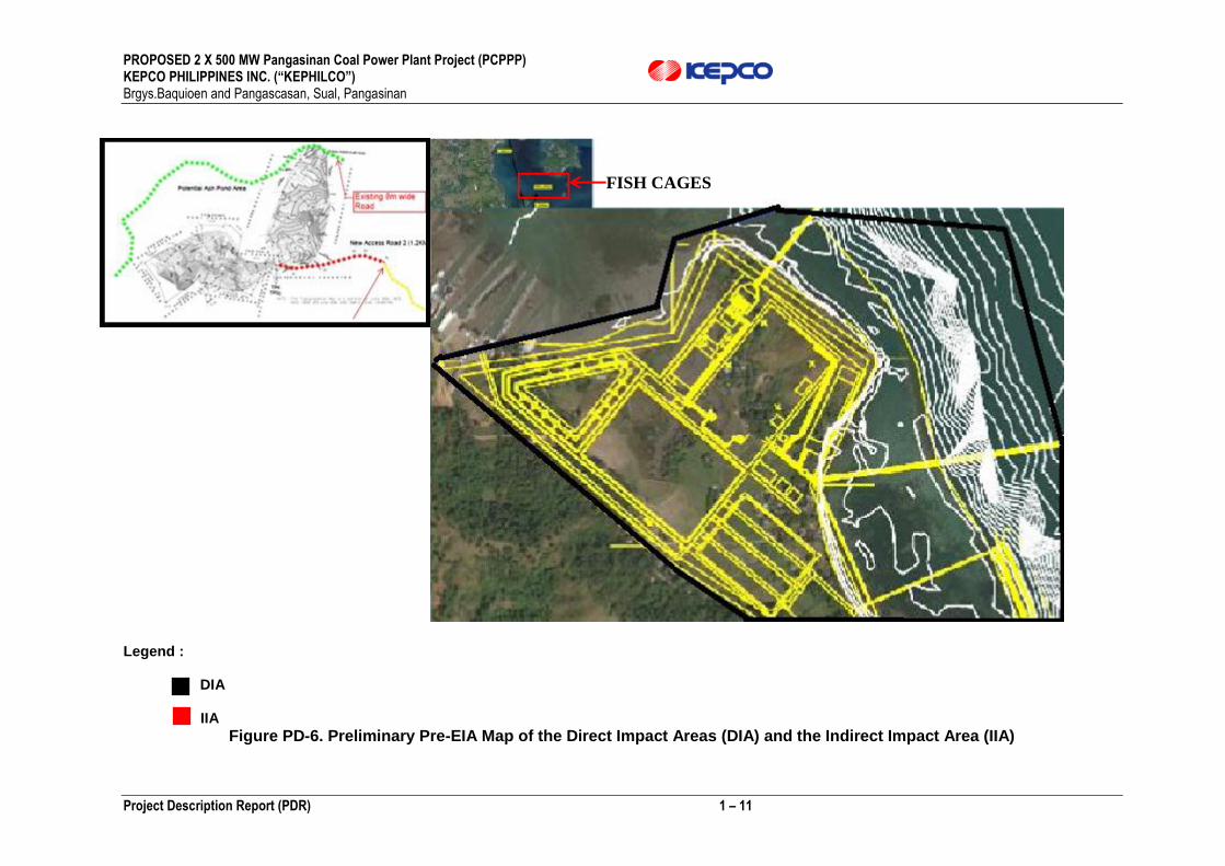
The map of the DIA and IIA is shown in Figure PD-6 from which the following major conclusions are made:
PROPOSED 2 X 500 MW Pangasinan Coal Power Plant Project (PCPPP) KEPCO PHILIPPINES INC. (“KEPHILCO”) Brgys.Baquioen and Pangascasan, Sual, Pangasinan
Project Description Report (PDR) 1 – 11
Legend : DIA IIA
Figure PD-6. Preliminary Pre-EIA Map of the Direct Impact Areas (DIA) and the Indirect Impact Area (IIA)
FISH CAGES

PROPOSED 2 X 500 MW Pangasinan Coal Power Plant Project (PCPPP) KEPCO PHILIPPINES INC. (“KEPHILCO”) Brgys.Baquioen and Pangascasan, Sual, Pangasinan
Project Description Report (PDR) 1 – 12
1.6 Project Rationale
Need for the project based on national regional/local economic development in terms of contribution to sustainable development agenda or current development thrusts Currently, the Municipality of Sual hosts the largest operating coal-fired power plant in the country. The said power plant was built last 1996 and is expected reach End-Of-Life (EOL) by year 2024. On the other hand, the Department of Energy recognizes the rapid growing demand for power in the country.
Table PD-7. Philippine Energy (Electricity) Demand/Supply Projections (Source: DOE) Justification for the Project with particular reference made to the economic and social benefits, including employment and associate economic development, which the project may provide. The status of the project is also discussed in a regional and national context.
On the national level
The proposed project will ensure the reliable delivery of electricity supply in Luzon in the year 2020 and beyond.
It will be a key infrastructure in sustaining the development of the country which has achieved remarkable growth compared to its neighboring countries.
Moreover, inasmuch as coal is still the cheapest source of power generation, the project will help in at least maintaining the current price levels of electricity which is the second highest in Asia.
PROPOSED 2 X 500 MW Pangasinan Coal Power Plant Project (PCPPP) KEPCO PHILIPPINES INC. (“KEPHILCO”) Brgys.Baquioen and Pangascasan, Sual, Pangasinan
Project Description Report (PDR) 1 – 13
Economic and Social Benefits
It is foreseen that the proposed project will bring progress in the municipality since (1) the proposed project will generate addition to the taxes to be paid i.e. local business taxes etc., (2) the local residents will be the priorities for employment by the proposed project. (3) In addition, the proposed project will provide cheaper and more reliable electricity to meet future demands.(4) Significant economic and socially-uplifting programs are expected through ER 1-94 as mandated by law.
Reliable and Affordable Power Cost
Coal power plants remain the most reliable and affordable base load plants in the Philippines. Without reliable and affordable electricity, the economic development may not be achieved. 1.7 Project Alternatives For Site Options The proposed project site is the most ideal location for the proposed project site because it best meets the following important site criteria.
Proximity to the sea. The site is accessible to coal delivery, including adequate water depth for
berthing of ocean going vessel(s).
Proximity to sea from which cooling water will be drawn
Accessibility for transport by road of construction materials.
Minimum aand manageable impact to the community since the community near the project site
has a low population density
Availability of land. At this time negotiations have thus progressed regarding the right to the use of
the land for the project.
Soil characteristics are amenable for construction and installation of heavy equipment.
Minimal marine resources that may be disturbed; distant from the fish cages.
Adjustments may, however, be made in respect of the specific site depending on the finality of the factors for site selection.
1.8 Criteria for Process/Technology Selection
1) Current market conditions dictate that the units are designed not only for base load operation but
also for operational flexibility. The plants are required to have adequate cycling capability both in terms of the number of starts and their frequency as well as the ability to accept rapid load changes.
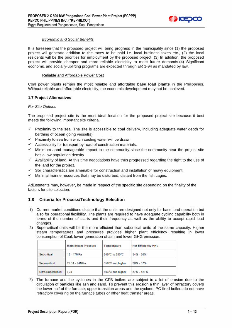
2) Supercritical units will be the more efficient than subcritical units of the same capacity. Higher steam temperatures and pressures provides higher plant efficiency resulting in lower consumption of Coal, lower generation of ash and lower GHG emission.
3) The furnace and the cyclones in the CFB boilers are subject to a lot of erosion due to the
circulation of particles like ash and sand. To prevent this erosion a thin layer of refractory covers the lower half of the furnace, upper transition areas and the cyclone. PC fired boilers do not have refractory covering on the furnace tubes or other heat transfer areas.

PROPOSED 2 X 500 MW Pangasinan Coal Power Plant Project (PCPPP) KEPCO PHILIPPINES INC. (“KEPHILCO”) Brgys.Baquioen and Pangascasan, Sual, Pangasinan
Project Description Report (PDR) 1 – 14
4) Matured and advances of Supercritical Technology 5) Economies-of-Scale per Unit basis
6) On Climate Change and GHG Generation; the following guidelines are observed.
GHG must necessarily be viewed from perspective og Global GHG inventory
Philippines is very small contributor to the global GHG inventory
Absence of the Philiippine regulatory framework to serve as enabling laws
Co-benefits options available and doable for the Philippine setting.
1.9 Criteria for Resource Utilization Alternatives sources of power, water, raw materials and other resources needed including factors significant to the selection such as supply sustainability and climate change projections
The various “Resources” aspects in the selection of the Technology proposed are summarized in Table PD-8 from which may be gleaned the rationale for the selection of the technology, use of coal and other resources for the project. Table PD-8. Matrix for Selection of Technology and Support Resources
Technology Key Selection Criteria
Energy Source
Water Others Climate Change
Thermal Power Plants
The KEPCO Technology Ultra-Supercritical Pulverised Coal
Coal Availability and Cost
Sea Water availability for cooling purposes
Proponent with experience
Phl GHG inventory minimal
Circulating Fluidized Bed Boiler Technology
Coal Availability and Cost
Sea Water availability for cooling purposes
Proponent with direct experience
Phl GHG inventory minimal
Pulverized Coal Technology Systems
Coal Availability and Cost
Same Proponent with direct experience
Same as above
CCGT LNG-Availability and Cost are key issues
Same Proponent with direct experience
Lesser GHG emissions (CO2)
Diesel Power Plants LSFO-Issue of Cost and Availability
Logistics Issue GHG emissions
HSFO Environmental Issues on Sulfur Dioxide emission
GHG emissions
Renewable Energies
Hydro Power Plant Not available in region for size of Plant
N.A. N.A. GHG emission Friendly
Solar Power Plant Same Same Same Same
Wind Power Plant Same Same Same Same
Others, Geothermal Same Same Same Same
Non-Conventional
Nuclear Power Plant Needs government policy and/or congressional intercession.
Essentially Carbon neutral

PROPOSED 2 X 500 MW Pangasinan Coal Power Plant Project (PCPPP) KEPCO PHILIPPINES INC. (“KEPHILCO”) Brgys.Baquioen and Pangascasan, Sual, Pangasinan
Project Description Report (PDR) 1 – 15
1.10 Support Facilities (i.e. energy/power generating facility, water supply system) 1.10.1 Boiler and Auxiliary Systems
General
1) The primary function of the boiler and auxiliary systems is to supply Ultra-supercritical steam to the turbine generator for the generation of electric power.
2) In addition, the boiler and auxiliary systems supply steam to the auxiliary steam system for plant usage.
3) The boiler and auxiliary systems consist of a water cooled furnace, superheater and reheater systems, desuperheater systems, convection pass, coal silo, CO2 firefighting system, coal feeding system, coal pulverizers, pulverized coal piping, combustion system, soot blowing system, boiler start-up system, structural steel, platforms and walkways, piping systems and instrumentation and control system.
Design Criteria
1) Boiler will be a top supported once-through ultra-supercritical, single reheat, balanced draft, pulverized coal design. Once-through boilers designs include two-pass and tower type arrangements. The two-pass oncethrough Ultra-supercritical design configuration results in a shorter steam generator; therefore, it is generally the preferred configuration for facilities where there are significant seismic considerations to be taken into account.
2) The auxiliary system interfaced with the boiler will be designed based on the requirements and design recommendations of the boiler manufacturer.
3) The boiler and auxiliary systems will be designed according to BMCR conditions.
4) The boiler will be capable of having full automation operation at more than 30% of TMCR without auxiliary fuel.
5) NOx emissions level measured as NO2 will not be more than 200 mg/Nm3 and SOX emissions level measured as S02 will not be more than 200 mg/Nm3 and CO will not be more than 500 mg/Nm3 and particulates not more than 30 mg/Nm3 on a 0oC 6% O2 dry flue gas basis leaving the stack during coal firing.
Selective Catalytic Reaction unit expected will be required to meet the NOx emission limit.
Flue Gas desulphurization (FGD) plant will be required to meet the Sox emission limit. Seawater FGD is envisaged and wet limestone FGD may be considered as optional alternative system by EPC.
6) The designing, manufacturing and arrangement of the boiler will be such as to prevent resonant vibration, and any other damaging vibrations and noise. The supporting steel structure of the boiler will be capable of withstanding equipment dead and live loads, boiler or system upset conditions as well as wind and seismic loads.
System Description
The boiler shall be a forced once-through design equipped with a state of the art firing system that includes highly efficient coal pulverisers as well as a low NOx firing system designed to minimize NOx
emissions and losses due to unburned coal.

PROPOSED 2 X 500 MW Pangasinan Coal Power Plant Project (PCPPP) KEPCO PHILIPPINES INC. (“KEPHILCO”) Brgys.Baquioen and Pangascasan, Sual, Pangasinan
Project Description Report (PDR) 1 – 16
Water system
The feedwater heating system will be designed to optimize the temperature of the feedwater being delivered to the boiler economizer inlet header through the check valve and stop valve at the economizer inlet where it is further heated in the economizer by the residual heat of combustion gas. The feedwater then passes through the furnace walls or evaporator section, separators, furnace roof and back pass walls prior to entering the low temperature superheated.
Superheater and Reheater Steam system
The superheater steam system will consist of three sections. The low temperature or primary section is located in the back pass of the unit, the platen or secondary section is located in the top of the furnace and the final or tertiary superheater section is located at the exit of the furnace over the slope of the furnace arch. Desuperheaters will be installed between the primary superheater and secondary superheater, and between the secondary superheater and final superheater to control steam temperature.
The high temperature reheater will be arranged in the upper part of the furnace and the low temperature reheater will be located in the back pass of the unit. Back pass dampers or burner tilts will be utilized as the primary method of controlling reheated steam temperature; however, emergency reheater desuperheaters will also be installed for additional temperature control during abnormal operating conditions. Sampling steam for steam analysis will be extracted from the main and reheat steam lines.
Combustion system
General
Coal will be temporarily stored in the raw coal silos prior to being fed to the pulverisers where it will be dried and pulverized to the necessary fineness for combustion in the furnace. Hot primary air will be used to dry the coal in the pulverisers and to transport the dried pulverized coal directly to the burners for combustion in the furnace.
Coal silo
Raw coal silos are used to temporarily store the coal transferred by conveyor in the coal handling system. There will be separate dedicated silos for each of the pulverizers which will be located in the front of the boiler above the pulverisers. The storage capacity will be sufficient for 16 hours of boiler operation at boiler maximum continuous rating using worst coal. The load cell determines the weight of the stored coal.
Worst Coal Consumption (t/hr) = 280 t/hr (per unit)
16 hours capacity (tonne) = 4480 (per unit)
Total Silo Storage Volume based on 800kg/m3 = 5600 m3 (per unit)
Coal feeder
Gravimetric type belt weigh feeder will be used to deliver coal from the raw coal silos to the pulverisers. The quantity of coal that is delivered to the pulverisers will be controlled by continuously weighing and adjusting the speed of the feeder belt to match the desired coal flow.
Coal Pulverisers
Vertical spindle type pulverisers with integral classifiers will be used to pulverize the coal into a fine power that will be transported to the furnace. Coal from the raw coal silos will be supplied to each pulveriser at a controlled rate by individual gravimetric coal feeders located above each coal

PROPOSED 2 X 500 MW Pangasinan Coal Power Plant Project (PCPPP) KEPCO PHILIPPINES INC. (“KEPHILCO”) Brgys.Baquioen and Pangascasan, Sual, Pangasinan
Project Description Report (PDR) 1 – 17
pulveriser. The number and output of the pulverisers will be based on the quantity of coal required to maintain the boiler maximum condition rating (BMCR) for the Design Coal and the full specified range of coals with one pulveriser out of service. Dried coal at the required fineness will be transported from the pulverisers to the boilers by tempered primary air for combustion.
Primary air will be used to dry the coal as it is being pulverised and to transport the pulverised coal to the boiler.
Hot primary air from the air preheater will be mixed with cold primary air that bypassed the air preheater to achieve desired temperature of the primary air that is supplied to the pulverisers. This temperature will be based on the characteristics of the coal that is being fired.
Coal Burners and Piping
The design and arrangement of coal burners and fuel piping system will provide for uniform heat input into the boiler as well as proper distribution of primary air and secondary air to achieve low NOx
emissions. Low NOx combustion system to be provided. Pulverised fuel piping to burners including necessary isolating gate, couplings and supports etc. with coal sampling device Pulverised coal between all burners served by one pulveriser under all conditions of loading.
Oil burner
Oil burners will be used by the boiler during start-up and for coal firing stabilization during low load operation.
The boiler shall be capable of operating at a minimum load of 40% (or lower) of maximum continuous rating (TMCR) without requiring additional fuel oil support.
Sootblower
A complete soot blowing system will be used to effectively remove all forms of ash from the superheaters, reheaters, economisers, air preheaters and other surfaces as required.
The arrangement of the soot blowers shall be based on the geometry of the heat transfer surfacer as well as tube spacing to ensure complete cleaning of the surfaces. Tube shields will also be provided for erosion protection.
Combustion Air and Flue Gas System
General
The combustion air and flue gas system supply primary and secondary combustion air and to discharge the flue gas to the stack.
System Description
1) For boiler combustion air is supplied by the primary air fans and the forced draft or secondary fans The flue gas is discharged to the stack through the air preheater and the electrostatic precipitator by the induced draft fan.
2) The primary air system will include two (2) 50% capacity primary air fans that will supply primary combustion air to the pulverisers through the air preheater and then transport pried pulverized coal to the boiler.
3) The secondary air system will include two (2) 50% capacity secondary air fans. The secondary air system will supply combustion air to the boiler through the air preheater.
4) Air preheating system

PROPOSED 2 X 500 MW Pangasinan Coal Power Plant Project (PCPPP) KEPCO PHILIPPINES INC. (“KEPHILCO”) Brgys.Baquioen and Pangascasan, Sual, Pangasinan
Project Description Report (PDR) 1 – 18
Two (2) 50% tri-sector regenerative air preheaters for each boiler shall be provided. The air preheaters will include steam soot blowers, water washing system and fire protection system.
5) A low alloy will be used to prevent the corrosion of the air preheater’s low temperature component.
6) Flue gas system
Flue gas is discharged directly to the stack through the air preheaters and electrostatic precipitators by two (2) 50% capacity induced draft fan.
Coal Handling System
General
The primary function of the coal handling system is to unload, store and transport coal to the raw coal silos of the boilers. The coal will be delivered and then unloaded, weighed, sampled and transported to the storage shed. The coal handling system includes the following sub-systems:
1) Coal unloading system,
2) Coal sampling system
3) Redundant transfer conveyors,
4) Coal storage system, Stacking/reclaiming system, Emergency reclaiming system,
5) Screening and crushing system,
6) Dust suppression systems and
7) Fire protection systems
Design Criteria
1) The coal delivered to the raw coal silos is screened and crushed to proper size in the crusher building.
2) All chutes and hopper are inclined properly and lined with stainless steel or other rust-resistant high strength material.
3) The transfer towers, crusher building, and coal silo will be enclosed. The coal conveyor is enclosed by a hood cover. Dust control will include the use of dry fogging systems as well as wet and dry dust suppression systems.
4) The anti-explosion area designated by NFPA is equipped with electrical facilities consisting of explosionproof designs.
Coal Unloading and Stacking System
Coal will be delivered by bulk coal vessel which will berth at the purpose built coal unloading jetty. The coal vessels will be unloaded by continuous ship unloaders and the coal transferred via the jetty and trestle conveying system to the coal storage yard.
The coal is transferred from the coal storage yard to the coal silos by reclaiming to the conveyor transfer system.
There shall be an emergency reclaim system provided utilizing mobile plant and emergency conveyor.
PROPOSED 2 X 500 MW Pangasinan Coal Power Plant Project (PCPPP) KEPCO PHILIPPINES INC. (“KEPHILCO”) Brgys.Baquioen and Pangascasan, Sual, Pangasinan
Project Description Report (PDR) 1 – 19
Coal Sampling System
An automated coal sampling system will be located prior to the coal shed and a second sampling system will be located following the crusher building.
Coal Reclaiming System
The coal is reclaimed from the coal storage yard by the stacking/reclaiming machines and transferred to the boiler coal silos by the conveying system.
Metal detectors and magnetic separators (self-cleaning type) are provided to protect the conveyor belts from tramp iron at the discharge pulleys of conveyors, respectively.
Plant Distribution and Silo Feeding System
Reclaimed coal will be conveyed to the crusher building where it will be screened and the oversized will be crushed to achieve the specified size. The coal will then be transferred to the tripper deck where it will be loaded into the raw coal silos.
Dust Collection System
The dust collection system consists of facilities for collecting the dust and spraying the reuse water produced during the transfer of the coal to the coal silos.
Fire Protection System
The fire protection system for the Facility will be designed to meet the requirements and recommendations of NFPA 850. The system will include but not limited to fire suppression systems, independent fire detection systems, standpipe, and fire hose stations, fire loop system, and portable fire extinguishers.
Ash Handling System
General
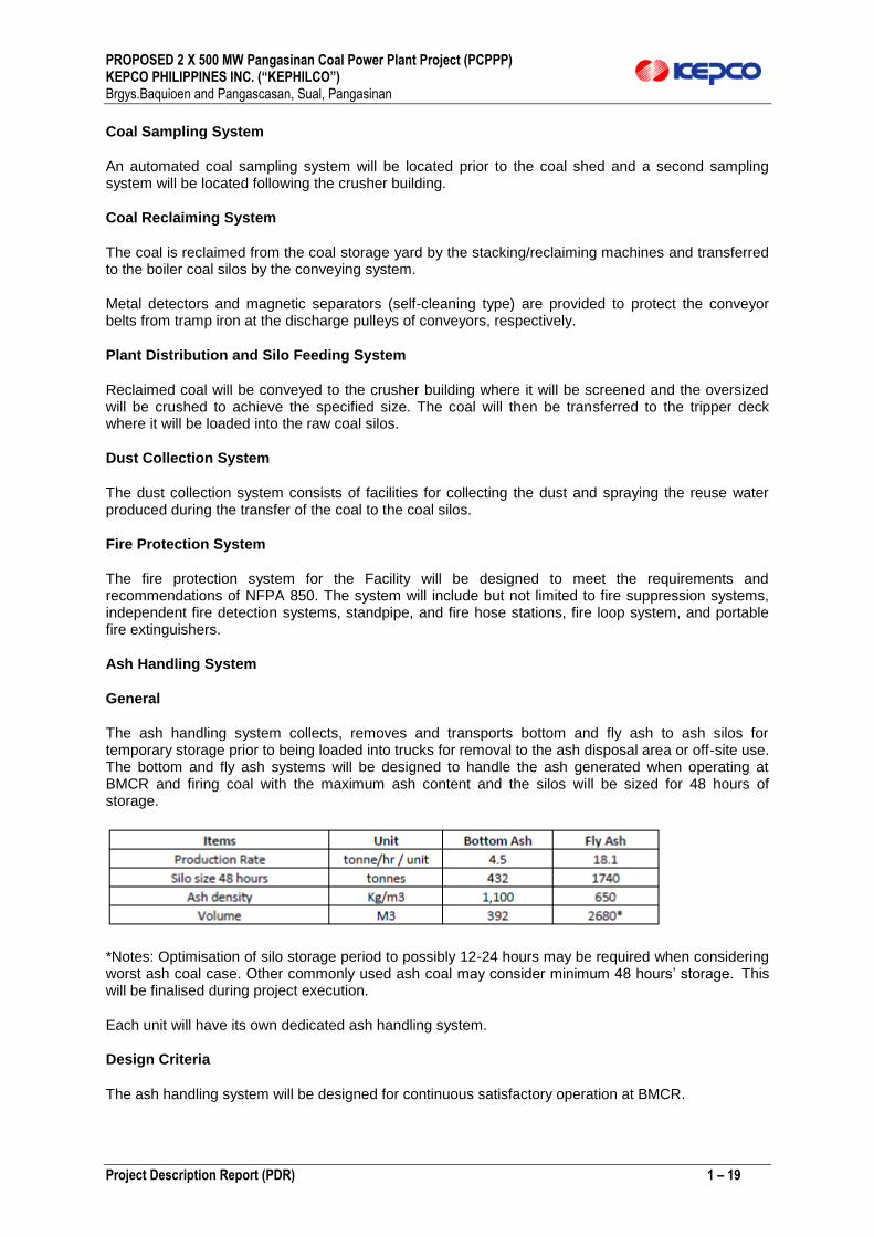
The ash handling system collects, removes and transports bottom and fly ash to ash silos for temporary storage prior to being loaded into trucks for removal to the ash disposal area or off-site use. The bottom and fly ash systems will be designed to handle the ash generated when operating at BMCR and firing coal with the maximum ash content and the silos will be sized for 48 hours of storage.
*Notes: Optimisation of silo storage period to possibly 12-24 hours may be required when considering worst ash coal case. Other commonly used ash coal may consider minimum 48 hours’ storage. This will be finalised during project execution.
Each unit will have its own dedicated ash handling system.
Design Criteria
The ash handling system will be designed for continuous satisfactory operation at BMCR.
PROPOSED 2 X 500 MW Pangasinan Coal Power Plant Project (PCPPP) KEPCO PHILIPPINES INC. (“KEPHILCO”) Brgys.Baquioen and Pangascasan, Sual, Pangasinan
Project Description Report (PDR) 1 – 20
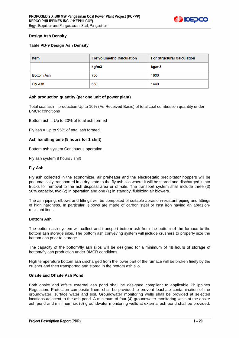
Design Ash Density
Table PD-9 Design Ash Density
Ash production quantity (per one unit of power plant)
Total coal ash = production Up to 10% (As Received Basis) of total coal combustion quantity under BMCR conditions
Bottom ash = Up to 20% of total ash formed
Fly ash = Up to 95% of total ash formed
Ash handling time (8 hours for 1 shift)
Bottom ash system Continuous operation
Fly ash system 8 hours / shift
Fly Ash
Fly ash collected in the economizer, air preheater and the electrostatic precipitator hoppers will be pneumatically transported in a dry state to the fly ash silo where it will be stored and discharged it into trucks for removal to the ash disposal area or off-site. The transport system shall include three (3) 50% capacity, two (2) in operation and one (1) in standby, fluidizing air blowers.
The ash piping, elbows and fittings will be composed of suitable abrasion-resistant piping and fittings of high hardness. In particular, elbows are made of carbon steel or cast iron having an abrasion-resistant liner.
Bottom Ash
The bottom ash system will collect and transport bottom ash from the bottom of the furnace to the bottom ash storage silos. The bottom ash conveying system will include crushers to properly size the bottom ash prior to storage.
The capacity of the bottom/fly ash silos will be designed for a minimum of 48 hours of storage of bottom/fly ash production under BMCR conditions.
High temperature bottom ash discharged from the lower part of the furnace will be broken finely by the crusher and then transported and stored in the bottom ash silo.
Onsite and Offsite Ash Pond
Both onsite and offsite external ash pond shall be designed compliant to applicable Philippines Regulation. Protection composite liners shall be provided to prevent leachate contamination of the groundwater, surface water and soil. Groundwater monitoring wells shall be provided at selected locations adjacent to the ash pond. A minimum of four (4) groundwater monitoring wells at the onsite ash pond and minimum six (6) groundwater monitoring wells at external ash pond shall be provided.

PROPOSED 2 X 500 MW Pangasinan Coal Power Plant Project (PCPPP) KEPCO PHILIPPINES INC. (“KEPHILCO”) Brgys.Baquioen and Pangascasan, Sual, Pangasinan
Project Description Report (PDR) 1 – 21
Higher number of groundwater monitoring wells shall be provided at suitable locations around the ash pond if required to allow proper groundwater contamination monitoring. A leachate collection and rain runoff drainage system shall be provided. The leachate system may consist of a leachate collection layer with a pipe network to convey the leachate to the sedimentation pond and waste water treatment facility.
Turbine/Generator and Auxiliary System
General
The function of the steam turbine is to transform the thermal energy of the steam generated in the boiler into kinetic energy, which in turn is transformed to generate electric power. Some of the thermal energy is extracted from several points during the turbine cycle and is used for heating feed water, and the remainder is discharged to the circulating water system through condenser.
Design Criteria
1) The steam turbine generator is a tandem compound, 3600 rpm, reheat, regenerating and condensing type.
2) Auxiliary systems having connection with the turbine generator are planned according to the requirement and design recommendations of the turbine generator supplier.
3) The turbines are designed to meet the characteristics of boiler load variation.
4) The turbines and bypass system are designed to meet the ramping rate and instantaneous step load change rate between the maximum guaranteed load and the minimum load.
5) The turbines are designed to be capable of continuous operation at all ranges between the maximum guaranteed load and the minimum load.
6) The turbines are designed to be capable of operation on partial arc admission and on full arc admission.
The turbines and control valves are designed to be capable of operation on constant pressure with the control valves operating sequentially.
7) The turbine, steam pipework, feedheating systems and drains systems shall be designed in accordance with ASME TDP-1 2013.
8) The turbine and auxiliary systems are designed to accommodate variations in steam pressure and to cope with the transient phenomenon of steam pressure and temperature occurring at instant load loss.
9) All piping of the turbine and auxiliary systems are designed to maintain constant flow rate of inlet and outlet steam during all modes of operation.
10) The number of high pressure and low pressure feedwater heaters shall be optimised by the tenderer but as expected shall be four high pressure feedwater heaters, three low pressure feedwater heaters and a deaerator.
Feedwater System
General
The feed water system delivers the feed water from the feed water storage tank to the boiler economizer inlet through high pressure feed water heater via the boiler feed water pumps. A secondary function of the boiler feed pumps is to deliver desuperheating water to the desuperheater

PROPOSED 2 X 500 MW Pangasinan Coal Power Plant Project (PCPPP) KEPCO PHILIPPINES INC. (“KEPHILCO”) Brgys.Baquioen and Pangascasan, Sual, Pangasinan
Project Description Report (PDR) 1 – 22
of the boiler. Pumps shall be capable of running in parallel with each other throughout the full operating range.
Design Criteria
1) The system design is based on the heat balance for the maximum calculated load with turbine valve wide open (VWO).
2) Feedwater conditioning chemicals are injected into the common suction line of the boiler feedwater pumps to maintain steam chemistry in the boiler and turbine.
3) Each feed pump set shall be capable of withstanding the reverse rotational speed resulting from non-return valve failure. Alternatively, each pump set shall be provided with a proven protection system including reverse flow and/or rotation monitoring and protection equipment which shall be designed to close the pump discharge valves so protecting the pump from damage.
4) Minimum flow recirculation line to the feedwater storage tank will be provided at the feedwater pump discharge line to avoid cavitation of the pumps.
5) Feedwater warm up system is used in all plant operating conditions except for cold shutdown period to prevent rubbing and thermal shock in standby or stopped pumps.
6) Sampling water for feedwater analysis will be extracted from the feedwater pump discharge header and the economizer inlet.
Condensate System
General
The condensate system condenses the exhausted steam from the turbine within the condenser, collects condensate in the hot well, and delivers it to the feed water storage tank through the gland steam condenser; the low pressure feed water heaters and the deaerator.
Each unit will have its dedicated condensate system.
Design Criteria
1) The system design is based on the heat balance for the maximum calculated load with turbine valve wide open(VWO) which provides the highest condensate flow condition.
2) The minimum flow recirculation line for the condensate pumps will be provided at the downstream of the gland steam condenser.
3) The condenser will be designed to prevent tube or baffle failures caused by steam impingement from the turbine exhaust.
4) The tubes will be expanded and seal welded at the cooling water side of the tube sheets to prevent leakage from tubes to tube sheet joints.
5) Individual bypass lines will be provided for low pressure feedwater heaters as well as the gland steam condenser.
Circulating Water System
General

PROPOSED 2 X 500 MW Pangasinan Coal Power Plant Project (PCPPP) KEPCO PHILIPPINES INC. (“KEPHILCO”) Brgys.Baquioen and Pangascasan, Sual, Pangasinan
Project Description Report (PDR) 1 – 23
The circulating water system supplies the cooling water (sea water) to the condenser and condenses the turbine exhaust steam. The system also supplies the cooling water (sea water) to the closed circuit cooling water heat exchangers in order to eliminate the heat load from various plant equipment.
Design Criteria
1) The design flow rate of the circulating water pumps is based on the cooling water demand of the condenser and related closed cooling water heat exchanger at the turbine valve wide open (VWO).
2) A common line should be installed between the circulating water pump discharge so that circulating water can be supplied to separate water boxes during a single circulating water pump trip.
3) The pump control system should be designed so as to protect itself against the water hammering pressure resulting from unit start, stop and trip.
4) A dedicated cooling water system is proposed for each unit circulating cooling water supply. The circulating water system will be divided such that one side may be repaired whilst the other side remains in service.
5) Debris filter
6) The circulating water intake structure shall be designed so that the circulating water pumps located in individual suction bays are able to supply cooling water to the condenser, and be provided with trash racks including trash rake assembly and travelling screen system to minimize the entrainment of debris.
7) A waterbox priming system shall be provided to remove non-condensable gases in the waterboxes.
Following are the parameters relevant to impacts on the environment, i.e. the marine ecology.
Volumetric Rates Maximum 20,939 kg/s per UNIT or 41 878 kg/s total
Temperature of Outfall/Return Cooling Water 8 deg C of the inlet temperature
Closed Cooling Water System
General
The closed cooling water (CCW) system removes the heat generated from the components of various plant equipment and dissipates the heat to the circulating water system.
The closed cooling water pump circulates cooling water through the closed system, withdrawing heat load from various equipment coolers, and transferring the heat load to the circulating water system via the primary heat exchangers.
Each unit shall have its own dedicated closed cooling water system. Each system shall have duty standby closed cooling water pumps and primary heat exchangers.
Design Criteria
1) The closed cooling water system will provide cooling water to respective Unit equipment coolers such as following. The closed cooling water pumps and the main heat exchangers are typically provided as 2x100% configuration
Turbine lube oil and control oil coolers

PROPOSED 2 X 500 MW Pangasinan Coal Power Plant Project (PCPPP) KEPCO PHILIPPINES INC. (“KEPHILCO”) Brgys.Baquioen and Pangascasan, Sual, Pangasinan
Project Description Report (PDR) 1 – 24
Generator coolers, feed water pump shaft seal water coolers and lube oil coolers
Service and instrument air compressors’ intercoolers and aftercoolers as applicable
Water analysis sample cooler
Boiler facility
Emergency diesel generator cooling water tank make-up
Condenser vacuum pump seal water coolers etc.
Light Oil System
General
The function of the ignition light oil system is to unload from the tank lorry, store, transfer and supply ignition oil to the boiler, auxiliary boiler, emergency diesel generator, etc. This system consists of an ignition light oil storage tank, ignition light oil pump, related piping and fittings, and instrumentation.
Design Criteria
The light oil system will supply liquid fuel to the start-up burners of the main boiler, emergency diesel generator and diesel driven firefighting water pump. The fuel oil is expected to be delivered to site via external road tankers. Alternatively, the liquid fuel may be delivered by ship tankers which would then require separate unloading station.
The combustion rate used to design the light oil system will be capable of supplying fuel to allow up to 40% of the BMCR load. (Final value will be decided at EPC contract stage)
Ignition light oil is of ASTM D975 Grade No. 2 distillation oil and its typical analysis is shown in Table PD-10.
Table PD-10 Analysis of ASTM D975 Grade No.2 Oil
Pollution control devices and corresponding facilities being served or connected Plant Flue Gas Emission Control Equipment
SO2 control
The sulphur content in the coal supply expected to be less than 1%, flue gas desulphurization plant will be included to allow the full range of proposed coals to be burnt whilst still capable of meeting a SO2 stack emission limit of 200 mg/Nm3. Seawater flue gas desulphurization has been recommended for this project considering simplicity, no additional chemical usage and proven effectiveness to remove SO2.
System Description

PROPOSED 2 X 500 MW Pangasinan Coal Power Plant Project (PCPPP) KEPCO PHILIPPINES INC. (“KEPHILCO”) Brgys.Baquioen and Pangascasan, Sual, Pangasinan
Project Description Report (PDR) 1 – 25
1) A percentage (typically 15-30%) of the condenser discharged cooling water (seawater) is extracted and routed to the absorber tower. Remaining condenser cooling water is routed to the neutralization and aeration basin. Dedicated pipelines for each unit are provided for supplying the seawater to the absorber tower and FGD neutralization and aeration basin.
2) At the absorber tower, pumped seawater comes in contact and is mixed with flue gas entering the absorber tower. The de-sulphurised flue gases are passed through a demister to remove water droplets before discharge to atmosphere via the stack.
3) Seawater discharged from each of the absorber towers is then passed into the neutralization and aeration basin here air is blown through the water stripping out CO2 and oxidising the unstable SO3 2-
to generate stable sulphate salts (SO4 2-), and returning the pH to levels acceptable for discharge
to the sea.
NOx control
Modification to the combustion process is the main method of abatement via utilization of over fire air ports, vitiated air through gas recirculation and low NOx burners, which are all primary NOx reduction measures. Low Nox combustion system to be provided.
Selective Catalytic Reduction (SCR) will be required as the secondary NOx reduction measure to comply with the emission limits. The SCR shall have more than 90% NOx removal efficiency so as to ensure the plant meets the emission limits.
Electrostatic Precipitator
General
The function of the electrostatic precipitator is to remove suspended particulate matter from the flue gas of the coal firing boiler so that the effluent particulate loading does not exceed the specified limits. The electrostatic precipitator collects fly ash using electrical forces to prevent atmospheric pollution.
Design Criteria
1) The electrostatic precipitator will consist of one chamber (with sections) suitable for 100% duty gas flow at BMCR based on worst case coal. It will be a cold side flue gas electrostatic precipitator, and will be located between the air preheater outlet and the ID fan inlet.
2) All hoppers will be provided with individually controlled heaters so as to maintain the entire inside face of the hopper at a temperature above 120 deg C during all operating conditions.
3) The electrostatic precipitator will be designed to perform as specified without fail during normal operation of the fired boiler.
4) A heated purge air system is required during unit start-up and low load operation when the vacuum within the electrostatic precipitator is unable to provide sufficient ventilation to the insulators. This prevents acid and moisture condensation that can provide a conductive path that generates the short circuits in the power input to the precipitator and accelerates insulator failure.
5) Corona discharges are produced due to the high field strength between collection electrodes and discharge electrodes. Electrons are set free.
6) The negative gas ion produced charges the dust particles migrating under the influence of the electric field towards the collection electrodes, where they release part of their charge and are captured. The electrostatic precipitator will be designed so that the collected dust and ash cannot escape again due to gas flow fluctuation.

PROPOSED 2 X 500 MW Pangasinan Coal Power Plant Project (PCPPP) KEPCO PHILIPPINES INC. (“KEPHILCO”) Brgys.Baquioen and Pangascasan, Sual, Pangasinan
Project Description Report (PDR) 1 – 26
System Description
1) The electrostatic precipitator system for each unit will consist of two 50% units with two casings per unit suitable for 100% duty gas flow at BMCR based on worst coal.
2) The precipitator of each boiler will consist of a collection section, hoppers and steel structures such as stairways, platforms, etc.
3) The dust particles accumulating on the collecting electrodes release their charge and fall into the hopper.
The remaining particles are periodically removed by rapping and weight.
Components Description
Collecting section
The collecting section is a group of discharge and collecting electrodes and rapping systems across the width of the precipitator.
Discharge Electrode
Discharge electrodes are suspended from insulators and have negative polarity. In the immediate vicinity of the discharge electrodes, corona discharges are produced due to high field strength, and electrons are set free.
Negatively charged discharge electrodes are supported from high-voltage insulators located in insulator compartments for mechanical protection
Collection Electrode
The collection electrode will be designed to provide maximum potential for the development of a strong electric field and collection of charged particles. The natural vibration frequency of the electrode should be as high as possible to ensure that even the fine dust particles are dislodged by a single impact.
Rapping Device
A rapping device will clean discharge electrodes, collecting plates and gas distribution devices by rapping to fall into the dust collection hopper. The optimized rapping time and rest period should be set up in accordance with the amount of dust.
Gas Distribution Device
A gas distribution device will be designed so that the flow of gas is distributed equally in the electrostatic precipitator. Random gas flow may cause re-entrainment of dust by hammering before dust particles are collected in the hopper, which greatly lowers the collecting effect of the EP.
Electric Charge Device
The distribution transformers are used to supply high tension power to the precipitator. Each should energize different fields.
Insulator Compartments
Insulator compartments will be provided with a hot air ventilation system to prevent insulator breakdown. This system will be complete with electric air heater and purge air blower. Each insulator will be equipped with electric heating to ensure that the temperature at the insulator will not be below
PROPOSED 2 X 500 MW Pangasinan Coal Power Plant Project (PCPPP) KEPCO PHILIPPINES INC. (“KEPHILCO”) Brgys.Baquioen and Pangascasan, Sual, Pangasinan
Project Description Report (PDR) 1 – 27
the dew point when the plant is started up from a cold state. If necessary, a small flushing air stream will be used to keep the insulator interior clean.
Fly Ash Collection Hoppers
The electrostatic precipitator will be designed to have fly ash hoppers at the base of the EP to collect dust that has been dislodged. Stored dust will be periodically discharged to the ash transport line by the ash handling system.
Fly ash hoppers will be surrounded by a heating steam tube so that the temperature at the fly ash hopper won't be below the dew point preventing stored dust from hardening. While the fly ash handling system is in operation, the fly ash hopper will be installed with vibration equipment to ease removal and discharge of the dust attached to the inside of the hopper.
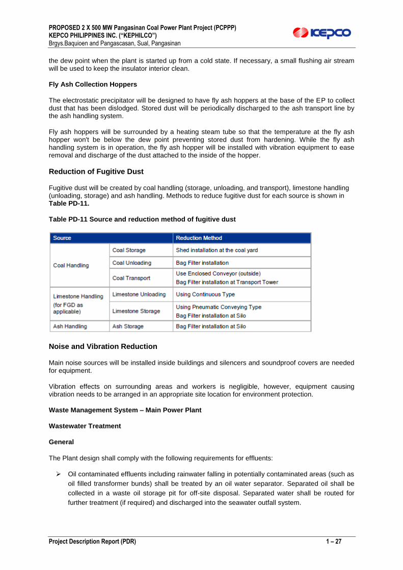
Reduction of Fugitive Dust
Fugitive dust will be created by coal handling (storage, unloading, and transport), limestone handling (unloading, storage) and ash handling. Methods to reduce fugitive dust for each source is shown in Table PD-11.
Table PD-11 Source and reduction method of fugitive dust
Noise and Vibration Reduction
Main noise sources will be installed inside buildings and silencers and soundproof covers are needed for equipment.
Vibration effects on surrounding areas and workers is negligible, however, equipment causing vibration needs to be arranged in an appropriate site location for environment protection.
Waste Management System – Main Power Plant
Wastewater Treatment
General
The Plant design shall comply with the following requirements for effluents:
Oil contaminated effluents including rainwater falling in potentially contaminated areas (such as
oil filled transformer bunds) shall be treated by an oil water separator. Separated oil shall be
collected in a waste oil storage pit for off-site disposal. Separated water shall be routed for
further treatment (if required) and discharged into the seawater outfall system.

PROPOSED 2 X 500 MW Pangasinan Coal Power Plant Project (PCPPP) KEPCO PHILIPPINES INC. (“KEPHILCO”) Brgys.Baquioen and Pangascasan, Sual, Pangasinan
Project Description Report (PDR) 1 – 28
Chemically contaminated effluents shall be routed to a neutralization plant where they are to be
neutralized by acid and caustic dosing. Neutralized effluent shall be routed for further treatment
(if required) and discharged into the seawater outfall system.
Industrial effluents shall be routed to a waste water treatment plant (WWTP) for appropriate
treatment prior to discharge into the seawater outfall system.
Uncontaminated rain water shall be collected in a storm water drainage system and discharged into the seawater outfall system.
Sanitary and domestic wastewater shall be routed to a sewage treatment plant and treated
before discharging to the seawater outfall system. Any waste sludge shall be removed from site
via tanker.
Any waste effluent which is not suitable for treatment and discharge shall be collected on site in suitable sumps for offsite disposal.
To extent possible the onsite and external ash ponds’ rain runoff and leachate collected shall be re-used after settlement process for dust suppression at the respective ash pond. The overflow, excess or not re-usable ash pond runoff and leachate shall be pumped from the external and onsite ash pond to the power plant common waste water treatment system OR the external ash pond dedicated waste water treatment system. Ash pond runoff and leachate treatment system shall be provided as part of the the power plant common waste water treatment system OR the external ash pond dedicated waste water treatment systems designed to allow treated effluent to meet environmental discharge requirements and to a quality such that the fish (at the fish farm) and other marine life are not affected during the plant operational life.
Design Criteria
The quality of treated wastewater should be maintained to meet effluent standard continuously. As such, the quality of the treated wastewater should meet or be better than that of effluent standards.
Any industrial effluent generated from the Plant shall be treated to comply with DENR Administrative Order No:2016-08 on Water Quality Guidelines and General Effluent Standards (Class SC) IFC 2008 EHS Guideline for Thermal Power Plants) before discharging downstream the treatment facility.
The wastewater can be classified into three types:
1) operational wastewater resulting from the required processes of the plant,
2) rainwater dependent wastewater and
3) irregular wastewater resulting from maintenance activities.
The wastewaters are processed and treated to meet DENR effluent standards prior to discharge into the outfall.
Operational wastewater discharged continuously during normal operation is the following:
ultrafiltration plant backwash water
seawater desalination plant effluent
brackish water demineralization plant
domestic wastewater,
PROPOSED 2 X 500 MW Pangasinan Coal Power Plant Project (PCPPP) KEPCO PHILIPPINES INC. (“KEPHILCO”) Brgys.Baquioen and Pangascasan, Sual, Pangasinan
Project Description Report (PDR) 1 – 29
laboratory drains, and
coal yard drains,
Rain dependent effluents are the ash yard run-off, the run-off in the fuel oil tank area and transformer areas.
Since the coal pile is fully covered, the possible run-off water from this source is minimal. This wastewater may or may not require treatment depending on the presence of oil or suspended solids.
The power plant will generate process wastewater and oily wastewater which will be treated before disposal.
Wastewater with oil will pass the oil water separator then will be subjected to wastewater treatment before being discharged.
Irregular wastewater is generated during commissioning and maintenance periods. The wastewater comes from:
condenser leak tests
boiler washing
de-aerator washing
air heater washing
boiler chemical cleansing waste water and
other cleaning water.
The amount of irregular wastewater will depend on the component being serviced.
Treated process waste streams and treated sanitary waste streams will be combined and monitored. The combined stream will be routed to the discharge structure.
Disposal of Waste Material
Industrial Solid Wastes
Industrial solid wastes include ash, slag, wasted conveyor belts and barrels, oily sludge from vehicles, equipment and oil and water separators, spent lubricants and other chemicals. If limestone based FGD system is applied, the byproducts disposal will also need to be considered.
Ash Production, Handling and Disposal
Burning of coal produces two types of boiler solid wastes; bottom ash and fly ash. Bottom ash,
comprising up to 10–20% of the total plant ash output, settles out of the flue gas stream and
agglomerates at the bottom of the furnace as clinker. It falls from the furnace as a range of dust, grits, friable solids, sintered solids and glassy melts. Utmost concern will be focused on ash production, handling and disposal.
The bottom ash will be discharged into a bottom ash surge hopper and transported to the bottom ash silo, from which the bottom ash will be taken out to the ash disposal area outside the plant.
PROPOSED 2 X 500 MW Pangasinan Coal Power Plant Project (PCPPP) KEPCO PHILIPPINES INC. (“KEPHILCO”) Brgys.Baquioen and Pangascasan, Sual, Pangasinan
Project Description Report (PDR) 1 – 30
Fly ash, 80–90% of the total ash, is fine ash that rises and becomes entrained in the exhaust gas
stream. Fly ash is removed from the exhaust gas stream by the EP. From the ash silos, the accumulated ash is removed by the following methods:
ash used for its pozzolanic characteristics is kept dry and transported by sealed tankers and transported to the cement factories that will take up 100% of the fly ash and bottom ash from the plant.
ash that will be permanently disposed of at the ash disposal area outside the plant will be conditioned by mixing it with water which causes a partial cementation thereby stabilizing the ash and preventing it from being blown by the wind.
Emergency Ash Pond
All bottom and fly ash will be taken out to landfill in the ash disposal area or to a cement factory for re-use. An ash pond will be installed for emergency ash storage. Runoff from the ash pond is generally acidic and must be neutralized before discharge.
Domestic Solid Waste
Domestic solid waste will include paper, cartons, plastic, bottles, tin cans, rubber, food left-over, etc. These will be collected and stored in waste bins properly sorted out into recyclables and non-recyclables before collection and disposal by the local government.
Some hazardous solid waste will include busted fluorescent lamps, spent industrial and car batteries, spent chemical cartridges and containers and expired chemicals. Within six (6) months from generation, these hazardous wastes will be removed, transported and disposed according to acceptable practices by the DENR accredited transporter and treater.
Footprint of proposed layout of project facilities.
Provided in Figure PD-9 is the footprint of the project facilities

PROPOSED 2 X 500 MW Pangasinan Coal Power Plant Project (PCPPP) KEPCO PHILIPPINES INC. (“KEPHILCO”) Brgys.Baquioen and Pangascasan, Sual, Pangasinan
Project Description Report (PDR) 1 – 31
Figure PD-7 POWER PLANT FACILITIES LAY OUT (PRELIMINARY ONLY)

PROPOSED 2 X 500 MW Pangasinan Coal Power Plant Project (PCPPP) KEPCO PHILIPPINES INC. (“KEPHILCO”) Brgys.Baquioen and Pangascasan, Sual, Pangasinan
Project Description Report (PDR) 1 – 32
2.0 Process and Technology
The trend for power generation technologies is towards the construction of more efficient power plants. One method of increasing the performance of a thermal power plant is to increase both the main steam and reheat temperatures in the cycle. For Supercritical power plant every 20°C rise in main and reheat steam temperatures can improve relative cycle efficiency by approximately 1%.
The drive for improved efficiency is requiring enhanced steam conditions with the implication of potentially increasing the material thickness to accommodate the increased pressures and temperatures and in the other case the market is dictating plants which are capable of operating flexibly to be able to quickly respond to load demand changes which requires reduced thermal mass in the system.
This contradiction is addressed by adopting advanced methods for designing thick walled components and by using more advanced materials that have the required strength characteristics at the selected operating conditions to allow thinner walled components to be designed.
The water/steam circulation systems in steam generators are divided into two main classifications:
Once-through steam generators in which all of the feedwater that is introduced into the unit is totally converted to steam in a single pass.
Drum-type boilers (subcritical) in which feedwater is fed to the boiler drum where it is then circulated through the furnace water walls and back to the drum, with steam/water separation occurring in the boiler drum and water recycled back to the water walls.
Although once-through type steam generators can be used for both sub and supercritical power plant projects, it is the only technology that can be employed for supercritical steam conditions where there is not a discrete steam/water phase separation.
The once-through technology eliminates the need for water/steam separation in boiler drums during operation above a minimum load point, and allows a simpler separator to be employed for start-up and low load conditions (periods of subcritical operation).
One main benefit for supercritical steam generators of the once-through design is that this type of steam generator does not have a steam drum due to the very high operating pressure of the supercritical steam cycle.
The boiler drum is a large very thick-walled vessel and requires controlled heating in operation, thus limiting ramp rates mainly for cold starts.
In addition to the lack of a drum and the thermal inertia that this represents, once-through steam generators also have a small evaporator volume which together allow for fast cold start-ups as well as for transient conditions and faster load changes.
In a drum boiler the limits on load change are about 3-5% per minute, while once-through steam generators can step-up the load to approximately 6% per minute. This makes once-through steam generators more suitable for the flexible operation required in modern units. Types of Combustion Technology The main types of boilers used in utility plants are Circulating Fluidized Bed (CFB) and Pulverized Coal (PC) Boilers; both have their advantages.
PC firing uses coal ground to a very fine powder sprayed into the furnace for combustion. CFBs use coal crushed to sizes of around 3 to 6 mm. The time, energy and facilities required to crush coal for a CFB is much less than what is required for a pulverized coal fired facility.

PROPOSED 2 X 500 MW Pangasinan Coal Power Plant Project (PCPPP) KEPCO PHILIPPINES INC. (“KEPHILCO”) Brgys.Baquioen and Pangascasan, Sual, Pangasinan
Project Description Report (PDR) 1 – 33
PC firing uses around 30 % of the combustion air as high pressure primary air for drying and transporting fuel.
CFBs use higher pressure primary air which is 60 % of the combustion air for fluidizing. The total air for combustion and the balanced draught system is essentially the same for both the systems.
The furnace and the cyclones in the CFB boilers are subject to a lot of erosion due to the circulation of particles like ash and sand. To prevent this erosion a thin layer of refractory covers the lower half of the furnace, upper transition areas and the cyclone. PC fired boilers do not have refractory covering on the furnace tubes or other heat transfer areas.
In a PC boiler a Flue Gas Desulphurisation unit is required for the reduction of Sulphur Dioxide. In CFB boilers limestone addition in the furnace reduces the Sulphur Dioxide during combustion itself. This requires only a simple limestone storage and handling unit.
In PC boilers around 15 % of ash collects at the bottom of the furnace and the balance in the electrostatic precipitators. In CFB boilers the collection at the bottom is almost 50 % lessening the load on the Electrostatic Precipitators.
CFBs can burn a wide range of poor fuels but are slow to change load; whereas, Pulverized Fuel (PF) units need to be designed for a limited range of coals but can change load rapidly compared to a CFB. While there are a number of vendors who can offer subcritical CFBs, only one vendor has a proven supercritical CFB currently on the market.
Figure PD-8 Typical Supercritical PC Boiler Configuration

PROPOSED 2 X 500 MW Pangasinan Coal Power Plant Project (PCPPP) KEPCO PHILIPPINES INC. (“KEPHILCO”) Brgys.Baquioen and Pangascasan, Sual, Pangasinan
Project Description Report (PDR) 1 – 34
Figure PD-9 Typical Overall PC Boiler Process
Over All Mass Balance
Figure PD-10 Material Balance for Coal and Ash
Figure PD-11 PCFPP Conceptual Drainage Plan

PROPOSED 2 X 500 MW Pangasinan Coal Power Plant Project (PCPPP) KEPCO PHILIPPINES INC. (“KEPHILCO”) Brgys.Baquioen and Pangascasan, Sual, Pangasinan
Project Description Report (PDR) 1 – 35
Power Generation and Water Supply Systems The plant raw water source shall be from reverse osmosis (RO) process treated seawater. The seawater shall be tapped from the cooling water pumps discharge common header. During complete plant shutdown, the CW pump station auxiliary cooling water pump shall provide required seawater via the common header. As minimum N+1 configuration equipment shall be provided such that each equipment shall be able to meet one Unit water consumption and with one being on standby. All equipment shall be provided as required to treat the sea water and produce water of the quality required to be used within the plant, including storage facilities and facilities required to treat the effluents and wastes from the water treatment plant to be suitable for discharge or disposal.
The treatment system shall as minimum consist of :
a pretreatment system consisting of ultrafiltration (UF) system
a seawater RO plant (SWRO)
a brackish water RO plant (BWRO)
- mixed bed polisher (MB) plant or electrodeionisation (EDI) units
one(1) potable water treatment system including remineralisation system, 2x100% pumps and
pressurised potable water storage tank
The complete water treatment system shall be designed and construction considering the
following criteria :
design capacity meeting below requirements without having to run respective plant
standby water
treatment train and without use of stored water (unless specified otherwise):
the Plant maximum simultaneous water demand during MCR operation
required potable and service water consumption;
Plant demineralised water consumption during MCR operation
able to fill one Unit’s boiler, water steam cycle piping and vessels within 24 hours
able to fill the fire fighting water storage tank within 8 hours period without the standby RO train in operation
supply required demineralsied water continuously during one boiler steam blow , however with capacity optimisation considering demineralised water tank storage
able to supply demineralised water equivalent to 3% of two(2) Units steam flow during MCR operation
ensure the continuous operation of mechanical functions during commissioning and testing until to Take Over of the Works;
ensure continuity of supply for demineralised water for running one Unit at full load when the other Unit is shutdown
ensure continuity of supply for potable and service usage during Plant shutdown
provide an adequate dedicated supply of fire fighting water for all fire fighting systems at all times including period of plant shutdown
PROPOSED 2 X 500 MW Pangasinan Coal Power Plant Project (PCPPP) KEPCO PHILIPPINES INC. (“KEPHILCO”) Brgys.Baquioen and Pangascasan, Sual, Pangasinan
Project Description Report (PDR) 1 – 36
Waste Water Management System
Waste Water Treatment systems shall be designed and installed to treat all industrial waste generated
from the plant during operation. The waste water treatment plant shall be designed to cater to regular
waste during operation and irregular waste during outages.
Discharge water quality from each of the treatment system shall be monitored for key constituents of
concern in accordance with constituents treated and the regulatory requirements. Waste water shall
be rerouted back to the waste water treatment system for further treatment should the treated water
quality fail to meet the required limits.
The waste water treatment system shall cater to all oily and chemical waste water from the entire
Plant including but not limited to the boiler, auxiliary boiler, steam turbine, transformers, pumps, tanks,
fuel and chemical unloading facilities, vessels drainage and heat exchangers drainage, onsite and
external ash pond leachate and ash pond rain runoff..
The treated waste water monitoring location should be selected with the objective of providing representative monitoring data. Effluent sampling stations shall be located at the final discharge, as well as at strategic upstream points prior to merging of different discharges. Storm water
Storm water shall be stored in a common storm water pond and re-used for dust suppression and
other possible re-use. Excess storm water shall be discharged to the sea. Oily waste water
Oily waste water shall include the following:
Oily waste water drain from the fuel oil tanker and fuel oil unloading/transfer pumps station
Runoff from transformers area
Oily waste water from lube oil tank area
Oily waste water shall be collected and treated by oil separators to meet environmental discharge limit
before entering the waste water storage basins. The oily waste shall be treated at first stage via an
API separator and as secondary treatment stage via induced air flotation (IAF) type separator. The
IAF separator related auxiliaries such as the emulsion breaker pumps and tank shall be provided. The
EPC Contractor may propose alternative solution proven to meet the environmental limits. All oily
waste water pumps shall be non-emulsifying type.
Treated discharge from the IAF shall be routed to the plant common normal waste water pond.
Normal waste water
All waste water generated during plant normal operation that cannot be discharged directly to the
environment shall be collected in a normal waste water pond. Seawater desalination plant effluent and
brackish water demineralization plant RO plant brine may be discharged direct to the CW discharge if
constituents already comply to the effluent environmental limits. Coal stockpile area rainwater runoff
and onsite ash runoff waste water shall be routed to settlement basins before reuse. Domestic
wastewater shall be treated via sanitary waste treatment plant before discharging to the normal waste
water pond.
The normal waste water pond shall be sized to store at least 24 hours of plant generated waste water
including the worst case abnormal waste water inflow. The collected waste water shall undergo pH
PROPOSED 2 X 500 MW Pangasinan Coal Power Plant Project (PCPPP) KEPCO PHILIPPINES INC. (“KEPHILCO”) Brgys.Baquioen and Pangascasan, Sual, Pangasinan
Project Description Report (PDR) 1 – 37
adjustment, and additional chemical treatment as required and coagulation process before routed to
2x100% clarifiers. During normal operation both clarifiers shall be in operation.
Normal waste water shall include the following:
ultrafiltration plant backwash water
pressure filter backwash
seawater desalination plant effluent
brackish water demineralization plant
domestic wastewater
sampling and laboratory drains
Turbine hall chemical dosing area and chemical waste water drain sump
coal stockpile runoff
ash runoff waste water
Deaerator /Feedwater tank drains
boiler and water steam cycle drains
The clarifier treated water shall be further filtered using pressure filters and activated carbon filter
(both equipment in 3 x 50% configuration for the Plant). pH adjustment shall be carried out as part of
final treatment. The treated water shall be stored in a common treated water pond sized to store the
Plant generated treated water during 24 hours’ operation in full load. The treated water quality shall be
such to allow reuse within the Plant. All chemical dosing rate shall be adjustable automatically in
accordance to the incoming flowrate.
Sludge from the clarified shall be stored in a sludge tank before transferred to a thickener and
dehydrator. The dried cake produced shall be stored temporarily in cake hopper before disposal to the
external mobile trucks. Sludge thickener, dehydrator and cake hopper shall be located in a building
allowing the mobile truck to enter for the cake hopper to drop the dried cakes into the truck from
higher elevation building floor.
The sludge thickener, dehydrator, and cake hopper shall be provided in 2x50% configuration and the
sludge tank sized to store minimum 24 hours of worst case sludge generated from the clarifier.
Abnormal waste water
All waste water generated during plant commissioning, specific maintenance activities, plant outage
conditions shall be considered as abnormal waste water. Abnormal waste water shall include waste
water generated during below activity:
condenser leak tests
boiler area washing
de-aerator washing
air heater washing
ash silo area washing
boiler chemical cleaning waste water and
other cleaning activities
PROPOSED 2 X 500 MW Pangasinan Coal Power Plant Project (PCPPP) KEPCO PHILIPPINES INC. (“KEPHILCO”) Brgys.Baquioen and Pangascasan, Sual, Pangasinan
Project Description Report (PDR) 1 – 38
The amount of irregular wastewater will depend on the component being serviced.
These abnormal waste water shall undergo initial treatment via aeration, pH adjustment or other
chemical treatment as necessary before transferred to the normal waste water pond.
Ash Pond runoff
Both onsite and offsite external ash pond shall be designed in compliant to applicable Philippines
Regulation. Protection composite liners shall be provided to prevent leachate contamination of the
groundwater, surface water and soil. Groundwater monitoring wells shall be provided at selected
locations adjacent to the ash pond. A minimum of four (4) groundwater monitoring wells at the onsite
ash pond and minimum six (6) groundwater monitoring wells at external ash pond shall be provided.
Higher number of groundwater monitoring wells shall be provided at suitable locations around the ash
pond if required to allow proper groundwater contamination monitoring. A leachate collection and rain
runoff drainage system shall be provided. The leachate system may consist of a leachate collection
layer with a pipe network to convey the leachate to the sedimentation pond and treatment facility.
To extent possible the onsite and external ash ponds’ rain runoff and leachate collected shall be re-
used after settlement process for dust suppression at the respective ash pond. The overflow, excess
or not re-usable ash pond runoff and leachate shall be pumped from the external and onsite ash pond
to the power plant common waste water treatment system. Ash pond runoff and leachate treatment
system shall be provided as part of the power plant common waste water treatment system or
external ash pond dedicated treatment system designed to allow treated effluent to meet
environmental discharge requirements and to a quality such that the fish (at the fish farm) and other
marine life are not affected during the plant operational life.
Perforated leachate collection pipe networks shall be provided to collect the leachate at the gravel
drainage layer. Minimum 200mm diameter pipes shall be provided to avoid clogging. Piping network
design shall allow injection of biocide and other cleaning solutions. Major intersections or bends shall
have inspection access. Leachate removal can be by gravity drainage to header pipes, or vertical
sumps or pipes coming up to side slope. Removal system proposed shall be effective for leachate
monitoring and removal by pumping.
3.0 Project Size For the Main Facility – the Power Plant
The total land requirement is 90 hectares for the power plant and 100 hectares for the ash pond.
The generating capacity is 2 x 500 MW (Gross) For the Major Component – the Ash Pond Land Area = 60-100 Hectares Rate of Ash Generation = See Above Values for Ash Produced 4.0 Development Plan, Description of Project Phases and Corresponding Timeframes
A description of the activities during the various project phase will provide inputs for impact
Identification, environmental management plan and social impacts/appropriate socially-oriented
program.

PROPOSED 2 X 500 MW Pangasinan Coal Power Plant Project (PCPPP) KEPCO PHILIPPINES INC. (“KEPHILCO”) Brgys.Baquioen and Pangascasan, Sual, Pangasinan
Project Description Report (PDR) 1 – 39
4.1 Pre-construction/ Pre-operational phase
This involves the exploration stage, project planning, the securing of appropriate Clearance(s)
and permit(s) from the DENR / EMB principally the ECC Feasibility studies which include
economics evaluation are integral part of this phase.
4.2 Construction/Development phase
Phases to be described in terms identifying specific activities (with special attention on those with significant environmental impacts as well as climate change adaptation options relevant to the project and project activities) and corresponding projected implementation timeframes:
o Pre-construction Phase
There are no environmental impacts during this phase; activities involved being mainly the following:
Land Acquisition-This is ongoing with the identification and negotiations being held with the land owners. The formal purchase or lease of land will necessarily have to wait until after an ECC shall have been secured.
Preliminary Engineering Studies – These include the following: Topographic surveys Bathymetric surveys Site geotechnical drilling (on shore and off-shore) Georesistivity studies Securing of Permits and Clearances such as but not limited Environmental
Compliance Certificate (ECC), Land Conversion (if required), Tree Cutting Permit and Various Permits from the LGU, e.g. construction permits, etc.
Plant Construction Phase
Site Preparation and Site Grading In general, the elevation of power plant is determined at the certain level according to the analysis of available oceanography data, flood water level and earth-volume calculation. In this project, a site grading is required for the construction area. The site grading contains generally the following works.
Site Grading
Excavation and Backfill
Drainage during construction
Ground soil analysis and Test
The proposed site has been engaged in farming area except for the small mountain near the sea. The elevation in accordance with the topography survey over the farming area ranges from 1.0 m ~ 3.0 m and the height of the mountain is about 45 m on the basis of M.S.L. The fundamental concept of the site grading is to cut the mountain and to fill up the rest farming area with the cut soil. The plant platform will be at increased elevation of ~5mEL to avoid the Tsunami hazard. According to such the earthwork balance study, soils for banking have to be borrowed from somewhere. Earthwork Cut and Fill Slope Cut and fill slopes shall be in accordance with the following.

PROPOSED 2 X 500 MW Pangasinan Coal Power Plant Project (PCPPP) KEPCO PHILIPPINES INC. (“KEPHILCO”) Brgys.Baquioen and Pangascasan, Sual, Pangasinan
Project Description Report (PDR) 1 – 40
Backfill
Materials, workmanship and testing procedures shall at least meet with the appropriate ASTM, AASHTO and BS Standards and procedures. Excavations and backfilling shall be carried out in accordance with applicable codes and approved procedures, in order to provide the required surface of contact between the structures and the bottom of foundations. All sub-grades shall be proven to be of adequate strength to support the works to be constructed upon it. Compaction of structural granular backfill materials shall be carried out within the
range of 2 % of the optimum moisture content to attain a maximum dry density of not less than 95 % established from modified proctor compaction tests (ASTM D-1557). Backfill materials shall be proven to be fit for engineering purposes in EPC contract stage.
Power Block Building Steel Structure
The turbine building houses turbine generators, condensers, feedwater pumps, deaerator, storage tank and other equipment required for power generation. The building will be designed to withstand dead load, equipment load, live load, wind or seismic load.
The main floors of the building are the operating and mezzanine floors. The operating floor is a concrete slab while the mezzanine floor is steel grating. Both floors are supported by structural steel framing. The deaerator-storage tank is supported by structural framing and the floor is concrete. The building foundation is reinforced concrete spread footings in combination with continuous footings.
The equipment foundations - T/G foundation, boiler feedwater pump foundation, Air compressor foundation etc. should be isolated from building structures to avoid transmission of vibration into them.
Combined noise resulted from T/G and other equipment should be less than standard as described in Plant Specification. Columns and Beams
The type of columns and beams is steel structure.
Steel surface required to fire protection should be coated using adequate materials
Floor The mezzanine floor is steel grating almost but reinforced concrete partially.
Floor drain line of Lube oil reservoir area should be connected to waste water treatment system through turbine building sump.
Whole of the roof floor is covered deck plate on roof truss and it must have the function of heat interruption and waterproofness. Building outside shall be finished by metal siding attached to steel girt.

PROPOSED 2 X 500 MW Pangasinan Coal Power Plant Project (PCPPP) KEPCO PHILIPPINES INC. (“KEPHILCO”) Brgys.Baquioen and Pangascasan, Sual, Pangasinan
Project Description Report (PDR) 1 – 41
Grade wall is built along the edge of building about 1.5m height from ground floor and metal siding begins at the top of grade wall. At the area adjacent to transformer, the grade wall is designed as 2 hr fire-fighting wall.
Building Foundation Building foundation shall be designed reinforced concrete structure foundation which resists the stresses transmitted from superstructure. It may be used pile or alternative method if it lacks of bearing resistance.
Cooling Water Pump Station and Discharge Structures
C.W. Pump Station
The primary function of C.W. pump station is to supply the cooling water steadily to the turbine condenser of the power plant. The C.W. pump station for the PCFPP shall be designed with the reinforced concrete and according to the pump bell mouth diameter and allowable approaching velocity in the pump bay, 0.45m/s. To secure the safe and steady pumping of the cooling water, Hydraulic Model Test and CFD analysis should be performed. The concrete strength for C.W. pump station is recommended to be 35MPa.
Discharge Structure
The primary function of discharge structure is to discharge the cooling water through the turbine condenser to the sea. In general the discharge structure, concrete box, shall be designed according to the design velocity less than 3.0m/s which is generally recommended the design velocity between 2.1m/s and 2.3m/s to increase the efficiency of the cooling water system. The concrete strength for the discharge structure shall not be less than 35MPa. Tank Foundation The tank foundation is designed to withstand the dead load including equipment load, live load, wind load and seismic load. The foundation is resisted against overturning and sliding. The maximum bearing pressure shall not be greater than the allowable bearing pressure. The tank is founded on reinforced concrete pentagonal foundation type. But, the foundation type can be changed to ring-wall type or pile type after the research of the soil layers on the site.
Coal Unloading Jetty and Access Trestle
Marine facilities shall be designed in accordance with applicable and procedure of Harbor Design Manual, Port Designer’s handbook, Port ACT, Channel Mark Act, and Marine Pollution Prevention Act. Marine facilities design shall be influenced by the meteorological condition and soil & rock condition directly or dominantly. So, marine facilities shall be designed considering basically the subsurface condition and additionally considering the meteorological conditions as follows:
○ Wind cause the forces occurring on the offshore facilities or mooring ships.
○ Wind cause the occurrence and development of wave.
○ Wind and air pressure cause the high tide.
Design tidal height shall be determined considering the highest water level, approximate high water level, approximate low water level and lowest low water level etc. Dimension of current used in the design is current direction and velocity determined by the actual observation, and the current variation shall be investigated in facilities design because the current varied by land topography and bathymetry.
PROPOSED 2 X 500 MW Pangasinan Coal Power Plant Project (PCPPP) KEPCO PHILIPPINES INC. (“KEPHILCO”) Brgys.Baquioen and Pangascasan, Sual, Pangasinan
Project Description Report (PDR) 1 – 42
○ Berth size shall be determined considering the ship and volume, berthing capacity and the unloading capacity of unloading equipment etc. For PCFPP, the capacity of coal transporting up to 80,000 DWT ship is planned and a jetty is requested to be constructed in front of the project area where the dredging is not needed within closest vicinity.
Usually the layout of unloading jetty shall be determined according to the followings. ○ Berth size and layout shall be determined considering the ship and volume and the unloading capacity of unloading equipment. For PCFPP, the capacity of coal transporting ship is 80,000 DWT and a new unloading dock is requested.
The berth orientation should be horizontal to the main current and perpendicular to
the design wave.
Width of port shall be decided according to technical specification of coal conveyor
system, coal unloader etc.
Length of port shall be decided considering space for safety of berthing, safe
mooring, various facilities of port for operating, maintanance area, economic etc. The
length of coal carrier of 80,000 ton level is usually more than 250 m but the length of
coal storage cell (from end cell to the other end cell) is approximately lower than 170
m. Where, the front end of the ship shall be moored during normal berth. When the
mooring dolphins are considered, the jetty of 210 m, considering a margin, was
reasonably recommended. The width of jetty, at this moment, is pending because it
depends on the coal unloader equipment and conveyor facilities.
Maneuvering during the berthing and deberthing of a ship will generally be done in one of the following ways:
a) By using only the ship’s own engine, rudder, bow thrusters and/or the ship anchor. b) With the assistance only of one more tugboats. c) By using the ships own anchor, and the assistance of one or more tugboats. d) With the use of berth or land based winches, and with the assistance of one or more
tugboats. e) With the use of mooring buoy, and with the assistance of one or more tugboats. f) A combination of two or more of the above mentioned systems.
Currently nearly all berthing and deberthing operations have been done after either cases a, b, c. The case d with use of land-based winches of hauling capacity of about 75 tons can have some technical advantages compared to case a, b, c or e. The difference in operation of case d is both of technical and of an administrative nature. From a technical point of view the efficiency, particularly with offshore wind, will tend to be higher with winches because the responsiveness to action by winches is much faster than for tugboats. The winch system is also safer because, with this system, the berthing operation is more punctual and faster than for tugboats operation only. For berthing of larger tankers the winch system is more economics since it will use fewer tugboats. The maneuvering including rotation near the jetty is recommended to be done according to the local sailing route regulation and/or the traditional methodology. However, the location of coal unloading jetty is planned to be constructed in front of the project area where the dredging is not needed within closest vicinity. Thus, No dredging near the jetty is required to secure the required water depth in normal berthing status. Considering the full draft and the berthing margin, the berthing area should be located at the point which secures the water depth of 116 m.. (Plan of the Coal Unloading Jetty)
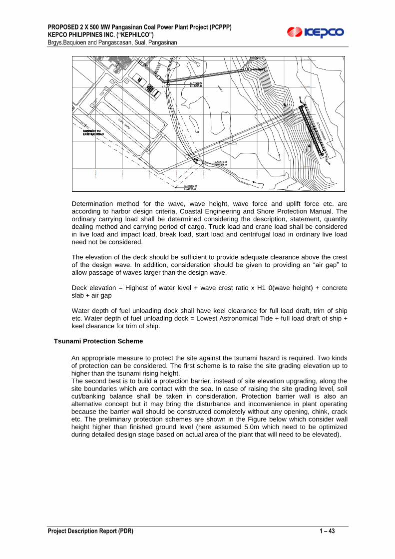
PROPOSED 2 X 500 MW Pangasinan Coal Power Plant Project (PCPPP) KEPCO PHILIPPINES INC. (“KEPHILCO”) Brgys.Baquioen and Pangascasan, Sual, Pangasinan
Project Description Report (PDR) 1 – 43
Determination method for the wave, wave height, wave force and uplift force etc. are according to harbor design criteria, Coastal Engineering and Shore Protection Manual. The ordinary carrying load shall be determined considering the description, statement, quantity dealing method and carrying period of cargo. Truck load and crane load shall be considered in live load and impact load, break load, start load and centrifugal load in ordinary live load need not be considered. The elevation of the deck should be sufficient to provide adequate clearance above the crest of the design wave. In addition, consideration should be given to providing an “air gap” to allow passage of waves larger than the design wave. Deck elevation = Highest of water level + wave crest ratio x H1 0(wave height) + concrete slab + air gap Water depth of fuel unloading dock shall have keel clearance for full load draft, trim of ship etc. Water depth of fuel unloading dock = Lowest Astronomical Tide + full load draft of ship + keel clearance for trim of ship.
Tsunami Protection Scheme
An appropriate measure to protect the site against the tsunami hazard is required. Two kinds of protection can be considered. The first scheme is to raise the site grading elevation up to higher than the tsunami rising height. The second best is to build a protection barrier, instead of site elevation upgrading, along the site boundaries which are contact with the sea. In case of raising the site grading level, soil cut/banking balance shall be taken in consideration. Protection barrier wall is also an alternative concept but it may bring the disturbance and inconvenience in plant operating because the barrier wall should be constructed completely without any opening, chink, crack etc. The preliminary protection schemes are shown in the Figure below which consider wall height higher than finished ground level (here assumed 5.0m which need to be optimized during detailed design stage based on actual area of the plant that will need to be elevated).

PROPOSED 2 X 500 MW Pangasinan Coal Power Plant Project (PCPPP) KEPCO PHILIPPINES INC. (“KEPHILCO”) Brgys.Baquioen and Pangascasan, Sual, Pangasinan
Project Description Report (PDR) 1 – 44
Preliminary Tsunami Protection wall
Figure PD-12 Initial Conceptual Plan for Protection Against Tsunamis Power Block Buildings
Turbine & Control Building Turbine Building is considered as closed type in fabricated structural steel including crane for the maintenance of turbine generator. The roof and floors shall be reinforced concrete slab and steel gratings on steel truss beam. Side claddings may consist of insulated metal sheet. Control Building shall be designed with the same concept above.
○ Main control room / Electronic room / Computer room
○ Electrical room / Battery room / Communication room
○ HVAC room / Firefighting room
○ Offices
○ Conference room / Storage
○ Kitchen
○ Toilet and Shower room with Locker room, etc.
System Related Buildings System Related Buildings shall be consist of buildings to be included the housing and operation of auxiliary facility system and public facility system of power plant.

PROPOSED 2 X 500 MW Pangasinan Coal Power Plant Project (PCPPP) KEPCO PHILIPPINES INC. (“KEPHILCO”) Brgys.Baquioen and Pangascasan, Sual, Pangasinan
Project Description Report (PDR) 1 – 45
(1) Water & Waste Water Treatment Building Water & Waste Water Treatment
Building is comprised of the followings, but not limited to:
○ Water treatment area
○ Waste water treatment area
○ Electrical room / Control room
○ Chemical Storage
○ Laboratory
○ Offices
○ Toilet and Shower room with Locker room, etc
(2) Coal Handling Building Coal Handling Building is comprised of the followings, but
not limited to:
○ Electrical room / Control room / Battery room
○ Offices
○ Toilet and Shower room with Locker room, etc.
(3) Chlorination Building Chlorination Building is comprised of the followings, but not
limited to:
○ Mechanical area
○ Electrical room / Control room
(4) Fuel Oil Pumphouse Fuel Oil Pumphouse is comprised of the following
○ Fuel oil pump area
(5) EP & Ash Electrical Building
○ Electrical / Control room
(6) SWYD Control Building
○ Electrical / Control room
(7) Auxiliary Boiler Electrical Building
○ Electrical / Control room
(8) Fire Water Pump House
○ Fire water pump area
(9) Gas Storage House
○ Gas storage room
(10) Coal Storage Shed
○ Coal storage area
Ancillary Buildings Ancillary building shall be consist of buildings to be included the service facility and ancillary facility for smooth operation of power plant. (1) Administration Building Administration Building is comprised of the followings, but not
limited to: ○ Offices ○ Conference rooms ○ Storages ○ Clinic ○ Rest room ○ Toilet and Shower room with Locker room, etc.
PROPOSED 2 X 500 MW Pangasinan Coal Power Plant Project (PCPPP) KEPCO PHILIPPINES INC. (“KEPHILCO”) Brgys.Baquioen and Pangascasan, Sual, Pangasinan
Project Description Report (PDR) 1 – 46
(2) Administration Building Annex Administration Building Annex is comprised of the followings, but not limited to:
○ Cafeteria ○ Kitchen ○ Food storage ○ Toilet and Shower room with Locker room, etc
(3) Workshop & Main Warehouse
Workshop & Main Warehouse is comprised of the followings, but not limited to: ○ Workshop area ○ Storage area for spare parts ○ Offices ○ Waiting room ○ Toilet and Shower room with Locker room, etc.
(4) Guard House
○ Guard room ○ Control room ○ Toilet and Shower room with Locker room, etc.
(5) Fire Station
○ Fire tank area / Ambulance area ○ Office ○ Storage
Landscape Landscaping by means of gardening and planting with grass, decorative bush and trees shall be provided at around road, buildings. The proper species and area of plantation shall be kept in compliance with the regulation. The trees, shrubs and grasses chosen shall be species which can thrive well under the prevailing climatic conditions. The soil shall be prepared appropriately for the plants.
4.3 Operation Phase: Timetable and Activities
The initially projected commissioning schedule is shown in Table PD-12 which reflects a 48 month scheduling after the securing of an Environmental Compliance Certificate. During the commissioning period, all plant components will be subjected to sectional tests to ensure that all systems and subsystems are fully functional. Necessary grid/interconnection tests required by the NGCP shall also be undertaken. Power grid tests (interconnection tests) will be performed to assure compliance of the proposed plant to the requirements of the NGCP’s Grid Code.
Coal will be transported by sea and received at the plant’s coal unloading jetty using coal handling facilities, The ash generated will be impounded in an engineered land fill at another site nearby the project. Air pollution control devices principally electrostatic precipitators (ESP) will be continuously operated to keep PM and SOx emissions within DENR emission standards. A Continuous Emissions Monitoring System (CEMS) compliant with the regulatory requirements of the EMB/DENR.
The project timetable is given in Table PD -12.
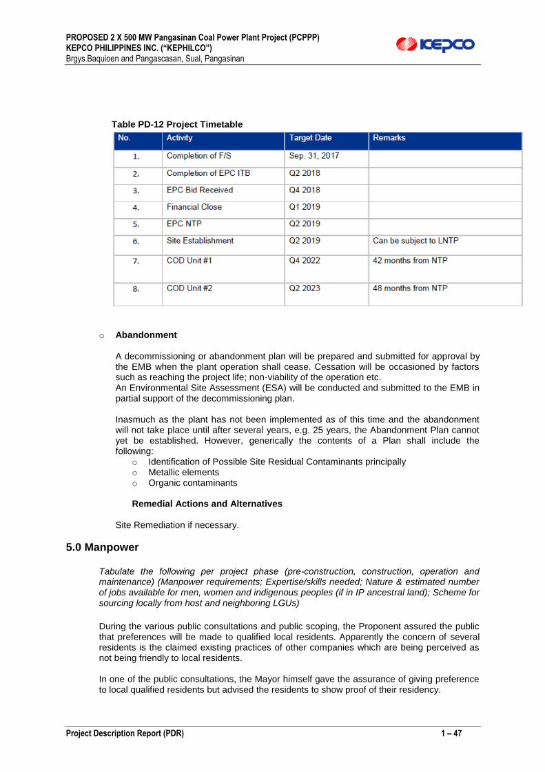
PROPOSED 2 X 500 MW Pangasinan Coal Power Plant Project (PCPPP) KEPCO PHILIPPINES INC. (“KEPHILCO”) Brgys.Baquioen and Pangascasan, Sual, Pangasinan
Project Description Report (PDR) 1 – 47
Table PD-12 Project Timetable
o Abandonment
A decommissioning or abandonment plan will be prepared and submitted for approval by the EMB when the plant operation shall cease. Cessation will be occasioned by factors such as reaching the project life; non-viability of the operation etc. An Environmental Site Assessment (ESA) will be conducted and submitted to the EMB in partial support of the decommissioning plan. Inasmuch as the plant has not been implemented as of this time and the abandonment will not take place until after several years, e.g. 25 years, the Abandonment Plan cannot yet be established. However, generically the contents of a Plan shall include the following:
o Identification of Possible Site Residual Contaminants principally o Metallic elements o Organic contaminants
Remedial Actions and Alternatives
Site Remediation if necessary.
5.0 Manpower
Tabulate the following per project phase (pre-construction, construction, operation and maintenance) (Manpower requirements; Expertise/skills needed; Nature & estimated number of jobs available for men, women and indigenous peoples (if in IP ancestral land); Scheme for sourcing locally from host and neighboring LGUs)
During the various public consultations and public scoping, the Proponent assured the public that preferences will be made to qualified local residents. Apparently the concern of several residents is the claimed existing practices of other companies which are being perceived as not being friendly to local residents.
In one of the public consultations, the Mayor himself gave the assurance of giving preference to local qualified residents but advised the residents to show proof of their residency.
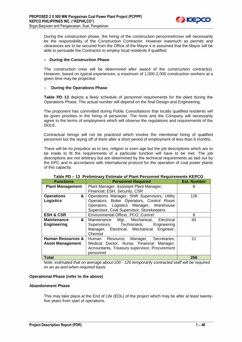
PROPOSED 2 X 500 MW Pangasinan Coal Power Plant Project (PCPPP) KEPCO PHILIPPINES INC. (“KEPHILCO”) Brgys.Baquioen and Pangascasan, Sual, Pangasinan
Project Description Report (PDR) 1 – 48
During the construction phase, the hiring of the construction personnel/crew will necessarily be the responsibility of the Construction Contractor. However inasmuch as permits and clearances are to be secured from the Office of the Mayor it is assumed that the Mayor will be able to persuade the Contractor to employ local residents if qualified.
o During the Construction Phase
The construction crew will be determined after award of the construction contract(s). However, based on typical experiences, a maximum of 1,000-2,000 construction workers at a given time may be projected. o During the Operations Phase
Table PD 13 depicts a likely schedule of personnel requirements for the plant during the Operations Phase. The actual number will depend on the final Design and Engineering.
The proponent has committed during Public Consultations that locally qualified residents will be given priorities in the hiring of personnel. The hires and the Company will necessarily agree to the terms of employment which will observe the regulations and requirements of the DOLE.
Contractual hirings will not be practiced which involve the intentional hiring of qualified personnel but the laying off of them after a short period of employment of less than 6 months. There will be no prejudice as to sex, religion or even age but the job descriptions which are to be made to fit the requirements of a particular function will have to be met. The job descriptions are not arbitrary but are determined by the technical requirements as laid out by the EPC and in accordance with international protocol for the operation of coal power plants of this capacity.
Table PD – 13 Preliminary Estimate of Plant Personnel Requirements KEPCO
Functions Personnel Required Est. Number
Plant Management Plant Manager, Assistant Plant Manager, Financial, ESH, Security, CSR
8
Operations & Logistics
Operations Manager, Shift Supervisors, Utility Operators, Boiler Operators, Control Room Operators, Logistics Manager, Warehouse Supervisor, Coal Supervisor, Storekeepers
126
ESH & CSR Environmental Officer, PCO, Comrel 8
Maintenance & Engineering
Maintenance Mgr, Mechanical, Electrical Supervisors, Technicians, Engineering Manager, Electrical, Mechanical Engineer, Chemist
93
Human Resources & Asset Management
Human Resource Manager, Secretaries, Medical Doctor, Nurse, Financial Manager, Accountants, Treasury supervisor, Procurement personnel
21
Total 256
Note: estimated that on average about 100 - 120 temporarily contracted staff will be required on an as-and-when-required basis.
Operational Phase (refer to the above)
Abandonment Phase
This may take place at the End of Life (EOL) of the project which may be after at least twenty-five years from start of operations.

PROPOSED 2 X 500 MW Pangasinan Coal Power Plant Project (PCPPP) KEPCO PHILIPPINES INC. (“KEPHILCO”) Brgys.Baquioen and Pangascasan, Sual, Pangasinan
Project Description Report (PDR) 1 – 49
The protocol and clearances for the abandonment or decommissioning of the project will be subject to approvals and guidelines from the Environmental Management Bureau (EMB) which shall be secured at least six (6) months from project abandonment/decommissioning.
6.0 Projected Timeframe
Table PD – 14 Projected Timeframe
Manpower Table PD-15. Estimate Manpower for the Construction Works
Activities Manpower Estimates
Unskilled Workers TBD
Skilled Workers TBD
Administrative and Managerial TBD
TOTAL 1000-2000
Table PD-15. Estimate Manpower for the Operations Works (Refer to the Table PD-12)
7.0 Indicative Project Investment Cost
1.834 Billion USD or 91.7 Billion Pesos (1USD:50PhP)
8.0 Initial Environmental Impacts and Management Plan (IMP)
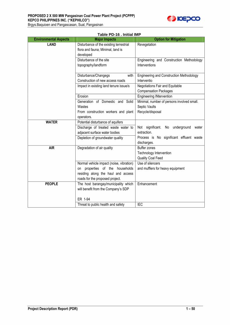
PROPOSED 2 X 500 MW Pangasinan Coal Power Plant Project (PCPPP) KEPCO PHILIPPINES INC. (“KEPHILCO”) Brgys.Baquioen and Pangascasan, Sual, Pangasinan
Project Description Report (PDR) 1 – 50
Table PD-16 . Initial IMP
Environmental Aspects Major Impacts Option for Mitigation
LAND Disturbance of the existing terrestrial
flora and fauna; Minimal, land is
developed
Revegetation
Disturbance of the site
topography/landform
Engineering and Construction Methodology
Interventions
Disturbance/Changegs with
Construction of new access roads
Engineering and Construction Methodology
Interventio
Impact in existing land tenure issue/s Negotiations Fair and Equitable
Compensation Packages
Erosion Engineering INtervention
Generation of Domestic and Solid
Wastes
From construction workers and plant
operators.
Minimal, number of persons involved small.
Septic Vaults
Recycle/disposal
WATER Potential disturbance of aquifers
Not significant. No underground water
extraction.
Process is No significant effluent waste
discharges.
Discharge of treated waste water to
adjacent surface water bodies
Depletion of groundwater quality
AIR Degradation of air quality Buffer zones
Technology Intervention
Quality Coal Feed
Normal vehicle impact (noise, vibration)
on properties of the households
residing along the haul and access
roads for the proposed project.
Use of silencers
and mufflers for heavy equipment
PEOPLE The host barangay/municipality which
will benefit from the Company’s SDP
ER 1-94
Enhancement
Threat to public health and safety IEC

PROPOSED 2 X 500 MW Pangasinan Coal Power Plant Project (PCPPP) KEPCO PHILIPPINES INC. (“KEPHILCO”) Brgys.Baquioen and Pangascasan, Sual, Pangasinan
Project Description Report (PDR) 1 – 51
TYPICAL PHOTOGRAPHS OF SITES Plates PD-2 Photographs of the Power Plant Site
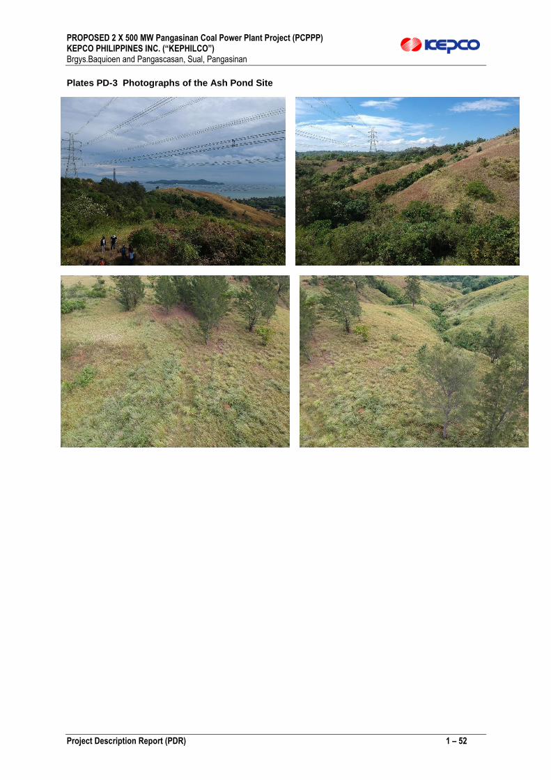
PROPOSED 2 X 500 MW Pangasinan Coal Power Plant Project (PCPPP) KEPCO PHILIPPINES INC. (“KEPHILCO”) Brgys.Baquioen and Pangascasan, Sual, Pangasinan
Project Description Report (PDR) 1 – 52
Plates PD-3 Photographs of the Ash Pond Site
Related Documents