Anderson and Kononov Kristen Anderson Kat Kononov November 8, 2010 Project Proposal Project Overview The aim of this project is to create a proof-of-concept model for a semi- autonomous car that avoids crashing into obstacles. The system does this by disallowing turning into an object and if an object is in its path the car avoids the object and regains its original direction High-Level Project Architecture This project involves several pieces of hardware in addition to the labkit, including a TV remote, an infrared receiver chip, a RC car and the car's controller, four distance sensors and a Xbee wireless transmitter. The driver uses the TV remote to send signals to the labkit. The infrared receiver chip receives the signals and passes them to the FPGA. The car is equipped with several distance sensors and an Xbee wireless transmitter. Each of the distance sensors will be mounted on the four sides of the vehicle: front, back, left right. The distance sensors data is sent using the XBee wireless transmitter. The corresponding XBee receiver is connected to the labkit, allowing for the sensor data to be input to the FPGA The FPGA processes the driver commands and the sensor data, and creates commands for the car based on those inputs. Those commands are transmitted to the car through the labkit in/outs which are connected to the remote control that comes with the car. See the High-Level Architecture Figure. FPGA Overview The FPGA contains three modules: the Controller Finite State Machine (FSM), the Driver Input Processing Module, the Sensor Input Processing Module, and the Car Command Output Module. The Controller FSM is responsible for making the car command decisions based off of the sensor and user inputs. The Driver Input Processing Module deciphers the serial information received by the remote. The Sensor Input Processing Module codes and transmits the car commands received by the FSM. Car Command Output Module receives the commands from the Controller FSM and outputs them to the labkit to transmit to the car. See the FPGA Overview figure. 1

Welcome message from author
This document is posted to help you gain knowledge. Please leave a comment to let me know what you think about it! Share it to your friends and learn new things together.
Transcript

Anderson and Kononov
Kristen AndersonKat KononovNovember 8, 2010
Project Proposal
Project Overview
The aim of this project is to create a proof-of-concept model for a semi-autonomous car that avoids crashing into obstacles. The system does this by disallowing turning into an object and if an object is in its path the car avoids the object and regains its original direction
High-Level Project Architecture
This project involves several pieces of hardware in addition to the labkit, including a TV remote, an infrared receiver chip, a RC car and the car's controller, four distance sensors and a Xbee wireless transmitter. The driver uses the TV remote to send signals to the labkit. The infrared receiver chip receives the signals and passes them to the FPGA. The car is equipped with several distance sensors and an Xbee wireless transmitter. Each of the distance sensors will be mounted on the four sides of the vehicle: front, back, left right. The distance sensors data is sent using the XBee wireless transmitter. The corresponding XBee receiver is connected to the labkit, allowing for the sensor data to be input to the FPGA The FPGA processes the driver commands and the sensor data, and creates commands for the car based on those inputs. Those commands are transmitted to the car through the labkit in/outs which are connected to the remote control that comes with the car. See the High-Level Architecture Figure.
FPGA Overview
The FPGA contains three modules: the Controller Finite State Machine (FSM), the Driver Input Processing Module, the Sensor Input Processing Module, and the Car Command Output Module. The Controller FSM is responsible for making the car command decisions based off of the sensor and user inputs. The Driver Input Processing Module deciphers the serial information received by the remote. The Sensor Input Processing Module codes and transmits the car commands received by the FSM. Car Command Output Module receives the commands from the Controller FSM and outputs them to the labkit to transmit to the car. See the FPGA Overview figure.
1

Anderson and Kononov
Controller FSM (Kristen)
The Controller FSM takes in the decoded user inputs from the Driver Input Processing Module and the sensor data from the Sensor Input Processing Module. From this information the Controller FSM decides which commands should be sent to the car and outputs them to the Car Command Output Module, to be transmitted from the remote to the car.
The Controller FSM decides what to do with the user inputs by comparing the sensors' data to preprogrammed minimum distances (min_dist_front, min_dist_left, min_dist_right, min_dist_back). These minimum distances ensure that the car won't hit any objects. If none of the sensors' data is smaller than their corresponding minimum distances the Controller FSM is in the passive state and all car commands equal user inputs.
If either the left distance sensor or the right distance sensor indicate a distance less than the minimum, the Controller FSM enters a state where it will ignore any user input to turn in that direction.
If both the left distance sensor and the right distance sensor indicate a distance less than the minimum, the Controller FSM enters a state where it will ignore any user input to turn.
If the front distance is less than min_dist_front and the user is indicating a forward path, then the car attempts to circumvent the obstacle by turning 90 degrees left or right, depending upon which sensor indicates the larger distance. The car then goes in a straight line until the side sensor sees the distance increase. At this point the car turns back in the direction it was originally asked to go. However, if the corresponding side distance sensor sees too small of a distance to keep turning, it will continue going straight until that distance is larger. The car keeps track of how much it has turned so far in case it is not able to return to its original trajectory in one motion. The amount of turn that the car completes is stored in a register and is incremented by the amount of time the car has spent in the turning state. This is a rough way to estimate the orientation of the car, so a gyro sensor may be introduced to allow for greater precision.
In the obstacle-avoiding state, the only user inputs which will have effect are the stop and override button. The stop will stop the vehicle and the override will put the Controller FSM into the passive state, returning control of the vehicle to the driver.
If the back distance is less than min_dist_back and the user is indicating a backwards path then the car will follow the exact state transitions as described for the front case.
If the front distance is less than min_dist_front, the left distance is less than min_dist_left, the right distance is less than min_dist_right the car will only respond to a backwards and stop command by the user.
If the back distance is less than min_dist_back, the left distance is less than
2

Anderson and Kononov
min_dist_left, the right distance is less than min_dist_right the car will only respond to a forwards and stop command by the user.
If all of the sensors indicate a distance less than the minimum the car stops and doesn't respond to any inputs by the user.
The Controller FSM will be tested first through ModelSim to verify that states are transitioning correctly. Then all of the states and state transition will be tested on the car. This needs to be done after the communication path between the distance sensors and the FPGA is established.
Driver Input Processing Module (Kat)
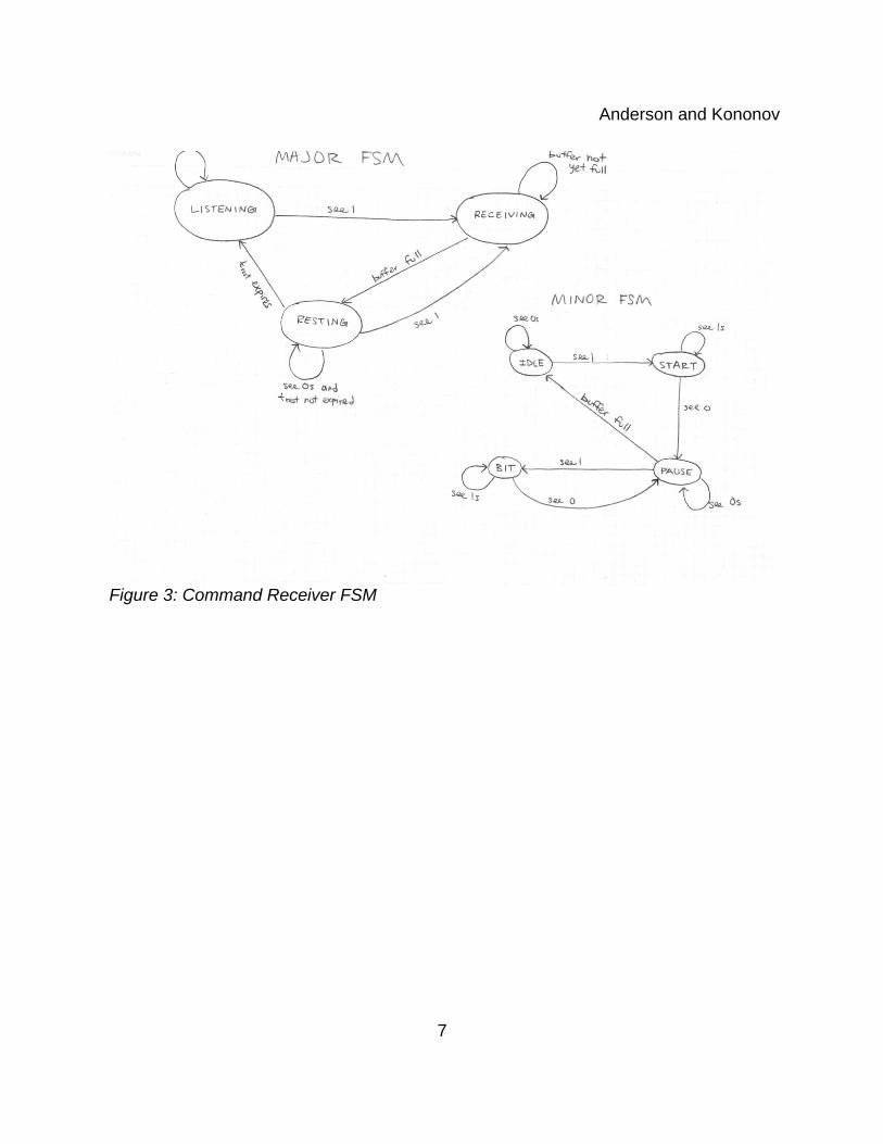
The role of the Driver Input Processing Module is to decipher the serial signal from the IR receiver. The IR receiver obtains command signal from the driver's remote and presents them in digital form to the Controller FSM. The serial data is sampled every 75μs and the samples are processed to determine whether the bit being transmitted is a 1 or a 0. The bit is stored in a buffer register. When the whole command has been received, the buffer is full and passes the complete command to a decoder. The decoder uses a look-up table to determine what action that command corresponds to, and the action is passed to the Controller FSM. The look-up table has an entry for each function that the car is expected to perform, and each entry is 4-5 bits long depending on the number of functions. There are more possible actions than just forward, backward, left, right, as we are limited to on the car's remote controller, because a TV remote is used to communicate commands. The buttons 2, 4, 5, 6 and 8 correspond to the car commands. Two increases the car's speed; 8 decreases the car's speed. Five stops the vehicle. Four turns it to the left and 6 turns it to the right. Enter acts as the override button to reset the Controller FSM. See Driver Input Processing Module Figure and Command Receiver FSM.
Sensor Input Processing Module (Kat)
The role of the Sensor Input Processing Module is to take in data that comes from sensors and present it to the Controller FSM. The sensor data is transmitted from the car to the labkit using wireless radios. It consists of the outputs from the four distance sensors on the front, back, and sides of the car. The distance of each sensor is stored in a register and updated as each new sample is received.
Car Command Output Module (Kat)
The role of the Car Command Output Module is to take the Controller FSM's car commands and pass them out of the FPGA and into the relays that control the car's remote control. For example, if the command is to drive forward, this module will output a HI to the relay that is connected to the forward button on the remote, until a different command is received. When the relay closes, it simulates the button being pressed
3

Anderson and Kononov
because an electrical connection is made between two contacts on the remote control PCB.
Conclusion
This project will create a proof-of-concept model for a next generation car that will avoid crashes perform driving tasks semi-autonomously. The project requires additional hardware that we have already acquired: two XBee radios, remote control car, and four distance sensors. Once the hardware is connected together, the project will provide opportunities for reaching design milestones that feature increasing levels of autonomous behaviors of the car.
4

Anderson and Kononov
5
Figure 1: High Level Architecture

Anderson and Kononov
6
Figure 2: FPGA Overview
Anderson and Kononov
7
Figure 3: Command Receiver FSM

Anderson and Kononov
8
Figure 4: Driver Input Processing Module
Related Documents