.. _ __.. | | . l . .I' PROJECT PLANS FOR REMEDIAL ACTION l AT '| ELKEM METALS COMPANY | MARIETTA, OHIO 1 I | Prepared By: Umetco Minerals Corporation 2754 Compass Drive Suite 280 g Grand Junction, Colorado 81506 , I and g j IT Corporation 312 Directors Drive 'g Knoxville, Tennessee 37923 I Prepared For: | Union Carbide Chemicals and Plastics Company., Inc. | P.O. Box 180 Sistersville,' West Virginia 26175 15 .U : ' || December 11,1992 |' E ,$1[iS90$ E bb M T 999yoool FM . . , - - .. . .- - . - . _ . .. -.

Welcome message from author
This document is posted to help you gain knowledge. Please leave a comment to let me know what you think about it! Share it to your friends and learn new things together.
Transcript
.. _ __...
| |.
l.
.I' PROJECT PLANSFOR
REMEDIAL ACTIONl
AT'|ELKEM METALS COMPANY
| MARIETTA, OHIO1
I |
Prepared By:Umetco Minerals Corporation
2754 Compass DriveSuite 280g
Grand Junction, Colorado 81506,
Iandg
j IT Corporation312 Directors Drive
'g Knoxville, Tennessee 37923
IPrepared For:
| Union Carbide Chemicals andPlastics Company., Inc.
| P.O. Box 180
Sistersville,' West Virginia 2617515.U:
' || December 11,1992
|' E ,$1[iS90$ E bb M T999yoool FM
. . , - - .. . .- - . - . _ . .. -.
:I
I PROJECT PLANSFORI
: REMEDIAL ACTION
/| ATELKEM METALS COMPANY
|. MARIETTA, OHIO
;g
IPrepared By:
!g Umetco Minerals Corporation2754 Compass Drive
g Suite 280Grand Junction, Colorado 81506
Ig and
g IT Corporation312 Directors Drive
| Knoxville, Tennessee - 37923
gPrepared For:
| Union Carbide Chemicals andPlastics Company, Inc.
| P.O. Box 180-
Sistersville, West Virginia 26175
I.g December 11,1992
- - - - -,-
ITable of Contents
Iles . EXECUTIVE SUMMARYg.
- -PART I WORK PLAN
| EDE'
1.0 Introduction 1-1
2.0 Project Background 2-1
2.1 Site Description 2-1
2.2 Site Security, Access and Egress 2-1I 2.3 Historical Site Use 2-1-
2.3.1 Prior Remedial Action 2-5
2.3.2 Prior Characterization 2-6
[ 2.4 Nature and Extent of Contamination 2-7,
| 2.4.1 Nature of Contamination 2-8.'
2.4.1.1 Radioactive Contaminants 2-8
2.4,1.2 Non-radioactive Contaminants 2-14
[ 2.4.2 Extent of Contamination 2 14
8-|
3.0 Project Management 3-1' 3.1 Organization 3-1
3.2 Personnel and Responsibilities - 3-1|
4.0 Remedial Action Tasks 4-1
4.1 Mobilization and Site Preparation 42-'
4.1.1 Mobilization 4-2
4.1.2 Site Preparation 4-3 -
;- 4.2 Soil Excavation 4-3-| 4.3 initial Decontamination 4-5 ~ -
- 4.4 Dismantling Equipment 4-6
I.' 4.4.1' Agglomerate Mill 4-7-
4A.2 Air Sizing / Dust Collection Ducting 47 _
LI KNunnnn992n c i
.
_ _ . -
.-
|$ Table of Contents (continued)
.E-W~ 4.4.3 Air Movers 4-7
.
4.4.4 Spinner Classifier 4-7 ;
- 4.4.5 Cyclone Collector 4-8
4.4.6 Storage Bins 4-8 ,
- 4.4.7 Baghouse Dust Co' lectors 484.4.8 Bucket Elevator 4-8 .
4.4.9 . Ball Mill 4-9,
' ' 4.4.10 Chutes, Hoppers, Feeders, and Other Equipment 49. 4.5 Dismantled Equipment Decontamination 4-9
_
5.0 On-Site Waste Management 51'
- . 5.1 Decontamination Solids 5-1
5.2 Decontamination Liquids 5-1
| 5.3 Process Equipment 5-1
5.4 Personnel Protective Equipment (PPE) and Other Wastes 5-2
6.0 Final Status Surveys 61, ,
'
6.1 Remedial Action Criteria 6-1
;- 6.2 Facilities and Equipment 6-1-
| 6.2.1 1.2rge Equipment 6-3
6.2.2 Small Equipment 63. . 6.3 Building 78 6-3.
6.3.1 Interior - Floor and Lower Walls 6-3
6.3.2 Interior - Ceiling and Upper Walls 6-4.
L 6.3.3 Exterior - Walls and Roof 6-4'
6.3.4 Indoor Air 6-4
- 6.4 Open Land 6-5-
.
6.5 Background Values 6-5
;g 6.6 Comparison with Guideline Values 6-7"
B 6.6.1 Removable Activity 6-7
6.6.2 Elevated Areas of Activity 6-7 .,
6.6.3 Exposure Rates 6-8.
g 7.0 waste oisposai 7-1
-- ,,
3.
Yi- _ +
- - _ _ _ _ _ _ _ _- _ -_ __ _ - - _ _ _ _ _ _ _ _ __ _ _ _ _ _ . _. _-
_
_
Table of Contents (conunued)
7.1 Packaging Requirements 7-1
7.2 Shipping Papers 7-1
7.3 Transport 7-1
j 7.4 D:sposal 7-1
:
8.0 Final Status Survey Report 8-1
9.0 Project Schedule 9-1
PART II HEALTH AND SAFETY PLAN
1.0 Introduction 1-1
8| 2.0 Personnel and Responsibilities 21
2.1 Project Responsibilities 2-1
.2.2 Health and Safety Responsibilities 2-1
r'
3.0 Tas! Hazard Analysis / Action lxvels 3-1
3.1 Introduction 3-1
3.2 lori:eag Radiation Hazards 3-1~
3.2.1 Radiation Protection Guides
(RPGs) and Action Levels 3-1
3.2.1.1 Radiation Exposure Limits 3-2
3.2.1.2 Monitoring of Internal Exposure 3-3
3.2.1.3 Exposure of Pregnant Workers 3-4
3.2.2.4 Contarnination Action Levels 3-5
3.3 Chemical Hazards 3-5
3.4 Physical Hazards 353.4.1 Heat Stress 3-5
3.4.2 Cold Stress 3-6
3.4.3 Falling Hazards 3-7
3.4.4 Slipping and Tripping Hazards 3-7
3.4.5 Confined Space Entry 3-7
renaTotm.9 err iii
_ _ _ _ _ _ - - _ _ _ - - - _ - _ _ _ - -
- _ - - - - - - - _ - _ _ _ - _ _ _ - - _ _ - _ -
I- | Table of Contents (continued) -
3.46 Hazardous Noisc 3-8- 3.4.7 Underground Utilities 3-8 ,
3.4.8 Overhead Utilities 3-8
[ 3.4.9 Equipment Inckout 3-8
3.4.10 Lifting Equipment 393.4.11 Open Flames 3-10
; 3.5 Project Task Hazards 3 10
'g 4 0 E<posure Monitoring Plans 4-1
~E 4.1 Environmental Monitoring Plan 4-1
4.2 Occupational Monitoring Plan 4-1
L 5.0 Engineering Controls 51
I6.0 Personal Pitective Equipment (PPE) 6-1
E -
i * 7.0 Work Zones and Site Control 7-1
7.1 Site Control 72. g5 7.1.1 Posting 72
7.1.2 Controlled Area Entry Requirements 7-3
7.1.3 Contamination Control 73~
7.2 Work Zones 75
I8.0 Decontamination Procedures 8-1
,
.
9.0 Safe Work Practices 9-1.
i 9.1 General Requirements 9-1
9.2 Working in a Restricted Area 9-1
10.0 Contingency Plans 10-1
10.1 General 10-1
10.2 Emergency Horn 10-1
10.3 Notification List 10-2
10.4 Evacuation Plan 10-2
_ ,m 1.
_ -- -
. - -
-
.
h Table of Contents (continued)^
,
11.0 Training Requirements 11-1-
.
12.0 Medical Surveillance Program 12-1
|| 13.0 Record Keeping Requirements 13-1
13.1 Medical Surveillance Records 13 1
13.2 Respirator Program Records 13-1
13.2.1 User Training and Medical Clearance 13 1
13.2.2 Unit Issue Maintenance Log 13 2I 13.2.3 Inspection of Units 13 2,
13.2.4 Fit Testing 13-2
.
. 13.3 Training Records 13-2
13.4 Worker Exposure Records 13 2 3
| 13.4.1 ' Worker Occupational Radiation Exposure 13-3
History File
.g 13.4.2 Preservation of Records 13-4
-PART III QUALITY ASSURANCE PROJECT PLANI1.0 INTRODUCTION 1-1
2.0 DATA QUALITY OBJECTIVES 2-1
I3.0 SAMPLING 3-1
3.1 Containers 3-1,
3.2 Preservation 3-3
3.3 Holding Times 3-3'
3.4 Shipping and Storage 3-3- 3.5 Docunientation 3-4
.
4.0 Sample Custody 4-1,
...
4.1 Field Operations 4-1
4.2 Laboratory Operations 4-1|,|
! KNSMTOQ12-94Tr y
i ,
. -
. .__ _ _. __ _ _
l
|
$ Table of Contents (continued)
5.0 Calibration Proecdures and Frequency 51. 5.1 Field Equipment 51
-
5.1.1 Primary and Secondary Calibrations 5-1
5.1.2 Air Samplers 5-1
, ( 5,1.3 Rutemeters and Scalers 5-2
5.1.4 fonizing Radiation Detectors 5-2'
? 5.1.5 Operational Checks 5-4
5.2 Laboratory Equipment 5-5..
- 6.0 Analytical Procedures 6-1 .
6.1 Field Operations 6-1'
6.2 Laboratory Operations 6-2
'f-
7.0 Data Reduction, Validation, and Reporting 7-1
= 7.1 Data Reduction 71-7.2 Data Validation 7-1
7.3 Data Reporting 72,
'
8.0 Interlaboratory Ouality Control Checks 8-1
8.1 Field Measurements 8-1- 8. 2 Laboratory Measurements S-1 ,
L| 9.0 Interlaboratory Ouality Control Chicks 9-1
9.1 Field Measurement:, 9-1 ,
| 9.2 12 oratory Measurements 9-1
10.0 Performance and Systems Audits 10-1
L 11.0 Preventive Maintenance 11-1.
11.1 Field Equipment 11-1
11.2 Laboratory Equipment 11-1
jI KN/9MMX712-9MTT vi
'
t 1
. . . .
._. _
.-
..
- Table of Contents (continued) |
I 1
; 12.0 Specific Routine Procedures to Assess Data Quality 12 1
: 12.1 Precision 12-1-
12.2 Accuracy 12-2
; - 12.3 Completeness 12-2
: 12.4 Sensitivity 12 2,
;I13.0 Corrective Action 13-1,
:js REFERENCES.
il!Ie:
I:
-
3
!I
!I:i
!I:
ilI.g :
.I:~ ~ " ~ ""I
-
. . _ _ __ _. . _ _ _ _
f
J
E Executive Summary
8- Union Carbide Corporation (UCC) previously processed tin slag at its Metals Division
plant in Marietta, Ohio, for the production of tantalum and niobium metals. The slagi
feedstocks contained sufficient radioactive source material to require licensing by the
U.S. Nuclear Regulatory Commission (NRC). During the early 1980s, UCC conducted
| remedial action at the facility and NRC subsequently released the site for unrestricted
use and terminated the license (NRC,1985). At about this same time, the facility was'
sold to Elkem Metals Company (Elkem) who currently owns and operates the facility.
I In the spring of 1992, Elkem identified the presence of elevated radiation levels associat-: -d with process equipment in Building 78 at the site. This process equipment and the
g associated radioactive cordamination were subsequently determined to result from UCC's.
i W prior licensed uctivities at the site.
| UCC is committed to performing the necessary remedial action for the radioactive
contamination present in the Building 78 process equipment. The NRC has indicated
g' that UCC would not require a radioactive materials license to conduct the requiredremedial action.
This document constitutes the project plans for the conduct of remedial action at,
Building 78 and includes the following:Ii
Work Plan (WP).
- g Health and Safety Plan (HSP).
Quality Assurance Project Plan (OAPP).g .,
;
Lgf
III
f
Y ^ 4d'' 4 4
-
._ _ _. . _ .. . . _. -. __. . _ . _ _ . . _ . . _ . _ _ .
2
i| ||
.
.
.I;-
I1
;
|I1
ii
!I ld
. ,.
I
4
: i
i l: '
i I' I,
'|II
,I|!.
PARTI||,
1
!Iii
i WORK PLAN!,Y
7
'III
~
IIIg _,,m.>,_,,
I-- -
- _ _ _ _ _ _ _ _ __ . _ _
-
1.0 IntroducilonI
The following Work Plan will provide the basic procedural framework for the conduct ofi remedial action at Building 78 of the Elkem facility in Marietta, Ohio. This decument
] provides the plans, procedures, and specifications for the conduct of the work and, in
i conjunction with the HSP and QAPP, will ensure that the work is of acceptable quality
and performed in a manner that is protective of human health and the environment.
II
II
I
B<
d
F.N.%' t"> W t .1( t t4vv12 4 Rtx) 1-1
- - _ - - - _ - _ - - _ - _ _ . - _ _ _ - _ - _ _ _ - _ - -
g .
!
'2.0 Project Background
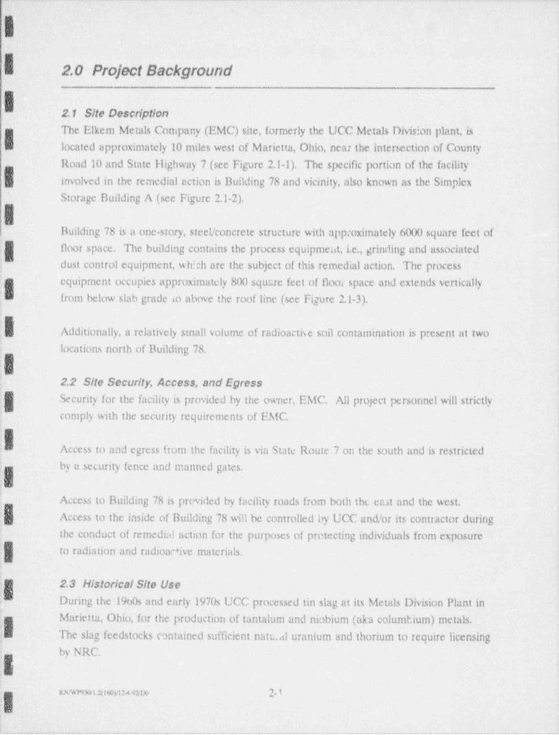
I 2.1 Site Descrip!!on;
5 The Elkem Metals Company (EMC) site, formerly the UCC Metals Division plant, is:W~ located apptoximately 10 miles west of Marietta, Ohio, near the intersection of County
Road 10 and State Highway 7 (see Figure 2.1-1). The specific portion of the facility'
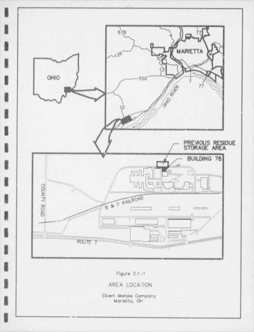
involved in the remedial action is Building 78 and vicinity, also known as the Simplex
Storage Building A (see Figure 2.1-2).
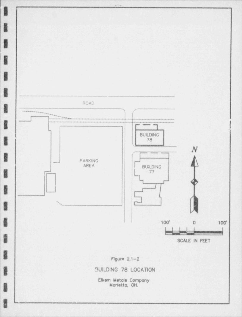
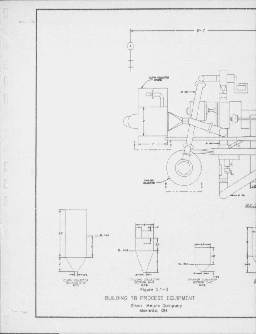
Building 78 is a one-story, steel / concrete structure with appmximately 6000 square feet of
floor space. The building contains the process equipment, i.e., grinding nnd associatedi dust control equipment, which are the subject of this remedial action. The process
equipment occupies approximately 800 square feet of floor space and extends vertically'
from below slab grade 40 above the roof line (see Figure 2.1-3).
j Additionally, a relatively stnall volume of radioactise soil contamination is present at two
locations north of Building 78..
. 2.2 Site Security, Access, and Egress
| Security for the facility is provided by the owner, EMC. All project personnel will strictly
] comply with the security requirements of EMC.
f Access to and egress from the facility is via State Route 7 on the south and is restricted
; by a security fence and manned gates..
i
Access to Building 78 is provided by facility roads from both the east and the west.:
Access to the inside of Building 78 will be controlled by UCC and/or its contractor during
the conduct of remedial action for the purposes of protecting individuals from exposure
i to radiation and radioamive materials.
2.3 HistoricalSite UseDuring the 1900s and early 1970s UCC processed tin slag at its Metals Division Plant in.
;g Marietta, Ohio, for the production of tantalum and niobium (aka columbium) metals.
;B The slag feedstocks contained sufficient natu.al uranium and thorium to require licensingby NRC.;
;E
__ u,:g.I
-- -,,.
as--> a
m
I| s'7s
- |I ' . .|g .
WARIETTA l
.j A .'
,
*
1['
, . -:
OHIO 550'I 9'
77
//'
.-3
I 9.' JI r
, ,
f PREVIOUS RESIDUEg [ STORAGE AREA
yBUILDING 78
,
N_ 7 _N~ -
I.
K / din $bLg
[] I| |s
a = ==l , , gg-_
I,,
I| __
| I Figure 2,1-1
| AREA LOCATION
Elkem Metals CompanyMarietta, OH.
; y ._
_ _ - - - - _
.'
Ip
I: g
iI |
ROAD
I ' '''g
_
I
-~1BUILDING
'I |78
'
r'
PARKING' --~
AREA BU;LDING77
r-I
I L
J\- cI300 o , oo.
"u~ms__
SCALE'IN FT.ET
| Figure 2.1-2
SUILDING 78 LOCATON
Elkem Metals CompanyMarietto, OH.
I. .
, . . . .~.
30'* f
_
t ,--
i
[ (Ptata..
1
r' C 7 'i 9 m
(~ N0"-- -
P() I I | |
^Ism< :
__ __ _ql ||1
I -
Q ,-'_|
1| g*
-_ _
: < - -flV11'
.e U
*'*'
_._ . __ a. iu
,,J t c,. 19 o=42 m
'L l4.4_
62
.. . \'N E 218 ---- oy4'
1
+. ,+ -~ gCLOTH COLECTOR CELONE COLLECTOR $' INNER CLASS 51ER t
SECTION A-A- SECTION 0-B' SECTION C-C' $,ILTJ N.Y.& M.T.S.
Figure 2.1-3
BUILDING 78 PROCESS EQUIPMENTElkem Metals Company
Marietto, OH.s,
i|!
<

_.
2-4
mm1) AU. Despenceeg secuM AfE AMeI0RapWE.* *
" ,M'*= a. e -
. _ _ . _ _ _ _
C*,). - U). - - - m m, if3
[ gt.
.., _ __ m ._ u#
___ pCr~ 1.
, ,_
L- gy ' l .<
6,O | 9| [8
"
r- I--
|L______.____u
h M ^.""
- O si "'"_
cd .. / _ AVERTURE7 A N NN n.1L I ,'CARD: s
-
/ ) )'' * -
)) ei W // / '
.( ) f I I U l 9- 31so Avattalje 0"I -,,3/ | - . r-~y Aperture
v -
,., / t,%9}=/
ra, _.w - r
fC - ---., a
__
e[=r) I-. , ...
' e',,- --
8 18~t g g.*'*" """
.
.
llNG 78""
, n t -. _,
) .,
E 4f.2'
,
~
. .- -..
c. o . J.
fb ---a9. ' * '
,
_m- 5, , _ , _ ,
\secy,r r ogggugergae
.12- ,_* .T ego
*0 * gC M,,-Esaa
.
N
9 =wM mt.%- - ?,e - 9 p ge-g.-, . , , , . , ., _ . s.
-
I:. The previously conducted tantalum-columbium (Ta Cb) processing is reported to have
included (Chem-Nuclear, April,1981):
y . Grindingil . Acid leaching
. Liquid / solid separation
. Solvent extractionI- . Calcination.
| The processing and associated waste management activities reportedly were conducted in
the Wet Process Building 77 and an adpcent residue storage area (Chem Nuclear,1981).
I:n the early 1970s UCC's Ta Cb operations were terminated. Site decommissioning and
decontamination activities were subsequently conducted (ARIX,1983 and 1984, Chem N-
uclear,1981) and confirmed by NRC's contractor (ORAU,1985), and the Material
License (SMB 933) terminated (NRC,1985).IEssentially, concurrent with the NRC license termination, the plant was sold to the
Elkem Metals Company (Elkem). Elkem currently operates the facility for metals
production; however, they reportedly are not, and have not, engaged in the processing of
source material tin slags or other radioactive materials.
2.3.1 Prior Remedial ActionUCC conducted remedial action at the site during the early 1980's to terminate the
license and to release the site for unrestricted use. The remedial action included theI following general components:
I . Removal of contaminated equipment and decontamination ofBuildmg 77Removal of contaminated soil and debris outside and adjacent to Building.
77
. Removal of process residues and contaminated soil north of
_|'.Building 77
. Site backfilling and restoration
. Offsite disposal of contaminated materials.-
II
w:wr9m mavunm 25
'
UCC's remedial action was confirmed by NRC's contractor and the license was subse-
quently terminated on July 3,1985.
2.3.2 Prior CharacterizationOn January 30,1992, at the request of Elkem, NRC and Ohio Department of Health
(ODH) representatives conducted an investigation of the elevated radiation levels
reported by Elkem at the Marietta facility. NRC made direct alpha and penetrating
radiation measurements and collected smears and solid material for laboratory analysis.
ODH also made penetrating radiation measurements (NRC,1992; ODH,1992).IThe NRC and ODH observed elevated radiation levels associated with process equip-
ment in Building 78 in excess of NRC's unrestricted release criteria. NRC determined
that the site poses no immediate threat to the public and that Elkem has appropriately
| posted the building and is restricting personnel access.
g 'ihe NRC requested that Elkem further evaluate the extent of contamination to the
buildings and enviroris and provide their findings to the NRC.
I During April,1992, Chemical Waste Management, Inc. (CWMI) personnel conducted a
radiological characterization of selected areas of the Marietta, Ohio facility for the Elkem
Metals Company. This work was performed as a result of the identification of elevated
radiation levels associated with equipment in Building 78 by Elkem personnel and at the
| request of NRC.
g CWMI reports that removable surface contamination in excess of the applicable limits
(NRC,1984) and elevated gamma radiation exposure rates were identified in Building 78
(CWMI,1992). CWMI also reports that the following areas appear not to have been
radiologically contaminated in excess of applicable limits:-
Ouonset storage buildings.
Rail siding north of Building 78.
. Settling pond between Highway 7 and the Muskingham River,Roof of Building 78. - .
Most of the floor of Building 78..
!I,
,
-
w.wrmaosoyuseo 2-6,
.
- - .. . . .-
CWM1 reports that all of the identified contamination is confined to the interior of the
process equipment in Building 78.e
in June of 1992, Umeteo Minerals Corporation (Umetco), a subsidiary of UCC, conduct-,
$| ed an assessment of the radiological contamination of the equipment in Building 78.
Umeteo performed alpha, beta gamma, and penetrating radiation measurements and
collected material samples for laboratory analysis. Umetco confirmed prior findings of,
: excess surface contamination and elevated penetrating radiation exposure rates associat-
ed with the equipment in Duilding 78 (Umetco, July,1992). Laboratory analyses of theI3 material samples collected confirmed the presence of licensable concentrations of natural
thorium and elevated concentrations of natural uranium and decay products. Umetco
| found no excess surface cantamination outside of the interior surfaces of the process'
equipment and found that approximately 90 percent of the surface contamination was
| typically easily removed.
Ig During a subsequent visit to the site in September of 1992, Umetco identified the
presence of radioactive soil contamination likely in excess of NRC's soil concentration
criteria. This soil contamination is outside and north of Building 78, along the railroadI siding and in the area of the form:r Ta-Cb process residue storage area.
2.4 Nature and Extent of Contamina!!onUCC previously processed tantalum, niobium, thorium, and uranium bearing slag feed
| stocks for the production of tantalum and niobium metals. The processing equipment in
Building 78 was used in the grinding and physical classification of the tin slag feedstocks.
IThe NRC recently provided revised guidance on the regulatory status of non-ore source
I materials and waste products resulting from the processing of source material for other
than source material constituents (Federal Register, May 13, 1992). In part, NRC has
stated that wastes resulting from the processing of source material for other than itsI source material content are not 11e.(2) by-product materials, as defined in the Atomic_
Energy Act. Further, NRC has stated that if a licensee disposes of source material
compounds or mixtures other than uranium or thorium ore, in tailings piles, only the
source material component would be excluded from the provisions of the Resource
Conservation and Recovery Act (RCRA). It is assumed that, in such situations, RCRA
could apply to these particular waste forms regardless of whether the licensee disposes of
the source material in a tailings pile or at some other appropriately licensed facility.
. KN/WP9WL20fo)A24WD 2-7
.|- The radioactive materials present in the processing equipment in Building 78 are of a-
non ore source material form. Based on NRC's most recent guidance (Federal Register,
May 13,1992), only the source material component of these wastes is excluded from the
provisions of RCRA.,
2.4.1 Nature of ContaminationThe nature of the contamination at this site has been characterized by several prior
investigations (CWMI- 1992, Umeteo - 1992, NRC - 1992). These investigations have- identified the presence of both radioactive and non-radioactive contaminants.
Based on these prior investigations, the contamination is primarily confined to the
interior of the process equipment and consists of a dry granular to powdery material.
Based on the distribution of radioactivity observed in the process equipment, it appears
| that the radionuclide concentration is higlict in the fines collected by the dust collection
system than in the more granular materiallocated in the front end of the grinding circuit.
This phenomenon is common in minerals processing.
A relatively small volume of radioactive soi. .antamination is present outside and northI of Building 78.
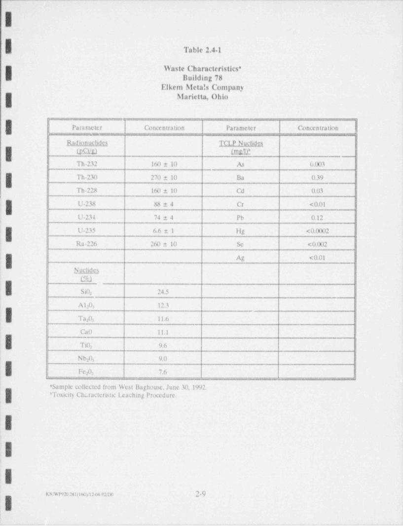
2.4.1.1 Radioactive ContaminantsLaboratory analyses of a waste sample collected from material accumulated in the West
| Baghouse are presented in Table 2.4-1. These analyses demonstrate the presence of the
following series of radionuclides:
* The thorium series commencing with 14 billion year thorium-232 andterminating with stable lead 208 (see Table 2.4-2)
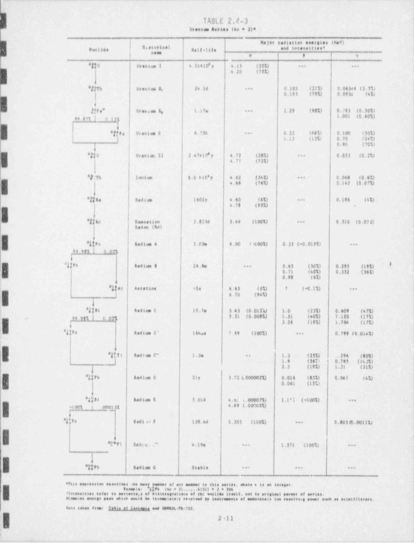
. The uranium series commencing with 4.5 billion year uranium 238 andterminating with stable lead 206 (see Table 2.4-3)
IThe parent to the actinium series, uranium-235, is also present, however, at a relatively
g; insignificant concentration.
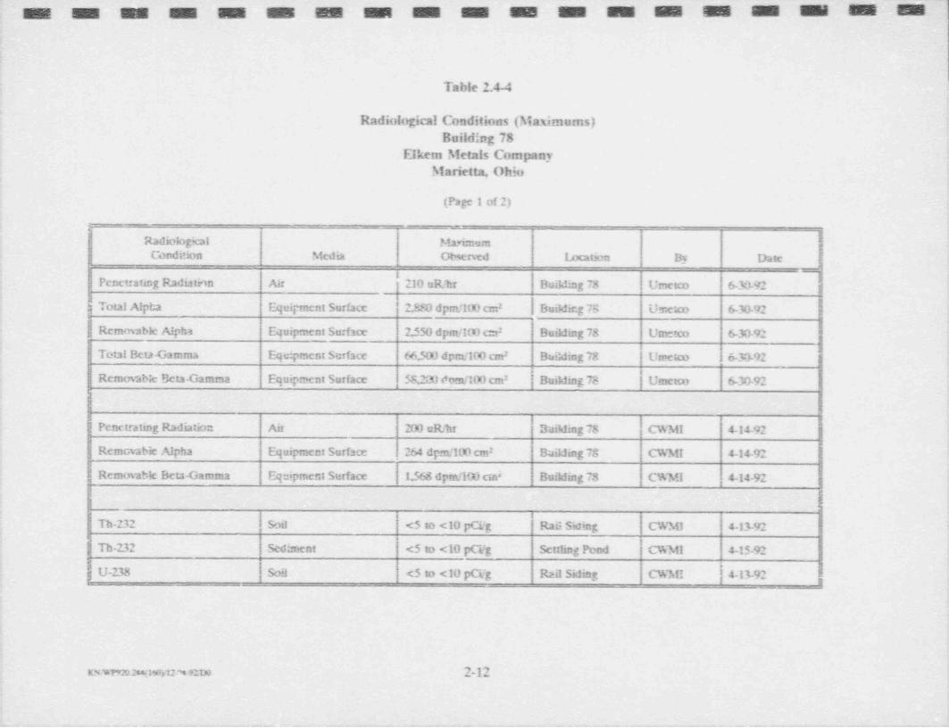
The maximum penetrating radiation and surface contamination levels observed at thisI site are summarized in Table 2.4-4. This table also summarizes the results of NRC and
CWMI sample analyses.
mwnnn:60 mum 2-8
-I
,
Table 2.41
Waste Characteristles*I Building 78 l
Elkem Metals CompanyMarietta, Ohio
Parameter Concentration Parameter Concentration
Radionuclides TCLP Nuclides(PfCit) (mgW
Th 232 160 10 As 0.003
Th-230 270 10 Ba 0.39
Th 228 160 10 Cd 0.03
U-238 88 4 Cr <0.01
U-234 74 2 4 Pb 0.12;
4
U-235 6.6 1 IIg <0.0002.
Ra-226 260 e 10 Se <0.002
Ag <0.01s
SuclideLTid
SiO 24.52,
A10 12.32 3
Ta20 11.63
Ca0 11,1
TiO 9.62
Nb 0 9.0. 2 3
[ Fe2 3 7.601
* Sample collected from West Baghouse, June 30,1992.' Toxicity Ch:.racteristic traching Procedure.
II
J
__ __m. 2.,
:- .
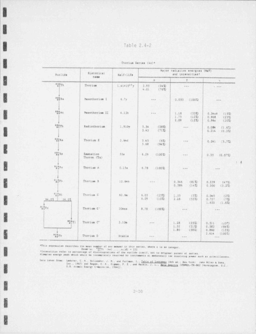
Table 2.4-2
Thorium 5ertas (4o)*
hajor radiation ener8tes (hef)mistoT1 CatNue11de g,gg.ggg, and latenettiert
|naesie t >1
'j'Th Thorium 1.41x 10"y 3.95 (24D |-- ---
4.01 (76V
*!!Ra hesothorive 1 6.7y 0.035 (100V--
|--
I
I sjjAc Mesotherium II 6.13h 1.18 (35V 0.34ct (15V---
1.75 (12V 0.908 (25V2.09 (12%) 0.96e (20%)
8|jn Radiothorium 1.910y 5.54 (28V 0.084 (1. 6 **)---
I 5.43 (71V 0.214 (0. 3 %)
s!!as Thorium I 3. %d 5.45 (60 0.241 '3.7V--
5.68 (94V
aj|ta E. mane t t oo 35s 6.29 (1000 0.53 (0. 07Q---
Thoron (Ta)
' 0ageFo Thettaa A 0.15s 4.78 (100Q -- --
|t
I sjjFh Thorisse 3 10.64h --- 0.346 (81V 0.239 (47%)0.386 (14Q 0.300 (3.2V
' 8||31 Thorit.m C 60.6e 6.05 (25V 1.33 (5V 0.060 (2D
I..
g,ng | 36.0% 6.09 (1CI) 2.16 (35V 0.727 (7D-
1.620 (1. 5 %)
"IeFo Thori m C' 304ns 8.78 (10CD --- ---
I. -f
*! T1 Thorium C" 3.10m 1.28 (25V 0.511 (43D---
[ 1.52 (21D 0.383 (56Vg 1.80 (30t) 0.860 (12 %)
. I.t 1.614 (100U*jjFb Thorium D 5 table -- --- --
'Tnte expreedtee desertbee tSe mase eveeer of any oneser is thle sories. where e le se 14teget.
I' In w to: ijjfh Ha) . . . . . 4 t M) * 232flateesttsas refer to pareestage of disteteerattees of the evallee steelt. set to ortstaal perene et eertee.eCemones energy poet untch would be sneemeletely resonne by teatrumente et moderately low toestries power euk es este:Alle t er s .Dora totes freet Leeveer. C. M.. aellander. J. M., and Perlese.1., Table of 1setew s (4th ed.; New Terkt Jehe Wiley 4 $one.
lar . 190) and nesse. 0. R. . Itsmea. P. E . and Metate. J. k.. hra _seee r ra (c1xtDL-T3 602 lh*ttesten. 0.C.:I U.S. Atente leers, cwteette.196AD.t
4
W2-10
.
II .
.
_ . _ _ _ - _ _ _ . _ _ _ _ _ _ _ _ _ - _ _ . _ _ - _ _ _ _
. - _ . ._ _ _ ..
e
TABLE 2.4-3vraim sntes (se + 2)*
. _
Major vedtatten enerates (Mef)I'8 "IDucites Melleitfe end totenettleet ,
_ _. . ,
-
'jjV Utentus 1 6.$110' y 6.11 (2$U ... ...
4.20 (731)
'!fth Dresive h 26 .1d 0.103 (2th 0.063e8 (3.3%)...
0.193 (791) 0.093 (6U|4
jfte" Dren.us 1, 1.lfs 2.29 (981) 0.74l (0.3c%)...
1.001 (0.60%)o pyg | pgy,
I ejhre 0.33 (66U 0.100 (301)Prestem 2 6. 7 5t, ...
j 1.13 (13%) 0.70 (24U0.90 (701)
I '!!U Urealm !! 2.47s10 ; 4.72 (281)8 0.03) (0, tu...
4.77 (721)
'f;Th tentum 3,0 at0*y 4.62 (261) 0.068 (0.6%)...
6.66 (76U 0.162 (0.071)
e!!Re Radium 1602y a.60 (41) 0.186 (61)...
4.)B (951) .
.
'l in teametten 3.8214 3.49 (IMft) 0.310 (0.074)...
Redon (Rn)
'jkto taitum A 3.0)e 6.00 (.1001) 0.33 (.0.0191) ...
99 981 l 0.on
i0.43 (10%) 0.295 (191) 0'jjft todtue 8 26.6eI ...
0.71 (40%) 0.332 (161)0.98 (60
'j|At Aetettne 2e 6:43 (4%) ? (.0.11) ..+
I 1 6.70 (94U
i ' jill Redtm C It.7m $.45 (0.012'aj 1.0 (231) 0.609 (471),, ,gg | ,,, , g7g 3.$1 (0.008%) 1.31 (601) 1 120 (171)'
;I,
3.24 (ItU n.764 (171)4
'jjr* Redlue C' 164 e 7.69 (1001) 0.799 (0.0161)...
'
;
'j!7i Redium C" 1.3a -+. 1.3 (231) . 296 (400- | 1.9 (36 0 0.79) (16tJt)
2.3 (191) 1.31 (211)
I-'jjrb kodiun D 2ly 3.72 0 0000021) 0.016 (131) 0.04) (41)
0.061 (13 4
's il kedim 1 3.014 6 o! 4 000071) 1.l'1 (.1001) ***
. inet j cooi3g 4.0 (.Cty)c51)--
Its * *d t n F 138.64 3.305 (1001)'
0.80)(0.00111)...
*I*T1 totaan f" 4.tte 1.371 (1001)... ...
!'Ijtb Radium 0 . Stable ... ... ...
_
*nte emeteestem denstbes he meet o.s+er of ee, enener to skte nesse. eene e to se sneeeer..
I leasele s 7$Pt he + 3) .. . . . 6(11) * 2 e 39691stenstiles refer to pertesteJe of eletseegretteus of the mellee iteett, est to melstaal perees of eetles.eCeaoles ewegy pese dieb oveld be tavesplosely teselewd by teatremente of modesseel.t les resolvist power seek as seletilletete.
Dete tenen frees fonte of loets and 06Wtat.Tt492.
2 'l 1
.
, ,y :w.- --s., .- , ,4 - ~ ~ . , , . . -
_ _ _ _ _ _ ._ __ ___
;
Table 2.4-4
Radiological Conditions (Maximums)Building 78
Elkem Metals CompanyMarietta, Ohio
(Page 1 of 2)
IRadiologkal MahmumCondition Media Observed Iecation By Date
i 7Penetrating Radiatinn Air |210uR/hr Building 73 Unetco 6-30-92 |
I | BuiMing73 Umesco 6-30-92 || Total Alpha Equi; ment Surface 2.880 dpm/100 cm2
Remmable A!pha Equipment surface 2,550 dpm/100 cm BuiMing 78 Umesco 6 30-922-
Building 78 | UmescoTotal Beta <amma Eqcipment Surface 65.50l) dpm/1CC cm2 . 6-30-926
Removabic Beta-Gamma Equipment Surface 58,200 tom /100 cm2 | Building 78 | Umetoy 6-30-92
Penetrating Radiation Air 200 uR!hr BaiMing 78 CW311 4-14-92
Remcvable Alpha Equipment Surface 264 dpm/100 cm Baikiing 78 CW31I L14-922
j Removable Beta-Gamma Equipment Surface 1,568 dpm/100 cmi Buikling 73 C%3fl 4-14-92I J
l ;l
Th-232 ISoil ' <5 to <10 pCilg Rail Sicing CW3U 4-13-92i i
| D-232 Sediment ' <5 to <10 pCilg Settling Pond | C%3tl L15-92Il
| 413-92g U-238 Soil <5 to <10 pCi/g Rail Siding CWMI
.
xmm2agmuwm 2-12
- . _ , . . - - - -
,. . .. . . . . . . . . . . _ . . . . . - . - . . - .
- M M M. M 'M M -M 'M M' M M M M- M M M M .M:,
Table 2.4-4
(Page 2 of 2).
. _ _
Radiobgical MaumumCondition Media 00sento Location By Date
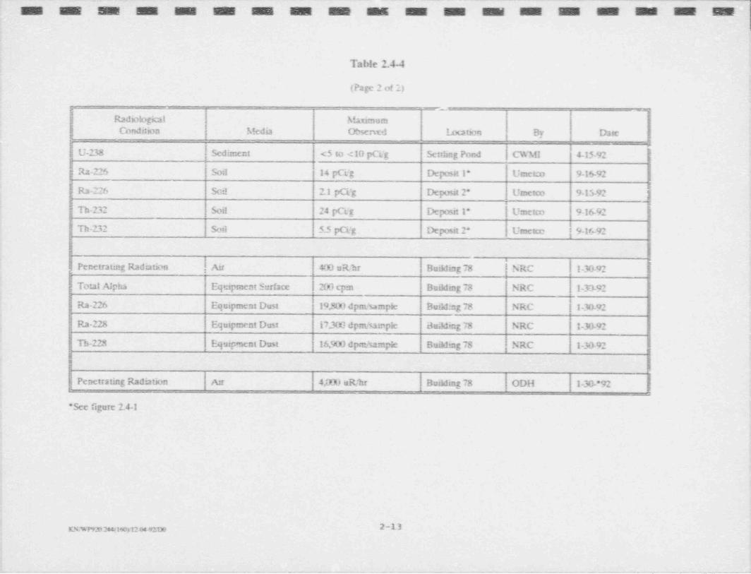
U-238 | Sediment <5 to <10 pC|g Settling Pond CWMI 4-15-92
|Ra-225 Soil 14 pCi'g Deposit 1* Umetro 9-16-92*
, Ra-226 Sci! 2.1 pCi'g Deposit 2* Umetco 9-15 92 |
hTh-232 Soi! 24 pGg Deposit 1* | Umerco 9-16 92
Th-232 Soil 5.5 pCilg Deposit 2* Umetcc | 9-16-92
lL Penetrating Radiation . ,I Air 400 uR/hr Building 78 NRC 1-30-92i! Total A!phs Equipment Surface 2C6 cpm Duilding 73 NRC 1-33-92
eRa-226 Equipment Dust 19,50) dpm'sampie Building 78 NRC [ 1-30-92
Ra-228 Equipment Dust 17.300 dpm/tampie Building 78 NRC -30-92
Th-223 Equipment Dust 16,900 dpm/sampic Building 78 |NRC 1-30 92,
iN
Penetrating Radiation Air 4,000 uR/hr Building 78 ODH 1-30 *92'
.
*See figure 2.4-1
f
K%vrv_n2miury12 04-9'.D0 2-13.
.. ~ . . - - -_ _ . _ _ _ . . _ _
IThe Umeteo data indicates a waste with a modest specific radioactivity and probable
$ccular equilibrium within the thorium series. The NRC dust sample analysis also
|. exhibits essentially radioactive equilibrium between Ra 228 and Th 228.
The Umeteo data shows near equilibrium between U-238 and U 234; however, the
Th 230 and Ra 226 concentrations are about three times higher and in near transient- equihbrium.
The surface contamination levels and penetrating radiation exposure rates observed by
Umetco and NRC me comparable. CWMI also found comparable penetrating exposure
rates, however, somewhat lower surface contamination levels. CDH found a penetrating
radiation exposure rate ten times higher than the other investigators and neither Umetco
nor NRC have been able to duplicate this measurement.
I2.4.1.2 Non Radioactive Contaminants
Tabic 2.41 presents the results of laboratory analyses of the site contaminant for total
: nuclides and Toxicity Characteristic l.raching Procedures (TCLP) nuclides. As expected,
;g the waste exhibits significant concentrations of tantalum und niobium. The TCLP: E leachate exhibited nuclide concentrations well below the regulatory limit (40 CFR 261.3).. -
t
2.4.2 Extent of Contamination| Several assessments of the radioactive contamination in Building 78 have been performed
(CWMI,1992; Umetco,1992; NRC,1992). These assessments determined that the,
contamination is generally confined to the interior of the process equipment in this,
building. Based on the existing data, contaminant levels in excess of NRC's release
criteria (NRC,1984) are present in the West Baghouse. Penetrating radiation measure-
ments indicate that a number of other locations, e.g., dust ducting bends, bottoms of-
'
hoppers and bins, etc., contain rn'.licactive rnaterial likely to exceed NRC's surface
contamination release criteria.
I
!
,
9
___ 2.m
-- - ._-
.. ._ _ . . . - - _ . . . .- --
IThe assessment conducted by CWMI for Elkem determined that the concentrations of
Th 232 and U 218 in soil and sediment at the facility are below NRC's cleanup guidelines(CWMI,1992).
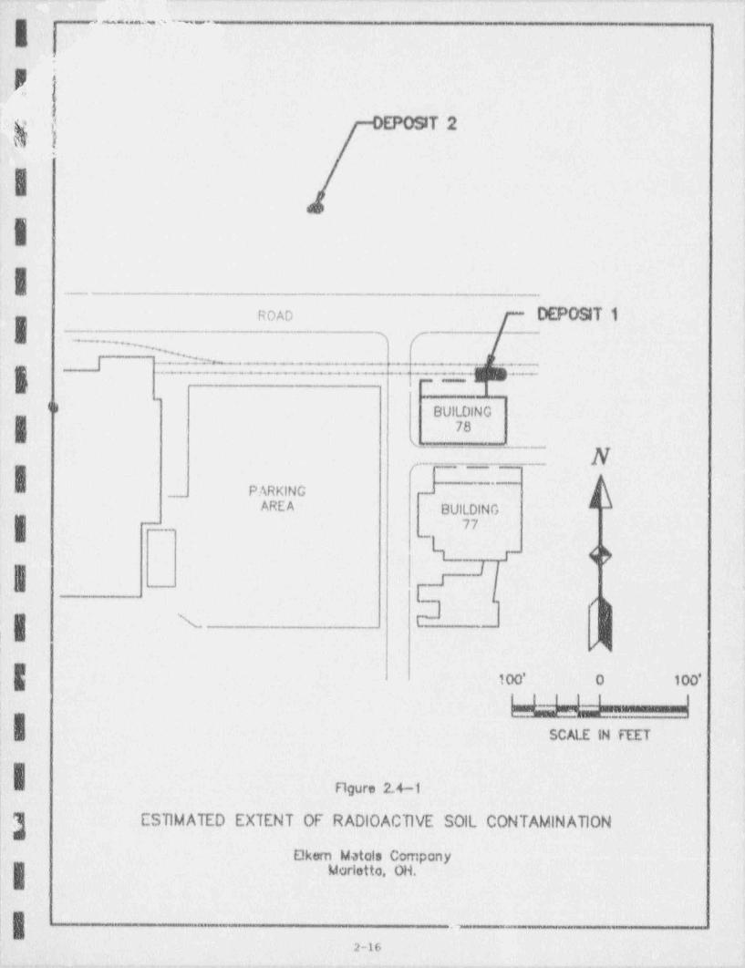
IDuring a site visit in September 1992, Umetco measured contact penetrating exposure ,
rates as high as 100 uR/hr in surficial soil outside and 'iorth of Building 78. Two areas of
anomalous penetrating radiation were found and surface soil samples were collected for
laboratory analysis. Samples were analyzed for Ra-226 and Th-232 (by TI.208) byI gamma spectroscopy. Result.s for Deposit I were 14 pCi/g Ra 226 and 24 pCi/g Th 232.
Deposit 2 analysis showed 2.1 pCi/g Ra 226 and 5.5 pCi/g Th 232. Deposit 1 results
indicate that levels exceed NRC's clean-up criteria. Deposit 2 results are below NRC's
criteria, but additional investigation will be performed to determine the source of the
elevated radiation levels. The estimated extent of radioactive soil contamination, based,
on these surface penetrating radiation measurements, is shown in Figure 2.41. The
estimated volumes are 5 cubic yards and 1 cubic yard for Deposits 1 and 2, respectively.,
The uncertainty associated with these volume estimates could be significant as noi
subsurface investigations have been conducted.IBased on the above investigations and those previously performed in support of license,
termination (Chem-Nuclear,1981; ARIX,1983 and 1984; ORAU,1985), radioactive
contamination at this facility is confined to Building 78 and to two relatively small soil
| areas outside and north of this building.,
?I,I
'I
yI
B
:
; ummuownurm 2-15
. . . _ -- .
_ ._ . - . . _ . - _ _ - _ .. ..
'
a.i_; - ,. .
,s yc .
T2'j'III _ _
ROAD DEPOSIT 1I 3 (~~.,
l .2 _.
,| ___ y ---
-
<,BUILDING
I 78t
,.-..
~'
PARKING -_
AREA BUILDING
|: 77-
-.-
Ii
,'
|
|: N rI
100' O 100''
, 2525-.-W|
SCALE IN FEET,
'h.
Figure 2.4-1I:!
'}- ESTIMATED EXTENT OF RADIOACTIVE S0ll CONTAMINATION
L E!kem Motols Company
'f- Marietto OH. .
LI - .-
-2-16
. _ _ _ . . _ . _ - - . _ _ _ _ _ .
.. . . _ - _ _ _ _ _ - _ _ _ _ _ _ _ _ _ _ _ - _ _ _ _ - _ _ _ _ - _ _ - - - - _ _ _ _ _ - _ _ - _
-
rL
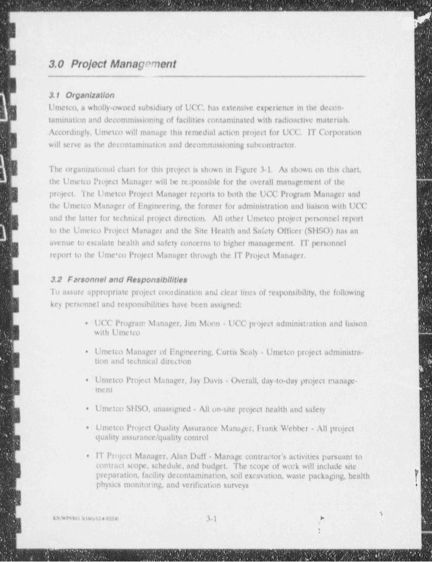
3.0 Project Management
i3.1 OrganizationUmetco, a wholly owned subsidiary of UCC. has extensive experience in the decon.
- tamination and deconunissioning of facilities cor:taminated with radioactive materials.
Accordingly, Umetco will manage this remedial action project for UCC IT Corporation i
will serve as the decontamination and deconunissioning subcontractor.
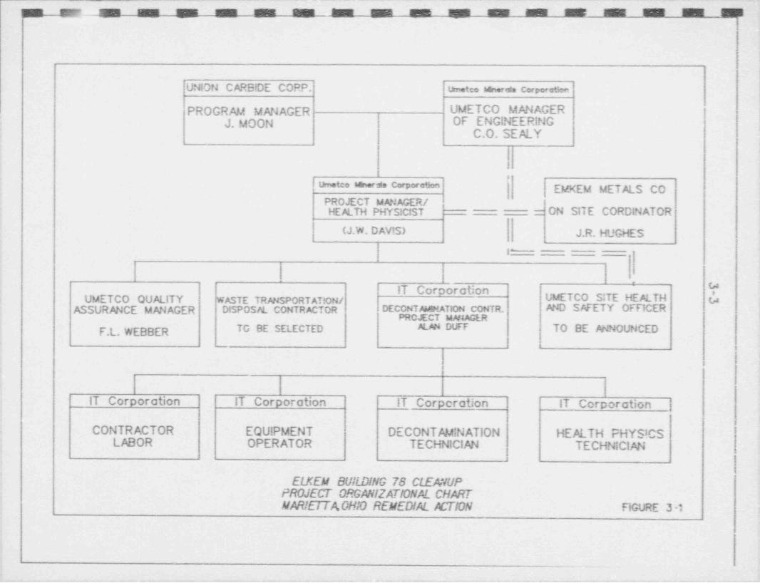
The organizational chart for this project is shown in Figure 31. As shown on this chart,
the Umetco Project Manager will be re:ponsible for the overall management of the;
| project. The Umetco Project Manager reports to both the UCC Program Manager und
3 the Umetco Manager of Engineering, the former for administration and liaison with UCC
and the latter for technical project direction. All other Umetco project Intsonnel report
to the Umetco Project Manager and the Site Health and Safety Officer (SilSO) has an
g avenue to escalate health and safety concerns to higher management. IT personnelB report to the Ume'co Project Manager through the IT Project Manager.
3.2 Farsonnel and ResponsibilitiesTo assure appropriate project coordination and clear lines of responsibility, the following
| key personnel and responsibilities have been assigned:
UCC Program Manager, Jim Moon - UCC project administration and liaison*
| with Umetco
Umetco Manager of Engineering, Curtis Sealy e Umetco project administra..
I tion and technical directioni
Umetco Project Manager, Jay Davis - Overall, day to-day project manage-+
I ment '
;
Umetco SHSO, unassigned - All on. site project health and safetya
Umetco Project Quality Assurance Manager, Frank Webber - All project.
quality assurance / quality control
IT Project Manager, Alan Duff - Manage contractor's activities pursuant to.
contract scope, schedule, and budget. The scope of work will include site,#
preparation, facility decontamination, soil excavation, waste packaging, healthphysics monitoring, and verification surveys t
1LNWi%hl hio0),1249M M 3.} ,[ ,
j_- _ _ _ _ - - _ - - - - - _ -
.
. . - - . - -
|I!l1,
;
. Waste Transportation / Disposal Contractor, to be selected Responsible forwaste transport to the disposal facility and pernianent disposal.
.
I.
;I l
;I
4
.B,4
E-
:
I;
IIti
g.
II
~ ~ , - - 32g
L .._ _ . . .
_ . . . . . .... . _ .- _ = _ _ _ . _ . ___ . _ . . _ .. _ __
'u usan- m' m .AM M M
_
i
i,
,
UNION CARBlDE CORP. | um.teo win.-at. cerpere+w
PROGRAM MANAGER UMETCO MANAGER | gJ. MOON | OF ENGINEERING
|.
:
I| | C.O. SEALY'
I!I,
""**** ''"*'*' %*'## EMKEM METALS CO :PROJECT MANAGER /HEALTH PHYS!CtST ' = ON SITE CORDINATOR'
(J.W. D AVIS) J.R. HUGHES'
1^ jl
IT Corcoration"
'fUMETCO QUALITY WASTE TRANSPORTAT!ON/ UMETCO SITE HEALTH u
ASSURANCE MANAGER DISPOSM. CONTRACTOR DECCNTAM! NATION CONTR. AND SAFETY OFFICERPROJECT M#tAGER '
F.L. WEBBER TO BE SELECTED ALAN DUFF TO BE ANNOUNCED
.
I.
IT Corporation IT Corporation IT Corperation IT Corporation |8
I i i
CONTRACTOR EQU!PMENT DECONTAMINATION HEALTH PHYS!CS I.
LABOR OPERATOR TECHNICIAN TECHNICIAN fI
*
ELKEM BUli. DING 78 CWANUPi=ROJECT ORGANIZATIONAL CHARTMAR!tt i ACHIO REMEDIAL ACTION FIGURE 3 -
'
.
.-__
y - fr b T k r w v' to w
. - . _
.
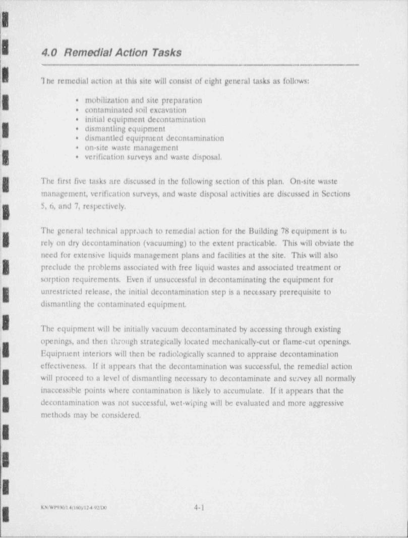
. 4.0 Remedial Action Tasks
I The remedial action at this site will consist of eight general tasks as follows:
J mobilization and site preparation.
. contaminated soil excavationinitial equipment decontamination.
.g . dismantling equipmentdismantled equipment decontamination.
on. site waste management*.
| verification surveys and waste disposal..
g- The first five tasks are discussed in the following section of this plan. On site waste
management, verification surveys, and waste disposal activities are discussed in Sections
5,6, and 7, respectively.
I
: The general technical appraach to remedial action for the 13uilding 78 equipment is to
rely on dry decontamination (vacuuming) to the extent practicable. This will obviate thei need for extensive liquids management plans and facilities at the site. This will also
preclude the problems associated with free liquid wastes and associated treatment or
sorption requirements. Even if unsuccessful in decontaminating the equipment for*
unrestricted release, the initial decontamination step is a necessary prerequisite to- dismantling the contaminated equipment.
The equipment will be initially vacuum decontaminated by accessing through existing
openings, and then through strategically located mechanically-cut or flame cut openings.
Equipment interiors will then be radiologically scanned to appraise decontamination
effectiveness. If it appears that the decontamination was successful, the remedial action
| will proceed to a level of dismantling necessary to decontaminate and savey all normally
inaccessible points where contamination is likely to accumulate. If it appears that the
g decontamination was not successful, wet wiping will be evaluated and more aggressive
methods may be considered.
IIIi'I
___ m,,
= = = -.. ..
- The contaminated soil removal will be conducted as a conventional soil excavation, with
appropriate monitoring and controls due to the radioactivity.
The wastes will be containerized on site, as generated, in appropriate shipping containers.
| After the remedial action is completed, as determined by verification surveys, the wastes
will be manifested and shipped off site for disposal at a facility licensed by either the
NRC or an agreement state to dispose of source material waste.
4.1 Mobilization and Site PreparationI 4.1.1 MobilizationUCC/Umeteu and IT personnel will mobilize to the site with all necessary equipment to
conduct the remedial action. This equipment will include, but not necessarily be limited
to the following:
Mobile office.
g lifting equipment (e.g., crane, manlift, forklift, slings, etc.).
Excavation equipment (e.g., skid loader, backhoe, etc.).
I Dismantling tools (e.g., power chisel, oxygen / acetylene torch, hand tools, etc.).
|_ . HEPA vacuums and ancillary equipment
Waste storage and shipping containers (e.g., DOT 17H drums, roll.off bins,.
| etc.)
. Containment cor. .truction materials (e.g., polyethylene film, lumber, etc.)I
. Radiological monitoring equipment (e.g., alpha and gamma scintillators, GMtubes, ratemeter/ scalers, air samplers, etc.)
. Safety equipment (e.g., fire extinguishers, first aid kit, eye wash, etc.)
. Personal protective equipment (e.g., respirators, gloves, coveralls, etc.)
. Miscellaneous decontamination equipment (e.g., wash tubs, brushes, towels,--I etc.)
I Other materials and supplies (e.g., data sheets, sample bottles, smears, tape,bags, snow fence, barricades, signs, etc.). '
Iouwmmowmw/co 4-2
.I
_ _ . _ _
II 4.1.2 Sito Preparation
Initial site preparation activities willinclude the deployment of two work area boundary
air monitoring stations and the conduct of baseline surface contamination surveys on
roadways and walkways around Building 78. A minimum 3-day air particulate and
| charcoal absorption canister sample must be collected at two stations (upwind and
downwind) for gross alpha and Rn 222 analyses, respectively, prior to commencing
.g remedial action.
Work zones will be established in Building 78 by erecting barricades or ropes to delineateI the zones. The work zones will be appropriately posted with radiation signs, personnel
.
decontamination instructions, etc. (see the HSP).
A temporary contamination containment will be constructed around the contaminated
| process equipment in Building 78. The containment will consis' of polyethylene film
supported by teinporary wooden uprights and is intended to limit the spread of contami-
g nation to other areas in Building 78.
The HEPA vacuums and ancillary equipment will then be set up in preparation for theinitial decontamination.,
Two approximately 7-gallon oil reservoirs, filled with oil, are present on the upper
equipment deck of Building 78. These reservoir.s provided lubricating oil for the grinding;|) equipment. The reservoirs were found with the covers in-place and it is believed that
radioactive contamination of the oil is not likely. Nevertheless, the contents shall be
fg sampled individually and submitted for laboratory determinations of total natt.ral
uranium, Ra 226, and isotopic thorium. Because of the possibility of sediment being
present, the oil must be agitated to suspend any sediment prior to sampling.
f
4.2 Soll Excavation
Prior to beginning the excavation of the two contaminated soil deposits (see Figure
2.41), work zones will be established at each, as shown in the Health and Safety Plan1
! (Part II, Figure 7-1). Elkem will then perform underground utility location activities for
the excavation areas and mark the locations of all such utilities on the grourJ and on site
j maps. Any idendfied utilities will be disabled (turned off and locked out, valved off and
bled, etc.) prior to beginning excavation. The soil removal activities will be conducted as
described below:
4 _n_ a.,:5
_.
,_ . - . . - - - .-
II Deposit 1 - Railroad ties .vithin the contaminated area will be removed and contain-
erized for disposal as radioactive waste. Rails will be removed, as re-
I quired, to access for soil excavetiore The initial areal limits of the excava-tion will be layed out using a gamma scintillation with the boundariesspray painted directly onto the soil surface. A skid loader or small
g backhoe will be used to excavate the contaminated soil, guided in real ti-me by gamma scintillation measurements. The excavation machine willhave a smooth-edged bucket (no teeth) to avoid 'lligging in"contamina-
| tion. The soil will be excavated and transferred directly from the excava.tion machine into transport / disposal containers, probably roll off bins.P:astic drapes and drops will be used, as required, to limit the spread of
-| contamination. Water spray will be used, as required, to control fugitivedust. The excavation will proceed until gamma scintillation measurements;
indicate that soil contaminated in excess of criteria has been removed.2
| The excavated area will then be subjected to verification smveys asdescribed in Section 6.0. After the verification of the attainment of the4
'
remedial action criteria, the area will be backfilled, and the ties andballast replaced. The tracks will then be realigned and installed.
j Depos/t 2 - This deposit will be excavated by machine as described for Deposit 1, orR possibly by htmd as the volume is small (estimated at about 1 cubic yard).
The excavation will be guided by real time gamma measurements and'
then verified as described in Section 6.0 After verification, the excavationI will be backfilled with clean soil.
I Direct gamma radiation measurements have been used extensively on the Uranium MillTailings Remedial Action (UMTRA) program and the Formerly Utilized Sites RemedialAction Program (FUSRAP). Various studies have been conducted to correlate such
g direct measurements to soil activities (DOE,1984: DOE,1985; Davis,1986). Thesea studies have demonstrated that for planar, homogenous soil sources, direct gamma
measurements can be used to estimate soil Ra 226 and Th-232 concentrations with good
I accuracy. Even for mixed radionuclides, e.g., Ra.226 with Th 232, and heterogeneousplanar soil sources, direct gamma methods are adequate and the most cost effectiveapproach for driving soil excavations.
I Previous work performed on h'rge, highly known, planar, homogenous sources of Ra 226and Th-232 at the U.S. Department of Energy Technical Mcasurements Center in GrandJunction, Colorado, have derived direct gamma to soil radionuclide correlation equations.
| For bare,2-inch by 2-inch sodium iodide scintillators, the following calibration algorithmshave been obtained repeatedly, with little variation:
Em2Xr
y = 29(Cn) + Bn and
xxwmmor iu mm 4-4I r
_ -._ ____
II
Ih:232
y = 43(Cn) + B,
where:
y = count rate, counts /second (cps),
I Cx, = Ra 226 concentration, pCi/g,Cn = Th 232 concentration, pCi/g, andB, = background (cosmic only), cps.
I Substituting the soil remedial action criteria values of S pCi Re 226/g and 10 pCiTh 232/g (see Section 6.0), the combined derived count rate, using B, = 74 cps, is 723| cps. This simplification disregards the criteria allowed background contributions forRa 226, contributions from naturally occurring K-40, and soil density, moisture, andradon flux considerations.ITo provide greater assurance that the criteria are attained without iterative excavation,the contaminated soil excavation at this site will proceed until the following direct gammaI criteria are met, based on 2 inch x 2 inch Nul measurements:
Excavations 6 inches or less in depth - 400 cps.I Excavations greater than 6 inches in depth - 500 cps..
| Final determination as to the effectiveness of remedial activities will be based upon
laboratory analysis of soil samples and grid surveys of the area.
IThe grid survey and soil sampling activitics are discussed in Section 6.0.
4.3 Infilal DecontaminationThe initial decontamination of Building 78 will be performed in a step-wise manner,
approximately sequentially as presented below. Tne general approach is to work from
the top (roof and upper equipment deck) to the bottom (floor and bucket elevator pit):
Vacuum the entire inside of Building 78 (i.e., walls, lloors, horizontal beams.
and surfaces, etc.) avoiding the immediate grinding equipment area (i.e.,
|. outside the contamination containment). This material will be containerized,labeled, and sampled and the samples analyzed for total natural uranium,Ra 226, and isotopic thorium. The existing data indicates that this materialis not radioactively contaminated and is probably a result of dust fallout fromactivities not associated with Ta Cb processing, Hold this material fordisposition depending on analyses
I- m o m w.,no 4-5
l'
. . . . -
___ _____ _ . - - _ _ _ _ - _ _ - _ _ _ _ _ _ _ _ _ _ _ _ _ _ _ . -
a
)
Vacuum all waste from around and inside the processing equipment that is.
accessible through existing openings. Containerize and label this waste forradioactive waste disposal
Remove grinding balls, waste, and liner from ti.e ball mill. Containerize and: .'
g label this waste for radioactive waste disposal
Remove socks from both baghouses. Containerize anu label for radioactive.
g waste disposal
Remove buckets and belt from bucket elevator Containerize and label for.
g radioactive waste disposal
Cut approximate one square foot openings at approximate 2 meter linear.
| intervals and at all bends and other limited acess points in dust collectionducti bucket elevator housing, storage 1: ins, cyclone and classifier, chutes,and other closed equipment to accommodate vacuum decontamination and
'
| radiation measurements. Use a gamma scintillator to identify specificlocations of waste accumulation. Make mechanical and/or flame-cuts.
proximate but not through these waste accumulationsI. Vacuum inside of equipment as made accessible through cut openings.
Containerize and label vacuumed material for radioactive waste disposal.4
Ductwork will be cut into manageable sized sections and lowered to the'
ground level for disassembly and decontamination
. Perform spot alpha and beta-gamma radiation scans at the locations ofgreatest pre decontamination surface contamination, e.g., inside west
,g baghouse, etc. If the spot scans indicate that remedial action criteria have5 been achieved, perform alpha and beta gamma scans of essentially MK)
percent of the interior surfaces of the process equipment, if spot scans
I identify excess contamination, perform additional vacuum and/or wet wipingdecontamination and repeat scans.,
| 4.4 Equipment DismantlingBased on the results of the initial decontamination, decisions can be made as to the need,
| for equipment dismantling for additional decontamination or disposal, it is expected that
some equipment dismantling will be required. Some dismantling will likely be necessmy'
to access additional interior surfaces for contamination measurements. For some
equipment, dismantling may not be necessary, provided that measurements at all traps
- g and other apptopriate access points can provide data that is likely to be representative ofW contamination on the interior of such equipment.;
_-- s.a;
. - . - - . . _ _ . . -- ..
_ _ _ _ _ _ _ _ . - ._ __. _ . .
IThe following equipment dismantling plans are sequenced npproximately as the work will
be performed, i.e,Iginning on the upper equiprnent deck and proceeding down in' '
elevation to the floor level..
i| 4.4.1 Agglomerate hilll1 An agglomerate mill, comparable to a Williams mill, located on the upper deck, was used
to break up ground, agglomerated feed prior to air sizing. Existing data (CWMI,1992;NitC,1992a) indicate that this unit is not contaminated in excess of the criteria. This
.
equipment does not appear to have potential contamination accumulation points which'I will require dismantling to access.,
4.4.2 Air Sizing / Dust Collection Ducting
This ducting is extensive and runs to and/or from every major piece of equipment. Few
'| surface contamination measurements have been made inside these ducts due to limited
access; however, the existing penetrating radiation measurements (CWMI,1992; Umetco,!
1992; NitC,1992a) indicate multiple points of contaminant accumulation.<
Duct dismantling has been determined to be required. The ducting will be mechanically
and/or llame cut into manageable lengths ( ~2m in length) and lowered to the floor for
additional decontamination, surveying, and/or containerization for disposal.,I'
4.4.3 Air Afoyers '
| There are three air movers (blowers) in the process equipment, the largest coupled to
the cyclone collector. lixisting data (CWMI,1992) indicates that the large cyclone air
g mover is not contaminated in excess of criteria. These equipment will be dismantled, as
required, to provide access for decontamination and representative surface contaminationmeasurements.
4.4.4 Spinner Classifier| A 4 foot diameter, mechanical type, roughing classifier, located on the third (top)
equipment deck, was used to size classify the ball mill product. No surface contamina-
.| tion measurements have been made inside the classifier due to lack of access; however,
penetrming measurements indicate the presence of accumulated material. The classifier
I < "'"'" " v""eo '"" orive" "x "" exter""' e'ec'rie = 'or """ '"er n '"'s or n 'e """'!
accumulation. Initial decontamination / survey access will be provided through flame cut
g openings in the wall of the outer cylinder cone. Additional dismantling, if required, will
_._ a.,
. . _ .
Ilikely involve removing the top closure to accommodate removal of the internal vaned
fan.
I4.4.5 Cyclone Collector
| The 5 foot diameter cyclone or centrifugal collector, located on the second equipment
deck, was used to site classify the Spinner pmduct. Existing surface contamination
measurements at the limited access points indicate that this unit is not contaminated in
excess of criteria (CWMI,1992); however, penetrating measurements indicate contami-
nant accumulation, particularly at the inlet duct. As with the classifier, initial decontam-I ination/ survey access will Le provided thropsh flame-cut openings in the outer wall.
Additional dismantling, if required, i> likely to involve removal of the top hat to provideaccess to the inner cylinder.
| 4.4.6 Storage Bins
Two 6-foot diameter and one 3-foot diameter, conical bottom, storage bin; are located
on the second and third equipment decks. Existing surface contamination measurements
indicate that these bins are not conta-inated in excess of criteria (CWM1,1992), and
penetrating measurements indicate minor material accumulations inside. Initial decon-I taminat5an/ survey access will be provided through existing openings in the bin tops and
through flame-cut openings in the lower sidewalls. Additional dismantling will beperformed, as required, for further decontamination and measurements.
| 4.4.7 Baghouse Dust Collectors
Two tubular filter, baghouse dust collectors were used to collect dust from the grinding
process. Existing surface contamination measurements (CWMI,1992; Umetco,1992)indicate that the west (fines) baghouse is contaminated in excess of criteria while the east
baghouse is not. Existing maintenance doors provide easy access to both collectors forI decontamination and measurements. Additional dismantling should not be required for
access and will likely be necessary only if collector removal for disposal is required.I4.4.8 Bucket Elevator
| The bucket elevator extends vertically from the bottom of the elevator pit (approximately
6 feet below slab grade) through the building roof. The elevator raised the grinding
circuit feed from the elevator pit to the storage bins. Existing data indicate that the
elevator is not contaminated in excess of criteria (CWMI,1992). There are several
Iamwmi 40w>>i +,nio 1-8
. _ _ _ _ - - _ _ _ _ _ _ _ _ _ _ _ _ _ _ _ _ _ _ _ _ _ _ _ _ __ _ _ _ _ _ _. _ _ __ _
!
<
I; points of potential material accumulation in this equipment; however, dismantling should
not be required unless decontamination is unsuccessful.
4.4.9 Ball Afill
| A 6 foot x 6 foot ball mill on the ground floor reduced the particle size of the Ta-Cbfeed for subsequent sizing and leaching. Existing surface contamination measurements
g iadicate that the millis not contamimited in excess of criteria (CWMI,1992). Some
dismantling of the mill drive system may be necessary to facilitate decontamination und,
measurements; however, more extensive dismantling should not be necessary unless ;I decontaminat;on is unsuccessful.
4.4.10 Chutes, Hoppers, Feeders, and Other EquipmentA number of transfer chutes, material feeders and hoppers, and other equipment (e.g.,
| electric motors, guards and shrouds, etc.) are included in the I.rocess equipment.
Existing surface contamination measurements indicate that this equipment is not
g contaminated in excess of criteria (CWMI,1992). Penetrating radiation measurements
do however, indicate material accumulations in sorne of these items which likely exceed
I criteria (CWMI,1992). Dismantling of this equipment will be performed, as required, for
additional decontamination and to provide access for measurements. For example.-
electric motor windings will be removed for decontamination or disposal. -
I4.5 Dismantled Equipment Decontamination
| The floor of 13uilding 78 will be used as a lay down and work nica, as required, for
decontaminating and surveying dismantled equipment. As previously discussed, dry
g decontamination will be emphasized due to liquids management and disposal problems.
Vacuum and wet wiping decontamination of dismantled equipment will be used only if
project experience indicates a reasonable likelihood of success. More aggressive methods
(e.g., shot.pcening) may be considered only if the cost to decontaminate is estimated to
be substantively less than the cost of direct disposal of the equipment. Care shall be
taken to ensure that no liquids r*: main in any process equipment (lubricants in motors,
etc.). If present, these liquids will be contaiaed and handled separately from otherwastes.
| At the completion of work on the process equipment, the temporary containination
containment shall be surveyed for radioactive contamination, disassembled, and disposed
g of as dictated by survey results.
_,_ _ m. 49
L
. -- . - - _ _ _ . -
.
;I.EE 5.0 On-Site Wasto Management
5.1 Decontamination Sollds; These solid radioactive wastes will include the dusts and mineral solids removed during- the equipment decontamination and the contaminated soils excavated from Deposits 1
jg and 2. These materials will be placed into waste shipping containers meeting the
! E requirements of 49 CFR as the waste is generated. Filled waste containers will then bc
labeled, scaled, secured, and surveyed for total and removable alpha and beta gamma,
,| and penetrating radiation pursuant to the requirements of 49 CFR 173. Container
exterior surfaces will be decontaminated, as required. Filled containers will then bc
|. moved to the covered loading dock on the north side of Building 78 for interim storage
until shipment.
' S.2 Decontamination Uquids
iE The volumes of potentially contaminated liquids generated during this project aretu expected to be small. These ligrids should be limited to those generated in personnel; and personal protective equipment decontamination. These liquids will be treated by the
i addition of enough sorbent material to sorb at least twice the volume of liquid in each'
respective container. The container will be lined with a minimum 4 mil plastic liner.The following sorbents may be usei
:g * Speedi Dri ;
!E * Florco. Opalex+ SuperfineI + Floor Dry
Celetam. Safe N DriI + Solid A Sorb* Chemsil 50
- I * Chernsil 3030+ Dicaperl llP200
I Sorbed liquid containers will be labeled, scaled, securca, surveyed, and stored as '
discussed in Section 5.1, until shipment for disposal.
5.3 Process EquipmentContaminated process equipment, e.g., ball mill liner, baghouse socks, etc., will be placedinto roll off bins for interim storage and shipment for disposal. Excavated soils andcontaminated equipment may be placed in common containers to fill voids and thereby
- ummnew.wrr 51
t
_ _ _ - - - _ . _ _ - . ~
I 1
minimize the volume of the total was,te shipment. These containers will be labeled,acaicd, set-sted, surveyed, and stored on the lluilding 78 dock until shipment.
5.4 Persunal Protective Equipment (PPE) and Other WastosThe generation o :9me cariteminated PPE, e.g., respirator cartridges, gloves, etc., can ber
I expected. These wastes wiii be combined with other radioactive wastes generated, e.g.,soil, as is convecient.
| One potentiel forcn of other radioarthu wastes is the oil in the reservoirs discussed in -
Section 4.1, If the aar; lysis of this ci' finds it radiologically contaminated, spes;ial plansfor containerizadon, shipment, and etisposal may be required due to its potentially
| hazardous characterisik
IIIII
'
IIII
;I,
'
.
1
1
-, -,1 s.2|^ ,|l
-
-
... . _ .
- _ _ _ _ _ _ _ _ _ - _ _ _ - - - _ _ - _ - - _ _ _ - - _ _ - - - _ _ _ _ _ _ _ - _ - _ - - _ _ - - _ _ _ _ _ - _ _ _ _ - _ _ _ _ _ _ - _
I6.0 Final Status Surveys
. Final status or verification surveys will be conducted after decontamination activities are
completed to determine the final radiobgical condition of the site. These surveys will
provide the required data to demonstrate timt all radiological parameters satisfy the
established remedial action criteria.
I6.1 Remedial Action Criteria
Radiological remedial action criteria for this site have been established for the following:
Facilhics and equipment released for unrestricted use.. Total alpha and beta ganuna surface contamination
Itemovable alpha and beta-gamma surface contamination.
| Iluilding released for unrestricted use.. Total alpha and beta gamma surface contamination. Removable alpha and beta-gamma surface contamination
| . Penetrating radiation exposure ratesRadon 222 progeny concentrations in indoor air.
| Site grounds.Th432 and Ra-226 concentrations in soil..
I These criteria are summarized in Table 6-1.
The final status survey data base will also be augmented by data from surveys conducted
during previous remedial action phases, such as during pre remedial action evaluations
| and soil excavation operations.
6.2 Facilitics and EquipmentAlpha and beta-gamma scans conducted concurrent with decontamination should ensure
'
the removal of surface contamination to below the Table 6-1 criteria. Systematic
measurements and random measurements, as required, are then to be performed on
- each equipment item from Building 78 to be released for unrestricted use.I
.
_ , _ _ 62I, . . - .-. _ _ _ . ~ . .-_. - - - . .
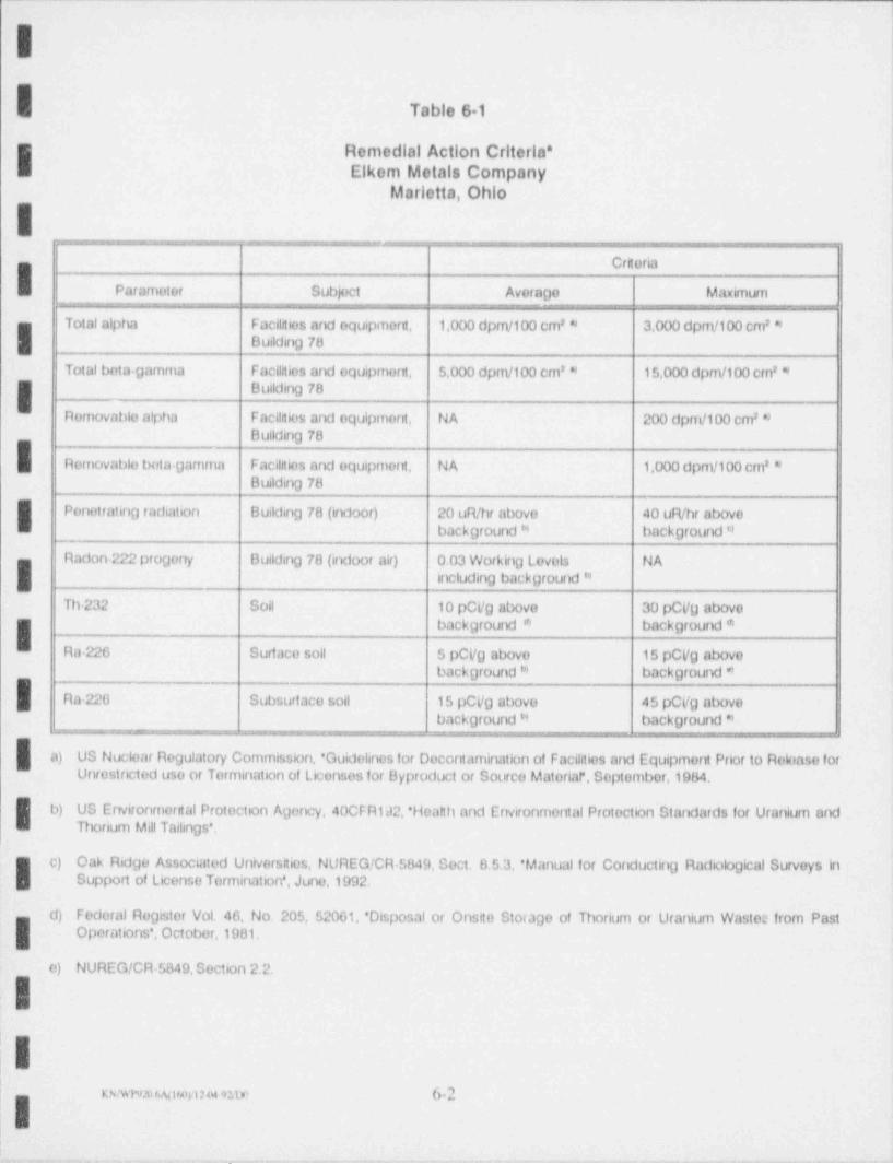
Table 61
I Remedial Action Criterla*Elkom Metals Company
Mariotta, Ohlo
ICrtoria
Paramotor Subject Avora00 Maximurn
Total alpha Facihtios and equipmort, 1,000 dpm/100 cm' * 3.000 dpm/100 cm' *Building 78
Total bota-gamma Facilities and equipmern, 5,000 dpm/100 cm' * 15,000 dpm/100 cm' *Building 78
Removablo alpha Facihtios and equipment, NA 200 dpm/100 cm' *Building 78
Removablo bota Damma Facihtios ard equipment, NA 1,000 dpm/100 cm' *Building 78
Ponotrating radiation Building 78 (indoor) 20 uR/hr abovo 40 uR/hr abovobackgroundh' back round *0
Radon 222 progony Building 70 (indoor air) 0.03 WorkinD ovels NALI including background 6'
Th-232 Soil 10 pCi/g above 30 pCVy abovobackground * background *
Ra-226 Surfaco soil 5 pCVg abovo 15 pCVg abovoback round'* back0round *0
Ra.220 Subsurfaco soll 15 pCi/0 abovo 45 pCyg abovoback round'4 background *0
a) US Nuclear Regulatory Commission, 'Guidehnos for Decontamination of Facilities and Equipment Prior to Roloaso forUnrestrcted uso or Termination of Licensos for Byproduct or Sourco Materlaf', Septembor,1984,
b) US Environmerital Protection Agency,40CFR192,'Heahh and Environmental Protection Standards for Uranium andThorium Mill TaitinOs',
c) Oak Ridge Associated Universnios, NUREG!CR 5849, Sect. 0.5.3, ' Manual for Conductirg Radiological Surveys inSupport of License Termination', Juno,1992.
d) Federal Rogister Vol. 46, No. 205, 52001, ' Disposal or Onstto Storage of Thorium or Uranium Wastos from PastOperations', October,1981.
c) NUREG/CR 5849,Section 2.2.
'
|I,
! KNMW31 fi.Nifofl2 04 92/10 b-2
_ _
___ __ __- - _ _ -
As presented in the Quality Assurance Project Plan (OAPP), the scanning instrume.
ntation to be employed will have a detection sensitivity of less than 25% of the respective
Table 6-1 criteria. Accordingly, the appropriate systematic measurement density is one
| per 2 m2 to provide at least 30 total and removable alpha and beta gamma data points(ORAU,1992)
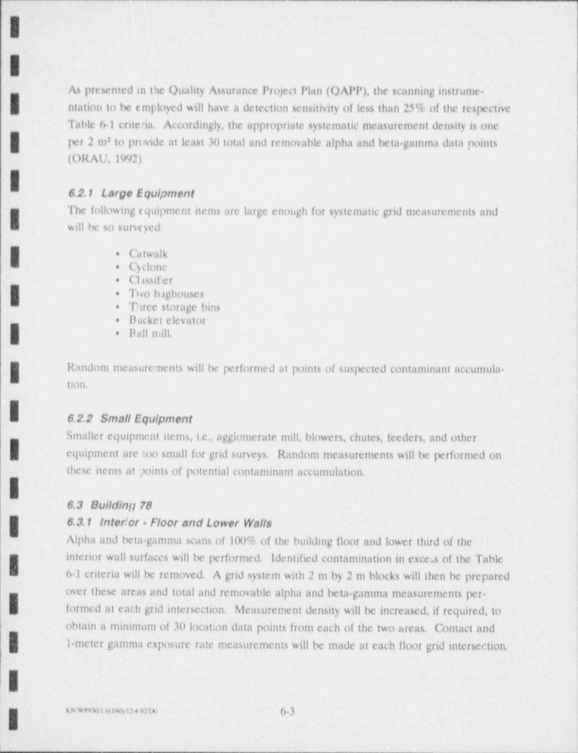
6.2.1 Large EquipmentThe following equipment items are large enough for systematic grid measurements andI will be so surveyed:
I Catwalk+
Cyclone.
Classifier.
+ Two baghousesThree storage bins.
Ducket elevator+
| Ihill mill..
Random measurements will be performed at points of suspected contaminant accumula.tion.
I 6.2.2 Small EquipmentSmaller equipment items, i.e., aggiamerate mill, blowers, chutes, feeders, and other
equipment are too small for grid surveys, Random measurements will be performed onthese items at points of potential contaminant accumulation.
6.3 Buildintj 786.3.1 Interior - Floor and Lower WallsAlpha and beta-gamma scans of 100% of the building floor and lower third of the
interior wall surfaces will be performed. Identified contamination in excess of the TableI 6-1 criteria will be removed. A grid system with 2 m by 2 m blocks will then be prepared
over these areas and total and removable alpha and beta gamma measurements per-. formed at each grid intersection. Measurement density will be increased, if required, to
obtain a minimum of 30 location data points from each of the two areas. Contact andj 1 meter gamma exposure rate measurements will be made at each floor grid intersection.
_ _ _ 63
L_ _ _ . _ _ _ . _ .
II 6.3.2 Interior - Celling and Upper Walls
if no excess contamination is found in the Door and lower wall sun'cys, the ceilings,
upper walls, and other overhead surfaces will have stratified random measurements. Aminimum of 30 measurement locations each, on vertical and horizontal surfaces where
contamination would likely accumulate, will be selected. The measurement density will
be at least one location per 20 m2 At each location a scan of the immediate area will be
performed to identify the presence of any elevated activity levels, followed by the
measurement
If excess contamination is identified during the Door and lower wall surveys or if ceiling
and upper wall scans or measurements indicate contamination exceeding 25% of theI Table 6-1 criteria, the surface will be considered potentially contaminated and will be
surveyed in the same manner as floors and lower walls.
6.3.3 Exterior - Walls and Roof
| Approximately 10% of the exterior lower wall and roof areas will be scanned for alpha
and beta gamma contamination. The scans will be focused around the baghouse exhaust
g stacks, bucket elevator tail pulley housing, and other points of potential contamination.
Subsequently, at least 30 randomly selected measurement locations or an average
measurement density of one per 50 m , whichever is greater, will be selected for each of2
I these two st,rface areas for total and removable activity. The identification of activity ;
levels in excess of 25% of the Table 6-1 criteria will result in more extensive surveys.
6.3.4 Indoor Air
| After all excess contamination has been removed from Building 78 and the associated
waste containers have been moved to interim storage outside the building, the indoor
g atmosphere will be sampled for short lived progeny of Rn 222. All windows and doors
will be closed and, excepting for normal entrance and egress, the building will be kept
I closed for 12 hours prior to sampling. Two each five minute air particulate grab samples
will then be collected in opposite ends of the building and analyzed by the modified
Kusnetz method. If these grab samples indicate an average concentration exceeding the
I- Table 61 criteria, a long term progeny monitor will be deployed to obtain a better
estimate of the annual average concentration. Sampling during each of the four seasons
|' may be required.
| .~ . ,_ ,,. m _ ,0. 64
.
-
,
6.4 Open Lands
|A grid system with 10m by 10m blocks will be established around the entire perimeter ofs
Building 78 and in the area of the Deposit 2 excavation. The building perimeter grid
( system will encompass the area of the Deposit 1 excavation. A near-surface ganuna scan
.
will be performed over the entire grid area. Contact and 1 meter gamma radiation
measurements will then be made at locations equidistant between the center and each of
| the four corners of each grid block. Systematic soil samples will be collected at the same
points (four per grid block) in the Deposit I and 2 excavation areas. Off grid gamma
measurements and soil semples will be collected as required, if the gamma scan indicates
potential soil activity in excess of 75% of the Table 6-1 criteria.
| 6.5 Background ValuesSeveral prior studies of the background radiation environment in the site vicinity have
been conducted to support past remedial action activities (Chem Nuclear,1981; ARIX,
1983), These background values ate summarized in Table 6-2. Both of these previous
studies identified elevated background conditions due to the presence of unlicensed slag
with elevated radionuclide content. One of these reports (Chem Nuclear,1981b) states
that care was taken to avoid these areas when making background measurements. ARIX
provided no similar discussion, however, based on the data from their study, it appears
that these anomalous background areas were not avoided.
IThese plans have been prepared under the premise that licensed wastes can be identified
by radiological characteristics. Should apparently anomalous background values in the -
soil excavation areas prove this approach to be untenable, consideration may be given to
| using surrogate analytes, such as Ta or Nb to replace radionuclides in soil.
Other requisite background levels, e.g., exposure and indoor radon progeny, may prove
problematic as well. Indoor radon, for example, is typically dependent upon many
structure specific variables such as local gealogy and soil characteristics, building design
and construction, occupant or user habits, etc. Background indoor radon concentrations
have little relevance to specific structures; however, if such a value is required, EPA
I studies of natural radon in Ohio may be used.
I
__ b.5
,. . .
_ . . . . . . . . . _ . . . . . . . . .
-
c
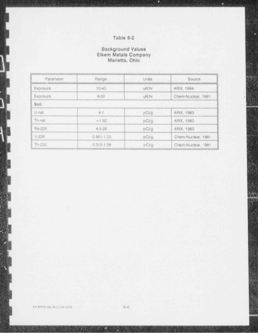
Table 6 2
Background Values- Elkem Metals Company
Marietta, Ohio
-
Parameter Range Units Source
Exposure 10-40 uR/hr ARIX,1984
Exposuro 8-30 uR/hr Chem Nuclear,1981 .
Soll:
U nat 4.1 pCVg ARtX,1983
Tiu at < 1.92 pCi/g ARIX,1983
raw 0 4.5-28 pCVg ARlX,1983
U 238 0.961 1.33 pCVg Chem-Nuclear,1981
Th-232 0.312 1.38 pCVg Chom-Nuclear, '981
II
! -
_ _
.. . .
________________- ______ _ - _ _ _ _ _ _ _ _ _ _ _ _ _ _ _ _ _ _ _ _ - _ _ _ _ _ _ _ _ _ _ _ _ _ _ _ _
L
[ 6.6 Comparison with Guldellne Values
6.6.1 Removable ActivityData for removable activity levels are compared directly to the criteria. The limit for
removable activity is 20% of the criteria for total surface activity. If that level is exceed-
ed, remediation and resurvey is .iecessary.
6.6.2 Elevated Areas of Activitylevels of residual activity, i.e., elevated areas, which exceed the criteria are initially
compared directly with the guideline. I
BulldIngs or Structures - The limit for activity on an equipment or building surface is
( three times the average criteria when averaged over an area of 100 cm . Residual2
activity exceeding this limit will be remediated and follow up surveys performed. Areas
of elevated activity between one and three times the criteria are then tested to assure
that the average surface activity level within a contiguous 1 m area coataining the2
clevated area is less than the criteria.
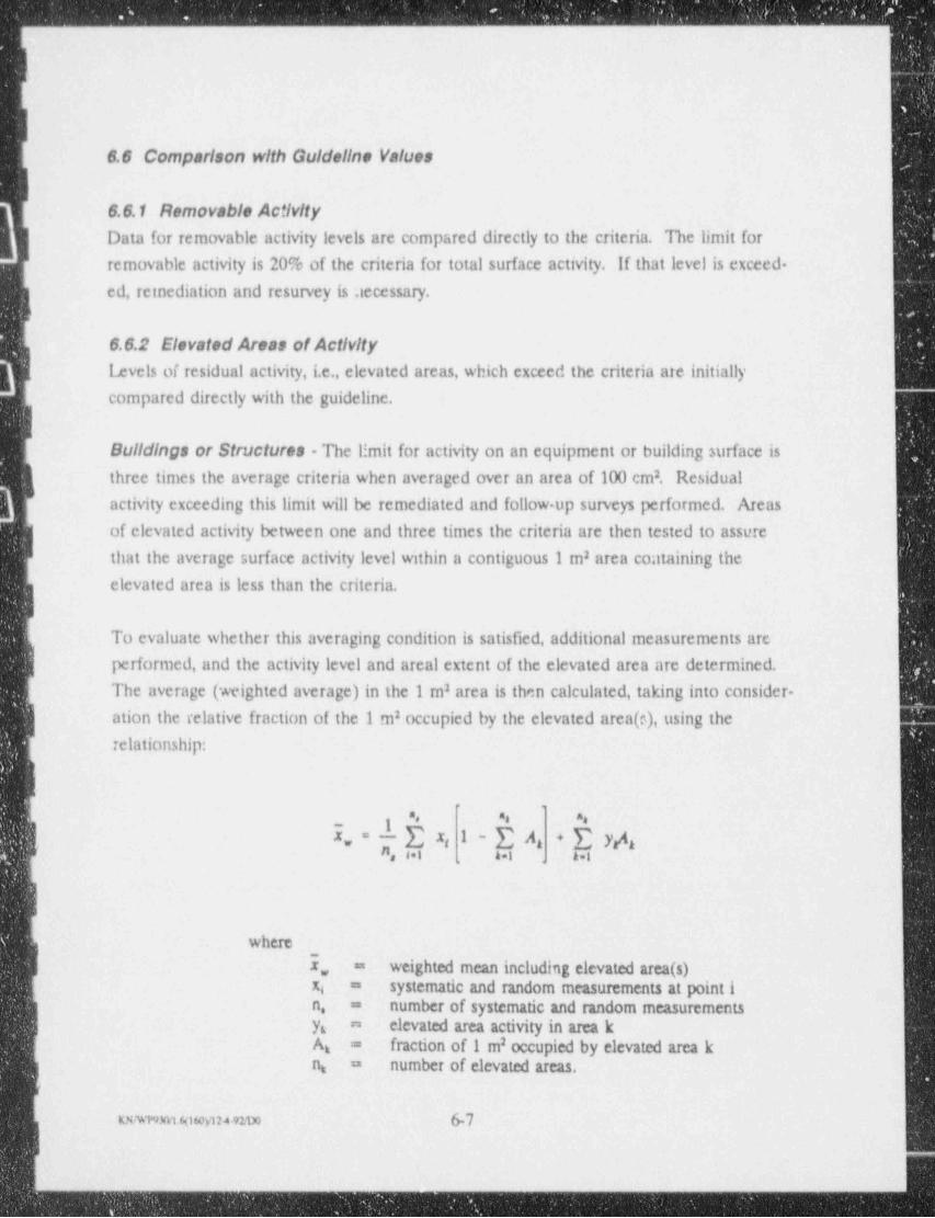
ITo evaluate whether this averaging condition is satisfied, additional measurements are
performed, and the activity level and areal extent of the elevated area are determined.
The average (weighted average) in the 1 m area is then calculated, taking into consider-2
| ation the relative fraction of the 1 m occupied by the elevated area (c), using the2
relationship:
8 83 A
5. " l , 2: I~EA + E Ja ig
f N, E Aai=1 41 A.:, ,
:
Iwhere
i,, weighted mean including elevated area (s)=
systematic and random measurements at point ixi =
number of systematic and random measurementsn, =
elevated area activity in area kyt a
fraction of 1 m occupied by elevated area k2Ag =
number of elevated areas.n. =
tKwwmyt to6092+92.im 6-7
{
. - _ _ _ __ _-_ ___ _ _ _ -
p
i
Soll- The limit for soil activity at any location is three times the average criteria.
Residual activity exceeding this level should be remediated and follow-up survey per-. formed. Areas of elevated activity between one and three times the criteria are than
tested to assure that the average concentration is less than (100/A)% times the criteria,
| where A is the area of the elevated activity in m2 levels exceeding this limit will be
remediated. If this comiition is satisfied, the average activity in the 100 m contiguous2
g area containing the region of elevated activity is then determined to assure that it is
within the criteria. The above equation is also used for this calculation, substituting 100
m2, when calculating average surface activity.
3 6.6.3 Exposure Rates
jE Exposure rate levels are compared directly with the criterion. The maximum exposure
, rate may not :xceed two times the criterion above background. If the levelis above that
value, the area will be remediated and resur/ eyed.
.I
II
,
I;I
IiII
_ _ _ _ e.sg
- .
_ - _ - _ -_ .- --
II 7.0 Waste Disposal
7.1 Packaging RequirementsThe wastes and conttuninated objects to be packaged and transported from this site for
disposal are classified as low specific actisity (LSA) pursuant to 49 CFR 173.403. These
g LSA materials will be transported as exclusive use and will M packaged .n accordance
W with 49 CFR Parts 172.310 and 173.425(b), and 10 CFR Part 71.
7.2 Shipping Papers.
I Each shipment of radioactive materials from this site produced as a result of this
remedial action will be accompanied by shipping papers which conform with the applica-
ble requirements of 49 CFR Part 172, Subparts 'B and C.,
9:
- O 7.3 Transport'
The radioactive materials will be transported to the disposal site by exclusive use trucks
over public highways. The shipments will be transported in conformance with 49 CFR
; Parts 173.425(b),173.448, and 177.ki
7.4 Disposal;
The radioactive materials will be shipped to an o1T. site disposal facility properly licensedH by the NRC or an agrcement state to receive and dispose of source material. Disposal
alternatives will tv: evaluated by UMETCO once waste types and volumes are known.
r
llI|I
I,I
I.
1usmsmosoms evo ?-1 1
-_ - - -- - - -
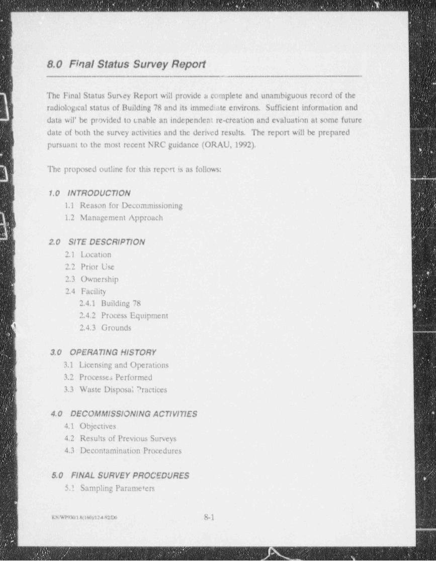
- - _ _ _ - _ - _ _ _ . _ _ . ._
t
' 8.0 Final Status Survey Report
The Final Status Sursey Report will provide a complete and unambiguous record of the
radiological status of Building 78 and its immediate emirons. Sufficient information and' data wil' be provided to enable an independent re-creation and evaluation at some future
date of both the survey activities and the derived results. The report will be prepared
pursuant to the most recent NRC guidance (ORAU,1992).
The proposed outline for this report is as follows:
1.0 INTRODUCTION1.1 Reason for Decommissioning
1.2 Management Approach
2.0 SITE DESCRIPTION2.1 Location
2.2 - Prior Use
2.3 Ovmership
2.4 Facility2.4.1 Building 78
2.4.2 Process Equipment
i; 2.4.3 Grounds
3.0 OPERATING HISTORY
3.1 Licensing and Operations3.2 Processe; Performed
3.3 Waste Disposa; Practices
4.0 DECOMMISSIONING ACTIVITIES4.1 Objectives
4.2 Results of Previous Surveys
4.3 Decontamination Procedures
5.0 FINAL SURVEY PROCEDURES
5.1 Sampling Parameters
i
KK'AT"TRI.8(160)/12492/D0 8-1 I
. _ - _ _ - _ _ _ _ _ _ - _ _ _ _ _ _ _ _ _ _ - _ _ _ _ _ _ _ _ _ _ _ _ _ _ _ _ _ _ - _ _ _ _ _ _ _ _ _ _ _ _ _ _ _ _ _ _ _ _ _ _ _ _ _ _ _ _ _ _ _ _ _ _ _ _ _ _ _ _ _ _ _ _ _ _ _ _ _ _ _ _ _ _ _ _ _ _ _ _ _ _ _ _ _ _ _ _ _ _ _ _ _ _
- - - _ _ _ _ _ _ - _ _ _ _ _ _ _ _ .
i
f 5.2 Background levels5.3 Guidelines Established
5.4 Equipment and Procedures
L R4.1 Instruments and Equipment
5.4.2 Instrument Use Techniques
S.? Survey Procedures
5.6 Survey Organization
~
6.0 SURVEY FINDINGS- 6.1 Data Reduction / Evaluation Methods
__
6.2 Statistical Evaluation
] 6.3 Comparison at Findings with Guideline Valu-s and Conditions!
7.0 SUh1 MARY
I
I .
I
I -
L
i1
||
[ ___ 2
. . .
-
.
?!
E 9.0 Project Schedule,.
!The schedule for this remedial action project is shown in Figure 91. This schedule,
- relates individual work phases to working days after NRC's approval of the project plans.
.
f
I!E:
:
.
-
1
;I:
il!
e .
IIE
Itt
I__,,,_,_ g.,
.g.
_.
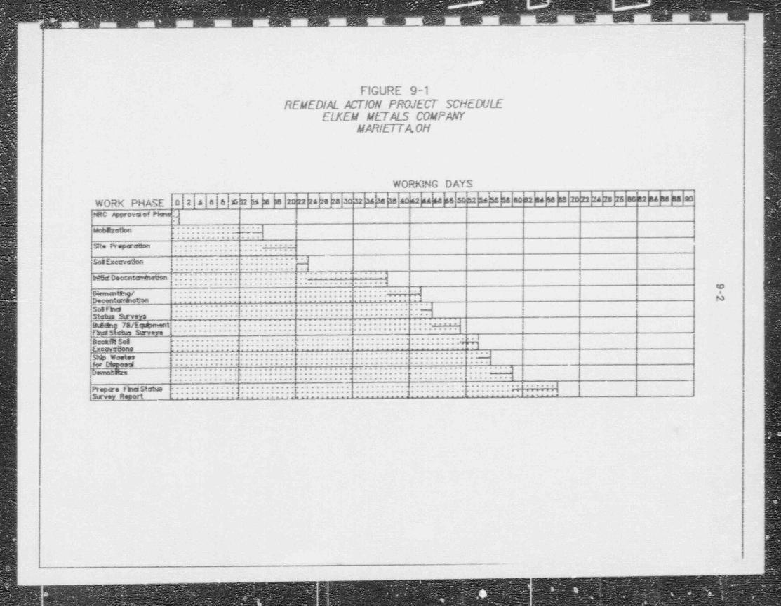
q m aus sur ums EJtJ CJ
FIGURE 9-1REMEDIAL ACTION PROJECT SCHEDULE l
ELKEM METALS COMPAWMARIETTA0H
WORK!NG DAYSi
u shs sa aoza sob upahe 1
24haWORK PHASE :e a a a a 6.a s ja a 2d22 s2 na as sa zo22 24 za zs aca2naasnaaoao42 44 4a sa so
kNRC Wovtsof Pime.............. .,..gg ........... _
j ............ . .
! h Props ce:m ............. .... ................. .... .
__
......... ., 99, 4 [ ...........| ,............. |..........
............ ..... ..... .<;
..'.. 4:)h.5ct Decentcmt.ietron j ;. . . . . : . . . . : . . ..;....... .. . :.
|............ .......... ..........
............. .......... ........... ........... ..e
mg . . . . . .
3, y............ ... ....... .......... ..... ..-
gg .. . ... .. ... .. ... . . j............ .......... .......... ........... ..
Status h ..r; .-.....-.-.. --..--..... ....-..... .... ...--. -...
..;........ .i........ . ~ . . .Ehe&n 75/Eht .......................
p 5{ m g ,y, ............ .......... ........... .......... .........
.
............. . ......... ........... ........... ........... .1|g e .,s,eg
. . _....... . .... . .. . . . 9.__
............. ........... ........... .......... .........9-G eov
_
..
...........g...........
....... .. .......... ..................g m,, ............ ....................... ........... ............. .
f.;r ttspeed. ..
.......... ........... ..........
.............. ,........... ..........< .......... ...........
gg ........ .... . . .. . . ... ... .. .... . . . .. .
.. .. _....... .............................. ........... .......... ........... ..... ....
..--.-.1,....*.*- .. -...*.>..** .... . ... ......* . ...*......
Prop <re FawsSt:r'as .-........*. .... ...... ........... .......... . *........... ...........$#V9Y Report .. ..
.......,..... . . . ... . .. . . . .... . .. . ...
. , .
I _
i
'
.. .
___
~ -
J
J
)1
J
IIE
EPART II
It
} HEALTH AND SAFETY PLAN
I -
:
i
!n
KNiWi%YllCOYr(160p2 7 97/m
1
_ _ - - _ - - _ _ _ - _ - _ - - _ _ _ - - _ - - _ _ - . _ - - - - _ - - - _ _ _ _ _ _ _ _ _ _ - - - _ - - _ - _ _ - _ - - - _ _ _ _ _ _ _ _ _ _ _ _ _ _ _ _ _ _ _ _ _ _ _ _ _ _ _ _ _ _ - _ - - - _ _ - . _ _ _ _ _ _
_ - _ . .__ _ _ . ._
1.0 Introductioni
The objectives of this Union Carbide Corporation (UCC) project specific Health and
Safety Plan (HSP) are to establish the procedures, personnel responsibilities, and training
necessary to protect the health and safety of all on-site personnel during the remedial
action at Building 78, Elkem Metals Company, Marietta, Ohio. The plan provides for
routine, but potentially hazardous, remedial action activities and for unexpected site,
t emergencies. The plan addresses radiological and non-radiological aspects of conducting
the remedial action in a manner that is protective of on-site personnel, the public, and
f the environment. Conformance with this plan is expected to maintain radiation doses to
as low as reasonably achievable (ALARA).
This document, in conjunction with the Work Plan (WP) and the Quality Assurance
Project Plan (OAPP), provides the planning framework for conducting the remedial
action at the site.
I
I
I
I
, _._ -
[_ _ _ __
-- . - _ _ _ - _ _ _ _ _ _ ._ _ .
I2.0 Personnel And Responsibilities
B2.1 Project ResponsibilitiesThe organizational chart for this project is shown in Figure 21. The associated project
i responsibili'.ies are discussed in Section 3.0 of the Work Plan.
2.2 Health and safety ResponsibilitiesProject Manager. The Umeteo Project Manager, Jay Davis, has overall responsibility for
health and safety during the project. These responsibilities include, but are not limitedto, those listed below:
Preparation of an effective site health and safety plan that satisfies the
.
NRC and OSHA requirements
Informing project staff of what radioactive and hazardous materials are+
present at the site, and the possible adverse health effects associated withexposure to these substances
Ensuring that adequate safety training and equipment are available for+
project personnel
Designating a Site Health and Safety Officer (SHSO).
Site Health and safety officer. Umetco's Site Health and Safety Officer is chargedwith the following responsibilities: r
Ensuring that all procedures stipulated in the Project Health and Safety-
| Plan are it.q.iemented during site activities
Updating equipment or orocedures based upon new information gathered.
R during site inspections and monitoring
;g Upgrading or downgrading (with approval of the Umetco Project ;.
g Manager) the levels of personnel protection based upon site observations (
Determining and posting locations and expedient routes to medical.
.
facilities for emergency medical services including poison control centers,and arranging for emergency transportation to medical facilities (asrequired)
$_ _ , , _ 21
,
_ __ _ _ _ - _
_ _ _ _ _ _ - _ _ _ _ _ _ _ _ _ _ _ _ _ _ _ _ _ _ _ _ _
|
Notifying (as required) local public emergency office (e.g., police and fire.
|- departments) of the nature of the team's operations and making
Iemergeng telephone numbers available to all team membersObserving work party members for symptoms of environmental exposures.
Arranging for the availability of emergency medical care and first aid on.
site, as necessarv.
Also, the Site Health and Safety Officer will have the authority to stop any site activity
involving Umetco or contractor personnel which threatens the health and safety of the
team or nearby populations, or adversely affects the local environment.
| Responsibilities of Other On site Personnel. Other personnel assigned to the site
.; hall be held accountable for compliance with the following directives:
Following all aspects of the Project Health and Safety Plan to include-
strict adherence to the ' buddy system"
Obeying orders and specific instructions issued by the Site Health and.
Safety Officer
Notifying the Site Health and Safety Officer of hazardous or potentially.
hazardous incidents or working conditions / situations.
IHealth Physics personnel will also have stop work authority,.
1
I
I
I
I
I
, ___ m'.li
- - - _ _ - _ _ - - - _ - - - _ _ - _ _ - - - - _ _ - _ - _ _ _ _ - - - - _ _ _ - _ - _ _ _ _ - _ - _ - _ _ _ _ - _ -
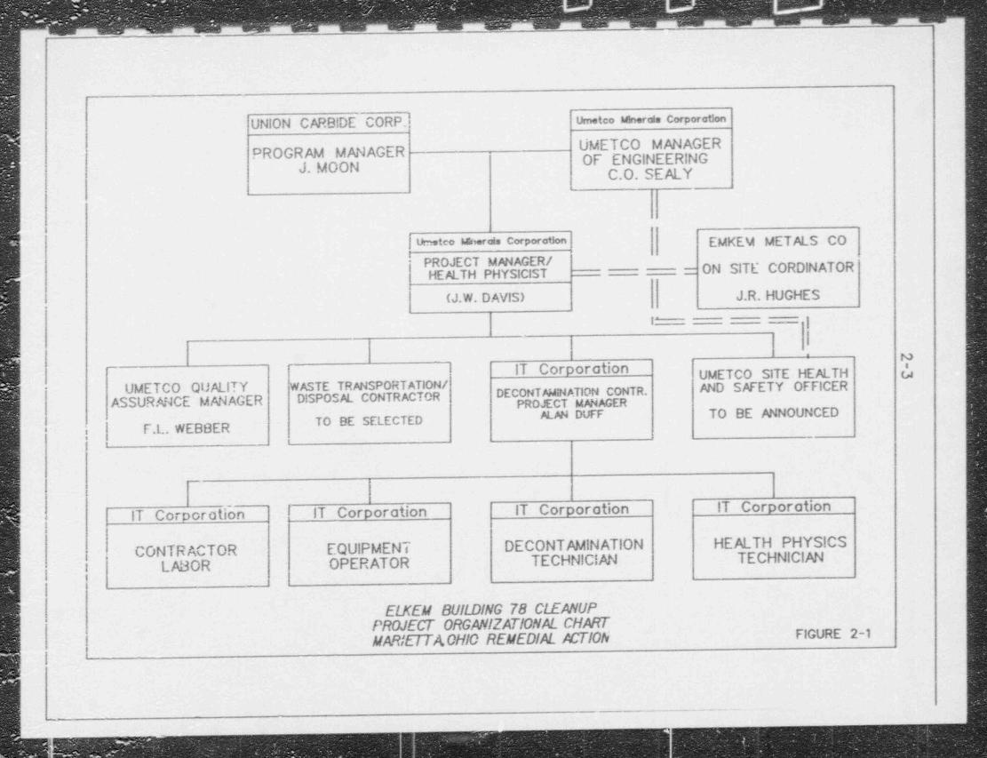
.. ,. ___ _ _ _ _ ___ _
UNION CARB!DE CORP.i urneteo mords corporatlon
UMETCO MANAGERPROGRAM MANAGER OF ENGINEERINGJ. MOON C.O.SEALY
!
l' |l ' um.tco w.rds corporam EMKEM METALS CO
PROJECT MANAGER /HEALTH PHYSICIST = ON SITE CORDINATOR
[
(J.W. DAVIS) J.R. HUGHES
I _jl
71 '
IT Corporation UMETCO SITE HEALTH uUMETCO QUALITY WASTE TRANSPORTATION /
ASSURANCE MANAGER DISPOSAL CONTRACTOR DECONTNINATION CONTR. AND SAFETY OFFICER-
PROJECT M#iAGERM AN DUFF TO BE ANNOUNCED
TO BE SELECTEDl- F.L. WEBBER|
-.
IT Corporation IT Corporation IT Corporotion IT Corporation-
J
CONTRACTOR EQUIPMENT DECONTAMINATION HEALTH PHYSICS
I LABOR OPERATOR TECHNICIAN TECHNICIAN
' ELKEM BUILDING 78 CLEANUPPROJECT ORGANIZATIONAL CHART
|MARiETTACHIO REMEDIAL ACTION FIGURE 2-1
i.. i!
._.
.* * ,
.-..-_m
g:
.g 1
N 3.0 Task Hazard Analysis / Action Levels
[3.1 IntroductionThe potential hazards to site workers, the general public, and the environment associated
I with the planned remedial action tasks can be summarized as follows:
. Exposure to ionizing radiation: . Exposure to inorganic chemical contaminants
* Heat stress, cold stress, noise, and exposure to other physical hazards.;l!.3.2 fonizing Radiation Hazards
| Ionizing radiation is of two types - particle and electromagnetic. Particle radiation is the
motion of small (subatomic) particles that have mass and, in most cases, electric charge,
and which transfer energy from one point to another. Particles of concern are designated'
alpha and beta. Electromagnetic radiation is similar to light. It is pure energy; there is
;g no particle associated with it. Gamma radiation and x-rays are the electromagnetic!5 radiation of concern and referred to as penetrating radiation.
Thorium, uranium, radium, and their associated decay products emit or generate all of
these types of ionizing radiation, i.e., alpha, beta, gamma, and x-ray radiation. Exposure
| to these radionuclides can result in external beta, gamma, and x-ray radiation doses due
to the proximity of individuals to the sources of the radiation, or by skin depositior of
| these contaminants. Internal doses from all four types of radiation can result from'
inhalation, ingestion, skin absorption, or skin penetration by injury of these radioactivei
species. Generally speaking, the foremost potential radiation hazards for this project are
the inhalation of alpha particle emitting radionuclides and working in proximity tot
,
; penetrating radiation emitting sources.;
.
:
The primary health risks associated with exposure to the radioactive materials at this site
i are due to chronic, long-term effects, specifically carcinogenesis and genetic effects.
; ?.1 Radiation Protection Guides (RPGs) and Action Levels^
The two basic principles for radiacica protection are:
'R- - There should not be any man-made radiation exposure without the expec-
tation of benefit resulting from such e.tposure.I
KN/WW34113(160ylj+92N4 3-1. ;
- _ _ - _ - _ _ - _ - _
Every effort should be made to maintain radiction doses as low as reason--
ably achievable (ALARA).|
| These two concepts are the underlying principles guiding the radiation protectionactivities at this site,
3.2.1.1 Radiation Exposure Limits
There are several levels of radiation protection standards the two most commonly
discussed are regulatory and administrative limits. Regulatory limits are those imposed
g on a licensee by the requirements of Title 10 Code of Federal Regulations Part 20. This
B code sets federally mandated limits on exposure for radiation workers, which may not be. exceeded. Administrative limits are limits imposed by a licensee on its workers.
Normally these limits are fractional portions of those listed in 10 CFR 20.101,103,104
(Revised January 1,1991) or the new draft 10 CFR 20.101 through and including section108.
For purposes of this health and safety plan administrative limits mandated for all workers
providing support assistance on this project are as follows.
1ih
B Annual Effective Dose Equivalent 500 mrem
Pregnant Female (gestation period) 100 mrem
These limits can be exceeded by less than a factor of two with approval of the Umetco
| Minerals Corporation Project Manager / Health Physicist and the IT Projec.t Manager. If
a worker's dose is to exceed 1000 mrem AEDE or 200 mrem to a pregnant female
approval must be obtained from the Union Carbide Corporation Program Manager and
the IT Corporate Health and Safety Manager.
To ensure that personnel do not exceed these administration limits radiation level guides
(RLGs) and radioactivity concentration guides (RCGs) have been established for this
project which are listed in Table 3.2-1. This table lists exposure condition, occupational-
guide, action level, action, and other pertinent information for each radionuclide or
radiation type expected to be of concern on this project. In all cases the listed action willbe performed when the action level is reached.
.
mewu.sa60m nuo 3-2
_
-. . . . . . . _ _
3.2.1.2 Monitoring ofInternal ExposureA bicassay program will be condected for all persoanel who routinely enter work zones
I posted as a Contamination Area or an Airborne Contamination Area. The bioassay
program allows for the monitoring and assessment of internal deposition of radioactive
material and worker internal dose due to those radioactive materials. Bionssay samples;
will be analyzed by an approved laboratory.
Each wcrker will submit a baseline urine sarnple prior to work on the project and then
submit a routine urine sample bi-weekly for the duration of the project.
. Resample Action Level- Resampling of a worker will take place if the analysis results
indicate an intake that results in a committed effective dose equivalent (CEDE) of >50
mrem. If the repeat measurement indicates an intake >50 mrem CEDE, further task
f evaluation will be performed. If the measured result is <50 mrem CEDE then no
further action is required and the worker will revert back to the routine bioassay
program.
Task Evaluation Action Level- If the results of a routinely scheduled bicassay mea-
surement, or a resample, indicate an intake of >50 merem CEDE, a repeat sample will- be provided by the worker as specified by the Project Health Physicist. Additionally, the
project health physicist will perform a task evaluation designed to ascertain the exposure
incident and pathway resuhing in the radionuclide(s) intake.
If the results of the repeat bioassay measurernent indicate an intake of >50 mrem CEDE
| but <100 mrem CEDE, perform continued bioassay monitoring to characterize worker
specific excretion functions. These bicassay measurements will continue until the
bioassay samples indicate an CEDE <50 mrem, at which time the worker can revert
back to the routine bioassay program.
Task Restriction Action Level- If the results of a routine scheduled bioassay measure-- ment, or a resample, indicate an intake which when summed with the external dose
received by the worker to give an Total Effective Dose Equivalent (TEDE) of >100
mrem, the worker's activities will be restricted immediately so as to avoid further intake
f of radioactive material. The Project Health Physicist will identify the required resamplebicassay matrix and schedule to characterize the worker's excretion functions. Based on
the results of these measurements, the Project Health Physicist will determine the
rxv.wnu20emw. coo 3-3
_ _ _ ._ _ - - ____________ -
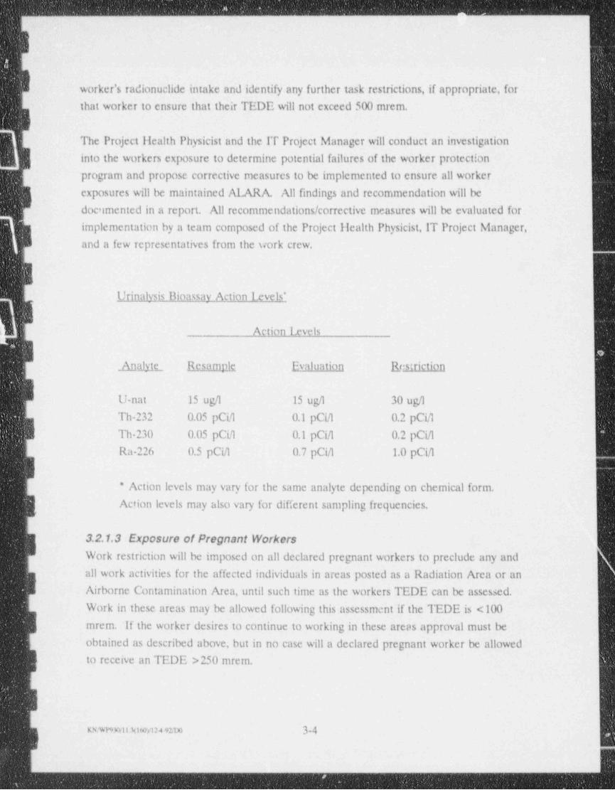
worker's radionuclide intake and identify any further task restrictions, if appropriate, for! that worker to ensure that their TEDE will not exceed 500 mrem.
The Project Health Physicist and the IT Project Manager will conduct an investigation
into the workers exposure to determine potential failures of the worker protection
program and propose corrective measures to be implemented to ensure all worker
exposures will be maintained ALARA. All findings and recommendation will be
doc'imented in a report. All recommendations / corrective measures will be evaluated for
g implementation by a team cornposed of the Project Health Physicist, IT Project Manager,B and a few icpresentatives from the work crew.
iUrinalysis Bioassav Action Levels'
Action Levels
Analytt B_cjampic Evaluation Restriction
U-nat 15 ugh 15 ugA 30 uga'
Th-232 0.05 pCiA 0.1 pCiA 0.2 pCia
Th-'230 0.05 pCiA 0.1 pCiA 0.2 pCiA
Ra-226 0.5 pCiA 0.7 pCiA 1.0 pCia
* Action levels may vary for the same analyte depending on chemical form.
Action levels may also vary for different sampling frequencies.
3.2.1.3 Exposure of Pregnant Workerss
Work restriction will be imposed on all declared pregnant workers to preclude any and'
all work activities for the affected individuals in areas posted as a Radiation Area or anAirborne Contamination Area, until such time as the workers TEDE can be assessed.
Work in these areas may be allowed following this assessment if the TEDE is <100
mrem. If the worker desires to continue to working in these areas approval must be
obtained as described above, but in no case will a declared pregnant worker be allowed
to receive an TEDE >250 mrem.
IKxw9wii h t6cyi24etm 3-4 |
.
_ - - - _ _ _ _ _ - _ _ - _ - _ _ _ _ _ - - - - - - _ _ - _ _ _ _ _ _ - _ _ _ _ _ - - _ ___-_. __
_._ _ - - _ _ _ _ _ _ _ _ - _ - _ _ _ _ _ _ _ _ _ - _ _ _ _ _ _ _ - _ _ _ _
3.2.1.4 Contamination Action LevelsContamination Anas (CAs) are established for the purposes of controlling personnel
exposures to radiatan and contamination within those areas, and to prevent the spread
of contamination om of those areas.
A CA is any area wh(re removable surface contamination on any exposed surface
exceeds the levels dictated by Reg Guide 1.86, Table 1.
3.3 ChemicalHazards| The potential chemical hazards associated with the remedial action tasks at this site are
due to the presence of inorganic chemical contaminants in the waste. Organic chemical
contaminants have not been detected and are not expected. The nature of the waste
form, i.e., a pyrometallurgical slag, would indicate a material probably deplete in volatile
nuclides, with many of the remaining nuclides in oxid:: forms.
Based on the relative abundance of the non radioactive nuclides in the waste and the
associated regulatory exposure limits (29 CFR,1910), tantalum is the most constraining
chemical hazard with a time-weighted average (TWA) air concentration limit of 5 mg/m .3I From the existing waste analysis data base, it has been calculated that the total airborne
dust concentration would be 53 mg/m to achieve the tantalum TWA. At this dust3
concentration, several of the radionuclides including Th-232, Th 230, and gross alpha
would be as much as ten times the respective RCGs or DACs.
Accordingly, appropriate monitoring and control of airborne radionuclides will ensure
adequate control of worker exposures to the chemical hazards at this site.
3.4 Physical Hazards
Site workers may be exposed to a number of potential physical hazards during the
remedial action.
3.4.1 Heat StressHeat stress can be a significant hazard because of the natural environmental conditions,
nature of work, protective clothing required, and unknown physical fitness of the
individuals involved. <
rxwnacitiAisovi:+9:oo 3-5,
1
_ _ _ _ - - _ _ - - _ _ - - _ _ - _ _ _ _ - - . - - _ _ _ - _ - - - - - - -
- ______ _ - _ _ _ __-___- ____ _ _____--__ _____ _ --_. _ - - _ -
Properly selected and donned personnel protective equipment provides an effective
barrier between the worker's organs and the environment. The largest organ in the
.f human body is the skin. One of the many functions of the skin is to regulate body
temperature through the process of sweat ng. Temperature regulation by the skin isi
| complex, but simply stated, blood vessels dilate (widen) when the body needs to lose
heat, or contract (narrow) when the body needs to reduce the amount of heat loss
through the skin.
g When heat production of the body is increased or when the ambient temperature isB unusually high, the sweat glands accelerate the production of perspiration. The rate of
perspiration may then outstrip the rate of evaporation, particularly if the humidity is high,
since the rate of evaporation declines with the rise in humidity. Heat is only lost when
the perspiration evaporates. The rate of evaporation is dependent on temperature,
| humidity, convection (wind currents), and radiant heat loss.
The protective garments that protect the skin from unwanted chemical exposure also
inhibits the evaporation of perspiration from the skin due to the high humidity inside the
garments. Convection currents cannot penetrate the protective garment to aid in the
evaporation / cooling process; thus, heat stress is likely to occar if workers are not aware
of the signs and symptoms of heat related illnesses.
Other factors that may contribute to heat related problems are:
I personal hygiene.
lack of acclimatization or conditiona
| health related problems-
fatigue and stress.
consumption of alcoholic beverages.
| poor dietary habits.
age..
Heat-related problems are not limited to the use of protective clothing.
3.4.2 Cold Stress
Pain in the extremities may be the first early warning of danger due to cold stress.
During exposure to cold, maximum severe shivering develops when the body temperature'
has fallen to 35"C (95*F). This must be taken as a sig., of danger to the workers and
exposure to cold should be immediately terminated for any workers when severe
me % mmu4em 3-6
_ _. .
. _ _ _ _ _ _ _ _ _ _ _ _ _ _ - - - _ _ _ - . . . . - - - _ _ _ _ - _ - _ _
,
-
shivering becomes evident. Useful physical or mental work is limited when severe
shivering occurs.
Since prolonged exposure to cold air, or to immersion in cold water, at temperatures well
| above freezing can lead to dangerous hypothermia, whole body protection must be
provided. Unless there are unusual or extenuating circumstances, cold injury to other
than hands, feet, and head is not likely to occur without the development of the initialsigns of hypothermia.
3.4.3 Falling Hazards
The nature ci the activities will necessitate that employees work at elevated levels. To
reduce the potential for falling from these elevated locations, OSHA-conforming manlifts
er ladders will be used.
Iin the event that an employee must work in an elevated location which is inaccessible by
the manlift or ladder, appropriate fall protection must be provided. This may consist of
safety nets or cables attached to belts / harnesses worn by employees connected to a fixed
I anchorage such as a steel beam. This type of fall protection shall be in compliance with
OSHA 1910.66,1926.104,1926.105, and 1926.556. Note that while any work is being
g performed from extensible and articulating boom platforms, all employees must wear ap body belt with a lanyard attached to the boom or basket.
| 3.4.4 Silpping and Tripping HazardsBecause of the various protruding objects on floors and slippery surfaces, care must be
| exercised at all times to prevent injuries from slips and trips. Special emphas's at safety
meetings is recommended. Also, all floor openings and holes shall be barricaded
i Since there are numerous slip and trip hazards at the site, special attention to house-
keeping will be emphasized to minimize these hazards.
3.4.5 Confined Space Entry
UCC does not plan to perform any activiti s in confined spaces at the site. A confined
space is a space having limited means of entry or egress and so enclosed that adequate
dilution ventilation is not obtained by natural or forced air movement. A coramed space
is subject to the accumulation of toxic or combustible agents, or to a deficiency of
n ewnamm+nm 37
_ _ _ _ _ _
-_ __
t
(
oxygen. Prior to cutting any process equipment vessels, the vessel shall be adequately'
ventilated or oxygen and explosive gas monitoring shall be performed.
If a field situation were to arise in which UCC or contractor personnel must enter a
confined space to perform an activity, then the SHSO will receive specific approval from
UCC's Project Manager prior to initiating the activity.
3.4.6 Hazardous NoiseHearing protection will be worn in proximity to all noise sources producing a sound level
rt ading at or above 80 dBA. This includes, but is not limited to, noise producing sources
such as metal cutting saws, generators, etc.
3.4.7 Underground UtiliticsUnderground utilities, particularly electrical and gas lines, can pose significant safety
hazards. No intr * subsurface activities will be conducted at the site until the under-
ground utility location service has identitied the locations of all underground utilities in
the work area and has trarked these locations on the ground and on site maps. In no
case will intrusive activities be conducted within ten feet of underground utilities, unlessthe utilities are disabled, i.e., valved-off and bled or locked.out.
3.4.8 Overhead UtilitiesOverhead utilities, particularly electrical, can also pose significant safety hazards. All
cranes and similar equipment must be operated by experienced operators. The equip-
ment must also be directed by a responsible person on the ground when working in
proximity to ovethead utilities. In no case will mobile equipment operate within ten feet. . -
of overhead utilities as measured between the nearest line and the fully extended
equipment boom.
3.4,9 Equipment Lockout
Lockout is the minimum precaution required whenever work is to be performed on any
electrical equipment or any stationary equipment controlled or powered thereby. All
sources of power for the equipment is to be opened and locked in the open or 'Off"
position. To assure that the power has been locked out, attempt to st_ art the equipment
or test the circuit before commencing work. The lockout must be marked or tagged sothat it can easily be identified as such. The lock is not to be removed until the work is
completed and all personnel and tools are clear,
uwnnuaimymeno 3-8 l
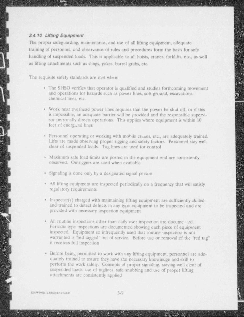
- -
H
b
3.4.10 Ulting EquipmentThe proper safeguarding, maintenance, and use of all lifting equipment, adequate
training of personnel, r.nd observance of rules and procedures form the basis for safe'
handling of suspended loads. This is applicable to a!! hoists, cranes, forklifts, etc., as well
| as lifting attachments such as slings, yokes, barrel grabs, etc.
The requisite safety standards are met when:
The SHSO verifies that operator is qualified and studies forthcoming movement.
and operations for hazards such as power lines, soft ground, excavations,chemical lines, etc.
| Wor:k near overhead power lines requires that the power be shut off, or if this.
is impossible, an adequate barrier will be provided and the responsible supervi-sor personally directs operations. This applies where equipment is within 10feet of energi.ad lines
Personnel operating or working with mobile cranes, etc., are adequately trained..
Lifts are made observing proper rigging and safety factors. Personnel stay wellclear of suspended loads. Tag lines are used for control
Maximum safe load limits are posted in the equipment and are consistently-
observed. Outriggers are used when available
Signaling is done only by a designated signal person.
All lifting equipment are inspected periodically on a frequency that will satisfy.
regulatory requirements
Inspector (s) charged with maintaining lifting equip. ment are sufficiently skilled.
and trained to detect defects in any type equipment to be inspected and areprovided with necessary inspection equipment
All routine inspections other than daily user inspection are documened..
Periodic type inspections are documented showing each piece of equipmentinspected. Equipment so infrequently used that routine inspection is notwarranted is " red tagged" out of service. Before use or removal of the " red tag"it receives full inspection
Before being permitted to work with any lifting equipment, personnel are ade-.
quately trained to assure they have the necessary knowledge and skill toperform the work safely. Concepts of proper signaling, staying well clear ofsuspended loads, use of taglines, safe snubbing and use of pmper liftingattachments are consistently applied
meatii2(iw>ct: 92ax 39
- _ _ _ _ _ _ _ _ - - _ _ _ _ - _ _ _ . _ _ _ _ _ _ _ _ _ _ _ _ _ _ . - _ - _ . . _ - _ - - _ _ _ - _ _ .
y
3.4.11 Open FlamosA welding and Gre permit will be required and must be displayed when welding ortorching anywhere where a fire hazard exists. A fire extinguisher and pressuried waterh0se must be ready at the job location during all wekihig und torching. A worker mustbe sismding by and able to watch for any sparks which muld start a fire. .ne weldingground damp must be located where any sparks will be seen.
No welding or gas cutting will be done within 50 feet of fuel storage areas.
The permit must be signed by the welder /torcher and the SHSO.
I3.5 Project Task HazardsIndividuals engaged in specific project tasks may encounter potential hazards unique to
that particular task. Contrarily, some tasks may involve potential hazards which are
j common throughout. To assist in relating specific remedial action tasks to associated
I potential hazards and monitoring requirement 3, Table 3.5 '1 has been developed.
I
I
i
i
lI
i
I
3_ _
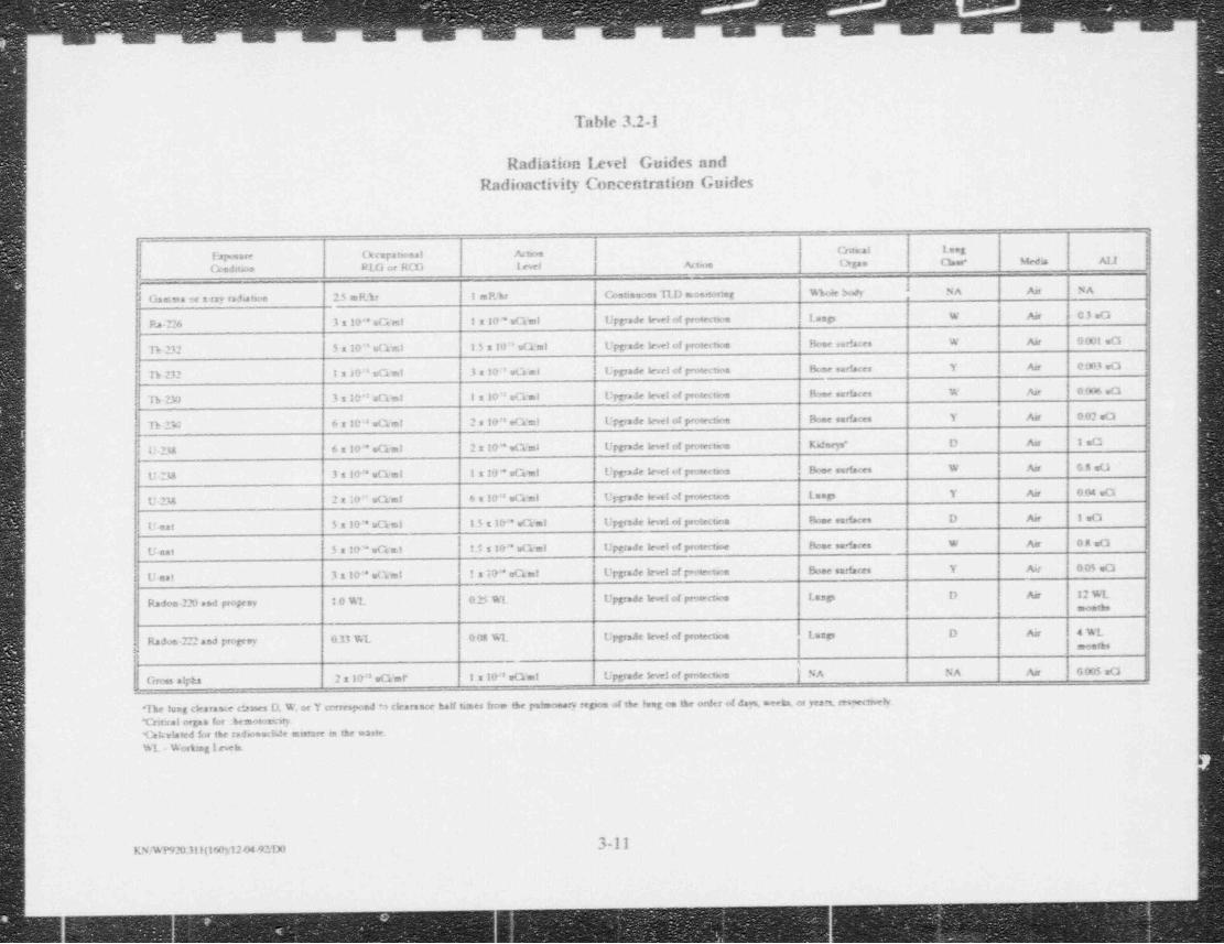
. . . . .. ., , . 3 ,
Table 3.2 1
Radiation Imel Guides andRadioacti5ity Concentration Guides
4-
Cntaal Leeg
f-Fzysere Ocupatsonal Actsos
Coadnkte RU) or ROG 1evel Actme Orgse Che Meda AU g
h&
Gamea or x-ray radates 15 mF.'kr impar Costioeons TLD e onetorsag %we ude NA An NA8
N Ra-226 3S&* eG mi t 1&* eGal Upgrade level of prosectne Lesp W Air C3eG
h 232 5 a10 ' = G est i 5 s 10" eG al Upgrade lewl of protectaos Home surfaces W Air 9001 eO|
| h 232 I z 10'' eGal 3 a 10' eGai Uppade level of p-oiectwo Home ser' aces Y Ar 0.003 =0
Th 230 3s1&*'aG m! 1 x 10' eG al Upgrade bel of protection Ibec surfaces W Air 096 eO
h 23: 6 x les ,q y 2 ,go." eG al Upgrade level c.t protectme Dooe surfaces Y Asr 002 eO
U.238 6 x 10'* eCant 2 x 1&**e G ai Upgrade levet of protectes Kifecys" D Aar 130
U 238 3 10'' eGal 1 x 10 * eGml Upg >de level 4 protertes Bone surfaces W An G5n0
U-238 2 x 10" eGm! 6 m 1&" eG eil Urgrade level of prowtes Laep Y Air 0 04 ed
U. eat 5 s 10" = Gel 1.5 ID* eGal Upgrade lew! of pretence Bose surfaces D Air 1eO
U-eat 5 s 10' eGa1 !.*. s 10" eG al Upgrade level of protectee Home sedaces W Asr O8=0
U-est 3 x 10'' eG ml ! 10" eGm! Uppade level of p oneoion Bone surfaces Y Air 0 05 =O
I
Radon-220 and progeey i 0 %1 03 %1 Upgrade level of pros-cta Lasp D Air 12 % 1mostbs
iD Air 4%L j
| LaspRadon.222 seJ progeny G.33 %1 0 02 % 1 Upgrade level of protecteosmee s 4
l
Gross ayka 2 x 10'8eG ar I a 10'' eG st Upgrade lew! of protecten NA NA Air O(US a0 |
"The lung clearnese c*.ames D. W. or Y correspond M clearance half times froe the pulmoearv repon of the long on the order of dag meeks, os yesn, reswetrvelv"Critral organ for .bemosornry.'Cakelated br the radosech.!c murare in the waste. |%L Wosbeglevek l
|
3-11 !'om9203 nieo>uo4eno1
!
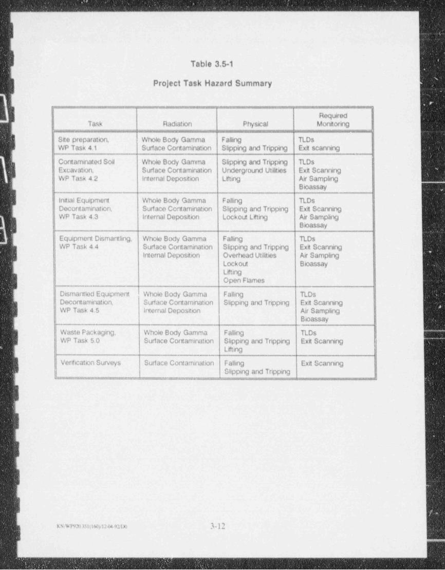
_ _ _ _ _ _ _ _ _ _-
s
-
Table 3.5-1i
Project Task Hazard Summary!
!
Required| Task Radiation Physical Monitoringi -
Site preparation, Whole Body Gamma Falling RDsWP Task 4.1 Surface Contamination Slipping and Tripping Ext scanning
, Contaminated Soil Whole Body Gamma Slipping and Tripping RDsExcavation, Surface Contamination Underground Utilities Exit Scanning
-
WP Task 4.2 Internal Deposition Lifting Air SamplingBioassay
initial Equipmern Whob Body Gamma Falling RDsDecontamination. Surf ace Contamination Slipping and Tripping Exit ScanningWP Task 4.3 Internal Deposition Lockout Lifting Air Sampling
Bioassay
Equipment Dismantling, Whole Body Gamma Falling TLDsa WP Task 4.4 Surface Contamination Slipping and Tripping Exit Scanning
| Internal Deposition Overhead Utildies Air SamplingLockout BioassayLiftingOpen Flames
Dismantled Equipment Whole Body Gamma Falling TLDsDecontamination, Surface Contamination Slipping and Tripping Exit Scanning
i WP Task 4.5 Intemal Doposition Air SamplingBioassay
Waste Packaging. Whole Body Gamma Falling TLDsI WP Task 5.0 Surface Contamination Stipping and Tripping Exit Scanning
Lifting
Venfication Surveys Surf ace Contam! nation Falling Exit Scanning
[Slipping and Tripping
i
I
I
!l
xs.wre m06on2a 92;no .1.n ;
i
_ _ _ _ _ _ _ _ _ _ _ _ _ _ _ _ _ _ _ _ _ _ _ _ _ _ _ _ _ _ _ _ _ _ _ _
- _ - - - _ - _ - -
\
4.0 Exposure Monitoring Plan_
The exposure monitoring plans for the remedial action at this site have been bifurcated
into two categories, i.e., environmental monitoring and occupational monitoring plans.
The environmental monitoring plan is directed at evaluating radiation levels immediately
outside the restricted area. The occupational monitoring plan is directed at evaluating
the exposure and dose to remedial action workers.
4.1 Environmental Monitoring PlanThe environmental monitoring plan has been developed to appraise the following:
Radioactivity in air particulates.
radon 222 gas.
gamma radiation.
radioactive surface contamination..
The site environmental monitoring plan is summarized in Table 4-1.
4.2 Occupational Monitoring Plan
The occupational monitoring plan for remedial action (RA) activities at this site has been
developed to appraise the following:4
Radiaactive contamination on workers and equipment.
Gamma and beta / gamma radiation exposure and dose rates-
Radon-220 and radon-222 progeny concentrations in air.
Long lived alpha particle emitting radionuclides in air.
Thorium-232 concentrations in bioassay samples.
Heat Stress.
Noise.
Oxygen deficiency / explosive gas in vessels to be cut..
The project occupational monitoring plan is summarized in Table 4-2.
Surveys for radioactive surface contamination on workers will be performed every time a
worker exits the controlled area. All equipment used in support of the remedial action
f will be surveyed, and decontaminated as required, for unrestricted release as specified by
the NRC (NRC,1984).
rswnwu 40weem 4-1
_ _ _ _ _ .
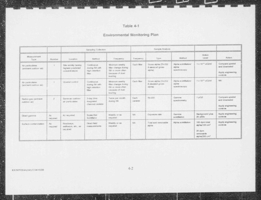
, . ., ,.
Table 4-1
Environmental Monitoring Plan|l!
Ii
SarnpEng Corectori $arnpas A mysm
ActonMonsuremers
Type Number Law Mood Frequency Frequer= r Type Me8 hod Loved Actum
As psinctda'es 1 See vicawy tW Cortruous Mamurn weeky E'an;h faer Groes abha Ch232 Alpha sciretatorv 1 x 1'J" uCVmi Compare tpwind
(embiert outdoor as) taghest predcted durry FiA wth fner change direg I ehed gross alpha and downwnf
concercatsors tagh reterWrm RA or rnore of!en alphe) spectroscopy
f%f becatse cd dust Appy enginnenngcoretesloading
1 Upwind corect Corwescus Maumsen weet V Each fear Grose alpha 0h232 Alphe sertAatiorv 1 x 10" uCVmi NA
f As partculatas(amters outdcor aa) dumg RA wth fiker change dtsvg i eievated guns ache
<
begn retertzm AA cw more often abha) opectroscopy
f2er Oct.ause of duel
badKQ
i
| Radon ges (smbert 2 Se.mo as cuidoor hay tirner Twee per entmth Each *h222 Gamma 1 pC41 Compare igwirufi
outdoor air; er pex:tAatee rueg'eted durirg RA carmter s k e--.mLy and downwwwf
(,harcorJ cansterAppy *n0 nneing
,
i
Direct gamma A6 A: repared Scab /Nat WesAh or as NA bposure rate Gamma Backgrosed pbs Apph engewomg
tegawed Stjrtdabr requred scirtantion 20 uFity coreots
Sur* ace corene.dnatum As Anadways. (keet field Weekh or as NA Total and removable Alpte echtmatum 100 dpm total App 4 enginnenng
reteired waAwevs. etc., as frieasuremerts requined alpha a%+uv100 cm' contrear
regaled20 dpm ,
remowable
! ]L
|
|
Ii
N |KRWP920.4At160y!2 04-92,D01<
_ _ _ _ _
. .. .. ..
-..
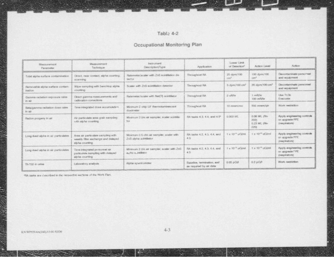
w -- i,,, - - _ , rw- 1 ._ . ;
Tabla 4-2
iI Occupationai Monitor!ng Plan
! Macsuremers Measuremert kutrument towerUr*Parameter Tectwhoe DescriptrWType Appkanon of Desectaxf Acton Level A: ewe
Total alpha surfwe cortaminaton Ovect, near cortsd. alpha courtry; Ratemnter/acabr weh ZnS ochdahon de- Throughoid RA 25 dpm/100 100 dpm/100 Doctavambsse persemet
scantwg tector em crn' and equirmert8
Homovabhr alpha surface cortam- Wipe sampire wth berrMop apha Scaler wth ZnS scet1Eation detec.or Throughts.2 RA 5 dperi/100 cm' 20 dpret/100 cm' A,6-4 pereennetmal equpmert
barnn countrg
Gamma radeton exposure rates Drect gamme meesisemewes and ' Rawmaterfscaler wP3s Nal(Tl) scots.afor ThroughotA M 2 uRita i 1 r$hr tJse TL!b100 mfttr Evacuse
h air calibrafien correct' nso
0Beta / gamma radunnan dose rates Trreirtegrated dose accur,tAtwat Mrspurn 2 chip UF thsemr*smnescent Throughoid PA to mrerNmo Soc mesm/qtr Woria restnctum
b air dosimeter
| Radon progeny h ar Air parbculate area grab eampang Msimme 2 Lws air actnpler, ocatar sch RA taehs 4 3, 4.4. and 4 5* 0.003 WL 0 06 WL (Th- Apply en0heenng oortects
| 2:'2) .
or avgrade PPEa uh alphe couting tor
015 WL (Rn- irespirebrs)f 47
Long INed alpba an se parrodstee Aiaa me partoutate 6amplirs;wth Wsmum C.5 cfm air sanW, scaler wth RA taska 41414.4, ard 1 m to"uCVmi 1x10**uC*ri App 4 enghser!rg coreots
weekly firer excharge and deisynd 2,.3 ciphe ubeduars 45 or t4grede PPEfreepiratars)
alpha courtrg
1. cog 49ed alpha b mir particulates Tewinregrakuf preorveier k*irnum 2 Vm eir sampler, scaler weh ZnS RA tasks 4 2,4.3 4 4, ard 1 m 10" uCi/nd 1x10'"uCVmt App 8y enghee rg coreces
45 or spgrade TPEpartict4 ate samptng wth c8eisyed j agA:s.artDitor (roopansers)alpha courtrg
T M 32 h tetne Laboratory analysis Alpte spwekwister Gsse4ns; W and 005 pG4 02 pCd Work restrienors
as required t>y air data,,
1% tasks are descrbed in the recosta asc5 ors of its Wo't Fan
1
|
!!
4-3KN/WP9234.N160),124i42:1Xt
J._
. . . - - ,
I' All remedial action workers will be monitored for shallow and deep dose equivalents
using personal thermoluminescent dosimeters (TLDs). Real time penetrating radiation,
.
expasure rate surveys will be performed at least weekly.
i- Radon-220 and raden-222 progeny concentrations in work areas will be monitored on at
, least a weekly basis or more frequently as required by the SHSO.
' Gross alpha emitting radionuclide concentrations in air particulates will be monitored by '
the delayed direct alpha counting of area and lapel breathing zone samples.i
II.
.
il1
.
!Is
!I
|I;
;I
;Ir
a
'=q_
_ _ _ . - _- _ _ _-__________ -_-____ _
-
r
5.0 Engineering Controls_
Engineering controls will provide the first line of defense against radiation hazards during
this remedial action. On this project, engineering controls will be used primarily to:-
limit the spread of contamination.
limit the aliborne radionuclide concentrations.+
Engineered contamination controls will include safe work practices, site control and workI zones, worker and workplace surface contamination monitoring, and decontamination, asirequired. See HSP Sections 7.0,8.0 and 9.0.
Engineering controls will also be used to limit the airborne radioactivity concentrations.
j Dust prevention or suppression measures may include water sprinkling or the use of
chemical suppression agents such as calcium chloride or vinyl acetate. Dust collection
measures willinclude the use of high-efficiency particulate filters on all vacuum decon--
tamination equipment used on the project.
III -
B
I'
Ii
K.wwwn Samuwm 5-1
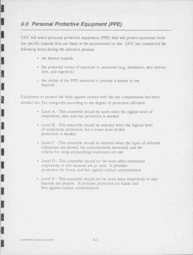
IG.0 Personal Protective Equipment (PPE)
I UCC will select personal protective equipment (PPE) that will protect personnel from
the specific hazards that are likely to be encountered on site. UCC has considered the
following items during the selection process:
the known hazards.
the potential routes of exposure to personnel (e.g., inhalation, skin absorp-.
tion, and ingestion)
the ability of the PPE materials to provide a barrier to the-
hazards.
Equipment to protect the body against contact with the site contaminants has been
divided into five categories according to the degree of protection afforded:
Ixvel A - This ensemble should be worn when the highest level of.
respiratory, skin, and eye protection is needed
I Level B - This ensemble should be selected when the highest level.
of respiratory protection, but a lesser level of skinprotection is needed
I Level C - This ensemble should be selected when the types of airborne.
substances are known, the concentrations measured, and thecriteria for using air-purifying respirators are met
Level D - This ensemble should not be worn when substantial.
respiratory or skin hazards are pr;sent. It providesprotection for hands and feet against surface contamination
. Level E - This ensemble should not be worn when respiratory or skinhazards are present. It provides protection for hands andfeet against surface contamination.I
I1
IiI
___ miI
_ _ _ _
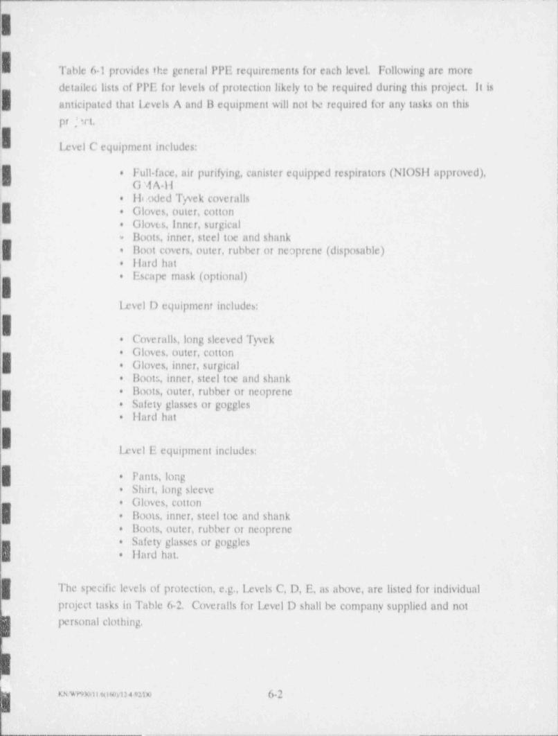
!
ITable 6-1 provides the general PPE requirements for each level. Following are more
detailed lists of PPE for levels of protection likely to be required during this project. Itis
anticipated that levels A and 11 equipment will not be required for any tasks on this
pr , :rt.
lxvel C equipment includes:
I Full face, air purifying, canister equipped respirators (NIOSil approved),.
G ',i A ll
Hooded Tyvek coveralls.
| Gloves, outer, cotton.
Gloves, inner, surgical.
Boots, inner, steel toe and shank*
Iloot covers, outer, rubber or neoprene (disposable).
liard hat.
Escape mask (optional).
level D equipment includes:
Coveralls, long sleeved Tyvek.
Gloves. outer, cotton.
Gloves, inner, surgical.
Iloots, inner, steel toe and shank.
.g Hoots, outer, rubber or neoprene.
|g Safety glasses or goggles.
liard hat.
|level E equipment includes:
Pants, long*
Shirt, long sleeve.
Gloves, cotton,.
Boots, inner, steel toe and shank.
Boots, outer, rubber or neoprene.
Safety glasses or goggles.
.
liard hat.! .
it
The specific levels of protection, e.g., Ixvels C, D, E, as above, are listed for individual
( project tasks in Table 6-2. Coveralls for lxvel D shall be company supplied and notpersonal clothing.
e,wnuur,omuuno 6-2
__ _
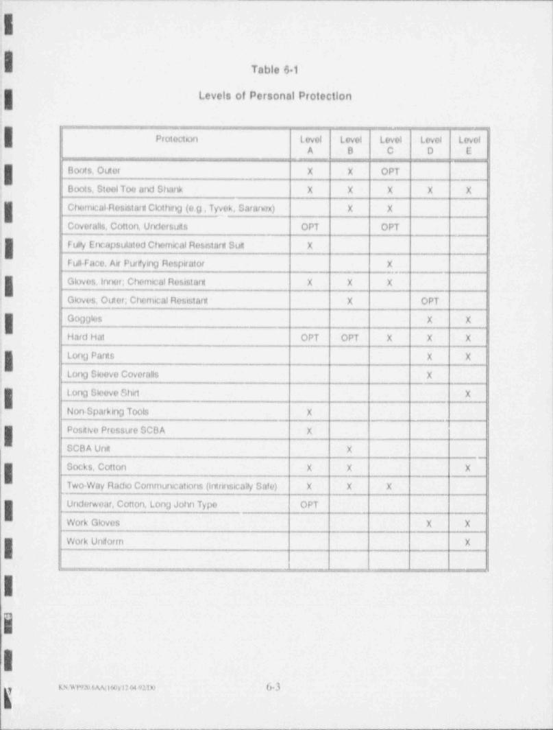
- .___ - -. _-.
I7
Table 61
Levels of Personal Protection.
]a
Protection Loyol Loyol Loyol Loyol Levol'
A B C D E.
,
Boots, Outer X X OPT1i Boots, StoolToo and Shank X X X X X
Chornical Rosistard Clothing (e.g , Tyvek, Sararvrx) X X
j Coveralis, Cotton, Undersuits OPT OPT
j Fuly Encapsulatod Chemical Roststarn Suit X
! Full-Faco, Air Pur#ying Respirator X_
Glovos Innor; Chemical Rosistart X X X
J Gkwes, Outor; Chemical Resistant X OPT
Go0gles X X
j Hard Hat OPT OPT X X X
Long Pants X X
j Lon0 Sloovo Coveralls X
i Long Sleevo Shirt X
l Non-Sparking Tools X._.
.Positivo Pressuro SCBA X
.
SCBA Unit X
Socks, Cotton X X X
Two Way Radio Communications (intrinsicaly Safo) X X X
Underwear, Cotton, Long John Typo OPT.
Work Gloves X X._
Work Undorm XI- ___ ,
I- - , , , _ u
Real time monitoring of the workplace for removable surface contamination and near
real time monitoring for airborne gross alpha and radon progeny will guide the SilSO in
upgrading or downgrading the required PPE from that specified in Table 6 2.
I.
o
4
-
I:
il:
:
'I1
I<
|.
II
e
t
! xowwu eisvi2+921)o (>-4 i
- i
.
- , , . . , - , . . , , , . - - - - . _ - - _ . - - . . . -
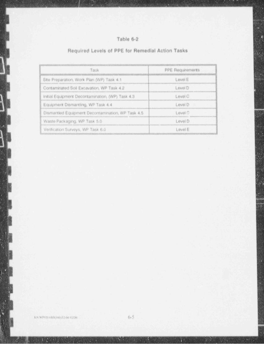
. _ _ _ _ - _ _ _ _ _ _ _ _ _ _ _ _ _
-
-
L
Table 6 2
Roquired Levels of PPE for Remedial Action Taskss
- _ . . _ _ . _ .._. I _ _ _ _ _ . . ___.- ,
U equre or s
Sito Preparation Work Plan (WP) Task 4.1 Lovel E
Contaminated Soll Excavation, WP Task 4.2 LevelD__
todial Equiprriont Decontarnination, (WP) Task 4.3 LevelC
i Equipment Dismarntng, WP Task 4.4 Levot D
Dismarnled Equipment Decornamination, WP Task 4.5 Lovel C
I_
Waste Packagtng, WP Task 5 0 Levot D__
Vershcation Surveys, WP Task 6.0 LovelEI
|||
B
i
___ s.s
- _ - _ _ _ _ _ - _ _ _ _ _ _ _-_.__ _
e
7.0 Work Zones And Site Control( . - _ _ _ __
- Umetco personnel will establish and/or maintain site control to (1) minimize the possibili-
ty of worker exposure to contaminants and (2) reduce off site release of contaminants.
To attain these goals, personnel will institute the following procedures as necessary:
Slie Access Control and Security
Fences, barrier tape, signs-
Sign in procedures-
- Site badges
Controlled access points-
Afinimize Personnel and Equipment on Site
| Medical clearance-
Required and appropriate training-
- Necessary briefings
Buddy system-
Estabilsh Work Zones
- Exclusion Zone (an exclusion zone will be restricted / controlled area notedand identified using the terminology of 10 CFR 20.203 ' Caution signs, labels,
| signals and controls")
( Contamination Reduction Zone (a site access control point used for transi--
tion between any type of appropriate restricted / controlled zone listed in 10
CFR 20,203 and a " clean" area)
Estabilshed Decontamination Procedures
See Section 8.0-
i
| DTI9M'II.7(Itt0024930 7-]
|
.im.i .- ..i..... , _ ., _ _ , _ , . _ _ , , __,_,,_,__,.,_,_,_,____________,,_,,_.,.,,_,____,.,____,,.,_,_______.___,,______.___,________.____m___;
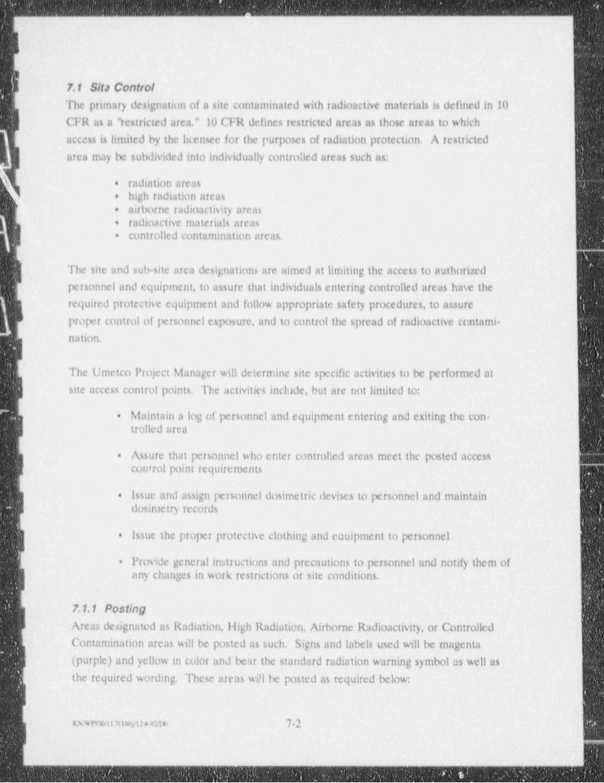
. _ _ _ - _ - - _ _ _ - __ _ _ _ _ _ __.
7.1 Sita ControlThe primary designation of a site contaminated with radioactive materials is defined in 10
CFR as a " restricted area." 10 CFR defines restricted areas as those areas to which
access is limited by the licensee for the 1*urposes of radiation protection. A restricted
area may be subdivided into individually controlled areas such as:
radiation areas+
i high radiation areas+
' airborne radioactivity areas+
radioactive materials areasa
controlled contamination areas.=
The site and sub site area designations are aimed at limiting the access to authorized
personnel and equipment, to assure that individuals entering controlled areas have the
required protective equipment and follow appropriate safety procedures, to assure
proper control of personnel exposure, and to control the spread of radioactive contami-nation.
The Umetco Project Manager will determine site specific activities to be performed at
| site access control points. The activities include, but are not limited to:
g Maintain a log of personnel and equipment entering and exiting the con--
| trolled area|
| Assure that personnel who enter controlled areas meet the posted access+
[ control point requirements
IIssue and assign personnel dosimetric devises to personnel and maintain.
dosimetry records
Issue the proper protective clothing and equipment to personnel*
Provide general instructions and precautions to personnel and notify them of>
any changes in work restrictions or site conditions.
| 7.1.1 PostingB Arear, designated as Radiation, High Radiation, Airborne Radioactivity, or Controlled
Contamination areas will be posted as such. Signs and labels used will be magenta
(purple) and yellow in color and bear the standard radiation warning symbol as well as
the required wording. These areas will be posted as required below:
||
mwnmonsovin e:1x, 72 ||
- _ - - _ - - - - - - - - _ _ _ _ _ - . - _ . - - - - _ _ - - _ _ _ _ - - _ _ - _ - - - - - - - - - - - - - - - - - - - - - - - - - - - - - - - - - - - - - - - - - - - - - - - - --__ _ _ _ _ -- .. -
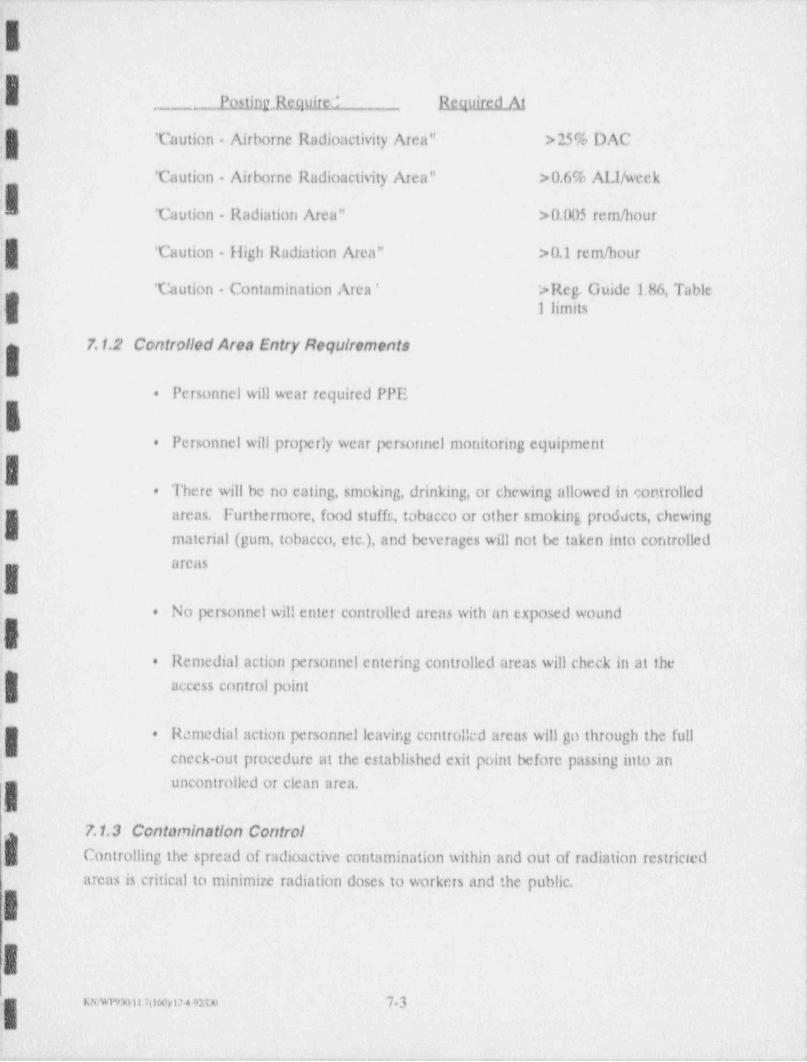
_= . _ _ . - - - .
IPostingJk_ quired Required At. ..
' Caution Airborne Radioactivity . Area" >25% DAC
' Caution - Airborne Radioactivity Area" >0.6% ALI/ week
! ' Caution - Radiation Area" >0.005 rem / hour
| ' Caution - High Radiation Area" >0.1 rem / hour;
' Caution Contamination Area ' > Reg. Guide 1,86, TableI limits
7.1.2 Controlled Area Entry Requirements
Personnel will wear required PPEa
Personnel will properly wear personnel monitoring equipment.
There will be no eating, smoking, drinking, or chewing allowed in controlled.
areas. Furthermore, food stuffr, tobacco or other smoking products, chewing
material (gum, tobacco, etc.), and beverages will not be taken into controlled,.
- areas
INo personnel will enter controlled areas with an exposed wound+
Remedial action personnel entering controlled areas will check in at the.
access control point
:. Remedial action personnel leaving contro!!cd areas will go through the fulla
- eneck out procedure at the established exit point before passing into anuncontrolled or clean area.I .
7.1.3 Contornination ControlControlling the spread of radioactive contamination within and out of radiation restricted
areas is critical to minimize radiation doses to workers and the public.,
I.
w wr9x u m wxi>49 vo 73I- - . . -. .
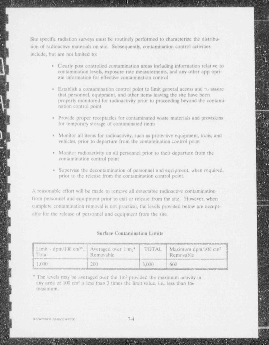
_ _ _ _ _ _ _ - - _ _ - _ - _ _ _ _ - _ _
Site specific radiation surveys must be routinely performed to characterize the distribu-,
i tion of radioactive rnaterials on site. Subsequently, contamination control activitiesinclude, but are not litnited to:
. Clearly post controlled contamination areas including information relatwe toI. contamination levels, exposure rate measurements, and nny other app:opri-| ate information for effective containination control
Establish a contamination control point to limit general access and to assure.
that personnel, equipment, and other items leaving the site have been
I properly monitored for radioactivity prior to proceeding beyond the contami-nation control point
..
I Provide proper receptacles for contaminated waste materials and provisions.
for temporary storage of contaminated items
g Monitor all items for radioactivity, such as protective equipment, tools, and.
vehicles, prior to departure from the contamination control point
| Monitor radioactivity on all personnel prior to their departure from the.
contamination control point
Supervise the decontamination of personnel and eqeipment, when required,.
prior to the release from the contamination control point.
A reasonable effort will be made to remove all detectable radioactive contamination
from personnel and equipment prior to exit or release from the site. However, when
complete contamination removalis not practical, the levels provided below are accept-
able for the release of personnel and equipment from the site.
"
Surface Contaminathm Limits
- - - .
Limit dpm/100 cm", Averaged over 1 m2 TOTAL Maximum dpm/100 ctn* 2
Total Removable R.cmovable
1,000 200 3,000 600
* The levels may be averaged over the 1m provided the maximum activity in2
7any area of 100 cm is less than 3 times the limit value, i.e.,less than themaXimuin.
RLwi%Al1 htmil24 ono 7-4
. .. .. ._ _____ __-___ . - _ - .
7.2 Work Zonos
L The Building 78 site will be divided into three specific work zones, i.e., the support zone,the contamination reduction zone (CRZ) and the exclusion 70ne. Refer to Figure 7-1.
:
The " contaminant reduction zone"(CRZ) will be between the exclusionary zone and the
| clean er support zone. The purpose of the CRZ is to provide an area where workersand materials can proceed from a contaminated area to a clean area.
| Access to the exclusionary zone will occur only through the CRZ. Access to the cleanarea from the exclusionary zone will also occur only through the CRZ.
( The CR7, will consist of discrete stations to systematically reduce the levels of potentialcontamination. These are shown in Figure 7-1 and will be established, clearly marked,maintained, and specific station instructions willle posted. The support zone will be
| defined as an uncontaminated area outside the CRZ and exclusion zone,v
The support men will abo serve as the site safety center where the following safetyequipment will be maintained:
g ABC type the extinguishers*
Industrial size. first aid kit[.
Eyewash*
Emergency signal horn.*
I
i
i
|
I
|
uw m u7owru4,ztm 7-5
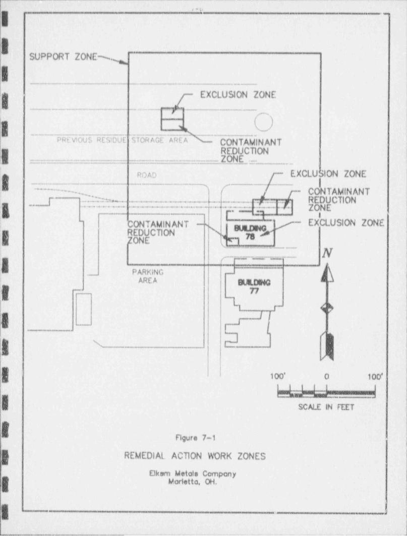
I-
. . .- -,
;
SUPPORT ZONE %,
I___ . _ _ _ . ._. .. -__
g g EXCLUSION ZONEm _- _ _ - ______ -jL.
|PREVIOUS RESIDUE j STORAGE AR CONTAMINANT
REDUCTION;I _ . _ _ _ . _ _ _ _ _ ___ ZONE.-
t j- EXCLUSION ZONEnoAo
/-- I'-- -... ,' ~ 7-- CONTAMINANT
. _.r .._ .J. - [ REDUCTION.
_p ~ .-_y _ - . _ _- ..
._ p- -
.
L 0,N E- . - . . . . . . .- ... . - .
.-
; _
gmqMg EXCLUSION ZONE"-
CONTAMIN ANT -sREDUCTION N 73ZONE y'1
N,__ - .,. .__ ,,
.__ PARKING -
AREA MDING '
77_
lI ( )r-
'f:I 'i
N
/'
100' O 100'
! _ LA-a----_
SCALE IN FEET
!
|E Figure 7-1
REMEDIAL ACTION WORK ZONES
Okam Metals CompanyMorietta. OH.
I 1-
._ _ _ _ _ _ _ - - _
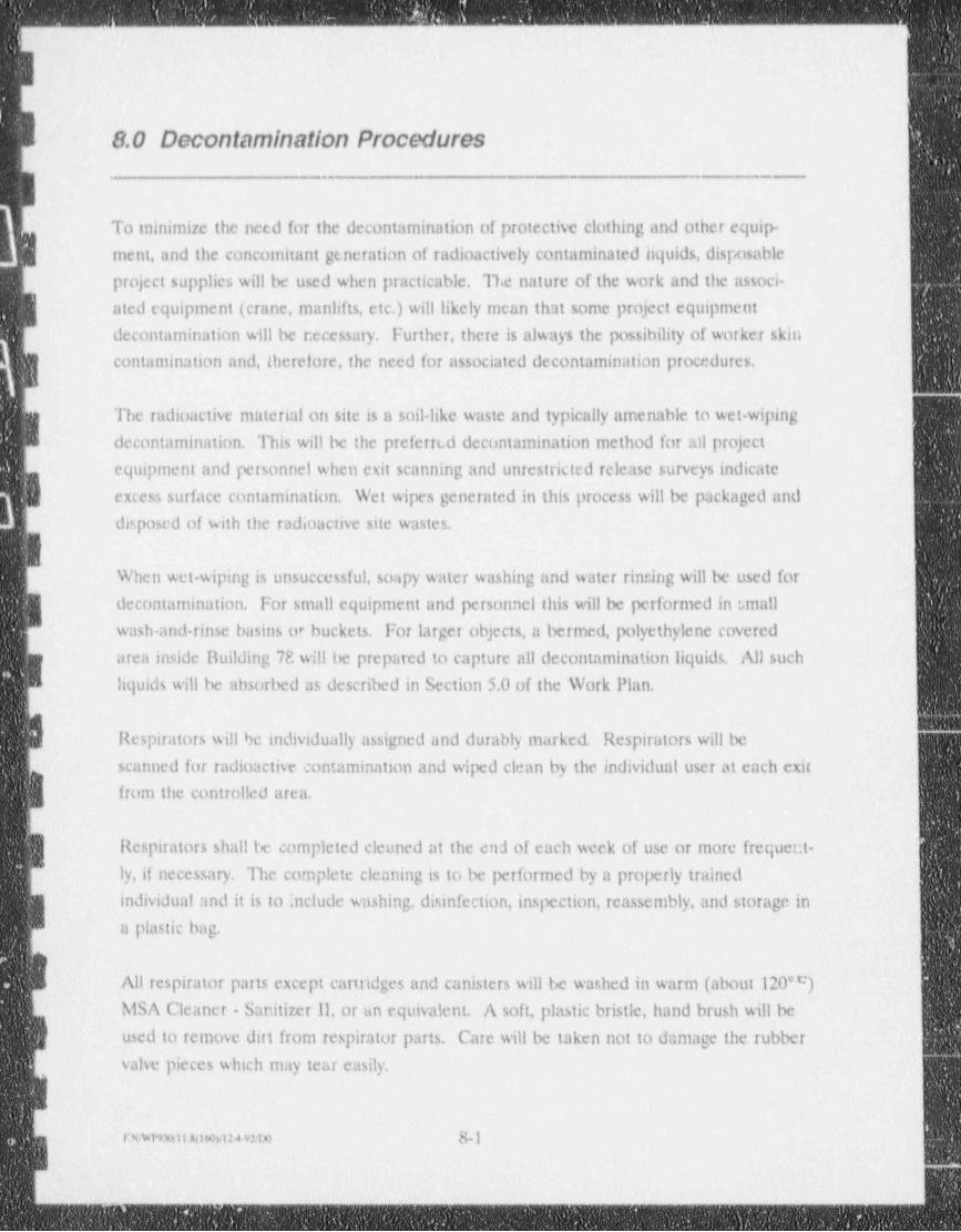
, - - _ _ _ _ _ _ _ _ _ _ _ -
-
me=+
8.0 Decontamination Procedures1
.
To minimize the need for the decontamination of protective clothing and other equip-
ment, and the concomitant generation of radioactively contaminated liquids, disposable
project supplies will be used when practicable. The nature of the work and the associ-
ated equipment (crane, manlifts, etc.) will likely mean that some project equipment
decontamination will be r.ecessmy. Further, there is always the possibility of worker skin
contamination and, therefore, the need for associated decontamination procedures.
The radioactive material on site is a soil-like waste and typically amenable to wet-wipingI decontamination. This will be the preferred decontamination method for adl project
equipment and personnel when exit scanning and unrestricted release surveys indicate
excess surface contamination. Wet wipes generated in this process will be packaged and
disposed of with the radioactive site wastes.
When wet wiping is unsuccessful, soapy water washing tmd water rinsing will be used for
g decontamination. For small equipment and personnel this will be performed in small
wash-and-rinse basins or buckets. For larger objects, a bermed, polyethylene covered
area inside Building 7P.will be prepared to capture all decontamination liquids. All such
liquids will be absorbed as described in Section 5.0 of the Work Plan.
Respirators will be individually assigned and durably marked. Respirators will be
scanned for radioactive contamination and wiped clean by the individual user at each exit
from the controlled area.
Respirators shall be completed cleaned at the end of each week of use or more frequent-
ly,if necessary. The complete cleaning is to be performed by a properly trained
individual and it is to include washing, disinfection, inspection, reassembly, and storage in
a plastic bag.
All respirator parts except eartridges and canisters will be washed in warm (about 120m)
MSA Cleaner - Sanitizer 11, or un equivalent. A soft, plastic bristle, hand brush will be
used to remove dirt from respirator parts. Cme will be taken not to damage the rubber
valve pieces which may tear easily,
rnmunowmm 8-1
_
- . _ _ - _ - _ _ _ _ _ _ _ _ _ _ _ _
a
r-
LAll remedial action workers will be required to proceed through decontamination
procedures before eating, at the end of each working day, or before leaving the site. All
outer clothing will be removed and properly disposed of, and employees will then wash-
up with soap and water.
IAll equipment, materials, and remedial action personnel will be monitored for radioactive
contamination during each exit from the CIG to the support zone. Decontamination will
be performed as required, based on these radiological measurements. Tools which may
be reused in a contaminated area may remain in the area in a properly marked radioac-
.I tive toolbox.4
)
;
Ie
IR
I.
IB
__ _ ,
|
i- - - _ - _ - _ _ _ _ _ _ _ _ _ _ _ _ _ _ _ _ _ _ _ _ _ _ _ _ _ _ _ _ _ _ - _ _ _ _ _ _ _ _ _ _ _ _ _ _ _ _ _ _ _ _ _ - _ - _ _ _ _ - _ _ - - _ - _ _ _ _ _ - _ - _ _ _ - _ - _ _ _ _ _ _ _ _ _ - _ _ - _ _ _ _ _ _ _ - _ _ _ _ _ _ _
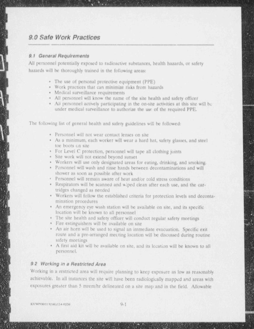
_ - _ _ _ _ _ _ _ _ _ _ _ _ _ _ _ _ _ _ _ _ _ _ _ _ _ . _ _
f9.0 Safe Work Practices
|
I 9.1 GeneralRequirementsAll personnel potentially exposed to radioactive substances, health hazards, or safety
hazards will be thoroughly trained in the following areas:
The use of personal protective equipment (PPE)-
Work practices that can minimize risks from hazardsa
Medical surveillance requirements.
| All personnel will know the name of the site health and safety officer*
All personnel actisely participating in the on site activities at this site will be.
under medical surveillance to authorize the use of the required PPE.
The following list of general health and safety guidelines will be followed:
Personnel will not wear contact lenses on site*
As a minimum, each worker will wear a hard hat, safety glasses, and steel.
.i toe boots On siteFor Level C protection, personnel will tape all clothing joints+
Site work will not extend beyond sunseta
I Workers will use only designated areas for cating, drinking, and smoking..
Personnel will wash and rinse hands between decontaminations and will*
shower as soon as possible after workPersonnel will remain aware of heat and/or cold stress conditions*
Respirators will be scanned and wiped clean after each use, and the car--
-
tridges changed as neededWorkers will follow the established criteria for protection levels and deconta-*
mination preceduresAn emergency eye wash station will be available on site, and its specific-
I location will be known to all personnelThe site health and safety officer will conduct regular safety meetings: *
g Fire extinguishers will be available on sitea
j An air horn will be used to signal an immediate evacuation. Specific exit+
route and a pre-arranged mecting location will be discussed during routineg safety meetings| A first aid kit will be available on site, and its location will be known to all*
personnel.
9 2 Working in a Restricted Arca
Working in a restricted area will require planning to keep exposure as low as reasonably
achievable, in allinstances the site will have been radiologically mapped and areas with
exposures greater than 5 mrem /hr delineated on a site map and in the field. Allowable
uwnwii 9tisosi:49mo 9-1
:
;
, _
-
-
5
times in these areas will be established by the SilSO in consultation with a health '
~
|. physicist.
General Rules:
L. Obey posted, verbal and written radiological control instructions
_ Use the survey meter to monitor exposure when in a contaminated area..
Personal " radiation badges"(TLDs) may be issued by the SilSO. Theseg badges may be used for up to three months. They should be worn at allB times on site and returned to the SilSO when leaving the site to be main-
tained in a low background area while not in useDo not loiter in radiation areasg .
R Do not eat, drink, chew or smoke in areas where radioactive contamination.
may be present
I Minimize the possibility of a radioactive spill (a sample) by carefully follow-.
ing sampling guidelinesFor known or possible radioactive spill, minimize its spread and notify the.
SilSO promptlyDo not unnecessariiy touch a contaminated surface or allow your clothing,.
tools or other equipment to do soAs practical, place all contaminated equipment such as tools and sampling.
bottles on disposable surfaces (e.g., sheet plastic) when not in use and insideproper disposal containers when work is finishedFollow good ' housekeeping" practices to minimize the amount of material.
that has to be contaminated or disposed of as radioactive wasteReport the presence of open wounds to your supervisor prior to work in.
areas where radioactive contamination exists. If a wound occurs while insuch an area, report immediately to radiological control personnelMonitor for contamination when exiting the CRZ.
h Follow all other health and safety requirements described in the site IIcalth.
and Safety Plan.
1
I
I
I
--- n
|
.. ._ . _
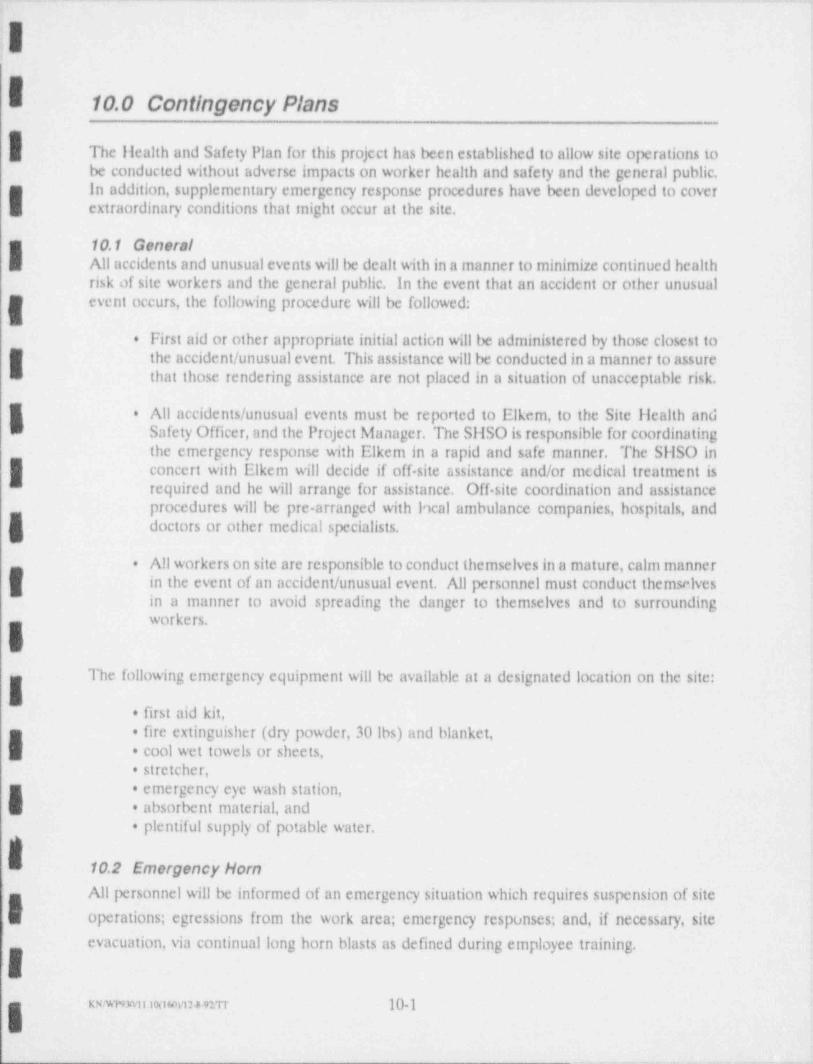
,-. . - __ . _ _ _ . _ _
|| ;0
10.0 Contingency Plans
The Health and Safety Plan for this project has been established to allow site operationsbe conducted without adverse impacts on worker health and safety and the general public.
I in addition, supplementary emergency response procedures have been developed to cover -
extraordinary conditions that might occur at the site,
10.1 Generali All accidents and unusual events will be dealt with in a manner to minimize continued health
risk of site workers and the general public. In the event that an accident or other unusualevent occurs, the following procedure will be followed:
. First aid or other appropriate initial action will be administered by those closest to
I the accident / unusual event. This assistance will be conducted in a manner to assurethat those rendering assistance are not placed in a situation of unacceptable risk.
l. All accidents / unusual events must be reported to Elkem, to the Site Health and
Safety Officer, and the Project Manager. The SHSO is responsible for coordinatingthe emergency response with Elkem in a rapid and safe manner. The SHSO in
g concert with Elkem will decide if off site assistance and/or medical treatment isrequired and he will arrange for assistance. Off site coordination and assistanceprocedures will be pre. arranged with local ambulance companies, hospitals, and
| doctors or other medical specialists.
. All workers on site are responsible to conduct themselves in a mature, calm manner
| in the event of an accident / unusual event. All personnel must conduct themselvesin a manner to avoid spreading the danger to themselves and to surroundingworkers.
The following emergency equipment will be available at a designated location on the site:
first aid kit,. fire extinguisher (dry powder,30 lbs) and blanket,
-I + cool wet towels or sheets,. stretcher,. emergency eye wash station,
I e absorbent material, and. plentiful supply of potable water.
10.2 Emergency Hom
All personnel will be informed of an emergency situation which requires suspension of site
I operations; egressions from the work area; emergency responsest and, if necessary, site
evacuation, via continual long horn blasts as defined during employee training.
_ , _ _ 10 1
-
,
-
10.3 Notification List
( The names and phone nurnbers of all personnel and agencies that could be involved in
emergency response will be established by the SilSO and posted at several prominent
[ locations at the site. Table 10-1 provides the notification list for use at this site.
~
10.4 Evacuation PlanAlthough very unlikely,it is possible that a site emergency could necessitate evacuating all
personnel from the site, if such a situation should arise, the SHSO will notify Elkem of this
event and the appropriate horn blast given for site evacuation. It is the responsibility ofI these individuals to evacuate personnel in a calm, controlled fashion._
All available vehicles located outside of the work zone will be used in the evacuation. All
personnel will exit the site and be taken to a rendezvous point selected by the SilSO
.h depending on wind direction, severity and type of incident, etc.
The following site evacuation protocol will be followed to the extent possible.
Evacuation notification will be a continuous blast on an air horn or by verbal.
communication.
Keep unwind of smoke, vapors, or spill location..
| * Exit through the decontamination corridor if possible.
+ If evacuation is not via the decontamination corridor, site personnel should remove
contaminated clothing once they are in a location of safety and carry it to therendezvous point.
. The SHSO will conduct a head count to insure all personnel have been evacuated
safely.
The log of on site personnel will be used to ensure that all individuals are accounted for,
if someone is missing, the SilSO will alert the appropriate on site and other emergency
personnel. Control of personnel at the rendezvous point is the responsibility of the SHSO
or his designated assistant, in concert with Elkem.
wwwwn wrwrrr 10-2
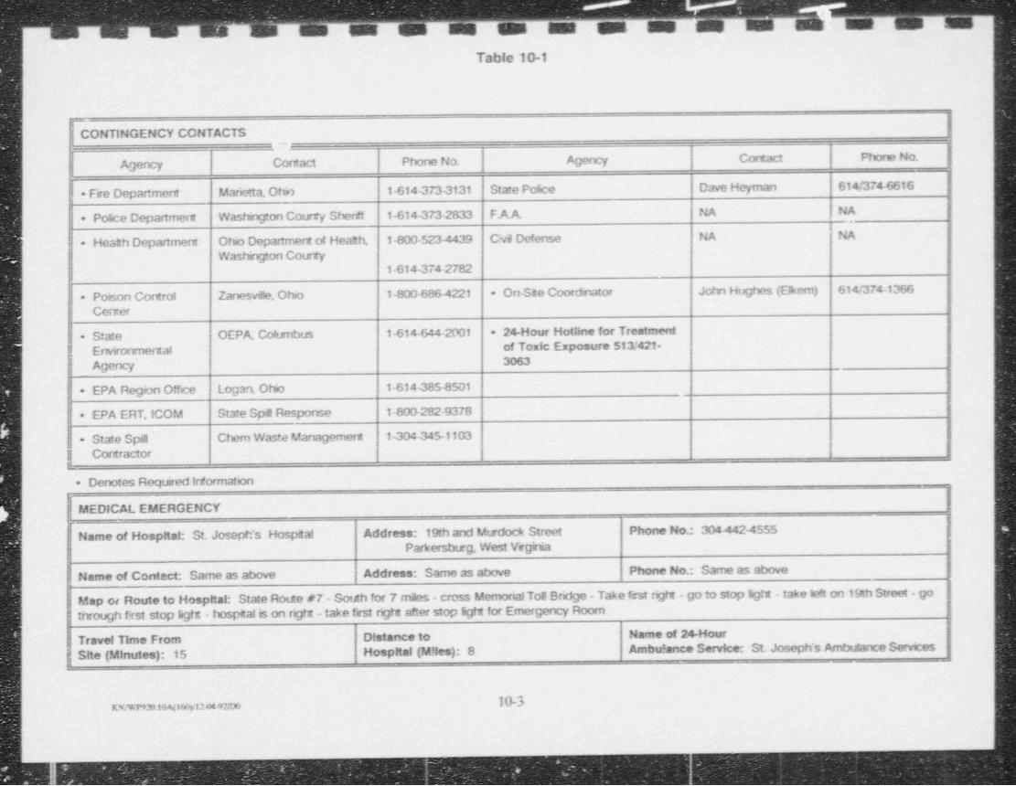
mMM m'M M m'~-
Tcble 10-1
r| CONTINGENCY CCNTACTS
Agency C act Phone No. Agency Contact Phone No-
* Fire Department Marietta. Ohio 1-614-373-3131 State Police Dave Heyman 614/374&t6
* Police Department Washngton County Sher 2f 1-614 4 73-2833 F.A.A. NA NA
i * Heanh Department Ohio Department of Health, 1-800-5234 439 Chril Defense NA NA
Washngton County1-6144 74-2782
+ Poison Control Zanesvif|e. Ohio 1-800-6864221 - On-Site Coordnator John Hughes (Elkem) 614/374-1366
Center
+ State OEPA, Cokanbus 1-614-644-2001 24-Hour Hotline for Treatment
Environmental of Toxic Exposure 513/421-3063Agency
+ EPA Region Offee Logan, Ohio 1-614-385-8501
+ EPA ERT. ICOM State Spill Response 1-800-282-9370
| - State Spill Chem Waste Management 1-304445-1103Contractor
._
- Denotes Required Irtormation|
MEDICAL EMERGENCY-
Name of Hospital: St. Joseph's Hospital Address: 19th and Mtrdock Street Phone No.: 304-442-4555Parkersburg. West Virginia
|!
| Name of Contact: Same as above Address: Same as above Phone No.: Same as above
Map or Route to Hospital: State Route #7 - South for 7 m3es - cross Memorial toe Bridge - Take first right - go to stop light - take left on 19th Street - gothrough first stop light - hospital is on right - take frst right after stop light for Emergency Room
Travel Time From Distance to Name of 24-Hour
, Site (Minutes): 15 Hospital (Miles): 8 Ambulance Service: St. Joseph's Ambulance Sennces!
l
j|10-3KN/WP92010NWy1244MTmi
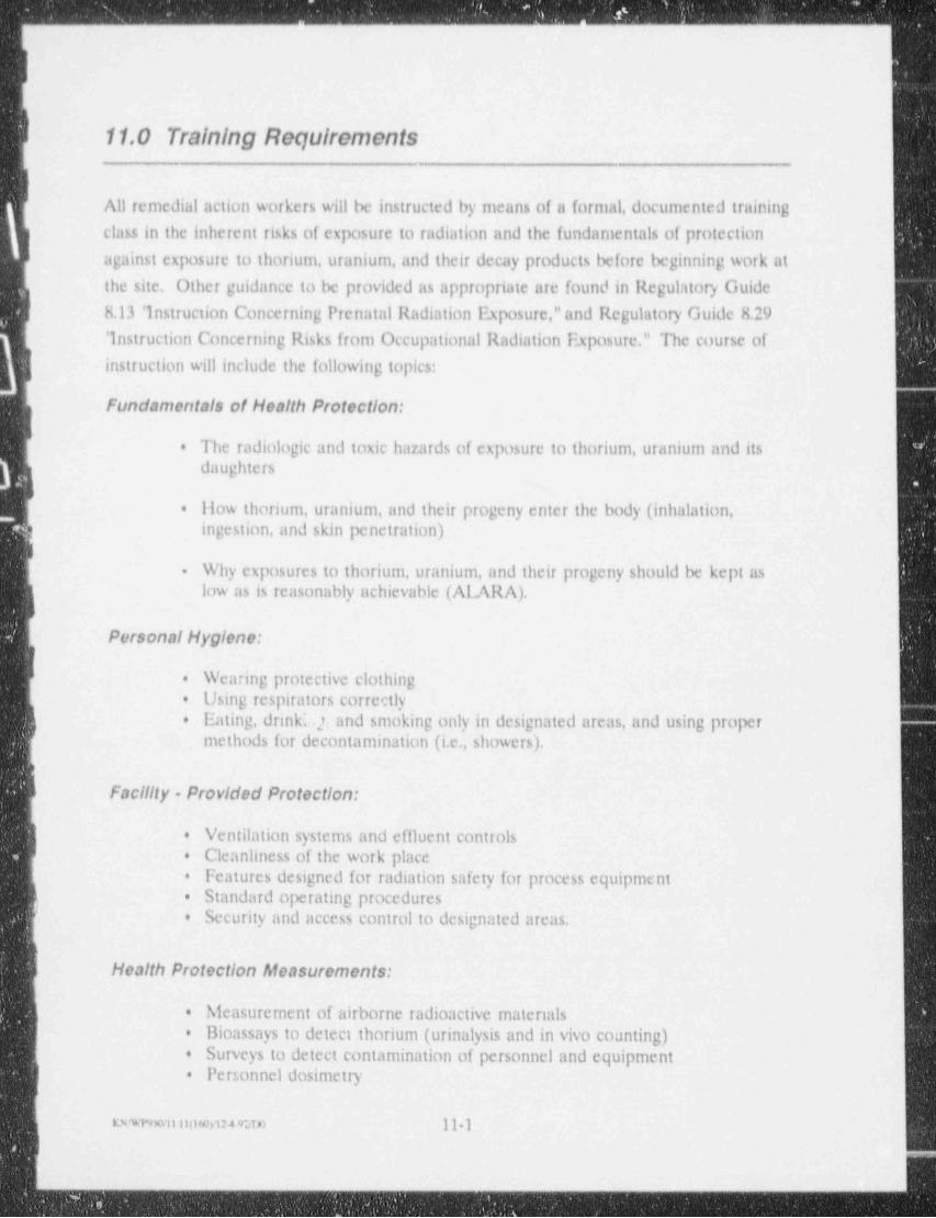
__
k
r
11.0 Training Requirementsk
-
All remedial action workers will be instructed by means of a formal, documented trainingt
class in the inherent risks of exposure to radiation and the fundamentals of protection
against exposure to thoriutn, uranium, and their decay products before beginning work at
the site. Other guidance to be provided as appropriate are found in Regulatory Guide'
8.13 ' instruction Concerning Prenatal Radiation Exposure,"and Regulatory Guide 8.29
' instruction Concerning Risks from Occupational Radiation Exposure." The course of
instruction will include the following topics:,
Fundamentals of Health Protection:i
The radiologic and toxic hazards of exposure to thorium, uranium and its.
daughters
How thorium, uranium, and their progeny enter the body (inhalation,.
e ingestion, and skin penetration)1
Why exposures to thorium, uranium, and their progeny should be kept as-
low as is reasonably achievable (A1 ARA).
Personal Hygiene:
Wearing protective clothing.
Using respirators correctly.
Eating, drinki.j; and smoking only in designated areas, and using proper.
methods for decontamination (i.e., showers).
Facility - Provided Protection:
Ventilation systems and effluent controls.
Cleanliness of the work place'
.
Features designed for radiation safety for process equipmenta
Standard operating procedures.
Security and access control to designated areas..
Health Protection Alcasurements:
Measurement of airborne radioactive materials.
Bioassays to detect thorium (urinalysis and in vivo counting).
Surveys to detect contamination of personnel and equipment+
| Personnel dosimetry.
w e munow>uu m 11 1!
- _ _ _ _ _ - - _ - _ _ _ - _ _ _ _ _
- ___- - _ . _ _ _ _ -
,
<
,
Respirator fit testing*
|
Radiation Protection Regulallons:
) Regulatory authority of NRC, OSliA, and State*
Employee rights in 10 CFR Part 19*
Radiation protection requirements in 10 CFR Part 20.+
All visitors who have not received training will be escorted by someone properly trained
| and knowledgeable about the hanirds at the site. At a minimum, visitors will be
instructed specifically on what they should do to avoid possible hanirds in the areas of
the site they will be visiting.
g A training file will be maintained on site for all project personnel and will containp documentation of applicable training completed.
| All projeci personnel shall have received the applicable trabling required by OSilA
29CFR1910.120 prior to commencing on site activities. Thb training includes 40 llour
| OSilA training,8 Ilour Refresher,24 llour on the job t.raning, and 8 hour Supervisor,
and llazard Communication Training, as required.
I
|
l
I
)
l
l
IKnwwu.ii(ison24 92;oo 11 2
_ _ . . .. _ _ _ _ _ _ _ _ - _ _ _ _ -___ _ _ _ _ _ _ _ _
-_ -_-_ __ _ - _ _ - - - - - - . -- - - - - - - - - - - -
-
J
12.0 MedicalSurvoillanco.
A pre project physical will be required of each worker that might be using a respirator in
their normal remedial action work duties. The physical will be necessary to evaluate the
individual's limitations to wearly respirator devices and will be given within nine months
prior to commencing work on the project.
The physical will be given by a licensed physician. He/she will indicate any medical
g restrictions the ernployee may have in regards to respirator use.
I The following clinical conditions will be considered in determining an individual's fitness
for respirator use:
B Chronic obstructive and restrictive lung disease - chronic bronchitis, emphy-.
sema, pneumoconioses, fibrothorax, asthma, etc.
j Ischemic heart disease coronary insufficiency and myocardial infarction.
Benign and accelerated hypertension.
Hemorrhagic disorders - vascular hemophilla, hypersplenism, thrombocyto-.
penia, purpura, etc.
EThyroid disorders or cystic fibrosis*
Epilepsy - grundmal, focal, etc.*
Diabetes mellitus.
Cerebrovascular accidents.
Facial abnormalities.
Kidney diseases.
Conductive and senorineural hearing lossa
Serious defects in visual acuity.
Ruptured cardrum or other disabilities.
Poor eyesight.
KN TP9 Ell.120fW12 dete 12 1
_ _ _ _ _ _ _ _ - _ _ _ _ . . _ _ _ _-
-
-
Poor hearing*>
'
liernia - can be aggravated by wearing / carrying respiratory protective.
equipment (SCHA)
Lack of use of fingers or hands - respirators such as gas masks, supplied-air.
respirators, and self. contained breathing apparattn require connection anddisconnection of parts and manipulation of valves and fittings during use.
I Persons with missing or disabled fingers may have difficulty in using thesedevises, particularly in an emergency where there is no one present to assistthem.
BMental factors must also be taken into consideration when employees are -+
required to wear respirators. Some individuals become claustrophobic when| wearing a respirator, These individuals should not be required to wearrespirators if the condition is severe enough to cause panic.
Scars, hollow temples, very prominent cheekbones, deep skin creases, and.
lack of teeth or dentures may cause respirator facepiece sealing problems.;
Dentures or missing teeth may cause problems in sealing a mouthpieceI around a person's mouth. Full dentures should be retained when wearing arespirator, but partial dentures may or may not have to be removed, depend-ing upon the possibility of swallowing them. With full lower dentures,I problems in fitting quarter masks can be expected, as the lower part of themask tends to unseat the dentures.
The physician will furnish the respective worker's employer with a signed medicalstatement indicating that the worker is or is not physically able to use respiratoryprotective equipment.
Ks wnwii i2(iewi 4.92.tx) 12-2
_.. ..
.
_
s
<|
13.0 Recordkeeping Roqurlomontsi
I|
10 CFR enumerates a number of recordkeeping requirements for workers who may be
exposed to radioactive materials. Such records are valuable in that they may be of legal
significance, sources of information indicating trends in site conditions, and sources of
general information to support future work planning. In order for these records to be
| meaningful and useful, it is important that they be legible, factual, clear, complete,
concise, dated, and signed by the persons recording the information.
Health and safety recordkeeping requirements for this site include:
. medical surveillance records,
. respirator program records,+ training records, and
worker exposure records.a
IFollowing is a discussion of these recordkeeping requirements at this site.
13.1 Medical Surveillance Records
| Records will be maintained in the following manner
. The physician will maintain all medical surveillance records.
| . Only the medical clearance form will be kept by UCC. All records generated by the physician will remain confidential.* Employees or designated representatives may request results of the examination.
| . Exposure reports, monitoring records, and other records will be kept for aperiod of 30 years beyond the last date of employment, or 20 years afteremployee's death.
i13.2 Respirator Program Records
| All respirator c : ram records and documents will be maintained by the Site Health andSafety Officer e JO). Inspection and maintenance forms will be obtained by thenindividual frora the SHSO. Forms will be promptly returned to the SHSO.
13.2.1 User Tralning and Medical Clearance
Each person using a respiratory device will be medically certified, trained, and
qualitatively fit-tested for a specific form of respiratory device.
Irwmu uxm1:292.Tr 13 1 1
- _ _ _ _ _ _ _ _ _ _ _ _ -_ _ _ _ _ __ -__ __ . . _ _ _
. - _ _ _ _ _ _ _ _ _ _ _ - _ _ _ _ _ _ _ _ _ _ _ _ _ _
13.2.2 Unit issuo Mr,Intonanco Log| A log will be kept for all types of respiratory protection devices issued and maintenance
procedures performed on each device. Log will also serve as a respirator assignment
sheet. The SHSO will record this data (see Figure 131),
i13.2.3 Inspection of UnlisSCBA and respirators used non routinely will be inspected by the individual assigned to
each unit for that particular time (see Figure 13 2).
Routinely used respirators will be inspected before and after use. inspection during
cleaning is to be recorded (see Figure 13 3).
13.2.4 Fit testinginitial and further qualitative fit-testing will be recorded (see Figure 13-4).
13.3 Tralning Records
Each employee attending the radiological health training course will receive a certificate
g documenting completion of the program. UCC will maintain files of training certificatesa for all personnel.
Radiological health training will be documented on a form as exhibited in Figure 13 5.
| 13.4 Worker Exposure Records
The primary function of radiological health recordkeeping is to document annual,
committed, and cumulative (lifetime) radiation doses of individual workers. This is
accomplished through a combination of external dose measurement records and internal
dose calculations based on bioassay and exposure (workplace) measurements. WorkersI must also provide documentation of prior radiation exposures and doses through prior
employer records.
Secondary recordkeeping functions include documentation of worker specific
| investigations, including medical, and radiological health training.
An Occupational Radiation Exposure History file is maintained for each employee who
may be or is exposed to ionizing radiation or radioactive materials during the discharge
of assigned duties.
t
a v w n no w m a c rr 13 2 I
_

,
-
Additionalinformation retained on file includes the results of radiation, contamination
L and air concentration surveys, and reports of overexposures and excessive levels andconcentrations,
d1
13.4.1 Worker Occupallonal Radiation Exposure History File
Each individual Occupational Radiation Exposure History file is updated on a frequency;
corresponding to the shortest interval of personnel monitoring, either external or internal
dosimetry. The Site llealth and Safety Officer may cause file updates to occur more
g frequently under condition:; of unplanned exposures or unexpected dosimetry results, inB all cases, the files will be updated at least annually.
The Occupational Radiation Exposure llistory file contains the following types of
information:
IIndividual's complete name.*
IIndividual's social security number.*
I Individual's date of birth.+
Records of prior occupational radiation exposure (forms NRC 4 and llP-lRH,.
Figures 13-6 and 13-7, respectively).
Records used in preparing NRC-4 and IIP-IRil.*
lReports of external and internal radiation exposure and doses (forms NRC 5.
and HP lRR, Figures 13-8 and 13 9, respectively).
Records of medical evaluations.*
Records of internal dosimetric data such as results of in vivo counting and.
bioassay sample analyses, types of samples and measurements, dates of samples
and measurements, etc.
Reports of exposure investigations performed, including the reasons for the.
investigations and the results.
Khr9Wil D(160Vl?492TT 13 3
_ _ _ _ _ _ - _ - _ _ _ _ _ _
,
,
L
Reports of cumulative internal and external radiation doses (form 1IP.CDR.+
IL Figure 13-10) including supporting calculations.
r\ 13.4.2 Proservation of Records
Employee medical and radiation exposure records will be preserved and maintained in a
retrievable form for at least 30 years.
Medical and radiation exposure analyses, sampling plans and results, descriptions of
[analytical and mathematical methods employed, and a summary of other background
I data relevant to interpretation of the results obtained will be preserved and maintained
as above for at least 30 years.
I
I
|
l
I
l
|
I
|
n5powit.is(too>12 7 92.TT 13-4|
__-_ - _ _ _ - _ _ _ _ _ _ _ _ _ _ -
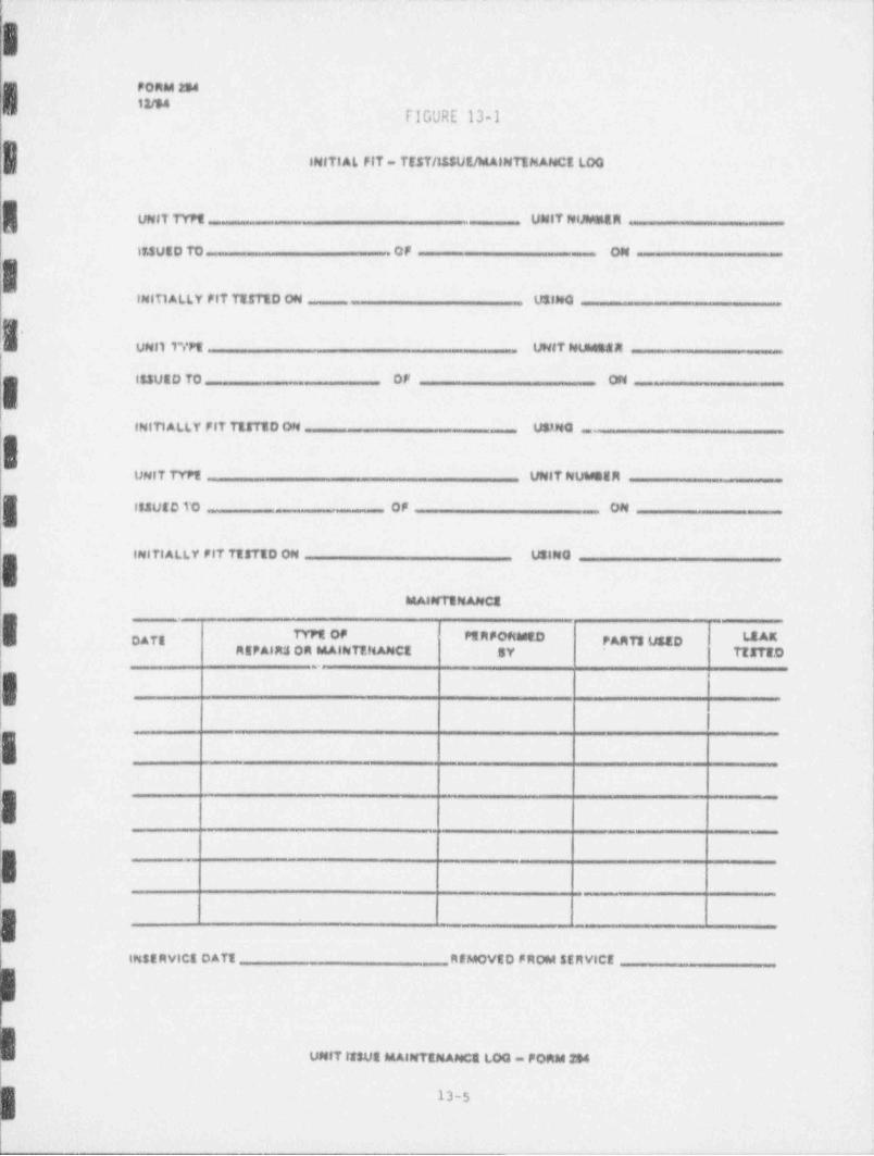
Yr
| PORM 254
( flGURE 13-1,
INITIAL FIT - TEST /1& SUE /MAINTEMAf4C1 LOG
UNIT TYPt UNITNIMMER
lt1UED TO .QF ON -
| INITI ALLY FIT TTITED ON U3th0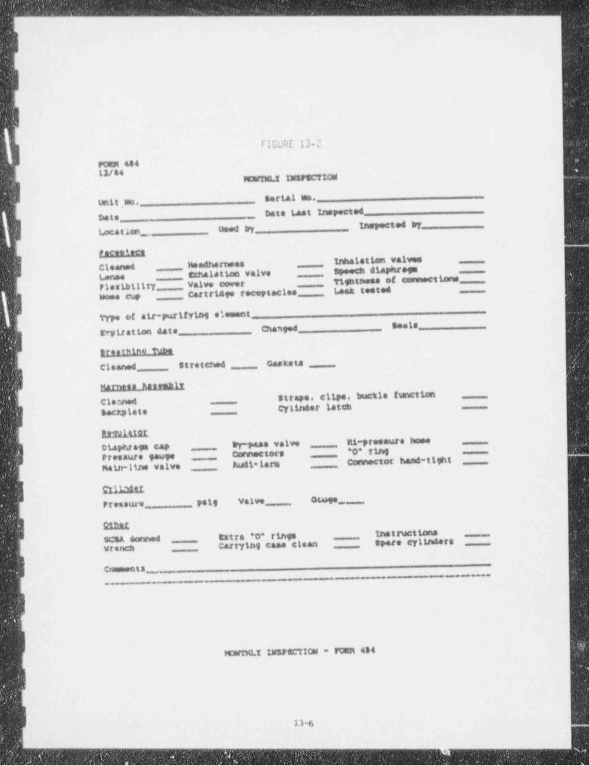
- - - - - - - _ _ __-- _ _ _ _ _ - _ - _ _ - _ _ _ _ _ _ _ _ _ _ _ _ _ _ _ _ _ __
L
F
FIGURE 13-2
w .. MUMMW
EeriAl Wo. _
tXtit ,Mo. .
Date _ Date t,ast Inspected
locatlon _ used by inspected try
recenteenInhalation valwa
Cleened Hes4harrassatxnalation valve Speech diaphragm,,,,,,,,,,,,
L,4nse tightriese of connectionsPlexiht11ty ,,,,,,,,,, valvo cworCartridge roce,tactes taak testedwoe.e cup
Type of air-purifying elementseatsteptration date changed ,,,
arenthino tubeClanned Stretched ___ Carksis
hui. Ass embiv.straps, clips, buckle (suwtiencleaned ,,
34ctylate cylinder latch
lutfNiil2Lj Diaphrage cap ty-pa.as valve Mi-pressure home
| Pressure tauge Coremeters *0* rirq_,,,,,,,,,,,
Main-line valve taalt-lara Connector hand-tight,,_
,,
Tril:bitiPressure psig Va lve _,,,,, omge,,,
S1hitIScsA 6artmed Extra *o* rings InstructionsV4tW:n CAftY1A9 Case cle&D Spare Cylinder $
omment s ,,,,, ,,,
..._.
I
M*nmu.Y Uf178CTION - FORH 484
-
~''-----_-___m___ _ , , _ _ ___
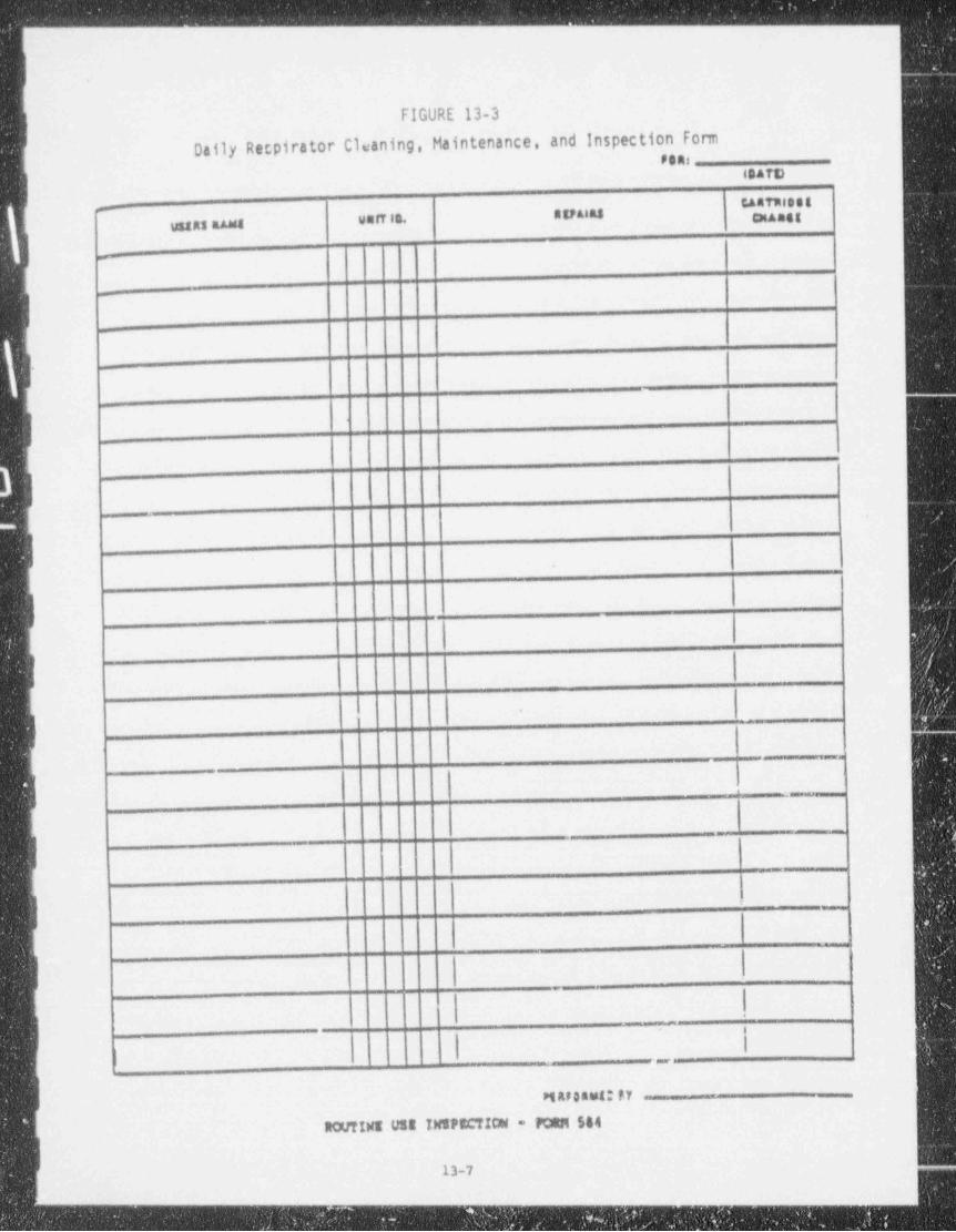
- - _ _ _ _ _ _ _ _ _ _ _
FIGURE 13-3
Daily Retpirator Cleaning, Maintenance, and Inspection fonnpens
esare
''"7,',',' 8vsn in, muuasussas mest
--
_
-
-
-,_
|
| .
I.
J,
-
_
1
I
:
_ _ _ _ _ _ _
||'
| -_
| Mas saut: PY - --
'
RotrINE USS INSPEC't!ON = FoltM 544 |
|13-7
- - - - - - _ - _ - _ _ _ _ _ _ _ _ _ _ _ _ _ _ _ _ _ __ _ ___ _ _
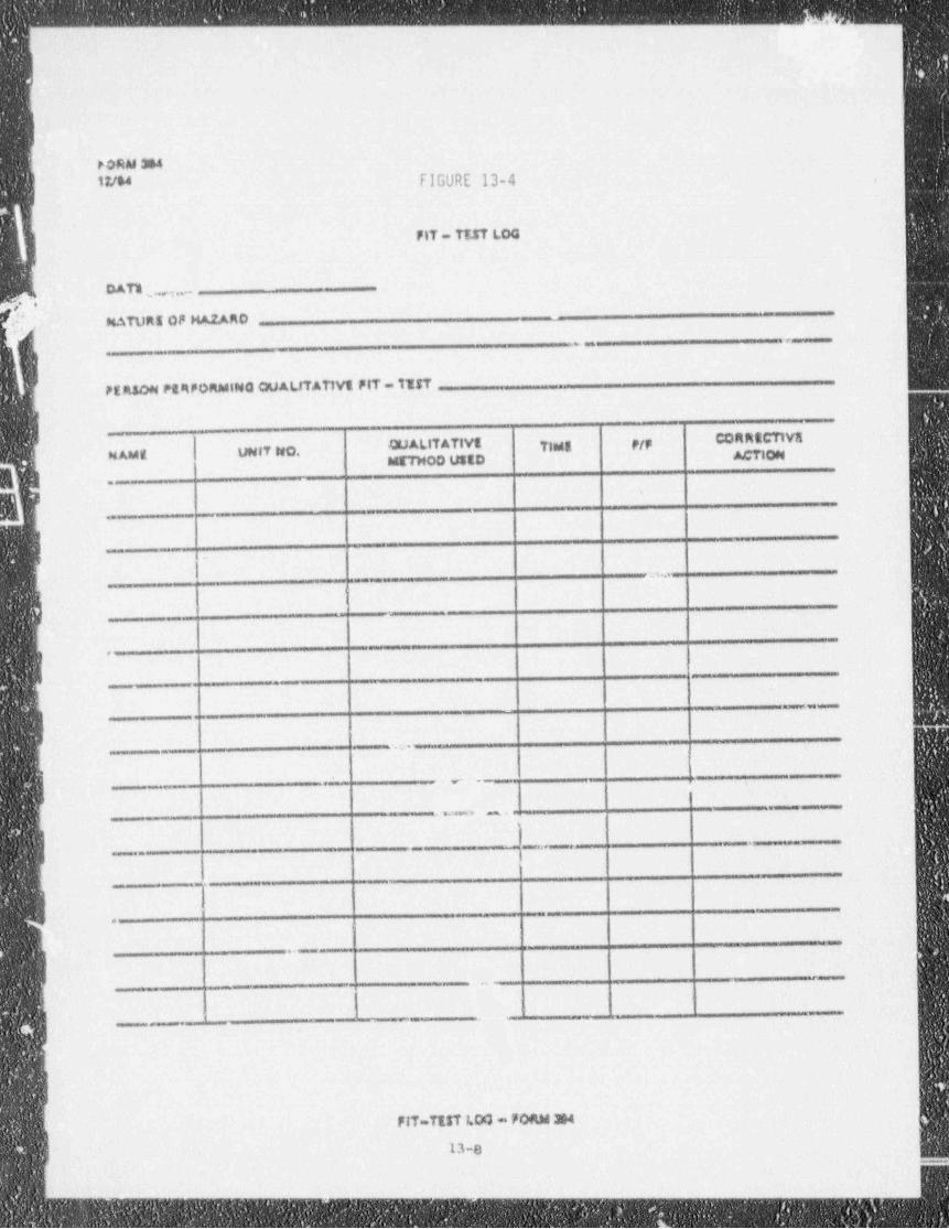
-. ~
PORM 364tute FIGURE 13-4
FIT - TT.KT LOG
DAT1 ,y,._
P?P MATUR$OFHAZARD
. . , _ .-
PE ASON PgRPORMING QUALITATIVE FIT = IIIT *
CORRECTIVEQUALITATIVE Tints P/PNAMg UNIT S*0.METHOD ustD C ON
--
:m._
9 ..
i
43sg% 4SiaWSUS
|
___-
.y 4 _
..n. . .. I
__ ,_ _ - -
t
i
c.
,em
. 585 . -
#
'
13-8
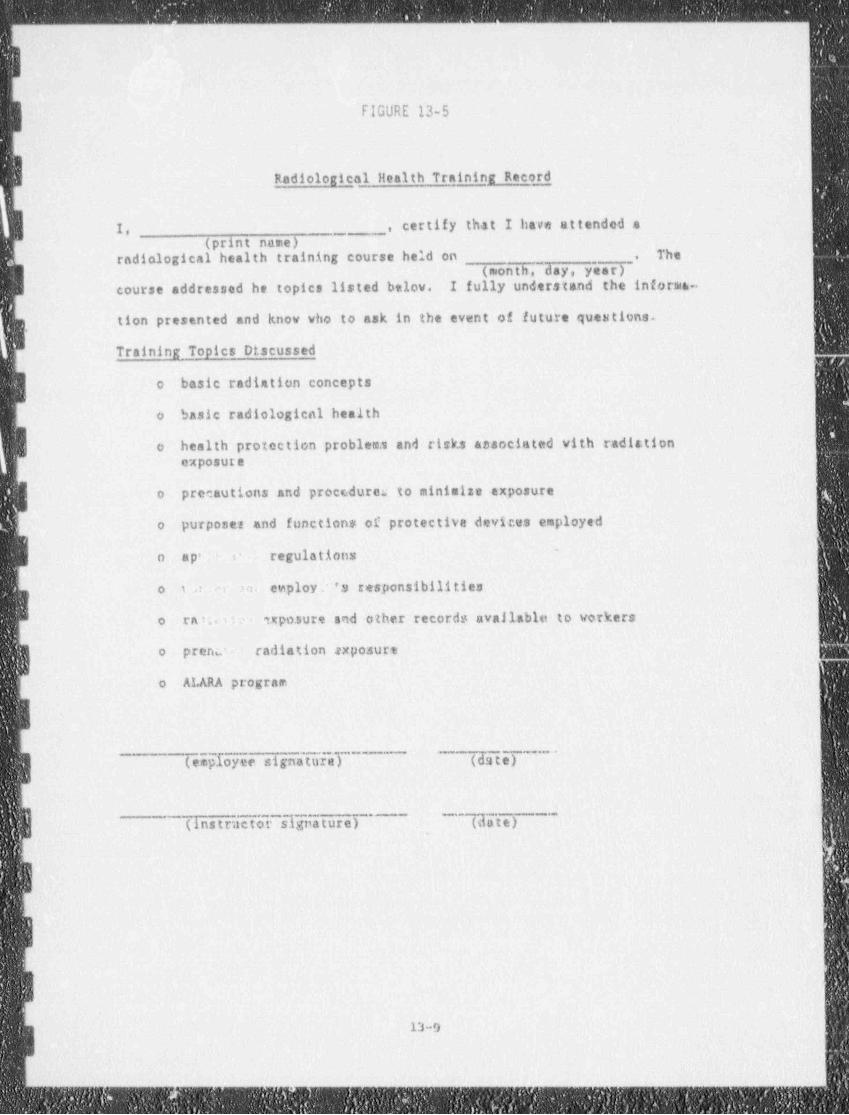
- ____-__ -.
L-
-
1
FIGURE 13-5
Radiologhal }{ealth Training Recordi
|
I, ., certify that I have attended a,_
(print name)radiological health training course held on _ The,
(month, day, year)course addressed he topics listed below. I fully understand the informs-
tion presented and know who to ask in the event of future questions.
Training Topics Dtscussed'
o basic radiation concepts,
o basic radiological health
health protection problema and risks associated with radiationoexposure
o precautions and proce.dures to minimize exposure j
purposes and functions of protectiva devices employed,
o
o a p' c regulations ~ fi
etnploy.. 's responsibilities eo t : n.
I o ra m si upo.sure and other records available to workers
o prenu radiation Neposure'
o ALARA program
I(employeesignatureT~ (date)
~
<
(instructor signature) '~~Tda t e)
)
,
i
13-9
_-
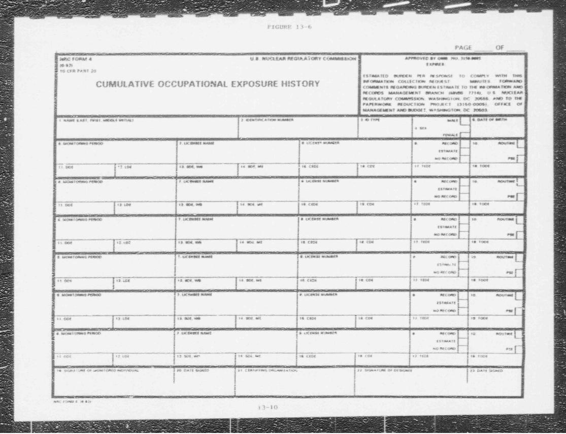
FIGURR 13-6
.PAGE OF
- _ _ - _ _ _ -.
-
ISeRC FORM 4 U 8. NL6 REG 8A.A eORY C(AtMtst:0.d APPROvtc gy Oese feu. Jessee.$
!. t EPunt a:to en.lIO C,a nni a
(5IIh4A TID ituRDE N MR RE $Pfmit tO COMPLV WIVM INe5" " " ^ ' " " "''"c'""""''' """"" " " ' " ' ' *CUMULATIVE OCCUPATlONAL EXPOSURE H! STORY COMWNIS MOARD.eG BU.tDEN ESinAA ff 10 THE INDORMA TE3M A880M COfO$ MANAO(WNi BRANCH &&ONGG 7714). (8 $ APJC1( AA 'MOULATCAtv COMIMS$30.e. WASH.*G,06.DC JU666. AND 70 TH$PAPE RWOmet M DUCitore PROJE C T 43860 00063. OFfeCE OF'
MANAGESMNT Afe 30D0(f. WASH.eGTON DC 20503.
ssEes a Ass, estss.M s rbets 2 etaruMC Avense mune..a 3 e rvet e.ag g i s.ca e ce .arw
. . .
- - _ . .. . .
-
-_
. .- - - - --- -
.. m . a. .-
,s ..._ t. co ..
eM AE(_
-
M
| Tim m . ,,. % .. . '.. c.ca .. m .,..o. .. voo.;
l . __ _ _ _ - _ _ _ _ . , --
| je. wve o M~
r ucewese e-
. ta.== mum sen . necono e, meer e4~|
~
| essa.ase
no ascese~
e.r f,,, - , , . .. .. .. c.m .. m . , , , - . . , _
,| |i
| [ s wcm.eo. a n ao ..ucem.en name . ucens =sm en e neco e se e.ove e "
| l e si.e.4,a_ {
E noacomo-
em p
[ ....e. . . . . .. .. .. .. c,m , .. cm ., .. . . . _
,
83' ins. ,6-
floU1.et |$ awa.f astes6 eldDCD f. tJc t.r9f f Eneaset S. uCEN34 enunas.2 'P Jtec o84m ;9_,
j] ero atr o.to Ptr
,,,_ ! .. _ - - -
. . _ . . . _ . .. c.m .. _ .. ..o. . . . _
.,
p _ .,o , oo- t,_ . ._._. . __ ..,
'
... ...w
| -c o.e-
P.q -g , , ...,, . , , . . . . .. m . .. c . . co. .. .
,
n~~
'iucemmemant--- - - _ _
f. o icn ac. o6E ~ no.sm {i: . . c e == =um e * . neco.e .4,
... . .'
=o as c omo~
e :a fn,._ . . . o. . . . - ,e ..c_ .. _ .. .. .. . _
.- _ . _ . - - . _ _ . _
se sew.a r usse o+ . ace.s omeo wmm __ l ao cast seasseo .ascame v 9o 4=.e.re. Ja smaetme o. peseu.es sa nai, ma.
l<
- - - _ -
_ _
asnC 73staa 8 .4 Sie
:3-10..
- - _
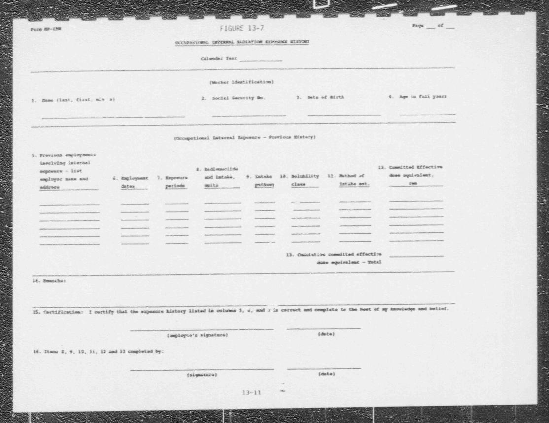
, , ., ,. ., ,~ ,-- ,
' = * " flGURE 13-7 em _ cf ___
cmirAsifwM. trnacmL sacrArgone cxm:ranz astner'
).calor.ds: Imar
I
(mster idestificatizal
1. m == (last, first, ele'al 2. social 2 - ,ity me. 3. mte of Easth 4. age im enti ya rs
I
t%tional Istereal Espemaze - Pterianas mistory)
13. Freet na es9 opments
iaealving laternaii
! M. Radiaan cif 4* 12. Ca mitted Effect1*e| ee5**ure - List
emptsyet mz== and 4. Delsymmet 1. Exposure .cys a me .N. 9. htake 14, sshattity 11. susthed of esse equivalent,'
| addreen dates periods esmit s oth*'T class intaka est. runI
i
!|
-
i
+
l ..
I
!
|I -,
|
13. Omr.alst135 comitted effectismmae , ogwiwalent - Total
14. semachm
1 certify that the eagesere klatory listed in colioma S J aiad h is correct and canylste te the best of ag Amosladge and t=11ef.15. Certificatimar
(amplops's st zataxel (dete)T
16 itaama 3, S.12,11,12 and 13 en giet 4 by:
(si e txzel (aste p
-
13-11 -
. - _ _ _ _ _ _ _
_- ,
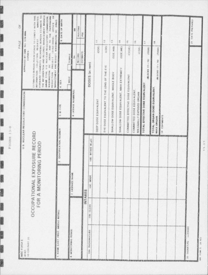
} M , i a| i|'|i
S 'o H e, tRO_ 5 f_ _ e' CW"ll NC O 3 H o_
__
' BtU A SW 0 T g
N '^ S"
r E 5 R nA5 R Ff " aC0 S PO * M"I uMt m2
n uA F F g
NoPO C O e uF' 5 s rE re ' C D E un " M t f
e " *E r E .T o se f
H N A n PGmT L O O A
"NIwa "t UA O 6 ||I
* O O C 6 _ ' 3 o 5 6 ? 8 1E s "S * A A O N ' [-I t 1 1 2T '
-
G ' f t 1
w U"Mt OI 4u H_ A G D0S f
EI at) I p
O E5'Q*SP N 5 A f E E E/
" R "aE DE O D w M. D D D DN RA8 Wnws D t3 EO R 1
I. e oE O( E C
i_..
E C T
"C 2C O u c ri
St
tTT I
o ~, EN C A S (A D D'tOct (
" Af % G A A n8ru_ I
1
r So "ia'DC
t T s oo 0o s- 5 /sN U GE l
E e sE
v M'A N J f- ' n E i t1t
.
l |j
"C*Um"O e
e. $ C OGo ,E 1D RN ta e 1
a O PA Y Y rr rr " T
* O * *a,, N. T I ||g E T S $
4 ON N in E Y MI CA K rN A 8
H cE f D E T O oa 1 I O M S O R N a rl A 7 T
"u*^4 I CC ^a 07 Gt E t
^ Pe i! E F D T E t at
1X S O X L
t
"R #6H UA " E
" 0 "* 4 rl 4
S O S L E A#E D N E TVf A A N O X 1 N" i ' D u W R *> -
.
I
DrsE
E H A U I T.L W M O .
A NLiI '.f- ige T
N rE
,
T. Es E
H N N V ET LaO T E r
s w N 4 S A U At LO E E O A G Q Vrs u - T L L D V R E U
fs T A A iOt uM N N T V V E u E O
I 1 v OD S EE NM 1 u L E U U OP Tt E E EO Y N A L Q Q S D SC EC V A E E O E O1 st V E Sc PY U t E E F O N D0 e
XO u S S FR t
O 3 e E O O O E DE T NC SE E D D D D Y ANT TE G A NA E E t T
L'i , S E W W T T t T R G E
U ' O S aA E Ot sC D O C O T T
/ fI I i
L Lo uL L M M&DE P L L i O8 R E E A A M MX A A X CT T- R E V H H O O A O O A3 R D E S S C C M T TME PA D e t1 E b
i
:
R u j
( jL
G I -E C NR U O ONU N p 7
I S.CD O
H 1f
EO A _ -TF U C 1RI a
A TC _
R e_i T
EE M NtRP O 0
_
U 0
G 12S
OIN E *
_ PR_XO -
u_ t
ET A O(
-H D_
I
LN u. ._
A .
I __
A O Cn
M _ eN O
S
O _ Ss. - E -
!TA 7 -
w. .
T|
| 8
_ -- K -P. AAR -rP O N_
-_
I
U F S_ S
C A,
1
C U - CMO ST W _C
N I_
. ~E-
_L
_
- Oi1
- =O _a E
-& I_ o E Si.
w O Ns E
[2Oi L
_De
Cn U i0
.f
-Tc o N26 O 3$ w EI t
M R A DfO
6 A t . m Af
F Hi
m R TFO i n A tM
e- p2
NA.J e.
0 a
oG mC2 AA.C
.
c1 Se
_ km9=.
8
0 f
0e_ l6 y$s q|]. |hp e f |N | $.
ta
'
I
eI wIhC i
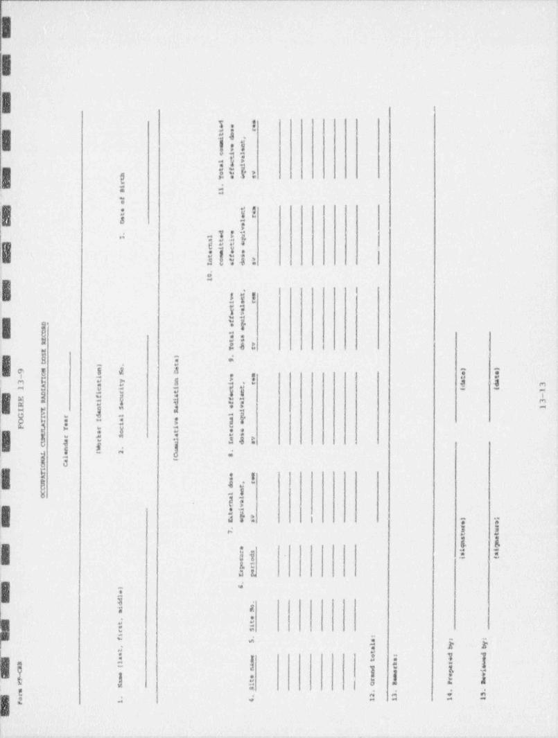
= |: ||
-
d .e e et v rt oi d ,m tm e co v ec i l
t al c va e it f u
h o f q vt T e s ar
.- i 1B 1-
f- o
t me c et e rstO a
-w
d ed.
3 l e v tqa t int t sr i ce n e sut i f sn o f e w
- I c 6 d s
- 0.1
-, _
. t n _
urevit ld ee v-
t lf eD e g
1 eC lC a at s,tR o r vT d eZ
$ l .D a 9C . t
9 M)
o e ) )nC a 5 D e ee m
-
- I l _
a a-
3 T t y n v e _t t
A a t o i , r d d 3I c i i t t1
-i (
D i r t c c 1
E A f u a e e - .R i c i f l
R t e d f a 3
I E s S a e w 1
T s R ll u
- S I r d l
-
C T a I a e a q
- F A e i v n et Y r c i r
U a o t e eM r k S a t s
t a r * s o vC d o - 1 d a
-n w ..
- L e t 2^ SA l (
H a-
C C-
IT . eC s er o , su d tw n.
A l ea l
n ar ve i.:ta g e
_ ) ;E e s e a
r r.-
7 u ut ta an p- ga i ir s s and .
i too ip rs eE p
.t 6eld
i o.d
_ m se,
t tis
r si
. sf :
5 al y y
, a b tt
_ t
M= o r ds
as= t e e
D l A k rm m d r a(
n e p i< e_ * m e a s e w-
r s r n
-r a t o a P aiN S. m . . . .
r 2 3 4 3..
r 1 4 1 1 1 1o
-
.
-
- ,
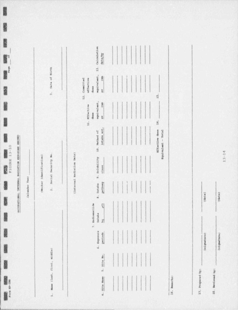
A a
4
.. i
|:
.
IL 4
. ai if'
EI 33'
|[ ?. a,it d
>s,
.
,| | :]llte 1
Y
i,.-
$ , f 5'. j ?.=
sili I
.I a i'
. ,,
: vi i;'| ! li .:
<: 3 11o
.s v J = sv ,
|g:=j 13ii } T-
1 e ! |,
, 5 B e 8 j-
: $ f,
.| | ! si i ,i
331- 1 id 53 3 1 3'
-
gg .
~i ig
> ,
.I'-| T
|39
las .s
r:
I'j 7- 7- ,
3 3N ,& g- g.,.
L|-d 2 3-
. , . .
a
b< = > > >
- | h
r i a 1 i..-
i
; |d d d:g!; ;
e_ _ _.
- . .-
|I.
:-|
LI i.
!I
;
|-
:IPARTlli
i
! I
-| QUALITY ASSURANCE PROJECT PLAN
|It
i
I ^
I. .
I.
I:| .
.
4 ' -' '
:
.
.
i
l|.
i|I 1.0 Introduction. ___
.|? The overall objective of the Quality Assurance / Quality Control (ONOC) program for
this project is to develop and irnplement procedures for field sarnpling, chain-of custody,
E laboratory analysis, and reporting that will assure legally and technically defensible
; sesults. The OA/OC program establishes and exercises control over the reliability of the! data produced in terms of precision, accuracy, represcatativeness,- completeness, and
comparability,
;liThe primag elements of the ONOC program are as follows:
Data quality objectives.
Sampling.,
;g sample custodya
iE calibration procedures and frequencya
. analytical procedures.
| data reduction, validation and reporting*
internal quality con 7rol checks; **
interlaboratory quality control checks.
jg performance and systems audits,
.
preventative maintenance-
-
specific routine procedures to assess data quality-
:{) corrective action.
.' quality assurance reports. ;.
;
!g4
Y
1Iil:
-
' b hIN[2,EkM .
:
. . .
|1
'
2.0 Data Quality Objectives
Data qual objectives (DOOs) for this project are bifurcated into direct field measure-.
'
ment DOOs (Table 21) and analyticallaboratory DQOs (Table 2-2). DOOs for data
precision, accuracy, sensitivity, and completeness have been established for all laboratory
and most direct field measurement parameters. DOos for representativeness are not
| quan:itative values which can be compared, but rather programmatic objectives which are
attained through the use of standardized sampling procedures, proper equipment
calibration, etc. DOOs for comparability are not quantitative values either and are
achieved by ensuring that all data are calculated using approp.tiate algorithms and,
reported in consistent units.
>
|I;
I.
v
:I!
:1
:I:
-
B
,I
II
-- 2.,,
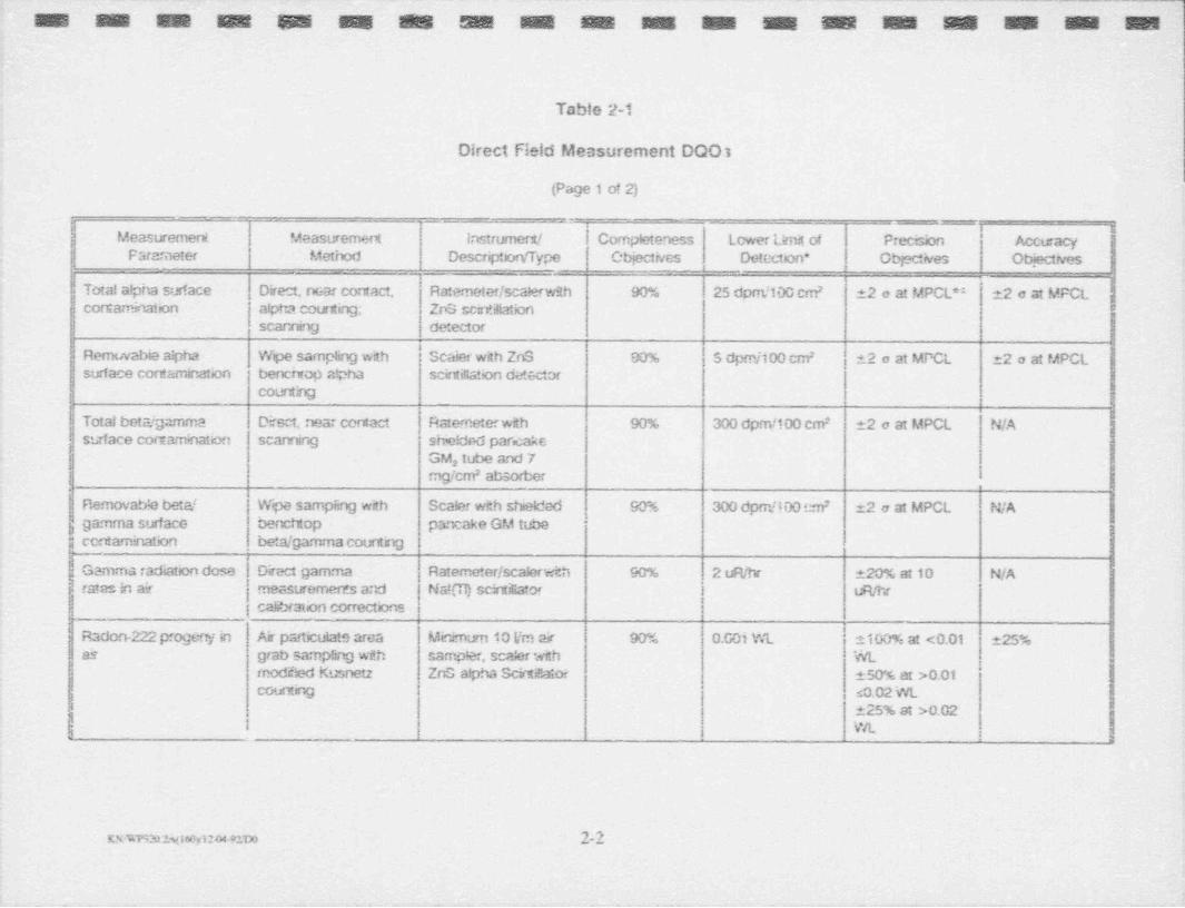
__ . .. ., . _ . _ - . ,_ _ ._ . . _ _ _ _
~M .m M''M .M M M 82155 M M M. M M M M :M M M M-
Table 2-1
Direct Field Measurement DOO3
(Page 1 of 2)
- --- . __,^
Measuremerd Measuremert lastrumert! Completeness Lower Limit of Preccon Accuacyi
Parameter Method Descripton/ Type Objectives Detecton* Objectives - ' Obiecth,e !.
,
2 o at MPCL*: 22 o at MFCL ' ITotal alpha surface Direct, near contact, Ratemeter/scalerwith 90% ' 25 dom /100 cm2
corsaminatkxi - * afptu courting; ZoS scWittationscanrnng detector
' Removabie alpha Wpe sampling with Scaier with ZnS 90% i S dpm/100 cm 12 o at MPCL 12 o at MPCL2
surface contamination bencrwop afaha scintillation detsciorcounting
t
|. Total beta / gammaDirs% near cordact Ratemeterwith 90% 300 dpm/100 cm 2 o at MPCL N/A j
2,
surface cortamination scannrg sheidr4 pancake'
GM, tube and 7mg/cm absorber
.
Removabk3 betal Wpa samp5ng with Sca!er with shielded 90% 300 dpm/iOO cm 2 o at MPCL N/A2
b gamma surface benchtop pancake GM tubej contamination beta / gamma counting -
! Gamma radiation dosa - | Direct gamma Ratemeter/scalerwith 90% 2 uR/hr 20% at 10 N/Ai ratasin air | measuremerr_s and Na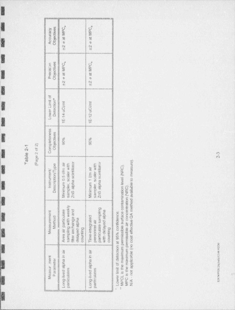
I,_ _ ___--
I
4
..
ni ii =oo5' O , o
yN,.,
}No.: 2
.
.yo Y- 5dt [3 o 0
}N N+1 fl |
8
*e.a -
B ..g g ges80 % ~
i| a (L W~
__.
.
g . .a , ,E Eh 8 bk.
a "n,
b D,g. . ~ <?
ID.T
}H. wt '$ C Eh ho-,
13 .p s a e aa
Eb 3$ d Ed 5 b1cf|.omeu =88
y$00 ay ,
E'}5*
M. i E>I E Nh. @ .5 $$
R 4ea-w q:n E Q
0
s e fa I E' nE Es .Lg .g 3
.
-'
g%cD o"%
:g* t E,0e <
=2 c 8 g <EEm *3 n
- g3 3 es 8n cam ee t fi F2 3g3 7 p .g =
e3o-
es w
. $. g ga w 7 p. yi h, E
*e s-k. o q u $e O ., Q .,$d 5 *0 'd!
* [e o$ e
$eoE*D. m
H; $t'e ooEw c35
W> mh30Q 3 5. o o -E8Mkb 3c a8'N
ogc~ y3,
$p eset .; a
u,gge.
%e 2 c x-o a 9 a
s$b ~5 " 'm . ae
m En E n$ E'g$g sy
21- 7'.ae u. a- ea2 900 n- #> y
@.51 , 3 s a. $.
.
3ce g sz31 aa :._ _ . _ .__ -~
.
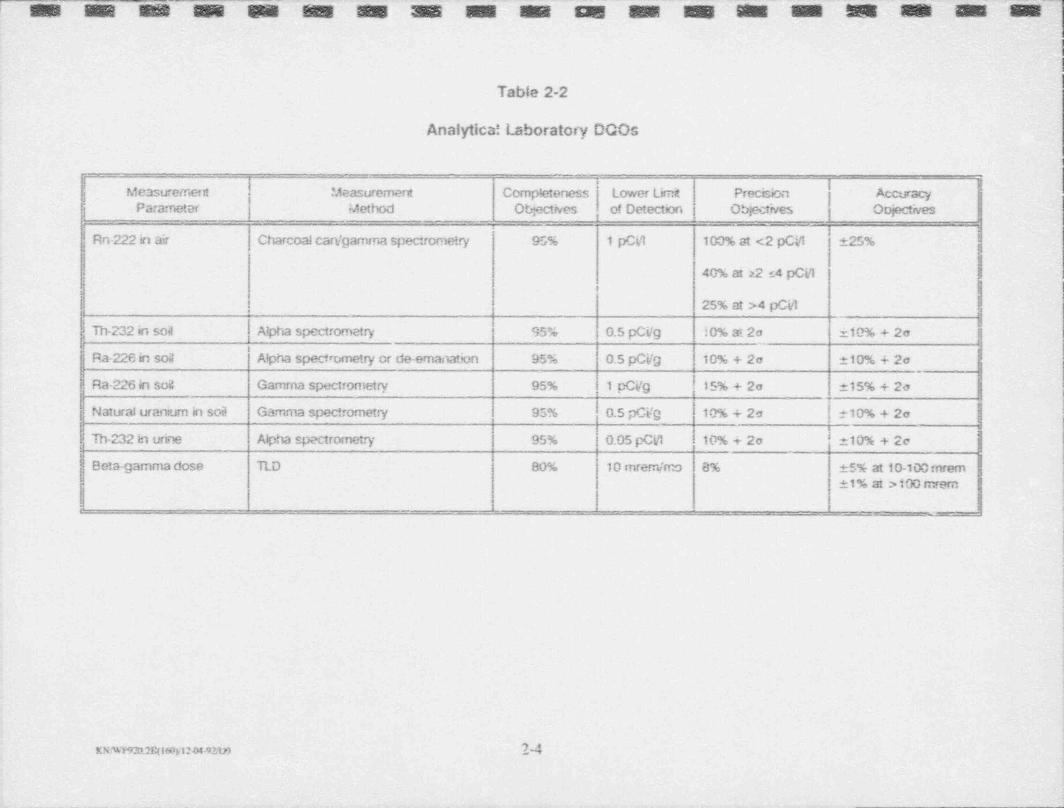
p 4 _q v g y g g g g "~ g ' Q ~" g ' y 'y g g '' g ' g/' g ;_; g-
Table 2-2
Analytica! Laboratory DCOs
1 lI .i Measurement Completeness Lower Limt Precision Accuracy -'Measuremeriti
| Parameter Method Otiectives of Detection } Objectives Oojectives_
Rn-222 in air Charcoal carVgamma spectrometry 95% 1 pCL1 100% at <2 pCi5 25%'
40% at 22 s4 pCi1
25% at >4 pCill,
'! Th-232 in soa Npha spectrometry 95% 0.5 pCVg 10% at 2o 10% + 2a-i'
Ra-226 in soa Alpha spectrometry or de-emanation 95 % 0.5 pCVg 10% + 2e 10% + 2o
Ra-2261n soi: Gamma spectrometry 95% 1 cCVg 15% + 2o 15% + 20
Natural uranium in sod Gamma spectrometry 95% 0.5 pCVg 10% + 2e t10% + 2o
Th-232 in urine Alpha spectrometry 95% 0.05 pCV! 10% + 2o 210% + 2o
Betagamma dose TLD 80% 10 mrem /mo 8% 5% at 10-100 mrem1% at >100 mrem
-
-
| M
- - - _ _ - _ _ - . - _ . _- ._ _- -_ --
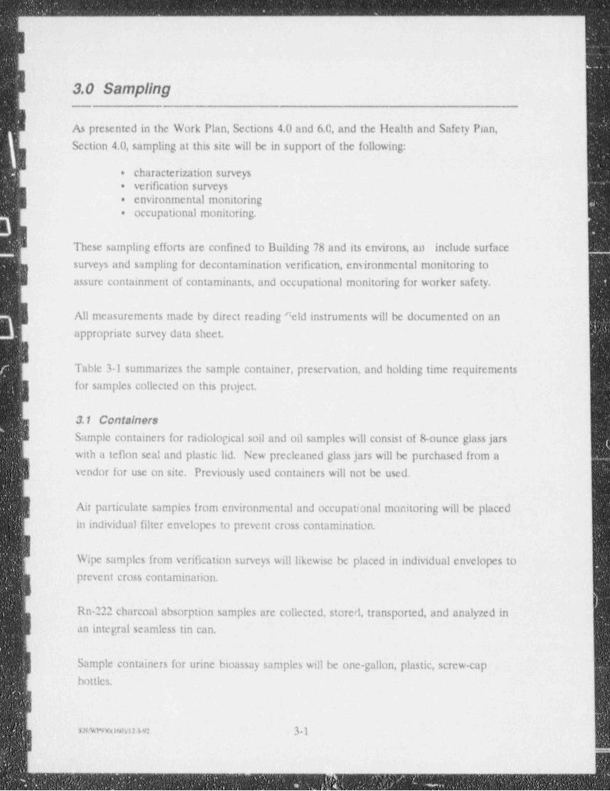
- _ _ _ _ _ _ _ - _ - _ _ _ - _ _ - _ _ - _ - _ _ - _ _ _ _ _ _ _ _ _ _ - _ - _ _ _ _ _ _ _ _ _ _ _ _ . _ _ _ - - _ _ ___ -_
3.0 Sampling
As presented in the Work Plan, Sections 4.0 and 6.0, and the Health and Safety Plan,
Section 4.0, sampling at this site will be in support of the following:
Icharacterization surveys+
verification surveys.
| environmental monitoring.
occupational monitoring..
I These sampling efforts are confined to Building 78 and its environs, an include surface
surveys and sampling for decontamination verification, environmental monitoring to
I assure containment of contaminants, and occupational monitoring for worker safety.
All measurements made by direct reading ^ eld instruments will be documented on an
appropriate survey data sheet.
ITable 3-1 summarizes the sample container, preservation, and holding time requirements
for samples collected on this project.
3.1 ContainersI Sample containers for radiological soil and oil samples will consist of 8-ounce glass jars
with a teflon seal and plastic lid. New precleaned glass jars will be purchased from a
vendor for use on site. Previously used containers will not be used.
| Air particulate samples from environmental and occupational monitoring will be placed
in individual filter envelopes to prevent cross contamination.
IWipe samples from verification surveys will likewise be placed in individual envelopes toprevent cross contamination.
1Rn-222 charcoal absorption samples are collected, stored, transported, and analyzed in
an integral seamless tin can.
Sample containers for urine bioassay samples will be one-gallon, plastic, screw-capbottles.
|mwmowyuam 3-1 !
_ -
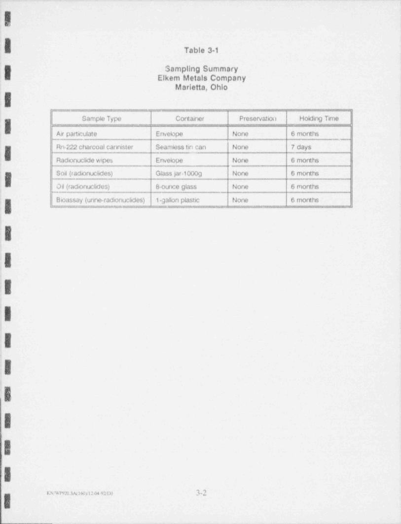
_ - .
!
,&E Table 3-1
I Sampling SummaryElkem Metals Company
Marietta, Ohio
Sample Type Cornainer Preservation Holding Time,
i Air particulate Envelope None 6 months
Rn-222 charcoal cannister Seamless tin can None 7 days
; Radionuclide wipes Envelope None 6 months.
Soil (radionuclides) Glass jar.1000g None 6 months.
Oil (radionuclides) 8-ounce glass None 6 months.
!- Bioassay (urine-radionuclides) 1-gallon plastic None 6 months__._ __
!
;I.
I-
.
i
:I4
b.
.g
ig.
I.Ig
_ _ , _ _ 32,
- ._- - _ - _ _ _ _ _ - _ _ _ - _ _ _ _ _ _ _ _ _ _ _ _ _ _ _ _ _ _-_ _ _ - .
-
-
3.2 PreservationI Preservation of radiological soil, oil, air particulate, charcoal canister, bioassay, and wipe
samples is not necessary due to the nature of the contaminants and the sample media.
Efforts will be made to protect Rn 222 canisters from undue exposure to temperatures in
excess of 100*F.-
In the unlikely event that water samples are collected, the samples will be preserved
using proper procedures to a pil of $_2.0 with nitric acid. These samples will then be
kept at a temperature of approximately 4'C until analyses.
3.3 Holding TimesSample analysis will be conducted in a timely manner such that the data will be valid.
,
liolding times for most radiological analyses samples are six months No samples will beanalyzed following expiration of holding times.
Air particulate and wipe samples will be analyzed in the field office immediately follow- i
ing collection or after the appropriate decay time has elapsed. ,
I Rn 222 charcoal canisters will be analyzed within seven days of closing. Table 3-1 lists
the holding times for each rautological sample parameter.
3.4 Shipping and Storage -
| Sample shipping and storage will be conducted in a manner that assures the integrity of
the samples is not compromised. Sample containers will be placed in plastic ziploc bags
and packaged to prevent breakage during shipping. Shipping containers will consist of
either large insulated plastic coolers, or sturdy cardboard or wooden shipping boxes.
I When temperatures of less than 4*C are required for preservation, plastic coolers are
required. A large plastic bag with ice will be prepared to prevent leakage and placedI inside the cooler with the samples.
Samples transported off site must be packaged for shipment in compliance with current
Department of Transportation (DOT) or International Air Transporters Association
(IATA) and commercial carrier regulations. All required government and commercial
carrier shipping papers must be filled out and shipment classifications made according to
current DOT or IATA regulations. The sampics will be packaged and cushioned
securely to prevent breakage and shipped via overnight freight to the contract laboratory,
xwwmo60m>92 33i|
. . . . . . . . . . . . . . .
Chain-of custody records and any other sample shipping documentation accompanying
the shipment will be enclosed in a ~vaterproof plastic bag and taped to the underside of ,
'
the cooler lid or in the top of the box. In general, preservatives added to routine-
environmental samples will not affect the classification of the samples for shipping
{|- purposes. Preservatives in pure or concentrated form should be shipped via applicableDOT regulations.
i
3.S Documentation'
jg_ Each sample will be labeled for identification with a specific sample number, date and;B time of collection, and the required analyses. A Sample Data Sheet will be prepared for
each sample and willinclude the following:
I Sample Identification Number.
. Sample Type or Matrix,
{| Date, Time and Location of Collection.
Sampler's Name4.
:g Required Analyses.
; g Type of Preservative.
Associated Comments such as Direct Field Measurements*
*
;- Data sheets, chain-of-custody forms and analytical data will be retained in a file for data
g validation purposes.
|3a
.
itil!I .
'I.I
-Iwwnnsavsnm 3-4
E.h
--___ _ _ - _ - - _ _ - _ - _ _ - _ - _ _ - - _ _ - - - -_ - _ _- - - -
a
_ , _
Y 4.0 Sample Custody
Sample chain of-custody is the tracking of samples that begins when the sample is-
collected, continues through laboratory analysis and ends with final disposal of the
sample. Chain-of-custody fixes sample accountability to the individual in possession of
the sample and ensures sample traceability. This minimizes the possibility of anyone
] tampering with the sample.o
4.1 Flcid Operations-
Samples collected in the field are labeled properly and placed in a secure container in
the custody of the sampler. The appropriate documentation is completed as discussed in
Section 3.5. Upon completion of sampling, a chain of custody form (Figure 4-1) is
completed, listing all of the samples and pertinent information including the required
, _ analyses.
_
Upon transferring of the samples from one individual to another, or when shipping, the
} sampler and receiving person will sign the custody form. This system allows for the
detailed tracking of who controlled the samples. If the samples are to be shipped, an- adhesive custody sem is placed across the opening of the shipping container in such a
manner that tampering with the container will cause damage to the seal and thus bedetected.
$ _
y 4.2 Laboratory Operations2
Upon receipt at the laboratory, samples are checked for damage, and for any discrep-
ancies between the accompanying documentation, sample ids and required analyses.j Each sample is assigned its own unique log number. A record of date received, condition
at receipt, client name/ address, sample ID and requested analyses is maintained on file
f for each sample. If any discrepancies me found, the client is notified immediately.
After log-in is complete, samples are placed in a holding area until ready for analysis.
g Samples that require strict chain-of custody protocol are secured and tracked by a_5 chain-of-custody record which follows each sample. Persons taking these samples frorn
i secured holding areas must sign and date the chain of-custody record upon removal andreturn.
F.N/WPWC60gl2-3T.1m 4-1
. _ ____ _ _ - _ _ _ _ _ _ ___ _ _
_ _ _ _ _ _ _ _
I!E
R At the completion of analyses, a report is generated including analytical results, matrix
spikes and operational OA checks. This report and the original chain of custody form
(from the field) is forwarded to UCC The chain of-custody is not complete until
received by UCC
IIIII
IIIIIII
II
I;|
m/wr9r46ovi2392no 42I._
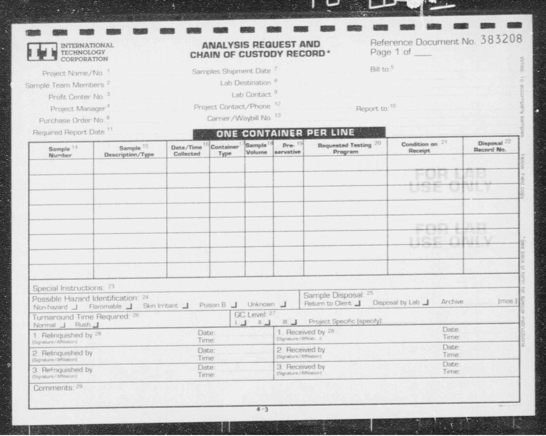
m M M M M M M M -m m m m M M M M M M
Ag y mNATIONAL ANALYSIS REQUEST AND Reference Document No. 383208'
T 1 fo7p"osoI CHAIN OF CUSTODY RECORD * Page 1 ofI
)E:
7 5Project Name/No. ' Samples Shipment Date 84fl to:
72 Lab Destination 8 0
Sample Team Membersf9
Profit Center No. 3 Lab Contact12
Project Manager # Project Contact / Phone Report to:'O
Purchase Order No.6 Carrier /Waybi!! No. '3 $5
Required Report Date '' ,
,
14 15 16 1 18 20 21 Disposag ?2Sample Sample Date/ Time Container Sample Pre '9 Requested Testing Condition on
Number Description / Type Collected Type Volume servative Program Receipt Record No.
!.
,g
|,
<s g| ?I
|.
,
|: s
a
55
I iS
23Special Instructions:25 a-
Possible Hazard Identification: 24 Sample Disposal:
Non-hazard J Rammable J Skin Irntant J Poison B J Unknown J Return to Client J Disposal by Lab J Archive (mos ) $0
Turnaround Time Required: 26 GC Level: 27,
Normal J Rush J 1. J 11. J 111. J Project Speaf<: (speafy): 3
Date: {1. Relinquished by 28 Date: 1. Received by 28isymun amami Time: isy mfew.A Time: g
EDate.Date: 2. Received by.
2. Relinquished by ts wm/e*am) Time:.j ts,r.eun/ma,=1 Time: e
Date:f 3. Re6nquished by _
:tsve-/w w=1 Time:Date: 3. Received bytsmaun/**==1 Time:
Comments: 29
~
4 -3
_ _ _ _
,
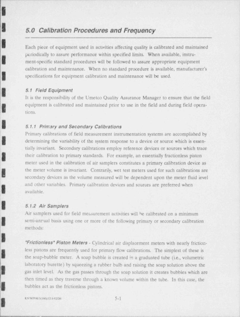
|| 5.0 Calibration Procedures and Frequency
ich piece of equipment used in activities affecting quality is calibrated and maintained
periodically to assure performance within specified limits. When available, instru-
ment specific standard procedures will be followed to assure appropriate equipment
calibration and maintenance. When no standard procedure is available, manufacturer's
| specifications for equipment calibration and maintenance will be used.
S.1 Field Equipmentit is the responsibility of the Umetco Ouality Assurance Manager to ensure that the field
equipment is calibrated and maintained prior to use in the field and during field opera-
tions.
5.1.1 Primary and Secondary Calibrations: Primary calibrations of field measurement instrumentation systems are accomplished by
determining the variability of the system response to a device or source which is essen-
tially invariant. Secondary calibrations employ reference devices or sources which trace
their calibration to primary standards. For example, an essentially fractionless piston
meter used in the calibration of air samplers constitutes a primary calibration device as
| the meter volume is invariant. Contrarily, wet rest meters used for such calibrations are:' secondary devices as the volume measured will be dependent upon the meter fluid level
and other variables. Primary calibration devices and sources are preferred when: available.
5.1.2 Air SamplersAir samplers used for field measurement activities will be calibrated on a minimum
semi-annual basis using one or more of the following primary or secondary calibrationmethods:
" Frictionless" F/ston Meters - Cylindrical air displacement meters with nearly friction-
less pistons are frequently used for primary flow calibrations. The simplest of these is|. the soap-bubble meter. A soap bubble is created in a graduated tube (i.e., volumetric
laboratory burette) by squeezing a rubber bulb and raising the soap solution above the
.
gas inlet level. As the gas passes through the soap solution it creates bubbles which are
then timed as they traverse through a known volume within the tube. In this case, the
bubbles act as the frictionless pistons.
. rawesomnnuo 5-1
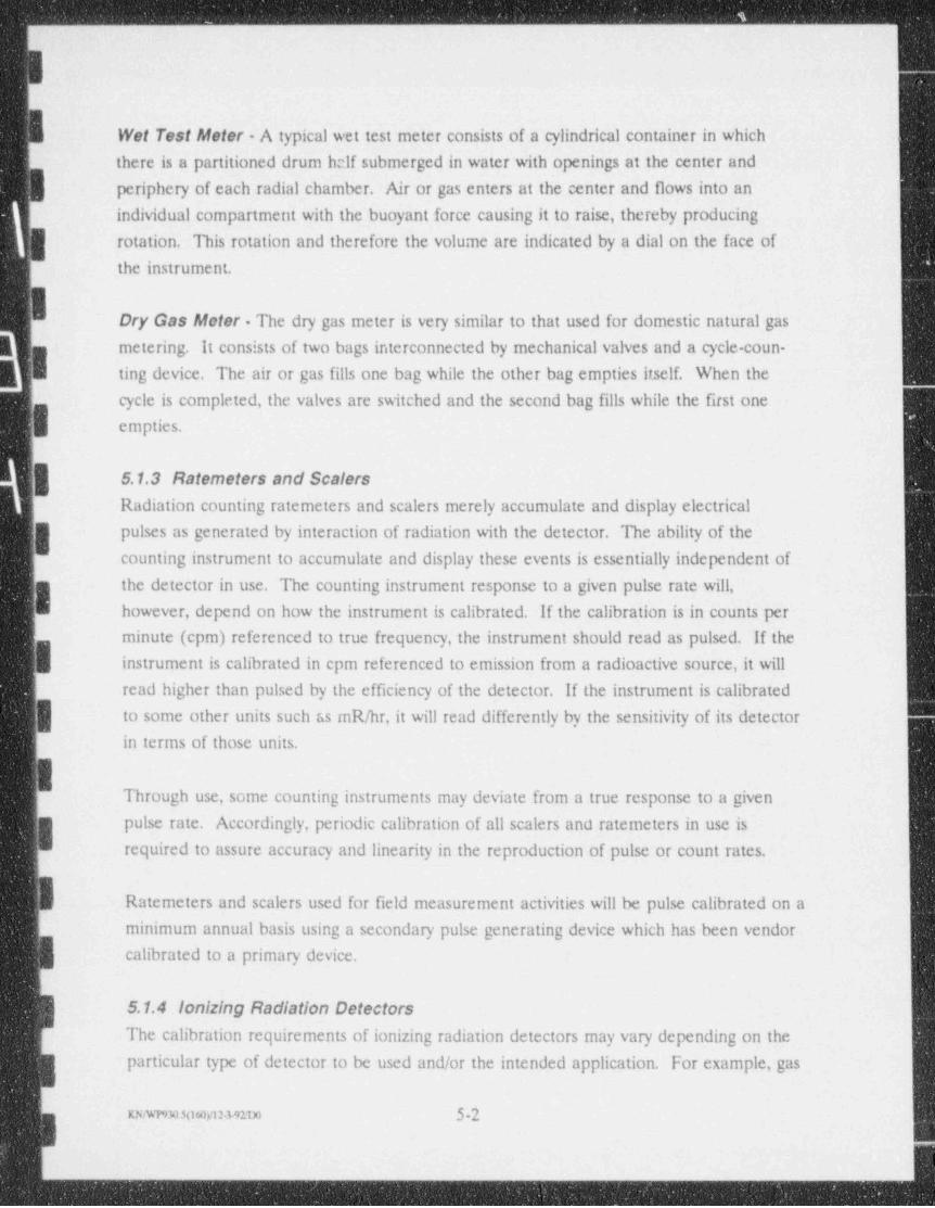
__ - _ _ _ _ _ _ _ _ _ _ _ _ _ _ _ _ _ _ _ ___ _ _
Wet Test Afeter - A typical wet test meter consists of a cylindrical container in which
there is a partitioned drum half submerged in water with openings at the center and
periphery of each radial chamber. Air or gas enters at the center and flows into an
individual compartment with the buoyant force causing it to raise, thereby producing
j rotation. This rotation and therefore the volume are indicated by a dial on the face of
the instrument.
I Dry Gas Afoter - The dry gas meter is very similar to that used for domestic natural gas
metering. It consists of two bags interconnected by mechanical valves and a cycle-coun-
I ting device. The air or gas fills one bag while the other bag empties itself. When the
cycle is completed, the valves are switched and the second bag fills while the first one
empties.
| 5.1.3 Ratemeters and Scalers
Radiation counting ratemeters and scalers merely accumulate and display electrical
g pulses as generated by interaction of radiation with the detector. The ability of the
counting instrument to accumulate and display these events is essentially independent of
the detector in use. The counting instrument response to a given pulse rate will,8 however, depend on how the instrument is calibrated. If the calibration is in counts per
minute (cpm) referenced to true frequency, the instrument should read as pulsed. If the
instrument is calibrated in cpm referenced to emission from a radioactive source, it willI read higher than pulsed by the efficiency of the detector. If the instrument is calibrated
to some other units such as mR/hr, it will read differently by the sensitivity of its detector -
in terms of those units.
Through use, some counting instruments may deviate from a true response to a given
pulse rate. Accordingly, periodic calibration of all scalers and ratemeters in use is
required to assure accuracy and linearity in the reproduction of pulse or count rates.
Ratemeters and scalers used for field measurement activities will be pulse calibrated on a
minimum annual basis using a secondary pulse generating device which has been vendor
calibrated to a primary device.
5.1.4 fonizing Radiation Detectors
The calibration requirements of ionizing radiation detectors may vary depending on the
particular type of detector to be used and/or the intended application. For example, gas
ww>w souwnw1x 5-2 \
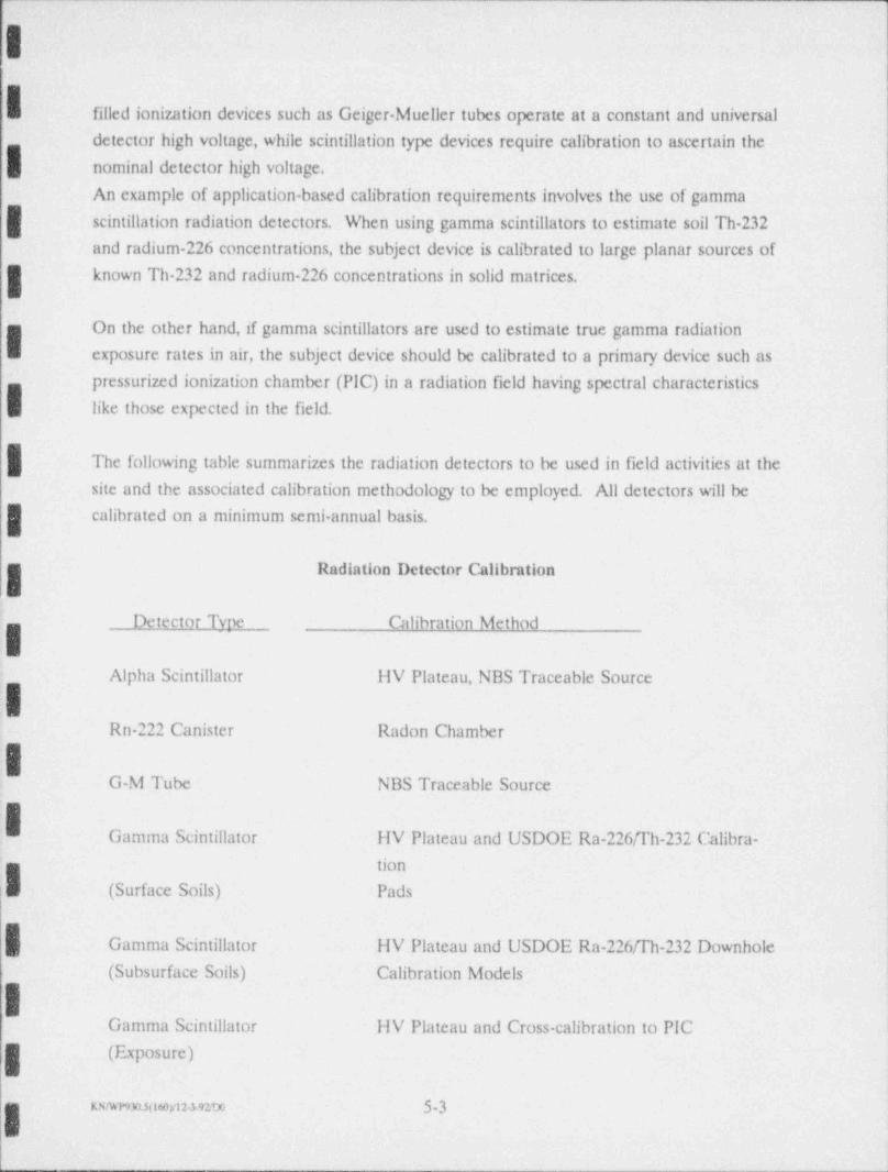
r
II: filled ionization devices such as Geiger-Mueller tubes operate at a constant and universal
detector high voltage, while scintillation type devices require calibration to ascertain the
nominal detector high voltage.
An example of application-based calibration requirements involves the use of gamma( scintillation radiation detectors. When using gamma scintillators to estimate soil Th-232
and radium 226 concentrations, the subject device is calibrated to large planar sources of
known Th-232 and radium 226 concentrations in solid matrices.
g On the other hand,if gamma scintillators are used to estimate true gamma radiationB exposure rates in air, the subject device should be calibrated to a primary device such as
pressurized ionization chamber (PIC) in a radiation field having spectral characteristics
like those expected in the field.
| The following table summarizes the radiation detectors to be used in field activities at the
site and the associated calibration methodology to be employed. All detectors will be
calibrated on a minimum semi annual basis.
- Radiation Detector Calibration
- Detector Tyne Calibration Method
Alpha Scintillator HV Plateau, NBS Traceable Source
Rn 222 Canister Radon Chamber
|IG-M Tube NBS Traceable Source
:.
~
Gamma Scintillator HV Plateau and USDOE Ra-226fI'h-232 Calibra-tion
'I (Surface Soils) Pads
| Gamma Scintillator HV Plateau and USDOE Ra-226ffh-232 Downhole
(Subsurface Soils) Calibration Models
-
Gamma Scintillator HV Plateau and Cross-calibration to PIC(Exposure)
xmmunemamm 5-3
I5.1.5 Operational Checks
Operational checks of field instrumentation are performed routinely during instrument
use to assure proper operation. These checks are performed more frequently than
formal calibrations, often daily, and sometimes take the form of an abbreviated calibra-
.| tion protocol.
A/r Samplers - Air samplers to be used on the site range from relatively high volume
continuous,120 Vac powered to low volume short term, DC battery powered pumps.
.
120 Vac line-powered, continuous air samplers will be checked for air mover and
rotameter operation prior to installation. Battery powered samplers will go into the field
for each day's use with fully charged, tested, or new batteries.
During field use, battery powered pumps will be calibrated for proper flow rate prior to
and at the end of each use. Line-powered, continuous samplers will have flow recorders
or will be checked (and documented or adjusted) at each 20% of the total sample time.
IRatemeters and Scalers - Ratemeters and scalers used for field measurements at the
site will be checked daily for proper operation. These checks will include the following,I_ as well as source response checks with an associated detector, as described below:
g Battery Condition.
Audio Operation.
Readout Response.
| Calibration Due Date.
Detector Cable Condition.
High Voltage (when exchanging detectors) :.
| Input Sensitivity (when exchanging detector types)..
Ion / zing Rad /ation Detectors - Radiation detectors used for field measurements at the
site will be check daily for proper operation with an associated ratemeter or scaler. In
some cases, such as the Eberline PRM-7 Micro-R meter, the detector is an integral part;
of the readout systern, whereas in other cases ratemeters and scalers may be used v.ith
various different detectors.
In either case, the measurement system (meter and detector) is checked daily for ,) roper
response to background and to a standard radioactive check source. Additionally, all'
detectors are checked daily for calibration due date, damage, and high vo! tape compati-
bility with meter.
rmwnsomymew 5-4I.
__ _.
I,
Alpha scintillation surface contamination detectors are checked for light leaks each day*
- before use and periodically throughout the day.
5.2 Laboratory Equipment
| I_aboratory equipment will be calibrated, adjusted, and maintained in accordance with
written procedures or instructions at intervals determined by frequency of usage or as
prescribed by codes, standards and manufacturer's recommendations. Calibration and
maintenance intervals will be defined in the applicable procedures. Procedures relating
to calibration will be approved by the Laboratory Manager, or his. designee, and the OAI Officer. These procedures include but are not limited to:
| equipment identification and dewription.,
equipment specifications;a .
calibratica and/or maintenance schedu:e.
equipment necesswy to accomplish ralibration.
procedures for calibration and/or mainteNnce..,
Items used as calibration standards will be certified to standards traceable to the
National lustitute of Standards Technology (formerly National Bureau of Standards), or
,| other accepwd standards (e.g., USEPA). If no known nationally recognized standard. exists, the basis for calibration will be documented.
IEquipment will be labeled with a calibration . sticker, a practical, which identifics the
assigned unique identification number, date at last calibration, w;th an indication as to'
; wao performna the last calibration, and the date the next calibration is due. An instrum-
i entsp;cific calibration / maintenance form S used to record data relating to each individu-jg"~ m cl cal;bration/ maintenance event.
'
Instrumers or equipmcat found or suspected to be out cf calibration or malfunctioning
wid be replaced anJ an evalua' ion made and documented by the responsible individual to
determine the validity of pmicas results, instruments requizing repair will be removed
nem service, repaired, and recalibrated before being mturned to scivice.
I|E.
__ s.s4;2
dw ."
.s
g
6.0 AnaylticalProcedures
Sample analyses to support the remedial action at this site will involve rea!- and near
real-time field analyses, as well as laboratory analyses. Sample analyses for both fieldI and laboratory operations will be conducted pursuant to the standard prc<:cdures
discussed in the following:
fi.1 Field Operai!ans
| The field analyses to be conducted in support of this project include:
:n . total and removable alpha surface contamination,j . radon progeny and long-lived alpha in air particulates,'
+ total and removable beta-gamma surface contamination, and gamma expo-i sure rates.g:B
The field measurements will be performed pursuant to standard procedmes which
conform with those established by NRC (NRC.1982; ORAU,1992) and by others
(MESA,1975). The field analytical procedures are summarized in tln: following discus-sions.
Alpha Rad /at/on - Alpha activity measurements will be perfonred on equipment and,
~
material surfaces, air particulate samples (filtcrs), and smear or wipe sampler The
method to be employed is direct alpha scintillation counting of the sample promptly after
[ collection or after a suitable deccy period. Rn-222 progeny air particulate samples are
; counted after 40 to 90 rninutes of decay, and the same samples are then counted for
Rn 220 proger.y concentrations after a Lhour decay period Long lived air particulate:- samples are counted after a 3-day d: cay to allow for the decay of Pb-212 and its alpha
emitting progeny. Surface contamination measurements typically do not require a decay; pc.tiod; howeve:, subject surfaces recently in contact with waste or radon progeny
con:aminated atmospheres may exhibit transient alpha activity due to progeny plate out.<r
The alpna count data are processed via appropriate algorithms incorporating sample- areas or volumesiinstrument eiliciency, background cormt rates, etc., to derive the media
,
concentratica or activity.i
-
h__ s .,
3
: g.
. .. .. - . ...
_ _ _ _ _ _ _
_
A
j Beta-Gamma Rad /ntlon - Beta. gamma measurements will be performed on equipment
and material smfaces and on smear or wipe samples. Pre-coimt decay periods are
necessaiy only if the subject surface may exhibit transient radon progeny plate-out.
5 Tne beta-gamma count data are processed via appropriate algorithms, as with alpha, to
derh e tne surface contamination levels.
- Gamma Radiation - Gamma radiation measurements are performed in situ to appraise
h penetrating exposure rates and to estimate rail radionuclide concentrations. The method
all to be employed is direct scintillation counting in air (for exposure) or on contact with the
soil surface. Scintillation exposure measurement instruments will be cross-calibrated to a'
PIC and soil measurement instruments will be calibrated using the matrix sources at the '
DOE Technical Measurements Center in Grand Junction, Colorado. .
s-- As with the other direct measurements, gamma data will be processed via appropriate
algorithms to derive exposure rates or estimates of soil activity.t
''
6.2 Laboratory OperationsLnboratori measurements of radiological constituents in site samples will be perfonned;
i by a pre-qualified radiochemistry laboratory.
42 All analysts are provided with copies of the procedures on which they are working. The
procedures give an abstract, the concentration range that the procedure is applicable to, }a list of possible interferences, directions for reagent preparation, safety considerations, a
g description of instrumentation set-up and use, and a sample calculation.
-2 /'
A brief discussion of the various analytical methods and matrices is presented below.
4g Radfum 226- Radium is coprecipitated with barium and lead. Barium.133 is added as a jgg tracer to deteunine chemical yield. The final precipitate is mounted ou a membnme
'
d fiher or electro-deposited, and then counted in an alpha spectrometer which has been ,
calibmted to count only alpha particles from Ra-226 and not any of its daughters or *
; mher ismopes. A Nal gamma spectrometer system is then used to measure the t. mount
] namssa-133 recovered.,
-- -,,
'l _ .,.y_
_.
I- An acceptable alternative method for Ra 226 analyses is by Radon 222 gas de-emanation.
This process uses de-emanated Rn-222 gas passed through a scintillation cell. Alpha
scintillation is then used to determine the radon concentration, and by algorithm, the
relative Ra-226 concentration.'
-
.
A third acceptable alternative analytical method for Ra 226 in soil is by gamma ray
spectrometry. In this method, the dry, pulverized sample is sealed in a counting jar (e.g.
Marinelli) and allovced to ingrow Rn 222 and its gamma emitting progeny. After a;
! known ingrowth time, the sample is counted on a gamma ray spectrometer and the
characteristic photons from Pb-214 and/or Bi-214 are measured and the associated
. Ra-226 concentration is calculated.
#Thorium 230,232,228 (Isotopic)- Thorium is collected on an ion exchange resin,
eluted and mounted on a counting planchet. The sample is then counted by alpha
pulse-beight analysis. Recovery can be determined by addition of thorium-227 tracer
carried through the procedure,
ig Uranium - Gamma Spectrome. fry Total uranium soil is determined by gamma spec-!N trometry using an intrinsic gennanium detector capable of distinguishing a wide spectrum
of gamma energies Samples will be counted and the U-238 daughter, Th 234 is flagged-
i to determine uranium content.
|. Radon-222 - The analysis of charcoal canister absorption samples is performed by
gamma spectremetry. Characteristic gamma photons from Rn-222 progeny (typically
;g Pb-214 and/or Bi.214) in transiem equilibrium with Rn 222 are counted and the originalmid-sampling average Rn-222 concentration is calculated.
!I
iI.
--.
.
t__ 63,
;D
-- _ . - - - _ - - -. . - _ _ _ -.
||7.0 Data Reduction, Validation and Reporting
,
i
7.1 Data ReductionProject data will be reduced to appropriate unitt (see Section 7.3) prior to reporting to
ensure data comparability. Data will be reduced using standard algorithms to derive the
media concentration / activity, as well as estimates of error and detection sensitivity.
Data may be further reduced into strata or area averages, site inventory, etc., as appro- |
| priate, pursuant to NRC guidance (ORAU,1992).
7.2 Data Valldation
Field measurement data will be validated on a number of bases including:
measurement data ts,-
*' inutument calibratLa records,+
instrument performance check records, andaI replicate measurements.e
| For some direct field measurement methods, interlaboratory comparison programs are
available for evnluating precision and accuracy (see Section 9). Where available and
| appropriate, results from such programs will also be used to assist in the data validation:
process. .
I Laboratory data will be validated on a number of bases including:
g + iesults of analytical group blanks and standards '
chemical recovery of surogates+
replicate analyses.
I blind performance sample analyses+
instrument calibration records and control charts.-
The results of interlaboratory cornparison analyses will be used where available and
appropriate (see Section 9) to assist in the lah data validation process.
I :
IKN! POD 11170edi123 P10 7.]
|-I.r
_ __ . . _ . ,.. ._ _.- . - - - - _ -_ _. ,_
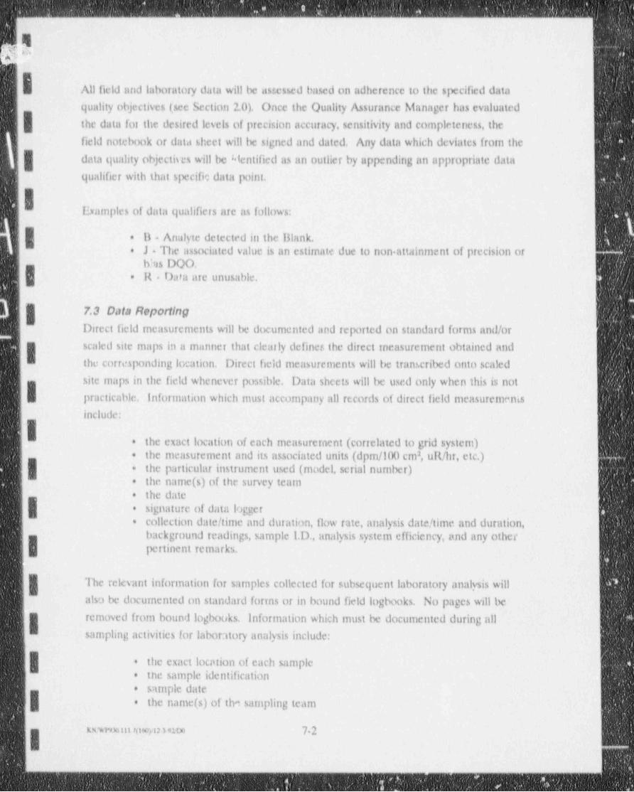
- - - _ _ - - - _ - _ _ - - - _ _ - - ..
,
46
All field and laboratory data will be assessed based on adherence to the specified data
quality objectives (see Section 2.0). Once the Quality Assurance Manager has evaluated
the data for the desired levels of precision accuracy, sensitivity and completeness, the
field notebook or data sheet will be signed and dated. Any data which deviates from the
| data quality objectives will be blentified as an outlier by appending an appropriate data
qualifier with that specific data point.
I Examples of data qualifiers are as follows:
| 11 Analyte detected in the Blank.+
J - The associated value is an estimate due to non attainment of precision or*
blus DQO.| R Data are unusable.* "
7.3 Data Reporting
Direct field measurements will be documented and reported on standard forms and/or '
I scaled site maps in a manner that cleanly definer, the direct incasurement obtained and
the corresponding location. Direct field measurements will be transcribed onto scaled
site maps in the field whenever possible. Data sheets will be used only when this is notI practicable. Information which must accompany all records of direct field measurementsinclude:
I the exact location of each measurement (cor elated to grid system)+
the measurement and its associated units (dpm/100 cm , uR/hr, etc.)2+
| the particular instrument used (model, serial number)+
the name(s) of the survey team+
the date -+-
signature of data logger+
collection date/ time and duration, flow rate, analysis date/ time and duration,*
background readings, sample 1.D., analysis system efficiency, and any otherI pertinent remarks.
The relevant information for sarnples collected for subsequent laboratory analysis will
also be documented on standard forms or in bound field logbooks. No pages will be
removed from bound logbooks, Information which must be documented during allsampling activities for laboratory analysis include:
| the exact location of each sample*
the sample identification+
sample date+
-| the name(s) of the sampling team*
m,m n uo,n mte 72I !
- _
. .. _ - - _ _ _ _ _ _ _ _ - - _ _ _ _ - _ _ _ _ _ _ _ _ _ - _ _ _ _
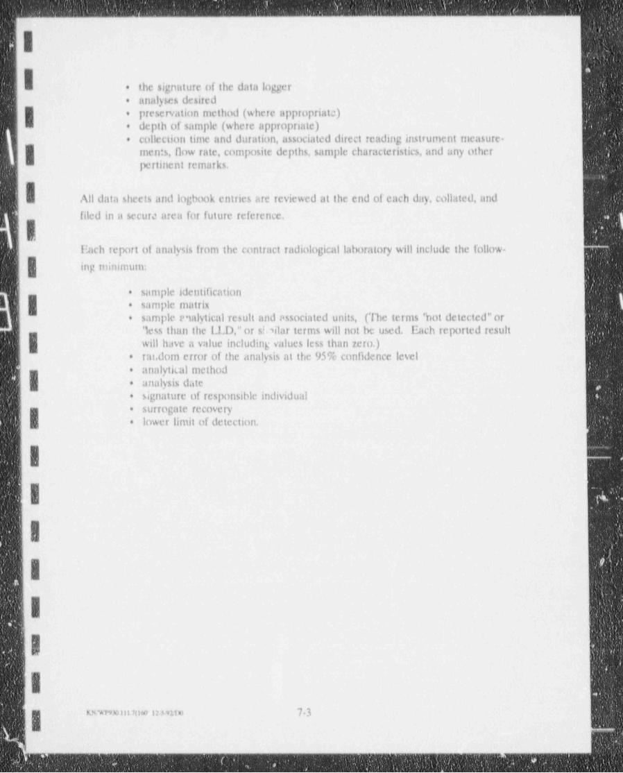
- .- _ _ _ _ _ _ _ _ _ _ _ _ . - _ _ -
II the signature of the data logger.
analyses desired.
I preservation method (where appropriata).
depth of sample (where appropriate)e
collecilon time and duration, associated direct reading instrument rneasure-.
g men:s, flow rate, composite depths, sample characteristics, and any otherpertinent remarks.
All data sheets and logbook entries are reviewed at the end of each day, collated, and
filed in a secure area for future reference.
fhich ieport of analysis from the contract radiological laboratory will include the follow-~
| ing minimum:
sample identificatione
| sarnple matrix.
sample e mlytical result and essociated units, (The terms ' hot detected"or.
'less than the LLD,"or s!.,ilar terms will not be used. Ilach reported result
| will have a value including values less than zero.)rm. dom error of the analysis at the 95% confidence level.
analytical method.
analysis date.
signature of responsible individual.
.surrogate recovery.
lower limit of detection..
1
IIII!I.
Ksur,30sitatie ir nr.ro 7-3
I.m__.__.__.______ -
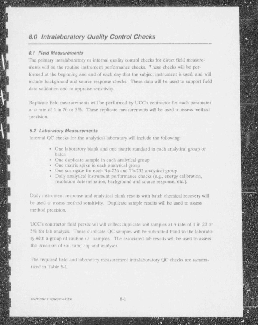
- _ _ _ _ _ _ _ _ _ _ _ _ ._ -- __-____-_ -__-__-
.
rL
8.0 Intralaboratory Guality Control Checkse._ _ _ --
.8.1 Field Measurements
|
q The primary intralaboratory or internal quality control checks for direct field sneasure-
J ments will be the routine instrument performance checks. 7 hese checks will be per-
formed at the beginning and end of each day that the subject instrument is used, and will
| include background and source response checks. These data will be used to support field
data validation and to appraise sensitivity.
IReplicate field measurements will be performed by UCC's contractor for each parameter
at a rate of 1 in 20 or 5%. These replicate measurements will be used to assess method
precision.
8.2 Laboratory MeasurementsInternal OC checks for the analytical laboratory will include the following:
I One laboratory blank and one matrix standard in each analytical group or+
batch
| One duplicate sample in each analytical group=
One matrix spike in each analytical group.
One surrogate for each Ra-226 and Th 232 analytical group.
| Daily analytical instrument performance checks (e.g., energy calibration,.
resolution determination, background and source response, etc.).
Daily instrument response and analytical blank results with batch chemical recovery will
be used to assess method sensitivity. Duplicate sample results will be used to assess
I method precision.
| UCC's contractor field personnel will collect duplicate soil samples at a rate of 1 in 20 or
5% for lab analysis. These d.iplicate OC samples will be submitted blind to the laborato-
| ry with a group of routine 3.t1 samples. The associated lab results will be used to assess
[ the precision of soil ramp.ing and analyses.
The required field and laboratory measurement intralaboratory OC checks are summa-
rized in Table 8-!.
xxwnnm 4mmnw 8-1
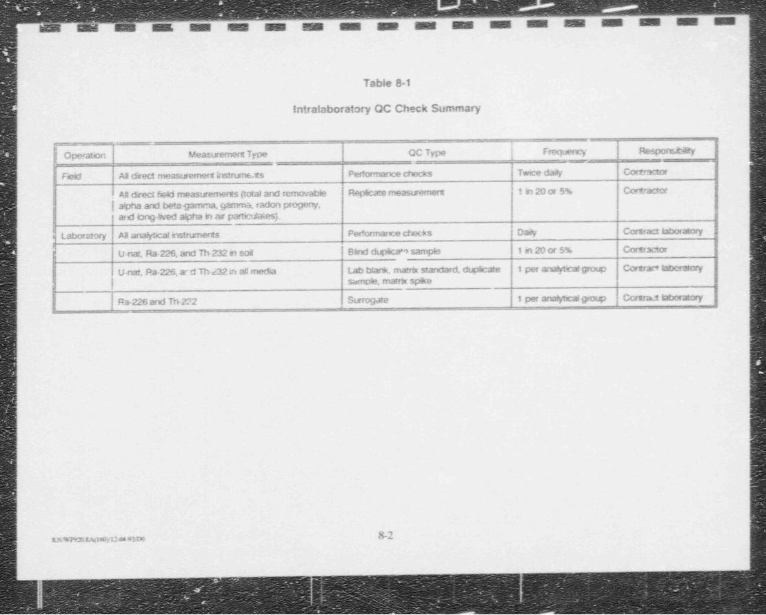
' M M M M i
Table 8-1
Intralaboratory OC Check Summary
___
__ .- _. ,
| Operation i Measuremert Type OC Type Frequency Respons.t4ty
I
Field AR direct measurement bstrums ts Performance checks Twice da?y Cort _ractor
. AH drect field measurements (total and removable Replicate measuremeru 1 in 20 or 5% Cortractor
| alpha and beta-gamma, gamma, radon progerrf,ard bog-thied alpha in at particit.aies).
f j Laboratory AR ana!yticalinstrumeras Performarx:e cf ecks | Dai!y Contract bboratory
| U-nat, Ra-226, and Th-232 in soa | Bhnd dupscam sampio | 1 in 20 or 5% Cortractor|
U-nat, Ra-226, a .d TM-232 in aC media Lab b!ank, matrix standard, dup 5cate 1 per a.a!y4scalgroup Cottract laDeratory
|sample, matrix spike
lRa-226 and Tn-232 Surrogate 1 per ana!ytcalgroup Ccruraet laboratory
| ,
,
;
ii
!1
i
|
)
| b-2KN,%7920.8A(16Gy12M-91DG
-'
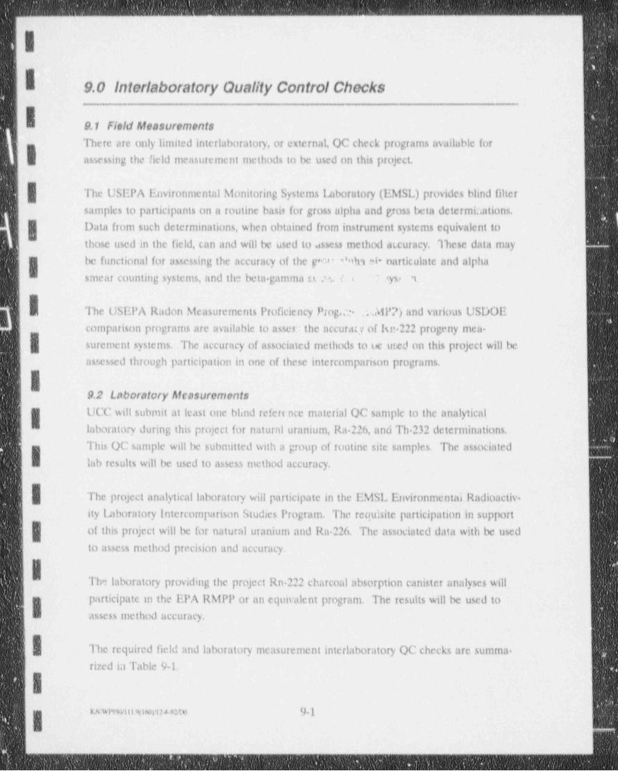
-__ . _ _ - _ _ _ - _ _ - -. - . _ . - _ __
I9.0 Interlaboratory Quality Control Checks
9.1 FleM Rfeasurements
There are only limited interlaboratory, or external, QC check programs available fort
assessing the field measurement methods to be used on this project.
| The USEPA Environmental Monitoring Systems imboratory (EMSL) provides blind filter
samples to participants on a routine basis for gross alpha and gross beta determi.iations.
g Data from such determinations, when obtained from instrument systems equivalent to
those used in the field, can and will be used to assess method accuracy. These data may
be functional for assessing the accuracy of the ge Wha * narticulate and alpha- smear counting systems, and the beta gamma s.u.w ( (- ' syst M.
The USEPA Radon Measurements Proficiency Proga.3 .. MPP) and various USDOE
comparison programs are available to asses the accuracy of kn 222 progeny men-
surement systems. The accuracy of associmed methods to ue ured on this project will be
assessed through participation in one of these intercomparison programs.
I9.2 Laboratory Alcasurements
UCC will submit at least one blind refere nce material QC sarnple to the analytical
laboratory during this project for natural uranium, Ra-226, and Th 232 determinations.
This OC sample will be submitted with a group of routine site samples. The associatedI lab results will be used to assess method accuracy.
The project analytical laboratory will participate in the EMSL Environmental Radioactiv.
ity Laboratory Intercomparison Studies Program. The requisite participation in support
| of this project will be for natural uranium and Ra 226. The associated data with be used
to assess method precision and accuracy.
The laboratory providing the project Rn-222 charcoal absorption canister analyses will
participate m the EPA RMPP or an equivalent program. The results will be used toI assess method accuracy.
The required field and laboratory measurement interlaboratory QC checks are summa.
rized in Table 9 L
IKnimmwmum 9-1I
_ _ _ - _ _ _ _ _ _ - _ - _ _ _ _ _ _ _ _ - - _ _ _ _ _ _ _ _ - - _ _ _ _ _ _ _ _ _ _ _ _ - _ _ - _ - - _ - - _ _ _ _ _ _ _ _ _ _ _ _ _ __
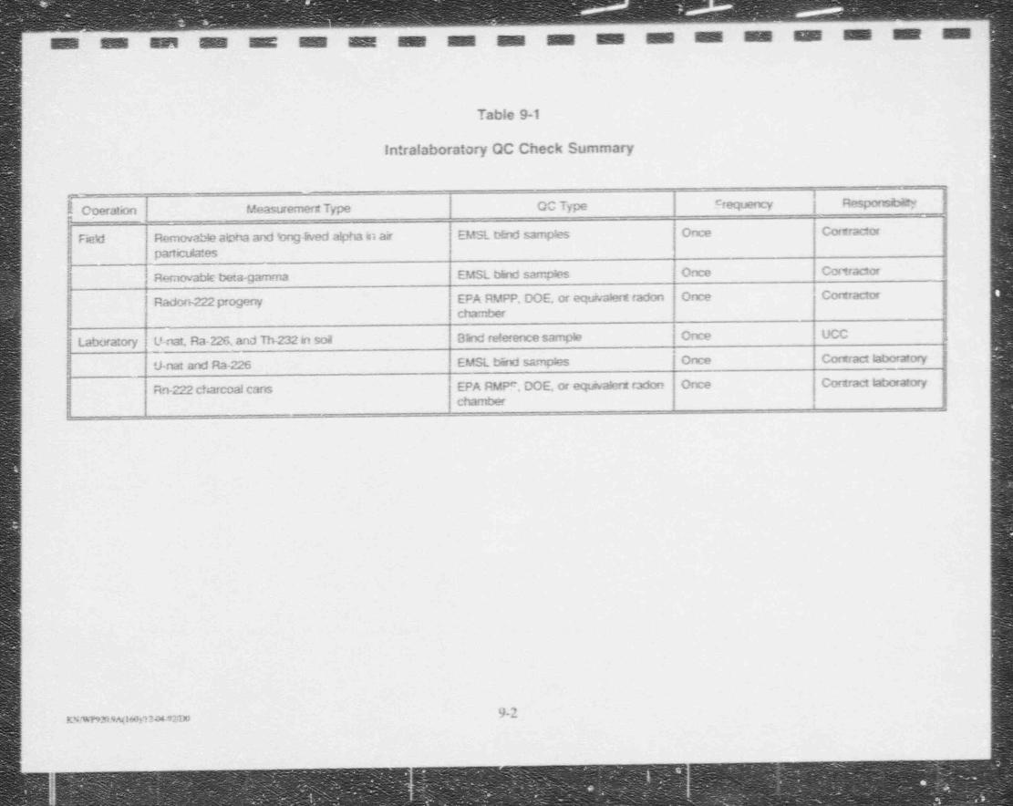
| M M M M M M M. M M M M M M M M M M M M
(
Table 9-1
Intrataboratory OC Check Summary
f Coeration Measurement Type OO Type Frequency | ResporcibiLYn
Fiekt Removable abha and bogIn,ed a!pha in air EMSL t2nd samples Once Contractor
partb dMesg
Rernovabk beta-gamma EMSL b5rd samples Once Cortractor jk 1
} Radon-222 progeny EPA RMPP, DOE, or egivalent radon Once Contractorchxnber
ILaboratory U-nat, Ra-226, and Th-232 in soil Blind reference sample Once UCC
nat and Ra-226 EMSL blind samphs | Once Cortract laboratory
Rn-222 charcoa! cans EPA RMPF, DOE, or eqd,#nx radon Once Contract laboratory
chamber
|l
:
1
.
9-2rssmomsonwww
...
in
. - _ _ _ _ _ _ _ _ - - _ _ . _ _ - _ _ .
-
10.0 Performance and Systems Audit._. _._.
'IAll of the measurement systems to be used on this project are currently ope:ational and
generating data, t.lbeit for other projects. Accordingly, systems audits are not appropri-
ate or necessary to ensure data quality for this project. A performance audit of both the
g fic!d and laboratory rnensurement systems is, however, both appropriate and necessary to
W assure demonstrable data quality for this project...
:| The Umerco OA Manager will conduct this performance audit during the conduct of the
project. The audit will encompass both field and laboratory measurernent systems and
will include, but not necessarily be limited to the following:
. review of reference standard preparation, certification, traceability, etc.,
'Ireview of sumpling procedures, including collection, storage, packaging, ship-.
ping, etc.,
.Ireview of measurement instrument calibration records, performance checks,.
control charts, maintenance records, etc.,
._appraisal of the overall measurement systems through the use of blind.
reference materials, samples, etc.,
review of existing intralaboratory OC checks.
review of project data management.'
.
j The audit will be documented in an audit report and submitted to UCC and Umetco
management for review and corrective action,if appropriate.
II
KN/WIWsif4Fl20 93*n 10-1
- . __- _ - - _ - - _ _
R
i 11.0 '4eventive Maintenance
I11.1 Fleid Equipment
I Air Samplers - Preventive maintenance of battery powered air samplers is limited to
char 1;ing and/or changing battery packs. 120 Vac line pom: red samplers require periodic
filling of the lubricating oil reservoir.
Radlation Measurement Equipment - Preventive maintenance of radiation
measurement equipment includes charging and/or changing battery packs, changing
detector cables, and repairing light leaks in alpha surface contamination measurement
|'
detectors.
Vendor manuals will be used as SOPS for exchanging batteries, and repairing or
exchanging cables. Use a strong light or sunlight to identify the precis,e locations of light
leaks in alpha scintillator mylar covers and repair using black lacquer.
11.2 Laboratory EquipmentVendor manuals and laboratory SOPS will be used to assure preventative maintenance
procedures are followed at the laboratory. Failure of equipment due to poor
| preventative maintenance practices will be documented and reported with the laboratorydata.
I&
-
IIIIeU <
Kswnwan24 nm 11 1I_ _ _ - _ _ _ - _ _ _ - _ - _ - _ _ _ _ _ _ _ _ _ _ _ - - _ _ _ _ - .
- . - _ _ _ - . _ _ _ - _ _ _ - - _ - _ - _ _ - - - - - _ _ _ - - - _ _ _ _ - _ _ . - _ - - - - - - - -
.Il
|
12.0 Specific Routine Procedures To Assess Data Quality
Specific routine procedures will be used to assess the following data quality parameters:
precision' +
* accuracy. completeness,
| sensitivity.=
. Representativeness should be considered an objective to be achieved rather than a
characteristic which can be described in quantitative terms. Representativeness will be
defined for this remedial action as the degree to which the data accurately and preciselyI represent the true environmental pollution existing at the site. Representativeness is<
being addressed by the use of a logical and thorough sampling and analysis plan which is
; based on all available knowledge of the site. The use of detailed sarnple locations and
proper sampling and analysis procedures will ensure that the data obtained represents
| the actual conditions in the area.'
i
Data comparability on this project will be assured through the use of appropriate and
consistent measurement procedures and the reporting of results in consistent and
comparable units.I,
12.1 Practs.'on
Precision is defined as the measure of the mutual agreement among individual measure-
ments of the same constituent in a sample, secured under the same analytical protocols.- | Fiehl and laboratory precision will be expressed as relative percent difference (RPD)
where:
[X1 - X2]iu n
(X1 + X2)/2" 2*
where: RPD u Relative percent difference between duplicate results,
X1 and X2 = Results of duplicate analyses, and
[XI - X2] = Absolute difference between duplicates XI and ' .
Precision objectives are based on the analytical results, which take intc account the levelof error introduced by field sampling techniques, field conditions, and naalytical variabili-
wwnnmuw.tn 12 1
.I
__ _ _ - - _ _ - _ _ _ _ _ _ _ _ _ _ _ _ _ _ _ _ _ _ . _ _ _ _
Ity. The RPD of all laboratory duplicates will be reported und the RPD of 11 eld dupli-cates will be calculated by UCC in order to evaluate the data precision.
12.2 AccwacyAccuracy is defined as the degree to which the analytical measurement reflects the trueconcentration level present.
The accuracy (percent bias) of individual project measurements will be evaluated usingthe following equation:
X-Y5 %. . y om>
where: Y = the known concentration or true value, and
X = the reported concentration.
12.3 Completeness
Completeness is a measure of all information necessary for a valid study. Completeness
will be evaluated by comparing project objectives to the resulting valid data. Generally,
it is not useful to try to measure this in quantitative terms. However, a measure of
| completeness can be quantitated by the amount of valid data obtained from a measure- -
ment system compared to the amount that was planned to be collected. Completeness
will be assessed for each parameter in the following manner:
c- LmD -
g where: C = Percentage of valid data for each parameter,
V = Number of valid results for each parameter, and
| D = Number of samples collected for each parameter.
12.4 SensitivityFor a particular measurement where radioactive disintegrations are detected (which may
include a radiochemical separation) sensitivity will be determined by the following:
4.66 sbun.CEVY exp( At)
where: LLD = the lower limit of detection,
u.snm,wmsnu 12 2i- _ _ _ _ _ _ - _ _ - _ _ _ _ _ _ . _ _ _ _ _ - _ _ _ _ _ _ _ _ _ - - _ _ _ _ ____ -
. _ _ _ _ _ _ _ _ _ _ _ _ _ _ _ _ _ _ - _ _ _ _ _ _ _ _ _ _ _ _ - - - _
-
-
L,
S = the standard deviation of background count rate,I C = appropriate activity conversion,
E a the counting efficiency,V = the sample volume, rnass, etc.,
I Y = the fractional radiochemical yield (if applicable),
I A = the decay constant for the particular radionuclide, andt = the elapsed time between sample collection and counting.
IIIIIIII -
I
mwnwammtm 12 3
_. ._
I13.0 Corrective Action
| If a deficiency affecting or potentially affecting data quality is identified during a formalaudit, a routine OC check, or at any other time, corrective action will be promptly initiated.Corrective action may be as simple as an instrument adjustment (e.g., detector high voltage)
| and in that case, will be initiated by the discoverer. Deficiencies which cannot be remediedby simple immediate field corrective actions will be promptly reported to the OA Managerfor long term action.
For either immediate or long term corrective actions, steps comprising a closed loop correc-tive action system will be as follows:
define the problem+
assign responsibility for investigating the problemI investigate and determine the cause of the problem+
+
determine a corrective action to eliminate the problem-
assign responsibility for implementing the corrective actionI establish effectiveness of the corrective action and implement the correction
+
+
verify that the corrective action has climinated the problem.+
IDepending on the nature of the problem, the corrective action employed may be formal or
informal. In either case, occurrence of the problem, corrective action used and verification
that the problem has been eliminated will be documented.
The Project Manager and/or Quality Assurance Officer will be responsible for initiating
corrective action at any contract laboratory and for ensuring and documenting that specified
| corrective actions have been satisfactorily completed.
g Brief reports as to the quality of the field and laboratory data will be submitted with normal
monthly project status reports unless an unusual condition exists. in the event unusual
conditions or problems are encountered, the Project Manager will prepare a brief report on
the conditions and corrective actions as soon as possible following discovery.
I
I__ u.1|
1
I
IREFERENCES - -
IChem Nuclear Systems, Inc.," Draft Report of Sampling Performed at the
Marietta, Ohio Plant of Union Carbide. Corporation", October,1981a.
Chem Nuclear Systems, Inc., " Draft Report of Sampling Performed at the
Marietta, Ohio Plant of Union Carbide Corporation", December,1981b.
| Chem Nuclear Systems, Inc., " Economic Evaluation of Decommissioning
Alternatives for Union Qirbide Corporation Metnis, Division, Marietta,
g Ohio Facility", April,1981.
'U.S. Nuclear Regulatory Commission," Guidelines for Decontamination of
Facilities and Equipment Prior to Release for Unrestricted Use or
Termination of Licenses for Byproduct, or Source Material", September,I 1984.
| ARIX Corporation," Radiological Assessment and Survey of the Processing
lluilding, Residue Storage, and Open 1;md Associated with Tantalum-
| Columbium (Ta Cb) Operations at Marietta, Ohio", February,1983.
ARIX Corporation," Addendum No.1 to the Report (Dated February,1983) onRadiological Assessment and Survey of the Processing Building, Residue
Storage, and Open lamd Associated with Tantalum-Columbium (Ta Cb)I Operations at Marietta, Ohio", April,1984.
U.S. Nuclear Regulatory Commission," Materials License SMR933 Amendment
No. 05", July 3,1985.
Oak Ridge Associated Universities," Confirmatory Radiological Survey of the
Union Cmbide Corporation, Metals Division Plant, Marietta, Ohio",May,1985.
. Chemical Waste Management, Inc., " Report of Radiological Characterization
Conducted by Chemical Waste Management ENRAC Nuclear Waste Division at the
R1I-
__,_.___._,._mm_ - - _ _ _ - - --____._____u_----------- - _ -- - - - - -- - - _ - ----- - ----- - - - - - - - " " - - - - - - --' ^ --
Elkem Metals Co., Marietta, Ohio Facility", May 18,1992.
| Federal Register, Volume 57, Number 93," Uranium Mill Facilities, Request for
Public Comments on Revised Guidance on Disposal of Non Atomic Energy Act of a
| 1954, Section 11e.(2) Byproduct Material in Tailings impoundments and
Position and Guidance on the Use of Uranium Mill Feed Mawrials Other ThanNatural Ores", May 13,1992.
" Atomic Energy Act of 1954", as amended.
U.S. Government Printing Office, " Title 40, Code of Federal Regulations".~
U.S. Government Printing Office," Title 10, Code of Federal Regulations".
IUmeteo Minerals Corporation," Draft Radiological Assessment of Building 78
Equipment at Elkem, Metals Company, Marietta, Ohio", July 27,1992.
REFEllENCES (Continued)
Daryi Widernan, U.S. Nuclear Regulatory Co.nmission, Region 111, Telephone
Conversation with Jay W. Davis of Umetco Minerals Corporation, August 31,
| 1992b.
U.S. Nuclear Regulatory Commission, Region 111, "Special Safety inspection"" Report", February 18,1992a.
Andrew Karam, Ohio Department of Ilealth," Trip Report", January 30,1992.
. U.S. Nuclear Regulatory Commission, Regulatory Guide 8.30," Health PhysicsSurveys in Uranium Mills", June,1983.
q . U.S. Environmental Protection Agency, Federal Guidance ILjort No.11,og EPA 520/1-88-020," Limiting Values of Radionuclide intake and Air
1
Concentration and Dose Conversion Factors for Inhalation, Submersion,-
and Ingestion", September,1988.
R-2I-
_ _ _ _ _ - _ _ _ _ _ _ _ -
_ _ _ _ _ _ _ _ _
II U.S. Government Printing Office, Title 29, Code of Federal Regulations.
U.S. Energy Research and Development Administration (ERDA), "IIASL-300
Procedures Manual", August 1,1975.
IU.S. Nuclear Regulatory Commission, Regulatory Guide 8.31,"Information
Relevant to Ensuring that Occupational Radiation Exposures at Uranium
Mills will be as Low as is Reasonably Achievable", May,1983.
I USNRC, Regulatory Guide 8.13," Instruction Concerning Prenatal Radiation
Exposure", Decemtvr,1987.
USNRC. Regulatory Guide 8.29, " Instruction Concerning Risks from Occupational
| Radiation Exposure", July,1981.
U.S. Department of Energy, GJfrMC-06," Surface Gamma Gay Measurement Protocol",
J uly,1984.
I U.S. Department of Energy, GJ/FMC-23," Gamma Ray instrument Calibration
Comparison Workshop", June,1985.
Unpublished Work, J. W. Davis,1986.
U.S. Government Printing Office, ' Title 49, Code of Federal Regulations".
IOak Ridge Associated Universities, NUREG/CR 5849," Manual for Conducting
Radiological Surveys in Support of License Termination", June,1992.
Mining Enforcement and Safety Administration," Sampling Mine Atmospheres for
Potential Alpha Energy Due to the Presence of Radon 220 (Thoron)
Daughters", IR 1015, 1975.
|
II
R3I__
Related Documents