International Journal of Engineering & Technology IJET-IJENS Vol:14 No:01 166 146901-7575-IJET-IJENS © February 2014 IJENS I J E N S Electronics Research Institute, El-Tahreer St. Dokki, Giza, Egypt Corresponding author: [email protected] This work was supported by Science and Technology Development Fund (STDF)), Ministry of scientific research, Egypt. Tracking System using Fixed Beamwidth Electronics Scanning Haythem H. Abdullah, Hala A. Elsadek, and Hesham Eldeeb Abstract— In several applications for tracking systems, the scanning rate is considered a critical factor. The mechanical steering appears to be impractical for its slow rate and space consumption so the need for electronics scanning appears clearly. But unfortunately, the electronic scanning suffer from beamwidth broadening and gain variations with steering angles. In this paper, a fixed beamwidth electronic scanning algorithm is proposed. The proposed algorithm is based on synthesizing sets of excitation coefficients to direct the main beam at some scanning angles. The synthesis takes into consideration the fixation of the beamwidth at these angles. The main concept is to enlarge the antenna array aperture size to a predefined optimum value to get a fixed beam in all the scanning angles. The synthesis of the excitation coefficients is done using a scheme based on the method of moments due to its accuracy in solving such problems. The optimum spacing between elements is determined using the genetic algorithm. One of the main advantages of the proposed algorithm is the applicability of synthesizing multibeam antenna array of fixed beamwidths using the superposition principle. The system is already built and tested with conventional microstrip antenna array elements where good tracking results are observed. Index Term— Genatic alagorithm, Method of Moments, Electronic scanning. I. INTRODUCTION The synthesis of fixed beamwidth scanned antenna arrays with minimum number of antenna elements is of main concern in many applications such as Radar systems and Tracking systems. Some of applications have mechanical steering systems, where a directive antenna array of a specific beam is mounted on a mechanical rotating system that directs the array to any direction keeping its beam unchanged such as rolling radar [1]. But the rate of direction change of the mechanical system is slow. The electronic scanning is used when it is necessary to vary the direction, or rate of change of direction of the array beam faster than is possible by mechanical movement of the aperture [2]. But electronic scanned radars suffer from the beamwidth variations with steering the main beam direction. The variations in the antenna array beamwidth as a function of the steering angle results in corresponding gain variations, and broadening of the main beam beamwidth which may cause signals from different transmitters to interfere with the desired transmitter signal. In this paper, it is introduced a new algorithm based on a combination between the method of moments (MoM) [3] and the genetic algorithm (GA) [4-7]. The proposed algorithm is used for the synthesis of scanned linear antenna arrays, and multi-beam antenna arrays with fixed minimum beamwidth at any direction with minimum number of equispaced antenna elements. In this paper, a tracking system based on fixing the beamwidth when scanning targets is presented. The paper is organized as follows: section II explains the problem formulation. In section III, the results and discussions are introduced. Finally, Section IV presents the conclusions for this research. II. PROBLEM FORMULATION The array factor of a linear antenna array consisting of isotropic antenna elements positioned symmetrically along the z-axis as shown in Figure 1 with uniform element spacing is given by [1]; () ∑ ( ( ) ) (1) Where is the excitation coefficient of the element, is the element spacing, and ⁄ is the free space wave number. The moment method and the genetic algorithm (MoM/GA) [9] are utilized to reconstruct new element locations and excitations that fulfill the required characteristics in the desired pattern. This synthesis method has shown its ability of reducing the number of elements for linear arrays compared to pencil-beam patterns and shaped-beam patterns [12]. The algorithm is based on solving a system of linear equations which is written in a matrix form as (2) where is the excitation coefficients vector to be determined. The elements of the matrix take the form ∫ ()() (3) The main focus is to introduce a scheme for filling the matrix in order to achieve predetermined beam characteristics. Each beam characteristic necessitates specific treatment in filling the matrix .

Welcome message from author
This document is posted to help you gain knowledge. Please leave a comment to let me know what you think about it! Share it to your friends and learn new things together.
Transcript

International Journal of Engineering & Technology IJET-IJENS Vol:14 No:01 166
146901-7575-IJET-IJENS © February 2014 IJENS I J E N S
Electronics Research Institute, El-Tahreer St. Dokki, Giza, Egypt Corresponding author: [email protected]
This work was supported by Science and Technology Development
Fund (STDF)), Ministry of scientific research, Egypt.
Tracking System using Fixed Beamwidth Electronics
Scanning Haythem H. Abdullah, Hala A. Elsadek, and Hesham Eldeeb
Abstract— In several applications for tracking systems, the
scanning rate is considered a critical factor. The mechanical
steering appears to be impractical for its slow rate and space
consumption so the need for electronics scanning appears clearly.
But unfortunately, the electronic scanning suffer from beamwidth
broadening and gain variations with steering angles. In this paper,
a fixed beamwidth electronic scanning algorithm is proposed. The
proposed algorithm is based on synthesizing sets of excitation
coefficients to direct the main beam at some scanning angles. The
synthesis takes into consideration the fixation of the beamwidth at
these angles. The main concept is to enlarge the antenna array
aperture size to a predefined optimum value to get a fixed beam in
all the scanning angles. The synthesis of the excitation coefficients
is done using a scheme based on the method of moments due to its
accuracy in solving such problems. The optimum spacing between
elements is determined using the genetic algorithm. One of the
main advantages of the proposed algorithm is the applicability of
synthesizing multibeam antenna array of fixed beamwidths using
the superposition principle. The system is already built and tested
with conventional microstrip antenna array elements where good
tracking results are observed.
Index Term— Genatic alagorithm, Method of Moments,
Electronic scanning.
I. INTRODUCTION
The synthesis of fixed beamwidth scanned antenna arrays
with minimum number of antenna elements is of main concern
in many applications such as Radar systems and Tracking
systems. Some of applications have mechanical steering
systems, where a directive antenna array of a specific beam is
mounted on a mechanical rotating system that directs the array
to any direction keeping its beam unchanged such as rolling
radar [1]. But the rate of direction change of the mechanical
system is slow. The electronic scanning is used when it is
necessary to vary the direction, or rate of change of direction of
the array beam faster than is possible by mechanical movement
of the aperture [2]. But electronic scanned radars suffer from
the beamwidth variations with steering the main beam
direction. The variations in the antenna array beamwidth as a
function of the steering angle results in corresponding gain
variations, and broadening of the main beam beamwidth which
may cause signals from different transmitters to interfere with
the desired transmitter signal. In this paper, it is introduced a
new algorithm based on a combination between the method of
moments (MoM) [3] and the genetic algorithm (GA) [4-7]. The
proposed algorithm is used for the synthesis of scanned linear
antenna arrays, and multi-beam antenna arrays with fixed
minimum beamwidth at any direction with minimum number
of equispaced antenna elements. In this paper, a tracking
system based on fixing the beamwidth when scanning targets is
presented. The paper is organized as follows: section II
explains the problem formulation. In section III, the results and
discussions are introduced. Finally, Section IV presents the
conclusions for this research.
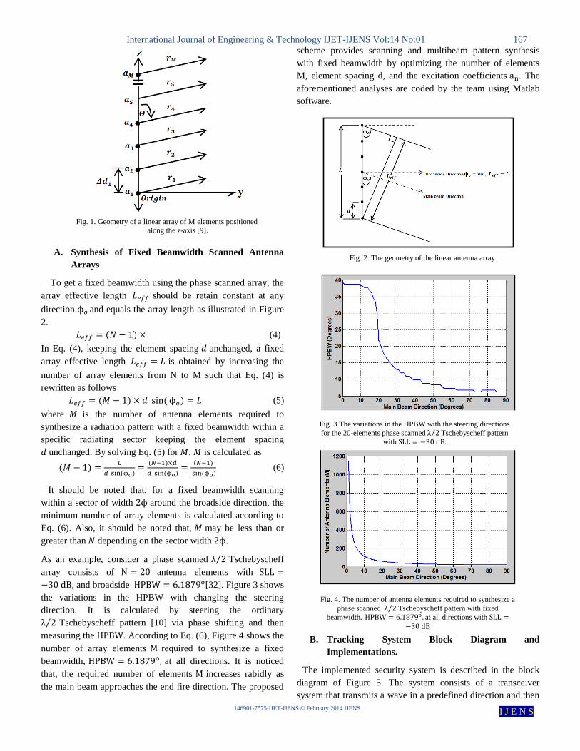
II. PROBLEM FORMULATION
The array factor of a linear antenna array consisting of
isotropic antenna elements positioned symmetrically along
the z-axis as shown in Figure 1 with uniform element
spacing is given by [1];
( ) ∑ ( (
) )
(1)
Where is the excitation coefficient of the element, is
the element spacing, and ⁄ is the free space wave
number. The moment method and the genetic algorithm
(MoM/GA) [9] are utilized to reconstruct new element
locations and excitations that fulfill the required characteristics
in the desired pattern. This synthesis method has shown its
ability of reducing the number of elements for linear arrays
compared to pencil-beam patterns and shaped-beam patterns
[12]. The algorithm is based on solving a system of linear
equations which is written in a matrix form as
(2)
where is the excitation
coefficients vector to be determined. The elements of the
matrix take the form
∫ ( ) ( )
(3)
The main focus is to introduce a scheme for filling the matrix
in order to achieve predetermined beam characteristics.
Each beam characteristic necessitates specific treatment in
filling the matrix .
International Journal of Engineering & Technology IJET-IJENS Vol:14 No:01 167
146901-7575-IJET-IJENS © February 2014 IJENS I J E N S
A. Synthesis of Fixed Beamwidth Scanned Antenna
Arrays
To get a fixed beamwidth using the phase scanned array, the
array effective length should be retain constant at any
direction and equals the array length as illustrated in Figure
2.
( ) (4)
In Eq. (4), keeping the element spacing unchanged, a fixed
array effective length is obtained by increasing the
number of array elements from N to M such that Eq. (4) is
rewritten as follows
( ) ( ) (5)
where is the number of antenna elements required to
synthesize a radiation pattern with a fixed beamwidth within a
specific radiating sector keeping the element spacing
unchanged. By solving Eq. (5) for , is calculated as
( )
( )
( )
( )
( )
( ) (6)
It should be noted that, for a fixed beamwidth scanning
within a sector of width around the broadside direction, the
minimum number of array elements is calculated according to
Eq. (6). Also, it should be noted that, may be less than or
greater than depending on the sector width .
As an example, consider a phase scanned ⁄ Tschebyscheff
array consists of antenna elements with
, and broadside [32]. Figure 3 shows
the variations in the HPBW with changing the steering
direction. It is calculated by steering the ordinary
⁄ Tschebyscheff pattern [10] via phase shifting and then
measuring the . According to Eq. (6), Figure 4 shows the
number of array elements required to synthesize a fixed
beamwidth, at all directions. It is noticed
that, the required number of elements increases rabidly as
the main beam approaches the end fire direction. The proposed
scheme provides scanning and multibeam pattern synthesis
with fixed beamwidth by optimizing the number of elements
M, element spacing d, and the excitation coefficients . The
aforementioned analyses are coded by the team using Matlab
software.
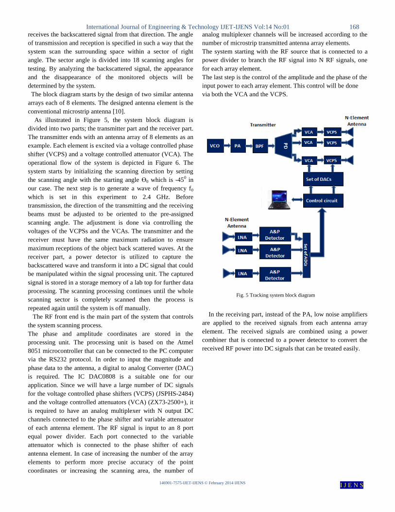
B. Tracking System Block Diagram and
Implementations.
The implemented security system is described in the block
diagram of Figure 5. The system consists of a transceiver
system that transmits a wave in a predefined direction and then
Fig. 2. The geometry of the linear antenna array
Fig. 1. Geometry of a linear array of M elements positioned
along the z-axis [9].
Fig. 3 The variations in the HPBW with the steering directions
for the 20-elements phase scanned λ ⁄ Tschebyscheff pattern
with
Fig. 4. The number of antenna elements required to synthesize a
phase scanned λ ⁄ Tschebyscheff pattern with fixed
beamwidth at all directions with
International Journal of Engineering & Technology IJET-IJENS Vol:14 No:01 168
146901-7575-IJET-IJENS © February 2014 IJENS I J E N S
receives the backscattered signal from that direction. The angle
of transmission and reception is specified in such a way that the
system scan the surrounding space within a sector of right
angle. The sector angle is divided into 18 scanning angles for
testing. By analyzing the backscattered signal, the appearance
and the disappearance of the monitored objects will be
determined by the system.
The block diagram starts by the design of two similar antenna
arrays each of 8 elements. The designed antenna element is the
conventional microstrip antenna [10].
As illustrated in Figure 5, the system block diagram is
divided into two parts; the transmitter part and the receiver part.
The transmitter ends with an antenna array of 8 elements as an
example. Each element is excited via a voltage controlled phase
shifter (VCPS) and a voltage controlled attenuator (VCA). The
operational flow of the system is depicted in Figure 6. The
system starts by initializing the scanning direction by setting
the scanning angle with the starting angle Ө0 which is -450 in
our case. The next step is to generate a wave of frequency f0
which is set in this experiment to 2.4 GHz. Before
transmission, the direction of the transmitting and the receiving
beams must be adjusted to be oriented to the pre-assigned
scanning angle. The adjustment is done via controlling the
voltages of the VCPSs and the VCAs. The transmitter and the
receiver must have the same maximum radiation to ensure
maximum receptions of the object back scattered waves. At the
receiver part, a power detector is utilized to capture the
backscattered wave and transform it into a DC signal that could
be manipulated within the signal processing unit. The captured
signal is stored in a storage memory of a lab top for further data
processing. The scanning processing continues until the whole
scanning sector is completely scanned then the process is
repeated again until the system is off manually.
The RF front end is the main part of the system that controls
the system scanning process.
The phase and amplitude coordinates are stored in the
processing unit. The processing unit is based on the Atmel
8051 microcontroller that can be connected to the PC computer
via the RS232 protocol. In order to input the magnitude and
phase data to the antenna, a digital to analog Converter (DAC)
is required. The IC DAC0808 is a suitable one for our
application. Since we will have a large number of DC signals
for the voltage controlled phase shifters (VCPS) (JSPHS-2484)
and the voltage controlled attenuators (VCA) (ZX73-2500+), it
is required to have an analog multiplexer with N output DC
channels connected to the phase shifter and variable attenuator
of each antenna element. The RF signal is input to an 8 port
equal power divider. Each port connected to the variable
attenuator which is connected to the phase shifter of each
antenna element. In case of increasing the number of the array
elements to perform more precise accuracy of the point
coordinates or increasing the scanning area, the number of
analog multiplexer channels will be increased according to the
number of microstrip transmitted antenna array elements.
The system starting with the RF source that is connected to a
power divider to branch the RF signal into N RF signals, one
for each array element.
The last step is the control of the amplitude and the phase of the
input power to each array element. This control will be done
via both the VCA and the VCPS.
In the receiving part, instead of the PA, low noise amplifiers
are applied to the received signals from each antenna array
element. The received signals are combined using a power
combiner that is connected to a power detector to convert the
received RF power into DC signals that can be treated easily.
Fig. 5 Tracking system block diagram

International Journal of Engineering & Technology IJET-IJENS Vol:14 No:01 169
146901-7575-IJET-IJENS © February 2014 IJENS I J E N S
III. RESULTS AND DISCUSSIONS
In this work, the scanning sector is chosen such that
( ), where the main beam at is
required to have a beam width close to the broadside main
beam at . Using Eq. (6), the minimum number of
elements required for array synthesis is found to be
with optimum element spacing . The synthesized
pattern has the same beamwidth as the broadside beamwidth
and acceptable side lobe level as shown in
Figure 8 in the broadside direction while it approaches -10.2 dB
at an angle of as illustrated in Figure 9.
Start
Generate signal at
frequency f0
Direct the beam of
the transmitter
toward Direction ӨN
Direct the beam of
the receiver toward
Direction ӨN
Detect the signal
level at direction ӨN
Store the signal level
at direction ӨN
ӨN =ӨN-1 + 1
Initialize scanning
direction
ӨN < ӨEND
Get peaks locations
(Target direction)
Fig. 6. Overall system operational flow
Fig. 7. The experimental setup
Fig. 8. The synthesized radiation pattern with 8 elements
antenna array with broadside radiation
Fig. 9. The synthesized radiation pattern with 8 elements
antenna array with maximum radiation at Ө𝑜 with
respect to the array line
International Journal of Engineering & Technology IJET-IJENS Vol:14 No:01 170
146901-7575-IJET-IJENS © February 2014 IJENS I J E N S
System Integration and Testing.
The integrated system is shown in Figure 7, where the two
antenna arrays are fabricated over FR4 substrates of thickness
1.6 mm. the RF front ends of the transmitter and the receiver
are integrated on separate boards. The connection between
boards is done via coaxial cables of bandwidth up to 18 GHz.
The two RF boards are controlled via two control boxes where
each box adjusts the feeding voltages of the attenuators and the
phase shifters. The whole system is controlled via a lab top
through the USB port. Before starting the system, the output
attenuation factor and the phase shifts of each of the RF front
end branches are calibrated by adjusting the control voltage of
each component.
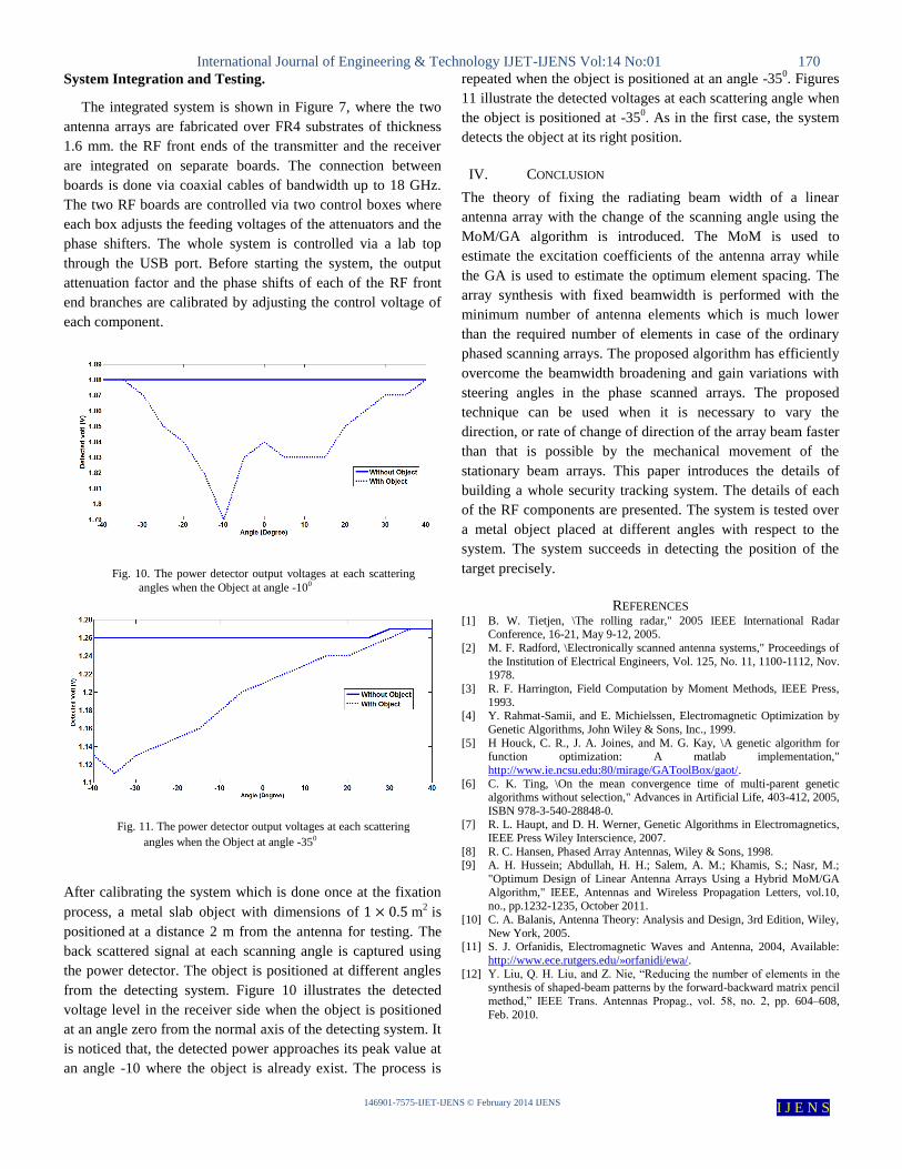
After calibrating the system which is done once at the fixation
process, a metal slab object with dimensions of m2 is
positioned at a distance 2 m from the antenna for testing. The
back scattered signal at each scanning angle is captured using
the power detector. The object is positioned at different angles
from the detecting system. Figure 10 illustrates the detected
voltage level in the receiver side when the object is positioned
at an angle zero from the normal axis of the detecting system. It
is noticed that, the detected power approaches its peak value at
an angle -10 where the object is already exist. The process is
repeated when the object is positioned at an angle -350. Figures
11 illustrate the detected voltages at each scattering angle when
the object is positioned at -350. As in the first case, the system
detects the object at its right position.
IV. CONCLUSION
The theory of fixing the radiating beam width of a linear
antenna array with the change of the scanning angle using the
MoM/GA algorithm is introduced. The MoM is used to
estimate the excitation coefficients of the antenna array while
the GA is used to estimate the optimum element spacing. The
array synthesis with fixed beamwidth is performed with the
minimum number of antenna elements which is much lower
than the required number of elements in case of the ordinary
phased scanning arrays. The proposed algorithm has efficiently
overcome the beamwidth broadening and gain variations with
steering angles in the phase scanned arrays. The proposed
technique can be used when it is necessary to vary the
direction, or rate of change of direction of the array beam faster
than that is possible by the mechanical movement of the
stationary beam arrays. This paper introduces the details of
building a whole security tracking system. The details of each
of the RF components are presented. The system is tested over
a metal object placed at different angles with respect to the
system. The system succeeds in detecting the position of the
target precisely.
REFERENCES [1] B. W. Tietjen, \The rolling radar," 2005 IEEE International Radar
Conference, 16-21, May 9-12, 2005.
[2] M. F. Radford, \Electronically scanned antenna systems," Proceedings of
the Institution of Electrical Engineers, Vol. 125, No. 11, 1100-1112, Nov. 1978.
[3] R. F. Harrington, Field Computation by Moment Methods, IEEE Press,
1993. [4] Y. Rahmat-Samii, and E. Michielssen, Electromagnetic Optimization by
Genetic Algorithms, John Wiley & Sons, Inc., 1999.
[5] H Houck, C. R., J. A. Joines, and M. G. Kay, \A genetic algorithm for function optimization: A matlab implementation,"
http://www.ie.ncsu.edu:80/mirage/GAToolBox/gaot/.
[6] C. K. Ting, \On the mean convergence time of multi-parent genetic algorithms without selection," Advances in Artificial Life, 403-412, 2005,
ISBN 978-3-540-28848-0. [7] R. L. Haupt, and D. H. Werner, Genetic Algorithms in Electromagnetics,
IEEE Press Wiley Interscience, 2007.
[8] R. C. Hansen, Phased Array Antennas, Wiley & Sons, 1998. [9] A. H. Hussein; Abdullah, H. H.; Salem, A. M.; Khamis, S.; Nasr, M.;
"Optimum Design of Linear Antenna Arrays Using a Hybrid MoM/GA
Algorithm," IEEE, Antennas and Wireless Propagation Letters, vol.10,
no., pp.1232-1235, October 2011.
[10] C. A. Balanis, Antenna Theory: Analysis and Design, 3rd Edition, Wiley,
New York, 2005. [11] S. J. Orfanidis, Electromagnetic Waves and Antenna, 2004, Available:
http://www.ece.rutgers.edu/»orfanidi/ewa/.
[12] Y. Liu, Q. H. Liu, and Z. Nie, “Reducing the number of elements in the synthesis of shaped-beam patterns by the forward-backward matrix pencil
method,” IEEE Trans. Antennas Propag., vol. 58, no. 2, pp. 604–608,
Feb. 2010.
Fig. 10. The power detector output voltages at each scattering
angles when the Object at angle -100
Fig. 11. The power detector output voltages at each scattering
angles when the Object at angle -350

International Journal of Engineering & Technology IJET-IJENS Vol:14 No:01 171
146901-7575-IJET-IJENS © February 2014 IJENS I J E N S
Dr. Haythem H. Abdullah received a BSc. degree in
Electronics and communication engineering from the
University of Benha, Egypt in 1998 and received his M.Sc.
and Ph.D. degrees from Cairo University in 2003 and 2010,
respectively. His M.Sc. is dedicated in the simulation of the
dispersive materials in the Finite Difference Time Domain
numerical technique and its application to the SAR
calculations within the Human head. The Ph.D. is dedicated on the radar target
identification. He now employed as a researcher at the electronics research
institute (ERI), Giza, Egypt. His current research interests are design and
optimization of microstrip antenna arrays and their
applications.
Dr. Hala Elsadek. is a professor at Microstrip
Department, Electronics Research Institute. She acted as department head from 2008-2012. Dr. Elsadek
graduated from Faculty of Engineering, Ain Shams
University, Cairo, Egypt 1991. Dr. Elsadek had her master degree from University of Gunma, Japan in 1996
while her PhD was through a channel between Cairo
University, Egypt and University of California, Irvine, USA in 2002. Her
research interests are in the field of RF wireless communications,
electromagnetic engineering and microstrip antenna systems. Dr. Elsadek
published three books, lead guest editors in one international journal in antennas and propagation and two patents in wireless communications and
antenna systems. She acts as a single author and as a co-author in more than 90
research papers in highly cited international journals and in proceedings of international conferences in her field, as IEEE Transactions on Antenna and
Propagation, IEEE Antenna and Wireless Propagation Letters, Microwave and
Optical Technology Letters, etc. She is a supervisor on master and PhD theses in different universities in Egypt and abroad (Japan and USA). Dr Elsadek
participates in more than 12 research projects at the national and international
levels as Egypt- NSF-USA joint fund program, Egypt STDF-France IRD joint fund program and the European Committee programs of FP6 and FP7. Her role
is from C-PI to PI. She is an IEEE senior member from 2011. She is awarded
the Egyptian Government Encouragement Prize for Young scientists in Engineering Science and Technology at 2006. She is included in several
biographical indexes all over the world: American Biographical Institute
Inc, Cambridge, England as one of the leading scientists of in 2008 and "Marquis Who's Who" Encyclopedia from 2008- to 2010 as one of the
worldwide scientists who demonstrate outstanding achievements in her field.
Dr. Elsadek is also a reviewer in many international societies in her field as IEEE Antenna and Propagation Society.
Dr. Hehsam Eldeeb is a professor at Computer and
Systems Department, Electronics Research Institute. He
acts as the Institute director from 2012-Now. Andhe was the Computer and System Department head from
2010-2012. Dr. Eldeeb graduated from Faculty of Engineering, Cairo University, and Cairo, Egypt in
1986. He had his master degree from same university in
1989 while his PhD degree was from Gunma University, Japan in 1996. His research interests are in
the field high performance computing systems and virtual reality. Dr. Eldeeb
acts as a single author and as a co-author in more than 50 research papers in highly cited international journals and in proceedings of international
conferences in his field, He is a head & member in more than 20 of national &
international research projects such as: US–Egypt Joint Fund projects, EU
projects and national research projects. He obtained a Patent in Computer &
Communications field from Egypt’s Patent office (2010). Dr Eldeeb is
supervising over 10 Master & PhD theses in high performance computers & Information technology fields. He also participated in composing two books in
computers & information technology fields
Related Documents

![[IJET V2I4P2] Authors:Damanbir Singh, Guneet Kaur](https://static.cupdf.com/doc/110x72/58edce381a28abb4318b4641/ijet-v2i4p2-authorsdamanbir-singh-guneet-kaur.jpg)


![(1)Personal Data (2)Academic Appointments (3)Scientific ... · [IJENS Researchers Promotion Group] ID: IJENS-1008-Kamal International Journals of Engineering & Sciences IJENS](https://static.cupdf.com/doc/110x72/5f07e8a47e708231d41f5cf7/1personal-data-2academic-appointments-3scientific-ijens-researchers-promotion.jpg)

![[IJET V2I4P1] Authors:Dashrath Singh Kathait](https://static.cupdf.com/doc/110x72/587385891a28ab272d8b5af1/ijet-v2i4p1-authorsdashrath-singh-kathait.jpg)