GHR No. 7253 County of Champaign, Illinois 1776 East Washington Urbana, IL 61802 Ph 217.384.3720 SATELLITE JAIL HVAC REPLACEMENT PROJECT AT 502 SOUTH LIERMAN AVENUE URBANA, ILLINOIS 61802 FOR COUNTY OF CHAMPAIGN URBANA, ILLINOIS 61802 PROJECT MANUAL ITB #2021-003 May 5, 2021

Welcome message from author
This document is posted to help you gain knowledge. Please leave a comment to let me know what you think about it! Share it to your friends and learn new things together.
Transcript
GHR No. 7253
County of Champaign, Illinois 1776 East Washington
Urbana, IL 61802 Ph 217.384.3720
SATELLITE JAIL HVAC REPLACEMENT PROJECT
AT
502 SOUTH LIERMAN AVENUE URBANA, ILLINOIS 61802
FOR
COUNTY OF CHAMPAIGN URBANA, ILLINOIS 61802
PROJECT MANUAL ITB #2021-003
May 5, 2021

GHR No. 7253
TABLE OF CONTENTS 00 0100 -1
County of Champaign, Illinois 1776 East Washington
Urbana, IL 61802 Ph217.384.3720
TABLE OF CONTENTS
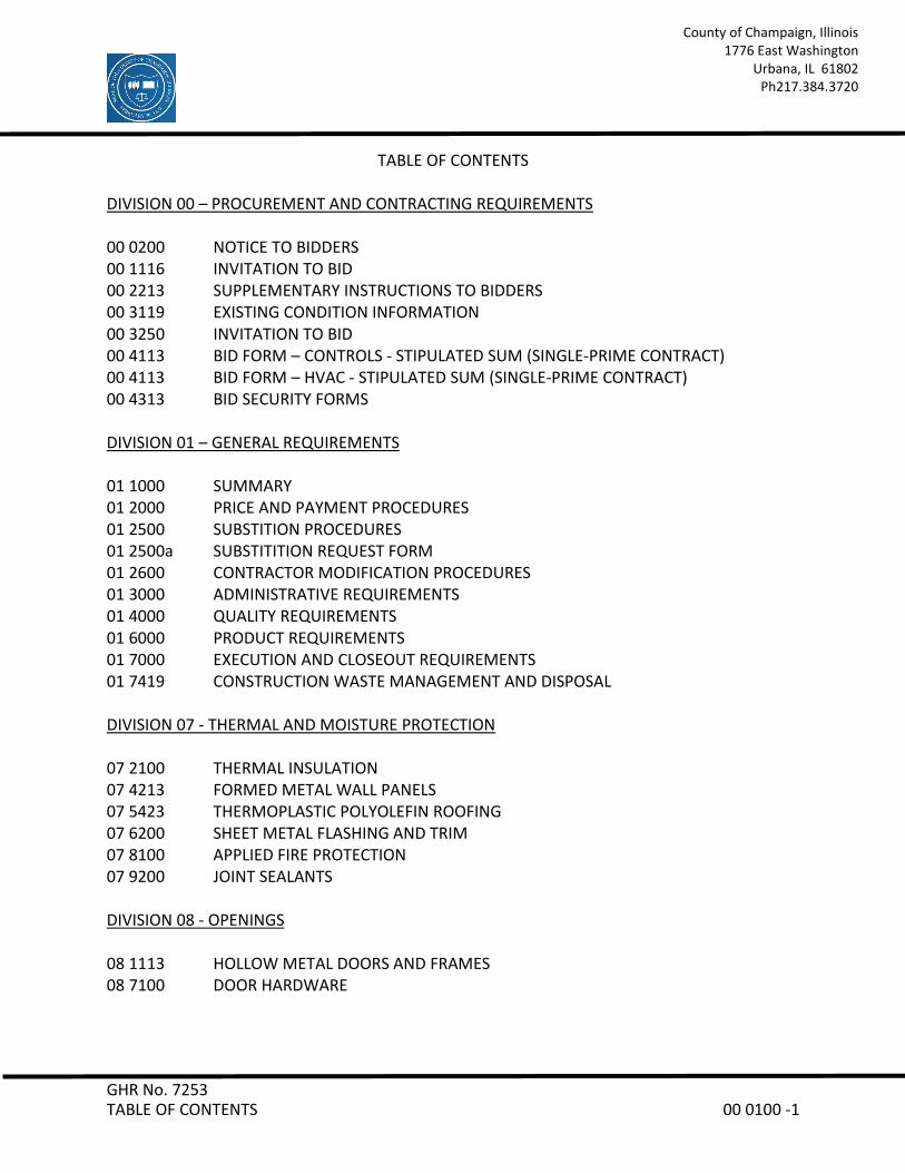
DIVISION 00 – PROCUREMENT AND CONTRACTING REQUIREMENTS 00 0200 NOTICE TO BIDDERS 00 1116 INVITATION TO BID 00 2213 SUPPLEMENTARY INSTRUCTIONS TO BIDDERS 00 3119 EXISTING CONDITION INFORMATION 00 3250 INVITATION TO BID 00 4113 BID FORM – CONTROLS - STIPULATED SUM (SINGLE-PRIME CONTRACT) 00 4113 BID FORM – HVAC - STIPULATED SUM (SINGLE-PRIME CONTRACT) 00 4313 BID SECURITY FORMS DIVISION 01 – GENERAL REQUIREMENTS 01 1000 SUMMARY 01 2000 PRICE AND PAYMENT PROCEDURES 01 2500 SUBSTITION PROCEDURES 01 2500a SUBSTITITION REQUEST FORM 01 2600 CONTRACTOR MODIFICATION PROCEDURES 01 3000 ADMINISTRATIVE REQUIREMENTS 01 4000 QUALITY REQUIREMENTS 01 6000 PRODUCT REQUIREMENTS 01 7000 EXECUTION AND CLOSEOUT REQUIREMENTS 01 7419 CONSTRUCTION WASTE MANAGEMENT AND DISPOSAL DIVISION 07 - THERMAL AND MOISTURE PROTECTION 07 2100 THERMAL INSULATION 07 4213 FORMED METAL WALL PANELS 07 5423 THERMOPLASTIC POLYOLEFIN ROOFING 07 6200 SHEET METAL FLASHING AND TRIM 07 8100 APPLIED FIRE PROTECTION 07 9200 JOINT SEALANTS DIVISION 08 - OPENINGS 08 1113 HOLLOW METAL DOORS AND FRAMES 08 7100 DOOR HARDWARE
GHR No. 7253
TABLE OF CONTENTS 00 0100 -2
County of Champaign, Illinois 1776 East Washington
Urbana, IL 61802 Ph217.384.3720
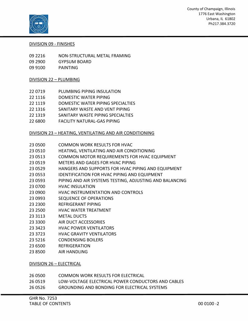
DIVISION 09 - FINISHES 09 2216 NON-STRUCTURAL METAL FRAMING 09 2900 GYPSUM BOARD 09 9100 PAINTING DIVISION 22 – PLUMBING 22 0719 PLUMBING PIPING INSULATION 22 1116 DOMESTIC WATER PIPING 22 1119 DOMESTIC WATER PIPING SPECIALTIES 22 1316 SANITARY WASTE AND VENT PIPING 22 1319 SANITARY WASTE PIPING SPECIALTIES 22 6800 FACILITY NATURAL-GAS PIPING DIVISION 23 – HEATING, VENTILATING AND AIR CONDITIONING 23 0500 COMMON WORK RESULTS FOR HVAC 23 0510 HEATING, VENTILATING AND AIR CONDITIONING 23 0513 COMMON MOTOR REQUIREMENTS FOR HVAC EQUIPMENT 23 0519 METERS AND GAGES FOR HVAC PIPING 23 0529 HANGERS AND SUPPORTS FOR HVAC PIPING AND EQUIPMENT 23 0553 IDENTIFICATION FOR HVAC PIPING AND EQUIPMENT 23 0593 PIPING AND AIR SYSTEMS TESTING, ADJUSTING AND BALANCING 23 0700 HVAC INSULATION 23 0900 HVAC INSTRUMENTATION AND CONTROLS 23 0993 SEQUENCE OF OPERATIONS 23 2300 REFRIGERANT PIPING 23 2500 HVAC WATER TREATMENT 23 3113 METAL DUCTS 23 3300 AIR DUCT ACCESSORIES 23 3423 HVAC POWER VENTILATORS 23 3723 HVAC GRAVITY VENTILATORS 23 5216 CONDENSING BOILERS 23 6500 REFRIGERATION 23 8500 AIR HANDLING DIVISION 26 – ELECTRICAL 26 0500 COMMON WORK RESULTS FOR ELECTRICAL 26 0519 LOW-VOLTAGE ELECTRICAL POWER CONDUCTORS AND CABLES 26 0526 GROUNDING AND BONDING FOR ELECTRICAL SYSTEMS
GHR No. 7253
TABLE OF CONTENTS 00 0100 -3
County of Champaign, Illinois 1776 East Washington
Urbana, IL 61802 Ph217.384.3720
26 0529 HANGERS AND SUPPORTS FOR ELECTRICAL SYSTEMS 26 0533 RACEWAY AND BOXES FOR ELECTRICAL SYSTEMS 26 0544 SLEEVES AND SLEEVE SEALS FOR ELECTRICAL RACEWAYS AND CABLING 26 0553 IDENTIFICATION FOR ELECTRICAL SYSTEMS 26 2416 PANELBOARDS 26 2726 WIRING DEVICES 26 2813 FUSES 26 2816 ENCLOSED SWITCHES AND CIRCUIT BREAKERS 26 2913.03 MANUAL AND MAGNETIC MOTOR CONTROLLERS 26 5119 LED INTERIOR LIGHTING DIVISION 27 - COMMUNICATIONS 27 0528 PATHWAYS FOR COMMUNICATIONS SYSTEMS 27 1500 COMMUNICATIONS HORIZONTAL CABLING DIVISION 28 - ELECTRONIC SAFETY AND SECURITY 28 3111 DIGITAL, ADDRESSABLE FIRE ALARM SYSTEM
GHR No. 7253
TABLE OF CONTENTS 00 0100 -4
County of Champaign, Illinois 1776 East Washington
Urbana, IL 61802 Ph217.384.3720
INDEX OF DRAWINGS C000: COVER SHEET M000: SYMBOLS AND ABBREVIATIONS A-103: ROOF PLAN – ARCHITECTURAL A-201: ROOF PLAN – DEMOLITION / DETAILS M-101A: FIRST FLOOR PLAN – AREA A – HVAC M-101B: FIRST FLOOR PLAN – AREA B – HVAC M-102: SECOND FLOOR PLAN – AREA B – HVAC M-103: ROOF PLAN - HVAC MD-103: ROOF PLAN – HVAC M-201: ENLARGED FLOOR PLANS – HVAC M-202: ENLARGED FLOOR PLANS – NEW PENTHOUSE – HVAC M-300: DETAILS - HVAC ED-103: ROOF PLAN – ELECTRICAL – DEMO E-103: ROOF PLAN – ELECTRICAL E-400: ELECTRICAL SCHEDULES END OF TABLE OF CONTENTS 00 0100
GHR No. 7253 NOTICE TO BIDDERS 00 0200 -1
County of Champaign, Illinois 1776 East Washington
Urbana, IL 61802 Ph 217.384.3720
May 5, 2021
BID: County of Champaign, Illinois Hail Damaged HVAC Replacement Project
Friday, June 4, 2021 3:00 P.M., Public Opening Lyle Shields Conference Room Brookens Administrative Center 1776 East Washington Urbana, Illinois 61802-4581 Dear Bidder: The County of Champaign is inviting the submission of sealed bids for the Satellite Jail HVAC Replacement Project at 502 South Lierman Avenue, Urbana, IL 61802. Specifications are prepared with the intent of offering equal opportunity to all bidders. No oral interpretations will be given to any bidder as to the meaning of the specifications. Requests for clarification must be submitted in writing via mail, fax or email to:
GHR Engineers and Associates, Inc. Attn.: Richard Van Note 1615 South Neil Street Champaign, IL 61820 Fax: (217) 356-1092 Email: [email protected]
Clarification requests must be received no later than Wednesday, May 28, 2021, 12:00 pm noon to be considered. Pursuant to the Illinois Prevailing Wage Act (820 ILCS 130/1 et seq.), not less than the prevailing rate of wages as determined by the Illinois Department of Labor, County of Champaign, or court on review shall be paid by the vendor/contractor to all laborers, workers and mechanics performing work under this purchase order. All bids are to be sealed and in the hands of the undersigned by the due date and time stated above, at which time bids will be publicly opened. There will be no bids accepted after said date and time. Your bid is to be submitted on the bid form provided. The envelope containing your bid is to be sealed and marked in the lower left-hand corner: “Sealed Bid: Satellite Jail HVAC Replacement Project: HVAC” or “Sealed Bid: Satellite Jail HVAC Replacement Project: Controls”. Bids will not be accepted by FAX mail.
GHR No. 7253 NOTICE TO BIDDERS 00 0200 -2
County of Champaign, Illinois 1776 East Washington
Urbana, IL 61802 Ph 217.384.3720
The Champaign County Board reserves the right to reject any or all bids, to accept the bids, or to waive any irregularities should it deem to be in the best interest of the County of Champaign to do so. The bids will be awarded to the lowest responsible bidder meeting specifications as determined by the Champaign County Board. Sincerely, Dana Brenner Facilities Director
END OF NOTICE TO BIDDERS 00 0200
GHR No. 7253 INVITATION TO BID 00 1116 -1
County of Champaign, Illinois 1776 East Washington
Urbana, IL 61802 Ph 217.384.3720
DOCUMENT 00 1116 - INVITATION TO BID - #2021-003
1.1 PROJECT INFORMATION
A. Notice to Bidders: Qualified bidders are invited to submit bids for Project as described in this Document.
B. Project Identification: Satellite Jail HVAC Replacement Project
1. Project Location: 502 South Lierman Avenue Urbana, IL 61802
C. Owner: County of Champaign
1. Owner's Representative:
Dana Brenner, Facilities Director 1776 East Washington Urbana, IL 61802-4581 Phone: (217) 384-3765 Fax: (217) 384-3896 Email: [email protected]
D. Project Design Team: GHR Engineers and Associates, Inc.
E. Project Description:
1. HVAC Bid: Project consists of removal of (4) air handling units & associated air-cooled condensing units. (4) new air handlers will be installed in same location. (2) new air cooled chillers to be located on roof. Existing boilers will be removed and replaced with high-efficiency condensing boilers. New penthouse to be constructed for new equipment. Install controls valves provided by controls contractor.
2. Controls Bid: Project consists of removal of existing pneumatic controls. Install new DDC controls on existing and new HVAC equipment. Provide control valves to HVAC contractor for installation.

GHR No. 7253 INVITATION TO BID 00 1116 -2
County of Champaign, Illinois 1776 East Washington
Urbana, IL 61802 Ph 217.384.3720
F. Construction Contract: Bids will be received for the following Work:
HVAC Contract – Prime Controls Contract – Assigned to HVAC Contractor
1.2 BID SUBMITTAL AND OPENING
A. Owner will receive sealed bids until the bid time and date at the location indicated below. Owner will consider bids prepared in compliance with the Contract Documents issued by Owner, and delivered as follows:
1. Bid Date: Friday, June 4, 2021. 2. Bid Time: 3:00 p.m., local time.
Location: Lyle Shields Conference Room Brookens Administration Center 1776 East Washington Urbana, IL 61802
B. Bids will be thereafter opened in the presence of the bidders and read aloud.
1.3 BID SECURITY
A. Bid security in the form of a bank draft/cashier's check, certified check, U.S. money order, or bid bond payable to County of Champaign shall be submitted with each bid in the amount of ten (10) percent of the bid amount. No bids may be withdrawn for a period of sixty (60) days after opening of bids. Owner reserves the right to reject any and all bids and to waive informalities and irregularities.
1.4 PREBID CONFERENCE / SITE VISIT
A. A prebid conference for all bidders will be held at Lyle Shields Conference Room, Brookens Administration Center, 1776 East Washington, Urbana, Illinois on Friday, May 21, 2021 at 3:00 pm, local time. Meet at front entrance.
GHR No. 7253 INVITATION TO BID 00 1116 -3
County of Champaign, Illinois 1776 East Washington
Urbana, IL 61802 Ph 217.384.3720
B. Building access for additional site visits may be made by contacting Owner’s Representative.
Dana Brenner, Facilities Director
Phone: 217-384-3765 Fax: 217-384-3896 E-mail: [email protected]
1.5 DOCUMENTS
A. Documents can be procured by emailing Shannon Hicks, [email protected]. All documents will be in pdf form by email only.
1.6 TIME OF COMPLETION
A. Bidders shall begin the Work on receipt of the Notice to Proceed and shall complete the Work within the Contract Time.
1. Anticipated Award of Contract: Board Meeting, Thursday, June 24, 2021. 2. Anticipated Letter of Notice of Award: On or about Friday, July 2, 2021. 3. Pre-Construction/Pre-Installation Meeting: TBD. 4. Substantial Completion: Friday, November 12, 2021. 5. Punch List: Issued on or about Tuesday, November 16, 2021. 6. Final Completion: Tuesday, November 30, 2021.
1.7 BIDDER'S QUALIFICATIONS
A. Bidders must be properly licensed under the laws governing their respective trades and be able to obtain insurance and bonds required for the Work. A Performance Bond, a separate Labor and Material Payment Bond, and Insurance in a form acceptable to Owner will be required of the successful Bidder.
END OF DOCUMENT 00 1116

GHR No. 7253 SUPPLEMENTARY INSTRUCTIONS TO BIDDERS 00 2213 - 1
County of Champaign, Illinois 1776 East Washington
Urbana, IL 61802 Ph 217.384.3720
DOCUMENT 00 2213 - SUPPLEMENTARY INSTRUCTIONS TO BIDDERS
1.1 SUPPLEMENTARY INSTRUCTIONS TO BIDDERS - BIDDER'S REPRESENTATIONS
A. The Bidder has investigated all required fees, permits, and regulatory requirements of authorities having jurisdiction and has properly included in the submitted bid the cost of such fees, permits, and requirements not otherwise indicated as provided by Owner.
1. Permit Application: Complete building permit application and file with
authorities having jurisdiction within five days of the Notice of Ward.
B. The Bidder is a properly licensed Contractor according to the laws and regulations of The State of Illinois and meets qualifications indicated in the Procurement and Contracting Documents.
C. The Bidder has incorporated into the Bid adequate sums for work performed by installers whose qualifications meet those indicated in the Procurement and Contracting Documents.
1.2 BIDDING DOCUMENTS
A. Interpretation or Correction of Procurement and Contracting Documents:
1. Submit Bidder's Requests for Interpretation as outlined in the Notice to Bidders.
B. Submit Requests for Substitution on form provided. Substitution requests shall be in advance of bid.
C. Addenda:
1. Addenda may be issued at any time prior to the receipt of bids.
2. Owner may elect to waive the requirement for acknowledging receipt of Addenda as follows:
a. Information received as part of the Bid indicates that the Bid, as submitted, reflects modifications to the Procurement and Contracting Documents included in an unacknowledged Addendum.
GHR No. 7253 SUPPLEMENTARY INSTRUCTIONS TO BIDDERS 00 2213 - 2
County of Champaign, Illinois 1776 East Washington
Urbana, IL 61802 Ph 217.384.3720
b. Modifications to the Procurement and Contracting Documents in an unacknowledged Addendum do not, in the opinion of Owner, affect the Contract Sum or Contract Time.
1.3 BIDDING PROCEDURES
A. Preparation of Bids:
1. The Bid shall include unit prices when called for by the Procurement and Contracting Documents. Owner may elect to consider unit prices in the determination of award. Unit prices will be incorporated into the Contract.
2. Owner may elect to disqualify a bid due to failure to submit a bid in the form requested, failure to bid requested alternates or unit prices, failure to complete entries in all blanks in the Bid Form, or inclusion by the Bidder of any alternates, conditions, limitations or provisions not called for.
Retail sales tax will NOT be included in the bid amount. The Owner is exempted by Section 3 of the Illinois Use Tax Act (Section 3, House Bill 1610, approved July 31, 1961, Illinois Revised Statutes 1967, Chapter 120, Section 439.3) from paying any of the taxes imposed by the Act and sales to Owner are exempt by Section 2, House Bill 1609, approved July 31, 1961, Illinois Revised statutes 1967, Chapter 120, Section 441) from any of the taxes imposed by the Act. The Department of Revenue of the State of Illinois under Rule No. 15, issued August 9, 1961, has declared that sales of materials to construction contractors for conversion into real estate for schools, governmental bodies, agencies and instrumentalities are not taxable retail sales. The Contractor shall be responsible for any sales, consumer, use and similar taxes for the Work.
3. Owner is not responsible for any costs incurred by a Contractor in the preparation or delivery of bids. The Contractor shall be responsible for the actual delivery of bids during business hours to the address indicated. Any bid received after the delivery deadline will be disqualified.
4. Owner reserves the right to obtain clarification of any point in a Contractor submittal or to obtain additional information.
FOIA: As an independent Contractor of the District, records in the possession of the Contractor related to this Agreement may be subject to the Illinois Freedom of Information Act (“FOIA”), 5 ILCS 140/5-1 et seq.; 5 ILCS 140/7(2). The Contractor shall immediately provide the District with any such records
GHR No. 7253 SUPPLEMENTARY INSTRUCTIONS TO BIDDERS 00 2213 - 3
County of Champaign, Illinois 1776 East Washington
Urbana, IL 61802 Ph 217.384.3720
requested by the District in order to timely respond to any FOIA request received by the District.
B. Subcontractors, Suppliers, and Manufacturers List Bid Supplement:
1. Provide list of major subcontractors, suppliers, and manufacturers furnishing or installing products no later than ten (10) business days following Notice to Proceed. Do not change subcontractors, suppliers, and manufacturers from those submitted without approval of Owner.
1.4 CONSIDERATION OF BIDS
A. Rejection of Bids:
Owner reserves the right to reject a bid based on Owner's and Design Team’s evaluation of qualification information submitted following opening of bids. Owner's evaluation of the Bidder's qualifications will include: status of licensure and record of compliance with licensing requirements, record of quality of completed work, record of Project completion and ability to complete, record of financial management including financial resources available to complete Project and record of timely payment of obligations, record of Project site management including compliance with requirements of authorities having jurisdiction, record of and number of current claims and disputes and the status of their resolution, and qualifications of the Bidder's proposed Project staff and proposed subcontractors.
1.5 PERFORMANCE BOND AND PAYMENT BOND
A. Both a Performance Bond and a Payment Bond will be required, each in an amount equal to 100 percent of the Contract Sum.
B. The Bidder shall deliver the required bonds to Owner no later than ten (10) days after the date of Notice of Intent to Award and no later than the date of execution of the Contract, whichever occurs first. Owner may deem the failure of the Bidder to deliver required bonds within the period of time allowed a default.
C. Bonds shall be executed and be in force on the date of the execution of the Contract.

GHR No. 7253 SUPPLEMENTARY INSTRUCTIONS TO BIDDERS 00 2213 - 4
County of Champaign, Illinois 1776 East Washington
Urbana, IL 61802 Ph 217.384.3720
1.6 INSURANCE
A. The Contractor shall take all necessary precautions and exercise due caution so as not to damage the premises or properties of others. The Contractor’s signature on the bid sheet certifies to the District that the Contractor has adequate insurance coverage for any vehicle that may be utilized in the delivery of products or materials on the District’s property. The Contractor shall submit evidence, satisfactory to the District, that the Contractor has coverage of General Liability Insurance, Worker’s Compensation Insurance, and Automobile Liability Insurance to the limits described below with companies licensed to do business in Illinois with an A.M. Best rating of A that is satisfactory to the District. The certificates of such insurance shall carry an endorsement to the effect that the Insurance Company will defend the District as a party in the event the successful bidder becomes a party to any litigation as a result of the activities of the Contractor, subcontractor, or any direct or indirect employee of same under the terms of this contract for injuries to property or person. Such policies shall name the District, its Board, Board members, employees, agents, and successors as an additional insured and provide that it is primary to, and not contributing with, any policy carried by Contractor covering the same loss with a waiver of subrogation in favor of the School District. The Contractor shall provide Certificates of Insurance for:
1. Vehicular: It is required that the successful Contractor present to the District, before commencing delivery under this Contract, a Certificate of Insurance covering all vehicles that may be utilized. Said insurance is to provide a $1,000,000 combined single limit for bodily injury and property damage. All certificates shall indicate that the carrying company shall not cancel insurance coverage without giving Owner thirty (30) days written advance notification.
2. Liability: It is required that the successful Contractor present to the District, before commencing delivery under this Contract, a Certificate of Insurance for which coverage is included for contractor liability, contingent liability, contractual liability, and product liability. Bodily injury and property damage limits of $1,000,000 occurrence and $2,000,000 aggregate. Said Certificate shall indicate that the carrying company shall not cancel insurance coverage without giving District thirty (30) days written advance notice.
3. Worker’s Compensation: Statutory Limits.
1.7 STANDARD CONTRACT CONDITIONS
A. This contract shall be governed in all aspects as to validity, construction, capacity, performance, or otherwise by the laws of the State of Illinois.

GHR No. 7253 SUPPLEMENTARY INSTRUCTIONS TO BIDDERS 00 2213 - 5
County of Champaign, Illinois 1776 East Washington
Urbana, IL 61802 Ph 217.384.3720
B. Contractors shall comply with the Civil Rights Act of 1964, as amended, all applicable State and Federal non-discrimination laws including but not limited to the Family and Medical Leave Act, the Americans with Disabilities Act, the Age Discrimination in Employment Act and shall comply with the provisions of the Illinois Human Rights Act.
C. Contractors shall not assign, transfer, convey, sublet, or otherwise dispose of this contract, including any or all of it right, title or interest therein, or its power to execute such contract to any person, company or corporation, without prior written consent of The County of Champaign.
D. By submitting a bid the Contractor certifies that the Contractor is not barred from bidding on this contract as a result of a violation of either the bid-rigging or bid-rotating provisions of Article 33E of the Criminal Code of 1961, as amended.
By submitting a bid, the Contractor, having 25 or more employees, does hereby certify pursuant to Section 3 of the Illinois Drug-Free Workplace Act (30 ILCS 580/3) that it shall provide a drug-free workplace for all employees engaged in the performance of work under the contract by complying with the requirements of the Illinois Drug-Free Workplace Act and, further certifies, that it is not ineligible for award of this contract by reason of debarment for a violation of the Illinois Drug-Free Workplace Act.
E. By submitting a bid, the Contractor does hereby certify pursuant to Section 2-105 of the Illinois Human Rights Act (775 ILCS 5/2-105) that it has a written sexual harassment policy that includes, at a minimum, the following information: (i) the illegality of sexual harassment; (ii) the definition of sexual harassment under State law; (iii) a description of sexual harassment, utilizing examples; (iv) an internal complaint process including penalties; (v) the legal recourse, investigative and complaint process available through the Department of Human Rights and Human Rights Commission; (vi) direction on how to contact the Department of Human Rights and Human Rights Commission; and (vii) protection against retaliation.
1.8 STATEMENT OF NON-DISCRIMINATION
A. The Illinois Human Rights Acts prohibits discrimination on the basis of: “race, color, religion, sex, national origin, ancestry, age, order of protection status, marital status, physical or mental disability, military status, sexual orientation, or unfavorable discharge from military service in connection with employment, real estate transactions, access to financial credit, and the availability of public accommodations.” It also prohibits sexual harassment and discrimination in employment on the basis of citizenship status.
GHR No. 7253 SUPPLEMENTARY INSTRUCTIONS TO BIDDERS 00 2213 - 6
County of Champaign, Illinois 1776 East Washington
Urbana, IL 61802 Ph 217.384.3720
1.9 PREVAILING WAGE
A. This contract calls for the construction of a “public work” within the meaning of the Illinois Prevailing Wage Act, 920 ILCS 130/.01. The Act requires contractors and subcontractors to pay al laborers, workers and mechanics performing services on public works projects no less than the “prevailing rate of wages” (hourly cash wages plus fringe benefits) in the county where the work is performed. Each Contractor and Subcontractor rendering services under this contract must comply with all requirements of this Act. Each Contractor and Subcontractor shall keep records of the prevailing wages paid to their employees, submit a monthly certified payroll to County of Champaign, and make such records available to County of Champaign for inspection upon seven business days notice.
B. For information regarding the current prevailing wage rates for Champaign County, Illinois can be found at:
http://www.illinois.gov/idol/laws-rules/conmed/pages/rates.aspx.
C. Prevailing Wage Rates change periodically. Contractor shall verify and revise the prevailing wages on a regular basis.
1.10 FAILURE TO FULFILL CONTRACT
A. When any Contractor fails to provide a service or provides a service which does not conform to the specifications, County of Champaign may, at its sole discretion, annul and set aside the contract entered into with said Contractor, either in whole or in part, and make and enter into a new contract for the same services in such manner as seems to County of Champaign to be to its best advantage. Any failure to furnish services by reason of the failure of the Contractor, as stated above, shall be a liability against such Contractor and his sureties. County of Champaign reserves the right to cancel, without penalty, any services which the successful Contractor may be unable to furnish because of economic conditions, governmental regulations or other similar causes beyond the control of the Contractor provided satisfactory proof is furnished to County of Champaign if requested.
B. Without Cause Termination: The County may terminate its contract with the Contractor without cause after providing the Contractor with thirty (30) days written notice.
GHR No. 7253 SUPPLEMENTARY INSTRUCTIONS TO BIDDERS 00 2213 - 7
County of Champaign, Illinois 1776 East Washington
Urbana, IL 61802 Ph 217.384.3720
1.11 EXECUTION OF THE CONTRACT
A. Subsequent to the Notice of Intent to Award, and within ten (10) business days after the prescribed Form of Agreement is presented to the Awardee for signature, the Awardee shall execute and deliver the Agreement to Owner through Architect, in such number of counterparts as Owner may require.
B. Owner may deem as a default the failure of the Awardee to execute the Contract and to supply the required bonds and insurance when the Agreement is presented for signature within the period of time allowed.
C. Unless otherwise indicated in the Procurement and Contracting Documents of the executed Agreement, the date of commencement of the Work shall be the date of the executed Agreement. In the event of a default, Owner may declare the amount of the Bid security forfeited and elect to either award the Contract to the next responsible bidder or re-advertise for bids.
1.12 INDEMNITY
A. To the fullest extent permitted by law, Contractor shall indemnify and hold harmless the Owner from and against claims, damages, losses and expenses, including but not limited to attorney’s fees, arising out of or resulting from performance of the work provided that such claim, damage, loss or expense is attributable to bodily injury, sickness, disease or death, or to injury to or destruction of tangible property, but only to the extent caused by the negligent acts or omissions of the Contractor, a subcontractor, anyone directly or indirectly employed by them or anyone for whose acts they may be liable, regardless of whether or not such claim damage, loss or expense is caused in part by a party indemnified hereunder.
END OF DOCUMENT 00 2213

GHR No. 7253 EXISTING CONDITIONS INFORMATION 00 3119 -1
County of Champaign, Illinois 1776 East Washington
Urbana, IL 61802 Ph 217.384.3720
DOCUMENT 00 3119 - EXISTING CONDITION INFORMATION
1.1 EXISTING CONDITION INFORMATION
A. This Document with its referenced attachments is part of the Procurement and Contracting Requirements for Project. They provide Owner's information for Bidders' convenience and are intended to supplement rather than serve in lieu of the Bidders' own investigations. They are made available for Bidders' convenience and information, but are not a warranty of existing conditions. This Document and its attachments are not part of the Contract Documents.
B. Photographic report of existing conditions that includes photographic documentation on existing conditions is appended to this Document.
END OF DOCUMENT 00 3119

GHR No. 7253 MINORITY AND FEMALE BUSINESS ENTERPRISE 00 3250 -1
County of Champaign, Illinois
1776 East Washington
Urbana, IL 61802
Ph 217.384.3720
DIVISION 0 - BIDDING AND CONTRACT REQUIREMENTS Section 00 32 50 – Minority and Female Business Enterprise
PART 1- GENERAL 1.1 SUMMARY
A. It is the intent of Champaign County to utilize Minority and Female Business Enterprises (MBE/FBE) in the project. In this regard, the Owner encourages minority and female participation as Prime Contractors, as well as for Prime Contractors to utilize available resources to identify such businesses, and recruit them to work as Subcontractors and suppliers on the Project. Champaign County is committed to providing equal employment opportunities to all employees, candidates for employment, and contractors and will not discriminate against any employee, candidate for employment, or contractor on the basis of race, color, religion, sex, national origin, disability, or other class protected by law. Attached is a sample Minority and Female Business Participation Documentation Form, for documenting all efforts made to utilize MBE/FBE. This document [Section 00 32 50.01 Minority and Female Business Enterprise form] is required to be submitted with the bid.
B. Documentation of good faith efforts are to be included in a bidders bid package submitted on the bid due date identified in Section 00 11 00 Invitation to Bid.
C. In its bid, a bidding entity shall list the name and relevant contact information of any
certified MBE/FBE firm with which the bidding entity plans to subcontract and the proposed dollar value of any subcontract(s).
D. Prime Contractor will list any and all MBE/FBEs contacted during the bid process, including
but not limited to sub-contractors, sub sub-contractors, and material suppliers. Contracted companies shall perform a commercially useful function for this project.
E. The Prime Contractor shall provide documentation with the Construction Schedule of Values (CSV) and with the Final Application for Payment. An updated MBE/FBE summary shall be submitted with any Change Order. The Prime Contractor and its subcontractors must provide to the Owner documentation on their good faith efforts to comply with both MBE/FBE contract and minority/women workforce participation goals. This would include, but not be limited to, weekly certified payroll reports, subcontract award and payment.
F. All such enterprises must perform a commercially useful function. Enterprises which might be considered "pass-throughs" or "fronts" are not permitted.
END OF SECTION 00 32 50

GHR No. 7253 MINORITY/FEMALE BUSINESS ENTERPRISE PROGRAM REQUIREMENTS 00 4105 -1
County of Champaign, Illinois
1776 East Washington
Urbana, IL 61802
Ph 217.384.3720
DIVISION 0 - BIDDING AND CONTRACT REQUIREMENTS Section 00 4105 – Minority/Female Business Enterprise Program Requirements
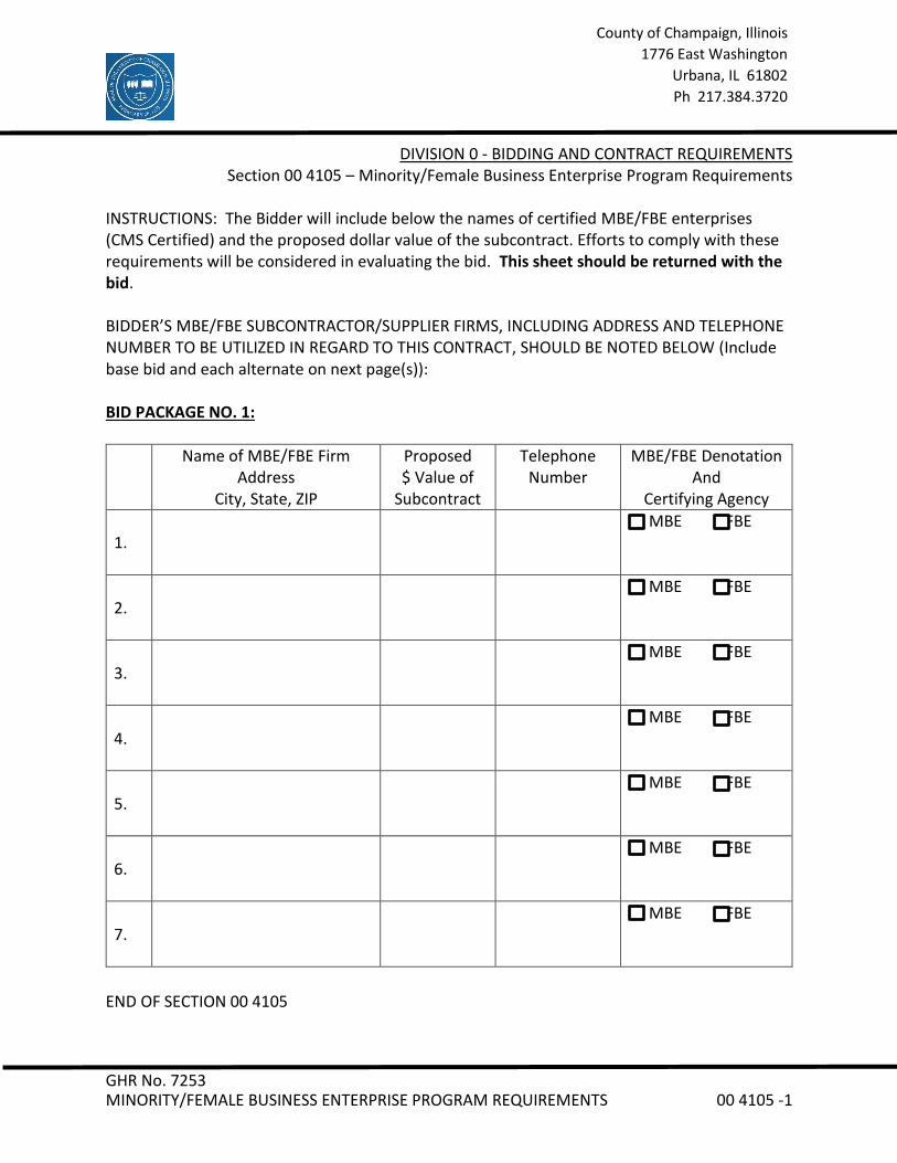
INSTRUCTIONS: The Bidder will include below the names of certified MBE/FBE enterprises (CMS Certified) and the proposed dollar value of the subcontract. Efforts to comply with these requirements will be considered in evaluating the bid. This sheet should be returned with the bid. BIDDER’S MBE/FBE SUBCONTRACTOR/SUPPLIER FIRMS, INCLUDING ADDRESS AND TELEPHONE NUMBER TO BE UTILIZED IN REGARD TO THIS CONTRACT, SHOULD BE NOTED BELOW (Include base bid and each alternate on next page(s)): BID PACKAGE NO. 1:
Name of MBE/FBE Firm Address
City, State, ZIP
Proposed $ Value of
Subcontract
Telephone Number
MBE/FBE Denotation And
Certifying Agency
1.
MBE FBE
2.
MBE FBE
3.
MBE FBE
4.
MBE FBE
5.
MBE FBE
6.
MBE FBE
7.
MBE FBE
END OF SECTION 00 4105


GHR No. 7253 BID FORM – STIPULATED SUM (SINGLE-PRIME CONTRACT) 00 4113 - 1
County of Champaign, Illinois 1776 East Washington
Urbana, IL 61802 Ph 217.384.3720
DOCUMENT 00 4113 - BID FORM - STIPULATED SUM (SINGLE-PRIME CONTRACT)
1.1 BID INFORMATION
A. Bidder: ____________________________________________________.
B. Project Name: Satellite Jail HVAC Replacement Project
C. Project Location: 502 South Lierman Avenue Urbana, Illinois 61802
D. Owner: County of Champaign
E. Building Design Team: GHR Engineers and Associates, Inc.
1.2 CERTIFICATIONS AND BASE BID
A. Controls Bid, Single-Prime (All Trades) Contract: The undersigned Bidder, having carefully examined the Procurement and Contracting Requirements, Conditions of the Contract, Drawings, Specifications, and all subsequent Addenda, as prepared by the Design Team, having visited the site, and being familiar with all conditions and requirements of the Work, hereby agrees to furnish all material, labor, equipment and services, including all scheduled allowances, necessary to complete the construction of the above-named project, according to the requirements of the Procurement and Contracting Documents, for the stipulated sum of: 1. ___________________________________________Dollars ($______________).
Bidders Note: Show bid amount in both words and figures. All spaces must be completed.
1.3 BID GUARANTEE
A. The undersigned Bidder agrees to execute a contract for this Work in the above amount and to furnish surety as specified within ten (10) days after a written Notice of Award, if offered within sixty (60) days after receipt of bids, and on failure to do so agrees to forfeit to Owner the attached bank draft/cashier's check, certified check, U.S. money order, or bid bond payable to County of Champaign, as liquidated damages for such failure, in an amount constituting ten percent (10%) of the Base Bid amount: 1. ___________________________________________Dollars ($______________).

GHR No. 7253 BID FORM – STIPULATED SUM (SINGLE-PRIME CONTRACT) 00 4113 - 2
County of Champaign, Illinois 1776 East Washington
Urbana, IL 61802 Ph 217.384.3720
B. In the event Owner does not offer Notice of Award within the time limits stated above, Owner will return to the undersigned the bank draft/cashier's check, certified check, U.S. money order, or bid bond.
C. The Owner reserves the right to accept or not accept Alternate Bids 1 and 2 in whatever order best serves the County’s needs.
1.4 TIME OF COMPLETION
A. The undersigned Bidder proposes and agrees hereby to commence the Work of the Contract Documents on a date specified in a written Notice to Proceed to be issued by Owner, and shall fully complete the Work as indicated in the Invitation to Bid.
1.5 ACKNOWLEDGEMENT OF ADDENDA
A. The undersigned Bidder acknowledges receipt of and use of the following Addenda in the preparation of this Bid:
1. Addendum No. 1, dated ____________________. 2. Addendum No. 2, dated ____________________. 3. Addendum No. 3, dated ____________________.
1.6 CONTRACTOR'S LICENSE
A. The undersigned warrants that he/she is duly authorized to bind contractually the entity submitting this bid, to fully perform all duties and to deliver all services in accordance with the terms and conditions set forth herein. All signatures to be sworn before a Notary Public.

GHR No. 7253 BID FORM – STIPULATED SUM (SINGLE-PRIME CONTRACT) 00 4113 - 3
County of Champaign, Illinois 1776 East Washington
Urbana, IL 61802 Ph 217.384.3720
1.7 SUBMISSION OF BID
Respectfully submitted this ____ day of ____________, 2021.
Submitted By: _______________________________
(Name of bidding firm or corporation)
Authorized Signature: _______________________________
(Handwritten signature)
Signed By: _______________________________
(Type or print name)
Title: _______________________________
(Owner/Partner/President/Vice President)
Witness By: _______________________________
(Handwritten signature)
Attest: _______________________________
(Handwritten signature)
By: _______________________________
(Type or print name)
Subscribed and sworn to before me this
______Day of ____________________, 2021.
________________________________, Notary Public
(Affix Notary Seal Here)
END OF DOCUMENT 00 4113

GHR No. 7253 BID FORM – STIPULATED SUM (SINGLE-PRIME CONTRACT) 00 4113 - 1
County of Champaign, Illinois 1776 East Washington
Urbana, IL 61802 Ph 217.384.3720
DOCUMENT 00 4113 - BID FORM - STIPULATED SUM (SINGLE-PRIME CONTRACT)
1.1 BID INFORMATION
A. Bidder: ____________________________________________________.
B. Project Name: Satellite Jail HVAC Replacement Project
C. Project Location: 502 South Lierman Avenue Urbana, Illinois 61802
D. Owner: County of Champaign
E. Building Design Team: GHR Engineers and Associates, Inc.
1.2 CERTIFICATIONS AND BASE BID
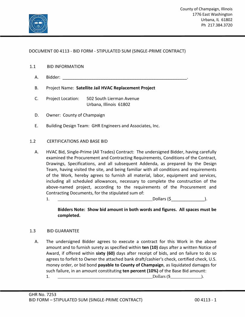
A. HVAC Bid, Single-Prime (All Trades) Contract: The undersigned Bidder, having carefully examined the Procurement and Contracting Requirements, Conditions of the Contract, Drawings, Specifications, and all subsequent Addenda, as prepared by the Design Team, having visited the site, and being familiar with all conditions and requirements of the Work, hereby agrees to furnish all material, labor, equipment and services, including all scheduled allowances, necessary to complete the construction of the above-named project, according to the requirements of the Procurement and Contracting Documents, for the stipulated sum of: 1. ___________________________________________Dollars ($______________).
Bidders Note: Show bid amount in both words and figures. All spaces must be completed.
1.3 BID GUARANTEE
A. The undersigned Bidder agrees to execute a contract for this Work in the above amount and to furnish surety as specified within ten (10) days after a written Notice of Award, if offered within sixty (60) days after receipt of bids, and on failure to do so agrees to forfeit to Owner the attached bank draft/cashier's check, certified check, U.S. money order, or bid bond payable to County of Champaign, as liquidated damages for such failure, in an amount constituting ten percent (10%) of the Base Bid amount: 1. ___________________________________________Dollars ($______________).
GHR No. 7253 BID FORM – STIPULATED SUM (SINGLE-PRIME CONTRACT) 00 4113 - 2
County of Champaign, Illinois 1776 East Washington
Urbana, IL 61802 Ph 217.384.3720
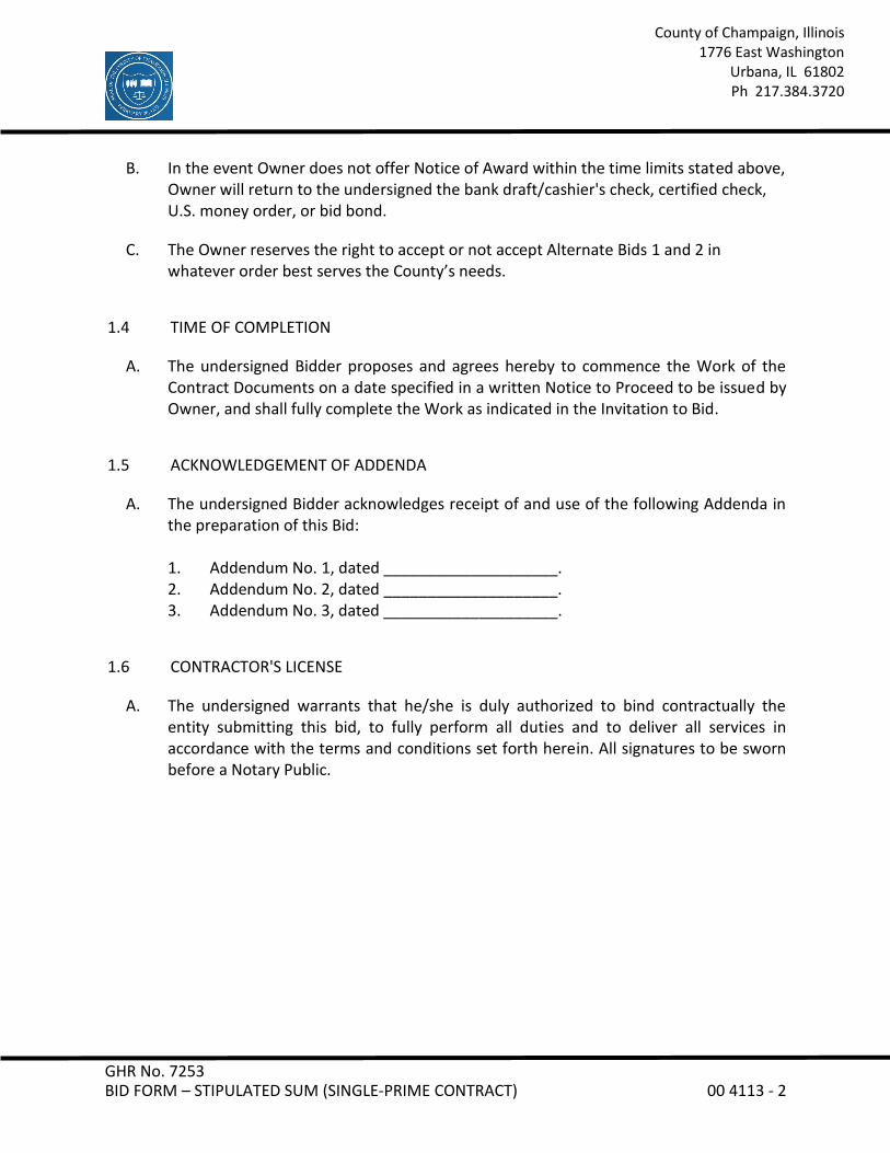
B. In the event Owner does not offer Notice of Award within the time limits stated above, Owner will return to the undersigned the bank draft/cashier's check, certified check, U.S. money order, or bid bond.
C. The Owner reserves the right to accept or not accept Alternate Bids 1 and 2 in whatever order best serves the County’s needs.
1.4 TIME OF COMPLETION
A. The undersigned Bidder proposes and agrees hereby to commence the Work of the Contract Documents on a date specified in a written Notice to Proceed to be issued by Owner, and shall fully complete the Work as indicated in the Invitation to Bid.
1.5 ACKNOWLEDGEMENT OF ADDENDA
A. The undersigned Bidder acknowledges receipt of and use of the following Addenda in the preparation of this Bid:
1. Addendum No. 1, dated ____________________. 2. Addendum No. 2, dated ____________________. 3. Addendum No. 3, dated ____________________.
1.6 CONTRACTOR'S LICENSE
A. The undersigned warrants that he/she is duly authorized to bind contractually the entity submitting this bid, to fully perform all duties and to deliver all services in accordance with the terms and conditions set forth herein. All signatures to be sworn before a Notary Public.
GHR No. 7253 BID FORM – STIPULATED SUM (SINGLE-PRIME CONTRACT) 00 4113 - 3
County of Champaign, Illinois 1776 East Washington
Urbana, IL 61802 Ph 217.384.3720
1.7 SUBMISSION OF BID
Respectfully submitted this ____ day of ____________, 2021.
Submitted By: _______________________________
(Name of bidding firm or corporation)
Authorized Signature: _______________________________
(Handwritten signature)
Signed By: _______________________________
(Type or print name)
Title: _______________________________
(Owner/Partner/President/Vice President)
Witness By: _______________________________
(Handwritten signature)
Attest: _______________________________
(Handwritten signature)
By: _______________________________
(Type or print name)
Subscribed and sworn to before me this
______Day of ____________________, 2021.
________________________________, Notary Public
(Affix Notary Seal Here)
END OF DOCUMENT 00 4113

GHR No. 7253 BID SECURITY FORMS 00 4313 - 1
County of Champaign, Illinois 1776 East Washington
Urbana, IL 61802 Ph 217.384.3720
DOCUMENT 00 4313 - BID SECURITY FORMS
1.1 BID FORM SUPPLEMENT
A. A completed bid bond form is required to be attached to the Bid Form.
1.2 BID BOND FORM
A. AIA Document A310, "Bid Bond," is the recommended form for a bid bond. A bid bond acceptable to Owner, is required to be attached to the Bid Form as a supplement.
B. Copies of AIA standard forms may be obtained from The American Institute of Architects; www.aia.org/contractdocs/purchase/index.htm; email: [email protected]; (800) 942-7732.
END OF DOCUMENT 00 4313

GHR No. 7253 SUMMARY 01 1000 -1
County of Champaign, Illinois 1776 East Washington
Urbana, IL 61802 Ph 217.384.3720
SECTION 01 1000 - SUMMARY
PART 1 - GENERAL
1.1 PROJECT INFORMATION
A. Project Identification: Satellite Jail HVAC Replacement Project
1. Project Location: 502 South Lierman Avenue Urbana, Illinois 61802
B. Owner: County of Champaign
C. Design Team: GHR Engineers and Associates, Inc.
D. Project Description:
1. HVAC Bid: Project consists of removal of (4) air handling units & associated air-cooled condensing units. (4) new air handlers will be installed in same location. (2) new air cooled chillers to be located on roof. Existing boilers will be removed and replaced with high-efficiency condensing boilers. New penthouse to be constructed for new equipment. Install controls valves provided by controls contractor.
2. Controls Bid: Project consists of removal of existing pneumatic controls. Install new DDC controls on existing and new HVAC equipment. Provide control valves to HVAC contractor for installation.
1.2 WORK RESTRICTIONS
Contractor's Use of Premises: During construction, Contractor will have limited use of site and building indicated. Contractor's use of premises is limited only by Owner's right to perform work or employ other contractors on portions of Project and as follows:
1. Owner will occupy premises during construction. Perform construction only during normal working hours 8 AM to 5 PM Monday thru Friday, other than holidays, unless otherwise agreed to in advance by Owner. Clean up work areas and return to usable condition at the end of each work period.
2. Limits: Limit site disturbance.
GHR No. 7253 SUMMARY 01 1000 -2
County of Champaign, Illinois 1776 East Washington
Urbana, IL 61802 Ph 217.384.3720
3. Driveways, Walkways, and Entrances: Keep driveways, loading areas, and entrances serving premises clear and available to Owner, Owner's employees, and emergency vehicles at all times. Do not use these areas for parking or storage of materials.
B. On-Site Work Hours: Limit work in the building to normal business working hours of 8 AM to 5 PM, Monday through Friday, unless otherwise indicated.
1. Weekend Hours: As permitted by Owner. Coordinate with Owner. 2. Early Morning Hours: 7 AM or as permitted by Owner. Coordinate with Owner. 3. 24 hour work may be necessary during AHU switchover. Coordinate with Owner.
C. Nonsmoking Building: Smoking is not permitted within the building or on the project site.
1.3 SITE
A. Contractor Job Trailer located to South of Building. Location shown on drawings.
B. Crane to be located on East side of Building. Location shown on drawings.
C. Workers to park in Brookens Parking Lot. Location shown on drawings.
1.4 UTILITIES
A. Electrical for Job Trailer responsibility of contractor.
B. Contractor to provide porta-toilet near job trailer.
1.5 BACKGROUND CHECKS
A. All workers to work within the building will be required to have a background check. Checks will be performed by the Sheriff’s Office. No fee to the contractor.
1.6 AHU WORK SCHEDULE
A. Schedule has allowed for a 1 week shutdown for each switchover of each AHU.
B. AHU switch over will be performed in the following order: AHU-4, AHU-3, AHU-2, and AHU-1.

GHR No. 7253 SUMMARY 01 1000 -3
County of Champaign, Illinois 1776 East Washington
Urbana, IL 61802 Ph 217.384.3720
1.7 MISC
A. Contractor to keep job site cleaned of loose debris.
B. Contractor tools and equipment to be secured nightly.
C. Protect roof and repair damage as needed.
D. Protect fire-safing during work.
PART 2 - PRODUCTS (Not Used)
PART 3 - EXECUTION (Not Used)
END OF SECTION 01 1000

GHR No. 7253 PRICE AND PAYMENT PROCEDURES 01 2000 -1
County of Champaign, Illinois 1776 East Washington
Urbana, IL 61802 Ph 217.384.3720
SECTION 01 2000 - PRICE AND PAYMENT PROCEDURES
PART 1 - GENERAL
1.1 PAYMENT PROCEDURES
A. Submit a Schedule of Values at least seven (7) days before the initial Application for Payment. Break down the Contract Sum into at least one line item for each Specification Section in the Project Manual table of contents. Coordinate the schedule of values with Contractor's construction schedule.
1. Arrange schedule of values consistent with format of AIA Document G703. 2. Round amounts to nearest whole dollar; total shall equal the Contract Sum. 3. Provide a separate line item in the schedule of values for each part of the Work
where Applications for Payment may include materials or equipment purchased or fabricated and stored, but not yet installed.
4. Provide separate line items in the schedule of values for initial cost of materials and for total installed value of that part of the Work.
5. Provide a separate line item in the schedule of values for each allowance.
B. Application for Payment Forms: Use AIA Document G702 and AIA Document G703 forms for Applications for Payment.
1. Anticipated Application for Payment Schedule:
a. Application for Payment No. 01: once material is delivered to project site b. Application for Payment No. 02: upon completion of installation c. Application for Payment No. 03: Final payment upon completion of punch list,
receipt of all close-out documents and completion of owner training
C. Submit three (3) copies of each application for payment according to the schedule established in Owner/Contractor Agreement.
1. Notarize and execute by a person authorized to sign legal documents on behalf of Contractor.
2. With each Application for Payment, Contractor shall include the Contractor’s waiver of lien for the full amount and partial waivers of mechanic's liens from subcontractors, sub-subcontractors, and suppliers for construction period covered by the previous application.
GHR No. 7253 PRICE AND PAYMENT PROCEDURES 01 2000 -2
County of Champaign, Illinois 1776 East Washington
Urbana, IL 61802 Ph 217.384.3720
3. Submit final Application for Payment with or preceded by conditional final waivers from every entity involved with performance of the Work covered by the application who is lawfully entitled to a lien.
a. Include insurance certificates, proof that taxes, fees, and similar obligations were paid, and evidence that claims have been settled.
b. Include affidavit of payment of debts and claims on AIA Document G706. c. Include affidavit of release of liens on AIA Document G706A. d. Include consent of surety to final payment on AIA Document G707.
4. Certified Payroll Statements: The Contractor shall submit Certified Payroll Statements pursuant to Illinois Law-Public Act 94-0515 with each payment application. The Certified Transcript of Payroll statement forms are available through the Illinois Department of Labor website: http://www.state.il.us/agency/idol/forms/pdfs/IL452CM02.pdf. Certified payroll statements are required from the Contractor and each Subcontractor. The statements are to include the time period of the payment application. Payment Applications will not be processed without accompanying Certified Payroll Statements.
PART 2 - PRODUCTS (Not Used)
PART 3 - EXECUTION (Not Used)
END OF SECTION 01 2000
GHR No. 7253 SUBSTITUTION PROCEDURES 01 2500 -1
County of Champaign, Illinois 1776 East Washington
Urbana, IL 61802 Ph217.384.3720
SECTION 01 2500 - SUBSTITUTION PROCEDURES
PART 1 - GENERAL
1.1 SUBSTITUTION PROCEDURES
A. Substitutions include changes in products, materials, equipment, and methods of Contractor.
B. Substitution Requests: Identify product or fabrication or installation method to be replaced. Include Specification Section number and title and Drawing numbers and titles. Substitutions will NOT be considered after bidding.
1. Substitution Request Form: Use facsimile of form provided in the Project Manual.
2. Submit requests by noon on Friday, May 28, 2021. 3. Identify product to be replaced and show compliance with requirements for
substitutions. Include a detailed comparison of significant qualities of proposed substitution with those of the Work specified, a list of changes needed to other parts of the Work required to accommodate proposed substitution, and any proposed changes in the Contract Sum or the Contract Time should the substitution be accepted.
4. Documentation: Show compliance with requirements for substitutions and the following, as applicable:
a. Statement indicating why specified product or fabrication or installation cannot be provided, if applicable.
b. Coordination information, including a list of changes or revisions needed to other parts of the Work and to construction performed by Owner and separate contractors that will be necessary to accommodate proposed substitution.
c. Detailed comparison of significant qualities of proposed substitution with those of the Work specified. Include annotated copy of applicable Specification Section. Significant qualities may include attributes such as performance, weight, size, durability, visual effect, sustainable design characteristics, warranties, and specific features and requirements indicated. Indicate deviations, if any, from the Work specified.
d. Product Data, including drawings and descriptions of products and fabrication and installation procedures.
GHR No. 7253 SUBSTITUTION PROCEDURES 01 2500 -2
County of Champaign, Illinois 1776 East Washington
Urbana, IL 61802 Ph217.384.3720
e. Samples, where applicable or requested:
1) All samples shall be clearly labeled with product information and Vendor contact information.
f. Certificates and qualification data, where applicable or requested. g. List of similar installations for completed projects with project names and
addresses and names and addresses of architects and owners. h. Material test reports from a qualified testing agency indicating and
interpreting test results for compliance with requirements indicated. i. Research reports evidencing compliance with building code in effect for
Project. j. Detailed comparison of Contractor's construction schedule using proposed
substitution with products specified for the Work, including effect on the overall Contract Time. If specified product or method of construction cannot be provided within the Contract Time, include letter from manufacturer, on manufacturer's letterhead, stating date of receipt of purchase order, lack of availability, or delays in delivery.
k. Cost information, including a proposal of change, if any, in the Contract Sum.
l. Contractor's certification that proposed substitution complies with requirements in the Contract Documents except as indicated in substitution request, is compatible with related materials, and is appropriate for applications indicated.
m. Contractor's waiver of rights to additional payment or time that may subsequently become necessary because of failure of proposed substitution to produce indicated results.
C. Architect will review proposed substitutions and notify Contractor of their acceptance or rejection via Addendum. If necessary, Architect will request additional information or documentation for evaluation.
1. Use product specified if Architect does not issue a decision on use of a proposed substitution within time allocated.
D. Do not submit unapproved substitutions on Shop Drawings or other submittals.
GHR No. 7253 SUBSTITUTION PROCEDURES 01 2500 -3
County of Champaign, Illinois 1776 East Washington
Urbana, IL 61802 Ph217.384.3720
PART 2 - PRODUCTS (Not Used)
PART 3 - EXECUTION (Not Used)
END OF SECTION 01 2500

GHR No. 7253 SUBSTITUTION REQUEST FORM 01 2500a - 1
County of Champaign, Illinois 1776 East Washington
Urbana, IL 61802 Ph217.384.3720
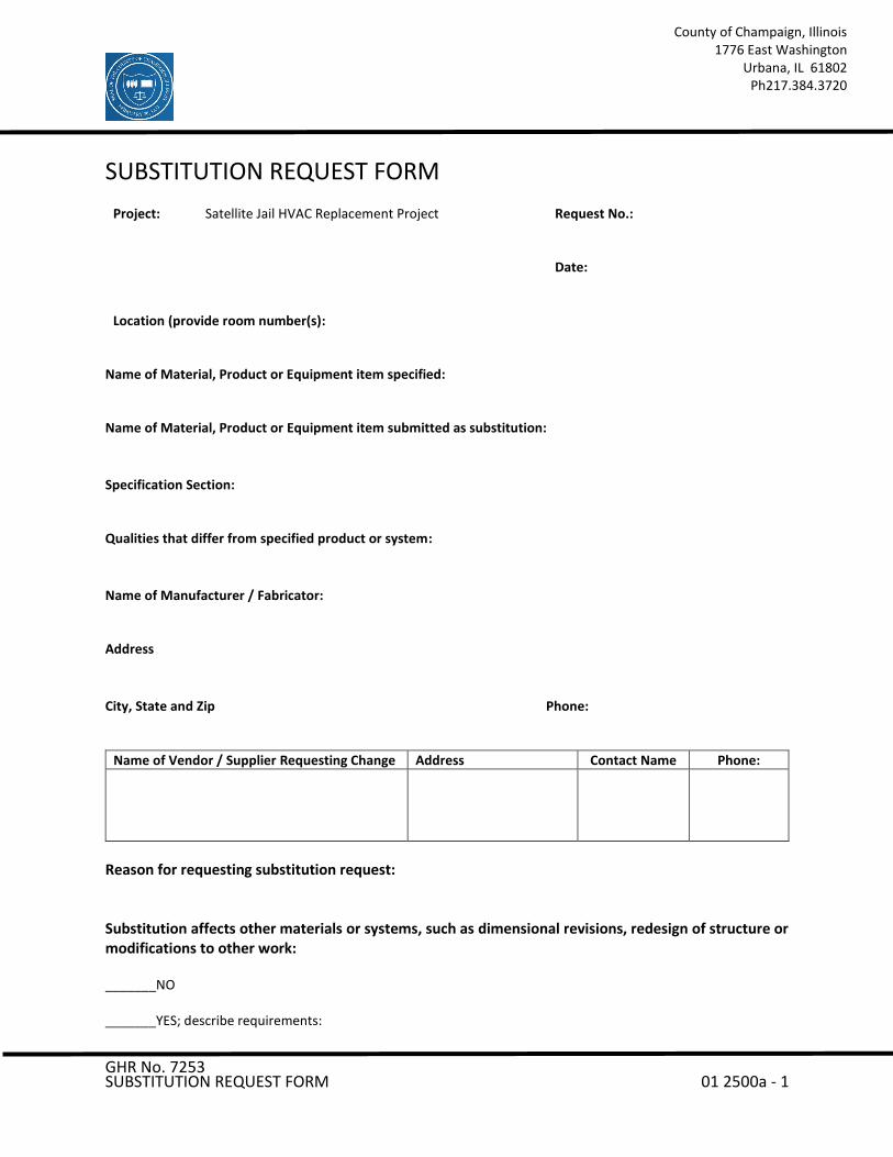
SUBSTITUTION REQUEST FORM
Project:
Satellite Jail HVAC Replacement Project
Request No.:
Date: Location (provide room number(s):
Name of Material, Product or Equipment item specified: Name of Material, Product or Equipment item submitted as substitution:
Specification Section: Qualities that differ from specified product or system:
Name of Manufacturer / Fabricator: Address
City, State and Zip Phone:
Name of Vendor / Supplier Requesting Change Address Contact Name Phone:
Reason for requesting substitution request: Substitution affects other materials or systems, such as dimensional revisions, redesign of structure or modifications to other work: _______NO _______YES; describe requirements:
GHR No. 7253 SUBSTITUTION REQUEST FORM 01 2500a - 2
County of Champaign, Illinois 1776 East Washington
Urbana, IL 61802 Ph217.384.3720
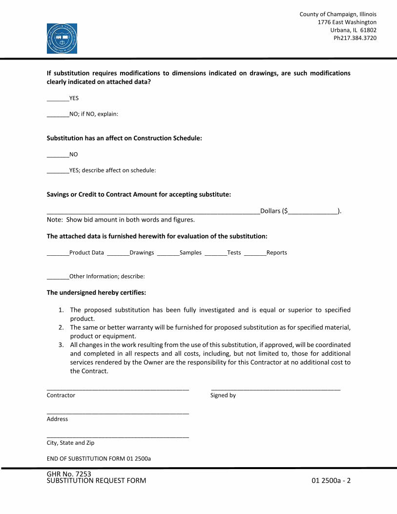
If substitution requires modifications to dimensions indicated on drawings, are such modifications clearly indicated on attached data? _______YES _______NO; if NO, explain:
Substitution has an affect on Construction Schedule: _______NO _______YES; describe affect on schedule:
Savings or Credit to Contract Amount for accepting substitute:
____________________________________________________________Dollars ($______________). Note: Show bid amount in both words and figures.
The attached data is furnished herewith for evaluation of the substitution: _______Product Data _______Drawings _______Samples _______Tests _______Reports _______Other Information; describe:
The undersigned hereby certifies:
1. The proposed substitution has been fully investigated and is equal or superior to specified product.
2. The same or better warranty will be furnished for proposed substitution as for specified material, product or equipment.
3. All changes in the work resulting from the use of this substitution, if approved, will be coordinated and completed in all respects and all costs, including, but not limited to, those for additional services rendered by the Owner are the responsibility for this Contractor at no additional cost to the Contract.
____________________________________________ ________________________________________ Contractor Signed by ____________________________________________ Address ____________________________________________ City, State and Zip END OF SUBSTITUTION FORM 01 2500a

GHR No. 7253 CONTRACT MODIFICATION PROCEDURES 01 2600 -1
County of Champaign, Illinois 1776 East Washington
Urbana, IL 61802 Ph 217.384.3720
SECTION 01 2600 - CONTRACT MODIFICATION PROCEDURES
PART 1 - GENERAL
1.1 CONTRACT MODIFICATION PROCEDURES
A. Design Team will issue supplemental instructions authorizing minor changes in the Work, not involving adjustment to the Contract Sum or the Contract Time.
B. Owner-Initiated Proposal Requests: Design Team will issue a detailed description of proposed changes in the Work.
1. Proposal Requests are not instructions either to stop work in progress or to execute the proposed change.
2. Within time specified in Proposal Request or 20 days, when not otherwise specified, after receipt of Proposal Request, submit a quotation estimating cost adjustments to the Contract Sum and the Contract Time.
C. Contractor-Initiated Proposals: If latent or changed conditions require modifications to the Contract, Contractor may initiate a claim by submitting a request for a change to Design Team.
D. On Owner's approval of a Proposal Request, Design Team will issue a Change Order for signatures of Owner and Contractor, for all changes to the Contract Sum or the Contract Time.
E. Design Team may issue a Construction Change Directive. Construction Change Directive instructs Contractor to proceed with a change in the Work, for subsequent inclusion in a Change Order.
1. Construction Change Directive contains a complete description of change in the Work. It also designates method to be followed to determine change in the Contract Sum or the Contract Time.
F. Documentation: Maintain detailed records on a time and material basis of work required by the Construction Change Directive. After completion of change, submit an itemized account and supporting data necessary to substantiate cost and time adjustments to the Contract.
GHR No. 7253 CONTRACT MODIFICATION PROCEDURES 01 2600 -2
County of Champaign, Illinois 1776 East Washington
Urbana, IL 61802 Ph 217.384.3720
PART 2 - PRODUCTS (Not Used)
PART 3 - EXECUTION (Not Used)
END OF SECTION 01 2600
GHR No. 7253 ADMINISTRATIVE REQUIREMENTS 01 3000 -1
County of Champaign, Illinois 1776 East Washington
Urbana, IL 61802 Ph 217.384.3720
SECTION 01 3000 - ADMINISTRATIVE REQUIREMENTS
PART 1 - GENERAL
1.1 PROJECT MANAGEMENT AND COORDINATION
A. Subcontract List: Submit a written summary identifying individuals or firms proposed for each portion of the Work.
B. Key Personnel Names: Within ten (10) days of starting construction operations, submit a list of key personnel assignments, including superintendent and other personnel in attendance at Project site. List e-mail addresses and telephone numbers.
C. Coordinate construction operations included in different Sections of the Specifications to ensure efficient and orderly installation of each part of the Work.
D. Requests for Information (RFIs): On discovery of the need for additional information or interpretation of the Contract Documents, Contractor shall prepare and submit an RFI. Use forms acceptable to Design Team and Owner.
E. Schedule and conduct (2) progress meetings at Project site, coordinated with the Design Team and Owner. Notify Owner of meeting dates and times. Require attendance of each subcontractor or other entity concerned with current progress or involved in planning, coordination, or performance of future activities.
1.2 SUBMITTAL ADMINISTRATIVE REQUIREMENTS
A. Coordinate each submittal with fabrication, purchasing, testing, delivery, other submittals, and related activities that require sequential activity.
1. No extension of the Contract Time will be authorized because of failure to transmit submittals enough in advance of the Work to permit processing, including resubmittals.
2. Submit two copies of each action submittal. Design Team will return one copy. 3. Submit one copy of each informational submittal. Design Team will not return
copies. 4. Design Team will discard submittals received from sources other than
Contractor.
GHR No. 7253 ADMINISTRATIVE REQUIREMENTS 01 3000 -2
County of Champaign, Illinois 1776 East Washington
Urbana, IL 61802 Ph 217.384.3720
B. Electronic Submittals: Identify and incorporate information in each electronic submittal file as follows:
1. Assemble complete submittal package into a single indexed file incorporating submittal requirements of a single Specification Section and transmittal form with links enabling navigation to each item.
2. Name file with unique identifier, including project identifier, Specification Section number, and revision identifier.
3. Provide means for insertion to permanently record Contractor's review and approval markings and action taken by Design Team.
C. Identify options requiring selection by Design Team.
D. Identify deviations from the Contract Documents on submittals.
E. Contractor's Construction Schedule Submittal Procedure:
1. Submit required submittals in the following format:
a. PDF electronic file.
2. Coordinate Contractor's construction schedule with the schedule of values, submittal schedule, progress reports, payment requests, and other required schedules and reports.
PART 2 - PRODUCTS
2.1 SUBMITTAL PROCEDURES
A. General Submittal Procedure Requirements: Prepare and submit submittals required by individual Specification Sections.
1. Submit electronic submittals via email as PDF electronic files to Shannon Hicks at GHR Engineers and Associates, Inc.: [email protected].
a. Design Team will return annotated file. Annotate and retain one copy of file as an electronic Project record document file.
2.2 ACTION SUBMITTALS
A. Submit two paper copies of each submittal unless otherwise indicated. Design Team will return one copy.
GHR No. 7253 ADMINISTRATIVE REQUIREMENTS 01 3000 -3
County of Champaign, Illinois 1776 East Washington
Urbana, IL 61802 Ph 217.384.3720
B. Product Data: Mark each copy to show applicable products and options. Include the following:
1. Manufacturer's written recommendations, product specifications, and installation instructions.
2. Wiring diagrams showing factory-installed wiring. 3. Printed performance curves and operational range diagrams. 4. Testing by recognized testing agency. 5. Compliance with specified standards and requirements.
C. Shop Drawings: Prepare Project-specific information, drawn accurately to scale. Do not base Shop Drawings on reproductions of the Contract Documents or standard printed data. Submit on sheets at least 8-1/2 by 11 inches but no larger than 30 by 42 inches. Include the following:
1. Dimensions and identification of products. 2. Fabrication and installation drawings and roughing-in and setting diagrams. 3. Wiring diagrams showing field-installed wiring. 4. Notation of coordination requirements. 5. Notation of dimensions established by field measurement.
2.3 INFORMATIONAL SUBMITTALS
A. Informational Submittals: Submit one paper copy of each submittal unless otherwise indicated. Design Team will not return copies.
B. Qualification Data: Include lists of completed projects with project names and addresses, names and addresses of Design Team and owners, and other information specified.
C. Product Certificates: Prepare written statements on manufacturer's letterhead certifying that product complies with requirements in the Contract Documents.
PART 3 - EXECUTION
3.1 SUBMITTAL REVIEW
A. Review each submittal and check for coordination with other Work of the Contract and for compliance with the Contract Documents. Note corrections and field dimensions. Mark with approval stamp before submitting to Design Team.
GHR No. 7253 ADMINISTRATIVE REQUIREMENTS 01 3000 -4
County of Champaign, Illinois 1776 East Washington
Urbana, IL 61802 Ph 217.384.3720
B. Design Team will review each action submittal, make marks to indicate corrections or modifications required, will stamp each submittal with an action stamp, and will mark stamp appropriately to indicate action.
C. Informational Submittals: Design Team will review each submittal and will not return it, or will return it if it does not comply with requirements. Design Team will forward each submittal to appropriate party.
D. Submittals not required by the Contract Documents may not be reviewed and may be discarded.
END OF SECTION 01 3000
GHR No. 7253 QUALITY REQUIREMENTS 01 4000 -1
County of Champaign, Illinois 1776 East Washington
Urbana, IL 61802 Ph 217.384.3720
SECTION 01 4000 - QUALITY REQUIREMENTS
PART 1 - GENERAL
1.1 SECTION REQUIREMENTS
A. Testing and inspecting services are required to verify compliance with requirements specified or indicated. These services do not relieve Contractor of responsibility for compliance with the Contract Document requirements.
B. Referenced Standards: If compliance with two or more standards is specified and the standards establish different or conflicting requirements, comply with the most stringent requirement. Refer uncertainties to Design Team for a decision.
C. Minimum Quantity or Quality Levels: The quantity or quality level shown or specified shall be the minimum. The actual installation may exceed the minimum within reasonable limits. Indicated numeric values are minimum or maximum, as appropriate, for the context of requirements. Refer uncertainties to Design Team for a decision.
D. Test and Inspection Reports: Prepare and submit certified written reports specified in other Sections. Include the following:
1. Date of issue. 2. Project title and number. 3. Name, address, and telephone number of testing agency. 4. Dates and locations of samples and tests or inspections. 5. Names of individuals making tests and inspections. 6. Description of the Work and test and inspection method. 7. Identification of product and Specification Section. 8. Complete test or inspection data. 9. Test and inspection results and an interpretation of test results. 10. Record of temperature and weather conditions at time of sample taking and
testing and inspecting. 11. Comments or professional opinion on whether tested or inspected Work
complies with the Contract Document requirements. 12. Name and signature of laboratory inspector. 13. Recommendations on retesting and reinspecting.

GHR No. 7253 QUALITY REQUIREMENTS 01 4000 -2
County of Champaign, Illinois 1776 East Washington
Urbana, IL 61802 Ph 217.384.3720
E. Permits, Licenses, and Certificates: For Owner's records, submit copies of permits, licenses, certifications, inspection reports, notices, receipts for fee payments, and similar documents, established for compliance with standards and regulations bearing on performance of the Work.
F. Testing Agency Qualifications: An independent agency with the experience and capability to conduct testing and inspecting indicated; and where required by authorities having jurisdiction, that is acceptable to authorities.
G. Retesting / Reinspecting: Regardless of whether original tests or inspections were Contractor’s responsibility, provide quality-control services, including retesting and reinspecting, for construction that replaced work that failed to comply with the Contract Documents.
H. Testing Agency Responsibilities: Cooperate with Design Team and Contractor in performance of duties. Provide qualified personnel to perform required tests and inspections.
1. Notify Design Team and Contractor of irregularities or deficiencies in the work
observed during performance of its services. 2. Do not release, revoke, alter or increase requirements of the Contract
Documents or approve or accept any portion of the work. 3. Do not perform any duties of Contractor.
I. Coordination: Coordinate sequence of activities to accommodate required quality-assurance and -control services with a minimum of delay and to avoid necessity of removing and replacing construction to accommodate testing and inspecting.
1. Schedule times for tests, inspections, obtaining samples, and similar activities.
J. Tests and Inspections: Owner will engage a qualified inspector to conduct inspections required by authorities having jurisdiction.
PART 2 - PRODUCTS (Not Used)
GHR No. 7253 QUALITY REQUIREMENTS 01 4000 -3
County of Champaign, Illinois 1776 East Washington
Urbana, IL 61802 Ph 217.384.3720
PART 3 - EXECUTION
3.1 REPAIR AND PROTECTION
A. Repair and protection are Contractor's responsibility, regardless of the assignment of responsibility for quality-control services.
B. Contractor will maintain a safe work site at all times. When the project is complete, Contractor shall return the work site and the surrounding areas to the same condition as they were prior to the beginning of the project.
END OF SECTION 01 4000

GHR No. 7253 PRODUCT REQUIREMENTS 01 6000 -1
County of Champaign, Illinois 1776 East Washington
Urbana, IL 61802 Ph 217.384.3720
SECTION 01 6000 - PRODUCT REQUIREMENTS
PART 1 - GENERAL
1.1 SECTION REQUIREMENTS
A. The term "product" includes the terms "material," "equipment," "system," and terms of similar intent.
B. Comparable Product Requests: Submit request for consideration of each comparable product. Identify product or fabrication or installation method to be replaced.
1. Show compliance with requirements for comparable product requests. 2. Design Team will review the proposed product and notify Contractor of its
acceptance or rejection.
C. Basis-of-Design Product Specification Submittal: Show compliance with requirements.
D. Compatibility of Options: If Contractor is given option of selecting between two or more products, select product compatible with products previously selected.
E. Deliver, store, and handle products using means and methods that will prevent damage, deterioration, and loss, including theft. Comply with manufacturer's written instructions.
1. Schedule delivery to minimize long-term storage at Project site and to prevent overcrowding of construction spaces.
2. Deliver products to Project site in manufacturer's original sealed container or packaging, complete with labels and instructions for handling, storing, unpacking, protecting, and installing.
3. Inspect products on delivery to ensure compliance with the Contract Documents and to ensure that products are undamaged and properly protected.
4. Store materials in a manner that will not endanger Project structure. 5. Store products that are subject to damage by the elements, under cover in a
weathertight enclosure above ground, with ventilation adequate to prevent condensation.
F. Warranties specified in other Sections shall be in addition to, and run concurrent with, other warranties required by the Contract Documents. Manufacturer's disclaimers and limitations on product warranties do not relieve Contractor of obligations under requirements of the Contract Documents.
GHR No. 7253 PRODUCT REQUIREMENTS 01 6000 -2
County of Champaign, Illinois 1776 East Washington
Urbana, IL 61802 Ph 217.384.3720
PART 2 - PRODUCTS
2.1 PRODUCT SELECTION PROCEDURES
A. Provide products that comply with the Contract Documents, are undamaged, and, unless otherwise indicated, are new at the time of installation.
1. Provide products complete with accessories, trim, finish, and other devices and components needed for a complete installation and the intended use and effect.
2. Where products are accompanied by the term "as selected," Owner will make selection.
3. Descriptive, performance, and reference standard requirements in the Specifications establish salient characteristics of products.
B. Where the following headings are used to list products or manufacturers, the Contractor's options for product selection are as follows:
1. Products:
a. Where requirements include "one of the following," provide one of the products listed that complies with requirements.
b. Where requirements do not include "one of the following," provide one of the products listed that complies with requirements or a comparable product.
2. Manufacturers:
a. Where requirements include "one of the following," provide a product that complies with requirements by one of the listed manufacturers.
b. Where requirements do not include "one of the following," provide a product that complies with requirements by one of the listed manufacturers or another manufacturer.
3. Basis-of-Design Product: Provide the product named, or indicated on the Drawings, or a comparable product by one of the listed manufacturers.
2.2 COMPARABLE PRODUCTS
A. Design Team will consider Contractor's request for comparable product in advance of Bidding only when the following conditions are satisfied:
GHR No. 7253 PRODUCT REQUIREMENTS 01 6000 -3
County of Champaign, Illinois 1776 East Washington
Urbana, IL 61802 Ph 217.384.3720
1. Evidence that the proposed product does not require revisions to the Contract Documents, that it is consistent with the Contract Documents and will produce the indicated results, and that it is compatible with other portions of the Work.
2. Detailed comparison of significant qualities of proposed product with those named in the Specifications.
3. List of similar installations for completed projects, if requested. 4. Samples, where applicable.
PART 3 - EXECUTION (Not Used)
END OF SECTION 01 6000


GHR No. 7253 EXECUTION AND CLOSEOUT REQUIREMENTS 01 7000 -1
County of Champaign, Illinois 1776 East Washington
Urbana, IL 61802 Ph 217.384.3720
SECTION 01 7000 - EXECUTION AND CLOSEOUT REQUIREMENTS
PART 1 - GENERAL
1.1 EXECUTION REQUIREMENTS
A. Cutting and Patching:
1. Structural Elements: When cutting and patching structural elements, notify Design Team of locations and details of cutting and await directions from Architect before proceeding. Shore, brace, and support structural elements during cutting and patching.
2. Operational Elements: Do not cut and patch operating elements and related components in a manner that results in reducing their capacity to perform as intended or that results in increased maintenance or decreased operational life or safety.
3. Visual Elements: Do not cut and patch construction in a manner that results in visual evidence of cutting and patching. Do not cut and patch exposed construction in a manner that would, in Architect's opinion, reduce the building's aesthetic qualities.
B. Manufacturer's Installation Instructions: Obtain and maintain on-site manufacturer's written recommendations and instructions for installation of products and equipment.
1.2 CLOSEOUT SUBMITTALS
A. Contractor's List of Incomplete Items: Initial submittal at Substantial Completion.
B. Certified List of Incomplete Items: Final submittal at Final Completion.
C. Operation and Maintenance Data: Submit two (2) copies of manual.
D. PDF Electronic File: Assemble manual into a composite electronically indexed file. Submit two (2) copies on digital media.
E. Record Product Data: Submit two (2) paper copies and annotated PDF electronic files and directories of each submittal.
GHR No. 7253 EXECUTION AND CLOSEOUT REQUIREMENTS 01 7000 -2
County of Champaign, Illinois 1776 East Washington
Urbana, IL 61802 Ph 217.384.3720
1.3 SUBSTANTIAL COMPLETION PROCEDURES
A. Prepare a list of items to be completed and corrected (punch list), the value of items on the list, and reasons why the Work is not complete.
B. Submittals Prior to Substantial Completion: Before requesting Substantial Completion inspection, complete the following:
1. Submit closeout submittals specified in other sections, including project record documents, operation and maintenance manuals, similar final record information, warranties, workmanship bonds, maintenance service agreements, final certifications, and similar documents.
2. Submit maintenance material submittals specified in other sections, including tools, spare parts, extra materials, and similar items, and deliver to location designated by Owner.
3. Submit test/adjust/balance records.
C. Procedures Prior to Substantial Completion: Before requesting Substantial Completion inspection, complete the following:
1. Complete startup and testing of systems and equipment. 2. Perform preventive maintenance on equipment used prior to Substantial
Completion. 3. Remove temporary facilities and controls. 4. Complete final cleaning requirements, including touchup painting. 5. Touch up and otherwise repair and restore marred exposed finishes to eliminate
visual defects.
D. Inspection: Submit a written request for inspection for Substantial Completion. On receipt of request, Architect will proceed with inspection or advise Contractor of unfulfilled requirements. Architect will prepare the Certificate of Substantial Completion after inspection or will advise Contractor of items that must be completed or corrected before certificate will be issued.
1.4 FINAL COMPLETION PROCEDURES
A. Submittals Prior to Final Completion: Before requesting inspection for determining final completion, complete the following:
1. Submit a final Application for Payment.

GHR No. 7253 EXECUTION AND CLOSEOUT REQUIREMENTS 01 7000 -3
County of Champaign, Illinois 1776 East Washington
Urbana, IL 61802 Ph 217.384.3720
2. Submit certified copy of Architect's Substantial Completion inspection list of
items to be completed or corrected (punch list), endorsed and dated by Architect. Certified copy of the list shall state that each item has been completed or otherwise resolved.
B. Submit a written request for final inspection for acceptance. On receipt of request, Design Team will either proceed with inspection or notify Contractor of unfulfilled requirements. Architect will prepare final Certificate for Payment after inspection or will advise Contractor of items that must be completed or corrected before certificate will be issued.
1. Reinspection: Request reinspection when the Work identified in previous inspections as incomplete is completed or corrected.
PART 2 - PRODUCTS
2.1 MATERIALS
A. In-Place Materials: Use materials for patching identical to in-place materials. For exposed surfaces, use materials that visually match in-place adjacent surfaces to the fullest extent possible.
B. Cleaning Agents: Use cleaning materials and agents recommended by manufacturer or fabricator of the surface to be cleaned. Do not use cleaning agents that are potentially hazardous to health or property or that might damage finished surfaces.
1. Use cleaning products that comply with Green Seal's GS-37, or if GS-37 is not applicable, use products that comply with the California Code of Regulations maximum allowable VOC levels.
2.2 OPERATION AND MAINTENANCE DOCUMENTATION
A. Directory: Prepare a single, comprehensive directory of operation and maintenance data and materials, listing items and their location to facilitate ready access to desired information.
B. Organization: Unless otherwise indicated, organize manual into separate sections for each system and subsystem, and separate sections for each piece of equipment not part of a system.

GHR No. 7253 EXECUTION AND CLOSEOUT REQUIREMENTS 01 7000 -4
County of Champaign, Illinois 1776 East Washington
Urbana, IL 61802 Ph 217.384.3720
1. Dividers: Provide heavy paper dividers with celluloid-covered tabs for each separate Section. Mark each tab to indicate contents. Provide a typed description of the product and major parts of equipment included in the Section on each divider.
C. Organize data into three-ring binders with identification on front and spine of each binder, and envelopes for folded drawings. Identify each binder on the front and spine with the printed title “OPERATION AND MAINTENANCE MANUAL”, Project title or name, year and subject matter covered. Indicate volume number for multiple volume sets of manuals. Include the following:
1. Manufacturer's operation and maintenance documentation. 2. Maintenance and service schedules. 3. Maintenance service contracts. Include name and telephone number of service
agent. 4. Emergency instructions. 5. Spare parts list and local sources of maintenance materials. 6. Wiring diagrams. 7. Copies of warranties. Include procedures to follow and required notifications for
warranty claims
2.3 RECORD DRAWINGS
A. Record Prints: Maintain a set of prints of the Contract Drawings and Shop Drawings, incorporating new and revised drawings as modifications are issued. Mark to show actual installation where installation varies from that shown originally. Accurately record information in an acceptable drawing technique.
1. Identify and date each record Drawing; include the designation "PROJECT RECORD DRAWING" in a prominent location.
B. Record Digital Data Files: Immediately before inspection for Certificate of Substantial Completion, review marked-up record prints with Architect. When authorized, prepare a full set of corrected digital data files of the Contract Drawings.
1. Format: Annotated PDF electronic file.
GHR No. 7253 EXECUTION AND CLOSEOUT REQUIREMENTS 01 7000 -5
County of Champaign, Illinois 1776 East Washington
Urbana, IL 61802 Ph 217.384.3720
PART 3 - EXECUTION
3.1 EXAMINATION AND PREPARATION
A. Before proceeding with each component of the Work, examine substrates, areas, and conditions, with Installer or Applicator present where indicated, for compliance with requirements for installation tolerances and other conditions affecting performance.
1. Verify compatibility with and suitability of substrates. 2. Examine roughing-in for mechanical and electrical systems. 3. Examine walls, floors, and roofs for suitable conditions.
B. Proceed with installation only after unsatisfactory conditions have been corrected.
C. Take field measurements as required to fit the Work properly. Where portions of the Work are indicated to fit to other construction, verify dimensions of other construction by field measurements before fabrication.
D. Verify space requirements and dimensions of items shown diagrammatically on Drawings.
3.2 CONSTRUCTION LAYOUT
A. Before proceeding to lay out the Work, verify layout information shown on Drawings.
3.3 INSTALLATION
A. Locate the Work and components of the Work accurately, in correct alignment and elevation, as indicated.
1. Make vertical work plumb and make horizontal work level. 2. Conceal wiring in finished areas unless otherwise indicated. 3. Maintain minimum headroom clearance of 96 inches in occupied spaces and 90
inches in unoccupied spaces.
B. Comply with manufacturer's written instructions and recommendations.
C. Conduct construction operations so no part of the Work is subjected to damaging operations or loading in excess of that expected during normal conditions of occupancy.

GHR No. 7253 EXECUTION AND CLOSEOUT REQUIREMENTS 01 7000 -6
County of Champaign, Illinois 1776 East Washington
Urbana, IL 61802 Ph 217.384.3720
D. Templates: Obtain and distribute to the parties involved templates for work specified to be factory prepared and field installed.
E. Attachment: Provide blocking and attachment plates and anchors and fasteners of adequate size and number to securely anchor each component in place. Where size and type of attachments are not indicated, verify size and type required for load conditions.
1. Mounting Heights: Where mounting heights are not indicated, mount components at heights directed by Owner.
F. Joints: Make joints of uniform width. Where joint locations in exposed work are not indicated, arrange joints for the best visual effect. Fit exposed connections together to form hairline joints.
G. Use products, cleaners, and installation materials that are not considered hazardous.
3.4 CUTTING AND PATCHING
A. Provide temporary support of work to be cut.
B. Protection: Protect in-place construction during cutting and patching to prevent damage. Provide protection from adverse weather conditions for portions of Project that might be exposed during cutting and patching operations.
C. Where existing services/systems are required to be removed, relocated, or abandoned, bypass such services/systems before cutting to prevent interruption to occupied areas.
D. Cutting: Cut in-place construction using methods least likely to damage elements retained or adjoining construction.
1. Cut holes and slots neatly to minimum size required, and with minimum disturbance of adjacent surfaces. Temporarily cover openings when not in use.
E. Patch with durable seams that are as invisible as possible. Provide materials and comply with installation requirements specified in other Sections.
1. Restore exposed finishes of patched areas and extend finish restoration into adjoining construction in a manner that will minimize evidence of patching and refinishing.

GHR No. 7253 EXECUTION AND CLOSEOUT REQUIREMENTS 01 7000 -7
County of Champaign, Illinois 1776 East Washington
Urbana, IL 61802 Ph 217.384.3720
2. Where walls or partitions that are removed extend one finished area into
another, patch and repair floor and wall surfaces in the new space. Provide an even surface of uniform finish, color, texture, and appearance.
3. Where patching occurs in a painted surface, prepare substrate and apply primer and intermediate paint coats appropriate for substrate over the patch, and apply final paint coat over entire unbroken surface containing the patch. Provide additional coats until patch blends with adjacent surfaces.
3.5 CLEANING
A. Clean Project site and work areas daily, including common areas. Dispose of materials lawfully.
1. Remove liquid spills promptly. 2. Where dust would impair proper execution of the Work, broom-clean or vacuum
the entire work area, as appropriate. 3. Remove debris from concealed spaces before enclosing the space.
B. Complete the following cleaning operations before requesting inspection for certification of Substantial Completion:
1. Clean Project site and grounds, in areas disturbed by construction activities. Sweep paved areas; remove stains, spills, and foreign deposits. Rake grounds that are neither planted nor paved to a smooth, even-textured surface.
2. Sweep paved areas broom clean. Remove spills, stains, and other foreign deposits.
3. Remove labels that are not permanent. 4. Clean transparent materials, including mirrors. Remove excess glazing
compounds. 5. Clean exposed finishes to a dust-free condition, free of stains, films, and foreign
substances. Sweep concrete floors broom clean. 6. Vacuum carpeted surfaces. 7. Wipe surfaces of mechanical and electrical equipment. Remove excess
lubrication and foreign substances. Clean plumbing fixtures. Clean light fixtures, lamps, globes, and reflectors.
3.6 OPERATION AND MAINTENANCE MANUAL PREPARATION
A. Operation and Maintenance Manuals: Assemble a complete set of operation and maintenance data indicating operation and maintenance of each system, subsystem, and piece of equipment not part of a system.
GHR No. 7253 EXECUTION AND CLOSEOUT REQUIREMENTS 01 7000 -8
County of Champaign, Illinois 1776 East Washington
Urbana, IL 61802 Ph 217.384.3720
B. Manufacturers' Data: Where manuals contain manufacturers' standard printed data, include only sheets pertinent to product or component installed. Mark each sheet to identify each product or component incorporated into the Work. If data include more than one item in a tabular format, identify each item using appropriate references from the Contract Documents. Identify data applicable to the Work and delete references to information not applicable.
1. Prepare supplementary text if manufacturers' standard printed data are unavailable and where the information is necessary for proper operation and maintenance of equipment or systems.
C. Drawings: Prepare drawings supplementing manufacturers' printed data to illustrate the relationship of component parts of equipment and systems and to illustrate control sequence and flow diagrams.
3.7 DEMONSTRATION AND TRAINING
A. Contractor to instruct Owner's personnel to adjust, operate, and maintain systems, subsystems, and equipment not part of a system. Include a detailed review of the following:
1. Include instruction for basis of system design and operational requirements, review of documentation, emergency procedures, operations, adjustments, troubleshooting, maintenance, and repairs.
B. Contractor shall train Owner’s teaching faculty on the online monitoring functionality of new system.
END OF SECTION 01 7000
GHR No. 7253 CONSTRUCTION WASTE MANAGEMENT AND DISPOSAL 01 7419 -1
County of Champaign, Illinois 1776 East Washington
Urbana, IL 61802 Ph 217.384.3720
SECTION 01 7419 - CONSTRUCTION WASTE MANAGEMENT AND DISPOSAL
PART 1 - GENERAL (Not Used)
PART 2 - PRODUCTS (Not Used)
PART 3 - EXECUTION
3.1 PLAN IMPLEMENTATION
A. General: Provide handling, containers, storage, signage, transportation, and other items as required to implement waste management plan during the entire duration of the Contract.
B. Training: Train workers, subcontractors, and suppliers on proper waste management procedures, as appropriate for the Work occurring at Project site.
1. Review locations established for recycling and disposal.
3.2 RECYCLING WASTE
A. Packaging:
1. Cardboard and Boxes: Break down packaging into flat sheets. Bundle and store in a dry location.
2. Polystyrene Packaging: Separate and bag materials. 3. Pallets: As much as possible, require deliveries using pallets to remove pallets
from Project site. For pallets that remain on-site, break down pallets into component wood pieces and comply with requirements for recycling wood.
4. Crates: Break down crates into component wood pieces and comply with requirements for recycling wood.
B. Wood Materials:
1. Sort and stack reusable members according to size, type, and length. Separate lumber, engineered wood products, panel products, and treated wood materials.
2. Clean Cut-Offs of Lumber: Grind or chip into small pieces. 3. Clean Sawdust: Bag sawdust that does not contain painted or treated wood.
C. Metals: Separate metals by type.

GHR No. 7253 CONSTRUCTION WASTE MANAGEMENT AND DISPOSAL 01 7419 -2
County of Champaign, Illinois 1776 East Washington
Urbana, IL 61802 Ph 217.384.3720
3.3 DISPOSAL OF WASTE
A. Except for items or materials to be recycled or otherwise reused, remove waste materials from Project site and legally dispose of them in a landfill or incinerator acceptable to authorities having jurisdiction.
B. Recycle recyclable materials off-site.
C. Do not burn waste materials.
END OF SECTION 01 7419

Satellite Jail THERMAL INSULATION IGW File 2125 07 21 00-1
SECTION 07 21 00 - THERMAL INSULATION
PART 1 - GENERAL
1.1 RELATED DOCUMENTS
A. Drawings and general provisions of the Contract, including General and Supplementary Conditions and Division 1 Specification Sections, apply to this Section.
1.2 SUMMARY
A. This Section includes the following: 1. Concealed building insulation. 2. Vapor retarders.
B. Related Sections include the following:
1. Division 9 Section "Gypsum Board Assemblies" for sound attenuation blankets.
1.3 SUBMITTALS
A. Product Data: For each type of product indicated.
1.4 QUALITY ASSURANCE
A. Source Limitations: Obtain each type of building insulation through one source.
B. Fire-Test-Response Characteristics: Provide insulation and related materials with the fire-test-response characteristics indicated, as determined by testing identical products per test method indicated below by UL or another testing and inspecting agency acceptable to authorities having jurisdiction. Identify materials with appropriate markings of applicable testing and inspecting agency.
1. Surface-Burning Characteristics: ASTM E 84. 2. Fire-Resistance Ratings: ASTM E 119. 3. Combustion Characteristics: ASTM E 136.
1.5 DELIVERY, STORAGE, AND HANDLING
A. Protect insulation materials from physical damage and from deterioration by moisture, soiling, and other sources. Store inside and in a dry location. Comply with manufacturer's written instructions for handling, storing, and protecting during installation.
B. Protect plastic insulation as follows:
1. Do not expose to sunlight, except to extent necessary for period of installation and concealment. 2. Protect against ignition at all times. Do not deliver plastic insulating materials to Project site
before installation time.
Satellite Jail THERMAL INSULATION IGW File 2125 07 21 00-2
3. Complete installation and concealment of plastic materials as rapidly as possible in each area of construction.
PART 2 - PRODUCTS
2.1 INSULATING MATERIALS
A. General: Provide insulating materials that comply with requirements and with referenced standards.
1. Preformed Units: Sizes to fit applications indicated; selected from manufacturer's standard thicknesses, widths, and lengths.
B. Extruded-Polystyrene Board Insulation: ASTM C 578, of type and density indicated below, with maximum flame-spread and smoke-developed indices of 75 and 450, respectively:
1. Type IV, 1.60 lb/cu. ft. (26 kg/cu. m).
C. Unfaced Mineral-Fiber Blanket Insulation: ASTM C 665, Type I (blankets without membrane facing); consisting of fibers manufactured from glass, slag wool, or rock wool; with maximum flame-spread and smoke-developed indices of 25 and 50, respectively; passing ASTM E 136 for combustion characteristics.
2.2 VAPOR RETARDERS
A. Polyethylene Vapor Retarder: ASTM D 4397, 6 mils (0.15 mm) thick, with maximum permeance rating of 0.13 perm (7.5 ng/Pa x s x sq. m).
B. Vapor-Retarder Tape: Pressure-sensitive tape of type recommended by vapor-retarder manufacturer for sealing joints and penetrations in vapor retarder.
PART 3 - EXECUTION
3.1 EXAMINATION
A. Examine substrates and conditions, with Installer present, for compliance with requirements for Sections in which substrates and related work are specified and other conditions affecting performance.
B. Proceed with installation only after unsatisfactory conditions have been corrected.
3.2 PREPARATION
A. Clean substrates of substances harmful to insulations or vapor retarders, including removing projections capable of puncturing vapor retarders or of interfering with insulation attachment.
3.3 INSTALLATION, GENERAL
A. Comply with insulation manufacturer's written instructions applicable to products and application indicated.
Satellite Jail THERMAL INSULATION IGW File 2125 07 21 00-3
B. Install insulation that is undamaged, dry, and unsoiled and that has not been left exposed at any time to ice and snow.
C. Extend insulation in thickness indicated to envelop entire area to be insulated. Cut and fit tightly around obstructions and fill voids with insulation. Remove projections that interfere with placement.
D. Water-Piping Coordination: If water piping is located on inside of insulated exterior walls, coordinate location of piping to ensure that it is placed on warm side of insulation and insulation encapsulates piping.
E. Apply single layer of insulation to produce thickness indicated, unless multiple layers are otherwise shown or required to make up total thickness.
3.4 INSTALLATION OF GENERAL BUILDING INSULATION
A. Install mineral-fiber blankets in cavities formed by framing members according to the following requirements:
1. Use blanket widths and lengths that fill the cavities formed by framing members. If more than one length is required to fill cavity, provide lengths that will produce a snug fit between ends.
2. Place blankets in cavities formed by framing members to produce a friction fit between edges of insulation and adjoining framing members.
3. For metal-framed wall cavities where cavity heights exceed 96 inches (2438 mm), support unfaced blankets mechanically and support faced blankets by taping stapling flanges to flanges of metal studs.
B. Stuff glass-fiber insulation into miscellaneous voids and cavity spaces where shown. Compact to approximately 40 percent of normal maximum volume equaling a density of approximately 2.5 lb/cu. ft. (40 kg/cu. m).
C. Install board insulation on masonry with small pads of adhesive spaced approximately 24 inches o.c. both ways, as recommended by manufacturer. Fit courses of insulation between furring channels and other confining obstructions, with edges butted tightly both ways. Press units firmly against masonry or other construction as shown.
3.5 INSTALLATION OF VAPOR RETARDERS
A. General: Extend vapor retarder to extremities of areas to be protected from vapor transmission. Secure in place with adhesives or other anchorage system as indicated. Extend vapor retarder to cover miscellaneous voids in insulated substrates, including those filled with loose-fiber insulation.
B. Seal vertical joints in vapor retarders over framing by lapping not less than two wall studs. Fasten vapor retarders to framing at top, end, and bottom edges; at perimeter of wall openings; and at lap joints. Space fasteners 16 inches (406 mm) o.c.
C. Firmly attach vapor retarders to substrates with mechanical fasteners or adhesives as recommended by vapor-retarder manufacturer.
D. Seal joints caused by pipes, conduits, electrical boxes, and similar items penetrating vapor retarders with vapor-retarder tape to create an airtight seal between penetrating objects and vapor retarder.
E. Repair any tears or punctures in vapor retarders immediately before concealment by other work. Cover with vapor-retarder tape or another layer of vapor retarder.
Satellite Jail THERMAL INSULATION IGW File 2125 07 21 00-4
3.6 PROTECTION
A. Protect installed insulation and vapor retarders from damage due to harmful weather exposures, physical abuse, and other causes. Provide temporary coverings or enclosures where insulation is subject to abuse and cannot be concealed and protected by permanent construction immediately after installation.
END OF SECTION 07 21 00
Satellite Jail FORMED METAL WALL PANELS IGW File 2125 07 42 13-1
SECTION 07 42 13 – FORMED METAL WALL PANELS
PART 1 - GENERAL
1.1 WORK INCLUDES
A. Base Bid:
1. Concealed-fastener, lap-seam metal wall panels.
1.2 RELATED WORK
A. 07 62 00 “Sheet Metal Flashing and Trim”
1.3 QUALITY ASSURANCE
A. Installer Qualifications: An entity that employs installers and supervisors who are trained and approved by manufacturer.
1.4 SUBMITTALS
A. Product Data: For each type of product.
1. Include construction details, material descriptions, dimensions of individual components and profiles, and finishes for each type of panel and accessory.
B. Shop Drawings:
1. Include fabrication and installation layouts of metal panels; details of edge conditions, joints, panel profiles, corners, anchorages, attachment system, trim, flashings, closures, and accessories; and special details.
2. Accessories: Include details of the flashing, trim, and anchorage systems, at a scale of not less than 1-1/2 inches per 12 inches (1:10).
C. Samples for Initial Selection: For each type of metal panel indicated with factory-applied finishes.
1. Include Samples of trim and accessories involving color selection.
D. Qualification Data: For Installer.
E. Product Test Reports: For each product, for tests performed by a qualified testing agency.
Satellite Jail FORMED METAL WALL PANELS IGW File 2125 07 42 13-2
F. Field quality-control reports.
G. Sample Warranties: For special warranties.
H. Maintenance Data: For metal panels to include in maintenance manuals.
PART 2 - PRODUCTS
2.1 PERFORMANCE REQUIREMENTS
A. Structural Performance: Provide metal panel systems capable of withstanding the effects of the following loads, based on testing according to ASTM E1592:
1. Wind Loads: As indicated on Drawings. 2. Deflection Limits: For wind loads, no greater than 1/180 of the span.
B. Air Infiltration: Air leakage of not more than 0.06 cfm/sq. ft. (0.3 L/s per sq. m) when tested according to ASTM E283 at the following test-pressure difference:
1. Test-Pressure Difference: 1.57 lbf/sq. ft. (75 Pa).
C. Water Penetration under Static Pressure: No water penetration when tested according to ASTM E331 at the following test-pressure difference:
1. Test-Pressure Difference: 6.24 lbf/sq. ft. (300 Pa).
D. Thermal Movements: Allow for thermal movements from ambient and surface temperature changes by preventing buckling, opening of joints, overstressing of components, failure of joint sealants, failure of connections, and other detrimental effects. Base calculations on surface temperatures of materials due to both solar heat gain and nighttime-sky heat loss.
1. Temperature Change (Range): 120 deg F (67 deg C).
E. Fire-Resistance Ratings: Comply with ASTM E119; testing by a qualified testing agency. Identify products with appropriate markings of applicable testing agency.
1. Indicate design designations from UL's "Fire Resistance Directory" or from the listings of another qualified testing agency.
2.2 CONCEALED-FASTENER, LAP-SEAM METAL WALL PANELS
A. Provide factory-formed metal panels designed to be field assembled by lapping and interconnecting side edges of adjacent panels and mechanically attaching through panel to supports using concealed fasteners in side laps. Include accessories required for weathertight installation.
Satellite Jail FORMED METAL WALL PANELS IGW File 2125 07 42 13-3
B. Flush-Profile, Concealed-Fastener Metal Wall Panels: Formed with vertical panel edges and a flat pan between panel edges; with flush joint between panels.
1. Acceptable Manufacturers: a. MBCI (Metal Building Components), Houston, TX. (FW-120-0 Panel) b. PAC-CLAD (Peterson Aluminum), Elk Grove Village, IL. (12” Flush
Panel with Clip) c. ATAS International, Allentown, PA. (Design Wall DWF Panel)
2. Metallic-Coated Steel Sheet: Zinc-coated (galvanized) steel sheet complying with ASTM A653/A653M, G90 (Z275) coating designation, or aluminum-zinc alloy-coated steel sheet complying with ASTM A792/A792M, Class AZ50 (Class AZM150) coating designation; structural quality. Pre-painted by the coil-coating process to comply with ASTM A755/A755M.
a. Nominal Thickness: 24 gauge or 0.0239 inch (0.86 mm). b. Exterior Finish: Two-coat fluoropolymer. c. Color: As selected by Architect from manufacturer's full range.
3. Panel Width: 12 inches.
4. Panel Thickness: 1 ½ inches.
2.3 MISCELLANEOUS MATERIALS
A. Miscellaneous Metal Subframing and Furring: ASTM C645, cold-formed, metallic-coated steel sheet, ASTM A653/A653M, G90 (Z275 hot-dip galvanized) coating designation or ASTM A792/A792M, Class AZ50 (Class AZM150) aluminum-zinc-alloy coating designation unless otherwise indicated. Provide manufacturer's standard sections as required for support and alignment of metal panel system.
B. Panel Accessories: Provide components required for a complete, weathertight panel system including trim, copings, fasciae, mullions, sills, corner units, clips, flashings, sealants, gaskets, fillers, closure strips, and similar items. Match material and finish of metal panels unless otherwise indicated.
1. Closures: Provide closures at eaves and rakes, fabricated of same metal as metal panels.
2. Backing Plates: Provide metal backing plates at panel end splices, fabricated from material recommended by manufacturer.
3. Closure Strips: Closed-cell, expanded, cellular, rubber or crosslinked, polyolefin-foam or closed-cell laminated polyethylene; minimum 1-inch- (25-mm-) thick, flexible closure strips; cut or premolded to match metal panel profile. Provide closure strips where indicated or necessary to ensure weathertight construction.
C. Flashing and Trim: Provide flashing and trim formed from same material as metal panels as required to seal against weather and to provide finished appearance. Locations include, but are not limited to, bases, drips, sills, jambs, corners, endwalls, framed
Satellite Jail FORMED METAL WALL PANELS IGW File 2125 07 42 13-4
openings, rakes, fasciae, parapet caps, soffits, reveals, and fillers. Finish flashing and trim with same finish system as adjacent metal panels.
D. Panel Fasteners: Self-tapping screws designed to withstand design loads. Provide exposed fasteners with heads matching color of metal panels by means of plastic caps or factory-applied coating. Provide EPDM or PVC sealing washers for exposed fasteners.
E. Panel Sealants: Provide sealant type recommended by manufacturer that are compatible with panel materials, are nonstaining, and do not damage panel finish.
1. Sealant Tape: Pressure-sensitive, 100 percent solids, gray polyisobutylene compound sealant tape with release-paper backing. Provide permanently elastic, nonsag, nontoxic, nonstaining tape 1/2 inch (13 mm) wide and 1/8 inch (3 mm) thick.
2. Joint Sealant: ASTM C920; elastomeric polyurethane or silicone sealant; of type, grade, class, and use classifications required to seal joints in metal panels and remain weathertight; and as recommended in writing by metal panel manufacturer.
3. Butyl-Rubber-Based, Solvent-Release Sealant: ASTM C1311.
2.4 WARRANTY
A. Special Warranty: Manufacturer's standard form in which manufacturer agrees to repair or replace components of metal panel systems that fail in materials or workmanship within specified warranty period.
1. Failures include, but are not limited to, the following:
a. Structural failures including rupturing, cracking, or puncturing. b. Deterioration of metals and other materials beyond normal weathering.
2. Warranty Period: One year from date of Substantial Completion.
B. Special Warranty on Panel Finishes: Manufacturer's standard form in which manufacturer agrees to repair finish or replace metal panels that show evidence of deterioration of factory-applied finishes within specified warranty period.
1. Exposed Panel Finish: Deterioration includes, but is not limited to, the following:
a. Color fading more than 5 Delta E units when tested according to ASTM D2244.
b. Chalking in excess of a No. 8 rating when tested according to ASTM D4214.
c. Cracking, checking, peeling, or failure of paint to adhere to bare metal.
2. Finish Warranty Period: 20 years from date of Substantial Completion.
Satellite Jail FORMED METAL WALL PANELS IGW File 2125 07 42 13-5
2.5 FABRICATION
A. Fabricate and finish metal panels and accessories at the factory, by manufacturer's standard procedures and processes, as necessary to fulfill indicated performance requirements demonstrated by laboratory testing. Comply with indicated profiles and with dimensional and structural requirements.
B. On-Site Fabrication: Subject to compliance with requirements of this Section, metal panels may be fabricated on-site using UL-certified, portable roll-forming equipment if panels are of same profile and warranted by manufacturer to be equal to factory-formed panels. Fabricate according to equipment manufacturer's written instructions and to comply with details shown.
C. Provide panel profile, including major ribs and intermediate stiffening ribs, if any, for full length of panel.
D. Fabricate metal panel joints with factory-installed captive gaskets or separator strips that provide a weathertight seal and prevent metal-to-metal contact, and that minimize noise from movements.
E. Sheet Metal Flashing and Trim: Fabricate flashing and trim to comply with manufacturer's recommendations and recommendations in SMACNA's "Architectural Sheet Metal Manual" that apply to design, dimensions, metal, and other characteristics of item indicated.
1. Form exposed sheet metal accessories that are without excessive oil canning, buckling, and tool marks and that are true to line and levels indicated, with exposed edges folded back to form hems.
2. Seams for Aluminum: Fabricate nonmoving seams with flat-lock seams. Form seams and seal with epoxy seam sealer. Rivet joints for additional strength.
3. Seams for Other Than Aluminum: Fabricate nonmoving seams in accessories with flat-lock seams. Tin edges to be seamed, form seams, and solder.
4. Sealed Joints: Form nonexpansion, but movable, joints in metal to accommodate sealant and to comply with SMACNA standards.
5. Conceal fasteners and expansion provisions where possible. Exposed fasteners are not allowed on faces of accessories exposed to view.
6. Fabricate cleats and attachment devices from same material as accessory being anchored or from compatible, noncorrosive metal recommended in writing by metal panel manufacturer.
a. Size: As recommended by SMACNA's "Architectural Sheet Metal Manual" or metal wall panel manufacturer for application but not less than thickness of metal being secured.
Satellite Jail FORMED METAL WALL PANELS IGW File 2125 07 42 13-6
2.6 FINISHES
A. Protect mechanical and painted finishes on exposed surfaces from damage by applying a strippable, temporary protective covering before shipping.
B. Appearance of Finished Work: Variations in appearance of abutting or adjacent pieces are acceptable if they are within one-half of the range of approved Samples. Noticeable variations in same piece are not acceptable. Variations in appearance of other components are acceptable if they are within the range of approved Samples and are assembled or installed to minimize contrast.
C. Aluminum-Zinc Alloy-Coated Steel Panels and Accessories:
1. Two-Coat Fluoropolymer: AAMA 2605. Fluoropolymer finish containing not less than 70 percent polyvinylidene fluoride (PVDF resin by weight in color coat. Prepare, pretreat, and apply coating to exposed metal surfaces to comply with coating and resin manufacturers' written instructions.)
PART 3 - EXECUTION
3.1 DELIVERY, STORAGE, AND HANDLING
A. Deliver components, metal panels, and other manufactured items so as not to be damaged or deformed. Package metal panels for protection during transportation and handling.
B. Unload, store, and erect metal panels in a manner to prevent bending, warping, twisting, and surface damage.
C. Stack metal panels horizontally on platforms or pallets, covered with suitable weathertight and ventilated covering. Store metal panels to ensure dryness, with positive slope for drainage of water. Do not store metal panels in contact with other materials that might cause staining, denting, or other surface damage.
D. Retain strippable protective covering on metal panels during installation.
3.2 FIELD CONDITIONS
A. Weather Limitations: Proceed with installation only when existing and forecasted weather conditions permit assembly of metal panels to be performed according to manufacturers' written instructions and warranty requirements.
Satellite Jail FORMED METAL WALL PANELS IGW File 2125 07 42 13-7
3.3 COORDINATION
A. Coordinate metal panel installation with rain drainage work, flashing, trim, construction of soffits, and other adjoining work to provide a leakproof, secure, and noncorrosive installation.
3.4 EXAMINATION
A. Examine substrates, areas, and conditions, with Installer present, for compliance with requirements for installation tolerances, metal panel supports, and other conditions affecting performance of the Work.
1. Examine wall framing to verify that girts, angles, channels, studs, and other structural panel support members and anchorage have been installed within alignment tolerances required by metal wall panel manufacturer.
2. Examine wall sheathing to verify that sheathing joints are supported by framing or blocking and that installation is within flatness tolerances required by metal wall panel manufacturer.
a. Verify that air- or water-resistive barriers have been installed over sheathing or backing substrate to prevent air infiltration or water penetration.
B. Examine roughing-in for components and systems penetrating metal panels to verify actual locations of penetrations relative to seam locations of metal panels before installation.
C. Proceed with installation only after unsatisfactory conditions have been corrected.
3.5 PREPARATION
A. Miscellaneous Supports: Install sub-framing, furring, and other miscellaneous panel support members and anchorages according to ASTM C754 and metal panel manufacturer's written recommendations.
3.6 INSTALLATION
A. Install metal panels according to manufacturer's written instructions in orientation, sizes, and locations indicated. Install panels perpendicular to supports unless otherwise indicated. Anchor metal panels and other components of the Work securely in place, with provisions for thermal and structural movement.
1. Shim or otherwise plumb substrates receiving metal panels. 2. Flash and seal metal panels at perimeter of all openings. Fasten with self-tapping
screws. Do not begin installation until air- or water-resistive barriers and flashings that will be concealed by metal panels are installed.

Satellite Jail FORMED METAL WALL PANELS IGW File 2125 07 42 13-8
3. Install screw fasteners in predrilled holes. 4. Locate and space fastenings in uniform vertical and horizontal alignment. 5. Install flashing and trim as metal panel work proceeds. 6. Locate panel splices over, but not attached to, structural supports. Stagger panel
splices and end laps to avoid a four-panel lap splice condition. 7. Align bottoms of metal panels and fasten with blind rivets, bolts, or self-tapping
screws. Fasten flashings and trim around openings and similar elements with self-tapping screws.
8. Provide weathertight escutcheons for pipe- and conduit-penetrating panels.
B. Fasteners:
1. Steel Panels: Use stainless steel fasteners for surfaces exposed to the exterior; use galvanized-steel fasteners for surfaces exposed to the interior.
2. Aluminum Panels: Use aluminum or stainless steel fasteners for surfaces exposed to the exterior; use aluminum or galvanized-steel fasteners for surfaces exposed to the interior.
3. Copper Panels: Use copper, stainless steel, or hardware-bronze fasteners. 4. Stainless Steel Panels: Use stainless steel fasteners.
C. Metal Protection: Where dissimilar metals contact each other or corrosive substrates, protect against galvanic action as recommended in writing by metal panel manufacturer.
D. Lap-Seam Metal Panels: Fasten metal panels to supports with fasteners at each lapped joint at location and spacing recommended by manufacturer.
1. Lap ribbed or fluted sheets one full rib. Apply panels and associated items true to line for neat and weathertight enclosure.
2. Provide metal-backed washers under heads of exposed fasteners bearing on weather side of metal panels.
3. Locate and space exposed fasteners in uniform vertical and horizontal alignment. Use proper tools to obtain controlled uniform compression for positive seal without rupture of washer.
4. Install screw fasteners with power tools having controlled torque adjusted to compress washer tightly without damage to washer, screw threads, or panels. Install screws in predrilled holes.
5. Flash and seal panels with weather closures at perimeter of all openings.
E. Watertight Installation:
1. Apply a continuous ribbon of sealant or tape to seal lapped joints of metal panels, using sealant or tape as recommend by manufacturer on side laps of nesting-type panels; and elsewhere as needed to make panels watertight.
2. Provide sealant or tape between panels and protruding equipment, vents, and accessories.
3. At panel splices, nest panels with minimum 6-inch (152-mm) end lap, sealed with sealant and fastened together by interlocking clamping plates.

Satellite Jail FORMED METAL WALL PANELS IGW File 2125 07 42 13-9
F. Accessory Installation: Install accessories with positive anchorage to building and weathertight mounting, and provide for thermal expansion. Coordinate installation with flashings and other components.
1. Install components required for a complete metal panel system including trim, copings, corners, seam covers, flashings, sealants, gaskets, fillers, closure strips, and similar items. Provide types indicated by metal wall panel manufacturer; or, if not indicated, provide types recommended by metal panel manufacturer.
G. Flashing and Trim: Comply with performance requirements, manufacturer's written installation instructions, and SMACNA's "Architectural Sheet Metal Manual." Provide concealed fasteners where possible, and set units true to line and level as indicated. Install work with laps, joints, and seams that are permanently watertight.
1. Install exposed flashing and trim that is without buckling and tool marks, and that is true to line and levels indicated, with exposed edges folded back to form hems. Install sheet metal flashing and trim to fit substrates and achieve waterproof performance.
2. Expansion Provisions: Provide for thermal expansion of exposed flashing and trim. Space movement joints at a maximum of 10 feet (3 m) with no joints allowed within 24 inches (610 mm) of corner or intersection. Where lapped expansion provisions cannot be used or would not be sufficiently waterproof, form expansion joints of intermeshing hooked flanges, not less than 1 inch (25 mm) deep, filled with mastic sealant (concealed within joints).
3.7 FIELD QUALITY CONTROL
A. Manufacturer's Field Service: Engage a factory-authorized service representative to test and inspect completed metal wall panel installation, including accessories.
B. Remove and replace metal wall panels where tests and inspections indicate that they do not comply with specified requirements.
C. Additional tests and inspections, at Contractor's expense, are performed to determine compliance of replaced or additional work with specified requirements.
D. Prepare test and inspection reports.
3.8 CLEANING AND PROTECTION
A. Remove temporary protective coverings and strippable films, if any, as metal panels are installed, unless otherwise indicated in manufacturer's written installation instructions. On completion of metal panel installation, clean finished surfaces as recommended by metal panel manufacturer. Maintain in a clean condition during construction.

Satellite Jail FORMED METAL WALL PANELS IGW File 2125 07 42 13-10
B. After metal panel installation, clear weep holes and drainage channels of obstructions, dirt, and sealant.
C. Replace metal panels that have been damaged or have deteriorated beyond successful repair by finish touchup or similar minor repair procedures.
END OF SECTION 074213
Satellite Jail THERMOPLASTIC POLYOLEFIN ROOFING IGW File 2125 07 54 23-1
SECTION 07 54 23 - THERMOPLASTIC POLYOLEFIN (TPO) ROOFING
PART 1 - GENERAL
1.1 RELATED DOCUMENTS
A. Drawings and general provisions of the Contract, including General and Supplementary Conditions and Division 1 Specification Sections, apply to this Section.
1.2 SUMMARY
A. Section Includes:
1. Adhered TPO membrane roofing system. 2. Roof insulation. 3. Gypsum Sheathing.
B. Related Sections:
1. Division 7 Section "Sheet Metal Flashing and Trim" for metal roof penetration flashings, flashings, and counterflashings.
2. Division 7 Section "Joint Sealants" for joint sealants, joint fillers, and joint preparation.
1.3 DEFINITIONS
A. TPO: Thermoplastic polyolefin.
B. Roofing Terminology: See ASTM D 1079 and glossary in NRCA's "The NRCA Roofing and Waterproofing Manual" for definitions of terms related to roofing work in this Section.
1.4 PERFORMANCE REQUIREMENTS
A. General Performance: Installed membrane roofing and base flashings shall withstand specified uplift pressures, thermally induced movement, and exposure to weather without failure due to defective manufacture, fabrication, installation, or other defects in construction. Membrane roofing and base flashings shall remain watertight.
B. Material Compatibility: Provide roofing materials that are compatible with one another under conditions of service and application required, as demonstrated by membrane roofing manufacturer based on testing and field experience.
C. FM Approvals Listing: Provide membrane roofing, base flashings, and component materials that comply with requirements in FM Approvals 4450 and FM Approvals 4470 as part of a membrane roofing system, and that are listed in FM Approvals' "RoofNav" for Class 1 or noncombustible construction, as applicable. Identify materials with FM Approvals markings.
1. Fire/Windstorm Classification: Class 1A-60. 2. Hail Resistance: MH.
Satellite Jail THERMOPLASTIC POLYOLEFIN ROOFING IGW File 2125 07 54 23-2
D. Energy Performance: Provide roofing system with initial Solar Reflectance Index not less than 78 when calculated according to ASTM E 1980, based on testing identical products by a qualified testing agency.
1.5 SUBMITTALS
A. Product Data: For each type of product indicated.
B. Shop Drawings: For roofing system. Include plans, elevations, sections, details, and attachments to other work.
1. Base flashings and membrane terminations. 2. Tapered insulation, including slopes. 3. Roof plan showing orientation of roof deck and orientation of membrane roofing and fastening
spacing and patterns for mechanically fastened membrane roofing. 4. Insulation fastening patterns for corner, perimeter, and field-of-roof locations.
C. Samples for Verification: For the following products:
1. Sheet roofing, of color specified, including T-shaped side and end lap seam. 2. Roof insulation. 3. Metal termination bars. 4. Battens. 5. Two insulation fasteners of each type, length, and finish.
D. Qualification Data: For qualified Installer and manufacturer.
E. Manufacturer Certificates: Signed by roofing manufacturer certifying that roofing system complies with requirements specified in "Performance Requirements" Article.
1. Submit evidence of compliance with performance requirements.
F. Product Test Reports: Based on evaluation of comprehensive tests performed by manufacturer and witnessed by a qualified testing agency, for components of membrane roofing system.
G. Maintenance Data: For roofing system to include in maintenance manuals.
H. Warranties: Sample of special warranties.
1.6 QUALITY ASSURANCE
A. Installer Qualifications: A qualified firm that is approved, authorized, or licensed by membrane roofing system manufacturer to install manufacturer's product and that is eligible to receive manufacturer's special warranty.
B. Source Limitations: Obtain components including roof insulation fasteners for membrane roofing system from same manufacturer as membrane roofing or approved by membrane roofing manufacturer.
C. Exterior Fire-Test Exposure: ASTM E 108, Class B; for application and roof slopes indicated, as determined by testing identical membrane roofing materials by a qualified testing agency. Materials shall be identified with appropriate markings of applicable testing agency.
D. Pre-installation Roofing Conference: Conduct conference at Project site.
Satellite Jail THERMOPLASTIC POLYOLEFIN ROOFING IGW File 2125 07 54 23-3
1. Meet with Owner, Architect, Owner's insurer if applicable, testing and inspecting agency representative, roofing Installer, roofing system manufacturer's representative, deck Installer, and installers whose work interfaces with or affects roofing, including installers of roof accessories and roof-mounted equipment.
2. Review methods and procedures related to roofing installation, including manufacturer's written instructions.
3. Review and finalize construction schedule and verify availability of materials, Installer's personnel, equipment, and facilities needed to make progress and avoid delays.
4. Examine deck substrate conditions and finishes for compliance with requirements, including flatness and fastening.
5. Review structural loading limitations of roof deck during and after roofing. 6. Review base flashings, special roofing details, roof drainage, roof penetrations, equipment curbs,
and condition of other construction that will affect roofing system. 7. Review governing regulations and requirements for insurance and certificates if applicable. 8. Review temporary protection requirements for roofing system during and after installation. 9. Review roof observation and repair procedures after roofing installation.
1.7 DELIVERY, STORAGE, AND HANDLING
A. Deliver roofing materials to Project site in original containers with seals unbroken and labeled with manufacturer's name, product brand name and type, date of manufacture, approval or listing agency markings, and directions for storing and mixing with other components.
B. Store liquid materials in their original undamaged containers in a clean, dry, protected location and within the temperature range required by roofing system manufacturer. Protect stored liquid material from direct sunlight.
1. Discard and legally dispose of liquid material that cannot be applied within its stated shelf life.
C. Protect roof insulation materials from physical damage and from deterioration by sunlight, moisture, soiling, and other sources. Store in a dry location. Comply with insulation manufacturer's written instructions for handling, storing, and protecting during installation.
D. Handle and store roofing materials and place equipment in a manner to avoid permanent deflection of deck.
1.8 PROJECT CONDITIONS
A. Weather Limitations: Proceed with installation only when existing and forecasted weather conditions permit roofing system to be installed according to manufacturer's written instructions and warranty requirements.
1.9 WARRANTY
A. Special Warranty: Manufacturer's standard or customized form, without monetary limitation, in which manufacturer agrees to repair or replace components of membrane roofing system that fail in materials or workmanship within specified warranty period.
1. Special warranty includes membrane roofing, base flashings, roof insulation, fasteners, roofing accessories, and other components of membrane roofing system.
2. Warranty Period: 20 years from date of Substantial Completion.

Satellite Jail THERMOPLASTIC POLYOLEFIN ROOFING IGW File 2125 07 54 23-4
B. Special Project Warranty: Submit roofing Installer's warranty, on warranty form at end of this Section, signed by Installer, covering the Work of this Section, including all components of membrane roofing system such as membrane roofing, base flashing, roof insulation, fasteners, cover boards, substrate boards, vapor retarders, roof pavers, and walkway products, for the following warranty period:
1. Warranty Period: Two years from date of Substantial Completion.
PART 2 - PRODUCTS
2.1 TPO MEMBRANE ROOFING
A. Fabric-Reinforced Thermoplastic Polyolefin Sheet: ASTM D 6878, internally fabric or scrim reinforced, uniform, flexible TPO sheet.
1. Manufacturers: Subject to compliance with requirements, provide products by one of the following:
a. Carlisle SynTec Incorporated, reinforced TPO- Sure-Weld. b. Firestone Building Products Company reinforced Ultraply TPO. c. GAF Materials Corp, EverGuard Extreme. d. Genflex Roofing Systems, EZ TPO e. Versico, VersiWeld f. Or equal, approved by the Architect at least 3 days prior to bid.
2. Thickness: 60 mils, nominal. 3. Exposed Face Color: White.
2.2 AUXILIARY MEMBRANE ROOFING MATERIALS
A. General: Auxiliary membrane roofing materials recommended by roofing system manufacturer for intended use, and compatible with membrane roofing.
1. Liquid-type auxiliary materials shall comply with VOC limits of authorities having jurisdiction.
B. Sheet Flashing: Manufacturer's standard unreinforced thermoplastic polyolefin sheet flashing, 55 mils thick, minimum, of same color as sheet membrane.
C. Bonding Adhesive: Manufacturer's standard.
D. Slip Sheet: Manufacturer's standard, of thickness required for application.
E. Metal Termination Bars: Manufacturer's standard, predrilled stainless-steel or aluminum bars, approximately 1 by 1/8 inch thick; with anchors.
F. Fasteners: Factory-coated steel fasteners and metal or plastic plates complying with corrosion-resistance provisions in FM Approvals 4470, designed for fastening membrane to substrate, and acceptable to membrane roofing system manufacturer.
G. Miscellaneous Accessories: Provide pourable sealers, preformed cone and vent sheet flashings, preformed inside and outside corner sheet flashings, T-joint covers, lap sealants, termination reglets, and other accessories.

Satellite Jail THERMOPLASTIC POLYOLEFIN ROOFING IGW File 2125 07 54 23-5
2.3 SUBSTRATE BOARDS
A. Fasteners: Factory-coated steel fasteners and metal or plastic plates complying with corrosion-resistance provisions in FM Approvals 4470, designed for fastening substrate board to roof deck.
2.4 ROOF INSULATION
A. General: Preformed roof insulation boards manufactured or approved by TPO membrane roofing manufacturer, selected from manufacturer's standard sizes suitable for application, of thicknesses indicated.
B. Polyisocyanurate Board Insulation: ASTM C 1289, Type II, Class 1, Grade 2, felt or glass-fiber mat facer on both major surfaces.
C. Provide preformed saddles, crickets, tapered edge strips, and other insulation shapes where indicated for sloping to drain. Fabricate to slopes indicated.
2.5 INSULATION ACCESSORIES
A. General: Furnish roof insulation accessories recommended by insulation manufacturer for intended use and compatibility with membrane roofing.
B. Fasteners: Factory-coated steel fasteners and metal or plastic plates complying with corrosion-resistance provisions in FM Approvals 4470, designed for fastening roof insulation to substrate, and acceptable to roofing system manufacturer.
C. Full-Spread Applied Insulation Adhesive: Insulation manufacturer's recommended spray-applied, low-rise, two-component urethane adhesive formulated to attach roof insulation to substrate or to another insulation layer.
D. Bead-applied, low-rise, one-component or multicomponent urethane adhesive is acceptable with coverage as required to meet FM 1-60 and 90 mph wind speed fastening requirements and installed per manufacturer’s recommendations.
PART 3 - EXECUTION
3.1 EXAMINATION
A. Examine substrates, areas, and conditions, with Installer present, for compliance with the following requirements and other conditions affecting performance of roofing system:
1. Verify that roof openings and penetrations are in place and curbs are set and braced and that roof drain bodies are securely clamped in place.
2. Verify that wood blocking, curbs, and nailers are securely anchored to roof deck at penetrations and terminations and that nailers match thicknesses of insulation.
3. Verify that concrete substrate is visibly dry and free of moisture. Test for capillary moisture by plastic sheet method according to ASTM D 4263.
B. Proceed with installation only after unsatisfactory conditions have been corrected.
Satellite Jail THERMOPLASTIC POLYOLEFIN ROOFING IGW File 2125 07 54 23-6
3.2 PREPARATION
A. Clean substrate of dust, debris, moisture, and other substances detrimental to roofing installation according to roofing system manufacturer's written instructions. Remove sharp projections.
B. Prevent materials from entering and clogging roof drains and conductors and from spilling or migrating onto surfaces of other construction. Remove roof-drain plugs when no work is taking place or when rain is forecast.
C. Complete terminations and base flashings and provide temporary seals to prevent water from entering completed sections of roofing system at the end of the workday or when rain is forecast. Remove and discard temporary seals before beginning work on adjoining roofing.
3.3 INSULATION INSTALLATION
A. Coordinate installing membrane roofing system components so insulation is not exposed to precipitation or left exposed at the end of the workday.
B. Comply with membrane roofing system and insulation manufacturer's written instructions for installing roof insulation.
C. Install insulation under area of roofing to achieve required thickness. Where overall insulation thickness is 2.7 inches or greater, install two or more layers with joints of each succeeding layer staggered from joints of previous layer a minimum of 6 inches in each direction.
D. Trim surface of insulation where necessary at roof drains so completed surface is flush and does not restrict flow of water.
E. Install insulation with long joints of insulation in a continuous straight line with end joints staggered between rows, abutting edges and ends between boards. Fill gaps exceeding 1/4 inch with insulation.
1. Cut and fit insulation within 1/4 inch of nailers, projections, and penetrations.
F. Mechanically Fastened Insulation: Install each layer of insulation and secure to deck using mechanical fasteners specifically designed and sized for fastening specified board-type roof insulation to deck type.
1. Fasten insulation according to requirements in FM Approvals' "RoofNav" for specified Windstorm Resistance Classification.
2. Fasten insulation to resist uplift pressure at corners, perimeter, and field of roof.
G. Install slip sheet over insulation and immediately beneath membrane roofing.
3.4 ADHERED MEMBRANE ROOFING INSTALLATION
A. Adhere membrane roofing over area to receive roofing and install according to membrane roofing system manufacturer's written instructions.
B. Start installation of membrane roofing in presence of membrane roofing system manufacturer's technical personnel.
C. Accurately align membrane roofing and maintain uniform side and end laps of minimum dimensions required by manufacturer. Stagger end laps.

Satellite Jail THERMOPLASTIC POLYOLEFIN ROOFING IGW File 2125 07 54 23-7
D. Bonding Adhesive: Apply to substrate and underside of membrane roofing at rate required by manufacturer and allow to partially dry before installing membrane roofing. Do not apply to splice area of membrane roofing.
E. In addition to adhering, mechanically fasten membrane roofing securely at terminations, penetrations, and perimeter of roofing.
F. Apply membrane roofing with side laps shingled with slope of roof deck where possible.
G. Seams: Clean seam areas, overlap membrane roofing, and hot-air weld side and end laps of membrane roofing and sheet flashings according to manufacturer's written instructions to ensure a watertight seam installation.
1. Test lap edges with probe to verify seam weld continuity. Apply lap sealant to seal cut edges of sheet membrane.
2. Verify field strength of seams a minimum of twice daily and repair seam sample areas. 3. Repair tears, voids, and lapped seams in roofing that does not comply with requirements.
H. Spread sealant bed over deck drain flange at roof drains and securely seal membrane roofing in place with clamping ring.
I. Install membrane roofing and auxiliary materials to tie in to existing roofing to maintain weathertightness of transition.
3.5 BASE FLASHING INSTALLATION
A. Install sheet flashings and preformed flashing accessories and adhere to substrates according to membrane roofing system manufacturer's written instructions.
B. Apply bonding adhesive to substrate and underside of sheet flashing at required rate and allow to partially dry. Do not apply to seam area of flashing.
C. Flash penetrations and field-formed inside and outside corners with cured or uncured sheet flashing.
D. Clean seam areas, overlap, and firmly roll sheet flashings into the adhesive. Hot-air weld side and end laps to ensure a watertight seam installation.
E. Terminate and seal top of sheet flashings and mechanically anchor to substrate through termination bars.
3.6 FIELD QUALITY CONTROL
A. Final Roof Inspection: Arrange for roofing system manufacturer's technical personnel to inspect roofing installation on completion.
B. Repair or remove and replace components of membrane roofing system where inspections indicate that they do not comply with specified requirements.
C. Additional inspections, at Contractor's expense, will be performed to determine compliance of replaced or additional work with specified requirements.
Satellite Jail THERMOPLASTIC POLYOLEFIN ROOFING IGW File 2125 07 54 23-8
3.7 PROTECTING AND CLEANING
A. Protect membrane roofing system from damage and wear during remainder of construction period. When remaining construction will not affect or endanger roofing, inspect roofing for deterioration and damage, describing its nature and extent in a written report, with copies to Architect and Owner.
B. Correct deficiencies in or remove membrane roofing system that does not comply with requirements; repair substrates; and repair or reinstall membrane roofing system to a condition free of damage and deterioration at time of Substantial Completion and according to warranty requirements.
C. Clean dirt overspray and spillage from adjacent construction using cleaning agents and procedures recommended by manufacturer of affected construction.
END OF SECTION 07 54 23
SECTION 07 62 00 – SHEET METAL FLASHING AND TRIM
Satellite Jail SHEET METAL FLASHING AND TRIM IGW File 2125 07 62 00 - 1
PART 1 - GENERAL
1.1 RELATED DOCUMENTS
A. Drawings and general provisions of the Contract, including General and Supplementary Condi-tions and Division 1 Specification Sections, apply to this Section.
1.2 SUMMARY
A. This Section includes sheet metal flashing and trim in the following categories:
1. Exposed trim and fascia 2. Leader Head 3. Downspouts 4. Metal flashing
a. Counter-flashing b. Other metal flashings as indicated.
B. Related Sections: The following Sections contain requirements that relate to this Section:
1. Section 06 10 00 “Rough Carpentry” 2. Section 07 92 00 "Joint Sealants"
1.3 PERFORMANCE REQUIREMENTS
A. General: Install sheet metal flashing and trim to withstand wind loads, structural movement, thermally induced movement, and exposure to weather without failing.
1.4 SUBMITTALS
A. General: Submit each item in this Article according to the Conditions of the Contract and Divi-sion 1 Specification Sections.
B. Product Data including manufacturer's material and finish data, installation instructions, and general recommendations for each specified flashing material and fabricated product.
C. Shop Drawings of each item specified showing layout, thickness and gages of metal, dimen-sions, profiles, methods of joining, and anchorage details.
D. Samples of sheet metal flashing, trim, and accessory items, in the specified finish.
1. 6-inch- (200-mm-) square samples of specified sheet materials to be exposed as finished surfaces.
2. 12-inch- (300-mm-) long samples of factory-fabricated products exposed as finished Work. Provide complete with specified factory finish.
3. Paint system manufacturer’s standard color selection charts.
SECTION 07 62 00 – SHEET METAL FLASHING AND TRIM
Satellite Jail SHEET METAL FLASHING AND TRIM IGW File 2125 07 62 00 - 2
E. Material Certification: Statement that metal complies with reference standards.
F. Warranty: Signed copies for paint finish.
1.5 QUALITY ASSURANCE
A. Provide sheet metal flashing and trim conforming with the following:
1. Recommended practices contained in Sheet Metal and Air Conditioning Contractors Na-tional Association, Inc., (SMACNA), The Aluminum Association and Architectural Sheet Metal Manual, Aluminum Construction Manual, Specifications for Aluminum Sheet Metal Work in Building Construction, current editions.
2. Specified requirements of the manufacturer of the metal. 3. Provide welding complying with American Welding Society Structural Welding Code for
Steel, AWS D1.1.
B. Installer Qualifications: Engage an experience Installer who has completed sheet metal flashing and trim work similar in material, design, and extent to that indicated for this Project and with a record of successful in-service performance.
1.6 PROJECT CONDITIONS
A. Coordinate Work of this Section with interfacing and adjoining Work for proper sequencing of each installation. Ensure best possible weather resistance, durability of Work, and protection of materials and finishes.
1.7 WARRANTY
A. Provide Paint Finish Manufacturer's written warranty stating that the paint finish used on sheet metal fabrications will be free from chipping, peeling, cracking, fading or blistering for a period of twenty (20) years.
B. Provide warranty signed by the Sheet Metal Fabricator and Paint Finish Manufacturer and Applicator (if separate from fabricator).
C. Special Project Warranty: Roofing Installer's Warranty, on warranty form at end of this Sec-tion, signed by roofing Installer, covering Work of this Section, in which Installer agrees to re-pair or replace components of roofing that fail in materials or workmanship within the following warranty period:
1. Warranty Period: Two years from date of Substantial Completion.
D. Submit copies to the Architect.
SECTION 07 62 00 – SHEET METAL FLASHING AND TRIM
Satellite Jail SHEET METAL FLASHING AND TRIM IGW File 2125 07 62 00 - 3
PART 2 - PRODUCTS
2.1 METALS
A. Aluminum: Alloy and temper recommended by aluminum producer and finisher for type of use and finish indicated and with not less than the strength and durability of alloy and temper desig-nated below:
1. Factory-Painted Aluminum Sheet: ASTM B 209 (ASTM B 209M), 3003-H14 or H24 temper where required for spring action, with a minimum thickness of 0.040 inch (1.0 mm), unless otherwise indicated.
2. Finish: Smooth, flat surface.
B. Metallic-Coated Steel Sheet: Provide zinc-coated (galvanized) steel sheet according to ASTM A 653/A 653M, G90 (Z275) coating designation; prepainted by coil-coating process to comply with ASTM A 755/A 755M.
1. Surface: Smooth, flat and with manufacturer's standard clear acrylic coating on both sides.
2.2 MISCELLANEOUS MATERIALS AND ACCESSORIES
A. Fasteners: Wood screws, annular threaded nails, self-tapping screws, self-locking rivets and bolts, and other suitable fasteners designed to withstand design loads and recommended by manufacturer of primary sheet metal.
1. General: Blind fasteners or self-drilling screws, gasketed, with hex-washer head.
a. Exposed Fasteners: Heads matching color of sheet metal using factory-applied coating. Provide metal-backed EPDM or PVC sealing washers under heads of exposed fasteners bearing on weather side of metal.
b. Blind Fasteners: High-strength aluminum or stainless-steel rivets suitable for metal being fastened.
c. Spikes and Ferrules: Same material as gutter; with spike with ferrule matching internal gutter width.
2. Fasteners for Aluminum Sheet: Aluminum or Series 300 stainless steel.
B. Sealant Tape: Pressure-sensitive, 100 percent solids, polyisobutylene compound sealant tape with release-paper backing. Provide permanently elastic, nonsag, nontoxic, nonstaining tape 1/2 inch (13 mm) wide and 1/8 inch (3 mm) thick.
C. Elastomeric Sealant: ASTM C 920, elastomeric polyurethane polymer sealant; of type, grade, class, and use classifications required to seal joints in sheet metal flashing and trim and remain watertight.
D. Butyl Sealant: ASTM C 1311, single-component, solvent-release butyl rubber sealant; polyisobutylene plasticized; heavy bodied for hooked-type expansion joints with limited movement.
SECTION 07 62 00 – SHEET METAL FLASHING AND TRIM
Satellite Jail SHEET METAL FLASHING AND TRIM IGW File 2125 07 62 00 - 4
E. Epoxy Seam Sealer: Two-part, noncorrosive, aluminum seam-cementing compound, recommended by aluminum manufacturer for exterior nonmoving joints, including riveted joints.
F. Asphalt Roofing Cement: ASTM D 4586, asbestos free, of consistency required for application.
G. Metal Accessories: Provide sheet metal clips, straps, anchoring devices, and similar accessory units as required for installation of Work, matching or compatible with material being installed; noncorrosive; size and thickness required for performance.
H. Joint Sealant: Refer to Section 07 92 00 – Joint Sealants
2.3 FABRICATION, GENERAL
A. General: Custom fabricate sheet metal flashing and trim to comply with details shown and recommendations in cited sheet metal standard that apply to design, dimensions, geometry, metal thickness, and other characteristics of item required. Fabricate sheet metal flashing and trim in shop to greatest extent possible.
1. Fabricate sheet metal flashing and trim in thickness or weight needed to comply with performance requirements, but not less than that specified for each application and metal.
2. Obtain field measurements for accurate fit before shop fabrication. 3. Form sheet metal flashing and trim to fit substrates without excessive oil canning,
buckling, and tool marks; true to line, levels, and slopes; and with exposed edges folded back to form hems.
4. Conceal fasteners and expansion provisions where possible. Do not use exposed fasteners on faces exposed to view.
5. Fabricate sheet metal flashing and trim that fit substrates and result in waterproof and weather-resistant performance once installed.
B. Fabrication Tolerances: Fabricate sheet metal flashing and trim that is capable of installation to a tolerance of 1/4 inch in 20 feet (6 mm in 6 m) on slope and location lines indicated on Drawings and within 1/8-inch (3-mm) offset of adjoining faces and of alignment of matching profiles.
C. Fabrication Tolerances: Fabricate sheet metal flashing and trim that is capable of installation to tolerances specified in MCA's "Guide Specification for Residential Metal Roofing."
D. Expansion Provisions: Form metal for thermal expansion of exposed flashing and trim.
1. Form expansion joints of intermeshing hooked flanges, not less than 1 inch (25 mm) deep, filled with butyl sealant concealed within joints.
2. Use lapped expansion joints only where indicated on Drawings. 3. Space movement joints at maximum of 10 feet (3 m) with no joints allowed within 24
inches (610 mm) of corner or intersection. 4. Where lapped or bayonet-type expansion provisions in Work cannot be used or would not
be sufficiently weatherproof and waterproof, form expansion joints of intermeshing hooked flanges, not less than 1 inch (25 mm) deep, filled with mastic sealant (concealed within joints).

SECTION 07 62 00 – SHEET METAL FLASHING AND TRIM
Satellite Jail SHEET METAL FLASHING AND TRIM IGW File 2125 07 62 00 - 5
E. Sealant Joints: Where movable, nonexpansion-type joints are required, form metal to provide for proper installation of elastomeric sealant according to cited sheet metal standard.
F. Fabricate cleats and attachment devices from same material as accessory being anchored or from compatible, noncorrosive metal.
G. Seams for Aluminum: Fabricate nonmoving seams with flat-lock seams. Form seams and seal with epoxy seam sealer. Rivet joints where necessary for strength.
H. Separate metal from noncompatible metal or corrosive substrates by coating concealed surfaces at locations of contact with asphalt mastic or other permanent separation as recommended by manufacturer.
I. Fabricate cleats and attachment devices from same material as sheet metal component being an-chored or from compatible, noncorrosive metal recommended by sheet metal manufacturer.
1. Size: As recommended by SMACNA manual or sheet metal manufacturer for applica-tion but never less than thickness of metal being secured.
J. Do not use graphite pencils to mark metal surfaces.
2.4 SHEET METAL FABRICATIONS
A. General: Fabricate sheet metal items in thickness or weight needed to comply with performance requirements but not less than that listed below for each application and metal.
B. Exposed Trim, and Fasciae: Fabricate from the following material:
1. Galvanized Steel: 0.022 inch (0.56 mm) thick.
C. Heavy Gauge Fasciae: Fabricate from the following material:
1. Galvanized Steel: 0.028 inch (0.71 mm) thick.
2.5 LEADER HEAD FABRICATION
A. Provide minimum 0.032 inch thick hung gutters leader head bottoms of profile shown on the Drawings. Lap ends 1 inch in direction of flow and solder.
B. Reinforce outer edge of leader head with a 3/4 inch x 3/16 inch aluminum stiffening bar.
C. Provide leader head supports fabricated from 3/4 inch x 3/16 inch aluminum bars riveted or bolted to outer edge.
D. Solder or weld outlet tubes to leader head and extend 3 inches into downspouts.
E. Provide removable basket type strainer in outlet tubes formed of minimum 0.032 inch thick aluminum wire.

SECTION 07 62 00 – SHEET METAL FLASHING AND TRIM
Satellite Jail SHEET METAL FLASHING AND TRIM IGW File 2125 07 62 00 - 6
2.6 DOWNSPOUT FABRICATION
A. Fabricate leaders or downspouts from not less than 0.032 inch thick sheet aluminum of size and shape shown in 8 feet to 30 feet sections. Provide longitudinal locked joints. Provide 1-1/2 inch telescoping end joints.
B. Support leaders in position clear of the wall by 1/8 inch x 3 inch aluminum straps spaced as shown on the Drawings, but in no case more than 10 feet. Punch prongs 1/2 inch high by 3/4 inch long in the strap to hold leader 3/4 inch from wall or provide an aluminum rod 1/4 inch di-ameter extending through the strap back of the leader. Fabricate straps to extend 2 inches on each side of leader.
C. Provide elbows at bottom where leaders empty onto roof.
D. Provide leader heads of design and size shown on the Drawings. Lock or weld all seams.
2.7 ALUMINUM FINISHES
A. General: Comply with Aluminum Association's (AA) "Designation System for Aluminum Fin-ishes" for finish designations and application recommendations.
B. Provide all exposed sheet metal free of scratches and serious blemishes affecting the finish sys-tem.
C. High-Performance Organic Coating Finish: AA-C12C42R1x (Chemical Finish: cleaned with inhibited chemicals; Chemical Finish: acid chromate-fluoride-phosphate conversion coating; Organic Coating: as specified below). Prepare, pretreat, and apply coating to exposed metal surfaces to comply with coating and resin manufacturer's instructions.
1. Fluoropolymer 2-Coat Coating System: Manufacturer's standard 2-coat, thermocured system composed of specially formulated inhibitive primer and fluoropolymer color top-coat containing not less than 70 percent polyvinylidene fluoride resin by weight; comply-ing with AAMA 2605.
a. Processed and clean aluminum in accordance with ASTM B 449, Section 5. b. Apply pretreatment conversion coating in accordance with ASTM D 1730, Type
B, Method 5 or 7 with pretreatment conversion coating weighing not less than 30 mg per sq. ft.
c. Apply primer not less than 0.20 to 0.30 mil dry film thickness. d. Apply mica metallic color coat not less than 0.70 to 0.90 dry film thickness.
D. Color: Match metal shingle color
2.8 STEEL FINISHES
A. Exposed Coil-Coated Finish:
1. Two-Coat Fluoropolymer: AAMA 621. Fluoropolymer finish containing not less than 70 percent PVDF resin by weight in color coat. Prepare, pretreat, and apply coating to ex-
SECTION 07 62 00 – SHEET METAL FLASHING AND TRIM
Satellite Jail SHEET METAL FLASHING AND TRIM IGW File 2125 07 62 00 - 7
posed metal surfaces to comply with coating and resin manufacturers' written instruc-tions.
B. Color: Match metal siding color
C. Concealed Finish: Pretreat with manufacturer's standard white or light-colored acrylic or poly-ester backer finish, consisting of prime coat and wash coat with minimum total dry film thick-ness of 0.5 mil (0.013 mm).
PART 3 - EXECUTION
3.1 EXAMINATION
A. Examine substrates and conditions under which sheet metal flashing and trim are to be installed and verify that Work may properly commence. Do not proceed with installation until unsatis-factory conditions have been corrected.
3.2 INSTALLATION
A. General: Unless otherwise indicated, install sheet metal flashing and trim to comply with per-formance requirements, manufacturer's installation instructions, and SMACNA's "Architectural Sheet Metal Manual." Anchor units of Work securely in place by methods indicated, providing for thermal expansion of metal units; conceal fasteners where possible, and set units true to line and level as indicated. Install Work with laps, joints, and seams that will be permanently water-tight and weatherproof.
B. Install exposed sheet metal Work that is without excessive oil canning, buckling, and tool marks and that is true to line and levels indicated, with exposed edges folded back to form hems. In-stall sheet metal flashing and trim to fit substrates and to result in waterproof and weather-resistant performance. Verify shapes and dimensions of surfaces to be covered before fabricat-ing sheet metal.
C. Expansion Provisions: Provide for thermal expansion of exposed sheet metal Work. Space movement joints at maximum of 10 feet (3 m) with no joints allowed within 24 inches (610 mm) of corner or intersection. Where lapped or bayonet-type expansion provisions in Work cannot be used or would not be sufficiently weatherproof and waterproof, form expansion joints of intermeshing hooked flanges, not less than 1 inch (25 mm) deep, filled with mastic sealant (concealed within joints).
D. Sealed Joints: Form nonexpansion, but movable, joints in metal to accommodate elastomeric sealant to comply with SMACNA standards. Fill joint with sealant and form metal to complete-ly conceal sealant.
1. Use joint adhesive for nonmoving joints specified not to be soldered.
E. Seams: Fabricate nonmoving seams in aluminum with flat-lock seams. Form seams and seal with epoxy seam sealer. Rivet joints for additional strength.
SECTION 07 62 00 – SHEET METAL FLASHING AND TRIM
Satellite Jail SHEET METAL FLASHING AND TRIM IGW File 2125 07 62 00 - 8
F. Separations: Separate metal from noncompatible metal or corrosive substrates by coating con-cealed surfaces, at locations of contact, with asphalt mastic or other permanent separation as recommended by manufacturer.
1. Underlayment: Where installing stainless steel or aluminum directly on cementitious or wood substrates, install a slip sheet of red-rosin paper and a course of polyethylene un-derlayment.
2. Bed flanges of Work in a thick coat of roofing cement where required for waterproof per-formance.
3.3 TERMINATION ASSEMBLY INSTALLATION
A. Install termination flashing lapping all joints 3 inches. Install pressure bars over top portion of termination assembly with end joints tightly butted and staggered over counterflashing joints. Anchor assembly to substrate with stainless steel or cadmium plated steel anchors with backed compression type neoprene washer. Provide anchors of sufficient size, length and type as re-quired by construction conditions to secure the assembly, compatible with substrate materials.
B. Install pressure bars over termination assembly, offset joints on sheet metal and termination bar not more than 4 inches and anchor to substrate 12 inches on center for anchors starting 1 inch from ends.
3.4 COUNTERFLASHING INSTALLATION
A. Provide counterflashing on vertical masonry walls and other surfaces as shown on the Drawings at termination of roof membrane base flashing and as counterflashing for clay roofing tile.
B. Build receiver of two-piece counterflashing assembly into masonry walls. Install counterflash-ing in receiver after installation of roof membrane or clay roofing tile.
3.5 DOWNSPOUT INSTALLATION
A. Anchoring:
1. Secure leaders/downspouts to masonry with expansion anchors and machine bolts of the cinch bolt type.
2. Attach to wood with stainless steel lag screws. 3. Attach to sheet metal with hex head, self-drilling screws with aluminum backed neoprene
washers. 4. Provide fastening on each side of leader/downspout above each strap to carry weight of
leader.
B. Install splash pans where downspouts spill onto roof.
3.6 COPING INSTALLATION
A. Assemble and anchor coping components to the construction to allow for expansion and con-traction, maintaining a weathertight condition.
SECTION 07 62 00 – SHEET METAL FLASHING AND TRIM
Satellite Jail SHEET METAL FLASHING AND TRIM IGW File 2125 07 62 00 - 9
B. Install and anchor coping units without the use of exposed fasteners. Install units straight, plumb, level and in proper alignment with other work.
C. Retain coping units with 4 inch long cleats specified, spaced not more than 24 inches o.c. on backside and continuous on front or building face. Secure one end with two nails and fold clip back over nail heads. Lock free end of cleat into seam or into folded edge of sheet metal.
D. Install flush butted concealed splice joint covers anchored to one side only to allow for expan-sion and contraction of assemblies.
E. Fill concealed butt joints and all other joints of the coping assembly with sealant.
3.7 CLEANING AND PROTECTION
A. Clean exposed metal surfaces, removing substances that might cause corrosion of metal or dete-rioration of finishes.
B. Provide final protection and maintain conditions that ensure sheet metal flashing and trim Work during construction is without damage or deterioration other than natural weathering at the time of Substantial Completion.
C. Touch-up finish coat system of all imperfection as recommended by manufacturer of finish coating system. Remove and replace any component that cannot be successfully repaired at no additional cost to the Owner.
END OF SECTION 07 62 00

Satellite Jail IGW File 2125
APPLIED FIRE PROTECTION 078100 - 1
SECTION 078100 - APPLIED FIRE PROTECTION
1.1 RELATED DOCUMENTS
A. Drawings and general provisions of the Contract, including General and Supplementary Conditions and Division 01 Specification Sections, apply to this Section.
1.2 SUMMARY
A. Section Includes:
1. Sprayed fire-resistive materials. 2. 1-hour protection for steel columns, beams, floor framing and roof framing.
1.3 DEFINITIONS
A. SFRM: Sprayed fire-resistive materials.
1.4 ACTION SUBMITTALS
A. Product Data: For the following:
1. Sprayed fire-resistive material. 2. Substrate primers. 3. Bonding agent. 4. Metal lath. 5. Reinforcing fabric. 6. Reinforcing mesh. 7. Sealer. 8. Topcoat.
B. Shop Drawings: Framing plans or schedules, or both, indicating the following:
1. Extent of fire protection for each construction and fire-resistance rating. 2. Applicable fire-resistance design designations of a qualified testing and inspecting
agency acceptable to authorities having jurisdiction. 3. Minimum sprayed fire-resistive material thicknesses needed to achieve required fire-
resistance rating of each structural component and assembly. 4. Treatment of sprayed fire-resistive material after application.
1.5 INFORMATIONAL SUBMITTALS
A. Product Certificates: For each type of sprayed fire-resistive material.
B. Evaluation Reports: For sprayed fire-resistive material, from ICC-ES.
C. Preconstruction Test Reports: For fire protection.

Satellite Jail IGW File 2125
APPLIED FIRE PROTECTION 078100 - 2
1.6 QUALITY ASSURANCE
A. Installer Qualifications: A firm or individual certified, licensed, or otherwise qualified by sprayed fire-resistive material manufacturer as experienced and with sufficient trained staff to install manufacturer's products according to specified requirements.
1.7 FIELD CONDITIONS
A. Environmental Limitations: Do not apply fire protection when ambient or substrate temperature is 44 deg F (7 deg C) or lower unless temporary protection and heat are provided to maintain temperature at or above this level for 24 hours before, during, and for 24 hours after product application.
B. Ventilation: Ventilate building spaces during and after application of fire protection, providing complete air exchanges according to manufacturer's written instructions. Use natural means or, if they are inadequate, forced-air circulation until fire protection dries thoroughly.
PART 2 - PRODUCTS
2.1 PERFORMANCE REQUIREMENTS
A. Assemblies: Provide fire protection, including auxiliary materials, according to requirements of each fire-resistance design and manufacturer's written instructions.
B. Source Limitations: Obtain fire protection for each fire-resistance design from single source.
C. Fire-Resistance Design: Indicated on Drawings, tested according to ASTM E119 or UL 263; testing by a qualified testing agency. Identify products with appropriate markings of applicable testing agency.
1. Steel members are to be considered unrestrained unless specifically noted otherwise.
D. Asbestos: Provide products containing no detectable asbestos.
2.2 SPRAYED FIRE-RESISTIVE MATERIALS
A. Sprayed Fire-Resistive Material: Manufacturer's standard, factory-mixed, lightweight, dry formulation, complying with indicated fire-resistance design, and mixed with water at Project site to form a slurry or mortar before conveyance and application or conveyed in a dry state and mixed with atomized water at place of application.
B. Concealed Areas: 1. “Monokote Type MK-6” or “Monokote Type MK-6/HY” (GCP Applied Technologies Inc.). 2. “Type 5GP” (Southwest Products, Carboline). 3. “Cafco 300” (Isolatek, Cafco).
C. Exposed Areas: 1. High Density Portland Cement:
a. “Monokote Z-146” (GCP Applied Technologies Inc.). b. “Pyrocrete 40” (Carboline). c. “Fendolite M-II” (Cafco).
Satellite Jail IGW File 2125
APPLIED FIRE PROTECTION 078100 - 3
1. Bond Strength: Minimum 150-lbf/sq. ft. (7.18-kPa) cohesive and adhesive strength based
on field testing according to ASTM E736. 2. Density: Not less than density specified in the approved fire-resistance design, according
to ASTM E605. 3. Thickness: As required for fire-resistance design indicated, measured according to
requirements of fire-resistance design or ASTM E605, whichever is thicker, but not less than 0.375 inch (9 mm).
4. Combustion Characteristics: ASTM E136. 5. Surface-Burning Characteristics: Comply with ASTM E84; testing by a qualified testing
agency. Identify products with appropriate markings of applicable testing agency.
a. Flame-Spread Index: 0. b. Smoke-Developed Index: 0.
6. Compressive Strength: Minimum 10 lbf/sq. in. (68.9 kPa) according to ASTM E761. 7. Corrosion Resistance: No evidence of corrosion according to ASTM E937. 8. Deflection: No cracking, spalling, or delamination according to ASTM E759. 9. Effect of Impact on Bonding: No cracking, spalling, or delamination according to
ASTM E760.
2.3 AUXILIARY MATERIALS
A. Provide auxiliary materials that are compatible with sprayed fire-resistive material and substrates and are approved by UL or another testing and inspecting agency acceptable to authorities having jurisdiction for use in fire-resistance designs indicated.
B. Substrate Primers: Primers approved by sprayed fire-resistive material manufacturer and complying with one or both of the following requirements:
1. Primer and substrate are identical to those tested in required fire-resistance design by UL or another testing and inspecting agency acceptable to authorities having jurisdiction.
2. Primer's bond strength in required fire-resistance design complies with specified bond strength for sprayed fire-resistive material and with requirements in UL's "Fire Resistance Directory" or in the listings of another qualified testing agency acceptable to authorities having jurisdiction, based on a series of bond tests according to ASTM E736.
C. Bonding Agent: Product approved by sprayed fire-resistive material manufacturer and complying with requirements in UL's "Fire Resistance Directory" or in the listings of another qualified testing agency acceptable to authorities having jurisdiction.
D. Metal Lath: Expanded metal lath fabricated from material of weight, configuration, and finish required, according to fire-resistance designs indicated and sprayed fire-resistive material manufacturer's written instructions. Include clips, lathing accessories, corner beads, and other anchorage devices required to attach lath to substrates and to receive sprayed fire-resistive material.
E. Reinforcing Fabric: Glass- or carbon-fiber fabric of type, weight, and form required to comply with fire-resistance designs indicated; approved and provided by sprayed fire-resistive material manufacturer.
F. Reinforcing Mesh: Metallic mesh reinforcement of type, weight, and form required to comply with fire-resistance design indicated; approved and provided by sprayed fire-resistive material manufacturer. Include pins and attachment.

Satellite Jail IGW File 2125
APPLIED FIRE PROTECTION 078100 - 4
G. Sealer: Transparent-drying, water-dispersible, tinted protective coating recommended in writing by sprayed fire-resistive material manufacturer for each fire-resistance design.
H. Topcoat: Suitable for application over sprayed fire-resistive material; of type recommended in writing by sprayed fire-resistive material manufacturer for each fire-resistance design.
PART 3 - EXECUTION
3.1 EXAMINATION
A. Examine substrates, areas, and conditions, with Installer present, for compliance with requirements for substrates and other conditions affecting performance of the Work and according to each fire-resistance design.
1. Verify that substrates are free of dirt, oil, grease, release agents, rolling compounds, mill scale, loose scale, incompatible primers, paints, and encapsulants, or other foreign substances capable of impairing bond of fire protection with substrates under conditions of normal use or fire exposure.
2. Verify that objects penetrating fire protection, including clips, hangers, support sleeves, and similar items, are securely attached to substrates.
3. Verify that substrates receiving fire protection are not obstructed by ducts, piping, equipment, or other suspended construction that will interfere with fire protection application.
B. Verify that concrete work on steel deck is complete before beginning Work.
C. Verify that roof construction, installation of rooftop HVAC equipment, and other related work are complete before beginning Work.
D. Conduct tests according to sprayed fire-resistive material manufacturer's written instructions to verify that substrates are free of substances capable of interfering with bond.
E. Prepare written report, endorsed by Installer, listing conditions detrimental to performance of the Work.
F. Proceed with installation only after unsatisfactory conditions have been corrected.
3.2 PREPARATION
A. Cover other work subject to damage from fallout or overspray of fire protection materials during application.
B. Clean substrates of substances that could impair bond of fire protection.
C. Prime substrates where included in fire-resistance design and where recommended in writing by sprayed fire-resistive material manufacturer unless compatible shop primer has been applied and is in satisfactory condition to receive fire protection.
D. For applications visible on completion of Project, repair substrates to remove surface imperfections that could affect uniformity of texture and thickness in finished surface of fire protection. Remove minor projections and fill voids that would telegraph through fire-resistive products after application.
Satellite Jail IGW File 2125
APPLIED FIRE PROTECTION 078100 - 5
3.3 APPLICATION
A. Construct fire protection assemblies that are identical to fire-resistance design indicated and products as specified, tested, and substantiated by test reports; for thickness, primers, sealers, topcoats, finishing, and other materials and procedures affecting fire protection Work.
B. Comply with sprayed fire-resistive material manufacturer's written instructions for mixing materials, application procedures, and types of equipment used to mix, convey, and apply fire protection; as applicable to particular conditions of installation and as required to achieve fire-resistance ratings indicated.
C. Coordinate application of fire protection with other construction to minimize need to cut or remove fire protection.
1. Do not begin applying fire protection until clips, hangers, supports, sleeves, and other items penetrating fire protection are in place.
2. Defer installing ducts, piping, and other items that would interfere with applying fire protection until application of fire protection is completed.
D. Metal Decks:
1. Do not apply fire protection to underside of metal deck substrates until concrete topping, if any, is completed.
2. Do not apply fire protection to underside of metal roof deck until roofing is completed; prohibit roof traffic during application and drying of fire protection.
E. Install auxiliary materials as required, as detailed, and according to fire-resistance design and sprayed fire-resistive material manufacturer's written instructions for conditions of exposure and intended use. For auxiliary materials, use attachment and anchorage devices of type recommended in writing by sprayed fire-resistive material manufacturer.
F. Spray apply fire protection to maximum extent possible. After the spraying operation in each area, complete the coverage by trowel application or other placement method recommended in writing by sprayed fire-resistive material manufacturer.
G. Extend fire protection in full thickness over entire area of each substrate to be protected.
H. Install body of fire protection in a single course unless otherwise recommended in writing by sprayed fire-resistive material manufacturer.
I. For applications over encapsulant materials, including lockdown (post-removal) encapsulants, apply fire protection that differs in color from that of encapsulant over which it is applied.
J. Where sealers are used, apply products that are tinted to differentiate them from fire protection over which they are applied.
K. Provide a uniform finish complying with description indicated for each type of fire protection material and matching finish approved for required mockups.
L. Cure fire protection according to sprayed fire-resistive material manufacturer's written instructions.
M. Do not install enclosing or concealing construction until after fire protection has been applied, inspected, and tested and corrections have been made to deficient applications.
Satellite Jail IGW File 2125
APPLIED FIRE PROTECTION 078100 - 6
N. Finishes: Where indicated, apply fire protection to produce the following finishes:
1. Manufacturer's Standard Finishes: Finish according to manufacturer's written instructions for each finish selected.
3.4 FIELD QUALITY CONTROL
A. Special Inspections: Owner will engage a qualified special inspector to perform the following special inspections:
1. Test and inspect as required by the IBC, Subsection 1705.13, "Sprayed Fire-Resistant Materials."
B. Perform the tests and inspections of completed Work in successive stages. Do not proceed with application of fire protection for the next area until test results for previously completed applications of fire protection show compliance with requirements. Tested values must equal or exceed values as specified and as indicated and required for approved fire-resistance design.
C. Fire protection will be considered defective if it does not pass tests and inspections.
1. Remove and replace fire protection that does not pass tests and inspections, and retest. 2. Apply additional fire protection, per manufacturer's written instructions, where test results
indicate insufficient thickness, and retest.
D. Prepare test and inspection reports.
3.5 CLEANING
A. Cleaning: Immediately after completing spraying operations in each containable area of Project, remove material overspray and fallout from surfaces of other construction and clean exposed surfaces to remove evidence of soiling.
3.6 PROTECTION
A. Protect fire protection, according to advice of manufacturer and Installer, from damage resulting from construction operations or other causes, so fire protection is without damage or deterioration at time of Substantial Completion.
3.7 REPAIRS
A. As installation of other construction proceeds, inspect fire protection and repair damaged areas and fire protection removed due to work of other trades.
B. Repair fire protection damaged by other work before concealing it with other construction.
C. Repair fire protection by reapplying it using same method as original installation or using manufacturer's recommended trowel-applied product.
END OF SECTION 078100
Satellite Jail JOINT SEALANTS IGW File 2125 07 92 00-1
SECTION 07 92 00 - JOINT SEALANTS
PART 1 - GENERAL
1.1 RELATED DOCUMENTS
A. Drawings and general provisions of the Contract, including General and Supplementary Conditions and Division 1 Specification Sections, apply to this Section.
1.2 SUMMARY
A. This Section includes sealants for the following applications, including those specified by reference to this Section:
B. This Section includes sealants for the following applications:
1. Exterior joints in the following vertical surfaces and nontraffic horizontal surfaces:
a. Control and expansion joints in cast-in-place concrete. b. Control and expansion joints in unit masonry. c. Joints between disimilar materials. d. Perimeter joints between materials listed above and frames of doors and windows. e. Control and expansion joints in ceiling and overhead surfaces. f. Other joints as indicated.
2. Exterior joints in the following horizontal traffic surfaces:
a. Control, expansion, and isolation joints in cast-in-place concrete slabs. b. Other joints as indicated.
3. Interior joints in the following vertical surfaces and horizontal nontraffic surfaces:
a. Control and expansion joints on exposed interior surfaces of exterior walls. b. Perimeter joints of exterior openings where indicated. c. Vertical control joints on exposed surfaces of interior unit masonry and concrete walls and
partitions. d. Perimeter joints between interior wall surfaces and frames of interior doors and windows. e. Joints between plumbing fixtures and adjoining walls, floor, and counter. f. Other joints as indicated.
4. Interior joints in the following horizontal traffic surfaces:
a. Control and expansion joints in cast-in-place concrete slabs. b. Other joints as indicated.
C. Related Sections include the following:
1. Division 4 Section "Unit Masonry Assemblies" for masonry control and expansion joint fillers and gaskets.
Satellite Jail JOINT SEALANTS IGW File 2125 07 92 00-2
2. Division 7 Section "Through-penetration Firestop Systems" for fire-resistant building joint-sealant systems.
3. Division 8 Section "Glazing" for glazing sealants. 4. Division 9 Section "Gypsum Board" for sealing perimeter joints of gypsum board partitions to
reduce sound transmission.
1.3 PERFORMANCE REQUIREMENTS
A. Provide elastomeric joint sealants that establish and maintain watertight and airtight continuous joint seals without staining or deteriorating joint substrates.
B. Provide joint sealants for interior applications that establish and maintain airtight and water-resistant continuous joint seals without staining or deteriorating joint substrates.
1.4 SUBMITTALS
A. Product Data: For each joint-sealant product indicated.
B. Samples for Initial Selection: Manufacturer’s color charts consisting of strips of cured sealants showing the full range of colors available for each product exposed to view.
C. Samples for Verification: For each type and color of joint sealant required. Install joint sealants in 1/2-inch- (13-mm-) wide joints formed between two 6-inch- (150-mm-) long strips of material matching the appearance of exposed surfaces adjacent to joint sealants.
D. Warranties: Special warranties specified in this Section.
1.5 QUALITY ASSURANCE
A. Installer Qualifications: An experienced installer who has specialized in installing joint sealants similar in material, design, and extent to those indicated for this Project and whose work has resulted in joint-sealant installations with a record of successful in-service performance.
B. Source Limitations: Obtain each type of joint sealant through one source from a single manufacturer.
1.6 DELIVERY, STORAGE, AND HANDLING
A. Deliver materials to Project site in original unopened containers or bundles with labels indicating manufacturer, product name and designation, color, expiration date, pot life, curing time, and mixing instructions for multicomponent materials.
B. Store and handle materials in compliance with manufacturers written instructions to prevent their deterioration or damage due to moisture, high or low temperatures, contaminants, or other causes.
1.7 PROJECT CONDITIONS
A. Environmental Limitations: Do not proceed with installation of joint sealants under the following conditions:
Satellite Jail JOINT SEALANTS IGW File 2125 07 92 00-3
1. When ambient and substrate temperature conditions are outside limits permitted by joint sealant manufacturer.
2. When ambient and substrate temperature conditions are outside limits permitted by joint sealant manufacturer or are below 40 deg F (4.4 deg C).
3. When joint substrates are wet.
B. Joint-Width Conditions: Do not proceed with installation of joint sealants where joint widths are less than those allowed by joint sealant manufacturer for applications indicated.
C. Joint-Substrate Conditions: Do not proceed with installation of joint sealants until contaminants capable of interfering with adhesion are removed from joint substrates.
1.8 WARRANTY
A. General Warranty: Special warranties specified in this Article shall not deprive Owner of other rights Owner may have under other provisions of the Contract Documents and shall be in addition to, and run concurrent with, other warranties made by Contractor under requirements of the Contract Documents.
B. Special Installer's Warranty: Written warranty, signed by Installer agreeing to repair or replace elastomeric joint sealants that do not comply with performance and other requirements specified in this Section within specified warranty period.
1. Warranty Period: Two years from date of Substantial Completion.
PART 2 - PRODUCTS
2.1 MATERIALS, GENERAL
A. Compatibility: Provide joint sealants, backings, and other related materials that are compatible with one another and with joint substrates under conditions of service and application, as demonstrated by sealant manufacturer based on testing and field experience.
B. Colors of Exposed Joint Sealants: As selected by Architect from manufacturer's full range for this characteristic.
2.2 ELASTOMERIC JOINT SEALANTS
A. Elastomeric Sealant Standard: Comply with ASTM C 920 and other requirements indicated for each liquid-applied chemically curing sealant in the Elastomeric Joint-Sealant Schedule at the end of Part 3, including those referencing ASTM C 920 classifications for type, grade, class, and uses.
B. Stain-Test-Response Characteristics: Where elastomeric sealants are specified in the Elastomeric Joint-Sealant Schedule to be nonstaining to porous substrates, provide products that have undergone testing according to ASTM C 1248 and have not stained porous joint substrates indicated for Project.
C. Suitability for Contact with Food: Where elastomeric sealants are indicated for joints that will come in repeated contact with food, provide products that comply with 21 CFR 177.2600.

Satellite Jail JOINT SEALANTS IGW File 2125 07 92 00-4
2.3 SOLVENT-RELEASE JOINT SEALANTS
A. Acrylic-Based Solvent-Release Joint-Sealant Standard: Comply with ASTM C 1311.
B. Butyl-Rubber-Based Solvent-Release Joint-Sealant Standard: Comply with ASTM C 1085.
C. Pigmented Narrow Joint Sealant: For each product of this description indicated in the Solvent-Release Joint-Sealant Schedule at the end of Part 3 provide manufacturer's standard, solvent-release-curing, pigmented, synthetic-rubber sealant complying with AAMA 803.3 and formulated for sealing joints 3/16 inch (5 mm) or smaller in width.
2.4 LATEX JOINT SEALANTS
A. Latex Sealant Standard: Comply with ASTM C 834 for each product of this description indicated in the Latex Joint-Sealant Schedule at the end of Part 3.
2.5 ACOUSTICAL JOINT SEALANTS
A. Acoustical Sealant for Exposed and Concealed Joints: For each product of this description indicated in the Acoustical Joint-Sealant Schedule at the end of Part 3, provide manufacturer's standard nonsag, paintable, nonstaining latex sealant complying with ASTM C 834 and the following:
1. Product effectively reduces airborne sound transmission through perimeter joints and openings in building construction as demonstrated by testing representative assemblies according to ASTM E 90.
B. Acoustical Sealant for Concealed Joints: For each product of this description indicated in the Acoustical Joint-Sealant Schedule at the end of Part 3, provide manufacturer's standard, nondrying, nonhardening, nonskinning, nonstaining, gunnable, synthetic-rubber sealant recommended for sealing interior concealed joints to reduce airborne sound transmission.
2.6 JOINT-SEALANT BACKING
A. General: Provide sealant backings of material and type that are nonstaining; are compatible with joint substrates, sealants, primers, and other joint fillers; and are approved for applications indicated by sealant manufacturer based on field experience and laboratory testing.
B. Cylindrical Sealant Backings: ASTM C 1330, of type indicated below and of size and density to control sealant depth and otherwise contribute to producing optimum sealant performance:
1. Type C: Closed-cell material with a surface skin. 2. Type O: Open-cell material. 3. Type B: Bicellular material with a surface skin. 4. Type: Any material indicated above.
C. Elastomeric Tubing Sealant Backings: Neoprene, butyl, EPDM, or silicone tubing complying with ASTM D 1056, nonabsorbent to water and gas, and capable of remaining resilient at temperatures down to minus 26 deg F (minus 32 deg C). Provide products with low compression set and of size and shape to provide a secondary seal, to control sealant depth, and otherwise contribute to optimum sealant performance.
Satellite Jail JOINT SEALANTS IGW File 2125 07 92 00-5
D. Bond-Breaker Tape: Polyethylene tape or other plastic tape recommended by sealant manufacturer for preventing sealant from adhering to rigid, inflexible joint-filler materials or joint surfaces at back of joint where such adhesion would result in sealant failure. Provide self-adhesive tape where applicable.
2.7 MISCELLANEOUS MATERIALS
A. Primer: Material recommended by joint sealant manufacturer where required for adhesion of sealant to joint substrates indicated.
B. Cleaners for Nonporous Surfaces: Chemical cleaners acceptable to manufacturers of sealants and sealant backing materials, free of oily residues or other substances capable of staining or harming joint substrates and adjacent nonporous surfaces in any way, and formulated to promote optimum adhesion of sealants with joint substrates.
C. Masking Tape: Nonstaining, nonabsorbent material compatible with joint sealants and surfaces adjacent to joints.
PART 3 - EXECUTION
3.1 EXAMINATION
A. Examine joints indicated to receive joint sealants, with Installer present, for compliance with requirements for joint configuration, installation tolerances, and other conditions affecting joint-sealant performance.
B. Proceed with installation only after unsatisfactory conditions have been corrected.
3.2 PREPARATION
A. Surface Cleaning of Joints: Clean out joints immediately before installing joint sealants to comply with joint sealant manufacturer's written instructions and the following requirements:
1. Remove all foreign material from joint substrates that could interfere with adhesion of joint sealant, including dust, paints (except for permanent, protective coatings tested and approved for sealant adhesion and compatibility by sealant manufacturer), old joint sealants, oil, grease, waterproofing, water repellents, water, surface dirt, and frost.
2. Clean porous joint substrate surfaces by brushing, grinding, blast cleaning, mechanical abrading, or a combination of these methods to produce a clean, sound substrate capable of developing optimum bond with joint sealants. Remove loose particles remaining from above cleaning operations by vacuuming or blowing out joints with oil-free compressed air. Porous joint surfaces include the following:
a. Concrete. b. Masonry. c. Unglazed surfaces of ceramic tile.
3. Remove laitance and form-release agents from concrete. 4. Clean nonporous surfaces with chemical cleaners or other means that do not stain, harm substrates,
or leave residues capable of interfering with adhesion of joint sealants.
a. Metal.
Satellite Jail JOINT SEALANTS IGW File 2125 07 92 00-6
b. Glass. c. Porcelain enamel. d. Glazed surfaces of ceramic tile.
B. Joint Priming: Prime joint substrates where recommended in writing by joint sealant manufacturer. Apply primer to comply with joint sealant manufacturers written instructions. Confine primers to areas of joint-sealant bond; do not allow spillage or migration onto adjoining surfaces.
C. Masking Tape: Use masking tape where required to prevent contact of sealant with adjoining surfaces that otherwise would be permanently stained or damaged by such contact or by cleaning methods required to remove sealant smears. Remove tape immediately after tooling without disturbing joint seal.
3.3 INSTALLATION OF JOINT SEALANTS
A. General: Comply with joint sealant manufacturer's written installation instructions for products and applications indicated, unless more stringent requirements apply.
B. Sealant Installation Standard: Comply with recommendations of ASTM C 1193 for use of joint sealants as applicable to materials, applications, and conditions indicated.
C. Acoustical Sealant Application Standard: Comply with recommendations of ASTM C 919 for use of joint sealants in acoustical applications as applicable to materials, applications, and conditions indicated.
D. Install sealant backings of type indicated to support sealants during application and at position required to produce cross-sectional shapes and depths of installed sealants relative to joint widths that allow optimum sealant movement capability.
1. Do not leave gaps between ends of sealant backings. 2. Do not stretch, twist, puncture, or tear sealant backings. 3. Remove absorbent sealant backings that have become wet before sealant application and replace
them with dry materials.
E. Install bond-breaker tape behind sealants where sealant backings are not used between sealants and back of joints.
F. Install sealants by proven techniques to comply with the following and at the same time backings are installed:
1. Place sealants so they directly contact and fully wet joint substrates. 2. Completely fill recesses provided for each joint configuration. 3. Produce uniform, cross-sectional shapes and depths relative to joint widths that allow optimum
sealant movement capability.
G. Tooling of Nonsag Sealants: Immediately after sealant application and before skinning or curing begins, tool sealants according to requirements specified below to form smooth, uniform beads of configuration indicated; to eliminate air pockets; and to ensure contact and adhesion of sealant with sides of joint.
1. Remove excess sealants from surfaces adjacent to joint. 2. Use tooling agents that are approved in writing by sealant manufacturer and that do not discolor
sealants or adjacent surfaces. 3. Provide concave joint configuration per Figure 5A in ASTM C 1193, unless otherwise indicated. 4. Provide recessed joint configuration, per Figure 5C in ASTM C 1193, of recess depth and at
locations indicated.
Satellite Jail JOINT SEALANTS IGW File 2125 07 92 00-7
3.4 CLEANING
A. Clean off excess sealants or sealant smears adjacent to joints as the Work progresses by methods and with cleaning materials approved in writing by manufacturers of joint sealants and of products in which joints occur.
3.5 PROTECTION
A. Protect joint sealants during and after curing period from contact with contaminating substances and from damage resulting from construction operations or other causes so sealants are without deterioration or damage at time of Substantial Completion. If, despite such protection, damage or deterioration occurs, cut out and remove damaged or deteriorated joint sealants immediately so installations with repaired areas are indistinguishable from the original work.
END OF SECTION 07 92 00

Satellite Jail HOLLOW METAL DOORS AND FRAMES IGW File 2125 08 11 13-1
SECTION 08 11 13 – HOLLOW METAL DOORS AND FRAMES
PART 1 - GENERAL
1.1 RELATED DOCUMENTS
A. Drawings and general provisions of the Contract, including General and Supplementary Conditions and Division 1 Specification Sections, apply to this Section.
1.2 SUMMARY
A. This Section includes the following:
1. Steel doors. 2. Steel door frames.
B. Related Sections include the following: 1. Section 08 71 00 "Door Hardware” for door hardware and weather stripping. 2. Section 09 91 00 "Painting" for field painting factory-primed doors and frames.
1.3 DEFINITIONS
A. Steel Sheet Thicknesses: Thickness dimensions, including those referenced in ANSI A250.8, are mini-mums as defined in referenced ASTM standards for both uncoated steel sheet and the uncoated base met-al of metallic-coated steel sheets.
1.4 SUBMITTALS
A. Product Data: For each type of door and frame indicated, include door designation, type, level and mod-el, material description, core description, construction details, label compliance, sound and fire-resistance ratings, and finishes.
B. Shop Drawings: Show the following:
1. Elevations of each door design. 2. Details of doors including vertical and horizontal edge details. 3. Frame details for each frame type including dimensioned profiles. 4. Details and locations of reinforcement and preparations for hardware. 5. Details of each different wall opening condition. 6. Details of anchorages, accessories, joints, and connections. 7. Coordination of glazing frames and stops with glass and glazing requirements.
C. Door Schedule: Use same reference designations indicated on Drawings in preparing schedule for doors and frames.
1.5 QUALITY ASSURANCE
Satellite Jail HOLLOW METAL DOORS AND FRAMES IGW File 2125 08 11 13-2
A. Steel Door and Frame Standard: Comply with ANSI A 250.8, unless more stringent requirements are in-dicated.
1.6 DELIVERY, STORAGE, AND HANDLING
A. Deliver doors and frames cardboard-wrapped or crated to provide protection during transit and job stor-age. Provide additional protection to prevent damage to finish of factory-finished doors and frames.
B. Inspect doors and frames on delivery for damage, and notify shipper and supplier if damage is found. Minor damages may be repaired provided refinished items match new work and are acceptable to Archi-tect. Remove and replace damaged items that cannot be repaired as directed.
C. Store doors and frames at building site under cover. Place units on minimum 4-inch- (100-mm) high wood blocking. Avoid using nonvented plastic or canvas shelters that could create a humidity chamber. If door packaging becomes wet, remove cartons immediately. Provide minimum 1/4-inch (6-mm) spaces between stacked doors to permit air circulation.
PART 2 - PRODUCTS
2.1 MANUFACTURERS
A. Manufacturers: Subject to compliance with requirements, provide products by one of the following:
1. Steel Doors and Frames:
a. Amweld Building Products, LLC. b. Ceco Door Products; a United Dominion Company. c. Curries Company. d. Steelcraft; a division of Ingersoll-Rand. e. Windsor Republic Doors
2.2 MATERIALS
A. Cold-Rolled Steel Sheets: ASTM A 366/A 366M, Commercial Steel (CS), or ASTM A 620/A 620M, Drawing Steel (DS), Type B; stretcher-leveled standard of flatness.
B. Metallic-Coated Steel Sheets: ASTM A 653/A 653M, Commercial Steel (CS), Type B, with an A40 (ZF120) zinc-iron-alloy (galvannealed) coating; stretcher-leveled standard of flatness.
C. Electrolytic Zinc-Coated Steel Sheet: ASTM A 591/A 591M, Commercial Steel (CS), Class B coating; mill phosphatized; suitable for unexposed applications; stretcher-leveled standard of flatness where used for face sheets.
2.3 DOORS
A. General: Provide doors of sizes, thicknesses, and designs indicated.
B. Interior Doors: Provide doors complying with requirements indicated below by referencing ANSI 250.8 for level and model and ANSI A250.4 for physical-endurance level:

Satellite Jail HOLLOW METAL DOORS AND FRAMES IGW File 2125 08 11 13-3
1. Level 3 and Physical Performance Level A (Extra Heavy Duty), Model 1 (Full Flush).
C. Exterior Doors: Provide doors complying with requirements indicated below by referencing ANSI A250.8 for level and model and ANSI A250.4 for physical-endurance level:
1. Level 3 and Physical Performance Level A (Extra Heavy Duty), Model 2 (Seamless).
D. Reinforce doors with rigid tubular frames where stiles and rails are less than 8 inches wide. Form tubular frames with 0.053 inch thick galvanized steel, welded to outer sheets.
E. Finish Hardware Reinforcement: Unless otherwise indicated herein, reinforce doors for scheduled finish hardware, as follows: 1. Butt Hinges: Steel plate not less than 0.187 inch thick x 1-1/2 inches wide x 6 inches longer than
hinge, secured by not less than six spot welds. 2. Continuous Hinges: Steel plate not less than 0.187 inch thick x 1-1/2 inches wide continuous, se-
cured by spot welds 8 inches o.c. 3. Mortise Locksets and Dead Bolts: Not less than 0.067 inch thick steel sheet, secured with not less
than two spot welds. 4. Cylindrical Locks: Not less than 0.093 inch thick steel sheet, secured with not less than two spot
welds. 5. Flush Bolts: Not less than 0.093 inch thick steel sheet, secured with not less than two spot welds. 6. Surface Applied Closers: Not less than 0.093 inch thick steel sheet, secured with not less than six
spot welds. 7. Push Plates and Bars: Not less than 0.053 inch thick steel sheet (except when through bolts are
shown or specified), secured with not less than two spot welds 8. Surface Panic Devices: 0.067 inch thick sheet steel (except when through bolts are shown or speci-
fied), secured with not less than two spot welds.
2.4 FRAMES
A. General: Provide steel frames for doors, transoms, sidelights, borrowed lights, and other openings that comply with ANSI A250.8 and with details indicated for type and profile. Conceal fastenings, unless otherwise indicated.
B. Exterior frames of 0.067-inch- (1.7-mm-) thick steel sheet for:
1. Level 3 steel doors, unless otherwise indicated.
C. Door Silencers: Except on weather-stripped frames, fabricate stops to receive three silencers on strike jambs of single-door frames and two silencers on heads of double-door frames.
D. Supports and Anchors: Fabricated from not less than 0.042-inch- (1.0-mm-) thick, electrolytic zinc-coated or metallic-coated steel sheet.
1. Wall Anchors in Masonry Construction: 0.177-inch- (4.5-mm-) diameter, steel wire complying with ASTM A 510 (ASTM A 510M) may be used in place of steel sheet.
E. Inserts, Bolts, and Fasteners: Manufacturer's standard units. Where zinc-coated items are to be built into exterior walls, comply with ASTM A 153/A 153M, Class C or D as applicable.
2.5 FABRICATION

Satellite Jail HOLLOW METAL DOORS AND FRAMES IGW File 2125 08 11 13-4
A. General: Fabricate steel door and frame units to comply with ANSI A250.8 and to be rigid, neat in ap-pearance, and free from defects including warp and buckle. Where practical, fit and assemble units in manufacturer's plant. Clearly identify work that cannot be permanently factory assembled before ship-ment, to assure proper assembly at Project site.
B. Exterior Door Construction: For exterior locations and elsewhere as indicated, fabricate doors, panels, and frames from metallic-coated steel sheet. Close top and bottom edges of doors flush as an integral part of door construction or by addition of 0.053-inch- (1.3-mm-) thick, metallic-coated steel channels with channel webs placed even with top and bottom edges.
C. Core Construction: One of the following manufacturer's standard core materials that produce a door complying with SDI standards: 1. Polyurethane. 2. Polystyrene. 3. Rigid mineral-fiber board.
D. Clearances for Non-Fire-Rated Doors: Not more than 1/8 inch (3.2 mm) at jambs and heads, except not more than 1/4 inch (6.4 mm) between pairs of doors. Not more than 3/4 inch (19 mm) at bottom.
E. Clearances for Fire-Rated Doors: As required by NFPA 80.
F. Single-Acting, Door-Edge Profile: Beveled edge.
G. Double-Acting, Door-Edge Profile: Round vertical edges with 2-1/8-inch (54-mm) radius.
H. Tolerances: Comply with SDI 117, "Manufacturing Tolerances for Standard Steel Doors and Frames."
I. Fabricate concealed stiffeners, reinforcement, edge channels, louvers, and moldings from either cold- or hot-rolled steel sheet.
J. Exposed Fasteners: Unless otherwise indicated, provide countersunk flat or oval heads for exposed screws and bolts.
K. Thermal-Rated (Insulating) Assemblies: At exterior locations and elsewhere as shown or scheduled, pro-vide doors fabricated as thermal-insulating door and frame assemblies and tested according to ASTM C 236 or ASTM C 976 on fully operable door assemblies.
1. Unless otherwise indicated, provide thermal-rated assemblies with U-value of 0.41 Btu/sq. ft. x h x deg F (2.33 W/sq. m x K) or better.
L. Hardware Preparation: Prepare doors and frames to receive mortised and concealed hardware according to final door hardware schedule and templates provided by hardware supplier. Comply with applicable requirements in ANSI A250.6 and ANSI A115 Series specifications for door and frame preparation for hardware.
1. For concealed overhead door stops, provide space, cutouts, reinforcement, and provisions for fas-tening in top rail of doors or head of frames, as applicable.
M. Frame Construction: Fabricate frames to shape shown.
1. Fabricate frames with mitered or coped and continuously welded corners and seamless face joints. 2. Provide welded frames with temporary spreader bars.
N. Reinforce doors and frames to receive surface-applied hardware. Drilling and tapping for surface-applied hardware may be done at Project site.
Satellite Jail HOLLOW METAL DOORS AND FRAMES IGW File 2125 08 11 13-5
O. Locate hardware as indicated on Shop Drawings or, if not indicated, according to ANSI A250.8.
P. Glazing Stops: Manufacturer's standard, formed from 0.032-inch- (0.8-mm-) thick steel sheet.
1. Provide nonremovable stops on outside of exterior doors and on secure side of interior doors for glass, louvers, and other panels in doors.
2. Provide screw-applied, removable, glazing stops on inside of glass, louvers, and other panels in doors.
Q. Astragals: As required by NFPA 80 to provide fire ratings indicated.
2.6 FINISHES
A. Prime Finish: Manufacturer's standard, factory-applied coat of rust-inhibiting primer complying with ANSI A250.10 for acceptance criteria.
PART 3 - EXECUTION
3.1 INSTALLATION
A. General: Install steel doors, frames, and accessories according to Shop Drawings, manufacturer's data, and as specified.
B. Placing Frames: Comply with provisions in SDI 105, unless otherwise indicated. Set frames accurately in position, plumbed, aligned, and braced securely until permanent anchors are set. After wall construc-tion is completed, remove temporary braces and spreaders, leaving surfaces smooth and undamaged.
1. Except for frames located in existing walls or partitions, place frames before construction of en-closing walls and ceilings.
2. In masonry construction, provide at least three wall anchors per jamb; install adjacent to hinge lo-cation on hinge jamb and at corresponding heights on strike jamb. Acceptable anchors include masonry wire anchors and masonry T-shaped anchors.
3. In existing concrete or masonry construction, provide at least three completed opening anchors per jamb; install adjacent to hinge location on hinge jamb and at corresponding heights on strike jamb. Set frames and secure to adjacent construction with bolts and masonry anchorage devices.
4. In metal-stud partitions, provide at least three wall anchors per jamb; install adjacent to hinge loca-tion on hinge jamb and at corresponding heights on strike jamb. Attach wall anchors to studs with screws.
5. Install fire-rated frames according to NFPA 80.
C. Door Installation: Comply with ANSI A250.8. Fit hollow-metal doors accurately in frames, within clearances specified in ANSI A250.8. Shim as necessary to comply with SDI 122 and ANSI/DHI A115.1G.
3.2 ADJUSTING AND CLEANING
A. Prime-Coat Touchup: Immediately after installation, sand smooth any rusted or damaged areas of prime coat and apply touch up of compatible air-drying primer.
END OF SECTION 08 11 13

Satellite Jail DOOR HARDWARE IGW File 2125 08 71 00-1
SECTION 08 71 00 - DOOR HARDWARE
PART 1 - GENERAL
1.1 RELATED DOCUMENTS
A. Drawings and general provisions of the Contract, including General and Supplementary Conditions and Division 1 Specification Sections, apply to this Section.
1.2 SUMMARY
A. This Section includes the following:
1. Commercial door hardware for the following: a. Swinging doors. b. Other doors to the extent indicated.
B. Related Sections include the following:
1. Section 08 11 13 “Hollow Metal Doors and Frames”
1.3 SUBMITTALS
A. Product Data: Include installation details, material descriptions, dimensions of individual components and profiles, and finishes.
B. Shop Drawings: Details of electrified door hardware, indicating the following:
1. Detail interface between electrified door hardware and security system.
C. Door Hardware Schedule: Prepared by or under the supervision of supplier, detailing fabrication and assembly of door hardware, as well as procedures and diagrams. Coordinate the final Door Hardware Schedule with doors, frames, and related work to ensure proper size, thickness, hand, function, and finish of door hardware.
1. Format: Comply with scheduling sequence and vertical format in DHI’s “Sequence and Format for the Hardware Schedule.”
2. Organization: Organize the Door Hardware Schedule into door hardware sets indicating complete designations of every item required for each door or opening.
3. Content: Include the following information:
a. Type, style, function, size, label, hand, and finish of each door hardware item. b. Manufacturer of each item. c. Fastenings and other pertinent information. d. Location of each door hardware set, cross-referenced to Drawings, both on floor plans and
in door and frame schedule. e. Explanation of abbreviations, symbols, and codes contained in schedule. f. Mounting locations for door hardware. g. Door and frame sizes and materials.
Satellite Jail DOOR HARDWARE IGW File 2125 08 71 00-2
D. Keying Schedule: Prepared by or under the supervision of supplier, detailing Owner’s final keying instructions for locks. Include schematic keying diagram and index each key set to unique door designations.
E. Product Certificates: Signed by manufacturers of electrified door hardware certifying that products furnished comply with requirements.
1. Certify that door hardware approved for use on types and sizes of labeled fire doors complies with listed fire door assemblies.
F. Maintenance Data: For each type of door hardware to include in maintenance manuals specified in Division 1.
G. Warranties: Special warranties specified in this Section.
1.4 QUALITY ASSURANCE
A. Installer Qualifications: An experienced installer who has completed door hardware similar in material, design, and extent to that indicated for this Project and whose work has resulted in construction with a record of successful in-service performance.
B. Supplier Qualifications: Door hardware supplier with warehousing facilities in Project’s vicinity and who is or employs a qualified Architectural Hardware Consultant, available during the course of the Work to consult with Contractor, Architect, and Owner about door hardware and keying.
C. Architectural Hardware Consultant Qualifications: A person who is currently certified by the Door and Hardware Institute as an Architectural Hardware Consultant and who is experienced in providing consulting services for door hardware installations that are comparable in material, design, and extent to that indicated for this Project.
D. Source Limitations: Obtain each type and variety of door hardware from a single manufacturer, unless otherwise indicated.
E. Regulatory Requirements: Comply with provisions of the following:
1. Where indicated to comply with accessibility requirements, comply with Americans with Disabilities Act (ADA), “Accessibility Guidelines for Buildings and Facilities (ADAAG),” ANSI A117.1 and the Illinois Accessibility Code as follows:
a. Handles, Pulls, Latches, Locks, and other Operating Devices: Shape that is easy to grasp with one hand and does not require tight grasping, tight pinching, or twisting of the wrist.
b. Door Closers: Comply with the following maximum opening-force requirements indicated: 1) Interior Hinged Doors: 5 lbf (22.2 N) applied perpendicular to door. 2) Fire Doors: Minimum opening force allowable by authorities having jurisdiction.
c. Thresholds: Not more than ½ inch (13 mm) high. Bevel raised thresholds with a slope of not more than 1:2.
2. NFPA 101: Comply with the following for means of egress doors:
a. Latches, Locks, and Exit Devices: Not more than 15 lbf (67 N) to release the latch. Locks shall not require the use of a key, tool, or special knowledge for operation.
Satellite Jail DOOR HARDWARE IGW File 2125 08 71 00-3
b. Door Closers: Not more than 30 lbf (133 N) to set door in motion and not more than 15 lbf (67 N) to open door to minimum required width.
c. Thresholds: Not more than ½ inch (13 mm) high.
3. Electrified Door Hardware: Listed and labeled as defined in NFPA 70, Article 100, by a testing agency acceptable to authorities having jurisdiction.
1.5 DELIVERY, STORAGE, AND HANDLING
A. Tag each item or package separately with identification related to the final Door Hardware Schedule, and include basic installation instructions with each item or package.
B. Deliver cylinders to A/E.
1.6 COORDINATION
A. Coordinate layout and installation of recessed pivots and or closers with floor construction and finishes. Cast anchoring inserts into concrete.
B. Templates: Obtain and distribute to the parties involved templates for doors, frames, and other work specified to be factory prepared for installing door hardware. Check Shop Drawings of other work to confirm that adequate provisions are made for locating and installing door hardware to comply with indicated requirements.
1.7 WARRANTY
A. General Warranty: Special warranties specified in this Article shall not deprive Owner of other rights Owner may have under other provisions of the Contract Documents and shall be in addition to, and run concurrent with, other warranties made by Contractor under requirements of the Contract Documents.
B. Special Warranty: Written warranty, executed by manufacturer agreeing to repair or replace components of door hardware that fail in materials or workmanship within specified warranty period. Failures include, but are not limited to, the following:
1. Structural failures including excessive deflection, cracking, or breakage. 2. Faulty operation of operators and door hardware. 3. Deterioration of metals, metal finishes, and other materials beyond normal weathering.
C. Warranty Period: Three (3) years from date of Substantial Completion, except as follows:
1. Electromagnetic Locks: Five (5) years from date of Substantial Completion. 2. Cylindrical Locksets: Five (5) years from date of Substantial Completion. 3. Exit Devices: Three (3) years from date of Substantial Completion. 4. Manual Closers: Ten (10) years from date of Substantial Completion.
1.8 MAINTENANCE
A. Maintenance Tools and Instructions: Furnish a complete set of specialized tools and maintenance instructions as needed for Owner’s continued adjustment, maintenance, and removal and replacement of door hardware.

Satellite Jail DOOR HARDWARE IGW File 2125 08 71 00-4
PART 2 - PRODUCTS
2.1 SCHEDULED DOOR HARDWARE
A. General: Provide door hardware for each door to comply with requirements in this Section, the Door Hardware Key at the end of Part 3 and as indicated in the Door/Hardware Schedule.
1. Door Hardware: Provide quantity, item, size, finish or color indicated, and products equivalent in function and comparable in quality to named products.
B. Designations: Requirements for design, grade, function, finish, size, and other distinctive qualities of each type of door hardware are indicated in the Door Hardware Key. Products are identified by using door hardware designations, as follows:
1. Named Manufacturer’s Products: Product designation and manufacturer are listed for each door hardware type required for the purpose of establishing minimum requirements. Manufacturers’ names are abbreviated in the Door Hardware Key.
2.2 HINGES
A. Manufacturers: Subject to compliance with requirements, provide products by one of the following:
1. Hinges:
a. Hager Companies (HAG). b. Lawrence Brothers, Inc. (LB). c. McKinney Products Company; Div. of ESSEX Industries, Inc. (MCK). d. Stanley Commercial Hardware; Div. of The Stanley Works (STH).
B. Quantity: Provide the following, unless otherwise indicated:
1. Three Hinges: For doors with heights 61 to 90 inches (1549 to 2286 mm).
C. Size: Provide the following, unless otherwise indicated, with hinge widths sized for door thickness and clearances required: Metal Thickness (inches) Maximum Door Size (inches) Hinge Height
(inches)Standard Weight
Heavy Weight
36 by 84 by 1-3/4 4-1/2 0.134 0.180 42 by 90 by 1-3/4 4-1/2 0.134 0.180
D. Template Requirements: Except for hinges and pivots to be installed entirely (both leaves) into wood doors and frames, provide only template-produced units.
E. Hinge Weight: Unless otherwise indicated, provide the following:
1. Entrance Doors: Heavy-weight hinges. 2. Doors with Closers: Antifriction-bearing hinges. 3. Interior Doors: Standard-weight hinges.
F. Hinge Base Metal: Unless otherwise indicated, provide the following:
Satellite Jail DOOR HARDWARE IGW File 2125 08 71 00-5
1. Exterior Hinges: Stainless steel, with stainless-steel pin.
G. Hinge Options: Comply with the following where indicated in the Door Hardware Schedule or on Drawings:
1. Nonremovable Pins: Provide set screw in hinge barrel that, when tightened into a groove in hinge pin, prevents removal of pin while door is closed; for the following applications:
a. Outswinging exterior doors.
2. Corners: Square.
H. Fasteners: Comply with the following:
1. Machine Screws: For metal doors and frames. Install into drilled and tapped holes. 2. Wood Screws: For wood doors and frames. 3. Screws: Phillips flat-head screws; machine screws (drilled and tapped holes) for metal doors;
wood screws for wood doors and frames. Finish screw heads to match surface of hinges.
2.3 LOCKS AND LATCHES
A. Manufacturers: Subject to compliance with requirements, provide products by one of the following:
1. Mechanical Locks and Latches:
a. Corbin Russwin Architectural Hardware; Div. of Yale Security Inc. (CR). b. Sargent Manufacturing Company; Div. of ESSEX Industries, Inc. (SGT). c. Schlage Lock Company; an Ingersoll-Rand Company (SCH).
B. Lock Trim: Comply with the following:
1. Lever: Wrought, forged, or cast. 2. Escutcheon (Rose): Wrought, forged, or cast. 3. Dummy Trim: Match lever lock trim and escutcheons. 4. Lockset Designs: Provide the lockset design designated in the Door Hardware Key, or if sets are
provided by another manufacturer, provide designs that match those designated.
C. Lock Functions: Function numbers and descriptions indicated in the Door Hardware Schedule comply with the following:
1. Bored Locks: BHMA A156.2.
D. Lock Throw: Comply with testing requirements for length of bolts to comply with labeled fire door requirements, and as follows:
1. Bored Locks: Minimum 1/2-inch (12.7-mm) latchbolt throw. 2. Deadbolts: Minimum 1-inch (25-mm) bolt throw.
E. Backset: 2-3/4 inches (70 mm), unless otherwise indicated.
2.4 DOOR BOLTS
A. Manufacturers: Subject to compliance with requirements, provide products by one of the following:
Satellite Jail DOOR HARDWARE IGW File 2125 08 71 00-6
1. Flush Bolts:
a. Glynn-Johnson; an Ingersoll-Rand Company (GJ). b. Hager Companies (HAG). c. Ives: H. B. Ives (IVS). d. NT Quality Hardware; an Ingersoll-Rand Company (NTQ). e. Rockwood Manufacturing Company (RM).
B. Bolt Throw: Comply with testing requirements for length of bolts to comply with labeled fire door requirements, and as follows:
1. 8” long Rectangular Surface Bolts: Minimum 7/8-inch (22-mm) throw.
2.5 CYLINDERS AND KEYING
A. Manufacturers: Subject to compliance with requirements, provide products by one of the following: 1. Exterior Cylinders: Keyed to Owner’s existing system
B. Cylinders: Manufacturer’s standard tumbler type, constructed from brass or bronze, stainless steel, or nickel silver, and complying with the following:
1. Number of Pins: Six. 2. Rim Type: Cylinders with back plate, flat-type vertical or horizontal tailpiece, and raised trim
ring. 3. Bored-Lock Type: Cylinders with tailpieces to suit locks
C. Permanent Cores: Manufacturer’s standard; finish face to match lockset.
1. Keying System: Provide cylinders keyed to Owner’s existing system.
2.6 CLOSERS
A. Manufacturers: Subject to compliance with requirements, provide products by one of the following:
1. Surface-Mounted Closers:
a. LCN Closers; an Ingersoll-Rand Company (LCN). b. Norton Door Controls; Div. of Yale Security Inc. (NDC). c. Sargent Manufacturing Company; Div. of ESSEX Industries, Inc. (SGT).
B. Standards: Comply with the following:
1. Closers: BHMA A156.4.
C. Surface Closers: BHMA Grade 1.
D. Certified Products: Provide door closers listed in BHMA’s “Directory of Certified Door Closers.”
E. Hold-Open Closers with hold-open function as noted.
F. Size of Units: Unless otherwise indicated, comply with manufacturer’s written recommendations for size of door closers depending on size of door, exposure to weather, and anticipated frequency of use. Provide factory-sized closers, adjustable to meet field conditions and requirements for opening force.
Satellite Jail DOOR HARDWARE IGW File 2125 08 71 00-7
2.7 STOPS AND HOLDERS
A. Manufacturers: Subject to compliance with requirements, provide products by one of the following:
1. Baldwin Hardware Corporation (BH). 2. Glynn-Johnson; an Ingersoll-Rand Company (GJ). 3. Hager Companies (HAG). 4. Ives: H. B. Ives (IVS). 5. Rockwood Manufacturing Company (RM). 6. Sargent Manufacturing Company; Div. of ESSEX Industries, Inc. (SGT).
B. Standards: Comply with the following:
1. Stops and Bumpers: BHMA A156.16. 2. Combination Overhead Holders and Stops: BHMA A156.8. 3. Door Silencers: BHMA A156.16.
C. Stops and Bumpers: BHMA Grade 1.
D. Combination Overhead Stops and Holders: BHMA Grade 1.
E. Floor Stops: For doors, unless wall or other type stops are scheduled or indicated. Do not mount floor stops where they will impede traffic. Drill and grout set.
1. Where floor or wall stops are not appropriate, provide overhead holders.
F. Silencers for Metal Door Frames: BHMA Grade 1; neoprene or rubber, minimum diameter ½ inch (13 mm); fabricated for drilled-in application to frame.
2.8 THRESHOLDS
A. Manufacturers: Subject to compliance with requirements, provide products by one of the following:
1. Pemko Manufacturing Co., Inc. (PEM). 2. Reese Enterprises, Inc. (RE). 3. Zero International, Inc. (ZRO).
B. Standard: Comply with BHMA A156.21.
2.9 FABRICATION
A. Manufacturer’s Nameplate: Do not provide manufacturers’ products that have manufacturer’s name or trade name displayed in a visible location (omit removable nameplates) except in conjunction with required fire-rated labels and as otherwise approved by Architect.
1. Manufacturer’s identification will be permitted on rim of lock cylinders only.
B. Base Metals: Produce door hardware units of base metal, fabricated by forming method indicated, using manufacturer’s standard metal alloy, composition, temper, and hardness. Furnish metals of a quality equal to or greater than that of specified door hardware units and BHMA A156.18 for finishes. Do not furnish manufacturer’s standard materials or forming methods if different from specified standard.
Satellite Jail DOOR HARDWARE IGW File 2125 08 71 00-8
C. Fasteners: Provide door hardware manufactured to comply with published templates generally prepared for machine, wood, and sheet metal screws. Provide screws according to commercially recognized industry standards for application intended. Provide Phillips flat-head screws with finished heads to match surface of door hardware, unless otherwise indicated.
1. Concealed Fasteners: For door hardware units that are exposed when door is closed, except for units already specified with concealed fasteners. Do not use through bolts for installation where bolt head or nut on opposite face is exposed unless it is the only means of securely attaching the door hardware. Where through bolts are used on hollow door and frame construction, provide sleeves for each through bolt.
2. Steel Machine or Wood Screws: For the following fire-rated applications:
a. Mortise hinges to doors. b. Strike plates to frames. c. Closers to doors and frames.
3. Steel Through Bolts: For the following fire-rated applications, unless door blocking is provided:
a. Surface hinges to doors. b. Closers to doors and frames. c. Surface-mounted exit devices.
4. Spacers or Sex Bolts: For through bolting of hollow metal doors.
2.10 FINISHES
A. Standard: Comply with BHMA A156.18.
B. Protect mechanical finishes on exposed surfaces from damage by applying a strippable, temporary protective covering before shipping.
C. Appearance of Finished Work: Variations in appearance of abutting or adjacent pieces are acceptable if they are within one-half of the range of approved Samples. Noticeable variations in the same piece are not acceptable. Variations in appearance of other components are acceptable if they are within the range of approved Samples and are assembled or installed to minimize contrast.
PART 3 - EXECUTION
3.1 EXAMINATION
A. Examine doors and frames, with Installer present, for compliance with requirements for installation tolerances, labeled fire door assembly construction, wall and floor construction, and other conditions affecting performance.
B. Proceed with installation only after unsatisfactory conditions have been corrected.
3.2 PREPARATION
A. Steel Doors and Frames: Comply with DHI A115 series.
1. Surface-Applied Door Hardware: Drill and tap doors and frames according to SDI 107.
Satellite Jail DOOR HARDWARE IGW File 2125 08 71 00-9
3.3 INSTALLATION
A. Mounting Heights: Mount door hardware units at heights indicated in following applicable publications, unless specifically indicated or required to comply with governing regulations:
1. Standard Steel Doors and Frames: DHI’s “Recommended Locations for Architectural Hardware for Standard Steel Doors and Frames.”
2. Custom Steel Doors and Frames: DHI’s “Recommended Locations for Builders’ Hardware for Custom Steel Doors and Frames.”
B. Install each door hardware item to comply with manufacturer’s written instructions. Where cutting and fitting are required to install door hardware onto or into surfaces that are later to be painted or finished in another way, coordinate removal, storage, and reinstallation of surface protective trim units with finishing work specified in Division 9 Sections. Do not install surface-mounted items until finishes have been completed on substrates involved.
1. Set units level, plumb, and true to line and location. Adjust and reinforce attachment substrates as necessary for proper installation and operation.
2. Drill and countersink units that are not factory prepared for anchorage fasteners. Space fasteners and anchors according to industry standards.
C. Thresholds: Set thresholds for exterior and acoustical doors in full bed of sealant complying with requirements specified in Division 7 Section “Joint Sealants.”
3.4 ADJUSTING
A. Initial Adjustment: Adjust and check each operating item of door hardware and each door to ensure proper operation or function of every unit. Replace units that cannot be adjusted to operate as intended. Adjust door control devices to compensate for final operation of heating and ventilating equipment and to comply with referenced accessibility requirements.
1. Door Closers: Adjust sweep period so that, from an open position of 70 degrees, the door will take at least 3 seconds to move to a point 3 inches (75 mm) from the latch, measured to the leading edge of the door.
3.5 CLEANING AND PROTECTION
A. Clean adjacent surfaces soiled by door hardware installation.
B. Clean operating items as necessary to restore proper function and finish.
C. Provide final protection and maintain conditions that ensure door hardware is without damage or deterioration at time of Substantial Completion.
3.6 DOOR HARDWARE KEY
Hinges
H1 Butt Hinges, Ball-Bearing, stainless steel Hager BB1191 US26D
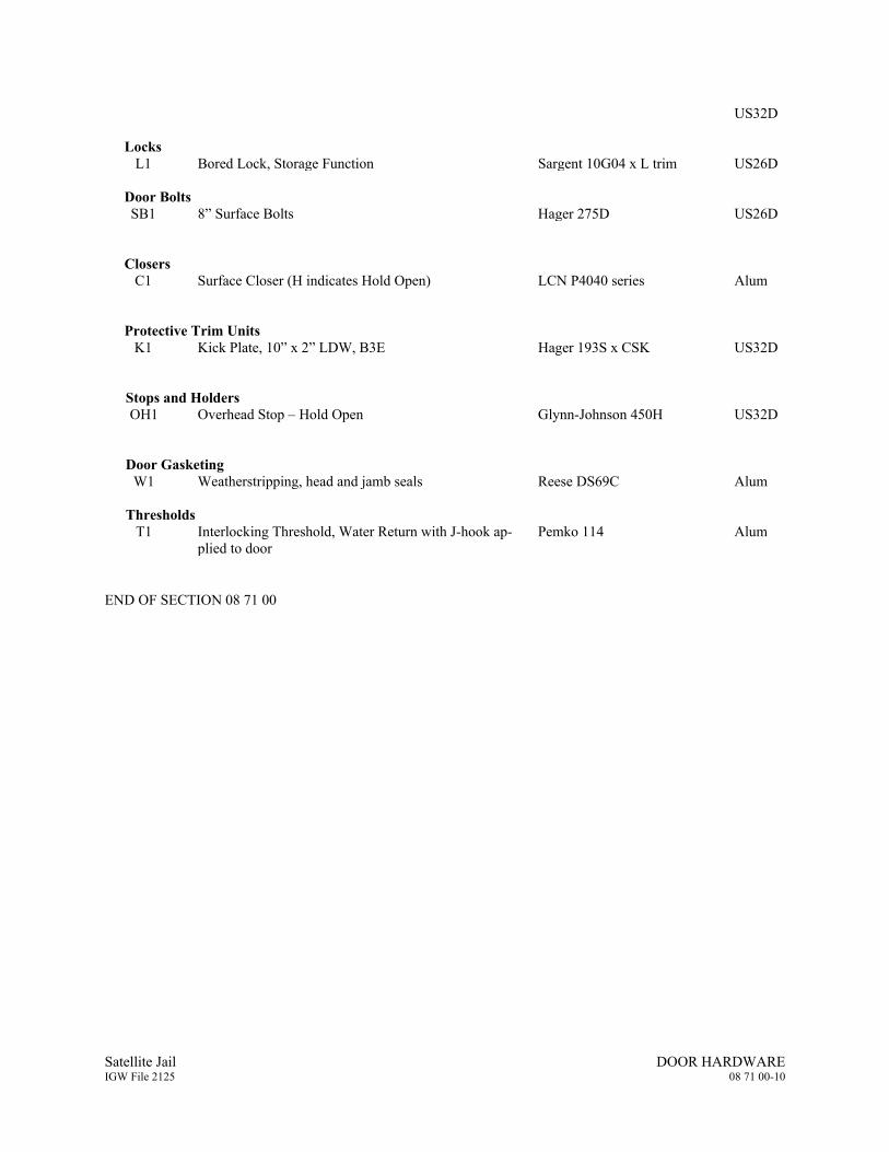
Satellite Jail DOOR HARDWARE IGW File 2125 08 71 00-10
US32D Locks
L1 Bored Lock, Storage Function Sargent 10G04 x L trim US26D Door Bolts SB1 8” Surface Bolts Hager 275D US26D
Closers
C1
Surface Closer (H indicates Hold Open)
LCN P4040 series Alum
Protective Trim Units
K1 Kick Plate, 10” x 2” LDW, B3E Hager 193S x CSK US32D
Stops and Holders OH1 Overhead Stop – Hold Open Glynn-Johnson 450H US32D
Door Gasketing
W1 Weatherstripping, head and jamb seals Reese DS69C Alum Thresholds
T1 Interlocking Threshold, Water Return with J-hook ap-plied to door
Pemko 114 Alum
END OF SECTION 08 71 00
Satellite Jail NON-STRUCTURAL METAL FRAMING IGW File 2125 09 22 16-1
SECTION 09 22 16 - NON-STRUCTURAL METAL FRAMING
PART 1 - GENERAL
1.1 RELATED DOCUMENTS
A. Drawings and general provisions of the Contract, including General and Supplementary Conditions and Division 01 Specification Sections, apply to this Section.
1.2 SUMMARY
A. Section Includes:
1. Non-load-bearing steel framing systems for interior gypsum board assemblies.
1.3 DEFINITIONS
A. Gage: Gages of wire specified are American Steel & Wire Co.’s wire gages, unless otherwise indicated.
1.4 SYSTEM DESCRIPTION
A. Delegated Design Requirements
1. Drawings of metal support system assemblies are diagrammatic and show design intent of finished profiles, shapes and forms; relationships between elements; location, identification, dimension and size of components, assemblies and accessories; and details and diagrams of connections.
B. Deflection Limits
1. Lateral loading: 5 psf for interior partitions; as prescribed for exterior walls.
2. Limit metal framing systems deflection under load to the following: a. L/240 where supporting gypsum board only. b. L/360 where supporting tile.
1.5 ACTION SUBMITTALS
A. Product Data: For each type of product.
PART 2 - PRODUCTS
2.1 PERFORMANCE REQUIREMENTS
A. Fire-Test-Response Characteristics: For fire-resistance-rated assemblies that incorporate non-load-bearing steel framing, provide materials and construction identical to those tested in assembly indicated, according to ASTM E 119 by an independent testing agency.

Satellite Jail NON-STRUCTURAL METAL FRAMING IGW File 2125 09 22 16-2
2.2 MANUFACTURERS
A. Provide metal framing members from one of the following: 1. Dietrich Industries, Inc. 2. Marino Industries, Inc. 3. Scafco Steel Stud Manufacturing Co. 4. Clark Western Building Systems, Inc.
2.3 FRAMING SYSTEMS
A. Framing Members, General: Comply with ASTM C 754 for conditions indicated.
1. Steel Sheet Components: Comply with ASTM C 645 requirements for metal unless otherwise indicated.
2. Protective Coating: ASTM A 653, G40.
B. Studs: ASTM C 645, punched web complying with the following
1. Bracing: Where the wall finish does not adequately brace both flanges of studs, provide bracing or reduce allowable stresses for computing stud heights in compliance with requirements of the authorities having jurisdiction.
2. Minimum Base-Metal Thickness: 20 gage 3. Depth: As indicated on Drawings
C. Top and Bottom Tracks: 1. As recommended by the manufacturer of each stud type and of the same gage as the studs in same
wall or partition, unless otherwise indicated on the Drawings. Provide unpunched, screwable tracks with 1-1/4-inch flanges.
D. Slip-Type Head Joints: Where indicated, provide one of the following:
1. Single Long-Leg Runner System: ASTM C 645 top runner with 2-inch- (51-mm-) deep flanges in thickness not less than indicated for studs, installed with studs friction fit into top runner and with continuous bridging located within 12 inches (305 mm) of the top of studs to provide lateral bracing.
2. Double-Runner System: ASTM C 645 top runners, inside runner with 2-inch- (51-mm-) deep flanges in thickness not less than indicated for studs and fastened to studs, and outer runner sized to friction fit inside runner.
3. Deflection Track: Steel sheet top runner manufactured to prevent cracking of finishes applied to interior partition framing resulting from deflection of structure above; in thickness not less than indicated for studs and in width to accommodate depth of studs.
a. Products: Subject to compliance with requirements, provide one of the following available products that may be incorporated into the Work:
1) Dietrich Metal Framing; SLP-TRK Slotted Deflection Track. 2) MBA Building Supplies; FlatSteel Deflection Track. 3) Steel Network Inc. (The); VertiTrack VTD Series. 4) Telling Industries; Vertical Slip Track
E. Cold-Rolled Channel Bridging: Steel, 0.053-inch (1.34-mm) minimum base-metal thickness, with minimum 1/2-inch- (13-mm-) wide flanges.
1. Depth: As indicated on Drawings
Satellite Jail NON-STRUCTURAL METAL FRAMING IGW File 2125 09 22 16-3
2. Clip Angle: Not less than 1-1/2 by 1-1/2 inches (38 by 38 mm), 0.068-inch- (1.72-mm-) thick, galvanized steel.
F. Hat-Shaped, Galvanized, Rigid Furring Channels: ASTM C 645.
1. Minimum Base-Metal Thickness: 25 gage 2. Depth: As indicated on Drawings.
G. Cold-Rolled Furring Channels: 0.053-inch (1.34-mm) uncoated-steel thickness, with minimum 1/2-inch- (13-mm-) wide flanges.
H. Horizontal stiffener, runner channels and bridging: Complying with ASTM A 1003, minimum 0.053 inch metal thick, channels fabricated of cold-rolled steel with flanges not less than 7/16-inch wide.
2.4 AUXILIARY MATERIALS
A. General: Provide auxiliary materials that comply with referenced installation standards.
1. Fasteners for Metal Framing: Of type, material, size, corrosion resistance, holding power, and other properties required to fasten steel members to substrates.
B. Screws: ASTM C 1002 for metal framing 25-gage and lighter; ASTM C 954 for heavier metal framing. Provide 3/8 inch head diameter, corrosion-resistant pan head screws; length and gage required by Code, or recommended by the metal framing manufacturer when not prescribed by Code.
C. Shot pins: 0.140-inch diameter low velocity powder-actuated drive pins equivalent to Ramset/Red Head No. 1508, or other as approved by Architect, with 7/8-inch minimum penetration into concrete.
D. Anchor bolts: ASTM A 307, non-headed type.
E. Expansion shields: FS FF-S-325, except do not use lead, fiber and plastic shields.
F. Isolation Strip at Exterior Walls: Adhesive-backed, closed-cell vinyl foam strips that allow fastener penetration without foam displacement, 1/8 inch (3.2 mm) thick, in width to suit steel stud size.
PART 3 - EXECUTION
3.1 EXAMINATION
A. Examine areas and substrates, with Installer present, and including welded hollow-metal frames, cast-in anchors, and structural framing, for compliance with requirements and other conditions affecting performance of the Work.
B. Proceed with installation only after unsatisfactory conditions have been corrected.
3.2 PREPARATION
1. Furnish concrete inserts and other devices indicated to other trades for installation in advance of time needed for coordination and construction.
Satellite Jail NON-STRUCTURAL METAL FRAMING IGW File 2125 09 22 16-4
3.3 INSTALLATION, GENERAL
A. Installation Standard: ASTM C 754.
1. Gypsum Plaster Assemblies: Also comply with requirements in ASTM C 841 that apply to framing installation.
2. Gypsum Board Assemblies: Also comply with requirements in ASTM C 840 that apply to framing installation.
B. Erect metal framing systems in compliance with their manufacturer's recommendations, the reference standards, the Drawings and these Specifications. Install supplementary framing, and blocking to support fixtures, equipment services, heavy trim, grab bars, toilet accessories, furnishings, or similar construction.
C. Use minimum 20-gage studs at the following locations:
1. Each side of door openings. 2. Where studs support backing plates, plumbing fixtures and wall-supported cabinets.
D. Install bracing at terminations in assemblies.
E. Do not bridge building control and expansion joints with non-load-bearing steel framing members. Frame both sides of joints independently.
3.4 INSTALLING FRAMED ASSEMBLIES
A. Align and securely anchor ceiling and floor tracks to building construction. Space anchors within 6 inches of ends of each track segment and at 24 inches o.c. maximum. Do not drive fasteners closer than 2 inches to slab or curb edge.
B. Where studs are installed directly against exterior masonry walls or dissimilar metals at exterior walls, install isolation strip between studs and exterior wall.
C. Install studs so flanges within framing system point in same direction.
D. Install tracks (runners) at floors and overhead supports. Extend framing full height to structural supports or substrates above suspended ceilings except where partitions are indicated to terminate at suspended ceilings. Continue framing around ducts penetrating partitions above ceiling.
1. Slip-Type Head Joints: Where framing extends to overhead structural supports, install to produce joints at tops of framing systems that prevent axial loading of finished assemblies.
2. Door Openings: Screw vertical studs at jambs to jamb anchor clips on door frames; install runner track section (for cripple studs) at head and secure to jamb studs.
a. Install two studs at each jamb unless otherwise indicated. b. Install cripple studs at head adjacent to each jamb stud, with a minimum 1/2-inch (13-mm)
clearance from jamb stud to allow for installation of control joint in finished assembly. c. Extend jamb studs through suspended ceilings and attach to underside of overhead
structure.
3. Other Framed Openings: Frame openings other than door openings the same as required for door openings unless otherwise indicated. Install framing below sills of openings to match framing required above door heads.
E. Furring:
Satellite Jail NON-STRUCTURAL METAL FRAMING IGW File 2125 09 22 16-5
1. Provide furring attached to concrete and metal framing to conceal utilities, furred soffits, and other furring as indicated.
2. Furring to receive gypsum board shall be screw-on channels directly attached to backing material, or applied over runner channels as applicable.
3. Space furring as indicated for studs. 4. Attach to concrete or masonry with stub nails, screws designed for masonry attachment, or
powder-driven fasteners spaced 24 inches (610 mm) o.c.
F. Installation Tolerance: Install each framing member so fastening surfaces vary not more than 1/8 inch (3 mm) from the plane formed by faces of adjacent framing.
G. Install extra stud, furring members and angle runners at terminations of dry wall work, and at openings and where required for support of other work occurring in the dry wall work.
H. Installation Tolerance: Install each framing member so fastening surfaces vary not more than 1/8 inch (3 mm) from the plane formed by faces of adjacent framing.
END OF SECTION 09 22 16


Satellite Jail GYPSUM BOARD IGW File 2125 09 29 00-1
SECTION 09 29 00 - GYPSUM BOARD
PART 1 - GENERAL
1.1 RELATED DOCUMENTS
A. Drawings and general provisions of the Contract, including General and Supplementary Conditions and Division 1 Specification Sections, apply to this Section.
1.2 SUMMARY
A. This Section includes the following:
1. Interior gypsum wallboard. 2. Trim Accessories.
B. Related Sections include the following: 1. Section 06 10 00 "Rough Carpentry" for wood blocking. 2. Section 09 22 16 “Non-structural Metal Framing” 3. Section 07 21 00 "Building Insulation" for insulation and vapor retarders installed in gypsum
board assemblies.
1.3 DEFINITIONS
A. Gypsum Board Terminology: Refer to ASTM C 11 for definitions of terms for gypsum board assemblies not defined in this Section or in other referenced standards.
1.4 SUBMITTALS
A. Product Data: For each type of product indicated.
B. Samples: For the following products:
1. Trim Accessories: Full-size sample in 12-inch- (300-mm-) long length for each trim accessory indicated.
1.5 QUALITY ASSURANCE
A. Fire-Test-Response Characteristics: For gypsum board assemblies with fire-resistance ratings, provide materials and construction identical to those tested in assembly indicated according to ASTM E 119 by an independent testing and inspecting agency acceptable to authorities having jurisdiction.
1.6 DELIVERY, STORAGE, AND HANDLING
A. Deliver materials in original packages, containers, or bundles bearing brand name and identification of manufacturer or supplier.
Satellite Jail GYPSUM BOARD IGW File 2125 09 29 00-2
B. Store materials inside under cover and keep them dry and protected against damage from weather, direct sunlight, surface contamination, corrosion, construction traffic, and other causes. Stack gypsum panels flat to prevent sagging.
1.7 PROJECT CONDITIONS
A. Environmental Limitations: Comply with ASTM C 840 requirements or gypsum board manufacturer's written recommendations, whichever are more stringent.
PART 2 - PRODUCTS
2.1 MANUFACTURERS
A. Manufacturers: Subject to compliance with requirements, provide products by one of the following:
1. Gypsum Board and Related Products:
a. American Gypsum Co. b. G-P Gypsum Corp. c. National Gypsum Company. d. United States Gypsum Co.
2.2 INTERIOR GYPSUM WALLBOARD
A. Panel Size: Provide in maximum lengths and widths available that will minimize joints in each area and correspond with support system indicated.
B. Gypsum Wallboard: Complying with FS SS-L-30 and ASTM C 36, ASTM C 630 and ASTM C 1396; tapered with beveled or radial edge for all finished joints, thickness as shown on the Drawings:
1. Type X:
a. Thickness: 5/8 inch (15.9 mm). b. Long Edges: Tapered. c. Location: Vertical surfaces, unless otherwise indicated.
2.3 JOINT TREATMENT MATERIALS
A. General: Comply with ASTM C 475.
B. Joint Tape:
1. Interior Gypsum Wallboard: Paper. 2. Tile Backing Panels: As recommended by panel manufacturer.
C. Joint Compound for Interior Gypsum Wallboard: For each coat use formulation that is compatible with other compounds applied on previous or for successive coats.
1. Prefilling: At open joints and damaged surface areas, use setting-type taping compound.
Satellite Jail GYPSUM BOARD IGW File 2125 09 29 00-3
2. Embedding and First Coat: For embedding tape and first coat on joints, fasteners, and trim flanges, use drying-type, all –purpose compound.
3. Fill Coat: For second coat, use drying-type, all-purpose compound. 4. Finish Coat: For third coat, use drying-type, all-purpose compound.
D. Joint Compound for Tile Backing Panels:
1. Water-Resistant Gypsum Backing Board: Use setting-type taping and setting-type, sandable topping compounds.
2. Cementitious Backer Units: As recommended by manufacturer.
E. AUXILIARY MATERIALS
F. General: Provide auxiliary materials that comply with referenced installation standards and manufacturer's written recommendations.
G. Laminating Adhesive: Adhesive or joint compound recommended for directly adhering gypsum panels to continuous substrate.
H. Steel Drill Screws: ASTM C 1002, unless otherwise indicated.
1. Use screws complying with ASTM C 954 for fastening panels to steel members from 0.033 to 0.112 inch (0.84 to 2.84 mm) thick.
2. For fastening cementitious backer units, use screws of type and size recommended by panel manufacturer.
I. Isolation Strip at Exterior Walls:
1. Asphalt-Saturated Organic Felt: ASTM D 226, Type I (No. 15 asphalt felt), nonperforated. 2. Foam Gasket: Adhesive-backed, closed-cell vinyl foam strips that allow fastener penetration
without foam displacement, 1/8 inch (3.2 mm) thick, in width to suit steel stud size.
J. Thermal Insulation: As specified in Division 7 Section "Building Insulation."
PART 3 - EXECUTION
3.1 EXAMINATION
A. Examine areas and substrates, with Installer present, and including welded hollow-metal frames, cast-in anchors, and structural framing, for compliance with requirements and other conditions affecting performance. Proceed with installation only after unsatisfactory conditions have been corrected.
3.2 APPLYING AND FINISHING PANELS, GENERAL
A. Gypsum Board Application and Finishing Standards: ASTM C 840 and GA-216.
B. Install gypsum panels with face side out. Butt panels together for a light contact at edges and ends with not more than 1/16 inch (1.5 mm) of open space between panels. Do not force into place.
C. Locate edge and end joints over supports, except in ceiling applications where intermediate supports or gypsum board back-blocking is provided behind end joints. Do not place tapered edges against cut edges
Satellite Jail GYPSUM BOARD IGW File 2125 09 29 00-4
or ends. Stagger vertical joints on opposite sides of partitions. Do not make joints other than control joints at corners of framed openings.
D. Attach gypsum panels to steel studs so leading edge or end of each panel is attached to open (unsupported) edges of stud flanges first.
E. Attach gypsum panels to framing provided at openings and cutouts.
F. Form control and expansion joints with space between edges of adjoining gypsum panels.
G. Cover both faces of steel stud partition framing with gypsum panels in concealed spaces (above ceilings, etc.), except in chases braced internally.
1. Unless concealed application is indicated or required for sound, fire, air, or smoke ratings, coverage may be accomplished with scraps of not less than 8 sq. ft. (0.7 sq. m) in area.
2. Fit gypsum panels around ducts, pipes, and conduits. 3. Where partitions intersect open concrete coffers, concrete joists, and other structural members
projecting below underside of floor/roof slabs and decks, cut gypsum panels to fit profile formed by coffers, joists, and other structural members; allow 1/4- to 3/8-inch- (6.4- to 9.5-mm-) wide joints to install sealant.
H. Isolate perimeter of non-load-bearing gypsum board partitions at structural abutments, except floors. Provide 1/4- to 1/2-inch- (6.4- to 12.7-mm-) wide spaces at these locations, and trim edges with U-bead edge trim where edges of gypsum panels are exposed. Seal joints between edges and abutting structural surfaces with acoustical sealant.
I. Space fasteners in gypsum panels according to referenced gypsum board application and finishing standard and manufacturer's written recommendations.
1. Space screws a maximum of 12 inches (304.8 mm) o.c. for vertical applications.
J. Space fasteners in panels that are tile substrates a maximum of 8 inches (203.2 mm) o.c.
3.3 PANEL APPLICATION METHODS
A. Single-Layer Application:
1. On ceilings, apply gypsum panels before wall/partition board application to the greatest extent possible and at right angles to framing, unless otherwise indicated.
2. On partitions/walls, apply gypsum panels vertically (parallel to framing), unless otherwise indicated or required by fire-resistance-rated assembly, and minimize end joints.
a. Stagger abutting end joints not less than one framing member in alternate courses of board. b. At stairwells and other high walls, install panels horizontally, unless otherwise indicated or
required by fire-resistance-rated assembly.
3. On Z-furring members, apply gypsum panels vertically (parallel to framing) with no end joints. Locate edge joints over furring members.
B. Single-Layer Fastening Methods: Apply gypsum panels to supports with steel drill screws.
C. Laminating to Substrate: Where gypsum panels are indicated as directly adhered to a substrate (other than studs, joists, furring members, or base layer of gypsum board), comply with gypsum board
Satellite Jail GYPSUM BOARD IGW File 2125 09 29 00-5
manufacturer's written recommendations and temporarily brace or fasten gypsum panels until fastening adhesive has set.
3.4 INSTALLING TRIM ACCESSORIES
A. General: For trim with back flanges intended for fasteners, attach to framing with same fasteners used for panels. Otherwise, attach trim according to manufacturer's written instructions.
B. Control Joints: Install control joints where substrate changes and at sections of wall or ceiling more than 30 feet long. Coordinate exact locations with Architect in the field.
3.5 FINISHING GYPSUM BOARD ASSEMBLIES
A. General: Treat gypsum board joints, interior angles, edge trim, control joints, penetrations, fastener heads, surface defects, and elsewhere as required to prepare gypsum board surfaces for decoration. Promptly remove residual joint compound from adjacent surfaces.
B. Prefill open joints and damaged surface areas.
C. Apply joint tape over gypsum board joints, except those with trim having flanges not intended for tape.
D. Gypsum Board Finish Levels: Finish panels to levels indicated below, according to ASTM C 840, for locations indicated:
1. Level 1: Embed tape at joints in ceiling plenum areas, concealed areas, and where indicated unless a higher level of finish is required for fire-resistance-rated assemblies and sound-rated assemblies.
2. Level 4: Embed tape and apply separate first, fill, and finish coats of joint compound to tape, fasteners, and trim flanges at panel surfaces that will be exposed to view, unless otherwise indicated.
END OF SECTION 09 29 00


Satellite Jail PAINTING IGW File 2125 09 91 00-1
SECTION 09 91 00 - PAINTING
PART 1 - GENERAL
1.1 RELATED DOCUMENTS
A. Drawings and general provisions of the Contract, including General and Supplementary Conditions and Division 1 Specification Sections, apply to this Section.
1.2 SUMMARY
A. This Section includes surface preparation and field painting of exposed exterior and interior items and surfaces.
1. Surface preparation, priming, and finish coats specified in this Section are in addition to shop priming and surface treatment specified in other Sections.
2. Surface treatment and priming for wall coverings.
B. Paint exposed surfaces, except where these Specifications indicate that the surface or material is not to be painted or is to remain natural. If an item or a surface is not specifically mentioned, paint the item or surface the same as similar adjacent materials or surfaces. If a color of finish is not indicated, Architect will select from standard colors and finishes available.
1. Painting includes field painting of exposed bare and covered pipes and ducts, hangers, exposed steel and iron supports, and surfaces of mechanical and electrical equipment that do not have a factory-applied final finish.
C. Do not paint prefinished items, concealed surfaces, finished metal surfaces, operating parts, and labels.
1. Prefinished items include the following factory-finished components:
a. Toilet enclosures. b. Lockers. c. Finished mechanical and electrical equipment. d. Light fixtures. e. Prefinished metal panels and liner panels
2. Concealed surfaces include walls or ceilings in the following generally inaccessible spaces:
a. Foundation spaces. b. Furred areas. c. Ceiling plenums. d. Utility tunnels. e. Pipe spaces. f. Duct shafts.
3. Finished metal surfaces include the following:
a. Anodized aluminum. b. Stainless steel. c. Chromium plate.
Satellite Jail PAINTING IGW File 2125 09 91 00-2
4. Operating parts include moving parts of operating equipment and the following:
a. Valve and damper operators. b. Linkages. c. Sensing devices. d. Motor and fan shafts.
5. Labels: Do not paint over UL, FMG, or other code-required labels or equipment name, identification, performance rating, or nomenclature plates.
D. Related Sections include the following:
1. Division 5 Section "Metal Fabrications" for shop priming ferrous metal. 2. Division 8 Section "Steel Doors and Frames" for factory priming steel doors and frames. 3. Division 9 Section "Gypsum Board Assemblies", and for surface preparation of gypsum
assemblies and fabrications.
1.3 DEFINITIONS
A. General: Standard coating terms defined in ASTM D 16 apply to this Section.
1. Flat refers to a lusterless or matte finish with a gloss range below 15 when measured at an 85-degree meter.
2. Eggshell refers to low-sheen finish with a gloss range between 20 and 35 when measured at a 60-degree meter.
3. Semigloss refers to medium-sheen finish with a gloss range between 35 and 70 when measured at a 60-degree meter.
4. Full gloss refers to high-sheen finish with a gloss range more than 70 when measured at a 60-degree meter.
1.4 SUBMITTALS
A. Product Data: For each paint system indicated. Include block fillers and primers.
1. Material List: An inclusive list of required coating materials. Indicate each material and cross-reference specific coating, finish system, and application. Identify each material by manufacturer's catalog number and general classification.
2. Manufacturer's Information: Manufacturer's technical information, including label analysis and instructions for handling, storing, and applying each coating material.
B. Samples for Initial Selection: For each type of finish-coat material indicated.
1. After color selection, Architect will furnish color chips for surfaces to be coated.
C. Samples for Verification: For each color and material to be applied, with texture to simulate actual conditions, on representative Samples of the actual substrate.
1. Provide stepped Samples, defining each separate coat, including block fillers and primers. Use representative colors when preparing Samples for review. Resubmit until required sheen, color, and texture are achieved.
2. Provide a list of materials and applications for each coat of each Sample. Label each Sample for location and application.
Satellite Jail PAINTING IGW File 2125 09 91 00-3
1.5 QUALITY ASSURANCE
A. Applicator Qualifications: A firm or individual experienced in applying paints and coatings similar in material, design, and extent to those indicated for this Project, whose work has resulted in applications with a record of successful in-service performance. Who meets Lead Safety for Renovation, Repair and Painting Rules and Regulations by the “State and Federal Government.
B. Source Limitations: Obtain block fillers and primers for each coating system from the same manufacturer as the finish coats.
1.6 DELIVERY, STORAGE, AND HANDLING
A. Deliver materials to Project site in manufacturer's original, unopened packages and containers bearing manufacturer's name and label and the following information:
1. Product name or title of material. 2. Product description (generic classification or binder type). 3. Manufacturer's stock number and date of manufacture. 4. Contents by volume, for pigment and vehicle constituents. 5. Thinning instructions. 6. Application instructions. 7. Color name and number. 8. VOC content.
B. Store materials not in use in tightly covered containers in a well-ventilated area at a minimum ambient temperature of 45 deg F (7 deg C). Maintain storage containers in a clean condition, free of foreign materials and residue.
1. Protect from freezing. Keep storage area neat and orderly. Remove oily rags and waste daily.
1.7 PROJECT CONDITIONS
A. Apply waterborne paints only when temperatures of surfaces to be painted and surrounding air are between 50 and 90 deg F (10 and 32 deg C).
B. Apply solvent-thinned paints only when temperatures of surfaces to be painted and surrounding air are between 45 and 95 deg F (7 and 35 deg C).
C. Do not apply paint in snow, rain, fog, or mist; or when relative humidity exceeds 85 percent; or at temperatures less than 5 deg F (3 deg C) above the dew point; or to damp or wet surfaces.
1. Painting may continue during inclement weather if surfaces and areas to be painted are enclosed and heated within temperature limits specified by manufacturer during application and drying periods.
1.8 EXTRA MATERIALS
A. Furnish extra paint materials from the same production run as the materials applied and in the quantities described below. Package with protective covering for storage and identify with labels describing contents. Deliver extra materials to Owner.
Satellite Jail PAINTING IGW File 2125 09 91 00-4
1. Quantity: Furnish Owner with an additional 3 percent, but not less than 1 gal. (3.8 L) or 1 case, as appropriate, of each material and color applied.
PART 2 - PRODUCTS
2.1 MANUFACTURERS
A. Products: Subject to compliance with requirements, provide one of the products listed in other Part 2 articles.
B. Manufacturers' Names: Shortened versions (shown in parentheses) of the following manufacturers' names are used in other Part 2 articles:
1. Benjamin Moore & Co. (Benjamin Moore). 2. M. A. Bruder & Sons, Inc. (M. A. B. Paint). 3. PPG Industries, Inc. (Pittsburgh Paints). 4. Sherwin-Williams Co. (Sherwin-Williams).
2.2 PAINT MATERIALS, GENERAL
A. Material Compatibility: Provide block fillers, primers, and finish-coat materials that are compatible with one another and with the substrates indicated under conditions of service and application, as demonstrated by manufacturer based on testing and field experience.
B. Material Quality: Provide manufacturer's best-quality paint material of the various coating types specified that are factory formulated and recommended by manufacturer for application indicated. Paint-material containers not displaying manufacturer's product identification will not be acceptable.
1. Proprietary Names: Use of manufacturer's proprietary product names to designate colors or materials is not intended to imply that products named are required to be used to the exclusion of equivalent products of other manufacturers. Furnish manufacturer's material data and certificates of performance for proposed substitutions.
C. Refer to the Paint Schedule at the end of this Section and building exterior, interior elevations and schedules on the Drawings.
2.3 EXTERIOR PRIMERS
A. Exterior Ferrous-Metal Primer: Factory-formulated rust-inhibitive metal primer for exterior application.
1. Benjamin Moore; Moore's IMC Alkyd Metal Primer No. M06: Applied at a dry film thickness of not less than 2.0 mils (0.051 mm).
2. M. A. B. Paint; Rust-O-Lastic Anti-Corrosive Primer 073-132: Applied at a dry film thickness of not less than 2.0 mils (0.051 mm).
3. Pittsburgh Paints; 90-712 Pitt-Tech One Pack Interior/Exterior Primer Finish DTM Industrial Enamel: Applied at a dry film thickness of not less than 3.0 mils (0.076 mm).
4. Sherwin-Williams; Kem Kromik Universal Metal Primer B50NZ6/B50WZ1: Applied at a dry film thickness of not less than 3.0 mils (0.076 mm).
B. Exterior Galvanized Metal Primer: Factory-formulated galvanized metal primer for exterior application.

Satellite Jail PAINTING IGW File 2125 09 91 00-5
1. Benjamin Moore; Moore's IMC Acrylic Metal Primer No. M04: Applied at a dry film thickness of not less than 2.0 mils (0.051 mm).
2. M. A. B. Paint; Rust-O-Lastic Hydro-Prime II Acrylic (DTM) Maintenance Primer 073-189: Applied at a dry film thickness of not less than 2.0 mils (0.051 mm).
3. Pittsburgh Paints; 90-709 Pitt-Tech One Pack Interior/Exterior Primer/Finish DTM Industrial Enamel: Applied at a dry film thickness of not less than 3.0 mils (0.076 mm).
4. Sherwin-Williams; primer not required over this substrate.
2.4 INTERIOR PRIMERS
A. Interior Gypsum Board Primer: Factory-formulated latex-based primer for interior application. Prime gypsum board for wall coverings per manufacturer’s recommendations.
1. Benjamin Moore; Moorcraft Super Spec Latex Enamel Undercoater & Primer Sealer No. 253: Applied at a dry film thickness of not less than 1.2 mils (0.030 mm).
2. M. A. B. Paint; Fresh Kote Vinyl Primer 037-100: Applied at a dry film thickness of not less than 1.5 mils (0.038 mm).
3. Pittsburgh Paints; 6-2 SpeedHide Interior Quick-Drying Latex Sealer: Applied at a dry film thickness of not less than 1.0 mil (0.025 mm).
4. Sherwin-Williams; PrepRite 200 Latex Wall Primer B28W200 Series: Applied at a dry film thickness of not less than 1.6 mils (0.041 mm).
B. Interior Ferrous-Metal Primer: Factory-formulated quick-drying rust-inhibitive alkyd-based metal primer.
1. Benjamin Moore; Moore's IMC Alkyd Metal Primer No. M06: Applied at a dry film thickness of not less than 2.0 mils (0.051 mm).
2. M. A. B. Paint; Rust-O-Lastic Anti-Corrosive Primer 073-132: Applied at a dry film thickness of not less than 2.0 mils (0.051 mm).
3. Pittsburgh Paints; 90-709 Pitt-Tech One Pack Interior/Exterior Primer/Finish DTM Industrial Enamel: Applied at a dry film thickness of not less than 1.5 mils (0.038 mm).
4. Sherwin-Williams; Kem Kromik Universal Metal Primer B50NZ6/B50WZ1: Applied at a dry film thickness of not less than 3.0 mils (0.076 mm).
C. Interior Zinc-Coated Metal Primer: Factory-formulated galvanized metal primer.
1. Benjamin Moore; Moore's IMC Acrylic Metal Primer No. M04: Applied at a dry film thickness of not less than 2.0 mils (0.051 mm).
2. M. A. B. Paint; Rust-O-Lastic Hydro-Prime II Acrylic (DTM) Maintenance Primer 073-189: Applied at a dry film thickness of not less than 2.0 mils (0.051 mm).
3. Pittsburgh Paints; 90-709 Pitt-Tech One Pack Interior/Exterior Primer/Finish DTM Industrial Enamel: Applied at a dry film thickness of not less than 3.0 mils (0.076 mm).
4. Sherwin-Williams; primer not required over this substrate. 5. Sherwin-Williams; Galvite HS B50WZ30: Applied at a dry film thickness of not less than 3.0
mils (0.076 mm).
2.5 EXTERIOR FINISH COATS
A. Exterior Semigloss Acrylic Enamel: Factory-formulated semigloss waterborne acrylic-latex enamel for exterior application.
Satellite Jail PAINTING IGW File 2125 09 91 00-6
1. Benjamin Moore; Moorcraft Super Spec Latex House & Trim Paint No. 170: Applied at a dry film thickness of not less than 1.1 mils (0.028 mm).
2. M. A. B. Paint; Sea Shore/Four Seasons Acrylic Latex Trim Enamel 024 Line: Applied at a dry film thickness of not less than 1.5 mils (0.038 mm).
3. Pittsburgh Paints; 6-900 Series SpeedHide Exterior House & Trim Semi-Gloss Acrylic Latex Paint: Applied at a dry film thickness of not less than 1.5 mils (0.038 mm).
4. Sherwin-Williams; A-100 Latex Gloss A8 Series: Applied at a dry film thickness of not less than 1.3 mils (0.033 mm).
2.6 INTERIOR FINISH COATS
A. Interior Low-Luster Acrylic Enamel (PL): Factory-formulated eggshell acrylic-latex interior enamel.
1. Benjamin Moore; Moorcraft Super Spec Latex Eggshell Enamel No. 274: Applied at a dry film thickness of not less than 1.3 mils (0.033 mm).
2. M. A. B. Paint; Fresh Kote Latex Satin Eggshell Enamel 405 Line: Applied at a dry film thickness of not less than 1.5 mils (0.038 mm).
3. Pittsburgh Paints; 6-400 Series SpeedHide Eggshell Acrylic Latex Enamel: Applied at a dry film thickness of not less than 1.25 mils (0.032 mm).
4. Sherwin-Williams; ProMar 200 Interior Latex Egg-Shell Enamel B20W200 Series: Applied at a dry film thickness of not less than 1.6 mils (0.041 mm).
2.7 EXTERIOR HIGH PERFORMANCE COATING FOR EXPOSED STEEL
1. Exposed Structural Steel indicated for high performance coating:
a. Sand, scrape and spot prime with compatible primer. b. One coat, Epoxy-Polyamide Coating, 3.00 mild dry film thickness, one of the following:
1) Tnemec Series N69 Hi-Build Epoxoline II 2) PPG Ameron Amerliock 400 Hi-Build Epoxy 3) Carboguard 825, Hi-Build Epoxy
c. One coat, High-Build Acrylic Polyurethane Enamel 2 to 3 mils dry film thickness, one of the following, no substitutions: 1) Series 73 (Semi-Gloss) Endura-Shield III Semi-Gloss, Tnemec Company, Inc.
(1054 Gloss & 1075 High Gloss) 2) PPG Ameron Amercoat 450H 3) Carbothane 133 HB Semi-Gloss, Carobline
PART 3 - EXECUTION
3.1 EXAMINATION
A. Examine substrates, areas, and conditions, with Applicator present, for compliance with requirements for paint application. Comply with procedures specified in PDCA P4.
1. Proceed with paint application only after unsatisfactory conditions have been corrected and surfaces receiving paint are thoroughly dry.
2. Start of painting will be construed as Applicator's acceptance of surfaces and conditions within a particular area.
Satellite Jail PAINTING IGW File 2125 09 91 00-7
B. Coordination of Work: Review other Sections in which primers are provided to ensure compatibility of the total system for various substrates. On request, furnish information on characteristics of finish materials to ensure use of compatible primers.
1. Notify Architect about anticipated problems when using the materials specified over substrates primed by others.
3.2 PREPARATION
A. General: Remove hardware and hardware accessories, plates, machined surfaces, lighting fixtures, and similar items already installed that are not to be painted. If removal is impractical or impossible because of size or weight of the item, provide surface-applied protection before surface preparation and painting.
1. After completing painting operations in each space or area, reinstall items removed using workers skilled in the trades involved.
B. Cleaning: Before applying paint or other surface treatments, clean substrates of substances that could impair bond of the various coatings. Remove oil and grease before cleaning.
1. Schedule cleaning and painting so dust and other contaminants from the cleaning process will not fall on wet, newly painted surfaces.
C. Surface Preparation: Clean and prepare surfaces to be painted according to manufacturer's written instructions for each particular substrate condition and as specified.
1. Provide barrier coats over incompatible primers or remove and reprime. 2. Cementitious Materials: Prepare concrete, concrete unit masonry, cement plaster, and mineral-
fiber-reinforced cement panel surfaces to be painted. Remove efflorescence, chalk, dust, dirt, grease, oils, and release agents. Roughen as required to remove glaze. If hardeners or sealers have been used to improve curing, use mechanical methods of surface preparation.
a. Use abrasive blast-cleaning methods if recommended by paint manufacturer. b. Determine alkalinity and moisture content of surfaces by performing appropriate tests. If
surfaces are sufficiently alkaline to cause the finish paint to blister and burn, correct this condition before application. Do not paint surfaces if moisture content exceeds that permitted in manufacturer's written instructions.
c. Clean concrete floors to be painted with a 5 percent solution of muriatic acid or other etching cleaner. Flush the floor with clean water to remove acid, neutralize with ammonia, rinse, allow to dry, and vacuum before painting.
3. Ferrous Metals: Clean ungalvanized ferrous-metal surfaces that have not been shop coated; remove oil, grease, dirt, loose mill scale, and other foreign substances. Use solvent or mechanical cleaning methods that comply with SSPC's recommendations.
4. Galvanized Surfaces: Clean galvanized surfaces with nonpetroleum-based solvents so surface is free of oil and surface contaminants. Remove pretreatment from galvanized sheet metal fabricated from coil stock by mechanical methods.
D. Material Preparation: Mix and prepare paint materials according to manufacturer's written instructions.
1. Maintain containers used in mixing and applying paint in a clean condition, free of foreign materials and residue.
Satellite Jail PAINTING IGW File 2125 09 91 00-8
2. Stir material before application to produce a mixture of uniform density. Stir as required during application. Do not stir surface film into material. If necessary, remove surface film and strain material before using.
3. Use only thinners approved by paint manufacturer and only within recommended limits.
E. Tinting: Tint each undercoat a lighter shade to simplify identification of each coat when multiple coats of same material are applied. Tint undercoats to match the color of the finish coat, but provide sufficient differences in shade of undercoats to distinguish each separate coat.
3.3 APPLICATION
A. General: Apply paint according to manufacturer's written instructions. Use applicators and techniques best suited for substrate and type of material being applied.
1. Do not paint over dirt, rust, scale, grease, moisture, scuffed surfaces, or conditions detrimental to formation of a durable paint film.
2. Provide finish coats that are compatible with primers used. 3. The term "exposed surfaces" includes areas visible when permanent or built-in fixtures, grilles,
convector covers, covers for finned-tube radiation, and similar components are in place. Extend coatings in these areas, as required, to maintain system integrity and provide desired protection.
4. Paint surfaces behind movable equipment and furniture the same as similar exposed surfaces. Before final installation of equipment, paint surfaces behind permanently fixed equipment or furniture with prime coat only.
5. Paint interior surfaces of ducts with a flat, nonspecular black paint where visible through registers or grilles.
B. Scheduling Painting: Apply first coat to surfaces that have been cleaned, pretreated, or otherwise prepared for painting as soon as practicable after preparation and before subsequent surface deterioration.
1. The number of coats and film thickness required are the same regardless of application method. Do not apply succeeding coats until previous coat has cured as recommended by manufacturer. If sanding is required to produce a smooth, even surface according to manufacturer's written instructions, sand between applications.
2. Omit primer over metal surfaces that have been shop primed and touchup painted. 3. If undercoats, stains, or other conditions show through final coat of paint, apply additional coats
until paint film is of uniform finish, color, and appearance. Give special attention to ensure that edges, corners, crevices, welds, and exposed fasteners receive a dry film thickness equivalent to that of flat surfaces.
4. Allow sufficient time between successive coats to permit proper drying. Do not recoat surfaces until paint has dried to where it feels firm, and does not deform or feel sticky under moderate thumb pressure, and until application of another coat of paint does not cause undercoat to lift or lose adhesion.
C. Application Procedures: Apply paints and coatings by brush, roller, spray, or other applicators according to manufacturer's written instructions.
1. Brushes: Use brushes best suited for type of material applied. Use brush of appropriate size for surface or item being painted.
2. Rollers: Use rollers of carpet, velvet-back, or high-pile sheep's wool as recommended by manufacturer for material and texture required.
3. Spray Equipment: Use airless spray equipment with orifice size as recommended by manufacturer for material and texture required.
Satellite Jail PAINTING IGW File 2125 09 91 00-9
D. Minimum Coating Thickness: Apply paint materials no thinner than manufacturer's recommended spreading rate to achieve dry film thickness indicated. Provide total dry film thickness of the entire system as recommended by manufacturer.
E. Prime Coats: Before applying finish coats, apply a prime coat, as recommended by manufacturer, to material that is required to be painted or finished and that has not been prime coated by others. Recoat primed and sealed surfaces where evidence of suction spots or unsealed areas in first coat appears, to ensure a finish coat with no burn-through or other defects due to insufficient sealing.
F. Pigmented (Opaque) Finishes: Completely cover surfaces as necessary to provide a smooth, opaque surface of uniform finish, color, appearance, and coverage. Cloudiness, spotting, holidays, laps, brush marks, runs, sags, ropiness, or other surface imperfections will not be acceptable.
G. Stipple Enamel Finish: Roll and redistribute paint to an even and fine texture. Leave no evidence of rolling, such as laps, irregularity in texture, skid marks, or other surface imperfections.
H. Completed Work: Match approved samples for color, texture, and coverage. Remove, refinish, or repaint work not complying with requirements.
3.4 CLEANING
A. Cleanup: At the end of each workday, remove empty cans, rags, rubbish, and other discarded paint materials from Project site.
1. After completing painting, clean glass and paint-spattered surfaces. Remove spattered paint by washing and scraping without scratching or damaging adjacent finished surfaces.
3.5 PROTECTION
A. Protect work of other trades, whether being painted or not, against damage from painting. Correct damage by cleaning, repairing or replacing, and repainting, as approved by Architect.
B. Provide "Wet Paint" signs to protect newly painted finishes. After completing painting operations, remove temporary protective wrappings provided by others to protect their work.
1. After work of other trades is complete, touch up and restore damaged or defaced painted surfaces. Comply with procedures specified in PDCA P1.
3.6 EXTERIOR PAINT SCHEDULE
A. Ferrous Metal: Provide the following finish systems over exterior ferrous metal. Primer is not required on shop-primed items.
1. Semigloss Acrylic-Enamel Finish: Two finish coats over a rust-inhibitive primer.
a. Primer: Exterior ferrous-metal primer. b. Finish Coats: Exterior semigloss acrylic enamel.
B. Zinc-Coated Metal: Provide the following finish systems over exterior zinc-coated metal surfaces:
1. Semigloss Acrylic-Enamel Finish: Two finish coats over a galvanized metal primer.
Satellite Jail PAINTING IGW File 2125 09 91 00-10
a. Primer: Exterior galvanized metal primer. b. Finish Coats: Exterior semigloss acrylic enamel.
3.7 INTERIOR PAINT SCHEDULE
A. Gypsum Board and plaster (PL): Provide the following finish systems over interior gypsum board surfaces:
1. Low-Luster Acrylic-Enamel Finish: Two finish coats over a primer.
a. Primer: Interior gypsum board primer. b. Finish Coats: Interior low-luster acrylic enamel.
B. Ferrous Metal (PA): Provide the following finish systems over ferrous metal:
1. Semi-gloss Alkyd Finish: Two finish coats over a primer.
a. Primer: Interior ferrous-metal primer. b. Finish Coats: Interior semi-gloss alkyd.
C. Zinc-Coated Metal: Provide the following finish systems over interior zinc-coated metal surfaces:
1. Low-Luster Acrylic-Enamel Finish: Two finish coats over a primer.
a. Primer: Interior zinc-coated metal primer. b. Finish Coats: Interior low-luster acrylic enamel.
END OF SECTION 09 91 00
DIVISION 22 - PLUMBINGSection 22 0719 - Plumbing Piping Insulation
PART 1 - GENERAL
1.1 RELATED DOCUMENTS
A. Drawings and general provisions of the Contract, including General and Supplementary Conditionsand Division 01 Specification Sections, apply to this Section.
1.2 SUMMARY
A. Section includes insulating the following plumbing piping services:
1. Domestic cold-water piping.
1.3 ACTION SUBMITTALS
A. Product Data: For each type of product indicated.
1.4 QUALITY ASSURANCE
A. Surface-Burning Characteristics: For insulation and related materials, as determined by testingidentical products according to ASTM E 84 by a testing agency acceptable to authorities havingjurisdiction. Factory label insulation and jacket materials and adhesive, mastic, tapes, and cementmaterial containers, with appropriate markings of applicable testing agency.
1. Insulation Installed Indoors: Flame-spread index of 25 or less, and smoke-developed indexof 50 or less.
PART 2 - PRODUCTS
2.1 INSULATION MATERIALS
A. Comply with requirements in "Piping Insulation Schedule, General," "Indoor Piping InsulationSchedule" articles for where insulating materials shall be applied.
B. Products shall not contain asbestos, lead, mercury, or mercury compounds.
C. Products that come in contact with stainless steel shall have a leachable chloride content of lessthan 50 ppm when tested according to ASTM C 871.
Satellite Jail 1 GHR - 05/21 - RAFHVAC Replacement 22 0719 - Plumbing Piping Insulation
D. Insulation materials for use on austenitic stainless steel shall be qualified as acceptable accordingto ASTM C 795.
E. Foam insulation materials shall not use CFC or HCFC blowing agents in the manufacturing process.
F. Mineral-Fiber, Preformed Pipe Insulation:
1. Products: Subject to compliance with requirements, provide one of the following:
a. Johns Manville; Micro-Lok.b. Knauf Insulation; 1000-Degree Pipe Insulation.c. Manson Insulation Inc.; Alley-K.d. Owens Corning; Fiberglas Pipe Insulation.
2. Type I, 850 Deg F Materials: Mineral or glass fibers bonded with a thermosetting resin. Comply with ASTM C 547, Type I, Grade A, with factory-applied ASJ-(SSL). Factory-appliedjacket requirements are specified in "Factory-Applied Jackets" Article.
2.2 INSULATING CEMENTS
A. Mineral-Fiber, Hydraulic-Setting Insulating and Finishing Cement: Comply with ASTM C 449.
1. Products: Subject to compliance with requirements, provide one of the following:
a. Ramco Insulation, Inc.; Ramcote 1200 and Quik-Cote.
2.3 ADHESIVES
A. Materials shall be compatible with insulation materials, jackets, and substrates and for bondinginsulation to itself and to surfaces to be insulated, unless otherwise indicated.
B. Mineral-Fiber Adhesive: Comply with MIL-A-3316C, Class 2, Grade A.
1. Products: Subject to compliance with requirements, provide one of the following:
a. Childers Brand, Specialty Construction Brands, Inc., a business of H. B. FullerCompany; CP-127.
b. Eagle Bridges - Marathon Industries; 225.c. Foster Brand, Specialty Construction Brands, Inc., a business of H. B. Fuller Company;
85-60/85-70.d. Mon-Eco Industries, Inc.; 22-25.
C. ASJ Adhesive, and FSK Jacket Adhesive: Comply with MIL-A-3316C, Class 2, Grade A for bondinginsulation jacket lap seams and joints.
1. Products: Subject to compliance with requirements, provide one of the following:
Satellite Jail 2 GHR - 05/21 - RAFHVAC Replacement 22 0719 - Plumbing Piping Insulation
a. Childers Brand, Specialty Construction Brands, Inc., a business of H. B. FullerCompany; CP-82.
b. Eagle Bridges - Marathon Industries; 225.c. Foster Brand, Specialty Construction Brands, Inc., a business of H. B. Fuller Company;
85-20.d. Mon-Eco Industries, Inc.; 22-25.
D. PVC Jacket Adhesive: Compatible with PVC jacket.
1. Products: Subject to compliance with requirements, provide one of the following:
a. Dow Corning Corporation; 739, Dow Silicone.b. Johns Manville; Zeston Perma-Weld, CEEL-TITE Solvent Welding Adhesive.c. P.I.C. Plastics, Inc.; Welding Adhesive.d. Speedline Corporation; Polyco VP Adhesive.
2.4 MASTICS
A. Materials shall be compatible with insulation materials, jackets, and substrates; comply withMIL-PRF-19565C, Type II.
1. For indoor applications, use mastics that have a VOC content of 50 g/L or less whencalculated according to 40 CFR 59, Subpart D (EPA Method 24).
B. Vapor-Barrier Mastic: Water based; suitable for indoor use on below-ambient services.
1. Products: Subject to compliance with requirements, provide one of the following:
a. Foster Brand, Specialty Construction Brands, Inc., a business of H. B. Fuller Company;30-80/30-90.
b. Vimasco Corporation; 749.
2. Water-Vapor Permeance: ASTM E 96/E 96M, Procedure B, 0.013 perm at 43-mil dry filmthickness.
3. Service Temperature Range: Minus 20 to plus 180 deg F.4. Solids Content: ASTM D 1644, 58 percent by volume and 70 percent by weight.5. Color: White.
2.5 SEALANTS
A. Joint Sealants:
1. Materials shall be compatible with insulation materials, jackets, and substrates.2. Permanently flexible, elastomeric sealant.3. Service Temperature Range: Minus 100 to plus 300 deg F.4. Color: White or gray.
Satellite Jail 3 GHR - 05/21 - RAFHVAC Replacement 22 0719 - Plumbing Piping Insulation

2.6 FIELD-APPLIED JACKETS
A. Field-applied jackets shall comply with ASTM C 921, Type I, unless otherwise indicated.
B. PVC Jacket: High-impact-resistant, UV-resistant PVC complying with ASTM D 1784, Class 16354-C;thickness as scheduled; roll stock ready for shop or field cutting and forming. Thickness isindicated in field-applied jacket schedules.
1. Products: Subject to compliance with requirements, provide one of the following:
a. Johns Manville; Zeston.b. P.I.C. Plastics, Inc.; FG Series.c. Proto Corporation; LoSmoke.d. Speedline Corporation; SmokeSafe.
2. Adhesive: As recommended by jacket material manufacturer.3. Color: White.4. Factory-fabricated fitting covers to match jacket if available; otherwise, field fabricate.
a. Shapes: 45- and 90-degree, short- and long-radius elbows, tees, valves, flanges,unions, reducers, end caps, soil-pipe hubs, traps, mechanical joints, and P-trap andsupply covers for lavatories.
PART 3 - EXECUTION
3.1 PREPARATION
A. Surface Preparation: Clean and dry surfaces to receive insulation. Remove materials that willadversely affect insulation application.
B. Coordinate insulation installation with the trade installing heat tracing. Comply withrequirements for heat tracing that apply to insulation.
C. Mix insulating cements with clean potable water; if insulating cements are to be in contact withstainless-steel surfaces, use demineralized water.
3.2 GENERAL INSTALLATION REQUIREMENTS
A. Install insulation materials, accessories, and finishes with smooth, straight, and even surfaces;free of voids throughout the length of piping including fittings, valves, and specialties.
B. Install insulation materials, forms, vapor barriers or retarders, jackets, and thicknesses requiredfor each item of pipe system as specified in insulation system schedules.
C. Install accessories compatible with insulation materials and suitable for the service. Installaccessories that do not corrode, soften, or otherwise attack insulation or jacket in either wet ordry state.
Satellite Jail 4 GHR - 05/21 - RAFHVAC Replacement 22 0719 - Plumbing Piping Insulation

D. Install insulation with longitudinal seams at top and bottom of horizontal runs.
E. Install multiple layers of insulation with longitudinal and end seams staggered.
F. Do not weld brackets, clips, or other attachment devices to piping, fittings, and specialties.
G. Keep insulation materials dry during application and finishing.
H. Install insulation with tight longitudinal seams and end joints. Bond seams and joints withadhesive recommended by insulation material manufacturer.
I. Install insulation with least number of joints practical.
J. Where vapor barrier is indicated, seal joints, seams, and penetrations in insulation at hangers,supports, anchors, and other projections with vapor-barrier mastic.
1. Install insulation continuously through hangers and around anchor attachments.2. For insulation application where vapor barriers are indicated, extend insulation on anchor
legs from point of attachment to supported item to point of attachment to structure. Taper and seal ends at attachment to structure with vapor-barrier mastic.
3. Install insert materials and install insulation to tightly join the insert. Seal insulation toinsulation inserts with adhesive or sealing compound recommended by insulation materialmanufacturer.
4. Cover inserts with jacket material matching adjacent pipe insulation. Install shields overjacket, arranged to protect jacket from tear or puncture by hanger, support, and shield.
K. Apply adhesives, mastics, and sealants at manufacturer's recommended coverage rate and wetand dry film thicknesses.
L. Install insulation with factory-applied jackets as follows:
1. Draw jacket tight and smooth.2. Cover circumferential joints with 3-inch- wide strips, of same material as insulation jacket.
Secure strips with adhesive and outward clinching staples along both edges of strip, spaced4 inches o.c.
3. Overlap jacket longitudinal seams at least 1-1/2 inches. Install insulation with longitudinalseams at bottom of pipe. Clean and dry surface to receive self-sealing lap. Staple laps withoutward clinching staples along edge at 2 inches o.c.
a. For below-ambient services, apply vapor-barrier mastic over staples.
4. Cover joints and seams with tape, according to insulation material manufacturer's writteninstructions, to maintain vapor seal.
5. Where vapor barriers are indicated, apply vapor-barrier mastic on seams and joints and atends adjacent to pipe flanges and fittings.
M. Cut insulation in a manner to avoid compressing insulation more than 75 percent of its nominalthickness.
Satellite Jail 5 GHR - 05/21 - RAFHVAC Replacement 22 0719 - Plumbing Piping Insulation
N. Finish installation with systems at operating conditions. Repair joint separations and cracking dueto thermal movement.
O. Repair damaged insulation facings by applying same facing material over damaged areas. Extendpatches at least 4 inches beyond damaged areas. Adhere, staple, and seal patches similar to buttjoints.
P. For above-ambient services, do not install insulation to the following:
1. Vibration-control devices.2. Testing agency labels and stamps.3. Nameplates and data plates.4. Cleanouts.
3.3 PENETRATIONS
A. Insulation Installation at Interior Wall and Partition Penetrations (That Are Not Fire Rated): Installinsulation continuously through walls and partitions.
B. Insulation Installation at Fire-Rated Wall and Partition Penetrations: Install insulationcontinuously through penetrations of fire-rated walls and partitions.
1. Comply with requirements in Division 07 Section "Penetration Firestopping" forfirestopping and fire-resistive joint sealers.
C. Insulation Installation at Floor Penetrations:
1. Pipe: Install insulation continuously through floor penetrations.2. Seal penetrations through fire-rated assemblies.
3.4 GENERAL PIPE INSULATION INSTALLATION
A. Requirements in this article generally apply to all insulation materials except where more specificrequirements are specified in various pipe insulation material installation articles.
B. Insulation Installation on Fittings, Valves, Strainers, Flanges, and Unions:
1. Install insulation over fittings, valves, strainers, flanges, unions, and other specialties withcontinuous thermal and vapor-retarder integrity unless otherwise indicated.
2. Insulate pipe elbows using preformed fitting insulation or mitered fittings made from samematerial and density as adjacent pipe insulation. Each piece shall be butted tightly againstadjoining piece and bonded with adhesive. Fill joints, seams, voids, and irregular surfaceswith insulating cement finished to a smooth, hard, and uniform contour that is uniformwith adjoining pipe insulation.
3. Insulate tee fittings with preformed fitting insulation or sectional pipe insulation of samematerial and thickness as used for adjacent pipe. Cut sectional pipe insulation to fit. Butteach section closely to the next and hold in place with tie wire. Bond pieces with adhesive.
Satellite Jail 6 GHR - 05/21 - RAFHVAC Replacement 22 0719 - Plumbing Piping Insulation
4. Insulate valves using preformed fitting insulation or sectional pipe insulation of samematerial, density, and thickness as used for adjacent pipe. Overlap adjoining pipeinsulation by not less than two times the thickness of pipe insulation, or one pipe diameter,whichever is thicker. For valves, insulate up to and including the bonnets, valvestuffing-box studs, bolts, and nuts. Fill joints, seams, and irregular surfaces with insulatingcement.
5. Insulate strainers using preformed fitting insulation or sectional pipe insulation of samematerial, density, and thickness as used for adjacent pipe. Overlap adjoining pipeinsulation by not less than two times the thickness of pipe insulation, or one pipe diameter,whichever is thicker. Fill joints, seams, and irregular surfaces with insulating cement. Insulate strainers so strainer basket flange or plug can be easily removed and replacedwithout damaging the insulation and jacket. Provide a removable reusable insulationcover. For below-ambient services, provide a design that maintains vapor barrier.
6. Insulate flanges and unions using a section of oversized preformed pipe insulation. Overlapadjoining pipe insulation by not less than two times the thickness of pipe insulation, or onepipe diameter, whichever is thicker.
7. Cover segmented insulated surfaces with a layer of finishing cement and coat with amastic. Install vapor-barrier mastic for below-ambient services and a breather mastic forabove-ambient services. Reinforce the mastic with fabric-reinforcing mesh. Trowel themastic to a smooth and well-shaped contour.
8. For services not specified to receive a field-applied jacket except for flexible elastomericand polyolefin, install fitted PVC cover over elbows, tees, strainers, valves, flanges, andunions. Terminate ends with PVC end caps. Tape PVC covers to adjoining insulation facingusing PVC tape.
9. Stencil or label the outside insulation jacket of each union with the word "union." Matchsize and color of pipe labels.
C. Insulate instrument connections for thermometers, pressure gages, pressure temperature taps,test connections, flow meters, sensors, switches, and transmitters on insulated pipes. Shapeinsulation at these connections by tapering it to and around the connection with insulatingcement and finish with finishing cement, mastic, and flashing sealant.
D. Install removable insulation covers at locations indicated. Installation shall conform to thefollowing:
1. Make removable flange and union insulation from sectional pipe insulation of samethickness as that on adjoining pipe. Install same insulation jacket as adjoining pipeinsulation.
2. When flange and union covers are made from sectional pipe insulation, extend insulationfrom flanges or union long at least two times the insulation thickness over adjacent pipeinsulation on each side of flange or union. Secure flange cover in place with stainless-steelor aluminum bands. Select band material compatible with insulation and jacket.
3. Construct removable valve insulation covers in same manner as for flanges, except dividethe two-part section on the vertical center line of valve body.
4. When covers are made from block insulation, make two halves, each consisting of miteredblocks wired to stainless-steel fabric. Secure this wire frame, with its attached insulation,to flanges with tie wire. Extend insulation at least 2 inches over adjacent pipe insulationon each side of valve. Fill space between flange or union cover and pipe insulation withinsulating cement. Finish cover assembly with insulating cement applied in two coats. After first coat is dry, apply and trowel second coat to a smooth finish.
Satellite Jail 7 GHR - 05/21 - RAFHVAC Replacement 22 0719 - Plumbing Piping Insulation
5. Unless a PVC jacket is indicated in field-applied jacket schedules, finish exposed surfaceswith a metal jacket.
3.5 INSTALLATION OF MINERAL-FIBER PREFORMED PIPE INSULATION
A. Insulation Installation on Straight Pipes and Tubes:
1. Secure each layer of preformed pipe insulation to pipe with wire or bands and tightenbands without deforming insulation materials.
2. Where vapor barriers are indicated, seal longitudinal seams, end joints, and protrusionswith vapor-barrier mastic and joint sealant.
3. For insulation with factory-applied jackets on above-ambient surfaces, secure laps withoutward clinched staples at 6 inches o.c.
4. For insulation with factory-applied jackets on below-ambient surfaces, do not staplelongitudinal tabs. Instead, secure tabs with additional adhesive as recommended byinsulation material manufacturer and seal with vapor-barrier mastic and flashing sealant.
B. Insulation Installation on Pipe Flanges:
1. Install preformed pipe insulation to outer diameter of pipe flange.2. Make width of insulation section same as overall width of flange and bolts, plus twice the
thickness of pipe insulation.3. Fill voids between inner circumference of flange insulation and outer circumference of
adjacent straight pipe segments with mineral-fiber blanket insulation.4. Install jacket material with manufacturer's recommended adhesive, overlap seams at least
1 inch, and seal joints with flashing sealant.
C. Insulation Installation on Pipe Fittings and Elbows:
1. Install preformed sections of same material as straight segments of pipe insulation whenavailable.
2. When preformed insulation elbows and fittings are not available, install mitered sectionsof pipe insulation, to a thickness equal to adjoining pipe insulation. Secure insulationmaterials with wire or bands.
D. Insulation Installation on Valves and Pipe Specialties:
1. Install preformed sections of same material as straight segments of pipe insulation whenavailable.
2. When preformed sections are not available, install mitered sections of pipe insulation tovalve body.
3. Arrange insulation to permit access to packing and to allow valve operation withoutdisturbing insulation.
4. Install insulation to flanges as specified for flange insulation application.
3.6 FIELD-APPLIED JACKET INSTALLATION
A. Where FSK jackets are indicated, install as follows:
Satellite Jail 8 GHR - 05/21 - RAFHVAC Replacement 22 0719 - Plumbing Piping Insulation
1. Draw jacket material smooth and tight.2. Install lap or joint strips with same material as jacket.3. Secure jacket to insulation with manufacturer's recommended adhesive.4. Install jacket with 1-1/2-inch laps at longitudinal seams and 3-inch- wide joint strips at end
joints.5. Seal openings, punctures, and breaks in vapor-retarder jackets and exposed insulation with
vapor-barrier mastic.
B. Where PVC jackets are indicated, install with 1-inch overlap at longitudinal seams and end joints. Seal with manufacturer's recommended adhesive.
1. Apply two continuous beads of adhesive to seams and joints, one bead under lap and thefinish bead along seam and joint edge.
C. Where metal jackets are indicated, install with 2-inch overlap at longitudinal seams and endjoints. Overlap longitudinal seams arranged to shed water. Seal end joints with weatherproofsealant recommended by insulation manufacturer. Secure jacket with stainless-steel bands 12inches o.c. and at end joints.
3.7 FINISHES
A. Insulation with ASJ, Glass-Cloth, or Other Paintable Jacket Material: Paint jacket with paintsystem identified below and as specified in Division 09 painting Sections.
1. Flat Acrylic Finish: Two finish coats over a primer that is compatible with jacket materialand finish coat paint. Add fungicidal agent to render fabric mildew proof.
a. Finish Coat Material: Interior, flat, latex-emulsion size.
3.8 INDOOR PIPING INSULATION SCHEDULE
A. Domestic Cold: Insulation shall be the following:
1. Mineral-Fiber, Preformed Pipe Insulation, Type I: 1 inch thick.
3.9 INDOOR, FIELD-APPLIED JACKET SCHEDULE
A. Install jacket over insulation material. For insulation with factory-applied jacket, install thefield-applied jacket over the factory-applied jacket.
B. Piping, Exposed:
1. PVC: 20 mils thick.
END OF SECTION 22 0719
Satellite Jail 9 GHR - 05/21 - RAFHVAC Replacement 22 0719 - Plumbing Piping Insulation

DIVISION 22 - PLUMBINGSection 22 1116 - Domestic Water Piping
Lead-Free Statement: The wetted surfaces of plumbing fixtures described in this section have a weighted-average lead content of no more than 0.25% when used in applications intended to convey or dispensewater for human consumption through drinking or cooking.
PART 1 - GENERAL
1.1 RELATED DOCUMENTS
A. Drawings and general provisions of the Contract, including General and Supplementary Conditionsand Division 01 Specification Sections, apply to this Section.
1.2 SUBMITTALS
A. Product Data: For the following products:
1. Specialty valves.2. Transition fittings.3. Dielectric fittings.
B. Field quality-control reports.
1.3 PROJECT CONDITIONS
A. Interruption of Existing Water Service: Do not interrupt water service to facilities occupied byOwner or others unless permitted under the following conditions and then only after arrangingto provide temporary water service according to requirements indicated:
1. Notify Owner no fewer than two days in advance of proposed interruption of water service.2. Do not proceed with interruption of water service without Owner’s written permission.
1.4 QUALITY ASSURANCE
A. Piping materials shall bear label, stamp, or other markings of specified testing agency.
B. Comply with NSF 61 for potable domestic water piping and components.
Satellite Jail 1 GHR - 05/21 - RAFHVAC Replacement 22 1116 - Domestic Water Piping

PART 2 - PRODUCTS
2.1 PIPING MATERIALS
A. Comply with requirements in "Piping Schedule" Article for applications of pipe, tube, fittingmaterials, and joining methods for specific services, service locations, and pipe sizes.
2.2 COPPER TUBE AND FITTINGS
A. Hard Copper Tube: ASTM B 88, Type L water tube, drawn temper.
1. Cast-Copper Solder-Joint Fittings: ASME B16.18, pressure fittings.2. Wrought-Copper Solder-Joint Fittings: ASME B16.22, wrought-copper pressure fittings.3. Bronze Flanges: ASME B16.24, Class 150, with solder-joint ends.4. Copper Unions: MSS SP-123, cast-copper-alloy, hexagonal-stock body, with
ball-and-socket, metal-to-metal seating surfaces, and solder-joint or threaded ends.5. Copper Pressure-Seal-Joint Fittings:
a. Manufacturers: Subject to compliance with requirements, provide products by oneof the following:
1) Elkhart Products Corporation; Industrial Division.2) NIBCO INC.3) Viega; Plumbing and Heating Systems.
b. NPS 2 and Smaller: Wrought-copper fitting with EPDM-rubber O-ring seal in eachend.
c. NPS 2-1/2 to NPS 4: Cast-bronze or wrought-copper fitting with EPDM-rubber O-ringseal in each end.
B. Soft Copper Tube: ASTM B 88, Type K and ASTM B 88, Type L water tube, annealed temper.
1. Copper Solder-Joint Fittings: ASME B16.22, wrought-copper pressure fittings.2. Copper Pressure-Seal-Joint Fittings:
a. Manufacturers: Subject to compliance with requirements, provide products by oneof the following:
1) Elkhart Products Corporation; Industrial Division.2) NIBCO INC.3) Viega; Plumbing and Heating Systems.
b. NPS 2 and Smaller: Wrought-copper fitting with EPDM-rubber O-ring seal in eachend.
c. NPS 3 and NPS 4: Cast-bronze or wrought-copper fitting with EPDM-rubber O-ringseal in each end.
Satellite Jail 2 GHR - 05/21 - RAFHVAC Replacement 22 1116 - Domestic Water Piping
2.3 PIPING JOINING MATERIALS
A. Pipe-Flange Gasket Materials: AWWA C110, rubber, flat face, 1/8 inch thick or ASME B16.21,nonmetallic and asbestos free, unless otherwise indicated; full-face or ring type unless otherwiseindicated.
B. Metal, Pipe-Flange Bolts and Nuts: ASME B18.2.1, carbon steel unless otherwise indicated.
C. Solder Filler Metals: ASTM B 32, lead-free alloys. Include water-flushable flux according toASTM B 813.
D. Brazing Filler Metals: AWS A5.8/A5.8M, BCuP Series, copper-phosphorus alloys for general-dutybrazing unless otherwise indicated.
2.4 TRANSITION FITTINGS
A. Fitting-Type Transition Couplings: Manufactured piping coupling or specified piping system fitting.
B. Sleeve-Type Transition Coupling: AWWA C219.
2.5 DIELECTRIC FITTINGS
A. General Requirements: Assembly of copper alloy and ferrous materials or ferrous material bodywith separating nonconductive insulating material suitable for system fluid, pressure, andtemperature.
B. Dielectric Unions:
1. Description:
a. Pressure Rating: 150 psig at 180 deg F.b. End Connections: Solder-joint copper alloy and threaded ferrous.
C. Dielectric Couplings:
1. Description:
a. Galvanized-steel coupling.b. Pressure Rating: 300 psig at 225 deg F.c. End Connections: Female threaded.d. Lining: Inert and noncorrosive, thermoplastic.
D. Dielectric Nipples:
1. Description:
a. Electroplated steel nipple complying with ASTM F 1545.b. Pressure Rating: 300 psig at 225 deg F.
Satellite Jail 3 GHR - 05/21 - RAFHVAC Replacement 22 1116 - Domestic Water Piping

c. End Connections: Male threaded or grooved.d. Lining: Inert and noncorrosive, propylene.
PART 3 - EXECUTION
3.1 PIPING INSTALLATION
A. Drawing plans, schematics, and diagrams indicate general location and arrangement of domesticwater piping. Indicated locations and arrangements are used to size pipe and calculate frictionloss, expansion, and other design considerations. Install piping as indicated unless deviations tolayout are approved on Coordination Drawings.
B. Install copper tubing under building slab according to CDA's "Copper Tube Handbook."
C. Install shutoff valve immediately upstream of each dielectric fitting.
D. Install piping indicated to be exposed and piping in equipment rooms and service areas at rightangles or parallel to building walls. Diagonal runs are prohibited unless specifically indicatedotherwise.
E. Install piping above accessible ceilings to allow sufficient space for ceiling panel removal, andcoordinate with other services occupying that space.
F. Install piping adjacent to equipment and specialties to allow service and maintenance.
G. Install piping to permit valve servicing.
H. Install nipples, unions, special fittings, and valves with pressure ratings the same as or higher thansystem pressure rating used in applications below unless otherwise indicated.
I. Install piping free of sags and bends.
J. Install fittings for changes in direction and branch connections.
K. Install unions in copper tubing at final connection to each piece of equipment, machine, andspecialty.
L. Install sleeves for piping penetrations of walls, ceilings, and floors. Comply with requirements forsleeves specified in Division 22 Section "Sleeves and Sleeve Seals for Plumbing Piping."
M. Install escutcheons for piping penetrations of walls, ceilings, and floors. Comply withrequirements for escutcheons specified in Division 22 Section "Escutcheons for Plumbing Piping."
3.2 JOINT CONSTRUCTION
A. Ream ends of pipes and tubes and remove burrs. Bevel plain ends of steel pipe.
Satellite Jail 4 GHR - 05/21 - RAFHVAC Replacement 22 1116 - Domestic Water Piping
B. Remove scale, slag, dirt, and debris from inside and outside of pipes, tubes, and fittings beforeassembly.
C. Threaded Joints: Thread pipe with tapered pipe threads according to ASME B1.20.1. Cut threadsfull and clean using sharp dies. Ream threaded pipe ends to remove burrs and restore full ID. Joinpipe fittings and valves as follows:
1. Apply appropriate tape or thread compound to external pipe threads.2. Damaged Threads: Do not use pipe or pipe fittings with threads that are corroded or
damaged.
D. Brazed Joints: Join copper tube and fittings according to CDA's "Copper Tube Handbook," "BrazedJoints" Chapter.
E. Soldered Joints: Apply ASTM B 813, water-flushable flux to end of tube. Join copper tube andfittings according to ASTM B 828 or CDA's "Copper Tube Handbook."
F. Pressure-Sealed Joints: Join copper tube and pressure-seal fittings with tools recommended byfitting manufacturer.
G. Dissimilar-Material Piping Joints: Make joints using adapters compatible with materials of bothpiping systems.
3.3 VALVE INSTALLATION
A. General-Duty Valves: Comply with requirements in Division 22 Section "General-Duty Valves forPlumbing Piping" for valve installations.
3.4 TRANSITION FITTING INSTALLATION
A. Install transition couplings at joints of dissimilar piping.
3.5 DIELECTRIC FITTING INSTALLATION
A. Install dielectric fittings in piping at connections of dissimilar metal piping and tubing.
3.6 HANGER AND SUPPORT INSTALLATION
A. Comply with requirements for pipe hanger and support products and installation.
1. Vertical Piping: MSS Type 8 or 42, clamps.2. Individual, Straight, Horizontal Piping Runs:
a. 100 Feet and Less: MSS Type 1, adjustable, steel clevis hangers.b. Longer Than 100 Feet: MSS Type 43, adjustable roller hangers.
Satellite Jail 5 GHR - 05/21 - RAFHVAC Replacement 22 1116 - Domestic Water Piping
3. Base of Vertical Piping: MSS Type 52, spring hangers.
B. Support vertical piping and tubing at base and at each floor.
C. Rod diameter may be reduced one size for double-rod hangers, to a minimum of 3/8 inch.
D. Install hangers for copper tubing with the following maximum horizontal spacing and minimumrod diameters:
1. NPS 3/4 and Smaller: 60 inches with 3/8-inch rod.
E. Install supports for vertical copper tubing every 10 feet.
F. Install supports for vertical steel piping every 15 feet.
G. Support piping and tubing not listed in this article according to MSS SP-69 and manufacturer'swritten instructions.
3.7 CONNECTIONS
A. Drawings indicate general arrangement of piping, fittings, and specialties.
B. Install piping adjacent to equipment and machines to allow service and maintenance.
3.8 FIELD QUALITY CONTROL
A. Perform tests and inspections.
B. Piping Inspections:
1. Do not enclose, cover, or put piping into operation until it has been inspected andapproved by authorities having jurisdiction.
2. During installation, notify authorities having jurisdiction at least one day before inspectionmust be made. Perform tests specified below in presence of authorities having jurisdiction:
a. Roughing-in Inspection: Arrange for inspection of piping before concealing orclosing-in after roughing-in and before setting fixtures.
b. Final Inspection: Arrange final inspection for authorities having jurisdiction toobserve tests specified below and to ensure compliance with requirements.
3. Reinspection: If authorities having jurisdiction find that piping will not pass tests orinspections, make required corrections and arrange for reinspection.
4. Reports: Prepare inspection reports and have them signed by authorities havingjurisdiction.
Satellite Jail 6 GHR - 05/21 - RAFHVAC Replacement 22 1116 - Domestic Water Piping
C. Piping Tests:
1. Fill domestic water piping. Check components to determine that they are not air boundand that piping is full of water.
2. Test for leaks and defects in new piping and parts of existing piping that have been altered,extended, or repaired. If testing is performed in segments, submit a separate report foreach test, complete with diagram of portion of piping tested.
3. Leave new, altered, extended, or replaced domestic water piping uncovered andunconcealed until it has been tested and approved. Expose work that was covered orconcealed before it was tested.
4. Cap and subject piping to static water pressure of 50 psig above operating pressure,without exceeding pressure rating of piping system materials. Isolate test source and allowto stand for four hours. Leaks and loss in test pressure constitute defects that must berepaired.
5. Repair leaks and defects with new materials and retest piping or portion thereof untilsatisfactory results are obtained.
6. Prepare reports for tests and for corrective action required.
D. Domestic water piping will be considered defective if it does not pass tests and inspections.
E. Prepare test and inspection reports.
3.9 CLEANING
A. Clean and disinfect potable domestic water piping as follows:
1. Purge new piping and parts of existing piping that have been altered, extended, or repairedbefore using.
2. Use purging and disinfecting procedures prescribed by authorities having jurisdiction; ifmethods are not prescribed, use procedures described in either AWWA C651 orAWWA C652 or follow procedures described below:
a. Flush piping system with clean, potable water until dirty water does not appear atoutlets.
b. Fill and isolate system according to either of the following:
1) Fill system or part thereof with water/chlorine solution with at least 50 ppmof chlorine. Isolate with valves and allow to stand for 24 hours.
2) Fill system or part thereof with water/chlorine solution with at least 200 ppmof chlorine. Isolate and allow to stand for three hours.
c. Flush system with clean, potable water until no chlorine is in water coming fromsystem after the standing time.
d. Submit water samples in sterile bottles to authorities having jurisdiction. Repeatprocedures if biological examination shows contamination.
B. Prepare and submit reports of purging and disinfecting activities.
C. Clean interior of domestic water piping system. Remove dirt and debris as work progresses.
Satellite Jail 7 GHR - 05/21 - RAFHVAC Replacement 22 1116 - Domestic Water Piping
3.10 PIPING SCHEDULE
A. Transition and special fittings with pressure ratings at least equal to piping rating may be used inapplications below unless otherwise indicated.
B. Flanges and unions may be used for aboveground piping joints unless otherwise indicated.
C. Aboveground domestic water piping, NPS 2 and smaller, shall be one of the following:
1. Hard copper tube, ASTM B 88, Type L; wrought- copper solder-joint fittings; and solderedjoints.
2. Hard copper tube, ASTM B 88, Type L; copper pressure-seal-joint fittings; andpressure-sealed joints.
3.11 VALVE SCHEDULE
A. Drawings indicate valve types to be used. Where specific valve types are not indicated, thefollowing requirements apply:
1. Shutoff Duty: Use ball valves for piping NPS 2 and smaller.2. Drain Duty: Hose-end drain valves.
END OF SECTION 22 1116
Satellite Jail 8 GHR - 05/21 - RAFHVAC Replacement 22 1116 - Domestic Water Piping
DIVISION 22 - PLUMBINGSection 22 1119 - Domestic Water Piping Specialties
Lead-Free Statement: The wetted surfaces of plumbing fixtures described in this section have a weighted-average lead content of no more than 0.25% when used in applications intended to convey or dispensewater for human consumption through drinking or cooking.
PART 1 - GENERAL
1.1 RELATED DOCUMENTS
A. Drawings and general provisions of the Contract, including General and Supplementary Conditionsand Division 01 Specification Sections, apply to this Section.
1.2 SUMMARY
A. This Section includes the following domestic water piping specialties:
1. Backflow preventers.2. Hose bibbs.3. Drain valves.
1.3 PERFORMANCE REQUIREMENTS
A. Minimum Working Pressure for Domestic Water Piping Specialties: 125 psig , unless otherwiseindicated.
1.4 SUBMITTALS
A. Product Data: For each type of product indicated.
B. Operation and maintenance data.
1.5 QUALITY ASSURANCE
A. NSF Compliance:
1. Comply with NSF 14, "Plastics Piping Components and Related Materials," for plasticdomestic water piping components.
2. Comply with NSF 61, "Drinking Water System Components - Health Effects; Sections 1through 9."
Satellite Jail 1 GHR - 05/21 - RAFHVAC Replacement 22 1119 - Domestic Water Piping Specialties

PART 2 - PRODUCTS
2.1 BACKFLOW PREVENTERS
A. Reduced-Pressure-Principle Backflow Preventers:
1. Manufacturers: Subject to compliance with requirements, provide products by one of thefollowing:
a. Conbraco Industries, Inc.b. FEBCO; SPX Valves & Controls.c. Watts Industries, Inc.; Water Products Div.d. Zurn Plumbing Products Group; Wilkins Div.
2. Standard: ASSE 1013 (UL listed or FM approved for fire service).3. Operation: Continuous-pressure applications.4. Pressure Loss: 12 psig maximum, through middle 1/3 of flow range.5. Accessories:
a. Domestic Water Valves: Ball type with threaded ends on inlet and outlet ofNPS 2and smaller;
b. Air-Gap Fitting: ASME A112.1.2, matching backflow-preventer connection.
2.2 HOSE BIBBS
A. Hose Bibbs:
1. Standard: ASME A112.18.1 for sediment faucets.2. Body Material: Bronze.3. Seat: Bronze, replaceable.4. Supply Connections: NPS 3/4 threaded or solder-joint inlet.5. Outlet Connection: Garden-hose thread complying with ASME B1.20.7.6. Pressure Rating: 125 psig.7. Vacuum Breaker: Integral nonremovable, drainable, hose-connection vacuum breaker
complying with ASSE 1011.8. Finish for Equipment Rooms: Rough bronze.9. Finish for Finished Rooms: Chrome or nickel plated.10. Operation for Equipment Rooms: Wheel handle or operating key.11. Operation for Finished Rooms: Operating key.12. Include operating key with each operating-key hose bibb.13. Include integral wall flange with each chrome- or nickel-plated hose bibb.
2.3 DRAIN VALVES
A. Ball-Valve-Type, Hose-End Drain Valves:
1. Standard: MSS SP-110 for standard-port, two-piece ball valves.
Satellite Jail 2 GHR - 05/21 - RAFHVAC Replacement 22 1119 - Domestic Water Piping Specialties
2. Pressure Rating: 400-psig minimum CWP.3. Size: NPS 3/4.4. Body: Copper alloy.5. Ball: Chrome-plated brass.6. Seats and Seals: Replaceable.7. Handle: Vinyl-covered steel.8. Inlet: Threaded or solder joint.9. Outlet: Threaded, short nipple with garden-hose thread complying with ASME B1.20.7 and
cap with brass chain.
PART 3 - EXECUTION
3.1 INSTALLATION
A. Install backflow preventers in each water supply to mechanical equipment and systems and toother equipment and water systems that may be sources of contamination. Comply withauthorities having jurisdiction.
1. Locate backflow preventers in same room as connected equipment or system.2. Install drain for backflow preventers with atmospheric-vent drain connection with air-gap
fitting, fixed air-gap fitting, or equivalent positive pipe separation of at least two pipediameters in drain piping and pipe to floor drain. Locate air-gap device attached to orunder backflow preventer. Simple air breaks are not acceptable for this application.
3. Do not install bypass piping around backflow preventers.
B. Piping installation requirements are specified in other Division 22 Sections. Drawings indicategeneral arrangement of piping and specialties.
C. Equipment Nameplates and Signs: Install engraved plastic-laminate equipment nameplate or signon or near each of the following:
1. Reduced-pressure-principle backflow preventers.
D. Distinguish among multiple units, inform operator of operational requirements, indicate safetyand emergency precautions, and warn of hazards and improper operations, in addition toidentifying unit. Nameplates and signs are specified in Division 22 Section "Identification forPlumbing Piping and Equipment."
3.2 FIELD QUALITY CONTROL
A. Perform the following tests and prepare test reports:
1. Test each backflow-prevention assembly according to authorities having jurisdiction andthe device's reference standard.
Satellite Jail 3 GHR - 05/21 - RAFHVAC Replacement 22 1119 - Domestic Water Piping Specialties
B. Remove and replace malfunctioning domestic water piping specialties and retest as specifiedabove.
END OF SECTION 22 1119
Satellite Jail 4 GHR - 05/21 - RAFHVAC Replacement 22 1119 - Domestic Water Piping Specialties
DIVISION 22 - PLUMBINGSection 22 1319 - Sanitary Waste and Vent Piping
PART 1 - GENERAL
1.1 RELATED DOCUMENTS
A. Drawings and general provisions of the Contract, including General and Supplementary Conditionsand Division 01 Specification Sections, apply to this Section.
1.2 SUMMARY
A. Section Includes:
1. Pipe, tube, and fittings.2. Specialty pipe fittings.
1.3 ACTION SUBMITTALS
A. Product Data: For each type of product indicated.
1.4 QUALITY ASSURANCE
A. Piping materials shall bear label, stamp, or other markings of specified testing agency.
PART 2 - PRODUCTS
2.1 PIPING MATERIALS
A. Comply with requirements in "Piping Schedule" Article for applications of pipe, tube, fittingmaterials, and joining methods for specific services, service locations, and pipe sizes.
2.2 HUB-AND-SPIGOT, CAST-IRON SOIL PIPE AND FITTINGS
A. Pipe and Fittings: ASTM A 74, Service class.
B. Gaskets: ASTM C 564, rubber.
2.3 HUBLESS, CAST-IRON SOIL PIPE AND FITTINGS
A. Pipe and Fittings: ASTM A 888 and CISPI 301.
Satellite Jail 1 GHR - 05/21 - RAFHVAC Replacement 22 1316 - Sanitary Waste and Vent Piping
B. CISPI, Hubless-Piping Couplings:
1. Manufacturers: Subject to compliance with requirements, provide products by one of thefollowing:
a. ANACO-Husky.b. Fernco Inc.c. Tyler Pipe.
2. Standards: ASTM C 1277 and CISPI 310.3. Description: Stainless-steel corrugated shield with stainless-steel bands and tightening
devices; and ASTM C 564, rubber sleeve with integral, center pipe stop.
C. Heavy-Duty, Hubless-Piping Couplings:
1. Manufacturers: Subject to compliance with requirements, provide products by one of thefollowing:
a. ANACO-Husky.b. Clamp-All Corp.c. Tyler Pipe.
2. Standards: ASTM C 1277 and ASTM C 1540.3. Description: Stainless-steel shield with stainless-steel bands and tightening devices; and
ASTM C 564, rubber sleeve with integral, center pipe stop.
2.4 SPECIALTY PIPE FITTINGS
A. Transition Couplings:
1. General Requirements: Fitting or device for joining piping with small differences in OD'sor of different materials. Include end connections same size as and compatible with pipesto be joined.
2. Fitting-Type Transition Couplings: Manufactured piping coupling or specified piping systemfitting.
3. Unshielded, Nonpressure Transition Couplings:
a. Manufacturers: Subject to compliance with requirements, provide products by oneof the following:
1) Fernco Inc.2) Mission Rubber Company; a division of MCP Industries, Inc.3) Plastic Oddities; a division of Diverse Corporate Technologies, Inc.
b. Standard: ASTM C 1173.c. Description: Elastomeric, sleeve-type, reducing or transition pattern. Include shear
ring and corrosion-resistant-metal tension band and tightening mechanism on eachend.
Satellite Jail 2 GHR - 05/21 - RAFHVAC Replacement 22 1316 - Sanitary Waste and Vent Piping
d. Sleeve Materials:
1) For Cast-Iron Soil Pipes: ASTM C 564, rubber.2) For Dissimilar Pipes: ASTM D 5926, PVC or other material compatible with
pipe materials being joined.
4. Shielded, Nonpressure Transition Couplings:
a. Manufacturers: Subject to compliance with requirements, provide products by oneof the following:
1) Cascade Waterworks Mfg. Co.2) Mission Rubber Company; a division of MCP Industries, Inc.
b. Standard: ASTM C 1460.c. Description: Elastomeric or rubber sleeve with full-length, corrosion-resistant outer
shield and corrosion-resistant-metal tension band and tightening mechanism oneach end.
PART 3 - EXECUTION
3.1 PIPING INSTALLATION
A. Drawing plans, schematics, and diagrams indicate general location and arrangement of pipingsystems. Indicated locations and arrangements were used to size pipe and calculate friction loss,expansion, pump sizing, and other design considerations. Install piping as indicated unlessdeviations to layout are approved on coordination drawings.
B. Install piping in concealed locations unless otherwise indicated and except in equipment roomsand service areas.
C. Install piping indicated to be exposed and piping in equipment rooms and service areas at rightangles or parallel to building walls. Diagonal runs are prohibited unless specifically indicatedotherwise.
D. Install piping above accessible ceilings to allow sufficient space for ceiling panel removal.
E. Install piping free of sags and bends.
F. Install fittings for changes in direction and branch connections.
G. Make changes in direction for soil and waste drainage and vent piping using appropriate branches,bends, and long-sweep bends. Sanitary tees and short-sweep 1/4 bends may be used on verticalstacks if change in direction of flow is from horizontal to vertical. Use long-turn, double Y-branchand 1/8-bend fittings if two fixtures are installed back to back or side by side with common drainpipe. Straight tees, elbows, and crosses may be used on vent lines. Do not change direction offlow more than 90 degrees. Use proper size of standard increasers and reducers if pipes ofdifferent sizes are connected. Reducing size of drainage piping in direction of flow is prohibited.
Satellite Jail 3 GHR - 05/21 - RAFHVAC Replacement 22 1316 - Sanitary Waste and Vent Piping
H. Install soil and waste drainage and vent piping at the following minimum slopes unless otherwiseindicated:
1. Horizontal Drainage Piping: 1/4 inch per foot downward in direction of flow for piping NPS3 and smaller; 1/8 inch per foot downward in direction of flow for piping NPS 4 and larger.
2. Vent Piping: 1 percent down toward vertical fixture vent or toward vent stack.
I. Install cast-iron soil piping according to CISPI's "Cast Iron Soil Pipe and Fittings Handbook,"Chapter IV, "Installation of Cast Iron Soil Pipe and Fittings."
J. Plumbing Specialties:
1. Install cleanouts at grade and extend to where building sanitary drains connect to buildingsanitary sewers in sanitary drainage gravity-flow piping. Comply with requirements forcleanouts specified in Section 22 13 19 "Sanitary Waste Piping Specialties."
2. Install drains in sanitary drainage gravity-flow piping. Comply with requirements for drainsspecified in Section 22 13 19 "Sanitary Waste Piping Specialties."
K. Do not enclose, cover, or put piping into operation until it is inspected and approved byauthorities having jurisdiction.
L. Install sleeves for piping penetrations of walls, ceilings, and floors. Comply with requirements forsleeves specified in Section 22 05 17 "Sleeves and Sleeve Seals for Plumbing Piping."
3.2 JOINT CONSTRUCTION
A. Join hub-and-spigot, cast-iron soil piping with gasket joints according to CISPI's "Cast Iron Soil Pipeand Fittings Handbook" for compression joints.
B. Join hubless, cast-iron soil piping according to CISPI 310 and CISPI's "Cast Iron Soil Pipe andFittings Handbook" for hubless-piping coupling joints.
3.3 SPECIALTY PIPE FITTING INSTALLATION
A. Transition Couplings:
1. Install transition couplings at joints of piping with small differences in OD's.2. In Drainage Piping: Unshielded or Shielded, nonpressure transition couplings.
3.4 HANGER AND SUPPORT INSTALLATION
A. Comply with requirements for pipe hanger and support devices.
1. Install carbon-steel pipe hangers for horizontal piping in noncorrosive environments.2. Install stainless-steel pipe hangers for horizontal piping in corrosive environments.3. Install carbon-steel pipe support clamps for vertical piping in noncorrosive environments.
Satellite Jail 4 GHR - 05/21 - RAFHVAC Replacement 22 1316 - Sanitary Waste and Vent Piping
4. Install stainless-steel pipe support clamps for vertical piping in corrosive environments.5. Vertical Piping: MSS Type 8 or Type 42, clamps.6. Install individual, straight, horizontal piping runs:
a. 100 Feet and Less: MSS Type 1, adjustable, steel clevis hangers.b. Longer Than 100 Feet: MSS Type 43, adjustable roller hangers.c. Longer Than 100 Feet if Indicated: MSS Type 49, spring cushion rolls.
7. Multiple, Straight, Horizontal Piping Runs 100 Feet or Longer: MSS Type 44, pipe rolls. Support pipe rolls on trapeze.
8. Base of Vertical Piping: MSS Type 52, spring hangers.
B. Support horizontal piping and tubing within 12 inches of each fitting and coupling.
C. Support vertical piping and tubing at base and at each floor.
D. Rod diameter may be reduced one size for double-rod hangers, with 3/8-inch minimum rods.
E. Install hangers for cast-iron soil piping with the following maximum horizontal spacing andminimum rod diameters:
1. NPS 1-1/2 and NPS 2: 60 inches with 3/8-inch rod.2. NPS 3: 60 inches with 1/2-inch rod.3. NPS 4 and NPS 5: 60 inches with 5/8-inch rod.4. Spacing for 10-foot lengths may be increased to 10 feet. Spacing for fittings is limited to
60 inches.
F. Install supports for vertical cast-iron soil piping every 15 feet.
3.5 CONNECTIONS
A. Drawings indicate general arrangement of piping, fittings, and specialties.
B. Connect soil and waste piping to exterior sanitary sewerage piping. Use transition fitting to joindissimilar piping materials.
C. Connect drainage and vent piping to the following:
1. Plumbing Specialties: Connect drainage and vent piping in sizes indicated, but not smallerthan required by plumbing code.
2. Comply with requirements for cleanouts and drains specified in Section 22 13 19 "SanitaryWaste Piping Specialties."
D. Where installing piping adjacent to equipment, allow space for service and maintenance ofequipment.
Satellite Jail 5 GHR - 05/21 - RAFHVAC Replacement 22 1316 - Sanitary Waste and Vent Piping
3.6 FIELD QUALITY CONTROL
A. During installation, notify authorities having jurisdiction at least 24 hours before inspection mustbe made. Perform tests specified below in presence of authorities having jurisdiction.
1. Roughing-in Inspection: Arrange for inspection of piping before concealing or closing-inafter roughing-in and before setting fixtures.
2. Final Inspection: Arrange for final inspection by authorities having jurisdiction to observetests specified below and to ensure compliance with requirements.
B. Reinspection: If authorities having jurisdiction find that piping will not pass test or inspection,make required corrections and arrange for reinspection.
C. Reports: Prepare inspection reports and have them signed by authorities having jurisdiction.
D. Test sanitary drainage and vent piping according to procedures of authorities having jurisdictionor, in absence of published procedures, as follows:
1. Test for leaks and defects in new piping and parts of existing piping that have been altered,extended, or repaired. If testing is performed in segments, submit separate report for eachtest, complete with diagram of portion of piping tested.
2. Leave uncovered and unconcealed new, altered, extended, or replaced drainage and ventpiping until it has been tested and approved. Expose work that was covered or concealedbefore it was tested.
3. Roughing-in Plumbing Test Procedure: Test drainage and vent piping except outsideleaders on completion of roughing-in. Close openings in piping system and fill with waterto point of overflow, but not less than 10-foot head of water. From 15 minutes beforeinspection starts to completion of inspection, water level must not drop. Inspect joints forleaks.
4. Finished Plumbing Test Procedure: After plumbing fixtures have been set and traps filledwith water, test connections and prove they are gastight and watertight. Plug vent-stackopenings on roof and building drains where they leave building. Introduce air into pipingsystem equal to pressure of 1-inch wg. Use U-tube or manometer inserted in trap of watercloset to measure this pressure. Air pressure must remain constant without introducingadditional air throughout period of inspection. Inspect plumbing fixture connections forgas and water leaks.
5. Repair leaks and defects with new materials and retest piping, or portion thereof, untilsatisfactory results are obtained.
6. Prepare reports for tests and required corrective action.
3.7 CLEANING AND PROTECTION
A. Clean interior of piping. Remove dirt and debris as work progresses.
B. Protect drains during remainder of construction period to avoid clogging with dirt and debris andto prevent damage from traffic and construction work.
C. Place plugs in ends of uncompleted piping at end of day and when work stops.
Satellite Jail 6 GHR - 05/21 - RAFHVAC Replacement 22 1316 - Sanitary Waste and Vent Piping
3.8 PIPING SCHEDULE
A. Aboveground, soil and waste piping shall be any of the following:
1. Service class, cast-iron soil pipe and fittings; gaskets; and gasketed joints.2. Hubless, cast-iron soil pipe and fittings; CISPI hubless-piping couplings; and coupled joints.3. Dissimilar Pipe-Material Couplings: Shielded, nonpressure transition couplings.
B. Aboveground, vent piping shall be any of the following:
1. Service class, cast-iron soil pipe and fittings; gaskets; and gasketed joints.2. Hubless, cast-iron soil pipe and fittings; CISPI hubless-piping couplings; and coupled joints.3. Dissimilar Pipe-Material Couplings: Shielded, nonpressure transition couplings.
END OF SECTION 22 1316
Satellite Jail 7 GHR - 05/21 - RAFHVAC Replacement 22 1316 - Sanitary Waste and Vent Piping

DIVISION 22 - PLUMBINGSection 22 1319 - Sanitary Waste Piping Specialties
PART 1 - GENERAL
1.1 RELATED DOCUMENTS
A. Drawings and general provisions of the Contract, including General and Supplementary Conditionsand Division 01 Specification Sections, apply to this Section.
1.2 SUMMARY
A. This Section includes the following sanitary drainage piping specialties:
1. Cleanouts.2. Floor drains.3. Roof flashing assemblies.4. Flashing materials.
1.3 SUBMITTALS
A. Product Data: For each type of product indicated. Include rated capacities, operatingcharacteristics, and accessories for the following:
1. Cleanouts.2. Floor drains.3. Trench drains.4. Channel drainage systems.5. Roof flashing assemblies.6. Through-penetration firestop assemblies.7. Miscellaneous sanitary drainage piping specialties.8. Flashing materials.9. Grease interceptors.10. Grease removal devices.11. Oil interceptors.12. Solids interceptors.
B. Operation and Maintenance Data: For drainage piping specialties to include in emergency,operation, and maintenance manuals.
1.4 QUALITY ASSURANCE
A. Drainage piping specialties shall bear label, stamp, or other markings of specified testing agency.
Satellite Jail 1 GHR - 05/21 - RAFHVAC Replacement 22 1319 - Sanitary Waste Piping Specialties
B. Electrical Components, Devices, and Accessories: Listed and labeled as defined in NFPA 70,Article 100, by a testing agency acceptable to authorities having jurisdiction, and marked forintended use.
C. Comply with NSF 14, "Plastics Piping Components and Related Materials," for plastic sanitarypiping specialty components.
1.5 COORDINATION
A. Coordinate size and location of concrete bases. Cast anchor-bolt inserts into bases. Concrete,reinforcement, and formwork requirements are specified in Division 03.
PART 2 - PRODUCTS
2.1 CLEANOUTS
A. Floor Cleanouts:
1. Manufacturers: Subject to compliance with requirements, provide products by one of thefollowing:
a. Josam Company; Josam Div.b. Smith, Jay R. Mfg. Co.; Division of Smith Industries, Inc.c. Tyler Pipe; Wade Div.d. Watts Drainage Products Inc.e. Zurn Plumbing Products Group; Specification Drainage Operation.
2. Standard: ASME A112.36.2M for adjustable housing or cast-iron soil pipe with cast-ironferrule cleanout.
3. Size: Same as connected branch.4. Body or Ferrule Material: Cast iron.5. Closure: Gasketed brass plug.6. Adjustable Housing Material: Cast iron with threads.
2.2 FLOOR DRAINS
A. Cast-Iron Floor Drains:
1. Manufacturers: Subject to compliance with requirements, provide products by one of thefollowing:
a. Josam Company; Josam Div.b. Smith, Jay R. Mfg. Co.; Division of Smith Industries, Inc.c. Tyler Pipe; Wade Div.d. Watts Drainage Products Inc.e. Zurn Plumbing Products Group; Specification Drainage Operation.
Satellite Jail 2 GHR - 05/21 - RAFHVAC Replacement 22 1319 - Sanitary Waste Piping Specialties
2. Standard: ASME A112.6.3.
2.3 ROOF FLASHING ASSEMBLIES
A. Roof Flashing:
1. On shingled or tar and gravel roofs, flash pipes passing through the roof with four poundsheet lead. Flashing shall extend 12" from pipe underneath roofing material in alldirections or provide a lead collar extending from flashing up around outside of, carriedover and turned down into top of pipe.
2. On metal roof systems, Contractor shall use matching roof jacks.3. Flash pipes passing through membrane roof with neoprene collar (Pate or equal) flashing
with stainless steel band clamp specifically designed for membrane roofing. Flashing shallextend 12" from pipe underneath roofing material in all directions. Coordinate installationwith Roofing Contractor.
4. Flash drains with flashing rings, unless otherwise specified, with four pound sheet leadextending 12" in all directions from flashing ring clamp device or of suitable approvedmaterial.
2.4 THROUGH-PENETRATION FIRESTOP ASSEMBLIES
A. Through-Penetration Firestop Assemblies:
1. Available Manufacturers: Subject to compliance with requirements, manufacturersoffering products that may be incorporated into the Work include, but are not limited to,the following:
a. ProSet Systems Inc.
2. Standard: UL 1479 assembly of sleeve and stack fitting with firestopping plug.3. Size: Same as connected soil, waste, or vent stack.4. Sleeve: Molded PVC plastic, of length to match slab thickness and with integral nailing
flange on one end for installation in cast-in-place concrete slabs.
2.5 FLASHING MATERIALS
A. Lead Sheet: ASTM B 749, Type L51121, copper bearing, with the following minimum weights andthicknesses, unless otherwise indicated:
1. General Use: 4.0-lb/sq. ft., 0.0625-inch thickness.2. Vent Pipe Flashing: 3.0-lb/sq. ft., 0.0469-inch thickness.3. Burning: 6-lb/sq. ft., 0.0938-inch thickness.
B. Copper Sheet: ASTM B 152/B 152M, of the following minimum weights and thicknesses, unlessotherwise indicated:
Satellite Jail 3 GHR - 05/21 - RAFHVAC Replacement 22 1319 - Sanitary Waste Piping Specialties
1. General Applications: 12 oz./sq. ft. thickness.2. Vent Pipe Flashing: 8 oz./sq. ft. thickness.
C. Zinc-Coated Steel Sheet: ASTM A 653/A 653M, with 0.20 percent copper content and 0.04-inchminimum thickness, unless otherwise indicated. Include G90 hot-dip galvanized,mill-phosphatized finish for painting if indicated.
D. Elastic Membrane Sheet: ASTM D 4068, flexible, chlorinated polyethylene, 40-mil minimumthickness.
E. Fasteners: Metal compatible with material and substrate being fastened.
F. Metal Accessories: Sheet metal strips, clamps, anchoring devices, and similar accessory unitsrequired for installation; matching or compatible with material being installed.
G. Solder: ASTM B 32, lead-free alloy.
H. Bituminous Coating: SSPC-Paint 12, solvent-type, bituminous mastic.
PART 3 - EXECUTION
3.1 INSTALLATION
A. Refer to Division 22 Section "Common Work Results for Plumbing" for piping joining materials,joint construction, and basic installation requirements.
B. Install cleanouts in aboveground piping and building drain piping according to the following,unless otherwise indicated:
1. Size same as drainage piping up to NPS 4. Use NPS 4 for larger drainage piping unless largercleanout is indicated.
2. Locate at each change in direction of piping greater than 45 degrees.3. Locate at minimum intervals of 50 feet for piping NPS 4 and smaller and 100 feet for larger
piping.4. Locate at base of each vertical soil and waste stack.
C. For floor cleanouts for piping below floors, install cleanout deck plates with top flush with finishedfloor.
D. For cleanouts located in concealed piping, install cleanout wall access covers, of types indicated,with frame and cover flush with finished wall.
E. Install floor drains at low points of surface areas to be drained. Set grates of drains flush withfinished floor, unless otherwise indicated.
1. Position floor drains for easy access and maintenance.2. Set floor drains below elevation of surrounding finished floor to allow floor drainage
Satellite Jail 4 GHR - 05/21 - RAFHVAC Replacement 22 1319 - Sanitary Waste Piping Specialties
3. Install floor-drain flashing collar or flange so no leakage occurs between drain and adjoiningflooring. Maintain integrity of waterproof membranes where penetrated.
4. Install individual traps for floor drains connected to sanitary building drain, unlessotherwise indicated.
F. Install roof flashing assemblies on sanitary stack vents and vent stacks that extend through roof.
G. Install through-penetration firestop assemblies in plastic conductors and stacks at floorpenetrations.
H. Install deep-seal traps on floor drains.
I. Install air-gap fittings on draining-type backflow preventers and on indirect-waste piping dischargeinto sanitary drainage system.
J. Install sleeve flashing device with each riser and stack passing through floors with waterproofmembrane.
K. Install escutcheons at wall, floor, and ceiling penetrations in exposed finished locations and withincabinets and millwork. Use deep-pattern escutcheons if required to conceal protruding pipefittings.
3.2 FLASHING INSTALLATION
A. Fabricate flashing from single piece unless large pans, sumps, or other drainage shapes arerequired. Join flashing according to the following if required:
1. Lead Sheets: Burn joints of lead sheets 6.0-lb/sq. ft., 0.0938-inch thickness or thicker. Solder joints of lead sheets 4.0-lb/sq. ft., 0.0625-inch thickness or thinner.
2. Copper Sheets: Solder joints of copper sheets.
B. Install sheet flashing on pipes, sleeves, and specialties passing through or embedded in floors androofs with waterproof membrane.
1. Pipe Flashing: Sleeve type, matching pipe size, with minimum length of 10 inches, and skirtor flange extending at least 8 inches around pipe.
2. Sleeve Flashing: Flat sheet, with skirt or flange extending at least 8 inches around sleeve.3. Embedded Specialty Flashing: Flat sheet, with skirt or flange extending at least 8 inches
around specialty.
C. Set flashing on floors and roofs in solid coating of bituminous cement.
D. Secure flashing into sleeve and specialty clamping ring or device.
E. Install flashing for piping passing through roofs with counterflashing or commercially madeflashing fittings, according to Division 07 Section "Sheet Metal Flashing and Trim."
F. Extend flashing up vent pipe passing through roofs and turn down into pipe, or secure flashinginto cast-iron sleeve having calking recess.
Satellite Jail 5 GHR - 05/21 - RAFHVAC Replacement 22 1319 - Sanitary Waste Piping Specialties
G. Fabricate and install flashing and pans, sumps, and other drainage shapes.
3.3 PROTECTION
A. Protect drains during remainder of construction period to avoid clogging with dirt or debris andto prevent damage from traffic or construction work.
B. Place plugs in ends of uncompleted piping at end of each day or when work stops.
END OF SECTION 22 1319
Satellite Jail 6 GHR - 05/21 - RAFHVAC Replacement 22 1319 - Sanitary Waste Piping Specialties

DIVISION 22 - PLUMBINGSection 22 6800 - Facility Natural-Gas Piping
PART 1 - GENERAL
1.1 RELATED DOCUMENTS
A. Drawings and general provisions of the Contract, including General and Supplementary Conditionsand Division 01 Specification Sections, apply to this Section.
1.2 SUMMARY
A. Section Includes:
1. Pipes, tubes, and fittings.2. Piping specialties.3. Piping and tubing joining materials.4. Valves.5. Pressure regulators.
1.3 PERFORMANCE REQUIREMENTS
A. Minimum Operating-Pressure Ratings:
1. Piping and Valves: 100 psig minimum unless otherwise indicated.2. Service Regulators: 65 psig minimum unless otherwise indicated.
B. Natural-Gas System Pressures within Buildings: Two pressure ranges. Primary pressure is 2 psig,and is reduced to secondary pressure of 0.5 psig.
1.4 ACTION SUBMITTALS
A. Product Data: For each type of product indicated.
1. Pipes, tubes and fittings.2. Valves.3. Pressure regulators.
1.5 INFORMATIONAL SUBMITTALS
A. Welding certificates.
Satellite Jail 1 GHR - 05/21 - RAFHVAC Replacement 22 6800 - Facility Natural-Gas Piping
1.6 CLOSEOUT SUBMITTALS
A. Operation and maintenance data.
1.7 QUALITY ASSURANCE
A. Steel Support Welding Qualifications: Qualify procedures and personnel according toAWS D1.1/D1.1M, "Structural Welding Code - Steel."
B. Pipe Welding Qualifications: Qualify procedures and operators according to ASME Boiler andPressure Vessel Code.
C. Electrical Components, Devices, and Accessories: Listed and labeled as defined in NFPA 70, bya qualified testing agency, and marked for intended location and application.
1.8 PROJECT CONDITIONS
A. Perform site survey, research public utility records, and verify existing utility locations. Contactutility-locating service for area where Project is located.
B. Interruption of Existing Natural-Gas Service: Do not interrupt natural-gas service to facilitiesoccupied by Owner or others unless permitted under the following conditions and then only afterarranging to provide purging and startup of natural-gas supply according to requirementsindicated:
1. Notify Owner no fewer than two days in advance of proposed interruption of natural-gasservice.
2. Do not proceed with interruption of natural-gas service without Owner’s writtenpermission.
PART 2 - PRODUCTS
2.1 PIPES, TUBES, AND FITTINGS
A. Steel Pipe: ASTM A 53/A 53M, black steel, Schedule 40, Type E or S, Grade B.
1. Malleable-Iron Threaded Fittings: ASME B16.3, Class 150, standard pattern.2. Wrought-Steel Welding Fittings: ASTM A 234/A 234M for butt welding and socket welding.3. Unions: ASME B16.39, Class 150, malleable iron with brass-to-iron seat, ground joint, and
threaded ends.4. Protective Coating for Underground Piping: Factory-applied, three-layer coating of epoxy,
adhesive, and PE.
a. Joint Cover Kits: Epoxy paint, adhesive, and heat-shrink PE sleeves.
Satellite Jail 2 GHR - 05/21 - RAFHVAC Replacement 22 6800 - Facility Natural-Gas Piping
2.2 JOINING MATERIALS
A. Joint Compound and Tape: Suitable for natural gas.
B. Welding Filler Metals: Comply with AWS D10.12/D10.12M for welding materials appropriate forwall thickness and chemical analysis of steel pipe being welded.
C. Brazing Filler Metals: Alloy with melting point greater than 1000 deg F complying withAWS A5.8/A5.8M. Brazing alloys containing more than 0.05 percent phosphorus are prohibited.
2.3 MANUAL GAS SHUTOFF VALVES
A. General Requirements for Metallic Valves, NPS 2 and Smaller: Comply with ASME B16.33.
1. CWP Rating: 125 psig.2. Threaded Ends: Comply with ASME B1.20.1.3. Dryseal Threads on Flare Ends: Comply with ASME B1.20.3.4. Tamperproof Feature: Locking feature for valves indicated in “Manual Gas Shutoff Valve
Schedule" Articles.5. Listing: Listed and labeled by an NRTL acceptable to authorities having jurisdiction for
valves 1 inch and smaller.6. Service Mark: Valves 1-1/4 inches to NPS 2 shall have initials "WOG" permanently marked
on valve body.
B. Full-Port, Bronze Ball Valves with Bronze Trim: MSS SP-110.
1. Manufacturers: Subject to compliance with requirements, provide products by one of thefollowing:
a. Crane.b. Conbraco Industries, Inc.; Apollo Div.c. McDonald, A. Y. Mfg. Co.
2. Body: Bronze, complying with ASTM B 584.3. Ball: Chrome-plated bronze.4. Stem: Bronze; blowout proof.5. Seats: Reinforced TFE; blowout proof.6. Packing: Separate pack nut or threaded-body packnut design with adjustable-stem packing.7. Ends: Threaded, flared, or socket as indicated in “Manual Gas Shutoff Valve Schedule"
Articles.8. CWP Rating: 600 psig.9. Listing: Valves NPS 1 and smaller shall be listed and labeled by an NRTL acceptable to
authorities having jurisdiction.10. Service: Suitable for natural-gas service with "WOG" indicated on valve body.
C. Bronze Plug Valves: MSS SP-78.
1. Manufacturers: Subject to compliance with requirements, provide products by one of thefollowing:
Satellite Jail 3 GHR - 05/21 - RAFHVAC Replacement 22 6800 - Facility Natural-Gas Piping
a. Lee Brass Company.b. McDonald, A. Y. Mfg. Co.
2. Body: Bronze, complying with ASTM B 584.3. Plug: Bronze.4. Ends: Threaded, socket, as indicated in "Underground Manual Gas Shutoff Valve Schedule"
and "Aboveground Manual Gas Shutoff Valve Schedule" Articles.5. Operator: Square head or lug type with tamperproof feature where indicated.6. Pressure Class: 125 psig.7. Listing: Valves NPS 1 and smaller shall be listed and labeled by an NRTL acceptable to
authorities having jurisdiction.8. Service: Suitable for natural-gas service with "WOG" indicated on valve body.
D. Cast-Iron, Nonlubricated Plug Valves: MSS SP-78.
1. Manufacturers: Subject to compliance with requirements, provide products by one of thefollowing:
a. McDonald, A. Y. Mfg. Co.b. Mueller Co.; Gas Products Div.c. Xomox Corporation; a Crane company.
2. Body: Cast iron, complying with ASTM A 126, Class B.3. Plug: Bronze or nickel-plated cast iron.4. Seat: Coated with thermoplastic.5. Stem Seal: Compatible with natural gas.6. Ends: Threaded or flanged as indicated in "Underground Manual Gas Shutoff Valve
Schedule" and "Aboveground Manual Gas Shutoff Valve Schedule" Articles.7. Operator: Square head or lug type with tamperproof feature where indicated.8. Pressure Class: 125 psig.9. Listing: Valves NPS 1 and smaller shall be listed and labeled by an NRTL acceptable to
authorities having jurisdiction.10. Service: Suitable for natural-gas service with "WOG" indicated on valve body.
2.4 PRESSURE REGULATORS
A. General Requirements:
1. Single stage and suitable for natural gas.2. Steel jacket and corrosion-resistant components.3. Elevation compensator.4. End Connections: Threaded for regulators NPS 2 and smaller.
B. Line Pressure Regulators: Comply with ANSI Z21.80.
1. Manufacturer: Subject to compliance with requirements.
a. Itron B34R.
Satellite Jail 4 GHR - 05/21 - RAFHVAC Replacement 22 6800 - Facility Natural-Gas Piping
b. Fisher.c. Invensys.d. Maxitrol.
2. Body: High tensile strength cast iron.3. Diaphragm Case: Die cast aluminum.4. Springs: Zinc-plated steel; interchangeable.5. Diaphragm Plate: Zinc-plated steel.6. Seat Disc: Nitrile rubber resistant to gas impurities, abrasion, and deformation at the valve
port.7. Orifice: Brass interchangeable.8. Seal Plug: Ultraviolet-stabilized, mineral-filled nylon.9. Single-port, self-contained regulator with orifice no larger than required at maximum
pressure inlet, and no pressure sensing piping external to the regulator.10. Pressure regulator shall maintain discharge pressure setting downstream, and not exceed
150 percent of design discharge pressure at shutoff.10.Overpressure Protection Device: Factory mounted on pressure regulator.
11. Atmospheric Vent: Factory- or field-installed, stainless-steel screen in opening if notconnected to vent piping.
12. Maximum Inlet Pressure: 2 psig.
2.5 DIELECTRIC UNIONS
A. Dielectric Unions
1. Manufacturers: Subject to compliance with requirements, provide products by one of thefollowing:
a. Capitol Manufacturing Company.b. Central Plastics Company.c. Hart Industries International, Inc.d. McDonald, A. Y. Mfg. Co.e. Watts Regulator Co.; Division of Watts Water Technologies, Inc.f. Wilkins; Zurn Plumbing Products Group.
2. Description:
a. Standard: ASSE 1079.b. Pressure Rating: 150 psig.c. End connections: Solder-joint copper alloy and threaded ferrous.
2.6 LABELING AND IDENTIFYING
A. Detectable Warning Tape: Acid- and alkali-resistant, PE film warning tape manufactured formarking and identifying underground utilities, a minimum of 6 inches wide and 4 mils thick,continuously inscribed with a description of utility, with metallic core encased in a protectivejacket for corrosion protection, detectable by metal detector when tape is buried up to 30 inchesdeep; colored yellow.
Satellite Jail 5 GHR - 05/21 - RAFHVAC Replacement 22 6800 - Facility Natural-Gas Piping

PART 3 - EXECUTION
3.1 PREPARATION
A. Close equipment shutoff valves before turning off natural gas to premises or piping section.
B. Inspect natural-gas piping according to NFPA 54 to determine that natural-gas utilization devicesare turned off in piping section affected.
C. Comply with NFPA 54 requirements for prevention of accidental ignition.
3.2 INDOOR PIPING INSTALLATION
A. Comply with NFPA 54 for installation and purging of natural-gas piping.
B. Drawing plans, schematics, and diagrams indicate general location and arrangement of pipingsystems. Indicated locations and arrangements are used to size pipe and calculate friction loss,expansion, and other design considerations. Install piping as indicated unless deviations to layoutare approved on Coordination Drawings.
C. Arrange for pipe spaces, chases, slots, sleeves, and openings in building structure during progressof construction, to allow for mechanical installations.
D. Install piping in concealed locations unless otherwise indicated and except in equipment roomsand service areas.
E. Install piping indicated to be exposed and piping in equipment rooms and service areas at rightangles or parallel to building walls. Diagonal runs are prohibited unless specifically indicatedotherwise.
F. Install piping above accessible ceilings to allow sufficient space for ceiling panel removal.
G. Locate valves for easy access.
H. Install natural-gas piping at uniform grade of 2 percent down toward drip and sediment traps.
I. Install piping free of sags and bends.
J. Install fittings for changes in direction and branch connections.
K. Verify final equipment locations for roughing-in.
L. Comply with requirements in Sections specifying gas-fired appliances and equipment forroughing-in requirements.
Satellite Jail 6 GHR - 05/21 - RAFHVAC Replacement 22 6800 - Facility Natural-Gas Piping
M. Drips and Sediment Traps: Install drips at points where condensate may collect, includingservice-meter outlets. Locate where accessible to permit cleaning and emptying. Do not installwhere condensate is subject to freezing.
1. Construct drips and sediment traps using tee fitting with bottom outlet plugged or capped. Use nipple a minimum length of 3 pipe diameters, but not less than 3 inches long and samesize as connected pipe. Install with space below bottom of drip to remove plug or cap.
N. Extend relief vent connections for service regulators, line regulators, and overpressure protectiondevices to outdoors and terminate with weatherproof vent cap.
O. Conceal pipe installations in walls, pipe spaces, utility spaces, above ceilings, below grade orfloors, and in floor channels unless indicated to be exposed to view.
P. Concealed Location Installations: Except as specified below, install concealed natural-gas pipingand piping installed under the building in containment conduit constructed of steel pipe withwelded joints as described in Part 2. Install a vent pipe from containment conduit to outdoorsand terminate with weatherproof vent cap.
1. Above Accessible Ceilings: Natural-gas piping, fittings, valves, and regulators may beinstalled in accessible spaces without containment conduit.
2. In Floors: Install natural-gas piping with welded or brazed joints and protective coating incast-in-place concrete floors. Cover piping to be cast in concrete slabs with minimum of1-1/2 inches of concrete. Piping may not be in physical contact with other metallicstructures such as reinforcing rods or electrically neutral conductors. Do not embed pipingin concrete slabs containing quick-set additives or cinder aggregate.
3. In Floor Channels: Install natural-gas piping in floor channels. Channels must have coverand be open to space above cover for ventilation.
4. In Walls or Partitions: Protect tubing installed inside partitions or hollow walls fromphysical damage using steel striker barriers at rigid supports.
a. Exception: Tubing passing through partitions or walls does not require strikerbarriers.
5. Prohibited Locations:
a. Do not install natural-gas piping in or through circulating air ducts, clothes or trashchutes, chimneys or gas vents (flues), ventilating ducts, or dumbwaiter or elevatorshafts.
b. Do not install natural-gas piping in solid walls or partitions.
Q. Use eccentric reducer fittings to make reductions in pipe sizes. Install fittings with level sidedown.
R. Connect branch piping from top or side of horizontal piping.
S. Install unions in pipes NPS 2 and smaller, adjacent to each valve, at final connection to each pieceof equipment.
T. Do not use natural-gas piping as grounding electrode.
Satellite Jail 7 GHR - 05/21 - RAFHVAC Replacement 22 6800 - Facility Natural-Gas Piping
U. Install strainer on inlet of each line-pressure regulator and automatic or electrically operatedvalve.
V. Install pressure gage upstream and downstream from each line regulator. Pressure gages arespecified in Section 22 05 19 "Meters and Gages for Plumbing Piping."
W. Install sleeves for piping penetrations of walls, ceilings, and floors. Comply with requirements forsleeves specified in Section 22 05 17 "Sleeves and Sleeve Seals for Plumbing Piping."
X. Install sleeve seals for piping penetrations of concrete walls and slabs. Comply with requirementsfor sleeve seals specified in Section 22 05 17 "Sleeves and Sleeve Seals for HVAC Piping."
Y. Install escutcheons for piping penetrations of walls, ceilings, and floors. Comply withrequirements for escutcheons specified in Section 22 05 18 "Escutcheons for Plumbing Piping."
3.3 VALVE INSTALLATION
A. Install manual gas shutoff valve for each gas appliance ahead of corrugated stainless-steel tubingor copper connector.
B. Install regulators and overpressure protection devices with maintenance access space adequatefor servicing and testing.
3.4 PIPING JOINT CONSTRUCTION
A. Ream ends of pipes and tubes and remove burrs.
B. Remove scale, slag, dirt, and debris from inside and outside of pipe and fittings before assembly.
C. Threaded Joints:
1. Thread pipe with tapered pipe threads complying with ASME B1.20.1.2. Cut threads full and clean using sharp dies.3. Ream threaded pipe ends to remove burrs and restore full inside diameter of pipe.4. Apply appropriate tape or thread compound to external pipe threads unless dryseal
threading is specified.5. Damaged Threads: Do not use pipe or pipe fittings with threads that are corroded or
damaged. Do not use pipe sections that have cracked or open welds.
D. Welded Joints:
1. Construct joints according to AWS D10.12/D10.12M, using qualified processes and weldingoperators.
2. Bevel plain ends of steel pipe.3. Patch factory-applied protective coating as recommended by manufacturer at field welds
and where damage to coating occurs during construction.
Satellite Jail 8 GHR - 05/21 - RAFHVAC Replacement 22 6800 - Facility Natural-Gas Piping
3.5 HANGER AND SUPPORT INSTALLATION
A. Comply with requirements for pipe hangers and supports specified in Section 22 05 29 "Hangersand Supports for Plumbing Piping and Equipment."
B. Install hangers for horizontal steel piping with the following maximum spacing and minimum rodsizes:
1. NPS 1 and Smaller: Maximum span, 96 inches; minimum rod size, 3/8 inch.2. NPS 1-1/4: Maximum span, 108 inches; minimum rod size, 3/8 inch.3. NPS 1-1/2 and NPS 2: Maximum span, 108 inches; minimum rod size, 3/8 inch.
C. Install hangers for horizontal, corrugated stainless-steel tubing with the following maximumspacing and minimum rod sizes:
1. NPS 3/8: Maximum span, 48 inches; minimum rod size, 3/8 inch.2. NPS 1/2: Maximum span, 72 inches; minimum rod size, 3/8 inch.3. NPS 3/4 and Larger: Maximum span, 96 inches; minimum rod size, 3/8 inch.
3.6 CONNECTIONS
A. Install natural-gas piping electrically continuous, and bonded to gas appliance equipmentgrounding conductor of the circuit powering the appliance according to NFPA 70 and NFPA 54.
B. Install piping adjacent to appliances to allow service and maintenance of appliances.
C. Connect piping to appliances using manual gas shutoff valves and unions. Install valve within 72inches of each gas-fired appliance and equipment. Install union between valve and appliancesor equipment.
D. Sediment Traps: Install tee fitting with capped nipple in bottom to form drip, as close as practicalto inlet of each appliance.
3.7 LABELING AND IDENTIFYING
A. Comply with requirements in Section 22 05 53 "Identification for Plumbing Piping and Equipment"for piping and valve identification.
3.8 PAINTING
A. Paint exposed, exterior metal piping, valves, service regulators, except components, withfactory-applied paint or protective coating.
1. Alkyd System: MPI EXT 5.1D.
a. Prime Coat: Alkyd anticorrosive metal primer.b. Intermediate Coat: Exterior alkyd enamel matching topcoat.
Satellite Jail 9 GHR - 05/21 - RAFHVAC Replacement 22 6800 - Facility Natural-Gas Piping
c. Topcoat: Exterior alkyd enamel (flat).d. Color: To match existing.
B. Damage and Touchup: Repair marred and damaged factory-applied finishes with materials andby procedures to match original factory finish.
3.9 FIELD QUALITY CONTROL
A. Test, inspect, and purge natural gas according to NFPA 54 and authorities having jurisdiction.
B. Natural-gas piping will be considered defective if it does not pass tests and inspections.
C. Prepare test and inspection reports.
3.10 INDOOR PIPING SCHEDULE
A. Aboveground, distribution piping shall be the following:
1. Steel pipe with malleable-iron fittings and threaded joints.2. Steel pipe with wrought-steel fittings and welded joints.
3.11 MANUAL GAS SHUTOFF VALVE SCHEDULE
A. Distribution piping valves shall be one of the following:
1. Pipe sizes NPS 2 and smaller;
a. One-piece, full-port, bronze ball valve with bronze trim.b. Two-piece, full-port, bronze ball valves with bronze trim.c. Bronze plug valve.
2. Pipe sizes NPS 2-1/2 and larger;
a. Two-piece, full-port, bronze ball valve with bronze trim.b. Bronze plug valve.c. Cast-iron, nonlubricated plug valve.
B. Valves in branch piping for single appliance shall be[ one of] the following:
1. One-piece, full-port, bronze ball valve with bronze trim.2. Two-piece, full-port, bronze ball valves with bronze trim.3. Bronze plug valve.
END OF SECTION 22 6800
Satellite Jail 10 GHR - 05/21 - RAFHVAC Replacement 22 6800 - Facility Natural-Gas Piping
DIVISION 23 - HEATING, VENTILATING AND AIR CONDITIONINGDocument 23 0500 - Common Work Results for HVAC
PART 1 - GENERAL
1.1 RELATED DOCUMENTS
A. Drawings and general provisions of the Contract, including General and Supplementary Conditionsand Division 01 Specification Sections, apply to this Section.
1.2 SUMMARY
A. This Section includes the following:
1. Piping materials and installation instructions common to most piping systems.2. Transition fittings.3. Dielectric fittings.4. Mechanical sleeve seals.5. Sleeves.6. Escutcheons.7. Grout.8. Equipment installation requirements common to equipment sections.9. Painting and finishing.10. Concrete bases.11. Supports and anchorages.
1.3 DEFINITIONS
A. Finished Spaces: Spaces other than mechanical and electrical equipment rooms, furred spaces,pipe and duct chases, unheated spaces immediately below roof, spaces above ceilings,unexcavated spaces, crawlspaces, and tunnels.
B. Exposed, Interior Installations: Exposed to view indoors. Examples include finished occupiedspaces and mechanical equipment rooms.
C. Exposed, Exterior Installations: Exposed to view outdoors or subject to outdoor ambienttemperatures and weather conditions. Examples include rooftop locations.
D. Concealed, Interior Installations: Concealed from view and protected from physical contact bybuilding occupants. Examples include above ceilings and chases.
E. Concealed, Exterior Installations: Concealed from view and protected from weather conditionsand physical contact by building occupants but subject to outdoor ambient temperatures. Examples include installations within unheated shelters.
Satellite Jail 1 GHR - 05/21 - RCVNHVAC Replacement 23 0500 - Common Work Results for HVAC
F. The following are industry abbreviations for plastic materials:
1. CPVC: Chlorinated polyvinyl chloride plastic.2. PE: Polyethylene plastic.3. PVC: Polyvinyl chloride plastic.
G. The following are industry abbreviations for rubber materials:
1. EPDM: Ethylene-propylene-dieneterpolymer rubber.2. NBR: Acrylonitrile-butadiene rubber.
1.4 SUBMITTALS
A. Product Data: For the following:
1. Transition fittings.2. Dielectric fittings. 3. Mechanical sleeve seals.4. Escutcheons.
B. Welding certificates.
1.5 QUALITY ASSURANCE
A. Steel Support Welding: Qualify processes and operators according to AWS D1.1, "StructuralWelding Code--Steel."
B. Steel Pipe Welding: Qualify processes and operators according to ASME Boiler and PressureVessel Code: Section IX, "Welding and Brazing Qualifications."
1. Comply with provisions in ASME B31 Series, "Code for Pressure Piping."2. Certify that each welder has passed AWS qualification tests for welding processes involved
and that certification is current.
C. Electrical Characteristics for HVAC Equipment: Equipment of higher electrical characteristics maybe furnished provided such proposed equipment is approved in writing and connecting electricalservices, circuit breakers, and conduit sizes are appropriately modified. If minimum energyratings or efficiencies are specified, equipment shall comply with requirements.
1.6 DELIVERY, STORAGE, AND HANDLING
A. Deliver pipes and tubes with factory-applied end caps. Maintain end caps through shipping,storage, and handling to prevent pipe end damage and to prevent entrance of dirt, debris, andmoisture.
Satellite Jail 2 GHR - 05/21 - RCVNHVAC Replacement 23 0500 - Common Work Results for HVAC
B. Store plastic pipes protected from direct sunlight. Support to prevent sagging and bending.
1.7 COORDINATION
A. Arrange for pipe spaces, chases, slots, and openings in building structure during progress ofconstruction, to allow for HVAC installations.
B. Coordinate installation of required supporting devices and set sleeves in poured-in-place concreteand other structural components as they are constructed.
C. Coordinate requirements for access panels and doors for HVAC items requiring access that areconcealed behind finished surfaces. Access panels and doors are specified in Division 08 Section"Access Doors and Frames."
1.8 HAZARDOUS MATERIALS
A. No asbestos-containing materials may be used anywhere on this project.
B. No lead-based materials may be used anywhere on this project.
1.9 LOCATION OF EQUIPMENT
A. The approximate location of all equipment and pipe is shown on the drawings.
B. Architect / Engineer may change the location of any equipment or piping 5' in any directionwithout these changes being made the subject of an extra charge provided such changes aremade before final installation.
C. Where offsets in piping, additional fittings, necessary drains, minor valves, traps, devices, etc., arerequired to complete the installation, to clear obstructions or the work of other Contractors orfor the proper operation of the system, these shall be deemed to be included in the Contract andshall be furnished and installed complete by the Contractor at no additional charge.
PART 2 - PRODUCTS
2.1 PIPE, TUBE, AND FITTINGS
A. Refer to individual Division 23 piping Sections for pipe, tube, and fitting materials and joiningmethods.
B. Pipe Threads: ASME B1.20.1 for factory-threaded pipe and pipe fittings.
Satellite Jail 3 GHR - 05/21 - RCVNHVAC Replacement 23 0500 - Common Work Results for HVAC

2.2 JOINING MATERIALS
A. Refer to individual Division 23 piping Sections for special joining materials not listed below.
B. Pipe-Flange Gasket Materials: Suitable for chemical and thermal conditions of piping systemcontents.
1. ASME B16.21, nonmetallic, flat, asbestos-free, 1/8-inch maximum thickness unlessthickness or specific material is indicated.
a. Full-Face Type: For flat-face, Class 125, cast-iron and cast-bronze flanges.b. Narrow-Face Type: For raised-face, Class 250, cast-iron and steel flanges.
2. AWWA C110, rubber, flat face, 1/8 inch thick, unless otherwise indicated; and full-face orring type, unless otherwise indicated.
C. Flange Bolts and Nuts: ASME B18.2.1, carbon steel, unless otherwise indicated.
D. Plastic, Pipe-Flange Gasket, Bolts, and Nuts: Type and material recommended by piping systemmanufacturer, unless otherwise indicated.
E. Solder Filler Metals: ASTM B 32, lead-free alloys. Include water-flushable flux according toASTM B 813.
F. Brazing Filler Metals: AWS A5.8, BCuP Series, copper-phosphorus alloys for general-duty brazing,unless otherwise indicated; and AWS A5.8, BAg1, silver alloy for refrigerant piping, unlessotherwise indicated.
G. Welding Filler Metals: Comply with AWS D10.12 for welding materials appropriate for wallthickness and chemical analysis of steel pipe being welded.
H. Solvent Cements for Joining Plastic Piping:
1. CPVC Piping: ASTM F 493.2. PVC Piping: ASTM D 2564. Include primer according to ASTM F 656.
I. Fiberglass Pipe Adhesive: As furnished or recommended by pipe manufacturer.
2.3 TRANSITION FITTINGS
A. Plastic-to-Metal Transition Fittings: CPVC and PVC one-piece fitting with manufacturer'sSchedule 80 equivalent dimensions; one end with threaded brass insert, and onesolvent-cement-joint end.
B. Plastic-to-Metal Transition Adaptors: One-piece fitting with manufacturer's SDR 11 equivalentdimensions; one end with threaded brass insert, and one solvent-cement-joint end.
Satellite Jail 4 GHR - 05/21 - RCVNHVAC Replacement 23 0500 - Common Work Results for HVAC
C. Plastic-to-Metal Transition Unions: MSS SP-107, CPVC and PVC four-part union. Include brassend, solvent-cement-joint end, rubber O-ring, and union nut.
2.4 DIELECTRIC FITTINGS
A. Description: Combination fitting of copper alloy and ferrous materials with threaded, solder-joint,plain, or weld-neck end connections that match piping system materials.
B. Insulating Material: Suitable for system fluid, pressure, and temperature.
C. Dielectric Unions: Factory-fabricated, union assembly, for 250-psig minimum working pressureat 180 deg F.
1. Manufacturers:
a. Capitol Manufacturing Co.b. Central Plastics Company.c. Eclipse, Inc.d. Epco Sales, Inc.e. Hart Industries, International, Inc.f. Watts Industries, Inc.; Water Products Div.g. Zurn Industries, Inc.; Wilkins Div.
D. Dielectric Flanges: Factory-fabricated, companion-flange assembly, for 150- or 300-psig minimumworking pressure as required to suit system pressures.
1. Manufacturers:
a. Capitol Manufacturing Co.b. Central Plastics Company.c. Epco Sales, Inc.d. Watts Industries, Inc.; Water Products Div.
E. Dielectric-Flange Kits: Companion-flange assembly for field assembly. Include flanges, full-face-or ring-type neoprene or phenolic gasket, phenolic or polyethylene bolt sleeves, phenolicwashers, and steel backing washers.
1. Manufacturers:
a. Advance Products & Systems, Inc.b. Calpico, Inc.c. Central Plastics Company.d. Pipeline Seal and Insulator, Inc.
2. Separate companion flanges and steel bolts and nuts shall have 150- or 300-psig minimumworking pressure where required to suit system pressures.
Satellite Jail 5 GHR - 05/21 - RCVNHVAC Replacement 23 0500 - Common Work Results for HVAC
F. Dielectric Couplings: Galvanized-steel coupling with inert and noncorrosive, thermoplastic lining;threaded ends; and 300-psig minimum working pressure at 225 deg F.
1. Manufacturers:
a. Calpico, Inc.b. Lochinvar Corp.
G. Dielectric Nipples: Electroplated steel nipple with inert and noncorrosive, thermoplastic lining;plain, threaded, or grooved ends; and 300-psig minimum working pressure at 225 deg F.
1. Manufacturers:
a. Perfection Corp.b. Precision Plumbing Products, Inc.c. Sioux Chief Manufacturing Co., Inc.d. Victaulic Co. of America.
2.5 MECHANICAL SLEEVE SEALS
A. Description: Modular sealing element unit, designed for field assembly, to fill annular spacebetween pipe and sleeve.
1. Manufacturers:
a. Advance Products & Systems, Inc.b. Calpico, Inc.c. Metraflex Co.d. Pipeline Seal and Insulator, Inc.
2. Sealing Elements: EPDM interlocking links shaped to fit surface of pipe. Include type andnumber required for pipe material and size of pipe.
3. Pressure Plates: Stainless steel. Include two for each sealing element.4. Connecting Bolts and Nuts: Stainless steel of length required to secure pressure plates to
sealing elements. Include one for each sealing element.
2.6 SLEEVES
A. Galvanized-Steel Sheet: 0.0239-inch minimum thickness; round tube closed with weldedlongitudinal joint.
B. Steel Pipe: ASTM A 53, Type E, Grade B, Schedule 40, galvanized, plain ends.
C. Cast Iron: Cast or fabricated "wall pipe" equivalent to ductile-iron pressure pipe, with plain endsand integral waterstop, unless otherwise indicated.
Satellite Jail 6 GHR - 05/21 - RCVNHVAC Replacement 23 0500 - Common Work Results for HVAC
D. Stack Sleeve Fittings: Manufactured, cast-iron sleeve with integral clamping flange. Includeclamping ring and bolts and nuts for membrane flashing.
1. Underdeck Clamp: Clamping ring with set screws.
2.7 ESCUTCHEONS
A. Description: Manufactured wall and ceiling escutcheons and floor plates, with an ID to closely fitaround pipe, tube, and insulation of insulated piping and an OD that completely covers opening.
B. One-Piece, Deep-Pattern Type: Deep-drawn, box-shaped brass with polished chrome-platedfinish.
C. One-Piece, Cast-Brass Type: With set screw.
1. Finish: Polished chrome-plated and rough brass.
D. Split-Casting, Cast-Brass Type: With concealed hinge and set screw.
1. Finish: Polished chrome-plated and rough brass.
E. One-Piece, Stamped-Steel Type: With set screw or spring clips and chrome-plated finish.
F. Split-Plate, Stamped-Steel Type: With concealed hinge, set screw or spring clips, andchrome-plated finish.
G. One-Piece, Floor-Plate Type: Cast-iron floor plate.
H. Split-Casting, Floor-Plate Type: Cast brass with concealed hinge and set screw.
2.8 GROUT
A. Description: ASTM C 1107, Grade B, nonshrink and nonmetallic, dry hydraulic-cement grout.
1. Characteristics: Post-hardening, volume-adjusting, nonstaining, noncorrosive, nongaseous,and recommended for interior and exterior applications.
2. Design Mix: 5000-psi, 28-day compressive strength.3. Packaging: Premixed and factory packaged.
PART 3 - EXECUTION
3.1 PIPING SYSTEMS - COMMON REQUIREMENTS
Satellite Jail 7 GHR - 05/21 - RCVNHVAC Replacement 23 0500 - Common Work Results for HVAC
A. Install piping according to the following requirements and Division 23 Sections specifying pipingsystems.
B. Drawing plans, schematics, and diagrams indicate general location and arrangement of pipingsystems. Indicated locations and arrangements were used to size pipe and calculate friction loss,expansion, pump sizing, and other design considerations. Install piping as indicated unlessdeviations to layout are approved on Coordination Drawings.
C. Install piping in concealed locations, unless otherwise indicated and except in equipment roomsand service areas.
D. Install piping indicated to be exposed and piping in equipment rooms and service areas at rightangles or parallel to building walls. Diagonal runs are prohibited unless specifically indicatedotherwise.
E. Install piping above accessible ceilings to allow sufficient space for ceiling panel removal.
F. Install piping to permit valve servicing.
G. Install piping at indicated slopes.
H. Install piping free of sags and bends.
I. Install fittings for changes in direction and branch connections.
J. Install piping to allow application of insulation.
K. Select system components with pressure rating equal to or greater than system operatingpressure.
L. Install escutcheons for penetrations of walls, ceilings, and floors according to the following:
1. Piping with Fitting or Sleeve Protruding from Wall: One-piece, deep-pattern type.2. Insulated Piping: One-piece, stamped-steel type with spring clips.3. Bare Piping at Wall and Floor Penetrations in Finished Spaces: One-piece, cast-brass type
with polished chrome-plated finish.4. Bare Piping at Wall and Floor Penetrations in Finished Spaces: One-piece, stamped-steel
type.5. Bare Piping at Ceiling Penetrations in Finished Spaces: One-piece or split-casting, cast-brass
type with polished chrome-plated finish.6. Bare Piping in Unfinished Service Spaces: One-piece, cast-brass type with rough-brass
finish.7. Bare Piping in Equipment Rooms: One-piece, cast-brass type.8. Bare Piping at Floor Penetrations in Equipment Rooms: One-piece, floor-plate type.
M. Sleeves are not required for core-drilled holes.
N. Permanent sleeves are not required for holes formed by removable PE sleeves.
Satellite Jail 8 GHR - 05/21 - RCVNHVAC Replacement 23 0500 - Common Work Results for HVAC
O. Install sleeves for pipes passing through concrete and masonry walls, gypsum-board partitions,and concrete floor and roof slabs.
1. Cut sleeves to length for mounting flush with both surfaces.
a. Exception: Extend sleeves installed in floors of mechanical equipment areas or otherwet areas 2 inches above finished floor level. Extend cast-iron sleeve fittings belowfloor slab as required to secure clamping ring if ring is specified.
2. Install sleeves in new walls and slabs as new walls and slabs are constructed.3. Install sleeves that are large enough to provide 1/4-inch annular clear space between
sleeve and pipe or pipe insulation. Use the following sleeve materials:
a. Steel Pipe Sleeves: For pipes smaller than NPS 6.b. Steel Sheet Sleeves: For pipes NPS 6 and larger, penetrating gypsum-board
partitions.c. Stack Sleeve Fittings: For pipes penetrating floors with membrane waterproofing.
Secure flashing between clamping flanges. Install section of cast-iron soil pipe toextend sleeve to 2 inches above finished floor level. Refer to Division 07 Section"Sheet Metal Flashing and Trim" for flashing.
1) Seal space outside of sleeve fittings with grout.
4. Except for underground wall penetrations, seal annular space between sleeve and pipe orpipe insulation, using joint sealants appropriate for size, depth, and location of joint. Referto Division 07 Section "Joint Sealants" for materials and installation.
P. Aboveground, Exterior-Wall Pipe Penetrations: Seal penetrations using sleeves and mechanicalsleeve seals. Select sleeve size to allow for 1-inch annular clear space between pipe and sleevefor installing mechanical sleeve seals.
1. Install steel pipe for sleeves smaller than 6 inches in diameter.2. Install cast-iron "wall pipes" for sleeves 6 inches and larger in diameter.3. Mechanical Sleeve Seal Installation: Select type and number of sealing elements required
for pipe material and size. Position pipe in center of sleeve. Assemble mechanical sleeveseals and install in annular space between pipe and sleeve. Tighten bolts against pressureplates that cause sealing elements to expand and make watertight seal.
Q. Underground, Exterior-Wall Pipe Penetrations: Install cast-iron "wall pipes" for sleeves. Seal pipepenetrations using mechanical sleeve seals. Select sleeve size to allow for 1-inch annular clearspace between pipe and sleeve for installing mechanical sleeve seals.
1. Mechanical Sleeve Seal Installation: Select type and number of sealing elements requiredfor pipe material and size. Position pipe in center of sleeve. Assemble mechanical sleeveseals and install in annular space between pipe and sleeve. Tighten bolts against pressureplates that cause sealing elements to expand and make watertight seal.
Satellite Jail 9 GHR - 05/21 - RCVNHVAC Replacement 23 0500 - Common Work Results for HVAC
R. Fire-Barrier Penetrations: Maintain indicated fire rating of walls, partitions, ceilings, and floorsat pipe penetrations. Seal pipe penetrations with firestop materials. Refer to Division 07 Section"Through-Penetration Firestop Systems" for materials.
S. Verify final equipment locations for roughing-in.
T. Refer to equipment specifications in other Sections of these Specifications for roughing-inrequirements.
3.2 PIPING JOINT CONSTRUCTION
A. Join pipe and fittings according to the following requirements and Division 23 Sections specifyingpiping systems.
B. Ream ends of pipes and tubes and remove burrs. Bevel plain ends of steel pipe.
C. Remove scale, slag, dirt, and debris from inside and outside of pipe and fittings before assembly.
D. Soldered Joints: Apply ASTM B 813, water-flushable flux, unless otherwise indicated, to tube end. Construct joints according to ASTM B 828 or CDA's "Copper Tube Handbook," using lead-freesolder alloy complying with ASTM B 32.
E. Brazed Joints: Construct joints according to AWS's "Brazing Handbook," "Pipe and Tube" Chapter,using copper-phosphorus brazing filler metal complying with AWS A5.8.
F. Threaded Joints: Thread pipe with tapered pipe threads according to ASME B1.20.1. Cut threadsfull and clean using sharp dies. Ream threaded pipe ends to remove burrs and restore full ID. Joinpipe fittings and valves as follows:
1. Apply appropriate tape to external pipe threads unless dry seal threading is specified.2. Damaged Threads: Do not use pipe or pipe fittings with threads that are corroded or
damaged. Do not use pipe sections that have cracked or open welds.
G. Welded Joints: Construct joints according to AWS D10.12, using qualified processes and weldingoperators according to Part 1 "Quality Assurance" Article.
H. Flanged Joints: Select appropriate gasket material, size, type, and thickness for serviceapplication. Install gasket concentrically positioned. Use suitable lubricants on bolt threads.
I. Plastic Piping Solvent-Cement Joints: Clean and dry joining surfaces. Join pipe and fittingsaccording to the following:
1. Comply with ASTM F 402 for safe-handling practice of cleaners, primers, and solventcements.
2. CPVC Piping: Join according to ASTM D 2846/D 2846M Appendix.
Satellite Jail 10 GHR - 05/21 - RCVNHVAC Replacement 23 0500 - Common Work Results for HVAC

3. PVC Pressure Piping: Join schedule number ASTM D 1785, PVC pipe and PVC socket fittingsaccording to ASTM D 2672. Join other-than-schedule-number PVC pipe and socket fittingsaccording to ASTM D 2855.
4. PVC Nonpressure Piping: Join according to ASTM D 2855.
J. Plastic Pressure Piping Gasketed Joints: Join according to ASTM D 3139.
K. Plastic Nonpressure Piping Gasketed Joints: Join according to ASTM D 3212.
L. PE Piping Heat-Fusion Joints: Clean and dry joining surfaces by wiping with clean cloth or papertowels. Join according to ASTM D 2657.
1. Plain-End Pipe and Fittings: Use butt fusion.2. Plain-End Pipe and Socket Fittings: Use socket fusion.
3.3 PIPING CONNECTIONS
A. Make connections according to the following, unless otherwise indicated:
1. Install unions, in piping NPS 2 and smaller, adjacent to each valve and at final connectionto each piece of equipment.
2. Install flanges, in piping NPS 2-1/2 and larger, adjacent to flanged valves and at finalconnection to each piece of equipment.
3. Wet Piping Systems: Install dielectric coupling and nipple fittings to connect pipingmaterials of dissimilar metals.
3.4 EQUIPMENT INSTALLATION - COMMON REQUIREMENTS
A. Install equipment to allow maximum possible headroom unless specific mounting heights are notindicated.
B. Install equipment level and plumb, parallel and perpendicular to other building systems andcomponents in exposed interior spaces, unless otherwise indicated.
C. Install HVAC equipment to facilitate service, maintenance, and repair or replacement ofcomponents. Connect equipment for ease of disconnecting, with minimum interference to otherinstallations. Extend grease fittings to accessible locations.
D. Install equipment to allow right of way for piping installed at required slope.
3.5 SPACE PREFERENCE
A. Coordinate the location and elevation of all work. Verify with all other Contractors to avoidconflicts.
Satellite Jail 11 GHR - 05/21 - RCVNHVAC Replacement 23 0500 - Common Work Results for HVAC
B. In case of conflicts, the following installation priorities shall prevail:
1. Recessed electric fixtures2. Sanitary / vent and storm drainage3. Closed loop water piping4. Low pressure ductwork5. Domestic water lines6. Sprinkler lines7. Electric conduits
C. No other work shall have preference over plumbing lines below fixtures.
D. No other work shall have preference over bus duct or conduit above or below electric switchgearand panels.
E. No piping conveying fluids shall be installed directly over electrical or elevator equipment.
3.6 PAINTING
A. Painting of HVAC systems, equipment, and components is specified in Division 09 Sections"Interior Painting" and "Exterior Painting."
B. Damage and Touchup: Repair marred and damaged factory-painted finishes with materials andprocedures to match original factory finish.
3.7 CONCRETE BASES
A. Concrete Bases: Anchor equipment to concrete base according to equipment manufacturer'swritten instructions and according to seismic codes at Project.
1. Construct concrete bases of dimensions indicated, but not less than 4 inches larger in bothdirections than supported unit.
2. Install dowel rods to connect concrete base to concrete floor. Unless otherwise indicated,install dowel rods on 18-inch centers around the full perimeter of the base.
3. Install epoxy-coated anchor bolts for supported equipment that extend through concretebase, and anchor into structural concrete floor.
4. Place and secure anchorage devices. Use supported equipment manufacturer's settingdrawings, templates, diagrams, instructions, and directions furnished with items to beembedded.
5. Install anchor bolts to elevations required for proper attachment to supported equipment.6. Install anchor bolts according to anchor-bolt manufacturer's written instructions.7. Use 3000-psi, 28-day compressive-strength concrete and reinforcement as specified in
Division 03.
3.8 ERECTION OF METAL SUPPORTS AND ANCHORAGES
Satellite Jail 12 GHR - 05/21 - RCVNHVAC Replacement 23 0500 - Common Work Results for HVAC
A. Refer to Division 05 Section "Metal Fabrications" for structural steel.
B. Cut, fit, and place miscellaneous metal supports accurately in location, alignment, and elevationto support and anchor HVAC materials and equipment.
C. Field Welding: Comply with AWS D1.1.
3.9 GROUTING
A. Mix and install grout for HVAC equipment base bearing surfaces, pump and other equipment baseplates, and anchors.
B. Clean surfaces that will come into contact with grout.
C. Provide forms as required for placement of grout.
D. Avoid air entrapment during placement of grout.
E. Place grout, completely filling equipment bases.
F. Place grout on concrete bases and provide smooth bearing surface for equipment.
G. Place grout around anchors.
H. Cure placed grout.
END 23 0500
Satellite Jail 13 GHR - 05/21 - RCVNHVAC Replacement 23 0500 - Common Work Results for HVAC

DIVISION 23 - HEATING, VENTILATING AND AIR CONDITIONINGDocument 23 0510 - Heating, Ventilating and Air Conditioning
PART 1 - GENERAL
1.1 WORK INCLUDES
A. Base Bid
1. HVAC Contractor: Provide and install heating, ventilating and air conditioningsystems as shown on the drawings and as specified herein. Work includes but isnot limited to the following:
a. Demolitionb. Hot water pipingc. Chilled water pipingd. Vent pipinge. Drain pipingf. Water specialtiesg. Expansion tanksh. Expansion jointsi. Valves and fittingsj. Refrigerant piping and accessoriesk. Circulating pumpsl. Water treatmentm. Flex connectionsn. Testingo. Cleaning
B. Work Not Included
1. Materials, equipment or final connections to items of equipment specified ornoted on the drawings to be furnished or executed under another contract.
1.2 RELATED WORK
A. Specified elsewhere:
1. Sections: Architectural / Structural and General Work2. Section 22 00 20 - Mechanical Insulation3. Division 23 - Mechanical Systems
1.3 QUALITY ASSURANCE
A. Use only new material and apparatus of the specified design and manufacturer. Furnish all materials in accordance with latest ANSI, AWWA, ASTM, NFPA, AGA, ASME,IBR, UL standards and other applicable standards or codes.
Satellite Jail 1 GHR - 05/21 - RCVNHVAC Replacement 23 0510 - Heating, Ventilating and Air Conditioning

1.4 SUBMITTALS
A. See Architectural Sections for requirements.
PART 2 - PRODUCTS
2.1 PIPING DATA - HEATING AND COOLING
A. Install all vents for all of the safety valves, pressure reducing valves and all equipmentin this contract requiring such vents. Connect safety valves to vent lines with an openconnection made by sliding a larger pipe over the stub from exhaust valve. Unlessotherwise shown on the drawings, extend vents through roof and where possible pitchall vent piping to drain into a condensate receiver. Flash all vents through roof with a12" high roof jack fabricated of 6 lb sheet lead and extend 12" from side of vent in alldirections on roof. Provide counter-flashing rain skirt clamped around pipe over topof roof jack.
B. Pipe and fittings for the various systems shall be as follows:
C. Hot Water Piping
1. All hot water piping shall be standard weight Schedule 40 black steel pipe with alljoints 2½" and larger welded or flanged. Fittings shall be standard weightscrewed cast iron or butt-type welding. Accomplish all reductions in horizontalsupply pipe size with eccentric reducing fittings installed with top level.
2. At HVAC Contractor's option, type L hard drawn copper tubing with wroughtcopper fittings may be used in sizes 2-1/2" and smaller. Solder all joints with 95-5 tin-antimony solder. Use dielectric unions at all connections to dissimilarmaterials.
D. Chilled Water Piping
1. All chilled water piping shall be standard weight Schedule 40 black steel pipe withall joints 2½" and larger welded or flanged. Fittings shall be standard weightscrewed cast iron or butt-type welding. Accomplish all reductions in horizontalsupply pipe size with eccentric reducing fittings installed with top level.
2. At HVAC Contractor's option type L hard drawn copper tubing with wroughtcopper fittings may be used in sizes 2" and smaller. Solder all joints with 95-5 tin-antimony solder. Use dielectric unions at all connections to dissimilar materials.
E. Vent Piping
1. All vent piping shall be Schedule 40 black steel, with all joints welded. Fittingsshall be standard weight butt-type welding of same material as piping.
F. Drain Piping
1. All above grade condensate drain piping shall be schedule 40 black steel or typeDWV copper piping with copper drainage fittings. Minimum size shall be 1½". Provide cleanout plug at all points where piping changes direction.
Satellite Jail 2 GHR - 05/21 - RCVNHVAC Replacement 23 0510 - Heating, Ventilating and Air Conditioning
G. Make-Up Water
1. All final connections of make-up water from the domestic water system shall beof materials as specified in the Plumbing Section - 22 10 10 of theseSpecifications. Final connections shall be by HVAC Contractor.
2.2 HOT WATER SPECIALTIES
A. Manual air vents in pipelines shall be constructed of short vertical sections of line sizepiping to form air chamber. See detail on drawings. Provide vents in all high points inpiping and at the top of each pipe riser.
B. Manual air vents at fin tube heating elements, cabinet unit heaters shall be brassneedle valves, screwdriver operated (Dole No. 9).
C. Automatic air vents shall be chrome-plated brass, float type, suitable for maximumsystem pressure.
D. Acceptable Manufacturers
1. Dunham-Bush2. Dole3. Sarco
2.3 PIPING SPECIALTIES
A. Provide and install pressure/temperature measuring glands to allow pressure andtemperature readings to be taken. Units shall be suitable for 500 psig withtemperatures ranging from 40 to 275EF. Units shall utilize nordel seals. (Minister andAssociates, 314 New Salem Street, Park Forest, Illinois 60466 (708) 481-6090). SiscoP/T plugs: MESA Inc. (314) 644-6060. Test Plugs: H.O. Trerice Co. TU: HCI 800-313-4822
B. Provide at the following locations:
1. Reheat coils (including in VAV boxes)2. Fan coils and blower coils3. Chilled water coils4. Hot water heating coils
2.4 DIAPHRAGM-TYPE EXPANSION TANKS
A. Provide and install ASME-stamped expansion tanks suitable for 125 psig workingpressure and 240EF operating temperature in HW and CHW systems. Tank shall beprimed steel with heavy duty butyl replaceable bladder. Tank shall be furnished withmounting saddles, system tapping and charging valve.
B. Contractor shall note mounting position of tanks and order tanks to suit.
C. Tank shall be air precharged to the initial fill pressure of the system.
Satellite Jail 3 GHR - 05/21 - RCVNHVAC Replacement 23 0510 - Heating, Ventilating and Air Conditioning

D. Mount vertical tanks on 3-1/2" poured concrete housekeeping pad. Pad by HVACContractor.
E. Pipe tanks per manufacturer's written recommendations. Note need for anti-siphonloops in heating application.
F. Acceptable Manufacturers
1. Amtrol2. Thrush3. Taco4. Armstrong5. B&G
G. Forward shop drawing submittals to Architect / Engineer for review.
2.5 AIR SEPARATOR
A. Provide a line-size centrifugal air separator in the hot water and chilled water systemsto provide for removal of air. The unit shall be designed to separate the water and airby centrifugal force and shall have flanged inlet and outlet connections and a topcenter tapping for the air eliminator connection to the expansion tanks.
B. Acceptable Manufacturers
1. Bell & Gossett2. Taco3. Thrush or Armstrong
C. Forward shop drawing submittals to the Architect / Engineer for review.
2.6 WATER PRESSURE REDUCING VALVE
A. Provide a pressure reducing valve on the cold water make up line to the hot waterheating (and chilled water) system. Outlet pressure shall be adjustable and shall beset at 15 psi. The valve shall control the pressure on the heating and chilled watersystems, shall be preceded by a gate valve, and shall have a pressure gauge installedafter it.
B. Acceptable Manufacturers
1. Bell and Gossett2. Taco3. Thrush4. Armstrong
Satellite Jail 4 GHR - 05/21 - RCVNHVAC Replacement 23 0510 - Heating, Ventilating and Air Conditioning

2.7 VALVES - HEATING
A. Use valves for all piping systems as scheduled below and locate in main and branchlines and at equipment where shown on the drawings for operation and maintenanceof the system.
B. All valves shall be line-sized (same size as line in which they are installed). Exceptionsto this requirement may be made for:
1. Control valves.2. Balancing valves.3. Triple duty valves.
C. Install a screwed or flanged union between each valve, within 6" of the valve and anyequipment or apparatus which may require service or removal. Arrange piping andvalves in such a manner that no piping need be disturbed, except branch to individualequipment or apparatus, when removing or servicing.
D. All valves shall be tight in operation and if any leaks are found, they shall be repackedwith best grade of packing to suit service.
E. All risers shall be valved. Branch runouts shall be valved where indicated on thedrawings.
F. All bypass valves shall be globe or butterfly type.
G. All shut-off valves 3" and larger shall be either gate valves or butterfly valves.
H. Gate Valves
1. General Shut-off Service - 2" and smaller up to 125 psig
a. Gate Valves for use in general shut-off service of steam, condensate,water, and oil shall be 125 SWP, 300 WOG, bronze threaded end, risingstem, solid wedge, union bonnet and gland packed.MANUFACTURER VALVE NUMBERPowell 2714Milwaukee 1151
2. General Shut-off Service - 2½" and larger up to 125 psig
a. Gate Valves shall be 125 SWP, 200 WOG, cast iron, flanged end bronzetrim, rising stem, OS & Y and gland packed.MANUFACTURER VALVE NUMBERPowell 1793Milwaukee F-2885-M
Satellite Jail 5 GHR - 05/21 - RCVNHVAC Replacement 23 0510 - Heating, Ventilating and Air Conditioning
3. General Shut-off Service - 2" and smaller over 125 psig
a. Gate Valves shall be 200 SWP, 400 WOG, bronze threaded end, risingstem, solid wedge, union bonnet and gland packed.MANUFACTURER VALVE NUMBERPowell 2375Milwaukee 1153
4. General Shut-off Service - 2" and smaller up to 150 psig
a. Gate Valves shall be 200 SWP, 400 WOG, bronze threaded end, risingstem, solid wedge, stainless or monel seat ring, union bonnet and glandpacked.MANUFACTURER VALVE NUMBERPowell 2375Milwaukee 1153
I. Globe Valves
1. General Modulating Service - 2" and smaller up to 125 psig
a. Globe Valves for use in general modulating service and steam,condensate, water and oil shall be 150 SWP, 300 WOG, bronze threadedend, union bonnet and gland packed disc material shall be compatible toline media.MANUFACTURER VALVE NUMBERPowell 150-AMilwaukee 590
2. General Modulating Service - 2½" and larger up to 125 psig
a. Globe Valves shall be 125 SWP, 200 WOG, flanged end, cast iron, OS & Y,rising stem and bronze trim.
MANUFACTURER VALVE NUMBERPowell 241Velan 0074 C Series
3. General Modulating Service - 2" and smaller over 125 psig
a. Globe Valves shall be 200 SWP, 400 WOG, bronze trim, threaded end,union bonnet, gland packed with hard faced stainless seat and disc.MANUFACTURER VALVE NUMBERPowell 110Milwaukee 592A
J. Check Valves
1. General Service - 2" and smaller up to 125 psig
Satellite Jail 6 GHR - 05/21 - RCVNHVAC Replacement 23 0510 - Heating, Ventilating and Air Conditioning
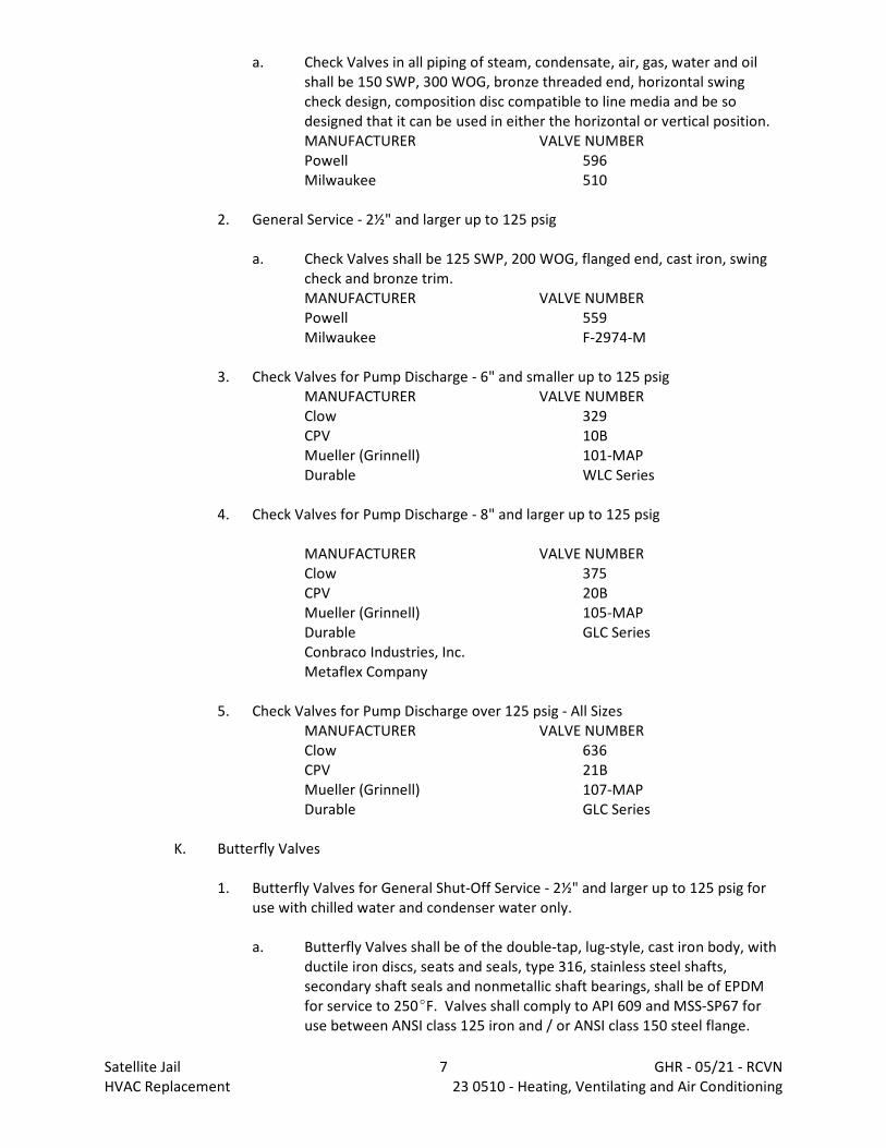
a. Check Valves in all piping of steam, condensate, air, gas, water and oilshall be 150 SWP, 300 WOG, bronze threaded end, horizontal swingcheck design, composition disc compatible to line media and be sodesigned that it can be used in either the horizontal or vertical position.MANUFACTURER VALVE NUMBERPowell 596Milwaukee 510
2. General Service - 2½" and larger up to 125 psig
a. Check Valves shall be 125 SWP, 200 WOG, flanged end, cast iron, swingcheck and bronze trim.MANUFACTURER VALVE NUMBERPowell 559Milwaukee F-2974-M
3. Check Valves for Pump Discharge - 6" and smaller up to 125 psigMANUFACTURER VALVE NUMBERClow 329CPV 10BMueller (Grinnell) 101-MAPDurable WLC Series
4. Check Valves for Pump Discharge - 8" and larger up to 125 psig
MANUFACTURER VALVE NUMBERClow 375CPV 20BMueller (Grinnell) 105-MAPDurable GLC SeriesConbraco Industries, Inc.Metaflex Company
5. Check Valves for Pump Discharge over 125 psig - All SizesMANUFACTURER VALVE NUMBERClow 636CPV 21BMueller (Grinnell) 107-MAPDurable GLC Series
K. Butterfly Valves
1. Butterfly Valves for General Shut-Off Service - 2½" and larger up to 125 psig foruse with chilled water and condenser water only.
a. Butterfly Valves shall be of the double-tap, lug-style, cast iron body, withductile iron discs, seats and seals, type 316, stainless steel shafts,secondary shaft seals and nonmetallic shaft bearings, shall be of EPDMfor service to 250EF. Valves shall comply to API 609 and MSS-SP67 foruse between ANSI class 125 iron and / or ANSI class 150 steel flange.
Satellite Jail 7 GHR - 05/21 - RCVNHVAC Replacement 23 0510 - Heating, Ventilating and Air Conditioning
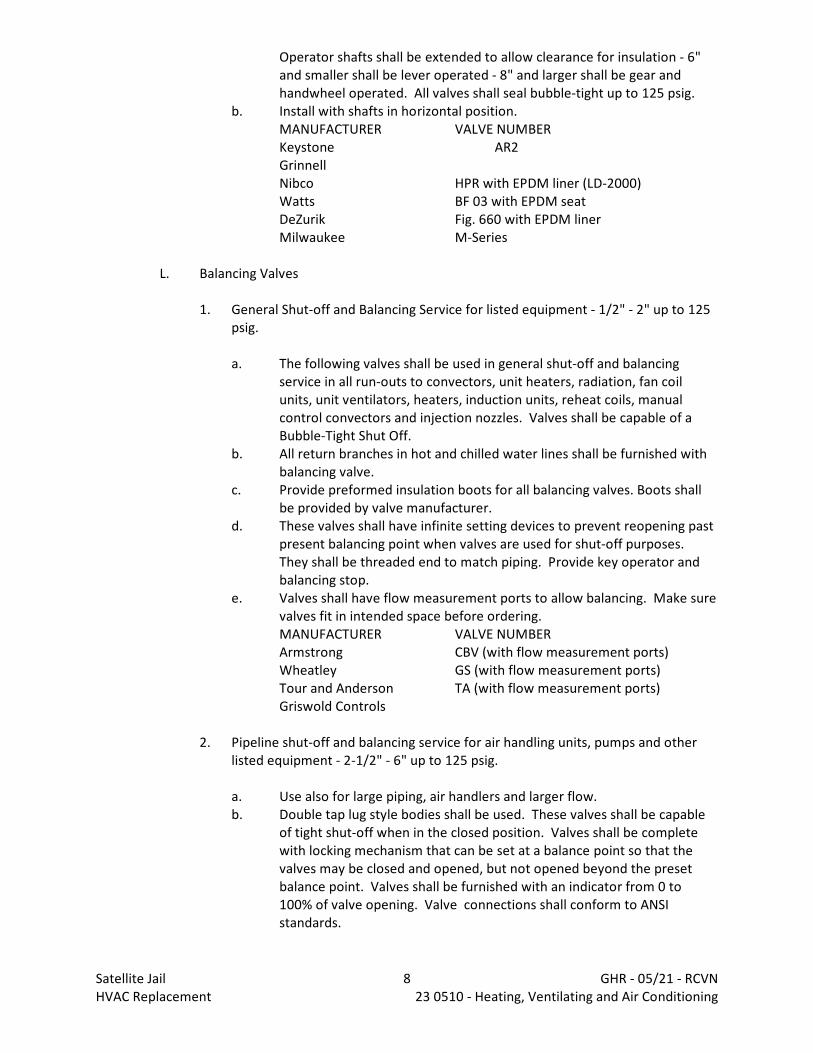
Operator shafts shall be extended to allow clearance for insulation - 6"and smaller shall be lever operated - 8" and larger shall be gear andhandwheel operated. All valves shall seal bubble-tight up to 125 psig.
b. Install with shafts in horizontal position.MANUFACTURER VALVE NUMBERKeystone AR2GrinnellNibco HPR with EPDM liner (LD-2000)Watts BF 03 with EPDM seatDeZurik Fig. 660 with EPDM linerMilwaukee M-Series
L. Balancing Valves
1. General Shut-off and Balancing Service for listed equipment - 1/2" - 2" up to 125psig.
a. The following valves shall be used in general shut-off and balancingservice in all run-outs to convectors, unit heaters, radiation, fan coilunits, unit ventilators, heaters, induction units, reheat coils, manualcontrol convectors and injection nozzles. Valves shall be capable of aBubble-Tight Shut Off.
b. All return branches in hot and chilled water lines shall be furnished withbalancing valve.
c. Provide preformed insulation boots for all balancing valves. Boots shallbe provided by valve manufacturer.
d. These valves shall have infinite setting devices to prevent reopening pastpresent balancing point when valves are used for shut-off purposes. They shall be threaded end to match piping. Provide key operator andbalancing stop.
e. Valves shall have flow measurement ports to allow balancing. Make surevalves fit in intended space before ordering.MANUFACTURER VALVE NUMBERArmstrong CBV (with flow measurement ports)Wheatley GS (with flow measurement ports)Tour and Anderson TA (with flow measurement ports)Griswold Controls
2. Pipeline shut-off and balancing service for air handling units, pumps and otherlisted equipment - 2-1/2" - 6" up to 125 psig.
a. Use also for large piping, air handlers and larger flow.b. Double tap lug style bodies shall be used. These valves shall be capable
of tight shut-off when in the closed position. Valves shall be completewith locking mechanism that can be set at a balance point so that thevalves may be closed and opened, but not opened beyond the presetbalance point. Valves shall be furnished with an indicator from 0 to100% of valve opening. Valve connections shall conform to ANSIstandards.
Satellite Jail 8 GHR - 05/21 - RCVNHVAC Replacement 23 0510 - Heating, Ventilating and Air Conditioning
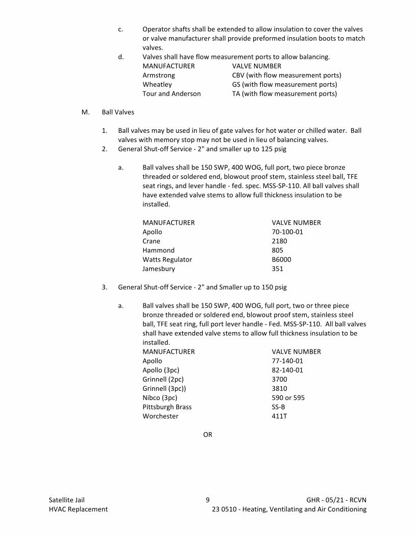
c. Operator shafts shall be extended to allow insulation to cover the valvesor valve manufacturer shall provide preformed insulation boots to matchvalves.
d. Valves shall have flow measurement ports to allow balancing.MANUFACTURER VALVE NUMBERArmstrong CBV (with flow measurement ports)Wheatley GS (with flow measurement ports)Tour and Anderson TA (with flow measurement ports)
M. Ball Valves
1. Ball valves may be used in lieu of gate valves for hot water or chilled water. Ballvalves with memory stop may not be used in lieu of balancing valves.
2. General Shut-off Service - 2" and smaller up to 125 psig
a. Ball valves shall be 150 SWP, 400 WOG, full port, two piece bronzethreaded or soldered end, blowout proof stem, stainless steel ball, TFEseat rings, and lever handle - fed. spec. MSS-SP-110. All ball valves shallhave extended valve stems to allow full thickness insulation to beinstalled.
MANUFACTURER VALVE NUMBERApollo 70-100-01Crane 2180Hammond 805Watts Regulator B6000Jamesbury 351
3. General Shut-off Service - 2" and Smaller up to 150 psig
a. Ball valves shall be 150 SWP, 400 WOG, full port, two or three piecebronze threaded or soldered end, blowout proof stem, stainless steelball, TFE seat ring, full port lever handle - Fed. MSS-SP-110. All ball valvesshall have extended valve stems to allow full thickness insulation to beinstalled.MANUFACTURER VALVE NUMBERApollo 77-140-01Apollo (3pc) 82-140-01Grinnell (2pc) 3700Grinnell (3pc)) 3810Nibco (3pc) 590 or 595Pittsburgh Brass SS-BWorchester 411T
OR
Satellite Jail 9 GHR - 05/21 - RCVNHVAC Replacement 23 0510 - Heating, Ventilating and Air Conditioning

2.8 PUMP DISCHARGE TRIPLE DUTY VALVES UP TO 125 PSIG - 2" THROUGH 8"
A. Valves shall be same manufacturer as related pumps. These valves shall be selectedfor between 3 feet and 5 feet of pressure drop across a wide-open valve at design flow(this may not necessarily yield line sized valve).
MANUFACTURER VALVE NUMBERArmstrong FTABell and Gossett Triple DutyTaco 360 seriesThrush TD series
2.9 DRAIN AND PURGE VALVES
A. Hose end valves for draining, purging and strainer blow-offs shall not be used. Provideand install full port ball valves with brass adaptor and brass cap.
B. Forward shop drawings of all valves to Architect / Engineer for review.
2.10 PRESSURE RELIEF VALVES
A. Pressure Relief Valves for use in all locations where shown or required by codes shallbe as follows:
SERVICE SIZE TYPEBoiler Safety Crosby-Ashton, Style HSand Steam Kunkel No. 253, semi-nozzleRelief All Consolidated, Style 1902
Watts 740Water Relief All Cash Acme Type F
B. Relief Valve capacity shall exceed maximum flow rate of upstream flow control device,pressure reducing valve, etc.
C. Pipe relief valves full size to floor drain.
D. Forward shop drawings of all valves to Architect / Engineer for review.
2.11 REFRIGERATION PIPING
A. Refrigeration piping shall be Type ACR hard drawn sealed and nitrogen filled specialrefrigeration duty copper. Fittings shall be wrought copper streamline fittings and allelbows shall be long radius.
B. Brazing shall be silver alloy having a minimum melting point of 1185EF. Piping shall befilled with oil pumped dry nitrogen during all brazing operations.
C. After the system is installed and before any piping is insulated, the entire refrigerationcircuit must be thoroughly leak tested. The following test procedure is recommended:
Satellite Jail 10 GHR - 05/21 - RCVNHVAC Replacement 23 0510 - Heating, Ventilating and Air Conditioning
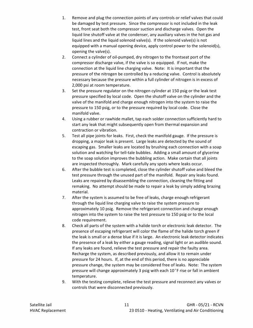
1. Remove and plug the connection points of any controls or relief valves that couldbe damaged by test pressure. Since the compressor is not included in the leaktest, front seat both the compressor suction and discharge valves. Open theliquid line shutoff valve at the condenser, any auxiliary valves in the hot gas andliquid lines and the liquid solenoid valve(s). If the solenoid valve(s) is notequipped with a manual opening device, apply control power to the solenoid(s),opening the valve(s).
2. Connect a cylinder of oil-pumped, dry nitrogen to the frontseat port of thecompressor discharge valve, if the valve is so equipped. If not, make theconnection at the liquid line charging valve. Note: It is important that thepressure of the nitrogen be controlled by a reducing valve. Control is absolutelynecessary because the pressure within a full cylinder of nitrogen is in excess of2,000 psi at room temperature.
3. Set the pressure regulator on the nitrogen cylinder at 150 psig or the leak testpressure specified by local code. Open the shutoff valve on the cylinder and thevalve of the manifold and charge enough nitrogen into the system to raise thepressure to 150 psig, or to the pressure required by local code. Close themanifold valve.
4. Using a rubber or rawhide mallet, tap each solder connection sufficiently hard tostart any leak that might subsequently open from thermal expansion andcontraction or vibration.
5. Test all pipe joints for leaks. First, check the manifold gauge. If the pressure isdropping, a major leak is present. Large leaks are detected by the sound ofescaping gas. Smaller leaks are located by brushing each connection with a soapsolution and watching for tell-tale bubbles. Adding a small amount of glycerineto the soap solution improves the bubbling action. Make certain that all jointsare inspected thoroughly. Mark carefully any spots where leaks occur.
6. After the bubble test is completed, close the cylinder shutoff valve and bleed thetest pressure through the unused part of the manifold. Repair any leaks found. Leaks are repaired by disassembling the connection, cleaning the fitting andremaking. No attempt should be made to repair a leak by simply adding brazingmaterial.
7. After the system is assumed to be free of leaks, charge enough refrigerantthrough the liquid line charging valve to raise the system pressure toapproximately 10 psig. Remove the refrigerant connection and charge enoughnitrogen into the system to raise the test pressure to 150 psig or to the localcode requirement.
8. Check all parts of the system with a halide torch or electronic leak detector. Thepresence of escaping refrigerant will color the flame of the halide torch green ifthe leak is small or a dense blue if it is large. An electronic leak detector indicatesthe presence of a leak by either a gauge reading, signal light or an audible sound. If any leaks are found, relieve the test pressure and repair the faulty area. Recharge the system, as described previously, and allow it to remain underpressure for 24 hours. If, at the end of this period, there is no appreciablepressure change, the system may be considered free of leaks. Note: The systempressure will change approximately 3 psig with each 10EF rise or fall in ambienttemperature.
9. With the testing complete, relieve the test pressure and reconnect any valves orcontrols that were disconnected previously.
Satellite Jail 11 GHR - 05/21 - RCVNHVAC Replacement 23 0510 - Heating, Ventilating and Air Conditioning
D. Evacuation
1. To speed the evacuation, connect the vacuum pump to as many points of thesystem as possible. To register the vacuum developed by the pump, a reliablevacuum gauge, such as a Zimmerli Gauge or an electronic vacuum gauge, isconnected to the liquid line charging valve. The compressor valves are thencracked off of their backseats, moving the valve disc to an intermediate positionbetween the backseat and the frontseat of the valve. Open the liquid linecharging valve.
2. The vacuum pump shall be started and operated until a vacuum equivalent to500 microns is registered by the vacuum gauge. The length of time required toachieve the 500 micron reading depends upon the size of the system and theamount of moisture within the system. Failure to reach the required vacuumreading may be due to:
a. Presence of a large amount of moisture. This will be removed withcontinued operation of the vacuum pump.
b. Inefficiency of the pump. Leaks within the pump or contaminated pumpoil may be the cause. This may be checked by operating the pumpagainst a vacuum gauge.
c. A system leak.
3. When the system has been evacuated, close the suction valve on the vacuumpump and then stop the pump. Backseat one of the compressor valves andremove the vacuum pump connection. Through this valve port charge enoughoil-pumped dry nitrogen into the system to raise the pressure to atmospheric. Re-evacuate the system. Any moisture remaining in the system is absorbed bythe dry nitrogen gas and is removed by the second evacuation.
4. After the 500 micron vacuum reading has been re-established, close the vacuumpump suction valve and stop the pump. Backseat the compressor valves andallow the system to stand under vacuum for a minimum of 12 hours. If thevacuum reading remains unchanged, the system is ready to receive its charge ofrefrigerant.
E. Charge system with proper quantity of refrigerant and lubricant.
F. Insulate suction line with foamed plastic insulation. See Specification Section 22 0020.
G. Forward shop drawing submittals to Architect / Engineer for review. Submittal shallinclude complete sketch of refrigerant piping system, sizes, fittings and lengths. Indicate on sketch that manufacturer approves layout and that warranty applies. (HVAC Contractor shall note that pipe sizes and layouts on drawings are for thepurpose of establishing a bid price. Final sizing and layout shall be determined andapproved by refrigeration equipment manufacturer.)
H. Refrigerant purge and relief shall be piped full size in separate lines to outdoors usingmaterials specified for refrigerant piping.
Satellite Jail 12 GHR - 05/21 - RCVNHVAC Replacement 23 0510 - Heating, Ventilating and Air Conditioning
2.12 REFRIGERATION ACCESSORIES
A. Furnish and install the following specialties in refrigeration piping from each unit:
1. 1 - liquid line catch-all filter-drier sized for 2 psi maximum pressure drop (with 3-valve bypass).
2. 1 - solenoid valve with 120 volt, 60 cycle coil on each refrigerant circuit.3. 1 - expansion valve with external equalizer on each refrigerant circuit.4. 1 - liquid indicator with moisture indicating bull's-eyes in each circuit immediately
upstream of expansion valve.5. Charging valves.6. Hot gas discharge muffler in each compressor circuit. Muffler shall be suitable
for horizontal or vertical installation, self-draining.
B. Acceptable Manufacturers
1. Mueller Brass Company2. Henry Valve Company3. Sporlan
2.13 REFRIGERANTS - GENERAL
A. Recover and Recycle Refrigerants
1. Refrigerant used in centrifugal water chillers should be recovered and / orrecycled for reuse, reprocessed (reclaimed), or properly disposed of, whenever itis removed from the equipment. Never release to atmosphere!
2. Always determine recycle or reclaim requirements of the refrigerant beforebeginning recovery procedure. Obtain a chemical analysis of the refrigerant ifnecessary. (Questions about recovered refrigerant and acceptable refrigerantquality standards are addressed in ARI Standard 700.)
B. Refrigerant Handling and Safety
1. Consult manufacturer's Material Safety Data Sheets (MSDS) on refrigerants beinghandled to understand health, safety, storage, handling and disposalrequirements. Use approved containment vessels and refer to appropriatesafety standards. Comply with all applicable transportation standards whenshipping refrigerant containers.
C. Service Equipment and Procedures
1. To minimize refrigerant emissions while recovering the refrigerant, use recyclingequipment such as a Trane "recycle / recovery system" or equivalent. Useequipment and methods which will pull the lowest possible system vacuum whilerecovering and condensing refrigerant. Equipment capable of pulling a vacuumof less than (500 microns - 1.0 mm) of mercury is recommended. Do not openthe unit to atmosphere for service work until the refrigerant charge is fullyremoved/recovered.
Satellite Jail 13 GHR - 05/21 - RCVNHVAC Replacement 23 0510 - Heating, Ventilating and Air Conditioning
2. Evacuation prior to charging should be done with a vacuum pump capable ofpulling a vacuum of (500 microns - 1.0 mm) of mercury or less. The unit shouldstand for 12 hours and the vacuum should not rise above 2,500 microns (2.5 mm)of mercury. A rise above 2,500 microns (2.5 mm) of mercury indicates a leak testis required to locate and repair any leaks. A leak test will be required on anyrepaired area. Charge refrigerant into the machine only when it is determinedthat the machine does not leak or contain moisture. Charge refrigerant into themachine by weight. A proper charge is required for efficient machine operation. When charging is complete, purge or drain charging lines into an approvedrefrigerant container. Seal all used refrigerant containers with approved closuredevices to prevent unused refrigerant from escaping to the atmosphere. Takeextra care to properly maintain all service equipment directly supportingrefrigerant service work such as gauges, hoses, vacuum pumps, and recyclingequipment.
3. When cleaning system components or parts, avoid using CFC-11 (R-11) or CFC-113 (R-113). Use only cleaning solvents that do not have ozone depletionfactors. Properly dispose of used materials. Refrigeration system cleanupmethods using filters and driers are preferred.
2.14 WATER CIRCULATING PUMPS - Base Mounted
A. Provide horizontally or vertically split-casing type circulating pumps as scheduled ondrawings, arranged to permit access to revolving parts without disconnecting suctionand discharge piping or moving motor. Pumps shall be fitted with grease lubricatedball bearings to zerk fittings and drain plugs in dust and moisture proof housing,machine fitted to assure permanent, perfect alignment (cast iron casing with bronzefittings). Renewable bronze casing wearing rings shall be provided. Pumps shall beequipped with mechanical seals (and stainless steel shaft sleeves). Provide bronzeimpeller. Manufacturer shall especially note arrangement of piping for high staticheads and shall check the water condition at job site before recommending type ofseal or packing gland.
B. Each pump shall deliver the total gpm listed in the schedule against the total dynamichead listed, and pump characteristic curve shall have a cut-off point at a head no morethan 20% or less than 10% above rated discharge head.
C. The pump shall be mounted on a cast iron or fabricated steel drip-lip subbase anddirect connected by Dodge Para-Flex, Woods, Falk or Waldron flexible coupling to theelectric motor.
1. See Section 23 0500 for further motor requirements.
D. Mount base with assembled pump and motor on 3½" thick concrete housekeepingbase. Base of pump shall be tightly packed with wet grout after pump is aligned,leveled and anchored. Install standpipe minimum of 12" high over grout pouring holeto assure that all areas of base are filled. Each pump shall be mounted on an inertiabase.
E. The manufacturer of all pumps shall be responsible for the supervision of the pumpinstallation and field alignment to make sure pumps installed are to their
Satellite Jail 14 GHR - 05/21 - RCVNHVAC Replacement 23 0510 - Heating, Ventilating and Air Conditioning
requirements. Submit alignment report to Architect / Engineer stating pumps areproperly aligned.
F. Suction diffusers with integral strainers shall be provided by the pump manufacturer. Diffusers shall match pumps and shall be provided with support foot and pressuregauge taps.
G. Acceptable Manufacturers
1. Armstrong2. Bell and Gossett3. Aurora4. Pacific Pump Company5. Thrush6. Taco, Inc.7. Wilo.
H. Forward shop drawing submittals to the Architect / Engineer for review. Include pumpcurve with operating point plotted.
I. Each pump shall be equipped with a VFD. Acceptable VFD manufacturers include ABB,Square D and Dan Foss. The VFD shall be provided by the Temperature ControlContractor.
2.15 WATER TREATMENT
A. Circulating Hot Water Systems
1. Provide and install bypass "shot" feeders welded steel construction with 300 psigworking pressure. Feeders shall be installed in all new HW systems and have thefollowing features.
a. 5 gallon capacityb. 3.5" fill port with quick opening coverc. 3/4" inlet and outlet connectionsd. 3/4" vent connectione. Safety cover that cannot be removed while feeder is pressurized
2. Shot feeders shall be piped in accord with manufacturer's details.3. Acceptable Manufacturers
a. Nalcob. Betzc. Dearbornd. JL Wingert Co.
B. Forward shop drawing submittals to the Architect / Engineer for review.
Satellite Jail 15 GHR - 05/21 - RCVNHVAC Replacement 23 0510 - Heating, Ventilating and Air Conditioning
2.16 EXPANSION JOINTS (Packless Type)
A. Furnish and install Flexonics type Tube Turns telescopic expansion joints with 2-plystainless steel bellows for all piping 2.50" and smaller where shown on drawings, orrequired for expansion of pipes and space does not permit use of fabricated expansionloops.
B. Furnish and install Flexonics single or dual flexing, as shown on drawings, Tube Turnsor ADSCO controlled flexing packless expansion joints with Type 304 stainless steelbellows for all piping 3" and larger where shown on drawings, or required forexpansion of pipes and space does not permit use of fabricated expansion loops.
2.17 FLEXIBLE PIPE CONNECTORS
A. Furnish and install molded "Teflon" flanged flexible couplings on suction and dischargeconnection of all piping deflections. Furnish connections complete with companionflanges, grommeted limit bolts and monel reinforcing rings.
B. Connectors shall be suitable for continuous operation at 220EF with pressures of 110psig.
C. Acceptable Manufacturers
1. Belmont2. Garlock Inc.3. John Dore Co.4. Mercer5. Metraflex6. Resistoflex7. Flex Flo (Thermatech)
D. Forward shop drawing submittals to the Architect / Engineer for review.
2.18 CENTRIFUGAL PUMPS WITH FLOOR-MOUNTED RECEIVER
A. Manufacturers: Subject to compliance with requirements, provide products by one ofthe following:
1. ITT Corporation; Domestic Pump Division.2. Roth Pump Company.3. Skidmore Pump.4. Spence Engineering Company, Inc.; Division of Circor International, Inc.5. Spirax-Sarco Inc.6. Sterling.
B. Description: Factory-fabricated, packaged, electric-driven pumps; with receiver,pumps, controls, and accessories suitable for operation with steam condensate.
Satellite Jail 16 GHR - 05/21 - RCVNHVAC Replacement 23 0510 - Heating, Ventilating and Air Conditioning
1. Electrical Components, Devices, and Accessories: Listed and labeled as defined inNFPA 70, by a qualified testing agency, and marked for intended location andapplication.
2. ASME Compliance: Fabricate and label steam condensate receivers to complywith ASME Boiler and Pressure Vessel Code: Section VIII, Division 1.
C. Configuration: Duplex floor-mounted pumps with receiver and float switches.
D. Receiver:
1. Floor mounted.2. Close-grained cast iron.3. Externally adjustable float switches.4. Flanges for pump mounting.5. Water-level gage and dial thermometer.6. Pressure gage at pump discharge.7. Bronze gate valves between receiver and pump discharge.8. Lifting eyebolts.9. Inlet vent and an overflow.10. Cast-iron inlet strainer.
E. Pumps:
1. Centrifugal, close coupled.2. Vertical design, permanently aligned, and bronze fitted.3. Stainless-steel shafts.4. Mechanical seals rated at 250 deg F.5. Rated to operate with a minimum of 2 feet of NPSH.6. Mounted on receiver flanges.
F. Motor:
1. Enclosure: Totally enclosed, fan cooled.2. Motor Bearings: Grease-lubricated ball bearings.3. Efficiency: Premium efficient.
G. Control Panel:
1. Factory wired between pumps and float switches, for single external electricalconnection.
2. Provide fused, control-power transformer if voltage exceeds 230 V ac.3. NEMA 250, Type 1 enclosure with hinged door and grounding lug, mounted on
pump.4. Motor controller for each pump.5. Electrical pump alternator to operate pumps in lead-lag sequence and allow both
pumps to operate on receiver high level.6. Manual lead-lag control to override electrical pump alternator and manually
select the lead pump.7. Momentary-contact "TEST" push button on cover for each pump.8. Numbered terminal strip.
Satellite Jail 17 GHR - 05/21 - RCVNHVAC Replacement 23 0510 - Heating, Ventilating and Air Conditioning
9. Disconnect switch.
PART 3 - EXECUTION
3.1 DEMOLITION
A. Pertinent Contractor shall remove all existing materials, system components,accessories and related items that will not be re-used.
B. HVAC Contractor shall ensure that system is inactive before disabling the system. HVAC Contractor shall ensure that removal of system will not compromise theOwner's operations before removal occurs.
C. Partial removals shall extend back to nearest active main. Provide and install caps orpipe plugs at main for all piping including pneumatic lines.
D. No piping shall be left open as a result of demolition operations. Cap or plug all openpiping (including pneumatic lines). Crimping is not an acceptable means of cappingpiping.
E. Refrigerant associated with demolished systems/equipment shall be reclaimed byHVAC Contractor in accord with applicable regulations. Such refrigerant becomes theproperty of the HVAC Contractor unless stated otherwise.
F. All hangers and clamps shall be removed as part of demolition work if they are not re-used.
G. All removed equipment and materials become the property of the pertinent removing Contractor unless otherwise noted.
3.2 DRAIN LINES
A. HVAC Contractor shall provide and install a complete drain system from all coil drainpans in all air handling units, fan coils, evaporator coils and cooling coils. On doublesloped pans and / or pans with two drain connections provide drains on both sides.
1. Where multiple, stacked cooling coils are used each coil shall have its own drainpan. Provide internal drop tubes from each such pan down to the main drainpan.
B. All drains shall be trapped. Traps shall be designed to withstand the maximum(positive or negative) pressures imposed on them by service without ponding orretaining water in the pans.
1. Dimension from bottom of pan outlet to trap invert shall be equal to two timesunit static pressure (in inches of water) plus unit velocity head (in inches ofwater).
2. Dimension from bottom of trap to trap outlet shall be equal to two times unitstatic pressure (in inches of water).
Satellite Jail 18 GHR - 05/21 - RCVNHVAC Replacement 23 0510 - Heating, Ventilating and Air Conditioning
C. Drain lines shall be the same size as the pan outlet connections.
D. All drain lines shall slope uniformly to termination point at slope of 1/8" per foot.
E. Terminate drain lines at floor drains with indirect connection.
3.3 PIPE GUIDES AND ANCHORS
A. Where expansion joints are used, pipes shall be guided two times on each side of theexpansion joint. The guides shall be from 5'-0" and 25'-0" from the anchor unlessotherwise noted on drawings. Guides shall be reviewed by the Architect / Engineerand shall be so designed as to prevent pipe movement in any direction except alongthe axis of the pipe run. Also provide guides on vertical pipes in shafts whereindicated.
B. Anchors shall be constructed of steel, shall be such as to prevent pipe movement inany direction, shall be welded to the pipe and shall be securely fastened to thebuilding structure as reviewed by the Architect / Engineer and shall have sufficientstrength to withstand the stress that it will be subjected to by the pipe movement.
3.4 WELDING
A. If requested, furnish proof of the competency of each welding operator and, at therequest of the Architect / Engineer, have all or any of the welding operators pass astandard qualification test such as ASME, AWS or Hartford Insurance Companyprocedure and tests. See Specification Section 22 00 10.
3.5 PRESSURE TESTS
A. All testing equipment, labor and accessories shall be provided by the HVAC Contractor.
B. HVAC Contractor shall disconnect or valve-off all equipment items that could bedamaged by testing. All damage resulting from testing shall be the responsibility ofthe HVAC Contractor.
C. All tests shall be performed before systems are concealed in building construction byinsulation or otherwise made inaccessible.
D. All leaks shall be repaired. Leaking systems shall be repaired and retested untilsystems are free of leaks. All damage resulting from leaks shall be the responsibility ofthe pertinent Contractor.
E. Tests shall be witnessed by the Architect / Engineer or designated representative.
F. Submit 3 copies of test reports to Architect / Engineer for record purposes. Tests shallbe typewritten, shall be signed by the HVAC Contractor and shall list name(s) ofwitness(es).
Satellite Jail 19 GHR - 05/21 - RCVNHVAC Replacement 23 0510 - Heating, Ventilating and Air Conditioning
G. Tests shall be conducted using clear water as the testing media except for refrigerationand compressed air piping. See "Refrigeration piping" for testing of refrigerationpiping. Use compressed air for testing of compressed air piping.
H. All new piping shall be tested by pump pressure to a working pressure of not less than100 psig. Where operating pressures exceed 50 psig, test pressure shall be two timesthe working pressure. Test duration shall be two hours for water tests, 8 hours for airtests.
I. After tests are satisfactorily completed, the piping shall be drained, equipmentreconnected and the system made ready for use.
3.6 CLEANING THE PIPING SYSTEMS
A. At completion of installation and before final capacity tests are conducted, thoroughlyclean all grease, oil and dirt from all parts of the new piping in a manner satisfactory tothe Architect / Engineer.
B. Flush entire new steam and condensate system with full steam pressure for a periodof two hours.
1. Remove trap interiors during cleaning and temporary piping shall be installed tovent steam to outside.
2. After the steam and condensate systems have been flushed, put system back innormal operation with condensate going to drain for a period of one week.
3. Thoroughly clean all new traps after the plant has been in continuous operationfor a period of thirty (30) days. Clean trap interiors and remove all foreignmatter.
4. Examine and clean all of the new trap strainers and new strainers for allautomatic valves.
C. Cleaning of Chilled/Hot Water Systems
1. Chilled water and hot water heating systems shall be chemically cleaned by oneof the methods outlined below:
a. Trisodium Phosphate-CausticThe system shall be filled with water and for every 100 gallons of systemvolume, 3 lbs. of trisodium phosphate and 3 lbs. of sodium hydroxideshall be added. This solution shall be circulated for 12 to 24 hours, at120EF if possible. At end of circulation time begin flushing as outlinedbelow in Section 2. CAUTION: This procedure shall not be used if metalssuch as aluminum or galvanized are present in the system. The alternatemethods “b” or “c” outlined below shall be used in these systems.
b. Acrysol QR-1086 and Dequest 2010The system shall be filled with water and for every 100 gallons of systemvolume, 2 gallons of cleaning concentrate shall be added. The cleaningconcentrate shall be prepared as follows. In 100 gallons of water, add
Satellite Jail 20 GHR - 05/21 - RCVNHVAC Replacement 23 0510 - Heating, Ventilating and Air Conditioning

the following quantities of chemicals in the following order and mixthoroughly until dissolved. Use a polyethylene drum:
(1) Acrysol QR-1086 (Rohm & Haas) 41.5 lbs(2) Dequest 2010 (Monsanto) 41.5 lbs(3) Potassium or Sodium Hydroxide 12.5 lbs
The cleaning solution shall be circulated in the system for 24 to 48 hours,preferably under light heat (120EF). If heat cannot be applied thencirculate for 48 hours under ambient conditions. At completion ofcirculation time begin flushing of system as outlined below in Section 2.
c. Drewsperse 4945 / Drewsperse 4395These are preblended proprietary cleaning chemicals. Drewsperse 4945is a combination of polymers, chelate, and a gluconic acid derivativedesigned to remove iron and copper oxides from the system. Drewsperse 4395 is a nonionic surfactant which effectively removes silt,mud, clay, oil and other suspended matter from the system allowingthem to be carried out of the system by flushing. To clean a system withthis procedure, add 1 gallon of Drewsperse 4945 and 1 gallon ofDrewsperse 4395 per 100 gallons of system volume. If foaming problemsdevelop, the use of an antifoam such as Dow Corning Antifoam A shouldovercome the foaming tendency of Drewsperse 4395. Circulate cleaningsolution for 48 hours, at a temperature of 120EF if possible. If heatcannot be applied increase cleaner circulation time to 72 hours. Aftercirculation time begin high velocity flushing as outlined below.
2. A temporary connection to city water with backflow prevention shall be providedto enable high velocity flushing of system. At completion of required cleanercirculation time begin continuous flushing of system while maintaining systemfull at all times to prevent the introduction of air into the system. Followingcleaning, submit samples of system water to independent testing lab todetermine if system has been cleaned properly. When cleaning system, ensurethat all automatic valves are open to coils so the entire system will circulate andbe cleaned. Also remove and clean system strainers following cleaning.
a. Pertinent Contractor shall be responsible for providing the necessarypumping action to obtain a minimum velocity of 3 ft / sec in the pipingbeing cleaned. Contractor shall be responsible for providing all bypassesand temporary piping necessary to clean the entire system(s).
3. After final cleaning, add 0.5 oz of Nalco 8325 (or approved equal) per gallon ofsystem volume, to provide a nitrite level of 500 to 750 parts per million. This is aglycol compatible blend of corrosion inhibitors and will passivate the cleanedmetal surfaces and protect them from corrosion. If filling the system withethylene glycol, drain only the volume from the system necessary to allow theintroduction of glycol into the system. If glycol is not to be added, this blend ofinhibitors must be left in the system.
Satellite Jail 21 GHR - 05/21 - RCVNHVAC Replacement 23 0510 - Heating, Ventilating and Air Conditioning

a. It may require 5 to 10 times the system volume to adequately flush thesystem. In order to properly clean a system, a minimum velocity of 3 ftper second must be attained in the system piping. If this velocity cannotbe developed then manual cleaning methods will have to be used inthose areas where this velocity is not achieved.
4. In systems which require the use of ethylene glycol based antifreeze solutions toprevent possible freezing and bursting of system piping, the glycol used to fill thesystem shall be as specified elsewhere.
5. Samples submitted to the independent testing laboratory shall meet thefollowing test limits before acceptance of the system.Chloroform extractables 5 PPM (mg/l) or lessParticulate matter 25 PPM (mg/l) or less
on 1.2 micron mediaCorrosion inhibitors 500-1000 as NitriteGlycol To percentage as per project specification.
3.7 CIRCULATION (WATER SYSTEM)
A. Insure a perfect and noiseless circulation of water and air throughout entire newwater system, without pounding or air binding, in any part of the system whenoperating at gauge pressures varying from 1/4 to 75 lbs.
B. Arrange all piping to drain by gravity. Provide drain valves with hose connections at alllow points in the system, in all isolated sections of piping, at the base of all risers anddownstream of all isolation valves.
C. Properly vent all high points in hot water heating and chilled water piping systems.
END 23 0510
Satellite Jail 22 GHR - 05/21 - RCVNHVAC Replacement 23 0510 - Heating, Ventilating and Air Conditioning
DIVISION 23 - HEATING, VENTILATING AND AIR CONDITIONINGDocument 23 0513 - Common Motor Requirements for HVAC Equipment
PART 1 - GENERAL
1.1 RELATED DOCUMENTS
A. Drawings and general provisions of the Contract, including General and Supplementary Conditionsand Division 01 Specification Sections, apply to this Section.
1.2 SUMMARY
A. Section includes general requirements for single-phase and polyphase, general-purpose,horizontal, small and medium, squirrel-cage induction motors for use on ac power systems up to600 V and installed at equipment manufacturer's factory or shipped separately by equipmentmanufacturer for field installation.
1.3 COORDINATION
A. Coordinate features of motors, installed units, and accessory devices to be compatible with thefollowing:
1. Motor controllers.2. Torque, speed, and horsepower requirements of the load.3. Ratings and characteristics of supply circuit and required control sequence.4. Ambient and environmental conditions of installation location.
PART 2 - PRODUCTS
2.1 GENERAL MOTOR REQUIREMENTS
A. Comply with requirements in this Section except when stricter requirements are specified inHVAC equipment schedules or Sections.
B. Comply with NEMA MG 1 unless otherwise indicated.
C. Comply with IEEE 841 for severe-duty motors.
Satellite Jail 1 GHR - 05/21 - RCVNHVAC Replacement 23 0513 - Common Motor Requirements for HVAC Equipment
2.2 MOTOR CHARACTERISTICS
A. Duty: Inverter duty rated at ambient temperature of 40 deg C and at altitude of 3300 feet abovesea level.
B. Capacity and Torque Characteristics: Sufficient to start, accelerate, and operate connected loadsat designated speeds, at installed altitude and environment, with indicated operating sequence,and without exceeding nameplate ratings or considering service factor.
2.3 POLYPHASE MOTORS
A. Description: NEMA MG 1, Design B, medium induction motor.
B. Efficiency: Energy efficient, as defined in NEMA MG 1.
C. Service Factor: 1.15.
D. Multispeed Motors: Separate winding for each speed.
E. Rotor: Random-wound, squirrel cage.
F. Bearings: Regreasable, shielded, antifriction ball bearings suitable for radial and thrust loading.
G. Insulation: Class F.
H. Code Letter Designation:
1. Motors 15 HP and Larger: NEMA starting Code F or Code G.2. Motors Smaller than 15 HP: Manufacturer's standard starting characteristic.
I. Enclosure Material: Cast iron for motor frame sizes 324T and larger; rolled steel for motor framesizes smaller than 324T.
2.4 POLYPHASE MOTORS WITH ADDITIONAL REQUIREMENTS
A. Motors Used with Reduced-Voltage and Multispeed Controllers: Match wiring connectionrequirements for controller with required motor leads. Provide terminals in motor terminal box,suited to control method.
B. Motors Used with Variable Frequency Controllers: Ratings, characteristics, and featurescoordinated with and approved by controller manufacturer.
1. Windings: Copper magnet wire with moisture-resistant insulation varnish, designed andtested to resist transient spikes, high frequencies, and short time rise pulses produced bypulse-width modulated inverters.
2. Energy- and Premium-Efficient Motors: Class B temperature rise; Class F insulation.
Satellite Jail 2 GHR - 05/21 - RCVNHVAC Replacement 23 0513 - Common Motor Requirements for HVAC Equipment
3. Inverter-Duty Motors: Class F temperature rise; Class H insulation.4. Thermal Protection: Comply with NEMA MG 1 requirements for thermally protected
motors.
2.5 SINGLE-PHASE MOTORS
A. Motors larger than 1/20 hp shall be one of the following, to suit starting torque and requirementsof specific motor application:
1. Permanent-split capacitor.2. Split phase.3. Capacitor start, capacitor run.
B. Multispeed Motors: Variable-torque, permanent-split-capacitor type.
C. Bearings: Prelubricated, antifriction ball bearings or sleeve bearings suitable for radial and thrustloading.
D. Motors 1/20 HP and Smaller: Shaded-pole type.
E. Thermal Protection: Internal protection to automatically open power supply circuit to motorwhen winding temperature exceeds a safe value calibrated to temperature rating of motorinsulation. Thermal-protection device shall automatically reset when motor temperature returnsto normal range.
PART 3 - EXECUTION (Not Applicable)
END 23 0513
Satellite Jail 3 GHR - 05/21 - RCVNHVAC Replacement 23 0513 - Common Motor Requirements for HVAC Equipment

DIVISION 23 - HEATING, VENTILATING AND AIR CONDITIONINGDocument 23 0519 - Meters and Gages for HVAC Piping
PART 1 - GENERAL
1.1 RELATED DOCUMENTS
A. Drawings and general provisions of the Contract, including General and Supplementary Conditionsand Division 01 Specification Sections, apply to this Section.
1.2 SUMMARY
A. Section Includes:
1. Bimetallic-actuated thermometers.2. Thermowells.3. Dial-type pressure gages.4. Gage attachments.5. Test plugs.6. Test-plug kits.
1.3 SUBMITTALS
A. Product Data: For each type of product indicated.
B. Wiring Diagrams: For power, signal, and control wiring.
C. Product Certificates: For each type of meter and gage, from manufacturer.
PART 2 - PRODUCTS
2.1 BIMETALLIC-ACTUATED THERMOMETERS
A. Basis-of-Design Product: Subject to compliance with requirements, provide thermometer orcomparable product by one of the following:
1. Ashcroft Inc.2. Ernst Flow Industries.3. Miljoco Corporation.4. Tel-Tru Manufacturing Company - AA575R.5. Trerice, H. O. Co.6. Weiss Instruments, Inc. - 5VBM.
Satellite Jail 1 GHR - 05/21 - RCVNHVAC Replacement 23 0519 - Meters and Gages for HVAC Piping
B. Standard: ASME B40.200.
C. Case: Sealed type; stainless steel with 3-inch or 5-inch nominal diameter.
D. Dial: Nonreflective aluminum with permanently etched scale markings and scales in deg F.
E. Connector Type(s): Union joint, adjustable angle with unified-inch screw threads.
F. Connector Size: ½ inch, with ASME B1.1 screw threads.
G. Stem: 0.25 or 0.375 inch in diameter; stainless steel.
H. Window: Plain glass.
I. Ring: Stainless steel.
J. Element: Bimetal coil.
K. Pointer: Dark-colored metal.
L. Accuracy: Plus or minus 1 percent of scale range.
2.2 DUCT-THERMOMETER MOUNTING BRACKETS
A. Description: Flanged bracket with screw holes, for attachment to air duct and made to holdthermometer stem.
2.3 THERMOWELLS
A. Thermowells:
1. Standard: ASME B40.200.2. Description: Pressure-tight, socket-type fitting made for insertion into piping tee fitting.3. Material for Use with Copper Tubing: CNR or CUNI.4. Material for Use with Steel Piping: CRES.5. Type: Stepped shank unless straight or tapered shank is indicated.6. External Threads: NPS ½, NPS 3/4, or NPS 1, ASME B1.20.1 pipe threads.7. Internal Threads: ½, 3/4, and 1 inch, with ASME B1.1 screw threads.8. Bore: Diameter required to match thermometer bulb or stem.9. Insertion Length: Length required to match thermometer bulb or stem.10. Lagging Extension: Include on thermowells for insulated piping and tubing.11. Bushings: For converting size of thermowell's internal screw thread to size of thermometer
connection.
B. Heat-Transfer Medium: Mixture of graphite and glycerin.
Satellite Jail 2 GHR - 05/21 - RCVNHVAC Replacement 23 0519 - Meters and Gages for HVAC Piping
2.4 PRESSURE GAGES
A. Direct-Mounted, Metal-Case, Dial-Type Pressure Gages:
1. Basis-of-Design Product: Subject to compliance with requirements, provide gage(s) orcomparable product by one of the following:
a. AMETEK, Inc.; U.S. Gauge.b. Ashcroft Inc.c. Ernst Flow Industries.d. Miljoco Corporation.e. Tel-Tru Manufacturing Company.f. Trerice, H. O. Co.g. Weiss Instruments, Inc.
2. Standard: ASME B40.100.3. Case: Sealed type(s); cast aluminum or drawn steel; 4-1/2-inch NOMINAL DIAMETER (6-
inch if mounted more than 10 feet above floor.4. Pressure-Element Assembly: Bourdon tube unless otherwise indicated.5. Pressure Connection: Brass, with NPS 1/4, ASME B1.20.1 pipe threads and bottom-outlet
type unless back-outlet type is indicated.6. Movement: Mechanical, with link to pressure element and connection to pointer.7. Dial: Nonreflective aluminum with permanently etched scale markings graduated in psi.8. Pointer: Dark-colored metal.9. Window: Glass.10. Ring: Stainless steel.11. Accuracy: Grade A, plus or minus 1 percent of middle half of scale range.
2.5 GAGE ATTACHMENTS
A. Snubbers: ASME B40.100, brass; with NPS 1/4, 1/2, ASME B1.20.1 pipe threads and piston-typesurge-dampening device. Include extension for use on insulated piping.
B. Siphons: Loop-shaped section of stainless-steel pipe with NPS 1/4 pipe threads.
C. Valves: Brass ball, with NPS 1/4 or NPS 1/2, ASME B1.20.1 pipe threads.
PART 3 - EXECUTION
3.1 INSTALLATION
A. Install thermowells with socket extending one-third of pipe diameter and in vertical position inpiping tees.
Satellite Jail 3 GHR - 05/21 - RCVNHVAC Replacement 23 0519 - Meters and Gages for HVAC Piping
B. Install thermowells of sizes required to match thermometer connectors. Include bushings ifrequired to match sizes.
C. Install thermowells with extension on insulated piping.
D. Fill thermowells with heat-transfer medium.
E. Install direct-mounted thermometers in thermowells and adjust vertical and tilted positions.
F. Install duct-thermometer mounting brackets in walls of ducts. Attach to duct with screws.
G. Install direct-mounted pressure gages in piping tees with pressure gage located on pipe at themost readable position.
H. Install valve and snubber in piping for each pressure gage for fluids (except steam).
I. Install thermometers in the following locations:
1. Where indicated on drawings.
J. Install pressure gages in the following locations:
1. Suction and discharge of each pump.
3.2 THERMOMETER SCALE-RANGE SCHEDULE
A. Scale Range for Piping: 0 to 250 deg F.
B. Scale Range for Air Ducts: Minus 40 to plus 110 deg F.
3.3 PRESSURE-GAGE SCALE-RANGE SCHEDULE
A. Scale Range for Piping: 0 to 100 psi.
END 23 0519
Satellite Jail 4 GHR - 05/21 - RCVNHVAC Replacement 23 0519 - Meters and Gages for HVAC Piping
DIVISION 23 - HEATING, VENTILATING AND AIR CONDITIONINGDocument 23 0529 - Hangers and Supports for HVAC Piping and Equipment
PART 1 - GENERAL
1.1 RELATED DOCUMENTS
A. Drawings and general provisions of the Contract, including General and Supplementary Conditionsand Division 01 Specification Sections, apply to this Section.
1.2 SUMMARY
A. This Section includes the following hangers and supports for HVAC system piping and equipment:
1. Steel pipe hangers and supports.2. Trapeze pipe hangers.3. Metal framing systems.4. Thermal-hanger shield inserts.5. Fastener systems.6. Pipe stands.7. Equipment supports.
1.3 DEFINITIONS
A. MSS: Manufacturers Standardization Society for The Valve and Fittings Industry Inc.
B. Terminology: As defined in MSS SP-90, "Guidelines on Terminology for Pipe Hangers andSupports."
1.4 PERFORMANCE REQUIREMENTS
A. Design supports for multiple pipes, including pipe stands, capable of supporting combined weightof supported systems, system contents, and test water.
B. Design equipment supports capable of supporting combined operating weight of supportedequipment and connected systems and components.
1.5 SUBMITTALS
A. Product Data: For the following:
1. Steel pipe hangers and supports.
Satellite Jail 1 GHR - 05/21 - RCVNHVAC Replacement 23 0529 - Hangers and Supports for HVAC Piping and Equipment
2. Fiberglass pipe hangers.3. Thermal-hanger shield inserts.4. Powder-actuated fastener systems.
B. Shop Drawings: Show fabrication and installation details for the following:
1. Trapeze pipe hangers. Include Product Data for components.2. Metal framing systems. Include Product Data for components.3. Pipe stands. Include Product Data for components.4. Equipment supports.
C. Welding certificates.
1.6 QUALITY ASSURANCE
A. Welding: Qualify procedures and personnel according to the following:
1. AWS D1.1, "Structural Welding Code--Steel."2. AWS D1.2, "Structural Welding Code--Aluminum."3. AWS D1.3, "Structural Welding Code--Sheet Steel."4. AWS D1.4, "Structural Welding Code--Reinforcing Steel."5. ASME Boiler and Pressure Vessel Code: Section IX.
PART 2 - PRODUCTS
2.1 MANUFACTURERS
A. In other Part 2 articles where titles below introduce lists, the following requirements apply toproduct selection:
1. Manufacturers: Subject to compliance with requirements, provide products by one of themanufacturers specified.
2.2 STEEL PIPE HANGERS AND SUPPORTS
A. Description: MSS SP-58, Types 1 through 58, factory-fabricated components. Refer to Part 3"Hanger and Support Applications" Article for where to use specific hanger and support types.
1. AAA Technology & Specialties Co., Inc.2. Bergen-Power Pipe Supports.3. B-Line Systems, Inc.; a division of Cooper Industries.4. Carpenter & Paterson, Inc.5. Empire Industries, Inc.6. ERICO/Michigan Hanger Co.
Satellite Jail 2 GHR - 05/21 - RCVNHVAC Replacement 23 0529 - Hangers and Supports for HVAC Piping and Equipment

7. Globe Pipe Hanger Products, Inc.8. Grinnell Corp.9. GS Metals Corp.10. National Pipe Hanger Corporation.11. PHD Manufacturing, Inc.12. PHS Industries, Inc.13. Piping Technology & Products, Inc.14. Tolco Inc.
B. Galvanized, Metallic Coatings: Pregalvanized or hot dipped.
C. Nonmetallic Coatings: Plastic coating, jacket, or liner.
D. Padded Hangers: Hanger with fiberglass or other pipe insulation pad or cushion for support ofbearing surface of piping.
2.3 TRAPEZE PIPE HANGERS
A. Description: MSS SP-69, Type 59, shop- or field-fabricated pipe-support assembly made fromstructural-steel shapes with MSS SP-58 hanger rods, nuts, saddles, and U-bolts.
2.4 METAL FRAMING SYSTEMS
A. Description: MFMA-3, shop- or field-fabricated pipe-support assembly made of steel channelsand other components.
B. Manufacturers:
1. B-Line Systems, Inc.; a division of Cooper Industries.2. ERICO/Michigan Hanger Co.; ERISTRUT Div.3. GS Metals Corp.4. Power-Strut Div.; Tyco International, Ltd.5. Thomas & Betts Corporation.6. Tolco Inc.7. Unistrut Corp.; Tyco International, Ltd.
C. Coatings: Manufacturer's standard finish, unless bare metal surfaces are indicated.
D. Nonmetallic Coatings: Plastic coating, jacket, or liner.
2.5 THERMAL-HANGER SHIELD INSERTS
A. Description: 100-psig- minimum, compressive-strength insulation insert encased in sheet metalshield.
Satellite Jail 3 GHR - 05/21 - RCVNHVAC Replacement 23 0529 - Hangers and Supports for HVAC Piping and Equipment

B. Manufacturers:
1. Carpenter & Paterson, Inc.2. ERICO/Michigan Hanger Co.3. PHS Industries, Inc.4. Pipe Shields, Inc.5. Rilco Manufacturing Company, Inc.6. Value Engineered Products, Inc.
C. Insulation-Insert Material for Cold Piping: ASTM C 552, Type II cellular glass with vapor barrier.
D. Insulation-Insert Material for Hot Piping: ASTM C 552, Type II cellular glass.
E. For Trapeze or Clamped Systems: Insert and shield shall cover entire circumference of pipe.
F. For Clevis or Band Hangers: Insert and shield shall cover lower 180 degrees of pipe.
G. Insert Length: Extend 2 inches beyond sheet metal shield for piping operating below ambient airtemperature.
2.6 FASTENER SYSTEMS
A. Powder-Actuated Fasteners: Threaded-steel stud, for use in hardened portland cement concretewith pull-out, tension, and shear capacities appropriate for supported loads and building materialswhere used.
1. Manufacturers:
a. Hilti, Inc.b. ITW Ramset/Red Head.c. Masterset Fastening Systems, Inc.d. MKT Fastening, LLC.e. Powers Fasteners.
B. Mechanical-Expansion Anchors: Insert-wedge-type zinc-coated steel, for use in hardenedportland cement concrete with pull-out, tension, and shear capacities appropriate for supportedloads and building materials where used.
1. Manufacturers:
a. B-Line Systems, Inc.; a division of Cooper Industries.b. Empire Industries, Inc.c. Hilti, Inc.d. ITW Ramset/Red Head.e. MKT Fastening, LLC.f. Powers Fasteners.
Satellite Jail 4 GHR - 05/21 - RCVNHVAC Replacement 23 0529 - Hangers and Supports for HVAC Piping and Equipment
2.7 EQUIPMENT SUPPORTS
A. Description: Welded, shop- or field-fabricated equipment support made from structural-steelshapes.
2.8 MISCELLANEOUS MATERIALS
A. Structural Steel: ASTM A 36/A 36M, steel plates, shapes, and bars; black and galvanized.
B. Grout: ASTM C 1107, factory-mixed and -packaged, dry, hydraulic-cement, nonshrink andnonmetallic grout; suitable for interior and exterior applications.
1. Properties: Nonstaining, noncorrosive, and nongaseous.2. Design Mix: 5000-psi, 28-day compressive strength.
PART 3 - EXECUTION
3.1 ENGINEERED SUPPORT SYSTEM INSTALLED AT EXISTING PLASTER CEILINGS
A. An engineered support system shall be furnished and installed per Specification Section 05 43 00and drawing CTR.003 S41-20 by assigned contractor (assignment by construction manager). Division 23 Contractor shall furnish and install all necessary steel supports and associatedmounting and fastening hardware to support all Division 23 items requiring support from above(diffusers, ductwork, piping, etc).
3.2 HANGER AND SUPPORT APPLICATIONS
A. Specific hanger and support requirements are specified in Sections specifying piping systems andequipment.
B. Comply with MSS SP-69 for pipe hanger selections and applications that are not specified in pipingsystem Sections.
C. Use hangers and supports with galvanized, metallic coatings for piping and equipment that willnot have field-applied finish.
D. Use nonmetallic coatings on attachments for electrolytic protection where attachments are indirect contact with copper tubing.
E. Use padded hangers for piping that is subject to scratching.
F. Horizontal-Piping Hangers and Supports: Unless otherwise indicated and except as specified inpiping system Sections, install the following types:
Satellite Jail 5 GHR - 05/21 - RCVNHVAC Replacement 23 0529 - Hangers and Supports for HVAC Piping and Equipment
1. Adjustable, Steel Clevis Hangers (MSS Type 1): For suspension of noninsulated or insulatedstationary pipes, NPS ½ to NPS 30.
2. Yoke-Type Pipe Clamps (MSS Type 2): For suspension of 120 to 450 deg F pipes, NPS 4 toNPS 16, requiring up to 4 inches of insulation.
3. Carbon- or Alloy-Steel, Double-Bolt Pipe Clamps (MSS Type 3): For suspension of pipes,NPS 3/4 to NPS 24, requiring clamp flexibility and up to 4 inches of insulation.
4. Steel Pipe Clamps (MSS Type 4): For suspension of cold and hot pipes, NPS ½ to NPS 24,if little or no insulation is required.
5. Pipe Hangers (MSS Type 5): For suspension of pipes, NPS ½ to NPS 4, to allow off-centerclosure for hanger installation before pipe erection.
6. Adjustable, Swivel Split- or Solid-Ring Hangers (MSS Type 6): For suspension ofnoninsulated stationary pipes, NPS 3/4 to NPS 8.
7. Adjustable, Steel Band Hangers (MSS Type 7): For suspension of noninsulated stationarypipes, NPS ½ to NPS 8.
8. Adjustable Band Hangers (MSS Type 9): For suspension of noninsulated stationary pipes,NPS ½ to NPS 8.
9. Adjustable, Swivel-Ring Band Hangers (MSS Type 10): For suspension of noninsulatedstationary pipes, NPS ½ to NPS 2.
10. Split Pipe-Ring with or without Turnbuckle-Adjustment Hangers (MSS Type 11): Forsuspension of noninsulated stationary pipes, NPS 3/8 to NPS 8.
11. Extension Hinged or 2-Bolt Split Pipe Clamps (MSS Type 12): For suspension ofnoninsulated stationary pipes, NPS 3/8 to NPS 3.
12. U-Bolts (MSS Type 24): For support of heavy pipes, NPS ½ to NPS 30.13. Clips (MSS Type 26): For support of insulated pipes not subject to expansion or
contraction.14. Pipe Saddle Supports (MSS Type 36): For support of pipes, NPS 4 to NPS 36, with steel pipe
base stanchion support and cast-iron floor flange.15. Pipe Stanchion Saddles (MSS Type 37): For support of pipes, NPS 4 to NPS 36, with steel
pipe base stanchion support and cast-iron floor flange and with U-bolt to retain pipe.16. Adjustable, Pipe Saddle Supports (MSS Type 38): For stanchion-type support for pipes, NPS
2-1/2 to NPS 36, if vertical adjustment is required, with steel pipe base stanchion supportand cast-iron floor flange.
17. Single Pipe Rolls (MSS Type 41): For suspension of pipes, NPS 1 to NPS 30, from 2 rods iflongitudinal movement caused by expansion and contraction might occur.
18. Adjustable Roller Hangers (MSS Type 43): For suspension of pipes, NPS 2-1/2 to NPS 20,from single rod if horizontal movement caused by expansion and contraction might occur.
19. Complete Pipe Rolls (MSS Type 44): For support of pipes, NPS 2 to NPS 42, if longitudinalmovement caused by expansion and contraction might occur but vertical adjustment is notnecessary.
20. Pipe Roll and Plate Units (MSS Type 45): For support of pipes, NPS 2 to NPS 24, if smallhorizontal movement caused by expansion and contraction might occur and verticaladjustment is not necessary.
21. Adjustable Pipe Roll and Base Units (MSS Type 46): For support of pipes, NPS 2 to NPS 30,if vertical and lateral adjustment during installation might be required in addition toexpansion and contraction.
G. Vertical-Piping Clamps: Unless otherwise indicated and except as specified in piping systemSections, install the following types:
Satellite Jail 6 GHR - 05/21 - RCVNHVAC Replacement 23 0529 - Hangers and Supports for HVAC Piping and Equipment
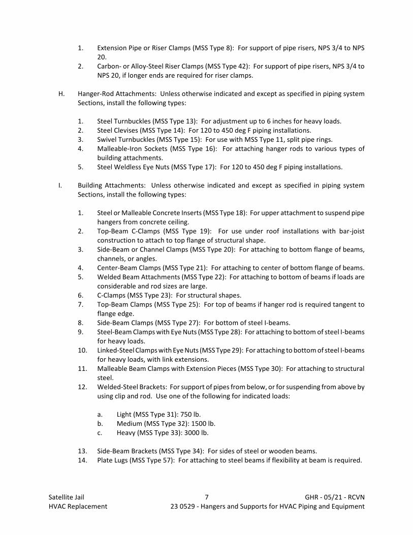
1. Extension Pipe or Riser Clamps (MSS Type 8): For support of pipe risers, NPS 3/4 to NPS20.
2. Carbon- or Alloy-Steel Riser Clamps (MSS Type 42): For support of pipe risers, NPS 3/4 toNPS 20, if longer ends are required for riser clamps.
H. Hanger-Rod Attachments: Unless otherwise indicated and except as specified in piping systemSections, install the following types:
1. Steel Turnbuckles (MSS Type 13): For adjustment up to 6 inches for heavy loads.2. Steel Clevises (MSS Type 14): For 120 to 450 deg F piping installations.3. Swivel Turnbuckles (MSS Type 15): For use with MSS Type 11, split pipe rings.4. Malleable-Iron Sockets (MSS Type 16): For attaching hanger rods to various types of
building attachments.5. Steel Weldless Eye Nuts (MSS Type 17): For 120 to 450 deg F piping installations.
I. Building Attachments: Unless otherwise indicated and except as specified in piping systemSections, install the following types:
1. Steel or Malleable Concrete Inserts (MSS Type 18): For upper attachment to suspend pipehangers from concrete ceiling.
2. Top-Beam C-Clamps (MSS Type 19): For use under roof installations with bar-joistconstruction to attach to top flange of structural shape.
3. Side-Beam or Channel Clamps (MSS Type 20): For attaching to bottom flange of beams,channels, or angles.
4. Center-Beam Clamps (MSS Type 21): For attaching to center of bottom flange of beams.5. Welded Beam Attachments (MSS Type 22): For attaching to bottom of beams if loads are
considerable and rod sizes are large.6. C-Clamps (MSS Type 23): For structural shapes.7. Top-Beam Clamps (MSS Type 25): For top of beams if hanger rod is required tangent to
flange edge.8. Side-Beam Clamps (MSS Type 27): For bottom of steel I-beams.9. Steel-Beam Clamps with Eye Nuts (MSS Type 28): For attaching to bottom of steel I-beams
for heavy loads.10. Linked-Steel Clamps with Eye Nuts (MSS Type 29): For attaching to bottom of steel I-beams
for heavy loads, with link extensions.11. Malleable Beam Clamps with Extension Pieces (MSS Type 30): For attaching to structural
steel.12. Welded-Steel Brackets: For support of pipes from below, or for suspending from above by
using clip and rod. Use one of the following for indicated loads:
a. Light (MSS Type 31): 750 lb.b. Medium (MSS Type 32): 1500 lb.c. Heavy (MSS Type 33): 3000 lb.
13. Side-Beam Brackets (MSS Type 34): For sides of steel or wooden beams.14. Plate Lugs (MSS Type 57): For attaching to steel beams if flexibility at beam is required.
Satellite Jail 7 GHR - 05/21 - RCVNHVAC Replacement 23 0529 - Hangers and Supports for HVAC Piping and Equipment
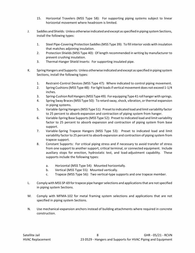
15. Horizontal Travelers (MSS Type 58): For supporting piping systems subject to linearhorizontal movement where headroom is limited.
J. Saddles and Shields: Unless otherwise indicated and except as specified in piping system Sections,install the following types:
1. Steel Pipe-Covering Protection Saddles (MSS Type 39): To fill interior voids with insulationthat matches adjoining insulation.
2. Protection Shields (MSS Type 40): Of length recommended in writing by manufacturer toprevent crushing insulation.
3. Thermal-Hanger Shield Inserts: For supporting insulated pipe.
K. Spring Hangers and Supports: Unless otherwise indicated and except as specified in piping systemSections, install the following types:
1. Restraint-Control Devices (MSS Type 47): Where indicated to control piping movement.2. Spring Cushions (MSS Type 48): For light loads if vertical movement does not exceed 1-1/4
inches.3. Spring-Cushion Roll Hangers (MSS Type 49): For equipping Type 41 roll hanger with springs.4. Spring Sway Braces (MSS Type 50): To retard sway, shock, vibration, or thermal expansion
in piping systems.5. Variable-Spring Hangers (MSS Type 51): Preset to indicated load and limit variability factor
to 25 percent to absorb expansion and contraction of piping system from hanger.6. Variable-Spring Base Supports (MSS Type 52): Preset to indicated load and limit variability
factor to 25 percent to absorb expansion and contraction of piping system from basesupport.
7. Variable-Spring Trapeze Hangers (MSS Type 53): Preset to indicated load and limitvariability factor to 25 percent to absorb expansion and contraction of piping system fromtrapeze support.
8. Constant Supports: For critical piping stress and if necessary to avoid transfer of stressfrom one support to another support, critical terminal, or connected equipment. Includeauxiliary stops for erection, hydrostatic test, and load-adjustment capability. Thesesupports include the following types:
a. Horizontal (MSS Type 54): Mounted horizontally.b. Vertical (MSS Type 55): Mounted vertically.c. Trapeze (MSS Type 56): Two vertical-type supports and one trapeze member.
L. Comply with MSS SP-69 for trapeze pipe hanger selections and applications that are not specifiedin piping system Sections.
M. Comply with MFMA-102 for metal framing system selections and applications that are notspecified in piping system Sections.
N. Use mechanical-expansion anchors instead of building attachments where required in concreteconstruction.
Satellite Jail 8 GHR - 05/21 - RCVNHVAC Replacement 23 0529 - Hangers and Supports for HVAC Piping and Equipment
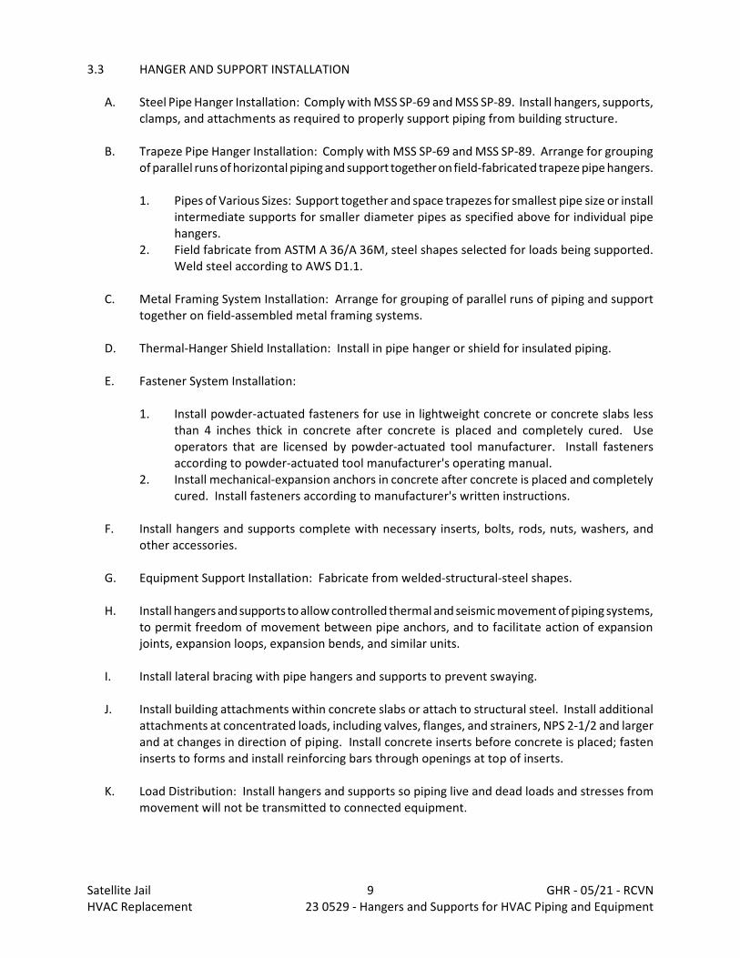
3.3 HANGER AND SUPPORT INSTALLATION
A. Steel Pipe Hanger Installation: Comply with MSS SP-69 and MSS SP-89. Install hangers, supports,clamps, and attachments as required to properly support piping from building structure.
B. Trapeze Pipe Hanger Installation: Comply with MSS SP-69 and MSS SP-89. Arrange for groupingof parallel runs of horizontal piping and support together on field-fabricated trapeze pipe hangers.
1. Pipes of Various Sizes: Support together and space trapezes for smallest pipe size or installintermediate supports for smaller diameter pipes as specified above for individual pipehangers.
2. Field fabricate from ASTM A 36/A 36M, steel shapes selected for loads being supported. Weld steel according to AWS D1.1.
C. Metal Framing System Installation: Arrange for grouping of parallel runs of piping and supporttogether on field-assembled metal framing systems.
D. Thermal-Hanger Shield Installation: Install in pipe hanger or shield for insulated piping.
E. Fastener System Installation:
1. Install powder-actuated fasteners for use in lightweight concrete or concrete slabs lessthan 4 inches thick in concrete after concrete is placed and completely cured. Useoperators that are licensed by powder-actuated tool manufacturer. Install fastenersaccording to powder-actuated tool manufacturer's operating manual.
2. Install mechanical-expansion anchors in concrete after concrete is placed and completelycured. Install fasteners according to manufacturer's written instructions.
F. Install hangers and supports complete with necessary inserts, bolts, rods, nuts, washers, andother accessories.
G. Equipment Support Installation: Fabricate from welded-structural-steel shapes.
H. Install hangers and supports to allow controlled thermal and seismic movement of piping systems,to permit freedom of movement between pipe anchors, and to facilitate action of expansionjoints, expansion loops, expansion bends, and similar units.
I. Install lateral bracing with pipe hangers and supports to prevent swaying.
J. Install building attachments within concrete slabs or attach to structural steel. Install additionalattachments at concentrated loads, including valves, flanges, and strainers, NPS 2-1/2 and largerand at changes in direction of piping. Install concrete inserts before concrete is placed; fasteninserts to forms and install reinforcing bars through openings at top of inserts.
K. Load Distribution: Install hangers and supports so piping live and dead loads and stresses frommovement will not be transmitted to connected equipment.
Satellite Jail 9 GHR - 05/21 - RCVNHVAC Replacement 23 0529 - Hangers and Supports for HVAC Piping and Equipment
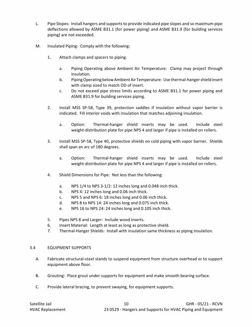
L. Pipe Slopes: Install hangers and supports to provide indicated pipe slopes and so maximum pipedeflections allowed by ASME B31.1 (for power piping) and ASME B31.9 (for building servicespiping) are not exceeded.
M. Insulated Piping: Comply with the following:
1. Attach clamps and spacers to piping.
a. Piping Operating above Ambient Air Temperature: Clamp may project throughinsulation.
b. Piping Operating below Ambient Air Temperature: Use thermal-hanger shield insertwith clamp sized to match OD of insert.
c. Do not exceed pipe stress limits according to ASME B31.1 for power piping andASME B31.9 for building services piping.
2. Install MSS SP-58, Type 39, protection saddles if insulation without vapor barrier isindicated. Fill interior voids with insulation that matches adjoining insulation.
a. Option: Thermal-hanger shield inserts may be used. Include steelweight-distribution plate for pipe NPS 4 and larger if pipe is installed on rollers.
3. Install MSS SP-58, Type 40, protective shields on cold piping with vapor barrier. Shieldsshall span an arc of 180 degrees.
a. Option: Thermal-hanger shield inserts may be used. Include steelweight-distribution plate for pipe NPS 4 and larger if pipe is installed on rollers.
4. Shield Dimensions for Pipe: Not less than the following:
a. NPS 1/4 to NPS 3-1/2: 12 inches long and 0.048 inch thick.b. NPS 4: 12 inches long and 0.06 inch thick.c. NPS 5 and NPS 6: 18 inches long and 0.06 inch thick.d. NPS 8 to NPS 14: 24 inches long and 0.075 inch thick.e. NPS 16 to NPS 24: 24 inches long and 0.105 inch thick.
5. Pipes NPS 8 and Larger: Include wood inserts.6. Insert Material: Length at least as long as protective shield.7. Thermal-Hanger Shields: Install with insulation same thickness as piping insulation.
3.4 EQUIPMENT SUPPORTS
A. Fabricate structural-steel stands to suspend equipment from structure overhead or to supportequipment above floor.
B. Grouting: Place grout under supports for equipment and make smooth bearing surface.
C. Provide lateral bracing, to prevent swaying, for equipment supports.
Satellite Jail 10 GHR - 05/21 - RCVNHVAC Replacement 23 0529 - Hangers and Supports for HVAC Piping and Equipment
3.5 METAL FABRICATIONS
A. Field Welding: Comply with AWS D1.1 procedures for shielded metal arc welding, appearanceand quality of welds, and methods used in correcting welding work, and with the following:
1. Use materials and methods that minimize distortion and develop strength and corrosionresistance of base metals.
2. Obtain fusion without undercut or overlap.3. Remove welding flux immediately.4. Finish welds at exposed connections so no roughness shows after finishing and contours
of welded surfaces match adjacent contours.
3.6 ADJUSTING
A. Hanger Adjustments: Adjust hangers to distribute loads equally on attachments and to achieveindicated slope of pipe.
B. Trim excess length of continuous-thread hanger and support rods to 1-1/2 inches.
3.7 PAINTING
A. Touch Up: Clean field welds and abraded areas of shop paint. Paint exposed areas immediatelyafter erecting hangers and supports. Use same materials as used for shop painting. Comply withSSPC-PA 1 requirements for touching up field-painted surfaces.
1. Apply paint by brush or spray to provide minimum dry film thickness of 2.0 mils.
B. Galvanized Surfaces: Clean welds, bolted connections, and abraded areas and applygalvanizing-repair paint to comply with ASTM A 780.
END 23 0529
Satellite Jail 11 GHR - 05/21 - RCVNHVAC Replacement 23 0529 - Hangers and Supports for HVAC Piping and Equipment

DIVISION 23 - HEATING, VENTILATING AND AIR CONDITIONINGDocument 23 0553 - Identification for HVAC Pipe and Equipment
PART 1 - GENERAL
1.1 RELATED DOCUMENTS
A. Drawings and general provisions of the Contract, including General and Supplementary Conditionsand Division 01 Specification Sections, apply to this Section.
1.2 SUMMARY
A. Section Includes:
1. Equipment labels.2. Warning signs and labels.3. Pipe labels.4. Valve tags.5. Warning tags.
1.3 SUBMITTALS
A. Product Data: For each type of product indicated.
B. Samples: For color, letter style, and graphic representation required for each identificationmaterial and device.
C. Equipment Label Schedule: Include a listing of all equipment to be labeled with the proposedcontent for each label.
D. Valve numbering scheme.
E. Valve Schedules: For each piping system to include in maintenance manuals.
1.4 COORDINATION
A. Coordinate installation of identifying devices with completion of covering and painting of surfaceswhere devices are to be applied.
B. Coordinate installation of identifying devices with locations of access panels and doors.
C. Install identifying devices before installing acoustical ceilings and similar concealment.
Satellite Jail 1 GHR - 05/21 - RCVNHVAC Replacement 23 0553 - Identification for HVAC Piping and Equipment

PART 2 - PRODUCTS
2.1 EQUIPMENT LABELS
A. Metal Labels for Outdoor Equipment:
1. Material and Thickness: Stainless steel, 0.025-inch minimum thickness, and havingpredrilled or stamped holes for attachment hardware.
2. Minimum Label Size: Length and width vary for required label content, but not less than2-1/2 by 3/4 inch.
3. Minimum Letter Size: 1/4 inch for name of units if viewing distance is less than 24 inches,½ inch for viewing distances up to 72 inches, and proportionately larger lettering forgreater viewing distances. Include secondary lettering two-thirds to three-fourths the sizeof principal lettering.
4. Fasteners: Stainless-steel rivets or self-tapping screws.5. Adhesive: Contact-type permanent adhesive, compatible with label and with substrate.
B. Plastic Labels for Indoor Equipment:
1. Material and Thickness: Multilayer, multicolor, plastic labels for mechanical engraving, 1/8inch thick, and having predrilled holes for attachment hardware.
2. Letter Color: White.3. Background Color: Blue.4. Maximum Temperature: Able to withstand temperatures up to 160 deg F.5. Minimum Label Size: Length and width vary for required label content, but not less than
2-1/2 by 3/4 inch.6. Minimum Letter Size: 1/4 inch for name of units if viewing distance is less than 24 inches,
½ inch for viewing distances up to 72 inches, and proportionately larger lettering forgreater viewing distances. Include secondary lettering two-thirds to three-fourths the sizeof principal lettering.
7. Fasteners: Stainless-steel rivets or self-tapping screws.8. Adhesive: Contact-type permanent adhesive, compatible with label and with substrate.
C. Label Content: Include equipment's Drawing designation or unique equipment number, Drawingnumbers where equipment is indicated (plans, details, and schedules), plus the SpecificationSection number and title where equipment is specified.
D. Equipment Label Schedule: For each item of equipment to be labeled, on 8-1/2-by-11-inch bondpaper. Tabulate equipment identification number and identify Drawing numbers whereequipment is indicated (plans, details, and schedules), plus the Specification Section number andtitle where equipment is specified. Equipment schedule shall be included in operation andmaintenance data.
2.2 WARNING SIGNS AND LABELS
A. Material and Thickness: Multilayer, multicolor, plastic labels for mechanical engraving, 1/8 inchthick, and having predrilled holes for attachment hardware.
Satellite Jail 2 GHR - 05/21 - RCVNHVAC Replacement 23 0553 - Identification for HVAC Piping and Equipment
B. Letter Color: Black.
C. Background Color: Yellow.
D. Maximum Temperature: Able to withstand temperatures up to 160 deg F.
E. Minimum Label Size: Length and width vary for required label content, but not less than 2-1/2by 3/4 inch.
F. Minimum Letter Size: 1/4 inch for name of units if viewing distance is less than 24 inches, ½ inchfor viewing distances up to 72 inches, and proportionately larger lettering for greater viewingdistances. Include secondary lettering two-thirds to three-fourths the size of principal lettering.
G. Fasteners: Stainless-steel rivets or self-tapping screws.
H. Adhesive: Contact-type permanent adhesive, compatible with label and with substrate.
I. Label Content: Include caution and warning information, plus emergency notificationinstructions.
2.3 PIPE LABELS
A. General Requirements for Manufactured Pipe Labels: Preprinted, color-coded, with letteringindicating service, and showing flow direction.
B. Pretensioned Pipe Labels: Precoiled, semirigid plastic formed to cover full circumference of pipeand to attach to pipe without fasteners or adhesive.
C. Self-Adhesive Pipe Labels: Printed plastic with contact-type, permanent-adhesive backing.
D. Pipe Label Contents: Include identification of piping service using same designations orabbreviations as used on Drawings, pipe size, and an arrow indicating flow direction.
1. Flow-Direction Arrows: Integral with piping system service lettering to accommodate bothdirections, or as separate unit on each pipe label to indicate flow direction.
2. Lettering Size: At least 1-1/2 inches high.
2.4 VALVE TAGS
A. Valve Tags: Stamped or engraved with 1/4-inch letters for piping system abbreviation and 1/2-inch numbers.
1. Tag Material: Brass, 0.032-inch minimum thickness, and having predrilled or stampedholes for attachment hardware.
2. Fasteners: Brass wire-link chain, beaded chain or S-hook.
B. Valve Schedules: For each piping system, on 8-1/2-by-11-inch bond paper. Tabulate valvenumber, piping system, system abbreviation (as shown on valve tag), location of valve (room or
Satellite Jail 3 GHR - 05/21 - RCVNHVAC Replacement 23 0553 - Identification for HVAC Piping and Equipment
space), normal-operating position (open, closed, or modulating), and variations for identification. Mark valves for emergency shutoff and similar special uses.
1. Valve-tag schedule shall be included in operation and maintenance data.
2.5 WARNING TAGS
A. Warning Tags: Preprinted or partially preprinted, accident-prevention tags, of plasticized cardstock with matte finish suitable for writing.
1. Size: 3 by 5-1/4 inches minimum.2. Fasteners: Brass grommet and wire.3. Nomenclature: Large-size primary caption such as "DANGER," "CAUTION," or "DO NOT
OPERATE."4. Color: Yellow background with black lettering.
PART 3 - EXECUTION
3.1 PREPARATION
A. Clean piping and equipment surfaces of substances that could impair bond of identificationdevices, including dirt, oil, grease, release agents, and incompatible primers, paints, andencapsulants.
3.2 EQUIPMENT LABEL INSTALLATION
A. Install or permanently fasten labels on each major item of mechanical equipment.
B. Locate equipment labels where accessible and visible.
3.3 PIPE LABEL INSTALLATION
A. Locate pipe labels where piping is exposed or above accessible ceilings in finished spaces; machinerooms; accessible maintenance spaces such as shafts, tunnels, and plenums; and exterior exposedlocations as follows:
1. Near each valve and control device.2. Near each branch connection, excluding short takeoffs for fixtures and terminal units.
Where flow pattern is not obvious, mark each pipe at branch.3. Near penetrations through walls, floors, ceilings, and inaccessible enclosures.4. At access doors, manholes, and similar access points that permit view of concealed piping.5. Near major equipment items and other points of origination and termination.6. Spaced at maximum intervals of 50 feet along each run. Reduce intervals to 25 feet in
areas of congested piping and equipment.
Satellite Jail 4 GHR - 05/21 - RCVNHVAC Replacement 23 0553 - Identification for HVAC Piping and Equipment
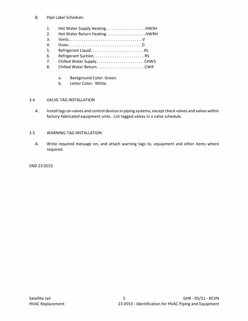
B. Pipe Label Schedule:
1. Hot Water Supply Heating. . . . . . . . . . . . . . . . . . .HWSH2. Hot Water Return Heating. . . . . . . . . . . . . . . . . . .HWRH3. Vents. . . . . . . . . . . . . . . . . . . . . . . . . . . . . . . . . . .V4. Drain. . . . . . . . . . . . . . . . . . . . . . . . . . . . . . . . . . .D5. Refrigerant Liquid. . . . . . . . . . . . . . . . . . . . . . . . . RL6. Refrigerant Suction. . . . . . . . . . . . . . . . . . . . . . . . RS7. Chilled Water Supply. . . . . . . . . . . . . . . . . . . . . . .CHWS8. Chilled Water Return. . . . . . . . . . . . . . . . . . . . . . .CWR
a. Background Color: Green.b. Letter Color: White.
3.4 VALVE-TAG INSTALLATION
A. Install tags on valves and control devices in piping systems, except check valves and valves withinfactory-fabricated equipment units. List tagged valves in a valve schedule.
3.5 WARNING-TAG INSTALLATION
A. Write required message on, and attach warning tags to, equipment and other items whererequired.
END 23 0553
Satellite Jail 5 GHR - 05/21 - RCVNHVAC Replacement 23 0553 - Identification for HVAC Piping and Equipment


DIVISION 23 - HEATING, VENTILATING AND AIR CONDITIONINGDocument 23 0593 - Piping and Air Systems Testing, Adjusting and Balancing
PART 1 - GENERAL
1.1 WORK INCLUDES
A. Base Bid
1. Test and Balance Contractor: Test, adjust and balance air and piping systems. Work includes but is not limited to the following.
2. Test and Balance
a. Hydronic systemsb. Air systemsc. Control system testsd. Reports
1.2 RELATED WORK
A. Specified elsewhere:
1. Sections: Architectural / Structural and General Work:2. Division 23 - Mechanical3. Division 26 - Electrical
1.3 JOB CONDITIONS
A. Heating, ventilating, and air conditioning equipment shall be completely installed andin continuous operation to accomplish the testing, adjusting and balancing workspecified. Complete air balancing prior to hydronic balancing.
B. Perform testing, adjusting and balancing when outside conditions approximate designconditions for heating and cooling functions or when the system is operating at designcapacity.
C. The Architect / Engineer may be present during testing and balancing to verify thatspecified procedures are followed.
1.4 QUALITY ASSURANCE
A. Testing and balancing shall be performed by independent firms specializing in suchwork.
1. The Test and Balance Contractor shall not be related to the Plumbing or HVACContractor in any business enterprise.
B. Only qualified personnel shall perform testing and balancing work.
Satellite Jail 1 GHR - 05/21 - RCVNHVAC Replacement 23 0593 - Piping Systems Testing, Adjusting & Balancing
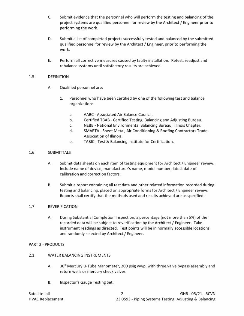
C. Submit evidence that the personnel who will perform the testing and balancing of theproject systems are qualified personnel for review by the Architect / Engineer prior toperforming the work.
D. Submit a list of completed projects successfully tested and balanced by the submittedqualified personnel for review by the Architect / Engineer, prior to performing thework.
E. Perform all corrective measures caused by faulty installation. Retest, readjust andrebalance systems until satisfactory results are achieved.
1.5 DEFINITION
A. Qualified personnel are:
1. Personnel who have been certified by one of the following test and balanceorganizations.
a. AABC - Associated Air Balance Council.b. Certified TBAB - Certified Testing, Balancing and Adjusting Bureau.c. NEBB - National Environmental Balancing Bureau, Illinois Chapter.d. SMARTA - Sheet Metal, Air Conditioning & Roofing Contractors Trade
Association of Illinois.e. TABIC - Test & Balancing Institute for Certification.
1.6 SUBMITTALS
A. Submit data sheets on each item of testing equipment for Architect / Engineer review. Include name of device, manufacturer's name, model number, latest date ofcalibration and correction factors.
B. Submit a report containing all test data and other related information recorded duringtesting and balancing, placed on appropriate forms for Architect / Engineer review. Reports shall certify that the methods used and results achieved are as specified.
1.7 REVERIFICATION
A. During Substantial Completion Inspection, a percentage (not more than 5%) of therecorded data will be subject to reverification by the Architect / Engineer. Takeinstrument readings as directed. Test points will be in normally accessible locationsand randomly selected by Architect / Engineer.
PART 2 - PRODUCTS
2.1 WATER BALANCING INSTRUMENTS
A. 30" Mercury U-Tube Manometer, 200 psig wwp, with three valve bypass assembly andreturn wells or mercury check valves.
B. Inspector's Gauge Testing Set.
Satellite Jail 2 GHR - 05/21 - RCVNHVAC Replacement 23 0593 - Piping Systems Testing, Adjusting & Balancing
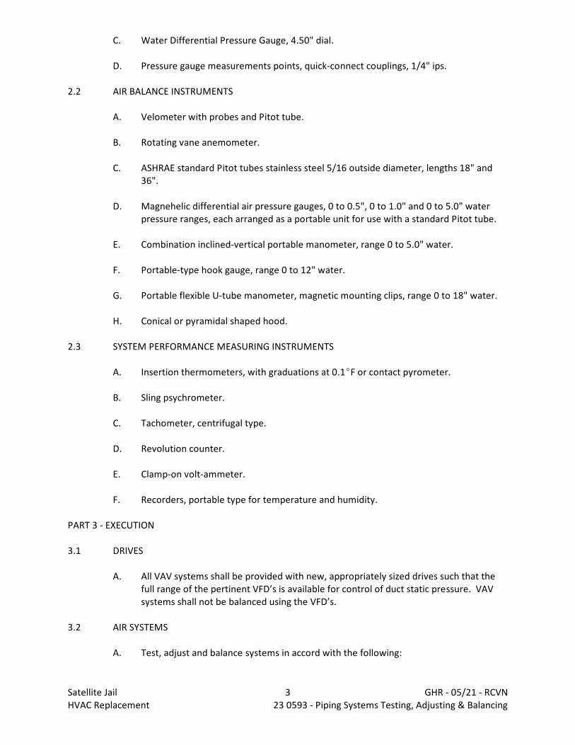
C. Water Differential Pressure Gauge, 4.50" dial.
D. Pressure gauge measurements points, quick-connect couplings, 1/4" ips.
2.2 AIR BALANCE INSTRUMENTS
A. Velometer with probes and Pitot tube.
B. Rotating vane anemometer.
C. ASHRAE standard Pitot tubes stainless steel 5/16 outside diameter, lengths 18" and36".
D. Magnehelic differential air pressure gauges, 0 to 0.5", 0 to 1.0" and 0 to 5.0" waterpressure ranges, each arranged as a portable unit for use with a standard Pitot tube.
E. Combination inclined-vertical portable manometer, range 0 to 5.0" water.
F. Portable-type hook gauge, range 0 to 12" water.
G. Portable flexible U-tube manometer, magnetic mounting clips, range 0 to 18" water.
H. Conical or pyramidal shaped hood.
2.3 SYSTEM PERFORMANCE MEASURING INSTRUMENTS
A. Insertion thermometers, with graduations at 0.1EF or contact pyrometer.
B. Sling psychrometer.
C. Tachometer, centrifugal type.
D. Revolution counter.
E. Clamp-on volt-ammeter.
F. Recorders, portable type for temperature and humidity.
PART 3 - EXECUTION
3.1 DRIVES
A. All VAV systems shall be provided with new, appropriately sized drives such that thefull range of the pertinent VFD’s is available for control of duct static pressure. VAVsystems shall not be balanced using the VFD’s.
3.2 AIR SYSTEMS
A. Test, adjust and balance systems in accord with the following:
Satellite Jail 3 GHR - 05/21 - RCVNHVAC Replacement 23 0593 - Piping Systems Testing, Adjusting & Balancing
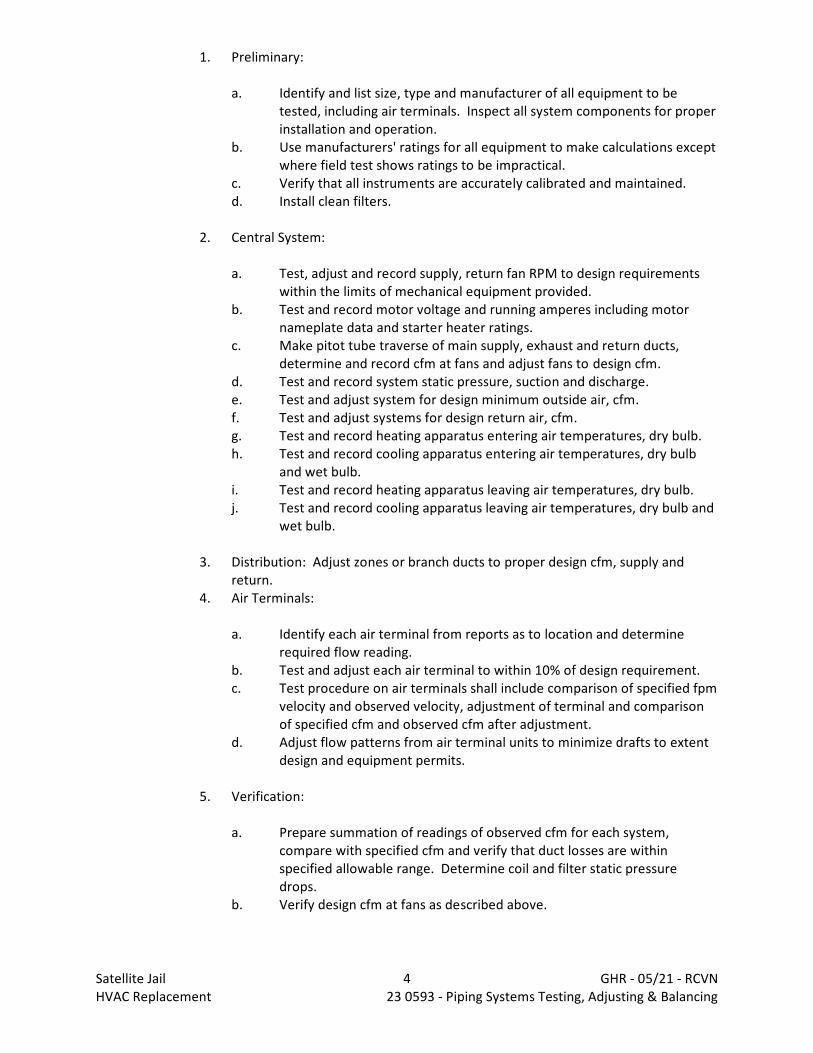
1. Preliminary:
a. Identify and list size, type and manufacturer of all equipment to betested, including air terminals. Inspect all system components for properinstallation and operation.
b. Use manufacturers' ratings for all equipment to make calculations exceptwhere field test shows ratings to be impractical.
c. Verify that all instruments are accurately calibrated and maintained.d. Install clean filters.
2. Central System:
a. Test, adjust and record supply, return fan RPM to design requirementswithin the limits of mechanical equipment provided.
b. Test and record motor voltage and running amperes including motornameplate data and starter heater ratings.
c. Make pitot tube traverse of main supply, exhaust and return ducts,determine and record cfm at fans and adjust fans to design cfm.
d. Test and record system static pressure, suction and discharge.e. Test and adjust system for design minimum outside air, cfm.f. Test and adjust systems for design return air, cfm.g. Test and record heating apparatus entering air temperatures, dry bulb.h. Test and record cooling apparatus entering air temperatures, dry bulb
and wet bulb.i. Test and record heating apparatus leaving air temperatures, dry bulb.j. Test and record cooling apparatus leaving air temperatures, dry bulb and
wet bulb.
3. Distribution: Adjust zones or branch ducts to proper design cfm, supply andreturn.
4. Air Terminals:
a. Identify each air terminal from reports as to location and determinerequired flow reading.
b. Test and adjust each air terminal to within 10% of design requirement.c. Test procedure on air terminals shall include comparison of specified fpm
velocity and observed velocity, adjustment of terminal and comparisonof specified cfm and observed cfm after adjustment.
d. Adjust flow patterns from air terminal units to minimize drafts to extentdesign and equipment permits.
5. Verification:
a. Prepare summation of readings of observed cfm for each system,compare with specified cfm and verify that duct losses are withinspecified allowable range. Determine coil and filter static pressuredrops.
b. Verify design cfm at fans as described above.
Satellite Jail 4 GHR - 05/21 - RCVNHVAC Replacement 23 0593 - Piping Systems Testing, Adjusting & Balancing

3.3 TESTING, BALANCING AND ADJUSTING
A. At the completion of the installation of the air distribution systems, the following testsshall be made.
B. All instruments for testing are to be furnished by this Contractor and must bereviewed by the Architect / Engineer before use on job. All readings shall be recordedon approved forms. All instruments used shall be recently calibrated and same set ofinstruments shall be used throughout the balancing procedures.
C. The air distribution systems shall be balanced with the volume dampers, splitterdampers and adjustable air extractors in the duct systems as follows:
1. All air handling equipment in building shall be operating during the balancingprocedures. Supply systems with return fans shall be balanced in the 100%outside air position. System shall then be set in minimum outside air positionand manual volume damper after automatic return air dampers adjusted tomaintain constant supply air volume. Supply systems without return fans shallbe adjusted to the minimum outside air position. All filters shall be new andclean. All volume dampers and extractors shall be set at 2/3 open position.
2. Fans shall be adjusted to specified air quantities by using rotating vaneanemometer traverse over entering air face of cooling coils in built-up airhandling systems, with pitot tube and inclined manometer or a velometer havingproper duct jet attachment for traverse at fan inlet.
3. Individual outlets shall be adjusted to specified air quantities using either the"proportional method" starting at last outlet and working towards main or the"trial and error" method, with a velometer having proper attachment or arotating vane anemometer.
4. Branch ducts (having more than one outlet) shall be adjusted to specified airquantities by using a pitot tube and inclined anemometer or a velometer havingproper duct jet attachment for traverse as near to takeoff as practical.
5. Above procedures shall essentially be followed for all systems and shall berepeated until proper balance is achieved throughout systems from -0% to +10%of specified air quantities.
D. After balance is completed, lock nuts or stop screws shall be installed at all volumedampers and extractors to permit them to be shut-off but prevent opening beyondthe set balance position.
E. For more detailed step-by-step procedures the Balancing and Adjustment Manual forAir Distribution Systems published by Sheet Metal and Air Conditioning ContractorsNational Association shall be used.
F. All readings taken throughout the balancing procedure shall be recorded on approvedforms and upon completion of balancing and testing shall be "certified" as beingcorrect and submitted for review.
G. Upon receipt of "certified" balancing forms and letter of certification that all balancing,testing and adjusting is completed in accordance with plans and specifications and thatall systems are operating properly, the Architect / Engineer or his designated
Satellite Jail 5 GHR - 05/21 - RCVNHVAC Replacement 23 0593 - Piping Systems Testing, Adjusting & Balancing
representative will conduct a balance inspection. Furnish personnel, instruments andequipment as required to assist the Architect / Engineer during this "balanceinspection".
H. If during the above balance inspection any portion of any system is found in improperbalance, that entire system shall be rebalanced and a new report submitted. Therebalance shall be checked and if again found in improper balance, this Contractorshall again rebalance and submit report. This procedure shall be repeated until thesystems are properly balanced to the satisfaction of the Architect / Engineer.
3.4 HYDRONIC HEATING SYSTEMS
A. Test, adjust and balance system in accordance with the following requirements:
1. Preliminary:
a. List all mechanical specifications of tested equipment and verify againstcontract documents. Inspect all system components for properinstallation and operation. Clean all screens.
b. Open all line valves to full open position. Close coil bypass stop valves,then set mixing control valve to full coil flow.
c. For each pump, verify rotation, test, and record pump shut-off head, andtest and record pump wide-open head.
d. Verify proper water level in expansion tanks and in the system. Verifythat system is entirely full of fluid. Vent all air vents.
e. Verify that air vents in high points of water systems are installed andoperating freely.
f. Verify that all instruments are accurately calibrated and maintained.
2. Central Equipment:
a. Set chilled water and hot water pumps to proper flow quantity.b. Adjust flow of chilled water through chiller to design value.c. Adjust flow of hot water through heat exchangers to design quantity.d. Adjust steam pressure at PRV and record at each steam heat exchanger.e. Observe leaving water temperatures and return water temperatures at
chiller and heat exchangers. Reset to correct design temperatures.f. Record pump operating suction and discharge pressures. Determine final
dynamic head.
3. Distribution:
a. Balance flow to each chilled water coil and hot water coil.b. Record steam pressure at each steam coil.
4. Terminal Units
a. Upon completion of flow readings and adjustments at coils, mark allsettings and record following data:
Satellite Jail 6 GHR - 05/21 - RCVNHVAC Replacement 23 0593 - Piping Systems Testing, Adjusting & Balancing
(1) Inlet water temperatures.(2) Leaving water temperatures.
b. Observe fluid pressure drop through coil at set flow rate on call for fullcooling and for full heating.
c. Set valve in bypass to match coil flow pressure drop on full bypass.
5. Verification:
a. Record rated and actual running amperage for each pump motor. Measure and record gpm of all pumps.
b. Record total dynamic head for each pump.
3.5 AUTOMATIC CONTROL SYSTEM
A. The Temperature Control Contractor shall set and adjust automatically operateddevices to achieve specified sequence of operation.
B. Testing organization shall verify all controls for proper calibration and list thosecontrols requiring adjustment by temperature control system installer.
3.6 SYSTEM PERFORMANCE REPORT
A. After the conclusion of balancing operations, make temporary installation of portablerecorders and simultaneously record temperatures and humidity during summer andwinter conditions at representative locations in each system.
B. Architect / Engineer will direct all test locations.
C. Make recordings during summer and winter for a seven-day period, continuous over aweekend, and including at least one period of operation at outside conditions within5EF wet bulb temperature of maximum summer design condition and within 10EF drybulb temperature of minimum winter design condition.
D. Report of test results shall include original recording and two reproductions.
3.7 SUBMISSION OF REPORTS
A. Fill in test results on approved forms.
B. Submit three certified copies of required test reports to the Architect / Engineer forreview.
C. Include in report a list of instruments used and test date of calibration.
D. Submittals shall be legibly signed by the individual(s) responsible for the accuracy ofthe
END 23 0593
Satellite Jail 7 GHR - 05/21 - RCVNHVAC Replacement 23 0593 - Piping Systems Testing, Adjusting & Balancing

DIVISION 23 - HEATING, VENTILATING AND AIR CONDITIONINGDocument 23 0700 - HVAC Insulation
PART 1 - GENERAL
1.1 WORK INCLUDES
A. Base Bid
1. Provide and install complete insulation systems as shown on the drawings and asspecified herein. Work includes, but is not limited to, the following:
a. HVAC Contractor: Insulating of:
(1) Hot water heating piping(2) Chilled water piping(3) Refrigerant piping(4) Ductwork
1.2 RELATED WORK
A. Specified elsewhere:
1. Division 23 - Mechanical Systems
1.3 QUALITY ASSURANCE
A. Installations shall be by qualified personnel thoroughly trained and experienced in theskills required and completely familiar with the manufacturer's current recommendedmethods of installation as well as the requirements of the work.
B. All insulation shall be applied in accordance with MICA "Commercial and IndustrialInsulation Standards".
1.4 SUBMITTALS
A. See Architectural Sections.
B. Provide submittals for:
1. Pipe insulation2. Equipment insulation3. Plastic insulation jacket4. Duct insulation
Satellite Jail 1 GHR - 05/21 - RCVNHVAC Replacement 23 0700 - Mechanical Insulation
PART 2 - PRODUCTS
2.1 INSULATION
A. Materials of insulation shall be manufactured by Johns-Manville, Schuller, OwensCorning, Knauf, Rubatex, Armstrong, Certain-Teed (acceptable manufacturers will varydepending upon material being specified herein after).
B. Insulation shall be rigid glass fiber with fire retardant vapor barrier jacket. Insulationof fittings shall be in accordance with manufacturer's recommendations using glassfiber wrapping and formed jacket.
C. Insulating materials and APT jackets shall conform to latest NFPA and IECC standardswith flame-spread rating not to exceed 25 and smoke developed rating not to exceed50. Vapor barrier jackets shall have a water vapor permeability rating not to exceed.02 perms when tested in accordance with ASTM Standard E-96.
D. Flexible fire retardant elastomeric thermal insulation for use on refrigerant piping andequipment in cold piping systems (strainers, pumps, special valves) shall bemanufactured by Armstrong, Schuller or Rubatek. Insulation shall have a flame spreadrating of 25 or less and a smoke developed rating of 50 or less. Seal all joints withappropriate adhesive. On equipment, such as strainers, the insulation shall beinstalled so that those portions of the equipment which require servicing will haveremovable sections for access.
1. Do not use elastomeric insulation on surfaces that exceed 120EF.2. Pertinent Contractors shall be responsible for ensuring that use of this material in
return air plenums is in full compliance with all codes and is acceptable to theauthority having jurisdiction. This matter shall be resolved before shop drawingsare submitted.
3. Elastomeric insulation shall not be used on two-pipe heating / cooling.
E. Specialties
1. All hot piping fittings and cold fittings and flanges shall be wrapped with lowdensity glass fiber blanket insulation built up to same thickness as adjacentinsulation and wired in place with 20 gauge copper clad annealed wire. Coverwith plastic pre-fab jacket and seal joint and end overlaps with white nylon tape.
2. All cold water valves, control valves, unions and other fittings requiring accessshall be insulated with elastomeric foam or fiberglass of the same thickness andtype as the rest of the system.
3. Covering on all pipe fittings shall be notched on the interior of fittings and shallpass unbroken through hangers and pipe sleeves.
4. Valves, unions, relief valves and strainers shall be insulated.5. Valves, unions, strainers and flanges in heating hot water piping need not be
covered. Insulation shall be tapered back, neatly cemented and covered same asfittings to permit access to the joint, valve and strainer without disturbingcovering.
6. Insulation and vapor barrier on cold piping systems shall be continuous and shallprevent condensation and water problems.
Satellite Jail 2 GHR - 05/21 - RCVNHVAC Replacement 23 0700 - Mechanical Insulation
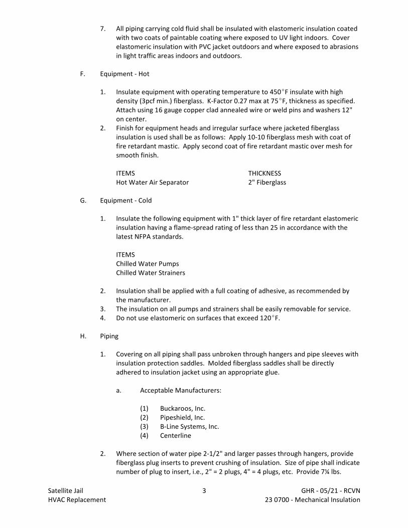
7. All piping carrying cold fluid shall be insulated with elastomeric insulation coatedwith two coats of paintable coating where exposed to UV light indoors. Coverelastomeric insulation with PVC jacket outdoors and where exposed to abrasionsin light traffic areas indoors and outdoors.
F. Equipment - Hot
1. Insulate equipment with operating temperature to 450EF insulate with highdensity (3pcf min.) fiberglass. K-Factor 0.27 max at 75EF, thickness as specified. Attach using 16 gauge copper clad annealed wire or weld pins and washers 12"on center.
2. Finish for equipment heads and irregular surface where jacketed fiberglassinsulation is used shall be as follows: Apply 10-10 fiberglass mesh with coat offire retardant mastic. Apply second coat of fire retardant mastic over mesh forsmooth finish.
ITEMS THICKNESSHot Water Air Separator 2" Fiberglass
G. Equipment - Cold
1. Insulate the following equipment with 1" thick layer of fire retardant elastomericinsulation having a flame-spread rating of less than 25 in accordance with thelatest NFPA standards.
ITEMSChilled Water PumpsChilled Water Strainers
2. Insulation shall be applied with a full coating of adhesive, as recommended bythe manufacturer.
3. The insulation on all pumps and strainers shall be easily removable for service.4. Do not use elastomeric on surfaces that exceed 120EF.
H. Piping
1. Covering on all piping shall pass unbroken through hangers and pipe sleeves withinsulation protection saddles. Molded fiberglass saddles shall be directlyadhered to insulation jacket using an appropriate glue.
a. Acceptable Manufacturers:
(1) Buckaroos, Inc.(2) Pipeshield, Inc.(3) B-Line Systems, Inc.(4) Centerline
2. Where section of water pipe 2-1/2" and larger passes through hangers, providefiberglass plug inserts to prevent crushing of insulation. Size of pipe shall indicatenumber of plug to insert, i.e., 2" = 2 plugs, 4" = 4 plugs, etc. Provide 7¼ lbs.
Satellite Jail 3 GHR - 05/21 - RCVNHVAC Replacement 23 0700 - Mechanical Insulation

density insulation on pipe 2" and smaller extending 6" beyond ends of metaljacket. Insulation shall be of same thickness as specified material. Vapor barriershall not be damaged.
a. Acceptable Manufacturers:
(1) Buckaroos, Inc.(2) Pipeshield, Inc.(3) B-Line Systems, Inc.(4) Centerline
3. All laps in jacket shall be on top of horizontal pipes and toward the wall in verticalpipes and shall be sealed with staples and flame retardant adhesive. Laps shallbe a minimum of 3" at end joints and 1-1/2" on longitudinal joints.
4. Insulate the following piping as described below, or as noted on drawings:5. Apply 3-1/2 lb minimum density, 0.27 maximum k factor / inch fiberglass pipe
insulation on piping systems.6. Apply 3-1/2 lb minimum density, 0.27 maximum k factor / inch fiberglass pipe
insulation on piping systems in accordance with the following:
HWSH - Hot Water Supply HeatingHWRH - Hot Water Return HeatingHWRRH - Hot Water Reverse Return Heating
PIPE SIZE INSULATION THICKNESS1-1/2" and less 1-1/2"2" and greater 2"
LPS - Low Pressure Steam PipingLPR - Low Pressure Return Piping
PIPE SIZE INSULATION THICKNESS1-1/2" and less 1-1/2"2" and greater 2"
CHWS - Chilled Water SupplyCHWR - Chilled Water ReturnCHWRR - Chilled Water Reverse Return
PIPE SIZE INSULATION THICKNESSAll Sizes 1-1/2"
7. Apply elastomeric foam pipe insulation on piping systems in accordance with thefollowing maximum k factor 0.27 / inch:
Refrigerant piping and all VRF equipment pipingDrain lines from cooling equipment
PIPE SIZE INSULATION THICKNESSAll 1"
Satellite Jail 4 GHR - 05/21 - RCVNHVAC Replacement 23 0700 - Mechanical Insulation
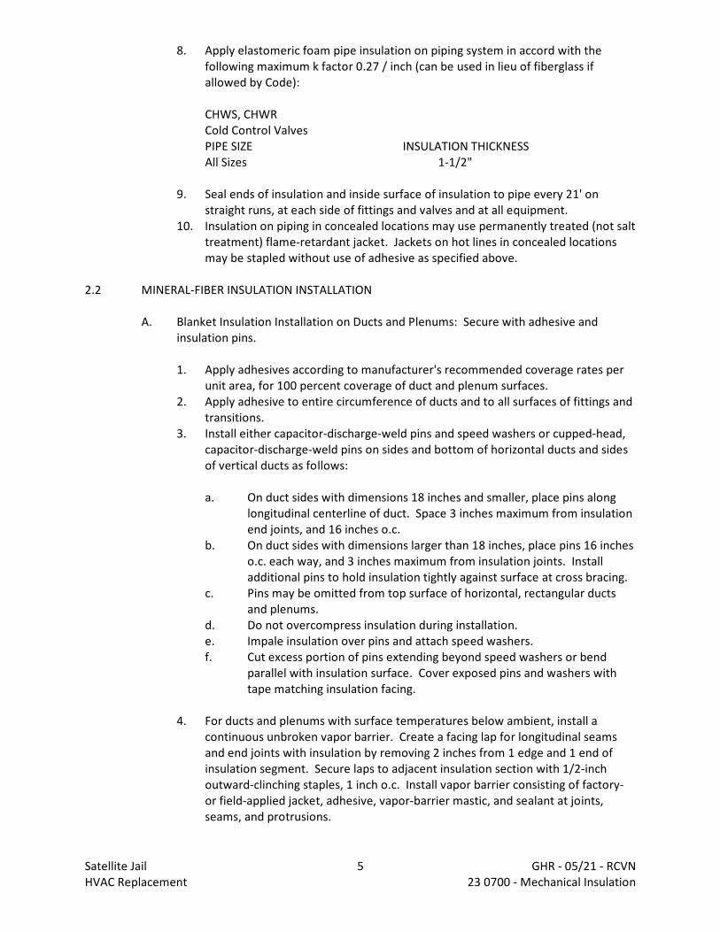
8. Apply elastomeric foam pipe insulation on piping system in accord with thefollowing maximum k factor 0.27 / inch (can be used in lieu of fiberglass ifallowed by Code):
CHWS, CHWRCold Control ValvesPIPE SIZE INSULATION THICKNESSAll Sizes 1-1/2"
9. Seal ends of insulation and inside surface of insulation to pipe every 21' onstraight runs, at each side of fittings and valves and at all equipment.
10. Insulation on piping in concealed locations may use permanently treated (not salttreatment) flame-retardant jacket. Jackets on hot lines in concealed locationsmay be stapled without use of adhesive as specified above.
2.2 MINERAL-FIBER INSULATION INSTALLATION
A. Blanket Insulation Installation on Ducts and Plenums: Secure with adhesive andinsulation pins.
1. Apply adhesives according to manufacturer's recommended coverage rates perunit area, for 100 percent coverage of duct and plenum surfaces.
2. Apply adhesive to entire circumference of ducts and to all surfaces of fittings andtransitions.
3. Install either capacitor-discharge-weld pins and speed washers or cupped-head,capacitor-discharge-weld pins on sides and bottom of horizontal ducts and sidesof vertical ducts as follows:
a. On duct sides with dimensions 18 inches and smaller, place pins alonglongitudinal centerline of duct. Space 3 inches maximum from insulationend joints, and 16 inches o.c.
b. On duct sides with dimensions larger than 18 inches, place pins 16 incheso.c. each way, and 3 inches maximum from insulation joints. Installadditional pins to hold insulation tightly against surface at cross bracing.
c. Pins may be omitted from top surface of horizontal, rectangular ductsand plenums.
d. Do not overcompress insulation during installation.e. Impale insulation over pins and attach speed washers.f. Cut excess portion of pins extending beyond speed washers or bend
parallel with insulation surface. Cover exposed pins and washers withtape matching insulation facing.
4. For ducts and plenums with surface temperatures below ambient, install acontinuous unbroken vapor barrier. Create a facing lap for longitudinal seamsand end joints with insulation by removing 2 inches from 1 edge and 1 end ofinsulation segment. Secure laps to adjacent insulation section with 1/2-inchoutward-clinching staples, 1 inch o.c. Install vapor barrier consisting of factory-or field-applied jacket, adhesive, vapor-barrier mastic, and sealant at joints,seams, and protrusions.
Satellite Jail 5 GHR - 05/21 - RCVNHVAC Replacement 23 0700 - Mechanical Insulation
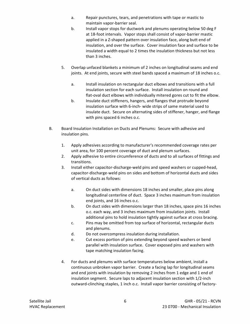
a. Repair punctures, tears, and penetrations with tape or mastic tomaintain vapor-barrier seal.
b. Install vapor stops for ductwork and plenums operating below 50 deg Fat 18-foot intervals. Vapor stops shall consist of vapor-barrier masticapplied in a Z-shaped pattern over insulation face, along butt end ofinsulation, and over the surface. Cover insulation face and surface to beinsulated a width equal to 2 times the insulation thickness but not lessthan 3 inches.
5. Overlap unfaced blankets a minimum of 2 inches on longitudinal seams and endjoints. At end joints, secure with steel bands spaced a maximum of 18 inches o.c.
a. Install insulation on rectangular duct elbows and transitions with a fullinsulation section for each surface. Install insulation on round andflat-oval duct elbows with individually mitered gores cut to fit the elbow.
b. Insulate duct stiffeners, hangers, and flanges that protrude beyondinsulation surface with 6-inch- wide strips of same material used toinsulate duct. Secure on alternating sides of stiffener, hanger, and flangewith pins spaced 6 inches o.c.
B. Board Insulation Installation on Ducts and Plenums: Secure with adhesive andinsulation pins.
1. Apply adhesives according to manufacturer's recommended coverage rates perunit area, for 100 percent coverage of duct and plenum surfaces.
2. Apply adhesive to entire circumference of ducts and to all surfaces of fittings andtransitions.
3. Install either capacitor-discharge-weld pins and speed washers or cupped-head,capacitor-discharge-weld pins on sides and bottom of horizontal ducts and sidesof vertical ducts as follows:
a. On duct sides with dimensions 18 inches and smaller, place pins alonglongitudinal centerline of duct. Space 3 inches maximum from insulationend joints, and 16 inches o.c.
b. On duct sides with dimensions larger than 18 inches, space pins 16 incheso.c. each way, and 3 inches maximum from insulation joints. Installadditional pins to hold insulation tightly against surface at cross bracing.
c. Pins may be omitted from top surface of horizontal, rectangular ductsand plenums.
d. Do not overcompress insulation during installation.e. Cut excess portion of pins extending beyond speed washers or bend
parallel with insulation surface. Cover exposed pins and washers withtape matching insulation facing.
4. For ducts and plenums with surface temperatures below ambient, install acontinuous unbroken vapor barrier. Create a facing lap for longitudinal seamsand end joints with insulation by removing 2 inches from 1 edge and 1 end ofinsulation segment. Secure laps to adjacent insulation section with 1/2-inchoutward-clinching staples, 1 inch o.c. Install vapor barrier consisting of factory-
Satellite Jail 6 GHR - 05/21 - RCVNHVAC Replacement 23 0700 - Mechanical Insulation
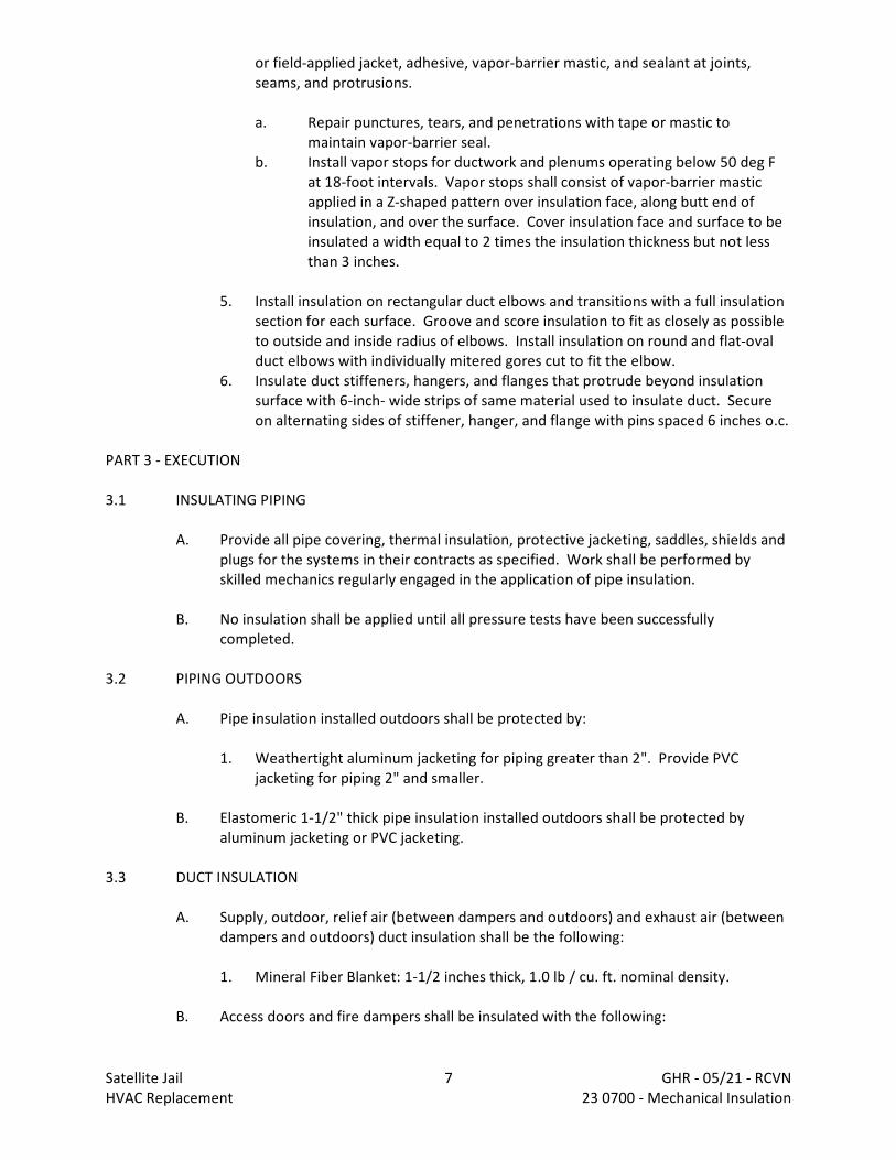
or field-applied jacket, adhesive, vapor-barrier mastic, and sealant at joints,seams, and protrusions.
a. Repair punctures, tears, and penetrations with tape or mastic tomaintain vapor-barrier seal.
b. Install vapor stops for ductwork and plenums operating below 50 deg Fat 18-foot intervals. Vapor stops shall consist of vapor-barrier masticapplied in a Z-shaped pattern over insulation face, along butt end ofinsulation, and over the surface. Cover insulation face and surface to beinsulated a width equal to 2 times the insulation thickness but not lessthan 3 inches.
5. Install insulation on rectangular duct elbows and transitions with a full insulationsection for each surface. Groove and score insulation to fit as closely as possibleto outside and inside radius of elbows. Install insulation on round and flat-ovalduct elbows with individually mitered gores cut to fit the elbow.
6. Insulate duct stiffeners, hangers, and flanges that protrude beyond insulationsurface with 6-inch- wide strips of same material used to insulate duct. Secureon alternating sides of stiffener, hanger, and flange with pins spaced 6 inches o.c.
PART 3 - EXECUTION
3.1 INSULATING PIPING
A. Provide all pipe covering, thermal insulation, protective jacketing, saddles, shields andplugs for the systems in their contracts as specified. Work shall be performed byskilled mechanics regularly engaged in the application of pipe insulation.
B. No insulation shall be applied until all pressure tests have been successfullycompleted.
3.2 PIPING OUTDOORS
A. Pipe insulation installed outdoors shall be protected by:
1. Weathertight aluminum jacketing for piping greater than 2". Provide PVCjacketing for piping 2" and smaller.
B. Elastomeric 1-1/2" thick pipe insulation installed outdoors shall be protected byaluminum jacketing or PVC jacketing.
3.3 DUCT INSULATION
A. Supply, outdoor, relief air (between dampers and outdoors) and exhaust air (betweendampers and outdoors) duct insulation shall be the following:
1. Mineral Fiber Blanket: 1-1/2 inches thick, 1.0 lb / cu. ft. nominal density.
B. Access doors and fire dampers shall be insulated with the following:
Satellite Jail 7 GHR - 05/21 - RCVNHVAC Replacement 23 0700 - Mechanical Insulation
1. Mineral Fiber Blanket: 1-1/2 inches thick, 1.0 lb / cu. ft. nominal density.
C. Exposed ductwork in finished areas shall be insulated with the following:
1. Mineral Fiber Board Insulation: 1-1/2 inches thick, 2 3 lb / cu. ft. nominal density.2. Board insulation to be painted shall have all service jacket.3. Board insulation not to be painted shall have foil jacket.4. Supply ductwork from heating only make-up air units does not require duct
insulation. The discharge air temperature shall not exceed in a difference of 15degrees F compared to the surrounding space temperature.
5. Exposed round ductwork to be double wall insulated spiral.
D. Finish areas include storage rooms, server rooms and bus
E. Concealed type 1 kitchen hood exhaust duct and plenum insulation shall be fire-ratedblanket or board; thickness as required to achieve 2 hour fire rating.
F. Generator exhaust and muffler insulation shall be fire-rated blanket or board;thickness as required to achieve 2 hour fire rating.
END 23 0700
Satellite Jail 8 GHR - 05/21 - RCVNHVAC Replacement 23 0700 - Mechanical Insulation
DIVISION 23 - HEATING, VENTILATING AND AIR CONDITIONINGDocument 23 0900 - Instrumentation and Control for HVAC
PART 1 - GENERAL
1.1 RELATED DOCUMENTS
A. Drawings and general provisions of the Contract, including General and Supplementary Conditionsand Division 01 Specification Sections, apply to this Section.
1.2 SUMMARY
A. This Section includes control equipment for HVAC systems and components, including controlcomponents for terminal heating and cooling units not supplied with factory-wired controls.
B. Related Sections include the following:
1. Division 23 Section "Meters and Gages for HVAC Piping" for measuring equipment thatrelates to this Section.
2. Division 23 Section "Sequence of Operations for HVAC Controls" for requirements thatrelate to this Section.
1.3 DEFINITIONS
A. DDC: Direct digital control.
B. I/O: Input/output.
C. LonWorks: A control network technology platform for designing and implementing interoperablecontrol devices and networks.
D. MS/TP: Master slave/token passing.
E. PC: Personal computer.
F. PID: Proportional plus integral plus derivative.
G. RTD: Resistance temperature detector.
H. IP: Internet protocol.
Satellite Jail 1 GHR - 05/21 - RCVNHVAC Replacement 23 0900 - HVAC Instrumentation and Controls
1.4 SYSTEM PERFORMANCE
A. Comply with the following performance requirements:
1. Graphic Display: Display graphic with minimum 20 dynamic points with current data within10 seconds.
2. Graphic Refresh: Update graphic with minimum 20 dynamic points with current datawithin 8 seconds.
3. Object Command: Reaction time of less than two seconds between operator commandof a binary object and device reaction.
4. Object Scan: Transmit change of state and change of analog values to control units orworkstation within six seconds.
5. Alarm Response Time: Annunciate alarm at workstation within 45 seconds. Multipleworkstations must receive alarms within five seconds of each other.
6. Program Execution Frequency: Run capability of applications as often as five seconds, butselected consistent with mechanical process under control.
7. Performance: Programmable controllers shall execute DDC PID control loops, and scan andupdate process values and outputs at least once per second.
8. Reporting Accuracy and Stability of Control: Report values and maintain measuredvariables within tolerances as follows:
a. Water Temperature: Plus or minus 1 deg F.b. Water Flow: Plus or minus 5 percent of full scale.c. Water Pressure: Plus or minus 2 percent of full scale.d. Space Temperature: Plus or minus 1 deg F.e. Ducted Air Temperature: Plus or minus 1 deg F.f. Outside Air Temperature: Plus or minus 2 deg F.g. Dew Point Temperature: Plus or minus 3 deg F.h. Temperature Differential: Plus or minus 0.25 deg F.i. Airflow (Pressurized Spaces): Plus or minus 3 percent of full scale.j. Airflow (Measuring Stations): Plus or minus 5 percent of full scale.k. Air Pressure (Space): Plus or minus 0.01-inch wg.l. Air Pressure (Ducts): Plus or minus 0.1-inch wg.m. Carbon Dioxide: Plus or minus 50 ppm.n. Electrical: Plus or minus 5 percent of reading.
1.5 SUBMITTALS
A. Product Data: Include manufacturer's technical literature for each control device. Indicatedimensions, capacities, performance characteristics, electrical characteristics, finishes formaterials, and installation and startup instructions for each type of product indicated.
1. DDC System Hardware: Bill of materials of equipment indicating quantity, manufacturer,and model number. Include technical data for operator workstation equipment, interfaceequipment, control units, transducers/transmitters, sensors, actuators, valves,relays/switches, control panels, and operator interface equipment.
Satellite Jail 2 GHR - 05/21 - RCVNHVAC Replacement 23 0900 - HVAC Instrumentation and Controls
2. Control System Software: Include technical data for operating system software, operatorinterface, color graphics, and other third-party applications.
3. Controlled Systems: Instrumentation list with element name, type of device,manufacturer, model number, and product data. Include written description of sequenceof operation including schematic diagram.
B. Shop Drawings: Detail equipment assemblies and indicate dimensions, weights, loads, requiredclearances, method of field assembly, components, and location and size of each field connection.
1. Bill of materials of equipment indicating quantity, manufacturer, and model number.2. Schematic flow diagrams showing fans, pumps, coils, dampers, valves, and control devices.3. Wiring Diagrams: Power, signal, and control wiring.4. Details of control panel faces, including controls, instruments, and labeling.5. Written description of sequence of operation.6. Schedule of dampers including size, leakage, and flow characteristics.7. Schedule of valves including flow characteristics.8. DDC System Hardware:
a. Wiring diagrams for control units with termination numbers.b. Schematic diagrams and floor plans for field sensors and control hardware.c. Schematic diagrams for control, communication, and power wiring, showing trunk
data conductors and wiring between operator workstation and control unitlocations.
9. Control System Software: List of color graphics indicating monitored systems, data(connected and calculated) point addresses, output schedule, and operator notations.
10. Controlled Systems:
a. Schematic diagrams of each controlled system with control points labeled andcontrol elements graphically shown, with wiring.
b. Scaled drawings showing mounting, routing, and wiring of elements including basesand special construction.
c. Written description of sequence of operation including schematic diagram.d. Points list.
C. Data Communications Protocol Certificates: Certify that each proposed DDC system componentcomplies with ASHRAE 135.
D. Data Communications Protocol Certificates: Certify that each proposed DDC system componentcomplies with LonWorks.
E. Samples for Initial Selection: For each color required, of each type of thermostat or sensor coverwith factory-applied color finishes.
F. Samples for Verification: For each color required, of each type of thermostat or sensor cover.
G. Software and Firmware Operational Documentation: Include the following:
Satellite Jail 3 GHR - 05/21 - RCVNHVAC Replacement 23 0900 - HVAC Instrumentation and Controls
1. Software operating and upgrade manuals.2. Program Software Backup: On a magnetic media or compact disc, complete with data files.3. Device address list.4. Printout of software application and graphic screens.5. Software license required by and installed for DDC workstations and control systems.
H. Software Upgrade Kit: For Owner to use in modifying software to suit future systems revisionsor monitoring and control revisions.
I. Qualification Data: For Installer and manufacturer.
J. Field quality-control test reports.
K. Operation and Maintenance Data: For HVAC instrumentation and control system to include inemergency, operation, and maintenance manuals. In addition to items specified in Division 01Section "Operation and Maintenance Data," include the following:
1. Maintenance instructions and lists of spare parts for each type of control device andcompressed-air station.
2. Interconnection wiring diagrams with identified and numbered system components anddevices.
3. Keyboard illustrations and step-by-step procedures indexed for each operator function.4. Inspection period, cleaning methods, cleaning materials recommended, and calibration
tolerances.5. Calibration records and list of set points.
1.6 QUALITY ASSURANCE
A. Installer Qualifications: Automatic control system manufacturer's authorized representative whois trained and approved for installation of system components required for this Project.
B. Electrical Components, Devices, and Accessories: Listed and labeled as defined in NFPA 70,Article 100, by a testing agency acceptable to authorities having jurisdiction, and marked forintended use.
C. Comply with ASHRAE 135 for DDC system components.
1.7 DELIVERY, STORAGE, AND HANDLING
A. Factory-Mounted Components: Where the equipment manufacturer's factory packaged controlsare capable of providing the BAS interface specified, the equipment manufacturer's controls maybe utilized. Where controls are provided by other than the equipment manufacturer, arrange forshipping of required devices to equipment manufacturer for factory mounting as required forproper equipment function.
B. System Software: Update to latest version of software at Project completion.
Satellite Jail 4 GHR - 05/21 - RCVNHVAC Replacement 23 0900 - HVAC Instrumentation and Controls

1.8 COORDINATION
A. Coordinate location of thermostats and other exposed control sensors with plans and roomdetails before installation.
B. Coordinate equipment with Division 27 Section "Clock Systems" to achieve compatibility withequipment that interfaces with that system.
C. Coordinate equipment with Division 26 Section "Network Lighting Controls" to achievecompatibility with equipment that interfaces with that system.
D. Coordinate equipment with Division 28 Section "Fire Detection and Alarm" to achievecompatibility with equipment that interfaces with that system.
E. Coordinate supply of conditioned electrical branch circuits for control units and operatorworkstation.
F. Coordinate equipment with Division 26 Section "Electrical Power Monitoring and Control" toachieve compatibility of communication interfaces.
G. Coordinate equipment with Division 26 Section "Panelboards" to achieve compatibility withstarter coils and annunciation devices.
H. Coordinate equipment with Division 26 Section "Motor-Control Centers" to achieve compatibilitywith motor starters and annunciation devices.
1.9 EXTRA MATERIALS
A. Furnish extra materials described below that match products installed and that are packaged withprotective covering for storage and identified with labels describing contents.
1. Replacement Materials: One replacement for each unique valve motor, controller,thermostat, positioning relay.
2. Maintenance Materials: Five thermostat adjusting key(s).
PART 2 - PRODUCTS
2.1 MANUFACTURERS
A. In other Part 2 articles where titles below introduce lists, the following requirements apply toproduct selection:
Satellite Jail 5 GHR - 05/21 - RCVNHVAC Replacement 23 0900 - HVAC Instrumentation and Controls

1. Available Manufacturers: Subject to compliance with requirements, manufacturersoffering products that may be incorporated into the Work.
2. Manufacturers: Subject to compliance with requirements, provide products by one of themanufacturers specified.
2.2 CONTROL SYSTEM
A. Manufacturers:
1. Alpha Controls.
B. Control system shall consist of sensors, indicators, actuators, final control elements, interfaceequipment, other apparatus, and accessories to control mechanical systems.
C. Control system shall consist of sensors, indicators, actuators, final control elements, interfaceequipment, other apparatus, accessories, and software connected to distributed controllersoperating in multiuser, multitasking environment on token-passing network and programmed tocontrol mechanical systems. An operator workstation shall permit interface with the network viadynamic color graphics with each mechanical system, building floor plan, and control devicedepicted by point-and-click graphics.
D. Expand existing temperature control system software database to include all new controlledmechanical equipment. Control system shall be accessible via campus Ethernet network.
2.3 DDC EQUIPMENT
A. Operator Workstation and Printer: Existing operator workstation and printer are to be retained.
1. Application Software: Modify existing temperature control software as necessary toprovide the level of control specified herein for new and existing equipment and systems.
a. I/O capability from operator station.b. System security for each operator via software password and access levels.c. Automatic system diagnostics; monitor system and report failures.d. Database creation and support.e. Automatic and manual database save and restore.f. Dynamic color graphic displays with up to 10 screen displays at once.g. Custom graphics generation and graphics library of HVAC equipment and symbols.h. Alarm processing, messages, and reactions.i. Trend logs retrievable in spreadsheets and database programs.j. Alarm and event processing.k. Object and property status and control.l. Automatic restart of field equipment on restoration of power.m. Data collection, reports, and logs. Include standard reports for the following:
1) Current values of all objects.
Satellite Jail 6 GHR - 05/21 - RCVNHVAC Replacement 23 0900 - HVAC Instrumentation and Controls

2) Current alarm summary.3) Disabled objects.4) Alarm lockout objects.5) Logs.
n. Custom report development.o. Utility and weather reports.p. Workstation application editors for controllers and schedules.q. Maintenance management.
2. Custom Application Software:
a. English language oriented.b. Full-screen character editor/programming environment.c. Allow development of independently executing program modules with
debugging/simulation capability.d. Support conditional statements.e. Support floating-point arithmetic with mathematic functions.f. Contains predefined time variables.
B. Diagnostic Terminal Unit: Portable notebook-style, PC-based microcomputer terminal capableof accessing system data by connecting to system network with minimum configuration asfollows:
1. System: With one integrated USB 2.0 port, integrated Intel Pro 10/100 (Ethernet),integrated audio, bios, and hardware monitoring.
2. Processor: Core 2, 2.0 GHz.3. Random-Access Memory: 1.0 GB.4. Graphics: Video adapter, minimum 1024 x 768 pixels, 64-MB video memory.5. Monitor: 15 inches, LCD color.6. Keyboard: QWERTY 105 keys in ergonomic shape.7. Hard-Disk Drive: 80 Gb.8. CD-ROM Read/Write Drive: 48x24x48.9. Pointing Device: Touch pad or other internal device.
C. Control Units: Modular, comprising processor board with programmable, nonvolatile,random-access memory; local operator access and display panel; integral interface equipment;and backup power source.
1. Units monitor or control each I/O point; process information; execute commands fromother control units, devices, and operator stations; and download from or upload tooperator workstation or diagnostic terminal unit.
2. Stand-alone mode control functions operate regardless of network status. Functionsinclude the following:
a. Global communications.b. Discrete/digital, analog, and pulse I/O.c. Monitoring, controlling, or addressing data points.
Satellite Jail 7 GHR - 05/21 - RCVNHVAC Replacement 23 0900 - HVAC Instrumentation and Controls
d. Software applications, scheduling, and alarm processing.e. Testing and developing control algorithms without disrupting field hardware and
controlled environment.
3. Standard Application Programs:
a. Electric Control Programs: Demand limiting, duty cycling, automatic timescheduling, start/stop time optimization, night setback/setup, on-off control withdifferential sequencing, staggered start, antishort cycling, PID control, DDC with finetuning, and trend logging.
b. HVAC Control Programs: Optimal run time, supply-air reset, and enthalpyswitchover.
c. Programming Application Features: Include trend point; alarm processing andmessaging; weekly, monthly, and annual scheduling; energy calculations; run-timetotalization; and security access.
d. Remote communications.e. Maintenance management.f. Units of Measure: Inch-pound and SI (metric).
4. Local operator interface provides for download from or upload to operator workstation ordiagnostic terminal unit.
5. ASHRAE 135 Compliance: Control units shall use ASHRAE 135 protocol and communicateusing ISO 8802-3 (Ethernet) datalink/physical layer protocol.
6. LonWorks Compliance: Control units shall use LonTalk protocol and communicate usingEIA/CEA 709.1 datalink/physical layer protocol.
D. Local Control Units: Modular, comprising processor board with electronically programmable,nonvolatile, read-only memory; and backup power source.
1. Units monitor or control each I/O point, process information, and download from or uploadto operator workstation or diagnostic terminal unit.
2. Stand-alone mode control functions operate regardless of network status. Functionsinclude the following:
a. Global communications.b. Discrete/digital, analog, and pulse I/O.c. Monitoring, controlling, or addressing data points.
3. Local operator interface provides for download from or upload to operator workstation ordiagnostic terminal unit.
4. ASHRAE 135 Compliance: Control units shall use ASHRAE 135 protocol and communicateusing ISO 8802-3 (Ethernet) datalink/physical layer protocol.
5. LonWorks Compliance: Control units shall use LonTalk protocol and communicate usingEIA/CEA 709.1 datalink/physical layer protocol.
E. I/O Interface: Hardwired inputs and outputs may tie into system through controllers. Protectpoints so that shorting will cause no damage to controllers.
Satellite Jail 8 GHR - 05/21 - RCVNHVAC Replacement 23 0900 - HVAC Instrumentation and Controls

1. Binary Inputs: Allow monitoring of on-off signals without external power.2. Pulse Accumulation Inputs: Accept up to 10 pulses per second.3. Analog Inputs: Allow monitoring of low-voltage (0- to 10-V dc), current (4 to 20 mA), or
resistance signals.4. Binary Outputs: Provide on-off or pulsed low-voltage signal, selectable for normally open
or normally closed operation with three-position (on-off-auto) override switches and statuslights.
5. Analog Outputs: Provide modulating signal, either low voltage (0- to 10-V dc) or current(4 to 20 mA) with status lights, two-position (auto-manual) switch, and manually adjustablepotentiometer.
6. Tri-State Outputs: Provide two coordinated binary outputs for control of three-point,floating-type electronic actuators.
7. Universal I/Os: Provide software selectable binary or analog outputs.
F. Power Supplies: Transformers with Class 2 current-limiting type or overcurrent protection; limitconnected loads to 80 percent of rated capacity. DC power supply shall match output current andvoltage requirements and be full-wave rectifier type with the following:
1. Output ripple of 5.0 mV maximum peak to peak.2. Combined 1 percent line and load regulation with 100-mic.sec. response time for 50
percent load changes.3. Built-in overvoltage and overcurrent protection and be able to withstand 150 percent
overload for at least 3 seconds without failure.
G. Power Line Filtering: Internal or external transient voltage and surge suppression forworkstations or controllers with the following:
1. Minimum dielectric strength of 1000 V.2. Maximum response time of 10 nanoseconds.3. Minimum transverse-mode noise attenuation of 65 dB.4. Minimum common-mode noise attenuation of 150 dB at 40 to 100 Hz.
2.4 UNITARY CONTROLLERS
A. Unitized, capable of stand-alone operation with sufficient memory to support its operatingsystem, database, and programming requirements, and with sufficient I/O capacity for theapplication.
1. Configuration: Local keypad and display; diagnostic LEDs for power, communication, andprocessor; wiring termination to terminal strip or card connected with ribbon cable;memory with bios; and 72-hour battery backup.
2. Operating System: Manage I/O communication to allow distributed controllers to sharereal and virtual object information and allow central monitoring and alarms. Performscheduling with real-time clock. Perform automatic system diagnostics; monitor systemand report failures.
3. ASHRAE 135 Compliance: Communicate using read (execute and initiate) and write(execute and initiate) property services defined in ASHRAE 135. Reside on network using
Satellite Jail 9 GHR - 05/21 - RCVNHVAC Replacement 23 0900 - HVAC Instrumentation and Controls

MS/TP datalink/physical layer protocol and have service communication port forconnection to diagnostic terminal unit.
4. LonWorks Compliance: Communicate using EIA/CEA 709.1 datalink/physical layer protocolusing LonTalk protocol.
5. Enclosure: Dustproof rated for operation at 32 to 120 deg F.6. Enclosure: Waterproof rated for operation at 40 to 150 deg F.
2.5 ANALOG CONTROLLERS
A. Step Controllers: 6- or 10-stage type, with heavy-duty switching rated to handle loads andoperated by electric motor.
B. Electric, Outdoor-Reset Controllers: Remote-bulb or bimetal rod-and-tube type, proportioningaction with adjustable throttling range, adjustable set point, scale range minus 10 to plus 70 degF, and single- or double-pole contacts.
C. Electronic Controllers: Wheatstone-bridge-amplifier type, in steel enclosure with provision forremote-resistance readjustment. Identify adjustments on controllers, including proportional bandand authority.
1. Single controllers can be integral with control motor if provided with accessible controlreadjustment potentiometer.
D. Fan-Speed Controllers: Solid-state model providing field-adjustable proportional control of motorspeed from maximum to minimum of 55 percent and on-off action below minimum fan speed. Controller shall briefly apply full voltage, when motor is started, to rapidly bring motor up tominimum speed. Equip with filtered circuit to eliminate radio interference.
2.6 ELECTRONIC SENSORS
A. Description: Vibration and corrosion resistant; for wall, immersion, or duct mounting as required.
B. Thermistor Temperature Sensors and Transmitters:
1. Manufacturers:
a. BEC Controls Corporation.b. Ebtron, Inc.c. Heat-Timer Corporation.d. I.T.M. Instruments Inc.e. MAMAC Systems, Inc.f. RDF Corporation.
2. Accuracy: Plus or minus 0.5 deg F at calibration point.3. Wire: Twisted, shielded-pair cable.
Satellite Jail 10 GHR - 05/21 - RCVNHVAC Replacement 23 0900 - HVAC Instrumentation and Controls
4. Insertion Elements in Ducts: Single point; use where not affected by temperaturestratification or where ducts are smaller than 9 sq. ft..
5. Averaging Elements in Ducts: 72 inches long, flexible; use where prone to temperaturestratification or where ducts are larger than 10 sq. ft..
6. Insertion Elements for Liquids: Brass or stainless-steel socket with minimum insertionlength of 2-1/2 inches.
7. Room Sensor Cover Construction: Manufacturer's standard locking covers.
a. Set-Point Adjustment: Concealed.b. Set-Point Indication: Exposed.c. Thermometer: Red-reading glass.
8. Outside-Air Sensors: Watertight inlet fitting, shielded from direct sunlight.9. Room Security Sensors: Stainless-steel cover plate with insulated back and security screws.
C. RTDs and Transmitters:
1. Manufacturers:
a. BEC Controls Corporation.b. MAMAC Systems, Inc.c. RDF Corporation.
2. Accuracy: Plus or minus 0.2 percent at calibration point.3. Wire: Twisted, shielded-pair cable.4. Insertion Elements in Ducts: Single point, 8 inches or 18 inches long; use where not
affected by temperature stratification or where ducts are smaller than 9 sq. ft..5. Averaging Elements in Ducts: 48 inches long, rigid; use where prone to temperature
stratification or where ducts are larger than 9 sq. ft.; length as required.6. Insertion Elements for Liquids: Brass socket with minimum insertion length of 2-1/2 inches.7. Room Sensor Cover Construction: Manufacturer's standard locking covers.
a. Set-Point Adjustment: Concealed.b. Set-Point Indication: Exposed.c. Thermometer: Red-reading glass.
8. Outside-Air Sensors: Watertight inlet fitting, shielded from direct sunlight.9. Room Security Sensors: Stainless-steel cover plate with insulated back and security screws.
D. Humidity Sensors: Bulk polymer sensor element.
1. Manufacturers:
a. BEC Controls Corporation.b. General Eastern Instruments.c. MAMAC Systems, Inc.d. ROTRONIC Instrument Corp.e. TCS/Basys Controls.
Satellite Jail 11 GHR - 05/21 - RCVNHVAC Replacement 23 0900 - HVAC Instrumentation and Controls
f. Vaisala.
2. Accuracy: 5 percent full range with linear output.3. Room Sensor Range: 20 to 80 percent relative humidity.4. Room Sensor Cover Construction: Manufacturer's standard locking covers.
a. Set-Point Adjustment: Exposed.b. Set-Point Indication: Exposed.
5. Duct Sensor: 20 to 80 percent relative humidity range with element guard and mountingplate.
6. Outside-Air Sensor: 20 to 80 percent relative humidity range with mounting enclosure,suitable for operation at outdoor temperatures of minus 22 to plus 185 deg F.
7. Duct and Sensors: With element guard and mounting plate, range of 0 to 100 percentrelative humidity.
E. Pressure Transmitters/Transducers:
1. Manufacturers:
a. BEC Controls Corporation.b. General Eastern Instruments.c. MAMAC Systems, Inc.d. ROTRONIC Instrument Corp.e. TCS/Basys Controls.f. Vaisala.
2. Static-Pressure Transmitter: Nondirectional sensor with suitable range for expected input,and temperature compensated.
a. Accuracy: 2 percent of full scale with repeatability of 0.5 percent.b. Output: 4 to 20 mA.c. Building Static-Pressure Range: 0- to 0.25-inch wg.d. Duct Static-Pressure Range: 0- to 5-inch wg.
3. Water Pressure Transducers: Stainless-steel diaphragm construction, suitable for service;minimum 150-psig operating pressure; linear output 4 to 20 mA.
4. Water Differential-Pressure Transducers: Stainless-steel diaphragm construction, suitablefor service; minimum 150-psig operating pressure and tested to 300-psig; linear output 4to 20 mA.
5. Differential-Pressure Switch (Air or Water): Snap acting, with pilot-duty rating and withsuitable scale range and differential.
6. Pressure Transmitters: Direct acting for gas, liquid, or steam service; range suitable forsystem; linear output 4 to 20 mA.
F. Room Sensor Cover Construction: Manufacturer's standard locking covers.
1. Set-Point Adjustment: Exposed.
Satellite Jail 12 GHR - 05/21 - RCVNHVAC Replacement 23 0900 - HVAC Instrumentation and Controls
2. Set-Point Indication: Exposed.
G. Room sensor accessories include the following:
1. Insulating Bases: For sensors located on exterior walls.2. Adjusting Key: As required for calibration and cover screws.
H. Photocell, see Section 23 0993 for description.
2.7 STATUS SENSORS
A. Status Inputs for Fans: Differential-pressure switch with pilot-duty rating and with adjustablerange of 0- to 5-inch wg.
B. Status Inputs for Pumps: Differential-pressure switch with pilot-duty rating and with adjustablepressure-differential range of 8 to 60 psig, piped across pump.
C. Status Inputs for Electric Motors: Comply with ISA 50.00.01, current-sensing fixed- or split-coretransformers with self-powered transmitter, adjustable and suitable for 175 percent of ratedmotor current.
D. Voltage Transmitter (100- to 600-V ac): Comply with ISA 50.00.01, single-loop, self-poweredtransmitter, adjustable, with suitable range and 1 percent full-scale accuracy.
E. Power Monitor: 3-phase type with disconnect/shorting switch assembly, listed voltage andcurrent transformers, with pulse kilowatt hour output and 4- to 20-mA kW output, with maximum2 percent error at 1.0 power factor and 2.5 percent error at 0.5 power factor.
F. Current Switches: Self-powered, solid-state with adjustable trip current, selected to matchcurrent and system output requirements.
G. Electronic Valve/Damper Position Indicator: Visual scale indicating percent of travel and 2- to10-V dc, feedback signal.
H. Water-Flow Switches: Bellows-actuated mercury or snap-acting type with pilot-duty rating,stainless-steel or bronze paddle, with appropriate range and differential adjustment, inNEMA 250, Type 1 enclosure.
1. Manufacturers:
a. BEC Controls Corporation.b. I.T.M. Instruments Inc.
Satellite Jail 13 GHR - 05/21 - RCVNHVAC Replacement 23 0900 - HVAC Instrumentation and Controls
2.8 GAS DETECTION EQUIPMENT
A. Manufacturers:
1. B. W. Technologies.2. CEA Instruments, Inc.3. Ebtron, Inc.4. Gems Sensors Inc.5. Greystone Energy Systems Inc.6. Honeywell International Inc.; Home & Building Control.7. INTEC Controls, Inc.8. I.T.M. Instruments Inc.9. MSA Canada Inc.10. QEL/Quatrosense Environmental Limited.11. Sauter Controls Corporation.12. Sensidyne, Inc.13. TSI Incorporated.14. Vaisala.15. Vulcain Inc.
B. Carbon Dioxide Sensor and Transmitter: Single detectors using solid-state infrared sensors;suitable over a temperature range of 23 to 130 deg F and calibrated for 0 to 2 percent, withcontinuous or averaged reading, 4- to 20-mA output;, for wall mounting.
C. Oxygen Sensor and Transmitter: Single detectors using solid-state zircon cell sensing; suitableover a temperature range of minus 32 to plus 1100 deg F and calibrated for 0 to 5 percent, withcontinuous or averaged reading, 4- to 20-mA output; for wall mounting.
D. Occupancy Sensor: Passive infrared, with time delay, daylight sensor lockout, sensitivity control,and 180-degree field of view with vertical sensing adjustment; for flush mounting.
2.9 THERMOSTATS
A. Manufacturers:
1. Same as Direct Digital Controller Manufacturer.
B. Combination Thermostat and Fan Switches: Line-voltage thermostat with push-button orlever-operated fan switch.
1. Label switches "FAN ON-OFF".2. Mount on single electric switch box.
C. Low-Voltage, On-Off Thermostats: NEMA DC 3, 24-V, bimetal-operated, mercury-switch type,with adjustable or fixed anticipation heater, concealed set-point adjustment, 55 to 85 deg Fset-point range, and 2 deg F maximum differential.
Satellite Jail 14 GHR - 05/21 - RCVNHVAC Replacement 23 0900 - HVAC Instrumentation and Controls
D. Line-Voltage, On-Off Thermostats: Bimetal-actuated, open contact or bellows-actuated, enclosed,snap-switch or equivalent solid-state type, with heat anticipator; listed for electrical rating; withconcealed set-point adjustment, 55 to 85 deg F set-point range, and 2 deg F maximumdifferential.
1. Electric Heating Thermostats: Equip with off position on dial wired to break ungroundedconductors.
2. Selector Switch: Integral, manual on-off-auto.
E. Remote-Bulb Thermostats: On-off or modulating type, liquid filled to compensate for changesin ambient temperature; with copper capillary and bulb, unless otherwise indicated.
1. Bulbs in water lines with separate wells of same material as bulb.2. Bulbs in air ducts with flanges and shields.3. Averaging Elements: Copper tubing with either single- or multiple-unit elements, extended
to cover full width of duct or unit; adequately supported.4. Scale settings and differential settings are clearly visible and adjustable from front of
instrument.5. On-Off Thermostat: With precision snap switches and with electrical ratings required by
application.6. Modulating Thermostats: Construct so complete potentiometer coil and wiper assembly
is removable for inspection or replacement without disturbing calibration of instrument.
F. Fire-Protection Thermostats: Listed and labeled by an NRTL acceptable to authorities havingjurisdiction; with fixed or adjustable settings to operate at not less than 75 deg F above normalmaximum operating temperature, and the following:
1. Reset: Manual.2. Reset: Automatic, with control circuit arranged to require manual reset at central control
panel; with pilot light and reset switch on panel labeled to indicate operation.
G. Immersion Thermostat: Remote-bulb or bimetal rod-and-tube type, proportioning action withadjustable throttling range and adjustable set point.
H. Airstream Thermostats: Two-pipe, fully proportional, single-temperature type; with adjustableset point in middle of range, adjustable throttling range, plug-in test fitting or permanent pressuregage, remote bulb, bimetal rod and tube, or averaging element.
I. Electric, Low-Limit Duct Thermostat: Snap-acting, single-pole, single-throw, manual- orautomatic- reset switch that trips if temperature sensed across any 12 inches of bulb length isequal to or below set point.
1. Bulb Length: Minimum 20 feet.2. Quantity: One thermostat for every 20 sq. ft. of coil surface.
J. Electric, High-Limit Duct Thermostat: Snap-acting, single-pole, single-throw, manual- orautomatic- reset switch that trips if temperature sensed across any 12 inches of bulb length isequal to or above set point.
Satellite Jail 15 GHR - 05/21 - RCVNHVAC Replacement 23 0900 - HVAC Instrumentation and Controls
1. Bulb Length: Minimum 20 feet.2. Quantity: One thermostat for every 20 sq. ft. of coil surface.
K. Heating/Cooling Valve-Top Thermostats: Proportional acting for proportional flow, withmolded-rubber diaphragm, remote-bulb liquid-filled element, direct and reverse acting atminimum shutoff pressure of 25 psig, and cast housing with position indicator and adjusting knob.
L. Thermostats shall be provided by the Temperature Control Subcontractor and compatible withthe BAS. Night setback and thermostat settings shall be controlled by BAS.
2.10 HUMIDISTATS
A. Manufacturers:
1. MAMAC Systems, Inc.2. ROTRONIC Instrument Corp.
B. Duct-Mounting Humidistats: Electric insertion, 2-position type with adjustable, 2 percentthrottling range, 20 to 80 percent operating range, and single- or double-pole contacts.
2.11 ACTUATORS
A. Electric Motors: Size to operate with sufficient reserve power to provide smooth modulatingaction or two-position action.
1. Comply with requirements in Division 23 Section "Common Motor Requirements for HVACEquipment."
2. Permanent Split-Capacitor or Shaded-Pole Type: Gear trains completely oil immersed andsealed. Equip spring-return motors with integral spiral-spring mechanism in housingsdesigned for easy removal for service or adjustment of limit switches, auxiliary switches,or feedback potentiometer.
3. Nonspring-Return Motors for Valves Larger Than NPS 2-1/2: Size for running torque of 150in. X lbf and breakaway torque of 300 in. X lbf.
4. Spring-Return Motors for Valves Larger Than NPS 2-1/2: Size for running and breakawaytorque of 150 in. X lbf.
5. Nonspring-Return Motors for Dampers Larger Than 25 Sq. Ft.: Size for running torque of150 in. X lbf and breakaway torque of 300 in. X lbf.
6. Spring-Return Motors for Dampers Larger Than 25 Sq. Ft.: Size for running and breakawaytorque of 150 in. X lbf.
B. Electronic Actuators: Direct-coupled type designed for minimum 60,000 full-stroke cycles at ratedtorque.
1. Manufacturers:
Satellite Jail 16 GHR - 05/21 - RCVNHVAC Replacement 23 0900 - HVAC Instrumentation and Controls
a. Schneider Electric.
2. Valves: Size for torque required for valve close off at maximum pump differential pressure.3. Dampers: Size for running torque calculated as follows:
a. Parallel-Blade Damper with Edge Seals: 7 inch-lb/sq. ft. of damper.b. Opposed-Blade Damper with Edge Seals: 5 inch-lb/sq. ft. of damper.c. Parallel-Blade Damper without Edge Seals: 4 inch-lb/sq. ft of damper.d. Opposed-Blade Damper without Edge Seals: 3 inch-lb/sq. ft. of damper.e. Dampers with 2- to 3-Inch wg of Pressure Drop or Face Velocities of 1000 to 2500
fpm: Increase running torque by 1.5.f. Dampers with 3- to 4-Inch wg of Pressure Drop or Face Velocities of 2500 to 3000
fpm: Increase running torque by 2.0.
4. Coupling: V-bolt and V-shaped, toothed cradle.5. Overload Protection: Electronic overload or digital rotation-sensing circuitry.6. Fail-Safe Operation: Mechanical, spring-return mechanism. Provide external, manual gear
release on nonspring-return actuators.7. Power Requirements (Two-Position Spring Return): 24-V ac.8. Power Requirements (Modulating): Maximum 10 VA at 24-V ac or 8 W at 24-V dc.9. Proportional Signal: 2- to 10-V dc or 4 to 20 mA, and 2- to 10-V dc position feedback signal.10. Temperature Rating: Minus 22 to plus 122 deg F.11. Temperature Rating (Smoke Dampers): Minus 22 to plus 250 deg F.12. Run Time: 12 seconds open, 5 seconds closed.
2.12 CONTROL VALVES
A. Manufacturers:
1. Schneider Electric. 2. Siemens.3. Honeywell.
B. Control Valves: Factory fabricated, of type, body material, and pressure class based on maximumpressure and temperature rating of piping system, unless otherwise indicated.
C. Hydronic system globe valves shall have the following characteristics:
1. NPS 2 and Smaller: Class 125 bronze body, bronze trim, rising stem, renewablecomposition disc, and screwed ends with backseating capacity repackable under pressure.
2. NPS 2-1/2 and Larger: Class 125 iron body, bronze trim, rising stem, plug-type disc, flangedends, and renewable seat and disc.
3. Internal Construction: Replaceable plugs and stainless-steel or brass seats.
a. Single-Seated Valves: Cage trim provides seating and guiding surfaces for plug ontop and bottom.
Satellite Jail 17 GHR - 05/21 - RCVNHVAC Replacement 23 0900 - HVAC Instrumentation and Controls
b. Double-Seated Valves: Balanced plug; cage trim provides seating and guidingsurfaces for plugs on top and bottom.
4. Sizing: 3-psig maximum pressure drop at design flow rate or the following:
a. Two Position: Line size.b. Two-Way Modulating: Either the value specified above or twice the load pressure
drop, whichever is more.c. Three-Way Modulating: Twice the load pressure drop, but not more than value
specified above.
5. Flow Characteristics: Two-way valves shall have equal percentage characteristics;three-way valves shall have linear characteristics.
6. Close-Off (Differential) Pressure Rating: Combination of actuator and trim shall provideminimum close-off pressure rating of 150 percent of total system (pump) head for two-wayvalves and 100 percent of pressure differential across valve or 100 percent of total system(pump) head.
D. Butterfly Valves: 200-psig, 150-psig maximum pressure differential, ASTM A 126 cast-iron orASTM A 536 ductile-iron body and bonnet, extended neck, stainless-steel stem, field-replaceableEPDM or Buna N sleeve and stem seals.
1. Body Style: Wafer.2. Disc Type: Aluminum bronze.3. Sizing: 1-psig maximum pressure drop at design flow rate.
2.13 DAMPERS
A. Manufacturers:
1. Air Balance Inc.2. Don Park Inc.; Autodamp Div.3. TAMCO (T. A. Morrison & Co. Inc.).4. United Enertech Corp.5. Vent Products Company, Inc.
B. Dampers: AMCA-rated, opposed-blade design; 0.108-inch- minimum thick, galvanized-steel or0.125-inch- minimum thick, extruded-aluminum frames with holes for duct mounting; damperblades shall not be less than 0.064-inch- thick galvanized steel with maximum blade width of 8inches and length of 48 inches.
1. Secure blades to 1/2-inch- diameter, zinc-plated axles using zinc-plated hardware, withoil-impregnated sintered bronze blade bearings, blade-linkage hardware of zinc-platedsteel and brass, ends sealed against spring-stainless-steel blade bearings, and thrustbearings at each end of every blade.
2. Operating Temperature Range: From minus 40 to plus 200 deg F.3. Edge Seals, Standard Pressure Applications: Closed-cell neoprene.
Satellite Jail 18 GHR - 05/21 - RCVNHVAC Replacement 23 0900 - HVAC Instrumentation and Controls
4. Edge Seals, Low-Leakage Applications: Use inflatable blade edging or replaceable rubberblade seals and spring-loaded stainless-steel side seals, rated for leakage at less than 10cfm per sq. ft. of damper area, at differential pressure of 4-inch wg when damper is heldby torque of 50 in. X lbf; when tested according to AMCA 500D.
2.14 CONTROL CABLE
A. Electronic and fiber-optic cables for control wiring are specified in Division 27 Section"Communications Horizontal Cabling."
PART 3 - EXECUTION
3.1 EXAMINATION
A. Verify that conditioned power supply is available to control units and operator workstation.
B. Verify that pneumatic piping and duct-, pipe-, and equipment-mounted devices are installedbefore proceeding with installation.
3.2 INSTALLATION
A. Install software in control units and operator workstation(s). Implement all features of programsto specified requirements and as appropriate to sequence of operation.
B. Connect and configure equipment and software to achieve sequence of operation specified.
C. Verify location of thermostats, humidistats, and other exposed control sensors with Drawings androom details before installation. Install devices 48 inches above the floor.
1. Install averaging elements in ducts and plenums in crossing or zigzag pattern.
D. Install guards on thermostats in the following locations:
1. Entrances.2. Public areas.3. Where indicated.
E. Install automatic dampers according to Division 23 Section "Air Duct Accessories."
F. Install damper motors on outside of duct in warm areas, not in locations exposed to outdoortemperatures.
Satellite Jail 19 GHR - 05/21 - RCVNHVAC Replacement 23 0900 - HVAC Instrumentation and Controls
G. Install labels and nameplates to identify control components according to Division 23 Section"Identification for HVAC Piping and Equipment."
H. Install hydronic instrument wells, valves, and other accessories according to Division 23 Section"Hydronic Piping."
I. Install refrigerant instrument wells, valves, and other accessories according to Division 23 Section"Refrigerant Piping."
J. Install duct volume-control dampers according to Division 23 Sections specifying air ducts.
K. Install electronic and fiber-optic cables according to Division 27 Section "CommunicationsHorizontal Cabling."
3.3 ELECTRICAL WIRING AND CONNECTION INSTALLATION
A. Install raceways, boxes, and cabinets according to Division 26 Section "Raceway and Boxes forElectrical Systems."
B. Install building wire and cable according to Division 26 Section "Low-Voltage Electrical PowerConductors and Cables."
C. Install signal and communication cable according to Division 27 Section "CommunicationsHorizontal Cabling."
1. Conceal cable, except in mechanical rooms and areas where other conduit and piping areexposed.
2. Install exposed cable in raceway.3. Install concealed cable in raceway.4. Bundle and harness multiconductor instrument cable in place of single cables where
several cables follow a common path.5. Fasten flexible conductors, bridging cabinets and doors, along hinge side; protect against
abrasion. Tie and support conductors.6. Number-code or color-code conductors for future identification and service of control
system, except local individual room control cables.7. Install wire and cable with sufficient slack and flexible connections to allow for vibration
of piping and equipment.
D. Connect manual-reset limit controls independent of manual-control switch positions. Automaticduct heater resets may be connected in interlock circuit of power controllers.
E. Connect hand-off-auto selector switches to override automatic interlock controls when switchis in hand position.
Satellite Jail 20 GHR - 05/21 - RCVNHVAC Replacement 23 0900 - HVAC Instrumentation and Controls
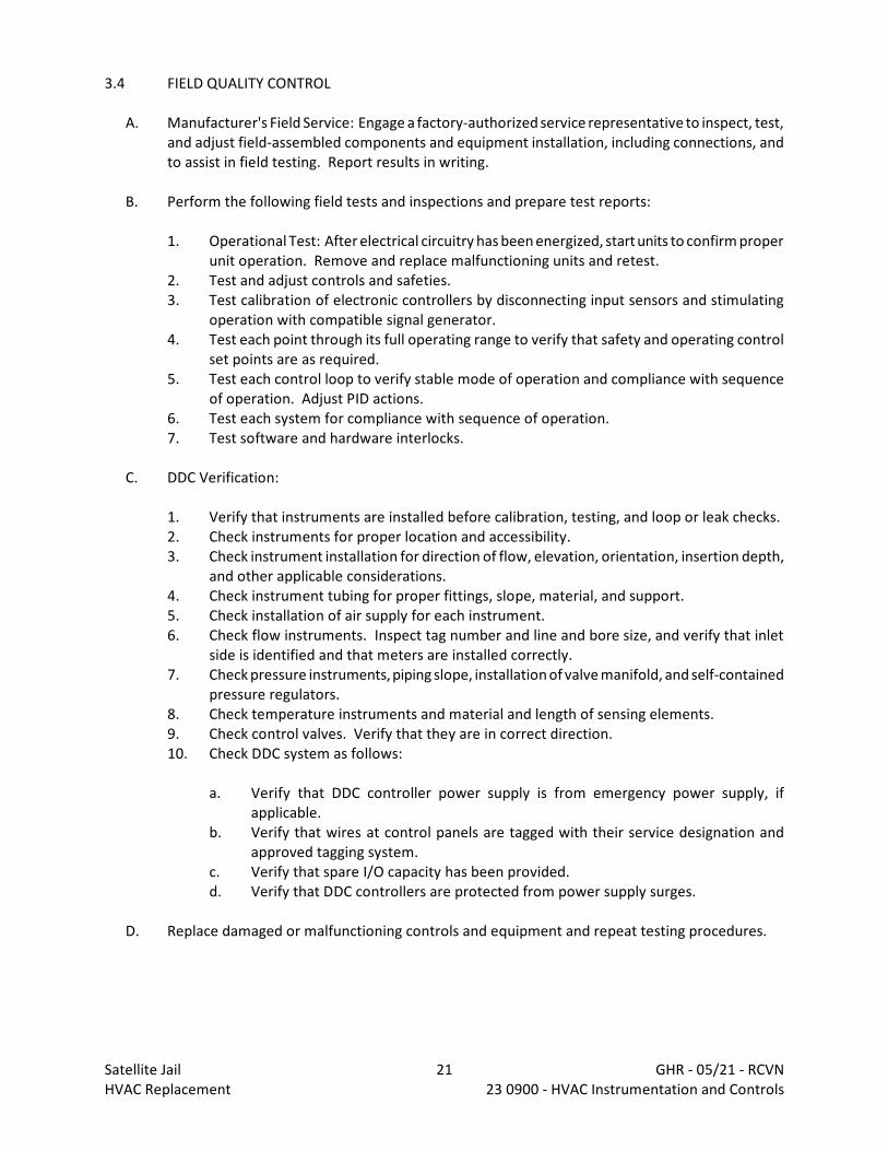
3.4 FIELD QUALITY CONTROL
A. Manufacturer's Field Service: Engage a factory-authorized service representative to inspect, test,and adjust field-assembled components and equipment installation, including connections, andto assist in field testing. Report results in writing.
B. Perform the following field tests and inspections and prepare test reports:
1. Operational Test: After electrical circuitry has been energized, start units to confirm properunit operation. Remove and replace malfunctioning units and retest.
2. Test and adjust controls and safeties.3. Test calibration of electronic controllers by disconnecting input sensors and stimulating
operation with compatible signal generator.4. Test each point through its full operating range to verify that safety and operating control
set points are as required.5. Test each control loop to verify stable mode of operation and compliance with sequence
of operation. Adjust PID actions.6. Test each system for compliance with sequence of operation.7. Test software and hardware interlocks.
C. DDC Verification:
1. Verify that instruments are installed before calibration, testing, and loop or leak checks.2. Check instruments for proper location and accessibility.3. Check instrument installation for direction of flow, elevation, orientation, insertion depth,
and other applicable considerations.4. Check instrument tubing for proper fittings, slope, material, and support.5. Check installation of air supply for each instrument.6. Check flow instruments. Inspect tag number and line and bore size, and verify that inlet
side is identified and that meters are installed correctly.7. Check pressure instruments, piping slope, installation of valve manifold, and self-contained
pressure regulators.8. Check temperature instruments and material and length of sensing elements.9. Check control valves. Verify that they are in correct direction.10. Check DDC system as follows:
a. Verify that DDC controller power supply is from emergency power supply, ifapplicable.
b. Verify that wires at control panels are tagged with their service designation andapproved tagging system.
c. Verify that spare I/O capacity has been provided.d. Verify that DDC controllers are protected from power supply surges.
D. Replace damaged or malfunctioning controls and equipment and repeat testing procedures.
Satellite Jail 21 GHR - 05/21 - RCVNHVAC Replacement 23 0900 - HVAC Instrumentation and Controls
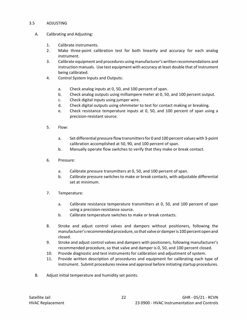
3.5 ADJUSTING
A. Calibrating and Adjusting:
1. Calibrate instruments.2. Make three-point calibration test for both linearity and accuracy for each analog
instrument.3. Calibrate equipment and procedures using manufacturer's written recommendations and
instruction manuals. Use test equipment with accuracy at least double that of instrumentbeing calibrated.
4. Control System Inputs and Outputs:
a. Check analog inputs at 0, 50, and 100 percent of span.b. Check analog outputs using milliampere meter at 0, 50, and 100 percent output.c. Check digital inputs using jumper wire.d. Check digital outputs using ohmmeter to test for contact making or breaking.e. Check resistance temperature inputs at 0, 50, and 100 percent of span using a
precision-resistant source.
5. Flow:
a. Set differential pressure flow transmitters for 0 and 100 percent values with 3-pointcalibration accomplished at 50, 90, and 100 percent of span.
b. Manually operate flow switches to verify that they make or break contact.
6. Pressure:
a. Calibrate pressure transmitters at 0, 50, and 100 percent of span.b. Calibrate pressure switches to make or break contacts, with adjustable differential
set at minimum.
7. Temperature:
a. Calibrate resistance temperature transmitters at 0, 50, and 100 percent of spanusing a precision-resistance source.
b. Calibrate temperature switches to make or break contacts.
8. Stroke and adjust control valves and dampers without positioners, following themanufacturer's recommended procedure, so that valve or damper is 100 percent open andclosed.
9. Stroke and adjust control valves and dampers with positioners, following manufacturer'srecommended procedure, so that valve and damper is 0, 50, and 100 percent closed.
10. Provide diagnostic and test instruments for calibration and adjustment of system.11. Provide written description of procedures and equipment for calibrating each type of
instrument. Submit procedures review and approval before initiating startup procedures.
B. Adjust initial temperature and humidity set points.
Satellite Jail 22 GHR - 05/21 - RCVNHVAC Replacement 23 0900 - HVAC Instrumentation and Controls
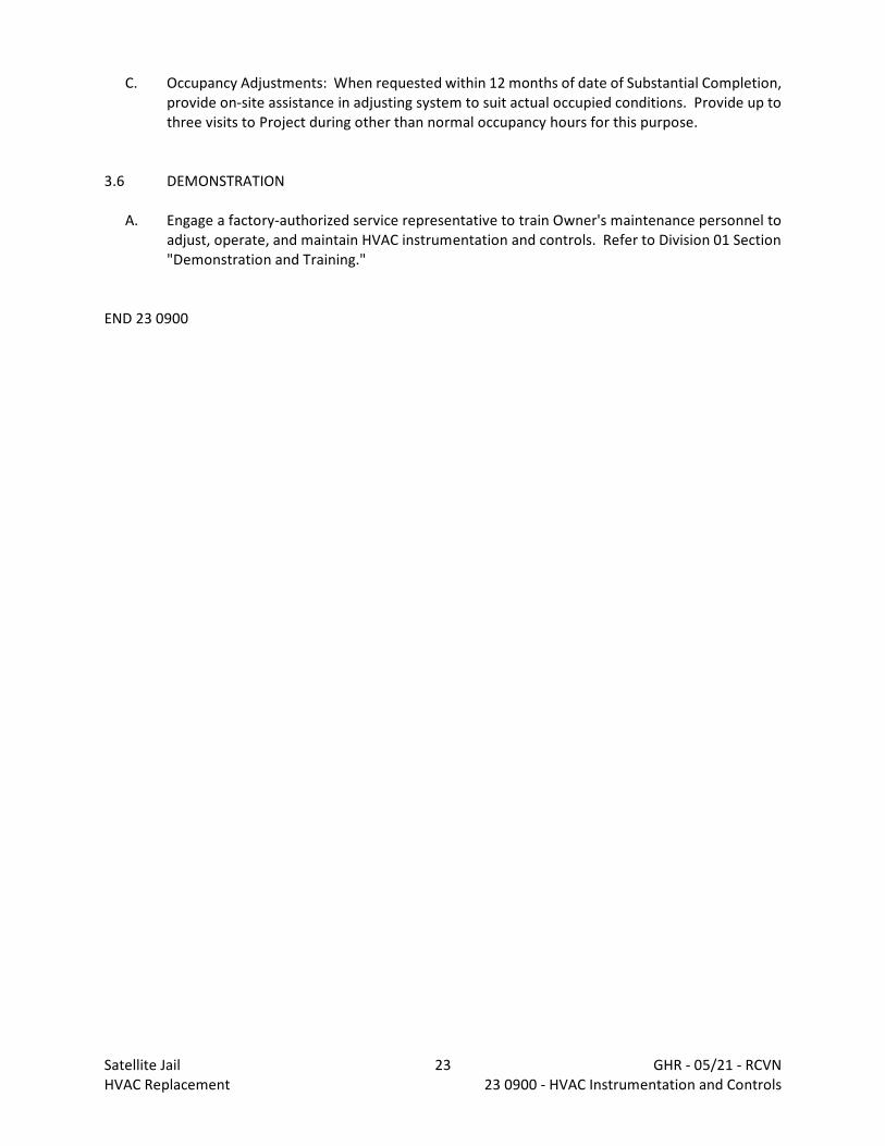
C. Occupancy Adjustments: When requested within 12 months of date of Substantial Completion,provide on-site assistance in adjusting system to suit actual occupied conditions. Provide up tothree visits to Project during other than normal occupancy hours for this purpose.
3.6 DEMONSTRATION
A. Engage a factory-authorized service representative to train Owner's maintenance personnel toadjust, operate, and maintain HVAC instrumentation and controls. Refer to Division 01 Section"Demonstration and Training."
END 23 0900
Satellite Jail 23 GHR - 05/21 - RCVNHVAC Replacement 23 0900 - HVAC Instrumentation and Controls

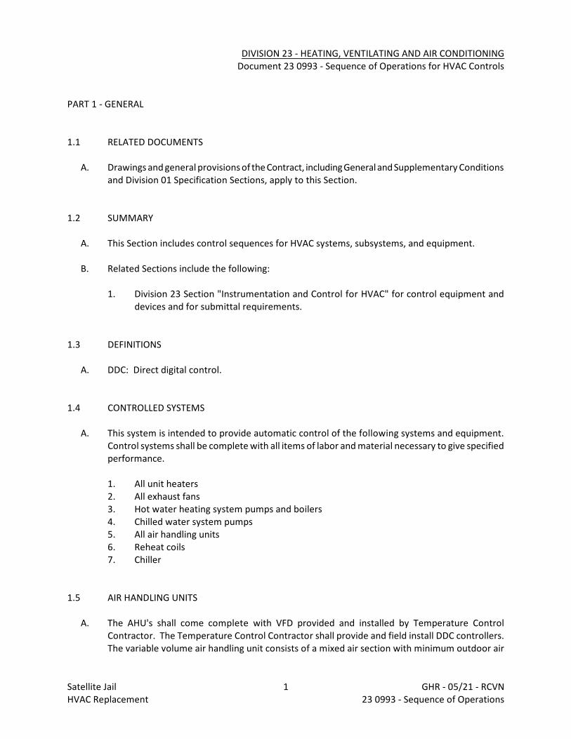
DIVISION 23 - HEATING, VENTILATING AND AIR CONDITIONINGDocument 23 0993 - Sequence of Operations for HVAC Controls
PART 1 - GENERAL
1.1 RELATED DOCUMENTS
A. Drawings and general provisions of the Contract, including General and Supplementary Conditionsand Division 01 Specification Sections, apply to this Section.
1.2 SUMMARY
A. This Section includes control sequences for HVAC systems, subsystems, and equipment.
B. Related Sections include the following:
1. Division 23 Section "Instrumentation and Control for HVAC" for control equipment anddevices and for submittal requirements.
1.3 DEFINITIONS
A. DDC: Direct digital control.
1.4 CONTROLLED SYSTEMS
A. This system is intended to provide automatic control of the following systems and equipment. Control systems shall be complete with all items of labor and material necessary to give specifiedperformance.
1. All unit heaters2. All exhaust fans3. Hot water heating system pumps and boilers4. Chilled water system pumps5. All air handling units6. Reheat coils7. Chiller
1.5 AIR HANDLING UNITS
A. The AHU's shall come complete with VFD provided and installed by Temperature ControlContractor. The Temperature Control Contractor shall provide and field install DDC controllers. The variable volume air handling unit consists of a mixed air section with minimum outdoor air
Satellite Jail 1 GHR - 05/21 - RCVNHVAC Replacement 23 0993 - Sequence of Operations
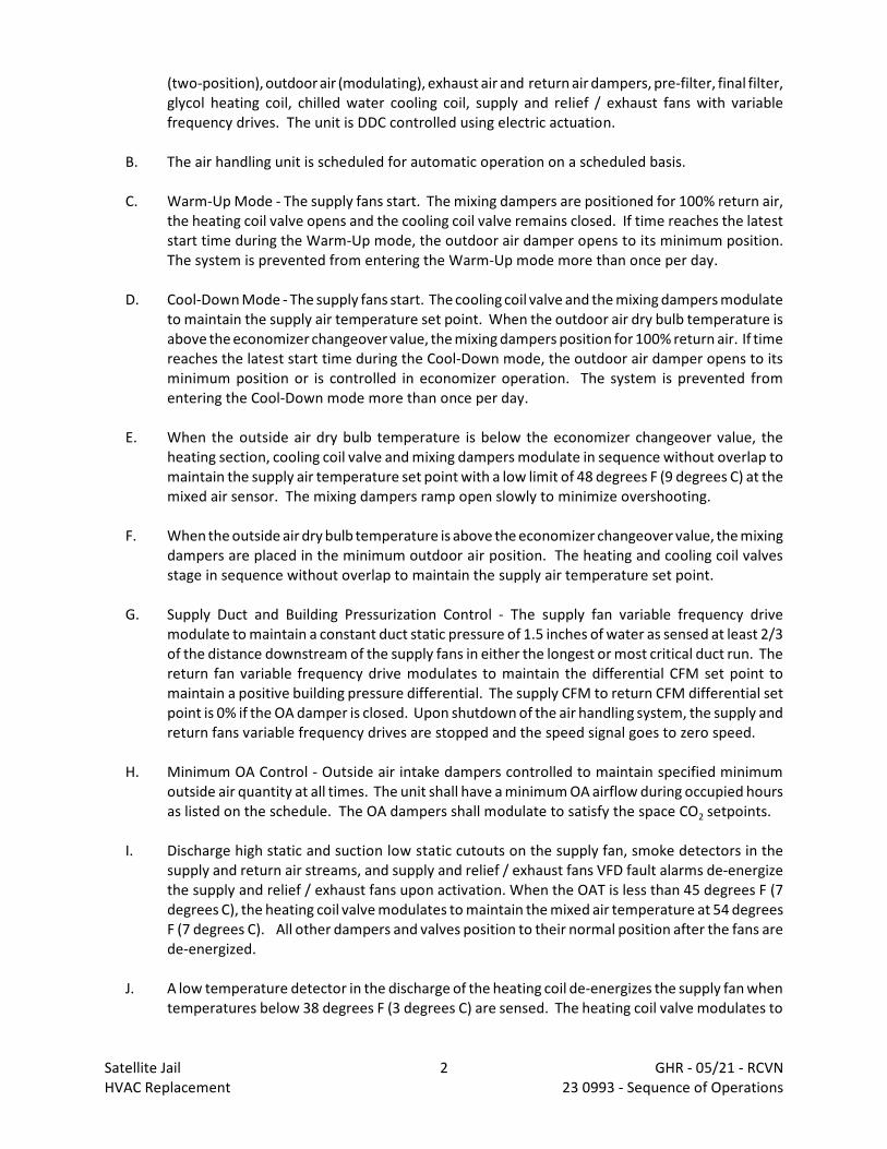
(two-position), outdoor air (modulating), exhaust air and return air dampers, pre-filter, final filter,glycol heating coil, chilled water cooling coil, supply and relief / exhaust fans with variablefrequency drives. The unit is DDC controlled using electric actuation.
B. The air handling unit is scheduled for automatic operation on a scheduled basis.
C. Warm-Up Mode - The supply fans start. The mixing dampers are positioned for 100% return air,the heating coil valve opens and the cooling coil valve remains closed. If time reaches the lateststart time during the Warm-Up mode, the outdoor air damper opens to its minimum position. The system is prevented from entering the Warm-Up mode more than once per day.
D. Cool-Down Mode - The supply fans start. The cooling coil valve and the mixing dampers modulateto maintain the supply air temperature set point. When the outdoor air dry bulb temperature isabove the economizer changeover value, the mixing dampers position for 100% return air. If timereaches the latest start time during the Cool-Down mode, the outdoor air damper opens to itsminimum position or is controlled in economizer operation. The system is prevented fromentering the Cool-Down mode more than once per day.
E. When the outside air dry bulb temperature is below the economizer changeover value, theheating section, cooling coil valve and mixing dampers modulate in sequence without overlap tomaintain the supply air temperature set point with a low limit of 48 degrees F (9 degrees C) at themixed air sensor. The mixing dampers ramp open slowly to minimize overshooting.
F. When the outside air dry bulb temperature is above the economizer changeover value, the mixingdampers are placed in the minimum outdoor air position. The heating and cooling coil valvesstage in sequence without overlap to maintain the supply air temperature set point.
G. Supply Duct and Building Pressurization Control - The supply fan variable frequency drivemodulate to maintain a constant duct static pressure of 1.5 inches of water as sensed at least 2/3of the distance downstream of the supply fans in either the longest or most critical duct run. Thereturn fan variable frequency drive modulates to maintain the differential CFM set point tomaintain a positive building pressure differential. The supply CFM to return CFM differential setpoint is 0% if the OA damper is closed. Upon shutdown of the air handling system, the supply andreturn fans variable frequency drives are stopped and the speed signal goes to zero speed.
H. Minimum OA Control - Outside air intake dampers controlled to maintain specified minimumoutside air quantity at all times. The unit shall have a minimum OA airflow during occupied hoursas listed on the schedule. The OA dampers shall modulate to satisfy the space CO2 setpoints.
I. Discharge high static and suction low static cutouts on the supply fan, smoke detectors in thesupply and return air streams, and supply and relief / exhaust fans VFD fault alarms de-energizethe supply and relief / exhaust fans upon activation. When the OAT is less than 45 degrees F (7degrees C), the heating coil valve modulates to maintain the mixed air temperature at 54 degreesF (7 degrees C). All other dampers and valves position to their normal position after the fans arede-energized.
J. A low temperature detector in the discharge of the heating coil de-energizes the supply fan whentemperatures below 38 degrees F (3 degrees C) are sensed. The heating coil valve modulates to
Satellite Jail 2 GHR - 05/21 - RCVNHVAC Replacement 23 0993 - Sequence of Operations

maintain the mixed air temperature at 54 degrees F (7 degrees C). All other dampers and valvesposition to their normal position after the fans are de-energized.
K. Current switches are installed on the load side of the supply and relief / exhaust fans VFDs. TheDDC system uses the switches to confirm the fans are in the desired state (i.e. on or off) andgenerates an alarm if status deviates from DDC start/stop control. The DDC system generates aVFD trouble alarm independent from the fan status.
L. During economizer free cooling operation as the need for additional outside air exceeds theairflow of the associated ERV, the RTU OA damper shall modulate open and relief fan shallenergize to maintain space differential pressure. Relief fans associated with air handler shallmodulate independently to maintain positive building / space pressure. Coordinate final locationof space differential pressure sensors with HVAC and General Contractors.
M. AHU-5 only: Remote switch (to be located in storm shelter away from VFD) shall have the abilityto force VFD into bypass mode allowing motor to run at full speed. When in bypass mode, motorshall run at full speed completely independent of building automation system such that damageto BAS components shall not infringe on motor's ability to operate. Switch and wiring shallprovide a contact closure to put VFD in bypass mode and shall be furnished and installed byelectrical trade.
1.6 CHILLED WATER PUMPS WITH VARIABLE FREQUENCY DRIVES
A. The chilled water system consists of two chilled water pumps with individual variable frequencydrives. The system is DDC controlled with electric actuation.
B. Chilled Water Pump Alternation - Chilled water pumps alternate to equalize runtime. Selectionof the lead pump is evaluated on a weekly basis. The pump with the least runtime is the leadpump. The pump with the most runtime is the lag pump.
C. Chilled Water Pump Control - The variable frequency drive modulates pump speed to maintainsystem differential pressure of 20 PSI (adjustable) as sensed near the end of the piping run. If thesystem differential pressure is below set point and the lead pump is at 100% speed for a timeinterval of 15 minutes, the lag pump starts. With both pumps on, the variable frequency drivesare modulated in unison to maintain system differential pressure. If the system differential is atset point and both pumps are on and at 45% speed for a time interval of 15 minutes the lag pumpis stopped.
D. The DDC system uses current switches to confirm the lead pump is in the desired state (i.e. on oroff) and generates an alarm if status deviates from DDC start/stop control. If the lead pump goesinto alarm, the lag pump starts.
1.7 HOT WATER SYSTEM AND VARIABLE SPEED HOT WATER PUMPS
Satellite Jail 3 GHR - 05/21 - RCVNHVAC Replacement 23 0993 - Sequence of Operations
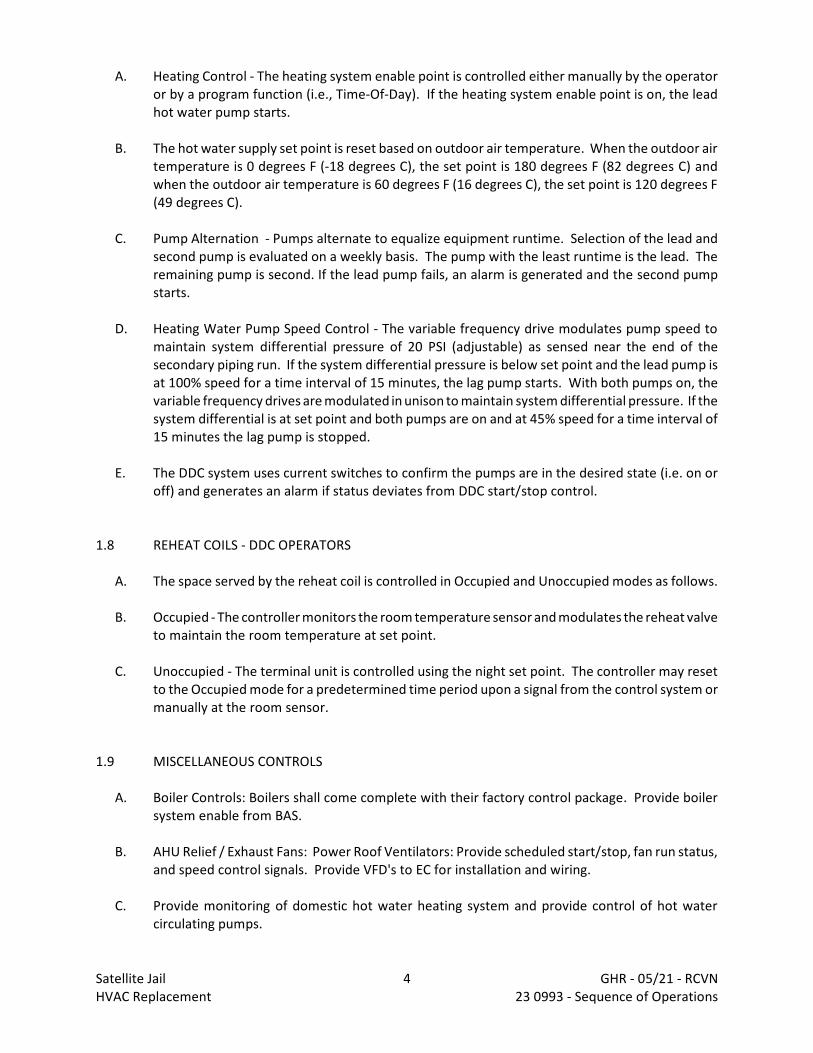
A. Heating Control - The heating system enable point is controlled either manually by the operatoror by a program function (i.e., Time-Of-Day). If the heating system enable point is on, the leadhot water pump starts.
B. The hot water supply set point is reset based on outdoor air temperature. When the outdoor airtemperature is 0 degrees F (-18 degrees C), the set point is 180 degrees F (82 degrees C) andwhen the outdoor air temperature is 60 degrees F (16 degrees C), the set point is 120 degrees F(49 degrees C).
C. Pump Alternation - Pumps alternate to equalize equipment runtime. Selection of the lead andsecond pump is evaluated on a weekly basis. The pump with the least runtime is the lead. Theremaining pump is second. If the lead pump fails, an alarm is generated and the second pumpstarts.
D. Heating Water Pump Speed Control - The variable frequency drive modulates pump speed tomaintain system differential pressure of 20 PSI (adjustable) as sensed near the end of thesecondary piping run. If the system differential pressure is below set point and the lead pump isat 100% speed for a time interval of 15 minutes, the lag pump starts. With both pumps on, thevariable frequency drives are modulated in unison to maintain system differential pressure. If thesystem differential is at set point and both pumps are on and at 45% speed for a time interval of15 minutes the lag pump is stopped.
E. The DDC system uses current switches to confirm the pumps are in the desired state (i.e. on oroff) and generates an alarm if status deviates from DDC start/stop control.
1.8 REHEAT COILS - DDC OPERATORS
A. The space served by the reheat coil is controlled in Occupied and Unoccupied modes as follows.
B. Occupied - The controller monitors the room temperature sensor and modulates the reheat valveto maintain the room temperature at set point.
C. Unoccupied - The terminal unit is controlled using the night set point. The controller may resetto the Occupied mode for a predetermined time period upon a signal from the control system ormanually at the room sensor.
1.9 MISCELLANEOUS CONTROLS
A. Boiler Controls: Boilers shall come complete with their factory control package. Provide boilersystem enable from BAS.
B. AHU Relief / Exhaust Fans: Power Roof Ventilators: Provide scheduled start/stop, fan run status,and speed control signals. Provide VFD's to EC for installation and wiring.
C. Provide monitoring of domestic hot water heating system and provide control of hot watercirculating pumps.
Satellite Jail 4 GHR - 05/21 - RCVNHVAC Replacement 23 0993 - Sequence of Operations
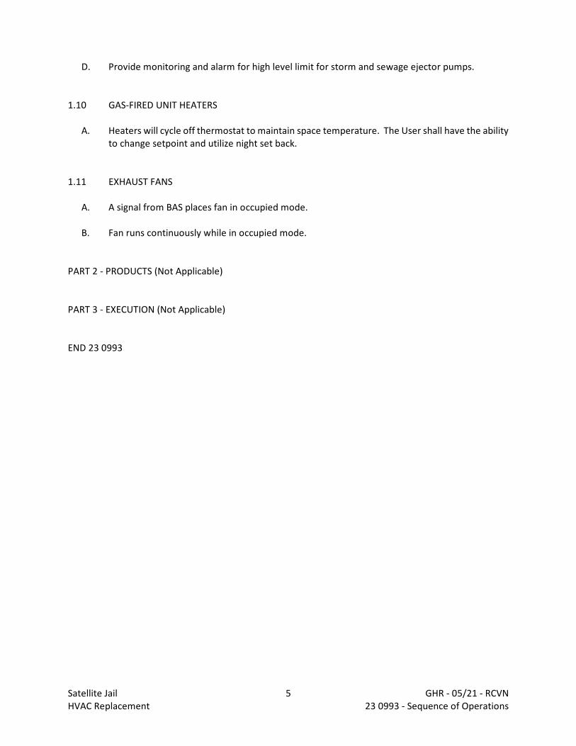
D. Provide monitoring and alarm for high level limit for storm and sewage ejector pumps.
1.10 GAS-FIRED UNIT HEATERS
A. Heaters will cycle off thermostat to maintain space temperature. The User shall have the abilityto change setpoint and utilize night set back.
1.11 EXHAUST FANS
A. A signal from BAS places fan in occupied mode.
B. Fan runs continuously while in occupied mode.
PART 2 - PRODUCTS (Not Applicable)
PART 3 - EXECUTION (Not Applicable)
END 23 0993
Satellite Jail 5 GHR - 05/21 - RCVNHVAC Replacement 23 0993 - Sequence of Operations
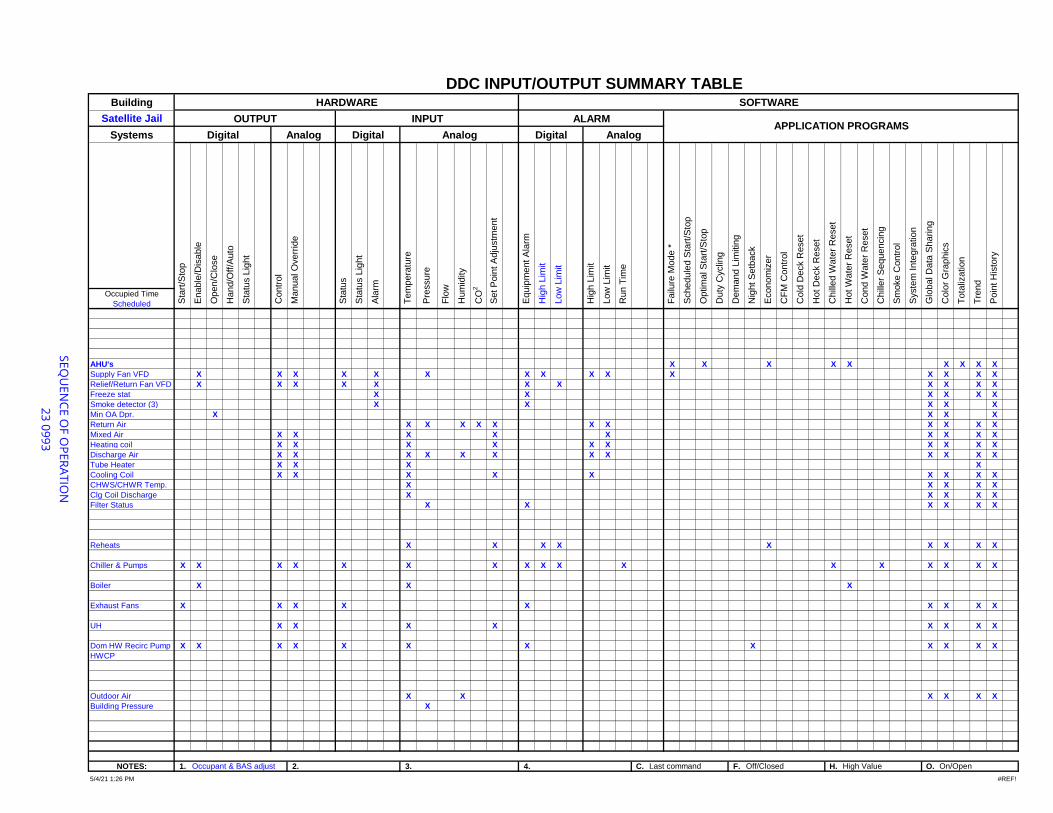
Building
Satellite Jail
Systems
Occupied Time
Scheduled
AHU's X X X X X X X X X
Supply Fan VFD X X X X X X X X X X X X X X X
Relief/Return Fan VFD X X X X X X X X X X X
Freeze stat X X X X X X
Smoke detector (3) X X X X X
Min OA Dpr. X X X X
Return Air X X X X X X X X X X X
Mixed Air X X X X X X X X X
Heating coil X X X X X X X X X X
Discharge Air X X X X X X X X X X X X
Tube Heater X X X X
Cooling Coil X X X X X X X X X
CHWS/CHWR Temp. X X X X X
Clg Coil Discharge X X X X X
Filter Status X X X X X X
Reheats X X X X X X X X X
Chiller & Pumps X X X X X X X X X X X X X X X X X
Boiler X X X
Exhaust Fans X X X X X X X X X
UH X X X X X X X X
Dom HW Recirc Pump X X X X X X X X X X X X
HWCP
Outdoor Air X X X X X X
Building Pressure X
NOTES: 1. 2. 3. 4. C. F. H. O.
SE
QU
EN
CE
OF O
PE
RA
TIO
N
23
09
93
Hum
idity
CO
2
Duty
Cyclin
g
#REF!
Dem
and L
imitin
g
Nig
ht S
etb
ack
On/Open
Hig
h L
imit
Colo
r G
raphic
s
Tota
lization
Syste
m Inte
gra
tion
Failu
re M
ode *
Optim
al S
tart
/Sto
p
Glo
bal D
ata
Sharing
AnalogAPPLICATION PROGRAMS
HARDWARE
OUTPUT INPUT
Poin
t H
isto
ry
Low
Lim
it
Cond W
ate
r R
eset
Low
Lim
it
Run T
ime
Tre
nd
CF
M C
ontr
ol
Digital
DDC INPUT/OUTPUT SUMMARY TABLE SOFTWARE
ALARM
Hig
h L
imit
Equip
ment A
larm
Set P
oin
t A
dju
stm
ent
Cold
Deck R
eset
Hot D
eck R
eset
Chill
ed W
ate
r R
eset
Open/C
lose
Hand/O
ff/A
uto
Sta
tus
Tem
pera
ture
5/4/21 1:26 PM
Flo
w
Enable
/Dis
able
Contr
ol
Manual O
verr
ide
Sta
tus L
ight
Sta
tus L
ight
Ala
rm
Sta
rt/S
top
Pre
ssure
Off/Closed
Sm
oke C
ontr
ol
Analog Digital Analog
Schedule
d S
tart
/Sto
p
Econom
izer
High ValueOccupant & BAS adjust Last command
Chill
er
Sequencin
g
Hot W
ate
r R
eset
Digital
DIVISION 23 - HEATING, VENTILATING AND AIR CONDITIONINGDocument 23 2300 - Refrigerant Piping
PART 1 - GENERAL
1.1 SUMMARY
A. This Section includes refrigerant piping used for air-conditioning applications.
1.2 PERFORMANCE REQUIREMENTS
A. Line Test Pressure for Refrigerant R-410a:
1. Suction Lines for Air-Conditioning Applications: 320 psig.2. Suction Lines for Heat-Pump Applications: 520 psig.3. Hot-Gas and Liquid Lines: 520 psig.
1.3 SUBMITTALS
A. Product Data: For each type of valve and refrigerant piping specialty indicated. Include pressuredrop based on manufacturer's test data.
B. Shop Drawings: Show layout of refrigerant piping and specialties, including pipe, tube, and fittingsizes, flow capacities, valve arrangements and locations, slopes of horizontal runs, oil traps,double risers, wall and floor penetrations, and equipment connection details. Show interface andspatial relationships between piping and equipment.
1. Refrigerant piping indicated on Drawings is schematic only. Size piping and design actualpiping layout, including oil traps, double risers, specialties, and pipe and tube sizes toaccommodate, as a minimum, equipment provided, elevation difference betweencompressor and evaporator, and length of piping to ensure proper operation andcompliance with warranties of connected equipment.
C. Field quality-control test reports.
D. Operation and maintenance data.
1.4 QUALITY ASSURANCE
A. Comply with ASHRAE 15, "Safety Code for Refrigeration Systems."
B. Comply with ASME B31.5, "Refrigeration Piping and Heat Transfer Components."
Satellite Jail 1 GHR - 05/21 - RCVNHVAC Replacement 23 2300 - Refrigerant Piping

1.5 PRODUCT STORAGE AND HANDLING
A. Store piping in a clean and protected area with end caps in place to ensure that piping interior andexterior are clean when installed.
PART 2 - PRODUCTS
2.1 COPPER TUBE AND FITTINGS
A. Copper Tube: ASTM B 280, Type ACR.
B. Wrought-Copper Fittings: ASME B16.22.
C. Wrought-Copper Unions: ASME B16.22.
D. Solder Filler Metals: ASTM B 32. Use 95-5 tin antimony or alloy HB solder to join copper socketfittings on copper pipe.
E. Brazing Filler Metals: AWS A5.8.
F. Flexible Connectors:
1. Body: Tin-bronze bellows with woven, flexible, tinned-bronze-wire-reinforced protectivejacket.
2. End Connections: Socket ends.3. Offset Performance: Capable of minimum 3/4-inch misalignment in minimum 7-inch- long
assembly.4. Pressure Rating: Factory test at minimum 500 psig.5. Maximum Operating Temperature: 250 deg F.
2.2 VALVES AND SPECIALTIES
A. Diaphragm Packless Valves:
1. Body and Bonnet: Forged brass or cast bronze; globe design with straight-through or anglepattern.
2. Diaphragm: Phosphor bronze and stainless steel with stainless-steel spring.3. Operator: Rising stem and hand wheel.4. Seat: Nylon.5. End Connections: Socket, union, or flanged.6. Working Pressure Rating: 500 psig.7. Maximum Operating Temperature: 275 deg F.
B. Packed-Angle Valves:
Satellite Jail 2 GHR - 05/21 - RCVNHVAC Replacement 23 2300 - Refrigerant Piping
1. Body and Bonnet: Forged brass or cast bronze.2. Packing: Molded stem, back seating, and replaceable under pressure.3. Operator: Rising stem.4. Seat: Nonrotating, self-aligning polytetrafluoroethylene.5. Seal Cap: Forged-brass or valox hex cap.6. End Connections: Socket, union, threaded, or flanged.7. Working Pressure Rating: 500 psig.8. Maximum Operating Temperature: 275 deg F.
C. Check Valves:
1. Body: Ductile iron, forged brass, or cast bronze; globe pattern.2. Bonnet: Bolted ductile iron, forged brass, or cast bronze; or brass hex plug.3. Piston: Removable polytetrafluoroethylene seat.4. Closing Spring: Stainless steel.5. Manual Opening Stem: Seal cap, plated-steel stem, and graphite seal.6. End Connections: Socket, union, threaded, or flanged.7. Maximum Opening Pressure: 0.50 psig.8. Working Pressure Rating: 500 psig.9. Maximum Operating Temperature: 275 deg F.
D. Service Valves:
1. Body: Forged brass with brass cap including key end to remove core.2. Core: Removable ball-type check valve with stainless-steel spring.3. Seat: Polytetrafluoroethylene.4. End Connections: Copper spring.5. Working Pressure Rating: 500 psig.
E. Safety Relief Valves: Provided by manufacturer.
F. Thermostatic Expansion Valves: Provided by manufacturer.
G. Moisture/Liquid Indicators: Provided by manufacturer.
H. Replaceable-Core Filter Dryers: Provided by manufacturer.
I. Permanent Filter Dryers: Provided by manufacturer.
J. Liquid Accumulators: Provided by manufacturer.
2.3 REFRIGERANTS
A. Available Manufacturers: Subject to compliance with requirements, manufacturers offeringproducts that may be incorporated into the Work include, but are not limited to, the following:
Satellite Jail 3 GHR - 05/21 - RCVNHVAC Replacement 23 2300 - Refrigerant Piping
B. Manufacturers: Subject to compliance with requirements, provide products by one of thefollowing:
1. Atofina Chemicals, Inc.2. DuPont Company; Fluorochemicals Div.3. Honeywell, Inc.; Genetron Refrigerants.4. INEOS Fluor Americas LLC.
PART 3 - EXECUTION
3.1 PIPING APPLICATIONS
A. Suction Lines NPS 1-1/2 and Smaller for Conventional Air-Conditioning Applications: Type ACR,annealed-temper tubing and wrought-copper fittings with brazed joints.
B. Hot-Gas and Liquid Lines: Copper, Type ACR, annealed-temper tubing and wrought-copperfittings with brazed or soldered joints.
C. Safety-Relief-Valve Discharge Piping: Copper, Type ACR, drawn-temper tubing andwrought-copper fittings with soldered joints.
3.2 VALVE AND SPECIALTY APPLICATIONS
A. Install diaphragm packless valves in liquid and discharge lines of compressor.
B. Install service valves for gage taps at strainers if they are not an integral part of strainers.
C. Install a check valve at the compressor discharge and a liquid accumulator at the compressorsuction connection.
D. Except as otherwise indicated, install diaphragm packless valves on inlet and outlet side of filterdryers.
E. Install a full-sized, three-valve bypass around filter dryers.
F. Install safety relief valves where required by ASME Boiler and Pressure Vessel Code. Pipesafety-relief-valve discharge line to outside according to ASHRAE 15.
G. Install moisture/liquid indicators in liquid line at the inlet of the thermostatic expansion valve orat the inlet of the evaporator coil capillary tube.
H. Install strainers upstream from and adjacent to the following unless they are furnished as anintegral assembly for device being protected.
Satellite Jail 4 GHR - 05/21 - RCVNHVAC Replacement 23 2300 - Refrigerant Piping
I. Install filter dryers in liquid line between compressor and thermostatic expansion valve, and inthe suction line at the compressor.
J. Install flexible connectors at compressors.
3.3 PIPING INSTALLATION
A. Drawing plans, schematics, and diagrams indicate general location and arrangement of pipingsystems; indicated locations and arrangements were used to size pipe and calculate friction loss,expansion, pump sizing, and other design considerations. Install piping as indicated unlessdeviations to layout are approved on Shop Drawings.
B. Install refrigerant piping according to ASHRAE 15.
C. Install piping in concealed locations unless otherwise indicated and except in equipment roomsand service areas.
D. Install piping indicated to be exposed and piping in equipment rooms and service areas at rightangles or parallel to building walls. Diagonal runs are prohibited unless specifically indicatedotherwise.
E. Install piping above accessible ceilings to allow sufficient space for ceiling panel removal.
F. Install piping adjacent to machines to allow service and maintenance.
G. Install piping free of sags and bends.
H. Install fittings for changes in direction and branch connections.
I. Select system components with pressure rating equal to or greater than system operatingpressure.
J. Refer to Division 23 Sections "Instrumentation and Control for HVAC" and "Sequence ofOperations for HVAC Controls" for solenoid valve controllers, control wiring, and sequence ofoperation.
K. Install piping as short and direct as possible, with a minimum number of joints, elbows, andfittings.
L. Arrange piping to allow inspection and service of refrigeration equipment. Install valves andspecialties in accessible locations to allow for service and inspection. Install access doors orpanels as specified in Division 08 Section "Access Doors and Frames" if valves or equipmentrequiring maintenance is concealed behind finished surfaces.
M. Install refrigerant piping in rigid or flexible conduit in locations where exposed to mechanicalinjury.
Satellite Jail 5 GHR - 05/21 - RCVNHVAC Replacement 23 2300 - Refrigerant Piping
N. Slope refrigerant piping as follows:
1. Install horizontal hot-gas discharge piping with a uniform slope downward away fromcompressor.
2. Install traps and double risers to entrain oil in vertical runs.3. Liquid lines may be installed level.
O. When brazing or soldering, remove solenoid-valve coils and sight glasses; also remove valvestems, seats, and packing, and accessible internal parts of refrigerant specialties. Do not applyheat near expansion-valve bulb.
P. Install piping with adequate clearance between pipe and adjacent walls and hangers or betweenpipes for insulation installation.
Q. Identify refrigerant piping and valves according to Division 23 Section "Identification for HVACPiping and Equipment."
R. Install sleeves for piping penetrations of walls, ceilings, and floors. Comply with requirements forsleeves specified in Division 23 Section "Sleeves and Sleeve Seals for HVAC Piping."
S. Install escutcheons for piping penetrations of walls, ceilings, and floors. Comply withrequirements for escutcheons specified in Division 23 Section "Escutcheons for HVAC Piping."
3.4 PIPE JOINT CONSTRUCTION
A. Soldered Joints: Construct joints according to ASTM B 828 or CDA's "Copper Tube Handbook."
B. Brazed Joints: Construct joints according to AWS's "Brazing Handbook," Chapter "Pipe and Tube."
1. Use Type BcuP, copper-phosphorus alloy for joining copper socket fittings with copperpipe.
2. Use Type BAg, cadmium-free silver alloy for joining copper with bronze or steel.
3.5 HANGERS AND SUPPORTS
A. Hanger, support, and anchor products are specified in Division 23 Section "Hangers and Supportsfor HVAC Piping and Equipment."
B. Install the following pipe attachments:
1. Adjustable steel clevis hangers for individual horizontal runs less than 20 feet long.2. Roller hangers and spring hangers for individual horizontal runs 20 feet or longer.3. Pipe Roller: MSS SP-58, Type 44 for multiple horizontal piping 20 feet or longer, supported
on a trapeze.4. Spring hangers to support vertical runs.
Satellite Jail 6 GHR - 05/21 - RCVNHVAC Replacement 23 2300 - Refrigerant Piping

5. Copper-clad hangers and supports for hangers and supports in direct contact with copperpipe.
C. Install hangers for copper tubing with the following maximum spacing and minimum rod sizes:
1. NPS 1/2: Maximum span, 60 inches; minimum rod size, 1/4 inch.2. NPS 5/8: Maximum span, 60 inches; minimum rod size, 1/4 inch.3. NPS 1: Maximum span, 72 inches; minimum rod size, 1/4 inch.4. NPS 1-1/4: Maximum span, 96 inches; minimum rod size, 3/8 inch.5. NPS 1-1/2: Maximum span, 96 inches; minimum rod size, 3/8 inch.6. NPS 2: Maximum span, 96 inches; minimum rod size, 3/8 inch.7. NPS 2-1/2: Maximum span, 108 inches; minimum rod size, 3/8 inch.8. NPS 3: Maximum span, 10 feet; minimum rod size, 3/8 inch.9. NPS 4: Maximum span, 12 feet; minimum rod size, ½ inch.
D. Support multifloor vertical runs at least at each floor.
3.6 FIELD QUALITY CONTROL
A. Perform tests and inspections and prepare test reports.
B. Tests and Inspections:
1. Comply with ASME B31.5, Chapter VI.2. Test refrigerant piping and specialties. Isolate compressor, condenser, evaporator, and
safety devices from test pressure if they are not rated above the test pressure.3. Test high- and low-pressure side piping of each system separately at not less than the
pressures indicated in Part 1 "Performance Requirements" Article.
a. Fill system with nitrogen to the required test pressure.b. System shall maintain test pressure at the manifold gage throughout duration of
test.c. Test joints and fittings with electronic leak detector or by brushing a small amount
of soap and glycerin solution over joints.d. Remake leaking joints using new materials, and retest until satisfactory results are
achieved.
3.7 SYSTEM CHARGING
A. Charge system using the following procedures:
1. Install core in filter dryers after leak test but before evacuation.2. Evacuate entire refrigerant system with a vacuum pump to 500 micrometers. If vacuum
holds for 12 hours, system is ready for charging.3. Break vacuum with refrigerant gas, allowing pressure to build up to 2 psig.4. Charge system with a new filter-dryer core in charging line.
Satellite Jail 7 GHR - 05/21 - RCVNHVAC Replacement 23 2300 - Refrigerant Piping
3.8 ADJUSTING
A. Adjust thermostatic expansion valve to obtain proper evaporator superheat.
B. Adjust high- and low-pressure switch settings to avoid short cycling in response to fluctuatingsuction pressure.
C. Adjust set-point temperature of air-conditioning or chilled-water controllers to the system designtemperature.
D. Perform the following adjustments before operating the refrigeration system, according tomanufacturer's written instructions:
1. Open shutoff valves in condenser water circuit.2. Verify that compressor oil level is correct.3. Open compressor suction and discharge valves.4. Open refrigerant valves except bypass valves that are used for other purposes.5. Check open compressor-motor alignment and verify lubrication for motors and bearings.
E. Replace core of replaceable filter dryer after system has been adjusted and after design flow ratesand pressures are established.
END 23 2300
Satellite Jail 8 GHR - 05/21 - RCVNHVAC Replacement 23 2300 - Refrigerant Piping
DIVISION 23 - HEATING, VENTILATING AND AIR CONDITIONINGDocument 23 2500 - HVAC Water Treatment
PART 1 - GENERAL
1.1 WORK INCLUDES
A. Base Bid
1. Mechanical Contractor: Work includes the following HVAC water-treatment systems:
a. Chemical treatment test equipment.b. HVAC water-treatment chemicals.
1.2 DEFINITIONS
A. EEPROM: Electrically erasable, programmable read-only memory.
B. Low Voltage: As defined in NFPA 70 for circuits and equipment operating at less than 50 V or forremote-control, signaling power-limited circuits.
C. TDS: Total dissolved solids.
1.3 PERFORMANCE REQUIREMENTS
A. Water quality for HVAC systems shall minimize corrosion, scale buildup, and biological growth foroptimum efficiency of HVAC equipment without creating a hazard to operating personnel or theenvironment.
B. Base HVAC water treatment on quality of water available at Project site, HVAC system equipmentmaterial characteristics and functional performance characteristics, operating personnelcapabilities, and requirements and guidelines of authorities having jurisdiction.
C. Closed hydronic systems, including (2) glycol hot water and chilled water loop systems, shall havethe following water qualities:
1. Propylene Glycol
a. This product shall be an industrially inhibited ethylene glycol based antifreezesolution to provide freeze and corrosion protection in HVAC systems such as chilledwater and hot water heating systems. The product shall not make use of any silicatecontaining corrosion inhibitors and should not be formulated to provide corrosionprotection for aluminum or galvanized metals. The product shall be formulated toprovide corrosion protection for the common metals of construction in HVAC
Satellite Jail 1 GHR - 05/21 - RCVNHVAC Replacement 23 2500 - HVAC Water Treatment

systems such as steel, copper, brass, bronze, solders, etc. Corrosion rates on thesemetals as determined under ASTM D1384 shall not exceed 0.5 mils penetration peryear.
Composition % By WeightEthylene Glycol (Total Glycols) 9 2.5%Dye, Inhibitors and Water 7 .5%
Specific Gravity 60/60 F 1 .133-1.140Reserve Alkalinity (ASTM D1121) Minimum 20 mlSulfates and Chlorides Total 5 0 ppmpH (50% Solution) 8 .5-9.0
b. The product shall contain a small percentage of an effective antifoam compound,(such as Dow Corning Antifoam A) to prevent the formation of foam.
c. The product shall be furnished in 55 gallon steel drums which are in good conditionand shall be fitted with standard bung plugs and seals to prevent contamination ofproduct.
2. Solutions shall be 30% ethylene glycol by weight, 14% ethylene glycol by volume. Galvanized steel and / or aluminum shall not be used in contact with glycol solutions.
3. Provide fractional horsepower self-priming transfer pump to allow filling of glycol systems. Pump shall be 120 VAC, cord and plug connected with hose end fittings. Provide 15' lengthof 3/4" flexible hose with hose end fittings to match hose bibb threads and pump fittings. Turn pump and hose over to Owner upon project completion and obtain receipt.
4. Water used in ethylene glycol systems shall be potable, free of foreign materials, and shallhave low (below 50 ppm) levels of chloride, sulfate and hard water ions.
5. Procedure to introduce ethylene glycol to systems:
a. Sample the local potable water supply. If levels of chloride, sulfate or hard waterhardness exceed 50 ppm, then provide acceptable water from off-site and notify theArchitect / Engineer in writing so arrangements can be made by the Owner for awater-softening service.
b. Calculate the amount of ethylene glycol required based on system volume.c. Pressure test system. Repair all leaks.d. Drain enough water from system to provide space for ethylene glycol.e. Add the correct amount of inhibited ethylene glycol solution and water.f. Circulate solution for at least 24 hours to ensure complete mixing. Withdraw one
sample per system and forward sample to ethylene glycol manufacturer foranalyses. Analyses shall include concentration, freeze point, pH, reserve alkalinityand appearance. Submit in a report the degradation products, scale promoters,contaminants, corrosives and inhibitors. Forward copies of potable water and ofglycol analyses to Architect / Engineer.
6. Stencil test dates on expansion tanks below system volume figures.7. Glycol systems shall be separated from potable water systems by air gaps or by
code-approved backflow preventers.8. Acceptable Manufacturers
Satellite Jail 2 GHR - 05/21 - RCVNHVAC Replacement 23 2500 - HVAC Water Treatment
a. Arco Chemical - Chill Safeb. Dow Chemical Dowtherm 4000c. DuPont or Interstate Intercool OP-100-RA-25 (800-322-6145)d. Union Carbide UCAR Food Freeze
9. Forward shop drawing submittals to Architect / Engineer for review. Automotiveanti-freeze is not acceptable.
D. Passivation for Galvanized Steel: For the first 60 days of operation.
1. pH: Maintain a value within 7 to 8.2. Calcium Carbonate Hardness: Maintain a value within 100 to 300 ppm.3. Calcium Carbonate Alkalinity: Maintain a value within 100 to 300 ppm.
1.4 SUBMITTALS
A. Product Data: Include rated capacities, operating characteristics, furnished specialties, andaccessories for the following products:
1. Chemical solution tanks.2. Chemical test equipment.3. Chemical material safety data sheets.
B. Shop Drawings: Pretreatment and chemical treatment equipment showing tanks, maintenancespace required, and piping connections to HVAC systems. Include plans, elevations, sections,details, and attachments to other work.
1. Wiring Diagrams: Power and control wiring.
C. Field quality-control test reports.
D. Other Informational Submittals:
1. Water-Treatment Program: Written sequence of operation on an annual basis for theapplication equipment required to achieve water quality defined in the "PerformanceRequirements" Article above.
2. Water Analysis: Illustrate water quality available at Project site.3. Passivation Confirmation Report: Verify passivation of galvanized-steel surfaces, and
confirm this observation in a letter to Architect.
1.5 QUALITY ASSURANCE
A. HVAC Water-Treatment Service Provider Qualifications: An experienced HVAC water-treatmentservice provider capable of analyzing water qualities, installing water-treatment equipment, andapplying water treatment as specified in this Section.
Satellite Jail 3 GHR - 05/21 - RCVNHVAC Replacement 23 2500 - HVAC Water Treatment
B. Electrical Components, Devices, and Accessories: Listed and labeled as defined in NFPA 70,Article 100, by a testing agency acceptable to authorities having jurisdiction, and marked forintended use.
1.6 MAINTENANCE SERVICE
A. Scope of Maintenance Service: Provide chemicals and service program to maintain waterconditions required above to inhibit corrosion, scale formation, and biological growth forgeothermal ground loop system and equipment. Services and chemicals shall be provided fora period of one year from date of Substantial Completion, and shall include the following:
1. Initial water analysis and HVAC water-treatment recommendations.2. Startup assistance for Contractor to flush the systems, clean with detergents, and initially
fill systems with required chemical treatment prior to operation.3. Periodic field service and consultation.4. Customer report charts and log sheets.5. Laboratory technical analysis.6. Analyses and reports of all chemical items concerning safety and compliance with
government regulations.
PART 2 - PRODUCTS
2.1 MANUFACTURERS
A. Available Manufacturers: Subject to compliance with requirements, manufacturers offeringproducts that may be incorporated into the Work include, but are not limited to, the following:
B. Manufacturers: Subject to compliance with requirements, provide products by one of thefollowing:
1. Ampion Corp.2. Anderson Chemical Co, Inc.3. Aqua-Chem, Inc.; Cleaver-Brooks Div.4. Barclay Chemical Co.; Water Management, Inc.5. Boland Trane Services6. GE Betz.7. GE Osmonics.8. H-O-H Chemicals, Inc.9. Metro Group. Inc. (The); Metropolitan Refining Div.10. ONDEO Nalco Company.11. Watcon, Inc.
2.2 STAINLESS-STEEL PIPES AND FITTINGS
Satellite Jail 4 GHR - 05/21 - RCVNHVAC Replacement 23 2500 - HVAC Water Treatment
A. Stainless-Steel Tubing: Comply with ASTM A 269, Type 316.
B. Stainless-Steel Fittings: Complying with ASTM A 815/A 815M, Type 316, Grade WP-S.
C. Two-Piece, Full-Port, Stainless-Steel Ball Valves: ASTM A 351, Type 316 stainless-steel body;ASTM A 276, Type 316 stainless-steel stem and vented ball, carbon-filled TFE seats, threaded bodydesign with adjustable stem packing, threaded ends, and 250-psig SWP and 600-psig CWP ratings.
D. Three-Piece, Full-Port, Stainless-Steel Ball Valves: ASTM A 351, Type 316 stainless-steel body;ASTM A 276, Type 316 stainless-steel stem and vented ball, threaded body design with adjustablestem packing, threaded ends, and 150-psig SWP and 600-psig CWP rating.
2.3 CHEMICAL TREATMENT TEST EQUIPMENT
A. Test Kit: Manufacturer-recommended equipment and chemicals in a wall-mounting cabinet fortesting pH, TDS, inhibitor, chloride, alkalinity, and hardness; sulfite and testable polymer tests forhigh-pressure boilers, and oxidizing biocide test for open cooling systems.
B. Sample Cooler:
1. Tube: Sample.
a. Size: NPS 1/4 tubing.b. Material: ASTM A 666, Type 316 stainless steel.c. Pressure Rating: Minimum 2000 psig.d. Temperature Rating: Minimum 850 deg F.
2. Shell: Cooling water.
a. Material: ASTM A 666, Type 304 stainless steel.b. Pressure Rating: Minimum 250 psig.c. Temperature Rating: Minimum 450 deg F.
3. Capacities and Characteristics:
a. Tube: Sample.
1) Flow Rate: 0.25 gpm.2) Entering Temperature: 400 deg F.3) Leaving Temperature: 88 deg F.4) Pressure Loss: 6.5 psig.
b. Shell: Cooling water.
1) Flow Rate: 3 gpm.
Satellite Jail 5 GHR - 05/21 - RCVNHVAC Replacement 23 2500 - HVAC Water Treatment
2) Entering Temperature: 70 deg F.3) Pressure Loss: 1.0 psig.
C. Corrosion Test-Coupon Assembly: Constructed of corrosive-resistant material, complete withpiping, valves, and mild steel and copper coupons. Locate copper coupon downstream from mildsteel coupon in the test-coupon assembly.
1. Two-station rack for closed-loop systems.
2.4 CHEMICALS
A. Chemicals shall be as recommended by water-treatment system manufacturer that arecompatible with piping system components and connected equipment, and that can attain waterquality specified in Part 1 "Performance Requirements" Article.
B. Water Softener Chemicals:
1. Mineral: High-capacity, sulfonated-polystyrene ion-exchange resin that is stable overentire pH range with good resistance to bead fracture from attrition or shock. Resinexchange capacity minimum 30,000 grains/cu. ft. of calcium carbonate of resin whenregenerated with 15 lb of salt.
2. Salt for Brine Tanks: High-purity sodium chloride, free of dirt and foreign material. Rockand granulated forms are not acceptable.
PART 3 - EXECUTION
3.1 WATER ANALYSIS
A. Perform an analysis of supply water to determine quality of water available at Project site.
3.2 INSTALLATION
A. Install chemical application equipment on concrete bases, level and plumb. Maintainmanufacturer's recommended clearances. Arrange units so controls and devices that requireservicing are accessible. Anchor chemical tanks and floor-mounting accessories to substrate.
B. Install water testing equipment on wall near water chemical application equipment.
C. Install interconnecting control wiring for chemical treatment controls and sensors.
D. Mount sensors and injectors in piping circuits.
E. Bypass Feeders: Install in closed hydronic systems, including geothermal ground loop system andequipped with the following:
Satellite Jail 6 GHR - 05/21 - RCVNHVAC Replacement 23 2500 - HVAC Water Treatment
1. Install bypass feeder in a bypass circuit around circulating pumps, unless otherwiseindicated on Drawings.
2. Install water meter in makeup water supply.3. Install test-coupon assembly in bypass circuit around circulating pumps, unless otherwise
indicated on Drawings.4. Install a gate or full-port ball isolation valves on inlet, outlet, and drain below feeder inlet.5. Install a swing check on inlet after the isolation valve.
3.3 CONNECTIONS
A. Piping installation requirements are specified in other Division 23 Sections. Drawings indicategeneral arrangement of piping, fittings, and specialties.
B. Install piping adjacent to equipment to allow service and maintenance.
C. Make piping connections between HVAC water-treatment equipment and dissimilar-metal pipingwith dielectric fittings. Dielectric fittings are specified in Division 23 Section "Common WorkResults for HVAC."
D. Install shutoff valves on HVAC water-treatment equipment inlet and outlet. Metal general-dutyvalves are specified in Division 23 Section "General-Duty Valves for HVAC Piping."
E. Refer to Division 22 Section "Domestic Water Piping Specialties" for backflow preventers requiredin makeup water connections to potable-water systems.
F. Confirm applicable electrical requirements in Division 26 Sections for connecting electricalequipment.
G. Ground equipment according to Division 26 Section "Grounding and Bonding for ElectricalSystems."
H. Connect wiring according to Division 26 Section "Low-Voltage Electrical Power Conductors andCables."
3.4 FIELD QUALITY CONTROL
A. Manufacturer's Field Service: Engage a factory-authorized service representative to inspect, test,and adjust components, assemblies, and equipment installations, including connections. Reportresults in writing.
B. Perform tests and inspections and prepare test reports.
1. Manufacturer's Field Service: Engage a factory-authorized service representative to inspectcomponents, assemblies, and equipment installations, including connections, and to assistin testing.
Satellite Jail 7 GHR - 05/21 - RCVNHVAC Replacement 23 2500 - HVAC Water Treatment
C. Tests and Inspections:
1. Inspect field-assembled components and equipment installation, including piping andelectrical connections.
2. Inspect piping and equipment to determine that systems and equipment have beencleaned, flushed, and filled with water, and are fully operational before introducingchemicals for water-treatment system.
3. Place HVAC water-treatment system into operation and calibrate controls during thepreliminary phase of HVAC systems' startup procedures.
4. Do not enclose, cover, or put piping into operation until it is tested and satisfactory testresults are achieved.
5. Test for leaks and defects. If testing is performed in segments, submit separate report foreach test, complete with diagram of portion of piping tested.
6. Leave uncovered and unconcealed new, altered, extended, and replaced water piping untilit has been tested and approved. Expose work that has been covered or concealed beforeit has been tested and approved.
7. Cap and subject piping to static water pressure of 50 psig above operating pressure,without exceeding pressure rating of piping system materials. Isolate test source and allowtest pressure to stand for four hours. Leaks and loss in test pressure constitute defects.
8. Repair leaks and defects with new materials and retest piping until no leaks exist.
D. Remove and replace malfunctioning units and retest as specified above.
E. Sample boiler water at one-week intervals after boiler startup for a period of five weeks, andprepare test report advising Owner of changes necessary to adhere to Part 1 "PerformanceRequirements" Article for each required characteristic. Sample boiler water at eight-weekintervals following the testing noted above to show that automatic chemical-feed systems aremaintaining water quality within performance requirements specified in this Section.
F. At eight-week intervals following Substantial Completion, perform separate water analyses onhydronic systems to show that automatic chemical-feed systems are maintaining water qualitywithin performance requirements specified in this Section. Submit written reports of wateranalysis advising Owner of changes necessary to adhere to Part 1 "Performance Requirements"Article.
G. Comply with ASTM D 3370 and with the following standards:
1. Silica: ASTM D 859.2. Steam System: ASTM D 1066.3. Acidity and Alkalinity: ASTM D 1067.4. Iron: ASTM D 1068.5. Water Hardness: ASTM D 1126.
3.5 DEMONSTRATION
Satellite Jail 8 GHR - 05/21 - RCVNHVAC Replacement 23 2500 - HVAC Water Treatment
A. Engage a factory-authorized service representative to train Owner’s maintenance personnel toadjust, operate, and maintain HVAC water-treatment systems and equipment. Refer toDivision 01 Section "Demonstration and Training."
B. Training: Provide a "how-to-use" self-contained breathing apparatus video that details exactoperating procedures of equipment.
END 23 2500
Satellite Jail 9 GHR - 05/21 - RCVNHVAC Replacement 23 2500 - HVAC Water Treatment

DIVISION 23 - HEATING, VENTILATING AND AIR CONDITIONINGDocument 23 3113 - Metal Ducts
PART 1 - GENERAL
1.1 RELATED DOCUMENTS
A. Drawings and general provisions of the Contract, including General and Supplementary Conditionsand Division 01 Specification Sections, apply to this Section.
1.2 SUMMARY
A. Section Includes:
1. Single-wall rectangular ducts and fittings.2. Double-wall round ducts and fittings.3. Sheet metal materials.4. Duct liner.5. Sealants and gaskets.6. Hangers and supports.7. Louvers.8. Single-wall round ducts and fittings.
B. Related Sections:
1. Division 23 Section "Testing, Adjusting, and Balancing for HVAC" for testing, adjusting, andbalancing requirements for metal ducts.
2. Division 23 Section "Air Duct Accessories" for dampers, sound-control devices,duct-mounting access doors and panels, turning vanes, and flexible ducts.
1.3 PERFORMANCE REQUIREMENTS
A. Structural Performance: Duct hangers and supports shall withstand the effects of gravity loadsand stresses within limits and under conditions described in SMACNA's "HVAC Duct ConstructionStandards - Metal and Flexible".
1.4 SUBMITTALS
A. Product Data: For each type of the following products:
1. Liners and adhesives.2. Sealants and gaskets.
Satellite Jail 1 GHR - 05/21 - RCVNHVAC Replacement 23 3113 - Metal Ducts
B. Shop Drawings:
1. Fabrication, assembly, and installation, including plans, elevations, sections, components,and attachments to other work.
2. Factory- and shop-fabricated ducts and fittings.3. Duct layout indicating sizes, configuration, liner material, and static-pressure classes.4. Elevation of top of ducts.5. Dimensions of main duct runs from building grid lines.6. Fittings.7. Reinforcement and spacing.8. Seam and joint construction.9. Penetrations through fire-rated and other partitions.10. Equipment installation based on equipment being used on Project.11. Locations for duct accessories, including dampers, turning vanes, and access doors and
panels.12. Hangers and supports, including methods for duct and building attachment and vibration
isolation.
PART 2 - PRODUCTS
2.1 SINGLE-WALL RECTANGULAR DUCTS AND FITTINGS
A. General Fabrication Requirements: Comply with SMACNA's "HVAC Duct Construction Standards- Metal and Flexible" based on indicated static-pressure class unless otherwise indicated.
B. Transverse Joints: Select joint types and fabricate according to SMACNA's "HVAC DuctConstruction Standards - Metal and Flexible," Figure 1-4, "Transverse (Girth) Joints," forstatic-pressure class, applicable sealing requirements, materials involved, duct-support intervals,and other provisions in SMACNA's "HVAC Duct Construction Standards - Metal and Flexible."
C. Longitudinal Seams: Select seam types and fabricate according to SMACNA's "HVAC DuctConstruction Standards - Metal and Flexible," Figure 1-5, "Longitudinal Seams - RectangularDucts," for static-pressure class, applicable sealing requirements, materials involved, duct-supportintervals, and other provisions in SMACNA's "HVAC Duct Construction Standards - Metal andFlexible."
D. Elbows, Transitions, Offsets, Branch Connections, and Other Duct Construction: Select types andfabricate according to SMACNA's "HVAC Duct Construction Standards - Metal and Flexible,"Chapter 2, "Fittings and Other Construction," for static-pressure class, applicable sealingrequirements, materials involved, duct-support intervals, and other provisions in SMACNA's"HVAC Duct Construction Standards - Metal and Flexible."
2.2 DOUBLE-WALL ROUND AND FLAT-OVAL DUCTS AND FITTINGS
Satellite Jail 2 GHR - 05/21 - RCVNHVAC Replacement 23 3113 - Metal Ducts
A. Manufacturers: Subject to compliance with requirements, provide products by one of thefollowing:
1. Lindab Inc.2. McGill AirFlow LLC.3. SEMCO Incorporated.4. Sheet Metal Connectors, Inc.5. Lapine Metal Products
B. Flat-Oval Ducts: Indicated dimensions are the duct width (major dimension) and diameter of theround sides connecting the flat portions of the duct (minor dimension) of the inner duct.
C. Outer Duct: Comply with SMACNA's "HVAC Duct Construction Standards - Metal and Flexible,"Chapter 3, "Round, Oval, and Flexible Duct," based on static-pressure class unless otherwiseindicated.1. Transverse Joints: Select joint types and fabricate according to SMACNA's "HVAC Duct
Construction Standards - Metal and Flexible," Figure 3-2, "Transverse Joints - Round Duct,"for static-pressure class, applicable sealing requirements, materials involved, duct-supportintervals, and other provisions in SMACNA's "HVAC Duct Construction Standards - Metaland Flexible."
a. Transverse Joints in Ducts Larger Than 60 Inches in Diameter: Flanged.
2. Longitudinal Seams: Select seam types and fabricate according to SMACNA's "HVAC DuctConstruction Standards - Metal and Flexible," Figure 3-1, "Seams - Round Duct andFittings," for static-pressure class, applicable sealing requirements, materials involved,duct-support intervals, and other provisions in SMACNA's "HVAC Duct ConstructionStandards - Metal and Flexible."
a. Fabricate round ducts larger than 90 inches in diameter with butt-weldedlongitudinal seams.
b. Fabricate flat-oval ducts larger than 72 inches in width (major dimension) withbutt-welded longitudinal seams.
3. Tees and Laterals: Select types and fabricate according to SMACNA's "HVAC DuctConstruction Standards - Metal and Flexible," Figure 3-4, "90 Degree Tees and Laterals,"and Figure 3-5, "Conical Tees," for static-pressure class, applicable sealing requirements,materials involved, duct-support intervals, and other provisions in SMACNA's "HVAC DuctConstruction Standards - Metal and Flexible."
D. Inner Duct: Minimum 0.028-inch perforated galvanized sheet steel having 3/32-inch- diameterperforations, with overall open area of 23 percent.
E. Interstitial Insulation: Fibrous-glass liner complying with ASTM C 1071, NFPA 90A, or NFPA 90B;and with NAIMA AH124, "Fibrous Glass Duct Liner Standard."
1. Cover insulation with polyester film complying with UL 181, Class 1.
Satellite Jail 3 GHR - 05/21 - RCVNHVAC Replacement 23 3113 - Metal Ducts
2.3 SHEET METAL MATERIALS
A. General Material Requirements: Comply with SMACNA's "HVAC Duct Construction Standards -Metal and Flexible" for acceptable materials, material thicknesses, and duct construction methodsunless otherwise indicated. Sheet metal materials shall be free of pitting, seam marks, rollermarks, stains, discolorations, and other imperfections.
B. Galvanized Sheet Steel: Comply with ASTM A 653/A 653M.
1. Galvanized Coating Designation: G60.2. Finishes for Surfaces Exposed to View: Mill phosphatized.
C. Carbon-Steel Sheets: Comply with ASTM A 1008/A 1008M, with oiled, matte finish for exposedducts.
D. Stainless-Steel Sheets: Comply with ASTM A 480/A 480M, Type 304 or 316, as indicated in the"Duct Schedule" Article; cold rolled, annealed, sheet. Exposed surface finish shall be No. 2B,No. 2D, No. 3, or No. 4 as indicated in the "Duct Schedule" Article.
E. Reinforcement Shapes and Plates: ASTM A 36/A 36M, steel plates, shapes, and bars; black andgalvanized.
1. Where black- and galvanized-steel shapes and plates are used to reinforce aluminum ducts,isolate the different metals with butyl rubber, neoprene, or EPDM gasket materials.
F. Tie Rods: Galvanized steel, 1/4-inch minimum diameter for lengths 36 inches or less; 3/8-inchminimum diameter for lengths longer than 36 inches.
2.4 DUCT LINER
A. Fibrous-Glass Duct Liner: Comply with ASTM C 1071, NFPA 90A, or NFPA 90B; and withNAIMA AH124, "Fibrous Glass Duct Liner Standard."
1. Manufacturers: Subject to compliance with requirements, provide products by one of thefollowing:
a. CertainTeed Corporation; Insulation Group.b. Johns Manville.c. Knauf Insulation.d. Owens Corning.
2. Water-Based Liner Adhesive: Comply with NFPA 90A or NFPA 90B and with ASTM C 916.
2.5 SEALANT AND GASKETS
Satellite Jail 4 GHR - 05/21 - RCVNHVAC Replacement 23 3113 - Metal Ducts
A. General Sealant and Gasket Requirements: Surface-burning characteristics for sealants andgaskets shall be a maximum flame-spread index of 25 and a maximum smoke-developed indexof 50 when tested according to UL 723; certified by an NRTL.
B. Two-Part Tape Sealing System:
1. Tape: Woven cotton fiber impregnated with mineral gypsum and modified acrylic/siliconeactivator to react exothermically with tape to form hard, durable, airtight seal.
2. Tape Width: 4 inches.3. Sealant: Modified styrene acrylic.4. Water resistant.5. Mold and mildew resistant.6. Maximum Static-Pressure Class: 10-inch wg, positive and negative.7. Service: Indoor and outdoor.8. Service Temperature: Minus 40 to plus 200 deg F.9. Substrate: Compatible with galvanized sheet steel (both PVC coated and bare), stainless
steel, or aluminum.
C. Water-Based Joint and Seam Sealant:
1. Application Method: Brush on.2. Solids Content: Minimum 65 percent.3. Shore A Hardness: Minimum 20.4. Water resistant.5. Mold and mildew resistant.6. VOC: Maximum 75 g/L (less water).7. Maximum Static-Pressure Class: 10-inch wg, positive and negative.8. Service: Indoor or outdoor.9. Substrate: Compatible with galvanized sheet steel (both PVC coated and bare), stainless
steel, or aluminum sheets.10. VOC: Maximum 395 g/L.
D. Flanged Joint Sealant: Comply with ASTM C 920.
1. General: Single-component, acid-curing, silicone, elastomeric.2. Type: S.3. Grade: NS.4. Class: 25.5. Use: O.
E. Flange Gaskets: Butyl rubber, neoprene, or EPDM polymer with polyisobutylene plasticizer.
2.6 HANGERS AND SUPPORTS
A. Hanger Rods for Noncorrosive Environments: Cadmium-plated steel rods and nuts.
Satellite Jail 5 GHR - 05/21 - RCVNHVAC Replacement 23 3113 - Metal Ducts
B. Hanger Rods for Corrosive Environments: Electrogalvanized, all-thread rods or galvanized rodswith threads painted with zinc-chromate primer after installation.
C. Strap and Rod Sizes: Comply with SMACNA's "HVAC Duct Construction Standards - Metal andFlexible," Table 4-1, "Rectangular Duct Hangers Minimum Size," and Table 4-2, "Minimum HangerSizes for Round Duct."
D. Steel Cables for Galvanized-Steel Ducts: Galvanized steel complying with ASTM A 603.
E. Steel Cables for Stainless-Steel Ducts: Stainless steel complying with ASTM A 492.
F. Steel Cable End Connections: Cadmium-plated steel assemblies with brackets, swivel, and boltsdesigned for duct hanger service; with an automatic-locking and clamping device.
G. Duct Attachments: Sheet metal screws, blind rivets, or self-tapping metal screws; compatiblewith duct materials.
H. Trapeze and Riser Supports:
1. Supports for Galvanized-Steel Ducts: Galvanized-steel shapes and plates.2. Supports for Stainless-Steel Ducts: Stainless-steel shapes and plates.
2.7 LOUVERS
A. Provide and install extruded aluminum louvers in walls as shown on drawings and as specifiedherein.
B. Intake louvers shall be 4" deep double hook design arranged to permit bottom of duct to hookover bottom blade for drainage to outside.
C. Louvers in other walls shall have wall flange on sides, top and bottom.
D. All louvers shall be constructed of minimum .081 extrusions, with reinforcing bosses and bars asrequired.
E. Furnish 5/8" mesh removable bird screens on inside of all louvers, constructed of .063 wire withextruded frames.
F. Louvers shall have color anodized finish. Final louver finish shall be selected byArchitect/Engineer at shop drawing review stage. Submit color samples with shop drawings.
G. All louvers shall have AMCA rating and label. The manufacturer shall furnish air pressure loss andwater penetration data with all submittals.
H. Acceptable manufacturers: Air Balance Inc., Chicago, Illinois; The Airolite Co., Marietta, Ohio;American Warming and Vent Co., Inc., Toledo, Ohio; Arrow United, Long Island City, New York;and Vent Products Co., Inc., Chicago, Illinois. Ruskin.
Satellite Jail 6 GHR - 05/21 - RCVNHVAC Replacement 23 3113 - Metal Ducts
I. Provide insulated panels to blank off unused portion(s) of louvers not used for ductedconnections:
1. Panels shall be insulated with 1" thick rigid closed cell foam enclosed in 22 gage (minimum)sheet metal.
2. Prime panels with rust-resistant paint, color selected by Architect.3. Panels shall be anodized aluminum in color to match louver.
J. Forward shop drawing submittals to the Architect/Engineer for review.
2.8 SINGLE-WALL ROUND DUCTS AND FITTINGS
A. General Fabrication Requirements: Comply with SMACNA's "HVAC Duct Construction Standards”.
1. Manufacturers: Subject to compliance with requirements, provide products by one of thefollowing:
a. Lindab Inc.b. McGill AirFlow LLC.c. SEMCO Incorporated.d. Sheet Metal Connectors, Inc.e. Spiral Manufacturing Co., Inc.
B. Transverse Joints: Select joint types and fabricate according to SMACNA's "HVAC DuctConstruction Standards”, "Transverse Joints - Round Duct," for static-pressure class, applicablesealing requirements, materials involved, duct-support intervals, and other provisions inSMACNA's "HVAC Duct Construction Standards - Metal and Flexible."
1. Transverse Joints in Ducts Larger Than 60 Inches in Diameter: Flanged.
C. Longitudinal Seams: Select seam types and fabricate according to SMACNA's "HVAC DuctConstruction Standards”, "Seams - Round Duct and Fittings," for static-pressure class, applicablesealing requirements, materials involved, duct-support intervals, and other provisions inSMACNA's "HVAC Duct Construction Standards - Metal and Flexible."
1. Fabricate round ducts larger than 90 inches in diameter with butt-welded longitudinalseams.
2. Fabricate flat-oval ducts larger than 72 inches in width (major dimension) with butt-weldedlongitudinal seams.
D. Tees and Laterals: Select types and fabricate according to SMACNA's "HVAC Duct ConstructionStandards”, "90 Degree Tees and Laterals", "Conical Tees", for static-pressure class, applicablesealing requirements, materials involved, duct-support intervals, and other provisions inSMACNA's "HVAC Duct Construction Standards - Metal and Flexible."
Satellite Jail 7 GHR - 05/21 - RCVNHVAC Replacement 23 3113 - Metal Ducts

PART 3 - EXECUTION
3.1 DUCT INSTALLATION
A. Drawing plans, schematics, and diagrams indicate general location and arrangement of ductsystem. Indicated duct locations, configurations, and arrangements were used to size ducts andcalculate friction loss for air-handling equipment sizing and for other design considerations. Install duct systems as indicated unless deviations to layout are approved on Shop Drawings andCoordination Drawings.
B. All ducts shall be of size indicated on the drawings. In no case shall the indicated duct size bechanged without written approval of the Architect / Engineer.
C. Duct sizes shown on drawings are met inside area. Where duct lining is specified, increase ductsizes to allow for lining.
D. Install ducts according to SMACNA's "HVAC Duct Construction Standards - Metal and Flexible"unless otherwise indicated.
E. Install round and flat-oval ducts in maximum practical lengths.
F. Install ducts with fewest possible joints.
G. Install factory- or shop-fabricated fittings for changes in direction, size, and shape and for branchconnections.
H. Unless otherwise indicated, install ducts vertically and horizontally, and parallel and perpendicularto building lines.
I. Install ducts close to walls, overhead construction, columns, and other structural and permanentenclosure elements of building.
J. Install ducts with a clearance of 1 inch, plus allowance for insulation thickness.
K. Route ducts to avoid passing through transformer vaults and electrical equipment rooms andenclosures.
L. Where ducts pass through non-fire rated interior partitions, seal around duct with non-combustible material.
M. Where ducts pass through non-fire-rated interior partitions and exterior walls and are exposedto view, cover the opening between the partition and duct or duct insulation with sheet metalflanges of same metal thickness as the duct. Overlap openings on four sides by at least 1-1/2inches.
Satellite Jail 8 GHR - 05/21 - RCVNHVAC Replacement 23 3113 - Metal Ducts

N. Where ducts pass through fire-rated interior partitions and exterior walls, install fire dampers. Comply with requirements in Division 23 Section "Air Duct Accessories" for fire and smokedampers.
O. Protect duct interiors from moisture, construction debris and dust, and other foreign materials.
3.2 INSTALLATION OF EXPOSED DUCTWORK
A. Protect ducts exposed in finished spaces from being dented, scratched, or damaged.
B. Trim duct sealants flush with metal. Create a smooth and uniform exposed bead. Do not usetwo-part tape sealing system.
C. Grind welds to provide smooth surface free of burrs, sharp edges, and weld splatter. Whenwelding stainless steel with a No. 3 or 4 finish, grind the welds flush, polish the exposed welds,and treat the welds to remove discoloration caused by welding.
D. Maintain consistency, symmetry, and uniformity in the arrangement and fabrication of fittings,hangers and supports, duct accessories, and air outlets.
E. Repair or replace damaged sections and finished work that does not comply with theserequirements.
F. Support all horizontal ducts up to 46" wide with field punched steel strap hangers, sized perSMACNA, placed down side, turned under bottom of ducts and securely fastened to the buildingconstruction in an approved manner. Ducts from 47" up to 70" wide shall have 1.50" x 1.50" x3/16" angle iron trapeze hangers with 3/8" diameter rods attached to building construction. Ducts from 71" up to 118" wide shall have 2.50" x 2" x 5/16" angle iron trapeze hangers with ½"diameter rods attached to building construction. Space horizontal duct supports not more than8'-0" apart. All hangers and stiffeners shall be galvanized steel.
G. No piping, conduit, ceiling supports or any other building element shall be suspended from ductsupports.
H. Carefully check the arrangement of ducts and dimensions of all working spaces at the building sothat there will be no interference with the running of ducts. Carefully lay out all openings in floorsand walls.
I. Increase duct sizes gradually, not exceeding 15 divergence or convergence in duct runs.
J. Where plenum-type takeoffs or runouts are shown and at all flex duct connections to rectangularducts, the area of opening into main duct shall be a minimum of 150% of branch duct area.
3.3 DUCT SEALING
Satellite Jail 9 GHR - 05/21 - RCVNHVAC Replacement 23 3113 - Metal Ducts
A. Seal ducts for duct static-pressure, seal classes, and leakage classes specified in "Duct Schedule"Article according to SMACNA's "HVAC Duct Construction Standards - Metal and Flexible."
B. Seal ducts to the following seal classes according to SMACNA's "HVAC Duct ConstructionStandards - Metal and Flexible":
1. Comply with SMACNA's "HVAC Duct Construction Standards - Metal and Flexible."2. Outdoor, Supply-Air Ducts: Seal Class A.3. Outdoor, Exhaust Ducts: Seal Class C.4. Outdoor, Return-Air Ducts: Seal Class C.5. Unconditioned Space, Supply-Air Ducts in Pressure Classes 2-Inch wg and Lower: Seal
Class B.6. Unconditioned Space, Supply-Air Ducts in Pressure Classes Higher Than2-Inch wg: Seal
Class A.7. Unconditioned Space, Exhaust Ducts: Seal Class C.8. Unconditioned Space, Return-Air Ducts: Seal Class B.9. Conditioned Space, Supply-Air Ducts in Pressure Classes2-Inch wg and Lower: Seal Class C.10. Conditioned Space, Supply-Air Ducts in Pressure Classes Higher Than 2-Inch wg: Seal
Class B.11. Conditioned Space, Exhaust Ducts: Seal Class B.12. Conditioned Space, Return-Air Ducts: Seal Class C.
3.4 HANGER AND SUPPORT INSTALLATION
A. Comply with SMACNA's "HVAC Duct Construction Standards - Metal and Flexible," Chapter 4,"Hangers and Supports."
B. Building Attachments: Concrete inserts, powder-actuated fasteners, or structural-steel fastenersappropriate for construction materials to which hangers are being attached.
1. Where practical, install concrete inserts before placing concrete.2. Install powder-actuated concrete fasteners after concrete is placed and completely cured.3. Use powder-actuated concrete fasteners for standard-weight aggregate concretes or for
slabs more than 4 inches thick.4. Do not use powder-actuated concrete fasteners for lightweight-aggregate concretes or for
slabs less than 4 inches thick.
C. Hanger Spacing: Comply with SMACNA's "HVAC Duct Construction Standards - Metal andFlexible," Table 4-1, "Rectangular Duct Hangers Minimum Size," and Table 4-2, "Minimum HangerSizes for Round Duct," for maximum hanger spacing; install hangers and supports within 24 inchesof each elbow and within 48 inches of each branch intersection.
D. Hangers Exposed to View: Threaded rod and angle or channel supports.
E. Support vertical ducts with steel angles or channel secured to the sides of the duct with welds,bolts, sheet metal screws, or blind rivets; support at each floor and at a maximum intervals of 16feet.
Satellite Jail 10 GHR - 05/21 - RCVNHVAC Replacement 23 3113 - Metal Ducts
F. Install upper attachments to structures. Select and size upper attachments with pull-out, tension,and shear capacities appropriate for supported loads and building materials where used.
3.5 CONNECTIONS
A. Make connections to equipment with flexible connectors complying with Division 23 Section "AirDuct Accessories."
B. Comply with SMACNA's "HVAC Duct Construction Standards - Metal and Flexible" for branch,outlet and inlet, and terminal unit connections.
3.6 PAINTING
A. Paint interior of metal ducts that are visible through registers and grilles and that do not haveduct liner. Apply one coat of flat, black, latex paint over a compatible galvanized-steel primer. Paint materials and application requirements are specified in Division 09 painting Sections.
3.7 START UP
A. Air Balance: Comply with requirements in Division 23 Section "Testing, Adjusting, and Balancingfor HVAC."
3.8 DUCT SCHEDULE
A. Supply Ducts:
1. Ducts Connected to Fan Coil Units, Heat Pumps, and Terminal Units:
a. Pressure Class: Positive 2-inch wg.b. Minimum SMACNA Seal Class: B.c. SMACNA Leakage Class for Rectangular: 12.d. SMACNA Leakage Class for Round and Flat Oval: 12.
2. Ducts Connected to Constant-Volume Air-Handling Units:
a. Pressure Class: Positive 3-inch wg.b. Minimum SMACNA Seal Class: A.c. SMACNA Leakage Class for Rectangular: 6.d. SMACNA Leakage Class for Round and Flat Oval: 6.
B. Return Ducts:
1. Ducts Connected to Fan Coil Units, Heat Pumps, and Terminal Units:
Satellite Jail 11 GHR - 05/21 - RCVNHVAC Replacement 23 3113 - Metal Ducts
a. Pressure Class: Positive or negative 2-inch wg.b. Minimum SMACNA Seal Class: B.c. SMACNA Leakage Class for Rectangular: 12.d. SMACNA Leakage Class for Round and Flat Oval: 12.
2. Ducts Connected to Air-Handling Units:
a. Pressure Class: Positive or negative 2-inch wg.b. Minimum SMACNA Seal Class: B.c. SMACNA Leakage Class for Rectangular: 6.d. SMACNA Leakage Class for Round and Flat Oval: 6.
C. Exhaust Ducts:
1. Ducts Connected to Fans Exhausting (ASHRAE 62.1, Class 1 and 2) Air:
a. Pressure Class: Negative 2-inch wg.b. Minimum SMACNA Seal Class: B if negative pressure, and A if positive pressure.c. SMACNA Leakage Class for Rectangular: 12.d. SMACNA Leakage Class for Round and Flat Oval: 6.
2. Ducts Connected to Commercial Kitchen Hoods: Comply with NFPA 96.
a. Exposed to View: Type 304, 14 gauge, stainless-steel sheet, No. 4 finish.b. Concealed: Type 304, stainless-steel sheet, No. 2D finish or 14 gauge carbon steel
sheet.c. Welded seams and joints.d. Pressure Class: Positive or negative 3-inch wg.e. SMACNA Leakage Class: 3.
D. Liner:
1. Return Air Ducts (Where Shown on the Drawings): Fibrous glass, Type I, 1 inch thick.2. Exhaust / Relief Ducts (Where Shown on the Drawings): Fibrous glass, Type I, 1 inch thick.
E. Elbow Configuration:
1. Rectangular Duct: Comply with SMACNA's "HVAC Duct Construction Standards - Metal andFlexible," Figure 2-2, "Rectangular Elbows."
a. Radius Type RE 1 with minimum 1.5 radius-to-diameter ratio.b. Radius Type RE 3 with minimum 1.0 radius-to-diameter ratio and two vanes.c. Mitered Type RE 2 with vanes complying with SMACNA's "HVAC Duct Construction
Standards - Metal and Flexible," Figure 2-3, "Vanes and Vane Runners," and Figure2-4, "Vane Support in Elbows."
Satellite Jail 12 GHR - 05/21 - RCVNHVAC Replacement 23 3113 - Metal Ducts

2. Round Duct: Comply with SMACNA's "HVAC Duct Construction Standards - Metal andFlexible," Figure 3-3, "Round Duct Elbows."
a. Minimum Radius-to-Diameter Ratio and Elbow Segments: Comply with SMACNA's"HVAC Duct Construction Standards - Metal and Flexible," Table 3-1, "MiteredElbows." Elbows with less than 90-degree change of direction have proportionatelyfewer segments.
1) Radius-to Diameter Ratio: 1.5.
b. Round Elbows, 12 Inches and Smaller in Diameter: Stamped or pleated.c. Round Elbows, 14 Inches and Larger in Diameter: Standing seam or welded.
F. Exposed Ductwork in Finished Areas:
1. Exposed round ductwork to be double wall insulated.2. Exposed rectangular ductwork to be board insulated and paintable.
END 23 3113
Satellite Jail 13 GHR - 05/21 - RCVNHVAC Replacement 23 3113 - Metal Ducts

DIVISION 23 - HEATING, VENTILATING AND AIR CONDITIONINGDocument 23 3300 - Air Duct Accessories
PART 1 - GENERAL
1.1 RELATED DOCUMENTS
A. Drawings and general provisions of the Contract, including General and Supplementary Conditionsand Division 01 Specification Sections, apply to this Section.
1.2 SUMMARY
A. Section Includes:
1. Backdraft and pressure relief dampers.2. Manual volume dampers.3. Control dampers.4. Fire dampers.5. Flange connectors.6. Turning vanes.7. Duct-mounted access doors.8. Flexible connectors.9. Flexible ducts.10. Duct accessory hardware.
B. Related Sections:
1. Division 23 Section "HVAC Gravity Ventilators" for roof-mounted ventilator caps.2. Division 28 Section "Fire Detection and Alarm" for duct-mounted fire and smoke detectors.
1.3 SUBMITTALS
A. Product Data: For each type of product indicated.
1. For duct silencers, include pressure drop and dynamic insertion loss data. Include breakoutnoise calculations for high transmission loss casings.
B. Shop Drawings: For duct accessories. Include plans, elevations, sections, details and attachmentsto other work.
1. Detail duct accessories fabrication and installation in ducts and other construction. Includedimensions, weights, loads, and required clearances; and method of field assembly intoduct systems and other construction. Include the following:
Satellite Jail 1 GHR - 05/21 - RCVNHVAC Replacement 23 3300 - Air Duct Accessories
a. Special fittings.b. Manual volume damper installations.c. Control damper installations.d. Fire-damper, smoke-damper, combination fire- and smoke-damper, ceiling, and
corridor damper installations, including sleeves; and duct-mounted access doors andremote damper operators.
e. Duct security bars.f. Wiring Diagrams: For power, signal, and control wiring.
C. Coordination Drawings: Reflected ceiling plans, drawn to scale, on which ceiling-mounted accesspanels and access doors required for access to duct accessories are shown and coordinated witheach other, using input from Installers of the items involved.
D. Operation and Maintenance Data: For air duct accessories to include in operation andmaintenance manuals.
1.4 QUALITY ASSURANCE
A. Comply with NFPA 90A, "Installation of Air Conditioning and Ventilating Systems," and withNFPA 90B, "Installation of Warm Air Heating and Air Conditioning Systems."
B. Comply with AMCA 500-D testing for damper rating.
1.5 EXTRA MATERIALS
A. Furnish extra materials that match products installed and that are packaged with protectivecovering for storage and identified with labels describing contents.
1. Fusible Links: Furnish quantity equal to 10 percent of amount installed.
PART 2 - PRODUCTS
2.1 MATERIALS
A. Comply with SMACNA's "HVAC Duct Construction Standards - Metal and Flexible" for acceptablematerials, material thicknesses, and duct construction methods unless otherwise indicated. Sheetmetal materials shall be free of pitting, seam marks, roller marks, stains, discolorations, and otherimperfections.
B. Galvanized Sheet Steel: Comply with ASTM A 653/A 653M.
1. Galvanized Coating Designation: G60.2. Exposed-Surface Finish: Mill phosphatized.
Satellite Jail 2 GHR - 05/21 - RCVNHVAC Replacement 23 3300 - Air Duct Accessories
C. Stainless-Steel Sheets: Comply with ASTM A 480/A 480M, Type 304, and having a No. 2 finish forconcealed ducts and No. 4 finish for exposed ducts.
D. Aluminum Sheets: Comply with ASTM B 209, Alloy 3003, Temper H14; with mill finish forconcealed ducts and standard, 1-side bright finish for exposed ducts.
E. Extruded Aluminum: Comply with ASTM B 221, Alloy 6063, Temper T6.
F. Reinforcement Shapes and Plates: Galvanized-steel reinforcement where installed on galvanizedsheet metal ducts; compatible materials for aluminum and stainless-steel ducts.
G. Tie Rods: Galvanized steel, 1/4-inch minimum diameter for lengths 36 inches or less; 3/8-inchminimum diameter for lengths longer than 36 inches.
2.2 BACKDRAFT AND PRESSURE RELIEF DAMPERS
A. Manufacturers: Subject to compliance with requirements, provide products by one of thefollowing:
1. Air Balance Inc.; a division of Mestek, Inc.2. American Warming and Ventilating; a division of Mestek, Inc.3. Cesco Products; a division of Mestek, Inc.4. Duro Dyne Inc.5. Greenheck Fan Corporation.6. Lloyd Industries, Inc.7. Nailor Industries Inc.8. NCA Manufacturing, Inc.9. Pottorff; a division of PCI Industries, Inc.10. Ruskin Company.11. SEMCO Incorporated.12. Vent Products Company, Inc.
B. Description: Gravity balanced.
C. Maximum Air Velocity: 2000 fpm.
D. Maximum System Pressure: 1-inch wg.
E. Frame: galvanized sheet steel or extruded aluminum with welded corners.
F. Blades: Multiple single-piece blades, center-pivoted, maximum 6-inch width, roll-formedaluminum with sealed edges.
G. Blade Action: Parallel.
H. Blade Seals: Extruded vinyl, mechanically locked or neoprene, mechanically locked.
Satellite Jail 3 GHR - 05/21 - RCVNHVAC Replacement 23 3300 - Air Duct Accessories
I. Return Spring: Adjustable tension.
J. Bearings: Steel ball or synthetic pivot bushings.
K. Accessories:
1. Adjustment device to permit setting for varying differential static pressure.2. Counterweights and spring-assist kits for vertical airflow installations.3. Electric actuators.4. Chain pulls.5. Bird screen.
2.3 MANUAL VOLUME DAMPERS
A. Standard, Steel, Manual Volume Dampers:
1. Manufacturers: Subject to compliance with requirements, provide products by one of thefollowing:
a. Air Balance Inc.; a division of Mestek, Inc.b. American Warming and Ventilating; a division of Mestek, Inc.c. Flexmaster U.S.A., Inc.d. McGill AirFlow LLC.e. METALAIRE, Inc.f. Nailor Industries Inc.g. Pottorff; a division of PCI Industries, Inc.h. Ruskin Company.i. Trox USA Inc.j. Vent Products Company, Inc.
2. Standard leakage rating, with linkage outside airstream.3. Suitable for horizontal or vertical applications.4. Frames:
a. Hat-shaped, galvanized-steel channels, 0.064-inch minimum thickness.b. Mitered and welded corners.c. Flanges for attaching to walls and flangeless frames for installing in ducts.
5. Blades:
a. Multiple or single blade.b. Parallel- or opposed-blade design.c. Stiffen damper blades for stability.d. Galvanized-steel, 0.064 inch thick.
6. Blade Axles: Galvanized steel.7. Bearings:
Satellite Jail 4 GHR - 05/21 - RCVNHVAC Replacement 23 3300 - Air Duct Accessories

a. Oil-impregnated bronze or molded synthetic.b. Dampers in ducts with pressure classes of 3-inch wg or less shall have axles full
length of damper blades and bearings at both ends of operating shaft.
8. Tie Bars and Brackets: Galvanized steel.
2.4 FIRE DAMPERS
A. Manufacturers: Subject to compliance with requirements, provide products by one of thefollowing:
1. Air Balance Inc.; a division of Mestek, Inc.2. Arrow United Industries; a division of Mestek, Inc.3. Cesco Products; a division of Mestek, Inc.4. Greenheck Fan Corporation.5. McGill AirFlow LLC.6. METALAIRE, Inc.7. Nailor Industries Inc.8. NCA Manufacturing, Inc.9. PHL, Inc.10. Pottorff; a division of PCI Industries, Inc.11. Prefco; Perfect Air Control, Inc.12. Ruskin Company.13. Vent Products Company, Inc.14. Ward Industries, Inc.; a division of Hart & Cooley, Inc.15. Limited Enertech.
B. Type: Static; rated and labeled according to UL 555 by an NRTL.
C. Closing rating in ducts up to 4-inch wg static pressure class and minimum 4000-fpm velocity.
D. Fire Rating: 3 hours.
E. Frame: Curtain type with blades outside airstream; fabricated with roll-formed, 0.034-inch- thickgalvanized steel; with mitered and interlocking corners.
F. Mounting Sleeve: Factory- or field-installed, galvanized sheet steel.
1. Minimum Thickness: 0.052 or 0.138 inch thick, as indicated, and of length to suitapplication.
2. Exception: Omit sleeve where damper-frame width permits direct attachment ofperimeter mounting angles on each side of wall or floor; thickness of damper frame mustcomply with sleeve requirements.
G. Mounting Orientation: Vertical or horizontal as indicated.
Satellite Jail 5 GHR - 05/21 - RCVNHVAC Replacement 23 3300 - Air Duct Accessories

H. Blades: Roll-formed, interlocking, 0.034-inch- thick, galvanized sheet steel. In place ofinterlocking blades, use full-length, 0.034-inch- thick, galvanized-steel blade connectors.
I. Horizontal Dampers: Include blade lock and stainless-steel closure spring.
J. Heat-Responsive Device: Replaceable, 165 deg F rated, fusible links.
2.5 FLANGE CONNECTORS
A. Manufacturers: Subject to compliance with requirements, provide products by one of thefollowing:
1. Ductmate Industries, Inc.2. Nexus PDQ; Division of Shilco Holdings Inc.3. Ward Industries, Inc.; a division of Hart & Cooley, Inc.
B. Description: Add-on or roll-formed, factory-fabricated, slide-on transverse flange connectors,gaskets, and components.
C. Material: Galvanized steel.
D. Gage and Shape: Match connecting ductwork.
2.6 TURNING VANES
A. Manufacturers: Subject to compliance with requirements, provide products by one of thefollowing:
1. Ductmate Industries, Inc.2. Duro Dyne Inc.3. METALAIRE, Inc.4. SEMCO Incorporated.5. Ward Industries, Inc.; a division of Hart & Cooley, Inc.
B. Manufactured Turning Vanes for Metal Ducts: Curved blades of galvanized sheet steel; supportwith bars perpendicular to blades set; set into vane runners suitable for duct mounting.
1. Acoustic Turning Vanes: Fabricate airfoil-shaped aluminum extrusions with perforatedfaces and fibrous-glass fill.
C. General Requirements: Comply with SMACNA's "HVAC Duct Construction Standards - Metal andFlexible"; Figures 2-3, "Vanes and Vane Runners," and 2-4, "Vane Support in Elbows."
D. Vane Construction: Single wall for ducts up to 48 inches wide and double wall for largerdimensions.
Satellite Jail 6 GHR - 05/21 - RCVNHVAC Replacement 23 3300 - Air Duct Accessories
2.7 REMOTE DAMPER OPERATORS
A. Manufacturers: Subject to compliance with requirements, provide products by one of thefollowing:
1. Pottorff; a division of PCI Industries, Inc.2. Ventfabrics, Inc.3. Young Regulator Company.
B. Description: Cable system designed for remote manual damper adjustment.
C. Tubing: Brass.
D. Cable: Stainless steel.
2.8 DUCT-MOUNTED ACCESS DOORS
A. Manufacturers: Subject to compliance with requirements, provide products by one of thefollowing:
1. American Warming and Ventilating; a division of Mestek, Inc.2. Cesco Products; a division of Mestek, Inc.3. Ductmate Industries, Inc.4. Flexmaster U.S.A., Inc.5. Greenheck Fan Corporation.6. McGill AirFlow LLC.7. Nailor Industries Inc.8. Pottorff; a division of PCI Industries, Inc.9. Ventfabrics, Inc.10. Ward Industries, Inc.; a division of Hart & Cooley, Inc.
B. Duct-Mounted Access Doors: Fabricate access panels according to SMACNA's "HVAC DuctConstruction Standards - Metal and Flexible"; Figures 2-10, "Duct Access Doors and Panels," and2-11, "Access Panels - Round Duct."
1. Door:
a. Double wall, rectangular.b. Galvanized sheet metal with insulation fill and thickness as indicated for duct
pressure class.c. Vision panel.d. Hinges and Latches: 1-by-1-inch butt or piano hinge and cam latches.e. Fabricate doors airtight and suitable for duct pressure class.
2. Frame: Galvanized sheet steel, with bend-over tabs and foam gaskets.3. Number of Hinges and Locks:
Satellite Jail 7 GHR - 05/21 - RCVNHVAC Replacement 23 3300 - Air Duct Accessories

a. Access Doors Less Than 12 Inches Square: No hinges and two sash locks.b. Access Doors up to 18 Inches Square: Two hinges and two sash locks.c. Access Doors up to 24 by 48 Inches: Three hinges and two compression latches with
outside and inside handles.d. Access Doors Larger Than 24 by 48 Inches: Four hinges and two compression latches
with outside and inside handles.
2.9 DUCT ACCESS PANEL ASSEMBLIES
A. Manufacturers: Subject to compliance with requirements, provide products by one of thefollowing:
1. Ductmate Industries, Inc.2. Flame Gard, Inc.3. 3M.
B. Labeled according to UL 1978 by an NRTL.
C. Panel and Frame: Minimum thickness 0.0528-inch carbon or 0.0428-inch stainless steel to matchduct material.
D. Fasteners: Carbon or stainless steel. Panel fasteners shall not penetrate duct wall.
E. Gasket: Comply with NFPA 96; grease-tight, high-temperature ceramic fiber, rated for minimum2000 deg F.
F. Minimum Pressure Rating: 10-inch wg, positive or negative.
2.10 FLEXIBLE CONNECTORS
A. Manufacturers: Subject to compliance with requirements, provide products by one of thefollowing:
1. Ductmate Industries, Inc.2. Duro Dyne Inc.3. Ventfabrics, Inc.4. Ward Industries, Inc.; a division of Hart & Cooley, Inc.
B. Materials: Flame-retardant or noncombustible fabrics.
C. Coatings and Adhesives: Comply with UL 181, Class 1.
D. Metal-Edged Connectors: Factory fabricated with a fabric strip 3-1/2 inches wide attached to 2strips of 2-3/4-inch- wide, 0.028-inch- thick, galvanized sheet steel or 0.032-inch- thick aluminumsheets. Provide metal compatible with connected ducts.
Satellite Jail 8 GHR - 05/21 - RCVNHVAC Replacement 23 3300 - Air Duct Accessories
E. Indoor System, Flexible Connector Fabric: Glass fabric double coated with neoprene.
1. Minimum Weight: 26 oz./sq. yd..2. Tensile Strength: 480 lbf/inch in the warp and 360 lbf/inch in the filling.3. Service Temperature: Minus 40 to plus 200 deg F.
F. Thrust Limits: Combination coil spring and elastomeric insert with spring and insert incompression, and with a load stop. Include rod and angle-iron brackets for attaching to fandischarge and duct.
1. Frame: Steel, fabricated for connection to threaded rods and to allow for a maximum of30 degrees of angular rod misalignment without binding or reducing isolation efficiency.
2. Outdoor Spring Diameter: Not less than 80 percent of the compressed height of the springat rated load.
3. Minimum Additional Travel: 50 percent of the required deflection at rated load.4. Lateral Stiffness: More than 80 percent of rated vertical stiffness.5. Overload Capacity: Support 200 percent of rated load, fully compressed, without
deformation or failure.6. Elastomeric Element: Molded, oil-resistant rubber or neoprene.7. Coil Spring: Factory set and field adjustable for a maximum of 1/4-inch movement at start
and stop.
2.11 FLEXIBLE DUCTS
A. Insulated, Flexible Duct: UL 181, Class 1, 2-ply vinyl film supported by helically wound,spring-steel wire; fibrous-glass insulation; aluminized vapor-barrier film.
1. Pressure Rating: 10-inch wg positive and 1.0-inch wg negative.2. Maximum Air Velocity: 4000 fpm.3. Temperature Range: Minus 10 to plus 160 deg F.
B. Flexible Duct Connectors:
1. Clamps: Stainless-steel band with cadmium-plated hex screw to tighten band with aworm-gear action in sizes 3 through 18 inches, to suit duct size.
2.12 DUCT ACCESSORY HARDWARE
A. Instrument Test Holes: Cast iron or cast aluminum to suit duct material, including screw cap andgasket. Size to allow insertion of pitot tube and other testing instruments and of length to suitduct-insulation thickness.
B. Adhesives: High strength, quick setting, neoprene based, waterproof, and resistant to gasolineand grease.
Satellite Jail 9 GHR - 05/21 - RCVNHVAC Replacement 23 3300 - Air Duct Accessories
2.13 DUCT SILENCERS
A. Manufacturers: Subject to compliance with requirements, provide products by one of thefollowing:
1. Dynasonic.2. Industrial Noise Control, Inc.3. McGill AirFlow LLC.4. Ruskin Company.5. Commercial Acoustics.6. Vibro-Acoustics.
B. General Requirements:
1. Factory fabricated.2. Fire-Performance Characteristics: Adhesives, sealants, packing materials, and accessory
materials shall have flame-spread index not exceeding 25 and smoke-developed index notexceeding 50 when tested according to ASTM E 84.
3. Airstream Surfaces: Surfaces in contact with the airstream shall comply with requirementsin ASHRAE 62.1-2004.
C. Shape:
1. Rectangular straight with splitters or baffles.2. Round straight with center bodies or pods.3. Rectangular elbow with splitters or baffles.4. Round elbow with center bodies or pods.5. Rectangular transitional with splitters or baffles.
D. Rectangular Silencer Outer Casing: ASTM A 653/A 653M, G60, galvanized sheet steel, 0.040 inchthick.
E. Round Silencer Outer Casing: ASTM A 653/A 653M, G60, galvanized sheet steel.
1. Sheet Metal Thickness for Units up to 24 Inches in Diameter: 0.034 inch thick.2. Sheet Metal Thickness for Units 26 through 40 Inches in Diameter: 0.040 inch thick.3. Sheet Metal Thickness for Units 42 through 52 Inches in Diameter: 0.052 inch thick.
F. Inner Casing and Baffles: ASTM A 653/A 653M, G60 galvanized sheet metal, 0.034 inch thick, andwith 1/8-inch- diameter perforations.
G. Connection Sizes: Match connecting ductwork unless otherwise indicated.
H. Principal Sound-Absorbing Mechanism:
1. Controlled impedance membranes and broadly tuned resonators without absorptivemedia.
2. Dissipative type with fill material.
Satellite Jail 10 GHR - 05/21 - RCVNHVAC Replacement 23 3300 - Air Duct Accessories
a. Fill Material: Inert and vermin-proof fibrous material, packed under not less than15 percent compression.
b. Erosion Barrier: Polymer bag enclosing fill, and heat sealed before assembly.
3. Lining: Fiberglas cloth.
I. Fabricate silencers to form rigid units that will not pulsate, vibrate, rattle, or otherwise react tosystem pressure variations. Do not use mechanical fasteners for unit assemblies.
1. Flange connections.2. Suspended Units: Factory-installed suspension hooks or lugs attached to frame in
quantities and spaced to prevent deflection or distortion.3. Reinforcement: Cross or trapeze angles for rigid suspension.
J. Accessories:
1. Factory-installed end caps to prevent contamination during shipping.2. Removable splitters.3. Airflow measuring devices.
K. Source Quality Control: Test according to ASTM E 477.
1. Testing to be witnessed by Architect.2. Record acoustic ratings, including dynamic insertion loss and generated-noise power levels
with an airflow of at least 2000-fpm face velocity.3. Leak Test: Test units for airtightness at 200 percent of associated fan static pressure or
6-inch wg static pressure, whichever is greater.
L. Capacities and Characteristics:
1. Configuration: Straight.2. Shape: Rectangular.3. Attenuation Mechanism: Acoustical glass fiber with protective film liner.4. Maximum Pressure Drop: 0.35-inch wg.5. Casing:
a. Attenuation: Standard.b. Outer Material: Galvanized steel.c. Inner Material: Galvanized steel.
6. Length: See plans.7. Face Dimension: See plans
PART 3 - EXECUTION
Satellite Jail 11 GHR - 05/21 - RCVNHVAC Replacement 23 3300 - Air Duct Accessories
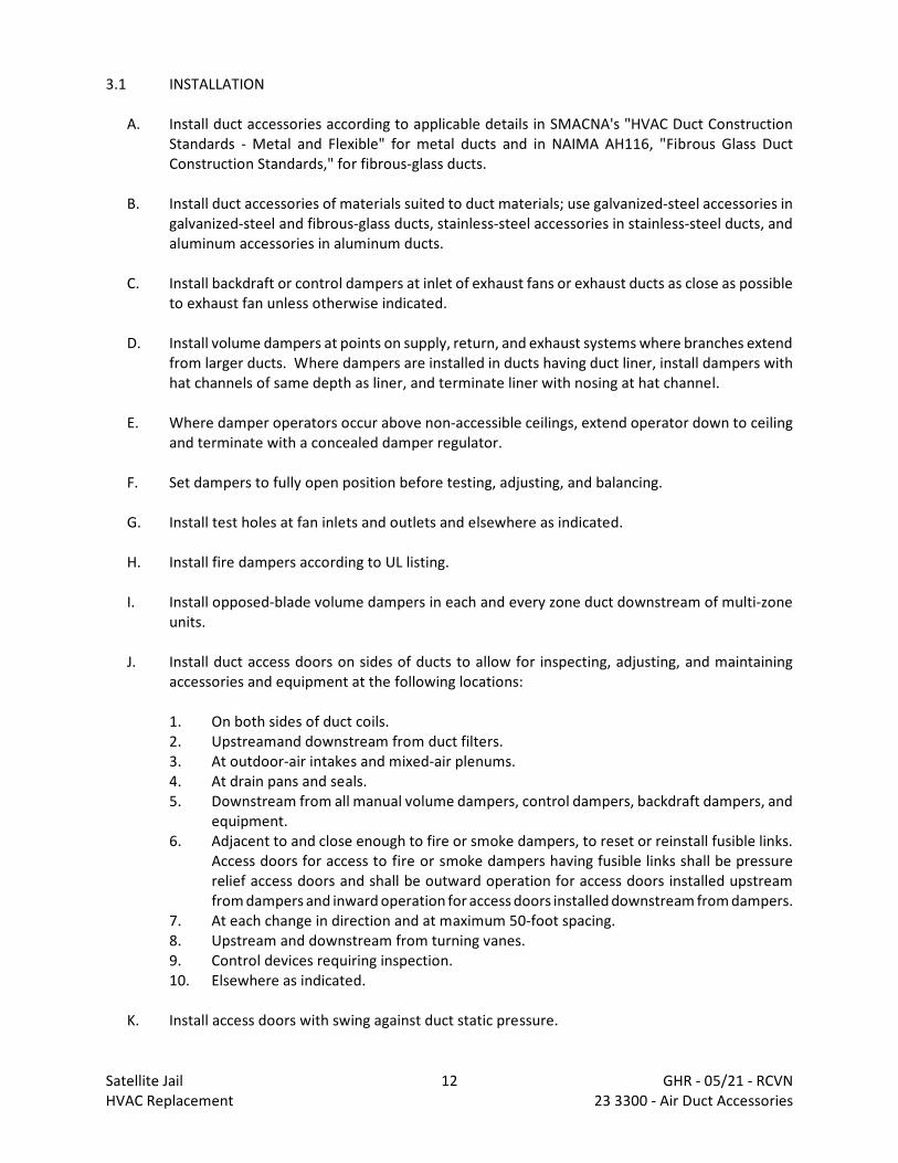
3.1 INSTALLATION
A. Install duct accessories according to applicable details in SMACNA's "HVAC Duct ConstructionStandards - Metal and Flexible" for metal ducts and in NAIMA AH116, "Fibrous Glass DuctConstruction Standards," for fibrous-glass ducts.
B. Install duct accessories of materials suited to duct materials; use galvanized-steel accessories ingalvanized-steel and fibrous-glass ducts, stainless-steel accessories in stainless-steel ducts, andaluminum accessories in aluminum ducts.
C. Install backdraft or control dampers at inlet of exhaust fans or exhaust ducts as close as possibleto exhaust fan unless otherwise indicated.
D. Install volume dampers at points on supply, return, and exhaust systems where branches extendfrom larger ducts. Where dampers are installed in ducts having duct liner, install dampers withhat channels of same depth as liner, and terminate liner with nosing at hat channel.
E. Where damper operators occur above non-accessible ceilings, extend operator down to ceilingand terminate with a concealed damper regulator.
F. Set dampers to fully open position before testing, adjusting, and balancing.
G. Install test holes at fan inlets and outlets and elsewhere as indicated.
H. Install fire dampers according to UL listing.
I. Install opposed-blade volume dampers in each and every zone duct downstream of multi-zoneunits.
J. Install duct access doors on sides of ducts to allow for inspecting, adjusting, and maintainingaccessories and equipment at the following locations:
1. On both sides of duct coils.2. Upstreamand downstream from duct filters.3. At outdoor-air intakes and mixed-air plenums.4. At drain pans and seals.5. Downstream from all manual volume dampers, control dampers, backdraft dampers, and
equipment.6. Adjacent to and close enough to fire or smoke dampers, to reset or reinstall fusible links.
Access doors for access to fire or smoke dampers having fusible links shall be pressurerelief access doors and shall be outward operation for access doors installed upstreamfrom dampers and inward operation for access doors installed downstream from dampers.
7. At each change in direction and at maximum 50-foot spacing.8. Upstream and downstream from turning vanes.9. Control devices requiring inspection.10. Elsewhere as indicated.
K. Install access doors with swing against duct static pressure.
Satellite Jail 12 GHR - 05/21 - RCVNHVAC Replacement 23 3300 - Air Duct Accessories
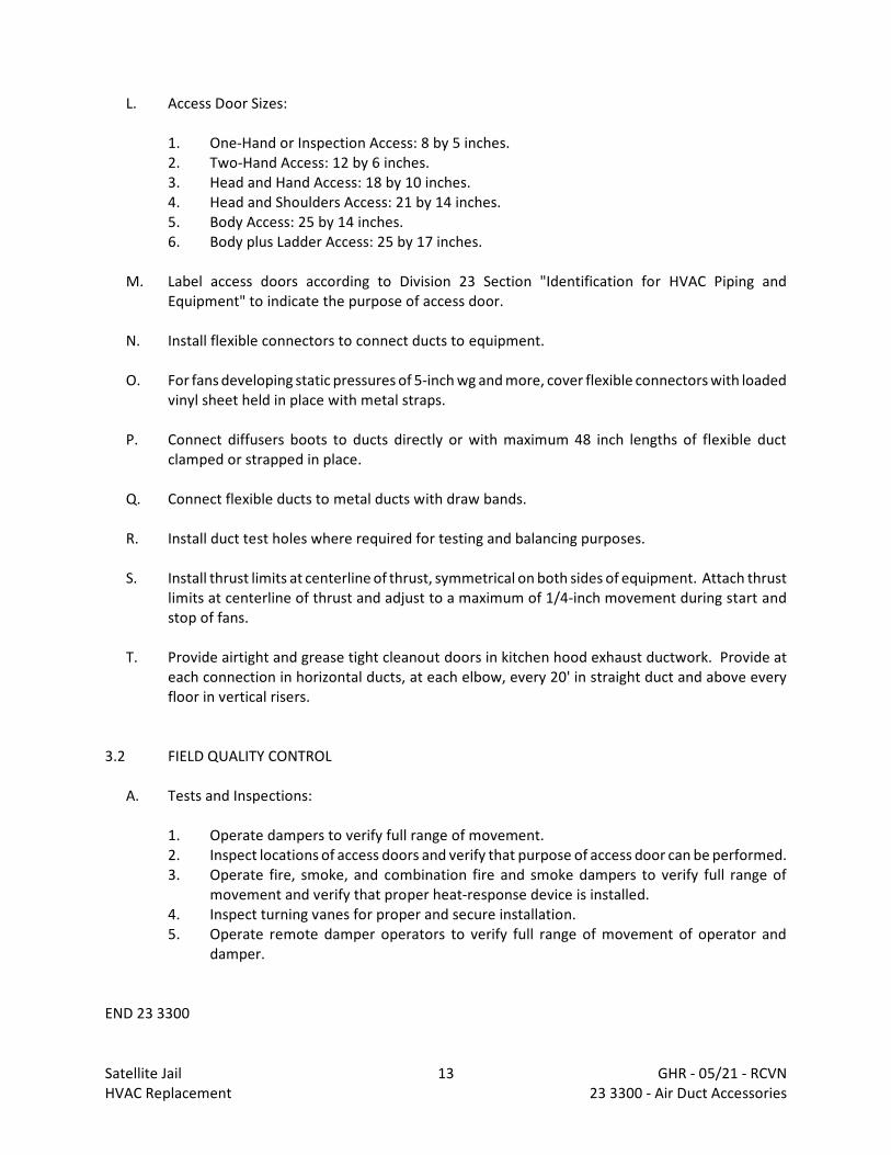
L. Access Door Sizes:
1. One-Hand or Inspection Access: 8 by 5 inches.2. Two-Hand Access: 12 by 6 inches.3. Head and Hand Access: 18 by 10 inches.4. Head and Shoulders Access: 21 by 14 inches.5. Body Access: 25 by 14 inches.6. Body plus Ladder Access: 25 by 17 inches.
M. Label access doors according to Division 23 Section "Identification for HVAC Piping andEquipment" to indicate the purpose of access door.
N. Install flexible connectors to connect ducts to equipment.
O. For fans developing static pressures of 5-inch wg and more, cover flexible connectors with loadedvinyl sheet held in place with metal straps.
P. Connect diffusers boots to ducts directly or with maximum 48 inch lengths of flexible ductclamped or strapped in place.
Q. Connect flexible ducts to metal ducts with draw bands.
R. Install duct test holes where required for testing and balancing purposes.
S. Install thrust limits at centerline of thrust, symmetrical on both sides of equipment. Attach thrustlimits at centerline of thrust and adjust to a maximum of 1/4-inch movement during start andstop of fans.
T. Provide airtight and grease tight cleanout doors in kitchen hood exhaust ductwork. Provide ateach connection in horizontal ducts, at each elbow, every 20' in straight duct and above everyfloor in vertical risers.
3.2 FIELD QUALITY CONTROL
A. Tests and Inspections:
1. Operate dampers to verify full range of movement.2. Inspect locations of access doors and verify that purpose of access door can be performed.3. Operate fire, smoke, and combination fire and smoke dampers to verify full range of
movement and verify that proper heat-response device is installed.4. Inspect turning vanes for proper and secure installation.5. Operate remote damper operators to verify full range of movement of operator and
damper.
END 23 3300
Satellite Jail 13 GHR - 05/21 - RCVNHVAC Replacement 23 3300 - Air Duct Accessories

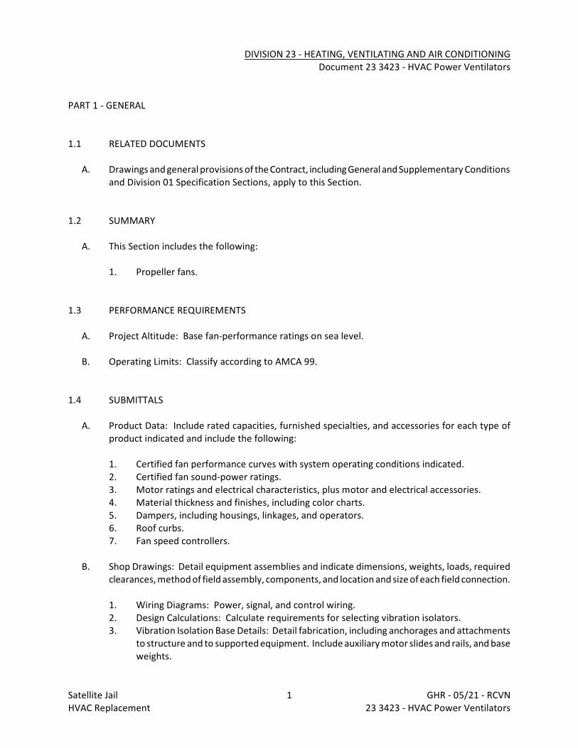
DIVISION 23 - HEATING, VENTILATING AND AIR CONDITIONINGDocument 23 3423 - HVAC Power Ventilators
PART 1 - GENERAL
1.1 RELATED DOCUMENTS
A. Drawings and general provisions of the Contract, including General and Supplementary Conditionsand Division 01 Specification Sections, apply to this Section.
1.2 SUMMARY
A. This Section includes the following:
1. Propeller fans.
1.3 PERFORMANCE REQUIREMENTS
A. Project Altitude: Base fan-performance ratings on sea level.
B. Operating Limits: Classify according to AMCA 99.
1.4 SUBMITTALS
A. Product Data: Include rated capacities, furnished specialties, and accessories for each type ofproduct indicated and include the following:
1. Certified fan performance curves with system operating conditions indicated.2. Certified fan sound-power ratings.3. Motor ratings and electrical characteristics, plus motor and electrical accessories.4. Material thickness and finishes, including color charts.5. Dampers, including housings, linkages, and operators.6. Roof curbs.7. Fan speed controllers.
B. Shop Drawings: Detail equipment assemblies and indicate dimensions, weights, loads, requiredclearances, method of field assembly, components, and location and size of each field connection.
1. Wiring Diagrams: Power, signal, and control wiring.2. Design Calculations: Calculate requirements for selecting vibration isolators.3. Vibration Isolation Base Details: Detail fabrication, including anchorages and attachments
to structure and to supported equipment. Include auxiliary motor slides and rails, and baseweights.
Satellite Jail 1 GHR - 05/21 - RCVNHVAC Replacement 23 3423 - HVAC Power Ventilators
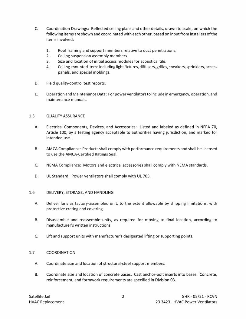
C. Coordination Drawings: Reflected ceiling plans and other details, drawn to scale, on which thefollowing items are shown and coordinated with each other, based on input from installers of theitems involved:
1. Roof framing and support members relative to duct penetrations.2. Ceiling suspension assembly members.3. Size and location of initial access modules for acoustical tile.4. Ceiling-mounted items including light fixtures, diffusers, grilles, speakers, sprinklers, access
panels, and special moldings.
D. Field quality-control test reports.
E. Operation and Maintenance Data: For power ventilators to include in emergency, operation, andmaintenance manuals.
1.5 QUALITY ASSURANCE
A. Electrical Components, Devices, and Accessories: Listed and labeled as defined in NFPA 70,Article 100, by a testing agency acceptable to authorities having jurisdiction, and marked forintended use.
B. AMCA Compliance: Products shall comply with performance requirements and shall be licensedto use the AMCA-Certified Ratings Seal.
C. NEMA Compliance: Motors and electrical accessories shall comply with NEMA standards.
D. UL Standard: Power ventilators shall comply with UL 705.
1.6 DELIVERY, STORAGE, AND HANDLING
A. Deliver fans as factory-assembled unit, to the extent allowable by shipping limitations, withprotective crating and covering.
B. Disassemble and reassemble units, as required for moving to final location, according tomanufacturer's written instructions.
C. Lift and support units with manufacturer's designated lifting or supporting points.
1.7 COORDINATION
A. Coordinate size and location of structural-steel support members.
B. Coordinate size and location of concrete bases. Cast anchor-bolt inserts into bases. Concrete,reinforcement, and formwork requirements are specified in Division 03.
Satellite Jail 2 GHR - 05/21 - RCVNHVAC Replacement 23 3423 - HVAC Power Ventilators
C. Coordinate installation of roof curbs, equipment supports, and roof penetrations. These itemsare specified in Division 07 Section "Roof Accessories."
PART 2 - PRODUCTS
2.1 WALL MOUNTED VENTILATORS
A. Available Manufacturers: Subject to compliance with requirements, manufacturers offeringproducts that may be incorporated into the Work include, but are not limited to, the following:
B. Manufacturers: Subject to compliance with requirements, provide products by one of thefollowing:
C. Basis-of-Design Product: Subject to compliance with requirements, provide the product indicatedon Drawings or by one of the following:
1. Acme Engineering & Mfg. Corp.2. Carnes Company HVAC.3. Greenheck.4. Loren Cook Company.
D. Description: Direct- or belt-driven centrifugal fans consisting of housing, wheel, fan shaft,bearings, motor and disconnect switch, drive assembly and accessories.
E. Housing: Removable, spun-aluminum, dome top and outlet baffle; square, one-piece, aluminumbase with venturi inlet cone.
F. Fan Wheels: Aluminum hub and wheel with backward-inclined blades.
G. Belt-Driven Drive Assembly: Resiliently mounted to housing, with the following features:
1. Fan Shaft: Turned, ground, and polished steel; keyed to wheel hub.2. Shaft Bearings: Permanently lubricated, permanently sealed, self-aligning ball bearings.3. Pulleys: Cast-iron, adjustable-pitch motor pulley.4. Fan and motor isolated from exhaust airstream.
H. Accessories:
1. Disconnect Switch: Nonfusible type, with thermal-overload protection mounted inside fanhousing, factory wired through an internal aluminum conduit.
2. Bird Screens: Removable, 1/2-inch mesh, aluminum or brass wire.
2.2 PROPELLER FANS
Satellite Jail 3 GHR - 05/21 - RCVNHVAC Replacement 23 3423 - HVAC Power Ventilators
A. Available Manufacturers: Subject to compliance with requirements, manufacturers offeringproducts that may be incorporated into the Work include, but are not limited to, the following:
B. Basis-of-Design Product: Subject to compliance with requirements, provide the product indicatedon Drawings or a comparable product by one of the following:
1. Acme Engineering & Mfg. Corp.2. Carnes Company HVAC.3. Greenheck.4. Loren Cook Company.5. Pennbarry.
C. Description: Direct-driven propeller fans consisting of fan blades, hub, housing, orifice ring,motor, drive assembly, and accessories.
D. Housing: Galvanized-steel sheet with flanged edges and integral orifice ring with baked-enamelfinish coat applied after assembly.
E. Steel Fan Wheels: Formed-steel blades riveted to heavy-gage steel spider bolted to cast-iron hub.
F. Accessories:
1. Motorized Shutters: Aluminum blades in aluminum frame; interlocked blades with nylonbearings and electric actuator wired to close when fan stops.
2. Motor-Side Back Guard: Galvanized steel, complying with OSHA specifications, removablefor maintenance.
3. Wall Sleeve: Galvanized steel to match fan and accessory size.4. Disconnect Switch: Nonfusible type, with thermal-overload protection mounted inside fan
housing, factory wired through an internal aluminum conduit.
2.3 MOTORS
A. Comply with requirements in Division 23 Section "Common Motor Requirements for HVACEquipment."
B. Enclosure Type: Totally enclosed, fan cooled.
2.4 SOURCE QUALITY CONTROL
A. Sound-Power Level Ratings: Comply with AMCA 301, "Methods for Calculating Fan Sound Ratingsfrom Laboratory Test Data." Factory test fans according to AMCA 300, "Reverberant RoomMethod for Sound Testing of Fans." Label fans with the AMCA-Certified Ratings Seal.
B. Fan Performance Ratings: Establish flow rate, pressure, power, air density, speed of rotation, andefficiency by factory tests and ratings according to AMCA 210, "Laboratory Methods of TestingFans for Rating."
Satellite Jail 4 GHR - 05/21 - RCVNHVAC Replacement 23 3423 - HVAC Power Ventilators
PART 3 - EXECUTION
3.1 INSTALLATION
A. Install power ventilators level and plumb.
B. Secure roof-mounting fans to roof curbs with cadmium-plated hardware. Refer to Division 07Section "Roof Accessories" for installation of roof curbs.
C. Install units with clearances for service and maintenance.
D. Label units according to requirements specified in Division 23 Section "Identification for HVACPiping and Equipment."
3.2 CONNECTIONS
A. Ground equipment according to Division 26 Section "Grounding and Bonding for ElectricalSystems."
B. Connect wiring according to Division 26 Section "Low-Voltage Electrical Power Conductors andCables."
3.3 FIELD QUALITY CONTROL
A. Perform the following field tests and inspections and prepare test reports:
1. Verify that shipping, blocking, and bracing are removed.2. Verify that unit is secure on mountings and supporting devices and that connections to
ducts and electrical components are complete. Verify that proper thermal-overloadprotection is installed in motors, starters, and disconnect switches.
3. Verify that cleaning and adjusting are complete.4. Disconnect fan drive from motor, verify proper motor rotation direction, and verify fan
wheel free rotation and smooth bearing operation. Reconnect fan drive system, align andadjust belts, and install belt guards.
5. Adjust belt tension.6. Adjust damper linkages for proper damper operation.7. Verify lubrication for bearings and other moving parts.8. Disable automatic temperature-control operators, energize motor and adjust fan to
indicated rpm, and measure and record motor voltage and amperage.9. Shut unit down and reconnect automatic temperature-control operators.10. Remove and replace malfunctioning units and retest as specified above.
Satellite Jail 5 GHR - 05/21 - RCVNHVAC Replacement 23 3423 - HVAC Power Ventilators
B. Test and adjust controls and safeties. Replace damaged and malfunctioning controls andequipment.
3.4 ADJUSTING
A. Adjust damper linkages for proper damper operation.
B. Adjust belt tension.
C. Refer to Division 23 Section "Testing, Adjusting, and Balancing for HVAC" for testing, adjusting,and balancing procedures.
D. Replace fan and motor pulleys as required to achieve design airflow.
E. Lubricate bearings.
END 23 3423
Satellite Jail 6 GHR - 05/21 - RCVNHVAC Replacement 23 3423 - HVAC Power Ventilators
DIVISION 23 - HEATING, VENTILATING AND AIR CONDITIONINGDocument 23 3723 - HVAC Gravity Ventilators
PART 1 - GENERAL
1.1 WORK INCLUDES
A. Base Bid
1. HVAC Contractor: Work includes:
a. Roof hoods.
1.2 PERFORMANCE REQUIREMENTS
A. Delegated Design: Design ventilators, including comprehensive engineering analysis by a qualifiedprofessional engineer, using structural performance requirements and design criteria indicated.
B. Structural Performance: Ventilators shall withstand the effects of gravity loads and the followingloads and stresses within limits and under conditions indicated without permanent deformationof ventilator components, noise or metal fatigue caused by ventilator blade rattle or flutter, orpermanent damage to fasteners and anchors. Wind pressures shall be considered to act normalto the face of the building.
1. Wind Loads: Determine loads based on a uniform pressure of 20 lbf/sq. ft., acting inwardor outward.
C. Thermal Movements: Allow for thermal movements from ambient and surface temperaturechanges, without buckling, opening of joints, overstressing of components, failure of connections,or other detrimental effects.
1. Temperature Change (Range): 120 deg F, ambient; material surfaces.
D. Water Entrainment: Limit water penetration through unit to comply with ASHRAE 62.1-2004.
1.3 SUBMITTALS
A. Product Data: For each type of product indicated.
B. Shop Drawings: For gravity ventilators. Include plans, elevations, sections, details, ventilatorattachments to curbs, and curb attachments to roof structure.
1. Show weep paths, gaskets, flashing, sealant, and other means of preventing waterintrusion.
Satellite Jail 1 GHR - 05/21 - RCVNHVAC Replacement 23 3723 - HVAC Gravity Ventilators

1.4 QUALITY ASSURANCE
A. Welding Qualifications: Qualify procedures and personnel according to the following:
1. AWS D1.2/D1.2M, "Structural Welding Code - Aluminum."2. AWS D1.3, "Structural Welding Code - Sheet Steel."
1.5 COORDINATION
A. Coordinate sizes and locations of roof curbs, equipment supports, and roof penetrations withactual equipment provided.
PART 2 - PRODUCTS
2.1 MATERIALS
A. Aluminum Extrusions: ASTM B 221, Alloy 6063-T5 or T-52.
B. Aluminum Sheet: ASTM B 209, Alloy 3003 or 5005 with temper as required for forming or asotherwise recommended by metal producer for required finish.
C. Galvanized-Steel Sheet: ASTM A 653/A 653M, G90 zinc coating, mill phosphatized.
D. Stainless-Steel Sheet: ASTM A 666, Type 304, with No. 4 finish.
E. Fasteners: Same basic metal and alloy as fastened metal or 300 Series stainless steel unlessotherwise indicated. Do not use metals that are incompatible with joined materials.
1. Use types and sizes to suit unit installation conditions.
2.2 FABRICATION, GENERAL
A. Factory or shop fabricate gravity ventilators to minimize field splicing and assembly. Disassembleunits to the minimum extent as necessary for shipping and handling. Clearly mark units forreassembly and coordinated installation.
B. Fabricate frames, including integral bases, to fit in openings of sizes indicated, with allowancesmade for fabrication and installation tolerances, adjoining material tolerances, and perimetersealant joints.
C. Fabricate units with closely fitted joints and exposed connections accurately located and secured.
Satellite Jail 2 GHR - 05/21 - RCVNHVAC Replacement 23 3723 - HVAC Gravity Ventilators
D. Fabricate supports, anchorages, and accessories required for complete assembly.
E. Perform shop welding by AWS-certified procedures and personnel.
2.3 ROOF HOODS
A. Manufacturers: Subject to compliance with requirements, provide products by one of thefollowing:
1. Acme Engineering & Mfg. Corporation.2. Carnes.3. Greenheck Fan Corporation.4. Loren Cook Company.5. Pennbarry
B. Factory or shop fabricate according to SMACNA's "HVAC Duct Construction Standards - Metal andFlexible," Figures 5-6 and 5-7.
C. Materials: Aluminum sheet, minimum 0.063-inch- thick base and 0.050-inch- thick hood; suitablyreinforced.
D. Roof Curbs: Galvanized-steel sheet; with mitered and welded corners; 1-1/2-inch- thick, rigidfiberglass insulation adhered to inside walls; and 1-1/2-inch wood nailer. Size as required to fitroof opening and ventilator base.
1. Configuration: Self-flashing without a cant strip with mounting flange.2. Overall Height: 12 inches.
E. Bird Screening: Aluminum, 1/2-inch- square mesh, 0.063-inch wire.
PART 3 - EXECUTION
3.1 INSTALLATION
A. Install gravity ventilators level, plumb, and at indicated alignment with adjacent work.
B. Install gravity ventilators with clearances for service and maintenance.
C. Install perimeter reveals and openings of uniform width for sealants and joint fillers, as indicated.
D. Install concealed gaskets, flashings, joint fillers, and insulation as installation progresses. Complywith Division 07 Section "Joint Sealants" for sealants applied during installation.
E. Label gravity ventilators according to requirements specified in Division 23 Section "Identificationfor HVAC Piping and Equipment."
Satellite Jail 3 GHR - 05/21 - RCVNHVAC Replacement 23 3723 - HVAC Gravity Ventilators
F. Protect galvanized and nonferrous-metal surfaces from corrosion or galvanic action by applyinga heavy coating of bituminous paint on surfaces that will be in contact with concrete, masonry,or dissimilar metals.
G. Repair finishes damaged by cutting, welding, soldering, and grinding. Restore finishes so noevidence remains of corrective work. Return items that cannot be refinished in the field to thefactory, make required alterations, and refinish entire unit or provide new units.
3.2 CONNECTIONS
A. Duct installation and connection requirements are specified in other Division 23 Sections. Drawings indicate general arrangement of ducts and duct accessories.
3.3 ADJUSTING
A. Adjust damper linkages for proper damper operation.
END 23 3723
Satellite Jail 4 GHR - 05/21 - RCVNHVAC Replacement 23 3723 - HVAC Gravity Ventilators
DIVISION 23 - HEATING, VENTILATING AND AIR CONDITIONINGDocument 23 5216 - Condensing Boilers
PART 1 - GENERAL
1.1 WORK INCLUDES
A. Base Bid
1. HVAC Contractor: Work includes packaged, factory-fabricated and -assembled, gas-fired,fire-tube condensing boilers, trim, and accessories for generating hot water.
1.2 SUBMITTALS
A. Product Data: Include performance data, operating characteristics, furnished specialties, andaccessories.
B. Shop Drawings: For boilers, boiler trim, and accessories. Include plans, elevations, sections,details, and attachments to other work.
1. Design calculations and vibration isolation base details.
a. Design Calculations: Calculate requirements for selecting vibration isolators andseismic restraints and for designing vibration isolation bases.
b. Vibration Isolation Base Details: Detail fabrication including anchorages andattachments to structure and to supported equipment. Include auxiliary motorslides and rails and equipment mounting frames.
2. Wiring Diagrams: Power, signal, and control wiring.
C. Source quality-control test reports.
D. Field quality-control test reports.
E. Operation and Maintenance Data: For boilers to include in emergency, operation, andmaintenance manuals.
F. Warranty: Special warranty specified in this Section.
G. Other Informational Submittals:
1. ASME Stamp Certification and Report: Submit "A," "S," or "PP" stamp certificate ofauthorization, as required by authorities having jurisdiction, and document hydrostatictesting of piping external to boiler.
Satellite Jail 1 GHR - 05/21 - RCVNHVAC Replacement 23 5216 - Condensing Boilers
1.3 QUALITY ASSURANCE
A. Electrical Components, Devices, and Accessories: Listed and labeled as defined in NFPA 70,Article 100, by a testing agency acceptable to authorities having jurisdiction, and marked forintended use.
B. ASME Compliance: Fabricate and label boilers to comply with ASME Boiler and Pressure VesselCode.
C. ASHRAE/IESNA 90.1 Compliance: Boilers shall have minimum efficiency according to "Gas and OilFired Boilers - Minimum Efficiency Requirements."
D. DOE Compliance: Minimum efficiency shall comply with 10 CFR 430, Subpart B, Appendix N,"Uniform Test Method for Measuring the Energy Consumption of Furnaces and Boilers."
E. UL Compliance: Test boilers for compliance with UL 795, "Commercial-Industrial Gas HeatingEquipment." Boilers shall be listed and labeled by a testing agency acceptable to authoritieshaving jurisdiction.
1.4 COORDINATION
A. Coordinate size and location of concrete bases. Cast anchor-bolt inserts into bases. Concrete,reinforcement, and formwork requirements are specified in Division 03.
1.5 WARRANTY
A. Special Warranty: Manufacturer's standard form in which manufacturer agrees to repair orreplace components of boilers that fail in materials or workmanship within specified warrantyperiod.
1. Warranty Period for Fire-Tube Condensing Boilers:
a. Leakage and Materials: 10 years from date of Substantial Completion.b. Heat Exchanger Damaged by Thermal Stress and Corrosion: Prorated for five years
from date of Substantial Completion.
PART 2 - PRODUCTS
2.1 MANUFACTURERS
A. Manufacturers shall verify boilers can be properly installed in available space with proper serviceaccess.
B. Manufacturers: Subject to compliance with requirements, provide products by one of thefollowing:
Satellite Jail 2 GHR - 05/21 - RCVNHVAC Replacement 23 5216 - Condensing Boilers
1. Lochinvar.2. Weil McLain.3. Raypak X-Fyre H7-850.4. RBI Futura Fusion.5. Riello.
2.2 HOT WATER BOILER BURNER UNIT (CONDENSING GAS FIRED)
A. Boiler Design
1. Boiler shall be a compact, single-pass, vertical down-fired Firetube type, with 316 Tistainless steel tubes, tube sheets, and combustion chamber. The boiler pressure vesselshall be completely insulated with a minimum of 2" of insulation and shall be encased ina sheet metal cabinet with powder coated finish.
2. The tubes shall be 316Ti Stainless Steel and shall be fitted with Aluminum Alloy internalheat transfer fins creating no less than 10 square feet of fireside heating surface per boilerhorsepower.
3. The Vessel shall be mounted on a structural steel stand with exhaust gasses collected in anon-coroiding drain collection box with drain fitting for draining condensation from theproducts of combustion. A condensate neutralizing box with limestone chips shall beshipped loose for field installation by the heating contractor.
4. The top tubesheet shall be fully accessible without burner disassembly or removal from theboiler. The burner assembly shall be complete with lifting hinges and pneumatic lifters.
5. Each boiler shall be constructed in accordance with the A.S.M.E. Section IV Code and bearthe "H" stamp and shall be manufactured within an ISO 9001 Certified facility to ensurehigh quality standards.
6. To drain the boiler, a bottom-threaded connection shall be provided at the front of theboiler and field piped by the installing contractor with a manual full size shutoff valve todrain.
B. Burner Design
1. General: Burner shall be forced draft type. It shall be mounted in and integral with theboiler hinged top door so when the door is opened the burner head, furnace, tubesheet,and tubes are exposed.
2. The burner shall be of the Unitized Venturi, Gas Valve, Blower, and burner head design.This pre-mix design shall utilize a variable speed fan connected to a venturi tosimultaneously modulate fuel and air for a minimum a 5:1 turndown ratio. The venturidesign shall also act as a method for compensating for changes in barometric pressure,temperature and humidity so the excess air levels are not adversely affected by changesin atmospheric conditions.
3. Burner head shall be constructed of a Fecralloy-metal fiber for solid body radiation of theburner flame. Combustion shall take place on the surface of the burner mantle, which shallbe constructed of a woven fecralloy material creating a 360 degree low temperatureradiant flame.
4. Emissions: The equipment shall be guaranteed to limit NOx emissions to 20 PPM or less,as certified by an independent testing lab. NOx emission levels shall not be exceeded at
Satellite Jail 3 GHR - 05/21 - RCVNHVAC Replacement 23 5216 - Condensing Boilers
full operating conditions and at designed turndown of the burner. Proof of such emissionscertification shall be made available to the engineer and demonstrated at the time ofstart-up. External flue gas recirculation shall not be accepted for emission control.
5. Gas Train - As a minimum, the gas train shall meet the requirements of CSA and ASMECSD-1 and shall include:
a. Low Gas Pressure Interlock, manual reset.b. High Gas Pressure Interlock, manual reset.c. Upstream and downstream manual test cocks.d. Ball Type manual shutoff valve upstream of the main gas valve.e. Unibody double safety gas valve assembly.f. Gas Pressure Regulatorg. Union connection to permit burner servicing.
6. Combustion Air Proving Switch shall be furnished to ensure sufficient combustion airflowis present for burner ignition firing.
7. To ensure that proper draft is not blocked in the stack, the burner shall include a High AirPressure Switch sensing the outlet pressure connection relative to stack back draft.
C. Boiler Trim
1. Safety valve(s) shall be ASME Section IV approved side outlet type mounted on the boilerair vent outlet. Size shall be in accordance with code requirements and set to open at 60psig.
2. Temperature and pressure gauge shall be mounted on the water outlet.3. Solid State Low water cut-off probe with manual reset and test switch.4. Manual Reset High Limit Temperature control; range not to exceed 210 F.5. Outlet water supply sensing probe for operating water limit setpoint.6. Return water-sensing probe for operating water limit setpoint.7. Boiler manufacturer shall provide a circulating pump for each boiler specifically sized for
the system.
D. Boiler Controls
1. The Boiler shall include a Computerized Boiler Burner control which shall be an integrated,solid state digital micro-processing modulating device, complete with sequence indication,fault reset, mode selection, and parameter set-point switches. It shall be mounted at thefront of the boiler panel for easy access and viewing. Provide controls for continuedheating should the lead or master boiler have a loss of power, one of the remaining boilersshall fire.
2. Controller shall provide for both flame safeguard and boiler control and shall perform thefollowing functions:
a. Burner sequencing with safe start check, pre-purge, electronic direct spark ignition,and post purge. Flame rod to prove combustion.
b. Flame Supervision. The control shall provide pre-purge and post-purge and shallmaintain a running history of operating hours, number of cycles, and the mostrecent six faults. The control shall be connected to a keyboard display module thatwill retrieve this information.
Satellite Jail 4 GHR - 05/21 - RCVNHVAC Replacement 23 5216 - Condensing Boilers

c. Safety Shutdown with display of error.d. Modulating control of the variable speed fan for fuel/air input relative to load
requirements.e. Gas pressure supervision, high and low.f. Combustion Air Proving Supervision.g. High Air Pressure [back draft too high] Supervision.h. The supply temperature and set-point temperature shall be displayed at all times by
an LED readout. Output shall be continuous PID via 4 -20 mA current.i. Controller shall have an option for communication device to a laptop computer
interface for service, troubleshooting, and start-up.j. Include the programming of system circulating pump and provide the programming
of 2 heating loops.k. All parameter input control set-points shall be factory downloaded with jobsite
conditions programmed at the time of initial jobsite operation. l. All controls to be panel mounted and so located on the boiler as to provide ease of
servicing the boiler without disturbing the controls and also located to preventpossible damage by water according to CSA requirements.
m. Electrical power supply shall be 120 volts, 60 cycle, single phase for the fan and forcontrol circuit requirements.
n. A sequencing control shall be provided to stage the boilers. The control shall includeautomatic rotation of lead boiler, an adjustable outdoor reset schedule, multiplesetback schedules and a digital display. The control shall force each boiler to lowfire, before allowing any boiler to operate at high fire. When all boilers are running,they will then be modulated in unison. The control shall be supplied by the boilersupplier.
o. Boilers shall be provided with a BACnet interface card for communication andcontrol through the new BAS. Manufacturer shall coordinate available points withthe Temperature Control Contractor for control sequence and alarms.
2.3 ELECTRICAL POWER
A. Controllers, Electrical Devices, and Wiring: Electrical devices and connections are specified inDivision 26 Sections.
2.4 VENTING KITS
A. Provide complete system ASTM A959, Type 29-4C stainless steel pipe, vent terminal, thimble,indoor plate, vent adapter, condensate trap, dilution tank and sealant. Acceptable manufacturersinclude: Z-Flex-Z-Vent III, Heat Fab, Inc. - Saf-T-Vent, Dura-Vent - Fas N Seal and Metal-Fab, Inc.- Corr/Guard. Install vent piping per manufacturer's written instruction.
B. Combustion-Air Intake: Complete system PVC, Vent terminal with screen, inlet air coupling andsealant. Install per manufacturer's written instructions.
Satellite Jail 5 GHR - 05/21 - RCVNHVAC Replacement 23 5216 - Condensing Boilers
2.5 SOURCE QUALITY CONTROL
A. Burner and Hydrostatic Test: Factory adjust burner to eliminate excess oxygen, carbon dioxide,oxides of nitrogen emissions, and carbon monoxide in flue gas and to achieve combustionefficiency; perform hydrostatic test.
B. Test and inspect factory-assembled boilers, before shipping, according to ASME Boiler andPressure Vessel Code.
C. Allow Using Agency access to source quality-control testing of boilers. Notify Architect 14 daysin advance of testing.
PART 3 - EXECUTION
3.1 EXAMINATION
A. Before boiler installation, examine roughing-in for concrete equipment bases, anchor-bolt sizesand locations, and piping and electrical connections to verify actual locations, sizes, and otherconditions affecting boiler performance, maintenance, and operations.
1. Final boiler locations indicated on Drawings are approximate. Determine exact locationsbefore roughing-in for piping and electrical connections.
B. Examine mechanical spaces for suitable conditions where boilers will be installed.
C. Proceed with installation only after unsatisfactory conditions have been corrected.
3.2 BOILER INSTALLATION
A. Install boilers level on concrete base. Concrete base is specified in Division 23 Section "CommonWork Results for HVAC,” and concrete materials and installation requirements are specified inDivision 03.
B. Install gas-fired boilers according to NFPA 54.
C. Assemble and install boiler trim.
D. Install electrical devices furnished with boiler but not specified to be factory mounted.
E. Install control wiring to field-mounted electrical devices.
3.3 CONNECTIONS
A. Piping installation requirements are specified in other Division 23 Sections. Drawings indicategeneral arrangement of piping, fittings, and specialties.
Satellite Jail 6 GHR - 05/21 - RCVNHVAC Replacement 23 5216 - Condensing Boilers
B. Install piping adjacent to boiler to allow service and maintenance.
C. Install piping from equipment drain connection to nearest floor drain. Piping shall be at least fullsize of connection. Provide an isolation valve if required.
D. Connect piping to boilers, except safety relief valve connections, with flexible connectors ofmaterials suitable for service. Flexible connectors and their installation are specified inDivision 23 Section "Common Work Results for HVAC.”
E. Connect gas piping to boiler gas-train inlet with union. Piping shall be at least full size of gas trainconnection. Provide a reducer if required.
F. Connect hot-water piping to supply- and return-boiler tappings with shutoff valve and union orflange at each connection.
G. Install piping from safety relief valves to nearest floor drain.
H. Install piping from safety valves to drip-pan elbow and to nearest floor drain.
I. Boiler Venting:
1. Install double wall flue venting kit and combustion-air intake.
J. Ground equipment according to Division 26 Section "Grounding and Bonding for ElectricalSystems."
K. Connect wiring according to Division 26 Section "Low Voltage Electrical Power ConductorsCables."
3.4 FIELD QUALITY CONTROL
A. Perform tests and inspections and prepare test reports.
1. Manufacturer's Field Service: Engage a factory-authorized service representative to inspectcomponents, assemblies, and equipment installations, including connections, and to assistin testing.
B. Tests and Inspections:
1. Perform installation and startup checks according to manufacturer's written instructions.2. Leak Test: Hydrostatic test. Repair leaks and retest until no leaks exist.3. Operational Test: Start units to confirm proper motor rotation and unit operation. Adjust
air-fuel ratio and combustion.4. Test and adjust controls and safeties. Replace damaged and malfunctioning controls and
equipment.
Satellite Jail 7 GHR - 05/21 - RCVNHVAC Replacement 23 5216 - Condensing Boilers
a. Check and adjust initial operating set points and high- and low-limit safety set pointsof fuel supply, water level and water temperature.
b. Set field-adjustable switches and circuit-breaker trip ranges as indicated.
C. Remove and replace malfunctioning units and retest as specified above.
D. Occupancy Adjustments: When requested within 12 months of date of Substantial Completion, provide on-site assistance in adjusting system to suit actual occupied conditions. Provide up totwo visits to Project during other than normal occupancy hours for this purpose.
3.5 DEMONSTRATION
A. Engage a factory-authorized service representative to train Using Agency's maintenancepersonnel to adjust, operate, and maintain boilers. Refer to Division 01 Section "Demonstrationand Training."
END 23 5216
Satellite Jail 8 GHR - 05/21 - RCVNHVAC Replacement 23 5216 - Condensing Boilers
DIVISION 23 - HEATING, VENTILATING AND AIR CONDITIONINGDocument 23 6500 - Refrigeration
PART 1 - GENERAL
1.1 WORK INCLUDES
A. Base Bid
1. HVAC Contractor: Provide and install refrigeration systems as shown on thedrawings and as specified herein. Work includes, but is not limited to, thefollowing:
a. Scroll chillerb. Start-up and reports
1.2 RELATED WORK
A. Specified elsewhere:
1. Sections: Architectural / Structural and General Work2. Division 23 - Mechanical Systems
1.3 QUALITY ASSURANCE
A. Manufacturers shall be responsible for verifying available power voltage and phase. Contact pertinent utility company and verify that voltage provided is acceptable inevery respect, including voltage variations and phase imbalances. All equipmentprovided on this project shall be fully warranted for operation on available power.
B. Use only new material and apparatus of the specified design and manufacturer. Furnish all materials in accordance with latest ANSI, AWWA, ASTM, NFPA, ARI, ULstandards and other applicable standards or codes. All chillers shall be rated in accordwith ARI standards.
1.4 SUBMITTALS
A. See Architectural Sections for Requirements.
PART 2 - PRODUCTS
2.1 SCROLL CHILLER
A. Chiller shall be completely factory-packaged including the evaporator, condenser,compressor, motor, lubrication system, control center, and all interconnecting unitpiping and wiring.
B. The initial charge of refrigerant and oil shall be supplied for the chiller.
Satellite Jail 1 GHR - 05/21 - RCVNHVAC Replacement 23 6500 - Refrigeration
2.2 ACCEPTABLE MANUFACTURERS
A. Trane.
B. York.
C. Carrier.
D. Daikin Applied
2.3 GENERAL UNIT DESCRIPTION
A. Factory assembled, single-piece chassis, air-cooled liquid chiller. Contained within thepackage shall be all factory wiring, piping, controls, and refrigerant charge (HFC-410A).
2.4 CABINET
A. Frame shall be heavy-gage, with a powder coated paint finish for both aestheticappeal and to offer more resistance to corrosion.
B. Units shall be constructed of a galvanized steel frame with galvanized steel panels andaccess doors. Component surfaces shall be finished with a powder-coated paint. Thecoating or paint system shall withstand a 1000-consecutive-hour salt spay applicationin accordance with standard ASTMB117.
2.5 COMPRESSORS
A. Fully hermetic scroll type compressors with R410A optimized and dedicated scrollprofile.
B. Direct drive motor cooled by suction gas with only three major moving parts and acompletely enclosed compression chamber which leads to increased efficiency.
C. Each compressor will have crankcase heaters installed and properly sized to minimizethe amount of liquid refrigerant present in the oil sump during off cycles.
2.6 EVAPORATOR
A. The evaporator shall be a high efficiency, brazed plate-to-plate type heat exchangerconsisting of parallel plates. Braze plates shall be stainless steel with copper brazematerial.
B. The evaporator shall be protected with an etched foil heater and insulated with 3/4inch insulation. This combination shall provide freeze protection down to -20F ambienttemperatures while the heater is powered. Contractor shall provide separate powerto energize heater and protect evaporator while chiller is disconnected.
C. The water side working pressure shall be rated at 150 psig and tested at 1.5 timesmaximum allowable water side working pressure.
Satellite Jail 2 GHR - 05/21 - RCVNHVAC Replacement 23 6500 - Refrigeration
D. The refrigerant side working pressure shall be rated at 460 psig (29.6 bars) and testedat 1.1 maximum allowable refrigerant side working pressure.
2.7 CONDENSER
A. The condenser coils shall consist of copper tubes mechanically bonded into plate-typealuminum fins. A subcooling coil shall be an integral part of the main condenser coil.
B. The maximum allowable working pressure of the condenser shall be 650 psig (44.8bars). The condensers shall be factory proof and leak tested at 715 psig (49.3 bars).
C. Low Sound Fans shall be dynamically and statically balanced, direct drive, corrosionresistant glass fiber reinforced composite blades molded into a low noise fan blade.
D. Low speed fan motors shall be three-phase with permanently lubricated ball bearingsand individually protected by circuit breakers.
E. Unit shall be capable of starting and running at outdoor ambient temperatures from32F to 125F (0C - 52C) for all sizes.
F. Provide architectural louvered panels to cover condenser coils and area below thecoils.
2.8 ENCLOSURES
A. Mount starters in a UL1995 rated panel for outdoor use.
B. The starter shall be across-the-line configuration, factory-mounted and fully pre-wiredto the compressor motor(s) and control panel.
C. A control power transformer shall be factory-installed and factory-wired to provideunit control power.
D. Control panel shall be dead front construction for enhanced service technician safety.
E. Power line connection type shall be circuit breaker with high fault rated panel.
2.9 REFRIGERATION COMPONENTS
A. Each refrigerant circuit shall include a filter drier, electronic expansion valve with siteglass, liquid line service valves and a complete operating charge of both refrigerantHFC-410A and compressor oil.
B. Each refrigerant circuit shall include a discharge line service valve to allow therefrigerant to be isolated in the condenser.
2.10 CONTROLS, SAFETIES AND DIAGNOSTICS
A. The microprocessor-based unit controller shall be factory-installed and factory-tested.
Satellite Jail 3 GHR - 05/21 - RCVNHVAC Replacement 23 6500 - Refrigeration

B. The unit display shall provide the following data:
1. Water and air temperatures2. Refrigerant levels and temperatures3. Flow switch status4. Compressor starts and run times
C. The unit controller shall provide chilled water reset based on return water as anenergy saving option.
D. The unit shall shut down if one or more of the following safeties has been breached:
1. Low evaporator refrigerant temperature and/or pressure2. High condenser refrigerant pressure3. Low oil flow4. Motor current overload5. High compressor discharge temperature6. Electronic distribution faults: phase loss, phase imbalance, or phase reversal
E. Unit shall be shipped with factory control and power wiring installed.
F. Provide BACnet MSTP interface card
2.11 Chilled Fluid Circuit
A. Chilled fluid circuit shall be rated for 150 psig (1034 kPa) working pressure.
B. Proof of flow switch shall be provided by the equipment manufacturer and installedthe correct number of pipe diameters from any elbow and in the correct orientation.
C. Units with brazed plate evaporators shall have a water strainer that is factoryprovided. It shall be installed with a blow down valve to facilitate periodic cleaning ofthe strainer to prevent it from becoming clogged.
2.12 ACCESSORIES AND OPTIONS FOR ROTARY CHILLER
A. Some accessories and options supersede standard product features. All options arefactory-mounted unless otherwise noted.
B. General Options:
1. Flow Switch: Vapor proof SPDT, NEMA 3R switch, 150 psig (10.3 barg), -20°F to250°F (-28.9°C to 121.1°C). (Field Mounted by Contractor)
2. Unit shall have internal vibration isolation.3. Hail guards for coil protection.4. Low noises fans, factory installed sound attenuators. Maximum sound power
listed below.5. Single point fused disconnect,6. Three years parts, labor and refrigerant warranty. Warranty shall cover complete
unit.
Satellite Jail 4 GHR - 05/21 - RCVNHVAC Replacement 23 6500 - Refrigeration
7. Refrigerant isolation valves.8. High efficiency chiller, ASHRAE 90.1 compliant, AHRI certified.9. Removable screens, single ply to protect coils from leaves, cotton wood seed,
litter debris, etc.
PART 3 - EXECUTION
3.1 MANUFACTURER'S FIELD SERVICES
A. OEM Startup is performed by factory trained and authorized servicing techniciansconfirming equipment has been correctly installed and passes specification checklistprior to equipment becoming operational and covered under OEM warranty.
1. Included OEM Factory Startup:
a. Centrifugal, Rotary Screw, and Scroll Chillers
B. Applied Chiller manufacturers shall maintain service capabilities no more than 100miles from the jobsite.
C. The manufacturer shall furnish complete submittal wiring diagrams of the packageunit as applicable for field maintenance.
END 23 6500
Satellite Jail 5 GHR - 05/21 - RCVNHVAC Replacement 23 6500 - Refrigeration

DIVISION 23 - HEATING, VENTILATING AND AIR CONDITIONINGDocument 23 8500 - Air Handling
PART 1 - GENERAL
1.1 WORK INCLUDES
A. Base Bid
1. HVAC Contractor: Provide and install air handling systems as shown on thedrawings and as specified. Work includes, but is not limited to, the following:
a. Air handling units and rooftop unitsb. Fans and accessories
B. Work Not Included:
1. Materials, equipment or final connections to items of equipment specified ornoted on the drawings to be furnished or executed under another contract.
1.2 RELATED WORK
A. Specified elsewhere:
1. Sections: Architectural / Structural and General Work2. Division 23 - Mechanical Systems
1.3 QUALITY ASSURANCE
A. Use only new material and apparatus of the specified design and manufacturer. Furnish all materials in accordance with latest ANSI, ASTM, NFPA, AMCA, SMACNA,ASHRAE, UL, MICA, AABC, ARI, ADC standards and other applicable standards or codes.
1.4 SUBMITTALS
A. See Architectural Sections for requirements.
PART 2 - PRODUCTS
2.1 AIR HANDLING UNITS AND ROOFTOP UNITS
A. Unit Casing
1. Unit manufacturer shall ship unit in segments as specified by the contractor forease of installation in tight spaces. The entire air handler shall be constructed ofgalvanized steel. Casing finished to meet ASTM B117 250-hour salt-spray test.The removal of access panels or access doors shall not affect the structuralintegrity of the unit. All removable panels shall be gasketed. All doors shall havegasketing around full perimeter to prevent air leakage. Contractor shall be
Satellite Jail 1 GHR - 05/21 - RCVNHVAC Replacement 23 8500 - Air Handling
responsible to provide connection flanges and all other framework that is neededto properly support the unit.
2. Casing performance - Casing air leakage shall not exceed leak class 6 (CL = 6) perASHRAE 111 at specified casing pressure, where maximum casing leakage(cfm/100 ft2 of casing surface area) = CL X P0.65.
3. Air leakage shall be determined at 1.00 times maximum casing static pressure upto 8 inches w.g. Specified air leakage shall be accomplished without the use ofcaulk. Total estimated air leakage shall be reported for each unit in CFM, as apercentage of supply air, and as an ASHRAE 111 Leakage Class.
4. Under 55F supply air temperature and design conditions on the exterior of theunit of 81F dry bulb and 73F wet bulb, condensation shall not form on the casingexterior. The AHU manufacturer shall provide tested casing thermal performancefor the scheduled supply air temperature plotted on a psychrometric chart. Thedesign condition on the exterior of the unit shall also be plotted on the chart. Iftested casing thermal data is not available, AHU manufacturer shall provide, inwriting to the Engineer and Owner, a guarantee against condensation forming onthe unit exterior at the stated design conditions above. The guarantee shall notethat the AHU manufacturer will cover all expenses associated with modifyingunits in the field should external condensate form on them. In lieu of AHUmanufacturer providing a written guarantee, the installing contractor mustprovide additional external insulation on AHU to prevent condensation.
5. Unit casing (wall/floor/roof panels and doors) shall be able to withstand up to 1.5times design static pressure, or 8-inch w.g., whichever is less, and shall notexceed 0.0042 per inch of panel span (L/240).
6. Floor panels shall have tread plate flooring - aluminum tread plate minimum0.125".
7. Unit casing panels shall be 2-inch double-wall construction, with solid galvanizedexterior and solid galvanized interior, to facilitate cleaning of unit interior.
8. Unit casing panels (roof, walls, floor) and doors shall be provided with aminimum thermal resistance (R-value) of 13 Hr*Ft2*°F/BTU.
9. Unit casing panels (roof, walls, floor) and external structural frame membersshall be completely insulated filling the entire panel cavity in all directions so thatno voids exist. Panel insulation shall comply with NFPA 90A.
10. Casing panel inner liners must not extend to the exterior of the unit or contactthe exterior frame. A mid-span, no-through-metal, internal thermal break shallbe provided for all unit casing panels.
11. Access panels and/or access doors shall be provided in all sections to allow easyaccess to drain pan, coil(s), motor, drive components and bearings for cleaning,inspection, and maintenance.
12. Access panels and doors shall be fully removable without the use of specializedtools to allow complete access of interior surfaces.
13. The fan section and discharge plenum section shall have 2" of additionalinsulation and perforated liner for sound attenuation.
B. Access Doors
1. Access doors shall be 2-inch double-wall construction. Interior and exterior shallbe of the same construction as the interior and exterior wall panels.
2. All doors downstream of the cooling coil shall be provided with a thermal breakconstruction of door panel and door frame.
Satellite Jail 2 GHR - 05/21 - RCVNHVAC Replacement 23 8500 - Air Handling
3. Gasketing shall be provided around the full perimeter of the doors to prevent airleakage.
4. Door hardware shall be surface-mounted to prevent through-cabinetpenetrations that could likely weaken the casing leakage and thermalperformance.
5. Handle hardware shall be designed to prevent unintended closure.6. Access doors shall be hinged and removable without the use of specialized tools
to allow.7. Hinges shall be interchangeable with the door handle hardware to allow for
alternating door swing in the field to minimize access interference due tounforeseen job site obstructions.
8. Door handle hardware shall be adjustable and visually indicate locking position ofdoor latch external to the section.
9. All doors shall be a 60-inch high when sufficient unit height is available, or themaximum height allowed by the unit height.
10. Multiple door handles shall be provided for each latching point of the doornecessary to maintain the specified air leakage integrity of the unit.
C. Primary Drain Pans
1. All cooling coil sections shall be provided with an insulated, double-wall, stainlesssteel drain pan.
2. The drain pan shall be designed in accordance with ASHRAE 62.1 being ofsufficient size to collect all condensation produced from the coil and sloped intwo planes, pitched toward drain connections, promoting positive drainage toeliminate stagnant water conditions when unit is installed level and trapped permanufacturer's requirements. See section 2.07, paragraph F through H forspecifications on intermediate drain pans between cooling coils.
3. The outlet shall be located at the lowest point of the pan and shall be sufficientdiameter to preclude drain pan overflow under any normally expected operatingcondition.
4. All drain pan threaded connections shall be visible external to the unit. Threadedconnections under the unit floor shall not be accepted.
5. Drain connections shall be of the same material as the primary drain pan andshall extend a minimum 2-1/2-inch beyond the base to ensure adequate roomfor field piping of condensate traps.
6. The installing contractor is responsible to ensure the unit is installed level,trapped in accordance with the manufacturer's requirements, and visuallyinspected to ensure proper drainage of condensate.
7. Coil support members inside the drain pan shall be of the same material as thedrain pan and coil casing.
8. If drain pans are required for heating coils, access sections, or mixing sectionsthey will be indicated in the plans.
D. Fans
1. Fan sections shall have a minimum of one hinged and latched access doorlocated on the drive side of the unit to allow inspection and maintenance of thefan, motor, and drive components. Construct door(s) per Section 2.04.
Satellite Jail 3 GHR - 05/21 - RCVNHVAC Replacement 23 8500 - Air Handling

2. Provide fans of type and class as specified on the schedule. Fan shafts shall besolid steel, coated with a rust-inhibiting coating, and properly designed so thatfan shaft does not pass through first critical speed as unit comes up to ratedRPM. All fans shall be statically and dynamically tested by the manufacturer forvibration and alignment as an assembly at the operating RPM to meet designspecifications. Fans controlled by variable frequency drives shall be statically anddynamically tested for vibration and alignment at speeds between 25% and 100%of design RPM. If fans are not factory-tested for vibration and alignment, thecontractor shall be responsible for cost and labor associated with field balancingand certified vibration performance. Fan wheels shall be keyed to fan shafts toprevent slipping.
3. All fans, including direct drive plenum fans, shall be mounted on isolation bases.Internally-mounted motor shall be on the same isolation base. Fan and motorshall be internally isolated with spring isolators. Unit sizes up to a nominal 4,000CFM shall have 1-inch spring isolation. Units with nominal CFM's higher than4,000 shall have 2-inch springs. A flexible connection (e.g. canvas duct) shall beinstalled between fan and unit casing to ensure complete isolation. Flexibleconnection shall comply with NFPA 90A and UL 181 requirements. If fans andmotors are not internally isolated, then the entire unit shall be externally isolatedfrom the building, including supply and return duct work, piping, and electricalconnections. External isolation shall be furnished by the installing contractor inorder to avoid transmission of noise and vibration through the ductwork andbuilding structure.
E. Motors and Drives
1. All motors and drives shall be factory-installed and run tested. All motors shall beinstalled on a slide base to permit adjustment of belt tension. Slide base shall bedesigned to accept all motor sizes offered by the air-handler manufacturer forthat fan size to allow a motor change in the future, should airflow requirementschange. Fan sections without factory-installed motors shall have motors fieldinstalled by the contractor. The contractor shall be responsible for all costsassociated with installation of motor and drive, alignment of sheaves and belts,run testing of the motor, and balancing of the assembly.
2. Motors shall meet or exceed all NEMA Standards Publication MG 1 - 2006requirements and comply with NEMA Premium efficiency levels when applicable.Motors shall comply with applicable requirements of NEC and shall be UL Listed.
3. Fan Motors shall be heavy duty, open drip-proof operable at 460 volts, 60Hz,3-phase. If applicable, motor efficiency shall meet or exceed NEMA Premiumefficiencies.
4. Direct driven fans shall use 2-pole (3600 rpm), 4-pole (1800 rpm) or 6-pole (1200rpm) motors, NEMA Design B, with Class B insulation capable to operatecontinuously at 104 deg F (40 deg C) without tripping overloads.
5. Motors shall have a +/- 10 percent voltage utilization range to protect againstvoltage variation.
6. Manufacturer shall provide for each fan a nameplate with the followinginformation to assist air balance contractor in start up and service personnel inmaintenance. Fan and motor sheave part number. Fan and motor bushing partnumber. Number of belts and belt part numbers. Fan design RPM and motor HP.Belt tension and deflection. Center distance between shafts
Satellite Jail 4 GHR - 05/21 - RCVNHVAC Replacement 23 8500 - Air Handling
F. Coils
1. Coils section header end panel shall be removable to allow for removal andreplacement of coils without impacting the structural integrity of the unit.
2. Install coils such that headers and return bends are enclosed by unit casing toensure that if condensate forms on the header or return bends, it is captured bythe drain pan under the coil.
3. Coils shall be manufactured with plate fins to minimize water carryover andmaximize airside thermal efficiency. Fin tube holes shall have drawn and belledcollars to maintain consistent fin spacing to ensure performance and air pressuredrop across the coil as scheduled. Tubes shall be mechanically expanded andbonded to fin collars for maximum thermal conductivity. Use of soldering ortinning during the fin-to-tube bonding process is not acceptable due to theinherent thermal stress and possible loss of bonding at that joint.
4. Construct coil casings of galvanized steel. End supports and tube sheets shallhave belled tube holes to minimize wear of the tube wall during thermalexpansion and contraction of the tube.
5. All coils shall be completely cleaned prior to installation into the air handling unit.Complete fin bundle in direction of airflow shall be degreased and steam cleanedto remove any lubricants used in the manufacturing of the fins, or dirt that mayhave accumulated, in order to minimize the chance for water carryover.
6. ½" tube coils shall have minimum tube thickness of 0.025" and 5/8" tubes shallhave minimum tube thickness of 0.024".
7. When two or more cooling coils are stacked in the unit, an intermediate drainpan shall be installed between each coil. The intermediate drain pan shall bedesigned being of sufficient size to collect all condensation produced from thecoil and sloped to promote positive drainage to eliminate stagnant waterconditions. The intermediate drain pan shall be constructed of the same materialas the sections primary drain pan.
8. The intermediate drain pan shall begin at the leading face of the water-producingdevice and be of sufficient length extending downstream to prevent condensatefrom passing through the air stream of the lower coil.
9. Intermediate drain pan shall include downspouts to direct condensate to theprimary drain pan. The intermediate drain pan outlet shall be located at thelowest point of the pan and shall be sufficient diameter to preclude drain panoverflow under any normally expected operating condition.
G. Filters
1. Provide factory-fabricated filter section of the same construction and finish asunit casings. Filter section shall have side access filter guides and access door(s)extending the full height of the casing to facilitate filter removal. Construct doorsin accordance with Section 2.04. Provide fixed filter blockoffs as required toprevent air bypass around filters. Blockoffs shall not need to be removed duringfilter replacement. Filters to be of size, and quantity needed to maximize filterface area of each particular unit size.
2. Filter type, MERV rating, and arrangement shall be provided as defined in projectplans and schedule
3. Manufacturer shall provide one set of startup filters. Provide two additional setsof filters. One set shall be installed at the completion of the project and the third
Satellite Jail 5 GHR - 05/21 - RCVNHVAC Replacement 23 8500 - Air Handling

set shall be turned over to the Owner as a replacement set. Provide an exteriorpressure gauge at the unit to check pressure drop across filters.
H. Dampers
1. All dampers, with the exception of external bypass and multizones (if scheduled),shall be internally mounted. Dampers shall be premium ultra low leak andlocated as indicated on the schedule and plans. Blade arrangement (parallel oropposed) shall be provided as indicated on the schedule and drawings. Dampersshall be Ruskin CD60 double-skin airfoil design or equivalent for minimal airleakage and pressure drop. Leakage rate shall not exceed 4 CFM/square foot atone inch water gauge complying with ASHRAE 90.1 maximum damper leakageand shall be AMCA licensed for Class 1A. All leakage testing and pressure ratingsshall be based on AMCA Standard 500-D. Manufacturer shall submit brand andmodel of damper(s) being furnished, if not Ruskin CD60.
I. Hood Inlet
1. Inlet hoods for each outside damper shall be provided with a high performancesine-wave moisture eliminator to prevent entrainment of water into the unitfrom outside air. Wire mesh screens shall not be acceptable as a moistureeliminator. Exhaust hoods shall be provided on exhaust air openings.
J. Discharge Plenum Sections
1. Plenums shall be provided as indicated in the schedule and plans to efficientlyturn air and provide acoustical attenuation. Discharge plenum opening types andsizes shall be scaled to meet pressure drop requirements scheduled and alignwith duct takeoffs. Provide additional 2" insulation and perforated liner forsound attenuation.
2. Provide grating over bottom opening for the unit.
K. Marine Lights
1. Marine lights shall be provided throughout AHUs as indicated on the scheduleand plans. Lights shall be instant-on, light-emitting diode (LED) type to minimizeamperage draw and shall produce lumens equivalent to a minimum 75Wincandescent bulb (1200 lumens). LED lighting shall provide instant-on, whitelight and have a minimum 50,000 hr life.
2. Light fixture shall be weather-resistant, enclosed and gasketed to prevent waterand dust intrusion.
3. Fixtures shall be designed for flexible positioning during maintenance and serviceactivities for best possible location providing full light on work surface of interestand not being blocked by technician.
4. All lights on a unit shall be wired in the factory to a single on-off switch.5. Installing contractor shall be responsible for providing 115V supply to the
factory-mounted marine light circuit (unless single-point power is specified to beprovided by AHU manufacturer).
Satellite Jail 6 GHR - 05/21 - RCVNHVAC Replacement 23 8500 - Air Handling
L. Convenience Outlets
1. A 15-amp, 115V GFCI convenience outlet shall be provided by the AHUmanufacturer. The outlet shall be separate from the load side of the equipmentper NEC requirements. Installing contractor shall be responsible for providing115V supply to the factory-mounted GFCI outlet circuit per NEC (even whensingle-point power is specified to be provided by AHU manufacturer).
M. Variable Frequency Drives (VFDs)
1. RTU VFDs to be factory installed. AHU variable frequency drives shall beprovided, mounted, and wired by the Temperature Control Contractor asindicated on the schedule and drawings. All standard and optional features shallbe included within the VFD enclosure, unless otherwise specified. The VFDs shallbe UL listed. The listing shall allow mounting in plenum or other air handlingcompartments. Acceptable VFD manufacturers include: ABB, Square D and DanFoss.
2. The VFD shall convert incoming fixed frequency three-phase AC power into avariable frequency and voltage for controlling the speed of three-phase ACmotors. The motor current shall closely approximate a sine wave. Motor voltageshall be varied with frequency to maintain desired motor magnetization currentsuitable for centrifugal pump and fan control and to eliminate the need formotor derating.
3. With the motor's rated voltage applied to the VFD input, the VFD shall allow themotor to produce full rated power at rated amps, RMS fundamental volts, andspeed without using the motor's service factor. VFDs utilizing sineweighted/coded modulation (with or without 3rd harmonic injection) mustprovide data verifying that the motors will not draw more than full load currentduring full load and full speed operation.
4. The VFD shall include an input full-wave bridge rectifier and maintain afundamental power factor near unity regardless of speed or load.
5. The VFD and options shall be tested to ANSI/UL Standard 508. The complete VFD,including all specified options, shall be assembled by the manufacturer, whichshall be UL 508 certified for the building and assembly of option panels.Assembly of separate panels with options by a third-party is not acceptable. Theappropriate UL stickers shall be applied to both the VFD and option panel, in thecase where these are not contained in one panel.
6. The VFD shall have DC link reactors on both the positive and negative rails of theDC bus to minimize power line harmonics. VFDs without DC link reactors shallprovide a minimum 3% impedance line reactor.
7. The VFDs full load amp rating shall meet or exceed NEC Table 430-150. The VFDshall be able to provide full rated output current continuously, 110% of ratedcurrent for 60 seconds and 160% of rated current for up to 0.5 second whilestarting.
8. The VFD shall be able to provide full torque at any selected frequency from 28 Hzto base speed to allow driving direct drive fans without derating.
9. An automatic energy optimization selection feature shall be provided standard inthe VFD. This feature shall automatically and continually monitor the motor¿sspeed and load and adjust the applied voltage to maximize energy savings andprovide up to an additional 3% to 10% energy savings.
Satellite Jail 7 GHR - 05/21 - RCVNHVAC Replacement 23 8500 - Air Handling
10. Input and output power circuit switching shall be able to be accomplishedwithout interlocks or damage to the VFD. Switching rate may be up to 1 time perminute on the input and unlimited on the output.
11. An automatic motor adaptation test algorithm shall measure motor statorresistance and reactance to optimize performance and efficiency. It shall not benecessary to run the motor or de-couple the motor from the load to run the test.
12. Galvanic and/or optical isolation shall be provided between the VFDs powercircuitry and control circuitry to ensure operator safety and to protect connectedelectronic control equipment from damage caused by voltage spikes, currentsurges, and ground loop currents. VFDs not including either galvanic or opticalisolation on both analog I/O and discrete I/O shall include additional isolationmodules.
13. The VFD shall minimize the audible motor noise through the use of an adjustablecarrier frequency. The carrier frequency shall be automatically adjusted tooptimize motor and VFD efficiencies while reducing motor noise.
14. Protective Features
a. Protection shall be provided against input transients, loss of AC linephase, output short circuit, output ground fault, overvoltage,undervoltage, VFD overtemperature and motor overtemperature. TheVFD shall display all faults as words. Codes are not acceptable.
b. The VFD shall be protected from sustained power or phase loss. The VFDshall provide full rated output with an input voltage as low as 90% of thenominal. The VFD shall continue to operate with reduced output with aninput voltage as low as 164 V AC for 208/230 volt units, 313 V AC for 460volt units, and 394 volts for 600 volts units.
c. The VFD shall incorporate a motor preheat circuit to keep the motorwarm and prevent condensation build up in the stator.
d. The VFD package shall include semi-conductor rated input fuses toprotect power components.
e. To prevent breakdown of the motor winding insulation, the VFD shall bedesigned to comply with IEC Part 34-17. Otherwise the AHUmanufacturer shall ensure that inverter rated motors are supplied.
f. The VFD shall include a "signal loss detection" circuit to sense the loss ofan analog input signal such as 4 to 20 mA or 2 to 10 V DC, and shall beprogrammable to react as desired in such an instance.
g. The VFD shall function normally when the keypad is removed while theVFD is running and continue to follow remote commands. No warningsor alarms shall be issued as a result of removing the keypad.
h. The VFD shall catch a rotating motor operating forward or reverse up tofull speed.
i. The VFD shall be rated for 100,000 amp interrupting capacity (AIC).j. The VFD shall include current sensors on all three output phases to
detect and report phase loss to the motor. The VFD shall identify whichof the output phases is low or lost.
k. The VFD shall continue to operate without faulting until input voltagereaches 300 V AC on 208/230 volt units, 539 V AC on 460 volt units, and690 volts on 600 volt units.
Satellite Jail 8 GHR - 05/21 - RCVNHVAC Replacement 23 8500 - Air Handling
15. Interface Features
a. Hand/Start, Off/Stop and Auto/Start selector switches shall be providedto start and stop the VFD and determine the speed reference. On unitswith bypass, a VFD/Off/Bypass selector switch shall be provided.
b. The VFD shall be able to be programmed to provide a 24 V DC outputsignal to indicate that the VFD is in Auto/Remote mode.
c. The VFD shall provide digital manual speed control. Potentiometers arenot acceptable.
d. A lockable, alphanumeric backlit display keypad shall be provided. Thekeypad shall be remotely mountable up to 10 feet away using standard9-pin cable.
e. The keypads for all sizes of VFDs shall be identical and interchangeable.f. To set up multiple VFDs, it shall be possible to upload all setup
parameters to the VFDs keypad, place that keypad on all other VFDs inturn and download the setup parameters to each VFD. To facilitatesetting up VFDs of various sizes, it shall be possible to download from thekeypad only size independent parameters.
g. The display shall be programmable to display in English, Spanish andFrench at a minimum.
h. A red FAULT light, a yellow WARNING light and a green POWER-ON lightshall be provided. These indications shall be visible both on the keypadand on the VFD when the keypad is removed.
i. A quick setup menu with factory preset typical HVAC parameters shall beprovided on the VFD eliminating the need for macros.
j. The VFD shall include a standard EIA-485 communications port andcapabilities to be connected at a future date to a Johnson Controls N2Metasys or Siemens FLN system at no additional cost to the owner. Theconnection shall be software selectable by the user.
k. At a minimum, the following points shall be controlled and/or accessible:
(1) VFD Start/Stop(2) Speed reference(3) Fault diagnostics(4) Meter points
(a) Motor power in HP(b) Motor power in kW(c) Motor kW-hr(d) Motor current(e) Motor voltage(f) Hours run(g) 2 feedback signals(h) DC link voltage(i) Thermal load on motor(j) Thermal load on VFD(k) Heatsink temperature
l. Four additional Form C 230 volt programmable relays shall be availablefor field installation within the VFD
Satellite Jail 9 GHR - 05/21 - RCVNHVAC Replacement 23 8500 - Air Handling
m. Two set-point control interfaces (PID control) shall be standard in theunit. The VFD shall be able to look at two feedback signals, compare withtwo set-points and make various process control decisions.
n. Floating point control interface shall be provided to increase/decreasespeed in response to contact closures.
o. Four simultaneous displays shall be available. They shall includefrequency or speed, run time, output amps and output power. VFDsunable to show these four displays simultaneously shall provide panelmeters.
p. Sleep mode shall be provided to automatically stop the VFD when itsspeed drops below set sleep level for a specified time. The VFD shallautomatically restart when the speed command exceeds the set wakelevel.
q. The sleep mode shall be functional in both follower mode and PID mode.r. A run permissive circuit shall be provided to accept a ¿system ready¿
signal to ensure that the VFD does not start until dampers or otherauxiliary equipment are in the proper state for VFD operation. The runpermissive circuit shall also be capable of sending an output signal as astart command to actuate external equipment before allowing the VFDto start.
s. The following displays shall be accessible from the control panel in actualunits: Reference Signal Value, Output Frequency in Hz or percent, OutputAmps, Motor HP, Motor kW, kWhr, Output Voltage, DC Bus Voltage, VFDTemperature in degrees, and unit CFM.
t. The display shall be programmed to read in inches of water column(in-wg).
u. The VFD shall be able to be programmed to sense the loss of load andsignal a no load/broken belt warning or fault.
v. If the temperature of the VFDs heat sink rises to 80°C, the VFD shallautomatically reduce its carrier frequency to reduce the heat sinktemperature. If the temperature of the heat sink continues to rise theVFD shall automatically reduce its output frequency to the motor. As theVFDs heat sink temperature returns to normal, the VFD shallautomatically increase the output frequency to the motor and return thecarrier frequency to its normal switching speed.
w. The VFD shall have temperature controlled cooling fans for quietoperation and minimized losses.
x. The VFD shall store in memory the last 10 faults and related operationaldata.
y. Eight programmable digital inputs shall be provided for interfacing withthe systems control and safety interlock circuitry.
z. Two programmable relay outputs, one Form C 240 V AC, one Form A 30V AC, shall be provided for remote indication of VFD status.
aa. Three programmable analog inputs shall be provided and shall accept adirect-or-reverse acting signal. Analog reference inputs accepted shallinclude two voltage (0 to 10 V DC, 2 to 10 V DC) and one current (0 to 20mA, 4 to 20 mA) input.
bb. Two programmable 0 to 20 mA analog outputs shall be provided forindication of VFD status. These outputs shall be programmable for
Satellite Jail 10 GHR - 05/21 - RCVNHVAC Replacement 23 8500 - Air Handling
output speed, frequency, current and power. They shall also beprogrammable to provide a selected 24V DC status indication.
cc. Under fire mode conditions, the VFD shall be able to be programmed toautomatically default to a preset speed.
16. Adjustments
a. The VFD shall have an adjustable carrier frequency in steps of not lessthan 0.1 kHz to allow tuning the VFD to the motor.
b. A minimum of sixteen preset speeds shall be provided.c. Four acceleration and four deceleration ramps shall be provided. Accel
and decel time shall be adjustable over the range from 0 to 3,600seconds to base speed. The shape of these curves shall be automaticallycontoured to ensure no-trip acceleration and deceleration.
d. Four current limit settings shall be provided.e. If the VFD trips on one of the following conditions, the VFD shall be
programmable for automatic or manual reset: undervoltage,overvoltage, current limit and inverter overload.
f. The number of restart attempts shall be selectable from 0 through 20 orinfinitely and the time between attempts shall be adjustable from 0through 600 seconds.
g. An automatic ¿on delay¿ shall be selectable from 0 to 120 seconds.
17. Service Conditions
a. VFDs shall provide full output in an ambient temperature from -10 to50°C (14 to 104°F).
b. VFDs shall provide full output in a relative humidity from 0 to 95%,non-condensing.
c. VFDs shall provide full output up to 3,300 feet elevation withoutderating.
d. VFDs shall provide full output with an AC line voltage variation from -10to +10% of nominal voltage.
e. No side clearance shall be required for cooling of any units. All power andcontrol wiring shall be done from the bottom.
18. Warranty
a. The VFD shall be warranted by the manufacturer for a period of 42months from date of shipment, or 36 months from start-up, which everoccurs first. The warranty shall include parts, labor, travel costs and livingexpenses incurred by the manufacturer to provide factory-authorizedon-site service.
N. Factory Wiring of Lights, VFDs, and Combination Starters/Disconnects
1. VFDs shall be wired per NEC, UL, and NFPA 90A requirements. Units withfactory-mounted controls shall also include power wiring from the VFD orstarter/disconnect control transformer to the control system transformers. Units
Satellite Jail 11 GHR - 05/21 - RCVNHVAC Replacement 23 8500 - Air Handling

with VFDs and factory-mounted controls shall have a binary start-stop signal andan analog speed signal wired from the direct digital controller to the VFD.
2. All power wiring for voltages greater than 24V and traveling through multipleunit sections shall be contained in an enclosed, metal, power-wiring raceway orEMT. Sections less than 6-inch in length may be contained in FMC.
3. The Temperature Control Contractor and RTU Manufacturer Service Technicianshall unit for proper operation and fan rotation.
4. For fan motors not supplied with a factory mounted and wired starter or VFD,the unit manufacturer shall supply a 4 X 4 NEMA 4 junction box on the exterior ofthe fan section(s) with wiring, prewired to the fan motor, to allow for ease offield installation of a starter or VFD.
5. On units provided with factory mounted and wired supply fan starter or VFD andDDC controls, the manufacturer shall provide a single point of power. Line-to-24vtransformers shall be provided with sufficient vA to power the unit mountedcontroller and factory installed control points.
O. Acceptable Manufacturers
1. Trane2. York Solution YC3. Carrier 39CC4. Daikin Applied Skyline Series
P. Warranty
1. Provide comprehensive 3-year warranty including parts and labor.
PART 3 - EXECUTION
3.1 INSTALLATION
A. Install all equipment per manufacturer's printed recommendations.
3.2 EXAMINATION
A. Verify that roof is ready to receive work.
B. Verify that proper power supply is available.
3.3 INSTALLATION
A. Install in accordance with manufacturer's instructions.
B. Mount units on factory built roof mounting frame providing watertight enclosure toprotect ductwork. Install roof mounting curb level.
3.4 MANUFACTURER'S FIELD SERVICES
A. Package rooftop unitary manufacturers shall maintain service capabilities no morethan 100 miles from the jobsite.
Satellite Jail 12 GHR - 05/21 - RCVNHVAC Replacement 23 8500 - Air Handling
B. The manufacturer shall furnish complete submittal wiring diagrams of the packageunit as applicable for field maintenance and service.
END 23 8500
Satellite Jail 13 GHR - 05/21 - RCVNHVAC Replacement 23 8500 - Air Handling


Satellite Jail 1 7253 - 05/21 - DAK HVAC Replacement 26 0500 – Common Work Results for Electrical
DIVISION 26 – ELECTRICAL Section 26 0500 – Common Work Results for Electrical
PART 1 - GENERAL
1.1 RELATED DOCUMENTS
A. Drawings and general provisions of the Contract, including General and Supplementary Conditions, apply to this Section.
1.2 SUMMARY
A. Section includes:
1. Electrical equipment coordination and installation. 2. Common electrical installation requirements.
PART 2 - PRODUCTS – DOES NOT APPLY
PART 3 - EXECUTION
3.1 INSPECTION OF BID DOCUMENTS AND PREMISES
A. Visit the premises, take measurements and verify all elevations shown on the drawings, inspect existing conditions and limitations, obtain first hand information necessary to submit a complete bid.
B. Thoroughly examine the complete set of contract documents including work required by other trades. Bidders are cautioned to acquaint themselves with requirements necessitating installation work of material or equipment furnished by other contractors or the Owner.
C. In the event of any conflict, discrepancy or inconsistency among the Contract Documents, interpretation shall be based on the following descending order or priority:
1. Specifications. 2. Drawings, and among the drawings, the following:
a. as between figures given on drawings and scaled measurements, the figures shall
govern; b. as between large scale drawings and small scale drawings, the large scale
drawings shall govern.

Satellite Jail 2 7253 - 05/21 - DAK HVAC Replacement 26 0500 – Common Work Results for Electrical
3. In the event that Work is called for by the drawings but not by the specifications, or by the specifications but not by the drawings, the Contractor shall be responsible for such Work.
3.2 COORDINATION
A. Coordinate arrangement, mounting, and support of electrical equipment:
1. To allow maximum possible headroom unless specific mounting heights that reduce headroom are indicated.
2. To provide for ease of disconnecting the equipment with minimum interference to other installations.
3. To allow right of way for piping and conduit installed at required slope. 4. So connecting raceways, cables, wireways, cable trays, and busways will be clear of
obstructions and of the working and access space of other equipment.
B. Coordinate installation of required supporting devices and set sleeves in cast-in-place concrete, masonry walls, and other structural components as they are constructed.
3.3 INTERRUPTION OF ELECTRICAL SYSTEMS AND SERVICES
A. Do not interrupt electric systems or service to facilities occupied by Owner or others unless permitted under the following conditions and then only after arranging to provide temporary electric service according to requirements indicated:
1. Notify Architect or Owner no fewer than seven days in advance of proposed
interruption of electrical service. Indicate:
a. The extent of the work to be done during the outage. b. Probable length of time required for the outage. c. Designed time at which the outage is to begin.
2. Do not proceed with interruption of electrical service without Architect's or Owner's written permission.
3. Schedule work to minimize the number and length of time of the outage(s) or interruption(s) of the various systems and services.
3.4 COMMON REQUIREMENTS FOR ELECTRICAL INSTALLATION
A. Comply with NECA 1.
B. Measure indicated mounting heights to bottom of unit for suspended items and to center of unit for wall-mounting items.
C. Headroom Maintenance: If mounting heights or other location criteria are not indicated, arrange and install components and equipment to provide maximum possible headroom consistent with these requirements.
Satellite Jail 3 7253 - 05/21 - DAK HVAC Replacement 26 0500 – Common Work Results for Electrical
D. Equipment: Install to facilitate service, maintenance, and repair or replacement of components of both electrical equipment and other nearby installations. Connect in such a way as to facilitate future disconnecting with minimum interference with other items in the vicinity.
E. Space Preference:
1. Carefully verify and coordinate the location and level of all lines. Run preliminary levels and check with all other contractors so that conflict in location may be avoided.
2. If conflicts occur, the following preference schedule shall be followed:
a. Recessed electric fixtures. b. High pressure ductwork. c. Sanitary drainage. d. Steam condensate, hot and chilled water. e. Low pressure ductwork. f. Domestic water storm and vent lines. g. Electric conduits.
3. No other work shall have preference over plumbing lines below fixtures. 4. No other work shall have preference over conduit above or below electric switchgear
and above or below panels. 5. No piping conveying fluids shall be provided directly over electrical or elevator
equipment.
F. Lines and Levels: Determine all grades, maintain necessary lines and levels throughout the progress of the work and assume full responsibility for their correctness. Where levels are indicated on the drawings, work shall be installed at those levels unless prior written approval to change is obtained from the Architect / Engineer.
G. Location of Equipment: The approximate location of all equipment is shown on the drawings. The Architect / Engineer reserves the right to change the location of all equipment 5' in any direction without these changes being made the subject of an extra charge provided such changes are made before final installation.
3.5 ELECTRICAL DEMOLITION
A. Disconnect and remove electrical systems, equipment and components indicated to be removed.
1. Wiring Devices to be Removed: Remove wiring devices indicated to be removed along
with associated cover plates. 2. Electrical Equipment to be Removed: Remove electrical equipment indicated to be
removed along with associated supports, fittings, raceways and conductors. 3. Motors and Mechanical Equipment to be Removed: Electrically disconnect each motor
and piece of mechanical equipment indicated to be removed and remove associated raceways, conduits, devices and electrical equipment.
Satellite Jail 4 7253 - 05/21 - DAK HVAC Replacement 26 0500 – Common Work Results for Electrical
4. Feeders and Branch Circuits to be Removed: Remove feeders and branch circuits indicated to be removed along with associated supports, fittings, raceway and conductors.
B. All removed electrical equipment, devices, raceways, conductors and associated items, except as noted below, shall become property of the Contractor and shall be properly disposed of by the Contractor.
C. Removal of existing electrical devices shall be such that all existing remaining electrical devices are kept in continuous service.
D. Existing circuit conductors connected to outlets, boxes or fixtures being removed shall be disconnected and removed back to next active remaining device.
E. Existing circuit conductors connected to other fixtures, devices or other electrical equipment that are not to be removed or disconnected and are passing through outlet boxes, fixtures and conduit that are being removed; shall be rerouted from remaining existing device to next remaining device as necessary to keep remaining devices in service and existing circuit conductors continuous.
F. Where connections of existing devices cannot be made continuous with existing conduit, boxes and conductors; new raceways and conductors shall be installed from existing remaining device to next remaining device.
G. For each item disconnected and removed, disconnect and remove defunct circuit wiring back to next active remaining device or to panel or switchboard from which the circuit originates.
H. For each item disconnected and removed, disconnect and remove abandoned, exposed conduits, and / or conduits made exposed by demolition, back to next active remaining device or to panel or switchboard from which the circuit originates.
I. All conditions shall be carefully field determined and verified.
J. Provide all abandoned ceiling outlets, switch boxes and outlet boxes with blank coverplates.
3.6 CUTTING AND PATCHING
A. Examine architectural and structural drawings to determine the general nature of the types of construction to be encountered during performance of electrical work.
B. All cutting and patching of masonry, carpentry, steel, iron work, concrete structural work, and finished surfaces belonging to the building shall be done in order that work may be properly installed. Replace or repair all disturbed constructions or finishes to its original condition and under no condition cut structural work except upon approval of the Architect / Engineer.
C. Cut through ceilings, floors, walls and partitions in a careful manner and fill the openings around the pipes and sleeves.
Satellite Jail 5 7253 - 05/21 - DAK HVAC Replacement 26 0500 – Common Work Results for Electrical
D. Carefully coordinate locations of openings and sleeves to avoid conflict with other trades. Furnish complete information concerning locations and sizes of openings to other trades in sufficient time for inclusion on their shop drawings.
E. Employ craftsmen and mechanics who are skilled and experienced in their respective trades to perform all cutting, fitting, matching, patch repairing, and finishing work required for installation of electrical work.
F. Perform cutting to neat line, in a manner that will not weaken the wall, partition, or floor being cut. Cut holes in floors to neat line. Perform drilling in a manner that will not cause breaking of floor around the drilled hole.
G. General Contractor shall patch, repair and unify all work and material that is cut.
3.7 OPENINGS IN EXISTING CONSTRUCTION
A. In existing construction, perform all cutting and patching where required in connection with the work. Match patching to existing adjacent surfaces.
B. All cutting in existing structural elements of building shall be accomplished with hole saws. Air hammers and cutting torches are not permitted.
C. Reinforced concrete slabs, steel joists, concrete floors and footings, or other structural work shall not be cut or disturbed in any way, unless as approved by the Architect / Engineer. The Electrical Contractor shall be held responsible for and correct all damage that he may cause.
D. Openings between conduit and floors or walls through fire or smoke barriers shall be closed with fire stop material to maintain fire or smoke barrier rating.
E. Fire stop material shall be Dow Corning 3-6548 Silicone RTV Foam, Chase Technology Corp. CTC PR-855 fire-resistant foam sealant, 3M CP-25 Series Caulk Fire Barrier, T & B S-101 Fire Barrier or Nelson Flameseal.
3.8 FIRESTOPPING
A. Apply firestopping to penetrations of fire-rated floor and wall assemblies for electrical installations to restore original fire-resistance rating of assembly.
3.9 FIREPROOFING REPAIR
A. Install all hangers, inserts, supports, anchorages, etc., prior to installation of fireproofing materials. Do not remove or damage fireproofing on roof deck, roof beams, roof framing, floor beams of other floor framing members, columns, or wind bracing during installation of any electrical work. If fireproofing is damaged or is removed, repair or replace to satisfaction of Architect / Engineer and at no additional expense to Owner.
Satellite Jail 6 7253 - 05/21 - DAK HVAC Replacement 26 0500 – Common Work Results for Electrical
3.10 FIELD CORRECTIONS AND CHANGES
A. Carefully and accurately record on field set of drawings, any deviations or changes in locations of conduit, wiring and/or equipment made in the field and shall keep the Architect / Engineer informed on all deviations and changes.
B. At the completion of the job, furnish the Architect / Engineer three (3) complete sets (not the field set) of drawings indicating these deviations or changes. Extra sets of drawings will be provided to the contractor for this purpose. Any changes in the exterior work shall be recorded by dimension.
3.11 OPERATION AND MAINTENANCE INSTRUCTIONS
A. Before final acceptance of the electrical installation, provide to the Architect / Engineer three (3) bound copies of a complete set of operating and maintenance instructions and procedures for all electrical systems and equipment furnished under this contract.
B. Prepare a complete file of maintenance and operating instructions which covers all electrical systems and equipment listed in the section entitled "Submittals".
C. Data shall be placed in an 8-1/2" x 11" slide hinge, heavy duty, three-post type, stiff cover binder. Each completed binder shall not exceed 3-1/2" in thickness. Label binder as follows:
ELECTRICAL SYSTEMS MAINTANENANCE AND OPERATING INSTRUCTIONS
SATELLITE JAIL HVAC REPLACEMENT
URBANA, ILLINOIS
D. Data shall include a complete table of contents, tabs, final approved shop drawings, wiring diagrams, manufacturer's operating and maintenance instructions, catalog brochure information, replacement parts lists, name, address and telephone number of nearest stocking supply house.
E. Drawings shall be neatly folded to approximately 8-1/2" x 11" size and inserted individually into 8-1/2" x 11" sheet protectors which shall be properly punched and inserted into the binder.
F. All material relative to the equipment for one system (i.e.; lighting fixtures, panelboards, motor starting equipment, etc.) shall be filed behind a clearly labeled filing tab. The following information shall be typed on the filing tab page: Item, Manufacturer, Contractor's Order Number, Supplier's Order Number, Manufacturer's Order Number.
G. Three completed files shall be submitted for review prior to job completion. Final payments will not be certified until the maintenance manuals have been received and reviewed.
Satellite Jail 7 7253 - 05/21 - DAK HVAC Replacement 26 0500 – Common Work Results for Electrical
H. Authorized manufacturer's personnel shall instruct (to the Owner's satisfaction) all personnel designated by the Owner in the use of equipment and systems as listed in the section entitled "Submittals".
I. Provide a minimum of two man days in two trips to the job before the job is accepted for the instruction and training of the Owner's representative in the operation and maintenance of the complete electrical system.
J. The above does not relieve the contractor of his responsibility of making service calls due to any defect which may develop with systems or equipment during the guarantee period nor shall these service calls be included as part of instruction time. Specific requirements in specifications for factor service representatives is also in addition to above requirements.
3.12 CLEANING UP
A. Before work can be considered complete, clean all surfaces of all paint, plaster, mortar, labels and other stains and remove all lumps of cement. Take care not to scratch, mar, or damaged surfaces in cleaning.
B. In case of dispute, the Owner / User may remove the rubbish and charge the cost to the one or more contractors as the Architect / Engineer may determine to be just.
END OF SECTION 26 0500

Satellite Jail 1 7253 - 05/21 - DAK HVAC Replacement 26 0519 – LV Electrical Power Conductors and Cables
DIVISION 26 – ELECTRICAL Section 26 0519 – Low-Voltage Electrical Power Conductors and Cables
PART 1 - GENERAL
1.1 RELATED DOCUMENTS
A. Drawings and general provisions of the Contract, including General and Supplementary Conditions, apply to this Section.
1.2 SUMMARY
A. Section Includes:
1. Building wires and cables rated 600 V and less. 2. Connectors, splices, and terminations rated 600 V and less.
PART 2 - PRODUCTS
2.1 CONDUCTORS AND CABLES
A. Manufacturers: Subject to compliance with requirements, provide products by one of the following:
1. General Cable; General Cable Corporation. 2. Senator Wire & Cable Company. 3. Southwire Company. 4. Nexans.
B. Copper Conductors: Comply with NEMA WC 70/ICEA S-95-658.
C. Conductor Insulation: Comply with NEMA WC 70/ICEA S-95-658 for Type THHN/THWN-2.
2.2 CONNECTORS AND SPLICES
A. Manufacturers: Subject to compliance with requirements, available manufacturers offering products that may be incorporated into the Work include, but are not limited to the following:
1. 3M. 2. Hubbell Power Systems, Inc. 3. ILSCO. 4. Tyco Electronics Corp.
Satellite Jail 2 7253 - 05/21 - DAK HVAC Replacement 26 0519 – LV Electrical Power Conductors and Cables
B. Description: Factory-fabricated connectors and splices of size, ampacity rating, material, type, and class for application and service indicated.
1. Expandable steel spring and polypropylene body type connectors and wire nuts for wire
sizes up to an including No. 10 AWG. 2. Bolt type connectors or mechanical compression crimp type for wire sizes No. 8 AWG
and larger. Cover connectors with three layers of 600 volt tape or heat shrinkable insulation equivalent to 150% conductor insulation.
2.3 SYSTEM DESCRIPTION
A. Electrical Components, Devices, and Accessories: Listed and labeled as defined in NFPA 70, by a qualified testing agency, and marked for intended location and application.
B. Comply with NFPA 70.
PART 3 - EXECUTION
3.1 CONDUCTOR MATERIAL APPLICATIONS
A. Feeders: Copper. Solid for No. 10 AWG and smaller; stranded for No. 8 AWG and larger.
B. Branch Circuits: Copper. Solid for No. 10 AWG and smaller; stranded for No. 8 AWG and larger, except VFC cable, which shall be extra flexible stranded.
3.2 CONDUCTOR INSULATION AND MULTICONDUCTOR CABLE APPLICATIONS AND WIRING METHODS
A. Exposed Feeders: Type THHN/THWN-2, single conductors in raceway.
B. Feeders Concealed in Ceilings, Walls, Partitions, and Crawlspaces: Type THHN/THWN-2, single conductors in raceway.
C. Exposed Branch Circuits, Including in Crawlspaces: Type THHN/THWN-2, single conductors in raceway.
D. Branch Circuits Concealed in Ceilings, Walls, and Partitions: Type THHN/THWN-2, single conductors in raceway.
E. Minimum wire size shall be No. 12 except for internal fixture wire which shall be minimum size of No. 14 type SF, SFF, PF, PFF or TFN, 600 volt.
F. All branch circuit wiring and feeder cables for circuits over 20 amps shall be sized as noted on the drawings. If size is not specifically noted, size all branch circuit wiring and feeder cables in accordance with the National Electrical Code.

Satellite Jail 3 7253 - 05/21 - DAK HVAC Replacement 26 0519 – LV Electrical Power Conductors and Cables
3.3 INSTALLATION OF CONDUCTORS AND CABLES
A. Conceal cables in finished walls, ceilings, and floors unless otherwise indicated.
B. Complete raceway installation between conductor and cable termination points according to Section 260533 "Raceways and Boxes for Electrical Systems" prior to pulling conductors and cables.
C. Use manufacturer-approved pulling compound or lubricant where necessary; compound used must not deteriorate conductor or insulation. Do not exceed manufacturer's recommended maximum pulling tensions and sidewall pressure values.
D. Use pulling means, including fish tape, cable, rope, and basket-weave wire/cable grips, that will not damage cables or raceway.
E. Install exposed cables parallel and perpendicular to surfaces of exposed structural members, and follow surface contours where possible.
F. Support cables according to Section 260529 "Hangers and Supports for Electrical Systems."
3.4 CONNECTIONS
A. Tighten electrical connectors and terminals according to manufacturer's published torque-tightening values. If manufacturer's torque values are not indicated, use those specified in UL 486A-486B.
B. Make splices, terminations, and taps that are compatible with conductor material and that possess equivalent or better mechanical strength and insulation ratings than unspliced conductors.
C. Splices and taps in conductors shall be as few in number as practicable.
D. Splices and taps shall be so made that they have an electrical resistance not in excess of that of 2’ of the conductor.
1. Use oxide inhibitor in each splice, termination, and tap for aluminum conductors.
E. Wiring at Outlets: Install conductor at each outlet, with at least 6 inches of slack.
F. Neutral conductors in outlet boxes at receptacles shall be jointed and pigtailed to the outlet. The removal of a receptacle from the circuit shall not affect the continuity of the neutral conductor.

Satellite Jail 4 7253 - 05/21 - DAK HVAC Replacement 26 0519 – LV Electrical Power Conductors and Cables
3.5 SLEEVE AND SLEEVE-SEAL INSTALLATION FOR ELECTRICAL PENETRATIONS
A. Install sleeves and sleeve seals at penetrations of exterior floor and wall assemblies. Comply with requirements in Section 260544 "Sleeves and Sleeve Seals for Electrical Raceways and Cabling."
3.6 FIRESTOPPING
A. Apply firestopping to electrical penetrations of fire-rated floor and wall assemblies to restore original fire-resistance rating of assembly according to Section 078413 "Penetration Firestopping."
3.7 FIELD QUALITY CONTROL
A. Perform the following tests and inspections:
1. After installing conductors and cables and before electrical circuitry has been energized, test service entrance and feeder conductors for compliance with requirements.
2. Perform each visual and mechanical inspection and electrical test stated in NETA Acceptance Testing Specification. Certify compliance with test parameters.
END OF SECTION 26 0519

Satellite Jail 1 7253 - 05/21 - DAK HVAC Replacement 26 0526 – Grounding and Bonding for Elec Sys
DIVISION 26 – ELECTRICAL Section 26 0526 – Grounding and Bonding for Electrical Systems
PART 1 - GENERAL
1.1 RELATED DOCUMENTS
A. Drawings and general provisions of the Contract, including General and Supplementary Conditions, apply to this Section.
1.2 SUMMARY
A. Section includes grounding and bonding systems and equipment.
B. Section includes grounding and bonding systems and equipment, plus the following special applications:
1. Underground distribution grounding. 2. Foundation steel electrodes.
1.3 QUALITY ASSURANCE
A. Electrical Components, Devices, and Accessories: Listed and labeled as defined in NFPA 70, by a qualified testing agency, and marked for intended location and application.
B. Comply with UL 467 for grounding and bonding materials and equipment.
PART 2 - PRODUCTS
2.1 MANUFACTURERS
A. Manufacturers: Subject to compliance with requirements, provide products by one of the following:
1. Burndy; Part of Hubbell Electrical Systems. 2. Dossert; AFL Telecommunications LLC. 3. ERICO International Corporation. 4. Fushi Copperweld Inc. 5. Galvan Industries, Inc.; Electrical Products Division, LLC. 6. Harger Lightning & Grounding. 7. ILSCO. 8. O-Z/Gedney; a brand of Emerson Industrial Automation. 9. Robbins Lightning, Inc. 10. Siemens Power Transmission & Distribution, Inc.
Satellite Jail 2 7253 - 05/21 - DAK HVAC Replacement 26 0526 – Grounding and Bonding for Elec Sys
2.2 SYSTEM DESCRIPTION
A. Electrical Components, Devices, and Accessories: Listed and labeled as defined in NFPA 70, by a qualified testing agency, and marked for intended location and application.
B. Comply with UL 467 for grounding and bonding materials and equipment.
2.3 CONDUCTORS
A. Insulated Conductors: Copper or tinned-copper wire or cable insulated for 600 V unless otherwise required by applicable Code or authorities having jurisdiction.
2.4 CONNECTORS
A. Listed and labeled by an NRTL acceptable to authorities having jurisdiction for applications in which used and for specific types, sizes, and combinations of conductors and other items connected.
PART 3 - EXECUTION
3.1 APPLICATIONS
A. Conductors: Install solid conductor for No. 8 AWG and smaller, and stranded conductors for No. 6 AWG and larger unless otherwise indicated.
3.2 EQUIPMENT GROUNDING
A. Install insulated equipment grounding conductors with all feeders and branch circuits. Separate grounding conductors are not shown on the drawings but shall be included in all raceways as set forth on the drawings.
B. Install insulated equipment grounding conductors with the following items, in addition to those required by NFPA 70. Separate grounding conductors are not shown on the drawings but shall be included in all raceways as set forth on the drawings.
1. Feeders and branch circuits. 2. Receptacle circuits. 3. Single-phase motor and appliance branch circuits. 4. Three-phase motor and appliance branch circuits.
C. Air-Duct Equipment Circuits: Install insulated equipment grounding conductor to duct-mounted electrical devices operating at 120 V and more, including air cleaners, heaters, dampers, humidifiers, and other duct electrical equipment. Bond conductor to each unit and to air duct and connected metallic piping.
Satellite Jail 3 7253 - 05/21 - DAK HVAC Replacement 26 0526 – Grounding and Bonding for Elec Sys
3.3 INSTALLATION
A. Grounding Conductors: Route along shortest and straightest paths possible unless otherwise indicated or required by Code. Avoid obstructing access or placing conductors where they may be subjected to strain, impact, or damage.
END OF SECTION 26 0526

Satellite Jail 1 7253 - 05/21 - DAK HVAC Replacement 26 0529 – Hangers and Supports for Elec Sys
DIVISION 26 – ELECTRICAL Section 26 0529 – Hangers and Supports for Electrical Systems
PART 1 - GENERAL
1.1 RELATED DOCUMENTS
A. Drawings and general provisions of the Contract, including General and Supplementary Conditions, apply to this Section.
1.2 SUMMARY
A. Section Includes:
1. Hangers and supports for electrical equipment and systems. 2. Construction requirements for concrete bases.
1.3 ACTION SUBMITTALS
A. Product Data: For each type of product.
1. Include construction details, material descriptions, dimensions of individual components and profiles, and finishes for the following:
a. Hangers. b. Steel slotted support systems.
2. Include rated capacities and furnished specialties and accessories.
PART 2 - PRODUCTS
2.1 SUPPORT, ANCHORAGE, AND ATTACHMENT COMPONENTS
A. Steel Slotted Support Systems: Comply with MFMA-4 factory-fabricated components for field assembly.
1. Manufacturers: Subject to compliance with requirements, provide products by one of the following:
a. Cooper B-Line, Inc.; a division of Cooper Industries. b. Flex-Strut Inc. c. Unistrut; an Atkore International company.
2. Material: Galvanized steel.
Satellite Jail 2 7253 - 05/21 - DAK HVAC Replacement 26 0529 – Hangers and Supports for Elec Sys
3. Channel Width: 1-5/8 inches. 4. Metallic Coatings: Hot-dip galvanized after fabrication and applied according to MFMA-
4. 5. Protect finishes on exposed surfaces from damage by applying a strippable, temporary
protective covering before shipping. 6. Channel Dimensions: Selected for applicable load criteria.
B. Conduit and Cable Support Devices: Steel hangers, clamps, and associated fittings, designed for types and sizes of raceway or cable to be supported.
C. Support for Conductors in Vertical Conduit: Factory-fabricated assembly consisting of threaded body and insulating wedging plug or plugs for nonarmored electrical conductors or cables in riser conduits. Plugs shall have number, size, and shape of conductor gripping pieces as required to suit individual conductors or cables supported. Body shall be made of malleable iron.
PART 3 - EXECUTION
3.1 APPLICATION
A. Comply with NECA 1 and NECA 101 for application of hangers and supports for electrical equipment and systems unless requirements in this Section are stricter.
B. Comply with requirements for raceways and boxes specified in Section 260533 "Raceways and Boxes for Electrical Systems."
C. Maximum Support Spacing and Minimum Hanger Rod Size for Raceway: Space supports for EMTs, IMCs, and RMCs as required by NFPA 70. Minimum rod size shall be 1/4 inch in diameter.
D. Multiple Raceways or Cables: Install trapeze-type supports fabricated with steel slotted support system, sized so capacity can be increased by at least 25 percent in future without exceeding specified design load limits.
1. Secure raceways and cables to these supports with two-bolt conduit clamps.
3.2 SUPPORT INSTALLATION
A. Comply with NECA 1 and NECA 101 for installation requirements except as specified in this article.
B. Strength of Support Assemblies: Where not indicated, select sizes of components so strength will be adequate to carry present and future static loads within specified loading limits. Minimum static design load used for strength determination shall be weight of supported components plus 200 lb.
Satellite Jail 3 7253 - 05/21 - DAK HVAC Replacement 26 0529 – Hangers and Supports for Elec Sys
C. Mounting and Anchorage of Surface-Mounted Equipment and Components: Anchor and fasten electrical items and their supports to building structural elements by the following methods unless otherwise indicated by code:
1. To Wood: Fasten with lag screws or through bolts. 2. To New Concrete: Bolt to concrete inserts. 3. To Masonry: Approved toggle-type bolts on hollow masonry units and expansion anchor
fasteners on solid masonry units. 4. To Existing Concrete: Expansion anchor fasteners. Anchors using explosive charges to
drive inserts into concrete shall not be used. 5. To Steel: Beam clamps (MSS SP-58, Type 19, 21, 23, 25, or 27), complying with MSS SP-
69 or metal framing channel welded to structure. 6. To Light Steel: Sheet metal screws. 7. Items Mounted on Hollow Walls and Nonstructural Building Surfaces: Mount cabinets,
panelboards, disconnect switches, control enclosures, pull and junction boxes, transformers, and other devices on slotted-channel racks attached to substrate by means that comply with seismic-restraint strength and anchorage requirements.
D. Drill holes for expansion anchors in concrete at locations and to depths that avoid the need for reinforcing bars.
E. Repair fireproofing damaged as a result of installing clamps or supports to structural steel.
3.3 PAINTING
A. Touchup: Clean field welds and abraded areas of shop paint. Paint exposed areas immediately after erecting hangers and supports. Use same materials as used for shop painting. Comply with SSPC-PA 1 requirements for touching up field-painted surfaces.
1. Apply paint by brush or spray to provide minimum dry film thickness of 2.0 mils.
B. Galvanized Surfaces: Clean welds, bolted connections, and abraded areas and apply galvanizing-repair paint to comply with ASTM A 780.
C. Prime paint all structural steel installed for pipe or equipment supports or burned by welding with one coat of rust inhibitive black paint at the time of installation.
END OF SECTION 26 0529

Satellite Jail 1 7253 - 05/21 - DAK HVAC Replacement 26 0533 – Raceways and Boxes for Elec Sys
DIVISION 26 – ELECTRICAL Section 26 0533 – Raceways and Boxes for Electrical Systems
PART 1 - GENERAL
1.1 RELATED DOCUMENTS
A. Drawings and general provisions of the Contract, including General and Supplementary Conditions, apply to this Section.
1.2 SUMMARY
A. Section Includes:
1. Metal conduits, tubing, and fittings. 2. Surface raceways. 3. Boxes, enclosures, and cabinets.
1.3 DEFINITIONS
A. GRC: Galvanized rigid steel conduit.
1.4 ACTION SUBMITTALS
A. Product Data: For surface raceways, wireways and fittings, floor boxes, hinged-cover enclosures, and cabinets.
PART 2 - PRODUCTS
2.1 METAL CONDUITS, TUBING, AND FITTINGS
A. Manufacturers: Subject to compliance with requirements, provide products by one of the following:
1. Allied Tube & Conduit; a part of Atkore International. 2. Republic Conduit. 3. Western Tube and Conduit Corporation.
B. Listing and Labeling: Metal conduits, tubing, and fittings shall be listed and labeled as defined in NFPA 70, by a qualified testing agency, and marked for intended location and application.
C. GRC: Comply with ANSI C80.1 and UL 6.

Satellite Jail 2 7253 - 05/21 - DAK HVAC Replacement 26 0533 – Raceways and Boxes for Elec Sys
D. EMT: Comply with ANSI C80.3 and UL 797.
E. FMC: Comply with UL 1; zinc-coated steel.
F. LFMC: Flexible steel conduit with PVC jacket and complying with UL 360.
G. Fittings for Metal Conduit: Comply with NEMA FB 1 and UL 514B.
1. Conduit Fittings for Hazardous (Classified) Locations: Comply with UL 886 and NFPA 70. 2. Fittings for EMT:
a. Material: Steel. b. Type: Compression.
3. Expansion Fittings: PVC or steel to match conduit type, complying with UL 651, rated for environmental conditions where installed, and including flexible external bonding jumper.
2.2 BOXES, ENCLOSURES, AND CABINETS
A. Manufacturers: Subject to compliance with requirements, provide products by one of the following:
1. Cooper Technologies Company. 2. Hubbell Incorporated. 3. MonoSystems, Inc. 4. RACO; Hubbell.
B. General Requirements for Boxes, Enclosures, and Cabinets: Boxes, enclosures, and cabinets installed in wet locations shall be listed for use in wet locations.
C. Sheet Metal Outlet and Device Boxes: Comply with NEMA OS 1 and UL 514A.
D. Small Sheet Metal Pull and Junction Boxes: NEMA OS 1.
E. Box extensions used to accommodate new building finishes shall be of same material as recessed box.
F. Device Box Dimensions: 4 inches square by 2-1/8 inches deep.
G. Gangable boxes are prohibited.
PART 3 - EXECUTION
3.1 RACEWAY APPLICATION
A. Outdoors: Apply raceway products as specified below unless otherwise indicated:
Satellite Jail 3 7253 - 05/21 - DAK HVAC Replacement 26 0533 – Raceways and Boxes for Elec Sys
1. Exposed Conduit: GRC. 2. Connection to Vibrating Equipment (Including Transformers and Hydraulic, Pneumatic,
Electric Solenoid, or Motor-Driven Equipment): LFMC. 3. Boxes and Enclosures, Aboveground: NEMA 250, Type 3R.
B. Indoors: Apply raceway products as specified below unless otherwise indicated:
1. Exposed, Not Subject to Physical Damage: EMT. 2. Exposed, Not Subject to Severe Physical Damage: EMT. 3. Exposed and Subject to Severe Physical Damage: EMT. Raceway locations include the
following:
a. Loading dock. b. Corridors used for traffic of mechanized carts, forklifts, and pallet-handling units. c. Mechanical rooms. d. Gymnasiums.
4. Concealed in Ceilings and Interior Walls and Partitions: EMT. 5. Connection to Vibrating Equipment (Including Transformers and Hydraulic, Pneumatic,
Electric Solenoid, or Motor-Driven Equipment): LFMC. 6. Damp or Wet Locations: GRC. 7. Boxes and Enclosures: NEMA 250, Type 1, except use NEMA 250, Type 4 stainless steel
in institutional and commercial kitchens and damp or wet locations. a. All boxes installed in poured concrete, block, brick or tile shall be masonry type. b. All multiple gang switch boxes shall be solid gang box. c. All surface-mounted boxes shall be cast FS or FD type. d. The minimum size of boxes shall be 4” x 4” x 2-1/8” minimum depth. For single
device installation, install square cut single device cover. e. Install all device boxes with square cut device covers for number of devices
required. f. For multiple gang boxes installed for more than one 277 volt switch, a barrier
shall be installed between each box gang.
C. Minimum Raceway Size: 3/4-inch trade size.
D. Raceway Fittings: Compatible with raceways and suitable for use and location.
1. EMT: Use compression, steel fittings. Comply with NEMA FB 2.10.
3.2 INSTALLATION
A. Comply with NECA 1 and NECA 101 for installation requirements except where requirements on Drawings or in this article are stricter. Comply with NECA 102 for aluminum conduits. Comply with NFPA 70 limitations for types of raceways allowed in specific occupancies and number of floors.
Satellite Jail 4 7253 - 05/21 - DAK HVAC Replacement 26 0533 – Raceways and Boxes for Elec Sys
B. Keep raceways at least 6 inches away from parallel runs of flues and steam or hot-water pipes. Install horizontal raceway runs above water and steam piping.
C. Complete raceway installation before starting conductor installation.
D. Comply with requirements in Section 260529 "Hangers and Supports for Electrical Systems" for hangers and supports.
E. Conduits and raceways shall not be supported from plumbing lines, ductwork or supports for equipment provided by other trades.
F. Arrange stub-ups so curved portions of bends are not visible above finished slab.
G. Install no more than the equivalent of three 90-degree bends in any conduit run except for control wiring conduits, for which fewer bends are allowed. Support within 12 inches of changes in direction.
H. Support conduit within 12 inches of enclosures to which attached.
I. Raceway Terminations at Locations Subject to Moisture or Vibration: Use insulating bushings to protect conductors including conductors smaller than No. 4 AWG.
J. Install raceways square to the enclosure and terminate at enclosures with locknuts. Install locknuts hand tight plus 1/4 turn more.
K. Do not rely on locknuts to penetrate nonconductive coatings on enclosures. Remove coatings in the locknut area prior to assembling conduit to enclosure to assure a continuous ground path.
L. Cut conduit perpendicular to the length. For conduits 2-inch trade size and larger, use roll cutter or a guide to make cut straight and perpendicular to the length.
M. Flexible Conduit Connections: Comply with NEMA RV 3. Use a maximum of 72 inches of flexible conduit for recessed and semirecessed luminaires, equipment subject to vibration, noise transmission, or movement; and for transformers and motors.
1. Use LFMC in damp or wet locations subject to severe physical damage. 2. Use LFMC or LFNC in damp or wet locations not subject to severe physical damage.
N. Mount boxes at heights indicated on Drawings. If mounting heights of boxes are not individually indicated, give priority to ADA requirements. Install boxes with height measured to center of box unless otherwise indicated.
O. Fasten junction and pull boxes to or support from building structure. Do not support boxes by conduits.
Satellite Jail 5 7253 - 05/21 - DAK HVAC Replacement 26 0533 – Raceways and Boxes for Elec Sys
3.3 SLEEVE AND SLEEVE-SEAL INSTALLATION FOR ELECTRICAL PENETRATIONS
A. Install sleeves and sleeve seals at penetrations of exterior floor and wall assemblies. Comply with requirements in Section 260544 "Sleeves and Sleeve Seals for Electrical Raceways and Cabling."
3.4 FIRESTOPPING
A. Install firestopping at penetrations of fire-rated floor and wall assemblies.
3.5 PROTECTION
A. Protect coatings, finishes, and cabinets from damage and deterioration.
1. Repair damage to galvanized finishes with zinc-rich paint recommended by manufacturer.
2. Repair damage to PVC coatings or paint finishes with matching touchup coating recommended by manufacturer.
B. Protect work from injury by keeping all conduit and boxes capped and plugged or otherwise protected. This includes damage by freezing and / or stoppage from building materials, sand, dirt or concrete.
END OF SECTION 26 0533

Satellite Jail 1 7253 - 05/21 - DAK HVAC Replacement 26 0544 – Sleeves and Sleeve Seals for Electrical Raceways and Cabling
DIVISION 26 – ELECTRICAL Section 26 0544 – Sleeves and Sleeve Seals for Electrical Raceways and Cabling
PART 1 - GENERAL
1.1 RELATED DOCUMENTS
A. Drawings and general provisions of the Contract, including General and Supplementary Conditions, apply to this Section.
1.2 SUMMARY
A. Section Includes:
1. Sleeves for raceway and cable penetration of non-fire-rated construction walls and floors.
2. Sleeve-seal systems. 3. Grout. 4. Silicone sealants.
1.3 ACTION SUBMITTALS
A. Product Data: For each type of product.
PART 2 - PRODUCTS
2.1 SLEEVES
A. Wall Sleeves:
1. Steel Pipe Sleeves: ASTM A 53/A 53M, Type E, Grade B, Schedule 40, zinc coated, plain ends.
B. Sleeves for Conduits Penetrating Non-Fire-Rated Gypsum Board Assemblies: Galvanized-steel sheet; 0.0239-inch minimum thickness; round tube closed with welded longitudinal joint, with tabs for screw-fastening the sleeve to the board.
2.2 GROUT
A. Description: Nonshrink; recommended for interior and exterior sealing openings in non-fire-rated walls or floors.
Satellite Jail 2 7253 - 05/21 - DAK HVAC Replacement 26 0544 – Sleeves and Sleeve Seals for Electrical Raceways and Cabling
B. Standard: ASTM C 1107/C 1107M, Grade B, post-hardening and volume-adjusting, dry, hydraulic-cement grout.
C. Design Mix: 5000-psi, 28-day compressive strength.
D. Packaging: Premixed and factory packaged.
2.3 SILICONE SEALANTS
A. Silicone Sealants: Single-component, silicone-based, neutral-curing elastomeric sealants of grade indicated below.
1. Grade: Pourable (self-leveling) formulation for openings in floors and other horizontal surfaces that are not fire rated.
B. Silicone Foams: Multicomponent, silicone-based liquid elastomers that, when mixed, expand and cure in place to produce a flexible, nonshrinking foam.
PART 3 - EXECUTION
3.1 SLEEVE INSTALLATION FOR NON-FIRE-RATED ELECTRICAL PENETRATIONS
A. Comply with NECA 1.
B. Comply with NEMA VE 2 for cable tray and cable penetrations.
C. Sleeves for Conduits Penetrating Above-Grade Non-Fire-Rated Concrete and Masonry-Unit Floors and Walls:
1. Interior Penetrations of Non-Fire-Rated Walls and Floors:
a. Seal annular space between sleeve and raceway or cable, using silicone sealant appropriate for size, depth, and location of joint.
b. Seal space outside of sleeves with mortar or grout. Pack sealing material solidly between sleeve and wall so no voids remain. Tool exposed surfaces smooth; protect material while curing.
2. Use pipe sleeves unless penetration arrangement requires rectangular sleeved opening. 3. Size pipe sleeves to provide 1/4-inch annular clear space between sleeve and raceway or
cable unless sleeve seal is to be installed. 4. Install sleeves for all wall penetrations unless core-drilled holes or formed openings are
used. Install sleeves during erection of walls. Cut sleeves to length for mounting flush with both surfaces of walls. Deburr after cutting.
5. Install sleeves for floor penetrations. Extend sleeves installed in floors 2 inches above finished floor level. Install sleeves during erection of floors.
Satellite Jail 3 7253 - 05/21 - DAK HVAC Replacement 26 0544 – Sleeves and Sleeve Seals for Electrical Raceways and Cabling
D. Sleeves for Conduits Penetrating Non-Fire-Rated Gypsum Board Assemblies:
1. Use circular metal sleeves unless penetration arrangement requires rectangular sleeved opening.
2. Seal space outside of sleeves with approved joint compound for gypsum board assemblies.
E. Exterior-Wall and Floor Penetrations: Install cast-iron pipe sleeves. Size sleeves to allow for 1-inch annular clear space between raceway or cable and sleeve for installing mechanical sleeve-seal system.
END OF SECTION 26 0544


Satellite Jail 1 7253 - 05/21 - DAK HVAC Replacement 26 0553 – Identification for Electrical Systems
DIVISION 26 – ELECTRICAL Section 26 0553 – Identification for Electrical Systems
PART 1 - GENERAL
1.1 RELATED DOCUMENTS
A. Drawings and general provisions of the Contract, including General and Supplementary Conditions, apply to this Section.
1.2 SUMMARY
A. Section Includes:
1. Identification for raceways. 2. Equipment identification labels, including arc-flash warning labels. 3. Miscellaneous identification products.
1.3 ACTION SUBMITTALS
A. Product Data: For each type of product.
1. Include construction details, material descriptions, dimensions of individual components and profiles, and finishes for electrical identification products.
PART 2 - PRODUCTS
2.1 PERFORMANCE REQUIREMENTS
A. Comply with ASME A13.1.
B. Comply with NFPA 70.
C. Comply with 29 CFR 1910.144 and 29 CFR 1910.145.
2.2 SIGNS
A. Laminated Acrylic or Melamine Plastic Signs:
1. Engraved legend. 2. Thickness:
a. For signs up to 20 sq. inches, minimum 1/16-inch-.
Satellite Jail 2 7253 - 05/21 - DAK HVAC Replacement 26 0553 – Identification for Electrical Systems
b. For signs larger than 20 sq. inches, 1/8 inch thick. c. Engraved legend with black letters on white face. d. Punched or drilled for mechanical fasteners. e. Framed with mitered acrylic molding and arranged for attachment at applicable
equipment.
3. Manufacturers: Subject to compliance with requirements, provide products by one of the following:
a. Brady Corporation. b. Carlton Industries, LP. c. emedco.
2.3 MISCELLANEOUS IDENTIFICATION PRODUCTS
A. Fasteners for Labels and Signs: Self-tapping, stainless-steel screws or stainless-steel machine screws with nuts and flat and lock washers.
PART 3 - EXECUTION
3.1 INSTALLATION
A. Verify and coordinate identification names, abbreviations, colors, and other features with requirements in other Sections requiring identification applications, Drawings, Shop Drawings, manufacturer's wiring diagrams, and operation and maintenance manual. Use consistent designations throughout Project.
B. Install identifying devices before installing acoustical ceilings and similar concealment.
C. Verify identity of each item before installing identification products.
D. Install identification materials and devices at locations for most convenient viewing without interference with operation and maintenance of equipment. Install access doors or panels to provide view of identifying devices.
E. Apply identification devices to surfaces that require finish after completing finish work.
F. Attach signs and plastic labels that are not self-adhesive type with mechanical fasteners appropriate to the location and substrate.
3.2 IDENTIFICATION SCHEDULE
A. Power-Circuit Conductor Identification, 600 V or Less:
1. Color-Coding for Phase- and Voltage-Level Identification, 600 V or Less: Use colors listed below for ungrounded service feeder and branch-circuit conductors.
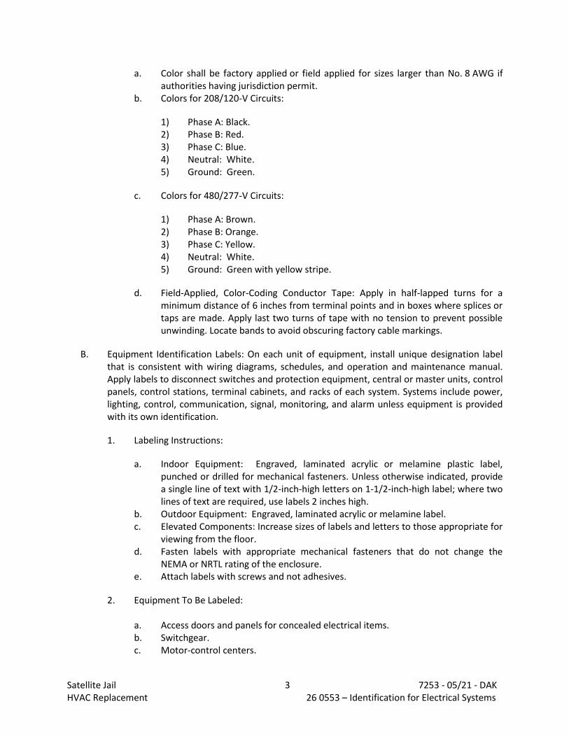
Satellite Jail 3 7253 - 05/21 - DAK HVAC Replacement 26 0553 – Identification for Electrical Systems
a. Color shall be factory applied or field applied for sizes larger than No. 8 AWG if authorities having jurisdiction permit.
b. Colors for 208/120-V Circuits:
1) Phase A: Black. 2) Phase B: Red. 3) Phase C: Blue. 4) Neutral: White. 5) Ground: Green.
c. Colors for 480/277-V Circuits:
1) Phase A: Brown. 2) Phase B: Orange. 3) Phase C: Yellow. 4) Neutral: White. 5) Ground: Green with yellow stripe.
d. Field-Applied, Color-Coding Conductor Tape: Apply in half-lapped turns for a minimum distance of 6 inches from terminal points and in boxes where splices or taps are made. Apply last two turns of tape with no tension to prevent possible unwinding. Locate bands to avoid obscuring factory cable markings.
B. Equipment Identification Labels: On each unit of equipment, install unique designation label that is consistent with wiring diagrams, schedules, and operation and maintenance manual. Apply labels to disconnect switches and protection equipment, central or master units, control panels, control stations, terminal cabinets, and racks of each system. Systems include power, lighting, control, communication, signal, monitoring, and alarm unless equipment is provided with its own identification.
1. Labeling Instructions:
a. Indoor Equipment: Engraved, laminated acrylic or melamine plastic label, punched or drilled for mechanical fasteners. Unless otherwise indicated, provide a single line of text with 1/2-inch-high letters on 1-1/2-inch-high label; where two lines of text are required, use labels 2 inches high.
b. Outdoor Equipment: Engraved, laminated acrylic or melamine label. c. Elevated Components: Increase sizes of labels and letters to those appropriate for
viewing from the floor. d. Fasten labels with appropriate mechanical fasteners that do not change the
NEMA or NRTL rating of the enclosure. e. Attach labels with screws and not adhesives.
2. Equipment To Be Labeled:
a. Access doors and panels for concealed electrical items. b. Switchgear. c. Motor-control centers.

Satellite Jail 4 7253 - 05/21 - DAK HVAC Replacement 26 0553 – Identification for Electrical Systems
d. Enclosed switches. e. Enclosed circuit breakers. f. Enclosed controllers. g. Variable-speed controllers. h. Push-button stations.
END OF SECTION 26 0553
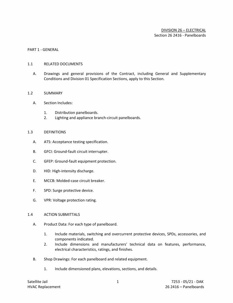
Satellite Jail 1 7253 - 05/21 - DAK HVAC Replacement 26 2416 – Panelboards
DIVISION 26 – ELECTRICAL Section 26 2416 - Panelboards
PART 1 - GENERAL
1.1 RELATED DOCUMENTS
A. Drawings and general provisions of the Contract, including General and Supplementary Conditions and Division 01 Specification Sections, apply to this Section.
1.2 SUMMARY
A. Section Includes:
1. Distribution panelboards. 2. Lighting and appliance branch-circuit panelboards.
1.3 DEFINITIONS
A. ATS: Acceptance testing specification.
B. GFCI: Ground-fault circuit interrupter.
C. GFEP: Ground-fault equipment protection.
D. HID: High-intensity discharge.
E. MCCB: Molded-case circuit breaker.
F. SPD: Surge protective device.
G. VPR: Voltage protection rating.
1.4 ACTION SUBMITTALS
A. Product Data: For each type of panelboard.
1. Include materials, switching and overcurrent protective devices, SPDs, accessories, and components indicated.
2. Include dimensions and manufacturers' technical data on features, performance, electrical characteristics, ratings, and finishes.
B. Shop Drawings: For each panelboard and related equipment.
1. Include dimensioned plans, elevations, sections, and details.
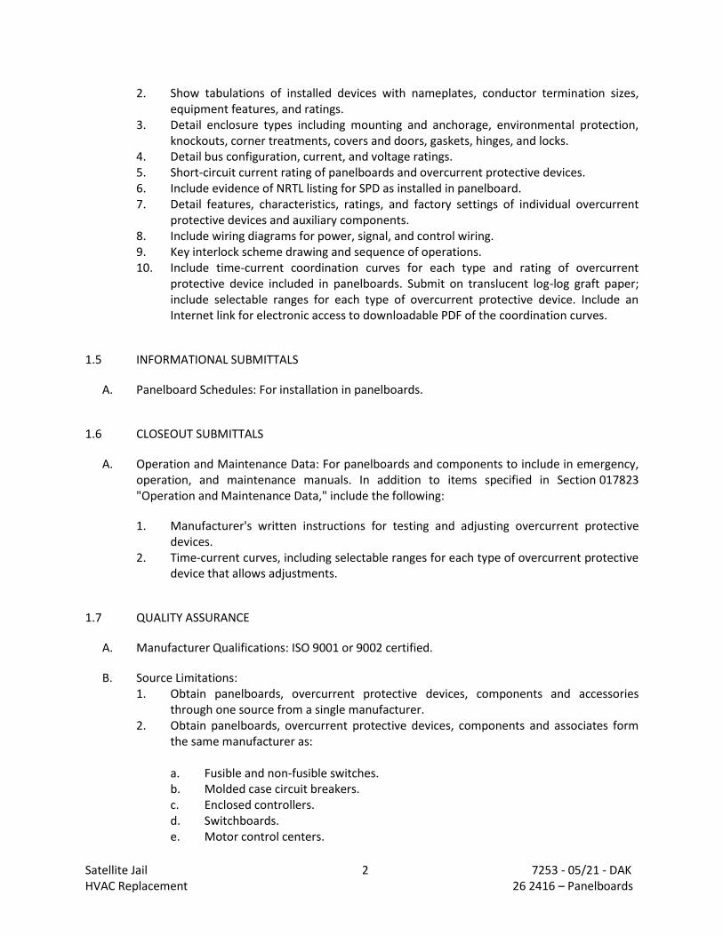
Satellite Jail 2 7253 - 05/21 - DAK HVAC Replacement 26 2416 – Panelboards
2. Show tabulations of installed devices with nameplates, conductor termination sizes, equipment features, and ratings.
3. Detail enclosure types including mounting and anchorage, environmental protection, knockouts, corner treatments, covers and doors, gaskets, hinges, and locks.
4. Detail bus configuration, current, and voltage ratings. 5. Short-circuit current rating of panelboards and overcurrent protective devices. 6. Include evidence of NRTL listing for SPD as installed in panelboard. 7. Detail features, characteristics, ratings, and factory settings of individual overcurrent
protective devices and auxiliary components. 8. Include wiring diagrams for power, signal, and control wiring. 9. Key interlock scheme drawing and sequence of operations. 10. Include time-current coordination curves for each type and rating of overcurrent
protective device included in panelboards. Submit on translucent log-log graft paper; include selectable ranges for each type of overcurrent protective device. Include an Internet link for electronic access to downloadable PDF of the coordination curves.
1.5 INFORMATIONAL SUBMITTALS
A. Panelboard Schedules: For installation in panelboards.
1.6 CLOSEOUT SUBMITTALS
A. Operation and Maintenance Data: For panelboards and components to include in emergency, operation, and maintenance manuals. In addition to items specified in Section 017823 "Operation and Maintenance Data," include the following:
1. Manufacturer's written instructions for testing and adjusting overcurrent protective devices.
2. Time-current curves, including selectable ranges for each type of overcurrent protective device that allows adjustments.
1.7 QUALITY ASSURANCE
A. Manufacturer Qualifications: ISO 9001 or 9002 certified.
B. Source Limitations: 1. Obtain panelboards, overcurrent protective devices, components and accessories
through one source from a single manufacturer. 2. Obtain panelboards, overcurrent protective devices, components and associates form
the same manufacturer as:
a. Fusible and non-fusible switches. b. Molded case circuit breakers. c. Enclosed controllers. d. Switchboards. e. Motor control centers.
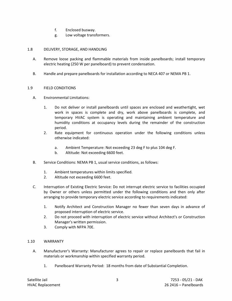
Satellite Jail 3 7253 - 05/21 - DAK HVAC Replacement 26 2416 – Panelboards
f. Enclosed busway. g. Low voltage transformers.
1.8 DELIVERY, STORAGE, AND HANDLING
A. Remove loose packing and flammable materials from inside panelboards; install temporary electric heating (250 W per panelboard) to prevent condensation.
B. Handle and prepare panelboards for installation according to NECA 407 or NEMA PB 1.
1.9 FIELD CONDITIONS
A. Environmental Limitations:
1. Do not deliver or install panelboards until spaces are enclosed and weathertight, wet work in spaces is complete and dry, work above panelboards is complete, and temporary HVAC system is operating and maintaining ambient temperature and humidity conditions at occupancy levels during the remainder of the construction period.
2. Rate equipment for continuous operation under the following conditions unless otherwise indicated:
a. Ambient Temperature: Not exceeding 23 deg F to plus 104 deg F. b. Altitude: Not exceeding 6600 feet.
B. Service Conditions: NEMA PB 1, usual service conditions, as follows:
1. Ambient temperatures within limits specified. 2. Altitude not exceeding 6600 feet.
C. Interruption of Existing Electric Service: Do not interrupt electric service to facilities occupied by Owner or others unless permitted under the following conditions and then only after arranging to provide temporary electric service according to requirements indicated:
1. Notify Architect and Construction Manager no fewer than seven days in advance of proposed interruption of electric service.
2. Do not proceed with interruption of electric service without Architect's or Construction Manager's written permission.
3. Comply with NFPA 70E.
1.10 WARRANTY
A. Manufacturer's Warranty: Manufacturer agrees to repair or replace panelboards that fail in materials or workmanship within specified warranty period.
1. Panelboard Warranty Period: 18 months from date of Substantial Completion.
Satellite Jail 4 7253 - 05/21 - DAK HVAC Replacement 26 2416 – Panelboards
B. Special Warranty: Manufacturer's standard form in which manufacturer agrees to repair or replace SPD that fails in materials or workmanship within specified warranty period.
1. SPD Warranty Period: Five years from date of Substantial Completion.
PART 2 - PRODUCTS
2.1 PANELBOARDS AND LOAD CENTERS COMMON REQUIREMENTS
A. Electrical Components, Devices, and Accessories: Listed and labeled as defined in NFPA 70, by a qualified testing agency, and marked for intended location and application.
B. Comply with NEMA PB 1.
C. Comply with NFPA 70.
D. Enclosures: Flush and Surface-mounted, dead-front cabinets.
1. Rated for environmental conditions at installed location.
a. Indoor Dry and Clean Locations: NEMA 250, Type 1.
2. Height: 84 inches maximum. 3. Front: Secured to box with concealed trim clamps. For surface-mounted fronts, match
box dimensions; for flush-mounted fronts, overlap box. Trims shall cover all live parts and shall have no exposed hardware.
4. Finishes:
a. Panels and Trim: Steel, factory finished immediately after cleaning and pretreating with manufacturer's standard two-coat, baked-on finish consisting of prime coat and thermosetting topcoat.
b. Back Boxes: Galvanized steel. c. Fungus Proofing: Permanent fungicidal treatment for overcurrent protective
devices and other components.
E. Incoming Mains:
1. Main Breaker: Main lug interiors up to 400 amperes shall be field convertible to main breaker.
F. Phase, Neutral, and Ground Buses:
1. Material: Tin-plated aluminum.
a. Plating shall run entire length of bus. b. Bus shall be fully rated the entire length.
Satellite Jail 5 7253 - 05/21 - DAK HVAC Replacement 26 2416 – Panelboards
2. Interiors shall be factory assembled into a unit. Replacing switching and protective devices shall not disturb adjacent units or require removing the main bus connectors.
3. Equipment Ground Bus: Adequate for feeder and branch-circuit equipment grounding conductors; bonded to box.
4. Isolated Ground Bus: Adequate for branch-circuit isolated ground conductors; insulated from box.
5. Full-Sized Neutral: Equipped with full-capacity bonding strap for service entrance applications. Mount electrically isolated from enclosure. Do not mount neutral bus in gutter.
G. Conductor Connectors: Suitable for use with conductor material and sizes.
1. Material: Tin-plated aluminum. 2. Terminations shall allow use of 75 deg C rated conductors without derating. 3. Size: Lugs suitable for indicated conductor sizes, with additional gutter space, if
required, for larger conductors. 4. Main and Neutral Lugs: Mechanical type, with a lug on the neutral bar for each pole in
the panelboard. 5. Ground Lugs and Bus-Configured Terminators: Mechanical type, with a lug on the bar
for each pole in the panelboard. 6. Feed-Through Lugs: Mechanical type, suitable for use with conductor material. Locate
at opposite end of bus from incoming lugs or main device. 7. Subfeed (Double) Lugs: Mechanical type suitable for use with conductor material.
Locate at same end of bus as incoming lugs or main device.
H. NRTL Label: Panelboards or load centers shall be labeled by an NRTL acceptable to authority having jurisdiction for use as service equipment with one or more main service disconnecting and overcurrent protective devices. Panelboards or load centers shall have meter enclosures, wiring, connections, and other provisions for utility metering. Coordinate with utility company for exact requirements.
I. Panelboard Short-Circuit Current Rating: Fully rated to interrupt symmetrical short-circuit current available at terminals. Assembly listed by an NRTL for 100 percent interrupting capacity.
1. Panelboards and overcurrent protective devices rated 240 V or less shall have short-circuit ratings as shown on Drawings, but not less than 10,000 A rms symmetrical.
2. Panelboards and overcurrent protective devices rated above 240 V and less than 600 V shall have short-circuit ratings as shown on Drawings, but not less than 14,000 A rms symmetrical.
2.2 PERFORMANCE REQUIREMENTS
A. Surge Suppression: Factory installed as an integral part of indicated panelboards, complying with UL 1449 SPD Type 2.
Satellite Jail 6 7253 - 05/21 - DAK HVAC Replacement 26 2416 – Panelboards
2.3 LIGHTING AND APPLIANCE BRANCH-CIRCUIT PANELBOARDS
A. Manufacturers: Subject to compliance with requirements, provide products by one of the following:
1. Eaton. 2. General Electric Company; GE Energy Management - Electrical Distribution. 3. Siemens. 4. Square D.
B. Panelboards: NEMA PB 1, lighting and appliance branch-circuit type.
C. Branch Overcurrent Protective Devices: Bolt-on circuit breakers, replaceable without disturbing adjacent units.
D. Doors: Concealed hinges; secured with flush latch with tumbler lock; keyed alike.
2.4 DISCONNECTING AND OVERCURRENT PROTECTIVE DEVICES
A. Manufacturers: Subject to compliance with requirements, provide products by one of the following:
1. Eaton. 2. General Electric Company; GE Energy Management - Electrical Distribution. 3. Siemens. 4. Square D.
B. MCCB: Comply with UL 489, with interrupting capacity to meet available fault currents.
1. Thermal-Magnetic Circuit Breakers:
a. Inverse time-current element for low-level overloads. b. Instantaneous magnetic trip element for short circuits. c. Adjustable magnetic trip setting for circuit-breaker frame sizes 250 A and larger.
2. Adjustable Instantaneous-Trip Circuit Breakers: Magnetic trip element with front-mounted, field-adjustable trip setting.
3. Electronic Trip Circuit Breakers:
a. RMS sensing. b. Field-replaceable rating plug or electronic trip. c. Digital display of settings, trip targets, and indicated metering displays. d. Multi-button keypad to access programmable functions and monitored data. e. Ten-event, trip-history log. Each trip event shall be recorded with type, phase,
and magnitude of fault that caused the trip. f. Integral test jack for connection to portable test set or laptop computer.
Satellite Jail 7 7253 - 05/21 - DAK HVAC Replacement 26 2416 – Panelboards
g. Field-Adjustable Settings:
1) Instantaneous trip. 2) Long- and short-time pickup levels. 3) Long and short time adjustments. 4) Ground-fault pickup level, time delay, and I squared T response.
4. GFCI Circuit Breakers: Single- and double-pole configurations with Class A ground-fault
protection (6-mA trip). 5. Subfeed Circuit Breakers: Vertically mounted. 6. MCCB Features and Accessories:
a. Standard frame sizes, trip ratings, and number of poles. b. Breaker handle indicates tripped status. c. UL listed for reverse connection without restrictive line or load ratings. d. Lugs: Mechanical style, suitable for number, size, trip ratings, and conductor
materials. e. Application Listing: Appropriate for application. f. Ground-Fault Protection: Integrally mounted relay and trip unit with adjustable
pickup and time-delay settings, push-to-test feature, and ground-fault indicator. g. Shunt Trip: 120-V trip coil energized from separate circuit, set to trip at 55
percent of rated voltage. h. Zone-Selective Interlocking: Integral with electronic trip unit; for interlocking
ground-fault protection function with other upstream or downstream devices.
2.5 IDENTIFICATION
A. Panelboard Label: Manufacturer's name and trademark, voltage, amperage, number of phases, and number of poles shall be located on the interior of the panelboard door.
B. Breaker Labels: Faceplate shall list current rating, UL and IEC certification standards, and AIC rating.
C. Circuit Directory: Computer-generated circuit directory mounted inside panelboard door with transparent plastic protective cover.
1. Circuit directory shall identify specific purpose with detail sufficient to distinguish it from all other circuits.
PART 3 - EXECUTION
3.1 EXAMINATION
A. Verify actual conditions with field measurements prior to ordering panelboards to verify that equipment fits in allocated space in, and comply with, minimum required clearances specified in NFPA 70.

Satellite Jail 8 7253 - 05/21 - DAK HVAC Replacement 26 2416 – Panelboards
B. Receive, inspect, handle, and store panelboards according to NECA 407 or NEMA PB 1.1.
C. Examine panelboards before installation. Reject panelboards that are damaged, rusted, or have been subjected to water saturation.
D. Examine elements and surfaces to receive panelboards for compliance with installation tolerances and other conditions affecting performance of the Work.
E. Proceed with installation only after unsatisfactory conditions have been corrected.
3.2 INSTALLATION
A. Coordinate layout and installation of panelboards and components with other construction that penetrates walls or is supported by them, including electrical and other types of equipment, raceways, piping, encumbrances to workspace clearance requirements, and adjacent surfaces. Maintain required workspace clearances and required clearances for equipment access doors and panels.
B. Comply with NECA 1.
C. Install panelboards and accessories according to NECA 407 or NEMA PB 1.1.
D. Equipment Mounting:
1. Attach panelboard to the vertical finished or structural surface behind the panelboard.
E. Temporary Lifting Provisions: Remove temporary lifting eyes, channels, and brackets and temporary blocking of moving parts from panelboards.
F. Comply with mounting and anchoring requirements specified in Section 260548.16 "Seismic Controls for Electrical Systems."
G. Mount top of trim 90 inches above finished floor unless otherwise indicated.
H. Mount panelboard cabinet plumb and rigid without distortion of box.
I. Mount recessed panelboards with fronts uniformly flush with wall finish and mating with back box.
J. Mount surface-mounted panelboards to steel slotted supports 1 1/4 inch in depth. Orient steel slotted supports vertically.
K. Install overcurrent protective devices and controllers not already factory installed.
1. Set field-adjustable, circuit-breaker trip ranges. 2. Tighten bolted connections and circuit breaker connections using calibrated torque
wrench or torque screwdriver per manufacturer's written instructions.
Satellite Jail 9 7253 - 05/21 - DAK HVAC Replacement 26 2416 – Panelboards
L. Make grounding connections and bond neutral for services and separately derived systems to ground. Make connections to grounding electrodes, separate grounds for isolated ground bars, and connections to separate ground bars.
M. Install filler plates in unused spaces.
N. Where flush mounted panelboards are installed, stub four 1-inch empty conduits from panelboard into accessible ceiling space or space designated to be ceiling space in the future. Stub four 1-inch empty conduits into raised floor space or below slab not on grade.
3.3 IDENTIFICATION
A. Identify field-installed conductors, interconnecting wiring, and components; install warning signs complying with requirements in Section 260553 "Identification for Electrical Systems."
B. Create a directory to indicate installed circuit loads; incorporate Owner's final room designations. Obtain approval before installing. Handwritten directories are not acceptable. Install directory inside panelboard door.
C. Panelboard Nameplates: Label each panelboard with a nameplate complying with requirements for identification specified in Section 260553 "Identification for Electrical Systems."
D. Device Nameplates: Label each branch circuit device in power panelboards with a nameplate complying with requirements for identification specified in Section 260553 "Identification for Electrical Systems."
3.4 FIELD QUALITY CONTROL
A. Manufacturer's Field Service: Engage a factory-authorized service representative to inspect, test, and adjust components, assemblies, and equipment installations, including connections.
B. Perform tests and inspections.
C. Acceptance Testing Preparation:
1. Test continuity of each circuit.
D. Tests and Inspections:
1. Perform each visual and mechanical inspection and electrical test for low-voltage air circuit breakers.
2. Correct malfunctioning units on-site, where possible, and retest to demonstrate compliance; otherwise, replace with new units and retest.
E. Panelboards will be considered defective if they do not pass tests and inspections.
Satellite Jail 10 7253 - 05/21 - DAK HVAC Replacement 26 2416 – Panelboards
3.5 ADJUSTING
A. Adjust moving parts and operable components to function smoothly, and lubricate as recommended by manufacturer.
B. Set field-adjustable circuit-breaker trip ranges as indicated
3.6 PROTECTION
A. Temporary Heating: Prior to energizing panelboards, apply temporary heat to maintain temperature according to manufacturer's written instructions.
END 26 2416
Satellite Jail 1 7253 - 05/21 - DAK HVAC Replacement 26 2726 – Wiring Devices
DIVISION 26 – ELECTRICAL Section 26 2726 – Wiring Devices
PART 1 - GENERAL
1.1 RELATED DOCUMENTS
A. Drawings and general provisions of the Contract, including General and Supplementary Conditions, apply to this Section.
1.2 SUMMARY
A. Section Includes:
1. GFCI receptacles.
1.3 DEFINITIONS
A. Abbreviations of Manufacturers' Names:
1. Cooper: Cooper Wiring Devices; Division of Cooper Industries, Inc. 2. Hubbell: Hubbell Incorporated: Wiring Devices-Kellems. 3. Leviton: Leviton Mfg. Company, Inc. 4. Pass & Seymour: Pass& Seymour/Legrand.
B. BAS: Building automation system.
C. EMI: Electromagnetic interference.
D. GFCI: Ground-fault circuit interrupter.
E. Pigtail: Short lead used to connect a device to a branch-circuit conductor.
F. RFI: Radio-frequency interference.
G. SPD: Surge protective device.
H. UTP: Unshielded twisted pair.
1.4 ACTION SUBMITTALS
A. Product Data: For each type of product.
B. Shop Drawings: List of legends and description of materials and process used for premarking wall plates.
Satellite Jail 2 7253 - 05/21 - DAK HVAC Replacement 26 2726 – Wiring Devices
1.5 CLOSEOUT SUBMITTALS
A. Operation and Maintenance Data: For wiring devices to include in all manufacturers' packing-label warnings and instruction manuals that include labeling conditions.
PART 2 - PRODUCTS
2.1 GENERAL WIRING-DEVICE REQUIREMENTS
A. Wiring Devices, Components, and Accessories: Listed and labeled as defined in NFPA 70, by a qualified testing agency, and marked for intended location and application.
B. Comply with NFPA 70.
C. Devices for Owner-Furnished Equipment:
1. Receptacles: Match plug configurations. 2. Cord and Plug Sets: Match equipment requirements.
D. Source Limitations: Obtain each type of wiring device and associated wall plate from single source from single manufacturer.
2.2 GFCI RECEPTACLES
A. General Description:
1. 125 V, 20 A, straight blade, feed-through type. 2. Comply with NEMA WD 1, NEMA WD 6 Configuration 5-20R, UL 498, UL 943 Class A, and
FS W-C-596. 3. Include indicator light that shows when the GFCI has malfunctioned and no longer
provides proper GFCI protection.
B. Duplex GFCI Convenience Receptacles:
1. Manufacturers: Subject to compliance with requirements, provide products by one of the following:
a. Eaton (Arrow Hart). b. Hubbell Incorporated; Wiring Device-Kellems. c. Leviton Manufacturing Co., Inc. d. Pass & Seymour/Legrand (Pass & Seymour).
2.3 FINISHES
A. Device Color:

Satellite Jail 3 7253 - 05/21 - DAK HVAC Replacement 26 2726 – Wiring Devices
1. Wiring Devices Connected to Normal Power System: White unless otherwise indicated or required by NFPA 70 or device listing.
B. The Architect / Engineer reserves the right to change the color at time of shop drawing review.
2.4 TOGGLE SWITCHES
A. Comply with NEMA WD 1, UL 20, and FS W-S-896.
B. Switches, 120/277 V, 20 A:
1. Single Pole:
a. Manufacturers: Subject to compliance with requirements, provide products by one of the following:
1) Eaton (Arrow Hart). 2) Hubbell Incorporated; Wiring Device-Kellems. 3) Leviton Manufacturing Co., Inc. 4) Pass & Seymour/Legrand (Pass & Seymour).
PART 3 - EXECUTION
3.1 INSTALLATION
A. Comply with NECA 1, including mounting heights listed in that standard, unless otherwise indicated.
B. Mounting Heights
1. Examine architectural details and elevations for heights indicated there. Coordinate mounting heights with wall treatment and finish.
2. Examine electrical drawings for heights indicated there. 3. Unless otherwise indicated:
a. Wall Switches: 48" above finished floor, except where special wall treatment
requires a higher or lower setting. b. Dimmer and Lighting Controls: 48" AFF, except where special wall treatment
requires higher or lower setting. c. Receptacles - General: 18" AFF. d. Receptacles in Mechanical and Electrical Equipment Rooms: 40" AFF. e. Receptacles - Exterior: 24" above finished grade.
4. Mounting heights given above shall be to the center line of the device. 5. In block walls, locate device in either bottom or top of the block course nearest to the
height indicated.
Satellite Jail 4 7253 - 05/21 - DAK HVAC Replacement 26 2726 – Wiring Devices
6. In brick walls, mount receptacles in the horizontal position in the brick course nearest to the height indicated.
7. Where receptacles are indicated to be installed above counters, mount in the horizontal position 4" from top of back splash to bottom of box.
C. Coordination with Other Trades:
1. Protect installed devices and their boxes. Do not place wall finish materials over device boxes and do not cut holes for boxes with routers that are guided by riding against outside of boxes.
2. Keep outlet boxes free of plaster, drywall joint compound, mortar, cement, concrete, dust, paint, and other material that may contaminate the raceway system, conductors, and cables.
3. Install device boxes in brick or block walls so that the cover plate does not cross a joint unless the joint is troweled flush with the face of the wall.
4. Install wiring devices after all wall preparation, including painting, is complete.
D. Conductors:
1. Do not strip insulation from conductors until right before they are spliced or terminated on devices.
2. Strip insulation evenly around the conductor using tools designed for the purpose. Avoid scoring or nicking of solid wire or cutting strands from stranded wire.
3. The length of free conductors at outlets for devices shall meet provisions of NFPA 70, Article 300, without pigtails.
4. Existing Conductors:
a. Cut back and pigtail, or replace all damaged conductors. b. Straighten conductors that remain and remove corrosion and foreign matter. c. Pigtailing existing conductors is permitted, provided the outlet box is large
enough.
E. Device Installation:
1. Replace devices that have been in temporary use during construction and that were installed before building finishing operations were complete.
2. Keep each wiring device in its package or otherwise protected until it is time to connect conductors.
3. Do not remove surface protection, such as plastic film and smudge covers, until the last possible moment.
4. Connect devices to branch circuits using pigtails that are not less than 6 inches in length. 5. When there is a choice, use side wiring with binding-head screw terminals. Wrap solid
conductor tightly clockwise, two-thirds to three-fourths of the way around terminal screw.
6. Use a torque screwdriver when a torque is recommended or required by manufacturer. 7. When conductors larger than No. 12 AWG are installed on 15- or 20-A circuits, splice
No. 12 AWG pigtails for device connections. 8. Tighten unused terminal screws on the device.
Satellite Jail 5 7253 - 05/21 - DAK HVAC Replacement 26 2726 – Wiring Devices
9. When mounting into metal boxes, remove the fiber or plastic washers used to hold device-mounting screws in yokes, allowing metal-to-metal contact.
F. Receptacle Orientation:
1. Install ground pin of vertically mounted receptacles up, and on horizontally mounted receptacles to the left.
G. Device Plates: Device plates shall fit tight against the finished walls and shall completely cover the openings in the walls for the boxes. Do not use oversized or extra-deep plates. Repair wall finishes and remount outlet boxes when standard device plates do not fit flush or do not cover rough wall opening. Device plates shall be attached and adjusted so they finish straight and level.
H. Arrangement of Devices: Unless otherwise indicated, mount flush, with long dimension vertical and with grounding terminal of receptacles on top. Group adjacent switches under single, multigang wall plates.
I. Adjust locations of floor service outlets and service poles to suit arrangement of partitions and furnishings.
3.2 GFCI RECEPTACLES
A. Install non-feed-through-type GFCI receptacles where protection of downstream receptacles is not required.
3.3 GROUND FAULT INTERRUTING RECEPTACLES
A. Where drawing or specifications call for 15 amp or 20 amp, 120 volt receptacles in the following locations, provide ground fault interrupting type receptacles.
1. Outdoors.
3.4 IDENTIFICATION
A. Comply with Section 260553 "Identification for Electrical Systems."
1. Receptacles and Switches: Provide all outlet and switch coverplates with identification labels showing panelboard designation and circuit breaker number connected to device.
a. Normal Circuits: Black letters indicating panel and circuit number on clear
background applied to front of coverplate. Minimum letter height 3/16”. b. Emergency Circuits: Red letter indicating panel and circuit number on clear
background applied to front of coverplate. Minimum letter height 3/16”.
Satellite Jail 6 7253 - 05/21 - DAK HVAC Replacement 26 2726 – Wiring Devices
2. Labels shall be attached to coverplates with pressure-sensitive adhesive. Devices installed in multi-outlet, surface raceways shall be provided with labels.
END OF SECTION 26 2726
Satellite Jail 1 7253 - 05/21 - DAK HVAC Replacement 26 2813 – Fuses
DIVISION 26 – ELECTRICAL Section 26 2813 – Fuses
PART 1 - GENERAL
1.1 RELATED DOCUMENTS
A. Drawings and general provisions of the Contract, including General and Supplementary Conditions, apply to this Section.
1.2 SUMMARY
A. Section Includes:
1. Cartridge fuses rated 600 V ac and less for use in the following:
a. Control circuits. b. Motor-control centers. c. Panelboards. d. Switchboards. e. Enclosed controllers. f. Enclosed switches.
1.3 ACTION SUBMITTALS
A. Product Data: For each type of product. Include construction details, material descriptions, dimensions of individual components and profiles, and finishes for spare-fuse cabinets. Include the following for each fuse type indicated:
1. Ambient Temperature Adjustment Information: If ratings of fuses have been adjusted to accommodate ambient temperatures, provide list of fuses with adjusted ratings.
a. For each fuse having adjusted ratings, include location of fuse, original fuse rating, local ambient temperature, and adjusted fuse rating.
b. Provide manufacturer's technical data on which ambient temperature adjustment calculations are based.
2. Dimensions and manufacturer's technical data on features, performance, electrical characteristics, and ratings.
3. Current-limitation curves for fuses with current-limiting characteristics. 4. Time-current coordination curves (average melt) and current-limitation curves
(instantaneous peak let-through current) for each type and rating of fuse. Submit in PDF format.
5. Coordination charts and tables and related data. 6. Fuse sizes for elevator feeders and elevator disconnect switches.
Satellite Jail 2 7253 - 05/21 - DAK HVAC Replacement 26 2813 – Fuses
1.4 CLOSEOUT SUBMITTALS
A. Operation and Maintenance Data: For fuses to include in emergency, operation, and maintenance manuals.
1. Ambient temperature adjustment information. 2. Current-limitation curves for fuses with current-limiting characteristics. 3. Time-current coordination curves (average melt) and current-limitation curves
(instantaneous peak let-through current) for each type and rating of fuse used on the Project. Submit in PDF format.
4. Coordination charts and tables and related data.
1.5 MAINTENANCE MATERIAL SUBMITTALS
A. Furnish extra materials that match products installed and that are packaged with protective covering for storage and identified with labels describing contents.
1. Fuses: Equal to 10 percent of quantity installed for each size and type, but no fewer than three of each size and type.
1.6 FIELD CONDITIONS
A. Where ambient temperature to which fuses are directly exposed is less than 40 deg F or more than 100 deg F, apply manufacturer's ambient temperature adjustment factors to fuse ratings.
PART 2 - PRODUCTS
2.1 MANUFACTURERS
A. Manufacturers: Subject to compliance with requirements, provide products by one of the following:
1. Bussmann, an Eaton business. 2. Edison; a brand of Bussmann by Eaton. 3. Littelfuse, Inc. 4. Mersen USA.
B. Source Limitations: Obtain fuses, for use within a specific product or circuit, from single source from single manufacturer.
2.2 CARTRIDGE FUSES
A. Characteristics: NEMA FU 1, current-limiting, nonrenewable cartridge fuses with voltage ratings consistent with circuit voltages.
Satellite Jail 3 7253 - 05/21 - DAK HVAC Replacement 26 2813 – Fuses
1. Type RK-1: 250 or 600-V, zero- to 600-A rating, 200 kAIC, time delay. 2. Type L: 600-V, 601- to 6000-A rating, 200 kAIC, time delay.
B. Electrical Components, Devices, and Accessories: Listed and labeled as defined in NFPA 70, by a qualified testing agency, and marked for intended location and application.
C. Comply with NEMA FU 1 for cartridge fuses.
D. Comply with NFPA 70.
E. Coordinate fuse ratings with utilization equipment nameplate limitations of maximum fuse size and with system short-circuit current levels.
PART 3 - EXECUTION
3.1 EXAMINATION
A. Examine fuses before installation. Reject fuses that are moisture damaged or physically damaged.
B. Examine holders to receive fuses for compliance with installation tolerances and other conditions affecting performance, such as rejection features.
C. Examine utilization equipment nameplates and installation instructions. Install fuses of sizes and with characteristics appropriate for each piece of equipment.
D. Evaluate ambient temperatures to determine if fuse rating adjustment factors must be applied to fuse ratings.
E. Proceed with installation only after unsatisfactory conditions have been corrected.
3.2 FUSE APPLICATIONS
A. Cartridge Fuses:
1. Feeders, 601 Amp through 6000 Amp: Class L, time delay. 2. Feeders, up to 600 Amp: Class RK1, time delay. 3. Motor Branch Circuits: Class RK1, time delay. 4. Other Branch Circuits: Class RK1, time delay. 5. Provide open-fuse indicator fuses or fuse covers with open fuse indication.
3.3 INSTALLATION
A. Install fuses in fusible devices. Arrange fuses so rating information is readable without removing fuse.

Satellite Jail 4 7253 - 05/21 - DAK HVAC Replacement 26 2813 – Fuses
3.4 IDENTIFICATION
A. Install labels complying with requirements for identification specified in Section 260553 "Identification for Electrical Systems" and indicating fuse replacement information inside of door of each fused switch and adjacent to each fuse block, socket, and holder.
END OF SECTION 26 2813
Satellite Jail 1 7253 - 05/21 - DAK HVAC Replacement 26 2816 – Enclosed Switches and Circuit Breakers
DIVISION 26 – ELECTRICAL Section 26 2816 – Enclosed Switches and Circuit Breakers
PART 1 - GENERAL
1.1 RELATED DOCUMENTS
A. Drawings and general provisions of the Contract, including General and Supplementary Conditions, apply to this Section.
1.2 SUMMARY
A. Section Includes:
1. Fusible switches. 2. Nonfusible switches. 3. Molded-case circuit breakers (MCCBs). 4. Molded-case switches. 5. Enclosures.
1.3 DEFINITIONS
A. NC: Normally closed.
B. NO: Normally open.
C. SPDT: Single pole, double throw.
1.4 ACTION SUBMITTALS
A. Product Data: For each type of enclosed switch, circuit breaker, accessory, and component indicated. Include nameplate ratings, dimensioned elevations, sections, weights, and manufacturers' technical data on features, performance, electrical characteristics, ratings, accessories, and finishes.
1. Enclosure types and details for types other than NEMA 250, Type 1. 2. Current and voltage ratings. 3. Short-circuit current ratings (interrupting and withstand, as appropriate). 4. Include evidence of a nationally recognized testing laboratory (NRTL) listing for series
rating of installed devices. 5. Detail features, characteristics, ratings, and factory settings of individual overcurrent
protective devices, accessories, and auxiliary components.

Satellite Jail 2 7253 - 05/21 - DAK HVAC Replacement 26 2816 – Enclosed Switches and Circuit Breakers
6. Include time-current coordination curves (average melt) for each type and rating of overcurrent protective device; include selectable ranges for each type of overcurrent protective device. Provide in PDF electronic format.
B. Shop Drawings: For enclosed switches and circuit breakers.
1. Include plans, elevations, sections, details, and attachments to other work. 2. Include wiring diagrams for power, signal, and control wiring.
1.5 CLOSEOUT SUBMITTALS
A. Operation and Maintenance Data: For enclosed switches and circuit breakers to include in emergency, operation, and maintenance manuals.
1. In addition to items specified in Section 017823 "Operation and Maintenance Data," include the following:
a. Manufacturer's written instructions for testing and adjusting enclosed switches and circuit breakers.
1.6 FIELD CONDITIONS
A. Environmental Limitations: Rate equipment for continuous operation under the following conditions unless otherwise indicated:
1. Ambient Temperature: Not less than minus 22 deg F and not exceeding 104 deg F. 2. Altitude: Not exceeding 6600 feet.
1.7 WARRANTY
A. Manufacturer's Warranty: Manufacturer and Installer agree to repair or replace components that fail in materials or workmanship within specified warranty period.
1. Warranty Period: One year(s) from date of Substantial Completion.
PART 2 - PRODUCTS
2.1 GENERAL REQUIREMENTS
A. Source Limitations: Obtain enclosed switches and circuit breakers, overcurrent protective devices, components, and accessories, within same product category, from single manufacturer.
B. Source Limitations:
Satellite Jail 3 7253 - 05/21 - DAK HVAC Replacement 26 2816 – Enclosed Switches and Circuit Breakers
1. Obtain fusible switches, non-fusible switches, molded case circuit breakers and switches from the same manufacturer as: a. Enclosed controllers. b. Switchboards. c. Distribution panelboards. d. Branch circuit panelboards. e. Motor control centers. f. Enclosed busway. g. Low voltage transformers.
C. Product Selection for Restricted Space: Drawings indicate maximum dimensions for enclosed switches and circuit breakers, including clearances between enclosures, and adjacent surfaces and other items. Comply with indicated maximum dimensions.
D. Electrical Components, Devices, and Accessories: Listed and labeled as defined in NFPA 70, by an NRTL, and marked for intended location and application.
E. Comply with NFPA 70.
2.2 FUSIBLE SWITCHES
A. Manufacturers: Subject to compliance with requirements, provide products by one of the following:
1. Eaton. 2. General Electric Company. 3. Siemens Industry, Inc. 4. Square D; by Schneider Electric.
B. Type HD, Heavy Duty:
1. Single throw. 2. Three pole. 3. 240 or 600-V ac as specified on drawings. 4. 1200 A and smaller. 5. UL 98 and NEMA KS 1, horsepower rated, with clips or bolt pads to accommodate
indicated fuses. 6. Lockable handle with capability to accept three padlocks, and interlocked with cover in
closed position.
C. Accessories:
1. Equipment Ground Kit: Internally mounted and labeled for copper and aluminum ground conductors.
2. Neutral Kit: Internally mounted; insulated, capable of being grounded and bonded; labeled for copper and aluminum neutral conductors.
3. Class R Fuse Kit: Provides rejection of other fuse types when Class R fuses are specified.
Satellite Jail 4 7253 - 05/21 - DAK HVAC Replacement 26 2816 – Enclosed Switches and Circuit Breakers
4. Auxiliary Contact Kit: Two NO/NC (Form "C") auxiliary contact(s), arranged to activate before switch blades open. Contact rating - 24-V ac.
5. Lugs: Mechanical type, suitable for number, size, and conductor material.
2.3 NONFUSIBLE SWITCHES
A. Manufacturers: Subject to compliance with requirements, provide products by one of the following:
1. Eaton. 2. General Electric Company. 3. Siemens Industry, Inc. 4. Square D; by Schneider Electric.
B. Type HD, Heavy Duty, Three Pole, Single Throw, 240 or 600-V ac, 1200 A and Smaller: UL 98 and NEMA KS 1, horsepower rated, lockable handle with capability to accept three padlocks, and interlocked with cover in closed position.
C. Accessories:
1. Equipment Ground Kit: Internally mounted and labeled for copper and aluminum ground conductors.
2. Neutral Kit: Internally mounted; insulated, capable of being grounded and bonded; labeled for copper and aluminum neutral conductors.
3. Auxiliary Contact Kit: Two NO/NC (Form "C") auxiliary contact(s), arranged to activate before switch blades open. Contact rating - 24-V ac.
4. Lugs: Mechanical type, suitable for number, size, and conductor material.
2.4 ENCLOSURES
A. Enclosed Switches and Circuit Breakers: UL 489, NEMA KS 1, NEMA 250, and UL 50, to comply with environmental conditions at installed location.
B. Enclosure Finish: The enclosure shall be finished with gray baked enamel paint, electrodeposited on cleaned, phosphatized steel (NEMA 250 Type 1) gray baked enamel paint, electrodeposited on cleaned, phosphatized galvannealed steel (NEMA 250 Types 3R, 12).
C. Conduit Entry: NEMA 250 Types 4, 4X, and 12 enclosures shall contain no knockouts. NEMA 250 Types 7 and 9 enclosures shall be provided with threaded conduit openings in both endwalls.
D. Enclosures designated as NEMA 250 Type 4, 4X stainless steel, 12, or 12K shall have a dual cover interlock mechanism to prevent unintentional opening of the enclosure cover when the circuit breaker is ON and to prevent turning the circuit breaker ON when the enclosure cover is open.
Satellite Jail 5 7253 - 05/21 - DAK HVAC Replacement 26 2816 – Enclosed Switches and Circuit Breakers
PART 3 - EXECUTION
3.1 EXAMINATION
A. Examine elements and surfaces to receive enclosed switches and circuit breakers for compliance with installation tolerances and other conditions affecting performance of the Work.
B. Proceed with installation only after unsatisfactory conditions have been corrected.
1. Commencement of work shall indicate Installer's acceptance of the areas and conditions as satisfactory.
3.2 ENCLOSURE ENVIRONMENTAL RATING APPLICATIONS
A. Enclosed Switches and Circuit Breakers: Provide enclosures at installed locations with the following environmental ratings.
1. Indoor, Dry and Clean Locations: NEMA 250, Type 1. 2. Outdoor Locations: NEMA 250, Type 3R.
3.3 INSTALLATION
A. Coordinate layout and installation of switches, circuit breakers, and components with equipment served and adjacent surfaces. Maintain required workspace clearances and required clearances for equipment access doors and panels.
B. Install individual wall-mounted switches and circuit breakers with tops at uniform height unless otherwise indicated.
C. Comply with mounting and anchoring requirements specified in Section 260548.16 "Seismic Controls for Electrical Systems."
D. Temporary Lifting Provisions: Remove temporary lifting of eyes, channels, and brackets and temporary blocking of moving parts from enclosures and components.
E. Install fuses in fusible devices.
F. Comply with NFPA 70 and NECA 1.
3.4 IDENTIFICATION
A. Comply with requirements in Section 260553 "Identification for Electrical Systems."
1. Identify field-installed conductors, interconnecting wiring, and components; provide warning signs.
Satellite Jail 6 7253 - 05/21 - DAK HVAC Replacement 26 2816 – Enclosed Switches and Circuit Breakers
2. Label each enclosure with engraved metal or laminated-plastic nameplate.
3.5 FIELD QUALITY CONTROL
A. Perform tests and inspections.
B. Tests and Inspections for Switches:
1. Visual and Mechanical Inspection:
a. Inspect physical and mechanical condition. b. Inspect anchorage, alignment, grounding, and clearances. c. Verify that the unit is clean. d. Verify blade alignment, blade penetration, travel stops, and mechanical
operation. e. Verify that fuse sizes and types match the Specifications and Drawings. f. Verify that each fuse has adequate mechanical support and contact integrity. g. Inspect bolted electrical connections for high resistance using one of the two
following methods:
1) Verify tightness of accessible bolted electrical connections by calibrated torque-wrench method in accordance with manufacturer's published data or NETA ATS Table 100.12.
a) Bolt-torque levels shall be in accordance with manufacturer's published data. In the absence of manufacturer's published data, use NETA ATS Table 100.12.
h. Verify correct phase barrier installation. i. Verify lubrication of moving current-carrying parts and moving and sliding
surfaces.
C. Enclosed switches and circuit breakers will be considered defective if they do not pass tests and inspections.
3.6 ADJUSTING
A. Adjust moving parts and operable components to function smoothly, and lubricate as recommended by manufacturer.
END OF SECTION 26 2816
Satellite Jail 1 7253 - 05/21 - DAK HVAC Replacement 26 2913.03 – Manual and Magnetic Motor Controllers
DIVISION 26 – ELECTRICAL Section 26 2913.03 – Manual and Magnetic Motor Controllers
PART 1 - GENERAL
1.1 RELATED DOCUMENTS
A. Drawings and general provisions of the Contract, including General and Supplementary Conditions, apply to this Section.
1.2 SUMMARY
A. Section Includes:
1. Manual motor controllers. 2. Combination full-voltage magnetic motor controllers. 3. Enclosures. 4. Accessories. 5. Identification.
1.3 DEFINITIONS
A. CPT: Control power transformer.
B. MCCB: Molded-case circuit breaker.
C. MCP: Motor circuit protector.
D. NC: Normally closed.
E. OCPD: Overcurrent protective device.
F. SCCR: Short-circuit current rating.
G. SCPD: Short-circuit protective device.
1.4 ACTION SUBMITTALS
A. Product Data: For each type of product.
1. Include rated capacities, operating characteristics, electrical characteristics, and furnished specialties and accessories.
B. Shop Drawings: For each type of magnetic controller.
Satellite Jail 2 7253 - 05/21 - DAK HVAC Replacement 26 2913.03 – Manual and Magnetic Motor Controllers
1. Include plans, elevations, sections, and mounting details. 2. Indicate dimensions, weights, required clearances, and location and size of each field
connection. 3. Wire Termination Diagrams and Schedules: Include diagrams for signal, and control
wiring. Identify terminals and wiring designations and color-codes to facilitate installation, operation, and maintenance. Indicate recommended types, wire sizes, and circuiting arrangements for field-installed wiring, and show circuit protection features. Differentiate between manufacturer-installed and field-installed wiring.
4. Include features, characteristics, ratings, and factory settings of individual overcurrent protective devices and auxiliary components.
C. Product Schedule: List the following for each enclosed controller:
1. Each installed magnetic controller type. 2. NRTL listing. 3. Factory-installed accessories. 4. Nameplate legends. 5. SCCR of integrated unit. 6. For each combination magnetic controller include features, characteristics, ratings, and
factory setting of the SCPD and OCPD.
a. Listing document proving Type 2 coordination.
7. For each series-rated combination state the listed integrated short-circuit current (withstand) rating of SCPD and OCPDs by an NRTL acceptable to authorities having jurisdiction.
1.5 CLOSEOUT SUBMITTALS
A. Operation and Maintenance Data: For magnetic controllers to include in operation and maintenance manuals.
1. In addition to items specified in Section 01 7823 "Operation and Maintenance Data," include the following:
a. Routine maintenance requirements for magnetic controllers and installed components.
b. Manufacturer's written instructions for testing and adjusting circuit breaker and MCP trip settings.
c. Manufacturer's written instructions for setting field-adjustable overload relays. d. Load-Current and Overload-Relay Heater List: Compile after motors have been
installed, and arrange to demonstrate that selection of heaters suits actual motor nameplate full-load currents.
e. Load-Current and List of Settings of Adjustable Overload Relays: Compile after motors have been installed, and arrange to demonstrate that switch settings for motor-running overload protection suit actual motors to be protected.
Satellite Jail 3 7253 - 05/21 - DAK HVAC Replacement 26 2913.03 – Manual and Magnetic Motor Controllers
1.6 QUALITY ASSURANCE
A. Source Limitations: 1. Obtain enclosed controllers from the same manufacturer as:
a. Fusible and non-fusible switches. b. Molded case circuit breakers. c. Switchboards. d. Distribution panelboards. e. Branch circuit panelboards. f. Motor control centers. g. Enclosed busway. h. Low voltage transformers.
1.7 DELIVERY, STORAGE, AND HANDLING
A. Store controllers indoors in clean, dry space with uniform temperature to prevent condensation. Protect controllers from exposure to dirt, fumes, water, corrosive substances, and physical damage.
1.8 FIELD CONDITIONS
A. Ambient Environment Ratings: Rate equipment for continuous operation under the following conditions unless otherwise indicated:
1. Ambient Temperature: Not less than23 deg F and not exceeding 104 deg F. 2. Altitude: Not exceeding 6600 feet for electromagnetic and manual devices. 3. The effect of solar radiation is not significant.
PART 2 - PRODUCTS
2.1 PERFORMANCE REQUIREMENTS
A. Electrical Components, Devices, and Accessories: Listed and labeled as defined in NFPA 70, by a qualified testing agency, and marked for intended location and use.
B. UL Compliance: Fabricate and label magnetic motor controllers to comply with UL 508 and UL 60947-4-1.
C. NEMA Compliance: Fabricate motor controllers to comply with ICS 2.
Satellite Jail 4 7253 - 05/21 - DAK HVAC Replacement 26 2913.03 – Manual and Magnetic Motor Controllers
2.2 MANUAL MOTOR CONTROLLERS
A. Motor-Starting Switches (MSS): "Quick-make, quick-break" toggle or push-button action; marked to show whether unit is off or on.
1. Manufacturers: Subject to compliance with requirements, provide products by one of the following: a. Eaton. b. General Electric Company. c. Siemens Industry, Inc. d. Square D; by Schneider Electric.
2. Standard: Comply with NEMA ICS 2, general purpose, Class A. 3. Configuration: Nonreversing. 4. Surface mounting. 5. Red pilot light.
B. Fractional Horsepower Manual Controllers (FHPMC): "Quick-make, quick-break" toggle or push-button action; marked to show whether unit is off, on, or tripped.
1. Manufacturers: Subject to compliance with requirements, provide products by one of the following: a. Eaton. b. General Electric Company. c. Siemens Industry, Inc. d. Square D; by Schneider Electric.
2. Configuration: Nonreversing. 3. Overload Relays: Inverse-time-current characteristics; NEMA ICS 2, Class 10 tripping
characteristics; heaters matched to nameplate full-load current of actual protected motor; external reset push button; melting alloy type.
4. Pilot Light: Red.
2.3 ENCLOSURES
A. Comply with NEMA 250, type designations as indicated on Drawings, complying with environmental conditions at installed location.
1. Dry and Clean Indoor Locations: Type 1. 2. Outdoor Locations: Type 3R.
B. The construction of the enclosures shall comply with NEMA ICS 6.
C. Controllers in hazardous (classified) locations shall comply with UL 1203 and shall be NEMA 250, Type 7C.
Satellite Jail 5 7253 - 05/21 - DAK HVAC Replacement 26 2913.03 – Manual and Magnetic Motor Controllers
2.4 ACCESSORIES
A. General Requirements for Control Circuit and Pilot Devices: NEMA ICS 5; factory installed in controller enclosure cover unless otherwise indicated.
1. Push Buttons, Pilot Lights, and Selector Switches: Standard-duty, except as needed to match enclosure type. Heavy-duty or oil-tight where indicated in the controller schedule.
a. Push Buttons: As indicated in the controller schedule. b. Pilot Lights: As indicated in the controller schedule.
2.5 IDENTIFICATION
A. Controller Nameplates: Laminated acrylic plastic signs, as described in Section 26 0553 "Identification for Electrical Systems," for each compartment, mounted with corrosion-resistant screws.
PART 3 - EXECUTION
3.1 EXAMINATION
A. Examine areas and space conditions for compliance with requirements for motor controllers, their relationship with the motors, and other conditions affecting performance of the Work.
3.2 INSTALLATION
A. Comply with NECA 1.
B. Wall-Mounted Controllers: Install magnetic controllers on walls with tops at uniform height indicated, and by bolting units to wall or mounting on lightweight structural-steel channels bolted to wall. For controllers not at walls, provide freestanding racks complying with Section 26 0529 "Hangers and Supports for Electrical Systems" unless otherwise indicated.
C. Maintain minimum clearances and workspace at equipment according to manufacturer's written instructions and NFPA 70.
D. Wiring within Enclosures: Bundle, lace, and train conductors to terminal points with no excess and without exceeding manufacturer's limitations on bending radii. Install lacing bars and distribution spools.
E. Setting of Overload Relays: Select and set overloads on the basis of full-load current rating as shown on motor nameplate. Adjust setting value for special motors as required by NFPA 70 for motors that are high-torque, high-efficiency, and so on.
Satellite Jail 6 7253 - 05/21 - DAK HVAC Replacement 26 2913.03 – Manual and Magnetic Motor Controllers
3.3 IDENTIFICATION
A. Identify system components, wiring, cabling, and terminals. Comply with requirements for identification specified in Section 26 0553 "Identification for Electrical Systems."
3.4 APPLICATIONS
A. Provide separately mounted motor controllers as scheduled and shown on the drawings.
B. Provide separate hand-off auto selector switch with maintained contacts in separate enclosure adjacent to manual starters where shown on the drawings or noted in the starter schedule.
C. Provide combination magnetic starters for all multiple phase operated equipment, as indicated in the starter schedule. All starters shall be complete with pilot lights in cover, externally operated fused disconnect switch, fuses, and three (3) proper sized overload heaters as required. Furnish additional accessories, such as auxiliary contacts, on-off selector switches, hand-off auto selector switches and push button with the starter as indicated in the schedule. All push-button and hand-off auto selector switches shall have maintained contacts.
D. Provide all magnetic and manual starters with properly sized overload elements.
E. Furnish controllers with additional accessories, such as auxiliary contacts, on-off push buttons and hand-off auto selector switches with the starter as indicated in the schedule.
F. All magnetic starters shall be provided with control coils for 120 volt control voltage. All 208 volt starters shall have a neutral in the circuit and control voltage shall be phase to neutral 120 volts. Control transformers shall be furnished for 480 volt starters. Provide in-line fuse in secondary circuit of control transformer.
G. The schedule of starters as shown on the drawings shall indicate motor horse power, phase, voltage, starter size, starter type, auxiliary contacts, types of accessories; such as push buttons or hand-off-automatic switches.
3.5 FIELD QUALITY CONTROL
A. Perform tests and inspections.
B. Tests and Inspections:
1. Comply with the provisions of NFPA 70B, "Testing and Test Methods" Chapter. 2. Visual and Mechanical Inspection:
a. Compare equipment nameplate data with drawings and specifications. b. Inspect physical and mechanical condition. c. Inspect anchorage, alignment, and grounding. d. Verify the unit is clean. e. Inspect contactors:
Satellite Jail 7 7253 - 05/21 - DAK HVAC Replacement 26 2913.03 – Manual and Magnetic Motor Controllers
1) Verify mechanical operation. 2) Verify contact gap, wipe, alignment, and pressure are according to
manufacturer's published data.
f. Motor-Running Protection:
1) Verify overload element rating is correct for its application. 2) If motor-running protection is provided by fuses, verify correct fuse rating.
g. Inspect bolted electrical connections for high resistance using one of the two following methods:
1) Use a low-resistance ohmmeter. Compare bolted connection resistance values with values of similar connections. Investigate values that deviate from those of similar bolted connections by more than 50 percent of the lowest value.
2) Verify tightness of accessible bolted electrical connections by calibrated torque-wrench method according to manufacturer's published data or NETA ATS Table 100.12. Bolt-torque levels shall be according to manufacturer's published data. In the absence of manufacturer's published data, use NETA ATS Table 100.12.
h. Verify appropriate lubrication on moving current-carrying parts and on moving and sliding surfaces.
3. Infrared Inspection: Perform the survey during periods of maximum possible loading. Remove all necessary covers prior to the inspection.
a. Comply with the recommendations of NFPA 70B, "Testing and Test Methods" Chapter, "Infrared Inspection" Article.
b. After Substantial Completion, but not more than 60 days after Final Acceptance, perform infrared inspection of the electrical power connections of each motor controller.
c. Follow-up Infrared Scanning: Perform an additional follow-up infrared scan of each motor controller 11 months after date of Substantial Completion.
d. Report of Infrared Inspection: Prepare a certified report that identifies the testing technician and equipment used, and lists the following results:
1) Description of equipment to be tested. 2) Discrepancies. 3) Temperature difference between the area of concern and the reference
area. 4) Probable cause of temperature difference. 5) Areas inspected. Identify inaccessible and unobservable areas and
equipment. 6) Load conditions at time of inspection. 7) Photographs and thermograms of the deficient area. 8) Recommended action.
Satellite Jail 8 7253 - 05/21 - DAK HVAC Replacement 26 2913.03 – Manual and Magnetic Motor Controllers
e. Equipment: Inspect distribution systems with imaging equipment capable of detecting a minimum temperature difference of 1?C at 30?C. The equipment shall detect emitted radiation and convert detected radiation to a visual signal.
f. Act on inspection results and recommended action, and considering the recommendations of NETA ATS, Table 100.18. Correct possible and probable deficiencies as soon as Owner's operations permit. Retest until deficiencies are corrected.
C. Motor controller will be considered defective if it does not pass tests and inspections.
END OF SECTION 26 2913.03
Satellite Jail 1 7253 - 05/21 - DAK HVAC Replacement 26 5119 – LED Interior Lighting
DIVISION 26 – ELECTRICAL Section 26 5119 – LED Interior Lighting
PART 1 - GENERAL
1.1 RELATED DOCUMENTS
A. Drawings and general provisions of the Contract, including General and Supplementary Conditions and Division 01 Specification Sections, apply to this Section.
1.2 SUMMARY
A. Related Requirements:
1. Section 26 0923 "Lighting Control Devices" for automatic control of lighting, including time switches, photoelectric relays, occupancy sensors, and multipole lighting relays and contactors.
1.3 DEFINITIONS
A. CCT: Correlated color temperature.
B. CRI: Color Rendering Index.
C. Fixture: See "Luminaire."
D. IP: International Protection or Ingress Protection Rating.
E. LED: Light-emitting diode.
F. Lumen: Measured output of lamp and luminaire, or both.
G. Luminaire: Complete lighting unit, including lamp, reflector, and housing.
1.4 ACTION SUBMITTALS
A. Product Data: For each type of product.
1. Arrange in order of luminaire designation. 2. Include data on features, accessories, and finishes. 3. Include physical description and dimensions of luminaires. 4. Include emergency lighting units, including batteries and chargers. 5. Include life, output (lumens, CCT, and CRI), and energy-efficiency data.

Satellite Jail 2 7253 - 05/21 - DAK HVAC Replacement 26 5119 – LED Interior Lighting
B. Shop Drawings: For nonstandard or custom luminaires.
1. Include plans, elevations, sections, and mounting and attachment details. 2. Include details of luminaire assemblies. Indicate dimensions, weights, loads, required
clearances, method of field assembly, components, and location and size of each field connection.
3. Include diagrams for power, signal, and control wiring.
1.5 INFORMATIONAL SUBMITTALS
A. Sample warranty.
B. DesignLights Consortium (DLC) listing of each light fixture.
1.6 CLOSEOUT SUBMITTALS
A. Operation and Maintenance Data: For luminaires and lighting systems to include in operation and maintenance manuals.
1.7 QUALITY ASSURANCE
A. All fixtures shall be listed with the DesignLights Consortium.
B. Provide luminaires from a single manufacturer for each luminaire type.
C. Each luminaire type shall be binned within a three-step MacAdam Ellipse to ensure color consistency among luminaires.
1.8 DELIVERY, STORAGE, AND HANDLING
A. Protect finishes of exposed surfaces by applying a strippable, temporary protective covering before shipping.
1.9 WARRANTY
A. Warranty: Manufacturer and Installer agree to repair or replace components of luminaires that fail in materials or workmanship within specified warranty period.
B. Warranty Period: Five year(s) from date of Substantial Completion.
1.10 DESIGNLIGHTS CONSORTIUM (DLC)
A. All light fixtures submitted on this project shall be listed on the DesignLights Consortium.
Satellite Jail 3 7253 - 05/21 - DAK HVAC Replacement 26 5119 – LED Interior Lighting
B. A/E will not accept any fixtures whose exact part number is not listed on the DesignLights Consotrium. Contractor shall provide evidence of listing with submittal.
PART 2 - PRODUCTS
2.1 PERFORMANCE REQUIREMENTS
A. Ambient Temperature: 41 to 104 deg F.
1. Relative Humidity: Zero to 95 percent.
B. Altitude: Sea level to 1000 feet.
2.2 LUMINAIRE REQUIREMENTS
A. Electrical Components, Devices, and Accessories: Listed and labeled as defined in NFPA 70, by a qualified testing agency, and marked for intended location and application.
B. Factory-Applied Labels: Comply with UL 1598. Include recommended lamps. Locate labels where they will be readily visible to service personnel, but not seen from normal viewing angles when lamps are in place.
1. Label shall include the following lamp characteristics:
a. "USE ONLY" and include specific lamp type. b. Lamp diameter, shape, size, wattage, and coating. c. CCT and CRI.
C. Recessed luminaires shall comply with NEMA LE 4.
D. NRTL Compliance: Luminaires for hazardous locations shall be listed and labeled for indicated class and division of hazard by an NRTL.
E. FM Global Compliance: Luminaires for hazardous locations shall be listed and labeled for indicated class and division of hazard by FM Global.
F. California Title 24 compliant.
G. Provide luminaires from a single manufacturer for each luminaire type.
2.3 MATERIALS
A. Metal Parts:
1. Free of burrs and sharp corners and edges. 2. Sheet metal components shall be steel unless otherwise indicated.
Satellite Jail 4 7253 - 05/21 - DAK HVAC Replacement 26 5119 – LED Interior Lighting
3. Form and support to prevent warping and sagging.
B. Steel:
1. ASTM A 36/A 36M for carbon structural steel. 2. ASTM A 568/A 568M for sheet steel.
C. Stainless Steel:
1. 1. Manufacturer's standard grade. 2. 2. Manufacturer's standard type, ASTM A 240/240 M.
D. Galvanized Steel: ASTM A 653/A 653M.
E. Aluminum: ASTM B 209.
2.4 METAL FINISHES
A. Variations in finishes are unacceptable in the same piece. Variations in finishes of adjoining components are acceptable if they are within the range of approved Samples and if they can be and are assembled or installed to minimize contrast.
2.5 LUMINAIRE SUPPORT
A. Comply with requirements in Section 26 0529 "Hangers and Supports for Electrical Systems" for channel and angle iron supports and nonmetallic channel and angle supports.
B. Single-Stem Hangers: 1/2-inch steel tubing with swivel ball fittings and ceiling canopy. Finish same as luminaire.
C. Wires: ASTM A 641/A 641 M, Class 3, soft temper, zinc-coated steel, 12 gage.
D. Rod Hangers: 3/16-inch minimum diameter, cadmium-plated, threaded steel rod.
E. Hook Hangers: Integrated assembly matched to luminaire, line voltage, and equipment with threaded attachment, cord, and locking-type plug.
PART 3 - EXECUTION
3.1 EXAMINATION
A. Examine substrates, areas, and conditions, with Installer present, for compliance with requirements for installation tolerances and other conditions affecting performance of the Work.
Satellite Jail 5 7253 - 05/21 - DAK HVAC Replacement 26 5119 – LED Interior Lighting
B. Examine roughing-in for luminaire to verify actual locations of luminaire and electrical connections before luminaire installation.
C. Proceed with installation only after unsatisfactory conditions have been corrected.
3.2 TEMPORARY LIGHTING
A. If approved by the Architect, use selected permanent luminaires for temporary lighting. When construction is sufficiently complete, clean luminaires used for temporary lighting and install new lamps.
3.3 INSTALLATION
A. Comply with NECA 1.
B. Lighting Fixtures: Set level, plumb and square with ceilings and walls. Install lamps in each fixture.
C. Support all fixtures from the building structure and not from the ceiling suspension system.
D. Support the fixtures from the bar joists, floor structure or roof structure above.
E. When a fixture occurs under ducts, the widths of duct shall be spanned with metal framing channel suspended and supported at both ends and the fixture attached to the metal framing channel.
F. Install luminaires level, plumb, and square with ceilings and walls unless otherwise indicated.
G. Install lamps in each luminaire.
H. Supports:
1. Sized and rated for luminaire weight. 2. Able to maintain luminaire position after cleaning and relamping. 3. Provide support for luminaire without causing deflection of ceiling or wall. 4. Luminaire-mounting devices shall be capable of supporting a horizontal force of 100
percent of luminaire weight and a vertical force of 400 percent of luminaire weight.
I. Flush-Mounted Luminaires:
1. Secured to outlet box. 2. Attached to ceiling structural members at four points equally spaced around
circumference of luminaire. 3. Trim ring flush with finished surface.
J. Wall-Mounted Luminaires:

Satellite Jail 6 7253 - 05/21 - DAK HVAC Replacement 26 5119 – LED Interior Lighting
1. Attached to structural members in walls. 2. Do not attach luminaires directly to gypsum board.
K. Suspended Luminaires:
1. Pendants and Rods: Where longer than 48 inches, brace to limit swinging. 2. Stem-Mounted, Single-Unit Luminaires: Suspend with twin-stem hangers. Support with
approved outlet box and accessories that hold stem and provide damping of luminaire oscillations. Support outlet box vertically to building structure using approved devices.
3. Continuous Rows of Luminaires: Use tubing or stem for wiring at one point and tubing or rod for suspension for each unit length of luminaire chassis, including one at each end.
4. Do not use ceiling grid as support for pendant luminaires. Connect support wires or rods to building structure.
L. Ceiling-Grid-Mounted Luminaires:
1. Secure to any required outlet box. 2. Secure luminaire to the luminaire opening using approved fasteners in a minimum of
four locations, spaced near corners of luminaire. 3. Use approved devices and support components to connect luminaire to ceiling grid and
building structure in a minimum of four locations, spaced near corners of luminaire.
M. Comply with requirements in Section 26 0519 "Low-Voltage Electrical Power Conductors and Cables" for wiring connections.
3.4 IDENTIFICATION
A. Identify system components, wiring, cabling, and terminals. Comply with requirements for identification specified in Section 26 0553 "Identification for Electrical Systems."
3.5 FIELD QUALITY CONTROL
A. Perform the following tests and inspections:
1. Operational Test: After installing luminaires, switches, and accessories, and after electrical circuitry has been energized, test units to confirm proper operation.
2. Test for Emergency Lighting: Interrupt power supply to demonstrate proper operation. Verify transfer from normal power to battery power and retransfer to normal.
B. Luminaire will be considered defective if it does not pass operation tests and inspections.
C. Prepare test and inspection reports.

Satellite Jail 7 7253 - 05/21 - DAK HVAC Replacement 26 5119 – LED Interior Lighting
3.6 ADJUSTING
A. Occupancy Adjustments: When requested within 12 months of date of Substantial Completion, provide on-site assistance in adjusting the direction of aim of luminaires to suit occupied conditions. Make up to two visits to Project during other-than-normal hours for this purpose. Some of this work may be required during hours of darkness.
1. During adjustment visits, inspect all luminaires. Replace lamps or luminaires that are defective.
2. Parts and supplies shall be manufacturer's authorized replacement parts and supplies. 3. Adjust the aim of luminaires in the presence of the Architect.
END 26 5119


Satellite Jail 1 7253 - 05/21 - DAK HVAC Replacement 27 0528 – Pathways for Communications Systems
DIVISION 27 – COMMUNICATIONS Section 27 0528 - Pathways for Communications Systems
PART 1 - GENERAL
1.1 RELATED DOCUMENTS
A. Drawings and Bidding and Contract Provisions, including General and Supplementary Conditions and Division 01 Specification Sections, apply to this Section.
1.2 SUMMARY
A. Section Includes:
1. Metal conduits and fittings. 2. Surface raceways. 3. Boxes, enclosures, and cabinets.
B. Coordinate pathway installation with Temperature Control Subcontractor.
1.3 ACTION SUBMITTALS
A. Product Data: For surface pathways, wireways and fittings.
PART 2 - PRODUCTS
2.1 METAL CONDUITS AND FITTINGS
A. General Requirements for Metal Conduits and Fittings:
1. Listed and labeled as defined in NFPA 70, by a qualified testing agency, and marked for intended location and application.
B. EMT: Comply with ANSI C80.3 and UL 797.
C. Fittings for Metal Conduit: Comply with NEMA FB 1 and UL 514B.
2.2 METAL WIREWAYS
A. Description: Sheet metal, complying with UL 870 and NEMA 250, Type 1 unless otherwise indicated, and sized according to NFPA 70.
Satellite Jail 2 7253 - 05/21 - DAK HVAC Replacement 27 0528 – Pathways for Communications Systems
1. Metal wireways installed outdoors shall be listed and labeled as defined in NFPA 70, by a qualified testing agency, and marked for intended location and application.
B. Fittings and Accessories: Include covers, couplings, offsets, elbows, hold-down straps, end caps, and other fittings to match and mate with wireways as required for complete system.
2.3 SURFACE PATHWAYS
A. General Requirements for Surface Pathways:
1. Listed and labeled as defined in NFPA 70, by a qualified testing agency, and marked for intended location and application.
B. Surface Metal Pathways (Wiremold): Steel with snap-on covers complying with UL 5. Manufacturer's standard enamel finish in color selected by Architect.
2.4 BOXES, ENCLOSURES, AND CABINETS
A. General Requirements for Boxes, Enclosures, and Cabinets.
B. Sheet-Metal Outlet and Device Boxes: Comply with NEMA OS 1 and UL 514A.
C. Small Sheet Metal Pull and Junction Boxes: NEMA OS 1.
D. Device Box Dimensions: as required for the application.
E. Cabinets shall be provided by the Control Subcontractor.
PART 3 - EXECUTION
3.1 PATHWAY APPLICATION
A. Indoors: Apply pathway products as specified below unless otherwise indicated:
1. Exposed, in finished areas: Wiremold. 2. Exposed, in unfinished areas (store rooms): EMT. 3. Exposed and Subject to Severe Physical Damage: EMT. Pathway locations include the
following:
a. Mechanical rooms.
4. Concealed in Ceilings and Interior Walls and Partitions: Pathway not required. 5. Horizontal Pathways for Communications Cable in Spaces Used for Environmental Air:
Plenum-type, communications-cable in hog rings. 6. Horizontal Pathways for Network Cable in Non-Plenum Ceiling Cavities: Cable with “hog
rings”.
Satellite Jail 3 7253 - 05/21 - DAK HVAC Replacement 27 0528 – Pathways for Communications Systems
B. Minimum Pathway Size: 3/4-inch trade size.
C. Pathway Fittings: Compatible with pathways and suitable for use and location.
1. EMT: Use compression, steel fittings.
3.2 INSTALLATION
A. Keep pathways at least 6 inches away from parallel runs of flues or hot-water pipes. Install horizontal pathway runs above water piping.
B. Complete pathway installation before starting conductor installation.
C. Install no more than the equivalent of two 90-degree bends in any pathway run. Support within 12 inches of changes in direction. Utilize long radius ells for cables.
D. Support conduit within 12 inches of enclosures to which attached.
E. Install pathways square to the enclosure and terminate at enclosures with locknuts. Install locknuts hand tight plus 1/4 turn more.
F. Do not rely on locknuts to penetrate nonconductive coatings on enclosures. Remove coatings in the locknut area prior to assembling conduit to enclosure to assure a continuous ground path.
G. Cut conduit perpendicular to the length.
H. Surface Pathways:
1. Secure surface pathway with screws or other anchor-type devices at intervals not exceeding 36 inches and with no less than two supports per straight pathway section. Support surface pathway according to manufacturer's written instructions. Tape and glue are not acceptable support methods.
3.3 EXISTING DDC CABLING
A. Existing cabling may or may not be managed in terms of being neatly managed in ceiling cavities. This contract will not require that cabling to be cleaned up.
B. All new cabling, however, must be neatly supported and managed. It is recommended that new cabling be a different color to avoid confusion between existing unmanaged cabling and new managed cabling.
END OF SECTION 27 0528

Satellite Jail 1 7253 - 05/21 - DAK HVAC Replacement 27 1500 – Communications Horizontal Cabling
DIVISION 27 – COMMUNICATIONS Section 27 1500 – Communications Horizontal Cabling
PART 1 - GENERAL
1.1 RELATED DOCUMENTS
A. Drawings and Bidding and Contract Provisions, including General and Supplementary Conditions and Division 01 Specification Sections, apply to this Section.
1.2 SUMMARY
A. Section Includes:
1. Nework cabling to all DDC controls and controls and controllers and to building Ethernet.
2. Cable connecting hardware, patch panels, and cross-connects. 3. Cabling system identification products. 4. Cable management system.
1.3 DEFINITIONS
A. EMI: Electromagnetic interference.
B. LAN: Local area network.
C. RCDD: Registered Communications Distribution Designer.
1.4 ADMINISTRATIVE REQUIREMENTS
A. Coordinate layout and installation of cabling with Alpha Controls.
1.5 ACTION SUBMITTALS
A. Shop Drawings:
1. Cabling administration drawings and printouts. 2. Wiring diagrams to show typical wiring schematics.
1.6 CLOSEOUT SUBMITTALS
A. Software and Firmware Operational Documentation:

Satellite Jail 2 7253 - 05/21 - DAK HVAC Replacement 27 1500 – Communications Horizontal Cabling
1. Device address list. 2. Printout of software application and graphic screens.
1.7 QUALITY ASSURANCE
A. Installer Qualifications: Cabling Installer must have personnel certified by BICSI on staff.
1. Layout Responsibility: Preparation of Shop Drawings, Cabling Administration Drawings and field testing program development by an RCDD employed by the Temperature Control Subcontractor.
2. Installation Supervision: Installation shall be under the direct supervision of Registered Technician, who shall be present at all times when Work of this Section is performed at Project site.
PART 2 - PRODUCTS
2.1 CABLING
A. Control Subcontractor shall consult with Owner’s IT Administrator and ensure cable used will be compatible with Owner’s network.
B. Control Subcontractor shall consult with Owner’s IT Administrator on method used to interface with Owner’s network and facilitate remote access to control system.
C. All cabling shall be plenum rated.
2.2 HORIZONTAL CABLING DESCRIPTION
A. Horizontal cable and its connecting hardware provide the means of transporting signals between the telecommunications outlet/connector and the horizontal cross-connect located in the communications equipment room. This cabling and its connecting hardware are called a "permanent link," a term that is used in the testing protocols.
1. TIA/EIA-568-B.1 requires that a minimum of two telecommunications outlet/connectors be installed for each work area.
2. Horizontal cabling shall contain no more than one transition point or consolidation point between the horizontal cross-connect and the telecommunications outlet/connector.
3. Bridged taps and splices shall not be installed in the horizontal cabling.
B. The maximum allowable horizontal cable length will be determined by the Control Subcontractor.
Satellite Jail 3 7253 - 05/21 - DAK HVAC Replacement 27 1500 – Communications Horizontal Cabling
2.3 PERFORMANCE REQUIREMENTS
A. General Performance: Horizontal cabling system shall comply with transmission standards in TIA/EIA-568-B.1 when tested according to test procedures of this standard.
B. Surface-Burning Characteristics: Comply with ASTM E 84; testing by a qualified testing agency. Identify products with appropriate markings of applicable testing agency.
1. Flame-Spread Index: 25 or less. 2. Smoke-Developed Index: 50 or less.
C. Electrical Components, Devices, and Accessories: Listed and labeled as defined in NFPA 70, by a qualified testing agency, and marked for intended location and application.
D. Grounding: Comply with J-STD-607-A.
2.4 IDENTIFICATION PRODUCTS
A. Comply with TIA/EIA-606-A and UL 969 for labeling materials, including label stocks, laminating adhesives, and inks used by label printers.
2.5 CABLE MANAGEMENT SYSTEM
A. Description: Computer-based cable management system, with integrated database and graphic capabilities.
B. Document physical characteristics by recording the network, TIA/EIA details, and connections between equipment and cable.
C. Information shall be presented in schematic plans.
1. AutoCAD drawing software shall be used as drawing and schematic plans software.
D. System shall interface with the following testing and recording devices:
1. Direct upload tests from circuit testing instrument into the personal computer. 2. Direct download circuit labeling into labeling printer.
2.6 SOURCE QUALITY CONTROL
A. Testing Agency: Engage a qualified testing service to evaluate cables.
Satellite Jail 4 7253 - 05/21 - DAK HVAC Replacement 27 1500 – Communications Horizontal Cabling
PART 3 - EXECUTION
3.1 WIRING METHODS
A. Install cables in pathways except in accessible ceiling spaces and in gypsum board partitions where unenclosed wiring method may be used. Conceal pathways and cables except in unfinished spaces.
1. Install plenum cable in environmental air spaces, including plenum ceilings. 2. Comply with requirements in Section 270528 "Pathways for Communications Systems."
B. Conceal conductors and cables in accessible ceilings, walls, and floors where possible.
3.2 INSTALLATION OF CABLES
A. Comply with NECA 1.
B. General Requirements for Cabling:
1. Comply with TIA/EIA-568-B.1. 2. Terminate conductors; no cable shall contain unterminated elements. 3. Cables may not be spliced. Secure and support cables at intervals not exceeding 30
inches and not more than 6 inches from cabinets, boxes, fittings, outlets, racks, frames, and terminals. Do not install bruised, kinked, scored, deformed, or abraded cable. Do not splice cable between termination, tap, or junction points. Remove and discard cable if damaged during installation and replace it with new cable.
C. Open-Cable Installation:
1. Cable shall not be run through structural members or in contact with pipes, ducts, or other potentially damaging items.
D. Separation from EMI Sources:
1. Comply with BICSI TDMM and TIA-569-B for separating unshielded copper voice and data communication cable from potential EMI sources, including electrical power lines and equipment.
2. Separation between open communications cables in raceways and unshielded power conductors and electrical equipment shall be as follows:
a. Electrical Equipment Rating Less Than 2 kVA: No requirement. b. Electrical Equipment Rating between 2 and 5 kVA: A minimum of 3 inches. c. Electrical Equipment Rating More Than 5 kVA: A minimum of 6 inches.
3. Separation between Communications Cables and Electrical Motors and Transformers, 5 kVA or HP and Larger: A minimum of 48 inches.

Satellite Jail 5 7253 - 05/21 - DAK HVAC Replacement 27 1500 – Communications Horizontal Cabling
4. Separation between Communications Cables and Fluorescent Fixtures: A minimum of 5 inches.
3.3 FIRESTOPPING
A. Comply with requirements in Section 078413 "Penetration Firestopping.
3.4 GROUNDING
A. Install grounding according to BICSI TDMM, "Grounding, Bonding, and Electrical Protection" Chapter.
END OF SECTION 27 1500

Satellite Jail 1 7253 - 05/21 - DAK HVAC Replacement 28 3111 – Digital, Addressable Fire-Alarm System
DIVISION 28 – ELECTRONIC SAFETY AND SECURITY Section 28 3111 – Digital Addressable Fire-Alarm System
PART 1 - GENERAL
1.1 RELATED DOCUMENTS
A. Drawings and general provisions of the Contract, including General and Supplementary Conditions and Division 01 Specification Sections, apply to this Section.
1.2 SUMMARY
A. Section Includes:
1. Fire-alarm control unit. 2. Manual fire-alarm boxes. 3. System smoke detectors. 4. CO detectors. 5. Heat detectors. 6. Notification appliances. 7. Device guards. 8. Remote annunciator. 9. Addressable interface device.
1.3 DEFINITIONS
A. EMT: Electrical Metallic Tubing.
B. FACP: Fire Alarm Control Panel.
C. HLI: High Level Interface.
D. NICET: National Institute for Certification in Engineering Technologies.
E. PC: Personal computer.
F. VESDA: Very Early Smoke-Detection Apparatus.
1.4 ACTION SUBMITTALS
A. Product Data: For each type of product, including furnished options and accessories.
1. Include construction details, material descriptions, dimensions, profiles, and finishes. 2. Include rated capacities, operating characteristics, and electrical characteristics.
Satellite Jail 2 7253 - 05/21 - DAK HVAC Replacement 28 3111 – Digital, Addressable Fire-Alarm System
B. Shop Drawings: For fire-alarm system.
1. Comply with recommendations and requirements in the "Documentation" section of the "Fundamentals" chapter in NFPA 72.
2. Include plans, elevations, sections, details, and attachments to other work. 3. Include details of equipment assemblies. Indicate dimensions, weights, loads, required
clearances, method of field assembly, components, and locations. Indicate conductor sizes, indicate termination locations and requirements, and distinguish between factory and field wiring.
4. Detail assembly and support requirements. 5. Include voltage drop calculations for notification-appliance circuits. 6. Include battery-size calculations. 7. Include input/output matrix. 8. Include statement from manufacturer that all equipment and components have been
tested as a system and meet all requirements in this Specification and in NFPA 72. 9. Include performance parameters and installation details for each detector. 10. Verify that each duct detector is listed for complete range of air velocity, temperature,
and humidity possible when air-handling system is operating. 11. Provide program report showing that air-sampling detector pipe layout balances
pneumatically within the airflow range of the air-sampling detector. 12. Include plans, sections, and elevations of heating, ventilating, and air-conditioning
ducts, drawn to scale; coordinate location of duct smoke detectors and access to them.
a. Show critical dimensions that relate to placement and support of sampling tubes, detector housing, and remote status and alarm indicators.
b. Show field wiring required for HVAC unit shutdown on alarm. c. Locate detectors according to manufacturer's written recommendations.
13. Include voice/alarm signaling-service equipment rack or console layout, grounding schematic, amplifier power calculation, and single-line connection diagram.
14. The system manufacturer shall furnish to the Electrical Contractor a complete wiring diagram of the system for use during construction.
15. Shop drawings for all components and a system wiring diagram showing devices and connections for this building installation shall be submitted for review. Wiring diagrams shall show location of all devices on floor plans and addressable codes adjacent to each device. Addressable codes shall be provided with English messages.
C. General Submittal Requirements:
1. Shop Drawings shall be prepared by persons with the following qualifications:
a. Trained and certified by manufacturer in fire-alarm system design.
1.5 INFORMATIONAL SUBMITTALS
A. Field quality-control reports.

Satellite Jail 3 7253 - 05/21 - DAK HVAC Replacement 28 3111 – Digital, Addressable Fire-Alarm System
1.6 CLOSEOUT SUBMITTALS
A. Operation and Maintenance Data: For fire-alarm systems and components to include in emergency, operation, and maintenance manuals.
1. In addition to items specified in Section 017823 "Operation and Maintenance Data," include the following:
a. Comply with the "Records" section of the "Inspection, Testing and Maintenance" chapter in NFPA 72.
b. Provide "Fire Alarm and Emergency Communications System Record of Completion Documents" according to the "Completion Documents" Article in the "Documentation" section of the "Fundamentals" chapter in NFPA 72.
c. Complete wiring diagrams showing connections between all devices and equipment. Each conductor shall be numbered at every junction point with indication of origination and termination points.
d. Riser diagram. e. Device addresses. f. Provide "Inspection and Testing Form" according to the "Inspection, Testing and
Maintenance" chapter in NFPA 72, and include the following:
1) Equipment tested. 2) Frequency of testing of installed components. 3) Frequency of inspection of installed components. 4) Requirements and recommendations related to results of maintenance. 5) Manufacturer's user training manuals.
g. Manufacturer's required maintenance related to system warranty requirements. h. Abbreviated operating instructions for mounting at fire-alarm control unit and
each annunciator unit.
1.7 QUALITY ASSURANCE
A. Installer Qualifications: Personnel shall be trained and certified by manufacturer for installation of units required for this Project.
B. NFPA Certification: Obtain certification according to NFPA 72 by a UL-listed alarm company.
1.8 PROJECT CONDITIONS
A. Interruption of Existing Fire-Alarm Service: Do not interrupt fire-alarm service to facilities occupied by Owner or others unless permitted under the following conditions and then only after arranging to provide temporary guard service according to requirements indicated:
1. Notify Architect no fewer than seven days in advance of proposed interruption of fire-alarm service.
2. Do not proceed with interruption of fire-alarm service without Architect's written permission.
Satellite Jail 4 7253 - 05/21 - DAK HVAC Replacement 28 3111 – Digital, Addressable Fire-Alarm System
B. Use of Devices during Construction: Protect devices during construction unless devices are placed in service to protect the facility during construction.
PART 2 - PRODUCTS
2.1 SYSTEM DESCRIPTION
A. All components provided shall be listed for use with the selected system.
B. Electrical Components, Devices, and Accessories: Listed and labeled as defined in NFPA 70, by a qualified testing agency, and marked for intended location and application.
2.2 SYSTEMS OPERATIONAL DESCRIPTION
A. Fire-alarm signal initiation shall be by one or more of the following devices:
1. Heat detectors. 2. Duct smoke detectors. 3. Carbon monoxide detectors.
B. Fire-alarm signal shall initiate the following actions:
1. Continuously operate alarm notification appliances. 2. Identify alarm and specific initiating device at fire-alarm control unit and remote
annunciators. 3. Transmit an alarm signal to the remote alarm receiving station. 4. Close smoke dampers in air ducts of designated air-conditioning duct systems. 5. Record events in the system memory. 6. Indicate device in alarm on the graphic annunciator.
C. Supervisory signal initiation shall be by one or more of the following devices and actions:
1. Valve supervisory switch. 2. Loss of communication with any panel on the network.
D. System trouble signal initiation shall be by one or more of the following devices and actions:
1. Open circuits, shorts, and grounds in designated circuits. 2. Opening, tampering with, or removing alarm-initiating and supervisory signal-initiating
devices. 3. Loss of communication with any addressable sensor, input module, relay, control
module, remote annunciator, printer interface, or Ethernet module. 4. Loss of primary power at fire-alarm control unit. 5. Ground or a single break in internal circuits of fire-alarm control unit. 6. Abnormal ac voltage at fire-alarm control unit. 7. Break in standby battery circuitry. 8. Failure of battery charging. 9. Abnormal position of any switch at fire-alarm control unit or annunciator.
Satellite Jail 5 7253 - 05/21 - DAK HVAC Replacement 28 3111 – Digital, Addressable Fire-Alarm System
E. System Supervisory Signal Actions:
1. Initiate notification appliances. 2. Identify specific device initiating the event at fire-alarm control unit and remote
annunciators. 3. Record the event on system printer. 4. After a time delay of 200 seconds, transmit a trouble or supervisory signal to the remote
alarm receiving station. 5. Display system status on graphic annunciator.
2.3 SYSTEM SMOKE DETECTORS
A. General Requirements for System Smoke Detectors:
1. Comply with UL 268; operating at 24-V dc, nominal. 2. Detectors shall be two-wire type. 3. Base Mounting: Detector and associated electronic components shall be mounted in a
twist-lock module that connects to a fixed base. Provide terminals in the fixed base for connection to building wiring.
4. Self-Restoring: Detectors do not require resetting or readjustment after actuation to restore them to normal operation.
5. Integral Visual-Indicating Light: LED type, indicating detector has operated and power-on status.
B. Duct Smoke Detectors: Photoelectric type complying with UL 268A.
1. Detector address shall be accessible from fire-alarm control unit and shall be able to identify the detector's location within the system and its sensitivity setting.
2. An operator at fire-alarm control unit, having the designated access level, shall be able to manually access the following for each detector:
a. Primary status. b. Device type. c. Present average value. d. Present sensitivity selected. e. Sensor range (normal, dirty, etc.).
3. Weatherproof Duct Housing Enclosure: NEMA 250, Type 4X; NRTL listed for use with the supplied detector for smoke detection in HVAC system ducts.
4. Each sensor shall have multiple levels of detection sensitivity. 5. Sampling Tubes: Design and dimensions as recommended by manufacturer for specific
duct size, air velocity, and installation conditions where applied. 6. Relay Fan Shutdown: Fully programmable relay rated to interrupt fan motor-control
circuit. 7. Remote Indicator and Test Station: LED status indicator and key switch to initiate alarm
for testing.
Satellite Jail 6 7253 - 05/21 - DAK HVAC Replacement 28 3111 – Digital, Addressable Fire-Alarm System
2.4 CARBON MONOXIDE DETECTORS
A. General: Carbon monoxide detector listed for connection to fire-alarm system.
1. Mounting: Adapter plate for outlet box mounting. 2. Testable by introducing test carbon monoxide into the sensing cell. 3. Detector shall provide alarm contacts and trouble contacts. 4. Detector shall send trouble alarm when nearing end-of-life, power supply problems, or
internal faults. 5. Comply with UL 2075. 6. Locate, mount, and wire according to manufacturer's written instructions. 7. Provide means for addressable connection to fire-alarm system. 8. Test button simulates an alarm condition.
2.5 HEAT DETECTORS
A. General Requirements for Heat Detectors: Comply with UL 521.
1. Temperature sensors shall test for and communicate the sensitivity range of the device.
B. Heat Detector, Fixed-Temperature Type: Actuated by temperature that exceeds a fixed temperature of 190 deg F.
1. Mounting: Twist-lock base interchangeable with smoke-detector bases. 2. Integral Addressable Module: Arranged to communicate detector status (normal, alarm,
or trouble) to fire-alarm control unit.
2.6 NOTIFICATION APPLIANCES
A. General Requirements for Notification Appliances: Connected to notification-appliance signal circuits, zoned as indicated, equipped for mounting as indicated, and with screw terminals for system connections.
1. Combination Devices: Factory-integrated audible and visible devices in a single-mounting assembly, equipped for mounting as indicated, and with screw terminals for system connections.
B. Visible Notification Appliances: Xenon strobe lights complying with UL 1971, with clear or nominal white polycarbonate lens mounted on an aluminum faceplate. The word "FIRE" is engraved in minimum 1-inch-high letters on the lens.
1. Rated Light Output:
a. 15/30/75/110 cd, selectable in the field.
2. Mounting: Wall mounted unless otherwise indicated. 3. For units with guards to prevent physical damage, light output ratings shall be
determined with guards in place. 4. Flashing shall be in a temporal pattern, synchronized with other units. 5. Strobe Leads: Factory connected to screw terminals.
Satellite Jail 7 7253 - 05/21 - DAK HVAC Replacement 28 3111 – Digital, Addressable Fire-Alarm System
6. Mounting Faceplate: Factory finished, red.
PART 3 - EXECUTION
3.1 EXAMINATION
A. Examine areas and conditions for compliance with requirements for ventilation, temperature, humidity, and other conditions affecting performance of the Work.
1. Verify that manufacturer's written instructions for environmental conditions have been permanently established in spaces where equipment and wiring are installed, before installation begins.
B. Examine roughing-in for electrical connections to verify actual locations of connections before installation.
C. Proceed with installation only after unsatisfactory conditions have been corrected.
3.2 EQUIPMENT INSTALLATION
A. Comply with NFPA 72, NFPA 101, and requirements of authorities having jurisdiction for installation and testing of fire-alarm equipment. Install all electrical wiring to comply with requirements in NFPA 70 including, but not limited to, Article 760, "Fire Alarm Systems."
1. Devices placed in service before all other trades have completed cleanup shall be replaced.
2. Devices installed but not yet placed in service shall be protected from construction dust, debris, dirt, moisture, and damage according to manufacturer's written storage instructions.
B. Install wall-mounted equipment, with tops of cabinets not more than 78 inches above the finished floor.
1. Comply with requirements for seismic-restraint devices specified in Section 260548.16 "Seismic Controls for Electrical Systems."
C. Install a cover on each smoke detector that is not placed in service during construction. Cover shall remain in place except during system testing. Remove cover prior to system turnover.
D. Duct Smoke Detectors: Comply with NFPA 72 and NFPA 90A. Install sampling tubes so they extend the full width of duct. Tubes more than 36 inches long shall be supported at both ends.
1. Do not install smoke detector in duct smoke-detector housing during construction. Install detector only during system testing and prior to system turnover.
2. Specific care should be taken in the location of duct-type sampling tubes and associated housing to allow for proper operation, testing and inspection. Where ductwork is visible, such as mechanical rooms, the detector shall be located in ductwork to allow the alarm indicating LED to be viewed from a common passage in room. Where detector cannot be located in ductwork to be viewed from a common passage, a remote alarm
Satellite Jail 8 7253 - 05/21 - DAK HVAC Replacement 28 3111 – Digital, Addressable Fire-Alarm System
indicator LED, test and reset assembly shall be provided on wall near detector for ease of locating detector in alarm condition. Actual location shall be confirmed by manufacturer as to duct width, filters, air velocities and bends in ductwork.
3. Duct detectors shall be mounted and checked prior to the start of any wiring. Checking for proper operation shall be done by the equipment supplier with a pressure differential meter. The differential pressure readings shall be between 0.04 and 1.30" of water as indicated on the differential pressure meter. If acceptable differential pressure readings are not obtained, the inlet sampling tube shall be replaced or modified by the equipment supplier until proper differential pressure readings are obtained. If inlet sampling tube replacement or modifications do not yield proper differential pressure readings, the duct detector assembly shall be relocated at no additional cost to the Owner. Wiring of duct detectors shall commence only after proper differential pressure readings have been obtained.
4. It shall be the responsibility of this contractor to ensure associated dampers close or associated air handling units are shut down upon detection of smoke by any duct mounted smoke detector.
E. Remote Status and Alarm Indicators: Install in a visible location near each smoke detector, sprinkler water-flow switch, and valve-tamper switch that is not readily visible from normal viewing position.
F. Smoke Detectors: 1. Coordinate locations of ceiling mounted smoke detectors with lights, sprinklers, HVAC
grilles and diffusers and all other ceiling mounted devices and appliances. 2. Locate all smoke detectors so that there is a minimum of 36" between the smoke
detector and nearest HVAC air distribution or return device. 3. Coordinate locations of smoke detectors in elevator shafts, pits and machine rooms with
sprinkler locations. Locate smoke detector within 24" of each sprinkler head.
G. Fire Alarm System Wiring
1. Wiring Method: Install wiring in conduit when exposed in unfinished spaces, mechanical spaces, or in spaces where wiring would be subject to damage (gymnasiums etc). In accessible ceiling spaces or crawl space wiring shall be permitted to be installed on a system of J-hooks. All branch wiring to individual devices in new construction shall be in conduit concealed in new walls. All branch wiring to individual devices in existing construction shall be in surface mounted raceway - Wiremold #500 or similar.
2. All rough-in boxes and junction boxes shall be of sufficient size for the conduit and conductors entering the same.
3. All wiring shall be in accordance with the manufacturer's wiring diagram and recommendations.
4. All wiring shall be multiple conductor cables with individually insulated conductors and outer vinyl jacket. The individual conductors shall be color coded throughout the system.
5. All connections and power sources introduced into the fire alarm system via the auxiliary contacts of the smoke detectors and addressable interface modules shall be in strict accord with the fire alarm manufacturer's requirements and recommendations.
6. The sprinkler system flow switches will be provided by others. Wire flow switches into the system through addressable interface modules.
Satellite Jail 9 7253 - 05/21 - DAK HVAC Replacement 28 3111 – Digital, Addressable Fire-Alarm System
7. The following is a general description of the system wiring requirements:
a. Addressable Device Circuits: Two conductor, #18 AWG, twisted, shielded, cable. b. Audible Alarm Circuit: Two conductor, #14 AWG, cable. c. Visual Alarm Circuit: Two conductor, #14 AWG, cable. d. Audible / Visual Alarm Circuit: Two conductor, #14 AWG, cable. e. Speaker Circuit: Two conductor, #14 AWG, twisted, shielded, audio cable. f. 24 VDC Device Power: Two conductor, #14 AWG, cable. g. Fan Stop Wiring: Two conductor, #14 AWG, THHN.
3.3 CONNECTIONS
A. For fire-protection systems related to doors in fire-rated walls and partitions and to doors in smoke partitions, comply with requirements in Section 087100 "Door Hardware." Connect hardware and devices to fire-alarm system.
1. Verify that hardware and devices are listed for use with installed fire-alarm system before making connections.
B. Make addressable connections with a supervised interface device to the following devices and systems. Install the interface device less than 36 inches from the device controlled. Make an addressable confirmation connection when such feedback is available at the device or system being controlled.
1. Smoke dampers in air ducts of designated HVAC duct systems. 2. Magnetically held-open doors. 3. Electronically locked doors and access gates. 4. Alarm-initiating connection to elevator recall system and components. 5. Supervisory connections at valve supervisory switches. 6. Supervisory connections at elevator shunt-trip breaker. 7. Supervisory connections at fire-pump power failure including a dead-phase or phase-
reversal condition.
3.4 IDENTIFICATION
A. Identify system components, wiring, cabling, and terminals. Comply with requirements for identification specified in Section 260553 "Identification for Electrical Systems."
B. Install framed instructions in a location visible from fire-alarm control unit.
3.5 GROUNDING
A. Ground fire-alarm control unit and associated circuits; comply with IEEE 1100. Install a ground wire from main service ground to fire-alarm control unit.
B. Ground shielded cables at the control panel location only. Insulate shield at device location.
Satellite Jail 10 7253 - 05/21 - DAK HVAC Replacement 28 3111 – Digital, Addressable Fire-Alarm System
3.6 FIELD QUALITY CONTROL
A. Field tests shall be witnessed by:
1. Architect / Engineer’s Representative. 2. Owner’s Representative. 3. Fire Alarm Manufacturer’s Service Representative.
B. Manufacturer's Field Service: Engage a factory-authorized service representative to test and inspect components, assemblies, and equipment installations, including connections.
C. Perform tests and inspections.
D. Perform the following tests and inspections with the assistance of a factory-authorized service representative:
1. Visual Inspection: Conduct visual inspection prior to testing.
a. Inspection shall be based on completed record Drawings and system documentation that is required by the "Completion Documents, Preparation" table in the "Documentation" section of the "Fundamentals" chapter in NFPA 72.
b. Comply with the "Visual Inspection Frequencies" table in the "Inspection" section of the "Inspection, Testing and Maintenance" chapter in NFPA 72; retain the "Initial/Reacceptance" column and list only the installed components.
2. System Testing: Comply with the "Test Methods" table in the "Testing" section of the "Inspection, Testing and Maintenance" chapter in NFPA 72.
3. Factory-authorized service representative shall prepare the "Fire Alarm System Record of Completion" in the "Documentation" section of the "Fundamentals" chapter in NFPA 72 and the "Inspection and Testing Form" in the "Records" section of the "Inspection, Testing and Maintenance" chapter in NFPA 72.
E. Fire-alarm system will be considered defective if it does not pass tests and inspections.
F. Prepare test and inspection reports.
3.7 MAINTENANCE SERVICE
A. Initial Maintenance Service: Beginning at Substantial Completion, maintenance service shall include 12 months' full maintenance by skilled employees of manufacturer's designated service organization. Include preventive maintenance, repair or replacement of worn or defective components, lubrication, cleaning, and adjusting as required for proper operation. Parts and supplies shall be manufacturer's authorized replacement parts and supplies.
1. Include visual inspections according to the "Visual Inspection Frequencies" table in the "Testing" paragraph of the "Inspection, Testing and Maintenance" chapter in NFPA 72.
2. Perform tests in the "Test Methods" table in the "Testing" paragraph of the "Inspection, Testing and Maintenance" chapter in NFPA 72.
3. Perform tests per the "Testing Frequencies" table in the "Testing" paragraph of the "Inspection, Testing and Maintenance" chapter in NFPA 72.
Satellite Jail 11 7253 - 05/21 - DAK HVAC Replacement 28 3111 – Digital, Addressable Fire-Alarm System
3.8 SOFTWARE SERVICE AGREEMENT
A. Comply with UL 864.
B. Technical Support: Beginning at Substantial Completion, service agreement shall include software support for two years.
C. Upgrade Service: At Substantial Completion, update software to latest version. Install and program software upgrades that become available within two years from date of Substantial Completion. Upgrading software shall include operating system and new or revised licenses for using software.
1. Upgrade Notice: At least 30 days to allow Owner to schedule access to system and to upgrade computer equipment if necessary.
3.9 DEMONSTRATION
A. Engage a factory-authorized service representative to train Owner's maintenance personnel to adjust, operate, and maintain fire-alarm system.
END 28 3111
Related Documents