Project Manual Brookville High School Elevator Installation Campbell County Public Schools Campbell County, VA CCADM 015-FY20 Issued for Bidding: February 6, 2020 Prepared By: Dewberry 551 Piney Forest Road Danville, Virginia 24540 434-797-4497

Welcome message from author
This document is posted to help you gain knowledge. Please leave a comment to let me know what you think about it! Share it to your friends and learn new things together.
Transcript
Project Manual
Brookville High School Elevator Installation Campbell County Public Schools Campbell County, VA
CCADM 015-FY20
Issued for Bidding: February 6, 2020
Prepared By: Dewberry 551 Piney Forest Road Danville, Virginia 24540 434-797-4497
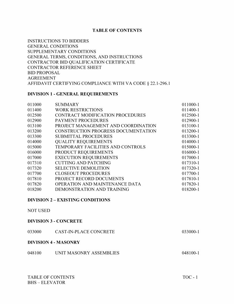
TABLE OF CONTENTS TOC - 1 BHS – ELEVATOR
TABLE OF CONTENTS INSTRUCTIONS TO BIDDERS GENERAL CONDITIONS SUPPLEMENTARY CONDITIONS GENERAL TERMS, CONDITIONS, AND INSTRUCTIONS CONTRACTOR BID QUALIFICATION CERTIFICATE CONTRACTOR REFERENCE SHEET BID PROPOSAL AGREEMENT AFFIDAVIT CERTIFYING COMPLIANCE WITH VA CODE § 22.1-296.1 DIVISION 1 - GENERAL REQUIREMENTS 011000 SUMMARY 011000-1 011400 WORK RESTRICTIONS 011400-1 012500 CONTRACT MODIFICATION PROCEDURES 012500-1 012900 PAYMENT PROCEDURES 012900-1 013100 PROJECT MANAGEMENT AND COORDINATION 013100-1 013200 CONSTRUCTION PROGRESS DOCUMENTATION 013200-1 013300 SUBMITTAL PROCEDURES 013300-1 014000 QUALITY REQUIREMENTS 014000-1 015000 TEMPORARY FACILITIES AND CONTROLS 015000-1 016000 PRODUCT REQUIREMENTS 016000-1 017000 EXECUTION REQUIREMENTS 017000-1 017310 CUTTING AND PATCHING 017310-1 017320 SELECTIVE DEMOLITION 017320-1 017700 CLOSEOUT PROCEDURES 017700-1 017810 PROJECT RECORD DOCUMENTS 017810-1 017820 OPERATION AND MAINTENANCE DATA 017820-1 018200 DEMONSTRATION AND TRAINING 018200-1 DIVISION 2 – EXISTING CONDITIONS NOT USED DIVISION 3 - CONCRETE 033000 CAST-IN-PLACE CONCRETE 033000-1 DIVISION 4 - MASONRY 048100 UNIT MASONRY ASSEMBLIES 048100-1
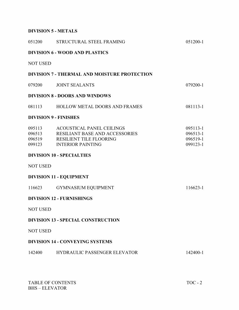
TABLE OF CONTENTS TOC - 2 BHS – ELEVATOR
DIVISION 5 - METALS 051200 STRUCTURAL STEEL FRAMING 051200-1 DIVISION 6 - WOOD AND PLASTICS NOT USED DIVISION 7 - THERMAL AND MOISTURE PROTECTION 079200 JOINT SEALANTS 079200-1 DIVISION 8 - DOORS AND WINDOWS 081113 HOLLOW METAL DOORS AND FRAMES 081113-1 DIVISION 9 - FINISHES 095113 ACOUSTICAL PANEL CEILINGS 095113-1 096513 RESILIANT BASE AND ACCESSORIES 096513-1 096519 RESILIENT TILE FLOORING 096519-1 099123 INTERIOR PAINTING 099123-1 DIVISION 10 - SPECIALTIES NOT USED DIVISION 11 - EQUIPMENT 116623 GYMNASIUM EQUIPMENT 116623-1 DIVISION 12 - FURNISHINGS NOT USED DIVISION 13 - SPECIAL CONSTRUCTION NOT USED DIVISION 14 - CONVEYING SYSTEMS 142400 HYDRAULIC PASSENGER ELEVATOR 142400-1
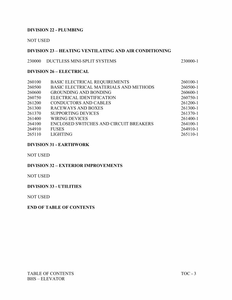
TABLE OF CONTENTS TOC - 3 BHS – ELEVATOR
DIVISION 22 - PLUMBING NOT USED DIVISION 23 – HEATING VENTILATING AND AIR CONDITIONING 230000 DUCTLESS MINI-SPLIT SYSTEMS 230000-1 DIVISION 26 – ELECTRICAL 260100 BASIC ELECTRICAL REQUIREMENTS 260100-1 260500 BASIC ELECTRICAL MATERIALS AND METHODS 260500-1 260600 GROUNDING AND BONDING 260600-1 260750 ELECTRICAL IDENTIFICATION 260750-1 261200 CONDUCTORS AND CABLES 261200-1 261300 RACEWAYS AND BOXES 261300-1 261370 SUPPORTING DEVICES 261370-1 261400 WIRING DEVICES 261400-1 264100 ENCLOSED SWITCHES AND CIRCUIT BREAKERS 264100-1 264910 FUSES 264910-1 265110 LIGHTING 265110-1 DIVISION 31 - EARTHWORK NOT USED DIVISION 32 – EXTERIOR IMPROVEMENTS NOT USED DIVISION 33 - UTILITIES NOT USED END OF TABLE OF CONTENTS
1
INSTRUCTIONS TO BIDDERS
1. DEFINED TERMS: Terms used in these instructions to Bidders which are defined in the Standard General
Conditions of the Construction Contract, NSPE DOCUMENT 1910-8 (1983 Edition) have the meanings assigned to them in the General Conditions.
2. QUALIFICATIONS OF BIDDERS: To demonstrate his/her qualifications for the Project, each Bidder must be
prepared to submit within five (5) days of Owner's request written evidence of the types set forth in the Supplementary Conditions or General Requirements, such as financial data, previous experience and evidence of authority to conduct business in the jurisdiction where the Project is located.
3. LICENSING: All bidders shall comply with licensing laws and related statutes, Title 54, Subtitle II, Chapter II,
Code of Virginia (as amended by 1992 Supplement), selected paragraphs of which are included herein for information:
Section 54.1-1100. (Repl. Vol. 2005) Definitions:
"Class A Contractors" perform or manage construction, removal, repair, or improvements when (i) the total value referred to in a single contract or project is $70,000 or more, or (ii) the total value of all such construction, removal, repair or improvements undertaken by such person within any twelve-month period is $500,000 or more. "Class B Contractors" perform or manage construction, removal, repair, or improvements when (i) the total value referred to in a single contract or project is $7,500 or more but less than $70,000, or (ii) the total value of all such construction, removal, repair, or improvements undertaken by such person within any twelve-month period is less than $150,000 or more, but less than $500,000. “Class C Contractors” perform or manage construction, removal, repair, or improvements when (i) the total value referred to in a single contract or project is over $1,000 but less than $7,500, or (ii) the total value of all such construction, removal, repair, or improvements undertaken by such person within any twelve-month period is less than $150,000. The Board shall require a master tradesmen license as a condition of licensure for electrical, plumbing and heating, ventilation and air conditioning contractors.
4. EXAMINATION OF CONTRACT DOCUMENTS AND SITE: 4.1 Before submitting his/her bid, each bidder must (a) examine the Contract documents thoroughly, (b) visit the site to familiarize himself/herself with local conditions that may in any manner affect personal performance of the work, (c) familiarize himself/herself with Federal, State and Local laws, ordinances, rules and regulations affecting performance of the work; and (d) carefully correlate his/her observations with the requirements of the Contract Documents. 4.2 The submission of a bid will constitute an irrebuttable presumption that the bidder has complied with every requirement of Article 4.
5. INTERPRETATIONS: All questions about the meaning or intent of the Contract Documents shall be submitted to the Purchasing Agent in writing. Replies will be issued by addenda mailed or delivered to all parties recorded by the Contract Agent or his designee as having received the bidding documents. Questions received less than (5) days prior to the date for opening of bids will not be answered. Only questions answered by formal written addenda will be binding. Oral or other interpretations or clarifications will be without legal effect.
6. BID SECURITY: The amount and type of bid security is stated in the invitation to bid. The required security
must be in the form of a certified or bank cashier's check made payable to the Owner or a bid bond issued by a surety licensed to conduct business in the state where the project is located and named in the current list of "Surety Companies Acceptable on Federal Bonds" as published in the Federal Register by the Audit Staff Bureau of Accounts, U.S. Treasury Department. The bid security of the successful bidder will be retained until he/she has executed the agreement and furnished the required contract security, whereupon it will be returned; if
2
he/she fails to execute and deliver the Agreement and furnish the required Contract Security within ten (10) days of the Notice of Award, the Owner may annul the Notice of Award and the Bid Security of that bidder will be forfeited. The Bid Security of any bidder whom the Owner believes to have a chance of receiving the award may be retained by Owner until the seventh day after the executed agreement is delivered by Owner to Contractor. Bid Security of other bidders will be returned within seven days of Owner's acceptance of winning bid.
7. CONTRACT TIME: The number of days for the completion of work (the Contract time) is set forth in the Form
of Proposal and will be included in the executed agreement. 8. SUBCONTRACTORS, ETC.:
8.1 If the Supplementary Conditions or Specifications require the identity of certain Subcontractors and other persons and organizations to be submitted to Owner in advance of the Notice of Award, the apparent low bidder and any other bidder so requested, will within seven (7) days after the day of the bid opening submit to Owner a list of all subcontractors and other persons and organizations (including those who are to furnish the principal items of material and equipment) proposed for those portions of the work as to which such identification is so required. Such list shall be accompanied by an experience statement with pertinent information as to similar projects and other evidence of qualification for each subcontractor, person and organization if requested by Owner.
If Owner, after due investigation, has reasonable objection to any proposed subcontractor, other person or organization, Owner may, before giving the Notice of Award, request the apparent low bidder to submit an acceptable substitute without an increase in his/her bid price before the bid will be considered. If the apparent low bidder declines to make any such substitution, he/she will not thereby sacrifice his/her bid security. Any subcontractor, or other person or organization so listed and to whom Owner does not make written objection prior to the giving Notice of Award will be deemed acceptable to Owner. 8.2 Contractor shall not be required to employ any subcontractor, other person or organization against whom he/she has reasonable objection.
9. BID FORM:
9.1 The bid form is included in the Contract Documents. Additional copies may be obtained from the Central Purchasing Department, P.O. Box 100, Rustburg, Virginia 24588, (434) 332-9669. 9.2 Bid forms must be completed in ink or by typewriter. The bid price of each item on the form must be stated in words and numerals; in case of a conflict, words will take precedence. 9.3 Bids by corporations must be executed in corporate name by the president, vice-president, or other corporate officer authorized to sign. The corporate address and state of incorporation shall be shown below the signature. 9.4 Bids by partnership must be executed in the partnership name and signed by a partner. His/her title must appear under his/her signature and the official address of the partnership must be shown below the signature. 9.5 All names must be typed or printed below the signature. 9.6 The bid shall contain an acknowledgment of receipt of all addenda (the numbers of which shall be filled in on the bid form).
10. SUBMISSION OF BIDS: Bids shall be submitted prior to 2:00 P.M., local prevailing time, February 26, 2020
to the Campbell County Central Purchasing Office, 1st Floor, Haberer Building, 47 Courthouse Lane, P.O. Box 100, Rustburg, Virginia. Bids must be in a sealed, opaque envelope, clearly marked “CCADM 015-FY20”. The Contractor's Class A or Class B license number shall be clearly indicated on the outside of the bid envelope.
11. MODIFICATION AND WITHDRAWAL OF BIDS: Bids may be modified or withdrawn by an appropriate
document duly executed (in the manner that a bid must be executed) and delivered to the place where bids are to

3
be submitted at any time prior to the opening of bids. 12. OPENING OF BIDS: Bids will be publicly opened and read aloud immediately following specified bid receipt
time of 2:00 P.M., February 26, 2020 in the Basement Level Conference Room, 47 Courthouse Lane, Haberer Building, Rustburg, Virginia.
13. BIDS TO REMAIN OPEN: All bids shall remain open for sixty (60) days after the day of the bid opening, but
Owner may, in his sole discretion, release any bid and return the bid security prior to that date. 14. AWARD OF CONTRACT:
14.1 Owner reserves the right to reject any and all bids and waive any and all informalities, and the right to disregard all nonconforming or conditional bids or counter proposals. 14.2 In evaluating bids, Owner shall consider the qualifications of the bidders, including references, proposed design and equipment, whether or not the bids comply with the prescribed requirements, and alternates and unit price if requested in the bid forms. Owner may consider the qualifications and experience of subcontractors and other persons and organizations (including those who are to furnish the principal items of material or equipment) proposed for those portions of the work as to which the identity of subcontractors and other persons and organizations must be submitted as specified in the Supplementary Conditions or Specifications. He may conduct such investigations as he deems necessary to establish the responsibility, qualifications and financial ability of the bidders, proposed subcontractors and other persons and organizations to do the work in accordance with the contract documents to Owner's satisfaction within the prescribed time. Owner reserves the right to reject the bid of any bidder who does not pass such evaluation to Owner's satisfaction, in the sole discretion of Owner. 14.3 If a contract is to be awarded, it will be awarded to the lowest responsive and responsible bidder as determined in accordance with the provision of the Virginia Public Procurement Act. 14.4 If the contract is to be awarded, Owner will give the apparent successful bidder a Notice of Award within sixty (60) days after the day of the bid opening. 14.5 Simultaneously with delivery of the executed counterparts of the agreement to Owner, Contractor shall deliver to Owner the required Contract Security.
15. AGREEMENT, BONDS AND CERTIFICATES OF INSURANCE:
15.1 Within ten (10) days after Notice of Award, the contractor agrees to execute the Form of Agreement included as one of the Contract Documents, and to furnish a Performance Bond in an amount equal to 100% of the Contract amount and a Labor and Material Payment bond in an amount equal to 100% of the Contract amount. Certificates of Insurance shall accompany the required bonds. If no contract is executed, the terms of this Request for Bids, Specifications, and contract documents shall control.
The form of agreement contained herein is a specimen only and is subject to final approval by the Campbell County School Board Attorney.
16. Contractor will be required to certify compliance with Virginia Code §22.1-296.1 per the attached affidavit.
4
GENERAL CONDITIONS
The provisions of the "Standard General Conditions of the Construction Contract", Form 1910-8 NSPE/ACEC (1983 Edition), fully apply as if contained herein except as modified by any supplemental conditions or specifications delineated.
AUTHORITY: National Society of Professional Engineers
(Milton F. Lunch, General Counsel), letter to Director of Public Works, Campbell County, dated February 16, 1979.
SUPPLEMENTARY CONDITIONS
1. SCOPE: These Supplementary Conditions are to supplement, modify or extend the provisions of the General Conditions to the extent hereinafter indicated.
2. "OR EQUAL” CLAUSE - SUBSTITUTION OF MATERIALS: Catalog numbers, specific names and brands
used in connection with materials and equipment mentioned in the specifications, are used to establish the minimum standard for quality, capacity, construction, performance, appearance, size, arrangement and general utility, including features of economic operation.
Equipment and materials herein specified have been selected on the basis of design criteria, performance
requirements and the standards outlined above, but, so as not to limit competition, other equipment or minimum standards will be approved as substitutes by the Owner if equality can be and is satisfactorily substantiated by written evidence, drawings, samples and other data submitted to the Owner by the Contractor.
Should such substitutions be approved by the Owner, it shall be understood and agreed that the cost of any
changes made necessary or caused through substitution, shall be borne by the Contractor. All substitutions must be submitted at least seven (7) days before Bid due date. A list of all approved
substitutions will be included in an addendum. No considerations will be given to substitutions after opening of bids.
3. BONDS: The Contractor shall secure and provide such bonds as called for under Article 6 and 15 of the
Instruction to Bidders. All bonds shall be written by sureties or insurance companies licensed or authorized to do business in Virginia and all performance bonds shall be countersigned by an authorized agent of the surety licensed to transact business in this State.
4. INSURANCE:
A. The Contractor shall secure and provide insurance in at least the following amounts:
(1) Automobile Liability Insurance: $1,000,000 combined single limit (2) Workers' Compensation Insurance at statutory limits as required under the Virginia Workers'
Compensation Act (3) General Liability Insurance: $1,000,000 occurrence limit, $2,000,000 general aggregate
B. The Contractor shall provide Campbell County School Board a certificate of insurance indicating the
insurance coverage outlined in A. Campbell County School Board shall be named as additional insured. The insurance company needs to be identified for each coverage. The certificates are to be signed by a person authorized by the insurance company to bind coverage on its behalf.
C. All insurance shall be written by insurance companies licensed to do business in the Commonwealth of
5
Virginia. The insurance company must have an A.M. Best rating of A- or better. D. The insurer shall provide 30 days written notice to Campbell County Schools before any cancellation or
non-renewal of insurance coverage. Failure to provide such notice will obligate the insurer to provide coverage as if cancellation or non-renewal did not take place.
5. REPAIRS: The Contractor is responsible for any damage to public or private property whatsoever and shall
replace or repair all such damage, to equal original condition and to Owner's approval and satisfaction. Whenever and wherever it becomes necessary for the Contractor to enter upon public thoroughfares or private property for the transportation of equipment and materials, or for construction work in connection with this project, the Contractor shall be responsible for any damage resulting therefrom.
6. APPLICATION FOR PAYMENT: The Owner agrees to pay to the Contractor for the satisfactory performance
of the Agreement, subject to such additions and deductions as are provided for in the specifications, in lawful money of the United States in conformity with the Schedule of Bid Items and according to the following method and schedule. Upon satisfactory completion of all work and testing under this Agreement and its acceptance by the Owner and upon submission by the Contractor of satisfactory evidence that all payroll, material bills, damage claims, and any other costs or claims whatever, incurred by the Contractor have been paid, the Owner shall make final payment within a period of forty-five (45) days following receipt of invoice, of all monies accrued and due to the Contractor.
7. CHANGE ORDERS: It is to be understood that no amount, in part or in whole, of a Change Order shall be
included in a Requisition for Payment by the Contractor until the Change Order has been executed and copies of the Change Order have been distributed to the parties.
8. PROCEED ORDERS: A Proceed Order is an instrument whereby the Owner may promptly order changes in
the work involving changes in cost and/or contract time, pending preparation and execution of a formal Change Order, so as to avoid delay in the construction work. Application for payment for work authorized by the Owner in a Proceed Order shall only be made subsequent to execution of a formal Change Order.
9. WRITTEN PROPOSAL: Without further request and within seven (7) days of the date of issue of a Proceed
Order, the Contractor shall submit a written proposal covering the work authorized in the Proceed Order so that a Change Order may be prepared for execution.
10. ORDER TO PROCEED: In the event the Owner, through the Contract Agent or his Designee, requests the
Contractor to submit a Change Order proposal for changes in contract work, the Contractor shall submit such a proposal in accordance with contract requirements within a reasonable time, as stipulated in such request. If the Contractor fails to submit said proposal within the time limit so stipulated, the Owner shall have the right to issue to the Contractor, through the Contract Agent or his Designee, an Order to Proceed with the required changes for an additional amount not to exceed, or a deduction of not less than the amount shown in the order; provided, however, in the event the Contractor is not in agreement with the amount stipulated in the Order to Proceed, he shall, within fourteen (14) days after the date of said work order, submit to the Contract Agent or his Designee an equitable proposal and develop with the Owner and/or Contract Agent or his Designee, a mutually acceptable price for the required change in work.
11. SUBCONTRACTORS: Contractor shall require his/her subcontractors to provide insurance coverage identical
to that specified above and each respective division of work if requested by the Owner. 12. EXTENSION OF TIME: DAMAGES FOR DELAYS: If the Contractor fails to complete the work within the
time fixed by the contract for the completion of the same, the Contractor shall be liable to the Owner in the amount set forth in the specifications as fixed, agreed and liquidated damages for each calendar day of delay until the work is completed, or if liquidated damages are not so fixed, for any actual damage occasioned by such delay.
13. PERMITS, FEES AND NOTICES: General Contractor will be required to obtain and pay for a Building Permit.
6
GENERAL TERMS, CONDITIONS, AND INSTRUCTIONS These general rules and conditions shall apply to each solicitation and consequent contract awarded by Campbell County Public Schools (Campbell County School Board), unless otherwise specified. In the event there is a conflict between any of these General Terms and Conditions and any Special Terms and Conditions of the contract, the Special Terms and Conditions shall apply except for paragraphs 21 (Standards of Contract), 25 (Indemnity), 32 (Contract Formation), and 37 (Costs & Fees). The Central Purchasing Office is responsible for much of the purchasing activity of Campbell County. The term “Owner” as used herein refers to the contracting entity which is the Campbell County School Board which is sometimes referred to as the Campbell County Public Schools, Campbell County Schools, or the Schools. The Offeror or their authorized representatives are expected to inform themselves fully as to the conditions, requirements, and specifications before submitting bids/proposals. Failure to do so will be at the Offeror’s own risk and except as provided by law. All solicitations issued and contracts awarded by Campbell County Schools are governed by the provisions of the Virginia Public Procurement Act as set forth in the Code of Virginia. 1. COMPETITION INTENDED: It is the Owner’s intent that this solicitation permits competition. It shall be the Offeror’s
responsibility to advise the Purchasing Agent in writing if any language, requirement, specification, etc., or any combination thereof inadvertently restricts or limits the requirements stated in this solicitation to a single source. The Purchasing Agent must receive such notification not later than ten (10) business days prior to the deadline set for acceptance of the bids/proposals.
CONDITIONS OF THE PROPOSAL
2. CLARIFICATION OF TERMS: If any Offeror has questions about the specifications or other solicitation documents, the
prospective Bidder/Offeror should contact the Central Purchasing Office no later than five (5) business days prior to the date set for the opening of bids or receipt of proposals. Any revisions to the solicitation will be made only by addendum issued by Central Purchasing. The paragraphs of this document apply to all purchases whether solicited by request for bid, request for proposals, or other method, regardless of the use of the word “bid” or “proposal” in an individual paragraph.
3. IDENTIFICATION OF BID/PROPOSAL ENVELOPE: The signed bid/proposal and requested copies should be returned in a separate envelope or package, sealed and identified with the following information: ADDRESSED AS INDICATED IN THE SOLICITATION DOCUMENTS BID/QUOTE/RFP NUMBER TITLE BID/PROPOSAL DUE DATE AND TIME VENDOR NAME AND COMPLETE MAILING ADDRESS (RETURN ADDRESS) If a proposal is not addressed with the information as shown above, the Offeror takes the risk that the envelope may be inadvertently opened and the information compromised, which may cause the proposal to be disqualified. Proposals may be hand delivered to the Central Purchasing Office. No other correspondence or other proposals should be placed in the envelope.
4. MANDATORY USE OF OWNER FORM AND TERMS AND CONDITIONS: If requested in the solicitation, failure
to submit a proposal on the official Owner form provided for that purpose shall be a cause for rejection of the proposal.
5. LATE PROPOSALS: Any proposal received at the Central Purchasing Office after the exact time specified for receipt of the proposal is considered a late proposal. The Owner is not responsible for delays in the delivery of the mail by the U.S. Postal Service, private carriers or the inter-office mail system. It is the sole responsibility of the Offeror to ensure their proposal reaches the Central Purchasing Office by the designated date and hour.
7
Late proposals/modifications will be returned to the Offeror unopened, if solicitation number, acceptance date and Offeror’s return address is shown on the container. If the Owner closes its offices due to inclement weather, scheduled proposal openings or receipt of proposals will be extended to the next business day, same time.
6. PROPOSAL OPENING: All proposals will be opened at the time and place specified and read publicly. At the time
fixed for the receipt of responses for Request for Proposals, only the names of the offerors will be made available to the public. Offerors have no expectation of confidentiality and at any time after the opening proposals may be available to the public, in the discretion of the Owner and according to law.
7. ADDENDA: By submitting a proposal, the Offeror certifies that (i) he has made due inquiry of the Owner as to the existence of any addenda issued in connection with the bid solicitation documents, (ii) he is satisfied that he has received any and all such addenda and he has taken the contents thereof into consideration when preparing and tabulating his bid; and (iii) he accepts full and complete responsibility for the receipt of any and all such addenda and waives any claim of mistake or error in his bid based upon his failure to have received any one or more addenda.
8. MODIFICATION OF PROPOSALS: Unauthorized modification of or any additions to any portion of the Invitation to Bid, Request for Quotation, or Request for Proposal may be cause for rejection of the bid/quotation request/proposal, or Owner may reject and refuse to consider any modification as a part of the proposal.
9. WITHDRAWAL OF PROPOSALS: A Offeror for a contract other than for public construction may request withdrawal of his or proposal under the following circumstances:
a. A written request for a withdrawal of a Proposal or any part thereof will be granted if received by the Owner prior to the specified bid opening date and time.
b. Requests for withdrawal of proposals after opening of such proposals but prior to award shall be transmitted to the Purchasing Agent, in writing, accompanied by full documentation supporting the request. If the request is based on a claim of error, documentation must show the basis of the error. Such documentation may take the form of supplier quotations, vendor work sheets, etc. If bid bonds were tendered with the bid, the Owner may exercise its right of collection subject to the provisions of §2.2-4330 of the Code of Virginia.
c. No Proposal may be withdrawn under this paragraph when the result would be the awarding of the contract on another Proposal of the same offeror or of another offeror in which the ownership of the withdrawing offeror is more than five percent. In the case of Invitation for Bid, if a bid is withdrawn under the authority of this paragraph, the lowest remaining bid shall be deemed to be the low bid. No offeror who is permitted to withdraw a proposal shall, for compensation, supply any material or labor to or perform any subcontract or other work agreement for the person or firm to whom the contract is awarded or otherwise benefit, directly or indirectly, from the performance of the project for which the withdrawn proposal was submitted.
10. ERRORS IN PROPOSALS: When an error is made in extending total prices, the unit bid price will govern. Erasures in proposals must be initialed by the Offeror. Carelessness in quoting prices, or in preparation of proposal otherwise, will not relieve the Offeror. Offerors are cautioned to recheck their proposals for possible error. Errors discovered after public opening cannot be corrected and the offeror will be required to perform if his or her proposal is accepted, except as provided in paragraph 9 hereof.
11. PUBLIC INSPECTION OF PROPOSALS: All submitted proposals, and any accompanying data, materials or documentation will become the property of the Owner and will be subject to public inspection in accordance with the Virginia Freedom of Information Act. Trade secrets or proprietary information submitted by an offeror shall not be subject to public disclosure under the Virginia Freedom of Information Act; however, the offeror must invoke the protections of §2.2-4342F of the Code of Virginia, in writing, either before or at the time the data or other material is submitted. The written notice must specifically identify the data or materials to be protected and state the reasons why protection is necessary. Trade secrets or proprietary information submitted by a bidder, offeror or contractor in connection with a procurement transaction or prequalification application submitted pursuant to subsection B of § 2.2-4317 shall not be subject to the Virginia Freedom of Information Act (§ 2.2-3700 et seq.); however, the bidder, offeror or contractor shall (i) invoke the protections of this section prior to or upon submission of the data or other materials, (ii) identify the data or other materials to be protected, and (iii) state the reasons why protection is necessary.
12. TAX EXEMPTION: The Owner is exempt from the payment of any federal excise or any Virginia sales tax. The bid
price must be net, exclusive of taxes. Tax exemption certificates will be furnished by Campbell County on request.
8
13. COUNTY BPOL LICENSING: All firms with a business location in Campbell County are required to be licensed in accordance with the County’s “Business, Professional, and Occupational Licensing (BPOL)” Tax Ordinance. Questions concerning the BPOL Tax should be directed to the Office of the Commissioner of the Revenue, telephone 434 332-9518.
SPECIFICATIONS
14. BRAND NAME OR EQUAL ITEMS: Any specific make, manufacturer or brand, names used in connection with articles
mentioned in the specifications are used to convey the general style, type, character, and quality of the article desired. The Owner may consider other brands as substitutes if written evidence and other data submitted to the Owner by the vendor can satisfactorily substantiate equality. The Owner’s representative shall be the sole determining authority as to quality, workmanship, and suitability of purpose. The Offeror is responsible to clearly and specifically indicate the product being offered and to provide sufficient descriptive literature, catalog cuts and technical detail to enable the Owner to determine if the product offered meets the requirements of the solicitation. Failure to furnish adequate data for evaluation purposes may result in declaring a proposal non-responsive. Unless the Offeror clearly indicates in its proposal that the product offered is an "equal" product, such proposal will be considered to offer the brand name product referenced in the solicitation, or in failure to consider the proposal.
15. PRODUCT EVALUATION: The Owner reserves the right to conduct any test it may deem advisable to establish that the
products and/or services offered are in accordance with the contract requirements. The Owner reserves the right to reject the proposal of any Offeror who does not pass such evaluation to the Owner’s satisfaction.
16. FORMAL SPECIFICATIONS: When a solicitation contains a specification which states no substitutes, no deviation therefrom will be permitted and the offeror will be required to furnish articles in conformity with that specification.
17. OMISSIONS & DISCREPANCIES: Any items or parts of any equipment/product listed in the solicitation which are not fully described or are omitted from such specification, and which are clearly necessary for the completion of such equipment/product and its appurtenances, shall be considered a part of such equipment/product although not directly specified or called for in the specifications. The Offeror shall abide by and comply with the true intent of the specifications and not take advantage of any unintentional error or omission, but shall fully complete every part as the true intent and meaning of the specifications and drawings.
18. CONDITION OF ITEMS: Unless otherwise specified in the solicitation, all items shall be new, in first class
condition.
AWARD AND CONTRACT 19. AWARD OR REJECTION OF BIDS:
a. The Owner shall award the contract to the highest qualified offeror who complies with all provisions of the RFP/B provided the proposal price is within funding available for the project. Awards made in response to a RFP/ will be made to the highest qualified offeror whose proposal is determined to be the most advantageous to the Owner taking into consideration the evaluation factors set forth in the RFP, in the sole judgment of the Owner.
b. The Owner reserves the right to reject any and all proposals, in whole or in part, to waive any and all informalities, whenever such rejection or waiver is in the best interest of the Owner.
c. Notice of Award – Upon the award or announcement of the decision to award a contract as a result of this solicitation, the purchasing department will publicly post such notice on the Campbell County website (www.co.campbell.va.us) for a minimum of 10 days.
20. QUALIFICATIONS OF OFFERORS: The Owner may make such reasonable investigations as deemed proper and necessary to determine the ability of the Offeror to perform the work/furnish the item(s) or services, and the Offeror shall furnish to the Owner all such information and data for this purpose as may be requested. The Owner reserves the right to inspect Offeror’s physical facilities prior to award to satisfy questions regarding the Offeror’s capabilities. The Owner further reserves the right to reject any proposal if the evidence submitted by or investigations of, such Offeror fails to satisfy the Owner that such Offeror is properly qualified to carry out the obligations of the contract and to complete the work/furnish the item(s) contemplated therein.
21. STANDARDS OF CONTRACT: The Owner reserves the right to cancel and terminate a contract at any time, at the convenience of the Owner. Repeated delays or partial deliveries and returns for inadequate, damaged, or spoiled products shall be interpreted as failure to meet contractual obligations and may cause cancellation of the contract. Upon receipt of notice of termination, the Contractor shall cease all deliveries or services unless advised by the Owner to do otherwise. In the event of termination, the contractor shall be compensated for those deliveries or services provided to the satisfaction of
9
the Owner as of the date of termination. That compensation shall be the sole remedy or compensation due to the Offeror/Contractor who shall have no other claim for damages.
22. AVAILABILITY OF FUNDS: Award and contract are conditioned upon appropriation and availability of funds from year to year. If sufficient appropriation and funding is not available, in the sole judgment of the Schools, the Schools may terminate the contract without penalty, cost, or damage payment.
23. NEGOTITIONS WITH LOWEST RESPONSIBLE BIDDER: Unless canceled or rejected, a responsive bid from the lowest responsible bidder will be accepted as submitted, except that if the bid from the lowest responsible bidder exceeds available funds, the Owner may negotiate with the apparent low bidder to obtain a contract price within available funds. The negotiation will be undertaken under conditions and procedures described in writing and approved by the Owner prior to issuance of the IFB, or according to the Code of Va.
24. INSURANCE: If requested in the solicitation, the Contractor shall secure and provide insurance in at least the following amounts: Automobile Liability Insurance: $1,000,000 combined single limit General Liability Insurance: $1,000,000 occurrence limit, $2,000,000 general aggregate Professional Liability (if appropriate): $1,000,000 occurrence limit, $2,000,000 aggregate Workers’ Compensation Insurance at statutory limits as required under the Virginia Workers’ compensation Act Within 15 days after Notice of Award, the Contractor agrees to furnish a Certificate of Insurance naming Campbell County Public Schools as additional insured. All insurance shall be written by insurance companies licensed to do business in the Commonwealth of Virginia. The insurance company must have an A.M. Best Rating of A- or better. The insurer shall provide 30 days written notice to Campbell County Public Schools before any cancellation or non-renewal of insurance coverage
25. INDEMNITY: The contractor shall indemnify and hold harmless the Campbell County School Board, its officers, boards,
commissions, agents and employees against any and all claims, demands, causes of action, suits, proceedings, damages, costs or liabilities (including costs or liabilities of the Campbell County School Board with respect to its employees), of every kind and nature whatsoever, including, but not limited to, damages for injury or death or damages to person or property, regardless of the merit of any of the same, including any attorney fees, accountant fees, expert witness or consultant fees, court costs, per diem, expense traveling and transportation expense, or other costs or expense arising out of or pertaining to the performance of the Agreement by contractor unless resulting from the negligence of the Campbell County School Board or its officers, boards, commissions, agents or employees in which event a court may apportion the damage.
26. PAYMENT TERMS: Unless otherwise provided in the solicitation, payment will be made thirty (30) days after receipt of a proper invoice, or thirty (30) days after receipt of all goods or acceptance or work, whichever is later. No interest, late charges, or attorney fees will be paid under any circumstances by the School Board.
27. CHANGES TO THE CONTRACT: a. During performance of the contract, the parties may agree to modify the scope of the contract. Any increase or
decrease in the price of the contract resulting from such modification shall be agreed to by the parties as a part of their written agreement to modify the scope of the contract.
b. The Owner may order changes within the general scope of the contract at any time by written notice to the Contractor. Changes within the scope of the contract may include, but are not limited to, services to be performed, the method of packing or shipment, and the place of delivery or installation. The Contractor shall comply with the notice upon receipt. The Contractor shall be compensated for any additional costs incurred as the result of such order and shall give the Owner a credit for any savings. Said compensation shall be determined by written mutual agreement between the parties.
c. No modification for a fixed price contract may be increased without the advance written approval of the Campbell County School Board.
28. EMPLOYMENT DISCRIMINATION: During the performance of this contract, the contractor agrees as follows: a. The contractor will not discriminate against any employee or applicant for employment because of race, religion,
color, sex, national origin, age, disability, or any other basis prohibited by state law relating to discrimination in employment, except where there is a bona fide occupational qualification reasonably necessary to the normal operation of the contractor. The contractor agrees to post in conspicuous places, available to employees and applicants for employment, notices setting forth the provisions of this nondiscrimination clause.
b. The contractor, in all solicitations or advertisements for employees placed by or on behalf of the contractor, will state that such contractor is an equal opportunity employer.
10
c. Notices, advertisements and solicitations place in accordance with federal law, rule or regulation shall be deemed sufficient for the purpose of meeting the requirements of this section.
d. The contractor will include the provisions of the foregoing paragraphs a, b and c in every subcontract or purchase order of over $10,000, so that the provisions will be binding upon each subcontractor or vendor.
29. DRUG FREE WORKPLACE: During the performance of this contract, the contractor agrees to (i) provide a drug-free workplace for the contractor’s employees; (ii) post in conspicuous places, available to employees and applicants for employment, a statement notifying employees that the unlawful manufacture, sale, distribution, dispensation, possession, or use of a controlled substance or marijuana is prohibited in the contractor’s workplace and specifying the actions that will be taken against employees for violations of such prohibition; (iii) state in all solicitations or advertisements for employees place by or on behalf of the contractor that the contractor maintains a drug-free workplace; and (iv) include the provisions of the foregoing clauses in every subcontract or purchase order of over $10,000, so that the provisions will be binding upon each subcontractor or vendor. For the purposes of this section, “drug-free workplace” means a site for the performance of work done in connection with a specific contract awarded to a contractor in accordance with this chapter, the employees of whom are prohibited from engaging in the unlawful manufacture, sale, distribution, dispensation, possession or use of any controlled substance or marijuana during the performance of the contract.
30. NONDISCRIMINATION STATEMENT: In accordance with the Code of Virginia §2.2-4310 and §2.2-4343.1, this
public body does not discriminate against faith based organizations or against a bidder or offeror because of race, religion, color, sex, national origin, age, disability, or any other basis prohibited by state law relating to discrimination in employment.
31. ILLEGAL ALIEN EMPLOYMENT: In accepting this contract, the Contractor certifies that it does not and will not, during the performance of this contract, violate the provisions of the Federal Immigration Reform and Control Act of 1986, which prohibits employment of illegal aliens.
32. LICENSE: If in a business or profession required to be licensed by the Commonwealth of Virginia, you must provide your state contractor’s or professional certificate number.
33. COMMONWEALTH OF VIRGINIA BUSINESS TRANSACTIONS: All Offerors organized, licensed or authorized to transact business or perform the contract contemplated in the Commonwealth of Virginia pursuant to Title 13.1 or Title 50 of the Virginia Code, or any other provision of the Code, must include in its proposals the identification number issued to it by the State Corporation Commission and a copy of any license. Any Offeror that is not required to be authorized or licensed to transact business or perform this contract in the Commonwealth as a foreign business entity under Title 13.1 or Title 50 or as otherwise required by law shall include in its proposal a statement describing why the Offeror is not required to be so authorized or licensed.
34. CONTRACT FORMATION: The Contractor or successful bidder or offeror agrees to sign a contract drafted or approved
by the Schools’ Attorney. In the event no such contract is signed, the terms and conditions of all specifications, plans, and documents of the Request for Proposal or Bid and all terms herein, shall constitute the terms of the contract and no provision of any response, proposal, or other agreement may vary or alter the same unless agreed in writing and approved by the Schools’ Attorney. No provision of any other contract document may waive this provision unless expressly so stated and signed by the parties.
35. MODIFICATION: Any term or provision submitted as part of your response that in any way attempts to change or modify the term of the contract documents or these contract terms, conditions, and instructions shall be ineffectual, null and void. In addition, Campbell County Schools may declare a proposal that attempts to do so unresponsive and disqualified, in its sole discretion. In lieu of declaring the proposal or response disqualified, the Schools shall consider the modifications null and of no effect.
36. ASSIGNMENT: The contractor shall not assign this contract without the prior written consent of Campbell County Schools.
37. COSTS AND FEES: In the event of any breach of contract, negligence, or other claim or cause of action that may arise against the Offeror/Contractor, said Offeror/Contractor shall be responsible for all attorney fees, accountant fees, expert witness or consultant fees, court costs, per diem, expense, traveling and transportation expense, or other costs or expense arising out of or pertaining to the performance of the work, contract, or agreement, by contractor and any resulting claim, suit, arbitration, mediation, investigation, testing, preparation,or action.
11
OFFEROR/CONTRACTOR REMEDIES 38. PROTEST: Offerors may refer to §2.2-4357 through §2.2-4364 of the Code of Virginia to determine their remedies
concerning this competitive process.
39. APPLICABLE LAWS AND VENUE: a. Any contract resulting from any solicitation shall be governed by the laws of the Commonwealth of Virginia.
Venue for any litigation arising from or related to a solicitation, RFP/B, or resulting work, business, or contract shall be proper only in Campbell County General District Court or Campbell County Circuit Court.
b. The Contractor shall comply with all applicable federal, state and local laws
40. CLAIMS PROCEDURE: Contractual claims must be submitted to the Campbell County School Board in writing no later than ten (10) days after the time of occurrence or beginning of the work upon which the claim is based. The Board will consider all facts provided to it in a format established by the Board and render a decision within sixty (60) days of receipt of the claim. Failure to act by the Board shall operate to relieve the contractor from the claims procedure and allow the contractor to file suit for relief.
41. SEVERABILITY: In the event that any provision of these documents shall be adjudged or decreed to be invalid, such ruling shall not invalidate the entire contract but shall pertain only to the provision in question or to the specific portion of such provision, and the remaining provisions shall continue to be valid, binding, and in full force and effect.
42. COOPERATIVE PROCUREMENT: This procurement is being conducted by the County of Campbell in accordance with the provisions of 2.2-4304 Code of Virginia. Except for contracts for architectural and engineering services, if agreed to by the contractor, other public bodies may utilize this contract. The Contractor shall deal directly with any public body it authorizes to use the contract. The County, its officials and staff are not responsible for placement of orders, invoicing, payments, contractual disputes, or any other transactions between the Contractor and any other public bodies, and in no event shall the County, its officials or staff be responsible for any costs, damages or injury resulting to any party from use of a County Contract. The County assumes no responsibility for any notifications of the availability of the contract for use by other public bodies, but the Contractor may conduct such notification.
12
CONTRACTOR BID QUALIFICATION CERTIFICATE This is to certify that this person/firm/corporation has not been barred from bidding on contracts by any governmental entity/agency in the Commonwealth of Virginia, nor is this person/firm/corporation a part of any firm/corporation that has been barred from bidding on contracts by any governmental entity/agency in the Commonwealth of Virginia.
___________________________________________________________ Name of Official
___________________________________________________________ Title
___________________________________________________________ Signature/Date
___________________________________________________________ Firm or Corporation
___________________________________________________________ Business Address
___________________________________________________________
NOTE: This form is to be completed and returned with BID PROPOSAL.
13
CONTRACTOR REFERENCE SHEET 1. CONTRACTOR: Name: __________________________________________________________________________________________ Address: _________________________________________________________________________________________ __________________________________________________________________________________________ Telephone Number: ___________________________ Fax Number: _____________________________ Contact Person: __________________________________________________ Title: ____________________ Email Address: _____________________________________________________________________________ 2. YEARS IN BUSINESS: Indicate the length of time you have been in business providing this type of service.
_________________________ Years _____________________ Months 3. REFERENCES:
Indicate below a listing of three (3) references in the Commonwealth of Virginia for whom you have provided the proposed service. Include the date service was furnished and the name and address of the person Campbell County Public Schools has your permission to contact. (Use separate sheet or attachments if necessary.)
PERSON TO CONTACT, PHONE CLIENT NAME AND ADDRESS NUMBER AND DATE OF SERVICE NOTE: This form is to be completed and returned with BID PROPOSAL.
14
BID PROPOSAL TO: Campbell County Public Schools Main Street, Highway24 Rustburg, VA 24588 FROM: __________________________________________________________________ __________________________________________________________________ __________________________________________________________________ (Bidder’s Name and Address) FOR: Campbell County Public Schools Brookville High School Elevator Installation The undersigned, having visited the site of the project named above and being familiar with local conditions affecting the cost of work and all the requirements of the contract documents, including addenda, proposes to enter into a contract for the following total lump sum bid to furnish all labor, materials, equipment, supervision, taxes and all else necessary for completion of the Work in accordance with the Contract Documents. I. Total Bid
Lump sum bid for the construction of a new elevator as described in the contract documents: ______________________________________________________________________($__________) Contract Award will be made to the lowest responsible and responsive Bidder for the Total Bid. II. Time Completion
The Bidder agrees to commence the work under this Contract on June 2, 2020 and to obtain final completion by September 11, 2020. See Specification Section 011000 “Summary of Work” for anticipated award/contract, shop drawing submittal, etc. dates.
It is understood and agreed that time is of the essence. The Bidder agrees to pay as Liquidated Damages the sum of three hundred dollars ($300.00) for each consecutive calendar day that the project extends beyond the date of final completion. III. Bid Security Attached hereto is a bid bond for five percent (5%) of the Base Bid, made payable to the Owner. IV. Receipt of Addenda The following addenda are acknowledge: Addendum No. ____; dated ________________ Addendum No. ____; dated ________________ Addendum No. ____; dated ________________ Addendum No. ____; dated ________________
15
Respectfully Submitted: By _________________________________________________________________ (Signature) Title ________________________________________________________________ (Type or Print Name and Title) Name of Bidder______________________________________________________ Business Address_____________________________________________________ ___________________________________________________________________ ___________________________________________________________________ Date of Bid__________________________________________________________ Contractor’s Phone Number_____________________________________________ Contractor’s Classification and License Number_____________________________ Attest______________________________________________________________ Signature & Title Date Contractor’s Seal (If Applicable)
Bidder to attach the following forms to the Bid Proposal: • Contractor’s Bid Qualification Certificate (page 13) • Contractor’s Reference Sheet (page 14) Note: Unit price is an amount proposed by Bidder, as stated on the Bid Form, applicable during the duration of the Work as a price per unit of measurement for materials, equipment, testing, etc. added to or deducted from the Contract Sum if the Scope of Work or estimated quantities of Work required are increased or decreased. Unit prices quoted will be applicable for the actual quantity within plus or minus 100 percent of the estimated quantity.
16
AGREEMENT This agreement made as of the _________ of ________________, 2020 by and between CAMPBELL COUNTY PUBLIC SCHOOLS hereinafter called the OWNER and (CONTRACTOR), hereinafter called the CONTRACTOR, WITNESSETH, that whereas the OWNER intends to conduct Campbell County Schools Parking Lot Addition, hereinafter called the PROJECT, in accordance with the INSTRUCTIONS TO BIDDERS, GENERAL CONDITIONS, SUPPLEMENTARY CONDITIONS, GENERAL TERMS, CONDITIONS, AND INSTRUCTIONS, and SPECIFICATIONS (Pages 1 through 11), of CCADM _________ owned by CAMPBELL COUNTY PUBLIC SCHOOLS. NOW, THEREFORE, the OWNER AND CONTRACTOR for the considerations hereinafter set forth, agree as follows: The CONTRACTOR AGREES to furnish all the necessary labor, materials, equipment, tools and services necessary to perform and complete in a workmanlike manner all work required for the Project, in strict compliance with the Contract Documents herein mentioned, which are hereby made a part of the Contract, including the following Addenda: ADDENDUM DATE
(a) CONTRACT TIME: Work under this Agreement shall be commenced upon written notice to proceed, and shall be completed within calendar days, as defined in the General Conditions of the Contract.
(b) SUBCONTRACTORS: The Contractor agrees to bind every sub-contractor to the terms of the
Contract Documents. The Contract Documents shall not be construed as creating any contractual relation between any subcontractor and the Owner.
The OWNER AGREES to pay, and the Contractor agrees to accept, in full payment for the performance of this Contract, the Contract amount of
______________________________________________________ Dollars ($ . __ ) (Total Written Amount) SAMPLE AGREEMENT ONLY
17
AGREEMENT
CONTRACT DOCUMENTS: In the event that any provisions of one Contract Document conflicts with the provision of another Contract Document, the provision in that contract Document first listed below shall govern, except as otherwise specifically stated:
(a) Agreement (This Instrument) (b) Addenda to Contract Documents (c) Remaining Legal and Procedural Documents
(l) Information for Bidders (including the General Terms and Conditions and Instructions) (2) Advertisement
(d) Detailed Specification Requirements (e) Drawings (f) Modifications of the General Conditions of the Contract (g) General Conditions of the Contract (h) Bonds
(l) Performance (2) Labor and Material Payment Bond (3) Proposal Guaranty
(i) Proposal
AUTHORITY AND RESPONSIBILITY OF THE ENGINEER: All work shall be done under the general supervision of the Director of Buildings and Grounds. The supervisor shall advise the Contract Agent of any and all questions which may arise as to the quality and acceptability of materials furnished, work performed, rate of progress of work, interpretation of Drawings and Specifications, and all questions as to the acceptable fulfillment of the Contract on the part of the Contractor. Decisions and answers to questions of the foregoing will be tendered by the Contract Agent. SUCCESSORS AND ASSIGNS: This agreement and all of the covenants hereto shall inure to the benefit of and be binding upon the Owner and legal representatives. Neither the Owner nor the Contractor shall have the right to assign, transfer or sublet his interests or obligations hereunder without written consent of the other party.
APPROPRIATION: Owner is bound only to the extent specific appropriation is provided sufficient to cover the project.
18
AGREEMENT
IN WITNESS WHEREOF, the parties have made and executed this Agreement, the day and year first above written: CAMPBELL COUNTY PUBLIC SCHOOLS OWNER CONTRACTOR Robert C. Johnson BY Superintendent of Schools P.O. Box 99 BUSINESS ADDRESS BUSINESS ADDRESS Rustburg, VA 24588 CITY STATE CITY STATE DATE ACCEPTED DATE ACCEPTED NOTE: Agreement furnished is a sample only.
19
AFFIDAVIT CERTIFYING COMPLIANCE WITH VA CODE § 22.1-296.1
Pursuant to Section 22.1 – 296.1 of the Code of Virginia, 1950, as amended, prior to the execution of this agreement, the Contractor shall provide written certification that all of its employees utilized in this agreement have not been convicted of a felony or any offense involving the sexual molestation or physical or sexual abuse or rape of a child. Name of Company/Vendor Signature of Contractor/Vendor Agent Date
SUMMARY 011000 - 1 BYHS – ELEVATOR
SECTION 011000 - SUMMARY
PART 1 - GENERAL
1.1 RELATED DOCUMENTS
A. Drawings and general provisions of the Contract, including General and Supplementary Conditions and other Division 1 Specification Sections, apply to this Section.
1.2 WORK COVERED BY CONTRACT DOCUMENTS
A. Project Identification: Project consists of Brookville High School Elevator Installation as shown on the contract drawings.
1. Project Location: 100 Laxton Road, Lynchburg, VA 24502 2. Owner: Campbell County Public Schools
B. Architect Identification: The Contract Documents, dated February 10, 2020, were prepared by Dewberry Engineers Inc., 551 Piney Forest Road, Danville, VA 24540.
C. The Work consists of the renovations of the existing building.
D. Schedule
1. Contractor to assume the following schedule. - Bid Opening February 26, 2020 - Award/Contracts Mach 3, 2020 - Elevator Shop Drawing Submittal March 17, 2020 - Begin construction June 2, 2020 - Final Completion September 11, 2020
1.3 CONTRACT
A. Project will be constructed under a general construction contract.
1.4 WORK SEQUENCE A. The Contract involves work in and around the existing facilities. All existing facilities will be
occupied during construction. All work shall be performed so as to minimize disruption to normal building functions. This includes limiting any work requiring shut down of equipment and disruptions of electrical service to all or part of the existing services shall be scheduled and approved through the Owner 72 hours in advance of any anticipated shut down.
1. In general, full functional use of occupied areas in the existing buildings and site is to be maintained during all normal school hours. Any work by the Contractors which is
SUMMARY 011000 - 2 BYHS – ELEVATOR
required to be outside normal 8 AM to 5 PM, Monday through Friday work hours in order to maintain Owner’s continued use of the existing facility is part of the Base Bid work of this project and is to be included in the Base Bid.
2. Maintain all existing building services to occupied areas of the site and building including but not limited to mechanical, electrical, power, water, sewer, cable, and telephone, fiber, etc. until new services are installed and operational. Submit a detailed schedule indicating installation of all new utilities and procedures for maintaining all building services.
1.5 SPECIFICATION FORMATS AND CONVENTIONS
A. Specification Format: The Specifications are organized into Divisions and Sections using the 16-division format and CSI/CSC's "MasterFormat" numbering system.
1. Section Identification: The Specifications use section numbers and titles to help cross-referencing in the Contract Documents. Sections in the Project Manual are in numeric sequence; however, the sequence is incomplete. Consult the table of contents at the beginning of the Project Manual to determine numbers and names of sections in the Contract Documents.
B. Specification Content: The Specifications use certain conventions for the style of language and the intended meaning of certain terms, words, and phrases when used in particular situations. These conventions are as follows:
1. Abbreviated Language: Language used in the Specifications and other Contract Documents is abbreviated. Words and meanings shall be interpreted as appropriate. Words implied, but not stated, shall be inferred as the sense requires. Singular words shall be interpreted as plural, and plural words shall be interpreted as singular where applicable as the context of the Contract Documents indicates.
2. Imperative mood and streamlined language are generally used in the Specifications. Requirements expressed in the imperative mood are to be performed by Contractor. Occasionally, the indicative or subjunctive mood may be used in the Section Text for clarity to describe responsibilities that must be fulfilled indirectly by Contractor or by others when so noted.
a. The words "shall," "shall be," or "shall comply with," depending on the context, are implied where a colon (:) is used within a sentence or phrase.
1.6 MISCELLANEOUS PROVISIONS A. The General Contractor shall keep the building and surrounding areas reasonably free from
rubbish at all times, and shall remove debris from site daily or when directed to do so by the Architect.
B. A cleaning crew approved by the Owner shall be provided by the general contractor and dust control shall be provided on a daily basis.
SUMMARY 011000 - 3 BYHS – ELEVATOR
C. As-Builts (Record Drawings) - General Contractor to record, on a clean set of plans and specifications, all approved changes made during construction. Also, coordinate with major subcontractors (mechanical, electrical and plumbing) and record all approved changes made during construction. Transfer all revisions to one (1) set at the end of the project and deliver to the Architect prior to application for final payment.
D. All areas violated by this project shall be returned as close to original construction as possible. The areas must be “ready” for student use when turned over to Owner.
E. An inspection will be conducted prior to Owner occupancy. All warranties shall extend from the date of substantial completion of the entire project.
F. Prior to expiration of one year warranty period Owner, Architect, Contractor will make a site visit to identify items that require corrections or replacement.
PART 2 - PRODUCTS (Not Used)
PART 3 - EXECUTION (Not Used)
END OF SECTION 011000

WORK RESTRICTIONS 011400 - 1 BHS – ELEVATOR
SECTION 011400 - WORK RESTRICTIONS
PART 1 - GENERAL
1.1 RELATED DOCUMENTS
A. Drawings and general provisions of the Contract, including General and Supplementary Conditions and other Division 1 Specification Sections, apply to this Section.
1.2 USE OF PREMISES
A. Use of Site: Limit use of premises to work in areas indicated. Do not disturb portions of site beyond areas in which the Work is indicated.
1. Limits: Confine constructions operations to areas with in contract limits indicated on contract drawings.
2. Owner Occupancy: Allow for Owner occupancy of building and site and use the public. 3. Driveways and Entrances: Keep driveways and entrances serving premises clear and
available to Owner, Owner's employees, and emergency vehicles at all times. Do not use these areas for parking or storage of materials.
a. Schedule deliveries to minimize use of driveways and entrances. b. Schedule deliveries to minimize space and time requirements for storage of
materials and equipment on-site. c. There will be bus traffic at each school site, Monday through Friday, in the
mornings and in the afternoons. The Contractor shall plan the work accordingly around this schedule to provide the least possible interference to activities of the Owner’s personnel, parents and children. Confirm exact times of day from owner.
B. Use of Existing Building: Maintain existing building in a weathertight condition throughout construction period. Repair damage caused by construction operations. Protect building and its occupants during construction period.
1.3 OCCUPANCY REQUIREMENTS
A. Full Owner Occupancy: Owner will occupy site and existing building during entire construction period. Cooperate with Owner during construction operations to minimize conflicts and facilitate Owner usage. Perform the Work so as not to interfere with Owner's operations.
B. Partial Owner Occupancy: Owner reserves the right to occupy and to place and install equipment in completed areas of building, before Substantial Completion, provided such occupancy does not interfere with completion of the Work. Such placement of equipment and partial occupancy shall not constitute acceptance of the total Work.
1. Architect will prepare a Certificate of Substantial Completion for each specific portion of the Work to be occupied before Owner occupancy.
WORK RESTRICTIONS 011400 - 2 BHS – ELEVATOR
2. Obtain a Certificate of Occupancy from authorities having jurisdiction before Owner occupancy.
3. Before partial Owner occupancy, mechanical and electrical systems shall be fully operational, and required tests and inspections shall be successfully completed. On occupancy, Owner will provide, operate, and maintain mechanical and electrical systems serving occupied portions of building.
4. An inspection will be conducted prior to Owner occupancy. All warranties shall extend from the date of substantial completion of the entire project.
PART 2 - PRODUCTS (Not Used)
PART 3 - EXECUTION (Not Used)
END OF SECTION 011400
CONTRACT MODIFICATION PROCEDURES 012500 - 1 BHS – ELEVATOR
SECTION 012500 - CONTRACT MODIFICATION PROCEDURES
PART 1 - GENERAL
1.1 RELATED DOCUMENTS
A. Drawings and general provisions of the Contract, including General and Supplementary Conditions and other Division 1 Specification Sections, apply to this Section.
1.2 SUMMARY
A. This Section specifies administrative and procedural requirements for handling and processing Contract modifications.
B. Related Sections include the following:
1. Division 1 Section "Product Requirements" for administrative procedures for handling requests for substitutions made after Contract award.
1.3 MINOR CHANGES IN THE WORK
A. Architect will issue supplemental instructions authorizing Minor Changes in the Work, not involving adjustment to the Contract Sum or the Contract Time, on AIA Document G710, "Architect's Supplemental Instructions."
1.4 PROPOSAL REQUESTS
A. Owner-Initiated Proposal Requests: Architect will issue a detailed description of proposed changes in the Work that may require adjustment to the Contract Sum or the Contract Time. If necessary, the description will include supplemental or revised Drawings and Specifications.
1. Proposal Requests issued by Architect are for information only. Do not consider them instructions either to stop work in progress or to execute the proposed change.
2. Within 10 days after receipt of Proposal Request, submit a quotation estimating cost adjustments to the Contract Sum and the Contract Time necessary to execute the change.
a. Include a list of quantities of products required or eliminated and unit costs, with total amount of purchases and credits to be made. If requested, furnish survey data to substantiate quantities.
b. Indicate applicable taxes, delivery charges, equipment rental, and amounts of trade discounts.
c. Include an updated Contractor's Construction Schedule that indicates the effect of the change, including, but not limited to, changes in activity duration, start and finish times, and activity relationship. Use available total float before requesting an extension of the Contract Time.

CONTRACT MODIFICATION PROCEDURES 012500 - 2 BHS – ELEVATOR
B. Contractor-Initiated Proposals: If latent or unforeseen conditions require modifications to the Contract, Contractor may propose changes by submitting a request for a change.
1. Include a statement outlining reasons for the change and the effect of the change on the Work. Provide a complete description of the proposed change. Indicate the effect of the proposed change on the Contract Sum and the Contract Time.
2. Include a list of quantities of products required or eliminated and unit costs, with total amount of purchases and credits to be made. If requested, furnish survey data to substantiate quantities.
3. Indicate applicable taxes, delivery charges, equipment rental, and amounts of trade discounts.
4. Include an updated Contractor's Construction Schedule that indicates the effect of the change, including, but not limited to, changes in activity duration, start and finish times, and activity relationship. Use available total float before requesting an extension of the Contract Time.
5. Comply with requirements in Division 1 Section "Product Requirements" if the proposed change requires substitution of one product or system for product or system specified.
C. Proposal Request Form: Use AIA Document G709 for Proposal Requests.
1.5 ALLOWANCES
A. Allowance Adjustment: To adjust allowance amounts, base each Change Order proposal on the difference between purchase amount and the allowance, multiplied by final measurement of work-in-place. If applicable, include reasonable allowances for cutting losses, tolerances, mixing wastes, normal product imperfections, and similar margins.
1. Include installation costs in purchase amount only where indicated as part of the allowance.
2. If requested, prepare explanation and documentation to substantiate distribution of overhead costs and other margins claimed.
3. Submit substantiation of a change in scope of work, if any, claimed in Change Orders related to unit-cost allowances.
4. Owner reserves the right to establish the quantity of work-in-place by independent quantity survey, measure, or count.
B. Submit claims for increased costs because of a change in scope or nature of the allowance described in the Contract Documents, whether for the Purchase Order amount or Contractor's handling, labor, installation, overhead, and profit. Submit claims within 14 days of receipt of the Change Order or Construction Change Directive authorizing work to proceed. Owner will reject claims submitted later than 21 days after such authorization.
1. Do not include Contractor's or subcontractor's indirect expense in the Change Order cost amount unless it is clearly shown that the nature or extent of work has changed from what could have been foreseen from information in the Contract Documents.
2. No change to Contractor's indirect expense is permitted for selection of higher- or lower-priced materials or systems of the same scope and nature as originally indicated.
CONTRACT MODIFICATION PROCEDURES 012500 - 3 BHS – ELEVATOR
1.6 CHANGE ORDER PROCEDURES
A. On Owner's approval of a Proposal Request, Architect will issue a Change Order for signatures of Owner and Contractor on AIA Document G701.
1. Deviations to Specifications and Drawings during construction that are authorized by Architect or Contractor without Owners approval, shall not become a liability or change order to Owner to make restitution therefore.
1.7 CONSTRUCTION CHANGE DIRECTIVE
A. Construction Change Directive: Architect may issue a Construction Change Directive on AIA Document G714. Construction Change Directive instructs Contractor to proceed with a change in the Work, for subsequent inclusion in a Change Order.
1. Construction Change Directive contains a complete description of change in the Work. It also designates method to be followed to determine change in the Contract Sum or the Contract Time.
B. Documentation: Maintain detailed records on a time and material basis of work required by the Construction Change Directive.
1. After completion of change, submit an itemized account and supporting data necessary to substantiate cost and time adjustments to the Contract.
PART 2 - PRODUCTS (Not Used)
PART 3 - EXECUTION (Not Used)
END OF SECTION 012500
PAYMENT PROCEDURES 012900 - 1 BHS – ELEVATOR
SECTION 012900 - PAYMENT PROCEDURES
PART 1 - GENERAL
1.1 RELATED DOCUMENTS
A. Drawings and general provisions of the Contract, including General and Supplementary Conditions and other Division 1 Specification Sections, apply to this Section.
1.2 SUMMARY
A. This Section specifies administrative and procedural requirements necessary to prepare and process Applications for Payment.
B. Related Sections include the following:
1. Division 1 Section "Contract Modification Procedures" for administrative procedures for handling changes to the Contract.
2. Division 1 Section "Construction Progress Documentation" for administrative requirements governing preparation and submittal of Contractor's Construction Schedule and Submittals Schedule.
1.3 DEFINITIONS
A. Schedule of Values: A statement furnished by Contractor allocating portions of the Contract Sum to various portions of the Work and used as the basis for reviewing Contractor's Applications for Payment.
1.4 SCHEDULE OF VALUES
A. Coordination: Coordinate preparation of the Schedule of Values with preparation of Contractor's Construction Schedule.
1. Correlate line items in the Schedule of Values with other required administrative forms and schedules, including the following:
a. Application for Payment forms with Continuation Sheets. b. Submittals Schedule.
2. Submit the Schedule of Values to Architect at earliest possible date but no later than 14 days before the date scheduled for submittal of initial Applications for Payment.
3. Subschedules: Where the Work is separated into phases requiring separately phased payments, provide subschedules showing values correlated with each phase of payment.
B. Format and Content: Use the Project Manual table of contents as a guide to establish line items for the Schedule of Values. Provide at least one line item for each Specification Section.
PAYMENT PROCEDURES 012900 - 2 BHS – ELEVATOR
1. Identification: Include the following Project identification on the Schedule of Values:
a. Project name and location. b. Name of Architect. c. Architect's project number. d. Contractor's name and address. e. Date of submittal.
2. Arrange the Schedule of Values in tabular form with separate columns to indicate the following for each item listed:
a. Related Specification Section or Division. b. Description of the Work. c. Name of subcontractor. d. Name of manufacturer or fabricator. e. Name of supplier. f. Change Orders (numbers) that affect value. g. Dollar value.
1) Percentage of the Contract Sum to nearest one-hundredth percent, adjusted to total 100 percent.
3. Provide a breakdown of the Contract Sum in enough detail to facilitate continued evaluation of Applications for Payment and progress reports. Coordinate with the Project Manual table of contents. Provide several line items for principal subcontract amounts, where appropriate.
4. Round amounts to nearest whole dollar; total shall equal the Contract Sum. 5. Provide a separate line item in the Schedule of Values for each part of the Work where
Applications for Payment may include materials or equipment purchased or fabricated and stored, but not yet installed.
a. Differentiate between items stored on-site and items stored off-site. Include evidence of insurance or bonded warehousing.
6. Provide separate line items in the Schedule of Values for initial cost of materials, for each subsequent stage of completion, and for total installed value of that part of the Work.
7. Allowances: Provide a separate line item in the Schedule of Values for each allowance. Show line-item value of unit-cost allowances, as a product of the unit cost, multiplied by measured quantity. Use information indicated in the Contract Documents to determine quantities.
8. Each item in the Schedule of Values and Applications for Payment shall be complete. Include total cost and proportionate share of general overhead and profit for each item.
a. Temporary facilities and other major cost items that are not direct cost of actual work-in-place may be shown either as separate line items in the Schedule of Values or distributed as general overhead expense, at Contractor's option.
9. Schedule Updating: Update and resubmit the Schedule of Values before the next Applications for Payment when Change Orders or Construction Change Directives result in a change in the Contract Sum.

PAYMENT PROCEDURES 012900 - 3 BHS – ELEVATOR
1.5 APPLICATIONS FOR PAYMENT
A. Each Application for Payment shall be consistent with previous applications and payments as certified by Architect and paid for by Owner.
1. Initial Application for Payment, Application for Payment at time of Substantial Completion, and final Application for Payment involve additional requirements.
B. Payment Application Times: The date for each progress payment is the 25th day of each month. The period covered by each Application for Payment starts on the day following the end of the preceding period and ends 15 days before the date for each progress payment.
C. Payment Application Forms: Use AIA Document G702 and AIA Document G703 Continuation Sheets as form for Applications for Payment.
D. Payment Application Forms: Use forms provided by Owner for Applications for Payment.
E. Application Preparation: Complete every entry on form. Notarize and execute by a person authorized to sign legal documents on behalf of Contractor. Architect will return incomplete applications without action.
1. Entries shall match data on the Schedule of Values and Contractor's Construction Schedule. Use updated schedules if revisions were made.
2. Include amounts of Change Orders and Construction Change Directives issued before last day of construction period covered by application.
F. Transmittal: Submit 6 signed and notarized original copies of each Application for Payment to Architect by a method ensuring receipt within 24 hours. One copy shall include waivers of lien and similar attachments if required.
1. Transmit each copy with a transmittal form listing attachments and recording appropriate information about application.
G. Waivers of Mechanic's Lien: With each Application for Payment, submit waivers of mechanic's liens from subcontractors, sub-subcontractors, and suppliers for construction period covered by the previous application.
1. Submit partial waivers on each item for amount requested, before deduction for retainage, on each item.
2. When an application shows completion of an item, submit final or full waivers. 3. Owner reserves the right to designate which entities involved in the Work must submit
waivers. 4. Submit final Application for Payment with or preceded by final waivers from every entity
involved with performance of the Work covered by the application who is lawfully entitled to a lien.
5. Waiver Forms: Submit waivers of lien on forms, executed in a manner acceptable to Owner.
H. Initial Application for Payment: Administrative actions and submittals that must precede or coincide with submittal of first Application for Payment include the following:
PAYMENT PROCEDURES 012900 - 4 BHS – ELEVATOR
1. List of subcontractors. 2. Schedule of Values. 3. Contractor's Construction Schedule (preliminary if not final). 4. Products list. 5. Schedule of unit prices. 6. Submittals Schedule (preliminary if not final). 7. Copies of building permits. 8. Copies of authorizations and licenses from authorities having jurisdiction for
performance of the Work. 9. Report of preconstruction conference. 10. Certificates of insurance and insurance policies. 11. Performance and payment bonds. 12. Data needed to acquire Owner's insurance.
I. Application for Payment at Substantial Completion: After issuing the Certificate of Substantial Completion, submit an Application for Payment showing 100 percent completion for portion of the Work claimed as substantially complete.
1. Include documentation supporting claim that the Work is substantially complete and a statement showing an accounting of changes to the Contract Sum.
2. This application shall reflect Certificates of Partial Substantial Completion issued previously for Owner occupancy of designated portions of the Work.
J. Final Payment Application: Submit final Application for Payment with releases and supporting documentation not previously submitted and accepted, including, but not limited, to the following:
1. Evidence of completion of Project closeout requirements. 2. Insurance certificates for products and completed operations where required and proof
that taxes, fees, and similar obligations were paid. 3. Updated final statement, accounting for final changes to the Contract Sum. 4. AIA Document G706, "Contractor's Affidavit of Payment of Debts and Claims." 5. AIA Document G706A, "Contractor's Affidavit of Release of Liens." 6. AIA Document G707, "Consent of Surety to Final Payment." 7. Evidence that claims have been settled. 8. Final meter readings for utilities, a measured record of stored fuel, and similar data as of
date of Substantial Completion or when Owner took possession of and assumed responsibility for corresponding elements of the Work.
9. Final, liquidated damages settlement statement.
PAYMENT PROCEDURES 012900 - 5 BHS – ELEVATOR
K. Application for Payment: Submit invoices for each pay request if requesting payment for materials properly stored on site. Owner will pay the amount of the invoices only. Mark up on stored materials for overhead and profit is not permitted.
L. Retainage: The 5% retainage, withheld from each pay request, will be held until the project is
100% completed.
PART 2 - PRODUCTS (Not Used)
PART 3 - EXECUTION (Not Used)
END OF SECTION 012900
PROJECT MANAGEMENT AND COORDINATION 013100 - 1 BHS – ELEVATOR
SECTION 013100 - PROJECT MANAGEMENT AND COORDINATION
PART 1 - GENERAL
1.1 RELATED DOCUMENTS
A. Drawings and general provisions of the Contract, including General and Supplementary Conditions and other Division 1 Specification Sections, apply to this Section.
1.2 SUMMARY
A. This Section includes administrative provisions for coordinating construction operations on Project including, but not limited to, the following:
1. General project coordination procedures. 2. Conservation. 3. Coordination Drawings. 4. Administrative and supervisory personnel. 5. Project meetings.
B. Each contractor shall participate in coordination requirements. Certain areas of responsibility will be assigned to a specific contractor.
C. Related Sections: The following Sections contain requirements that relate to this Section: 1. Division 1 Section "Construction Progress Documentation" for preparing and submitting
the Contractor's Construction Schedule. 2. Division 1 Section "Execution Requirements" for procedures for coordinating general
installation and field-engineering services, including establishment of benchmarks and control points.
3. Division 1 Section "Closeout Procedures" for coordinating Contract closeout.
1.3 COORDINATION
A. Coordination: Coordinate construction operations included in various Sections of the Specifications to ensure efficient and orderly installation of each part of the Work. Coordinate construction operations, included in different Sections, that depend on each other for proper installation, connection, and operation.
B. Coordination: Each contractor shall coordinate its construction operations with those of other contractors and entities to ensure efficient and orderly installation of each part of the Work. Each contractor shall coordinate its operations with operations, included in different Sections, that depend on each other for proper installation, connection, and operation.
1. Schedule construction operations in sequence required to obtain the best results where installation of one part of the Work depends on installation of other components, before or after its own installation.
PROJECT MANAGEMENT AND COORDINATION 013100 - 2 BHS – ELEVATOR
2. Coordinate installation of different components with other contractors to ensure maximum accessibility for required maintenance, service, and repair.
3. Make adequate provisions to accommodate items scheduled for later installation.
C. If necessary, prepare memoranda for distribution to each party involved, outlining special procedures required for coordination. Include such items as required notices, reports, and list of attendees at meetings.
1. Prepare similar memoranda for Owner and separate contractors if coordination of their Work is required.
D. Administrative Procedures: Coordinate scheduling and timing of required administrative procedures with other construction activities and activities of other contractors to avoid conflicts and to ensure orderly progress of the Work. Such administrative activities include, but are not limited to, the following:
1. Preparation of Contractor's Construction Schedule. 2. Preparation of the Schedule of Values. 3. Installation and removal of temporary facilities and controls. 4. Delivery and processing of submittals. 5. Progress meetings. 6. Preinstallation conferences. 7. Project closeout activities.
E. Conservation: Coordinate construction activities to ensure that operations are carried out with consideration given to conservation of energy, water, and materials.
1. Salvage materials and equipment involved in performance of, but not actually incorporated into, the Work.
1.4 SUBMITTALS
A. Coordination Drawings: Prepare Coordination Drawings if limited space availability necessitates maximum utilization of space for efficient installation of different components or if coordination is required for installation of products and materials fabricated by separate entities.
1. Indicate relationship of components shown on separate Shop Drawings. 2. Indicate required installation sequences. 3. Refer to Division 15 Section "Basic Mechanical Materials and Methods" and Division 16
Section "Basic Electrical Materials and Methods" for specific Coordination Drawing requirements for mechanical and electrical installations.
B. Staff Names: Within 10 days of starting construction operations, submit a list of principal staff assignments, including superintendent and other personnel in attendance at Project site. Identify individuals and their duties and responsibilities; list addresses and telephone numbers, including home and office telephone numbers. Provide names, addresses, and telephone numbers of individuals assigned as standbys in the absence of individuals assigned to Project.
1. Post copies of list in Project meeting room, in temporary field office, and by each temporary telephone.
PROJECT MANAGEMENT AND COORDINATION 013100 - 3 BHS – ELEVATOR
1.5 ADMINISTRATIVE AND SUPERVISORY PERSONNEL
A. General: In addition to Project superintendent, provide other administrative and supervisory personnel as required for proper performance of the Work.
1. Include special personnel required for coordination of operations with other contractors.
1.6 PROJECT MEETINGS
A. General: Schedule and conduct meetings and conferences at Project site, unless otherwise indicated.
1. Attendees: Inform participants and others involved, and individuals whose presence is required, of date and time of each meeting. Notify Owner and Architect of scheduled meeting dates and times.
2. Agenda: Contractor shall prepare the meeting agenda. Distribute the agenda to all invited attendees.
3. Minutes: Contractor shall record significant discussions and agreements achieved. Distribute the meeting minutes to everyone concerned, including Owner and Architect, no later than 3 days after each job progress meeting. In addition the contractor shall maintain a list of all uncompleted items from previous job progress meetings and distribute with minutes.
B. Preconstruction Conference: The Architect shall schedule a preconstruction conference before starting construction, at a time convenient to Owner and Architect, but no later than 15 days after execution of the Agreement. The conference will be used at Project site or another convenient location. Conduct the meeting to review responsibilities and personnel assignments.
1. Attendees: Authorized representatives of Owner, Architect, and their consultants; Contractor and its superintendent; major subcontractors; manufacturers; suppliers; and other concerned parties shall attend the conference. All participants at the conference shall be familiar with Project and authorized to conclude matters relating to the Work.
2. Agenda: Discuss items of significance that could affect progress, including the following:
a. Tentative construction schedule. b. Phasing. c. Critical work sequencing. d. Designation of responsible personnel. e. Procedures for processing field decisions and Change Orders. f. Procedures for processing Applications for Payment. g. Distribution of the Contract Documents. h. Submittal procedures. i. Preparation of Record Documents. j. Use of the premises. k. Responsibility for temporary facilities and controls. l. Parking availability. m. Office, work, and storage areas. n. Equipment deliveries and priorities. o. First aid.
PROJECT MANAGEMENT AND COORDINATION 013100 - 4 BHS – ELEVATOR
p. Security. q. Progress cleaning. r. Working hours.
C. Preinstallation Conferences: Conduct a preinstallation conference at Project site before each construction activity that requires coordination with other construction.
1. Attendees: Installer and representatives of manufacturers and fabricators involved in or affected by the installation and its coordination or integration with other materials and installations that have preceded or will follow, shall attend the meeting. Advise Architect of scheduled meeting dates.
2. Agenda: Review progress of other construction activities and preparations for the particular activity under consideration, including requirements for the following:
a. Contract Documents. b. Options. c. Related Change Orders. d. Purchases. e. Deliveries. f. Submittals. g. Review of mockups. h. Possible conflicts. i. Compatibility problems. j. Time schedules. k. Weather limitations. l. Manufacturer's written recommendations. m. Warranty requirements. n. Compatibility of materials. o. Acceptability of substrates. p. Temporary facilities and controls. q. Space and access limitations. r. Regulations of authorities having jurisdiction. s. Testing and inspecting requirements. t. Required performance results. u. Protection of construction and personnel.
3. Record significant conference discussions, agreements, and disagreements and distributed to Owner and Architect.
4. Do not proceed with installation if the conference cannot be successfully concluded. Initiate whatever actions are necessary to resolve impediments to performance of the Work and reconvene the conference at earliest feasible date.
D. Progress Meetings: Conduct progress meetings at two week intervals. Coordinate dates of meetings with preparation of payment requests.
1. Attendees: In addition to representatives of Owner and Architect, each contractor, subcontractor, supplier, and other entity concerned with current progress or involved in planning, coordination, or performance of future activities shall be represented at these meetings. All participants at the conference shall be familiar with Project and authorized to conclude matters relating to the Work.
PROJECT MANAGEMENT AND COORDINATION 013100 - 5 BHS – ELEVATOR
2. Agenda: Review and correct or approve minutes of previous progress meeting. Review other items of significance that could affect progress. Include topics for discussion as appropriate to status of Project.
a. Contractor's Construction Schedule: Review progress since the last meeting. Determine whether each activity is on time, ahead of schedule, or behind schedule, in relation to Contractor's Construction Schedule. Determine how construction behind schedule will be expedited; secure commitments from parties involved to do so. Discuss whether schedule revisions are required to ensure that current and subsequent activities will be completed within the Contract Time.
b. Review present and future needs of each entity present, including the following:
1) Interface requirements. 2) Sequence of operations. 3) Status of submittals. 4) Deliveries. 5) Off-site fabrication. 6) Access. 7) Site utilization. 8) Temporary facilities and controls. 9) Work hours. 10) Hazards and risks. 11) Progress cleaning. 12) Quality and work standards. 13) Change Orders. 14) Documentation of information for payment requests.
3. Reporting: Contractor shall record and distribute minutes of the meeting to each party present and to parties who should have been present. Include a brief summary, in narrative form, of progress since the previous meeting and report.
a. Schedule Updating: Revise Contractor's Construction Schedule after each progress meeting where revisions to the schedule have been made or recognized. Issue revised schedule concurrently with the report of each meeting.
E. Miscellaneous Provisions 1. Contractor shall use actual room names and numbers, not room numbers indicated on
drawings for panel boards, controls, intercom systems, etc. General Contractor shall coordinate with Owner for room names and numbers and distribute to subcontractors accordingly.
PART 2 - PRODUCTS (Not Used)
PART 3 - EXECUTION (Not Used)
END OF SECTION 013100
CONSTRUCTION PROGRESS DOCUMENTATION 013200 - 1 BHS – ELEVATOR
SECTION 013200 - CONSTRUCTION PROGRESS DOCUMENTATION
PART 1 - GENERAL
1.1 RELATED DOCUMENTS
A. Drawings and general provisions of the Contract, including General and Supplementary Conditions and other Division 1 Specification Sections, apply to this Section.
1.2 SUMMARY
A. This Section includes administrative and procedural requirements for documenting the progress of construction during performance of the Work, including the following:
1. Preliminary Construction Schedule. 2. Contractor's Construction Schedule. 3. Submittals Schedule. 4. Daily construction reports. 5. Material location reports. 6. Field condition reports.
B. Related Sections include the following: 1. Division 1 Section "Payment Procedures" for submitting the Schedule of Values. 2. Division 1 Section "Project Management and Coordination" for submitting and
distributing meeting and conference minutes. 3. Division 1 Section "Submittal Procedures" for submitting schedules and reports. 4. Division 1 Section "Quality Requirements" for submitting a schedule of tests and
inspections.
1.3 DEFINITIONS
A. Activity: A discrete part of a project that can be identified for planning, scheduling, monitoring, and controlling the construction project. Activities included in a construction schedule consume time and resources.
1. Critical activities are activities on the critical path. They must start and finish on the planned early start and finish times.
2. Predecessor activity is an activity that must be completed before a given activity can be started.
B. CPM: Critical path method, which is a method of planning and scheduling a construction project where activities are arranged based on activity relationships. Network calculations determine when activities can be performed and the critical path of Project.
C. Critical Path: The longest continuous chain of activities through the network schedule that establishes the minimum overall Project duration and contains no float.
CONSTRUCTION PROGRESS DOCUMENTATION 013200 - 2 BHS – ELEVATOR
D. Event: The starting or ending point of an activity.
E. Float: The measure of leeway in starting and completing an activity.
F. Fragnet: A partial or fragmentary network that breaks down activities into smaller activities for greater detail.
G. Major Area: A story of construction, a separate building, or a similar significant construction element.
H. Milestone: A key or critical point in time for reference or measurement.
I. Network Diagram: A graphic diagram of a network schedule, showing activities and activity relationships.
1.4 SUBMITTALS
A. Submittals Schedule: Submit 6 copies of schedule. Arrange the following information in a tabular format:
1. Scheduled date for first submittal. 2. Specification Section number and title. 3. Submittal category (action or informational). 4. Name of subcontractor. 5. Description of the Work covered. 6. Scheduled date for Architect's final release or approval.
B. Preliminary Construction Schedule: Submit six printed copies; one a single sheet of reproducible media, and one a print.
C. Contractor's Construction Schedule: Submit six printed copies of initial schedule, one a reproducible print and one a blue- or black-line print, large enough to show entire schedule for entire construction period.
1.5 COORDINATION
A. Coordinate preparation and processing of schedules and reports with performance of construction activities and with scheduling and reporting of separate contractors.
B. Coordinate Contractor's Construction Schedule with the Schedule of Values, list of subcontracts, Submittals Schedule, progress reports, payment requests, and other required schedules and reports.
1. Secure time commitments for performing critical elements of the Work from parties involved.
2. Coordinate each construction activity in the network with other activities and schedule them in proper sequence.
CONSTRUCTION PROGRESS DOCUMENTATION 013200 - 3 BHS – ELEVATOR
PART 2 - PRODUCTS
2.1 SUBMITTALS SCHEDULE
A. Preparation: Submit a schedule of submittals, arranged in chronological order by dates required by construction schedule. Include time required for review, resubmittal, ordering, manufacturing, fabrication, and delivery when establishing dates.
1. Coordinate Submittals Schedule with list of subcontracts, the Schedule of Values, and Contractor's Construction Schedule.
2. Initial Submittal: Submit concurrently with preliminary bar-chart schedule. Include submittals required during the first 60 days of construction. List those required to maintain orderly progress of the Work and those required early because of long lead time for manufacture or fabrication.
a. At Contractor's option, show submittals on the Preliminary Construction Schedule, instead of tabulating them separately.
3. Final Submittal: Submit concurrently with the first complete submittal of Contractor's Construction Schedule.
2.2 CONTRACTOR'S CONSTRUCTION SCHEDULE, GENERAL
A. Procedures: Comply with procedures contained in AGC's "Construction Planning & Scheduling."
B. Time Frame: Extend schedule from date established for commencement of the Work to date of Final Completion.
1. Contract completion date shall not be changed by submission of a schedule that shows an early completion date, unless specifically authorized by Change Order.
C. Activities: Treat each story or separate area as a separate numbered activity for each principal element of the Work. Comply with the following:
1. Activity Duration: Define activities so no activity is longer than 20 days, unless specifically allowed by Architect.
2. Procurement Activities: Include procurement process activities for long lead items and major items, requiring a cycle of more than 60 days, as separate activities in schedule. Procurement cycle activities include, but are not limited to, submittals, approvals, purchasing, fabrication, and delivery.
3. Submittal Review Time: Include review and resubmittal times indicated in Division 1 Section "Submittal Procedures" in schedule. Coordinate submittal review times in Contractor's Construction Schedule with Submittals Schedule.
4. Startup and Testing Time: Include not less than 7 days for startup and testing. 5. Substantial Completion: Indicate completion in advance of date established for
Substantial Completion, and allow time for Architect's administrative procedures necessary for certification of Substantial Completion.
CONSTRUCTION PROGRESS DOCUMENTATION 013200 - 4 BHS – ELEVATOR
D. Constraints: Include constraints and work restrictions indicated in the Contract Documents and as follows in schedule, and show how the sequence of the Work is affected.
1. Phasing: Arrange list of activities on schedule by phase. 2. Work Restrictions: Show the effect of the following items on the schedule:
a. Coordination with existing construction. b. Limitations of continued occupancies. c. Uninterruptible services. d. Partial occupancy before Substantial Completion. e. Use of premises restrictions. f. Provisions for future construction. g. Seasonal variations. h. Environmental control.
3. Work Stages: Indicate important stages of construction for each major portion of the Work, including, but not limited to, the following:
a. Subcontract awards. b. Submittals. c. Purchases. d. Mockups. e. Fabrication. f. Sample testing. g. Deliveries. h. Installation. i. Tests and inspections. j. Adjusting. k. Curing. l. Startup and placement into final use and operation.
4. Area Separations: Identify each major area of construction for each major portion of the Work. Indicate where each construction activity within a major area must be sequenced or integrated with other construction activities to provide for the following:
a. Structural completion. b. Permanent space enclosure. c. Completion of mechanical installation. d. Completion of electrical installation. e. Substantial Completion.
E. Milestones: Include milestones indicated in the Contract Documents in schedule, including, but not limited to, the Notice to Proceed, Substantial Completion, and Final Completion.
F. Cost Correlation: At the head of schedule, provide a cost correlation line, indicating planned and actual costs. On the line, show dollar volume of the Work performed as of dates used for preparation of payment requests.
1. Refer to Division 1 Section "Payment Procedures" for cost reporting and payment procedures.
CONSTRUCTION PROGRESS DOCUMENTATION 013200 - 5 BHS – ELEVATOR
G. Computer Software: Prepare schedules using a program that has been developed specifically to manage construction schedules.
2.3 PRELIMINARY CONSTRUCTION SCHEDULE
A. Bar-Chart Schedule: Submit preliminary horizontal bar-chart-type construction schedule within seven days of date established for the Notice to Proceed.
B. Preparation: Indicate each significant construction activity separately. Identify first workday of each week with a continuous vertical line. Outline significant construction activities for first 60 days of construction. Include skeleton diagram for the remainder of the Work and a cash requirement prediction based on indicated activities.
2.4 CONTRACTOR'S CONSTRUCTION SCHEDULE (GANTT CHART)
A. Gantt-Chart Schedule: Submit a comprehensive, fully developed, horizontal Gantt-chart-type, Contractor's Construction Schedule within 30 days of date established for commencement of the Work. Base schedule on the Preliminary Construction Schedule and whatever updating and feedback was received since the start of Project.
B. Preparation: Indicate each significant construction activity separately. Identify first workday of each week with a continuous vertical line.
1. For construction activities that require 3 months or longer to complete, indicate an estimated completion percentage in 10 percent increments within time bar.
2.5 REPORTS
A. Daily Construction Reports: Prepare a daily construction report recording the following information concerning events at Project site:
1. List of subcontractors at Project site. 2. List of separate contractors at Project site. 3. Approximate count of personnel at Project site. 4. High and low temperatures and general weather conditions. 5. Accidents. 6. Meetings and significant decisions. 7. Unusual events (refer to special reports). 8. Stoppages, delays, shortages, and losses. 9. Meter readings and similar recordings. 10. Emergency procedures. 11. Orders and requests of authorities having jurisdiction. 12. Change Orders received and implemented. 13. Construction Change Directives received. 14. Services connected and disconnected. 15. Equipment or system tests and startups. 16. Partial Completions and occupancies. 17. Substantial Completions authorized.
CONSTRUCTION PROGRESS DOCUMENTATION 013200 - 6 BHS – ELEVATOR
B. Material Location Reports: At monthly intervals, prepare a comprehensive list of materials delivered to and stored at Project site. List shall be cumulative, showing materials previously reported plus items recently delivered. Include with list a statement of progress on and delivery dates for materials or items of equipment fabricated or stored away from Project site.
C. Field Condition Reports: Immediately on discovery of a difference between field conditions and the Contract Documents, prepare a detailed report. Submit with a request for information. Include a detailed description of the differing conditions, together with recommendations for changing the Contract Documents.
2.6 SPECIAL REPORTS
A. General: Submit special reports directly to Owner within one day of an occurrence. Distribute copies of report to parties affected by the occurrence.
B. Reporting Unusual Events: When an event of an unusual and significant nature occurs at Project site, whether or not related directly to the Work, prepare and submit a special report. List chain of events, persons participating, response by Contractor's personnel, evaluation of results or effects, and similar pertinent information. Advise Owner in advance when these events are known or predictable.
PART 3 - EXECUTION
3.1 CONTRACTOR'S CONSTRUCTION SCHEDULE
A. Contractor's Construction Schedule Updating: At monthly intervals, update schedule to reflect actual construction progress and activities. Issue schedule one week before each regularly scheduled progress meeting.
1. Revise schedule immediately after each meeting or other activity where revisions have been recognized or made. Issue updated schedule concurrently with the report of each such meeting.
2. Include a report with updated schedule that indicates every change, including, but not limited to, changes in logic, durations, actual starts and finishes, and activity durations.
3. As the Work progresses, indicate Actual Completion percentage for each activity.
B. Distribution: Distribute copies of approved schedule to Architect Owner, separate contractors, testing and inspecting agencies, and other parties identified by Contractor with a need-to-know schedule responsibility.
1. Post copies in Project meeting rooms and temporary field offices. 2. When revisions are made, distribute updated schedules to the same parties and post in the
same locations. Delete parties from distribution when they have completed their assigned portion of the Work and are no longer involved in performance of construction activities.
END OF SECTION 013200
SUBMITTAL PROCEDURES 013300 - 1 BHS – ELEVATOR
SECTION 013300 - SUBMITTAL PROCEDURES
PART 1 - GENERAL
1.1 RELATED DOCUMENTS
A. Drawings and general provisions of the Contract, including General and Supplementary Conditions and other Division 1 Specification Sections, apply to this Section.
1.2 SUMMARY
A. This Section includes administrative and procedural requirements for submitting Shop Drawings, Product Data, Samples, and other miscellaneous submittals.
B. Related Sections include the following:
1. Division 1 Section "Payment Procedures" for submitting Applications for Payment. 2. Division 1 Section "Project Management and Coordination" for submitting Coordination
Drawings. 3. Division 1 Section "Construction Progress Documentation" for submitting schedules and
reports, including Contractor's Construction Schedule and the Submittals Schedule. 4. Division 1 Section "Quality Requirements" for submitting test and inspection reports and
Delegated-Design Submittals and for erecting mockups. 5. Division 1 Section "Closeout Procedures" for submitting warranties Project Record
Documents and Operation and Maintenance Manuals. 6. Division 1 Section "Project Record Documents" for submitting Record Drawings, Record
Specifications, and Record Product Data. 7. Division 1 Section "Operation and Maintenance Data" for operation and maintenance
manual requirements.
1.3 DEFINITIONS
A. Action Submittals: Written and graphic information that requires Architect's responsive action.
B. Informational Submittals: Written information that does not require Architect's approval. Submittals may be rejected for not complying with requirements.
1.4 SUBMITTAL PROCEDURES
A. General: Electronic copies of CAD Drawings of the Contract Drawings will not be provided by Architect for Contractor's use in preparing submittals.
B. Coordination: Coordinate preparation and processing of submittals with performance of construction activities.
SUBMITTAL PROCEDURES 013300 - 2 BHS – ELEVATOR
1. Coordinate each submittal with fabrication, purchasing, testing, delivery, other submittals, and related activities that require sequential activity.
2. Coordinate transmittal of different types of submittals for related parts of the Work so processing will not be delayed because of need to review submittals concurrently for coordination.
a. Architect reserves the right to withhold action on a submittal requiring coordination with other submittals until related submittals are received.
C. Submittals Schedule: Comply with requirements in Division 1 Section "Construction Progress Documentation" for list of submittals and time requirements for scheduled performance of related construction activities.
D. Processing Time: Allow enough time for submittal review, including time for resubmittals, as follows. Time for review shall commence on Architect's receipt of submittal.
1. Initial Review: Allow 15 days for initial review of each submittal. Allow additional time if processing must be delayed to permit coordination with subsequent submittals. Architect will advise Contractor when a submittal being processed must be delayed for coordination.
2. Concurrent Review: Where concurrent review of submittals by Architect's consultants, Owner, or other parties is required, allow 21days for initial review of each submittal.
3. If intermediate submittal is necessary, process it in same manner as initial submittal. 4. Allow 15 days for processing each resubmittal. 5. No extension of the Contract Time will be authorized because of failure to transmit
submittals enough in advance of the Work to permit processing.
E. Identification: Place a permanent label or title block on each submittal for identification.
1. Indicate name of firm or entity that prepared each submittal on label or title block. 2. Provide a space approximately 4 by 5 inches on label or beside title block to record
Contractor's review and approval markings and action taken by Architect. 3. Include the following information on label for processing and recording action taken:
a. Project name. b. Date. c. Name and address of Architect. d. Name and address of Contractor. e. Name and address of subcontractor. f. Name and address of supplier. g. Name of manufacturer. h. Unique identifier, including revision number. i. Number and title of appropriate Specification Section. j. Drawing number and detail references, as appropriate. k. Other necessary identification.
F. Deviations: Highlight, encircle, or otherwise identify deviations from the Contract Documents on submittals.
SUBMITTAL PROCEDURES 013300 - 3 BHS – ELEVATOR
G. Additional Copies: Unless additional copies are required for final submittal, and unless Architect observes noncompliance with provisions of the Contract Documents, initial submittal may serve as final submittal.
1. Submit one copy of submittal to concurrent reviewer in addition to specified number of copies to Architect.
2. Additional copies submitted for maintenance manuals will be marked with action taken and will be returned.
H. Transmittal: Package each submittal individually and appropriately for transmittal and handling. Transmit each submittal using a transmittal form. Architect discard submittals received from sources other than Contractor.
1. On an attached separate sheet, prepared on Contractor's letterhead, record relevant information, requests for data, revisions other than those requested by Architect on previous submittals, and deviations from requirements of the Contract Documents, including minor variations and limitations. Include the same label information as the related submittal.
2. Include Contractor's certification stating that information submitted complies with requirements of the Contract Documents.
3. Transmittal Form: Use AIA Document G810. 4. Transmittal Form: Provide locations on form for the following information:
a. Project name. b. Date. c. Destination (To:). d. Source (From:). e. Names of subcontractor, manufacturer, and supplier. f. Category and type of submittal. g. Submittal purpose and description. h. Submittal and transmittal distribution record. i. Remarks. j. Signature of transmitter.
I. Distribution: Furnish copies of final submittals to manufacturers, subcontractors, suppliers, fabricators, installers, authorities having jurisdiction, and others as necessary for performance of construction activities. Show distribution on transmittal forms.
J. Use for Construction: Use only final submittals with mark indicating action taken by Architect in connection with construction.
PART 2 - PRODUCTS
2.1 ACTION SUBMITTALS
A. General: Prepare and submit Action Submittals required by individual Specification Sections.
SUBMITTAL PROCEDURES 013300 - 4 BHS – ELEVATOR
1. Number of Copies: Submit 3 copies of each submittal, unless otherwise indicated. Architect will return three to four copies. Mark up and retain one returned copy as a Project Record Document.
B. Product Data: Collect information into a single submittal for each element of construction and type of product or equipment.
1. If information must be specially prepared for submittal because standard printed data are not suitable for use, submit as Shop Drawings, not as Product Data.
2. Mark each copy of each submittal to show which products and options are applicable. 3. Include the following information, as applicable:
a. Manufacturer's written recommendations. b. Manufacturer's product specifications. c. Manufacturer's installation instructions. d. Standard color charts. e. Manufacturer's catalog cuts. f. Wiring diagrams showing factory-installed wiring. g. Printed performance curves. h. Operational range diagrams. i. Mill reports. j. Standard product operating and maintenance manuals. k. Compliance with recognized trade association standards. l. Compliance with recognized testing agency standards. m. Application of testing agency labels and seals. n. Notation of coordination requirements.
C. Shop Drawings: Prepare Project-specific information, drawn accurately to scale. Do not base Shop Drawings on reproductions of the Contract Documents or standard printed data.
1. Preparation: Include the following information, as applicable:
a. Dimensions. b. Identification of products. c. Fabrication and installation drawings. d. Roughing-in and setting diagrams. e. Wiring diagrams showing field-installed wiring, including power, signal, and
control wiring. f. Shopwork manufacturing instructions. g. Templates and patterns. h. Schedules. i. Design calculations. j. Compliance with specified standards. k. Notation of coordination requirements. l. Notation of dimensions established by field measurement.
2. Wiring Diagrams: Differentiate between manufacturer-installed and field-installed wiring.
3. Sheet Size: Except for templates, patterns, and similar full-size drawings, submit Shop Drawings on sheets at least 8-1/2 by 11 inches but no larger than 30 by 40 inches.
SUBMITTAL PROCEDURES 013300 - 5 BHS – ELEVATOR
4. Number of Copies: Submit seven blue- or black-line prints of each submittal, unless prints are required for operation and maintenance manuals. Submit seven prints where prints are required for operation and maintenance manuals. Architect will retain three prints; remainder will be returned. Mark up and retain one returned print as a Project Record Drawing.
D. Coordination Drawings: Comply with requirements in Division 1 Section "Project Management and Coordination."
E. Samples: Prepare physical units of materials or products, including the following:
1. Comply with requirements in Division 1 Section "Quality Requirements" for mockups. 2. Samples for Initial Selection: Submit manufacturer's color charts consisting of units or
sections of units showing the full range of colors, textures, and patterns available. 3. Samples for Verification: Submit full-size units or Samples of size indicated, prepared
from the same material to be used for the Work, cured and finished in manner specified, and physically identical with the product proposed for use, and that show full range of color and texture variations expected. Samples include, but are not limited to, the following: partial sections of manufactured or fabricated components; small cuts or containers of materials; complete units of repetitively used materials; swatches showing color, texture, and pattern; color range sets; and components used for independent testing and inspection.
4. Preparation: Mount, display, or package Samples in manner specified to facilitate review of qualities indicated. Prepare Samples to match Architect's sample where so indicated. Attach label on unexposed side that includes the following:
a. Generic description of Sample. b. Product name or name of manufacturer. c. Sample source.
5. Additional Information: On an attached separate sheet, prepared on Contractor's letterhead, provide the following:
a. Size limitations. b. Compliance with recognized standards. c. Availability. d. Delivery time.
6. Submit Samples for review of kind, color, pattern, and texture for a final check of these characteristics with other elements and for a comparison of these characteristics between final submittal and actual component as delivered and installed.
a. If variation in color, pattern, texture, or other characteristic is inherent in the product represented by a Sample, submit at least three sets of paired units that show approximate limits of the variations.
b. Refer to individual Specification Sections for requirements for Samples that illustrate workmanship, fabrication techniques, details of assembly, connections, operation, and similar construction characteristics.
SUBMITTAL PROCEDURES 013300 - 6 BHS – ELEVATOR
7. Number of Samples for Initial Selection: Submit one full set of available choices where color, pattern, texture, or similar characteristics are required to be selected from manufacturer's product line. Architect will return submittal with options selected.
8. Number of Samples for Verification: Submit three sets of Samples. Architect will retain two Sample sets; remainder will be returned. Mark up and retain one returned Sample set as a Project Record Sample.
a. Submit a single Sample where assembly details, workmanship, fabrication techniques, connections, operation, and other similar characteristics are to be demonstrated.
9. Disposition: Maintain sets of approved Samples at Project site, available for quality-control comparisons throughout the course of construction activity. Sample sets may be used to determine final acceptance of construction associated with each set.
a. Samples that may be incorporated into the Work are indicated in individual Specification Sections. Such Samples must be in an undamaged condition at time of use.
b. Samples not incorporated into the Work, or otherwise designated as Owner's property, are the property of Contractor.
F. Product Schedule or List: Prepare a written summary indicating types of products required for the Work and their intended location. Include the following information in tabular form:
1. Type of product. Include unique identifier for each product. 2. Number and name of room or space. 3. Location within room or space.
G. Submittals Schedule: Comply with requirements in Division 1 Section "Construction Progress Documentation."
H. Application for Payment: Comply with requirements in Division 1 Section "Payment Procedures."
I. Schedule of Values: Comply with requirements in Division 1 Section "Payment Procedures."
J. Subcontract List: Prepare a written summary identifying individuals or firms proposed for each portion of the Work, including those who are to furnish products or equipment fabricated to a special design. Include the following information in tabular form:
1. Name, address, and telephone number of entity performing subcontract or supplying products.
2. Number and title of related Specification Section(s) covered by subcontract. 3. Drawing number and detail references, as appropriate, covered by subcontract.
2.2 INFORMATIONAL SUBMITTALS
A. General: Prepare and submit Informational Submittals required by other Specification Sections.
SUBMITTAL PROCEDURES 013300 - 7 BHS – ELEVATOR
1. Number of Copies: Submit two copies of each submittal, unless otherwise indicated. Architect will not return copies.
2. Certificates and Certifications: Provide a notarized statement that includes signature of entity responsible for preparing certification. Certificates and certifications shall be signed by an officer or other individual authorized to sign documents on behalf of that entity.
3. Test and Inspection Reports: Comply with requirements in Division 1 Section "Quality Requirements."
B. Contractor's Construction Schedule: Comply with requirements in Division 1 Section "Construction Progress Documentation."
C. Qualification Data: Prepare written information that demonstrates capabilities and experience of firm or person. Include lists of completed projects with project names and addresses, names and addresses of architects and owners, and other information specified.
D. Product Certificates: Prepare written statements on manufacturer's letterhead certifying that product complies with requirements.
E. Welding Certificates: Prepare written certification that welding procedures and personnel comply with requirements. Submit record of Welding Procedure Specification (WPS) and Procedure Qualification Record (PQR) on AWS forms. Include names of firms and personnel certified.
F. Installer Certificates: Prepare written statements on manufacturer's letterhead certifying that Installer complies with requirements and, where required, is authorized for this specific Project.
G. Manufacturer Certificates: Prepare written statements on manufacturer's letterhead certifying that manufacturer complies with requirements. Include evidence of manufacturing experience where required.
H. Material Certificates: Prepare written statements on manufacturer's letterhead certifying that material complies with requirements.
I. Material Test Reports: Prepare reports written by a qualified testing agency, on testing agency's standard form, indicating and interpreting test results of material for compliance with requirements.
J. Preconstruction Test Reports: Prepare reports written by a qualified testing agency, on testing agency's standard form, indicating and interpreting results of tests performed before installation of product, for compliance with performance requirements.
K. Compatibility Test Reports: Prepare reports written by a qualified testing agency, on testing agency's standard form, indicating and interpreting results of compatibility tests performed before installation of product. Include written recommendations for primers and substrate preparation needed for adhesion.
L. Field Test Reports: Prepare reports written by a qualified testing agency, on testing agency's standard form, indicating and interpreting results of field tests performed either during installation of product or after product is installed in its final location, for compliance with requirements.
SUBMITTAL PROCEDURES 013300 - 8 BHS – ELEVATOR
M. Product Test Reports: Prepare written reports indicating current product produced by manufacturer complies with requirements. Base reports on evaluation of tests performed by manufacturer and witnessed by a qualified testing agency, or on comprehensive tests performed by a qualified testing agency.
N. Research/Evaluation Reports: Prepare written evidence, from a model code organization acceptable to authorities having jurisdiction, that product complies with building code in effect for Project. Include the following information:
1. Name of evaluation organization. 2. Date of evaluation. 3. Time period when report is in effect. 4. Product and manufacturers' names. 5. Description of product. 6. Test procedures and results. 7. Limitations of use.
O. Maintenance Data: Prepare written and graphic instructions and procedures for operation and normal maintenance of products and equipment. Comply with requirements in Division 1 Section "Closeout Procedures."
P. Design Data: Prepare written and graphic information, including, but not limited to, performance and design criteria, list of applicable codes and regulations, and calculations. Include list of assumptions and other performance and design criteria and a summary of loads. Include load diagrams if applicable. Provide name and version of software, if any, used for calculations. Include page numbers.
Q. Manufacturer's Instructions: Prepare written or published information that documents manufacturer's recommendations, guidelines, and procedures for installing or operating a product or equipment. Include name of product and name, address, and telephone number of manufacturer. Include the following, as applicable:
1. Preparation of substrates. 2. Required substrate tolerances. 3. Sequence of installation or erection. 4. Required installation tolerances. 5. Required adjustments. 6. Recommendations for cleaning and protection.
R. Manufacturer's Field Reports: Prepare written information documenting factory-authorized service representative's tests and inspections. Include the following, as applicable:
1. Name, address, and telephone number of factory-authorized service representative making report.
2. Statement on condition of substrates and their acceptability for installation of product. 3. Statement that products at Project site comply with requirements. 4. Summary of installation procedures being followed, whether they comply with
requirements and, if not, what corrective action was taken. 5. Results of operational and other tests and a statement of whether observed performance
complies with requirements. 6. Statement whether conditions, products, and installation will affect warranty.
SUBMITTAL PROCEDURES 013300 - 9 BHS – ELEVATOR
7. Other required items indicated in individual Specification Sections.
S. Insurance Certificates and Bonds: Prepare written information indicating current status of insurance or bonding coverage. Include name of entity covered by insurance or bond, limits of coverage, amounts of deductibles, if any, and term of the coverage.
T. Material Safety Data Sheets: Submit information directly to Owner. If submitted to Architect, Architect will not review this information but will return it with no action taken.
PART 3 - EXECUTION
3.1 CONTRACTOR'S REVIEW
A. Review each submittal and check for compliance with the Contract Documents. Note corrections and field dimensions. Mark with approval stamp before submitting to Architect.
B. Approval Stamp: Stamp each submittal with a uniform, approval stamp. Include Project name and location, submittal number, Specification Section title and number, name of reviewer, date of Contractor's approval, and statement certifying that submittal has been reviewed, checked, and approved for compliance with the Contract Documents.
3.2 ARCHITECT'S ACTION
A. General: Architect will not review submittals that do not bear Contractor's approval stamp and will return them without action.
B. Action Submittals: Architect will review each submittal, make marks to indicate corrections or modifications required, and return it. Architect will stamp each submittal with an action stamp and will mark stamp appropriately to indicate action taken, as follows:
C. Informational Submittals: Architect will review each submittal and will not return it or will reject and return it if it does not comply with requirements. Architect will forward each submittal to appropriate party.
D. Submittals not required by the Contract Documents will not be reviewed and may be discarded.
END OF SECTION 013300
QUALITY REQUIREMENTS 014000 - 1 BHS – ELEVATOR
SECTION 014000 - QUALITY REQUIREMENTS
PART 1 - GENERAL
1.1 RELATED DOCUMENTS
A. Drawings and general provisions of the Contract, including General and Supplementary Conditions and other Division 1 Specification Sections, apply to this Section.
1.2 SUMMARY
A. This Section includes administrative and procedural requirements for quality assurance and quality control.
B. Testing and inspecting services are required to verify compliance with requirements specified or indicated. These services do not relieve Contractor of responsibility for compliance with the Contract Document requirements.
1. Specific quality-control requirements for individual construction activities are specified in the Sections that specify those activities. Requirements in those Sections may also cover production of standard products.
2. Specified tests, inspections, and related actions do not limit Contractor's quality-control procedures that facilitate compliance with the Contract Document requirements.
3. Requirements for Contractor to provide quality-control services required by Architect, Owner, or authorities having jurisdiction are not limited by provisions of this Section.
C. Related Sections include the following:
1. Division 1 Section "Construction Progress Documentation" for developing a schedule of required tests and inspections.
2. Division 1 Section "Cutting and Patching" for repair and restoration of construction disturbed by testing and inspecting activities.
3. Divisions 2 through 26 Sections for specific test and inspection requirements.
1.3 DEFINITIONS
A. Quality-Assurance Services: Activities, actions, and procedures performed before and during execution of the Work to guard against defects and deficiencies and ensure that proposed construction complies with requirements.
B. Quality-Control Services: Tests, inspections, procedures, and related actions during and after execution of the Work to evaluate that completed construction complies with requirements. Services do not include contract enforcement activities performed by Architect.
C. Mockups: Full-size, physical example assemblies to illustrate finishes and materials. Mockups are used to verify selections made under Sample submittals, to demonstrate aesthetic effects
QUALITY REQUIREMENTS 014000 - 2 BHS – ELEVATOR
and, where indicated, qualities of materials and execution, and to review construction, coordination, testing, or operation; they are not Samples.
D. Testing Agency: An entity engaged to perform specific tests, inspections, or both. Testing laboratory shall mean the same as testing agency.
1.4 DELEGATED DESIGN
A. Performance and Design Criteria: Where professional design services or certifications by a design professional are specifically required of Contractor by the Contract Documents, provide products and systems complying with specific performance and design criteria indicated.
1. If criteria indicated are not sufficient to perform services or certification required, submit a written request for additional information to Architect.
1.5 SUBMITTALS
A. Qualification Data: For testing agencies specified in "Quality Assurance" Article to demonstrate their capabilities and experience. Include proof of qualifications in the form of a recent report on the inspection of the testing agency by a recognized authority.
B. Delegated-Design Submittal: In addition to Shop Drawings, Product Data, and other required submittals, submit a statement, signed and sealed by the responsible design professional, for each product and system specifically assigned to Contractor to be designed or certified by a design professional, indicating that the products and systems are in compliance with performance and design criteria indicated. Include list of codes, loads, and other factors used in performing these services.
C. Schedule of Tests and Inspections: Prepare in tabular form and include the following:
1. Specification Section number and title. 2. Description of test and inspection. 3. Identification of applicable standards. 4. Identification of test and inspection methods. 5. Number of tests and inspections required. 6. Time schedule or time span for tests and inspections. 7. Entity responsible for performing tests and inspections. 8. Requirements for obtaining samples. 9. Unique characteristics of each quality-control service.
D. Reports: Prepare and submit certified written reports that include the following:
1. Date of issue. 2. Project title and number. 3. Name, address, and telephone number of testing agency. 4. Dates and locations of samples and tests or inspections. 5. Names of individuals making tests and inspections. 6. Description of the Work and test and inspection method. 7. Identification of product and Specification Section.
QUALITY REQUIREMENTS 014000 - 3 BHS – ELEVATOR
8. Complete test or inspection data. 9. Test and inspection results and an interpretation of test results. 10. Ambient conditions at time of sample taking and testing and inspecting. 11. Comments or professional opinion on whether tested or inspected Work complies with
the Contract Document requirements. 12. Name and signature of laboratory inspector. 13. Recommendations on retesting and reinspecting.
E. Permits, Licenses, and Certificates: For Owner's records, submit copies of permits, licenses, certifications, inspection reports, releases, jurisdictional settlements, notices, receipts for fee payments, judgments, correspondence, records, and similar documents, established for compliance with standards and regulations bearing on performance of the Work.
1.6 QUALITY ASSURANCE
A. Fabricator Qualifications: A firm experienced in producing products similar to those indicated for this Project and with a record of successful in-service performance, as well as sufficient production capacity to produce required units.
B. Factory-Authorized Service Representative Qualifications: An authorized representative of manufacturer who is trained and approved by manufacturer to inspect installation of manufacturer's products that are similar in material, design, and extent to those indicated for this Project.
C. Installer Qualifications: A firm or individual experienced in installing, erecting, or assembling work similar in material, design, and extent to that indicated for this Project, whose work has resulted in construction with a record of successful in-service performance.
D. Manufacturer Qualifications: A firm experienced in manufacturing products or systems similar to those indicated for this Project and with a record of successful in-service performance.
E. Professional Engineer Qualifications: A professional engineer who is legally qualified to practice in jurisdiction where Project is located and who is experienced in providing engineering services of the kind indicated. Engineering services are defined as those performed for installations of the system, assembly, or product that are similar to those indicated for this Project in material, design, and extent.
F. Specialists: Certain sections of the Specifications require that specific construction activities shall be performed by entities who are recognized experts in those operations. Specialists shall satisfy qualification requirements indicated and shall be engaged for the activities indicated.
1. Requirement for specialists shall not supersede building codes and similar regulations governing the Work, nor interfere with local trade-union jurisdictional settlements and similar conventions.
G. Testing Agency Qualifications: An agency with the experience and capability to conduct testing and inspecting indicated, as documented by ASTM E 548, and that specializes in types of tests and inspections to be performed.
QUALITY REQUIREMENTS 014000 - 4 BHS – ELEVATOR
H. Preconstruction Testing: Testing agency shall perform preconstruction testing for compliance with specified requirements for performance and test methods.
1. Contractor responsibilities include the following:
a. Provide test specimens and assemblies representative of proposed materials and construction. Provide sizes and configurations of assemblies to adequately demonstrate capability of product to comply with performance requirements.
b. Submit specimens in a timely manner with sufficient time for testing and analyzing results to prevent delaying the Work.
c. Fabricate and install test assemblies using installers who will perform the same tasks for Project.
d. When testing is complete, remove assemblies; do not reuse materials on Project.
2. Testing Agency Responsibilities: Submit a certified written report of each test, inspection, and similar quality-assurance service to Architect with copy to Contractor. Interpret tests and inspections and state in each report whether tested and inspected work complies with or deviates from the Contract Documents.
I. Mockups: Before installing portions of the Work requiring mockups, build mockups for each form of construction and finish required to comply with the following requirements, using materials indicated for the completed Work:
1. Build mockups in location and of size indicated or, if not indicated, as directed by Architect.
2. Notify Architect seven days in advance of dates and times when mockups will be constructed.
3. Demonstrate the proposed range of aesthetic effects and workmanship. 4. Obtain Architect's approval of mockups before starting work, fabrication, or construction. 5. Maintain mockups during construction in an undisturbed condition as a standard for
judging the completed Work. 6. Demolish and remove mockups when directed, unless otherwise indicated.
1.7 QUALITY CONTROL
A. Owner Responsibilities: Where quality-control services are indicated as Owner's responsibility, Owner will engage a qualified testing agency to perform these services.
1. Owner will furnish Contractor with names, addresses, and telephone numbers of testing agencies engaged and a description of the types of testing and inspecting they are engaged to perform.
2. Payment for these services will be made from testing and inspecting allowances, as authorized by Change Orders.
3. Costs for retesting and reinspecting construction that replaces or is necessitated by work that failed to comply with the Contract Documents will be charged to Contractor.
B. Contractor Responsibilities: Unless otherwise indicated, provide quality-control services specified and required by authorities having jurisdiction.
QUALITY REQUIREMENTS 014000 - 5 BHS – ELEVATOR
1. Where services are indicated as Contractor's responsibility, engage a qualified testing agency to perform these quality-control services.
a. Contractor shall not employ the same entity engaged by Owner, unless agreed to in writing by Owner.
2. Notify testing agencies at least 24 hours in advance of time when Work that requires testing or inspecting will be performed.
3. Where quality-control services are indicated as Contractor's responsibility, submit a certified written report, in duplicate, of each quality-control service.
4. Testing and inspecting requested by Contractor and not required by the Contract Documents are Contractor's responsibility.
5. Submit additional copies of each written report directly to authorities having jurisdiction, when they so direct.
C. Special Tests and Inspections: Owner will engage a testing agency to conduct special tests and inspections required by authorities having jurisdiction as the responsibility of Owner.
1. Testing agency will notify Architect and Contractor promptly of irregularities and deficiencies observed in the Work during performance of its services.
2. Testing agency will submit a certified written report of each test, inspection, and similar quality-control service to Architect with copy to Contractor and to authorities having jurisdiction.
3. Testing agency will submit a final report of special tests and inspections at Substantial Completion, which includes a list of unresolved deficiencies.
4. Testing agency will interpret tests and inspections and state in each report whether tested and inspected work complies with or deviates from the Contract Documents.
5. Testing agency will retest and reinspect corrected work.
D. Manufacturer's Field Services: Where indicated, engage a factory-authorized service representative to inspect field-assembled components and equipment installation, including service connections. Report results in writing.
E. Retesting/Reinspecting: Regardless of whether original tests or inspections were Contractor's responsibility, provide quality-control services, including retesting and reinspecting, for construction that revised or replaced Work that failed to comply with requirements established by the Contract Documents.
F. Testing Agency Responsibilities: Cooperate with Architect and Contractor in performance of duties. Provide qualified personnel to perform required tests and inspections.
1. Notify Architect and Contractor promptly of irregularities or deficiencies observed in the Work during performance of its services.
2. Interpret tests and inspections and state in each report whether tested and inspected work complies with or deviates from requirements.
3. Submit a certified written report, in duplicate, of each test, inspection, and similar quality-control service through Contractor.
4. Do not release, revoke, alter, or increase requirements of the Contract Documents or approve or accept any portion of the Work.
5. Do not perform any duties of Contractor.
QUALITY REQUIREMENTS 014000 - 6 BHS – ELEVATOR
G. Associated Services: Cooperate with agencies performing required tests, inspections, and similar quality-control services, and provide reasonable auxiliary services as requested. Notify agency sufficiently in advance of operations to permit assignment of personnel. Provide the following:
1. Access to the Work. 2. Incidental labor and facilities necessary to facilitate tests and inspections. 3. Adequate quantities of representative samples of materials that require testing and
inspecting. Assist agency in obtaining samples. 4. Facilities for storage and field-curing of test samples. 5. Delivery of samples to testing agencies. 6. Preliminary design mix proposed for use for material mixes that require control by testing
agency. 7. Security and protection for samples and for testing and inspecting equipment at Project
site.
H. Coordination: Coordinate sequence of activities to accommodate required quality-assurance and quality-control services with a minimum of delay and to avoid necessity of removing and replacing construction to accommodate testing and inspecting.
1. Schedule times for tests, inspections, obtaining samples, and similar activities.
I. Schedule of Tests and Inspections: Prepare a schedule of tests, inspections, and similar quality-control services required by the Contract Documents. Submit schedule within 30 days of date established for commencement of the Work.
1. Distribution: Distribute schedule to Owner, Architect, testing agencies, and each party involved in performance of portions of the Work where tests and inspections are required.
PART 2 - PRODUCTS (Not Used)
PART 3 - EXECUTION
3.1 REPAIR AND PROTECTION
A. General: On completion of testing, inspecting, sample taking, and similar services, repair damaged construction and restore substrates and finishes.
1. Provide materials and comply with installation requirements specified in other Sections of these Specifications. Restore patched areas and extend restoration into adjoining areas in a manner that eliminates evidence of patching.
2. Comply with the Contract Document requirements for Division 1 Section "Cutting and Patching."
B. Protect construction exposed by or for quality-control service activities.
QUALITY REQUIREMENTS 014000 - 7 BHS – ELEVATOR
C. Repair and protection are Contractor's responsibility, regardless of the assignment of responsibility for quality-control services.
END OF SECTION 014000
TEMPORARY FACILITIES AND CONTROLS 015000 - 1 BHS – ELEVATOR
SECTION 015000 - TEMPORARY FACILITIES AND CONTROLS
PART 1 - GENERAL
1.1 RELATED DOCUMENTS
A. Drawings and general provisions of the Contract, including General and Supplementary Conditions and other Division 1 Specification Sections, apply to this Section.
1.2 SUMMARY
A. This Section includes requirements for temporary facilities and controls, including temporary utilities, support facilities, and security and protection facilities.
B. Temporary utilities include, but are not limited to, the following:
1. Sewers and drainage. 2. Water service and distribution. 3. Sanitary facilities, including toilets, wash facilities, and drinking-water facilities. 4. Heating and cooling facilities. 5. Ventilation. 6. Electric power service. 7. Lighting. 8. Telephone service.
C. Support facilities include, but are not limited to, the following: 1. Project identification and temporary signs. 2. Waste disposal facilities. 3. Field offices. 4. Storage and fabrication sheds. 5. Lifts and hoists. 6. Construction aids and miscellaneous services and facilities.
D. Security and protection facilities include, but are not limited to, the following:
1. Environmental protection. 2. Stormwater control. 3. Tree and plant protection. 4. Pest control. 5. Site enclosure fence. 6. Security enclosure and lockup. 7. Barricades, warning signs, and lights. 8. Temporary enclosures. 9. Temporary partitions. 10. Fire protection.
TEMPORARY FACILITIES AND CONTROLS 015000 - 2 BHS – ELEVATOR
E. Related Sections include the following: 1. Division 1 Section "Submittal Procedures" for procedures for submitting copies of
implementation and termination schedule and utility reports. 2. Division 1 Section "Execution Requirements" for progress cleaning requirements. 3. Divisions 2 through 16 for temporary heat, ventilation, and humidity requirements for
products in those Sections.
1.3 DEFINITIONS
A. Permanent Enclosure: As determined by Architect, permanent or temporary roofing is complete, insulated, and weathertight; exterior walls are insulated and weathertight; and all openings are closed with permanent construction or substantial temporary closures.
1.4 USE CHARGES
A. General: Cost or use charges for temporary facilities are not chargeable to Owner or Architect and shall be included in the Contract Sum. Allow other entities to use temporary services and facilities without cost, including, but not limited to, the following:
1. Owner's construction forces. 2. Occupants of Project. 3. Architect. 4. Testing agencies. 5. Personnel of authorities having jurisdiction.
B. Water Service: Use water from Owner's existing water system without metering and without payment of use charges.
C. Electric Power Service: Use electric power from Owner's existing system without metering and without payment of use charges.
1.5 SUBMITTALS
A. Temporary Utility Reports: Submit reports of tests, inspections, meter readings, and similar procedures performed on temporary utilities.
B. Implementation and Termination Schedule: Within 15 days of date established for submittal of Contractor's Construction Schedule, submit a schedule indicating implementation and termination of each temporary utility.
1.6 QUALITY ASSURANCE
A. Standards: Comply with ANSI A10.6, NECA's "Temporary Electrical Facilities," and NFPA 241.
1. Trade Jurisdictions: Assigned responsibilities for installation and operation of temporary utilities are not intended to interfere with trade regulations and union jurisdictions.
TEMPORARY FACILITIES AND CONTROLS 015000 - 3 BHS – ELEVATOR
2. Electric Service: Comply with NECA, NEMA, and UL standards and regulations for temporary electric service. Install service to comply with NFPA 70.
B. Tests and Inspections: Arrange for authorities having jurisdiction to test and inspect each temporary utility before use. Obtain required certifications and permits.
1.7 PROJECT CONDITIONS
A. Temporary Utilities: At earliest feasible time, when acceptable to Owner, change over from use of temporary service to use of permanent service.
1. Temporary Use of Permanent Facilities: Installer of each permanent service shall assume responsibility for operation, maintenance, and protection of each permanent service during its use as a construction facility before Owner's acceptance, regardless of previously assigned responsibilities.
B. Conditions of Use: The following conditions apply to use of temporary services and facilities by all parties engaged in the Work:
1. Keep temporary services and facilities clean and neat. 2. Relocate temporary services and facilities as required by progress of the Work.
PART 2 - PRODUCTS
2.1 MATERIALS
A. General: Provide new materials. Undamaged, previously used materials in serviceable condition may be used if approved by Architect. Provide materials suitable for use intended.
B. Lumber and Plywood: Comply with requirements in Division 6 Section "Rough Carpentry."
C. Paint: Comply with requirements in Division 9 Section "Painting."
D. Tarpaulins: Fire-resistive labeled with flame-spread rating of 15 or less.
E. Water: Potable.
2.2 EQUIPMENT
A. General: Provide equipment suitable for use intended.
B. Field Offices: Mobile units with lockable entrances, operable windows, and serviceable finishes; heated and air conditioned; on foundations adequate for normal loading.
C. Fire Extinguishers: Hand carried, portable, UL rated. Provide class and extinguishing agent as indicated or a combination of extinguishers of NFPA-recommended classes for exposures.
TEMPORARY FACILITIES AND CONTROLS 015000 - 4 BHS – ELEVATOR
1. Comply with NFPA 10 and NFPA 241 for classification, extinguishing agent, and size required by location and class of fire exposure.
D. Self-Contained Toilet Units: Single-occupant units of chemical, aerated recirculation, or combustion type; vented; fully enclosed with a glass-fiber-reinforced polyester shell or similar nonabsorbent material.
E. Drinking-Water Fixtures: Containerized, tap-dispenser, bottled-water drinking-water units, including paper cup supply.
F. Heating Equipment: Unless Owner authorizes use of permanent heating system, provide vented, self-contained, liquid-propane-gas or fuel-oil heaters with individual space thermostatic control.
1. Use of gasoline-burning space heaters, open-flame heaters, or salamander-type heating units is prohibited.
2. Heating Units: Listed and labeled, by a testing agency acceptable to authorities having jurisdiction, and marked for intended use for type of fuel being consumed.
G. Electrical Outlets: Properly configured, NEMA-polarized outlets to prevent insertion of 110- to 120-V plugs into higher-voltage outlets; equipped with ground-fault circuit interrupters, reset button, and pilot light.
H. Power Distribution System Circuits: Where permitted and overhead and exposed for surveillance, wiring circuits, not exceeding 125-V ac, 20-A rating, and lighting circuits may be nonmetallic sheathed cable.
PART 3 - EXECUTION
3.1 INSTALLATION, GENERAL
A. Locate facilities where they will serve Project adequately and result in minimum interference with performance of the Work. Relocate and modify facilities as required.
B. Provide each facility ready for use when needed to avoid delay. Maintain and modify as required. Do not remove until facilities are no longer needed or are replaced by authorized use of completed permanent facilities.
3.2 TEMPORARY UTILITY INSTALLATION
A. General: Engage appropriate local utility company to install temporary service or connect to existing service. Where utility company provides only part of the service, provide the remainder with matching, compatible materials and equipment. Comply with utility company recommendations.
1. Arrange with utility company, Owner, and existing users for time when service can be interrupted, if necessary, to make connections for temporary services.
2. Provide adequate capacity at each stage of construction. Before temporary utility is available, provide trucked-in services.
TEMPORARY FACILITIES AND CONTROLS 015000 - 5 BHS – ELEVATOR
3. Obtain easements to bring temporary utilities to Project site where Owner's easements cannot be used for that purpose.
B. Water Service: Install water service and distribution piping in sizes and pressures adequate for construction until permanent water service is in use. Sterilize temporary water piping before use.
C. Water Service: Use of Owner's existing water service facilities will be permitted, as long as facilities are cleaned and maintained in a condition acceptable to Owner. At Substantial Completion, restore these facilities to condition existing before initial use.
1. Provide rubber hoses as necessary to serve Project site. 2. As soon as water is required at each level, extend service to form a temporary water- and
fire-protection standpipe. Provide distribution piping. Space outlets so water can be reached with a 100-foot (30-m) hose. Provide one hose at each outlet.
3. Where installations below an outlet might be damaged by spillage or leakage, provide a drip pan of suitable size to minimize water damage. Drain accumulated water promptly from pans.
4. Provide pumps to supply a minimum of 30-psi static pressure at highest point. Equip pumps with surge and storage tanks and automatic controls to supply water uniformly at reasonable pressures.
D. Sanitary Facilities: Provide temporary toilets, wash facilities, and drinking-water fixtures. Comply with regulations and health codes for type, number, location, operation, and maintenance of fixtures and facilities.
1. Disposable Supplies: Provide toilet tissue, paper towels, paper cups, and similar disposable materials for each facility. Maintain adequate supply. Provide covered waste containers for disposal of used material.
2. Toilets: Use of Owner's existing toilet facilities will not be permitted. 3. Toilets: Install self-contained toilet units. Shield toilets to ensure privacy. 4. Drinking-Water Facilities: Provide bottled-water, drinking-water units.
E. Heating and Cooling: Provide temporary heating and cooling required by construction activities for curing or drying of completed installations or for protecting installed construction from adverse effects of low temperatures or high humidity. Select equipment from that specified that will not have a harmful effect on completed installations or elements being installed.
1. Maintain a minimum temperature of 50 deg F in permanently enclosed portions of building for normal construction activities, and 65 deg F for finishing activities and areas where finished Work has been installed.
F. Ventilation and Humidity Control: Provide temporary ventilation required by construction activities for curing or drying of completed installations or for protecting installed construction from adverse effects of high humidity. Select equipment from that specified that will not have a harmful effect on completed installations or elements being installed. Coordinate ventilation requirements to produce ambient condition required and minimize energy consumption.
G. Electric Power Service: Use of Owner's existing electric power service will be permitted, as long as equipment is maintained in a condition acceptable to Owner.
TEMPORARY FACILITIES AND CONTROLS 015000 - 6 BHS – ELEVATOR
H. Electric Distribution: Provide receptacle outlets adequate for connection of power tools and equipment.
1. Provide waterproof connectors to connect separate lengths of electrical power cords if single lengths will not reach areas where construction activities are in progress. Do not exceed safe length-voltage ratio.
2. Provide warning signs at power outlets other than 110 to 120 V. 3. Provide metal conduit, tubing, or metallic cable for wiring exposed to possible damage.
Provide rigid steel conduits for wiring exposed on grades, floors, decks, or other traffic areas.
4. Provide metal conduit enclosures or boxes for wiring devices. 5. Provide 4-gang outlets, spaced so 100-foot extension cord can reach each area for power
hand tools and task lighting. Provide a separate 125-V ac, 20-A circuit for each outlet.
I. Lighting: Provide temporary lighting with local switching that provides adequate illumination for construction operations and traffic conditions.
1. Install and operate temporary lighting that fulfills security and protection requirements without operating entire system.
2. Provide one 100-W incandescent lamp per 500 sq. ft., uniformly distributed, for general lighting, or equivalent illumination.
3. Provide one 100-W incandescent lamp every 50 feet in traffic areas. 4. Provide one 100-W incandescent lamp per story in stairways and ladder runs, located to
illuminate each landing and flight.
J. Telephone Service: Provide temporary telephone service throughout construction period for common-use facilities used by all personnel engaged in construction activities. Install separate telephone line for each field office and first-aid station.
1. Provide additional telephone lines for the following:
a. In field office with more than two occupants, install a telephone for each additional occupant or pair of occupants.
b. Provide a dedicated telephone line for each facsimile machine and computer with modem in each field office.
c. Provide phone lines and data port for inspectors office.
2. At each telephone, post a list of important telephone numbers.
a. Police and fire departments. b. Ambulance service. c. Contractor's home office. d. Architect's office. e. Engineers' offices. f. Owner's office. g. Principal subcontractors' field and home offices.
3. Provide an answering machine on superintendent's telephone. 4. Furnish superintendent with electronic paging device for use when away from field
office.
TEMPORARY FACILITIES AND CONTROLS 015000 - 7 BHS – ELEVATOR
5. Provide a portable cellular telephone for superintendent's use in making and receiving telephone calls when away from field office.
3.3 SUPPORT FACILITIES INSTALLATION
A. General: Comply with the following:
1. Locate field offices, storage sheds, sanitary facilities, and other temporary construction and support facilities in area approved by Architect/Owner.
2. Provide incombustible construction for offices, shops, and sheds located within construction area or within 30 feet of building lines. Comply with NFPA 241.
3. Maintain support facilities until near Substantial Completion of the entire project.
B. Traffic Controls: Provide temporary traffic controls at junction of temporary roads with public roads. Include warning signs for public traffic and "STOP" signs for entrance onto public roads. Comply with requirements of authorities having jurisdiction.
C. Project Identification and Temporary Signs: Prepare Project identification and other signs in sizes indicated. Install signs where indicated to inform public and persons seeking entrance to Project. Do not permit installation of unauthorized signs.
1. Engage an experienced sign painter to apply graphics for Project identification signs. Comply with details indicated.
2. Prepare temporary signs to provide directional information to construction personnel and visitors.
3. Construct signs of exterior-type Grade B-B high-density concrete form overlay plywood in sizes and thicknesses indicated. Support on posts or framing of preservative-treated wood or steel.
4. Paint sign panel and applied graphics with exterior-grade alkyd gloss enamel over exterior primer.
5. Include project name, contractors name, owners name, and architects name on the project identification sign. Submit layout for architects approval.
D. Waste Disposal Facilities: Provide waste-collection containers in sizes adequate to handle waste from construction operations. Containerize and clearly label hazardous, dangerous, or unsanitary waste materials separately from other waste. Comply with Division 1 Section "Execution Requirements" for progress cleaning requirements.
1. If required by authorities having jurisdiction, provide separate containers, clearly labeled, for each type of waste material to be deposited.
2. Develop a waste management plan for Work performed on Project. Indicate types of waste materials Project will produce and estimate quantities of each type. Provide detailed information for on-site waste storage and separation of recyclable materials. Provide information on destination of each type of waste material and means to be used to dispose of all waste materials.
E. Common-Use Field Office: Provide an insulated, weathertight, air-conditioned field office for use as a common facility by all personnel engaged in construction activities; of sufficient size to accommodate required office personnel and meetings of 15 persons at Project site. Keep office clean and orderly.
TEMPORARY FACILITIES AND CONTROLS 015000 - 8 BHS – ELEVATOR
1. Furnish and equip offices as follows:
a. Desk and four chairs, four-drawer file cabinet, a plan table, a plan rack, and bookcase and copy machine.
b. Water cooler and private toilet complete with water closet, lavatory, and medicine cabinet with mirror.
c. Coffee machine and supplies, including regular and decaffeinated coffee, filters, cups, stirring sticks, creamer, sugar, and sugar substitute.
d. Provide a room of not less than 240 sq. ft. for Project meetings. Furnish room with conference table, 15 folding chairs, and 4-foot- square tack board.
e. Provide room for Owners inspector separate from superintendents’ office.
2. Construct framing, sheathing, and siding using fire-retardant-treated lumber and plywood.
3. Paint exposed lumber and plywood with exterior-grade acrylic-latex emulsion over exterior primer. Paint interior walls with two coats of interior latex-flat wall paint.
4. Provide resilient floor covering and painted gypsum wallboard walls and acoustical ceiling. Provide operable windows with adjustable blinds and insect screens.
5. Provide an electric heater with thermostat capable of maintaining a uniform indoor temperature of 68 deg F. Provide an air-conditioning unit capable of maintaining an indoor temperature of 72 deg F.
6. Provide fluorescent light fixtures capable of maintaining average illumination of 20 fc at desk height. Provide 110- to 120-V duplex outlets spaced at not more than 12-foot intervals, 1 per wall in each room.
F. Storage and Fabrication Sheds: Provide sheds sized, furnished, and equipped to accommodate materials and equipment involved, including temporary utility services. Sheds may be open shelters or fully enclosed spaces within building or elsewhere on-site.
1. Construct framing, sheathing, and siding using fire-retardant-treated lumber and plywood.
2. Paint exposed lumber and plywood with exterior-grade acrylic-latex emulsion over exterior primer.
G. Lifts and Hoists: Provide facilities for hoisting materials and personnel. Truck cranes and similar devices used for hoisting materials are considered "tools and equipment" and not temporary facilities.
3.4 SECURITY AND PROTECTION FACILITIES INSTALLATION
A. Environmental Protection: Provide protection, operate temporary facilities, and conduct construction in ways and by methods that comply with environmental regulations and that minimize possible air, waterway, and subsoil contamination or pollution or other undesirable effects. Avoid using tools and equipment that produce harmful noise. Restrict use of noisemaking tools and equipment to hours that will minimize complaints from persons or firms near Project site.
B. Stormwater Control: Provide earthen embankments and similar barriers in and around excavations and subgrade construction, sufficient to prevent flooding by runoff of stormwater from heavy rains.
TEMPORARY FACILITIES AND CONTROLS 015000 - 9 BHS – ELEVATOR
C. Tree and Plant Protection: Install temporary fencing located as indicated or outside the drip line of trees to protect vegetation from construction damage. Protect tree root systems from damage, flooding, and erosion.
D. Tree and Plant Protection: Comply with requirements in Division 2 Section "Tree Protection and Trimming."
E. Pest Control: Before deep foundation work has been completed, retain a local exterminator or pest-control company to recommend practices to minimize attraction and harboring of rodents, roaches, and other pests. Engage this pest-control service to perform extermination and control procedures at regular intervals so Project will be free of pests and their residues at Substantial Completion. Obtain extended warranty for Owner. Perform control operations lawfully, using environmentally safe materials.
F. Barricades, Warning Signs, and Lights: Comply with standards and code requirements for erecting structurally adequate barricades. Paint with appropriate colors, graphics, and warning signs to inform personnel and public of possible hazard. Where appropriate and needed, provide lighting, including flashing red or amber lights.
1. For safety barriers, provide minimum 5/8-inch- thick exterior plywood.
G. Temporary Enclosures: Provide temporary enclosures for protection of construction, in progress and completed, from exposure, foul weather, other construction operations, and similar activities. Provide temporary weathertight enclosure for building exterior.
1. Where heating or cooling is needed and permanent enclosure is not complete, provide insulated temporary enclosures. Coordinate enclosure with ventilating and material drying or curing requirements to avoid dangerous conditions and effects.
2. Vertical Openings: Close openings of 25 sq. ft. or less with plywood or similar materials. 3. Horizontal Openings: Close openings in floor or roof decks and horizontal surfaces with
load-bearing, wood-framed construction. 4. Install tarpaulins securely using fire-retardant-treated wood framing and other materials. 5. Where temporary wood or plywood enclosure exceeds 100 sq. ft. in area, use fire-
retardant-treated material for framing and main sheathing.
H. Temporary Partitions: Erect and maintain dustproof partitions and temporary enclosures to limit dust and dirt migration and to separate areas from fumes and noise.
1. Construct dustproof partitions of not less than nominal 4-inch studs, 5/8-inch gypsum wallboard with joints taped on occupied side, and 1/2-inch fire-retardant plywood on construction side.
2. Construct dustproof, floor-to-ceiling partitions of not less than nominal 4-inch studs, 2 layers of 3-mil polyethylene sheets, inside and outside temporary enclosure. Cover floor with 2 layers of 3-mil polyethylene sheets, extending sheets 18 inches up the side walls. Overlap and tape full length of joints. Cover floor with 3/4-inch fire-retardant plywood.
a. Construct a vestibule and airlock at each entrance to temporary enclosure with not less than 48 inches between doors. Maintain water-dampened foot mats in vestibule.
3. Insulate partitions to provide noise protection to occupied areas.
TEMPORARY FACILITIES AND CONTROLS 015000 - 10 BHS – ELEVATOR
4. Seal joints and perimeter. Equip partitions with dustproof doors and security locks. 5. Protect air-handling equipment. 6. Weatherstrip openings.
I. Temporary Fire Protection: Until fire-protection needs are supplied by permanent facilities, install and maintain temporary fire-protection facilities of types needed to protect against reasonably predictable and controllable fire losses. Comply with NFPA 241.
1. Provide fire extinguishers, installed on walls on mounting brackets, visible and accessible from space being served, with sign mounted above.
a. Field Offices: Class A stored-pressure water-type extinguishers. b. Other Locations: Class ABC dry-chemical extinguishers or a combination of
extinguishers of NFPA-recommended classes for exposures. c. Locate fire extinguishers where convenient and effective for their intended
purpose; provide not less than one extinguisher on each floor at or near each usable stairwell.
2. Store combustible materials in containers in fire-safe locations. 3. Maintain unobstructed access to fire extinguishers, fire hydrants, temporary fire-
protection facilities, stairways, and other access routes for firefighting. Prohibit smoking in hazardous fire-exposure areas.
4. Supervise welding operations, combustion-type temporary heating units, and similar sources of fire ignition.
5. Permanent Fire Protection: At earliest feasible date in each area of Project, complete installation of permanent fire-protection facility, including connected services, and place into operation and use. Instruct key personnel on use of facilities.
6. Develop and supervise an overall fire-prevention and first-aid fire-protection program for personnel at Project site. Review needs with local fire department and establish procedures to be followed. Instruct personnel in methods and procedures. Post warnings and information.
7. Provide hoses for fire protection of sufficient length to reach construction areas. Hang hoses with a warning sign stating that hoses are for fire-protection purposes only and are not to be removed. Match hose size with outlet size and equip with suitable nozzles.
3.5 OPERATION, TERMINATION, AND REMOVAL
A. Supervision: Enforce strict discipline in use of temporary facilities. To minimize waste and abuse, limit availability of temporary facilities to essential and intended uses.
B. Maintenance: Maintain facilities in good operating condition until removal. Protect from damage caused by freezing temperatures and similar elements.
1. Maintain operation of temporary enclosures, heating, cooling, humidity control, ventilation, and similar facilities on a 24-hour basis where required to achieve indicated results and to avoid possibility of damage.
2. Prevent water-filled piping from freezing. Maintain markers for underground lines. Protect from damage during excavation operations.
TEMPORARY FACILITIES AND CONTROLS 015000 - 11 BHS – ELEVATOR
C. Temporary Facility Changeover: Except for using permanent fire protection as soon as available, do not change over from using temporary security and protection facilities to permanent facilities until Substantial Completion.
D. Termination and Removal: Remove each temporary facility when need for its service has ended, when it has been replaced by authorized use of a permanent facility, or no later than Substantial Completion. Complete or, if necessary, restore permanent construction that may have been delayed because of interference with temporary facility. Repair damaged Work, clean exposed surfaces, and replace construction that cannot be satisfactorily repaired.
1. Materials and facilities that constitute temporary facilities are the property of Contractor. Owner reserves right to take possession of Project identification signs.
2. Remove temporary paving not intended for or acceptable for integration into permanent paving. Where area is intended for landscape development, remove soil and aggregate fill that do not comply with requirements for fill or subsoil. Remove materials contaminated with road oil, asphalt and other petrochemical compounds, and other substances that might impair growth of plant materials or lawns. Repair or replace street paving, curbs, and sidewalks at temporary entrances, as required by authorities having jurisdiction.
3. At Substantial Completion, clean and renovate permanent facilities used during construction period. Comply with final cleaning requirements in Division 1 Section "Closeout Procedures."
END OF SECTION 015000
PRODUCT REQUIREMENTS 016000 - 1 BHS – ELEVATOR
SECTION 016000 - PRODUCT REQUIREMENTS
PART 1 - GENERAL
1.1 RELATED DOCUMENTS
A. Drawings and general provisions of the Contract, including General and Supplementary Conditions and other Division 1 Specification Sections, apply to this Section.
1.2 SUMMARY
A. This Section includes the following administrative and procedural requirements: selection of products for use in Project; product delivery, storage, and handling; manufacturers' standard warranties on products; special warranties; product substitutions; and comparable products.
B. Related Sections include the following:
1. Division 1 Section "Closeout Procedures" for submitting warranties for contract closeout. 2. Divisions 2 through 26 Sections for specific requirements for warranties on products and
installations specified to be warranted.
1.3 DEFINITIONS
A. Products: Items purchased for incorporating into the Work, whether purchased for Project or taken from previously purchased stock. The term "product" includes the terms "material," "equipment," "system," and terms of similar intent.
1. Named Products: Items identified by manufacturer's product name, including make or model number or other designation, shown or listed in manufacturer's published product literature, that is current as of date of the Contract Documents.
2. New Products: Items that have not previously been incorporated into another project or facility. Products salvaged or recycled from other projects are not considered new products.
3. Comparable Product: Product that is demonstrated and approved through submittal process, or where indicated as a product substitution, to have the indicated qualities related to type, function, dimension, in-service performance, physical properties, appearance, and other characteristics that equal or exceed those of specified product.
B. Substitutions: Changes in products, materials, equipment, and methods of construction from those required by the Contract Documents and proposed by Contractor.
C. Basis-of-Design Product Specification: Where a specific manufacturer's product is named and accompanied by the words "basis of design," including make or model number or other designation, to establish the significant qualities related to type, function, dimension, in-service performance, physical properties, appearance, and other characteristics for purposes of evaluating comparable products of other named manufacturers.
PRODUCT REQUIREMENTS 016000 - 2 BHS – ELEVATOR
D. Manufacturer's Warranty: Preprinted written warranty published by individual manufacturer for a particular product and specifically endorsed by manufacturer to Owner.
E. Special Warranty: Written warranty required by or incorporated into the Contract Documents, either to extend time limit provided by manufacturer's warranty or to provide more rights for Owner.
1.4 SUBMITTALS
A. Product List: Submit a list, in tabular from, showing specified products. Include generic names of products required. Include manufacturer's name and proprietary product names for each product.
1. Coordinate product list with Contractor's Construction Schedule and the Submittals Schedule.
2. Form: Tabulate information for each product under the following column headings:
a. Specification Section number and title. b. Generic name used in the Contract Documents. c. Proprietary name, model number, and similar designations. d. Manufacturer's name and address. e. Supplier's name and address. f. Installer's name and address. g. Projected delivery date or time span of delivery period. h. Identification of items that require early submittal approval for scheduled delivery
date.
3. Initial Submittal: Within 30 days after date of commencement of the Work, submit 3 copies of initial product list. Include a written explanation for omissions of data and for variations from Contract requirements.
a. At Contractor's option, initial submittal may be limited to product selections and designations that must be established early in Contract period.
4. Completed List: Within 60 days after date of commencement of the Work, submit 3 copies of completed product list. Include a written explanation for omissions of data and for variations from Contract requirements.
5. Architect's Action: Architect will respond in writing to Contractor within 15 days of receipt of completed product list. Architect's response will include a list of unacceptable product selections and a brief explanation of reasons for this action. Architect's response, or lack of response, does not constitute a waiver of requirement that products comply with the Contract Documents.
B. Substitution Requests: Submit three copies of each request for consideration. Identify product or fabrication or installation method to be replaced. Include Specification Section number and title and Drawing numbers and titles.
1. Substitution Request Form: Use CSI Form 13.1A. 2. Documentation: Show compliance with requirements for substitutions and the following,
as applicable:
PRODUCT REQUIREMENTS 016000 - 3 BHS – ELEVATOR
a. Statement indicating why specified material or product cannot be provided. b. Coordination information, including a list of changes or modifications needed to
other parts of the Work and to construction performed by Owner and separate contractors, that will be necessary to accommodate proposed substitution.
c. Detailed comparison of significant qualities of proposed substitution with those of the Work specified. Significant qualities may include attributes such as performance, weight, size, durability, visual effect, and specific features and requirements indicated.
d. Product Data, including drawings and descriptions of products and fabrication and installation procedures.
e. Samples, where applicable or requested. f. List of similar installations for completed projects with project names and
addresses and names and addresses of architects and owners. g. Material test reports from a qualified testing agency indicating and interpreting test
results for compliance with requirements indicated. h. Research/evaluation reports evidencing compliance with building code in effect for
Project, from a model code organization acceptable to authorities having jurisdiction.
i. Detailed comparison of Contractor's Construction Schedule using proposed substitution with products specified for the Work, including effect on the overall Contract Time. If specified product or method of construction cannot be provided within the Contract Time, include letter from manufacturer, on manufacturer's letterhead, stating lack of availability or delays in delivery.
j. Cost information, including a proposal of change, if any, in the Contract Sum. k. Contractor's certification that proposed substitution complies with requirements in
the Contract Documents and is appropriate for applications indicated. l. Contractor's waiver of rights to additional payment or time that may subsequently
become necessary because of failure of proposed substitution to produce indicated results.
3. Architect's Action: If necessary, Architect will request additional information or documentation for evaluation within one week of receipt of a request for substitution. Architect will notify Contractor of acceptance or rejection of proposed substitution within 15 days of receipt of request, or 7 days of receipt of additional information or documentation, whichever is later.
a. Form of Acceptance: Change Order. b. Use product specified if Architect cannot make a decision on use of a proposed
substitution within time allocated.
C. Basis-of-Design Product Specification Submittal: Comply with requirements in Division 1 Section "Submittal Procedures." Show compliance with requirements.
1.5 QUALITY ASSURANCE
A. Compatibility of Options: If Contractor is given option of selecting between two or more products for use on Project, product selected shall be compatible with products previously selected, even if previously selected products were also options.
PRODUCT REQUIREMENTS 016000 - 4 BHS – ELEVATOR
1. Each contractor is responsible for providing products and construction methods compatible with products and construction methods of other contractors.
2. If a dispute arises between contractors over concurrently selectable but incompatible products, Architect will determine which products shall be used.
1.6 PRODUCT DELIVERY, STORAGE, AND HANDLING
A. Deliver, store, and handle products using means and methods that will prevent damage, deterioration, and loss, including theft. Comply with manufacturer's written instructions.
1. Schedule delivery to minimize long-term storage at Project site and to prevent overcrowding of construction spaces.
2. Coordinate delivery with installation time to ensure minimum holding time for items that are flammable, hazardous, easily damaged, or sensitive to deterioration, theft, and other losses.
3. Deliver products to Project site in an undamaged condition in manufacturer's original sealed container or other packaging system, complete with labels and instructions for handling, storing, unpacking, protecting, and installing.
4. Inspect products on delivery to ensure compliance with the Contract Documents and to ensure that products are undamaged and properly protected.
5. Store products to allow for inspection and measurement of quantity or counting of units. 6. Store materials in a manner that will not endanger Project structure. 7. Store products that are subject to damage by the elements, under cover in a weathertight
enclosure above ground, with ventilation adequate to prevent condensation. 8. Comply with product manufacturer's written instructions for temperature, humidity,
ventilation, and weather-protection requirements for storage. 9. Protect stored products from damage.
B. Storage: Provide a secure location and enclosure at Project site for storage of materials and equipment by Owner's construction forces. Coordinate location with Owner.
1.7 PRODUCT WARRANTIES
A. Warranties specified in other Sections shall be in addition to, and run concurrent with, other warranties required by the Contract Documents. Manufacturer's disclaimers and limitations on product warranties do not relieve Contractor of obligations under requirements of the Contract Documents.
B. Special Warranties: Prepare a written document that contains appropriate terms and identification, ready for execution. Submit a draft for approval before final execution.
1. Manufacturer's Standard Form: Modified to include Project-specific information and properly executed.
2. Specified Form: Forms are included with the Specifications. Prepare a written document using appropriate form properly executed.
3. Refer to Divisions 2 through 16 Sections for specific content requirements and particular requirements for submitting special warranties.
C. Submittal Time: Comply with requirements in Division 1 Section "Closeout Procedures."
PRODUCT REQUIREMENTS 016000 - 5 BHS – ELEVATOR
PART 2 - PRODUCTS
2.1 PRODUCT OPTIONS
A. General Product Requirements: Provide products that comply with the Contract Documents, that are undamaged, and unless otherwise indicated, that are new at time of installation.
1. Provide products complete with accessories, trim, finish, fasteners, and other items needed for a complete installation and indicated use and effect.
2. Standard Products: If available, and unless custom products or nonstandard options are specified, provide standard products of types that have been produced and used successfully in similar situations on other projects.
3. Owner reserves the right to limit selection to products with warranties not in conflict with requirements of the Contract Documents.
4. Where products are accompanied by the term "as selected," Architect will make selection.
5. Where products are accompanied by the term "match sample," sample to be matched is Architect's.
6. Descriptive, performance, and reference standard requirements in the Specifications establish "salient characteristics" of products.
7. Or Equal: Where products are specified by name and accompanied by the term "or equal" or "or approved equal" or "or approved," comply with provisions in "Comparable Products" Article to obtain approval for use of an unnamed product.
B. Product Selection Procedures: Procedures for product selection include the following:
1. Product: Where Specification paragraphs or subparagraphs titled "Product" name a single product and manufacturer, provide the product named.
2. Manufacturer/Source: Where Specification paragraphs or subparagraphs titled "Manufacturer" or "Source" name single manufacturers or sources, provide a product by the manufacturer or from the source named that complies with requirements.
3. Products: Where Specification paragraphs or subparagraphs titled "Products" introduce a list of names of both products and manufacturers, provide one of the products listed that complies with requirements.
4. Manufacturers: Where Specification paragraphs or subparagraphs titled "Manufacturers" introduce a list of manufacturers' names, provide a product by one of the manufacturers listed that complies with requirements.
5. Available Products: Where Specification paragraphs or subparagraphs titled "Available Products" introduce a list of names of both products and manufacturers, provide one of the products listed or another product that complies with requirements. Comply with provisions in "Comparable Products" Article to obtain approval for use of an unnamed product.
6. Available Manufacturers: Where Specification paragraphs or subparagraphs titled
"Available Manufacturers" introduce a list of manufacturers' names, provide a product by
PRODUCT REQUIREMENTS 016000 - 6 BHS – ELEVATOR
one of the manufacturers listed or another manufacturer that complies with requirements. Comply with provisions in "Comparable Products" Article to obtain approval for use of an unnamed product.
7. Product Options: Where Specification paragraphs titled "Product Options" indicate that
size, profiles, and dimensional requirements on Drawings are based on a specific product or system, provide either the specific product or system indicated or a comparable product or system by another manufacturer. Comply with provisions in "Product Substitutions" Article.
8. Visual Matching Specification: Where Specifications require matching an established Sample, select a product (and manufacturer) that complies with requirements and matches Architect's sample. Architect's decision will be final on whether a proposed product matches satisfactorily.
a. If no product available within specified category matches satisfactorily and complies with other specified requirements, comply with provisions of the Contract Documents on "substitutions" for selection of a matching product.
9. Visual Selection Specification: Where Specifications include the phrase "as selected from manufacturer's colors, patterns, textures" or a similar phrase, select a product (and manufacturer) that complies with other specified requirements.
a. Standard Range: Where Specifications include the phrase "standard range of colors, patterns, textures" or similar phrase, Architect will select color, pattern, or texture from manufacturer's product line that does not include premium items.
b. Full Range: Where Specifications include the phrase "full range of colors, patterns, textures" or similar phrase, Architect will select color, pattern, or texture from manufacturer's product line that includes both standard and premium items.
10. Allowances: Refer to individual Specification Sections and "Allowance" provisions in Division 1 for allowances that control product selection and for procedures required for processing such selections.
2.2 PRODUCT SUBSTITUTIONS
A. Timing: Architect will consider requests for substitution if received within 15 days prior to the bid opening. Requests received after that time may be considered or rejected at discretion of Architect.
B. Conditions: Architect will consider Contractor's request for substitution when the following conditions are satisfied. If the following conditions are not satisfied, Architect will return requests without action, except to record noncompliance with these requirements:
1. Requested substitution offers Owner a substantial advantage in cost, time, energy conservation, or other considerations, after deducting additional responsibilities Owner must assume. Owner's additional responsibilities may include compensation to Architect for redesign and evaluation services, increased cost of other construction by Owner, and similar considerations.
2. Requested substitution does not require extensive revisions to the Contract Documents.
PRODUCT REQUIREMENTS 016000 - 7 BHS – ELEVATOR
3. Requested substitution is consistent with the Contract Documents and will produce indicated results.
4. Substitution request is fully documented and properly submitted. 5. Requested substitution will not adversely affect Contractor's Construction Schedule. 6. Requested substitution has received necessary approvals of authorities having
jurisdiction. 7. Requested substitution is compatible with other portions of the Work. 8. Requested substitution has been coordinated with other portions of the Work. 9. Requested substitution provides specified warranty. 10. If requested substitution involves more than one contractor, requested substitution has
been coordinated with other portions of the Work, is uniform and consistent, is compatible with other products, and is acceptable to all contractors involved.
2.3 COMPARABLE PRODUCTS
A. Where products or manufacturers are specified by name, submit the following, in addition to other required submittals, to obtain approval of an unnamed product:
1. Evidence that the proposed product does not require extensive revisions to the Contract Documents, that it is consistent with the Contract Documents and will produce the indicated results, and that it is compatible with other portions of the Work.
2. Detailed comparison of significant qualities of proposed product with those named in the Specifications. Significant qualities include attributes such as performance, weight, size, durability, visual effect, and specific features and requirements indicated.
3. Evidence that proposed product provides specified warranty. 4. List of similar installations for completed projects with project names and addresses and
names and addresses of architects and owners, if requested. 5. Samples, if requested.
PART 3 - EXECUTION (Not Used)
END OF SECTION 016000
EXECUTION REQUIREMENTS 017000 - 1 BHS – ELEVATOR
SECTION 017000 - EXECUTION REQUIREMENTS
PART 1 - GENERAL
1.1 RELATED DOCUMENTS
A. Drawings and general provisions of the Contract, including General and Supplementary Conditions and other Division 1 Specification Sections, apply to this Section.
1.2 SUMMARY
A. This Section includes general procedural requirements governing execution of the Work including, but not limited to, the following:
1. Construction layout. 2. Field engineering and surveying. 3. General installation of products. 4. Coordination of Owner-installed products. 5. Progress cleaning. 6. Starting and adjusting. 7. Protection of installed construction. 8. Correction of the Work.
B. Related Sections include the following:
1. Division 1 Section "Project Management and Coordination" for procedures for coordinating field engineering with other construction activities.
2. Division 1 Section "Submittal Procedures" for submitting surveys. 3. Division 1 Section "Cutting and Patching" for procedural requirements for cutting and
patching necessary for the installation or performance of other components of the Work.
1.3 SUBMITTALS
A. Landfill Receipts: Submit copy of receipts issued by a landfill facility, licensed to accept hazardous materials, for hazardous waste disposal.
1.4 QUALITY ASSURANCE
A. Land Surveyor Qualifications: A professional land surveyor who is legally qualified to practice in jurisdiction where Project is located and who is experienced in providing land-surveying services of the kind indicated.
EXECUTION REQUIREMENTS 017000 - 2 BHS – ELEVATOR
PART 2 - PRODUCTS (Not Used)
PART 3 - EXECUTION
3.1 EXAMINATION
A. Existing Conditions: The existence and location of site improvements, utilities, and other construction indicated as existing are not guaranteed. Before beginning work, investigate and verify the existence and location of mechanical and electrical systems and other construction affecting the Work.
1. Before construction, verify the location and points of connection of utility services.
B. Existing Utilities: The existence and location of underground and other utilities and construction indicated as existing are not guaranteed. Before beginning sitework, investigate and verify the existence and location of underground utilities and other construction affecting the Work.
1. Before construction, verify the location and invert elevation at points of connection of sanitary sewer, storm sewer, and water-service piping; and underground electrical services.
2. Furnish location data for work related to Project that must be performed by public utilities serving Project site.
C. Acceptance of Conditions: Examine substrates, areas, and conditions, with Installer or Applicator present where indicated, for compliance with requirements for installation tolerances and other conditions affecting performance. Record observations.
1. Written Report: Where a written report listing conditions detrimental to performance of the Work is required by other Sections, include the following:
a. Description of the Work. b. List of detrimental conditions, including substrates. c. List of unacceptable installation tolerances. d. Recommended corrections.
2. Verify compatibility with and suitability of substrates, including compatibility with existing finishes or primers.
3. Examine roughing-in for mechanical and electrical systems to verify actual locations of connections before equipment and fixture installation.
4. Examine walls, floors, and roofs for suitable conditions where products and systems are to be installed.
5. Proceed with installation only after unsatisfactory conditions have been corrected. Proceeding with the Work indicates acceptance of surfaces and conditions.
EXECUTION REQUIREMENTS 017000 - 3 BHS – ELEVATOR
3.2 PREPARATION
A. Existing Utility Information: Furnish information to local utility that is necessary to adjust, move, or relocate existing utility structures, utility poles, lines, services, or other utility appurtenances located in or affected by construction. Coordinate with authorities having jurisdiction.
B. Existing Utility Interruptions: Do not interrupt utilities serving facilities occupied by Owner or others unless permitted under the following conditions and then only after arranging to provide temporary utility services according to requirements indicated:
1. Notify Architect and Owner not less than five days in advance of proposed utility interruptions.
2. Do not proceed with utility interruptions without Architect's and Owner's written permission.
C. Field Measurements: Take field measurements as required to fit the Work properly. Recheck measurements before installing each product. Where portions of the Work are indicated to fit to other construction, verify dimensions of other construction by field measurements before fabrication. Coordinate fabrication schedule with construction progress to avoid delaying the Work.
D. Space Requirements: Verify space requirements and dimensions of items shown diagrammatically on Drawings.
E. Review of Contract Documents and Field Conditions: Immediately on discovery of the need for clarification of the Contract Documents, submit a request for information to Architect. Include a detailed description of problem encountered, together with recommendations for changing the Contract Documents.
3.3 CONSTRUCTION LAYOUT
A. Verification: Before proceeding to lay out the Work, verify layout information shown on Drawings, in relation to the property survey and existing benchmarks. If discrepancies are discovered, notify Architect promptly.
B. General: Engage a land surveyor to lay out the Work using accepted surveying practices.
1. Establish benchmarks and control points to set lines and levels at each story of construction and elsewhere as needed to locate each element of Project.
2. Establish dimensions within tolerances indicated. Do not scale Drawings to obtain required dimensions.
3. Inform installers of lines and levels to which they must comply. 4. Check the location, level and plumb, of every major element as the Work progresses. 5. Notify Architect when deviations from required lines and levels exceed allowable
tolerances. 6. Close site surveys with an error of closure equal to or less than the standard established
by authorities having jurisdiction.
EXECUTION REQUIREMENTS 017000 - 4 BHS – ELEVATOR
C. Site Improvements: Locate and lay out site improvements, including pavements, grading, fill and topsoil placement, utility slopes, and invert elevations.
D. Building Lines and Levels: Locate and lay out control lines and levels for structures, building foundations, column grids, and floor levels, including those required for mechanical and electrical work. Transfer survey markings and elevations for use with control lines and levels. Level foundations and piers from two or more locations.
E. Record Log: Maintain a log of layout control work. Record deviations from required lines and levels. Include beginning and ending dates and times of surveys, weather conditions, name and duty of each survey party member, and types of instruments and tapes used. Make the log available for reference by Architect.
3.4 FIELD ENGINEERING
A. Identification: Owner will identify existing benchmarks, control points, and property corners.
B. Reference Points: Locate existing permanent benchmarks, control points, and similar reference points before beginning the Work. Preserve and protect permanent benchmarks and control points during construction operations.
1. Do not change or relocate existing benchmarks or control points without prior written approval of Architect. Report lost or destroyed permanent benchmarks or control points promptly. Report the need to relocate permanent benchmarks or control points to Architect before proceeding.
2. Replace lost or destroyed permanent benchmarks and control points promptly. Base replacements on the original survey control points.
C. Benchmarks: Establish and maintain a minimum of two permanent benchmarks on Project site, referenced to data established by survey control points. Comply with authorities having jurisdiction for type and size of benchmark.
1. Record benchmark locations, with horizontal and vertical data, on Project Record Documents.
2. Where the actual location or elevation of layout points cannot be marked, provide temporary reference points sufficient to locate the Work.
3. Remove temporary reference points when no longer needed. Restore marked construction to its original condition.
3.5 INSTALLATION
A. General: Locate the Work and components of the Work accurately, in correct alignment and elevation, as indicated.
1. Make vertical work plumb and make horizontal work level. 2. Where space is limited, install components to maximize space available for maintenance
and ease of removal for replacement. 3. Conceal pipes, ducts, and wiring in finished areas, unless otherwise indicated. 4. Maintain minimum headroom clearance of 8 feet in spaces without a suspended ceiling.
EXECUTION REQUIREMENTS 017000 - 5 BHS – ELEVATOR
B. Comply with manufacturer's written instructions and recommendations for installing products in applications indicated.
C. Install products at the time and under conditions that will ensure the best possible results. Maintain conditions required for product performance until Substantial Completion.
D. Conduct construction operations so no part of the Work is subjected to damaging operations or loading in excess of that expected during normal conditions of occupancy.
E. Tools and Equipment: Do not use tools or equipment that produce harmful noise levels.
F. Anchors and Fasteners: Provide anchors and fasteners as required to anchor each component securely in place, accurately located and aligned with other portions of the Work.
1. Mounting Heights: Where mounting heights are not indicated, mount components at heights directed by Architect.
2. Allow for building movement, including thermal expansion and contraction.
G. Joints: Make joints of uniform width. Where joint locations in exposed work are not indicated, arrange joints for the best visual effect. Fit exposed connections together to form hairline joints.
H. Hazardous Materials: Use products, cleaners, and installation materials that are not considered hazardous.
3.6 PROGRESS CLEANING
A. General: Clean Project site and work areas daily, including common areas. Coordinate progress cleaning for joint-use areas where more than one installer has worked. Enforce requirements strictly. Dispose of materials lawfully.
1. Comply with requirements in NFPA 241 for removal of combustible waste materials and debris.
2. Do not hold materials more than 7 days during normal weather or 3 days if the temperature is expected to rise above 80 deg F.
3. Containerize hazardous and unsanitary waste materials separately from other waste. Mark containers appropriately and dispose of legally, according to regulations.
B. Site: Maintain Project site free of waste materials and debris.
C. Work Areas: Clean areas where work is in progress to the level of cleanliness necessary for proper execution of the Work.
1. Remove liquid spills promptly. 2. Where dust would impair proper execution of the Work, broom-clean or vacuum the
entire work area, as appropriate.
D. Installed Work: Keep installed work clean. Clean installed surfaces according to written instructions of manufacturer or fabricator of product installed, using only cleaning materials specifically recommended. If specific cleaning materials are not recommended, use cleaning materials that are not hazardous to health or property and that will not damage exposed surfaces.
EXECUTION REQUIREMENTS 017000 - 6 BHS – ELEVATOR
E. Concealed Spaces: Remove debris from concealed spaces before enclosing the space.
F. Exposed Surfaces: Clean exposed surfaces and protect as necessary to ensure freedom from damage and deterioration at time of Substantial Completion.
G. Cutting and Patching: Clean areas and spaces where cutting and patching are performed. Completely remove paint, mortar, oils, putty, and similar materials.
1. Thoroughly clean piping, conduit, and similar features before applying paint or other finishing materials. Restore damaged pipe covering to its original condition.
H. Waste Disposal: Burying or burning waste materials on-site will not be permitted. Washing waste materials down sewers or into waterways will not be permitted.
I. During handling and installation, clean and protect construction in progress and adjoining materials already in place. Apply protective covering where required to ensure protection from damage or deterioration at Substantial Completion.
J. Clean and provide maintenance on completed construction as frequently as necessary through the remainder of the construction period. Adjust and lubricate operable components to ensure operability without damaging effects.
K. Limiting Exposures: Supervise construction operations to assure that no part of the construction, completed or in progress, is subject to harmful, dangerous, damaging, or otherwise deleterious exposure during the construction period.
3.7 STARTING AND ADJUSTING
A. Start equipment and operating components to confirm proper operation. Remove malfunctioning units, replace with new units, and retest.
B. Adjust operating components for proper operation without binding. Adjust equipment for proper operation.
C. Test each piece of equipment to verify proper operation. Test and adjust controls and safeties. Replace damaged and malfunctioning controls and equipment.
D. Manufacturer's Field Service: If a factory-authorized service representative is required to inspect field-assembled components and equipment installation, comply with qualification requirements in Division 1 Section "Quality Requirements."
3.8 PROTECTION OF INSTALLED CONSTRUCTION
A. Provide final protection and maintain conditions that ensure installed Work is without damage or deterioration at time of Substantial Completion.
B. Comply with manufacturer's written instructions for temperature and relative humidity.
EXECUTION REQUIREMENTS 017000 - 7 BHS – ELEVATOR
3.9 CORRECTION OF THE WORK
A. Repair or remove and replace defective construction. Restore damaged substrates and finishes. Comply with requirements in Division 1 Section "Cutting and Patching."
1. Repairing includes replacing defective parts, refinishing damaged surfaces, touching up with matching materials, and properly adjusting operating equipment.
B. Restore permanent facilities used during construction to their specified condition.
C. Remove and replace damaged surfaces that are exposed to view if surfaces cannot be repaired without visible evidence of repair.
D. Repair components that do not operate properly. Remove and replace operating components that cannot be repaired.
E. Remove and replace chipped, scratched, and broken glass or reflective surfaces.
F. All areas violated by this project shall be returned as close to the original condition as possible. The areas must be “ready” for students use when turned over to Owner.
END OF SECTION 017000
CUTTING AND PATCHING 017310 - 1 BHS – ELEVATOR
SECTION 017310 - CUTTING AND PATCHING
PART 1 - GENERAL
1.1 RELATED DOCUMENTS
A. Drawings and general provisions of the Contract, including General and Supplementary Conditions and other Division 1 Specification Sections, apply to this Section.
1.2 SUMMARY
A. This Section includes procedural requirements for cutting and patching.
B. Related Sections include the following:
1. Division 1 Section "Selective Demolition" for demolition of selected portions of the building for alterations.
2. Division 7 Section "Through-Penetration Firestop Systems" for patching fire-rated construction.
3. Divisions 2 through 26 Sections for specific requirements and limitations applicable to cutting and patching individual parts of the Work.
a. Requirements in this Section apply to mechanical and electrical installations. Refer to Divisions 22, 23, and 26 Sections for other requirements and limitations applicable to cutting and patching mechanical and electrical installations.
1.3 DEFINITIONS
A. Cutting: Removal of existing construction necessary to permit installation or performance of other Work.
B. Patching: Fitting and repair work required to restore surfaces to original conditions after installation of other Work.
1.4 SUBMITTALS
A. Cutting and Patching Proposal: Submit a proposal describing procedures at least 10 days before the time cutting and patching will be performed, requesting approval to proceed. Include the following information:
1. Extent: Describe cutting and patching, show how they will be performed, and indicate why they cannot be avoided.
2. Changes to Existing Construction: Describe anticipated results. Include changes to structural elements and operating components as well as changes in building's appearance and other significant visual elements.
3. Products: List products to be used and firms or entities that will perform the Work.
CUTTING AND PATCHING 017310 - 2 BHS – ELEVATOR
4. Dates: Indicate when cutting and patching will be performed. 5. Utilities: List utilities that cutting and patching procedures will disturb or affect. List
utilities that will be relocated and those that will be temporarily out of service. Indicate how long service will be disrupted.
6. Structural Elements: Where cutting and patching involve adding reinforcement to structural elements, submit details and engineering calculations showing integration of reinforcement with original structure.
7. Architect's Approval: Obtain approval of cutting and patching proposal before cutting and patching. Approval does not waive right to later require removal and replacement of unsatisfactory work.
1.5 QUALITY ASSURANCE
A. Structural Elements: Do not cut and patch structural elements in a manner that could change their load-carrying capacity or load-deflection ratio.
B. Operational Elements: Do not cut and patch the following operating elements and related components in a manner that results in reducing their capacity to perform as intended or that results in increased maintenance or decreased operational life or safety.
1. Primary operational systems and equipment. 2. Air or smoke barriers. 3. Fire-protection systems. 4. Control systems. 5. Communication systems. 6. Conveying systems. 7. Electrical wiring systems. 8. Operating systems of special construction in Division 13 Sections.
C. Miscellaneous Elements: Do not cut and patch the following elements or related components in a manner that could change their load-carrying capacity, that results in reducing their capacity to perform as intended, or that results in increased maintenance or decreased operational life or safety.
1. Water, moisture, or vapor barriers. 2. Membranes and flashings. 3. Exterior curtain-wall construction. 4. Equipment supports. 5. Piping, ductwork, vessels, and equipment. 6. Noise- and vibration-control elements and systems.
D. Visual Requirements: Do not cut and patch construction in a manner that results in visual evidence of cutting and patching. Do not cut and patch construction exposed on the exterior or in occupied spaces in a manner that would, in Architect's opinion, reduce the building's aesthetic qualities. Remove and replace construction that has been cut and patched in a visually unsatisfactory manner.
1. If possible, retain original Installer or fabricator to cut and patch exposed Work listed below. If it is impossible to engage original Installer or fabricator, engage another recognized, experienced, and specialized firm.
CUTTING AND PATCHING 017310 - 3 BHS – ELEVATOR
a. Processed concrete finishes. b. Matched-veneer woodwork. c. Preformed metal panels. d. Roofing. e. Firestopping. f. Window wall system. g. Stucco and ornamental plaster. h. Terrazzo. i. Finished wood flooring. j. Wall covering. k. HVAC enclosures, cabinets, or covers.
E. Cutting and Patching Conference: Before proceeding, meet at Project site with parties involved in cutting and patching, including mechanical and electrical trades. Review areas of potential interference and conflict. Coordinate procedures and resolve potential conflicts before proceeding. All cutting and patching shall be performed by the mechanics of the trade involved.
1.6 WARRANTY
A. Existing Warranties: Remove, replace, patch, and repair materials and surfaces cut or damaged during cutting and patching operations, by methods and with materials so as not to void existing warranties.
PART 2 - PRODUCTS
2.1 MATERIALS
A. General: Comply with requirements specified in other Sections of these Specifications.
B. Existing Materials: Use materials identical to existing materials. For exposed surfaces, use materials that visually match existing adjacent surfaces to the fullest extent possible.
1. If identical materials are unavailable or cannot be used, use materials that, when installed, will match the visual and functional performance of existing materials.
PART 3 - EXECUTION
3.1 EXAMINATION
A. Examine surfaces to be cut and patched and conditions under which cutting and patching are to be performed.
1. Compatibility: Before patching, verify compatibility with and suitability of substrates, including compatibility with existing finishes or primers.
2. Proceed with installation only after unsafe or unsatisfactory conditions have been corrected.
CUTTING AND PATCHING 017310 - 4 BHS – ELEVATOR
3.2 PREPARATION
A. Temporary Support: Provide temporary support of Work to be cut.
B. Protection: Protect existing construction during cutting and patching to prevent damage. Provide protection from adverse weather conditions for portions of Project that might be exposed during cutting and patching operations.
C. Adjoining Areas: Avoid interference with use of adjoining areas or interruption of free passage to adjoining areas.
D. Existing Services: Where existing services are required to be removed, relocated, or abandoned, bypass such services before cutting to avoid interruption of services to occupied areas.
3.3 PERFORMANCE
A. General: Employ skilled workers to perform cutting and patching. Proceed with cutting and patching at the earliest feasible time, and complete without delay.
1. Cut existing construction to provide for installation of other components or performance of other construction, and subsequently patch as required to restore surfaces to their original condition.
2. All cutting and patching shall be performed by the mechanics of the trade involved.
B. Cutting: Cut existing construction by sawing, drilling, breaking, chipping, grinding, and similar operations, including excavation, using methods least likely to damage elements retained or adjoining construction. If possible, review proposed procedures with original Installer; comply with original Installer's written recommendations.
1. In general, use hand or small power tools designed for sawing and grinding, not hammering and chopping. Cut holes and slots as small as possible, neatly to size required, and with minimum disturbance of adjacent surfaces. Temporarily cover openings when not in use.
2. Existing Finished Surfaces: Cut or drill from the exposed or finished side into concealed surfaces.
3. Concrete and Masonry: Cut using a cutting machine, such as an abrasive saw or a diamond-core drill.
4. Excavating and Backfilling: Comply with requirements in applicable Division 2 Sections where required by cutting and patching operations.
5. Mechanical and Electrical Services: Cut off pipe or conduit in walls or partitions to be removed. Cap, valve, or plug and seal remaining portion of pipe or conduit to prevent entrance of moisture or other foreign matter after cutting.
6. Proceed with patching after construction operations requiring cutting are complete.
C. Patching: Patch construction by filling, repairing, refinishing, closing up, and similar operations following performance of other Work. Patch with durable seams that are as invisible as possible. Provide materials and comply with installation requirements specified in other Sections of these Specifications.
CUTTING AND PATCHING 017310 - 5 BHS – ELEVATOR
1. Inspection: Where feasible, test and inspect patched areas after completion to demonstrate integrity of installation.
2. Exposed Finishes: Restore exposed finishes of patched areas and extend finish restoration into retained adjoining construction in a manner that will eliminate evidence of patching and refinishing.
3. Floors and Walls: Where walls or partitions that are removed extend one finished area into another, patch and repair floor and wall surfaces in the new space. Provide an even surface of uniform finish, color, texture, and appearance. Remove existing floor and wall coverings and replace with new materials, if necessary, to achieve uniform color and appearance.
a. Where patching occurs in a painted surface, apply primer and intermediate paint coats over the patch and apply final paint coat over entire unbroken surface containing the patch. Provide additional coats until patch blends with adjacent surfaces.
4. Ceilings: Patch, repair, or rehang existing ceilings as necessary to provide an even-plane surface of uniform appearance.
5. Exterior Building Enclosure: Patch components in a manner that restores enclosure to a weathertight condition.
END OF SECTION 017310
SELECTIVE DEMOLITION 017320 - 1 BHS – ELEVATOR
SECTION 017320 - SELECTIVE DEMOLITION
PART 1 - GENERAL
1.1 RELATED DOCUMENTS
A. Drawings and general provisions of the Contract, including General and Supplementary Conditions and other Division 1 Specification Sections, apply to this Section.
1.2 SUMMARY
A. This Section includes the following:
1. Demolition and removal of selected portions of a building or structure. 2. Demolition and removal of selected site elements. 3. Repair procedures for selective demolition operations.
B. Related Sections include the following:
1. Division 1 Section "Summary" for use of the premises and phasing requirements. 2. Division 1 Section "Work Restrictions" for restrictions on use of the premises due to
Owner or tenant occupancy. 3. Division 1 Section "Temporary Facilities and Controls" for temporary construction and
environmental-protection measures for selective demolition operations. 4. Division 1 Section "Cutting and Patching" for cutting and patching procedures for
selective demolition operations. 5. Division 22 and 23 Sections for demolishing, cutting, patching, or relocating mechanical
items. 6. Division 26 Sections for demolishing, cutting, patching, or relocating electrical items.
1.3 DEFINITIONS
A. Remove: Detach items from existing construction and legally dispose of them off-site, unless indicated to be removed and salvaged or removed and reinstalled.
B. Remove and Salvage: Detach items from existing construction and deliver them to Owner ready for reuse.
C. Remove and Reinstall: Detach items from existing construction, prepare them for reuse, and reinstall them where indicated.
D. Existing to Remain: Existing items of construction that are not to be removed and that are not otherwise indicated to be removed, removed and salvaged, or removed and reinstalled.

SELECTIVE DEMOLITION 017320 - 2 BHS – ELEVATOR
1.4 MATERIALS OWNERSHIP
A. Except for items or materials indicated to be reused, salvaged, reinstalled, or otherwise indicated to remain Owner's property, demolished materials shall become Contractor's property and shall be removed from Project site.
B. Historic items, relics, and similar objects including, but not limited to, windows and doors, commemorative plaques and tablets, antiques, and other items of interest or value to Owner that may be encountered during selective demolition remain Owner's property. Carefully remove and salvage each item or object in a manner to prevent damage and deliver promptly to Owner.
1.5 SUBMITTALS
A. Qualification Data: For firms and persons specified in "Quality Assurance" Article to demonstrate their capabilities and experience. Include lists of completed projects with project names and addresses, names and addresses of architects and owners, and other information specified.
B. Proposed Dust-Control and Noise-Control Measures: Submit statement or drawing that indicates the measures proposed for use, proposed locations, and proposed time frame for their operation. Identify options if proposed measures are later determined to be inadequate.
C. Schedule of Selective Demolition Activities: Indicate the following:
1. Detailed sequence of selective demolition and removal work, with starting and ending dates for each activity. Ensure Owner's on-site operations are uninterrupted.
2. Interruption of utility services. 3. Coordination for shutoff, capping, and continuation of utility services. 4. Locations of temporary partitions and means of egress. 5. Coordination of Owner's continuing occupancy of portions of existing building and of
Owner's partial occupancy of completed Work.
D. Inventory: After selective demolition is complete, submit a list of items that have been removed and salvaged.
E. Predemolition Photographs or Videotape: Show existing conditions of adjoining construction and site improvements, including finish surfaces, that might be misconstrued as damage caused by selective demolition operations. Submit before Work begins.
F. Landfill Records: Indicate receipt and acceptance of hazardous wastes by a landfill facility licensed to accept hazardous wastes.
1.6 QUALITY ASSURANCE
A. Demolition Firm Qualifications: An experienced firm that has specialized in demolition work similar in material and extent to that indicated for this Project.
B. Professional Engineer Qualifications: Comply with Division 1 Section "Quality Requirements."
SELECTIVE DEMOLITION 017320 - 3 BHS – ELEVATOR
C. Regulatory Requirements: Comply with governing EPA notification regulations before beginning selective demolition. Comply with hauling and disposal regulations of authorities having jurisdiction.
D. Standards: Comply with ANSI A10.6 and NFPA 241.
1.7 PROJECT CONDITIONS
A. Owner will occupy portions of building immediately adjacent to selective demolition area. Conduct selective demolition so Owner's operations will not be disrupted. Provide not less than 72 hours' notice to Owner of activities that will affect Owner's operations.
B. Maintain access to existing walkways, corridors, and other adjacent occupied or used facilities.
1. Do not close or obstruct walkways, corridors, or other occupied or used facilities without written permission from authorities having jurisdiction.
C. Owner assumes no responsibility for condition of areas to be selectively demolished.
1. Conditions existing at time of inspection for bidding purpose will be maintained by Owner as far as practical.
2. Before selective demolition, Owner will remove the following items:
a. Furniture, selected equipment, photographs, artwork, etc.
D. Hazardous Materials: Hazardous materials are not present in building to be selectively demolished.
E. Storage or sale of removed items or materials on-site will not be permitted.
F. Utility Service: Maintain existing utilities indicated to remain in service and protect them against damage during selective demolition operations.
1. Maintain fire-protection facilities in service during selective demolition operations.
G. Dust control shall be provided on a daily basis.
1.8 WARRANTY
A. Existing Warranties: Remove, replace, patch, and repair materials and surfaces cut or damaged during selective demolition, by methods and with materials so as not to void existing warranties.
1. If possible, retain original Installer or fabricator to patch the exposed Work listed below that is damaged during selective demolition. If it is impossible to engage original Installer or fabricator, engage another recognized experienced and specialized firm, properly licensed to patch the work. a. Polyurethane foam roofing.
SELECTIVE DEMOLITION 017320 - 4 BHS – ELEVATOR
PART 2 - PRODUCTS
2.1 REPAIR MATERIALS
A. Use repair materials identical to existing materials.
1. If identical materials are unavailable or cannot be used for exposed surfaces, use materials that visually match existing adjacent surfaces to the fullest extent possible.
2. Use materials whose installed performance equals or surpasses that of existing materials.
B. Comply with material and installation requirements specified in individual Specification Sections.
PART 3 - EXECUTION
3.1 EXAMINATION
A. Verify that utilities have been disconnected and capped.
B. Survey existing conditions and correlate with requirements indicated to determine extent of selective demolition required.
C. Inventory and record the condition of items to be removed and reinstalled and items to be removed and salvaged.
D. When unanticipated mechanical, electrical, or structural elements that conflict with intended function or design are encountered, investigate and measure the nature and extent of conflict. Promptly submit a written report to Architect.
E. Engage a professional engineer to survey condition of building to determine whether removing any element might result in structural deficiency or unplanned collapse of any portion of structure or adjacent structures during selective demolition operations.
F. Perform surveys as the Work progresses to detect hazards resulting from selective demolition activities.
3.2 UTILITY SERVICES
A. Existing Utilities: Maintain services indicated to remain and protect them against damage during selective demolition operations.
B. Do not interrupt existing utilities serving occupied or operating facilities unless authorized in writing by Owner and authorities having jurisdiction. Provide temporary services during interruptions to existing utilities, as acceptable to Owner and to authorities having jurisdiction.
1. Provide at least 72 hours' notice to Owner if shutdown of service is required during changeover.
SELECTIVE DEMOLITION 017320 - 5 BHS – ELEVATOR
C. Utility Requirements: Locate, identify, disconnect, and seal or cap off indicated utilities serving areas to be selectively demolished.
1. Arrange to shut off indicated utilities with utility companies. 2. If utility services are required to be removed, relocated, or abandoned, before proceeding
with selective demolition provide temporary utilities that bypass area of selective demolition and that maintain continuity of service to other parts of building.
3. Cut off pipe or conduit in walls or partitions to be removed. Cap, valve, or plug and seal remaining portion of pipe or conduit after bypassing.
D. Utility Requirements: Refer to Division 15 and 16 Sections for shutting off, disconnecting, removing, and sealing or capping utilities. Do not start selective demolition work until utility disconnecting and sealing have been completed and verified in writing.
3.3 PREPARATION
A. Dangerous Materials: Drain, purge, or otherwise remove, collect, and dispose of chemicals, gases, explosives, acids, flammables, or other dangerous materials before proceeding with selective demolition operations.
B. Pest Control: Employ a certified, licensed exterminator to treat building and to control rodents and vermin before and during selective demolition operations.
C. Site Access and Temporary Controls: Conduct selective demolition and debris-removal operations to ensure minimum interference with roads, streets, walks, walkways, and other adjacent occupied and used facilities.
1. Do not close or obstruct streets, walks, walkways, or other adjacent occupied or used facilities without permission from Owner and authorities having jurisdiction. Provide alternate routes around closed or obstructed traffic ways if required by governing regulations.
2. Erect temporary protection, such as walks, fences, railings, canopies, and covered passageways, where required by authorities having jurisdiction.
3. Protect existing site improvements, appurtenances, and landscaping to remain. 4. Erect a plainly visible fence around drip line of individual trees or around perimeter drip
line of groups of trees to remain.
D. Temporary Facilities: Provide temporary barricades and other protection required to prevent injury to people and damage to adjacent buildings and facilities to remain.
1. Provide protection to ensure safe passage of people around selective demolition area and to and from occupied portions of building.
2. Provide temporary weather protection, during interval between selective demolition of existing construction on exterior surfaces and new construction, to prevent water leakage and damage to structure and interior areas.
3. Protect walls, ceilings, floors, and other existing finish work that are to remain or that are exposed during selective demolition operations.
4. Cover and protect furniture, furnishings, and equipment that have not been removed.
SELECTIVE DEMOLITION 017320 - 6 BHS – ELEVATOR
E. Temporary Enclosures: Provide temporary enclosures for protection of existing building and construction, in progress and completed, from exposure, foul weather, other construction operations, and similar activities. Provide temporary weathertight enclosure for building exterior.
1. Where heating or cooling is needed and permanent enclosure is not complete, provide insulated temporary enclosures. Coordinate enclosure with ventilating and material drying or curing requirements to avoid dangerous conditions and effects.
F. Temporary Partitions: Erect and maintain dustproof partitions and temporary enclosures to limit dust and dirt migration and to separate areas from fumes and noise.
G. Temporary Shoring: Provide and maintain interior and exterior shoring, bracing, or structural support to preserve stability and prevent movement, settlement, or collapse of construction to remain, and to prevent unexpected or uncontrolled movement or collapse of construction being demolished.
1. Strengthen or add new supports when required during progress of selective demolition.
3.4 POLLUTION CONTROLS
A. Dust Control: Use water mist, temporary enclosures, and other suitable methods to limit spread of dust and dirt. Comply with governing environmental-protection regulations.
1. Do not use water when it may damage existing construction or create hazardous or objectionable conditions, such as ice, flooding, and pollution.
2. Wet mop floors to eliminate trackable dirt and wipe down walls and doors of demolition enclosure. Vacuum carpeted areas.
B. Disposal: Remove and transport debris in a manner that will prevent spillage on adjacent surfaces and areas.
1. Remove debris from elevated portions of building by chute, hoist, or other device that will convey debris to grade level in a controlled descent.
C. Cleaning: Clean adjacent structures and improvements of dust, dirt, and debris caused by selective demolition operations. Return adjacent areas to condition existing before selective demolition operations began.
3.5 SELECTIVE DEMOLITION
A. General: Demolish and remove existing construction only to the extent required by new construction and as indicated. Use methods required to complete the Work within limitations of governing regulations and as follows:
1. Proceed with selective demolition systematically, from higher to lower level. Complete selective demolition operations above each floor or tier before disturbing supporting members on the next lower level.
SELECTIVE DEMOLITION 017320 - 7 BHS – ELEVATOR
2. Neatly cut openings and holes plumb, square, and true to dimensions required. Use cutting methods least likely to damage construction to remain or adjoining construction. Use hand tools or small power tools designed for sawing or grinding, not hammering and chopping, to minimize disturbance of adjacent surfaces. Temporarily cover openings to remain.
3. Cut or drill from the exposed or finished side into concealed surfaces to avoid marring existing finished surfaces.
4. Do not use cutting torches until work area is cleared of flammable materials. At concealed spaces, such as duct and pipe interiors, verify condition and contents of hidden space before starting flame-cutting operations. Maintain fire watch and portable fire-suppression devices during flame-cutting operations.
5. Maintain adequate ventilation when using cutting torches. 6. Remove decayed, vermin-infested, or otherwise dangerous or unsuitable materials and
promptly dispose of off-site. 7. Remove structural framing members and lower to ground by method suitable to avoid
free fall and to prevent ground impact or dust generation. 8. Locate selective demolition equipment and remove debris and materials so as not to
impose excessive loads on supporting walls, floors, or framing. 9. Dispose of demolished items and materials promptly. 10. Return elements of construction and surfaces that are to remain to condition existing
before selective demolition operations began.
B. Existing Facilities: Comply with building manager's requirements for using and protecting elevators, stairs, walkways, loading docks, building entries, and other building facilities during selective demolition operations.
C. Removed and Salvaged Items: Comply with the following:
1. Clean salvaged items. 2. Pack or crate items after cleaning. Identify contents of containers. 3. Store items in a secure area until delivery to Owner. 4. Transport items to Owner's storage area on-site in an area designated by Owner. 5. Protect items from damage during transport and storage.
D. Removed and Reinstalled Items: Comply with the following:
1. Clean and repair items to functional condition adequate for intended reuse. Paint equipment to match new equipment.
2. Pack or crate items after cleaning and repairing. Identify contents of containers. 3. Protect items from damage during transport and storage. 4. Reinstall items in locations indicated. Comply with installation requirements for new
materials and equipment. Provide connections, supports, and miscellaneous materials necessary to make item functional for use indicated.
E. Existing Items to Remain: Protect construction indicated to remain against damage and soiling during selective demolition. When permitted by Architect, items may be removed to a suitable, protected storage location during selective demolition and cleaned and reinstalled in their original locations after selective demolition operations are complete.
F. Concrete: Demolish in small sections. Cut concrete to a depth of at least 3/4 inch at junctures with construction to remain, using power-driven saw. Dislodge concrete from reinforcement at
SELECTIVE DEMOLITION 017320 - 8 BHS – ELEVATOR
perimeter of areas being demolished, cut reinforcement, and then remove remainder of concrete indicated for selective demolition. Neatly trim openings to dimensions indicated.
G. Concrete: Demolish in sections. Cut concrete full depth at junctures with construction to remain and at regular intervals, using power-driven saw, then remove concrete between saw cuts.
H. Masonry: Demolish in small sections. Cut masonry at junctures with construction to remain, using power-driven saw, then remove masonry between saw cuts.
I. Concrete Slabs-on-Grade: Saw-cut perimeter of area to be demolished, then break up and remove.
J. Resilient Floor Coverings: Remove floor coverings and adhesive according to recommendations in RFCI-WP and its Addendum.
1. Remove residual adhesive and prepare substrate for new floor coverings by one of the methods recommended by RFCI.
K. Roofing: Remove no more existing roofing than can be covered in one day by new roofing. Refer to applicable Division 7 Section for new roofing requirements.
L. Air-Conditioning Equipment: Remove equipment without releasing refrigerants.
3.6 PATCHING AND REPAIRS
A. General: Promptly repair damage to adjacent construction caused by selective demolition operations.
B. Patching: Comply with Division 1 Section "Cutting and Patching."
C. Repairs: Where repairs to existing surfaces are required, patch to produce surfaces suitable for new materials.
1. Completely fill holes and depressions in existing masonry walls that are to remain with an approved masonry patching material applied according to manufacturer's written recommendations.
D. Finishes: Restore exposed finishes of patched areas and extend restoration into adjoining construction in a manner that eliminates evidence of patching and refinishing.
E. Floors and Walls: Where walls or partitions that are demolished extend one finished area into another, patch and repair floor and wall surfaces in the new space. Provide an even surface of uniform finish color, texture, and appearance. Remove existing floor and wall coverings and replace with new materials, if necessary, to achieve uniform color and appearance.
1. Patch with durable seams that are as invisible as possible. Provide materials and comply with installation requirements specified in other Sections of these Specifications.
2. Where patching occurs in a painted surface, apply primer and intermediate paint coats over patch and apply final paint coat over entire unbroken surface containing patch. Provide additional coats until patch blends with adjacent surfaces.
SELECTIVE DEMOLITION 017320 - 9 BHS – ELEVATOR
3. Where feasible, test and inspect patched areas after completion to demonstrate integrity of installation.
F. Ceilings: Patch, repair, or rehang existing ceilings as necessary to provide an even-plane surface of uniform appearance.
3.7 DISPOSAL OF DEMOLISHED MATERIALS
A. General: Promptly dispose of demolished materials. Do not allow demolished materials to accumulate on-site.
B. Burning: Do not burn demolished materials on-site.
C. Disposal: Transport demolished materials off Owner's property and legally dispose of them.
3.8 SELECTIVE DEMOLITION SCHEDULE
END OF SECTION 017320
CLOSEOUT PROCEDURES 017700 - 1 BHS – ELEVATOR
SECTION 017700 - CLOSEOUT PROCEDURES
PART 1 - GENERAL
1.1 RELATED DOCUMENTS
A. Drawings and general provisions of the Contract, including General and Supplementary Conditions and other Division 1 Specification Sections, apply to this Section.
1.2 SUMMARY
A. This Section includes administrative and procedural requirements for contract closeout, including, but not limited to, the following:
1. Inspection procedures. 2. Project Record Documents. 3. Operation and maintenance manuals. 4. Warranties. 5. Instruction of Owner's personnel. 6. Final cleaning.
B. Related Sections include the following:
1. Division 1 Section "Payment Procedures" for requirements for Applications for Payment for Substantial and Final Completion.
2. Division 1 Section "Construction Progress Documentation" for submitting Final Completion construction photographs and negatives.
3. Division 1 Section "Execution Requirements" for progress cleaning of Project site. 4. Division 1 Section "Project Record Documents" for submitting Record Drawings, Record
Specifications, and Record Product Data. 5. Division 1 Section "Operation and Maintenance Data" for operation and maintenance
manual requirements. 6. Division 1 Section "Demonstration and Training" for requirements for instruction of
Owner's personnel. 7. Divisions 2 through 26 Sections for specific closeout and special cleaning requirements
for products of those Sections.
1.3 SUBSTANTIAL COMPLETION
A. Preliminary Procedures: Before requesting inspection for determining date of Substantial Completion, complete the following. List items below that are incomplete in request.
1. Prepare a list of items to be completed and corrected (punch list), the value of items on the list, and reasons why the Work is not complete.
2. Advise Owner of pending insurance changeover requirements. 3. Submit specific warranties, workmanship bonds, maintenance service agreements, final
certifications, and similar documents.
CLOSEOUT PROCEDURES 017700 - 2 BHS – ELEVATOR
4. Obtain and submit releases permitting Owner unrestricted use of the Work and access to services and utilities. Include occupancy permits, operating certificates, and similar releases.
5. Prepare and submit Project Record Documents, operation and maintenance manuals. 6. Deliver tools, spare parts, extra materials, and similar items to location designated by
Owner. Label with manufacturer's name and model number where applicable. 7. Make final changeover of permanent locks and deliver keys to Owner. Advise Owner's
personnel of changeover in security provisions. 8. Complete startup testing of systems. 9. Submit test/adjust/balance records. 10. Terminate and remove temporary facilities from Project site, along with mockups,
construction tools, and similar elements. 11. Advise Owner of changeover in heat and other utilities. 12. Submit changeover information related to Owner's occupancy, use, operation, and
maintenance. 13. Complete final cleaning requirements, including touchup painting. 14. Touch up and otherwise repair and restore marred exposed finishes to eliminate visual
defects. 15. Contractor to coordinate actual room names and numbers with electrical panel schedule,
mechanical controls, intercom system, etc. Do not use drawing names and numbers.
B. Inspection: Submit a written request for inspection for Substantial Completion. On receipt of request, Architect will either proceed with inspection or notify Contractor of unfulfilled requirements. Architect will prepare the Certificate of Substantial Completion after inspection or will notify Contractor of items, either on Contractor's list or additional items identified by Architect, that must be completed or corrected before certificate will be issued.
1. Reinspection: Request reinspection when the Work identified in previous inspections as incomplete is completed or corrected.
2. Results of completed inspection will form the basis of requirements for Final Completion.
1.4 FINAL COMPLETION
A. Preliminary Procedures: Before requesting final inspection for determining date of Final Completion, complete the following:
1. Submit a final Application for Payment according to Division 1 Section "Payment Procedures."
2. Submit certified copy of Architect's Substantial Completion inspection list of items to be completed or corrected (punch list), endorsed and dated by Architect. The certified copy of the list shall state that each item has been completed or otherwise resolved for acceptance.
3. Submit evidence of final, continuing insurance coverage complying with insurance requirements.
4. Submit pest-control final inspection report and warranty. 5. Instruct Owner's personnel in operation, adjustment, and maintenance of products,
equipment, and systems. Submit demonstration and training videotapes.
CLOSEOUT PROCEDURES 017700 - 3 BHS – ELEVATOR
B. Inspection: Submit a written request for final inspection for acceptance. On receipt of request, Architect will either proceed with inspection or notify Contractor of unfulfilled requirements. Architect will prepare a final Certificate for Payment after inspection or will notify Contractor of construction that must be completed or corrected before certificate will be issued.
1. Reinspection: Request reinspection when the Work identified in previous inspections as incomplete is completed or corrected.
1.5 LIST OF INCOMPLETE ITEMS (PUNCH LIST)
A. Preparation: Submit three copies of list. Include name and identification of each space and area affected by construction operations for incomplete items and items needing correction including, if necessary, areas disturbed by Contractor that are outside the limits of construction.
1. Organize list of spaces in sequential order, starting with exterior areas first and proceeding from lowest floor to highest floor.
2. Organize items applying to each space by major element, including categories for ceiling, individual walls, floors, equipment, and building systems.
3. Include the following information at the top of each page:
a. Project name. b. Date. c. Name of Architect. d. Name of Contractor. e. Page number.
1.6 PROJECT RECORD DOCUMENTS
A. General: Do not use Project Record Documents for construction purposes. Protect Project Record Documents from deterioration and loss. Provide access to Project Record Documents for Architect's reference during normal working hours.
B. Record Drawings: Maintain and submit one set of blue- or black-line white prints of Contract Drawings and Shop Drawings.
1. Mark Record Prints to show the actual installation where installation varies from that shown originally. Require individual or entity who obtained record data, whether individual or entity is Installer, subcontractor, or similar entity, to prepare the marked-up Record Prints.
a. Give particular attention to information on concealed elements that cannot be readily identified and recorded later.
b. Accurately record information in an understandable drawing technique. c. Record data as soon as possible after obtaining it. Record and check the markup
before enclosing concealed installations. d. Mark Contract Drawings or Shop Drawings, whichever is most capable of showing
actual physical conditions, completely and accurately. Where Shop Drawings are marked, show cross-reference on Contract Drawings.
CLOSEOUT PROCEDURES 017700 - 4 BHS – ELEVATOR
2. Mark record sets with erasable, red-colored pencil. Use other colors to distinguish between changes for different categories of the Work at the same location.
3. Mark important additional information that was either shown schematically or omitted from original Drawings.
4. Note Construction Change Directive numbers, Change Order numbers, alternate numbers, and similar identification where applicable.
5. Identify and date each Record Drawing; include the designation "PROJECT RECORD DRAWING" in a prominent location. Organize into manageable sets; bind each set with durable paper cover sheets. Include identification on cover sheets.
C. Record Specifications: Submit one copy of Project's Specifications, including addenda and contract modifications. Mark copy to indicate the actual product installation where installation varies from that indicated in Specifications, addenda, and contract modifications.
1. Give particular attention to information on concealed products and installations that cannot be readily identified and recorded later.
2. Mark copy with the proprietary name and model number of products, materials, and equipment furnished, including substitutions and product options selected.
3. Note related Change Orders, Record Drawings, and Product Data, where applicable.
D. Record Product Data: Submit one copy of each Product Data submittal. Mark one set to indicate the actual product installation where installation varies substantially from that indicated in Product Data.
1. Give particular attention to information on concealed products and installations that cannot be readily identified and recorded later.
2. Include significant changes in the product delivered to Project site and changes in manufacturer's written instructions for installation.
3. Note related Change Orders, Record Drawings, and Record Specifications, where applicable.
E. Miscellaneous Record Submittals: Assemble miscellaneous records required by other Specification Sections for miscellaneous record keeping and submittal in connection with actual performance of the Work. Bind or file miscellaneous records and identify each, ready for continued use and reference.
1.7 OPERATION AND MAINTENANCE MANUALS
A. Assemble a complete set of operation and maintenance data indicating the operation and maintenance of each system, subsystem, and piece of equipment not part of a system. Include operation and maintenance data required in individual Specification Sections and as follows:
1. Operation Data:
a. Emergency instructions and procedures. b. System, subsystem, and equipment descriptions, including operating standards. c. Operating procedures, including startup, shutdown, seasonal, and weekend
operations. d. Description of controls and sequence of operations. e. Piping diagrams.
CLOSEOUT PROCEDURES 017700 - 5 BHS – ELEVATOR
2. Maintenance Data:
a. Manufacturer's information, including list of spare parts. b. Name, address, and telephone number of Installer or supplier. c. Maintenance procedures. d. Maintenance and service schedules for preventive and routine maintenance. e. Maintenance record forms. f. Sources of spare parts and maintenance materials. g. Copies of maintenance service agreements. h. Copies of warranties and bonds.
B. Organize operation and maintenance manuals into suitable sets of manageable size. Bind and index data in heavy-duty, 3-ring, vinyl-covered, loose-leaf binders, in thickness necessary to accommodate contents, with pocket inside the covers to receive folded oversized sheets. Identify each binder on front and spine with the printed title "OPERATION AND MAINTENANCE MANUAL," Project name, and subject matter of contents.
1.8 WARRANTIES
A. Submittal Time: Submit written warranties on request of Architect for designated portions of the Work where commencement of warranties other than date of Substantial Completion is indicated.
B. Partial Occupancy: Submit properly executed warranties within 15 days of completion of designated portions of the Work that are completed and occupied or used by Owner during construction period by separate agreement with Contractor.
C. Organize warranty documents into an orderly sequence based on the table of contents of the Project Manual.
1. Bind warranties and bonds in heavy-duty, 3-ring, vinyl-covered, loose-leaf binders, thickness as necessary to accommodate contents, and sized to receive 8-1/2-by-11-inch paper.
2. Provide heavy paper dividers with plastic-covered tabs for each separate warranty. Mark tab to identify the product or installation. Provide a typed description of the product or installation, including the name of the product and the name, address, and telephone number of Installer.
3. Identify each binder on the front and spine with the typed or printed title "WARRANTIES," Project name, and name of Contractor.
D. Provide additional copies of each warranty to include in operation and maintenance manuals.
CLOSEOUT PROCEDURES 017700 - 6 BHS – ELEVATOR
PART 2 - PRODUCTS
2.1 MATERIALS
A. Cleaning Agents: Use cleaning materials and agents recommended by manufacturer or fabricator of the surface to be cleaned. Do not use cleaning agents that are potentially hazardous to health or property or that might damage finished surfaces.
PART 3 - EXECUTION
3.1 DEMONSTRATION AND TRAINING
A. Instruction: Instruct Owner's personnel to adjust, operate, and maintain systems, subsystems, and equipment not part of a system.
1. Provide instructors experienced in operation and maintenance procedures. 2. Provide instruction at mutually agreed-on times. For equipment that requires seasonal
operation, provide similar instruction at the start of each season. 3. Schedule training with Owner, through Architect, with at least seven days' advance
notice. 4. Coordinate instructors, including providing notification of dates, times, length of
instruction, and course content. 5. Video tape all demonstration and training procedures at end of each phase. Provide 3
copies of each tape.
B. Program Structure: Develop an instruction program that includes individual training modules for each system and equipment not part of a system, as required by individual Specification Sections. For each training module, develop a learning objective and teaching outline. Include instruction for the following:
1. System design and operational philosophy. 2. Review of documentation. 3. Operations. 4. Adjustments. 5. Troubleshooting. 6. Maintenance. 7. Repair.
3.2 FINAL CLEANING
A. General: Provide final cleaning. Conduct cleaning and waste-removal operations to comply with local laws and ordinances and Federal and local environmental and antipollution regulations.
B. Cleaning: Employ experienced workers or professional cleaners for final cleaning. Clean each surface or unit to condition expected in an average commercial building cleaning and maintenance program. Comply with manufacturer's written instructions.
CLOSEOUT PROCEDURES 017700 - 7 BHS – ELEVATOR
1. Complete the following cleaning operations before requesting inspection for certification of Substantial Completion for entire Project or for a portion of Project:
a. Clean Project site, yard, and grounds, in areas disturbed by construction activities, including landscape development areas, of rubbish, waste material, litter, and other foreign substances.
b. Sweep paved areas broom clean. Remove petrochemical spills, stains, and other foreign deposits.
c. Rake grounds that are neither planted nor paved to a smooth, even-textured surface.
d. Remove tools, construction equipment, machinery, and surplus material from Project site.
e. Remove snow and ice to provide safe access to building. f. Clean exposed exterior and interior hard-surfaced finishes to a dirt-free condition,
free of stains, films, and similar foreign substances. Avoid disturbing natural weathering of exterior surfaces. Restore reflective surfaces to their original condition.
g. Remove debris and surface dust from limited access spaces, including roofs, plenums, shafts, trenches, equipment vaults, manholes, attics, and similar spaces.
h. Sweep concrete floors broom clean in unoccupied spaces. i. Vacuum carpet and similar soft surfaces, removing debris and excess nap;
shampoo if visible soil or stains remain. j. Clean transparent materials, including mirrors and glass in doors and windows.
Remove glazing compounds and other noticeable, vision-obscuring materials. Replace chipped or broken glass and other damaged transparent materials. Polish mirrors and glass, taking care not to scratch surfaces.
k. Remove labels that are not permanent. l. Touch up and otherwise repair and restore marred, exposed finishes and surfaces.
Replace finishes and surfaces that cannot be satisfactorily repaired or restored or that already show evidence of repair or restoration.
1) Do not paint over "UL" and similar labels, including mechanical and electrical nameplates.
m. Wipe surfaces of mechanical and electrical equipment, elevator equipment, and similar equipment. Remove excess lubrication, paint and mortar droppings, and other foreign substances.
n. Replace parts subject to unusual operating conditions. o. Clean plumbing fixtures to a sanitary condition, free of stains, including stains
resulting from water exposure. p. Replace disposable air filters and clean permanent air filters. Clean exposed
surfaces of diffusers, registers, and grills. q. Clean ducts, blowers, and coils if units were operated without filters during
construction. r. Clean light fixtures, lamps, globes, and reflectors to function with full efficiency.
Replace burned-out bulbs, and those noticeably dimmed by hours of use, and defective and noisy starters in fluorescent and mercury vapor fixtures to comply with requirements for new fixtures.
s. Leave Project clean and ready for occupancy.
CLOSEOUT PROCEDURES 017700 - 8 BHS – ELEVATOR
C. Pest Control: Engage an experienced, licensed exterminator to make a final inspection and rid Project of rodents, insects, and other pests. Prepare a report.
D. Comply with safety standards for cleaning. Do not burn waste materials. Do not bury debris or excess materials on Owner's property. Do not discharge volatile, harmful, or dangerous materials into drainage systems. Remove waste materials from Project site and dispose of lawfully.
3.3 PUNCH LIST: Contactor is required to complete all punch lists within 30 days of substantial completion of each phase.
END OF SECTION 017700
PROJECT RECORD DOCUMENTS 017810 - 1 BHS – ELEVATOR
SECTION 017810 - PROJECT RECORD DOCUMENTS
PART 1 - GENERAL
1.1 RELATED DOCUMENTS
A. Drawings and general provisions of the Contract, including General and Supplementary Conditions and other Division 1 Specification Sections, apply to this Section.
1.2 SUMMARY
A. This Section includes administrative and procedural requirements for Project Record Documents, including the following:
1. Record Drawings. 2. Record Specifications. 3. Record Product Data.
B. Related Sections include the following: 1. Division 1 Section "Closeout Procedures" for general closeout procedures and
maintenance manual requirements. 2. Division 1 Section "Operation and Maintenance Data" for operation and maintenance
manual requirements. 3. Divisions 2 through 26 Sections for specific requirements for Project Record Documents
of products in those Sections.
1.3 SUBMITTALS
A. Record Drawings: Comply with the following:
1. Number of Copies: Submit one set of marked-up Record Prints.
B. Record Specifications: Submit one copy of Project's Specifications, including addenda and contract modifications.
C. Record Product Data: Submit one copy of each Product Data submittal.
1. Where Record Product Data is required as part of operation and maintenance manuals, submit marked-up Product Data as an insert in the manual instead of submittal as Record Product Data.
PROJECT RECORD DOCUMENTS 017810 - 2 BHS – ELEVATOR
PART 2 - PRODUCTS
2.1 RECORD DRAWINGS
A. Record Prints: Maintain one set of blue- or black-line white prints of the Contract Drawings and Shop Drawings.
1. Preparation: Mark Record Prints to show the actual installation where installation varies from that shown originally. Require individual or entity who obtained record data, whether individual or entity is Installer, subcontractor, or similar entity, to prepare the marked-up Record Prints.
a. Give particular attention to information on concealed elements that would be difficult to identify or measure and record later.
b. Accurately record information in an understandable drawing technique. c. Record data as soon as possible after obtaining it. Record and check the markup
before enclosing concealed installations.
2. Content: Types of items requiring marking include, but are not limited to, the following:
a. Dimensional changes to Drawings. b. Revisions to details shown on Drawings. c. Depths of foundations below first floor. d. Locations and depths of underground utilities. e. Revisions to routing of piping and conduits. f. Revisions to electrical circuitry. g. Actual equipment locations. h. Duct size and routing. i. Locations of concealed internal utilities. j. Changes made by Change Order or Construction Change Directive. k. Changes made following Architect's written orders. l. Details not on the original Contract Drawings. m. Field records for variable and concealed conditions. n. Record information on the Work that is shown only schematically.
3. Mark the Contract Drawings or Shop Drawings, whichever is most capable of showing actual physical conditions, completely and accurately. If Shop Drawings are marked, show cross-reference on the Contract Drawings.
4. Mark record sets with erasable, red-colored pencil. Use other colors to distinguish between changes for different categories of the Work at the same location.
5. Mark important additional information that was either shown schematically or omitted from original Drawings.
6. Note Construction Change Directive numbers, alternate numbers, Change Order numbers, and similar identification, where applicable.
B. Format: Identify and date each Record Drawing; include the designation "PROJECT RECORD DRAWING" in a prominent location.
PROJECT RECORD DOCUMENTS 017810 - 3 BHS – ELEVATOR
1. Record Prints: Organize Record Prints and newly prepared Record Drawings into manageable sets. Bind each set with durable paper cover sheets. Include identification on cover sheets.
2. Identification: As follows:
a. Project name. b. Date. c. Designation "PROJECT RECORD DRAWINGS." d. Name of Architect. e. Name of Contractor.
2.2 RECORD SPECIFICATIONS
A. Preparation: Mark Specifications to indicate the actual product installation where installation varies from that indicated in Specifications, addenda, and contract modifications.
1. Give particular attention to information on concealed products and installations that cannot be readily identified and recorded later.
2. Mark copy with the proprietary name and model number of products, materials, and equipment furnished, including substitutions and product options selected.
3. Record the name of the manufacturer, supplier, Installer, and other information necessary to provide a record of selections made.
4. For each principal product, indicate whether Record Product Data has been submitted in operation and maintenance manuals instead of submitted as Record Product Data.
5. Note related Change Orders, Record Drawings, and Product Data where applicable.
2.3 RECORD PRODUCT DATA
A. Preparation: Mark Product Data to indicate the actual product installation where installation varies substantially from that indicated in Product Data submittal.
1. Give particular attention to information on concealed products and installations that cannot be readily identified and recorded later.
2. Include significant changes in the product delivered to Project site and changes in manufacturer's written instructions for installation.
3. Note related Change Orders, Record Drawings, and Product Data where applicable.
2.4 MISCELLANEOUS RECORD SUBMITTALS
A. Assemble miscellaneous records required by other Specification Sections for miscellaneous record keeping and submittal in connection with actual performance of the Work. Bind or file miscellaneous records and identify each, ready for continued use and reference.
PROJECT RECORD DOCUMENTS 017810 - 4 BHS – ELEVATOR
PART 3 - EXECUTION
3.1 RECORDING AND MAINTENANCE
A. Recording: Maintain one copy of each submittal during the construction period for Project Record Document purposes. Post changes and modifications to Project Record Documents as they occur; do not wait until the end of Project.
B. Maintenance of Record Documents and Samples: Store Record Documents and Samples in the field office apart from the Contract Documents used for construction. Do not use Project Record Documents for construction purposes. Maintain Record Documents in good order and in a clean, dry, legible condition, protected from deterioration and loss. Provide access to Project Record Documents for Architect's reference during normal working hours.
END OF SECTION 017810
OPERATION AND MAINTENANCE DATA 017820 - 1 BHS – ELEVATOR
SECTION 017820 - OPERATION AND MAINTENANCE DATA
PART 1 - GENERAL
1.1 RELATED DOCUMENTS
A. Drawings and general provisions of the Contract, including General and Supplementary Conditions and other Division 1 Specification Sections, apply to this Section.
1.2 SUMMARY
A. This Section includes administrative and procedural requirements for preparing operation and maintenance manuals, including the following:
1. Operation and maintenance documentation directory. 2. Emergency manuals. 3. Operation manuals for systems, subsystems, and equipment. 4. Maintenance manuals for the care and maintenance of products, materials, and finishes
systems and equipment.
B. Related Sections include the following: 1. Division 1 Section "Submittal Procedures" for submitting copies of submittals for
operation and maintenance manuals. 2. Division 1 Section "Closeout Procedures" for submitting operation and maintenance
manuals. 3. Division 1 Section "Project Record Documents" for preparing Record Drawings for
operation and maintenance manuals. 4. Divisions 2 through 26 Sections for specific operation and maintenance manual
requirements for products in those Sections.
1.3 DEFINITIONS
A. System: An organized collection of parts, equipment, or subsystems united by regular interaction.
B. Subsystem: A portion of a system with characteristics similar to a system.
1.4 SUBMITTALS
A. Initial Submittal: Submit 2 draft copies of each manual at least 15 days before requesting inspection for Substantial Completion. Include a complete operation and maintenance directory. Architect will return 1 copy of draft and mark whether general scope and content of manual are acceptable.
B. Final Submittal: Submit three copies of each manual in final form at least 15 days before final inspection. Architect will return copy with comments within 15 days after final inspection.
OPERATION AND MAINTENANCE DATA 017820 - 2 BHS – ELEVATOR
1. Correct or modify each manual to comply with Architect's comments. Submit 3 copies of each corrected manual within 15 days of receipt of Architect's comments.
1.5 COORDINATION
A. Where operation and maintenance documentation includes information on installations by more than one factory-authorized service representative, assemble and coordinate information furnished by representatives and prepare manuals.
PART 2 - PRODUCTS
2.1 OPERATION AND MAINTENANCE DOCUMENTATION DIRECTORY
A. Organization: Include a section in the directory for each of the following:
1. List of documents. 2. List of systems. 3. List of equipment. 4. Table of contents.
B. List of Systems and Subsystems: List systems alphabetically. Include references to operation and maintenance manuals that contain information about each system.
C. List of Equipment: List equipment for each system, organized alphabetically by system. For pieces of equipment not part of system, list alphabetically in separate list.
D. Tables of Contents: Include a table of contents for each emergency, operation, and maintenance manual.
E. Identification: In the documentation directory and in each operation and maintenance manual, identify each system, subsystem, and piece of equipment with the same designation used in the Contract Documents. If no designation exists, assign a designation according to ASHRAE Guideline 4, "Preparation of Operating and Maintenance Documentation for Building Systems."
2.2 MANUALS, GENERAL
A. Organization: Unless otherwise indicated, organize each manual into a separate section for each system and subsystem, and a separate section for each piece of equipment not part of a system. Each manual shall contain the following materials, in the order listed:
1. Title page. 2. Table of contents. 3. Manual contents.
B. Title Page: Enclose title page in transparent plastic sleeve. Include the following information:
1. Subject matter included in manual. 2. Name and address of Project.
OPERATION AND MAINTENANCE DATA 017820 - 3 BHS – ELEVATOR
3. Name and address of Owner. 4. Date of submittal. 5. Name, address, and telephone number of Contractor. 6. Name and address of Architect. 7. Cross-reference to related systems in other operation and maintenance manuals.
C. Table of Contents: List each product included in manual, identified by product name, indexed to the content of the volume, and cross-referenced to Specification Section number in Project Manual.
1. If operation or maintenance documentation requires more than one volume to accommodate data, include comprehensive table of contents for all volumes in each volume of the set.
D. Manual Contents: Organize into sets of manageable size. Arrange contents alphabetically by system, subsystem, and equipment. If possible, assemble instructions for subsystems, equipment, and components of one system into a single binder.
1. Binders: Heavy-duty, 3-ring, vinyl-covered, loose-leaf binders, in thickness necessary to accommodate contents, sized to hold 8-1/2-by-11-inch paper; with clear plastic sleeve on spine to hold label describing contents and with pockets inside covers to hold folded oversize sheets.
a. If two or more binders are necessary to accommodate data of a system, organize data in each binder into groupings by subsystem and related components. Cross-reference other binders if necessary to provide essential information for proper operation or maintenance of equipment or system.
b. Identify each binder on front and spine, with printed title "OPERATION AND MAINTENANCE MANUAL," Project title or name, and subject matter of contents. Indicate volume number for multiple-volume sets.
2. Dividers: Heavy-paper dividers with plastic-covered tabs for each section. Mark each tab to indicate contents. Include typed list of products and major components of equipment included in the section on each divider, cross-referenced to Specification Section number and title of Project Manual.
3. Protective Plastic Sleeves: Transparent plastic sleeves designed to enclose diagnostic software diskettes for computerized electronic equipment.
4. Supplementary Text: Prepared on 8-1/2-by-11-inch, 20-lb/sq. ft. white bond paper. 5. Drawings: Attach reinforced, punched binder tabs on drawings and bind with text.
a. If oversize drawings are necessary, fold drawings to same size as text pages and use as foldouts.
b. If drawings are too large to be used as foldouts, fold and place drawings in labeled envelopes and bind envelopes in rear of manual. At appropriate locations in manual, insert typewritten pages indicating drawing titles, descriptions of contents, and drawing locations.
2.3 EMERGENCY MANUALS
A. Content: Organize manual into a separate section for each of the following:
OPERATION AND MAINTENANCE DATA 017820 - 4 BHS – ELEVATOR
1. Type of emergency. 2. Emergency instructions. 3. Emergency procedures.
B. Type of Emergency: Where applicable for each type of emergency indicated below, include instructions and procedures for each system, subsystem, piece of equipment, and component:
1. Fire. 2. Flood. 3. Gas leak. 4. Water leak. 5. Power failure. 6. Water outage. 7. System, subsystem, or equipment failure. 8. Chemical release or spill.
C. Emergency Instructions: Describe and explain warnings, trouble indications, error messages, and similar codes and signals. Include responsibilities of Owner's operating personnel for notification of Installer, supplier, and manufacturer to maintain warranties.
D. Emergency Procedures: Include the following, as applicable:
1. Instructions on stopping. 2. Shutdown instructions for each type of emergency. 3. Operating instructions for conditions outside normal operating limits. 4. Required sequences for electric or electronic systems. 5. Special operating instructions and procedures.
2.4 OPERATION MANUALS
A. Content: In addition to requirements in this Section, include operation data required in individual Specification Sections and the following information:
1. System, subsystem, and equipment descriptions. 2. Performance and design criteria if Contractor is delegated design responsibility. 3. Operating standards. 4. Operating procedures. 5. Operating logs. 6. Wiring diagrams. 7. Control diagrams. 8. Piped system diagrams. 9. Precautions against improper use. 10. License requirements including inspection and renewal dates.
B. Descriptions: Include the following:
1. Product name and model number. 2. Manufacturer's name. 3. Equipment identification with serial number of each component. 4. Equipment function.
OPERATION AND MAINTENANCE DATA 017820 - 5 BHS – ELEVATOR
5. Operating characteristics. 6. Limiting conditions. 7. Performance curves. 8. Engineering data and tests. 9. Complete nomenclature and number of replacement parts.
C. Operating Procedures: Include the following, as applicable:
1. Startup procedures. 2. Equipment or system break-in procedures. 3. Routine and normal operating instructions. 4. Regulation and control procedures. 5. Instructions on stopping. 6. Normal shutdown instructions. 7. Seasonal and weekend operating instructions. 8. Required sequences for electric or electronic systems. 9. Special operating instructions and procedures.
D. Systems and Equipment Controls: Describe the sequence of operation, and diagram controls as installed.
E. Piped Systems: Diagram piping as installed, and identify color-coding where required for identification.
2.5 PRODUCT MAINTENANCE MANUAL
A. Content: Organize manual into a separate section for each product, material, and finish. Include source information, product information, maintenance procedures, repair materials and sources, and warranties and bonds, as described below.
B. Source Information: List each product included in manual, identified by product name and arranged to match manual's table of contents. For each product, list name, address, and telephone number of Installer or supplier and maintenance service agent, and cross-reference Specification Section number and title in Project Manual.
C. Product Information: Include the following, as applicable:
1. Product name and model number. 2. Manufacturer's name. 3. Color, pattern, and texture. 4. Material and chemical composition. 5. Reordering information for specially manufactured products.
D. Maintenance Procedures: Include manufacturer's written recommendations and the following:
1. Inspection procedures. 2. Types of cleaning agents to be used and methods of cleaning. 3. List of cleaning agents and methods of cleaning detrimental to product. 4. Schedule for routine cleaning and maintenance. 5. Repair instructions.

OPERATION AND MAINTENANCE DATA 017820 - 6 BHS – ELEVATOR
E. Repair Materials and Sources: Include lists of materials and local sources of materials and related services.
F. Warranties and Bonds: Include copies of warranties and bonds and lists of circumstances and conditions that would affect validity of warranties or bonds.
1. Include procedures to follow and required notifications for warranty claims.
2.6 SYSTEMS AND EQUIPMENT MAINTENANCE MANUAL
A. Content: For each system, subsystem, and piece of equipment not part of a system, include source information, manufacturers' maintenance documentation, maintenance procedures, maintenance and service schedules, spare parts list and source information, maintenance service contracts, and warranty and bond information, as described below.
B. Source Information: List each system, subsystem, and piece of equipment included in the manual, identified by product name and arranged to match manual's table of contents. For each product, list name, address, and telephone number of Installer or supplier and maintenance service agent, and cross-reference Specification Section number and title in Project Manual.
C. Manufacturers' Maintenance Documentation: Manufacturers' maintenance documentation including the following information for each component part or piece of equipment:
1. Standard printed maintenance instructions and bulletins. 2. Drawings, diagrams, and instructions required for maintenance, including disassembly
and component removal, replacement, and assembly. 3. Identification and nomenclature of parts and components. 4. List of items recommended to be stocked as spare parts.
D. Maintenance Procedures: Include the following information and items that detail essential maintenance procedures:
1. Test and inspection instructions. 2. Troubleshooting guide. 3. Precautions against improper maintenance. 4. Disassembly; component removal, repair, and replacement; and reassembly instructions. 5. Aligning, adjusting, and checking instructions. 6. Demonstration and training videotape, if available.
E. Maintenance and Service Schedules: Include service and lubrication requirements, list of required lubricants for equipment, and separate schedules for preventive and routine maintenance and service with standard time allotment.
1. Scheduled Maintenance and Service: Tabulate actions for daily, weekly, monthly, quarterly, semiannual, and annual frequencies.
2. Maintenance and Service Record: Include manufacturers' forms for recording maintenance.
OPERATION AND MAINTENANCE DATA 017820 - 7 BHS – ELEVATOR
F. Spare Parts List and Source Information: Include lists of replacement and repair parts, with parts identified and cross-referenced to manufacturers' maintenance documentation and local sources of maintenance materials and related services.
G. Maintenance Service Contracts: Include copies of maintenance agreements with name and telephone number of service agent.
H. Warranties and Bonds: Include copies of warranties and bonds and lists of circumstances and conditions that would affect validity of warranties or bonds.
1. Include procedures to follow and required notifications for warranty claims.
PART 3 - EXECUTION
3.1 MANUAL PREPARATION
A. Operation and Maintenance Documentation Directory: Prepare a separate manual that provides an organized reference to emergency, operation, and maintenance manuals.
B. Emergency Manual: Assemble a complete set of emergency information indicating procedures for use by emergency personnel and by Owner's operating personnel for types of emergencies indicated.
C. Product Maintenance Manual: Assemble a complete set of maintenance data indicating care and maintenance of each product, material, and finish incorporated into the Work.
D. Operation and Maintenance Manuals: Assemble a complete set of operation and maintenance data indicating operation and maintenance of each system, subsystem, and piece of equipment not part of a system.
1. Engage a factory-authorized service representative to assemble and prepare information for each system, subsystem, and piece of equipment not part of a system.
2. Prepare a separate manual for each system and subsystem, in the form of an instructional manual for use by Owner's operating personnel.
E. Manufacturers' Data: Where manuals contain manufacturers' standard printed data, include only sheets pertinent to product or component installed. Mark each sheet to identify each product or component incorporated into the Work. If data include more than one item in a tabular format, identify each item using appropriate references from the Contract Documents. Identify data applicable to the Work and delete references to information not applicable.
1. Prepare supplementary text if manufacturers' standard printed data are not available and where the information is necessary for proper operation and maintenance of equipment or systems.
F. Drawings: Prepare drawings supplementing manufacturers' printed data to illustrate the relationship of component parts of equipment and systems and to illustrate control sequence and flow diagrams. Coordinate these drawings with information contained in Record Drawings to ensure correct illustration of completed installation.
OPERATION AND MAINTENANCE DATA 017820 - 8 BHS – ELEVATOR
1. Do not use original Project Record Documents as part of operation and maintenance manuals.
2. Comply with requirements of newly prepared Record Drawings in Division 1 Section "Project Record Documents."
G. Comply with Division 1 Section "Closeout Procedures" for the schedule for submitting operation and maintenance documentation.
END OF SECTION 017820
DEMONSTRATION AND TRAINING 018200 - 1 BHS – ELEVATOR
SECTION 018200 - DEMONSTRATION AND TRAINING
PART 1 - GENERAL
1.1 RELATED DOCUMENTS
A. Drawings and general provisions of the Contract, including General and Supplementary Conditions and other Division 1 Specification Sections, apply to this Section.
1.2 SUMMARY
A. This Section includes administrative and procedural requirements for instructing Owner's personnel, including the following:
1. Demonstration of operation of systems, subsystems, and equipment. 2. Training in operation and maintenance of systems, subsystems, and equipment.
B. Related Sections include the following:
1. Division 1 Section "Project Management and Coordination" for requirements for preinstruction conferences.
1.3 SUBMITTALS
A. Instruction Program: Submit three copies of outline of instructional program for demonstration and training, including a schedule of proposed dates, times, length of instruction time, and instructors' names for each training module. Include learning objective and outline for each training module.
1. At completion of training, submit three complete training manuals for Owner's use.
B. Qualification Data: For firms and persons specified in "Quality Assurance" Article to demonstrate their capabilities and experience. Include lists of completed projects with project names and addresses, names and addresses of architects and owners, and other information specified.
C. Attendance Record: For each training module, submit list of participants and length of instruction time.
D. Evaluations: For each participant and for each training module, submit results and documentation of performance-based test.
1.4 QUALITY ASSURANCE
A. Facilitator Qualifications: A firm or individual experienced in training or educating maintenance personnel in a training program similar in content and extent to that indicated for
DEMONSTRATION AND TRAINING 018200 - 2 BHS – ELEVATOR
this Project, and whose work has resulted in training or education with a record of successful learning performance.
B. Instructor Qualifications: A factory-authorized service representative, complying with requirements in Division 1 Section "Quality Requirements," experienced in operation and maintenance procedures and training.
C. Preinstruction Conference: Conduct conference at Project site to comply with requirements in Division 1 Section "Project Management and Coordination." Review methods and procedures related to demonstration and training including, but not limited to, the following:
1. Inspect and discuss locations and other facilities required for instruction. 2. Review and finalize instruction schedule and verify availability of educational materials,
instructors' personnel, audiovisual equipment, and facilities needed to avoid delays. 3. Review required content of instruction. 4. For instruction that must occur outside, review weather and forecasted weather conditions
and procedures to follow if conditions are unfavorable.
1.5 COORDINATION
A. Coordinate instruction schedule with Owner's operations. Adjust schedule as required to minimize disrupting Owner's operations.
B. Coordinate instructors, including providing notification of dates, times, length of instruction time, and course content.
C. Coordinate content of training modules with content of approved emergency, operation, and maintenance manuals. Do not submit instruction program until operation and maintenance data has been reviewed and approved by Architect.
PART 2 - PRODUCTS
2.1 INSTRUCTION PROGRAM
A. Program Structure: Develop an instruction program that includes individual training modules for each system and equipment not part of a system, as required by individual Specification Sections, and as follows:
1. Motorized doors, including overhead coiling doors and overhead coiling grilles. 2. Equipment, including projection screens, food service equipment, and laboratory fume
hoods. 3. Fire-protection systems, including fire alarm, fire pumps, and fire-extinguishing systems. 4. Intrusion detection systems. 5. Conveying systems, including elevators. 6. Laboratory equipment, including laboratory air and vacuum equipment and piping. 7. Heat generation, including boilers, pumps, and water distribution piping. 8. Refrigeration systems, including chillers, cooling towers, condensers, pumps, and
distribution piping.
DEMONSTRATION AND TRAINING 018200 - 3 BHS – ELEVATOR
9. HVAC systems, including air-handling equipment, air distribution systems, and terminal equipment and devices.
10. HVAC instrumentation and controls. 11. Electrical service and distribution, including transformers, switchboards, panelboards,
uninterruptible power supplies, and motor controls. 12. Packaged engine generators, including transfer switches. 13. Lighting equipment and controls. 14. Communication systems, including intercommunication, surveillance, clocks and
programming, voice and data, and television equipment.
B. Training Modules: Develop a learning objective and teaching outline for each module. Include a description of specific skills and knowledge that participant is expected to master. For each module, include instruction for the following:
1. Basis of System Design, Operational Requirements, and Criteria: Include the following:
a. System, subsystem, and equipment descriptions. b. Performance and design criteria if Contractor is delegated design responsibility. c. Operating standards. d. Regulatory requirements. e. Equipment function. f. Operating characteristics. g. Limiting conditions. h. Performance curves.
2. Documentation: Review the following items in detail:
a. Emergency manuals. b. Operations manuals. c. Maintenance manuals. d. Project Record Documents. e. Identification systems. f. Warranties and bonds. g. Maintenance service agreements and similar continuing commitments.
3. Emergencies: Include the following, as applicable:
a. Instructions on meaning of warnings, trouble indications, and error messages. b. Instructions on stopping. c. Shutdown instructions for each type of emergency. d. Operating instructions for conditions outside of normal operating limits. e. Sequences for electric or electronic systems. f. Special operating instructions and procedures.
4. Operations: Include the following, as applicable:
a. Startup procedures. b. Equipment or system break-in procedures. c. Routine and normal operating instructions. d. Regulation and control procedures. e. Control sequences.
DEMONSTRATION AND TRAINING 018200 - 4 BHS – ELEVATOR
f. Safety procedures. g. Instructions on stopping. h. Normal shutdown instructions. i. Operating procedures for emergencies. j. Operating procedures for system, subsystem, or equipment failure. k. Seasonal and weekend operating instructions. l. Required sequences for electric or electronic systems. m. Special operating instructions and procedures.
5. Adjustments: Include the following:
a. Alignments. b. Checking adjustments. c. Noise and vibration adjustments. d. Economy and efficiency adjustments.
6. Troubleshooting: Include the following:
a. Diagnostic instructions. b. Test and inspection procedures.
7. Maintenance: Include the following:
a. Inspection procedures. b. Types of cleaning agents to be used and methods of cleaning. c. List of cleaning agents and methods of cleaning detrimental to product. d. Procedures for routine cleaning e. Procedures for preventive maintenance. f. Procedures for routine maintenance. g. Instruction on use of special tools.
8. Repairs: Include the following:
a. Diagnosis instructions. b. Repair instructions. c. Disassembly; component removal, repair, and replacement; and reassembly
instructions. d. Instructions for identifying parts and components. e. Review of spare parts needed for operation and maintenance.
PART 3 - EXECUTION
3.1 PREPARATION
A. Assemble educational materials necessary for instruction, including documentation and training module. Assemble training modules into a combined training manual.
B. Set up instructional equipment at instruction location.
DEMONSTRATION AND TRAINING 018200 - 5 BHS – ELEVATOR
3.2 INSTRUCTION
A. Facilitator: Engage a qualified facilitator to prepare instruction program and training modules, to coordinate instructors, and to coordinate between Contractor and Owner for number of participants, instruction times, and location.
B. Engage qualified instructors to instruct Owner's personnel to adjust, operate, and maintain systems, subsystems, and equipment not part of a system.
1. Architect will furnish an instructor to describe basis of system design, operational requirements, criteria, and regulatory requirements.
2. Owner will furnish an instructor to describe Owner's operational philosophy. 3. Owner will furnish Contractor with names and positions of participants.
C. Scheduling: Provide instruction at mutually agreed on times. For equipment that requires seasonal operation, provide similar instruction at start of each season.
1. Schedule training with Owner, through Architect, with at least seven days' advance notice.
D. Video tape all demonstration and training procedures and sessions at end of each phase. Provide 3 copies of each disc.
END OF SECTION 018200
CAST-IN-PLACE CONCRETE 033000 - 1 BHS - ELEVATOR
SECTION 033000 - CAST-IN-PLACE CONCRETE
PART 1 - GENERAL
1.1 RELATED DOCUMENTS
A. Drawings and general provisions of the Contract, including General and Supplementary Conditions and Division 1 Specification Sections, apply to this Section.
1.2 SUMMARY
A. This Section specifies cast-in place concrete, including formwork, reinforcement, concrete materials, mixture design, placement procedures, and finishes, for the following:
1. Footings. 2. Walls. 3. Slabs-on-grade. 4. Suspended Slabs.
1.3 ACTION SUBMITTALS
A. Product Data: For each type of product indicated.
B. Design Mixtures: For each concrete mixture. Submit alternate design mixtures when characteristics of materials, Project conditions, weather, test results, or other circumstances warrant adjustments.
1. Indicate amounts of mixing water to be withheld for later addition at Project site.
C. Steel Reinforcement Shop Drawings: Placing drawings that detail fabrication, bending, and placement. Include bar sizes, lengths, material, grade, bar schedules, stirrup spacing, bent bar diagrams, bar arrangement, splices and laps, mechanical connections, tie spacing, hoop spacing, and supports for concrete reinforcement.
1.4 INFORMATIONAL SUBMITTALS
A. Qualification Data: For installer and manufacturer.
B. Material Certificates: For each of the following, signed by manufacturers:
1. Cementitious materials. 2. Admixtures. 3. Form materials and form-release agents. 4. Steel reinforcement and accessories. 5. Waterstops. 6. Curing compounds. 7. Floor and slab treatments. 8. Bonding agents. 9. Adhesives. 10. Vapor barriers. 11. Repair materials.
CAST-IN-PLACE CONCRETE 033000 - 2 BHS - ELEVATOR
C. Material Test Reports: For the following, from a qualified testing agency, indicating compliance with requirements:
1. Aggregates. Include service record data indicating absence of deleterious expansion of concrete due to alkali aggregate reactivity.
1.5 QUALITY ASSURANCE
A. Installer Qualifications: A qualified installer who employs on Project personnel qualified as ACI-certified Flatwork Technician and Finisher and a supervisor who is an ACI-certified Concrete Flatwork Technician.
B. Manufacturer Qualifications: A firm experienced in manufacturing ready-mixed concrete products and that complies with ASTM C 94 requirements for production facilities and equipment. Manufacturer shall be certified according to NRMCA's "Certification of Ready Mixed Concrete Production Facilities."
C. Testing Agency Qualifications: An independent agency, qualified according to ASTM C 1077 and ASTM E 329 for testing indicated, as documented according to ASTM E 548.
1. Personnel conducting field tests shall be qualified as ACI Concrete Field Testing Technician, Grade 1, according to ACI CP-01 or an equivalent certification program.
2. Personnel performing laboratory tests shall be ACI-certified Concrete Strength Testing Technician and Concrete Laboratory Testing Technician - Grade I. Testing Agency laboratory supervisor shall be an ACI-certified Concrete Laboratory Testing Technician - Grade II.
D. Source Limitations: Obtain each type or class of cementitious material of the same brand from the same manufacturer's plant, obtain aggregate from one source, and obtain admixtures through one source from a single manufacturer.
E. ACI Publications: Comply with the following unless modified by requirements in the Contract Documents:
1. ACI 301, "Specification for Structural Concrete," 2. ACI 117, "Specifications for Tolerances for Concrete Construction and Materials."
F. Concrete Testing Service: Engage a qualified independent testing agency to perform material evaluation tests and to design concrete mixtures.
1.6 DELIVERY, STORAGE, AND HANDLING
A. Steel Reinforcement: Deliver, store, and handle steel reinforcement to prevent bending and damage.
B. Waterstops: Store waterstops under cover to protect from moisture, sunlight, dirt, oil, and other contaminants.
CAST-IN-PLACE CONCRETE 033000 - 3 BHS - ELEVATOR
PART 2 - PRODUCTS
2.1 MANUFACTURERS
A. In other Part 2 articles where titles below introduce lists, the following requirements apply to product selection:
1. Available Products: Subject to compliance with requirements, products that may be incorporated into the Work include, but are not limited to, products specified.
2. Available Manufacturers: Subject to compliance with requirements, manufacturers offering products that may be incorporated into the Work include, but are not limited to, manufacturers specified.
2.2 FORM-FACING MATERIALS
A. Smooth-Formed Finished Concrete: Form-facing panels that will provide continuous, true, and smooth concrete surfaces. Furnish in largest practicable sizes to minimize number of joints.
1. Exterior-grade plywood panels, suitable for concrete forms, complying with DOC PS 1, and as follows:
a. Medium-density overlay, Class 1 or better; mill-release agent treated and edge sealed.
B. Rough-Formed Finished Concrete: Plywood, lumber, metal, or another approved material. Provide lumber dressed on at least two edges and one side for tight fit.
C. Forms for Cylindrical Columns, Pedestals, and Supports: Metal, glass-fiber-reinforced plastic, paper, or fiber tubes that will produce surfaces with gradual or abrupt irregularities not exceeding specified formwork surface class. Provide units with sufficient wall thickness to resist plastic concrete loads without detrimental deformation.
D. Chamfer Strips: Wood, metal, PVC, or rubber strips, 3/4 by 3/4 inch, minimum.
E. Form-Release Agent: Commercially formulated form-release agent that will not bond with, stain, or adversely affect concrete surfaces and will not impair subsequent treatments of concrete surfaces.
1. Formulate form-release agent with rust inhibitor for steel form-facing materials.
F. Form Ties: Factory-fabricated, removable or snap-off metal or glass-fiber-reinforced plastic form ties designed to resist lateral pressure of fresh concrete on forms and to prevent spalling of concrete on removal.
1. Furnish units that will leave no corrodible metal closer than 1 inch to the plane of exposed concrete surface.
2. Furnish ties that, when removed, will leave holes no larger than 1 inch in diameter in concrete surface.
CAST-IN-PLACE CONCRETE 033000 - 4 BHS - ELEVATOR
2.3 STEEL REINFORCEMENT
A. Reinforcing Bars: ASTM A 615, Grade 60, deformed.
B. Plain-Steel Wire: ASTM A 82.
C. Plain-Steel Welded Wire Reinforcement: ASTM A 185, plain, fabricated from as-drawn steel wire into flat sheets.
2.4 REINFORCEMENT ACCESSORIES
A. Joint Dowel Bars: ASTM A 615, Grade 60, plain-steel bars, cut bars true to length with ends square and free of burrs.
B. Bar Supports: Bolsters, chairs, spacers, and other devices for spacing, supporting, and fastening reinforcing bars and welded wire reinforcement in place. Manufacture bar supports from steel wire, plastic, or precast concrete according to CRSI's "Manual of Standard Practice," of greater compressive strength than concrete. For concrete surfaces exposed to view where legs of wire bar supports contact forms, use CRSI Class 1 plastic-protected steel wire or CRSI Class 2 stainless-steel bar supports.
2.5 CONCRETE MATERIALS
A. Cementitious Material: Use the following cementitious materials, of the same type, brand, and source, throughout Project:
1. Portland Cement: ASTM C 150, Type I / II.
a. Fly Ash: ASTM C 618, Class C or F.
B. Normal-Weight Aggregates: ASTM C 33, Class 3S coarse aggregate or better, graded. Provide aggregates from a single source.
1. Maximum Coarse-Aggregate Size: 1 inch nominal. 2. Fine Aggregate: Free of materials with deleterious reactivity to alkali in cement.
C. Water: ASTM C 94 and potable.
2.6 ADMIXTURES
A. Air-Entraining Admixture: ASTM C 260.
B. Chemical Admixtures: Provide admixtures certified by manufacturer to be compatible with other admixtures and that will not contribute water-soluble chloride ions exceeding those permitted in hardened concrete. Do not use calcium chloride or admixtures containing calcium chloride. Anti-freeze admixtures are not permitted.
1. Water-Reducing Admixture: ASTM C 494, Type A. 2. Retarding Admixture: ASTM C 494, Type B. 3. Water-Reducing and Retarding Admixture: ASTM C 494, Type D. 4. High-Range, Water-Reducing Admixture: ASTM C 494, Type F.
CAST-IN-PLACE CONCRETE 033000 - 5 BHS - ELEVATOR
5. High-Range, Water-Reducing and Retarding Admixture: ASTM C 494, Type G. 6. Plasticizing and Retarding Admixture: ASTM C 1017, Type II.
2.7 WATERSTOPS
A. Flexible PVC Waterstops: CE CRD-C 572, for embedding in concrete to prevent passage of fluids through joints. Factory fabricate corners, intersections, and directional changes.
1. Profile: Flat, dumbbell without center bulb. 2. Dimensions: 4 inches by 3/16 inch thick.
2.8 VAPOR BARRIERS
A. Plastic Vapor Barrier: ASTM E 1745, Class A with a Perm Rating less than or equal to 0.012 perms (grains / (ft2 *hr *in. Hg)) as tested by ASTM E 96.
1. Available Products:
a. Stego Wrap (15 mil) Vapor Barrier by Stego Industries, LLC. b. Perminator (15 mil) by W.R. Meadows. c. Zero-Perm (15 mil) by Alumiseal Industries, Inc.
B. Vapor Barrier Accessories:
1. Seal Tape: Water vapor transmission rate per ASTM E 96 of 0.3 perms or less. 2. Vapor Proofing Mastic: Water vapor transmission rate per ASTM E 96 of 0.3 perms or
less. 3. Pipe Boots: Construct pipe boots from vapor barrier material, pressure sensitive tape
and/or mastic per manufacturer’s instructions.
2.9 CURING MATERIALS
A. Evaporation Retarder: Waterborne, monomolecular film forming, manufactured for application to fresh concrete.
1. Available Products:
a. Axim Concrete Technologies; Cimfilm. b. Burke by Edoco; BurkeFilm. c. ChemMasters; Spray-Film. d. Dayton Superior Corporation; Sure Film. e. Euclid Chemical Company (The); Eucobar. f. Kaufman Products, Inc.; Vapor Aid. g. Lambert Corporation; Lambco Skin. h. L&M Construction Chemicals, Inc.; E-Con. i. Meadows, W. R., Inc.; Sealtight Evapre. j. Metalcrete Industries; Waterhold. k. Nox-Crete Products Group, Kinsman Corporation; Monofilm. l. Sika Corporation, Inc.; SikaFilm. m. Symons Corporation, a Dayton Superior Company; Finishing Aid. n. Vexcon Chemicals, Inc.; Certi-Vex EnvioAssist.
CAST-IN-PLACE CONCRETE 033000 - 6 BHS - ELEVATOR
B. Moisture-Retaining Cover: ASTM C 171, polyethylene film or white burlap-polyethylene sheet.
C. Water: Potable.
D. Clear, Waterborne, Membrane-Forming Curing Compound: ASTM C 309, Type 1, Class B, dissipating.
1. Available Products:
a. Anti-Hydro International, Inc.; AH Curing Compound #2 DR WB. b. Burke by Edoco; Aqua Resin Cure. c. ChemMasters; Safe-Cure Clear. d. Dayton Superior Corporation; Day Chem Rez Cure (J-11-W). e. Euclid Chemical Company (The); Kurez DR VOX. f. Kaufman Products, Inc.; Thinfilm 420. g. Lambert Corporation; Aqua Kure-Clear. h. Meadows, W. R., Inc.; 1100 Clear. i. Nox-Crete Products Group, Kinsman Corporation; Resin Cure E. j. Symons Corporation, a Dayton Superior Company; Resi-Chem Clear Cure. k. Tamms Industries, Inc.; Horncure WB 30. l. Vexcon Chemicals, Inc.; Certi-Vex Enviocure 100.
2.10 RELATED MATERIALS
A. Expansion- and Isolation-Joint-Filler Strips: ASTM D 1751, asphalt-saturated cellulosic fiber or ASTM D 1752, cork or self-expanding cork.
B. Semirigid Joint Filler: Two-component, semirigid, 100 percent solids, aromatic polyurea with a Type A shore durometer hardness range of 90 to 95 per ASTM D 2240.
C. Bonding Agent: ASTM C 1059, Type II, non-redispersible, acrylic emulsion or styrene butadiene.
D. Epoxy Bonding Adhesive: ASTM C 881, two-component epoxy resin, capable of humid curing and bonding to damp surfaces, of class suitable for application temperature and of grade to suit requirements, and as follows:
1. Types IV and V, load bearing, for bonding hardened or freshly mixed concrete to hardened concrete.
E. High-Strength Epoxy Doweling System: Epoxy doweling system shall consist of an injectable two-part epoxy complying with the requirements of ASTM C881-90, Type IV, Grade 3, Class B and C except gel times. Epoxy doweling system shall be tested in accordance with ICC Acceptance Criteria 308 demonstrating compliance with the performance features of ACI 355.2. Epoxy doweling system shall have an ICC-ES Evaluation Report (ESR) indicating it is intended for use in both cracked and uncracked normal weight concrete in Seismic Design Categories A through F. The epoxy doweling system shall be installed according to manufacturer’s instructions.
1. Available Products:
CAST-IN-PLACE CONCRETE 033000 - 7 BHS - ELEVATOR
a. Hilti HIT-HY 200 Epoxy Adhesive Anchoring System (ICC ESR-3187) b. ITW Red Head EPCON G5 Adhesive Anchoring System (ICC ESR-1137) c. Simpson Strong-Tie SET-XP Epoxy Adhesive Anchors (ICC ESR-2508)
2.11 REPAIR MATERIALS
A. Repair Underlayment: Cement-based, polymer-modified, self-leveling product that can be applied in thicknesses from 1/8 inch and that can be feathered at edges to match adjacent floor elevations.
1. Cement Binder: ASTM C 150, portland cement or hydraulic or blended hydraulic cement as defined in ASTM C 219.
2. Primer: Product of underlayment manufacturer recommended for substrate, conditions, and application.
3. Aggregate: Well-graded, washed gravel, 1/8 to 1/4 inch or coarse sand as recommended by underlayment manufacturer.
4. Compressive Strength: Not less than 4000 psi at 28 days when tested according to ASTM C 109.
B. Repair Overlayment: Cement-based, polymer-modified, self-leveling product that can be applied in thicknesses from 1/8 inch and that can be feathered at edges to match adjacent floor elevations.
1. Cement Binder: ASTM C 150, portland cement or hydraulic or blended hydraulic cement as defined in ASTM C 219.
2. Primer: Product of topping manufacturer recommended for substrate, conditions, and application.
3. Aggregate: Well-graded, washed gravel, 1/8 to 1/4 inch or coarse sand as recommended by topping manufacturer.
4. Compressive Strength: Not less than 5000 psi at 28 days when tested according to ASTM C 109.
2.12 CONCRETE MIXTURES, GENERAL
A. Prepare design mixtures for each type and strength of concrete, proportioned on the basis of laboratory trial mixture or field test data, or both, according to ACI 301. Use a qualified independent testing agency for preparing and reporting proposed mixture designs based on laboratory trial mixtures.
B. Cementitious Materials: Limit percentage, by weight, of cementitious materials other than portland cement in concrete as follows:
1. Fly Ash: 25 percent.
C. Limit water-soluble, chloride-ion content in hardened concrete to 0.30 percent by weight of cement.
D. Admixtures: Use admixtures according to manufacturer's written instructions.
CAST-IN-PLACE CONCRETE 033000 - 8 BHS - ELEVATOR
1. Use water-reducing, high-range water-reducing, or plasticizing admixture in concrete, as required, for placement and workability.
2. Use water-reducing and retarding admixture when required by high temperatures, low humidity, or other adverse placement conditions.
3. Use water-reducing admixture in pumped concrete and concrete with a water-cementitious materials ratio below 0.50.
2.13 CONCRETE MIXTURES FOR BUILDING ELEMENTS
A. Footings: Proportion normal weight concrete mixture as follows:
1. Minimum Compressive Strength: 4,000 psi at 28 days. 2. Slump Limit: 4 inches, plus or minus 1 inch. 8 inches for concrete with verified slump
of 2 to 4 inches before adding high-range water-reducing admixture or plasticizing admixture.
3. Air Content: 5 percent, plus or minus 1 percent at point of delivery for 1-inch nominal maximum aggregate size.
B. Walls: Proportion normal weight concrete mixture as follows:
1. Minimum Compressive Strength: 4,000 psi at 28 days. 2. Slump Limit: 4 inches, plus or minus 1 inch. 8 inches for concrete with verified slump
of 2 to 4 inches before adding high-range water-reducing admixture or plasticizing admixture. Use zero slump concrete for locations where dry pack concrete is required to be used under existing footings.
3. Air Content: 5 percent, plus or minus 1 percent at point of delivery for 1-inch nominal maximum aggregate size.
C. Slabs-on-Grade: Proportion normal weight concrete mixture as follows:
1. Minimum Compressive Strength: 4,000 psi at 28 days. 2. Slump Limit: 4 inches, plus or minus 1 inch. 8 inches for concrete with verified slump
of 2 to 4 inches before adding high-range water-reducing admixture or plasticizing admixture.
3. Air Content: Do not allow air content of trowel-finished interior floors to exceed 3 percent.
D. Suspended Slabs: Proportion normal weight concrete mixture as follows:
1. Minimum Compressive Strength: 4,000 psi at 28 days. 2. Slump Limit: 4 inches, plus or minus 1 inch. 8 inches for concrete with verified slump
of 2 to 4 inches before adding high-range water-reducing admixture or plasticizing admixture.
3. Air Content: Do not allow air content of trowel-finished interior floors to exceed 3 percent.
2.14 FABRICATING REINFORCEMENT
A. Fabricate steel reinforcement according to CRSI's "Manual of Standard Practice."
CAST-IN-PLACE CONCRETE 033000 - 9 BHS - ELEVATOR
2.15 CONCRETE MIXING
A. Ready-Mixed Concrete: Measure, batch, mix, and deliver concrete according to ASTM C 94 and ASTM C 1116, and furnish batch ticket information.
1. When air temperature is between 85 and 90 deg F, reduce mixing and delivery time from 1-1/2 hours to 75 minutes; when air temperature is above 90 deg F, reduce mixing and delivery time to 60 minutes.
B. Project-Site Mixing: Not Allowed.
PART 3 - EXECUTION
3.1 FORMWORK
A. Design, erect, shore, brace, and maintain formwork, according to ACI 301, to support vertical, lateral, static, and dynamic loads, and construction loads that might be applied, until structure can support such loads.
B. Construct formwork so concrete members and structures are of size, shape, alignment, elevation, and position indicated, within tolerance limits of ACI 117.
C. Limit concrete surface irregularities, designated by ACI 347R as abrupt or gradual, as follows:
1. Class A, 1/8 inch for smooth-formed finished surfaces. 2. Class B, 1/4 inch for rough-formed finished surfaces.
D. Construct forms tight enough to prevent loss of concrete mortar.
E. Fabricate forms for easy removal without hammering or prying against concrete surfaces. Provide crush or wrecking plates where stripping may damage cast concrete surfaces. Provide top forms for inclined surfaces steeper than 1.5 horizontal to 1 vertical.
1. Install keyways, reglets, recesses, and the like, for easy removal. 2. Do not use rust-stained steel form-facing material.
F. Set edge forms, bulkheads, and intermediate screed strips for slabs to achieve required elevations and slopes in finished concrete surfaces. Provide and secure units to support screed strips; use strike-off templates or compacting-type screeds.
G. Provide temporary openings for cleanouts and inspection ports where interior area of formwork is inaccessible. Close openings with panels tightly fitted to forms and securely braced to prevent loss of concrete mortar. Locate temporary openings in forms at inconspicuous locations.
H. Chamfer exterior corners and edges of permanently exposed concrete.
I. Form openings, chases, offsets, sinkages, keyways, blocking, screeds, and bulkheads required in the Work. Determine sizes and locations from trades providing such items.
CAST-IN-PLACE CONCRETE 033000 - 10 BHS - ELEVATOR
J. Clean forms and adjacent surfaces to receive concrete. Remove chips, wood, sawdust, dirt, and other debris just before placing concrete.
K. Retighten forms and bracing before placing concrete, as required, to prevent mortar leaks and maintain proper alignment.
L. Coat contact surfaces of forms with form-release agent, according to manufacturer's written instructions, before placing reinforcement.
3.2 EMBEDDED ITEMS
A. Place and secure anchorage devices and other embedded items required for adjoining work that is attached to or supported by cast-in-place concrete. Use setting drawings, templates, diagrams, instructions, and directions furnished with items to be embedded.
1. Install anchor rods, accurately located, to elevations required and complying with tolerances in Section 7.5 of AISC's "Code of Standard Practice for Steel Buildings and Bridges."
2. Install dovetail anchor slots in concrete structures as indicated.
3.3 REMOVING AND REUSING FORMS
A. General: Formwork for sides of walls, piers, and similar parts of the Work that does not support weight of concrete may be removed after cumulatively curing at not less than 50 deg F for 24 hours after placing concrete, if concrete is hard enough to not be damaged by form-removal operations and curing and protection operations are maintained.
1. Leave formwork for beam soffits, joists, slabs, and other structural elements that supports weight of concrete in place until concrete has achieved at least 70 percent of its 28-day design compressive strength.
2. Remove forms only if shores have been arranged to permit removal of forms without loosening or disturbing shores.
B. Clean and repair surfaces of forms to be reused in the Work. Split, frayed, delaminated, or otherwise damaged form-facing material will not be acceptable for exposed surfaces. Apply new form-release agent.
C. When forms are reused, clean surfaces, remove fins and laitance, and tighten to close joints. Align and secure joints to avoid offsets. Do not use patched forms for exposed concrete surfaces unless approved by Architect.
3.4 VAPOR BARRIERS
A. Plastic Vapor Barriers: Place, protect, and repair vapor retarders according to ASTM E 1643 and manufacturer's written instructions. Lap joints 6 inches and seal with manufacturer's recommended tape.
3.5 STEEL REINFORCEMENT
A. General: Comply with CRSI's "Manual of Standard Practice" for placing reinforcement.
CAST-IN-PLACE CONCRETE 033000 - 11 BHS - ELEVATOR
1. Do not cut or puncture vapor retarder. Repair damage and reseal vapor retarder before placing concrete.
B. Clean reinforcement of loose rust and mill scale, earth, ice, and other foreign materials that would reduce bond to concrete.
C. Accurately position, support, and secure reinforcement against displacement. Locate and support reinforcement with bar supports to maintain minimum concrete cover. Do not tack weld crossing reinforcing bars. Weld reinforcing bars according to AWS D1.4, where indicated.
1. Weld reinforcing bars according to AWS D1.4 where indicated.
D. Set wire ties with ends directed into concrete, not toward exposed concrete surfaces.
E. Install welded wire reinforcement in longest practicable lengths on bar supports spaced to minimize sagging. Lap edges and ends of adjoining sheets at least one mesh spacing. Offset laps of adjoining sheet widths to prevent continuous laps in either direction. Lace overlaps with wire.
3.6 JOINTS
A. General: Construct joints true to line with faces perpendicular to surface plane of concrete.
B. Construction Joints in walls, beams, columns, piers, and footings (not applicable to slab-on-grade): Install so strength and appearance of concrete are not impaired, at locations indicated or as approved by Architect.
1. Place joints perpendicular to main reinforcement. Continue reinforcement across construction joints, unless otherwise indicated.
2. Form keyed joints as indicated. Embed keys at least 1-1/2 inches into concrete. 3. Locate horizontal joints in walls and columns at underside of floors, slabs, beams, and
girders and at the top of footings or floor slabs. 4. Use epoxy-bonding adhesive at locations where fresh concrete is placed against hardened
or partially hardened concrete surfaces.
C. Doweled Construction Joints in Slab-on-Grade: Install dowel bars and support assemblies at joints where indicated. Lubricate or asphalt coat one-half of dowel length to prevent concrete bonding to one side of joint. Do not continue reinforcement through sides of strip placements of slabs.
D. Contraction Joints in Slabs-on-Grade: Form weakened-plane contraction joints, sectioning concrete into areas as indicated. Construct contraction joints for a depth equal to at least one-fourth of concrete thickness as follows:
1. Grooved Joints: Form contraction joints after initial floating by grooving and finishing each edge of joint to a radius of 1/8 inch. Repeat grooving of contraction joints after applying surface finishes. Eliminate groover tool marks on concrete surfaces.
2. Sawed Joints: Form contraction joints with power saws equipped with shatterproof abrasive or diamond-rimmed blades. Cut 1/8-inch-wide joints into concrete when cutting
CAST-IN-PLACE CONCRETE 033000 - 12 BHS - ELEVATOR
action will not tear, abrade, or otherwise damage surface and before concrete develops random contraction cracks.
E. Isolation Joints in Slabs-on-Grade: After removing formwork, install joint-filler strips at slab junctions with vertical surfaces, such as column pedestals, foundation walls, and other locations, as indicated.
1. Extend joint-filler strips full width and depth of joint, terminating flush with finished concrete surface, unless otherwise indicated.
3.7 WATERSTOPS
A. Flexible Waterstops: Install in construction joints and at other joints indicated to form a continuous diaphragm. Install in longest lengths practicable. Support and protect exposed waterstops during progress of the Work. Field fabricate joints in waterstops according to manufacturer's written instructions.
3.8 CONCRETE PLACEMENT
A. Before placing concrete, verify that installation of formwork, reinforcement, and embedded items is complete and that required inspections have been performed.
B. Before test sampling and placing concrete, water may be added at Project site, subject to limitations of ACI 301.
1. Do not add water to concrete after adding high-range water-reducing admixtures to mixture.
C. Deposit concrete continuously in one layer or in horizontal layers of such thickness that no new concrete will be placed on concrete that has hardened enough to cause seams or planes of weakness. If a section cannot be placed continuously, provide construction joints as indicated. Deposit concrete to avoid segregation.
1. Deposit concrete in horizontal layers of depth to not exceed formwork design pressures and in a manner to avoid inclined construction joints.
2. Consolidate placed concrete with mechanical vibrating equipment according to ACI 301. 3. Do not use vibrators to transport concrete inside forms. Insert and withdraw vibrators
vertically at uniformly spaced locations to rapidly penetrate placed layer and at least 6 inches into preceding layer. Do not insert vibrators into lower layers of concrete that have begun to lose plasticity. At each insertion, limit duration of vibration to time necessary to consolidate concrete and complete embedment of reinforcement and other embedded items without causing mixture constituents to segregate.
D. Deposit and consolidate concrete for floors and slabs in a continuous operation, within limits of construction joints, until placement of a panel or section is complete.
1. Consolidate concrete during placement operations so concrete is thoroughly worked around reinforcement and other embedded items and into corners.
2. Maintain reinforcement in position on chairs during concrete placement. 3. Screed slab surfaces with a straightedge and strike off to correct elevations. 4. Slope surfaces uniformly to drains where required.
CAST-IN-PLACE CONCRETE 033000 - 13 BHS - ELEVATOR
5. Begin initial floating using bull floats or darbies to form a uniform and open-textured surface plane, before excess bleedwater appears on the surface. Do not further disturb slab surfaces before starting finishing operations.
E. Cold-Weather Placement: Comply with ACI 306.1 and as follows. Protect concrete work from physical damage or reduced strength that could be caused by frost, freezing actions, or low temperatures.
1. When average high and low temperature is expected to fall below 40 deg F for three successive days, maintain delivered concrete mixture temperature within the temperature range required by ACI 301.
2. Do not use frozen materials or materials containing ice or snow. Do not place concrete on frozen subgrade or on subgrade containing frozen materials.
3. Do not use calcium chloride, salt, or other materials containing antifreeze agents or chemical accelerators unless otherwise specified and approved in mixture designs.
F. Hot-Weather Placement: Comply with ACI 301 and as follows:
1. Maintain concrete temperature below 90 deg F at time of placement. Chilled mixing water or chopped ice may be used to control temperature, provided water equivalent of ice is calculated to total amount of mixing water. Using liquid nitrogen to cool concrete is Contractor's option.
2. Fog-spray forms, steel reinforcement, and subgrade just before placing concrete. Keep subgrade uniformly moist without standing water, soft spots, or dry areas.
3.9 FINISHING FORMED SURFACES
A. Rough-Formed Finish: As-cast concrete texture imparted by form-facing material with tie holes and defects repaired and patched. Remove fins and other projections that exceed specified limits on formed-surface irregularities.
1. Apply to concrete surfaces not exposed to public view.
B. Smooth-Formed Finish: As-cast concrete texture imparted by form-facing material, arranged in an orderly and symmetrical manner with a minimum of seams. Repair and patch tie holes and defects. Remove fins and other projections that exceed specified limits on formed-surface irregularities.
1. Apply to concrete surfaces exposed to public view.
C. Related Unformed Surfaces: At tops of walls, horizontal offsets, and similar unformed surfaces adjacent to formed surfaces, strike off smooth and finish with a texture matching adjacent formed surfaces. Continue final surface treatment of formed surfaces uniformly across adjacent unformed surfaces, unless otherwise indicated.
3.10 FINISHING FLOORS AND SLABS
A. General: Comply with ACI 302.1R recommendations for screeding, restraightening, and finishing operations for concrete surfaces. Do not wet concrete surfaces.
CAST-IN-PLACE CONCRETE 033000 - 14 BHS - ELEVATOR
B. Float Finish: Consolidate surface with power-driven floats or by hand floating if area is small or inaccessible to power driven floats. Restraighten, cut down high spots, and fill low spots. Repeat float passes and restraightening until surface is left with a uniform, smooth, granular texture.
1. Apply float finish to surfaces to receive trowel finish.
C. Trowel Finish: After applying float finish, apply first troweling and consolidate concrete by hand or power-driven trowel. Continue troweling passes and restraighten until surface is free of trowel marks and uniform in texture and appearance. Grind smooth any surface defects that would telegraph through applied coatings or floor coverings.
1. Apply a trowel finish to surfaces exposed to view or to be covered with resilient flooring, carpet, ceramic or quarry tile set over a cleavage membrane, paint, or another thin-film-finish coating system.
D. Trowel and Fine-Broom Finish: Apply a first trowel finish to surfaces where ceramic or quarry tile is to be installed by either thickset or thin-set method. While concrete is still plastic, slightly scarify surface with a fine broom.
1. Comply with flatness and levelness tolerances for trowel finished floor surfaces.
3.11 MISCELLANEOUS CONCRETE ITEMS
A. Filling In: Fill in holes and openings left in concrete structures, unless otherwise indicated, after work of other trades is in place. Mix, place, and cure concrete, as specified, to blend with in-place construction. Provide other miscellaneous concrete filling indicated or required to complete the Work.
3.12 CONCRETE PROTECTING AND CURING
A. General: Protect freshly placed concrete from premature drying and excessive cold or hot temperatures. Comply with ACI 306.1 for cold-weather protection and ACI 301 for hot-weather protection during curing.
B. Evaporation Retarder: Apply evaporation retarder to unformed concrete surfaces if hot, dry, or windy conditions cause moisture loss approaching 0.2 lb/sq. ft. x h before and during finishing operations. Apply according to manufacturer's written instructions after placing, screeding, and bull floating or darbying concrete, but before float finishing.
C. Formed Surfaces: Cure formed concrete surfaces, including underside of beams, supported slabs, and other similar surfaces. If forms remain during curing period, moist cure after loosening forms. If removing forms before end of curing period, continue curing for the remainder of the curing period.
D. Unformed Surfaces: Begin curing immediately after finishing concrete. Cure unformed surfaces, including floors and slabs, concrete floor toppings, and other surfaces.
E. Cure concrete according to ACI 308.1, by one or a combination of the following methods:
CAST-IN-PLACE CONCRETE 033000 - 15 BHS - ELEVATOR
1. Moisture-Retaining-Cover Curing: Cover concrete surfaces with moisture-retaining cover for curing concrete, placed in widest practicable width, with sides and ends lapped at least 12 inches, and sealed by waterproof tape or adhesive. Cure for not less than seven days. Immediately repair any holes or tears during curing period using cover material and waterproof tape.
a. Use moisture-retaining covers to cure concrete surfaces to receive floor coverings. b. Use moisture-retaining covers to cure concrete surfaces to receive penetrating
liquid floor treatments. c. Cure concrete surfaces to receive floor coverings with either a moisture-retaining
cover or a curing compound that the manufacturer certifies will not interfere with bonding of floor covering used on Project.
2. Curing Compound: Apply uniformly in continuous operation by power spray or roller according to manufacturer's written instructions. Recoat areas subjected to heavy rainfall within three hours after initial application. Maintain continuity of coating and repair damage during curing period.
a. After curing period has elapsed, remove curing compound without damaging concrete surfaces by method recommended by curing compound manufacturer unless manufacturer certifies curing compound will not interfere with bonding of floor covering used on Project.
3. Curing and Sealing Compound: Apply uniformly to floors and slabs indicated in a continuous operation by power spray or roller according to manufacturer's written instructions. Recoat areas subjected to heavy rainfall within three hours after initial application. Repeat process 24 hours later and apply a second coat. Maintain continuity of coating and repair damage during curing period.
3.13 CONCRETE SURFACE REPAIRS
A. Defective Concrete: Repair and patch defective areas when approved by Architect. Remove and replace concrete that cannot be repaired and patched to Architect's approval.
B. Patching Mortar: Mix dry-pack patching mortar, consisting of one part portland cement to two and one-half parts fine aggregate passing a No. 16 sieve, using only enough water for handling and placing.
C. Repairing Formed Surfaces: Surface defects include color and texture irregularities, cracks, spalls, air bubbles, honeycombs, rock pockets, fins and other projections on the surface, and stains and other discolorations that cannot be removed by cleaning.
1. Immediately after form removal, cut out honeycombs, rock pockets, and voids more than 1/2 inch in any dimension in solid concrete, but not less than 1 inch in depth. Make edges of cuts perpendicular to concrete surface. Clean, dampen with water, and brush-coat holes and voids with bonding agent. Fill and compact with patching mortar before bonding agent has dried. Fill form-tie voids with patching mortar or cone plugs secured in place with bonding agent.
2. Repair defects on surfaces exposed to view by blending white portland cement and standard portland cement so that, when dry, patching mortar will match surrounding color. Patch a test area at inconspicuous locations to verify mixture and color match
CAST-IN-PLACE CONCRETE 033000 - 16 BHS - ELEVATOR
before proceeding with patching. Compact mortar in place and strike off slightly higher than surrounding surface.
3. Repair defects on concealed formed surfaces that affect concrete's durability and structural performance as determined by Architect.
D. Repairing Unformed Surfaces: Test unformed surfaces, such as floors and slabs, for finish and verify surface tolerances specified for each surface. Correct low and high areas. Test surfaces sloped to drain for trueness of slope and smoothness; use a sloped template.
1. Repair finished surfaces containing defects. Surface defects include spalls, popouts, honeycombs, rock pockets, crazing and cracks in excess of 0.01 inch wide or that penetrate to reinforcement or completely through unreinforced sections regardless of width, and other objectionable conditions.
2. After concrete has cured at least 14 days, correct high areas by grinding. 3. Correct localized low areas during or immediately after completing surface finishing
operations by cutting out low areas and replacing with patching mortar. Finish repaired areas to blend into adjacent concrete.
4. Correct other low areas scheduled to receive floor coverings with a repair underlayment. Prepare, mix, and apply repair underlayment and primer according to manufacturer's written instructions to produce a smooth, uniform, plane, and level surface. Feather edges to match adjacent floor elevations.
5. Correct other low areas scheduled to remain exposed with a repair topping. Cut out low areas to ensure a minimum repair topping depth of 1/4 inch to match adjacent floor elevations. Prepare, mix, and apply repair topping and primer according to manufacturer's written instructions to produce a smooth, uniform, plane, and level surface.
6. Repair defective areas, except random cracks and single holes 1 inch or less in diameter, by cutting out and replacing with fresh concrete. Remove defective areas with clean, square cuts and expose steel reinforcement with at least a 3/4-inch clearance all around. Dampen concrete surfaces in contact with patching concrete and apply bonding agent. Mix patching concrete of same materials and mixture as original concrete except without coarse aggregate. Place, compact, and finish to blend with adjacent finished concrete. Cure in same manner as adjacent concrete.
7. Repair random cracks and single holes 1 inch or less in diameter with patching mortar. Groove top of cracks and cut out holes to sound concrete and clean off dust, dirt, and loose particles. Dampen cleaned concrete surfaces and apply bonding agent. Place patching mortar before bonding agent has dried. Compact patching mortar and finish to match adjacent concrete. Keep patched area continuously moist for at least 72 hours.
E. Perform structural repairs of concrete, subject to Architect's approval, using epoxy adhesive and patching mortar.
F. Repair materials and installation not specified above may be used, subject to Architect's approval.
3.14 FIELD QUALITY CONTROL
A. Testing and Inspecting: Contractor will engage a qualified testing and inspecting agency to perform field tests and inspections and prepare test reports.
B. Inspections:
CAST-IN-PLACE CONCRETE 033000 - 17 BHS - ELEVATOR
1. Steel reinforcement placement. 2. Verification of use of required design mixture. 3. Concrete placement, including conveying and depositing. 4. Curing procedures and maintenance of curing temperature.
C. Concrete Tests: Testing of composite samples of fresh concrete obtained according to ASTM C 172 shall be performed according to the following requirements:
1. Testing Frequency: Obtain one composite sample for each day's pour of each concrete mixture exceeding 5 cu. yd., but less than 25 cu. yd., plus one set for each additional 50 cu. yd. or fraction thereof.
a. When frequency of testing will provide fewer than five compressive-strength tests for each concrete mixture, testing shall be conducted from at least five randomly selected batches or from each batch if fewer than five are used.
2. Slump: ASTM C 143; one test at point of placement for each composite sample, but not less than one test for each day's pour of each concrete mixture. Perform additional tests when concrete consistency appears to change.
3. Air Content: ASTM C 231, pressure method, for normal-weight concrete; ASTM C 173, volumetric method, for structural lightweight concrete; one test for each composite sample, but not less than one test for each day's pour of each concrete mixture.
4. Concrete Temperature: ASTM C 1064; one test hourly when air temperature is 40 deg F and below and when 80 deg F and above, and one test for each composite sample.
5. Compression Test Specimens: ASTM C 31. Cast and laboratory cure one set of four standard cylinder specimens for each composite sample.
6. Compressive-Strength Tests: ASTM C 39; test one laboratory-cured specimen at 7 days and two specimens at 28 days, and retain one specimen for later testing at 56 days if 28 day strength falls below the required specified strength.
a. A compressive-strength test shall be the average compressive strength from a set of two specimens obtained from same composite sample and tested at age indicated.
7. Strength of each concrete mixture will be satisfactory if every average of any three consecutive compressive-strength tests equals or exceeds specified compressive strength and no compressive-strength test value falls below specified compressive strength by more than 500 psi.
8. Test results shall be reported in writing to Architect, concrete manufacturer, and Contractor within 48 hours of testing. Reports of compressive-strength tests shall contain Project identification name and number, date of concrete placement, name of concrete testing and inspecting agency, location of concrete batch in Work, design compressive strength at 28 days, concrete mixture proportions and materials, compressive breaking strength, and type of break for both 7- and 28-day tests.
9. Nondestructive Testing: Impact hammer, sonoscope, or other nondestructive device may be permitted by Architect but will not be used as sole basis for approval or rejection of concrete.
10. Additional Tests: Testing and inspecting agency shall make additional tests of concrete when test results indicate that slump, air entrainment, compressive strengths, or other requirements have not been met, as directed by Architect. Testing and inspecting agency may conduct tests to determine adequacy of concrete by cored cylinders complying with ASTM C 42 or by other methods as directed by Architect.
CAST-IN-PLACE CONCRETE 033000 - 18 BHS - ELEVATOR
11. Additional testing and inspecting, at Contractor's expense, will be performed to determine compliance of replaced or additional work with specified requirements.
12. Correct deficiencies in the Work that test reports and inspections indicate dos not comply with the Contract Documents.
END OF SECTION 033000
UNIT MASONRY ASSEMBLIES 048100 - 1 BHS – ELEVATOR
SECTION 048100 - UNIT MASONRY ASSEMBLIES
PART 1 - GENERAL
1.1 RELATED DOCUMENTS
A. Drawings and general provisions of the Contract, including General and Supplementary Conditions and Division 1 Specification Sections, apply to this Section.
1.2 SUMMARY
A. This Section includes unit masonry assemblies consisting of the following:
1. Concrete masonry units (CMUs). 2. Mortar and grout. 3. Reinforcing steel. 4. Masonry joint reinforcement. 5. Ties and anchors. 6. Miscellaneous masonry accessories.
B. Related Sections include the following:
1. Division 7 Section "Joint Sealants" for sealing control and expansion joints in unit
masonry.
1.3 DEFINITIONS
A. Reinforced Masonry: Masonry containing reinforcing steel in grouted cells.
1.4 PERFORMANCE REQUIREMENTS
A. Provide unit masonry that develops the following net-area compressive strengths (f'm) at 28 days. Determine compressive strength of masonry from average net-area compressive strengths of masonry units and mortar types (unit-strength method) according to Tables 1 and 2 in ACI 530.1/ASCE 6/TMS 602.
1. For Concrete Unit Masonry: f'm = 1500 psi.
1.5 SUBMITTALS
A. Product Data: For each type of product indicated.
B. Shop Drawings: For the following:
UNIT MASONRY ASSEMBLIES 048100 - 2 BHS – ELEVATOR
1. Reinforcing Steel: Detail bending and placement of unit masonry reinforcing bars. Comply with ACI 315, "Details and Detailing of Concrete Reinforcement."
C. Material Certificates: Include statements of material properties indicating compliance with requirements including compliance with standards and type designations within standards. Provide for each type and size of the following:
1. Masonry units.
a. Include material test reports substantiating compliance with requirements.
2. Cementitious materials. Include brand, type, and name of manufacturer. 3. Grout mixes. Include description of type and proportions of ingredients. 4. Reinforcing bars. 5. Joint reinforcement.
D. Mix Designs: For each type of mortar and grout. Include description of type and proportions of ingredients.
1. Include test reports, per ASTM C 780, for mortar mixes required to comply with property specification.
E. Cold-Weather Procedures: Detailed description of methods, materials, and equipment to be used to comply with cold-weather requirements.
1.6 QUALITY ASSURANCE
A. Source Limitations for Masonry Units: Obtain exposed masonry units of a uniform texture and color, or a uniform blend within the ranges accepted for these characteristics, through one source from a single manufacturer for each product required.
B. Source Limitations for Mortar Materials: Obtain mortar ingredients of a uniform quality, including color for exposed masonry, from a single manufacturer for each cementitious component and from one source or producer for each aggregate.
C. Fire-Resistance Ratings: Where indicated, provide materials and construction identical to those of assemblies with fire-resistance ratings determined per ASTM E 119 by a testing and inspecting agency, by equivalent concrete masonry thickness, or by other means, as acceptable to authorities having jurisdiction.
1.7 DELIVERY, STORAGE, AND HANDLING
A. Store masonry units on elevated platforms in a dry location. If units are not stored in an enclosed location, cover tops and sides of stacks with waterproof sheeting, securely tied. If units become wet, do not install until they are dry.
B. Store cementitious materials on elevated platforms, under cover, and in a dry location. Do not use cementitious materials that have become damp.
UNIT MASONRY ASSEMBLIES 048100 - 3 BHS – ELEVATOR
C. Store aggregates where grading and other required characteristics can be maintained and contamination avoided.
D. Deliver preblended, dry mortar mix in moisture-resistant containers designed for lifting and emptying into dispensing silo. Store preblended, dry mortar mix in delivery containers on elevated platforms, under cover, and in a dry location or in a metal dispensing silo with weatherproof cover.
E. Store masonry accessories, including metal items, to prevent corrosion and accumulation of dirt and oil.
1.8 PROJECT CONDITIONS
A. Protection of Masonry: During construction, cover tops of walls, projections, and sills with waterproof sheeting at end of each day's work. Cover partially completed masonry when construction is not in progress.
1. Extend cover a minimum of 24 inches down both sides and hold cover securely in place. 2. Where 1 wythe of multiwythe masonry walls is completed in advance of other wythes,
secure cover a minimum of 24 inches down face next to unconstructed wythe and hold cover in place.
B. Do not apply uniform floor or roof loads for at least 12 hours and concentrated loads for at least 3 days after building masonry walls or columns.
C. Stain Prevention: Prevent grout, mortar, and soil from staining the face of masonry to be left exposed or painted. Immediately remove grout, mortar, and soil that come in contact with such masonry.
1. Protect base of walls from rain-splashed mud and from mortar splatter by spreading coverings on ground and over wall surface.
2. Protect sills, ledges, and projections from mortar droppings. 3. Protect surfaces of window and door frames, as well as similar products with painted and
integral finishes, from mortar droppings. 4. Turn scaffold boards near the wall on edge at the end of each day to prevent rain from
splashing mortar and dirt onto completed masonry.
D. Cold-Weather Requirements: Do not use frozen materials or materials mixed or coated with ice or frost. Do not build on frozen substrates. Remove and replace unit masonry damaged by frost or by freezing conditions. Comply with cold-weather construction requirements contained in ACI 530.1/ASCE 6/TMS 602.
1. Cold-Weather Cleaning: Use liquid cleaning methods only when air temperature is 40 deg F and above and will remain so until masonry has dried, but not less than 7 days after completing cleaning.
E. Hot-Weather Requirements: Comply with hot-weather construction requirements contained in ACI 530.1/ASCE 6/TMS 602.
UNIT MASONRY ASSEMBLIES 048100 - 4 BHS – ELEVATOR
PART 2 - PRODUCTS
2.1 MANUFACTURERS
A. In other Part 2 articles where titles below introduce lists, the following requirements apply to product selection:
1. Products: Subject to compliance with requirements, provide one of the products specified.
2. Manufacturers: Subject to compliance with requirements, provide products by one of the manufacturers specified.
2.2 MASONRY UNITS, GENERAL
A. Defective Units: Referenced masonry unit standards may allow a certain percentage of units to exceed tolerances and to contain chips, cracks, or other defects exceeding limits stated in the standard. Do not uses units where such defects, including dimensions that vary from specified dimensions by more than stated tolerances, will be exposed in the completed Work or will impair the quality of completed masonry.
2.3 CONCRETE MASONRY UNITS (CMUs)
A. Shapes: Provide shapes indicated and as follows:
1. Provide special shapes for lintels, corners, jambs, sashes, movement joints, headers, bonding, and other special conditions.
2. Provide bullnose units for outside corners, unless otherwise indicated.
B. Concrete Masonry Units: ASTM C 90.
1. Weight Classification: Lightweight, unless otherwise indicated. 2. Size (Width): 8” x 16” nominal face dimensions. Manufactured to dimensions 3/8 inch
less than nominal dimensions. 3. Exposed Faces: Provide color and texture matching the range represented by Architect's
sample.
2.4 CONCRETE AND MASONRY LINTELS
A. General: Provide either concrete or masonry lintels, at Contractor's option, complying with requirements below.
B. Concrete Lintels: Precast units made from concrete matching concrete masonry units in color, texture, and compressive strength and with reinforcing bars indicated or required to support loads indicated. Cure precast lintels by same method used for concrete masonry units.
a. Course with masonry and scored at 16” o.c.
UNIT MASONRY ASSEMBLIES 048100 - 5 BHS – ELEVATOR
C. Masonry Lintels: Prefabricated or built-in-place masonry lintels made from bond beam concrete masonry units with reinforcing bars placed as indicated and filled with coarse grout. Cure precast lintels before handling and installing. Temporarily support built-in-place lintels until cured. a. Course with masonry and scored at 16” o.c.
2.5 MORTAR AND GROUT MATERIALS
A. Portland Cement: ASTM C150/C150M, Type I or II, except Type III may be used for cold- weather construction. Provide natural color.
1. Alkali content shall not be more than 0.1 percent when tested according to ASTM C114.
B. Hydrated Lime: ASTM C207, Type S.
C. Portland Cement-Lime Mix: Packaged blend of portland cement and hydrated lime containing no other ingredients.
D. Masonry Cement: ASTM C91/C91M.
E. Mortar Cement: ASTM C1329/C1329M.
F. Mortar Pigments: Natural and synthetic iron oxides and chromium oxides, compounded for use in mortar mixes and complying with ASTM C979/C979M. Use only pigments with a record of satisfactory performance in masonry mortar.
G. Aggregate for Mortar: ASTM C 144.
1. For mortar that is exposed to view, use washed aggregate consisting of natural sand or crushed stone.
2. For joints less than 1/4 inch thick, use aggregate graded with 100 percent passing the No. 16 sieve.
H. Aggregate for Grout: ASTM C 404.
I. Cold-Weather Admixture: Nonchloride, noncorrosive, accelerating admixture complying with ASTM C 494/C 494M, Type C, and recommended by manufacturer for use in masonry mortar of composition indicated.
J. Water: Potable.
2.6 REINFORCEMENT
A. Uncoated Steel Reinforcing Bars: ASTM A 615/A 615M or ASTM A 996/A 996M, Grade 60.
B. Masonry Joint Reinforcement, General: ASTM A 951.
1. Interior Walls: Mill-galvanized, carbon steel. 2. Exterior Walls: Hot-dip galvanized, carbon steel.
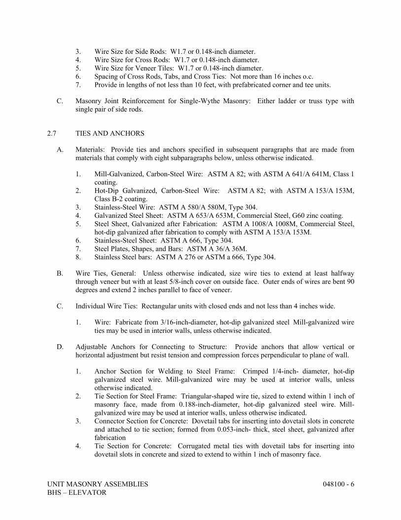
UNIT MASONRY ASSEMBLIES 048100 - 6 BHS – ELEVATOR
3. Wire Size for Side Rods: W1.7 or 0.148-inch diameter. 4. Wire Size for Cross Rods: W1.7 or 0.148-inch diameter. 5. Wire Size for Veneer Tiles: W1.7 or 0.148-inch diameter. 6. Spacing of Cross Rods, Tabs, and Cross Ties: Not more than 16 inches o.c. 7. Provide in lengths of not less than 10 feet, with prefabricated corner and tee units.
C. Masonry Joint Reinforcement for Single-Wythe Masonry: Either ladder or truss type with single pair of side rods.
2.7 TIES AND ANCHORS
A. Materials: Provide ties and anchors specified in subsequent paragraphs that are made from materials that comply with eight subparagraphs below, unless otherwise indicated.
1. Mill-Galvanized, Carbon-Steel Wire: ASTM A 82; with ASTM A 641/A 641M, Class 1 coating.
2. Hot-Dip Galvanized, Carbon-Steel Wire: ASTM A 82; with ASTM A 153/A 153M, Class B-2 coating.
3. Stainless-Steel Wire: ASTM A 580/A 580M, Type 304. 4. Galvanized Steel Sheet: ASTM A 653/A 653M, Commercial Steel, G60 zinc coating. 5. Steel Sheet, Galvanized after Fabrication: ASTM A 1008/A 1008M, Commercial Steel,
hot-dip galvanized after fabrication to comply with ASTM A 153/A 153M. 6. Stainless-Steel Sheet: ASTM A 666, Type 304. 7. Steel Plates, Shapes, and Bars: ASTM A 36/A 36M. 8. Stainless Steel bars: ASTM A 276 or ASTM a 666, Type 304.
B. Wire Ties, General: Unless otherwise indicated, size wire ties to extend at least halfway through veneer but with at least 5/8-inch cover on outside face. Outer ends of wires are bent 90 degrees and extend 2 inches parallel to face of veneer.
C. Individual Wire Ties: Rectangular units with closed ends and not less than 4 inches wide.
1. Wire: Fabricate from 3/16-inch-diameter, hot-dip galvanized steel Mill-galvanized wire ties may be used in interior walls, unless otherwise indicated.
D. Adjustable Anchors for Connecting to Structure: Provide anchors that allow vertical or horizontal adjustment but resist tension and compression forces perpendicular to plane of wall.
1. Anchor Section for Welding to Steel Frame: Crimped 1/4-inch- diameter, hot-dip galvanized steel wire. Mill-galvanized wire may be used at interior walls, unless otherwise indicated.
2. Tie Section for Steel Frame: Triangular-shaped wire tie, sized to extend within 1 inch of masonry face, made from 0.188-inch-diameter, hot-dip galvanized steel wire. Mill-galvanized wire may be used at interior walls, unless otherwise indicated.
3. Connector Section for Concrete: Dovetail tabs for inserting into dovetail slots in concrete and attached to tie section; formed from 0.053-inch- thick, steel sheet, galvanized after fabrication
4. Tie Section for Concrete: Corrugated metal ties with dovetail tabs for inserting into dovetail slots in concrete and sized to extend to within 1 inch of masonry face.
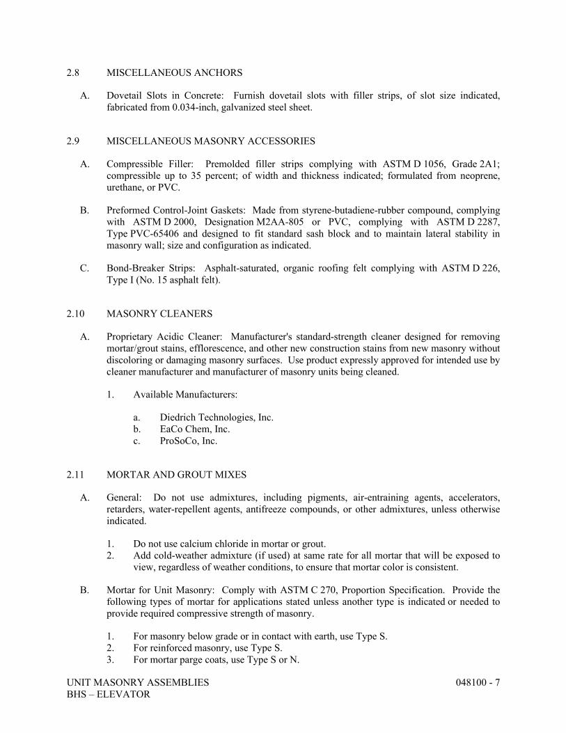
UNIT MASONRY ASSEMBLIES 048100 - 7 BHS – ELEVATOR
2.8 MISCELLANEOUS ANCHORS
A. Dovetail Slots in Concrete: Furnish dovetail slots with filler strips, of slot size indicated, fabricated from 0.034-inch, galvanized steel sheet.
2.9 MISCELLANEOUS MASONRY ACCESSORIES
A. Compressible Filler: Premolded filler strips complying with ASTM D 1056, Grade 2A1; compressible up to 35 percent; of width and thickness indicated; formulated from neoprene, urethane, or PVC.
B. Preformed Control-Joint Gaskets: Made from styrene-butadiene-rubber compound, complying with ASTM D 2000, Designation M2AA-805 or PVC, complying with ASTM D 2287, Type PVC-65406 and designed to fit standard sash block and to maintain lateral stability in masonry wall; size and configuration as indicated.
C. Bond-Breaker Strips: Asphalt-saturated, organic roofing felt complying with ASTM D 226, Type I (No. 15 asphalt felt).
2.10 MASONRY CLEANERS
A. Proprietary Acidic Cleaner: Manufacturer's standard-strength cleaner designed for removing mortar/grout stains, efflorescence, and other new construction stains from new masonry without discoloring or damaging masonry surfaces. Use product expressly approved for intended use by cleaner manufacturer and manufacturer of masonry units being cleaned.
1. Available Manufacturers:
a. Diedrich Technologies, Inc. b. EaCo Chem, Inc. c. ProSoCo, Inc.
2.11 MORTAR AND GROUT MIXES
A. General: Do not use admixtures, including pigments, air-entraining agents, accelerators, retarders, water-repellent agents, antifreeze compounds, or other admixtures, unless otherwise indicated.
1. Do not use calcium chloride in mortar or grout. 2. Add cold-weather admixture (if used) at same rate for all mortar that will be exposed to
view, regardless of weather conditions, to ensure that mortar color is consistent.
B. Mortar for Unit Masonry: Comply with ASTM C 270, Proportion Specification. Provide the following types of mortar for applications stated unless another type is indicated or needed to provide required compressive strength of masonry.
1. For masonry below grade or in contact with earth, use Type S. 2. For reinforced masonry, use Type S. 3. For mortar parge coats, use Type S or N.
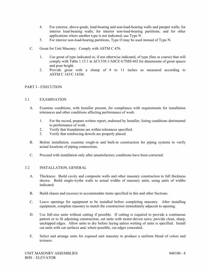
UNIT MASONRY ASSEMBLIES 048100 - 8 BHS – ELEVATOR
4. For exterior, above-grade, load-bearing and non-load-bearing walls and parapet walls; for interior load-bearing walls; for interior non-load-bearing partitions; and for other applications where another type is not indicated, use Type N.
5. For interior non-load-bearing partitions, Type O may be used instead of Type N.
C. Grout for Unit Masonry: Comply with ASTM C 476.
1. Use grout of type indicated or, if not otherwise indicated, of type (fine or coarse) that will comply with Table 1.15.1 in ACI 530.1/ASCE 6/TMS 602 for dimensions of grout spaces and pour height.
2. Provide grout with a slump of 8 to 11 inches as measured according to ASTM C 143/C 143M.
PART 3 - EXECUTION
3.1 EXAMINATION
A. Examine conditions, with Installer present, for compliance with requirements for installation tolerances and other conditions affecting performance of work.
1. For the record, prepare written report, endorsed by Installer, listing conditions detrimental to performance of work.
2. Verify that foundations are within tolerances specified. 3. Verify that reinforcing dowels are properly placed.
B. Before installation, examine rough-in and built-in construction for piping systems to verify actual locations of piping connections.
C. Proceed with installation only after unsatisfactory conditions have been corrected.
3.2 INSTALLATION, GENERAL
A. Thickness: Build cavity and composite walls and other masonry construction to full thickness shown. Build single-wythe walls to actual widths of masonry units, using units of widths indicated.
B. Build chases and recesses to accommodate items specified in this and other Sections.
C. Leave openings for equipment to be installed before completing masonry. After installing equipment, complete masonry to match the construction immediately adjacent to opening.
D. Use full-size units without cutting if possible. If cutting is required to provide a continuous pattern or to fit adjoining construction, cut units with motor-driven saws; provide clean, sharp, unchipped edges. Allow units to dry before laying unless wetting of units is specified. Install cut units with cut surfaces and, where possible, cut edges concealed.
E. Select and arrange units for exposed unit masonry to produce a uniform blend of colors and textures.
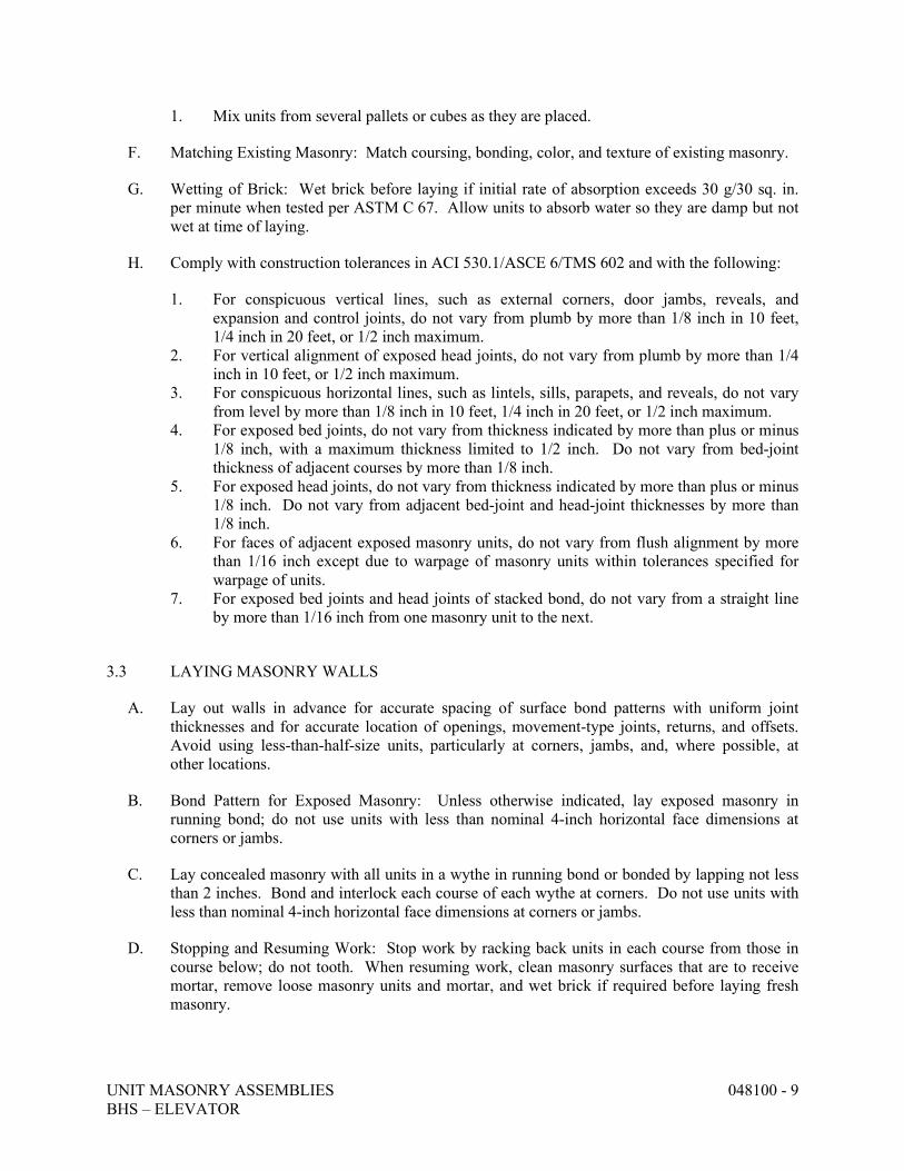
UNIT MASONRY ASSEMBLIES 048100 - 9 BHS – ELEVATOR
1. Mix units from several pallets or cubes as they are placed.
F. Matching Existing Masonry: Match coursing, bonding, color, and texture of existing masonry.
G. Wetting of Brick: Wet brick before laying if initial rate of absorption exceeds 30 g/30 sq. in. per minute when tested per ASTM C 67. Allow units to absorb water so they are damp but not wet at time of laying.
H. Comply with construction tolerances in ACI 530.1/ASCE 6/TMS 602 and with the following:
1. For conspicuous vertical lines, such as external corners, door jambs, reveals, and expansion and control joints, do not vary from plumb by more than 1/8 inch in 10 feet, 1/4 inch in 20 feet, or 1/2 inch maximum.
2. For vertical alignment of exposed head joints, do not vary from plumb by more than 1/4 inch in 10 feet, or 1/2 inch maximum.
3. For conspicuous horizontal lines, such as lintels, sills, parapets, and reveals, do not vary from level by more than 1/8 inch in 10 feet, 1/4 inch in 20 feet, or 1/2 inch maximum.
4. For exposed bed joints, do not vary from thickness indicated by more than plus or minus 1/8 inch, with a maximum thickness limited to 1/2 inch. Do not vary from bed-joint thickness of adjacent courses by more than 1/8 inch.
5. For exposed head joints, do not vary from thickness indicated by more than plus or minus 1/8 inch. Do not vary from adjacent bed-joint and head-joint thicknesses by more than 1/8 inch.
6. For faces of adjacent exposed masonry units, do not vary from flush alignment by more than 1/16 inch except due to warpage of masonry units within tolerances specified for warpage of units.
7. For exposed bed joints and head joints of stacked bond, do not vary from a straight line by more than 1/16 inch from one masonry unit to the next.
3.3 LAYING MASONRY WALLS
A. Lay out walls in advance for accurate spacing of surface bond patterns with uniform joint thicknesses and for accurate location of openings, movement-type joints, returns, and offsets. Avoid using less-than-half-size units, particularly at corners, jambs, and, where possible, at other locations.
B. Bond Pattern for Exposed Masonry: Unless otherwise indicated, lay exposed masonry in running bond; do not use units with less than nominal 4-inch horizontal face dimensions at corners or jambs.
C. Lay concealed masonry with all units in a wythe in running bond or bonded by lapping not less than 2 inches. Bond and interlock each course of each wythe at corners. Do not use units with less than nominal 4-inch horizontal face dimensions at corners or jambs.
D. Stopping and Resuming Work: Stop work by racking back units in each course from those in course below; do not tooth. When resuming work, clean masonry surfaces that are to receive mortar, remove loose masonry units and mortar, and wet brick if required before laying fresh masonry.
UNIT MASONRY ASSEMBLIES 048100 - 10 BHS – ELEVATOR
E. Built-in Work: As construction progresses, build in items specified in this and other Sections. Fill in solidly with masonry around built-in items.
F. Fill space between steel frames and masonry solidly with mortar, unless otherwise indicated.
G. Where built-in items are to be embedded in cores of hollow masonry units, place a layer of metal lath, wire mesh, or plastic mesh in the joint below and rod mortar or grout into core.
H. Fill cores in hollow concrete masonry units with grout 24 inches under bearing plates, beams, lintels, posts, and similar items, unless otherwise indicated.
I. Build non-load-bearing interior partitions full height of story to underside of solid floor or roof structure above, unless otherwise indicated.
1. Install compressible filler in joint between top of partition and underside of structure above.
2. At fire-rated partitions, treat joint between top of partition and underside of structure above to comply with Division 7 Section "Fire-Resistive Joint Systems."
3.4 MORTAR BEDDING AND JOINTING
A. Lay hollow concrete masonry units as follows:
1. With face shells fully bedded in mortar and with head joints of depth equal to bed joints. 2. With webs fully bedded in mortar in all courses of piers, columns, and pilasters. 3. With webs fully bedded in mortar in grouted masonry, including starting course on
footings. 4. With entire units, including areas under cells, fully bedded in mortar at starting course on
footings where cells are not grouted.
B. Lay solid masonry units with completely filled bed and head joints; butter ends with sufficient mortar to fill head joints and shove into place. Do not deeply furrow bed joints or slush head joints.
C. Tool exposed joints slightly concave when thumbprint hard, using a jointer larger than joint thickness, unless otherwise indicated.
1. For glazed masonry units, use a nonmetallic jointer 3/4 inch or more in width.
3.5 MASONRY JOINT REINFORCEMENT
A. General: Install entire length of longitudinal side rods in mortar with a minimum cover of 5/8 inch on exterior side of walls, 1/2 inch elsewhere. Lap reinforcement a minimum of 6 inches.
1. Space reinforcement not more than 16 inches o.c. 2. Space reinforcement not more than 8 inches o.c. in foundation walls and parapet walls. 3. Provide reinforcement not more than 8 inches above and below wall openings and
extending 12 inches beyond openings.
a. Reinforcement above is in addition to continuous reinforcement.
UNIT MASONRY ASSEMBLIES 048100 - 11 BHS – ELEVATOR
B. Interrupt joint reinforcement at control and expansion joints, unless otherwise indicated.
C. Provide continuity at wall intersections by using prefabricated T-shaped units.
D. Provide continuity at corners by using prefabricated L-shaped units.
E. Cut and bend reinforcing units as directed by manufacturer for continuity at returns, offsets, column fireproofing, pipe enclosures, and other special conditions.
3.6 ANCHORING MASONRY TO STRUCTURAL MEMBERS
A. Anchor masonry to structural members where masonry abuts or faces structural members to comply with the following:
1. Provide an open space not less than 1/2 inch in width between masonry and structural member, unless otherwise indicated. Keep open space free of mortar and other rigid materials.
2. Anchor masonry to structural members with anchors embedded in masonry joints and attached to structure.
3. Space anchors as indicated, but not more than 24 inches o.c. vertically and 36 inches o.c. horizontally.
3.7 CONTROL AND EXPANSION JOINTS
A. General: Install control and expansion joint materials in unit masonry as masonry progresses. Do not allow materials to span control and expansion joints without provision to allow for in-plane wall or partition movement.
B. Form control joints in concrete masonry as follows:
1. Install preformed control-joint gaskets designed to fit standard sash block.
C. Form expansion joints in brick made from clay or shale as follows:
1. Build in compressible joint fillers where indicated.
3.8 LINTELS
A. Install steel lintels where indicated.
B. Provide concrete or masonry lintels where shown and where openings of more than 12 inches for brick-size units and 24 inches for block-size units are shown without structural steel or other supporting lintels.
C. Provide minimum bearing of 8 inches at each jamb, unless otherwise indicated.
UNIT MASONRY ASSEMBLIES 048100 - 12 BHS – ELEVATOR
3.9 REINFORCED UNIT MASONRY INSTALLATION
A. Temporary Formwork and Shores: Construct formwork and shores as needed to support reinforced masonry elements during construction.
1. Construct formwork to provide shape, line, and dimensions of completed masonry as indicated. Make forms sufficiently tight to prevent leakage of mortar and grout. Brace, tie, and support forms to maintain position and shape during construction and curing of reinforced masonry.
2. Do not remove forms and shores until reinforced masonry members have hardened sufficiently to carry their own weight and other temporary loads that may be placed on them during construction.
B. Placing Reinforcement: Comply with requirements in ACI 530.1/ASCE 6/TMS 602.
C. Grouting: Do not place grout until entire height of masonry to be grouted has attained enough strength to resist grout pressure.
1. Comply with requirements in ACI 530.1/ASCE 6/TMS 602 for cleanouts and for grout placement, including minimum grout space and maximum pour height.
2. Limit height of vertical grout pours to not more than 60 inches.
3.10 REPAIRING, POINTING, AND CLEANING
A. Remove and replace masonry units that are loose, chipped, broken, stained, or otherwise damaged or that do not match adjoining units. Install new units to match adjoining units; install in fresh mortar, pointed to eliminate evidence of replacement.
B. Pointing: During the tooling of joints, enlarge voids and holes, except weep holes, and completely fill with mortar. Point up joints, including corners, openings, and adjacent construction, to provide a neat, uniform appearance. Prepare joints for sealant application, where indicated.
C. In-Progress Cleaning: Clean unit masonry as work progresses by dry brushing to remove mortar fins and smears before tooling joints.
D. Final Cleaning: After mortar is thoroughly set and cured, clean exposed masonry as follows:
1. Remove large mortar particles by hand with wooden paddles and nonmetallic scrape hoes or chisels.
2. Test cleaning methods on sample wall panel; leave one-half of panel uncleaned for comparison purposes. Obtain Architect's approval of sample cleaning before proceeding with cleaning of masonry.
3. Protect adjacent stone and nonmasonry surfaces from contact with cleaner by covering them with liquid strippable masking agent or polyethylene film and waterproof masking tape.
4. Wet wall surfaces with water before applying cleaners; remove cleaners promptly by rinsing surfaces thoroughly with clear water.
5. Clean masonry with a proprietary acidic cleaner applied according to manufacturer's written instructions.
UNIT MASONRY ASSEMBLIES 048100 - 13 BHS – ELEVATOR
6. Clean concrete masonry by cleaning method indicated in NCMA TEK 8-2A applicable to type of stain on exposed surfaces.
3.11 MASONRY WASTE DISPOSAL
A. Salvageable Materials: Unless otherwise indicated, excess masonry materials are Contractor's property. At completion of unit masonry work, remove from Project site.
END OF SECTION 048100
STRUCTURAL STEEL FRAMING 051200 - 1 BHS ELEVATOR
SECTION 051200 – STRUCTURAL STEEL FRAMING
PART 1 - GENERAL
1.1 RELATED DOCUMENTS
A. Drawings and general provisions of the Contract, including General and Supplementary Conditions and Division 01 Specification Sections, apply to this Section.
1.2 SUMMARY
A. Section Includes:
1. Structural steel. 2. Grout.
1.3 DEFINITIONS
A. Structural Steel: Elements of structural-steel frame, as classified by AISC 303, "Code of Standard Practice for Steel Buildings and Bridges."
1.4 PERFORMANCE REQUIREMENTS
A. Connections: Provide details of simple shear connections required by the Contract Documents to be selected or completed by structural-steel fabricator to withstand loads indicated and comply with other information and restrictions indicated.
1. Select and complete connections using schematic details indicated and AISC 360. 2. Use ASD; data are given at service-load level.
1.5 ACTION SUBMITTALS
A. Product Data: For each type of product indicated.
B. Shop Drawings: Show fabrication of structural-steel components.
1. Include details of cuts, connections, splices, camber, holes, and other pertinent data. 2. Include embedment drawings. 3. Indicate welds by standard AWS symbols, distinguishing between shop and field welds,
and show size, length, and type of each weld. Show backing bars that are to be removed and supplemental fillet welds where backing bars are to remain.
4. Indicate type, size, and length of bolts, distinguishing between shop and field bolts. Identify pretensioned and slip-critical high-strength bolted connections.
1.6 INFORMATIONAL SUBMITTALS
A. Qualification Data: For qualified fabricator and professional engineer.
B. Welding certificates.
C. Mill test reports for structural steel, including chemical and physical properties.
STRUCTURAL STEEL FRAMING 051200 - 2 BHS ELEVATOR
D. Product Test Reports: For the following:
1. Bolts, nuts, and washers including mechanical properties and chemical analysis. 2. Tension-control, high-strength bolt-nut-washer assemblies. 3. Nonshrink grout.
E. Source quality-control reports.
1.7 QUALITY ASSURANCE
A. Installer Qualifications: Engage an experienced Installer who has completed structural steel work similar in material, design, and extent to that indicated for this Project and with a record of successful in-service performance.
B. Fabricator Qualifications: Engage a firm experienced in fabricating structural steel similar to that indicated for this Project and with a record of successful in-service performance, as well as sufficient production capacity to fabricate structural steel without delaying the Work.
C. Welding Qualifications: Qualify procedures and personnel according to AWS D1.1, "Structural Welding Code - Steel."
1. Welders and welding operators performing work on bottom-flange, demand-critical welds shall pass the supplemental welder qualification testing, as required by AWS D1.8. FCAW-S and FCAW-G shall be considered separate processes for welding personnel qualification.
D. Comply with applicable provisions of the following specifications and documents:
1. AISC 303. 2. AISC 360. 3. RCSC's "Specification for Structural Joints Using ASTM A 325 or A 490 Bolts."
1.8 DELIVERY, STORAGE, AND HANDLING
A. Store materials to permit easy access for inspection and identification. Keep steel members off ground and spaced by using pallets, dunnage, or other supports and spacers. Protect steel members and packaged materials from corrosion and deterioration.
1. Do not store materials on structure in a manner that might cause distortion, damage, or overload to members or supporting structures. Repair or replace damaged materials or structures as directed.
B. Store fasteners in a protected place in sealed containers with manufacturer's labels intact.
1. Fasteners may be repackaged provided Design-Builder's testing and inspecting agency observes repackaging and seals containers.
2. Clean and relubricate bolts and nuts that become dry or rusty before use. 3. Comply with manufacturers' written recommendations for cleaning and lubricating
ASTM F 1852 fasteners and for retesting fasteners after lubrication.
STRUCTURAL STEEL FRAMING 051200 - 3 BHS ELEVATOR
1.9 COORDINATION
A. Coordinate installation of anchorage items to be embedded in or attached to other construction without delaying the Work. Provide setting diagrams, sheet metal templates, instructions, and directions for installation.
PART 2 - PRODUCTS
2.1 STRUCTURAL STEEL MATERIALS
A. W-Shapes: ASTM A 992, Grade 50.
B. Channels, Angles: ASTM A 36.
C. Plate and Bar: ASTM A 36.
D. Welding Electrodes: Comply with AWS requirements.
2.2 BOLTS, CONNECTORS, AND ANCHORS
A. High-Strength Bolts, Nuts, and Washers: ASTM A 325, Type 1, heavy-hex steel structural bolts; ASTM A 563, Grade C, heavy-hex carbon-steel nuts; and ASTM F 436, Type 1, hardened carbon-steel washers; all with plain finish.
B. Tension-Control, High-Strength Bolt-Nut-Washer Assemblies: ASTM F 1852, Type 1, heavy-hex head assemblies consisting of steel structural bolts with splined ends, heavy-hex carbon-steel nuts, and hardened carbon-steel washers.
1. Finish: Plain
C. Unheaded Anchor Rods: ASTM F 1554, Grade 36.
1. Configuration: Straight. 2. Nuts: ASTM A 563 heavy-hex carbon steel. 3. Plate Washers: ASTM A 36 carbon steel. 4. Washers: ASTM F 436, Type 1, hardened carbon steel. 5. Finish: Plain.
D. Headed Anchor Rods: ASTM F 1554, Grade 36, straight.
1. Nuts: ASTM A 563 heavy-hex carbon steel. 2. Plate Washers: ASTM A 36 carbon steel. 3. Washers: ASTM F 436, Type 1, hardened carbon steel. 4. Finish: Plain.
E. Threaded Rods: ASTM A 36.
1. Nuts: ASTM A 563 heavy-hex carbon steel. 2. Washers: ASTM F 436, Type 1, hardened carbon steel. 3. Finish: Plain.
STRUCTURAL STEEL FRAMING 051200 - 4 BHS ELEVATOR
2.3 PRIMER
A. Primer: SSPC-Paint 25 BCS, Type, zinc oxide, alkyd, linseed oil primer. Color: Grey.
B. Galvanizing Repair Paint: ASTM A 780.
2.4 GROUT
A. Nonmetallic, Shrinkage-Resistant Grout: ASTM C 1107, factory-packaged, nonmetallic aggregate grout, noncorrosive and nonstaining, mixed with water to consistency suitable for application and a 30-minute working time.
2.5 FABRICATION
A. Structural Steel: Fabricate and assemble in shop to greatest extent possible. Fabricate according to AISC's "Code of Standard Practice for Steel Buildings and Bridges" and AISC 360.
1. Camber structural-steel members where indicated. 2. Fabricate beams with rolling camber up. 3. Identify high-strength structural steel according to ASTM A 6 and maintain markings
until structural steel has been erected. 4. Mark and match-mark materials for field assembly. 5. Complete structural-steel assemblies, including welding of units, before starting shop-
priming operations.
B. Thermal Cutting: Perform thermal cutting by machine to greatest extent possible.
1. Plane thermally cut edges to be welded to comply with requirements in AWS D1.1.
C. Bolt Holes: Cut, drill, or punch standard bolt holes perpendicular to metal surfaces.
D. Finishing: Accurately finish ends of columns and other members transmitting bearing loads.
E. Cleaning: Clean and prepare steel surfaces that are to remain unpainted according to SSPC-SP 1, "Solvent Cleaning or SSPC-SP 2, "Hand Tool Cleaning."
F. Holes: Provide holes required for securing other work to structural steel and for other work to pass through steel framing members.
1. Cut, drill, or punch holes perpendicular to steel surfaces. Do not thermally cut bolt holes or enlarge holes by burning.
2. Baseplate Holes: Cut, drill, mechanically thermal cut, or punch holes perpendicular to steel surfaces.
3. Weld threaded nuts to framing and other specialty items indicated to receive other work.
STRUCTURAL STEEL FRAMING 051200 - 5 BHS ELEVATOR
2.6 SHOP CONNECTIONS
A. High-Strength Bolts: Shop install high-strength bolts according to RCSC's "Specification for Structural Joints Using ASTM A 325 or A 490 Bolts" for type of bolt and type of joint specified.
1. Joint Type: Snug tightened unless indicated as Pretensioned or Slip Critical on drawings.
B. Weld Connections: Comply with AWS D1.1 for tolerances, appearances, welding procedure specifications, weld quality, and methods used in correcting welding work.
1. Assemble and weld built-up sections by methods that will maintain true alignment of axes without exceeding tolerances in AISC 303 for mill material.
2.7 SHOP PRIMING
A. Shop prime steel surfaces except the following:
1. Surfaces embedded in concrete or mortar. Extend priming of partially embedded members to a depth of 2 inches.
2. Surfaces to be field welded. 3. Surfaces of high-strength bolted, slip-critical connections. 4. Surfaces to receive sprayed fire-resistive materials (applied fireproofing). 5. Galvanized surfaces. 6. Surfaces enclosed in interior construction.
B. Surface Preparation: Clean surfaces to be painted. Remove loose rust and mill scale and spatter, slag, or flux deposits. Prepare surfaces according to the following specifications and standards:
1. SSPC-SP 3, "Power Tool Cleaning."
C. Priming: Immediately after surface preparation, apply primer according to manufacturer's written instructions and at rate recommended by SSPC to provide a minimum dry film thickness of 1.5 mils. Use priming methods that result in full coverage of joints, corners, edges, and exposed surfaces.
1. Stripe paint corners, crevices, bolts, welds, and sharp edges. 2. Apply two coats of shop paint to surfaces that are inaccessible after assembly or erection.
Change color of second coat to distinguish it from first.
2.8 GALVANIZING
A. Hot-Dip Galvanized Finish: Where indicated, apply zinc coating by the hot-dip process to structural steel according to ASTM A 123.
STRUCTURAL STEEL FRAMING 051200 - 6 BHS ELEVATOR
PART 3 - EXECUTION
3.1 EXAMINATION
A. Verify, with steel Erector present, elevations of concrete- and masonry-bearing surfaces and locations of anchor rods, bearing plates, and other embedments for compliance with requirements.
1. Prepare a certified survey of bearing surfaces, anchor rods, bearing plates, and other embedments showing dimensions, locations, angles, and elevations.
B. Proceed with installation only after unsatisfactory conditions have been corrected.
3.2 PREPARATION
A. Provide temporary shores, guys, braces, and other supports during erection to keep structural steel secure, plumb, and in alignment against temporary construction loads and loads equal in intensity to design loads. Remove temporary supports when permanent structural steel, connections, and bracing are in place unless otherwise indicated.
3.3 ERECTION
A. Set structural steel accurately in locations and to elevations indicated and according to AISC 303 and AISC 360.
B. Baseplates and Beam Bearing Plates: Clean concrete- and masonry-bearing surfaces of bond-reducing materials, and roughen surfaces prior to setting plates. Clean bottom surface of plates.
1. Set plates for structural members on wedges, shims, or setting nuts as required. 2. Weld plate washers to top of baseplate. 3. Snug-tighten anchor rods after supported members have been positioned and plumbed.
Do not remove wedges or shims but, if protruding, cut off flush with edge of plate before packing with grout.
4. Promptly pack grout solidly between bearing surfaces and plates so no voids remain. Neatly finish exposed surfaces; protect grout and allow to cure. Comply with manufacturer's written installation instructions for shrinkage-resistant grouts.
C. Maintain erection tolerances of structural steel within AISC's "Code of Standard Practice for Steel Buildings and Bridges."
D. Align and adjust various members that form part of complete frame or structure before permanently fastening. Before assembly, clean bearing surfaces and other surfaces that will be in permanent contact with members. Perform necessary adjustments to compensate for discrepancies in elevations and alignment.
1. Level and plumb individual members of structure. 2. Make allowances for difference between temperature at time of erection and mean
temperature when structure is completed and in service.
E. Splice members only where indicated.
STRUCTURAL STEEL FRAMING 051200 - 7 BHS ELEVATOR
F. Do not use thermal cutting during erection unless approved by Engineer. Finish thermally cut sections within smoothness limits in AWS D1.1.
G. Do not enlarge unfair holes in members by burning or using drift pins. Ream holes that must be enlarged to admit bolts.
3.4 FIELD CONNECTIONS
A. High-Strength Bolts: Install high-strength bolts according to RCSC's "Specification for Structural Joints Using ASTM A 325 or A 490 Bolts" for type of bolt and type of joint specified.
1. Joint Type: Snug tightened unless indicated as Pretensioned or Slip Critical on drawings.
B. Weld Connections: Comply with AWS D1.1 for tolerances, appearances, welding procedure specifications, weld quality, and methods used in correcting welding work.
1. Comply with AISC 303 and AISC 360 for bearing, alignment, adequacy of temporary connections, and removal of paint on surfaces adjacent to field welds.
2. Remove backing bars or runoff tabs where indicated, back gouge, and grind steel smooth. 3. Assemble and weld built-up sections by methods that will maintain true alignment of
axes without exceeding tolerances in AISC's "Code of Standard Practice for Steel Buildings and Bridges" for mill material.
3.5 FIELD QUALITY CONTROL
A. Testing Agency: Contractor will engage a qualified independent testing and inspecting agency to inspect field welds and high-strength bolted connections and prepare test reports.
B. Bolted Connections: Bolted connections will be tested and inspected according to RCSC's "Specification for Structural Joints Using ASTM A 325 or A 490 Bolts."
C. Welded Connections: Field welds will be visually inspected according to AWS D1.1.
1. In addition to visual inspection, field welds will be tested and inspected according to AWS D1.1 and the following inspection procedures, at testing agency's option:
a. Liquid Penetrant Inspection: ASTM E 165. b. Magnetic Particle Inspection: ASTM E 709; performed on root pass and on
finished weld. Cracks or zones of incomplete fusion or penetration will not be accepted.
c. Ultrasonic Inspection: ASTM E 164. d. Radiographic Inspection: ASTM E 94.
D. Correct deficiencies in Work that test reports and inspections indicate does not comply with the Contract Documents.
STRUCTURAL STEEL FRAMING 051200 - 8 BHS ELEVATOR
3.6 REPAIRS AND PROTECTION
A. Galvanized Surfaces: Clean areas where galvanizing is damaged or missing and repair galvanizing to comply with ASTM A 780.
END OF SECTION 051200
JOINT SEALANTS BHS – ELEVATOR
079200 - 1
SECTION 079200 - JOINT SEALANTS
PART 1 - GENERAL
1.1 RELATED DOCUMENTS
A. Drawings and general provisions of the Contract, including General and Supplementary Conditions and Division 01 Specification Sections, apply to this Section.
1.2 SUMMARY
A. Section Includes:
1. Silicone joint sealants. 2. Urethane joint sealants. 3. Latex joint sealants.
B. Related Sections:
1. Division 04 Section "Unit Masonry" for masonry control and expansion joint fillers and gaskets.
1.3 SUBMITTALS
A. Product Data: For each joint-sealant product indicated.
B. Samples for Initial Selection: Manufacturer's color charts consisting of strips of cured sealants showing the full range of colors available for each product exposed to view.
C. Samples for Verification: For each kind and color of joint sealant required, provide Samples with joint sealants in 1/2-inch- wide joints formed between two 6-inch- long strips of material matching the appearance of exposed surfaces adjacent to joint sealants.
D. Joint-Sealant Schedule: Include the following information:
1. Joint-sealant application, joint location, and designation. 2. Joint-sealant manufacturer and product name. 3. Joint-sealant formulation. 4. Joint-sealant color.
E. Warranties: Sample of special warranties.
1.4 QUALITY ASSURANCE
A. Installer Qualifications: Manufacturer's authorized representative who is trained and approved for installation of units required for this Project.
JOINT SEALANTS BHS – ELEVATOR
079200 - 2
B. Source Limitations: Obtain each kind of joint sealant from single source from single manufacturer.
C. Mockups: Install sealant in mockups of assemblies specified in other Sections that are indicated to receive joint sealants specified in this Section. Use materials and installation methods specified in this Section.
1.5 PROJECT CONDITIONS
A. Do not proceed with installation of joint sealants under the following conditions:
1. When ambient and substrate temperature conditions are outside limits permitted by joint-sealant manufacturer or are below 40 deg F.
2. When joint substrates are wet. 3. Where joint widths are less than those allowed by joint-sealant manufacturer for
applications indicated. 4. Where contaminants capable of interfering with adhesion have not yet been removed
from joint substrates.
1.6 WARRANTY
A. Special Installer's Warranty: Manufacturer's standard form in which Installer agrees to repair or replace joint sealants that do not comply with performance and other requirements specified in this Section within specified warranty period.
1. Warranty Period: Two years from date of Substantial Completion.
B. Special Manufacturer's Warranty: Manufacturer's standard form in which joint-sealant manufacturer agrees to furnish joint sealants to repair or replace those that do not comply with performance and other requirements specified in this Section within specified warranty period.
1. Warranty Period: Twenty years from date of Substantial Completion.
C. Special warranties specified in this article exclude deterioration or failure of joint sealants from the following:
1. Movement of the structure caused by structural settlement or errors attributable to design or construction resulting in stresses on the sealant exceeding sealant manufacturer's written specifications for sealant elongation and compression.
2. Disintegration of joint substrates from natural causes exceeding design specifications. 3. Mechanical damage caused by individuals, tools, or other outside agents. 4. Changes in sealant appearance caused by accumulation of dirt or other atmospheric
contaminants.
JOINT SEALANTS BHS – ELEVATOR
079200 - 3
PART 2 - PRODUCTS
2.1 MATERIALS, GENERAL
A. Compatibility: Provide joint sealants, backings, and other related materials that are compatible with one another and with joint substrates under conditions of service and application, as demonstrated by joint-sealant manufacturer, based on testing and field experience.
B. Liquid-Applied Joint Sealants: Comply with ASTM C 920 and other requirements indicated for each liquid-applied joint sealant specified, including those referencing ASTM C 920 classifications for type, grade, class, and uses related to exposure and joint substrates.
C. Stain-Test-Response Characteristics: Where sealants are specified to be nonstaining to porous substrates, provide products that have undergone testing according to ASTM C 1248 and have not stained porous joint substrates indicated for Project.
D. Colors of Exposed Joint Sealants: As selected by Architect from manufacturer's full range.
2.2 SILICONE JOINT SEALANTS
A. Mildew-Resistant, Single-Component, Acid-Curing Silicone Joint Sealant: ASTM C 920, Type S, Grade NS, Class 25, for Use NT.
1. Products: Subject to compliance with requirements, provide one of the following:
a. BASF Building Systems; Omniplus. b. Dow Corning Corporation; 786 Mildew Resistant. c. GE Advanced Materials - Silicones; Sanitary SCS1700. d. May National Associates, Inc.; Bondaflex Sil 100 WF. e. Tremco Incorporated; Tremsil 200 Sanitary.
2.3 URETHANE JOINT SEALANTS
A. Single-Component, Nonsag, Urethane Joint Sealant: ASTM C 920, Type S, Grade NS, Class 25, for Use NT.
1. Products: Subject to compliance with requirements, provide one of the following:
a. BASF Building Systems; Sonolastic NP1. b. Bostik, Inc.; Chem-Calk 900. c. May National Associates, Inc.; Bondaflex PUR 25. d. Pecora Corporation; Dynatrol I-XL. e. Sika Corporation, Construction Products Division; Sikaflex - 1a. f. Tremco Incorporated; Dymonic.
B. Single-Component, Pourable, Traffic-Grade, Urethane Joint Sealant: ASTM C 920, Type S, Grade P, Class 25, for Use T.
JOINT SEALANTS BHS – ELEVATOR
079200 - 4
1. Products: Subject to compliance with requirements, provide one of the following:
a. BASF Building Systems; Sonolastic SL 1. b. Bostik, Inc.; Chem-Calk 950. c. May National Associates, Inc.; Bondaflex PUR 35 SL. d. Pecora Corporation; Urexpan NR-201. e. Polymeric Systems, Inc.; Flexiprene 952. f. Schnee-Morehead, Inc.; Permathane SM7101. g. Sika Corporation. Construction Products Division; Sikaflex - 1CSL. h. Tremco Incorporated; Vulkem 45.
2.4 LATEX JOINT SEALANTS
A. Latex Joint Sealant: Acrylic latex or siliconized acrylic latex, ASTM C 834, Type OP, Grade NF.
1. Products: Subject to compliance with requirements, provide one of the following:
a. BASF Building Systems; Sonolac. b. Bostik, Inc.; Chem-Calk 600. c. May National Associates, Inc.; Bondaflex 600. d. Pecora Corporation; AC-20+. e. Schnee-Morehead, Inc.; SM 8200. f. Tremco Incorporated; Tremflex 834.
2.5 JOINT SEALANT BACKING
A. General: Provide sealant backings of material that are nonstaining; are compatible with joint substrates, sealants, primers, and other joint fillers; and are approved for applications indicated by sealant manufacturer based on field experience and laboratory testing.
B. Cylindrical Sealant Backings: ASTM C 1330, Type C (closed-cell material with a surface skin), and of size and density to control sealant depth and otherwise contribute to producing optimum sealant performance.
C. Bond-Breaker Tape: Polyethylene tape or other plastic tape recommended by sealant manufacturer for preventing sealant from adhering to rigid, inflexible joint-filler materials or joint surfaces at back of joint. Provide self-adhesive tape where applicable.
2.6 MISCELLANEOUS MATERIALS
A. Primer: Material recommended by joint-sealant manufacturer where required for adhesion of sealant to joint substrates indicated, as determined from preconstruction joint-sealant-substrate tests and field tests.
B. Cleaners for Nonporous Surfaces: Chemical cleaners acceptable to manufacturers of sealants and sealant backing materials, free of oily residues or other substances capable of staining or
JOINT SEALANTS BHS – ELEVATOR
079200 - 5
harming joint substrates and adjacent nonporous surfaces in any way, and formulated to promote optimum adhesion of sealants to joint substrates.
C. Masking Tape: Nonstaining, nonabsorbent material compatible with joint sealants and surfaces adjacent to joints.
PART 3 - EXECUTION
3.1 EXAMINATION
A. Examine joints indicated to receive joint sealants, with Installer present, for compliance with requirements for joint configuration, installation tolerances, and other conditions affecting joint-sealant performance.
B. Proceed with installation only after unsatisfactory conditions have been corrected.
3.2 PREPARATION
A. Surface Cleaning of Joints: Clean out joints immediately before installing joint sealants to comply with joint-sealant manufacturer's written instructions and the following requirements:
1. Remove all foreign material from joint substrates that could interfere with adhesion of joint sealant, including dust, paints (except for permanent, protective coatings tested and approved for sealant adhesion and compatibility by sealant manufacturer), old joint sealants, oil, grease, waterproofing, water repellents, water, surface dirt, and frost.
2. Clean porous joint substrate surfaces by brushing, grinding, mechanical abrading, or a combination of these methods to produce a clean, sound substrate capable of developing optimum bond with joint sealants. Remove loose particles remaining after cleaning operations above by vacuuming or blowing out joints with oil-free compressed air. Porous joint substrates include the following:
a. Concrete. b. Masonry.
3. Remove laitance and form-release agents from concrete. 4. Clean nonporous joint substrate surfaces with chemical cleaners or other means that do
not stain, harm substrates, or leave residues capable of interfering with adhesion of joint sealants. Nonporous joint substrates include the following:
a. Metal. b. Glass. c. Glazed surfaces of ceramic tile.
B. Joint Priming: Prime joint substrates where recommended by joint-sealant manufacturer or as indicated by preconstruction joint-sealant-substrate tests or prior experience. Apply primer to comply with joint-sealant manufacturer's written instructions. Confine primers to areas of joint-sealant bond; do not allow spillage or migration onto adjoining surfaces.
JOINT SEALANTS BHS – ELEVATOR
079200 - 6
C. Masking Tape: Use masking tape where required to prevent contact of sealant or primer with adjoining surfaces that otherwise would be permanently stained or damaged by such contact or by cleaning methods required to remove sealant smears. Remove tape immediately after tooling without disturbing joint seal.
3.3 INSTALLATION OF JOINT SEALANTS
A. General: Comply with joint-sealant manufacturer's written installation instructions for products and applications indicated, unless more stringent requirements apply.
B. Sealant Installation Standard: Comply with recommendations in ASTM C 1193 for use of joint sealants as applicable to materials, applications, and conditions indicated.
C. Install sealant backings of kind indicated to support sealants during application and at position required to produce cross-sectional shapes and depths of installed sealants relative to joint widths that allow optimum sealant movement capability.
1. Do not leave gaps between ends of sealant backings. 2. Do not stretch, twist, puncture, or tear sealant backings. 3. Remove absorbent sealant backings that have become wet before sealant application and
replace them with dry materials.
D. Install bond-breaker tape behind sealants where sealant backings are not used between sealants and backs of joints.
E. Install sealants using proven techniques that comply with the following and at the same time backings are installed:
1. Place sealants so they directly contact and fully wet joint substrates. 2. Completely fill recesses in each joint configuration. 3. Produce uniform, cross-sectional shapes and depths relative to joint widths that allow
optimum sealant movement capability.
F. Tooling of Nonsag Sealants: Immediately after sealant application and before skinning or curing begins, tool sealants according to requirements specified in subparagraphs below to form smooth, uniform beads of configuration indicated; to eliminate air pockets; and to ensure contact and adhesion of sealant with sides of joint.
1. Remove excess sealant from surfaces adjacent to joints. 2. Use tooling agents that are approved in writing by sealant manufacturer and that do not
discolor sealants or adjacent surfaces. 3. Provide concave joint profile per Figure 8A in ASTM C 1193, unless otherwise
indicated. 4. Provide flush joint profile where indicated per Figure 8B in ASTM C 1193. 5. Provide recessed joint configuration of recess depth and at locations indicated per
Figure 8C in ASTM C 1193.
a. Use masking tape to protect surfaces adjacent to recessed tooled joints.
JOINT SEALANTS BHS – ELEVATOR
079200 - 7
G. Acoustical Sealant Installation: At sound-rated assemblies and elsewhere as indicated, seal construction at perimeters, behind control joints, and at openings and penetrations with a continuous bead of acoustical sealant. Install acoustical sealant at both faces of partitions at perimeters and through penetrations. Comply with ASTM C 919 and with manufacturer's written recommendations.
3.4 CLEANING
A. Clean off excess sealant or sealant smears adjacent to joints as the Work progresses by methods and with cleaning materials approved in writing by manufacturers of joint sealants and of products in which joints occur.
3.5 PROTECTION
A. Protect joint sealants during and after curing period from contact with contaminating substances and from damage resulting from construction operations or other causes so sealants are without deterioration or damage at time of Substantial Completion. If, despite such protection, damage or deterioration occurs, cut out and remove damaged or deteriorated joint sealants immediately so installations with repaired areas are indistinguishable from original work.
3.6 JOINT-SEALANT SCHEDULE
A. Joint-Sealant Application: Exterior joints in horizontal traffic surfaces.
1. Joint Locations:
a. Isolation and contraction joints in cast-in-place concrete slabs.
2. Urethane Joint Sealant: Single component, nonsag, traffic grade. 3. Joint-Sealant Color: As selected by Architect from manufacturer's full range of colors.
B. Joint-Sealant Application: Exterior joints in vertical surfaces and horizontal nontraffic surfaces.
1. Joint Locations:
a. Joints between plant-precast architectural concrete units. b. Joints between metal panels. c. Joints between different materials listed above. d. Perimeter joints between materials listed above and frames of doors, windows, and
louvers.
2. Urethane Joint Sealant: Single component, nonsag, Class 25. 3. Joint-Sealant Color: As selected by Architect from manufacturer's full range of colors.
C. Joint-Sealant Application: Interior joints in horizontal traffic surfaces.
1. Joint Locations:
JOINT SEALANTS BHS – ELEVATOR
079200 - 8
a. Isolation joints in cast-in-place concrete slabs. b. Control and expansion joints in tile flooring.
2. Urethane Joint Sealant: Single component, nonsag, traffic grade. 3. Joint-Sealant Color: As selected by Architect from manufacturer's full range of colors.
D. Joint-Sealant Application: Interior joints in vertical surfaces and horizontal nontraffic surfaces.
1. Joint Locations:
a. Perimeter joints of exterior openings where indicated. b. Perimeter joints between interior wall surfaces and frames of interior doors,
windows, and elevator entrances.
2. Joint Sealant: Latex. 3. Joint-Sealant Color: As selected by Architect from manufacturer's full range of colors.
E. Joint-Sealant Application: Mildew-resistant interior joints in vertical surfaces and horizontal nontraffic surfaces.
1. Joint Sealant Location:
a. Joints between plumbing fixtures and adjoining walls, floors, and counters. b. Tile control and expansion joints where indicated.
2. Joint Sealant: Single component, nonsag, mildew resistant, acid curing. 3. Joint-Sealant Color: As selected by Architect from manufacturer's full range of colors.
END OF SECTION 079200
HOLLOW METAL DOORS AND FRAMES 081113 - 1 BHS – ELEVATOR
SECTION 081113 - HOLLOW METAL DOORS AND FRAMES
PART 1 - GENERAL
1.1 RELATED DOCUMENTS
A. Drawings and general provisions of the Contract, including General and Supplementary Conditions and Division 01 Specification Sections, apply to this Section.
1.2 SUMMARY
A. Section Includes:
1. Standard hollow metal frames.
B. Related Sections:
1. Division 04 Section "Unit Masonry" for embedding anchors for hollow metal work into masonry construction.
1.3 DEFINITIONS
A. Minimum Thickness: Minimum thickness of base metal without coatings.
B. Standard Hollow Metal Work: Hollow metal work fabricated according to ANSI/SDI A250.8.
1.4 SUBMITTALS
A. Product Data: For each type of product indicated. Include construction details, material descriptions, core descriptions, fire-resistance rating and finishes.
B. Shop Drawings: Include the following:
1. Frame details for each frame type, including dimensioned profiles and metal thicknesses. 2. Locations of reinforcement and preparations for hardware. 3. Details of each different wall opening condition. 4. Details of anchorages, joints, field splices, and connections. 5. Details of moldings, removable stops, and glazing. 6. Details of conduit and preparations for power, signal, and control systems.
C. Other Action Submittals:
1. Schedule: Provide a schedule of hollow metal work prepared by or under the supervision of supplier, using same reference numbers for details and openings as those on Drawings. Coordinate with door hardware schedule.
HOLLOW METAL DOORS AND FRAMES 081113 - 2 BHS – ELEVATOR
D. Product Test Reports: Based on evaluation of comprehensive tests performed by a qualified testing agency, for each type of hollow metal door and frame assembly.
1.5 QUALITY ASSURANCE
A. Source Limitations: Obtain hollow metal work from single source from single manufacturer.
1.6 DELIVERY, STORAGE, AND HANDLING
A. Deliver hollow metal work palletized, wrapped, or crated to provide protection during transit and Project-site storage. Do not use nonvented plastic.
1. Provide additional protection to prevent damage to finish of factory-finished units.
B. Deliver welded frames with two removable spreader bars across bottom of frames, tack welded to jambs and mullions.
C. Store hollow metal work under cover at Project site. Place in stacks of five units maximum in a vertical position with heads up, spaced by blocking, on minimum 4-inch- (102-mm-) high wood blocking. Do not store in a manner that traps excess humidity.
1. Provide minimum 1/4-inch (6-mm) space between each stacked door to permit air circulation.
1.7 PROJECT CONDITIONS
A. Field Measurements: Verify actual dimensions of openings by field measurements before fabrication.
1.8 COORDINATION
A. Coordinate installation of anchorages for hollow metal frames. Furnish setting drawings, templates, and directions for installing anchorages, including sleeves, concrete inserts, anchor bolts, and items with integral anchors. Deliver such items to Project site in time for installation.
PART 2 - PRODUCTS
2.1 MANUFACTURERS
A. Manufacturers: Subject to compliance with requirements, provide products by one of the following:
1. Amweld Building Products, LLC. 2. Ceco Door Products; an Assa Abloy Group company. 3. Curries Company; an Assa Abloy Group company. 4. Kewanee Corporation (The).
HOLLOW METAL DOORS AND FRAMES 081113 - 3 BHS – ELEVATOR
5. Pioneer Industries, Inc. 6. Steelcraft; an Ingersoll-Rand company.
2.2 MATERIALS
A. Cold-Rolled Steel Sheet: ASTM A 1008/A 1008M, Commercial Steel (CS), Type B; suitable for exposed applications.
B. Hot-Rolled Steel Sheet: ASTM A 1011/A 1011M, Commercial Steel (CS), Type B; free of scale, pitting, or surface defects; pickled and oiled.
C. Metallic-Coated Steel Sheet: ASTM A 653/A 653M, Commercial Steel (CS), Type B; with minimum A40 (ZF120) metallic coating.
D. Frame Anchors: ASTM A 591/A 591M, Commercial Steel (CS), 40Z (12G) coating designation; mill phosphatized.
1. For anchors built into exterior walls, steel sheet complying with ASTM A 1008/A 1008M or ASTM A 1011/A 1011M, hot-dip galvanized according to ASTM A 153/A 153M, Class B.
E. Inserts, Bolts, and Fasteners: Hot-dip galvanized according to ASTM A 153/A 153M.
F. Powder-Actuated Fasteners in Concrete: Fastener system of type suitable for application indicated, fabricated from corrosion-resistant materials, with clips or other accessory devices for attaching hollow metal frames of type indicated.
G. Grout: ASTM C 476, except with a maximum slump of 4 inches (102 mm), as measured according to ASTM C 143/C 143M.
H. Bituminous Coating: Cold-applied asphalt mastic, SSPC-Paint 12, compounded for 15-mil (0.4-mm) dry film thickness per coat. Provide inert-type noncorrosive compound free of asbestos fibers, sulfur components, and other deleterious impurities.
2.3 STANDARD HOLLOW METAL FRAMES
A. General: Comply with ANSI/SDI A250.8 and with details indicated for type and profile.
B. Interior Frames: Fabricated from cold-rolled steel sheet unless metallic-coated sheet is indicated.
1. Fabricate frames with mitered or coped and welded face corners and seamless joints. 2. Frames for Level 2 Steel Doors: 0.053-inch- (1.3-mm-) thick steel sheet. 3. Frames for Level 3 Steel Doors: 0.053-inch- (1.3-mm-) thick steel sheet. 4. Frames for Wood Doors: 0.053-inch- (1.3-mm-) thick steel sheet.
C. Hardware Reinforcement: Fabricate according to ANSI/SDI A250.6 with reinforcement plates from same material as frames.
HOLLOW METAL DOORS AND FRAMES 081113 - 4 BHS – ELEVATOR
2.4 FRAME ANCHORS
A. Jamb Anchors:
1. Masonry Type: Adjustable strap-and-stirrup or T-shaped anchors to suit frame size, not less than 0.042 inch (1.0 mm) thick, with corrugated or perforated straps not less than 2 inches (50 mm) wide by 10 inches (250 mm) long; or wire anchors not less than 0.177 inch (4.5 mm) thick.
2. Postinstalled Expansion Type for In-Place Concrete or Masonry: Minimum 3/8-inch- (9.5-mm-) diameter bolts with expansion shields or inserts. Provide pipe spacer from frame to wall, with throat reinforcement plate, welded to frame at each anchor location.
B. Floor Anchors: Formed from same material as frames, not less than 0.042 inch (1.0 mm) thick, and as follows:
1. Monolithic Concrete Slabs: Clip-type anchors, with two holes to receive fasteners.
2.5 ACCESSORIES
A. Grout Guards: Formed from same material as frames, not less than 0.016 inch (0.4 mm) thick.
2.6 FABRICATION
A. Fabricate hollow metal work to be rigid and free of defects, warp, or buckle. Accurately form metal to required sizes and profiles, with minimum radius for thickness of metal. Where practical, fit and assemble units in manufacturer's plant. To ensure proper assembly at Project site, clearly identify work that cannot be permanently factory assembled before shipment.
B. Hollow Metal Frames: Where frames are fabricated in sections due to shipping or handling limitations, provide alignment plates or angles at each joint, fabricated of same thickness metal as frames.
1. Welded Frames: Weld flush face joints continuously; grind, fill, dress, and make smooth, flush, and invisible.
2. Provide countersunk, flat- or oval-head exposed screws and bolts for exposed fasteners unless otherwise indicated.
3. Grout Guards: Weld guards to frame at back of hardware mortises in frames to be grouted.
4. Floor Anchors: Weld anchors to bottom of jambs and mullions with at least four spot welds per anchor.
5. Jamb Anchors: Provide number and spacing of anchors as follows:
a. Masonry Type: Locate anchors not more than 18 inches (457 mm) from top and bottom of frame. Space anchors not more than 32 inches (813 mm) o.c. and as follows:
1) Three anchors per jamb from 60 to 90 inches (1524 to 2286 mm) high.
HOLLOW METAL DOORS AND FRAMES 081113 - 5 BHS – ELEVATOR
b. Stud-Wall Type: Locate anchors not more than 18 inches (457 mm) from top and bottom of frame. Space anchors not more than 32 inches (813 mm) o.c. and as follows:
1) Four anchors per jamb from 60 to 90 inches (1524 to 2286 mm) high.
6. Door Silencers: Except on weather-stripped doors, drill stops to receive door silencers as follows. Keep holes clear during construction.
a. Single-Door Frames: Drill stop in strike jamb to receive three door silencers. b. Double-Door Frames: Drill stop in head jamb to receive two door silencers.
C. Fabricate concealed stiffeners, edge channels, and hardware reinforcement from either cold- or hot-rolled steel sheet.
D. Hardware Preparation: Factory prepare hollow metal work to receive templated mortised hardware, including cutouts, reinforcements, mortising, drilling and tapping to match existing door hardware.
2.7 STEEL FINISHES
A. Prime Finish: Apply manufacturer's standard primer immediately after cleaning and pretreating.
1. Shop Primer: Manufacturer's standard, fast-curing, lead- and chromate-free primer complying with ANSI/SDI A250.10 acceptance criteria; recommended by primer manufacturer for substrate; compatible with substrate and field-applied coatings despite prolonged exposure.
PART 3 - EXECUTION
3.1 EXAMINATION
A. Examine substrates, areas, and conditions, with Installer present, for compliance with requirements for installation tolerances and other conditions affecting performance of the Work.
B. Examine roughing-in for embedded and built-in anchors to verify actual locations before frame installation.
C. For the record, prepare written report, endorsed by Installer, listing conditions detrimental to performance of the Work.
D. Proceed with installation only after unsatisfactory conditions have been corrected.
3.2 PREPARATION
A. Remove welded-in shipping spreaders installed at factory. Restore exposed finish by grinding, filling, and dressing, as required to make repaired area smooth, flush, and invisible on exposed faces.
HOLLOW METAL DOORS AND FRAMES 081113 - 6 BHS – ELEVATOR
B. Prior to installation, adjust and securely brace welded hollow metal frames for squareness, alignment, twist, and plumbness to the following tolerances:
1. Squareness: Plus or minus 1/16 inch (1.6 mm), measured at door rabbet on a line 90 degrees from jamb perpendicular to frame head.
2. Alignment: Plus or minus 1/16 inch (1.6 mm), measured at jambs on a horizontal line parallel to plane of wall.
3. Twist: Plus or minus 1/16 inch (1.6 mm), measured at opposite face corners of jambs on parallel lines, and perpendicular to plane of wall.
4. Plumbness: Plus or minus 1/16 inch (1.6 mm), measured at jambs on a perpendicular line from head to floor.
C. Drill and tap doors and frames to receive nontemplated, mortised, and surface-mounted door hardware.
3.3 INSTALLATION
A. General: Install hollow metal work plumb, rigid, properly aligned, and securely fastened in place; comply with Drawings and manufacturer's written instructions.
B. Hollow Metal Frames: Install hollow metal frames of size and profile indicated.
1. Set frames accurately in position, plumbed, aligned, and braced securely until permanent anchors are set. After wall construction is complete, remove temporary braces, leaving surfaces smooth and undamaged.
a. At fire-protection-rated openings, install frames according to NFPA 80. b. Where frames are fabricated in sections because of shipping or handling
limitations, field splice at approved locations by welding face joint continuously; grind, fill, dress, and make splice smooth, flush, and invisible on exposed faces.
c. Install frames with removable glazing stops located on secure side of opening. d. Install door silencers in frames before grouting. e. Remove temporary braces necessary for installation only after frames have been
properly set and secured. f. Check plumbness, squareness, and twist of frames as walls are constructed. Shim
as necessary to comply with installation tolerances. g. Field apply bituminous coating to backs of frames that are filled with grout
containing antifreezing agents.
2. Floor Anchors: Provide floor anchors for each jamb and mullion that extends to floor, and secure with postinstalled expansion anchors.
a. Floor anchors may be set with powder-actuated fasteners instead of postinstalled
expansion anchors if so indicated and approved on Shop Drawings.
3. Masonry Walls: Coordinate installation of frames to allow for solidly filling space between frames and masonry with grout.
4. Concrete Walls: Solidly fill space between frames and concrete with grout. Take precautions, including bracing frames, to ensure that frames are not deformed or damaged by grout forces.
HOLLOW METAL DOORS AND FRAMES 081113 - 7 BHS – ELEVATOR
5. In-Place Concrete or Masonry Construction: Secure frames in place with postinstalled expansion anchors. Countersink anchors, and fill and make smooth, flush, and invisible on exposed faces.
6. Installation Tolerances: Adjust hollow metal door frames for squareness, alignment, twist, and plumb to the following tolerances:
a. Squareness: Plus or minus 1/16 inch (1.6 mm), measured at door rabbet on a line 90 degrees from jamb perpendicular to frame head.
b. Alignment: Plus or minus 1/16 inch (1.6 mm), measured at jambs on a horizontal line parallel to plane of wall.
c. Twist: Plus or minus 1/16 inch (1.6 mm), measured at opposite face corners of jambs on parallel lines, and perpendicular to plane of wall.
d. Plumbness: Plus or minus 1/16 inch (1.6 mm), measured at jambs at floor.
3.4 ADJUSTING AND CLEANING
A. Final Adjustments: Check and readjust operating hardware items immediately before final inspection. Leave work in complete and proper operating condition. Remove and replace defective work, including hollow metal work that is warped, bowed, or otherwise unacceptable.
B. Remove grout and other bonding material from hollow metal work immediately after installation.
C. Prime-Coat Touchup: Immediately after erection, sand smooth rusted or damaged areas of prime coat and apply touchup of compatible air-drying, rust-inhibitive primer.
D. Metallic-Coated Surfaces: Clean abraded areas and repair with galvanizing repair paint according to manufacturer's written instructions.
END OF SECTION 081113

ACOUSTICAL PANEL CEILINGS 095113 - 1 BHS – ELEVATOR
SECTION 095113 - ACOUSTICAL PANEL CEILINGS
PART 1 - GENERAL
1.1 RELATED DOCUMENTS
A. Drawings and general provisions of the Contract, including General and Supplementary Conditions and Division 01 Specification Sections, apply to this Section.
1.2 SUMMARY
A. This Section includes acoustical panels and exposed suspension systems for ceilings.
1.3 DEFINITIONS
A. AC: Articulation Class.
B. CAC: Ceiling Attenuation Class.
C. LR: Light Reflectance coefficient.
D. NRC: Noise Reduction Coefficient.
1.4 SUBMITTALS
A. Product Data: For each type of product indicated.
B. Samples for Verification: For each component indicated and for each exposed finish required, prepared on Samples of size indicated below.
1. Acoustical Panel: Set of 6-inch- square Samples of each type, color, pattern, and texture. 2. Exposed Suspension System Members, Moldings, and Trim: Set of 12-inch- long
Samples of each type, finish, and color.
C. Product Test Reports: Based on evaluation of comprehensive tests performed by a qualified testing agency, for each acoustical panel ceiling.
D. Maintenance Data: For finishes to include in maintenance manuals.
1.5 QUALITY ASSURANCE
A. Fire-Test-Response Characteristics: Provide acoustical panel ceilings that comply with the following requirements:
ACOUSTICAL PANEL CEILINGS 095113 - 2 BHS – ELEVATOR
1. Surface-Burning Characteristics: Provide acoustical panels with the following surface-burning characteristics complying with ASTM E 1264 for Class A materials as determined by testing identical products per ASTM E 84:
a. Smoke-Developed Index: 450 or less.
B. Preinstallation Conference: Conduct conference at Project site to comply with requirements in Division 01 Section "Project Management and Coordination."
1.6 DELIVERY, STORAGE, AND HANDLING
A. Deliver acoustical panels, suspension system components, and accessories to Project site in original, unopened packages and store them in a fully enclosed, conditioned space where they will be protected against damage from moisture, humidity, temperature extremes, direct sunlight, surface contamination, and other causes.
B. Before installing acoustical panels, permit them to reach room temperature and a stabilized moisture content.
C. Handle acoustical panels carefully to avoid chipping edges or damaging units in any way.
1.7 PROJECT CONDITIONS
A. Environmental Limitations: Do not install acoustical panel ceilings until spaces are enclosed and weatherproof, wet work in spaces is complete and dry, work above ceilings is complete, and ambient temperature and humidity conditions are maintained at the levels indicated for Project when occupied for its intended use.
1. Pressurized Plenums: Operate ventilation system for not less than 48 hours before beginning acoustical panel ceiling installation.
1.8 COORDINATION
A. Coordinate layout and installation of acoustical panels and suspension system with other construction that penetrates ceilings or is supported by them, including light fixtures, HVAC equipment, fire-suppression system, and partition assemblies.
1.9 EXTRA MATERIALS
A. Furnish extra materials described below that match products installed and that are packaged with protective covering for storage and identified with labels describing contents.
1. Acoustical Ceiling Panels: Full-size panels equal to 2.0 percent of quantity installed. 2. Suspension System Components: Quantity of each exposed component equal to 2.0
percent of quantity installed.
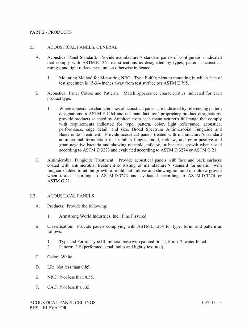
ACOUSTICAL PANEL CEILINGS 095113 - 3 BHS – ELEVATOR
PART 2 - PRODUCTS
2.1 ACOUSTICAL PANELS, GENERAL
A. Acoustical Panel Standard: Provide manufacturer's standard panels of configuration indicated that comply with ASTM E 1264 classifications as designated by types, patterns, acoustical ratings, and light reflectances, unless otherwise indicated.
1. Mounting Method for Measuring NRC: Type E-400; plenum mounting in which face of test specimen is 15-3/4 inches away from test surface per ASTM E 795.
B. Acoustical Panel Colors and Patterns: Match appearance characteristics indicated for each product type.
1. Where appearance characteristics of acoustical panels are indicated by referencing pattern designations in ASTM E 1264 and not manufacturers' proprietary product designations, provide products selected by Architect from each manufacturer's full range that comply with requirements indicated for type, pattern, color, light reflectance, acoustical performance, edge detail, and size. Broad Spectrum Antimicrobial Fungicide and Bactericide Treatment: Provide acoustical panels treated with manufacturer's standard antimicrobial formulation that inhibits fungus, mold, mildew, and gram-positive and gram-negative bacteria and showing no mold, mildew, or bacterial growth when tested according to ASTM D 3273 and evaluated according to ASTM D 3274 or ASTM G 21.
C. Antimicrobial Fungicide Treatment: Provide acoustical panels with face and back surfaces coated with antimicrobial treatment consisting of manufacturer's standard formulation with fungicide added to inhibit growth of mold and mildew and showing no mold or mildew growth when tested according to ASTM D 3273 and evaluated according to ASTM D 3274 or ASTM G 21.
2.2 ACOUSTICAL PANELS
A. Products: Provide the following:
1. Armstrong World Industries, Inc.; Fine Fissured.
B. Classification: Provide panels complying with ASTM E 1264 for type, form, and pattern as follows:
1. Type and Form: Type III, mineral base with painted finish; Form 2, water felted. 2. Pattern: CE (perforated, small holes and lightly textured).
C. Color: White.
D. LR: Not less than 0.85.
E. NRC: Not less than 0.55.
F. CAC: Not less than 35.
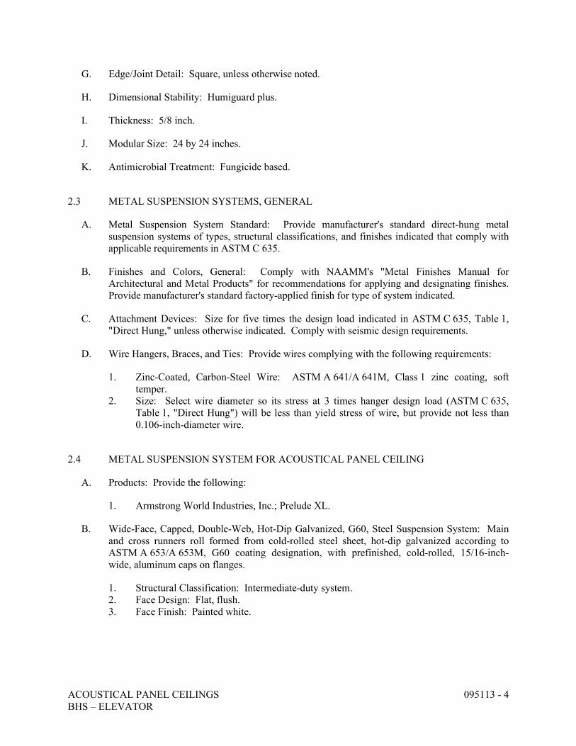
ACOUSTICAL PANEL CEILINGS 095113 - 4 BHS – ELEVATOR
G. Edge/Joint Detail: Square, unless otherwise noted.
H. Dimensional Stability: Humiguard plus.
I. Thickness: 5/8 inch.
J. Modular Size: 24 by 24 inches.
K. Antimicrobial Treatment: Fungicide based.
2.3 METAL SUSPENSION SYSTEMS, GENERAL
A. Metal Suspension System Standard: Provide manufacturer's standard direct-hung metal suspension systems of types, structural classifications, and finishes indicated that comply with applicable requirements in ASTM C 635.
B. Finishes and Colors, General: Comply with NAAMM's "Metal Finishes Manual for Architectural and Metal Products" for recommendations for applying and designating finishes. Provide manufacturer's standard factory-applied finish for type of system indicated.
C. Attachment Devices: Size for five times the design load indicated in ASTM C 635, Table 1, "Direct Hung," unless otherwise indicated. Comply with seismic design requirements.
D. Wire Hangers, Braces, and Ties: Provide wires complying with the following requirements:
1. Zinc-Coated, Carbon-Steel Wire: ASTM A 641/A 641M, Class 1 zinc coating, soft temper.
2. Size: Select wire diameter so its stress at 3 times hanger design load (ASTM C 635, Table 1, "Direct Hung") will be less than yield stress of wire, but provide not less than 0.106-inch-diameter wire.
2.4 METAL SUSPENSION SYSTEM FOR ACOUSTICAL PANEL CEILING
A. Products: Provide the following:
1. Armstrong World Industries, Inc.; Prelude XL.
B. Wide-Face, Capped, Double-Web, Hot-Dip Galvanized, G60, Steel Suspension System: Main and cross runners roll formed from cold-rolled steel sheet, hot-dip galvanized according to ASTM A 653/A 653M, G60 coating designation, with prefinished, cold-rolled, 15/16-inch- wide, aluminum caps on flanges.
1. Structural Classification: Intermediate-duty system. 2. Face Design: Flat, flush. 3. Face Finish: Painted white.

ACOUSTICAL PANEL CEILINGS 095113 - 5 BHS – ELEVATOR
2.5 METAL EDGE MOLDINGS AND TRIM
A. Roll-Formed, Sheet-Metal Edge Moldings and Trim: Type and profile indicated or, if not indicated, manufacturer's standard moldings for edges and penetrations; formed from sheet metal of same material, finish, and color as that used for exposed flanges of suspension system runners.
1. Provide manufacturer's standard edge moldings that fit acoustical panel edge details and suspension systems indicated and that match width and configuration of exposed runners, unless otherwise indicated.
2. For lay-in panels with reveal edge details, provide stepped edge molding that forms reveal of same depth and width as that formed between edge of panel and flange at exposed suspension member.
PART 3 - EXECUTION
3.1 EXAMINATION
A. Examine substrates, areas, and conditions, including structural framing to which acoustical panel ceilings attach or abut, with Installer present, for compliance with requirements specified in this and other Sections that affect ceiling installation and anchorage and with requirements for installation tolerances and other conditions affecting performance of acoustical panel ceilings.
1. Proceed with installation only after unsatisfactory conditions have been corrected.
3.2 PREPARATION
A. Measure each ceiling area and establish layout of acoustical panels to balance border widths at opposite edges of each ceiling. Avoid using less-than-half-width panels at borders, and comply with layout shown on reflected ceiling plans.
3.3 INSTALLATION
A. General: Install acoustical panel ceilings to comply with ASTM C 636 and seismic design requirements indicated, per manufacturer's written instructions and CISCA's "Ceiling Systems Handbook."
1. Fire-Rated Assembly: Install fire-rated ceiling systems according to tested fire-rated design.
B. Suspend ceiling hangers from building's structural members and as follows:
1. Install hangers plumb and free from contact with insulation or other objects within ceiling plenum that are not part of supporting structure or of ceiling suspension system.
2. Splay hangers only where required to miss obstructions; offset resulting horizontal forces by bracing, countersplaying, or other equally effective means.
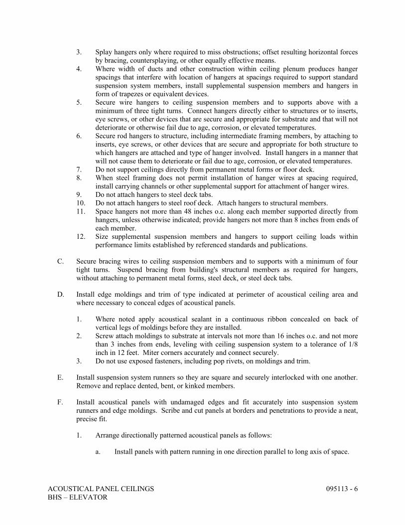
ACOUSTICAL PANEL CEILINGS 095113 - 6 BHS – ELEVATOR
3. Splay hangers only where required to miss obstructions; offset resulting horizontal forces by bracing, countersplaying, or other equally effective means.
4. Where width of ducts and other construction within ceiling plenum produces hanger spacings that interfere with location of hangers at spacings required to support standard suspension system members, install supplemental suspension members and hangers in form of trapezes or equivalent devices.
5. Secure wire hangers to ceiling suspension members and to supports above with a minimum of three tight turns. Connect hangers directly either to structures or to inserts, eye screws, or other devices that are secure and appropriate for substrate and that will not deteriorate or otherwise fail due to age, corrosion, or elevated temperatures.
6. Secure rod hangers to structure, including intermediate framing members, by attaching to inserts, eye screws, or other devices that are secure and appropriate for both structure to which hangers are attached and type of hanger involved. Install hangers in a manner that will not cause them to deteriorate or fail due to age, corrosion, or elevated temperatures.
7. Do not support ceilings directly from permanent metal forms or floor deck. 8. When steel framing does not permit installation of hanger wires at spacing required,
install carrying channels or other supplemental support for attachment of hanger wires. 9. Do not attach hangers to steel deck tabs. 10. Do not attach hangers to steel roof deck. Attach hangers to structural members. 11. Space hangers not more than 48 inches o.c. along each member supported directly from
hangers, unless otherwise indicated; provide hangers not more than 8 inches from ends of each member.
12. Size supplemental suspension members and hangers to support ceiling loads within performance limits established by referenced standards and publications.
C. Secure bracing wires to ceiling suspension members and to supports with a minimum of four tight turns. Suspend bracing from building's structural members as required for hangers, without attaching to permanent metal forms, steel deck, or steel deck tabs.
D. Install edge moldings and trim of type indicated at perimeter of acoustical ceiling area and where necessary to conceal edges of acoustical panels.
1. Where noted apply acoustical sealant in a continuous ribbon concealed on back of vertical legs of moldings before they are installed.
2. Screw attach moldings to substrate at intervals not more than 16 inches o.c. and not more than 3 inches from ends, leveling with ceiling suspension system to a tolerance of 1/8 inch in 12 feet. Miter corners accurately and connect securely.
3. Do not use exposed fasteners, including pop rivets, on moldings and trim.
E. Install suspension system runners so they are square and securely interlocked with one another. Remove and replace dented, bent, or kinked members.
F. Install acoustical panels with undamaged edges and fit accurately into suspension system runners and edge moldings. Scribe and cut panels at borders and penetrations to provide a neat, precise fit.
1. Arrange directionally patterned acoustical panels as follows:
a. Install panels with pattern running in one direction parallel to long axis of space.
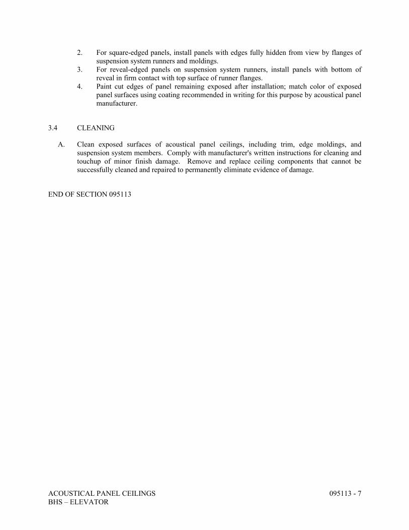
ACOUSTICAL PANEL CEILINGS 095113 - 7 BHS – ELEVATOR
2. For square-edged panels, install panels with edges fully hidden from view by flanges of suspension system runners and moldings.
3. For reveal-edged panels on suspension system runners, install panels with bottom of reveal in firm contact with top surface of runner flanges.
4. Paint cut edges of panel remaining exposed after installation; match color of exposed panel surfaces using coating recommended in writing for this purpose by acoustical panel manufacturer.
3.4 CLEANING
A. Clean exposed surfaces of acoustical panel ceilings, including trim, edge moldings, and suspension system members. Comply with manufacturer's written instructions for cleaning and touchup of minor finish damage. Remove and replace ceiling components that cannot be successfully cleaned and repaired to permanently eliminate evidence of damage.
END OF SECTION 095113
RESILIENT BASE AND ACCESSORIES 096513 - 1 BHS – ELEVATOR
SECTION 096513 - RESILIENT BASE AND ACCESSORIES
PART 1 - GENERAL
1.1 RELATED DOCUMENTS
A. Drawings and general provisions of the Contract, including General and Supplementary Conditions and Division 01 Specification Sections, apply to this Section.
1.2 SUMMARY
A. Section Includes:
1. Resilient base. 2. Resilient molding accessories.
B. Related Sections:
1. Division 09 Section "Resilient Tile Flooring" for resilient floor tile.
1.3 SUBMITTALS
A. Product Data: For each type of product indicated.
B. Samples for Initial Selection: For each type of product indicated.
C. Samples for Verification: For each type of product indicated, in manufacturer's standard-size Samples but not less than 12 inches long, of each resilient product color, texture, and pattern required.
D. Product Schedule: For resilient products. Use same designations indicated on Drawings.
1.4 QUALITY ASSURANCE
A. Fire-Test-Response Characteristics: As determined by testing identical products according to ASTM E 648 or NFPA 253 by a qualified testing agency.
1. Critical Radiant Flux Classification: Class I, not less than 0.45 W/sq. cm.
1.5 DELIVERY, STORAGE, AND HANDLING
A. Store resilient products and installation materials in dry spaces protected from the weather, with ambient temperatures maintained within range recommended by manufacturer, but not less than 50 deg F or more than 90 deg F.
RESILIENT BASE AND ACCESSORIES 096513 - 2 BHS – ELEVATOR
1.6 PROJECT CONDITIONS
A. Maintain ambient temperatures within range recommended by manufacturer, but not less than 70 deg F or more than 95 deg F, in spaces to receive resilient products during the following time periods:
1. 48 hours before installation. 2. During installation. 3. 48 hours after installation.
B. Until Substantial Completion, maintain ambient temperatures within range recommended by manufacturer, but not less than 55 deg F or more than 95 deg F.
C. Install resilient products after other finishing operations, including painting, have been completed.
1.7 EXTRA MATERIALS
A. Furnish extra materials that match products installed and that are packaged with protective covering for storage and identified with labels describing contents.
1. Furnish not less than 10 linear feet for every 500 linear feet or fraction thereof, of each type, color, pattern, and size of resilient product installed.
PART 2 - PRODUCTS
2.1 RESILIENT BASE
A. Resilient Base:
1. Manufacturer: Provide the following:
a. Roppe b. Mannington
B. Resilient Base Standard: ASTM F 1861.
1. Material Requirement: Type TS (rubber, vulcanized thermoset). 2. Manufacturing Method: Group I (solid, homogeneous). 3. Style: Cove (base with toe).
C. Minimum Thickness: 0.125 inch.
D. Height: 4 inches.
E. Lengths: Cut lengths 48 inches long or coils in manufacturer's standard length.
F. Outside Corners: Job formed or preformed.
RESILIENT BASE AND ACCESSORIES 096513 - 3 BHS – ELEVATOR
G. Inside Corners: Job formed or preformed.
H. Finish: Low luster.
I. Colors and Patterns: To be selected by Owner.
2.2 RESILIENT MOLDING ACCESSORY
A. Resilient Molding Accessory:
1. Manufacturer: Provide the following:
a. Mannington
b. Roppe
B. Description: Reducer strip for resilient floor covering.
C. Material: Rubber.
D. Profile and Dimensions: As indicated.
E. Colors and Patterns: Match rubber base.
2.3 INSTALLATION MATERIALS
A. Trowelable Leveling and Patching Compounds: Latex-modified, portland cement based or blended hydraulic-cement-based formulation provided or approved by manufacturer for applications indicated.
B. Adhesives: Water-resistant type recommended by manufacturer to suit resilient products and substrate conditions indicated.
C. Floor Polish: Provide protective liquid floor polish products as recommended by resilient stair tread manufacturer.
PART 3 - EXECUTION
3.1 EXAMINATION
A. Examine substrates, with Installer present, for compliance with requirements for maximum moisture content and other conditions affecting performance of the Work.
B. Verify that finishes of substrates comply with tolerances and other requirements specified in other Sections and that substrates are free of cracks, ridges, depressions, scale, and foreign deposits that might interfere with adhesion of resilient products.
C. Proceed with installation only after unsatisfactory conditions have been corrected.
RESILIENT BASE AND ACCESSORIES 096513 - 4 BHS – ELEVATOR
3.2 PREPARATION
A. Prepare substrates according to manufacturer's written instructions to ensure adhesion of resilient products.
B. Fill cracks, holes, and depressions in substrates with trowelable leveling and patching compound and remove bumps and ridges to produce a uniform and smooth substrate.
C. Do not install resilient products until they are same temperature as the space where they are to be installed.
1. Move resilient products and installation materials into spaces where they will be installed at least 48 hours in advance of installation.
D. Sweep and vacuum clean substrates to be covered by resilient products immediately before installation.
3.3 RESILIENT BASE INSTALLATION
A. Comply with manufacturer's written instructions for installing resilient base.
B. Apply resilient base to walls, columns, pilasters, casework and cabinets in toe spaces, and other permanent fixtures in rooms and areas where base is required.
C. Install resilient base in lengths as long as practicable without gaps at seams and with tops of adjacent pieces aligned.
D. Tightly adhere resilient base to substrate throughout length of each piece, with base in continuous contact with horizontal and vertical substrates.
E. Do not stretch resilient base during installation.
F. On masonry surfaces or other similar irregular substrates, fill voids along top edge of resilient base with manufacturer's recommended adhesive filler material.
G. Preformed Corners: Install preformed corners before installing straight pieces.
H. Job-Formed Corners:
1. Outside Corners: Use straight pieces of maximum lengths possible. Form without producing discoloration (whitening) at bends.
2. Inside Corners: Use straight pieces of maximum lengths possible.
3.4 RESILIENT ACCESSORY INSTALLATION
A. Comply with manufacturer's written instructions for installing resilient accessories.
B. Resilient Molding Accessories: Butt to adjacent materials and tightly adhere to substrates throughout length of each piece. Install reducer strips at edges of resilient floor covering that would otherwise be exposed.
RESILIENT BASE AND ACCESSORIES 096513 - 5 BHS – ELEVATOR
3.5 CLEANING AND PROTECTION
A. Comply with manufacturer's written instructions for cleaning and protection of resilient products.
B. Perform the following operations immediately after completing resilient product installation:
1. Remove adhesive and other blemishes from exposed surfaces. 2. Sweep and vacuum surfaces thoroughly. 3. Damp-mop surfaces to remove marks and soil.
C. Protect resilient products from mars, marks, indentations, and other damage from construction operations and placement of equipment and fixtures during remainder of construction period.
D. Cover resilient products until Substantial Completion.
END OF SECTION 096513
RESILIENT TILE FLOORING 096519 - 1 BHS – ELEVATOR
SECTION 096519 - RESILIENT TILE FLOORING
PART 1 - GENERAL
1.1 RELATED DOCUMENTS
A. Drawings and general provisions of the Contract, including General and Supplementary Conditions and Division 01 Specification Sections, apply to this Section.
1.2 SUMMARY
A. Section Includes:
1. Vinyl composition floor tile.
B. Related Sections:
1. Division 09 Section "Resilient Base and Accessories" for resilient base, reducer strips, and other accessories installed with resilient floor coverings.
1.3 SUBMITTALS
A. Product Data: For each type of product indicated.
B. Shop Drawings: For each type of floor tile. Include floor tile layouts, edges, columns, doorways, enclosing partitions, built-in furniture, cabinets, and cutouts. Submit drawings showing layout of all custom water jet designs.
1. Show details of special patterns.
C. Samples for Verification: Full-size units of each color and pattern of floor tile required.
D. Product Schedule: For floor tile. Use same designations indicated on Drawings.
E. Maintenance Data: For each type of floor tile to include in maintenance manuals.
1.4 QUALITY ASSURANCE
A. Fire-Test-Response Characteristics: As determined by testing identical products according to ASTM E 648 or NFPA 253 by a qualified testing agency.
1. Critical Radiant Flux Classification: Class I, not less than 0.45 W/sq. cm.
RESILIENT TILE FLOORING 096519 - 2 BHS – ELEVATOR
1.5 DELIVERY, STORAGE, AND HANDLING
A. Store floor tile and installation materials in dry spaces protected from the weather, with ambient temperatures maintained within range recommended by manufacturer, but not less than 50 deg F or more than 90 deg F. Store floor tiles on flat surfaces.
1.6 PROJECT CONDITIONS
A. Maintain ambient temperatures within range recommended by manufacturer, but not less than 70 deg F or more than 95 deg F, in spaces to receive floor tile during the following time periods:
1. 48 hours before installation. 2. During installation. 3. 48 hours after installation.
B. Until Substantial Completion, maintain ambient temperatures within range recommended by manufacturer, but not less than 55 deg F or more than 95 deg F.
C. Close spaces to traffic during floor tile installation.
D. Close spaces to traffic for 48 hours after floor tile installation.
E. Install floor tile after other finishing operations, including painting, have been completed.
1.7 EXTRA MATERIALS
A. Furnish extra materials that match products installed and that are packaged with protective covering for storage and identified with labels describing contents.
1. Floor Tile: Furnish 1 box for every 50 boxes or fraction thereof, of each type, color, and pattern of floor tile installed.
PART 2 - PRODUCTS
2.1 VINYL COMPOSITION FLOOR TILE
A. Products: Provide the following:
1. Armstrong World Industries, Inc.; Standard Excelon.
B. Tile Standard: ASTM F 1066, Class 2, through-pattern tile.
C. Wearing Surface: Smooth.
D. Thickness: 0.125 inch.
E. Size: 12 by 12 inches.
RESILIENT TILE FLOORING 096519 - 3 BHS – ELEVATOR
F. Colors and Patterns: To be selected by Owner.
2.2 INSTALLATION MATERIALS
A. Trowelable Leveling and Patching Compounds: Latex-modified, portland cement based or blended hydraulic-cement-based formulation provided or approved by manufacturer for applications indicated.
B. Adhesives: Water-resistant type recommended by manufacturer to suit floor tile and substrate conditions indicated.
C. Floor Polish: Provide protective liquid floor polish products as recommended by manufacturer.
PART 3 - EXECUTION
3.1 EXAMINATION
A. Examine substrates, with Installer present, for compliance with requirements for maximum moisture content and other conditions affecting performance of the Work.
B. Verify that finishes of substrates comply with tolerances and other requirements specified in other Sections and that substrates are free of cracks, ridges, depressions, scale, and foreign deposits that might interfere with adhesion of floor tile.
C. Proceed with installation only after unsatisfactory conditions have been corrected.
3.2 PREPARATION
A. Prepare substrates according to manufacturer's written instructions to ensure adhesion of resilient products.
B. Concrete Substrates: Prepare according to ASTM F 710.
1. Verify that substrates are dry and free of curing compounds, sealers, and hardeners. 2. Remove substrate coatings and other substances that are incompatible with adhesives and
that contain soap, wax, oil, or silicone, using mechanical methods recommended by manufacturer. Do not use solvents.
3. Alkalinity and Adhesion Testing: Perform tests recommended by manufacturer. Proceed with installation only after substrates pass testing.
4. Moisture Testing: Perform tests recommended by manufacturer and as follows. Proceed with installation only after substrates pass testing.
a. Perform anhydrous calcium chloride test, ASTM F 1869. Proceed with installation only after substrates have maximum moisture-vapor-emission rate of 3 lb of water/1000 sq. ft. in 24 hours.
C. Fill cracks, holes, and depressions in substrates with trowelable leveling and patching compound and remove bumps and ridges to produce a uniform and smooth substrate.
RESILIENT TILE FLOORING 096519 - 4 BHS – ELEVATOR
D. Do not install floor tiles until they are same temperature as space where they are to be installed.
1. Move resilient products and installation materials into spaces where they will be installed at least 48 hours in advance of installation.
E. Sweep and vacuum clean substrates to be covered by resilient products immediately before installation.
F. In the base bid provide leveling/patching up to 100% of the total square footage of the renovated areas of existing building consisting of three coats of sand and patch prior to installing VCT.
3.3 FLOOR TILE INSTALLATION
A. Comply with manufacturer's written instructions for installing floor tile.
B. Lay out floor tiles from center marks established with principal walls, discounting minor offsets, so tiles at opposite edges of room are of equal width. Adjust as necessary to avoid using cut widths that equal less than one-half tile at perimeter.
1. Lay tiles in pattern indicated.
C. Match floor tiles for color and pattern by selecting tiles from cartons in the same sequence as manufactured and packaged, if so numbered. Discard broken, cracked, chipped, or deformed tiles.
1. Lay tiles with grain direction alternating in adjacent tiles (basket-weave pattern) and in pattern of colors and sizes indicated.
D. Scribe, cut, and fit floor tiles to butt neatly and tightly to vertical surfaces and permanent fixtures including built-in furniture, cabinets, pipes, outlets, and door frames.
E. Extend floor tiles into toe spaces, door reveals, closets, and similar openings. Extend floor tiles to center of door openings.
F. Install floor tiles on covers for telephone and electrical ducts, building expansion-joint covers, and similar items in finished floor areas. Maintain overall continuity of color and pattern between pieces of tile installed on covers and adjoining tiles. Tightly adhere tile edges to substrates that abut covers and to cover perimeters.
G. Adhere floor tiles to flooring substrates using a full spread of adhesive applied to substrate to produce a completed installation without open cracks, voids, raising and puckering at joints, telegraphing of adhesive spreader marks, and other surface imperfections.
3.4 CLEANING AND PROTECTION
A. Comply with manufacturer's written instructions for cleaning and protection of floor tile.
B. Perform the following operations immediately after completing floor tile installation:
RESILIENT TILE FLOORING 096519 - 5 BHS – ELEVATOR
1. Remove adhesive and other blemishes from exposed surfaces. 2. Sweep and vacuum surfaces thoroughly. 3. Damp-mop surfaces to remove marks and soil.
C. Protect floor tile products from mars, marks, indentations, and other damage from construction operations and placement of equipment and fixtures during remainder of construction period.
D. Floor Polish: Remove soil, visible adhesive, and surface blemishes from floor tile surfaces before applying liquid floor polish.
1. Apply five coats of floor polish. 2. Provide same floor polish owner currently uses.
E. Cover floor tile until Substantial Completion.
END OF SECTION 096519
INTERIOR PAINTING 099123 - 1 BHS – ELEVATOR
SECTION 099123 - INTERIOR PAINTING
PART 1 - GENERAL
1.1 RELATED DOCUMENTS
A. Drawings and general provisions of the Contract, including General and Supplementary Conditions and Division 01 Specification Sections, apply to this Section.
1.2 SUMMARY
A. This Section includes surface preparation and the application of paint systems on the following interior substrates: 1. Concrete masonry units (CMU). 2. Steel.
B. Related Sections include the following:
1. Division 05 Sections for shop priming of metal substrates with primers specified in this Section.
1.3 SUBMITTALS
A. Product Data: For each type of product indicated.
B. Samples for Initial Selection: For each type of topcoat product indicated.
C. Product List: For each product indicated, include the following:
1. Cross-reference to paint system and locations of application areas. Use same designations indicated on Drawings and in schedules.
2. Printout of current "MPI Approved Products List" for each product category specified in Part 2, with the proposed product highlighted.
1.4 QUALITY ASSURANCE
A. MPI Standards:
1. Products: Complying with MPI standards indicated and listed in "MPI Approved Products List."
2. Preparation and Workmanship: Comply with requirements in "MPI Architectural Painting Specification Manual" for products and paint systems indicated.
B. Mockups: Apply benchmark samples of each paint system indicated and each color and finish selected to verify preliminary selections made under sample submittals and to demonstrate aesthetic effects and set quality standards for materials and execution.
INTERIOR PAINTING 099123 - 2 BHS – ELEVATOR
1. Architect will select one surface to represent surfaces and conditions for application of each paint system specified in Part 3.
a. Wall and Ceiling Surfaces: Provide samples of at least 100 sq. ft. b. Other Items: Architect will designate items or areas required.
2. Apply benchmark samples after permanent lighting and other environmental services have been activated.
3. Final approval of color selections will be based on benchmark samples.
a. If preliminary color selections are not approved, apply additional benchmark samples of additional colors selected by Architect at no added cost to Owner.
1.5 DELIVERY, STORAGE, AND HANDLING
A. Store materials not in use in tightly covered containers in well-ventilated areas with ambient temperatures continuously maintained at not less than 45 deg F.
1. Maintain containers in clean condition, free of foreign materials and residue. 2. Remove rags and waste from storage areas daily.
1.6 PROJECT CONDITIONS
A. Apply paints only when temperature of surfaces to be painted and ambient air temperatures are between 50 and 95 deg F.
B. Do not apply paints when relative humidity exceeds 85 percent; at temperatures less than 5 deg F above the dew point; or to damp or wet surfaces.
1.7 EXTRA MATERIALS
A. Furnish extra materials described below that are from same production run (batch mix) as materials applied and that are packaged for storage and identified with labels describing contents.
1. Quantity: Furnish an additional 5 percent, but not less than 1 gal. of each material and color applied.
PART 2 - PRODUCTS
2.1 MANUFACTURERS
A. Available Manufacturers: Subject to compliance with requirements, manufacturers offering products that may be incorporated into the Work include, but are not limited to, the following:
1. Benjamin Moore & Co. 2. Duron, Inc.
INTERIOR PAINTING 099123 - 3 BHS – ELEVATOR
3. ICI Paints. 4. Kelly-Moore Paints. 5. M.A.B. Paints. 6. PPG Architectural Finishes, Inc. 7. Sherwin-Williams Company (The).
2.2 PAINT, GENERAL
A. Material Compatibility:
1. Provide materials for use within each paint system that are compatible with one another and substrates indicated, under conditions of service and application as demonstrated by manufacturer, based on testing and field experience.
2. For each coat in a paint system, provide products recommended in writing by manufacturers of topcoat for use in paint system and on substrate indicated.
B. VOC Content of Field-Applied Interior Paints and Coatings: Provide products that comply with the following limits for VOC content, exclusive of colorants added to a tint base, when calculated according to 40 CFR 59, Subpart D (EPA Method 24); these requirements do not apply to paints and coatings that are applied in a fabrication or finishing shop:
1. Flat Paints, Coatings, and Primers: VOC content of not more than 50 g/L. 2. Nonflat Paints, Coatings, and Primers: VOC content of not more than 150 g/L. 3. Flat Topcoat Paints: VOC content of not more than 50 g/L. 4. Nonflat Topcoat Paints: VOC content of not more than 150 g/L. 5. Primers, Sealers, and Undercoaters: VOC content of not more than 200 g/L.
C. Colors: As selected by Architect from manufacturer's full range.
2.3 BLOCK FILLERS
A. Interior/Exterior Latex Block Filler: MPI #4.
1. VOC Content: E Range of E2.
2.4 PRIMERS/SEALERS
A. Interior Latex Primer/Sealer: MPI #50.
1. VOC Content: E Range of E2. 2. Environmental Performance Rating: EPR 2.
2.5 METAL PRIMERS
A. Alkyd Anticorrosive Metal Primer: MPI #79.
INTERIOR PAINTING 099123 - 4 BHS – ELEVATOR
1. VOC Content: E Range of E1.
B. Waterborne Galvanized-Metal Primer: MPI #134.
1. VOC Content: E Range of E3. 2. Environmental Performance Rating: EPR 3.
2.6 LATEX PAINTS
A. Interior Latex (Flat): MPI #53 (Gloss Level 1).
1. VOC Content: E Range of E2. 2. Environmental Performance Rating: EPR 1.5.
B. High-Performance Architectural Latex (Eggshell): MPI #139 (Gloss Level 3).
1. VOC Content: E Range of E2. 2. Environmental Performance Rating: EPR 5.
C. High-Performance Architectural Latex (Semigloss): MPI #141 (Gloss Level 5).
1. VOC Content: E Range of E1. 2. Environmental Performance Rating: EPR 5.
PART 3 - EXECUTION
3.1 EXAMINATION
A. Examine substrates and conditions, with Applicator present, for compliance with requirements for maximum moisture content and other conditions affecting performance of work.
B. Maximum Moisture Content of Substrates: When measured with an electronic moisture meter as follows:
1. Masonry (Clay and CMU): 12 percent.
C. Verify suitability of substrates, including surface conditions and compatibility with existing finishes and primers.
D. Begin coating application only after unsatisfactory conditions have been corrected and surfaces are dry.
1. Beginning coating application constitutes Contractor's acceptance of substrates and conditions.
INTERIOR PAINTING 099123 - 5 BHS – ELEVATOR
3.2 PREPARATION
A. Comply with manufacturer's written instructions and recommendations in "MPI Architectural Painting Specification Manual" applicable to substrates indicated.
B. Remove plates, machined surfaces, and similar items already in place that are not to be painted. If removal is impractical or impossible because of size or weight of item, provide surface-applied protection before surface preparation and painting.
1. After completing painting operations, use workers skilled in the trades involved to reinstall items that were removed. Remove surface-applied protection if any.
2. Do not paint over labels of independent testing agencies or equipment name, identification, performance rating, or nomenclature plates.
C. Clean substrates of substances that could impair bond of paints, including dirt, oil, grease, and incompatible paints and encapsulants.
1. Remove incompatible primers and reprime substrate with compatible primers as required to produce paint systems indicated.
D. Concrete Masonry Substrates: Remove efflorescence and chalk. Do not paint surfaces if moisture content or alkalinity of surfaces to be painted exceeds that permitted in manufacturer's written instructions.
E. Steel Substrates: Remove rust and loose mill scale. Clean using methods recommended in writing by paint manufacturer.
3.3 APPLICATION
A. Apply paints according to manufacturer's written instructions.
1. Use applicators and techniques suited for paint and substrate indicated. 2. Paint surfaces behind movable equipment and furniture same as similar exposed surfaces.
Before final installation, paint surfaces behind permanently fixed equipment or furniture with prime coat only.
3. Paint front and backsides of access panels, removable or hinged covers, and similar hinged items to match exposed surfaces.
B. Tint each undercoat a lighter shade to facilitate identification of each coat if multiple coats of same material are to be applied. Tint undercoats to match color of topcoat, but provide sufficient difference in shade of undercoats to distinguish each separate coat.
C. If undercoats or other conditions show through topcoat, apply additional coats until cured film has a uniform paint finish, color, and appearance.
D. Apply paints to produce surface films without cloudiness, spotting, holidays, laps, brush marks, roller tracking, runs, sags, ropiness, or other surface imperfections. Cut in sharp lines and color breaks.
INTERIOR PAINTING 099123 - 6 BHS – ELEVATOR
E. Painting Mechanical and Electrical Work: Paint items exposed in equipment rooms and occupied spaces including, but not limited to, the following:
1. Mechanical work:
a. Visible portions of internal surfaces of metal ducts, without liner, behind air inlets and outlets.
b. Duct, equipment, and pipe insulation having cotton or canvas insulation covering or other paintable jacket material.
c. Mechanical equipment that is indicated to have a factory-primed finish for field painting.
2. Electrical work: a. Exposed conduit and plywood backing panels.
3.4 FIELD QUALITY CONTROL
A. Testing of Paint Materials: Owner reserves the right to invoke the following procedure at any time and as often as Owner deems necessary during the period when paints are being applied:
1. Owner will engage the services of a qualified testing agency to sample paint materials being used. Samples of material delivered to Project site will be taken, identified, sealed, and certified in presence of Contractor.
2. Testing agency will perform tests for compliance of paint materials with product requirements.
3. Owner may direct Contractor to stop applying paints if test results show materials being used do not comply with product requirements. Contractor shall remove noncomplying-paint materials from Project site, pay for testing, and repaint surfaces painted with rejected materials. Contractor will be required to remove rejected materials from previously painted surfaces if, on repainting with complying materials, the two paints are incompatible.
3.5 CLEANING AND PROTECTION
A. At end of each workday, remove rubbish, empty cans, rags, and other discarded materials from Project site.
B. After completing paint application, clean spattered surfaces. Remove spattered paints by washing, scraping, or other methods. Do not scratch or damage adjacent finished surfaces.
C. Protect work of other trades against damage from paint application. Correct damage to work of other trades by cleaning, repairing, replacing, and refinishing, as approved by Architect, and leave in an undamaged condition.
D. At completion of construction activities of other trades, touch up and restore damaged or defaced painted surfaces.
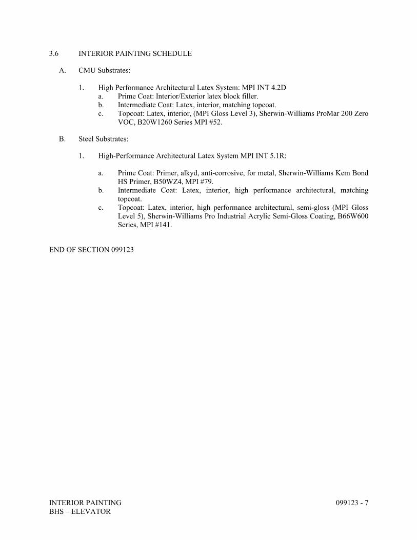
INTERIOR PAINTING 099123 - 7 BHS – ELEVATOR
3.6 INTERIOR PAINTING SCHEDULE
A. CMU Substrates:
1. High Performance Architectural Latex System: MPI INT 4.2D a. Prime Coat: Interior/Exterior latex block filler. b. Intermediate Coat: Latex, interior, matching topcoat. c. Topcoat: Latex, interior, (MPI Gloss Level 3), Sherwin-Williams ProMar 200 Zero
VOC, B20W1260 Series MPI #52.
B. Steel Substrates:
1. High-Performance Architectural Latex System MPI INT 5.1R:
a. Prime Coat: Primer, alkyd, anti-corrosive, for metal, Sherwin-Williams Kem Bond HS Primer, B50WZ4, MPI #79.
b. Intermediate Coat: Latex, interior, high performance architectural, matching topcoat.
c. Topcoat: Latex, interior, high performance architectural, semi-gloss (MPI Gloss Level 5), Sherwin-Williams Pro Industrial Acrylic Semi-Gloss Coating, B66W600 Series, MPI #141.
END OF SECTION 099123
GYMNASIUM EQUIPMENT BYHS – ELEVATOR
116623 - 1
SECTION 116623 - GYMNASIUM EQUIPMENT
PART 1 - GENERAL
1.1 SUMMARY
A. Section Includes:
1. Safety pads.
1.2 ACTION SUBMITTALS
A. Product Data: For each type of product.
B. Shop Drawings: For gymnasium equipment.
1. Include plans, elevations, sections, and attachment details.
C. Samples: For each exposed product and for each item and color specified.
1.3 QUALITY ASSURANCE
A. Installer Qualifications: An entity that employs installers and supervisors who are trained and approved by manufacturer.
1.4 WARRANTY
A. Special Warranty: Manufacturer agrees to repair or replace components of gymnasium equipment that fail in materials or workmanship within specified warranty period.
1. Warranty Period: Five years from date of Substantial Completion.
PART 2 - PRODUCTS
2.1 SAFETY PADS
A. Surface-Burning Characteristics: Comply with ASTM E84; testing by a qualified testing agency. Identify products with appropriate markings of applicable testing agency.
1. Flame-Spread Index: 25 or less. 2. Smoke-Developed Index: 450 or less.
B. Pad Coverings: Provide safety pad fabric covering that is fabricated from puncture- and tear-resistant, PVC-coated polyester or nylon-reinforced PVC fabric, minimum 14-oz./sq. yd. and
GYMNASIUM EQUIPMENT BYHS – ELEVATOR
116623 - 2
treated with fungicide for mildew resistance; with surface-burning characteristics indicated, and lined with fire-retardant liner.
C. Wall Safety Pads: Padded wall wainscot panels designed to be attached in a continuous row; each panel section consisting of fill laminated to backer board, with visible surfaces fully covered by seamless fabric covering, free of sag and wrinkles and firmly attached to back of backer board.
1. Backer Board: Minimum 3/8-inch- thick fire-retardant-treated plywood by pressure process according to AWPA U1, Use Category UCFA Fire Retardant Interior.
2. Fire-Resistive Fill: Multiple-impact-resistant foam minimum 2-inch- thick, fire-resistive neoprene, 6.0-lb/cu. ft. density.
3. Size: Each panel section 24 inches wide by minimum 72 inches long of manufacturer's standard dimensions.
4. Installation Method: Manufacturer's standard. 5. Fabric Covering Color(s): Match school colors as selected by Architect from
manufacturer's full range for two color(s).
PART 3 - EXECUTION
3.1 INSTALLATION, GENERAL
A. Comply with manufacturer's written installation instructions.
B. Permanently Placed Gymnasium Equipment and Components: Install rigid, level, plumb, square, and true; anchored securely to supporting structure; positioned at locations and elevations indicated; in proper relationship to adjacent construction; and aligned with court layout.
END OF SECTION 116623
HYDRAULIC PASSENGER ELEVATORS 142400-1 BHS – ELEVATOR
SECTION 142400 – HYDRAULIC PASSENGER ELEVATORS
PART 1 GENERAL
1.1 RELATED DOCUMENTS
A. Drawings and general provisions of the Contract, including General and Supplementary Conditions and Division 1 Specification Sections, apply to this Section.
1.2 SUMMARY
A. Section includes: Hydraulic passenger elevators as shown and specified. Elevator work includes: 1. Standard pre-engineered hydraulic passenger elevators. 2. Elevator car enclosures, hoistway entrances and signal equipment. 3. Operation and control systems. 4. Jack(s). 5. Accessibility provisions for physically disabled persons. 6. Equipment, machines, controls, systems and devices as required for safely operating the
specified elevators at their rated speed and capacity. 7. Materials and accessories as required to complete the elevator installation.
B. Related Sections:
1. Division 1 General Requirements: Meet or exceed all referenced sustainability requirements. 2. Division 3 Concrete: Installing inserts, sleeves and anchors in concrete. 3. Division 4 Masonry: Installing inserts, sleeves and anchors in masonry. 4. Division 5 Metals:
a. Providing hoist beams, pit ladders, steel framing, auxiliary support steel and divider beams for supporting guide-rail brackets.
b. Providing steel angle sill supports and grouting hoistway entrance sills and frames. 5. Division 9 Finishes: Providing elevator car finish flooring and field painting unfinished and
shop primed ferrous materials. 6. Division 16 Sections:
a. Providing electrical service to elevators, including fused disconnect switches. b. Emergency power supply, transfer switch and auxiliary contacts. c. Heat and smoke sensing devices. d. Convenience outlets and illumination in control room, hoistway and pit.
7. Division 22 Plumbing a. Sump pit and oil interceptor.
8. Division 23 Heating, Ventilation and Air Conditioning a. Heating and ventilating hoistways and/or control room.
C. General contractor shall provide the following in accordance with the requirements of the Model
Building Code and ANSI A17.1 Code. For specific rules, refer to ANSI A17.1, Part 3 for hydraulic elevators. State or local requirements must be used if more stringent. The cost of this work is not by the elevator subcontractor but is a part of the building construction by the General Contractor.
HYDRAULIC PASSENGER ELEVATORS 142400-2 BHS – ELEVATOR
1. Elevator hoist beam to be provided at top of elevator shaft. Beam must be able to accommodate proper loads and clearances for elevator installation and operation.
2. Supply in ample time for installation by other trades, inserts, anchors, bearing plates, brackets, supports and bracing including all setting templates and diagrams for placement.
3. Hatch walls require a minimum two hours of fire rating. Hoistway should be clear and plumb with variations not to exceed 1/2'' at any point.
4. Elevator hoistways shall have barricades, as required. 5. Install bevel guards at 75° on all recesses, projections or setbacks over 2'' (4'' for A17.1 2000
areas) except for loading or unloading. 6. Provide rail bracket supports at pit, each floor and roof. For guide rail bracket supports,
provide divider beams between hoistway at each floor and roof. 7. Pit floor shall be level and free of debris. Reinforce dry pit to sustain normal vertical forces
from rails and buffers. 8. Where pit access is by means of the lowest hoistway entrance, a vertical ladder of non-
combustible material extending 42'' minimum, (48'' minimum for A17.1-2000 areas) shall be provided at the same height, above sill of access door or handgrips.
9. Machine room to be enclosed and protected. 10. Machine Room temperature must be maintained between 55º and 90º F. 11. If machine room is remote from the elevator hoistway, clear access must be available above
the ceiling or metal/concrete raceways in floor for oil line and wiring duct from machine room.
12. Access to the machinery space and machine room must be in accordance with the governing authority or code.
13. Provide an 8” x 16” cutout through machine room wall, for oil line and wiring duct, coordinated with elevator contractor at the building site.
14. All wire and conduit should run remote from the hoistways. 15. When heat, smoke or combustion sensing devices are required, connect to elevator control
cabinet terminals. Contacts on the sensors should be sided for 12-volt D.C. 16. Install and furnish finished flooring in elevator cab. 17. Finished floors and entrance walls are not to be constructed until after sills and door frames
are in place. Consult elevator contractor for rough opening size. The general contractor shall supply the drywall framing so that the wall fire resistance rating is maintained, when drywall construction is used.
18. Where sheet rock or drywall construction is used for front walls, it shall be of sufficient strength to maintain the doors in true lateral alignment. Drywall contractor to coordinate with elevator contractor.
19. Before erection of rough walls and doors; erect hoistway sills, headers, and frames. After rough walls are finished; erect fascias and toe guards. Set sill level and slightly above finished floor at landings.
20. To maintain legal fire rating (masonry construction), door frames are to be anchored to walls and properly grouted in place.
21. The elevator wall shall interface with the hoistway entrance assembly and be in strict compliance with the elevator contractor's requirements.
22. General Contractor shall fill and grout around entrances, as required.
HYDRAULIC PASSENGER ELEVATORS 142400-3 BHS – ELEVATOR
23. Elevator sill supports shall be provided at each opening. 24. All walls and sill supports must be plumb where openings occur. 25. For applications with jack hole, free and clear access to the elevator pit area for the jack hole-
drilling rig is required. 26. Where jack hole is required, remove all spoils from jack hole drilling. 27. When not provided by Elevator Contractor, jack hole shall accommodate the jack unit. If
required, the jack hole is to be provided in strict accordance with the elevator contractor's shop drawings.
28. Locate a light fixture (200 lx / 19 fc) and convenience outlet in pit with switch located adjacent to the access door.
29. A light switch and fused disconnect switch for each elevator should be located inside the machine room adjacent to the door, where practical, per the National Electrical Code (NFPA No. 70).
30. For signal systems and power operated door: provide ground and branch wiring circuits, including main line switch.
31. For car light and fan: provide a feeder and branch wiring circuits, including main line switch. 32. Wall thickness may increase when fixtures are mounted in drywall. These requirements must
be coordinated between the general contractor and the elevator contractor. 33. Provide supports, patching and recesses to accommodate hall button boxes, signal fixtures,
etc. 34. Locate telephone and convenience outlet on control panel.
1.3 SUBMITTALS
A. Product data: When requested, the elevator contractor shall provide standard cab, entrance and signal fixture data to describe product for approval.
B. Shop drawings: 1. Show equipment arrangement in the corridor, pit, and hoistway and/or optional control room.
Provide plans, elevations, sections and details of assembly, erection, anchorage, and equipment location.
2. Indicate elevator system capacities, sizes, performances, safety features, finishes and other pertinent information.
3. Show floors served, travel distances, maximum loads imposed on the building structure at points of support and all similar considerations of the elevator work.
4. Indicate electrical power requirements and branch circuit protection device recommendations.
C. Powder Coat paint selection: Submit manufacturer’s standard selection charts for exposed finishes and materials.
D. Plastic laminate selection: Submit manufacturer’s standard selection charts for exposed finishes and materials.
E. Metal Finishes: Upon request, standard metal samples provided.
HYDRAULIC PASSENGER ELEVATORS 142400-4 BHS – ELEVATOR
F. Operation and maintenance data. Include the following: 1. Owner’s manuals and wiring diagrams. 2. Parts list, with recommended parts inventory.
1.4 QUALITY ASSURANCE
A. Manufacturer Qualifications: An approved manufacturer with minimum 15 years of experience in manufacturing, installing, and servicing elevators of the type required for the project. 1. The manufacturer of machines, controllers, signal fixtures, door operators cabs, entrances,
and all other major parts of elevator operating equipment. a. The major parts of the elevator equipment shall be manufactured by the installing
company, and not be an assembled system. 2. The manufacturer shall have a documented, on-going quality assurance program. 3. ISO-9001:2000 Manufacturer Certified 4. ISO-14001:2004 Environmental Management System Certified 5. LEED Gold certified elevator manufacturing facility.
B. Installer Qualifications: The manufacturer or an authorized agent of the manufacturer with not
less than 15 years of satisfactory experience installing elevators equal in character and performance to the project elevators.
C. Regulatory Requirements: 1. ASME A17.1 Safety Code for Elevators and Escalators, latest edition or as required by the
local building code. 2. Building Code: National. 3. NFPA 70 National Electrical Code. 4. NFPA 80 Fire Doors and Windows. 5. Americans with Disabilities Act - Accessibility Guidelines (ADAAG) 6. Section 407 in ICC A117.1, when required by local authorities 7. CAN/CSA C22.1 Canadian Electrical Code 8. CAN/CSA B44 Safety Code for Elevators and Escalators. 9. California Department of Public Health Standard Method V1.1–2010, CA Section 01350
D. Fire-rated entrance assemblies: Opening protective assemblies including frames, hardware, and
operation shall comply with ASTM E2074, CAN4-S104 (ULC-S104), UL10(b), and NFPA Standard 80. Provide entrance assembly units bearing Class B or 11/2-hour label by a Nationally Recognized Testing Laboratory (2-hour label in Canada).
E. Inspection and testing: 1. Elevator Installer shall obtain and pay for all required inspections, tests, permits and fees for
elevator installation. 2. Arrange for inspections and make required tests. 3. Deliver to the Owner upon completion and acceptance of elevator work.
HYDRAULIC PASSENGER ELEVATORS 142400-5 BHS – ELEVATOR
1.5 DELIVERY, STORAGE AND HANDLING
A. Manufacturing shall deliver elevator materials, components and equipment and the contractor is responsible to provide secure and safe storage on job site.
1.6 PROJECT CONDITIONS
A. Temporary Use: Elevators shall not be used for temporary service or for any other purpose during the construction period before Substantial Completion and acceptance by the purchaser unless agreed upon by Elevator Contractor and General Contractor with signed temporary agreement.
B. Provide the hole for the jack unit (if required by the type of jack provided), based on excavation through normal soil or clay which can be removed by manual digging or by standard truck-mounted regular drilling unit. Provide a casing if required to retain the walls of the hole. General contractor shall remove excavation spoils deposited in the elevator pit. 1. If a physical obstruction or hindrance is encountered below the ground surface, including
boulders, rock, gravel, wood, metal, pilings, sand, water, quick sand, caves, public utilities or any other foreign material, obtain written authorization to proceed with excavating using special excavation equipment.
2. Maintain a daily log of time and material costs involved. 3. Elevator contractor will be compensated on a time and material basis for additional costs
incurred after encountering the physical obstruction or hindrance, including the cost of the special excavation equipment.
1.7 WARRANTY
A. Warranty: Submit elevator manufacturer's standard written warranty agreeing to repair, restore or replace defects in elevator work materials and workmanship not due to ordinary wear and tear or improper use or care for 12 months after final acceptance.
1.8 MAINTENANCE
A. Furnish maintenance and call back service for a period of 12 months for each elevator after completion of installation or acceptance thereof by beneficial use, whichever is earlier, during normal working hours excluding callbacks. 1. Service shall consist of periodic examination of the equipment, adjustment, lubrication,
cleaning, supplies and parts to keep the elevators in proper operation. Maintenance work, including emergency call back repair service, shall be performed by trained employees of the elevator contractor during regular working hours.
2. Submit parts catalog and show evidence of local parts inventory with complete list of recommended spare parts. Parts shall be produced by manufacturer of original equipment.
3. Manufacturer shall have service office and full-time service personnel within a 100-mile radius of the project site.
HYDRAULIC PASSENGER ELEVATORS 142400-6 BHS – ELEVATOR
PART 2 PRODUCTS
2.1 MANUFACTURERS
A. Subject to compliance with requirements, provide products manufactured by Thyssenkrupp Elevator, Endura Hydraulic Elevator, or comparable products by one of the following: 1. Otis Elevator Co. 2. Dover Elevator Co.
2.2 MATERIALS, GENERAL
A. All Elevator Cab materials including frame, buttons, lighting, wall and ceiling assembly, laminates and carpet shall have an EPD and an HPD and shall meet the California Department of Public Health Standard Method V1.1–2010, CA Section 01350 as mentioned in 1.03.9 of this specification.
B. Colors, patterns, and finishes: As selected by the Architect from manufacturer's full range of standard colors, patterns, and finishes.
C. Steel: 1. Shapes and bars: Carbon. 2. Sheet: Cold-rolled steel sheet, commercial quality, Class 1, matte finish. 3. Finish: Factory-applied baked enamel for structural parts, powder coat for architectural parts.
Color selection must be based on elevator manufacture’s standard selections.
D. Plastic laminate: Decorative high-pressure type, complying with NEMA LD3, Type GP-50 General Purpose Grade, nominal 0.050" thickness. Laminate selection must be based on elevator manufacture’s standard selections.
E. Flooring by others.
2.3 HOISTWAY EQUIPMENT
A. Platform: Fabricated frame of formed or structural steel shapes, gusseted and rigidly welded with a wood sub-floor. Underside of the platform shall be fireproofed. The car platform shall be designed and fabricated to support one-piece loads weighing up to 25% of the rated capacity.
B. Sling: Steel stiles bolted or welded to a steel crosshead and bolstered with bracing members to remove strain from the car enclosure.
C. Guide Rails: Steel, omega shaped, fastened to the building structure with steel brackets.
D. Guides: Slide guides shall be mounted on top and bottom of the car.
HYDRAULIC PASSENGER ELEVATORS 142400-7 BHS – ELEVATOR
E. Buffers: Provide substantial buffers in the elevator pit. Mount buffers on continuous channels fastened to the elevator guide rail or securely anchored to the pit floor. Provide extensions if required by project conditions.
F. Jack: A jack unit shall be of sufficient size to lift the gross load the height specified. Factory test jack to ensure adequate strength and freedom from leakage. Brittle material, such as gray cast iron, is prohibited in the jack construction. Provide the following jack type: Twin post holeless telescopic 2-stage. Two jacks piped together, mounted one on each side of the car with each having two telescopic sections designed to extend in a synchronized manner when oil is pumped into the assembly. Each jack section will be guided from within the casing or the plunger assembly used to house the section. Each plunger shall have a high pressure sealing system which will not allow for seal movement or displacement during the course of operation. Each jack assembly shall have a check valve built into the assembly to allow for automatically re-syncing the two plunger sections by moving the jack to its fully contracted position. The jack shall be designed to be mounted on the pit floor or in a recess in the pit floor. Each jack section shall have a bleeder valve to discharge any air trapped in the section.
G. Automatic Self-Leveling: Provide each elevator car with a self-leveling feature to automatically bring the car to the floor landings and correct for over travel or under travel. Self-leveling shall, within its zone, be automatic and independent of the operating device. The car shall be maintained approximately level with the landing irrespective of its load.
H. Wiring, Piping, and Oil: Provide all necessary hoistway wiring in accordance with the National Electrical Code. All necessary code compliant pipe and fittings shall be provided to connect the power unit to the jack unit. theoiltype
2.4 POWER UNIT
A. Power Unit (Oil Pumping and Control Mechanism): A self-contained unit consisting of the following items: 1. An oil reservoir with tank cover. 2. An oil hydraulic pump. 3. An electric motor. 4. An oil control valve with the following components built into single housing; high pressure
relief valve, check valve, automatic unloading up start valve, lowering and leveling valve, and electro-magnetic controlling solenoids.
B. Pump: Positive displacement type pump specifically manufactured for oil-hydraulic elevator
service. Pump shall be designed for steady discharge with minimum pulsation to give smooth and quiet operation. Output of pump shall not vary more than 10 percent between no load and full load on the elevator car.
C. Motor: Standard manufacture motor specifically designed for oil-hydraulic elevator service. Duty rating shall be selected for specified speed and load.
HYDRAULIC PASSENGER ELEVATORS 142400-8 BHS – ELEVATOR
D. Oil Control Unit: The following components shall be built into a single housing. Welded
manifolds with separate valves to accomplish each function are not acceptable. Adjustments shall be accessible and be made without removing the assembly from the oil line. 1. Relief valve shall be adjustable and be capable of bypassing the total oil flow without
increasing back pressure more than 10 percent above that required to barely open the valve. 2. Up start and stop valve shall be adjustable and designed to bypass oil flow during start and
stop of motor pump assembly. Valve shall close slowly, gradually diverting oil to or from the jack unit, ensuring smooth up starts and up stops.
3. Check valve shall be designed to close quietly without permitting any perceptible reverse flow.
4. Lowering valve and leveling valve shall be adjustable for down start speed, lowering speed, leveling speed and stopping speed to ensure smooth "down" starts and stops. The leveling valve shall be designed to level the car to the floor in the direction the car is traveling after slowdown is initiated.
5. Provided with constant speed regulation in both up and down direction. Feature to compensate for load changes, oil temperature, and viscosity changes.
6. Solid State Starting: Provide an electronic starter featuring adjustable starting currents. 7. Oil Type: Provide a zinc free, inherently biodegradable lubricant formulated with premium
base stocks to provide outstanding protection for demanding hydraulic systems, especially those operating in environmentally sensitive areas.
2.5 HOISTWAY ENTRANCES
A. Doors and Frames: Provide complete hollow metal type hoistway entrances at each hoistway opening bolted\knock down construction. 1. Manufacturer's standard entrance design consisting of hangers, doors, hanger supports,
hanger covers, fascia plates (where required), sight guards, and necessary hardware. 2. Main landing door & frame finish: Stainless steel panels, no. 4 brushed finish. 3. Typical door & frame finish: Stainless steel panels, No. 4 brushed finish.
B. Interlocks: Equip each hoistway entrance with an approved type interlock tested as required by
code. Provide door restriction devices as required by code.
C. Door Hanger and Tracks: Provide sheave type two-point suspension hangers and tracks for each hoistway horizontal sliding door. 1. Sheaves: Polyurethane tires with ball bearings properly sealed to retain grease. 2. Hangers: Provide an adjustable device beneath the track to limit the up-thrust of the doors
during operation. 3. Tracks: Drawn steel shapes, smooth surface and shaped to conform to the hanger sheaves.
D. Hoistway Sills: Extruded metal, with groove(s) in top surface. Provide mill finish on aluminum.
HYDRAULIC PASSENGER ELEVATORS 142400-9 BHS – ELEVATOR
2.6 PASSENGER ELEVATOR CAR ENCLOSURE
A. Car Enclosure: 1. Walls: Cab type a steel shell design, reinforced cold-rolled steel with an applied panel
design. The applied panels design, shall be arranged vertically on wood core panels covered on both sides with high pressure plastic laminate.
2. Reveals and frieze: Stainless steel, No. 4 brushed finish 3. Canopy: Cold-rolled steel with hinged exit. 4. Ceiling: Suspended type, LED lighting with translucent diffuser mounted in a metal
frame. Framework shall be finished with a factory applied powder coat finish. 5. Cab Fronts, Return, Transom, Soffit and Strike: Provide panels faced with No. 4 brushed
stainless steel 6. Doors: Horizontal sliding car doors reinforced with steel for panel rigidity. Hang doors on
sheave type hangers with polyurethane tires that roll on a polished steel track and are guided at the bottom by non-metallic sliding guides. a. Door Finish: Stainless steel panels: No. 4 brushed finish.
b. Cab Sills: Extruded aluminum, mill finish. 7. Handrail: Provide 2'' flat metal bar on side and rear walls on front opening cars and side walls
only on front and rear opening cars. Handrails shall have a stainless steel, No. 4 brushed finish.
8. Ventilation: Manufacturer’s standard exhaust fan, mounted on the car top. 9. Protection pads and buttons: Provide one set of vinyl protection pads with metal grommets
for the project. Provide pad buttons on cab front(s) and walls.
B. Car Top Inspection: Provide a car top inspection station with an “Auto-Inspection” switch, an "emergency stop" switch, and constant pressure "up and down" direction and safety buttons to make the normal operating devices inoperative. The station shall give the inspector complete control of the elevator. The car top inspection station shall be mounted in the door operator assembly.
2.7 DOOR OPERATION
A. Door Operation: Provide a direct or alternating current motor driven heavy duty operator designed to operate the car and hoistway doors simultaneously. The door control system shall be digital closed loop and the closed loop circuit shall give constant feedback on the position and velocity of the elevator door. The motor torque shall be constantly adjusted to maintain the correct door speed based on its position and load. All adjustments and setup shall be through the computer based service tool. Door movements shall follow a field programmable speed pattern with smooth acceleration and deceleration at the ends of travel. The mechanical door operating mechanism shall be arranged for manual operation in event of power failure. Doors shall automatically open when the car arrives at the landing and automatically close after an adjustable time interval or when the car is dispatched to another landing. AC controlled units with oil checks, or other deviations are not acceptable.
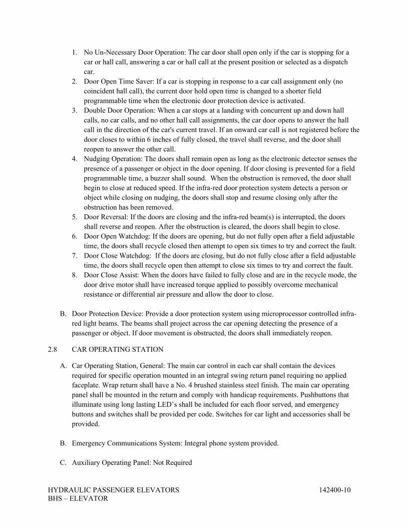
HYDRAULIC PASSENGER ELEVATORS 142400-10 BHS – ELEVATOR
1. No Un-Necessary Door Operation: The car door shall open only if the car is stopping for a car or hall call, answering a car or hall call at the present position or selected as a dispatch car.
2. Door Open Time Saver: If a car is stopping in response to a car call assignment only (no coincident hall call), the current door hold open time is changed to a shorter field programmable time when the electronic door protection device is activated.
3. Double Door Operation: When a car stops at a landing with concurrent up and down hall calls, no car calls, and no other hall call assignments, the car door opens to answer the hall call in the direction of the car's current travel. If an onward car call is not registered before the door closes to within 6 inches of fully closed, the travel shall reverse, and the door shall reopen to answer the other call.
4. Nudging Operation: The doors shall remain open as long as the electronic detector senses the presence of a passenger or object in the door opening. If door closing is prevented for a field programmable time, a buzzer shall sound. When the obstruction is removed, the door shall begin to close at reduced speed. If the infra-red door protection system detects a person or object while closing on nudging, the doors shall stop and resume closing only after the obstruction has been removed.
5. Door Reversal: If the doors are closing and the infra-red beam(s) is interrupted, the doors shall reverse and reopen. After the obstruction is cleared, the doors shall begin to close.
6. Door Open Watchdog: If the doors are opening, but do not fully open after a field adjustable time, the doors shall recycle closed then attempt to open six times to try and correct the fault.
7. Door Close Watchdog: If the doors are closing, but do not fully close after a field adjustable time, the doors shall recycle open then attempt to close six times to try and correct the fault.
8. Door Close Assist: When the doors have failed to fully close and are in the recycle mode, the door drive motor shall have increased torque applied to possibly overcome mechanical resistance or differential air pressure and allow the door to close.
B. Door Protection Device: Provide a door protection system using microprocessor controlled infra-
red light beams. The beams shall project across the car opening detecting the presence of a passenger or object. If door movement is obstructed, the doors shall immediately reopen.
2.8 CAR OPERATING STATION
A. Car Operating Station, General: The main car control in each car shall contain the devices required for specific operation mounted in an integral swing return panel requiring no applied faceplate. Wrap return shall have a No. 4 brushed stainless steel finish. The main car operating panel shall be mounted in the return and comply with handicap requirements. Pushbuttons that illuminate using long lasting LED’s shall be included for each floor served, and emergency buttons and switches shall be provided per code. Switches for car light and accessories shall be provided.
B. Emergency Communications System: Integral phone system provided.
C. Auxiliary Operating Panel: Not Required
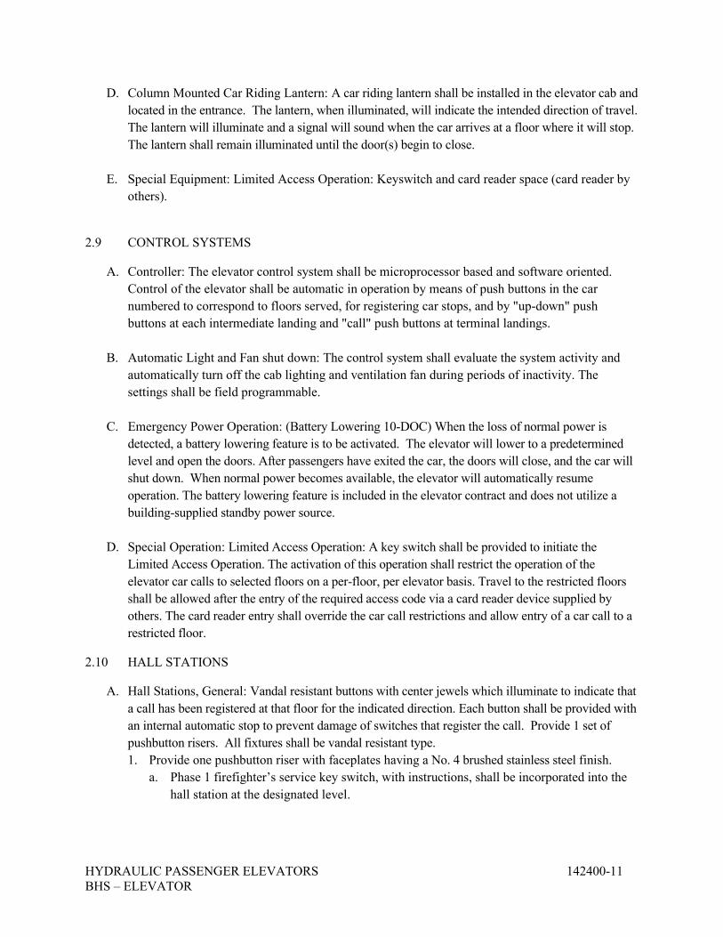
HYDRAULIC PASSENGER ELEVATORS 142400-11 BHS – ELEVATOR
D. Column Mounted Car Riding Lantern: A car riding lantern shall be installed in the elevator cab and located in the entrance. The lantern, when illuminated, will indicate the intended direction of travel. The lantern will illuminate and a signal will sound when the car arrives at a floor where it will stop. The lantern shall remain illuminated until the door(s) begin to close.
E. Special Equipment: Limited Access Operation: Keyswitch and card reader space (card reader by others).
2.9 CONTROL SYSTEMS
A. Controller: The elevator control system shall be microprocessor based and software oriented. Control of the elevator shall be automatic in operation by means of push buttons in the car numbered to correspond to floors served, for registering car stops, and by "up-down" push buttons at each intermediate landing and "call" push buttons at terminal landings.
B. Automatic Light and Fan shut down: The control system shall evaluate the system activity and automatically turn off the cab lighting and ventilation fan during periods of inactivity. The settings shall be field programmable.
C. Emergency Power Operation: (Battery Lowering 10-DOC) When the loss of normal power is detected, a battery lowering feature is to be activated. The elevator will lower to a predetermined level and open the doors. After passengers have exited the car, the doors will close, and the car will shut down. When normal power becomes available, the elevator will automatically resume operation. The battery lowering feature is included in the elevator contract and does not utilize a building-supplied standby power source.
D. Special Operation: Limited Access Operation: A key switch shall be provided to initiate the Limited Access Operation. The activation of this operation shall restrict the operation of the elevator car calls to selected floors on a per-floor, per elevator basis. Travel to the restricted floors shall be allowed after the entry of the required access code via a card reader device supplied by others. The card reader entry shall override the car call restrictions and allow entry of a car call to a restricted floor.
2.10 HALL STATIONS
A. Hall Stations, General: Vandal resistant buttons with center jewels which illuminate to indicate that a call has been registered at that floor for the indicated direction. Each button shall be provided with an internal automatic stop to prevent damage of switches that register the call. Provide 1 set of pushbutton risers. All fixtures shall be vandal resistant type. 1. Provide one pushbutton riser with faceplates having a No. 4 brushed stainless steel finish.
a. Phase 1 firefighter’s service key switch, with instructions, shall be incorporated into the hall station at the designated level.
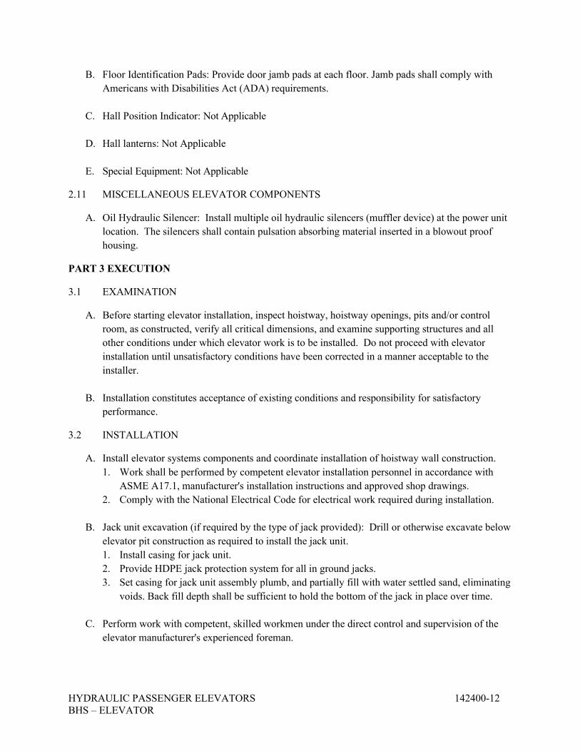
HYDRAULIC PASSENGER ELEVATORS 142400-12 BHS – ELEVATOR
B. Floor Identification Pads: Provide door jamb pads at each floor. Jamb pads shall comply with Americans with Disabilities Act (ADA) requirements.
C. Hall Position Indicator: Not Applicable
D. Hall lanterns: Not Applicable
E. Special Equipment: Not Applicable
2.11 MISCELLANEOUS ELEVATOR COMPONENTS
A. Oil Hydraulic Silencer: Install multiple oil hydraulic silencers (muffler device) at the power unit location. The silencers shall contain pulsation absorbing material inserted in a blowout proof housing.
PART 3 EXECUTION
3.1 EXAMINATION
A. Before starting elevator installation, inspect hoistway, hoistway openings, pits and/or control room, as constructed, verify all critical dimensions, and examine supporting structures and all other conditions under which elevator work is to be installed. Do not proceed with elevator installation until unsatisfactory conditions have been corrected in a manner acceptable to the installer.
B. Installation constitutes acceptance of existing conditions and responsibility for satisfactory performance.
3.2 INSTALLATION
A. Install elevator systems components and coordinate installation of hoistway wall construction. 1. Work shall be performed by competent elevator installation personnel in accordance with
ASME A17.1, manufacturer's installation instructions and approved shop drawings. 2. Comply with the National Electrical Code for electrical work required during installation.
B. Jack unit excavation (if required by the type of jack provided): Drill or otherwise excavate below elevator pit construction as required to install the jack unit. 1. Install casing for jack unit. 2. Provide HDPE jack protection system for all in ground jacks. 3. Set casing for jack unit assembly plumb, and partially fill with water settled sand, eliminating
voids. Back fill depth shall be sufficient to hold the bottom of the jack in place over time.
C. Perform work with competent, skilled workmen under the direct control and supervision of the elevator manufacturer's experienced foreman.

HYDRAULIC PASSENGER ELEVATORS 142400-13 BHS – ELEVATOR
D. Supply in ample time for installation by other trades, inserts, anchors, bearing plates, brackets, supports, and bracing including all setting templates and diagrams for placement.
E. Welded construction: Provide welded connections for installation of elevator work where bolted connections are not required for subsequent removal or for normal operation, adjustment, inspection, maintenance, and replacement of worn parts. Comply with AWS standards for workmanship and for qualification of welding operators.
F. Coordination: Coordinate elevator work with the work of other trades, for proper time and sequence to avoid construction delays. Use benchmarks, lines, and levels designated by the Contractor, to ensure dimensional coordination of the work.
G. Install machinery, guides, controls, car and all equipment and accessories to provide a quiet, smoothly operating installation, free from side sway, oscillation or vibration.
H. Alignment: Coordinate installation of hoistway entrances with installation of elevator guide rails for accurate alignment of entrances with cars. Where possible, delay final adjustment of sills and doors until car is operable in shaft. Reduce clearances to minimum safe, workable dimensions at each landing.
I. Erect hoistway sills, headers, and frames before erection of rough walls and doors; erect fascia and toe guards after rough walls finished. Set sill units accurately aligned and slightly above finish floor at landings.
J. Lubricate operating parts of system, where recommended by manufacturer.
3.3 FIELD QUALITY CONTROL
A. Acceptance testing: Upon completion of the elevator installation and before permitting use of elevator, perform acceptance tests as required and recommended by Code and governing regulations or agencies. Perform other tests, if any, as required by governing regulations or agencies.
B. Advise Owner, Contractor, Architect, and governing authorities in advance of dates and times tests are to be performed on the elevator.
3.4 ADJUSTING
A. Make necessary adjustments of operating devices and equipment to ensure elevator operates smoothly and accurately.
3.5 CLEANING
A. Before final acceptance, remove protection from finished surfaces and clean and polish surfaces in accordance with manufacturer's recommendations for type of material and finish provided.
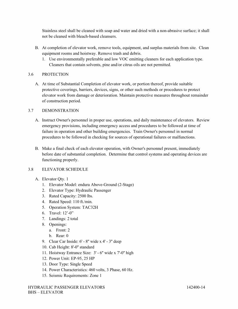
HYDRAULIC PASSENGER ELEVATORS 142400-14 BHS – ELEVATOR
Stainless steel shall be cleaned with soap and water and dried with a non-abrasive surface; it shall not be cleaned with bleach-based cleansers.
B. At completion of elevator work, remove tools, equipment, and surplus materials from site. Clean equipment rooms and hoistway. Remove trash and debris. 1. Use environmentally preferable and low VOC emitting cleaners for each application type.
Cleaners that contain solvents, pine and/or citrus oils are not permitted.
3.6 PROTECTION
A. At time of Substantial Completion of elevator work, or portion thereof, provide suitable protective coverings, barriers, devices, signs, or other such methods or procedures to protect elevator work from damage or deterioration. Maintain protective measures throughout remainder of construction period.
3.7 DEMONSTRATION
A. Instruct Owner's personnel in proper use, operations, and daily maintenance of elevators. Review emergency provisions, including emergency access and procedures to be followed at time of failure in operation and other building emergencies. Train Owner's personnel in normal procedures to be followed in checking for sources of operational failures or malfunctions.
B. Make a final check of each elevator operation, with Owner's personnel present, immediately before date of substantial completion. Determine that control systems and operating devices are functioning properly.
3.8 ELEVATOR SCHEDULE
A. Elevator Qty. 1 1. Elevator Model: endura Above-Ground (2-Stage) 2. Elevator Type: Hydraulic Passenger 3. Rated Capacity: 2500 lbs. 4. Rated Speed: 110 ft./min. 5. Operation System: TAC32H 6. Travel: 12’-0” 7. Landings: 2 total 8. Openings:
a. Front: 2 b. Rear: 0
9. Clear Car Inside: 6' - 8'' wide x 4' - 3'' deep 10. Cab Height: 8'-0'' standard 11. Hoistway Entrance Size: 3' - 6'' wide x 7'-0'' high 12. Power Unit: EP-95, 25 HP 13. Door Type: Single Speed 14. Power Characteristics: 460 volts, 3 Phase, 60 Hz. 15. Seismic Requirements: Zone 1
HYDRAULIC PASSENGER ELEVATORS 142400-15 BHS – ELEVATOR
16. Hoistway Dimensions: 8' - 4'' wide x 5' - 9'' deep 17. Pit Depth: 4' - 0'' 18. Button & Fixture Style: Vandal Resistant Signal Fixtures 19. Limited Access Operation: A key switch shall be provided to initiate the Limited Access
Operation. The activation of this operation shall restrict the operation of the elevator car calls to selected floors on a per-floor, per elevator basis.
END OF SECTION 142400
DUCTLESS MINI-SPLIT SYSTEMS 230000 - 1 BHS - ELEVATOR
SECTION 230000 – DUCTLESS MINI-SPLIT SYSTEMS
PART 1 - GENERAL
1.1. MECHANICAL WORK
A. All work shall be performed in accordance with applicable federal, state and local codes and regulations. Mechanical equipment shall be selected to meet or exceed the requirements of the Energy Conservation Code.
B. Hazardous Materials Warning: If uncovered materials are suspected of containing asbestos, lead-based paint, PCB’s, or any other hazardous material, stop work in that area and report the concern to the construction manager, owner and architect/engineer immediately.
C. Furnish and install all incidental accessories required to make the mechanical work complete and operational. If any aspect of the work is undefined or unclear after the final bid addendum, include the cost for the highest quality solution.
D. These drawings are diagrammatic. Exact equipment locations and pipe routing shall be coordinated with the building and site conditions. The actual equipment and minimum clearance dimensions shall be verified with the supplier. Fittings not shown on the drawings might be required.
E. Refrigerant piping shall be Type L copper tubing and wrought-copper fittings with soldered joints. Insulate indoor piping with 1-inch thick elastomeric insulation and outdoor with 2-inches thick elastomeric insulation and aluminum jacket.
F. Condensate drain piping shall be Type DWV, drawn-temper copper tubing, wrought-copper fittings and soldered joints. Insulate piping with 1-inch elastomeric insulation. Piping shall be no less than 3/4-inch.
G. Adhesive and mastics shall meet low VOC requirements of 50 g/L or less.
H. All mechanical work shall be warranted by the contractor for 1 year from the owner’s written acceptance of substantial completion. The compressor parts, labor and refrigerant shall be warrantied for 5 years.
I. Provide equipment cut sheets, installation, and operation and maintenance manuals as required by Division 1 but no less than 2 copies.
1.2. EXTRA MATERIALS
A. Furnish extra materials that match products installed and that are packaged with protective covering for storage and identified with labels describing contents.
1. Filters: One set for each indoor unit.
DUCTLESS MINI-SPLIT SYSTEMS 230000 - 2 BHS - ELEVATOR
PART 2 - PRODUCTS
2.1. DUCTLESS MINI-SPLIT SYSTEMS
A. Manufacturers: Provide equipment from one of the following manufacturers that meets the requirements of the bid documents: Carrier/Toshiba; Daikin/McQuay; Johnson Controls/York; LG; Mitsubishi; or Trane.
B. DMSS shall meet national standards and the requirements of the equipment schedule, including cooling and heating capacities and efficiencies.
C. Indoor unit shall include minimum merv-6 permanent, removable and cleanable air filter and abs plastic or stainless steel condensate drain pan.
D. Outdoor unit shall include low ambient control devices.
E. Safety Overflow Switch: Electronic water sensor with manual reset switch that senses high water level and sends unit disable signal to prevent further condensate production. Drain line installed devices are not acceptable.
F. System shall have single-point electrical connection at outdoor unit with power and controls circuits to indoor unit. Provide fused disconnect switch in NEMA 3R enclosure sized for outdoor unit and motor-rated disconnect switch in NEMA 1 enclosure for indoor unit.
G. Provide programmable solid-state electronic microprocessor-based space thermostat and controls that provides automatic heating / cooling switching, short-cycle protection, and led display. Battery operated wireless remote controls are not acceptable.
PART 3 - EXECUTION
3.1. DUCTLESS MINI-SPLIT SYSTEM INSTALLATION
A. Comply with manufacturer’s installation guidelines.
B. Coordinate the installation of equipment with other trades prior to purchase and installation. Maintain minimum equipment and device maintenance clearances. Installed materials not coordinated shall be removed and reinstalled at no additional cost.
C. Wall mounted control sensors shall be installed at 48-inches above the floor to the top of the back-box. Coordinate exact locations with light switches. When both are indicated adjacent to a door, locate the switch closest to the door and the sensor within 12-inches of the switch.
D. All roof modifications and repairs shall meet the requirements of the roof warranty.
E. All power and control wiring shall be installed in conduit complying with the strictest requirements of NFPA 70 and Division 26. Extend power conduit and wiring from disconnecting means to equipment connections.
F. Install penetrations of life-safety rated assemblies per approved UL detail in accordance with the building code. Unless otherwise noted the elevator equipment room walls shall be protected as 2-hour fire and smoke barriers.
G. Install refrigerant piping in compliance with ASHRAE 15 and Mechanical Code Chapter 11 – “Refrigeration”.
DUCTLESS MINI-SPLIT SYSTEMS 230000 - 3 BHS - ELEVATOR
H. Install galvanized steel pipe sleeves at each wall penetration. PVC sleeves are not acceptable. Water-tight seal penetration with clear silicone caulk. Install escutcheons at pipe penetrations of interior surfaces.
I. Install factory-fabricated pipe hangers with 12-inch long insulation shields at 5 foot spacings.
J. Control and alarm devices shall be installed in back-boxes within new and existing walls. Surface-mounted conduit and raceway will not be accepted except for existing solid concrete walls. Device back-boxes in fire-rated walls shall have firestop putty pads or equivalent UL-listed installation.
K. Install indoor and outdoor units plumb and level.
L. Perform complete installation, start-up and verification per manufacturer recommendations. Provide a letter to the engineer certifying this was successfully completed and warranting the installation.
END OF SECTION 230000
BASIC ELECTRICAL REQUIREMENTS 260100 - 1 BHS – ELEVATOR
SECTION 260100 - BASIC ELECTRICAL REQUIREMENTS PART 1 - GENERAL 1.1 RELATED DOCUMENTS A. Drawings and general provisions of Contract, including General and Supplementary Conditions
and Division 1 Specification Sections, apply to this and the other sections of Division 26. 1.2 SUMMARY A. This Section includes general administrative and procedural requirements for electrical
installations. The following administrative and procedural requirements are included in this Section to expand the requirements specified in Division 1:
1. Submittals. 2. Record documents. 3. Maintenance manuals. 4. Rough-ins. 5. Electrical installations. 6. Cutting and patching. 7. Inspections B. Related Sections: The following sections contain requirements that relate to this section: 1. Division 26 Section "Basic Electrical Materials and Methods," for materials and methods
common to the remainder of Division 26. 1.3 SUBMITTALS A. General: Follow the procedures specified in Division 1 Section "Submittals." B. Specific Requirements to Electrical Submittals: 1. Submittal Documents Quality: Facsimile documents prohibited. Submittals containing
sheets copied from facsimile documents will be automatically Rejected and returned to Contractor without review. Also submittals containing poor quality copies will be automatically Rejected and returned to Contractor without review.
2. Submittal Document: Submittal may be submitted in PDF format. 1.4 RECORD DOCUMENTS A. Prepare record documents in accordance with the requirements in Division 1 Section "Contract
Closeout." In addition to the requirements specified in Division 1, indicate installed conditions for:
BASIC ELECTRICAL REQUIREMENTS 260100 - 2 BHS – ELEVATOR
B. Major raceway systems, size and location, for both exterior and interior; locations of control devices; distribution and branch electrical circuitry; and fuse and circuit breaker size and arrangements.
1. Equipment locations (exposed and concealed), dimensioned from prominent building
lines. 2. Approved substitutions, Contract Modifications, and actual equipment and materials
installed. 1.5 MAINTENANCE MANUALS A. Prepare maintenance manuals in accordance with Division 1 Section "Contract Closeout." In
addition to the requirements specified in Division 1, include the following information for equipment items:
1. Description of function, normal operating characteristics and limitations, performance
curves, engineering data and tests, and complete nomenclature and commercial numbers of replacement parts.
2. Maintenance procedures for routine preventative maintenance and troubleshooting; disassembly, repair, and reassembly; aligning and adjusting instructions.
3. Warranty Information: Copies of documentation for all additional and secondary warranties shall be included.
1.7 DELIVERY, STORAGE, AND HANDLING A. Deliver products to the project properly identified with names, model numbers, types, grades,
compliance labels, and other information needed for identification. PART 2 - PRODUCTS (Not Applicable) PART 3 - EXECUTION 3.1 ROUGH-IN A. Verify final locations for rough-ins with field measurements and with the requirements of the
actual equipment to be connected. B. Refer to equipment specifications in Divisions 26 for rough-in requirements. 3.2 ELECTRICAL INSTALLATIONS A. General: Sequence, coordinate, and integrate the various elements of electrical systems,
materials, and equipment. Comply with the following requirements:
1. Coordinate electrical systems, equipment, and materials installation with other building components.
2. Verify all dimensions by field measurements.
BASIC ELECTRICAL REQUIREMENTS 260100 - 3 BHS – ELEVATOR
3. Arrange for chases, slots, and openings in other building components during progress of construction, to allow for electrical installations.
4. Coordinate the installation of required supporting devices and sleeves to be set in poured-in-place concrete and other structural components, as they are constructed.
5. Sequence, coordinate, and integrate installations of electrical materials and equipment for efficient flow of the Work. Give particular attention to large equipment requiring positioning prior to closing in the building.
6. Where mounting heights are not detailed or dimensioned, install systems, materials, and equipment to provide the maximum headroom possible.
7. Coordinate connection of electrical systems with exterior underground utilities and services. Comply with requirements of governing regulations, franchised service companies, and controlling agencies. Provide required connection for each service.
8. Install systems, materials, and equipment to conform with approved submittal data, including coordination drawings, to greatest extent possible. Conform to arrangements indicated by the Contract Documents, recognizing that portions of the Work are shown only in diagrammatic form. Where coordination requirements conflict with individual system requirements, refer conflict to the Architect.
9. Install systems, materials, and equipment level and plumb, parallel and perpendicular to other building systems and components, where installed exposed in finished spaces.
10. Install electrical equipment to facilitate servicing, maintenance, and repair or replacement of equipment components. As much as practical, connect equipment for ease of disconnecting, with minimum of interference with other installations.
11. Install access panel or doors where units are concealed behind finished surfaces. 12. Install systems, materials, and equipment giving right-of-way priority to systems required
to be installed at a specified slope. 3.3 CUTTING AND PATCHING A. General: Perform cutting and patching in accordance with the following requirements: 1. Perform cutting, fitting, and patching of electrical equipment and materials required to: a. Remove and replace defective Work. b. Remove and replace Work not conforming to requirements of the Contract
Documents. d. Upon written instructions from the Engineer, uncover and restore Work to provide
for Engineer observation of concealed Work. 2. Cut, remove, and legally dispose of selected electrical equipment, components, and
materials as indicated, including but not limited to removal of electrical items indicated to be removed and items made obsolete by the new Work.
3. Protect the structure, furnishings, finishes, and adjacent materials not indicated or scheduled to be removed.
4. Provide and maintain temporary partitions or dust barriers adequate to prevent the spread of dust and dirt to adjacent areas.
5. Protection of Installed Work: During cutting and patching operations, protect adjacent installations.
BASIC ELECTRICAL REQUIREMENTS 260100 - 4 BHS – ELEVATOR
6. Patch existing finished surfaces and building components using new materials matching existing materials and experienced Installers. Installers' qualifications refer to the materials and methods required for the surface and building components being patched.
PART 4 - INSPECTIONS
A. Authority Having Jurisdiction: The City of Danville is the Authority Having Jurisdiction (AHJ) for the Electrical Inspections on this project. It is the responsibility of the Electrical Contractor to notify the City of Danville to schedule the required rough-in, above ceiling, and final inspections. No work will be covered up until after the inspection has been completed and approved.
END OF SECTION 260100
BASIC ELECTRICAL MATERIALS AND METHODS 260500 - 1 BHS – ELEVATOR
SECTION 260500 - BASIC ELECTRICAL MATERIALS AND METHODS
PART 1 - GENERAL
1.1 RELATED DOCUMENTS
A. Drawings and general provisions of the Contract, including General and Supplementary Conditions and Division 1 Specification Sections, apply to this Section.
1.2 SUMMARY
A. This Section includes the following:
1. Electrical Equipment Installation. 2. Firestopping. 3. Cutting and patching for electrical construction. 4. Touchup painting.
1.3 QUALITY ASSURANCE
A. Electrical Components, Devices, and Accessories: Listed and labeled as defined in NFPA 70, Article 100, by a testing agency acceptable to authorities having jurisdiction, and marked for intended use.
B. Comply with NFPA 70.
1.4 COORDINATION
A. Sequence, coordinate, and integrate installing electrical materials and equipment for efficient flow of the Work.
PART 2 - PRODUCTS
2.1 TOUCHUP PAINT
A. For Equipment: Equipment manufacturer's paint selected to match installed equipment finish.
B. Galvanized Surfaces: Zinc-rich paint recommended by item manufacturer.
BASIC ELECTRICAL MATERIALS AND METHODS 260500 - 2 BHS – ELEVATOR
PART 3 - EXECUTION
3.1 ELECTRICAL EQUIPMENT INSTALLATION
A. Headroom Maintenance: If mounting heights or other location criteria are not indicated, arrange and install components and equipment to provide the maximum possible headroom.
B. Materials and Components: Install level, plumb, and parallel and perpendicular to other building systems and components, unless otherwise indicated.
C. Equipment: Install to facilitate service, maintenance, and repair or replacement of components. Connect for ease of disconnecting, with minimum interference with other installations.
D. Right of Way: Give to raceways and piping systems installed at a required slope.
3.2 FIRESTOPPING
A. Apply firestopping to cable and raceway penetrations of fire-rated floor and wall assemblies to achieve fire-resistance rating of the assembly.
3.3 CUTTING AND PATCHING
A. Cut, channel, chase, and drill floors, walls, partitions, ceilings, and other surfaces required to permit electrical installations. Perform cutting by skilled mechanics of trades involved.
B. Repair and refinish disturbed finish materials and other surfaces to match adjacent undisturbed surfaces. Install new fireproofing where existing firestopping has been disturbed. Repair and refinish materials and other surfaces by skilled mechanics of trades involved.
3.4 REFINISHING AND TOUCHUP PAINTING
A. Refinish and touch up paint. Paint materials and application requirements are specified in Division 9 Section "Painting."
1. Clean damaged and disturbed areas and apply primer, intermediate, and finish coats to suit the degree of damage at each location.
2. Follow paint manufacturer's written instructions for surface preparation and for timing and application of successive coats.
3. Repair damage to galvanized finishes with zinc-rich paint recommended by manufacturer.
4. Repair damage to PVC or paint finishes with matching touchup coating recommended by manufacturer.
BASIC ELECTRICAL MATERIALS AND METHODS 260500 - 3 BHS – ELEVATOR
3.5 CLEANING AND PROTECTION
A. On completion of installation, including outlets, fittings, and devices, inspect exposed finish. Remove burrs, dirt, paint spots, and construction debris.
B. Protect equipment and installations and maintain conditions to ensure that coatings, finishes, and cabinets are without damage or deterioration at time of Substantial Completion.
END OF SECTION 260500
GROUNDING AND BONDING 260600 - 1 BHS – ELEVATOR
SECTION 260600 - GROUNDING AND BONDING
PART 1 - GENERAL
1.1 RELATED DOCUMENTS
A. Drawings and general provisions of the Contract, including General and Supplementary Conditions and Division 1 Specification Sections, apply to this Section.
1.2 SUMMARY
A. This Section includes grounding of electrical systems and equipment. Grounding requirements specified in this Section may be supplemented by special requirements of systems described in other Sections.
1.3 SUBMITTALS
A. Qualification Data: For firms and persons specified in "Quality Assurance" Article.
B. Field Test Reports: Submit written test reports to include the following:
1. Test procedures used. 2. Test results that comply with requirements. 3. Results of failed tests and corrective action taken to achieve test results that comply with
requirements.
1.4 QUALITY ASSURANCE
A. Testing Agency Qualifications: Testing agency as defined by OSHA in 29 CFR 1910.7 or a member company of the InterNational Electrical Testing Association and that is acceptable to authorities having jurisdiction.
1. Testing Agency's Field Supervisor: Person currently certified by the InterNational Electrical Testing Association to supervise on-site testing specified in Part 3.
B. Electrical Components, Devices, and Accessories: Listed and labeled as defined in NFPA 70, Article 100, by a testing agency acceptable to authorities having jurisdiction, and marked for intended use.
1. Comply with UL 467.
GROUNDING AND BONDING 260600 - 2 BHS – ELEVATOR
PART 2 - PRODUCTS
2.1 MANUFACTURERS
A. Available Manufacturers: Subject to compliance with requirements, manufacturers offering products that may be incorporated into the Work include, but are not limited to, the following:
1. Grounding Conductors, Cables, Connectors:
a. Apache Grounding/Erico Inc. b. Boggs, Inc. c. Chance/Hubbell. d. Copperweld Corp. e. Dossert Corp. f. Erico Inc.; Electrical Products Group. g. Framatome Connectors/Burndy Electrical. h. Galvan Industries, Inc. i. Harger Lightning Protection, Inc. j. Hastings Fiber Glass Products, Inc. k. Thomas & Betts, Electrical.
2.2 GROUNDING CONDUCTORS
A. For insulated conductors, comply with Division 26 Section "Conductors and Cables."
B. Material: Copper.
C. Equipment Grounding Conductors: Insulated with green-colored insulation.
D. Bare Copper Conductors: Comply with the following:
1. Solid Conductors: ASTM B 3. 2. Assembly of Stranded Conductors: ASTM B 8. 3. Tinned Conductors: ASTM B 33.
E. Copper Bonding Conductors: As follows:
1. Bonding Cable: 28 kcmil, 14 strands of No. 17 AWG copper conductor, 1/4 inch (6.4 mm) in diameter.
2. Bonding Conductor: No. 4 or No. 6 AWG, stranded copper conductor. 3. Bonding Jumper: Bare copper tape, braided bare copper conductors, terminated with
copper ferrules; 1-5/8 inches (42 mm) wide and 1/16 inch (1.5 mm) thick. 4. Tinned Bonding Jumper: Tinned-copper tape, braided copper conductors, terminated
with copper ferrules; 1-5/8 inches (42 mm) wide and 1/16 inch (1.5 mm) thick.
GROUNDING AND BONDING 260600 - 3 BHS – ELEVATOR
1.5 CONNECTOR PRODUCTS A. Comply with IEEE 837 and UL 467; listed for use for specific types, sizes, and combinations of
conductors and connected items.
B. Bolted Connectors: Bolted-pressure-type connectors, or compression type.
PART 3 - EXECUTION
3.1 APPLICATION
A. In raceways, use insulated equipment grounding conductors.
B. Equipment Grounding Conductor Terminations: Use bolted pressure clamps.
3.2 EQUIPMENT GROUNDING CONDUCTORS
A. Comply with NFPA 70, Article 250, for types, sizes, and quantities of equipment grounding conductors, unless specific types, larger sizes, or more conductors than required by NFPA 70 are indicated.
B. Install equipment grounding conductors in all feeders and circuits.
3.3 INSTALLATION
A. Grounding Conductors: Route along shortest and straightest paths possible, unless otherwise indicated. Avoid obstructing access or placing conductors where they may be subjected to strain, impact, or damage.
B. Bonding Straps and Jumpers: Install so vibration by equipment mounted on vibration isolation hangers and supports is not transmitted to rigidly mounted equipment. Use exothermic-welded connectors for outdoor locations, unless a disconnect-type connection is required; then, use a bolted clamp. Bond straps directly to the basic structure taking care not to penetrate any adjacent parts. Install straps only in locations accessible for maintenance.
3.4 CONNECTIONS
A. General: Make connections so galvanic action or electrolysis possibility is minimized. Select connectors, connection hardware, conductors, and connection methods so metals in direct contact will be galvanically compatible.
1. Use electroplated or hot-tin-coated materials to ensure high conductivity and to make contact points closer to order of galvanic series.
2. Make connections with clean, bare metal at points of contact, remove paint where required.
GROUNDING AND BONDING 260600 - 4 BHS – ELEVATOR
3. Coat and seal connections having dissimilar metals with inert material to prevent future penetration of moisture to contact surfaces.
B. Equipment Grounding Conductor Terminations: For No. 8 AWG and larger, use pressure-type grounding lugs. No. 10 AWG and smaller grounding conductors may be terminated with winged pressure-type connectors.
C. Noncontact Metal Raceway Terminations: If metallic raceways terminate at metal housings without mechanical and electrical connection to housing, terminate each conduit with a grounding bushing. Connect grounding bushings with a bare grounding conductor to grounding bus or terminal in housing. Bond electrically noncontinuous conduits at entrances and exits with grounding bushings and bare grounding conductors, unless otherwise indicated.
D. Compression-Type Connections: Use hydraulic compression tools to provide correct circumferential pressure for compression connectors. Use tools and dies recommended by connector manufacturer. Provide embossing die code or other standard method to make a visible indication that a connector has been adequately compressed on grounding conductor.
END OF SECTION 260600
ELECTRICAL IDENTIFICATION 260750 - 1 BHS – ELEVATOR
SECTION 260750 - ELECTRICAL IDENTIFICATION
PART 1 - GENERAL
1.1 RELATED DOCUMENTS
A. Drawings and general provisions of the Contract, including General and Supplementary Conditions and Division 1 Specification Sections, apply to this Section.
1.2 SUMMARY
A. This Section includes electrical identification materials and devices required to comply with ANSI C2, NFPA 70, OSHA standards, and authorities having jurisdiction.
1.3 SUBMITTALS
A. Product Data: For each electrical identification product indicated.
1.4 QUALITY ASSURANCE
A. Comply with ANSI C2.
B. Comply with NFPA 70.
C. Comply with ANSI A13.1 and NFPA 70 for color-coding.
PART 2 - PRODUCTS
2.1 RACEWAY AND CABLE LABELS
A. Colored Adhesive Tape: Self-adhesive vinyl tape not less than 3 mils thick by 1 to 2 inches wide (0.08 mm thick by 25 to 51 mm wide).
B. Plasticized Card-Stock Tags: Vinyl cloth with preprinted and field-printed legends. Orange background, unless otherwise indicated, with eyelet for fastener.
2.2 NAMEPLATES AND SIGNS
A. Safety Signs: Comply with 29 CFR, Chapter XVII, Part 1910.145.
B. Engraved Plastic Nameplates and Signs: Engraving stock, melamine plastic laminate, minimum 1/16 inch (1.6 mm) thick for signs up to 20 sq. in. (129 sq. cm) and 1/8 inch (3.2 mm) thick for larger sizes. Punched or drilled for mechanical fasteners.
1. 120/208V Equipment: Blue surface with white core.
ELECTRICAL IDENTIFICATION 260750 - 2 BHS – ELEVATOR
2. 277/480V Equipment: Black surface with white core. 3. Generator Fed/Fire Alarm Equipment: Red surface with white core.
C. Baked-Enamel Signs for Interior Use: Preprinted aluminum signs, punched or drilled for fasteners, with colors, legend, and size required for the application. 1/4-inch (6.4-mm) grommets in corners for mounting.
D. Fasteners for Nameplates and Signs: Self-tapping, stainless-steel screws.
2.3 MISCELLANEOUS IDENTIFICATION PRODUCTS
A. Cable Ties: Fungus-inert, self-extinguishing, one-piece, self-locking, Type 6/6 nylon cable ties.
1. Minimum Width: 3/16 inch (5 mm). 2. Tensile Strength: 50 lb (22.3 kg) minimum. 3. Temperature Range: Minus 40 to plus 185 deg F (Minus 40 to plus 85 deg C). 4. Color: According to color-coding.
B. Paint: Formulated for the type of surface and intended use.
1. Primer for Galvanized Metal: Single-component acrylic vehicle formulated for galvanized surfaces.
2. Primer for Concrete Masonry Units: Heavy-duty-resin block filler. 3. Primer for Concrete: Clear, alkali-resistant, binder-type sealer. 4. Enamel: Silicone-alkyd or alkyd urethane as recommended by primer manufacturer.
PART 3 - EXECUTION
3.1 INSTALLATION
A. Identification Materials and Devices: Install at locations for most convenient viewing without interference with operation and maintenance of equipment.
B. Lettering, Colors, and Graphics: Coordinate names, abbreviations, colors, and other designations with corresponding designations in the Contract Documents or with those required by codes and standards. Use consistent designations throughout Project.
C. Sequence of Work: If identification is applied to surfaces that require finish, install identification after completing finish work.
D. Self-Adhesive Identification Products: Clean surfaces before applying.
E. Install painted identification according to manufacturer's written instructions and as follows:
1. Clean surfaces of dust, loose material, and oily films before painting. 2. Prime surfaces using type of primer specified for surface. 3. Apply one intermediate and one finish coat of enamel.
ELECTRICAL IDENTIFICATION 260750 - 3 BHS – ELEVATOR
F. Color Banding Raceways and Exposed Cables: Band exposed and accessible raceways of the systems listed below:
1. Bands: Pretensioned, wraparound plastic sleeves; colored adhesive tape; or a combination of both. Make each color band 2 inches (51 mm) wide, completely encircling conduit, and place adjacent bands of two-color markings in contact, side by side.
2. Band Locations: At changes in direction, at penetrations of walls and floors, at 50-foot (15-m) maximum intervals in straight runs, and at 25-foot (7.6-m) maximum intervals in congested areas.
3. Junction Box Covers: Paint concealed junction box covers as listed below. 4. Apply the following colors to the systems listed below:
a. Fire Alarm System: Red.
G. Caution Labels for Indoor Boxes and Enclosures for Power and Lighting: Install pressure-sensitive, self-adhesive labels identifying system voltage with black letters on orange background. Install on exterior of door or cover.
H. Circuit Identification Labels on Outlet Boxes, Junction Boxes and Pull Boxes: Install labels externally.
1. Exposed Boxes: Pressure-sensitive, self-adhesive plastic label on faceplate. Use clear label with black letters.
2. Concealed Boxes: Plasticized card-stock tags. 3. Labeling Legend: Permanent, waterproof listing of panel and circuit number or
equivalent.
I. Secondary Service, Feeder, and Branch-Circuit Conductors: Color-code throughout the secondary electrical system.
1. Color-code 208/120-V system as follows:
a. Phase A: Black. b. Phase B: Red. c. Phase C: Blue. d. Neutral: White. e. Ground: Green.
2. Color-code 480/277-V system as follows:
a. Phase A: Brown. b. Phase B: Orange. c. Phase C: Yellow. d. Neutral: Gray. e. Ground: Green.
3. Factory apply color the entire length of conductors, except the following field-applied, color-coding methods may be used instead of factory-coded wire for sizes larger than No. 10 AWG:
ELECTRICAL IDENTIFICATION 260750 - 4 BHS – ELEVATOR
a. Colored, pressure-sensitive plastic tape in half-lapped turns for a distance of 6 inches (150 mm) from terminal points and in boxes where splices or taps are made. Apply last two turns of tape with no tension to prevent possible unwinding. Use 1-inch- (25-mm-) wide tape in colors specified. Adjust tape bands to avoid obscuring cable identification markings.
b. Colored cable ties applied in groups of three ties of specified color to each wire at each terminal or splice point starting 3 inches (76 mm) from the terminal and spaced 3 inches (76 mm) apart. Apply with a special tool or pliers, tighten to a snug fit, and cut off excess length.
J. Apply identification to conductors as follows:
1. Conductors to Be Extended in the Future: Indicate source and circuit numbers. 2. Multiple Power or Lighting Circuits in the Same Enclosure: Identify each conductor with
source, voltage, circuit number, and phase. Use color-coding to identify circuits' voltage and phase.
3. Multiple Control and Communication Circuits in the Same Enclosure: Identify each conductor by its system and circuit designation. Use a consistent system of tags, color-coding, or cable marking tape.
K. Apply warning, caution, and instruction signs as follows:
1. Warnings, Cautions, and Instructions: Install to ensure safe operation and maintenance of electrical systems and of items to which they connect. Install engraved plastic-laminated instruction signs with approved legend where instructions are needed for system or equipment operation. Install metal-backed butyrate signs for outdoor items.
L. Equipment Identification Labels: Engraved plastic laminate. Install on each unit of equipment, including central or master unit of each system. Locate label on exterior of any enclosure. This includes power, lighting, signal, and alarm systems, unless units are specified with their own self-explanatory identification. Unless otherwise indicated, provide a single line of text with 1/2-inch high lettering on 1-1/2-inch high label; where two lines of text are required, use labels 2 inches high. Use surface and core colors as listed in Part 2 above. Provide labels for all electrical equipment listed below. In general, all labels shall include riser diagram ID, amperage, voltage, number of phases/poles, and equipment served from (source). Provide additional information as listed below:
1. Disconnect switches: equipment served by. a. Provide label for all disconnects provided by Division 23 or 26.
2. Enclosed circuit breakers: equipment served by. a. Provide label for all disconnects provided by Division 23 or 26.
END OF SECTION 260750
CONDUCTORS AND CABLES 261200 - 1 BHS – ELEVATOR
SECTION 261200 - CONDUCTORS AND CABLES
PART 1 - GENERAL
1.1 RELATED DOCUMENTS
A. Drawings and general provisions of the Contract, including General and Supplementary Conditions and Division 1 Specification Sections, apply to this Section.
1.2 SUMMARY
A. This Section includes building wires and cables and associated connectors, splices, and terminations for wiring systems rated 600 V and less.
1.3 SUBMITTALS
A. Field Test Reports: Indicate and interpret test results for compliance with performance requirements.
1.4 QUALITY ASSURANCE
A. Listing and Labeling: Provide wires and cables specified in this Section that are listed and labeled.
1. The Terms "Listed" and "Labeled": As defined in NFPA 70, Article 100. 2. Listing and Labeling Agency Qualifications: A "Nationally Recognized Testing
Laboratory" as defined in OSHA Regulation 1910.7.
B. Comply with NFPA 70.
1.5 DELIVERY, STORAGE, AND HANDLING
A. Deliver wires and cables according to NEMA WC 26.
1.6 COORDINATION
A. Coordinate layout and installation of cables with other installations.
B. Revise locations and elevations from those indicated, as required to suit field conditions and as approved by Architect.
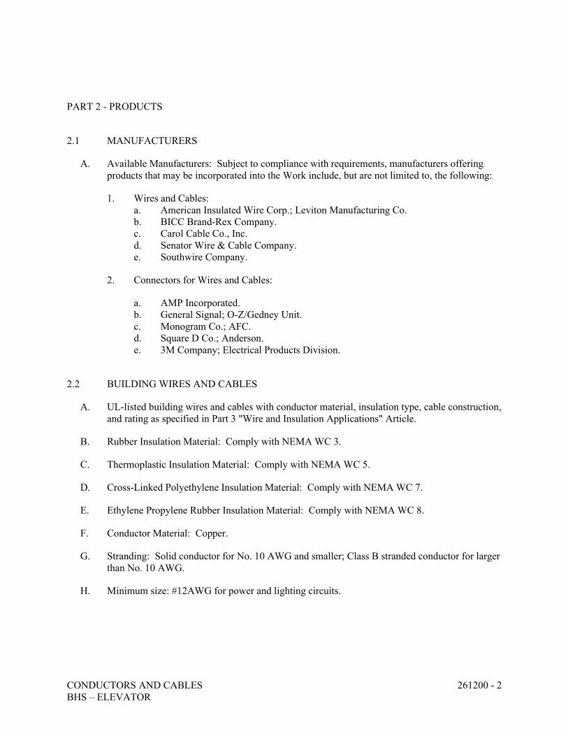
CONDUCTORS AND CABLES 261200 - 2 BHS – ELEVATOR
PART 2 - PRODUCTS
2.1 MANUFACTURERS
A. Available Manufacturers: Subject to compliance with requirements, manufacturers offering products that may be incorporated into the Work include, but are not limited to, the following:
1. Wires and Cables: a. American Insulated Wire Corp.; Leviton Manufacturing Co. b. BICC Brand-Rex Company. c. Carol Cable Co., Inc. d. Senator Wire & Cable Company. e. Southwire Company.
2. Connectors for Wires and Cables:
a. AMP Incorporated. b. General Signal; O-Z/Gedney Unit. c. Monogram Co.; AFC. d. Square D Co.; Anderson. e. 3M Company; Electrical Products Division.
2.2 BUILDING WIRES AND CABLES
A. UL-listed building wires and cables with conductor material, insulation type, cable construction, and rating as specified in Part 3 "Wire and Insulation Applications" Article.
B. Rubber Insulation Material: Comply with NEMA WC 3.
C. Thermoplastic Insulation Material: Comply with NEMA WC 5.
D. Cross-Linked Polyethylene Insulation Material: Comply with NEMA WC 7.
E. Ethylene Propylene Rubber Insulation Material: Comply with NEMA WC 8.
F. Conductor Material: Copper.
G. Stranding: Solid conductor for No. 10 AWG and smaller; Class B stranded conductor for larger than No. 10 AWG.
H. Minimum size: #12AWG for power and lighting circuits.
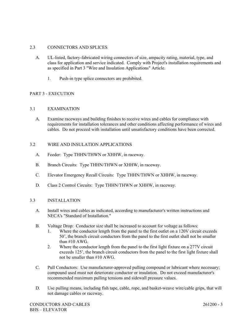
CONDUCTORS AND CABLES 261200 - 3 BHS – ELEVATOR
2.3 CONNECTORS AND SPLICES
A. UL-listed, factory-fabricated wiring connectors of size, ampacity rating, material, type, and class for application and service indicated. Comply with Project's installation requirements and as specified in Part 3 "Wire and Insulation Applications" Article. 1. Push-in type splice connectors are prohibited.
PART 3 - EXECUTION
3.1 EXAMINATION
A. Examine raceways and building finishes to receive wires and cables for compliance with requirements for installation tolerances and other conditions affecting performance of wires and cables. Do not proceed with installation until unsatisfactory conditions have been corrected.
3.2 WIRE AND INSULATION APPLICATIONS
A. Feeder: Type THHN/THWN or XHHW, in raceway.
B. Branch Circuits: Type THHN/THWN or XHHW, in raceway.
C. Elevator Emergency Recall Circuits: Type THHN/THWN or XHHW, in raceway.
D. Class 2 Control Circuits: Type THHN/THWN or XHHW, in raceway.
3.3 INSTALLATION
A. Install wires and cables as indicated, according to manufacturer's written instructions and NECA's "Standard of Installation."
B. Voltage Drop: Conductor size shall be increased to account for voltage as follows: 1. Where the conductor length from the panel to the first outlet on a 120V circuit exceeds
50’, the branch circuit conductors from the panel to the first outlet shall not be smaller than #10 AWG.
2. Where the conductor length from the panel to the first light fixture on a 277V circuit exceeds 125’, the branch circuit conductors from the panel to the first light fixture shall not be smaller than #10 AWG.
C. Pull Conductors: Use manufacturer-approved pulling compound or lubricant where necessary; compound used must not deteriorate conductor or insulation. Do not exceed manufacturer's recommended maximum pulling tensions and sidewall pressure values.
D. Use pulling means, including fish tape, cable, rope, and basket-weave wire/cable grips, that will not damage cables or raceway.
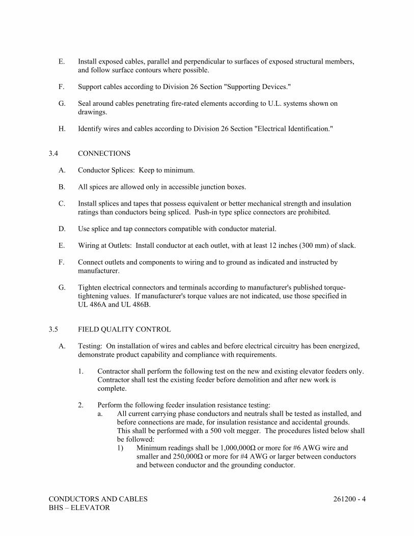
CONDUCTORS AND CABLES 261200 - 4 BHS – ELEVATOR
E. Install exposed cables, parallel and perpendicular to surfaces of exposed structural members, and follow surface contours where possible.
F. Support cables according to Division 26 Section "Supporting Devices."
G. Seal around cables penetrating fire-rated elements according to U.L. systems shown on drawings.
H. Identify wires and cables according to Division 26 Section "Electrical Identification."
3.4 CONNECTIONS
A. Conductor Splices: Keep to minimum.
B. All spices are allowed only in accessible junction boxes.
C. Install splices and tapes that possess equivalent or better mechanical strength and insulation ratings than conductors being spliced. Push-in type splice connectors are prohibited.
D. Use splice and tap connectors compatible with conductor material.
E. Wiring at Outlets: Install conductor at each outlet, with at least 12 inches (300 mm) of slack.
F. Connect outlets and components to wiring and to ground as indicated and instructed by manufacturer.
G. Tighten electrical connectors and terminals according to manufacturer's published torque-tightening values. If manufacturer's torque values are not indicated, use those specified in UL 486A and UL 486B.
3.5 FIELD QUALITY CONTROL
A. Testing: On installation of wires and cables and before electrical circuitry has been energized, demonstrate product capability and compliance with requirements.
1. Contractor shall perform the following test on the new and existing elevator feeders only. Contractor shall test the existing feeder before demolition and after new work is complete.
2. Perform the following feeder insulation resistance testing: a. All current carrying phase conductors and neutrals shall be tested as installed, and
before connections are made, for insulation resistance and accidental grounds. This shall be performed with a 500 volt megger. The procedures listed below shall be followed: 1) Minimum readings shall be 1,000,000Ω or more for #6 AWG wire and
smaller and 250,000Ω or more for #4 AWG or larger between conductors and between conductor and the grounding conductor.

CONDUCTORS AND CABLES 261200 - 5 BHS – ELEVATOR
2) After all fixtures, devices, and equipment are installed and all connections completed to each panel, the contractor shall disconnect the neutral feeder conductor from the neutral bar and take a megger reading between the neutral bar and the grounded enclosure. If this reading is less than 250,000 ohms, the contractor shall disconnect the branch circuit neutral wires from this neutral bar. The contractor shall then test each one separately to the panel and until the low readings are found. The contractor shall correct troubles, reconnect and retest until at least 250,000 ohms from the neutral bar to the grounded panel can be achieved with only the neutral feeder disconnected.
b. Copy of all testing reports shall be sent to the, engineer of record and to the Owner.
B. Correct malfunctioning conductors and cables at Project site, where possible, and retest to demonstrate compliance; otherwise, remove and replace with new units and retest.
END OF SECTION 261200
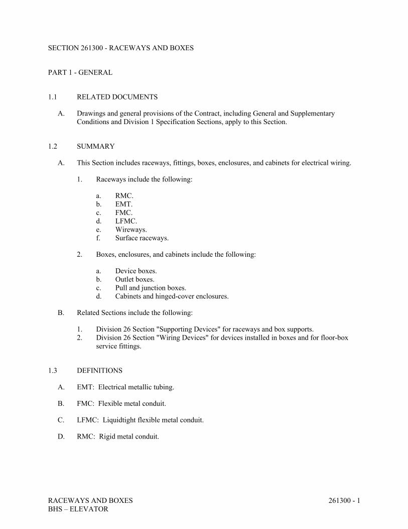
RACEWAYS AND BOXES 261300 - 1 BHS – ELEVATOR
SECTION 261300 - RACEWAYS AND BOXES
PART 1 - GENERAL
1.1 RELATED DOCUMENTS
A. Drawings and general provisions of the Contract, including General and Supplementary Conditions and Division 1 Specification Sections, apply to this Section.
1.2 SUMMARY
A. This Section includes raceways, fittings, boxes, enclosures, and cabinets for electrical wiring.
1. Raceways include the following:
a. RMC. b. EMT. c. FMC. d. LFMC. e. Wireways. f. Surface raceways.
2. Boxes, enclosures, and cabinets include the following:
a. Device boxes. b. Outlet boxes. c. Pull and junction boxes. d. Cabinets and hinged-cover enclosures.
B. Related Sections include the following:
1. Division 26 Section "Supporting Devices" for raceways and box supports. 2. Division 26 Section "Wiring Devices" for devices installed in boxes and for floor-box
service fittings.
1.3 DEFINITIONS
A. EMT: Electrical metallic tubing.
B. FMC: Flexible metal conduit.
C. LFMC: Liquidtight flexible metal conduit.
D. RMC: Rigid metal conduit.
RACEWAYS AND BOXES 261300 - 2 BHS – ELEVATOR
1.4 SUBMITTALS
A. Product Data: For surface raceways, wireways and fittings, floor boxes, hinged-cover enclosures, and cabinets.
B. Shop Drawings: Include layout drawings showing components and wiring for nonstandard boxes, enclosures, and cabinets.
1.5 QUALITY ASSURANCE
A. Listing and Labeling: Provide raceways and boxes specified in this Section that are listed and labeled.
1. The Terms "Listed" and "Labeled": As defined in NFPA 70, Article 100. 2. Listing and Labeling Agency Qualifications: A "Nationally Recognized Testing
Laboratory" as defined in OSHA Regulation 1910.7.
B. Comply with NECA's "Standard of Installation."
C. Comply with NFPA 70.
1.6 COORDINATION
A. Coordinate layout and installation of raceways and boxes with other construction elements to ensure adequate headroom, working clearance, and access.
PART 2 - PRODUCTS
2.1 MANUFACTURERS
A. Available Manufacturers: Subject to compliance with requirements, manufacturers offering products that may be incorporated into the Work include, but are not limited to, the following:
1. Metal Conduit and Tubing:
a. Alflex Corp. b. Anamet, Inc.; Anaconda Metal Hose. c. Anixter Brothers, Inc. d. Carol Cable Co., Inc. e. Cole-Flex Corp. f. Electri-Flex Co. g. Flexcon, Inc.; Coleman Cable Systems, Inc. h. Grinnell Co.; Allied Tube and Conduit Div. i. Monogram Co.; AFC.
RACEWAYS AND BOXES 261300 - 3 BHS – ELEVATOR
j. Spiraduct, Inc. k. Triangle PWC, Inc. l. Wheatland Tube Co.
2. Nonmetallic Conduit:
a. Anamet, Inc.; Anaconda Metal Hose. b. Arnco Corp. c. Breeze-Illinois, Inc. d. Cantex Industries; Harsco Corp. e. Certainteed Corp.; Pipe & Plastics Group. f. Cole-Flex Corp. g. Condux International; Electrical Products. h. Electri-Flex Co. i. George-Ingraham Corp. j. Hubbell, Inc.; Raco, Inc. k. Lamson & Sessions; Carlon Electrical Products. l. R&G Sloan Manufacturing Co., Inc. m. Spiraduct, Inc. n. Thomas & Betts Corp.
3. Conduit Bodies and Fittings:
a. American Electric; Construction Materials Group. b. Crouse-Hinds; Div. of Cooper Industries. c. Emerson Electric Co.; Appleton Electric Co. d. Hubbell, Inc.; Killark Electric Manufacturing Co. e. Lamson & Sessions; Carlon Electrical Products. f. O-Z/Gedney; Unit of General Signal. g. Scott Fetzer Co.; Adalet-PLM. h. Spring City Electrical Manufacturing Co.
4. Metal Wireways:
a. Hoffman Engineering Co. b. Keystone/Rees, Inc. c. Square D Co.
5. Boxes, Enclosures, and Cabinets:
a. American Electric; FL Industries. b. Butler Manufacturing Co.; Walker Division. c. Crouse-Hinds; Div. of Cooper Industries. d. Electric Panelboard Co., Inc. e. Erickson Electrical Equipment Co. f. Hoffman Engineering Co.; Federal-Hoffman, Inc. g. Hubbell Inc.; Killark Electric Manufacturing Co. h. Hubbell Inc.; Raco, Inc. i. Lamson & Sessions; Carlon Electrical Products. j. O-Z/Gedney; Unit of General Signal. k. Parker Electrical Manufacturing Co.
RACEWAYS AND BOXES 261300 - 4 BHS – ELEVATOR
l. Robroy Industries, Inc.; Electrical Division. m. Scott Fetzer Co.; Adalet-PLM. n. Spring City Electrical Manufacturing Co. o. Thomas & Betts Corp. p. Woodhead Industries, Inc.; Daniel Woodhead Co.
2.2 METAL CONDUIT AND TUBING
A. Rigid Steel Conduit: ANSI C80.1.
B. EMT and Fittings: ANSI C80.3. Fittings: Compression type. Cast, pot metal, set-crew, or crimp type fittings are not acceptable.
C. FMC: Zinc-coated steel.
D. LFMC: Flexible steel conduit with PVC jacket.
E. Fittings: NEMA FB 1; compatible with conduit/tubing materials.
2.3 METAL WIREWAYS
A. Material: Sheet metal sized and shaped as indicated.
B. Fittings and Accessories: Include couplings, offsets, elbows, expansion joints, adapters, hold-down straps, end caps, and other fittings to match and mate with wireways as required for complete system.
C. Select features, unless otherwise indicated, as required to complete wiring system and to comply with NFPA 70.
D. Wireway Covers: Hinged type.
E. Finish: Manufacturer’s standard enamel finish.
2.5 OUTLET AND DEVICE BOXES
A. Sheet Metal Boxes: NEMA OS 1.
B. Cast-Metal Boxes: NEMA FB 1, Type FD, cast box with gasketed cover.
2.6 PULL AND JUNCTION BOXES
A. Small Sheet Metal Boxes: NEMA OS 1.
B. Cast-Metal Boxes: NEMA FB 1, cast aluminum with gasketed cover.
RACEWAYS AND BOXES 261300 - 5 BHS – ELEVATOR
2.7 ENCLOSURES AND CABINETS
A. Cabinets: NEMA 250, Type 1, galvanized steel box with removable interior panel and removable front, finished inside and out with manufacturer's standard enamel. Hinged door in front cover with flush latch and concealed hinge. Key latch to match panelboards. Include metal barriers to separate wiring of different systems and voltage, and include accessory feet where required for freestanding equipment.
PART 3 - EXECUTION
3.1 EXAMINATION
A. Examine surfaces to receive raceways, boxes, enclosures, and cabinets for compliance with installation tolerances and other conditions affecting performance of raceway installation. Do not proceed with installation until unsatisfactory conditions have been corrected.
3.2 WIRING METHODS
A. Outdoors: Use the following wiring methods:
1. Exposed: Rigid galvanized steel. 2. Concealed: Rigid galvanized steel. 3. Connection to Vibrating Equipment (Including Transformers and Hydraulic, Pneumatic,
Electric Solenoid, or Motor-Driven Equipment): LFMC. 4. Boxes and Enclosures: NEMA 250, Type 3R or Type 4.
B. Indoors: Use the following wiring methods:
1. Exposed: a. Rigid galvanized steel, or IMC: All feeders and branch circuits in elevator pits,
elevator machine room and electrical room. 2. Concealed: EMT. 3. Connection to Vibrating Equipment (Including Transformers and Hydraulic, Pneumatic,
Electric Solenoid, or Motor-Driven Equipment): FMC; except in wet or damp locations, use LFMC.
4. Damp or Wet Locations: Rigid steel conduit. 5. Corrosive Environments: Rigid steel conduit. 6. Boxes and Enclosures: NEMA 250, Type 1, except as follows:
a. Damp or Wet Locations: NEMA 250, Type 4, nonmetallic. b. Where exposed to severe corrosive influence (Type 4X) and/or severe physical
damage.
3.3 INSTALLATION
A. Install raceways, boxes, enclosures, and cabinets as indicated, according to manufacturer's written instructions.
RACEWAYS AND BOXES 261300 - 6 BHS – ELEVATOR
B. Minimum Raceway Size:
1. Interior: 3/4-inch trade size.
C. Conceal conduit and EMT, unless otherwise indicated, within finished walls, ceilings, and floors.
D. Keep raceways at least 6 inches (150 mm) away from parallel runs of flues and steam or hot-water pipes. Install horizontal raceway runs above water and steam piping.
E. Install raceways level and square and at proper elevations. Provide adequate headroom.
F. Complete raceway installation before starting conductor installation.
G. Support raceways as specified in Division 26 Section "Supporting Devices."
H. Use temporary closures to prevent foreign matter from entering raceways.
I. Make bends and offsets so ID is not reduced. Keep legs of bends in the same plane and straight legs of offsets parallel, unless otherwise indicated.
J. Use raceway fittings compatible with raceways and suitable for use and location. For intermediate steel conduit, use threaded rigid steel conduit fittings, unless otherwise indicated.
K. Run concealed raceways, with a minimum of bends, in the shortest practical distance considering the type of building construction and obstructions, unless otherwise indicated.
L. Install exposed raceways parallel to or at right angles to nearby surfaces or structural members, and follow the surface contours as much as practical.
1. Run parallel or banked raceways together, on common supports where practical. 2. Make bends in parallel or banked runs from same centerline to make bends parallel. Use
factory elbows only where elbows can be installed parallel; otherwise, provide field bends for parallel raceways.
3. Raceways installed on interior face of exterior walls shall be supported with ¼” space from wall with clamp-backs or strut.
M. Join raceways with fittings designed and approved for the purpose and make joints tight.
1. Make raceway terminations tight. Use bonding bushings or wedges at connections subject to vibration. Use bonding jumpers where joints cannot be made tight.
2. Use insulating bushings to protect conductors.
N. Terminations: Where raceways are terminated with locknuts and bushings, align raceways to enter squarely and install locknuts with dished part against the box. Where terminations are not secure with 1 locknut, use 2 locknuts: 1 inside and 1 outside the box.
O. Where raceways are terminated with threaded hubs, screw raceways or fittings tightly into the hub so the end bears against the wire protection shoulder. Where chase nipples are used, align raceways so the coupling is square to the box and tighten the chase nipple so no threads are exposed.
RACEWAYS AND BOXES 261300 - 7 BHS – ELEVATOR
P. Install pull wires in empty raceways. Use No. 14 AWG zinc-coated steel or monofilament plastic line with not less than 200-lb (90-kg) tensile strength. Leave at least 12 inches (300 mm) of slack at each end of the pull wire.
Q. Install raceway sealing fittings according to manufacturer's written instructions. Locate fittings at suitable, approved, and accessible locations and fill them with UL-listed sealing compound. For concealed raceways, install each fitting in a flush steel box with a blank cover plate having a finish similar to that of adjacent plates or surfaces. Install raceway sealing fittings at the following points:
1. Where conduits pass from warm to cold locations, such as the boundaries of refrigerated spaces.
2. Where otherwise required by NFPA 70.
R. Flexible Connections: Use maximum of 6 feet (1830 mm) of flexible conduit for for equipment subject to vibration, noise transmission, or movement; and for all motors. Use liquidtight flexible conduit in wet or damp locations. Install separate ground conductor across flexible connections.
S. Install hinged-cover enclosures and cabinets plumb. Support at each corner.
3.4 PROTECTION
A. Provide final protection and maintain conditions, in a manner acceptable to manufacturer and Installer, that ensure coatings, finishes, and cabinets are without damage or deterioration at the time of Substantial Completion.
1. Repair damage to galvanized finishes with zinc-rich paint recommended by manufacturer.
3.5 CLEANING
A. On completion of installation, including outlet fittings and devices, inspect exposed finish. Remove burrs, dirt, and construction debris and repair damaged finish, including chips, scratches, and abrasions.
END OF SECTION 261300
SUPPORTING DEVICES 261370 - 1 BHS - ELEVATOR
SECTION 261370 - SUPPORTING DEVICES PART 1 - GENERAL 1.1 RELATED DOCUMENTS
A. Drawings and general provisions of Contract, including General and Supplementary Conditions and Division 1 Specification Sections, apply to this Section.
B. Requirements of the following Division 26 Sections apply to the following sections:
1. Division 26 Section "Basic Electrical Requirements." 2. Division 26 Section "Basic Electrical Materials and Methods."
1.2 SUMMARY
A. This Section includes secure support from the building structure for electrical items by means of hangers, supports, anchors, sleeves, inserts, seals, and associated fastenings.
1.3 SUBMITTALS
A. Product data for each type of product specified.
B. Shop drawings indicating details of fabricated products and materials.
1.4 QUALITY ASSURANCE
A. Electrical Component Standard: Components and installation shall comply with NFPA 70 "National Electrical Code."
PART 2 - PRODUCTS 2.1 COATINGS
A. Coating: Supports, support hardware, and fasteners shall be protected with zinc coating or with treatment of equivalent corrosion resistance using approved alternative treatment, finish, or inherent material characteristic. Products for use outdoors shall be hot-dip galvanized.
2.2 MANUFACTURED SUPPORTING DEVICES
A. Raceway Supports: Clevis hangers, riser clamps, two-hole conduit straps, threaded C-clamps with retainers, ceiling trapeze hangers, wall brackets, and spring steel clamps.
B. Fasteners: Types, materials, and construction features as follows:
2. Expansion Anchors: Carbon steel wedge or sleeve type. 3. Toggle Bolts: All steel springhead type.
SUPPORTING DEVICES 261370 - 2 BHS - ELEVATOR
C. Conduit Sealing Bushings: Factory-fabricated watertight conduit sealing bushing assemblies
suitable for sealing around conduit, or tubing passing through concrete floors and walls. Construct seals with steel sleeve, malleable iron body, neoprene sealing grommets or rings, metal pressure rings, pressure clamps, and cap screws.
D. Cable Supports for Vertical Conduit: Factory-fabricated assembly consisting of threaded body
and insulating wedging plug for nonarmored electrical cables in riser conduits. Provide plugs with number and size of conductor gripping holes as required to suit individual risers. Construct body of malleable-iron casting with hot-dip galvanized finish.
E. U-Channel Systems: 16-gage steel channels, with 9/16-inch-diameter holes, at a minimum of
8 inches on center, in top surface. Provide fittings and accessories that mate and match with U-channel and are of the same manufacture.
2.3 FABRICATED SUPPORTING DEVICES
A. General: Shop- or field-fabricated supports or manufactured supports assembled from U-channel components.
B. Steel Brackets: Fabricated of angles, channels, and other standard structural shapes. Connect
with welds and machine bolts to form rigid supports.
C. Pipe Sleeves: Provide pipe sleeves of one of the following:
1. Sheet Metal: Fabricate from galvanized sheet metal; round tube closed with snaplock joint, welded spiral seams, or welded longitudinal joint. Fabricate sleeves from the following gage metal for sleeve diameter noted: a. 3-inch and smaller: 20-gage. b. 4-inch to 6-inch: 16-gage. c. over 6-inch: 14-gage.
2. Steel Pipe: Fabricate from Schedule 40 galvanized steel pipe.
PART 3 - EXECUTION 3.1 INSTALLATION
A. Install supporting devices to fasten electrical components securely and permanently in accordance with NEC requirements.
B. Coordinate with the building structural system and with other electrical installation.
C. Raceway Supports: Comply with the NEC and the following requirements:
1. Conform to manufacturer's recommendations for selection and installation of supports.
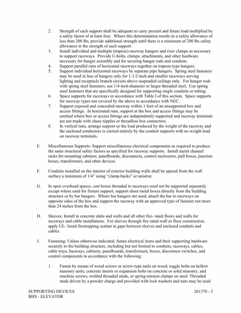
SUPPORTING DEVICES 261370 - 3 BHS - ELEVATOR
2. Strength of each support shall be adequate to carry present and future load multiplied by a safety factor of at least four. Where this determination results in a safety allowance of less than 200 lbs, provide additional strength until there is a minimum of 200 lbs safety allowance in the strength of each support.
3. Install individual and multiple (trapeze) raceway hangers and riser clamps as necessary to support raceways. Provide U-bolts, clamps, attachments, and other hardware necessary for hanger assembly and for securing hanger rods and conduits.
4. Support parallel runs of horizontal raceways together on trapeze-type hangers. 5. Support individual horizontal raceways by separate pipe hangers. Spring steel fasteners
may be used in lieu of hangers only for 1-1/2-inch and smaller raceways serving lighting and receptacle branch circuits above suspended ceilings only. For hanger rods with spring steel fasteners, use 1/4-inch-diameter or larger threaded steel. Use spring steel fasteners that are specifically designed for supporting single conduits or tubing.
6. Space supports for raceways in accordance with Table I of this section. Space supports for raceway types not covered by the above in accordance with NEC.
7. Support exposed and concealed raceway within 1 foot of an unsupported box and access fittings. In horizontal runs, support at the box and access fittings may be omitted where box or access fittings are independently supported and raceway terminals are not made with chase nipples or threadless box connectors.
8. In vertical runs, arrange support so the load produced by the weight of the raceway and the enclosed conductors is carried entirely by the conduit supports with no weight load on raceway terminals.
E. Miscellaneous Supports: Support miscellaneous electrical components as required to produce
the same structural safety factors as specified for raceway supports. Install metal channel racks for mounting cabinets, panelboards, disconnects, control enclosures, pull boxes, junction boxes, transformers, and other devices.
F. Conduits installed on the interior of exterior building walls shall be spaced from the wall
surface a minimum of 1/4” using “clamp-backs” or unistrut.
G. In open overhead spaces, cast boxes threaded to raceways need not be supported separately except where used for fixture support; support sheet metal boxes directly from the building structure or by bar hangers. Where bar hangers are used, attach the bar to raceways on opposite sides of the box and support the raceway with an approved type of fastener not more than 24 inches from the box.
H. Sleeves: Install in concrete slabs and walls and all other fire- rated floors and walls for
raceways and cable installations. For sleeves through fire rated-wall or floor construction, apply UL- listed firestopping sealant in gaps between sleeves and enclosed conduits and cables.
J. Fastening: Unless otherwise indicated, fasten electrical items and their supporting hardware
securely to the building structure, including but not limited to conduits, raceways, cables, cable trays, busways, cabinets, panelboards, transformers, boxes, disconnect switches, and control components in accordance with the following:
1. Fasten by means of wood screws or screw-type nails on wood, toggle bolts on hollow
masonry units, concrete inserts or expansion bolts on concrete or solid masonry, and machine screws, welded threaded studs, or spring-tension clamps on steel. Threaded studs driven by a powder charge and provided with lock washers and nuts may be used
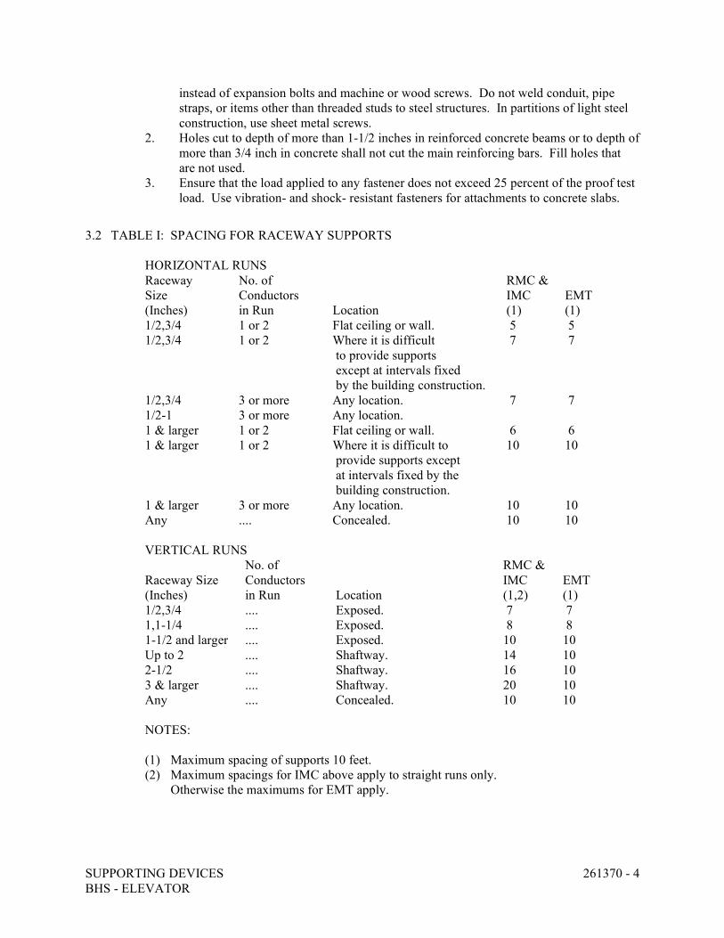
SUPPORTING DEVICES 261370 - 4 BHS - ELEVATOR
instead of expansion bolts and machine or wood screws. Do not weld conduit, pipe straps, or items other than threaded studs to steel structures. In partitions of light steel construction, use sheet metal screws.
2. Holes cut to depth of more than 1-1/2 inches in reinforced concrete beams or to depth of more than 3/4 inch in concrete shall not cut the main reinforcing bars. Fill holes that are not used.
3. Ensure that the load applied to any fastener does not exceed 25 percent of the proof test load. Use vibration- and shock- resistant fasteners for attachments to concrete slabs.
3.2 TABLE I: SPACING FOR RACEWAY SUPPORTS
HORIZONTAL RUNS Raceway No. of RMC & Size Conductors IMC EMT (Inches) in Run Location (1) (1) 1/2,3/4 1 or 2 Flat ceiling or wall. 5 5 1/2,3/4 1 or 2 Where it is difficult 7 7
to provide supports except at intervals fixed by the building construction.
1/2,3/4 3 or more Any location. 7 7 1/2-1 3 or more Any location. 1 & larger 1 or 2 Flat ceiling or wall. 6 6 1 & larger 1 or 2 Where it is difficult to 10 10
provide supports except at intervals fixed by the building construction.
1 & larger 3 or more Any location. 10 10 Any .... Concealed. 10 10 VERTICAL RUNS
No. of RMC & Raceway Size Conductors IMC EMT (Inches) in Run Location (1,2) (1) 1/2,3/4 .... Exposed. 7 7 1,1-1/4 .... Exposed. 8 8 1-1/2 and larger .... Exposed. 10 10 Up to 2 .... Shaftway. 14 10 2-1/2 .... Shaftway. 16 10 3 & larger .... Shaftway. 20 10 Any .... Concealed. 10 10 NOTES: (1) Maximum spacing of supports 10 feet. (2) Maximum spacings for IMC above apply to straight runs only.
Otherwise the maximums for EMT apply.

SUPPORTING DEVICES 261370 - 5 BHS - ELEVATOR
Abbreviations: EMT Electrical metallic tubing. IMC Intermediate metallic conduit. RMC Rigid metallic conduit.
END OF SECTION 261370
WIRING DEVICES 261400 - 1 BHS – ELEVATOR
SECTION 261400 - WIRING DEVICES
PART 1 - GENERAL
1.1 RELATED DOCUMENTS
A. Drawings and general provisions of the Contract, including General and Supplementary Conditions and Division 1 Specification Sections, apply to this Section.
1.2 SUMMARY
A. This Section includes receptacles, connectors, switches, and finish plates.
1.3 DEFINITIONS
A. GFCI: Ground-fault circuit interrupter.
1.4 SUBMITTALS
A. Product Data: For each product specified.
B. Shop Drawings: Legends for receptacles and switch plates.
C. Maintenance Data: For materials and products to include in maintenance manuals specified in Division 1.
1.5 QUALITY ASSURANCE
A. Electrical Components, Devices, and Accessories: Listed and labeled as defined in NFPA 70, Article 100, by a testing agency acceptable to authorities having jurisdiction.
B. Comply with NEMA WD 1.
C. Comply with NFPA 70.
1.6 COORDINATION
PART 2 - PRODUCTS
2.1 MANUFACTURERS
A. Available Manufacturers: Subject to compliance with requirements, manufacturers offering products that may be incorporated into the Work include, but are not limited to, the following:
WIRING DEVICES 261400 - 2 BHS – ELEVATOR
Wiring Devices:
a. Hubbell, Inc.; Wiring Devices Div. b. Leviton Manufacturing Co., Inc. c. Pass & Seymour/Legrand; Wiring Devices Div.
2.2 RECEPTACLES
A. Straight-Blade and Locking Receptacles: Heavy-Duty grade. 1. NEMA 5-20R (standard #WDI.101968). 2. Arranged for back and side wiring. 3. Grounding type. Separate single or double grounding terminals with screw lugs and a
direct, green insulated conductor connector to system ground. Screw shall be green and hex-headed.
4. Listed by an approved third party agency.
B. GFCI Receptacles: Feed-through type, with integral NEMA WD 6, Configuration 5-20R duplex receptacle arranged to protect connected downstream receptacles on same circuit. Design units for installation in a 2-3/4-inch- (70-mm-) deep outlet box without an adapter.
C. Color: Receptacles connected to Normal Power System: Ivory unless otherwise indicated or required by NFPA 70. Receptacles connected to Standby Power Panel – GP: Red
2.3 SWITCHES
A. Snap Switches: Heavy-duty, quiet type. Color: Ivory. 1. 20A, 120/277v, AC only. 2. Grounding type, with green hex-head grounding screw. 3. Quiet type operating mechanism; shall not utilize mercury switches. 4. Listed by an approved third party agency.
2.4 WALL PLATES
A. Single and combination types match corresponding wiring devices.
1. Plate-Securing Screws: Metal with head color to match plate finish. 2. Material for Finished Spaces: 0.04-inch- (1-mm-) thick, Type 302, satin-finished
stainless steel. 3. Material for Unfinished Spaces: Galvanized steel. 4. Wet-Location, Weatherproof Cover Plates: Where installing receptacles in wet locations,
provide weatherproof covers closable over attached cords maintaining their weather proof integrity while in use and with listed weather resistant receptacles (NEC 406.9(B)).
WIRING DEVICES 261400 - 3 BHS – ELEVATOR
PART 3 - EXECUTION
3.1 INSTALLATION
A. Install devices and assemblies plumb and secure.
B. Install wall plates when painting is complete.
C. Do not share neutral conductor on load side of dimmers.
D. Arrangement of Devices: Unless otherwise indicated, mount flush, with long dimension vertical, and grounding terminal of receptacles on top. Group adjacent switches under single, multigang wall plates.
E. Protect devices and assemblies during painting.
3.2 IDENTIFICATION
A. Comply with Division 26 Section "Electrical Identification."
1. Switches: Where three or more switches are ganged, and elsewhere as indicated, identify each switch with approved legend engraved on wall plate.
2. Receptacles: Identify panelboard and circuit number from which served. Use machine-printed, pressure-sensitive, abrasion-resistant label tape on face of plate and durable wire markers or tags within outlet boxes.
3.3 CONNECTIONS
A. Grounding: Connect wiring device grounding terminal to outlet box with bonding jumper. Connect wiring device grounding terminal to branch-circuit equipment grounding conductor
B. Tighten electrical connectors and terminals according to manufacturers published torque-tightening values. If manufacturers torque values are not indicated, use those specified in UL 486A and UL 486B.
3.4 FIELD QUALITY CONTROL
A. Test wiring devices for proper polarity and ground continuity. Operate each device at least six times.
B. Test GFCI operation with both local and remote fault simulations according to manufacturer's written instructions.
C. Replace damaged or defective components.
WIRING DEVICES 261400 - 4 BHS – ELEVATOR
3.5 CLEANING
A. Internally clean devices, device outlet boxes, and enclosures. Replace stained or improperly painted wall plates or devices.
END OF SECTION 261400
ENCLOSED SWITCHES AND CIRCUIT BREAKERS 264100 - 1 BHS – ELEVATOR
SECTION 264100 - ENCLOSED SWITCHES AND CIRCUIT BREAKERS
PART 1 - GENERAL
1.1 RELATED DOCUMENTS
A. Drawings and general provisions of the Contract, including General and Supplementary Conditions and Division 1 Specification Sections, apply to this Section.
1.2 SUMMARY
A. This Section includes individually mounted enclosed switches and circuit breakers used for the following:
1. Feeder and branch-circuit protection. 2. Motor and equipment disconnecting means. 3. Elevator disconnect switch.
B. Related Sections include the following:
1. Division 26 Section "Wiring Devices" for attachment plugs, receptacles, and toggle switches used for disconnecting means.
1.3 DEFINITIONS
A. GFCI: Ground-fault circuit interrupter.
B. RMS: Root mean square.
C. SPDT: Single pole, double throw.
1.4 SUBMITTALS
A. Product Data: For each type of switch, circuit breaker, accessory, and component indicated. Include dimensions and manufacturers' technical data on features, performance, electrical characteristics, ratings, and finishes.
B. Maintenance Data: For enclosed switches and circuit breakers and for components to include in maintenance manuals specified in Division 1. In addition to requirements specified in Division 1 Section "Closeout Procedures," include the following:
1. Routine maintenance requirements for components. 2. Manufacturer's written instructions for testing and adjusting switches and circuit
breakers.
ENCLOSED SWITCHES AND CIRCUIT BREAKERS 264100 - 2 BHS – ELEVATOR
1.5 QUALITY ASSURANCE
A. Electrical Components, Devices, and Accessories: Listed and labeled as defined in NFPA 70, Article 100, by a testing agency acceptable to authorities having jurisdiction, and marked for intended use.
B. Comply with NEMA AB 1 and NEMA KS 1.
C. Comply with NFPA 70.
1.6 COORDINATION
A. Coordinate layout and installation of switches, circuit breakers, and components with other construction, including conduit, piping, equipment, and adjacent surfaces. Maintain required workspace clearances and required clearances for equipment access doors and panels.
PART 2 - PRODUCTS
2.1 MANUFACTURERS
A. Available Manufacturers: Subject to compliance with requirements, manufacturers offering products that may be incorporated into the Work include, but are not limited to, the following:
1. Fusible Switches:
a. Eaton Corp.; Cutler-Hammer Products. b. General Electric Co.; Electrical Distribution & Control Division. c. Siemens Energy & Automation, Inc. d. Square D Co.
2. Elevator Disconnect Switches:
a. Cooper Bussman, Inc. b. Eaton Corp.; Cutler-Hammer Products. c. General Electric Co.; Electrical Distribution & Control Division. d. Siemens Energy & Automation, Inc.
2.2 ELEVATOR DISCONNECT SWITCH
A. Elevator Disconnect Switch shall consist of integral fused disconnect switch with shunt trip device. Shunt trip device shall be activated by the closing of a 120VAC dry contact on the Fire Alarm system. Elevator Disconnect switch shall also have a voltage monitoring relay that monitors power to shunt trip device and is supervised by the Fire Alarm system.
B. Provide Elevator Disconnect Switch in a single enclosure with all necessary switching mechanism, shunt-trip device, fuse holders, relay(s), control transformer and other appurtenances for a complete listed system. The switch shall have an ampere rating as shown on the Contract Drawings, and shall include a horsepower rated fusible switch with shunt trip
ENCLOSED SWITCHES AND CIRCUIT BREAKERS 264100 - 3 BHS – ELEVATOR
capabilities. The fuse rating of the switch shall be based upon elevator manufacturer requirements and utilize Class J Fuses. It shall include as an accessory, a 100VA control power transformer with primary and secondary fuses. It shall also contain an isolation relay with a 120VAC coil. A normally open dry contact shall be provided by the Fire Alarm System to energize the isolation relay and activate the shunt trip solenoid. The module shall contain a Key to Test Switch, a green “ON” Pilot Light, One set of Auxiliary Mechanical Interlocked Form C contacts, and Fire Alarm Voltage Monitoring Relay.
2.3 ENCLOSED SWITCHES
A. All Switches: 1. Nonteasible, positive, quick make-quick break mechanisms. 2. Handles whose positions are easily recognizable and are padlockable in either the “on” or
“off” positions. 3. Defeatable door interlocks that prevent the door from opening when the operating handle
is in the “on” position.
B. Enclosed, Nonfusible Switch: NEMA KS 1, Type HD, with lockable handle.
C. Enclosed, Fusible Switch, 800 A and Smaller: NEMA KS 1, Type HD, with clips to accommodate specified fuses, lockable handle with two padlocks, and interlocked with cover in closed position.
2.4 ENCLOSURES
D. NEMA AB 1 and NEMA KS 1 to meet environmental conditions of installed location.
1. Outdoor Locations: NEMA 250, Type 3R. 2. Other Wet or Damp Indoor Locations: NEMA 250, Type 4.
2.6 FACTORY FINISHES
A. Finish: Manufacturer's standard grey paint applied to factory-assembled and -tested enclosures before shipping.
PART 3 - EXECUTION
3.1 EXAMINATION
A. Examine elements and surfaces to receive enclosed switches and circuit breakers for compliance with installation tolerances and other conditions affecting performance.
1. Proceed with installation only after unsatisfactory conditions have been corrected.
ENCLOSED SWITCHES AND CIRCUIT BREAKERS 264100 - 4 BHS – ELEVATOR
3.2 INSTALLATION
A. Temporary Lifting Provisions: Remove temporary lifting eyes, channels, and brackets and temporary blocking of moving parts from enclosures and components.
3.3 IDENTIFICATION
A. Identify field-installed conductors, interconnecting wiring, and components; provide warning signs as specified in Division 26 Section "Electrical Identification."
B. Enclosure Nameplates: Label each enclosure with engraved metal or laminated-plastic nameplate mounted with corrosion-resistant screws as specified in Division 26 Section "Electrical Identification."
3.4 CONNECTIONS
A. Install equipment grounding connections for switches and circuit breakers with ground continuity to main electrical ground bus.
B. Install power wiring. Install wiring between switches and circuit breakers, and control and indication devices.
C. Tighten electrical connectors and terminals according to manufacturer's published torque-tightening values. If manufacturer's torque values are not indicated, use those specified in UL 486A and UL 486B.
3.5 FIELD QUALITY CONTROL
A. Prepare for acceptance tests as follows:
1. Test insulation resistance for each enclosed switch, circuit breaker, component, and control circuit.
2. Test continuity of each line- and load-side circuit.
3.6 ADJUSTING
A. Set field-adjustable switches and circuit-breaker trip ranges.
3.7 CLEANING
A. On completion of installation, inspect interior and exterior of enclosures. Remove paint splatters and other spots. Vacuum dirt and debris; do not use compressed air to assist in cleaning. Repair exposed surfaces to match original finish.

ENCLOSED SWITCHES AND CIRCUIT BREAKERS 264100 - 5 BHS – ELEVATOR
END OF SECTION 264100
FUSES 264910 - 1 BHS – ELEVATOR
SECTION 264910 - FUSES
PART 1 - GENERAL
1.1 RELATED DOCUMENTS
A. Drawings and general provisions of the Contract, including General and Supplementary Conditions and Division 1 Specification Sections, apply to this Section.
1.2 SUMMARY
A. This Section includes cartridge fuses, rated 600 V and less, for use in switches, panelboards, switchboards, controllers, and motor-control centers; and spare fuse cabinets.
1.3 SUBMITTALS
A. Product Data: Include dimensions and manufacturer's technical data on features, performance, electrical characteristics, and ratings for each fuse type indicated.
B. Maintenance Data: For tripping devices to include in maintenance manuals specified in Division 1.
1.4 QUALITY ASSURANCE
A. Source Limitations: Provide fuses from a single manufacturer.
B. Electrical Components, Devices, and Accessories: Listed and labeled as defined in NFPA 70, Article 100, by a testing agency acceptable to authorities having jurisdiction, and marked for intended use.
C. Comply with NEMA FU 1.
D. Comply with NFPA 70.
1.5 PROJECT CONDITIONS
A. Where ambient temperature to which fuses are directly exposed is less than 40 deg F (4.4 deg C) or more than 100 deg F (38 deg C), apply manufacturer's ambient temperature adjustment factors to fuse ratings.
1.6 COORDINATION
A. Coordinate fuse ratings with HVAC and Elevator equipment nameplate limitations of maximum fuse size.
FUSES 264910 - 2 BHS – ELEVATOR
1.7 EXTRA MATERIALS
A. Furnish extra materials described below that match products installed and that are packaged in original cartons or containers and identified with labels describing contents.
1. Fuses: Quantity equal to 20 percent of each fuse type and size, but not fewer than 1 set of 3 of each type and size.
PART 2 - PRODUCTS
2.1 MANUFACTURERS
A. Available Manufacturers: Subject to compliance with requirements, manufacturers offering products that may be incorporated into the Work include, but are not limited to, the following:
1. Cooper Industries, Inc.; Bussmann Div. 2. Eagle Electric Mfg. Co., Inc. 3. Ferraz Corp. 4. General Electric Co.; Wiring Devices Div. 5. Gould Shawmut. 6. Tracor, Inc.; Littelfuse, Inc. Subsidiary.
2.2 CARTRIDGE FUSES
A. Characteristics: NEMA FU 1, nonrenewable cartridge fuse; class and current rating indicated; voltage rating consistent with circuit voltage.
PART 3 - EXECUTION
3.1 EXAMINATION
A. Examine utilization equipment nameplates and installation instructions. Install fuses of sizes and with characteristics appropriate for each piece of equipment.
B. Proceed with installation only after unsatisfactory conditions have been corrected.
3.2 FUSE APPLICATIONS
A. Motor and Motor Controller Branch Circuits: Class RK5, UL listed, current limiting time delay, 200 kA interrupting rating.
B. Other Individual Equipment Branch Circuits: Class RK5, UL listed, non-time delay, 50 kA interrupting rating.
FUSES 264910 - 3 BHS – ELEVATOR
3.3 INSTALLATION
A. Fuses shall be selected as to provide a fully selective system.
B. Install fuses in fusible devices. Arrange fuses so rating information is readable without removing fuse.
C. Fusible safety switches with short-circuit withstand ratings of 100kA or 200kA require Class R or Class J rejection fuse block feature.
3.4 IDENTIFICATION
A. Install labels indicating fuse replacement information on inside door of each fused switch.
END OF SECTION 264910
LIGHTING 265110 - 1 BHS – ELEVATOR
SECTION 265110 - LIGHTING
PART 1 - GENERAL
1.1 RELATED DOCUMENTS
A. Drawings and general provisions of the Contract, including General and Supplementary Conditions and Division 1 Specification Sections, apply to this Section.
1.2 SUMMARY
A. This Section includes lighting fixtures, lamps, ballasts, and accessories.
1.3 SUBMITTALS
A. Product Data: 1. Light Fixtures: For each type of lighting fixture indicated, arranged in order of fixture
designation. Provide manufacturer’s published literature which includes data on features, accessories, and the following: a. Dimensions of fixtures. b. Certified results of independent laboratory tests for fixtures and lamps for
electrical ratings and photometric data. c. Manufacturer and type of ballasts. d. Manufacturer and types of lamps.
B. Maintenance Data: For lighting fixtures to include in maintenance manuals specified in Division 1. Include all warranty information and documentation with maintenance data.
1.4 QUALITY ASSURANCE
A. Fixtures and Accessories: Listed and labeled as defined in NFPA 70, Article 100, by a testing agency acceptable to authorities having jurisdiction.
B. Comply with NFPA 70.
C. NFPA 101 Compliance: Comply with visibility and luminance requirements for exit signs.
1.5 COORDINATION
A. Fixtures, Mounting Hardware, and Trim: Coordinate layout and installation of lighting fixtures with ceiling system and other construction.
1.6 WARRANTY
LIGHTING 265110 - 2 BHS – ELEVATOR
A. Special Warranty for Electronic Ballasts: Written warranty, executed by manufacturer agreeing to replace fluorescent electronic ballasts that fails in materials or workmanship within 5 years from date of manufacturer, but not less than 4 years from date of Final Acceptance.
B. Special Warranty for Emergency Exit Signs, Emergency Lighting Units, and Emergency Ballasts: Written warranty, executed by manufacturer agreeing to replace entire sign/unit/ballast that fails within 3 years from date of Final Acceptance. The batteries within sign/unit/ballast shall be covered for an additional 2 years by a pro-rated warranty.
PART 2 - PRODUCTS
2.1 MANUFACTURERS
A. Available Manufacturers and Products: Subject to compliance with requirements, manufacturers and respective products that may be incorporated into the Work are indicated on the drawings in Light Fixture Schedule on sheet E-1.
1. It is the intent of the Light Fixture Schedule to denote the quality standard of product desired and not to restrict bidders to a specific brand, make, manufacturer or specific name. The manufacturers and products listed in Schedule are used only to set forth and convey to bidders the general style, type, character, and quality of product desired. Substitution of equivalent products will be acceptable according to the following paragraph.
2.2 FIXTURES AND FIXTURE COMPONENTS, GENERAL
A. Metal Parts: Free from burrs, sharp corners, and edges.
B. Sheet Metal Components: Steel, unless otherwise indicated. Form and support to prevent warping and sagging.
C. Doors, Frames, and Other Internal Access: Smooth operating, free from light leakage under operating conditions, and arranged to permit relamping without use of tools. Arrange doors, frames, lenses, diffusers, and other pieces to prevent accidental falling during relamping and when secured in operating position.
D. Reflecting Surfaces: Minimum reflectance as follows, unless otherwise indicated:
1. White Surfaces: 85 percent. 2. Specular Surfaces: 83 percent. 3. Diffusing Specular Surfaces: 75 percent. 4. Laminated Silver Metallized Film: 90 percent.
E. Lenses, Diffusers, Covers, and Globes: 100 percent virgin acrylic plastic or annealed crystal glass, unless otherwise indicated.
1. Plastic: High resistance to yellowing and other changes due to aging, exposure to heat, and ultraviolet radiation.
2. Lens Thickness: 0.125 inch (3 mm) minimum, unless greater thickness is indicated.
LIGHTING 265110 - 3 BHS – ELEVATOR
2.3 FLUORESCENT LAMP BALLASTS
A. General Requirements: Unless otherwise indicated, features include the following:
1. Designed for type and quantity of lamps indicated at full light output. 2. Total Harmonic Distortion Rating: Less than 10 percent. 3. Sound Rating: A. 4. Protection: Class P Thermal Cutout 5. Normal Ambient Operating Temperature: 104 deg F (40 deg C) 6. Maximum Case Temperature: 77 deg F (25 deg C) above operating ambient
B. Electronic Ballasts for Linear Lamps: Unless otherwise indicated, features include the following, besides those in "General Requirements" Paragraph above:
1. Shall meet or exceed requirements listed in ANSI C82.11. 2. Encapsulation: Without voids in potting compound. 3. Parallel Lamp Circuits: Multiple lamp ballasts connected to maintain full light output on
surviving lamps if one or more lamps fail.
C. Ballasts for Compact Lamps in Surface Mounted Fixtures: Unless otherwise indicated, additional features include the following:
1. Type: Electronic. 2. Power Factor: 90 percent, minimum. 3. Operating Frequency: 20 kHz or higher. 4. Flicker: Less than 5 percent. 5. Lamp Current Crest Factor: Less than 1.7. 6. Transient Protection: Comply with IEEE C62.41 for Category A1 locations.
2.4 LED DRIVERS
A. General: 1. Ten-year operational life while operating with a case temperature range of 0 degrees C to
62 degrees C and 90 percent non-condensing relative humidity. 2. Electrolytic capacitors to operate at least 20 degrees C below the capacitor’s maximum
temperature rating when the driver is under fully-loaded conditions and case temperature is 62 degrees C.
3. Designed and tested to withstand electrostatic discharges up to 15,000 V without impairment per IEC 801-2.
4. Maximum inrush current of 2 amperes for 120V and 277 V drivers. 5. Withstand up to a 4,000 volt surge without impairment of performance as defined by
ANSI C62.41 Category A. 6. Manufactured in a facility that employ ESD reduction practices in compliance with
ANSI/ESD S20.20. 7. Inaudible in a 27 dBA ambient environment. 8. No visible change in light output with a variation of +/- 10 percent line voltage input. 9. Total Harmonic Distortion less than 10 percent and meet ANSI C82.11 maximum
allowable THD requirements
LIGHTING 265110 - 4 BHS – ELEVATOR
B. Compatibility of driver and LED light engine must be tested and ensured by driver manufacturer.
2.5 LAMPS
A. Fluorescent Color Temperature and Minimum Color-Rendering Index: 4100 K and 75 CRI, unless otherwise indicated.
1. Noncompact Fluorescent Lamp Life: Rated average is 20,000 hours at 3 hours per start when used on rapid-start circuits.
2.6 FIXTURE SUPPORT COMPONENTS
A. Comply with Division 26 Section "Supporting Devices," for channel- and angle-iron supports and nonmetallic channel and angle supports.
2.7 FINISHES
A. Fixtures: Manufacturer's standard, unless otherwise indicated.
1. Paint Finish: Applied over corrosion-resistant treatment or primer, free of defects.
PART 3 - EXECUTION
3.1 INSTALLATION
A. Fixtures: Set level, plumb, and square with ceiling and walls, and secure according to manufacturer's written instructions and approved submittal materials. Install lamps in each fixture.
3.2 CONNECTIONS
A. Ground equipment.
1. Tighten electrical connectors and terminals according to manufacturer's published torque-tightening values. If manufacturer's torque values are not indicated, use those specified in UL 486A and UL 486B.
3.3 FIELD QUALITY CONTROL
A. Inspect each installed fixture for damage. Replace damaged fixtures and components.
B. Tests: As follows:
1. Verify normal operation of each fixture after installation.
LIGHTING 265110 - 5 BHS – ELEVATOR
C. Malfunctioning Fixtures and Components: Replace or repair, then retest. Repeat procedure until units operate properly.
D. Corrosive Fixtures: Replace during warranty period.
3.4 CLEANING AND ADJUSTING
A. Clean fixtures internally and externally after installation. Use methods and materials recommended by manufacturer.
3.5 LIGHTING FIXTURE SCHEDULE
1. Fixture Type: Refer to drawings.
END OF SECTION 265110

www.dewberry.com
Related Documents


