Project Lavotica- Automating the Dishwashing Process Paul Rougeau Livio Caputo Marc Massicotte

Welcome message from author
This document is posted to help you gain knowledge. Please leave a comment to let me know what you think about it! Share it to your friends and learn new things together.
Transcript

Project Lavotica-
Automating the
Dishwashing Process
Paul Rougeau
Livio Caputo
Marc Massicotte

Rougeau, Caputo, Massicotte
1
Abstract
Alexandre Brunet, the Co-President of Pizza 900, currently spends around $100,000 CAD
annually to have the dishes of his restaurant washed and unloaded. The purpose of this project was
to assess the current procedure and identify a way to eliminate the need for an employee to operate
the dishwashing station. The name “Lavotica” is derived from the combination of two Italian
words: ‘Lavare’ meaning to wash, and ‘Robotica’ which translates to robotics. This title helps to
encapture the vision our team had, to automate the unloading and stacking of dishware in an
efficient manner with minimal human interaction. The project design is a multi-phase system
concept comprised of a linearly actuated tray retrieval system, a robotic arm assisted unloading
system, a conveyor belt transportation system as well as redesigned washing trays for the dishware
used at the facility. Testing was focused and conducted on a model of the robotic arm system for
proof of concept and concept analysis. Environmental, social and economic analyses were
performed. Lavotica’s innovative process and technological modifications limit waste production,
while decreasing water and energy consumption. The following report will describe the details and
function of this procedure.
Acknowledgements We would like to thank Professor Viacheslav Adamchuk for allocating us space in the robotics
laboratory to test this project. Additionally we would like to thank Professor Chandra
Madramootoo for his sustained support and patience. We would like to also acknowledge the input
of Alexandre Brunet and thank him and his team at Pizza 900.

Rougeau, Caputo, Massicotte
2
Table of Contents
1. Introduction………………………………………………………………………………5
1.1. Vision Statement…………………………………………………………………..5
1.2. Mentor Information………………………………………………………………..6
1.3. Funding…………………………………………………………………………....6
1.4. Customer Needs Assessment……………………………………………………...6
1.4.1. Weighting of Customer Needs…………………………………………….7
2. Literature Review………………………………………………………………………..8
2.1. Life Cycle Analysis (LCA)...........………………………………………………...8
2.2. Proximity Sensors…………………………………………………………………9
2.3. MPAQ Regulations for Dishwasher……………………………………………..11
2.3.1. Pre-Cleaning Step: Disassembly…………………………………………11
2.3.2. Pre-Wash…………………………………………………………………11
2.3.3. Wash-Automatic…………………………………………………………11
2.3.4. Rinse-Automatic…………………………………………………………11
2.3.5. Drying-Automatic………………………………………………………..11
2.4. Pre-Rinse Phase………………………………………………………………….12
2.5. Wash Phase………………………………………………………………………12
2.6. Linear Actuator………………………………………………………………......12
2.7. Unloading Phase (Robotic Arm)............................................................................13
3. Design Approach………………………………………………………………………..13
3.1. Design Criteria…………………………………………………………………...13
3.2. Design Parameters………………………………………………….....................14
3.3. Alternative Designs………………………………………………………………14
3.3.1. Multi-Axis Robotic Mechanism…………………………………………15
3.3.2. Dishware Targeting System……………………………………………...15
3.3.3. Gripping System…………………………………………………………16
3.4. Design Selection ………………………………………………………………...17
3.4.1. Identifying the Problem………………………………………………….17
3.4.2. Researching Criteria and Constraints…………………………………….17
3.4.3. Brainstorming Possible Solutions………………………………………..17

Rougeau, Caputo, Massicotte
3
3.4.4. Picking the Best Solution………………………………………………...18
3.4.5. Selection of Conveyor Belt………………………………………………19
3.4.6. Arm Selection……………………………………………………………19
3.4.7. Targeting System
Selection………………………………………………………………….20
3.4.8. Gripping System Selection………………………………………………20
4. Design Implementation…………………………………………………………………21
4.1. Constructing Model……………………………………………………………...21
4.2. System Overview………………………………………………………………...22
4.3. Design Testing…………………………………………………………………...22
4.3.1. Braccio Robotic Arm Testing……………………………………………22
4.3.2. Proximity Sensor Testing………………………………………………...24
4.3.3. Humidity Considerations………………………………………………...27
4.4. Process System Flowchart……………………………………………………….29
4.5. Design of Customized Commercial Dishware Rack…………………………….32
5. Design Considerations………………………………………………………………….34
5.1. Environmental Considerations…………………………………………………...34
5.1.1. Water Consumption……………………………………………………...34
5.1.2. Energy Consumption…………………………………………………….35
5.2. Social Considerations…………………………………………………………….36
5.2.1. Occupational Health and Safety………………………………………….36
5.2.2. Technophobia…………………………………………………………….37
5.3. Risk Factor Matrix……………………………………………………………….38
5.4. Economic Considerations………………………………………………………..39
5.4.1. Break-Even-Analysis…………………………………………………….39
5.4.2. Cost-Benefit Analysis……………………………………………………42
5.5. Life Cycle Assessment…………………………………………………………...45
5.5.1. Functional Unit of Analysis, Impact Categories, and System Boundary..45
5.5.2. Life Cycle Energy Analysis……………………………………………...46
5.5.3. End of Life Strategies……………………………………………………48
6. Conclusion ……………………………………………………………………………...49

Rougeau, Caputo, Massicotte
4
6.1. Recommendations………………………………………………………………..50
7. References……………………………………………………………………………….51
8. Appendix………………………………………………………………………………...55
8.1. Calculation of Vacuum Cup Size………………………………………………...55
8.2. Stacking Count System Diagram………………………………………………...56 8.3. AutoCAD Design of Customized Dishwasher Trays…………………………………....57

Rougeau, Caputo, Massicotte
5
1. Introduction
Pizza 900, located 2049 Peel Street in downtown Montreal boasts the Neapolitan way of
making delicious pizzas. The art of making a Neapolitan pizza originated in Naples, Italy. This
approach to making pizza begins with fresh ingredients: a simple dough, fresh raw tomatoes,
fresh basil, fresh mozzarella cheese, and olive oil. Despite their simplistic nature, the products of
this company demonstrate incredible depth of quality. Completely modernizing this process
could jeopardize the products’ historical integrity, but in a continuously evolving world more and
more companies are looking to technological advances to assist them in their craft. Alexandre
Brunet, the Pizzaiolo and Co-President of Pizza 900, came to the realization that though the
crafting of the pizza must remain traditional, other more monotonous and tedious tasks would
benefit from automated assistance. He approached the Bioresource Engineering students with an
idea to restructure the dishwashing process and handle the demand for clean dishes at the Peel
location. The cost of having someone wash the dishes manually could be eliminated, while
simultaneously diminishing water and energy consumption.
The current process used at Pizza 900 is a basic system used by most restaurants. After
dishware has been used typically a waiter will retrieve the dishes and bring them to someone
working in the dishwashing area. The individual working in the dishwashing area will scrape the
larger pieces of food into the trash and then rinse the dish and then loads them into the
dishwashing trays. Once the trays are full they are placed into the dishwasher where they go
through the wash cycle and air dry. Afterwards, they are taken out and placed for pickup to be
used again by the customers. This project aims to automate the stacking and transport of the
dishes and optimize the tray geometry to reduce the number of daily wash cycles, ultimately
decreasing energy and water consumption as well as labor and energy costs.
1.1. Vision Statement
To integrate an automated portion to the pre-existing dishwashing system of Pizza 900,
capable of unloading and stacking the dishware to increase their profitability, while reducing
water and energy consumption.

Rougeau, Caputo, Massicotte
6
1.2. Mentor Information
Dr. Viacheslav Adamchuk pursued his undergraduate studies at the National Agricultural
University of Ukraine and then went on to obtain his Masters and PhD at the University of
Purdue. Today, however, he continues his devotion to knowledge, and works at McGill
University as a full professor and was department chair of Bioresource engineering. This
professor’s knowledge and insight was an asset to this project because of his knowledge of
robotics.
1.3. Funding
This project has been supported and funded by Alexandre Brunet. He has offered to
reimburse the purchases that are deemed necessary for the construction of the testing model.
Initially, there was some controversy as to whether the client or McGill University would receive
intellectual property, but the client took ownership and funding was given to begin later in the
semester. 1.4. Customer Needs Assessment
Table 1. Initial Customer Needs List Obtained from Interviews and Observations
Table 2. Hierarchical Customer Needs List (With weighting factors)
Rougeau, Caputo, Massicotte
7
1.4.1. Weighting of Customer Needs
In our decision making process a large weight was dedicated to making
our project clean and reliable for the restaurant. We believed that two of the main
priorities of the establishment was to maintain a clean environment and have the
ability to rely on a service that will deliver consistency that will better serve the
customer in the long run. Figure 1 illustrates the use of one method, the
Analytical Hierarchy Process (AHP), to create a weighted hierarchical client
needs list.
Table 3: AHP Pairwise Comparison Chart to Determine Weighting for Main Objective
Categories
Maneuverable User
Friendly
Reliable Sanitary Total Weighting
Maneuverable 1.00 0.33 0.50 0.20 2.03 0.09
User Friendly 3.00 1.00 0.50 0.50 5.00 0.21
Reliable 2.00 2.00 1.00 3.00 8.00 0.34
Sanitary 5.00 2.00 0.33 1.00 8.33 0.36

Rougeau, Caputo, Massicotte
8
2. Literature Review 2.1. Life Cycle Analysis (LCA) The term lifecycle analysis is defined by ISO as a compilation and evaluation of the
inputs, outputs, and potential environmental impacts of a product system through its lifecycle
(International Organization for Standardization, 2006). The LCA technique follows standard ISO
14040:2006, and involves phases of goal and scope definition, inventory analysis, impact
assessment and interpretation (International Organization for Standardization, 2006). The
International Organization for Standardization develops and publishes international standards.
The ISO creates documents that provide requirements, specifications, guidelines or
characteristics that can be used consistently to ensure that materials, products, processes and
services are fit for their purpose (International Organization for Standardization, 2006). In terms
of life cycle assessment, the international standard that exists is ISO 14040, titled
“Environmental management – Life cycle assessment – Principles and framework.”
The LCA technique outlined in the standard involves four phases:
i. The goal and scope definition phase
ii. The inventory analysis phase
iii. The impact assessment phase
iv. The interpretation phase
These standard phases must be respected in the elaboration of a Life cycle assessment to
be in line with ISO standards. When considering the life cycle assessment of our design the goal
and scope definition phase involves outlining the lack of current data related to the impact on the
environment. The ‘goal’ for this design project was to automate the stacking process of the Pizza
900 sanitation location. The ‘scope’ for this project includes the entire dishwashing process and
how it is done from insertion to extraction. The ‘inventory analysis’ phase reviews current or
similar projects that involve our design and their respective impacts on the environment. The
“impact assessment” phase is the core of the LCA data collection. It involves analyzing the
impacts of our design, as well as the manufacturing, usage, and raw materials. In the
“interpretation phase” the data that is collected helps to showcase potential issues that may arise
in our design and leads to more strategic action.

Rougeau, Caputo, Massicotte
9
2.2. Proximity Sensors Proximity sensors perform detection without physical contact. Using a transducer they
monitor specific physical phenomena such as electromagnetic fields, light or sound, and convert
changes in these physical phenomena into electrical signals (voltages). There are a wide variety
of proximity sensors available on the market. Their applications range from being mounted on
the bumpers of cars to identify other parked cars to being used in touch screens for identifying
the presence of faces, among other uses. The differences between proximity sensors are
determined by the physical phenomenon whose change is measured. This includes capacitance,
Doppler Effect, eddy-current, inductive, photoelectric, laser, radar, ultrasonic sensing etc. The
most commonly used in the applications of robotics however are mainly, capacitance, inductive
and photoelectric (Benet, Blanes, Simó, & Pérez, 2002).
Inductive proximity sensors detect ferrous targets in a magnetic field. The oscillator in
the sensor establishes a symmetrical oscillating magnetic field which is radiated outwards from
the ferrous core of the sensor. The introduction of ferrous material, ideally mild steel with a
thickness greater than one millimeter, induces the formation of individual and small electrical
currents on its metallic surface. The induced current alters the reluctance of the magnetic circuit
which consequently decreases the oscillations amplitude. A component known as a Schmitt
trigger then interprets these fluctuations in magnetic field and output a resulting signal. Various
manners of magnetic oscillation interpretation exist. Normally open configurations output an
“on” signal when an object is introduced into the field and conversely, a normally closed
configuration has an “off” signal when an object is present in the field. Electrical outputs are
then read externally using microcontrollers or programmable logic controllers (PLC) among
other devices. The single “on” and “off” switch is repeated and the speed of one of these cycles
is measured by cycles per second which gives a frequency rating for the unit. Typical ranges of
frequency ratings for inductive sensors 500 Hz to 5000 Hz for DC and 10 Hz to 20 Hz for AC
power. Their ranges are limited to extreme close proximities in most cases, less than a millimeter
to 60 millimeters. A clear advantage of inductive sensors however is their abilities to withstand
environmental disruptions. They avoid issues of degradation from tear as they have no moving
parts and they are known to operate regardless of sizeable buildup of grease, non-metallic dust or
fluids that may be present (Cheng, Chen, Razdan, & Buller, 2011).

Rougeau, Caputo, Massicotte
10
Another commonly used sensor is the capacitance sensor as it can detect both metallic
and non-metallic objects. These sensors are usually reserved for applications in sight glass
monitoring, tank liquid level detection, and hopper powder level recognition. They use
conduction plates at different potentials configured to operate as an open capacitor. As an object
enters the sensing zone, the capacitance of the plate in the air filled (insulated) environment
increase. This is a similar process to the inductive sensors, except that when an object is
introduced, it creates changes in the oscillator’s amplitude which is changes the Schmitt trigger
state and then an output signal is sent. The sensing range of capacitance sensors are between 2
mm to 60mm with sensing frequencies ranging from 10 Hz to 50Hz (slightly slower than
inductive sensors). False readings can be problematic with these sensors as they are sensitive to
most material types therefore must be kept away from any non-targeted objects (Jachowicz,
Wójtowicz, & Weremczuk, 2000).
The industrial sensor world is heavily dominated by photoelectric sensors as their low
cost and wide range of versatility position them as attractive options for companies. As
photoelectric sensors are a general category of optic sensors, many different types exists.
However, the majority of them follow a similar overall design with an emitter light source
(which can be an LED, laser diode, etc.), a phototransistor receiver (or photodiode) for emitted
light detection, and amplifiers to increase the received signals. A beam of visible or infrared light
is emitted to the detecting receiver. The variations of the photoelectric sensors are classified as
either the output is sent with a void of light, this is called darkon sensor, or the output is from
light detected which is a light-on sensor. The way the light is received can also vary as far as the
configuration and technique of light detection but usually fall under three main categories.
Through beam sensors have two separate housing parts with detection occurring when an object
obstructs the beam passing between them. Retro-reflective sensors use a similar technique to
through beams except that the receiver and detector are house together on the same side of the
target. Lastly, diffuse sensors have a similar configuration to retro-reflective sensors but the
signal diverges until the object moves into the beam path and reflects some light back to the
receiver. In general, photoelectric sensors have sensing ranges from less than 1mm to a
staggering 60 m maximum distance. Their simple designs and high reliability make them a
suitable choice for most proximity detection applications (Benet, Blanes, Simó, & Pérez, 2002).

Rougeau, Caputo, Massicotte
11
2.3. MAPAQ Regulations for Dishwasher
The MAPAQ is the Ministry of Agriculture, Fisheries and Food of Quebec. This is the
specific branch of the provincial government that handles food inspection and the hygiene of the
services involved. The design is to adhere to the following descriptive overviews of the
regulations that govern the use of dishwashers in commercial applications (MAPAQ, 2018):
2.3.1. Pre-Cleaning Step: Disassembly
This preliminary step helps to ensure efficient cleaning and sanitation of all rooms and
surfaces. It reduces the accumulation of water and food, which reduces the risk of the appearance
of biofilms. Equipment should be removed daily, or more frequently, if there is a risk of
contamination.
2.3.2. Pre-Wash
Food debris should be removed over a trash bin, scupper or garbage container or in a
dishwasher using the prewash cycle. Depending on the situation, for an efficient cleaning,
utensils and equipment can be rinsed or soaped or rubbed with a non-metallic abrasive.
2.3.3. Wash-Automatic
In most food establishments, a dishwasher is used. This appliance must be used and
maintained in accordance with the manufacturer's instructions. It is advisable to display these
instructions near the device. In particular, the user must ensure that the detergent supply is
sufficient, that the openings of the wash arms are not obstructed and that the washing
temperature is appropriate. The wash water must be at a temperature at least 60 ° C
2.3.4. Rinse-Automatic
The flushing water temperature must be at least 82 ° C or as recommended by the
manufacturer.
2.3.5. Drying-Automatic
Whether during the manual or automatic procedure, drying is an important step to prevent
the accumulation of stagnant water, which is conducive to the growth of microorganisms.
Generally, dishwashers offer a drying cycle.
Rougeau, Caputo, Massicotte
12
2.4. Pre-Rinse Phase
Originally there was a lot of focus on the pre-rinse phase and how there could be control
of the amount of water used and the dishware could be properly pre-cleaned. Upon further
review, it was found as far as water consumption is concerned, savings in the consumption of
energy and water for dishwashing is controlled by the consumer. “Through such decisions as
machine versus manual washing, the extent of pre‐rinsing dishes, the selection of dishwasher
cycles, and how fully and efficiently the dishwasher is loaded, consumers ultimately decide the
water and energy use involved in the dishwashing process” (Emmel et al., 2003). Furthermore, it
was found that dishwasher manufacturers advise against a pre-washing phase and suggest rather
a scrape or wiping of the dishes before being placed inside the dishwasher because most modern
dishwashers are designed to handle food remnants. This was further supported by a study where
“In general, no major differences can be seen between the selected pretreatment routines in terms
of ‘dissatisfied’ and ‘very dissatisfied’ dishwasher users (each less than 5%). Also, the
proportion of respondents claiming to be ‘satisfied’ and ‘very satisfied’ together is quite
balanced (around 85%). ‘Very satisfied’ respondents follow the recommended practice to scrape
off dishes (39%); the difference between the extremes ‘pre‐rinsing’ and ‘no pretreatment’ is
about 5%, just marginal” (Richter, P., 2010). This states that there is no clear difference between
the satisfaction levels of the surveyed dishwasher operators for the two treatments, and
considering the energy and water usage it would be logical to use the scraping technique in a
sustainable practice.
2.5. Wash Phase
The washing will be done by the dishwasher present at the Pizza 900 location. The
dishwasher will run the typical desired wash cycle of 2.1 minutes while also running a cycle to
dry the dishes thoroughly. The designed system will work in conjunction with the current
dishwasher used at Pizza 900 and seamlessly integrate automated aspects to its function.
2.6. Linear Actuator
Linear actuators use supplied energy to extend or retract in a straight line direction.
Various types of linear actuators exist such as hydraulic, mechanical, piezoelectric as well as
electro-mechanical. Applications are varied among many different industries, the type used is

Rougeau, Caputo, Massicotte
13
predominantly decided by the requirements of the task (for example, a required value of force or
length of motion) (Art-Linear Actuator, 2018). Two desired uses could be found for a linear
actuator in the design. The first use for the linear actuator would be to open the dishwasher up
once the proper cycles had concluded. This actuator would be on a timer and need to be
calibrated. The second use is to extend and bring the trays to the unloading area. The advantage
of the linear actuator is the obvious lack of interaction needed, it is a simple component and can
perform monotonous functions consistently and accurately.
2.7. Unloading Phase (Robotic Arm)
Robotic arms are often used to automate human functions. Their precise and consistent
movements are very useful in many industrial applications. During the unloading phase of the
design the tray will utilize a robotic arm to move the dishware from the unloading zone to the
conveyor belt. This multi-axis robotic arm will be programmed to stack the dishes in their
respective piles and the utensils in the designated location to be easily accessed by the operator.
3. Design Approach
3.1. Design Criteria
After meeting with Alexandre Brunet the following criterias were agreed upon.
Function: The system implemented will clean, sanitize, and prepare the dishes
ready for use in a timely fashion.
Limited User Interaction: The design will involve very limited human
interaction. It will only be deemed necessary at the designated drop-off and pick-up
stations.
Handle Capacity: The process designed will be able to handle maximum
capacity of dishes in case of under estimated lunch or dinner rush.
Durable: The additions to the dishwasher area will not corrode and remain
durable through consistent use.
Safe: The design chosen will not cause harm due to the lack of users and will be
contain proper warnings for moving parts and maintain ample distance for any employee
nearby
Rougeau, Caputo, Massicotte
14
Practical: The design will also consider failure and given a malfunction will not
render manual washing impossible. It will be designed to make use of the facilities
already on site.
3.2. Design Parameters
The conditions below must be met to improve the current process done at Pizza 900 and
fulfill the design goals.
Automated Dishwashing Process: In order to deem the design project a success the
cleaning operation applied to the dishes must be of limited contact with employees. The plates
will be scraped and placed in the trays at the desired location. Once these plates are properly
entered into the washable trays they will be placed in the dishwasher and the dirty dishes will
begin their journey to be cleaned. The dishwasher will be locked into place by an employee
where the washing, sanitizing and brunt of the drying will be done by the dishwasher. Next, The
dishes will exit the dishwasher at a temperature of 82 ° C. Following this, the tray will move on
to a conveyor belt that will transport this tray from the open dishwasher to the designated drying
station. Here the dishes will be stacked in proper piles by the robotic arm using the recognition
system and left to cool down until desired for pick-up by an employee.
Limited Water Usage: After further consideration of the potential energy cost of the
design it was decided the best way to achieve a lower water demand would be by increasing the
capacity of the trays that are used in the dishwashing process. The Current trays are not
specifically designed to handle the utensils and plates used by Pizza 900 and with some precision
engineering the trays would be able to efficiently use the finite amount of space inside the
dishwasher and in turn cut back on the number of uses necessary to maintain a sufficient amount
of clean supplies for the customers.
3.3. Alternative Designs
When Pizza 900 approached our team, the Co-President of the company envisioned an
automated dishwashing system to improve the current method by increasing efficiency and
reliability, while decreasing the associated costs. The viable alternatives for the robotic
mechanism, the gripping component, and the localization of the dishware were analyzed
separately and then combined to produce our final engineering design.
Rougeau, Caputo, Massicotte
15
3.3.1. Multi-Axis Robotic Mechanism
A multitude of robotic mechanisms with different numbers of robotic axes were
considered for the design. An axis, in a robotics context, can be interpreted as a degree of
freedom (DOF). If a robot has three degrees of freedom it can manoeuvre in the X-Y-Z axes
(ASME, 2017).
Our team considered the utilization of a 3-axis, 4-axis, and 5-axis robot. The 3-axis
robotic arm can be used for simple pick-and-place operations, where parts are placed with
identical orientation and are dropped in the same exact place. A 4-axis robotic arm was
considered, as it enables the system to rotate, while still traveling along the X-Y-Z axes.
Selective Compliance Articulated Robot Arms (SCARA), Delta robots, and other traditional
robots work with 4-axes. By adding another motor, 5-axis robotic arms are developed. These
arms are able to move through the three spatial axes, while also rotating on two additional axes
giving them almost total freedom of movement (Bélanger-Barrette, 2015).
3.3.2. Dishware Targeting System
Two main methodologies were investigated for the localization and targeting component
of our system: a predetermined coordinate system in our programming code, and object detection
through computer vision.
The first of the two avenues explored is the cheaper and less complex approach. By
calculating the geometry of the trays and keeping the positioning of the dishware constant, our
robot is able to perform pre-determined commands. This can be achieved through the
development of a computer program code able to carry out the operations of our present
mechanical system in question. This code may be written in combination of one or more
programming languages providing us with some degree of flexibility depending on hardware
used.
An alternative methodology, is to combine computer vision with the robotic arm and
designing a smart robot arm system which can identify objects from images automatically and
perform given tasks. In this case, the loaded trays are initially photographed through an internal
camera, and all the objects in the image are identified using image processing methods. Once the
image has been properly analyzed, all detected objects’ coordinates are determined and
transferred to the robotic arm. Afterwards, the arm joints’ angles are calculated according to the

Rougeau, Caputo, Massicotte
16
received coordinates and the robotic arm targets the dishware and lifts it in the order it was
detected (Yurtoğlu, 2018).\
3.3.3. Gripping System
An analysis of possible gripping mechanisms was conducted for this design as well. The
gripping mechanism is used for the removal of the plates from the trays once the tray has been
removed from the dishwasher and placed in the unloading zone. Gripping systems considered for
the removal of the plates are the magnetic contact, jaw gripper and vacuum cup.
Magnetic contact systems have been already applied to dishware loading and unloading
systems in recent years. These systems use magnetic end-effectors attached to a robotic arm to
grip targeted articles. Using an input from a localization system, the gripper locates a targeted
dish and “engages” the magnetic end-effector when it is within a specified proximity (around 1
cm). The system relies on the use of magnetic dishware, where the plates are either made of
ferromagnetic materials or are fitted with permanent magnets. (Birkmeyer et al., 2017)
Jaw grippers are systems that create contact points around objects so that they can be
moved. Jaw grippers can be pneumatic or electrical. Pneumatic systems use compressed air to
move pistons that manipulate the position of their contact pieces onto the targeted object,
whereas electrical systems use electrical components usually linear actuators and servomotors.
Many different forms of these grippers exist. The parallel gripper has opposing jaws that move
parallel to each other externally around a targeted object or push outwards on the internal walls
of the object to create sufficient pressure for manipulation. Alternatively, there is the angular
gripper which has rotating jaws around a central pivot. The length of each contact piece and
angles of rotation can be adjusted to the geometry of the targeted object (Zhang, & Goldberg
2001). In addition to the motion trajectory, jaw grips can vary in design for the end-attachments
or contact pieces. Encompassing grips create a frame around the entire object and lock.
Alternatively, there are pure friction dependent grips. These usually can be smaller than
encompassing grips however often require high grip force to secure the object depending on the
coefficient of friction of the materials used for the contact piece (Guelker, 2014).
A vacuum cup system uses a soft flexible material in conjunction with an air hose to
create a high friction vacuum contact with a surface. These can be attached to the ends of jaw
grippers or used independently to grip objects. Primarily there are two types of vacuum cups, flat

Rougeau, Caputo, Massicotte
17
and bellows. Flat cups work well with horizontal loading shear and have quick response time.
Bellows suction cups are good for textured or irregular surfaces and offer dampening which
helps when working with sensitive objects or abrasive movements. Vacuum cups are primarily
made of silicone, nitrile, polyurethane or Viton depending on the abrasion and temperatures of
the application (Zhang, & Goldberg 2001).
3.4. Design Selection 3.4.1. Identifying the problem
The client, Alexandre Brunet, informed us that he wanted to eliminate the need to pay
someone to be doing the dishes. Many ideas were discussed on how to do this, but an arm for
stacking appeared to be a superior option.
3.4.2. Researching Criteria and Constraints
When attempting to research our topic it was hard to find topics similar to our design.
The robotic arm to stack dishes was truly an innovative design that needed to be looked at in
much more depth. The arm would need to fit into the small kitchen space available at the
location and would need to be accessible for maintenance. Given the nature of a restaurant
kitchen regular cleaning would need to be scheduled to adhere to standards as well as check-up
routines to confirm the high humidity environment is not adversely affecting the arm itself. The
arm would need to be able to run through a high traffic lunch or dinner rush and handle
consistent daily use.
3.4.3. Brainstorming Possible Solutions
Many solutions were brainstormed, including a complete removal of the dishwashing
system to increase capacity. Instead our team decided that would be too costly and we opted to
design a tray that would both increase the capacity of plates that could be handled as well as
enable our arm to work on a coordinate system instead of a visual sensor that would potentially
fog in high humidity environments. Then do adhere to MAPAQ laws it was decided that the
parts that would be handling the dishware would be stainless steel to account for sanitation (easy
wipe down) as well as aesthetic. This in conjunction with a removable vacuum seal that can be
replaced and washed will allow for operations to run smoothly and with limited resistance.

Rougeau, Caputo, Massicotte
18
3.4.4. Picking the Best Solution
In picking the best solution, a numerical evaluation matrix was used. A scale of 1 to 10
was implemented, with 10 being the highest possible attribute score. Moreover, each
consideration was weighted between 1 and 5. The best solution is the solution with the highest
weighted average among categories.
Table 4: Pugh Chart method to determine path
Design Constraints
and Objectives
(Weight)
Baseline Complete Redesign
of Dishwashing
Station
Integrated Tray
Method
Aesthetics (2) 0 1 0.5
Cost to Remove
(5)
0 -1 0
Ergonomics
(5)
0 0.5 1
Time to Build (4) 0 -1 -0.5
Environmental
Impacts (5)
0 0.5 1
Maintenance (2) 0 -1 0
Total→ Weighted
Average
0 -4 9
For reasons of cost efficiency, time, and scale and from conclusions from the tabulation
above, it was established that the best solution for our project was to design new trays and focus
primarily on the stacking process of the dishwashing system. This design will also greatly reduce
the environmental impact of removing and discarding parts of the dishwashing station as well
improve the efficiency of the dishwasher with our tray design. There will be less maintenance in
conjunction with less new, automatic parts and thus a lesser stress on employees to adapt.

Rougeau, Caputo, Massicotte
19
3.4.5. Selection of Conveyor Belt
A conveyor belt system is needed to transport the stacked dishware and cutlery to be
accessed by the operator. It was necessary to find a belt delivery system that could be used in a
kitchen environment. The decision was made to use stainless steel covered system for the
durability and cleanliness of the material. There were many other factors to consider such as
moisture resistance from the water, size, cleanability and chemical resistance.
The decision to choose the right type of conveyor belt system to install is shown by the
following Pugh chart in Table 1. In this Pugh chart, it was determined among the criteria
discussed which of the models of conveyor belts would work best in a kitchen environment for
the employees and appeal to the artistic nature of the customers.
Table 5: Pugh Chart Analysis of Various Conveyor Belt Options
Based on Table 5, the Clean Move Ultra was chosen because it performed better using
the Pugh chart and given the stress on cleanability, durability, the need for a high resistance to a
moisture rich environment and the fact that this style of belt allowed for all the exposed parts to
be stainless steel. The Ultra option was clearly the superior choice. Our client has stressed these
parameters to be paramount, therefore other criteria such as material and installation costs were
not included but will be further analyzed in the near future.
3.4.6. Arm Selection
The 3-axis robotic arm is limiting by only granting overhead access to the dishware.
Since the dishes will be taken from a vertical position in the tray and placed horizontally in the
stack, a rotating motor at the end effector is required. Additionally, since the the location of the
two stacks will be 90° from each other in the horizontal plane, another rotating motor will be
needed to manipulate the dishware in this limited area. Additional axes of rotation could increase

Rougeau, Caputo, Massicotte
20
efficiency and fluidity of motion of the arm but with their additional cost they are unnecessary
for this application. The 5-axis robotic arm is sufficient for the process.
3.4.7. Targeting System Selection
The targeting system selection was based on their functionality in the given environment.
Close proximity to a dishwasher with limited ventilation could pose a large risk of lens fogging
from vapor if a camera were to be installed for computer vision. This would create considerable
error to the overall accuracy of computer vision system. In addition, computer vision systems can
add cost from the required hardware and complexity from the software needed. Therefore the
option of using a pre-set coordinate system was selected. The plates are loaded into specific slots
in the washing trays and those positions (once the tray is in the designated unloading zone) are
constant. The arm will simply configure the end effector accordingly to these positions.
3.4.8. Gripping System Selection
The various options in gripping selection were thoroughly researched and discussed
extensively with our client. The magnetic gripping system did not satisfy the project’s
constraints. The main reason was due to the fact that our client does not wish to replace nor
modify his dishware to accommodate a magnetic system. Replacing dishware for magnetic
dishware would an added cost and could have other repercussions by changing the dishware
aesthetics.
The second dishware gripping system considered was a jaw gripper configuration.
Although quite common in commercial and industrial automation systems, several potential
issues arose upon further analysis. With a diameter of just over 30cm, the plates are much too
large for an encompassing grip around them. The pure friction grip could require a sizeable
amount of force and would have difficulty if the plates were still slightly wet, varying the
coefficient of friction meaning variable force would be needed. Wet plates would affect most
grip configurations therefore this reason was not the main deterrent. The principle issue found
with the jaw gripper is the fact that they require access to both sides of the plate, which
significantly increases the space given between plates in their tray configuration. Additionally,
placing the plates will also be an issue with a grip underneath because they will be stacked and
the lower lip of the grip will be caught between the plate and the stack.

Rougeau, Caputo, Massicotte
21
For the above mentioned reasons, the vacuum grip system was selected. It is commonly
used in industry for gripping various flat surfaced objects and requires access from only a single
frontal plane, reducing space between plates. The single side gripping also facilitates the stacking
of the plates with only requiring above clearance. As seen in Figure 5 in the Appendix, Eqn (1)
and Eqn (2) show the theoretical diameter of the vacuum cup of around 5.1 cm that would be
needed to manipulate our dishware.
4. Design Implementation 4.1. Constructing Model
We constructed the model using a Tinkerkit Braccio Robot (T05000) from Digi-Key
Electronics. The original manufacturer is the Arduino Corporation which offers a range of
software and hardware tools for use. Arduino boards are a popular tool for product development
and an extremely successful tool for STEM/STEAM education. The arm was put together and
the necessary movements were being implemented. Due to time constraints, unfamiliarity with
Arduino, and an unforeseen intellectual property debate that greatly stalled the project further
coding and precision alignment is necessary to develop a more complete model to showcase. The
incomplete model can be seen in Figure 1 where the complete model can be seen in Figure 3.
Figure 1 The incomplete model arm from Arduino

Rougeau, Caputo, Massicotte
22
4.2. System Overview
The design for an automated dishwashing system consists of various stages each with
multiple functional components. Once the tray is loaded and the dishwasher begins its wash
cycle, the autonomous system begins. The first stage is the linear actuated opening of the
dishwasher followed by the tray retrieval component. This is then followed by the robotic arm
unloading of the plates and cutlery to the stacking zone. Finally, the stacked plates and cutlery
pod is transported to the final destination via the conveyor belt system for workers to access
them.
4.3. Design Testing
4.3.1 Braccio Robotic Arm Testing
The design testing was focused on the robotic arm design concept. The acquiry of the
Arduino Braccio Robotic Arm allowed for various coding and testing to be performed. The unit
was assembled quickly and base test codes were ran. This testing phase became an iterative
process as calculated angles were not showing expected results.
The first preliminary test conducted was a test file made to verify the correct assembly of
the unit’s various components. The six-servo-motor arm was configured to the “reach” position
where each motor’s angles were selected to configure the arm in a vertically erect straight
position. From this test many individual servo motor adjustments were required as the angles
imputed did not reflect the expected results. This involved repeated disassemblies and servo
motor calibrations using a secondary Arduino Uno microcontroller board.
The secondary test involved the assessment of the arm’s gripping ability. The first
observation was made that the range of the gripping teeth was limited to a 63 degree window,
from 10° to 73°. This restriction determined the parameters for the geometry of the target object.
As the gripping width in the “open” position was 11 cm and the “closed” width was about 9.5
cm, our object’s dimensions for initial load testing would need to be in that range. Several
objects were tested such as 10 cm diameter cups of varying wall thickness but tests resulted in
failures. This was due to the gripping mechanism’s limited load range. The plastic cups were
weighed at 33g, 19.5g, and 17g and the force applied on them from the gripping servo in
Rougeau, Caputo, Massicotte
23
combination with an apparent lack of friction (observed slipping) resulted in the arms inability to
lift the objects. Therefore, a lightweight sphere of aluminum foil was used that met the
dimensional and weight requirements of the gripping mechanism. The aluminum foil object was
around 9.8 cm in diameter with a weight of 9 g.
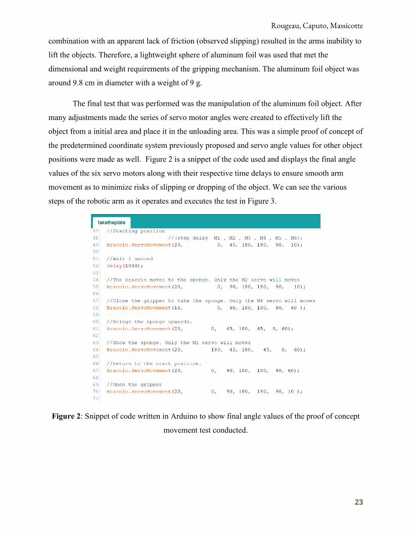
The final test that was performed was the manipulation of the aluminum foil object. After
many adjustments made the series of servo motor angles were created to effectively lift the
object from a initial area and place it in the unloading area. This was a simple proof of concept of
the predetermined coordinate system previously proposed and servo angle values for other object
positions were made as well. Figure 2 is a snippet of the code used and displays the final angle
values of the six servo motors along with their respective time delays to ensure smooth arm
movement as to minimize risks of slipping or dropping of the object. We can see the various
steps of the robotic arm as it operates and executes the test in Figure 3.
Figure 2: Snippet of code written in Arduino to show final angle values of the proof of concept
movement test conducted.

Rougeau, Caputo, Massicotte
24
Figure 3: Snapshots of Braccio Robotic arm executing the test. Step 1 shows initial rest position,
Step 3 is the acquiry of the object and Step 5 is the placement of the object.
Though our testing design uses a jaw gripper, our concept design still utilizes the vacuum
cup system but due to the incompatible coding softwares it was not possible to code the use of a
vacuum system on our Arduino based testing code.
4.3.2 Proximity Sensor Testing
Proximity Sensors were evaluated and we tested their effectiveness and best location. On
the Braccio arm the proximity sensor affixed to various points to find optimum positioning to
best identify plate presence. We selected an infrared proximity sensor for its availability and low
cost.
We used the Sharp GP2Y0A02YK0F infrared proximity sensor. The product’s
specifications stated that the product has a range of measurement of 10 cm to 80 cm. This posed
a few issues from a design perspective as the gripping teeth, to which the sensor is attached, are
around 11 cm apart. Therefore the presence of a plate between the gripping teeth would be at a
distance of only 5 cm, which is out of the sensor’s supposed precision range. Objects placed
closer than the minimum distance range return substantially higher analog outputs that are
inconsistent with the expected in-range results.

Rougeau, Caputo, Massicotte
25
Figure 4: Display of code used for testing of Sharp sensor values.
A test was conducted to see what values are obtained when the object is set under 10 cm
away from the sensor and at varying distances. The setup of the sensor involved connecting the
proximity sensor to the Arduino Uno board and then affixing to a flat surface. A circular
cardboard cut-out was used to replicate a dish and the sensor was used to identify the presence of
the plate. The code used is displayed in Figure 4. It shows the analogRead method used to output
values with a delay of 3 seconds to allow the object to be moved to the next position. The values
obtained can be displayed on the following table.
Table 6: Values of proximity sensor distance test
These values were then graphed to easily identify trends or anomalies.
Rougeau, Caputo, Massicotte
26
Figure 5: Graphical representation of values of proximity sensor distance test
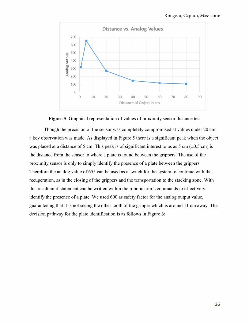
Though the precision of the sensor was completely compromised at values under 20 cm,
a key observation was made. As displayed in Figure 5 there is a significant peak when the object
was placed at a distance of 5 cm. This peak is of significant interest to us as 5 cm (±0.5 cm) is
the distance from the sensor to where a plate is found between the grippers. The use of the
proximity sensor is only to simply identify the presence of a plate between the grippers.
Therefore the analog value of 655 can be used as a switch for the system to continue with the
recuperation, as in the closing of the grippers and the transportation to the stacking zone. With
this result an if statement can be written within the robotic arm’s commands to effectively
identify the presence of a plate. We used 600 as safety factor for the analog output value,
guaranteeing that it is not seeing the other tooth of the gripper which is around 11 cm away. The
decision pathway for the plate identification is as follows in Figure 6:

Rougeau, Caputo, Massicotte
27
Figure 6: Flowchart representation of decision making pathway for plate identification
and communication with arm
During the experiment we also noted certain limitations. The values of interest obtained
were indeed anomalies and replications could prove to be difficult. Additionally when affixed on
the gripper hand, the proximity sensor needs a constant background to successfully identify an
object at the specified distance. The loops in the code above were written with 3 second delays
but when it is attached to the arm, the commencement of the sensor readings must be enabled by
the correct position of the arm which was difficult to code in the loop form of Arduino.
Furthermore, when using infrared sensors, slight changes in light can be significant in sensor
readings. The difference in light values from the testing area to that of its other implementation
environments could be large enough to force the recalibration of the 5 cm window code.
4.3.3 Humidity Considerations
Once the dishwasher has finished cleaning the dishes there will be a release of water
vapor into the air, thus creating a humid environment. This is potentially problematic to our
design because it would begin to corrode the exposed wiring and joints and progress to leave our
arm inoperable. Humidity is a significant problem when considering metallic moving parts and it
is understood that corrosion progresses rapidly when relative humidity levels are raised. This
relationship can be seen in Figure 7 below.

Rougeau, Caputo, Massicotte
28
Figure 7: Rust vs. Relative Humidity (Apiste Corporation, 2018)
This graph was compiled by exposing a metal sheet to the air which includes humidity
and inspecting the respective rusting quantity. This depicts the relationship between rust and
humidity and serves to set a limit to the environment our model arm can withstand. Since we do
not wish to test the limits of the single model arm obtained we decided to brainstorm potential
recommendations to combat this foreseeable issue. The solution discussed was to enclose the
structure and route all the cables internally to equip the arm to handle the most extreme cases as
well as allow the water to flow vertically. An example of this can be seen in Figure 8 below.
Figure 8: Advantage of Cable Orientation (Moisture Protection of Electronics - 2014)

Rougeau, Caputo, Massicotte
29
This in conjunction with routine maintenance and an educated employee staff that would
watch for potential breaks in the enclosure would help to keep the electrical components dry and
working safely.
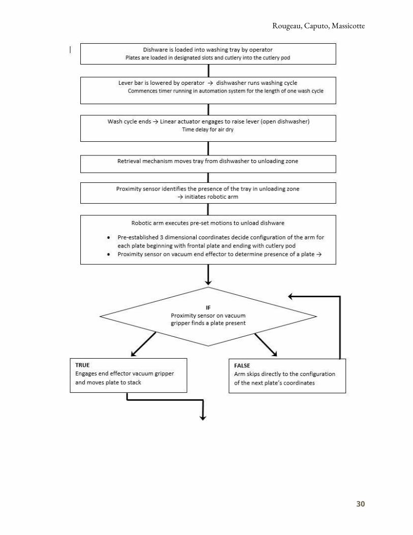
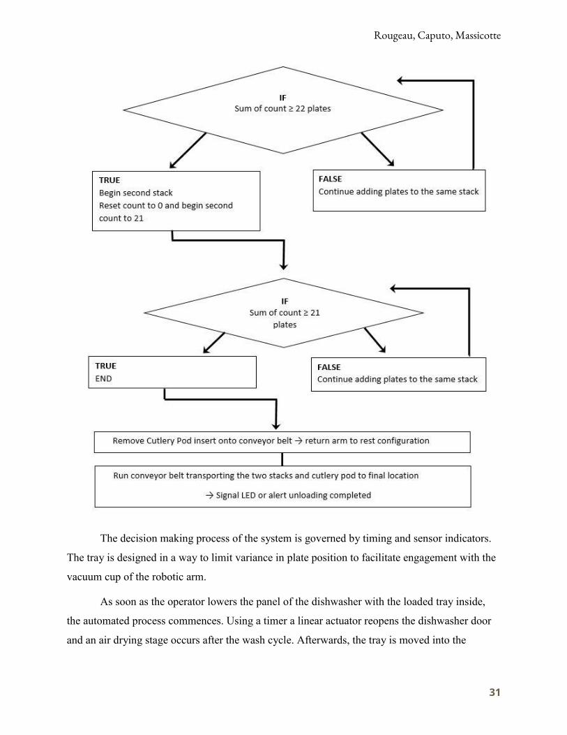
4.4 Process System Flowchart
This is a general overview of individual phases’ communication and processing decisions
in the system:
Rougeau, Caputo, Massicotte
30
Rougeau, Caputo, Massicotte
31
The decision making process of the system is governed by timing and sensor indicators.
The tray is designed in a way to limit variance in plate position to facilitate engagement with the
vacuum cup of the robotic arm.
As soon as the operator lowers the panel of the dishwasher with the loaded tray inside,
the automated process commences. Using a timer a linear actuator reopens the dishwasher door
and an air drying stage occurs after the wash cycle. Afterwards, the tray is moved into the

Rougeau, Caputo, Massicotte
32
unloading zone using a second linear actuator and hook system. A proximity sensor identifies the
tray and the above decision process is executed by the arm and vacuum end effector to unload
and stack the dishware.
In the second stack, the proximity sensor on the end effector maintains a count of present
dishes and empty positions if the dishwasher is under loaded which determines how many plates
total will end up stacked avoiding and infinite false loop. The present dish count determines the
height of placement of the robotic arm as illustrated in Figure 6 in the Appendix. The empty
position count determines when to end the first and/or second stack. Stacks of under 25 plates
were determined to avoid tipping yet limit number of total stacks.
Finally the dish stacks and cutlery pod are moved using a conveyor belt around to the
final position across from the initial loading area. This facilitates the operators’ trip where they
can load the dishwasher tray and simply behind them they can access the cleaned dishware for
immediate use in the restaurant. Alerting systems are available to communicate the completion
of a washing cycle to the operators and will be implemented if deemed necessary by the client.
4.5 Design of Customized Commercial Dishware Rack
In addition to the development of the robotic arm, our team redesigned the current
dishware racks utilized by Pizza 900 to improve the efficiency of the dishwashing process.
Furthermore, by remodeling the trays we are able to ensure a consistent geometrical orientation
of the dishware, enabling us to use a predetermined coordinate system in our programming code
to target the tableware during the unloading stage of the process.
When our team first visited the kitchen facility of Pizza 900 in early September, we
examined their current dishwashing process. The restaurant is equipped with square peg
dishware racks with a side length of 49 cm, which at full capacity can fit 25 pizza plates or
approximately 50 forks and 50 knives. Due to the size of the dishwasher, the development of
larger trays was not feasible, however hefty improvements could be made as the dissimilar
geometries of the current trays and the dishware left a lot of the tray area unused. Moreover, our
team envisioned one single tray able to hold cutlery and pizza plates concurrently to eliminate
the inevitable extra wash cycles the restaurant is running. Pizza 900 utilizes 0.5 cm thick plates
with a diameter of 30.48 cm, therefore in our design it was decided to make the allotted space for
each plate 1 cm wide and 31 cm long. As 49 cm is the limiting factor of the dishwasher for the
Rougeau, Caputo, Massicotte
33
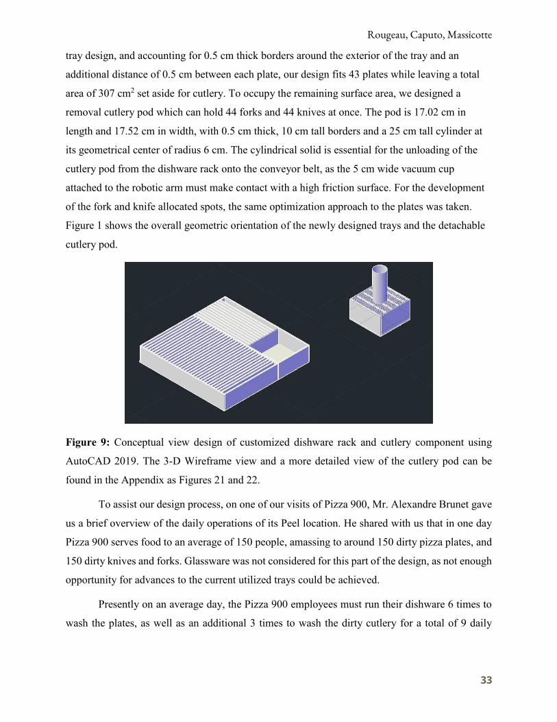
tray design, and accounting for 0.5 cm thick borders around the exterior of the tray and an
additional distance of 0.5 cm between each plate, our design fits 43 plates while leaving a total
area of 307 cm2 set aside for cutlery. To occupy the remaining surface area, we designed a
removal cutlery pod which can hold 44 forks and 44 knives at once. The pod is 17.02 cm in
length and 17.52 cm in width, with 0.5 cm thick, 10 cm tall borders and a 25 cm tall cylinder at
its geometrical center of radius 6 cm. The cylindrical solid is essential for the unloading of the
cutlery pod from the dishware rack onto the conveyor belt, as the 5 cm wide vacuum cup
attached to the robotic arm must make contact with a high friction surface. For the development
of the fork and knife allocated spots, the same optimization approach to the plates was taken.
Figure 1 shows the overall geometric orientation of the newly designed trays and the detachable
cutlery pod.
Figure 9: Conceptual view design of customized dishware rack and cutlery component using
AutoCAD 2019. The 3-D Wireframe view and a more detailed view of the cutlery pod can be
found in the Appendix as Figures 21 and 22.
To assist our design process, on one of our visits of Pizza 900, Mr. Alexandre Brunet gave
us a brief overview of the daily operations of its Peel location. He shared with us that in one day
Pizza 900 serves food to an average of 150 people, amassing to around 150 dirty pizza plates, and
150 dirty knives and forks. Glassware was not considered for this part of the design, as not enough
opportunity for advances to the current utilized trays could be achieved.
Presently on an average day, the Pizza 900 employees must run their dishware 6 times to
wash the plates, as well as an additional 3 times to wash the dirty cutlery for a total of 9 daily

Rougeau, Caputo, Massicotte
34
cycles. With the implementation of the new trays, Pizza 900 will see a 73 % increase in plates per
rack and an addition of 88 cutlery spots per rack, therefore reducing the number of daily
dishwashing cycles 23% from 9 to 6.9. This more efficient system will hence help Pizza 900
maximize returns, lower their environmental impact, and leave more time to its employees to focus
on more productive tasks.
5. Design Considerations 5.1 Environmental Considerations When Mr. Brunet approached us, he envisioned not only a profitable modification to his
restaurant’s daily operations, but also an opportunity to become more environmentally
sustainable. The design made careful use of the facilities already available at the location and
looked to eliminate variable use of water and energy due to human error and interaction.
5.1.1 Water Consumption
Commercial dishwashers vary in their water use from 2.5 to 8.0 gallons of water per
minute, depending on the type of dishwasher (Buschatzke, 2014). When visiting the Peel
location, our team ran a full cycle of the dishwasher and timed it to be precisely 2.1 minutes.
Using these values, the daily water consumption of Pizza 900 at minimum and maximum
conditions with and without the introduction of our newly designed trays can be found.

Rougeau, Caputo, Massicotte
35
In conclusion, the implementation of these customized trays will result in a 23 %
decrease of water usage by the dishwashing system, and Pizza 900 could save more than 60,000
L of water in a year.
Further water savings can be achieved by modifying the current pre-rinsing process of
Pizza 900. A low-flow, high-performance pre-rinse spray valve is in fact the single most cost-
effective piece of equipment for water savings in commercial kitchens and our team has made
numerous recommendations to our client, stressing the benefits of the installation of this
apparatus (Delagah, 2015).
5.1.2 Energy Consumption
In 2003, the U.S. Department of Energy (DOE) established that a minimally compliant
dishwasher would use 2.17 kWh per load of dishes (Hoak and Parker, 2008). Using this value,
the daily energy consumption of Pizza 900 due to the dishwashing equipment with and without
the introduction of our newly designed trays can be calculated.
Once again we notice a 23 % decrease in the KWh consumed by the dishwashing
equipment, amounting to a reduction in energy usage of 1664 KWh in one calendar year. As we
move forward with the project a more thorough energy analysis will be completed, taking into
account the overall energy the whole automated system will consume.
Rougeau, Caputo, Massicotte
36
5.2 Social Considerations
There are two perspectives to consider when discussing the project. The first perspective
is the users. The user must have a simple, but effective time with the new design and feel safe
when in proximity of the operation. The user must also be left ample space to walk around and
input dirty dishes or take clean ones away. The other social perspective to consider is that of the
customer of Pizza 900. The performance of the system must be smooth and not disturb the dining
environment of a customer whether that be noise, smell, malfunction, or even being an eyesore.
5.2.1 Occupational Health and Safety
It is important when considering any process in the workforce that the project considers
the impact to the employees who are directly affected. According to the government of Canada,
“A health and safety program is a definite plan of action designed to prevent accidents and
occupational diseases. Some form of a program is required under occupational health and safety
legislation in most Canadian jurisdictions. A health and safety program must include the
elements required by the health and safety legislation as a minimum” (CCOH, 2018). The basics
of the plan outlined are laid out below:
● Individual responsibility.
● Joint occupational health and safety committee.
● Health and safety rules.
● Correct work procedures.
● Employee orientation.
● Training.
● Workplace inspections.
● Reporting and investigating accidents/incidents.
● Emergency procedures.
● Medical and first aid.
● Health and safety promotion.
● Workplace specific items.
The safety and health of the employees and customers comes first in any design process.
The supervisor will ensure they are familiar with the equipment present and the employees are
properly trained on how to use it. There will be guidelines and warnings posted on the correct

Rougeau, Caputo, Massicotte
37
use of the facilities being used as well as procedures on what to do when a malfunction or
mishap occurs. All personal will be held responsible to maintain the high standard set by the
supervisor and enforcing it amongst other employees. All other relevant laws and regulations
will be incorporated in the program as a minimum.
Further social considerations involve suitable noise level in the workplace. This is to be
monitored in the selection process of vacuum gripping systems primarily in the pump selection.
As the required force to lift a single plate is not enormous, the required mini-pump associated
with the system can easily fit within the bounds of safe noise levels. The Vuototecnica boasts a
small level of less than 50 dB in all their mini pump products (around -.04 bar pressure)
(Vuototecnica, 2018). This value is well below the 90 dB regulatory standard of Quebec
(CCOH, 2018). A second aspect considered in the product selection for the gripping system is
maintenance. There are a wide variety of pumps available with sufficient specifications for the
task that require no lubrication, which significantly reduces maintenance requirements of the
entire system (Vuototecnica, 2018).
It should also be noted that the gripping system being used by the robotic arm will be
detachable and therefore fall under standard sanitization practices once a full use of one day has
concluded. This is within the guidelines set by the MAPAQ and will also help promote a healthy
and enjoyable dining experience for the customers.
5.2.2 Technophobia
Technophobia is the fear or dislike of advanced technologies. With rates of innovation
and technological improvements continuing to rise, technophobia is a rising social issue
particularly in the workforce. Furthermore, technophobes have a higher probability to report
experiencing anxiety-related mental health issues and to fear unemployment and financial
insecurity (McClure, 2017). Therefore, this section assesses the threat of technological
unemployment and the impact our system will have on Pizza 900’s current employees.
One of the main concerns for many is that the job market is diminishing due to increases
in automation. Additionally, many believe not only that work prospects are decreasing but also
that this rapid development of the robotics industry is increasing demand for educated workers
and threatening the survival of the less educated (Acemoglu, 2003). Even those who have
completed a college education may encounter fear of unemployment and financial insecurity as

Rougeau, Caputo, Massicotte
38
software and robots can do human work with higher reliability, higher efficiencies, and lower
costs.
Throughout our design we continuously considered the direct and indirect effects of
introducing our system into Pizza 900’s value chain, taking into account its possible replacement
of the current dishwashing system. When we presented our concerns about a possible rise in
technophobia in his restaurant as a result of this automation, Mr. Brunet explained us that he
didn’t plan on letting go any of his current employees. Rather, he envisions they could be moved
to more productive and less mundane tasks. By taking advantage of the increase in manpower,
Pizza 900 will maximize its profits by increasing the value delivered to customers. Furthermore,
by removing workers from dull responsibilities you can greatly limit workforce depression,
increase collaboration and teamwork, and ultimately maximize profits.
5.3 Risk Factor Matrix
Table 7: Risk Factor Matrix
Keeping the safety of those involved in mind it was important once the design path had
been finalized to consider the possible risks that finished product might entail. The risk factor
matrix in Table 7 was made based on the template used by The United States Department of
Energy. In their system, a risk is ranked from 1-3. The number one is considered the lowest risk,
colored green, and least likely. The number two is moderate risk, colored orange, and moderate
likelihood. The number three is considered the highest risk, colored red, and most likely to occur
(Department of Energy, 2018).

Rougeau, Caputo, Massicotte
39
5.4 Economic Considerations
To accurately determine the economic viability of this design, a thorough financial
analysis must be completed. The following economic analysis is split into two sections: a break
even analysis of the investment in new dishware racks, and a cost-benefit analysis of the whole
envisioned system. Lavotica will experience first mover advantages entering a new market hence
primary market research data is unavailable, therefore several simplifying assumptions were
made.
5.4.1 Break- Even Analysis
Break-even analysis is a financial analysis technique widely used by management and
accountants to determine the break-even point of an investment as shown in Figure 10.
Figure 10: General Break Even Graph (Tutor2u Business, 2018)
To put it simply, total variable and fixed costs with and without the utilization of the
customized trays are compared, to determine the time at which Pizza 900’s investment in the
new trays becomes profitable.
To complete the analysis we must first compute the fixed relevant costs, which are
simply equal to the cost of the customized trays. Polypropylene was chosen to construct our
trays, as its thermal properties enable it to withstand high temperatures and it is a widely used
and affordable plastic (Grebowicz et al., 2007). Using the measure function on AutoCAD 2019,
our team found the total volume of our customized trays and cutlery pod to be 9604 .. 3.

Rougeau, Caputo, Massicotte
40
Using the density of our material, its cost per weight, and the overall volume of our design we
can calculate the total cost of one dishware rack:
Now that the fixed costs involved with the production of new trays have been calculated,
the variable costs must be found to finish the economic analysis. To calculate the variable costs
associated with the dishwashing process, both before and after the implementation of the trays,
the water and energy costs must be found and summed. The Ville de Montreal website specifies
the price of water to be 0.22 $𝑐3 (Ville de Montreal, 2018), while Hydro-Quebec’s Electricity
Rates effective April 1, 2018, for medium power usage, in Montreal are 9.81 cents per KWh
(Hydro Quebec, 2018). The following formulas were used to calculate the total maximum
variable costs, hence at maximum water consumption:

Rougeau, Caputo, Massicotte
41
Using these equations data for total costs for a full calendar year was found and plotted
against time.
Figure 11: Total costs with and without use of customized dishware rack at
maximum water usage.
Figure 11 follows the principles outlined in Figure 10. The fixed costs for the system
presently in motion are $ 0 as no initial investments must be made, while the fixed costs once the
new trays are introduced jump up to $5.10 which is the initial capital expenditure for the
production of the trays. The variable costs then grow at a constant rate proportional to time and
the moment the two curves intersect represents the break-even point. To find the break-even
point we simply equate the total variable plus fixed costs of the current system to the total
variable plus fixed costs of the newly incorporated system and find time. The capital investment
in one tray therefore becomes profitable for Pizza 900 after just 5.6 days. The net savings from
the introduction of the trays at any point in time can be seen in Figure 4, which clearly illustrates
how there is potential to save around $326 in a period of 1 year, a 64 % return on investment.

Rougeau, Caputo, Massicotte
42
Figure 12: Estimated savings at any point in time over a period of 1 year with the
utilization of customized trays.
5.4.2 Cost-Benefit Analysis
Robot utilization has risen exponentially since the 1960s, and the significant advances in
computing technology, artificial intelligence and electronics have contributed to them becoming
safer to use, easier to program, and more affordable. In fact, the price of industrial robots has
fallen more than 25% since 2014 and is expected to continue following this downward trend. The
main factors in determining robot costs are reach, number of axes, application, end of arm
tooling and safety components. Implementing a robotic arm system which could effectively
operate in Pizza 900’s limited kitchen space, considering the costs of conversion, has a cost
structure like the one depicted in Table 8.
Table 8: Cost Analysis of Implementation of Automated Dishwashing System
This breakdown was gathered using appropriate assumptions and data collected from the
costs of similar products in the robotics industry, as Lavotica will experience first mover
advantages entering a new market and primary market research data is therefore unavailable.

Rougeau, Caputo, Massicotte
43
Furthermore, manual labor costs were calculated assuming a total of 40 hours will be needed for
installing the system at a rate of 15 $/hr.
However, to determine the economic viability of this robotic-arm design a detailed
financial analysis must be completed. As the driving reason for Mr. Brunet to implement this
automated dishwashing system is cost reduction, the design must be simultaneously innovative,
reliable, and cost efficient hence enticing restaurant owners to alter their current work
organizational structure. To calculate the true cost of operating the robotic arm, labor cost
savings must be considered. By replacing manual labor with robots, the average global labor-cost
savings could reach 16% worldwide by 2025, and as high as 24% in countries with higher wages
such as Canada (Boston Consulting Group, 2015).
Figure 13 : Labor-cost savings from adoption of advanced industrial robots (%, 2025)
To put these labor cost savings into perspective we can calculate and compare the
operating costs of the current dishwashing system utilized at Pizza 900, vs. the possible state
once Lavotica’s technology is introduced. Assuming 40-hour work weeks, 52 weeks a year, and
considering that after accounting for health care, insurance, income and time off Mr. Brunet
spends $100,000 on dishwasher salaries:
Rougeau, Caputo, Massicotte
44
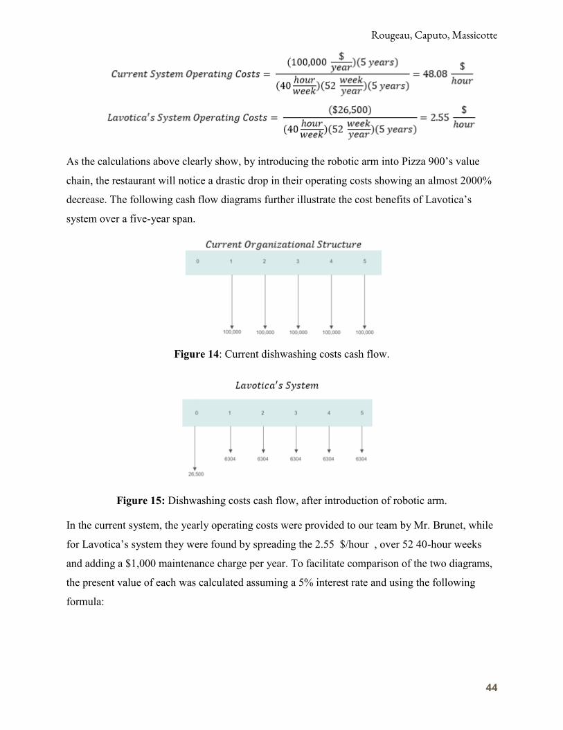
As the calculations above clearly show, by introducing the robotic arm into Pizza 900’s value
chain, the restaurant will notice a drastic drop in their operating costs showing an almost 2000%
decrease. The following cash flow diagrams further illustrate the cost benefits of Lavotica’s
system over a five-year span.
Figure 14: Current dishwashing costs cash flow.
Figure 15: Dishwashing costs cash flow, after introduction of robotic arm.
In the current system, the yearly operating costs were provided to our team by Mr. Brunet, while
for Lavotica’s system they were found by spreading the 2.55 $/hour , over 52 40-hour weeks
and adding a $1,000 maintenance charge per year. To facilitate comparison of the two diagrams,
the present value of each was calculated assuming a 5% interest rate and using the following
formula:

Rougeau, Caputo, Massicotte
45
Therefore, under conventional operational methods in 5 years, Pizza 900 will spend
$432,947.67 on dishwashing services, while with the introduction of Lavotica’s automated
dishwashing system it will only spend $53,793.02. This means that in just five years the
introduction of this new system will directly save $379,154.65 to the Pizza 900 owners.
Additionally, further intangible economic benefits come from the installation of Lavotica’s
automated dishwashing system through increased cleanliness reliability, as well as continuous
operation with minimal human intervention.
5.5 Life Cycle Assessment
Life-cycle assessment (LCA), also known as life-cycle analysis, is a powerful tool to
determine the holistic environmental impacts associated with every stage of a products life, from
material extraction to disposal or recycling (International Organization for Standardization,
2006). After all phases are properly investigated and assessed, the results are then compared and
analyzed among various factors. For the purpose of this design report, the life cycle analysis
aims to determine the energy demand of the washing system operated by Pizza 900.
Furthermore, this LCA investigates the environmental impact, measured as net carbon dioxide
(CO2) emissions because of raw material extraction, production, distribution, consumer use, and
disposal or recycling.
5.5.1 Functional Unit of Analysis, Impact Categories, and System Boundary
For the purpose of this examination, we will use one dirty pizza plate as our functional
unit of analysis. The impact categories that are investigated are CO2 emissions, and total energy
use. These values are calculated over the dishwasher’s lifespan, which Pizza 900 replaces every
decade. Furthermore, the system boundary for this study entails raw material extraction,
manufacturing, and use phase for a dishwasher. Phases such as transportation and end-of-life are
not considered for this section, but rather are discussed further along in the paper.

Rougeau, Caputo, Massicotte
46
5.5.2 Life Cycle Energy Analysis
To begin our analysis, we established through secondary research the total energy
associated with acquiring and processing all the raw materials that comprise an average
dishwasher from 2008. Boustani et al., in their appliance remanufacturing and life cycle energy
and economic savings paper outline this process. First, they gathered raw materials energy
intensity in dishwashers by using the data on the energy cost of common materials. Next,
knowing the raw materials’ energy requirements, the energy demand of raw material acquisition
and processing phase was quantified. Likewise, to quantify the energy used during the
manufacturing and assembly phase we can base our calculations on literary values and multiply
the manufacturing energy intensity by unit mass (Boustani et al., 2010). Their research produced
the following figure illustrating the life cycle energy demands of new appliances:
Figure 16: Life Cycle Energy Assessment of New Appliances (Boustani et al,2010)
The use phase is clearly dominating energy consumption, as it represents around 90% of the life
cycle energy for all three appliances examined. Assuming Pizza 900’s dishwasher has a similar
energy usage structure as the one investigated by Boustani et al., by quantifying energy
consumption during one phase we can find proportionally the energy usage of the remaining
stages.
The direct energy use of Pizza 900’s dishwasher over its lifecycle was calculated using
the energy consumption equations (with the implementation of the customized trays) outlined in
the environmental considerations section of the paper, and is depicted in Figure 17:

Rougeau, Caputo, Massicotte
47
Figure 17: Energy Consumption of Pizza 900’s dishwasher over its 10-year lifespan.
As Figure 17 clearly shows, Pizza 900’s dishwasher will consume around 54640 KWh because
of operation over ten years.
Furthermore, to produce a more comprehensive life cycle analysis, we can calculate the
energy required to heat the water used by Pizza 900’s dishwasher to the desired temperatures.
Assuming the water comes in at 15 °C, and must reach a temperature of 35 °C, the total energy
used to heat water can be calculated as follows:
If we assume maximum water consumption (526.7 L/day), and use values under standard
atmospheric conditions for both the density and specific heat of water, then the daily energy
needed to heat the water is:
If we then multiply this usage of energy times the lifespan of the dishwasher we can
quantify the total energy consumption due to water heating for Pizza 900’s dishwasher:
Therefore, the total energy consumption during operation of the dishwasher over 10 years is
98440 kWh.

Rougeau, Caputo, Massicotte
48
Now using proportional analysis gathered through secondary research, we can calculate
the energy consumed during raw materials processing and manufacturing:
Now that we successfully quantified the holistic energy consumption of a dishwasher, we
can assess its impact to climate change in terms of kg of carbon dioxide emitted. Holistic Energy
Consumption=98840+9844+2953.2=111637.2 kWh which is equivalent to 78.9 metric tons of
Carbon Dioxide Equivalent (EPA, 2018). To put this number into perspective the following
figure was developed:
Figure 18: Carbon Dioxide Equivalences to life cycle energy use of Pizza 900 dishwasher
5.5.3 End of Life Strategies
In this section, the energy impacts associated with disposing or recycling of the
dishwashing system were investigated. First, we looked at the impact transportation to a local
landfill or recycling facility has after conducting a detailed literature review on the topic, we
assumed a traveling distance of around 50 miles. From Keoleian study, we gathered the typical
transportation energy of a diesel-operated tractor-trailer is about 2.05 MJ per ton-miles of
transport, shifting our focus to the energy consumed during the actual disposal or recycling

Rougeau, Caputo, Massicotte
49
process (Keoleian et al., 1997). In the case of system disposal, we made the simplifying
assumption that the energy consumption of this end-of-life process is negligible. This enabled us
to better investigate the energy impacts of disposal as an end game strategy, which turn out to be
less than 0.02% of the total life cycle energy (Boustani et al., 2010).
As an alternative to disposal, our system could be recycled for parts, remanufactured to
increase its lifespan, or donated to an educational institute to be used for research rather than
industrial purposes. All three of these are likely to be net energy-expending, as a result of energy
consumption during transportation and end life treatments. Nevertheless, remanufacturing of
appliances can increase their energy ratings and efficiency, making these options viable if the
right conditions apply.
In conclusion, the dishwashing system does have significant negative effects on the
environment, further stressing the added sustainability value from the introduction of our
customized dishware racks. Furthermore, our robotic arm system will have a longer lifespan than
the dishwashers currently operated, decreasing its net carbon footprint.
6. Conclusion
The automatic stacking unit design for Pizza 900 will fulfill the desired parameters set in
the scope of this project. The system will eliminate the necessity for someone to reorganize the
dishware once the wash cycle has concluded. Additionally, with the design of the newly
customized trays Pizza 900 will reduce the amount of daily water consumed by increasing the
capacity of the trays. This innovation will minimize Pizza 900’s environmental impact by not
only decreasing water usage, but also energy consumption.
The trend of increasing automation has been facilitated in part by the newest
technological advancements in fields such as sensor research and robotics in combination with
the decreasing price of automation in general. A great reduction in initial capital investment in
the past decade have allowed for projects such as Lavotica to be viable alternatives to
traditionally labor intensive aspects of businesses.
This projects aimed to propose an overall system concept with economic, environmental
and social justifications to solve a common issue of cost of labor in industry. We proposed a
system that would be able to be integrated into the existing environment of operation of our
Rougeau, Caputo, Massicotte
50
client. We concentrated on critical components of this overall design to conduct testing and see
that our concepts could indeed be applied at the fundamental levels.
Lavotica is excited to see the future of the project as our client contacts us with invested
interest in our system overview and plans to use our research in the next phase of his plan to
implement a full-scale operational semi-autonomous dish unloading system at Pizza 900 with the
plan to expand even further afterwards.
6.1. Recommendations
This system that was envisioned by this design still has much room to grow and improve.
It should be noted that optimizing the movement of the arm, a recapture system for the water
used, a heat exchanger to optimize the drying cycle of the dishwasher, further optimization of the
dishwasher, and alternative powering would all increase the efficiencies of the project. Also, a
system to deal with food waste generated by the scraping of leftovers would be beneficial form
an environmental standpoint.
If the client allows it, we would recommend further work to be taken on this project. In,
fact, this project could be divided into several aspects that each could be investigates as stand-
alone research design concepts. The unloading phase, using a robotic arm was chosen to be the
focus of this testing phase the tray retrieval system from the dishwasher as well as the conveyor
belt and possible cleanliness quality checkpoints using computer vision are all areas that are of
great interest for the project.
We recommend using a more precise robotic arm system which the final budget permits.
This arm should have waterproofing and corrosion resistant components to cover the metal
moving parts of the system as well as the exposed wires. This aspect is of great importance as
humidity not only limits the operational lifespan of the system but the oxidation of metals
threatens the risk of rust contamination in dishes which could be a health concern to clients as
well as the fact that unprotected wires in the presence of moisture pose a risk of electrical fires.

Rougeau, Caputo, Massicotte
51
7. References
Acemoglu, D. (2003). Technology and inequality. The National Bureau of Economic
Research. Retrieved from http://www.nber.org/reporter/winter03/technologyandinequality.html
Art - Linear Actuator. (n.d.). Retrieved from http://www.intellidrives.com/Article-Linear-
Actuator
Bélanger-Barrette, M. (2015). Robohub. Retrieved from https://robohub.org/how-many-
axes-does-my-robot-need/
Benet, G., Blanes, F., Simó, J., & Pérez, P. (2002). Using infrared sensors for distance
measurement in mobile robots. Robotics and Autonomous Systems, 40(4), 255–266.
https://doi.org/10.1016/s0921-8890(02)00271-3
Binstock, J. (2013). Life Cycle Analysis: Comparison of Hand-Washing and Dishwasher
Machines. Retrieved from https://www.ioes.ucla.edu/wp-content/uploads/handwashing-vs-
dishwashing.pdf.
Birkmeyer, P. M., Pouliot, L. H., & Peters, K. M. (2017). US20180036889A1 - Dish
Manipulation Systems And Methods. Retrieved from
https://patents.google.com/patent/US20180036889A1/en
Boston Consulting Group. (2015, February 02). How a Takeoff in Advanced Robotics
Will Power the Next Productivity S... Retrieved from
https://www.slideshare.net/TheBostonConsultingGroup/robotics-in-manufacturing
Boustani, A. et al. (2010). Appliance remanufacturing and life cycle energy and
economic savings. Institute of Electrical and Electronics Engineers.
Buschatzke, T. (2014, March 27). Technologies - Kitchen Equipment. Retrieved from
http://www.azwater.gov/AzDWR/StatewidePlanning/Conservation2/Technologies/Tech pages
templates/KitchenEquipment.htm
Cable orientation - Moisture Protection Of Electronics. (2014, April 22). Retrieved from
https://www.efficientplantmag.com/2013/09/moisture-protection-of-electronics/
Canadian Centre for Occupational Health. (2018, November 29). (none). Retrieved from
https://www.ccohs.ca/oshanswers/phys_agents/exposure_can.html

Rougeau, Caputo, Massicotte
52
Cheng, H., Chen, A. M., Razdan, A., & Buller, E. (2011). Contactless gesture recognition
system using proximity sensors. 2011 IEEE International Conference on Consumer Electronics
(ICCE), . https://doi.org/10.1109/icce.2011.5722510
Cutting-Edge Conveyor Systems. (n.d.). Retrieved from
https://www.mknorthamerica.com/
Delagah, A. (2015). Water conservation in commercial apps. Retrieved from
https://www.hpacmag.com/features/water-conservation-in-commercial-apps/
Department of Energy. (n.d.). Retrieved from https://www.energy.gov/
DUDSON, Gibson, S. (2018). Dudson Pizza Plate Enquiry [E-mail to the author].
EPA. (2018, October 15). Greenhouse Gas Equivalencies Calculator. Retrieved from
https://www.epa.gov/energy/greenhouse-gas-equivalencies-calculator
G. Keoleian, K. Kar, M. Manion, J.W. Bulkley (1997). Industrial ecology of the
automobile: A life cycle perspective: Society of Automotive Engineers.
Grebowicz, J., Lau, S., & Wunderlich, B. (2007, March 08). The thermal properties of
polypropylene. Retrieved from https://onlinelibrary.wiley.com/doi/abs/10.1002/polc.5070710106
Guelker, M. (2014). The difference between robotic grippers with parallel, three-finger,
and angled designs. Retrieved from https://www.machinedesign.com/robotics/difference-
between-robotic-grippers-parallel-three-finger-and-angled-designs
Hoak, D., & Parker, D. (2008). How Energy Efficient Are Modern Dishwashers?
Retrieved from https://aceee.org/files/proceedings/2008/data/papers/1_123.pdf
How Many Axes Does Your Robot Need? (n.d.). Retrieved from
https://www.asme.org/engineering-topics/articles/robotics/many-axes-does-robot-need
Hydro Quebec. (2018). 2018 Electricity Rates. Retrieved from
http://www.hydroquebec.com/data/documents-donnees/pdf/electricity-rates.pdf
International Organization for Standardization. (2006). ISO 14040: 2006. Retrieved from
ISO: https://www.iso.org/standard/37456.html

Rougeau, Caputo, Massicotte
53
Jachowicz, R., Wójtowicz, G., & Weremczuk, J. (2000). A non-contact passive
electromagnetic transmitter to any capacitive sensor — design, theory, and model tests. Sensors
and Actuators A: Physical, 85(1-3), 402–408. https://doi.org/10.1016/s0924-4247(00)00398-8
Lenntech. (2018). Water Treatment Solutions. Retrieved from
https://www.lenntech.com/polypropylene.htm
Linear Actuators. (n.d.). Retrieved from https://www.windynation.com/linear-actuators
MAPAQ Accueil. (n.d.). Retrieved from
https://www.mapaq.gouv.qc.ca/fr/Pages/Accueil.aspx
McClure, P. K. (2017). “You’re Fired,” Says the Robot. Social Science Computer
Review, 36(2), 139-156. doi:10.1177/0894439317698637
Operations: Introduction to Break-even Analysis | tutor2u Business. (n.d.). Retrieved
from https://www.tutor2u.net/business/reference/operations-introduction-to-break-even-analysis
Pizza 900 Logo- Baillargeon, Régis. “Pizzeria No. 900: Chirurgiens De La Pizza.”
Bienvenue Sur Mon Blogue Culinaire., 21 Mar. 2016, blog-bouffe-regis-baillargeon.over-
blog.com/2016/03/pizzeria-no-900-chirurgiens-de-la-pizza.html.
RH vs Rust - Effect of humidity on electronic devices|Technical Information|Apiste
Corporation. (n.d.). Retrieved from http://www.apiste-
global.com/enc/technology_enc/detail/id=1263
Richter, P. (2010, February 01). Automatic dishwashers: Efficient machines or less
efficient consumer habits? Retrieved from
https://onlinelibrary.wiley.com/doi/full/10.1111/j.1470-6431.2009.00839.x
SCHMALZ GmbH: Innovative Vacuum Technology from Schmalz. (2018). Retrieved
from https://www.schmalz.com/en/vacuum-knowledge/the-vacuum-system-and-its-
components/system-design-calculation-example/theoretical-holding-force-of-a-suction-cup/
Statista. (2018). Polypropylene price U.S. 2005-2020 | Statistic. Retrieved from
https://www.statista.com/statistics/796033/us-price-of-polypropylene/Ville de Montreal. (2018).
User fees for water and solid waste services. Retrieved from
http://ville.montreal.qc.ca/portal/page?_pageid=44,289391&_dad=portal&_schema=PORTAL

Rougeau, Caputo, Massicotte
54
Vuototecnica. (2018). Vacuum pumps and pumpsets. Retrieved from
http://www.vuototecnica.co.uk/products.php?cat=111
Yurtoğlu, N. (2018). Http://www.historystudies.net/dergi//birinci-dunya-savasinda-bir-
asayis-sorunu-sebinkarahisar-ermeni-isyani20181092a4a8f.pdf. History Studies International
Journal of History, 10(7), 241-264. doi:10.9737/hist.2018.658
Zhang, T., & Goldberg, K. (2001). Design of robot gripper jaws based on trapezoidal
modules. Proceedings 2001 ICRA. IEEE International Conference on Robotics and Automation
(Cat. No.01CH37164), . https://doi.org/10.1109/robot.2001.932735

Rougeau, Caputo, Massicotte
55
8. Appendix
8.1 Calculations of Vacuum Cup Size
Figure 19: Free body diagram of forces involved in vertical vacuum cup configuration
(SCHMALZ, 2018)

Rougeau, Caputo, Massicotte
56
Note: Value of coefficient of friction based on damp ceramic surface (minimum). ΔP value is
taken as standard for mini pump vacuum systems (SCHMALZ, 2018)
8.2 Stacking Count System Diagram
Figure 20: Schematic representation of stacking system that uses present plate count to sum the
height of the next plate’s placement. Each present plate adds to a total height starting at 0 cm
adding plate thickness, 0.5 cm, to each placement position.

Rougeau, Caputo, Massicotte
57
8.3 AutoCAD Design of Customized Dishwasher Trays
Figure 21: 3D Wireframe view design of customized dishware rack and cutlery component
using AutoCad 2019.
Figure 22: 3D Wireframe detailed view design of customized cutlery pod using AutoCad 2019.
Note: Dimensions and proportions are discussed in detail in the design implementation section.
Related Documents