Autonomous SLAM Robot MECHENG 706 Daylin Alvares, Akshay Khatri, Aman Mehta, Perzaan Mehta Project Report PROJECT IN MECHATRONICS ENGINEERING Department of Mechanical Engineering The University of Auckland 5 June 2016

Welcome message from author
This document is posted to help you gain knowledge. Please leave a comment to let me know what you think about it! Share it to your friends and learn new things together.
Transcript

Autonomous SLAM Robot
MECHENG 706
Daylin Alvares, Akshay Khatri, Aman Mehta, Perzaan Mehta
Project Report
PROJECT IN MECHATRONICS ENGINEERING
Department of Mechanical EngineeringThe University of Auckland
5 June 2016

This page was intentionally left blank.
ii
iii
Executive Summary
The aim of this project was to design and create an autonomous vacuum cleaner whoseprimary objective is to maximise area coverage over an unknown environment. In order toeffectively complete the task at hand, the robot was designed using SLAM methodologiesand principles to allow it to localise itself and map the entire arena. A multi-directionalmecanum wheel robot controlled by an Arduino Mega microcontroller along with a rangeof sensors were compiled together for the purpose of allowing the robot achieve SLAM ob-jectives. The sensors were set up strategically to optimise the inflow of relevant informationto the robot.
The Arduino is programmed with robust software in order to equip it with the necessarylogic required to effectively navigate around the room and avoid any obstructions. Further-more, the robot can reproduce its surrounding in the form of a basic 2D map when usedin conjunction with the developed Windows Form application. The application can plot themap in real time using the data sent from the robot and can differentiate between obstaclesand walls. The absolute location of the robot can be calculated and the path that has beentraversed is also displayed.Overall the resulting product is robust and meets all the projectrequirements.
iv

Table of Contents
1 Introduction . . . . . . . . . . . . . . . . . . . . . . . . . . . . . . . . . . . . . . 1
2 Problem Specification . . . . . . . . . . . . . . . . . . . . . . . . . . . . . . . . . 1
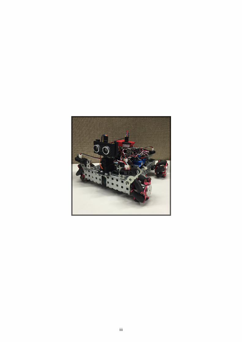
3 Hardware . . . . . . . . . . . . . . . . . . . . . . . . . . . . . . . . . . . . . . . . 13.1 Robotic Platform . . . . . . . . . . . . . . . . . . . . . . . . . . . . . . . . . 1
3.1.1 Arduino Mega 2560 . . . . . . . . . . . . . . . . . . . . . . . . . . . 23.1.2 Mecanum Wheels . . . . . . . . . . . . . . . . . . . . . . . . . . . . 2
3.2 Sensors . . . . . . . . . . . . . . . . . . . . . . . . . . . . . . . . . . . . . . 23.2.1 IR Sensors . . . . . . . . . . . . . . . . . . . . . . . . . . . . . . . . 23.2.2 MPU-9150 . . . . . . . . . . . . . . . . . . . . . . . . . . . . . . . . 33.2.3 HC-SR04 SONAR . . . . . . . . . . . . . . . . . . . . . . . . . . . . 4
3.3 Signal Processing . . . . . . . . . . . . . . . . . . . . . . . . . . . . . . . . . 53.4 Sensor Placement . . . . . . . . . . . . . . . . . . . . . . . . . . . . . . . . . 6
4 Software . . . . . . . . . . . . . . . . . . . . . . . . . . . . . . . . . . . . . . . . 74.1 Software Architecture . . . . . . . . . . . . . . . . . . . . . . . . . . . . . . . 7
4.1.1 Class Interaction . . . . . . . . . . . . . . . . . . . . . . . . . . . . . 74.1.2 Executional Structure . . . . . . . . . . . . . . . . . . . . . . . . . . 7
4.2 Sensor Interface . . . . . . . . . . . . . . . . . . . . . . . . . . . . . . . . . . 84.3 Motor Interface . . . . . . . . . . . . . . . . . . . . . . . . . . . . . . . . . . 94.4 Obstacle Handler . . . . . . . . . . . . . . . . . . . . . . . . . . . . . . . . . 10
4.4.1 Obstacle Detection . . . . . . . . . . . . . . . . . . . . . . . . . . . . 104.4.2 Obstacle Avoidance . . . . . . . . . . . . . . . . . . . . . . . . . . . . 12
4.5 Path Controller . . . . . . . . . . . . . . . . . . . . . . . . . . . . . . . . . . 134.5.1 Path Initialisation . . . . . . . . . . . . . . . . . . . . . . . . . . . . . 134.5.2 Path Following . . . . . . . . . . . . . . . . . . . . . . . . . . . . . . 16
4.6 Mapping and Localisation . . . . . . . . . . . . . . . . . . . . . . . . . . . . 184.6.1 Localisation . . . . . . . . . . . . . . . . . . . . . . . . . . . . . . . . 184.6.2 Mapping . . . . . . . . . . . . . . . . . . . . . . . . . . . . . . . . . . 19
5 Results and Discussion . . . . . . . . . . . . . . . . . . . . . . . . . . . . . . . . 205.1 Demonstration Performance . . . . . . . . . . . . . . . . . . . . . . . . . . . 205.2 SLAM Taxonomy . . . . . . . . . . . . . . . . . . . . . . . . . . . . . . . . . 21
5.2.1 Volumetric vs Feature Based . . . . . . . . . . . . . . . . . . . . . . 215.2.2 Topological vs Geometric . . . . . . . . . . . . . . . . . . . . . . . . 215.2.3 Known vs Unknown Correspondence . . . . . . . . . . . . . . . . . 215.2.4 Small vs Large Uncertainty . . . . . . . . . . . . . . . . . . . . . . . 215.2.5 Active vs Passive . . . . . . . . . . . . . . . . . . . . . . . . . . . . 215.2.6 Anytime vs Any Space . . . . . . . . . . . . . . . . . . . . . . . . . 21
6 Conclusions . . . . . . . . . . . . . . . . . . . . . . . . . . . . . . . . . . . . . . . 226.1 Conclusion . . . . . . . . . . . . . . . . . . . . . . . . . . . . . . . . . . . . 226.2 Suggested Improvements . . . . . . . . . . . . . . . . . . . . . . . . . . . . . 22
v
List of Figures
Figure 1 IR Sensor Readings . . . . . . . . . . . . . . . . . . . . . . . . . . . . 3Figure 2 MPU Gyroscope Readings . . . . . . . . . . . . . . . . . . . . . . . . 4Figure 3 SONAR Readings . . . . . . . . . . . . . . . . . . . . . . . . . . . . . 5Figure 4 Filtered IR Readings . . . . . . . . . . . . . . . . . . . . . . . . . . . 5Figure 5 Sensor Placements . . . . . . . . . . . . . . . . . . . . . . . . . . . . . 6Figure 6 Class Diagram . . . . . . . . . . . . . . . . . . . . . . . . . . . . . . . 7Figure 7 Executional Structure . . . . . . . . . . . . . . . . . . . . . . . . . . 8Figure 8 Meccanum Wheel Logic . . . . . . . . . . . . . . . . . . . . . . . . . 10Figure 9 Sweep FSM . . . . . . . . . . . . . . . . . . . . . . . . . . . . . . . . 11Figure 10 Inner Spiral Obstacle Detection . . . . . . . . . . . . . . . . . . . . . 12Figure 11 Obstacle Avoidance FSM . . . . . . . . . . . . . . . . . . . . . . . . . 12Figure 12 Zeroing FSM . . . . . . . . . . . . . . . . . . . . . . . . . . . . . . . 14Figure 13 Stages of Zeroing . . . . . . . . . . . . . . . . . . . . . . . . . . . . 16Figure 14 Drive FSM . . . . . . . . . . . . . . . . . . . . . . . . . . . . . . . . . 16Figure 15 Localisation Diagram . . . . . . . . . . . . . . . . . . . . . . . . . . . 19Figure 16 Mapping and Localisation Software . . . . . . . . . . . . . . . . . . . 20Figure 17 Demonstration Trace . . . . . . . . . . . . . . . . . . . . . . . . . . . 20
List of Tables
Table 1 Available IR sensors . . . . . . . . . . . . . . . . . . . . . . . . . . . . 2
vi

1. Introduction
With technology trends moving fast towards autonomous, self sufficient and intelligentmachines, the development of SLAM (simultaneous localisation and mapping) algorithmsare not only advantageous but even essential to emerging technologies such as self drivingcars/forklifts. Whilst the concept of SLAM was first proposed in the 90’s, it is only inrecent years that the technology and computational power required to solve the problem tosome degree has become available .
An autonomous vacuum cleaner would provide immense benefit allowing one to maintainthe hygiene standards of their home without having to waste their own time doing it orspending money contracting it out.The report below details the design and development ofa robot able to autonomously navigate through a foreign environment utilising a SLAMalgorithm.
2. Problem Specification
The SLAM project draws aspects from many disciplines across engineering. To completethis project successfully an in depth understanding into sensing, signal processing andprogramming will be required.
The aim of the project is to build a robot that can traverse across a flat rectangulararena autonomously whilst maximising area coverage, reducing running time and avoidingobstacles. Additionally the path traversed by the robot must be recorded and a map of thesurroundings is to be constructed from the data gathered from the sensors.
A mobile robotic platform with mecanum wheels has been provided. The platform providesa chassis for the sensors, motors and microcontroller to be mounted on. To effectivelycomplete the project the microcontroller will need to be programmed to compute sensorreadings and apply logic to manipulate the robot’s movement appropriately.
3. Hardware
3.1 Robotic Platform
The following pieces of hardware were provided for the development of the project. Thelist was as follows:
• Arduino Mega 256 controller
• 4 servo motors - driver included
• 4 mecanum wheels to facilitate manoeuvring in all directions
• A 12V Lipo battery
• A steel chassis
• 4 IR sensors
• MPU-9150
• A Bluetooth module
1

• A SONAR sensor with a servo motor
Whilst all the equipment in the list above is not necessarily required to be used for theproject, the list is exhaustive and no additional pieces of hardware were allowed to beincorporated into the final product
3.1.1 Arduino Mega 2560
An Arduino Mega 2560 microcontroller is the main processor of the system and is re-sponsible of sending signals to the motors and receiving signals from the range of sensorsthat can be use. The bluetooth module allows for wireless serial communication of themicrocontroller to serial monitors and processors which in turn can be used for the mappingand localisation of the robot.
3.1.2 Mecanum Wheels
The 4 mecanum wheels work in conjunction with each other to provide omni-directionalmotion of the robot. It is able to be manoeuvred anywhere within the X and Y planeswhile being able to rotate in the Z axis. The wheels are controlled through the motors andtheir respective drivers and powered using the Lipo battery.
3.2 Sensors
3.2.1 IR Sensors
There were three different IR sensors that were made available for use (see Table 1), eachwith a different working range in which it would detect distance accurately.
Sensor Type Model Number RangeShort Range D120XJ0 4cm - 30cm
Medium Range 2Y0A21 10cm - 80cmLong Range 2Y0A02 20cm - 150cm
Table 1 Available IR sensors
It was decided that the limited range of the short range sensors would not be suitable forour application as the size of the board was fairly large. The medium range sensors havea similar minimum distance to the short range sensors but can also detect over doublethe maximum distance. Testing was carried out on the long range and medium range IRsensors to confirm the working range and linearity of results.
2

Figure 1 IR Sensor Readings
From experiments conducted (see Figure 1) , it was found that the medium range IR sensorswere very accurate and linear within their working range of 10cm to 80cm. However, thelong range sensors were less accurate and not as linear within their working range.
As a result of the irregularity of the response from the long range sensors, it was decidedthat the the two long range sensors would be exchanged for two medium range sensorsinstead.
3.2.2 MPU-9150
The MPU-9150 is a 9 degrees of freedom motion processing unit (MPU) consisting of a3-axis accelerometer, gyroscope and magnetometer.
Initial testing on yaw reading was done using a open-source library for the MPU tocalculate the yaw reading. The open source library implemented sensor fusion between allthree sensor reading to calculate an accurate output. However, the sensor fusion algorithmwas very computationally expensive. This reduced the responsiveness of the robot as it wassampling sensor readings less frequently.
3

Figure 2 MPU Gyroscope Readings
To find a solution testing was done on integrated gyroscope readings (see Figure ??). Afterfiltering the raw data, the integrated gyroscope angular velocity had minimal drift. Thismethod provided a reliable measurement which was used to determine the orientation ofthe robot.
3.2.3 HC-SR04 SONAR
The HC-SR04 SONAR sensor was provided. This distance sensor has the largest workingrange of the distance sensors provided (2cm - 400cm). This sensor can detect both asmaller minimum and maximum distance than any of the supplied IR sensors, making itthe most effective sensor available according to the data sheets. Testing was carried outto see how accurate and linear the SONAR measurement were, the results are shown inFigure 3
4

Figure 3 SONAR Readings
3.3 Signal Processing
In order to be able to use the sensor readings to make control decisions, signal processingis necessary to give steady responsive outputs. A filter library was used to implementdigital filters on all the sensors. The IR sensors were filtered using a 3Hz low-pass filter,the sonar uses a 5Hz low-pass filter and the gyroscope uses a 1Hz low-pass filter. All thecut-off frequencies were determined through empirical means to attenuate high frequencynoise but maintain sensor responsiveness. Figure 4 shows the effect of the low-pass filteron the IR sensor readings.
Figure 4 Filtered IR Readings
5

3.4 Sensor Placement
Sensor placement was heavily dependent on the path that the robot was to take. Initiallythe robot was meant to follow a square-wave pattern. For this case, two side IR sensorswere mounted on both the left and right side of the robot, one by each wheel. The sonarwas mounted on a servo at the front of the robot, facing forwards (see Figure 5a). Thisprovided perception on all sides of the robot, except for the back. This was adequate giventhat the robot would not need to drive backwards at any point. The servo motor would beused to sweep the SONAR for obstacle detection while the side IR sensors would allowthe robot to detect where it should be in relation to the walls.
(a) Sensor Placements for Square-wave (b) Sensor Placements for Spiral
Figure 5 Sensor Placements
The planned path was later changed to an inward spiral to reduce the path complexity.The sensors were then relocated to prevent the robot from sampling redundant information.Two of the IR sensors were placed on the front of the robot, the other two IR sensors wereplaced on the left side of the device, one on the front half and the other on the back half.The sonar remained front and centre facing forward (see Figure 5b).
The two IR sensors on the side of the robot work in conjunction with the MPU to keepthe robot aligned with the wall when spiralling and also to detect when an obstacle haspassed on its left side during the obstacle avoidance. The two front IR sensors would beused in conjunction with the SONAR sensor to aid in obstacle detection. Since the robotwould consistently be spiralling clockwise, sensors on the right side of the robot were nolonger required.
6

4. Software
4.1 Software Architecture
The following two sections portray two main aspects of the software architecture; classinteraction and executional structure.
4.1.1 Class Interaction
The class interaction involves a low level to high level data flow. The low level hardwaredriver classes i.e. Sensor Interface and Motor Interface pass information onto the ObstacleHandler class. The Path Control class which contains the top level logic has access toall the lower level classes. This is the extent of data flow on board the Arduino. Furtherto this data is fed via serial Bluetooth communication to the external processor runningthe slam algorithm to produce a map of the robot’s environment. Figure 6 illustrates theinteraction between classes.
Figure 6 Class Diagram
4.1.2 Executional Structure
The executional structure explains the overall functionality of the architecture. During thesetup method, the initialisation methods are called for each class. Then a single methodis called in a loop that carries out a set of instructions every iteration (see Figure 7). Atthe beginning of each loop the latest sensor readings are updated, these readings are thenused to implement control logic for the remaining instructions in that iteration. This isan essential step to ensure comparability of readings throughout an entire iteration. Theiteration frequency is sufficiently large resulting in a fast refresh rate and minimal sacrificein response sensitivity. The control logic is implemented in a single finite state machine(FSM) - Drive which contains three sub-FSMs for zeroing at start up, avoiding obstaclesand performing a sonar sweep. The FSMs implement the full functionality of the robotand will be further explained in this section.
7

Figure 7 Executional Structure
4.2 Sensor Interface
The Sensor Interface class is used to obtain readings from the MPU, IR and Sonar sensorsand convert the raw data into useful information. The following methods have beenimplemented to produce the desired functionality.
UpdateSensors: The UpdateSensors method updates the class attributes that correspond toeach of the relevant sensors (Left-Front/Right-Front/Side-Front/Side-Back IR sensors, Sonarand MPU) . It does this by calling an internal function to read the sensors. For the IRsensors, the arduino reads from the relevant analog pin. The distance in cm is calculatedusing Equation (1). Since the medium range sensors are only accurate in the range 10-80cmthe readings are capped at these limits. The raw input is then filtered and stored as theappropriate attribute.
Distance =4800
readV alue− 20(1)
The sonar sensor is implemented by sending a 10 microsecond pulse from the trigger pin.A pulse is then returned when the sound wave reflects of a surface back to the sonar. Thispulse is read as a duration from the echo pin and the distance in cm is calculated usingEquation (2). The sonar reading is then filtered and stored as the appropriate attribute.
Distance = duration× 0.034
2(2)
The gyroscope readings are obtained using the MPU9150BasicAHRS library. The gyroscopemeasures angular velocities in the X, Y and Z directions. Based on the MPU orientation onthe robot, the Z gyroscope reading is needed to determine the relevant angular displacementof the robot. The reading is filtered and passed through an integration algorithm that uses
8

the trapezium rule and the elapsed time between readings to convert the angular velocityto an angular displacement in degrees. This angular displacement is then stored as theappropriate attribute.
GetSensorReading: This method takes a sensor type as an input and returns the valueof the most recent measurement taken by that sensor. This method in conjunction withUpdateSensors ensures that all sensor readings are comparable as they were all taken atthe same time. As long as UpdateSensors is called repeatedly at high frequency this makesthe sensor measurement system highly robust without compromising on sensitivity.
ResetAngle: This method resets the angular displacement to 0. It is used at the end ofzeroing to allow the path control algorithm to work effectively. It can also be used tocounteract gyroscope drift which can cause a large integration error. This however is notrequired in the scope of this project and the drift is negligible for the required runtime.
4.3 Motor Interface
The Motor Interface is the driver which controls the four continuous rotation servo motors.The Arduino ’Servo.h’ library is used to write a value (in microseconds) to the servo. Theshaft output responds accordingly. A write value of 1500 corresponds to 0 angular velocity,values above 1500 result in counter clockwise motion and values below 1500 rotate theservo shaft clockwise.
The wheel logic shown in Figure 8 was implemented in separate member methods toproduce the desired motion. In addition to those shown in the diagram CorrectLeft andCorrectRight were developed. These two methods rotate the left and right front wheelsin the opposite direction to pivot the robot right or left. In all the movement methodsa multiplier value must be given as the argument. A multiplier of 1 will increment ordecrement the nominal write value (1500) by 100 microseconds to rotate the wheel counter-clockwise or clockwise, respectively. A multiplier of 2 changes the increment/decrementvalue to 200 and so on. The use of multipliers means that speed controllers can bedeveloped to vary the output shaft speed dynamically and produce smoother, more efficientmovements.
9

Figure 8 Meccanum Wheel Logic
4.4 Obstacle Handler
All obstacle detection and avoidance logic was implemented within the ObstacleHandlerclass. The following section explains the algorithms implemented to achieve the desiredfunctionality.
4.4.1 Obstacle Detection
Obstacle detection involved both detecting the object in front of the robot as well asdetermining if the object is an obstacle or a wall. The logic was implemented using thefollowing three methods:
1. DetectObstacle: This method is called from WallFollow within PathControl. It checksif the two front IR sensors and front SONAR sensor return a value below 20cm. Ifso, the DetectObstacle function returns a true boolean to WallFollow, otherwise itreturns a false. Each of the sensors also sets a flag within ObstacleHandler when anobstacle is detected.
2. GetObstacleType: This method is called from WallFollow within PathControl if anobstacle has been detected by DetectObstacle. It checks which sensor flags havebeen raised by DetectObstacle to try and determine whether the robot is up againsta wall or an obstacle, and if it’s an obstacle its position. It first checks that if the allthe sensors are showing values within 6cm of each other regardless of whether theirflags have been raised or not, the function communicates to WallFollow that a wall
10

is present. It then checks for which sensor flags have been set by DetectObstacle.If all three sensor flags are raised, it also returns that the robot is at a wall. Ifthe right/left sensor flags have been set either alone, or with the middle sensor flag,the function returns that an obstacle has been found and records the position of theobstacle. The distances from the obstacle and sidewall are then recorded for use inobstacle avoidance. If the middle sensor flag has been raised alone, more informationis needed to determine whether the sensor has been triggered by a wall or obstacleand the method communicates this to the WallFollow function.
3. Sweep: This method is called from WallFollow when only the middle sensor flaghas been raised by the DetectObstacle function. It is used to determine whether thesensor has been triggered by a wall or obstacle by taking more sensor readings. Thefunctionality of Sweep is implemented using a FSM as shown in Figure 9 .
Figure 9 Sweep FSM
It starts by recording the middle SONAR sensor reading. Next, the robot rotatesclockwise by 30° and records another SONAR measurement. If the robot is on aninner loop of its path, it rotates to take another reading from the sonar 30° in thecounter-clockwise direction from the initial position. However if the robot is on anouter spiral, it rotates back to its original position to avoid getting an invalid readingfrom the wall. These values are then normalised using trigonometric rules. If allthe values were within 6cm of each other the function returns that it has detected awall. If the condition is not met, it means that an obstacle is present. If the robotis on an inner spiral, the obstacle could lay between its intended stopping distance(virtual wall) and the actual wall distance. If this is the case, the stopping distanceof the robot has to be recalculated to account for the obstacle to prevent the robotfrom turning early (see Figure 10). In any other scenario, the function returns that anobstacle is present and records its position. It also records the robot’s distance fromthe obstacle itself and the side walls just as it does in the GetObstacleType function.
11

Figure 10 Inner Spiral Obstacle Detection
4.4.2 Obstacle Avoidance
The goal of obstacle avoidance is to manoeuvre the robot safely around the obstacle withoutcollision. All obstacle avoidance methods are called from within the AvoidObstacle method.AvoidObstacle is called from WallFollow when an obstacle has been detected from eitherGetObstacleType or Sweep. The obstacle avoidance algorithm is implemented using a FSMas shown in Figure 11.
Figure 11 Obstacle Avoidance FSM
Initially, during the MOVE_INLINE state, the position of the obstacle and current spiralis required. If the robot was traversing an outer spiral and the obstacle was on its right,it would strafe right until the SONAR was central with the obstacle. If the robot wastraversing an inner spiral it would strafe left until the SONAR was central with the obstacle.In every other scenario the robot would not have to realign itself and would move directlyinto the APPROACH state.
Once in the APPROACH state, the robot moves forward towards the obstacle at a reducedspeed until any of the front sensors measures a distance below 10cm. The robot thentransitions into the MOVE_ACROSS state.
In the MOVE_ACROSS state it checks if the robot is on an inner spiral and if the obstaclepresent is on its right. If this condition is met, the robot strafes left until all three of thesensors are clear. In any other scenario the robot strafes right until the all three of the
12

sensors are clear. Once strafing is finished, the distance from the wall in front is recordedby the sonar and the FSM moves into the MOVE_PAST state.
In the MOVE_PAST state, it checks on which direction the robot has strafed to in theprevious state. If the robot strafed towards the right, the robot moves forward until thereis a falling edge on the rear side-facing IR sensor. A falling edge is defined by the IRsensor measurement falling from a value greater than 14cm down to below 14cm. Oncethis occurs, the robot then moves into AVOID_FINISH. If the robot has strafed to the rightin MOVE_ACROSS the robot moves forward up until the front SONAR records value 40cmsmaller than it did at the end of MOVE_ACROSS. This ensures that the robot will be clearof the obstacle. The robot then moves into AVOID_FINISH.
Once in AVOID_FINISH, the FSM is reset for the next time AvoidObstacle is called. Therobot then returns back to PathControl. In PathControl, the side sensors are sampled tomaintain the correct distance from the wall. Since no realignment was conducted aftermoving past the obstacle in MOVE_PAST, the method MaintainWallDist will immediatelybe called to return the robot to its required position from the wall before continuing onwith its normal path.
The MOVE_INLINE state was used to move the SONAR sensor in line with the obstacleso that it could accurately approach the obstacle without causing a collision. However, therobot will not do this in two particular scenarios:
1. When the robot detects an obstacle on its left and it is on an outer spiral, it will notmove the SONAR in line because it would have to strafe left, and this could resultin it hitting the side wall.
2. The second scenario is when an obstacle is detected on the robot’s right and it istraversing an inner spiral. This is because it would be inefficient for the robot tostrafe right before approaching, then further manoeuvre around the right side of theobstacle and finally strafe all the way back after it has finished avoiding. Instead, therobot moves into approach before passing the obstacle on its left, and then return toits desired wall distance once back in PathControl.
4.5 Path Controller
4.5.1 Path Initialisation
The main control logic of the robot assumes that the starting position will be at a cornerwith a wall at the rear and at the left. To achieve this a zeroing algorithm was developedto allow the robot to find a corner and position itself correctly from any starting position.
13

Figure 12 Zeroing FSM
The algorithm is implemented through a sub-FSM (see Figure 12) within the main Drive-FSM. This allows the sensor readings to update as the code is run repeatedly. The FSMconsists of 10 states (including AvoidObstacle):
1. ZeroStartForward: The robot’s goal in this state is to drive forward until any oneof its three forward facing sensors drops below 35cm. It then proceeds to theZeroFrontAlign state.
2. ZeroFrontAlign: The purpose of this state is to use the front IR sensors to rotatethe robot so it aligns perpendicular to the wall as shown in position 2 on Figure13. It does this by comparing the readings from the IR sensors. If the left sensorreading greater or less than the right the robot rotates clockwise or counter-clockwise,respectively, until the two readings lie within 1cm of each other. If the robot canalign the front two sensors it moves into the ZeroForward state. There is a possibilitythat the robot will not be facing a wall in this state and thus will not be able to alignthe front sensors. This is the case if the robot is trying to align against an obstacle.In this scenario a timeout will occur in the ZeroFrontAlign the robot moves into theZeroStrafe state.
3. ZeroStrafe: In the this state, it is assumed the robot has encountered an obstacleand it strafes left until all front facing sensors are clear. It then returns to theZeroStartForward state.
14

4. ZeroForward: In this case the robot approaches the wall until the sonar is below 12cm(position 3 on Figure 13). At this point it checks whether there is any final frontfacing sensor realignment required. If there is it goes back into the ZeroFrontAlignstate, otherwise it moves into the ZeroTurn state. Prior to entering the turning stateit stores the current MPU angular displacement as a variable.
5. ZeroTurn: This state implements a 90º clockwise turn. The robot turns clockwisecontinuously until its new angular displacement is 90degrees greater than the valuestored previously in the ZeroForward state. After completing the turn it enters theZeroForward_2 state.
6. ZeroForward_2: At this point the robot will be moving along the wall as shown inposition 4 on Figure 13. In this state the robot aims to do 2 things, remain parallelto the wall and maintain a constant distance from the wall. If the side sensors areout of alignment the robot moves into the ZeroSideAlign state. If both of the sidesensors are greater or less than 13cm from the wall and the robot is parallel with wallthen the robot moves into the MaintainWallDist state. In the ZeroForward_2 stateit is also possible to encounter an obstacle in which case the AvoidObstacle methoddescribed in section 4.4.2. Once the robot has reached a wall it stores the currentangular displacement and triggers the ZeroFinish state.
7. ZeroSideAlign: During this state the robot attempts to align the side sensors usingsimilar logic to that in the ZeroFrontAlign method. If the back IR sensor readingis greater or less than the front sensor the robot pivots right or left, respectively tocorrect the misalignment. Once the sensor lie within 1cm of each other the functionreturns to the state from which it was called.
8. MaintainWallDist: This algorithm assumes that the robot is already parallel with thewall. The robot compares each of its side IR sensors with a specified correctWallDis-tance value. If both sensors are greater or less than the correct value the robot strafesleft or right, respectively, until they are within 2cm of the correct value. Once thecondition is met the function returns to the state from which it was called.
9. ZeroFinish: This is the final step of the zeroing sequence. The robot assumes it is ina corner facing a wall. It then uses the same logic described in ZeroTurn to rotate 90º.After this it carries out a side sensor alignment check and enters the ZeroSideAlignstate if necessary. This is a very important step because it will determine the startingangular displacement for the main path algorithm. Once the robot is parallel with thewall it will be in position 5 on Figure 13. It then resets the angular displacement tozero and enters the WallFollow drive state.
15

Figure 13 Stages of Zeroing
4.5.2 Path Following
The main path following logic is implemented in the main Drive FSM (see Figure 14).This is the main top-level FSM that runs every iteration. At the start of each loop themethod UpdateSensors is called to sample the latest sensor readings from all the sensors.After completing path initialisation the robot switches into the WALL_FOLLOW state.
Figure 14 Drive FSM
1. WALL_FOLLOW: WALL_FOLLOW acts as the main central state for PathControl. Allother states are called from within WALL_FOLLOW and all these states also returnback to WALL_FOLLOW once they are completed. Once in the WallFollow method,
16

it calls the method DetectObstacle from ObstacleHandler. If an obstacle is detected,it then calls GetObstacleType. If the robot is at a wall, WallFollow switches into theAPPROACH_WALL state. If an obstacle is detected, the state is switched to AVOID.If it is unable to make a decision, it moves into SWEEP where it can gather moreinformation from the sensors to determine the object. WallFollow is also comparesthe angular displacement from the MPU with the desired angular displacement. If thedifference is greater than 3°, the robot switches to ADJUST_PIVOT which correctsthe angular displacement. The desired wall distance is also calculated by WallFollowusing the information on which spiral it is currently traversing. If the differencebetween desired wall distance and both side sensor values exceeds 3cm along, thestate changes to ADJUST_STRAFE to correct this. Once the desired path has beencompleted and covered the entire map, the state FINISH_PATH is called to finish therun. If none of the afformentioned conditions are met and the state has not changed,a method from MotorInterface is called to make the robot move forwards.
2. APPROACH_WALL: The method ApproachWall is called from within this state. Theminimum range measured by the front three sensors is taken, if any measurementis within 10cm of the stopping distance calculated in ObstacleHandler the robotswitches state into TURNING. It also increments the desired angular displacement ofthe robot by 90° which used to accurately rotate the robot during the TURNING stateas well as aligning the robot during WALL_FOLLOW. While the robot approachesthe wall, the robot moves forward at speed proportional to its distance to the desiredstopping location. Through testing it was found that the TURNING state was calledwithin 10cm of the stopping distance as it provided the robot adequate space to rotatewithout colliding with the wall.
3. TURNING: While in this state, the Rotate method is called to rotate the car clockwiseuntil the desired angular displacement has been reached. Once the robot is at thedesired angular displacement, the robot switches state back to WALL_FOLLOW.
4. ADJUST_PIVOT: The robot enters this state when the difference between the desiredangular displacement and actual angular displacement exceeds 3°. A method calledPivot is called during this state which rotates the robot clockwise or counter-clockwiseas needed to regain the desired angular displacement. Once the robot has returned tothe desired heading, it switches back to the WALL_FOLLOW state. Through testingit was found ±3° was the best range to work with and gave us the best response incorrecting the robot’s heading.
5. ADJUST_STRAFE: The robot enters this state when the difference between the ac-tual wall distance and desired wall distance is greater than 3cm whilst the angulardisplacement is within 4° of its desired value. Once in this state, the method Main-tainWallDist is called. This method compares the difference between the desired andactual wall distances and makes the robot either strafe left or right to reduce thisoffset. Once it is back within the range the state is returned back to WALL_FOLLOW.Through testing it was found ±3cm was the best range to work with provided thebest response in correcting the robot’s wall distance.
6. AVOIDING: Once in the AVOIDING state, the method AvoidObstacle in ObstacleHand-ler is called. Refer to section 4.5 for detailed explanations the logic implemented.
7. SWEEP: Once in the AVOIDING state, the method Sweep in ObstacleHandler iscalled. Refer to section 4.5.1 for detailed explanations on its logic.
17
8. FINISH_PATH: Once the path is completed the robot transitions into this state. Itstops the robot from moving and remains in this state forever to indicate that therobot has finished its operation.
4.6 Mapping and Localisation
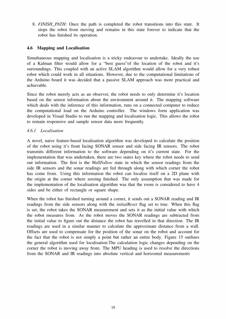
Simultaneous mapping and localisation is a tricky endeavour to undertake. Ideally the useof a Kalman filter would allow for a “best guess”of the location of the robot and it’ssurroundings. This coupled with an active SLAM algorithm would allow for a very robustrobot which could work in all situations. However, due to the computational limitations ofthe Arduino board it was decided that a passive SLAM approach was more practical andachievable.
Since the robot merely acts as an observer, the robot needs to only determine it’s locationbased on the sensor information about the environment around it. The mapping softwarewhich deals with the inference of this information, runs on a connected computer to reducethe computational load on the Arduino controller. The windows form application wasdeveloped in Visual Studio to run the mapping and localisation logic. This allows the robotto remain responsive and sample sensor data more frequently.
4.6.1 Localisation
A novel, naive feature-based localisation algorithm was developed to calculate the positionof the robot using it’s front facing SONAR sensor and side facing IR sensors. The robottransmits different information to the software depending on it’s current state. For theimplementation that was undertaken, there are two states key where the robot needs to sendout information. The first is the WallFollow state in which the sensor readings from theside IR sensors and the sonar readings are fed through along with which corner the robothas come from. Using this information the robot can localise itself on a 2D plane withthe origin at the corner where zeroing finished. The only assumption that was made forthe implementation of the localisation algorithm was that the room is considered to have 4sides and be either of rectangle or square shape.
When the robot has finished turning around a corner, it sends out a SONAR reading and IRreadings from the side sensors along with the initialReset flag set to true. When this flagis set, the robot takes the SONAR measurement and sets it as the initial value with whichthe robot measures from. As the robot moves the SONAR readings are subtracted fromthe initial value to figure out the distance the robot has travelled in that direction. The IRreadings are used in a similar manner to calculate the approximate distance from a wall.Offsets are used to compensate for the position of the sonar on the robot and account forthe fact that the robot is not simply a point but rather an entire body. Figure 15 outlinesthe general algorithm used for localisation.The calculation logic changes depending on thecorner the robot is moving away from. The MPU heading is used to resolve the directionsfrom the SONAR and IR readings into absolute vertical and horizontal measurements
18

Figure 15 Localisation Diagram
4.6.2 Mapping
The mapping aspect of the algorithm determines landmarks based on the robot’s interactionswith them. This means that until the robot approaches and determines the landmark, itdoes not know what the landmark is, only that there is something in its path.
Once the robot enters AvoidObstacle, the robot sends out a message with information aboutthe position of the obstacle detected relative to the robot. The mapping algorithm then takesinto account this offset and adds the correct coordinates of the obstacle to the Cartesianplane.
Thus in order to map the entire area the robot will have to drive everywhere and interactwith all possible obstacles. The walls are mapped using the wall following state whilsttraversing the spiral. Thus, by localising itself using the walls, the robot can also effectivelycreate the boundaries for the map.
Figure 16 shows the user interface for the mapping and localisation software. The mapis generated in real time as the robot transmits data throughout it’s run. On the left handside of the window is a text box which displays the messages sent by the robot to allowfor easy debugging. Furthermore, for ease of use, live sensor readings are displayed on therobot schematic on the right side of the window. The software runs across multiple threadsand receives messages asynchronously in improve performance and provide a pleasant userexperience.
19
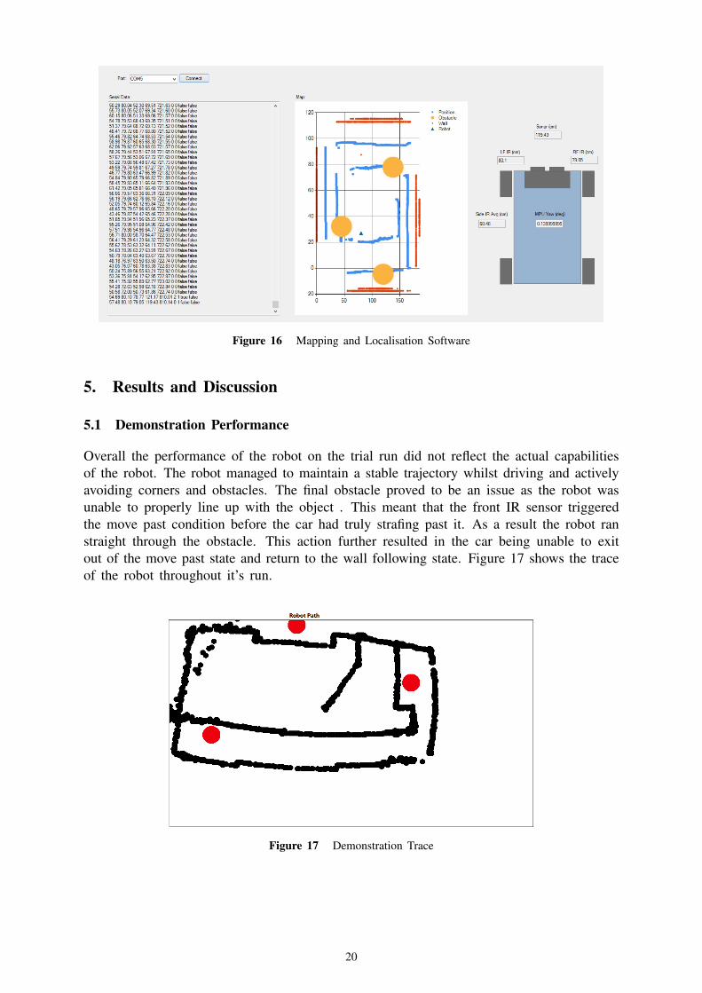
Figure 16 Mapping and Localisation Software
5. Results and Discussion
5.1 Demonstration Performance
Overall the performance of the robot on the trial run did not reflect the actual capabilitiesof the robot. The robot managed to maintain a stable trajectory whilst driving and activelyavoiding corners and obstacles. The final obstacle proved to be an issue as the robot wasunable to properly line up with the object . This meant that the front IR sensor triggeredthe move past condition before the car had truly strafing past it. As a result the robot ranstraight through the obstacle. This action further resulted in the car being unable to exitout of the move past state and return to the wall following state. Figure 17 shows the traceof the robot throughout it’s run.
Figure 17 Demonstration Trace
20

5.2 SLAM Taxonomy
Within the overarching SLAM problem paradigm there exists many smaller fundamentaldecisions which need to be addressed in order to fully and accurately produce a SLAMalgorithm. Below is a list of each decision and the way in which it was addressed.
5.2.1 Volumetric vs Feature Based
Whilst ideally a volumetric map with very high resolution would be the desired outcome,in reality it would be too computationally expensive to run using an Arduino board. Fur-thermore, the resolution of the map can only be as accurate as the resolution of the sensors.Thus with all these factors considered it seemed more practical and prudent to attempt afeature-based approach where the robot merely needed to identify the features and theirrelative positions rather than completely recreating a lifelike replica.
5.2.2 Topological vs Geometric
Overall a hybrid method between both approaches were used to create the map. Wallswere identified topologically using the assumption that the walls were straight along eachside of the arena, whist the mapping software approximated the exact position of the robotand obstacles using geometric methods.
5.2.3 Known vs Unknown Correspondence
The robot and mapping software together implemented unknown correspondence to allowfor more flexibility and robustness. The software uses a naive approach and as such doesnot identify objects until it attempts to avoid it. Therefore if the robot passed the sameobstacle twice it would plot the object twice and would not be able to distinguish that ithad already encountered it. However, some of the benefits that this approach provides isthat the robot could be used in any situation and plot the room with relative ease as thenumber of assumptions made are minimal. Furthermore, since the path was predetermined,the robot would not encounter the same obstacle more than once.
5.2.4 Small vs Large Uncertainty
Since the path of the robot had been predetermined the uncertainty was minimised due tothe lack of variables for the localisation and mapping algorithm to factor in. The smalluncertainty approach was undertaken in order to reduce the number of assumptions thatneeded to be made increased the robustness of the algorithm.
5.2.5 Active vs Passive
A passive SLAM algorithm was used to minimise the computational strain and increasethe responsiveness of the robot to the environment. Active SLAM would have required anon-board map for the robot to track down unexplored areas. The map itself would be quitecomputationally expensive to interpret and process on-board the robot. By allowing themap to be generated on an external computer meant that the robot could focus on purelyresponding to the environment.
5.2.6 Anytime vs Any Space
The primary goal of this project was to cover the entire area of the arena. As such, therobot was designed to follow an anytime methodology as it could take as much time as
21

required provided it could cover the entire area. However once the robot was able tocompletely cover the area in it’s entirety, the speed was increased to minimise the time.
6. Conclusions
6.1 Conclusion
The effectiveness of an autonomous vehicle can be measured by how intelligently it reactsto it’s surroundings. In this respect the SLAM algorithms and methodologies play anintegral part in the creation of this intelligence and it’s robustness to the environment.
It can be clearly seen that the SLAM approach provided immense benefits for an autonom-ous vacuum cleaner. The solution presented in the report was able to navigate aroundrooms of any size and easily avoid obstacles thanks to the integration of SLAM principles.The robot behaves consistently with the environment and disparities are only caused by theodd misplaced obstacle which prevent the sensors detecting it has passed the object.
The vacuum cleaner met the fundamental objective by being able to cover the entire areaof the room. Furthermore it was able to avoid most obstacles barring one or two oddlyplaced obstacles. The functionality could be improved by an improved mapping logic andutilisation of the servo motor thus freeing up the front IR sensors for detection elsewhere.Potentially having the IR sensors freed up could have allowed for better data for mapping.
6.2 Suggested Improvements
• Servo Motor: A major hurdle faced during the implementation of obstacle detectionand avoidance was encountering a blown servo. The gears within the servo hadslipped and as a result it was not functional. To account for this, the function Sweepin ObstacleHandler was created which rotated the entire vehicle to take readings fromthe sonar. Therefore, if a working servo was available, it would have been easier toobtain accurate readings without moving the entire robot from its desired path.
• Mapping: The current mapping algorithm used does not map the robot’s movementwhilst turning around corners. Whilst the robot is turning, the sensors point tothe corners and walls at acute angles and therefore gave inaccurate readings. Thesereadings were unreasonable to use for mapping and were left out as a result. Thereforeone improvement that would be made would be to create a map which does not leavegaps in the path traversed.
22
Related Documents