Project-Impact/CSE/IITB/93 CG/Mod-2/SC/1 Basic Raster Graphics • "Trifles make perfection, but perfection is no trifle" Michael Angelo ++ Topics • Scan conversion – line segments – polygon • Filling – polygon – thick primitives • Clipping – line segments – polygon

Project-Impact/CSE/IITB/93 CG/Mod-2/SC/1 Basic Raster Graphics "Trifles make perfection, but perfection is no trifle" Michael Angelo ++ Topics Scan conversion.
Dec 14, 2015
Welcome message from author
This document is posted to help you gain knowledge. Please leave a comment to let me know what you think about it! Share it to your friends and learn new things together.
Transcript

Project-Impact/CSE/IITB/93 CG/Mod-2/SC/1
Basic Raster Graphics
• "Trifles make perfection, but perfection is no trifle"
Michael Angelo
++ Topics
• Scan conversion
– line segments
– polygon
• Filling
– polygon
– thick primitives
• Clipping
– line segments
– polygon

Project-Impact/CSE/IITB/93 CG/Mod-2/SC/2
Scan Converting Line Segments
• Compute coordinates of pixel that lie on or near an infinitely thin line segment placed on a 2D integer grid.
• Criteria
– Sequence of pixels should be 'straight'
– If slope is between -1 and 1, exactly 1 pixel should be 'illuminated' in each column
– All lines should have constant brightness (independent of length and orientation)
– Rapid display
– Thick lines, dotted lines
– Other special effects
--
Project-Impact/CSE/IITB/93 CG/Mod-2/SC/3
Scan Converting Line Segments
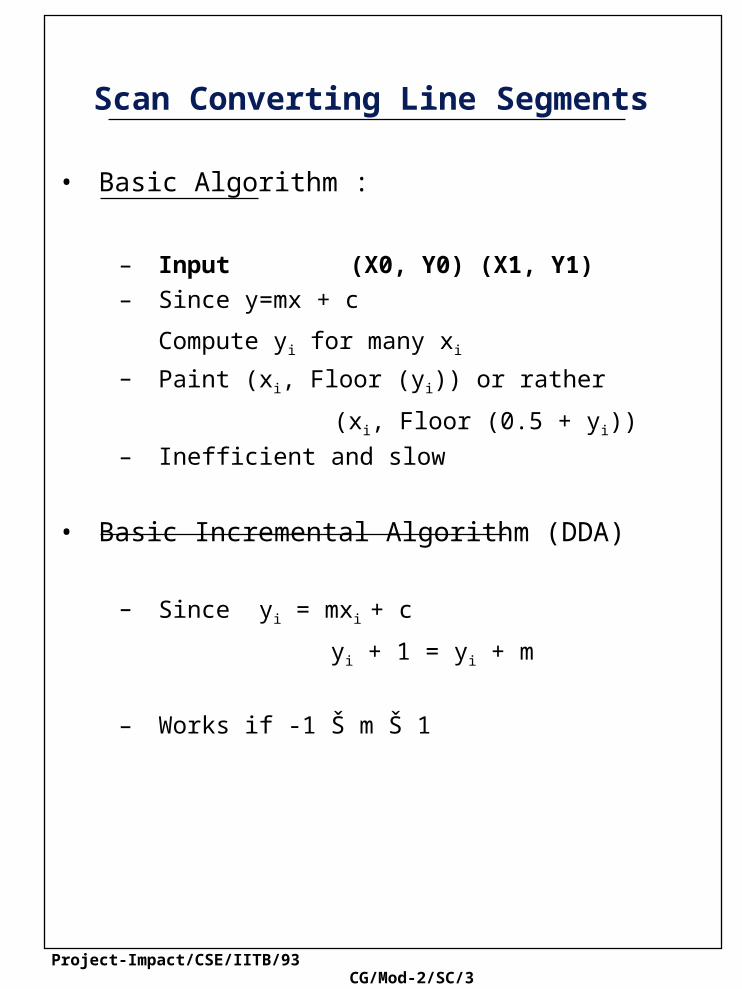
• Basic Algorithm :
– Input (X0, Y0) (X1, Y1)
– Since y=mx + c
Compute yi for many xi
– Paint (xi, Floor (yi)) or rather
(xi, Floor (0.5 + yi))
– Inefficient and slow
• Basic Incremental Algorithm (DDA)
– Since yi = mxi + c
yi + 1 = yi + m
– Works if -1 Š m Š 1
Project-Impact/CSE/IITB/93 CG/Mod-2/SC/4
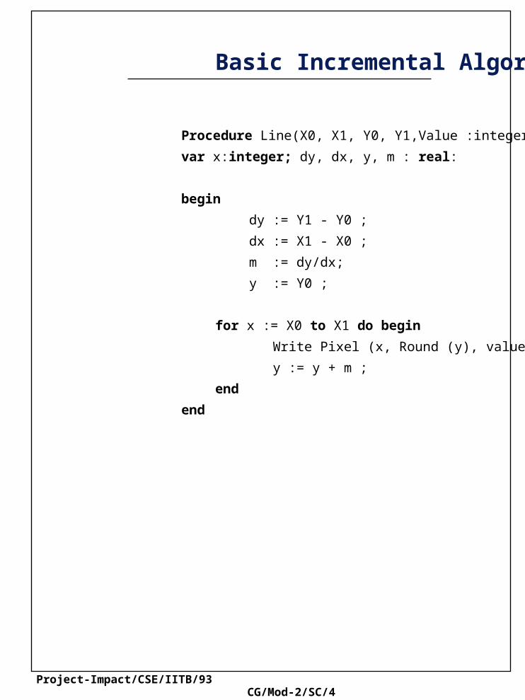
Basic Incremental Algorithm
Procedure Line(X0, X1, Y0, Y1,Value :integer)
var x:integer; dy, dx, y, m : real:
begin
dy := Y1 - Y0 ;
dx := X1 - X0 ;
m := dy/dx;
y := Y0 ;
for x := X0 to X1 do begin
Write Pixel (x, Round (y), value);
y := y + m ;
end
end

Project-Impact/CSE/IITB/93 CG/Mod-2/SC/5
Mid point Line Algorithm
• Motivated by – floating point computation
– orientation dependency
in previous algorithm.
• Basic idea illustrated for slope between 0 to 1
– Recall only one pixel in each column
– Which pixel (E or NE) can be found if midpoint M is determined to be above (E) or below (NE) the line
– The determination is easy if implicit form of line segment is chosen
F(x,y) = Ax + By + C
F(x,y) = 0 for line segment
E
NE
M

Project-Impact/CSE/IITB/93 CG/Mod-2/SC/6
Mid point Line Algorithm
• Implementation – Use a decision variable "d" = F(xi+1,yi+1/2)
– d > 0 implies E
– Method needed to 'update' d.
– Initialization
• Algorithm generalizes for circles, ellipses, conics.
dinit = F x0 + 1, y0 + 1/2 = a + b/2
dold a
If NE, dnew dold a b
If E, dnew F xp 2, yp 12
Project-Impact/CSE/IITB/93 CG/Mod-2/SC/7
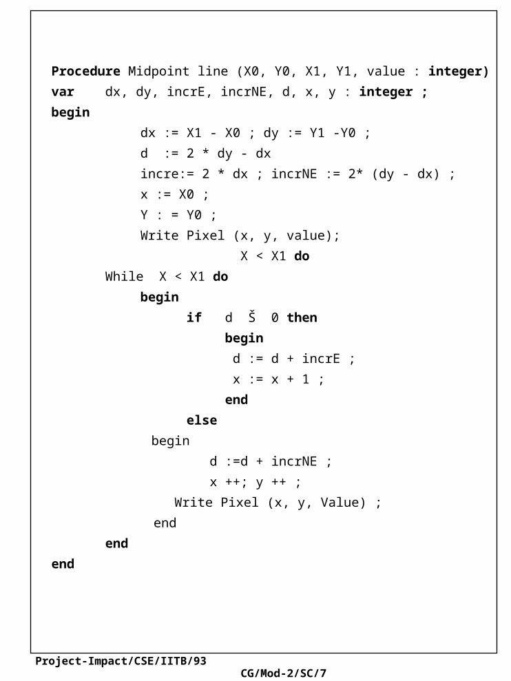
Procedure Midpoint line (X0, Y0, X1, Y1, value : integer)
var dx, dy, incrE, incrNE, d, x, y : integer ;
begin
dx := X1 - X0 ; dy := Y1 -Y0 ;
d := 2 * dy - dx
incre:= 2 * dx ; incrNE := 2* (dy - dx) ;
x := X0 ;
Y : = Y0 ;
Write Pixel (x, y, value);
X < X1 do
While X < X1 do
begin
if d Š 0 then
begin
d := d + incrE ;
x := x + 1 ;
end
else
begin
d :=d + incrNE ;
x ++; y ++ ;
Write Pixel (x, y, Value) ;
end
end
end

Project-Impact/CSE/IITB/93 CG/Mod-2/SC/8
Integer Arithmetic Scan Conversion
• Sometimes we want the scan conversion to be biased
• Pixels only to the 'right' of the line segment should be turned on.
• Midpoint algorithm is 'too' fair !
• Basic Idea : (Illustrated with case when slope >1)
– Store increment separately as numerator and denominator
– Example : Suppose xmin = 3 and slope = 7/2 Separately store the sequence
3, 23/7, 25/7,27/7,29/7
x i + 1 = x i + 1m
fd
Project-Impact/CSE/IITB/93 CG/Mod-2/SC/9
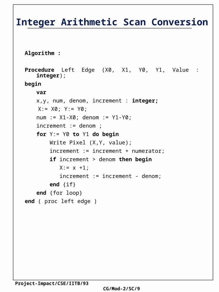
Integer Arithmetic Scan Conversion
Algorithm :
Procedure Left Edge (X0, X1, Y0, Y1, Value : integer);
begin
var
x,y, num, denom, increment : integer;
X:= X0; Y:= Y0;
num := X1-X0; denom := Y1-Y0;
increment := denom ;
for Y:= Y0 to Y1 do begin
Write Pixel (X,Y, value);
increment := increment + numerator;
if increment > denom then begin
X:= x +1;
increment := increment - denom;
end {if}
end {for loop}
end ( proc left edge )
Project-Impact/CSE/IITB/93 CG/Mod-2/SC/10
Clipping Line Segments
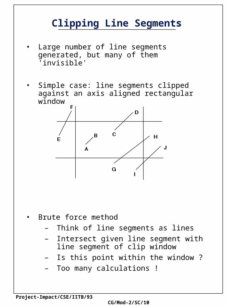
• Large number of line segments generated, but many of them 'invisible'
• Simple case: line segments clipped against an axis aligned rectangular window
• Brute force method
– Think of line segments as lines
– Intersect given line segment with line segment of clip window
– Is this point within the window ?
– Too many calculations !
Project-Impact/CSE/IITB/93 CG/Mod-2/SC/11
Clipping Line Segments
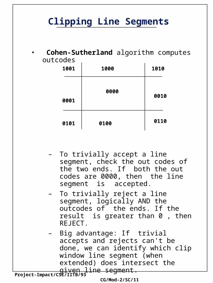
• Cohen-Sutherland algorithm computes outcodes
– To trivially accept a line segment, check the out codes of the two ends. If both the out codes are 0000, then the line segment is accepted.
– To trivially reject a line segment, logically AND the outcodes of the ends. If the result is greater than 0 , then REJECT.
– Big advantage: If trivial accepts and rejects can't be done, we can identify which clip window line segment (when extended) does intersect the given line segment.
– Point of intersection is computed only in this case
10001001
0001
00000010
0101 0100 0110
1010

Project-Impact/CSE/IITB/93 CG/Mod-2/SC/12
Procedure Clip (X0, Y0, X1, Y1, Xmin Xmax, Ymin, Ymax : real
type edge = (Left, Right, Bottom, Top);
outcode = Set of edge;
var accept, done : boolean;
Outcode0, Outcode1, OutcodeOut : outcode;
x, y : real ;
procedure CompOutCode (x, y : real;
var code : outcode );
begin
code := [ ]
if y > ymax then code := code + {Top};
else if y < ymin then code := code + {Bottom};
if x > xmax then code := code + {Right};
else if x < xmin then code := code + {Left};
end ;
begin
accept := false ; done := false ;
CompOutCode (X0,Y0, Outcode0);
CompOutCode (X1 Y1, Outcode1)
repeat
if (Outcode0 = [ ]) and (outcode1 = [ ])then
begin
accept := true : done := true ;
end
else if (outcode0 * outcode1) <> [ ] then
done := true
else

Project-Impact/CSE/IITB/93 CG/Mod-2/SC/13
begin
if outcode0 <> [ ] then
outcodeOut := outcode 0
then
outcodeOut := outcode1 ;
if Top in outcodeOut then
begin
x:= X0 + (X1 - X0)/(Y1 - Y0) (Ymax -Y0);
y:= Ymax
end
else if Bottom in outcodeOut then begin
X:= X + (X1-Xo) * (Ymin-Y0) / (Y1-Y0);
X:= Ymin ;
end
else if Right in outcodeOut then begin
y:= Y0 + (Y1-Yo) * (Xmax-X0) / (X1-X0):
x:= Xmax
end
if (outcodeOut = outcode 0) then
begin X0 :=x; Y0 :=y;
CompOutCode (X0, Y0, OutcodeO);
end
else
begin
X1:=x; Y1:= y;
CompOutCode (X1, Y1, Outcode1);
end
until (done):
Project-Impact/CSE/IITB/93 CG/Mod-2/SC/14
Parametric Line Clipping
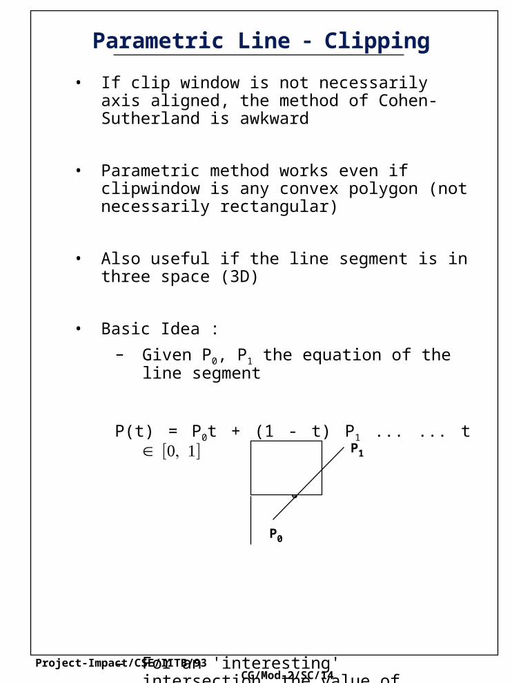
• If clip window is not necessarily axis aligned, the method of Cohen-Sutherland is awkward
• Parametric method works even if clipwindow is any convex polygon (not necessarily rectangular)
• Also useful if the line segment is in three space (3D)
• Basic Idea :
– Given P0, P1 the equation of the line segment
P(t) = P0t + (1 - t) P1 ... ... t
– For an 'interesting' intersection, the value of parameter 't' at point of intersection [0,1]. Thus line segments can be 'shortened' or clipped.
P0
P1

Project-Impact/CSE/IITB/93 CG/Mod-2/SC/15
Parametric Line - Clipping
P t Pa . Ni = 0
t = N i . P0 Pa
N i . P1 P0
Pb
P1
Ni
P0
P1
P1
P0
Ni
P0
Pa
Pb
P(t)
P1
• Some intersections are 'potentially' entering and some are leaving
• Mathematics
• Leaving if angle is < 90 (sign of denominator)
D = Ni . (P1 P0) > 0
Project-Impact/CSE/IITB/93 CG/Mod-2/SC/16
Parametric Line Clipping
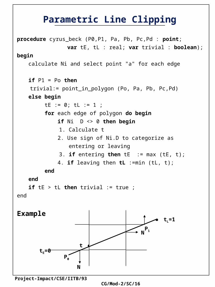
procedure cyrus_beck (P0,P1, Pa, Pb, Pc,Pd : point;
var tE, tL : real; var trivial : boolean);
begin
calculate Ni and select point "a" for each edge
if P1 = Po then
trivial:= point_in_polygon (Po, Pa, Pb, Pc,Pd)
else begin
tE := 0; tL := 1 ;
for each edge of polygon do begin
if Ni D <> 0 then begin
1. Calculate t
2. Use sign of Ni.D to categorize as
entering or leaving
3. if entering then tE := max (tE, t);
4. if leaving then tL :=min (tL, t);
end
end
if tE > tL then trivial := true ;
end
Example
N
N
P0
P1
tE=0
tL=1
t
Project-Impact/CSE/IITB/93 CG/Mod-2/SC/17
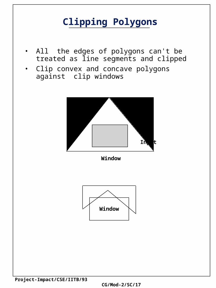
Clipping Polygons
• All the edges of polygons can't be treated as line segments and clipped
• Clip convex and concave polygons against clip windows
Window
Window
Input

Project-Impact/CSE/IITB/93 CG/Mod-2/SC/18
Basic Sutherland Hodgman Algorithm
const max = 20 ;
type vertex = point; edge = array [1..2] of vertex ;
vertexArray = array [1..Max} of vertex ;
procedure clip (in : vertexArray: var out : vertexarray ;
inlength : integer ; var outlength :
integer ; bdy : edge);
Var s, p, i : vertex;
j : integer ;
begin
outlength := 0;
s := in [inlength] ;
for j := 1 to inlength do begin
p := in [j] ;
if Inside (p, bdy) then
if Inside (s, bdy) then
Output (P, outlength,out);
else begin
intersect (i, s, p, bdy);
Output (i, outlength, out);
Output (p, outlength out);
end
else
if Inside (s, bdy) then begin
Intersect (i, s, p, bdy) ;
Output (i, outlength, out)
end
s := p ;
end {for}
end
Project-Impact/CSE/IITB/93 CG/Mod-2/SC/19
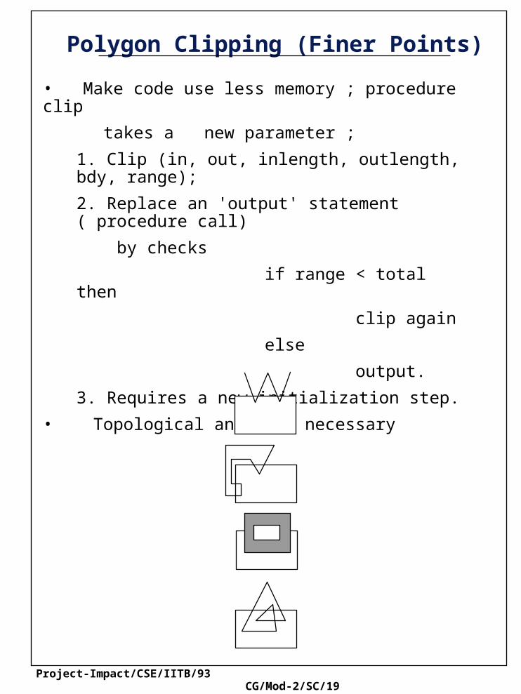
Polygon Clipping (Finer Points)
• Make code use less memory ; procedure clip
takes a new parameter ;
1. Clip (in, out, inlength, outlength, bdy, range);
2. Replace an 'output' statement ( procedure call)
by checks
if range < total then
clip again
else
output.
3. Requires a new initialization step.
• Topological analysis necessary

Project-Impact/CSE/IITB/93 CG/Mod-2/SC/20
Filling Polygons
• Shading a polygon with some color or stipple pattern gives it 'character'
• Shading a rectangle is easy, but watch out for xor mode drawing when two rectangles intersect
• Convention: a 'boundary' pixel is not considered to be part of the primitive if the halfplane defined by the edge of pixel lies below or to the left of the edge. (Pixel on top and right part of rectangle won't be drawn).
Common point
Project-Impact/CSE/IITB/93 CG/Mod-2/SC/21
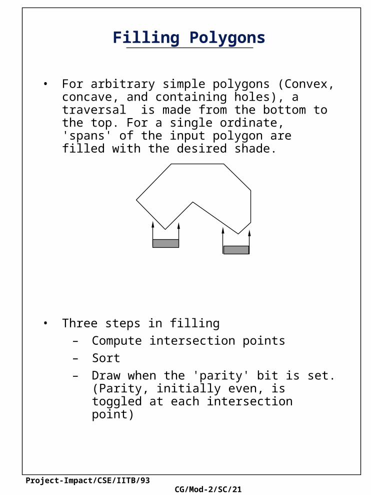
Filling Polygons
• For arbitrary simple polygons (Convex, concave, and containing holes), a traversal is made from the bottom to the top. For a single ordinate, 'spans' of the input polygon are filled with the desired shade.
• Three steps in filling
– Compute intersection points
– Sort
– Draw when the 'parity' bit is set. (Parity, initially even, is toggled at each intersection point)

Project-Impact/CSE/IITB/93 CG/Mod-2/SC/22
Simple Ordered Edge List
Consider the polygon shown in Figure.
The polygon vertices are
Intersections with the half interval scan lines are
Scan line 1.5 : (8, 1.5), (1, 1.5)
Scan line 2.5 : (8, 2.5), (1, 2.5)
Scan line 3.5 : (8, 3.5), (5.5, 3.5), (4.5, 3.5), (1, 3.5)
Scan line 4.5 : (8, 4.5), (6.5, 4.5), (3.5, 4.5), (1, 4.5)
Scan line 5.5 : (8, 5.5), (7.5, 5.5), (2.5, 5.5), (1, 5.5)
Scan line 6.5 : (1.5, 6.5), (1, 6.5)
Scan line 7.5 : none
P1 1, 1 , P2 8, 1 , P3 8, 6 , P4 5, 3 and P5 1, 7
Solid area scan conversion
Project-Impact/CSE/IITB/93 CG/Mod-2/SC/23
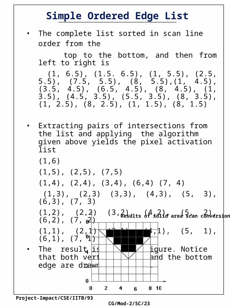
Simple Ordered Edge List
• The complete list sorted in scan line order from the top to the bottom, and then from left to right is
(1, 6.5), (1.5. 6.5), (1, 5.5), (2.5, 5.5), (7.5, 5.5), (8, 5.5),(1, 4.5), (3.5, 4.5), (6.5, 4.5), (8, 4.5), (1, 3.5), (4.5, 3.5), (5.5, 3.5), (8, 3.5), (1, 2.5), (8, 2.5), (1, 1.5), (8, 1.5)
• Extracting pairs of intersections from the list and applying the algorithm given above yields the pixel activation list
(1,6)
(1,5), (2,5), (7,5)
(1,4), (2,4), (3,4), (6,4) (7, 4)
(1,3), (2,3) (3,3), (4,3), (5, 3), (6,3), (7, 3)
(1,2), (2,2) (3,2), (4,2), (5, 2), (6,2), (7, 2)
(1,1), (2,1) (3,1), (4,1), (5, 1), (6,1), (7, 1)
• The result is shown in figure. Notice that both vertical edges and the bottom edge are drawn correctely.
Results of solid area scan conversion of polygon
Project-Impact/CSE/IITB/93 CG/Mod-2/SC/24
Scan Line (Edge List) Algorithm
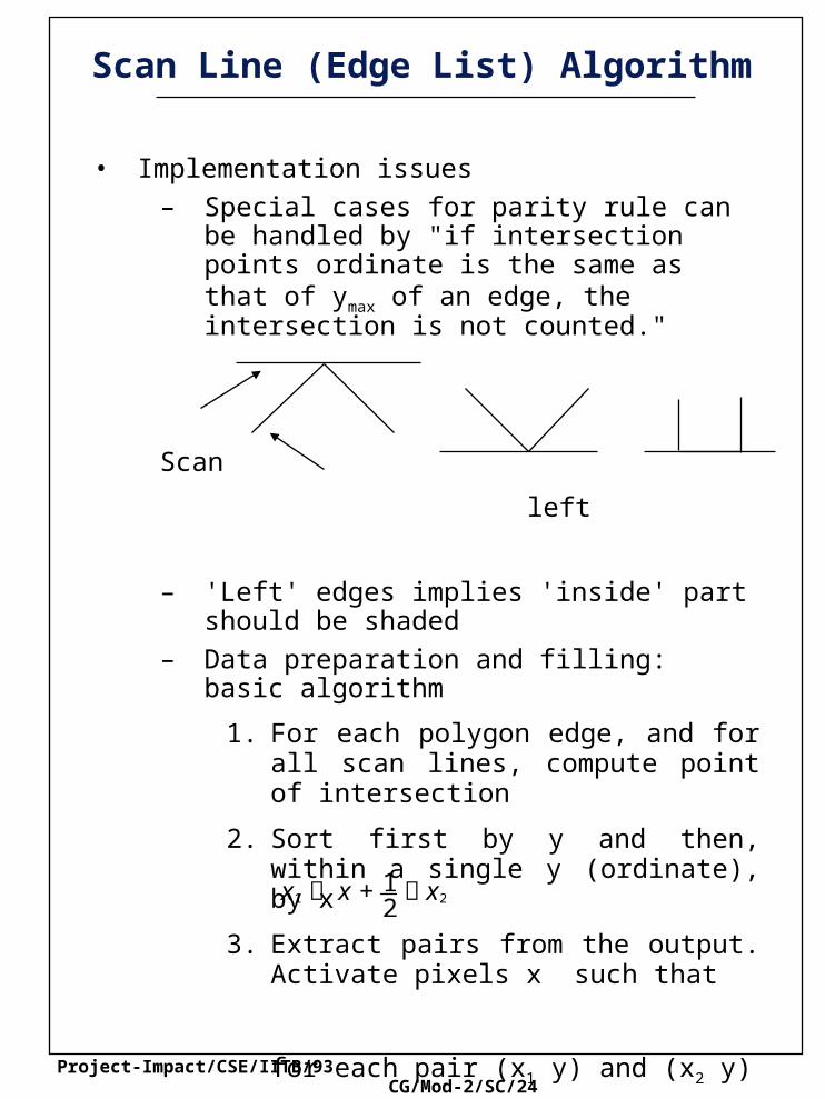
• Implementation issues
– Special cases for parity rule can be handled by "if intersection points ordinate is the same as that of ymax of an edge, the intersection is not counted."
Scan
left
– 'Left' edges implies 'inside' part should be shaded
– Data preparation and filling: basic algorithm
1. For each polygon edge, and for all scan lines, compute point of intersection
2. Sort first by y and then, within a single y (ordinate), by x
3. Extract pairs from the output. Activate pixels x such that
for each pair (x1 y) and (x2 y)
x1 x + 12
x2
Project-Impact/CSE/IITB/93 CG/Mod-2/SC/25
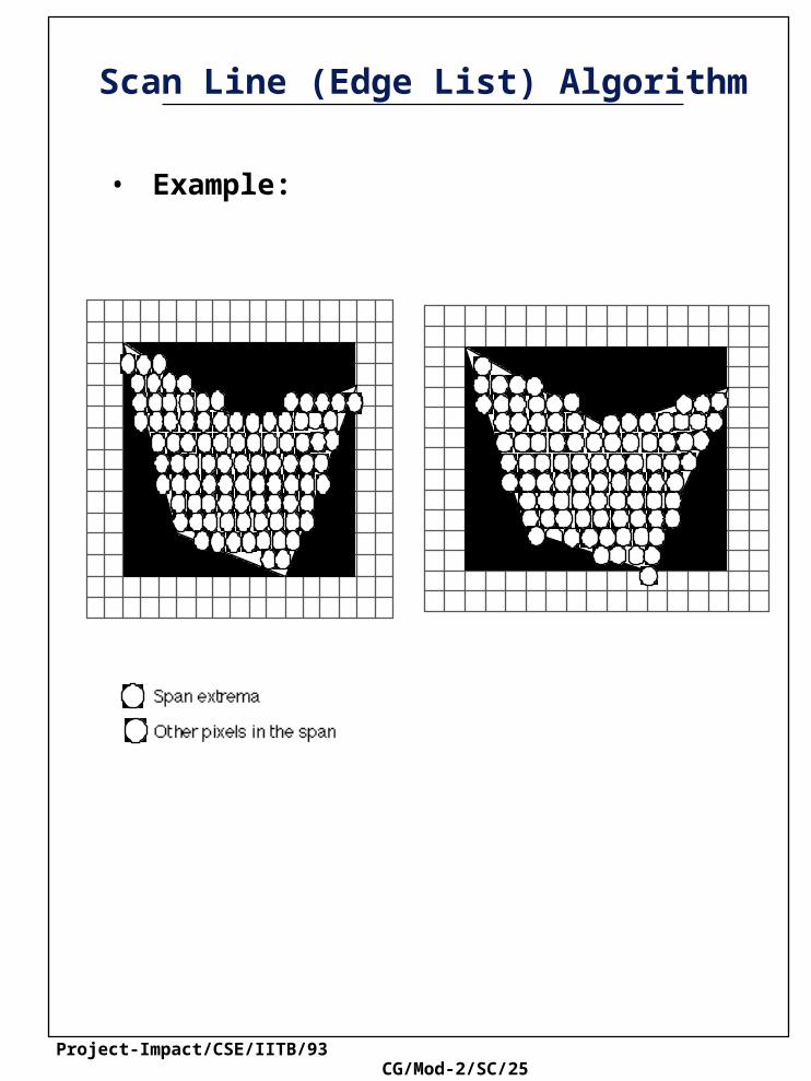
Scan Line (Edge List) Algorithm
• Example:

Project-Impact/CSE/IITB/93 CG/Mod-2/SC/26
y-bucket sort
1 null2 xBA, xBA, ymin= 6, xBC, xBC, ymin= 43 null4 xCD, xCD, ymin= 85 null6 xAD, xAD, ymin= 87 null8 null
Edge Sets Active Edges
Active Edge List
Scan line 3 :xBA+ xBA, xBA,xBC xBC, xBC
Scan linexBA + 3xBA, xBA, xCD + xCD, xCD
Scan line 7 :xCD + 3xCD, xCD,xAD, + xAD, xAD
C
1
234
678
5
Scan line
B
A
D
Project-Impact/CSE/IITB/93 CG/Mod-2/SC/27
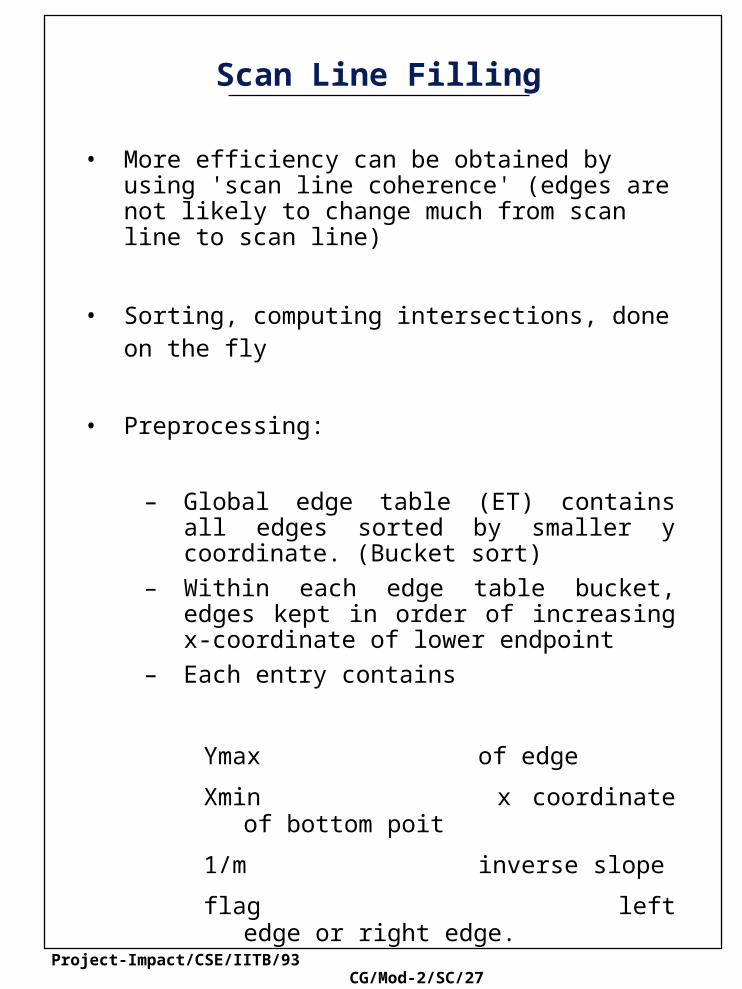
Scan Line Filling
• More efficiency can be obtained by using 'scan line coherence' (edges are not likely to change much from scan line to scan line)
• Sorting, computing intersections, done on the fly
• Preprocessing:
– Global edge table (ET) contains all edges sorted by smaller y coordinate. (Bucket sort)
– Within each edge table bucket, edges kept in order of increasing x-coordinate of lower endpoint
– Each entry contains
Ymax of edge
Xmin x coordinate of bottom poit
1/m inverse slope
flag left edge or right edge.

Project-Impact/CSE/IITB/93 CG/Mod-2/SC/28
Scan Line Filling
• Example
Polygon and scan line 8
ymaxC
Project-Impact/CSE/IITB/93 CG/Mod-2/SC/29
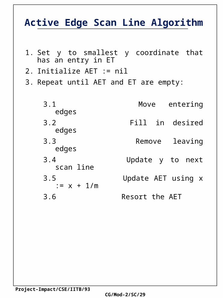
Active Edge Scan Line Algorithm
1. Set y to smallest y coordinate that has an entry in ET
2. Initialize AET := nil
3. Repeat until AET and ET are empty:
3.1 Move entering edges
3.2 Fill in desired edges
3.3 Remove leaving edges
3.4 Update y to next scan line
3.5 Update AET using x := x + 1/m
3.6 Resort the AET

Project-Impact/CSE/IITB/93 CG/Mod-2/SC/30
Active Edge Scan Line Algorithm
1. Set y to the smallest y coordinate that has an entry in the ET; i.e. y for the first nonempty bucket
2. Initialize the AET to be empty
3. Repeat until the AET and ET are empty:
3.1 Move from ET bucket y to the AET those edges whose ymin = y (entering edges), maintaing AET sort order on x
3.2 Fill in desired pixel values on scan line y by using pairs of x coordinates from the AET
3.3 Remove from the AET those entries for which y = ymax (edges not involved in the next scan line)
3.4 Increment y by 1 (to the y coordinate of the next scan line)
3.5 For each nonvertical edge remaining in the AET, update x for the new y
3.6 Because the previous step may have caused the AET to become out of order on x, resort the AET

Project-Impact/CSE/IITB/93 CG/Mod-2/SC/31
Active Edge Scan Line Algorithm
Project-Impact/CSE/IITB/93 CG/Mod-2/SC/32
Image Space Filling Algorithms
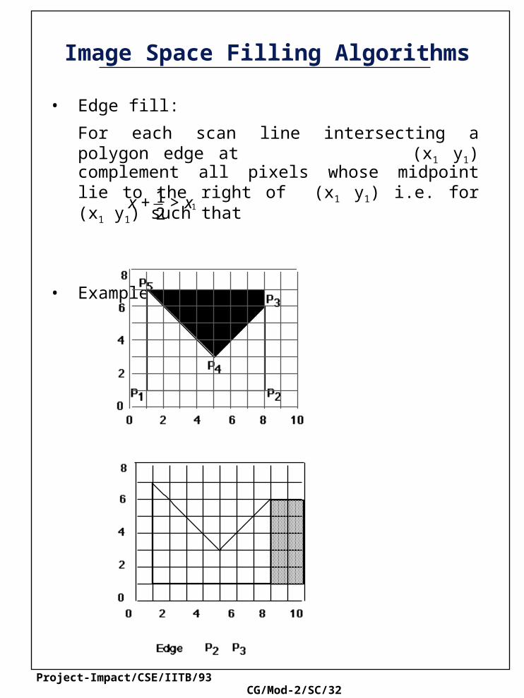
• Edge fill:
For each scan line intersecting a polygon edge at (x1 y1) complement all pixels whose midpoint lie to the right of (x1 y1) i.e. for (x1 y1) such that
• Example
x + 12
> x1

Project-Impact/CSE/IITB/93 CG/Mod-2/SC/33
Image Space Filling Algorithms
Edge Fill Algorithm
Project-Impact/CSE/IITB/93 CG/Mod-2/SC/34
Image Space Filling Algorithms
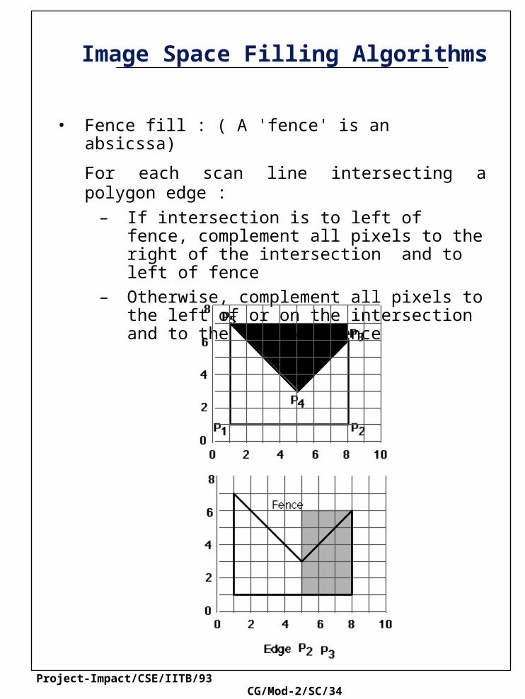
• Fence fill : ( A 'fence' is an absicssa)
For each scan line intersecting a polygon edge :
– If intersection is to left of fence, complement all pixels to the right of the intersection and to left of fence
– Otherwise, complement all pixels to the left of or on the intersection and to the right of fence
Project-Impact/CSE/IITB/93 CG/Mod-2/SC/35
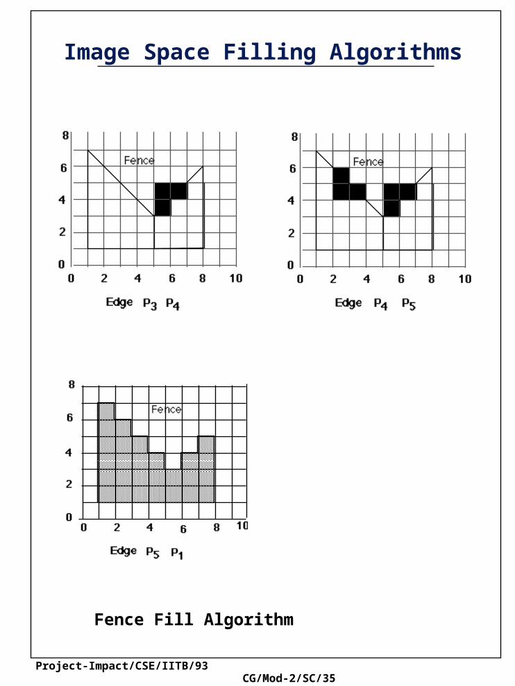
Image Space Filling Algorithms
Fence Fill Algorithm
Project-Impact/CSE/IITB/93 CG/Mod-2/SC/36
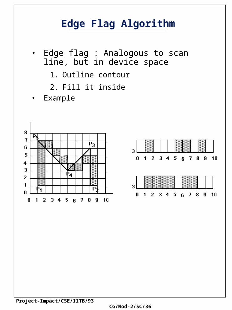
Edge Flag Algorithm
• Edge flag : Analogous to scan line, but in device space
1. Outline contour
2. Fill it inside
• Example
Project-Impact/CSE/IITB/93 CG/Mod-2/SC/37
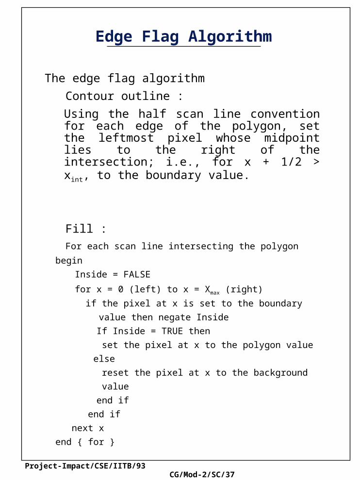
Edge Flag Algorithm
The edge flag algorithm
Contour outline :
Using the half scan line convention for each edge of the polygon, set the leftmost pixel whose midpoint lies to the right of the intersection; i.e., for x + 1/2 > xint, to the boundary value.
Fill :
For each scan line intersecting the polygon begin
Inside = FALSE
for x = 0 (left) to x = Xmax (right)
if the pixel at x is set to the boundary
value then negate Inside
If Inside = TRUE then
set the pixel at x to the polygon value
else
reset the pixel at x to the background
value
end if
end if
next x
end { for }
Project-Impact/CSE/IITB/93 CG/Mod-2/SC/38
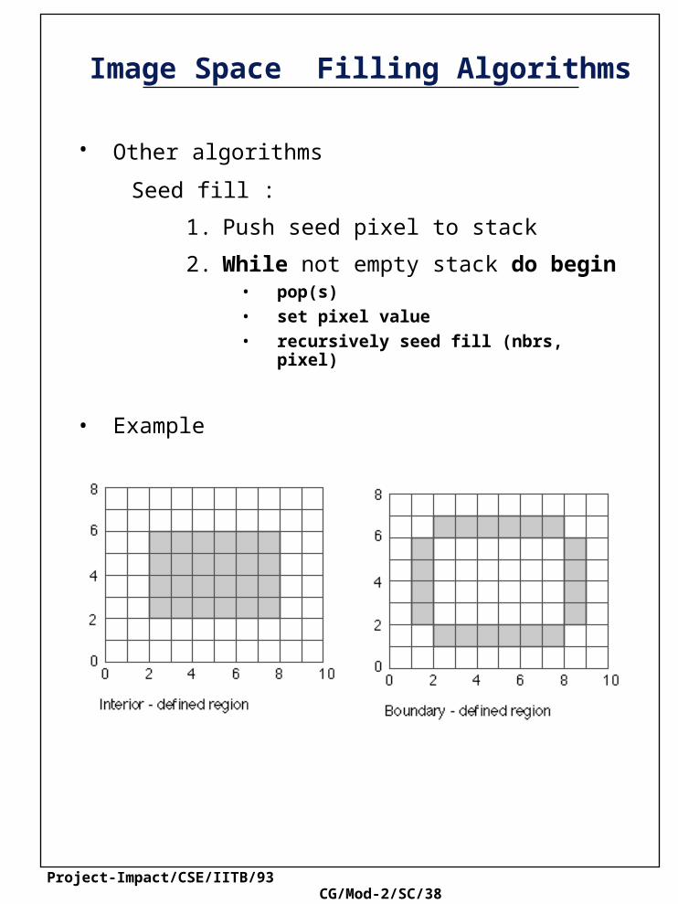
Image Space Filling Algorithms
• Other algorithms Seed fill :
1. Push seed pixel to stack
2. While not empty stack do begin• pop(s)
• set pixel value
• recursively seed fill (nbrs, pixel)
• Example

Project-Impact/CSE/IITB/93 CG/Mod-2/SC/39
Image Space Filling Algorithms

Project-Impact/CSE/IITB/93 CG/Mod-2/SC/40
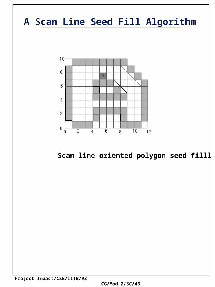
A Scan Line Seed Fill Algorithm
Scan line seed fill algorithm
A seed pixel on a span is popped from a stack containing the seed pixel
The span containing the seed pixel is filled to the right and left of seed pixel along a scan line until a boundary is found.
The algorithm remembers the extreme left and the extreme right pixel in the span as xleft and xright.
In the range of xleft Š x Š xright the scan lines immediately above & immediately below the current scan line are examined to see if they completely contain either boundary pixels or previously filled points. If these scan lines do not contain either boundary or previously filled pixels, then in the range Xleft Š x Š Xright the extreme right pixel in 0each span is marked as a seed pixel and pushed onto the stack.

Project-Impact/CSE/IITB/93 CG/Mod-2/SC/41
A Scan Line Seed Fill Algorithm

Project-Impact/CSE/IITB/93 CG/Mod-2/SC/42
A Scan Line Seed Fill Algorithm
Project-Impact/CSE/IITB/93 CG/Mod-2/SC/43
A Scan Line Seed Fill Algorithm
Scan-line-oriented polygon seed filll algorithm
Related Documents