Project Administrator (PD_Project) Reference Guide Document Number Version Date Pages DPDS3-PB-200030A PDS 7.1 April 2002 1-526 DPDS3-PB-200030B PDS 7.2 February 2003 527-630 DPDS3-PB-200030C PDS 7.3 October 2004 631-688 DPDS3-PB-200030D PDS 8.0 SE November 2005 689-706

Welcome message from author
This document is posted to help you gain knowledge. Please leave a comment to let me know what you think about it! Share it to your friends and learn new things together.
Transcript
Project Administrator (PD_Project) Reference Guide Document Number Version Date Pages DPDS3-PB-200030A PDS 7.1 April 2002 1-526 DPDS3-PB-200030B PDS 7.2 February 2003 527-630 DPDS3-PB-200030C PDS 7.3 October 2004 631-688 DPDS3-PB-200030D PDS 8.0 SE November 2005 689-706

Copyright Copyright © 1984-2005 Intergraph Corporation. All Rights Reserved.
Including software, file formats, and audiovisual displays; may be used pursuant to applicable software license agreement; contains confidential and proprietary information of Intergraph and/or third parties which is protected by copyright law, trade secret law, and international treaty, and may not be provided or otherwise made available without proper authorization.
Restricted Rights Legend Use, duplication, or disclosure by the Government is subject to restrictions as set forth in subparagraph (c) of the Contractor Rights in Technical Data clause at DFARS 252.227-7013, subparagraph (b) of the Rights in Computer Software or Computer Software Documentation clause at DFARS 252.227-7014, subparagraphs (b)(1) and (2) of the License clause at DFARS 252.227-7015, or subparagraphs (c) (1) and (2) of Commercial Computer Software---Restricted Rights at 48 CFR 52.227-19, as applicable.
Unpublished---rights reserved under the copyright laws of the United States.
Intergraph Corporation
Huntsville, Alabama 35894-0001
Warranties and Liabilities All warranties given by Intergraph Corporation about equipment or software are set forth in your purchase contract, and nothing stated in, or implied by, this document or its contents shall be considered or deemed a modification or amendment of such warranties. Intergraph believes the information in this publication is accurate as of its publication date.
The information and the software discussed in this document are subject to change without notice and are subject to applicable technical product descriptions. Intergraph Corporation is not responsible for any error that may appear in this document.
The software discussed in this document is furnished under a license and may be used or copied only in accordance with the terms of this license.
No responsibility is assumed by Intergraph for the use or reliability of software on equipment that is not supplied by Intergraph or its affiliated companies. THE USER OF THE SOFTWARE IS EXPECTED TO MAKE THE FINAL EVALUATION AS TO THE USEFULNESS OF THE SOFTWARE IN HIS OWN ENVIRONMENT.
Trademarks Intergraph, the Intergraph logo, SmartSketch, FrameWorks, SmartPlant, INtools, MARIAN, and PDS are registered trademarks of Intergraph Corporation. Microsoft and Windows are registered trademarks of Microsoft Corporation. MicroStation is a registered trademark of Bentley Systems, Inc. ISOGEN is a registered trademark of Alias Limited. Other brands and product names are trademarks of their respective owners.

If You Need Assistance________________
If You Need Assistance
Intergraph Online
Our web site brings you fast, convenient, up-to-the-minute information about Intergraph’sproducts, services, and direction. Our web address is: http://www.intergraph.com.
Support
For the lasest Support Services information, use a World Wide Web browser to connect tohttp://www.intergraph.com/ppo/services/support.asp.
If you are outside of the United States, please call your local Intergraph office. The most up-to-date list of international offices and distributors is available on the web athttp://www.intergraph.com.
Intergraph Directory
The following numbers are only valid in the United States unless otherwise indicated. If youare outside the United States, please call your local Intergraph office.
Intergraph General Information
All countries — 1-256-730-2000
Training Registration
1-800-766-7701 (U.S. Only)
1-256-730-5400 (Outside the U.S.)
Mailing Address
Intergraph Process, Power & Offshore300 Intergraph WayMadison, Alabama 35758U.S.A.
You can also reach us by electronic mail at [email protected].
3

________________
Documentation Contacts
We are constantly working on updates and improvements to the documents and othereducational media. If you have any suggestions on where we can improve the documentationor where you think more information is needed, let us know. You can reach us by:
Mail Intergraph Process, Power & OffshoreDocumentation Manager300 Intergraph WayMadison, AL 35758
4
Table of Contents________________
Table of Contents
If You Need Assistance ........................................................................................................ 3Intergraph Directory ............................................................................................................. 3
Preface .......................................................................................................................................... 13
Document Purpose ................................................................................................................ 13Document Prerequisites / Audience ...................................................................................... 13Related Documents/Products ................................................................................................ 13About this Document ............................................................................................................ 14Additional Information ......................................................................................................... 14
General Conventions .................................................................................................................... 15
Keyboard Conventions ......................................................................................................... 16Terminology ......................................................................................................................... 17
1. Introduction .................................................................................................................................. 19
Process & Power PDS Overview ................................................................................................. 20Project Setup ................................................................................................................................ 21
System Setup ........................................................................................................................ 212D Setup ............................................................................................................................... 223D Setup ............................................................................................................................... 23
Preliminary Design ...................................................................................................................... 23
Process Flow Diagram (PFD) ............................................................................................... 23
Detailed Design — 2D ................................................................................................................. 24
Process & Instrumentation Diagram (P&ID) ........................................................................ 24Instrument Data Manager (IDM) .......................................................................................... 24
Detailed Design — 3D ................................................................................................................. 25
Equipment Modeling (PD_EQP) .......................................................................................... 25FrameWorks Plus (FW+) ...................................................................................................... 25Piping Design Graphics (PD_Design) .................................................................................. 26Reference Data Manager (PD_Data) .................................................................................... 26Drawing Manager (PD_Draw) .............................................................................................. 27PDS Stress Analysis Interface (PD_Stress) .......................................................................... 27Interference Checker/Manager (PD_Clash) .......................................................................... 28PDS Isometric Interface (PD_ISO, PD_ISOGEN) ............................................................... 28Report Manager (PD_Report) ............................................................................................... 29
5
Project Administrator — April 2002________________
Project Engineer HVAC (PE-HVAC) .................................................................................. 29EE Raceway Modeling ......................................................................................................... 29Design Review Integrator (PD_Review) .............................................................................. 30
1.1 Project Organization ................................................................................................................... 311.2 Project Administrator Overview ................................................................................................ 321.3 System Setup .............................................................................................................................. 35
1.3.1 System Configurations ................................................................................................... 361.3.2 Loading Products ........................................................................................................... 371.3.3 Loading Baseline Software ............................................................................................ 371.3.4 Loading PDS Products ................................................................................................... 381.3.5 Loading PDS for Windows NT ...................................................................................... 401.3.6 Loading Database Products ............................................................................................ 421.3.7 NFS Overview ................................................................................................................ 42
1.4 Database Information ................................................................................................................. 43
1.4.1 PDS and the Relational Interface System (RIS) ............................................................ 43
1.5 Preparing the Server and Workstations for PDS ........................................................................ 44
2. PDS Environment ........................................................................................................................ 45
PD Shell ....................................................................................................................................... 46
PD_Shell Form Conventions ..................................................................................................... 49Common Tools on the PD_Shell Forms .................................................................................... 49Batch Processes .......................................................................................................................... 52
Help .............................................................................................................................................. 53
3. Project Administrator ................................................................................................................... 55
4. Project Setup Manager ................................................................................................................. 57
4.1 Create Project ...................................................................................................................... 59
4.1.1 Project Control Schema ........................................................................................... 634.1.2 ModelDraft/FrameWorks Plus Project .................................................................... 644.1.3 Raceway Project Schema ........................................................................................ 674.1.4 Piping Design Schema ............................................................................................ 684.1.5 Piping RDB Schema ............................................................................................... 724.1.6 Raceway RDB Schema ........................................................................................... 734.1.7 Specify Coordinate System ..................................................................................... 744.1.8 Revise Working Units ............................................................................................. 77
4.2 Revise Project —Attribute Display ..................................................................................... 804.3 Revise Project — Add Attributes ........................................................................................ 824.4 Revise Project — DBAccess ............................................................................................... 84
6
Table of Contents________________
4.5 Delete Project ...................................................................................................................... 87
Delete Reference Data ......................................................................................................... 90
4.6 Insert FrameWorks Data ..................................................................................................... 934.7 Insert ModelDraft Data ....................................................................................................... 954.8 Insert Electrical Raceway Data ........................................................................................... 984.9 Delete FrameWorks Sub-Project ......................................................................................... 100
5. Project Environment Manager ..................................................................................................... 101
Project Environment Manager Form ................................................................................... 101
5.1 Create Options Form ........................................................................................................... 104
5.1.1 Create Discipline Data ............................................................................................ 1065.1.2 Create Design Area Data ......................................................................................... 1085.1.3 Create Model ........................................................................................................... 1115.1.4 Copy Model ............................................................................................................. 117Design Volume Offset ......................................................................................................... 123Attach Equipment Model .................................................................................................... 1245.1.5 Create Database Tables ........................................................................................... 1285.1.6 Create Model Data from ASCII File ....................................................................... 129
5.2 Revise Options Form .......................................................................................................... 135
5.2.1 Revise Project Data ................................................................................................. 1365.2.2 Revise Project Location .......................................................................................... 138
5.2.2.1 Update Model File Specifications ............................................................ 144
5.2.3 Revise Discipline Data ............................................................................................ 1515.2.4 Revise Design Area Data ........................................................................................ 1535.2.5 Revise Model Data .................................................................................................. 1565.2.6 Revise Area Model Association .............................................................................. 158
5.3 Delete Options Form ........................................................................................................... 160
5.3.1 Delete Discipline ..................................................................................................... 1625.3.2 Delete Design Area Form ........................................................................................ 1635.3.3 Delete Model ........................................................................................................... 165
5.4 Report Options Form .......................................................................................................... 167
5.4.1 Report - Models ....................................................................................................... 1685.4.2 Report - Named Items ............................................................................................. 171
5.5 Model Setup Data Form ...................................................................................................... 174
7
Project Administrator — April 2002________________ 6. Project Data Manager ................................................................................................................... 177
Project Data Manager Form ................................................................................................ 177
6.1 Seed Options Form .............................................................................................................. 179
6.1.1 Revise 3D Model Data ............................................................................................ 1816.1.2 Coordinate System Definition ................................................................................. 1836.1.3 Angular/Slope Label/Readout ................................................................................. 1856.1.4 Date/Time Format ................................................................................................... 1876.1.5 Coordinate Label/Readout Descriptions ................................................................. 1896.1.6 Coordinate Label/Readout Format .......................................................................... 1926.1.7 Coordinate Label/Readout Units ............................................................................. 1946.1.8 Coordinate Label/Readout Precision ....................................................................... 1976.1.9 Revise Interference Check Data .............................................................................. 2006.1.10 Define Construction Tolerances ............................................................................ 2046.1.11 Select Action Discipline ........................................................................................ 2066.1.12 Propagate Interference Check Data ....................................................................... 2086.1.13 Revise Equipment Data ......................................................................................... 2116.1.14 Graphic Symbology .............................................................................................. 2126.1.15 Nozzle Default Placement Options ....................................................................... 2156.1.16 Reference Database File Specifications - Specify Approved or Unapproved ....... 2176.1.17 Interference Envelope Emulation Data ................................................................. 2196.1.18 Revise Piping Model Data .................................................................................... 2216.1.19 Component Placement .......................................................................................... 2236.1.20 Piping Data Control .............................................................................................. 2266.1.21 Physical Units ....................................................................................................... 2306.1.22 Nozzle Transfer ..................................................................................................... 2336.1.23 Material Takeoff .................................................................................................... 2356.1.24 Design Review Label ............................................................................................ 2396.1.25 Default Segment Data ........................................................................................... 2406.1.26 Reference Database File Specifications - Review File Names ............................. 2426.1.27 Design Checks Options ......................................................................................... 2456.1.28 Design Checks End Prep Table ............................................................................. 2486.1.29 Symbology Diagnostic Markers ............................................................................ 2516.1.30 Symbology - Model .............................................................................................. 2546.1.31 Symbology - Insulation ......................................................................................... 2576.1.32 Symbology Level and Color ................................................................................. 2606.1.33 Propagate Piping Model Data ............................................................................... 2696.1.34 Revise Drawing Data - Seed File .......................................................................... 2726.1.35 Drawing Category Data ......................................................................................... 2746.1.36 Label Text Sizes .................................................................................................... 2756.1.37 Reference Database File Specifications - Drawing Files ...................................... 2776.1.38 Mass Annotation Data ........................................................................................... 2796.1.39 PDS Drawing Annotation Category Data ............................................................. 2816.1.40 User-Defined Drawing Annotation Category Data ............................................... 2846.1.41 Hidden Line Data .................................................................................................. 2876.1.42 Coordinate Label Data .......................................................................................... 2896.1.43 Prefix/Suffix Data for Coordinate Labels ............................................................. 2926.1.44 Miscellaneous Label Data ..................................................................................... 295
8

Table of Contents________________
6.1.45 Propagate Drawing Data ....................................................................................... 2996.1.46 Report of Seed File Data ....................................................................................... 303
6.2 Model .................................................................................................................................. 305
6.2.1 Revise 3D Model Data ............................................................................................ 3076.2.2 Design Volume Coordinate System Definition ....................................................... 3086.2.3 Revise Model Data - Seed Files .............................................................................. 3116.2.4 Report ...................................................................................................................... 313
6.3 Equipment ........................................................................................................................... 314
6.3.1 Revise 3D Model Data ............................................................................................ 3166.3.2 Revise Equipment Data - Model Data .................................................................... 3186.3.3 Report ...................................................................................................................... 320
6.4 Drawing ............................................................................................................................... 321
6.4.1 Revise 3D Drawing Data ........................................................................................ 3236.4.2 Revise Drawing Data .............................................................................................. 3256.4.3 Report ...................................................................................................................... 327
6.5 Interference .......................................................................................................................... 329
7. Project Control Manager .............................................................................................................. 331
Project Control Manager Form ........................................................................................... 331
7.1 Report Format Form ............................................................................................................ 335
7.1.1 Format Creation/Revision Form ............................................................................. 3367.1.2 Format Deletion Form ............................................................................................. 339
7.2 Report Discrimination Data Form ....................................................................................... 341
7.2.1 Discrimination Data Creation Form ........................................................................ 343
Project Search Criteria ............................................................................................ 345
7.2.2 Copy Report Discrimination Data ........................................................................... 3487.2.3 Revise Report Discrimination Data ........................................................................ 3507.2.4 Discrimination Data Deletion Form ........................................................................ 352
7.3 Report Form ........................................................................................................................ 353
7.3.1 Report Creation Form ............................................................................................. 3557.3.2 Report Revision Form ............................................................................................. 3607.3.3 Report Deletion Form ............................................................................................. 3627.3.4 Report Approval Form ............................................................................................ 3637.3.5 Report Multiple Submit Form ................................................................................. 365
9

Project Administrator — April 2002________________
7.4 Report Management Defaults Form .................................................................................... 3677.5 Package ............................................................................................................................... 369
7.5.1 Create Package ........................................................................................................ 3707.5.2 Revise Package ........................................................................................................ 3737.5.3 Delete Package ........................................................................................................ 375
8. Project Archival Manager ............................................................................................................ 377
Project Archival Manager Form .......................................................................................... 377
8.1 Project Archival .................................................................................................................. 379
Project Archival Options Form ........................................................................................... 3818.1.1 Project Control Data ................................................................................................ 3838.1.2 Model Data .............................................................................................................. 3848.1.3 Drawing Data .......................................................................................................... 3868.1.4 Pipe Support Drawing Data .................................................................................... 3878.1.5 Interference Management Data ............................................................................... 3888.1.6 Report Data ............................................................................................................. 3898.1.7 DesignReview Management Data ........................................................................... 3908.1.8 Reference Data ........................................................................................................ 3908.1.9 Isometric Drawing Management Data .................................................................... 3938.1.10 FrameWorks Projects ............................................................................................ 3948.1.11 2D Project .............................................................................................................. 3948.1.12 Complete Project ................................................................................................... 3958.1.13 User Data ............................................................................................................... 396
8.2 Scheduled Project Archival ................................................................................................. 398
8.2.1 Archival Creation/Revision ..................................................................................... 4018.2.2 Delete Archival Schedule ........................................................................................ 4058.2.3 Review Schedule ..................................................................................................... 406
8.3 Active Project Retrieval ...................................................................................................... 4078.4 Inactive Project Retrieval .................................................................................................... 4108.5 Import Project Retrieval ...................................................................................................... 418
8.5.1 Schedule Project Import .......................................................................................... 423
9. System Manager ........................................................................................................................... 427
9.1 Create Project Directory File .............................................................................................. 4299.2 Edit Project Directory File .................................................................................................. 4319.3 Manage Project Directory File ............................................................................................ 433
10. File Lock Manager ..................................................................................................................... 435
11. Export to PDME ......................................................................................................................... 437
10
Table of Contents________________
Options ................................................................................................................................ 437
11.1 Overwrite /Regenerate Intermediate File .......................................................................... 441
Field Descriptions ............................................................................................................... 441Operating Sequence ............................................................................................................ 442
11.2 P&I Drawings .................................................................................................................... 443
Field Descriptions ............................................................................................................... 443Operating Sequence ............................................................................................................ 444
11.3 PFD ................................................................................................................................... 445
Field Descriptions ............................................................................................................... 445Operating Sequence ............................................................................................................ 446
11.4 IDM ................................................................................................................................... 447
Field Descriptions ............................................................................................................... 447Operating Sequence ............................................................................................................ 448
11.5 Orthographic Drawings ..................................................................................................... 449
Field Descriptions ............................................................................................................... 450Operating Sequence ............................................................................................................ 451
11.6 Isometric Drawings ........................................................................................................... 452
Field Descriptions ............................................................................................................... 452Operating Sequence ............................................................................................................ 453
11.7 Structural Drawings .......................................................................................................... 454
Field Descriptions ............................................................................................................... 454Operating Sequence ............................................................................................................ 455
11.8 MTO Reports .................................................................................................................... 456
Field Descriptions ............................................................................................................... 456
11.9 DesignReview Sessions .................................................................................................... 45711.10 Document Types ............................................................................................................. 458PDS/PDME Document Index Format .......................................................................................... 459
Document Index Format Record Definitions ...................................................................... 459Sample index.doc File ......................................................................................................... 462
12. Access Control Manager ............................................................................................................ 467
11
Project Administrator — April 2002________________
12.1 Access Control Manager Password Form ....................................................................... 46812.2 Access Control Manager Form ....................................................................................... 470
12.2.1 Revise Data ....................................................................................................... 47112.2.2 Delete Data ........................................................................................................ 47312.2.3 Disable Project Access Control ......................................................................... 47312.2.4 Enable Project Access Control .......................................................................... 47412.2.5 Create Report .................................................................................................... 47412.2.6 Load User Definition ......................................................................................... 474
12.3 Access Control Files ....................................................................................................... 476
12.3.1 Authorization Data ............................................................................................ 47712.3.2 P&ID Category .................................................................................................. 477
12.3.2.1 Instrumentation Category ................................................................. 478
12.3.3 Piping Category ................................................................................................. 47812.3.4 Equipment Model Category .............................................................................. 47912.3.5 Structural Category ........................................................................................... 48012.3.6 Electrical Raceway Category ............................................................................ 48112.3.7 Orthographic Drawing Category ....................................................................... 48112.3.8 Isometric Drawing Category ............................................................................. 48212.3.9 Clash Management Data Category .................................................................... 48312.3.10 Project Data Category ..................................................................................... 484
12.4 User Functions ................................................................................................................ 485
Appendix A: Upgrading Existing Projects ....................................................................................... 487
6.0/6.1 to 6.3 Update Process ..................................................................................................... 4895.* to 6.0 Update Process ........................................................................................................... 4934.3 to 5.0 Update Process ........................................................................................................... 4974.2 Update Process ..................................................................................................................... 5074.1 Update Process ..................................................................................................................... 510
Glossary ............................................................................................................................................... 513
Index .................................................................................................................................................... 519
12
Table of Contents________________
Preface
Document Purpose
This document is a reference guide for the Project Administrator module of the PDS 3Dproducts. PDS 3D uses interactive graphics and database management techniques to integratethe engineering and design/drafting execution of plant design.
The Project Administrator module is one part of the overall Plant Design System. It isspecifically designed to support the creation and manipulation of project data for use by the3D Plant Design modules.
This document is designed as a reference; it is organized around the structure of the productrather than presenting a typical work flow. Use this guide when you need to look up aspecific Project Administrator function.
Document Prerequisites / Audience
This document is intended for system administrators who have a working knowledge ofproject setup. Knowledge of relational database systems and networking is recommended.Also, you should be familiar with a text editor, such as vi or EMACS.
Related Documents/Products
MicroStation software is required to operate the PDS 3D Modules. Information aboutMicroStation capabilities can be found in the following documents:
MicroStation Reference Guide
MicroStation User’s Guide
Intergraph Corporation’s Relational Interface System (RIS)TM is required to operate PDS 3D,along with a relational database management system (RDBMS) supported by RIS. Currently,these include Informix, Oracle, and Ingres. Information about RIS capabilities can befound in the following documents:
Relational Interface System (RIS) Reference Manual
Relational Interface System (RIS) Operator Training Guide
For more information on related aspects of the PDS 3D products, consult the followingdocuments:
PDS Reference Data Manager (PD_Data) Reference Guide
13

Project Administrator — April 2002________________ PDS 3D VAX to Workstation Translation Reference Guide
PDS Piping Design Graphics (PD_Design) Reference Guide
PDS Equipment Modeling (PD_Eqp) Reference Guide
PDS Report Manager (PD_Report) Reference Guide
About this Document
This document contains front matter, numbered sections, appendices, a glossary, and an index.Much of this document is devoted to a description of the forms used to setup and maintain aproject.
Section 1 Provides an overview of the product. It describes general information,terms, and work flow.
Section 2 Describes the product environment. This includes information onaccessing the product and common conventions for working in the PDS3D modules.
Section 3 Describes the main Project Administrator form used to access the product.
Sections 4-12 Describe the individual managers which make up the ProjectAdministrator including operating steps for each form within the manager.
Appendices Provide additional information related to the Project Administrator suchas error messages, and instructions on upgrading a project.
Additional Information
The following informational files are delivered with the software in the /usr#/ip32/ directory.
File Name Contents
README Describes changes and additions to the product since the last version. For afixes release, the fixes are appended to the top of the initial file to provide ahistory of all changes to the product. Includes Comments and TroubleReport numbers which describe what problems have been fixed. Providesspecial notices to the customer. Lists any exceptions made to thecertification.
14
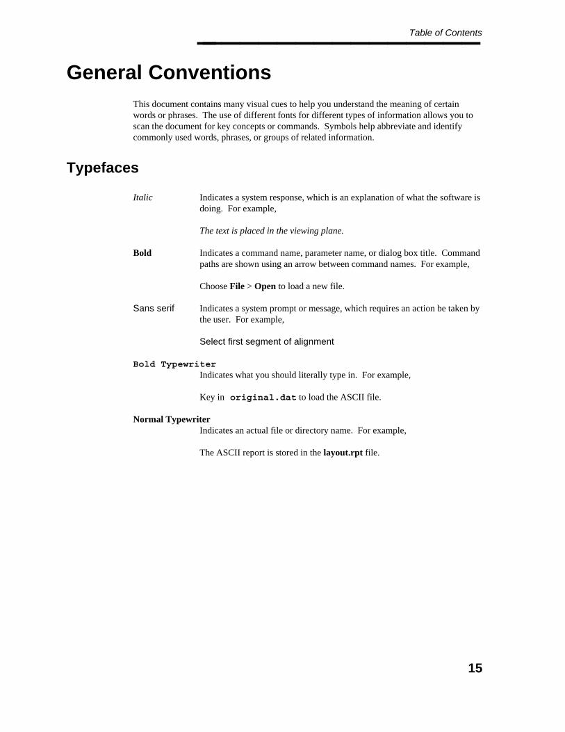
Table of Contents________________
General Conventions
This document contains many visual cues to help you understand the meaning of certainwords or phrases. The use of different fonts for different types of information allows you toscan the document for key concepts or commands. Symbols help abbreviate and identifycommonly used words, phrases, or groups of related information.
Typefaces
Italic Indicates a system response, which is an explanation of what the software isdoing. For example,
The text is placed in the viewing plane.
Bold Indicates a command name, parameter name, or dialog box title. Commandpaths are shown using an arrow between command names. For example,
Choose File > Open to load a new file.
Sans serif Indicates a system prompt or message, which requires an action be taken bythe user. For example,
Select first segment of alignment
Bold TypewriterIndicates what you should literally type in. For example,
Key in original.dat to load the ASCII file.
Normal TypewriterIndicates an actual file or directory name. For example,
The ASCII report is stored in the layout.rpt file.
15
Project Administrator — April 2002________________
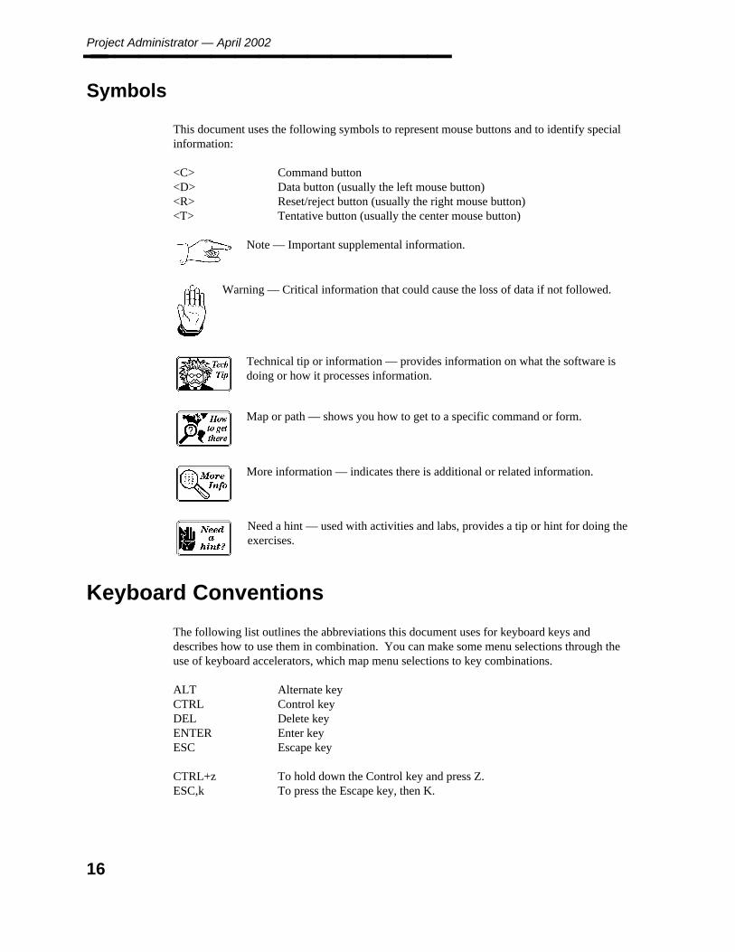
Symbols
This document uses the following symbols to represent mouse buttons and to identify specialinformation:
<C> Command button<D> Data button (usually the left mouse button)<R> Reset/reject button (usually the right mouse button)<T> Tentative button (usually the center mouse button)
Note — Important supplemental information.
Warning — Critical information that could cause the loss of data if not followed.
Technical tip or information — provides information on what the software isdoing or how it processes information.
Map or path — shows you how to get to a specific command or form.
More information — indicates there is additional or related information.
Need a hint — used with activities and labs, provides a tip or hint for doing theexercises.
Keyboard Conventions
The following list outlines the abbreviations this document uses for keyboard keys anddescribes how to use them in combination. You can make some menu selections through theuse of keyboard accelerators, which map menu selections to key combinations.
ALT Alternate keyCTRL Control keyDEL Delete keyENTER Enter keyESC Escape key
CTRL+z To hold down the Control key and press Z.ESC,k To press the Escape key, then K.
16
Table of Contents________________
Terminology
Click To use a mouse or key combination to pick an item that begins anaction. For example,
Click Apply to save the changes.
Select To mark an item by highlighting it with key combinations or by pickingit with your cursor. Selecting does not initiate an action. Afterselecting an item, you click the action you want to affect the item. Forexample,
Select the file original.dat from the list box, then click Delete toremove it from the directory.
In addition, you would select items to define parameters, such asselecting toggle buttons. This also applies to selecting graphicelements from the design file. For example,
Select the line string to define the graphic template.
Tentative-select To place a tentative point on an existing graphic element in a designfile. If you are using the CLIX operating system, you tentative-selectby double-clicking with a mouse or pressing <T> on a hand-heldcursor. If you are using the Windows NT operating system, youtentative-select by pressing a left-button, right-button chord.
Double-click To select and execute a command by clicking the mouse or hand-heldcursor button twice in rapid succession. This term implies that you areclicking the data button (<D>) as part of a menu or dialog box action.For example,
Double-click on the file original.dat to load it into the new surface.
Drag To press and hold the data button (<D>) while moving the mouse orhand-held cursor.
Type To key a character string into a text box.
Key in To type in data and press ENTER to enter the data and execute thedefault action.
In a dialog box, pressing TAB after keying in data willenter the data and move the cursor to the next field.
17

Project Administrator — April 2002________________
18

1. Intro
du
ction
Introduction________________
1. Introduction
Welcome to the Project Administrator (PD_Project) module of the Plant Design System of software.Intergraph’s plant design software can be used to design any type of plant—from petrochemical plants, offshoreplatforms, chemical and pharmaceutical plants, consumer products (food, beverages, cosmetics, soap, paper, andso forth), to power plants, waste water treatment plants, and cogeneration facilities.
Specifically, the Plant Design System (PDS) integrates many discipline-specific software modules; thesemodules automate the many phases of a plant design project. Project Administrator (PD_Project) is one of thesemodules.
19
Project Administrator — April 2002________________
Process & Power PDS Overview
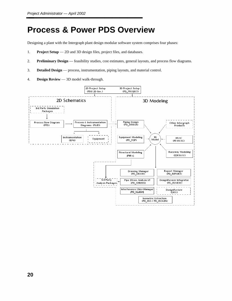
Designing a plant with the Intergraph plant design modular software system comprises four phases:
1. Project Setup — 2D and 3D design files, project files, and databases.
2. Preliminary Design — feasibility studies, cost estimates, general layouts, and process flow diagrams.
3. Detailed Design — process, instrumentation, piping layouts, and material control.
4. Design Review — 3D model walk-through.
20

1. Intro
du
ction
Project Setup________________
Project Setup
Before work can begin on a project, extensive system setup needs to be completed. The following outlines thebasic flow for initial system setup and project creation. This system and project setup is usually done by thesystem manager. Once the project has been set up, other tasks are done by the designer.
System Setup
PDS can run either standalone on a workstation or configured in a server/client relationship. Due to the size andscope of PDS projects, most companies use a server/client relationship. A PDS server can act as a databaseserver, a file server, and/or a product server. Network File System (NFS) is a program that accesses files on theserver for processing on the client computers.
PDS uses relational databases to store information about virtually all aspects of the project, including
Project data, such as file names and locations.
Reference data, such as piping commodity descriptions.
Design data, such as temperature and pressure values that are associated with graphic elements.
The PDS products attach to the relational databases through the Relational Interface Software (RIS) program.RIS supports popular Relational Database Management Systems, such as Informix, Oracle, and Microsoft SQLServer.
21
Project Administrator — April 2002________________
2D Setup
The PDS2D product is the base platform loaded on each computer that will be using PDS 2D applicationsoftware, such as P&ID, PFD, and IDM.
PDS2D is the interface to the PDS 2D application product line. It can be either loaded with the client option toaccess software on a product server or installed locally. PDS2D enables you to perform project administrativefunctions. These functions include tasks such as establishing and modifying reference data files, projects, units,and drawings.
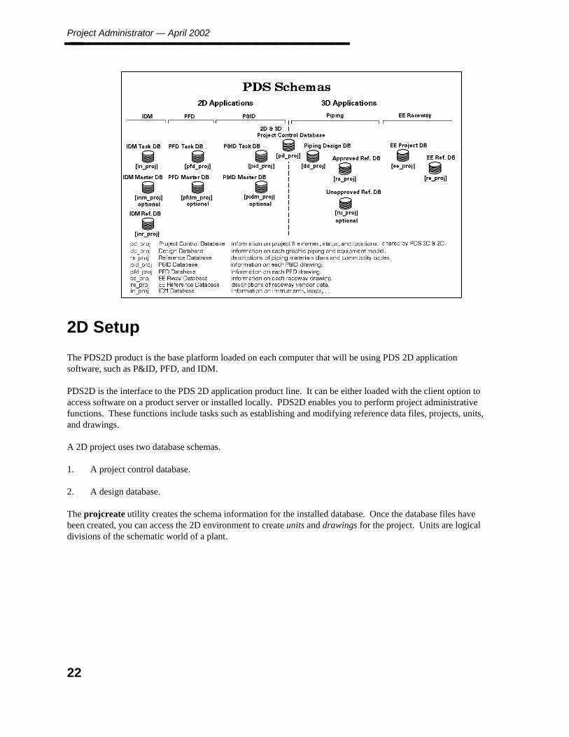
A 2D project uses two database schemas.
1. A project control database.
2. A design database.
The projcreate utility creates the schema information for the installed database. Once the database files havebeen created, you can access the 2D environment to create units and drawings for the project. Units are logicaldivisions of the schematic world of a plant.
22

1. Intro
du
ction
Project Setup________________
3D Setup
The PD_Shell product is loaded on each computer that will be using the PDS 3D products. Other PDS 3Dproducts can be either loaded on the computer using the client option or installed locally.
A 3D project uses three database schemas.
1. A project control database.
2. A material/reference database.
3. A design database.
The 2D and 3D project share a common project control database. The Project Administrator module enablesyou to create the database files, seed files, and project environment files. A 3D project is divided into designareas by disciplines. Disciplines represent the various 3D modeling applications (such as Piping, Equipment,and HVAC). A design area represents a specific volume of the project for a given discipline. Each design areacomprises a set of models that contain the actual design data.
Preliminary Design
Process Flow Diagram (PFD)
Conceptual design of a plant includes feasibility studies,cost estimates, and process simulations. Third-partyprocess simulation packages such as ASPEN or SimSciallow engineers to perform preliminary calculations suchas chemical equilibriums, reactions, heat and materialbalances, and/or design pressures and temperatures. Thedata produced from these calculations is transferred toPDS where a process flow diagram (PFD) is developed.
23
Project Administrator — April 2002________________
Detailed Design — 2D
Process & Instrumentation Diagram (P&ID)
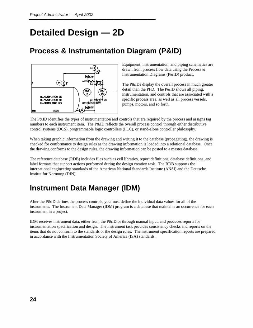
Equipment, instrumentation, and piping schematics aredrawn from process flow data using the Process &Instrumentation Diagrams (P&ID) product.
The P&IDs display the overall process in much greaterdetail than the PFD. The P&ID shows all piping,instrumentation, and controls that are associated with aspecific process area, as well as all process vessels,pumps, motors, and so forth.
The P&ID identifies the types of instrumentation and controls that are required by the process and assigns tagnumbers to each instrument item. The P&ID reflects the overall process control through either distributivecontrol systems (DCS), programmable logic controllers (PLC), or stand-alone controller philosophy.
When taking graphic information from the drawing and writing it to the database (propagating), the drawing ischecked for conformance to design rules as the drawing information is loaded into a relational database. Oncethe drawing conforms to the design rules, the drawing information can be posted to a master database.
The reference database (RDB) includes files such as cell libraries, report definitions, database definitions ,andlabel formats that support actions performed during the design creation task. The RDB supports theinternational engineering standards of the American National Standards Institute (ANSI) and the DeutscheInstitut fur Normung (DIN).
Instrument Data Manager (IDM)
After the P&ID defines the process controls, you must define the individual data values for all of theinstruments. The Instrument Data Manager (IDM) program is a database that maintains an occurrence for eachinstrument in a project.
IDM receives instrument data, either from the P&ID or through manual input, and produces reports forinstrumentation specification and design. The instrument task provides consistency checks and reports on theitems that do not conform to the standards or the design rules. The instrument specification reports are preparedin accordance with the Instrumentation Society of America (ISA) standards.
24
1. Intro
du
ction
Detailed Design — 3D________________
Detailed Design — 3D
Equipment Modeling (PD_EQP)
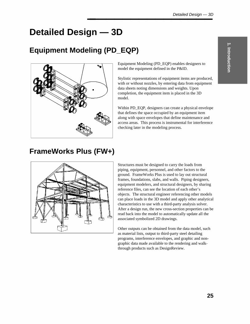
Equipment Modeling (PD_EQP) enables designers tomodel the equipment defined in the P&ID.
Stylistic representations of equipment items are produced,with or without nozzles, by entering data from equipmentdata sheets noting dimensions and weights. Uponcompletion, the equipment item is placed in the 3Dmodel.
Within PD_EQP, designers can create a physical envelopethat defines the space occupied by an equipment itemalong with space envelopes that define maintenance andaccess areas. This process is instrumental for interferencechecking later in the modeling process.
FrameWorks Plus (FW+)
Structures must be designed to carry the loads frompiping, equipment, personnel, and other factors to theground. FrameWorks Plus is used to lay out structuralframes, foundations, slabs, and walls. Piping designers,equipment modelers, and structural designers, by sharingreference files, can see the location of each other’sobjects. The structural engineer referencing other modelscan place loads in the 3D model and apply other analyticalcharacteristics to use with a third-party analysis solver.After a design run, the new cross-section properties can beread back into the model to automatically update all theassociated symbolized 2D drawings.
Other outputs can be obtained from the data model, suchas material lists, output to third-party steel detailingprograms, interference envelopes, and graphic and non-graphic data made available to the rendering and walk-through products such as DesignReview.
25
Project Administrator — April 2002________________
Piping Design Graphics (PD_Design)
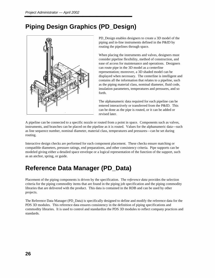
PD_Design enables designers to create a 3D model of thepiping and in-line instruments defined in the P&ID byrouting the pipelines through space.
When placing the instruments and valves, designers mustconsider pipeline flexibility, method of construction, andease of access for maintenance and operations. Designerscan route pipe in the 3D model as a centerlinerepresentation; moreover, a 3D shaded model can bedisplayed when necessary. The centerline is intelligent andcontains all the information that relates to a pipeline, suchas the piping material class, nominal diameter, fluid code,insulation parameters, temperatures and pressures, and soforth.
The alphanumeric data required for each pipeline can beentered interactively or transferred from the P&ID. Thiscan be done as the pipe is routed, or it can be added orrevised later.
A pipeline can be connected to a specific nozzle or routed from a point in space. Components such as valves,instruments, and branches can be placed on the pipeline as it is routed. Values for the alphanumeric data—suchas line sequence number, nominal diameter, material class, temperatures and pressures—can be set duringrouting.
Interactive design checks are performed for each component placement. These checks ensure matching orcompatible diameters, pressure ratings, end preparations, and other consistency criteria. Pipe supports can bemodeled giving either a detailed space envelope or a logical representation of the function of the support, suchas an anchor, spring, or guide.
Reference Data Manager (PD_Data)
Placement of the piping components is driven by the specification. The reference data provides the selectioncriteria for the piping commodity items that are found in the piping job specification and the piping commoditylibraries that are delivered with the product. This data is contained in the RDB and can be used by otherprojects.
The Reference Data Manager (PD_Data) is specifically designed to define and modify the reference data for thePDS 3D modules. This reference data ensures consistency in the definition of piping specifications andcommodity libraries. It is used to control and standardize the PDS 3D modules to reflect company practices andstandards.
26
1. Intro
du
ction
Drawing Manager (PD_Draw)________________
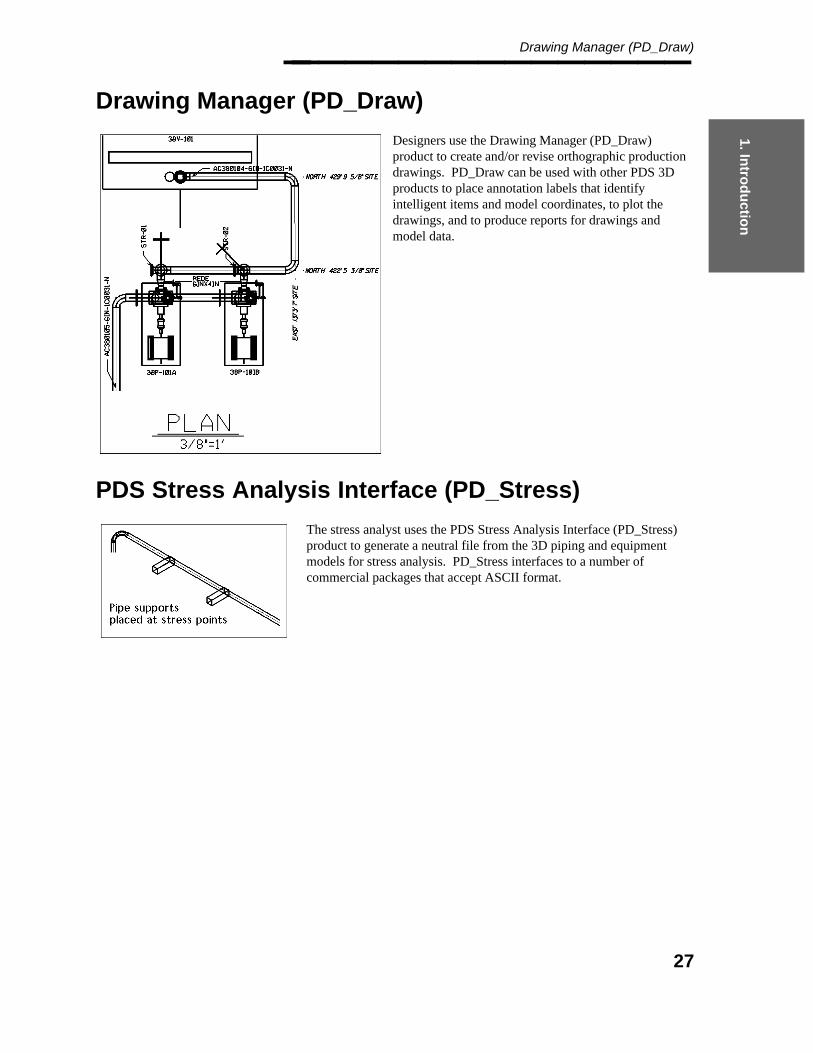
Drawing Manager (PD_Draw)
Designers use the Drawing Manager (PD_Draw)product to create and/or revise orthographic productiondrawings. PD_Draw can be used with other PDS 3Dproducts to place annotation labels that identifyintelligent items and model coordinates, to plot thedrawings, and to produce reports for drawings andmodel data.
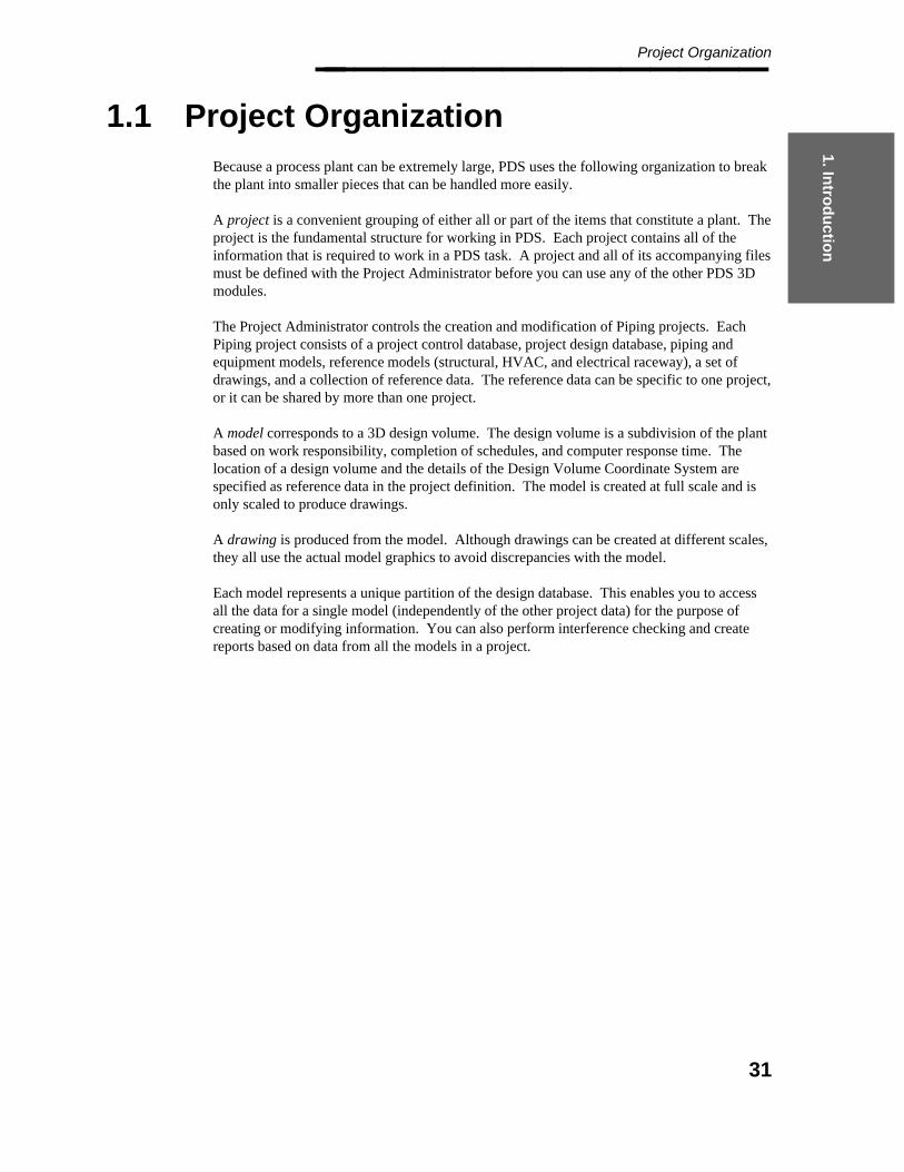
PDS Stress Analysis Interface (PD_Stress)
The stress analyst uses the PDS Stress Analysis Interface (PD_Stress)product to generate a neutral file from the 3D piping and equipmentmodels for stress analysis. PD_Stress interfaces to a number ofcommercial packages that accept ASCII format.
27

Project Administrator — April 2002________________
Interference Checker/Manager (PD_Clash)
Interference Checker/Manager (PD_Clash) creates envelope filesfor all models in the specified project, design area, or for individualmodels that have an envelope builder that is specific to eachdiscipline in the Interference Checker/Manager. It also collectsenvelope data for the models that have envelope files that werepreviously created by one of the other PDS modules. Thechecker/manager processes the specified design volume andidentifies all of the interference clashes.
It then produces reports that allow the designer to review interferences and review and/or revise the approvalstatus of the interferences. The software places graphical markers for the project, produces plots of clashes, andproduces an interference report file.
PDS Isometric Interface (PD_ISO, PD_ISOGEN)
PDS Isometric Interface (PD_ISO,PD_ISOGEN) enables designers to extractisometric drawings from the plant model, eitherinteractively or through a batch process. Theinteractive extraction can be used for testing theinterface and verifying a specific pipeline. Batchgeneration of isometrics is used for generatingproduction drawings on a project. With eitherfunction, a bill of materials is automaticallygenerated and attached to the isometric drawing.An optional MTO file can be generated whichcan be printed or used as input to the materialcontrol system.
28

1. Intro
du
ction
Drawing Manager (PD_Draw)________________
Report Manager (PD_Report)
You can generate material take-off reports(MTOs) on piping and equipment models withthe PD_Report program. The MTO processgenerates reports by using the graphical data inthe specified models to refer to the designdatabase, reference database, project database,and material description libraries for the data onwhich to report. This data includes impliedmaterials, such as bolts, gaskets, and welds, thatare not represented in the model but arenecessary for the specified connectivity.PD_Report also maintains the data that definesthe format, content and approval status of thereports.
Project Engineer HVAC (PE-HVAC)
PE-HVAC enables designers to place fittings anddevices while laying out duct routes. You can definethe active parameters for duct characteristics such aswidth, depth, shape, material, construction status, andservice.
EE Raceway Modeling
Electrical Engineer Raceway Modeling (EERWAY)enables designers to extract data from the RDB and create a3D model using the centerline and/or three-line componentgraphics. With this 3D model, you can create interferenceenvelopes and run interference detection, produce MTOs,and extract raceway drawings.
29

Project Administrator — April 2002________________
Design Review Integrator (PD_Review)
The PD_Review interface provides an intelligent link to Intergraph’s DesignReview package. You can useDesignReview to walk through a PDS model—in full shaded mode—and review the design and alphanumericdata.
Engineering data, such as instrument numbers, equipment numbers, line numbers, and line sizes, is availablewhen walking through the model. Comments are stored in a separate tag file and can be accessed later duringthe review session. On subsequent walk-throughs, the original comment can be reviewed along with theresponsible designer’s actions.
Also with DesignReview, the model can be used to train operations and maintenance personnel before or afterthe plant is constructed. DesignReview is not included in the PDS package and must be purchased separately.
30
1. Intro
du
ction
Project Organization________________
1.1 Project Organization
Because a process plant can be extremely large, PDS uses the following organization to breakthe plant into smaller pieces that can be handled more easily.
A project is a convenient grouping of either all or part of the items that constitute a plant. Theproject is the fundamental structure for working in PDS. Each project contains all of theinformation that is required to work in a PDS task. A project and all of its accompanying filesmust be defined with the Project Administrator before you can use any of the other PDS 3Dmodules.
The Project Administrator controls the creation and modification of Piping projects. EachPiping project consists of a project control database, project design database, piping andequipment models, reference models (structural, HVAC, and electrical raceway), a set ofdrawings, and a collection of reference data. The reference data can be specific to one project,or it can be shared by more than one project.
A model corresponds to a 3D design volume. The design volume is a subdivision of the plantbased on work responsibility, completion of schedules, and computer response time. Thelocation of a design volume and the details of the Design Volume Coordinate System arespecified as reference data in the project definition. The model is created at full scale and isonly scaled to produce drawings.
A drawing is produced from the model. Although drawings can be created at different scales,they all use the actual model graphics to avoid discrepancies with the model.
Each model represents a unique partition of the design database. This enables you to accessall the data for a single model (independently of the other project data) for the purpose ofcreating or modifying information. You can also perform interference checking and createreports based on data from all the models in a project.
31

Project Administrator — April 2002________________
1.2 Project Administrator Overview
The Project Administrator (PD_Project) module enables you to define project data and createproject files including database files, design files, seed files, and reports. It is specificallydesigned to support the creation and revision of project data for use by other PDS 3Dmodules.
Project Administrator contains the following basic components:
Project Environment Manager
Project Data Manager
Project Setup Manager
Project Control Manager
Project Archival Manager
System Manager
File Lock Manager
Access Control Manager
Export to PDME
Project Environment Manager
The Project Environment Manager component creates, revises, and deletes disciplines,design areas, and model files; revises the project/client information; revises the disk locationof a project or file; and creates a report of information in the project control database. TheProject Control Database contains information that relates to every aspect of a project.
Project Data Manager
Each project contains seed files that are used when creating a project, a design area, a modeldesign volume, or a drawing file. The Project Data Manager enables you to revise theseseed files or similar data in existing model, drawing, and envelope files. This data includessettings for the following basic information:
Definition of coordinate systems and volumes.
Definition of physical units.
Formats for coordinate labels and other annotation graphics.
32
1. Intro
du
ction
Project Administrator Overview________________ Formats for message displays such as coordinate readout.
Graphic symbology for each model and drawing category.
Graphic symbology for non-component graphics.
Tables of hard and soft compatibility parameters.
Tolerance values for design checks, interference detection, and segment and pipe lengththresholds.
Tables for end preparation and pressure ratings.
Names of specific files and tables for component placement and material take-off.
Selection of approved or unapproved RDB data for the project or model.
Project Setup Manager
The Project Setup Manager component enables you to create a new project or delete anexisting project. You must create a project before you can access any of the other PDS 3Dactivities. When you create a project, the system creates the associated database schemas foruse in storing and accessing the project control data, design data, and reference data.
Project Control Manager
The Project Control Manager component enables you to create a package of projectdocuments for use in revision control. A package can include any of the documents that areassociated with a project, such as isometric drawings, orthographic drawings, and reports.You can define package information in the project control database and report on thisinformation for revision control.
Project Archival Manager
The Project Archival Manager component enables you to back up a complete project or asubset of the project files. You can also retrieve all or part of an archived project.
System Manager
The System Manager component enables you to revise the project directory file. The projectdirectory file contains the names and locations of all the projects on the network.
33
Project Administrator — April 2002________________
File Lock Manager
The File Lock Manager enables you to unlock files that are currently locked by another useror process.
Access Control Manager
The Access Control Manager provides the PDS system manager with the ability to restrictthe end user’s access to data on the basis of the project number, the type of data, andprivileges assigned to the user.
Export to PDME
The Export to PDME prepares a data set that consists of user-defined documents and adocument index for import into the Plant Data Management Environment (PDME).
34
1. Intro
du
ction
System Setup________________
1.3 System Setup
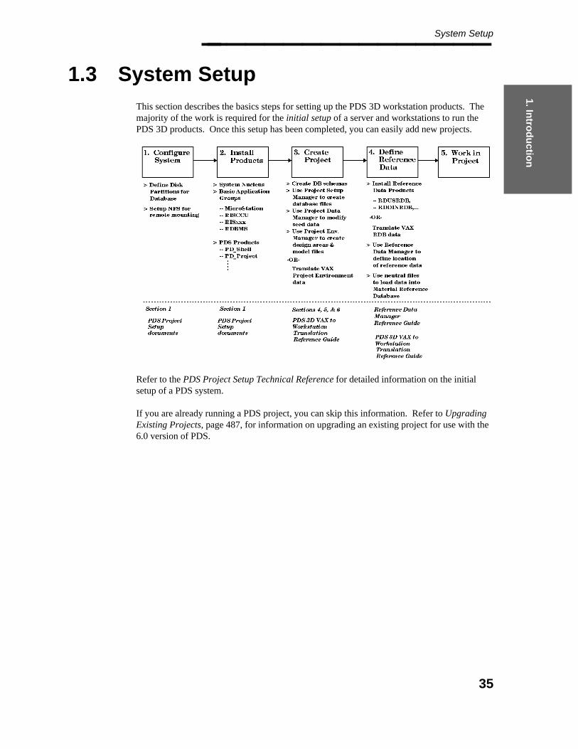
This section describes the basics steps for setting up the PDS 3D workstation products. Themajority of the work is required for the initial setup of a server and workstations to run thePDS 3D products. Once this setup has been completed, you can easily add new projects.
Refer to the PDS Project Setup Technical Reference for detailed information on the initialsetup of a PDS system.
If you are already running a PDS project, you can skip this information. Refer to UpgradingExisting Projects, page 487, for information on upgrading an existing project for use with the6.0 version of PDS.
35

Project Administrator — April 2002________________
1.3.1 System Configurations
This section outlines the system hardware and software considerations required to supportPDS. PDS can run either standalone on a workstation or configured in a client/serverrelationship. Due to the size and scope of PDS projects, most companies use a client/serverrelationship.
Servers
PDS uses the following types of servers based on logical functions:
Database Server — This is the location of the relational database files. All databasefiles are created and stored on this machine.
Software Server — This is the location of the PDS application products. By using asoftware server, you can load all the PDS software in a central location and haveindividual workstations access the software through Network File System (NFS)software.
File Server — This is the central location used to store project files such as referencedata libraries, seed files, model files, drawings, and reports.
Compute Server — This is the location for processing compute-intensive activities suchas interference checking and hiddenline removal.
Depending on your system requirements, you can designate one server to perform all of theseduties, or you can split them across multiple machines.
Workstations
A client is a node (usually a workstation) that accesses data or performs a function on theremote resource (usually a server). In most PDS configurations, the files reside on the server,and processing takes place on the client workstation.
PDS supports workstations that run on the Windows NT operating system.
36

1. Intro
du
ction
Loading Products________________
1.3.2 Loading Products
You should load the appropriate PDS products and their prerequisites to the server(s) andworkstation(s) that are to be used on your network.
1.3.3 Loading Baseline Software
Windows NT Baseline
PDS requires the standard Microsoft baseline products as well as all of the following specificproducts:
Baseline software including Microsoft Windows NT version 3.5.1 or higher andservice packs (contact Intergraph support or check web pages for currentrecommendations).
TCPIP protocol.
MicroStation 5.5 for Windows NT. MicroStation must be loaded before loading Iplotor any of the PDS products.
37
Project Administrator — April 2002________________ NTNFS (PCNFS) — Network File System. The network file system is Diskaccess, ifaccess to CLIX file servers is required.
RIS_share — The RIS client software.
Interplot Products — Iplot client is mandatory. Iplot server may be required dependingon the plotter configuration.
NT Batch.
1.3.4 Loading PDS Products
The PDS application software can be loaded on the local workstations or loaded on a serverand accessed remotely through the network. You should load the most heavily used productslocally and access the remainder of the products remotely.
The only PDS products required to exist on local workstations are PD_SHELL andPD_LICE.
The remaining PDS products can be loaded on a server or on a local workstation.
Advantages and Disadvantages of RemoteAccess
Accessing the PDS products remotely makes system maintenance easier. You canupgrade to the latest version of software by upgrading the server.
Accessing the PDS products remotely introduces performance sacrifices atinitialization.
PDS 3D Installation Options
The product installation procedures for each of the PDS 3D products provide the followingdownload options:
Local (default) — The complete product is downloaded to the applicable workstation,and the applicable batch queues are created automatically.
Client — The system prompts for the software server node to be used for the executablesoftware to conserve disk space on the client workstation. The applicable batch queuesare created automatically in the same manner as for the local option.
Server — This option is the same as the local option, except that, on CLIX, both theC100 and C400 versions of the executables are installed. MicroStation is not requiredon the software server.
38
1. Intro
du
ction
Loading Products________________
PDS Products
Load the following PDS products on the software server and PDS workstations using one ofthe options described above. To set up a software server for use by a set of clientworkstations, all of the following products should be installed using the server option:
PD_LICE — This product controls access to the PDS products. It is required on allPDS workstations.
PD_Shell — This product controls execution of all other PDS 3D products. Thisproduct is required on all PDS workstations and must be installed with the local option.
PD_Project (Project Administrator) — The system creates the following Batch Queues:PDarchival, PDcreate_model, PDcopy_model, PDdelete_model, PDprojec_report, andPDproject_data.
PD_Data (Reference Data Manager) — The system creates an Batch Queue namedPDreference.
PD_Design (Piping Designer) — The system creates the following Batch Queues:PDapproval_mgr, PDdb_verify, PDdesign_checks, and PDpid_report.
PD_Draw (Drawing Manager) — The system creates the following Batch Queues:PDhline, PDplot, and PDcreate_dwg.
PD_Review (DesignReview Integrator) — The system creates an Batch Queue namedPDlabel_builder.
PD_Clash (Interference Manager) — The system creates the following Batch Queues:PDclash_checker and PDclash_server.
PD_Report (Report Manager) — The system creates a Batch Queue named PDreport.
PD_EQP (Equipment Modeling) — The system creates the following Batch Queues:PDloadeqp and PDeqp_report.
PD_ISO (ISO Extraction Interface) — The system creates the following Batch Queues:PDisocreate and PDisoplot.
RD_USRDB (U.S. Practice Reference Database).
RD_DINRDB (DIN Reference Database).
VHL (Vector Hidden Line Manager).
PDS2D (PDS 2D Applications) — The system creates an Batch Queue namedPDS2DQUEUE.
SmartPlant P&ID Integration Tools — If SmartPlant P&ID is not loaded on thecomputer, the system loads the tools necessary for transferring data from SmartPlantP&ID to PDS 3D.
39

Project Administrator — April 2002________________
Using the Client Option
For each of the products loaded with the client option, the system prompts for the node nameof the PDS software server and the file path for the product directory (such asc:\win32app\ingr\pddesign) on the software server.
The system adds an entry to the registry with the provided information.
1.3.5 Loading PDS for Windows NT
Installation Options
You can use the PDS Component Loader to install multiple applications at one time or toinstall individual applications one at a time. Follow these steps to load the PDS applicationsoftware:
1. Insert the CD-ROM containing the PDS software into the CD drive. Use the FileManager to activate the CDROM drive.
2. Double-click setup.exe from the displayed list of files and directories to activate thePDS Component Loader.
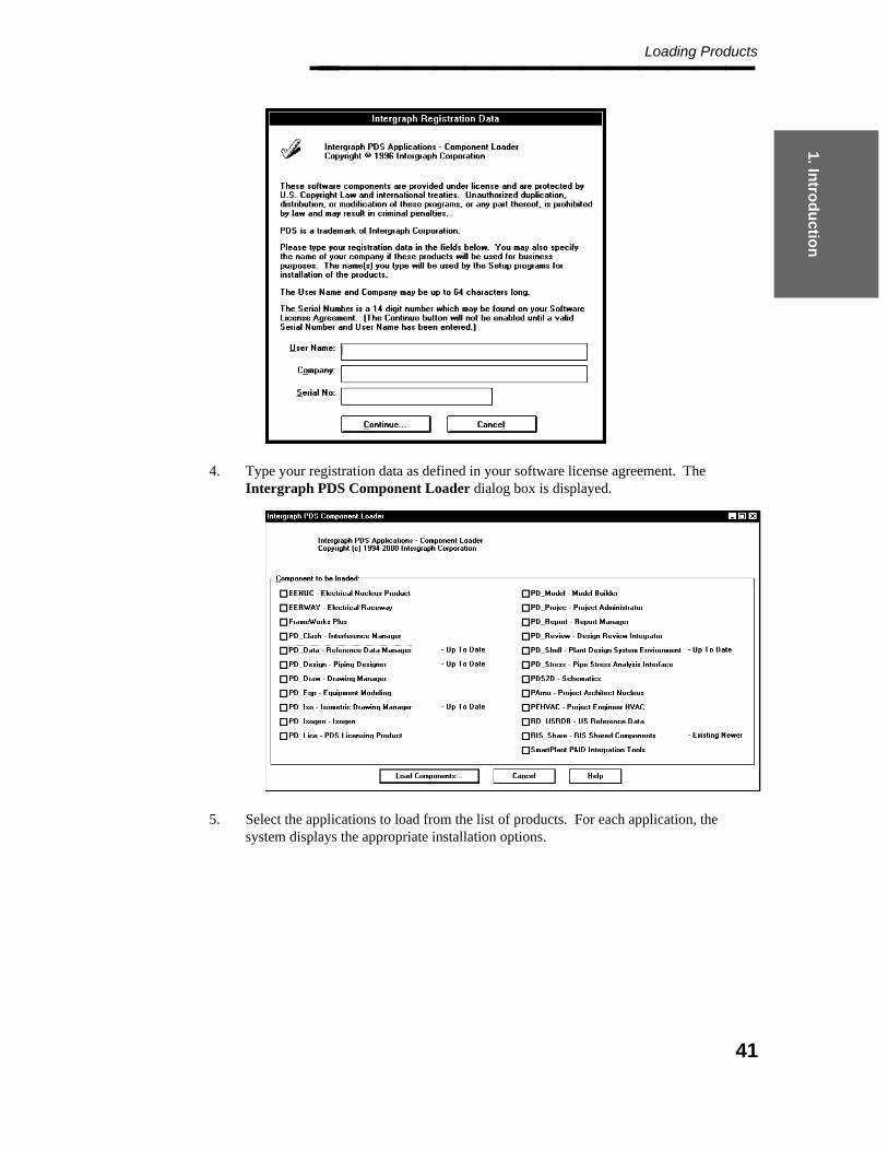
3. Choose Continue to load the PDS software products. The Intergraph RegistrationData dialog box is displayed.
40
1. Intro
du
ction
Loading Products________________
4. Type your registration data as defined in your software license agreement. TheIntergraph PDS Component Loader dialog box is displayed.
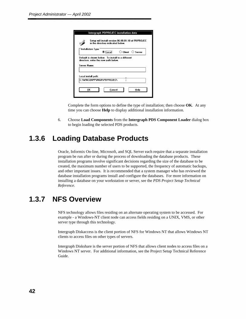
5. Select the applications to load from the list of products. For each application, thesystem displays the appropriate installation options.
41
Project Administrator — April 2002________________
Complete the form options to define the type of installation; then choose OK. At anytime you can choose Help to display additional installation information.
6. Choose Load Components from the Intergraph PDS Component Loader dialog boxto begin loading the selected PDS products.
1.3.6 Loading Database Products
Oracle, Informix On-line, Microsoft, and SQL Server each require that a separate installationprogram be run after or during the process of downloading the database products. Theseinstallation programs involve significant decisions regarding the size of the database to becreated, the maximum number of users to be supported, the frequency of automatic backups,and other important issues. It is recommended that a system manager who has reviewed thedatabase installation programs install and configure the databases. For more information oninstalling a database on your workstation or server, see the PDS Project Setup TechnicalReference.
1.3.7 NFS Overview
NFS technology allows files residing on an alternate operating system to be accessed. Forexample - a Windows-NT client node can access fields residing on a UNIX, VMS, or otherserver type through this technology.
Intergraph Diskaccess is the client portion of NFS for Windows NT that allows Windows NTclients to access files on other types of servers.
Intergraph Diskshare is the server portion of NFS that allows client nodes to access files on aWindows NT server. For additional information, see the Project Setup Technical ReferenceGuide.
42
1. Intro
du
ction
Database Information________________
1.4 Database Information
PDS uses databases to store information that is applicable to all aspects of the project,including project control data and reference data. PDS also uses databases to associatenongraphic information and user-definable attributes with graphic elements in the design files.PDS 3D provides a consistent interface for the maintenance of these databases.
All databases you create for PDS are relational databases, meaning that they are based on arelational data model — a relation being a two-dimensional table made up of rows andcolumns. Most relational databases have a Structured Query Language (SQL) interface.
The PDS 3D products attach to the relational databases through Intergraph Corporation’sRelational Interface System (RIS). RIS is a generic relational database interface that isolatesthe SQL interface differences in specific vendors’ relational database management systems(RDBMSs). It provides a generic networked access to all databases that are generated withpopular RDBMSs supported by RIS, including Informix (both Standard Engine and On-line),Oracle, Sybase, and SQL Server. For information on installing the RDBMS systems on yourworkstation or server, see the PDS Project Setup Technical Reference.
1.4.1 PDS and the Relational Interface System(RIS)
PDS 3D uses RIS to define information in an RDBMS. An RIS schema identifies a uniquedatabase/user combination in the commercial database system. Users are established fordifferent RDBMSs in different ways; in fact, the concept of a database differs greatly fromone RDBMS to another. The various interfaces provided in PDS allow you to maintaindatabases through RIS efficiently, without requiring you to know the differences betweenRDBMSs or the syntax of the RIS create schema statement.
RIS works in conjunction with existing databases. You must have RISimplemented on your network and also have one of the Relational DatabaseManagement Systems (RDBMSs) supported by RIS, such as Informix, Oracle,or SQL Server.
Intergraph Corporation recommends that database creation and manipulationsbe performed at the system manager level. The system manager should befamiliar with the theory and practice of the Relational Interface System to besuccessful. See the PDS Project Setup Technical Reference Guide.
The Component Loader runs a check of the registry keystringHKEY_LOCAL_MACHINE>SOFTWARE>Intergraph>Common inpreparing for delivery of the RIS Shared Components. If this registrykeystring does not exist, the Component Loader creates it with a value ofc:\win32app\ingr\share. If the keystring does exist, it must be nolonger than 22 characters and must not contain any spaces. If either of theserules is violated, a warning dialog box displays, and the RIS Components willnot be delivered. For information on modifying the registry keystring, see theProject Setup Technical Reference (DEA506740), Appendix J.
43

Project Administrator — April 2002________________
1.5 Preparing the Server andWorkstations for PDS
Intergraph recommends using dedicated login accounts for running PDS. This sectiondescribes the steps required to define the necessary accounts on a PDS software/file server andthe client workstations. See the PDS Project Setup Technical Reference Guide for additionalinformation.
44
2. PD
S
En
viron
men
t
PDS Environment________________
2. PDS Environment
The PDS 3D software supports a variety of applications. All the supported applications use acommon interface that is controlled by the PD Shell program. This ensures consistencyacross applications and minimizes the amount of time required to learn the product.
The PDS 3D modules provide a simple user interface through extensive use of forms. Themodules also provide an on-line Help capability for easy access to information while workingin the product.
The PDS 3D software uses available nucleus tools such as MicroStation and FORMS. Itsupports standard software such as NFS, NQS, and RIS required to set up data across anetwork. This design facilitates the use of non-PDS tools such as relational databases andthird party software.
The PD_Shell Environment and all batch jobs in the PDS 3D products interface toIntergraph’s Network Licensing System.
45
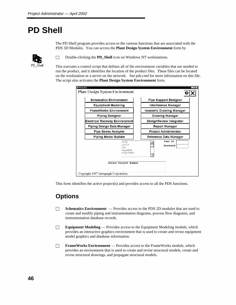
Project Administrator — April 2002________________
PD Shell
The PD Shell program provides access to the various functions that are associated with thePDS 3D Modules. You can access the Plant Design System Environment form by
Double-clicking the PD_Shell icon on Windows NT workstations.
This executes a control script that defines all of the environment variables that are needed torun the product, and it identifies the location of the product files. These files can be locatedon the workstation or a server on the network. See pds.cmd for more information on this file.The script also activates the Plant Design System Environment form.
This form identifies the active project(s) and provides access to all the PDS functions.
Options
Schematics Environment — Provides access to the PDS 2D modules that are used tocreate and modify piping and instrumentation diagrams, process flow diagrams, andinstrumentation database records.
Equipment Modeling — Provides access to the Equipment Modeling module, whichprovides an interactive graphics environment that is used to create and revise equipmentmodel graphics and database information.
FrameWorks Environment — Provides access to the FrameWorks module, whichprovides an environment that is used to create and revise structural models, create andrevise structural drawings, and propagate structural models.
46
2. PD
S
En
viron
men
t
PD Shell________________ Piping Designer — Activates an interactive command environment that is used tocreate piping and in-line instrumentation in the model; revise existing model graphicsand database information; and verify the integrity of the data in the model.
Electrical Raceway Environment — Provides access to the Electrical Racewaymodule, which provides an interactive environment that is used to create and reviseraceway models and access raceway utilities.
Piping Design Data Manager — Provides access to a set of options that are used toverify the integrity of the graphic and database information that is associated with amodel.
Piping Model Builder — Enables you to create piping graphics from a nongraphicsenvironment. This module is used with PD_Design to create an accurate 3D model ofthe piping network.
Pipe Support Designer — Activates an interactive command environment that is usedto create pipe supports in the model, and revise existing pipe support model graphicsand database information.
Pipe Stress Analysis — Activates a set of forms that are used to extract informationfrom piping models for input to third-party pipe stress analysis products.
Interference Manager — Activates a set of forms that are used to check forinterferences among project models and to control approved interferences.
Isometric Drawing Manager — Activates a set of forms that are used to extractisometric drawings from piping models and to review or plot the created isometricdrawings.
Drawing Manager — Activates a set of forms that are used to create and manipulatedrawings and drawing views; provide access to the interactive graphics environment fordrawings; and provide access to a plot manager and vector hiddenline manager.
DesignReview Integrator — Activates a set of forms that are used to extractinformation to form label files for use in DesignReview and to review data from aDesignReview session.
Report Manager — Activates a set of forms that are used to create and revise reportformat files and report on information in a project including Material Take-Off reports.
Project Administrator — Provides access to a set of forms that are used to create aproject, create and revise project files, define project seed data, and control the project.
Reference Data Manager — Provides access to a set of forms that are used to controlthe reference data for a project including Piping Job Specification data, GraphicCommodity Data, Alphanumeric Commodity Data, Standard Note Library, LabelDescription Library, and Piping Assembly Library.
47
Project Administrator — April 2002________________
Other Fields
User ID — Used for access control. This field also sets the Review User ID for use inthe Interference Manager module.
If access control has been defined, you must key in a valid user ID as defined by yoursystem manager to gain access to the projects. Refer to Access Control Manager, page467, for more information on using access control.
If access control has not been defined, no entry is required for this field.
Password — Key in the password for the specified user ID.
Project List Field — Displays the defined projects for the network and allows you toselect the active project. The system lists all the defined PDS projects (2D-only, 3D-only, and 2D & 3D). An error is displayed if you select an option that is incompatiblewith the active project. For example, if the active project is a 2D-only project, youcannot access the the Interference Manager module.
If access control has been defined, only those projects for which you have some level ofaccess are displayed.
Message Area — Displays prompts and messages that are associated with the activeprocess. Error messages are displayed in red.
48
2. PD
S
En
viron
men
t
PD_Shell Form Conventions________________
PD_Shell Form Conventions
The following Conventions describe how to respond to the various buttons, lists, and promptsthat make up the environments. The display size of forms and dialog boxes in the non-Microstation graphics environment are independent of the size of the workstation’s displaysystem. Most forms contain the same basic features: buttons, fields, text, and other gadgets.In general, anything you find on a form is called a gadget.
Selecting Options
You move through the PD_Shell forms by selecting function buttons or other gadgets fromthe form. Select means to place the screen cursor (which appears as an arrow) on top of ascreen gadget and press <D>.
For most of the forms with scrolling lists, you can double-click on a row to select and acceptthe data in that row. This performs the same action as selecting a row (which highlights) andthen selecting the Accept button.
You use the select action to select functions, access other forms, activate data fields, togglebuttons, select from lists, scroll through data displayed on the screen, and so on.
The following summarizes other basic actions you use in the environments:
Enter — When keying in any data in a key-in field, press the <ENTER> or <Tab> keyfor the data to be entered into the system. You can also press <ENTER> or <Tab> tomove through a set of key-in fields.
Delete — If you make a mistake while keying in text, press the <Delete> key to erasecharacter(s) to the left of the cursor.
Common Tools on the PD_Shell Forms
There are many gadgets in the environments that are common to most or all of the forms. Thefollowing describes these tools.
Standard Commands
The PD_Shell forms have a set of standard buttons in the upper right corner of most of theform windows. The available commands vary from form to form depending on the type ofoperation.
The Help button activates on-line Help for the active form. Help remains active until youdelete the Help window.
49
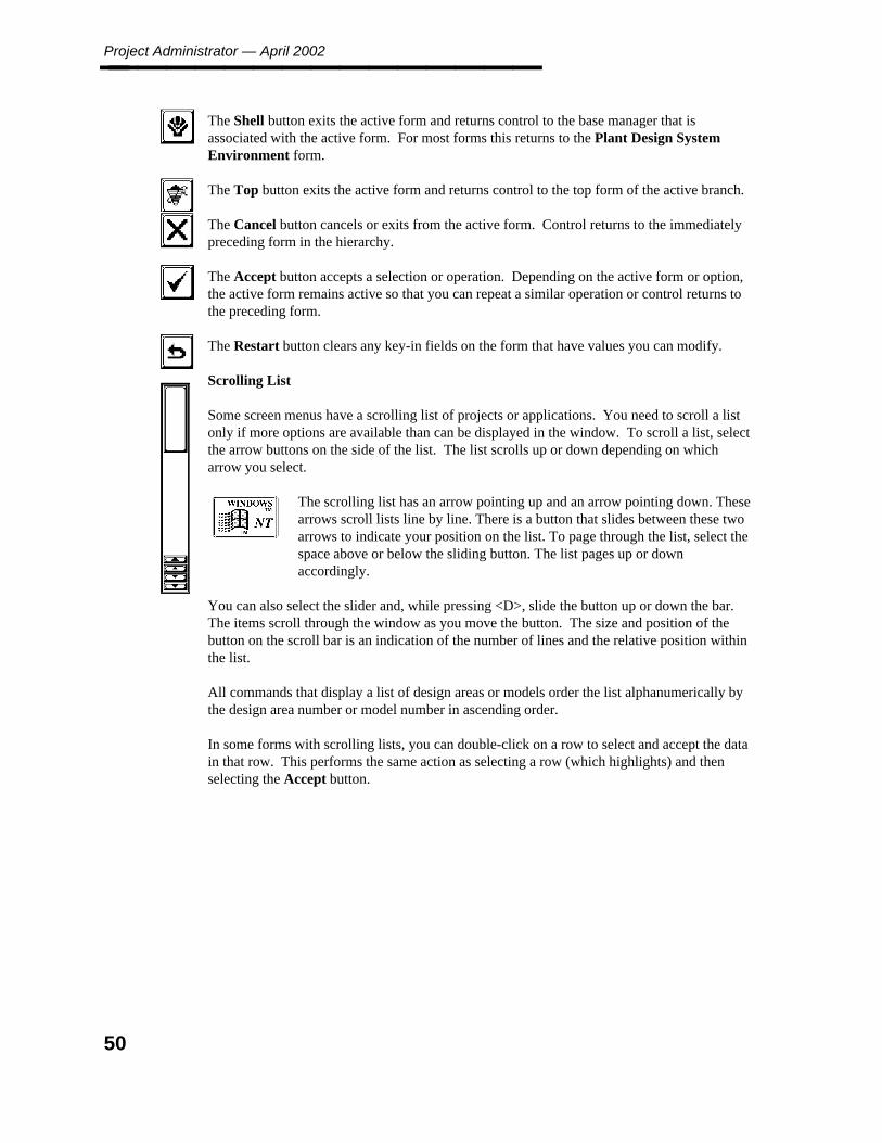
Project Administrator — April 2002________________
The Shell button exits the active form and returns control to the base manager that isassociated with the active form. For most forms this returns to the Plant Design SystemEnvironment form.
The Top button exits the active form and returns control to the top form of the active branch.
The Cancel button cancels or exits from the active form. Control returns to the immediatelypreceding form in the hierarchy.
The Accept button accepts a selection or operation. Depending on the active form or option,the active form remains active so that you can repeat a similar operation or control returns tothe preceding form.
The Restart button clears any key-in fields on the form that have values you can modify.
Scrolling List
Some screen menus have a scrolling list of projects or applications. You need to scroll a listonly if more options are available than can be displayed in the window. To scroll a list, selectthe arrow buttons on the side of the list. The list scrolls up or down depending on whicharrow you select.
The scrolling list has an arrow pointing up and an arrow pointing down. Thesearrows scroll lists line by line. There is a button that slides between these twoarrows to indicate your position on the list. To page through the list, select thespace above or below the sliding button. The list pages up or downaccordingly.
You can also select the slider and, while pressing <D>, slide the button up or down the bar.The items scroll through the window as you move the button. The size and position of thebutton on the scroll bar is an indication of the number of lines and the relative position withinthe list.
All commands that display a list of design areas or models order the list alphanumerically bythe design area number or model number in ascending order.
In some forms with scrolling lists, you can double-click on a row to select and accept the datain that row. This performs the same action as selecting a row (which highlights) and thenselecting the Accept button.
50
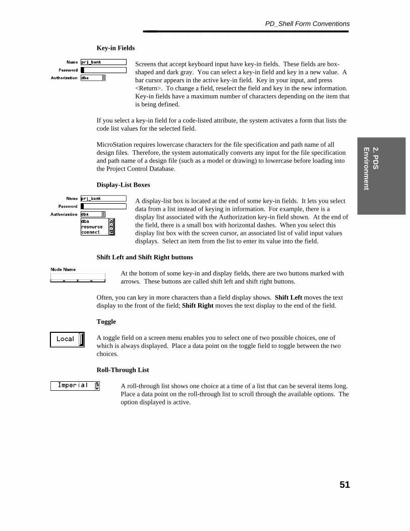
2. PD
S
En
viron
men
t
PD_Shell Form Conventions________________ Key-in Fields
Screens that accept keyboard input have key-in fields. These fields are box-shaped and dark gray. You can select a key-in field and key in a new value. Abar cursor appears in the active key-in field. Key in your input, and press<Return>. To change a field, reselect the field and key in the new information.Key-in fields have a maximum number of characters depending on the item thatis being defined.
If you select a key-in field for a code-listed attribute, the system activates a form that lists thecode list values for the selected field.
MicroStation requires lowercase characters for the file specification and path name of alldesign files. Therefore, the system automatically converts any input for the file specificationand path name of a design file (such as a model or drawing) to lowercase before loading intothe Project Control Database.
Display-List Boxes
A display-list box is located at the end of some key-in fields. It lets you selectdata from a list instead of keying in information. For example, there is adisplay list associated with the Authorization key-in field shown. At the end ofthe field, there is a small box with horizontal dashes. When you select thisdisplay list box with the screen cursor, an associated list of valid input valuesdisplays. Select an item from the list to enter its value into the field.
Shift Left and Shift Right buttons
At the bottom of some key-in and display fields, there are two buttons marked witharrows. These buttons are called shift left and shift right buttons.
Often, you can key in more characters than a field display shows. Shift Left moves the textdisplay to the front of the field; Shift Right moves the text display to the end of the field.
Toggle
A toggle field on a screen menu enables you to select one of two possible choices, one ofwhich is always displayed. Place a data point on the toggle field to toggle between the twochoices.
Roll-Through List
A roll-through list shows one choice at a time of a list that can be several items long.Place a data point on the roll-through list to scroll through the available options. Theoption displayed is active.
51
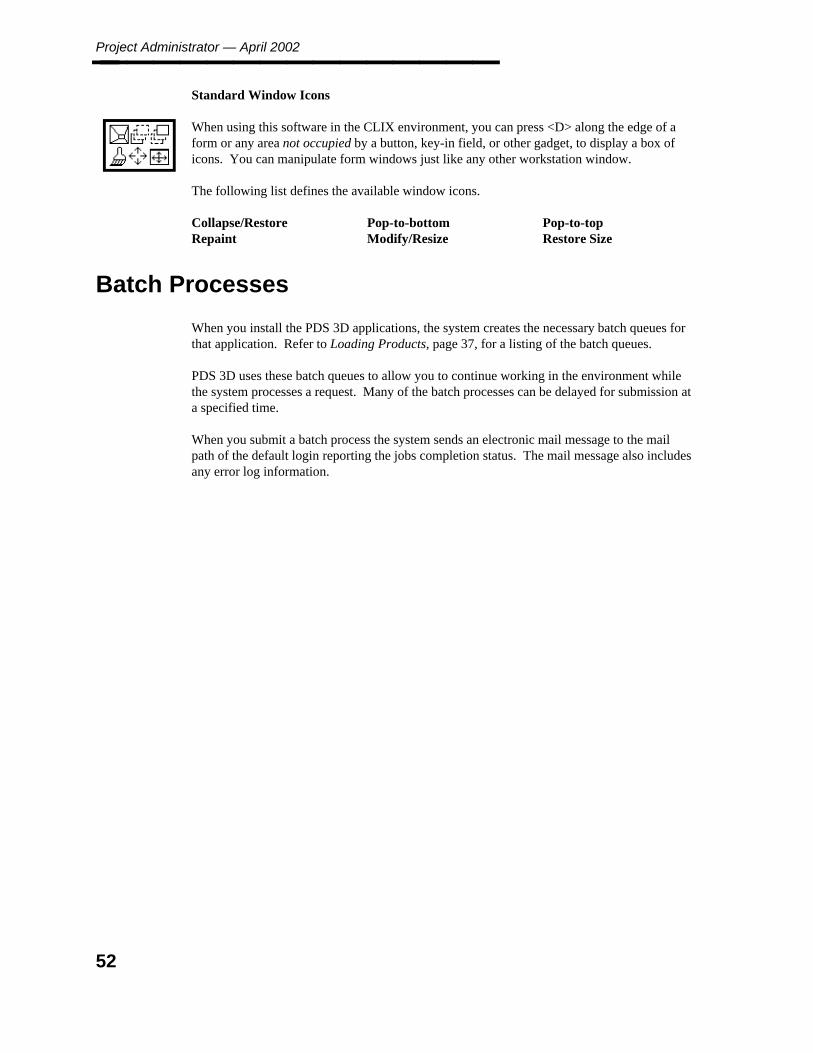
Project Administrator — April 2002________________ Standard Window Icons
When using this software in the CLIX environment, you can press <D> along the edge of aform or any area not occupied by a button, key-in field, or other gadget, to display a box oficons. You can manipulate form windows just like any other workstation window.
The following list defines the available window icons.
Collapse/RestoreRepaint
Pop-to-bottomModify/Resize
Pop-to-topRestore Size
Batch Processes
When you install the PDS 3D applications, the system creates the necessary batch queues forthat application. Refer to Loading Products, page 37, for a listing of the batch queues.
PDS 3D uses these batch queues to allow you to continue working in the environment whilethe system processes a request. Many of the batch processes can be delayed for submission ata specified time.
When you submit a batch process the system sends an electronic mail message to the mailpath of the default login reporting the jobs completion status. The mail message also includesany error log information.
52
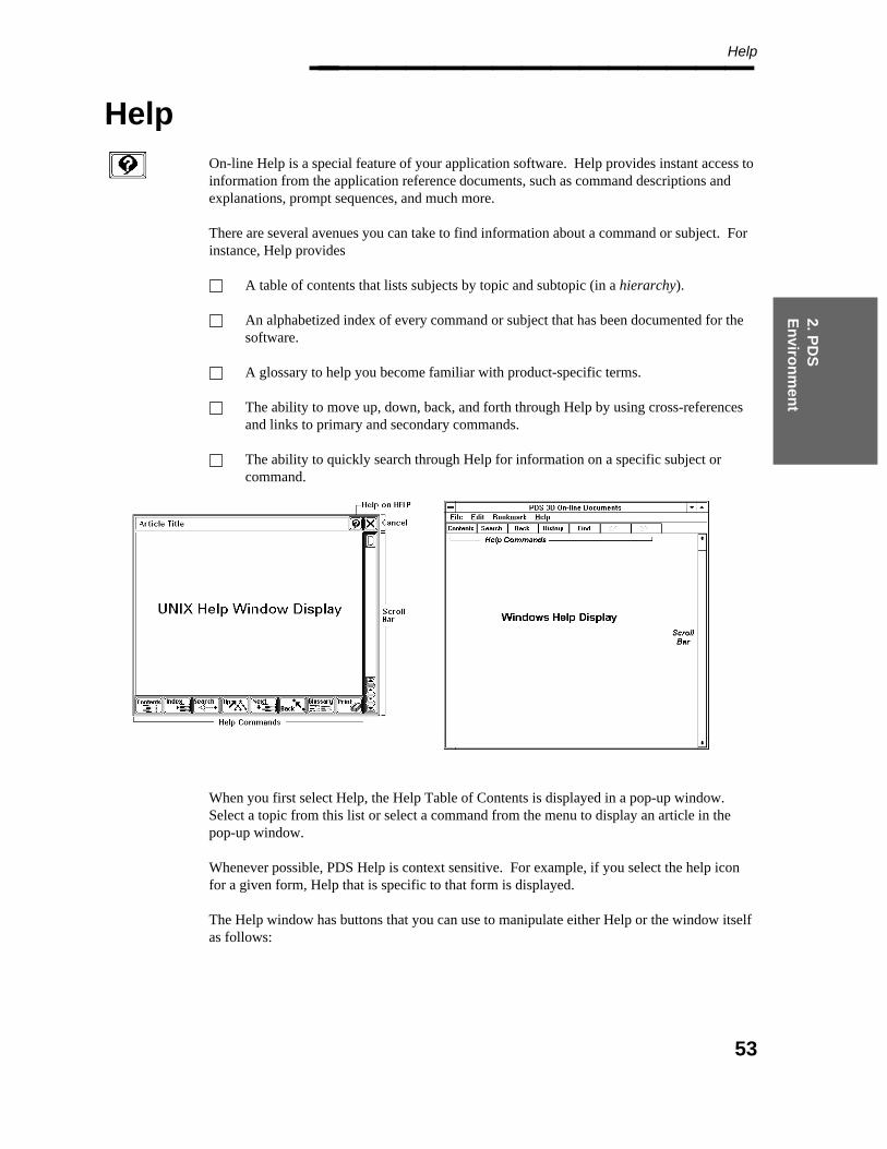
2. PD
S
En
viron
men
t
Help________________
Help
On-line Help is a special feature of your application software. Help provides instant access toinformation from the application reference documents, such as command descriptions andexplanations, prompt sequences, and much more.
There are several avenues you can take to find information about a command or subject. Forinstance, Help provides
A table of contents that lists subjects by topic and subtopic (in a hierarchy).
An alphabetized index of every command or subject that has been documented for thesoftware.
A glossary to help you become familiar with product-specific terms.
The ability to move up, down, back, and forth through Help by using cross-referencesand links to primary and secondary commands.
The ability to quickly search through Help for information on a specific subject orcommand.
When you first select Help, the Help Table of Contents is displayed in a pop-up window.Select a topic from this list or select a command from the menu to display an article in thepop-up window.
Whenever possible, PDS Help is context sensitive. For example, if you select the help iconfor a given form, Help that is specific to that form is displayed.
The Help window has buttons that you can use to manipulate either Help or the window itselfas follows:
53
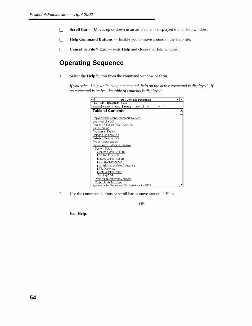
Project Administrator — April 2002________________ Scroll Bar — Moves up or down in an article that is displayed in the Help window.
Help Command Buttons — Enable you to move around in the Help file.
Cancel or File > Exit — exits Help and closes the Help window.
Operating Sequence
1. Select the Help button from the command window or form.
If you select Help while using a command, help on the active command is displayed. Ifno command is active, the table of contents is displayed.
2. Use the command buttons or scroll bar to move around in Help.
— OR —
Exit Help.
54

3. Pro
ject A
dm
inistrato
r
Project Administrator________________
3. Project Administrator
The Project Administrator controls the handling of databases and files within a project. Itprovides functions for creating and manipulating a project, managing files, and setting up thesystem.
Select the Project Administrator option from the Plant Design System Environment form.The Project Administrator form is displayed.
Select the option to be performed.
Project Environment Manager — Enables you to create, revise, and deletedisciplines, design areas, and model files; revise the project/client information or disklocation of a project or model; or create a report of information in the project controldatabase and design database (see Project Environment Manager Form, page 101).
Project Data Manager — Enables you to revise the RDB seed data used to createmodel files, drawings, and envelope files and to revise the RDB data for existing modelfiles, drawings, or interference marker files (see Project Data Manager Form, page177).
Project Setup Manager — Enables you to create a project and the related databasefiles or to delete an existing project (see Project Setup Manager, page 57).
Project Control Manager — Enables you to create a package of project documents foruse in revision control. You can define package information in the project controldatabase and report on this information for revision control (see Project ControlManager Form, page 331).
55

Project Administrator — April 2002________________ Project Archival Manager — Enables you to archive a complete project or subsets ofa project and retrieve all or part of an archived project (see Project Archival ManagerForm, page 377).
System Manager — Enables you to revise the project directory file (see Edit ProjectDirectory File, page 431).
File Lock Manager — Enables you to unlock files currently locked by another user orprocess (see File Lock Manager, page 435).
Access Control Manager — Enables you to modify user passwords for use with theAccess Control option (see Access Control Manager, page 467).
Export to PDME — Enables you to prepare a data set that consists of documents and adocument index for import into the Project Data Management Environment (PDME)(see Export to PDME, page 437).
Workflow
The following steps outline the basic operations for setting up a project:
1. Create a project using the Project Setup Manager option. The first time you enter thePDS environment, the system branches directly to the Project Administrator formsince no initial project data exists. The Express Project Creation utility can also beused on Windows NT. See the Express Project Setup document for details.
2. Modify the seed data for the project using the Project Data Manager option. Thisenables you to make any changes to the delivered model or drawing reference databefore any model files or drawings are created.
3. Create a design area for the piping discipline using the Project Environment Manageroption.
4. Create the model data for a set of model files using the Project Environment Manageroption.
5. Create the database tables for the defined model files using the Create DatabaseTables option in the Project Environment Manager.
56
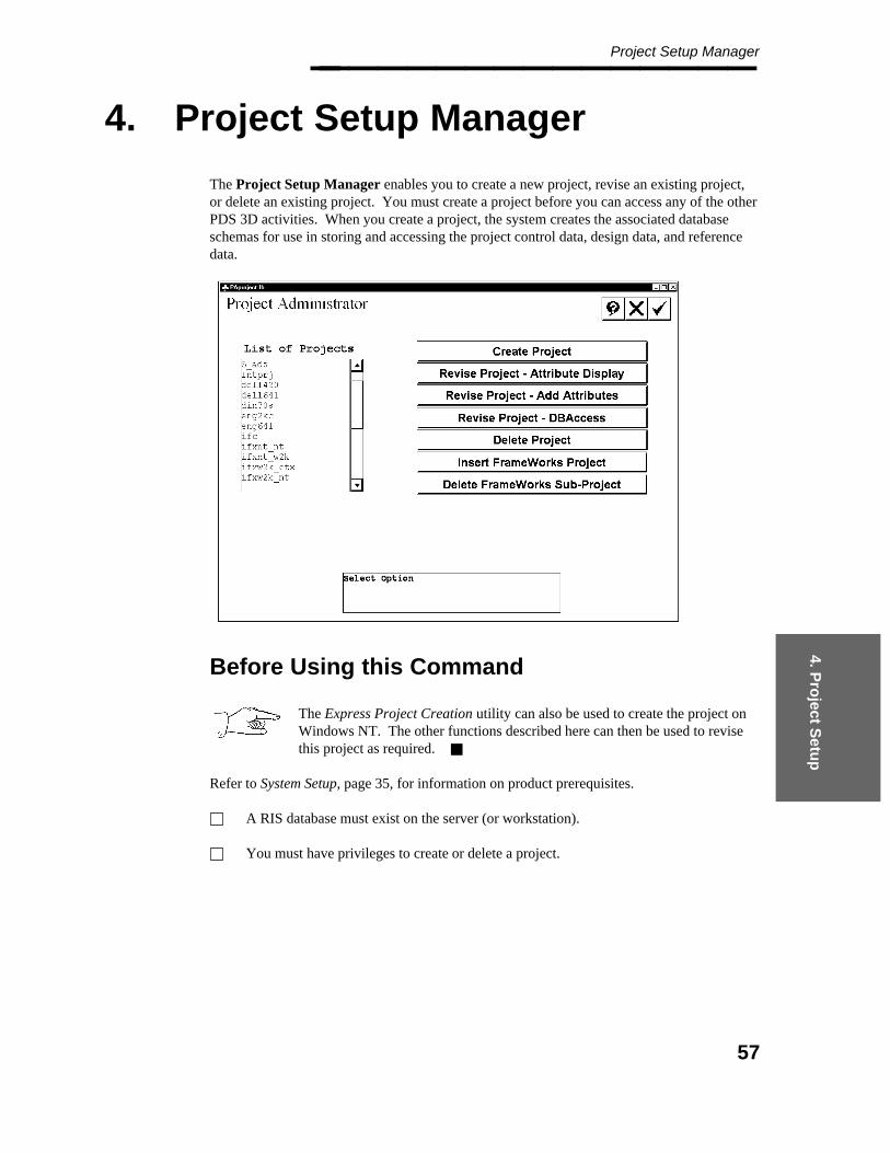
4. Pro
ject Setu
p
Project Setup Manager________________
4. Project Setup Manager
The Project Setup Manager enables you to create a new project, revise an existing project,or delete an existing project. You must create a project before you can access any of the otherPDS 3D activities. When you create a project, the system creates the associated databaseschemas for use in storing and accessing the project control data, design data, and referencedata.
Before Using this Command
The Express Project Creation utility can also be used to create the project onWindows NT. The other functions described here can then be used to revisethis project as required.
Refer to System Setup, page 35, for information on product prerequisites.
A RIS database must exist on the server (or workstation).
You must have privileges to create or delete a project.
57
Project Administrator — April 2002________________
Options
Create Project — Defines a new project and create associated database files.
Revise Project — Attribute Display — Defines attributes within the design databaseto be displayed/not displayed for database operations.
Revise Project - Add Attributes — Adds user-defined attributes to an existing designdatabase.
Revise Project - DBAccess — Revises the database structure to support DBAccessreporting of PDS data in the relational database.
Delete Project — Deletes an existing project and associated database and model files.
Insert FrameWorks Data — Defines FrameWorks data that is required to access thestructural application within the PD_Shell environment. This is option is diplayedwhen the structural project data has not been defined for the active project.
Insert Electrical Raceway Data Defines the location of project and reference data thatis required to access the Electrical Raceway module within the PD_Shell environment.This option is displayed when the Raceway project data has not been defined for theactive project.
58
4. Pro
ject Setu
p
Create Project________________
4.1 Create Project
This option enables you to define a new project and create the associated database files. Indefining the project, you can modify the design schema, set up the coordinate system, andmodify the working units.
You can use Create Project to create a project that consists only of 3D data, one that consistsonly of 2D data, or one that consists of several integrated modules such as 3D, 2D, ElectricalRaceway, and structural. For an integrated project, you can create all the database schemas atone time, or you can create only the PDS 3D schemas initially and add the PDS 2D and/orElectrical Raceway schemas later. This document describes the steps to create a PDS 3DProject. Refer to the PDS Project Setup Technical Reference for information on creating a2D-Only project or creating a fully integrated project.
A PDS 3D project uses three database schemas:
1. Project Control schema.
2. Design Data schema.
3. Material Reference Data schema. (This is optionally two database schemas if you electto use both approved and unapproved specification data.)
You can define these database schemas in a single database, or you can spread the schemasover several different databases. You can also share a Material Reference Data schemaamong multiple projects.
PDS 2D shares the project control database with the PDS 3D project. Each PDS 2Dapplication (such as P&ID, PFD, and IDM) requires an application schema.
You can also create the following Electrical Raceway database schemas:
Raceway Project Schema.
Raceway Reference Schema.
Before Using This Command
You must setup the necessary database files before you can create the project databaseschemas. See the PDS Project Setup Technical Reference for details.
Operating Sequence
1. Choose Create Project from the Project Administrator form.
The Create Project Data form is displayed.
59
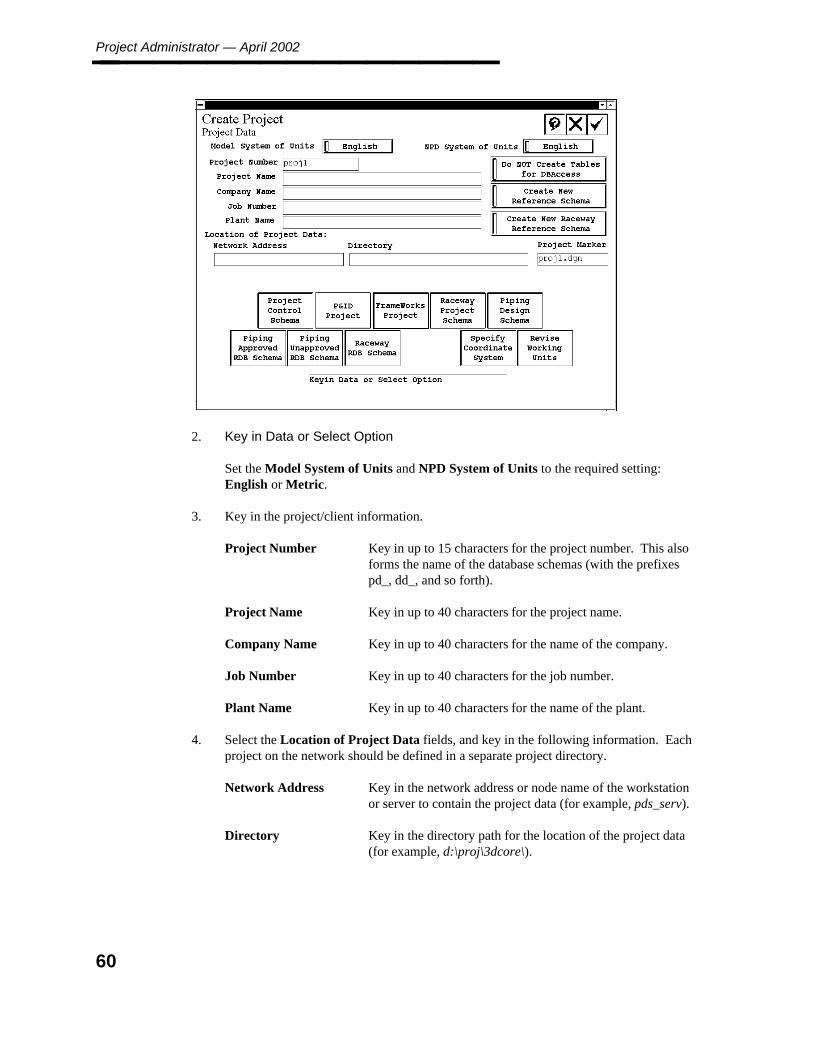
Project Administrator — April 2002________________
2. Key in Data or Select Option
Set the Model System of Units and NPD System of Units to the required setting:English or Metric.
3. Key in the project/client information.
Project Number Key in up to 15 characters for the project number. This alsoforms the name of the database schemas (with the prefixespd_, dd_, and so forth).
Project Name Key in up to 40 characters for the project name.
Company Name Key in up to 40 characters for the name of the company.
Job Number Key in up to 40 characters for the job number.
Plant Name Key in up to 40 characters for the name of the plant.
4. Select the Location of Project Data fields, and key in the following information. Eachproject on the network should be defined in a separate project directory.
Network Address Key in the network address or node name of the workstationor server to contain the project data (for example, pds_serv).
Directory Key in the directory path for the location of the project data(for example, d:\proj\3dcore\).
60
4. Pro
ject Setu
p
Create Project________________
5. Define the Project Marker file. The default is the project number with the extension.dgn.
6. Set the toggle to Do Not Create Tables for DBAccess to create the database schemaswithout the additional database structure required for DBAccess reporting.
— OR —
Set the toggle to Create Tables for DBAccess to create the additional databasestructure required for DBAccess reporting of PDS data. This option will create amscodelist table and a set of join tables for each standard note type (both system-required and user-defined) for each of the PDS schemas. Refer to Revise Project —DBAccess, page 84 for more information on this option.
7. Set the toggle to Create New Reference Schema to define a new Material ReferenceDatabase for this project. This is the default option.
— OR —
Set the toggle to Use Existing Reference Schema to use a previously created MaterialReference Database for the project being created. This automatically deactivates thePiping Unapproved RDB Schema option.
When you select the Piping Approved RDB Schema option, the system displays a listof project numbers for previously created projects. Selecting a project numberdetermines the schema names for the approved and unapproved (if applicable) MaterialReference Databases.
If you intend to have multiple projects share the same approved andunapproved Material Reference Database, it is suggested that you createan artificial project for the purpose of maintaining and verifying the datawithin the Material Reference Database.
8. Set the toggle to Create New Raceway Reference Schema to define a new RacewayReference Database for this project. This is the default option.
— OR —
Set the toggle to Use Existing Raceway Reference Schema to use a previously createdRaceway Reference Database for the project being created.
When you select the Raceway RDB Schema option, the system displays a list ofproject numbers for previously created projects.
9. Create the database schemas for the new project.
Project Control Schema - See page 63 P&ID Project — When this option ishighlighted (the default), the system creates the project for both 2D data and 3D data.This data is required if you intend to access the P&ID product from within thePD_Shell environment.
61
Project Administrator — April 2002________________ If this option is selected, but the P&ID product does not exist in the specified location,the system displays a warning dialog box when you create the project.
ModelDraft/FrameWorks Project - See page 64Raceway Project Schema - See page 67Piping Design Schema - See page 68
10. Create the reference database schemas for the new project.
Piping Approved RDB Schema - See page 72Piping Unapproved RDB Schema - See page 72Raceway RDB Schema - See page 73
11. Select the Optional Selections to modify the project setup.
Specify Coordinate System - See page 74Revise Working Units - See page 77
12. Choose the Confirm button to accept the specified information and to create theproject. The following messages are displayed:
Creating ProjectCreate project databaseCreating RIS tableCreating project database ....Creating design database ....Creating reference database .....
Creating Raceway Project Schema Tables ....Creating Raceway RDB Schema Tables ....
Successfully created project
The system also copies the database definition files, seed files, queue description file,drawing plot size table, and category text files to the project directory.
The system returns to the Project Setup form.
You can now create design areas and models using the Project Environment Manager.
62

4. Pro
ject Setu
p
Project Control Schema________________
4.1.1 Project Control Schema
Choose the Project Control Schema option from the Project Data form to define the projectenvironment database. This database schema contains the project environment data such asdesign area and model specifications.
The following illustration indicates the completed form display for an Oracle database. Theform fields vary slightly depending on the type of database being created and the operatingsystem of the database server.
Completion of the Create Schema form is covered in the database specific appendices of thePDS Project Setup Technical Reference.
63
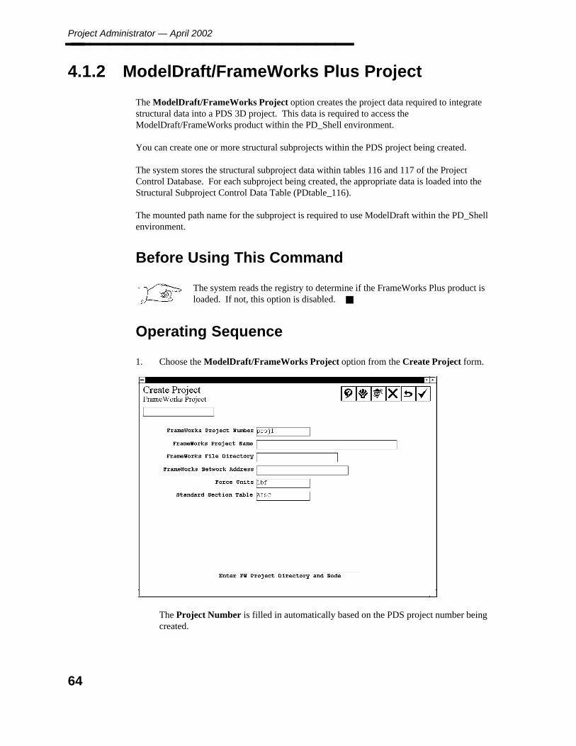
Project Administrator — April 2002________________
4.1.2 ModelDraft/FrameWorks Plus Project
The ModelDraft/FrameWorks Project option creates the project data required to integratestructural data into a PDS 3D project. This data is required to access theModelDraft/FrameWorks product within the PD_Shell environment.
You can create one or more structural subprojects within the PDS project being created.
The system stores the structural subproject data within tables 116 and 117 of the ProjectControl Database. For each subproject being created, the appropriate data is loaded into theStructural Subproject Control Data Table (PDtable_116).
The mounted path name for the subproject is required to use ModelDraft within the PD_Shellenvironment.
Before Using This Command
The system reads the registry to determine if the FrameWorks Plus product isloaded. If not, this option is disabled.
Operating Sequence
1. Choose the ModelDraft/FrameWorks Project option from the Create Project form.
The Project Number is filled in automatically based on the PDS project number beingcreated.
64
4. Pro
ject Setu
p
ModelDraft/FrameWorks Plus Project________________
2. Enter Project Directory and Node
Key in the location information for the structural project files.
ModelDraft/FrameWorks Project NumberKey in the number of the structural subproject (forexample, str).
ModelDraft/FrameWorks Project NameKey in the description of the structural subproject.
ModelDraft/FrameWorks File DirectoryKey in the directory path name for the location of thestructural models. For ModelDraft, the specifieddirectory path must exist. The system will createdirectories at the specified point.
For FrameWorks Plus, the system appends the projectnumber to the specified file directory to arrive at the basepath. For example, if the project number is str and thefile directory is d:\pdsproj\, the base path for structuralsubdirectories is d:\pdsproj\str\.
ModelDraft/FrameWorks Network AddressKey in the node name or network address for the locationof the structural models.
ModelDraft Mount Point Key in the prefix of the mount point for the location ofthe structural models (such as /usr3). The prefix isrequired because the structural PSD file includes themounted path name rather than a network address and apath name.
The specified mount point must be created on eachmachine that will access the ModelDraft product. Thisvalue cannot be changed once the project is created.
ModelDraft/FrameWorks Force UnitsSpecifies the force units for the model(unit for specifyingload force).
ModelDraft/FrameWorks Standard Section TableSpecifies the main standard section table for this model.You cannot change the standard section table after themodel is created.
The system stores this data in the Project Control Database for use in creatingstructural models in the Project Environment and to support ModelDraft/FrameWorksnetwork operations within the PD_Shell environment.
65

Project Administrator — April 2002________________
3. Accept or Revise Information
Choose the Confirm button to accept the specified structural subproject information.
The system creates a structural project subdirectory structure at the specified networkaddress and path name. It copies supplementary data from theModelDraft/FrameWorks product directory to the structural project directory. In thisprocess, the structural symbology data, symbology.md, is copied as symbology.sms.
4. The system clears the input fields to enable you to specify additional subprojects.
When you are finished defining the structural subprojects, choose Cancel to return tothe Create Project form.
66

4. Pro
ject Setu
p
Raceway Project Schema________________
4.1.3 Raceway Project Schema
The Raceway Project Schema creates the project data required to integrate electrical racewaydata into a PDS 3D project. You can run this option at the time you are creating an integratedproject or at a later time. This enables you to create the electrical raceway data for an existing3D project without having to enter the EE Nucleus, create a raceway project, and then insertthe raceway data.
See the PDS Project Setup Technical Reference for information regarding thecreation of the EE Raceway project.
67
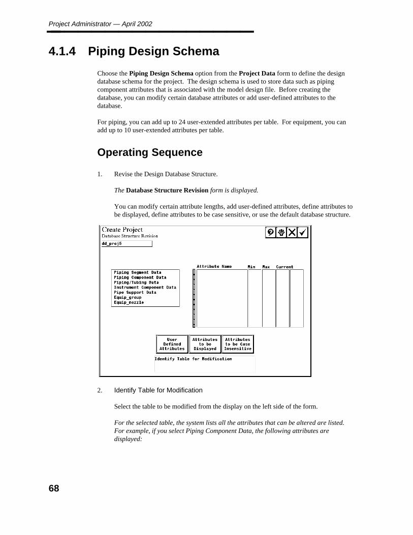
Project Administrator — April 2002________________
4.1.4 Piping Design Schema
Choose the Piping Design Schema option from the Project Data form to define the designdatabase schema for the project. The design schema is used to store data such as pipingcomponent attributes that is associated with the model design file. Before creating thedatabase, you can modify certain database attributes or add user-defined attributes to thedatabase.
For piping, you can add up to 24 user-extended attributes per table. For equipment, you canadd up to 10 user-extended attributes per table.
Operating Sequence
1. Revise the Design Database Structure.
The Database Structure Revision form is displayed.
You can modify certain attribute lengths, add user-defined attributes, define attributes tobe displayed, define attributes to be case sensitive, or use the default database structure.
2. Identify Table for Modification
Select the table to be modified from the display on the left side of the form.
For the selected table, the system lists all the attributes that can be altered are listed.For example, if you select Piping Component Data, the following attributes aredisplayed:
68
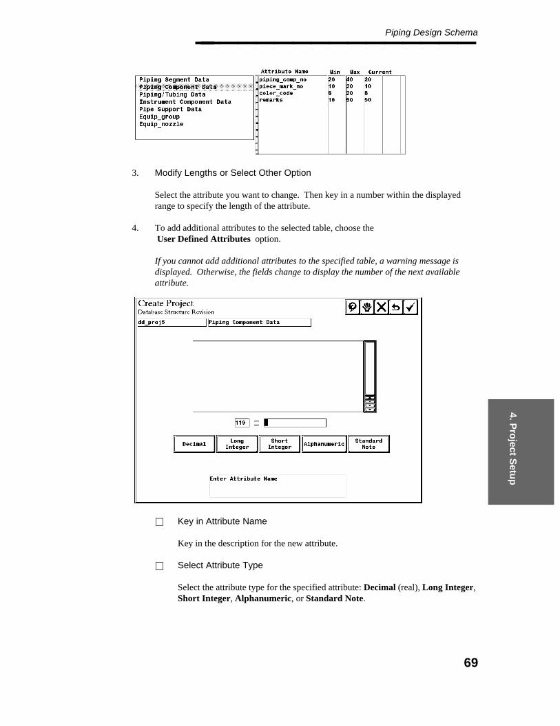
4. Pro
ject Setu
p
Piping Design Schema________________
3. Modify Lengths or Select Other Option
Select the attribute you want to change. Then key in a number within the displayedrange to specify the length of the attribute.
4. To add additional attributes to the selected table, choose theUser Defined Attributes option.
If you cannot add additional attributes to the specified table, a warning message isdisplayed. Otherwise, the fields change to display the number of the next availableattribute.
Key in Attribute Name
Key in the description for the new attribute.
Select Attribute Type
Select the attribute type for the specified attribute: Decimal (real), Long Integer,Short Integer, Alphanumeric, or Standard Note.
69
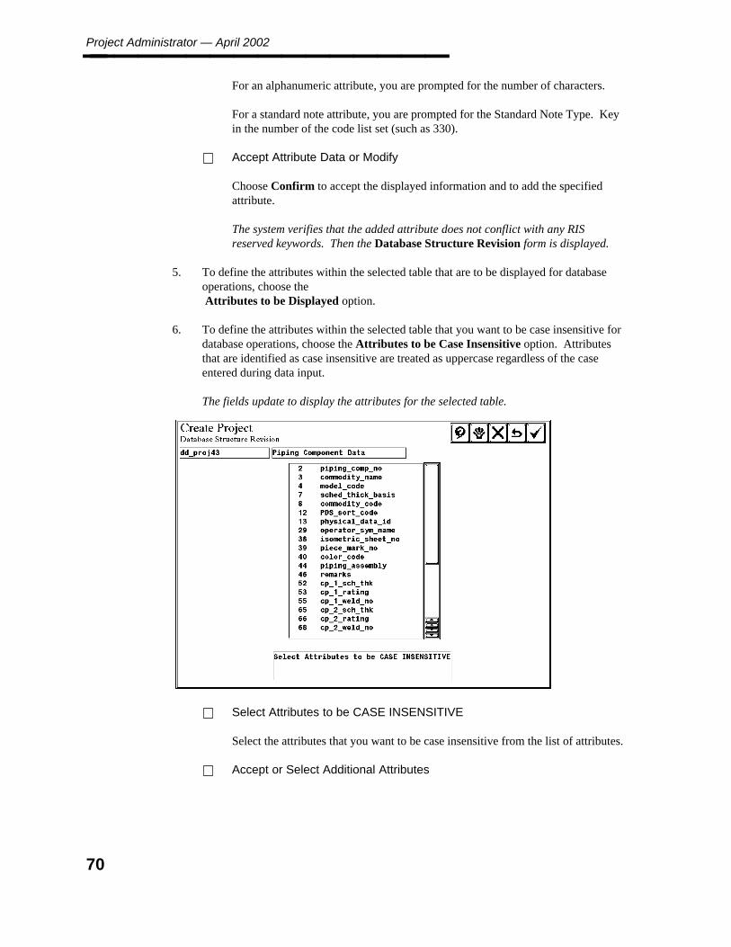
Project Administrator — April 2002________________ For an alphanumeric attribute, you are prompted for the number of characters.
For a standard note attribute, you are prompted for the Standard Note Type. Keyin the number of the code list set (such as 330).
Accept Attribute Data or Modify
Choose Confirm to accept the displayed information and to add the specifiedattribute.
The system verifies that the added attribute does not conflict with any RISreserved keywords. Then the Database Structure Revision form is displayed.
5. To define the attributes within the selected table that are to be displayed for databaseoperations, choose theAttributes to be Displayed option.
6. To define the attributes within the selected table that you want to be case insensitive fordatabase operations, choose the Attributes to be Case Insensitive option. Attributesthat are identified as case insensitive are treated as uppercase regardless of the caseentered during data input.
The fields update to display the attributes for the selected table.
Select Attributes to be CASE INSENSITIVE
Select the attributes that you want to be case insensitive from the list of attributes.
Accept or Select Additional Attributes
70
4. Pro
ject Setu
p
Piping Design Schema________________ Choose Confirm to change the data type of the selected attribute(s).
The Database Structure Revision form is redisplayed.
The selected attributes will have their alphanumeric data automatically converted touppercase in the following situations.
When a row is being created in the database.
When a row is being updated in the database.
When a value for such a column in a table is being used as search criteria for adatabase query
In terms of case sensitivity, you must consistently define alphanumericdata that is to be transferred from the P&ID database to the PipingDesign database to successfully transfer the data.
Presently, all alphanumeric data, with the following exceptions is considered to be casesensitive. The following alphanumeric data will always be considered to be uppercaseand cannot be changed.
Piping materials class.
Schedule/thickness.
Pressure rating.
Commodity code.
Any attributes that are designated as case insensitive will have their data type changedfrom character to upper_case in the design.ddl file in the project directory.
If, after creating a project, you determine that an attribute wasinadvertently selected or not selected for case insensitivity, you can editthe design.ddl file manually to reverse the selection. However, this willnot update any previously created data.
7. Choose Confirm to exit the form and to proceed to the Create Schema form.
See the PDS Project Setup Technical Reference appendices for details on completion ofthe Create Schema form.
71
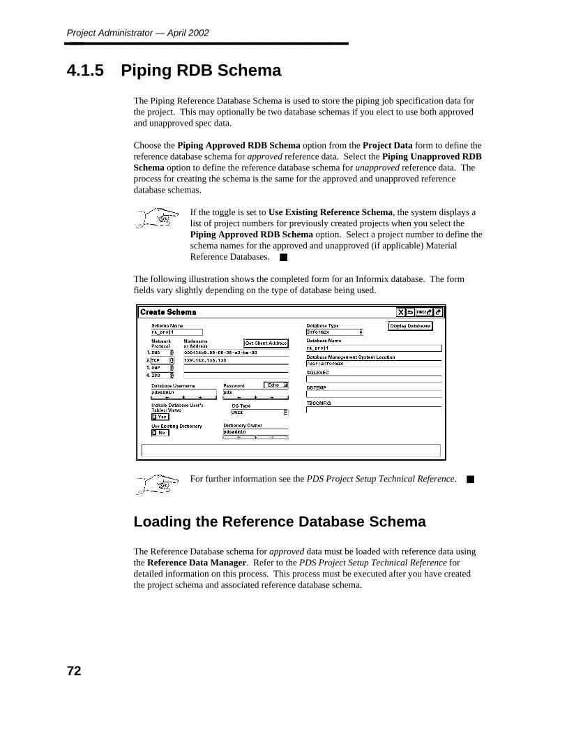
Project Administrator — April 2002________________
4.1.5 Piping RDB Schema
The Piping Reference Database Schema is used to store the piping job specification data forthe project. This may optionally be two database schemas if you elect to use both approvedand unapproved spec data.
Choose the Piping Approved RDB Schema option from the Project Data form to define thereference database schema for approved reference data. Select the Piping Unapproved RDBSchema option to define the reference database schema for unapproved reference data. Theprocess for creating the schema is the same for the approved and unapproved referencedatabase schemas.
If the toggle is set to Use Existing Reference Schema, the system displays alist of project numbers for previously created projects when you select thePiping Approved RDB Schema option. Select a project number to define theschema names for the approved and unapproved (if applicable) MaterialReference Databases.
The following illustration shows the completed form for an Informix database. The formfields vary slightly depending on the type of database being used.
For further information see the PDS Project Setup Technical Reference.
Loading the Reference Database Schema
The Reference Database schema for approved data must be loaded with reference data usingthe Reference Data Manager. Refer to the PDS Project Setup Technical Reference fordetailed information on this process. This process must be executed after you have createdthe project schema and associated reference database schema.
72

4. Pro
ject Setu
p
Raceway RDB Schema________________
4.1.6 Raceway RDB Schema
You can create an Electrical Raceway Reference Database schema or have the project beingcreated reference an existing Raceway Reference Database created for a different project.
Choose the Raceway RDB Schema option from the Project Data form to define thereference database schema for electrical raceway.
If the toggle is set to Use Existing Raceway Reference Schema, the systemdisplays a list of project numbers for previously created projects when youselect the Raceway RDB Schema option. Choose a project number to definethe schema names for the Raceway Reference Database.
The following illustration indicates the completed form for an Informix database. The formfields vary slightly depending on the type of database being used.
For further information see the PDS Project Setup Technical Reference.
73

Project Administrator — April 2002________________
4.1.7 Specify Coordinate System
This option enables you to revise the coordinate system parameters for the project. You canset the name of the coordinate system and specify the coordinate system monument. Theplant monument is applied to the seed files that are used to create piping and equipmentmodels, drawings, and interference marker files. Therefore, this value must be defined beforeany of the project environment data is created.
The default values for the plant monument can be used for most projects. You may need tomodify the plant coordinate system if you need to use coordinate values that are too large tofit into the MicroStation file, due to limitations imposed by the working units for the model.
Refer to Create Model, page 111, and Design Volume Coordinate System Definition, page308, for information on defining a design volume coordinate system (DVCS). A DVCS isonly required if different models need to have their coordinates referenced from a differentpoint.
Operating Sequence
1. Plant Coordinate System Description
Key in up to 40 characters to describe the Plant Coordinate System to be used for theproject.
74

4. Pro
ject Setu
p
Specify Coordinate System________________
2. Plant Coordinate System Monument
Key in the easting, northing, and elevation coordinates to be assigned to the center ofthe design volume for the plant. This point corresponds to the MicroStation position0,0,0.
3. Choose the Confirm button to accept the specified coordinate system data and to returnto the Create Project form.
— OR —
Choose the Cancel button to exit the form without changing the coordinate systemdefinition.
75
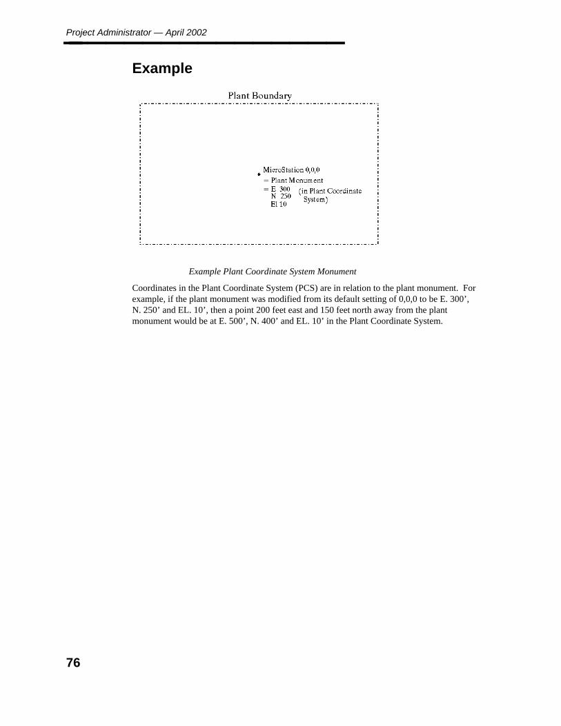
Project Administrator — April 2002________________
Example
Example Plant Coordinate System Monument
Coordinates in the Plant Coordinate System (PCS) are in relation to the plant monument. Forexample, if the plant monument was modified from its default setting of 0,0,0 to be E. 300’,N. 250’ and EL. 10’, then a point 200 feet east and 150 feet north away from the plantmonument would be at E. 500’, N. 400’ and EL. 10’ in the Plant Coordinate System.
76
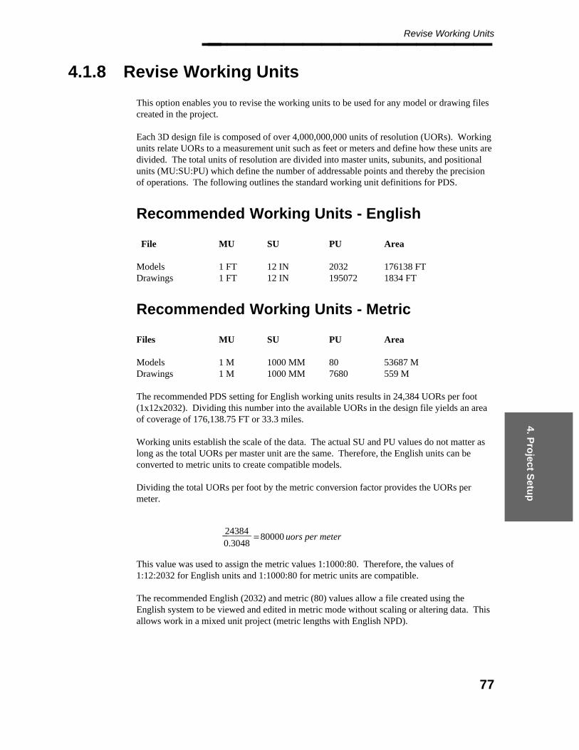
4. Pro
ject Setu
p
Revise Working Units________________
4.1.8 Revise Working Units
This option enables you to revise the working units to be used for any model or drawing filescreated in the project.
Each 3D design file is composed of over 4,000,000,000 units of resolution (UORs). Workingunits relate UORs to a measurement unit such as feet or meters and define how these units aredivided. The total units of resolution are divided into master units, subunits, and positionalunits (MU:SU:PU) which define the number of addressable points and thereby the precisionof operations. The following outlines the standard working unit definitions for PDS.
Recommended Working Units - English
File MU SU PU Area
Models 1 FT 12 IN 2032 176138 FTDrawings 1 FT 12 IN 195072 1834 FT
Recommended Working Units - Metric
Files MU SU PU Area
Models 1 M 1000 MM 80 53687 MDrawings 1 M 1000 MM 7680 559 M
The recommended PDS setting for English working units results in 24,384 UORs per foot(1x12x2032). Dividing this number into the available UORs in the design file yields an areaof coverage of 176,138.75 FT or 33.3 miles.
Working units establish the scale of the data. The actual SU and PU values do not matter aslong as the total UORs per master unit are the same. Therefore, the English units can beconverted to metric units to create compatible models.
Dividing the total UORs per foot by the metric conversion factor provides the UORs permeter.
0.304824384_______ = 80000 uors per meter
This value was used to assign the metric values 1:1000:80. Therefore, the values of1:12:2032 for English units and 1:1000:80 for metric units are compatible.
The recommended English (2032) and metric (80) values allow a file created using theEnglish system to be viewed and edited in metric mode without scaling or altering data. Thisallows work in a mixed unit project (metric lengths with English NPD).
77

Project Administrator — April 2002________________
For interference checking to work properly, the working units must be thesame for all the 3D models for the project. This includes raceway andstructural models and any other disciplines to be used, not just piping andequipment models.
The positional units for drawings should be defined so that the drawing has the sameresolution as the model. To maintain the same resolution, the smallest drawing view scale isused so that the PUs of the drawing file are no less than the maximum factor times the PUsused in the model.
The smallest drawing view scale for the delivered drawing seed files is 1/8" = 1’ (12"). Thisyields a factor of 96 to be applied to the model units to determine the drawing units.
1/812____ = 96
2032 x 96 = 195072 80 x 96 = 7680
For metric units, the factor is also 96 (96 x 80 = 7680).
Operating Sequence
The following form reflects the display for a project using English units. The form will varyslightly if you are using metric units.
78
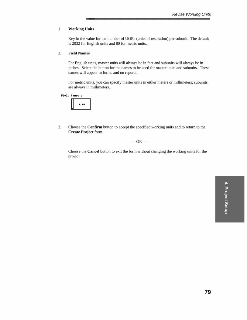
4. Pro
ject Setu
p
Revise Working Units________________ 1. Working Units
Key in the value for the number of UORs (units of resolution) per subunit. The defaultis 2032 for English units and 80 for metric units.
2. Field Names
For English units, master units will always be in feet and subunits will always be ininches. Select the button for the names to be used for master units and subunits. Thesenames will appear in forms and on reports.
For metric units, you can specify master units in either meters or millimeters; subunitsare always in millimeters.
3. Choose the Confirm button to accept the specified working units and to return to theCreate Project form.
— OR —
Choose the Cancel button to exit the form without changing the working units for theproject.
79
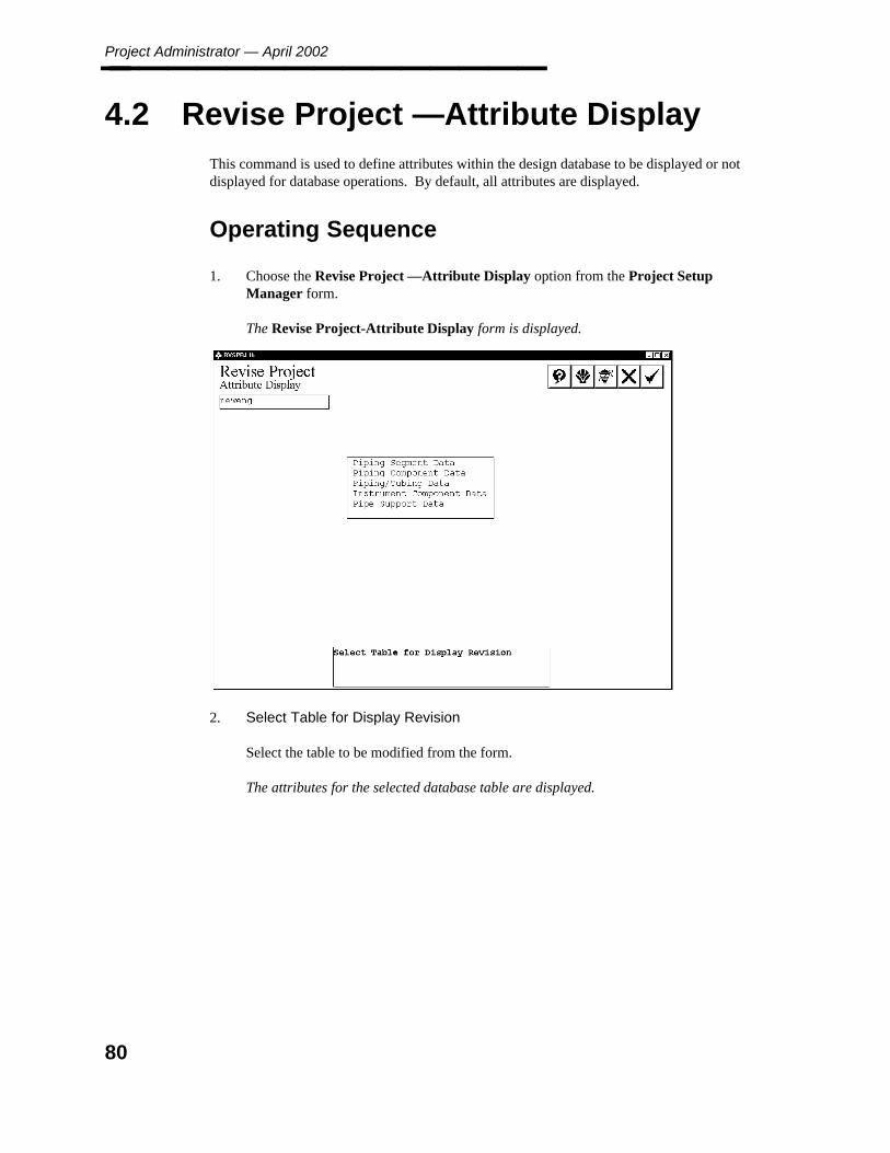
Project Administrator — April 2002________________
4.2 Revise Project —Attribute Display
This command is used to define attributes within the design database to be displayed or notdisplayed for database operations. By default, all attributes are displayed.
Operating Sequence
1. Choose the Revise Project —Attribute Display option from the Project SetupManager form.
The Revise Project-Attribute Display form is displayed.
2. Select Table for Display Revision
Select the table to be modified from the form.
The attributes for the selected database table are displayed.
80

4. Pro
ject Setu
p
Revise Project —Attribute Display________________
3. Select Attributes to NOT be Displayed
Select the attributes to not be displayed from the list of attributes.
4. Accept or Select Additional Attributes
Choose the Confirm button to accept the displayed information.
You are returned to Step 2.
5. When you have finished selecting attributes, choose the Confirm button to accept theattribute revisions.
The Project Setup form is redisplayed.
81
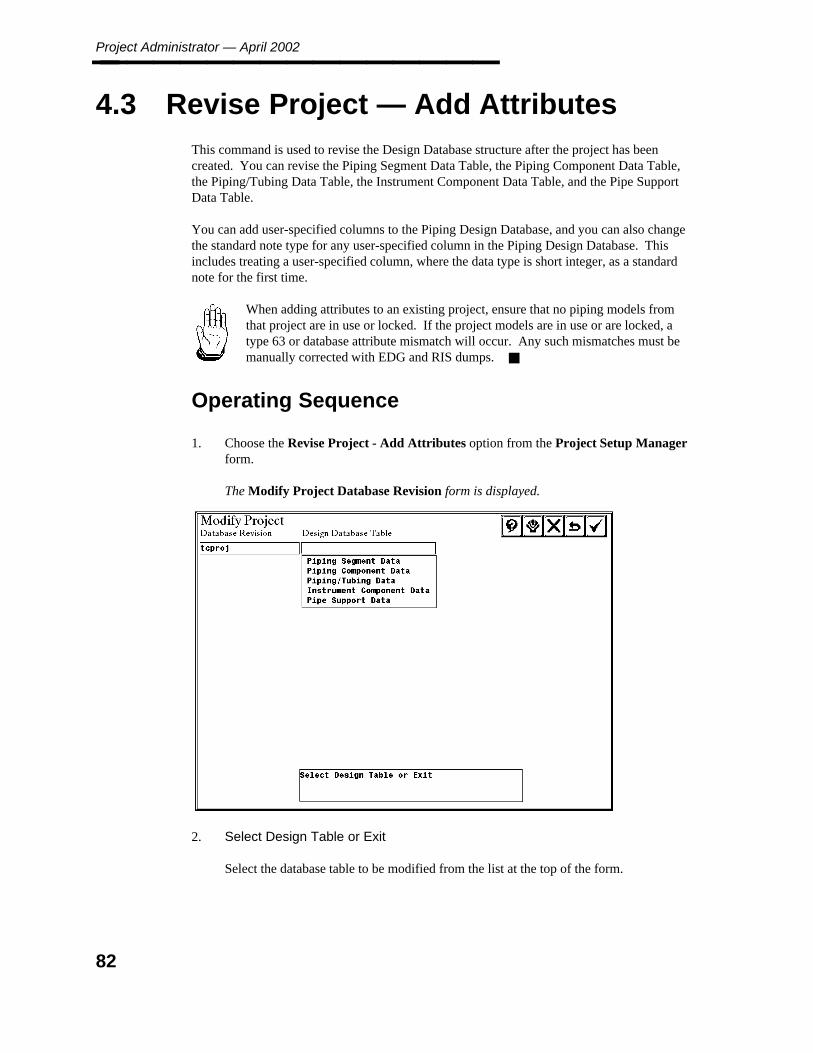
Project Administrator — April 2002________________
4.3 Revise Project — Add Attributes
This command is used to revise the Design Database structure after the project has beencreated. You can revise the Piping Segment Data Table, the Piping Component Data Table,the Piping/Tubing Data Table, the Instrument Component Data Table, and the Pipe SupportData Table.
You can add user-specified columns to the Piping Design Database, and you can also changethe standard note type for any user-specified column in the Piping Design Database. Thisincludes treating a user-specified column, where the data type is short integer, as a standardnote for the first time.
When adding attributes to an existing project, ensure that no piping models fromthat project are in use or locked. If the project models are in use or are locked, atype 63 or database attribute mismatch will occur. Any such mismatches must bemanually corrected with EDG and RIS dumps.
Operating Sequence
1. Choose the Revise Project - Add Attributes option from the Project Setup Managerform.
The Modify Project Database Revision form is displayed.
2. Select Design Table or Exit
Select the database table to be modified from the list at the top of the form.
82

4. Pro
ject Setu
p
Revise Project — Add Attributes________________ Any existing user-defined and system attributes are displayed (excluding the defaultsystem attributes). The system-added attributes are displayed in a different color toindicate that you cannot revise them.
3. Edit New Entry or Select Entry to Edit
Select an existing user-defined attribute from the scroll area to change the standard notetype.
— OR —
Select the attribute name field to add a new user-defined attribute. Key in the attributename, and select the attribute type (decimal, short integer, long integer, oralphanumeric).
For an alphanumeric attribute, you must also specify the number of characters.
For a short integer attribute, you can select the standard note field to define a standardnote type (such as 330) for the attribute.
4. Repeat Step 3 to add any additional attributes. Then choose the Confirm button toaccept the modifications.
83
Project Administrator — April 2002________________
4.4 Revise Project — DBAccess
This command revises an existing project to include the additional database structure requiredto support DBAccess reporting of PDS data in the relational database.
The system creates an mscodelist table and a set of join tables for each standard note type(both those required by the system and those created by the user) in the appropriate schemasof the relational database.
You can revise the database structure that is required for DBAccess reporting by adding theappropriate entries for any new user-defined standard note types.
Once this option has been processed, any piping models that are created with the CreateDatabase Tables or Copy Model options of the Project Environment Manager will becreated with the necessary database structure for DBAccess reporting.
Before Using This Command
You must specify the maximum length of the text for each standard note type in the StandardNote Library before creating the relational database structure. This maximum length is usedto create the standard note data in the relational database. The maximum lengths must bespecified in an ASCII file named stnote_max_len that must reside in the project directory.
Entries in this file consist of one line for each standard note type with the following format.
!note type max length short?35 15 *36 10
The note type and the maximum length are separated by one or more spaces or tabs. Anasterisk (*) following the maximum length indicates that the short version of the standard notedata be loaded into the relational database. The default is that the long version be loaded.Comments can be placed anywhere in the file and must be preceded by an exclamation point(!).
You can determine which standard note data is loaded or not loaded into the relationaldatabase. If the maximum length for a standard note type is defined as zero (0) or thestandard note type is not included in stnote_max_len, the data for that standard note type willnot be loaded.
A default note length file is delivered with the PD_Shell product in the filewin32app\ingr\pdshell\lib\stnote_max_len. These maximum lengths were determined on thebasis of the long option of standard note data reporting. To minimize relational database size,you should exercise discretion in specifying the maximum length. The maximum length forany standard note type is restricted to 240 characters by RIS.
84

4. Pro
ject Setu
p
Revise Project — DBAccess________________ ! This file contains the maximum text length allowed for each note/code type. The! format required is one entry per line with the note/code type appearing first and! then the maximum length separated by spaces. Comments are designated by an exclamation! point in the first column. An "*" to the right of the maximum length number designates! to use the short description.!35 15 *36 1037 1050 15 *69 20125 5130 10145 55148 60160 15180 45 *190 10200 5210 5220 6230 6330 20340 3360 30365 25380 50390 5400 30420 60425 6430 60499 350530 25550 40570 25575 60576 50577 50578 25999 401010 51028 101056 51064 201074 151100 201201 151202 21203 151204 351205 301207 301310 251312 301410 151620 161630 361710 301720 602000 15
85
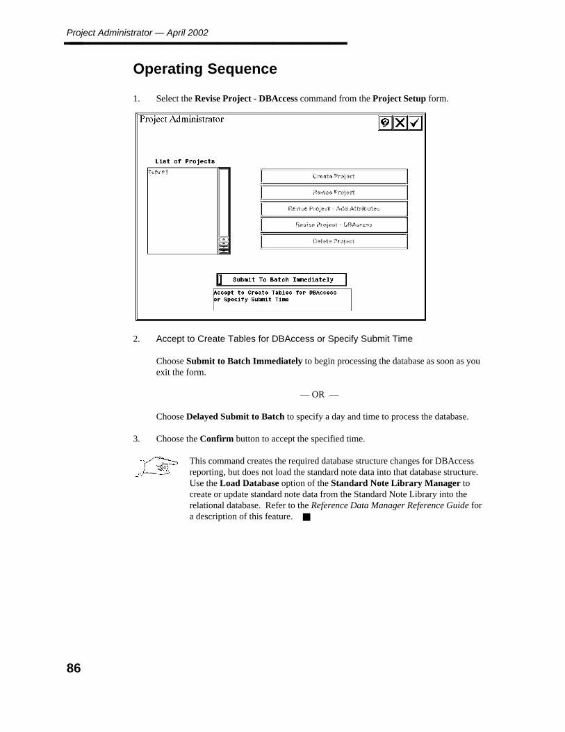
Project Administrator — April 2002________________
Operating Sequence
1. Select the Revise Project - DBAccess command from the Project Setup form.
2. Accept to Create Tables for DBAccess or Specify Submit Time
Choose Submit to Batch Immediately to begin processing the database as soon as youexit the form.
— OR —
Choose Delayed Submit to Batch to specify a day and time to process the database.
3. Choose the Confirm button to accept the specified time.
This command creates the required database structure changes for DBAccessreporting, but does not load the standard note data into that database structure.Use the Load Database option of the Standard Note Library Manager tocreate or update standard note data from the Standard Note Library into therelational database. Refer to the Reference Data Manager Reference Guide fora description of this feature.
86
4. Pro
ject Setu
p
Delete Project________________
4.5 Delete Project
This option is used to delete an existing project. It deletes all the files that are associated withthe project, including the project database files, seed files, queue description, drawing plotsizetable, category text files, design areas specifications, model files, and drawings.
You can also delete all or part of the reference data that is associated with a project. Thesystem automatically deletes any applicable Table Revision Management Libraries whendeleting the Material/Reference Database. Note that the system will not check to see if any ofthis data is being used by another project.
If applicable, the Delete Project command will
Automatically delete the optional data added to support DBAccess reporting.
Recognize any seed drawings that have been defined on the basis of a specific drawingtype.
Delete the following electrical raceway data:
— The raceway models and the corresponding interference envelopes.
— The raceway seed model, rwysdz.dgn, in the project directory.
— The raceway design database.
— Optionally, the raceway Reference Database and the raceway Graphic CommodityLibrary.
Delete all associated structural subprojects, including the model management data, thestructural design areas, the structural models, and the structural drawings thatcorrespond to each of the structural subprojects being deleted.
87
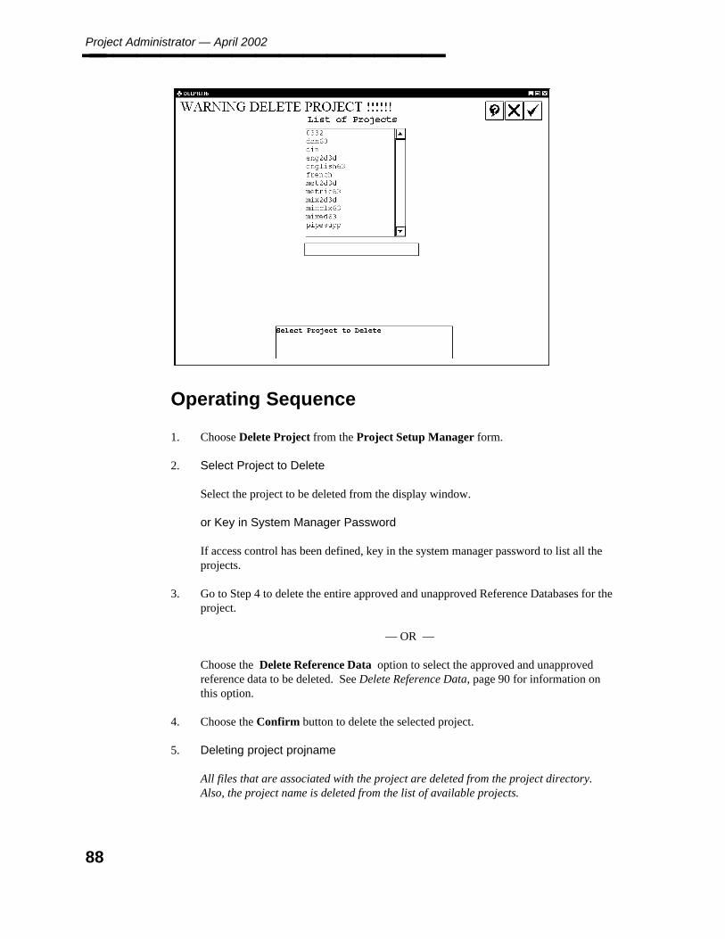
Project Administrator — April 2002________________
Operating Sequence
1. Choose Delete Project from the Project Setup Manager form.
2. Select Project to Delete
Select the project to be deleted from the display window.
or Key in System Manager Password
If access control has been defined, key in the system manager password to list all theprojects.
3. Go to Step 4 to delete the entire approved and unapproved Reference Databases for theproject.
— OR —
Choose the Delete Reference Data option to select the approved and unapprovedreference data to be deleted. See Delete Reference Data, page 90 for information onthis option.
4. Choose the Confirm button to delete the selected project.
5. Deleting project projname
All files that are associated with the project are deleted from the project directory.Also, the project name is deleted from the list of available projects.
88
4. Pro
ject Setu
p
Delete Project________________
6. Choose the Cancel button to return to the Project Setup form.
When a schema is dropped in an Oracle database, the tables are not removedfrom the Oracle database. (That is, if you want to delete a schema, drop thetables first; then drop the schema.)
If Delete Project fails, it will offer you a chance to delete the project namefrom the list of available projects. At the prompt, choose the Confirm buttonto remove the project name despite the error.
89

Project Administrator — April 2002________________
Delete Reference Data
This option is used to select the approved and unapproved reference data to be deleted. Thesystem lists all the Reference Database data for the selected project.
Select RDB File Type for Deletion
Select the data to be deleted, or select from the options at the bottom of the form. Thenchoose the Confirm button to return to the Delete Project form.
Options
The form options enable you to delete the following additional reference data that may beshared by multiple projects.
For each of these options, the system warns that the data may be shared by other projects. Itwill not actually verify whether any of the data is being used by another project.
Isometric Data
This option deletes isometric drawing management data, including isometric drawings,isometric drawing borders, and defaults files.
You can delete all isometric drawing management data that is associated with the projectthrough the Isometric Drawing Management Data Table of the Project Control Database.You can select individual isometric drawing management data from a list of all such data.
90
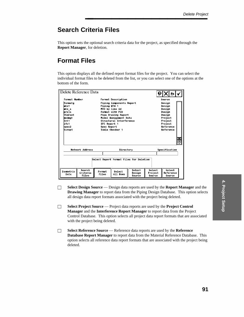
4. Pro
ject Setu
p
Delete Project________________
Search Criteria Files
This option sets the optional search criteria data for the project, as specified through theReport Manager, for deletion.
Format Files
This option displays all the defined report format files for the project. You can select theindividual format files to be deleted from the list, or you can select one of the options at thebottom of the form.
Select Design Source — Design data reports are used by the Report Manager and theDrawing Manager to report data from the Piping Design Database. This option selectsall design data report formats associated with the project being deleted.
Select Project Source — Project data reports are used by the Project ControlManager and the Interference Report Manager to report data from the ProjectControl Database. This option selects all project data report formats that are associatedwith the project being deleted.
Select Reference Source — Reference data reports are used by the ReferenceDatabase Report Manager to report data from the Material Reference Database. Thisoption selects all reference data report formats that are associated with the project beingdeleted.
91

Project Administrator — April 2002________________
Select All Rows
This option selects all the items on the Delete Reference Data form for deletion. The systemhighlights all the items selected for deletion.
92
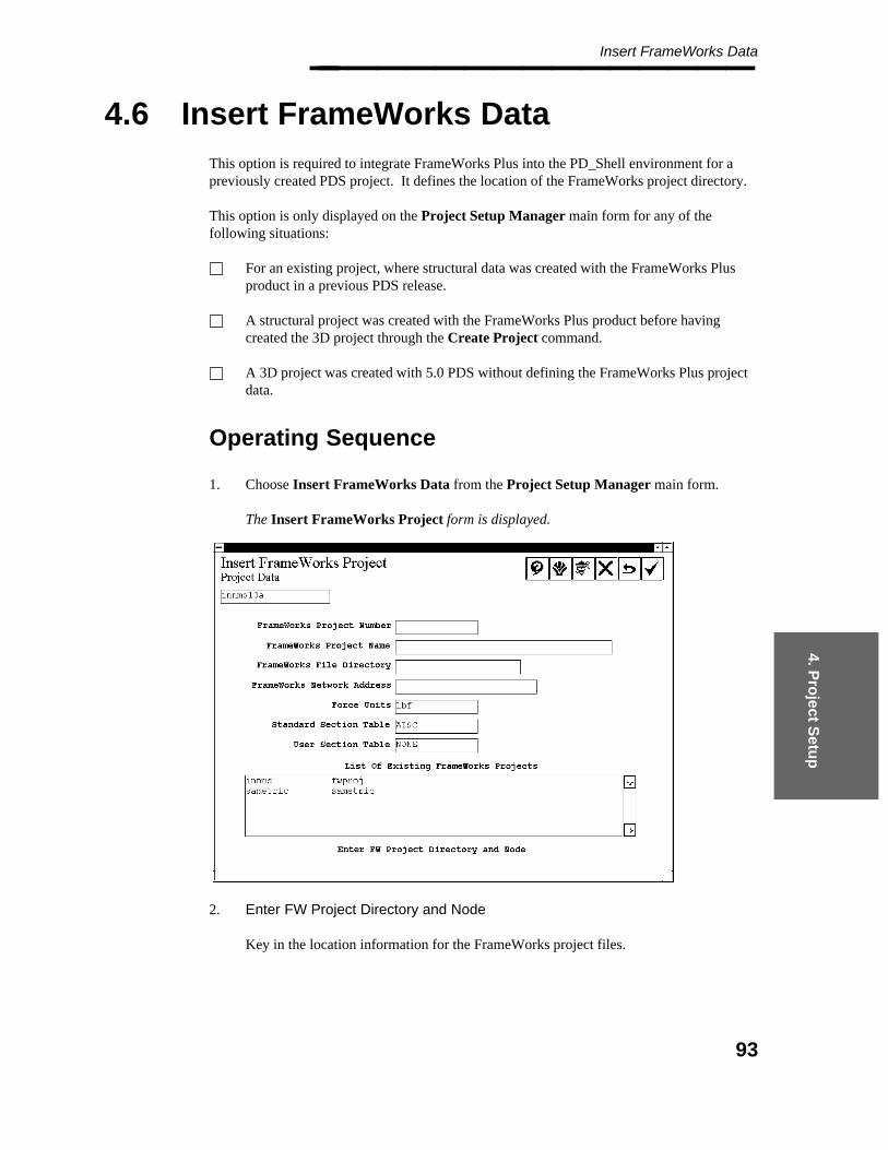
4. Pro
ject Setu
p
Insert FrameWorks Data________________
4.6 Insert FrameWorks Data
This option is required to integrate FrameWorks Plus into the PD_Shell environment for apreviously created PDS project. It defines the location of the FrameWorks project directory.
This option is only displayed on the Project Setup Manager main form for any of thefollowing situations:
For an existing project, where structural data was created with the FrameWorks Plusproduct in a previous PDS release.
A structural project was created with the FrameWorks Plus product before havingcreated the 3D project through the Create Project command.
A 3D project was created with 5.0 PDS without defining the FrameWorks Plus projectdata.
Operating Sequence
1. Choose Insert FrameWorks Data from the Project Setup Manager main form.
The Insert FrameWorks Project form is displayed.
2. Enter FW Project Directory and Node
Key in the location information for the FrameWorks project files.
93
Project Administrator — April 2002________________ FrameWorks Project Name — Key in the name of the FrameWorks subproject.
FrameWorks File Directory — Key in the directory path name for the locationof the structural models. The system appends the project number to the specifiedfile directory to arrive at the base path. For example, if the project number is strand the file directory is d:\pdsproj\, the base path for structural subdirectories isd:\pdsproj\str\.
FrameWorks Network Address — Key in the node name or network addressfor the location of the structural models.
The system stores this data in the Project Control Database for use in creatingstructural models in the Project Environment and to support FrameWorks networkoperations within the PD_Shell environment.
3. Accept or Revise FrameWorks Information
Choose the Confirm button to accept the specified FrameWorks subprojectinformation.
The defined subprojects are listed in the scroll field at the bottom of the form. Thesystem also verifies that the specified data defines a valid FrameWorks projectdirectory.
— If the FrameWorks project does not exist, the system creates a structural projectsubdirectory structure at the specified network address and path name. It copiessupplementary data from the FrameWorks product directory to the structuralproject directory. In this process, the structural symbology data, symbology.md, iscopied as symbology.sms.
— If the FrameWorks project exists, the system updates the FrameWorks projectinformation in the Project Control Database but does not create any directory files.
4. The system clears the input fields to allow you to specify additional subprojects.
When you are finished defining the structural subprojects, choose the Cancel button toreturn to the Create Project form.
If structural models already exist for the inserted FrameWorks project, use theCreate Model from ASCII File command rather than the Create Modelcommand to add the necessary model information to the project database.
94
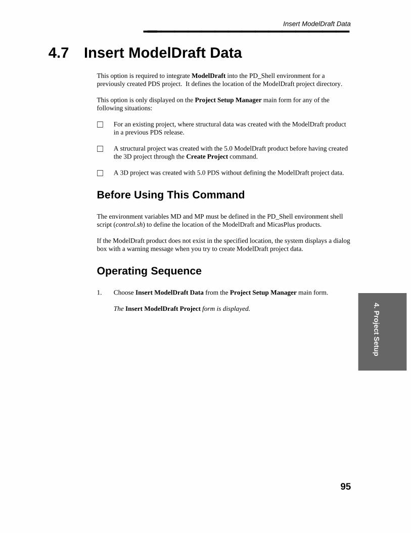
4. Pro
ject Setu
p
Insert ModelDraft Data________________
4.7 Insert ModelDraft Data
This option is required to integrate ModelDraft into the PD_Shell environment for apreviously created PDS project. It defines the location of the ModelDraft project directory.
This option is only displayed on the Project Setup Manager main form for any of thefollowing situations:
For an existing project, where structural data was created with the ModelDraft productin a previous PDS release.
A structural project was created with the 5.0 ModelDraft product before having createdthe 3D project through the Create Project command.
A 3D project was created with 5.0 PDS without defining the ModelDraft project data.
Before Using This Command
The environment variables MD and MP must be defined in the PD_Shell environment shellscript (control.sh) to define the location of the ModelDraft and MicasPlus products.
If the ModelDraft product does not exist in the specified location, the system displays a dialogbox with a warning message when you try to create ModelDraft project data.
Operating Sequence
1. Choose Insert ModelDraft Data from the Project Setup Manager main form.
The Insert ModelDraft Project form is displayed.
95
Project Administrator — April 2002________________
2. Enter MDR Project Directory and Node
Key in the location information for the ModelDraft project files.
ModelDraft Project Name — Key in the name of the ModelDraft subproject.
ModelDraft File Directory — Key in the directory path name for the location ofthe structural models.
ModelDraft Network Address — Key in the node name or network address forthe location of the structural models.
ModelDraft Mount Point — Key in the prefix of the mount point for thelocation of the structural models (such as /usr3). The prefix is required becausethe structural PDS file includes the mounted path name rather than a networkaddress and a path name.
The specified mount point must be created on each machine that will access theModelDraft product. This value cannot be changed after the project is created.
The system stores this data in the Project Control Database for use in creatingstructural models in the Project Environment and to support ModelDraft networkoperations within the PD_Shell environment.
3. Accept or Revise ModelDraft Information
Choose the Confirm button to accept the specified ModelDraft subproject information.
The defined subprojects are listed in the scroll field at the bottom of the form. Thesystem also verifies that the specified data defines a valid ModelDraft project directory.
96

4. Pro
ject Setu
p
Insert ModelDraft Data________________
— If the ModelDraft project does not exist, the system creates a structural projectsubdirectory structure at the specified network address and path name. It copiessupplementary data from the ModelDraft product directory to the structural projectdirectory. In this process, the structural symbology data, symbology.md, is copiedas symbology.sms.
— If the ModelDraft project exists, the system updates the ModelDraft projectinformation in the Project Control Database but does not create any directory files.
4. The system clears the input fields to allow you to specify additional subprojects.
When you are finished defining the structural subprojects, choose the Cancel button toreturn to the Create Project form.
If structural models already exist for the inserted ModelDraft project, use theCreate Model from ASCII File command rather than the Create Modelcommand to add the necessary model information to the project database.
97
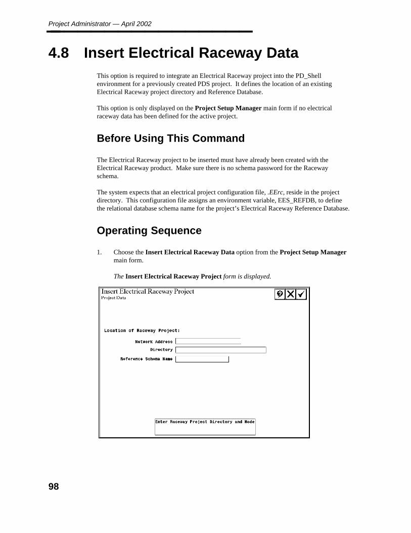
Project Administrator — April 2002________________
4.8 Insert Electrical Raceway Data
This option is required to integrate an Electrical Raceway project into the PD_Shellenvironment for a previously created PDS project. It defines the location of an existingElectrical Raceway project directory and Reference Database.
This option is only displayed on the Project Setup Manager main form if no electricalraceway data has been defined for the active project.
Before Using This Command
The Electrical Raceway project to be inserted must have already been created with theElectrical Raceway product. Make sure there is no schema password for the Racewayschema.
The system expects that an electrical project configuration file, .EErc, reside in the projectdirectory. This configuration file assigns an environment variable, EES_REFDB, to definethe relational database schema name for the project’s Electrical Raceway Reference Database.
Operating Sequence
1. Choose the Insert Electrical Raceway Data option from the Project Setup Managermain form.
The Insert Electrical Raceway Project form is displayed.
98

4. Pro
ject Setu
p
Insert Electrical Raceway Data________________
2. Enter Raceway Project Directory and Node
Key in the node name and the directory path for the directory where the electricalraceway project currently exists, including the *.prj directory in the path name. (This isthe the location of the .prj file.)
3. Key in the schema name for the electrical raceway reference database.
4. Choose the Confirm button to accept the specified raceway project information.
The network address and path name are stored in the Project Control Database as thedefault location for creating electrical raceway models.
If the name of the Raceway project schema is not EE_<projname>, you mustedit PDtable102 through RIS and change the name of the Raceway projectschema. This is required for labels to work properly in PDS.
99
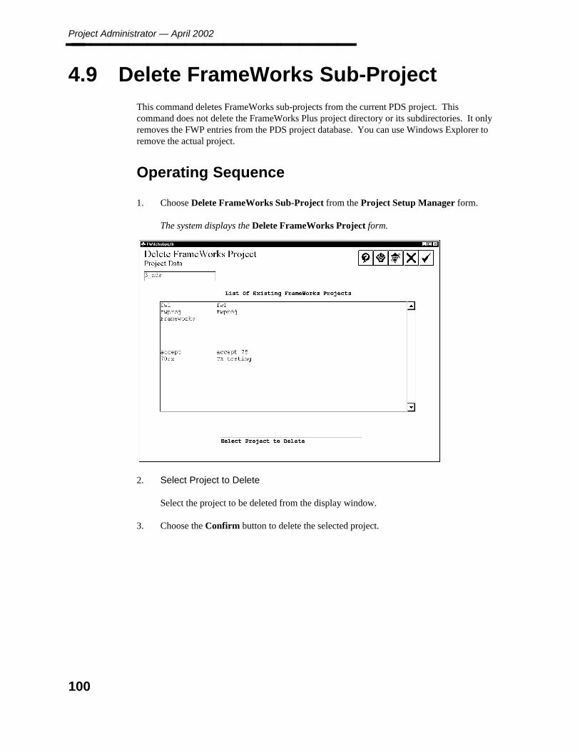
Project Administrator — April 2002________________
4.9 Delete FrameWorks Sub-Project
This command deletes FrameWorks sub-projects from the current PDS project. Thiscommand does not delete the FrameWorks Plus project directory or its subdirectories. It onlyremoves the FWP entries from the PDS project database. You can use Windows Explorer toremove the actual project.
Operating Sequence
1. Choose Delete FrameWorks Sub-Project from the Project Setup Manager form.
The system displays the Delete FrameWorks Project form.
2. Select Project to Delete
Select the project to be deleted from the display window.
3. Choose the Confirm button to delete the selected project.
100

5. En
viron
men
t M
anag
er
Project Environment Manager________________
5. Project Environment Manager
The Project Environment Manager is used to create, revise, and delete disciplines, designareas, and model files; revise the project information location of a project or model; or createa report of information in the project control database and design database.
The Project Control database is created as part of a new project. (See the Project SetupManager.) The project is the fundamental structure for working in PDS. Each projectcontains all the information required to design a plant in the PDS environment. PDS uses thefollowing organization to divide the project:
A discipline is a grouping based on application. The project is initially created with thefollowing disciplines: Piping, Equipment, Structural, HVAC, Raceway andArchitecture. Additional user-defined disciplines (up to a total of ten) can also becreated.
A design area represents a specified volume of the project for a specific discipline.Design areas are used to divide the project into smaller areas for operations to beperformed only on a subset of the entire plant, such as interference checking orreporting.
A model corresponds to a specific 3D volume for a discipline within the specifieddesign area. A model represents the smallest subdivision of the project based on workresponsibility.
Project Environment Manager Form
The Project Environment Manager form is used to:
Create and Delete Disciplines, Design Areas, and Model Files.Revise the project information.Relocate an entire project, a single model, or a drawing to a new location.Revise the definitions for Disciplines, Design Areas, and Model Files.Report on models or drawings in the Project Control Database.Report on Named Items in Piping and Equipment models.Define the default location for new models.
Option Descriptions
Create — Displays the Create Options form to create disciplines, design areas, andmodel files. For more information about the Create Options form, see page 104.
Revise — Displays the Revise Options form to edit the description of the project, or ofa discipline, area or model. The project directory or a single model or drawing mayalso be moved. For more information about the Revise Option form, see page 135.
101
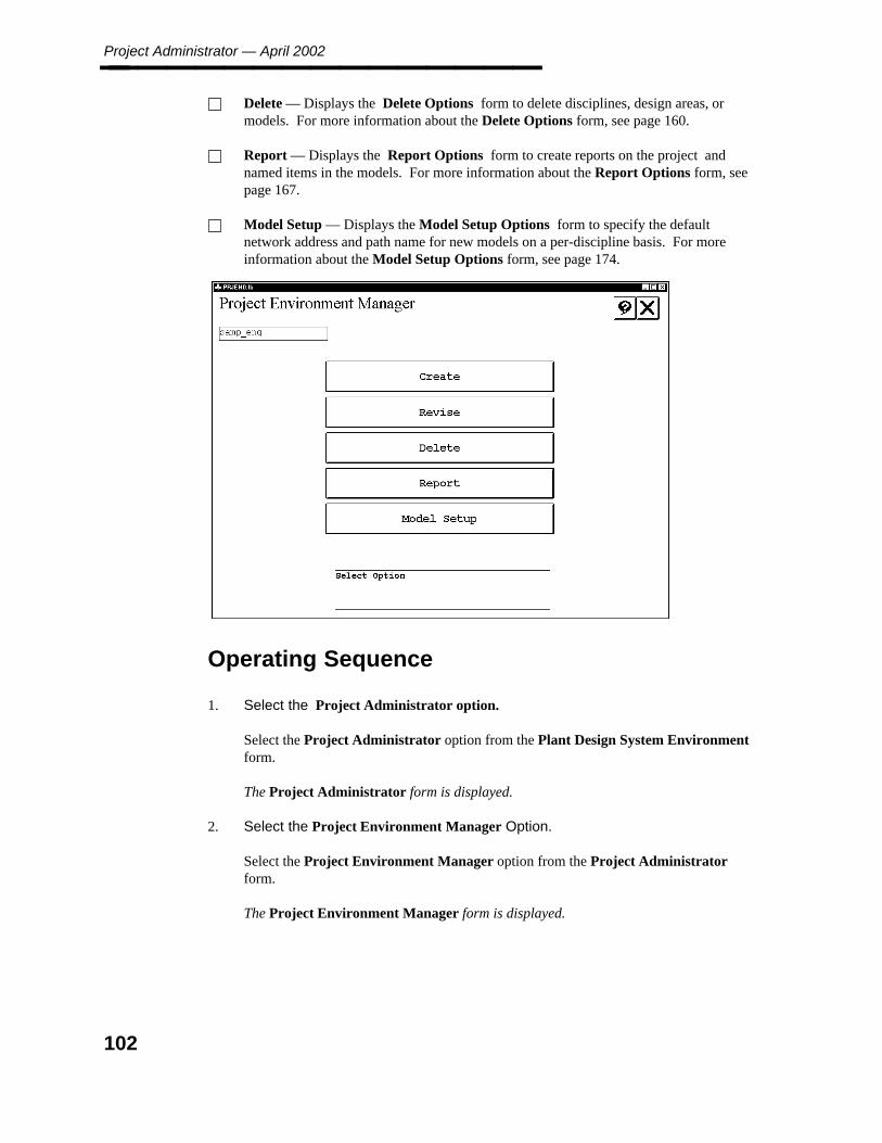
Project Administrator — April 2002________________ Delete — Displays the Delete Options form to delete disciplines, design areas, ormodels. For more information about the Delete Options form, see page 160.
Report — Displays the Report Options form to create reports on the project andnamed items in the models. For more information about the Report Options form, seepage 167.
Model Setup — Displays the Model Setup Options form to specify the defaultnetwork address and path name for new models on a per-discipline basis. For moreinformation about the Model Setup Options form, see page 174.
Operating Sequence
1. Select the Project Administrator option.
Select the Project Administrator option from the Plant Design System Environmentform.
The Project Administrator form is displayed.
2. Select the Project Environment Manager Option.
Select the Project Environment Manager option from the Project Administratorform.
The Project Environment Manager form is displayed.
102

5. En
viron
men
t M
anag
er
Project Environment Manager________________
3. Select Option.
Select the Create, Revise, Delete, Report, or Model Setup option.
The selected Create Options, Revise Options, Report Options, or Model SetupOptions form is displayed.
103

Project Administrator — April 2002________________
5.1 Create Options Form
The Create Options form is used to create disciplines, design areas or models for the activeproject. For Piping, Equipment and Raceway models, seed files from the project directory areused to create the new model. The Project Data Manager can be used to edit the projectseed files prior to (and in some cases even after) model creation.
Option Descriptions
Create Discipline Data — Creates a user-defined (non-PDS) discipline. See page106.
Create Design Area Data — Creates a design area within a discipline. Multipledesign areas can be defined for each discipline. See page 108.
Create Model — Used to create a new Piping, Equipment, Structural or Racewaymodel for the specified design area or to create a model definition for the other non-PDS disciplines. See page 111.
Copy Model — Copies a model within the current project or to another project. Seepage 117.
Create Database Tables — Creates the database tables for Piping and Equipmentmodels. See page 128.
Create Model from ASCII File — Creates multiple models based on the parametersin a text file. See page 129.
104

5. En
viron
men
t M
anag
er
Create Options Form________________
Operating Sequence
1. Select Create Option.
Select the Create option from the Project Environment Manager form.
The Create Options form is displayed.
2. Select Option
Select the Create Discipline Data, Create Design Area Data, Create Model, CopyModel, Create Database Tables, or Create model from ASCII File option.
The selected Create Discipline Data, Create Design Area Data, Create Model, CopyModel, Create Database Tables, or Create model from ASCII File form isdisplayed.
105

Project Administrator — April 2002________________
5.1.1 Create Discipline Data
The Create Discipline Data option is used to create up to ten disciplines for the activeproject. Projects are initially created with the Piping, Equipment, Structural, HVAC,Raceway, and Architecture disciplines. When this option is selected, the existing disciplinedefinitions are displayed in the Disciplines list.
Field Descriptions
Disciplines — A listing of the existing disciplines.
Discipline Name — The name of the new discipline to be created.
PLANTGEN Discipline toggle — Only one discipline per project can be designated asa PLANTGEN discipline.
Clash Discipline toggle — Only one discipline per project can be designated as a Clashdiscipline.
The Clash discipline is used to define area volumes for envelope generation andinterference checking. The volume can be defined in plant coordinates or using adefined Design Volume Coordinate System (DVCS).
No models can be created in the Clash discipline, either manually or byASCII file.
106
5. En
viron
men
t M
anag
er
Create Discipline Data________________
Operating Sequence
1. Select Create Discipline Data Option.
Select the Create Discipline Data option from the Create Options form.
The Disciplines field is updated.
2. Type Discipline Name.
Type the name of the discipline to be created and press the Enter key.
3. Select the PLANTGEN Discipline or Clash Discipline option, if applicable.
4. Accept Discipline Information.
Choose the Confirm button to accept the specified discipline information.
The specified discipline data is written to the Project Control Database, and theDisciplines list is updated with the new entry.
— OR —
Select another option to cancel the discipline definition.
107

Project Administrator — April 2002________________
5.1.2 Create Design Area Data
The Create Design Area Data option creates new design areas for the a discipline. A designarea can optionally specify a fixed volume of the project area. The volume for a design areacan define a unique area or overlap that of another design volume. Numerous operations inPDS can be performed on the entire project, on all models in a specified area, or on singlemodels in an area.
The volumes associated with a design area have a marked effect oninterference checking. For a complex discipline such as Piping, divide theproject into several areas rather than specify one design area for the entireproject volume.
Create Design Area Data Form
The Create Design Area Data form is used to specify the Design Area Name, Design AreaDescription and also if the area has a predefined volume.
Field Descriptions
Design Area Name — Specifies a name for the new Design Area. Type up to 10characters for the new Design Area Name. Do not use special characters such as the atsymbol(@), the pound sign (#), the percent symbol (%), the caret symbol (ˆ), theampersand (&), the asterisk (*), the exclamation point (!), or the pipe symbol (|).
Description — Specifies a description for the new Design Area. Type up to 40characters for the description of the new Design Area, or press Enter to skip this field.
Interference Management Design Area toggle — When this toggle is selected, aninterference management marker is created for the design area. This file is used todisplay interference markers to review and control clashes. (The system uses the designarea name as the name of the marker file with the extension .<discipline indexnumber>, for example, pipea1.1.) If the toggle is set to Interference ManagementDesign Area, the Volume fields are active to define the volume coordinates for thedesign area.
The decision to use predefined volume definitions for design areas requires carefulplanning. See the Interference Checker/Manager (PD_Clash) guide for additionaldiscussion of this topic.
Type the easting, northing, and elevation coordinates to define the volume of the designarea. Use negative values to specify coordinates in the west or south.
Define DVCS — Activates the Design Volume Coordinate System Definition form,allowing you to specify DVCS settings. This button only appears if you are creating adesign area in the Clash discipline. Refer to Design Volume Coordinate SystemDefinition, page 308 for more information on DVCS definition.
108
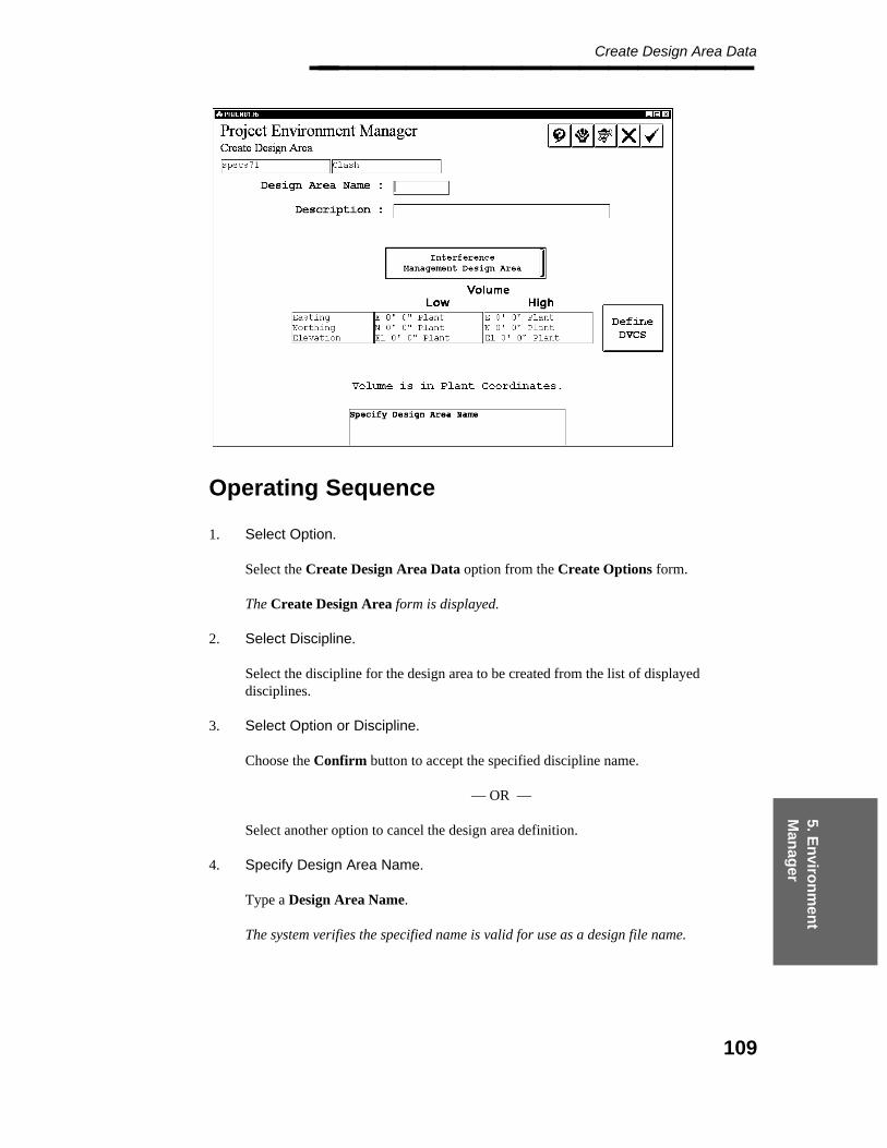
5. En
viron
men
t M
anag
er
Create Design Area Data________________
Operating Sequence
1. Select Option.
Select the Create Design Area Data option from the Create Options form.
The Create Design Area form is displayed.
2. Select Discipline.
Select the discipline for the design area to be created from the list of displayeddisciplines.
3. Select Option or Discipline.
Choose the Confirm button to accept the specified discipline name.
— OR —
Select another option to cancel the design area definition.
4. Specify Design Area Name.
Type a Design Area Name.
The system verifies the specified name is valid for use as a design file name.
109

Project Administrator — April 2002________________
5. Specify Design Area Description.
Select the Design Area Description field and type the description text.
6. For Structural design areas, select the Sub-Project field, and select a structural projectfrom the list.
7. For Clash discipline design areas using DVCS, select Define DVCS and use the DesignVolume Coordinate System Definition form to enter the DVCS settings. ClickAccept on the Design Volume Coordinate System Definition form to return to theCreate Design Area form.
8. Set Interference Management Design Area toggle.
Set the toggle to Interference Management Design Area to create an interferencemanagement file for the design area and specify a predefined volume.
— OR —
Set the toggle to No Interference Management Design Area to use the project-widemarker file, rather than creating a marker file for this area.
This step is not necessary for Clash discipline areas.
9. Accept or Specify Design Area Data.
When all information has been defined, choose the Confirm button to accept thedefinition of the design area.
The design area specification is written to the project control database. If a predefinedvolume was specified, the project marker file is copied to create an interference markerfile for that area.
110
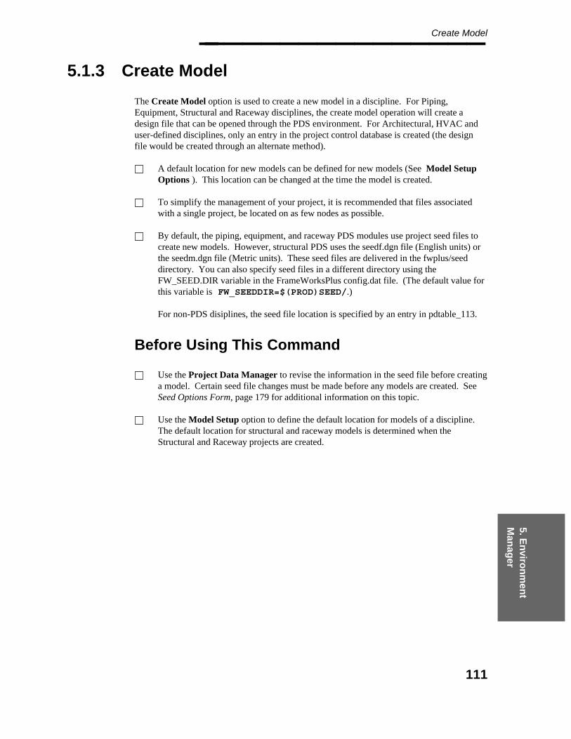
5. En
viron
men
t M
anag
er
Create Model________________
5.1.3 Create Model
The Create Model option is used to create a new model in a discipline. For Piping,Equipment, Structural and Raceway disciplines, the create model operation will create adesign file that can be opened through the PDS environment. For Architectural, HVAC anduser-defined disciplines, only an entry in the project control database is created (the designfile would be created through an alternate method).
A default location for new models can be defined for new models (See Model SetupOptions ). This location can be changed at the time the model is created.
To simplify the management of your project, it is recommended that files associatedwith a single project, be located on as few nodes as possible.
By default, the piping, equipment, and raceway PDS modules use project seed files tocreate new models. However, structural PDS uses the seedf.dgn file (English units) orthe seedm.dgn file (Metric units). These seed files are delivered in the fwplus/seeddirectory. You can also specify seed files in a different directory using theFW_SEED.DIR variable in the FrameWorksPlus config.dat file. (The default value forthis variable is FW_SEEDDIR=$(PROD)SEED/.)
For non-PDS disiplines, the seed file location is specified by an entry in pdtable_113.
Before Using This Command
Use the Project Data Manager to revise the information in the seed file before creatinga model. Certain seed file changes must be made before any models are created. SeeSeed Options Form, page 179 for additional information on this topic.
Use the Model Setup option to define the default location for models of a discipline.The default location for structural and raceway models is determined when theStructural and Raceway projects are created.
111

Project Administrator — April 2002________________
Field Descriptions
Non-Frameworks Plus Models
Model Number — Type up to 10 characters for the name/number of the design file tobe created/defined. (For structural models, the number is limited to 9 characters.)
Model Name — The system verifies the specified name is valid for use as a design filename. It fills in the Model Name automatically by appending .dgn to the specifiedmodel number. For structural models, entries for a .dgn file is created in the projectcontrol database. However, only the .dgn file is created on disk/ The .frz file, must becreated with the same name, from within Frameworks. The Model Name may beedited.
Model Directory — If a default location was specified in the Model Setup Options,the node name and path appear in this field. The location of Structural and Racewaymodels cannot be changed.
Workstation/Server Name — This field defaults to the node name and path specifiedin the Model Setup Options. Type a network address or node name to specify thesystem on which the model file is to be created.
Application Type — This field defaults to the active discipline and sets the responsiblediscipline attribute in PDtable_113. The responsible discipline attribute is used by theenvelope builder and the Interference Checker to determine the actual discipline if theDiscipline Matrix is used. For example, this provides a method to use a piping modelfor HVAC ducting and have the clashes from that model treated by the InterferenceChecker as HVAC components in to assign responsibility for the clash. Refer to theInterference Checker/Manager (PD_Clash) User’s Guide for more information.
112
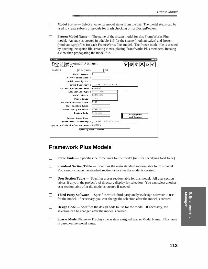
5. En
viron
men
t M
anag
er
Create Model________________ Model Status — Select a value for model status from the list. The model status can beused to create subsets of models for clash checking or for DesignReview.
Frozen Model Name — The name of the frozen model for this FrameWorks Plusmodel. An entry is created in pdtable 113 for the sparse (modname.dgn) and frozen(modname.prp) files for each FrameWorks Plus model. The frozen model file is createdby opening the sparse file, creating views, placing FraneWorks Plus members, freezinga view then propagating the model file.
Framework Plus Models
Force Units — Specifies the force units for the model (unit for specifying load force).
Standard Section Table — Specifies the main standard section table for this model.You cannot change the standard section table after the model is created.
User Section Table — Specifies a user section table for this model. All user sectiontables, if any, in the project’s \sl directory display for selection. You can select anotheruser section table after the model is created if needed.
Third Party Software — Specifies which third party analysis/design software to usefor the model. If necessary, you can change the selection after the model is created.
Design Code — Specifies the design code to use for the model. If necessary, theselection can be changed after the model is created.
Sparse Model Name — Displays the system assigned Sparse Model Name. This nameis based on the model name.
113
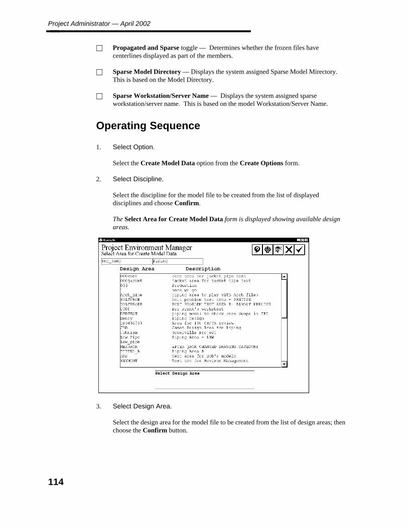
Project Administrator — April 2002________________ Propagated and Sparse toggle — Determines whether the frozen files havecenterlines displayed as part of the members.
Sparse Model Directory — Displays the system assigned Sparse Model Mirectory.This is based on the Model Directory.
Sparse Workstation/Server Name — Displays the system assigned sparseworkstation/server name. This is based on the model Workstation/Server Name.
Operating Sequence
1. Select Option.
Select the Create Model Data option from the Create Options form.
2. Select Discipline.
Select the discipline for the model file to be created from the list of displayeddisciplines and choose Confirm.
The Select Area for Create Model Data form is displayed showing available designareas.
3. Select Design Area.
Select the design area for the model file to be created from the list of design areas; thenchoose the Confirm button.
114

5. En
viron
men
t M
anag
er
Create Model________________ The Create Model Data form is displayed.
4. Specify Model Information.
Type the Model Number, Model Name, Model Description, Model Directory,Workstation/Server Name, Application Type, and Model Status.
5. For structural models, provide the additional information: Application Type, togglefor Propagated Only, Sparse Model Name, Sparse Model Directory and SparseWorkstation/Server Name.
Additional information can be specified for FrameWorks models: ForceUnits, Standard Section Table, and User Section Table.
6. Accept or Specify Attribute.
Choose the Confirm button to accept the displayed model data.
The specified model management data is written to the Project Control Database. Ifthe discipline is Piping, Equipment, or EE Raceway the Design Volume CoordinateSystem Definition form is displayed.
115

Project Administrator — April 2002________________
Refer to Design Volume Coordinate System Definition, page 308, for information on theDesign Volume Coordinate System Definition form.
For Piping and Equipment models, an additional operation to create databasetables must also be performed before these models can be used by PDS.
116
5. En
viron
men
t M
anag
er
Copy Model________________
5.1.4 Copy Model
The Copy Model option creates a copy of an existing model file within the current project orto another project. All contents of the specified file are copied to the new file. This optioncan be used with Piping, Equipment, Structural, or Raceway models.
The Copy Model command makes the following database-related changes based on thesetting for Copy in the Piping Data Control option of the Project Data Manager. The copysetting is determined by the setting in the destination model. Refer to Piping Data Control,page 226, for more information.
If the copy option is set to Append Prefix, the system adds two asterisks (**) as aprefix to name attributes to signify the piping segment or component has been copiedand the name attribute may require updating. The following attributes are consideredname attributes for this operation:
line number labelpiping component numberpipe tag numberinstruct component numberpipe support numberline id
If the copy option is set to No Prefix, the ** prefix is removed when copying a pipingsegment or a component with a name attribute that includes the ** prefix from aprevious copy operation.
Regardless of how this option is set, name attributes that are undefined (blank) will nothave the prefix added.
The following database-related changes are also made:
For piping components, pipes, and instrument components, the weld numbers at eachwelded end are set to undefined (blank). The alphanumeric description ID of a pipingsegment is automatically deleted by a copy operation.
For piping segments, the approval status is set to not approved.
Inter-Project Copies With Different Systemof Units
When copying a piping model from another project, the system automatically converts certainattributes, such as face-to-face dimension or surface area, when the system of units for thoseattributes changes from the source project to the destination project. The following data issubject to units conversion in copying piping from one project to another:
117
Project Administrator — April 2002________________ Piping Segment Data
insulation thicknessinsulation densityheat tracing temperature
Piping Component Data
maximum temperatureface-to-face dimensiondimension adimension bdimension csurface areaempty weightwater weightoperator weight (or branch reinforcement width or orifice size)heat tracing temperaturepiping outside diameter (five connect points)face-to-center dimension (five connect points)gasket gap (five connect points)
Piping/Tubing Data
maximum temperaturepiping outside diameterpipe lengthsurface areaempty weightwater weightcold spring lengthheat tracing temperaturegasket gap (both ends)
Instrument Component Data
face-to-face dimensiondimension adimension bdimension csurface areaempty weightwater weightoperator weightheat tracing temperatureinsulation thicknessinsulation densitypiping outside diameter (five connect points)face-to-center dimension (five connect points)gasket gap (five connect points)
118
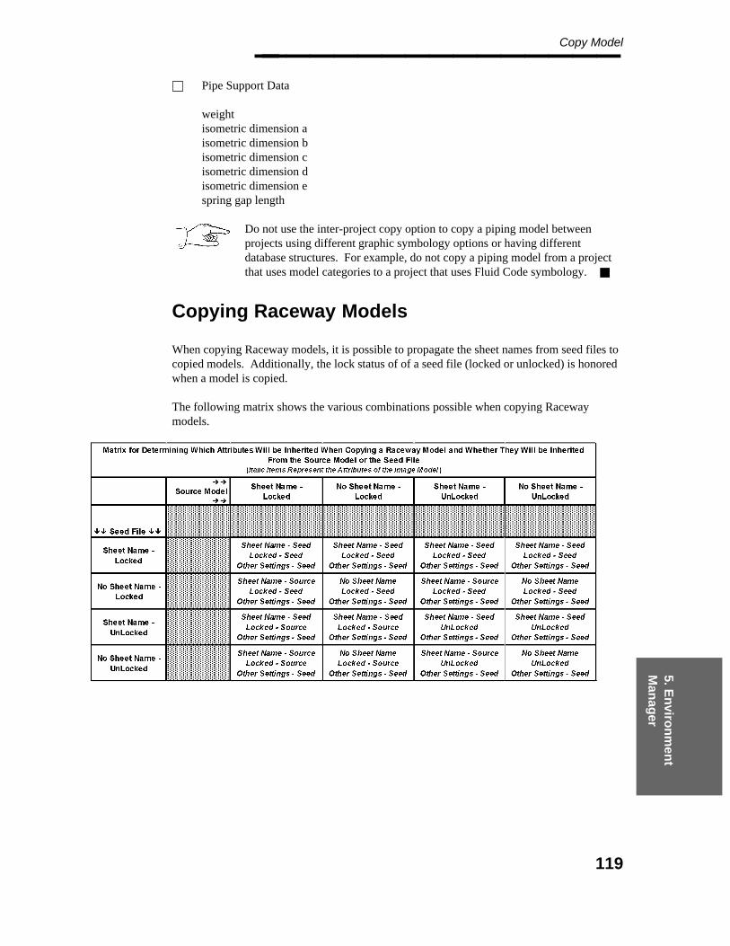
5. En
viron
men
t M
anag
er
Copy Model________________ Pipe Support Data
weightisometric dimension aisometric dimension bisometric dimension cisometric dimension disometric dimension espring gap length
Do not use the inter-project copy option to copy a piping model betweenprojects using different graphic symbology options or having differentdatabase structures. For example, do not copy a piping model from a projectthat uses model categories to a project that uses Fluid Code symbology.
Copying Raceway Models
When copying Raceway models, it is possible to propagate the sheet names from seed files tocopied models. Additionally, the lock status of of a seed file (locked or unlocked) is honoredwhen a model is copied.
The following matrix shows the various combinations possible when copying Racewaymodels.
119
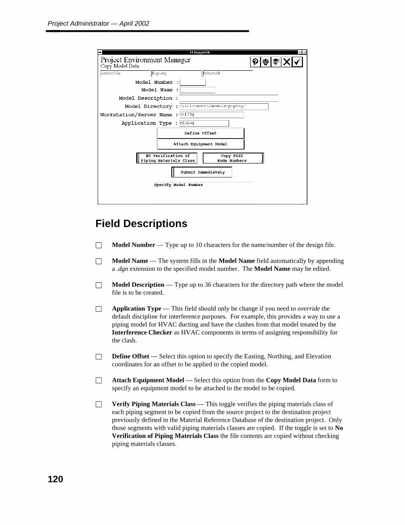
Project Administrator — April 2002________________
Field Descriptions
Model Number — Type up to 10 characters for the name/number of the design file.
Model Name — The system fills in the Model Name field automatically by appendinga .dgn extension to the specified model number. The Model Name may be edited.
Model Description — Type up to 36 characters for the directory path where the modelfile is to be created.
Application Type — This field should only be change if you need to override thedefault discipline for interference purposes. For example, this provides a way to use apiping model for HVAC ducting and have the clashes from that model treated by theInterference Checker as HVAC components in terms of assigning responsibility forthe clash.
Define Offset — Select this option to specify the Easting, Northing, and Elevationcoordinates for an offset to be applied to the copied model.
Attach Equipment Model — Select this option from the Copy Model Data form tospecify an equipment model to be attached to the model to be copied.
Verify Piping Materials Class — This toggle verifies the piping materials class ofeach piping segment to be copied from the source project to the destination projectpreviously defined in the Material Reference Database of the destination project. Onlythose segments with valid piping materials classes are copied. If the toggle is set to NoVerification of Piping Materials Class the file contents are copied without checkingpiping materials classes.
120
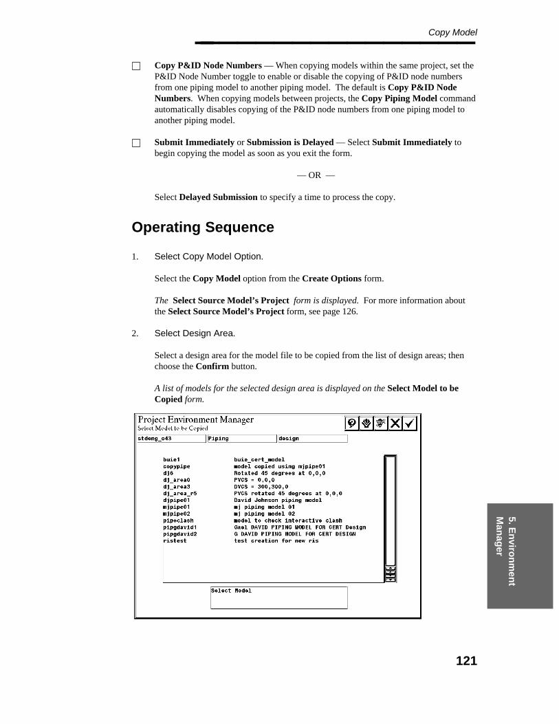
5. En
viron
men
t M
anag
er
Copy Model________________ Copy P&ID Node Numbers — When copying models within the same project, set theP&ID Node Number toggle to enable or disable the copying of P&ID node numbersfrom one piping model to another piping model. The default is Copy P&ID NodeNumbers. When copying models between projects, the Copy Piping Model commandautomatically disables copying of the P&ID node numbers from one piping model toanother piping model.
Submit Immediately or Submission is Delayed — Select Submit Immediately tobegin copying the model as soon as you exit the form.
— OR —
Select Delayed Submission to specify a time to process the copy.
Operating Sequence
1. Select Copy Model Option.
Select the Copy Model option from the Create Options form.
The Select Source Model’s Project form is displayed. For more information aboutthe Select Source Model’s Project form, see page 126.
2. Select Design Area.
Select a design area for the model file to be copied from the list of design areas; thenchoose the Confirm button.
A list of models for the selected design area is displayed on the Select Model to beCopied form.
121

Project Administrator — April 2002________________
3. Select Model.
Select the existing model design file to be copied; then choose the Confirm button.
The Select Area for Copied Model form is displayed.
4. Select Design Area.
Select the design area for the model file to be created from the list of design areas; thenchoose the Confirm button.
The Copy Model Data form is displayed.
5. Specify Model Information.
Type the Model Number, Model Description, and Application Type information forthe design file to be created.
6. Define a Design Volume Offset.
Select Define Offset to define a design volume offset for the model to be copied.
The Copy Model Data - Offset form is displayed. For more information about theCopy Model Data - Offset form, see page 123.
7. Attach Equipment Model
Select Attach Equipment Model to specify an equipment model to be attached to themodel to be copied.
The Attach Equipment Model form is displayed. For more information about theAttach Equipment Model form, see page 124.
8. Set Verify Piping Materials Class toggle.
Set the toggle to Verify Piping Materials Class or No Verification of PipingMaterials Class.
9. Set the P&ID Node Number toggle Copy P&ID Node Numbers or Do Not CopyP&ID Node Numbers.
The default is Copy P&ID Node Numbers.
10. Select Submit Immediately to begin copying the model as soon as you exit the form.
— OR —
Select Submission is Delayed to specify a time to process the copy.
122

5. En
viron
men
t M
anag
er
Copy Model________________
11. Accept Model data.
Choose the Confirm button to accept the specified data.
The Design Volume Coordinate System Definition form is displayed. Refer toDesign Volume Coordinate System Definition, page 308, for information about thisoption.
12. Submit Copy Request.
Choose the Confirm button on the Design Volume Coordinate System Definitionform.
The copy request is submitted to the batch queue PDcopy_model and the Select Modelto be Copied form is displayed.
Design Volume Offset
The Design Volume Offset option is used to specify the Easting, Northing, and Elevationcoordinates for an offset to be applied to the copied model.
123
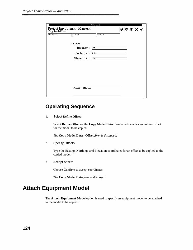
Project Administrator — April 2002________________
Operating Sequence
1. Select Define Offset.
Select Define Offset on the Copy Model Data form to define a design volume offsetfor the model to be copied.
The Copy Model Data - Offset form is displayed.
2. Specify Offsets.
Type the Easting, Northing, and Elevation coordinates for an offset to be applied to thecopied model.
3. Accept offsets.
Choose Confirm to accept coordinates.
The Copy Model Data form is displayed.
Attach Equipment Model
The Attach Equipment Model option is used to specify an equipment model to be attachedto the model to be copied.
124

5. En
viron
men
t M
anag
er
Copy Model________________
Operating Sequence
1. Select Attach Equipment Model.
Select Attach Equipment Model from the Copy Model Data form to specify anequipment model to be attached to the model to be copied.
The Select Equipment Area for Attachment form is displayed.
2. Select Design Area.
Select the equipment model file to be attached to the new model design file.
3. Choose Confirm.
The Select Reference Model to be Attached form is displayed.
4. Specify Reference Model.
Select a reference model to be attached and choose Confirm.
The Copy Model Data form is displayed.
125

Project Administrator — April 2002________________
Select Source Model’s Project Form
The Select Source Model’s Project form displays a list of available projects, allowingselection to copy when establishing a new project. This form works with Piping, Equipment,Raceway, and Structural models. It copies all contents of the specified file to the new file.
Field Descriptions
Project — This field lists the available projects for source model selection. Eachproject contains all the information required to design a plant in the PDS environment.
Discipline —A grouping of the projects based on application. The Project ControlDatabase is initially created with the following disciplines: Piping, Equipment,Structural, and Raceway.
Operating Sequence
1. Select Copy Model Option.
Select the Copy Model option from the Create Options form.
The system displays the Select Source Models Project form.
2. Accept or Select Source Project.
Select the project for the model file to be copied from the list of projects.
3. Set Discipline Toggle.
126
5. En
viron
men
t M
anag
er
Copy Model________________ Set the discipline toggle to Piping or Equipment for the model file to be copied.
4. Choose the Confirm button to accept the project and discipline.
127

Project Administrator — April 2002________________
5.1.5 Create Database Tables
The Create Database Tables option creates tables for piping and equipment models in thedesign (DD) schema. This is a batch job that can be submitted immediately or at a specifiedtime.
Operating Sequence
1. Select the Create Database Tables Option.
Select Create Database Tables from the Create Options form.
The Submit Immediately toggle is displayed.
2. Accept the Create Options form to submit the batch job immediately.
— OR —
Select Submission is Delayed to specify a time to process the models.
3. Submit Model Creation Request.
Choose the Confirm button.
When the Create Options form is accepted, the model creation request is submitted tothe PDcreate_model batch queue for processing.
128

5. En
viron
men
t M
anag
er
Create Model Data from ASCII File________________
5.1.6 Create Model Data from ASCII File
The Create Model Data from ASCII File creates areas, models and drawings from an ASCIIinput file. For piping, equipment, structural, and raceway models, design files are created.For other disciplines, only the model definitions are created. For Piping and Equipmentmodels, you can also specify a Design Volume Coordinate System for each model.
This command can be used to create model definitions for existing ModelDraftor Frameworks Plus models without writing over the existing design files.
Format
Information in the ASCII files is the same as that entered into the forms seen in the PDSEnvironment.
The format used to define the model management data is a set of entries of the form:Keyword:data.
There must be a colon (:) separating the keyword and the data.
For any entry in this list, there is a maximum of 132 characters per line of data.
The ASCII file(s) to be used to create a model, must be in order by the keywords listedbelow. The software will not function at all if the order is wrong.
For structural models, the Force Units, Standard Section Table and User Section Tablevalues come from the FrameWorks Plus information in the project database. Thedefault value for the Third Party Software option is STAADIII, and the default valuefor the Design Code is AISC-ASD. These defaults are the same values that appear ina model create using the Create Model Interactive command.
Keywords
The following keywords are used to define the data; they are the same as the fields specifiedin the Create Design Area form and the Create Model Data form, including structuralmodels:
Discipline — The discipline name exactly as it appears in the PD_Shell environment(example: Discipline:Piping). This is required information.
Area_Name — A required 20-character design area name; it must be unique acrossdisciplines (example: Area_Name:Piping_A).
Area_Desc — An optional 40-character description for the design area being created(example: Area_Desc:Piping Area A).
129
Project Administrator — April 2002________________
This keyword is required when creating a new area. If the area alreadyexists, use Area_Name only.
Area_Marker_File — An option to indicate that you want an interference marker filefor the area (example: Area_Marker_File:Yes).
This option is only for use in combination with Area_Desc.
Area_Volume_Low/High — An option that indicates if the design area will have apredefined volume for interference checking purposes. This is required ifArea_Marker_File is Yes; the low volume and high volume represent the limits of thevolume processed by the interference checker (example: Area_Volume_Low:-100,-250,-50 Area_Volume_High:150,30,120).
This option is only for use in combination with Area_Marker_File.
Sub_Proj_Number — Required information for new structural models. It is thestructural subproject number of the FrameWorks Plus or ModelDraftsubproject.(example: Sub_Proj_Number:fw_proj1)
This option is required when creating a new area in combination withArea_Desc.
Model_Number — A required 10-character piping model number of the model to becreated (example: Model_Number:Model_A).
Model_Desc — A required 40-character description of the model to be created(example: Model_Desc:Model A Description).
File_Spec — An optional 14-character file specification of the model to be created. If avalue is not specified or the keyword is missing, the file specification defaults to themodel number with the extension .dgn (example: Model_A.dgn).
This option is not supported for structural models, because the filespecification is defined in the subproject.
Path_Name — An optional 35-character directory path where the model file is to becreated (example: d:\proj\models\). If this value is not specified or the keywordis missing, the default values as defined with the Model Setup option are used.
This option is not supported for structural models, because the filespecification is defined in the subproject.
Network_Address — An optional 26-character node name of the system on which themodel file is to be stored (example: Network_Address:jwdoe_3). This value isnot specified or the keyword is missing, the default values as defined with the ModelSetup option, are used.
130
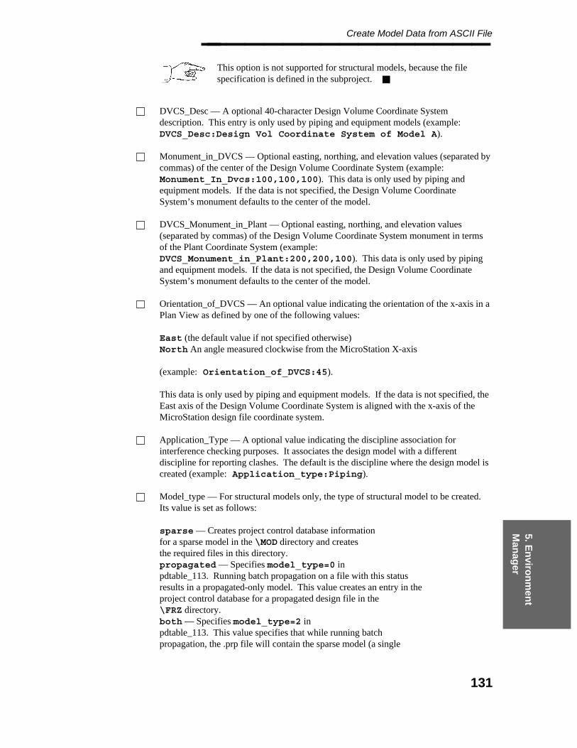
5. En
viron
men
t M
anag
er
Create Model Data from ASCII File________________
This option is not supported for structural models, because the filespecification is defined in the subproject.
DVCS_Desc — A optional 40-character Design Volume Coordinate Systemdescription. This entry is only used by piping and equipment models (example:DVCS_Desc:Design Vol Coordinate System of Model A).
Monument_in_DVCS — Optional easting, northing, and elevation values (separated bycommas) of the center of the Design Volume Coordinate System (example:Monument_In_Dvcs:100,100,100). This data is only used by piping andequipment models. If the data is not specified, the Design Volume CoordinateSystem’s monument defaults to the center of the model.
DVCS_Monument_in_Plant — Optional easting, northing, and elevation values(separated by commas) of the Design Volume Coordinate System monument in termsof the Plant Coordinate System (example:DVCS_Monument_in_Plant:200,200,100). This data is only used by pipingand equipment models. If the data is not specified, the Design Volume CoordinateSystem’s monument defaults to the center of the model.
Orientation_of_DVCS — An optional value indicating the orientation of the x-axis in aPlan View as defined by one of the following values:
East (the default value if not specified otherwise)North An angle measured clockwise from the MicroStation X-axis
(example: Orientation_of_DVCS:45).
This data is only used by piping and equipment models. If the data is not specified, theEast axis of the Design Volume Coordinate System is aligned with the x-axis of theMicroStation design file coordinate system.
Application_Type — A optional value indicating the discipline association forinterference checking purposes. It associates the design model with a differentdiscipline for reporting clashes. The default is the discipline where the design model iscreated (example: Application_type:Piping).
Model_type — For structural models only, the type of structural model to be created.Its value is set as follows:
sparse — Creates project control database informationfor a sparse model in the \MOD directory and createsthe required files in this directory.propagated — Specifies model_type=0 inpdtable_113. Running batch propagation on a file with this statusresults in a propagated-only model. This value creates an entry in theproject control database for a propagated design file in the\FRZ directory.both — Specifies model_type=2 inpdtable_113. This value specifies that while running batchpropagation, the .prp file will contain the sparse model (a single
131
Project Administrator — April 2002________________ line model) and a 3D model (the propagated model). This valuecreates a project control database entry for a propagated model in the\FRZ directory.
The only Model_Type value which actually creates physical files is sparse. Thisvalue, if the model does not already exist, executes the FrameWorks Plus cremodutility, which creates all 14 files in the FW+ project\MOD directory as well as acorresponding entry in pdtable_113. The propagated and both values do NOTcreate physical files; they only create entries in pdtable_113.
Model_Status — An optional value for the model status from code list set 1605. Thisvalue is used to exclude models from being processed in PD_Clash.
The following is an example of a simple file used to create two piping models and onestructural model:
Discipline:PipingArea_Name:Piping_AArea_Desc:Piping Area AModel_Number:A2pipe1Model_Desc:Piping Model 1 from ASCIIFile_Spec:A2pipe1.dgnPath_Name:C:\users\acme\proj1\Network_Address:pds_servDVCS_Desc:Model DVCSMonument_in_DVCS:-1000,0,0DVCS_Monument_in_Plant:350,325,0Orientation_of_DVCS:NorthApplication_Type:PipingDiscipline:StructuralArea_Name:SA1Area_Desc:FrameWorks Plus Area A SteelSub_Proj_Number:fwproj1Area_Marker_File:YesArea_Volume_Low:-100,-250,-50Area_Volume_High:150,30,120Model_Number:steel1Model_Desc:Structural Model 1 from ASCIIModel_Type:bothPath_Name:c:\users\acme\stproj1Network_Address:pds_servApplication_Type:Structural
The following listing is an example of an ASCII file used to create structural models andproject control database information.
Discipline:StructuralArea_Name:AS1Area_Desc:Frameworks Plus Area SteelArea_Marker_File:YesArea_Volume_Low:-100,-250,-50Area_Volume_High:150,30,120Sub_Proj_Number:fwproj1Model_Number:steel1Model_Desc: linearModel_Type:sparseApplication_Type:StructuralModel_Number:steel1
132

5. En
viron
men
t M
anag
er
Create Model Data from ASCII File________________ Model_Desc:linear prpModel_Type:bothApplication_Type:Structural
Before Using This Command
Create an ASCII file to define the models to be created using the specified conventions.
For structural models and areas, the FrameWorks Plus Project must have been createdusing the Project Administrator > Project Setup Manager > Insert FrameWorksProject command.
Operating Sequence
1. Select Create Model from ASCII File Option.
Select the Create Model from ASCII File option from the Create Options form.
The Create Model from ASCII File form is displayed.
2. Specify ASCII File Spec.
Type the information for the location of the ASCII file in the ASCII File Name,Directory and Network Address fields.
3. Submit Immediately or Submission is Delayed Select Submit Immediately to beginprocessing the request as soon as you exit the form.
— OR —
Select Submission is Delayed to specify a time to process the request.
133

Project Administrator — April 2002________________
4. Accept the specified time.
Choose the Confirm button to accept the specified time.
The request is submitted to the batch queue PDcreate_model.
For Piping and Equipment models created using this method, the tables in thePiping Design Database must still be created. Use the Create DatabaseTables option of the Project Environment Manager for this.
134
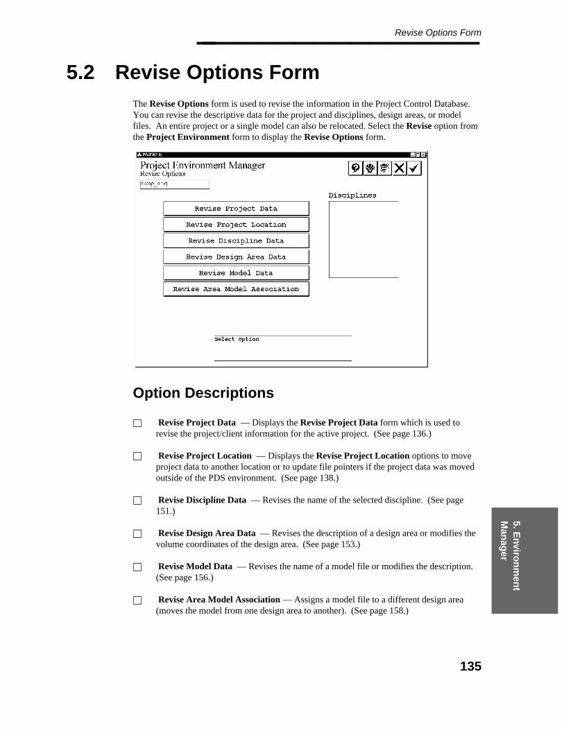
5. En
viron
men
t M
anag
er
Revise Options Form________________
5.2 Revise Options Form
The Revise Options form is used to revise the information in the Project Control Database.You can revise the descriptive data for the project and disciplines, design areas, or modelfiles. An entire project or a single model can also be relocated. Select the Revise option fromthe Project Environment form to display the Revise Options form.
Option Descriptions
Revise Project Data — Displays the Revise Project Data form which is used torevise the project/client information for the active project. (See page 136.)
Revise Project Location — Displays the Revise Project Location options to moveproject data to another location or to update file pointers if the project data was movedoutside of the PDS environment. (See page 138.)
Revise Discipline Data — Revises the name of the selected discipline. (See page151.)
Revise Design Area Data — Revises the description of a design area or modifies thevolume coordinates of the design area. (See page 153.)
Revise Model Data — Revises the name of a model file or modifies the description.(See page 156.)
Revise Area Model Association — Assigns a model file to a different design area(moves the model from one design area to another). (See page 158.)
135

Project Administrator — April 2002________________
5.2.1 Revise Project Data
The Revise Project Data form is used to revise the project/client information for the activeproject. The system displays existing information for the project (initially defined when theproject was created).
Field Descriptions
Project Name — Type up to 40 characters for the project name or project description.This does not affect the project number.
Job Number — Type up to 40 characters for the job number.
Company Name — Type up to 40 characters for the name of the client.
Plant Name — Type up to 40 characters for the location of the project.
Operating Sequence
1. Select the Revise Project Data Option.
Select the Revise Project Data option from the Revise Options form.
2. Select Attribute for Revision.
Select the Project Name, Job Number, Company Name or Plant Name field to berevised.
136

5. En
viron
men
t M
anag
er
Revise Project Data________________
3. Type Revisions.
Type any changes to the project/client information.
4. Accept Specification.
Choose the Confirm button to accept the specification.
The project data is updated in the Project Control Database.
137
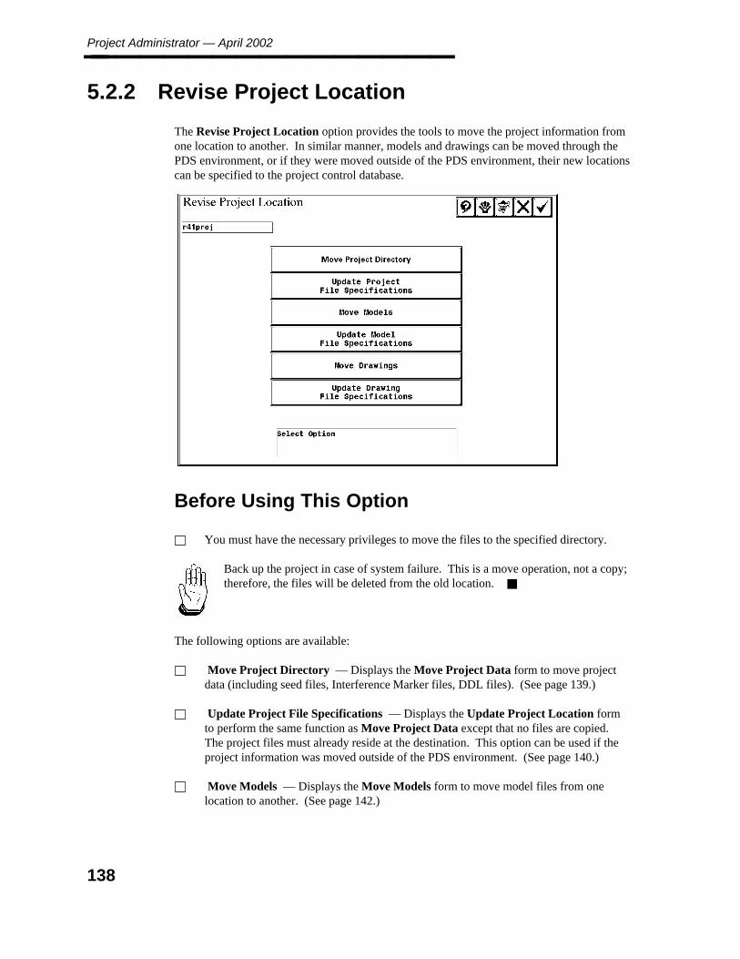
Project Administrator — April 2002________________
5.2.2 Revise Project Location
The Revise Project Location option provides the tools to move the project information fromone location to another. In similar manner, models and drawings can be moved through thePDS environment, or if they were moved outside of the PDS environment, their new locationscan be specified to the project control database.
Before Using This Option
You must have the necessary privileges to move the files to the specified directory.
Back up the project in case of system failure. This is a move operation, not a copy;therefore, the files will be deleted from the old location.
The following options are available:
Move Project Directory — Displays the Move Project Data form to move projectdata (including seed files, Interference Marker files, DDL files). (See page 139.)
Update Project File Specifications — Displays the Update Project Location formto perform the same function as Move Project Data except that no files are copied.The project files must already reside at the destination. This option can be used if theproject information was moved outside of the PDS environment. (See page 140.)
Move Models — Displays the Move Models form to move model files from onelocation to another. (See page 142.)
138
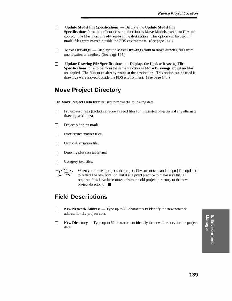
5. En
viron
men
t M
anag
er
Revise Project Location________________ Update Model File Specifications — Displays the Update Model FileSpecifications form to perform the same function as Move Models except no files arecopied. The files must already reside at the destination. This option can be used ifmodel files were moved outside the PDS environment. (See page 144.)
Move Drawings — Displays the Move Drawings form to move drawing files fromone location to another. (See page 144.)
Update Drawing File Specifications — Displays the Update Drawing FileSpecifications form to perform the same function as Move Drawings except no filesare copied. The files must already reside at the destination. This option can be used ifdrawings were moved outside the PDS environment. (See page 148.)
Move Project Directory
The Move Project Data form is used to move the following data:
Project seed files (including raceway seed files for integrated projects and any alternatedrawing seed files),
Project plot plan model,
Interference marker files,
Queue description file,
Drawing plot size table, and
Category text files.
When you move a project, the project files are moved and the proj file updatedto reflect the new location, but it is a good practice to make sure that allrequired files have been moved from the old project directory to the newproject directory.
Field Descriptions
New Network Address — Type up to 26-characters to identify the new networkaddress for the project data.
New Directory — Type up to 50-characters to identify the new directory for the projectdata.
139
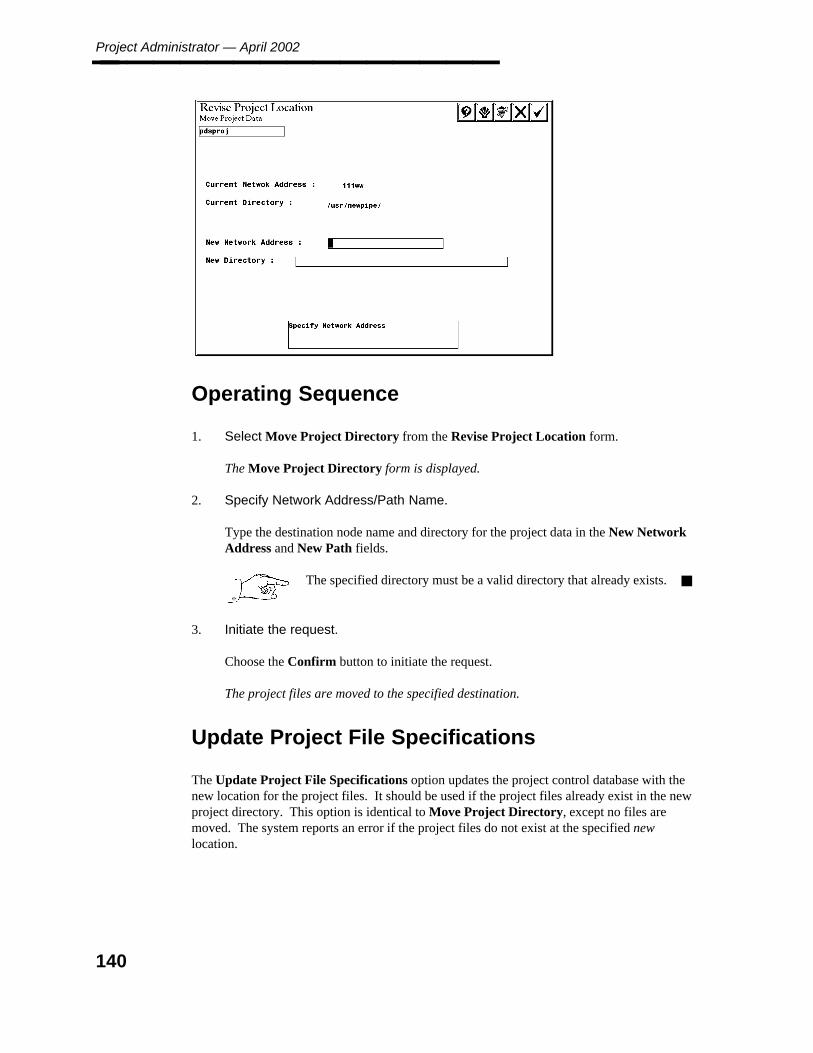
Project Administrator — April 2002________________
Operating Sequence
1. Select Move Project Directory from the Revise Project Location form.
The Move Project Directory form is displayed.
2. Specify Network Address/Path Name.
Type the destination node name and directory for the project data in the New NetworkAddress and New Path fields.
The specified directory must be a valid directory that already exists.
3. Initiate the request.
Choose the Confirm button to initiate the request.
The project files are moved to the specified destination.
Update Project File Specifications
The Update Project File Specifications option updates the project control database with thenew location for the project files. It should be used if the project files already exist in the newproject directory. This option is identical to Move Project Directory, except no files aremoved. The system reports an error if the project files do not exist at the specified newlocation.
140

5. En
viron
men
t M
anag
er
Revise Project Location________________
Field Descriptions
New Network Address — Type up to 26-characters to identify the network address ofthe project data.
New Directory — Type up to 50-characters to identify the new directory of the projectdata.
Operating Sequence
1. Select Update Project File Specifications.
Select Update Project file Specifications from the Revise Project Location form.
The Update Project Location form is displayed.
2. Specify New Network Address/Path Name.
Type the destination node name and directory for the project data in the New NetworkAddress and New Path fields.
The project files must exist in the new directory.
141
Project Administrator — April 2002________________
3. Initiate the Request.
Choose the Confirm button to initiate the request.
The project control database is updated with the new location.
Move Models
The Move Models option moves selected model files to a specified location. It moves allmodel-specific data (model_number.*) including the interference envelope file associated withthe model. For piping models, it also includes any diagnostic report files.
Field Descriptions
Model Number — A 10-character name/number of the design file. This field isdisplay only.
Source Address — The network address of the model files to be moved. This field isdisplay only.
Source Directory — The source directory identification of the model files to bemoved. This field is display only.
Destination Address — The network address where the model files are to be moved.This field can be modified.
Destination Directory — The directory identification where the model files are to bemoved. This field can be modified.
Move All to Same Destination toggle — Displays the fields to identify destinationaddress and directory for all models in the active area.
Move All to Default Location — Moves all model files to a previously specifieddefault location in the active area.
Operating Sequence
1. Select the Move Models Option.
Select Move Models from the Revise Project Location form to move a model designfile or set of files.
The active disciplines for the project are displayed.
142

5. En
viron
men
t M
anag
er
Revise Project Location________________
2. Select Discipline.
Select a discipline; then choose the Confirm button.
The design area for the current discipline are displayed.
3. Select Design Area.
Select the area of the models to be moved; then choose the Confirm button.
The Move Model Files form is displayed, enabling you to specify the destination.
4. Specify Destinations.
Select model file(s), and type the destination(s). Use the scroll arrows to scroll throughthe listings.
— OR —
Select Move All to Same Destination to move all the listed files to a specifieddestination.
— OR —
Select Move All to Default Location to move all the listed files to the specified defaultdrawing directory as specified in the Model Setup Data form.
143
Project Administrator — April 2002________________
5. Accept Destination(s).
Choose the Confirm button to accept the defined destination(s).
5.2.2.1 Update Model File Specifications
The Update Model File Specifications option is used to update the project control databasewith the new locations of project models. This option should be used if the model filesalready exist in the destination directory. This option is identical to Move Models, except nofiles are copied. The system reports an error if the model files do not exist at the specifieddestination.
Field Descriptions
Model Number — A 10-character name/number of the design file. This field isdisplay only.
Source Address — The network address for the model files to be updated. This field isdisplay only.
Source Directory — The source directory identification of the model files to beupdated. This field is display only.
Destination Address — The network address where the model files have been movedor copied.
Destination Directory — The directory identification where the model files have beenmoved or copied.
Move All to Same Destination toggle — Displays the fields to identify destinationaddress and directory for all models.
Move All to Default Location — Moves all model files to a previously specifieddefault location.
Operating Sequence
1. Select the Update Model File Specifications Option.
Select Update Model File Specifications from the Revise Project Location form toupdate a model or set of models.
The active disciplines for the project are displayed.
144
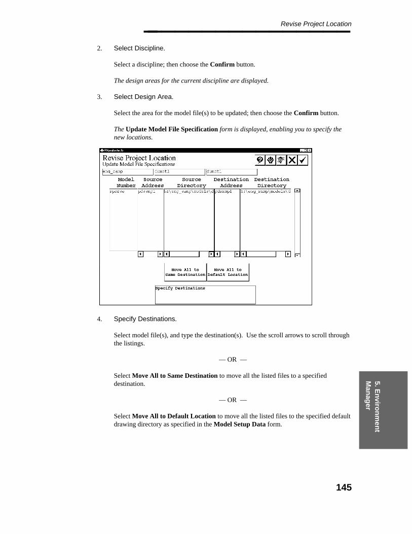
5. En
viron
men
t M
anag
er
Revise Project Location________________
2. Select Discipline.
Select a discipline; then choose the Confirm button.
The design areas for the current discipline are displayed.
3. Select Design Area.
Select the area for the model file(s) to be updated; then choose the Confirm button.
The Update Model File Specification form is displayed, enabling you to specify thenew locations.
4. Specify Destinations.
Select model file(s), and type the destination(s). Use the scroll arrows to scroll throughthe listings.
— OR —
Select Move All to Same Destination to move all the listed files to a specifieddestination.
— OR —
Select Move All to Default Location to move all the listed files to the specified defaultdrawing directory as specified in the Model Setup Data form.
145
Project Administrator — April 2002________________
5. Accept Destination(s).
Choose the Confirm button to accept the defined destination(s).
Move Drawings
The Move Drawings option moves selected drawing files to a specified location. It moves alldrawing-specific data (drawing_number.*) with the drawing. If applicable, the systemrecognizes any seed drawings defined on the basis of a specific drawing type.
Field Descriptions
Drawing Number — A 10-character name/number of the drawing. This field isdisplay only.
Source Address — The network address for the drawings to be moved. This field isdisplay only.
Source Directory — The source directory identification of the drawings to be moved.This field is display only.
Destination Address — The network address where the drawings will be moved. Thisfield can be modified.
Destination Directory — The directory identification where the drawings will bemoved. This field can be modified.
Move All to Same Destination toggle — Displays the fields to identify destinationaddress and directory for all drawings in the current type.
Move All to Default Location — Moves all drawings in the current type to a specifieddefault location.
Operating Sequence
1. Select the Move Drawings Option.
Select Move Drawings from the Revise Project Location form to move a drawing fileor set of files.
The Move Drawings form is displayed, enabling you to select the drawing type tomove.
146

5. En
viron
men
t M
anag
er
Revise Project Location________________
2. Select Drawing Type.
Select a drawing type, then choose the Confirm button.
The fields update to show all the drawings in that drawing type.
3. Specify Destinations.
Select drawing file(s), and type the destination(s). You can use the scroll arrows toscroll through the listings.
147
Project Administrator — April 2002________________
— OR —
Select Move All to Same Destination to move all the listed drawings to a specifieddestination.
— OR —
Select Move All to Default Location to move all the listed drawings to the specifieddefault drawing directory as specified in the Model Setup Data form.
4. Accept Destination(s).
Choose the Confirm button to accept the defined destination(s).
Update Drawings File Specifications
The Update Drawings File Specifications option is used to update the project controldatabase with the new locations of selected drawings. It should be used if the files alreadyexist in the destination directory. This option is identical to Move Drawings, except no filesare copied. The system reports an error if the drawing files do not exist at the specifieddestination.
Field Descriptions
Drawing Number — The name/number of the drawing. This field is display only.
Source Address — The network address for the drawings to be updated. This field isdisplay only.
Source Directory — The source directory identification of the drawings to be updated.This field is display only.
Destination Address — The network address where the drawing files have beenmoved or copied. This field can be modified.
Destination Directory — The directory identification where the drawing files havebeen moved or copied. This field can be modified.
Move All to Same Destination toggle — Displays the fields to identify a destinationaddress and directory for all drawings.
Move All to Default Location — Moves all drawing files to a previously specifieddefault location.
148

5. En
viron
men
t M
anag
er
Revise Project Location________________
Operating Sequence
1. Select the Update Drawing File Specifications Option.
Select Update Drawing File Specifications from the Revise Project Location form toupdate a drawing file or set of files.
The active drawing types for the project are displayed.
2. Select Drawing Type.
Select a drawing type; then choose the Confirm button.
The Update Drawing File Specification form is displayed, enabling you to specify thedestination.
3. Specify Destinations.
Select drawing file(s), and type the destination(s). Use the scroll arrows to scrollthrough the listings.
— OR —
Select Move All to Same Destination to move all the listed files to a specifieddestination.
— OR —
Select Move All to Default Location to move all the listed files to the specified defaultdrawing directory.
149

Project Administrator — April 2002________________
4. Accept Destination(s).
Choose the Confirm button to accept the defined destination(s).
150

5. En
viron
men
t M
anag
er
Revise Discipline Data________________
5.2.3 Revise Discipline Data
The Revise Discipline Data option is used to modify the name of an existing discipline. Thisoption should not be used to change the meaning of any disciplines.
Field Descriptions
Discipline Name — A unique name must be assigned to each new discipline.
PLANTGEN Discipline toggle — Only one discipline per project can be designated asa PLANTGEN discipline.
Operating Sequence
1. Select the Revise Discipline Data Option.
Select the Revise Discipline Data option from the Revise Options form.
A list of available disciplines is displayed.
2. Select Discipline.
Select the discipline to be modified, then choose the Confirm button.
The Discipline Name field and PLANTGEN Discipline toggle are displayed on theRevise Options form.
151

Project Administrator — April 2002________________
3. Specify Discipline Name.
Type the new name for the selected discipline.
4. Accept or Select Option or Discipline.
Choose the Confirm button to accept the specified discipline information.
The list of disciplines is updated to reflect the specified change.
152
5. En
viron
men
t M
anag
er
Revise Design Area Data________________
5.2.4 Revise Design Area Data
The Revise Design Area Data option is used to revise an existing design area name,description, or predefined volume definition. This option provides file locking for the designarea Interference Management models using data in the Project Control Data base.
Field Descriptions
Design Area Name — Specifies a Design Area Name for the revised Design Area.Type up to 10 characters for the new Design Area Name or press ENTER. Do not usespecial characters such as the at symbol(@), the pound sign (#), the percent symbol(%), the caret symbol (ˆ), the ampersand (&), the asterisk (*), the exclamation point (!),or the pipe symbol (|).
Description — Specifies a Design Area Description of the revised Design Area. Typeup to 40 characters for the description of the Design Area, or press <ENTER> to skipthis field.
Operating Sequence
1. Select Option.
Select the Revise Design Area Data option from the Revise Options form.
A list of available disciplines is displayed.
2. Select Discipline.
Select the discipline containing the design area to be modified, and choose the Confirmbutton.
The Revise Design Area form displays with a list of available design areas.
153
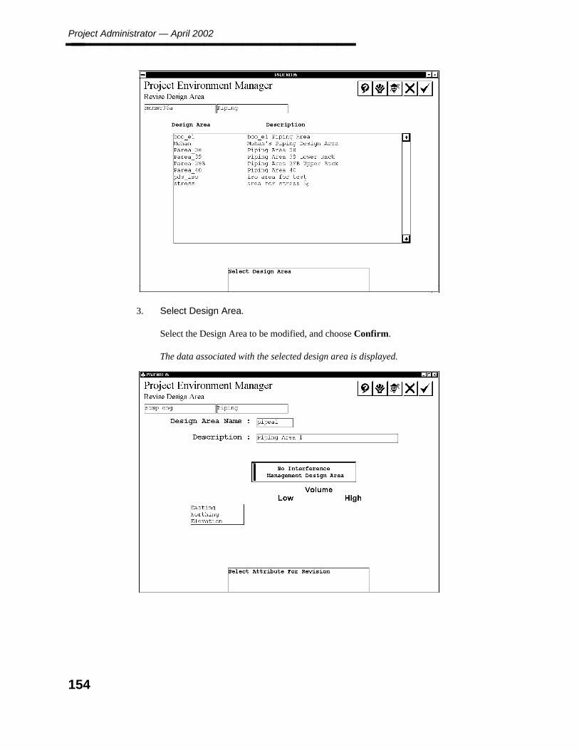
Project Administrator — April 2002________________
3. Select Design Area.
Select the Design Area to be modified, and choose Confirm.
The data associated with the selected design area is displayed.
154

5. En
viron
men
t M
anag
er
Revise Design Area Data________________
4. Select Attribute for Revision.
Type any modifications to the Design Area name or description.
The system verifies the specified name is also valid for use as a design file name.
5. Type the easting, northing, and elevation coordinates to define/change the volume ofthe design area. Use negative values to specify coordinates in the west or south.
6. Accept Modifications.
Choose the Confirm button to accept the modifications.
The selected Design Area Specification record is updated.
Choose the Cancel button if no changes were made.
155

Project Administrator — April 2002________________
5.2.5 Revise Model Data
The Revise Model Data option is used to change the name, description, application type ormodel status of an existing model file.
Operating Sequence
1. Select the Revise Model Data Option.
Select the Revise Model Data option from the Revise Options form.
A list of disciplines is displayed.
2. Select Discipline.
Select the discipline of the model file to be modified; then choose the Confirm button.
The design areas for the selected discipline are displayed.
3. Select Design Area.
Select the Design Area of the model file to be modified; then choose the Confirmbutton.
The model files for the selected design area are displayed.
4. Select Model.
Select the model to be revised; then choose Confirm.
The model number and description are displayed.
156
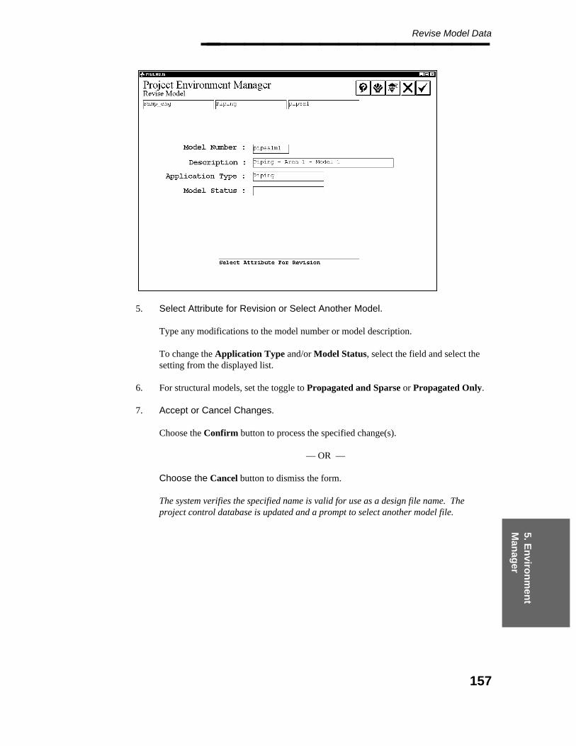
5. En
viron
men
t M
anag
er
Revise Model Data________________
5. Select Attribute for Revision or Select Another Model.
Type any modifications to the model number or model description.
To change the Application Type and/or Model Status, select the field and select thesetting from the displayed list.
6. For structural models, set the toggle to Propagated and Sparse or Propagated Only.
7. Accept or Cancel Changes.
Choose the Confirm button to process the specified change(s).
— OR —
Choose the Cancel button to dismiss the form.
The system verifies the specified name is valid for use as a design file name. Theproject control database is updated and a prompt to select another model file.
157

Project Administrator — April 2002________________
5.2.6 Revise Area Model Association
The Revise Area Model Association option is used to associate a model file with a specifieddesign area. This has the effect of moving the model file from one design area to another.
Operating Sequence
1. Select Revise Area Model Association.
Select the Revise Area Model Association option from the Revise Options form.
A list of disciplines is displayed.
2. Select Discipline.
Select the discipline for the model file to be modified; then choose the Confirm button.
The design areas for the selected discipline are displayed.
3. Select Design Area.
Select the existing design area for the model file to be modified; then choose theConfirm button.
The Revise Area Model Association form is displayed showing the available models.
158
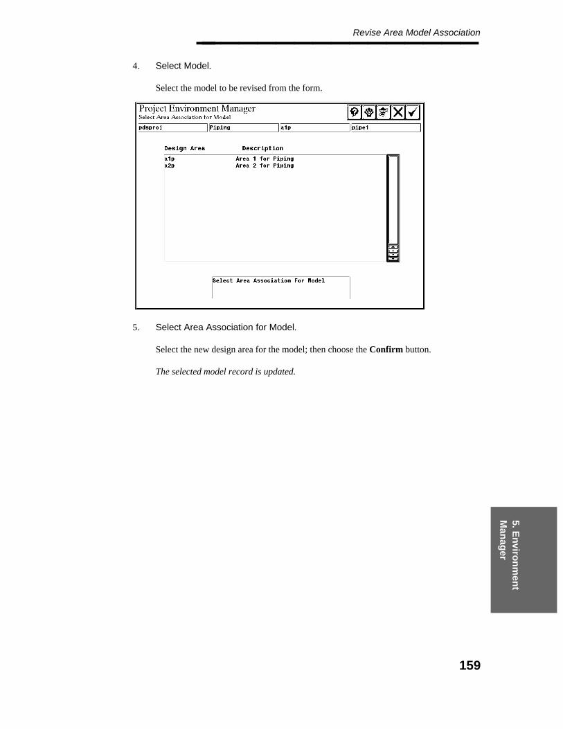
5. En
viron
men
t M
anag
er
Revise Area Model Association________________
4. Select Model.
Select the model to be revised from the form.
5. Select Area Association for Model.
Select the new design area for the model; then choose the Confirm button.
The selected model record is updated.
159
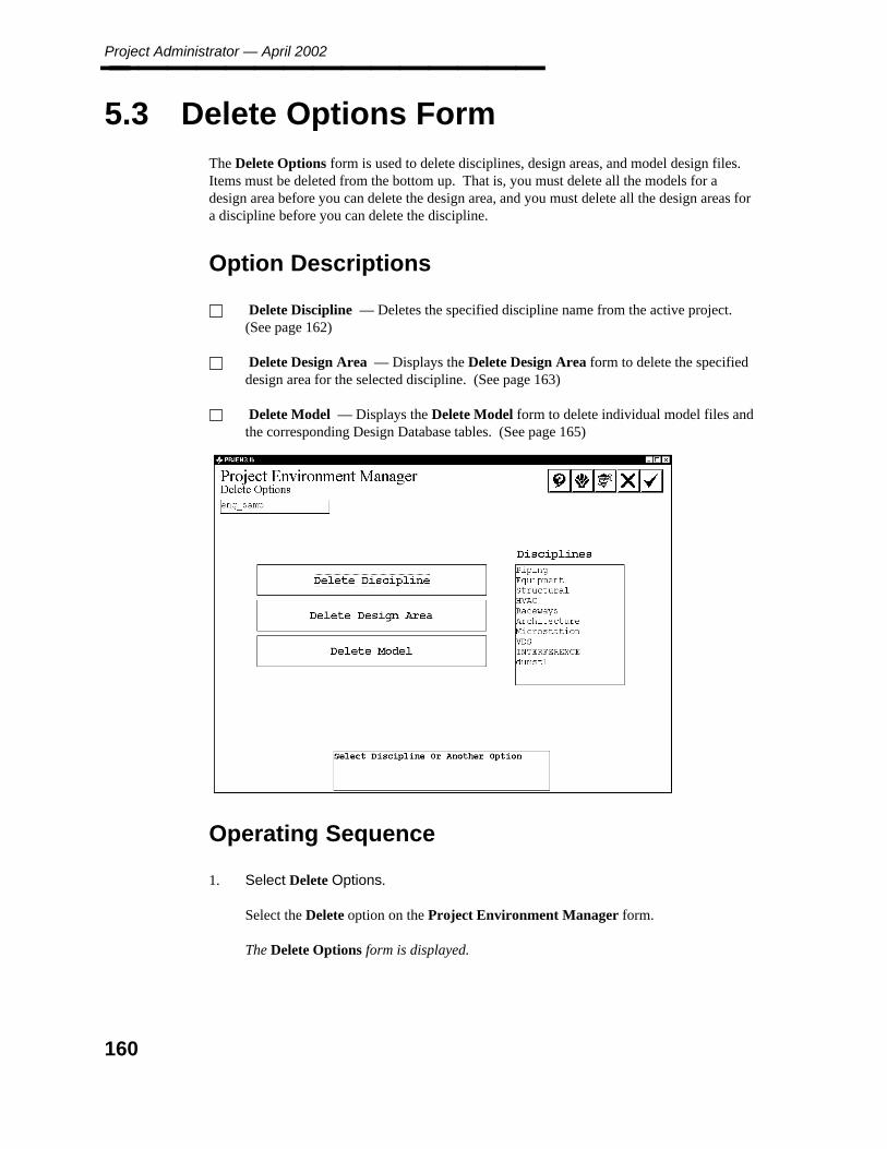
Project Administrator — April 2002________________
5.3 Delete Options Form
The Delete Options form is used to delete disciplines, design areas, and model design files.Items must be deleted from the bottom up. That is, you must delete all the models for adesign area before you can delete the design area, and you must delete all the design areas fora discipline before you can delete the discipline.
Option Descriptions
Delete Discipline — Deletes the specified discipline name from the active project.(See page 162)
Delete Design Area — Displays the Delete Design Area form to delete the specifieddesign area for the selected discipline. (See page 163)
Delete Model — Displays the Delete Model form to delete individual model files andthe corresponding Design Database tables. (See page 165)
Operating Sequence
1. Select Delete Options.
Select the Delete option on the Project Environment Manager form.
The Delete Options form is displayed.
160

5. En
viron
men
t M
anag
er
Delete Options Form________________
2. Select Option.
Select the Delete Discipline, Delete Design Area or Delete Model option.
The associated discipline, design area or model form is displayed.
161

Project Administrator — April 2002________________
5.3.1 Delete Discipline
The Delete Discipline option is used to delete a specified discipline from the active project.A discipline file cannot be deleted when it contains any design area or model files. You mustdelete the individual files before removing the discipline.
The system does not allow you to delete the six original PDS disciplines.
Operating Sequence
1. Select the Delete Discipline Option.
Select the Delete Discipline option from the Delete Options form.
A list of user-defined disciplines is displayed.
2. Select Discipline or Another Option.
Select the discipline to be deleted from the list of disciplines for the project.
3. Select Another Discipline or Option.
Choose the Confirm button to delete the specified discipline name.
The system checks the project control database. If the discipline does not contain anydesign, data, the system deletes the discipline from the database and removes the namefrom the list of disciplines.
162
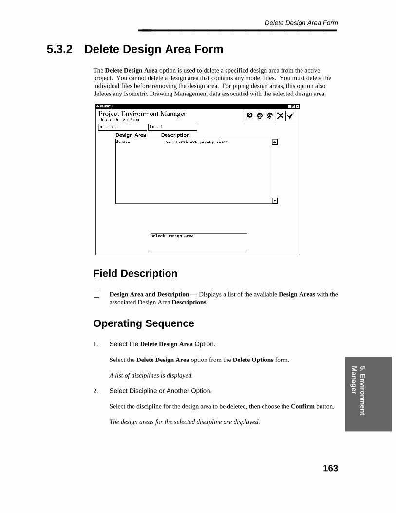
5. En
viron
men
t M
anag
er
Delete Design Area Form________________
5.3.2 Delete Design Area Form
The Delete Design Area option is used to delete a specified design area from the activeproject. You cannot delete a design area that contains any model files. You must delete theindividual files before removing the design area. For piping design areas, this option alsodeletes any Isometric Drawing Management data associated with the selected design area.
Field Description
Design Area and Description — Displays a list of the available Design Areas with theassociated Design Area Descriptions.
Operating Sequence
1. Select the Delete Design Area Option.
Select the Delete Design Area option from the Delete Options form.
A list of disciplines is displayed.
2. Select Discipline or Another Option.
Select the discipline for the design area to be deleted, then choose the Confirm button.
The design areas for the selected discipline are displayed.
163
Project Administrator — April 2002________________
3. Select Design Area.
Select the design area to be deleted.
4. Accept or Select Another Design Area.
Choose the Confirm button to delete the selected design area.
The design area is deleted from the project control database and the design area nameis deleted from the list of design areas. The area marker file (if present) is also deleted.
164
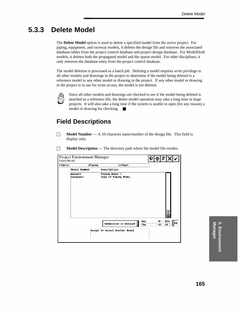
5. En
viron
men
t M
anag
er
Delete Model________________
5.3.3 Delete Model
The Delete Model option is used to delete a specified model from the active project. Forpiping, equipment, and raceway models, it deletes the design file and removes the associateddatabase tables from the project control database and project design database. For ModelDraftmodels, it deletes both the propagated model and the sparse model. For other disciplines, itonly removes the database entry from the project control database.
The model deletion is processed as a batch job. Deleting a model requires write privilege toall other models and drawings in the project to determine if the model being deleted is areference model to any other model or drawing in the project. If any other model or drawingin the project is in use for write access, the model is not deleted.
Since all other models and drawings are checked to see if the model being deleted isattached as a reference file, the delete model operation may take a long time in largeprojects. It will also take a long time if the system is unable to open (for any reason) amodel or drawing for checking.
Field Descriptions
Model Number — A 10-character name/number of the design file. This field isdisplay only.
Model Description — The directory path where the model file resides.
165

Project Administrator — April 2002________________
Operating Sequence
1. Select the Delete Model Option.
Select the Delete Model Option from the Delete Options form.
A list of disciplines is displayed.
2. Select Discipline or Another Option.
Select the discipline of the model to be deleted; then choose the Confirm button.
A list of design areas is displayed.
3. Select Design Area.
Select Delete Design Area Form, page 163 then choose the Confirm button.
All the models for the selected design area are displayed.
4. Select Model.
Select the model to be deleted.
5. Accept or Select Another Model.
Select Submit Immediately to begin deleting the model as soon as you exit the form.
— OR —
Select Submission is Delayed to specify a time to process the deletion.
6. Accept Deletion.
Choose the Confirm button to accept the deletion.
The deletion request is submitted to the batch queue PDdelete_model. At the specifiedtime, the request begins processing and the model file is deleted with its associateddatabase files.
166
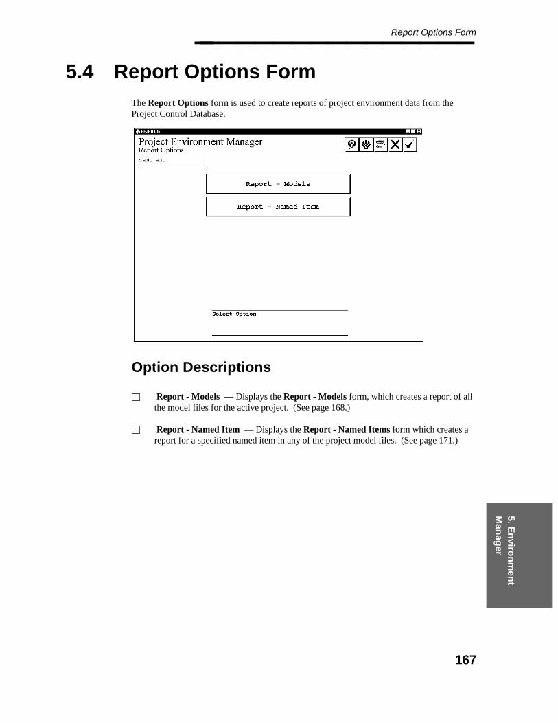
5. En
viron
men
t M
anag
er
Report Options Form________________
5.4 Report Options Form
The Report Options form is used to create reports of project environment data from theProject Control Database.
Option Descriptions
Report - Models — Displays the Report - Models form, which creates a report of allthe model files for the active project. (See page 168.)
Report - Named Item — Displays the Report - Named Items form which creates areport for a specified named item in any of the project model files. (See page 171.)
167
Project Administrator — April 2002________________
5.4.1 Report - Models
The Report - Models option creates a report of the model files in the Project DesignDatabase. This report lists all the models in the active project by discipline and design area.It lists the models alphanumerically by model number in ascending order.
The Project Control Manager can also be used to generate a customizedmodel management report. Refer to Project Control Manager Form, page331, for more information on this option. A sample report format for modelmanagement data is delivered in the file ˜/pdprojec/sample/model_mgt.fmt.
Field Descriptions
Print / Delete — Submits the generated report output file to the specified print queueand deletes the output file.
Print / Save — Submits the generated report output file to the specified print queue andsaves the output file.
Save — Saves the output file without printing.
Operating Sequence
1. Select the Report - Models Option.
Select the Report - Models option from the Report Options form.
A set of printing options are displayed in the middle of the form.
168
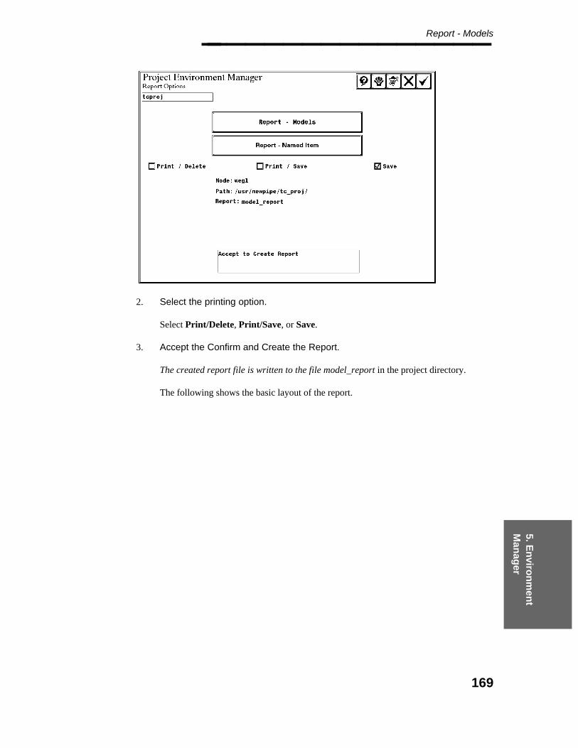
5. En
viron
men
t M
anag
er
Report - Models________________
2. Select the printing option.
Select Print/Delete, Print/Save, or Save.
3. Accept the Confirm and Create the Report.
The created report file is written to the file model_report in the project directory.
The following shows the basic layout of the report.
169
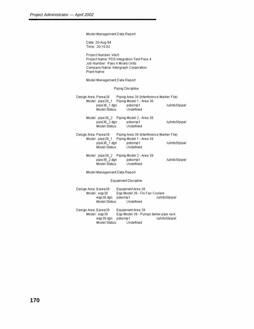
Project Administrator — April 2002________________
170

5. En
viron
men
t M
anag
er
Report - Named Items________________
5.4.2 Report - Named Items
The Report - Named Items option creates a report on a Named Item in the Project DesignDatabase. This report contains a list of model files which contain the Named Item, theirassociated area specifications, and their associated disciplines.
Option Descriptions
Named Items Options — A report may be generated based on the selected option:Piping Component Number Line Number Label Instrument Component NumberEquipment & Nozzle Number Line ID Pipe Equipment Number Pipe Support
Data entry field — Type selection data associated with the chosen Named Item Option.
Submit Immediately or Submission is Delayed Select Submit Immediately to begincopying the model as soon as you exit the form.
— OR —
Select Submission is Delayed to specify a time to process the copy.
171
Project Administrator — April 2002________________
Operating Sequence
1. Select the Report-Named Item form.
Select the Report-Named Item form from the Report Options form.
The Report-Named Item form is displayed.
2. Select Option.
Select the option for the type of Named Item to be reported.
One of the following prompts is displayed based on the option you select:
3. Specify Line Number Label.
Type the line number label to be reported. The Line Number Label is composed ofseveral attributes as defined in the Label Description Library.
4. Specify Line ID.
Type the line identification to be reported. The Line ID is composed of the Unit Code,Line Number, and the fluid code.
Specify Component NumberSpecify Instrument NumberSpecify Pipe NumberSpecify Pipe Support Number
Type the tag number of the item(s) to be reported.
5. Specify Equipment Number.
Type the equipment identification.
6. Specify Nozzle Number.
Type the equipment number/nozzle ID.
You can specify more than one value for the selected attribute.
7. Submit Immediately or Submission is Delayed Select Submit Immediately to beginthe report as soon as you exit the form.
— OR —
Select Submission is Delayed to specify a time to process the report.
172

5. En
viron
men
t M
anag
er
Report - Named Items________________
8. Accept Data.
After specifying all the values to be reported, choose the Confirm button to accept thedata defined for the search and to submit the job to the batch queue for processing.
The Project Design Database is searched for the named item(s), and a report of theassociated model specification is created.
173
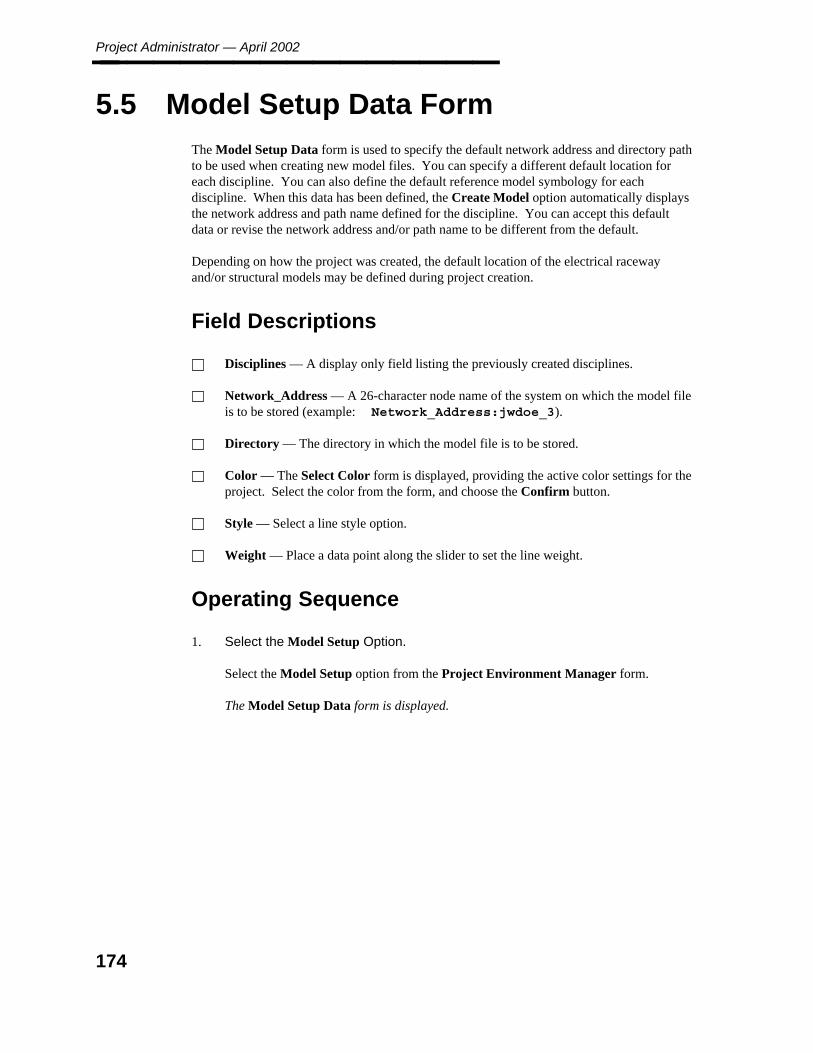
Project Administrator — April 2002________________
5.5 Model Setup Data Form
The Model Setup Data form is used to specify the default network address and directory pathto be used when creating new model files. You can specify a different default location foreach discipline. You can also define the default reference model symbology for eachdiscipline. When this data has been defined, the Create Model option automatically displaysthe network address and path name defined for the discipline. You can accept this defaultdata or revise the network address and/or path name to be different from the default.
Depending on how the project was created, the default location of the electrical racewayand/or structural models may be defined during project creation.
Field Descriptions
Disciplines — A display only field listing the previously created disciplines.
Network_Address — A 26-character node name of the system on which the model fileis to be stored (example: Network_Address:jwdoe_3).
Directory — The directory in which the model file is to be stored.
Color — The Select Color form is displayed, providing the active color settings for theproject. Select the color from the form, and choose the Confirm button.
Style — Select a line style option.
Weight — Place a data point along the slider to set the line weight.
Operating Sequence
1. Select the Model Setup Option.
Select the Model Setup option from the Project Environment Manager form.
The Model Setup Data form is displayed.
174
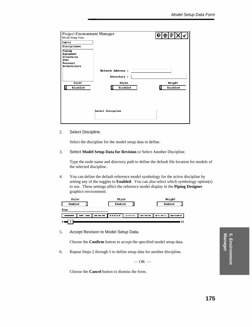
5. En
viron
men
t M
anag
er
Model Setup Data Form________________
2. Select Discipline.
Select the discipline for the model setup data to define.
3. Select Model Setup Data for Revision or Select Another Discipline.
Type the node name and directory path to define the default file location for models ofthe selected discipline.
4. You can define the default reference model symbology for the active discipline bysetting any of the toggles to Enabled. You can also select which symbology option(s)to use. These settings affect the reference model display in the Piping Designergraphics environment.
5. Accept Revision to Model Setup Data.
Choose the Confirm button to accept the specified model setup data.
6. Repeat Steps 2 through 5 to define setup data for another discipline.
— OR —
Choose the Cancel button to dismiss the form.
175

Project Administrator — April 2002________________
176
6. Pro
ject Data
Man
ager
Project Data Manager________________
6. Project Data Manager
The Project Data Manager is used to examine and/or revise the settings used when creatingnew models or to otherwise tailor the behavior of PDS to meet the needs of the project. Thisdata is used when creating a design area interference marker file, a model design volume, adrawing file, or an interference envelope file. The following conventions describe the formsin the Project Data Manager.
The operation of each form is described in a linear fashion for clarity. However, theoptions on the form can be selected in any order.
The Shell and Top options can be used to jump back along the command stack ratherthan exiting the forms one at a time. See PD_Shell Form Conventions, page 49 underPD Shell.
Project Data Manager Form
The Project Data Manager form is used to:
Revise the 3D Plant Design data and RDB seed data used to create model, drawing, andinterference marker files.
Revise the 3D Plant Design data and RDB data for existing Piping and Equipment modeldesign volumes.
Revise the 3D Plant Design data and RDB data for existing drawings.
Revise the RDB data for interference marker files.
Option Descriptions
Seed — Displays the Seed Options form, to review or revise the project data stored inthe seed files and the project marker file.
Model — Displays the Model Options form, to review or revise the project datastored in Piping model files.
Equipment — Displays the Equipment Options form, to review or revise the projectdata stored in Equipment model files.
Drawing — Displays the Drawing Options form, to review or revise the project datastored in drawing files.
Interference — Displays the Interference Options form, to review or revise theproject data for interference marker files.
177
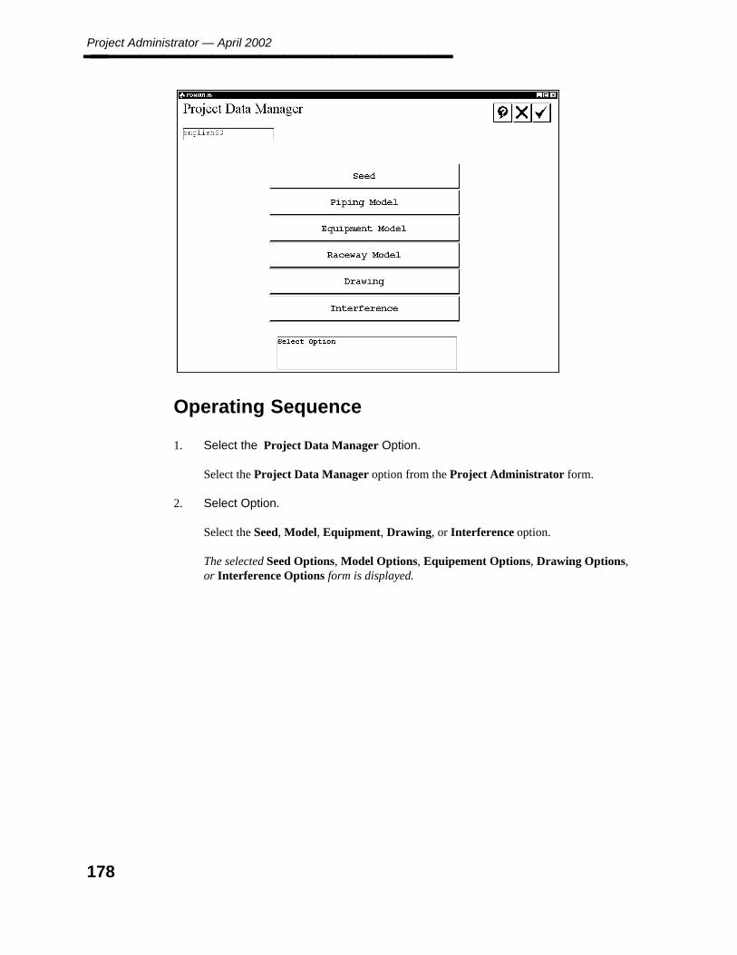
Project Administrator — April 2002________________
Operating Sequence
1. Select the Project Data Manager Option.
Select the Project Data Manager option from the Project Administrator form.
2. Select Option.
Select the Seed, Model, Equipment, Drawing, or Interference option.
The selected Seed Options, Model Options, Equipement Options, Drawing Options,or Interference Options form is displayed.
178

6. Pro
ject Data
Man
ager
Seed Options Form________________
6.1 Seed Options Form
The Seed options form is used to revise the seed files for creating new design volumes anddrawings, or revise the project marker file for creation of area interference marker files. Areport of all the seed file settings for the active project can also be created.
Option Descriptions
3D Model Data - Revise — Revises 3D PDS data in the seed files for the activeproject. (See page 181.)
Interference Check Data
— Revise — Used to specify settings used when analyzing interference envelopes.(See page 200.)
— Propagate — Applies settings from the project Interference Management model toall design area Interference Management models within the active project or to a listof selected Interference Management models. (See page 208.)
Equipment Data - Revise — Revises data in the equipment seed file for the activeproject. (See page 211.)
Piping Model Data
— Revise Seed Files - Revises data in the piping seed file for the active project. (Seepage 221.)
— Propagate Seed Files - Applies settings from the active piping model seed file toall piping models within the active project or to a list of selected piping models.(See page 269.)
Drawing Data
— Revise — Revises data in the drawing seed file for the active project. (See page272.)
— Propagate — Appliess settings from the specified drawing seed file to alldrawings within the active project, all drawings of a specified type, or a list ofselected drawings. (See page 299.)
Report of Seed File Data — Creates a report of all project seed file settings. (Seepage 303.)
179

Project Administrator — April 2002________________
Operating Sequence
1. Select Seed Option
Select the Seed option from the Project Data Manager form.
The Seed Options form is displayed.
2. Select Option
Select the 3D Plant Design Data - Revise, Interference Check Data - Revise orPropagate, Equipment Data - Revise, Piping Model Data - Revise or Propagate,Drawing Data - Revise or Propagate, or Report of Seedfile Data option.
The selected 3D Plant Design Data - Revise, Interference Check Data - Revise orPropagate, Equipment Data - Revise, Piping Model Data - Revise or Propagate,Drawing Data - Revise or Propagate, or Report of Seedfile Data form is displayed.
180
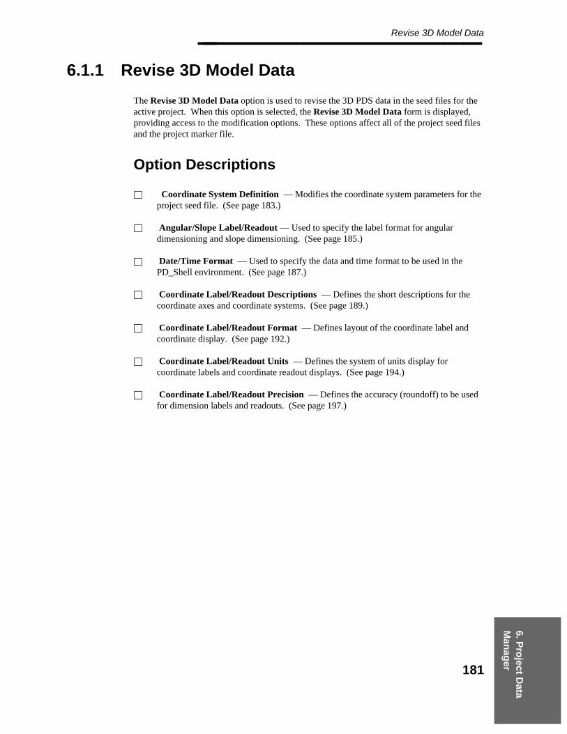
6. Pro
ject Data
Man
ager
Revise 3D Model Data________________
6.1.1 Revise 3D Model Data
The Revise 3D Model Data option is used to revise the 3D PDS data in the seed files for theactive project. When this option is selected, the Revise 3D Model Data form is displayed,providing access to the modification options. These options affect all of the project seed filesand the project marker file.
Option Descriptions
Coordinate System Definition — Modifies the coordinate system parameters for theproject seed file. (See page 183.)
Angular/Slope Label/Readout — Used to specify the label format for angulardimensioning and slope dimensioning. (See page 185.)
Date/Time Format — Used to specify the data and time format to be used in thePD_Shell environment. (See page 187.)
Coordinate Label/Readout Descriptions — Defines the short descriptions for thecoordinate axes and coordinate systems. (See page 189.)
Coordinate Label/Readout Format — Defines layout of the coordinate label andcoordinate display. (See page 192.)
Coordinate Label/Readout Units — Defines the system of units display forcoordinate labels and coordinate readout displays. (See page 194.)
Coordinate Label/Readout Precision — Defines the accuracy (roundoff) to be usedfor dimension labels and readouts. (See page 197.)
181
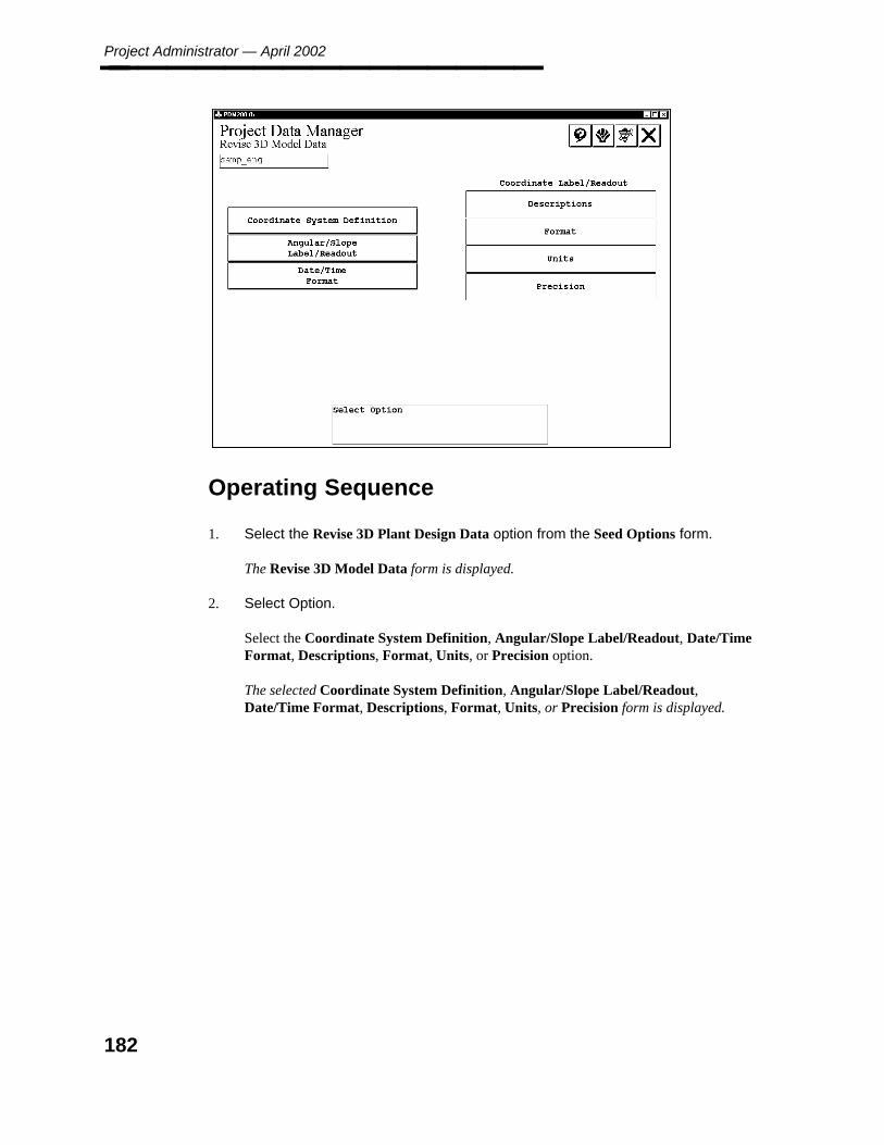
Project Administrator — April 2002________________
Operating Sequence
1. Select the Revise 3D Plant Design Data option from the Seed Options form.
The Revise 3D Model Data form is displayed.
2. Select Option.
Select the Coordinate System Definition, Angular/Slope Label/Readout, Date/TimeFormat, Descriptions, Format, Units, or Precision option.
The selected Coordinate System Definition, Angular/Slope Label/Readout,Date/Time Format, Descriptions, Format, Units, or Precision form is displayed.
182
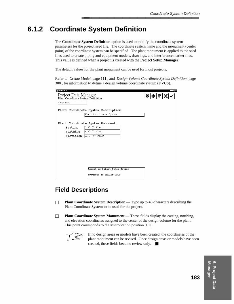
6. Pro
ject Data
Man
ager
Coordinate System Definition________________
6.1.2 Coordinate System Definition
The Coordinate System Definition option is used to modify the coordinate systemparameters for the project seed file. The coordinate system name and the monument (centerpoint) of the coordinate system can be specified. The plant monument is applied to the seedfiles used to create piping and equipment models, drawings, and interference marker files.This value is defined when a project is created with the Project Setup Manager.
The default values for the plant monument can be used for most projects.
Refer to Create Model, page 111 , and Design Volume Coordinate System Definition, page308 , for information to define a design volume coordinate system (DVCS).
Field Descriptions
Plant Coordinate System Description — Type up to 40-characters describing thePlant Coordinate System to be used for the project.
Plant Coordinate System Monument — These fields display the easting, northing,and elevation coordinates assigned to the center of the design volume for the plant.This point corresponds to the MicroStation position 0,0,0.
If no design areas or models have been created, the coordinates of theplant monument can be revised. Once design areas or models have beencreated, these fields become review only.
183

Project Administrator — April 2002________________
Example of Plant Coordinate SystemMonument
Coordinates in the Plant Coordinate System (PCS) are in relation to the plant monument. Forexample, if the plant monument was modified from its default setting of 0,0,0 to be E. 300’,N. 250’ and EL. 10’, then a point 200 feet east and 150 feet north away from the plantmonument would be at E. 500’, N. 400’ and EL. 10’ in the Plant Coordinate System. Formore information, see the 3D Coordinate Systems section in the PDS 3D Theory User’sGuide.
Operating Sequence
1. Select Option.
Select the Coordinate System Definition option from the Revise 3D Plant DesginData form.
The Plant Coordinate System Definition form is displayed.
2. Specify Plant Coordinate System Description.
Type the Plant Coordinate System Description for the project.
3. Specify Plant Coordinate System Monument.
Type the Easting, Northing, and Elevation for the project.
4. Accept Coordinate System Definition.
Choose the Confirm button to accept the displayed Coordinate System Definition.
The Revise 3D Model Data form is displayed.
184

6. Pro
ject Data
Man
ager
Angular/Slope Label/Readout________________
6.1.3 Angular/Slope Label/Readout
The Angular/Slope Label/Readout option is used to specify the label format for angulardimensioning and slope dimensioning. Decimal degrees or degrees and minutes can be used.The accuracy (roundoff) can also be specified for the angular/slope values.
Field Descriptions
Angular Label — Toggle the format for angular dimensioning text between DecimalDegrees and Degrees and Minutes.
Angular Readout — Toggle the format for angular readout values between DecimalDegrees and Degrees and Minutes.
Label/Readout Degrees Accuracy — The displayed options vary depending on theformat settings for Angular Label and Angular Readout. Select the precision to be usedfor angular dimensioning and slope dimensioning text.
Degree Short Description and Minute Short Description — These fields are onlydisplayed if the format is set to degrees and minutes. In each field, type a singlecharacter to specify the indicators for degrees and minutes.
Angular Input — Select this field to toggle the format to define angular input. Ahorizontal angle can be measures as either a clockwise offset (looking at a plan view)from North (North-0) or a couter-clockwise offset (looking at a plan view) from East(East=0).
Slope Readout Formation — Select the dimension format for slope readout values.
185
Project Administrator — April 2002________________
Operating Sequence
1. Select Option.
Select the Angular/Slope Label/Readout option from the Revise 3D Plant DesignData form.
2. Specify Angular Label.
Toggle the format for angular dimensioning text between Decimal Degrees andDegrees and Minutes.
3. Select Angular Readout.
Toggle the format for angular readout values between Decimal Degrees and Degreesand Minutes.
4. Select Label/Readout Degrees Accuracy.
Displayed options vary depending on the format settings for Angular Label andAngular Readout. Select the precision to be used for angular dimensioning and slopedimensioning text.
5. Specify Degree Short Description and Minute Short Description.
These fields are only displayed if the format is set to degrees andminutes.
In each field, type a single character to specify the indicators for degrees and minutes.
6. Select Angular Input.
Toggle the format used to define angular input. A horizontal angle can be measured aseither a clockwise offset (looking at a plan view) from North (North=0) or a counter-clockwise offset (looking at a plan view) from East (East=0).
7. Specify Slope Readout Formation.
Select the dimension format to be used for slope readout values.
8. Accept Angular/Slope Label/Readout Information.
Choose the Confirm button to accept the specified Angular/Slope Label/Readoutinformation.
The Revise 3D Model Data form is displayed.
186

6. Pro
ject Data
Man
ager
Date/Time Format________________
6.1.4 Date/Time Format
The Date/Time Format option is used to specify the display format for the data and time inthe PD_Shell environment. The defined setting is also respected by the Plot Manager and theAutomated Title Block option. When the Date/Time Format option is chosen, theDate/Time Format form is displayed.
For existing seed files, the default date/time format is used until another optionis selected. The specified format can be propagated to other drawings or aformat specified for an individual drawing within the project.
Option Descriptions
dow MMM DD hh:mm:ss YYYY — The 3-character day of the week, 3-charactermonth, 2-character day, 2-character hour, 2-character minute, 2-character second and4-character year, separated by spaces representation of the current date and time. Thisis the default option.
DD - MMM - YYYY hh:mm:ss — The 2-character day, 3-character month, 4-characteryear, 2-character hour, 2-character minute and 2-character second, separated by spaces,representation of the current date and time.
DD - MM - YY — The 2-character day, 2-character month and 2-character year,separated by hyphens, representation of the current date and time.
MM / DD / YY — The 2-character month, 2-character day and 2-character year,separated by slashes, representation of the current date and time.
DD / MM / YY — The 2-character day, 2-character month and 2-character year,separated by slashes, representation of the current date.
MMM DD , YYYY — The 3-character month abbreviation, 2-character day and 4-character year representation of the current date.
DD MMM YYYY — The 2-character day, 3-character month abbreviation and 4-character year representation of the current date.
MM / DD — The 2-character month and 2-character day representation of the currentdate.
DD / MM — The 2-character day and 2-character month representation of the currentdate.
Format Example
dow MMM DD hh:mm:ss YYYY Mon Feb 28 11:37:23 1994(default)
DD - MMM - YYYY hh:mm:ss 28-Feb-1994 11:37:23DD - MM - YY 28-02-94
187
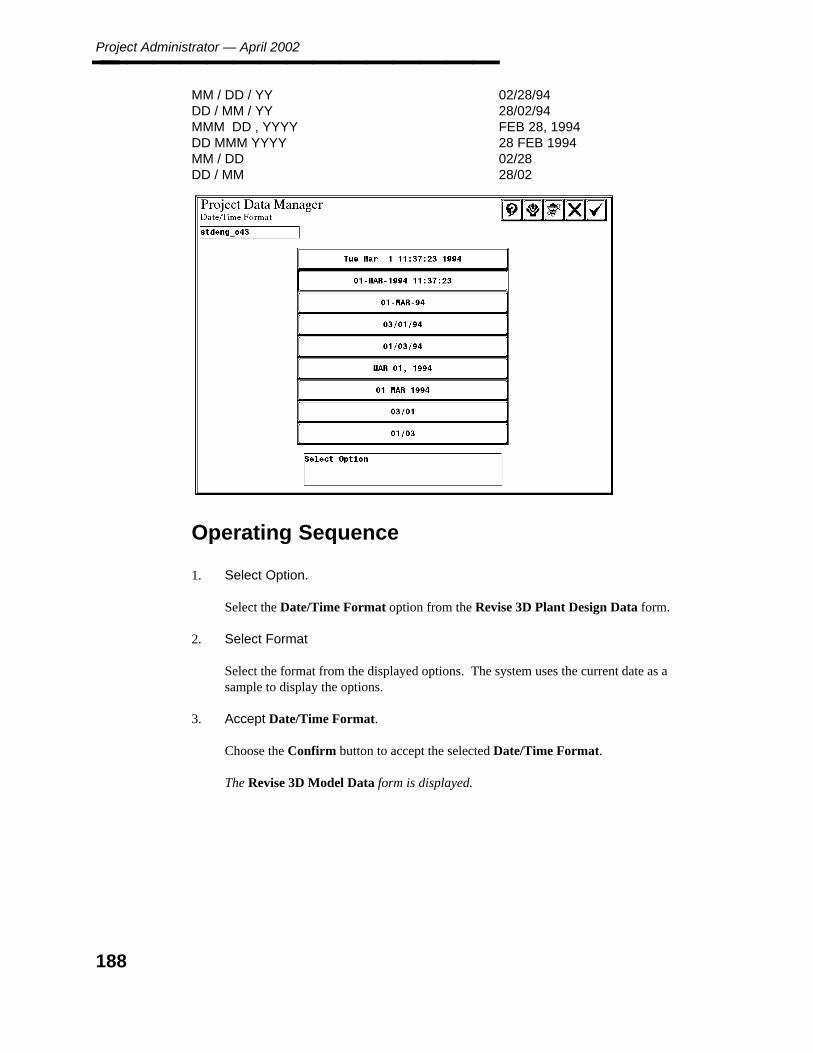
Project Administrator — April 2002________________ MM / DD / YY 02/28/94DD / MM / YY 28/02/94MMM DD , YYYY FEB 28, 1994DD MMM YYYY 28 FEB 1994MM / DD 02/28DD / MM 28/02
Operating Sequence
1. Select Option.
Select the Date/Time Format option from the Revise 3D Plant Design Data form.
2. Select Format
Select the format from the displayed options. The system uses the current date as asample to display the options.
3. Accept Date/Time Format.
Choose the Confirm button to accept the selected Date/Time Format.
The Revise 3D Model Data form is displayed.
188

6. Pro
ject Data
Man
ager
Coordinate Label/Readout Descriptions________________
6.1.5 Coordinate Label/Readout Descriptions
Coordinate labels are used to display coordinate values (locations) in the model or in adrawing. Coordinate readouts are used to display coordinate values in forms and reports.This option is used to define the short descriptions for the coordinate axes and coordinatesystems.
Field Descriptions
Coordinate Label Format and Coordinate Readout Format —These fields at the topof the form display a typical coordinate label and readout using the active option. Assettings are changed, these fields are updated to reflect the new format.
Coordinate System Design Volume Label — Type up to 12-alphanumeric charactersto change the selected Coordinate System Design Volume Label value.
Coordinate System Design Volume Readout — Type up to 6-alphanumericcharacters to change the selected Coordinate System Design Volume Readout value.
Coordinate System Plant Label — Type up to 12-alphanumeric characters to changethe selected Coordinate System Plant Label value.
Coordinate System Plant Readout — Type up to 6-alphanumeric characters to changethe selected Coordinate System Plant Readout value
Coordinate System World Label — Type up to 12-alphanumeric characters tochange the selected Coordinate System World Label value.
189
Project Administrator — April 2002________________ Coordinate System World Readout — Type up to 6-alphanumeric characters tochange the selected Coordinate System World Readout value.
Coordinate Axis East Label — Type up to 6-alphanumeric characters to change theselected Coordinate Axis East Label value.
Coordinate Axis East Readout — Type up to 2-alphanumeric characters to changethe selected Coordinate Axis East Readout value.
Coordinate Axis West Label — Type up to 6-alphanumeric characters to change theselected Coordinate Axis West Label value.
Coordinate Axis West Readout — Type up to 2-alphanumeric characters to changethe selected Coordinate Axis West Readout value.
Coordinate Axis North Label — Type up to 6-alphanumeric characters to change theselected Coordinate Axis North Label value.
Coordinate Axis North Readout — Type up to 2-alphanumeric characters to changethe selected Coordinate Axis North Readout value.
Coordinate Axis South Label — Type up to 6-alphanumeric characters to change theselected Coordinate Axis South Label value.
Coordinate Axis South Readout — Type up to 2-alphanumeric characters to changethe selected Coordinate Axis South Readout value.
Coordinate Axis Elevation Label — Type up to 6-alphanumeric characters to changethe selected Coordinate Axis Elevation Label value.
Coordinate Axis Elevation Readout — Type up to 2-alphanumeric characters tochange the selected Coordinate Axis Elevation Readout value.
Dimensioning —Toggle the setting between English and English/Metric.
Operating Sequence
1. Specify Coordinate System Label.
Type up to 12 alphanumeric characters to change the selected coordinate system.Specify Label value.
2. Specify Coordinate System Readout
Type up to 2 alphanumeric characters to change the selected coordinate systemReadout value.
190

6. Pro
ject Data
Man
ager
Coordinate Label/Readout Descriptions________________
3. Specify Coordinate Axis.
Type up to 6 alphanumeric characters to change the Label name of the selectedcoordinate axis. Type up to 2 alphanumeric characters to change the Readout code fora coordinate axis.
4. Select Dimensioning.
Toggle the setting between English and English/Metric.
5. Accept Coordinate Label/Readout Descriptions.
Choose the Confirm button to accept the specified Coordinate Label/ReadoutDescriptions information.
The Revise 3D Model Data form is displayed.
191
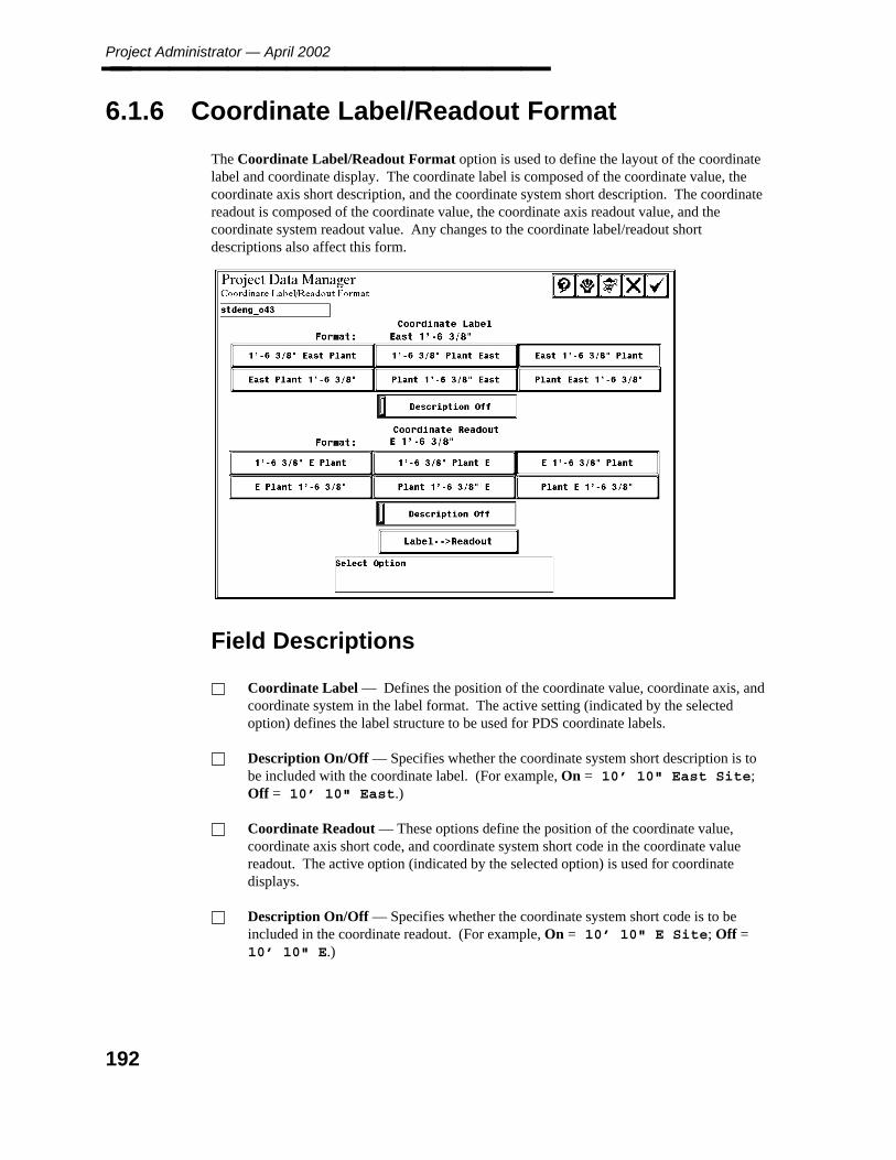
Project Administrator — April 2002________________
6.1.6 Coordinate Label/Readout Format
The Coordinate Label/Readout Format option is used to define the layout of the coordinatelabel and coordinate display. The coordinate label is composed of the coordinate value, thecoordinate axis short description, and the coordinate system short description. The coordinatereadout is composed of the coordinate value, the coordinate axis readout value, and thecoordinate system readout value. Any changes to the coordinate label/readout shortdescriptions also affect this form.
Field Descriptions
Coordinate Label — Defines the position of the coordinate value, coordinate axis, andcoordinate system in the label format. The active setting (indicated by the selectedoption) defines the label structure to be used for PDS coordinate labels.
Description On/Off — Specifies whether the coordinate system short description is tobe included with the coordinate label. (For example, On = 10’ 10" East Site;Off = 10’ 10" East.)
Coordinate Readout — These options define the position of the coordinate value,coordinate axis short code, and coordinate system short code in the coordinate valuereadout. The active option (indicated by the selected option) is used for coordinatedisplays.
Description On/Off — Specifies whether the coordinate system short code is to beincluded in the coordinate readout. (For example, On = 10’ 10" E Site; Off =10’ 10" E.)
192
6. Pro
ject Data
Man
ager
Coordinate Label/Readout Format________________ Label –>Readout — Sets the Coordinate Readout option to match the definedCoordinate Label option.
Operating Sequence
1. Select the Coordinate Label/Readout Format option from the Revise 3D PlantDesign Data form.
2. Select Coordinate Label.
Select one of the options to define the position of the coordinate value, coordinate axis,and coordinate system in the label format.
3. Select Description On/Off.
Select this field to specify whether the coordinate system short description is to beincluded with the coordinate label.
4. Select Coordinate Readout.
Select one of the options to define the position of the coordinate value, coordinate axisshort code, and coordinate system short code in the coordinate value readout.
5. Select Description On/Off.
Select this field to specify whether the coordinate system short code is to be included inthe coordinate readout.
6. Select Label –>Readout.
Choose this option to set the Coordinate Readout option to match the definedCoordinate Label option.
7. Accept Coordinate Label/Readout Units.
Choose the Confirm button to accept the specified Coordinate Label/Readout Unitsinformation.
The Revise 3D Model Data form is displayed.
193
Project Administrator — April 2002________________
6.1.7 Coordinate Label/Readout Units
The Coordinate Label/Readout Units option is used to define the system of units display forcoordinate labels and coordinate readout displays. When this option is selected, theCoordinate Label/Readout Units form is displayed. The fields on the form vary dependingon whether the project units are English or metric.
Field Descriptions
Coordinate Label Format — Displays the system of units for coordinate labels.
Coordinate Readout Format — Displays the system of units for coordinate readoutdisplays.
Label Units — Selects a Master Units Only or Master Units and Subunits format.
Readout Units — Selects a Master Units Only, Master Units and Subunits, orSubunits Only format.
Coordinate Label — Selects upper/lower case label to be displayed when placingmetric drawing labels.
This option is only available for metric projects.
Metric System of Units Label — Selects a Master Units Only, Master Units andSubunits, or Subunits Only format.
Master Units Short Description — Up to 2-characters indicator for each Label,Readout and Metric System of Units for master units.
Subunits Short Description — Up to 2-characters indicator for each Label, Readoutand Metric System of Units to define subunits.
Master Units and Subunits Separator — A single character for each Label, Readoutand Metric System of Units to define a separator between subunits and fractions.
Subunits and Fraction of Subunits Separator — A single character for each Label,Readout and Metric System of Units to define a separator between subunits andfractions.
194
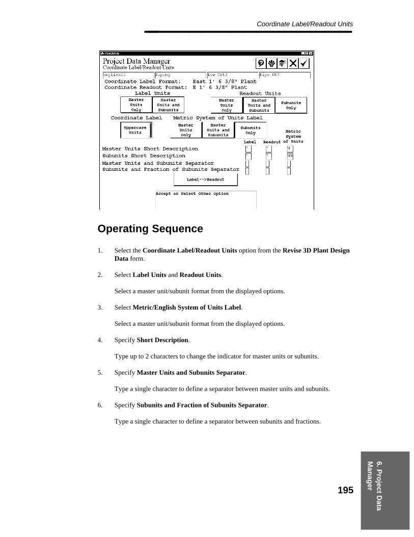
6. Pro
ject Data
Man
ager
Coordinate Label/Readout Units________________
Operating Sequence
1. Select the Coordinate Label/Readout Units option from the Revise 3D Plant DesignData form.
2. Select Label Units and Readout Units.
Select a master unit/subunit format from the displayed options.
3. Select Metric/English System of Units Label.
Select a master unit/subunit format from the displayed options.
4. Specify Short Description.
Type up to 2 characters to change the indicator for master units or subunits.
5. Specify Master Units and Subunits Separator.
Type a single character to define a separator between master units and subunits.
6. Specify Subunits and Fraction of Subunits Separator.
Type a single character to define a separator between subunits and fractions.
195

Project Administrator — April 2002________________
7. Select Label –> Readout.
Choose this option to set the Coordinate Readout options to match the definedCoordinate Label options.
8. Accept Coordinate Label/Readout Format.
Choose the Confirm button to accept the specified Coordinate Label/ReadoutFormat information.
The Revise 3D Model Data form is displayed.
196

6. Pro
ject Data
Man
ager
Coordinate Label/Readout Precision________________
6.1.8 Coordinate Label/Readout Precision
The Coordinate Label/Readout Precision option is used to define the accuracy (roundoff) tobe used for dimension labels and readouts. When selected, this option displays theCoordinate Label/Readout Precision form. Fields on this form vary depending on whetherthe project units are English or metric.
Field Descriptions
Label Precision — Specifies the roundoff factor to be used for linear dimension labels.The options vary depending on whether the toggle at the lower left of the form is set toLabel Fraction or Label Decimal.
Readout Precision — Specifies the roundoff factor to be used for linear dimensionreadouts. The options vary depending on whether the toggle at the lower right of theform is set to Readout Fraction or Readout Decimal.
Metric System of Units Label Precision — Specifies the precision to be used for thesecondary system of units. The options vary depending on the setting for secondaryunits.
Label Mode toggle — Specifies either Fraction or Decimal for the label.
Label Fraction/Alphnumeric Font — Toggles the label fraction format to LabelAlphanumeric Fraction to display fractions in alphanumeric format (1/2) or to LabelFraction Font to display fractions using the fraction font ( ⁄1
2).
The option is only displayed if the Label Mode or Readout Mode toggleis set to Label Fraction or Readout Fraction and the system of units isEnglish.
Readout Fraction/Decimal — Toggles the Readout format to Readout Decimal orReadout Fraction.
197

Project Administrator — April 2002________________
Operating Sequence
1. Select the Coordinate Label/Readout Precision option fro the Revise 3D PlantDesign Data form.
2. Specify Label Precision.
Select the roundoff factor to be used for linear dimension labels.
3. Select Readout Precision.
Select the roundoff factor to be used for linear dimension readouts.
4. Select Metric System of Units Label Precision.
Select the precision to be used for the secondary system of units.
5. Select Label and Readout Toggles.
Toggle the Label mode and Readout mode to either Fraction or Decimal.
6. Select Label Fraction.
Toggle the label fraction format to Label Alphanumeric Fraction or Label FractionFont.
198

6. Pro
ject Data
Man
ager
Coordinate Label/Readout Precision________________
7. Accept Coordinate Label/Readout Precision.
Choose the Confirm button to accept the specified Coordinate Label/ReadoutPrecision information.
The Revise 3D Model Data form is displayed.
199
Project Administrator — April 2002________________
6.1.9 Revise Interference Check Data
The Revise Interference Check Data option is used to specify emulation data for use inanalyzing interference envelopes. In interference detection, the system uses a set of cylindersto emulate the volume of a model graphic. These settings determine the number and size ofthe cylinders to be used. (These settings can be overridden during the operation of theInterference Checker.) Refer to the PDS Interference Checker/Manager Reference Guide formore information on the interference checking process. When the Revise InterferenceCheck Data option is selected, the Interference Check Data form is displayed.
Field Descriptions
Torus — Identifies the number of cylinders (per 90 degrees) to be used whenrepresenting a torus (elbow).
Truncated Cone — Identifies the cylinder length to be used to represent a cone(reducer or valve body).
Semi-ellipsoid — Identifies the cylinder length to be used to represent a semi-ellipsoid(cap or head).
Weld Construction Tolerance Disabled/Weld Construction Tolerance Enabled —By default, weld tolerances are disabled, but may be activated with this toggle. Onceweld construction tolerances are enabled, they appear in the graphic display of the clashenvelopes.
Slicing Tolerance — Displays the thickness of the slice that the software uses tosubdivide the shapes in a model to do the internal computations. This should not beconfused with Construction Tolerances (sometimes referred to as constructionclearances), which are used to maintain distances between items in the model.
Because the Slicing Tolerance is related to the size of model items, use cautionif you edit this value to a larger number as some small items may be missed.
Construction Tolerance Disabled/Enabled — By default, construction tolerances aredisabled for an existing interference marker model. If inter-discipline constructiontolerances are enabled, the system displays the Define Construction Tolerancesbutton.
Define Construction Tolerances — Displays the Construction Tolerance form.This option is only active when Construction Tolerance is enabled.
Interference Marker Symbology - Levels Unapproved and Approved — TheLevels, Unapproved, Approved fields set the design file level for unapproved andapproved interference clash markers.
200

6. Pro
ject Data
Man
ager
Revise Interference Check Data________________ Interference Marker Symbology - Weight — Select the line weight used to displayinterference markers.
Interference Marker Symbology - Color — Select the color used to displayinterference markers.
Intersection Threshold — Defines the amount of overlap allowed before theintersection of two components is considered a clash. Valid Intersection Thresholdvalues are within the range of 20 to 1000 Units of Resolution (UORs). The defaultvalue is 20 UORs.
Select Action Discipline — Assigns responsibility for resolving inter-disciplineinterference clashes.
Clash Plot Graphics - Default/Detail — Set the toggle to Default or Detail to specifythe detail for clash plot graphics used by the Interference Checker plot.
Operating Sequence
1. Select Revise Interference Check Data.
Select the Revise Interference Check Data option from the Seed Options form.
The Interference Check Data form is displayed
2. Specify Torus.
Type the number of cylinders to represent a torus.
201
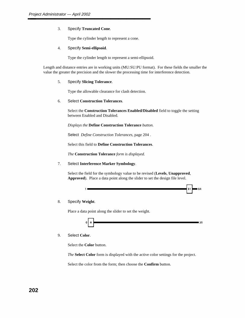
Project Administrator — April 2002________________
3. Specify Truncated Cone.
Type the cylinder length to represent a cone.
4. Specify Semi-ellipsoid.
Type the cylinder length to represent a semi-ellipsoid.
Length and distance entries are in working units (MU:SU:PU format). For these fields the smaller thevalue the greater the precision and the slower the processing time for interference detection.
5. Specify Slicing Tolerance.
Type the allowable clearance for clash detection.
6. Select Construction Tolerances.
Select the Construction Tolerances Enabled/Disabled field to toggle the settingbetween Enabled and Disabled.
Displays the Define Construction Tolerance button.
Select Define Construction Tolerances, page 204 .
Select this field to Define Construction Tolerances.
The Construction Tolerance form is displayed.
7. Select Interference Marker Symbology.
Select the field for the symbology value to be revised (Levels, Unapproved,Approved). Place a data point along the slider to set the design file level.
8. Specify Weight.
Place a data point along the slider to set the weight.
9. Select Color.
Select the Color button.
The Select Color form is displayed with the active color settings for the project.
Select the color from the form; then choose the Confirm button.
202

6. Pro
ject Data
Man
ager
Revise Interference Check Data________________ The Interference Check Data form is displayed.
10. Select Intersection Threshold.
Type the UORs or Subunits in the appropriate text box. Valid values are within therange of 20 to 1000 UORs (1/64" to 1/2" or 0.25 mm to 12.5 mm). A warning isdisplayed.
If the Intersection Threshold value is valid, the warning states that "Actual Clashes maynot be reported based on the intersection value of XXXX UORs." If the IntersectionThreshold Value entered is above 1000 UORs, the system changes the value to 1000UORs and displays the previous warning. If the Intersection Threshold Value entered isless than 20, the system changes the value to 20 UORs.
11. Select Action Discipline .
Select the Select Action Discipline button.
The Select Action Discipline form is displayed.
Select a Discipline to assign as Action Discipline.
The Responsible and Not Responsible fields fill in with current disciplineassignments. Select a discipline to change the status between Responsible and NotResponsible.
The selected discipline moves from one column to the other.
12. Accept Action Discipline.
Choose the Confirm button to accept the specified Action Discipline information.
The Interference Check Data form is displayed.
13. Select Clash Plot Graphics.
Set the toggle to Default to specify that the Interference Checker plot the default clashplot graphics. Set the toggle to Detail to specify that the Interference Checker plotmore detailed clash plot graphics.
14. Accept Interference Check Data.
Choose the Confirm button to accept the specified Interference Check Data.
The Seed Options form is displayed.
203

Project Administrator — April 2002________________
6.1.10 Define Construction Tolerances
The Define Construction Tolerances option is used to define the construction tolerancevalues between disciplines. The Interference Checker modifies each interference envelope byincreasing its dimensions by one-half of the applicable construction tolerance for the twodisciplines being compared. When the Define Construction Tolerances option is selected,the Construction Tolerance form is displayed.
Field Descriptions
Horizontal Beam Angular Tolerance — An angle in degrees to define the allowedangular tolerance from horizontal for discriminating between beams and other linearstructural members.
The system recognizes a beam as a linearstructural member that iswithin the specified tolerance. This parameter allows the InterferenceChecker to resolve the problem of piping legitimately resting onstructural beams. If the centerline of the piping is parallel to thehorizontal plane and the bottom of the piping is coincident with the topof the structural member, the construction tolerance is ignored and aninterference clash is not reported (unless the insulation of the pipeclashes with the beam).
Disciplines — The list of disciplines includes any user-specified, non-PDS disciplines,but is limited to a total of ten disciplines.
Construction Tolerances for HVAC — The construction tolerance in model subunitsfor each paired combination of disciplines, such as piping versus piping or pipingversus structural. Type the construction tolerance in model subunits for each pairedcombination of disciplines, such as piping versus piping or piping versus structural.The list of disciplines includes any user-specified, non-PDS disciplines, but is limited toa total of ten disciplines.
204
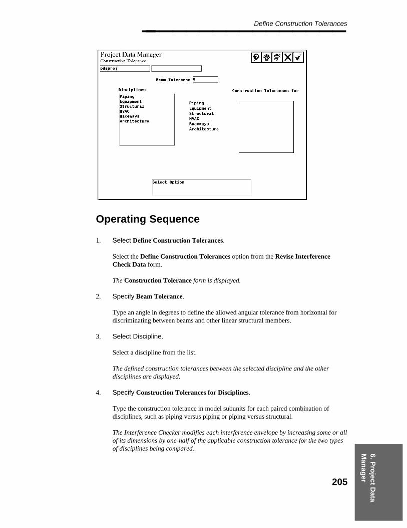
6. Pro
ject Data
Man
ager
Define Construction Tolerances________________
Operating Sequence
1. Select Define Construction Tolerances.
Select the Define Construction Tolerances option from the Revise InterferenceCheck Data form.
The Construction Tolerance form is displayed.
2. Specify Beam Tolerance.
Type an angle in degrees to define the allowed angular tolerance from horizontal fordiscriminating between beams and other linear structural members.
3. Select Discipline.
Select a discipline from the list.
The defined construction tolerances between the selected discipline and the otherdisciplines are displayed.
4. Specify Construction Tolerances for Disciplines.
Type the construction tolerance in model subunits for each paired combination ofdisciplines, such as piping versus piping or piping versus structural.
The Interference Checker modifies each interference envelope by increasing some or allof its dimensions by one-half of the applicable construction tolerance for the two typesof disciplines being compared.
205

Project Administrator — April 2002________________
6.1.11 Select Action Discipline
The Select Action Discipline option is used to to specify the assignment of responsibility toresolve inter-discipline interference clashes on the basis of a matrix of disciplines. Forexample, you can specify that piping versus structural clashes are to be assigned to the pipinggroup, whereas equipment versus structural clashes are to be assigned to the structural group.All intra-discipline clashes are assigned to that discipline automatically for resolution.
The plots of interference clashes that can be plotted with the Interference Checker or fromthe Interference Manager graphics environment include the assignment of responsibility forresolution of the clash on the plot. Each interference clash that is plotted is assignedautomatically to one of the disciplines that has been specified in the Project Control Database.
The following default matrix is provided:
The responsibility for interference clashes between piping and any other discipline isassigned to piping.
The responsibility for interference clashes between equipment and any other discipline(other than piping) is assigned to equipment.
The responsibility for interference clashes between electrical raceway and any otherdiscipline (other than piping and equipment) is assigned to electrical raceway.
The responsibility for interference clashes between HVAC and any discipline (otherthan the previously mentioned disciplines) is assigned to HVAC.
The responsibility for interference clashes between architectural and any otherdiscipline (other than the previously mentioned disciplines) is assigned to architectural.
When the Select Action Discipline option is selected, the following form is displayed:
206
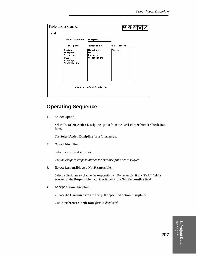
6. Pro
ject Data
Man
ager
Select Action Discipline________________
Operating Sequence
1. Select Option.
Select the Select Action Discipline option from the Revise Interference Check Dataform.
The Select Action Discipline form is displayed.
2. Select Discipline.
Select one of the disciplines.
The the assigned responsibilities for that discipline are displayed.
3. Select Responsible and Not Responsible.
Select a discipline to change the responsibility. For example, if the HVAC field isselected in the Responsible field, it switches to the Not Responsible field.
4. Accept Action Discipline.
Choose the Confirm button to accept the specified Action Discipline.
The Interference Check Data form is displayed.
207

Project Administrator — April 2002________________
6.1.12 Propagate Interference Check Data
The Propagate Interference Check Data option applies settings from the projectInterference Management model to all the design area Interference Management modelswithin the active project or a list of selected Interference Management models. The followingseed data is propagated:
The construction tolerance toggle setting and the construction tolerance matrix. Formore information, see Revise Interference Check Data, page 200 , and DefineConstruction Tolerances, page 204 .
Assignment of responsibility matrix. For more information, see Revise InterferenceCheck Data, page 200 .
Envelope emulation data. For more information, see Revise Interference Check Data,page 200 .
Clash Plot Graphics Option. For more information, see Revise Interference CheckData, page 200 .
Intersection Threshold Data. For more information, see Revise Interference CheckData, page 200 .
Operating Sequence
1. Select Option.
Select the Propagate Interference Check Data option from the Revise Seed Fileform.
The Propagate Data to Marker Files is displayed, providing access to the propagationoptions.
208
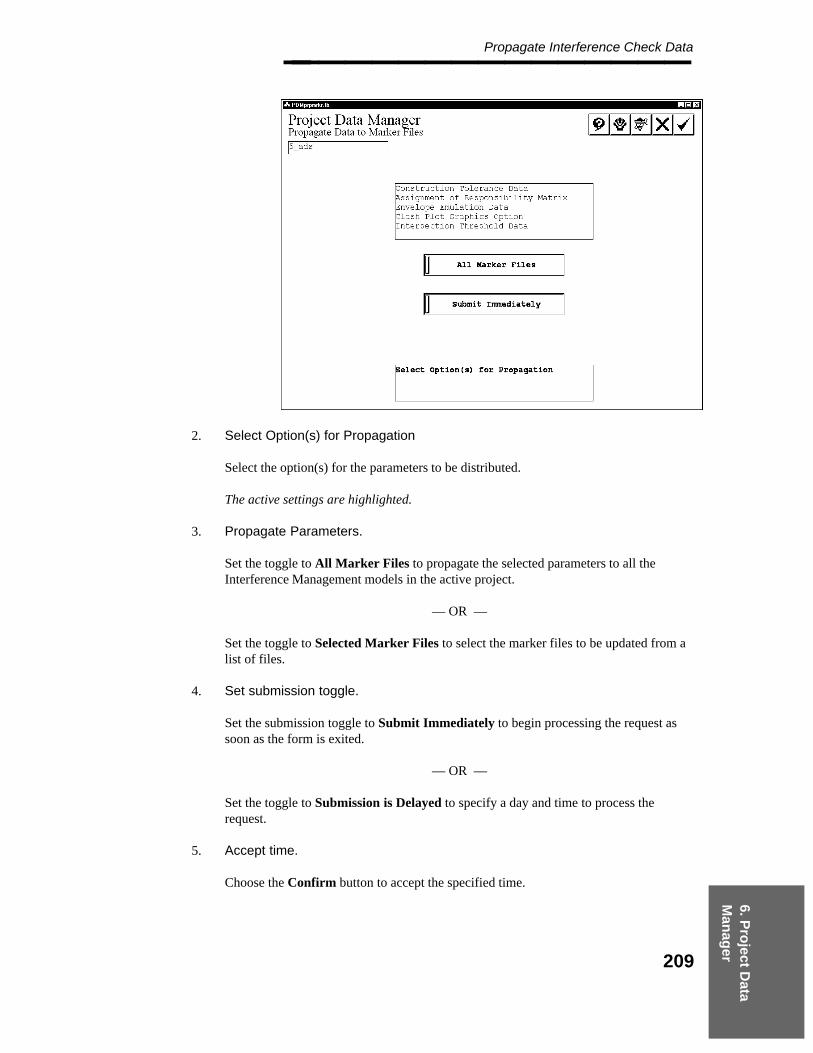
6. Pro
ject Data
Man
ager
Propagate Interference Check Data________________
2. Select Option(s) for Propagation
Select the option(s) for the parameters to be distributed.
The active settings are highlighted.
3. Propagate Parameters.
Set the toggle to All Marker Files to propagate the selected parameters to all theInterference Management models in the active project.
— OR —
Set the toggle to Selected Marker Files to select the marker files to be updated from alist of files.
4. Set submission toggle.
Set the submission toggle to Submit Immediately to begin processing the request assoon as the form is exited.
— OR —
Set the toggle to Submission is Delayed to specify a day and time to process therequest.
5. Accept time.
Choose the Confirm button to accept the specified time.
209

Project Administrator — April 2002________________ If All Marker Files is active, go to Step 8.
If Selected Marker Files was selected, a list of disciplines is displayed.
6. Select design area marker file.
Select the discipline for the design area marker file(s) to be updated; then choose theConfirm button.
The Select Design Area form is displayed.
7. Select Design Area
Select the design area(s) for the Interference Management models to be updated.
8. Accept to Submit for Processing or Select Discipline for additional Markers
Repeat steps 6 and 7 to select additional Interference Management models.
9. Accept Propagate Interference Check Data information.
Choose the Confirm button to process the request.
The request is submitted to the batch queue named PDproject_data.
210
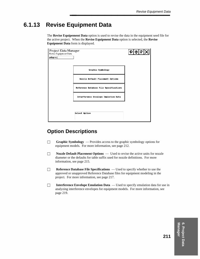
6. Pro
ject Data
Man
ager
Revise Equipment Data________________
6.1.13 Revise Equipment Data
The Revise Equipement Data option is used to revise the data in the equipment seed file forthe active project. When the Revise Equipment Data option is selected, the ReviseEquipment Data form is displayed.
Option Descriptions
Graphic Symbology — Provides access to the graphic symbology options forequipment models. For more information, see page 212.
Nozzle Default Placement Options — Used to revise the active units for nozzlediameter or the defaults for table suffix used for nozzle definitions. For moreinformation, see page 215.
Reference Database File Specifications — Used to specify whether to use theapproved or unapproved Reference Database files for equipment modeling in theproject. For more information, see page 217.
Interference Envelope Emulation Data — Used to specify emulation data for use inanalyzing interference envelopes for equipment models. For more information, seepage 219.
211
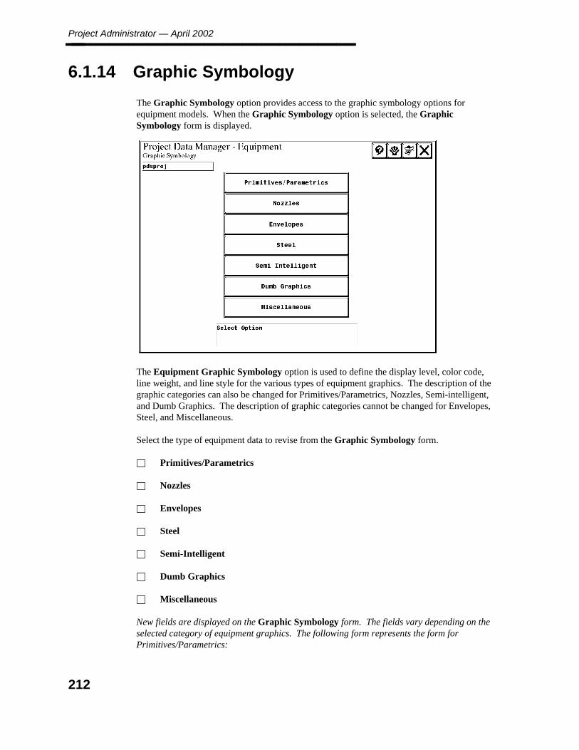
Project Administrator — April 2002________________
6.1.14 Graphic Symbology
The Graphic Symbology option provides access to the graphic symbology options forequipment models. When the Graphic Symbology option is selected, the GraphicSymbology form is displayed.
The Equipment Graphic Symbology option is used to define the display level, color code,line weight, and line style for the various types of equipment graphics. The description of thegraphic categories can also be changed for Primitives/Parametrics, Nozzles, Semi-intelligent,and Dumb Graphics. The description of graphic categories cannot be changed for Envelopes,Steel, and Miscellaneous.
Select the type of equipment data to revise from the Graphic Symbology form.
Primitives/Parametrics
Nozzles
Envelopes
Steel
Semi-Intelligent
Dumb Graphics
Miscellaneous
New fields are displayed on the Graphic Symbology form. The fields vary depending on theselected category of equipment graphics. The following form represents the form forPrimitives/Parametrics:
212

6. Pro
ject Data
Man
ager
Graphic Symbology________________
Operating Sequence
1. Select symbology value.
Select the field for the symbology value to be revised.
Use the scroll bar to page through the available categories.
2. Specify Category.
For Primitives/Parametrics, Nozzles, Semi-intelligent, and Dumb Graphics type to 40characters to change the category description. For Envelopes, Steel, and Miscellaneousthis field is display only.This value is displayed when any related operations are performed in the PDS 3Dproducts.
3. Select Level.
Place a data point along the slider to set the MicroStation display level.
4. Select Color.
The Select Color form is displayed with the active color settings for the project. Selectthe color from the form, and choose the Confirm button.
213

Project Administrator — April 2002________________
5. Select Weight
Place a data point along the slider to set the weight.
6. Select Symbology.
Select the desired symbology option.
7. Accept Graphic Symbology.
Choose the Confirm button to accept the specified Graphic Symbology.
The Project Data Manager - Equipment form is displayed.
214

6. Pro
ject Data
Man
ager
Nozzle Default Placement Options________________
6.1.15 Nozzle Default Placement Options
This option is used to revise the active units for nozzle diameter or the defaults for table suffixused for nozzle definitions. When this option is selected, the Nozzle Default PlacementOptions form is displayed.
Field Descriptions
System of Units — Defines the active system of units for nominal diameter for nozzles.Select this field to toggle the setting to English or Metric.
Small is <= — Specifies the Nominal Piping Diameter ranges that classify nozzles assmall.
Large is <= — Specifies the Nominal Piping Diameter ranges that classify nozzles aslarge.
Table Name — Identifies the name of the Nominal Piping Diameter table used toverify valid nominal diameter values for nozzles.
Define Table Suffix By End Type - Bolted, Female or Male — Identifies the tablesuffix value from CL576 (5 = US Practices).
215
Project Administrator — April 2002________________
Operating Sequence
1. Select Option.
Select the Nozzle Default Placement Options form the Revise Equipment Data form.
The Nozzle Default Placement Options form is displayed.
2. Select Nominal Piping Diameter and System of Units.
Define the active system of units for nominal diameter for nozzles.Select this field to toggle the setting to English or Metric.
3. Select Small is <= xIN and Large is >= xxIN.
Specify the NPD ranges that classify nozzles as small, medium, or large. To change adiameter value, select the appropriate field and type the new value.
4. Specify Nominal Piping Diameter Table Name.
Identifies the name of the NPD table used to verify valid nominal diameter values fornozzles.
5. Select Default Table Suffix by End Type.
Select the table suffix field to be modified and type a new value from CL576 (5 = USPractices).
6. Accept Nozzle Default Placement Options.
Choose the Confirm button to accept the Nozzle Default Placement Options.
The Revise Equipment Data form is displayed.
216

6. Pro
ject Data
Man
ager
Reference Database File Specifications - Specify Approved or Unapproved________________
6.1.16 Reference Database File Specifications -Specify Approved or Unapproved
The Reference Database File Specifications option is used to specify whether to use theapproved or unapproved Reference Database files for equipment modeling in the project.When this option is selected, the Reference Database File Specifications form is displayed.
Field Descriptions
Database File — Identifies the Piping Reference Database for the project.
Approval Status — Specifies the RDB to be approved or unapproved for the selecteditem.
Network Address — Displays the Network Address for the selected item.
Directory — Displays the Directory location for the selected item.
Specification — Displays the Specification name for the selected item.
217
Project Administrator — April 2002________________
Operating Sequence
1. Select Option.
Select the Reference Database File Specifications option from the Revise EquipmentData form.
The Reference Database File Specifications form is displayed.
2. Select Database file.
Use the Scroll Area to select the field to review one of the library or table names. Thename and location of the file for the selected field is identified.
— Graphic Commodity Library — ˜\pdeqp\dat\zi_eqpms.lib
— Tutorial Definition Library — ˜\pdeqp\dat\zi_tutlib.lib
— Equipment Physical Data Library
— Piping Physical Data Library — \rdusrdb\us-pcdim.1
— Piping Design Standard Note Library — \rdusrdb\stp_note.1
— Piping Specification Table Library — ˜\rdusrdb\pjs_tbl.1
— Cell Library — ˜\pdeqp\dat\equip.cel
— Forms Directory Location — ˜\pdeqp
3. Specify Approval Status.
Specify to use the approved RDB or unapproved RDB for the selected item.
4. Accept Reference Database File Specifications.
Choose the Confirm button to accept the Reference Database File Specifications.
The Revise Equipment Data form is displayed.
218
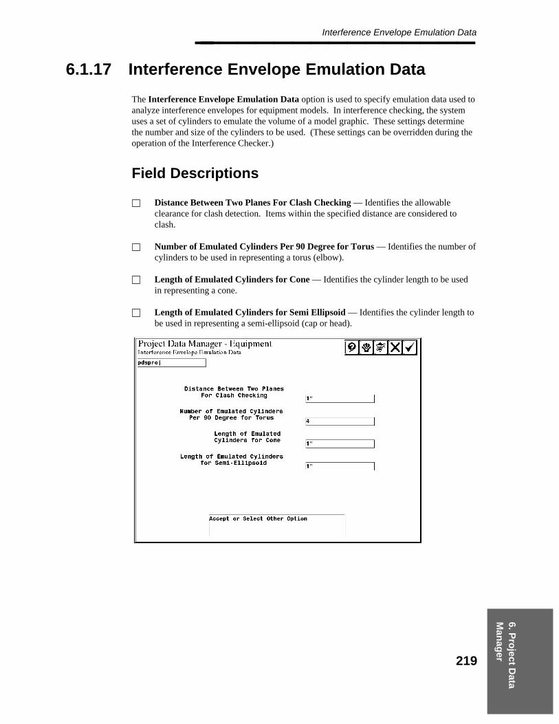
6. Pro
ject Data
Man
ager
Interference Envelope Emulation Data________________
6.1.17 Interference Envelope Emulation Data
The Interference Envelope Emulation Data option is used to specify emulation data used toanalyze interference envelopes for equipment models. In interference checking, the systemuses a set of cylinders to emulate the volume of a model graphic. These settings determinethe number and size of the cylinders to be used. (These settings can be overridden during theoperation of the Interference Checker.)
Field Descriptions
Distance Between Two Planes For Clash Checking — Identifies the allowableclearance for clash detection. Items within the specified distance are considered toclash.
Number of Emulated Cylinders Per 90 Degree for Torus — Identifies the number ofcylinders to be used in representing a torus (elbow).
Length of Emulated Cylinders for Cone — Identifies the cylinder length to be usedin representing a cone.
Length of Emulated Cylinders for Semi Ellipsoid — Identifies the cylinder length tobe used in representing a semi-ellipsoid (cap or head).
219

Project Administrator — April 2002________________
Operating Sequence
1. Select Option.
Select the Interference Envelope Emulation Data option from the ReviseEquipement Data form.
The Interference Envelope Emulation Data form is displayed.
Select the appropriate field, and type any changes to the envelope emulation data. Length and distancevalues are in working units (MU:SU:PU format). For these fields, the smaller the value the greater theprecision and the slower the processing time for Interference Checking.
2. Specify Distance Between Two Planes for Clash Checking.
Identify the allowable clearance for clash detection. Items within the specified distanceare considered to clash.
3. Specify Number of Emulated Cylinders Per 90 Degree for Torus.
Identify the number of cylinders to be used when representing a torus (elbow).
4. Specify Length of Emulated Cylinders for Cone.
Identify the cylinder length to be used when representing a cone.
5. Specify Length of Emulated Cylinders for Semi-Ellipsoid
Identify the cylinder length to be used when representing a semi-ellipsoid (cap or head).
6. Accept Interference Envelope Emulation Data.
Choose the Confirm button to accept the specified Interference Envelope EmulationData.
The Revise Equipment Data form is displayed.
220

6. Pro
ject Data
Man
ager
Revise Piping Model Data________________
6.1.18 Revise Piping Model Data
The Revise Piping Model Data option is used to revise the piping model data in the seed filesfor the active project.
Option Descriptions
Component Placement — Used to specify the graphic commodity library tables, thesymbols to be used for special graphics, and the tolerance values for the automaticcomponent placement and for determining the end of a pipe or the proximity of acomponent. (See page 223.)
Piping Data Control — Enables/disables access to the weight table, processesschedule/thickness overrides, and specifies working units and classifications fornominal piping diameter. (See page 226.)
Physical Units — Used to to set the active physical units for Insulation Density,Surface Area, Dry/Wet Weights, and Maximum Temperature in the Piping Job Spec.(See page 230.)
Nozzle Transfer — Used to specify the nozzle attributes to be transferred to theassociated piping segment when connecting to a nozzle. (See page 233.)
Material Takeoff — Used to specify the source of commodity information, units forbolt length and diameter, and item names used to reference a commodity item in theGraphic Commodity Library. (See page 235.)
Design Review Label — Used to select which model component types will not haveDesignReview labels generated by the Label Builder. (See page 239.)
Default Segment Data — Used to define certain segment parameters that are stored inthe type 63 elements. (See page 240.)
Reference Database File Specifications — Used to review file names for ReferenceDatabase files, graphic commodity data, dimension tables, and spec tables. (See page242.)
Design Checks Options — Used to specify hard and soft design rule consistencycheck parameters for components and line route segments and to specify the tolerancevalues to be used when processing design checks. (See page 245.)
Design Checks End Prep Table — Used to select the classification of endpreparations to review or modify. (See page 248.)
Symbology Diagnostic Markers — Used to specify the graphic symbology to be usedfor view-independent symbols (markers), the symbols to be used for special graphics,and the line weight for marker graphics. (See page 251.)
221

Project Administrator — April 2002________________ Symbology Model — Used to specify the model symbology for component placementand to indicate whether color codes are based on model category, fluid code, orconstruction status. (See page 254.)
Insulation — Used to define symbology for insulation graphics. (See page 257.)
Symbology Level, Color, and Style — Used to set the symbology for the model, fluidcode, or construction status as specified by the Symbology Model setting. (See page260.)
222
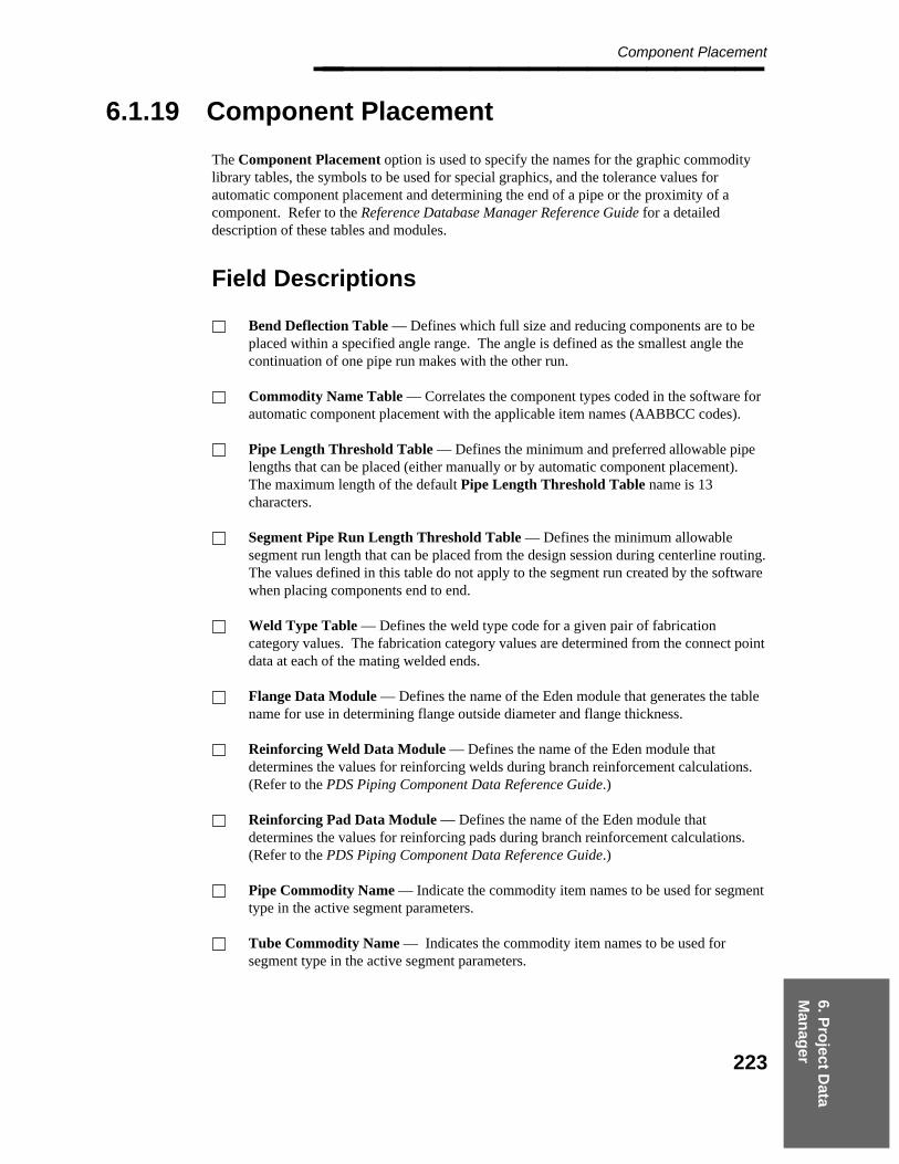
6. Pro
ject Data
Man
ager
Component Placement________________
6.1.19 Component Placement
The Component Placement option is used to specify the names for the graphic commoditylibrary tables, the symbols to be used for special graphics, and the tolerance values forautomatic component placement and determining the end of a pipe or the proximity of acomponent. Refer to the Reference Database Manager Reference Guide for a detaileddescription of these tables and modules.
Field Descriptions
Bend Deflection Table — Defines which full size and reducing components are to beplaced within a specified angle range. The angle is defined as the smallest angle thecontinuation of one pipe run makes with the other run.
Commodity Name Table — Correlates the component types coded in the software forautomatic component placement with the applicable item names (AABBCC codes).
Pipe Length Threshold Table — Defines the minimum and preferred allowable pipelengths that can be placed (either manually or by automatic component placement).The maximum length of the default Pipe Length Threshold Table name is 13characters.
Segment Pipe Run Length Threshold Table — Defines the minimum allowablesegment run length that can be placed from the design session during centerline routing.The values defined in this table do not apply to the segment run created by the softwarewhen placing components end to end.
Weld Type Table — Defines the weld type code for a given pair of fabricationcategory values. The fabrication category values are determined from the connect pointdata at each of the mating welded ends.
Flange Data Module — Defines the name of the Eden module that generates the tablename for use in determining flange outside diameter and flange thickness.
Reinforcing Weld Data Module — Defines the name of the Eden module thatdetermines the values for reinforcing welds during branch reinforcement calculations.(Refer to the PDS Piping Component Data Reference Guide.)
Reinforcing Pad Data Module — Defines the name of the Eden module thatdetermines the values for reinforcing pads during branch reinforcement calculations.(Refer to the PDS Piping Component Data Reference Guide.)
Pipe Commodity Name — Indicate the commodity item names to be used for segmenttype in the active segment parameters.
Tube Commodity Name — Indicates the commodity item names to be used forsegment type in the active segment parameters.
223

Project Administrator — April 2002________________ Angular Tolerance (Automated Component) — Indicates the acceptable deviation indegrees for flow centerline alignment. If an attempt is made to place a component at anangle outside the tolerance, the system displays a warning message.
Vicinity Tolerance — Indicates the acceptable clearance in working units for use incomponent placement. If an attempt is made to place a component within the specifiedtolerance, the system displays a warning message.
Commodity Synonyms — When commodity synonyms are enabled, a user-definedCommodity Synonym Library can be used to define the relationship betweencommodity names used in the P&ID task and commodity names in PDS 3D. (Refer tothe Reference Data Manager (PD_Data) Reference Guide for more information on thislibrary.)
Operating Sequence
1. Select Option.
Select the Component Placement option from the Revise Piping Model Data form.
The Component Placement form is displayed.
2. Specify Bend Deflection Table.
Select the Bend Deflection Table field and type the associated table name.
3. Specify Commodity Item Name Table.
Select the Commodity Item Name Table field and type the associated table name.
224
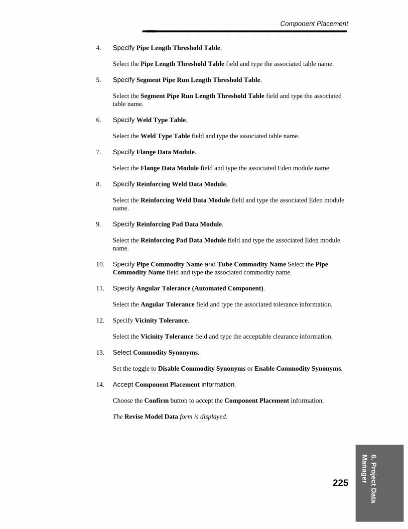
6. Pro
ject Data
Man
ager
Component Placement________________
4. Specify Pipe Length Threshold Table.
Select the Pipe Length Threshold Table field and type the associated table name.
5. Specify Segment Pipe Run Length Threshold Table.
Select the Segment Pipe Run Length Threshold Table field and type the associatedtable name.
6. Specify Weld Type Table.
Select the Weld Type Table field and type the associated table name.
7. Specify Flange Data Module.
Select the Flange Data Module field and type the associated Eden module name.
8. Specify Reinforcing Weld Data Module.
Select the Reinforcing Weld Data Module field and type the associated Eden modulename.
9. Specify Reinforcing Pad Data Module.
Select the Reinforcing Pad Data Module field and type the associated Eden modulename.
10. Specify Pipe Commodity Name and Tube Commodity Name Select the PipeCommodity Name field and type the associated commodity name.
11. Specify Angular Tolerance (Automated Component).
Select the Angular Tolerance field and type the associated tolerance information.
12. Specify Vicinity Tolerance.
Select the Vicinity Tolerance field and type the acceptable clearance information.
13. Select Commodity Synonyms.
Set the toggle to Disable Commodity Synonyms or Enable Commodity Synonyms.
14. Accept Component Placement information.
Choose the Confirm button to accept the Component Placement information.
The Revise Model Data form is displayed.
225

Project Administrator — April 2002________________
6.1.20 Piping Data Control
The Piping Data Control option is used to enable/disable access to the weight table, selectthe option for processing schedule/thickness override, and specify working units andclassifications for nominal piping diameter.
Field Descriptions
Fluid Code Control — Specifies whether the system will use the setting for the fluidcode in the Piping Materials Class data of the Piping Job specification to limit theacceptable fluid code(s) while modeling. The default is to not limit the fluid codevalues.
Weight Table — Specifies whether a weight table is to be used to find the dry weightof a component. Using a weight table is required for those cases where, for a specificgeometric industry standard, material causes the dry weight data to differ, but not thedimensional data.
Geometric Industry Standard — Specifies the geometric industry standard to be usedfor the company practice Physical Data Library.
When this toggle is set to Default, the geometric industry standard range is defined tobe from 31,000 through 31,999. This setting is required if you plan to use any of thefollowing industry practices: European B, International A, or International B.
When this toggle is set to Expanded, the geometric industry standard range forcompany practice is defined to be from 28,000 through 31,999. This is the activeoption for any piping models created with the 4.0 version of PDS.
P&ID Database — Specifies whether the Master or the Task PID database is used, ifboth are available for the project.
Branch Component Assoc for Isometric Drawings — Specifies whether the branchcomponent will be associated with the header line or branch line during isometricextraction.
This property only applies to olet geometry branch components. Tees,crosses and wyes follow the ISOGEN convention of being owned by theline at CP1 of the fitting.
Copy — Specifies whether to append ** as a prefix to name attributes (for example,line number label and component number) to signify that the segment or componentwas copied and that the name attribute may require updating.
Piping Segment Data — Specifies whether the Brief list or the Complete list of pipingsegment data should be displayed as the default in the Piping Designer graphicsenvironment. Refer to Default Segment Data, page 240 , for more information onsegment data.
226
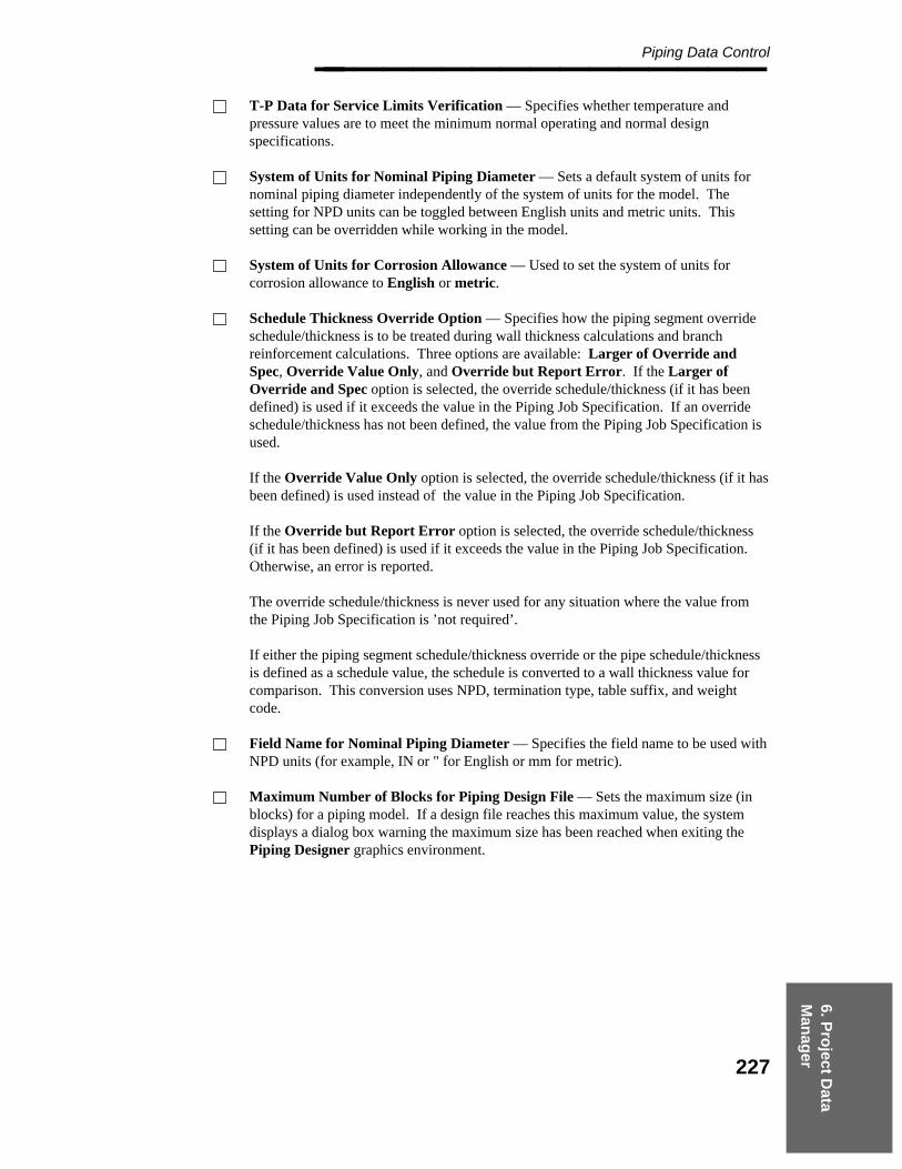
6. Pro
ject Data
Man
ager
Piping Data Control________________ T-P Data for Service Limits Verification — Specifies whether temperature andpressure values are to meet the minimum normal operating and normal designspecifications.
System of Units for Nominal Piping Diameter — Sets a default system of units fornominal piping diameter independently of the system of units for the model. Thesetting for NPD units can be toggled between English units and metric units. Thissetting can be overridden while working in the model.
System of Units for Corrosion Allowance — Used to set the system of units forcorrosion allowance to English or metric.
Schedule Thickness Override Option — Specifies how the piping segment overrideschedule/thickness is to be treated during wall thickness calculations and branchreinforcement calculations. Three options are available: Larger of Override andSpec, Override Value Only, and Override but Report Error. If the Larger ofOverride and Spec option is selected, the override schedule/thickness (if it has beendefined) is used if it exceeds the value in the Piping Job Specification. If an overrideschedule/thickness has not been defined, the value from the Piping Job Specification isused.
If the Override Value Only option is selected, the override schedule/thickness (if it hasbeen defined) is used instead of the value in the Piping Job Specification.
If the Override but Report Error option is selected, the override schedule/thickness(if it has been defined) is used if it exceeds the value in the Piping Job Specification.Otherwise, an error is reported.
The override schedule/thickness is never used for any situation where the value fromthe Piping Job Specification is ’not required’.
If either the piping segment schedule/thickness override or the pipe schedule/thicknessis defined as a schedule value, the schedule is converted to a wall thickness value forcomparison. This conversion uses NPD, termination type, table suffix, and weightcode.
Field Name for Nominal Piping Diameter — Specifies the field name to be used withNPD units (for example, IN or " for English or mm for metric).
Maximum Number of Blocks for Piping Design File — Sets the maximum size (inblocks) for a piping model. If a design file reaches this maximum value, the systemdisplays a dialog box warning the maximum size has been reached when exiting thePiping Designer graphics environment.
227
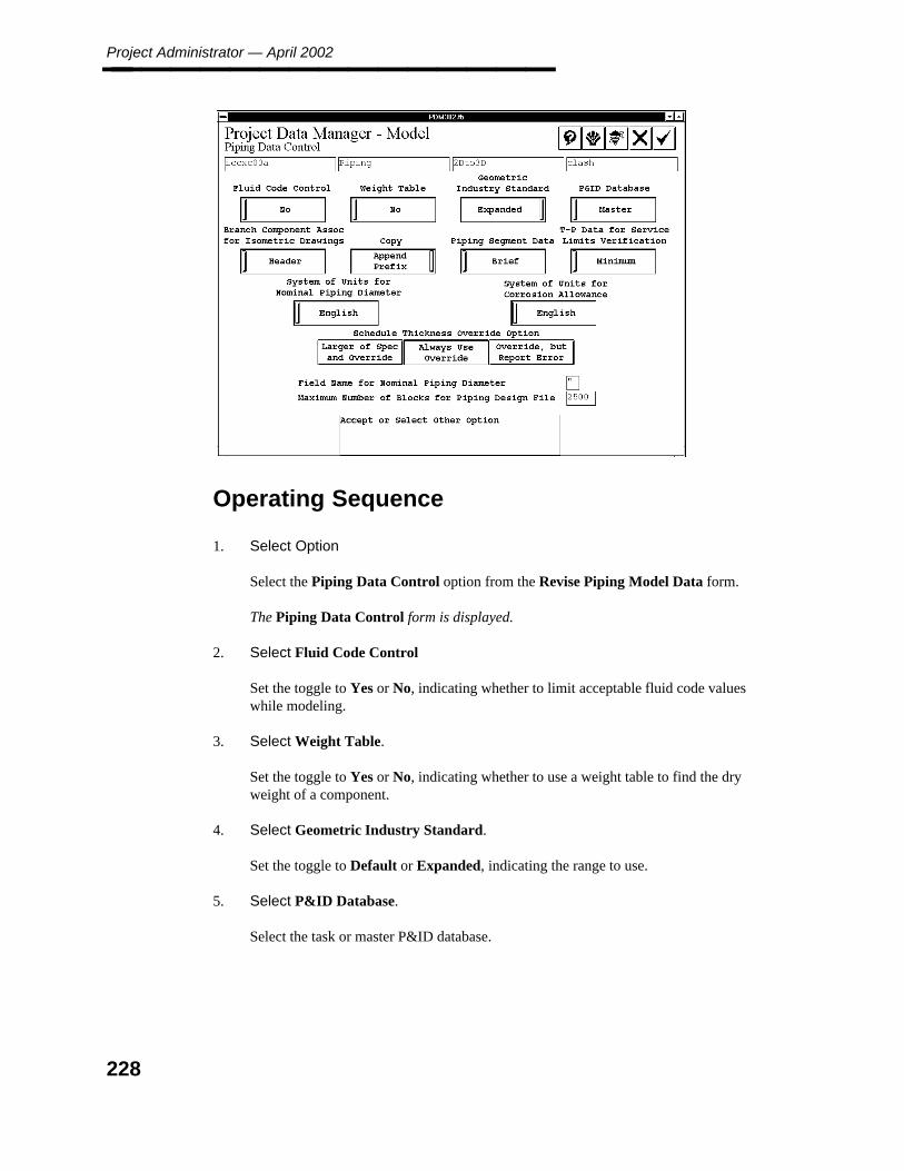
Project Administrator — April 2002________________
Operating Sequence
1. Select Option
Select the Piping Data Control option from the Revise Piping Model Data form.
The Piping Data Control form is displayed.
2. Select Fluid Code Control
Set the toggle to Yes or No, indicating whether to limit acceptable fluid code valueswhile modeling.
3. Select Weight Table.
Set the toggle to Yes or No, indicating whether to use a weight table to find the dryweight of a component.
4. Select Geometric Industry Standard.
Set the toggle to Default or Expanded, indicating the range to use.
5. Select P&ID Database.
Select the task or master P&ID database.
228

6. Pro
ject Data
Man
ager
Piping Data Control________________
6. Select Branch Component Assoc for Isometric Drawings
Set the toggle to Header or Branch, indicating whether the branch component is to beassociated with the header line.
7. Select Copy.
Set the toggle to Append Prefix or No Prefix> indicating whether to append ** as aprefix to name attributes.
8. Select Piping Segment Data.
Set the toggle to Complete or Brief indicating the complete or brief list of pipingsegment data should be displayed.
9. Select T-P Data for Service Limits Verification
Set the toggle to Minimum or No Minimum to indicate if temperature and pressurevalves are to meet minimum normal operating and design specifications.
10. Select System of Units for Nominal Piping Diameter.
Set the toggle to English or Metric.
11. Select System of Units for Corrosion Allowance
Set the toggle to English or Metric.
12. Select Schedule Thickness Override Option.
Select Larger of Spec and Override, Always Use Override, or Override, but ReportError.
13. Select Field Name for Nominal Piping Diameter.
Type a 2-character alphanumeric field name.
14. Specify Maximum Number of Blocks for Piping Design File.
Type up to 5-character numeric maximum size.
15. Accept Piping Data Control information.
Choose the Confirm button to accept the Piping Data Control information.
The Revise Piping Model Data form is displayed.
229
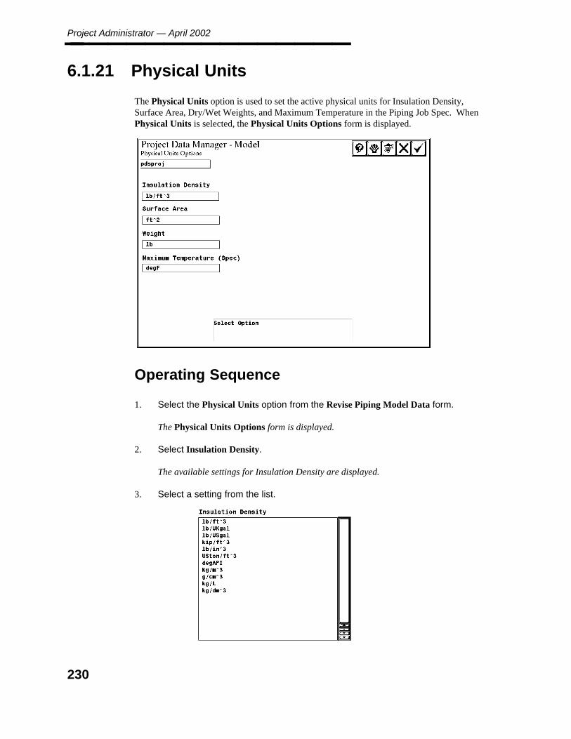
Project Administrator — April 2002________________
6.1.21 Physical Units
The Physical Units option is used to set the active physical units for Insulation Density,Surface Area, Dry/Wet Weights, and Maximum Temperature in the Piping Job Spec. WhenPhysical Units is selected, the Physical Units Options form is displayed.
Operating Sequence
1. Select the Physical Units option from the Revise Piping Model Data form.
The Physical Units Options form is displayed.
2. Select Insulation Density.
The available settings for Insulation Density are displayed.
3. Select a setting from the list.
230

6. Pro
ject Data
Man
ager
Physical Units________________ The Physical Units Options form is displayed.
4. Select Surface Area.
The available settings for Surface Area are displayed.
5. Select a Surface Area setting.
Select a setting from the Surface Area list. This setting provides surface area valuesfor painting requirements.
The Physical Units Options form is displayed.
6. Select Weight.
The available settings for weight are displayed.
7. Select physical units for weight measurement.
Select the physical units to be used when performing dry and wet weight calculations.The active setting is used to supply data to the stress analysis interface.
The Physical Units Options form is displayed.
231

Project Administrator — April 2002________________
8. Select Maximum Temperature (Spec).
The available settings for maximum temperature are displayed.
9. Select units.
Select the units to be used in performing design checks for components.
The Physical Units Options form is displayed.
232
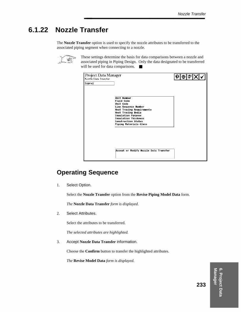
6. Pro
ject Data
Man
ager
Nozzle Transfer________________
6.1.22 Nozzle Transfer
The Nozzle Transfer option is used to specify the nozzle attributes to be transferred to theassociated piping segment when connecting to a nozzle.
These settings determine the basis for data comparisons between a nozzle andassociated piping in Piping Design. Only the data designated to be transferredwill be used for data comparisons.
Operating Sequence
1. Select Option.
Select the Nozzle Transfer option from the Revise Piping Model Data form.
The Nozzle Data Transfer form is displayed.
2. Select Attributes.
Select the attributes to be transferred.
The selected attributes are highlighted.
3. Accept Nozzle Data Transfer information.
Choose the Confirm button to transfer the highlighted attributes.
The Revise Model Data form is displayed.
233

Project Administrator — April 2002________________
To remove the highlight from a selected attribute (and to not transfer theattribute), select the attribute.
Nominal piping diameter and piping materials class are transferredautomatically.
234

6. Pro
ject Data
Man
ager
Material Takeoff________________
6.1.23 Material Takeoff
The Material Takeoff option is used to specify the source of commodity information, unitsfor bolt length and diameter, and specify item names used to reference a commodity item inthe Graphic Commodity Library. Refer to the Reference Data Manager Reference Guide forinformation about the stud table, bolt length calculations, and the bolt commodity code table.
Field Descriptions
Bolt Length Roundoff — Specifies the manner by which bolt lengths are to bedetermined. Three options are available: Preferred Bolt Length Table, BoltRoundoff Factor, and No Roundoff. If the Preferred Bolt Length Table option isselected, the preferred bolt length table is used. If the Bolt Roundoff Factor option ischosen, the specified roundoff factor is multiplied by the exact bolt length to calculatethe bolt lengths. If No Roundoff is selected, the exact length is used.
Length Calculation — Specifies the method to be used to calculate bolt length. Thebolt length is read from the stud table. The table value can be determined using therating and table suffix (Almost Precise) or using termination type, rating, and tablesuffix (Precise).
Bolt Commodity Code — Specifies the method to be used to determine the commoditycode for bolts (Piping Job Specification or Bolt Commodity Code Table) for use inmaterial takeoff.
Field Fit Length — Toggle the setting between Off or On. If this field is On, thesystem displays a field to input the Field Fit Length Table name.
Bolt Diameter Units — Specifies the system of units for bolt diameter.
Bolt Length Units — Specifies the system of units for bolt length.
Gasket Search — Specifies the Gasket Search to be Default or Alternate.
Header Weld for RPAD — Specifies the setting of Report or Do Not Report. Whenset to Report, the header welds for reinforcing pads are automatically generated.
Branch Weld for RPAD — Specifies the setting of Report or Do Not Report. Whenset to Report, the branch welds for reinforcing pads are automatically generated.
Commodity Code - Specify the setting of Size Independent or Size Dependent.
If the field is set to Size Dependent, two additional options are displayed: Source ofImplied Data and Source of Material Description.
Source of Implied Data — Specifies the source of the commodity code for reportingimplied data from the Piping Commodity Implied Material Data Table. The defaultoption (System Commodity Code) specifies the system is to use the commodity codedefined in the Piping Commodity Specification Data Table (Table 202 attribute 18).
235
Project Administrator — April 2002________________ The Size-Dependent Commodity Code option specifies the system is to use thecommodity code defined in the Piping Commodity Size-Dependent Material Data Table(Table 211 attribute 7).
Source of Material Description — Specifies the source of the commodity code forreporting a component’s material description. The default option (System CommodityCode) specifies the system is to use the commodity code defined in the PipingCommodity Specification Data Table (Table 202 attribute 18).
The Size-Dependent Commodity Code option specifies the system is to use thecommodity code defined in the Piping Commodity Size-Dependent Material Data Table(Table 211 attribute 7).
Gasket Commodity Name, Bolt Commodity Name, and Nut Commodity Name —Indicates the default commodity item names to be used to report implied materials(gaskets, bolts, and nuts) unless a specific override is set for the component beingreported.
Bolt Length Table — Specifies the name of the table that defines the low and highrange for calculated bolt lengths and the corresponding preferred or purchased lengthsof the bolt. This field is only used if the Bolt Length Roundoff option is set toPreferred Bolt Length Table.
Bolt Length Roundoff Factor — Specifies the value for the bolt roundoff factor insubunits. This value is only used if the Bolt Length Roundoff option is set to BoltRoundoff Factor.
Field Fit Length Table — Specifies the name of the table which defines the field fitlength. This value is only used if the Field Fit Lenght option is set to On.
Operating Sequence
1. Select Option.
Select the Material Takeoff option from the Revise Piping Model Data form.
The Material Takeoff Options form is displayed.
2. Select Bolt Length Roundoff.
Select Preferred Bolt Length Table, Bolt Roudoff Factor, or No Roundoff.
If Preferred Bolt Length Table is selected, the Bolt Length Table field is displayed.
If Bolt Roundoff Factor is selected, the Bolt Length Roundoff Factor field isdisplayed.
If No Roundoff is selected, no roundoff field is displayed.
236

6. Pro
ject Data
Man
ager
Material Takeoff________________
3. Select Length Calculation.
Specify the method of Precise or Almost Precise to be used to calculate bolt length.
4. Select Bolt Commodity Code.
Specify the method of Piping Job Spec or Bolt Commodity Code Table to be used todetermine the Comomdity code for bolts.
5. Select Field Fit Length.
Specify On or Off for the Field Fit Length.
If On is selected, the Field Fit Length Table field is displayed.
6. Select Bolt Diameter Units.
Specify Metric or English for the system of units for bolt diameter.
7. Select Bolt Length Units.
Specify Metric or English for the system of units for bolt units.
8. Select Gasket Search.
Specify Alternate or Default for the gasket search.
9. Select Header Weld for RPAD.
Specify Do Not Report or Report.
10. Select Branch Weld for RPAD.
Specify Do Not Report or Report.
11. Specify Gasket Commodity Name.
Type the default gasket commodity name.
12. Specify Bolt Commodity Name.
Type the default bolt commodity name.
13. Specify Bolt Length Roundoff Factor.
This field displays only if Bolt Roundoff Factor is selected for the Bolt LengthRoundoff option. Type the name of the Bolt Length Roundoff Factor table.
14. Specify Field Fit Length Table.
237

Project Administrator — April 2002________________ This field displays only if On is selected for the Field Fit Length option. Type thename of the Field Fit Length Table.
15. Select Commodity Code.
Specify Size Dependent or Size Independent
If Size Dependent is selected, the Source of Implied Data and Source of MaterialDescription options display.
16. Select Source of Implied Data.
Specify Size Dependent Commodity Code or System Commodity Code.
17. Select Size Dependent Commodity Code.
Specify Size Dependent Commodity Code or System Commodity Code.
18. Accept Material Takeoff Options.
Choose the Confirm button to accept Material Takeoff Options.
The Revise Model Data form is displayed.
238
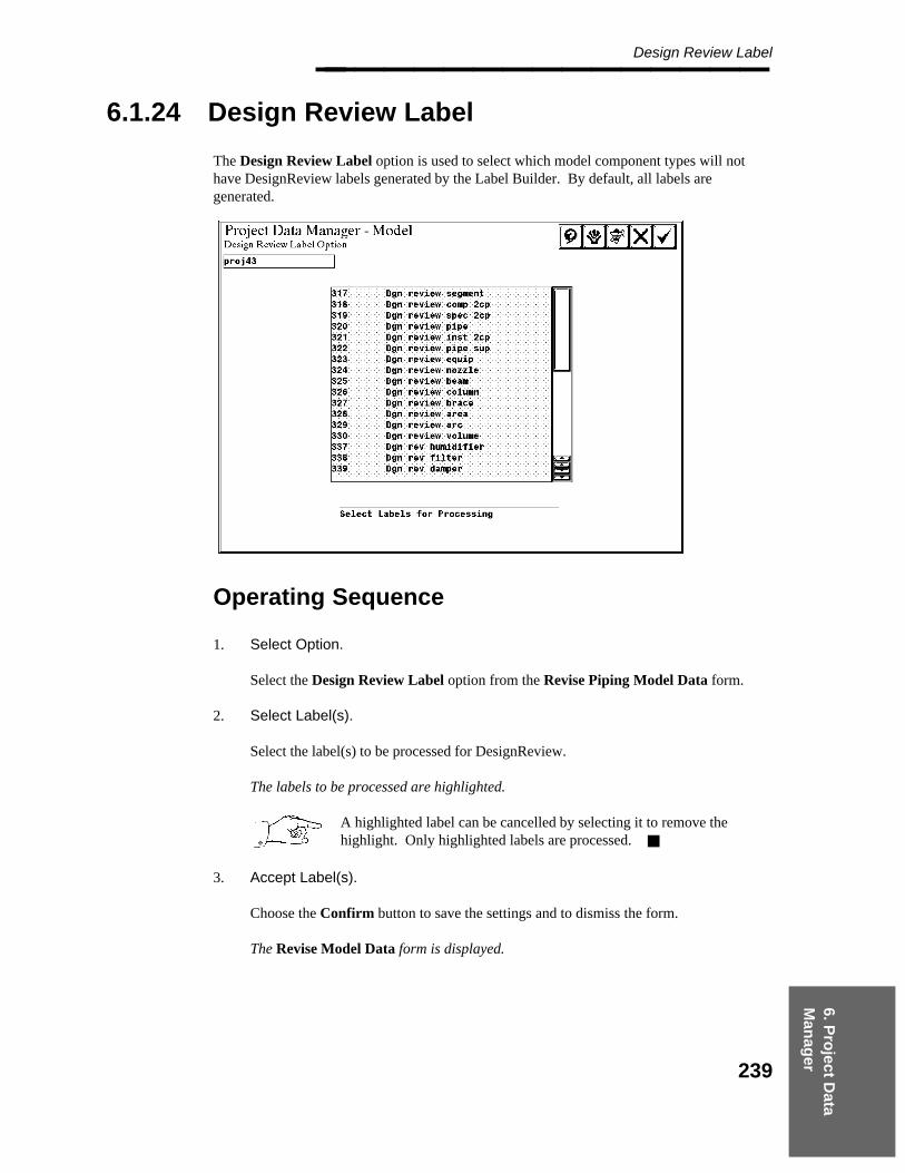
6. Pro
ject Data
Man
ager
Design Review Label________________
6.1.24 Design Review Label
The Design Review Label option is used to select which model component types will nothave DesignReview labels generated by the Label Builder. By default, all labels aregenerated.
Operating Sequence
1. Select Option.
Select the Design Review Label option from the Revise Piping Model Data form.
2. Select Label(s).
Select the label(s) to be processed for DesignReview.
The labels to be processed are highlighted.
A highlighted label can be cancelled by selecting it to remove thehighlight. Only highlighted labels are processed.
3. Accept Label(s).
Choose the Confirm button to save the settings and to dismiss the form.
The Revise Model Data form is displayed.
239
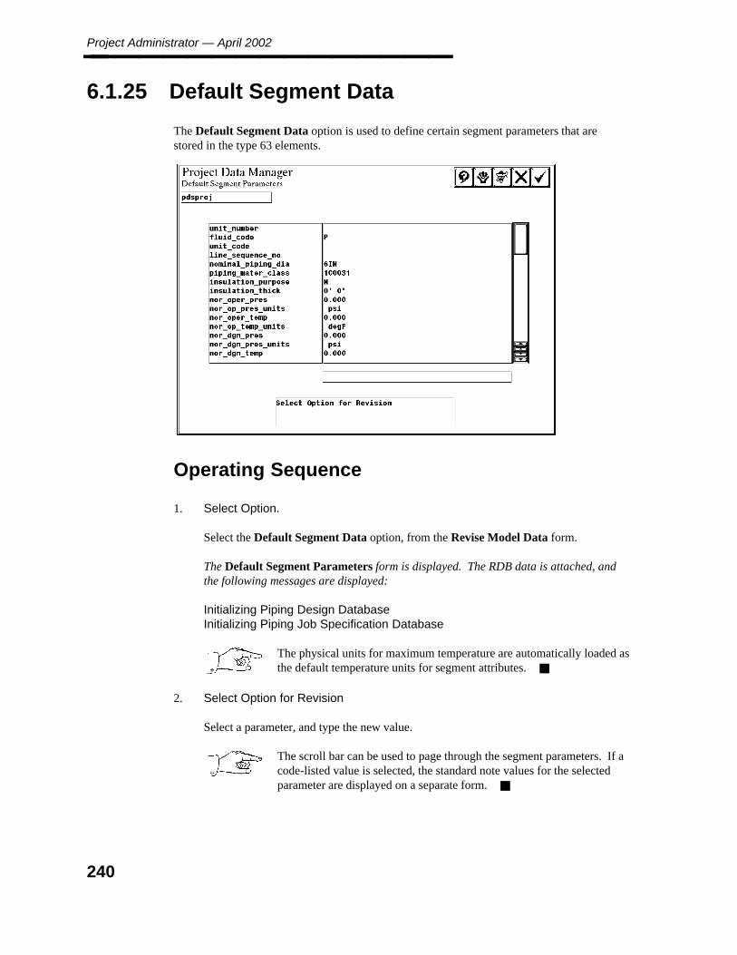
Project Administrator — April 2002________________
6.1.25 Default Segment Data
The Default Segment Data option is used to define certain segment parameters that arestored in the type 63 elements.
Operating Sequence
1. Select Option.
Select the Default Segment Data option, from the Revise Model Data form.
The Default Segment Parameters form is displayed. The RDB data is attached, andthe following messages are displayed:
Initializing Piping Design DatabaseInitializing Piping Job Specification Database
The physical units for maximum temperature are automatically loaded asthe default temperature units for segment attributes.
2. Select Option for Revision
Select a parameter, and type the new value.
The scroll bar can be used to page through the segment parameters. If acode-listed value is selected, the standard note values for the selectedparameter are displayed on a separate form.
240
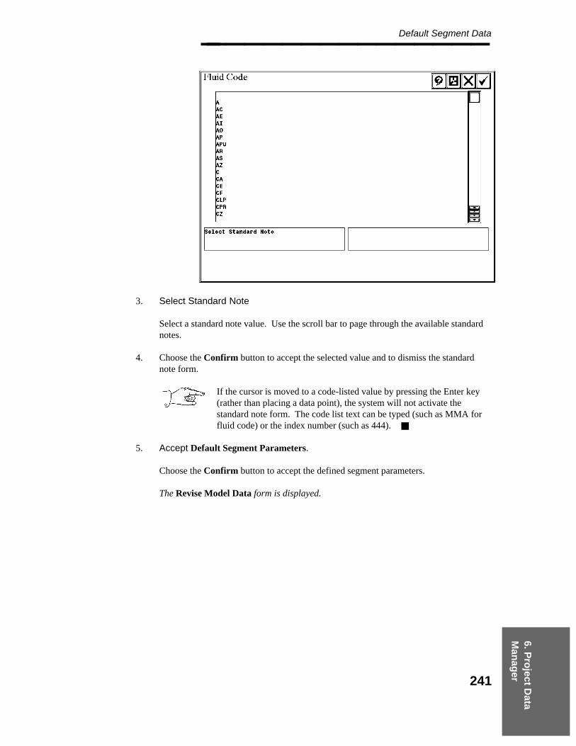
6. Pro
ject Data
Man
ager
Default Segment Data________________
3. Select Standard Note
Select a standard note value. Use the scroll bar to page through the available standardnotes.
4. Choose the Confirm button to accept the selected value and to dismiss the standardnote form.
If the cursor is moved to a code-listed value by pressing the Enter key(rather than placing a data point), the system will not activate thestandard note form. The code list text can be typed (such as MMA forfluid code) or the index number (such as 444).
5. Accept Default Segment Parameters.
Choose the Confirm button to accept the defined segment parameters.
The Revise Model Data form is displayed.
241
Project Administrator — April 2002________________
6.1.26 Reference Database File Specifications -Review File Names
The Reference Database File Specifications option is used to review the file names forReference Database Files, graphic commodity data, dimension tables, and spec tables.Whether to use approved or unapproved RDB data can be determined for each item. The filespecifications are defined through the Reference Data Manager. Refer to the ReferenceDatabase Manager Reference Guide for a detailed description of these files.
The following RDB files are available:
Material/Specification Reference Database — Identifies the Piping ReferenceDatabase for the project.
Piping Job Specification Table Library — Identifies the location of the Spec Tablelibrary (pjstb.l).
Short Material Description Library — Identifies the library containing the short bill-of-material description for all piping commodity items and the BOM descriptionaddenda for taps (us_shbom.l).
Long Material Description Library — Identifies the library containing the long BOMdescription for all piping commodity items (us_lgbom.l). The long BOM description isonly used for requisitions.
Specialty Material Description Library — Identifies the library that contains theBOM description for engineered items, in-line instruments, and pipe supports(us_spbom.l). This library is customer-specific and is not delivered with the software.
Standard Note Library — Identifies the location of the standard note library(std_note.l).
Label Description Library — Identifies the location for the label description library(labels.l).
Piping Assembly Library Identifies the location for the Piping Assembly library. Thislibrary contains the symbol definitions for assemblies (assembly.l).
Graphic Commodity Library — Identifies the library containing the Eden modulesused to place components in the model (pip_gcom.l).
Physical Data Library — Identify the library files containing the physical data tablesfor a range of geometric industry standards (us_pcdim.l).
Commodity Synonym Library — Identifies the user-defined library containing themap for translating the commodity names used in Piping to those used in the P&IDtask.
242
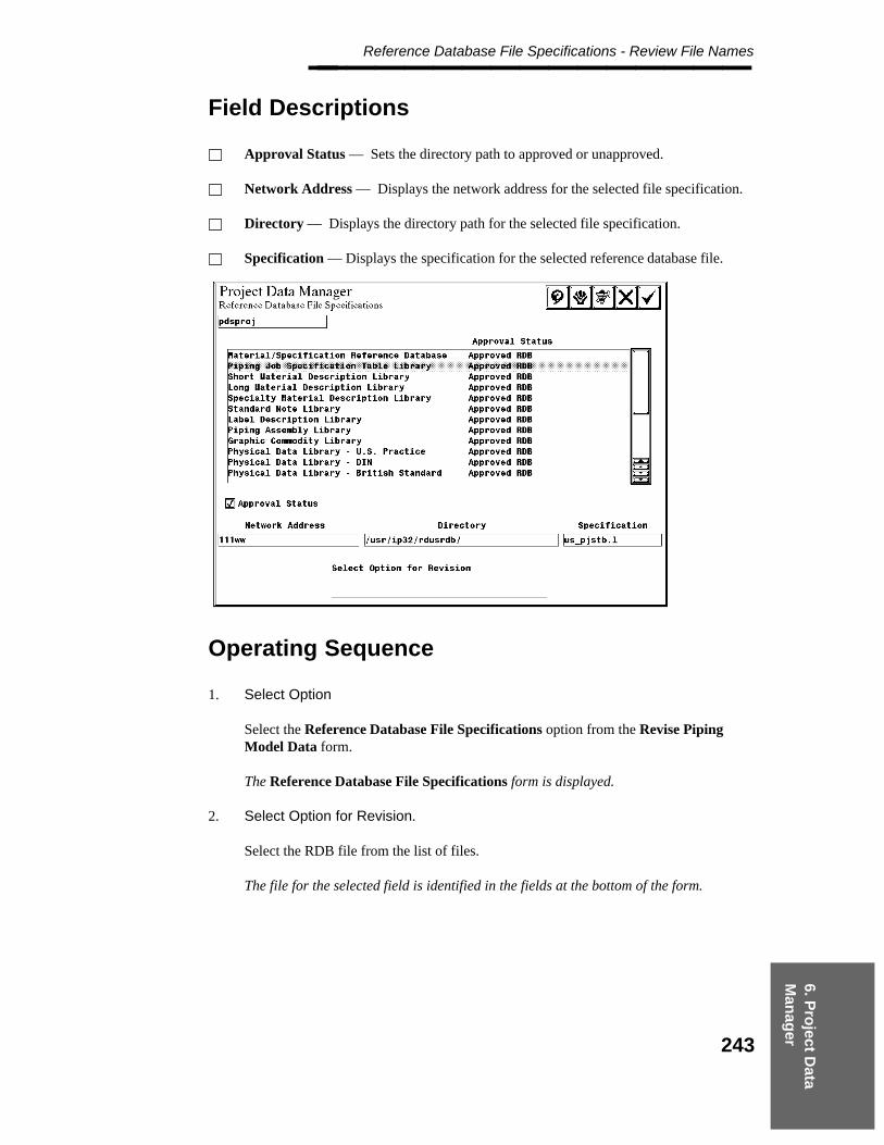
6. Pro
ject Data
Man
ager
Reference Database File Specifications - Review File Names________________
Field Descriptions
Approval Status — Sets the directory path to approved or unapproved.
Network Address — Displays the network address for the selected file specification.
Directory — Displays the directory path for the selected file specification.
Specification — Displays the specification for the selected reference database file.
Operating Sequence
1. Select Option
Select the Reference Database File Specifications option from the Revise PipingModel Data form.
The Reference Database File Specifications form is displayed.
2. Select Option for Revision.
Select the RDB file from the list of files.
The file for the selected field is identified in the fields at the bottom of the form.
243

Project Administrator — April 2002________________
3. Accept RDB files.
Choose the Confirm button to accept any changes to the RDB files and to dismiss theform.
The Revise Piping Model Data form is displayed.
244
6. Pro
ject Data
Man
ager
Design Checks Options________________
6.1.27 Design Checks Options
Design checks are used to ensure that connected pressurized piping and instrumentation in themodel is compatible in terms of a set of design rules. This option is used to specify hard andsoft design rule consistency check parameters for components and line route segments and tospecify the tolerance values to be used to process design checks. These tolerances are used todefine the acceptable tolerances between connected components. Any discrepancy greaterthan the defined tolerance is reported as an inconsistency.
Field Descriptions
Interactive Check — Selects the applicable parameter toggle setting of Check (*) orNo Check. This determines which parameters are compared during interactiveconsistency checks.
Schedule/thickness interactive design checks do not work, because at thetime that the check is done during placement, the wall thickness has notbeen calculated. The Batch Design Checker does check theschedule/thickness and reports errors.
The interactive design check for outside diameter does not work.
Design Checker — Selects the applicable parameter toggle the setting of Check (*) orNo Check. This allows the options for post-placement design checks to be specifiedindependently of the interactive design checks in the model. Until a selection is made,the state of each post-placement Design Checks option defaults to the same state as thecorresponding interactive Design Checks option.
The design check for outside diameter does not work.
Hard/Soft — Selects the applicable parameter toggle of Hard or Soft. A hardinconsistency constitutes an error, and a soft inconsistency constitutes a warning.
Flow Centerline Alignment Tolerances — An angle value in degrees to indicate theacceptable tolerance for flow centerline alignment between connected components.
Insulation Thickness Tolerances — A value in subunits to indicate the acceptabletolerance for insulation thickness.
Enable/Disable Piping Segments Flow Direction Check — Toggles to determinewhether flow direction is to be checked for piping segments.
245
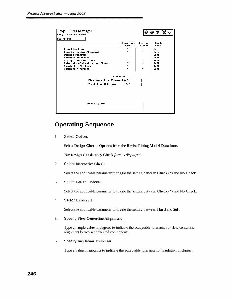
Project Administrator — April 2002________________
Operating Sequence
1. Select Option.
Select Design Checks Options from the Revise Piping Model Data form.
The Design Consistency Check form is displayed.
2. Select Interactive Check.
Select the applicable parameter to toggle the setting between Check (*) and No Check.
3. Select Design Checker.
Select the applicable parameter to toggle the setting between Check (*) and No Check.
4. Select Hard/Soft.
Select the applicable parameter to toggle the setting between Hard and Soft.
5. Specify Flow Centerline Alignment.
Type an angle value in degrees to indicate the acceptable tolerance for flow centerlinealignment between connected components.
6. Specify Insulation Thickness.
Type a value in subunits to indicate the acceptable tolerance for insulation thickness.
246

6. Pro
ject Data
Man
ager
Design Checks Options________________
7. Accept Design Consistency Check Specifications.
Choose the Confirm button to accept Design Consistency Check specifications.
The Revise Model Data form is displayed.
247
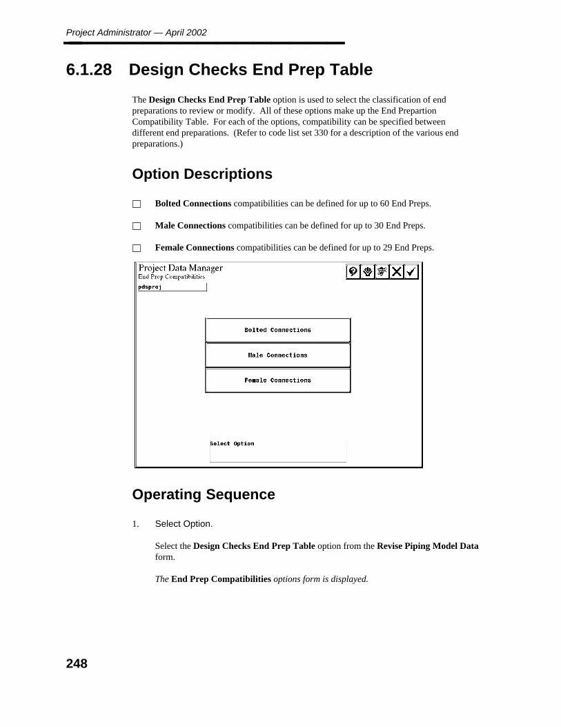
Project Administrator — April 2002________________
6.1.28 Design Checks End Prep Table
The Design Checks End Prep Table option is used to select the classification of endpreparations to review or modify. All of these options make up the End PrepartionCompatibility Table. For each of the options, compatibility can be specified betweendifferent end preparations. (Refer to code list set 330 for a description of the various endpreparations.)
Option Descriptions
Bolted Connections compatibilities can be defined for up to 60 End Preps.
Male Connections compatibilities can be defined for up to 30 End Preps.
Female Connections compatibilities can be defined for up to 29 End Preps.
Operating Sequence
1. Select Option.
Select the Design Checks End Prep Table option from the Revise Piping Model Dataform.
The End Prep Compatibilities options form is displayed.
248
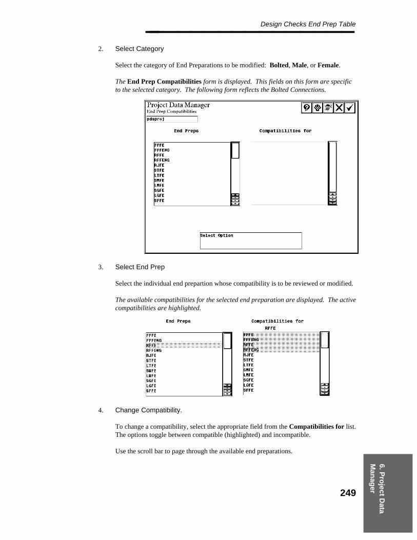
6. Pro
ject Data
Man
ager
Design Checks End Prep Table________________
2. Select Category
Select the category of End Preparations to be modified: Bolted, Male, or Female.
The End Prep Compatibilities form is displayed. This fields on this form are specificto the selected category. The following form reflects the Bolted Connections.
3. Select End Prep
Select the individual end prepartion whose compatibility is to be reviewed or modified.
The available compatibilities for the selected end preparation are displayed. The activecompatibilities are highlighted.
4. Change Compatibility.
To change a compatibility, select the appropriate field from the Compatibilities for list.The options toggle between compatible (highlighted) and incompatible.
Use the scroll bar to page through the available end preparations.
249
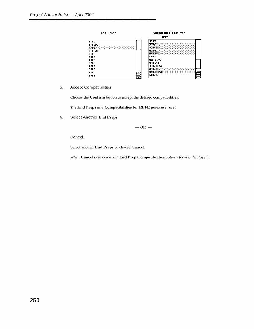
Project Administrator — April 2002________________
5. Accept Compatibilities.
Choose the Confirm button to accept the defined compatibilities.
The End Preps and Compatibilities for RFFE fields are reset.
6. Select Another End Preps
— OR —
Cancel.
Select another End Preps or choose Cancel.
When Cancel is selected, the End Prep Compatibilities options form is displayed.
250
6. Pro
ject Data
Man
ager
Symbology Diagnostic Markers________________
6.1.29 Symbology Diagnostic Markers
The Symbology Diagnostic Markers option is used to specify the graphic symbology to beused for view independent symbols (markers), the symbols to be used for special graphics,and the line weight for marker graphics.
Field Descriptions
Symbol Font Number — Identifies the symbol font for symbology.
Text Height — Identifies the text height for symbology.
Text Width — Identifies the text width for symbology.
Field Weld Symbol Name — The character number (within the Symbol Font) of thesymbol to be assigned for field welds.
Isometric Drawing Limit Symbol Name — The character number (within the SymbolFont) of the symbol to be assigned for isometric drawing limits. No permanentgraphics are placed in the model for a field weld or isometric drawing limit. Thisinformation can be displayed while working in the model by using the TemporarySymbology command.
Diagnostic Markers — Displays the slide bar to select the text weights for DiagnosticMarkers.
Automated Placement Markers — Displays the slide bar to select the line and textweights for Automated Placement Markers.
These markers are used to indicate errors (such as an attempt to place a component thatis not defined in the active Piping Materials Class) in automated component placement.Piping errors are indicated by a P, and components are indicated by a C.
Model Reconstruction Markers — Displays the slide bar to select the line and textweights for Model Reconstruction Markers.
These markers are used to indicate errors that are detected during model reconstruction.
Field Weld and Isometric Drawing Symbol — Displays the slide bar to select the lineand text weights for Field Weld and Isometric Drawing Symbol.
These markers are used as temporary symbology to indicate the location of field weldsor isometric drawing limits along a pipeline.
251
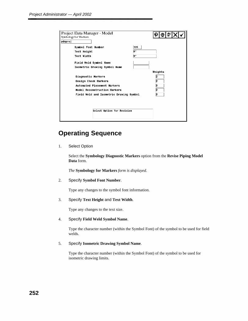
Project Administrator — April 2002________________
Operating Sequence
1. Select Option
Select the Symbology Diagnostic Markers option from the Revise Piping ModelData form.
The Symbology for Markers form is displayed.
2. Specify Symbol Font Number.
Type any changes to the symbol font information.
3. Specify Text Height and Text Width.
Type any changes to the text size.
4. Specify Field Weld Symbol Name.
Type the character number (within the Symbol Font) of the symbol to be used for fieldwelds.
5. Specify Isometric Drawing Symbol Name.
Type the character number (within the Symbol Font) of the symbol to be used forisometric drawing limits.
252

6. Pro
ject Data
Man
ager
Symbology Diagnostic Markers________________
6. Select Diagnostic Markers.
Select the line weights for Diagnostic markers from the displayed slide bar.
7. Specify Automated Placement Markers.
Select the line weights for Automated Placement Markers from the displayed slidebar.
8. Specify Model Reconstruction Markers.
Select the line weights for Model Reconstruction Markers from the displayed slidebar.
9. Specify Field Weld and Isometric Drawing Symbol
Select the line weights for Field Weld and Isometric Drawing Symbol from thedisplayed slide bar.
10. Accept Symbology for Markers.
Choose Confirm to accept settings for Symbology for Markers.
The Revise Model Data form is displayed.
253

Project Administrator — April 2002________________
6.1.30 Symbology - Model
The Symbology - Model option is used to specify the model symbology for componentplacement and to indicate whether color codes are based on model category, fluid code, orconstruction status.
Field Descriptions
Piping Commodity Weights — Displays the slide bar to select the line weights forPiping Commodity Weights.
Piping Specialty Weights — Displays the slide bar to select the line weights forPiping Specialty Weights.
Instrument Weights — Displays the slide bar to select the line weights forInstrument Weights.
Piping/Tubing Weights — Displays the slide bar to select the line weights forPiping/Tubing Weights.
Pipe Support Weights — Displays the slide bar to select the line weights for PipeSupport Weights.
Model Symbology — Select the model symbology option (Simple or Detailed) to beused when placing components. This setting can be overridden while working in themodel.
Simple model symbology displays flanged components such as valves without showingthe flange, thereby using less design file space. The displayed valve diameter is thesame as the size of the flange, and the flange is reported in the MTO.
Detailed model symbology displays the flange at the ends of all flanged components.
Color — Define this option before any models are created; do not change this optionafter any model data has been defined. For a description of the color codes defined as afunction of model category, see Model Category, page 260 .
For a description of the color codes defined as a function of fluid code ranges, seeFluid Code, page 263 . For a description of the color codes and line styles defined as afunction of construction status, see Construction Status, page 266 . A dialog box isdisplayed if the Color option is revised under the following conditions.
— If this option is revised for the piping seed model when only the piping seed modelexists, (as at project creation) a message displays warning to select the proper optionand it should not be changed once design data has been created.
— If this option is revised for the piping seed model when one or more piping modelshave been created, a message displays warning the model symbology option shouldnot be changed once design data has been created.
254
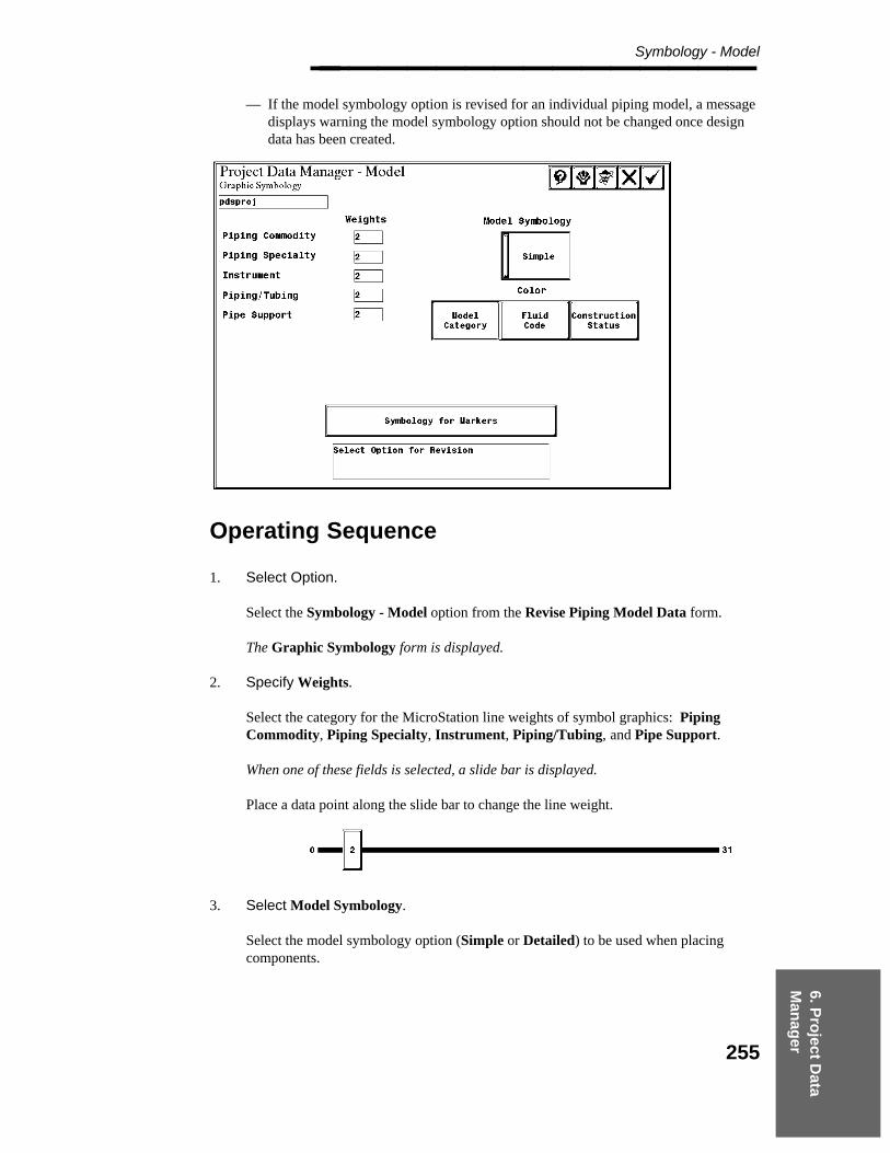
6. Pro
ject Data
Man
ager
Symbology - Model________________
— If the model symbology option is revised for an individual piping model, a messagedisplays warning the model symbology option should not be changed once designdata has been created.
Operating Sequence
1. Select Option.
Select the Symbology - Model option from the Revise Piping Model Data form.
The Graphic Symbology form is displayed.
2. Specify Weights.
Select the category for the MicroStation line weights of symbol graphics: PipingCommodity, Piping Specialty, Instrument, Piping/Tubing, and Pipe Support.
When one of these fields is selected, a slide bar is displayed.
Place a data point along the slide bar to change the line weight.
3. Select Model Symbology.
Select the model symbology option (Simple or Detailed) to be used when placingcomponents.
255

Project Administrator — April 2002________________
4. Select Color.
Select the option (Model Category, Fluid Code, or Construction Status) to define theuse of color in segregating model graphics.
5. Accept Graphic Symbology.
Choose Confirm to accept Graphic Symbology.
The Revise Model Data form is displayed.
256

6. Pro
ject Data
Man
ager
Symbology - Insulation________________
6.1.31 Symbology - Insulation
The Symbology - Insulation option is used to define graphic symbology for insulationdisplay within a piping model.
Field Descriptions
Level — The drawing level on which insulation graphics are to be placed. Allinsulation graphics are placed on the defined graphic level.
Default Color — The Select Color form is placed with the default insulation colorselected. A color or color number (as defined in the current PDS color form) may beselected from the form.
Weight — Displays the slide bar to select the line weights for insulation graphics. Allinsulation are placed using the selected line weight.
Style — Displays line style for insulation graphics. All insulation will be placed usingthe selected line style.
Place Insulation Graphics or Do Not Place Insulation Graphics toggle — A togglesetting which defines whether insulation graphics are placed in the model.
This toggle setting can also be set in the Piping Design Graphicssoftware under the Active Options command.
Placement of Insulation Graphics is controlled by adding or removingthe model category Insulation Graphics in PD_Draw or the PD_Designsoftware. For more information about adding or removing modelcategories refer to the Drawing Manager (PD_Draw) User’s Guide orthe Piping Design Graphics (PD_Design) Reference Guide.
Insulation Purpose — This field is for display only. It lists all of the available types ofinsulation as defined in code list 220. See Appendix G of the Piping Component DataReference Guide to review code list 220.
Color — Displays the associated color for each Insulation Purpose. A maximum of20 Insulation Purposes can be defined. After the initial 20, the Default Color isassigned. The Select Color form is displayed with the default insulation color selected.Select a color or color number (as defined in the current PDS color form) to assign aspecific color to an insulation purpose or select Undefined to remove the currentlyassigned color. Select Confirm to accept the currently defined colors.
257

Project Administrator — April 2002________________
The Color setting overrides the color defined in the Default Color field.
A maximum of 20 Insulation Purposes can be defined. SubsequentInsulation Purposes are assigned the Default Color.
If a customized Select Color form is being used with insulationgraphics, the form will need to be modified, COLOR.fb, to add theUndefined button. The form can be modified COLOR.fb using DBAccess. Modify the form using the following information:
gadget_label = 99key = 3099Text = ’Undefined’
Operating Sequence
1. Select Option.
Select the Symbology - Insulation option from the Revise Piping Model Data form.
The Insulation Graphics Symbology form is displayed.
2. Specify Level.
Type the drawing level on which insulation graphics are to be placed.
3. Select Default Color.
The Select Color form is placed with the default insulation color selected.
Select a color or color number (as defined in the current PDS color form) from theform; then choose the Confirm button.
258

6. Pro
ject Data
Man
ager
Symbology - Insulation________________
4. Select Weight.
Select the Weight field and place a data point along the slider to set the weight.
5. Select Style.
Select the Style field and choose a line style for insulation graphics.
6. Select Place Insulation Graphics/Do Not Place Insulation Graphics
Select a toggle setting to define if insulation graphics are placed in the model.
7. Select Color.
Select the Color field.
The Select Color form is displayed with the default insulation color selected.
Select a color or color number (as defined in the current PDS color form) to assign aspecific color to an insulation purpose or select Undefined to remove the currentlyassigned color.
Select Confirm to acceptthe currently defined colors.
8. Accept Insulation Graphics Symbology.
Choose Confirm to accept Insulation Graphics Symbology.
The Revise Model Data form is displayed.
259
Project Administrator — April 2002________________
6.1.32 Symbology Level and Color
The Symbology Level and Color option varies depending on the active model symbology asdefined with the Symbology Model command. Depending on the active option, the systemdisplays one of the following forms:
Model CategoryFluid CodeConstruction Status
When the Level and Color options are selected, the system displays a dialog box warning thisoption should not be changed once design data has been created.
Model Category
If the model symbology color option is set to Model Category, the Level and Color optionactivates the Graphic Symbology - Model Category form, which may be used to specify:
Levels and color codes by model category.
Nominal piping diameter ranges (small, medium, and large) used when determininglevels for piping segments, commodity items, pipes, engineered items, and in-lineinstruments.
Levels and color codes for labels and markers.
The color codes are only used if color is defined as a function of Model Category in theGraphic Symbology form.
Field Descriptions
Nominal Piping Diameter: Small is <= — Defines the size for a small nominal pipingdiameter.
Nominal Piping Diameter: Large is >= — Defines the size for a large pipingdiameter.
Model Category — Display only field which identifies the Model Category.
Approved or Not Approved — Display only assignment of Approved or NotApproved for the corresponding Model Category.
Nominal Piping Diameter — Display only assignment of the Nominal PipingDiameter size.
Level — Displays the drawing level for the associated Model Category.
260
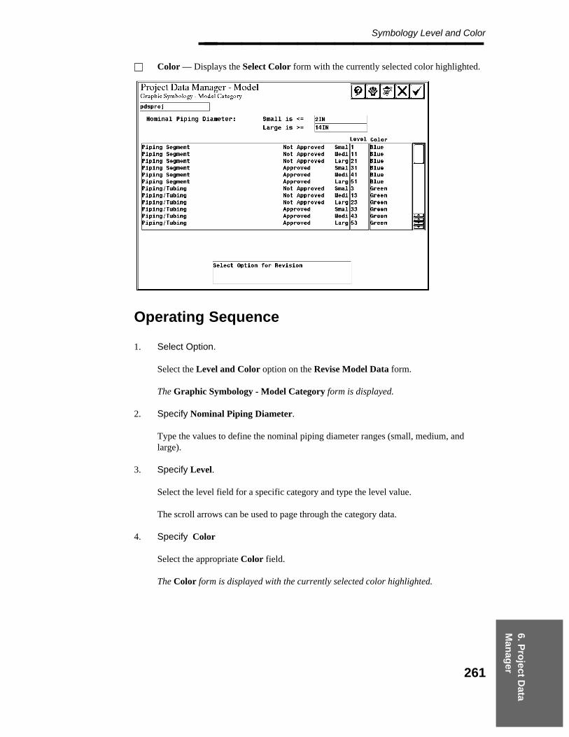
6. Pro
ject Data
Man
ager
Symbology Level and Color________________ Color — Displays the Select Color form with the currently selected color highlighted.
Operating Sequence
1. Select Option.
Select the Level and Color option on the Revise Model Data form.
The Graphic Symbology - Model Category form is displayed.
2. Specify Nominal Piping Diameter.
Type the values to define the nominal piping diameter ranges (small, medium, andlarge).
3. Specify Level.
Select the level field for a specific category and type the level value.
The scroll arrows can be used to page through the category data.
4. Specify Color
Select the appropriate Color field.
The Color form is displayed with the currently selected color highlighted.
261
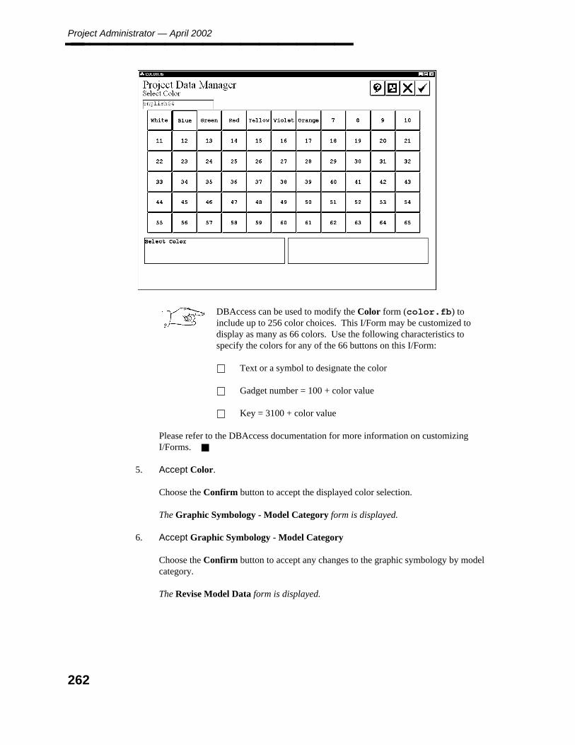
Project Administrator — April 2002________________
DBAccess can be used to modify the Color form (color.fb) toinclude up to 256 color choices. This I/Form may be customized todisplay as many as 66 colors. Use the following characteristics tospecify the colors for any of the 66 buttons on this I/Form:
Text or a symbol to designate the color
Gadget number = 100 + color value
Key = 3100 + color value
Please refer to the DBAccess documentation for more information on customizingI/Forms.
5. Accept Color.
Choose the Confirm button to accept the displayed color selection.
The Graphic Symbology - Model Category form is displayed.
6. Accept Graphic Symbology - Model Category
Choose the Confirm button to accept any changes to the graphic symbology by modelcategory.
The Revise Model Data form is displayed.
262
6. Pro
ject Data
Man
ager
Symbology Level and Color________________
Fluid Code
If the model symbology color option is set to Fluid Code, the Level and Color optiondisplays the Graphic Symbology - Fluid Code form, to specify:
Levels and colors for piping and components as a function of fluid code ranges.
Levels and color codes for piping segments and pipe supports.
Levels and color codes for labels and markers.
It is recommended that you have codelist 125 (fluid code) defined and loadedbefore setting these values.
The fluid codes should be grouped into like categories. For example, all utilitywater fluids in the range of 2-19.
263
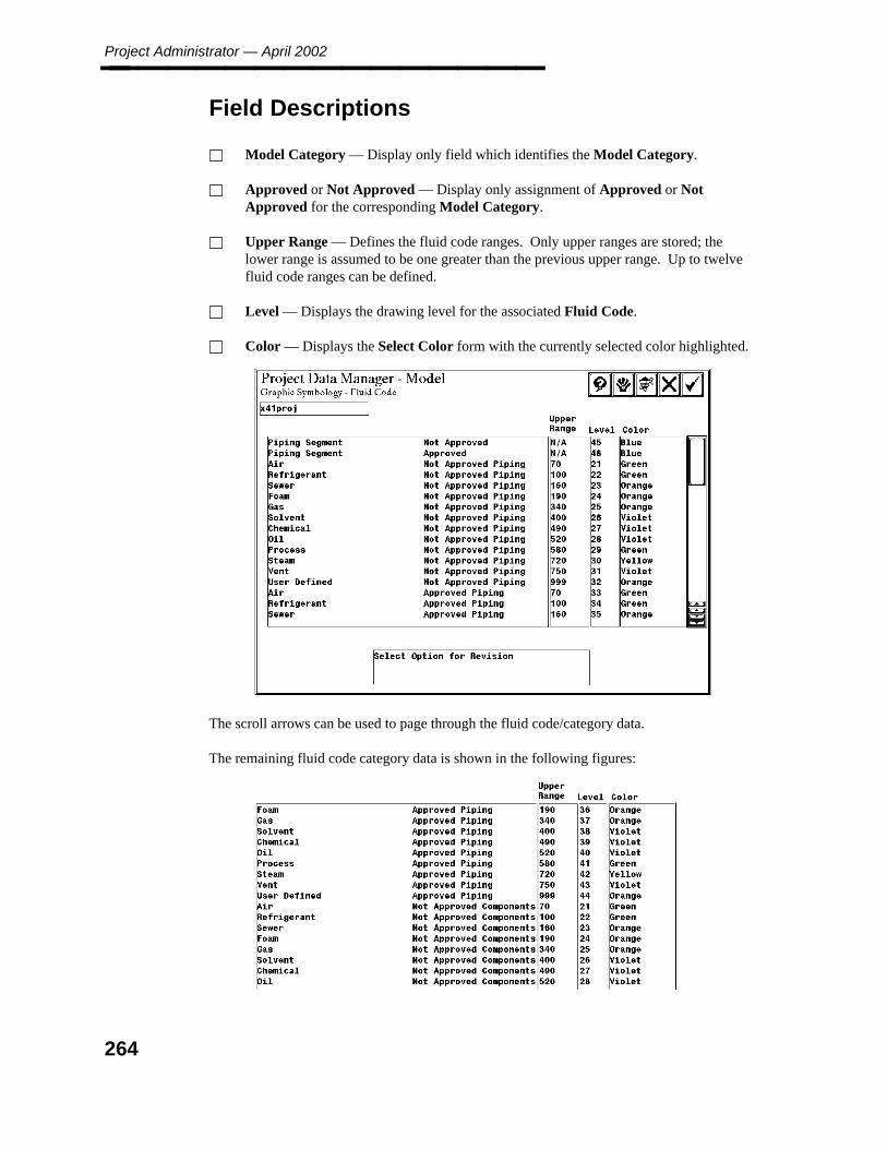
Project Administrator — April 2002________________
Field Descriptions
Model Category — Display only field which identifies the Model Category.
Approved or Not Approved — Display only assignment of Approved or NotApproved for the corresponding Model Category.
Upper Range — Defines the fluid code ranges. Only upper ranges are stored; thelower range is assumed to be one greater than the previous upper range. Up to twelvefluid code ranges can be defined.
Level — Displays the drawing level for the associated Fluid Code.
Color — Displays the Select Color form with the currently selected color highlighted.
The scroll arrows can be used to page through the fluid code/category data.
The remaining fluid code category data is shown in the following figures:
264
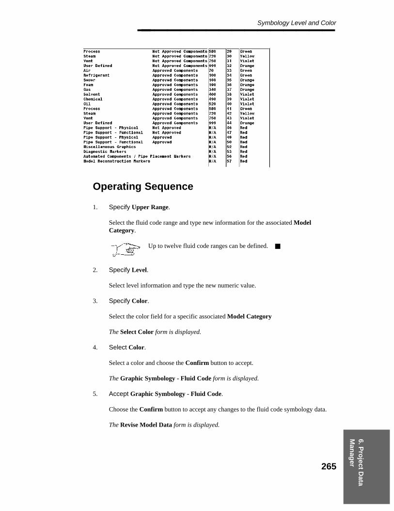
6. Pro
ject Data
Man
ager
Symbology Level and Color________________
Operating Sequence
1. Specify Upper Range.
Select the fluid code range and type new information for the associated ModelCategory.
Up to twelve fluid code ranges can be defined.
2. Specify Level.
Select level information and type the new numeric value.
3. Specify Color.
Select the color field for a specific associated Model Category
The Select Color form is displayed.
4. Select Color.
Select a color and choose the Confirm button to accept.
The Graphic Symbology - Fluid Code form is displayed.
5. Accept Graphic Symbology - Fluid Code.
Choose the Confirm button to accept any changes to the fluid code symbology data.
The Revise Model Data form is displayed.
265

Project Administrator — April 2002________________
Construction Status
If the model symbology color option is set to Construction Status, two symbology optionsare displayed on the Revise Model Data form: Level and Color and Style.
Level
When the Level option is selected, the Graphic Symbology - Construction Status form isdisplayed. This form is used to specify the level assignments by category.
Field Descriptions
Small is <= — Specifies the Nominal Piping Diameter ranges that classify nozzles assmall.
Large is <= — Specifies the Nominal Piping Diameter ranges that classify nozzles aslarge.
Model Category — Display only field which identifies the Model Category.
Approved or Not Approved — Display only assignment of Approved or NotApproved for the corresponding Model Category.
Level — Displays the drawing level for the associated Model Category.
266
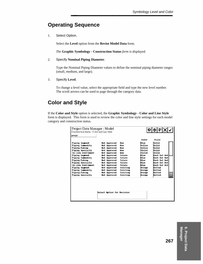
6. Pro
ject Data
Man
ager
Symbology Level and Color________________
Operating Sequence
1. Select Option.
Select the Level option from the Revise Model Data form.
The Graphic Symbology - Construction Status form is displayed.
2. Specify Nominal Piping Diameter.
Type the Nominal Piping Diameter values to define the nominal piping diameter ranges(small, medium, and large).
3. Specify Level.
To change a level value, select the appropriate field and type the new level number.The scroll arrows can be used to page through the category data.
Color and Style
If the Color and Style option is selected, the Graphic Symbology - Color and Line Styleform is displayed. This form is used to review the color and line style settings for each modelcategory and construction status.
267
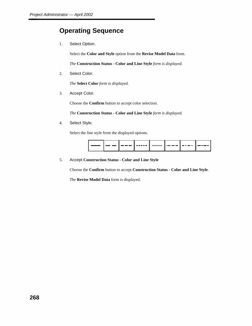
Project Administrator — April 2002________________
Operating Sequence
1. Select Option.
Select the Color and Style option from the Revise Model Data form.
The Construction Status - Color and Line Style form is displayed.
2. Select Color.
The Select Color form is displayed.
3. Accept Color.
Choose the Confirm button to accept color selection.
The Construction Status - Color and Line Style form is displayed.
4. Select Style.
Select the line style from the displayed options.
5. Accept Construction Status - Color and Line Style
Choose the Confirm button to accept Construction Status - Color and Line Style.
The Revise Model Data form is displayed.
268
6. Pro
ject Data
Man
ager
Propagate Piping Model Data________________
6.1.33 Propagate Piping Model Data
The Propagate Piping Model option distributes selected settings from the active pipingmodel seed file to all piping models within the active project or a list of selected pipingmodels. The following Type 63 data can be propagated to the specified piping models:
Date/Time Format, page 187Component Placement, page 223Piping Data Control, page 226Physical Units, page 230Nozzle Transfer, page 233Material Takeoff, page 235Design Review Label, page 239Reference Database File Specifications - Review File Names, page 242Design Checks Options, page 245Design Checks End Prep Table, page 248Symbology Diagnostic Markers, page 251Symbology - Insulation, page 257
The only model data that cannot be propagated is the Default Active Segment Data optionand the Level and Color options, which should not be revised after piping models have beencreated.
Field Descriptions
Model Data Options — Displays the model data options available for propagation.
Piping Models Selection toggle — Specifies Selected Piping Models or All PipingModels for propagation. Set the toggle to All Piping Models to propagate the selectedparameters to all the piping models in the active project.
— OR —
Set the toggle to Selected Piping Models to select the model files to be updated from alist of design areas.
Submission toggle — Specifies Submit Immediately or Submission is Delayed formodel propagation. Set the submission toggle to Submit Immediately to beginprocessing the request when the form is exited.
— OR —
Set the toggle to Submission is Delayed to specify a day and time to process therequest.
269
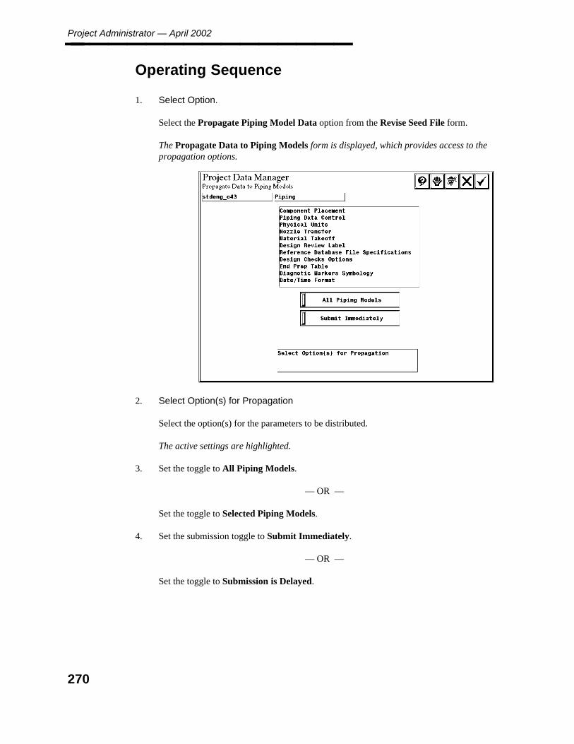
Project Administrator — April 2002________________
Operating Sequence
1. Select Option.
Select the Propagate Piping Model Data option from the Revise Seed File form.
The Propagate Data to Piping Models form is displayed, which provides access to thepropagation options.
2. Select Option(s) for Propagation
Select the option(s) for the parameters to be distributed.
The active settings are highlighted.
3. Set the toggle to All Piping Models.
— OR —
Set the toggle to Selected Piping Models.
4. Set the submission toggle to Submit Immediately.
— OR —
Set the toggle to Submission is Delayed.
270
6. Pro
ject Data
Man
ager
Propagate Piping Model Data________________
5. Accept Propagation Data.
If All Piping Models is active, go to Step 9.
— OR —
If Selected Piping Models is selected, the system displays a list of design areas for theproject.
6. Select Design Area
Select the design area for the model file(s) to be updated and choose the Confirmbutton.
7. Select Model.
Select the model file(s) to be updated.
8. Accept Model File(s).
Choose the Confirm button to accept model file(s).
9. Accept to Submit for Processing or Select Area for Addition Models
Repeat steps 6 and 7 to select additional areas/models.
10. Accept Propagation Request.
Choose the Confirm button to process the request.
The request is submitted to the batch queue named PDproject_data.
271
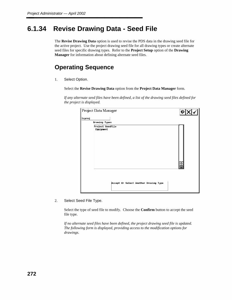
Project Administrator — April 2002________________
6.1.34 Revise Drawing Data - Seed File
The Revise Drawing Data option is used to revise the PDS data in the drawing seed file forthe active project. Use the project drawing seed file for all drawing types or create alternateseed files for specific drawing types. Refer to the Project Setup option of the DrawingManager for information about defining alternate seed files.
Operating Sequence
1. Select Option.
Select the Revise Drawing Data option from the Project Data Manager form.
If any alternate seed files have been defined, a list of the drawing seed files defined forthe project is displayed.
2. Select Seed File Type.
Select the type of seed file to modify. Choose the Confirm button to accept the seedfile type.
If no alternate seed files have been defined, the project drawing seed file is updated.The following form is displayed, providing access to the modification options fordrawings.
272
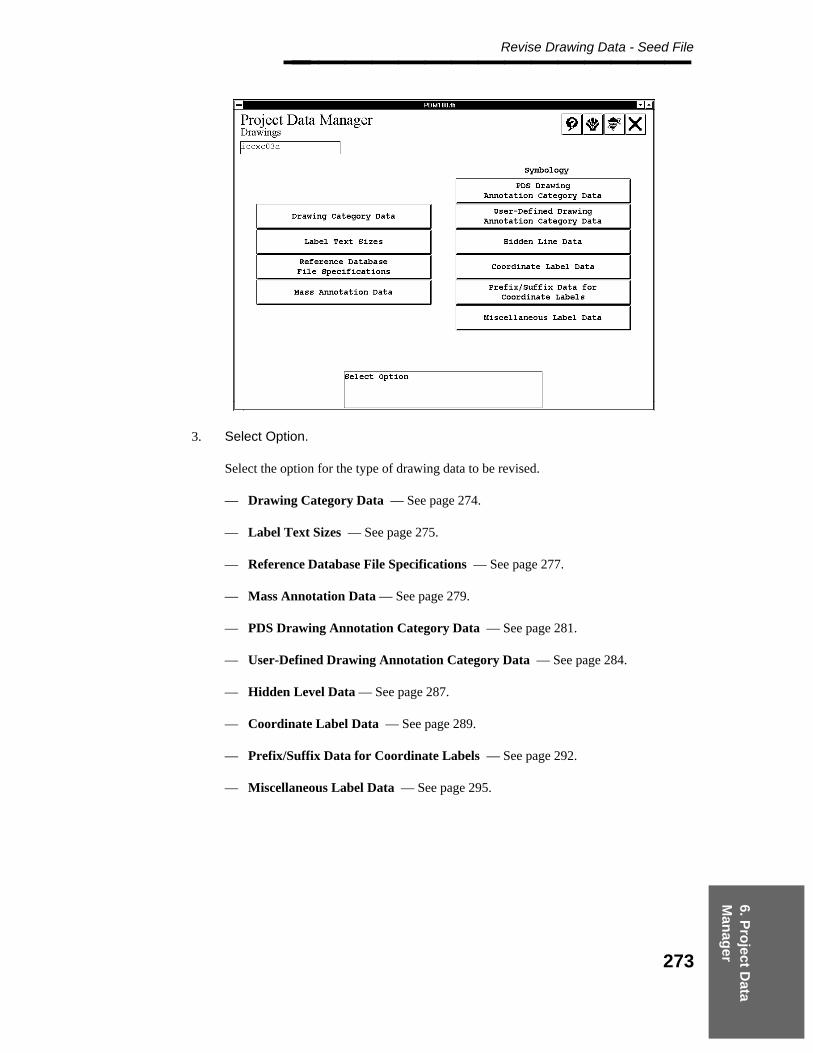
6. Pro
ject Data
Man
ager
Revise Drawing Data - Seed File________________
3. Select Option.
Select the option for the type of drawing data to be revised.
— Drawing Category Data — See page 274.
— Label Text Sizes — See page 275.
— Reference Database File Specifications — See page 277.
— Mass Annotation Data — See page 279.
— PDS Drawing Annotation Category Data — See page 281.
— User-Defined Drawing Annotation Category Data — See page 284.
— Hidden Level Data — See page 287.
— Coordinate Label Data — See page 289.
— Prefix/Suffix Data for Coordinate Labels — See page 292.
— Miscellaneous Label Data — See page 295.
273

Project Administrator — April 2002________________
6.1.35 Drawing Category Data
The Drawing Category Data option is used to specify the MicroStation display levels foreach drawing category including labels and markers. The names for the categories are readfrom the drwcats.txt file for the project. Refer to the Drawing Manager Reference Guide formore information on these categories.
Field Descriptions
Drawing Category — The names for the categories as read from the drwcats.txt file forthe project.
Level — The MicroStation display levels for each drawing category labels.
Operating Sequence
1. Select the Drawing Category Data option from the Drawings form.
2. Specify Level Select the appropriate field and type the new level value. The scroll barcan be used to page through the category data.
274

6. Pro
ject Data
Man
ager
Label Text Sizes________________
6.1.36 Label Text Sizes
The Label Text Sizes option is used to define the active text width and text height to be usedfor label text. This setting can be revised while working in a drawing.
Text size is limited by the Precision setting in 3D Design Data. For exampleif the Precision is set to 1/16", the smallest allowed text size is 1/16".
Field Descriptions
Active — Identifies the corresponding Text Height and Text Width as the default forlabel text.
Text Height — Defines the height to be used for label text.
Text Width — Defines the width to be used for label text.
The display units are required in the Text Height and Text Width fields. Forexample, in an English project, label text placed with a height of 1/64without the trailing " would have a display height of 3/16" (1/64 of a foot)rather than 1/64".
275

Project Administrator — April 2002________________
Operating Sequence
1. Select Option.
Select the Label Text Sizes option from the Drawings form.
The Label Text Sizes form is displayed.
2. Select Height or Width Value.
Select any Text Height and Text Width values to change the size.
3. Select Active.
Select an entry in the Active column to identify the default width/height for label text.
4. Accept Label Text Sizes.
Choose the Confirm button to accept Label Text Sizes.
The Drawings form is displayed.
276
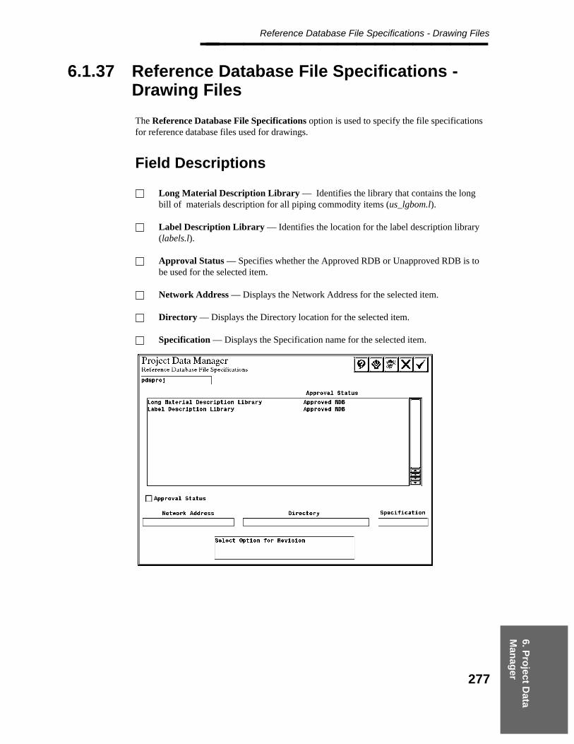
6. Pro
ject Data
Man
ager
Reference Database File Specifications - Drawing Files________________
6.1.37 Reference Database File Specifications -Drawing Files
The Reference Database File Specifications option is used to specify the file specificationsfor reference database files used for drawings.
Field Descriptions
Long Material Description Library — Identifies the library that contains the longbill of materials description for all piping commodity items (us_lgbom.l).
Label Description Library — Identifies the location for the label description library(labels.l).
Approval Status — Specifies whether the Approved RDB or Unapproved RDB is tobe used for the selected item.
Network Address — Displays the Network Address for the selected item.
Directory — Displays the Directory location for the selected item.
Specification — Displays the Specification name for the selected item.
277
Project Administrator — April 2002________________
Operating Sequence
1. Select Option.
Select the Reference Database File Specifications option from the Drawings form.
The Reference Database File Specifications form is displayed.
2. Select Option for Revision
Select the RDB file from the list of files.
The file for the selected field is identified in the fields at the bottom of the form.
3. Select Approval Status.
Select Approval Status to specify whether the Approved RDB or Unapproved RDB isto be used for the selected item.
4. Accept Reference Database File Specifications
Choose the Confirm button to accept any changes to the RDB files.
The Drawings form is displayed.
278
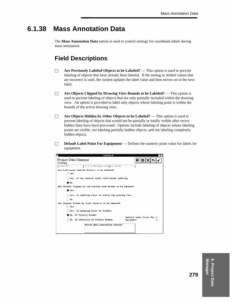
6. Pro
ject Data
Man
ager
Mass Annotation Data________________
6.1.38 Mass Annotation Data
The Mass Annotation Data option is used to control settings for coordinate labels duringmass annotation.
Field Descriptions
Are Previously Labeled Objects to be Labeled? — This option is used to preventlabeling of objects that have already been labeled. If the setting to relabel values thatare incorrect is used, the system updates the label value and then moves on to the nextlabel.
Are Objects Clipped by Drawing View Bounds to be Labeled? — This option isused to prevent labeling of objects that are only partially included within the drawingview. An option is provided to label only objects whose labeling point is within thebounds of the active drawing view.
Are Objects Hidden by Other Objects to be Labeled? — This option is used toprevent labeling of objects that would not be partially or totally visible after vectorhidden lines have been processed. Options include labeling of objects whose labelingpoints are visible, not labeling partially hidden objects, and not labeling completelyhidden objects.
Default Label Point For Equipment — Defines the numeric point value for labels forequipment.
279
Project Administrator — April 2002________________
Operating Sequence
1. Select Option.
Select the Mass Annotation Data option from the Drawings form.
The Mass Annotation Data information is displayed on the Drawings form.
2. Select Are Previously Labeled Objects to be Labeled?
Select Yes, Yes, If the Current Label Value Needs Updating, or No.
3. Select Are Objects Clipped by Drawing View Bounds to be Labeled?
Select Yes, Yes, If Labeling Point is within the Drawing View, or No.
4. Select Are Objects Hidden by Other Objects to be Labeled?
Select Yes, Yes, If Labeling Point is visible, No, if Totally Hidden, or No, If Partiallyor Totally Hidden.
5. Select Default Label Point For Equipment.
Specify the numeric Default Label Point For Equipment.
6. Accept Mass Annotation Data.
Choose the Confirm button to accept Mass Annotation Data.
The Drawings form is displayed.
280
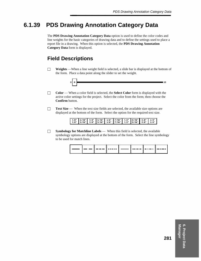
6. Pro
ject Data
Man
ager
PDS Drawing Annotation Category Data________________
6.1.39 PDS Drawing Annotation Category Data
The PDS Drawing Annotation Category Data option is used to define the color codes andline weights for the basic categories of drawing data and to define the settings used to place areport file in a drawing. When this option is selected, the PDS Drawing AnnotationCategory Data form is displayed.
Field Descriptions
Weights —When a line weight field is selected, a slide bar is displayed at the bottom ofthe form. Place a data point along the slider to set the weight.
Color — When a color field is selected, the Select Color form is displayed with theactive color settings for the project. Select the color from the form; then choose theConfirm button.
Text Size — When the text size fields are selected, the available size options aredisplayed at the bottom of the form. Select the option for the required text size.
Symbology for Matchline Labels — When this field is selected, the availablesymbology options are displayed at the bottom of the form. Select the line symbologyto be used for match lines.
281

Project Administrator — April 2002________________
Operating Sequence
1. Select Option.
Select the PDS Drawing Annotation Category Data option from the Drawings form.
2. Specify Weights and Colors.
Specify the line weight and color for the categories of drawing graphics.
Revision CloudFlow ArrowReportDate and Time for Plotting and VHLMatchline LabelsDimensioningMiscellaneous
3. Select Symbology for Matchline Labels.
Specify Symbology for Matchline Labels.
4. Select text size options.
Specify the text size for Reports and Date and Time for Plotting and VHL.
282

6. Pro
ject Data
Man
ager
PDS Drawing Annotation Category Data________________
5. Accept PDS Drawing Annotation Category Data.
Choose the Confirm button to accept PDS Drawing Annotation Category Data
The Drawings form is displayed.
283
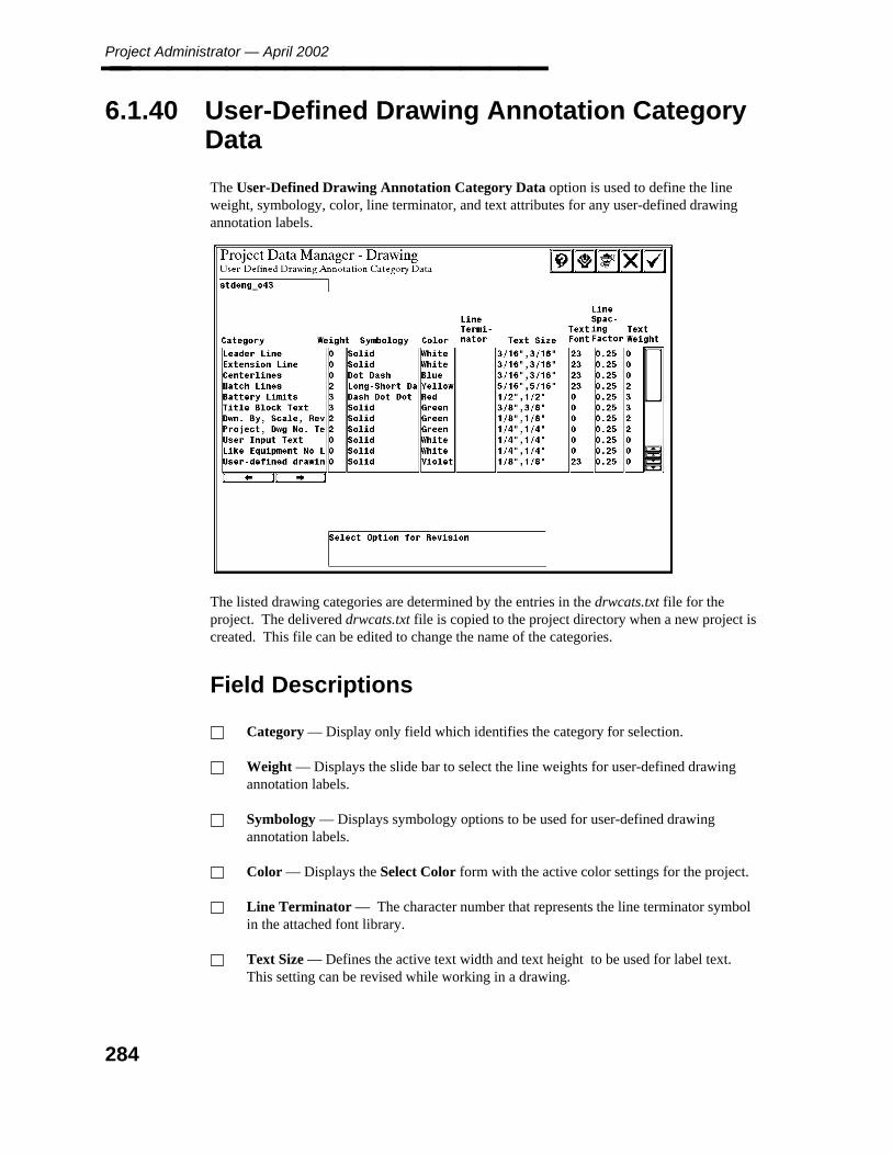
Project Administrator — April 2002________________
6.1.40 User-Defined Drawing Annotation CategoryData
The User-Defined Drawing Annotation Category Data option is used to define the lineweight, symbology, color, line terminator, and text attributes for any user-defined drawingannotation labels.
The listed drawing categories are determined by the entries in the drwcats.txt file for theproject. The delivered drwcats.txt file is copied to the project directory when a new project iscreated. This file can be edited to change the name of the categories.
Field Descriptions
Category — Display only field which identifies the category for selection.
Weight — Displays the slide bar to select the line weights for user-defined drawingannotation labels.
Symbology — Displays symbology options to be used for user-defined drawingannotation labels.
Color — Displays the Select Color form with the active color settings for the project.
Line Terminator — The character number that represents the line terminator symbolin the attached font library.
Text Size — Defines the active text width and text height to be used for label text.This setting can be revised while working in a drawing.
284
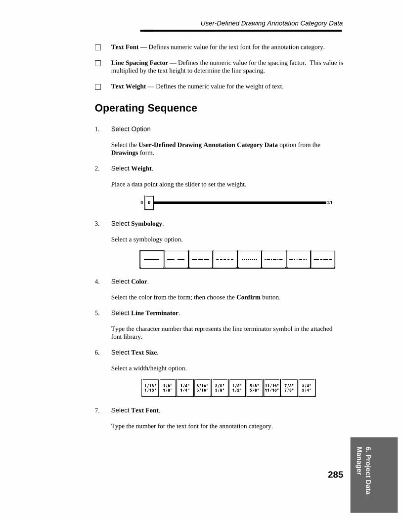
6. Pro
ject Data
Man
ager
User-Defined Drawing Annotation Category Data________________ Text Font — Defines numeric value for the text font for the annotation category.
Line Spacing Factor — Defines the numeric value for the spacing factor. This value ismultiplied by the text height to determine the line spacing.
Text Weight — Defines the numeric value for the weight of text.
Operating Sequence
1. Select Option
Select the User-Defined Drawing Annotation Category Data option from theDrawings form.
2. Select Weight.
Place a data point along the slider to set the weight.
3. Select Symbology.
Select a symbology option.
4. Select Color.
Select the color from the form; then choose the Confirm button.
5. Select Line Terminator.
Type the character number that represents the line terminator symbol in the attachedfont library.
6. Select Text Size.
Select a width/height option.
7. Select Text Font.
Type the number for the text font for the annotation category.
285
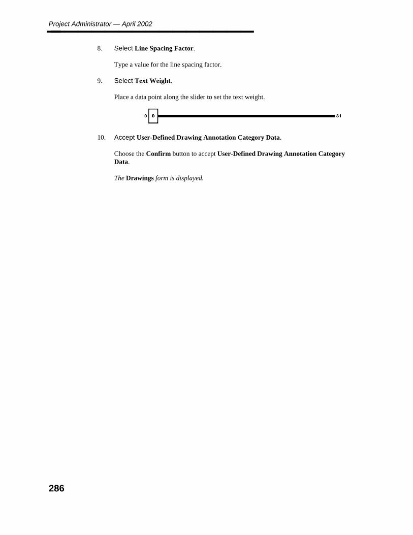
Project Administrator — April 2002________________
8. Select Line Spacing Factor.
Type a value for the line spacing factor.
9. Select Text Weight.
Place a data point along the slider to set the text weight.
10. Accept User-Defined Drawing Annotation Category Data.
Choose the Confirm button to accept User-Defined Drawing Annotation CategoryData.
The Drawings form is displayed.
286
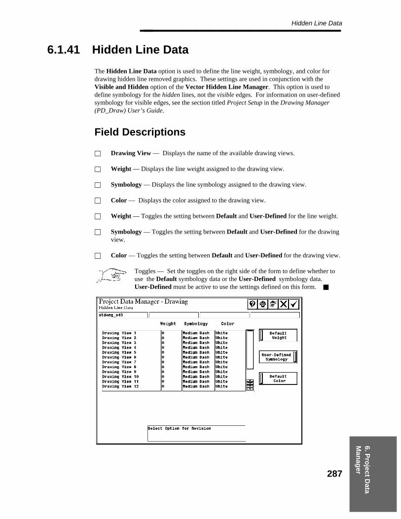
6. Pro
ject Data
Man
ager
Hidden Line Data________________
6.1.41 Hidden Line Data
The Hidden Line Data option is used to define the line weight, symbology, and color fordrawing hidden line removed graphics. These settings are used in conjunction with theVisible and Hidden option of the Vector Hidden Line Manager. This option is used todefine symbology for the hidden lines, not the visible edges. For information on user-definedsymbology for visible edges, see the section titled Project Setup in the Drawing Manager(PD_Draw) User’s Guide.
Field Descriptions
Drawing View — Displays the name of the available drawing views.
Weight — Displays the line weight assigned to the drawing view.
Symbology — Displays the line symbology assigned to the drawing view.
Color — Displays the color assigned to the drawing view.
Weight — Toggles the setting between Default and User-Defined for the line weight.
Symbology — Toggles the setting between Default and User-Defined for the drawingview.
Color — Toggles the setting between Default and User-Defined for the drawing view.
Toggles — Set the toggles on the right side of the form to define whether touse the Default symbology data or the User-Defined symbology data.User-Defined must be active to use the settings defined on this form.
287
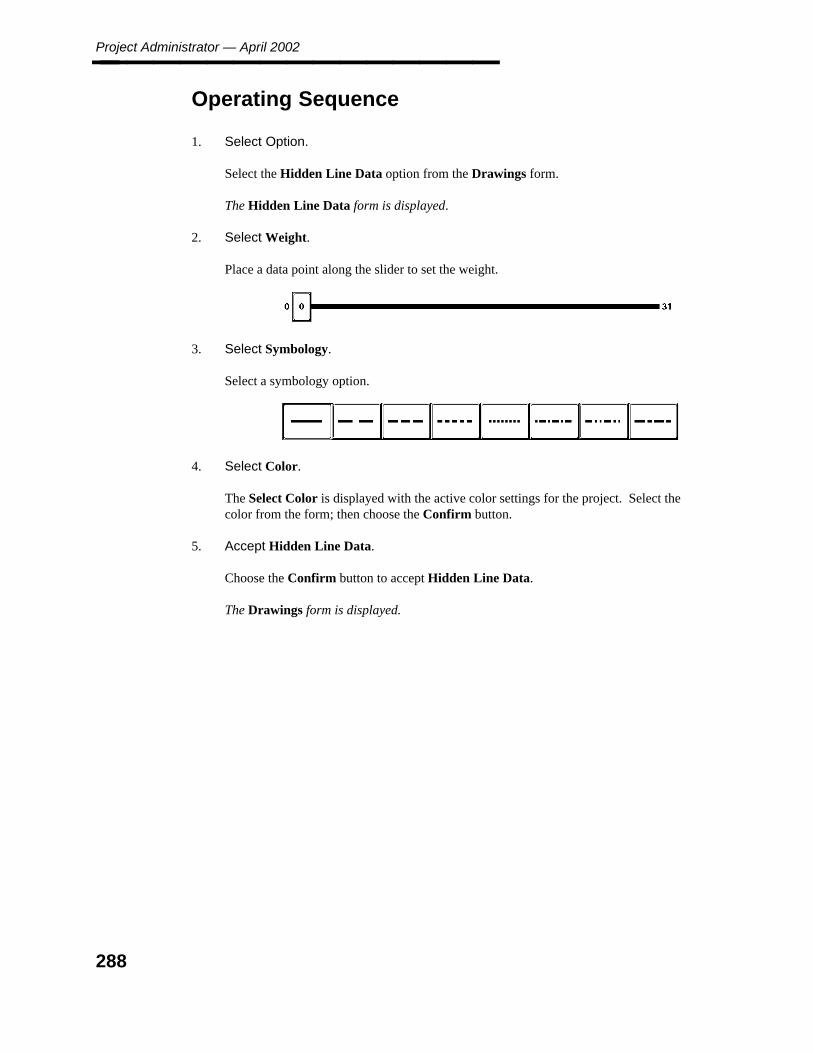
Project Administrator — April 2002________________
Operating Sequence
1. Select Option.
Select the Hidden Line Data option from the Drawings form.
The Hidden Line Data form is displayed.
2. Select Weight.
Place a data point along the slider to set the weight.
3. Select Symbology.
Select a symbology option.
4. Select Color.
The Select Color is displayed with the active color settings for the project. Select thecolor from the form; then choose the Confirm button.
5. Accept Hidden Line Data.
Choose the Confirm button to accept Hidden Line Data.
The Drawings form is displayed.
288
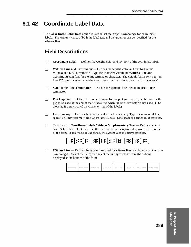
6. Pro
ject Data
Man
ager
Coordinate Label Data________________
6.1.42 Coordinate Label Data
The Coordinate Label Data option is used to set the graphic symbology for coordinatelabels. The characteristics of both the label text and the graphics can be specified for thewitness line.
Field Descriptions
Coordinate Label — Defines the weight, color and text font of the coordinate label.
Witness Line and Terminator — Defines the weight, color and text font of theWitness and Line Terminator. Type the character within the Witness Line andTerminator text font for the line terminator character. The default font is font 125. Infont 125, the character A produces a cross +o, F produces a *, and X produces an X.
Symbol for Line Terminator — Defines the symbol to be used to indicate a lineterminator.
Plot Gap Size — Defines the numeric value for the plot gap size. Type the size for thegap to be used at the end of the witness line when the line terminator is not used. (Theplot size is a function of the character size of the label.)
Line Spacing — Defines the numeric value for line spacing. Type the amount of linespace to be between multi-line Coordinate Labels. Line space is a function of text size.
Text Size for Coordinate Labels Without Supplementary Text — Defines the textsize. Select this field; then select the text size from the options displayed at the bottomof the form. If this value is undefined, the system uses the active text size.
Witness Line — Defines the type of line used for witness line (Symbology or AlternateSymbology>. Select the field; then select the line symbology from the optionsdisplayed at the bottom of the form.
289
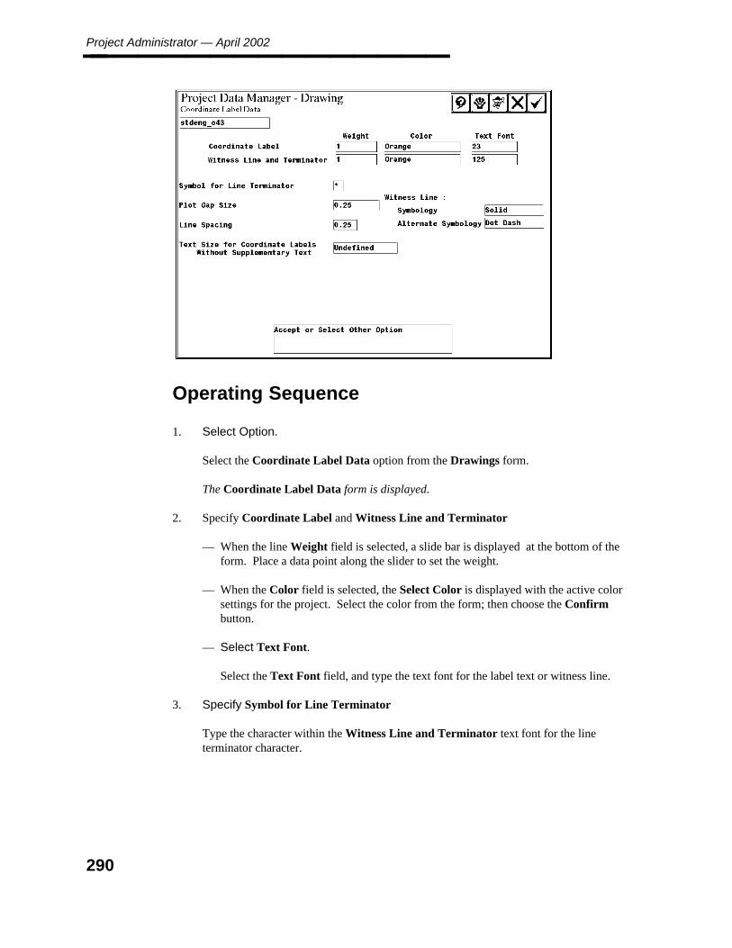
Project Administrator — April 2002________________
Operating Sequence
1. Select Option.
Select the Coordinate Label Data option from the Drawings form.
The Coordinate Label Data form is displayed.
2. Specify Coordinate Label and Witness Line and Terminator
— When the line Weight field is selected, a slide bar is displayed at the bottom of theform. Place a data point along the slider to set the weight.
— When the Color field is selected, the Select Color is displayed with the active colorsettings for the project. Select the color from the form; then choose the Confirmbutton.
— Select Text Font.
Select the Text Font field, and type the text font for the label text or witness line.
3. Specify Symbol for Line Terminator
Type the character within the Witness Line and Terminator text font for the lineterminator character.
290
6. Pro
ject Data
Man
ager
Coordinate Label Data________________
4. Specify Plot Gap Size
Type the size for the gap to be used at the end of the witness line when the lineterminator is not used.
5. Specify Line Spacing
Type the amount of line space to be between multi-line Coordinate Labels.
6. Select Witness Line
Select the field; then select the line symbology from the options displayed at the bottomof the form.
7. Select Text Size for Coordinate Labels Without Supplementary Text
Select this field; then select the text size from the options displayed at the bottom of theform.
8. Accept Coordinate Label Data.
Choose the Confirm button to accept the Coordinate Label Data.
The Drawings form is displayed.
291
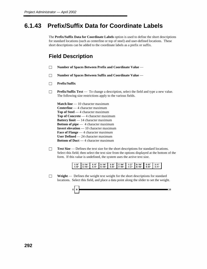
Project Administrator — April 2002________________
6.1.43 Prefix/Suffix Data for Coordinate Labels
The Prefix/Suffix Data for Coordinate Labels option is used to define the short descriptionsfor standard locations (such as centerline or top of steel) and user-defined locations. Theseshort descriptions can be added to the coordinate labels as a prefix or suffix.
Field Description
Number of Spaces Between Prefix and Coordinate Value —
Number of Spaces Between Suffix and Coordinate Value —
Prefix/Suffix
Prefix/Suffix Text — To change a description, select the field and type a new value.The following size restrictions apply to the various fields.
Match line — 10 character maximumCenterline — 4 character maximumTop of Steel — 4 character maximumTop of Concrete — 4 character maximumBattery limit — 14 character maximumBottom of pipe — 4 character maximumInvert elevation — 10 character maximumFace of Flange — 4 character maximumUser Defined — 24 character maximumBottom of Duct — 4 character maximum
Text Size — Defines the text size for the short descriptions for standard locations.Select this field; then select the text size from the options displayed at the bottom of theform. If this value is undefined, the system uses the active text size.
Weight — Defines the weight text weight for the short descriptions for standardlocations. Select this field, and place a data point along the slider to set the weight.
292
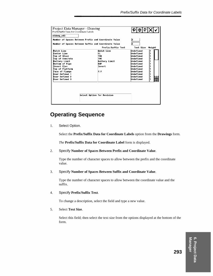
6. Pro
ject Data
Man
ager
Prefix/Suffix Data for Coordinate Labels________________
Operating Sequence
1. Select Option.
Select the Prefix/Suffix Data for Coordinate Labels option from the Drawings form.
The Prefix/Suffix Data for Coordinate Label form is displayed.
2. Specify Number of Spaces Between Prefix and Coordinate Value.
Type the number of character spaces to allow between the prefix and the coordinatevalue.
3. Specify Number of Spaces Between Suffix and Coordinate Value.
Type the number of character spaces to allow between the coordinate value and thesuffix.
4. Specify Prefix/Suffix Text.
To change a description, select the field and type a new value.
5. Select Text Size.
Select this field; then select the text size from the options displayed at the bottom of theform.
293

Project Administrator — April 2002________________
6. Select Weight.
Select this field, and place a data point along the slider to set the weight.
7. Accept Prefix/Suffix Data for Coordinate Labels.
Choose the Confirm button to accept the Prefix/Suffix Data for Coordinate Labels.
The Drawings form is displayed.
294

6. Pro
ject Data
Man
ager
Miscellaneous Label Data________________
6.1.44 Miscellaneous Label Data
The Miscellaneous Label Data option is used to define various label data and the settingsused to place a report file in a drawing.
Field Descriptions
Flow Arrow Cell Name — The symbol name for the flow direction arrow. The defaultsymbol name is FLOARR.
Symbol Font Number — The number for the text font for the report graphics. Anyvalid symbol font contained in the current font library may be used. Font 50 is the onlyIntergraph-delivered font with constant character width. If the font or font library isredefined, there may be some dependencies regarding the characters used in the symbolfont for diagnostic markers.
Line Spacing Factor — The value for the line spacing factor. This value is multipliedby the text height to determine the line spacing between the coordinate label and thematch line.
Line Spacing for Watchline Labels — The value for the line spacing factor. Thisvalue is multiplied by the text height to determine the line spacing.
Field Name for Nominal Piping Diameter — The symbol to be used for NPD ondrawings (such as IN or "). This value is used by the Name Label command for anydrawing labels that include the NPD attribute from a piping segment or from a piping orinstrument component.
Maximum Number of Blank Lines Between Text — A value to limit the number ofblank lines in the report.
Text Font for Date and Time for Plotting — The number for the text font to be usedfor the date and time stamp on plotted drawings.
Text Length Extensions — Specifies padding between the label text and the labelenclosure for the following label enclosure options. Circular Enclosure — The valueused to determine whether the label’s text fits within a circular label enclosure. Typethe extension to the text length as a scale factor (such as 0.25) applied to the averagetext width. The text length for the label is determined from the summation of the actualfont size for each character in the label’s text, as defined in the font library. Theaverage text width is determined by dividing the actual text length by the number ofcharacters in the label’s text. Rectangular Enclosure — The value used to determinethe length of a rectangular label enclosure. Type the extension to the text length as ascale factor (such as 0.25) applied to the average text width. The length of the rectangleis determined by the actual length of the label’s text for that specific label. The textlength is determined from the summation of the actual font size for each character in thelabel’s text, as defined in the font library. The average text width is determined bydividing the actual text length by the number of characters in the label’s text.
295

Project Administrator — April 2002________________ Prefix/Suffix Option for Matchline Labels — When either of these options (Eastingor Northing) is selected, the available prefix/suffix options are displayed.
Leader Line and Line Terminator Options toggle — The toggle at the bottom of theform to specify the leader line and line termination options to use. Default LeaderLine and Line Terminator Options tells the Place Name Label command to respectthe Leader Line On/Off option and the Line Terminator On/Off option, as defined inthe Label Description Library.
Override Leader Line and Line Terminator Options tells the Place Name Labelcommand to use the options defined at placement.
The default continues to be that label options, as specified through theReference Data Manager, are respected in drawing annotation.
296
6. Pro
ject Data
Man
ager
Miscellaneous Label Data________________
Operating Sequence
1. Select Option.
Select the Miscellaneous Label Data option from the Drawings form.
The Miscellaneous Label Data form is displayed.
2. Select Flow Arrow Cell Name.
Select the field, and type the symbol name for the flow direction arrow.
3. Specify Symbol Font Number.
Type the number for the text font for the report graphics.
4. Specify Line Spacing Factor.
Type a value for the line spacing factor.
5. Specify Line Spacing for Matchline Labels.
Type a value for the line spacing factor.
6. Specify Field Name for Nominal Piping Diameter.
Type the symbol to be used for NPD on drawings (such as IN or ").
7. Specify Maximum Number of Blank Lines between Text.
Type a value to limit the number of blank lines in the report.
8. Specify Text Font for Date and Time for Plotting.
Type the number for the text font to be used for the date and time stamp on plotteddrawings.
9. Specify Circular Enclosure
Type the extension to the text length as a scale factor (such as 0.25) applied to theaverage text width.
10. Specify Rectangular Enclosure.
Type the extension to the text length as a scale factor (such as 0.25) applied to theaverage text width.
297

Project Administrator — April 2002________________
11. Select Prefix/Suffix Option for Matchline Labels
When either of these options (Easting or Northing) is selected, select from thedisplayed available prefix/suffix options.
12. Select Leader Line and Line Terminator Option.
Use the toggle at the bottom of the form to specify the leader line and line terminationoptions to use.
13. Accept Miscellaneous Label Data.
Choose the Confirm button to accept Miscellaneous Label Data.
The Drawings form is displayed.
298

6. Pro
ject Data
Man
ager
Propagate Drawing Data________________
6.1.45 Propagate Drawing Data
The Propagate Drawing Data option applies settings from the specified drawing seed file toall drawings within the active project, all drawings of a specified drawing type, or a list ofselected drawings. If any alternate seed drawings have been defined with the DrawingManager’s Project Setup command, the source of this data can be selected. Otherwise, theproject seed drawing is the source of this data.
If the project seed drawing is selected, the extent of the propagated data optionallyincludes all drawings within the project, including any alternate seed drawings.
If one of the alternate seed drawings is selected, the extent of the data changes is limitedto the drawings that are associated with that drawing type.
If any changes are made through the Revise 3D Plant Design Data option, thosechanges are automatically propagated to the alternate seed drawings.
The only drawing data that cannot be propagated is the Drawing Category data, which shouldnot be revised after drawings have been created.
Field Descriptions
Seed File — The list of drawing seed files that are defined for the project.
Propagation Options — This option propagates the following Type 63 data:
Date/Time Format, page 187Label Text Sizes, page 275Reference Database File Specifications - Drawing Files, page 277Mass Annotation Data, page 279PDS Drawing Annotation Category Data, page 281User-Defined Drawing Annotation Category Data, page 284Hidden Line Data, page 287Coordinate Label Data, page 289Prefix/Suffix Data for Coordinate Labels, page 292Miscellaneous Label Data, page 295
Drawings toggle — Specifies All Drawings or Selected Drawings for propagation.Set the toggle to All Drawings to propagate the selected parameters to all the drawingsin the active project.
— OR —
Set the toggle to Selected Drawings to select the drawing files to be updated from a listof Drawing Types.
299
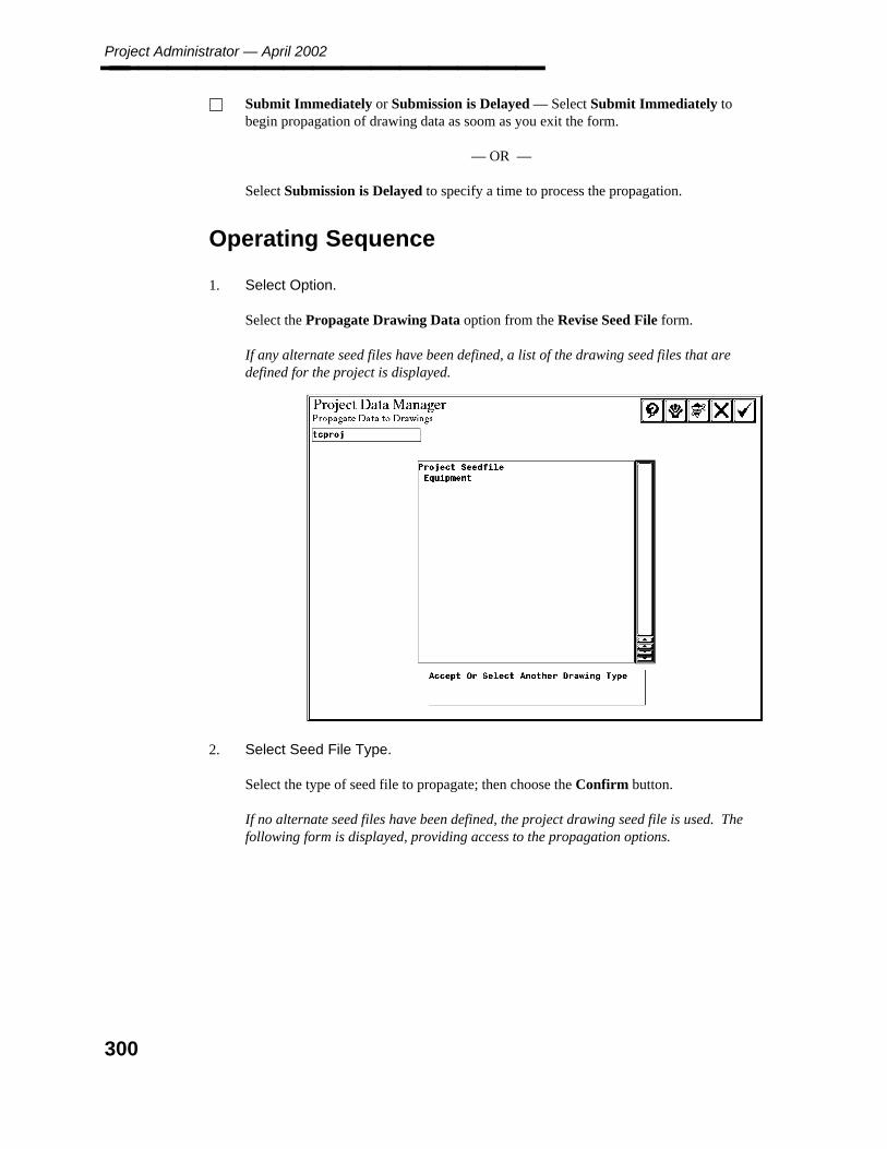
Project Administrator — April 2002________________ Submit Immediately or Submission is Delayed — Select Submit Immediately tobegin propagation of drawing data as soom as you exit the form.
— OR —
Select Submission is Delayed to specify a time to process the propagation.
Operating Sequence
1. Select Option.
Select the Propagate Drawing Data option from the Revise Seed File form.
If any alternate seed files have been defined, a list of the drawing seed files that aredefined for the project is displayed.
2. Select Seed File Type.
Select the type of seed file to propagate; then choose the Confirm button.
If no alternate seed files have been defined, the project drawing seed file is used. Thefollowing form is displayed, providing access to the propagation options.
300
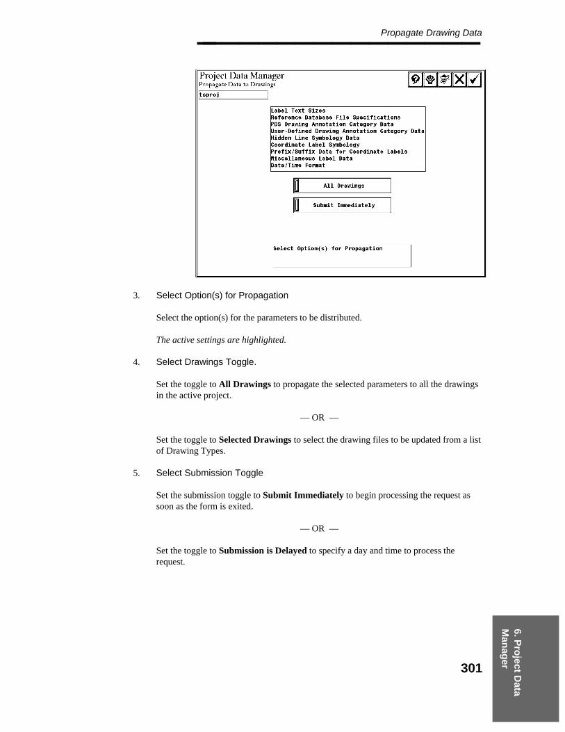
6. Pro
ject Data
Man
ager
Propagate Drawing Data________________
3. Select Option(s) for Propagation
Select the option(s) for the parameters to be distributed.
The active settings are highlighted.
4. Select Drawings Toggle.
Set the toggle to All Drawings to propagate the selected parameters to all the drawingsin the active project.
— OR —
Set the toggle to Selected Drawings to select the drawing files to be updated from a listof Drawing Types.
5. Select Submission Toggle
Set the submission toggle to Submit Immediately to begin processing the request assoon as the form is exited.
— OR —
Set the toggle to Submission is Delayed to specify a day and time to process therequest.
301
Project Administrator — April 2002________________
6. Accept Submission Time.
Choose the Confirm button to accept the specified time.
If the All Drawings option is active, go to Step 9.
7. Select Drawing Type
If Selected Drawings is selected, a list of drawing types is displayed.
8. Select the drawing type for the drawing(s) to be updated; then choose the Confirmbutton.
9. Select Drawing
Select the drawing(s) to be updated.
10. Accept to Submit for Processing or Select Type for Addition Drawings
Repeat Steps 5 and 6 to select additional drawings.
11. Choose the Confirm button to process the request.
The request is submitted to the batch queue named PDproject_data.
302
6. Pro
ject Data
Man
ager
Report of Seed File Data________________
6.1.46 Report of Seed File Data
The Report of Seed File Data option creates a printable copy of the data stored in the type 63elements for the project seed files. The report can be printed and/or save it as an ASCII file.If any alternate drawing seed files have been defined, the system also reports on the data inthese seed files. The generated report provides the following features:
The project number appears on the title page of the report.
The heading on each page of the report indicates the type of data being reported. Forexample,
Project Data Manager
3D Plant Design Data
Plant Coordinate System Definition
The contents of the report are ordered in the same sequence as the Project DataManager’s user interface.
Field Descriptions
Print/Delete — Submits the generated report output file to the specified print queueand deletes the output file.
Print/Save — Submits the generated report output file to the specified print queue andsaves the output file.
Save — Saves the output file without printing.
303
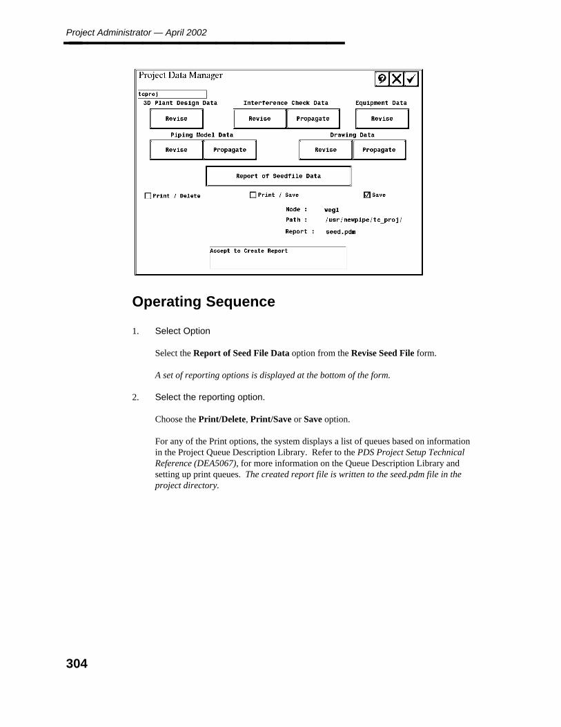
Project Administrator — April 2002________________
Operating Sequence
1. Select Option
Select the Report of Seed File Data option from the Revise Seed File form.
A set of reporting options is displayed at the bottom of the form.
2. Select the reporting option.
Choose the Print/Delete, Print/Save or Save option.
For any of the Print options, the system displays a list of queues based on informationin the Project Queue Description Library. Refer to the PDS Project Setup TechnicalReference (DEA5067), for more information on the Queue Description Library andsetting up print queues. The created report file is written to the seed.pdm file in theproject directory.
304
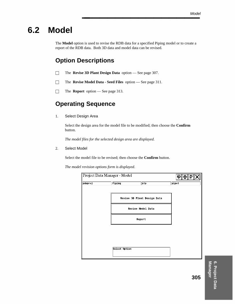
6. Pro
ject Data
Man
ager
Model________________
6.2 Model
The Model option is used to revise the RDB data for a specified Piping model or to create areport of the RDB data. Both 3D data and model data can be revised.
Option Descriptions
The Revise 3D Plant Design Data option — See page 307.
The Revise Model Data - Seed Files option — See page 311.
The Report option — See page 313.
Operating Sequence
1. Select Design Area
Select the design area for the model file to be modified; then choose the Confirmbutton.
The model files for the selected design area are displayed.
2. Select Model
Select the model file to be revised; then choose the Confirm button.
The model revision options form is displayed.
305

Project Administrator — April 2002________________
3. Select Option.
Select the model option to be performed.
The selected option is processed see Revise 3D Model Data, page 307
4. Select Revise Model Data - Seed Files see Revise Model Data - Seed Files, page 311
5. Select Report see Report, page 313
306
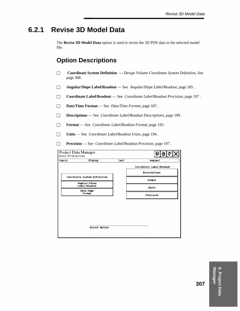
6. Pro
ject Data
Man
ager
Revise 3D Model Data________________
6.2.1 Revise 3D Model Data
The Revise 3D Model Data option is used to revise the 3D PDS data in the selected modelfile.
Option Descriptions
Coordinate System Definition — Design Volume Coordinate System Definition, Seepage 308.
Angular/Slope Label/Readout — See Angular/Slope Label/Readout, page 185 .
Coordinate Label/Readout — See Coordinate Label/Readout Precision, page 197 .
Date/Time Format — See Date/Time Format, page 187 .
Descriptions — See Coordinate Label/Readout Descriptions, page 189 .
Format — See Coordinate Label/Readout Format, page 192 .
Units — See Coordinate Label/Readout Units, page 194 .
Precision — See Coordinate Label/Readout Precision, page 197 .
307

Project Administrator — April 2002________________
6.2.2 Design Volume Coordinate System Definition
The Design Volume Coordinate System Definition option is used to modify the designvolume coordinate system parameters for the specified model. The coordinate system namecan be specified and the design volume monument (center point) of the coordinate system canbe defined. The design volume coordinate system (DVCS) is a second coordinate system (inaddition to the plant coordinate system) that can be defined for an individual model. A DVCSis only required if different models need to have their coordinates referenced from a differentpoint.
For more information, see the Design Volume Coordinate System section ofthe PDS 3D Theory User’s Guide.
To use a DVCS while working in a model or drawing, the active coordinatesystem must be defined with the Active Options command. If the designvolume monument is modified for a model, the design volume monumentmust also be revised for any drawings to use referencing those models.
Field Descriptions
Design Volume Coordinate System Description — Description of up to 40 charactersfor the Design Volume Coordinate System to be used for the model.
Monument in Design Volume Coordinate System — The easting, northing, andelevation coordinates associated with the design volume monument relative to theDesign Volume Coordinate System. The plant monument corresponds to MicroStationpoint 0,0,0 in the model.
Design Volume Monument in Plant Coordinate System — Defines the orientation ofthe plan view for display purposes. ↑North defines North at the top of the screen in aplan view. North→ defines North at the right of the screen in a plan view.
Orientation toggle – Defines the orientation of the plan view for display purposes.↑North defines North at the top of the screen in a plan view. North→ defines North atthe right of the screen in a plan view.
Origination of Design Volume Coordinate System as Clockwise Angular Offset ofDesign Volume North from Plant North. — The an angular offset to be applied to thedesign volume relative to the Plant Coordinate System.
If the DVCS is rotated, then all models should use this same angle. This isnecessary for all the reference model attachments to orient consistently in themodels and drawings.
If only certain models need to be rotated, the following alternative can be used.Create models with standard rotation and model the piping systemsorthogonally. When finished, use the Rotate Piping command to orient thepiping at the specific angle.
308

6. Pro
ject Data
Man
ager
Design Volume Coordinate System Definition________________
Relationship of Plant Monument and Design Volume Monument (Example)
Operating Sequence
1. Specify Design Volume Coordinate System Description.
Type up to 40 characters to describe the Design Volume Coordinate System to be usedfor the model.
309

Project Administrator — April 2002________________
2. Specify Monument in Design Volume Coordinate System.
Type the easting, northing, and elevation coordinates to be associated with the designvolume monument relative to the Design Volume Coordinate System.
3. Specify Orientation.
Define the orientation of the plan view for display purposes.
4. Specify Design Volume Monument in Plant Coordinate System.
Type the easting, northing, and elevation coordinates to be associated with the designvolume monument relative to the Design Volume Coordinate System.
5. Specify Orientation of Design Volume Coordinate System as Clockwise AngularOffset of Design Volume North from Plant North. Type an angular offset to beapplied to the design volume relative to the Plant Coordinate System.
6. Accept Design Volume Coordinate System Definition.
Choose the Confirm button to accept the Design Volume Coordinate SystemDefinition.
The Revise 3D Model Data form is displayed.
310
6. Pro
ject Data
Man
ager
Revise Model Data - Seed Files________________
6.2.3 Revise Model Data - Seed Files
The Revise Model Data option is used to revise the Model data for the selected model file.
Option Descriptions
Component Placement — See Component Placement, page 223 .
Piping Data Control — See Piping Data Control, page 226 .
Physical Units — See Physical Units, page 230 .
Nozzle Transfer — See Nozzle Transfer, page 233 .
Material Takeoff — See Material Takeoff, page 235 .
Design Review Label — See Design Review Label, page 239 .
Default Segment Data — See Default Segment Data, page 240 .
Reference Database File Specifications — SeeReference Database File Specifications - Review File Names, page 242 .
Design Checks
Options — See Design Checks Options, page 245 .End Prep Table — See Design Checks End Prep Table, page 248 .
Symbology —
Diagnostic Markers — See Symbology Diagnostic Markers, page 251 .Model — See Symbology - Model, page 254 .Level and Color
Model Category — See Model Category, page 260 .Fluid Code — See Fluid Code, page 263 .Construction Status — See Construction Status, page 266 .
311

Project Administrator — April 2002________________
Operating Sequence
1. Select the Revise Model Data option from the Project Data Manager - Model form.
2. Select the option for the type of model data to be revised. Refer to the followingsections for a description of the forms associated with these modification options.
312
6. Pro
ject Data
Man
ager
Report________________
6.2.4 Report
The Report option is used to create a report of the data stored in the type 63 elements for theselected model file. The report can be printed and/or saved as an ASCII file.
Field Descriptions
Print/Delete — Submits the generated report output file to the specified print queueand deletes the output file.
Print/Save — Submits the generated report output file to the specified print queue andsaves the output file.
Save — Saves the output file without printing.
Operating Sequence
1. Select Option
Select the Report option from the Project Data Manager - Model form.
The report options are displayed.
2. Select Report Option.
Choose the report option of Print/Delete, Print/Save or Save.
For any of the Print options, a list of queues is displayed based on information in theProject Queue Description Library. Refer to the PDS Project Setup TechnicalReference (DEA5067), for more information on the Queue Description Library andsetting up print queues.
3. Accept Report Options.
Choose the Confirm button create the report.
The created report file is written to the model.pdm file (where model is the active modelnumber) in the directory where the model file is located.
313
Project Administrator — April 2002________________
6.3 Equipment
The Equipment option is used to revise the RDB data for a specified Equipment model or tocreate a report of the RDB data. Both 3D data and model data can be revised.
Option Descriptions
Revise 3D Plant Design Data — See page 316.
Revise Equipment Data - Model Data — See page 318.
Report — See page 320.
Operating Sequence
1. Select Option.
Select the Equipment Model option from the Project Data Manager form.
2. Select Design Area.
Select the design area for the equipment model to be modified; then choose theConfirm button.
The model files for the selected design area are displayed.
3. Select Model
Select the equipment model file to be revised; then choose the Confirm button.
The model revision options form is displayed.
314
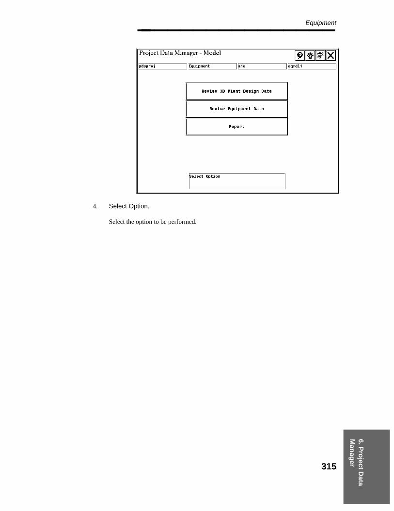
6. Pro
ject Data
Man
ager
Equipment________________
4. Select Option.
Select the option to be performed.
315
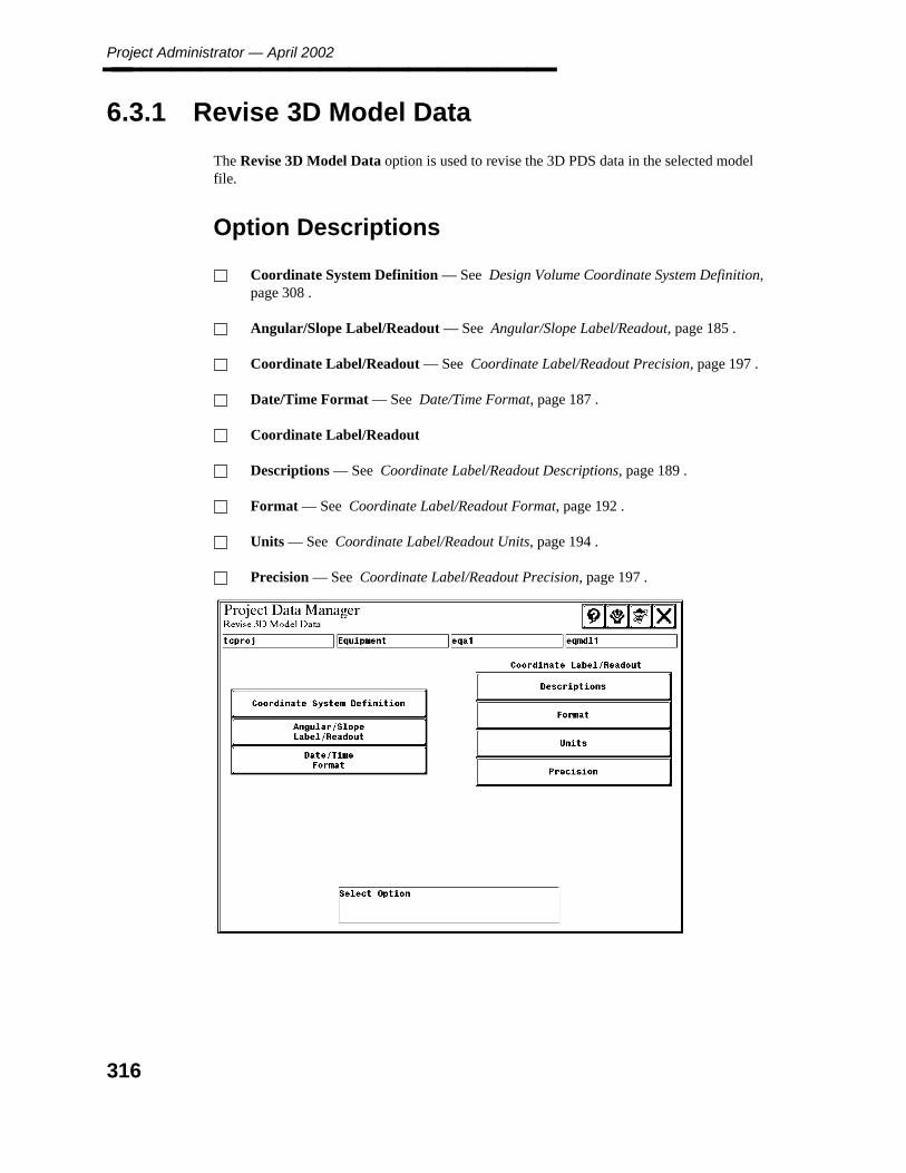
Project Administrator — April 2002________________
6.3.1 Revise 3D Model Data
The Revise 3D Model Data option is used to revise the 3D PDS data in the selected modelfile.
Option Descriptions
Coordinate System Definition — See Design Volume Coordinate System Definition,page 308 .
Angular/Slope Label/Readout — See Angular/Slope Label/Readout, page 185 .
Coordinate Label/Readout — See Coordinate Label/Readout Precision, page 197 .
Date/Time Format — See Date/Time Format, page 187 .
Coordinate Label/Readout
Descriptions — See Coordinate Label/Readout Descriptions, page 189 .
Format — See Coordinate Label/Readout Format, page 192 .
Units — See Coordinate Label/Readout Units, page 194 .
Precision — See Coordinate Label/Readout Precision, page 197 .
316

6. Pro
ject Data
Man
ager
Revise 3D Model Data________________
Operating Sequence
1. Select Option.
Select the Revise 3D Plant Design Data option from the Project Data Manager -Model form.
The Revise 3D Model Data form is displayed.
2. Select Option.
Select the option for the type of 3D data to be revised.
The form associated with the selected option is displayed.
317

Project Administrator — April 2002________________
6.3.2 Revise Equipment Data - Model Data
The Revise Equipment Data - Model Data option is used to revise the model data for theselected equipment model file.
Option Descriptions
Graphic Symbology — See Graphic Symbology, page 212 .
Nozzle Default Placement Options — See Nozzle Default Placement Options, page215 .
Reference Database File Specifications — See Reference Database FileSpecifications - Specify Approved or Unapproved, page 217 .
Interference Envelope Emulation Data — See Interference Envelope EmulationData, page 219 .
Operating Sequence
1. Select Option.
Select the Revise Equipment Data option from the Project Data Manager - Modelform.
The Revise Equipement Data form is displayed.
318

6. Pro
ject Data
Man
ager
Revise Equipment Data - Model Data________________
2. Select Option.
Select the option for the type of model data to be revised.
The form associated with the selected option is displayed.
319

Project Administrator — April 2002________________
6.3.3 Report
The Report option is used to create a printable copy of the data stored in the type 63 elementsfor the selected model file. The system displays the message Report Creation in Progress
The created report file is written to the file model.pdm in the project directory (where model isthe active equipment model number).
320

6. Pro
ject Data
Man
ager
Drawing________________
6.4 Drawing
The Drawing option is used to revise the RDB data for a specified drawing or to create areport of the RDB data. Both 3D data and drawing data can be revised.
Option Descriptions
Revise 3D Plant Design Data — See page 323.
Revise Drawing Data — See page 325.
Report — See page 327.
Operating Sequence
1. Select Option
Select the Drawing option from the Project Data Manager form.
The Drawing Types are displayed for selection.
2. Select Drawing Type
Select the drawing type for the drawing to be modified; then choose the Confirmbutton.
The drawing files for the selected type are displayed.
3. Select Drawing
Select the drawing file to be revised; then choose the Confirm button.
The drawing revision options form is displayed.
321
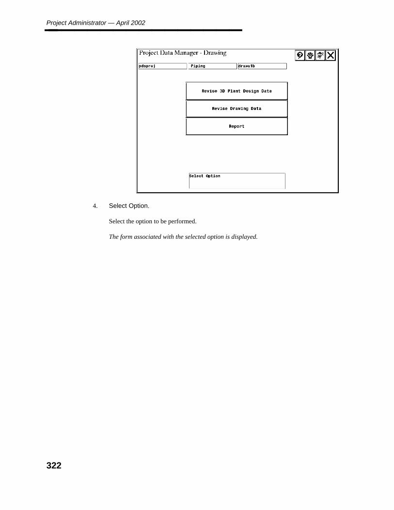
Project Administrator — April 2002________________
4. Select Option.
Select the option to be performed.
The form associated with the selected option is displayed.
322
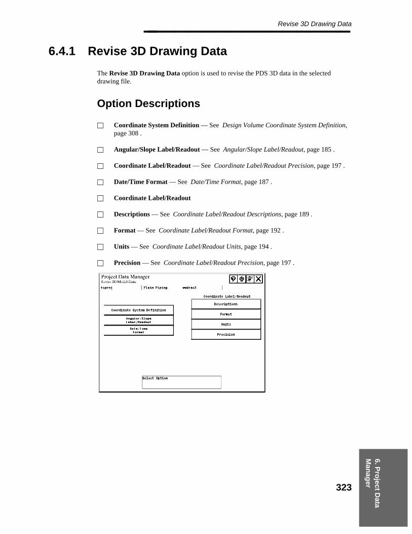
6. Pro
ject Data
Man
ager
Revise 3D Drawing Data________________
6.4.1 Revise 3D Drawing Data
The Revise 3D Drawing Data option is used to revise the PDS 3D data in the selecteddrawing file.
Option Descriptions
Coordinate System Definition — See Design Volume Coordinate System Definition,page 308 .
Angular/Slope Label/Readout — See Angular/Slope Label/Readout, page 185 .
Coordinate Label/Readout — See Coordinate Label/Readout Precision, page 197 .
Date/Time Format — See Date/Time Format, page 187 .
Coordinate Label/Readout
Descriptions — See Coordinate Label/Readout Descriptions, page 189 .
Format — See Coordinate Label/Readout Format, page 192 .
Units — See Coordinate Label/Readout Units, page 194 .
Precision — See Coordinate Label/Readout Precision, page 197 .
323

Project Administrator — April 2002________________
Operating Sequence
1. Select Option
Select the Revise 3D Plant Design Data option from the Project Data Manager -Drawing form.
The Revise 3D Model Data form is displayed.
2. Select Option.
Select the option for the type of 3D data to be revised.
The form associated with the selected option is displayed.
324
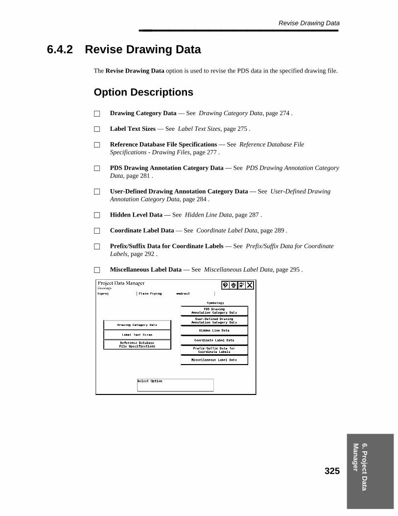
6. Pro
ject Data
Man
ager
Revise Drawing Data________________
6.4.2 Revise Drawing Data
The Revise Drawing Data option is used to revise the PDS data in the specified drawing file.
Option Descriptions
Drawing Category Data — See Drawing Category Data, page 274 .
Label Text Sizes — See Label Text Sizes, page 275 .
Reference Database File Specifications — See Reference Database FileSpecifications - Drawing Files, page 277 .
PDS Drawing Annotation Category Data — See PDS Drawing Annotation CategoryData, page 281 .
User-Defined Drawing Annotation Category Data — See User-Defined DrawingAnnotation Category Data, page 284 .
Hidden Level Data — See Hidden Line Data, page 287 .
Coordinate Label Data — See Coordinate Label Data, page 289 .
Prefix/Suffix Data for Coordinate Labels — See Prefix/Suffix Data for CoordinateLabels, page 292 .
Miscellaneous Label Data — See Miscellaneous Label Data, page 295 .
325

Project Administrator — April 2002________________
Operating Sequence
1. Select Option.
Select the Revise Drawing Data option from the Project Data Manager - Drawingform.
The Revise 3D Model Data form is displayed.
2. Select Option.
Select the option for the type of drawing data to be revised.
The form associated with the selected option is displayed.
326

6. Pro
ject Data
Man
ager
Report________________
6.4.3 Report
The Report option is used to create a printable copy of the data stored in the type 63 elementsfor the selected drawing file.
Field Descriptions
Print/Delete — Submits the generated report output file to the specified print queueand deletes the output file.
Print/Save — Submits the generated report output file to the specified print queue andsaves the output file.
Save — Saves the output file without printing.
Operating Sequence
1. Select Option.
Select the Report option from the Drawing form.
A set of reporting options is displayed at the bottom of the form.
2. Select the reporting option.
Choose the Print/Delete, Print/Save or Save option.
For any of the Print options, a list of queues is displayed based on information in theProject Queue Description Library. Refer to the PDS Project Setup TechnicalReference (DEA5067), for more information on the Queue Description Library andsetting up print queues.
327

Project Administrator — April 2002________________
3. Accept Report Options.
Choose the Confirm button create the report.
The created report file is written to the file draw.pdm (where draw is the active drawingnumber) in the directory where the drawing file is located.
328

6. Pro
ject Data
Man
ager
Interference________________
6.5 Interference
The Interference option is used to revise the RDB data for a specified interference markerfile or to create a report of the RDB data. Both 3D data and interference data can be revised.When revising data, the system locks the selected design area Interference Managementmodels using data in the Project Control Database.
Option Descriptions
Revise 3D Plant Design Data — See Revise 3D Model Data, page 181 .
Revise Interference Check Data — See Revise Interference Check Data, page 200 .
Report — See Report, page 313 . The Report option is used to create a printablecopy of the data stored in the type 63 elements for the selected design area interferencemarker file.
Operating Sequence
1. Select Interference Option.
Select the Interference option from the Project Data Manager form.
The Select Discipline form is displayed.
329

Project Administrator — April 2002________________
2. Select Discipline
Select the discipline for the interference marker file to be modified; then choose theConfirm button.
The design areas for the selected discipline are displayed.
3. Select Design Area
Select the design area for the interference marker file to be revised; then choose theConfirm button.
The interference revision options form is displayed.
4. Select Option
Select the option to be performed.
The form associated with the selected option is displayed.
330

7. Pro
ject C
on
trol
Project Control Manager________________
7. Project Control Manager
The Project Control Manager enables you to create a package of project documents for usein revision control. A package can include any of the documents that are associated with aproject such as isometric drawings, orthographic drawings, and reports. You can definepackage information in the project control database and report on this information for revisioncontrol.
Project Control Manager Form
The Project Control Manager form is used to:
Insert, revise, or delete report format files for project control reports.Create, revise, or delete discrimination data for project control reports.Create or revise a project control report file and generate a report using an existing report file.Define the default node name and path for the report definition files in the Project Control Database.Define the project documents that make up a package.
Option Descriptions
Report Format — Used to insert, revise, or delete report format files for projectcontrol reports.
Report Discrimination Data — Used to create, revise, or delete discrimination datafor project control reports.
331

Project Administrator — April 2002________________ Report — Used to create or revise a project control report file and generate a reportusing an existing report file.
Report Management Data — Used to define the default node name and path for thereport definition files in the Project Control Database.
Package — Used to define the project documents that make up a package.
Project Control Database TableRelationships
The Project Control Database recognizes relationships between many tables as one record ofdata for the purposes of reporting. Because many tables in the Project Control Database haverelationships to other tables, the report format indexes support report formats such that datafrom different tables within the Project Control Database can be sorted and reported as if itwas one set of data. Because each record of data can only include one unique row of data,only columns that form a relationship to other tables for a unique value can be used as thesource of the data. In other words, a column that forms a relationship to another table must bea one-to-one relationship or a many-to-one relationship — not a one-to-many relationship.
For example, in the Clash Management Data Table (PDtable_131), column 4 is theunique_sequence_no. A corresponding column (column 12) exists in the Clash Data PerProject Table (PDtable_132), the recent_sequence_no. There are typically many rows in theClash Data Per Project Table that reference each row of the Clash Management Data Table.Therefore, when formatting data to be reported from the Clash Data Per Project Table, youcan reference the Clash Management Data Table using column 12, which represents therelationship. However, if you are formatting data to be reported from the Clash ManagementData Table, you cannot reference the Clash Data Per Project Table using column 4, since therewould be many rows of the Clash Data Per Project Table for which column 12 had the samevalue as column 4 of the Clash Management Data Table.
The following example describes the construct that is required to include relationships withinthe report format.
DAt#c1[#c2][#c3]..... = Project Control Data report format indexes,where
t = table numberc1 = column number for preceding table number[c2] = optional column numbers which forms the
relationship to the previous column number, c1[c3] = optional column numbers which forms the
relationship to the previous column number, c2
Refer to the Report Manager Reference Guide for more information on defining indexes forProject Control report format files.
The following is a list of relationships that can be used in formatting reports of data in theProject Control Database.
332

7. Pro
ject C
on
trol
Project Control Manager________________ Source RelationshipTable Name Col No Table Name Col No
PDtable_112 1 PDtable_111 1
PDtable_113 2 PDtable_111 1PDtable_113 3 PDtable_112 1
PDtable_121 19 PDtable_125 2
PDtable_122 5 PDtable_121 1
PDtable_123 1 PDtable_122 1PDtable_123 2 PDtable_113 1
PDtable_124 5 PDtable_121 1PDtable_124 6 PDtable_122 1PDtable_124 7 PDtable_122 1PDtable_124 8 PDtable_122 1PDtable_124 9 PDtable_122 1PDtable_124 10 PDtable_122 1PDtable_124 11 PDtable_122 1PDtable_124 12 PDtable_122 1PDtable_124 13 PDtable_122 1PDtable_124 14 PDtable_122 1PDtable_124 15 PDtable_122 1
PDtable_125 1 PDtable_121 1
PDtable_131 2 PDtable_111 1PDtable_131 3 PDtable_112 2
PDtable_132 3 PDtable_134 1PDtable_132 4 PDtable_134 1PDtable_132 5 PDtable_113 1PDtable_132 6 PDtable_113 1PDtable_132 7 PDtable_111 1PDtable_132 8 PDtable_111 1PDtable_132 12 PDtable_131 4PDtable_132 13 PDtable_112 2PDtable_132 14 PDtable_111 1
PDtable_133 2 PDtable_132 1PDtable_133 3 PDtable_131 4
PDtable_134 4 PDtable_113 1
PDtable_135 2 PDtable_132 1
PDtable_136 2 PDtable_132 1
PDtable_141 15 PDtable_142 1
333

Project Administrator — April 2002________________ PDtable_141 16 PDtable_143 1PDtable_141 17 PDtable_144 1
PDtable_144 1 PDtable_141 1
PDtable_162 2 PDtable_161 1
PDtable_180 2 PDtable_182 1
PDtable_181 5 PDtable_182 1
PDtable_183 2 PDtable_112 2PDtable_183 3 PDtable_112 2PDtable_183 4 PDtable_112 2PDtable_183 5 PDtable_112 2PDtable_183 6 PDtable_112 2PDtable_183 7 PDtable_112 2PDtable_183 11 PDtable_184 1PDtable_183 12 PDtable_182 1PDtable_183 13 PDtable_112 2PDtable_183 14 PDtable_112 2PDtable_183 15 PDtable_112 2PDtable_183 16 PDtable_112 2PDtable_183 17 PDtable_112 2PDtable_183 18 PDtable_112 2PDtable_183 19 PDtable_112 2PDtable_183 20 PDtable_112 2PDtable_183 21 PDtable_112 2PDtable_183 22 PDtable_112 2
PDtable_185 2 PDtable_183 1PDtable_185 18 PDtable_184 1
PDtable_186 2 PDtable_185 1PDtable_186 12 PDtable_182 1
334
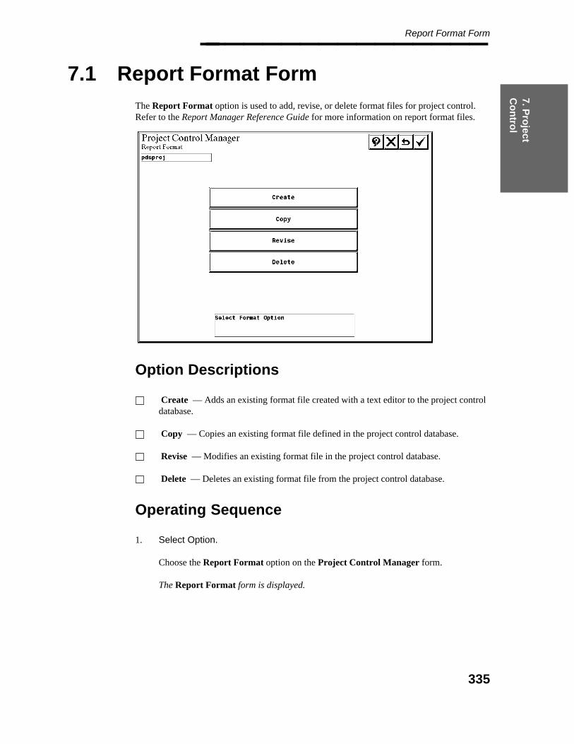
7. Pro
ject C
on
trol
Report Format Form________________
7.1 Report Format Form
The Report Format option is used to add, revise, or delete format files for project control.Refer to the Report Manager Reference Guide for more information on report format files.
Option Descriptions
Create — Adds an existing format file created with a text editor to the project controldatabase.
Copy — Copies an existing format file defined in the project control database.
Revise — Modifies an existing format file in the project control database.
Delete — Deletes an existing format file from the project control database.
Operating Sequence
1. Select Option.
Choose the Report Format option on the Project Control Manager form.
The Report Format form is displayed.
335

Project Administrator — April 2002________________
7.1.1 Format Creation/Revision Form
When you select Create, Copy, or Revise from the Report Format form, the ProjectControl Manager Format Creation/Revision form is displayed.
This form creates, copies, or revises a record in the project control database; this recorddefines the location of a format file. The format file itself defines the contents and format ofthe report. Both the location specification and the format file must exist to report on PDSdata.
Field Descriptions
Number — Type up to 20 characters for the format file to be created.
Description — Type up to 49 characters to describe the format file.
File Specification — Type the file name of the ASCII format file to be processed.
Path — Displays the disk location of the report format file. This field may be updated.The Path field retains the active setting.
Node — Displays the node name where the report format file is located. This field maybe updated. The Node field retains the active setting.
Before Using this Command
You must create an ASCII report format file. A set of sample format files is delivered withthe PD_Project product in the \win32app\ingr\pdprojec\sample directory.
model_mgt.fmt — Report format for model management data including the pre-definedvolume for a design area.
336

7. Pro
ject C
on
trol
Format Creation/Revision Form________________ draw_mgt.fmt — Report format for orthographic drawing management data.
iso_mgt.fmt — Report format for isometric drawing management data.
iso_rev.fmt — Report format for isometric drawing revision management data.
Operating Sequence
1. Select Option.
Select Create, Copy, or Revise from the Report Format form.
A list of available records displays for copy or revision. To create a database record,go to Step 3.
2. Select Report Format
From the displayed list, select the record to be copied or revised. Then select Accept.
Key-in fields are displayed for you to specify the required database information.
3. Specify Report Format Data
Type the format file information.
— Number
— Description
— File Specification
The system verifies the report format file exists on the system and the file does notalready exist in the project.
4. Specify Path.
Type the disk location of the report format file. The Path field retains the active setting.
5. Specify Node
Type the node name where the report format file is located. The Node field retains theactive setting.
6. Accept Report Format File.
Choose the Confirm button to add the specified format file to the project controldatabase.
337

Project Administrator — April 2002________________ The message Format File Data Entry Created is displayed.
7. Choose the Cancel button to exit the form.
— OR —
Add another report format file to the project.
338

7. Pro
ject C
on
trol
Format Deletion Form________________
7.1.2 Format Deletion Form
The Delete Report Format File option is used to delete an existing format file from theproject control database.
Field Descriptions
Number — Displays the format file number.
Description — Displays the format file description.
Operating Sequence
1. Select Option
Select the Delete option from the Report Format form.
A list of the defined project control report format files for the active project isdisplayed.
2. Select Format
Select the format file to be deleted; then choose the Confirm button.
339

Project Administrator — April 2002________________
3. Accept to Delete Format Data
Choose the Confirm button to delete the identified format file.
The format file is deleted from the project control database.
The Format Data has been Deleted message is displayed.
340
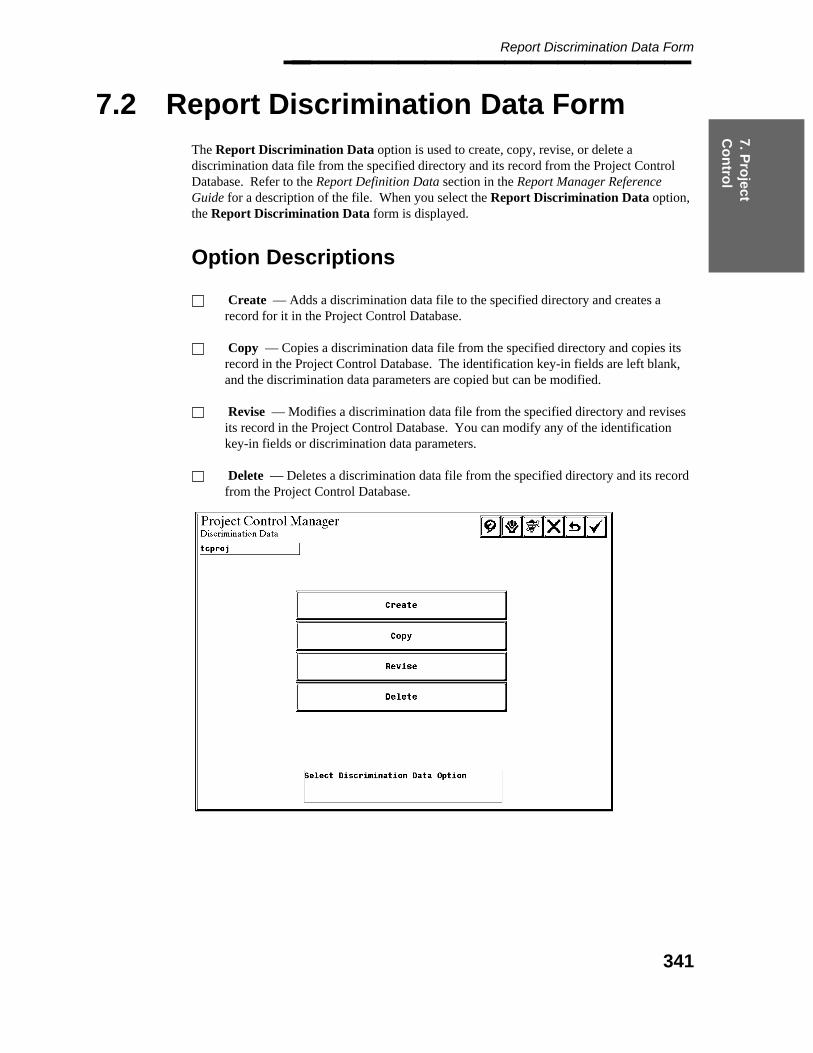
7. Pro
ject C
on
trol
Report Discrimination Data Form________________
7.2 Report Discrimination Data Form
The Report Discrimination Data option is used to create, copy, revise, or delete adiscrimination data file from the specified directory and its record from the Project ControlDatabase. Refer to the Report Definition Data section in the Report Manager ReferenceGuide for a description of the file. When you select the Report Discrimination Data option,the Report Discrimination Data form is displayed.
Option Descriptions
Create — Adds a discrimination data file to the specified directory and creates arecord for it in the Project Control Database.
Copy — Copies a discrimination data file from the specified directory and copies itsrecord in the Project Control Database. The identification key-in fields are left blank,and the discrimination data parameters are copied but can be modified.
Revise — Modifies a discrimination data file from the specified directory and revisesits record in the Project Control Database. You can modify any of the identificationkey-in fields or discrimination data parameters.
Delete — Deletes a discrimination data file from the specified directory and its recordfrom the Project Control Database.
341
Project Administrator — April 2002________________
Operating Sequence
1. Select Option.
Select the Report Discrimination Data option from the Project Control Managerform.
The Discrimination Data form is displayed.
2. Select Report Discrimination Option.
Choose from the Create, Copy, Revise, or Delete options.
— OR —
Choose the Cancel button to exit the form.
342
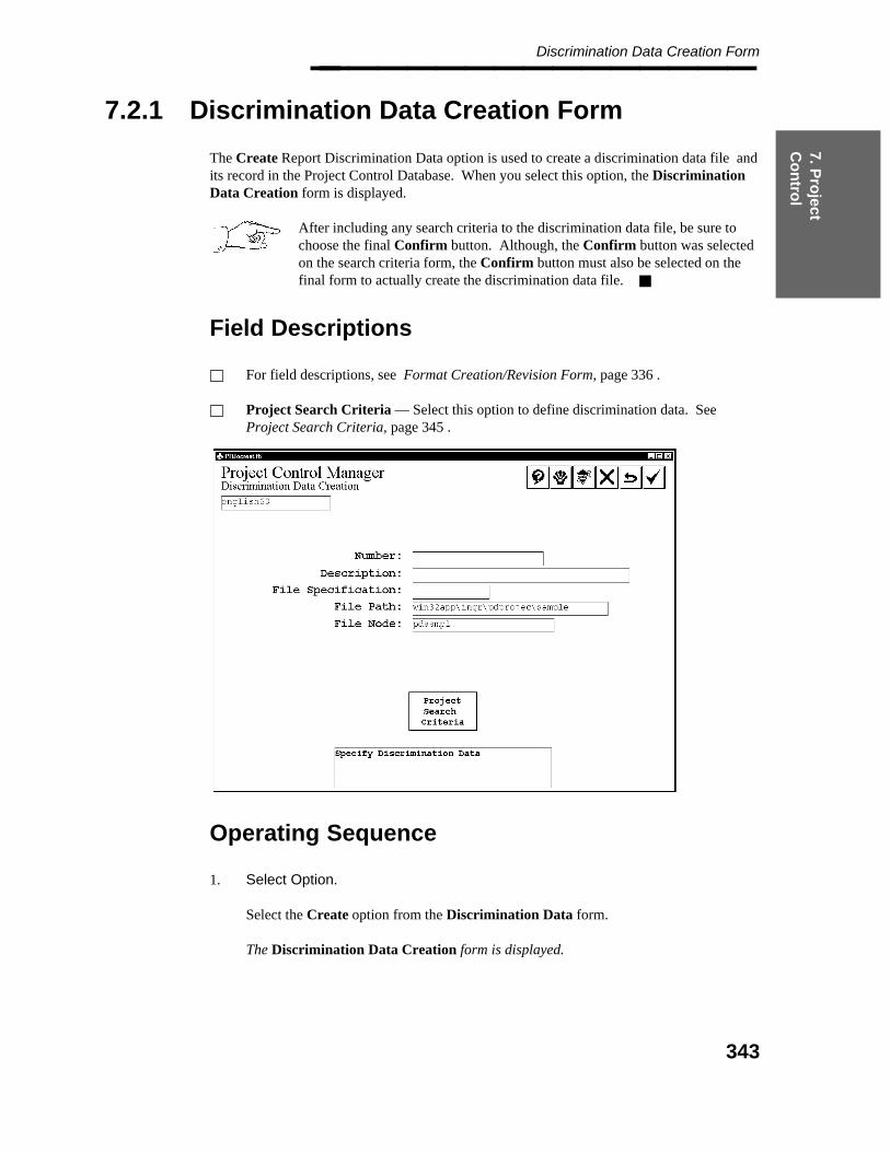
7. Pro
ject C
on
trol
Discrimination Data Creation Form________________
7.2.1 Discrimination Data Creation Form
The Create Report Discrimination Data option is used to create a discrimination data file andits record in the Project Control Database. When you select this option, the DiscriminationData Creation form is displayed.
After including any search criteria to the discrimination data file, be sure tochoose the final Confirm button. Although, the Confirm button was selectedon the search criteria form, the Confirm button must also be selected on thefinal form to actually create the discrimination data file.
Field Descriptions
For field descriptions, see Format Creation/Revision Form, page 336 .
Project Search Criteria — Select this option to define discrimination data. SeeProject Search Criteria, page 345 .
Operating Sequence
1. Select Option.
Select the Create option from the Discrimination Data form.
The Discrimination Data Creation form is displayed.
343

Project Administrator — April 2002________________
2. Specify Discrimination Data
Type the discrimination data file information.
The system verifies that the file does not already have a record in the project.
3. Specify Path
Type the disk location of the discrimination data file.
This field retains the active setting.
4. Specify Node
Type the node name where the discrimination data file is located.
This field retains the active setting.
5. Select Project Search Criteria.
Select the Project Search Criteria option to define the discrimination data.
For more information, see Project Search Criteria, page 345 .
344
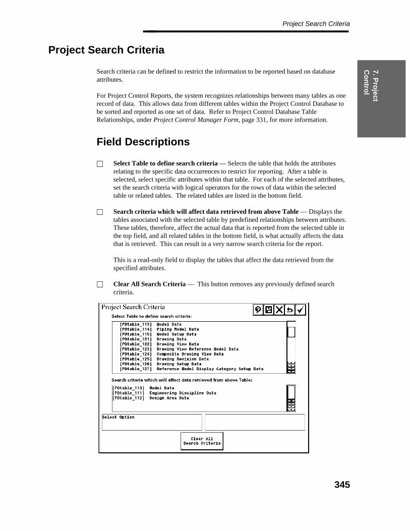
7. Pro
ject C
on
trol
Project Search Criteria________________
Project Search Criteria
Search criteria can be defined to restrict the information to be reported based on databaseattributes.
For Project Control Reports, the system recognizes relationships between many tables as onerecord of data. This allows data from different tables within the Project Control Database tobe sorted and reported as one set of data. Refer to Project Control Database TableRelationships, under Project Control Manager Form, page 331, for more information.
Field Descriptions
Select Table to define search criteria — Selects the table that holds the attributesrelating to the specific data occurrences to restrict for reporting. After a table isselected, select specific attributes within that table. For each of the selected attributes,set the search criteria with logical operators for the rows of data within the selectedtable or related tables. The related tables are listed in the bottom field.
Search criteria which will affect data retrieved from above Table — Displays thetables associated with the selected table by predefined relationships between attributes.These tables, therefore, affect the actual data that is reported from the selected table inthe top field, and all related tables in the bottom field, is what actually affects the datathat is retrieved. This can result in a very narrow search criteria for the report.
This is a read-only field to display the tables that affect the data retrieved from thespecified attributes.
Clear All Search Criteria — This button removes any previously defined searchcriteria.
345
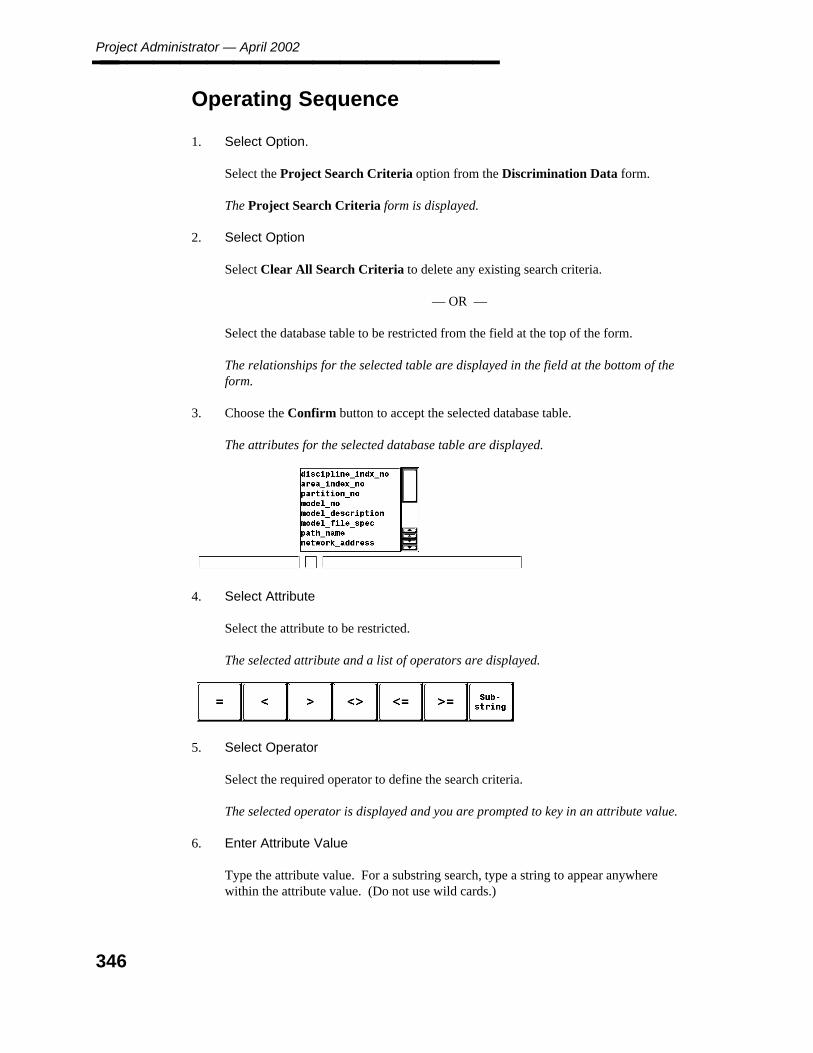
Project Administrator — April 2002________________
Operating Sequence
1. Select Option.
Select the Project Search Criteria option from the Discrimination Data form.
The Project Search Criteria form is displayed.
2. Select Option
Select Clear All Search Criteria to delete any existing search criteria.
— OR —
Select the database table to be restricted from the field at the top of the form.
The relationships for the selected table are displayed in the field at the bottom of theform.
3. Choose the Confirm button to accept the selected database table.
The attributes for the selected database table are displayed.
4. Select Attribute
Select the attribute to be restricted.
The selected attribute and a list of operators are displayed.
5. Select Operator
Select the required operator to define the search criteria.
The selected operator is displayed and you are prompted to key in an attribute value.
6. Enter Attribute Value
Type the attribute value. For a substring search, type a string to appear anywherewithin the attribute value. (Do not use wild cards.)
346

7. Pro
ject C
on
trol
Project Search Criteria________________ If the attribute is code-listed, a list of values from the standard note library is displayed.Select the value; then choose the Confirm button.
If the attribute has a date value, the Define Date Time form is displayed.
The system validates the input and displays the defined search criteria.
7. Accept or Select And/Or Operator
Select AND to specify an additional condition or select OR to specify an alternativecondition.
— OR —
Choose the Confirm button to accept the defined search criteria.
347

Project Administrator — April 2002________________
7.2.2 Copy Report Discrimination Data
The Copy Report Discrimination Data option is used to copy a discrimination data file andcreate a record in the Project Control Database. The copied discrimination data file can bemodified.
Field Descriptions
For more information see Format Creation/Revision Form, page 336 .
Project Search Criteria — see Project Search Criteria, page 345 .
Operating Sequence
1. Select Option.
Select the Copy option from the Discrimination Data form.
A list of all the defined discrimination data files for the active project is displayed.
2. Select Discrimination Data
Select the record number of the discrimination data file to copy; then choose theConfirm button.
The discrimination data file and its record are copied, and the Discrimination DataRevision form is displayed. The first three identification fields are empty so that youcan specify the new data for the new discrimination data record.
348

7. Pro
ject C
on
trol
Copy Report Discrimination Data________________
3. Specify New Data for Copy
Type data to define the discrimination data record.
— Number — see Format Creation/Revision Form, page 336 .
— Description — see Format Creation/Revision Form, page 336 .
— File Specification — see Format Creation/Revision Form, page 336 .
The system verifies the file does not already have a record in the project.
4. Select as many options as necessary to revise the discrimination data file.
5. Select Project Search Criteria
Select the Project Search Criteria option to define the discrimination data.
6. Accept Discrimination Data
Choose the Confirm button to save the new discrimination data to a file and its newrecord to the the Project Control Database.
Discrimination Data Entry Created
7. Dismiss Form
Choose the Cancel button to dismiss the form.
349
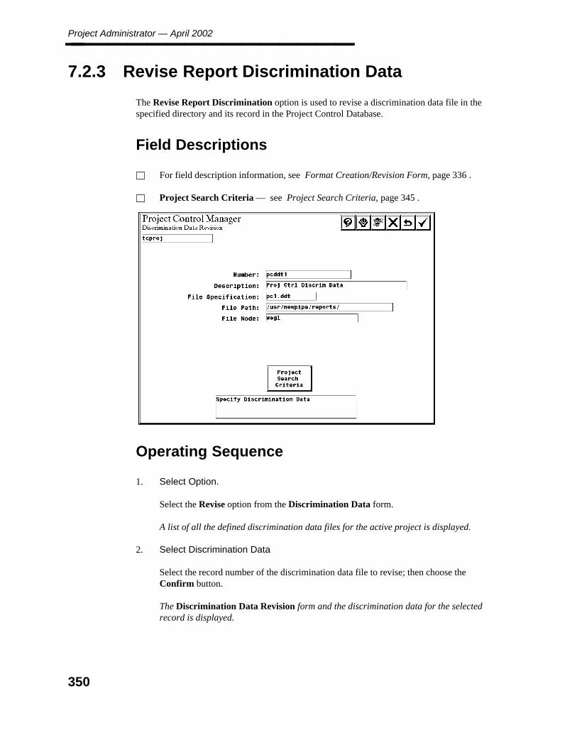
Project Administrator — April 2002________________
7.2.3 Revise Report Discrimination Data
The Revise Report Discrimination option is used to revise a discrimination data file in thespecified directory and its record in the Project Control Database.
Field Descriptions
For field description information, see Format Creation/Revision Form, page 336 .
Project Search Criteria — see Project Search Criteria, page 345 .
Operating Sequence
1. Select Option.
Select the Revise option from the Discrimination Data form.
A list of all the defined discrimination data files for the active project is displayed.
2. Select Discrimination Data
Select the record number of the discrimination data file to revise; then choose theConfirm button.
The Discrimination Data Revision form and the discrimination data for the selectedrecord is displayed.
350

7. Pro
ject C
on
trol
Revise Report Discrimination Data________________
3. Specify Discrimination Data
Type any changes to the discrimination data record displayed in the information fields.
4. Select as many options as necessary to revise the discrimination data file.
5. Select Search Criteria.
Select the Project Search Criteria option to define the discrimination data.
For more information, see Project Search Criteria, page 345 .
6. Accept Discrimination Data Revisions
Choose the Confirm button to accept the revisions to the discrimination data file and itsrecord.
7. Dismiss Form.
Choose the Cancel button to dismiss the form.
The Discrimination Data form is displayed.
351

Project Administrator — April 2002________________
7.2.4 Discrimination Data Deletion Form
The Delete Report Discrimination Data option is used to delete a discrimination data filefrom the specified directory and its record from the Project Control Database.
Operating Sequence
1. Select Option
Select the Delete option from the Discrimination Data form.
The Deletion form and a record Number list that includes all of the defined formatfiles for the active project are displayed.
2. Select Discrimination Data
Select the record number of the discrimination data file to delete; then choose theConfirm button.
3. Accept to Delete Discrimination Data
Choose the Confirm button to delete the discrimination data file from your directoryand its record from the Project Control Database.
The Discrimination Data has been Deleted message is displayed.
352
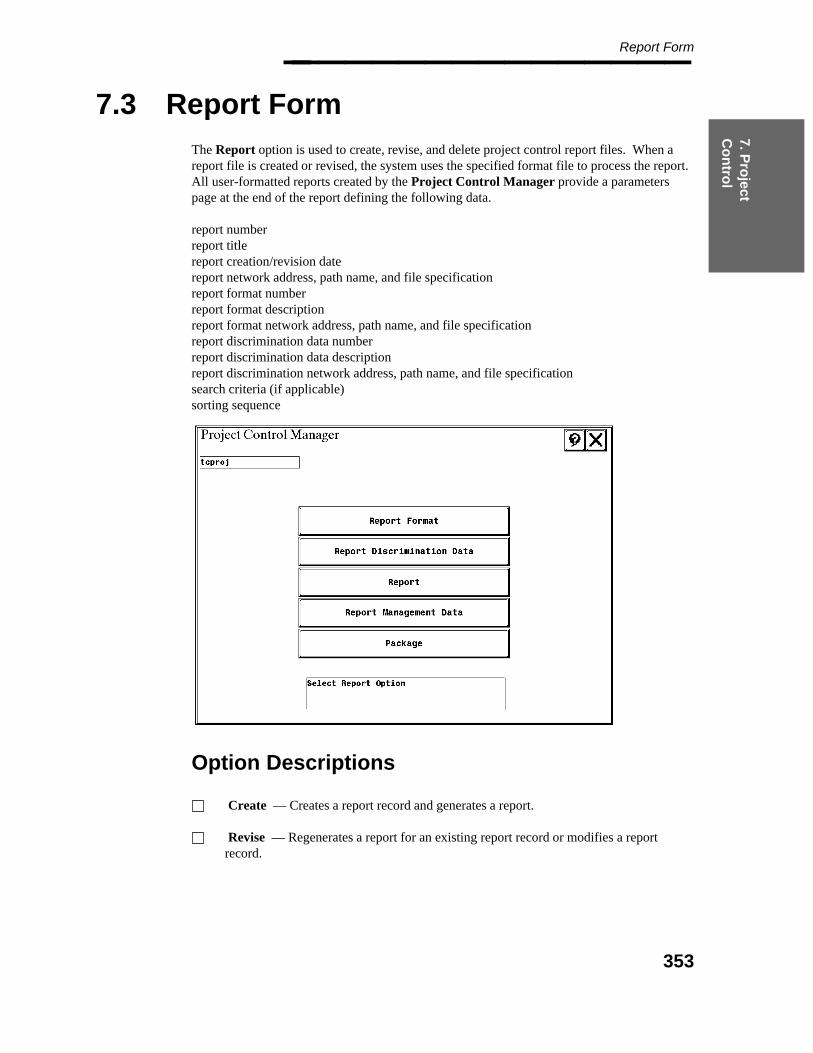
7. Pro
ject C
on
trol
Report Form________________
7.3 Report Form
The Report option is used to create, revise, and delete project control report files. When areport file is created or revised, the system uses the specified format file to process the report.All user-formatted reports created by the Project Control Manager provide a parameterspage at the end of the report defining the following data.
report numberreport titlereport creation/revision datereport network address, path name, and file specificationreport format numberreport format descriptionreport format network address, path name, and file specificationreport discrimination data numberreport discrimination data descriptionreport discrimination network address, path name, and file specificationsearch criteria (if applicable)sorting sequence
Option Descriptions
Create — Creates a report record and generates a report.
Revise — Regenerates a report for an existing report record or modifies a reportrecord.
353

Project Administrator — April 2002________________ Delete — Deletes an existing report record and the corresponding report.
Approve — Approves an existing report.
Multi-Create — Submits multiple reports in one operation.
354
7. Pro
ject C
on
trol
Report Creation Form________________
7.3.1 Report Creation Form
The Create Report option is used to create a report file and submit the file for reportprocessing. The created report file definition is stored in the project control database for usein recreating the report.
Before Using this Command
A report format file must exist for the report to be created.
At least one package file must exist for the active project that defines the documents forthe package.
The print options print to the default print queue. You can use qmgr to change thedefault print queue.
Field Descriptions
Report Number — Type up to 20 characters for the report file to be created.
Report Title — Type up to 49 characters to describe the report file.
Report File Spec — Type the file name of the output report file to be created.
Report File Path — Type the disk location for the output report file to be created.This field retains the active setting.
Report Node — Type the node name for the output report file. This field retains theactive setting. Report Format File — Specifies which format file to use for the activereport. When this field is selected, the defined format files for the project are displayed.
Report Discrimination Data — Specifies which discrimination data to use for theactive report. When this field is selected, a list of available discrimination data recordsis displayed.
Revision Number — Type up to three alphanumeric characters for the report revisionnumber.
Last Revision Number — Displays the revision number of the last report generated.This information cannot be edited.
Revised By — Type up to five alphanumeric characters for the user who made thereport revision.
Checked By — Type up to five alphanumeric characters for the user who checked thereport.
355

Project Administrator — April 2002________________ Revision Description — Type up to 40 alphanumeric characters to describe the reportrevision.
Print/Delete — Submits the generated report output file to the specified print queueand deletes the output file.
Print/Save — Submits the generated report output file to the specified print queue andsaves the output file.
Save — Saves the output file and suppresses printing.
Operating Sequence
1. Select Option.
Select the Create option from the Report form.
The Report Creation form is displayed.
2. Specify Report Data.
Type the report file information.
3. Define the format file and discrimination data to be used for the report.
4. Specify Report Format File.
Select the Report Format File field.
356
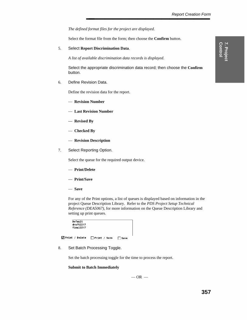
7. Pro
ject C
on
trol
Report Creation Form________________ The defined format files for the project are displayed.
Select the format file from the form; then choose the Confirm button.
5. Select Report Discrimination Data.
A list of available discrimination data records is displayed.
Select the appropriate discrimination data record; then choose the Confirmbutton.
6. Define Revision Data.
Define the revision data for the report.
— Revision Number
— Last Revision Number
— Revised By
— Checked By
— Revision Description
7. Select Reporting Option.
Select the queue for the required output device.
— Print/Delete
— Print/Save
— Save
For any of the Print options, a list of queues is displayed based on information in theproject Queue Description Library. Refer to the PDS Project Setup TechnicalReference (DEA5067), for more information on the Queue Description Library andsetting up print queues.
8. Set Batch Processing Toggle.
Set the batch processing toggle for the time to process the report.
Submit to Batch Immediately
— OR —
357
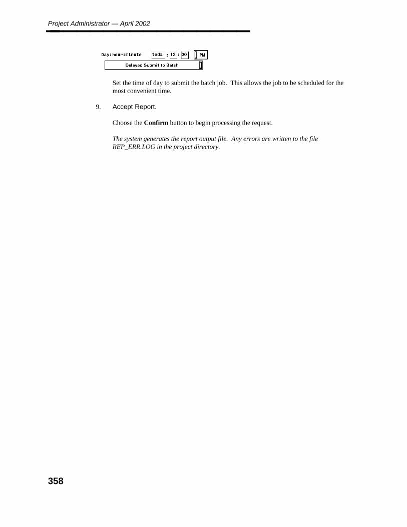
Project Administrator — April 2002________________
Set the time of day to submit the batch job. This allows the job to be scheduled for themost convenient time.
9. Accept Report.
Choose the Confirm button to begin processing the request.
The system generates the report output file. Any errors are written to the fileREP_ERR.LOG in the project directory.
358
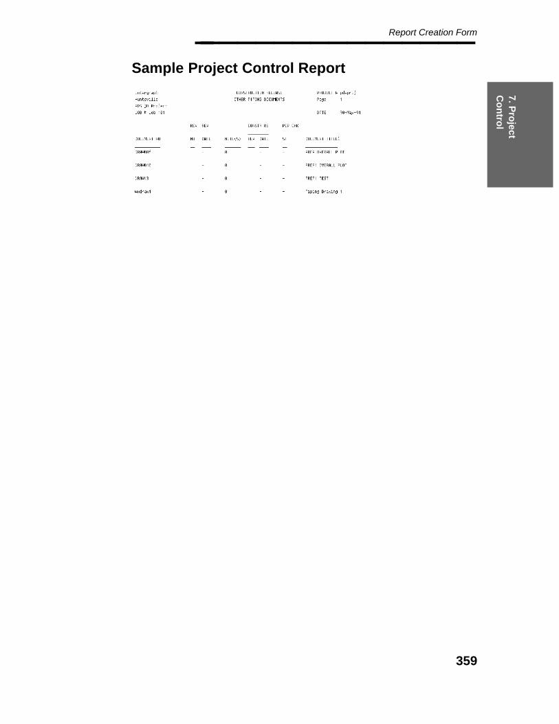
7. Pro
ject C
on
trol
Report Creation Form________________
Sample Project Control Report
359
Project Administrator — April 2002________________
7.3.2 Report Revision Form
The Revise Report File option is used to recreate an output report file for an existing reportfile in the project control database.
Field Descriptions
For field description information, see Report Creation Form, page 355 .
Revise Data Only/Revise Report and Data toggle — Specifies revision of data only,or the report and the data. If the report and data are revised, you will be prompted toselect the appropriate print/save/delete and immediate/delayed batch submissionoptions.
If anything except the Report Number and the Report Title fields are modified,the toggle is automatically set to Revise Report and Data and the report isregenerated.
Operating Sequence
1. Select Option.
Select the Revise option from the Report form.
The report files for the project and their descriptions are displayed.
2. Select Report File.
Select the report file to be revised from the form; then choose the Confirm button.
The Report Revision form for the specified file is displayed.
360

7. Pro
ject C
on
trol
Report Revision Form________________
3. Accept Report Revision.
Choose the Confirm button to regenerate the report output file. Refer to <CreateReport File for a description of the processing options.
The Select Report Revision form is displayed.
Choose the Cancel button to exit the form.
— OR —
Select another report for revision.
361

Project Administrator — April 2002________________
7.3.3 Report Deletion Form
The Delete Report File option is used to delete an existing report file from the project controldatabase and its associated output file.
Field Descriptions
For more information see Report Creation Form, page 355 .
Operating Sequence
1. Select Option.
Select the Delete option from the Report form.
The report files for the project and their descriptions are displayed.
2. Select Report.
Select the report file to be deleted from the form; then choose the Confirm button.
3. Accept to Delete Report Data.
Choose the Confirm button to delete the report file definition in the project controldatabase and to delete the report output file.
The Report Data has been Deleted message is displayed.
362
7. Pro
ject C
on
trol
Report Approval Form________________
7.3.4 Report Approval Form
The Approve Report option is used to approve an existing report record in the ProjectControl Database. The system displays the Record Number display list. It then displays theapproval and revision fields which are used to store approval revision information.
The Approval Status of revised reports is automatically not approved,regardless of its previous status.
The first time a record is approved, only the Approval Initials: field is active.Once a record has been approved, all of the other fields, which are revisionfields, are active.
Field Descriptions
Report Number — Displays the report number identification of the selected report.This field may not be modified.
Report Description — Displays the report description of the selected report. This fieldmay not be modified.
Approved By — Type up to five alphanumeric characters to identify the operatorapproving the report.
Revision Number — Displays the report revision number.This field may not be modified.
Revised By — Displays identification of the user who made the report revision.
Checked By — Displays identification of the user who checked the report. This fieldmay not be modified.
Revision Description — Displays the description of the report revision. This field maynot be modified.
363
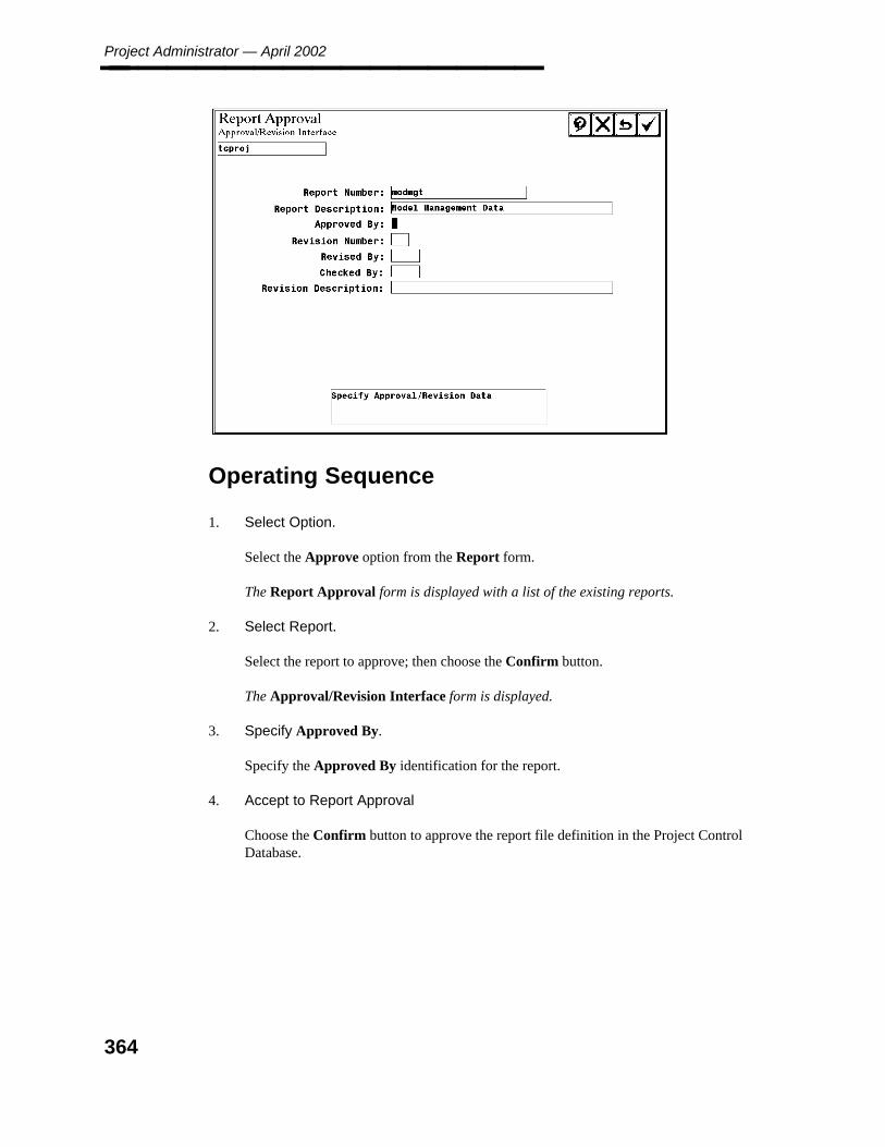
Project Administrator — April 2002________________
Operating Sequence
1. Select Option.
Select the Approve option from the Report form.
The Report Approval form is displayed with a list of the existing reports.
2. Select Report.
Select the report to approve; then choose the Confirm button.
The Approval/Revision Interface form is displayed.
3. Specify Approved By.
Specify the Approved By identification for the report.
4. Accept to Report Approval
Choose the Confirm button to approve the report file definition in the Project ControlDatabase.
364
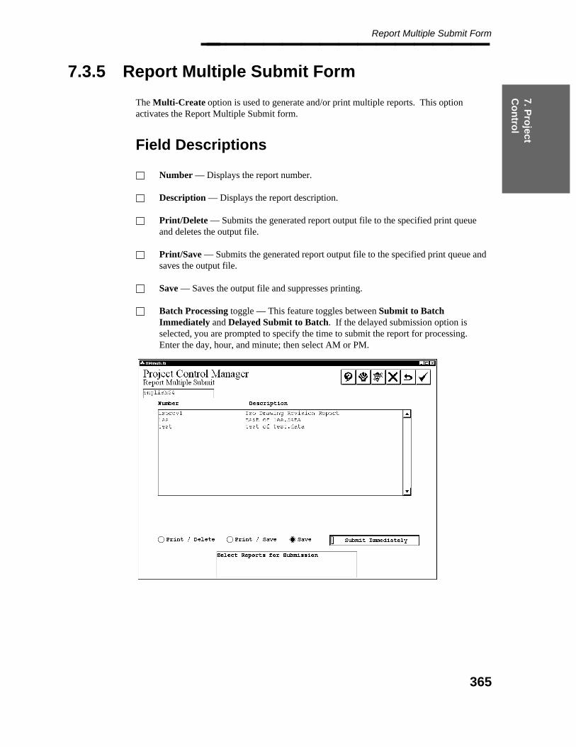
7. Pro
ject C
on
trol
Report Multiple Submit Form________________
7.3.5 Report Multiple Submit Form
The Multi-Create option is used to generate and/or print multiple reports. This optionactivates the Report Multiple Submit form.
Field Descriptions
Number — Displays the report number.
Description — Displays the report description.
Print/Delete — Submits the generated report output file to the specified print queueand deletes the output file.
Print/Save — Submits the generated report output file to the specified print queue andsaves the output file.
Save — Saves the output file and suppresses printing.
Batch Processing toggle — This feature toggles between Submit to BatchImmediately and Delayed Submit to Batch. If the delayed submission option isselected, you are prompted to specify the time to submit the report for processing.Enter the day, hour, and minute; then select AM or PM.
365
Project Administrator — April 2002________________
Operating Sequence
1. Select Option.
Select the Multi-Create option from the Report form.
The Report Multiple Submit form is displayed with a report record Number displaylist and the printing options.
2. Select Report(s).
Select the report(s) to submit.
3. Select Reporting Option.
Select a reporting option of Print/Delete, Print/Save, or Save.
For any of the Print options, a list of queues is displayed based on information in theproject queue_descript file.
4. Select Queue.
Select the queue for the required output device.
5. Set Batch Processing Toggle.
Set the batch processing toggle for the time to process the report.
6. Accept or Cancel Report Request.
Choose the Confirm button to begin processing the request. Then choose the Cancelbutton to exit the Multi-Create process.
— OR —
Choose the Cancel button to exit the Multi-Create process without processing thereport(s).
The Project Control Manager form is displayed.
366

7. Pro
ject C
on
trol
Report Management Defaults Form________________
7.4 Report Management Defaults Form
The Report Management Defaults option is used to define the node name and path of thereport definition files. This form defines the default locations used in other forms. Thisoption is used primarily for setup.
Field Descriptions
Report Path —The path name of the format file(s).
Report Node — The node name of the format file(s).
Report Format Path — The path of the format file(s).
Report Format Node — The node name of the format file(s).
Report Discrimination Data Path/Node — The node name of the discrimination datafile(s).
Report Discrimination Data Node — The node name of the discrimination datafile(s).
367

Project Administrator — April 2002________________
Operating Sequence
1. Select Option.
Select the Report Management Data option from the Project Control Manager form.
The Report Management Data form is displayed.
2. Type the path and node name for the report definition files.
— Report Path/Node
— Report Format Path/Node
— Report Discrimination Data Path/Node
3. Accept Report Definition.
Choose the Confirm button to accept the defined paths and node names for the reportdefinition file.
368
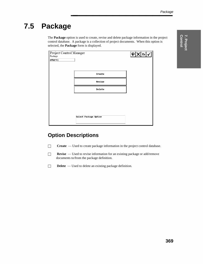
7. Pro
ject C
on
trol
Package________________
7.5 Package
The Package option is used to create, revise and delete package information in the projectcontrol database. A package is a collection of project documents. When this option isselected, the Package form is displayed.
Option Descriptions
Create — Used to create package information in the project control database.
Revise — Used to revise information for an existing package or add/removedocuments to/from the package definition.
Delete — Used to delete an existing package definition.
369
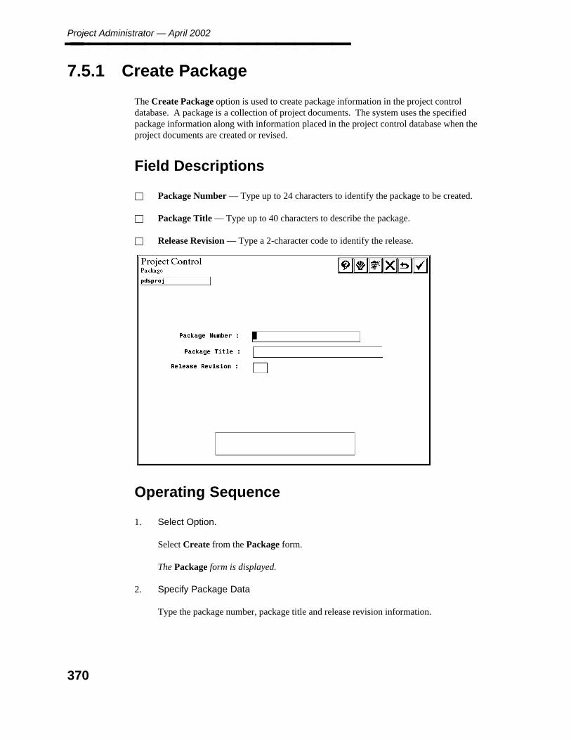
Project Administrator — April 2002________________
7.5.1 Create Package
The Create Package option is used to create package information in the project controldatabase. A package is a collection of project documents. The system uses the specifiedpackage information along with information placed in the project control database when theproject documents are created or revised.
Field Descriptions
Package Number — Type up to 24 characters to identify the package to be created.
Package Title — Type up to 40 characters to describe the package.
Release Revision — Type a 2-character code to identify the release.
Operating Sequence
1. Select Option.
Select Create from the Package form.
The Package form is displayed.
2. Specify Package Data
Type the package number, package title and release revision information.
370

7. Pro
ject C
on
trol
Create Package________________
3. Accept or Specify Package Data
Choose the Confirm button to create the specified package.
The Document Source form is displayed.
4. Select Source Document
Select the source of the document to be added to the package; then choose the Confirmbutton.
The Document Subtype form is displayed.
5. Select Document Subtype.
Select the subtype for the selected drawing type; then choose the Confirm button.
The documents (drawings or reports) for the selected type and subtype are displayed.
371

Project Administrator — April 2002________________
6. Select Documents.
Select the document to be added to the package contents; then choose the Confirmbutton.
The specified document is added to the package, and you are returned to Step 5.
372
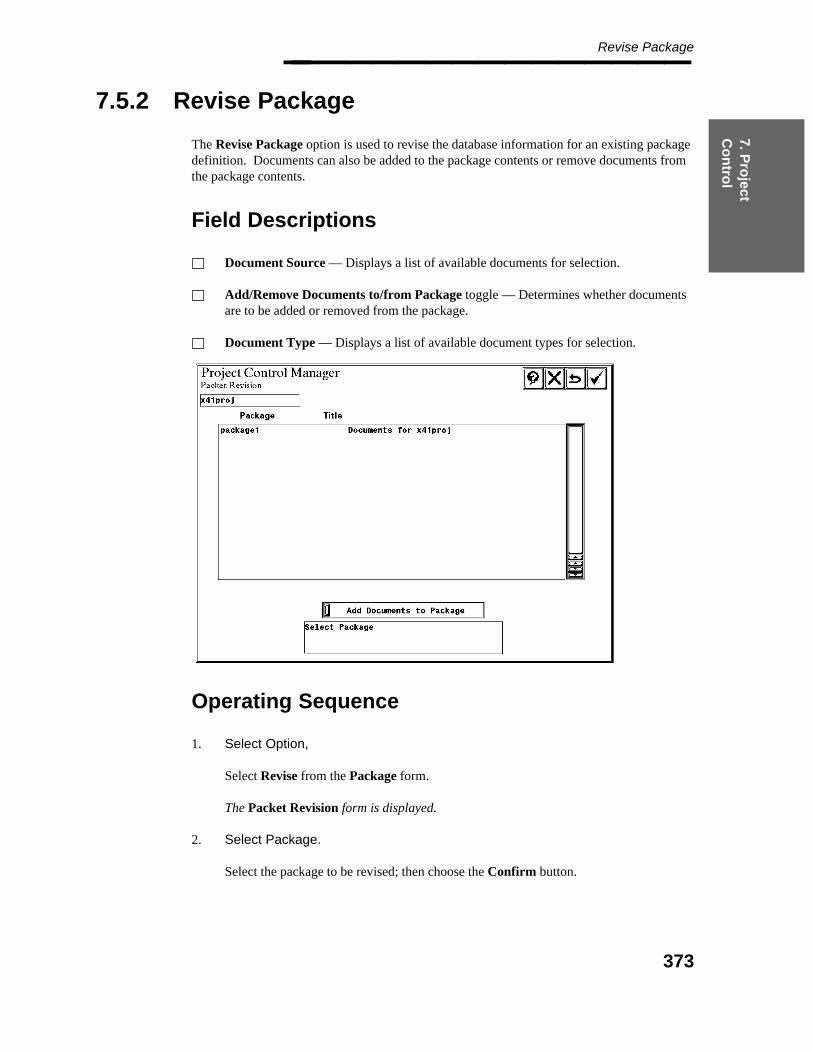
7. Pro
ject C
on
trol
Revise Package________________
7.5.2 Revise Package
The Revise Package option is used to revise the database information for an existing packagedefinition. Documents can also be added to the package contents or remove documents fromthe package contents.
Field Descriptions
Document Source — Displays a list of available documents for selection.
Add/Remove Documents to/from Package toggle — Determines whether documentsare to be added or removed from the package.
Document Type — Displays a list of available document types for selection.
Operating Sequence
1. Select Option,
Select Revise from the Package form.
The Packet Revision form is displayed.
2. Select Package.
Select the package to be revised; then choose the Confirm button.
373
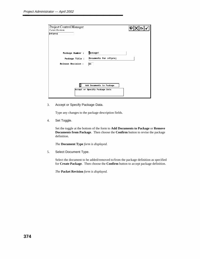
Project Administrator — April 2002________________
3. Accept or Specify Package Data.
Type any changes to the package description fields.
4. Set Toggle.
Set the toggle at the bottom of the form to Add Documents to Package or RemoveDocuments from Package. Then choose the Confirm button to revise the packagedefinition.
The Document Type form is displayed.
5. Select Document Type.
Select the document to be added/removed to/from the package definition as specifiedfor Create Package. Then choose the Confirm button to accept package definition.
The Packet Revision form is displayed.
374
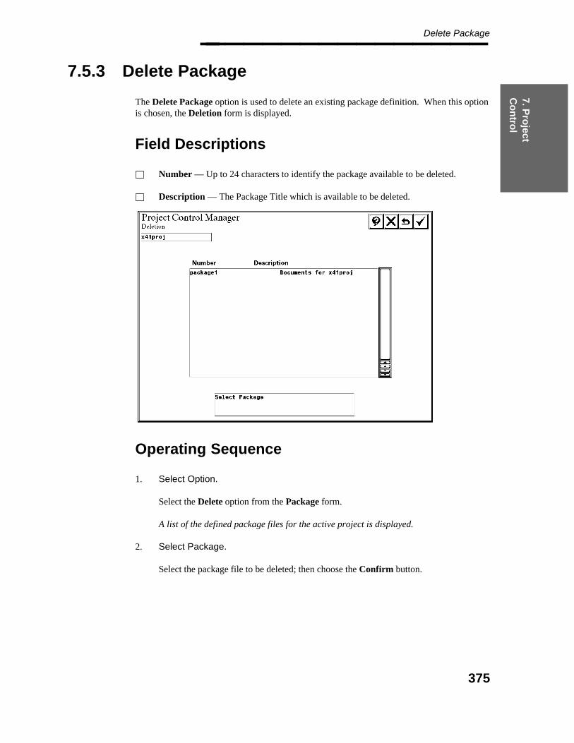
7. Pro
ject C
on
trol
Delete Package________________
7.5.3 Delete Package
The Delete Package option is used to delete an existing package definition. When this optionis chosen, the Deletion form is displayed.
Field Descriptions
Number — Up to 24 characters to identify the package available to be deleted.
Description — The Package Title which is available to be deleted.
Operating Sequence
1. Select Option.
Select the Delete option from the Package form.
A list of the defined package files for the active project is displayed.
2. Select Package.
Select the package file to be deleted; then choose the Confirm button.
375

Project Administrator — April 2002________________
3. Accept to Delete Package.
Choose the Confirm button to delete the identified package file.
The package definition is deleted from the project control database, and the PackageData has been Deleted message is displayed.
376

8. Arch
ival M
anag
er
Project Archival Manager________________
8. Project Archival Manager
The Project Archival Manager provides archival and retrieval facilities for a project,including the relational database. You can archive a complete project or subsets of a projectand retrieve all or part of that project at a later time. For example, you can archive a projectfor purposes of backup and then restore a single model data set (a piping model and itsassociated relational database tables, interference envelope file, and diagnostic report files).
Schedule Project Import provides the capability to divide a single project between two ormore sites, allowing work to be performed in parallel.
The capability to archive subsets of a project provides the flexibility to archive a project fromseveral servers (or workstations) to reduce the time required for archival.
The PDS 2D data can be archived or retrieved together with the PDS 3D data within the sameproject; or the PDS 2D data can be archived or retrieved independently of any PDS 3D data.
Project Archival Manager Form
The Project Archival Manager form is used to:Perform project archival.Schedule project archival.Perform active project archival.Perform inactive project archival.Import archived models and drawings.Schedule project import for worksharing.
377

Project Administrator — April 2002________________
Option Descriptions
Project Archival — Creates a set of compressed files of the project data set and savesthis data to a hard disk location.
Scheduled Project Archival — Defines a schedule for archiving a project data set ona regular basis.
Active Project Retrieval — Retrieves data from an archive into an active project torecover a single model data set from the archived project.
Inactive Project Retrieval — Recreates a project from an archive.
Import Project Retrieval — Imports models and drawings archived for one projectinto the active (or destination) project.
Scheduled Project Import — Defines a schedule for importing models and drawingson a regular basis.
Operating Sequence
Select Option.
Select Project Archival Manager from the Project Administrator form.
The Project Archival Manager form is displayed.
378
8. Arch
ival M
anag
er
Project Archival________________
8.1 Project Archival
The Project Archival option creates a set of compressed files to archive a specified projectdata set. This data is compressed in zip format and saved to a hard disk location. Allrelational database data is saved using the RIS unload utility transparently from within theProject Archival command.
Project archival produces the following log files:
3D archive performed from within PD_Shell
c:\temp\projname.arl File listing PDS environment variables andcommands executed.
c:\temp\scratchdir\projname.arc Log file of archival job, showing filesarchived as well as any errors.
c:\temp\scratchdir\pdsbatch.txt Same as projname.arc. May not be presentif PDS Automail has been configured.
2D archive or 2D/3D archive performed from within PD Shell
c:\temp\projname.arc Log file of 2D archival job, showing filesarchived as well as any errors.
c:\temp\projname.arl File listing PDS environment variables andcommands executed.
c:\temp\p2datjob.log 2D archive scratch file.c:\temp\scratchdir\projname.arc Log file of 2D or 2D/3D archival job,
showing files archived as well as any errors.c:\temp\scratchdir\pdsbatch.txt Same as projname.arc. May not be present
if PDS Automail has been configured.
In the file/directory naming convention, projname will be the name of your project (forexample, c:\temp\myproj.arl) and scratchdir is the subdirectory createdautomatically by PDS and has a name prefaced by ar (for example,c:\temp\ar926977232). For additonal information on the naming convention of thescratch directories within c:\temp, refer to the PD_Shell readme file.
Before Using This Command
PDS archives are performed in batch mode. The job is submitted directly to the PD_archivalqueue in the case of interactive archives or submitted to this same queue at a specifiedperiodic interval in the case of scheduled archives. For both interactive and scheduled batchjobs, an appropriate account mapping must be created using the NT Batch Manager Utility. Ifan appropriate account mapping is not established, the archive will fail. A discussion of thecreation of an appropriate NTbatch account can be found in the System AdministratorReponsibilities section of the PDS Project Setup Technical Reference (DEA5067). If data isto be archived to a hard disk location, ensure that the directory path exists and that you havepermission to write files to the directory. Also ensure there is adequate free space on the disk.
379
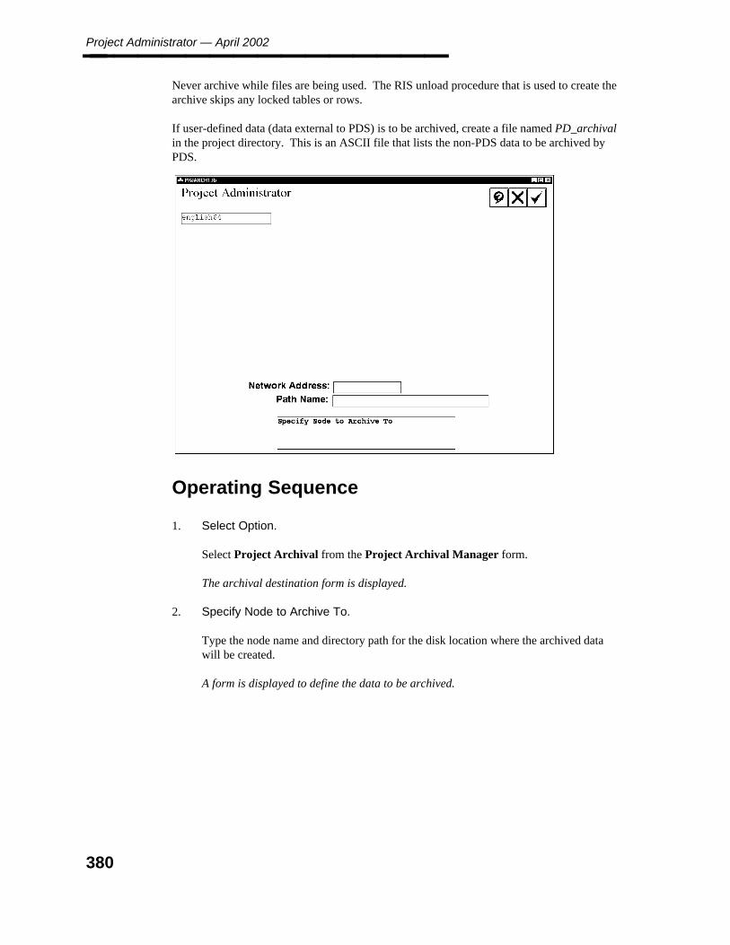
Project Administrator — April 2002________________ Never archive while files are being used. The RIS unload procedure that is used to create thearchive skips any locked tables or rows.
If user-defined data (data external to PDS) is to be archived, create a file named PD_archivalin the project directory. This is an ASCII file that lists the non-PDS data to be archived byPDS.
Operating Sequence
1. Select Option.
Select Project Archival from the Project Archival Manager form.
The archival destination form is displayed.
2. Specify Node to Archive To.
Type the node name and directory path for the disk location where the archived datawill be created.
A form is displayed to define the data to be archived.
380

8. Arch
ival M
anag
er
Project Archival________________
Project Archival Options Form
The Project Archival Options form selects the data to be archived. For more informationabout this option, see Project Archival, page 379 .
Options
Project Control DataModel DataDrawing DataPipe Support Drawing DataInterference Management DataReport DataDesignReview Management DataReference DataIsometric Drawing Management DataFrameWorks Projects2D ProjectComplete ProjectUser Data
Operating Sequence
1. Select Option.
Select the option(s) for project data to be archived.
381
Project Administrator — April 2002________________ For Project Control Data, The Batch Processing toggle is displayed. Select SubmitImmediately or Delayed Submission with date and time. For more information, seeProject Control Data, page 383 .
For Model Data, a form is displayed to specify the model(s) to be archived. For moreinformation, see Model Data, page 384 .
For Drawing Data, a form is displayed to specify the drawing(s) to be archived. Formore information, see Drawing Data, page 386 .
For Pipe Support Drawing Data, the Batch Processing toggle is displayed. SelectSubmit Immediately or Delayed Submission with date and time. For more information,see Pipe Support Drawing Data, page 387 .
For Interference Management Data, the Batch Submission toggle is displayed.Select Submit Immediately or Delayed Submission with date and time. For moreinformation, see Interference Management Data, page 388 .
For Report Data, the Batch Processing toggle is displayed. Select SubmitImmediately or Delayed Submission with date and time. For more information, seeReport Data, page 389 .
For DesignReview Management Data, the Batch Processing toggle is displayed.Select Submit Immediately or Delayed Submission with date and time. For moreinformation, see DesignReview Management Data, page 390 .
For Reference Data, a set of fields is displayed to select the reference data to archive.For more information, see Reference Data, page 390 .
For Isometric Drawing Management Data, the Batch Submission toggle isdisplayed. Select Submit Immediately or Delayed Submission with date and time. Formore information, see Isometric Drawing Management Data, page 393 .
For FrameWorks Projects, the Batch Submission toggle is displayed. Select SubmitImmediately or Delayed Submission with date and time. For more information, seeFrameWorks Projects, page 394 .
For 2D Project data, a form is displayed to identify the 2D data to archive. For moreinformation, see 2D Project, page 394 .
The Complete Project option archives all of the project data. For more information,see Complete Project, page 395 .
The User Data option archives data that has been created outside of PDS or data thathas been created in support of PDS, but which is not recognized by PDS. For moreinformation on this option, see User Data, page 396 .
2. Specify Archive Time.
Set the time of day to process the archive request.
382

8. Arch
ival M
anag
er
Project Archival________________
3. Accept Project Archival Data.
Choose the Confirm button to begin processing the request.
Information on the archival process is written to the ARCHIVE.LOG file which iswritten into the project directory at the conclusion of the batch job.
8.1.1 Project Control Data
The Project Control Data option is used to archive much of the information stored in theproject control schema in addition to seed files and other files stored in the project directory.
Operating Sequence
1. Select Option.
Select the Project Control Data option from the Project Archival Options form.
The Batch Submission, toggle is displayed.
2. Select Batch Submission Type.
Select Submit Immediately.
— OR —
Delayed Submit and specify submission date and time.
3. Submit Project Control Data Archive.
Choose the Confirm button to process archive.
The Project Archival Options form is displayed.
Project Control Database tables are archived into a file named PD_project_mgt that includesthe following data:
project description data PDtable_101reference database management PDtable_102project control data PDtable_103archival management data PDtable_104discipline data PDtable_111design area data PDtable_112model data PDtable_113piping model data PDtable_114model setup data PDtable_115structural sub-project control PDtable_116
383
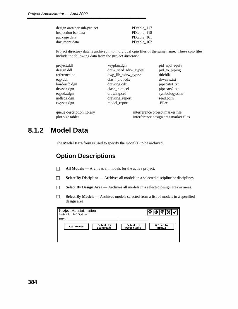
Project Administrator — April 2002________________
design area per sub-project PDtable_117inspection iso data PDtable_118package data PDtable_161document data PDtable_162
Project directory data is archived into individual cpio files of the same name. These cpio filesinclude the following data from the project directory:
project.ddldesign.ddlreference.ddleqp.ddlborderifc.dgndrwsdz.dgneqpsdz.dgnmdlsdz.dgnrwysdz.dgn
keyplan.dgndraw_seed.<drw_type>dwg_lib_<drw_type>clash_plot.cdxdrawing.cdxclash_plot.celdrawing.celdrawing_reportmodel_report
pid_npd_equivpid_to_pipingtitleblkdrwcats.txtpipecats1.txtpipecats2.txtsymbology.smsseed.pdm.EErc
queue description libraryplot size tables
interference project marker fileinterference design area marker files
8.1.2 Model Data
The Model Data form is used to specify the model(s) to be archived.
Option Descriptions
All Models — Archives all models for the active project.
Select By Discipline — Archives all models in a selected discipline or disciplines.
Select By Design Area — Archives all models in a selected design area or areas.
Select By Models — Archives models selected from a list of models in a specifieddesign area.
384
8. Arch
ival M
anag
er
Project Archival________________
Operating Sequence
1. Select Option.
Select the Model Data option on the Project Archival Options form.
The Project Archival Options - Model Data, form is displayed to specify the model(s)to be archived.
2. Select Option.
Select the option to identify the model file(s).
When Select by Discipline, Select by Design Area or Select by Models is selected, theavailable disciplines are displayed for selection.
Model Archival Data Set
Piping model data is archived into a set of files that include the following data for each pipingmodel:
Data File Name
sparse model design file mdls<model_number>propagated model design file mdlp<model_number>interference envelope file env_<model_number>diagnostic report files p_<extension>_<model_index_no>
Design Checks reportsP&ID Comparison reportsRDB revision management reportsMiscellaneous diagnostics reports
DesignReview label file lbl_<model_index_no>database load data PDM<model_number>
piping segment data (PDtable_12)piping component data (PDtable_34)piping/tubing data (PDtable_50)instrument component data (PDtable_67)pipe support data (PDtable_80)
Equipment model data is archived into a set of files that include the following data for eachequipment model:
Data File Name
model design file mdl_<model_number>interference envelope file env_<model_number>DesignReview label file lbl_<model_number>database load data PDM<model_number>
equipment data (PDtable_21)nozzle data (PDtable_22)
385
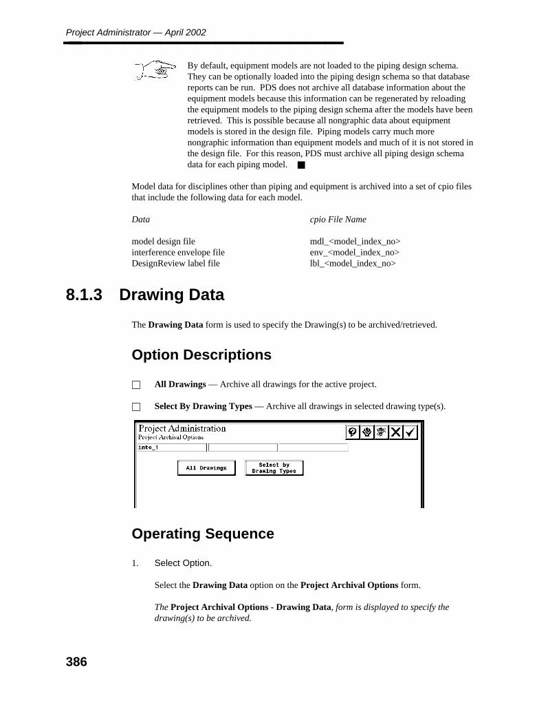
Project Administrator — April 2002________________
By default, equipment models are not loaded to the piping design schema.They can be optionally loaded into the piping design schema so that databasereports can be run. PDS does not archive all database information about theequipment models because this information can be regenerated by reloadingthe equipment models to the piping design schema after the models have beenretrieved. This is possible because all nongraphic data about equipmentmodels is stored in the design file. Piping models carry much morenongraphic information than equipment models and much of it is not stored inthe design file. For this reason, PDS must archive all piping design schemadata for each piping model.
Model data for disciplines other than piping and equipment is archived into a set of cpio filesthat include the following data for each model.
Data cpio File Name
model design file mdl_<model_index_no>interference envelope file env_<model_index_no>DesignReview label file lbl_<model_index_no>
8.1.3 Drawing Data
The Drawing Data form is used to specify the Drawing(s) to be archived/retrieved.
Option Descriptions
All Drawings — Archive all drawings for the active project.
Select By Drawing Types — Archive all drawings in selected drawing type(s).
Operating Sequence
1. Select Option.
Select the Drawing Data option on the Project Archival Options form.
The Project Archival Options - Drawing Data, form is displayed to specify thedrawing(s) to be archived.
386
8. Arch
ival M
anag
er
Project Archival________________
2. Select Option.
Select the option to identify the drawing file(s).
When Select by Drawing Types, is selected, the available drawing types are displayedfor selection.
Drawing Data Archival Data Set
Drawing management data from the project control schema is archived into a file namedPD_draw_mgt that includes the following drawing management data:
drawing data PDtable_121drawing view data PDtable_122drawing view reference model data PDtable_123composite drawing view data PDtable_124drawing revision data PDtable_125drawing setup data PDtable_126reference model category setup data PDtable_127plotting setup data PDtable_128
Drawing graphics data is archived into a set of cpio files nameddrw_<drawing_index_number> for each drawing’s design file.
8.1.4 Pipe Support Drawing Data
The Pipe Support Drawing Data option is used to archive pipe support drawing data.
Operating Sequence
1. Select Option.
Select the Pipe Support Drawing Data option from the Project Archival Optionsform.
The Batch Submission toggle is displayed.
2. Select Batch Submission Type.
Select Submit Immediately.
— OR —
Delayed Submit and specify submission date and time.
387

Project Administrator — April 2002________________
3. Accept to Archive Data or Exit.
Choose the Confirm button to process archive.
The Project Archival Options form is displayed.
Pipe support drawing data from the project control schema is archived into a file namedPD_psdraw_mgt that includes the following data:
pipe support drawing management data PDtable_170
Drawing graphics data is archived into a set of cpio files namedpsdwg_<support_unique_no> for each design file.
8.1.5 Interference Management Data
The Interference Management Data option is used to archive clash data.
Operating Sequence
1. Select Option.
Select the Interference Management Data option from the Project Archival Optionsform.
The Batch Submission, toggle is displayed.
2. Select Batch Submission Type.
Select Submit Immediately.
— OR —
Delayed Submit and specify submission date and time.
3. Submit Interference Management Data Archive.
Choose the Confirm button to process archive.
The Project Archival Options form is displayed.
Interference management data from the project control schema is archived into a file namedPD_clash_mgt that includes the following data:
interference clash job data PDtable_131interference clash data - project PDtable_132interference clash data - job PDtable_133component clash data - project PDtable_134interference clash review history PDtable_135
388

8. Arch
ival M
anag
er
Project Archival________________ interference clash plot history PDtable_136
8.1.6 Report Data
The Report Data option is used to archive report management data.
Operating Sequence
1. Select Option.
Select the Report Data option from the Project Archival Options form.
The Batch Submission, toggle is displayed.
2. Select Batch Submission Type.
Select Submit Immediately.
— OR —
Delayed Submit and specify submission date and time.
3. Submit Report Data Archive.
Choose the Confirm button to process archive.
The Project Archival Options form is displayed.
Report management data from the project control schema is archived into a file namedPD_report_mgt that includes the following data:
report data PDtable_141format data PDtable_142discrimination data PDtable_143revision data PDtable_144
Report output data is archived into a set of files that include the following data:
Data File Name
reports report_<report_index_no>format files format_<format_index_no>discrimination files filter_<format_index_no>
389

Project Administrator — April 2002________________
8.1.7 DesignReview Management Data
The DesignReview Management Data option is used to archive DesignReview data.
Operating Sequence
1. Select Option.
Select the DesignReview Management Data option from the Project ArchivalOptions form.
The Batch Submission, toggle is displayed.
2. Select Batch Submission Type.
Select Submit Immediately.
— OR —
Delayed Submit and specify submission date and time.
3. Submit DesignReview Management Data Archive.
Choose the Confirm button to process archive.
The Project Archival Options form is displayed.
DesignReview management data is archived into a set of files that include the following data:
Data File Name
DesignReview control files control_<review_index_no>DesignReview label filesDesignReview tag file tag_<review_index_no>database load data PD_review_mgt
DesignReview management data(PDtable_151)
8.1.8 Reference Data
The Reference Data option is used to specify reference data to be archived.
390
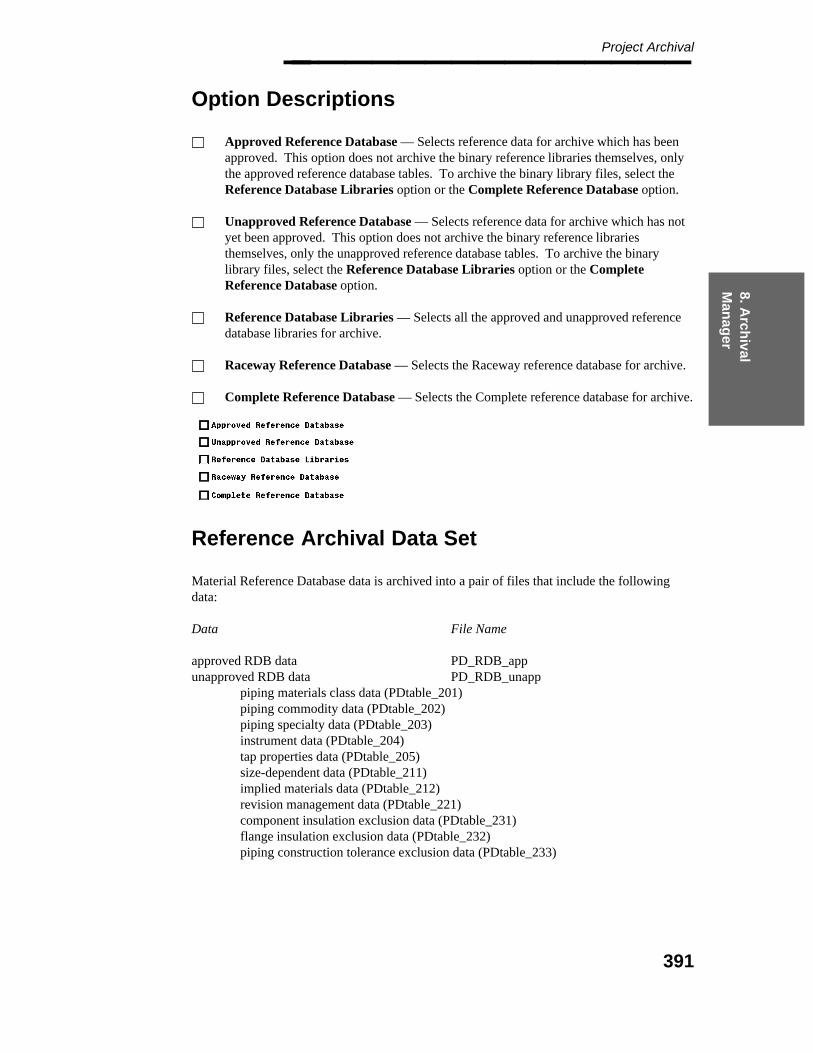
8. Arch
ival M
anag
er
Project Archival________________
Option Descriptions
Approved Reference Database — Selects reference data for archive which has beenapproved. This option does not archive the binary reference libraries themselves, onlythe approved reference database tables. To archive the binary library files, select theReference Database Libraries option or the Complete Reference Database option.
Unapproved Reference Database — Selects reference data for archive which has notyet been approved. This option does not archive the binary reference librariesthemselves, only the unapproved reference database tables. To archive the binarylibrary files, select the Reference Database Libraries option or the CompleteReference Database option.
Reference Database Libraries — Selects all the approved and unapproved referencedatabase libraries for archive.
Raceway Reference Database — Selects the Raceway reference database for archive.
Complete Reference Database — Selects the Complete reference database for archive.
Reference Archival Data Set
Material Reference Database data is archived into a pair of files that include the followingdata:
Data File Name
approved RDB data PD_RDB_appunapproved RDB data PD_RDB_unapp
piping materials class data (PDtable_201)piping commodity data (PDtable_202)piping specialty data (PDtable_203)instrument data (PDtable_204)tap properties data (PDtable_205)size-dependent data (PDtable_211)implied materials data (PDtable_212)revision management data (PDtable_221)component insulation exclusion data (PDtable_231)flange insulation exclusion data (PDtable_232)piping construction tolerance exclusion data (PDtable_233)
391
Project Administrator — April 2002________________ Reference Database libraries and the corresponding text libraries are archived into a set offiles that include the following data for the approved and unapproved reference data:
Graphic Commodity LibraryLabel Description LibraryStandard Note LibraryPiping Assembly LibraryPhysical Data LibrariesPiping Spec Table Library
Short Material Description LibraryLong Material Description LibrarySpecialty Description LibraryEquipment Graphic Commodity LibraryEquipment TDF LibraryEquipment Cell Library
These files are named as either rdb_app_<rdb_type> for approved Reference Databaselibraries or rdb_unapp_<rdb_type> for unapproved libraries.
The following list shows the reference data types (<rdb_type) by name and number:
Type Library Name File11 Piping Job Spec Table Library pjs_tbl.l12 Physical Dimension Library - US us_pcdim.l13 Graphic Commodity Library pipe_gcom.l14 Label Description Library labels.l15 Standard Note Library std_note.l17 Piping Assembly Library assembly.l21 Long Material Description Library long_bom.l22 Short Material Description Library short_bom.l25 Physical Dimension Library - DIN din_pcdim.l26 Physical Dimension Library - British Standard bs_pcdim.l27 Physical Dimension Library - European Practice A eua_pcdim.l28 Physical Dimension Library - European Practice B eub_pcdim.l29 Physical Dimension Library - JIS jis_pcdim.l30 Physical Dimension Library - Australian aus_pcdim.l31 Physical Dimension Library - International Practice A ina_pcdim.l32 Physical Dimension Library - International Practice B inb_pcdim.l33 Physical Dimension Library - Company Practice cmp_pcdim.l35 Specialty Material Description Library spclty_bom.l
The system automatically archives any applicable Table Revision Management Libraries,when archiving the Reference Data.
Source files for the piping job specification (such as pmc, pcd, and tap data files) and materialdescriptions (long, short, and specialty) are archived into a set of cpio files.
The electrical raceway reference data is archived into a cpio file named PD_RWAY_rdb thatincludes a RIS unload file for each table in the relational database.
392

8. Arch
ival M
anag
er
Project Archival________________
8.1.9 Isometric Drawing Management Data
The Isometric Drawing Management Data option is used to archive isometric drawing files,default files, seed files, plot files, drawing border files and database information.
Operating Sequence
1. Select Option.
Select the Isometric Drawing Management Data option from the Project ArchivalOptions form.
The Batch Submission, toggle is displayed.
2. Select Batch Submission Type.
Select Submit Immediately.
— OR —
Delayed Submit and specify submission date and time.
3. Submit Isometric Drawing Management Data Archive.
Choose the Confirm button to process archive.
The Project Archival Options form is displayed.
The isometric drawing management data is archived into a set of files which include thefollowing data with the following naming conventions:
Data File Name
isometric drawing files iso_<iso_index_no>default files iso_<iso_index_no>seed files iso_<iso_index_no>plot files iso_<iso_index_no>drawing border files iso_<iso_index_no>database information PD_iso_dwg_mgt
project options data (PDtable_180)defaults set data (PDtable_181)isometric area definition data (PDtable_182)isometric user data definition (PDtable_183)isometric drawing extraction data (PDtable_184)isometric drawing revision data (PDtable_185)isometric occurrence data (PDtable_186)isometric sheet extraction (PDtable_187)
393
Project Administrator — April 2002________________
8.1.10 FrameWorks Projects
Operating Sequence
1. Select Option.
Select the FrameWorks Projects option from the Project Archival Options form.
The Batch Submission toggle is displayed.
2. Select Batch Submission Type.
Select Submit Immediately.
— OR —
Delayed Submit and specify submission date and time.
3. Accept to Archive Data or Cancel.
Choose the Confirm button to process archive.
The Project Archival Options form is displayed.
This option archives the entire FWP subproject to a single zip file, which can then be restoredin its entirety using the Active Project Retrieval command.
The files in the archive produced by this option are named fw_x, where x is the subprojectindex number from pdtable_116.
Note that if your FWP subproject includes files that are located outside the directorylisted in pdtable_116, then this option will not archive those files. An examplewould be FWP section libraries stored on the client nodes rather than on the projectfile server.
8.1.11 2D Project
For 2D Drawing Data, an additional form is displayed for you to specify the drawings(s) tobe archived. Choosing the 2D project option from the Project Archival Options form bringsyou into an environment where all or parts of your 2D project can be archived. Thisenvironment is also accessible from within the PDS2D product. For additional informationregarding this option, refer to the System Administrator Reponsibilities section of the PDSProject Setup Technical Reference (DEA5067).
394
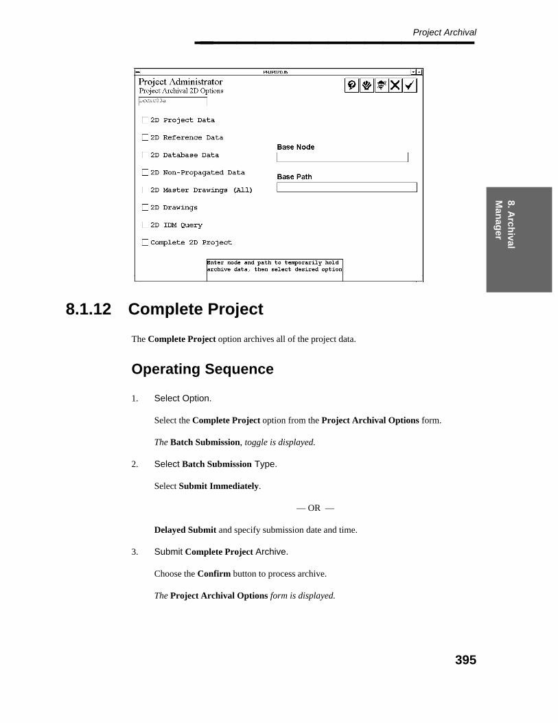
8. Arch
ival M
anag
er
Project Archival________________
8.1.12 Complete Project
The Complete Project option archives all of the project data.
Operating Sequence
1. Select Option.
Select the Complete Project option from the Project Archival Options form.
The Batch Submission, toggle is displayed.
2. Select Batch Submission Type.
Select Submit Immediately.
— OR —
Delayed Submit and specify submission date and time.
3. Submit Complete Project Archive.
Choose the Confirm button to process archive.
The Project Archival Options form is displayed.
395
Project Administrator — April 2002________________
8.1.13 User Data
The User Data option is used to archive data that has been created outside of PDS or data thathas been created in support of PDS, but which is not recognized by PDS. The user-defineddata to be archived is defined in the file PD_archival in the project directory.
When this option is selected, the Project Archival Manager reads a file named PD_archivalthat resides in the project directory to see which files and/or directories to archive. This filemust be created by the user and has a defined format as described below.
The data list must be in the following format:
SAVESET_NAME: <user-defined name of save set>
The name of this save set must not exceed 14 characters. You can specify as many savesets as needed.
DESCRIPTION: <user-defined description of save set>
The description of this save set must not exceed 40 characters.
NETWORK_ADDRESS: <source location of the data to bearchived>
Specify the nodename of the system on which the files to be archived reside. Thenetwork address of this data must not exceed 26 characters.
PATH_NAME: <full file specification of the files to bearchived>
A directory can be specified for the PATH_NAME to archive all of the files (andsubdirectories and the files in the subdirectories). In that directory, a single file, ormore than one file can be specified by separating each file name with a comma. Theentire PATH_NAME specification cannot exceed 60 characters.
All data to be archived within one save set must reside on the same network address and in thesame directory. That is, data that exists on different nodes or in different paths must bearchived in different save sets.
Operating Sequence
1. Select Option.
Select the User Data option from the Project Archival Options form.
The Batch Submission toggle is displayed.
396

8. Arch
ival M
anag
er
Project Archival________________
2. Select Batch Submission Type.
Select Submit Immediately.
— OR —
Delayed Submit and specify submission date and time.
3. Submit User Data Archive.
Choose the Confirm button to process archive.
The Project Archival Options form is displayed.
Archived User Data
The User Data option is used to produce a single compressed file with the namesaveset_name in the specified output directory.
397
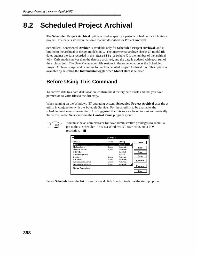
Project Administrator — April 2002________________
8.2 Scheduled Project Archival
The Scheduled Project Archival option is used to specify a periodic schedule for archiving aproject. The data is stored in the same manner described for Project Archival.
Scheduled Incremental Archive is available only for Scheduled Project Archival, and islimited to the archival of design models only. The incremental archive checks all model filedates against the data recorded in the datefile_X (where X is the number of the archivaljob). Only models newer than the date are archived, and the date is updated with each run ofthe archival job. The Date Management file resides in the same location as the ScheduledProject Archival script, and is unique for each Scheduled Project Archival run. This option isavailable by selecting the Incremental toggle when Model Data is selected.
Before Using This Command
To archive data to a hard disk location, confirm the directory path exists and that you havepermission to write files to the directory.
When running on the Windows NT operating system, Scheduled Project Archival uses the atutility in conjunction with the Schedule Service. For the at utility to be available, theschedule service must be running. It is suggested that this service be set to start automatically.To do this, select Services from the Control Panel program group.
You must be an administrator (or have administrative privileges) to submit ajob to the at scheduler. This is a Windows NT restriction, not a PDSrestriction.
Select Schedule from the list of services, and click Startup to define the startup option.
398
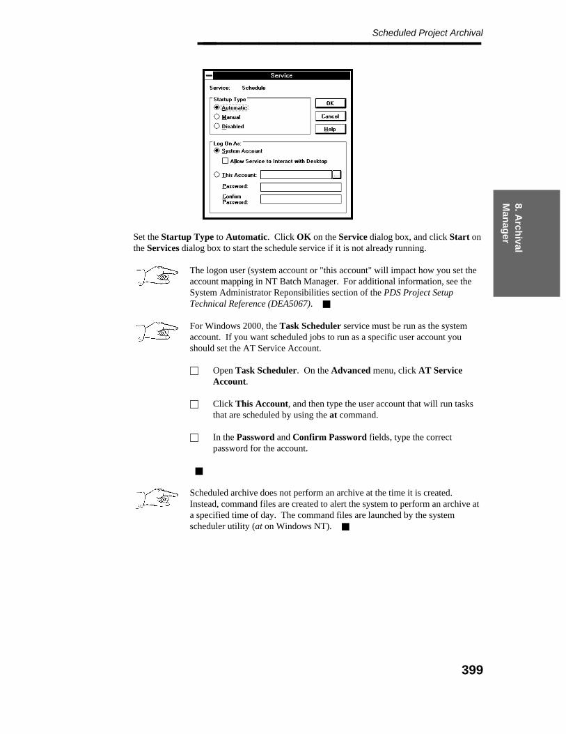
8. Arch
ival M
anag
er
Scheduled Project Archival________________
Set the Startup Type to Automatic. Click OK on the Service dialog box, and click Start onthe Services dialog box to start the schedule service if it is not already running.
The logon user (system account or "this account" will impact how you set theaccount mapping in NT Batch Manager. For additional information, see theSystem Administrator Reponsibilities section of the PDS Project SetupTechnical Reference (DEA5067).
For Windows 2000, the Task Scheduler service must be run as the systemaccount. If you want scheduled jobs to run as a specific user account youshould set the AT Service Account.
Open Task Scheduler. On the Advanced menu, click AT ServiceAccount.
Click This Account, and then type the user account that will run tasksthat are scheduled by using the at command.
In the Password and Confirm Password fields, type the correctpassword for the account.
Scheduled archive does not perform an archive at the time it is created.Instead, command files are created to alert the system to perform an archive ata specified time of day. The command files are launched by the systemscheduler utility (at on Windows NT).
399

Project Administrator — April 2002________________
Operating Sequence
1. Select Option.
Select Scheduled Project Archival from the Project Archival Manager form.
The Scheduled Project Archival form is displayed.
2. Select the required option.
— Create — Creates a scheduled archive. See page 401.
— Revise — Revises an existing scheduled archive. See page 401.
— Delete — Deletes a scheduled archive. See page 405.
— Review Schedule — Reviews previously defined archival schedules. See page406.
400
8. Arch
ival M
anag
er
Archival Creation/Revision________________
8.2.1 Archival Creation/Revision
These options are used to create or revise a schedule for archiving a project (or a subset of aproject) on a periodic basis. You can establish multiple scheduled archives for each project.One suggested method is complete project once per week, then models and drawings on anightly basis.
A suggested procedure is to archive the complete project once per week, andarchive models and drawings on a nightly basis.
The archive is performed on the node where the scheduled archive is created.However, the archival data may be created on a different node. For example, ascheduled project archive may be created on a compute server and the archivejob can specify the archival information is placed on a file server.
Field Descriptions
Shell Script — The Shell Script field is filled in automatically using the conventionarchive_<archival_index_no>.
Number — Type up to 24 alphanumeric characters for the name of the archivalschedule.
Description — Type up to 40 alphanumeric characters for the description of thearchival schedule.
File Specification and Path — Type the file name and directory path for the ArchivalSchedule Data file. This file defines the time of day for archival, the frequency ofarchival, and the data to be archived.
Automated Data Exchange — Select this option to display the fields to define theNodename, logon, password and location for the data exchange.
401
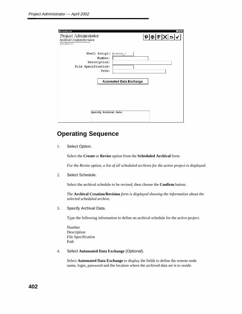
Project Administrator — April 2002________________
Operating Sequence
1. Select Option.
Select the Create or Revise option from the Scheduled Archival form.
For the Revise option, a list of all scheduled archives for the active project is displayed.
2. Select Schedule.
Select the archival schedule to be revised; then choose the Confirm button.
The Archival Creation/Revision form is displayed showing the information about theselected scheduled archive.
3. Specify Archival Data.
Type the following information to define an archival schedule for the active project.
NumberDescriptionFile SpecificationPath
4. Select Automated Data Exchange (Optional).
Select Automated Data Exchange to display the fields to define the remote nodename, login, password and the location where the archived data set is to reside.
402
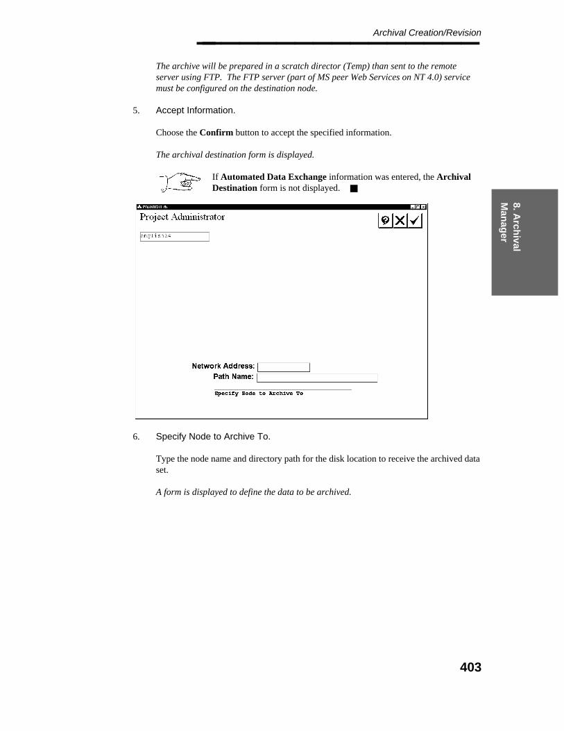
8. Arch
ival M
anag
er
Archival Creation/Revision________________ The archive will be prepared in a scratch director (Temp) than sent to the remoteserver using FTP. The FTP server (part of MS peer Web Services on NT 4.0) servicemust be configured on the destination node.
5. Accept Information.
Choose the Confirm button to accept the specified information.
The archival destination form is displayed.
If Automated Data Exchange information was entered, the ArchivalDestination form is not displayed.
6. Specify Node to Archive To.
Type the node name and directory path for the disk location to receive the archived dataset.
A form is displayed to define the data to be archived.
403
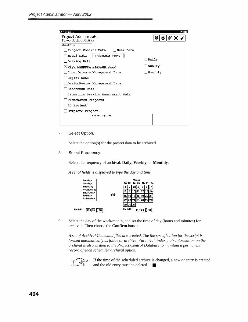
Project Administrator — April 2002________________
7. Select Option.
Select the option(s) for the project data to be archived.
8. Select Frequency.
Select the frequency of archival: Daily, Weekly, or Monthly.
A set of fields is displayed to type the day and time.
9. Select the day of the week/month, and set the time of day (hours and minutes) forarchival. Then choose the Confirm button.
A set of Archival Command files are created. The file specification for the script isformed automatically as follows: archive_<archival_index_no> Information on thearchival is also written to the Project Control Database to maintain a permanentrecord of each scheduled archival option.
If the time of the scheduled archive is changed, a new at entry is createdand the old entry must be deleted.
404

8. Arch
ival M
anag
er
Delete Archival Schedule________________
8.2.2 Delete Archival Schedule
The Delete Archival Schedule option deletes an existing archival schedule file.
Operating Sequence
1. Select Option.
Select the Delete option from the Schedule Archival form.
A list of archival schedules for the active project is displayed.
2. Select Archival Schedule File.
Select the archival schedule to be deleted; then choose the Confirm button.
3. Accept to Delete Archival Data.
Choose the Confirm button to delete the selected archival schedule.
A warning is displayed with instructions to delete the schedule.
405
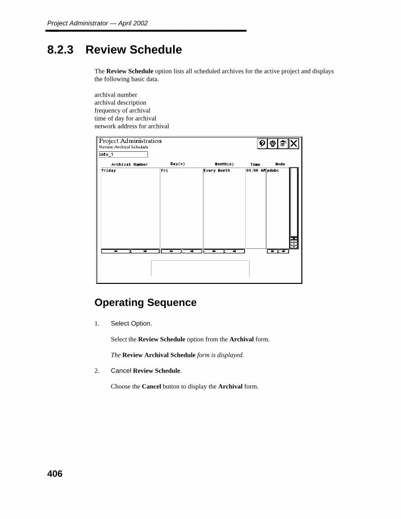
Project Administrator — April 2002________________
8.2.3 Review Schedule
The Review Schedule option lists all scheduled archives for the active project and displaysthe following basic data.
archival numberarchival descriptionfrequency of archivaltime of day for archivalnetwork address for archival
Operating Sequence
1. Select Option.
Select the Review Schedule option from the Archival form.
The Review Archival Schedule form is displayed.
2. Cancel Review Schedule.
Choose the Cancel button to display the Archival form.
406

8. Arch
ival M
anag
er
Active Project Retrieval________________
8.3 Active Project Retrieval
The Active Project Retrieval option is used to retrieve all or part of a project data set from anarchive into an active project. All relational database data is retrieved using the RIS loadutility transparently from within the Project Retrieval command.
Active project retrieval requires the archived project to be available. This may requirerecreation of the archived project. Active project retrieval also requires a drawing, model orreport to be retrieved must exist in the active project. Active project retrieval requires thepiping and equipment models have the same database attributes as those archived.
The Approved Reference Database and Unapproved Reference Database option do notretrieve archived binary reference libraries, only archived reference database tables. Toretrieve the binary files, you must use the Reference Database Libraries option or theComplete Reference Database option.
When using active project retrieval to restore a piping or equipment model,error messages in the log file are displayed informing that indexes in thedatabase already exist and can not be recreated. No further action needs to betaken regarding this error.
Active project retrieval also restores files into the locations from which theywere archived. This may pose a problem if the archived files are to be restoredinto a different location.
Active project retrieval requires that the archived project have the same nameas the active project. The archived project and the active project need not bethe same version. For example, piping models from a PDS 5.4 archive can beactively retrieved into a PDS 6.3 project. The model must exist in the activeproject prior to retrieval.
Before Using This Command
If you plan to retrieve a model drawing or report that has been deleted from the active project,it must be recreated (active project retrieval will not recreate the model, drawing or report if itdoes not already exist in the project).
407

Project Administrator — April 2002________________
Operating Sequence
1. Select Option.
Select Active Project Retrieval from the Project Archival Manager form.
The initial project retrieval form is displayed.
2. Specify Node to Retrieve From.
Type the node name and directory path for the disk location to receive the archived dataset.
The Project Retrieval Options form is displayed.
408
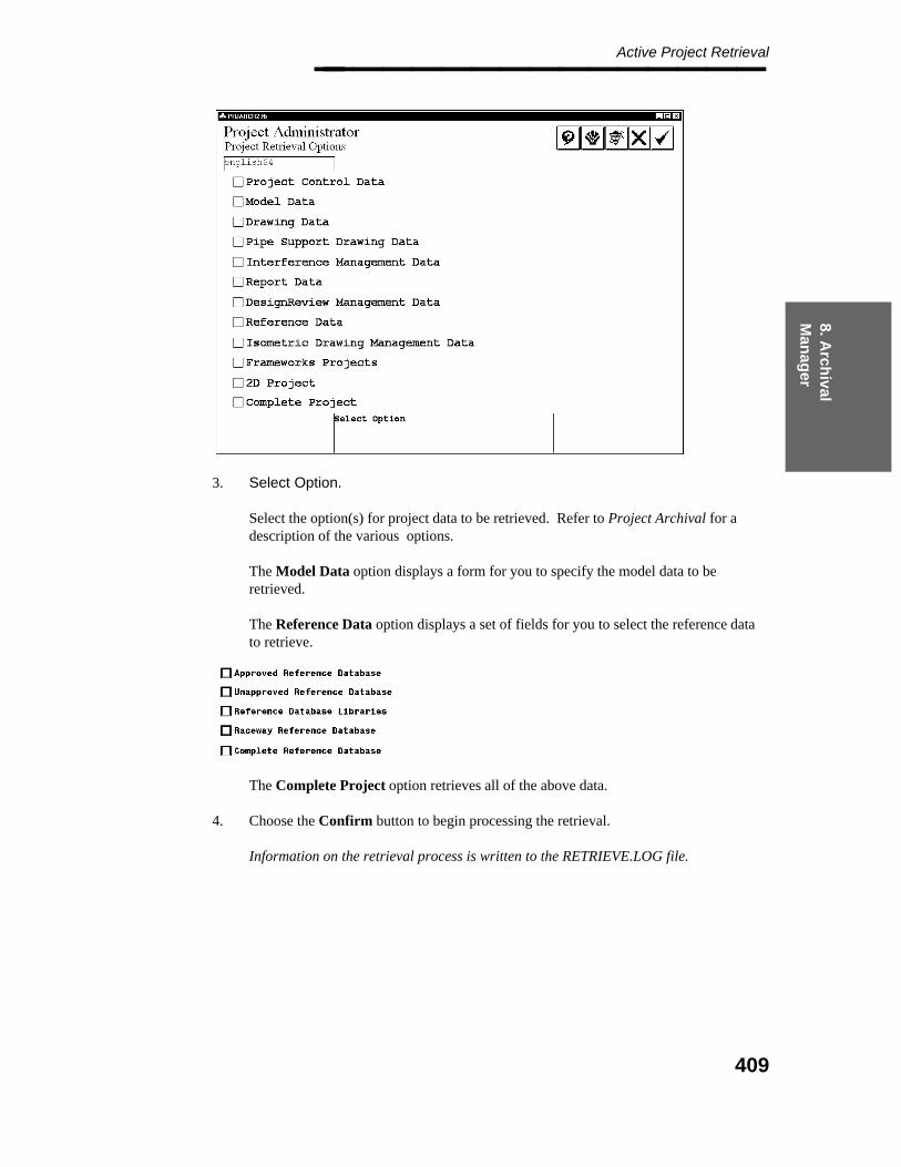
8. Arch
ival M
anag
er
Active Project Retrieval________________
3. Select Option.
Select the option(s) for project data to be retrieved. Refer to Project Archival for adescription of the various options.
The Model Data option displays a form for you to specify the model data to beretrieved.
The Reference Data option displays a set of fields for you to select the reference datato retrieve.
The Complete Project option retrieves all of the above data.
4. Choose the Confirm button to begin processing the retrieval.
Information on the retrieval process is written to the RETRIEVE.LOG file.
409

Project Administrator — April 2002________________
8.4 Inactive Project Retrieval
The Inactive Project Retrieval option is used to retrieve data from an archived data set for aproject not currently active on the network. The project is re-created and the data is restoredinto the Project Control Database before proceeding to retrieve any design data or referencedata. The project directory file is also updated to include the previously inactive project.
Inactive project retrieval requires that a full project archival data set be used. If only part ofthe project was archived (for example, all data except isometric information), inactive projectretrieval may not be used.
A project archived using an older version of PDS can be retrieved using anewer version of PDS. For example, a project archived using PDS version 5can be inactively retrieved using PDS version 6. After the project has beenretrieved, the prompt is displayed to upgrade the project when it is firstselected from the PD Shell main menu.
Options and Commands
Use/Do Not Use ASCII File — Allows use of an ASCII file, express.txt, to update filelocations. The system uses the express.txt file that is located in the ˜\pdshell\seed\directory. For more information on the express.txt file, see the PDS Express ProjectCreation Quick Reference.
Before Using This Command
To retrieve an inactive archived project, you must
Re-create the directory structure as it existed on the original project. This includesdirectories for EE Raceway and Frameworks data. Inactive Project Retrieval does notre-create any missing directories.
Create the required databases and database users in the RDBMS.
For a 3D-only project, the following areas must have been included in the archive:
Project Control DataModel DataDrawing DataPipe Supports DataInterference Management DataReport DataDesignReview Management DataReference DataIsometric Drawing Management DataFrameWorks Projects
410
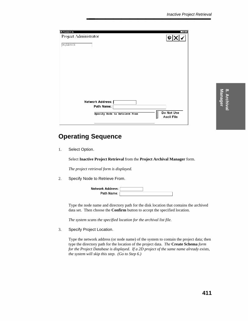
8. Arch
ival M
anag
er
Inactive Project Retrieval________________
Operating Sequence
1. Select Option.
Select Inactive Project Retrieval from the Project Archival Manager form.
The project retrieval form is displayed.
2. Specify Node to Retrieve From.
Type the node name and directory path for the disk location that contains the archiveddata set. Then choose the Confirm button to accept the specified location.
The system scans the specified location for the archival list file.
3. Specify Project Location.
Type the network address (or node name) of the system to contain the project data; thentype the directory path for the location of the project data. The Create Schema formfor the Project Database is displayed. If a 2D project of the same name already exists,the system will skip this step. (Go to Step 6.)
411
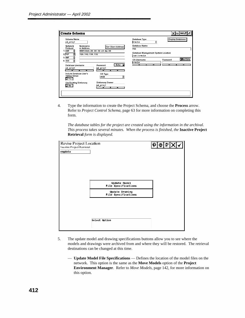
Project Administrator — April 2002________________
4. Type the information to create the Project Schema, and choose the Process arrow.Refer to Project Control Schema, page 63 for more information on completing thisform.
The database tables for the project are created using the information in the archival.This process takes several minutes. When the process is finished, the Inactive ProjectRetrieval form is displayed.
5. The update model and drawing specifications buttons allow you to see where themodels and drawings were archived from and where they will be restored. The retrievaldestinations can be changed at this time.
— Update Model File Specifications — Defines the location of the model files on thenetwork. This option is the same as the Move Models option of the ProjectEnvironment Manager. Refer to Move Models, page 142, for more information onthis option.
412
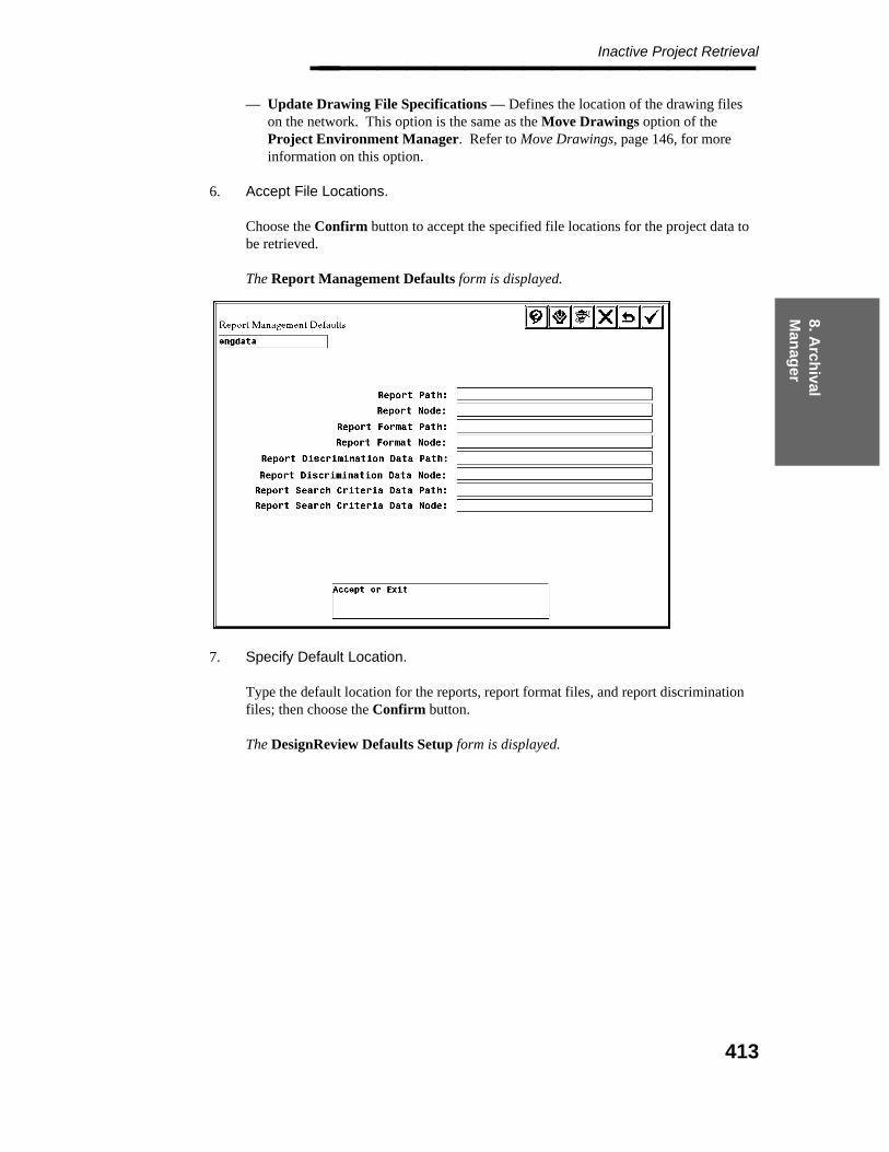
8. Arch
ival M
anag
er
Inactive Project Retrieval________________
— Update Drawing File Specifications — Defines the location of the drawing fileson the network. This option is the same as the Move Drawings option of theProject Environment Manager. Refer to Move Drawings, page 146, for moreinformation on this option.
6. Accept File Locations.
Choose the Confirm button to accept the specified file locations for the project data tobe retrieved.
The Report Management Defaults form is displayed.
7. Specify Default Location.
Type the default location for the reports, report format files, and report discriminationfiles; then choose the Confirm button.
The DesignReview Defaults Setup form is displayed.
413
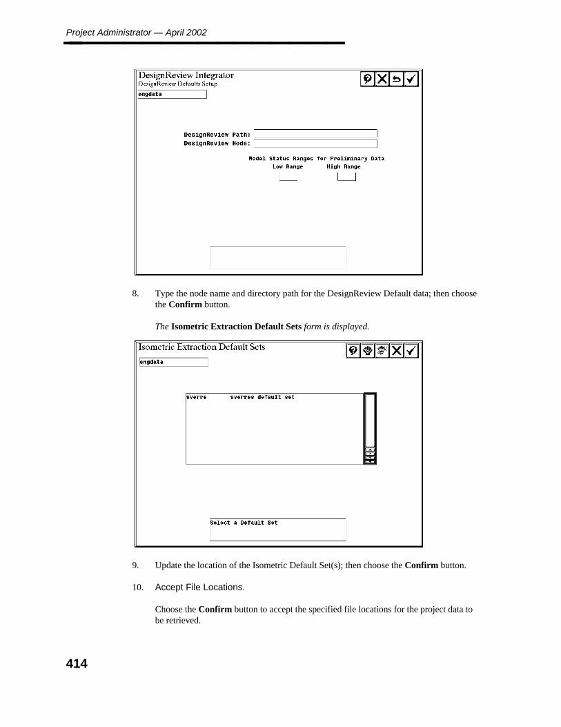
Project Administrator — April 2002________________
8. Type the node name and directory path for the DesignReview Default data; then choosethe Confirm button.
The Isometric Extraction Default Sets form is displayed.
9. Update the location of the Isometric Default Set(s); then choose the Confirm button.
10. Accept File Locations.
Choose the Confirm button to accept the specified file locations for the project data tobe retrieved.
414
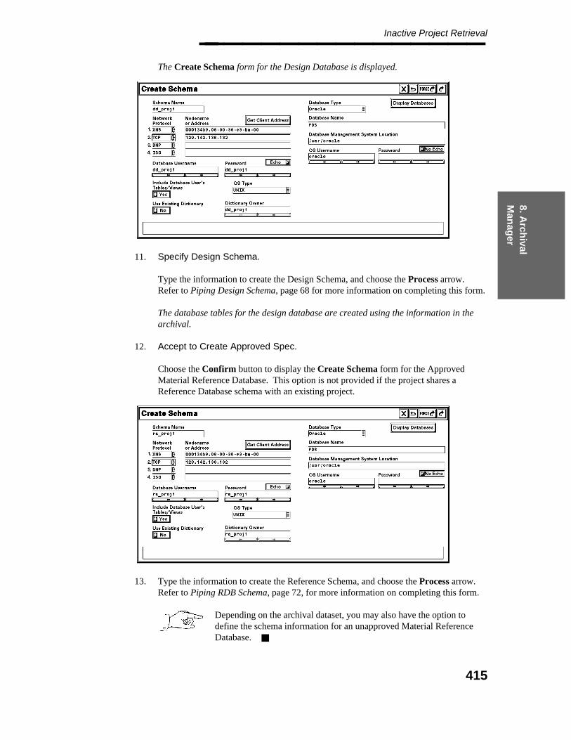
8. Arch
ival M
anag
er
Inactive Project Retrieval________________ The Create Schema form for the Design Database is displayed.
11. Specify Design Schema.
Type the information to create the Design Schema, and choose the Process arrow.Refer to Piping Design Schema, page 68 for more information on completing this form.
The database tables for the design database are created using the information in thearchival.
12. Accept to Create Approved Spec.
Choose the Confirm button to display the Create Schema form for the ApprovedMaterial Reference Database. This option is not provided if the project shares aReference Database schema with an existing project.
13. Type the information to create the Reference Schema, and choose the Process arrow.Refer to Piping RDB Schema, page 72, for more information on completing this form.
Depending on the archival dataset, you may also have the option todefine the schema information for an unapproved Material ReferenceDatabase.
415
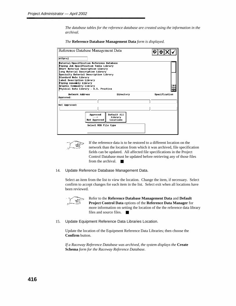
Project Administrator — April 2002________________ The database tables for the reference database are created using the information in thearchival.
The Reference Database Management Data form is displayed.
If the reference data is to be restored to a different location on thenetwork than the location from which it was archived, file specificationfields can be updated. All affected file specifications in the ProjectControl Database must be updated before retrieving any of those filesfrom the archival.
14. Update Reference Database Management Data.
Select an item from the list to view the location. Change the item, if necessary. Selectconfirm to accept changes for each item in the list. Select exit when all locations havebeen reviewed.
Refer to the Reference Database Management Data and DefaultProject Control Data options of the Reference Data Manager formore information on setting the location of the the reference data libraryfiles and source files.
15. Update Equipment Reference Data Libraries Location.
Update the location of the Equipment Reference Data Libraries; then choose theConfirm button.
If a Raceway Reference Database was archived, the system displays the CreateSchema form for the Raceway Reference Database.
416
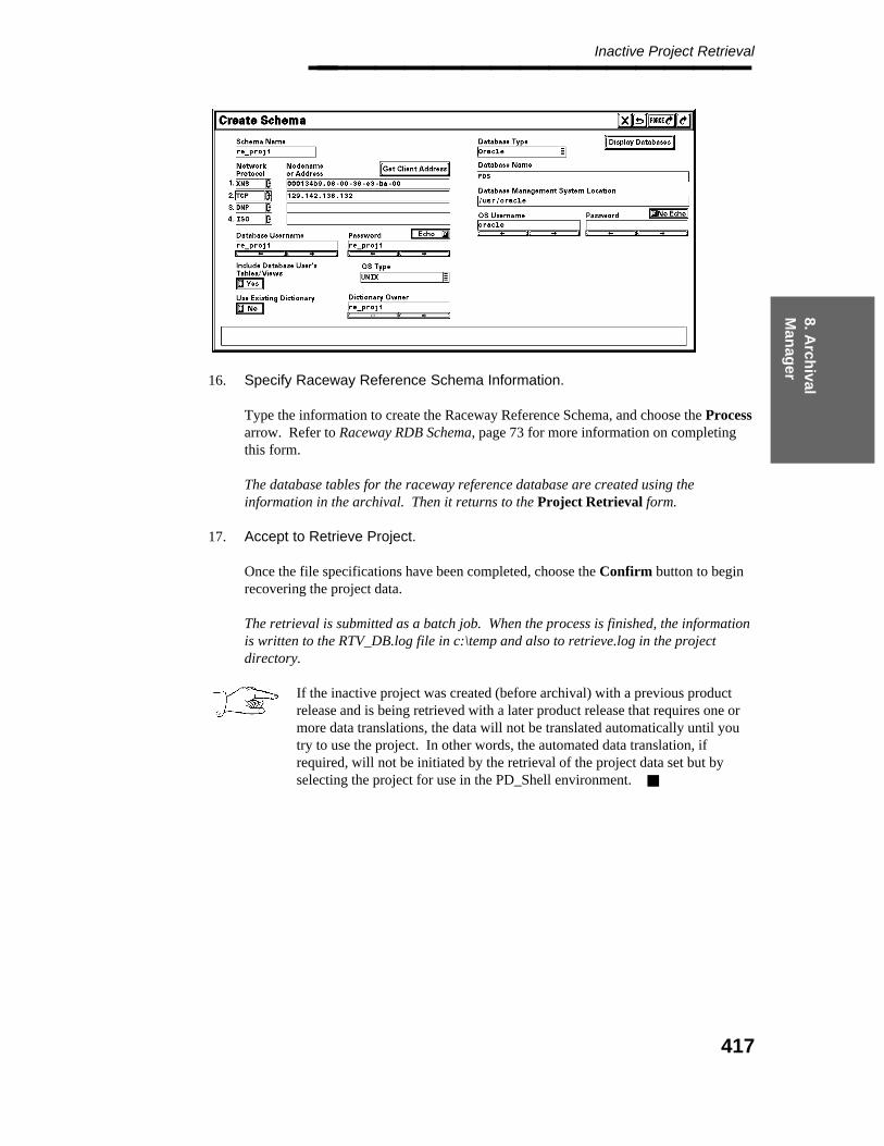
8. Arch
ival M
anag
er
Inactive Project Retrieval________________
16. Specify Raceway Reference Schema Information.
Type the information to create the Raceway Reference Schema, and choose the Processarrow. Refer to Raceway RDB Schema, page 73 for more information on completingthis form.
The database tables for the raceway reference database are created using theinformation in the archival. Then it returns to the Project Retrieval form.
17. Accept to Retrieve Project.
Once the file specifications have been completed, choose the Confirm button to beginrecovering the project data.
The retrieval is submitted as a batch job. When the process is finished, the informationis written to the RTV_DB.log file in c:\temp and also to retrieve.log in the projectdirectory.
If the inactive project was created (before archival) with a previous productrelease and is being retrieved with a later product release that requires one ormore data translations, the data will not be translated automatically until youtry to use the project. In other words, the automated data translation, ifrequired, will not be initiated by the retrieval of the project data set but byselecting the project for use in the PD_Shell environment.
417
Project Administrator — April 2002________________
8.5 Import Project Retrieval
The Import Project Retrieval command imports models, orthographic drawings and pipesupport drawings from an archive into an active project. All or selected models and drawingscan be imported into the destination project.
Import project retrieval recreates a model or drawing if it does not exist in the active project.The active project and the archive must have been created in the same version of PDS.
If a model is restored to a previous version, some other data within the project temporarilymay not be synchronized with the restored version of the model. For example, if a componentwas placed in the model at a time after the archival of that model and that component wasreported as an interference clash, that same clash will appear in any Interference Managerreviews until the Interference Checker processes that model again. At that time, the recordof the clash is changed to a deleted state in the Interference Management data. This is thesame situation that would arise if you deleted a component involved in an interference clash.
A similar situation arises with components that are used as the source of either associativename labels or coordinate labels in orthographic drawings. The label continues to appear inthe drawing until the Update Labels command is run for the applicable drawing view(s).
Any reports that were created by extracting data from the restored model will be incorrectdepending on the changes that were lost in restoring to the archived version of the model.
However, the Piping Designer and the Model Builder will not re-use any of the uniquenumbers for piping segments and components that were lost in restoring the data to thearchived version of a piping model. This data will not be restored to its previous values whena single piping model or any group of piping models is being restored to archived versions toeliminate the problem just described.
Before Using This Command
This option requires that the archived data to be imported is created with PDS version 4.3 orlater. Archives that were created with earlier versions of PDS do not contain an import map.
The source (archived) project and the destination (active) project must be consistent. Thisincludes
Identical database structure. Any user-defined attributes in the source project must alsobe present in the destination project.
Identical or compatible reference data. Specification data used by the source projectmust be defined in the destination project. All the reference data libraries must beconsistent.
Use the Model Setup command of the Project Environment Manager to define the defaultlocation for models by discipline in the destination project.
418

8. Arch
ival M
anag
er
Import Project Retrieval________________
Operating Sequence
1. Select Option.
Select Import Project Retrieval from the Project Archival Manager form.
The archival media form is displayed.
2. Specify Node to Retrieve From.
Type the node name and directory path for the disk location containing the archiveddata set.
A form is displayed to define the archived data to be retrieved.
419
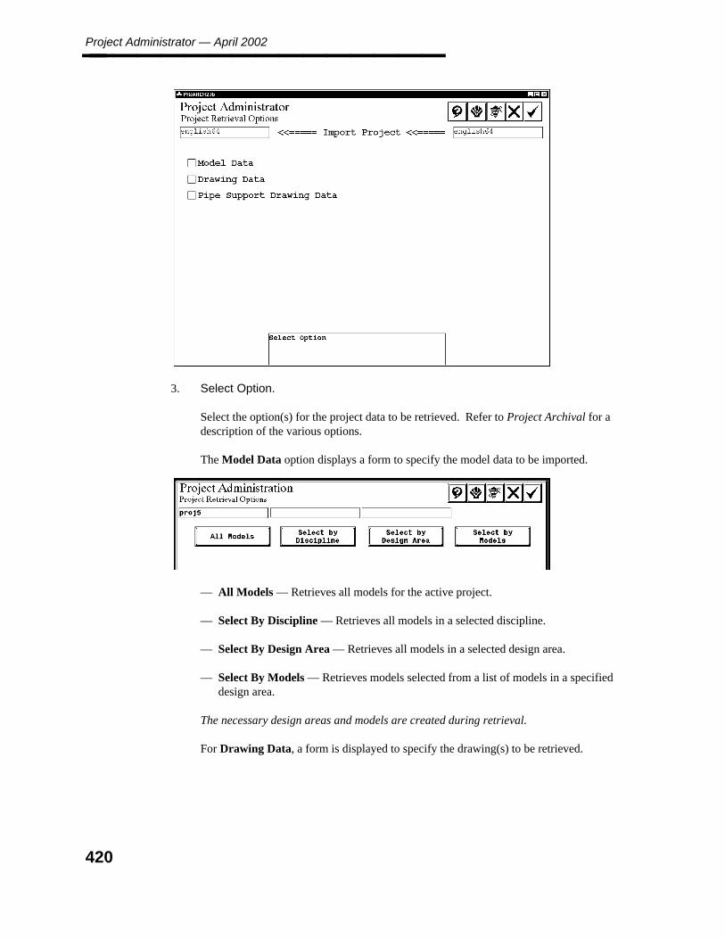
Project Administrator — April 2002________________
3. Select Option.
Select the option(s) for the project data to be retrieved. Refer to Project Archival for adescription of the various options.
The Model Data option displays a form to specify the model data to be imported.
— All Models — Retrieves all models for the active project.
— Select By Discipline — Retrieves all models in a selected discipline.
— Select By Design Area — Retrieves all models in a selected design area.
— Select By Models — Retrieves models selected from a list of models in a specifieddesign area.
The necessary design areas and models are created during retrieval.
For Drawing Data, a form is displayed to specify the drawing(s) to be retrieved.
420

8. Arch
ival M
anag
er
Import Project Retrieval________________
— All Drawings — Retrieve all drawings for the active project.
— Select By Drawing Types — Retrieve all drawings in selected drawing type(s).
— Select Individual Drawings — Retrieve drawings selected from a list of drawingsin a selected drawing type.
The Pipe Support Drawing Data option displays the Submit Immediately / DelayedSubmit toggle.
4. Select Submit Immediately to begin importing files as soon as you exit the form.
— OR —
Select Delayed Submit to specify a time and date to process the request.
5. Begin Retrieval.
Choose the Confirm button to begin processing the retrieval.
The request is submitted to the batch queue PDarchival for processing. Processinginformation is written to the IMPORT.LOG file in the project directory.
Processing
When a piping model is imported, the system may need to revise the partition number for thatpiping model to include the piping model in the destination project. As a consequence, thefollowing data will also be revised as it is loaded into the destination project. The system:
Updates the partition number of piping segments and components in the graphicalattribute linkages in the piping model.
Updates the partition number of piping segments and components in each systemunique number in the database.
Updates the partition numbers for nozzles that are included with piping segments (formaintaining the association between the nozzle and the piping model) in the databasefor piping segments. Any association to nozzles that reside in an equipment model thatis not in the destination project, either before or after the import process, will be clearedautomatically.
421

Project Administrator — April 2002________________ Updates the partition number in the graphical attribute linkages in any orthographicdrawings that are being imported that include a piping model that is being imported.
Initializes the appropriate data in the Piping Model Data Table (PDtable_114) of theProject Control Database.
Performs Database Verification for any piping model that has been imported. Thisresults in orphan records in the database being deleted automatically, and orphan pipingsegments or components in the model having the symbology changed.
Import Model Data
If the models being imported do not exist in the destination project, the system automaticallycreates the model management data in the Project Control Database of the destination project.These models are created with the default network address and path name defined in theProject Control Database on the basis of discipline. If this default network address and pathname are not defined, an error message is displayed, and the models are not imported.
If a piping model being imported already exists in the destination project, the system updatesthe revision date for that model in the Project Control Database.
When importing a piping model or an equipment model into the destination project from adifferent project, the system maintains reference model attachments for those other modelsthat are included in the destination project, either before or after being imported into theproject. If the reference model does not exist in the destination project or it is not beingimported, the system deletes that reference model attachment.
When importing a model into the destination project from a different project, the other filesassociated with the model, such as the interference envelope file and the DesignReview labelfile, are not deleted or replaced. This data must be re-created, as required.
Import Drawing Data
If all reference models for a drawing are not in the destination project or are not beingimported, the system generates an error in the error log and the drawing is not imported.
When retrieving drawings, PDS verifies that any referenced models exist in theproject. If these models do not exist, the references to the models are removedfrom the drawing.
The system updates any associative name labels or coordinate labels if the applicablereference model is being imported into the project at the same time. Otherwise, the associatedlabel is deleted from the drawing. The system maintains reference model attachments forthose models that are also being imported into the project.
In order for the imported drawing to be opened, pdtable_126 mustcorrectly specify the default location of all drawing types, and the requiredborder file must also be retrieved.
422

8. Arch
ival M
anag
er
Import Project Retrieval________________
Import Pipe Support Drawing Data
If the pipe support drawings being imported do not exist in the destination project, the systemautomatically creates the pipe support data in the Project Control Database of the destinationproject. These drawings are created with the default node name and path name defined in theProject Control Database on the basis of discipline. If this default node name and path nameare not defined, an error message is displayed, and the drawings are not imported.
If a pipe support drawing being imported already exists in the destination project, the systemupdates the revision date for that drawing in the Project Control Database.
8.5.1 Schedule Project Import
The Schedule Project Import command is used to schedule the Import of Model Data into aproject. Individual models and drawings can be selected to be imported into the destinationproject from a list of the archived data or import all the models and/or drawings archived for aproject.
Effective use of the Schedule Project Import feature depends upon the use of IncrementalArchive and Automated Data Exchange.
Since there is always the possibility that data being imported has not arrived at the importingsite, the process ensures the data set being imported is complete and current.
Before Using This Command
The source (archived) project and the destination (active) project must be consistent. Thisincludes:
Identical database structure. Any user-defined attributes in the source project must alsobe defined exactly the same in the destination project and vice versa.
Identical or compatible reference data. Any specification data used by the sourceproject must be defined in the destination project. All the reference data libraries mustbe consistent.
Operating Sequence
1. Select Option.
Select Scheduled Project Import from the Project Archival Manager form.
The archival media form is displayed.
2. Specify Node to Retrieve From.
423

Project Administrator — April 2002________________ Type the node name and directory path for the disk location containing the archiveddata set.
A form is displayed to define the archived data to be retrieved.
3. Select Option.
Select the option(s) for the project data to be retrieved. Refer to Project Archival for adescription of the various options.
The Model Data option displays a form to specify the model data to be imported.
— All Models — Retrieves all models for the active project.
— Select By Discipline — Retrieves all models in a selected discipline.
— Select By Design Area — Retrieves all models in a selected design area.
— Select By Models — Retrieves models selected from a list of models in a specifieddesign area.
The necessary design areas and models are created during retrieval.
424
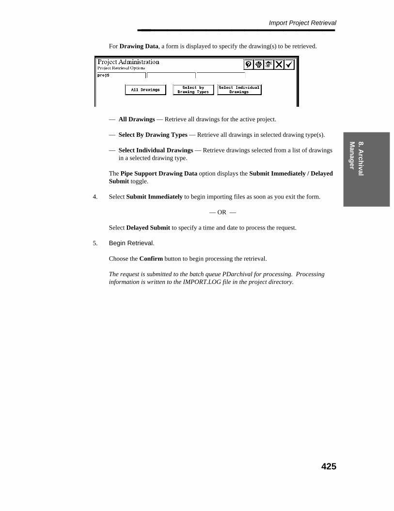
8. Arch
ival M
anag
er
Import Project Retrieval________________ For Drawing Data, a form is displayed to specify the drawing(s) to be retrieved.
— All Drawings — Retrieve all drawings for the active project.
— Select By Drawing Types — Retrieve all drawings in selected drawing type(s).
— Select Individual Drawings — Retrieve drawings selected from a list of drawingsin a selected drawing type.
The Pipe Support Drawing Data option displays the Submit Immediately / DelayedSubmit toggle.
4. Select Submit Immediately to begin importing files as soon as you exit the form.
— OR —
Select Delayed Submit to specify a time and date to process the request.
5. Begin Retrieval.
Choose the Confirm button to begin processing the retrieval.
The request is submitted to the batch queue PDarchival for processing. Processinginformation is written to the IMPORT.LOG file in the project directory.
425

Project Administrator — April 2002________________
426

9. System
M
anag
er
System Manager________________
9. System Manager
The System Manager command is used to revise the project directory file. This filemaintains the list of active projects on the network. You can revise the project type (2D/3D)and/or the project location.
This option can also be used to re-create the project directory file if it is inadvertently deleted.If the project directory file does not exist on the network, no projects appear in the list ofactive projects on the initial PD_Shell form.
This situation can also occur if the exported variables PROJ_FILE and PROJ_ADDRare not defined or are defined incorrectly in the PDS.CMD file. Ensure that proj_filedoes not exist in the project directory before trying to re-create it.
Before Using This Command
Make sure the project directory file is not being used anywhere on the network at the time thatit is being revised.
Option Descriptions
Edit Project Directory File — Revise the project type (2D/3D/both), networkaddress, or project directory path for a selected project.
Manage Project Directory File — Create a satellite project directory file for use inrestricting users from accessing all the projects in the master project directory file.
427

Project Administrator — April 2002________________
Operating Sequence
1. Select Option.
Select System Manager from the Project Administrator form.
If there are no projects in the project directory file, the Create Project File form isdisplayed.
For more information, see Create Project Directory File, page 429.
If there are projects in the project directory file, the System Manager FunctionSelection form is displayed.
2. Select Option.
Select the Edit Project Directory File or Manage Project Directory File option.
If Edit Project Directory File is selected, the Edit Project File form is displayed.
If Manage Project Directory File is selected, the Manage Project File form isdisplayed.
428
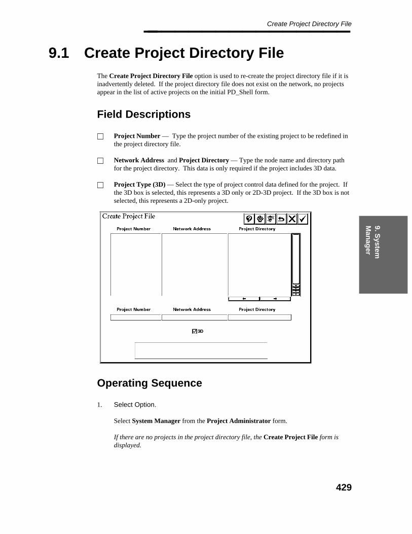
9. System
M
anag
er
Create Project Directory File________________
9.1 Create Project Directory File
The Create Project Directory File option is used to re-create the project directory file if it isinadvertently deleted. If the project directory file does not exist on the network, no projectsappear in the list of active projects on the initial PD_Shell form.
Field Descriptions
Project Number — Type the project number of the existing project to be redefined inthe project directory file.
Network Address and Project Directory — Type the node name and directory pathfor the project directory. This data is only required if the project includes 3D data.
Project Type (3D) — Select the type of project control data defined for the project. Ifthe 3D box is selected, this represents a 3D only or 2D-3D project. If the 3D box is notselected, this represents a 2D-only project.
Operating Sequence
1. Select Option.
Select System Manager from the Project Administrator form.
If there are no projects in the project directory file, the Create Project File form isdisplayed.
429

Project Administrator — April 2002________________
2. Specify Project Number
Type the Project Number.
The system verifies the Project Control Database exists, where the schema name ispd_<project_number> and verifies that project number is unique within the projectdirectory file being created.
3. Specify Network Address and Project Directory.
Type the Network Address and Project Directory
The system verifies the project directory is unique within the project directory file beingcreated and that it is a valid network location.
4. Specify Project Type.
Select the type of project control data defined for the project.
5. Accept Project Entry.
Choose the Confirm button each time you add or edit a project entry.
6. Accept Project Directory Information.
When all additions are completed, choose the Confirm button to save the projectdirectory information.
Choose the Confirm button to save the project file.
The System Manager Function Selection form is displayed.
430
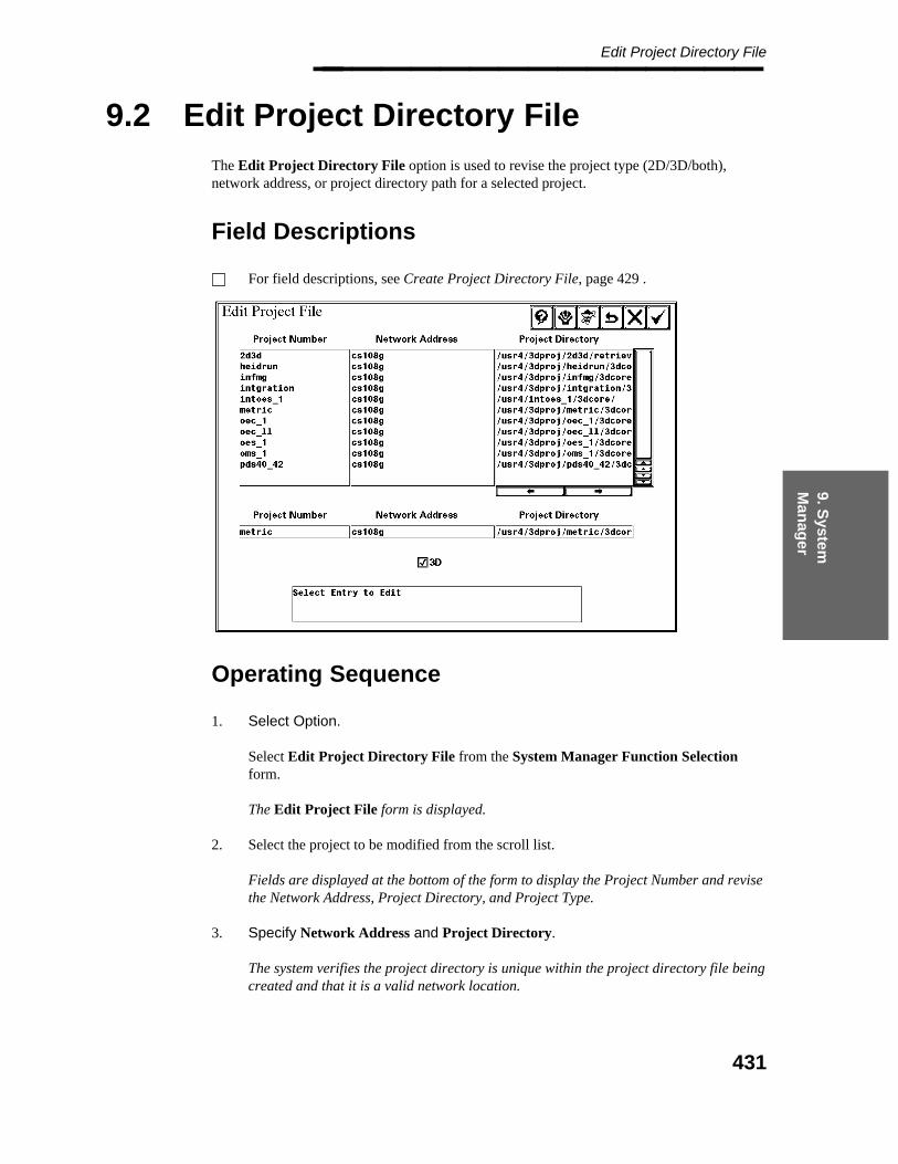
9. System
M
anag
er
Edit Project Directory File________________
9.2 Edit Project Directory File
The Edit Project Directory File option is used to revise the project type (2D/3D/both),network address, or project directory path for a selected project.
Field Descriptions
For field descriptions, see Create Project Directory File, page 429 .
Operating Sequence
1. Select Option.
Select Edit Project Directory File from the System Manager Function Selectionform.
The Edit Project File form is displayed.
2. Select the project to be modified from the scroll list.
Fields are displayed at the bottom of the form to display the Project Number and revisethe Network Address, Project Directory, and Project Type.
3. Specify Network Address and Project Directory.
The system verifies the project directory is unique within the project directory file beingcreated and that it is a valid network location.
431

Project Administrator — April 2002________________
4. Project Type (3D)
Select the type of project control data defined for the project. If the 3D box is selected,this represents a 3D only or 2D-3D project. If the 3D box is not selected, this representsa 2D-only project.
5. Accept Project Entry.
Choose the Confirm button each time you add or edit a project entry.
6. When all changes are completed, choose the Confirm button to save the projectdirectory information.
— OR —
Choose the Cancel button to exit the form without saving the changes/additions.
The System Manager Function Selection form is displayed.
432
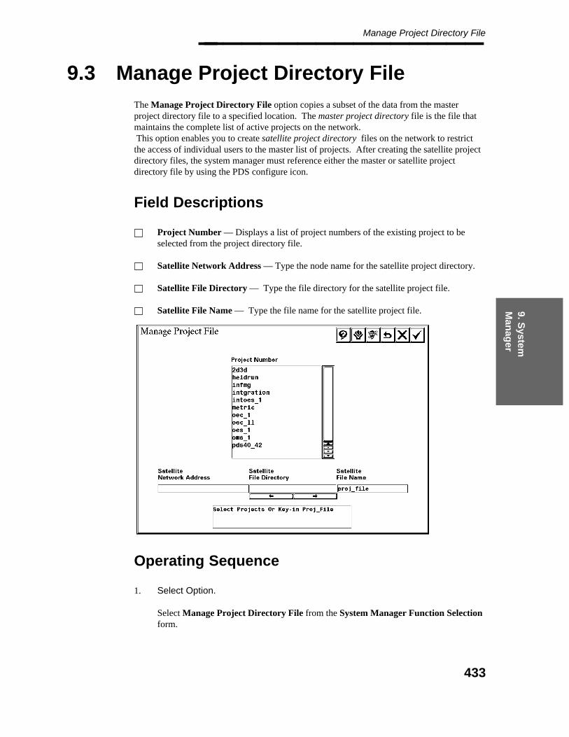
9. System
M
anag
er
Manage Project Directory File________________
9.3 Manage Project Directory File
The Manage Project Directory File option copies a subset of the data from the masterproject directory file to a specified location. The master project directory file is the file thatmaintains the complete list of active projects on the network.This option enables you to create satellite project directory files on the network to restrictthe access of individual users to the master list of projects. After creating the satellite projectdirectory files, the system manager must reference either the master or satellite projectdirectory file by using the PDS configure icon.
Field Descriptions
Project Number — Displays a list of project numbers of the existing project to beselected from the project directory file.
Satellite Network Address — Type the node name for the satellite project directory.
Satellite File Directory — Type the file directory for the satellite project file.
Satellite File Name — Type the file name for the satellite project file.
Operating Sequence
1. Select Option.
Select Manage Project Directory File from the System Manager Function Selectionform.
433
Project Administrator — April 2002________________ The Manage Project File form is displayed with the complete list of projects from themaster project directory file.
2. Select Projects or Type Proj_File
Type the network address, path name, and file specification of the satellite projectdirectory file to be created.
The system verifies the project directory file is being created in a valid network locationand that you have write access to that directory.
3. Select Project Number(s).
Select the appropriate project number(s) from the scroll list; then choose the Confirmbutton to accept the defined information.
The specified satellite project directory file is created with the selected projects.
434
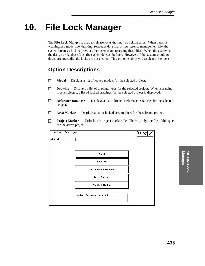
10. File L
ock
Man
ager
File Lock Manager________________
10. File Lock Manager
The File Lock Manger is used to release locks that may be held in error. When a user isworking in a model file, drawing, reference data file, or interference management file, thesystem creates a lock to prevent other users from accessing these files. When the user exitsthe design or database files, the system deletes the lock. However, if the system should godown unexpectedly, the locks are not cleared. This option enables you to clear these locks.
Option Descriptions
Model — Displays a list of locked models for the selected project.
Drawing — Displays a list of drawing types for the selected project. When a drawingtype is selected, a list of locked drawings for the selected project is displayed.
Reference Database — Displays a list of locked Reference Databases for the selectedproject.
Area Marker — Displays a list of locked area markers for the selected project.
Project Marker — Unlocks the project marker file. There is only one file of this typefor the active project.
435
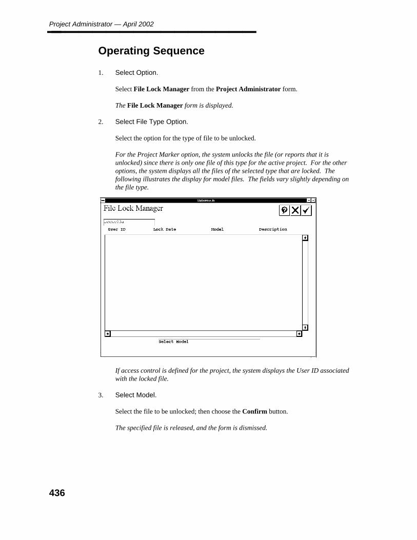
Project Administrator — April 2002________________
Operating Sequence
1. Select Option.
Select File Lock Manager from the Project Administrator form.
The File Lock Manager form is displayed.
2. Select File Type Option.
Select the option for the type of file to be unlocked.
For the Project Marker option, the system unlocks the file (or reports that it isunlocked) since there is only one file of this type for the active project. For the otheroptions, the system displays all the files of the selected type that are locked. Thefollowing illustrates the display for model files. The fields vary slightly depending onthe file type.
If access control is defined for the project, the system displays the User ID associatedwith the locked file.
3. Select Model.
Select the file to be unlocked; then choose the Confirm button.
The specified file is released, and the form is dismissed.
436
11. Exp
ort to
P
DM
E
Export to PDME________________
11. Export to PDME
The Export to PDME command prepares a data set that consists of user-defined documentsand a document index for import into the Plant Data Management Environment (PDME).This feature is intended to address the needs of the owner-operator users of PDS and enhancethe value of PDS for the engineering and construction industry.
The Export to PDME command creates a collection of documents and an associated ASCIIindex list, the document index file. The documents are bundled into a compressed cpio file.The document index file, named index.doc, is included in the document bundle. You canwrite the bundle to a specified directory on a hard disk or directly to tape.
This command is also included in the stand-alone PDS 2D environment. The user interface isidentical in both environments, except that fewer options for selecting the document type arepresented in the PDS 2D environment.
The document bundle requires that each document be associated with a unit. This associationis implicit for the documents associated with the PDS 2D products, since the process unit isused to segregate schematic documents in the Project Control Database. Because PDS 3Ddocuments are not explicitly associated with a process unit, you must define the appropriateprocess unit for a set of documents. PDS 3D documents can be created without a definingunit. The batch extraction places unit data of NONE. This information is written into theindex.doc file, and if not edited will create a unit in the PDME software called NONE. Itis highly recommended that you export 3D documents with the same unit information asrequired by the 2D documents to ensure proper links in the PDME software.
PDME ensures that a process unit is unique within the PDME database before creatinganother unit record. Typically, the documents within the same process unit are imported intoPDME more than once in extracting a document bundle from PDS. The same issue applies todocuments that may be already present in the PDME database.
Options
You can select the document types to be included in the document bundle by selecting fromthe following list of document types.
P&I Drawings — Equipment, instrumentation, and piping schematics are drawn fromprocess flow data using the Process Instrumentation Diagrams (P&ID) product.
PFD — The Process Flow Diagram (PFD) may be developed in PDS usingcalculations performed in third-party process simulation packages such as ASPEN orSimSci.
IDM — This type of document represents the Instrument Data Manager (IDM)database that maintains an occurrence for each instrument in a project.
437
Project Administrator — April 2002________________ Orthographic Drawings — This type of document represents the drawings createdthrough the Drawing Manager environment.
Isometric Drawings — This type of document represents the drawings extracted fromthe plant model.
Structural Drawings — This type of document represents the drawings created usingFrameWorks.
MTO Reports — This type of document represents the Material Takeoff Options tospecify the source of commodity information.
DesignReview Models — This type of document represents the DesignReviewsessions that have been defined through the DesignReview Administrator.
Items Not Successfully Exported Report — Generates a report of any items ordocuments not exported and the reason for the failure.
Successfully Exported Documents — Generates a report of the documentssuccessfully exported. The individual plant items of the successful documents are notincluded.
Pre-Define Location for Export Packages — A default node may be defined with apath for the location of the export file on a per project basis allowing the package to benamed. The name of the package is used to create a directory under the default nodeand path for placement of the export files.
Add Document Comments — A comment may be added which applies to alldocuments selected (highlighted) when the comment is entered.
Before using this command
This command requires sufficient free disk space to store the data. You must have writeaccess to the directory to be used to store the export data.
438

11. Exp
ort to
P
DM
E
Export to PDME________________
Operating Sequence
1. Select Option.
Select the Export to PDME command from the Project Administrator form.
The Export to PDME form is displayed.
2. Select Export Option.
Select the option to save the export files.
Export Data to Hard DiskExport Data to Hard Disk ==> Tape
3. Specify Tape Drive Netaddr
Type the node name of the system on which the tape drive resides.
— AND/OR —
Specify Netaddr to Archive To
Type the node name and directory path for the disk location to receive the export data.
The system activates a form to define the documents to be exported.
439
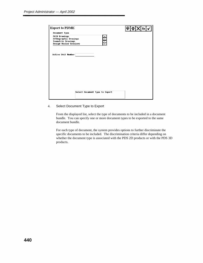
Project Administrator — April 2002________________
4. Select Document Type to Export
From the displayed list, select the type of documents to be included in a documentbundle. You can specify one or more document types to be exported to the samedocument bundle.
For each type of document, the system provides options to further discriminate thespecific documents to be included. The discrimination criteria differ depending onwhether the document type is associated with the PDS 2D products or with the PDS 3Dproducts.
440
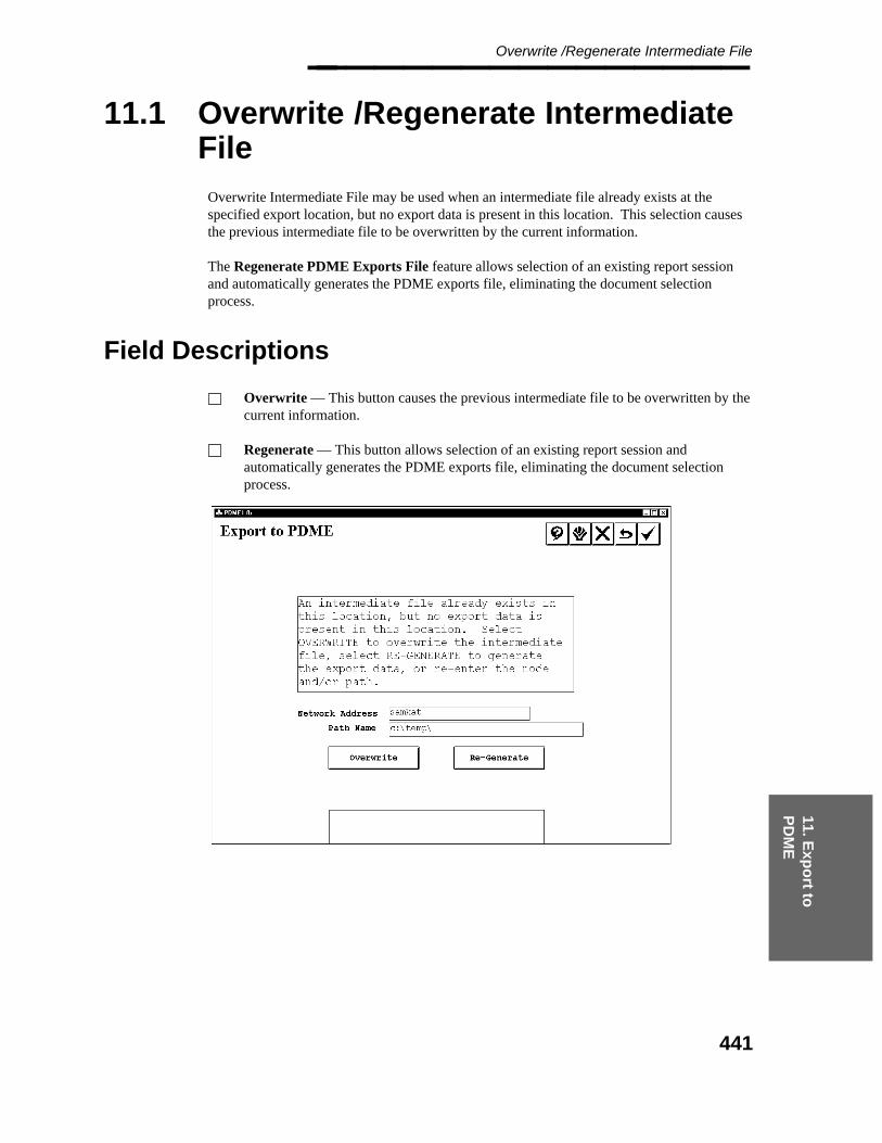
11. Exp
ort to
P
DM
E
Overwrite /Regenerate Intermediate File________________
11.1 Overwrite /Regenerate IntermediateFile
Overwrite Intermediate File may be used when an intermediate file already exists at thespecified export location, but no export data is present in this location. This selection causesthe previous intermediate file to be overwritten by the current information.
The Regenerate PDME Exports File feature allows selection of an existing report sessionand automatically generates the PDME exports file, eliminating the document selectionprocess.
Field Descriptions
Overwrite — This button causes the previous intermediate file to be overwritten by thecurrent information.
Regenerate — This button allows selection of an existing report session andautomatically generates the PDME exports file, eliminating the document selectionprocess.
441

Project Administrator — April 2002________________
Operating Sequence
1. Select Option
Select the Overwrite or Regenerate Intermediate file button.
The Export to PDME - Document Type form is displayed.
442
11. Exp
ort to
P
DM
E
P&I Drawings________________
11.2 P&I Drawings
The documents to be bundled can be discriminated on the basis of the unit number and thedrawing number. The default mode for the unit number is no units are selected, and for thedrawing number, no drawings are selected. Select all units and select all drawings can beused to make multiple selections. Select Restart to clear any previously specified searchcriteria.
If no P&ID data is defined for the project, the unit number must be typed.
The document bundle for P&ID drawings automatically includes an index that associatestagged components with the corresponding P&I drawing.
Field Descriptions
Unit Number — Unit number as defined in the P&ID database.
Unit Name — Unit name as defined in the P&ID database.
Select All Units — This button selects all units for processing.
Select Drawings in Unit — This button selects all drawings in the selected unit forprocessing.
Drawing Number — Drawing number as defined in the P&ID database.
Drawing Name — Drawing name as defined in the P&ID database.
Select All Drawings — This button selects all drawings for processing.
443
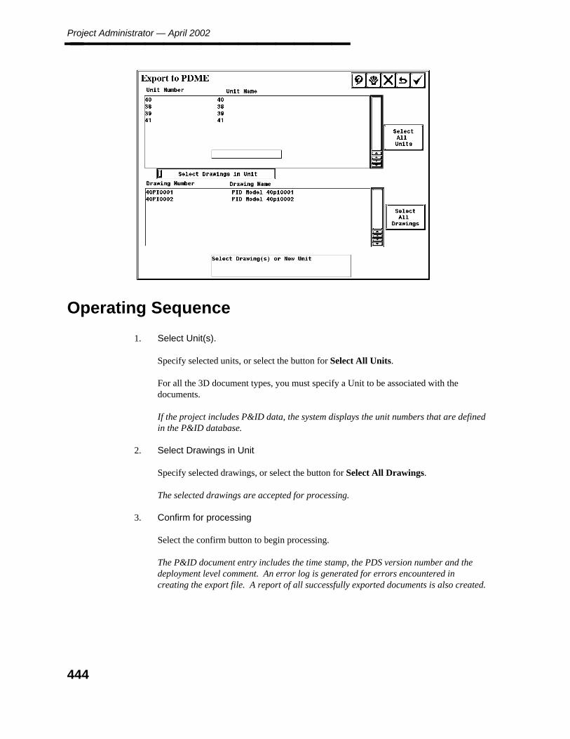
Project Administrator — April 2002________________
Operating Sequence
1. Select Unit(s).
Specify selected units, or select the button for Select All Units.
For all the 3D document types, you must specify a Unit to be associated with thedocuments.
If the project includes P&ID data, the system displays the unit numbers that are definedin the P&ID database.
2. Select Drawings in Unit
Specify selected drawings, or select the button for Select All Drawings.
The selected drawings are accepted for processing.
3. Confirm for processing
Select the confirm button to begin processing.
The P&ID document entry includes the time stamp, the PDS version number and thedeployment level comment. An error log is generated for errors encountered increating the export file. A report of all successfully exported documents is also created.
444
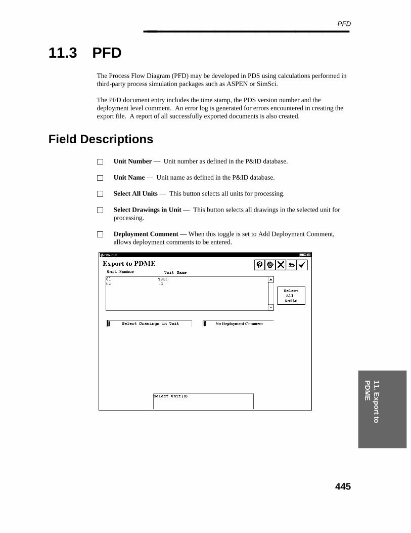
11. Exp
ort to
P
DM
E
PFD________________
11.3 PFD
The Process Flow Diagram (PFD) may be developed in PDS using calculations performed inthird-party process simulation packages such as ASPEN or SimSci.
The PFD document entry includes the time stamp, the PDS version number and thedeployment level comment. An error log is generated for errors encountered in creating theexport file. A report of all successfully exported documents is also created.
Field Descriptions
Unit Number — Unit number as defined in the P&ID database.
Unit Name — Unit name as defined in the P&ID database.
Select All Units — This button selects all units for processing.
Select Drawings in Unit — This button selects all drawings in the selected unit forprocessing.
Deployment Comment — When this toggle is set to Add Deployment Comment,allows deployment comments to be entered.
445
Project Administrator — April 2002________________
Operating Sequence
1. Select Unit(s).
Specify selected units, or select the button for Select All Units.
For all the 3D document types, you must specify a Unit to be associated with thedocuments.
If the project includes PFD data, the system displays the unit numbers that are definedin the P&ID database.
2. Select Drawings in Unit
Specify selected drawings, or select the button for Select All Drawings.
The selected drawings are accepted for processing.
3. Confirm for processing
Select the confirm button to begin processing.
The PFD document entry includes the time stamp, the PDS version number and thedeployment level comment. An error log is generated for errors encountered increating the export file. A report of all successfully exported documents is also created.
446
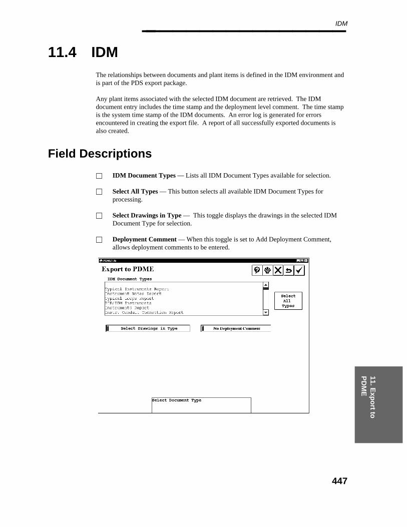
11. Exp
ort to
P
DM
E
IDM________________
11.4 IDM
The relationships between documents and plant items is defined in the IDM environment andis part of the PDS export package.
Any plant items associated with the selected IDM document are retrieved. The IDMdocument entry includes the time stamp and the deployment level comment. The time stampis the system time stamp of the IDM documents. An error log is generated for errorsencountered in creating the export file. A report of all successfully exported documents isalso created.
Field Descriptions
IDM Document Types — Lists all IDM Document Types available for selection.
Select All Types — This button selects all available IDM Document Types forprocessing.
Select Drawings in Type — This toggle displays the drawings in the selected IDMDocument Type for selection.
Deployment Comment — When this toggle is set to Add Deployment Comment,allows deployment comments to be entered.
447
Project Administrator — April 2002________________
Operating Sequence
1. Select IDM Document Type(s).
Specify selected document types, or select the button for Select All Units.
If the Select Drawings in Type toggle is selected, a list of available drawings isdisplayed.
2. Select Drawings in Type
Specify selected drawings, or select the button for Select All Drawings.
The selected drawings are accepted for processing.
3. Confirm for processing
Select the confirm button to begin processing.
The IDM document entry includes the time stamp, the PDS version number and thedeployment level comment. An error log is generated for errors encountered increating the export file. A report of all successfully exported documents is also created.
448

11. Exp
ort to
P
DM
E
Orthographic Drawings________________
11.5 Orthographic Drawings
Pipe Support Tags and Piping Specialty Item Tags are available for inclusion in the ItemExport of the Orthographic Drawings. The prompt is displayed to determine Are the PipeSupport Tags Unique and Are Specialty Item Tags Unique. These tags must be uniqueacross the entire project for successful import into PDME, therefore the questions arepresented prior to the list of drawings.
For a label to be exported, it must include one of the following attributes:
Segment Attribute2 (line_Number_label) or Attribute 3 (line_id)Component Attribute 2 (piping_comp_no)Pipe Attribute 2 (piping_comp_no)Instrument Attribute 2 (instrument_comp_no)Pipe Support Attribute 2 (pipe_support_no)Equipment Attribute 2 (equip_no).
All of the labels within a drawing which meet the attribute criteria are exported as an item toPDME.
The Orthographic Drawing document entry includes the time stamp and the deployment levelcomment.
449
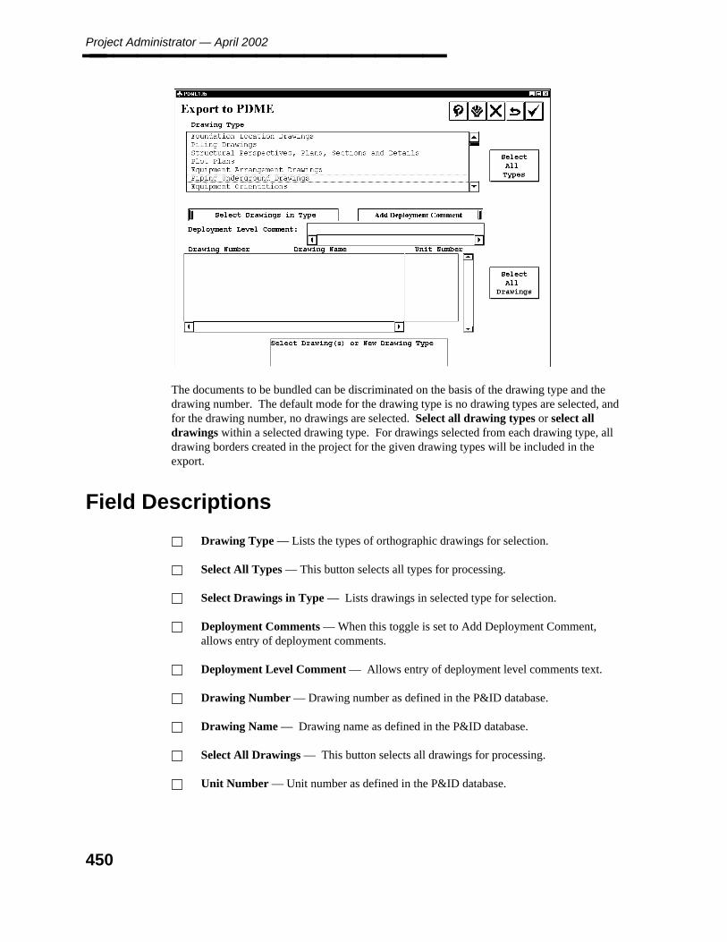
Project Administrator — April 2002________________
The documents to be bundled can be discriminated on the basis of the drawing type and thedrawing number. The default mode for the drawing type is no drawing types are selected, andfor the drawing number, no drawings are selected. Select all drawing types or select alldrawings within a selected drawing type. For drawings selected from each drawing type, alldrawing borders created in the project for the given drawing types will be included in theexport.
Field Descriptions
Drawing Type — Lists the types of orthographic drawings for selection.
Select All Types — This button selects all types for processing.
Select Drawings in Type — Lists drawings in selected type for selection.
Deployment Comments — When this toggle is set to Add Deployment Comment,allows entry of deployment comments.
Deployment Level Comment — Allows entry of deployment level comments text.
Drawing Number — Drawing number as defined in the P&ID database.
Drawing Name — Drawing name as defined in the P&ID database.
Select All Drawings — This button selects all drawings for processing.
Unit Number — Unit number as defined in the P&ID database.
450

11. Exp
ort to
P
DM
E
Orthographic Drawings________________
Operating Sequence
1. Clear Search Criteria
Select Restart to clear any previously specified search criteria.
Previous search criteria is cleared.
2. Specify Unit Number
Specify the unit number to associate with the orthographic drawings included in thedocument bundle.
3. Confirm for processing
Select the confirm button to begin processing.
The Orthographic Drawings document entry includes the time stamp, the PDS versionnumber and the deployment level comment. An error log is generated for errorsencountered in creating the export file. A report of all successfully exported documentsis also created.
451

Project Administrator — April 2002________________
11.6 Isometric Drawings
Pipe Support Tags and Piping Specialty Item Tags may be included in the Item export of theIsometric Drawings. The prompt is displayed to determine Are the Pipe Support Tagsunique? The next prompt is displayed to determine Are the Specialty Item Tags unique?These prompts are displayed prior to the list of isometric drawings, as the tags must be uniqueacross the entire project for successful import into PDME.
The documents to be bundled can be discriminated on the basis of the Piping design area andthe drawing number. The default mode for the drawing type is that no Piping design areas areselected, and for the drawing number is that no drawings are selected. Options are provide toselect all design areas or to select all drawings within a selected design area.
Restart can be selected to clear any previously specified search criteria.
A file may be generated for each sheet of the drawing containing the Plant Item Informationneeded for export. This information is retrieved for the selected ISO and is inserted into theexport file for PDME. The Isometric document entry includes the time stamp and thedeployment level comment.
For isometric documents to be exported successfully, the isometrics must be extracted withthe Increment Revision option set on the Create Batch Input form. The item tags on theisometric are generated with the Generate PDME Data option on the Schedule Batch form.The item tag information is appended to the index.doc file during successful export to PDMEof isometric drawing documents. For more information on the Isometric commands refer tothe ISOGEN Reference Guide.
Field Descriptions
Document Type — Displays the list to select the type of documents to be included in adocument bundle. You can specify one or more document types to be exported to thesame document bundle.
Active Unit Number — Unit number for the active P&ID document.
Are The Pipe Support Tags Unique? — Determines if Pipe Support Tags are unique.Default is set to Yes.
Are The Specialty Item Tags Unique? — Determines if Specialty Item Tags areunique. Default is set to Yes.
Pipe Support Tags and Specialty Item Tags must be unique across the entireproject for successful import into PDME.
452
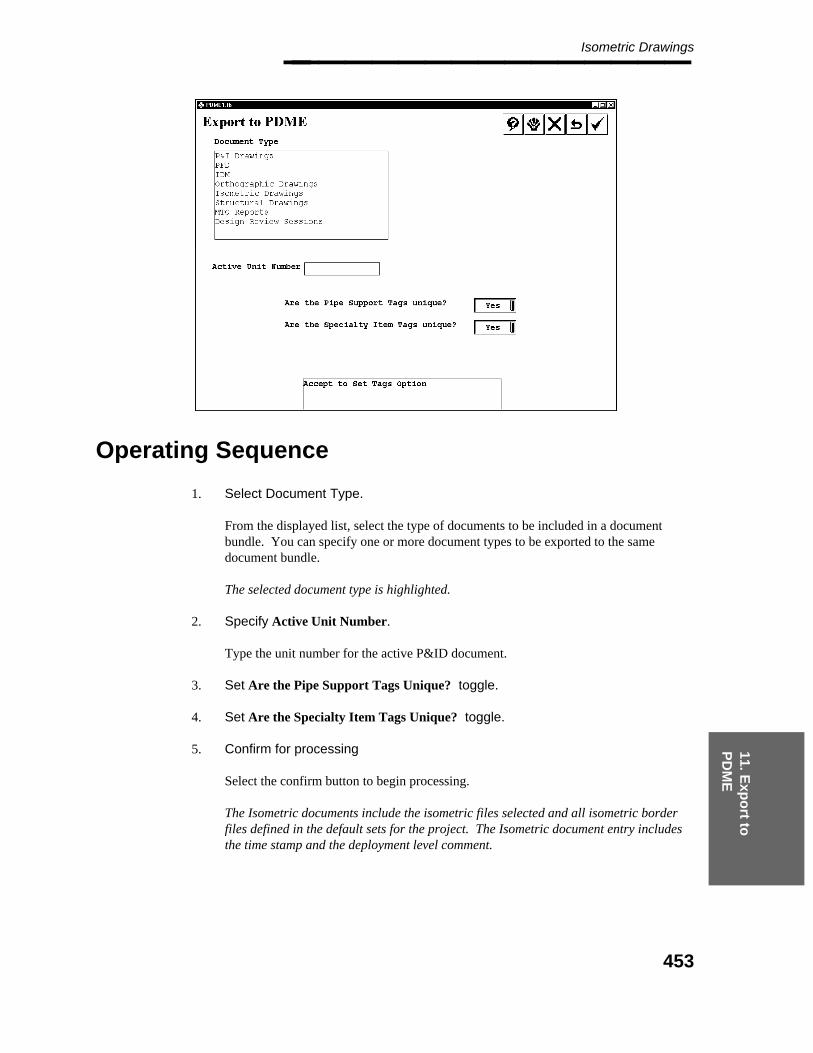
11. Exp
ort to
P
DM
E
Isometric Drawings________________
Operating Sequence
1. Select Document Type.
From the displayed list, select the type of documents to be included in a documentbundle. You can specify one or more document types to be exported to the samedocument bundle.
The selected document type is highlighted.
2. Specify Active Unit Number.
Type the unit number for the active P&ID document.
3. Set Are the Pipe Support Tags Unique? toggle.
4. Set Are the Specialty Item Tags Unique? toggle.
5. Confirm for processing
Select the confirm button to begin processing.
The Isometric documents include the isometric files selected and all isometric borderfiles defined in the default sets for the project. The Isometric document entry includesthe time stamp and the deployment level comment.
453
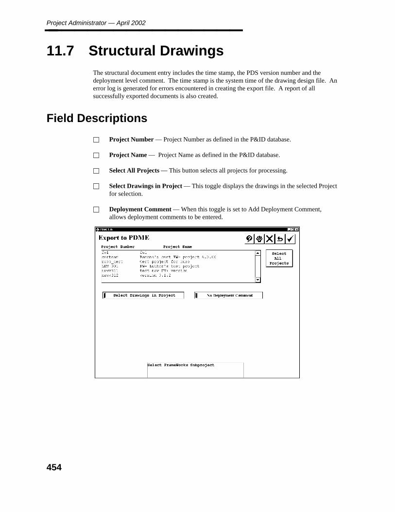
Project Administrator — April 2002________________
11.7 Structural Drawings
The structural document entry includes the time stamp, the PDS version number and thedeployment level comment. The time stamp is the system time of the drawing design file. Anerror log is generated for errors encountered in creating the export file. A report of allsuccessfully exported documents is also created.
Field Descriptions
Project Number — Project Number as defined in the P&ID database.
Project Name — Project Name as defined in the P&ID database.
Select All Projects — This button selects all projects for processing.
Select Drawings in Project — This toggle displays the drawings in the selected Projectfor selection.
Deployment Comment — When this toggle is set to Add Deployment Comment,allows deployment comments to be entered.
454
11. Exp
ort to
P
DM
E
Structural Drawings________________
Operating Sequence
1. Clear Search Criteria
Select Restart to clear any previously specified search criteria.
Previous search criteria is cleared.
2. Specify Project Number/Name
Specify the project number and name to associate with the structural drawings includedin the document bundle.
3. Confirm for processing
Select the confirm button to begin processing.
The Structural Drawings document entry includes the time stamp, the PDS versionnumber and the deployment level comment. An error log is generated for errorsencountered in creating the export file. A report of all successfully exported documentsis also created.
455
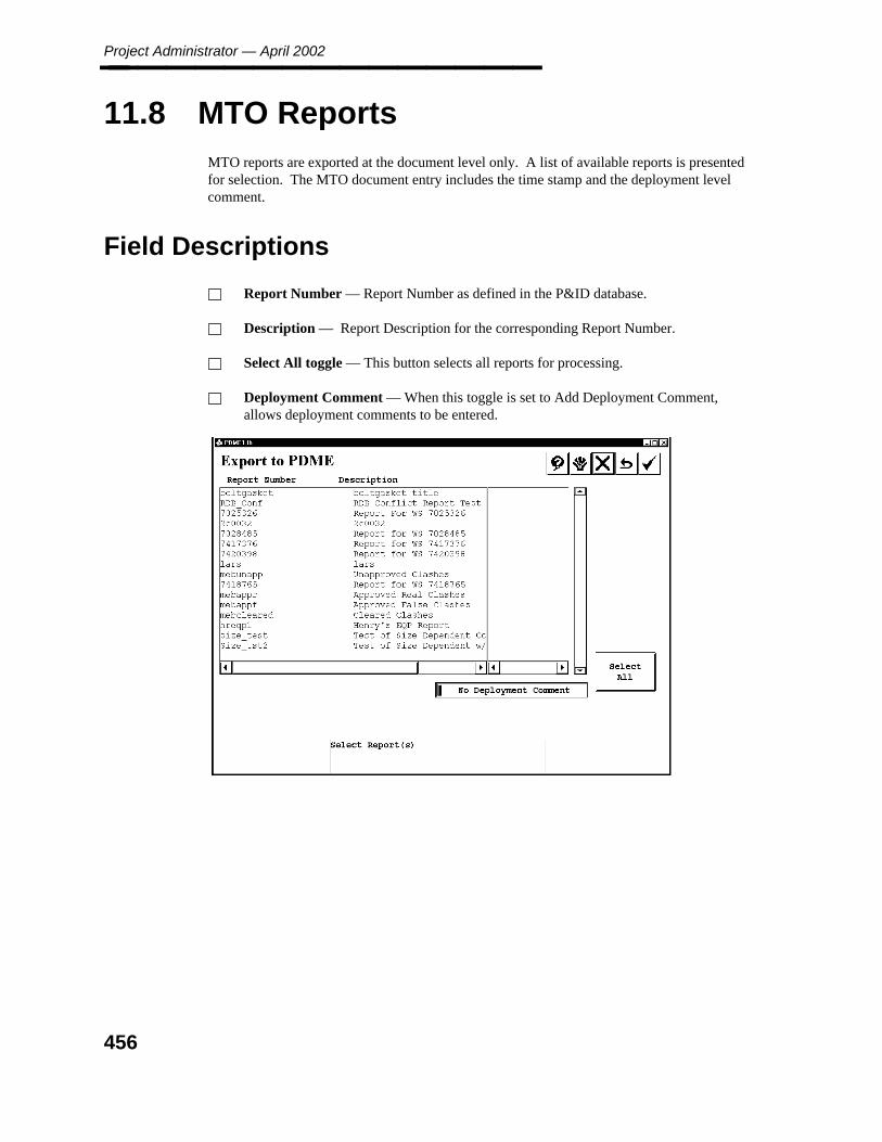
Project Administrator — April 2002________________
11.8 MTO Reports
MTO reports are exported at the document level only. A list of available reports is presentedfor selection. The MTO document entry includes the time stamp and the deployment levelcomment.
Field Descriptions
Report Number — Report Number as defined in the P&ID database.
Description — Report Description for the corresponding Report Number.
Select All toggle — This button selects all reports for processing.
Deployment Comment — When this toggle is set to Add Deployment Comment,allows deployment comments to be entered.
456

11. Exp
ort to
P
DM
E
DesignReview Sessions________________
11.9 DesignReview Sessions
Models can be discriminated to be bundled on the basis of the DesignReview sessions definedin the Project Control Database. The list of sessions includes the session number and thesession name (description). The default mode for discrimination is that no DesignReviewsessions are selected. Options are provided to select all DesignReview sessions. You canselect Restart to clear any previously specified search criteria.
The document bundle for a DesignReview model includes the control file, the applicationmodels, and the corresponding tag files. A DesignReview model is created in the PDMEdatabase as a folder to group these files into a single entity.
457
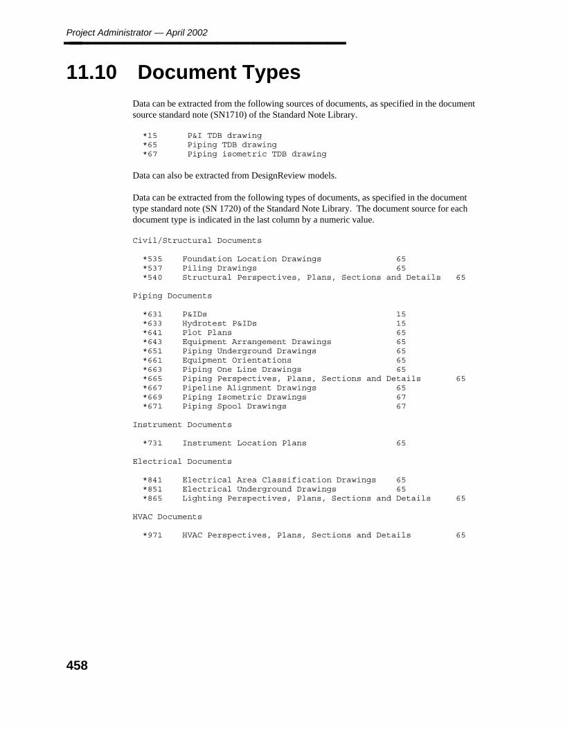
Project Administrator — April 2002________________
11.10 Document Types
Data can be extracted from the following sources of documents, as specified in the documentsource standard note (SN1710) of the Standard Note Library.
*15 P&I TDB drawing*65 Piping TDB drawing*67 Piping isometric TDB drawing
Data can also be extracted from DesignReview models.
Data can be extracted from the following types of documents, as specified in the documenttype standard note (SN 1720) of the Standard Note Library. The document source for eachdocument type is indicated in the last column by a numeric value.
Civil/Structural Documents
*535 Foundation Location Drawings 65*537 Piling Drawings 65*540 Structural Perspectives, Plans, Sections and Details 65
Piping Documents
*631 P&IDs 15*633 Hydrotest P&IDs 15*641 Plot Plans 65*643 Equipment Arrangement Drawings 65*651 Piping Underground Drawings 65*661 Equipment Orientations 65*663 Piping One Line Drawings 65*665 Piping Perspectives, Plans, Sections and Details 65*667 Pipeline Alignment Drawings 65*669 Piping Isometric Drawings 67*671 Piping Spool Drawings 67
Instrument Documents
*731 Instrument Location Plans 65
Electrical Documents
*841 Electrical Area Classification Drawings 65*851 Electrical Underground Drawings 65*865 Lighting Perspectives, Plans, Sections and Details 65
HVAC Documents
*971 HVAC Perspectives, Plans, Sections and Details 65
458
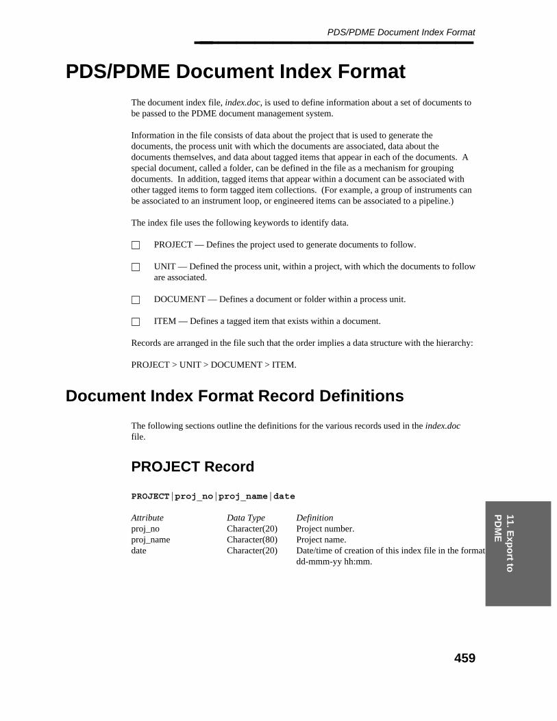
11. Exp
ort to
P
DM
E
PDS/PDME Document Index Format________________
PDS/PDME Document Index Format
The document index file, index.doc, is used to define information about a set of documents tobe passed to the PDME document management system.
Information in the file consists of data about the project that is used to generate thedocuments, the process unit with which the documents are associated, data about thedocuments themselves, and data about tagged items that appear in each of the documents. Aspecial document, called a folder, can be defined in the file as a mechanism for groupingdocuments. In addition, tagged items that appear within a document can be associated withother tagged items to form tagged item collections. (For example, a group of instruments canbe associated to an instrument loop, or engineered items can be associated to a pipeline.)
The index file uses the following keywords to identify data.
PROJECT — Defines the project used to generate documents to follow.
UNIT — Defined the process unit, within a project, with which the documents to followare associated.
DOCUMENT — Defines a document or folder within a process unit.
ITEM — Defines a tagged item that exists within a document.
Records are arranged in the file such that the order implies a data structure with the hierarchy:
PROJECT > UNIT > DOCUMENT > ITEM.
Document Index Format Record Definitions
The following sections outline the definitions for the various records used in the index.docfile.
PROJECT Record
PROJECT|proj_no|proj_name|date
Attribute Data Type Definitionproj_no Character(20) Project number.proj_name Character(80) Project name.date Character(20) Date/time of creation of this index file in the format
dd-mmm-yy hh:mm.
459
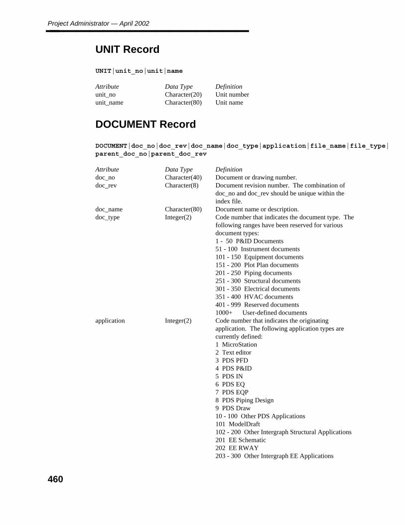
Project Administrator — April 2002________________
UNIT Record
UNIT|unit_no|unit|name
Attribute Data Type Definitionunit_no Character(20) Unit numberunit_name Character(80) Unit name
DOCUMENT Record
DOCUMENT|doc_no|doc_rev|doc_name|doc_type|application|file_name|file_type|parent_doc_no|parent_doc_rev
Attribute Data Type Definitiondoc_no Character(40) Document or drawing number.doc_rev Character(8) Document revision number. The combination of
doc_no and doc_rev should be unique within theindex file.
doc_name Character(80) Document name or description.doc_type Integer(2) Code number that indicates the document type. The
following ranges have been reserved for variousdocument types:1 - 50 P&ID Documents51 - 100 Instrument documents101 - 150 Equipment documents151 - 200 Plot Plan documents201 - 250 Piping documents251 - 300 Structural documents301 - 350 Electrical documents351 - 400 HVAC documents401 - 999 Reserved documents1000+ User-defined documents
application Integer(2) Code number that indicates the originatingapplication. The following application types arecurrently defined:1 MicroStation2 Text editor3 PDS PFD4 PDS P&ID5 PDS IN6 PDS EQ7 PDS EQP8 PDS Piping Design9 PDS Draw10 - 100 Other PDS Applications101 ModelDraft102 - 200 Other Intergraph Structural Applications201 EE Schematic202 EE RWAY203 - 300 Other Intergraph EE Applications
460
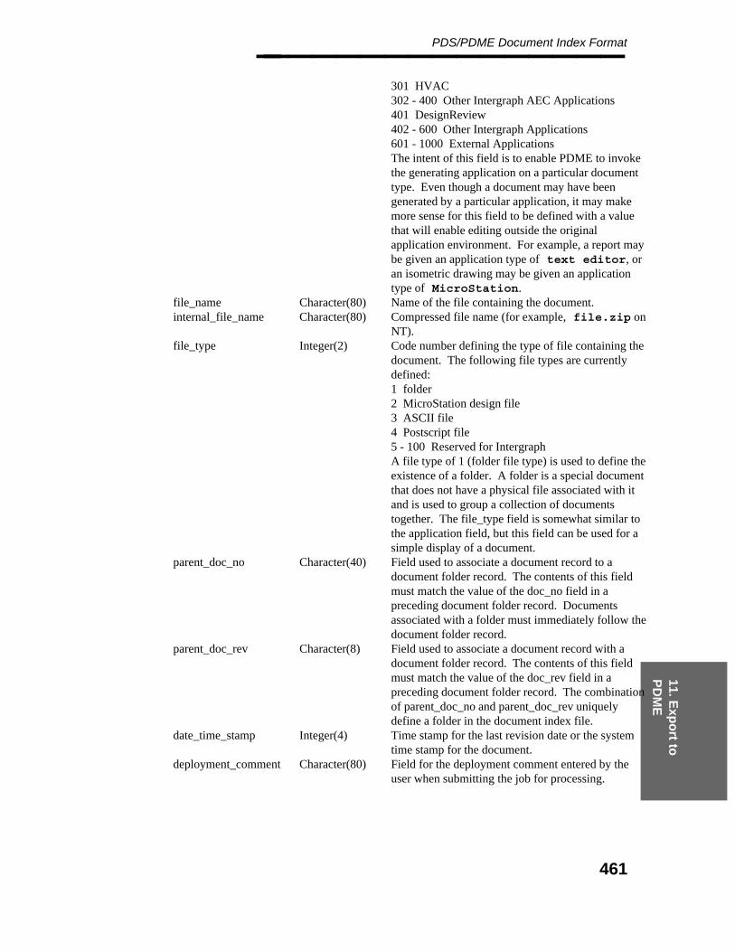
11. Exp
ort to
P
DM
E
PDS/PDME Document Index Format________________
301 HVAC302 - 400 Other Intergraph AEC Applications401 DesignReview402 - 600 Other Intergraph Applications601 - 1000 External ApplicationsThe intent of this field is to enable PDME to invokethe generating application on a particular documenttype. Even though a document may have beengenerated by a particular application, it may makemore sense for this field to be defined with a valuethat will enable editing outside the originalapplication environment. For example, a report maybe given an application type of text editor, oran isometric drawing may be given an applicationtype of MicroStation.
file_name Character(80) Name of the file containing the document.internal_file_name Character(80) Compressed file name (for example, file.zip on
NT).file_type Integer(2) Code number defining the type of file containing the
document. The following file types are currentlydefined:1 folder2 MicroStation design file3 ASCII file4 Postscript file5 - 100 Reserved for IntergraphA file type of 1 (folder file type) is used to define theexistence of a folder. A folder is a special documentthat does not have a physical file associated with itand is used to group a collection of documentstogether. The file_type field is somewhat similar tothe application field, but this field can be used for asimple display of a document.
parent_doc_no Character(40) Field used to associate a document record to adocument folder record. The contents of this fieldmust match the value of the doc_no field in apreceding document folder record. Documentsassociated with a folder must immediately follow thedocument folder record.
parent_doc_rev Character(8) Field used to associate a document record with adocument folder record. The contents of this fieldmust match the value of the doc_rev field in apreceding document folder record. The combinationof parent_doc_no and parent_doc_rev uniquelydefine a folder in the document index file.
date_time_stamp Integer(4) Time stamp for the last revision date or the systemtime stamp for the document.
deployment_comment Character(80) Field for the deployment comment entered by theuser when submitting the job for processing.
461
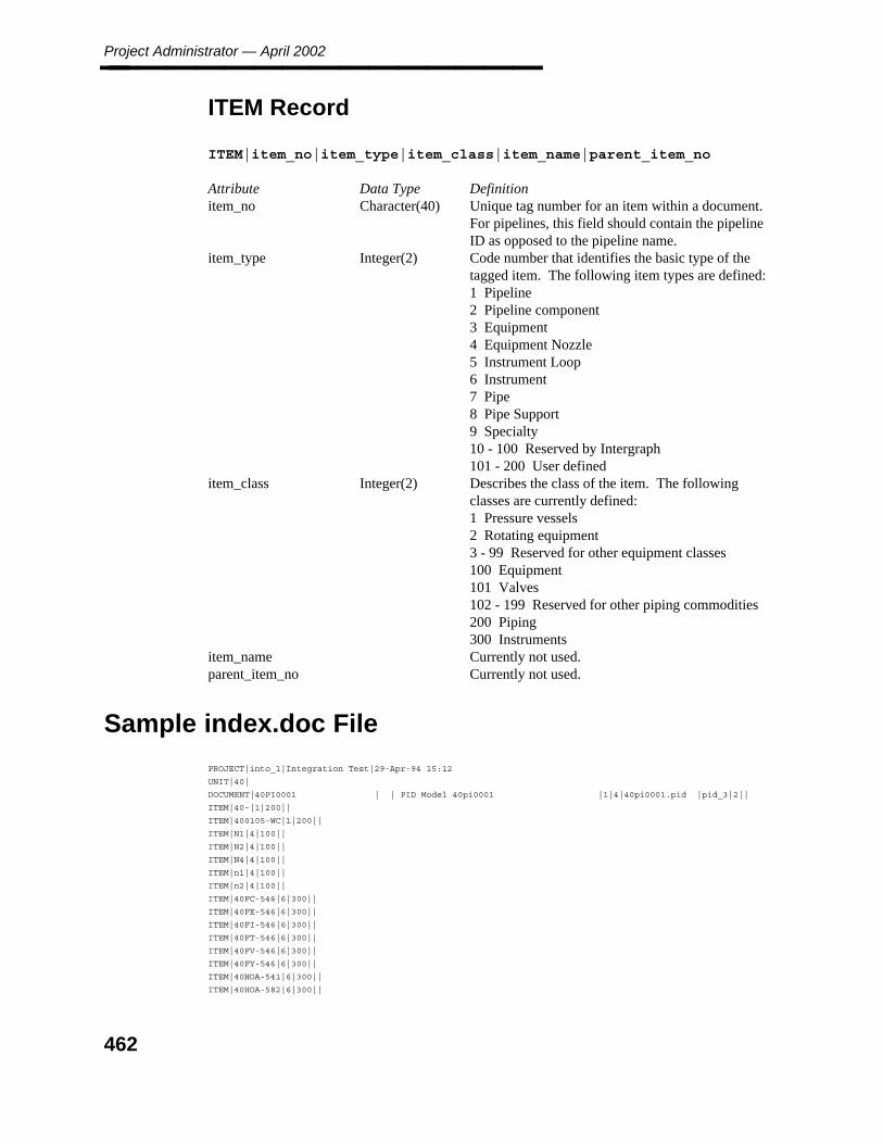
Project Administrator — April 2002________________
ITEM Record
ITEM|item_no|item_type|item_class|item_name|parent_item_no
Attribute Data Type Definitionitem_no Character(40) Unique tag number for an item within a document.
For pipelines, this field should contain the pipelineID as opposed to the pipeline name.
item_type Integer(2) Code number that identifies the basic type of thetagged item. The following item types are defined:1 Pipeline2 Pipeline component3 Equipment4 Equipment Nozzle5 Instrument Loop6 Instrument7 Pipe8 Pipe Support9 Specialty10 - 100 Reserved by Intergraph101 - 200 User defined
item_class Integer(2) Describes the class of the item. The followingclasses are currently defined:1 Pressure vessels2 Rotating equipment3 - 99 Reserved for other equipment classes100 Equipment101 Valves102 - 199 Reserved for other piping commodities200 Piping300 Instruments
item_name Currently not used.parent_item_no Currently not used.
Sample index.doc File
PROJECT|into_1|Integration Test|29-Apr-94 15:12
UNIT|40|
DOCUMENT|40PI0001 | | PID Model 40pi0001 |1|4|40pi0001.pid |pid_3|2||
ITEM|40-|1|200||
ITEM|400105-WC|1|200||
ITEM|N1|4|100||
ITEM|N2|4|100||
ITEM|N4|4|100||
ITEM|n1|4|100||
ITEM|n2|4|100||
ITEM|40FC-546|6|300||
ITEM|40FE-546|6|300||
ITEM|40FI-546|6|300||
ITEM|40FT-546|6|300||
ITEM|40FV-546|6|300||
ITEM|40FY-546|6|300||
ITEM|40HOA-541|6|300||
ITEM|40HOA-582|6|300||
462
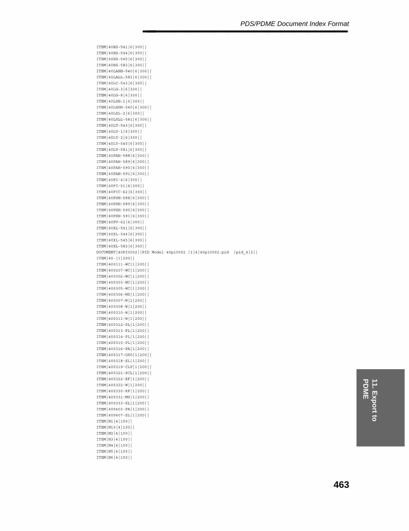
11. Exp
ort to
P
DM
E
PDS/PDME Document Index Format________________ ITEM|40HS-541|6|300||
ITEM|40HS-544|6|300||
ITEM|40HS-545|6|300||
ITEM|40HS-582|6|300||
ITEM|40LAHH-540|6|300||
ITEM|40LALL-581|6|300||
ITEM|40LC-543|6|300||
ITEM|40LG-3|6|300||
ITEM|40LG-8|6|300||
ITEM|40LSH-1|6|300||
ITEM|40LSHH-540|6|300||
ITEM|40LSL-2|6|300||
ITEM|40LSLL-581|6|300||
ITEM|40LT-543|6|300||
ITEM|40LY-1|6|300||
ITEM|40LY-2|6|300||
ITEM|40LY-540|6|300||
ITEM|40LY-581|6|300||
ITEM|40PAH-588|6|300||
ITEM|40PAH-589|6|300||
ITEM|40PAH-590|6|300||
ITEM|40PAH-591|6|300||
ITEM|40PI-4|6|300||
ITEM|40PI-51|6|300||
ITEM|40PIC-62|6|300||
ITEM|40PSH-588|6|300||
ITEM|40PSH-589|6|300||
ITEM|40PSH-590|6|300||
ITEM|40PSH-591|6|300||
ITEM|40PV-62|6|300||
ITEM|40XL-541|6|300||
ITEM|40XL-544|6|300||
ITEM|40XL-545|6|300||
ITEM|40XL-582|6|300||
DOCUMENT|40PI0002||PID Model 40pi0002 |1|4|40pi0002.pid |pid_4|2||
ITEM|40-|1|200||
ITEM|400111-WC|1|200||
ITEM|400207-WC|1|200||
ITEM|400302-WC|1|200||
ITEM|400303-WC|1|200||
ITEM|400305-WC|1|200||
ITEM|400306-MS|1|200||
ITEM|400307-W|1|200||
ITEM|400308-W|1|200||
ITEM|400310-W|1|200||
ITEM|400311-W|1|200||
ITEM|400312-SL|1|200||
ITEM|400313-PL|1|200||
ITEM|400314-PL|1|200||
ITEM|400315-PL|1|200||
ITEM|400316-PA|1|200||
ITEM|400317-OSO|1|200||
ITEM|400318-SL|1|200||
ITEM|400319-CLP|1|200||
ITEM|400321-SCL|1|200||
ITEM|400322-RF|1|200||
ITEM|400322-W|1|200||
ITEM|400330-RF|1|200||
ITEM|400331-MS|1|200||
ITEM|400333-SL|1|200||
ITEM|400403-PA|1|200||
ITEM|400607-SL|1|200||
ITEM|N1|4|100||
ITEM|N10|4|100||
ITEM|N2|4|100||
ITEM|N3|4|100||
ITEM|N4|4|100||
ITEM|N5|4|100||
ITEM|N6|4|100||
463
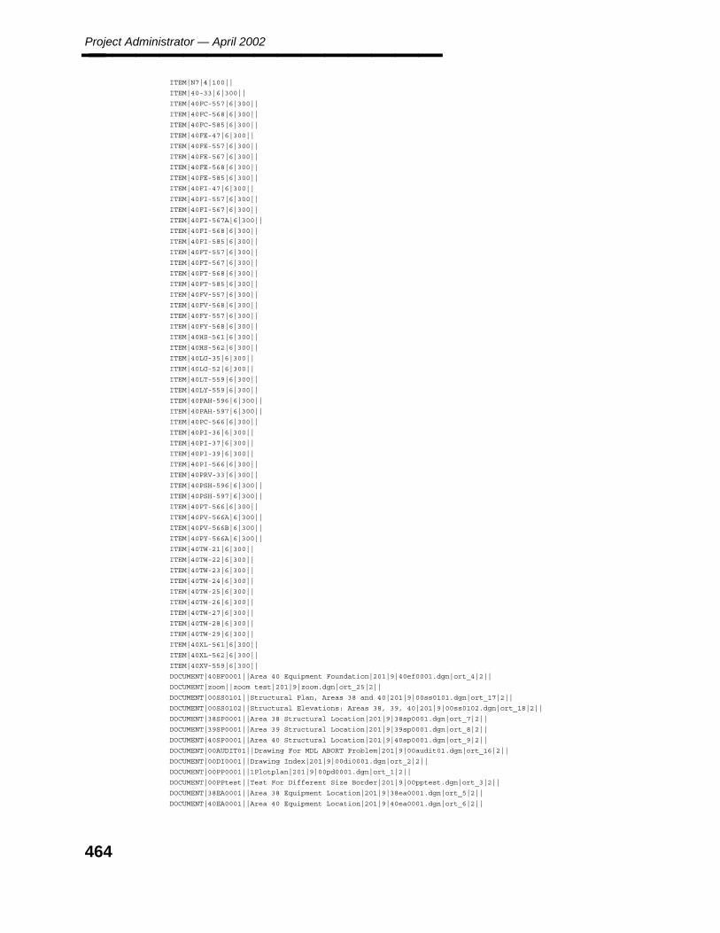
Project Administrator — April 2002________________ ITEM|N7|4|100||
ITEM|40-33|6|300||
ITEM|40FC-557|6|300||
ITEM|40FC-568|6|300||
ITEM|40FC-585|6|300||
ITEM|40FE-47|6|300||
ITEM|40FE-557|6|300||
ITEM|40FE-567|6|300||
ITEM|40FE-568|6|300||
ITEM|40FE-585|6|300||
ITEM|40FI-47|6|300||
ITEM|40FI-557|6|300||
ITEM|40FI-567|6|300||
ITEM|40FI-567A|6|300||
ITEM|40FI-568|6|300||
ITEM|40FI-585|6|300||
ITEM|40FT-557|6|300||
ITEM|40FT-567|6|300||
ITEM|40FT-568|6|300||
ITEM|40FT-585|6|300||
ITEM|40FV-557|6|300||
ITEM|40FV-568|6|300||
ITEM|40FY-557|6|300||
ITEM|40FY-568|6|300||
ITEM|40HS-561|6|300||
ITEM|40HS-562|6|300||
ITEM|40LG-35|6|300||
ITEM|40LG-52|6|300||
ITEM|40LT-559|6|300||
ITEM|40LY-559|6|300||
ITEM|40PAH-596|6|300||
ITEM|40PAH-597|6|300||
ITEM|40PC-566|6|300||
ITEM|40PI-36|6|300||
ITEM|40PI-37|6|300||
ITEM|40PI-39|6|300||
ITEM|40PI-566|6|300||
ITEM|40PRV-33|6|300||
ITEM|40PSH-596|6|300||
ITEM|40PSH-597|6|300||
ITEM|40PT-566|6|300||
ITEM|40PV-566A|6|300||
ITEM|40PV-566B|6|300||
ITEM|40PY-566A|6|300||
ITEM|40TW-21|6|300||
ITEM|40TW-22|6|300||
ITEM|40TW-23|6|300||
ITEM|40TW-24|6|300||
ITEM|40TW-25|6|300||
ITEM|40TW-26|6|300||
ITEM|40TW-27|6|300||
ITEM|40TW-28|6|300||
ITEM|40TW-29|6|300||
ITEM|40XL-561|6|300||
ITEM|40XL-562|6|300||
ITEM|40XV-559|6|300||
DOCUMENT|40EF0001||Area 40 Equipment Foundation|201|9|40ef0001.dgn|ort_4|2||
DOCUMENT|zoom||zoom test|201|9|zoom.dgn|ort_25|2||
DOCUMENT|00SS0101||Structural Plan, Areas 38 and 40|201|9|00ss0101.dgn|ort_17|2||
DOCUMENT|00SS0102||Structural Elevations: Areas 38, 39, 40|201|9|00ss0102.dgn|ort_18|2||
DOCUMENT|38SP0001||Area 38 Structural Location|201|9|38sp0001.dgn|ort_7|2||
DOCUMENT|39SP0001||Area 39 Structural Location|201|9|39sp0001.dgn|ort_8|2||
DOCUMENT|40SP0001||Area 40 Structural Location|201|9|40sp0001.dgn|ort_9|2||
DOCUMENT|00AUDIT01||Drawing For MDL ABORT Problem|201|9|00audit01.dgn|ort_16|2||
DOCUMENT|00DI0001||Drawing Index|201|9|00di0001.dgn|ort_2|2||
DOCUMENT|00PP0001||1Plotplan|201|9|00pd0001.dgn|ort_1|2||
DOCUMENT|00PPtest||Test For Different Size Border|201|9|00pptest.dgn|ort_3|2||
DOCUMENT|38EA0001||Area 38 Equipment Location|201|9|38ea0001.dgn|ort_5|2||
DOCUMENT|40EA0001||Area 40 Equipment Location|201|9|40ea0001.dgn|ort_6|2||
464

11. Exp
ort to
P
DM
E
PDS/PDME Document Index Format________________ DOCUMENT|00PD0101||Area 40 Piping Plan|201|9|00pd0101.dgn|ort_26|2||
DOCUMENT|00PD0102||Area 40 Piping Sections|201|9|00pd0102.dgn|ort_22|2||
DOCUMENT|00PD0201||Area 39 Piping Plan (IGUG)|201|9|00pd0201.dgn|ort_23|2||
DOCUMENT|00PD0302||Area 40 Piping Sections|201|9|00pd0302.dgn|ort_24|2||
DOCUMENT|00PD0303||Area 38 Plan & Sections|201|9|00pd0303.dgn|ort_27|2||
DOCUMENT|38PD0001||Area 38 Piping Plan|201|9|38pd0001.dgn|ort_10|2||
DOCUMENT|38PD0002||Area 38 Piping Sections|201|9|38pd0002.dgn|ort_11|2||
DOCUMENT|39PP0001||Area 39 Piping Plan Low|201|9|39pp0001.dgn|ort_12|2||
DOCUMENT|39PP0002||Area 39 Piping Plan High|201|9|39pp0002.dgn|ort_13|2||
DOCUMENT|40PP0001||Area 40 Piping Plan|201|9|40pp0001.dgn|ort_14|2||
DOCUMENT|40PP0002||Area 40 Piping Sections|201|9|40pp0002.dgn|ort_15|2||
DOCUMENT|TR_TESTS||Scratch Drawing For TR Testing|201|9|tr_tests.dgn|ort_28|2||
DOCUMENT|00EA0101||Elec Plan Drawing|201|9|00ea0101.dgn|ort_19|2||
DOCUMENT|00EA0102||Elec Elevation Drawing|201|9|00ea0102.dgn|ort_20|2||
DOCUMENT|P400104WC_1|0|Fabrication |201|7|||1||
DOCUMENT|P400104WC_sheet_1|0|Fabrication |201|7|p400104wc.i01|p400104wc.i01|2|P400104WC_1|0
DOCUMENT|P400104WC_sheet_2|0|Fabrication |201|7|p400104wc.i02|p400104wc.i02|2|P400104WC_1|0
ITEM|400104-WC |1|200||
DOCUMENT|P400105WC_1|1|Fabrication |201|7|p400104wc.i02|p400104wc.i02|1|P400104WC_1|0
DOCUMENT|P400105WC_sheet_1|1|Fabrication |201|7|p400105wc.i01|p400105wc.i01|2|P400105WC_1|1
DOCUMENT|P400105WC_sheet_2|1|Fabrication |201|7|p400105wc.i02|p400105wc.i02|2|P400105WC_1|1
ITEM|400105-WC |1|200||
DOCUMENT|P400207WC_1|1|Fabrication |201|7|p400105wc.i02|p400105wc.i02|1|P400105WC_1|1
DOCUMENT|P400207WC_sheet_1|1|Fabrication |201|7|p400207wc.i01|p400207wc.i01|2|P400207WC_1|1
ITEM|400207-WC |1|200||
DOCUMENT|P400303WC_1|0|Fabrication |201|7|p400207wc.i01|p400207wc.i01|1|P400207WC_1|1
DOCUMENT|P400303WC_sheet_1|0|Fabrication |201|7|p400303wc.i01|p400303wc.i01|2|P400303WC_1|0
ITEM|400303-WC |1|200||
DOCUMENT|P400305WC_1|1|Fabrication |201|7|p400303wc.i01|p400303wc.i01|1|P400303WC_1|0
DOCUMENT|P400305WC_sheet_1|1|Fabrication |201|7|p400305wc.i01|p400305wc.i01|2|P400305WC_1|1
ITEM|400305-WC |1|200||
DOCUMENT|P400306WC_1|1|Fabrication |201|7|p400305wc.i01|p400305wc.i01|1|P400305WC_1|1
DOCUMENT|P400306WC_sheet_1|1|Fabrication |201|7|p400306wc.i01|p400306wc.i01|2|P400306WC_1|1
DOCUMENT|P400306WC_sheet_2|1|Fabrication |201|7|p400306wc.i02|p400306wc.i02|2|P400306WC_1|1
ITEM|400306-WC |1|200||
DOCUMENT|P400307W_1|0|Fabrication |201|7|p400306wc.i02|p400306wc.i02|1|P400306WC_1|1
DOCUMENT|P400307W_sheet_1|0|Fabrication |201|7|p400307w.i01|p400307w.i01|2|P400307W_1|0
DOCUMENT|P400307W_sheet_2|0|Fabrication |201|7|p400307w.i02|p400307w.i02|2|P400307W_1|0
ITEM|400307-W |1|200||
DOCUMENT|P400308AWC_1|1|Fabrication |201|7|p400307w.i02|p400307w.i02|1|P400307W_1|0
DOCUMENT|P400308AWC_sheet_1|1|Fabrication|201|7|p400308awc.i01|p400308awc.i01|2|P400308AWC_1|1
ITEM|400308A-WC |1|200||
DOCUMENT|P400308WC_1|0|Fabrication |201|7|p400308awc.i01|p400308awc.i01|1|P400308AWC_1|1
DOCUMENT|P400308WC_sheet_1|0|Fabrication |201|7|p400308wc.i01|p400308wc.i01|2|P400308WC_1|0
ITEM|**400308-WC |1|200||
DOCUMENT|P400308WC_1|1|Fabrication |201|7|p400308wc.i01|p400308wc.i01|1|P400308WC_1|0
DOCUMENT|P400308WC_sheet_1|1|Fabrication |201|7|p400308wc.i01|p400308wc.i01|2|P400308WC_1|1
DOCUMENT|P400308WC_sheet_2|1|Fabrication |201|7|p400308wc.i02|p400308wc.i02|2|P400308WC_1|1
ITEM|400308-WC |1|200||
DOCUMENT|P400310W_1|1|Fabrication |201|7|p400308wc.i02|p400308wc.i02|1|P400308WC_1|1
DOCUMENT|P400310W_sheet_1|1|Fabrication |201|7|p400310w.i01|p400310w.i01|2|P400310W_1|1
ITEM|400310-W |1|200||
DOCUMENT|P400311W_1|1|Fabrication |201|7|p400310w.i01|p400310w.i01|1|P400310W_1|1
DOCUMENT|P400311W_sheet_1|1|Fabrication |201|7|p400311w.i01|p400311w.i01|2|P400311W_1|1
ITEM|400311-W |1|200||
DOCUMENT|P400313WC_1|1|Fabrication |201|7|p400311w.i01|p400311w.i01|1|P400311W_1|1
DOCUMENT|P400313WC_sheet_1|1|Fabrication |201|7|p400313wc.i01|p400313wc.i01|2|P400313WC_1|1
ITEM|400313-WC |1|200||
DOCUMENT|P400314WC_1|2|Fabrication |201|7|p400313wc.i01|p400313wc.i01|1|P400313WC_1|1
DOCUMENT|P400314WC_sheet_1|2|Fabrication |201|7|p400314wc.i01|p400314wc.i01|2|P400314WC_1|2
ITEM|400314-WC |1|200||
DOCUMENT|P400316WC_1|2|Fabrication |201|7|p400314wc.i01|p400314wc.i01|1|P400314WC_1|2
DOCUMENT|P400316WC_sheet_1|2|Fabrication |201|7|p400316wc.i01|p400316wc.i01|2|P400316WC_1|2
ITEM|400316-WC |1|200||
DOCUMENT|P400318WC_1|0|Fabrication |201|7|p400316wc.i01|p400316wc.i01|1|P400316WC_1|2
DOCUMENT|P400318WC_sheet_1|0|Fabrication |201|7|p400318wc.i01|p400318wc.i01|2|P400318WC_1|0
DOCUMENT|P400318WC_sheet_2|0|Fabrication |201|7|p400318wc.i02|p400318wc.i02|2|P400318WC_1|0
DOCUMENT|P400318WC_sheet_3|0|Fabrication |201|7|p400318wc.i03|p400318wc.i03|2|P400318WC_1|0
ITEM|400318-WC |1|200||
465
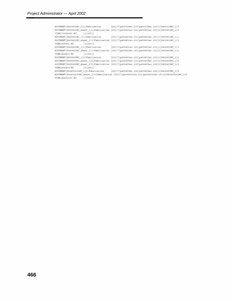
Project Administrator — April 2002________________ DOCUMENT|P400401WC_1|1|Fabrication |201|7|p400318wc.i03|p400318wc.i03|1|P400318WC_1|0
DOCUMENT|P400401WC_sheet_1|1|Fabrication |201|7|p400401wc.i01|p400401wc.i01|2|P400401WC_1|1
ITEM|**400401-WC |1|200||
DOCUMENT|P400401WC_1|1|Fabrication |201|7|p400401wc.i01|p400401wc.i01|1|P400401WC_1|1
DOCUMENT|P400401WC_sheet_1|1|Fabrication |201|7|p400401wc.i01|p400401wc.i01|2|P400401WC_1|1
ITEM|400401-WC |1|200||
DOCUMENT|P400403WC_1|1|Fabrication |201|7|p400401wc.i01|p400401wc.i01|1|P400401WC_1|1
DOCUMENT|P400403WC_sheet_1|1|Fabrication |201|7|p400403wc.i01|p400403wc.i01|2|P400403WC_1|1
ITEM|400403-WC |1|200||
DOCUMENT|P400409WC_1|0|Fabrication |201|7|p400403wc.i01|p400403wc.i01|1|P400403WC_1|1
DOCUMENT|P400409WC_sheet_1|0|Fabrication |201|7|p400409wc.i01|p400409wc.i01|2|P400409WC_1|0
DOCUMENT|P400409WC_sheet_2|0|Fabrication |201|7|p400409wc.i02|p400409wc.i02|2|P400409WC_1|0
ITEM|400409-WC |1|200||
DOCUMENT|P40400101WC_1|0|Fabrication |201|7|p400409wc.i02|p400409wc.i02|1|P400409WC_1|0
DOCUMENT|P40400101WC_sheet_1|0|Fabrication |201|7|p40400101w.i01|p40400101w.i01|2|P40400101WC_1|0
ITEM|40400101-WC |1|200||
466

12. Access
Co
ntro
l
Access Control Manager________________
12. Access Control Manager
The PD_Shell provides project management tools to control a user’s access to specific data.The Access Control Manager provides the PDS system manager with the option to restrictthe end user’s access to data on the basis of the project number, the type of data, andprivileges assigned to the user.
Once access control has been defined, each user’s view of the PD Shell environment isdependent on his defined access control parameters.
The PD_Shell environment only lists projects for which the user has access.
The buttons for any command in the PD_Shell environment for which a user does nothave access are disabled.
467

Project Administrator — April 2002________________
12.1 Access Control Manager PasswordForm
As part of this access control feature, the access data must be defined for each user that isintended to use the PD_Shell environment for any of the projects on the network. At anytime, a user’s identification data may be revised or deleted with the Revise Data and DeleteData options.
Operating Sequence
1. At the main PD_Shell form, type system in the User ID field. Then type the systemmanager password in the Password field.
If no password has been defined for the system User ID (as when using this option forthe first time), the Access Control Manager Password form is displayed.
2. Type the system manager information as follows:
— Initials — Type up to four characters for the initials of the system manager at yoursite (for example, SM).
— User Name — Type up to 40 characters in any format for the name of the PDSsystem manager (for example, PDS Administrator).
— Password — Type up to 8 characters for the password for the PDS systemmanager (for example, PDS).
468

12. Access
Co
ntro
l
Access Control Manager Password Form________________ Once the password has been revised and accepted, the new password is required togain entry to the Access Control Manager.
3. Accept To Create System Record
Choose the Confirm button to accept the specified system manager information.
The Access Control Manager form is displayed.
469
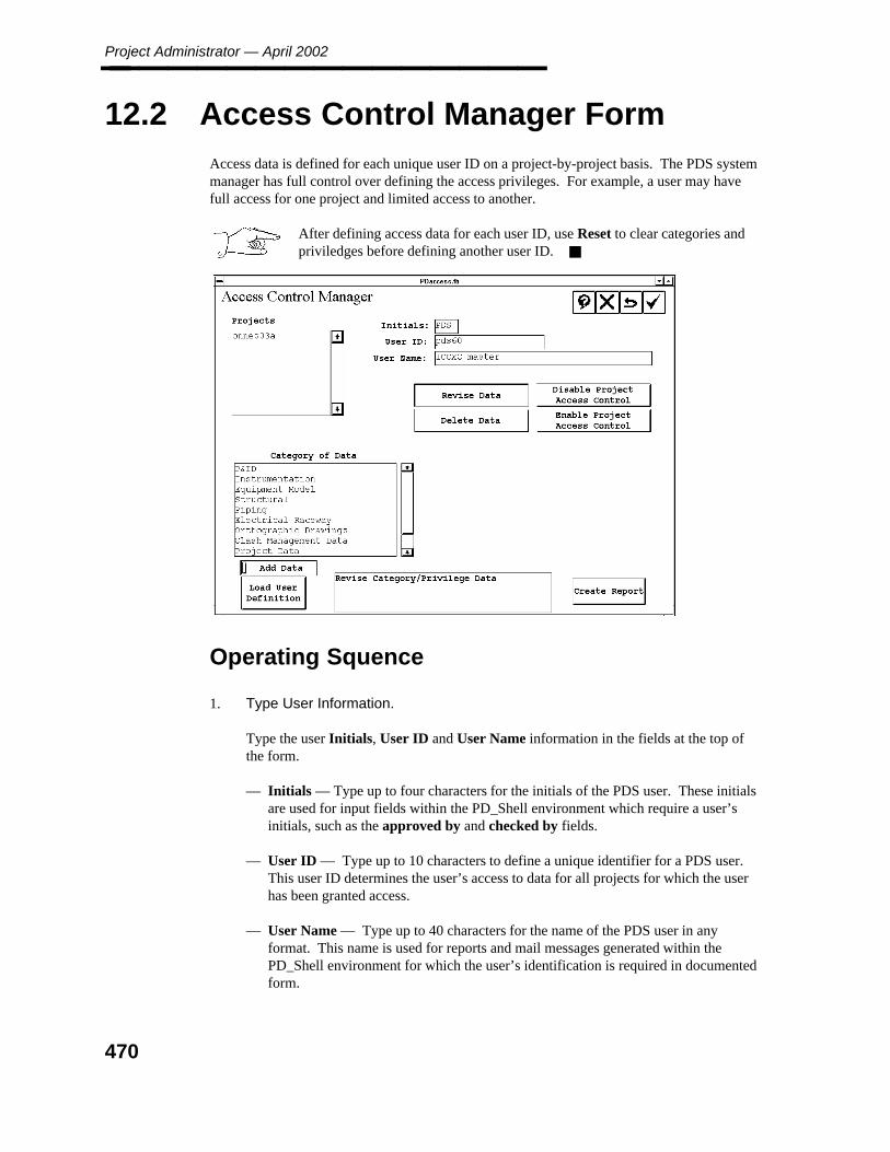
Project Administrator — April 2002________________
12.2 Access Control Manager Form
Access data is defined for each unique user ID on a project-by-project basis. The PDS systemmanager has full control over defining the access privileges. For example, a user may havefull access for one project and limited access to another.
After defining access data for each user ID, use Reset to clear categories andpriviledges before defining another user ID.
Operating Squence
1. Type User Information.
Type the user Initials, User ID and User Name information in the fields at the top ofthe form.
— Initials — Type up to four characters for the initials of the PDS user. These initialsare used for input fields within the PD_Shell environment which require a user’sinitials, such as the approved by and checked by fields.
— User ID — Type up to 10 characters to define a unique identifier for a PDS user.This user ID determines the user’s access to data for all projects for which the userhas been granted access.
— User Name — Type up to 40 characters for the name of the PDS user in anyformat. This name is used for reports and mail messages generated within thePD_Shell environment for which the user’s identification is required in documentedform.
470
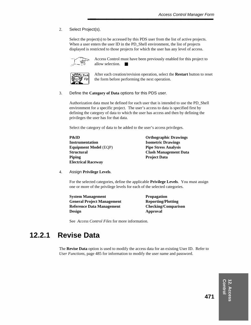
12. Access
Co
ntro
l
Access Control Manager Form________________
2. Select Project(s).
Select the project(s) to be accessed by this PDS user from the list of active projects.When a user enters the user ID in the PD_Shell environment, the list of projectsdisplayed is restricted to those projects for which the user has any level of access.
Access Control must have been previously enabled for this project toallow selection.
After each creation/revision operation, select the Restart button to resetthe form before performing the next operation.
3. Define the Category of Data options for this PDS user.
Authorization data must be defined for each user that is intended to use the PD_Shellenvironment for a specific project. The user’s access to data is specified first bydefining the category of data to which the user has access and then by defining theprivileges the user has for that data.
Select the category of data to be added to the user’s access privileges.
P&IDInstrumentationEquipment Model (EQP)StructuralPipingElectrical Raceway
Orthographic DrawingsIsometric DrawingsPipe Stress AnalysisClash Management DataProject Data
4. Assign Privilege Levels.
For the selected categories, define the applicable Privilege Levels. You must assignone or more of the privilege levels for each of the selected categories.
System ManagementGeneral Project ManagementReference Data ManagementDesign
PropagationReporting/PlottingChecking/ComparisonApproval
See Access Control Files for more information.
12.2.1 Revise Data
The Revise Data option is used to modify the access data for an existing User ID. Refer toUser Functions, page 485 for information to modify the user name and password.
471
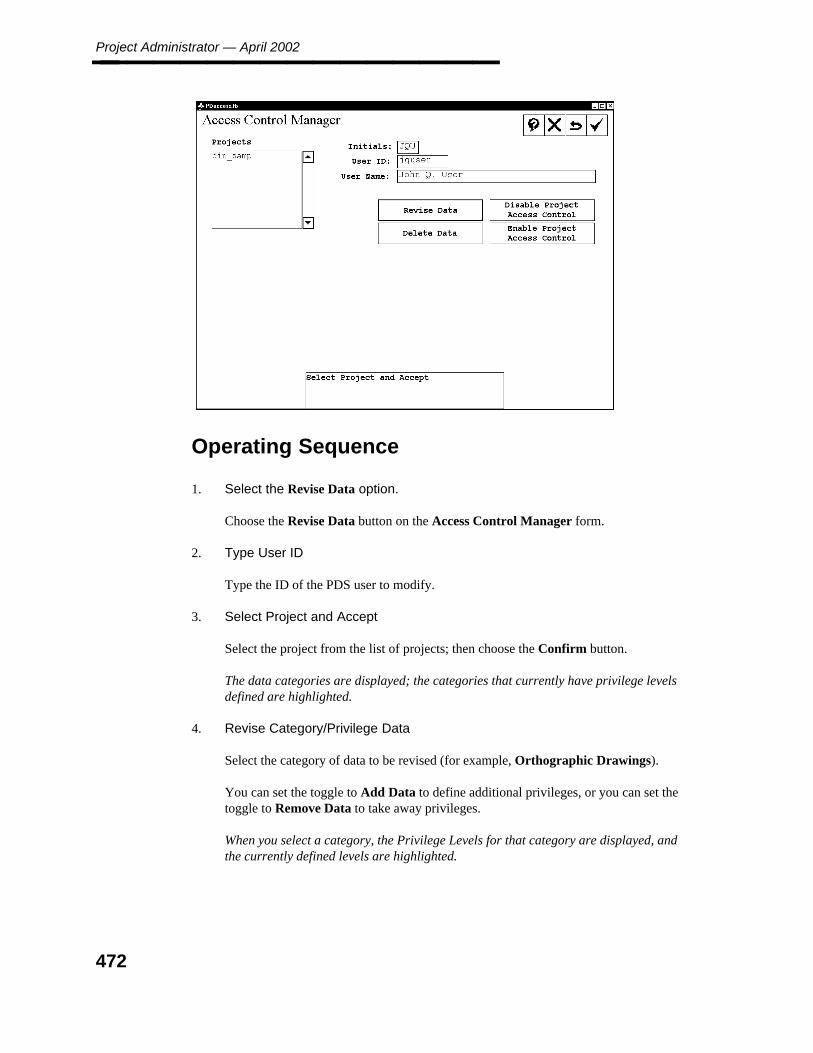
Project Administrator — April 2002________________
Operating Sequence
1. Select the Revise Data option.
Choose the Revise Data button on the Access Control Manager form.
2. Type User ID
Type the ID of the PDS user to modify.
3. Select Project and Accept
Select the project from the list of projects; then choose the Confirm button.
The data categories are displayed; the categories that currently have privilege levelsdefined are highlighted.
4. Revise Category/Privilege Data
Select the category of data to be revised (for example, Orthographic Drawings).
You can set the toggle to Add Data to define additional privileges, or you can set thetoggle to Remove Data to take away privileges.
When you select a category, the Privilege Levels for that category are displayed, andthe currently defined levels are highlighted.
472

12. Access
Co
ntro
l
Access Control Manager Form________________
5. Select the privilege level to add or remove from the displayed list of categories.
6. Accept to Create Records
When you have completed revising the Category and Privilege data, choose theConfirm button to accept the new settings.
12.2.2 Delete Data
The Delete Data option is used to delete the access data for a specified user ID and project.
Operating Sequence
1. Type User ID
Type the ID of the PDS user to delete.
2. Select Project and Accept to Delete
Select the project from the list of projects; then choose the Confirm button.
All the user access data for the selected project and User ID is deleted.
12.2.3 Disable Project Access Control
The Disable Project Access Control option is used to disable all access control for a selectedproject. Once a project has been disabled, it is not displayed in the list of projects for anyaccess control operations.
Operating Sequence
1. Select Project
Select the project from the list of projects.
2. Accept to Remove Access Control on <projname> or Exit
Choose the Confirm button to remove all access controls for the selected project.
473
Project Administrator — April 2002________________
12.2.4 Enable Project Access Control
The Enable Project Access Control option is used to enable a project for access control.This option allows the project to be selected for access control operations.
Operating Sequence
1. Select Project
Select the project to be enabled from the list of projects.
2. Accept to Add Access Control on <projname> or Exit
Choose the Confirm button to allow access control for the selected project.
12.2.5 Create Report
The Create Report option is used to save your access control settings to a file. The access.rptfile can be copied into the project, then use Load User Definition to copy these access controlusernames and privileges to the new project.
Operating Sequence
1. Select Project
Select the project to be enabled from the list of projects.
2. Select Create Report.
Select Create Report to generate a report.
12.2.6 Load User Definition
The Load User Definition option is used to load previously saved access control settings.
Operating Sequence
1. Select Project
Select the project from which to load access controls.
474

12. Access
Co
ntro
l
Access Control Manager Form________________
2. Select Load User Definition.
Select Load User Definition to load the selected user definition.
The access controls from the access.rpt file are applied to the selected project.
475

Project Administrator — April 2002________________
12.3 Access Control Files
The Access Control Manager creates a User Identification List file named PDS_user_id inthe same directory as the Project Directory List (the directory referenced by the PROJ_FILEenvironment variable). This file stores the identification data for the defined user IDs. Eachuser ID is encrypted for security and is given a system-assigned unique identifier.
Project archival does not back up access control data automatically. It isimportant to back up this data periodically.
Once the User Identification List file has been loaded with any user identification data, accesscontrol is enabled for all projects on the network (at least those projects using the PDS 5.0 orhigher release). Therefore, any use of satellite Project Directory Lists to control a access toproject must be discontinued.
For each project on the network, the Access Control Manager creates a Project AuthorizationList, named PDS_access, in the project directory. This file stores the authorization data thatapplies to the project for each User ID.
The Access Control Manager uses the unique identifier from the User Identification List toassociate a user with the user’s defined authorization data in the Project Authorization List.
476
12. Access
Co
ntro
l
Authorization Data________________
12.3.1 Authorization Data
The following authorization data must be defined for each user who is intended to use thePD_Shell environment for a specific project through the Access Control Manager. Thisprovides control of a user’s access to data within a project. A user’s authorization for accessto data may be identical from one project to another. or the user’s authorization can be defineddifferently for different projects. Access to data is specified first by defining the category ofdata to which the user has access and then by defining the privileges for that data.
The following descriptions illustrate the use of privilege levels within each category of data.Not all privilege level are applicable for each of the categories (for example, Propagation hasno function within the Piping Category). Only the valid privilege levels are listed for each ofthe categories.
12.3.2 P&ID Category
Design — Provides access to all P&ID operations. No other privileges are applicable.
477
Project Administrator — April 2002________________
12.3.2.1 Instrumentation Category
Design — Provides access to all IDM operations. No other privileges are applicable.
12.3.3 Piping Category
The following represents the list of activities that are applicable for each privilege level withinthe Piping category:
System Management —
Reference Database Management Data (Reference Data Manager)Default Project Control Data (Reference Data Manager)Component I/Forms Customization (Piping Designer)Report Management Data (Report Manager)Access Control Manager (Project Administrator)Segment I/Forms Customization (Piping Design Data Manager)
General Project Management —
Project Data Manager (Project Administrator)Report Format (Report Manager)Copy Report Format (Report Manager)Report Discrimination Data (Report Manager)Report Search Criteria (Report Manager)Delete Report (Report Manager)Access Control Manager (Project Administrator)
Reference Data Management —
Piping Job Specification Manager (Reference Data Manager)Graphic Data Library Manager (Reference Data Manager)Material Description Library Manager (Reference Data Manager)Standard Note Library Manager (Reference Data Manager)Label Description Library Manager (Reference Data Manager)Piping Assembly Library Manager (Reference Data Manager)Table Checker (Reference Data Manager)Access Control Manager (Project Administrator)Spec Writer (Reference Data Manager)Piping Job Specification Tables (Reference Data Manager)Piping Job Spec Report Manager (Reference Data Manager)Physical Data Library Manager (Reference Data Manager)Support Tutorial Definition Manager (Reference Data Manager)
478
12. Access
Co
ntro
l
Instrumentation Category________________ Design —
Piping Designer environment (Piping Designer)Model Builder (Model Builder)Access Control Manager (Project Administrator)Pipe Support Designer (Pipe Support Designer)
Reporting/Plotting —
Create Report (Report Manager)Revise Report (Report Manager)Multi-Create Report (Report Manager)Acces Control Manager (Project Administator)Delete Report (Report Manager)
Checking/Comparison —
Design Checker (Piping Designer)P&ID Comparison Report Manager (Piping Designer)Database Verification Manager (Piping Designer)Reference Database Revision Manager (Reference Data Manager)Access Control Manager (Project Administator)Inspection Iso Data Manager (Piping Design Data Manager)
Approval —
Approval Control Manager (Piping Designer)Approve Report (Report Manager)Access Control Manager (Project Administrator)Inspection Iso Data Manager (Piping Design Data Manager)Approval Control Manager - Line ID (Piping Design Data Manager)
12.3.4 Equipment Model Category
The following represents the list of activities that are applicable for each privilege within theEquipment Model category:
System Management —
Database Library File Manager (Equipment Modeling)Access Control Manager (Project Administrator)
Reference Data —
Graphic Library Manager (Equipment Modeling)Access Control Manager (Project Administrator)
479
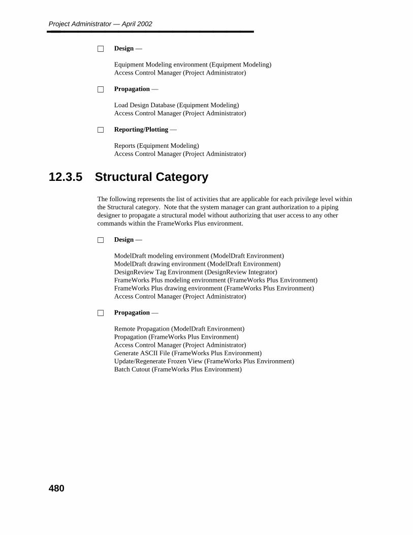
Project Administrator — April 2002________________ Design —
Equipment Modeling environment (Equipment Modeling)Access Control Manager (Project Administrator)
Propagation —
Load Design Database (Equipment Modeling)Access Control Manager (Project Administrator)
Reporting/Plotting —
Reports (Equipment Modeling)Access Control Manager (Project Administrator)
12.3.5 Structural Category
The following represents the list of activities that are applicable for each privilege level withinthe Structural category. Note that the system manager can grant authorization to a pipingdesigner to propagate a structural model without authorizing that user access to any othercommands within the FrameWorks Plus environment.
Design —
ModelDraft modeling environment (ModelDraft Environment)ModelDraft drawing environment (ModelDraft Environment)DesignReview Tag Environment (DesignReview Integrator)FrameWorks Plus modeling environment (FrameWorks Plus Environment)FrameWorks Plus drawing environment (FrameWorks Plus Environment)Access Control Manager (Project Administrator)
Propagation —
Remote Propagation (ModelDraft Environment)Propagation (FrameWorks Plus Environment)Access Control Manager (Project Administrator)Generate ASCII File (FrameWorks Plus Environment)Update/Regenerate Frozen View (FrameWorks Plus Environment)Batch Cutout (FrameWorks Plus Environment)
480

12. Access
Co
ntro
l
Instrumentation Category________________
12.3.6 Electrical Raceway Category
The following represents the list of activities that are applicable for each privilege level withinthe Electrical Raceway category:
General Project Management —
Utilities (Electrical Raceway Environment)Access Control Manager (Project Administrator)
Reference Data —
Load Reference Database (Electrical Raceway Environment)Access Control Manager (Project Administrator)
Design —
Raceway modeling environment (Electrical Raceway Environment)DesignReview Tag Environment (DesignReview Integrator)Access Control Manager (Project Administrator)
12.3.7 Orthographic Drawing Category
The following represents the list of activities that are applicable for each privilege level withinthe Orthographic Drawings category:
System Management —
Drawing Project Setup Manager (Drawing Manager)Plot Setup Manager (Drawing Manager)Access Control Manager (Project Administrator)
General Project Management —
Create Drawing (Drawing Manager)Revise Drawing (Drawing Manager)Delete Drawing (Drawing Manager)Report - Drawing Management Data (Drawing Manager)Project Planner (Drawing Manager)Access Control Manager (Project Administrator)
Design —
Drawing Composition/Annotation (Drawing Manager)Access Control Manager (Project Administrator)
481

Project Administrator — April 2002________________ Propagation —
VHL Manager (Drawing Manager)Access Control Manager (Project Administrator)Update Annotation Labels (Drawing Manager)Search Criteria for VHL (Drawing Manager)
Reporting/Plotting —
Report - Model Data (Drawing Manager)Plot Manager (Drawing Manager)Access Control Manager (Project Administrator)
Approval —
Approve Drawing (Drawing Manager)Access Control Manager (Project Administrator)
12.3.8 Isometric Drawing Category
The following represents the list of activities that are applicable for each privilege within theIsometric category:
System Management —
Define Project Options (Isometric Drawing Manager)Access Control Manager (Project Administrator)
General Project Management —
Utilities (Isometric Drawing Manager)Revise Iso Area (Isometric Drawing Manager)Create Drawing (Isometric Drawing Manager)Revise Drawing (Isometric Drawing Manager)Delete Drawing (Isometric Drawing Manager)Access Control Manager (Project Administrator)List Drawings (Isometric Drawing Manager)
Reference Data —
Define Default Sets (Isometric Drawing Manager)Access Control Manager (Project Administrator)
Design —
View Graphics (Isometric Drawing Manager)Access Control Manager (Project Administrator)List Drawings (Isometric Drawing Manager)
482

12. Access
Co
ntro
l
Instrumentation Category________________ Reporting/Plotting —
Create Batch Job Input (Isometric Drawing Manager)Submit Batch Job (Isometric Drawing Manager)Reports (Isometric Drawing Manager)Plot (Isometric Drawing Manager)Access Control Manager (Project Administrator)List Drawings (Isometric Drawing Manager)
12.3.9 Clash Management Data Category
The following represents the list of activities that are applicable for each privilege level withinthe Clash Management Data category:
System Management —
Interference Plot Management Data (Interference Manager)Interference Report Management Data (Interference Manager)Access Control Manager (Project Administrator)
Reference Data Management —
Interference Checker Data (Interference Manager)Access Control Manager (Project Administrator)
Reporting/Plotting —
Interference Plot Manager (Interference Manager)Interference Report Manager (Interference Manager)Interference Management Data (Interference Manager)Access Control Manager (Project Administrator)
Checking/Comparison —
Envelope Builder (Interference Manager)Envelope Diagnostics (Interference Manager)Interference Checker (Interference Manager)Access Control Manager (Project Administrator)Envelope Verification (Interference Manager)
Approval —
Interference Approval Manager (Interference Manager)Access Control Manager (Project Administrator)
483

Project Administrator — April 2002________________
12.3.10 Project Data Category
The following represents the list of activities that are applicable for each privilege level withinthe Project Data category:
System Management —
Access Control Manager (Project Administrator)Project Setup Manager (Project Administrator)Project Archival Manager (Project Administrator)System Manager (Project Administrator)File Lock Manager (Project Administrator)
General Project Management —
Project Environment Manager (Project Administrator)Access Control Manager (Project Administrator)
Design —
DesignReview Administrator (DesignReview Integrator)DesignReview Defaults Setup (DesignReview Integrator)DesignReview Model Transmittal (DesignReview Integrator)Access Control Manager (Project Administrator)Export to PDME (Project Administrator)
Reporting/Plotting —
Project Control Manager (Project Administrator)Access Control Manager (Project Administrator)
484

12. Access
Co
ntro
l
User Functions________________
12.4 User Functions
The Access Control Manager option on the Project Administrator form can be used tomodify user information for the active PDS user ID.
Operating Sequence
1. Select the Access Control Manager option from the Project Administrator form.
The Access Control Manager form is displayed.
2. Type the User ID for the PDS user to be modified.
The defined user information is displayed.
3. Type any changes to the user information as follows:
— Initials — Type up to four characters for the initials of the PDS user. These initialsare used for input fields within the PD_Shell environment which require a user’sinitials (for example, the approved by and checked by fields).
— User Name — Type up to 40 characters in any format for the name of the PDSuser. This name is used for reports and mail messages generated within thePD_Shell environment for which the user’s identification is required in documentedform.
— Password — Type up to 8 characters for your password. Once the password hasbeen revised and accepted, the Access Control Manager will require the revisedpassword.
485
Project Administrator — April 2002________________
You cannot change passwords for other user IDs, only your own.
To change the password, a valid access control username must beentered and a project must be selected on the PD_Shell Main Menu.Then, use the Project Administrator and Access Control Manager tochange the password.
4. Accept To Create System Record
Choose the Confirm button to accept the specified user information.
486

A. P
roject
Up
grad
e
Appendix A: Upgrading Existing Projects________________
Appendix A Upgrading ExistingProjects
If you have previously upgraded to version 6.3, there is no additional upgraderequired for 6.4.
For the 6.3 release of PDS 3D, several data structures within the project data set wereextended to support additional enhancements. The PD_Shell environment provides atranslation process to upgrade a project that was created with a previous PDS release (a 4.*,5.*, or 6.0/6.1 version). You cannot continue working in a project until the project’s data sethas been upgraded.
Errors and Warnings
The project data set’s version number will only be revised in the project directory file and inthe Project Control Database once that project has been upgraded successfully. If a fatal erroroccurs during the upgrade of a project data set, the project data set’s version number will notbe revised. Under these circumstances, you will hbe the opportunity to correct the problemand re-enter the PD_Shell environment to continue the project upgrade.
All non-fatal errors generate warning messages. Both the fatal error messages and thewarning messages are recorded in the project upgrade.log file.
Most of the errors are caused by file protection problems or difficulty in locating the files.
Shared Reference Data
The following rules apply when the Material Reference Database is being shared by more thanone project.
The new table will not be added multiple times for a Material Reference Database thatis being shared.
Only the reference.ddl file in the project directory will be updated, if the MaterialReference Database is being shared with at least one other project and has beenpreviously upgraded for that project.
All the projects which share a Material Reference Database must be upgraded at thesame time. If this is not feasible, you must create a new Material Reference Databasefor the project that is to be upgraded.
You cannot create a new project using the current PDS release that shares the MaterialReference Database with another project that is being completed with an older PDSrelease.
487
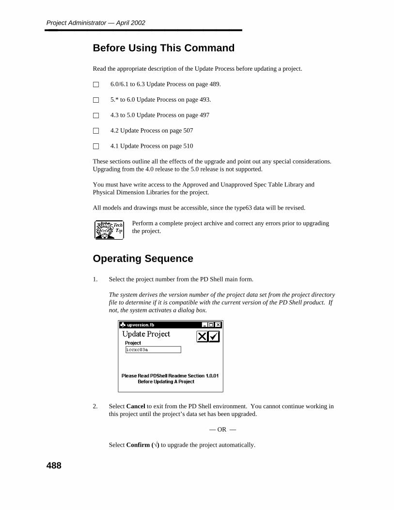
Project Administrator — April 2002________________
Before Using This Command
Read the appropriate description of the Update Process before updating a project.
6.0/6.1 to 6.3 Update Process on page 489.
5.* to 6.0 Update Process on page 493.
4.3 to 5.0 Update Process on page 497
4.2 Update Process on page 507
4.1 Update Process on page 510
These sections outline all the effects of the upgrade and point out any special considerations.Upgrading from the 4.0 release to the 5.0 release is not supported.
You must have write access to the Approved and Unapproved Spec Table Library andPhysical Dimension Libraries for the project.
All models and drawings must be accessible, since the type63 data will be revised.
Perform a complete project archive and correct any errors prior to upgradingthe project.
Operating Sequence
1. Select the project number from the PD Shell main form.
The system derives the version number of the project data set from the project directoryfile to determine if it is compatible with the current version of the PD Shell product. Ifnot, the system activates a dialog box.
2. Select Cancel to exit from the PD Shell environment. You cannot continue working inthis project until the project’s data set has been upgraded.
— OR —
Select Confirm (√) to upgrade the project automatically.
488

A. P
roject
Up
grad
e
Appendix A: Upgrading Existing Projects________________ The system begins upgrading the project’s data set. It creates a log file namedupdate.log, in the project directory which includes a detailed listing of all the data thathas been revised. The system also displays informative messages in the dialog box asthe project data set is upgraded.
Update in Progress
Initializing Databases
Updating Project Database Information
Updating Reference Database Information
Updating Design Database Information
Rewriting proj_file with New Data Version
Finished Project Update
6.0/6.1 to 6.3 Update Process
The following files will be revised by upgrading a project:
Project Control Database and its corresponding definition (project.ddl)
Piping Design Database and its corresponding definition (design.ddl)
Reference Database and its corresponding definition (reference.ddl)
piping seed file and all piping models
drawing seed file(s) and all drawings
area marker files
all approved and unapproved Reference Database Libraries
489

Project Administrator — April 2002________________
Summary of Database Changes
Project Control Database
PDtable_103
The system updates the Project Control Data table (PDtable 103) to include two new columns.
Project Control Data
table number = 103, number of columns = 41
40 , sup_tdf_table_path , character (36)41 , sup_tdf_table_node , character (26)
PDtable_104
The system updates the Project Archival Management Data Table (PDtable_104) to includeone new column.
Project Archival Management Data
table number = 104, number of columns = 11
11 , schedule_type , short
PDtable_170
The system adds the Pipe Support Drawing Management Data (PDtable_170) to the ProjectControl Database.
Pipe Support Drawing Management Data
table number = 170, number of columns = 16
1 , support_unique_no , integer2 , ganged_id , integer3 , grouped_id , integer4 , area_index_no , short5 , model_index_no , short6 , drawing_title , character (40)7 , drawing_file_spec , character (40)8 , path_name , character (40)9 , network_address , character (40)10 , support_lineid , character (40)11 , material_index , character (20)12 , revision_no , short13 , revision_date , integer14 , drawing_status , short15 , sheet_no , short16 , sheet_total , short
490

A. P
roject
Up
grad
e
Appendix A: Upgrading Existing Projects________________
Piping Design Database
PDtable_80
The system updates the Pipe Support Data Table (PDtable_80) to include twelve newcolumns.
Pipe Support Data
table number = 80, number of columns = 50
39 , mark_number , character(80)40 , group_id , integer41 , gang_id , integer42 , material_grade , short , standard note 14543 , weld_code , short44 , material_index , character(16)45 , operating_load , double46 , installed_load , double47 , hydrostatic_load , double48 , total_movement_1 , double , in subunits – distance attribute49 , total_movement_2 , double , in subunits – distance attribute50 , rod_diameter , double , in subunits – distance attribute
The columns are appended to the end of the table (after any columns you may have added>.
Specification/Material Reference Database
PDtable_240
The system adds the Pipe Support Group Table (PDtable_240).
Piping Support Group
table number = 240, number of columns = 3
1 , system_unique_no , integer2 , support_group , character (6)3 , group_descr , character (40)
PDtable_241
The system adds the Piping Support Commodity Reference Data Table (PDtable_241).
Piping Support Commodity Reference Data
table number = 241, number of columns = 11
491
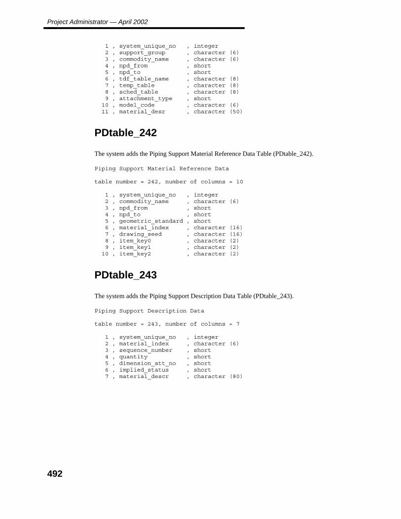
Project Administrator — April 2002________________
1 , system_unique_no , integer2 , support_group , character (6)3 , commodity_name , character (6)4 , npd_from , short5 , npd_to , short6 , tdf_table_name , character (8)7 , temp_table , character (8)8 , sched_table , character (8)9 , attachment_type , short10 , model_code , character (6)11 , material_desr , character (50)
PDtable_242
The system adds the Piping Support Material Reference Data Table (PDtable_242).
Piping Support Material Reference Data
table number = 242, number of columns = 10
1 , system_unique_no , integer2 , commodity_name , character (6)3 , npd_from , short4 , npd_to , short5 , geometric_standard , short6 , material_index , character (16)7 , drawing_seed , character (16)8 , item_key0 , character (2)9 , item_key1 , character (2)10 , item_key2 , character (2)
PDtable_243
The system adds the Piping Support Description Data Table (PDtable_243).
Piping Support Description Data
table number = 243, number of columns = 7
1 , system_unique_no , integer2 , material_index , character (6)3 , sequence_number , short4 , quantity , short5 , dimension_att_no , short6 , implied_status , short7 , material_descr , character (80)
492
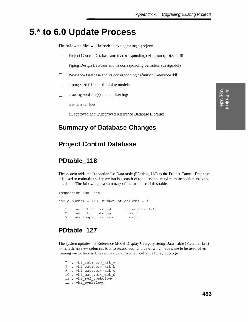
A. P
roject
Up
grad
e
Appendix A: Upgrading Existing Projects________________
5.* to 6.0 Update Process
The following files will be revised by upgrading a project:
Project Control Database and its corresponding definition (project.ddl)
Piping Design Database and its corresponding definition (design.ddl)
Reference Database and its corresponding definition (reference.ddl)
piping seed file and all piping models
drawing seed file(s) and all drawings
area marker files
all approved and unapproved Reference Database Libraries
Summary of Database Changes
Project Control Database
PDtable_118
The system adds the Inspection Iso Data table (PDtable_118) to the Project Control Database;it is used to maintain the inpsection iso search criteria, and the maximum inspection assignedon a line. The following is a summary of the structure of this table:
Inspection Iso Data
table number = 118, number of columns = 3
1 , inspection_iso_id , character(24)2 , inspection_status , short3 , max_inspection_key , short
PDtable_127
The system updates the Reference Model Display Category Setup Data Table (PDtable_127)to include six new columns: four to record your choice of which levels are to be used whenrunning vector hidden line removal, and two new columns for symbology.
7 , vhl_category_msk_a8 , vhl_category_msk_b9 , vhl_category_msk_c10 , vhl_category_msk_d11 , vhl_ref_symbology12 , vhl_symbology
493

Project Administrator — April 2002________________
Piping Design Database
PDtable_12
The system updates the Piping Segment Data Table (PDtable_12_n) to include two newcolumns.
75 , inspection_iso_id , character(24)76 , index_to_pi_dwg , integer
The system appends the columns to the end of the table (after any columns that you may haveadded).
PDtable_34
The system updates the Piping Component Data Table (PDtable_34_n) to include eight newcolumns.
119 , last_placed_date , integer120 , generic_comp_no , character(20)121 , inspection_key , short122 , cp_1_inspect_key , short123 , cp_2_inspect_key , short124 , cp_3_inspect_key , short125 , cp_4_inspect_key , short126 , cp_5_inspect_key , short
The columns are appended to the end of the table (after any columns that you may haveadded).
PDtable_50
The system updates the Piping/Tubing Data Table (PDtable_50_n) to include four newcolumns.
58 , last_placed_date , integer59 , inspection_key , short60 , end_1_inspect_key , short61 , end_2_inspect_key , short
The columns are appended to the end of the table (after any columns that you may haveadded).
494

A. P
roject
Up
grad
e
Appendix A: Upgrading Existing Projects________________
PDtable_67
The system updates the Instrument/Component Data Table (PDtable_67_n) to include eightnew columns.
126 , last_placed_date , integer127 , generic_comp_no , character(20)128 , inspection_key , short129 , cp_1_inspect_key , short130 , cp_2_inspect_key , short131 , cp_3_inspect_key , short132 , cp_4_inspect_key , short133 , cp_5_inspect_key , short
The columns are appended to the end of the table (after any columns that you may haveadded).
PDtable_80
The system updates the Pipe Support Data Table (PDtable_80_n) to include two newcolumns.
37 , last_placed_date , integer38 , inspection_key , short
The columns are appended to the end of the table (after any columns that you may haveadded).
Material Reference Database
PDtable_203 and PDtable 204
The system updates the Piping Specialty Specification Data table (PDtable_203) and theInstrument Component Specification Data table (PDtable_204) to include a new column torecord the type of input form for instruments and piping specialties.
26 , input_form_type , short , SN 990
495

Project Administrator — April 2002________________
Summary of Library Changes
Label Description Library
This library has been modified to include the following new label numbers:
332 = Segment Data - Line1333 = Segment Data - Line2334 = Segment Data - Line3335 = Inspection Iso Id
(DesignReview Labels)
390 = PLANTGEN PIPE391 = PLANTGEN COMPONENT392 = PLANTGEN EQP/MISC393 = PLANTGEN NOZZLE394 = PLANTGEN STR/CIVIL395 = PLANTGEN HVAC396 = PLANTGEN RACEWAY397 = PLANTGEN SUPPORT
(Clash Labels)
2240 = PLANTGEN PIPE2241 = PLANTGEN COMPONENT2242 = PLANTGEN EQP/MISC2243 = PLANTGEN NOZZLE2244 = PLANTGEN STR/CIVIL2245 = PLANTGEN HVAC2246 = PLANTGEN RACEWAY2247 = PLANTGEN SUPPORT
(Drawing Labels)
2500 = PLANTGEN PIPE2501 = PLANTGEN COMPONENT2502 = PLANTGEN EQP/MISC2503 = PLANTGEN NOZZLE2504 = PLANTGEN STR/CIVIL2505 = PLANTGEN HVAC2506 = PLANTGEN RACEWAY2507 = PLANTGEN SUPPORT
Label number 335 is required for Inspection Iso Management Data.
496
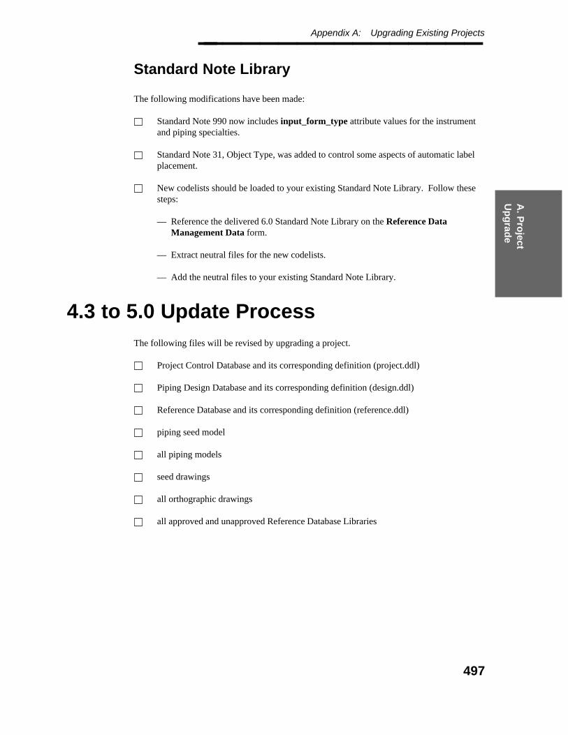
A. P
roject
Up
grad
e
Appendix A: Upgrading Existing Projects________________
Standard Note Library
The following modifications have been made:
Standard Note 990 now includes input_form_type attribute values for the instrumentand piping specialties.
Standard Note 31, Object Type, was added to control some aspects of automatic labelplacement.
New codelists should be loaded to your existing Standard Note Library. Follow thesesteps:
— Reference the delivered 6.0 Standard Note Library on the Reference DataManagement Data form.
— Extract neutral files for the new codelists.
— Add the neutral files to your existing Standard Note Library.
4.3 to 5.0 Update Process
The following files will be revised by upgrading a project.
Project Control Database and its corresponding definition (project.ddl)
Piping Design Database and its corresponding definition (design.ddl)
Reference Database and its corresponding definition (reference.ddl)
piping seed model
all piping models
seed drawings
all orthographic drawings
all approved and unapproved Reference Database Libraries
497
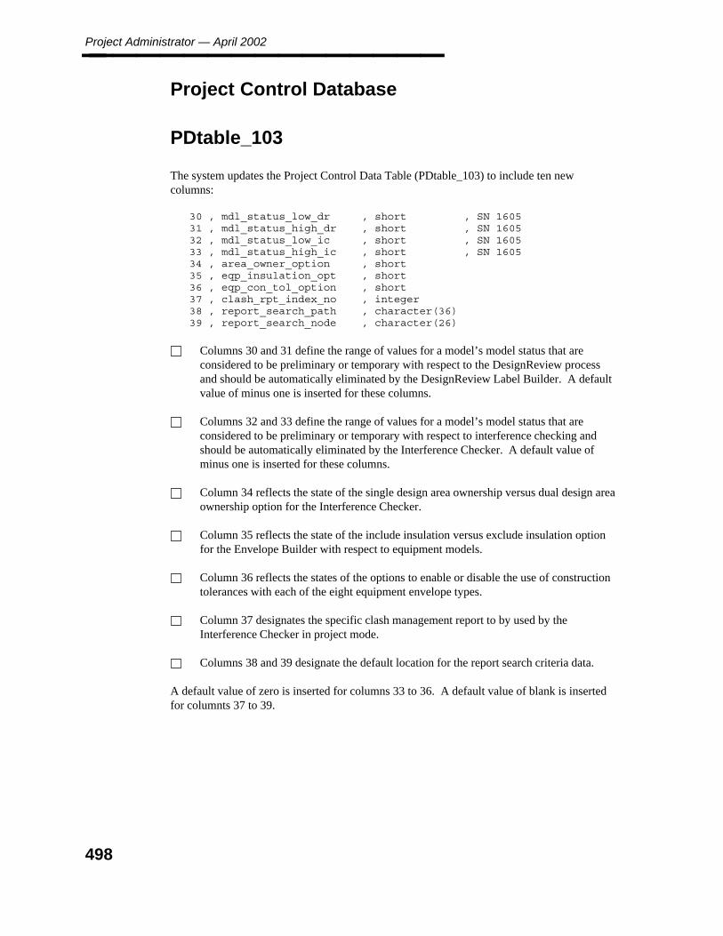
Project Administrator — April 2002________________
Project Control Database
PDtable_103
The system updates the Project Control Data Table (PDtable_103) to include ten newcolumns:
30 , mdl_status_low_dr , short , SN 160531 , mdl_status_high_dr , short , SN 160532 , mdl_status_low_ic , short , SN 160533 , mdl_status_high_ic , short , SN 160534 , area_owner_option , short35 , eqp_insulation_opt , short36 , eqp_con_tol_option , short37 , clash_rpt_index_no , integer38 , report_search_path , character(36)39 , report_search_node , character(26)
Columns 30 and 31 define the range of values for a model’s model status that areconsidered to be preliminary or temporary with respect to the DesignReview processand should be automatically eliminated by the DesignReview Label Builder. A defaultvalue of minus one is inserted for these columns.
Columns 32 and 33 define the range of values for a model’s model status that areconsidered to be preliminary or temporary with respect to interference checking andshould be automatically eliminated by the Interference Checker. A default value ofminus one is inserted for these columns.
Column 34 reflects the state of the single design area ownership versus dual design areaownership option for the Interference Checker.
Column 35 reflects the state of the include insulation versus exclude insulation optionfor the Envelope Builder with respect to equipment models.
Column 36 reflects the states of the options to enable or disable the use of constructiontolerances with each of the eight equipment envelope types.
Column 37 designates the specific clash management report to by used by theInterference Checker in project mode.
Columns 38 and 39 designate the default location for the report search criteria data.
A default value of zero is inserted for columns 33 to 36. A default value of blank is insertedfor columnts 37 to 39.
498
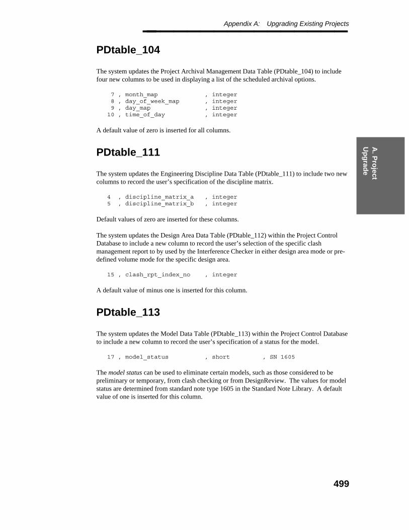
A. P
roject
Up
grad
e
Appendix A: Upgrading Existing Projects________________
PDtable_104
The system updates the Project Archival Management Data Table (PDtable_104) to includefour new columns to be used in displaying a list of the scheduled archival options.
7 , month_map , integer8 , day_of_week_map , integer9 , day_map , integer10 , time_of_day , integer
A default value of zero is inserted for all columns.
PDtable_111
The system updates the Engineering Discipline Data Table (PDtable_111) to include two newcolumns to record the user’s specification of the discipline matrix.
4 , discipline_matrix_a , integer5 , discipline_matrix_b , integer
Default values of zero are inserted for these columns.
The system updates the Design Area Data Table (PDtable_112) within the Project ControlDatabase to include a new column to record the user’s selection of the specific clashmanagement report to by used by the Interference Checker in either design area mode or pre-defined volume mode for the specific design area.
15 , clash_rpt_index_no , integer
A default value of minus one is inserted for this column.
PDtable_113
The system updates the Model Data Table (PDtable_113) within the Project Control Databaseto include a new column to record the user’s specification of a status for the model.
17 , model_status , short , SN 1605
The model status can be used to eliminate certain models, such as those considered to bepreliminary or temporary, from clash checking or from DesignReview. The values for modelstatus are determined from standard note type 1605 in the Standard Note Library. A defaultvalue of one is inserted for this column.
499
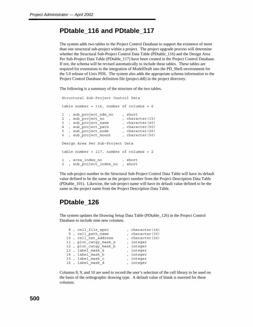
Project Administrator — April 2002________________
PDtable_116 and PDtable_117
The system adds two tables to the Project Control Database to support the existence of morethan one structural sub-project within a project. The project upgrade process will determinewhether the Structural Sub-Project Control Data Table (PDtable_116) and the Design AreaPer Sub-Project Data Table (PDtable_117) have been created in the Project Control Database.If not, the schema will be revised automatically to include these tables. These tables arerequired for extensions to the integration of ModelDraft into the PD_Shell environment forthe 5.0 release of Unix PDS. The system also adds the appropriate schema information to theProject Control Database definition file (project.ddl) in the project directory.
The following is a summary of the structure of the two tables.
Structural Sub-Project Control Data
table number = 116, number of columns = 6
1 , sub_project_ndx_no , short2 , sub_project_no , character(15)3 , sub_project_name , character(40)4 , sub_project_path , character(50)5 , sub_project_node , character(26)6 , sub_project_mount , character(50)
Design Area Per Sub-Project Data
table number = 117, number of columns = 2
1 , area_index_no , short2 , sub_project_index_no , short
The sub-project number in the Structural Sub-Project Control Data Table will have its defaultvalue defined to be the same as the project number from the Project Description Data Table(PDtable_101). Likewise, the sub-project name will have its default value defined to be thesame as the project name from the Project Description Data Table.
PDtable_126
The system updates the Drawing Setup Data Table (PDtable_126) in the Project ControlDatabase to include nine new columns.
8 , cell_file_spec , character(14)9 , cell_path_name , character(36)10 , cell_net_address , character(26)11 , plot_catgy_mask_a , integer12 , plot_catgy_mask_b , integer13 , label_mask_a , integer14 , label_mask_b , integer15 , label_mask_c , integer16 , label_mask_d , integer
Columns 8, 9, and 10 are used to record the user’s selection of the cell library to be used onthe basis of the orthographic drawing type. A default value of blank is inserted for thesecolumns.
500
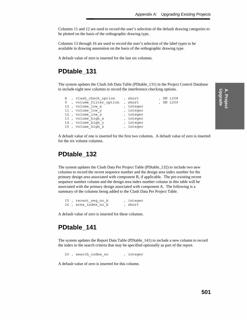
A. P
roject
Up
grad
e
Appendix A: Upgrading Existing Projects________________ Columns 11 and 12 are used to record the user’s selection of the default drawing categories tobe plotted on the basis of the orthographic drawing type.
Columns 13 through 16 are used to record the user’s selection of the label types to beavailable in drawing annotation on the basis of the orthographic drawing type.
A default value of zero is inserted for the last six columns.
PDtable_131
The system updates the Clash Job Data Table (PDtable_131) in the Project Control Databaseto include eight new columns to record the interference checking options.
8 , clash_check_option , short , SN 12089 , volume_filter_option , short , SN 120910 , volume_low_x , integer11 , volume_low_y , integer12 , volume_low_z , integer13 , volume_high_x , integer14 , volume_high_y , integer15 , volume_high_z , integer
A default value of one is inserted for the first two columns. A default value of zero is insertedfor the six volume columns.
PDtable_132
The system updates the Clash Data Per Project Table (PDtable_132) to include two newcolumns to record the recent sequence number and the design area index number for theprimary design area associated with component B, if applicable. The pre-existing recentsequence number column and the design area index number column in this table will beassociated with the primary design associated with component A. The following is asummary of the columns being added to the Clash Data Per Project Table.
15 , recent_seq_no_b , integer16 , area_index_no_b , short
A default value of zero is inserted for these columns.
PDtable_141
The system updates the Report Data Table (PDtable_141) to include a new column to recordthe index to the search criteria that may be specified optionally as part of the report.
20 , search_index_no , integer
A default value of zero is inserted for this column.
501
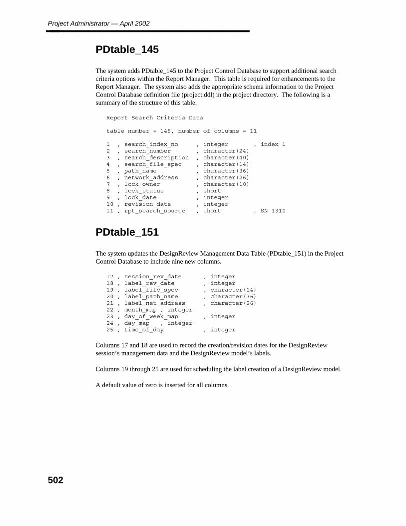
Project Administrator — April 2002________________
PDtable_145
The system adds PDtable_145 to the Project Control Database to support additional searchcriteria options within the Report Manager. This table is required for enhancements to theReport Manager. The system also adds the appropriate schema information to the ProjectControl Database definition file (project.ddl) in the project directory. The following is asummary of the structure of this table.
Report Search Criteria Data
table number = 145, number of columns = 11
1 , search_index_no , integer , index 12 , search_number , character(24)3 , search_description , character(40)4 , search_file_spec , character(14)5 , path_name , character(36)6 , network_address , character(26)7 , lock_owner , character(10)8 , lock_status , short9 , lock_date , integer10 , revision_date , integer11 , rpt_search_source , short , SN 1310
PDtable_151
The system updates the DesignReview Management Data Table (PDtable_151) in the ProjectControl Database to include nine new columns.
17 , session_rev_date , integer18 , label_rev_date , integer19 , label_file_spec , character(14)20 , label_path_name , character(36)21 , label_net_address , character(26)22 , month_map , integer23 , day_of_week_map , integer24 , day_map , integer25 , time_of_day , integer
Columns 17 and 18 are used to record the creation/revision dates for the DesignReviewsession’s management data and the DesignReview model’s labels.
Columns 19 through 25 are used for scheduling the label creation of a DesignReview model.
A default value of zero is inserted for all columns.
502
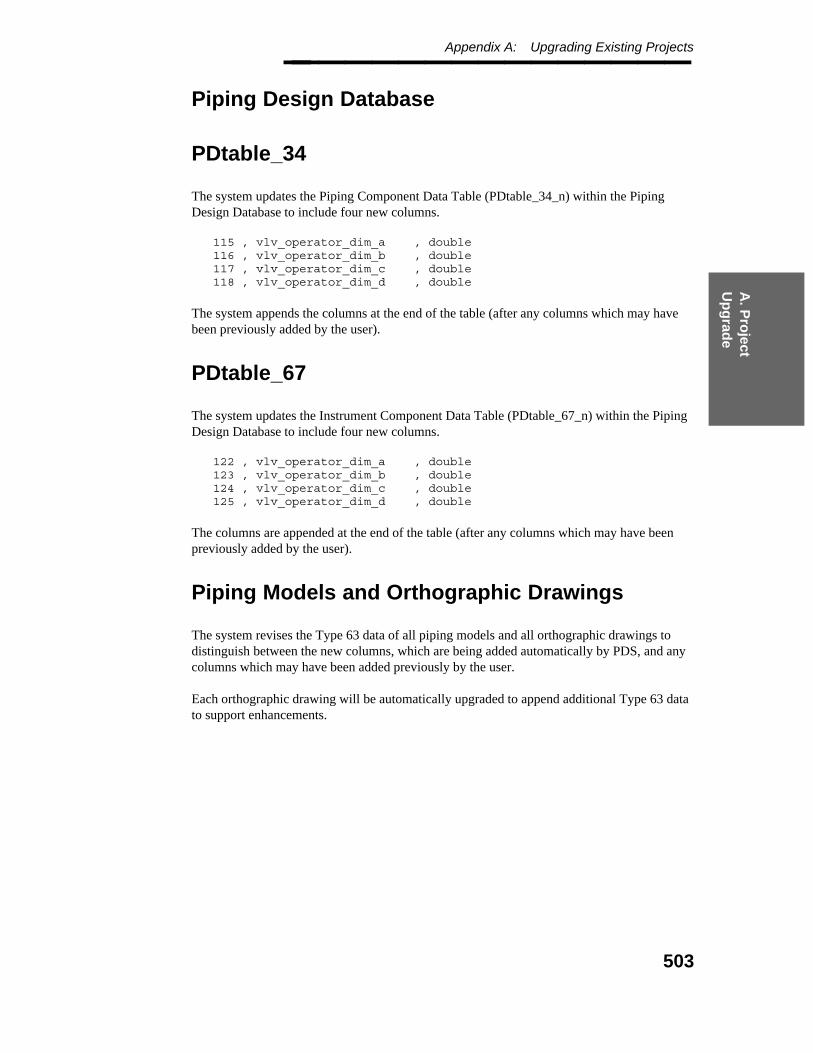
A. P
roject
Up
grad
e
Appendix A: Upgrading Existing Projects________________
Piping Design Database
PDtable_34
The system updates the Piping Component Data Table (PDtable_34_n) within the PipingDesign Database to include four new columns.
115 , vlv_operator_dim_a , double116 , vlv_operator_dim_b , double117 , vlv_operator_dim_c , double118 , vlv_operator_dim_d , double
The system appends the columns at the end of the table (after any columns which may havebeen previously added by the user).
PDtable_67
The system updates the Instrument Component Data Table (PDtable_67_n) within the PipingDesign Database to include four new columns.
122 , vlv_operator_dim_a , double123 , vlv_operator_dim_b , double124 , vlv_operator_dim_c , double125 , vlv_operator_dim_d , double
The columns are appended at the end of the table (after any columns which may have beenpreviously added by the user).
Piping Models and Orthographic Drawings
The system revises the Type 63 data of all piping models and all orthographic drawings todistinguish between the new columns, which are being added automatically by PDS, and anycolumns which may have been added previously by the user.
Each orthographic drawing will be automatically upgraded to append additional Type 63 datato support enhancements.
503
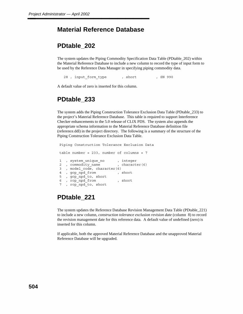
Project Administrator — April 2002________________
Material Reference Database
PDtable_202
The system updates the Piping Commodity Specification Data Table (PDtable_202) withinthe Material Reference Database to include a new column to record the type of input form tobe used by the Reference Data Manager in specifying piping commodity data.
28 , input_form_type , short , SN 990
A default value of zero is inserted for this column.
PDtable_233
The system adds the Piping Construction Tolerance Exclusion Data Table (PDtable_233) tothe project’s Material Reference Database. This table is required to support InterferenceChecker enhancements to the 5.0 release of CLIX PDS. The system also appends theappropriate schema information to the Material Reference Database definition file(reference.ddl) in the project directory. The following is a summary of the structure of thePiping Construction Tolerance Exclusion Data Table.
Piping Construction Tolerance Exclusion Data
table number = 233, number of columns = 7
1 , system_unique_no , integer2 , commodity_name , character(6)3 , model_code, character(6)4 , gcp_npd_from , short5 , gcp_npd_to, short6 , rcp_npd_from , short7 , rcp_npd_to, short
PDtable_221
The system updates the Reference Database Revision Management Data Table (PDtable_221)to include a new column, construction tolerance exclusion revision date (column 8) to recordthe revision management date for this reference data. A default value of undefined (zero) isinserted for this column.
If applicable, both the approved Material Reference Database and the unapproved MaterialReference Database will be upgraded.
504
A. P
roject
Up
grad
e
Appendix A: Upgrading Existing Projects________________
Shared Reference Data
The following rules apply when the Material Reference Database is being shared by more thanone project.
The new table will not be added multiple times for a Material Reference Database thatis being shared.
Only the reference.ddl file in the project directory will be updated, if the MaterialReference Database is being shared with at least one other project and has beenpreviously upgraded for that project.
All the projects which share a Material Reference Database must be upgraded at thesame time. If this is not feasible, you must create a new Material Reference Databasefor the project that is to be upgraded.
You cannot create a new project with the 5.0 PDS release that shares the MaterialReference Database with another project that is being completed with an earlier PDSrelease.
Libraries
The system updates the Label Description Library (approved and unapproved) to correct aproblem with labels that include user-defined attributes. A library which is being shared bytwo or more projects will not be upgraded multiple times. Once upgraded, the user cannotshare this library with any project being completed with a previous Unix PDS release.
The upgrade to the Label Description Library will make it impossible to copy a LabelDescription Library from a project using an earlier release into a project using the 5.0 release.
For releases prior to the 4.2 PDS release, a problem existed in the Reference Data Manager,such that the binary tree structure in a reference data library (such as the Graphic CommodityLibrary) could be corrupted without the user immediately detecting any problems with thatlibrary. Although the software problem was corrected in the 4.2 PDS release, the dataproblem that resulted may have persisted beyond that release, particularly if the library has notbeen compressed. As a final step within the project upgrade process, the system will verifythe integrity of the binary tree structure within each of the reference data libraries. If an erroris detected, a specific warning message will be reported, both interactively and in the upgradelog. In this event, you should contact Intergraph immediately for assistance in repairing thelibrary.
Update Notes
The feature to display additional clash management data on clash plots will require a changeto the format of the clash plot border. As a result, you must copy the clash plot border(borderifc.dgn) from the IF_Check product directory into the project directory. Theautomated upgrade process will not automatically copy the new plot clash border into theproject directory, since you may have customized the clash plot border, such as adding thecompany name or logo.
505

Project Administrator — April 2002________________
When retrieving data that has been created and archived with 4.3 PDS (or 4.1or 4.2 PDS), the Project Archival command will automatically upgrade thedata to the format, as required by 5.0 PDS.
If upgrading from the 4.2 release to the 5.0 release, refer to Section 1.5.2 for the details of thedata translation that apply. If upgrading from the 4.1 release to the 5.0 release, refer toSections 1.5.2 and 1.5.3 for the details of the data translation that apply.
506

A. P
roject
Up
grad
e
Appendix A: 4.2 Update Process________________
4.2 Update Process
The following files will be revised by upgrading a project.
Project Control Database and its corresponding definition (project.ddl)
Piping Design Database and its corresponding definition (design.ddl)
Material Reference Database and its corresponding definition (reference.ddl)
piping seed model
all piping models
seed drawing
all orthographic drawings
Project Control Database
The system updates the Model Data Table (PDtable_113) within the Project Control Databaseto include a new column, model type (column 16). This column records the type of structuralmodel, sparse or propagated.
The following steps are performed to update the Project Control Database.
The system reads the column name for the new column from the Project ControlDatabase definition (project.ddl) in the PD_Shell product.
The system appends column 16 to the end of the Model Data Table. A default value ofzero (propagated structural model) is inserted for this column.
The system appends the column name for the new column to the Project ControlDatabase definition (project.ddl) in the project directory and updates the number ofcolumns for this table.
The automated project upgrade cannot determine the model management datafor the sparse model from the data for the corresponding propagated model,since there was no file management correlation between the two models (priorto the 4.3 PDS release). Therefore, you must load the model management datafor the sparse structural models through the Project Environment Manager,once the project has been upgraded.
For any previously created structural models, refer to Create Model Data from ASCII File,page 129, for information on creating model management data from an ASCII list.
The system updates the Model Setup Data Table (PDtable_115) within the Project ControlDatabase to include two new columns, reference model symbology (column 4) and symbologydisplay option (column 5). These new columns record the selection of the default referencemodel symbology display on the basis of the discipline.
507
Project Administrator — April 2002________________ The following steps are performed to upgrade the Project Control Database.
The system reads the column names for the new columns from the Project ControlDatabase definition (project.ddl) in the PD_Shell product.
The system appends columns 4 and 5 to the end of the Model Setup Data Table.Default values of undefined (zero) are inserted for these columns.
The system appends the column names for the new columns to the Project ControlDatabase definition (project.ddl) in the project directory and updates the number ofcolumns for this table.
The system updates the Drawing Setup Data Table (PDtable_126) within the Project ControlDatabase to include a new column, seed drawing option (column 7). This column records theselection of the seed drawing to be used within that drawing type.
The following steps are performed to upgrade the Project Control Database.
The system reads the column name for the new column from the Project ControlDatabase definition (project.ddl) in the PD_Shell product.
The system appends column 7 to the end of the Drawing Setup Data Table. A defaultvalue of zero (use the project seed drawing) is inserted for this column.
The system appends the column name for the new column to the Project ControlDatabase definition (project.ddl) in the project directory and updates the number ofcolumns for this table.
The system performs the following changes to the structure of the clash management data inthe Project Control Database to improve performance.
indexes the unique clash id in the Clash Review History Table (PDtable_135) of theProject Control Database.
indexes the recent sequence number in the Clash Data Per Project Table (PDtable_132)of the Project Control Database.
removes the indices for model index number a and model index number b in the ClashData Per Project Table (PDtable_132) of the Project Control Database.
removes the indices for unique sequence number and clash type in the Clash Data PerJob Table (PDtable_133) of the Project Control Database.
PDS 4.3 creates isometric drawing management data, when a new piping design area iscreated with the Project Environment Manager. In previous releases, the isometric drawingmanagement data had to be created as a separate activity through the Isometric DrawingManager. To support this feature, the system creates isometric drawing management data forany existing piping design areas for which iso design areas have not been created. For eachpiping design area that does not have the corresponding isometric drawing management data,the system creates a row in the Isometric Design Area Definition Data Table (PDtable_183)that is associated with the applicable Design Area Data Table (PDtable_112). All othercolumns in this table are loaded with blank (or zero) values.
508

A. P
roject
Up
grad
e
Appendix A: 4.2 Update Process________________
Piping Design Database
The system updates the Piping Segment Data Table within the Piping Design Database toinclude a new column, color code, for piping segments. The column is added automaticallyat the end of the table (after any existing user-defined columns).
The default name for this column is color_code. If you need to change the name of thiscolumn ,for example to resolve a conflict with the name of a user-defined column, you mustedit the design.ddl in the PD_Shell product directory, prior to updating a project.
The color code column has a default length of 8 characters, but you can increase that length toa maximum of 20 characters.
The system updates the Instrument Component Data Table within the Piping Design Databaseto include a new column, bend angle, for instrument components. The column is addedautomatically at the end of the table (after any existing user-defined columns).
To distinguish between these columns, which are being added automatically by PDS, and anyuser-defined columns, additional data must be revised in the Type 63 data of all piping modelsand all orthographic drawings.
509
Project Administrator — April 2002________________
Material Reference Database
The system determines whether the following tables have been created in the project’sMaterial Reference Database.
Component Insulation Exclusion Data Table (PDtable_231)Flange Insulation Exclusion Data Table (PDtable_232)
If not, the following steps are performed to upgrade the Material Reference Database.
The system revises the schema to include the Component Insulation Exclusion DataTable (PDtable_231) and the Flange Insulation Exclusion Data Table (PDtable_232).These tables are required to support enhancements to the Piping Envelope Builder;however, the use of these enhancements is optional.
The system adds the appropriate schema information to the Material ReferenceDatabase definition file (reference.ddl) in the project directory.
The system updates the Reference Database Revision Management Data Table(PDtable_221) to include two new columns, component insulation exclusion revisiondate (column 6) and flange insulation exclusion revision date (column 7), to record therevision management dates for this reference date.
— The system reads the column names for the new columns from the MaterialReference Database definition (reference.ddl) in the PD_Shell product.
— The system appends the two new columns to the end of the Reference DatabaseRevision Management Data table. Default values of undefined (zero) are insertedfor these columns.
— The system appends the column names for the new columns to the MaterialReference Database definition (reference.ddl) in the project directory and updatesthe number of columns for this table.
If applicable, both the approved Material Reference Database and the unapproved MaterialReference Database will be upgraded.
4.1 Update Process
The following files will be revised by upgrading a project.
Project Control Database and its corresponding definition (project.ddl)
Approved Physical Data Libraries
Unapproved Physical Data Libraries
510

A. P
roject
Up
grad
e
Appendix A: 4.2 Update Process________________ Approved Piping Job Specification Table Library
Unapproved Piping Job Specification Table Library
You must have write privileges for all of the above files as well as for thedirectory(ies) where the Physical Data Libraries and Piping Job SpecificationTable Library reside.
Project Control Database
The system updates the Component Clash Data Table (PDtable_134) within the ProjectControl Database to include a new attribute, component model status (column 7), to record theapplicable discipline’s model (or approval) status for that specific component.
The following steps are performed to upgrade the Project Control Database.
The system reads the column name for the new column from the Project ControlDatabase definition (project.ddl) in the PD_Shell product.
The system appends column 7 to the end of the Component Clash Data Table. Adefault value of zero (undefined) is inserted for this column.
The system appends the column name for the new column to the Project ControlDatabase definition (project.ddl) in the project directory and updates the number ofcolumns for this table.
Reference Data
The system updates the approved and unapproved (if applicable) Physical Data Library (orLibraries) and Piping Job Specification Table Library to provide revision management datesfor each table entry. A library which is being shared by two or more projects will not beupgraded multiple times. Once upgraded, the user can share this library with any other projectbeing completed with a previous CLIX PDS release.
511

Project Administrator — April 2002________________
512
Glo
ssary
Glossary________________
Glossary
attribute A property or characteristic of an entity. A column in an entity table.
batch queue A queue, or channel for moving requests, created through NQS. A batchqueue handles scheduling for processes submitted through the formsinterface.
cancel box A box that appears in the upper right corner of the PD Shell forms andcontains an X. Place a data point on the cancel box to exit the active formor option.
client In network operations, a node that accesses data or performs a function onthe remote resource (usually a server). All network operations (database,NFS, NQS) between two or more nodes establish a client/serverrelationship.
CLIX The acronym for the CLIPPER-UNIX operating environment whichsupports the MicroStation 32 graphics platform.
code list A set of acceptable values for a specific attribute (column) that can bereferred to by an index number or selected from a form. For example, thecode list set for the fluid code attribute allows you to select from a set ofstandard entries (such as P for process or MMA for methyl alcohol).
code-listed attribute An attribute linked to a specific entry in a code list set. These attributevalues can be referenced by entering the associated code list number.
color table A file that contains the standard color settings to be used for a design file orset of design files.
column An attribute of a table. A group of columns defines a table.
confirm button A button that appears in the upper right corner of a form and contains agreen check mark. Choose the confirm button to initiate a selected option.
coordinate system A geometric relation used to denote the location of points in the designcube. PDS models use the plant coordinate system, whereby points arelocated by traversing the easting, northing, and elevation axes of the designcube. Normally, coordinate systems have their origin defined as 0,0,0,though this is not required.
database A collection of comprehensive informational files having predeterminedstructure and organization that can then be communicated, interpreted, orprocessed by a specific program.
database table The part of the database that is made of rows and columns and containsinformation about the project and design elements.
513
Project Administrator — April 2002________________
design area A grouping of model files by discipline. A design area can refer to aspecific volume of the project area or the entire project area. The definedvolume can represent a unique volume or overlap another design volume.
Design areas are used to manipulate sets of design files. This is useful foroperations which require multiple design volumes such as reporting andinterference checking.
design database A database that contains the nongraphic design data for a project. Eachmodel represents a partition of the database.
entity An object (project, drawing, element, and so forth) of interest about whichinformation is stored; a relational database table.
form An interface or screen menu designed with the I/FORMS product.
full path name The name of the entire path or directory hierarchy to a file, including the filename. See also relative path name.
gadget A portion of a form, such as a button, a field, or a checklist, that responds toinformation. Gadgets can display default values or act as data entry areas.
help files On-line documentation that provides command descriptions and sequences,and other information to help you use the software.
Informix A relational database management system supported by RIS.
Ingres A relational database management system supported by RIS.
integrated project A project created with Piping, P&ID, Electrical Raceway, and ModelDraftData.
IPLOT An InterPlot client product that provides command-line, tutorial, and usercommand interfaces for plotting.
key-in field The field on a screen used to accept user-supplied data. Also known as dataentry field.
model A graphic representation or schema.
model A 3D design volume.
model number A database attribute used to refer to a 3D model in the active project
module A specialized application within PDS such as the Piping Designer orEquipment Modeling task.
monument The origin point for a coordinate system or design volume.
network An interconnection of computers that enables them to share data andcontrol. The term network can mean the devices that connect the system, orit can mean the connected system.
514
Glo
ssary
Glossary________________
neutral file An ASCII file which can be used to load data into a library, database, ordesign file.
NFS The acronym for Network File System, the system that provides access todata that is distributed among machines through an interconnection ofcomputers. NFS allows you to mount a remote resource to your localworkstation so you can access the data as though it were local. NFS isusually used to access centralized data on a server.
node Any addressable device (such as a VAX computer, a workstation, or aserver) that is connected to a network. The network enables the connectednodes to share data and system control.
node address The hard-wired Ethernet address assigned to each node when it ismanufactured. It is necessary for each node to identify and communicatewith another node in the network.
node name A name, or alias, that can be assigned to the node address of a device on anetwork. The node name for Intergraph workstations can be a maximum of6 alphanumeric characters while all other devices on the network allow upto 14 alphanumeric characters in the node name.
NQS The acronym for Network Queuing System, the software package thatallows you to define network-wide batch and device queues. Use of NQSinvolves setting up local resource queues on the system(s) where theresources reside and setting up ‘‘pipe queues’’ on the systems that are tohave access to the resources.
NPD The acronym for nominal piping diameter.
Oracle A relational database management system supported by RIS.
partition a subset of the database. Each model represents a partition of the Designdatabase.
path name The sequence of directories leading to a file. See also absolute path nameand relative path name.
PDS Plant Design System.
pipeline name A piping line number label that usually corresponds to sections of pipingwithin a model.
pipe queue A controlled channel for moving requests to batch or device queues onremote systems and for receiving status and/or data in response.
project control database A database used to define all the information related to managing a projectincluding design area definitions, interference management data, andrevision management data.
515
Project Administrator — April 2002________________
RDB The acronym for Reference Database. A collection of reference data thatcontains information relative to industry design codes, vendor’s catalogdata, job specifications, commodity libraries, graphics symbology, labeldescriptions, report formats, and other information of a similar manner.
reference database See RDB.
Relational DatabaseManagement System(RDBMS)
A database management system that uses SQL, the Structured QueryLanguage developed by IBM, to implement and query data in relationaltables.
Relational InterfaceSystem
A generic relational database interface that isolates the differences inspecific vendors’ relational database management systems.
relative path name The sequence of directories that lead from the current directory to a specificfile. See also path name and absolute path name.
report format file A file that determines the contents and format of a report. It defines all theneeded criteria for creating the actual report, including which databaseattributes are reported.
RIS The acronym for Relational Interface System.
row A unit of related information in a table. One collection of column values fora table.
schema An RIS identifier of a unique database/user combination that exists in acommercial database system.
search criteria A set of values used to scan a database or object library.
seed data The default data used to create new projects, models, or drawings.
seed file A design file used to create a design file with a set of default parameters.
server In network operations, the node that maintains common data or performs acommon task needed by clients. All network operations (database, NFS,and NQS) between two or more nodes establish a client/server relationship.
source file The uncompiled version of a language file or other data table. Source filesare usually contained in text libraries. See also neutral file.
standard note A set of acceptable responses defined in the Standard Note Library. Seealso code-list.
Standard Note Library A library that contains the text for code-listed attributes and standard notes.All attributes identified as code-listed are stored in the database as integerdata.
toggle To switch; to change between two alternatives.
516

Glo
ssary
Glossary________________
type 63 element An element used to store active parameters and customization data in amodel or drawing. Most of the customization data defined with the ProjectData Manager is stored in a type 63 element.
517

Project Administrator — April 2002________________
518

Ind
ex
Index________________
Index
Aactive
project retrieval 407add
database attributes 82angular/slope label/readout 185annotation
drawing 281mass 279
approvereport 363
approved RDB 242archival
creation/revision 401archive
project data 377, 379scheduled 398
area model associationrevise 158
ASCIIcreate
design area from file 129model from file 129
assignment of responsibility 206attributes
user-defined 69automated placement
angular tolerance 224
Bbaseline software 37batch
processes 52bend deflection table 223bolt 236bolts
commodity code 235Eden data module 236length 235roundoff 235
branch 226branch weld 235
Cclient 36
commoditycode 235item name table 223synonym library 224
componentplacement 223
constructionstatus 266
conventionsforms 49
coordinatelabel
prefix/suffix 292label/readout
descriptions 189format 192precision 197symbology 289units 194
system 74definition 183design volume 308
copymodel 117prefix 226report
discrimination data 348format 336
createarchive schedule 401copy model 117database
tables 128design
area data 108schema
database structure revision 68design area
from ASCII file 129discipline data 106model 111
from ASCII file 129package 370project 59
environment data 104piping
519
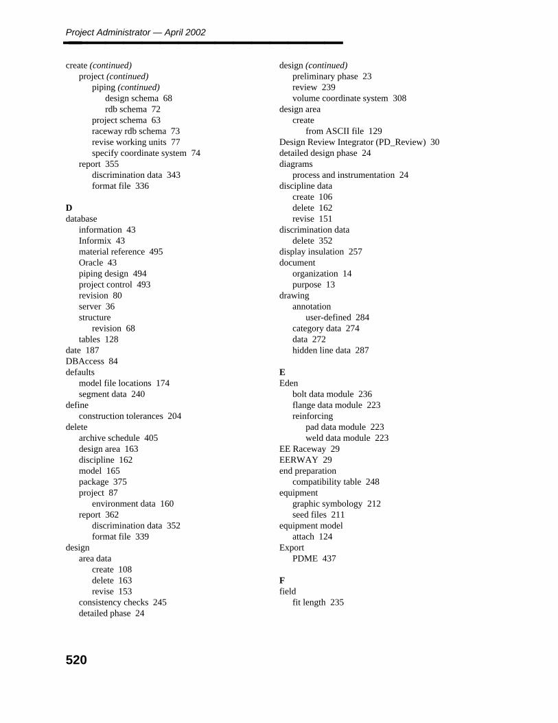
Project Administrator — April 2002________________ create (continued)
project (continued)piping (continued)
design schema 68rdb schema 72
project schema 63raceway rdb schema 73revise working units 77specify coordinate system 74
report 355discrimination data 343format file 336
Ddatabase
information 43Informix 43material reference 495Oracle 43piping design 494project control 493revision 80server 36structure
revision 68tables 128
date 187DBAccess 84defaults
model file locations 174segment data 240
defineconstruction tolerances 204
deletearchive schedule 405design area 163discipline 162model 165package 375project 87
environment data 160report 362
discrimination data 352format file 339
designarea data
create 108delete 163revise 153
consistency checks 245detailed phase 24
design (continued)preliminary phase 23review 239volume coordinate system 308
design areacreate
from ASCII file 129Design Review Integrator (PD_Review) 30detailed design phase 24diagrams
process and instrumentation 24discipline data
create 106delete 162revise 151
discrimination datadelete 352
display insulation 257document
organization 14purpose 13
drawingannotation
user-defined 284category data 274data 272hidden line data 287
EEden
bolt data module 236flange data module 223reinforcing
pad data module 223weld data module 223
EE Raceway 29EERWAY 29end preparation
compatibility table 248equipment
graphic symbology 212seed files 211
equipment modelattach 124
ExportPDME 437
Ffield
fit length 235
520

Ind
ex
Index________________ file
lock manager 34, 435server 36specifications
reference data 242flanges
data 223flow
centerline alignment 245fluid code 226, 263format
date and time 187forms
conventions 49FrameWorks Plus 25FW+ 25
Ggadgets
conventions 49gasket 236gaskets 235geometric industry standard 226graphic
symbology 119, 254, 260construction status 266dumb graphics 212equipment 212fluid code 263for insulation display 257markers 251model category 260nozzles 212primitives/parametrics 212semi-intelligent 212
Hheader weld 235help 53hidden line
data 287
IIDM 24IF_Check 28import
project retrieval 418schedule project 423
inactive project retrieval 410initial
system setup 36
instrumentation diagrams (P&ID) 24insulation
graphic symbology 257insulation thickness 245interference
envelope emulation data 219responsibility 206
interference check datapropagate 208
introductionProject Administrator Overview 32Project Administrator (PD_Project) 19project organization 31
Llabel
description library 496text sizes 275
librarylabel description 496standard note 497
line terminator 289loading
products 37lock files 435
Mmanage
project directory file 433marker symbology 251mass annotation 279material
takeoffoptions 235
material reference database 495miscellaneous label data 295model
category 260create
from ASCII file 129data
revise 156, 221delete 165file creating 111report 168setup 174
modeldraftproject 64
monumentdesign volume 308plant 74, 183
521
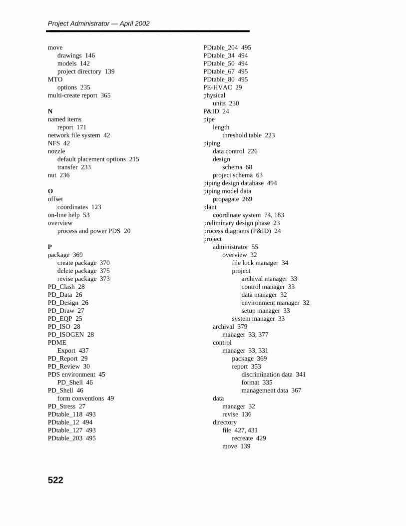
Project Administrator — April 2002________________ move
drawings 146models 142project directory 139
MTOoptions 235
multi-create report 365
Nnamed items
report 171network file system 42NFS 42nozzle
default placement options 215transfer 233
nut 236
Ooffset
coordinates 123on-line help 53overview
process and power PDS 20
Ppackage 369
create package 370delete package 375revise package 373
PD_Clash 28PD_Data 26PD_Design 26PD_Draw 27PD_EQP 25PD_ISO 28PD_ISOGEN 28PDME
Export 437PD_Report 29PD_Review 30PDS environment 45
PD_Shell 46PD_Shell 46
form conventions 49PD_Stress 27PDtable_118 493PDtable_12 494PDtable_127 493PDtable_203 495
PDtable_204 495PDtable_34 494PDtable_50 494PDtable_67 495PDtable_80 495PE-HVAC 29physical
units 230P&ID 24pipe
lengththreshold table 223
pipingdata control 226design
schema 68project schema 63
piping design database 494piping model data
propagate 269plant
coordinate system 74, 183preliminary design phase 23process diagrams (P&ID) 24project
administrator 55overview 32
file lock manager 34project
archival manager 33control manager 33data manager 32environment manager 32setup manager 33
system manager 33archival 379
manager 33, 377control
manager 33, 331package 369report 353
discrimination data 341format 335management data 367
datamanager 32revise 136
directoryfile 427, 431
recreate 429move 139
522
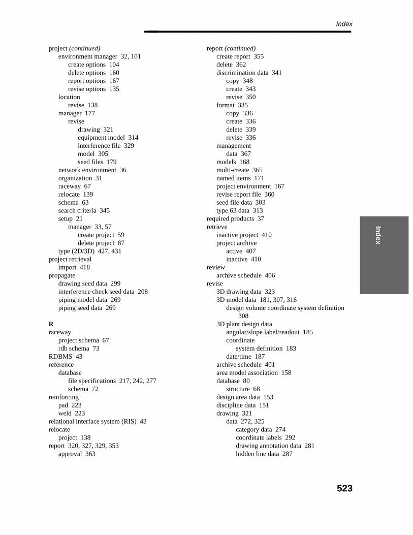
Ind
ex
Index________________ project (continued)
environment manager 32, 101create options 104delete options 160report options 167revise options 135
locationrevise 138
manager 177revise
drawing 321equipment model 314interference file 329model 305seed files 179
network environment 36organization 31raceway 67relocate 139schema 63search criteria 345setup 21
manager 33, 57create project 59delete project 87
type (2D/3D) 427, 431project retrieval
import 418propagate
drawing seed data 299interference check seed data 208piping model data 269piping seed data 269
Rraceway
project schema 67rdb schema 73
RDBMS 43reference
databasefile specifications 217, 242, 277schema 72
reinforcingpad 223weld 223
relational interface system (RIS) 43relocate
project 138report 320, 327, 329, 353
approval 363
report (continued)create report 355delete 362discrimination data 341
copy 348create 343revise 350
format 335copy 336create 336delete 339revise 336
managementdata 367
models 168multi-create 365named items 171project environment 167revise report file 360seed file data 303type 63 data 313
required products 37retrieve
inactive project 410project archive
active 407inactive 410
reviewarchive schedule 406
revise3D drawing data 3233D model data 181, 307, 316
design volume coordinate system definition308
3D plant design dataangular/slope label/readout 185coordinate
system definition 183date/time 187
archive schedule 401area model association 158database 80
structure 68design area data 153discipline data 151drawing 321
data 272, 325category data 274coordinate labels 292drawing annotation data 281hidden line data 287
523
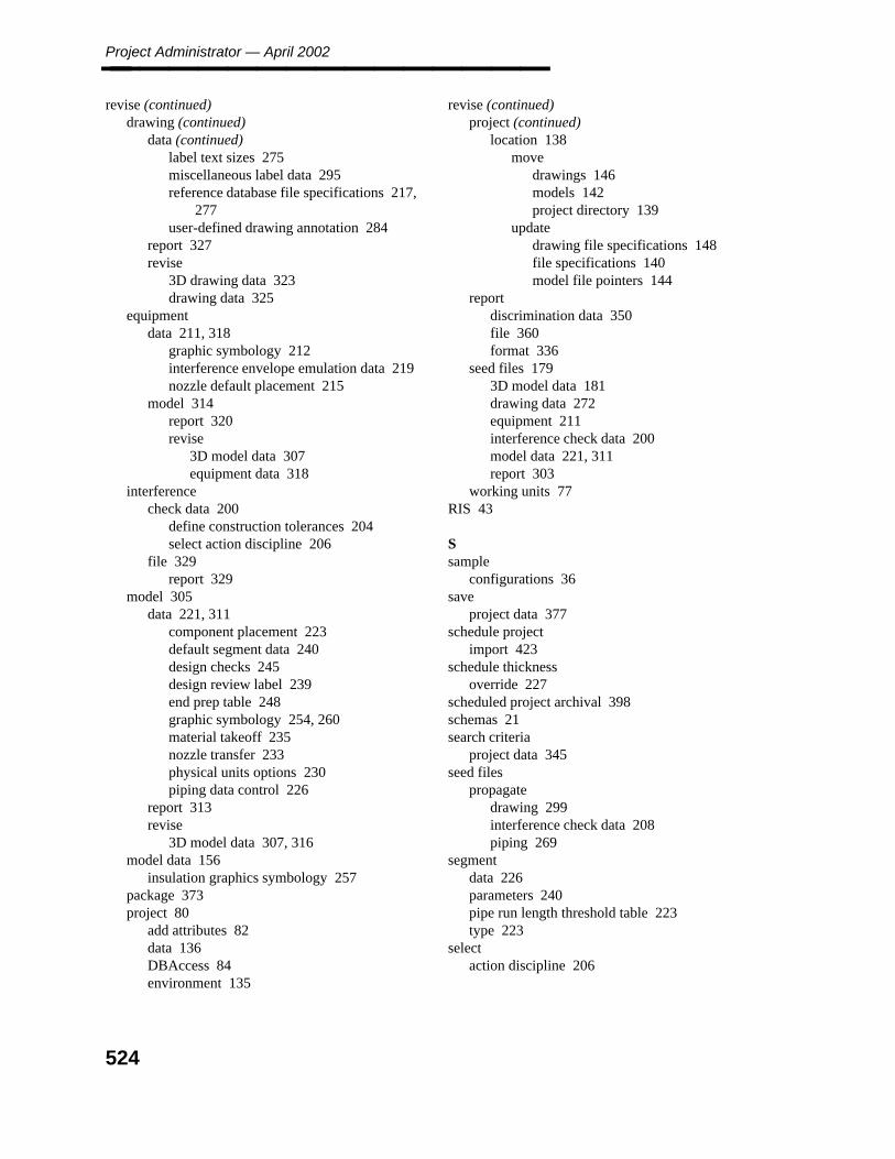
Project Administrator — April 2002________________ revise (continued)
drawing (continued)data (continued)
label text sizes 275miscellaneous label data 295reference database file specifications 217,
277user-defined drawing annotation 284
report 327revise
3D drawing data 323drawing data 325
equipmentdata 211, 318
graphic symbology 212interference envelope emulation data 219nozzle default placement 215
model 314report 320revise
3D model data 307equipment data 318
interferencecheck data 200
define construction tolerances 204select action discipline 206
file 329report 329
model 305data 221, 311
component placement 223default segment data 240design checks 245design review label 239end prep table 248graphic symbology 254, 260material takeoff 235nozzle transfer 233physical units options 230piping data control 226
report 313revise
3D model data 307, 316model data 156
insulation graphics symbology 257package 373project 80
add attributes 82data 136DBAccess 84environment 135
revise (continued)project (continued)
location 138move
drawings 146models 142project directory 139
updatedrawing file specifications 148file specifications 140model file pointers 144
reportdiscrimination data 350file 360format 336
seed files 1793D model data 181drawing data 272equipment 211interference check data 200model data 221, 311report 303
working units 77RIS 43
Ssample
configurations 36save
project data 377schedule project
import 423schedule thickness
override 227scheduled project archival 398schemas 21search criteria
project data 345seed files
propagatedrawing 299interference check data 208piping 269
segmentdata 226parameters 240pipe run length threshold table 223type 223
selectaction discipline 206
524

Ind
ex
Index________________ server 36
setup 44setup
2D project 213D project 21project 21
shared reference data 487, 505software
database products 42installation options 38PDS products 39requirements 37server 36
source projectselect 126
supplementary text 292system
configurations 36manager 33, 427
create 429edit 431manage 433
of units 194NPD 227
setup 35database information 43installing products 37
Systemunits for corrosion allowance 227
Ttables
bend deflection 223commodity item name 223PDtable_118 493PDtable_12 494PDtable_127 493PDtable_203 495PDtable_204 495PDtable_34 494PDtable_50 494PDtable_67 495PDtable_80 495pipe length threshold 223segment pipe run length threshold 223weld type 223
temperature and pressure data 227time 187tolerance values 223typefaces 15
Uunapproved RDB 242unlock files 435update
5.* to 6.0 4936.0/6.1 to 6.3 489drawing file specifications 148model file specifications 144project file specification 140
upgradeto 6.3 487
user-defined attributes 69
Wweight table 226weld
type table 223witness line 289working units 77worksharing 423
525

Project Administrator — April 2002________________
526

Project Administrator (PD_Project) Reference Guide Addendum February 2003 DPDS3-PB-200030B For PDS version 07.02.00.** This document supplements DPDS3-PB-200030A.
Project Administrator Reference Guide Addendum – February 2003
528
Table of Contents Project Setup Manager (replaces 4.0) ...................................................................... 530
Site Administrator........................................................................................................... 532 Create Site ............................................................................................................................. 533 Revise Site............................................................................................................................. 535 Delete Site ............................................................................................................................. 537
Specify Coordinate System (replaces 4.1.7)................................................................... 538 Create Model (replaces 5.1.3) .................................................................................. 540 Copy Model (replaces 5.1.4).................................................................................... 546 Create Model Data from ASCII File (replaces 5.1.6) .............................................. 552 Revise Options Form (replaces 5.2)......................................................................... 558
Revise Project Data (replaces 5.2.1)............................................................................... 560 Revise Site ID for Models .............................................................................................. 562
Revise Site ID for Models By Project ................................................................................... 563 Revise Site ID for Models By Area....................................................................................... 564 Revise Site ID for Models By Model .................................................................................... 565
Project Data Manager (replaces 6.0)........................................................................ 566 Project Data Manager Form............................................................................................ 566 Raceway.......................................................................................................................... 568
Revise 3D Plant Design Data ................................................................................................ 570 Report .................................................................................................................................... 573
Project Archival Options Form................................................................................ 575 Model Data (replaces 8.1.2)............................................................................................ 578 Drawing Data (replaces 8.1.3) ........................................................................................ 581 Site Data ......................................................................................................................... 583 Active Project Retrieval (replaces 8.3) ........................................................................... 584 Model/Drawing Data Retrieval for Workshare Projects................................................. 587 Import Project Retrieval (replaces 8.5)........................................................................... 588
Scheduled Project Import (replaces 8.5.1)............................................................................. 595 Model/Drawing Import for Workshare Projects ............................................................. 598
Model Data Import Flowchart ............................................................................................... 600 Drawing Data Import Flowchart............................................................................................ 601 Drawing View Check Flowchart ........................................................................................... 602 Composite Drawing View Check Flowchart ......................................................................... 603
File Lock Manager (replaces 10.0) .......................................................................... 604 Update Plant Monument .......................................................................................... 607 PDS Reference Data Auditing Tool Utility ............................................................. 609 Audit Tools Interface ............................................................................................... 610
File Menu........................................................................................................................ 612 New Configuration File ......................................................................................................... 612 Open Configuration File........................................................................................................ 612 Save Configuration................................................................................................................ 612 Save Configuration As .......................................................................................................... 612 Exit ........................................................................................................................................ 612
Audit Menu..................................................................................................................... 613 FTP Login ............................................................................................................................. 613 Browse FTP Folders.............................................................................................................. 614 Select Reference Data............................................................................................................ 615 File Transfer .......................................................................................................................... 616 Audit Mode 1 ........................................................................................................................ 618 Audit Mode 2 ........................................................................................................................ 620

529
Audit Mode 3 ........................................................................................................................ 622 View Menu ..................................................................................................................... 623
Audit Report .......................................................................................................................... 623 View/Analyze Audit Mode 3 Report..................................................................................... 624 Batch Log File ....................................................................................................................... 626
Help Menu ...................................................................................................................... 627 Contents................................................................................................................................. 627 About Audit Tools................................................................................................................. 627
Batch Job Dialog Box..................................................................................................... 628
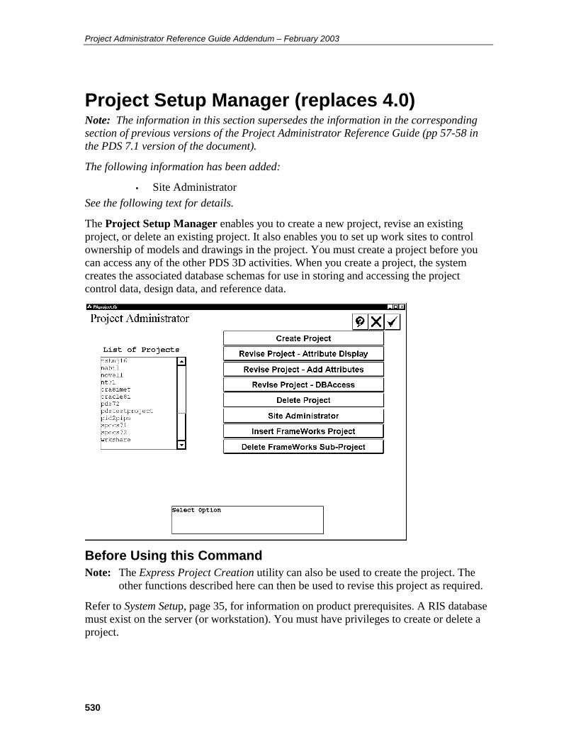
Project Administrator Reference Guide Addendum – February 2003
530
Project Setup Manager (replaces 4.0) Note: The information in this section supersedes the information in the corresponding section of previous versions of the Project Administrator Reference Guide (pp 57-58 in the PDS 7.1 version of the document).
The following information has been added:
• Site Administrator See the following text for details.
The Project Setup Manager enables you to create a new project, revise an existing project, or delete an existing project. It also enables you to set up work sites to control ownership of models and drawings in the project. You must create a project before you can access any of the other PDS 3D activities. When you create a project, the system creates the associated database schemas for use in storing and accessing the project control data, design data, and reference data.
Before Using this Command Note: The Express Project Creation utility can also be used to create the project. The
other functions described here can then be used to revise this project as required.
Refer to System Setup, page 35, for information on product prerequisites. A RIS database must exist on the server (or workstation). You must have privileges to create or delete a project.

531
Options Create Project — Defines a new project and create associated database files.
Revise Project — Attribute Display — Defines attributes within the design database to be displayed/not displayed for database operations.
Revise Project - Add Attributes — Adds user-defined attributes to an existing design database.
Revise Project - DBAccess — Revises the database structure to support DBAccess reporting of PDS data in the relational database.
Delete Project — Deletes an existing project and associated database and model files.
Site Administrator — Defines master and satellite sites.
Insert FrameWorks Data — Defines FrameWorks data that is required to access the structural application within the PD_Shell environment. This option is displayed when the structural project data has not been defined for the active project.
Insert Electrical Raceway Data — Defines the location of project and reference data that is required to access the Electrical Raceway module within the PD_Shell environment.
This option is displayed when the Raceway project data has not been defined for the active project.
Delete FrameWorks Plus Sub-Project — Deletes the FrameWorks Plus Sub-Project attached to the active project.
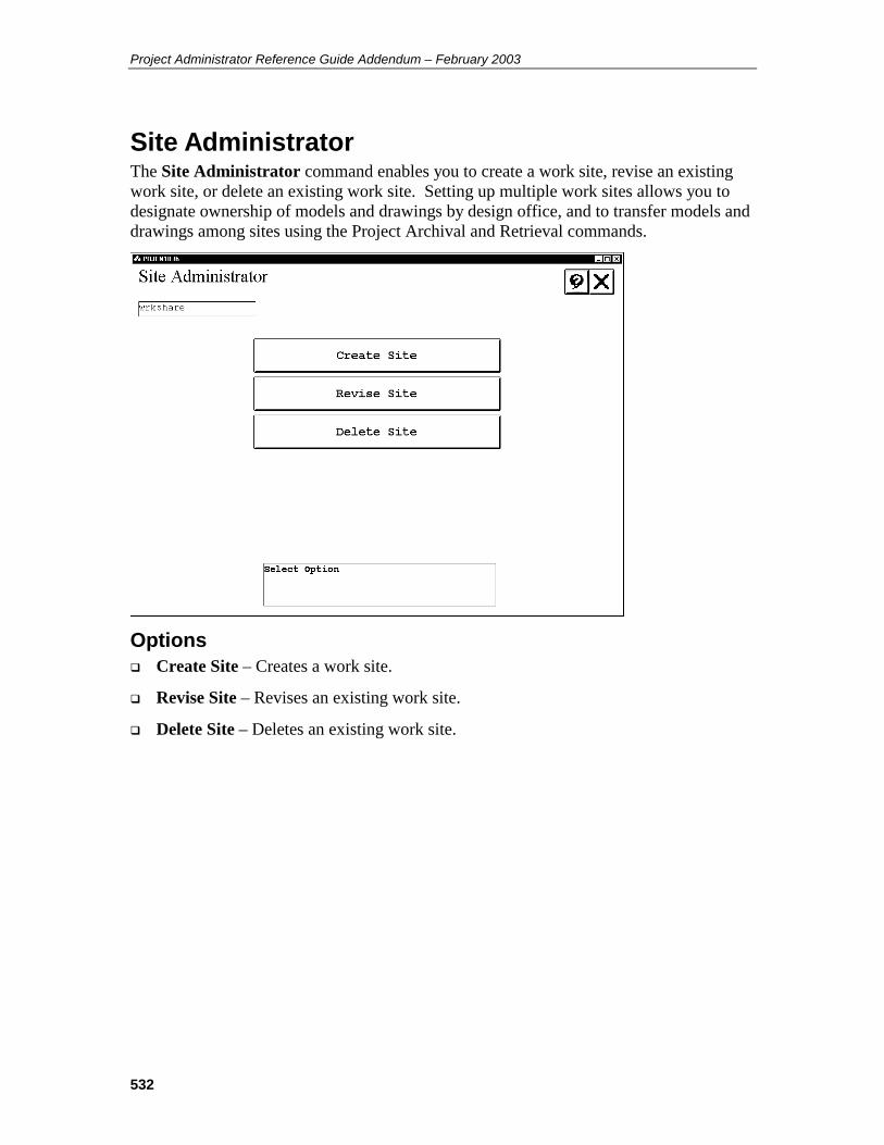
Project Administrator Reference Guide Addendum – February 2003
532
Site Administrator The Site Administrator command enables you to create a work site, revise an existing work site, or delete an existing work site. Setting up multiple work sites allows you to designate ownership of models and drawings by design office, and to transfer models and drawings among sites using the Project Archival and Retrieval commands.
Options Create Site – Creates a work site.
Revise Site – Revises an existing work site.
Delete Site – Deletes an existing work site.
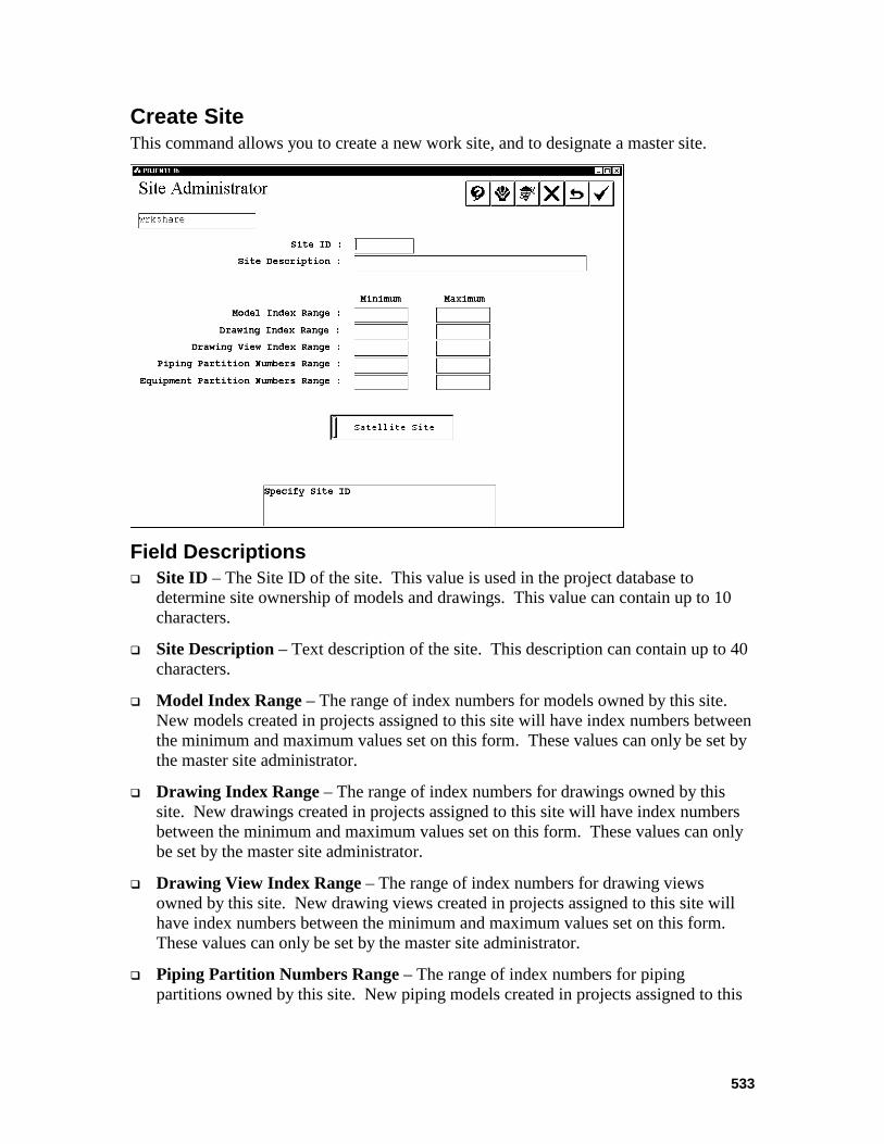
533
Create Site This command allows you to create a new work site, and to designate a master site.
Field Descriptions Site ID – The Site ID of the site. This value is used in the project database to
determine site ownership of models and drawings. This value can contain up to 10 characters.
Site Description – Text description of the site. This description can contain up to 40 characters.
Model Index Range – The range of index numbers for models owned by this site. New models created in projects assigned to this site will have index numbers between the minimum and maximum values set on this form. These values can only be set by the master site administrator.
Drawing Index Range – The range of index numbers for drawings owned by this site. New drawings created in projects assigned to this site will have index numbers between the minimum and maximum values set on this form. These values can only be set by the master site administrator.
Drawing View Index Range – The range of index numbers for drawing views owned by this site. New drawing views created in projects assigned to this site will have index numbers between the minimum and maximum values set on this form. These values can only be set by the master site administrator.
Piping Partition Numbers Range – The range of index numbers for piping partitions owned by this site. New piping models created in projects assigned to this

Project Administrator Reference Guide Addendum – February 2003
534
site will have partition numbers between the minimum and maximum values set on this form. These values can only be set by the master site administrator.
Equipment Partition Numbers Range – The range of index numbers for equipment partitions owned by this site. New equipment models created in projects assigned to this site will have partition numbers between the minimum and maximum values set on this form. These values can only be set by the master site administrator.
Master Site / Satellite Site toggle– This read-only toggle shows whether the site is the master site for the project or a satellite site. By default, the first site created is the master site.
Operating Sequence 1. Select Create Site on the Site Administrator form.
The Create Site form displays.
2. Set the values as necessary for the new site.
Note: The first site you create will be the master site. Subsequent sites will all be satellite sites.
3. Click Accept.
The system adds the new site data to the database.
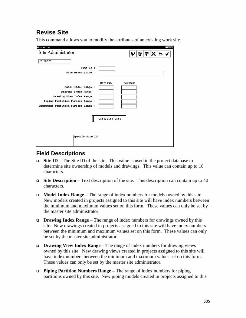
535
Revise Site This command allows you to modify the attributes of an existing work site.
Field Descriptions Site ID – The Site ID of the site. This value is used in the project database to
determine site ownership of models and drawings. This value can contain up to 10 characters.
Site Description – Text description of the site. This description can contain up to 40 characters.
Model Index Range – The range of index numbers for models owned by this site. New models created in projects assigned to this site will have index numbers between the minimum and maximum values set on this form. These values can only be set by the master site administrator.
Drawing Index Range – The range of index numbers for drawings owned by this site. New drawings created in projects assigned to this site will have index numbers between the minimum and maximum values set on this form. These values can only be set by the master site administrator.
Drawing View Index Range – The range of index numbers for drawing views owned by this site. New drawing views created in projects assigned to this site will have index numbers between the minimum and maximum values set on this form. These values can only be set by the master site administrator.
Piping Partition Numbers Range – The range of index numbers for piping partitions owned by this site. New piping models created in projects assigned to this
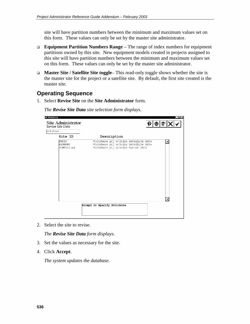
Project Administrator Reference Guide Addendum – February 2003
536
site will have partition numbers between the minimum and maximum values set on this form. These values can only be set by the master site administrator.
Equipment Partition Numbers Range – The range of index numbers for equipment partitions owned by this site. New equipment models created in projects assigned to this site will have partition numbers between the minimum and maximum values set on this form. These values can only be set by the master site administrator.
Master Site / Satellite Site toggle– This read-only toggle shows whether the site is the master site for the project or a satellite site. By default, the first site created is the master site.
Operating Sequence 1. Select Revise Site on the Site Administrator form.
The Revise Site Data site selection form displays.
2. Select the site to revise.
The Revise Site Data form displays.
3. Set the values as necessary for the site.
4. Click Accept.
The system updates the database.
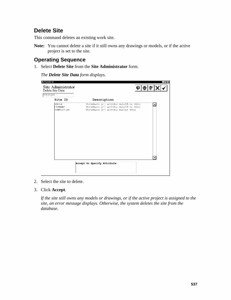
537
Delete Site This command deletes an existing work site.
Note: You cannot delete a site if it still owns any drawings or models, or if the active project is set to the site.
Operating Sequence 1. Select Delete Site from the Site Administrator form.
The Delete Site Data form displays.
2. Select the site to delete.
3. Click Accept.
If the site still owns any models or drawings, or if the active project is assigned to the site, an error message displays. Otherwise, the system deletes the site from the database.
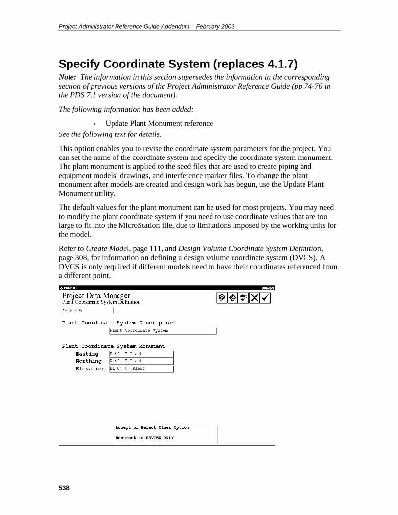
Project Administrator Reference Guide Addendum – February 2003
538
Specify Coordinate System (replaces 4.1.7) Note: The information in this section supersedes the information in the corresponding section of previous versions of the Project Administrator Reference Guide (pp 74-76 in the PDS 7.1 version of the document).
The following information has been added:
• Update Plant Monument reference See the following text for details.
This option enables you to revise the coordinate system parameters for the project. You can set the name of the coordinate system and specify the coordinate system monument. The plant monument is applied to the seed files that are used to create piping and equipment models, drawings, and interference marker files. To change the plant monument after models are created and design work has begun, use the Update Plant Monument utility.
The default values for the plant monument can be used for most projects. You may need to modify the plant coordinate system if you need to use coordinate values that are too large to fit into the MicroStation file, due to limitations imposed by the working units for the model.
Refer to Create Model, page 111, and Design Volume Coordinate System Definition, page 308, for information on defining a design volume coordinate system (DVCS). A DVCS is only required if different models need to have their coordinates referenced from a different point.

539
Operating Sequence 1. Plant Coordinate System Description
Key in up to 40 characters to describe the Plant Coordinate System to be used for the project.
2. Plant Coordinate System Monument
Key in the easting, northing, and elevation coordinates to be assigned to the center of the design volume for the plant. This point corresponds to the MicroStation position 0,0,0.
3. Choose the Confirm button to accept the specified coordinate system data and to return to the Create Project form.
—OR —
Choose the Cancel button to exit the form without changing the coordinate system definition.
Example
Example Plant Coordinate System Monument
Coordinates in the Plant Coordinate System (PCS) are in relation to the plant monument. For example, if the plant monument was modified from its default setting of 0,0,0 to be E. 300’, N. 250’ and EL. 10’, then a point 200 feet east and 150 feet north away from the plant monument would be at E. 500’, N. 400’ and EL. 10’ in the Plant Coordinate System.

Project Administrator Reference Guide Addendum – February 2003
540
Create Model (replaces 5.1.3) Note: The information in this section supersedes the information in the corresponding section of previous versions of the Project Administrator Reference Guide (pp 111-116 in the PDS 7.1 version of the document).
The following information has been added or modified:
• Site ID field • Site information in Before Using This Command section • Removed structural model number limitation
See the following text for details.
The Create Model option is used to create a new model in a discipline. For Piping, Equipment, Structural and Raceway disciplines, the create model operation will create a design file that can be opened through the PDS environment. For Architectural, HVAC and user-defined disciplines, only an entry in the project control database is created (the design file would be created through an alternate method).
A default location for new models can be defined for new models (See Model Setup Options). This location can be changed at the time the model is created.
To simplify the management of your project, it is recommended that files associated with a single project, be located on as few nodes as possible.
By default, the piping, equipment, and raceway PDS modules use project seed files to create new models. However, structural PDS uses the seedf.dgn file (English units) or the seedm.dgn file (Metric units). These seed files are delivered in the fwplus/seed directory. You can also specify seed files in a different directory using the FW_SEED.DIR variable in the Frameworks Plus config.dat file. (The default value for this variable is FW_SEEDDIR=$(PROD)SEED/.)
For non-PDS disciplines, the seed file location is specified by an entry in pdtable_113.
Before Using This Command Use the Project Data Manager to revise the information in the seed file before
creating a model. Certain seed file changes must be made before any models are created. See Seed Options Form, page 179 for additional information on this topic.
Use the Model Setup option to define the default location for models of a discipline. The default location for structural and raceway models is determined when the Structural and Raceway projects are created.
If you are planning to establish a workshare project with different sites, create the site data using the Site Administrator commands before creating any models in the project. This workflow will ensure that model index and partition index numbers are not duplicated between workshare sites.
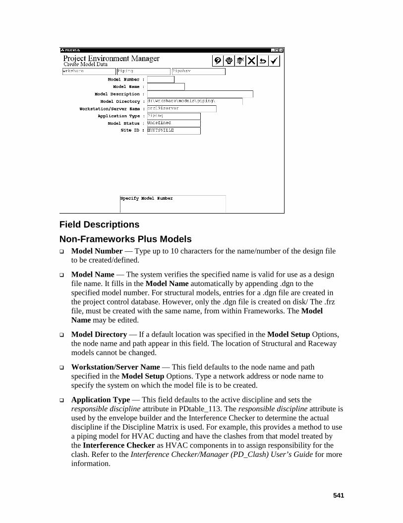
541
Field Descriptions Non-Frameworks Plus Models Model Number — Type up to 10 characters for the name/number of the design file
to be created/defined.
Model Name — The system verifies the specified name is valid for use as a design file name. It fills in the Model Name automatically by appending .dgn to the specified model number. For structural models, entries for a .dgn file are created in the project control database. However, only the .dgn file is created on disk/ The .frz file, must be created with the same name, from within Frameworks. The Model Name may be edited.
Model Directory — If a default location was specified in the Model Setup Options, the node name and path appear in this field. The location of Structural and Raceway models cannot be changed.
Workstation/Server Name — This field defaults to the node name and path specified in the Model Setup Options. Type a network address or node name to specify the system on which the model file is to be created.
Application Type — This field defaults to the active discipline and sets the responsible discipline attribute in PDtable_113. The responsible discipline attribute is used by the envelope builder and the Interference Checker to determine the actual discipline if the Discipline Matrix is used. For example, this provides a method to use a piping model for HVAC ducting and have the clashes from that model treated by the Interference Checker as HVAC components in to assign responsibility for the clash. Refer to the Interference Checker/Manager (PD_Clash) User’s Guide for more information.
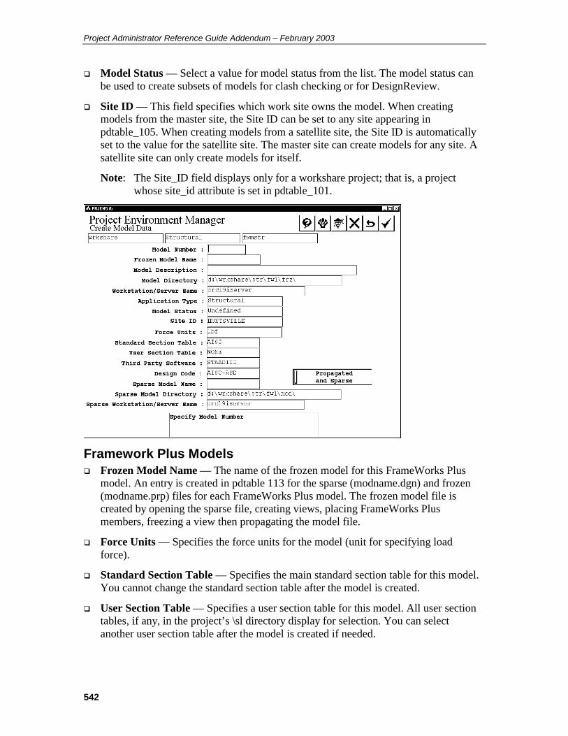
Project Administrator Reference Guide Addendum – February 2003
542
Model Status — Select a value for model status from the list. The model status can be used to create subsets of models for clash checking or for DesignReview.
Site ID — This field specifies which work site owns the model. When creating models from the master site, the Site ID can be set to any site appearing in pdtable_105. When creating models from a satellite site, the Site ID is automatically set to the value for the satellite site. The master site can create models for any site. A satellite site can only create models for itself.
Note: The Site_ID field displays only for a workshare project; that is, a project whose site_id attribute is set in pdtable_101.
Framework Plus Models Frozen Model Name — The name of the frozen model for this FrameWorks Plus
model. An entry is created in pdtable 113 for the sparse (modname.dgn) and frozen (modname.prp) files for each FrameWorks Plus model. The frozen model file is created by opening the sparse file, creating views, placing FrameWorks Plus members, freezing a view then propagating the model file.
Force Units — Specifies the force units for the model (unit for specifying load force).
Standard Section Table — Specifies the main standard section table for this model. You cannot change the standard section table after the model is created.
User Section Table — Specifies a user section table for this model. All user section tables, if any, in the project’s \sl directory display for selection. You can select another user section table after the model is created if needed.

543
Third Party Software — Specifies which third party analysis/design software to use for the model. If necessary, you can change the selection after the model is created.
Design Code — Specifies the design code to use for the model. If necessary, the selection can be changed after the model is created.
Sparse Model Name — Displays the system assigned Sparse Model Name. This name is based on the model name.
Propagated and Sparse toggle — Determines whether the frozen files have centerlines displayed as part of the members.
Sparse Model Directory — Displays the system assigned Sparse Model Directory. This value is based on the Model Directory.
Sparse Workstation/Server Name — Displays the system assigned sparse workstation/server name. This value is based on the model Workstation/Server Name.
Operating Sequence 1. Select Option.
Select the Create Model Data option from the Create Options form.
2. Select Discipline.
Select the discipline for the model file to be created from the list of displayed disciplines and choose Confirm.
The Select Area for Create Model Data form is displayed showing available design areas.
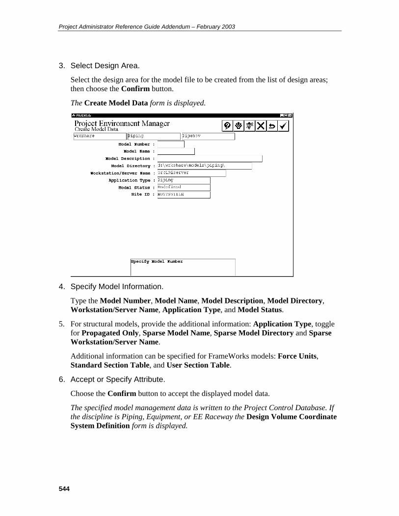
Project Administrator Reference Guide Addendum – February 2003
544
3. Select Design Area.
Select the design area for the model file to be created from the list of design areas; then choose the Confirm button.
The Create Model Data form is displayed.
4. Specify Model Information.
Type the Model Number, Model Name, Model Description, Model Directory, Workstation/Server Name, Application Type, and Model Status.
5. For structural models, provide the additional information: Application Type, toggle for Propagated Only, Sparse Model Name, Sparse Model Directory and Sparse Workstation/Server Name.
Additional information can be specified for FrameWorks models: Force Units, Standard Section Table, and User Section Table.
6. Accept or Specify Attribute.
Choose the Confirm button to accept the displayed model data.
The specified model management data is written to the Project Control Database. If the discipline is Piping, Equipment, or EE Raceway the Design Volume Coordinate System Definition form is displayed.
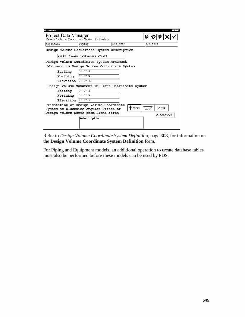
545
Refer to Design Volume Coordinate System Definition, page 308, for information on the Design Volume Coordinate System Definition form.
For Piping and Equipment models, an additional operation to create database tables must also be performed before these models can be used by PDS.
Project Administrator Reference Guide Addendum – February 2003
546
Copy Model (replaces 5.1.4) Note: The information in this section supersedes the information in the corresponding section of previous versions of the Project Administrator Reference Guide (pp 117-123 in the PDS 7.1 version of the document).
The following information has been added:
• Site ID bullet See the following text for details.
The Copy Model option creates a copy of an existing model file within the current project or to another project. All contents of the specified file are copied to the new file. This option can be used with Piping, Equipment, Structural, or Raceway models.
The Copy Model command makes the following database-related changes based on the setting for Copy in the Piping Data Control option of the Project Data Manager. The copy setting is determined by the setting in the destination model. Refer to Piping Data Control, page 226, for more information.
If the copy option is set to Append Prefix, the system adds two asterisks (**) as a prefix to name attributes to signify the piping segment or component has been copied and the name attribute may require updating. The following attributes are considered name attributes for this operation:
line number label piping component number pipe tag number instruct component number pipe support number line id
If the copy option is set to No Prefix, the ** prefix is removed when copying a piping segment or a component with a name attribute that includes the ** prefix from a previous copy operation.
Regardless of how this option is set, name attributes that are undefined (blank) will not have the prefix added.
The following database-related changes are also made:
For piping components, pipes, and instrument components, the weld numbers at each welded end are set to undefined (blank). The alphanumeric description ID of a piping segment is automatically deleted by a copy operation.
For piping segments, the approval status is set to not approved.
When copying a model from the same project or a different project, the copied model inherits the Site ID of the active project. This change applies only to workshare projects; that is, projects whose site_id attribute is set in pdtable_101.

547
Inter-Project Copies With Different System of Units When copying a piping model from another project, the system automatically converts certain attributes, such as face-to-face dimension or surface area, when the system of units for those attributes changes from the source project to the destination project. The following data is subject to units conversion in copying piping from one project to another:
Piping Segment Data
insulation thickness insulation density heat tracing temperature
Piping Component Data
maximum temperature face-to-face dimension dimension a dimension b dimension c surface area empty weight water weight operator weight (or branch reinforcement width or orifice size) heat tracing temperature piping outside diameter (five connect points) face-to-center dimension (five connect points) gasket gap (five connect points)
Piping/Tubing Data
maximum temperature piping outside diameter pipe length surface area empty weight water weight cold spring length heat tracing temperature gasket gap (both ends)
Instrument Component Data
face-to-face dimension dimension a dimension b dimension c surface area empty weight
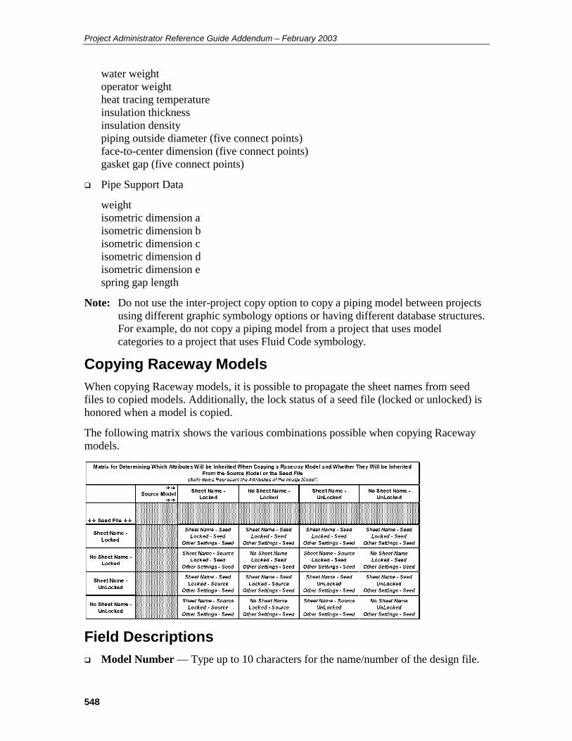
Project Administrator Reference Guide Addendum – February 2003
548
water weight operator weight heat tracing temperature insulation thickness insulation density piping outside diameter (five connect points) face-to-center dimension (five connect points) gasket gap (five connect points)
Pipe Support Data
weight isometric dimension a isometric dimension b isometric dimension c isometric dimension d isometric dimension e spring gap length
Note: Do not use the inter-project copy option to copy a piping model between projects using different graphic symbology options or having different database structures. For example, do not copy a piping model from a project that uses model categories to a project that uses Fluid Code symbology.
Copying Raceway Models When copying Raceway models, it is possible to propagate the sheet names from seed files to copied models. Additionally, the lock status of a seed file (locked or unlocked) is honored when a model is copied.
The following matrix shows the various combinations possible when copying Raceway models.
Field Descriptions Model Number — Type up to 10 characters for the name/number of the design file.
549
Model Name — The system fills in the Model Name field automatically by appending a .dgn extension to the specified model number. The Model Name may be edited.
Model Description — Type up to 36 characters for the directory path where the model file is to be created.
Application Type — This field should only be change if you need to override the default discipline for interference purposes. For example, this provides a way to use a piping model for HVAC ducting and have the clashes from that model treated by the Interference Checker as HVAC components in terms of assigning responsibility for the clash.
Define Offset — Select this option to specify the Easting, Northing, and Elevation coordinates for an offset to be applied to the copied model.
Attach Equipment Model — Select this option from the Copy Model Data form to specify an equipment model to be attached to the model to be copied.
Verify Piping Materials Class — This toggle verifies the piping materials class of each piping segment to be copied from the source project to the destination project previously defined in the Material Reference Database of the destination project. Only those segments with valid piping materials classes are copied. If the toggle is set to No Verification of Piping Materials Class the file contents are copied without checking piping materials classes.
Copy P&ID Node Numbers — When copying models within the same project, set the P&ID Node Number toggle to enable or disable the copying of P&ID node numbers from one piping model to another piping model. The default is Copy P&ID Node Numbers. When copying models between projects, the Copy Piping Model command automatically disables copying of the P&ID node numbers from one piping model to another piping model.
Submit Immediately or Submission is Delayed — Select Submit Immediately to begin copying the model as soon as you exit the form.
—OR —
Select Delayed Submission to specify a time to process the copy.
Operating Sequence 1. Select Copy Model Option.
Select the Copy Model option from the Create Options form.
The Select Source Model’s Project form is displayed. For more information about the Select Source Model’s Project form, see page 126.
2. Select Design Area.
Project Administrator Reference Guide Addendum – February 2003
550
Select a design area for the model file to be copied from the list of design areas; then choose the Confirm button.
A list of models for the selected design area is displayed on the Select Model to be Copied form.
3. Select Model.
Select the existing model design file to be copied; then choose the Confirm button.
The Select Area for Copied Model form is displayed.
4. Select Design Area.
Select the design area for the model file to be created from the list of design areas; then choose the Confirm button.
The Copy Model Data form is displayed.
5. Specify Model Information.
Type the Model Number, Model Description, and Application Type information for the design file to be created.
6. Define a Design Volume Offset.
Select Define Offset to define a design volume offset for the model to be copied.
The Copy Model Data - Offset form is displayed. For more information about the Copy Model Data - Offset form, see page 123.
7. Attach Equipment Model
Select Attach Equipment Model to specify an equipment model to be attached to the model to be copied.
The Attach Equipment Model form is displayed. For more information about the Attach Equipment Model form, see page 124.
8. Set Verify Piping Materials Class toggle.
Set the toggle to Verify Piping Materials Class or No Verification of Piping Materials Class.
9. Set the P&ID Node Number toggle Copy P&ID Node Numbers or Do Not Copy P&ID Node Numbers.
The default is Copy P&ID Node Numbers.
10. Select Submit Immediately to begin copying the model as soon as you exit the form.
—OR —
Select Submission is Delayed to specify a time to process the copy.
11. Accept Model data.

551
Choose the Confirm button to accept the specified data.
The Design Volume Coordinate System Definition form is displayed. Refer to Design Volume Coordinate System Definition, page 308, for information about this option.
12. Submit Copy Request.
Choose the Confirm button on the Design Volume Coordinate System Definition form.
The copy request is submitted to the batch queue PDcopy_model and the Select Model to be Copied form is displayed.
Project Administrator Reference Guide Addendum – February 2003
552
Create Model Data from ASCII File (replaces 5.1.6) Note: The information in this section supersedes the information in the corresponding section of previous versions of the Project Administrator Reference Guide (pp 129-134 in the PDS 7.1 version of the document).
The following information has been added:
• Site ID setting See the following text for details.
The Create Model Data from ASCII File creates areas, models and drawings from an ASCII input file. For piping, equipment, structural, and raceway models, design files are created. For other disciplines, only the model definitions are created. For Piping and Equipment models, you can also specify a Design Volume Coordinate System for each model.
Note: This command can be used to create model definitions for existing ModelDraft or Frameworks Plus models without writing over the existing design files.
Format Information in the ASCII files is the same as that entered into the forms seen in the PDS Environment.
The format used to define the model management data is a set of entries of the form:
Keyword:data.
There must be a colon (:) separating the keyword and the data.
For any entry in this list, there is a maximum of 132 characters per line of data.
The ASCII file(s) to be used to create a model, must be in order by the keywords listed below. The software will not function at all if the order is wrong.
For structural models, the Force Units, Standard Section Table and User Section Table values come from the FrameWorks Plus information in the project database. The default value for the Third Party Software option is STAADIII, and the default value for the Design Code is AISC-ASD. These defaults are the same values that appear in a model create using the Create Model Interactive command.
Keywords The following keywords are used to define the data; they are the same as the fields specified in the Create Design Area form and the Create Model Data form, including structural models:
553
Site_ID — An optional value for the site ID. If no value is specified, the site ID will be the same as the project site ID set in pdtable_101. If the project does not belong to a site, the site ID is set to NULL.
Discipline — The discipline name exactly as it appears in the PD_Shell environment (example: Discipline:Piping). This is required information.
Area_Name — A required 20-character design area name; it must be unique across disciplines (example: Area_Name:Piping_A).
Area_Desc — An optional 40-character description for the design area being created (example: Area_Desc:Piping Area A).
Note: This keyword is required when creating a new area. If the area already exists, use Area_Name only.
Area_Marker_File — An option to indicate that you want an interference marker file for the area (example: Area_Marker_File:Yes).
Note: This option is only for use in combination with Area_Desc.
Area_Volume_Low/High — An option that indicates if the design area will have a predefined volume for interference checking purposes. This is required if Area_Marker_File is Yes; the low volume and high volume represent the limits of the volume processed by the interference checker (example: Area_Volume_Low:-100,-250,-50 Area_Volume_High:150,30,120).
Note: This option is only for use in combination with Area_Marker_File.
Sub_Proj_Number — Required information for new structural models. It is the structural subproject number of the FrameWorks Plus or ModelDraft subproject. (example: Sub_Proj_Number:fw_proj1)
Note: This option is required when creating a new area in combination with Area_Desc.
Model_Number — A required 10-character piping model number of the model to be created (example: Model_Number:Model_A).
Model_Desc — A required 40-character description of the model to be created (example: Model_Desc:Model A Description).
File_Spec — An optional 14-character file specification of the model to be created. If a value is not specified or the keyword is missing, the file specification defaults to the model number with the extension .dgn (example: Model_A.dgn).
Note: This option is not supported for structural models, because the file specification is defined in the subproject.
Path_Name — An optional 35-character directory path where the model file is to be created (example: d:\proj\models\). If this value is not specified or the

Project Administrator Reference Guide Addendum – February 2003
554
keyword is missing, the default values as defined with the Model Setup option are used.
Note: This option is not supported for structural models, because the file specification is defined in the subproject.
Network_Address — An optional 26-character node name of the system on which the model file is to be stored (example: Network_Address:jwdoe_3). This value is not specified or the keyword is missing, the default values as defined with the Model Setup option, are used.
Note: This option is not supported for structural models, because the file specification is defined in the subproject.
DVCS_Desc — An optional 40-character Design Volume Coordinate System description. This entry is only used by piping and equipment models (example: DVCS_Desc:Design Vol Coordinate System of Model A).
Monument_in_DVCS — Optional easting, northing, and elevation values (separated by commas) of the center of the Design Volume Coordinate System (example: Monument_In_Dvcs:100,100,100). This data is only used by piping and equipment models. If the data is not specified, the Design Volume Coordinate System’s monument defaults to the center of the model.
DVCS_Monument_in_Plant — Optional easting, northing, and elevation values (separated by commas) of the Design Volume Coordinate System monument in terms of the Plant Coordinate System (example: DVCS_Monument_in_Plant:200,200,100). This data is only used by piping and equipment models. If the data is not specified, the Design Volume Coordinate System’s monument defaults to the center of the model.
Orientation_of_DVCS — An optional value indicating the orientation of the x-axis in a Plan View as defined by one of the following values:
East (the default value if not specified otherwise)
North An angle measured clockwise from the MicroStation X-axis (example: Orientation_of_DVCS:45).
This data is only used by piping and equipment models. If the data is not specified, the East axis of the Design Volume Coordinate System is aligned with the x-axis of the MicroStation design file coordinate system.
Application_Type — An optional value indicating the discipline association for interference checking purposes. It associates the design model with a different discipline for reporting clashes. The default is the discipline where the design model is created (example: Application_type:Piping).
Model_type — For structural models only, the type of structural model to be created.
Its value is set as follows:
555
sparse — Creates project control database information for a sparse model in the \MOD directory and creates the required files in this directory.
propagated — Specifies model_type=0 in pdtable_113. Running batch propagation on a file with this status results in a propagated-only model. This value creates an entry in the project control database for a propagated design file in the \FRZ directory.
both — Specifies model_type=2 in pdtable_113. This value specifies that while running batch propagation, the .prp file will contain the sparse model (a single line model) and a 3D model (the propagated model). This value creates a project control database entry for a propagated model in the \FRZ directory.
The only Model_Type value that actually creates physical files is sparse. This value, if the model does not already exist, executes the FrameWorks Plus cremodutility, which creates all 14 files in the FW+ project\MOD directory as well as a corresponding entry in pdtable_113. The propagated and both values do NOT create physical files; they only create entries in pdtable_113.
Model_Status — An optional value for the model status from code list set 1605. This value is used to exclude models from being processed in PD_Clash.
The following is an example of a simple file used to create two piping models and one structural model that belong to the HUNTSVILLE site: Site_ID:HUNTSVILLEDiscipline:PipingArea_Name:Piping_AArea_Desc:Piping Area AModel_Number:A2pipe1Model_Desc:Piping Model 1 from ASCIIFile_Spec:A2pipe1.dgnPath_Name:C:\users\acme\proj1\Network_Address:pds_servDVCS_Desc:Model DVCSMonument_in_DVCS:-1000,0,0DVCS_Monument_in_Plant:350,325,0Orientation_of_DVCS:NorthApplication_Type:PipingSite_ID:HUNTSVILLEDiscipline:StructuralArea_Name:SA1Area_Desc:FrameWorks Plus Area A SteelSub_Proj_Number:fwproj1Area_Marker_File:YesArea_Volume_Low:-100,-250,-50Area_Volume_High:150,30,120Model_Number:steel1Model_Desc:Structural Model 1 from ASCIIModel_Type:bothPath_Name:c:\users\acme\stproj1Network_Address:pds_servApplication_Type:Structural
The following listing is an example of an ASCII file used to create structural models and project control database information. Discipline:StructuralArea_Name:AS1

Project Administrator Reference Guide Addendum – February 2003
556
Area_Desc:Frameworks Plus Area SteelArea_Marker_File:YesArea_Volume_Low:-100,-250,-50Area_Volume_High:150,30,120Sub_Proj_Number:fwproj1Model_Number:steel1Model_Desc: linearModel_Type:sparseApplication_Type:StructuralModel_Number:steel1Model_Desc:linear prpModel_Type:bothApplication_Type:Structural
Before Using This Command Create an ASCII file to define the models to be created using the specified
conventions.
For structural models and areas, the FrameWorks Plus Project must have been created using the Project Administrator > Project Setup Manager > Insert FrameWorks Project command.
Operating Sequence 1. Select Create Model from ASCII File Option.
Select the Create Model from ASCII File option from the Create Options form.
The Create Model from ASCII File form is displayed.
2. Specify ASCII File Spec.
Type the information for the location of the ASCII file in the ASCII File Name, Directory and Network Address fields.

557
3. Submit Immediately or Submission is Delayed Select Submit Immediately to begin processing the request as soon as you exit the form.
—OR —
Select Submission is Delayed to specify a time to process the request.
4. Accept the specified time.
Choose the Confirm button to accept the specified time.
The request is submitted to the batch queue PDcreate_model.
Note: For Piping and Equipment models created using this method, the tables in the Piping Design Database must still be created. Use the Create Database Tables option of the Project Environment Manager for this.

Project Administrator Reference Guide Addendum – February 2003
558
Revise Options Form (replaces 5.2) Note: The information in this section supersedes the information in the corresponding section of previous versions of the Project Administrator Reference Guide (p. 135 in the PDS 7.1 version of the document).
The following information has been added:
• Revise Site ID for Models See the following text for details.
The Revise Options form is used to revise the information in the Project Control Database. You can revise the descriptive data for the project and disciplines, design areas, or model files. An entire project or a single model can also be relocated. Select the Revise option from the Project Environment form to display the Revise Options form.
Option Descriptions Revise Project Data — Displays the Revise Project Data form, which is used to
revise the project/client information for the active project. (See page 136.)
Revise Project Location — Displays the Revise Project Location options to move project data to another location or to update file pointers if the project data was moved outside of the PDS environment. (See page 138.)
Revise Discipline Data — Revises the name of the selected discipline. (See page 151.)
Revise Design Area Data — Revises the description of a design area or modifies the volume coordinates of the design area. (See page 153.)

559
Revise Model Data — Revises the name of a model file or modifies the description. (See page 156.)
Revise Area Model Association — Assigns a model file to a different design area (moves the model from one design area to another). (See page 158.)
Revise Site_ID for Models — Assigns a model file to a different work site.
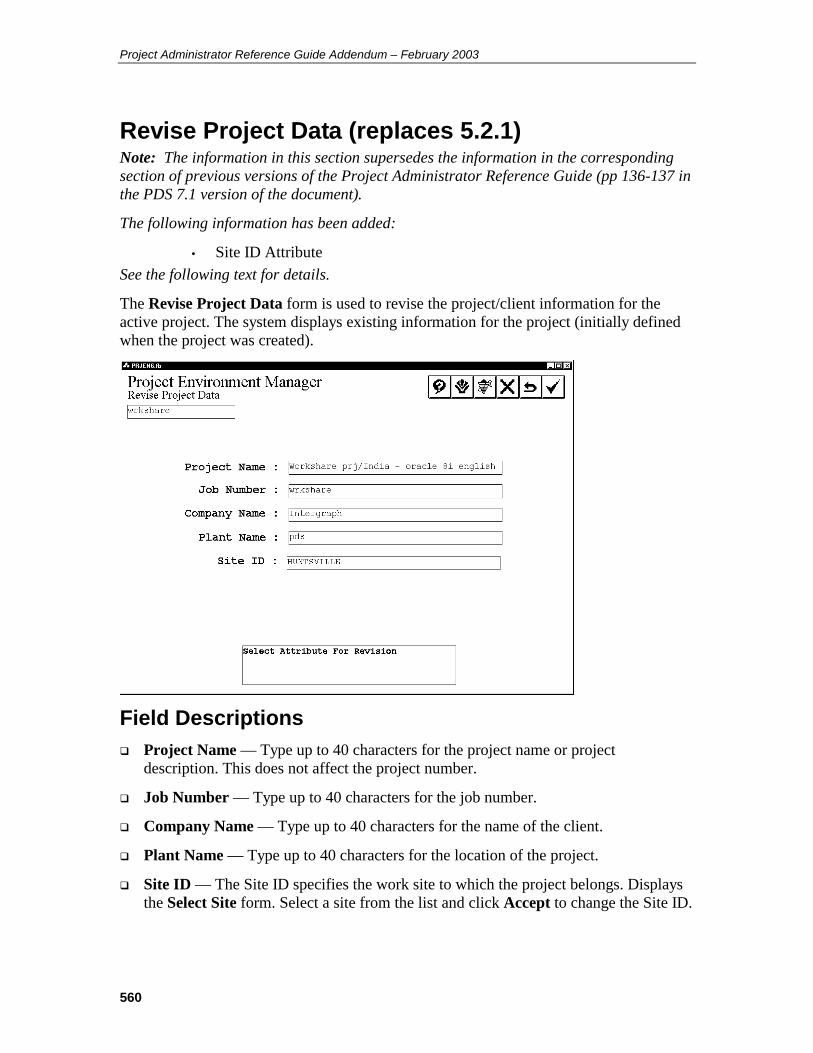
Project Administrator Reference Guide Addendum – February 2003
560
Revise Project Data (replaces 5.2.1) Note: The information in this section supersedes the information in the corresponding section of previous versions of the Project Administrator Reference Guide (pp 136-137 in the PDS 7.1 version of the document).
The following information has been added:
• Site ID Attribute See the following text for details.
The Revise Project Data form is used to revise the project/client information for the active project. The system displays existing information for the project (initially defined when the project was created).
Field Descriptions Project Name — Type up to 40 characters for the project name or project
description. This does not affect the project number.
Job Number — Type up to 40 characters for the job number.
Company Name — Type up to 40 characters for the name of the client.
Plant Name — Type up to 40 characters for the location of the project.
Site ID — The Site ID specifies the work site to which the project belongs. Displays the Select Site form. Select a site from the list and click Accept to change the Site ID.
561
Operating Sequence 1. Select the Revise Project Data Option.
Select the Revise Project Data option from the Revise Options form.
2. Select Attribute for Revision.
Select the Project Name, Job Number, Company Name or Plant Name field to be revised.
3. Type Revisions.
Type any changes to the project/client information.
4. If necessary, select the Site ID field to display the Select Site form and assign the project to a different work site. On the Select Site form, select a site and choose Accept.
The Revise Project Data form displays.
5. Accept Specification.
Choose the Confirm button to accept the specification.
The project data is updated in the Project Control Database.

Project Administrator Reference Guide Addendum – February 2003
562
Revise Site ID for Models This option allows you to reassign models to different work sites by changing the site ID by project, area, or model.
Note: This option is only available at the master site.
Options By Project – Displays models by project for Site ID revision.
By Area – Displays models by design area for Site ID revision.
By Model – Displays individual models for Site ID revision.

563
Revise Site ID for Models By Project This option allows you to update the Site ID for models in the active project.
Note: This option is only available at the master site.
Field Descriptions Model Number – Lists all the models in the active project.
Source Site_ID – Displays the current site to which the model belongs.
Destination Site_ID – Specifies the new site to which the model will belong.
Change All to Same Site_ID – Allows you to change all models in the active project to belong to the same site.
Operating Sequence Specific Models 1. Select By Projects from the Revise Site_ID for Models form.
The Revise Site_ID for Models form displays.
2. Select the Destination Site_ID to change.
The Select Site form displays.
3. Select a site.
4. Click Accept.
The Revise Site_ID for Models form displays with the new Site ID.
All Models in Project 1. Select By Projects from the Revise Site_ID for Models form.
The Revise Site_ID for Models form displays.
2. Click Change All to Same Site_ID.
The Site_ID for All Models field displays.
3. Select the Site_ID for All Models field.
The Select Site form displays.
4. Select a site.
5. Click Accept.
The Revise Site_ID for Models forms displays with all models assigned to the new Site ID.
Project Administrator Reference Guide Addendum – February 2003
564
Revise Site ID for Models By Area This option allows you to change the Site ID for models in a particular design area.
Note: This option is only available at the master site.
Operating Sequence Specific Models 1. Select By Area from the Revise Site_ID for Models form.
2. Select a discipline.
3. Click Accept.
4. Select an area.
5. Click Accept.
6. Select the Destination Site_ID to change.
The Select Site form displays.
7. Select a site.
8. Click Accept.
The Revise Site_ID for Models form displays with the new Site ID.
All Models in Area 1. Select By Area from the Revise Site_ID for Models form.
2. Select a discipline.
3. Click Accept.
4. Select an area.
5. Click Accept.
6. Click Change All to Same Site_ID.
The Site_ID for All Models field displays.
7. Select the Site_ID for All Models field.
The Select Site form displays.
8. Select a site.
9. Click Accept.
The Revise Site_ID for Models forms displays with all models assigned to the new Site ID.

565
Revise Site ID for Models By Model This option allows you to change the site ID for individual models.
Note: This option is only available at the master site.
Operating Sequence 1. Select By Model from the Revise Site_ID for Models form.
2. Select a discipline.
3. Click Accept.
4. Select an area.
5. Click Accept.
6. Select a model.
7. Click Accept.
8. Select the Destination Site_ID to change.
The Select Site form displays.
9. Select a site.
10. Click Accept.
The Revise Site_ID for Models form displays with the new Site ID.

Project Administrator Reference Guide Addendum – February 2003
566
Project Data Manager (replaces 6.0) Note: The information in this section supersedes the information in the corresponding section of previous versions of the Project Administrator Reference Guide (pp 177-178 in the PDS 7.1 version of the document).
The following information has been added:
• Raceway Model command See the following text for details.
The Project Data Manager is used to examine and/or revise the settings used when creating new models or to otherwise tailor the behavior of PDS to meet the needs of the project. This data is used when creating a design area interference marker file, a model design volume, a drawing file, or an interference envelope file. The following conventions describe the forms in the Project Data Manager.
The operation of each form is described in a linear fashion for clarity. However, the options on the form can be selected in any order.
The Shell and Top options can be used to jump back along the command stack rather than exiting the forms one at a time. See PD_Shell Form Conventions, page 49 under PD Shell.
Project Data Manager Form The Project Data Manager form is used to:
Revise the 3D Plant Design data and RDB seed data used to create model, drawing, and interference marker files.
Revise the 3D Plant Design data and RDB data for existing Piping and Equipment model design volumes.
Revise the 3D Plant Design data for existing Raceway model design volumes.
Revise the 3D Plant Design data and RDB data for existing drawings.
Revise the RDB data for interference marker files.
Option Descriptions Seed — Displays the Seed Options form, to review or revise the project data stored
in the seed files and the project marker file.
Piping Model — Displays the Model Options form, to review or revise the project data stored in Piping model files.
Equipment Model — Displays the Equipment Options form, to review or revise the project data stored in Equipment model files.
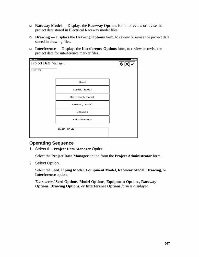
567
Raceway Model — Displays the Raceway Options form, to review or revise the project data stored in Electrical Raceway model files.
Drawing — Displays the Drawing Options form, to review or revise the project data stored in drawing files.
Interference — Displays the Interference Options form, to review or revise the project data for interference marker files.
Operating Sequence 1. Select the Project Data Manager Option.
Select the Project Data Manager option from the Project Administrator form.
2. Select Option.
Select the Seed, Piping Model, Equipment Model, Raceway Model, Drawing, or Interference option.
The selected Seed Options, Model Options, Equipment Options, Raceway Options, Drawing Options, or Interference Options form is displayed.

Project Administrator Reference Guide Addendum – February 2003
568
Raceway The Raceway option is used to revise the 3D design data for a specified Electrical Raceway model or to create a report of the RDB data.
Option Descriptions Revise 3D Plant Design Data — Displays the Design Volume Coordinate System form.
Report — Creates a printable copy of the data stored in the type 63 elements for the selected raceway model.
Operating Sequence 1. Select Option.
Select the Raceway Model option from the Project Data Manager form.
2. Select Design Area.
Select the design area for the raceway model to be modified; then choose the Confirm button.
The model files for the selected design area are displayed.
3. Select Model
Select the raceway model file to be revised; then choose the Confirm button.
The model revision options form is displayed.
4. Select Option.

569
Select the option to be performed.

Project Administrator Reference Guide Addendum – February 2003
570
Revise 3D Plant Design Data This option is used to modify the design volume coordinate system parameters for the specified model. The coordinate system name can be specified and the design volume monument (center point) of the coordinate system can be defined. The design volume coordinate system (DVCS) is a second coordinate system (in addition to the plant coordinate system) that can be defined for an individual model. A DVCS is only required if different models need to have their coordinates referenced from a different point.
Note: For more information, see the Design Volume Coordinate System section of the PDS 3D Theory User’s Guide.
Note: To use a DVCS while working in a model or drawing, the active coordinate system must be defined with the Active Options command. If the design volume monument is modified for a model, the design volume monument must also be revised for any drawings to use referencing those models.
Field Descriptions Design Volume Coordinate System Description — Description of up to 40
characters for the Design Volume Coordinate System to be used for the model.
Monument in Design Volume Coordinate System — The easting, northing, and elevation coordinates associated with the design volume monument relative to the Design Volume Coordinate System. The plant monument corresponds to MicroStation point 0,0,0 in the model.
Design Volume Monument in Plant Coordinate System — Defines the orientation of the plan view for display purposes. North defines North at the top of the screen in a plan view. North defines North at the right of the screen in a plan view.
Orientation toggle – Defines the orientation of the plan view for display purposes. North defines North at the top of the screen in a plan view. North defines North
at the right of the screen in a plan view.
Origination of Design Volume Coordinate System as Clockwise Angular Offset of Design Volume North from Plant North — The an angular offset to be applied to the design volume relative to the Plant Coordinate System.
Caution: If the DVCS is rotated, then all models should use this same angle. This is necessary for all the reference model attachments to orient consistently in the models and drawings.
If only certain models need to be rotated, the following alternative can be used. Create models with standard rotation and model the piping systems orthogonally. When finished, use the Rotate Piping command to orient the piping at the specific angle.
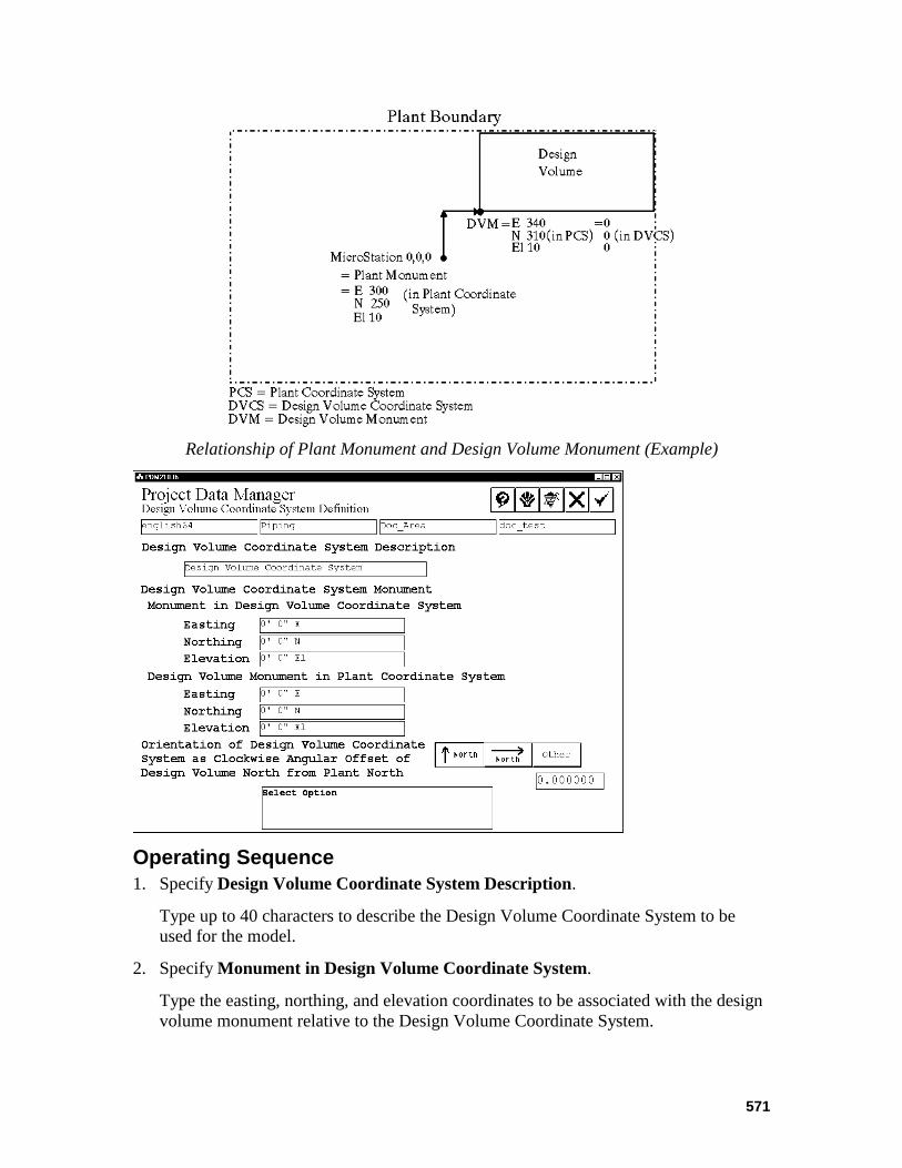
571
Relationship of Plant Monument and Design Volume Monument (Example)
Operating Sequence 1. Specify Design Volume Coordinate System Description.
Type up to 40 characters to describe the Design Volume Coordinate System to be used for the model.
2. Specify Monument in Design Volume Coordinate System.
Type the easting, northing, and elevation coordinates to be associated with the design volume monument relative to the Design Volume Coordinate System.

Project Administrator Reference Guide Addendum – February 2003
572
3. Specify Orientation.
Define the orientation of the plan view for display purposes.
4. Specify Design Volume Monument in Plant Coordinate System.
Type the easting, northing, and elevation coordinates to be associated with the design volume monument relative to the Design Volume Coordinate System.
5. Specify Orientation of Design Volume Coordinate System as Clockwise Angular Offset of Design Volume North from Plant North.
Type an angular offset to be applied to the design volume relative to the Plant Coordinate System.
6. Accept Design Volume Coordinate System Definition.
Choose the Confirm button to accept the Design Volume Coordinate System Definition.
The Revise 3D Model Data form is displayed.

573
Report The Report option is used to create a printable copy of the data stored in the type 63 elements for the selected raceway model.
Field Descriptions Print/Delete — Submits the generated report output file to the specified print queue
and deletes the output file.
Print/Save — Submits the generated report output file to the specified print queue and saves the output file.
Save — Saves the output file without printing.
Operating Sequence 1. Select Option.
Select the Report option from the Project Data Manager - Raceways form.
A set of reporting options is displayed at the bottom of the form.
2. Select the reporting option.
Choose the Print/Delete, Print/Save or Save option.
For any of the Print options, a list of queues is displayed based on information in the Project Queue Description Library. Refer to the PDS Project Setup Technical Reference, for more information on the Queue Description Library and setting up print queues.
3. Accept Report Options.

Project Administrator Reference Guide Addendum – February 2003
574
Choose the Confirm button create the report.
The created report file is written to the file rway.pdm (where rway is the active model number) in the directory where the model is located.
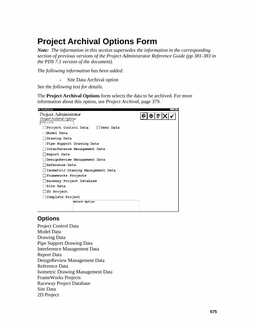
575
Project Archival Options Form Note: The information in this section supersedes the information in the corresponding section of previous versions of the Project Administrator Reference Guide (pp 381-383 in the PDS 7.1 version of the document).
The following information has been added:
• Site Data Archival option See the following text for details.
The Project Archival Options form selects the data to be archived. For more information about this option, see Project Archival, page 379.
Options Project Control Data Model Data Drawing Data Pipe Support Drawing Data Interference Management Data Report Data DesignReview Management Data Reference Data Isometric Drawing Management Data FrameWorks Projects Raceway Project Database Site Data 2D Project

Project Administrator Reference Guide Addendum – February 2003
576
Complete Project User Data
Operating Sequence 1. Select Option.
Select the option(s) for project data to be archived.
For Project Control Data, The Batch Processing toggle is displayed. Select Submit Immediately or Delayed Submission with date and time. For more information, see Project Control Data, page 383.
For Model Data, a form is displayed to specify the model(s) to be archived. For more information, see Model Data, page 384.
For Drawing Data, a form is displayed to specify the drawing(s) to be archived. For more information, see Drawing Data, page 386.
For Pipe Support Drawing Data, the Batch Processing toggle is displayed. Select Submit Immediately or Delayed Submission with date and time. For more information, see Pipe Support Drawing Data, page 387.
For Interference Management Data, the Batch Submission toggle is displayed. Select Submit Immediately or Delayed Submission with date and time. For more information, see Interference Management Data, page 388.
For Report Data, the Batch Processing toggle is displayed. Select Submit Immediately or Delayed Submission with date and time. For more information, see Report Data, page 389.
For DesignReview Management Data, the Batch Processing toggle is displayed. Select Submit Immediately or Delayed Submission with date and time. For more information, see DesignReview Management Data, page 390.
For Reference Data, a set of fields is displayed to select the reference data to archive. For more information, see Reference Data, page 390.
For Isometric Drawing Management Data, the Batch Submission toggle is displayed. Select Submit Immediately or Delayed Submission with date and time. For more information, see Isometric Drawing Management Data, page 393.
For FrameWorks Projects, the Batch Submission toggle is displayed. Select Submit Immediately or Delayed Submission with date and time. For more information, see FrameWorks Projects, page 394.
For Raceway Project Database, the Batch Submission toggle is displayed. Select Submit Immediately or Delayed Submission with date and time.
For Site Data, the Batch Submission toggle is displayed. Select Submit Immediately or Delayed Submission with date and time. This option is available only for workshare projects; that is, projects whose Site_ID attribute is set in pdtable_101.

577
For 2D Project, a form is displayed to identify the 2D data to archive. For more information, see 2D Projects, page 394.
The Complete Project option archives all of the project data. For more information, see Complete Project, page 395.
The User Data option archives data that has been created outside of PDS or data that has been created in support of PDS, but which is not recognized by PDS. For more information on this option, see User Data, page 396.
2. Specify Archive Time.
Set the time of day to process the archive request.
3. Accept Project Archival Data.
Choose the Confirm button to begin processing the request.
Information on the archival process is written to the ARCHIVE.LOG file, which is written into the project directory at the conclusion of the batch job.

Project Administrator Reference Guide Addendum – February 2003
578
Model Data (replaces 8.1.2) Note: The information in this section supersedes the information in the corresponding section of previous versions of the Project Administrator Reference Guide (pp 384-386 in the PDS 7.1 version of the document).
The following information has been added:
• Site ID Filter See the following text for details.
The Model Data form is used to specify the model(s) to be archived.
Option Descriptions Site ID Filter — Allows archival of models that belong to a specific work site. The
default value for this field is NONE. This filter can be used in conjunction with the other filters on this form. This option is available only for workshare projects; that is, projects whose site_id attribute is set in pdtable_101.
All Models — Archives all models for the active project.
Select By Discipline — Archives all models in a selected discipline or disciplines.
Select By Design Area — Archives all models in a selected design area or areas.
Select By Models — Archives models selected from a list of models in a specified design area.
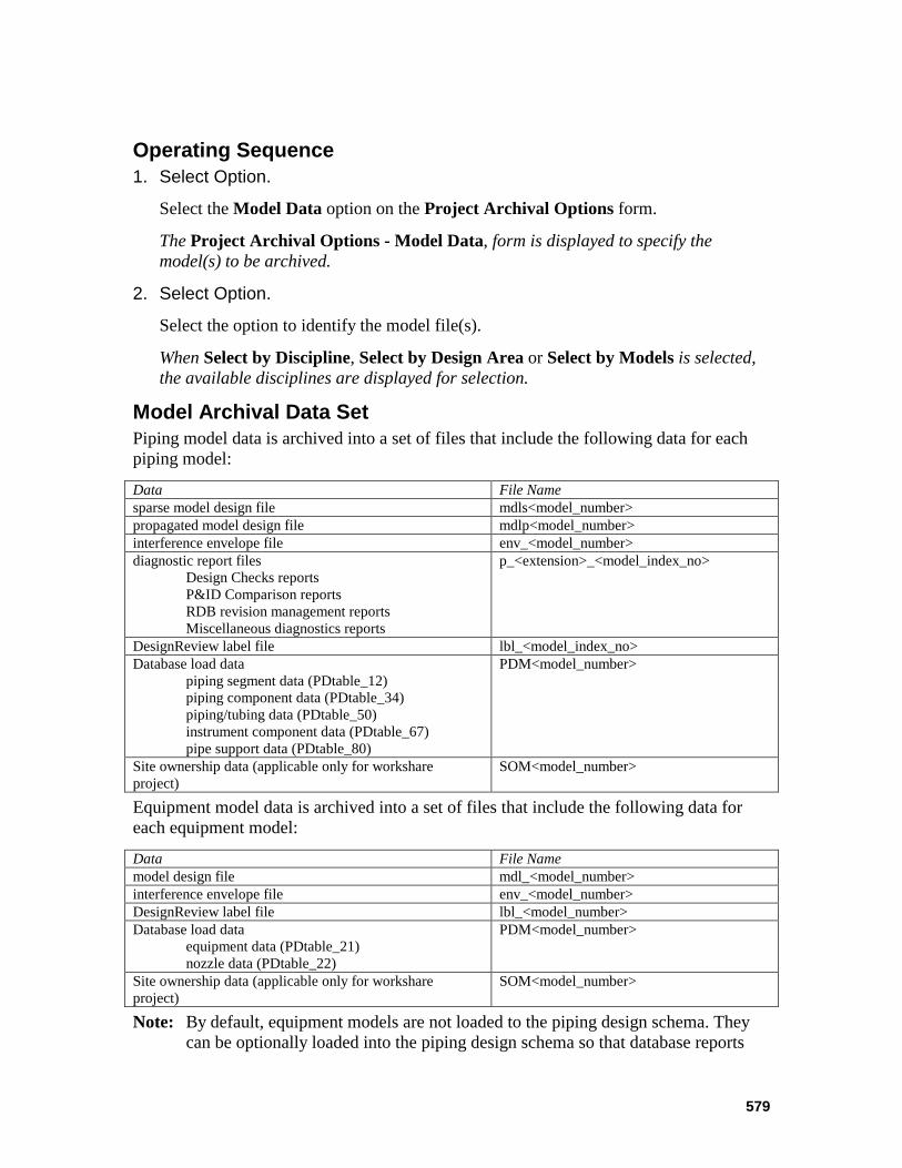
579
Operating Sequence 1. Select Option.
Select the Model Data option on the Project Archival Options form.
The Project Archival Options - Model Data, form is displayed to specify the model(s) to be archived.
2. Select Option.
Select the option to identify the model file(s).
When Select by Discipline, Select by Design Area or Select by Models is selected, the available disciplines are displayed for selection.
Model Archival Data Set Piping model data is archived into a set of files that include the following data for each piping model:
Data File Name sparse model design file mdls<model_number> propagated model design file mdlp<model_number> interference envelope file env_<model_number> diagnostic report files
Design Checks reports P&ID Comparison reports RDB revision management reports Miscellaneous diagnostics reports
p_<extension>_<model_index_no>
DesignReview label file lbl_<model_index_no> Database load data
piping segment data (PDtable_12) piping component data (PDtable_34) piping/tubing data (PDtable_50) instrument component data (PDtable_67) pipe support data (PDtable_80)
PDM<model_number>
Site ownership data (applicable only for workshare project)
SOM<model_number>
Equipment model data is archived into a set of files that include the following data for each equipment model:
Data File Name model design file mdl_<model_number> interference envelope file env_<model_number> DesignReview label file lbl_<model_number> Database load data
equipment data (PDtable_21) nozzle data (PDtable_22)
PDM<model_number>
Site ownership data (applicable only for workshare project)
SOM<model_number>
Note: By default, equipment models are not loaded to the piping design schema. They can be optionally loaded into the piping design schema so that database reports

Project Administrator Reference Guide Addendum – February 2003
580
can be run. PDS does not archive all database information about the equipment models because this information can be regenerated by reloading the equipment models to the piping design schema after the models have been retrieved. This is possible because all nongraphic data about equipment models is stored in the design file. Piping models carry much more nongraphic information than equipment models and much of it is not stored in the design file. For this reason, PDS must archive all piping design schema data for each piping model.
Model data for disciplines other than piping and equipment is archived into a set of cpio files that include the following data for each model.
Data cpio File Name model design file mdl_<model_index_no> interference envelope file env_<model_index_no> DesignReview label file lbl_<model_index_no> Site ownership data (applicable only for workshare project)
SOM<model_number>

581
Drawing Data (replaces 8.1.3) Note: The information in this section supersedes the information in the corresponding section of previous versions of the Project Administrator Reference Guide (pp 386-387 in the PDS 7.1 version of the document).
The following information has been added:
• Site ID Filter See the following text for details.
The Drawing Data form is used to specify the Drawing(s) to be archived/retrieved.
Option Descriptions Site ID Filter — Allows archival of drawings that belong to a specific work site. The
default value for this field is NONE. This filter can be used in conjunction with the other filters on this form. This option is available only for workshare projects; that is, projects whose site_id attribute is set in pdtable_101.
All Drawings — Archive all drawings for the active project.
Select By Drawing Types — Archive all drawings in selected drawing type(s).
Operating Sequence 1. Select Option.
Select the Drawing Data option on the Project Archival Options form.
The Project Archival Options - Drawing Data form is displayed to specify the drawing(s) to be archived.
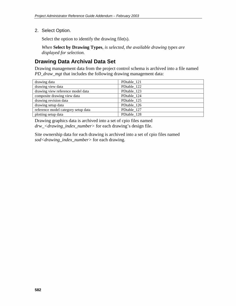
Project Administrator Reference Guide Addendum – February 2003
582
2. Select Option.
Select the option to identify the drawing file(s).
When Select by Drawing Types, is selected, the available drawing types are displayed for selection.
Drawing Data Archival Data Set Drawing management data from the project control schema is archived into a file named PD_draw_mgt that includes the following drawing management data:
drawing data PDtable_121 drawing view data PDtable_122 drawing view reference model data PDtable_123 composite drawing view data PDtable_124 drawing revision data PDtable_125 drawing setup data PDtable_126 reference model category setup data PDtable_127 plotting setup data PDtable_128
Drawing graphics data is archived into a set of cpio files named drw_<drawing_index_number> for each drawing’s design file.
Site ownership data for each drawing is archived into a set of cpio files named sod<drawing_index_number> for each drawing.

583
Site Data The Site Data option is used to archive site information and site ownership information.
This option is available only for workshare projects; that is, projects whose site_id attribute is set in pdtable_101.
Operating Sequence 1. Select Option.
Select the Site Data option from the Project Archival Options form.
The Batch Submission toggle displays.
2. Select Batch Submission Type.
Select Submit Immediately.
—OR —
Delayed Submit and specify submission date and time.
3. Submit Site Data Archive.
Choose the Confirm button to process the archive.
The Project Archival Options form displays.
Site Data Archival Data Set Site data from the project control schema is archived into a file named PD_site_mgt that includes the following site management data:
Site data PDtable_105 Model ownership data PDtable_119 Drawing ownership data PDtable_129
Project Administrator Reference Guide Addendum – February 2003
584
Active Project Retrieval (replaces 8.3) Note: The information in this section supersedes the information in the corresponding section of previous versions of the Project Administrator Reference Guide (pp 407-409 in the PDS 7.1 version of the document).
The following information has been added:
• Site Data option on Retrieval Options form • Caution about retrieving project data with Complete Project option • Recommendation to run RIS unload and NTBACKUP before
performing active retrieval See the following text for details.
The Active Project Retrieval option is used to retrieve all or part of a project data set from an archive into an active project. All relational database data is retrieved using the RIS load utility transparently from within the Project Retrieval command.
Active project retrieval requires the archived project to be available. This may require recreation of the archived project. Active project retrieval also requires a drawing, model or report to be retrieved must exist in the active project. Active project retrieval requires the piping and equipment models have the same database attributes as those archived.
The Approved Reference Database and Unapproved Reference Database option do not retrieve archived binary reference libraries, only archived reference database tables. To retrieve the binary files, you must use the Reference Database Libraries option or the Complete Reference Database option.
Note: When using active project retrieval to restore a piping or equipment model, error messages in the log file are displayed informing that indexes in the database already exist and cannot be recreated. No further action needs to be taken regarding this error.
Note: Active project retrieval also restores files into the locations from which they were archived. This may pose a problem if the archived files are to be restored into a different location.
Note: Active project retrieval requires that the archived project have the same name as the active project. The archived project and the active project need not be the same version. For example, piping models from a PDS 5.4 archive can be actively retrieved into a PDS 6.3 project. The model must exist in the active project prior to retrieval.
Caution: Active project retrieval by complete project may pose a problem if the active project contains models or drawings that are not in the archival set. In such cases, the active retrieval deletes active project data that does not appear in the archival set, including discipline, area, models, FrameWorks Plus sub-projects, and the corresponding entries in the Project Control tables (111, 112, 113, 116, etc.). It does not delete actual model or drawing files, and leaves the tables in
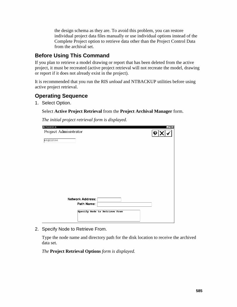
585
the design schema as they are. To avoid this problem, you can restore individual project data files manually or use individual options instead of the Complete Project option to retrieve data other than the Project Control Data from the archival set.
Before Using This Command If you plan to retrieve a model drawing or report that has been deleted from the active project, it must be recreated (active project retrieval will not recreate the model, drawing or report if it does not already exist in the project).
It is recommended that you run the RIS unload and NTBACKUP utilities before using active project retrieval.
Operating Sequence 1. Select Option.
Select Active Project Retrieval from the Project Archival Manager form.
The initial project retrieval form is displayed.
2. Specify Node to Retrieve From.
Type the node name and directory path for the disk location to receive the archived data set.
The Project Retrieval Options form is displayed.
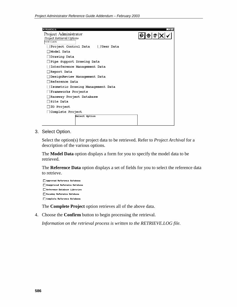
Project Administrator Reference Guide Addendum – February 2003
586
3. Select Option.
Select the option(s) for project data to be retrieved. Refer to Project Archival for a description of the various options.
The Model Data option displays a form for you to specify the model data to be retrieved.
The Reference Data option displays a set of fields for you to select the reference data to retrieve.
The Complete Project option retrieves all of the above data.
4. Choose the Confirm button to begin processing the retrieval.
Information on the retrieval process is written to the RETRIEVE.LOG file.
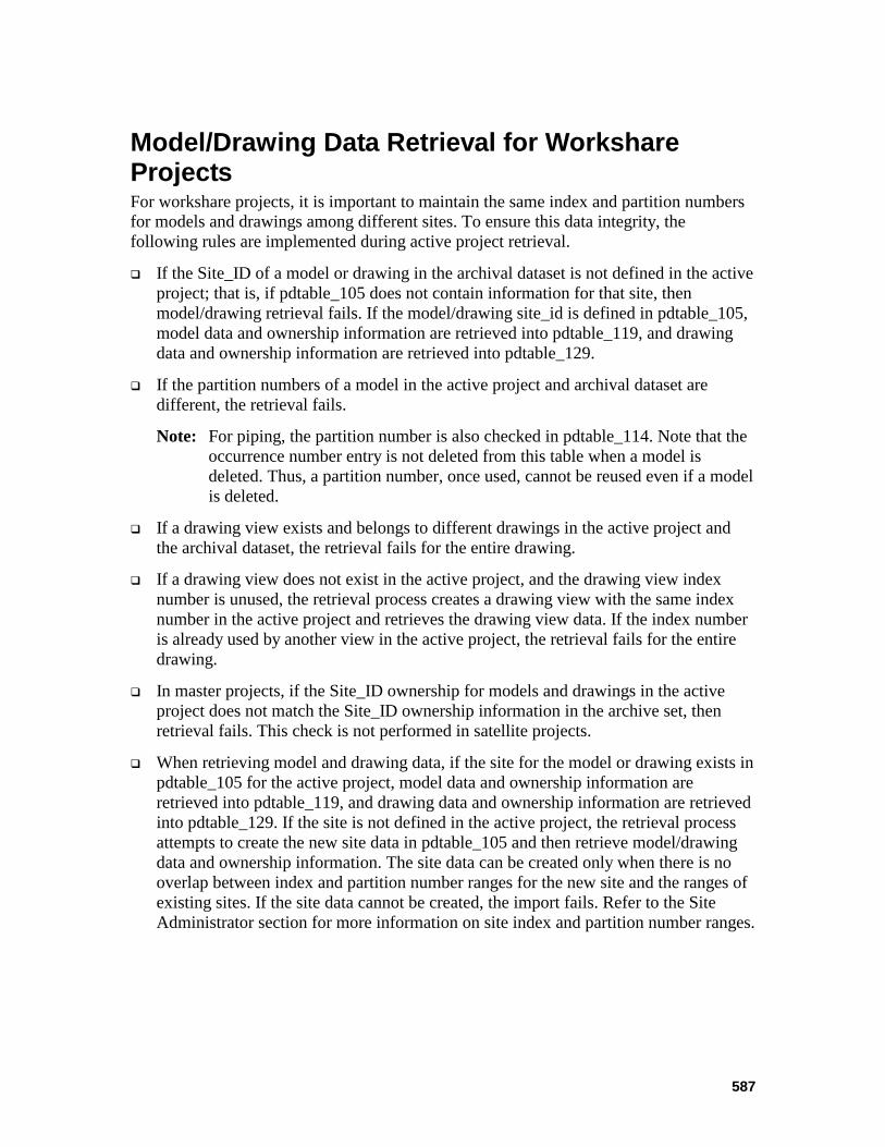
587
Model/Drawing Data Retrieval for Workshare Projects For workshare projects, it is important to maintain the same index and partition numbers for models and drawings among different sites. To ensure this data integrity, the following rules are implemented during active project retrieval.
If the Site_ID of a model or drawing in the archival dataset is not defined in the active project; that is, if pdtable_105 does not contain information for that site, then model/drawing retrieval fails. If the model/drawing site_id is defined in pdtable_105, model data and ownership information are retrieved into pdtable_119, and drawing data and ownership information are retrieved into pdtable_129.
If the partition numbers of a model in the active project and archival dataset are different, the retrieval fails.
Note: For piping, the partition number is also checked in pdtable_114. Note that the occurrence number entry is not deleted from this table when a model is deleted. Thus, a partition number, once used, cannot be reused even if a model is deleted.
If a drawing view exists and belongs to different drawings in the active project and the archival dataset, the retrieval fails for the entire drawing.
If a drawing view does not exist in the active project, and the drawing view index number is unused, the retrieval process creates a drawing view with the same index number in the active project and retrieves the drawing view data. If the index number is already used by another view in the active project, the retrieval fails for the entire drawing.
In master projects, if the Site_ID ownership for models and drawings in the active project does not match the Site_ID ownership information in the archive set, then retrieval fails. This check is not performed in satellite projects.
When retrieving model and drawing data, if the site for the model or drawing exists in pdtable_105 for the active project, model data and ownership information are retrieved into pdtable_119, and drawing data and ownership information are retrieved into pdtable_129. If the site is not defined in the active project, the retrieval process attempts to create the new site data in pdtable_105 and then retrieve model/drawing data and ownership information. The site data can be created only when there is no overlap between index and partition number ranges for the new site and the ranges of existing sites. If the site data cannot be created, the import fails. Refer to the Site Administrator section for more information on site index and partition number ranges.
Project Administrator Reference Guide Addendum – February 2003
588
Import Project Retrieval (replaces 8.5) Note: The information in this section supersedes the information in the corresponding section of previous versions of the Project Administrator Reference Guide (pp 418-423 in the PDS 7.1 version of the document).
The following information has been added:
• Site ID Filters • Site ID information in the Import Model Data and Import Drawing
Data sections • Removal of UNC path names for reference models during import
See the following text for details.
The Import Project Retrieval command imports models, orthographic drawings and pipe support drawings from an archive into an active project. All or selected models and drawings can be imported into the destination project.
Import project retrieval recreates a model or drawing if it does not exist in the active project. The active project and the archive must have been created in the same version of PDS.
If a model is restored to a previous version, some other data within the project temporarily may not be synchronized with the restored version of the model. For example, if a component was placed in the model at a time after the archival of that model and that component was reported as an interference clash, that same clash will appear in any Interference Manager reviews until the Interference Checker processes that model again. At that time, the record of the clash is changed to a deleted state in the Interference Management data. This is the same situation that would arise if you deleted a component involved in an interference clash.
A similar situation arises with components that are used as the source of either associative name labels or coordinate labels in orthographic drawings. The label continues to appear in the drawing until the Update Labels command is run for the applicable drawing view(s).
Any reports that were created by extracting data from the restored model will be incorrect depending on the changes that were lost in restoring to the archived version of the model.
However, the Piping Designer and the Model Builder will not re-use any of the unique numbers for piping segments and components that were lost in restoring the data to the archived version of a piping model. This data will not be restored to its previous values when a single piping model or any group of piping models is being restored to archived versions to eliminate the problem just described.
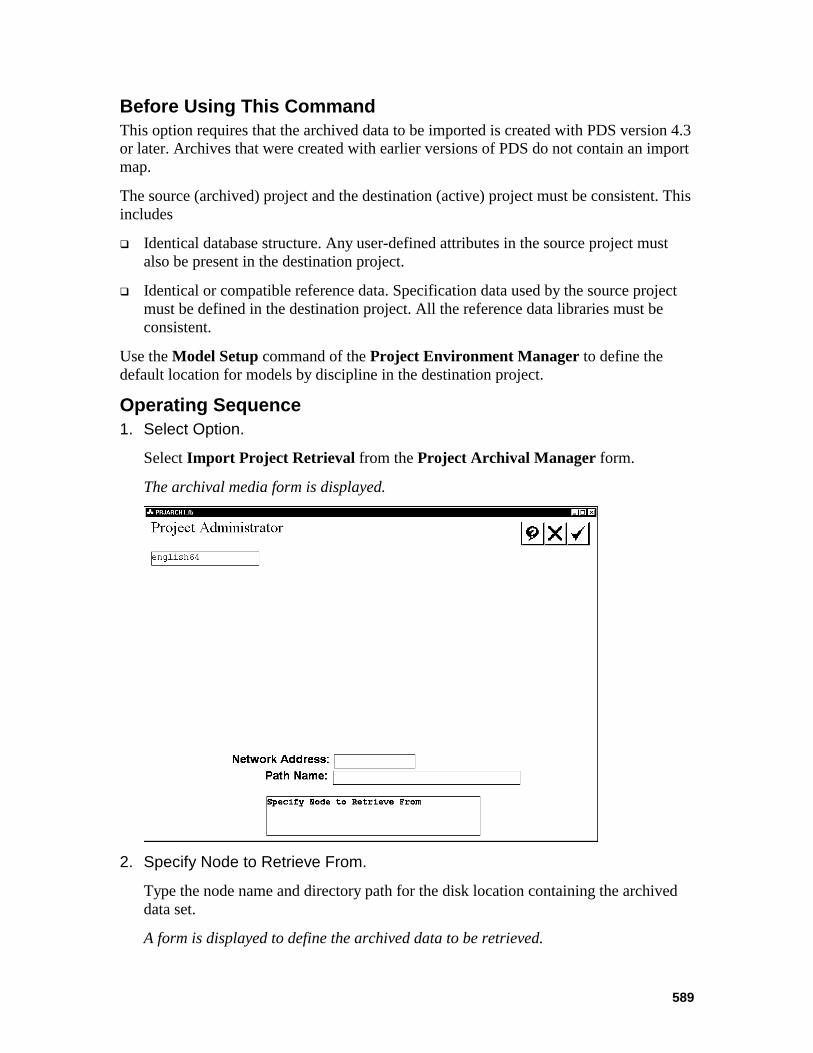
589
Before Using This Command This option requires that the archived data to be imported is created with PDS version 4.3 or later. Archives that were created with earlier versions of PDS do not contain an import map.
The source (archived) project and the destination (active) project must be consistent. This includes
Identical database structure. Any user-defined attributes in the source project must also be present in the destination project.
Identical or compatible reference data. Specification data used by the source project must be defined in the destination project. All the reference data libraries must be consistent.
Use the Model Setup command of the Project Environment Manager to define the default location for models by discipline in the destination project.
Operating Sequence 1. Select Option.
Select Import Project Retrieval from the Project Archival Manager form.
The archival media form is displayed.
2. Specify Node to Retrieve From.
Type the node name and directory path for the disk location containing the archived data set.
A form is displayed to define the archived data to be retrieved.
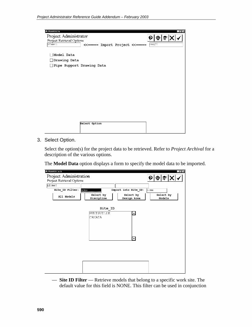
Project Administrator Reference Guide Addendum – February 2003
590
3. Select Option.
Select the option(s) for the project data to be retrieved. Refer to Project Archival for a description of the various options.
The Model Data option displays a form to specify the model data to be imported.
— Site ID Filter — Retrieve models that belong to a specific work site. The
default value for this field is NONE. This filter can be used in conjunction
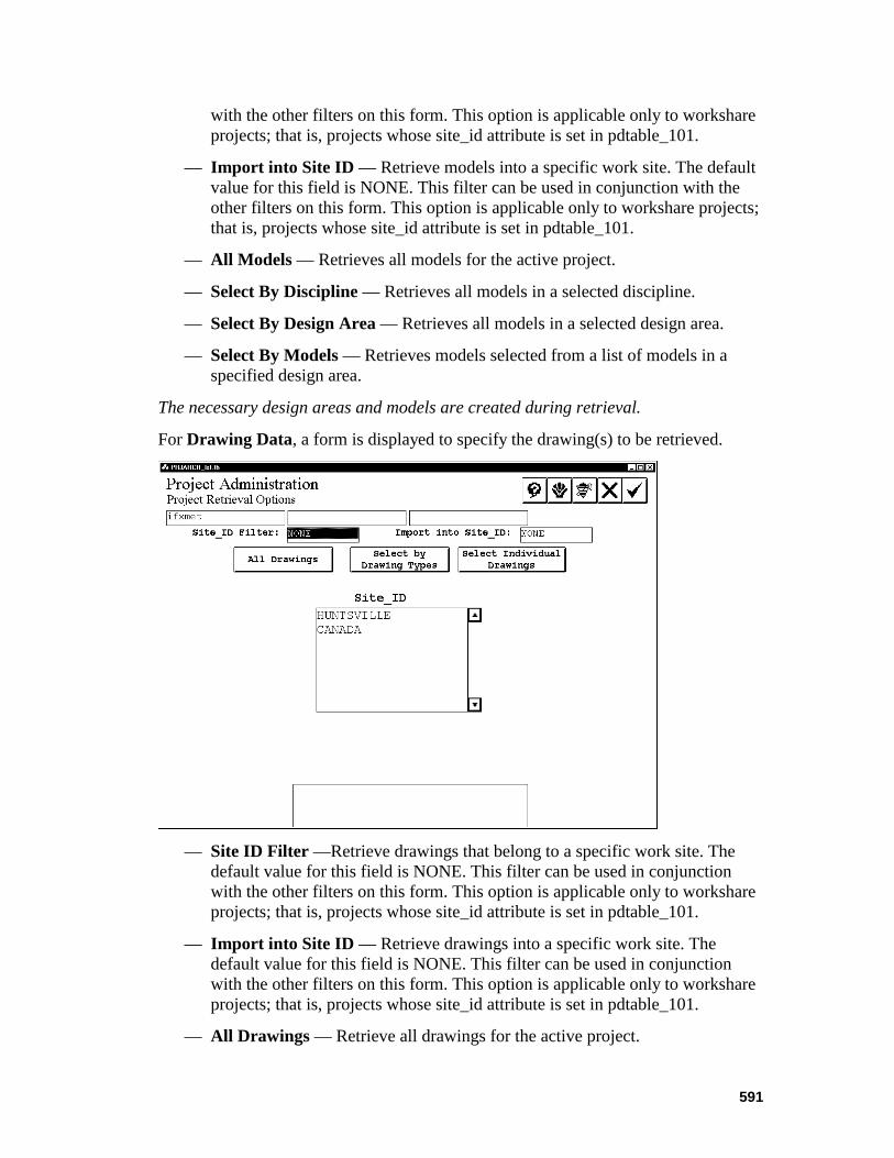
591
with the other filters on this form. This option is applicable only to workshare projects; that is, projects whose site_id attribute is set in pdtable_101.
— Import into Site ID — Retrieve models into a specific work site. The default value for this field is NONE. This filter can be used in conjunction with the other filters on this form. This option is applicable only to workshare projects; that is, projects whose site_id attribute is set in pdtable_101.
— All Models — Retrieves all models for the active project.
— Select By Discipline — Retrieves all models in a selected discipline.
— Select By Design Area — Retrieves all models in a selected design area.
— Select By Models — Retrieves models selected from a list of models in a specified design area.
The necessary design areas and models are created during retrieval.
For Drawing Data, a form is displayed to specify the drawing(s) to be retrieved.
— Site ID Filter —Retrieve drawings that belong to a specific work site. The
default value for this field is NONE. This filter can be used in conjunction with the other filters on this form. This option is applicable only to workshare projects; that is, projects whose site_id attribute is set in pdtable_101.
— Import into Site ID — Retrieve drawings into a specific work site. The default value for this field is NONE. This filter can be used in conjunction with the other filters on this form. This option is applicable only to workshare projects; that is, projects whose site_id attribute is set in pdtable_101.
— All Drawings — Retrieve all drawings for the active project.
Project Administrator Reference Guide Addendum – February 2003
592
— Select By Drawing Types — Retrieve all drawings in selected drawing type(s).
— Select Individual Drawings — Retrieve drawings selected from a list of drawings in a selected drawing type.
The Pipe Support Drawing Data option displays the Submit Immediately / Delayed Submit toggle.
4. Select Submit Immediately to begin importing files as soon as you exit the form.
—OR —
Select Delayed Submit to specify a time and date to process the request.
5. Begin Retrieval.
Choose the Confirm button to begin processing the retrieval.
The request is submitted to the batch queue PDarchival for processing. Processing information is written to the IMPORT.LOG file in the project directory.
Processing When a piping model is imported, the system may need to revise the partition number for that piping model to include the piping model in the destination project. As a consequence, the following data will also be revised as it is loaded into the destination project. The system:
Updates the partition number of piping segments and components in the graphical attribute linkages in the piping model.
Updates the partition number of piping segments and components in each system unique number in the database.
Updates the partition numbers for nozzles that are included with piping segments (for maintaining the association between the nozzle and the piping model) in the database for piping segments. Any association to nozzles that reside in an equipment model that is not in the destination project, either before or after the import process, will be cleared automatically.
Updates the partition number in the graphical attribute linkages in any orthographic drawings that are being imported that include a piping model that is being imported.
Initializes the appropriate data in the Piping Model Data Table (PDtable_114) of the Project Control Database.
Performs Database Verification for any piping model that has been imported. This results in orphan records in the database being deleted automatically, and orphan piping segments or components in the model having the symbology changed.
593
Import Model Data If the models being imported do not exist in the destination project, the system automatically creates the model management data in the Project Control Database of the destination project. These models are created with the default network address and path name defined in the Project Control Database on the basis of discipline. If this default network address and path name are not defined, an error message is displayed, and the models are not imported.
If a piping model being imported already exists in the destination project, the system updates the revision date for that model in the Project Control Database.
When importing a piping model or an equipment model into the destination project from a different project, the system maintains reference model attachments for those other models that are included in the destination project, either before or after being imported into the project. If the reference model does not exist in the destination project or it is not being imported, the system deletes that reference model attachment. When importing a model with reference model attachments, the system removes the original file path from the reference file element, and stores only the reference file name. This removal prevents the system from looking for the reference file in its original location.
When importing a model into the destination project from a different project, the other files associated with the model, such as the interference envelope file and the DesignReview label file, are not deleted or replaced. This data must be re-created, as required.
Import Drawing Data If all reference models for a drawing are not in the destination project or are not being imported, the system generates an error in the error log and the drawing is not imported.
Note: When retrieving drawings, PDS verifies that any referenced models exist in the project. If these models do not exist, the references to the models are removed from the drawing.
When importing a drawing with reference model attachments, the system removes the original file path from the reference file element, and stores only the reference file name. This removal prevents the system from looking for the reference file in its original location.
The system updates any associative name labels or coordinate labels if the applicable reference model is being imported into the project at the same time. Otherwise, the associated label is deleted from the drawing. The system maintains reference model attachments for those models that are also being imported into the project.
Note: In order for the imported drawing to be opened, pdtable_126 must correctly specify the default location of all drawing types, and the required border file must also be retrieved.

Project Administrator Reference Guide Addendum – February 2003
594
Import Pipe Support Drawing Data If the pipe support drawings being imported do not exist in the destination project, the system automatically creates the pipe support data in the Project Control Database of the destination project. These drawings are created with the default node name and path name defined in the Project Control Database on the basis of discipline. If this default node name and path name are not defined, an error message is displayed, and the drawings are not imported.
If a pipe support drawing being imported already exists in the destination project, the system updates the revision date for that drawing in the Project Control Database.
595
Scheduled Project Import (replaces 8.5.1) Note: The information in this section supersedes the information in the corresponding section of previous versions of the Project Administrator Reference Guide (pp 418-423 in the PDS 7.1 version of the document).
The following information has been added:
• Site ID Filters See the following text for details.
The Schedule Project Import command is used to schedule the Import of Model Data into a project. Individual models and drawings can be selected to be imported into the destination project from a list of the archived data or import all the models and/or drawings archived for a project.
Effective use of the Schedule Project Import feature depends upon the use of Incremental Archive and Automated Data Exchange.
Since there is always the possibility that data being imported has not arrived at the importing site, the process ensures the data set being imported is complete and current.
Before Using This Command The source (archived) project and the destination (active) project must be consistent. This includes:
Identical database structure. Any user-defined attributes in the source project must also be defined exactly the same in the destination project and vice versa.
Identical or compatible reference data. Any specification data used by the source project must be defined in the destination project. All the reference data libraries must be consistent.
Operating Sequence 1. Select Option.
Select Scheduled Project Import from the Project Archival Manager form.
The archival media form is displayed.
2. Specify Node to Retrieve From.
Type the node name and directory path for the disk location containing the archived data set.
A form is displayed to define the archived data to be retrieved.
3. Select Option.
Select the option(s) for the project data to be retrieved. Refer to Project Archival for a description of the various options.
The Model Data option displays a form to specify the model data to be imported.
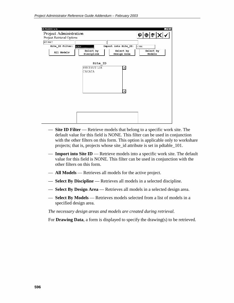
Project Administrator Reference Guide Addendum – February 2003
596
— Site ID Filter — Retrieve models that belong to a specific work site. The
default value for this field is NONE. This filter can be used in conjunction with the other filters on this form. This option is applicable only to workshare projects; that is, projects whose site_id attribute is set in pdtable_101.
— Import into Site ID — Retrieve models into a specific work site. The default value for this field is NONE. This filter can be used in conjunction with the other filters on this form.
— All Models — Retrieves all models for the active project.
— Select By Discipline — Retrieves all models in a selected discipline.
— Select By Design Area — Retrieves all models in a selected design area.
— Select By Models — Retrieves models selected from a list of models in a specified design area.
The necessary design areas and models are created during retrieval.
For Drawing Data, a form is displayed to specify the drawing(s) to be retrieved.

597
— Site ID Filter —Retrieve drawings that belong to a specific work site. The
default value for this field is NONE. This filter can be used in conjunction with the other filters on this form. This option is applicable only to workshare projects; that is, projects whose site_id attribute is set in pdtable_101.
— Import into Site ID — Retrieve drawings into a specific work site. The default value for this field is NONE. This filter can be used in conjunction with the other filters on this form.
— All Drawings — Retrieve all drawings for the active project.
— Select By Drawing Types — Retrieve all drawings in selected drawing type(s).
— Select Individual Drawings — Retrieve drawings selected from a list of drawings in a selected drawing type.
The Pipe Support Drawing Data option displays the Submit Immediately / Delayed Submit toggle.
4. Select Submit Immediately to begin importing files as soon as you exit the form.
—OR —
Select Delayed Submit to specify a time and date to process the request.
5. Begin Retrieval.
Choose the Confirm button to begin processing the retrieval.
The request is submitted to the batch queue PDarchival for processing. Processing information is written to the IMPORT.LOG file in the project directory.

Project Administrator Reference Guide Addendum – February 2003
598
Model/Drawing Import for Workshare Projects For workshare projects it is important to maintain the same index and partition numbers for models and drawings in the active project and the archive. To ensure this data integrity, the following rules are implemented while importing models and drawings.
Note: The following rules apply only if the active project is a workshare project; that is, if the site_id attribute is set in pdtable_101.Otherwise, the regular import workflow applies.
If project numbers are the same for the active project and the archival data set, the import process uses the following rules.
— If a model exists and the index/partition numbers are identical in the active project and the archive, then the model data is imported. Otherwise, the import fails.
Note: For piping, the partition number is also checked in pdtable_114. Note that the occurrence number entry is not deleted from this table when a model is deleted. Thus, a partition number, once used, cannot be reused even if a model is deleted.
— For drawings, if a drawing exists and the index number is identical between the active project and the archive, perform drawing view checks before importing.
— If a model or drawing does not exist, and if the index /partition numbers are unused in the active project, then create a model or drawing with the same index/partition numbers and import the model/drawing data. Otherwise, the import fails. For drawings, also perform drawing view checks before importing.
— In master projects, if the Site_ID ownership for models and drawings in the active project does not match the Site_ID ownership information in the archive set, then the import fails. This check is not done in satellite projects.
If project numbers are different for active project and archival data set, the import process uses the following rules.
— If the model or drawing number exists and the index and partition numbers are identical between the active project and the archive, then import the model or drawing. For drawings, also perform drawing view checks before importing.
— If the model or drawing number does not exist, and if the Import into Site_ID field is selected on the Import form, then create a model or drawing in the selected site and import the model/drawing data. For drawings, also perform drawing view checks before importing.
— If the model or drawing number does not exist, and if the Import into Site_ID field is not selected on the Import form, and if the model Site_ID exists or can
599
be inserted without conflict, then insert the new Site_ID if required, create a model or drawing in the same site as in the archival data set, and import the model/drawing data. For drawings, also perform drawing view checks before importing.
— In master projects, if the Site_ID ownership for models and drawing in the active project does not match the Site_ID ownership information in the archive set, then the import fails. This check is not done in satellite projects.
When importing model and drawing data, if the site for the model or drawing exists in pdtable_105 for the active project, then model data and ownership information are imported into pdtable_119, and drawing data and ownership information are imported into pdtable_129. If the site is not defined in the active project, the import process attempts to create the new site data in pdtable_105 and then import model/drawing data and ownership information. The site data can be created only when there is no overlap between index and partition number ranges for the new site and the ranges of existing sites. If the site data cannot be created, the import fails. Refer to the Site Administrator section for more information on site index and partition number ranges.
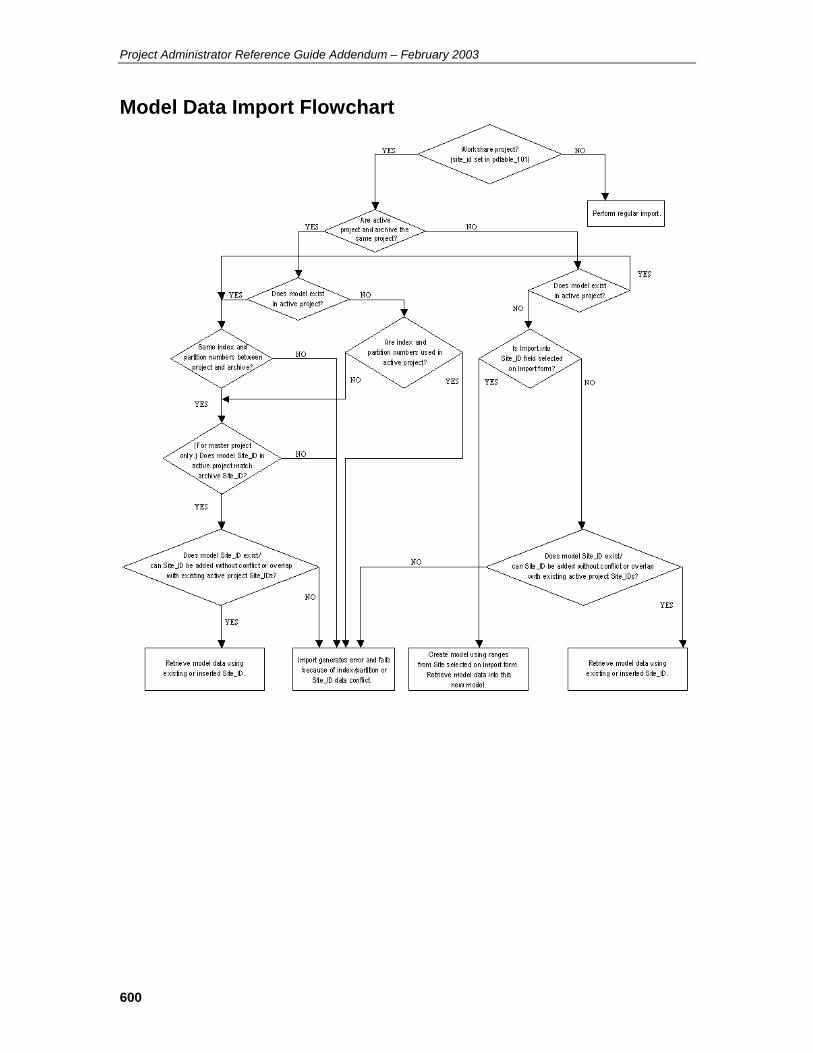
Project Administrator Reference Guide Addendum – February 2003
600
Model Data Import Flowchart

601
Drawing Data Import Flowchart

Project Administrator Reference Guide Addendum – February 2003
602
Drawing View Check Flowchart

603
Composite Drawing View Check Flowchart

Project Administrator Reference Guide Addendum – February 2003
604
File Lock Manager (replaces 10.0) Note: The information in this section supersedes the information in the corresponding section of previous versions of the Project Administrator Reference Guide (pp 435-436 in the PDS 7.1 version of the document).
The following information has been added:
• Design Review Control File • Weld IDs • Lock/Unlock Offsite Data
See the following text for details.
The File Lock Manger is used to release locks that may be held in error. When a user is working in a model file, drawing, reference data file, or interference management file, the system creates a lock to prevent other users from accessing these files. When the user exits the design or database files, the system deletes the lock. However, if the system should go down unexpectedly, the locks are not cleared. This option enables you to clear these locks.
Option Descriptions Model — Displays a list of locked models for the selected project.
Drawing — Displays a list of drawing types for the selected project. When a drawing type is selected, a list of locked drawings for the selected project is displayed.
Reference Database — Displays a list of locked Reference Databases for the selected project.
Area Marker — Displays a list of locked area markers for the selected project.
Project Marker — Unlocks the project marker file. There is only one file of this type for the active project.
Design Review Control File — Unlocks the Design Review control file.
Weld IDs — Displays a list of locked Weld IDs for the selected project.
Lock/Unlock Offsite Data — Displays the Lock/Unlock All Offsite Models/Drawings toggle. This toggle locks or unlocks models and drawings that do not belong to the current work site. Individual models and drawings can still be unlocked or locked using the corresponding options on this form. This option is applicable only to workshare projects; that is, projects whose site_id attribute is set in pdtable_101.
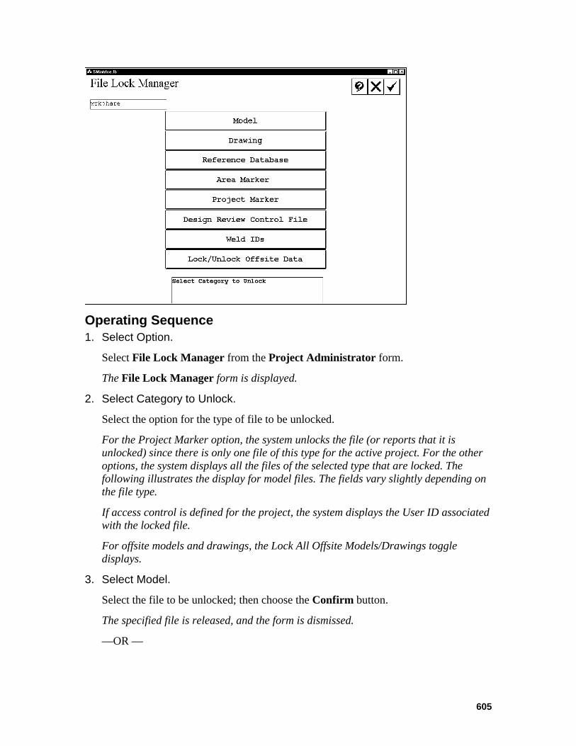
605
Operating Sequence 1. Select Option.
Select File Lock Manager from the Project Administrator form.
The File Lock Manager form is displayed.
2. Select Category to Unlock.
Select the option for the type of file to be unlocked.
For the Project Marker option, the system unlocks the file (or reports that it is unlocked) since there is only one file of this type for the active project. For the other options, the system displays all the files of the selected type that are locked. The following illustrates the display for model files. The fields vary slightly depending on the file type.
If access control is defined for the project, the system displays the User ID associated with the locked file.
For offsite models and drawings, the Lock All Offsite Models/Drawings toggle displays.
3. Select Model.
Select the file to be unlocked; then choose the Confirm button.
The specified file is released, and the form is dismissed.
—OR —
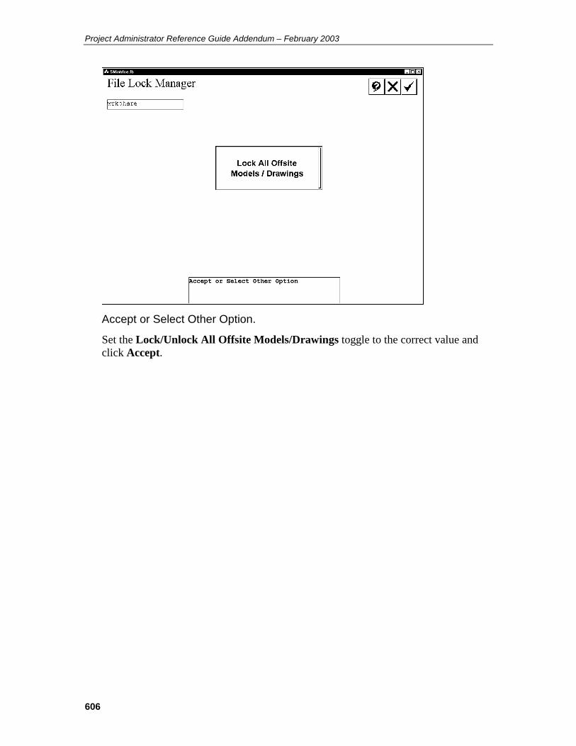
Project Administrator Reference Guide Addendum – February 2003
606
Accept or Select Other Option.
Set the Lock/Unlock All Offsite Models/Drawings toggle to the correct value and click Accept.
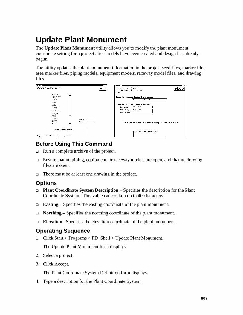
607
Update Plant Monument The Update Plant Monument utility allows you to modify the plant monument coordinate setting for a project after models have been created and design has already begun.
The utility updates the plant monument information in the project seed files, marker file, area marker files, piping models, equipment models, raceway model files, and drawing files.
Before Using This Command Run a complete archive of the project.
Ensure that no piping, equipment, or raceway models are open, and that no drawing files are open.
There must be at least one drawing in the project.
Options Plant Coordinate System Description – Specifies the description for the Plant
Coordinate System. This value can contain up to 40 characters.
Easting – Specifies the easting coordinate of the plant monument.
Northing – Specifies the northing coordinate of the plant monument.
Elevation– Specifies the elevation coordinate of the plant monument.
Operating Sequence 1. Click Start > Programs > PD_Shell > Update Plant Monument.
The Update Plant Monument form displays.
2. Select a project.
3. Click Accept.
The Plant Coordinate System Definition form displays.
4. Type a description for the Plant Coordinate System.

Project Administrator Reference Guide Addendum – February 2003
608
5. Type values for the Plant Coordinate System Monument coordinates.
6. Click Accept.
The system verifies that you have access to all the necessary project files. If you do not have access to all the files, the form displays a list of files for you to resolve.
When all necessary files in the project are accessible, the system updates the plant monument information in all the files and generates a log file in the c:\temp folder.

609
PDS Reference Data Auditing Tool Utility The PDS Reference Data Auditing Tool utility allows PDS users to audit and report the discrepancies between the active project reference database and an archived dataset. The utility can transfer data over an FTP connection, so that the project database and archive dataset can reside at different PDS project sites. The utility can also be used to maintain data integrity among models and drawings at different workshare sites.
Because of the amount of reference data processed during an audit, the Audit Tool utility performs the audit and file transfer operations in batch mode. You can run these batch operations immediately or schedule them to run at a later time.
The Audit Tool utility stores audit parameters in configuration files, which allow users to perform periodic audits without repeating audit setup for each run. It also stores the results of the audits in report files, which can be viewed, filtered, emailed, or printed from within the utility interface.

Project Administrator Reference Guide Addendum – February 2003
610
Audit Tools Interface This section describes the Audit Tool interface. The Audit Tool commands are available from the toolbar and from menus on the PDS Reference Data Auditing Tool dialog box.
Options New Configuration – Opens a default new configuration, as if the user had just started the utility.
Open Configuration – Opens an existing configuration (.cfg) file.
Save Configuration – Saves the current configuration file. If you have not previously saved the configuration file, the system prompts you for a file name and location.
FTP Login – Specifies the location of the remote PDS site, and the login name and password used to access the remote site.
Browse FTP Folders – Allows you to view and select folders on the remote PDS site and the archive dataset location.
Select Reference Data – Specifies which reference data to compare between the project and the archive dataset.
File Transfer – Copies the specified remote archive dataset to the local directory using an FTP connection.
Audit Mode 1 – Copies the remote archive dataset over an FTP connection to the local computer, and then compares the local project database to the transferred archive dataset.
Audit Mode 2 – Compares the local project database to a local archive dataset.
Audit Mode 3 – Compares the model and drawing data in the local project database to the model and drawing data in a local archive dataset.
View Audit Report – Displays the Audit Report Viewer, which allows you to view, sort, print, email, or save audit report data.
View Batch Log – Displays the Batch Log viewer, which allows you to view and print existing batch log files.
Help – Displays the Audit Tool Help file.
Exit – Closes the Audit Tool utility.

611
Project – Specifies the active project.

Project Administrator Reference Guide Addendum – February 2003
612
File Menu The commands on the File menu allow you to open and save configuration files, and exit the Audit Tool.
New Configuration File This command changes the audit configuration to a default configuration, clearing any existing settings. Audit configuration files contain all the settings involved in a reference data audit operation, and allow you to save these settings in order to perform repeated audits without re-entering information each time.
Open Configuration File This command opens a previously saved audit configuration file.
Save Configuration This command saves the current configuration file. If you have not previously saved the configuration file, the system prompts you for a file name and location.
Save Configuration As This command saves the current configuration with a different file name.
Exit This command closes the Audit Tool utility.

613
Audit Menu FTP Login This command specifies the location of the remote PDS site, and the user name and password used to access the site.
Options Remote Host – The name of the computer on which the remote PDS archive dataset resides.
Username – The username used to access the remote computer.
Password – The password used to access the remote computer.
OK – Saves the remote host name, username, and password to the current configuration file, and attempts to log in to the remote computer.
Cancel – Closes the FTP Login dialog box without saving the login information.
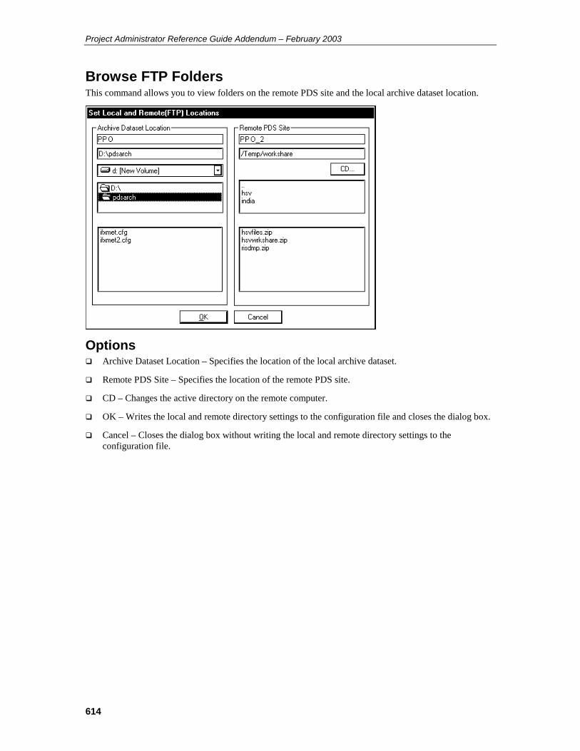
Project Administrator Reference Guide Addendum – February 2003
614
Browse FTP Folders This command allows you to view folders on the remote PDS site and the local archive dataset location.
Options Archive Dataset Location – Specifies the location of the local archive dataset.
Remote PDS Site – Specifies the location of the remote PDS site.
CD – Changes the active directory on the remote computer.
OK – Writes the local and remote directory settings to the configuration file and closes the dialog box.
Cancel – Closes the dialog box without writing the local and remote directory settings to the configuration file.
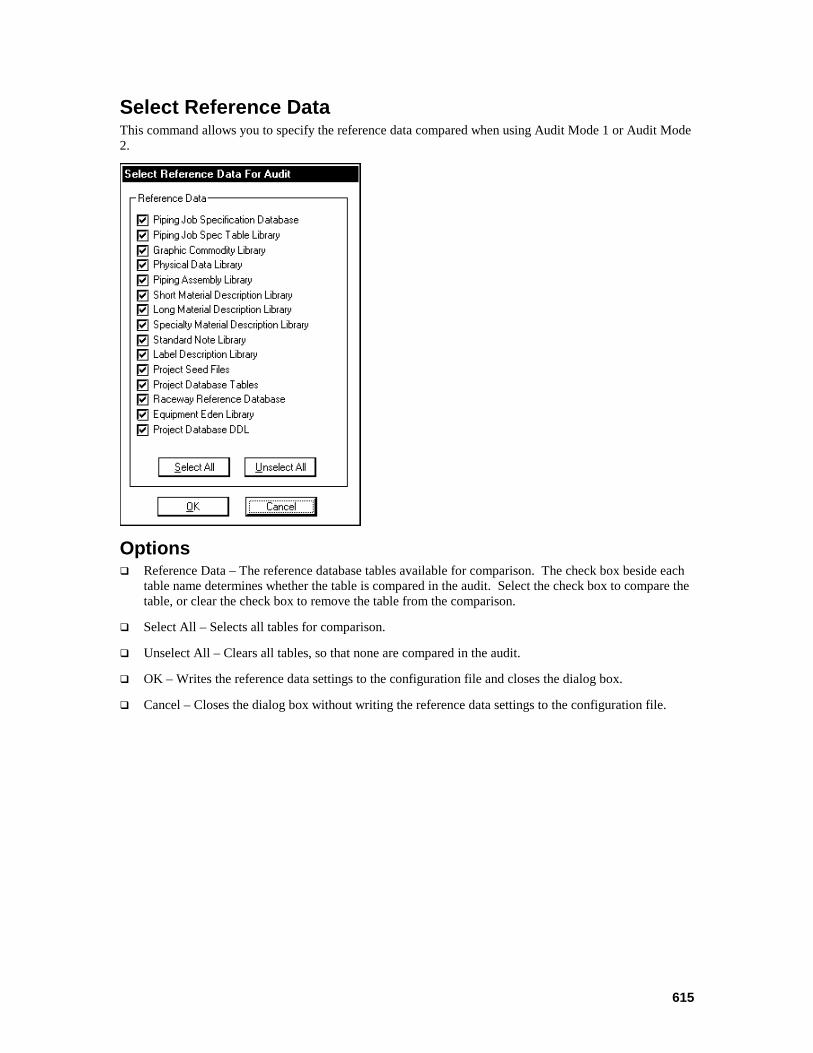
615
Select Reference Data This command allows you to specify the reference data compared when using Audit Mode 1 or Audit Mode 2.
Options Reference Data – The reference database tables available for comparison. The check box beside each
table name determines whether the table is compared in the audit. Select the check box to compare the table, or clear the check box to remove the table from the comparison.
Select All – Selects all tables for comparison.
Unselect All – Clears all tables, so that none are compared in the audit.
OK – Writes the reference data settings to the configuration file and closes the dialog box.
Cancel – Closes the dialog box without writing the reference data settings to the configuration file.

Project Administrator Reference Guide Addendum – February 2003
616
File Transfer This command copies the specified remote archive dataset to the local directory.
Options Remote PDS Site – The name of the computer on which the remote PDS archive dataset resides.
Remote Path – The directory path containing the remote PDS archive dataset on the remote computer.
Local Archive Directory – The location of the local archive dataset.
Submit Batch Job – Displays the Batch Job dialog box, which allows you to run the File Transfer command immediately or at a specified time.
Before Using This Command Ensure that the remote site has run a PDS project archive and consolidated the archived data set into a single directory.
Steps 1. Click Start > Programs > PD_Shell > Audit Tools.
The PDS Reference Data Auditing Tool interface displays.
2. Select a project.
3. Click Audit > Audit Setup > File Transfer.
The Login to Remote FTP Site dialog box displays.
4. Type the remote computer name, username and password.
5. Click OK.
The system logs in to the remote computer and the Set Local and Remote(FTP) Locations dialog box displays.
6. Select the destination directory on the local computer.
7. Select the source directory on the remote computer.
8. Click OK.
The File Transfer – Get Archive from a given FTP Location dialog box displays.
9. Click Submit Batch Job.
The Batch Job dialog box displays.
10. Click Now to submit the batch job immediately, or click Later to set a time for the batch file transfer to begin.
11. Click Save to save the current configuration.

617
12. Click Submit.
The batch job is added to the batch queue or scheduled, depending on the selected batch submission option.

Project Administrator Reference Guide Addendum – February 2003
618
Audit Mode 1 This command copies the remote archive dataset over an FTP connection to the local computer, and then compares the local project database to the transferred archive dataset.
Options Remote PDS Site –The name of the computer on which the remote PDS archive dataset resides.
Remote Path – The directory path containing the remote PDS archive dataset on the remote computer.
Local Archive Directory – The destination of the local copy of the remote archive dataset.
Reference Data – Displays the Reference Data dialog box, which allows you to specify the reference data compared between the local project and the remote archive dataset.
Submit Batch Job – Displays the Batch Job dialog box, which allows you to run the Audit command immediately or at a specified time.
Before Using This Command Ensure that the remote site has run a PDS project archive and consolidated the archived data set into a single directory.
Steps 1. Click Start > Programs > PD_Shell > Audit Tools.
The PDS Reference Data Auditing Tool interface displays.
2. Select a project.
3. Click Audit > Audit Setup > Audit Mode 1.
The Login to Remote FTP Site dialog box displays.
4. Type the remote computer name, username and password.
5. Click OK.
The system logs in to the remote computer and the Set Local and Remote(FTP) Locations dialog box displays.
6. Select the destination directory on the local computer.
7. Select the source directory on the remote computer.
8. Click OK.
The Mode 1 – Project Vs Transferred Remote Archive dialog box displays.
9. Click Reference Data.
The Select Reference Data for Audit dialog box displays.

619
10. Select the reference data to compare between the remote archive and the local project database.
11. Click OK.
12. Click Submit Batch Job.
The Batch Job dialog box displays.
13. Click Now to submit the batch job immediately, or click Later to set a time for the batch file transfer to begin.
14. Click Save to save the current configuration.
15. Click Submit.
The batch job is added to the batch queue or scheduled, depending on the selected batch submission option.

Project Administrator Reference Guide Addendum – February 2003
620
Audit Mode 2 This command compares the local project database to a local archive dataset.
Options Archive Dataset Locations – Specifies the location of the local archive dataset.
Reference Data – Displays the Reference Data dialog box, which allows you to specify the reference data compared between the local project and the remote archive dataset.
Submit Batch Job – Displays the Batch Job dialog box, which allows you to run the Audit command immediately or at a specified time.
Before Using This Command Ensure that the archived data set has been consolidated into a single directory.
Steps 1. Click Start > Programs > PD_Shell > Audit Tools.
The PDS Reference Data Auditing Tool interface displays.
2. Select a project.
3. Click Audit > Audit Setup > Audit Mode 2.
The Mode 2 – Project Vs Local Archive dialog box displays.
4. Select the location of the archive dataset on the local computer.
5. Click Reference Data.
The Select Reference Data for Audit dialog box displays.
6. Select the reference data to compare between the archive dataset and the local project database.
7. Click OK.
8. Click Submit Batch Job.
The Batch Job dialog box displays.

621
9. Click Now to submit the batch job immediately, or click Later to set a time for the batch file transfer to begin.
10. Click Save to save the current configuration.
11. Click Submit.
The batch job is added to the batch queue or scheduled, depending on the selected batch submission option.

Project Administrator Reference Guide Addendum – February 2003
622
Audit Mode 3 This command compares the model and drawing data in the local project database to the model and drawing data in a local archive dataset. This command can be used to maintain data integrity for models and drawings in workshare projects.
Options Archive Dataset Locations – Specifies the location of the local archive dataset.
Submit Batch Job – Displays the Batch Job dialog box, which allows you to run the Audit command immediately or at a specified time.
Before Using This Command Ensure that the archived dataset has been consolidated into a single directory.
Steps 1. Click Start > Programs > PD_Shell > Audit Tools.
The PDS Reference Data Auditing Tool interface displays.
2. Select a project.
3. Click Audit > Audit Setup > Audit Mode 3.
The Mode 3 – Project Vs Local Archive dialog box displays.
4. Select the location of the archive dataset on the local computer.
5. Click Submit Batch Job.
The Batch Job dialog box displays.
6. Click Now to submit the batch job immediately, or click Later to set a time for the batch file transfer to begin.
7. Click Save to save the current configuration.
8. Click Submit.
The batch job is added to the batch queue or scheduled, depending on the selected batch submission option.
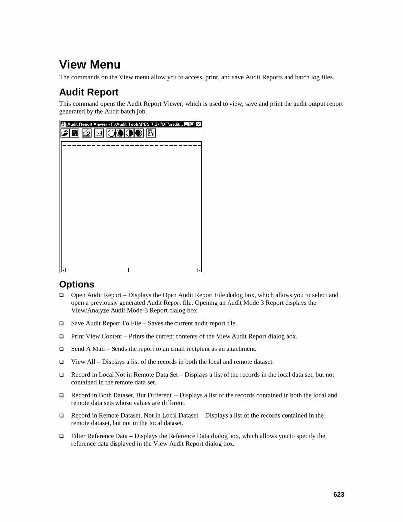
623
View Menu The commands on the View menu allow you to access, print, and save Audit Reports and batch log files.
Audit Report This command opens the Audit Report Viewer, which is used to view, save and print the audit output report generated by the Audit batch job.
Options Open Audit Report – Displays the Open Audit Report File dialog box, which allows you to select and
open a previously generated Audit Report file. Opening an Audit Mode 3 Report displays the View/Analyze Audit Mode-3 Report dialog box.
Save Audit Report To File – Saves the current audit report file.
Print View Content – Prints the current contents of the View Audit Report dialog box.
Send A Mail – Sends the report to an email recipient as an attachment.
View All – Displays a list of the records in both the local and remote dataset.
Record in Local Not in Remote Data Set – Displays a list of the records in the local data set, but not contained in the remote data set.
Record in Both Dataset, But Different – Displays a list of the records contained in both the local and remote data sets whose values are different.
Record in Remote Dataset, Not in Local Dataset – Displays a list of the records contained in the remote dataset, but not in the local dataset.
Filter Reference Data – Displays the Reference Data dialog box, which allows you to specify the reference data displayed in the View Audit Report dialog box.

Project Administrator Reference Guide Addendum – February 2003
624
View/Analyze Audit Mode 3 Report This dialog box displays a report generated using Audit Mode 3. This report contains data for all models and drawings in the local archive dataset and the active project database.
Options Drawings/Models list – Specifies whether to display models or drawings in the report view.
Conflict Data list – Specifies which drawings or models to display in the report view. The available options are Only In Project, In Conflict, and Only in Archive. The Only In Project option displays models or drawings that appear in the project, but not in the archive. The In Conflict option displays models or drawings with conflicting data. The Only In Archive option displays models or drawings that appear in the archive, but not in the project.
View As HTML – Displays the current contents of the Detailed Display of Conflicts as an HTML file in a Web browser. The report can be printed from the Web browser itself. For reports displaying models or drawings in conflict, the conflicting attributes, which display in red in the Detailed Display, appear in a bold typeface for easy identification on a printed report.
Save As HTML – Saves the current contents of the Detailed Display of Conflicts to an HTML file.
Attribute Name – A list of model or drawing database attributes. Attributes that are in conflict display in red. The check box beside the attribute name determines whether the attribute is displayed as a column in the Detailed Display of Conflicts. To display only the attributes in conflict, right click in the

625
Attributes to Show/Compare Filter view and click Select Differing Attributes Only. The displayed attributes list is remembered even in case of a switch between Models/Drawings.
Project Filter – Filters the Detailed Display of Conflicts by attribute value from the project database. To enter a project filter, select the attribute row, and then click the Project Filter field in the row. This field is case sensitive.
Archive Filter – Filters the Detailed Display of Conflicts by attribute value from the archive dataset. To enter an archive filter, select the attribute row, and then click the Archive Filter field in the row. This field is case sensitive. This option is only available in case of ‘In Conflict Report’
Detailed Display of Conflicts – This area displays the model or drawing data from the project database and archive dataset, as specified by the other fields on the dialog box. Model or drawing data in conflict between the project and archive appear in red. The first column in the display indicates whether the model or drawing is in the project (P) or archive (A). To change the order of the attribute columns, select a column title and drag it to the new location. The same column order is used in the HTML view. Column order is reset with any changes that require a refresh of columns in the Detailed Display, such as changing the Models/Drawings option, or adding or removing attributes in the display.
Note: Changes in the data section of the Mode 3 report output file, which begins right after the Time of Generation line, can generate unpredictable results and should be avoided. However, you can add text to appear in HTML output by inserting lines into the Mode 3 report file right before the Time of Generation line. Any new lines of text must be in the following format: Text : text
For example,
Reason : OffSite data out of sync in Master site. Action taken : Updated Master site with latest archives from owning satellite sites.

Project Administrator Reference Guide Addendum – February 2003
626
Batch Log File This command allows you to open and print existing batch log files.
Options Open Log File – Displays the Open Log File dialog box, which allows you to select and open a batch
log file.
Print Log File – Prints the current batch log file.
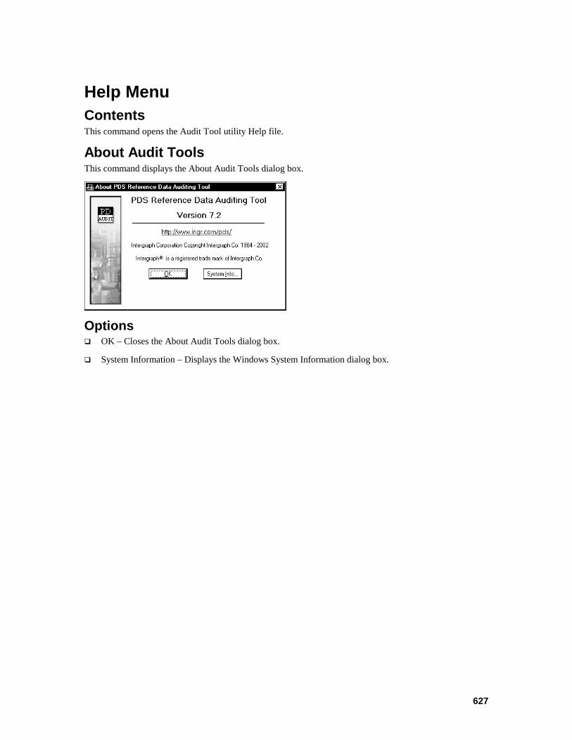
627
Help Menu Contents This command opens the Audit Tool utility Help file.
About Audit Tools This command displays the About Audit Tools dialog box.
Options OK – Closes the About Audit Tools dialog box.
System Information – Displays the Windows System Information dialog box.
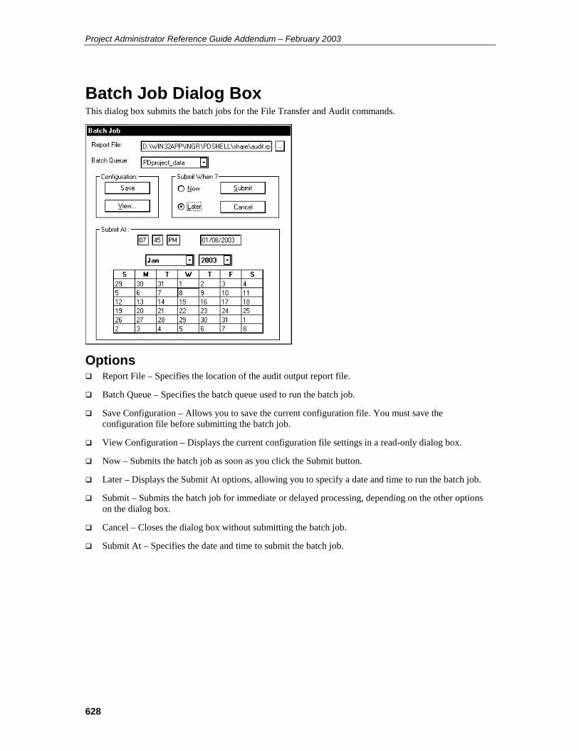
Project Administrator Reference Guide Addendum – February 2003
628
Batch Job Dialog Box This dialog box submits the batch jobs for the File Transfer and Audit commands.
Options Report File – Specifies the location of the audit output report file.
Batch Queue – Specifies the batch queue used to run the batch job.
Save Configuration – Allows you to save the current configuration file. You must save the configuration file before submitting the batch job.
View Configuration – Displays the current configuration file settings in a read-only dialog box.
Now – Submits the batch job as soon as you click the Submit button.
Later – Displays the Submit At options, allowing you to specify a date and time to run the batch job.
Submit – Submits the batch job for immediate or delayed processing, depending on the other options on the dialog box.
Cancel – Closes the dialog box without submitting the batch job.
Submit At – Specifies the date and time to submit the batch job.
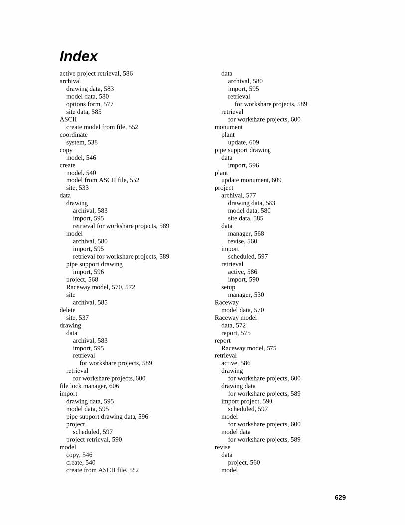
629
Index active project retrieval, 586 archival
drawing data, 583 model data, 580 options form, 577 site data, 585
ASCII create model from file, 552
coordinate system, 538
copy model, 546
create model, 540 model from ASCII file, 552 site, 533
data drawing
archival, 583 import, 595 retrieval for workshare projects, 589
model archival, 580 import, 595 retrieval for workshare projects, 589
pipe support drawing import, 596
project, 568 Raceway model, 570, 572 site
archival, 585 delete
site, 537 drawing
data archival, 583 import, 595 retrieval
for workshare projects, 589 retrieval
for workshare projects, 600 file lock manager, 606 import
drawing data, 595 model data, 595 pipe support drawing data, 596 project
scheduled, 597 project retrieval, 590
model copy, 546 create, 540 create from ASCII file, 552
data archival, 580 import, 595 retrieval
for workshare projects, 589 retrieval
for workshare projects, 600 monument
plant update, 609
pipe support drawing data
import, 596 plant
update monument, 609 project
archival, 577 drawing data, 583 model data, 580 site data, 585
data manager, 568 revise, 560
import scheduled, 597
retrieval active, 586 import, 590
setup manager, 530
Raceway model data, 570
Raceway model data, 572 report, 575
report Raceway model, 575
retrieval active, 586 drawing
for workshare projects, 600 drawing data
for workshare projects, 589 import project, 590
scheduled, 597 model
for workshare projects, 600 model data
for workshare projects, 589 revise
data project, 560
model
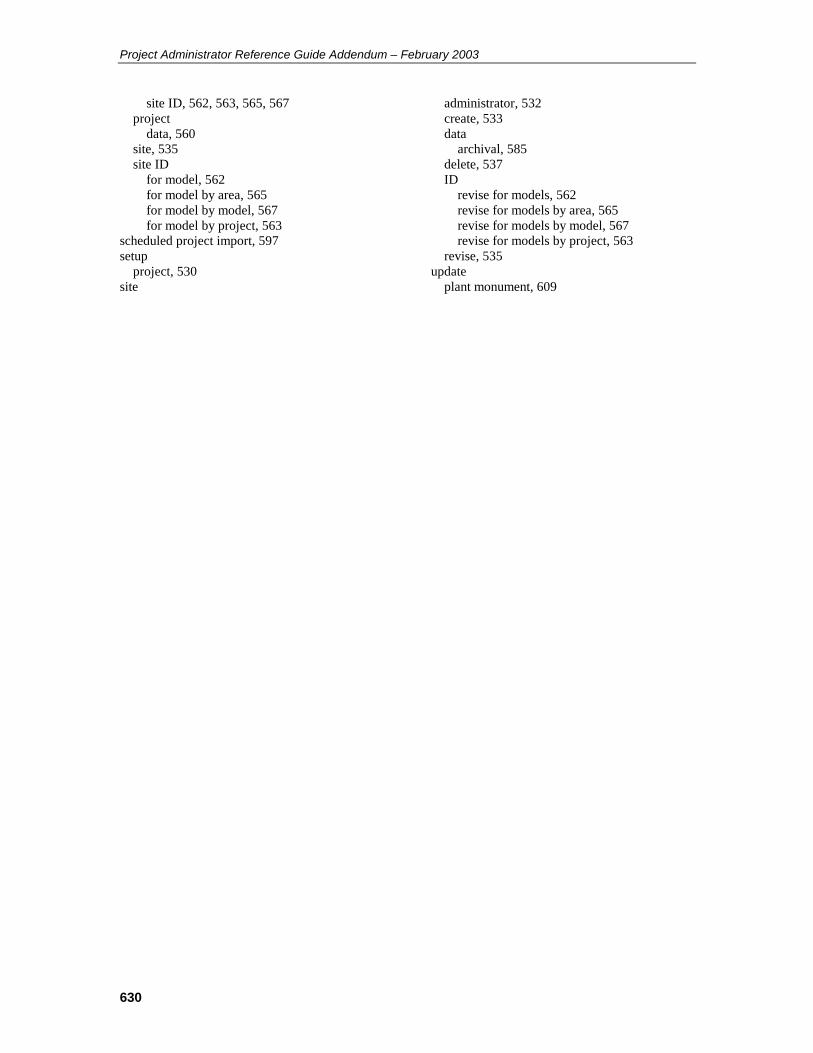
Project Administrator Reference Guide Addendum – February 2003
630
site ID, 562, 563, 565, 567 project
data, 560 site, 535 site ID
for model, 562 for model by area, 565 for model by model, 567 for model by project, 563
scheduled project import, 597 setup
project, 530 site
administrator, 532 create, 533 data
archival, 585 delete, 537 ID
revise for models, 562 revise for models by area, 565 revise for models by model, 567 revise for models by project, 563
revise, 535 update
plant monument, 609

Project Administrator (PD_Project) Reference Guide Addendum October 2004 DPDS3-PB-200030C For PDS version 07.03.00.** This document supplements DPDS3-PB-200030B.
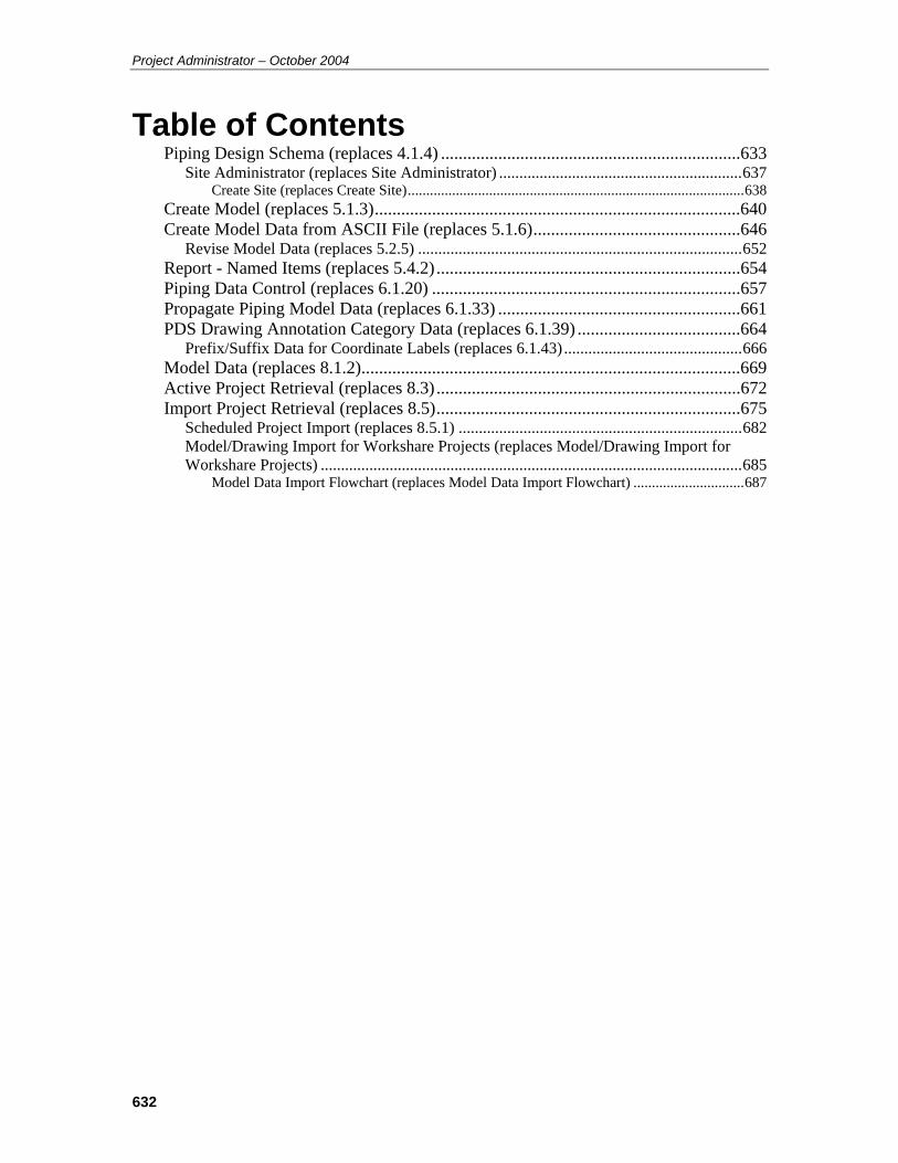
Project Administrator – October 2004
632
Table of Contents Piping Design Schema (replaces 4.1.4) ....................................................................633
Site Administrator (replaces Site Administrator) ............................................................637 Create Site (replaces Create Site)...........................................................................................638
Create Model (replaces 5.1.3)...................................................................................640 Create Model Data from ASCII File (replaces 5.1.6)...............................................646
Revise Model Data (replaces 5.2.5) ................................................................................652 Report - Named Items (replaces 5.4.2) .....................................................................654 Piping Data Control (replaces 6.1.20) ......................................................................657 Propagate Piping Model Data (replaces 6.1.33) .......................................................661 PDS Drawing Annotation Category Data (replaces 6.1.39) .....................................664
Prefix/Suffix Data for Coordinate Labels (replaces 6.1.43) ............................................666 Model Data (replaces 8.1.2)......................................................................................669 Active Project Retrieval (replaces 8.3) .....................................................................672 Import Project Retrieval (replaces 8.5).....................................................................675
Scheduled Project Import (replaces 8.5.1) ......................................................................682 Model/Drawing Import for Workshare Projects (replaces Model/Drawing Import for Workshare Projects) ........................................................................................................685
Model Data Import Flowchart (replaces Model Data Import Flowchart) ..............................687
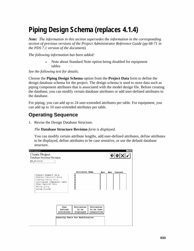
633
Piping Design Schema (replaces 4.1.4) Note: The information in this section supersedes the information in the corresponding section of previous versions of the Project Administrator Reference Guide (pp 68-71 in the PDS 7.1 version of the document).
The following information has been added:
• Note about Standard Note option being disabled for equipment tables
See the following text for details.
Choose the Piping Design Schema option from the Project Data form to define the design database schema for the project. The design schema is used to store data such as piping component attributes that is associated with the model design file. Before creating the database, you can modify certain database attributes or add user-defined attributes to the database.
For piping, you can add up to 24 user-extended attributes per table. For equipment, you can add up to 10 user-extended attributes per table.
Operating Sequence 1. Revise the Design Database Structure.
The Database Structure Revision form is displayed.
You can modify certain attribute lengths, add user-defined attributes, define attributes to be displayed, define attributes to be case sensitive, or use the default database structure.
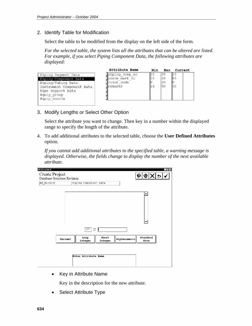
Project Administrator – October 2004
634
2. Identify Table for Modification
Select the table to be modified from the display on the left side of the form.
For the selected table, the system lists all the attributes that can be altered are listed. For example, if you select Piping Component Data, the following attributes are displayed:
3. Modify Lengths or Select Other Option
Select the attribute you want to change. Then key in a number within the displayed range to specify the length of the attribute.
4. To add additional attributes to the selected table, choose the User Defined Attributes option.
If you cannot add additional attributes to the specified table, a warning message is displayed. Otherwise, the fields change to display the number of the next available attribute.
• Key in Attribute Name
Key in the description for the new attribute.
• Select Attribute Type
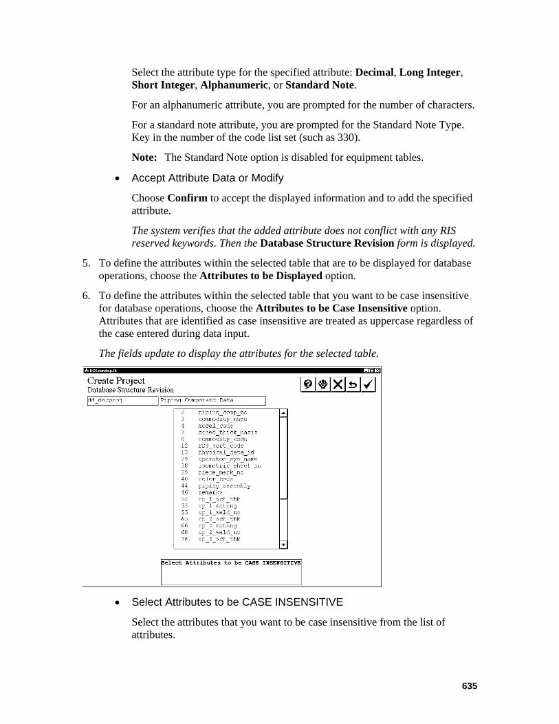
635
Select the attribute type for the specified attribute: Decimal, Long Integer, Short Integer, Alphanumeric, or Standard Note.
For an alphanumeric attribute, you are prompted for the number of characters.
For a standard note attribute, you are prompted for the Standard Note Type. Key in the number of the code list set (such as 330).
Note: The Standard Note option is disabled for equipment tables.
• Accept Attribute Data or Modify
Choose Confirm to accept the displayed information and to add the specified attribute.
The system verifies that the added attribute does not conflict with any RIS reserved keywords. Then the Database Structure Revision form is displayed.
5. To define the attributes within the selected table that are to be displayed for database operations, choose the Attributes to be Displayed option.
6. To define the attributes within the selected table that you want to be case insensitive for database operations, choose the Attributes to be Case Insensitive option. Attributes that are identified as case insensitive are treated as uppercase regardless of the case entered during data input.
The fields update to display the attributes for the selected table.
• Select Attributes to be CASE INSENSITIVE
Select the attributes that you want to be case insensitive from the list of attributes.
Project Administrator – October 2004
636
• Accept or Select Additional Attributes
Choose Confirm to change the data type of the selected attribute(s).
The Database Structure Revision form is redisplayed.
The selected attributes will have their alphanumeric data automatically converted to uppercase in the following situations.
• When a row is being created in the database.
• When a row is being updated in the database.
• When a value for such a column in a table is being used as search criteria for a database query
Note: In terms of case sensitivity, you must consistently define alphanumeric data that is to be transferred from the P&ID database to the Piping Design database to successfully transfer the data.
Presently, all alphanumeric data, with the following exceptions is considered to be case sensitive. The following alphanumeric data will always be considered to be uppercase and cannot be changed.
• Piping materials class.
• Schedule/thickness.
• Pressure rating.
• Commodity code.
Any attributes that are designated as case insensitive will have their data type changed from character to upper_case in the design.ddl file in the project directory.
Note: If, after creating a project, you determine that an attribute was inadvertently selected or not selected for case insensitivity, you can edit the design.ddl file manually to reverse the selection. However, this will not update any previously created data.
7. Choose Confirm to exit the form and to proceed to the Create Schema form.
See the PDS Project Setup Technical Reference appendices for details on completion of the Create Schema form.

637
Site Administrator (replaces Site Administrator) Note: The information in this section supersedes the information in the corresponding section of previous versions of the Project Administrator Reference Guide (p. 532 in the PDS 7.2 version of the document).
The following information has been added:
• Note about importing from non-workshare projects See the following text for details.
The Site Administrator command enables you to create a work site, revise an existing work site, or delete an existing work site. Setting up multiple work sites allows you to designate ownership of models and drawings by design office, and to transfer models and drawings among sites using the Project Archival and Retrieval commands.
Note: If your workshare setup requires importing models from non-workshare projects, you must create a site with the Site_ID OFFSITE.
Options Create Site – Creates a work site.
Revise Site – Revises an existing work site.
Delete Site – Deletes an existing work site.
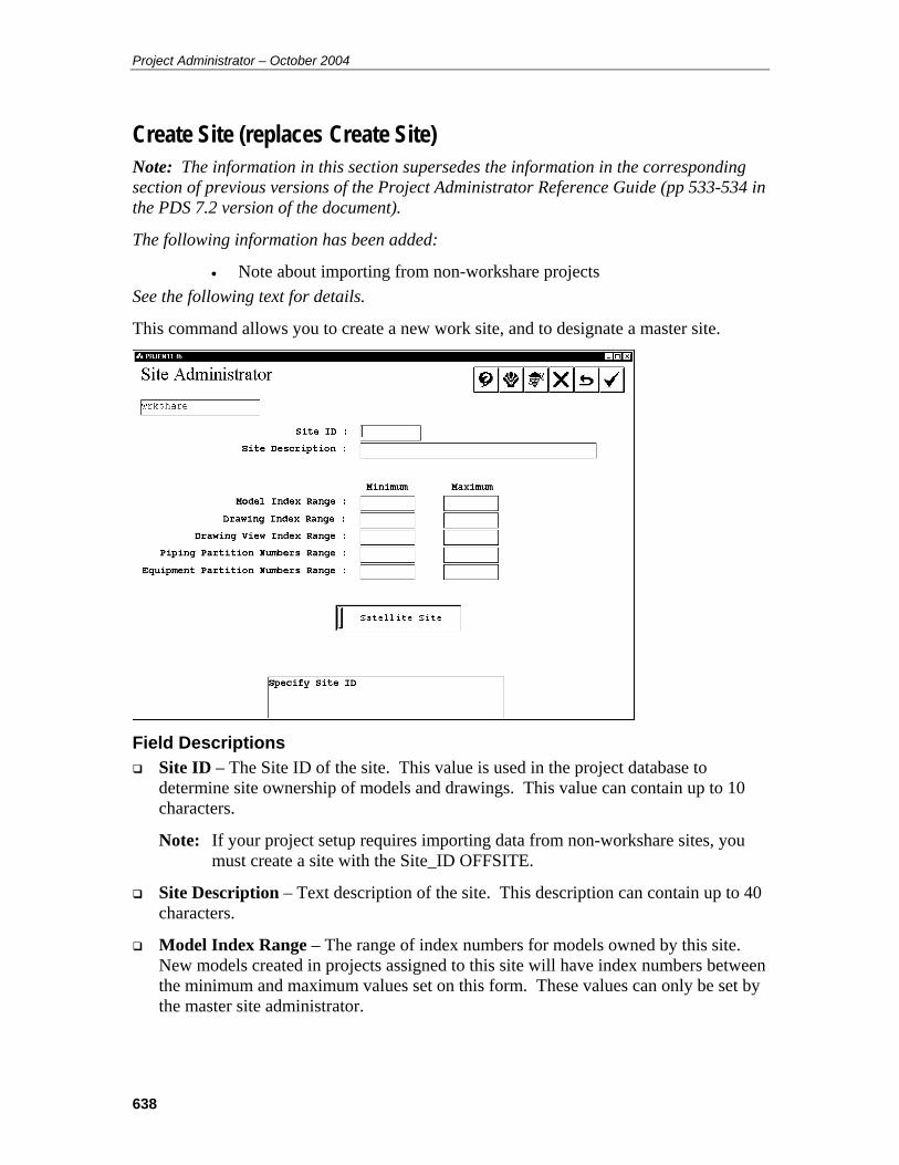
Project Administrator – October 2004
638
Create Site (replaces Create Site) Note: The information in this section supersedes the information in the corresponding section of previous versions of the Project Administrator Reference Guide (pp 533-534 in the PDS 7.2 version of the document).
The following information has been added:
• Note about importing from non-workshare projects See the following text for details.
This command allows you to create a new work site, and to designate a master site.
Field Descriptions Site ID – The Site ID of the site. This value is used in the project database to
determine site ownership of models and drawings. This value can contain up to 10 characters.
Note: If your project setup requires importing data from non-workshare sites, you must create a site with the Site_ID OFFSITE.
Site Description – Text description of the site. This description can contain up to 40 characters.
Model Index Range – The range of index numbers for models owned by this site. New models created in projects assigned to this site will have index numbers between the minimum and maximum values set on this form. These values can only be set by the master site administrator.

639
Drawing Index Range – The range of index numbers for drawings owned by this site. New drawings created in projects assigned to this site will have index numbers between the minimum and maximum values set on this form. These values can only be set by the master site administrator.
Drawing View Index Range – The range of index numbers for drawing views owned by this site. New drawing views created in projects assigned to this site will have index numbers between the minimum and maximum values set on this form. These values can only be set by the master site administrator.
Piping Partition Numbers Range – The range of index numbers for piping partitions owned by this site. New piping models created in projects assigned to this site will have partition numbers between the minimum and maximum values set on this form. These values can only be set by the master site administrator.
Equipment Partition Numbers Range – The range of index numbers for equipment partitions owned by this site. New equipment models created in projects assigned to this site will have partition numbers between the minimum and maximum values set on this form. These values can only be set by the master site administrator.
Master Site / Satellite Site toggle– This read-only toggle shows whether the site is the master site for the project or a satellite site. By default, the first site created is the master site.
Operating Sequence 1. Select Create Site on the Site Administrator form.
The Create Site form displays.
2. Set the values as necessary for the new site.
Note: The first site you create will be the master site. Subsequent sites will all be satellite sites.
3. Click Accept.
The system adds the new site data to the database.
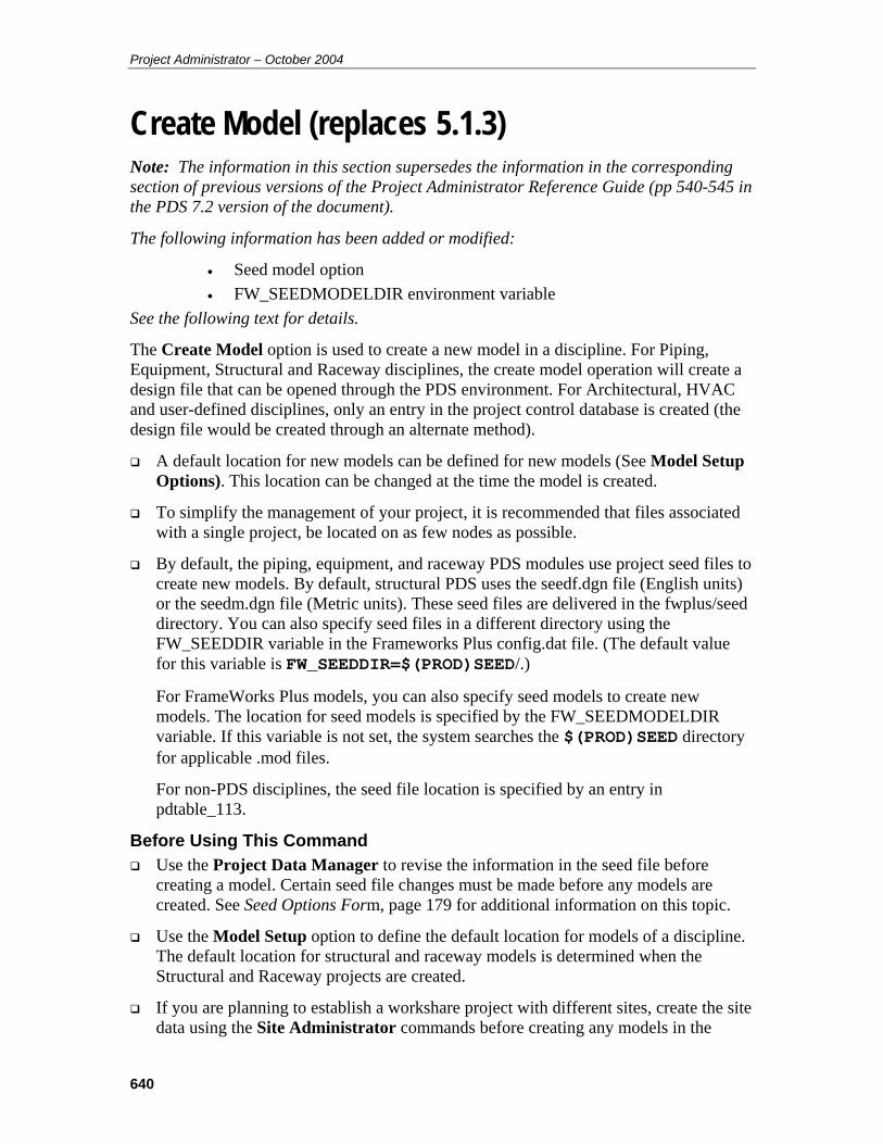
Project Administrator – October 2004
640
Create Model (replaces 5.1.3) Note: The information in this section supersedes the information in the corresponding section of previous versions of the Project Administrator Reference Guide (pp 540-545 in the PDS 7.2 version of the document).
The following information has been added or modified:
• Seed model option • FW_SEEDMODELDIR environment variable
See the following text for details.
The Create Model option is used to create a new model in a discipline. For Piping, Equipment, Structural and Raceway disciplines, the create model operation will create a design file that can be opened through the PDS environment. For Architectural, HVAC and user-defined disciplines, only an entry in the project control database is created (the design file would be created through an alternate method).
A default location for new models can be defined for new models (See Model Setup Options). This location can be changed at the time the model is created.
To simplify the management of your project, it is recommended that files associated with a single project, be located on as few nodes as possible.
By default, the piping, equipment, and raceway PDS modules use project seed files to create new models. By default, structural PDS uses the seedf.dgn file (English units) or the seedm.dgn file (Metric units). These seed files are delivered in the fwplus/seed directory. You can also specify seed files in a different directory using the FW_SEEDDIR variable in the Frameworks Plus config.dat file. (The default value for this variable is FW_SEEDDIR=$(PROD)SEED/.)
For FrameWorks Plus models, you can also specify seed models to create new models. The location for seed models is specified by the FW_SEEDMODELDIR variable. If this variable is not set, the system searches the $(PROD)SEED directory for applicable .mod files.
For non-PDS disciplines, the seed file location is specified by an entry in pdtable_113.
Before Using This Command Use the Project Data Manager to revise the information in the seed file before
creating a model. Certain seed file changes must be made before any models are created. See Seed Options Form, page 179 for additional information on this topic.
Use the Model Setup option to define the default location for models of a discipline. The default location for structural and raceway models is determined when the Structural and Raceway projects are created.
If you are planning to establish a workshare project with different sites, create the site data using the Site Administrator commands before creating any models in the
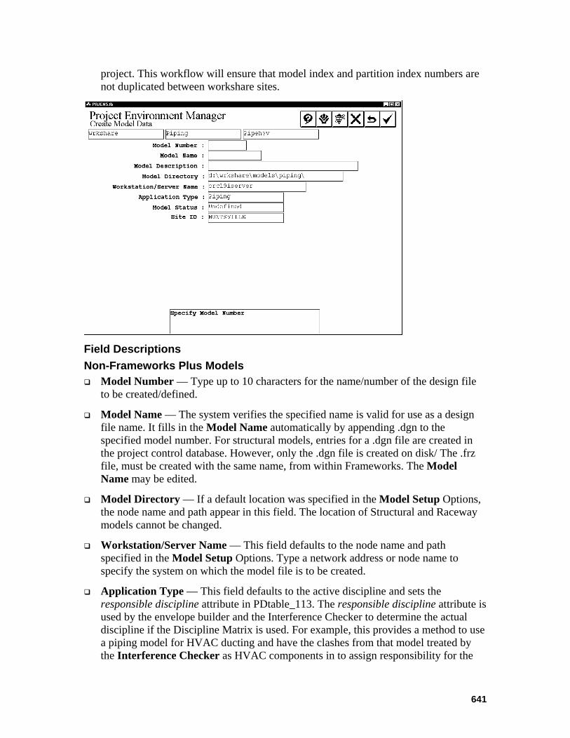
641
project. This workflow will ensure that model index and partition index numbers are not duplicated between workshare sites.
Field Descriptions Non-Frameworks Plus Models Model Number — Type up to 10 characters for the name/number of the design file
to be created/defined.
Model Name — The system verifies the specified name is valid for use as a design file name. It fills in the Model Name automatically by appending .dgn to the specified model number. For structural models, entries for a .dgn file are created in the project control database. However, only the .dgn file is created on disk/ The .frz file, must be created with the same name, from within Frameworks. The Model Name may be edited.
Model Directory — If a default location was specified in the Model Setup Options, the node name and path appear in this field. The location of Structural and Raceway models cannot be changed.
Workstation/Server Name — This field defaults to the node name and path specified in the Model Setup Options. Type a network address or node name to specify the system on which the model file is to be created.
Application Type — This field defaults to the active discipline and sets the responsible discipline attribute in PDtable_113. The responsible discipline attribute is used by the envelope builder and the Interference Checker to determine the actual discipline if the Discipline Matrix is used. For example, this provides a method to use a piping model for HVAC ducting and have the clashes from that model treated by the Interference Checker as HVAC components in to assign responsibility for the

Project Administrator – October 2004
642
clash. Refer to the Interference Checker/Manager (PD_Clash) User’s Guide for more information.
Model Status — Select a value for model status from the list. The model status can be used to create subsets of models for clash checking or for DesignReview.
Site ID — This field specifies which work site owns the model. When creating models from the master site, the Site ID can be set to any site appearing in pdtable_105. When creating models from a satellite site, the Site ID is automatically set to the value for the satellite site. The master site can create models for any site. A satellite site can only create models for itself.
Note: The Site_ID field displays only for a workshare project; that is, a project whose site_id attribute is set in pdtable_101.
Framework Plus Models Seed Model — Specifies the name of the seed model to use as a basis for the new
FrameWorks Plus model.
Frozen Model Name — The name of the frozen model for this FrameWorks Plus model. An entry is created in pdtable 113 for the sparse (modname.dgn) and frozen (modname.prp) files for each FrameWorks Plus model. The frozen model file is created by opening the sparse file, creating views, placing FrameWorks Plus members, freezing a view then propagating the model file.
Force Units — Specifies the force units for the model (unit for specifying load force).
Standard Section Table — Specifies the main standard section table for this model. You cannot change the standard section table after the model is created.

643
User Section Table — Specifies a user section table for this model. All user section tables, if any, in the project’s \sl directory display for selection. You can select another user section table after the model is created if needed.
Third Party Software — Specifies which third party analysis/design software to use for the model. If necessary, you can change the selection after the model is created.
Design Code — Specifies the design code to use for the model. If necessary, the selection can be changed after the model is created.
Sparse Model Name — Displays the system assigned Sparse Model Name. This name is based on the model name.
Propagated and Sparse toggle — Determines whether the frozen files have centerlines displayed as part of the members.
Sparse Model Directory — Displays the system assigned Sparse Model Directory. This value is based on the Model Directory.
Sparse Workstation/Server Name — Displays the system assigned sparse workstation/server name. This value is based on the model Workstation/Server Name.
Note: If a seed model is selected, the following values are grayed out, because they are defined in the seed model:
Force Units Standard Section Table User Section Table Third Party Software Design Code
Operating Sequence 1. Select Option.
Select the Create Model Data option from the Create Options form.
2. Select Discipline.
Select the discipline for the model file to be created from the list of displayed disciplines and choose Confirm.
The Select Area for Create Model Data form is displayed showing available design areas.
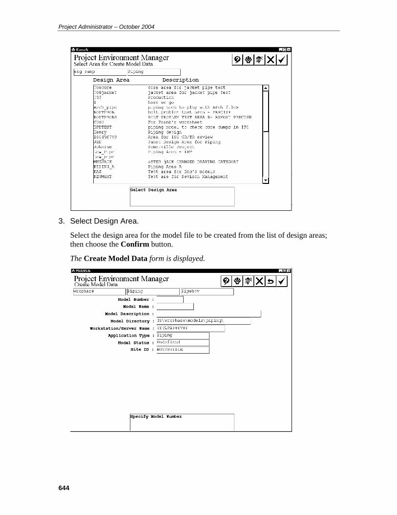
Project Administrator – October 2004
644
3. Select Design Area.
Select the design area for the model file to be created from the list of design areas; then choose the Confirm button.
The Create Model Data form is displayed.
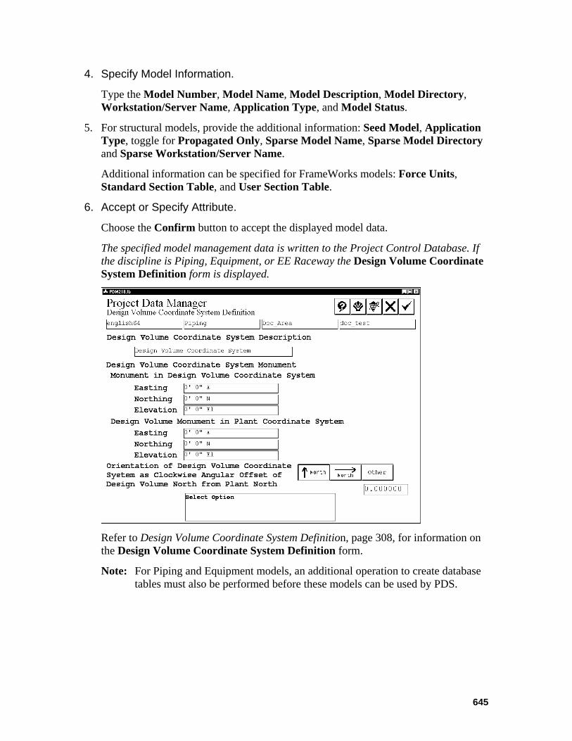
645
4. Specify Model Information.
Type the Model Number, Model Name, Model Description, Model Directory, Workstation/Server Name, Application Type, and Model Status.
5. For structural models, provide the additional information: Seed Model, Application Type, toggle for Propagated Only, Sparse Model Name, Sparse Model Directory and Sparse Workstation/Server Name.
Additional information can be specified for FrameWorks models: Force Units, Standard Section Table, and User Section Table.
6. Accept or Specify Attribute.
Choose the Confirm button to accept the displayed model data.
The specified model management data is written to the Project Control Database. If the discipline is Piping, Equipment, or EE Raceway the Design Volume Coordinate System Definition form is displayed.
Refer to Design Volume Coordinate System Definition, page 308, for information on the Design Volume Coordinate System Definition form.
Note: For Piping and Equipment models, an additional operation to create database tables must also be performed before these models can be used by PDS.
Project Administrator – October 2004
646
Create Model Data from ASCII File (replaces 5.1.6) Note: The information in this section supersedes the information in the corresponding section of previous versions of the Project Administrator Reference Guide (pp 557-562 in the PDS 7.2 version of the document).
The following information has been added:
• Corrected first ASCII file example • Added information to Site ID keyword description
See the following text for details.
The Create Model Data from ASCII File creates areas, models and drawings from an ASCII input file. For piping, equipment, structural, and raceway models, design files are created. For other disciplines, only the model definitions are created. For Piping and Equipment models, you can also specify a Design Volume Coordinate System for each model.
Note: This command can be used to create model definitions for existing ModelDraft or Frameworks Plus models without writing over the existing design files.
Format Information in the ASCII files is the same as that entered into the forms seen in the PDS Environment.
The format used to define the model management data is a set of entries of the form:
Keyword:data.
There must be a colon (:) separating the keyword and the data.
For any entry in this list, there is a maximum of 132 characters per line of data.
The ASCII file(s) to be used to create a model, must be in order by the keywords listed below. The software will not function at all if the order is wrong.
For structural models, the Force Units, Standard Section Table and User Section Table values come from the FrameWorks Plus information in the project database. The default value for the Third Party Software option is STAADIII, and the default value for the Design Code is AISC-ASD. These defaults are the same values that appear in a model create using the Create Model Interactive command.
647
Keywords The following keywords are used to define the data; they are the same as the fields specified in the Create Design Area form and the Create Model Data form, including structural models:
Site_ID — An optional value for the site ID. If no value is specified, the site ID will be the same as the project site ID set in pdtable_101. If the project does not belong to a site, the site ID is set to NULL. This keyword is case sensitive. This keyword should only appear once in a particular ASCII file. If models are to be created for multiple site IDs, a separate ASCII file is required for each site ID.
Discipline — The discipline name exactly as it appears in the PD_Shell environment (example: Discipline:Piping). This is required information.
Area_Name — A required 20-character design area name; it must be unique across disciplines (example: Area_Name:Piping_A).
Area_Desc — An optional 40-character description for the design area being created (example: Area_Desc:Piping Area A).
Note: This keyword is required when creating a new area. If the area already exists, use Area_Name only.
Area_Marker_File — An option to indicate that you want an interference marker file for the area (example: Area_Marker_File:Yes).
Note: This option is only for use in combination with Area_Desc.
Area_Volume_Low/High — An option that indicates if the design area will have a predefined volume for interference checking purposes. This is required if Area_Marker_File is Yes; the low volume and high volume represent the limits of the volume processed by the interference checker (example: Area_Volume_Low:-100,-250,-50 Area_Volume_High:150,30,120).
Note: This option is only for use in combination with Area_Marker_File.
Sub_Proj_Number — Required information for new structural models. It is the structural subproject number of the FrameWorks Plus or ModelDraft subproject. (example: Sub_Proj_Number:fw_proj1)
Note: This option is required when creating a new area in combination with Area_Desc.
Model_Number — A required 10-character piping model number of the model to be created (example: Model_Number:Model_A).
Model_Desc — A required 40-character description of the model to be created (example: Model_Desc:Model A Description).
Project Administrator – October 2004
648
File_Spec — An optional 14-character file specification of the model to be created. If a value is not specified or the keyword is missing, the file specification defaults to the model number with the extension .dgn (example: Model_A.dgn).
Note: This option is not supported for structural models, because the file specification is defined in the subproject.
Path_Name — An optional 35-character directory path where the model file is to be created (example: d:\proj\models\). If this value is not specified or the keyword is missing, the default values as defined with the Model Setup option are used.
Note: This option is not supported for structural models, because the file specification is defined in the subproject.
Network_Address — An optional 26-character node name of the system on which the model file is to be stored (example: Network_Address:jwdoe_3). This value is not specified or the keyword is missing, the default values as defined with the Model Setup option, are used.
Note: This option is not supported for structural models, because the file specification is defined in the subproject.
DVCS_Desc — An optional 40-character Design Volume Coordinate System description. This entry is only used by piping and equipment models (example: DVCS_Desc:Design Vol Coordinate System of Model A).
Monument_in_DVCS — Optional easting, northing, and elevation values (separated by commas) of the center of the Design Volume Coordinate System (example: Monument_In_Dvcs:100,100,100). This data is only used by piping and equipment models. If the data is not specified, the Design Volume Coordinate System’s monument defaults to the center of the model.
DVCS_Monument_in_Plant — Optional easting, northing, and elevation values (separated by commas) of the Design Volume Coordinate System monument in terms of the Plant Coordinate System (example: DVCS_Monument_in_Plant:200,200,100). This data is only used by piping and equipment models. If the data is not specified, the Design Volume Coordinate System’s monument defaults to the center of the model.
Orientation_of_DVCS — An optional value indicating the orientation of the x-axis in a Plan View as defined by one of the following values:
East (the default value if not specified otherwise)
North An angle measured clockwise from the MicroStation X-axis (example: Orientation_of_DVCS:45).
This data is only used by piping and equipment models. If the data is not specified, the East axis of the Design Volume Coordinate System is aligned with the x-axis of the MicroStation design file coordinate system.
649
Application_Type — An optional value indicating the discipline association for interference checking purposes. It associates the design model with a different discipline for reporting clashes. The default is the discipline where the design model is created (example: Application_type:Piping).
Model_type — For structural models only, the type of structural model to be created.
Its value is set as follows:
sparse — Creates project control database information for a sparse model in the \MOD directory and creates the required files in this directory.
propagated — Specifies model_type=0 in pdtable_113. Running batch propagation on a file with this status results in a propagated-only model. This value creates an entry in the project control database for a propagated design file in the \FRZ directory.
both — Specifies model_type=2 in pdtable_113. This value specifies that while running batch propagation, the .prp file will contain the sparse model (a single line model) and a 3D model (the propagated model). This value creates a project control database entry for a propagated model in the \FRZ directory.
The only Model_Type value that actually creates physical files is sparse. This value, if the model does not already exist, executes the FrameWorks Plus cremod utility, which creates all 14 files in the FW+ project\MOD directory as well as a corresponding entry in pdtable_113. The propagated and both values do NOT create physical files; they only create entries in pdtable_113.
Model_Status — An optional value for the model status from code list set 1605. This value is used to exclude models from being processed in PD_Clash.
Project Administrator – October 2004
650
The following is an example of a simple file used to create one piping model and one structural model that both belong to the HUNTSVILLE site: Site_ID:HUNTSVILLE Discipline:Piping Area_Name:Piping_A Area_Desc:Piping Area A Model_Number:A2pipe1 Model_Desc:Piping Model 1 from ASCII File_Spec:A2pipe1.dgn Path_Name:C:\users\acme\proj1\ Network_Address:pds_serv DVCS_Desc:Model DVCS Monument_in_DVCS:-1000,0,0 DVCS_Monument_in_Plant:350,325,0 Orientation_of_DVCS:North Application_Type:Piping Discipline:Structural Area_Name:SA1 Area_Desc:FrameWorks Plus Area A Steel Sub_Proj_Number:fwproj1 Area_Marker_File:Yes Area_Volume_Low:-100,-250,-50 Area_Volume_High:150,30,120 Model_Number:steel1 Model_Desc:Structural Model 1 from ASCII Model_Type:both Path_Name:c:\users\acme\stproj1 Network_Address:pds_serv Application_Type:Structural
The following listing is an example of an ASCII file used to create structural models and project control database information. Discipline:Structural Area_Name:AS1 Area_Desc:Frameworks Plus Area Steel Area_Marker_File:Yes Area_Volume_Low:-100,-250,-50 Area_Volume_High:150,30,120 Sub_Proj_Number:fwproj1 Model_Number:steel1 Model_Desc: linear Model_Type:sparse Application_Type:Structural Model_Number:steel1 Model_Desc:linear prp Model_Type:both Application_Type:Structural
Before Using This Command Create an ASCII file to define the models to be created using the specified
conventions.
For structural models and areas, the FrameWorks Plus Project must have been created using the Project Administrator > Project Setup Manager > Insert FrameWorks Project command.
Operating Sequence 1. Select Create Model from ASCII File Option.
Select the Create Model from ASCII File option from the Create Options form.

651
The Create Model from ASCII File form is displayed.
2. Specify ASCII File Spec.
Type the information for the location of the ASCII file in the ASCII File Name, Directory and Network Address fields.
3. Submit Immediately or Submission is Delayed Select Submit Immediately to begin processing the request as soon as you exit the form.
—OR —
Select Submission is Delayed to specify a time to process the request.
4. Accept the specified time.
Choose the Confirm button to accept the specified time.
The request is submitted to the batch queue PDcreate_model.
Note: For Piping and Equipment models created using this method, the tables in the Piping Design Database must still be created. Use the Create Database Tables option of the Project Environment Manager for this.
Project Administrator – October 2004
652
Revise Model Data (replaces 5.2.5) Note: The information in this section supersedes the information in the corresponding section of previous versions of the Project Administrator Reference Guide (pp 156-157 in the PDS 7.1 version of the document).
The following information has been added:
• Renaming a model also renames related files. See the following text for details.
The Revise Model Data option is used to change the name, description, application type or model status of an existing model file.
Operating Sequence 1. Select the Revise Model Data Option.
Select the Revise Model Data option from the Revise Options form.
A list of disciplines is displayed.
2. Select Discipline.
Select the discipline of the model file to be modified; then choose the Confirm button.
The design areas for the selected discipline are displayed.
3. Select Design Area.
Select the Design Area of the model file to be modified; then choose the Confirm button.
The model files for the selected design area are displayed.
4. Select Model.
Select the model to be revised; then choose Confirm.
The model number and description are displayed.

653
5. Select Attribute for Revision or Select Another Model.
Type any modifications to the model number or model description. To change the Application Type and/or Model Status, select the field and select the setting from the displayed list.
Note: If you change the model number, the names of any related files in the model directory are automatically changed to match the new model number. Exceptions to this action are structural models, models that have been sent to DesignReview, and output files that are placed in a location other than the model directory.
6. For structural models, set the toggle to Propagated and Sparse or Propagated Only.
7. Accept or Cancel Changes.
Choose the Confirm button to process the specified change(s).
—OR —
Choose the Cancel button to dismiss the form.
The system verifies the specified name is valid for use as a design file name. The project control database is updated and a prompt to select another model file.

Project Administrator – October 2004
654
Report - Named Items (replaces 5.4.2) Note: The information in this section supersedes the information in the corresponding section of previous versions of the Project Administrator Reference Guide (pp 171-173 in the PDS 7.1 version of the document).
The following information has been added:
• Location of created file in the last step of the operating sequence See the following text for details.
The Report - Named Items option creates a report on a Named Item in the Project Design Database. This report contains a list of model files which contain the Named Item, their associated area specifications, and their associated disciplines.
Option Descriptions Named Items Options — A report may be generated based on the selected option:
Piping Component Number Line Number Label Instrument Component Number Equipment & Nozzle Number Line ID Pipe Equipment Number Pipe Support
Data entry field — Type selection data associated with the chosen Named Item Option.
Submit Immediately or Submission is Delayed Select Submit Immediately to begin copying the model as soon as you exit the form.
—OR —
Select Submission is Delayed to specify a time to process the copy.
655
Operating Sequence 1. Select the Report-Named Item form.
Select the Report-Named Item form from the Report Options form.
The Report-Named Item form is displayed.
2. Select Option.
Select the option for the type of Named Item to be reported.
One of the following prompts is displayed based on the option you select:
3. Specify Line Number Label.
Type the line number label to be reported. The Line Number Label is composed of several attributes as defined in the Label Description Library.
4. Specify Line ID.
Type the line identification to be reported. The Line ID is composed of the Unit Code, Line Number, and the fluid code.
Specify Component Number Specify Instrument Number Specify Pipe Number Specify Pipe Support Number
Type the tag number of the item(s) to be reported.
5. Specify Equipment Number.
Type the equipment identification.
6. Specify Nozzle Number.
Type the equipment number/nozzle ID.
You can specify more than one value for the selected attribute.
7. Submit Immediately or Submission is Delayed Select Submit Immediately to begin the report as soon as you exit the form.
—OR —
Select Submission is Delayed to specify a time to process the report.
8. Accept Data.
After specifying all the values to be reported, choose the Confirm button to accept the data defined for the search and to submit the job to the batch queue for processing.

Project Administrator – October 2004
656
The Project Design Database is searched for the named item(s), and a report of the associated model specification is created in a file named project.rni in the /temp directory.
Here is an example of a created report: Report on Named Items
Date: 26-Mar-01 Time: 08:49:48
Equipment Number : 40E-101 eqpmod1 Eqp Model for Cert
657
Piping Data Control (replaces 6.1.20) Note: The information in this section supersedes the information in the corresponding section of previous versions of the Project Administrator Reference Guide (pp 226-229 in the PDS 7.1 version of the document).
The following information has been added:
• Rule for Insulation Purpose when set to None toggle See the following text for details.
The Piping Data Control option is used to enable/disable access to the weight table, select the option for processing schedule/thickness override, and specify working units and classifications for nominal piping diameter.
Field Descriptions Fluid Code Control— Specifies whether the system will use the setting for the fluid
code in the Piping Materials Class data of the Piping Job specification to limit the acceptable fluid code(s) while modeling. The default is to not limit the fluid code values.
Weight Table — Specifies whether a weight table is to be used to find the dry weight of a component. Using a weight table is required for those cases where, for a specific geometric industry standard, material causes the dry weight data to differ, but not the dimensional data.
Geometric Industry Standard — Specifies the geometric industry standard to be used for the company practice Physical Data Library.
When this toggle is set to Default, the geometric industry standard range is defined to be from 31,000 through 31,999. This setting is required if you plan to use any of the following industry practices: European B, International A, or International B.
When this toggle is set to Expanded, the geometric industry standard range for company practice is defined to be from 28,000 through 31,999. This is the active option for any piping models created with the 4.0 version of PDS.
P&ID Database— Specifies whether the Master or the Task PID database is used, if both are available for the project.
Branch Component Assoc for Isometric Drawings— Specifies whether the branch component will be associated with the header line or branch line during isometric extraction.
Note: This property only applies to olet geometry branch components. Tees, crosses and wyes follow the ISOGEN convention of being owned by the line at CP1 of the fitting.
Project Administrator – October 2004
658
Copy — Specifies whether to append ** as a prefix to name attributes (for example, line number label and component number) to signify that the segment or component was copied and that the name attribute may require updating.
Piping Segment Data— Specifies whether the Brief list or the Complete list of piping segment data should be displayed as the default in the Piping Designer graphics environment. Refer to Default Segment Data, page 240 , for more information on segment data.
T-P Data for Service Limits Verification— Specifies whether temperature and pressure values are to meet the minimum normal operating and normal design specifications.
System of Units for Nominal Piping Diameter — Sets a default system of units for nominal piping diameter independently of the system of units for the model. The setting for NPD units can be toggled between English units and metric units. This setting can be overridden while working in the model.
System of Units for Corrosion Allowance — Used to set the system of units for corrosion allowance to English or metric.
Rule for Insulation Purpose when set to None — Specifies whether the system clears the insulation density on the segment when the segment insulation purpose is set to 1 (blank) or 2 (none). If the insulation density is undefined, setting the insulation purpose to blank or none will NOT change the insulation density when this toggle is set to Do Not Clear Density. The insulation density will be set to undefined when this toggle is set to Clear Density and the insulation purpose is set to blank or none.
Note: In the graphical environment, the following commands will respect this toggle when the insulation purpose is set to blank or none: Sketch, Load Active Segment, and Revise Attributes.
Schedule Thickness Override Option — Specifies how the piping segment override schedule/thickness is to be treated during wall thickness calculations and branch reinforcement calculations. Three options are available: Larger of Override and Spec, Override Value Only, and Override but Report Error. If the Larger of Override and Spec option is selected, the override schedule/thickness (if it has been defined) is used if it exceeds the value in the Piping Job Specification. If an override schedule/thickness has not been defined, the value from the Piping Job Specification is used.
If the Override Value Only option is selected, the override schedule/thickness (if it has been defined) is used instead of the value in the Piping Job Specification.
If the Override but Report Error option is selected, the override schedule/thickness (if it has been defined) is used if it exceeds the value in the Piping Job Specification. Otherwise, an error is reported.
The override schedule/thickness is never used for any situation where the value from the Piping Job Specification is ’not required’.

659
If either the piping segment schedule/thickness override or the pipe schedule/thickness is defined as a schedule value, the schedule is converted to a wall thickness value for comparison. This conversion uses NPD, termination type, table suffix, and weight code.
Field Name for Nominal Piping Diameter— Specifies the field name to be used with NPD units (for example, IN or " for English or mm for metric).
Maximum Number of Blocks for Piping Design File— Sets the maximum size (in blocks) for a piping model. If a design file reaches this maximum value, the system displays a dialog box warning the maximum size has been reached when exiting the Piping Designer graphics environment.
Operating Sequence 1. Select Option
Select the Piping Data Control option from the Revise Piping Model Data form.
The Piping Data Control form is displayed.
2. Select Fluid Code Control
Set the toggle to Yes or No, indicating whether to limit acceptable fluid code values while modeling.
3. Select Weight Table.
Set the toggle to Yes or No, indicating whether to use a weight table to find the dry weight of a component.
4. Select Geometric Industry Standard.

Project Administrator – October 2004
660
Set the toggle to Default or Expanded, indicating the range to use.
5. Select P&ID Database.
Select the task or master P&ID database.
6. Select Branch Component Assoc for Isometric Drawings
Set the toggle to Header or Branch, indicating whether the branch component is to be associated with the header line.
7. Select Copy.
Set the toggle to Append Prefix or No Prefix> indicating whether to append ** as a prefix to name attributes.
8. Select Piping Segment Data.
Set the toggle to Complete or Brief indicating the complete or brief list of piping segment data should be displayed.
9. Select T-P Data for Service Limits Verification
Set the toggle to Minimum or No Minimum to indicate if temperature and pressure valves are to meet minimum normal operating and design specifications.
10. Select System of Units for Nominal Piping Diameter.
Set the toggle to English or Metric.
11. Select System of Units for Corrosion Allowance
Set the toggle to English or Metric.
12. Select Rule for Insulation Purpose when set to None.
Set the toggle to Clear Density or Do Not Clear Density.
13. Select Schedule Thickness Override Option.
Select Larger of Spec and Override, Always Use Override, or Override, but Report Error.
14. Select Field Name for Nominal Piping Diameter.
Type a 2-character alphanumeric field name.
15. Specify Maximum Number of Blocks for Piping Design File.
Type up to 5-character numeric maximum size.
16. Accept Piping Data Control information.
Choose the Confirm button to accept the Piping Data Control information.
The Revise Piping Model Data form is displayed.

661
Propagate Piping Model Data (replaces 6.1.33) Note: The information in this section supersedes the information in the corresponding section of previous versions of the Project Administrator Reference Guide (pp 269-271 in the PDS 7.1 version of the document).
The following information has been added:
• Rule for Insulation Purpose/Density See the following text for details.
The Propagate Piping Model option distributes selected settings from the active piping model seed file to all piping models within the active project or a list of selected piping models. The following Type 63 data can be propagated to the specified piping models:
Date/Time Format, page 187 Component Placement, page 223 Piping Data Control, page 226 Physical Units, page 230 Nozzle Transfer, page 233 Material Takeoff, page 235 Design Review Label, page 239 Reference Database File Specifications - Review File Names, page 242 Design Checks Options, page 245 Design Checks End Prep Table, page 248 Symbology Diagnostic Markers, page 251 Symbology - Insulation, page 257 Rule for Insulation Purpose/Density, page 657
The only model data that cannot be propagated is the Default Active Segment Data option and the Level and Color options, which should not be revised after piping models have been created.
Field Descriptions Model Data Options — Displays the model data options available for propagation.
Piping Models Selection toggle — Specifies Selected Piping Models or All Piping Models for propagation. Set the toggle to All Piping Models to propagate the selected parameters to all the piping models in the active project.
—OR —
Set the toggle to Selected Piping Models to select the model files to be updated from a list of design areas.
Submission toggle — Specifies Submit Immediately or Submission is Delayed for model propagation. Set the submission toggle to Submit Immediately to begin processing the request when the form is exited.
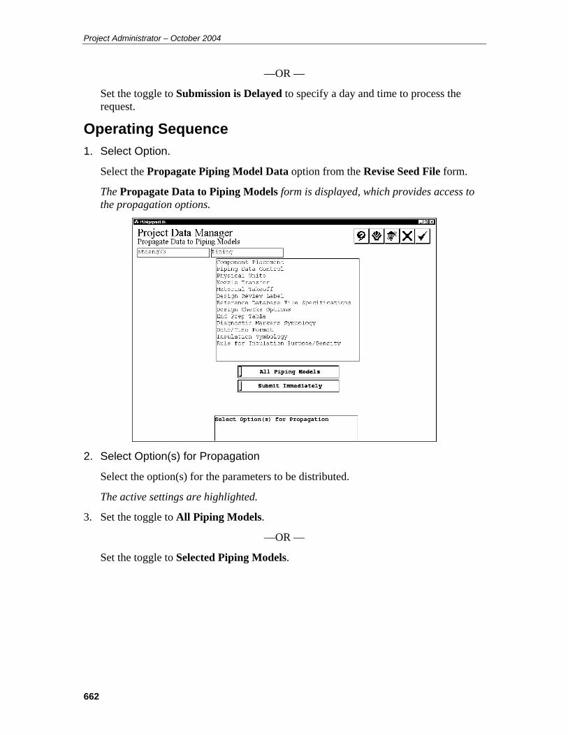
Project Administrator – October 2004
662
—OR —
Set the toggle to Submission is Delayed to specify a day and time to process the request.
Operating Sequence 1. Select Option.
Select the Propagate Piping Model Data option from the Revise Seed File form.
The Propagate Data to Piping Models form is displayed, which provides access to the propagation options.
2. Select Option(s) for Propagation
Select the option(s) for the parameters to be distributed.
The active settings are highlighted.
3. Set the toggle to All Piping Models.
—OR —
Set the toggle to Selected Piping Models.
663
4. Set the submission toggle to Submit Immediately.
—OR —
Set the toggle to Submission is Delayed.
5. Accept Propagation Data.
If All Piping Models is active, go to Step 9.
—OR —
If Selected Piping Models is selected, the system displays a list of design areas for the project.
6. Select Design Area
Select the design area for the model file(s) to be updated and choose the Confirm button.
7. Select Model.
Select the model file(s) to be updated.
8. Accept Model File(s).
Choose the Confirm button to accept model file(s).
9. Accept to Submit for Processing or Select Area for Addition Models
Repeat steps 6 and 7 to select additional areas/models.
10. Accept Propagation Request.
Choose the Confirm button to process the request.
The request is submitted to the batch queue named PDproject_data.

Project Administrator – October 2004
664
PDS Drawing Annotation Category Data (replaces 6.1.39) Note: The information in this section supersedes the information in the corresponding section of previous versions of the Project Administrator Reference Guide (pp 281-283 in the PDS 7.1 version of the document).
The following information has been added:
• Color, style, and weight settings for Area Volume Graphics. See the following text for details.
The PDS Drawing Annotation Category Data option is used to define the color codes and line weights for the basic categories of drawing data and to define the settings used to place a report file in a drawing. When this option is selected, the PDS Drawing Annotation Category Data form is displayed.
Field Descriptions Weights —When a line weight field is selected, a slide bar is displayed at the bottom
of the form. Place a data point along the slider to set the weight.
Colors — When a color field is selected, the Select Color form is displayed with the
active color settings for the project. Select the color from the form; then choose the Confirm button.
Text Size — When the text size fields are selected, the available size options are displayed at the bottom of the form. Select the option for the required text size.

665
Symbology — When this field is selected, the available symbology options are
displayed at the bottom of the form. Select the line symbology to be used.
Operating Sequence 1. Select Option.
Select the PDS Drawing Annotation Category Data option from the Drawings form.
2. Specify Weights and Colors.
Specify the line weight and color for the categories of drawing graphics.
Revision Cloud
Flow Arrow
Report
Date and Time for Plotting and VHL
Matchline Labels
Dimensioning
Miscellaneous
3. Select Symbology for Matchline Labels.
Specify Symbology for Matchline Labels.
4. Select text size options.
Specify the text size for Reports and Date and Time for Plotting and VHL.
5. Select Area Volume Graphics options.
Specify the display options for area volume graphics.
6. Accept PDS Drawing Annotation Category Data.
Choose the Confirm button to accept PDS Drawing Annotation Category Data
The Drawings form is displayed.
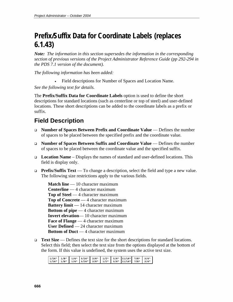
Project Administrator – October 2004
666
Prefix/Suffix Data for Coordinate Labels (replaces 6.1.43) Note: The information in this section supersedes the information in the corresponding section of previous versions of the Project Administrator Reference Guide (pp 292-294 in the PDS 7.1 version of the document).
The following information has been added:
• Field descriptions for Number of Spaces and Location Name. See the following text for details.
The Prefix/Suffix Data for Coordinate Labels option is used to define the short descriptions for standard locations (such as centerline or top of steel) and user-defined locations. These short descriptions can be added to the coordinate labels as a prefix or suffix.
Field Description Number of Spaces Between Prefix and Coordinate Value — Defines the number
of spaces to be placed between the specified prefix and the coordinate value.
Number of Spaces Between Suffix and Coordinate Value — Defines the number of spaces to be placed between the coordinate value and the specified suffix.
Location Name – Displays the names of standard and user-defined locations. This field is display only.
Prefix/Suffix Text — To change a description, select the field and type a new value. The following size restrictions apply to the various fields.
Match line — 10 character maximum Centerline — 4 character maximum Top of Steel — 4 character maximum Top of Concrete — 4 character maximum Battery limit — 14 character maximum Bottom of pipe — 4 character maximum Invert elevation— 10 character maximum Face of Flange — 4 character maximum User Defined — 24 character maximum Bottom of Duct — 4 character maximum
Text Size — Defines the text size for the short descriptions for standard locations. Select this field; then select the text size from the options displayed at the bottom of the form. If this value is undefined, the system uses the active text size.

667
Weight — Defines the weight text weight for the short descriptions for standard locations. Select this field, and place a data point along the slider to set the weight.
Operating Sequence 1. Select Option.
Select the Prefix/Suffix Data for Coordinate Labels option from the Drawings form.
The Prefix/Suffix Data for Coordinate Label form is displayed.
2. Specify Number of Spaces Between Prefix and Coordinate Value.
Type the number of character spaces to allow between the prefix and the coordinate value.
3. Specify Number of Spaces Between Suffix and Coordinate Value.
Type the number of character spaces to allow between the coordinate value and the suffix.
4. Specify Prefix/Suffix Text.
To change a description, select the field and type a new value.
Project Administrator – October 2004
668
5. Select Text Size.
Select this field; then select the text size from the options displayed at the bottom of the form.
6. Select Weight.
Select this field, and place a data point along the slider to set the weight.
7. Accept Prefix/Suffix Data for Coordinate Labels.
Choose the Confirm button to accept the Prefix/Suffix Data for Coordinate Labels.
The Drawings form is displayed.

669
Model Data (replaces 8.1.2) Note: The information in this section supersedes the information in the corresponding section of previous versions of the Project Administrator Reference Guide (pp 578-580 in the PDS 7.2 version of the document).
The following information has been added:
• Changed DesignReview label file name syntax. See the following text for details.
The Model Data form is used to specify the model(s) to be archived.
Option Descriptions Site ID Filter — Allows archival of models that belong to a specific work site. The
default value for this field is NONE. This filter can be used in conjunction with the other filters on this form. This option is available only for workshare projects; that is, projects whose site_id attribute is set in pdtable_101.
All Models — Archives all models for the active project.
Select By Discipline — Archives all models in a selected discipline or disciplines.
Select By Design Area — Archives all models in a selected design area or areas.
Select By Models — Archives models selected from a list of models in a specified design area.
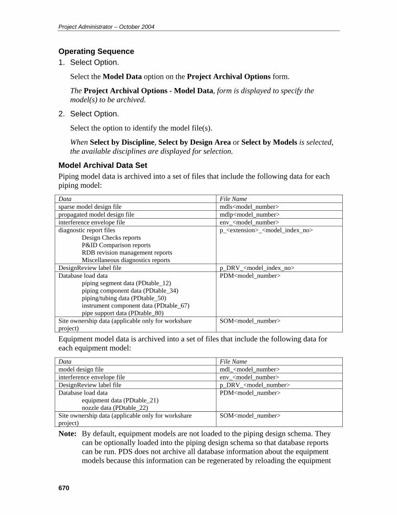
Project Administrator – October 2004
670
Operating Sequence 1. Select Option.
Select the Model Data option on the Project Archival Options form.
The Project Archival Options - Model Data, form is displayed to specify the model(s) to be archived.
2. Select Option.
Select the option to identify the model file(s).
When Select by Discipline, Select by Design Area or Select by Models is selected, the available disciplines are displayed for selection.
Model Archival Data Set Piping model data is archived into a set of files that include the following data for each piping model:
Data File Name sparse model design file mdls<model_number> propagated model design file mdlp<model_number> interference envelope file env_<model_number> diagnostic report files
Design Checks reports P&ID Comparison reports RDB revision management reports Miscellaneous diagnostics reports
p_<extension>_<model_index_no>
DesignReview label file p_DRV_<model_index_no> Database load data
piping segment data (PDtable_12) piping component data (PDtable_34) piping/tubing data (PDtable_50) instrument component data (PDtable_67) pipe support data (PDtable_80)
PDM<model_number>
Site ownership data (applicable only for workshare project)
SOM<model_number>
Equipment model data is archived into a set of files that include the following data for each equipment model:
Data File Name model design file mdl_<model_number> interference envelope file env_<model_number> DesignReview label file p_DRV_<model_number> Database load data
equipment data (PDtable_21) nozzle data (PDtable_22)
PDM<model_number>
Site ownership data (applicable only for workshare project)
SOM<model_number>
Note: By default, equipment models are not loaded to the piping design schema. They can be optionally loaded into the piping design schema so that database reports can be run. PDS does not archive all database information about the equipment models because this information can be regenerated by reloading the equipment
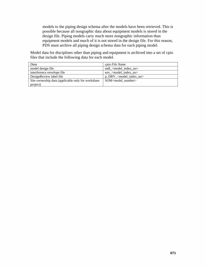
671
models to the piping design schema after the models have been retrieved. This is possible because all nongraphic data about equipment models is stored in the design file. Piping models carry much more nongraphic information than equipment models and much of it is not stored in the design file. For this reason, PDS must archive all piping design schema data for each piping model.
Model data for disciplines other than piping and equipment is archived into a set of cpio files that include the following data for each model.
Data cpio File Name model design file mdl_<model_index_no> interference envelope file env_<model_index_no> DesignReview label file p_DRV_<model_index_no> Site ownership data (applicable only for workshare project)
SOM<model_number>

Project Administrator – October 2004
672
Active Project Retrieval (replaces 8.3) Note: The information in this section supersedes the information in the corresponding section of previous versions of the Project Administrator Reference Guide (pp 584-586 in the PDS 7.2 version of the document).
The following information has been added:
• Note about exiting PD_Shell after starting retrieval to ensure standard note library retrieval.
See the following text for details.
The Active Project Retrieval option is used to retrieve all or part of a project data set from an archive into an active project. All relational database data is retrieved using the RIS load utility transparently from within the Project Retrieval command.
Active project retrieval requires the archived project to be available. This may require recreation of the archived project. Active project retrieval also requires a drawing, model or report to be retrieved must exist in the active project. Active project retrieval requires the piping and equipment models have the same database attributes as those archived.
The Approved Reference Database and Unapproved Reference Database option do not retrieve archived binary reference libraries, only archived reference database tables. To retrieve the binary files, you must use the Reference Database Libraries option or the Complete Reference Database option.
Note: When using active project retrieval to restore a piping or equipment model, error messages in the log file are displayed informing that indexes in the database already exist and cannot be recreated. No further action needs to be taken regarding this error.
Note: Active project retrieval also restores files into the locations from which they were archived. This may pose a problem if the archived files are to be restored into a different location.
Note: Active project retrieval requires that the archived project have the same name as the active project. The archived project and the active project need not be the same version. For example, piping models from a PDS 5.4 archive can be actively retrieved into a PDS 6.3 project. The model must exist in the active project prior to retrieval.
Note: In order to retrieve the standard note library properly, you must exit PD_Shell after submitting the retrieval for processing.
Caution: Active project retrieval by complete project may pose a problem if the active project contains models or drawings that are not in the archival set. In such cases, the active retrieval deletes active project data that does not appear in the archival set, including discipline, area, models, FrameWorks Plus sub-projects, and the corresponding entries in the Project Control tables (111, 112, 113, 116,
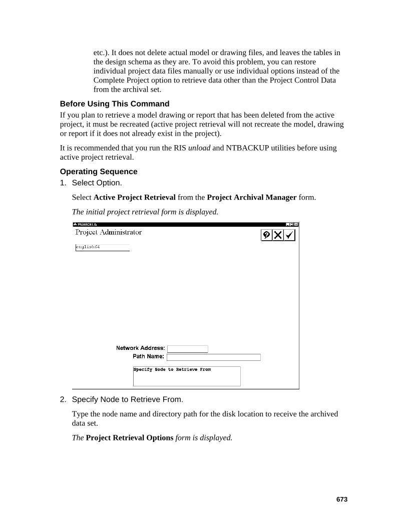
673
etc.). It does not delete actual model or drawing files, and leaves the tables in the design schema as they are. To avoid this problem, you can restore individual project data files manually or use individual options instead of the Complete Project option to retrieve data other than the Project Control Data from the archival set.
Before Using This Command If you plan to retrieve a model drawing or report that has been deleted from the active project, it must be recreated (active project retrieval will not recreate the model, drawing or report if it does not already exist in the project).
It is recommended that you run the RIS unload and NTBACKUP utilities before using active project retrieval.
Operating Sequence 1. Select Option.
Select Active Project Retrieval from the Project Archival Manager form.
The initial project retrieval form is displayed.
2. Specify Node to Retrieve From.
Type the node name and directory path for the disk location to receive the archived data set.
The Project Retrieval Options form is displayed.
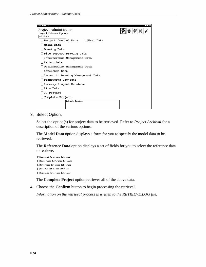
Project Administrator – October 2004
674
3. Select Option.
Select the option(s) for project data to be retrieved. Refer to Project Archival for a description of the various options.
The Model Data option displays a form for you to specify the model data to be retrieved.
The Reference Data option displays a set of fields for you to select the reference data to retrieve.
The Complete Project option retrieves all of the above data.
4. Choose the Confirm button to begin processing the retrieval.
Information on the retrieval process is written to the RETRIEVE.LOG file.
675
Import Project Retrieval (replaces 8.5) Note: The information in this section supersedes the information in the corresponding section of previous versions of the Project Administrator Reference Guide (pp 588-594 in the PDS 7.1 version of the document).
The following information has been added:
• OFFSITE Site_ID requirement for importing from non-workshare projects
• Note regarding importing structural models See the following text for details.
The Import Project Retrieval command imports models, orthographic drawings and pipe support drawings from an archive into an active project. All or selected models and drawings can be imported into the destination project.
Import project retrieval recreates a model or drawing if it does not exist in the active project. The active project and the archive must have been created in the same version of PDS.
If a model is restored to a previous version, some other data within the project temporarily may not be synchronized with the restored version of the model. For example, if a component was placed in the model at a time after the archival of that model and that component was reported as an interference clash, that same clash will appear in any Interference Manager reviews until the Interference Checker processes that model again. At that time, the record of the clash is changed to a deleted state in the Interference Management data. This is the same situation that would arise if you deleted a component involved in an interference clash.
A similar situation arises with components that are used as the source of either associative name labels or coordinate labels in orthographic drawings. The label continues to appear in the drawing until the Update Labels command is run for the applicable drawing view(s).
Any reports that were created by extracting data from the restored model will be incorrect depending on the changes that were lost in restoring to the archived version of the model.
However, the Piping Designer and the Model Builder will not re-use any of the unique numbers for piping segments and components that were lost in restoring the data to the archived version of a piping model. This data will not be restored to its previous values when a single piping model or any group of piping models is being restored to archived versions to eliminate the problem just described.
Before Using This Command This option requires that the archived data to be imported is created with PDS version 4.3 or later. Archives that were created with earlier versions of PDS do not contain an import map.

Project Administrator – October 2004
676
The source (archived) project and the destination (active) project must be consistent. This includes
Identical database structure. Any user-defined attributes in the source project must also be present in the destination project.
Identical or compatible reference data. Specification data used by the source project must be defined in the destination project. All the reference data libraries must be consistent.
Use the Model Setup command of the Project Environment Manager to define the default location for models by discipline in the destination project.
To import models into a workshare project from a project that is not set up as a workshare project, you must first set up a Site_ID named OFFSITE. This reserved Site_ID allows you to import models from non-workshare projects without enforcing the normal workshare index and partition number checks.
Operating Sequence 1. Select Option.
Select Import Project Retrieval from the Project Archival Manager form.
The archival media form is displayed.
2. Specify Node to Retrieve From.
Type the node name and directory path for the disk location containing the archived data set.
A form is displayed to define the archived data to be retrieved.
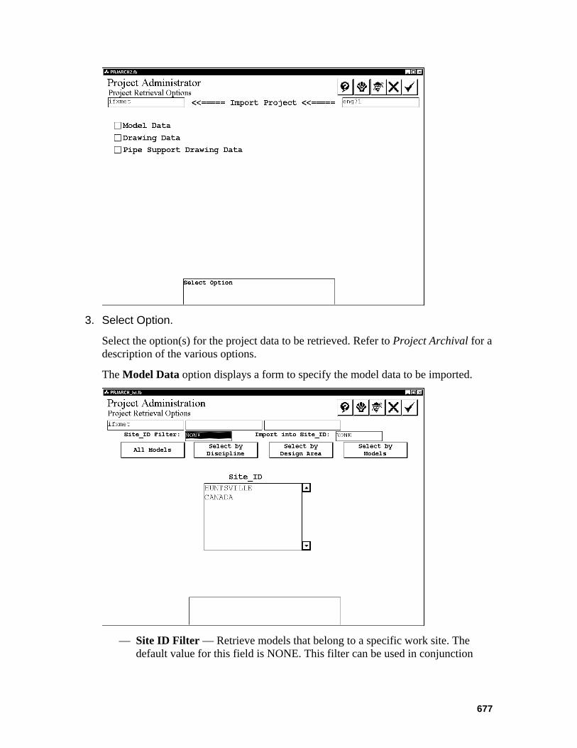
677
3. Select Option.
Select the option(s) for the project data to be retrieved. Refer to Project Archival for a description of the various options.
The Model Data option displays a form to specify the model data to be imported.
— Site ID Filter — Retrieve models that belong to a specific work site. The
default value for this field is NONE. This filter can be used in conjunction

Project Administrator – October 2004
678
with the other filters on this form. This option is applicable only to workshare projects; that is, projects whose site_id attribute is set in pdtable_101.
— Import into Site ID — Retrieve models into a specific work site. The default value for this field is NONE. This filter can be used in conjunction with the other filters on this form. This option is applicable only to workshare projects; that is, projects whose site_id attribute is set in pdtable_101.
To import models from a non-workshare project into a workshare project, you must specify the OFFSITE Site_ID.
— All Models — Retrieves all models for the active project.
— Select By Discipline — Retrieves all models in a selected discipline.
— Select By Design Area — Retrieves all models in a selected design area.
— Select By Models — Retrieves models selected from a list of models in a specified design area.
The necessary design areas and models are created during retrieval.
For Drawing Data, a form is displayed to specify the drawing(s) to be retrieved.
— Site ID Filter —Retrieve drawings that belong to a specific work site. The
default value for this field is NONE. This filter can be used in conjunction with the other filters on this form. This option is applicable only to workshare projects; that is, projects whose site_id attribute is set in pdtable_101.
— Import into Site ID — Retrieve drawings into a specific work site. The default value for this field is NONE. This filter can be used in conjunction
679
with the other filters on this form. This option is applicable only to workshare projects; that is, projects whose site_id attribute is set in pdtable_101.
— All Drawings — Retrieve all drawings for the active project.
— Select By Drawing Types — Retrieve all drawings in selected drawing type(s).
— Select Individual Drawings — Retrieve drawings selected from a list of drawings in a selected drawing type.
The Pipe Support Drawing Data option displays the Submit Immediately / Delayed Submit toggle.
4. Select Submit Immediately to begin importing files as soon as you exit the form.
—OR —
Select Delayed Submit to specify a time and date to process the request.
5. Begin Retrieval.
Choose the Confirm button to begin processing the retrieval.
The request is submitted to the batch queue PDarchival for processing. Processing information is written to the IMPORT.LOG file in the project directory.
Processing When a piping model is imported, the system may need to revise the partition number for that piping model to include the piping model in the destination project. As a consequence, the following data will also be revised as it is loaded into the destination project. The system:
Updates the partition number of piping segments and components in the graphical attribute linkages in the piping model.
Updates the partition number of piping segments and components in each system unique number in the database.
Updates the partition numbers for nozzles that are included with piping segments (for maintaining the association between the nozzle and the piping model) in the database for piping segments. Any association to nozzles that reside in an equipment model that is not in the destination project, either before or after the import process, will be cleared automatically.
Updates the partition number in the graphical attribute linkages in any orthographic drawings that are being imported that include a piping model that is being imported.
Initializes the appropriate data in the Piping Model Data Table (PDtable_114) of the Project Control Database.
Project Administrator – October 2004
680
Performs Database Verification for any piping model that has been imported. This results in orphan records in the database being deleted automatically, and orphan piping segments or components in the model having the symbology changed.
Import Model Data If the models being imported do not exist in the destination project, the system automatically creates the model management data in the Project Control Database of the destination project. These models are created with the default network address and path name defined in the Project Control Database on the basis of discipline. If this default network address and path name are not defined, an error message is displayed, and the models are not imported.
If a piping model being imported already exists in the destination project, the system updates the revision date for that model in the Project Control Database.
When importing a piping model or an equipment model into the destination project from a different project, the system maintains reference model attachments for those other models that are included in the destination project, either before or after being imported into the project. If the reference model does not exist in the destination project or it is not being imported, the system deletes that reference model attachment. When importing a model with reference model attachments, the system removes the original file path from the reference file element, and stores only the reference file name. This removal prevents the system from looking for the reference file in its original location.
When importing a model into the destination project from a different project, the other files associated with the model, such as the interference envelope file and the DesignReview label file, are not deleted or replaced. This data must be re-created, as required.
Note: When importing a structural model into a project that contains a model with the same model ID as the model being imported, the model ID for the imported model is changed. In such a case, it is recommended that you perform the following actions:
Detach and then reattach the structural models after import.
Recreate the analytical decks for the model.
Recreate the frozen views of the model.
Rerun batch propagation.
Run the Rename Elements command if the model ID is part of the element name.
Import Drawing Data If all reference models for a drawing are not in the destination project or are not being imported, the system generates an error in the error log and the drawing is not imported.
681
Note: When retrieving drawings, PDS verifies that any referenced models exist in the project. If these models do not exist, the references to the models are removed from the drawing.
When importing a drawing with reference model attachments, the system removes the original file path from the reference file element, and stores only the reference file name. This removal prevents the system from looking for the reference file in its original location.
The system updates any associative name labels or coordinate labels if the applicable reference model is being imported into the project at the same time. Otherwise, the associated label is deleted from the drawing. The system maintains reference model attachments for those models that are also being imported into the project.
Note: In order for the imported drawing to be opened, pdtable_126 must correctly specify the default location of all drawing types, and the required border file must also be retrieved.
Import Pipe Support Drawing Data If the pipe support drawings being imported do not exist in the destination project, the system automatically creates the pipe support data in the Project Control Database of the destination project. These drawings are created with the default node name and path name defined in the Project Control Database on the basis of discipline. If this default node name and path name are not defined, an error message is displayed, and the drawings are not imported.
If a pipe support drawing being imported already exists in the destination project, the system updates the revision date for that drawing in the Project Control Database.
Project Administrator – October 2004
682
Scheduled Project Import (replaces 8.5.1) Note: The information in this section supersedes the information in the corresponding section of previous versions of the Project Administrator Reference Guide (pp 595-597 in the PDS 7.2 version of the document).
The following information has been added:
• OFFSITE Site_ID requirement for importing from non-workshare projects
See the following text for details.
The Schedule Project Import command is used to schedule the Import of Model Data into a project. Individual models and drawings can be selected to be imported into the destination project from a list of the archived data or import all the models and/or drawings archived for a project.
Effective use of the Schedule Project Import feature depends upon the use of Incremental Archive and Automated Data Exchange.
Since there is always the possibility that data being imported has not arrived at the importing site, the process ensures the data set being imported is complete and current.
Before Using This Command The source (archived) project and the destination (active) project must be consistent. This includes:
Identical database structure. Any user-defined attributes in the source project must also be defined exactly the same in the destination project and vice versa.
Identical or compatible reference data. Any specification data used by the source project must be defined in the destination project. All the reference data libraries must be consistent.
Operating Sequence 1. Select Option.
Select Scheduled Project Import from the Project Archival Manager form.
The archival media form is displayed.
2. Specify Node to Retrieve From.
Type the node name and directory path for the disk location containing the archived data set.
A form is displayed to define the archived data to be retrieved.

683
3. Select Option.
Select the option(s) for the project data to be retrieved. Refer to Project Archival for a description of the various options.
The Model Data option displays a form to specify the model data to be imported.
— Site ID Filter — Retrieve models that belong to a specific work site. The
default value for this field is NONE. This filter can be used in conjunction with the other filters on this form. This option is applicable only to workshare projects; that is, projects whose site_id attribute is set in pdtable_101.
— Import into Site ID — Retrieve models into a specific work site. The default value for this field is NONE. This filter can be used in conjunction with the other filters on this form.
To import models from a non-workshare project into a workshare project, you must specify the OFFSITE Site_ID.
— All Models — Retrieves all models for the active project.
— Select By Discipline — Retrieves all models in a selected discipline.
— Select By Design Area — Retrieves all models in a selected design area.
— Select By Models — Retrieves models selected from a list of models in a specified design area.
The necessary design areas and models are created during retrieval.
For Drawing Data, a form is displayed to specify the drawing(s) to be retrieved.

Project Administrator – October 2004
684
— Site ID Filter —Retrieve drawings that belong to a specific work site. The
default value for this field is NONE. This filter can be used in conjunction with the other filters on this form. This option is applicable only to workshare projects; that is, projects whose site_id attribute is set in pdtable_101.
— Import into Site ID — Retrieve drawings into a specific work site. The default value for this field is NONE. This filter can be used in conjunction with the other filters on this form.
— All Drawings — Retrieve all drawings for the active project.
— Select By Drawing Types — Retrieve all drawings in selected drawing type(s).
— Select Individual Drawings — Retrieve drawings selected from a list of drawings in a selected drawing type.
The Pipe Support Drawing Data option displays the Submit Immediately / Delayed Submit toggle.
4. Select Submit Immediately to begin importing files as soon as you exit the form.
—OR —
Select Delayed Submit to specify a time and date to process the request.
5. Begin Retrieval.
Choose the Confirm button to begin processing the retrieval.
The request is submitted to the batch queue PDarchival for processing. Processing information is written to the IMPORT.LOG file in the project directory.
685
Model/Drawing Import for Workshare Projects (replaces Model/Drawing Import for Workshare Projects) Note: The information in this section supersedes the information in the corresponding section of previous versions of the Project Administrator Reference Guide (pp 598-599 in the PDS 7.2 version of the document).
The following information has been added:
• OFFSITE Site_ID requirement for importing from non-workshare projects
See the following text for details.
For workshare projects it is important to maintain the same index and partition numbers for models and drawings in the active project and the archive. To ensure this data integrity, the following rules are implemented while importing models and drawings.
Note: The following rules apply only if the active project is a workshare project; that is, if the site_id attribute is set in pdtable_101.Otherwise, the regular import workflow applies.
If project numbers are the same for the active project and the archival data set, the import process uses the following rules.
— If a model exists and the index/partition numbers are identical in the active project and the archive, then the model data is imported. Otherwise, the import fails.
Note: For piping, the partition number is also checked in pdtable_114. Note that the occurrence number entry is not deleted from this table when a model is deleted. Thus, a partition number, once used, cannot be reused even if a model is deleted.
— For drawings, if a drawing exists and the index number is identical between the active project and the archive, perform drawing view checks before importing.
— If a model or drawing does not exist, and if the index /partition numbers are unused in the active project, then create a model or drawing with the same index/partition numbers and import the model/drawing data. Otherwise, the import fails. For drawings, also perform drawing view checks before importing.
— In master projects, if the Site_ID ownership for models and drawings in the active project does not match the Site_ID ownership information in the archive set, then the import fails. This check is not done in satellite projects.

Project Administrator – October 2004
686
If project numbers are different for active project and archival data set, the import process uses the following rules.
— For models, if the model number exists in the active project, check whether the model belongs to the OFFSITE Site_ID. If so, import the model. Model data in pdtable_113 and pdtable_119 remains unchanged. If the model number does not belong to the OFFSITE Site_ID, check whether the index and partition numbers are identical between the active project and the archive.
— If the model or drawing number exists and the index and partition numbers are identical between the active project and the archive, then import the model or drawing. For drawings, also perform drawing view checks before importing.
— If the model or drawing number does not exist, and if the Import into Site_ID field is selected on the Import form, then create a model or drawing in the selected site and import the model/drawing data. For drawings, also perform drawing view checks before importing.
— If the model or drawing number does not exist, and if the Import into Site_ID field is not selected on the Import form, and if the model Site_ID exists or can be inserted without conflict, then insert the new Site_ID if required, create a model or drawing in the same site as in the archival data set, and import the model/drawing data. For drawings, also perform drawing view checks before importing.
— In master projects, if the Site_ID ownership for models and drawing in the active project does not match the Site_ID ownership information in the archive set, then the import fails. This check is not done in satellite projects.
When importing model and drawing data, if the site for the model or drawing exists in pdtable_105 for the active project, then model data and ownership information are imported into pdtable_119, and drawing data and ownership information are imported into pdtable_129. If the site is not defined in the active project, the import process attempts to create the new site data in pdtable_105 and then import model/drawing data and ownership information. The site data can be created only when there is no overlap between index and partition number ranges for the new site and the ranges of existing sites. If the site data cannot be created, the import fails. Refer to the Site Administrator section for more information on site index and partition number ranges.
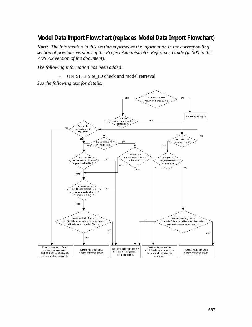
687
Model Data Import Flowchart (replaces Model Data Import Flowchart) Note: The information in this section supersedes the information in the corresponding section of previous versions of the Project Administrator Reference Guide (p. 600 in the PDS 7.2 version of the document).
The following information has been added:
• OFFSITE Site_ID check and model retrieval See the following text for details.
Project Administrator – October 2004
688
Index active project retrieval, 672 annotation
drawing, 664 archival
model data, 669 ASCII
create model from file, 646 create
model, 640 model from ASCII file, 646 site, 638
data drawing
import, 680 model
import, 680 pipe support drawing
import, 681 drawing
data import, 680
retrieval for workshare projects, 685
drawing annotation category data, 664 import
drawing data, 680 model data, 680 pipe support drawing data, 681 project
scheduled, 682 project retrieval, 675
model create, 640 create from ASCII file, 646 data
import, 680 retrieval
for workshare projects, 685 model data
archival, 669
revise, 652 named items
report, 654 pipe support drawing
data import, 681
piping data control, 657 piping design schema, 633 piping model data
propagate, 661 project
import scheduled, 682
project archival model data, 669
project retrieval active, 672 import, 675
propagate piping model data, 661 piping seed data, 661
report named items, 654
retrieval active, 672 drawing
for workshare projects, 685 import project, 675
scheduled, 682 model
for workshare projects, 685 revise
drawing annotation data, 664 model data, 652
scheduled project import, 682 seed files
piping, 661 site
administrator, 637 create, 638

Project Administrator (PD_Project) Reference Guide Addendum November 2005 DPDS3-PB-200030D For PDS SE version 08.00.00.** This document supplements DPDS3-PB-200030C.

Project Administrator – November 2005
Table of Contents Common Tools on the PD_Shell Forms (replaces PD Shell subsection).................691 Copy Model (replaces 5.1.4) ....................................................................................694 Default Segment Data (replaces 6.1.25) ...................................................................700 Appendix A: Upgrading Existing Projects (replaces Appendix A: Upgrading Existing Projects) ....................................................................................................................703
690

Common Tools on the PD_Shell Forms (replaces PD Shell subsection) Note: The information in this section supersedes the information in the corresponding section of previous versions of the Project Administrator Reference Guide (pp 49-51 in the PDS 7.1 version of the document).
The following information has been added:
• Path Location Fields subsection See the following text for details.
There are many gadgets in the environments that are common to most or all of the forms. The following describes these tools.
Standard Commands The PD_Shell forms have a set of standard buttons in the upper right corner of most of the form windows. The available commands vary from form to form depending on the type of operation.
The Help button activates on-line Help for the active form. Help remains active until you delete the Help window.
The Shell button exits the active form and returns control to the base manager that is associated with the active form. For most forms this returns to the Plant Design System Environment form.
The Top button exits the active form and returns control to the top form of the active branch.
The Cancel button cancels or exits from the active form. Control returns to the immediately preceding form in the hierarchy.
The Accept button accepts a selection or operation. Depending on the active form or option, the active form remains active so that you can repeat a similar operation or control returns to the preceding form.
The Restart button clears any key-in fields on the form that have values you can modify.
691

Project Administrator – November 2005
Scrolling List Some screen menus have a scrolling list of projects or applications. You need to scroll a list only if more options are available than can be displayed in the window. To scroll a list, select the arrow buttons on the side of the list. The list scrolls up or down depending on which arrow you select.
The scrolling list has an arrow pointing up and an arrow pointing down. These arrows scroll lists line by line. There is a button that slides between these two arrows to indicate your position on the list. To page through the list, select the space above or below the sliding button. The list pages up or down accordingly.
You can also select the slider and, while pressing <D>, slide the button up or down the bar. The items scroll through the window as you move the button. The size and position of the button on the scroll bar is an indication of the number of lines and the relative position within the list.
All commands that display a list of design areas or models order the list alphanumerically by the design area number or model number in ascending order.
In some forms with scrolling lists, you can double-click on a row to select and accept the data in that row. This performs the same action as selecting a row (which highlights) and then selecting the Accept button.
Key-in Fields Screens that accept keyboard input have key-in fields. These fields are box-shaped and dark gray. You can select a key-in field and key in a new value. A bar cursor appears in the active key-in field. Key in your input, and press <Return>. To change a field, reselect the field and key in the new information.
Key-in fields have a maximum number of characters depending on the item that is being defined.
If you select a key-in field for a code-listed attribute, the system activates a form that lists the code list values for the selected field.
MicroStation requires lowercase characters for the file specification and path name of all design files. Therefore, the system automatically converts any input for the file specification and path name of a design file (such as a model or drawing) to lowercase before loading into the Project Control Database.
Display-List Boxes A display-list box is located at the end of some key-in fields. It lets you select data from a list instead of keying in information. For example, there is a display list associated with the Authorization key-in field shown. At the end of the field, there is a small box with horizontal dashes. When you select this display list box with the screen cursor, an associated list of valid input values displays. Select an item from the list to enter its value into the field.
692

Shift Left and Shift Right buttons At the bottom of some key-in and display fields, there are two buttons marked with arrows. These buttons are called shift left and shift right buttons.
Often, you can key in more characters than a field display shows. Shift Left moves the text display to the front of the field; Shift Right moves the text display to the end of the field.
Path Location Fields Some key-in fields are used to specify paths for various files and folders, such as project folders, model files, reference data files, drawing files, and isometric drawing files. Prior to PDS 8.0, these path fields required the user to enter a full path, including the drive name. For example, d:\project1\piping\models. Beginning with PDS 8.0, path fields accept share names as input. For example, if you have the project1 folder set up as a share, you could enter \project1\piping\models or project1\piping\models as the path for piping models.
This new functionality allows administrators to set different permissions for shares used by different sets of users. For more information on setting up shares and permissions, see the PDS Project Setup Technical Reference.
Toggle A toggle field on a screen menu enables you to select one of two possible choices, one of which is always displayed. Place a data point on the toggle field to toggle between the two choices.
Roll-Through List A roll-through list shows one choice at a time of a list that can be several items long. Place a data point on the roll-through list to scroll through the available options. The option displayed is active.
693
Project Administrator – November 2005
Copy Model (replaces 5.1.4) Note: The information in this section supersedes the information in the corresponding section of previous versions of the Project Administrator Reference Guide (pp 546-551 in the PDS 7.2 version of the document).
The following information has been added:
• Site ID field See the following text for details.
The Copy Model option creates a copy of an existing model file within the current project or to another project. All contents of the specified file are copied to the new file. This option can be used with Piping, Equipment, Structural, or Raceway models.
The Copy Model command makes the following database-related changes based on the setting for Copy in the Piping Data Control option of the Project Data Manager. The copy setting is determined by the setting in the destination model. Refer to Piping Data Control, page 226, for more information.
If the copy option is set to Append Prefix, the system adds two asterisks (**) as a prefix to name attributes to signify the piping segment or component has been copied and the name attribute may require updating. The following attributes are considered name attributes for this operation:
line number label piping component number pipe tag number instruct component number pipe support number line id
If the copy option is set to No Prefix, the ** prefix is removed when copying a piping segment or a component with a name attribute that includes the ** prefix from a previous copy operation.
Regardless of how this option is set, name attributes that are undefined (blank) will not have the prefix added.
The following database-related changes are also made:
For piping components, pipes, and instrument components, the weld numbers at each welded end are set to undefined (blank). The alphanumeric description ID of a piping segment is automatically deleted by a copy operation.
For piping segments, the approval status is set to not approved.
When copying a model from the same project or a different project, the copied model inherits the Site ID of the active project. This change applies only to workshare projects; that is, projects whose site_id attribute is set in pdtable_101.
694
Inter-Project Copies With Different System of Units When copying a piping model from another project, the system automatically converts certain attributes, such as face-to-face dimension or surface area, when the system of units for those attributes changes from the source project to the destination project. The following data is subject to units conversion in copying piping from one project to another:
Piping Segment Data
insulation thickness insulation density heat tracing temperature
Piping Component Data
maximum temperature face-to-face dimension dimension a dimension b dimension c surface area empty weight water weight operator weight (or branch reinforcement width or orifice size) heat tracing temperature piping outside diameter (five connect points) face-to-center dimension (five connect points) gasket gap (five connect points)
Piping/Tubing Data
maximum temperature piping outside diameter pipe length surface area empty weight water weight cold spring length heat tracing temperature gasket gap (both ends)
Instrument Component Data
face-to-face dimension dimension a dimension b dimension c surface area empty weight water weight
695
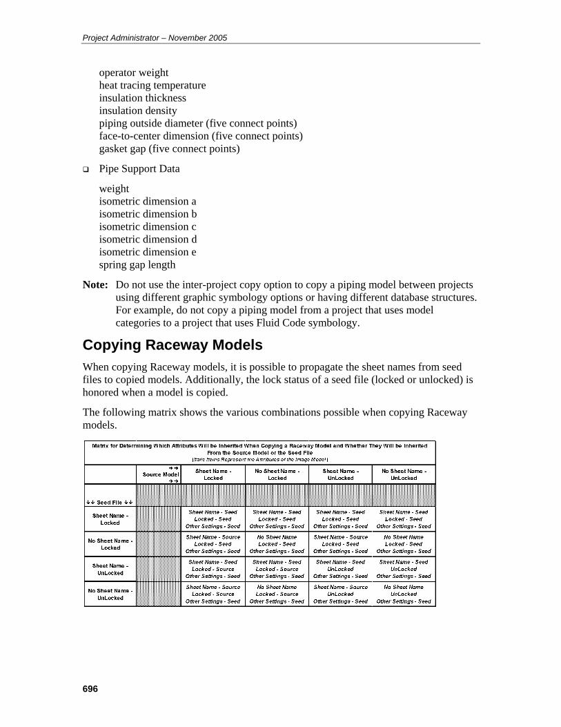
Project Administrator – November 2005
operator weight heat tracing temperature insulation thickness insulation density piping outside diameter (five connect points) face-to-center dimension (five connect points) gasket gap (five connect points)
Pipe Support Data
weight isometric dimension a isometric dimension b isometric dimension c isometric dimension d isometric dimension e spring gap length
Note: Do not use the inter-project copy option to copy a piping model between projects using different graphic symbology options or having different database structures. For example, do not copy a piping model from a project that uses model categories to a project that uses Fluid Code symbology.
Copying Raceway Models When copying Raceway models, it is possible to propagate the sheet names from seed files to copied models. Additionally, the lock status of a seed file (locked or unlocked) is honored when a model is copied.
The following matrix shows the various combinations possible when copying Raceway models.
696
Field Descriptions Model Number — Type up to 10 characters for the name/number of the design file.
Model Name — The system fills in the Model Name field automatically by appending a .dgn extension to the specified model number. The Model Name may be edited.
Model Description — Type up to 36 characters for the directory path where the model file is to be created.
Application Type — This field should only be change if you need to override the default discipline for interference purposes. For example, this provides a way to use a piping model for HVAC ducting and have the clashes from that model treated by the Interference Checker as HVAC components in terms of assigning responsibility for the clash.
Define Offset — Select this option to specify the Easting, Northing, and Elevation coordinates for an offset to be applied to the copied model.
Attach Equipment Model — Select this option from the Copy Model Data form to specify an equipment model to be attached to the model to be copied.
Verify Piping Materials Class — This toggle verifies the piping materials class of each piping segment to be copied from the source project to the destination project previously defined in the Material Reference Database of the destination project. Only those segments with valid piping materials classes are copied. If the toggle is set to No Verification of Piping Materials Class the file contents are copied without checking piping materials classes.
Copy P&ID Node Numbers — When copying models within the same project, set the P&ID Node Number toggle to enable or disable the copying of P&ID node numbers from one piping model to another piping model. The default is Copy P&ID Node Numbers. When copying models between projects, the Copy Piping Model command automatically disables copying of the P&ID node numbers from one piping model to another piping model.
Site_ID — This field specifies the work site to which the model will be copied. When copying models from the master site, the Site ID can be set to any site appearing in pdtable_105. When copying models from a satellite site, the Site ID is automatically set to the value for the satellite site, and cannot be changed. The master site can copy models to any site. A satellite site can only copy models into itself.
Note: The Site_ID field displays only for a workshare project; that is, a project whose site_id attribute is set in pdtable_101.
Submit Immediately or Submission is Delayed — Select Submit Immediately to begin copying the model as soon as you exit the form.
—OR —
Select Delayed Submission to specify a time to process the copy.
697
Project Administrator – November 2005
Operating Sequence 1. Select Copy Model Option.
Select the Copy Model option from the Create Options form.
The Select Source Model’s Project form is displayed. For more information about the Select Source Model’s Project form, see page 126.
2. Select Design Area.
Select a design area for the model file to be copied from the list of design areas; then choose the Confirm button.
A list of models for the selected design area is displayed on the Select Model to be Copied form.
3. Select Model.
Select the existing model design file to be copied; then choose the Confirm button.
The Select Area for Copied Model form is displayed.
4. Select Design Area.
Select the design area for the model file to be created from the list of design areas; then choose the Confirm button.
The Copy Model Data form is displayed.
5. Specify Model Information.
Type the Model Number, Model Description, and Application Type information for the design file to be created.
6. Define a Design Volume Offset.
Select Define Offset to define a design volume offset for the model to be copied.
The Copy Model Data - Offset form is displayed. For more information about the Copy Model Data - Offset form, see page 123.
7. Attach Equipment Model
Select Attach Equipment Model to specify an equipment model to be attached to the model to be copied.
The Attach Equipment Model form is displayed. For more information about the Attach Equipment Model form, see page 124.
8. Set Verify Piping Materials Class toggle.
Set the toggle to Verify Piping Materials Class or No Verification of Piping Materials Class.
698

9. Set the P&ID Node Number toggle Copy P&ID Node Numbers or Do Not Copy P&ID Node Numbers.
The default is Copy P&ID Node Numbers.
10. If copying from the master site in a workshare environment, select the Site ID into which to copy the model.
11. Select Submit Immediately to begin copying the model as soon as you exit the form.
—OR —
Select Submission is Delayed to specify a time to process the copy.
12. Accept Model data.
Choose the Confirm button to accept the specified data.
The Design Volume Coordinate System Definition form is displayed. Refer to Design Volume Coordinate System Definition, page 308, for information about this option.
13. Submit Copy Request.
Choose the Confirm button on the Design Volume Coordinate System Definition form.
The copy request is submitted to the batch queue PDcopy_model and the Select Model to be Copied form is displayed.
699
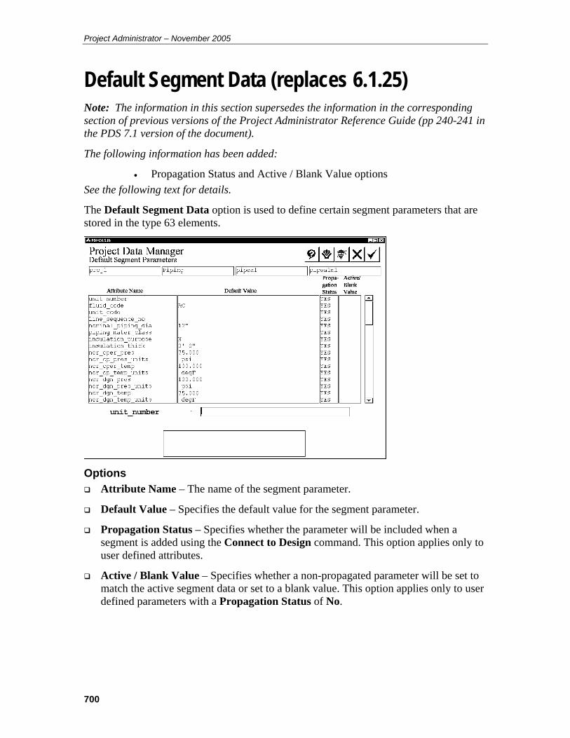
Project Administrator – November 2005
Default Segment Data (replaces 6.1.25) Note: The information in this section supersedes the information in the corresponding section of previous versions of the Project Administrator Reference Guide (pp 240-241 in the PDS 7.1 version of the document).
The following information has been added:
• Propagation Status and Active / Blank Value options See the following text for details.
The Default Segment Data option is used to define certain segment parameters that are stored in the type 63 elements.
Options Attribute Name – The name of the segment parameter.
Default Value – Specifies the default value for the segment parameter.
Propagation Status – Specifies whether the parameter will be included when a segment is added using the Connect to Design command. This option applies only to user defined attributes.
Active / Blank Value – Specifies whether a non-propagated parameter will be set to match the active segment data or set to a blank value. This option applies only to user defined parameters with a Propagation Status of No.
700
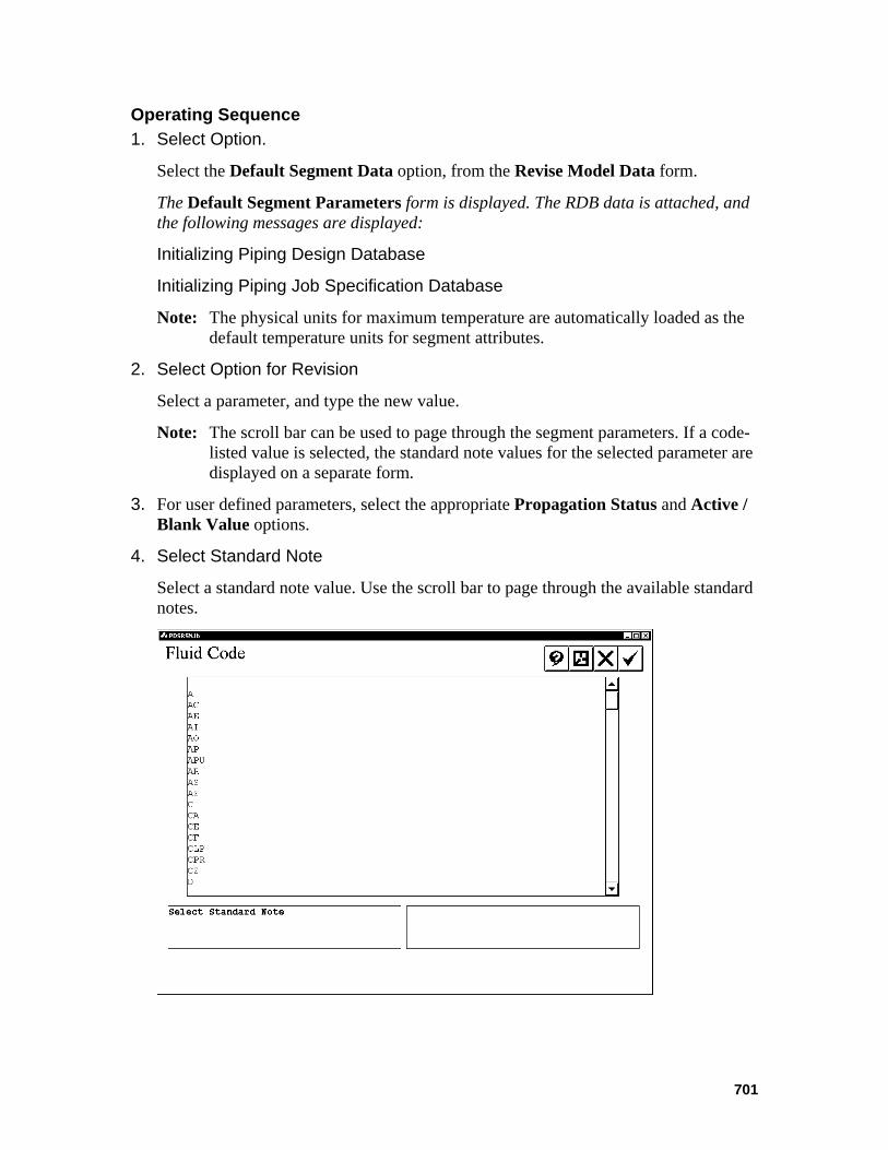
Operating Sequence 1. Select Option.
Select the Default Segment Data option, from the Revise Model Data form.
The Default Segment Parameters form is displayed. The RDB data is attached, and the following messages are displayed:
Initializing Piping Design Database
Initializing Piping Job Specification Database
Note: The physical units for maximum temperature are automatically loaded as the default temperature units for segment attributes.
2. Select Option for Revision
Select a parameter, and type the new value.
Note: The scroll bar can be used to page through the segment parameters. If a code-listed value is selected, the standard note values for the selected parameter are displayed on a separate form.
3. For user defined parameters, select the appropriate Propagation Status and Active / Blank Value options.
4. Select Standard Note
Select a standard note value. Use the scroll bar to page through the available standard notes.
701

Project Administrator – November 2005
5. Choose the Confirm button to accept the selected value and to dismiss the standard note form.
Note: If the cursor is moved to a code-listed value by pressing the Enter key (rather than placing a data point), the system will not activate the standard note form. The code list text can be typed (such as MMA for fluid code) or the index number (such as 444).
6. Accept Default Segment Parameters.
Choose the Confirm button to accept the defined segment parameters.
The Revise Model Data form is displayed.
702
Appendix A: Upgrading Existing Projects (replaces Appendix A: Upgrading Existing Projects) Note: The information in this section supersedes the information in the corresponding section of previous versions of the Project Administrator Reference Guide (pp 487-489 in the PDS 7.1 version of the document).
The following information has been added:
• Note regarding project upgrades for verions 7.0 and later See the following text for details.
Note: If you are upgrading an existing project to PDS version 7.0 or later, refer to the Project Upgrade section in the README.TXT file delivered with PDS for more detailed instructions on project updgrades.
Note: If you have previously upgraded to version 6.3, there is no additional upgrade required for 6.4.
For the 6.3 release of PDS 3D, several data structures within the project data set were extended to support additional enhancements. The PD_Shell environment provides a translation process to upgrade a project that was created with a previous PDS release (a 4.*, 5.*, or 6.0/6.1 version). You cannot continue working in a project until the project’s data set has been upgraded.
Errors and Warnings The project data set’s version number will only be revised in the project directory file and in the Project Control Database once that project has been upgraded successfully. If a fatal error occurs during the upgrade of a project data set, the project data set’s version number will not be revised. Under these circumstances, you will hbe the opportunity to correct the problem and re-enter the PD_Shell environment to continue the project upgrade.
All non-fatal errors generate warning messages. Both the fatal error messages and the warning messages are recorded in the project upgrade.log file.
Most of the errors are caused by file protection problems or difficulty in locating the files.
Shared Reference Data The following rules apply when the Material Reference Database is being shared by more than one project.
The new table will not be added multiple times for a Material Reference Database that is being shared.
703
Project Administrator – November 2005
Only the reference.ddl file in the project directory will be updated, if the Material Reference Database is being shared with at least one other project and has been previously upgraded for that project.
All the projects which share a Material Reference Database must be upgraded at the same time. If this is not feasible, you must create a new Material Reference Database for the project that is to be upgraded.
You cannot create a new project using the current PDS release that shares the Material Reference Database with another project that is being completed with an older PDS release.
Before Using This Command Read the appropriate description of the Update Process before updating a project.
6.0/6.1 to 6.3 Update Process on page 489.
5.* to 6.0 Update Process on page 493.
4.3 to 5.0 Update Process on page 497
4.2 Update Process on page 507
4.1 Update Process on page 510
These sections outline all the effects of the upgrade and point out any special considerations. Upgrading from the 4.0 release to the 5.0 release is not supported.
You must have write access to the Approved and Unapproved Spec Table Library and Physical Dimension Libraries for the project.
All models and drawings must be accessible, since the type63 data will be revised.
Tech Tip: Perform a complete project archive and correct any errors prior to upgrading the project.
704

Operating Sequence 1. Select the project number from the PD Shell main form.
The system derives the version number of the project data set from the project directory file to determine if it is compatible with the current version of the PD Shell product. If not, the system activates a dialog box.
2. Select Cancel to exit from the PD Shell environment. You cannot continue working
in this project until the project’s data set has been upgraded.
—OR —
Select Confirm (�) to upgrade the project automatically.
The system begins upgrading the project’s data set. It creates a log file named update.log, in the project directory which includes a detailed listing of all the data that has been revised. The system also displays informative messages in the dialog box as the project data set is upgraded.
Update in Progress
Initializing Databases
Updating Project Database Information
Updating Reference Database Information
Updating Design Database Information
Rewriting proj_file with New Data Version
Finished Project Update
705

Project Administrator – November 2005
Index copy
model, 694 model
copy, 694
706
Related Documents


![[INSERT PROJECT NAME]€¦ · Project name Project Number [Where applicable] Project Manager Project Controller Project location [Insert brief details of project location, including](https://static.cupdf.com/doc/110x72/603496f741d854077e52cec0/insert-project-name-project-name-project-number-where-applicable-project-manager.jpg)