PROGRESS REPORT ON CALIBRATION OF STRENGTH IV LIMIT STATE IN AASHTO LRFD BRIDGE DESIGN SPECIFICATIONS AASHTO T-5 Meeting Austin, TX July 10, 2012 Presented By Wagdy G. Wassef, P.E., Ph.D., Modjeski and Masters, Inc.

Welcome message from author
This document is posted to help you gain knowledge. Please leave a comment to let me know what you think about it! Share it to your friends and learn new things together.
Transcript

PROGRESS REPORT ON
CALIBRATION OF STRENGTH IV LIMIT STATE IN
AASHTO LRFD BRIDGE DESIGN
SPECIFICATIONS
AASHTO T-5 Meeting
Austin, TX
July 10, 2012
Presented By
Wagdy G. Wassef, P.E., Ph.D., Modjeski and Masters, Inc.

Scope of Work (1)
• Compile a set of six straight, square, 3-
span steel I-girder bridges (Group 1)
– Center span length starts at 100 ft,
incremented by 100 ft
– Side spans 80% of center span
– Cross-section representative of 2-lane
Interstate Highway bridge with shoulders
– Gutter-to-Gutter width 44 ft, 5 Girders at 10’-2”
– Sufficiently designed to accurately provide DL

Group 1 Bridges
Bridge Span 1 (ft) Span 2 (ft) Span 3 (ft) Total Length (ft)
100 80 100 80 260
200 160 200 160 520
300 240 300 240 780
400 320 400 320 1040
500 400 500 400 1300
600 480 600 480 1560

Scope of Work (2)
• Compile set of six existing bridges (40-600
ft span lengths) (Group 2 Bridges)
– Short-span concrete slab bridge (~40 ft)
– Spliced concrete I-girder bridge (~180 ft)
– Multicell Concrete Box Girder Bridge (~250 ft)
– Steel trusses (~250 ft & ~600 ft)
– Segmental concrete box girder (~525 ft)
– Bridges assumed to be straight and square
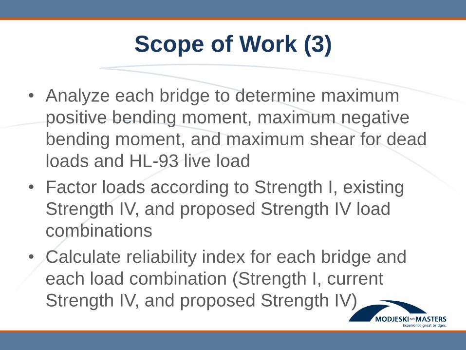
Scope of Work (3)
• Analyze each bridge to determine maximum
positive bending moment, maximum negative
bending moment, and maximum shear for dead
loads and HL-93 live load
• Factor loads according to Strength I, existing
Strength IV, and proposed Strength IV load
combinations
• Calculate reliability index for each bridge and
each load combination (Strength I, current
Strength IV, and proposed Strength IV)
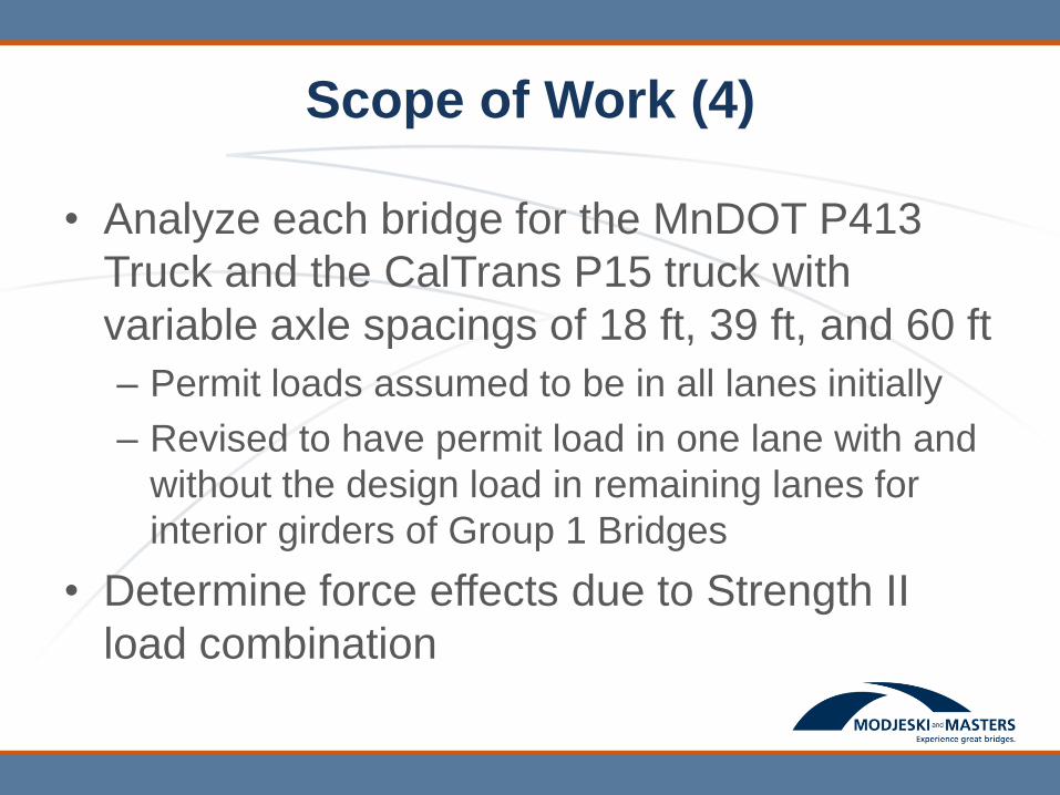
Scope of Work (4)
• Analyze each bridge for the MnDOT P413
Truck and the CalTrans P15 truck with
variable axle spacings of 18 ft, 39 ft, and 60 ft
– Permit loads assumed to be in all lanes initially
– Revised to have permit load in one lane with and
without the design load in remaining lanes for
interior girders of Group 1 Bridges
• Determine force effects due to Strength II
load combination
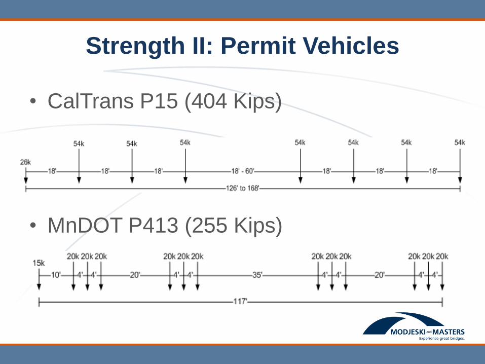
Strength II: Permit Vehicles
• CalTrans P15 (404 Kips)
• MnDOT P413 (255 Kips)
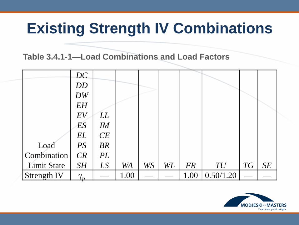
Existing Strength IV Combinations
Table 3.4.1-1—Load Combinations and Load Factors
Load
Combination
Limit State
DC
DD
DW
EH
EV
ES
EL
PS
CR
SH
LL
IM
CE
BR
PL
LS WA WS WL FR TU TG SE
Strength IV γp — 1.00 — — 1.00 0.50/1.20 — —

Existing Strength IV Combinations
Table 3.4.1-2—Load Factors for Permanent Loads, γp
Type of Load, Foundation Type, and
Method Used to Calculate Downdrag
Load Factor
Maximum Minimum
DC: Component and Attachments
DC: Strength IV only
1.25
1.50
0.90
0.90
1.5 1.5DC DW
For most superstructure cases when Strength IV controls, load
combination:
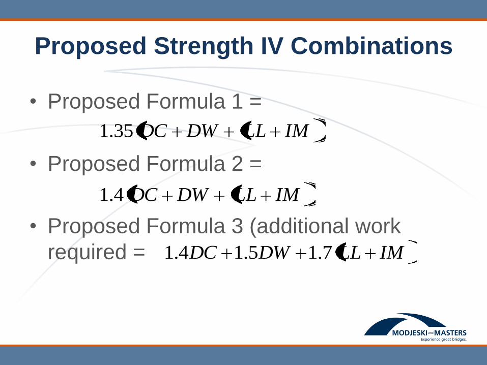
Proposed Strength IV Combinations
• Proposed Formula 1 =
• Proposed Formula 2 =
• Proposed Formula 3 (additional work
required =
IMLLDWDC35.1
IMLLDWDC4.1
IMLLDWDC 7.15.14.1

Group 1 Interior Girders
Strength II and Strength IV compared
to Strength I
(For Strength II: Permit Vehicles in all Lanes)

Group 1 – End Span Positive Bending
• Interior Girders
• For strength II:
Permit vehicle in all
lanes
• Impact of 1.33 applied
to permit vehicles
Str. II MN P413
Strength I
Str. II P15-18
Strength I
Str. II P15-39
Strength I
Str. II P15-60
Strength I
Cur. Str. IV
Strength I
1.35 (D+L)
Strength I
1.4(D+L)
Strength I
Bridge
100 0.85 1.18 1.18 1.18 0.39 0.87 0.90
200 1.01 1.64 1.37 1.23 0.56 0.91 0.94
300 1.06 1.70 1.51 1.35 0.66 0.93 0.97
400 1.01 1.63 1.50 1.38 0.74 0.95 0.99
500 0.95 1.53 1.43 1.34 0.81 0.97 1.01
600 0.88 1.41 1.34 1.27 0.86 0.98 1.02
0.00
0.50
1.00
1.50
2.00
2.50
100 200 300 400 500 600
Rat
io o
f En
d S
pan
Po
siti
ve L
L M
om
en
t
Center Span Length (ft)
Str. II MN P413
Strength I
Str. II P15-18
Strength I
Str. II P15-39
Strength I
Str. II P15-60
Strength ICur. Str. IV
Strength I
1.35 (D+L)
Strength I
1.4(D+L)
Strength I
For Strength II Comparison:
Permit Truck / HL93

Group 1 – End Span Positive Bending
0.00
0.20
0.40
0.60
0.80
1.00
1.20
1.40
1.60
1.80
2.00
100 200 300 400 500 600
Rat
io o
f En
d S
pan
Po
siti
ve M
om
en
t
Center Span Length (ft)
Str. II MN P413Strength I
Str. II P15-18Strength I
Str. II P15-39Strength I
Str. II P15-60Strength I
Cur. Str. IVStrength I
1.35 (D+L)Strength I
1.4(D+L)Strength I
• Interior Girders
•For strength II:
Permit vehicle in all
lanes
•Impact of 1.33 applied to
permit vehicles
Str. II MN P413
Strength I
Str. II P15-18
Strength I
Str. II P15-39
Strength I
Str. II P15-60
Strength I
Cur. Str. IV
Strength I
1.35 (D+L)
Strength I
1.4(D+L)
Strength I
Bridge
100 0.90 1.12 1.12 1.12 0.39 0.87 0.90
200 1.01 1.33 1.20 1.12 0.56 0.91 0.94
300 1.02 1.31 1.22 1.15 0.66 0.93 0.97
400 1.01 1.23 1.19 1.14 0.74 0.95 0.99
500 0.99 1.16 1.13 1.11 0.81 0.97 1.01
600 0.97 1.11 1.09 1.07 0.86 0.98 1.02
Strength II Comparison:
Factored (DL + Permit Truck) /
Factored (DL+ HL93)
This is the case used for
Strength II comparisons in all
subsequent slides
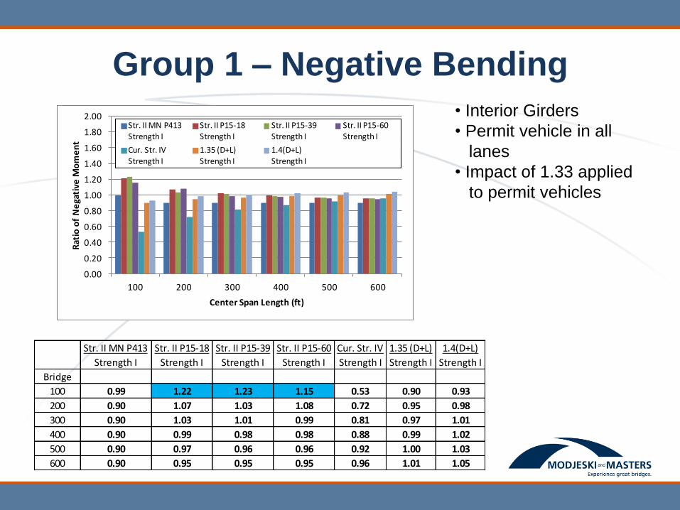
Group 1 – Negative Bending
• Interior Girders
• Permit vehicle in all
lanes
• Impact of 1.33 applied
to permit vehicles
0.00
0.20
0.40
0.60
0.80
1.00
1.20
1.40
1.60
1.80
2.00
100 200 300 400 500 600
Rat
io o
f N
ega
tive
Mo
me
nt
Center Span Length (ft)
Str. II MN P413Strength I
Str. II P15-18Strength I
Str. II P15-39Strength I
Str. II P15-60Strength I
Cur. Str. IV
Strength I
1.35 (D+L)
Strength I
1.4(D+L)
Strength I
Str. II MN P413
Strength I
Str. II P15-18
Strength I
Str. II P15-39
Strength I
Str. II P15-60
Strength I
Cur. Str. IV
Strength I
1.35 (D+L)
Strength I
1.4(D+L)
Strength I
Bridge
100 0.99 1.22 1.23 1.15 0.53 0.90 0.93
200 0.90 1.07 1.03 1.08 0.72 0.95 0.98
300 0.90 1.03 1.01 0.99 0.81 0.97 1.01
400 0.90 0.99 0.98 0.98 0.88 0.99 1.02
500 0.90 0.97 0.96 0.96 0.92 1.00 1.03
600 0.90 0.95 0.95 0.95 0.96 1.01 1.05

Group 1 – Center Span Positive Bending
0.00
0.20
0.40
0.60
0.80
1.00
1.20
1.40
1.60
1.80
2.00
100 200 300 400 500 600
Rat
io o
f C
en
ter
Span
Po
siti
ve M
om
en
t
Center Span Length (ft)
Str. II MN P413Strength I
Str. II P15-18Strength I
Str. II P15-39Strength I
Str. II P15-60Strength I
Cur. Str. IV
Strength I
1.35 (D+L)
Strength I
1.4(D+L)
Strength I
Str. II MN P413
Strength I
Str. II P15-18
Strength I
Str. II P15-39
Strength I
Str. II P15-60
Strength I
Cur. Str. IV
Strength I
1.35 (D+L)
Strength I
1.4(D+L)
Strength I
Bridge
100 0.90 1.21 1.15 1.15 0.36 0.86 0.89
200 1.02 1.40 1.24 1.15 0.52 0.90 0.93
300 1.02 1.35 1.26 1.18 0.60 0.92 0.95
400 1.00 1.25 1.20 1.15 0.69 0.94 0.98
500 0.98 1.17 1.14 1.11 0.77 0.96 1.00
600 0.96 1.12 1.10 1.07 0.82 0.97 1.01
• Interior Girders
• Permit vehicle in all
lanes
• Impact of 1.33 applied
to permit vehicles
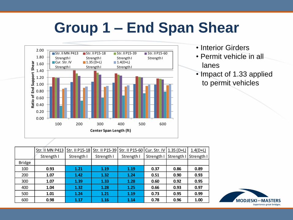
Group 1 – End Span Shear
0.00
0.20
0.40
0.60
0.80
1.00
1.20
1.40
1.60
1.80
2.00
100 200 300 400 500 600
Rat
io o
f En
d S
up
po
rt S
he
ar
Center Span Length (ft)
Str. II MN P413Strength I
Str. II P15-18Strength I
Str. II P15-39Strength I
Str. II P15-60Strength I
Cur. Str. IVStrength I
1.35 (D+L)Strength I
1.4(D+L)Strength I
Str. II MN P413
Strength I
Str. II P15-18
Strength I
Str. II P15-39
Strength I
Str. II P15-60
Strength I
Cur. Str. IV
Strength I
1.35 (D+L)
Strength I
1.4(D+L)
Strength I
Bridge
100 0.93 1.21 1.19 1.19 0.37 0.86 0.89
200 1.07 1.42 1.32 1.24 0.51 0.90 0.93
300 1.07 1.39 1.33 1.28 0.60 0.92 0.95
400 1.04 1.32 1.28 1.25 0.66 0.93 0.97
500 1.01 1.24 1.21 1.19 0.73 0.95 0.99
600 0.98 1.17 1.16 1.14 0.78 0.96 1.00
• Interior Girders
• Permit vehicle in all
lanes
• Impact of 1.33 applied
to permit vehicles

Group 1 – Shear Left of Interior Support
0.00
0.20
0.40
0.60
0.80
1.00
1.20
1.40
1.60
1.80
2.00
100 200 300 400 500 600
Rat
io o
f Sh
ear
to
Le
ft o
f In
teri
or
Sup
po
rt
Center Span Length (ft)
Str. II MN P413Strength I
Str. II P15-18Strength I
Str. II P15-39Strength I
Str. II P15-60Strength I
Cur. Str. IV
Strength I
1.35 (D+L)
Strength I
1.4(D+L)
Strength I
Str. II MN P413
Strength I
Str. II P15-18
Strength I
Str. II P15-39
Strength I
Str. II P15-60
Strength I
Cur. Str. IV
Strength I
1.35 (D+L)
Strength I
1.4(D+L)
Strength I
Bridge
100 1.00 1.29 1.26 1.23 0.47 0.89 0.92
200 1.07 1.38 1.30 1.21 0.64 0.93 0.96
300 1.04 1.29 1.26 1.22 0.72 0.95 0.98
400 1.00 1.20 1.18 1.16 0.78 0.96 1.00
500 0.97 1.13 1.12 1.11 0.82 0.97 1.01
600 0.95 1.08 1.07 1.07 0.87 0.99 1.02
• Interior Girders
• Permit vehicle in all
lanes
• Impact of 1.33 applied
to permit vehicles
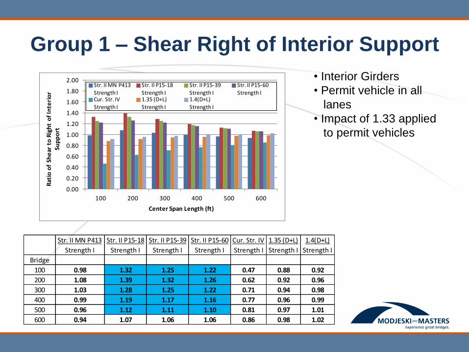
Group 1 – Shear Right of Interior Support
0.00
0.20
0.40
0.60
0.80
1.00
1.20
1.40
1.60
1.80
2.00
100 200 300 400 500 600
Rat
io o
f Sh
ear
to
Rig
ht
of
Inte
rio
r Su
pp
ort
Center Span Length (ft)
Str. II MN P413Strength I
Str. II P15-18Strength I
Str. II P15-39Strength I
Str. II P15-60Strength I
Cur. Str. IV
Strength I
1.35 (D+L)
Strength I
1.4(D+L)
Strength I
Str. II MN P413
Strength I
Str. II P15-18
Strength I
Str. II P15-39
Strength I
Str. II P15-60
Strength I
Cur. Str. IV
Strength I
1.35 (D+L)
Strength I
1.4(D+L)
Strength I
Bridge
100 0.98 1.32 1.25 1.22 0.47 0.88 0.92
200 1.08 1.39 1.32 1.26 0.62 0.92 0.96
300 1.03 1.28 1.25 1.22 0.71 0.94 0.98
400 0.99 1.19 1.17 1.16 0.77 0.96 0.99
500 0.96 1.12 1.11 1.10 0.81 0.97 1.01
600 0.94 1.07 1.06 1.06 0.86 0.98 1.02
• Interior Girders
• Permit vehicle in all
lanes
• Impact of 1.33 applied
to permit vehicles

Group 1 Interior Girders
Strength II and Strength IV compared to Strength I
(For Strength II: Permit Vehicles in One Lane with
HL-93 Design Load in Adjacent Lanes)

Group 1 – End Span Positive Bending
• Interior Girders
• Permit vehicle in one
lane, HL-93 Design
Load in adjacent lane(s)
• Impact of 1.33 applied
to permit vehicle
0.00
0.20
0.40
0.60
0.80
1.00
1.20
1.40
1.60
1.80
2.00
100 200 300 400 500 600
Rat
io o
f En
d S
pan
Po
siti
ve M
om
en
t
Center Span Length (ft)
Str. II MN P413Strength I
Str. II P15-18Strength I
Str. II P15-39Strength I
Str. II P15-60Strength I
Cur. Str. IVStrength I
1.35 (D+L)Strength I
1.4(D+L)Strength I
Str. II MN P413
Strength I
Str. II P15-18
Strength I
Str. II P15-39
Strength I
Str. II P15-60
Strength I
Cur. Str. IV
Strength I
1.35 (D+L)
Strength I
1.4(D+L)
Strength I
Bridge
100 0.88 1.01 1.01 1.01 0.39 0.87 0.90
200 0.95 1.13 1.06 1.01 0.56 0.91 0.94
300 0.97 1.12 1.08 1.04 0.66 0.93 0.97
400 0.96 1.08 1.06 1.03 0.74 0.95 0.99
500 0.96 1.05 1.04 1.02 0.81 0.97 1.01
600 0.95 1.03 1.02 1.01 0.86 0.98 1.02

Group 1 – Negative Bending
• Interior Girders
• Permit vehicle in one
lane, HL-93 Design Load
in adjacent lane(s)
• Impact of 1.33 applied
to permit vehicle
0.00
0.20
0.40
0.60
0.80
1.00
1.20
1.40
1.60
1.80
2.00
100 200 300 400 500 600
Rat
io o
f N
ega
tive
Mo
me
nt
Center Span Length (ft)
Str. II MN P413Strength I
Str. II P15-18Strength I
Str. II P15-39Strength I
Str. II P15-60Strength I
Cur. Str. IV
Strength I
1.35 (D+L)
Strength I
1.4(D+L)
Strength I
Str. II MN P413
Strength I
Str. II P15-18
Strength I
Str. II P15-39
Strength I
Str. II P15-60
Strength I
Cur. Str. IV
Strength I
1.35 (D+L)
Strength I
1.4(D+L)
Strength I
Bridge
100 0.95 1.08 1.09 1.04 0.53 0.90 0.93
200 0.90 1.00 0.98 1.01 0.72 0.95 0.98
300 0.91 0.98 0.97 0.96 0.81 0.97 1.01
400 0.92 0.97 0.96 0.96 0.88 0.99 1.02
500 0.92 0.96 0.96 0.96 0.92 1.00 1.03
600 0.93 0.96 0.95 0.95 0.96 1.01 1.05

Group 1 – Center Span Positive Bending
• Interior Girders
• Permit vehicle in one
lane, HL-93 Design Load
in adjacent lane(s)
• Impact of 1.33 applied
to permit vehicle
0.00
0.20
0.40
0.60
0.80
1.00
1.20
1.40
1.60
1.80
2.00
100 200 300 400 500 600
Rat
io o
f C
en
ter
Span
Po
siti
ve M
om
en
t
Center Span Length (ft)
Str. II MN P413Strength I
Str. II P15-18Strength I
Str. II P15-39Strength I
Str. II P15-60Strength I
Cur. Str. IV
Strength I
1.35 (D+L)
Strength I
1.4(D+L)
Strength I
Str. II MN P413
Strength I
Str. II P15-18
Strength I
Str. II P15-39
Strength I
Str. II P15-60
Strength I
Cur. Str. IV
Strength I
1.35 (D+L)
Strength I
1.4(D+L)
Strength I
Bridge
100 0.88 1.07 1.03 1.03 0.36 0.86 0.89
200 0.96 1.17 1.08 1.03 0.52 0.90 0.93
300 0.96 1.14 1.09 1.05 0.60 0.92 0.95
400 0.96 1.09 1.06 1.04 0.69 0.94 0.98
500 0.95 1.05 1.04 1.02 0.77 0.96 1.00
600 0.94 1.03 1.02 1.01 0.82 0.97 1.01
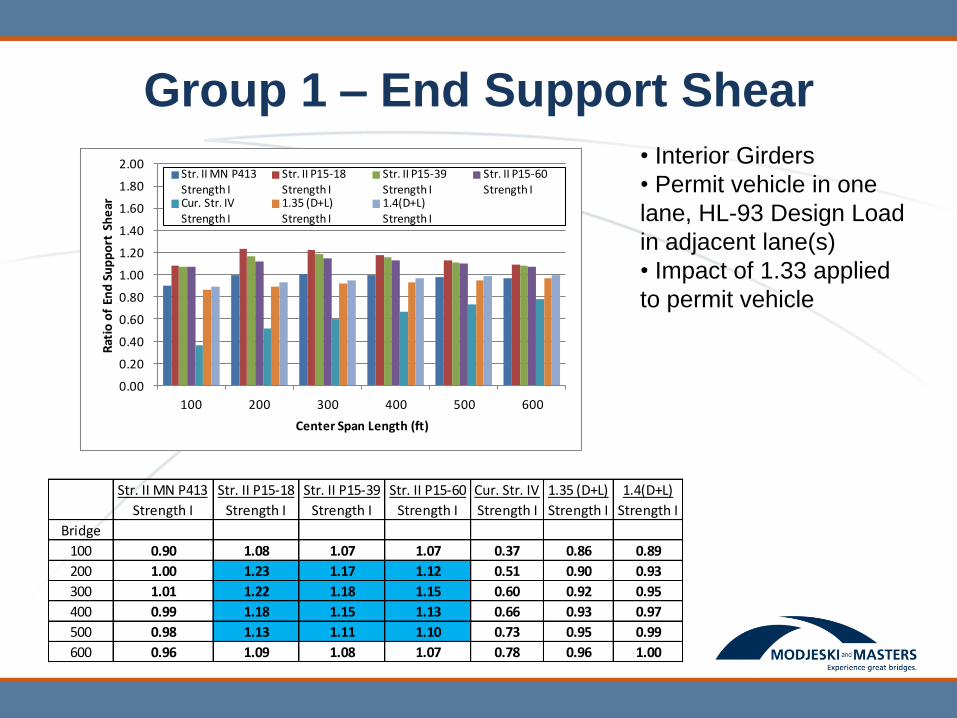
Group 1 – End Support Shear
• Interior Girders
• Permit vehicle in one
lane, HL-93 Design Load
in adjacent lane(s)
• Impact of 1.33 applied
to permit vehicle
0.00
0.20
0.40
0.60
0.80
1.00
1.20
1.40
1.60
1.80
2.00
100 200 300 400 500 600
Rat
io o
f En
d S
up
po
rt S
he
ar
Center Span Length (ft)
Str. II MN P413Strength I
Str. II P15-18Strength I
Str. II P15-39Strength I
Str. II P15-60Strength I
Cur. Str. IVStrength I
1.35 (D+L)Strength I
1.4(D+L)Strength I
Str. II MN P413
Strength I
Str. II P15-18
Strength I
Str. II P15-39
Strength I
Str. II P15-60
Strength I
Cur. Str. IV
Strength I
1.35 (D+L)
Strength I
1.4(D+L)
Strength I
Bridge
100 0.90 1.08 1.07 1.07 0.37 0.86 0.89
200 1.00 1.23 1.17 1.12 0.51 0.90 0.93
300 1.01 1.22 1.18 1.15 0.60 0.92 0.95
400 0.99 1.18 1.15 1.13 0.66 0.93 0.97
500 0.98 1.13 1.11 1.10 0.73 0.95 0.99
600 0.96 1.09 1.08 1.07 0.78 0.96 1.00
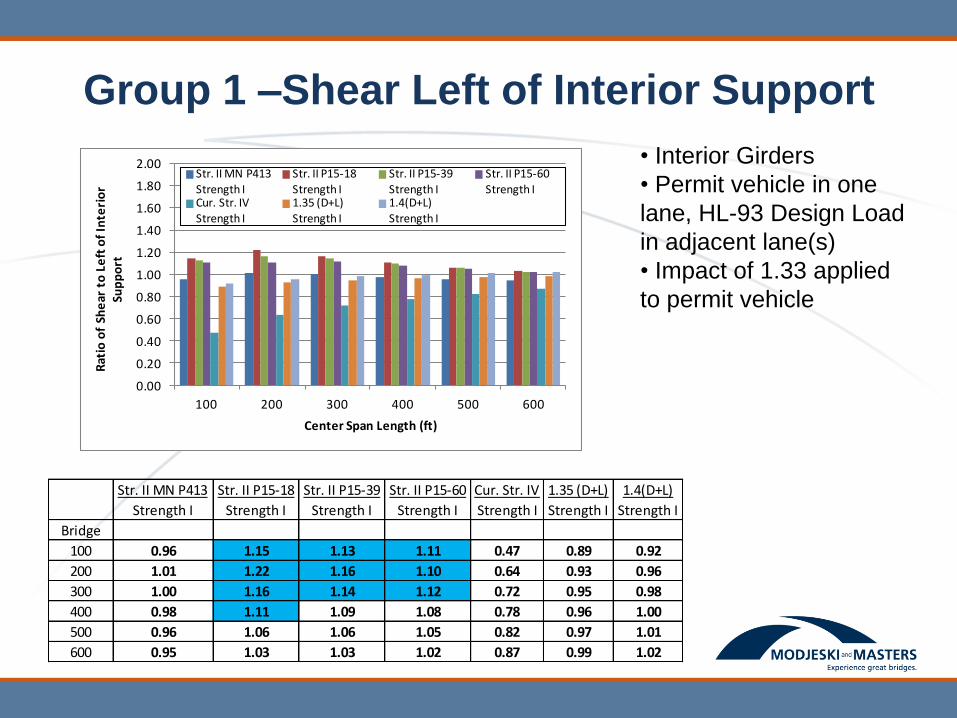
Group 1 –Shear Left of Interior Support
• Interior Girders
• Permit vehicle in one
lane, HL-93 Design Load
in adjacent lane(s)
• Impact of 1.33 applied
to permit vehicle
0.00
0.20
0.40
0.60
0.80
1.00
1.20
1.40
1.60
1.80
2.00
100 200 300 400 500 600
Rat
io o
f Sh
ear
to
Le
ft o
f In
teri
or
Sup
po
rt
Center Span Length (ft)
Str. II MN P413Strength I
Str. II P15-18Strength I
Str. II P15-39Strength I
Str. II P15-60Strength I
Cur. Str. IV
Strength I
1.35 (D+L)
Strength I
1.4(D+L)
Strength I
Str. II MN P413
Strength I
Str. II P15-18
Strength I
Str. II P15-39
Strength I
Str. II P15-60
Strength I
Cur. Str. IV
Strength I
1.35 (D+L)
Strength I
1.4(D+L)
Strength I
Bridge
100 0.96 1.15 1.13 1.11 0.47 0.89 0.92
200 1.01 1.22 1.16 1.10 0.64 0.93 0.96
300 1.00 1.16 1.14 1.12 0.72 0.95 0.98
400 0.98 1.11 1.09 1.08 0.78 0.96 1.00
500 0.96 1.06 1.06 1.05 0.82 0.97 1.01
600 0.95 1.03 1.03 1.02 0.87 0.99 1.02

Group 1 –Shear Right of Interior Support
• Interior Girders
• Permit vehicle in one
lane, HL-93 Design Load
in adjacent lane(s)
• Impact of 1.33 applied
to permit vehicle
0.00
0.20
0.40
0.60
0.80
1.00
1.20
1.40
1.60
1.80
2.00
100 200 300 400 500 600
Rat
io o
f Sh
ear
to
Rig
ht
of
Inte
rio
r Su
pp
ort
Center Span Length (ft)
Str. II MN P413Strength I
Str. II P15-18Strength I
Str. II P15-39Strength I
Str. II P15-60Strength I
Cur. Str. IV
Strength I
1.35 (D+L)
Strength I
1.4(D+L)
Strength I
Str. II MN P413
Strength I
Str. II P15-18
Strength I
Str. II P15-39
Strength I
Str. II P15-60
Strength I
Cur. Str. IV
Strength I
1.35 (D+L)
Strength I
1.4(D+L)
Strength I
Bridge
100 0.94 1.17 1.12 1.10 0.47 0.88 0.92
200 1.01 1.22 1.18 1.13 0.62 0.92 0.96
300 0.99 1.16 1.14 1.12 0.71 0.94 0.98
400 0.97 1.10 1.09 1.08 0.77 0.96 0.99
500 0.95 1.06 1.05 1.04 0.81 0.97 1.01
600 0.94 1.02 1.02 1.02 0.86 0.98 1.02

Group 2 Bridges – Concrete Slab
• Span Length = 41’-6”
• Slab thickness = 31”
• Reinforcement = 3.3 in2/ft

Group 2 Bridges – Spliced Concrete I-
girder
• Span Length = 206’-8”, splices at 28’-5½”
from centerline bearing
• Cross-section:

Group 2 Bridges – Steel Trusses
Bridge Span Length (ft) Truss Spacing (ft) Number of Lanes
Truss #1 250’-0” 89’-0” 6
Truss #2 617’-6” 94’-0” 6
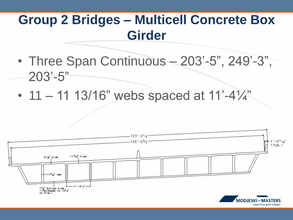
Group 2 Bridges – Multicell Concrete Box
Girder
• Three Span Continuous – 203’-5”, 249’-3”,
203’-5”
• 11 – 11 13/16” webs spaced at 11’-4¼”
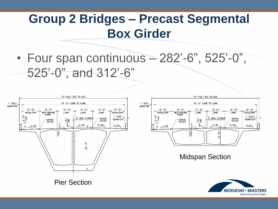
Group 2 Bridges – Precast Segmental
Box Girder
• Four span continuous – 282’-6”, 525’-0”,
525’-0”, and 312’-6”
Pier Section
Midspan Section

Group 2 – End/Simple Span Positive
Moment • Permit vehicle in all
lanes
• Impact of 1.33 applied to
permit vehicles
0.00
0.20
0.40
0.60
0.80
1.00
1.20
1.40
1.60
1.80
2.00
Concrete Slab
Spliced PC I Girder
250' Truss 617.5' Truss MultiCell Box Girder
Segmental Box
Rat
io o
f En
d S
pan
Po
siti
ve M
om
en
ts
Bridge Example
Str. II MN P413Strength I
Str. II P15-18Strength I
Str. II P15-39Strength I
Str. II P15-60Strength I
Cur. Str. IVStrength I
1.35(D+L)Strength I
1.4(D+L)Strength I
Str. II MN P413
Strength I
Str. II P15-18
Strength I
Str. II P15-39
Strength I
Str. II P15-60
Strength I
Cur. Str. IV
Strength I
1.35(D+L)
Strength I
1.4(D+L)
Strength I
Bridge
Concrete Slab 0.91 0.98 0.98 0.98 0.65 0.92 0.96
Spliced PC I Girder 1.04 1.31 1.21 1.12 0.73 0.95 0.99
250' Truss 1.03 1.24 1.18 1.12 0.82 0.98 1.01
617.5' Truss 0.95 1.06 1.05 1.04 0.92 1.01 1.05
MultiCell Box Girder 1.02 1.21 1.14 1.09 0.84 0.98 1.01
Segmental Box 0.97 1.19 1.15 1.12 0.71 0.95 0.98
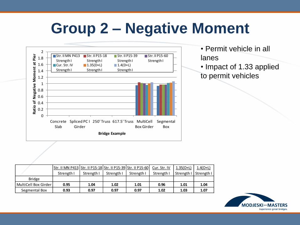
Group 2 – Negative Moment
• Permit vehicle in all
lanes
• Impact of 1.33 applied
to permit vehicles
0
0.2
0.4
0.6
0.8
1
1.2
1.4
1.6
1.8
2
Concrete Slab
Spliced PC I Girder
250' Truss 617.5' Truss MultiCell Box Girder
Segmental Box
Rat
io o
f N
ega
tive
Mo
me
nt
at P
ier
Bridge Example
Str. II MN P413
Strength I
Str. II P15-18
Strength I
Str. II P15-39
Strength I
Str. II P15-60
Strength ICur. Str. IV
Strength I
1.35(D+L)
Strength I
1.4(D+L)
Strength I
Str. II MN P413
Strength I
Str. II P15-18
Strength I
Str. II P15-39
Strength I
Str. II P15-60
Strength I
Cur. Str. IV
Strength I
1.35(D+L)
Strength I
1.4(D+L)
Strength I
Bridge
MultiCell Box Girder 0.95 1.04 1.02 1.01 0.96 1.01 1.04
Segmental Box 0.93 0.97 0.97 0.97 1.02 1.03 1.07
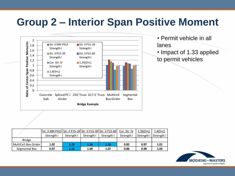
Group 2 – Interior Span Positive Moment
• Permit vehicle in all
lanes
• Impact of 1.33 applied
to permit vehicles
0
0.2
0.4
0.6
0.8
1
1.2
1.4
1.6
1.8
2
Concrete Slab
Spliced PC I Girder
250' Truss 617.5' Truss MultiCell Box Girder
Segmental Box
Rat
io o
f C
en
ter
Span
Po
siti
ve M
om
en
ts
Bridge Example
Str. II MN P413Strength I
Str. II P15-18Strength I
Str. II P15-39Strength I
Str. II P15-60Strength I
Cur. Str. IVStrength I
1.35(D+L)Strength I
1.4(D+L)
Strength I
Str. II MN P413
Strength I
Str. II P15-18
Strength I
Str. II P15-39
Strength I
Str. II P15-60
Strength I
Cur. Str. IV
Strength I
1.35(D+L)
Strength I
1.4(D+L)
Strength I
Bridge
MultiCell Box Girder 1.02 1.23 1.16 1.10 0.82 0.97 1.01
Segmental Box 0.97 1.12 1.09 1.07 0.86 0.99 1.03

Group 2 – Simple Support Shear
• Permit vehicle in all
lanes
• Impact of 1.33 applied
to permit vehicles
0.000.200.400.600.801.001.201.401.601.802.002.202.40
Concrete Slab
Spliced PC I Girder
250' Truss 617.5' Truss MultiCell Box Girder
Segmental Box
Rat
io o
f En
d S
up
po
rt S
he
ars
Bridge Example
Str. II MN P413
Strength IStr. II P15-18
Strength IStr. II P15-39
Strength IStr. II P15-60
Strength ICur. Str. IVStrength I
1.35(D+L)Strength I
1.4(D+L)Strength I
Str. II MN P413
Strength I
Str. II P15-18
Strength I
Str. II P15-39
Strength I
Str. II P15-60
Strength I
Cur. Str. IV
Strength I
1.35(D+L)
Strength I
1.4(D+L)
Strength I
Bridge
Concrete Slab 0.90 1.04 1.04 1.04 0.60 0.91 0.94
Spliced PC I Girder 1.09 1.40 1.34 1.29 0.65 0.93 0.96
250' Truss 0.96 1.12 1.10 1.08 0.82 0.98 1.01
617.5' Truss 0.91 0.99 0.99 0.98 0.92 1.01 1.05
MultiCell Box Girder 0.95 1.15 1.11 1.07 0.69 0.94 0.97
Segmental Box 0.90 1.07 1.05 1.03 0.70 0.95 0.98
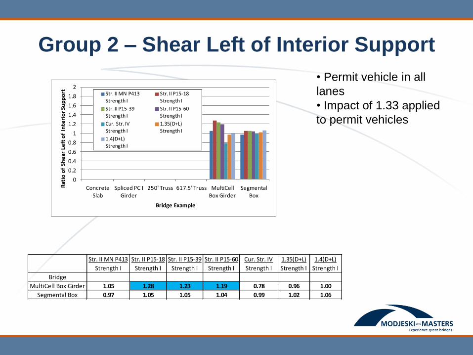
Group 2 – Shear Left of Interior Support
• Permit vehicle in all
lanes
• Impact of 1.33 applied
to permit vehicles
0
0.2
0.4
0.6
0.8
1
1.2
1.4
1.6
1.8
2
Concrete Slab
Spliced PC I Girder
250' Truss 617.5' Truss MultiCell Box Girder
Segmental Box
Rat
io o
f Sh
ear
Le
ft o
f In
teri
or
Sup
po
rt
Bridge Example
Str. II MN P413Strength I
Str. II P15-18Strength I
Str. II P15-39Strength I
Str. II P15-60Strength I
Cur. Str. IV
Strength I
1.35(D+L)
Strength I
1.4(D+L)
Strength I
Str. II MN P413
Strength I
Str. II P15-18
Strength I
Str. II P15-39
Strength I
Str. II P15-60
Strength I
Cur. Str. IV
Strength I
1.35(D+L)
Strength I
1.4(D+L)
Strength I
Bridge
MultiCell Box Girder 1.05 1.28 1.23 1.19 0.78 0.96 1.00
Segmental Box 0.97 1.05 1.05 1.04 0.99 1.02 1.06
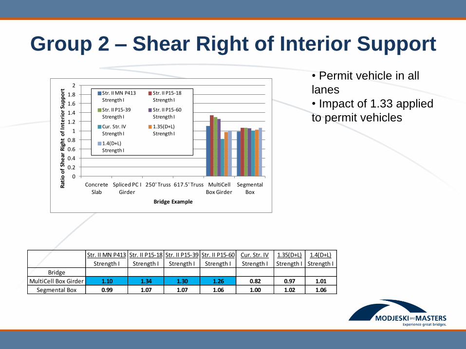
Group 2 – Shear Right of Interior Support
• Permit vehicle in all
lanes
• Impact of 1.33 applied
to permit vehicles
0
0.2
0.4
0.6
0.8
1
1.2
1.4
1.6
1.8
2
Concrete Slab
Spliced PC I Girder
250' Truss 617.5' Truss MultiCell Box Girder
Segmental Box
Rat
io o
f Sh
ear
Rig
ht
of
Inte
rio
r Su
pp
ort
Bridge Example
Str. II MN P413Strength I
Str. II P15-18Strength I
Str. II P15-39
Strength I
Str. II P15-60
Strength I
Cur. Str. IV
Strength I1.35(D+L)
Strength I
1.4(D+L)Strength I
Str. II MN P413
Strength I
Str. II P15-18
Strength I
Str. II P15-39
Strength I
Str. II P15-60
Strength I
Cur. Str. IV
Strength I
1.35(D+L)
Strength I
1.4(D+L)
Strength I
Bridge
MultiCell Box Girder 1.10 1.34 1.30 1.26 0.82 0.97 1.01
Segmental Box 0.99 1.07 1.07 1.06 1.00 1.02 1.06

Ratio of Strength II to Strength I (interior girders with permit vehicles in all lanes,
Impact = 33%)
MnDOT P413 CalTrans P15-18 ft
CalTrans P15-39ft
CalTrans P15-60ft
Min Max Min Max Min Max Min Max
M+end 0.90 1.04 0.98 1.33 0.98 1.22 0.98 1.15
M+center 0.90 1.02 1.12 1.40 1.09 1.26 1.07 1.18
M- 0.90 0.99 0.95 1.22 0.95 1.23 0.95 1.15
Vend 0.90 1.09 0.99 1.42 0.99 1.34 0.98 1.29
Vleft 0.95 1.07 1.05 1.38 1.05 1.30 1.04 1.23
Vright 0.94 1.10 1.07 1.39 1.06 1.32 1.06 1.26
* Simple span moments and shears are considered in M+end and Vend rows
MnDOT P413 CalTrans P15-18 ft
CalTrans P15-39ft
CalTrans P15-60ft
Min Max Min Max Min Max Min Max
M+end 0.88 1.04 0.98 1.31 0.98 1.21 0.98 1.12
M+center 0.88 1.02 1.03 1.23 1.02 1.16 1.01 1.10
M- 0.90 0.95 0.96 1.08 0.95 1.09 0.95 1.04
Vend 0.90 1.09 0.99 1.40 0.99 1.34 0.98 1.29
Vleft 0.95 1.05 1.03 1.28 1.03 1.23 1.02 1.19
Vright 0.94 1.10 1.02 1.34 1.02 1.30 1.02 1.26
* Simple span moments and shears are considered in M+end and Vend rows
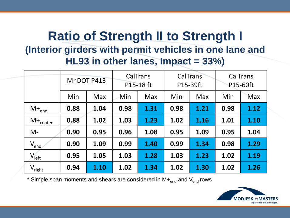
Ratio of Strength II to Strength I (Interior girders with permit vehicles in one lane and
HL93 in other lanes, Impact = 33%)

MnDOT P413 CalTrans P15-18 ft
CalTrans P15-39ft
CalTrans P15-60ft
Min Max Min Max Min Max Min Max
M+end 0.74 0.90 0.87 1.07 0.87 1.01 0.85 0.95
M+center 0.74 0.86 0.91 1.10 0.90 1.01 0.88 0.95
M- 0.81 0.89 0.90 1.01 0.90 1.02 0.89 0.97
Vend 0.78 1.00 0.88 1.25 0.88 1.21 0.86 1.16
Vleft 0.88 0.97 0.97 1.21 0.96 1.14 0.96 1.10
Vright 0.86 1.00 0.98 1.21 0.98 1.16 0.98 1.12
* Simple span moments and shears are considered in M+end and Vend rows
Ratio of Strength II to Strength I (Interior girders with permit vehicles in one lane,
Impact of 33%)
MnDOT P413 CalTrans P15-18 ft
CalTrans P15-39ft
CalTrans P15-60ft
Min Max Min Max Min Max Min Max
M+end 0.82 0.98 0.92 1.22 0.92 1.13 0.92 1.07
M+center 0.82 0.97 1.06 1.27 1.03 1.16 1.02 1.09
M- 0.89 0.93 0.93 1.11 0.93 1.13 0.93 1.06
Vend 0.85 1.02 0.96 1.28 0.96 1.24 0.95 1.19
Vleft 0.92 1.00 1.02 1.27 1.02 1.19 1.01 1.14
Vright 0.90 1.05 1.02 1.27 1.02 1.22 1.01 1.19
* Simple span moments and shears are considered in M+end and Vend rows
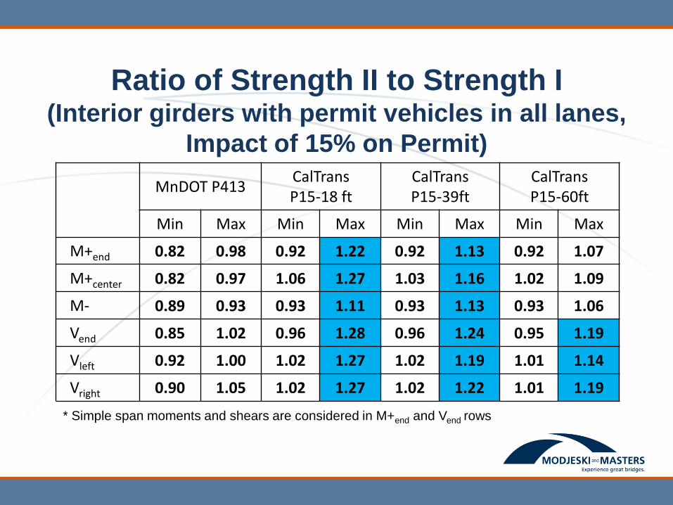
Ratio of Strength II to Strength I (Interior girders with permit vehicles in all lanes,
Impact of 15% on Permit)

MnDOT P413 CalTrans P15-18 ft
CalTrans P15-39ft
CalTrans P15-60ft
Min Max Min Max Min Max Min Max
M+end 0.68 0.86 0.82 1.01 0.82 0.96 0.82 0.92
M+center 0.68 0.84 0.88 1.01 0.84 0.94 0.84 0.90
M- 0.78 0.89 0.88 0.94 0.86 0.95 0.86 0.90
Vend 0.74 0.94 0.85 1.16 0.84 1.12 0.83 1.08
Vleft 0.82 0.92 0.95 1.12 0.95 1.06 0.94 1.03
Vright 0.80 0.96 0.96 1.12 0.96 1.09 0.95 1.06
* Simple span moments and shears are considered in M+end and Vend rows
Ratio of Strength II to Strength I (Interior girders with permit vehicles in one lane,
Impact of 15% on Permit)
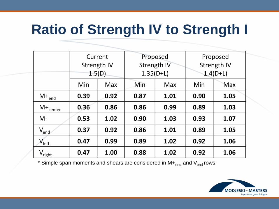
Ratio of Strength IV to Strength I
Current Strength IV
1.5(D)
Proposed Strength IV 1.35(D+L)
Proposed Strength IV
1.4(D+L)
Min Max Min Max Min Max
M+end 0.39 0.92 0.87 1.01 0.90 1.05
M+center 0.36 0.86 0.86 0.99 0.89 1.03
M- 0.53 1.02 0.90 1.03 0.93 1.07
Vend 0.37 0.92 0.86 1.01 0.89 1.05
Vleft 0.47 0.99 0.89 1.02 0.92 1.06
Vright 0.47 1.00 0.88 1.02 0.92 1.06
* Simple span moments and shears are considered in M+end and Vend rows

Strength IV: Reliability Analysis
Group 1 Bridges - Interior Girders
2.0
2.5
3.0
3.5
4.0
4.5
0.0 0.2 0.4 0.6 0.8 1.0
Be
ta
DL/(DL+LL)
Original Calibration Existing Specif ications
Proposed Formula 1 Proposed Formula 2

Strength IV: Reliability Analysis
Group 1 Bridges - Interior Girders
2.0
2.5
3.0
3.5
4.0
4.5
0.0 0.2 0.4 0.6 0.8 1.0
Be
ta
DL/(DL+LL)
Original Calibration Existing Specif ications
Proposed Formula 1 Proposed Formula 2
Proposed Formula 3

Reliability Analysis – Precast Girders
2.0
2.5
3.0
3.5
4.0
4.5
0.0 0.2 0.4 0.6 0.8 1.0
Be
ta
DL/(DL+LL)
Original Calibration Existing Specif ications
Proposed Formula 1 Proposed Formula 2
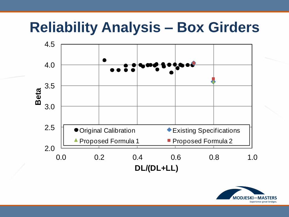
Reliability Analysis – Box Girders
2.0
2.5
3.0
3.5
4.0
4.5
0.0 0.2 0.4 0.6 0.8 1.0
Be
ta
DL/(DL+LL)
Original Calibration Existing Specif ications
Proposed Formula 1 Proposed Formula 2

Reliability Analysis - Trusses
2.00
2.50
3.00
3.50
4.00
4.50
0.00 0.20 0.40 0.60 0.80 1.00
Be
ta
DL/(DL+LL)
Existing Specif ications Proposed Formula 1
Proposed Formula 2

Conclusions
Strength II Comparisons (1)
• The CA-P15 trucks produce live load effects
significantly higher than the HL93
• When assumed to be in all lanes, the CA-P15
trucks produce Strength II factored design load
effects (DL + Permit) significantly higher than the
Strength I factored design load effects (DL +
HL93)
Conclusions
Strength II Comparisons (2)
• The ratio between Strength II and Strength I
factored design load effects is reduced when the
permit vehicles are assumed to exist in one lane
with HL93 load in other lanes
• A larger reduction is achieved when the permit
load is assumed to have lower impact and/or
when no other loads are assumed on the bridge
concurrently with the permit load

Conclusions
Strength II Comparisons (3)
• When assumed to exist in all lanes, the MN-413
truck produce Strength II design loads effects no
more than 10% higher than Strength I design
load effects

Conclusions
Strength IV Reliability Index
• The two proposed load combinations
(1.35 DL + 1.35 LL) and (1.4 DL + 1.4 LL)
Do not control over Strength I for the bridges
included in this study except in few cases and by
not more than 5% for the latter combination.
• When Strength I controls, the reliability index
does not change. When Strength IV controls
(with slight margin), the difference in the
reliability index is small
Related Documents