Progress of key strategies in development of electrospun scaffolds: bone tissue This article has been downloaded from IOPscience. Please scroll down to see the full text article. 2012 Sci. Technol. Adv. Mater. 13 043002 (http://iopscience.iop.org/1468-6996/13/4/043002) Download details: IP Address: 161.142.24.130 The article was downloaded on 11/09/2012 at 08:56 Please note that terms and conditions apply. View the table of contents for this issue, or go to the journal homepage for more Home Search Collections Journals About Contact us My IOPscience

Welcome message from author
This document is posted to help you gain knowledge. Please leave a comment to let me know what you think about it! Share it to your friends and learn new things together.
Transcript

Progress of key strategies in development of electrospun scaffolds: bone tissue
This article has been downloaded from IOPscience. Please scroll down to see the full text article.
2012 Sci. Technol. Adv. Mater. 13 043002
(http://iopscience.iop.org/1468-6996/13/4/043002)
Download details:
IP Address: 161.142.24.130
The article was downloaded on 11/09/2012 at 08:56
Please note that terms and conditions apply.
View the table of contents for this issue, or go to the journal homepage for more
Home Search Collections Journals About Contact us My IOPscience
IOP PUBLISHING SCIENCE AND TECHNOLOGY OF ADVANCED MATERIALS
Sci. Technol. Adv. Mater. 13 (2012) 043002 (13pp) doi:10.1088/1468-6996/13/4/043002
TOPICAL REVIEW
Progress of key strategies in developmentof electrospun scaffolds: bone tissueSumit Pramanik, Belinda Pingguan-Murphyand Noor Azuan Abu Osman
Department of Biomedical Engineering, Faculty of Engineering, Centre for Applied Biomechanics,University of Malaya, Kuala Lumpur 50603, Malaysia
E-mail: [email protected]
Received 22 April 2012Accepted for publication 26 June 2012Published 8 August 2012Online at stacks.iop.org/STAM/13/043002
AbstractThere has been unprecedented development in tissue engineering (TE) over the last few yearsowing to its potential applications, particularly in bone reconstruction or regeneration. In thisarticle, we illustrate several advantages and disadvantages of different approaches to thedesign of electrospun TE scaffolds. We also review the major benefits of electrospun fibers forthree-dimensional scaffolds in hard connective TE applications and identify the key strategiesthat can improve the mechanical properties of scaffolds for bone TE applications. A fewinteresting results of recent investigations have been explained for future trends in TE scaffoldresearch.
Keywords: tissue engineering, hard tissue, electrospinning, nanofiber, polymer, scaffolding
1. Introduction
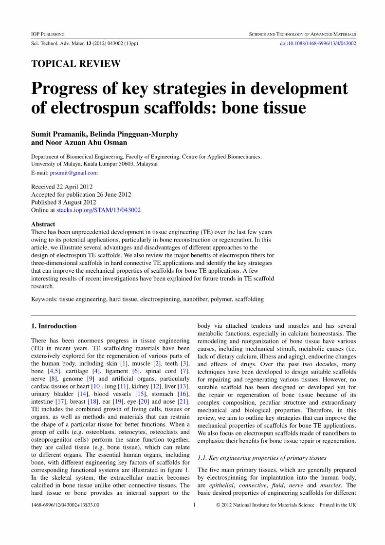
There has been enormous progress in tissue engineering(TE) in recent years. TE scaffolding materials have beenextensively explored for the regeneration of various parts ofthe human body, including skin [1], muscle [2], teeth [3],bone [4,5], cartilage [4], ligament [6], spinal cord [7],nerve [8], genome [9] and artificial organs, particularlycardiac tissues or heart [10], lung [11], kidney [12], liver [13],urinary bladder [14], blood vessels [15], stomach [16],intestine [17], breast [18], ear [19], eye [20] and nose [21].TE includes the combined growth of living cells, tissues ororgans, as well as methods and materials that can restrainthe shape of a particular tissue for better functions. When agroup of cells (e.g. osteoblasts, osteocytes, osteoclasts andosteoprogenitor cells) perform the same function together,they are called tissue (e.g. bone tissue), which can relateto different organs. The essential human organs, includingbone, with different engineering key factors of scaffolds forcorresponding functional systems are illustrated in figure 1.In the skeletal system, the extracellular matrix becomescalcified in bone tissue unlike other connective tissues. Thehard tissue or bone provides an internal support to the
body via attached tendons and muscles and has severalmetabolic functions, especially in calcium homeostasis. Theremodeling and reorganization of bone tissue have variouscauses, including mechanical stimuli, metabolic causes (i.e.lack of dietary calcium, illness and aging), endocrine changesand effects of drugs. Over the past two decades, manytechniques have been developed to design suitable scaffoldsfor repairing and regenerating various tissues. However, nosuitable scaffold has been designed or developed yet forthe repair or regeneration of bone tissue because of itscomplex composition, peculiar structure and extraordinarymechanical and biological properties. Therefore, in thisreview, we aim to outline key strategies that can improve themechanical properties of scaffolds for bone TE applications.We also focus on electrospun scaffolds made of nanofibers toemphasize their benefits for bone tissue repair or regeneration.
1.1. Key engineering properties of primary tissues
The five main primary tissues, which are generally preparedby electrospinning for implantation into the human body,are epithelial, connective, fluid, nerve and muscles. Thebasic desired properties of engineering scaffolds for different
1468-6996/12/043002+13$33.00 1 © 2012 National Institute for Materials Science Printed in the UK
Sci. Technol. Adv. Mater. 13 (2012) 043002 Topical Review
Figure 1. Schematic of essential human organs listing functionalities required from implanted scaffolds.
tissues and the effect of electrospun materials on the TEscaffolds are illustrated in table 1.
Depending on the applications and functions, anelectrospun TE scaffold can be temporary or permanent.Usually, a temporary scaffold is highly porous and fullybiodegradable, without side effects of by-products, whereasa permanent scaffold is highly biocompatible, mechanicallystrong, nondegradable, and remains inside the body for a longtime.
1.2. Different tissue engineering approaches
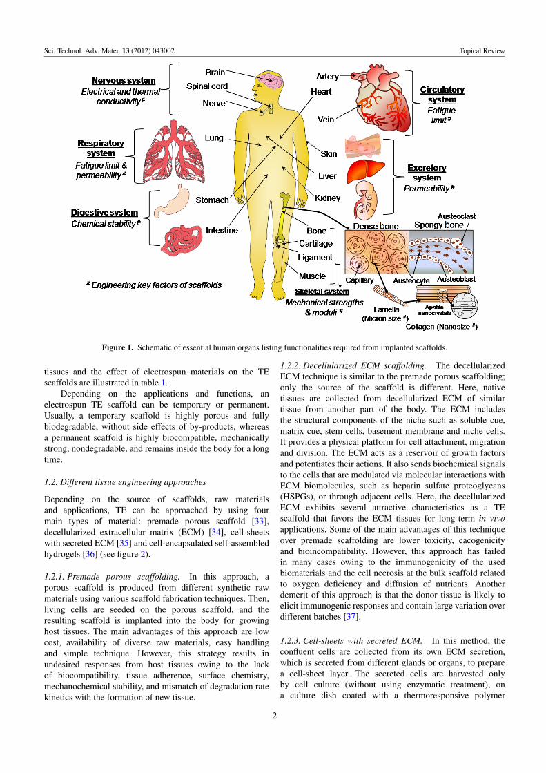
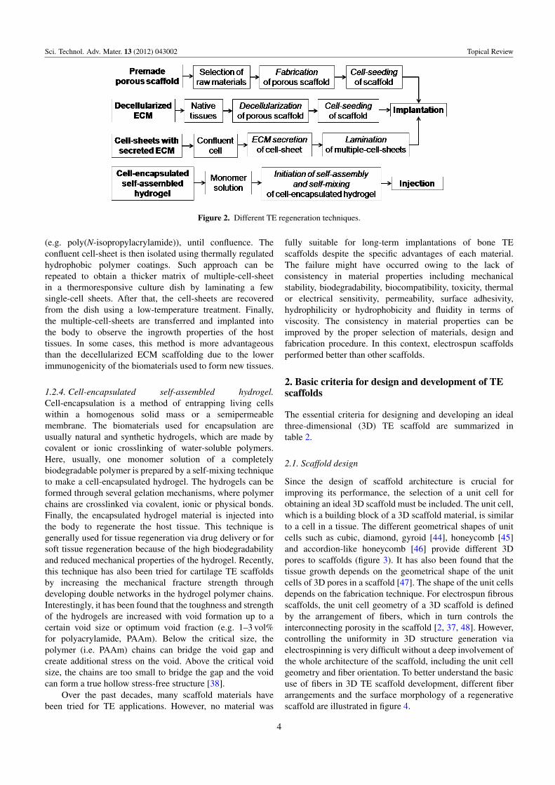
Depending on the source of scaffolds, raw materialsand applications, TE can be approached by using fourmain types of material: premade porous scaffold [33],decellularized extracellular matrix (ECM) [34], cell-sheetswith secreted ECM [35] and cell-encapsulated self-assembledhydrogels [36] (see figure 2).
1.2.1. Premade porous scaffolding. In this approach, aporous scaffold is produced from different synthetic rawmaterials using various scaffold fabrication techniques. Then,living cells are seeded on the porous scaffold, and theresulting scaffold is implanted into the body for growinghost tissues. The main advantages of this approach are lowcost, availability of diverse raw materials, easy handlingand simple technique. However, this strategy results inundesired responses from host tissues owing to the lackof biocompatibility, tissue adherence, surface chemistry,mechanochemical stability, and mismatch of degradation ratekinetics with the formation of new tissue.
1.2.2. Decellularized ECM scaffolding. The decellularizedECM technique is similar to the premade porous scaffolding;only the source of the scaffold is different. Here, nativetissues are collected from decellularized ECM of similartissue from another part of the body. The ECM includesthe structural components of the niche such as soluble cue,matrix cue, stem cells, basement membrane and niche cells.It provides a physical platform for cell attachment, migrationand division. The ECM acts as a reservoir of growth factorsand potentiates their actions. It also sends biochemical signalsto the cells that are modulated via molecular interactions withECM biomolecules, such as heparin sulfate proteoglycans(HSPGs), or through adjacent cells. Here, the decellularizedECM exhibits several attractive characteristics as a TEscaffold that favors the ECM tissues for long-term in vivoapplications. Some of the main advantages of this techniqueover premade scaffolding are lower toxicity, cacogenicityand bioincompatibility. However, this approach has failedin many cases owing to the immunogenicity of the usedbiomaterials and the cell necrosis at the bulk scaffold relatedto oxygen deficiency and diffusion of nutrients. Anotherdemerit of this approach is that the donor tissue is likely toelicit immunogenic responses and contain large variation overdifferent batches [37].
1.2.3. Cell-sheets with secreted ECM. In this method, theconfluent cells are collected from its own ECM secretion,which is secreted from different glands or organs, to preparea cell-sheet layer. The secreted cells are harvested onlyby cell culture (without using enzymatic treatment), ona culture dish coated with a thermoresponsive polymer
2
Sci. Technol. Adv. Mater. 13 (2012) 043002 Topical Review
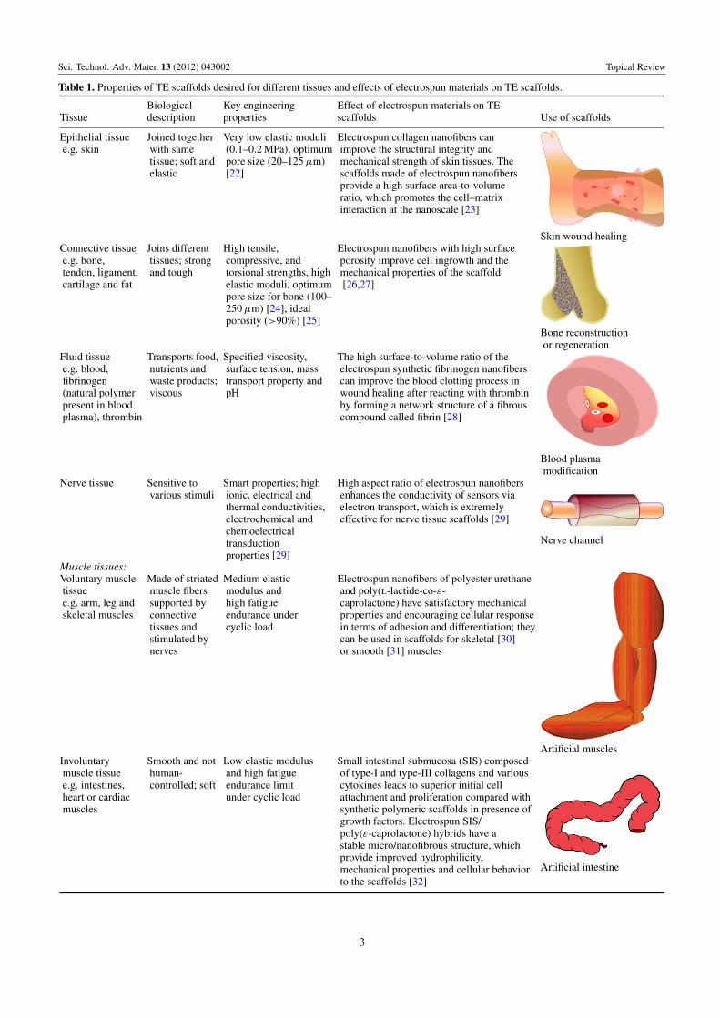
Table 1. Properties of TE scaffolds desired for different tissues and effects of electrospun materials on TE scaffolds.
Biological Key engineering Effect of electrospun materials on TETissue description properties scaffolds Use of scaffolds
Epithelial tissue Joined together Very low elastic moduli Electrospun collagen nanofibers cane.g. skin with same (0.1–0.2 MPa), optimum improve the structural integrity and
tissue; soft and pore size (20–125 µm) mechanical strength of skin tissues. Theelastic [22] scaffolds made of electrospun nanofibers
provide a high surface area-to-volumeratio, which promotes the cell–matrixinteraction at the nanoscale [23]
Skin wound healingConnective tissue Joins different High tensile, Electrospun nanofibers with high surfacee.g. bone, tissues; strong compressive, and porosity improve cell ingrowth and thetendon, ligament, and tough torsional strengths, high mechanical properties of the scaffoldcartilage and fat elastic moduli, optimum [26,27]
pore size for bone (100–250 µm) [24], idealporosity (>90%) [25]
Bone reconstructionor regeneration
Fluid tissue Transports food, Specified viscosity, The high surface-to-volume ratio of thee.g. blood, nutrients and surface tension, mass electrospun synthetic fibrinogen nanofibersfibrinogen waste products; transport property and can improve the blood clotting process in(natural polymer viscous pH wound healing after reacting with thrombinpresent in blood by forming a network structure of a fibrousplasma), thrombin compound called fibrin [28]
Blood plasmamodification
Nerve tissue Sensitive to Smart properties; high High aspect ratio of electrospun nanofibersvarious stimuli ionic, electrical and enhances the conductivity of sensors via
thermal conductivities, electron transport, which is extremelyelectrochemical and effective for nerve tissue scaffolds [29]chemoelectricaltransductionproperties [29]
Nerve channel
Muscle tissues:Voluntary muscle Made of striated Medium elastic Electrospun nanofibers of polyester urethanetissue muscle fibers modulus and and poly(l-lactide-co-ε-e.g. arm, leg and supported by high fatigue caprolactone) have satisfactory mechanicalskeletal muscles connective endurance under properties and encouraging cellular response
tissues and cyclic load in terms of adhesion and differentiation; theystimulated by can be used in scaffolds for skeletal [30]nerves or smooth [31] muscles
Artificial musclesInvoluntary Smooth and not Low elastic modulus Small intestinal submucosa (SIS) composedmuscle tissue human- and high fatigue of type-I and type-III collagens and variouse.g. intestines, controlled; soft endurance limit cytokines leads to superior initial cellheart or cardiac under cyclic load attachment and proliferation compared withmuscles synthetic polymeric scaffolds in presence of
growth factors. Electrospun SIS/poly(ε-caprolactone) hybrids have astable micro/nanofibrous structure, whichprovide improved hydrophilicity,mechanical properties and cellular behaviorto the scaffolds [32]
Artificial intestine
3
Sci. Technol. Adv. Mater. 13 (2012) 043002 Topical Review
Figure 2. Different TE regeneration techniques.
(e.g. poly(N-isopropylacrylamide)), until confluence. Theconfluent cell-sheet is then isolated using thermally regulatedhydrophobic polymer coatings. Such approach can berepeated to obtain a thicker matrix of multiple-cell-sheetin a thermoresponsive culture dish by laminating a fewsingle-cell sheets. After that, the cell-sheets are recoveredfrom the dish using a low-temperature treatment. Finally,the multiple-cell-sheets are transferred and implanted intothe body to observe the ingrowth properties of the hosttissues. In some cases, this method is more advantageousthan the decellularized ECM scaffolding due to the lowerimmunogenicity of the biomaterials used to form new tissues.
1.2.4. Cell-encapsulated self-assembled hydrogel.Cell-encapsulation is a method of entrapping living cellswithin a homogenous solid mass or a semipermeablemembrane. The biomaterials used for encapsulation areusually natural and synthetic hydrogels, which are made bycovalent or ionic crosslinking of water-soluble polymers.Here, usually, one monomer solution of a completelybiodegradable polymer is prepared by a self-mixing techniqueto make a cell-encapsulated hydrogel. The hydrogels can beformed through several gelation mechanisms, where polymerchains are crosslinked via covalent, ionic or physical bonds.Finally, the encapsulated hydrogel material is injected intothe body to regenerate the host tissue. This technique isgenerally used for tissue regeneration via drug delivery or forsoft tissue regeneration because of the high biodegradabilityand reduced mechanical properties of the hydrogel. Recently,this technique has also been tried for cartilage TE scaffoldsby increasing the mechanical fracture strength throughdeveloping double networks in the hydrogel polymer chains.Interestingly, it has been found that the toughness and strengthof the hydrogels are increased with void formation up to acertain void size or optimum void fraction (e.g. 1–3 vol%for polyacrylamide, PAAm). Below the critical size, thepolymer (i.e. PAAm) chains can bridge the void gap andcreate additional stress on the void. Above the critical voidsize, the chains are too small to bridge the gap and the voidcan form a true hollow stress-free structure [38].
Over the past decades, many scaffold materials havebeen tried for TE applications. However, no material was
fully suitable for long-term implantations of bone TEscaffolds despite the specific advantages of each material.The failure might have occurred owing to the lack ofconsistency in material properties including mechanicalstability, biodegradability, biocompatibility, toxicity, thermalor electrical sensitivity, permeability, surface adhesivity,hydrophilicity or hydrophobicity and fluidity in terms ofviscosity. The consistency in material properties can beimproved by the proper selection of materials, design andfabrication procedure. In this context, electrospun scaffoldsperformed better than other scaffolds.
2. Basic criteria for design and development of TEscaffolds
The essential criteria for designing and developing an idealthree-dimensional (3D) TE scaffold are summarized intable 2.
2.1. Scaffold design
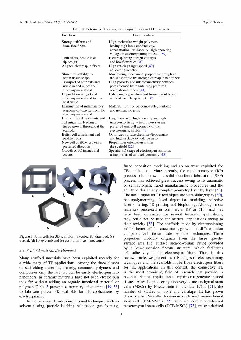
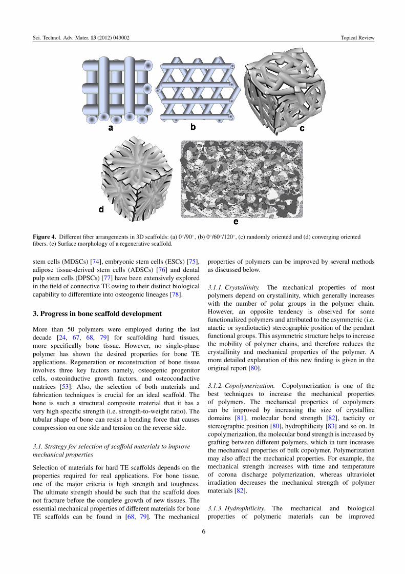
Since the design of scaffold architecture is crucial forimproving its performance, the selection of a unit cell forobtaining an ideal 3D scaffold must be included. The unit cell,which is a building block of a 3D scaffold material, is similarto a cell in a tissue. The different geometrical shapes of unitcells such as cubic, diamond, gyroid [44], honeycomb [45]and accordion-like honeycomb [46] provide different 3Dpores to scaffolds (figure 3). It has also been found that thetissue growth depends on the geometrical shape of the unitcells of 3D pores in a scaffold [47]. The shape of the unit cellsdepends on the fabrication technique. For electrospun fibrousscaffolds, the unit cell geometry of a 3D scaffold is definedby the arrangement of fibers, which in turn controls theinterconnecting porosity in the scaffold [2, 37, 48]. However,controlling the uniformity in 3D structure generation viaelectrospinning is very difficult without a deep involvement ofthe whole architecture of the scaffold, including the unit cellgeometry and fiber orientation. To better understand the basicuse of fibers in 3D TE scaffold development, different fiberarrangements and the surface morphology of a regenerativescaffold are illustrated in figure 4.
4
Sci. Technol. Adv. Mater. 13 (2012) 043002 Topical Review
Table 2. Criteria for designing electrospun fibers and TE scaffolds.
Function Design criteria
Strong, uniform and High-molecular-weight polymersbead-free fibers having high ionic conductivity,
concentration, or viscosity; high operatingvoltage in electrospinning process [39]
Thin fibers, needle-like Electrospinning at high voltagestip design and low flow rates [40]Aligned electrospun fibers High rotating target speed [40];
collector geometryStructural stability to Maintaining mechanical properties throughoutretain tissue shape the 3D scaffold by strong electrospun nanofibersTransport of nutrients and High porosity and interconnectivity betweenwaste in and out of the pores formed by maintaining preferredelectrospun scaffold orientation of fibers [41]Degradation integrity of Balancing degradation and formation of tissueelectrospun scaffold to leave without toxic by-products [42]host tissueElimination of inflammatory Materials must be biocompatible, nontoxicresponse or toxicity from the and noncarcinogenicelectrospun scaffoldHigh cell seeding density and Large pore size, high porosity and highcell migration leading to interconnectivity between pores usingtissue growth throughout the preferred unit cell geometry of thescaffold electrospun scaffolds [43]Better cell attachment and Optimized surface chemistry/topographyproliferation and high surface-to-volume ratioNew cell or ECM growth in Proper fiber orientation withinpreferred direction the scaffold [22]Growth of 3D tissues and Specific 3D shape of electrospun scaffoldsorgans using preferred unit cell geometry [43]
Figure 3. Unit cells for 3D scaffolds: (a) cubic, (b) diamond, (c)gyroid, (d) honeycomb and (e) accordion-like honeycomb.
2.2. Scaffold material development
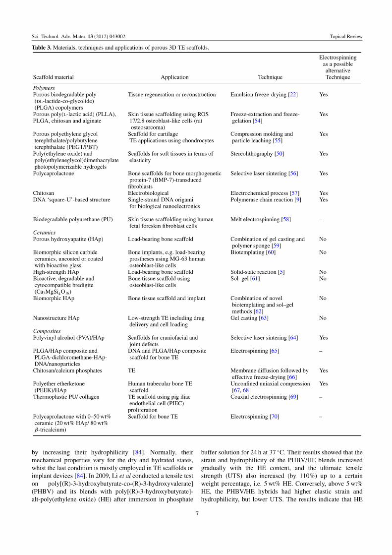
Many scaffold materials have been exploited recently fora wide range of TE applications. Among the three classesof scaffolding materials, namely, ceramics, polymers andcomposites only the last two can be easily electrospun intonanofibers, as ceramic materials have not been electrospunthus far without adding an organic functional material orpolymer. Table 3 presents a summary of attempts [49–53]to fabricate porous 3D scaffolds for TE applications byelectrospinning.
In the previous decade, conventional techniques such assolvent casting, particle leaching, salt fusion, gas foaming,
fused deposition modeling and so on were exploited forTE applications. More recently, the rapid prototype (RP)process, also known as solid free-form fabrication (SFF)process, has achieved great success owing to its automaticor semiautomatic rapid manufacturing procedures and theability to design any complex geometry layer by layer [53].The most important RP techniques are stereolithography [50],photopolymerizing, fused deposition modeling, selectivelaser sintering, 3D printing and bioplotting. Although mostmaterials processed in commercial RP or SFF machineshave been optimized for several technical applications,they could not be used for medical applications owing totheir toxicity [53]. The scaffolds made by electrospinningexhibit better cellular attachment, growth and differentiationcompared with those made by other techniques. Theseproperties probably originate from the large specificsurface area (i.e. surface area-to-volume ratio) providedby a low-dimension fibrous structure, which facilitatescell adhesivity to the electrospun fibers. Thus, in thisreview article, we present the advantages of electrospinningtechniques and the scaffolds made from electrospun fibersfor TE applications. In this context, the connective TEis the most promising field of research that provides apotential clinical application to repair or regenerate injuredtissues. After the pioneering discovery of mesenchymal stemcells (MSCs) by Friedenstein in the late 1970s [71], thenumber of studies on bone and cartilage TE has growndramatically. Recently, bone-marrow-derived mesenchymalstem cells (BM-MSCs) [72], umbilical cord blood-derivedmesenchymal stem cells (UCB-MSCs) [73], muscle-derived
5
Sci. Technol. Adv. Mater. 13 (2012) 043002 Topical Review
Figure 4. Different fiber arrangements in 3D scaffolds: (a) 0◦/90◦, (b) 0◦/60◦/120◦, (c) randomly oriented and (d) converging orientedfibers. (e) Surface morphology of a regenerative scaffold.
stem cells (MDSCs) [74], embryonic stem cells (ESCs) [75],adipose tissue-derived stem cells (ADSCs) [76] and dentalpulp stem cells (DPSCs) [77] have been extensively exploredin the field of connective TE owing to their distinct biologicalcapability to differentiate into osteogenic lineages [78].
3. Progress in bone scaffold development
More than 50 polymers were employed during the lastdecade [24, 67, 68, 79] for scaffolding hard tissues,more specifically bone tissue. However, no single-phasepolymer has shown the desired properties for bone TEapplications. Regeneration or reconstruction of bone tissueinvolves three key factors namely, osteogenic progenitorcells, osteoinductive growth factors, and osteoconductivematrices [53]. Also, the selection of both materials andfabrication techniques is crucial for an ideal scaffold. Thebone is such a structural composite material that it has avery high specific strength (i.e. strength-to-weight ratio). Thetubular shape of bone can resist a bending force that causescompression on one side and tension on the reverse side.
3.1. Strategy for selection of scaffold materials to improvemechanical properties
Selection of materials for hard TE scaffolds depends on theproperties required for real applications. For bone tissue,one of the major criteria is high strength and toughness.The ultimate strength should be such that the scaffold doesnot fracture before the complete growth of new tissues. Theessential mechanical properties of different materials for boneTE scaffolds can be found in [68, 79]. The mechanical
properties of polymers can be improved by several methodsas discussed below.
3.1.1. Crystallinity. The mechanical properties of mostpolymers depend on crystallinity, which generally increaseswith the number of polar groups in the polymer chain.However, an opposite tendency is observed for somefunctionalized polymers and attributed to the asymmetric (i.e.atactic or syndiotactic) stereographic position of the pendantfunctional groups. This asymmetric structure helps to increasethe mobility of polymer chains, and therefore reduces thecrystallinity and mechanical properties of the polymer. Amore detailed explanation of this new finding is given in theoriginal report [80].
3.1.2. Copolymerization. Copolymerization is one of thebest techniques to increase the mechanical propertiesof polymers. The mechanical properties of copolymerscan be improved by increasing the size of crystallinedomains [81], molecular bond strength [82], tacticity orstereographic position [80], hydrophilicity [83] and so on. Incopolymerization, the molecular bond strength is increased bygrafting between different polymers, which in turn increasesthe mechanical properties of bulk copolymer. Polymerizationmay also affect the mechanical properties. For example, themechanical strength increases with time and temperatureof corona discharge polymerization, whereas ultravioletirradiation decreases the mechanical strength of polymermaterials [82].
3.1.3. Hydrophilicity. The mechanical and biologicalproperties of polymeric materials can be improved
6
Sci. Technol. Adv. Mater. 13 (2012) 043002 Topical Review
Table 3. Materials, techniques and applications of porous 3D TE scaffolds.
Electrospinningas a possiblealternative
Scaffold material Application Technique Technique
PolymersPorous biodegradable poly Tissue regeneration or reconstruction Emulsion freeze-drying [22] Yes(dl-lactide-co-glycolide)(PLGA) copolymers
Porous poly(l-lactic acid) (PLLA), Skin tissue scaffolding using ROS Freeze-extraction and freeze- YesPLGA, chitosan and alginate 17/2.8 osteoblast-like cells (rat gelation [54]
osteosarcoma)Porous polyethylene glycol Scaffold for cartilage Compression molding and Yesterephthalate/polybutylene TE applications using chondrocytes particle leaching [55]terephthalate (PEGT/PBT)
Poly(ethylene oxide) and Scaffolds for soft tissues in terms of Stereolithography [50] Yespoly(ethyleneglycol)dimethacrylate elasticityphotopolymerizable hydrogels
Polycaprolactone Bone scaffolds for bone morphogenetic Selective laser sintering [56] Yesprotein-7 (BMP-7)-transducedfibroblasts
Chitosan Electrobiological Electrochemical process [57] YesDNA ‘square-U’-based structure Single-strand DNA origami Polymerase chain reaction [9] Yes
for biological nanoelectronics
Biodegradable polyurethane (PU) Skin tissue scaffolding using human Melt electrospinning [58] –fetal foreskin fibroblast cells
CeramicsPorous hydroxyapatite (HAp) Load-bearing bone scaffold Combination of gel casting and No
polymer sponge [59]Biomorphic silicon carbide Bone implants, e.g. load-bearing Biotemplating [60] Noceramics, uncoated or coated prostheses using MG-63 humanwith bioactive glass osteoblast-like cells
High-strength HAp Load-bearing bone scaffold Solid-state reaction [5] NoBioactive, degradable and Bone tissue scaffold using Sol–gel [61] Nocytocompatible bredigite osteoblast-like cells(Ca7MgSi4O16)
Biomorphic HAp Bone tissue scaffold and implant Combination of novel Nobiotemplating and sol–gelmethods [62]
Nanostructure HAp Low-strength TE including drug Gel casting [63] Nodelivery and cell loading
CompositesPolyvinyl alcohol (PVA)/HAp Scaffolds for craniofacial and Selective laser sintering [64] Yes
joint defectsPLGA/HAp composite and DNA and PLGA/HAp composite Electrospinning [65] –PLGA-dichloromethane-HAp- scaffold for bone TEDNA/nanoparticles
Chitosan/calcium phosphates TE Membrane diffusion followed by Yeseffective freeze-drying [66]
Polyether etherketone Human trabecular bone TE Unconfined uniaxial compression Yes(PEEK)/HAp scaffold [67, 68]
Thermoplastic PU/ collagen TE scaffold using pig iliac Coaxial electrospinning [69] –endothelial cell (PIEC)proliferation
Polycaprolactone with 0–50 wt% Scaffold for bone TE Electrospinning [70] –ceramic (20 wt% HAp/ 80 wt%β-tricalcium)
by increasing their hydrophilicity [84]. Normally, theirmechanical properties vary for the dry and hydrated states,whist the last condition is mostly employed in TE scaffolds orimplant devices [84]. In 2009, Li et al conducted a tensile teston poly[(R)-3-hydroxybutyrate-co-(R)-3-hydroxyvalerate](PHBV) and its blends with poly[(R)-3-hydroxybutyrate]-alt-poly(ethylene oxide) (HE) after immersion in phosphate
buffer solution for 24 h at 37 ◦C. Their results showed that thestrain and hydrophilicity of the PHBV/HE blends increasedgradually with the HE content, and the ultimate tensilestrength (UTS) also increased (by 110%) up to a certainweight percentage, i.e. 5 wt% HE. Conversely, above 5 wt%HE, the PHBV/HE hybrids had higher elastic strain andhydrophilicity, but lower UTS. The results indicate that HE
7
Sci. Technol. Adv. Mater. 13 (2012) 043002 Topical Review
improves the hydrophilicity of PHBV/HE polymers throughsurface modification, and the hydrophilicity further increasesthe mechanical properties by increasing the crosslinkingbetween the poly[(R)-3-hydroxybutyrate] (PHB) segmentsof HE and PHBV matrix up to a certain level (i.e. 5 wt%HE for this PHBV/HE system). Above a critical level, thewater absorption increases rapidly, and this deterioratesthe mechanical strength [84]. Lu et al [85] reported thatthe tensile and tear strengths of addition silicone, whichis generally hydrophobic and is used as an impressionmaterial, can be improved by making it hydrophilic afterthe addition of surfactants. It has also been found that themoderately hydrophilic polymers support the attachment ofa high fraction of fibroblast cells [83]. Moreover, the celladhesion via adsorbed protein can be improved by surfaceswith intermediate wettability. On the other hand, hydrophobicpolymers such as polytetrafluoroethylene polypropyleneand polyethyleneterapthalate, polystyrene provide a limitedsupport for cell attachment. The poor cell attachment tononpolar polymers (e.g. polystyrene) is possibly related tothe lower degree of crystallinity in amorphous materials orhydrophobic polymers [83]. The different crystallinities ofhydrophobic polymers further alter the mechanical properties.However, a technical problem associated with hydrophilicpolymers, which is frequently faced when changing themedium during in vitro cell culture experiments, is thatsmaller hydrophilic electrospun fibers are lifted off the bulkscaffold owing to higher wetting in aqueous medium [40].This problem can be solved by optimizing the hydrophilicityof polymers using proper surface modifiers.
3.1.4. Surface treatment. A few recent studies have shownthat the mechanical properties of the bulk polymers orfibrous polymers can be improved by several surfacetreatment techniques [80, 86]. The polymer surface iseffectively modified with polar groups containing ester(–COOR), ether (–O–), ketone (>CO), epoxy, carboxylicacid (–COOH), hydroxyl (–OH), acetyl (–COCH3), amide(–CONH2), amine (–NH2) or other moieties by a suitablesurface treatment. The treatment improves the surfaceactivity, polarity, hydrophilicity and mechanical propertiesof the electrospun polymers. The resulting surface-modifiedelectrospun fiber may be advantageous for TE scaffolds usedin connective tissues, including bone, cartilage, ligament andtendon reconstructions or replacements.
3.1.5. Composite fabrication or hybridization. Most of therecent investigations on tissue scaffoldings follow thistechnique because it is inexpensive and allows easy andprecise control of the physical, chemical and biologicalproperties. The organic part of bone tissue, such as protein,gives tensile strength and the inorganic part, calcium andphosphorus salts, provides compressive strength to the bone.The inorganic part of the natural bone is mostly similar tosynthetic hydroxyapatite (HAp, [Ca5(PO4)3OH]) in structureand chemical composition. The structure of bone is a highlyorganized hierarchy of the inorganic (HAp) and organic(e.g. Type-I collagen) phases [60], and in situ growth of
inorganic phosphate compounds such as nanohydroxyapatiteon the nanoparticles or nanofibers of an organic polymer mayenhance the interfacial bonding between inorganic ceramicsand organic polymers [60, 87, 88]. This innovative techniquealso improves the cell attachment and cell proliferation on thescaffold surfaces.
3.1.6. Solubility. Many materials with low solubility havegood mechanical properties, biocompatibility and lowimmune response. However, their limited solubility (e.g. forchitosan, polyether ether ketone) hinders electrospinning[80, 89]. Their good mechanical properties originate fromthe network structure and strong hydrogen bonding. Themechanical properties of electrospun composite scaffoldsalso depend on the solubility of second-phase materialsused with the polymer matrix in the body plasma orsimulated body fluids. If the materials start to biodegrade ordissolve during in vivo use, the mechanical properties of thescaffold can deteriorate in an uncontrollable manner. Thisis often observed in composites of polymers and calciumphosphates. Several types of calcium phosphates have beenused in various biomedical fields, and their stability inwater under physiological conditions (pH 7.4, at 37 ◦C)increases in the following sequence: monocalcium phosphate[MCP, Ca(H2PO4)2 · H2O], tetracalcium phosphate [TTCP,Ca4P2O9], α-tricalcium phosphate [α-TCP, α-Ca3(PO4)2],dicalcium phosphate dihydrate [DCPD, CaHPO4 · 2H2O],dicalcium phosphate [DCP, CaHPO4], octacalcium phosphate[OCP, Ca8(HPO4)2(PO4)4 · 5H2O], β-tricalcium phosphate[β-TCP, β-Ca3(PO4)2], calcium-deficient hydroxyapatite[CDHAp, Ca9(HPO4)(PO4)5OH], HAp [90]. Therefore,depending on the mode of application, different ceramicsand biopolymers should be combined in composite or hybridscaffolds.
3.2. Selection of electrospinning technique
Synthetic polymer-based electrospun fibers offer adjustablemechanical properties and surface functionalization viabiomolecular coatings or chemical conjugation of specificsignaling molecules. The vital properties of electrospun fibersthat can be tuned via electrospinning are nanofiber diameter,surface morphology, mechanical properties, porosity andpore-size distribution [91]. The basic principle of theelectrospinning process is that an electrical voltage, which issufficient to overcome the surface tension of the polymericsolution, causes the polymer droplets to elongate and ejectas a fine fiber [70]. The electrospun fibers are used toform non-woven mats that are assembled into scaffolds.In this process, better fibers are produced from polymerswith higher molecular weights. One of the major advantagesof electrospun fibers is that they have better molecularbinding, which in turn improves their mechanical properties.Electrospinning can be performed in various modes includingsolution, melt and coaxial electrospinning. In solutionelectrospinning, the polymer is dissolved in a suitable solvent,whereas in melt electrospinning, the polymer is directlyelectrospun from the melt. The former method produces
8
Sci. Technol. Adv. Mater. 13 (2012) 043002 Topical Review
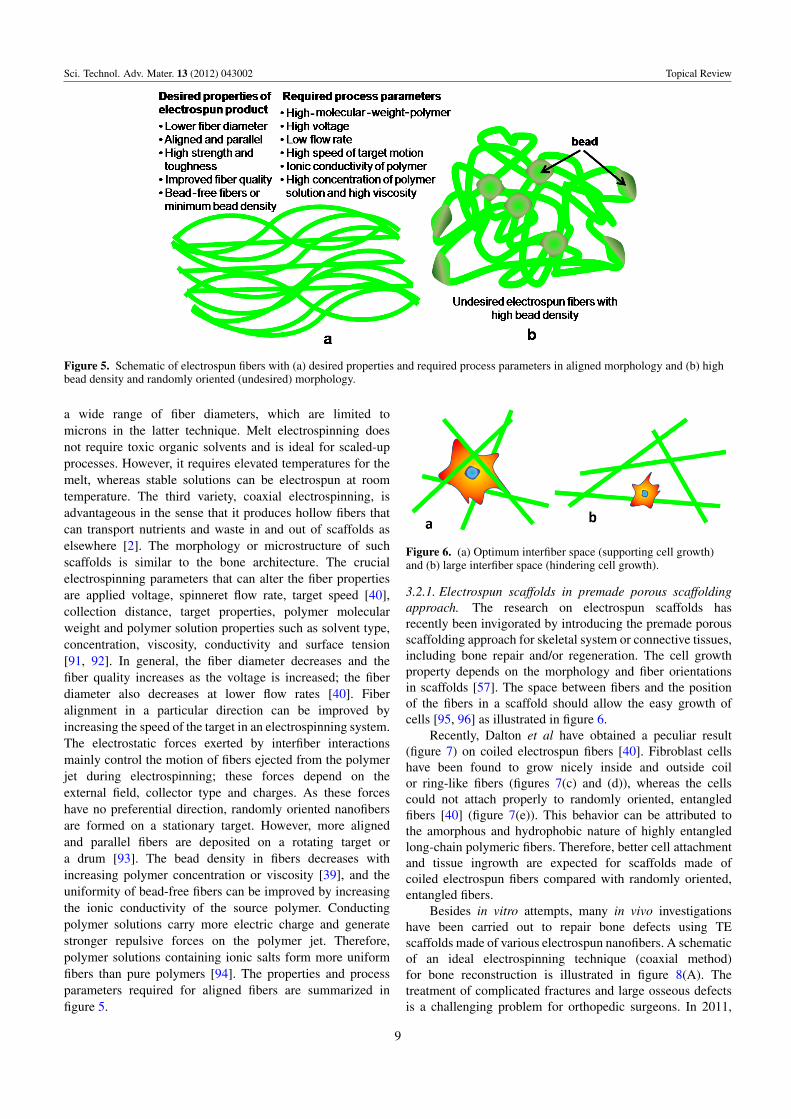
Figure 5. Schematic of electrospun fibers with (a) desired properties and required process parameters in aligned morphology and (b) highbead density and randomly oriented (undesired) morphology.
a wide range of fiber diameters, which are limited tomicrons in the latter technique. Melt electrospinning doesnot require toxic organic solvents and is ideal for scaled-upprocesses. However, it requires elevated temperatures for themelt, whereas stable solutions can be electrospun at roomtemperature. The third variety, coaxial electrospinning, isadvantageous in the sense that it produces hollow fibers thatcan transport nutrients and waste in and out of scaffolds aselsewhere [2]. The morphology or microstructure of suchscaffolds is similar to the bone architecture. The crucialelectrospinning parameters that can alter the fiber propertiesare applied voltage, spinneret flow rate, target speed [40],collection distance, target properties, polymer molecularweight and polymer solution properties such as solvent type,concentration, viscosity, conductivity and surface tension[91, 92]. In general, the fiber diameter decreases and thefiber quality increases as the voltage is increased; the fiberdiameter also decreases at lower flow rates [40]. Fiberalignment in a particular direction can be improved byincreasing the speed of the target in an electrospinning system.The electrostatic forces exerted by interfiber interactionsmainly control the motion of fibers ejected from the polymerjet during electrospinning; these forces depend on theexternal field, collector type and charges. As these forceshave no preferential direction, randomly oriented nanofibersare formed on a stationary target. However, more alignedand parallel fibers are deposited on a rotating target ora drum [93]. The bead density in fibers decreases withincreasing polymer concentration or viscosity [39], and theuniformity of bead-free fibers can be improved by increasingthe ionic conductivity of the source polymer. Conductingpolymer solutions carry more electric charge and generatestronger repulsive forces on the polymer jet. Therefore,polymer solutions containing ionic salts form more uniformfibers than pure polymers [94]. The properties and processparameters required for aligned fibers are summarized infigure 5.
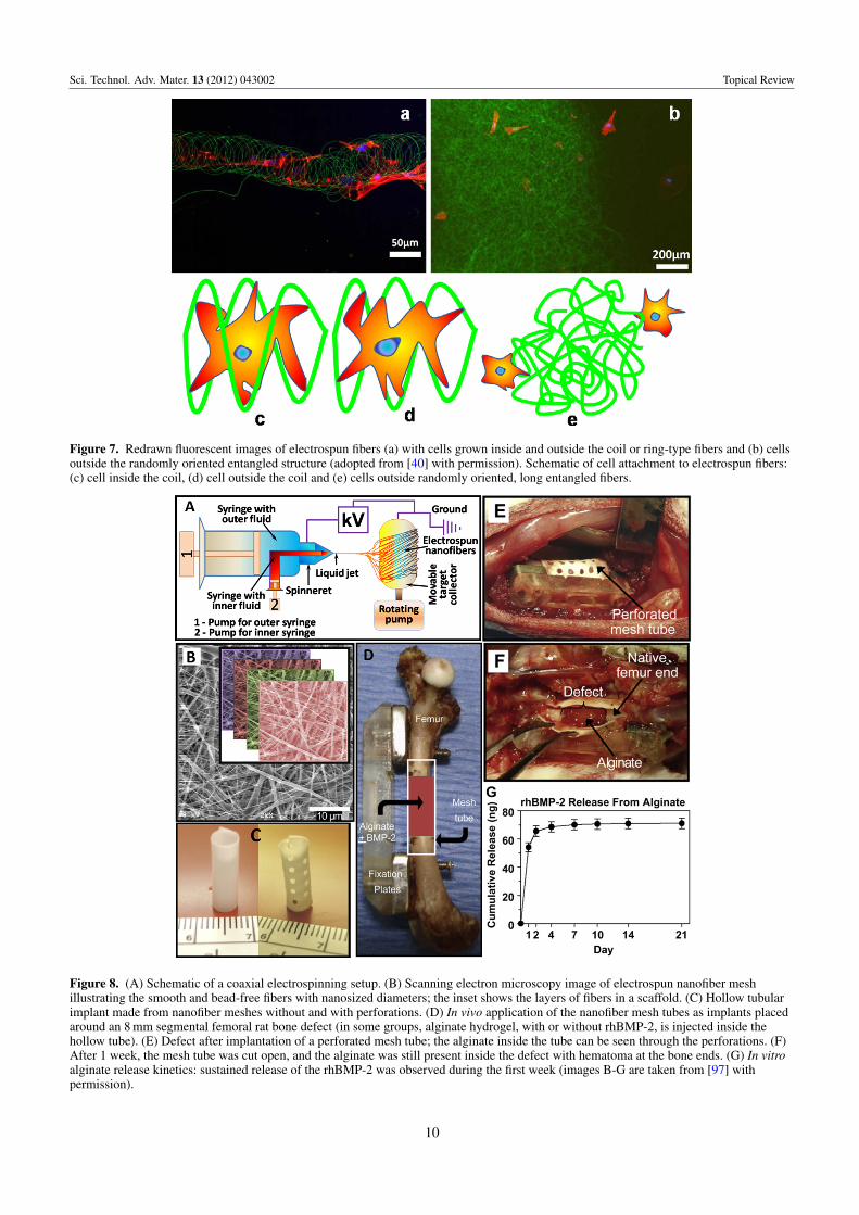
Figure 6. (a) Optimum interfiber space (supporting cell growth)and (b) large interfiber space (hindering cell growth).
3.2.1. Electrospun scaffolds in premade porous scaffoldingapproach. The research on electrospun scaffolds hasrecently been invigorated by introducing the premade porousscaffolding approach for skeletal system or connective tissues,including bone repair and/or regeneration. The cell growthproperty depends on the morphology and fiber orientationsin scaffolds [57]. The space between fibers and the positionof the fibers in a scaffold should allow the easy growth ofcells [95, 96] as illustrated in figure 6.
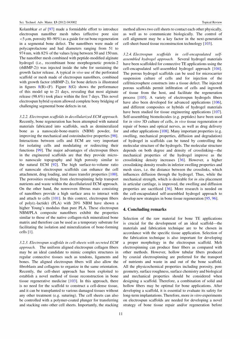
Recently, Dalton et al have obtained a peculiar result(figure 7) on coiled electrospun fibers [40]. Fibroblast cellshave been found to grow nicely inside and outside coilor ring-like fibers (figures 7(c) and (d)), whereas the cellscould not attach properly to randomly oriented, entangledfibers [40] (figure 7(e)). This behavior can be attributed tothe amorphous and hydrophobic nature of highly entangledlong-chain polymeric fibers. Therefore, better cell attachmentand tissue ingrowth are expected for scaffolds made ofcoiled electrospun fibers compared with randomly oriented,entangled fibers.
Besides in vitro attempts, many in vivo investigationshave been carried out to repair bone defects using TEscaffolds made of various electrospun nanofibers. A schematicof an ideal electrospinning technique (coaxial method)for bone reconstruction is illustrated in figure 8(A). Thetreatment of complicated fractures and large osseous defectsis a challenging problem for orthopedic surgeons. In 2011,
9
Sci. Technol. Adv. Mater. 13 (2012) 043002 Topical Review
Figure 7. Redrawn fluorescent images of electrospun fibers (a) with cells grown inside and outside the coil or ring-type fibers and (b) cellsoutside the randomly oriented entangled structure (adopted from [40] with permission). Schematic of cell attachment to electrospun fibers:(c) cell inside the coil, (d) cell outside the coil and (e) cells outside randomly oriented, long entangled fibers.
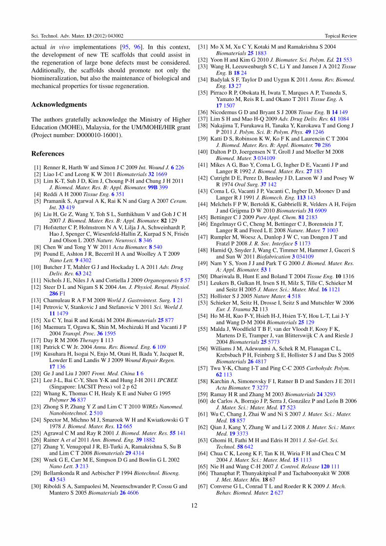
Figure 8. (A) Schematic of a coaxial electrospinning setup. (B) Scanning electron microscopy image of electrospun nanofiber meshillustrating the smooth and bead-free fibers with nanosized diameters; the inset shows the layers of fibers in a scaffold. (C) Hollow tubularimplant made from nanofiber meshes without and with perforations. (D) In vivo application of the nanofiber mesh tubes as implants placedaround an 8 mm segmental femoral rat bone defect (in some groups, alginate hydrogel, with or without rhBMP-2, is injected inside thehollow tube). (E) Defect after implantation of a perforated mesh tube; the alginate inside the tube can be seen through the perforations. (F)After 1 week, the mesh tube was cut open, and the alginate was still present inside the defect with hematoma at the bone ends. (G) In vitroalginate release kinetics: sustained release of the rhBMP-2 was observed during the first week (images B-G are taken from [97] withpermission).
10
Sci. Technol. Adv. Mater. 13 (2012) 043002 Topical Review
Kolambkar et al [97] made a formidable effort to introduceelectrospun nanofiber mesh tubes (effective pore size<5 µm, porosity 80–90%) as a guide for rat bone regenerationin a segmental bone defect. The nanofibers were made ofpolycaprolactone and had diameters ranging from 51 to974 nm, with 82% of the values lying between 50 and 150 nm.The nanofiber mesh combined with peptide-modified alginatehydrogel (i.e., recombinant bone morphogenetic protein-2(rhBMP-2)) was injected inside the tube for sustaining thegrowth factor release. A typical in vivo use of the perforatedscaffold or mesh made of electrospun nanofibers, combinedwith growth factor (rhBMP-2), for bone defects is illustratedin figures 8(B)–(F). Figure 8(G) shows the performanceof this model up to 21 days, revealing that most alginaterelease (98.6%) took place within the first 7 days. This novelelectrospun hybrid system allowed complete bony bridging ofchallenging segmental bone defects in rat.
3.2.2. Electrospun scaffolds in decellularized ECM approach.Recently, bone regeneration has been attempted with naturalmaterials fabricated into scaffolds, such as demineralizedbone as a nanoscale-bone-matrix (NBM) powder, forimproving the mechanical and osteoinductive properties [98].Interactions between cells and ECM are very importantfor isolating cells and modulating or redirecting theirfunctions [99]. The major advantages of electrospun fibersin the engineered scaffolds are that they provide micro-to nanoscale topography and high porosity similar tothe natural ECM [92]. The high surface-to-volume ratioof nanoscale electrospun scaffolds can enhance the cellattachment, drug loading, and mass transfer properties [100].The porosities resulting from electrospinning help transportnutrients and waste within the decellularized ECM approach.On the other hand, the nonwoven fibrous mats consistingof nanofibers provide a high surface area to interact withand attach to cells [101]. In this context, electrospun fibersof poly(l-lactide) (PLA) with 20% NBM have shown ahigher Young’s modulus than pure PLA. These electrospunNBM/PLA composite nanofibers exhibit the propertiessimilar to those of the native collagen-rich mineralized bonematrix and therefore can be used as a temporary substrate forfacilitating the isolation and mineralization of bone-formingcells [1].
3.2.3. Electrospun scaffolds in cell-sheets with secreted ECMapproach. The uniform aligned electrospun collagen fibersmay be an ideal candidate to mimic complex structures inregular connective tissues such as tendons, ligaments andbones. The aligned electrospun fibers will also allow thefibroblasts and collagens to organize in the same orientation.Recently, the cell-sheet approach has been exploited toestablish a novel method of tissue reconstruction in bonetissue regenerative medicine [103]. In this approach, thereis no need for the scaffold to construct a cell-dense tissue,and it can be transplanted to various damaged tissues withoutany other treatment (e.g. suturing). The cell sheets can alsobe controlled with a polymer-coated plunger for transferringand stacking onto other cell sheets. Importantly, the stacking
method allows two cell sheets to contact each other physically,as well as to communicate biologically. The control ofcell alignment may be a key factor in the next-generationcell-sheet-based tissue reconstruction technology [103].
3.2.4. Electrospun scaffolds in cell-encapsulated self-assembled hydrogel approach. Several hydrogel materialshave been scaffolded for connective TE applications using thecell-encapsulated self-assembled hydrogel approach [104].The porous hydrogel scaffolds can be used for microcarriersuspension culture of cells and for injection of thecell/microsphere constructs into a tissue defect. The injectedporous scaffolds permit infiltration of cells and ingrowthof tissue from the host, and facilitate the regenerationprocess [105]. A variety of electrospun hydrogels fibershave also been developed for advanced applications [106],and different composites or hybrids of hydrogel materialshave been studied for tissue engineering applications [107].Self-assembling biomolecules (e.g. peptides) have been usedfor in vitro 3D culture of cells, in vivo tissue regeneration orrepair of bones and optical nerves, as well as drug deliveryand other applications [108]. Many important properties (e.g.swelling, mechanical properties, diffusion and degradation)of hydrogel in scaffolds can be tuned by controlling themolecular structure of the hydrogels. The molecular structuredepends on both degree and density of crosslinking—themechanical properties of the hydrogel improve as thecrosslinking density increases [36]. However, a highercrosslinking density results in inferior swelling properties andmesh sizes, i.e. the distance between the crosslinks, whichinfluences diffusion through the hydrogel. Thus, while themechanical strength, which is desirable for in situ placementin articular cartilage, is improved, the swelling and diffusionproperties are sacrificed [36]. More research is needed onthe cell-encapsulated self-assembled hydrogel approach todevelop new strategies in bone tissue regeneration [95, 96].
4. Concluding remarks
Selection of the raw material for bone TE applicationsis crucial for the development of an ideal scaffold—thematerials and fabrication technique are to be chosen inaccordance with the specific tissue application. Selection ofthe fabrication technique is also important for developinga proper morphology in the electrospun scaffold. Meltelectrospinning can produce finer fibers as compared withother methods. However, hollow tubular fibers producedby coaxial electrospinning are preferred for the transportof nutrients and waste in and out of the bone scaffold.All the physicochemical properties including porosity, poregeometry, surface roughness, surface chemistry and biologicaland mechanical properties should be considered whendesigning a scaffold. Therefore, a combination of solid andhollow fibers may be optimal for bone applications. Afterdeveloping a scaffold, it is essential to evaluate its safety forlong-term implantations. Therefore, more in vitro experimentson electrospun scaffolds are needed for developing a novelstrategy of bone tissue repair and/or regeneration before
11
Sci. Technol. Adv. Mater. 13 (2012) 043002 Topical Review
actual in vivo implementations [95, 96]. In this context,the development of new TE scaffolds that could assist inthe regeneration of large bone defects must be considered.Additionally, the scaffolds should promote not only thebiomineralization, but also the maintenance of biological andmechanical properties for tissue regeneration.
Acknowledgments
The authors gratefully acknowledge the Ministry of HigherEducation (MOHE), Malaysia, for the UM/MOHE/HIR grant(Project number: D000010-16001).
References
[1] Renner R, Harth W and Simon J C 2009 Int. Wound J. 6 226[2] Liao I-C and Leong K W 2011 Biomaterials 32 1669[3] Lim K-T, Suh J D, Kim J, Choung P-H and Chung J H 2011
J. Biomed. Mater. Res. B: Appl. Biomater. 99B 399[4] Reddi A H 2000 Tissue Eng. 6 351[5] Pramanik S, Agarwal A K, Rai K N and Garg A 2007 Ceram.
Int. 33 419[6] Liu H, Ge Z, Wang Y, Toh S L, Sutthikhum V and Goh J C H
2007 J. Biomed. Mater. Res. B: Appl. Biomater. 82 129[7] Hofstetter C P, Holmstrom N A V, Lilja J A, Schweinhardt P,
Hao J, Spenger C, Wiesenfeld-Hallin Z, Kurpad S N, FrisenJ and Olson L 2005 Nature. Neurosci. 8 346
[8] Chen W and Tong Y W 2011 Acta Biomater. 8 540[9] Pound E, Ashton J R, Becerril H A and Woolley A T 2009
Nano Lett. 9 4302[10] Butcher J T, Mahler G J and Hockaday L A 2011 Adv. Drug
Deliv. Rev. 63 242[11] Nichols J E, Niles J A and Cortiella J 2009 Organogenesis 5 57[12] Steer D L and Nigam S K 2004 Am. J. Physiol. Renal. Physiol.
286 F1[13] Chamuleau R A F M 2009 World J. Gastrointest. Surg. 1 21[14] Petrovic V, Stankovic J and Stefanovic V 2011 Sci. World J.
11 1479[15] Xu C Y, Inai R and Kotaki M 2004 Biomaterials 25 877[16] Maemura T, Ogawa K, Shin M, Mochizuki H and Vacanti J P
2004 Transpl. Proc. 36 1595[17] Day R M 2006 Therapy 1 113[18] Patrick C W Jr. 2004 Annu. Rev. Biomed. Eng. 6 109[19] Kusuhara H, Isogai N, Enjo M, Otani H, Ikada Y, Jacquet R,
Lowder E and Landis W J 2009 Wound Repair Regen.17 136
[20] Ge J and Liu J 2007 Front. Med. China 1 6[21] Lee J-L, Bai C-Y, Shen Y-K and Hung J-H 2011 IPCBEE
(Singapore: IACSIT Press) vol 2 p 62[22] Whang K, Thomas C H, Healy K E and Nuber G 1995
Polymer 36 837[23] Zhong S P, Zhang Y Z and Lim C T 2010 WIREs Nanomed.
Nanobiotechnol. 2 510[24] Spector M, Michno M J, Smarook W H and Kwiatkowski G T
1978 J. Biomed. Mater. Res. 12 665[25] Agrawal C M and Ray R 2001 J. Biomed. Mater. Res. 55 141[26] Rainer A et al 2011 Ann. Biomed. Eng. 39 1882[27] Zhang Y, Venugopal J R, El-Turki A, Ramakrishna S, Su B
and Lim C T 2008 Biomaterials 29 4314[28] Wnek G E, Carr M E, Simpson D G and Bowlin G L 2002
Nano Lett. 3 213[29] Bellamkonda R and Aebischer P 1994 Biotechnol. Bioeng.
43 543[30] Riboldi S A, Sampaolesi M, Neuenschwander P, Cossu G and
Mantero S 2005 Biomaterials 26 4606
[31] Mo X M, Xu C Y, Kotaki M and Ramakrishna S 2004Biomaterials 25 1883
[32] Yoon H and Kim G 2010 J. Biomater. Sci. Polym. Ed. 21 553[33] Wang H, Leeuwenburgh S C, Li Y and Jansen J A 2012 Tissue
Eng. B 18 24[34] Badylak S F, Taylor D and Uygun K 2011 Annu. Rev. Biomed.
Eng. 13 27[35] Pirraco R P, Obokata H, Iwata T, Marques A P, Tsuneda S,
Yamato M, Reis R L and Okano T 2011 Tissue Eng. A17 1507
[36] Nicodemus G D and Bryant S J 2008 Tissue Eng. B 14 149[37] Lim S H and Mao H-Q 2009 Adv. Drug Deliv. Rev. 61 1084[38] Nakajima T, Furukawa H, Tanaka Y, Kurokawa T and Gong J
P 2011 J. Polym. Sci. B: Polym. Phys. 49 1246[39] Katti D S, Robinson K W, Ko F K and Laurencin C T 2004
J. Biomed. Mater. Res. B: Appl. Biomater. 70 286[40] Dalton P D, Joergensen N T, Groll J and Moeller M 2008
Biomed. Mater. 3 034109[41] Mikes A G, Bao Y, Coma L G, Ingher D E, Vacanti J P and
Langer R 1992 J. Biomed. Mater. Res. 27 183[42] Cutright D E, Perez D, Beasley J D, Larson W J and Posey W
R 1974 Oral Surg. 37 142[43] Coma L G, Vacanti J P, Vacanti C, Ingber D, Moonev D and
Langer R J 1991 J. Biomech. Eng. 113 143[44] Melchels F P W, Bertoldi K, Gabbrielli R, Velders A H, Feijen
J and Grijpma D W 2010 Biomaterials 31 6909[45] Bettinger C J 2009 Pure Appl. Chem. 81 2183[46] Engelmayr G C, Cheng M, Bettinger C J, Borenstein J T,
Langer R and Freed L E 2008 Nature. Mater. 7 1003[47] Rumpler M, Woesz A, Dunlop J W C, van Dongen J T and
Fratzl P 2008 J. R. Soc. Interface 5 1173[48] Hamid Q, Snyder J, Wang C, Timmer M, Hammer J, Guceri S
and Sun W 2011 Biofabrication 3 034109[49] Nam Y S, Yoon J J and Park T G 2000 J. Biomed. Mater. Res.
A: Appl. Biomater. 53 1[50] Dhariwala B, Hunt E and Boland T 2004 Tissue Eng. 10 1316[51] Leukers B, Gulkan H, Irsen S H, Milz S, Tille C, Schieker M
and Seitz H 2005 J. Mater. Sci.: Mater. Med. 16 1121[52] Hollister S J 2005 Nature Mater. 4 518[53] Schieker M, Seitz H, Drosse I, Seitz S and Mutschler W 2006
Eur. J. Trauma 32 113[54] Ho M-H, Kuo P-Y, Hsieh H-J, Hsien T-Y, Hou L-T, Lai J-Y
and Wang D-M 2004 Biomaterials 25 129[55] Malda J, Woodfield T B F, van der Vloodt F, Kooy F K,
Martens D E, Tramper J, van Blitterswijk C A and Riesle J2004 Biomaterials 25 5773
[56] Williams J M, Adewunmi A, Schek R M, Flanagan C L,Krebsbach P H, Feinberg S E, Hollister S J and Das S 2005Biomaterials 26 4817
[57] Twu Y-K, Chang I-T and Ping C-C 2005 Carbohydr. Polym.62 113
[58] Karchin A, Simonovsky F I, Ratner B D and Sanders J E 2011Acta Biomater. 7 3277
[59] Ramay H R and Zhang M 2003 Biomaterials 24 3293[60] de Carlos A, Borrajo J P, Serra J, Gonzalez P and Leon B 2006
J. Mater. Sci.: Mater. Med. 17 523[61] Wu C, Chang J, Zhai W and Ni S 2007 J. Mater. Sci.: Mater.
Med. 18 857[62] Qian J, Kang Y, Zhang W and Li Z 2008 J. Mater. Sci.: Mater.
Med. 19 3373[63] Ghomi H, Fathi M H and Edris H 2011 J. Sol–Gel. Sci.
Technol. 58 642[64] Chua C K, Leong K F, Tan K H, Wiria F H and Chea C M
2004 J. Mater. Sci.: Mater. Med. 15 1113[65] Nie H and Wang C-H 2007 J. Control. Release 120 111[66] Thanaphat P, Thunyakitpisal P and Tachaboonyakit W 2008
J. Met. Mater. Min. 18 67[67] Converse G L, Conrad T L and Roeder R K 2009 J. Mech.
Behav. Biomed. Mater. 2 627
12
Sci. Technol. Adv. Mater. 13 (2012) 043002 Topical Review
[68] Pramanik S 2011 PhD Thesis Kanpur, India p 392[69] Chen R, Huang C, Ke Q, He C, Wang H and Mo X 2010
Colloids. Surf. B 79 315[70] Patlolla A, Collins G and Arinzeh T L 2010 Acta Biomater.
6 90[71] Friedenstein A J 1976 Int. Rev. Cytol. 47 327[72] Wu M-Y, Chen N, Liu L-K, Yuan H, Li Q-L and Chen S-H
2009 Polymers 24 301[73] Kim J-Y, Jeon H B, Yang Y S, Oh W and Chang J W 2010
World J. Stem Cells 2 34[74] Usas A and Huard J 2007 Biomaterials 28 5401[75] Jukes J M, Both S K, Leusink A, Sterk L M T, van Blitterswijk
C A and de Boer J 2008 Proc. Natl Acad. Sci. USA 105 6840[76] Sterodimas A, de Faria J, Nicaretta B and Pitanguy I 2010
J. Plast. Reconstr. Aesthetic Surg. 63 1886[77] Cordeiro M M, Dong Z, Kaneko T, Zhang Z, Miyazawa M, Shi
S, Smith A J and Nor J E 2008 J. Endod. 34 962[78] Seong J M, Kim B-C, Park J-H, Kwon I K, Mantalaris A and
Hwang Y-S 2010 Biomed. Mater. 5 062001[79] Pramanik S and Kar K K 2012 Development in
Nanocomposites ed K K Kar and A Hodzic (Singapore: RPSPublisher) (at press)
[80] Pramanik S and Kar K K 2012 J. Appl. Polym. Sci. 123 1100[81] Grijpma D W and Pennings A J 1994 Macromol. Chem. Phys.
195 1649[82] Lei J and Liao X 2001 Eur. Polym. J. 37 771[83] Lydon M, Minett T W and Tighe B J 1985 Biomaterials 6 396[84] Li X, Liu K L, Wang M, Wong S Y, Tjiu W C, He C B, Goh S
H and Li J 2009 Acta Biomater. 5 2002[85] Lu H, Nguyen B and Powers J M 2004 J. Prosthet. Dent.
92 151[86] Abdolahifard M, Bahrami S H and Malek R M A 2011 ISRN
Org. Chem. 2011 265415[87] Tong H W and Wang M 2011 Bioceram. Dev. Appl. 1 D110107[88] Kar K K and Pramanik S 2012 US Patent 20120107612 A1
Published on May 3, 2012 (World Patent. WO 2012/004637Date: 12 January 2012)
[89] Park H N, Lee J B, Moon H-J, Yang D H and Kwon I K 2011Nanofibers—Production, Properties and FunctionalApplications ed T Lin (Rijeka, Croatia: InTech Publisher)p 327
[90] Horvath L, Smit I, Sikiric M and Filipovic-Vincekovic N 2000J. Cryst. Growth 219 91
[91] Kumbar S G, James R, Nukavarapu S P and Laurencin C T2008 Biomed. Mater. 3 034002
[92] Sill T J and von Recum H A 2008 Biomaterials 29 1989[93] Zhang Q, Chang Z, Zhu M, Mo X and Chen D 2007
Nanotechnology 18 115611[94] Kim S J, Lee C K and Kim S I 2005 J. Appl. Polym. Sci.
96 1388[95] Stevens M M and George J H 2005 Science 310 1135[96] Mager M D, LaPointe V and Stevens M M 2011 Nature.
Chem. 3 582[97] Kolambkar Y M, Dupont K M, Boerckel J D, Huebsch N,
Mooney D J, Hutmacher D W and Guldberg R E 2011Biomaterials 32 65
[98] Traphagen S and Yelick P C 2009 Regen. Med. 4 747[99] Li M, Mondrinos M J, Gandhi M R, Ko F K, Weiss A S and
Lelkes P I 2005 Biomaterials 26 5999[100] Flemming R G, Murphy C J, Abrams G A, Goodman S L and
Nealey P F 1999 Biomaterials 20 573[101] Sharma B and Elisseeff J H 2004 Ann. Biomed. Eng. 32 148[102] Ko E K, Jeong S I, Lee J H and Shin H 2008 Macromol.
Biosci. 8 1098[103] Takahashi H, Nakayama M, Shimizu T, Yamato M and
Okano T 2011 Biomaterials 32 8830[104] Kisiday J, Jin M, Kurz B, Hung H, Semino C, Zhang S and
Grodzinsky A J 2002 Proc. Natl. Acad. Sci. USA 99 9996[105] Chung H J and Park T G 2007 Adv. Drug Deliv. Rev. 59
249[106] Burdick J A and Prestwich G D 2011 Adv. Mater. 23 H41[107] Jha A K, Yang W, Kirn-Safran C B, Farach-Carson M C and
Jia X 2009 Biomaterials 30 6964[108] Semino C E 2008 J. Dent. Res. 87 606
13
Related Documents