Cracks, microcracks and fracture in polymer structures: Formation, detection, autonomic repair Firas Awaja a,b,⇑ , Shengnan Zhang c , Manoj Tripathi a , Anton Nikiforov d , Nicola Pugno e,a,f a Centre for Materials and Microsystems, Fondazione Bruno Kessler, via Sommarive 18, I-38123 Trento, Italy b Department of Orthopaedic Surgery, Medical University of Innsbruck, Innrain 36, Innsbruck, Austria c School of Aerospace, Mechanical and Mechatronic Engineering, The University of Sydney, Sydney, NSW 2006, Australia d Department of Applied Physics, Ghent University, Sint-Pietersnieuwstraat 41 B4, 9000 Ghent, Belgium e Laborarory of Bio-Inspired and Graphene Nanomechanics, Department of Civil, Environmental and Mechanical Engineering, University of Trento, via Mesiano 77, I-38123 Trento, Italy f School of Engineering and Materials Science, Queen Mary University of London, Mile End Road, E1 4NS London, United Kingdom article info Article history: Received 11 August 2015 Accepted 27 July 2016 Available online 28 July 2016 Keywords: Polymer composites Cracks Microcracks Polymer structures Self-repair abstract Polymers and polymer composites are susceptible to premature failure due to the forma- tion of cracks and microcracks during their service time. Evolution of cracks and microc- racks could induce catastrophic material failure. Therefore, the detection/diagnostics and effective repair of cracks and microcracks are vital for ensuring the performance reliability, cost effectiveness and safety for polymer structures. Cracks and microcracks, however, are difficult to detect and often repair processes are complex. Biologically inspired self-healing polymer systems with inherent ability to repair damage have the potential to autonomi- cally repair cracks and microcracks. This article is a review on the latest developments on the topics of cracks and microcracks initiation and propagation in polymer structures and it discusses the current techniques for detection and observation. Furthermore, cracks and microcrack repair through bio-mimetic self-healing techniques is discussed along with surface active protection. A separate section is dedicated to fracture analysis and discusses in details fracture mechanics and formation. Ó 2016 Elsevier Ltd. All rights reserved. Contents 1. Introduction ............................................................................................ 537 2. Cracks and microcracks: formation; initiation and propagation ................................................... 538 2.1. Thermal stress induced microcracking.................................................................. 539 2.2. Mechanical fatigue induced microcracking (mechanical cycling) ............................................ 540 2.3. Surface breaking cracks.............................................................................. 540 2.4. Thermo-mechanical stresses induced cracking ........................................................... 541 2.5. Stress corrosion cracking ............................................................................ 541 2.6. Thermo-oxidation-induced crack ...................................................................... 543 2.7. Microcracking due to UV exposure .................................................................... 544 2.8. Microcracking due to hygrothermal ageing .............................................................. 545 http://dx.doi.org/10.1016/j.pmatsci.2016.07.007 0079-6425/Ó 2016 Elsevier Ltd. All rights reserved. ⇑ Corresponding author at: Experimental Orthopaedics, Department of Orthopaedic Surgery, Medical University Innsbruck, Innrain 36, 1st floor, 6020, Innsbruck, Austria. E-mail address: [email protected] (F. Awaja). Progress in Materials Science 83 (2016) 536–573 Contents lists available at ScienceDirect Progress in Materials Science journal homepage: www.elsevier.com/locate/pmatsci

Welcome message from author
This document is posted to help you gain knowledge. Please leave a comment to let me know what you think about it! Share it to your friends and learn new things together.
Transcript
Progress in Materials Science 83 (2016) 536–573
Contents lists available at ScienceDirect
Progress in Materials Science
journal homepage: www.elsevier .com/locate /pmatsc i
Cracks, microcracks and fracture in polymer structures:Formation, detection, autonomic repair
http://dx.doi.org/10.1016/j.pmatsci.2016.07.0070079-6425/� 2016 Elsevier Ltd. All rights reserved.
⇑ Corresponding author at: Experimental Orthopaedics, Department of Orthopaedic Surgery, Medical University Innsbruck, Innrain 36, 1st floInnsbruck, Austria.
E-mail address: [email protected] (F. Awaja).
Firas Awaja a,b,⇑, Shengnan Zhang c, Manoj Tripathi a, Anton Nikiforov d, Nicola Pugno e,a,f
aCentre for Materials and Microsystems, Fondazione Bruno Kessler, via Sommarive 18, I-38123 Trento, ItalybDepartment of Orthopaedic Surgery, Medical University of Innsbruck, Innrain 36, Innsbruck, Austriac School of Aerospace, Mechanical and Mechatronic Engineering, The University of Sydney, Sydney, NSW 2006, AustraliadDepartment of Applied Physics, Ghent University, Sint-Pietersnieuwstraat 41 B4, 9000 Ghent, Belgiume Laborarory of Bio-Inspired and Graphene Nanomechanics, Department of Civil, Environmental and Mechanical Engineering,University of Trento, via Mesiano 77, I-38123 Trento, Italyf School of Engineering and Materials Science, Queen Mary University of London, Mile End Road, E1 4NS London, United Kingdom
a r t i c l e i n f o a b s t r a c t
Article history:Received 11 August 2015Accepted 27 July 2016Available online 28 July 2016
Keywords:Polymer compositesCracksMicrocracksPolymer structuresSelf-repair
Polymers and polymer composites are susceptible to premature failure due to the forma-tion of cracks and microcracks during their service time. Evolution of cracks and microc-racks could induce catastrophic material failure. Therefore, the detection/diagnostics andeffective repair of cracks and microcracks are vital for ensuring the performance reliability,cost effectiveness and safety for polymer structures. Cracks and microcracks, however, aredifficult to detect and often repair processes are complex. Biologically inspired self-healingpolymer systems with inherent ability to repair damage have the potential to autonomi-cally repair cracks and microcracks. This article is a review on the latest developmentson the topics of cracks and microcracks initiation and propagation in polymer structuresand it discusses the current techniques for detection and observation. Furthermore, cracksand microcrack repair through bio-mimetic self-healing techniques is discussed along withsurface active protection. A separate section is dedicated to fracture analysis and discussesin details fracture mechanics and formation.
� 2016 Elsevier Ltd. All rights reserved.
Contents
1. Introduction . . . . . . . . . . . . . . . . . . . . . . . . . . . . . . . . . . . . . . . . . . . . . . . . . . . . . . . . . . . . . . . . . . . . . . . . . . . . . . . . . . . . . . . . . . . . 5372. Cracks and microcracks: formation; initiation and propagation . . . . . . . . . . . . . . . . . . . . . . . . . . . . . . . . . . . . . . . . . . . . . . . . . . . 538
2.1. Thermal stress induced microcracking. . . . . . . . . . . . . . . . . . . . . . . . . . . . . . . . . . . . . . . . . . . . . . . . . . . . . . . . . . . . . . . . . . 5392.2. Mechanical fatigue induced microcracking (mechanical cycling) . . . . . . . . . . . . . . . . . . . . . . . . . . . . . . . . . . . . . . . . . . . . 5402.3. Surface breaking cracks. . . . . . . . . . . . . . . . . . . . . . . . . . . . . . . . . . . . . . . . . . . . . . . . . . . . . . . . . . . . . . . . . . . . . . . . . . . . . . 5402.4. Thermo-mechanical stresses induced cracking . . . . . . . . . . . . . . . . . . . . . . . . . . . . . . . . . . . . . . . . . . . . . . . . . . . . . . . . . . . 5412.5. Stress corrosion cracking . . . . . . . . . . . . . . . . . . . . . . . . . . . . . . . . . . . . . . . . . . . . . . . . . . . . . . . . . . . . . . . . . . . . . . . . . . . . 5412.6. Thermo-oxidation-induced crack . . . . . . . . . . . . . . . . . . . . . . . . . . . . . . . . . . . . . . . . . . . . . . . . . . . . . . . . . . . . . . . . . . . . . . 5432.7. Microcracking due to UV exposure . . . . . . . . . . . . . . . . . . . . . . . . . . . . . . . . . . . . . . . . . . . . . . . . . . . . . . . . . . . . . . . . . . . . 5442.8. Microcracking due to hygrothermal ageing . . . . . . . . . . . . . . . . . . . . . . . . . . . . . . . . . . . . . . . . . . . . . . . . . . . . . . . . . . . . . . 545
or, 6020,
TS
F. Awaja et al. / Progress in Materials Science 83 (2016) 536–573 537
3. Crack and microcrack detection: non-destructive evaluation . . . . . . . . . . . . . . . . . . . . . . . . . . . . . . . . . . . . . . . . . . . . . . . . . . . . . 547
able 1ome a
Com
Carb
Carb
Glas
Carb
Glas
Glas
3.1. Optical . . . . . . . . . . . . . . . . . . . . . . . . . . . . . . . . . . . . . . . . . . . . . . . . . . . . . . . . . . . . . . . . . . . . . . . . . . . . . . . . . . . . . . . . . . . 5483.2. Optical Coherence Tomography (OCT) . . . . . . . . . . . . . . . . . . . . . . . . . . . . . . . . . . . . . . . . . . . . . . . . . . . . . . . . . . . . . . . . . . 5483.3. Microscopy (optical microscopy, SEM). . . . . . . . . . . . . . . . . . . . . . . . . . . . . . . . . . . . . . . . . . . . . . . . . . . . . . . . . . . . . . . . . . 5493.4. Sonic testing . . . . . . . . . . . . . . . . . . . . . . . . . . . . . . . . . . . . . . . . . . . . . . . . . . . . . . . . . . . . . . . . . . . . . . . . . . . . . . . . . . . . . . 5493.5. Tap testing . . . . . . . . . . . . . . . . . . . . . . . . . . . . . . . . . . . . . . . . . . . . . . . . . . . . . . . . . . . . . . . . . . . . . . . . . . . . . . . . . . . . . . . . 5493.6. Acoustic emission . . . . . . . . . . . . . . . . . . . . . . . . . . . . . . . . . . . . . . . . . . . . . . . . . . . . . . . . . . . . . . . . . . . . . . . . . . . . . . . . . . 5493.7. Ultrasonic testing . . . . . . . . . . . . . . . . . . . . . . . . . . . . . . . . . . . . . . . . . . . . . . . . . . . . . . . . . . . . . . . . . . . . . . . . . . . . . . . . . . 5493.8. Penetrating radiation . . . . . . . . . . . . . . . . . . . . . . . . . . . . . . . . . . . . . . . . . . . . . . . . . . . . . . . . . . . . . . . . . . . . . . . . . . . . . . . 550
3.8.1. Conventional X-ray radiography . . . . . . . . . . . . . . . . . . . . . . . . . . . . . . . . . . . . . . . . . . . . . . . . . . . . . . . . . . . . . . . 5503.8.2. X-ray computed microtomography . . . . . . . . . . . . . . . . . . . . . . . . . . . . . . . . . . . . . . . . . . . . . . . . . . . . . . . . . . . . . 5503.8.3. Compton backscattering diffraction . . . . . . . . . . . . . . . . . . . . . . . . . . . . . . . . . . . . . . . . . . . . . . . . . . . . . . . . . . . . 550
3.9. Thermal/infrared techniques . . . . . . . . . . . . . . . . . . . . . . . . . . . . . . . . . . . . . . . . . . . . . . . . . . . . . . . . . . . . . . . . . . . . . . . . . 551
4. Self-healing: autonomic repair and manufacturing techniques . . . . . . . . . . . . . . . . . . . . . . . . . . . . . . . . . . . . . . . . . . . . . . . . . . . 5524.1. Microencapsulations . . . . . . . . . . . . . . . . . . . . . . . . . . . . . . . . . . . . . . . . . . . . . . . . . . . . . . . . . . . . . . . . . . . . . . . . . . . . . . . . 5544.2. Hollow short glass fibres . . . . . . . . . . . . . . . . . . . . . . . . . . . . . . . . . . . . . . . . . . . . . . . . . . . . . . . . . . . . . . . . . . . . . . . . . . . . 5554.3. Intrinsic self-healing . . . . . . . . . . . . . . . . . . . . . . . . . . . . . . . . . . . . . . . . . . . . . . . . . . . . . . . . . . . . . . . . . . . . . . . . . . . . . . . . 556
5. Active protection . . . . . . . . . . . . . . . . . . . . . . . . . . . . . . . . . . . . . . . . . . . . . . . . . . . . . . . . . . . . . . . . . . . . . . . . . . . . . . . . . . . . . . . . 5566. Fracture mechanics for polymer composites . . . . . . . . . . . . . . . . . . . . . . . . . . . . . . . . . . . . . . . . . . . . . . . . . . . . . . . . . . . . . . . . . . 557
6.1. Micromechanical deformation in blends and composites. . . . . . . . . . . . . . . . . . . . . . . . . . . . . . . . . . . . . . . . . . . . . . . . . . . 5576.2. Macroscopic stiffness of composites . . . . . . . . . . . . . . . . . . . . . . . . . . . . . . . . . . . . . . . . . . . . . . . . . . . . . . . . . . . . . . . . . . . 5606.3. Resistance to crack propagation . . . . . . . . . . . . . . . . . . . . . . . . . . . . . . . . . . . . . . . . . . . . . . . . . . . . . . . . . . . . . . . . . . . . . . . 561
7. Recommendations for future work . . . . . . . . . . . . . . . . . . . . . . . . . . . . . . . . . . . . . . . . . . . . . . . . . . . . . . . . . . . . . . . . . . . . . . . . . . 563Acknowledgements . . . . . . . . . . . . . . . . . . . . . . . . . . . . . . . . . . . . . . . . . . . . . . . . . . . . . . . . . . . . . . . . . . . . . . . . . . . . . . . . . . . . . . 565References . . . . . . . . . . . . . . . . . . . . . . . . . . . . . . . . . . . . . . . . . . . . . . . . . . . . . . . . . . . . . . . . . . . . . . . . . . . . . . . . . . . . . . . . . . . . . 565
1. Introduction
Polymer materials used in the automotive, aerospace and space industries are required to perform in conditions wherethey may undergo severe mechanical, thermal and chemical damage. Replacing or repairing damaged parts is often expen-sive and difficult.
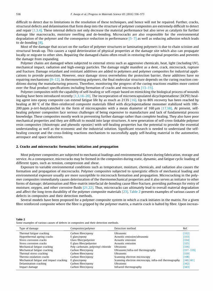
Polymer structural damage can be classified into macro and microscopic levels. Microscopic scale damage such as micro-cracking occurs as a result of impact and internal stresses. Microcracking is the major cause of material failure due to itsnature of being undetected and also because of the induced structure fragmentation which leads to the reduction ofmechanical properties such as strength, stiffness and dimensional stability [1,2]. Table 1 shows the most common polymercomposites and their advantages, applications and main source of cracks and microcrack damage.
Macroscopic damage is traditionally detected visually and repaired manually. Damage inspection techniques such asultrasonics and radiography are used to detect microscopic and internal damage. However, damage like microcracking is
pplications of fibre reinforced composites and their crack susceptibility.
posite type Qualities Application Sources for cracks Ref.
on fibre/PEEK Biocompatible, low wear rate,chemical stability, imagingcapability, tailored stiffness
Medical implants,aerospace structures
Impact loading [322–324]
on fibre/E-epoxy Light, stiff, strong Military and civilaircraft parts,cryogenic fuel tanks
Fatigue cracking is a major threat forstructures in this application,permeation of liquid and gaseous fuel,gas leakage
[325–327]
s fibre/epoxy Cost-effective manufacturing,replacement for steel tubingsusceptibility to corrosion
Liners in oil directionalwells, ship hulls, windturbines
Harsh environments, losing structuralintegrity, then durability becomes anissue, fatigue crack
[141,328]
on fibre/UHMWPE Low moisture absorption, resistanceto corrosive chemicals, high abrasionresistance and high impact strength
Medical implants Delamination cracks [329,330]
s fibre/vinylester Good chemical stability in seawater,low cost
Fishing and patrolboats, submarinedomes, water andcrude oil pipes
Environmentally induced crack [146,331]
s fibre/polyester Low cost, good chemical stability inseawater
Boat hulls, windturbine blades
Irreversible damage to composite as aresult of environmental ageing
[139,140,148]
538 F. Awaja et al. / Progress in Materials Science 83 (2016) 536–573
difficult to detect due to limitations in the resolution of these techniques, and hence will not be repaired. Further, cracks,structural defects and delamination that form deep into the structure of polymer composites are extremely difficult to detectand repair [1,3,4]. These internal defects not only decrease the material performance but also serve as catalysts for furtherdamage like macrocracks, moisture swelling and de-bonding. Microcracks are also responsible for the environmentaldegradation of the polymer and the consequence reduction in performance [5–7] as well as reducing adhesion which leadsto de-bonding [8].
Most of the damage that occurs on the surface of polymer structures or laminating polymers is due to chain scission andstructural break-up. This causes a rapid deterioration of physical properties at the damage site which also can propagatelocally or migrate to other sites. Repairing the damaged chains often result in restoring the original properties and preventsthe damage from expanding.
Polymer chains are damaged when subjected to external stress such as aggressive chemicals, heat, light (including UV),mechanical impact, radiation and high-energy particles. The damage might manifest as a dent, crack, microcrack, ruptureand fracture. Damage retardant and resistant additives are added to polymers and polymer composites for industrial appli-cations to provide protection. However, once damage stress overwhelms the protection barrier, these additives have norepairing mechanisms [9–12]. In thermosetting polymers, the final molecular structure depends on the curing reaction con-ditions during the manufacturing process. Therefore, monitoring the progress of the curing reactions enables more controlover the final product specifications including formation of cracks and microcracks [13–15].
Polymer composites with the capability of self-healing or self-repair based on mimicking the biological process of woundshealing have been introduced recently [1,3,16–20]. The incorporation of microencapsulated dicyclopentadiene (DCPD) heal-ing agent into epoxy composite can extend fatigue life by as much as 213% [16]. Up to 80% recovery has been reached byhealing at 80 �C of the fibre-reinforced composite materials filled with dicyclopentadiene monomer stabilized with 100–200 ppm p-tert-butylcatechol in the form of microcapsules with a mean diameter of 160 lm [17,18]. At present, self-healing polymer composites face serious challenges of being expensive to manufacture and lack of fundamental processknowledge. These composites mostly work in preventing further damage rather than complete healing. They also have poormechanical properties and they are difficult to mould into large structures. A new generation of self-cross-linkable polymerresin composites (thixotropic and phenolic epoxies) with self-healing properties has the potential to provide the essentialunderstanding as well as the economic and the industrial solution. Significant research is needed to understand the self-healing concept and the cross-linking reactions mechanism to successfully apply self-healing material in the automotive,aerospace and space industries.
2. Cracks and microcracks: formation; initiation and propagation
Most polymer composites are subjected to mechanical loadings and environmental factors during fabrication, storage andservice. As a consequence, microcracks may be formed in the composites during static, dynamic, and fatigue cyclic loading ofdifferent types, such as tension, compression and shear.
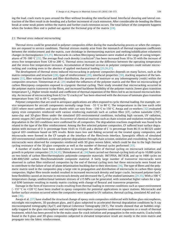
Exposure to variable environmental conditions such as temperature, moisture, chemicals, and radiation also causes theformation and propagation of microcracks. Polymer composites subjected to synergistic effects of mechanical loading andenvironmental exposure usually are more susceptible to microcrack formation and propagation. Microcracking in the poly-mer composites immediately causes deterioration of the thermomechanical properties and it also serves as initiator to otherforms of damage; delamination and fibre-matrix interfacial de-bonding cause fibre fracture, providing pathways for entry ofmoisture, oxygen, and other corrosive fluids [21,22]. Thus, microcracks can ultimately lead to overall material degradationand affect the long term durability of the polymer composite materials [23]. Table 2 presents examples of various causes ofdefects in composites and their detection methods.
Several models have been proposed for a polymer composite system in which a crack initiates in the matrix. For a givenfibre reinforced composite where the fibre is gripped by the polymer matrix, a matrix crack is halted by fibre. Upon increas-
Table 2Some examples of various causes of defects in composites and their detection methods.
Type of damage Composites/polymer Detection method Ref.
Thermal fatigue cracking Carbon fibre/epoxy Ultrasonic [332]Hygrothermal ageing cracks E glass/epoxy Acoustic emission/ultrasonic [333]Stress corrosion cracks Glass fibre/polyester Acoustic emission [334]Stress corrosion cracks E glass fibre/polyester Acoustic emission [335]Mechanical fatigue cracking Poly carbonate, polyvinyl chloride Ultrasonic [336]Mechanical fatigue cracking Carbon fibre/epoxy Ultrasonic/infra-red thermography [337–339]Thermal stress cracking Carbon fibre/epoxy Ultrasonic [339]Thermo-oxidation cracks Carbon fibre/epoxy Scanning electron microscopy [108]Mechanical fatigue and impact cracking E glass/epoxy Scanning electron microscopy, infra-red thermography [340,341]Delamination cracking Carbon fibre/epoxy Ultrasonic [342]Impact damage Carbon fibre/epoxy Infrared thermography [343]
F. Awaja et al. / Progress in Materials Science 83 (2016) 536–573 539
ing the load, crack starts to pass around the fibre without breaking the interfacial bond. Interfacial shearing and lateral con-traction of the fibre result in de-bonding and a further increment of crack extension. After considerable de-bonding the fibresbreak at some weak points within the matrix and further crack extension occurs. The total failure of the composite happenswhen the broken fibre end is pulled out against the frictional grip of the matrix [24].
2.1. Thermal stress induced microcracking
Thermal stress could be generated in polymer composites either during the manufacturing process or when the compos-ites are exposed to service conditions. Thermal stresses mainly arise from the mismatch of thermal expansion coefficientsbetween the reinforcement and the matrix, cure shrinkage in thermosetting matrices and melting/solidification volumetricchanges in thermoplastics [23,25]. Microcracks in carbon fibre/epoxy laminates were studied at the range of curing temper-atures of 70–180 �C [25]. The average final crack density (cracks/cm2) has been increased from 10 to 35 with the increase ofstress free temperature from 120 to 200 �C. Thermal stress increases as the difference between the operating temperatureand the stress-free temperature increases. Accumulation of thermal stresses in polymer composites could initiate microc-racking and cracking even in the absence of applied mechanical loading [23,26,27].
The development of thermal stress induced microcracking in polymer composites depends on many factors, such as thematrix composition and structure [28], type of reinforcement [29], interfacial properties [30], stacking sequence of the lam-inates [31], fibre volume fraction and fibre distribution, the presence of moisture or any inhomogeneity (voids) within thecomposites structure. Timmerman et al. [29] studied the influences of the polymer matrix and the fibre on microcracking ofcarbon fibre/epoxy composites exposed to cryogenic thermal cycling. Their study revealed that microcracking occurred inthe polymer matrix transverse to the fibres, and increased backbone flexibility of the polymer matrix (lower glass transitiontemperature Tg). Higher tensile moduli and coefficient of thermal expansion of the fibres led to an increased microcrack den-sity. An increase of microcracking from 8.5 to 72 cracks/cm2 has been observed with the decrease of laminate glass transitiontemperature from 142 to 69 �C, respectively.
Polymer composites that are used in aerospace applications are often exposed to cyclic thermal loading. For example, ser-vice temperatures for aircraft components normally range from �55 �C to 80 �C. The temperatures in the low earth orbit(LEO) where most satellites and space shuttle orbit can vary from �150 �C to 150 �C. Awaja and co-workers [32] evaluatedepoxy resin composites reinforced with various reinforcing materials such as carbon fibre (CF), carbon nanotube (CNT),nano-clay and 3D-glass fibres under the simulated LEO environmental conditions, including high vacuum, UV radiation,atomic oxygen (AO) and thermal cycles. Occurrence of chemical reactions such as chain scission and oxidation resulting fromdegradation in the LEO conditions were confirmed for all composites. The degradation reactions magnitude was found to berelated to the type of the filler reinforcement. Among the five selected polymer composites, CF suffered least surface degra-dation with increase of O 1s percentage from 10.6% to 15.6% and a decline of C 1s percentage from 86.1% to 80.52% undertypical LEO conditions based on XPS results. Resin mass loss and flaking occurred on the treated epoxy composites, andmicrocracks were formed in the CF sample at the interface of the fibre/resin interface. Synergistic effects of simulatedLEO environmental conditions accelerate polymer degradation through chain scission, oxidation and crosslinking. No surfacemicrocracks were observed for composites reinforced with 3D glass woven fabric, which could be due to the high thermalcycling resistance of the 3D glass composite as well as the number of thermal cycles performed [33].
A number of studies have been undertaken to investigate the effect of thermal cycling on microcrack initiation andgrowth in polymer composites [29,34,35]. Shimokawa et al. [34] have carried out thermal-cycling tests of up to 10,000 cycleson two kinds of carbon fibre/thermoplastic polyimide composite materials: IM7/PIXA, IM7/K3B, and up to 1000 cycles onG40-800/5260 carbon fibre/bismaleimide composite material. A fairly large number of transverse microcracks wereobserved in carbon fibre reinforced composites by the end of thermal cycling tests but these microcracks were found notto contribute to the failure of out-of-plane delamination buckling due to their directions [34]. The type of fibres and the poly-meric matrix used in the composites play a large role in propagation and distribution of microcracks in carbon fibre epoxycomposites. Higher fibre tensile moduli resulted in increased microcrack density and larger cracks. Increased polymer back-bone flexibility caused an increase in microcrack density and decreased the Tg of the studied laminates [29,35]. With a 100 �Ctemperature change, unidirectional laminate stresses of ±15 MPa can be generated, with somewhat higher values for a typ-ical 0/90 laminate resulting in mainly matrix cracking with change of flexural and transverse properties.
Damage in the form of transverse cracks resulting from thermal loading in extreme conditions such as space environment(�157 �C to +120 �C) have been studied in epoxy composites for potential applications in space stations. Microcracks andfurther surface erosion occurred when the composites were exposed to UV radiation, thermal cycling, simulated AO and vac-uum [36].
Awaja et al. [37] have studied the structural change of epoxy resin composites reinforced with hollow glass microspheres,microlight microspheres, 3D parabeam glass, and E-glass subjected to accelerated thermal degradation conditions by X-raymicrocomputed tomography (XlCT) and Optical Coherence Tomography (OCT). The results showed that air bubbles origi-nally trapped in the glass microsphere and microlight microsphere composites underwent expansion as a result of thermaltreatment, which has been proved to be the main cause for crack initiation and propagation in the resin matrix. Cracks/voidsfound in the E-glass and 3D-glass composites subjected to elevated temperature result are mostly in the resin matrix andpropagate into the fabric reinforcement.
540 F. Awaja et al. / Progress in Materials Science 83 (2016) 536–573
2.2. Mechanical fatigue induced microcracking (mechanical cycling)
Fatigue, in general, and of polymers in particular, is the major cause of component failure due to cyclic or random appli-cation of load [38]. Once under alternating loads, most polymers will fail at stress levels much lower than they can withstandunder monotonic loading conditions. As a result of the periodic nature of the applied load, micro-cracks initiate and prop-agate at relatively low stress level and finally the structure will fracture. Although investigation of the fatigue failure phe-nomenon in metals dates back to 18th century [39], studies in polymer fatigue have been conducted since 1960s andseveral early articles and review papers cover both experimental and theoretical investigations of fatigue failure in polymers[40–46]. In some cases, principles initially developed to explain fatigue failure in metals can accurately describe fatigue phe-nomena in bulk polymers [38].
Increased application of polymer based materials in various engineering components and advanced structures demandsimproved polymer fatigue properties. There are several parameters influencing the fatigue behaviour of polymers includingstress amplitude, intensity and frequency; environmental factors such as temperature and humidity; surface coating as wellas material variables e.g. polymer structure, viscoelastic characteristics and molecular weight distribution [47].
One of the strategies for improving fatigue behaviour of brittle thermosetting polymers is to enhance fracture toughness.This could be achieved by introducing a second phase such as rigid fillers, rubbery particles/thermoplastic modifiers andmicrocapsules to the polymer matrix [16,48–57]. While the toughening mechanism in rubber modified thermosets is dueto shear yielding and plastic void growth, a crack tip pinning or crack surface bridging mechanism is in play for solid fillermodified polymers. Using both rubbery particles and solid fillers has been shown to result in synergistic toughening in epoxypolymer [48]. Addition of modifiers at 10 vol% into a ductile epoxy polymer led to improvement of fatigue crack propagationresistance of the polymer by more than 100% [49]. Becu et al. [50] have shown that the fracture toughness of the epoxymatrix expressed as the constant in the Paris Law can be improved from 437 � 10�3 for pure epoxy to 0.7 � 10�3 by intro-ducing core-shell particles at a volume fraction of up to 24%. In [51] the Paris law constant for epoxy polymer was found tobe strongly dependent on the concentration of liquid-filled urea-formaldehyde microcapsules, varying from 8.2 � 10�2 forneat epoxy to approximately 8.6 � 10�4 above 10 wt% microcapsules, but was independent of microcapsule diameter. Sim-ilar result was observed for the use of wax-protected, recrystallized Grubbs’ catalyst leading to 104 increase in the rate ofpolymerization of bulk dicyclopentadiene and extending the fatigue life of a polymer by a factor of 30 times or more[52]. Artificial crack closure and hydrodynamic pressure crack-tip shielding have also been shown to reduce the fatigue crackgrowth. The mechanism involved in these methods is crack-tip shielding in which the intensity of the crack tip stress isreduced using polymer infiltration and/or a viscous fluid [16,58–66]. This therefore makes the concept of employing micro-capsules very interesting as it utilises all the aforementioned mechanisms to enhance the fatigue performance of the poly-mer [16,52].
Recently the interest in the hydrodynamic response of ships in rough seas has increased significantly. Ships and otherfloating structures in seaways frequently experience wave slamming or pounding which give rise to elastic vibrationthroughout the hull. As a result of the slamming waves, the ship’s structure is subjected to repeated impulse forces thatcause high fatigue stresses and damage to the structure [67–69] which is often made of carbon steel. Reinforced polymersoffer better alternatives to carbon steel. They are about 30–70% lighter than carbon steel and provide stealth capability. Moreimportantly, the fatigue accumulation of composite materials is reported to be 4–7 orders of magnitude lower than in metalsand that is why composite vessels have never shown fatigue problems [70–72]. However, composites have their own draw-backs, they are only suitable for smaller ships or boats because they lack the stiffness and the in-plane strength required forthe large ship hulls.
Sandwich composites are finding an increasing number of applications in marine structures such as floating marinas orthe decks of offshore platforms. The high stiffness, light-weight and energy absorption give the sandwich composites anadvantage over t conventional materials [73]. Marine sandwich structures demonstrate particular failure modes as a conse-quence of complex in service cycling slamming loads. Slamming loads can cause core crushing, shear failure in the core,facesheet-core de-bonding and compressive or tensile failure of the laminates that over time can reduce the load carryingcapability of the marine composites and compromise the seaworthiness of the structure. Detection of the extent of damagein marine sandwich structures under slamming impact are of high importance as it has been found that the face sheets insandwich composite usually remain intact with no visible or apparent damage and therefore obscure any failure events inthe core and the interface where damage is likely to initiate and propagate [74–76].
2.3. Surface breaking cracks
Polymers and polymer composites are widely used in space technologies and space structures due to their strength, lightweight, good thermal and electrical insulation properties. Most of the components in aerospace structures are subjected tocyclic loads and thermal stresses. As a result of cyclic loads, cyclic stresses are induced which can result in local crack ini-tiation and growth. The cracks are mostly initiated at external surfaces. Initiation and propagation of small cracks deepwithin the structure, where detection is difficult and repair is virtually impossible, can cause catastrophic component failure.Prevention of fatigue failure depends on accurate life prediction and regular inspection. In addition, a self-healing approachhas been recently explored [77] to improve the fatigue life of polymers and prevent catastrophic failure of aerospace com-ponents. The dicyclopentadiene microcapsules (50–200 lm) with a urea-formaldehyde shell were used for a self-healing
F. Awaja et al. / Progress in Materials Science 83 (2016) 536–573 541
composite production. A recovery of about 75% of the virgin fracture load has been achieved with an average healing effi-ciency of 60%.
2.4. Thermo-mechanical stresses induced cracking
Many engineering components or structures are often subjected to combined thermal and mechanical loads. These com-ponents are subjected to cyclic strains which are generated both thermally and mechanically. Example of such componentsand structures are the parts of aircraft engine hot section that operate in a high temperature environment along withmechanical loading, nuclear reactors that are subjected to both high temperature and pressure and high pressure vesselsand boilers [78–80].
Thermo-mechanical cyclic loading may result in crack initiation and the propagation of existing cracks. These thermo-mechanical stresses cause damage to the components and lead to a failure. Predicting the safe life period of components sub-jected to thermo-mechanical stresses is of great importance and challenge to the industry [81–83]. In [83] the combinedthermal cycling (CTC) and mechanical loading (ML) tests were shown to be a time and cost efficient way to generate crackpropagation data and so can be used to predict isothermal crack processes.
2.5. Stress corrosion cracking
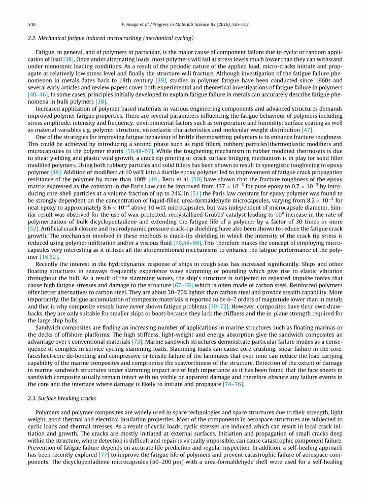
Stress corrosion cracking (SCC) is a common problem for polymers and composites that serve under a combination ofmechanical stress and chemically aggressive environment. For polyolefin pipe, it is commonly observed in the form of amicrocrack colony within a surface layer of degraded polymer exposed to both mechanical stress and chemically aggressiveenvironment [84,85]. Four stages of SCC have been distinguished by Choi et al. [85]: (1) multiple crack initiations due tolocalized material degradation, (2) individual crack growth, (3) cracks interaction and formation of crack clusters, and (4)crack/cluster instability or crack cluster growth resulting in ultimate failure. Fig. 1 shows stress SCC formation in combinedaggressive chemical environment and mechanical stress. Hogg [86] developed a model for SCC growth in fibre reinforcedcomposites in acidic environments and concluded that the resin’s toughness plays a critical role in resisting the crackgrowth. The rate of crack growth under stress corrosion conditions was found to be controlled by the stress acting on thefibres as logda/dt (m/s) = 0.0057r22 (MPa) � 12.57 (conditions: T is 20 �C, 0.65 M HCl) where r22 is the stress acting inthe fibre direction. The resin matrix modifies the stress acting on the fibres which controls the crack growth rate duringstress corrosion.
Fig. 1. Stress corrosion cracks formation in combined aggressive chemical environment and mechanical stress. Copyright 2014. Reprint from [85].

542 F. Awaja et al. / Progress in Materials Science 83 (2016) 536–573
Polymer composites can be used as insulators for overhead high voltage transmission lines with voltages ranging from69 kV to 735 kV. Composite insulators are susceptible to brittle fracture caused by SCC of the composite materials, seeFig. 2, as a result of combined effect of moisture, and corona discharge which forms acid solutions in service [87–93]. Severalcritical factors have been identified to influence SCC in polymer composites insulators. These include resin and fibre type,acid type and concentrations, composite surface conditions and external stress. Owen et al. [92] analysed various statesof electrical and mechanical damage of a group of ten 275 kV polymeric insulators. The combined effect of electrical activityand moisture appears to be similar to acid stress corrosion and responsible for producing brittle fracture of the pultrudedrods of insulators.
It has been demonstrated that in nitric acid environment and in the presence of mechanical bending load, the extent ofstress corrosion damage on the surface of high voltage composite insulators is strongly dependent on the type of polymerresin used. Vinyl ester, epoxy and polyester are the three most common used resins for composite insulators. Studies showedthat the resistance of the E-glass/vinyl ester composite to the initiation of SCC in nitric acid is approximately 10 times greaterthan that of E-glass/epoxy composite. Furthermore, the E-glass/epoxy system exhibits approximately 5 times higher resis-tance to the initiation of SCC than the E-glass/modified polyester system [94]. SCC growth in composites can occur far belowthe fracture strength since fibres under stress are very sensitive to acid environment. Under the stress corrosion, acid envi-ronments drastically affect the life of composites [95].
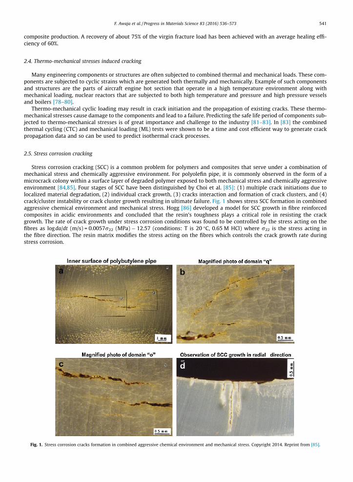
The initiation of SCC has also been evaluated in acid environment and in the absence of mechanical loads. Kumosa et al.[96] demonstrated that E-glass/epoxy composites used in composite high voltage insulators with the line voltage from 60 to735 kV are the most susceptible to stress corrosion damage in nitric acid environment when no mechanical stress is applied.It has been speculated that this is mainly due to the different amount of fibres exposed on the surface of polymer composites(35.5% and 11.7% for the epoxy and modified polyester composite, respectively) as a result of different manufacturing pro-cess and physical properties of resins used. The externally applied stresses are not necessary for the initiation of SCC on thesurfaces of fibre reinforced polymer composite insulators. The SCC can develop in fibres embedded in a polymer resin due topresence of residual stresses in the composites, Fig. 3. However their initiation rates will decrease with time to zero if exter-nal mechanical loads are not applied.
Surface condition of polymer composites used in high voltage insulators plays a key role in SCC. In order to provide a bet-ter adhesion between composite rods and other components used in insulators, which ultimately leads to preventing mois-ture coming into contact with composite rods, the composite surface is subjected to sandblasting. Sandblasted unidirectionalE-glass/polymer composite insulators that were subjected to mechanical bending loads in the presence of nitric acid(pH = 1.2) have shown no negative effect on the SCC initiation and propagation. Low and medium level of sand blastingexhibited slight improvement in composite resistance to the initiation and propagation of stress corrosion cracks. The resis-tance to SCC was evaluated as an acoustic emission signal (AE) to stress corrosion cracking. The improvement of resistance ofE-glass/vinyl ester from 34.2 to 17 and 7.5 AE events for as-supplied, low sandblasted, and medium sandblasted samples wasattributed to release of residual extrusion stresses in the fibres [97].
Chemical composition of fibres used in fibre reinforced composite insulators has an influence on SCC resistance of com-posites. Boron free E-glass fibre reinforced polymer composites exhibit a significant enhancement in SCC resistance in nitricacid environment of pH 1.2 from 43,699 AE events for E-glass/modified polyester to 327 AE events. This effect is despite thefact that boron-free E-glass composites have a high level of surface fibre exposure [98].
Polymer matrix composites are increasingly being used in advanced structures such as aerospace components that expe-rience high temperatures (more than 100 �C) and oxidative environments. While reinforcing fibres used in these structuralparts may tolerate such a severe condition, it is the matrix and fibre/matrix interface that can be readily degraded causingthe structural failure [99,100]. Two epoxy/carbon model composite systems, R922-1/C-12K and R6376/C-12K, were
Fig. 2. Destruction of high voltage insulator due to action of moisture, electrical field and acidic environment. Copyright 2014. Reprint from [92].
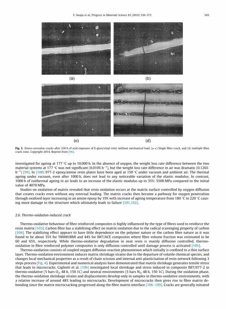
Fig. 3. Stress-corrosion cracks after 336 h of acid exposure of E-glass/vinyl ester without mechanical load. (a–c) Single fibre crack, and (d) multiple fibrecrack zone. Copyright 2014. Reprint from [96].
F. Awaja et al. / Progress in Materials Science 83 (2016) 536–573 543
investigated for ageing at 177 �C up to 10,000 h. In the absence of oxygen, the weight loss rate difference between the twomaterial systems at 177 �C was not significant (0.010% h�1), but the weight loss rate difference in air was dramatic (0.126%h�1) [99]. In [100] 977-2 epoxy/amine resin plates have been aged at 150 �C under vacuum and ambient air. The thermalageing under vacuum, even after 1000 h, does not lead to any noticeable variation of the elastic modulus. In contrast,1000 h of isothermal ageing in air leads to an increase of the elastic modulus up to 35%: 5500 MPa compared to the initialvalue of 4070 MPa.
Studies on oxidation of matrix revealed that resin oxidation occurs at the matrix surface controlled by oxygen diffusionthat creates cracks even without any external loading. The matrix cracks then become a pathway for oxygen penetrationthrough oxidised layer increasing in an amine epoxy by 19% with increase of ageing temperature from 180 �C to 220 �C caus-ing more damage to the structure which ultimately leads to failure [101,102].
2.6. Thermo-oxidation-induced crack
Thermo-oxidative behaviour of fibre reinforced composites is highly influenced by the type of fibres used to reinforce theresin matrix [103]. Carbon fibre has a stabilising effect on matrix oxidation due to the radical scavenging property of carbon[104]. The stabilizing effect appears to have little dependence on the polymer nature or the carbon fibre nature as it wasfound to be about 35% for T800H/BMI and 44% for IM7/ACE composites where fibre volume fraction was estimated to be60 and 65%, respectively. While thermo-oxidative degradation in neat resin is mainly diffusion controlled, thermo-oxidation in fibre reinforced polymer composites is only diffusion controlled until damage process is activated [105].
Thermo-oxidation consists of coupled oxygen diffusion-reaction phenomenon which initially is confined to a thin surfacelayer. Thermo-oxidation environment induces matrix shrinkage strains due to the departure of volatile chemical species, andchanges local mechanical properties as a result of chain scission and internal anti-plasticisation of resin network following 3steps process (Fig. 4). Experimental and numerical analysis have demonstrated that matrix shrinkage generates tensile stressthat leads to microcracks. Gigliotti et al. [106] investigated local shrinkage and stress induced in composite IM7/977-2 inthermo-oxidative (5 bars O2, 48 h, 150 1C) and neutral environments (5 bars N2, 48 h, 150 1C). During the oxidation phase,the thermo-oxidation shrinkage strains and displacements develop only in samples in thermo-oxidative environments, witha relative increase of around 48% leading to microcracks. Development of microcracks then gives rise to fibre matrix de-bonding since the matrix microcracking progressed along the fibre matrix interface [106–109]. Cracks are generally initiated
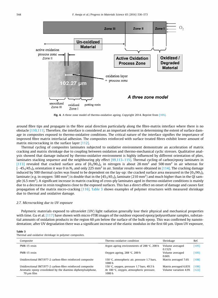
Fig. 4. A three zone model of thermo-oxidative ageing. Copyright 2014. Reprint from [105].
544 F. Awaja et al. / Progress in Materials Science 83 (2016) 536–573
around fibre tips and propagate in the fibre axial direction particularly along the fibre-matrix interface where there is noobstacle [110,111]. Therefore, the interface is considered as an important element in determining the extent of surface dam-age in composites exposed to thermo-oxidative conditions. The critical nature of the interface signifies the importance ofimproved fibre matrix interfacial adhesion. The composites reinforced with surface treated fibres exhibit lower amount ofmatrix microcracking in the surface layer [112].
Thermal cycling of composites laminates subjected to oxidative environment demonstrate an acceleration of matrixcracking and matrix shrinkage due to coupling between oxidation and thermo-mechanical cyclic stresses. Qualitative anal-ysis showed that damage induced by thermo-oxidative environment is highly influenced by different orientation of plies,laminates stacking sequence and the neighbouring ply effect [99,113–115]. Thermal cycling of carbon/epoxy laminates in[113] revealed that cracked surface area of [03/903]S in nitrogen is about 28 mm2 and 500 mm2 in air whereas for[�453/453]S orientation it was 0 in N2 and only 225 mm2 in air. Similar results were obtained in [114]. The cracking damageinduced by 500 thermal cycles was found to be dependent on the lay-up: the cracked surface area measured in the [03/903]Slaminate (e.g. in oxygen: 580 mm2) is double that in the [453/453]S laminate (210 mm2) and much higher than in the QI sam-ple (6.5 mm2). A significant increase in matrix cracking of cross-ply laminates aged in thermo-oxidative conditions is mainlydue to a decrease in resin toughness close to the exposed surfaces. This has a direct effect on onset of damage and causes fastpropagation of the matrix micro-cracking [116]. Table 3 shows examples of polymer structures with measured shrinkagedue to thermal and oxidative damage.
2.7. Microcracking due to UV exposure
Polymeric materials exposed to ultraviolet (UV) light radiation generally lose their physical and mechanical propertieswith time. Gu et al. [117] have shownwith micro-FTIR images of the outdoor exposed epoxy/polyurethane samples, substan-tial amounts of oxidation products in the region 60 lm below the surface of the bulk epoxy. This was confirmed by nanoin-dentation; after UV degradation there was a significant increase of the elastic modulus in the first 60 lm. Upon UV exposure,
Table 3Thermal and oxidative shrinkage in polymer composites.
Composite Thermo oxidative condition Shrinkage Ref.
PMR-15 resin Argon ageing environments of 288 �C, 200 h Volume averaged0.152%
[105]
PMR-15 resin Oxygen ageing, 288 �C, 200 h Volume averaged0.66%
[105]
Unidirectional IM7/977-2 carbon-fibre reinforced composite 150 �C, atmospheric air, pressure 1.7 bars,1000 h
Matrix averaged 7.6% [108]
Unidirectional IM7/977-2 carbon-fibre reinforced composite 150 �C, oxygen, pressure 1.7 bars, 49.5 h Matrix averaged 6.83% [108]Aromatic epoxy crosslinked by the diamino diphenylsulphone,
70 lm filmAt 180 �C, oxygen, atmospheric pressure,1000 h
Volume variation 4.9% [122]
F. Awaja et al. / Progress in Materials Science 83 (2016) 536–573 545
UV photons are absorbed by polymers and these give rise to photo-oxidative reactions which cause molecular chain scissionand/or chain crosslinking [6,118]. Molecular chain scission process generates polymer radicals and lowers the molecularweight of polymers. Chain crosslinking results in excessive embrittlement as a result of reduced molecular mobility andis mainly responsible for the formation of microcracks [119]. For some polymers such as polyethylene, both crosslinkingand chain scission may take place concurrently as a result of UV exposure.
UV degradation is not limited to the polymer bulk, it usually starts at the surface and penetrates gradually to the bulk. In aset of experiments with high-performance polymers (Kapton, Mylar, Lexan, PEEK) effect of UV treatment/atomic oxygen(flux 1.7 � 102 �C m�2) for 5–8 h has been studied in [120] and top layer of 0.1–0.2 lm was affected by UV degradation[120]. Surface oxidation occurs upon UV radiation which accumulates thermomechanical stress on the surface leading tomechanical pressure that spreads into the bulk and forms cracks.
Thermal history of polymers has been found to influence their UV stability. PVC that has been processed for long periodsand/or high temperature demonstrates less resistance to UV damage [10]. This may be due to the increase in the degree ofdegradation of macromolecular compounds as a result of processing temperature and time. Thermodynamic analysis for PVChas shown that the generation and growth of micro-voids (both in number and length) which is followed by formation ofcracks is a result of relaxation of residual energy, creation of polar groups and the adjustment of conformation of macro-molecular chains [121]. UV radiation has enough energy to break the carbon and oxygen bonds in polymers and to form vola-tile fragments. Surface outgassing of volatiles leads to shrinkage of the skin layer which generates further mechanicalstresses that can propagate into the bulk of the composites [107,122,123]. In [122] oxidative induced shrinkage of the poly-mer made of a mixture of aromatic epoxy (triglycidyl amino phenol-diglycidyl ether of bisphenol F) crosslinked by an aro-matic diamine, has been studied after thermal ageing. At the surface of a 1.5 mm sample exposed 900 h at 150 �C, theshrinkage was equal to 2.5% and tensile stress of 85 MPa with corresponding compressive stress in the sample core of10 MPa. The environmental degradation behaviour of epoxy-organoclay nanocomposites due to accelerated UV was studiedby Woo et al. [6]. SEM results showed that microcracks started to appear on both the neat epoxy and nanocomposite surfaceafter about 300 h of UV exposure. Upon further exposure, the microcracks propagated deeper into the matrix and becomebroadened in the neat epoxy. Compared to neat epoxy, cracks on the nanocomposite surface appeared to be wider and shal-lower due to the presence of organoclay in the nanocomposites. Similarly, after exposure to 500 h of UV radiation, formationof microcracks has also been found in the epoxy matrix in carbon fibre reinforced epoxy composites [118]. These microcrack-ing phenomenon are caused by excessive brittleness of the polymer matrix resulting from increased crosslinked moleculesgenerated through photo-oxidation reactions induced by UV radiation. Matrix cracking and extensive de-bonding of theglass fibre-epoxy matrix interface after 100 h exposure to UV has also been reported [124].
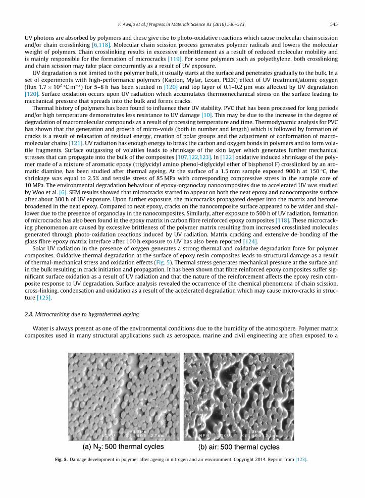
Solar UV radiation in the presence of oxygen generates a strong thermal and oxidative degradation force for polymercomposites. Oxidative thermal degradation at the surface of epoxy resin composites leads to structural damage as a resultof thermal-mechanical stress and oxidation effects (Fig. 5). Thermal stress generates mechanical pressure at the surface andin the bulk resulting in crack initiation and propagation. It has been shown that fibre reinforced epoxy composites suffer sig-nificant surface oxidation as a result of UV radiation and that the nature of the reinforcement affects the epoxy resin com-posite response to UV degradation. Surface analysis revealed the occurrence of the chemical phenomena of chain scission,cross-linking, condensation and oxidation as a result of the accelerated degradation which may cause micro-cracks in struc-ture [125].
2.8. Microcracking due to hygrothermal ageing
Water is always present as one of the environmental conditions due to the humidity of the atmosphere. Polymer matrixcomposites used in many structural applications such as aerospace, marine and civil engineering are often exposed to a
Fig. 5. Damage development in polymer after ageing in nitrogen and air environment. Copyright 2014. Reprint from [123].
546 F. Awaja et al. / Progress in Materials Science 83 (2016) 536–573
hygrothermal environments defined as an environment with combined moisture and high temperatures. Many polymermatrices tend to absorb significant amounts of water when exposed to high humidity. The absorbed moisture combined withan elevated temperature causes detrimental physical and mechanical effects to the composites [126–128]. Hygrothermalageing in polymer composites is illustrated in Fig. 6.
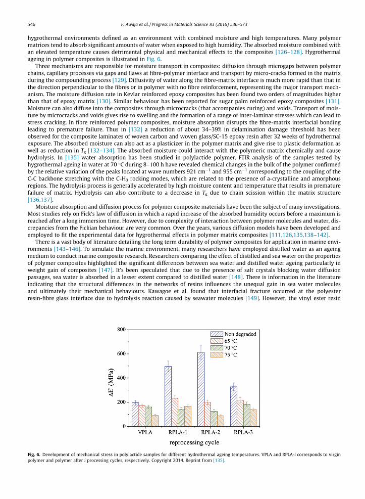
Three mechanisms are responsible for moisture transport in composites: diffusion through microgaps between polymerchains, capillary processes via gaps and flaws at fibre-polymer interface and transport by micro-cracks formed in the matrixduring the compounding process [129]. Diffusivity of water along the fibre-matrix interface is much more rapid than that inthe direction perpendicular to the fibres or in polymer with no fibre reinforcement, representing the major transport mech-anism. The moisture diffusion rate in Kevlar reinforced epoxy composites has been found two orders of magnitudes higherthan that of epoxy matrix [130]. Similar behaviour has been reported for sugar palm reinforced epoxy composites [131].Moisture can also diffuse into the composites through microcracks (that accompanies curing) and voids. Transport of mois-ture by microcracks and voids gives rise to swelling and the formation of a range of inter-laminar stresses which can lead tostress cracking. In fibre reinforced polymer composites, moisture absorption disrupts the fibre-matrix interfacial bondingleading to premature failure. Thus in [132] a reduction of about 34–39% in delamination damage threshold has beenobserved for the composite laminates of woven carbon and woven glass/SC-15 epoxy resin after 32 weeks of hydrothermalexposure. The absorbed moisture can also act as a plasticizer in the polymer matrix and give rise to plastic deformation aswell as reduction in Tg [132–134]. The absorbed moisture could interact with the polymeric matrix chemically and causehydrolysis. In [135] water absorption has been studied in polylactide polymer. FTIR analysis of the samples tested byhygrothermal ageing in water at 70 �C during 8–100 h have revealed chemical changes in the bulk of the polymer confirmedby the relative variation of the peaks located at wave numbers 921 cm�1 and 955 cm�1 corresponding to the coupling of theC-C backbone stretching with the C-H3 rocking modes, which are related to the presence of a-crystalline and amorphousregions. The hydrolysis process is generally accelerated by high moisture content and temperature that results in prematurefailure of matrix. Hydrolysis can also contribute to a decrease in Tg due to chain scission within the matrix structure[136,137].
Moisture absorption and diffusion process for polymer composite materials have been the subject of many investigations.Most studies rely on Fick’s law of diffusion in which a rapid increase of the absorbed humidity occurs before a maximum isreached after a long immersion time. However, due to complexity of interaction between polymer molecules and water, dis-crepancies from the Fickian behaviour are very common. Over the years, various diffusion models have been developed andemployed to fit the experimental data for hygrothermal effects in polymer matrix composites [111,126,135,138–142].
There is a vast body of literature detailing the long term durability of polymer composites for application in marine envi-ronments [143–146]. To simulate the marine environment, many researchers have employed distilled water as an ageingmedium to conduct marine composite research. Researchers comparing the effect of distilled and sea water on the propertiesof polymer composites highlighted the significant differences between sea water and distilled water ageing particularly inweight gain of composites [147]. It’s been speculated that due to the presence of salt crystals blocking water diffusionpassages, sea water is absorbed in a lesser extent compared to distilled water [148]. There is information in the literatureindicating that the structural differences in the networks of resins influences the unequal gain in sea water moleculesand ultimately their mechanical behaviours. Kawagoe et al. found that interfacial fracture occurred at the polyesterresin-fibre glass interface due to hydrolysis reaction caused by seawater molecules [149]. However, the vinyl ester resin
Fig. 6. Development of mechanical stress in polylactide samples for different hydrothermal ageing temperatures. VPLA and RPLA-i corresponds to virginpolymer and polymer after i processing cycles, respectively. Copyright 2014. Reprint from [135].
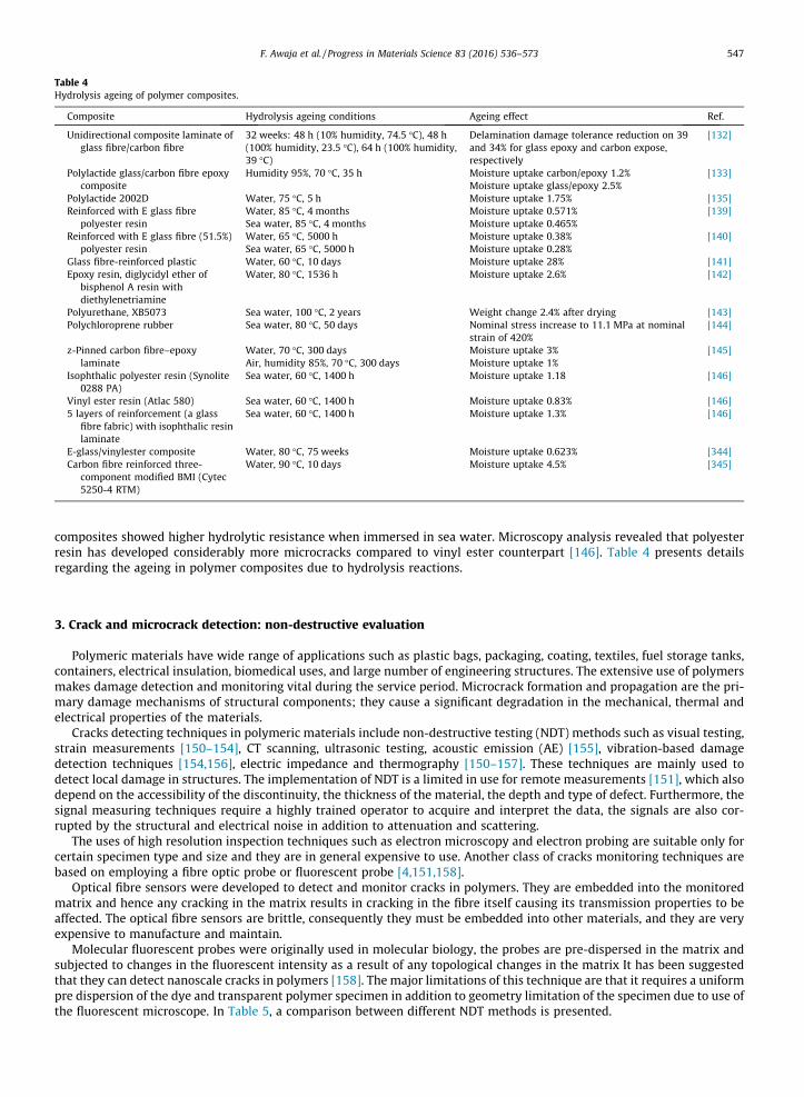
Table 4Hydrolysis ageing of polymer composites.
Composite Hydrolysis ageing conditions Ageing effect Ref.
Unidirectional composite laminate ofglass fibre/carbon fibre
32 weeks: 48 h (10% humidity, 74.5 �C), 48 h(100% humidity, 23.5 �C), 64 h (100% humidity,39 �C)
Delamination damage tolerance reduction on 39and 34% for glass epoxy and carbon expose,respectively
[132]
Polylactide glass/carbon fibre epoxycomposite
Humidity 95%, 70 �C, 35 h Moisture uptake carbon/epoxy 1.2%Moisture uptake glass/epoxy 2.5%
[133]
Polylactide 2002D Water, 75 �C, 5 h Moisture uptake 1.75% [135]Reinforced with E glass fibre
polyester resinWater, 85 �C, 4 monthsSea water, 85 �C, 4 months
Moisture uptake 0.571%Moisture uptake 0.465%
[139]
Reinforced with E glass fibre (51.5%)polyester resin
Water, 65 �C, 5000 hSea water, 65 �C, 5000 h
Moisture uptake 0.38%Moisture uptake 0.28%
[140]
Glass fibre-reinforced plastic Water, 60 �C, 10 days Moisture uptake 28% [141]Epoxy resin, diglycidyl ether of
bisphenol A resin withdiethylenetriamine
Water, 80 �C, 1536 h Moisture uptake 2.6% [142]
Polyurethane, XB5073 Sea water, 100 �C, 2 years Weight change 2.4% after drying [143]Polychloroprene rubber Sea water, 80 �C, 50 days Nominal stress increase to 11.1 MPa at nominal
strain of 420%[144]
z-Pinned carbon fibre–epoxylaminate
Water, 70 �C, 300 daysAir, humidity 85%, 70 �C, 300 days
Moisture uptake 3%Moisture uptake 1%
[145]
Isophthalic polyester resin (Synolite0288 PA)
Sea water, 60 �C, 1400 h Moisture uptake 1.18 [146]
Vinyl ester resin (Atlac 580) Sea water, 60 �C, 1400 h Moisture uptake 0.83% [146]5 layers of reinforcement (a glass
fibre fabric) with isophthalic resinlaminate
Sea water, 60 �C, 1400 h Moisture uptake 1.3% [146]
E-glass/vinylester composite Water, 80 �C, 75 weeks Moisture uptake 0.623% [344]Carbon fibre reinforced three-
component modified BMI (Cytec5250-4 RTM)
Water, 90 �C, 10 days Moisture uptake 4.5% [345]
F. Awaja et al. / Progress in Materials Science 83 (2016) 536–573 547
composites showed higher hydrolytic resistance when immersed in sea water. Microscopy analysis revealed that polyesterresin has developed considerably more microcracks compared to vinyl ester counterpart [146]. Table 4 presents detailsregarding the ageing in polymer composites due to hydrolysis reactions.
3. Crack and microcrack detection: non-destructive evaluation
Polymeric materials have wide range of applications such as plastic bags, packaging, coating, textiles, fuel storage tanks,containers, electrical insulation, biomedical uses, and large number of engineering structures. The extensive use of polymersmakes damage detection and monitoring vital during the service period. Microcrack formation and propagation are the pri-mary damage mechanisms of structural components; they cause a significant degradation in the mechanical, thermal andelectrical properties of the materials.
Cracks detecting techniques in polymeric materials include non-destructive testing (NDT) methods such as visual testing,strain measurements [150–154], CT scanning, ultrasonic testing, acoustic emission (AE) [155], vibration-based damagedetection techniques [154,156], electric impedance and thermography [150–157]. These techniques are mainly used todetect local damage in structures. The implementation of NDT is a limited in use for remote measurements [151], which alsodepend on the accessibility of the discontinuity, the thickness of the material, the depth and type of defect. Furthermore, thesignal measuring techniques require a highly trained operator to acquire and interpret the data, the signals are also cor-rupted by the structural and electrical noise in addition to attenuation and scattering.
The uses of high resolution inspection techniques such as electron microscopy and electron probing are suitable only forcertain specimen type and size and they are in general expensive to use. Another class of cracks monitoring techniques arebased on employing a fibre optic probe or fluorescent probe [4,151,158].
Optical fibre sensors were developed to detect and monitor cracks in polymers. They are embedded into the monitoredmatrix and hence any cracking in the matrix results in cracking in the fibre itself causing its transmission properties to beaffected. The optical fibre sensors are brittle, consequently they must be embedded into other materials, and they are veryexpensive to manufacture and maintain.
Molecular fluorescent probes were originally used in molecular biology, the probes are pre-dispersed in the matrix andsubjected to changes in the fluorescent intensity as a result of any topological changes in the matrix It has been suggestedthat they can detect nanoscale cracks in polymers [158]. The major limitations of this technique are that it requires a uniformpre dispersion of the dye and transparent polymer specimen in addition to geometry limitation of the specimen due to use ofthe fluorescent microscope. In Table 5, a comparison between different NDT methods is presented.

Table 5Comparison of different non-destructive testing methods for composites.
Inspection method Major detected defects Strength and limitation Ref.
Visual inspection Surface crack, delamination,impact damage
Simple, rapid, inexpensive, sub-surface flaws cannot be detected, should beused along with other detection methods
[160]
Optical CoherenceTomography(OCT)
Cracks, delamination, voids 3D high resolution imaging, not suitable for carbon fibre composites due tomaking the object opaque for imaging
[346,347]
Microscopy (lightmicroscopy,SEM)
Cracks, voids, delamination,fibre breakage
Evaluation of crack initiation and propagation, SEM sample preparationtakes time, infield inspection not possible, small sample size studied
[160,348]
Tap test Delamination, cracking Can be used for moisture sensitive composites, simple, inexpensive,insufficient sensitivity for field applications
[349,350]
Acoustic emission Cracks, delamination, fibrebreakage
Suitable for field tests, high sensitivity, only suitable for detection growingflaws, defect size and location difficult to obtain, sensitivity affected bysurrounding noise, not suitable for thick specimen
[171,351,352]
Ultrasonic Cracks, delamination, voids andforeign objects
Depth and location of flaws can be determined, can be used when only oneside access to composite is possible, hard to detect the defects in region nearthe probe
[353,354]
X-ray radiography Foreign inclusions, cracks,voids, fibre alignment, fibresplitting
Thick section of composite can be inspected, poor image contrast, high costdue to OH&S associated with ionising radiation
[171,355]
X-ray computedmicro-tomography
Cracks and micro-cracks, voids 3D images reveals the nature and shape of defects, in service damagesincluding delamination hard to detect without penetrant, higher cost due toOH&S
[183,356]
Comptonbackscatteringdiffraction
Cracks and micro-cracks, voids,porosity, fibre misalignment
One-sided inspection possible as well as tomographic imaging, layer-by-layer inspection of object, higher cost associated to the control exposure ofpersonnel to ionising radiation
[171,349]
Infraredthermography
Voids, cracks, foreigninclusions, delamination,impact damage
Rapid area coverage, remote sensing possible, one-sided inspection possible,anisotropy masks indications
[357,358]
548 F. Awaja et al. / Progress in Materials Science 83 (2016) 536–573
3.1. Optical
Optical test methods which utilise visible part of electro-magnetic spectrum (wavelength roughly between 400 and700 nm) are primarily used to detect surface and near-surface defects of many polymers and PMC. Visual inspection (eye,photography, dye penetrants) using optical microscopy is commonly employed to observe surface microcracking in polymercomposites. Photomicrographs of the sample surfaces are taken and the number of microcracks on the surface is counted.Determination of microcracking density in polymer composites can be done by dividing the total number of microcrackson the sample face by the face area. Microscopy is also used to study the propagation of microcracks by recording the loca-tion of microcracks before applying thermal or fatigue cycling. Bright and polarized light microscopy are generally used toidentify micro-cracks in composites however in composite materials with low contrast such as carbon fibre reinforced com-posites a contrast dye and dark illumination or a laser dye and epi-fluorescence are employed to enhance the contrast help-ing to detect microcracks. Dyes are employed along with dark field or polarized light to analyse micro-cracks in polymercomposites containing translucent fibres such as Kevlar, glass, nylon and polyester. Coloured dyes are impregnated into finemicro-cracks through capillary action that otherwise cannot be detected. In order to examine micro-cracks in thermoplasticpolymers fluorescence penetrants are used and florescence microscopy is employed to observe micro-cracks [159,160].
3.2. Optical Coherence Tomography (OCT)
OCT is a non-destructive and contact-free optical imaging technique which allows extremely high-resolution, depth-resolved, three-dimensional imaging of microstructure within scattering media [161]. It was originally developed forbiomedical applications of biological tissue evaluation and it is based on the interference phenomena of white or low-coherence light to determine distances and displacement. The principle of OCT is similar to B-mode ultrasound imaging,except that OCT typically employs near-infrared light rather than sound. OCT imaging has also found application in non-destructive evaluation for non-biological materials including polymers which have transparent or translucent appearance.Besides polymers, OCT is also well suited to retrieve relevant information on the internal defects and structure of polymercomposites, such as GFRP. However, some polymer composites comprising of certain filler materials like carbon particles,carbon fibres and nanotubes could render the polymer matrix opaque resulting in incompatibility with OCT imaging[162]. With the advancement of OCT technique, several other OCT techniques have been developed in addition to classicOCT, such as ultrahigh-resolution OCT (UHR-OCT) and polarization-sensitive OCT (PS-OCT). UHR-PS-OCT imaging of thematrix fracture, cracks and internal stress in GFRP materials has demonstrated its promising potential in detecting defectin the early stage [163].
F. Awaja et al. / Progress in Materials Science 83 (2016) 536–573 549
3.3. Microscopy (optical microscopy, SEM)
Microscopy is a useful tool to determine the cause of failure, as well as establishing the area of crack initiation. Opticalmicroscopy sample preparation generally involves sectioning, mounting and polishing the area under examination. Not allcracks can be detected using optical microscopy, for some materials introduced fluorescent dyes are required to identifymatrix cracking [164]. Scanning electron microscopy on the other hand provides more information on the process of crackinitiation and propagation, however, the samples need to be coated using a thin layer of gold in order to avoid electroniccharge building up. Scanning electron microscopy has been extensively used to study the failure mechanism of polymercomposites and to identify the directions of crack propagation and to determine the origins of fracture in fibre reinforcedcomposites [164,165].
3.4. Sonic testing
Sonic and ultrasonic test methods are based on elastic waves propagation in solid or fluid media. They can be groupedinto two categories: active and passive methods. Active methods require transmission of acoustic waves into materialsand the reception of waves reflected or transmitted from the materials. Passive methods only involve the reception of thewaves emitted by the material itself.
3.5. Tap testing
Tap testing requires an operator to tap the structure to be inspected by hand or by a suitable instrument such as a ham-mer or some other light weight object and detect the defects by listening to the resulting sound. It is an inexpensive, fast andeasy method to roughly evaluate and locate the defects of PMC materials [166].
3.6. Acoustic emission
Acoustic emission (AE) refers to the phenomenon of transient elastic wave generation resulting from a rapid release ofstrain energy due to microstructural changes in the material when subjected to mechanical or thermal stresses. It is anexample of passive methods which analyse the ultrasound pulses emitted by the defects in real time. AE sensors (transduc-ers) which can sense the stress waves propagating through a structure are required to detect AE activity. It is an effectivenon-destructive technique to monitor damage growth in different structural materials. When a failure mechanism is acti-vated, strain-energy release propagates as a stress-wave from the failure source through the medium and is detected atthe surface. AE technique can be applied to determine both the location of the source and the nature of the damage. For poly-mer composites, many failure mechanisms have been identified as AE sources, including matrix cracking, fibre-matrix inter-face de-bonding, fibre fracture and delamination [167].
3.7. Ultrasonic testing
Ultrasonic testing of polymer composites is based on the detection and the interpretation of the ultrasonic wavesreflected by defects such as cracks or voids. The term ultrasonic refers to acoustic waves with a frequency above the limitof human hearing, approximately 20 kHz. In contrast to electromagnetic waves, ultrasonic waves are a form of mechanicalenergy that consists of oscillations or vibrations of the atoms or molecules of a material. Based on the oscillation pattern ofthe atoms/molecules, Ultrasonic waves can propagate in four principal modes, including longitudinal waves, transverse/shear waves, surface/Raleigh waves, and Lamb or plate waves. In ultrasonic testing, generation and detection of ultrasonicwaves requires the use of ultrasonic transducers which convert electrical energy into acoustical (mechanical) energy andalso a coupling mediumwith high ultrasonic signal transmission strength being placed between the transducer and the sam-ple. The signal can be detected in either reflection or transmission mode.
Kinra et al. [168] developed an ultrasonic backscattering technique for the detection of matrix cracks in laminated com-posites. The extensive damage of matrix cracking in this composite was produced during liquid hydrogen (LH2) permeabilitytests where the composite was subjected to thermo-mechanical loading at cryogenic temperature. The incident wave isreflected away from the transducer which also acts as a receiver when there is no interaction between the incident waveand the matrix crack, and this indicates the received signal is zero. With the presence of matrix cracks, the incident waveis partly reflected back to the transducer and the received signal becomes finite. This technique has shown the ability todetect matrix cracks in each ply of the composite laminate in the present of extensive damage in all the plies.
The ability of pulse-echo ultrasonic methods to detect fatigue induced damage generated by cyclic flexural loading inthick glass fibre reinforced polymer (GRP) composites has been assessed [169]. The results indicated that cracks inducedat low fatigue stresses were difficult to detect by ultrasonic methods because cracks grew in the through-thickness directionwhich is parallel to the transmission direction of the ultrasound waves. While at high fatigue stress, damages are more easilydetected.
Shear wave through-transmission ultrasonic C-scan imaging was shown to be a useful technique for detection of the par-tial and internal transverse cracks in a cross-ply graphite/bismaleimide laminate [170]. With the shear wave through-
550 F. Awaja et al. / Progress in Materials Science 83 (2016) 536–573
transmission ultrasonic technique, inclined transducers are placed in a confocal configuration, with the sample occupyingfocal plane. When a crack is present across the focal area of the transducers, ultrasound beam is partially reflected by thecrack, which causes the transmitted signal amplitude to change.
3.8. Penetrating radiation
3.8.1. Conventional X-ray radiographyRadiation methods used for non-destructive testing of materials are based on recording and analysing of penetrating ion-
ising radiation after interaction with the object being inspected. In conventional radiography X-ray beam is used to bombardthe target. The unabsorbed radiation hits a radiation sensitive film and a 2-D image is formed upon development of film.Microfocal X-radiography produces sharper images compared to conventional X-ray methods as it utilises a significantlysmaller X-ray beam. X-ray images with sufficient contrast are usually hard to obtain in fibre reinforced composites due tolow atomic weight of composite molecular components. To improve images, a contrast medium such as sulphur or silveriodide is used [171].
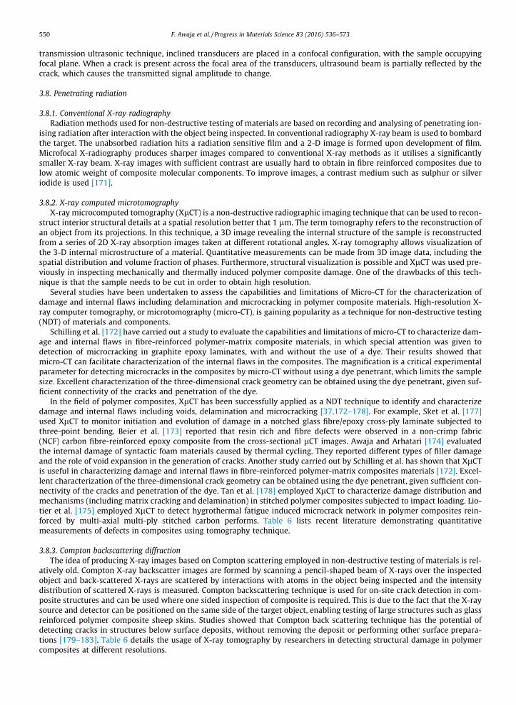
3.8.2. X-ray computed microtomographyX-ray microcomputed tomography (XlCT) is a non-destructive radiographic imaging technique that can be used to recon-
struct interior structural details at a spatial resolution better that 1 lm. The term tomography refers to the reconstruction ofan object from its projections. In this technique, a 3D image revealing the internal structure of the sample is reconstructedfrom a series of 2D X-ray absorption images taken at different rotational angles. X-ray tomography allows visualization ofthe 3-D internal microstructure of a material. Quantitative measurements can be made from 3D image data, including thespatial distribution and volume fraction of phases. Furthermore, structural visualization is possible and XlCT was used pre-viously in inspecting mechanically and thermally induced polymer composite damage. One of the drawbacks of this tech-nique is that the sample needs to be cut in order to obtain high resolution.
Several studies have been undertaken to assess the capabilities and limitations of Micro-CT for the characterization ofdamage and internal flaws including delamination and microcracking in polymer composite materials. High-resolution X-ray computer tomography, or microtomography (micro-CT), is gaining popularity as a technique for non-destructive testing(NDT) of materials and components.
Schilling et al. [172] have carried out a study to evaluate the capabilities and limitations of micro-CT to characterize dam-age and internal flaws in fibre-reinforced polymer-matrix composite materials, in which special attention was given todetection of microcracking in graphite epoxy laminates, with and without the use of a dye. Their results showed thatmicro-CT can facilitate characterization of the internal flaws in the composites. The magnification is a critical experimentalparameter for detecting microcracks in the composites by micro-CT without using a dye penetrant, which limits the samplesize. Excellent characterization of the three-dimensional crack geometry can be obtained using the dye penetrant, given suf-ficient connectivity of the cracks and penetration of the dye.
In the field of polymer composites, XlCT has been successfully applied as a NDT technique to identify and characterizedamage and internal flaws including voids, delamination and microcracking [37,172–178]. For example, Sket et al. [177]used XlCT to monitor initiation and evolution of damage in a notched glass fibre/epoxy cross-ply laminate subjected tothree-point bending. Beier et al. [173] reported that resin rich and fibre defects were observed in a non-crimp fabric(NCF) carbon fibre-reinforced epoxy composite from the cross-sectional lCT images. Awaja and Arhatari [174] evaluatedthe internal damage of syntactic foam materials caused by thermal cycling. They reported different types of filler damageand the role of void expansion in the generation of cracks. Another study carried out by Schilling et al. has shown that XlCTis useful in characterizing damage and internal flaws in fibre-reinforced polymer-matrix composites materials [172]. Excel-lent characterization of the three-dimensional crack geometry can be obtained using the dye penetrant, given sufficient con-nectivity of the cracks and penetration of the dye. Tan et al. [178] employed XlCT to characterize damage distribution andmechanisms (including matrix cracking and delamination) in stitched polymer composites subjected to impact loading. Lio-tier et al. [175] employed XlCT to detect hygrothermal fatigue induced microcrack network in polymer composites rein-forced by multi-axial multi-ply stitched carbon performs. Table 6 lists recent literature demonstrating quantitativemeasurements of defects in composites using tomography technique.
3.8.3. Compton backscattering diffractionThe idea of producing X-ray images based on Compton scattering employed in non-destructive testing of materials is rel-
atively old. Compton X-ray backscatter images are formed by scanning a pencil-shaped beam of X-rays over the inspectedobject and back-scattered X-rays are scattered by interactions with atoms in the object being inspected and the intensitydistribution of scattered X-rays is measured. Compton backscattering technique is used for on-site crack detection in com-posite structures and can be used where one sided inspection of composite is required. This is due to the fact that the X-raysource and detector can be positioned on the same side of the target object, enabling testing of large structures such as glassreinforced polymer composite sheep skins. Studies showed that Compton back scattering technique has the potential ofdetecting cracks in structures below surface deposits, without removing the deposit or performing other surface prepara-tions [179–183]. Table 6 details the usage of X-ray tomography by researchers in detecting structural damage in polymercomposites at different resolutions.
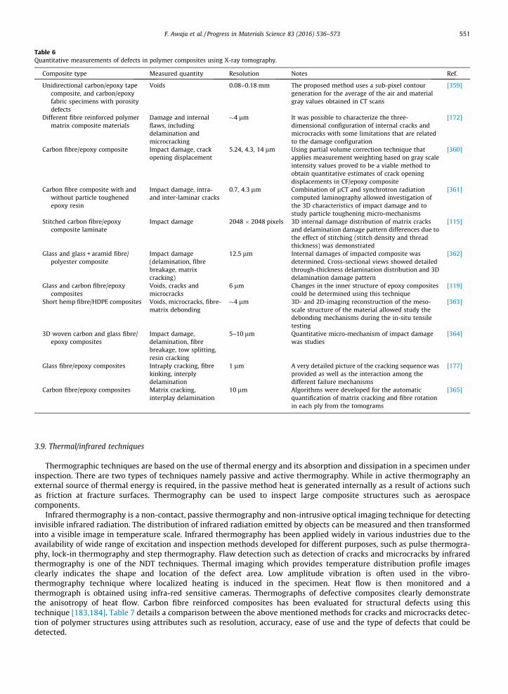
Table 6Quantitative measurements of defects in polymer composites using X-ray tomography.
Composite type Measured quantity Resolution Notes Ref.
Unidirectional carbon/epoxy tapecomposite, and carbon/epoxyfabric specimens with porositydefects
Voids 0.08–0.18 mm The proposed method uses a sub-pixel contourgeneration for the average of the air and materialgray values obtained in CT scans
[359]
Different fibre reinforced polymermatrix composite materials
Damage and internalflaws, includingdelamination andmicrocracking
�4 lm It was possible to characterize the three-dimensional configuration of internal cracks andmicrocracks with some limitations that are relatedto the damage configuration
[172]
Carbon fibre/epoxy composite Impact damage, crackopening displacement
5.24, 4.3, 14 lm Using partial volume correction technique thatapplies measurement weighting based on gray scaleintensity values proved to be a viable method toobtain quantitative estimates of crack openingdisplacements in CF/epoxy composite
[360]
Carbon fibre composite with andwithout particle toughenedepoxy resin
Impact damage, intra-and inter-laminar cracks
0.7, 4.3 lm Combination of lCT and synchrotron radiationcomputed laminography allowed investigation ofthe 3D characteristics of impact damage and tostudy particle toughening micro-mechanisms
[361]
Stitched carbon fibre/epoxycomposite laminate
Impact damage 2048 � 2048 pixels 3D internal damage distribution of matrix cracksand delamination damage pattern differences due tothe effect of stitching (stitch density and threadthickness) was demonstrated
[115]
Glass and glass + aramid fibre/polyester composite
Impact damage(delamination, fibrebreakage, matrixcracking)
12.5 lm Internal damages of impacted composite wasdetermined. Cross-sectional views showed detailedthrough-thickness delamination distribution and 3Ddelamination damage pattern
[362]
Glass and carbon fibre/epoxycomposites
Voids, cracks andmicrocracks
6 lm Changes in the inner structure of epoxy compositescould be determined using this technique
[119]
Short hemp fibre/HDPE composites Voids, microcracks, fibre-matrix debonding
�4 lm 3D- and 2D-imaging reconstruction of the meso-scale structure of the material allowed study thedebonding mechanisms during the in-situ tensiletesting
[363]
3D woven carbon and glass fibre/epoxy composites
Impact damage,delamination, fibrebreakage, tow splitting,resin cracking
5–10 lm Quantitative micro-mechanism of impact damagewas studies
[364]
Glass fibre/epoxy composites Intraply cracking, fibrekinking, interplydelamination
1 lm A very detailed picture of the cracking sequence wasprovided as well as the interaction among thedifferent failure mechanisms
[177]
Carbon fibre/epoxy composites Matrix cracking,interplay delamination
10 lm Algorithms were developed for the automaticquantification of matrix cracking and fibre rotationin each ply from the tomograms
[365]
F. Awaja et al. / Progress in Materials Science 83 (2016) 536–573 551
3.9. Thermal/infrared techniques
Thermographic techniques are based on the use of thermal energy and its absorption and dissipation in a specimen underinspection. There are two types of techniques namely passive and active thermography. While in active thermography anexternal source of thermal energy is required, in the passive method heat is generated internally as a result of actions suchas friction at fracture surfaces. Thermography can be used to inspect large composite structures such as aerospacecomponents.
Infrared thermography is a non-contact, passive thermography and non-intrusive optical imaging technique for detectinginvisible infrared radiation. The distribution of infrared radiation emitted by objects can be measured and then transformedinto a visible image in temperature scale. Infrared thermography has been applied widely in various industries due to theavailability of wide range of excitation and inspection methods developed for different purposes, such as pulse thermogra-phy, lock-in thermography and step thermography. Flaw detection such as detection of cracks and microcracks by infraredthermography is one of the NDT techniques. Thermal imaging which provides temperature distribution profile imagesclearly indicates the shape and location of the defect area. Low amplitude vibration is often used in the vibro-thermography technique where localized heating is induced in the specimen. Heat flow is then monitored and athermograph is obtained using infra-red sensitive cameras. Thermographs of defective composites clearly demonstratethe anisotropy of heat flow. Carbon fibre reinforced composites has been evaluated for structural defects using thistechnique [183,184]. Table 7 details a comparison between the above mentioned methods for cracks and microcracks detec-tion of polymer structures using attributes such as resolution, accuracy, ease of use and the type of defects that could bedetected.
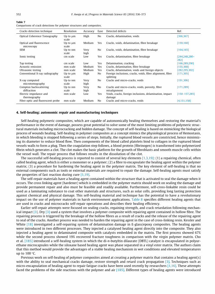
Table 7Comparisons of crack detections for polymer structures and composites.
Cracks detection technique Resolution Accuracy Ease Detected defects Ref.
Optical Coherence Tomography Up to lmscale
High No Cracks, delamination, voids [366,367]
Optical and fluorescencemicroscopy
Up to lmscale
Medium Yes Cracks, voids, delamination, fibre breakage [159,160]
SEM Up to nmscale
Veryhigh
No Cracks, voids, delamination, fibre breakage [164,165]
Sonic testing cm scale Low Yes Cracks, delamination, fibre breakage [244,248,280–282]
Tap testing cm scale Low Yes Delamination, cracking [166,289,290]Acoustic emission mm scale Medium Yes Cracks, delamination, fibre breakage [155,368]Ultrasonic testing mm scale Medium Yes Cracks, delamination, voids and foreign objects [282,295,302]Conventional X-ray radiography Up to lm
scaleHigh No Foreign inclusions, cracks, voids, fibre alignment, fibre
splitting[171,305]
X-ray computedmicrotomography
Up to nmscale
Veryhigh
No Cracks and micro-cracks, voids [191,306]
Compton backscatteringdiffraction
Up to nmscale
Veryhigh
No Cracks and micro-cracks, voids, porosity, fibremisalignment
[171,289]
Electric impedance andthermography
mm scale Low Yes Voids, cracks, foreign inclusions, delamination, impactdamage
[150–157,285]
Fibre optic and fluorescent probe mm scale Medium No Cracks and micro-cracks, voids [4,151,158]
552 F. Awaja et al. / Progress in Materials Science 83 (2016) 536–573
4. Self-healing: autonomic repair and manufacturing techniques
Self-healing polymeric composites, which are capable of autonomically healing themselves and restoring the material’sperformance in the event of damage, possess great potential to solve some of the most limiting problems of polymeric struc-tural materials including microcracking and hidden damage. The concept of self-healing is based on mimicking the biologicalprocess of wounds healing. Self-healing in polymer composites as a concept mimics the physiological process of Hemostasis,in which bleeding is stopped following a series of steps. Initially, the ruptured blood vessels are constricted, hence minimiz-ing its diameter to reduce blood flow. Then components of the blood called platelets bind to collagen in the ruptured bloodvessels walls to form a plug. Then the coagulation step follows, a blood protein (fibrinogen) is transformed into polymerizedfibrin which generates a clot. The clot makes the basic platform for the growth of fibroblasts and smooth muscle cells withinthe vessel wall. The repair process that follows results in the dissolution of the clot.
The successful self-healing process is reported to consist of several key elements [1,3,19]: (1) a repairing chemical, oftencalled healing agent, which is either a monomer or a polymer; (2) a fibre to encapsulate the healing agent within the polymermatrix; (3) a procedure for hardening the healing agent in the polymer matrix. The key element of self-healing is that noexternal components such as tools or external materials are required to repair the damage. Self-healing agents must satisfythe properties of fast reaction during cure [1,19].
The self-repair materials have a healing agent contained within the structure that is activated to seal the damage when itoccurs. The cross linking agent (hardener) which is embedded in the polymer matrix should work on sealing the damage andprovide permanent repair and also must be feasible and readily available. Furthermore, self-cross-linkable resin could beused as a laminating substance to coat other materials and structures, such as solar cells, providing long lasting protectionagainst chemical and physical damage. This self-healing material and technique has the potential to have a revolutionaryimpact on the use of polymer materials in harsh environment applications. Table 8 specifies different healing agents thatare used in cracks and microcracks self-repair operations and describes their healing efficiency.
Earlier self-repair attempts were focused on sealing cracks, regaining strength, and crack retardation following mechan-ical impact [3]. Dry [3] used a system that involves a polymer composite with repairing agent contained in hollow fibre. Therepairing process is triggered by the breakage of the hollow fibres as a result of cracks and the release of the repairing agentto seal of the cracks. Another process was needed to harden the repairing agent in the case of cross-linking resin. Kessler andWhite [18] investigated a self-repairing system of delamination damage in E-glass/epoxy composites. The healing agentswere introduced in two different processes. They injected a catalysed healing agent directly into the composite. They alsoinjected a healing agent to delaminated composite with catalysts embedded in the matrix. The first process showed 67%while the second process showed 19% recovered fracture toughness in comparison with the virgin polymer matrix. Choet al. [185] introduced a self-healing system in which the di-n-butyltin dilaurate (DBTL) catalyst is encapsulated in polyur-ethane microcapsules while the siloxane based healing agent was phase separated in a vinyl ester matrix. The authors claimthat this method would provide the advantages of a stable healing mechanism in wet conditions and elevated temperaturesup to 100 �C.
Previous work on self-healing of polymer composites aimed at creating a polymer matrix that contains a healing agent(s)with the ability to seal mechanical cracks damage, restore strength and retard crack propagation [3]. Techniques such asmicro-encapsulation of healing agent to repair fatigue cracks have been used recently by researchers [1,16]. These attemptsfaced the problems of the side reactions with the polymer and air [185]. Different types of healing agents were introduced
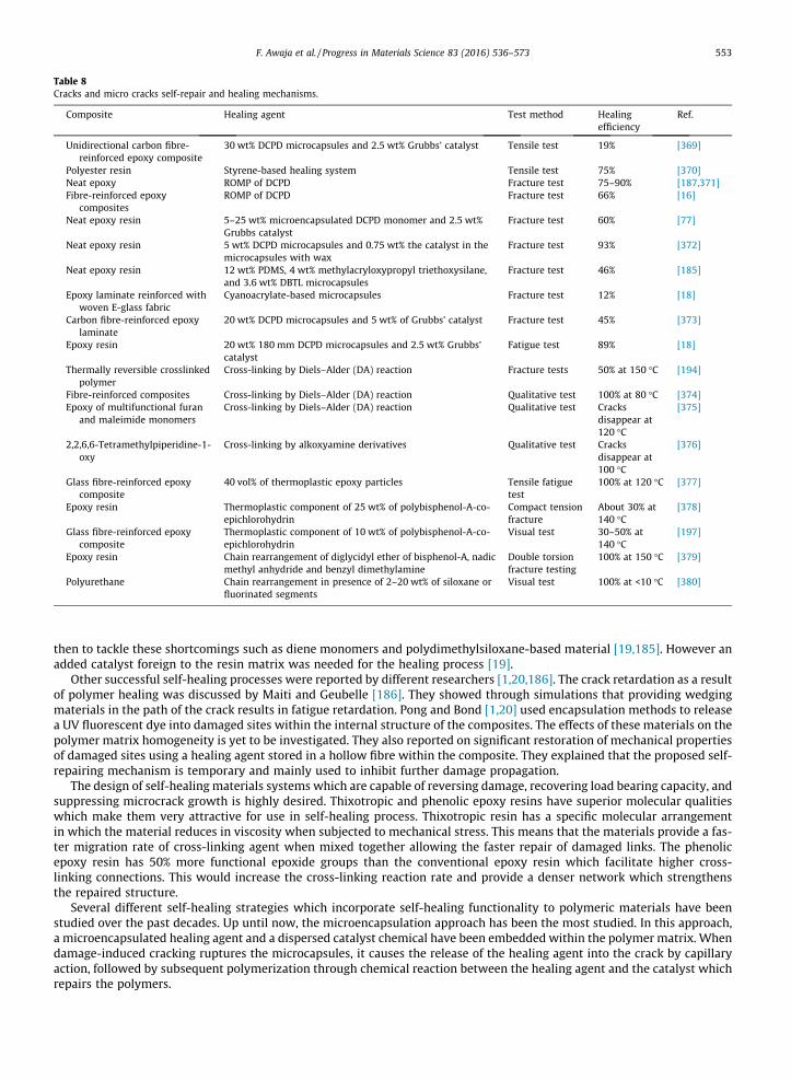
Table 8Cracks and micro cracks self-repair and healing mechanisms.
Composite Healing agent Test method Healingefficiency
Ref.
Unidirectional carbon fibre-reinforced epoxy composite
30 wt% DCPD microcapsules and 2.5 wt% Grubbs’ catalyst Tensile test 19% [369]
Polyester resin Styrene-based healing system Tensile test 75% [370]Neat epoxy ROMP of DCPD Fracture test 75–90% [187,371]Fibre-reinforced epoxy
compositesROMP of DCPD Fracture test 66% [16]
Neat epoxy resin 5–25 wt% microencapsulated DCPD monomer and 2.5 wt%Grubbs catalyst
Fracture test 60% [77]
Neat epoxy resin 5 wt% DCPD microcapsules and 0.75 wt% the catalyst in themicrocapsules with wax
Fracture test 93% [372]
Neat epoxy resin 12 wt% PDMS, 4 wt% methylacryloxypropyl triethoxysilane,and 3.6 wt% DBTL microcapsules
Fracture test 46% [185]
Epoxy laminate reinforced withwoven E-glass fabric
Cyanoacrylate-based microcapsules Fracture test 12% [18]
Carbon fibre-reinforced epoxylaminate
20 wt% DCPD microcapsules and 5 wt% of Grubbs’ catalyst Fracture test 45% [373]
Epoxy resin 20 wt% 180 mm DCPD microcapsules and 2.5 wt% Grubbs’catalyst
Fatigue test 89% [18]
Thermally reversible crosslinkedpolymer
Cross-linking by Diels–Alder (DA) reaction Fracture tests 50% at 150 �C [194]
Fibre-reinforced composites Cross-linking by Diels–Alder (DA) reaction Qualitative test 100% at 80 �C [374]Epoxy of multifunctional furan
and maleimide monomersCross-linking by Diels–Alder (DA) reaction Qualitative test Cracks
disappear at120 �C
[375]
2,2,6,6-Tetramethylpiperidine-1-oxy
Cross-linking by alkoxyamine derivatives Qualitative test Cracksdisappear at100 �C
[376]
Glass fibre-reinforced epoxycomposite
40 vol% of thermoplastic epoxy particles Tensile fatiguetest
100% at 120 �C [377]
Epoxy resin Thermoplastic component of 25 wt% of polybisphenol-A-co-epichlorohydrin
Compact tensionfracture
About 30% at140 �C
[378]
Glass fibre-reinforced epoxycomposite
Thermoplastic component of 10 wt% of polybisphenol-A-co-epichlorohydrin
Visual test 30–50% at140 �C
[197]
Epoxy resin Chain rearrangement of diglycidyl ether of bisphenol-A, nadicmethyl anhydride and benzyl dimethylamine
Double torsionfracture testing
100% at 150 �C [379]
Polyurethane Chain rearrangement in presence of 2–20 wt% of siloxane orfluorinated segments
Visual test 100% at <10 �C [380]
F. Awaja et al. / Progress in Materials Science 83 (2016) 536–573 553
then to tackle these shortcomings such as diene monomers and polydimethylsiloxane-based material [19,185]. However anadded catalyst foreign to the resin matrix was needed for the healing process [19].
Other successful self-healing processes were reported by different researchers [1,20,186]. The crack retardation as a resultof polymer healing was discussed by Maiti and Geubelle [186]. They showed through simulations that providing wedgingmaterials in the path of the crack results in fatigue retardation. Pong and Bond [1,20] used encapsulation methods to releasea UV fluorescent dye into damaged sites within the internal structure of the composites. The effects of these materials on thepolymer matrix homogeneity is yet to be investigated. They also reported on significant restoration of mechanical propertiesof damaged sites using a healing agent stored in a hollow fibre within the composite. They explained that the proposed self-repairing mechanism is temporary and mainly used to inhibit further damage propagation.
The design of self-healing materials systems which are capable of reversing damage, recovering load bearing capacity, andsuppressing microcrack growth is highly desired. Thixotropic and phenolic epoxy resins have superior molecular qualitieswhich make them very attractive for use in self-healing process. Thixotropic resin has a specific molecular arrangementin which the material reduces in viscosity when subjected to mechanical stress. This means that the materials provide a fas-ter migration rate of cross-linking agent when mixed together allowing the faster repair of damaged links. The phenolicepoxy resin has 50% more functional epoxide groups than the conventional epoxy resin which facilitate higher cross-linking connections. This would increase the cross-linking reaction rate and provide a denser network which strengthensthe repaired structure.
Several different self-healing strategies which incorporate self-healing functionality to polymeric materials have beenstudied over the past decades. Up until now, the microencapsulation approach has been the most studied. In this approach,a microencapsulated healing agent and a dispersed catalyst chemical have been embedded within the polymer matrix. Whendamage-induced cracking ruptures the microcapsules, it causes the release of the healing agent into the crack by capillaryaction, followed by subsequent polymerization through chemical reaction between the healing agent and the catalyst whichrepairs the polymers.
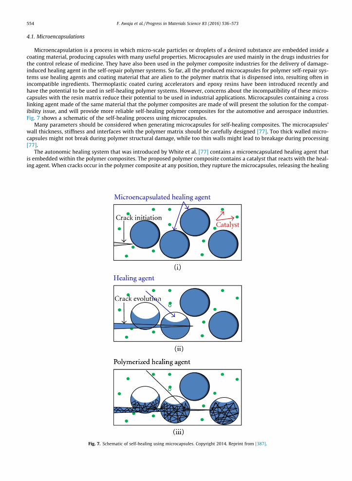
554 F. Awaja et al. / Progress in Materials Science 83 (2016) 536–573
4.1. Microencapsulations
Microencapsulation is a process in which micro-scale particles or droplets of a desired substance are embedded inside acoating material, producing capsules with many useful properties. Microcapsules are used mainly in the drugs industries forthe control release of medicine. They have also been used in the polymer composite industries for the delivery of damage-induced healing agent in the self-repair polymer systems. So far, all the produced microcapsules for polymer self-repair sys-tems use healing agents and coating material that are alien to the polymer matrix that is dispensed into, resulting often inincompatible ingredients. Thermoplastic coated curing accelerators and epoxy resins have been introduced recently andhave the potential to be used in self-healing polymer systems. However, concerns about the incompatibility of these micro-capsules with the resin matrix reduce their potential to be used in industrial applications. Microcapsules containing a crosslinking agent made of the same material that the polymer composites are made of will present the solution for the compat-ibility issue, and will provide more reliable self-healing polymer composites for the automotive and aerospace industries.Fig. 7 shows a schematic of the self-healing process using microcapsules.
Many parameters should be considered when generating microcapsules for self-healing composites. The microcapsules’wall thickness, stiffness and interfaces with the polymer matrix should be carefully designed [77]. Too thick walled micro-capsules might not break during polymer structural damage, while too thin walls might lead to breakage during processing[77].
The autonomic healing system that was introduced by White et al. [77] contains a microencapsulated healing agent thatis embedded within the polymer composites. The proposed polymer composite contains a catalyst that reacts with the heal-ing agent. When cracks occur in the polymer composite at any position, they rupture the microcapsules, releasing the healing
Fig. 7. Schematic of self-healing using microcapsules. Copyright 2014. Reprint from [387].
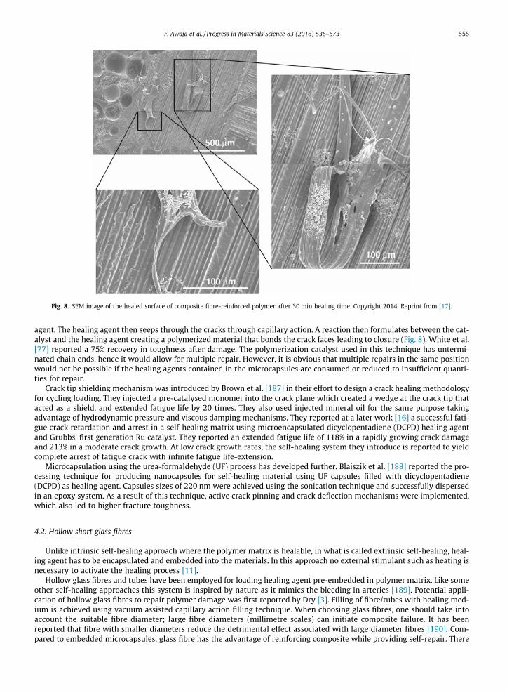
Fig. 8. SEM image of the healed surface of composite fibre-reinforced polymer after 30 min healing time. Copyright 2014. Reprint from [17].
F. Awaja et al. / Progress in Materials Science 83 (2016) 536–573 555
agent. The healing agent then seeps through the cracks through capillary action. A reaction then formulates between the cat-alyst and the healing agent creating a polymerized material that bonds the crack faces leading to closure (Fig. 8). White et al.[77] reported a 75% recovery in toughness after damage. The polymerization catalyst used in this technique has untermi-nated chain ends, hence it would allow for multiple repair. However, it is obvious that multiple repairs in the same positionwould not be possible if the healing agents contained in the microcapsules are consumed or reduced to insufficient quanti-ties for repair.
Crack tip shielding mechanism was introduced by Brown et al. [187] in their effort to design a crack healing methodologyfor cycling loading. They injected a pre-catalysed monomer into the crack plane which created a wedge at the crack tip thatacted as a shield, and extended fatigue life by 20 times. They also used injected mineral oil for the same purpose takingadvantage of hydrodynamic pressure and viscous damping mechanisms. They reported at a later work [16] a successful fati-gue crack retardation and arrest in a self-healing matrix using microencapsulated dicyclopentadiene (DCPD) healing agentand Grubbs’ first generation Ru catalyst. They reported an extended fatigue life of 118% in a rapidly growing crack damageand 213% in a moderate crack growth. At low crack growth rates, the self-healing system they introduce is reported to yieldcomplete arrest of fatigue crack with infinite fatigue life-extension.
Microcapsulation using the urea-formaldehyde (UF) process has developed further. Blaiszik et al. [188] reported the pro-cessing technique for producing nanocapsules for self-healing material using UF capsules filled with dicyclopentadiene(DCPD) as healing agent. Capsules sizes of 220 nm were achieved using the sonication technique and successfully dispersedin an epoxy system. As a result of this technique, active crack pinning and crack deflection mechanisms were implemented,which also led to higher fracture toughness.
4.2. Hollow short glass fibres
Unlike intrinsic self-healing approach where the polymer matrix is healable, in what is called extrinsic self-healing, heal-ing agent has to be encapsulated and embedded into the materials. In this approach no external stimulant such as heating isnecessary to activate the healing process [11].
Hollow glass fibres and tubes have been employed for loading healing agent pre-embedded in polymer matrix. Like someother self-healing approaches this system is inspired by nature as it mimics the bleeding in arteries [189]. Potential appli-cation of hollow glass fibres to repair polymer damage was first reported by Dry [3]. Filling of fibre/tubes with healing med-ium is achieved using vacuum assisted capillary action filling technique. When choosing glass fibres, one should take intoaccount the suitable fibre diameter; large fibre diameters (millimetre scales) can initiate composite failure. It has beenreported that fibre with smaller diameters reduce the detrimental effect associated with large diameter fibres [190]. Com-pared to embedded microcapsules, glass fibre has the advantage of reinforcing composite while providing self-repair. There
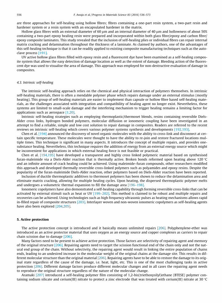
556 F. Awaja et al. / Progress in Materials Science 83 (2016) 536–573
are three approaches for self-healing using hollow fibres; fibres containing a one-part resin system, a two-part resin andhardener system or a resin system with an encapsulated hardener in the matrix.
Hollow glass fibres with an external diameter of 60 lm and an internal diameter of 40 lm and hollowness of about 50%containing a two-part epoxy healing resin were prepared and incorporated within both glass fibre/epoxy and carbon fibre/epoxy composite laminates. This study revealed that the inclusion of self-healing plies or individual fibres can repair internalmatrix cracking and delamination throughout the thickness of a laminate. As claimed by authors, one of the advantages ofthis self-healing technique is that it can be readily applied to existing composite manufacturing techniques such as the auto-clave process [191].
UV active hollow glass fibres filled with epoxy resin and a fluorescent dye have been examined as a self-healing compos-ite system that allows the easy detection of damage location as well as the extent of damage. Bleeding action of the fluores-cent dye was used to visualise the area of damage. This approach was employed for non-destructive evaluation of damage incomposites.
4.3. Intrinsic self-healing
The intrinsic self-healing approach relies on the chemical and physical interaction of polymers themselves. In intrinsicself-healing materials, there is often a mendable polymer phase which repairs damage under an external stimulus (mostlyheating). This group of self-healing materials are easier to implement than capsule or hollow fibre based self-healing mate-rials, as the challenges associated with integration and compatibility of healing agent no longer exist. Nevertheless, thesesystems are limited to small-scale damage and the interfering mechanism to trigger healing remains a limiting factor forapplications such as aerospace [1,20].
Intrinsic self-healing strategies such as employing thermoplastic/thermoset blends, resins containing reversible Diels-Alder cross links, hydrogen bonded polymers, molecular diffusion or ionomeric coupling have been investigated in anattempt to find a reliable, simple and low cost solution to repair damage in composites. Readers are referred to the recentreviews on intrinsic self-healing which covers various polymer systems synthesis and developments [192,193].
Chen et al. [194] announced the discovery of novel organic molecules with the ability to cross-link and disconnect at cer-tain specific temperature. These molecules were thought to have the ability to re-join and restore fractured locations mul-tiple times. This technique is significant in many aspects. It introduces the concept of multiple repairs, and provides one-substance healing. Nevertheless, this technique requires the addition of energy from an external energy source which mightbe inconvenient for applications in which external healing force is not feasible or practical.
Chen et al. [194,195] have developed a transparent and highly cross linked polymeric material based on synthesisedfuran-maleimide via a Diels-Alder reaction that is thermally active. Broken bonds reformed upon heating above 120 �Cand an infinite amount of crack healing could be achieved. Using maleimide–furan compounds, other researchers modifiedthis approach and developed thermally reversible cross-linked polymers such as polyamides and epoxy resins. Despite thepopularity of the furan-maleimide Diels-Alder reaction, other polymers based on Diels-Alder reaction have been reported.
Inclusion of ductile thermoplastic additives to thermoset polymers has been shown to reduce the delamination area andeliminate matrix cracking, allowing for multiple healing cycles. Upon heating, the dispersed thermoplastic polymer meltsand undergoes a volumetric thermal expansion to fill the damage area [196–198].
Ionomeric copolymers have also demonstrated a self-healing capability through forming reversible cross-links that can beactivated by external stimuli such as heat or UV [199–202]. This method is claimed to be robust and multiple repairs andrecoveries can be achieved. Using technologies such as high frequency ultrasonic pulses as heating mechanisms allows rapidin-filled repair of composite structures [203]. Interlayer woven and non-woven ionomeric copolymers as self-healing agentshave also been explored [204,205].
5. Active protection
The active protection concept is introduced and it basically means unlimited repairs [206]. Polyphenylene-ether wasintroduced as an active protector material that uses oxygen as an energy source and copper complexes as carriers to repairchain scission due to damage [206].
Many factors need to be present to achieve active protection. Those factors are selectivity of repairing agent and memoryof the original structure [206]. Repairing agents need to target the scission functional end of the chain only and not the nat-ural end group of the chain. Without selectivity, the repairing agent would result in linking the entire population of chainsends, leading to an undesired increase in the molecular weight of the original chains at the damage site. This results in dif-ferent molecular structure than the original material [206]. Repairing agents have to be able to restore the damage to its orig-inal state regardless of the cause of the damage, i.e. heat, light, etc. This is one of the most challenging tasks in activeprotection [206]. Different damage factors produce different molecular changes and in all cases the repairing agent needsto reproduce the original structure regardless of the nature of the molecular change.
Aramaki [207] introduced a self-healing polymer film consisting of 1,2-bis(triethoxysilyl)ethane (BTESE) polymer con-taining sodium silicate and cerium(III) nitrate to protect a zinc electrode that was treated with cerium(III) nitrate at 30 �C
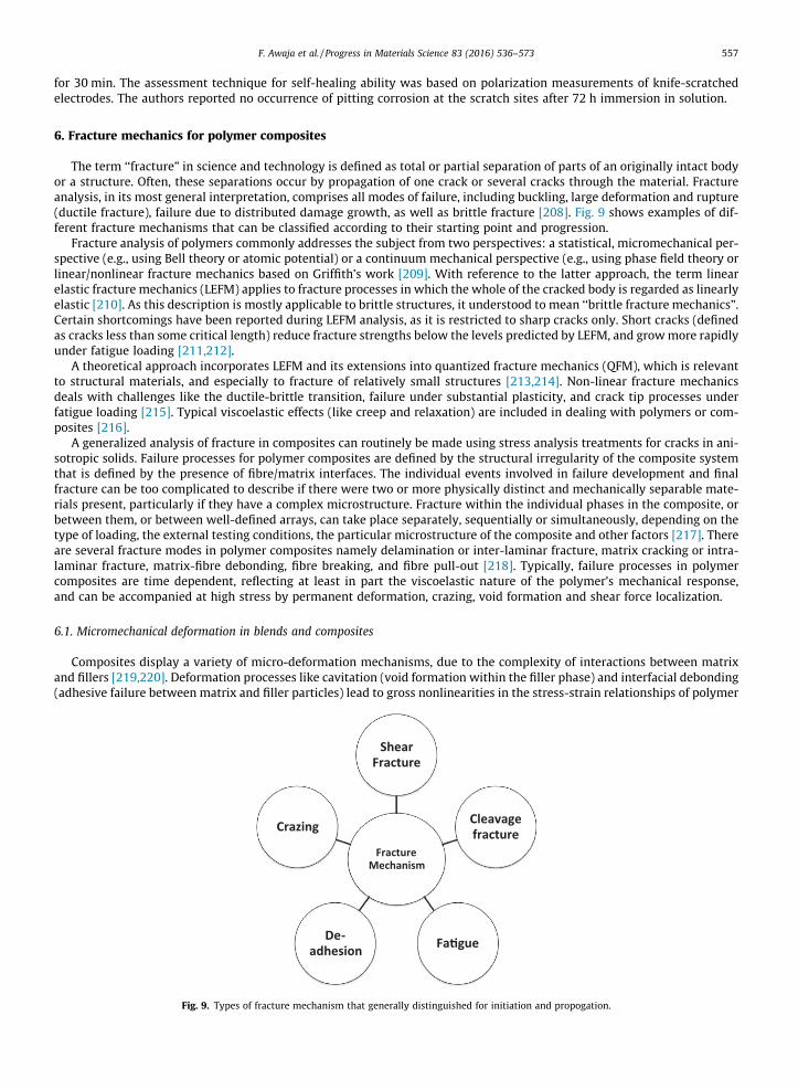
F. Awaja et al. / Progress in Materials Science 83 (2016) 536–573 557
for 30 min. The assessment technique for self-healing ability was based on polarization measurements of knife-scratchedelectrodes. The authors reported no occurrence of pitting corrosion at the scratch sites after 72 h immersion in solution.
6. Fracture mechanics for polymer composites
The term ‘‘fracture” in science and technology is defined as total or partial separation of parts of an originally intact bodyor a structure. Often, these separations occur by propagation of one crack or several cracks through the material. Fractureanalysis, in its most general interpretation, comprises all modes of failure, including buckling, large deformation and rupture(ductile fracture), failure due to distributed damage growth, as well as brittle fracture [208]. Fig. 9 shows examples of dif-ferent fracture mechanisms that can be classified according to their starting point and progression.
Fracture analysis of polymers commonly addresses the subject from two perspectives: a statistical, micromechanical per-spective (e.g., using Bell theory or atomic potential) or a continuum mechanical perspective (e.g., using phase field theory orlinear/nonlinear fracture mechanics based on Griffith’s work [209]. With reference to the latter approach, the term linearelastic fracture mechanics (LEFM) applies to fracture processes in which the whole of the cracked body is regarded as linearlyelastic [210]. As this description is mostly applicable to brittle structures, it understood to mean ‘‘brittle fracture mechanics”.Certain shortcomings have been reported during LEFM analysis, as it is restricted to sharp cracks only. Short cracks (definedas cracks less than some critical length) reduce fracture strengths below the levels predicted by LEFM, and growmore rapidlyunder fatigue loading [211,212].
A theoretical approach incorporates LEFM and its extensions into quantized fracture mechanics (QFM), which is relevantto structural materials, and especially to fracture of relatively small structures [213,214]. Non-linear fracture mechanicsdeals with challenges like the ductile-brittle transition, failure under substantial plasticity, and crack tip processes underfatigue loading [215]. Typical viscoelastic effects (like creep and relaxation) are included in dealing with polymers or com-posites [216].
A generalized analysis of fracture in composites can routinely be made using stress analysis treatments for cracks in ani-sotropic solids. Failure processes for polymer composites are defined by the structural irregularity of the composite systemthat is defined by the presence of fibre/matrix interfaces. The individual events involved in failure development and finalfracture can be too complicated to describe if there were two or more physically distinct and mechanically separable mate-rials present, particularly if they have a complex microstructure. Fracture within the individual phases in the composite, orbetween them, or between well-defined arrays, can take place separately, sequentially or simultaneously, depending on thetype of loading, the external testing conditions, the particular microstructure of the composite and other factors [217]. Thereare several fracture modes in polymer composites namely delamination or inter-laminar fracture, matrix cracking or intra-laminar fracture, matrix-fibre debonding, fibre breaking, and fibre pull-out [218]. Typically, failure processes in polymercomposites are time dependent, reflecting at least in part the viscoelastic nature of the polymer’s mechanical response,and can be accompanied at high stress by permanent deformation, crazing, void formation and shear force localization.
6.1. Micromechanical deformation in blends and composites
Composites display a variety of micro-deformation mechanisms, due to the complexity of interactions between matrixand fillers [219,220]. Deformation processes like cavitation (void formation within the filler phase) and interfacial debonding(adhesive failure between matrix and filler particles) lead to gross nonlinearities in the stress-strain relationships of polymer
Fracture Mechanism
Shear Fracture
Cleavage fracture
Fa�gue De-adhesion
Crazing
Fig. 9. Types of fracture mechanism that generally distinguished for initiation and propogation.
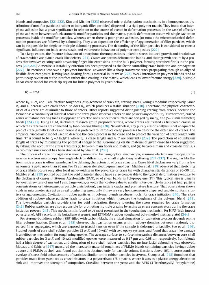
558 F. Awaja et al. / Progress in Materials Science 83 (2016) 536–573
blends and composites [221,222]. Kim and Michler [223] observed micro-deformation mechanisms in a homogeneous dis-tribution of modifier particles (rubber or inorganic filler particles) dispersed in a rigid polymer matrix. They found that inter-phase adhesion has a great significance in relation to the course of events in deformation processes. In the case of effectivephase adhesion between soft, elastomeric modifier particles and the matrix, plastic deformation occurs via single cavitationprocesses inside the modifier particles, whereas when there is poor phase adhesion, (or none) the micromechanical defor-mation processes are followed by debonding. They also depend on the efficiency of agglomeration of filler particles, whichcan be responsible for single or multiple debonding processes. The debonding of the filler particles is considered to exert asignificant influence on both stress-strain and volumetric behaviour of polymer composites [222].
To a large extent, the fracture behaviour of amorphous thermoplastics is linked to stress-induced growth and breakdownof crazes which are planar, crack-like defects [224]. Crazes are porous deformation bands, and their growth occurs by a pro-cess that involves existing voids advancing finger-like extensions into the bulk polymer, forming stretched fibrils in the pro-cess [225,226]. A meniscus instability criterion has been proposed as the factor controlling craze initiation and propagation[227]. The meniscus ‘‘concave air-polymer interface” advances like a sharp transverse crack propagating through an alignedflexible-fibre composite, leaving load-bearing fibrous material in its wake [228]. Weak interfaces in polymer blends tend topermit easy cavitation at the interface rather than crazing in the matrix, which leads to lower fracture energy [229]. A simplelinear craze model for crack tip region for brittle polymer is given below:
K2c ¼ urcE ð1Þ
where Kc, u, ry and E are fracture toughness, displacement of crack tip, crazing stress, Young’s modulus respectively. Sincerc and E increase with crack speed, so does Kc, which produces a stable situation [230]. Therefore, the physical character-istics of a craze are dissimilar to those of cracks. Other reports suggested distinguishing crazing from cracks, because theformer has a continuity of material across the craze plane whereas cracks do not possess any continuity. Furthermore, crazedzones withstand bearing loads as opposed to cracked ones, since their surface are bridged by many, fine (5–30 nm diameter)fibrils [224,231]. Using LEFM, Bucknall’s research group proposed criteria, where crazes are treated as frustrated cracks, inwhich the craze walls are connected by load-bearing fibrils [228]. Nevertheless, any purely elastic analysis is not adequate topredict craze growth kinetics and hence it is preferred to introduce creep processes to describe the extension of crazes. Theempirical viscoelastic model used to describe the creep process in the craze and to predict the variation of craze length withtime ‘‘t” is found to be cz = A ln(t/t⁄), where cz is craze length and A, t⁄ are constants [232]. The prediction of equilibriumlength of crazes by minimizing the potential energy of the surrounding elastic material of given craze has been suggested.By taking into account the stress transfers (i) between main fibrils and matrix, and (ii) between main and cross-tie fibrils, amicro-mechanics model has been discussed by Sha et al. [233].
The process of craze propagation is mostly monitored by using optical microscopy, scanning electron microscopy, trans-mission electron microscopy, low angle electron diffraction, or small angle X-ray scattering [234–237]. The regular fibrilla-tion inside a craze is often regarded as the defining characteristic of craze structure. Craze fibril thicknesses vary from a fewnanometers up to more than 20 nm. For PS at nanoscale (electrospun nanofiber), Michler et al. [238] observed that stretchingof craze fibrils occurs only after local nano-voiding in the pre-craze or craze tip with characteristic distances of 20–30 nm.Michler et al. [239] pointed out that the void diameter should have a size comparable to the typical deformation event, i.e. tothe thickness of crazes in Styrene Acrylonitrile (SAN), or of shear bands in Polypropylene (PP). This typical size is usuallybetween a few tens of nm and 1 lm. Large voids, or voids that coalesce due to smaller inter-particle distance (at high particleconcentrations or heterogeneous particle distribution), can initiate cracks and premature fracture. That observation showsvoids in micrometer size act as a real toughening agent only if they are very homogeneously dispersed, and do not form clus-ters or agglomerates. Cavitation in rubber particles in polymer blends produces nuclei for craze initiation [240]. Thereforeaddition of rubbery phase particles leads to craze initiation which increases the toughness of the polymer blend [241].The low-modulus particles provide sites for void nucleation, thereby lowering the stress required for craze formation[242]. Rubber particles are also responsible for promoting multiple crazing by acting as stress concentrators during the crazeinitiation process [243]. This mechanism is found to be most prominent in the toughening mechanism for HIPS (high impactpolystyrene), ABS (acrylonitrile butadiene styrene), and RTPMMA (rubber toughened poly-methyl methacrylate) [244].
For styrene-butadiene rubber (SBR) filled with carbon–black, the critical elongation for cavitation to occur depends on thefiller volume fraction. Zhang et al. [245] observed that cavitation occurs within rubbery domains between randomly dis-persed filler aggregates, which are exposed to triaxial tension even if the sample is deformed uniaxially. Sue et al. [246].Studied bends of core-shell rubber particles (3 wt% and 10 wt%) with two epoxy systems, and found that craze-like damageis an effective mechanism for toughening epoxies. The average surface-to-surface interparticle distances between core-shellrubber particles for 3 wt% and 10 wt% modified epoxies were measured as 0.17 lm and 0.08 lm respectively. Both blendshad a high degree of cavitation, and elongation of core-shell rubber particles but no interfacial debonding was observed.Mauzac and Schirrer [247] measured the increase in material toughness of PMMA blends containing particles having rubberas core and PMMA as shell, and found out that it is obtained only for particle volume fractions above 10%. It corresponds tooverlap of stress field enhancements of particles. Similar to the rubber particles in styrene, Shang et al. [248] found out thatparticles made from yeast act as craze initiators in a polyurethane (PU) matrix, where it acts as a plastic energy absorptionsink and improves the strength of composites. Crosslink between the yeast and the APTS (3-Triethoxysilyl Propylamine)
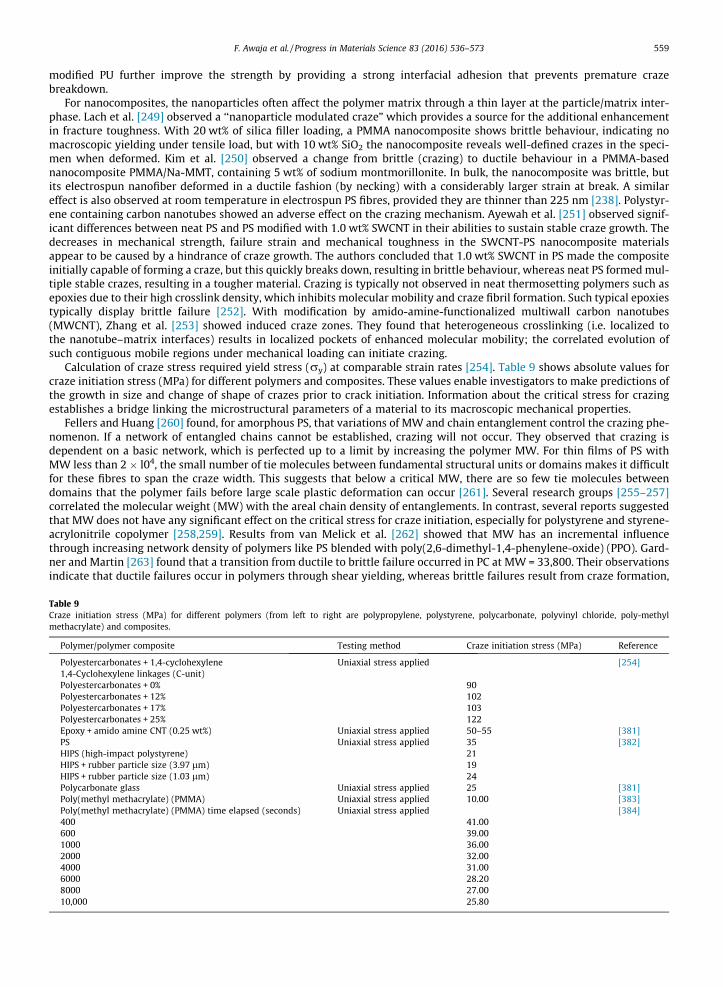
F. Awaja et al. / Progress in Materials Science 83 (2016) 536–573 559
modified PU further improve the strength by providing a strong interfacial adhesion that prevents premature crazebreakdown.
For nanocomposites, the nanoparticles often affect the polymer matrix through a thin layer at the particle/matrix inter-phase. Lach et al. [249] observed a ‘‘nanoparticle modulated craze” which provides a source for the additional enhancementin fracture toughness. With 20 wt% of silica filler loading, a PMMA nanocomposite shows brittle behaviour, indicating nomacroscopic yielding under tensile load, but with 10 wt% SiO2 the nanocomposite reveals well-defined crazes in the speci-men when deformed. Kim et al. [250] observed a change from brittle (crazing) to ductile behaviour in a PMMA-basednanocomposite PMMA/Na-MMT, containing 5 wt% of sodium montmorillonite. In bulk, the nanocomposite was brittle, butits electrospun nanofiber deformed in a ductile fashion (by necking) with a considerably larger strain at break. A similareffect is also observed at room temperature in electrospun PS fibres, provided they are thinner than 225 nm [238]. Polystyr-ene containing carbon nanotubes showed an adverse effect on the crazing mechanism. Ayewah et al. [251] observed signif-icant differences between neat PS and PS modified with 1.0 wt% SWCNT in their abilities to sustain stable craze growth. Thedecreases in mechanical strength, failure strain and mechanical toughness in the SWCNT-PS nanocomposite materialsappear to be caused by a hindrance of craze growth. The authors concluded that 1.0 wt% SWCNT in PS made the compositeinitially capable of forming a craze, but this quickly breaks down, resulting in brittle behaviour, whereas neat PS formedmul-tiple stable crazes, resulting in a tougher material. Crazing is typically not observed in neat thermosetting polymers such asepoxies due to their high crosslink density, which inhibits molecular mobility and craze fibril formation. Such typical epoxiestypically display brittle failure [252]. With modification by amido-amine-functionalized multiwall carbon nanotubes(MWCNT), Zhang et al. [253] showed induced craze zones. They found that heterogeneous crosslinking (i.e. localized tothe nanotube–matrix interfaces) results in localized pockets of enhanced molecular mobility; the correlated evolution ofsuch contiguous mobile regions under mechanical loading can initiate crazing.
Calculation of craze stress required yield stress (ry) at comparable strain rates [254]. Table 9 shows absolute values forcraze initiation stress (MPa) for different polymers and composites. These values enable investigators to make predictions ofthe growth in size and change of shape of crazes prior to crack initiation. Information about the critical stress for crazingestablishes a bridge linking the microstructural parameters of a material to its macroscopic mechanical properties.
Fellers and Huang [260] found, for amorphous PS, that variations of MW and chain entanglement control the crazing phe-nomenon. If a network of entangled chains cannot be established, crazing will not occur. They observed that crazing isdependent on a basic network, which is perfected up to a limit by increasing the polymer MW. For thin films of PS withMW less than 2 � l04, the small number of tie molecules between fundamental structural units or domains makes it difficultfor these fibres to span the craze width. This suggests that below a critical MW, there are so few tie molecules betweendomains that the polymer fails before large scale plastic deformation can occur [261]. Several research groups [255–257]correlated the molecular weight (MW) with the areal chain density of entanglements. In contrast, several reports suggestedthat MW does not have any significant effect on the critical stress for craze initiation, especially for polystyrene and styrene-acrylonitrile copolymer [258,259]. Results from van Melick et al. [262] showed that MW has an incremental influencethrough increasing network density of polymers like PS blended with poly(2,6-dimethyl-1,4-phenylene-oxide) (PPO). Gard-ner and Martin [263] found that a transition from ductile to brittle failure occurred in PC at MW = 33,800. Their observationsindicate that ductile failures occur in polymers through shear yielding, whereas brittle failures result from craze formation,
Table 9Craze initiation stress (MPa) for different polymers (from left to right are polypropylene, polystyrene, polycarbonate, polyvinyl chloride, poly-methylmethacrylate) and composites.
Polymer/polymer composite Testing method Craze initiation stress (MPa) Reference
Polyestercarbonates + 1,4-cyclohexylene Uniaxial stress applied [254]1,4-Cyclohexylene linkages (C-unit)Polyestercarbonates + 0% 90Polyestercarbonates + 12% 102Polyestercarbonates + 17% 103Polyestercarbonates + 25% 122Epoxy + amido amine CNT (0.25 wt%) Uniaxial stress applied 50–55 [381]PS Uniaxial stress applied 35 [382]HIPS (high-impact polystyrene) 21HIPS + rubber particle size (3.97 lm) 19HIPS + rubber particle size (1.03 lm) 24Polycarbonate glass Uniaxial stress applied 25 [381]Poly(methyl methacrylate) (PMMA) Uniaxial stress applied 10.00 [383]Poly(methyl methacrylate) (PMMA) time elapsed (seconds) Uniaxial stress applied [384]400 41.00600 39.001000 36.002000 32.004000 31.006000 28.208000 27.0010,000 25.80
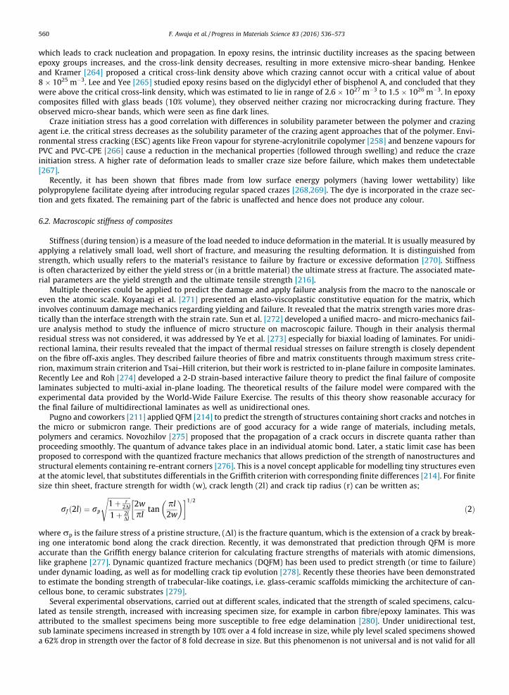
560 F. Awaja et al. / Progress in Materials Science 83 (2016) 536–573
which leads to crack nucleation and propagation. In epoxy resins, the intrinsic ductility increases as the spacing betweenepoxy groups increases, and the cross-link density decreases, resulting in more extensive micro-shear banding. Henkeeand Kramer [264] proposed a critical cross-link density above which crazing cannot occur with a critical value of about8 � 1025 m�3. Lee and Yee [265] studied epoxy resins based on the diglycidyl ether of bisphenol A, and concluded that theywere above the critical cross-link density, which was estimated to lie in range of 2.6 � 1027 m�3 to 1.5 � 1026 m�3. In epoxycomposites filled with glass beads (10% volume), they observed neither crazing nor microcracking during fracture. Theyobserved micro-shear bands, which were seen as fine dark lines.
Craze initiation stress has a good correlation with differences in solubility parameter between the polymer and crazingagent i.e. the critical stress decreases as the solubility parameter of the crazing agent approaches that of the polymer. Envi-ronmental stress cracking (ESC) agents like Freon vapour for styrene-acrylonitrile copolymer [258] and benzene vapours forPVC and PVC-CPE [266] cause a reduction in the mechanical properties (followed through swelling) and reduce the crazeinitiation stress. A higher rate of deformation leads to smaller craze size before failure, which makes them undetectable[267].
Recently, it has been shown that fibres made from low surface energy polymers (having lower wettability) likepolypropylene facilitate dyeing after introducing regular spaced crazes [268,269]. The dye is incorporated in the craze sec-tion and gets fixated. The remaining part of the fabric is unaffected and hence does not produce any colour.
6.2. Macroscopic stiffness of composites
Stiffness (during tension) is a measure of the load needed to induce deformation in the material. It is usually measured byapplying a relatively small load, well short of fracture, and measuring the resulting deformation. It is distinguished fromstrength, which usually refers to the material’s resistance to failure by fracture or excessive deformation [270]. Stiffnessis often characterized by either the yield stress or (in a brittle material) the ultimate stress at fracture. The associated mate-rial parameters are the yield strength and the ultimate tensile strength [216].
Multiple theories could be applied to predict the damage and apply failure analysis from the macro to the nanoscale oreven the atomic scale. Koyanagi et al. [271] presented an elasto-viscoplastic constitutive equation for the matrix, whichinvolves continuum damage mechanics regarding yielding and failure. It revealed that the matrix strength varies more dras-tically than the interface strength with the strain rate. Sun et al. [272] developed a unified macro- and micro-mechanics fail-ure analysis method to study the influence of micro structure on macroscopic failure. Though in their analysis thermalresidual stress was not considered, it was addressed by Ye et al. [273] especially for biaxial loading of laminates. For unidi-rectional lamina, their results revealed that the impact of thermal residual stresses on failure strength is closely dependenton the fibre off-axis angles. They described failure theories of fibre and matrix constituents through maximum stress crite-rion, maximum strain criterion and Tsai–Hill criterion, but their work is restricted to in-plane failure in composite laminates.Recently Lee and Roh [274] developed a 2-D strain-based interactive failure theory to predict the final failure of compositelaminates subjected to multi-axial in-plane loading. The theoretical results of the failure model were compared with theexperimental data provided by the World-Wide Failure Exercise. The results of this theory show reasonable accuracy forthe final failure of multidirectional laminates as well as unidirectional ones.
Pugno and coworkers [211] applied QFM [214] to predict the strength of structures containing short cracks and notches inthe micro or submicron range. Their predictions are of good accuracy for a wide range of materials, including metals,polymers and ceramics. Novozhilov [275] proposed that the propagation of a crack occurs in discrete quanta rather thanproceeding smoothly. The quantum of advance takes place in an individual atomic bond. Later, a static limit case has beenproposed to correspond with the quantized fracture mechanics that allows prediction of the strength of nanostructures andstructural elements containing re-entrant corners [276]. This is a novel concept applicable for modelling tiny structures evenat the atomic level, that substitutes differentials in the Griffith criterion with corresponding finite differences [214]. For finitesize thin sheet, fracture strength for width (w), crack length (2l) and crack tip radius (r) can be written as;
rf ð2lÞ ¼ rp
ffiffiffiffiffiffiffiffiffiffiffiffiffiffi1þ r
2Dl
1þ 2lDl
s2wpl
tanpl2w
� �� �1=2ð2Þ
where rp is the failure stress of a pristine structure, (Dl) is the fracture quantum, which is the extension of a crack by break-ing one interatomic bond along the crack direction. Recently, it was demonstrated that prediction through QFM is moreaccurate than the Griffith energy balance criterion for calculating fracture strengths of materials with atomic dimensions,like graphene [277]. Dynamic quantized fracture mechanics (DQFM) has been used to predict strength (or time to failure)under dynamic loading, as well as for modelling crack tip evolution [278]. Recently these theories have been demonstratedto estimate the bonding strength of trabecular-like coatings, i.e. glass-ceramic scaffolds mimicking the architecture of can-cellous bone, to ceramic substrates [279].
Several experimental observations, carried out at different scales, indicated that the strength of scaled specimens, calcu-lated as tensile strength, increased with increasing specimen size, for example in carbon fibre/epoxy laminates. This wasattributed to the smallest specimens being more susceptible to free edge delamination [280]. Under unidirectional test,sub laminate specimens increased in strength by 10% over a 4 fold increase in size, while ply level scaled specimens showeda 62% drop in strength over the factor of 8 fold decrease in size. But this phenomenon is not universal and is not valid for all
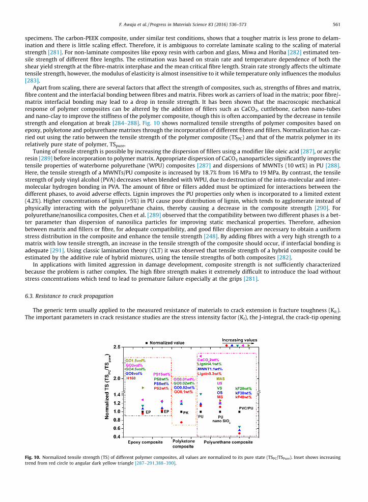
F. Awaja et al. / Progress in Materials Science 83 (2016) 536–573 561
specimens. The carbon-PEEK composite, under similar test conditions, shows that a tougher matrix is less prone to delam-ination and there is little scaling effect. Therefore, it is ambiguous to correlate laminate scaling to the scaling of materialstrength [281]. For non-laminate composites like epoxy resin with carbon and glass, Miwa and Horiba [282] estimated ten-sile strength of different fibre lengths. The estimation was based on strain rate and temperature dependence of both theshear yield strength at the fibre-matrix interphase and the mean critical fibre length. Strain rate strongly affects the ultimatetensile strength, however, the modulus of elasticity is almost insensitive to it while temperature only influences the modulus[283].
Apart from scaling, there are several factors that affect the strength of composites, such as, strengths of fibres and matrix,fibre content and the interfacial bonding between fibres and matrix. Fibres work as carriers of load in the matrix; poor fibre/-matrix interfacial bonding may lead to a drop in tensile strength. It has been shown that the macroscopic mechanicalresponse of polymer composites can be altered by the addition of fillers such as CaCO3, cuttlebone, carbon nano-tubesand nano-clay to improve the stiffness of the polymer composite, though this is often accompanied by the decrease in tensilestrength and elongation at break [284–288]. Fig. 10 shows normalized tensile strengths of polymer composites based onepoxy, polyketone and polyurethane matrixes through the incorporation of different fibres and fillers. Normalization has car-ried out using the ratio between the tensile strength of the polymer composite (TSPC) and that of the matrix polymer in itsrelatively pure state of polymer, TSpure.
Tuning of tensile strength is possible by increasing the dispersion of fillers using a modifier like oleic acid [287], or acrylicresin [289] before incorporation to polymer matrix. Appropriate dispersion of CaCO3 nanoparticles significantly improves thetensile properties of waterborne polyurethane (WPU) composites [287] and dispersions of MWNTs (10 wt%) in PU [288].Here, the tensile strength of a MWNTs/PU composite is increased by 18.7% from 16 MPa to 19 MPa. By contrast, the tensilestrength of poly vinyl alcohol (PVA) decreases when blended with WPU, due to destruction of the intra-molecular and inter-molecular hydrogen bonding in PVA. The amount of fibre or fillers added must be optimized for interactions between thedifferent phases, to avoid adverse effects. Lignin improves the PU properties only when is incorporated to a limited extent(4.2%). Higher concentrations of lignin (>5%) in PU cause poor distribution of lignin, which tends to agglomerate instead ofphysically interacting with the polyurethane chains, thereby causing a decrease in the composite strength [290]. Forpolyurethane/nanosilica composites, Chen et al. [289] observed that the compatibility between two different phases is a bet-ter parameter than dispersion of nanosilica particles for improving static mechanical properties. Therefore, adhesionbetween matrix and fillers or fibre, for adequate compatibility, and good filler dispersion are necessary to obtain a uniformstress distribution in the composite and enhance the tensile strength [248]. By adding fibres with a very high strength to amatrix with low tensile strength, an increase in the tensile strength of the composite should occur, if interfacial bonding isadequate [291]. Using classic lamination theory (CLT) it was observed that tensile strength of a hybrid composite could beestimated by the additive rule of hybrid mixtures, using the tensile strengths of both composites [282].
In applications with limited aggression in damage development, composite strength is not sufficiently characterizedbecause the problem is rather complex. The high fibre strength makes it extremely difficult to introduce the load withoutstress concentrations which tend to lead to premature failure especially at the grips [281].
6.3. Resistance to crack propagation
The generic term usually applied to the measured resistance of materials to crack extension is fracture toughness (KIc).The important parameters in crack resistance studies are the stress intensity factor (KI), the J-integral, the crack-tip opening
Fig. 10. Normalized tensile strength (TS) of different polymer composites, all values are normalized to its pure state (TSPC/TSPure). Inset shows increasingtrend from red circle to angular dark yellow triangle [287–291,388–390].
562 F. Awaja et al. / Progress in Materials Science 83 (2016) 536–573
displacement (CTOD), and the crack-tip opening angle (CTOA) [292]. Crack propagation rate is commonly expressed as afunction of KI or its equivalent partner, energy release rate (G) [208]. Different crack behaviour can be predicted under vari-able loading conditions that include ‘‘crack driving force” (e.g., KI, G, or J) and crack stability [293,294]. The correlationbetween KI and G (the elastic energy release rate) is:
G ¼ ðK2IðmodeIÞ=E
0Þ þ ðK2IðmodeIIÞ=E
0Þ þ K2IðmodeIIIÞ=E
0Þ ð3Þ
where the elastic constants of material is (E0 = E) for plane stress or E0 = E/(1 � m2) for plane strain [278]. KI is the factor driv-ing crack propagation, under mode I(opening), mode II(sliding), or mode III(tearing) conditions, and is only a function ofgeometry and applied load. The multi-mode loading conditions are described in literature elsewhere for further discussion[267]. Improvement of KIc in a polymer composite is achieved by reducing KI at the crack tip [295]. Brighenti et al. [296]examined and calculated a wide database of KI for fibre-reinforced composites, to determine the applied stress value respon-sible for the appearance and propagation of the de-bonding based crack along the fibre. They argued that knowledge of KIand the fibre-matrix critical interface energy made it possible to control the detrimental effect and to properly tailor thedegree of de-bonding under a defined stress level.
Although KI can be used to compare fracture toughness values for composite materials, it is limited to specimens withsharp cracks, and might not be applicable for those with rounded notches or blunt cracks [297]. Salazar et al. [298] suggestedfor blunt cracks to consider an apparent fracture toughness (KB) equivalent to that of a sharp-crack specimen with a stressdistribution, at the instant of fracture, identical to that of the specimen with a blunt crack. Their investigation for epoxy resinfound fracture toughness increased rapidly with crack tip radius and microscopic analysis of the fracture surface indicatedthat blunting was the reason for the steady increase. Krishnan et al. [299] investigated bi-material (polymer/aluminium)specimens with notches at different angles 30�, 90� and 120�. They observed for weakly bonded polymer/metal specimens,that the crack initiation load increases with the increase of the notch angle. However, for strongly bonded polymer/metalspecimens, the notch with an angle of 90� has lower crack initiation load compared to the other two notch angles (30�and 120�) due to the complex relationship between the crack driving force and material’s resistance to crack initiation froma notch.
KIC for a polymer composite depends on its inherent polymer matrix toughness. A linear relationship has been observedfor glass-polymer composites, with toughness increasing in proportion to the toughness of the neat polymer [300]. The capa-bility of intrinsic plasticity in a thermoset governs the inherent matrix toughness, which is determined by the density ofcross-links. If cross-links density increases, the ‘deformability’ of the network will decrease, as was observed in epoxy resin[265]. Therefore, increasing the molecular weight of the liquid resin and/or the hardener units, for example in an epoxy resin,decreases the cross linking density, which leads to enhanced toughness. Nevertheless, simply using lightly cross linkedepoxy matrices is not the ultimate solution for improving KIC. Polymers often behave in an undesirably brittle mannerbecause plastic deformation is constrained [301]. Moreover, constraint alters other important characteristics such asthermo-mechanical properties, stiffness, strength and modulus, which are desired and required in various applications.
The relationship between the local stress crack propagation criterion in terms of KIc, Gc (critical strain energy release rate)and critical crack tip stresses (rc) is written as follows (for plane strain, where m is Poisson’s ratio):
rc ¼ffiffiffiffiffiffiffiffiffiffiffiffiffiffiffiffiffiffiffiffiffiffiffiffi
EGc
ð1� #2Þpa
s¼ KICffiffiffiffiffiffiffiffiffiffiffiffiffiffiffiffiffiffi
ð1� #2Þq ffiffiffiffiffiffi
pap ð4Þ
The influence of KIC and GC for different loading rates was observed by Kanchanomai et al. [294] who observed a decrease inKIC and GC with increasing loading rate for epoxy resins. With the assumption of quantised energy dissipation, Pugno andRuoff [214] formulated a general relationship for KIc using quantized fracture mechanics (QFM), where crack propagationis based on discrete extension steps, rather than the continuous (Griffith) approach. From an energy balance, a relationshipbetween KIc of the material and conditions for propagation of cracks/defects was obtained as:
KIC ¼ K� ¼ffiffiffiffiffiffiffiffiffiffiffiffiffiffiffiffihK2
I ilþDll
q; for Mode I; II; III; ð5Þ
where K⁄ is the square root of the ‘‘mean” value of the KI2 along the fracture quantum length (Dl), for a crack of length ‘‘l”. The
hypothesis of QFM is based on quantized propagation in a linear elastic continuum medium. It is well suited both to first-order with linear elastic fracture mechanics (LEFM) and to second-order for non-linear fracture mechanics. The advantage ofQFM over classical LEFM is that the former places no restrictions on treating defects and cracks of multiple sizes and shapes.The theoretical value obtained from QFM for variable micro size circular holes agreed well with experimental results fromtests on polysilicon thin films [302]. Analogously, for dynamic loads, DQFM (dynamic quantized fracture mechanics) hasbeen presented and used to study the toughness, strength and time to failure of solids, as well as the time evolution ofthe crack tip [278]. The ‘‘mean” value of KI is considered during a quantum interval of time (Dt) where discretization isassumed in both space and time during propagation of the crack. It leads to the following relationship.
KIC ¼ffiffiffiffiffiffiffiffiffiffiffiffiffiffiffiffiffiffiffiffiffiffiffiffiffiffiffihhK2
I ilþDll itt�Dt
q; for Mode I; II; III; ð6Þ
F. Awaja et al. / Progress in Materials Science 83 (2016) 536–573 563
For a viscoelastic material and under certain loading conditions, Gc is considered as the preferred characterizing param-eter for crack extension, rather than the fracture toughness (KIc) [303]. It has also been experimentally demonstrated forcarbon-fibre/epoxy materials, where Gc is found to be independent of de-bonding length, which supports the idea that Gc
is a valid fracture criterion [304].An analogous nonlinear elastic fracture mechanics approach may be used based on the critical J-integral (JIC) [305,306],
where J is the nonlinear elastic strain energy release rate and hence equivalent to G under linear elastic conditions [293]. Itrepresents the energy per unit area necessary to initiate a crack and is obtained by extrapolation to zero crack advancementof the J-R curve, which describes the energy per unit area necessary for the advancement of a propagating crack. Recently,measurements have been made, from cracks propagating across a fully yielded ligament, of the amount of energy required toinitiate a crack in an already yielded material [307]. Salazar and co-worker used J-R curves to determine the influence of thesharpening methodology on the stable crack growth resistance of ethylene–propylene block copolymers [308]. At fracture, JICcan be related to the crack tip opening displacement, CTOD (d), and the yield stress (ry) by the relation JIC = ryd. One impor-tant feature of the J-integral is that, it is path independent, so any convenient path can be chosen if stress and displacementare known. This approach works well for polymers provided they are not too ductile. To deal with highly ductile polymers,the EWF (essential work of fracture) approach has been applied to determine the toughening response. The great advantageof EWF over the J-integral is to provide a clear distinction between the energy required to produce new surface (essentialpart: the work spent in the inner fracture process zone) and volume-related energy dissipation (non-essential part: the workspent in expanding the plastic deformation zone) [309].
Certain modifiers have been suggested for tuning the KIC of a polymer. The classification of modifiers has been described,depending on their rigidity relative to polymer matrix. Modifiers less rigid than the polymer matrix may serve as tougheningagents in matrices which show ductility to some degree. Generally, they provide the toughening mechanism through forma-tion of micro-voids (e.g. in rubber particles) and promoting delocalized micro-crack and crack bridging effect (for thermo-plastic particles). In order to gain improvements of multiple properties, the fillers should possess (1) a higher rigidity thanthe polymer to increase its stiffness, (2) a high specific surface, (3) a sufficient filler-matrix bonding to improve strength andto allow a controlled stress transfer from the matrix to the fillers, and (4) preferably small dimensions to reduce local stressconcentrations and to generate high toughness and impact resistance. Table 10 shows a list of Epoxy polymer compositeswith different modifiers performed under different facture toughness characterization.
In the presence of rigid filler particles of nearly microscopic dimensions, the toughening mechanism may comprise crackdeflection, plastic deformation and crack front pinning. The reduction of the filler dimensions in brittle polymer compositesis one of the most promising pathways to improving the toughness, since the microstructural perfection of compositesincreases by minimizing the size of potential defects (e.g. inclusions, agglomerates) [310]. There are also reports on nano-void formation and presence of a dilatation zone when the interface is strong [311]. For composites, where the dispersedparticles are in the nano-scale, several toughening mechanisms come to play depending on the filler type. For example,nano-sized silica particles increase the toughness of the epoxy matrix through de-bonding of particles which is followedby plastic void growth [312]. Whereas, for carbon nano-tubes reinforcing an epoxy system, pull-out of nano-tubes andde-bonding seems to contribute to the increase in fracture energy and the contribution from plastic void growth is minimal[313]. When it comes to fillers with layered structures such as nano-clay or silicates (layered), crack-deflection, micro-cracking and plastic void growth are the major toughening mechanisms [314,315] and with the addition of graphene, crackdeflection and crack pinning has been reported [316].
The incorporation of controlled and optimized amounts of modifiers tunes the mechanical characteristics of composites,see Fig. 11. Concentrations over a critical value, of modifiers like halloysite (HNT) [317], and glass beads [265], in polyethy-lene terephthalate (PET) [318] lead to the formation of aggregates, which cause poor interfacial adhesion and low stresstransfer between the reinforcements and the matrix. For brittle polymers like poly(methyl methacrylate) (PMMA), toughen-ing by modifiers like mica reaches a plateau i.e. the toughness increases by up to 66% before reaching a critical concentration(in the case of mica 0.8 vol%) without compromising tensile strength. With further increases in filler content, plastic defor-mation in the PMMA matrix gets restricted, and there is a reduction in the elongation at break [319]. For a MMT–PANI(montmorillonite-polyaniline) nanocomposite, the improvement in toughness is attributed to breakage of the clay aggre-gates. The clay layers (MMT or Bentonite) act as stress concentrators and promote a large number of micro-cracks fromthe fracture surface by crack deflection. Up to 23 wt% of MMT clay in the nanocomposite of PANI (polyaniline as the emer-aldine salt (EMS)) significantly improves the fracture toughness, hardness and impact energy of polyaniline. At higher con-tents, clay aggregates present within the intercalated nanocomposites reduce the resistance to crack propagation [320].Another factor that influences the fracture behaviour of MMT–PANI nanocomposites is crystalline morphology, especiallythe size and the form of crystals, of semi-crystalline polymer PANI. In contrast to PEEK polymer, crystallization leads to adrop in toughness [321], with incorporation of carbon fibre (APC-2), the fracture toughness of the laminates depends onthe interfacial interaction but not on matrix crystallinity.
7. Recommendations for future work
Detection and quantitative evaluation of cracks and microcracks is vital for the prevention and repair measures in poly-mer composites. While newly developed non-destructive instrumentation with improved image processing capability, for
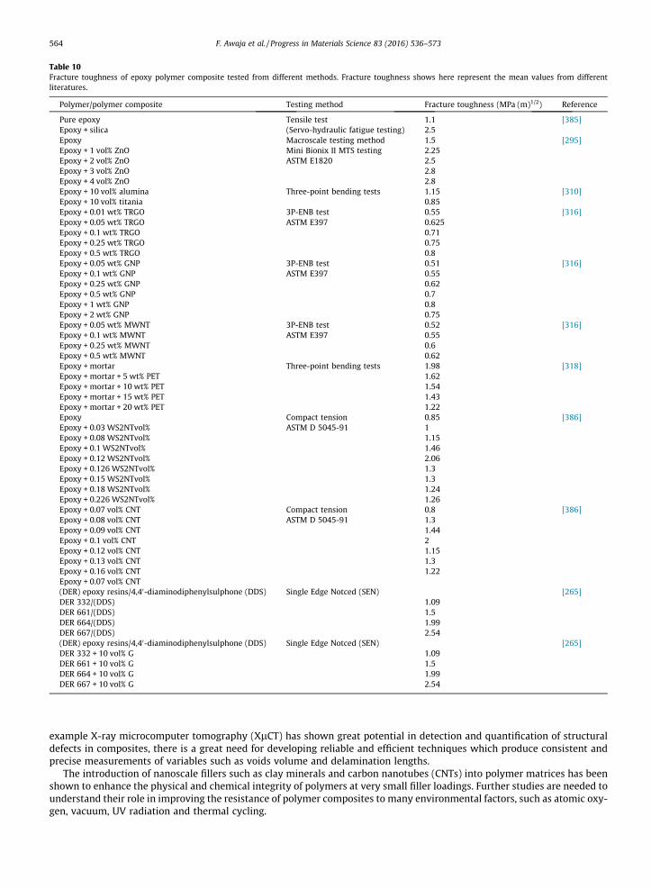
Table 10Fracture toughness of epoxy polymer composite tested from different methods. Fracture toughness shows here represent the mean values from differentliteratures.
Polymer/polymer composite Testing method Fracture toughness (MPa (m)1/2) Reference
Pure epoxy Tensile test 1.1 [385]Epoxy + silica (Servo-hydraulic fatigue testing) 2.5Epoxy Macroscale testing method 1.5 [295]Epoxy + 1 vol% ZnO Mini Bionix II MTS testing 2.25Epoxy + 2 vol% ZnO ASTM E1820 2.5Epoxy + 3 vol% ZnO 2.8Epoxy + 4 vol% ZnO 2.8Epoxy + 10 vol% alumina Three-point bending tests 1.15 [310]Epoxy + 10 vol% titania 0.85Epoxy + 0.01 wt% TRGO 3P-ENB test 0.55 [316]Epoxy + 0.05 wt% TRGO ASTM E397 0.625Epoxy + 0.1 wt% TRGO 0.71Epoxy + 0.25 wt% TRGO 0.75Epoxy + 0.5 wt% TRGO 0.8Epoxy + 0.05 wt% GNP 3P-ENB test 0.51 [316]Epoxy + 0.1 wt% GNP ASTM E397 0.55Epoxy + 0.25 wt% GNP 0.62Epoxy + 0.5 wt% GNP 0.7Epoxy + 1 wt% GNP 0.8Epoxy + 2 wt% GNP 0.75Epoxy + 0.05 wt% MWNT 3P-ENB test 0.52 [316]Epoxy + 0.1 wt% MWNT ASTM E397 0.55Epoxy + 0.25 wt% MWNT 0.6Epoxy + 0.5 wt% MWNT 0.62Epoxy + mortar Three-point bending tests 1.98 [318]Epoxy + mortar + 5 wt% PET 1.62Epoxy + mortar + 10 wt% PET 1.54Epoxy + mortar + 15 wt% PET 1.43Epoxy + mortar + 20 wt% PET 1.22Epoxy Compact tension 0.85 [386]Epoxy + 0.03 WS2NTvol% ASTM D 5045-91 1Epoxy + 0.08 WS2NTvol% 1.15Epoxy + 0.1 WS2NTvol% 1.46Epoxy + 0.12 WS2NTvol% 2.06Epoxy + 0.126 WS2NTvol% 1.3Epoxy + 0.15 WS2NTvol% 1.3Epoxy + 0.18 WS2NTvol% 1.24Epoxy + 0.226 WS2NTvol% 1.26Epoxy + 0.07 vol% CNT Compact tension 0.8 [386]Epoxy + 0.08 vol% CNT ASTM D 5045-91 1.3Epoxy + 0.09 vol% CNT 1.44Epoxy + 0.1 vol% CNT 2Epoxy + 0.12 vol% CNT 1.15Epoxy + 0.13 vol% CNT 1.3Epoxy + 0.16 vol% CNT 1.22Epoxy + 0.07 vol% CNT(DER) epoxy resins/4,40-diaminodiphenylsulphone (DDS) Single Edge Notced (SEN) [265]DER 332/(DDS) 1.09DER 661/(DDS) 1.5DER 664/(DDS) 1.99DER 667/(DDS) 2.54(DER) epoxy resins/4,40-diaminodiphenylsulphone (DDS) Single Edge Notced (SEN) [265]DER 332 + 10 vol% G 1.09DER 661 + 10 vol% G 1.5DER 664 + 10 vol% G 1.99DER 667 + 10 vol% G 2.54
564 F. Awaja et al. / Progress in Materials Science 83 (2016) 536–573
example X-ray microcomputer tomography (XlCT) has shown great potential in detection and quantification of structuraldefects in composites, there is a great need for developing reliable and efficient techniques which produce consistent andprecise measurements of variables such as voids volume and delamination lengths.
The introduction of nanoscale fillers such as clay minerals and carbon nanotubes (CNTs) into polymer matrices has beenshown to enhance the physical and chemical integrity of polymers at very small filler loadings. Further studies are needed tounderstand their role in improving the resistance of polymer composites to many environmental factors, such as atomic oxy-gen, vacuum, UV radiation and thermal cycling.
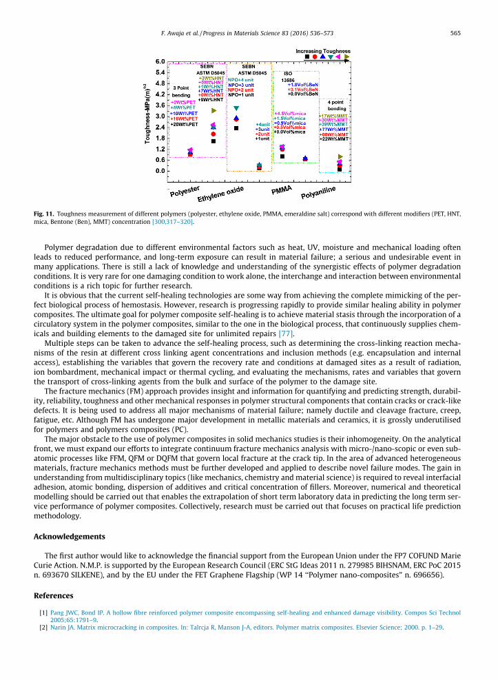
Fig. 11. Toughness measurement of different polymers (polyester, ethylene oxide, PMMA, emeraldine salt) correspond with different modifiers (PET, HNT,mica, Bentone (Ben), MMT) concentration [300,317–320].
F. Awaja et al. / Progress in Materials Science 83 (2016) 536–573 565
Polymer degradation due to different environmental factors such as heat, UV, moisture and mechanical loading oftenleads to reduced performance, and long-term exposure can result in material failure; a serious and undesirable event inmany applications. There is still a lack of knowledge and understanding of the synergistic effects of polymer degradationconditions. It is very rare for one damaging condition to work alone, the interchange and interaction between environmentalconditions is a rich topic for further research.
It is obvious that the current self-healing technologies are some way from achieving the complete mimicking of the per-fect biological process of hemostasis. However, research is progressing rapidly to provide similar healing ability in polymercomposites. The ultimate goal for polymer composite self-healing is to achieve material stasis through the incorporation of acirculatory system in the polymer composites, similar to the one in the biological process, that continuously supplies chem-icals and building elements to the damaged site for unlimited repairs [77].
Multiple steps can be taken to advance the self-healing process, such as determining the cross-linking reaction mecha-nisms of the resin at different cross linking agent concentrations and inclusion methods (e.g. encapsulation and internalaccess), establishing the variables that govern the recovery rate and conditions at damaged sites as a result of radiation,ion bombardment, mechanical impact or thermal cycling, and evaluating the mechanisms, rates and variables that governthe transport of cross-linking agents from the bulk and surface of the polymer to the damage site.
The fracture mechanics (FM) approach provides insight and information for quantifying and predicting strength, durabil-ity, reliability, toughness and other mechanical responses in polymer structural components that contain cracks or crack-likedefects. It is being used to address all major mechanisms of material failure; namely ductile and cleavage fracture, creep,fatigue, etc. Although FM has undergone major development in metallic materials and ceramics, it is grossly underutilisedfor polymers and polymers composites (PC).
The major obstacle to the use of polymer composites in solid mechanics studies is their inhomogeneity. On the analyticalfront, we must expand our efforts to integrate continuum fracture mechanics analysis with micro-/nano-scopic or even sub-atomic processes like FFM, QFM or DQFM that govern local fracture at the crack tip. In the area of advanced heterogeneousmaterials, fracture mechanics methods must be further developed and applied to describe novel failure modes. The gain inunderstanding frommultidisciplinary topics (like mechanics, chemistry and material science) is required to reveal interfacialadhesion, atomic bonding, dispersion of additives and critical concentration of fillers. Moreover, numerical and theoreticalmodelling should be carried out that enables the extrapolation of short term laboratory data in predicting the long term ser-vice performance of polymer composites. Collectively, research must be carried out that focuses on practical life predictionmethodology.
Acknowledgements
The first author would like to acknowledge the financial support from the European Union under the FP7 COFUND MarieCurie Action. N.M.P. is supported by the European Research Council (ERC StG Ideas 2011 n. 279985 BIHSNAM, ERC PoC 2015n. 693670 SILKENE), and by the EU under the FET Graphene Flagship (WP 14 ‘‘Polymer nano-composites” n. 696656).
References
[1] Pang JWC, Bond IP. A hollow fibre reinforced polymer composite encompassing self-healing and enhanced damage visibility. Compos Sci Technol2005;65:1791–9.
[2] Narin JA. Matrix microcracking in composites. In: Talrcja R, Manson J-A, editors. Polymer matrix composites. Elsevier Science; 2000. p. 1–29.
566 F. Awaja et al. / Progress in Materials Science 83 (2016) 536–573
[3] Dry C. Procedures developed for self-repair of polymer matrix composite materials. Compos Struct 1996;35:263–9.[4] Dry C, McMillan W. A novel method to detect crack location and volume in opaque and semi-opaque brittle materials. Smart Mater Struct
1997;6:35–9.[5] Joseph PV, Rabello MS, Mattoso LHC, Joseph K, Thomas S. Environmental effects on the degradation behaviour of sisal fibre reinforced polypropylene
composites. Compos Sci Technol 2002;62:1357–72.[6] Woo RSC, Chen Y, Zhu H, Li J, Kim J-K, Leung CKY. Environmental degradation of epoxy-organoclay nanocomposites due to UV exposure. Part I: photo-
degradation. Compos Sci Technol 2007;67:3448–56.[7] Woo RSC, Zhu H, Leung CKY, Kim J-K. Environmental degradation of epoxy-organoclay nanocomposites due to UV exposure: part II: residual
mechanical properties. Compos Sci Technol 2008;68:2149–55.[8] Awaja F, Gilbert M, Kelly G, Fox B, Pigram PJ. Adhesion of polymers. Prog Polym Sci 2009;34:948–68.[9] Blaiszik BJ, Kramer SLB, Olugebefola SC, Moore JS, Sottos NR, White SR. Self-healing polymers and composites. Annu Rev Mater Res 2010;40:179–211.[10] Feldman D. Polymer weathering: photo-oxidation. J Polym Environ 2002;10:163–73.[11] Yuan YC, Yin T, Rong MZ, Zhang MQ. Self healing in polymers and polymer composites. Concepts, realization and outlook: a review. Exp Polym Lett
2008;2:238–50.[12] Wang CH, Sidhu K, Yang T, Zhang J, Shanks R. Interlayer self-healing and toughening of carbon fibre/epoxy composites using copolymer films. Compos
A Appl Sci Manuf 2012;43:512–8.[13] Awaja F, Riessen Gv, Fox B, Kelly G, Pigram PJ. Time-of-flight secondary ion mass spectrometry investigation of epoxy resin curing behavior in real
time. J Appl Polym Sci 2009;113:2765–76.[14] Awaja F, Riessen Gv, Kelly G, Fox B, Pigram PJ. ToF-SIMS investigation of epoxy resin curing reaction at different resin to hardener ratios. J Appl Polym
Sci 2008;110:2711–7.[15] Awaja F, Gilbert M, Fox B, Kelly G, Pigram PJ. Investigation of the postcure reaction and surface energy of epoxy resins using time-of-flight secondary
ion mass spectrometry and contact-angle measurements. J Appl Polym Sci 2009;113:2755–64.[16] Brown EN, White SR, Sottos NR. Retardation and repair of fatigue cracks in a microcapsule toughened epoxy composite – part II: in situ self-healing.
Compos Sci Technol 2005;65:2474–80.[17] Kessler MR, Sottos NR, White SR. Self-healing structural composite materials. Compos A Appl Sci Manuf 2003;34:743–53.[18] Kessler MR, White SR. Self-activated healing of delamination damage in woven composites. Compos A Appl Sci Manuf 2001;32:683–99.[19] Liu X, Lee JK, Yoon SH, Kessler MR. Characterization of diene monomers as healing agents for autonomic damage repair. J Appl Polym Sci
2006;101:1266–72.[20] Pang JWC, Bond IP. Bleeding composites-damage detection and self-repair using a biomimetic approach. Compos A Appl Sci Manuf 2005;36:183–8.[21] Ju J, Morgan RJ. Characterization of microcrack development in BMI-carbon fiber composite under stress and thermal cycling. J Compos Mater
2004;38:2007–24.[22] Nairn JA. 2.12-matrix microcracking in composites. In: Zweben AKC, editor. Comprehensive composite materials. Oxford: Pergamon; 2000. p. 403–32.[23] Hiemstra DL, Sottos NR. Thermally induced interfacial microcracking in polymer matrix composites. J Compos Mater 1993;27:1030–51.[24] Kim J-K, Mai Y-w. High strength, high fracture toughness fibre composites with interface control—a review. Compos Sci Technol 1991;41:
333–78.[25] Timmerman JF, Hayes BS, Seferis JC. Cure temperature effects on cryogenic microcracking of polymeric composite materials. Polym Compos
2003;24:132–9.[26] Bafekrpour E, Simon GP, Habsuda J, Naebe M, Yang C, Fox B. Fabrication and characterization of functionally graded synthetic graphite/phenolic
nanocomposites. Mater Sci Eng, A 2012;545:123–31.[27] Bafekrpour E, Simon G, Yang C, Habsuda J, Naebe M, Fox B. Effect of compositional gradient on thermal behavior of synthetic graphite–phenolic
nanocomposites. J Therm Anal Calorim 2012;109:1169–76.[28] Ray BC. Study of the influence of thermal shock on interfacial damage in thermosetting matrix aramid fiber composites. J Mater Sci Lett
2003;22:201–2.[29] Timmerman JF, Tillman MS, Hayes BS, Seferis JC. Matrix and fiber influences on the cryogenic microcracking of carbon fiber/epoxy composites.
Compos A Appl Sci Manuf 2002;33:323–9.[30] Timmerman JF, Hayes BS, Seferis JC. Cryogenic microcracking of carbon fiber/epoxy composites: influences of fiber-matrix adhesion. J Compos Mater
2003;37:1939–50.[31] Bechel VT, Fredin MB, Donaldson SL, Kim RY, Camping JD. Effect of stacking sequence on micro-cracking in a cryogenically cycled carbon/
bismaleimide composite. Compos A Appl Sci Manuf 2003;34:663–72.[32] Awaja F, Moon JB, Gilbert M, Zhang S, Kim CG, Pigram PJ. Surface molecular degradation of selected high performance polymer composites under low
earth orbit environmental conditions. Polym Degrad Stab 2011;96:1301–9.[33] Awaja F, Moon JB, Zhang S, Gilbert M, Kim CG, Pigram PJ. Surface molecular degradation of 3D glass polymer composite under low earth orbit
simulated space environment. Polym Degrad Stab 2010;95:987–96.[34] Shimokawa T, Katoh H, Hamaguchi Y, Sanbongi S, Mizuno H, Nakamura H, et al. Effect of thermal cycling on microcracking and strength degradation
of high-temperature polymer composite materials for use in next-generation SST structures. J Compos Mater 2002;36:885–95.[35] Hancox NL. Thermal effects on polymer matrix composites: part 1. Thermal cycling. Mater Des 1998;19:85–91.[36] Han J-H, Kim C-G. Low earth orbit space environment simulation and its effects on graphite/epoxy composites. Compos Struct 2006;72:218–26.[37] Awaja F, Arhatari B, Wiesauer K, Leiss E, Stifter D. An investigation of the accelerated thermal degradation of different epoxy resin composites using X-
ray microcomputed tomography and optical coherence tomography. Polym Degrad Stab 2009;94:1814–24.[38] Radon JC. Fatigue crack growth in polymers. Int J Fract 1980;16:533–52.[39] Wöhler A. Wöhler’s experiments on the strength of metals. Engineering 1867;2:160–1.[40] Andrews EH. Cracking and crazing in polymeric glasses. In: Haward RN, editor. The physics of glassy polymers. Netherlands: Springer; 1973. p.
394–453.[41] kambour RP. A review of crazing and fracture in thermoplastics. J Polym Sci: Macromol Rev 1973;7:1–154.[42] Manson JA, Hertzberg RW. Fatigue failure in polymers. CRC Crit Rev Macromol Sci 1973;1:433–500.[43] Plumridge WJ. Review: fatigue-crack propagation in metallic and polymeric materials. J Mater Sci 1972;7:939–62.[44] Rabinowitz S, Beardmore P. Craze formation and fracture in glassy polymers. CRC Crit Rev Macromol Sci 1972;1:1–45.[45] Regel VR, Tamuzh VP. Fracture and fatigue of polymers and composites (survey). Polym Mech 1977;13:392–408.[46] Schultz JM. Properties of solid polymeric materials. In: Schultz JM, editor. Treaties on material science and technology. Orlando: Academic Press;
1977. p. 599–632.[47] Sauer JA, Richardson GC. Fatigue of polymers. Int J Fract 1980;16:499–532.[48] Azimi HR, Pearson RA, Hertzberg RW. Role of crack tip shielding mechanisms in fatigue of hybrid epoxy composites containing rubber and solid glass
spheres. J Appl Polym Sci 1995;58:449–63.[49] Azimi HR, Pearson RA, Hertzberg RW. Fatigue of hybrid epoxy composites: epoxies containing rubber and hollow glass spheres. Polym Eng Sci
1996;36:2352–65.[50] Becu L, Maazouz A, Sautereau H, Gerard JF. Fracture behavior of epoxy polymers modified with core-shell rubber particles. J Appl Polym Sci
1997;65:2419–31.[51] Brown EN, White SR, Sottos NR. Fatigue crack propagation in microcapsule-toughened epoxy. J Mater Sci 2006;41:6266–73.
F. Awaja et al. / Progress in Materials Science 83 (2016) 536–573 567
[52] Jones AS, Rule JD, Moore JS, Scottos NR, White SR. Life extension of self-healing polymers with rapidly growing fatigue cracks. J R Soc Interface2007;4:395–403.
[53] Karger-Kocsis J, Friedrich K. Microstructure-related fracture toughness and fatigue crack growth behaviour in toughened, anhydride-cured epoxyresins. Compos Sci Technol 1993;48:263–72.
[54] Sautereau H, Maazouz A, Gerard JF, Trotignon JP. Fatigue behaviour of glass bead filled epoxy. J Mater Sci 1995;30:1715–8.[55] Kawaguchi T, Pearson RA. The moisture effect on the fatigue crack growth of glass particle and fiber reinforced epoxies with strong and weak bonding
conditions: part 2. A microscopic study on toughening mechanism. Compos Sci Technol 2004;64:1991–2007.[56] Hayes BS, Seferis JC. Modification of thermosetting resins and composites through preformed polymer particles: a review. Polym Compos
2001;22:451–67.[57] McMurray MK, Amagi S. The effect of time and temperature on flexural creep and fatigue strength of a silica particle filled epoxy resin. J Mater Sci
1999;34:5927–36.[58] Davis FH, Ellison EG. Hydrodynamic pressure effects of viscous fluid flow in a fatigue crack. Fatigue Fract Eng Mater Struct 1989;12:527–42.[59] Elber W. Fatigue crack closure under cyclic tension. Eng Fract Mech 1970;2:37–45.[60] Endo K, Okada T, Komai K, Kiyota M. Fatigue crack propagation of steel in oil. Bull Jpn Soc Mech Eng 1972;15:1316–23.[61] Galvin GD, Naylor H. Effect of lubricants on the fatigue of steel and other metals. Proc Inst Mech Eng 1964;179:857–75.[62] Plumbridge WJ. Mechano-environmental effects in fatigue. Mater Sci Eng 1977;27:197–208.[63] Plumbridge WJ, Ross PJ, Parry JSC. Fatigue crack growth in liquids under pressure. Mater Sci Eng 1985;68:219–32.[64] Polk CJ, Murphy WR, Rowe CN. Determining fatigue crack propagation rates in lubricating environments through the application of a fracture
mechanics technique. Am Soc Lubr Eng Trans 1975;18:290–8.[65] Tzou JL, Suresh S, Ritchie RO. Fatigue crack propagation in oil environments: 1. Crack growth behavior in silicone and paraffin oils. Acta Metall
1985;33:105–16.[66] Yi KS, Cox BN, Dauskardt RH. Fatigue crack-growth behavior of materials in viscous fluid environment. J Mech Phys Solids 1999;47:1843–71.[67] Faltinsen OM. Hydroelastic slamming. J Mar Sci Technol 2000;5:49–65.[68] Caridis PA, Stefanou M. Dynamic elastic/viscoplastic response of hull plating subjected to hydrodynamic wave impact. J Ship Res 1997;41:130–46.[69] Wang G, Tang S, Shin Y. Direct calculation approach for designing a ship-shaped FPSO’S bow against wave slamming load. In: Proceedings of the
twelfth international offshore and polar engineering conference, Kitakyushu, Japan. p. 35–42.[70] McGeorge D, Vredeveldt AW. In: Williams JG, Pavan A, editors. Mode I fracture toughness of secondary bonds of a novel CFRP hull structure. Eur Struct
Integrity Soc, Elsevier; 2000. p. 83–96.[71] Boyd SW, Blake JIR, Shenoi RA, Kapadia A. Integrity of hybrid steel to composite joints for marine application. Proc IMechE Part M: J Eng Marit Environ
2004:235–46.[72] Buckley WH, Stavovy AB, Taylor DW. Progress in the development of structural load criteria for extreme waves. In: Proc extreme loads response
symposium. Arlington, VA; New York: Soc Naval Architects and Marine Engineers; 1981. p. 75–88. Available from: <http://www.shipstructure.org/pdf/81symp06.pdf>.
[73] Charca S, Shafiq B, Just F. Repeated slamming of sandwich composite panels on water. J Sandwich Struct Mater 2009;11:409–24.[74] Charca S, Shafiq B. Damage assessment due to single slamming of foam core sandwich composites. J Sandwich Struct Mater 2010;12:97112.[75] Sharma N, Gibson RF, Ayorinde EO. Fatigue of foam and honeycomb core composite sandwich structures: a tutorial. J Sandwich Struct Mater
2006;8:263–319.[76] Sutherland LS, Soares CG. Impact behaviour of typical marine composite laminates. Compos B Eng 2005;37:89–100.[77] White SR, Sottos NR, Geubelle PH, Moore JS, Kessler MR, Sriram SR, et al. Autonomic healing of polymer composites. Nature 2001;409:794–7.[78] Mackerle J. Finite elements in the analysis of pressure vessels and piping, an addendum (1996–1998). Int J Press Vessels Pip 1999;76:461–85.[79] Pant M, Singh IV, Mishra BK. A numerical study of crack interactions under thermo-mechanical load using EFGM. J Mech Sci Technol 2011;25:403–13.[80] Vikrant KSN, Ramareddy GV, Pavan AHV, Singh K. Estimation of residual life of boiler tubes using steamside oxide scale thickness. Int J Press Vessels
Pip 2013;104:69–75.[81] Ellison EG, Al-Zamily A. Fracture and life prediction under thermal-mechanical strain cycling. Fatigue Fract Eng Mater Struct 1994;17:53–67.[82] Halford G. Brief summary of the evolution of high-temperature creep-fatigue life prediction models for crack initiation. NASA-CP-3230
1993;1:121–50.[83] Lansinger J, Hansson T, Clevfors O. Fatigue crack growth under combined thermal cycling and mechanical loading. Int J Fatigue 2007;29:1383–90.[84] Choi B-H, Chudnovsky A, Sehanobish K. Stress corrosion cracking in plastic pipes: observation and modeling. Int J Fract 2007;145:81–8.[85] Choi B-H, Chudnovsky A, Paradkar R, Michie W, Zhou Z, Cham P-M. Experimental and theoretical investigation of stress corrosion crack (SCC) growth
of polyethylene pipes. Polym Degrad Stab 2009;94:859–67.[86] Hogg PJ. A model for stress corrosion crack growth in glass reinforced plastics. Compos Sci Technol 1990;38:23–42.[87] Akhtar A, Wong JY. Failure analysis of brittle fracture in nonceramic insulators. J Compos Tech Res 1987;9:95–100.[88] Chughtai AR, Smith DM, Kumosa MS. Chemical analysis of a field-failed composite suspension insulator. Compos Sci Technol 1998;58:1641–7.[89] Harris SJ, Nobel B, Owen MJ. Metallographic investigation of the damage caused to GRP by the combined action of electrical, mechanical and chemical
environments. J Mater Sci 1984;19:1596–604.[90] Kumosa M, Narayan HS, Qiu Q, Bansal A. Brittle fracture of non-ceramic suspension insulators with epoxy cone end-fittings. Compos Sci Technol
1997;57:739–51.[91] Noble B, Harris SJ, Owen MJ. Stress corrosion cracking of GRP pultruded rods in acid environments. J Mater Sci 1983;18:1244–54.[92] Owen MJ, Harris SJ, Noble B. Failure of high voltage electrical insulators with pultruded glass fibre-reinforced plastic cores. Composites
1986;17:217–26.[93] Dai J, Yao X, Liang X, Yeh HY. Experimental study of microcracks in stress corrosion of fibre reinforced composites. Polym Testing 2006;25:758–65.[94] Megel M, Kumosa L, Ely T, Armentrout D, Kumosa M. Initiation of stress-corrosion cracking in unidirectional glass/polymer composite materials.
Compos Sci Technol 2001;61:231–46.[95] Akdemir A, Tarakcioglu N, Avci A. Stress corrosion crack growth in glass/polyester composites with surface crack. Compos B Eng 2001;32:123–9.[96] Kumosa L, Armentrout D, Kumosa M. An evaluation of the critical conditions for the initiation of stress corrosion cracking in unidirectional E-glass/
polymer composites. Compos Sci Technol 2001;61:615–23.[97] Kumosa L, Armentrout D, Kumosa M. The effect of sandblasting on the initiation of stress corrosion cracking in unidirectional E-glass/polymer
composites used in high voltage composite (non-ceramic) insulators. Compos Sci Technol 2002;62:1999–2015.[98] Kumosa L, Kumosa M, Armentrout D. Resistance to stress corrosion cracking of unidirectional ECR-glass/polymer composites for high voltage
composite insulator applications. Compos A Appl Sci Manuf 2003;34:1–15.[99] Tsotsis TK, Lee SM. Long-term thermo-oxidative aging in composite materials: failure mechanisms. Compos Sci Technol 1998;58:355–68.[100] Olivier L, Ho NQ, Grandidier JC, Lafarie-Frenot MC. Characterization by ultra-micro indentation of an oxidized epoxy polymer: correlation with the
predictions of a kinetic model of oxidation. Polym Degrad Stab 2008;93:489–97.[101] Colin X, Marais C, Verdu J. A new method for predicting the thermal oxidation of thermoset matrices: application to an amine crosslinked epoxy.
Polym Testing 2001;20:795–803.[102] Lafarie-Frenot MC, Grandidier JC, Gigliotti M, Olivier L, Colin X, Verdu J, et al. Thermo-oxidation behaviour of composite materials at high
temperatures: a review of research activities carried out within the COMEDI program. Polym Degrad Stab 2010;95:965–74.[103] Bowles KJ, Nowak G. Thermo-oxidative stability studies of celion 6000/PMR-15 unidirectional composites, PMR-15, and celion 6000 fiber. J Compos
Mater 1988;22:966–85.

568 F. Awaja et al. / Progress in Materials Science 83 (2016) 536–573
[104] Colin X, Marais C, Verdu J. Kinetic modelling of the stabilizing effect of carbon fibres on thermal ageing of thermoset matrix composites. Compos SciTechnol 2005;65:117–27.
[105] Pochiraju KV, Tandon GP, Schoeppner GA. Evolution of stress and deformations in high-temperature polymer matrix composites during thermo-oxidative aging. Mech Time-Depend Mater 2008;12:45–68.
[106] Gigliotti M, Olivier L, Vu DQ, Grandidier J-C, Lafarie-Frenot MC. Local shrinkage and stress induced by thermo-oxidation in composite materials athigh temperatures. J Mech Phys Solids 2011;59:696–712.
[107] Olivier L, Baudet C, Bertheau D, Grandidier JC, Lafarie-Frenot MC. Development of experimental, theoretical and numerical tools for studying thermo-oxidation of CFRP composites. Compos A Appl Sci Manuf 2009;40:1008–16.
[108] Vu DQ, Gigliotti M, Lafarie-Frenot MC. Experimental characterization of thermo-oxidation-induced shrinkage and damage in polymer–matrixcomposites. Compos A Appl Sci Manuf 2012;43:577–86.
[109] Colin X, Verdu J. Strategy for studying thermal oxidation of organic matrix composites. Compos Sci Technol 2005;65:411–9.[110] Colin X, Mavel A, Marias C, Verdu J. Interaction between cracking and oxidation in organic matrix composites. J Compos Mater 2005;39:1371–89.[111] Roy S. Prediction of anomalous hygrothermal effects in polymer matrix composites. J Reinf Plast Compos 1999;18:1197–207.[112] Madhukar MS, Bowles KJ, Papadopoulos DS. Thermo-oxidative stability and fiber surface modification effects on the inplane shear properties of
graphite/PMR-15 composites. J Compos Mater 1997;31:596–618.[113] Rouquie S, Lafarie-Frenot MC, Cinquin J, Colombaro AM. Thermal cycling of carbon/epoxy laminates in neutral and oxidative environments. Compos
Sci Technol 2005;65:403–9.[114] Lafarie-Frenot MC, Rouquie S. Influence of oxidative environments on damage in C/epoxy laminates subjected to thermal cycling. Compos Sci Technol
2004;64:1725–35.[115] Tandon GP, Pochiraju KV. Heterogeneous thermo-oxidative behaviour of multidirectional laminated composites. J Compos Mater 2011;45:415–35.[116] Vu D-Q, Gigliotti M, Lafarie-Frenot MC. The effect of thermo-oxidation on matrix cracking of cross-ply [0/90]S composite laminates. Compos A Appl
Sci Manuf 2013;44:114–21.[117] Gu X, Michaels C, Drzal P, Jasmin J, Martin D, Nguyen T, et al. Probing photodegradation beneath the surface: a depth profiling study of UV-degraded
polymeric coatings with microchemical imaging and nanoindentation. J Coat Technol Res 2007;4:389–99.[118] Kumar BG, Singh RP, Nakamura T. Degradation of carbon fiber-reinforced epoxy composites by ultraviolet radiation and condensation. J Compos
Mater 2002;36:2713–33.[119] Awaja F, Nguyen M-T, Zhang S, Arhatari B. The investigation of inner structural damage of UV and heat degraded polymer composites using X-ray
micro CT. Compos A Appl Sci Manuf 2011;42:408–18.[120] Iskanderova Z, Kleiman J, Gudimenko Y, Tennyson RC, Morison WD. Comparison of surface modification of polymeric materials for protection from
severe oxidative environments using different ion sources. Surf Coat Technol 2000;127:18–23.[121] Xiang J, Wang J, Chen X, Lei J. Formation mechanism of microvoids and microcracks of poly(vinyl chloride) under an artificial aging environment. J
Appl Polym Sci 2012;125:291–9.[122] Decelle J, Huet N, Bellenger V. Oxidation induced shrinkage for thermally aged epoxy networks. Polym Degrad Stab 2003;81:239–48.[123] Lafarie-Frenot MC, Rouquié S, Ho NQ, Bellenger V. Comparison of damage development in C/epoxy laminates during isothermal ageing or thermal
cycling. Compos A Appl Sci Manuf 2006;37:662–71.[124] Chang LN, Chow WS. Accelerated weathering on glass fiber/epoxy/organo-montmorillonite nanocomposites. J Compos Mater 2010;44:1421–34.[125] Awaja F, Pigram PJ. Surface molecular characterisation of different epoxy resin composites subjected to UV accelerated degradation using XPS and
ToF-SIMS. Polym Degrad Stab 2009;94:651–8.[126] Aditya PK, Sinha PK. Diffusion coefficients of polymeric composites subjected to periodic hygrothermal exposure. J Reinf Plast Compos
1992;11:1035–47.[127] Sawpan MA, Holdsworth PG, Renshaw P. Glass transitions of hygrothermal aged pultruded glass fibre reinforced polymer rebar by dynamic
mechanical thermal analysis. Mater Des 2012;42:272–8.[128] Dag S, Yildirim B, Arslan O, Arman EE. Hygrothermal fracture analysis of orthotropic materials using Jk integral. J Therm Stresses 2012;35:596–613.[129] Robert M, Roy R, Benmokrane B. Environmental effects on glass fibre reinforced polypropylene thermoplastic composites laminates for structural
applications. Polym Compos 2010;31:604–11.[130] Aronhime MT, Neumann S, Marom G. The anisotropic diffusion of water in Kevlar epoxy composites. J Mater Sci 1987;22:2435–6.[131] Leman Z, Sapuan SM, Saifol AM, Maleque MA, AhmadMMHM. Moisture absorption behaviour of sugar palm fibre reinforced epoxy composites. Mater
Des 2008;29:1666–70.[132] Jana RN, Bhunia H. Hygrothermal degradation of the composite laminates from woven carbon/SC-15 epoxy resin and woven glass/SC-15 epoxy resin.
Polym Compos 2008;29:664–9.[133] Ray BC. Temperature effect during humid ageing on interfaces of glass and carbon fibres reinforced epoxy composites. J Colloid Interface Sci
2006;298:111–7.[134] Slater C, Davis C, Strangwood M. Compression set of thermoplastic polyurethane under different thermal-mechanical-moisture conditions. Polym
Degrad Stab 2011;96:2139–44.[135] Badia JD, Santonja-Blasco L, Martinez-Felipe A, Ribes-Greus A. Hygrothermal ageing of reprocessed polylactide. Polym Degrad Stab 2012;97:1881–90.[136] Miller SG, Roberts GD, Bail JL, Kohlman LW, BiniendaWK. Effects of hygrothermal cycling on the chemical, thermal, and mechanical properties of 862/
W epoxy resin. High Perform Polym 2012;24:470–7.[137] Phua YJ, Chow WS, Mohd Ishak ZA. The hydrolytic effect of moisture and hygrothermal aging on poly(butylene succinate)/organo-montmorillonite
nanocomposites. Polym Degrad Stab 2011;96:1194–203.[138] Jiang X, Kolstein H, Bijlaard FSK. Moisture diffusion and hygrothermal aging in pultruded fibre reinforced polymer composites of bridge decks. Mater
Des 2012;37:304–12.[139] Ben Daly H, Ben Brahim H, Hfaied N, Harchay M, Boukhili R. Investigation of water absorption in pultruded composites containing fillers and low
profile additives. Polym Compos 2007;28:355–64.[140] Ben Daly H, Harchay M, Belhadjsalah H, Boukhili R. Experimental characterization and numerical simulation of the humidity absorption process in
glass reinforced composites under dissymmetric exposure conditions. Polym Compos 2009;30:1825–36.[141] Eslami S, Taheri-Behrooz F, Taheri F. Long-term hygrothermal response of perforated GFRP plates with/without application of constant external
loading. Polym Compos 2012;33:467–75.[142] Papanicolaou GC, Kosmidou TV, Vatalis AS, Delides CG. Water absorption mechanism and some anomalous effects on the mechanical and viscoelastic
behavior of an epoxy system. J Appl Polym Sci 2006;99:1328–39.[143] Davies P, Evrard G. Accelerated ageing of polyurethanes for marine applications. Polym Degrad Stab 2007;92:1455–64.[144] Gac PYL, Saux VL, Paris M, Marco Y. Ageing mechanism and mechanical degradation behaviour of polychloroprene rubber in a marine environment:
comparison of accelerated ageing and long term exposure. Polym Degrad Stab 2012;97:288–96.[145] Mouritz AP. Environmental durability of z-pinned carbon fibre-epoxy laminate exposed to water. Compos Sci Technol 2012;72:1568–74.[146] Visco AM, Campo N, Cianciafara P. Comparison of seawater absorption properties of thermoset resins based composites. Compos A Appl Sci Manuf
2011;42:123–30.[147] Davies P, MazÉas F, Casari P. Sea water aging of glass reinforced composites: shear behaviour and damage modeling. J Compos Mater
2001;35:1343–73.[148] Mouzakis DE, Zoga H, Galiotis C. Accelerated environmental ageing study of polyester/glass fiber reinforced composites (GFRPCs). Compos B Eng
2008;39:467–75.
F. Awaja et al. / Progress in Materials Science 83 (2016) 536–573 569
[149] Kawagoe M, Doi Y, Fuwa N, Yasuda T, Takata K. Effects of absorbed water on the interfacial fracture between layers of unsaturated polyester and glass.J Mater Sci 2011;36:5161–7.
[150] Collette SA, Sutton MA, Miney P, Reynolds AP, Xiaodong L, Colavita PE, et al. Development of patterns for nanoscale strain measurements: I.Fabrication of imprinted Au webs for polymeric materials. Nanotechnology 2004;15:1812–7.
[151] Gheorghiu C, Labossiére P, Proulx J. Fiber optic sensors for strain measurement of CFRP-strengthened RC beams. Struct Health Monit 2005;4:67–80.[152] Belarbi A, Watkins SE, Chandrashekhara K, Corra J, Konz B. Smart fiber-reinforced polymer rods featuring improved ductility and health monitoring
capabilities. Smart Mater Struct 2001;10:427–31.[153] Berfield TA, Patel JK, Shimmin RG, Braun PV, Lambros J, Sottos NR. Fluorescent image correlation for nanoscale deformation measurements. Small
2006;2:631–5.[154] Lestari W, Qiao P. Damage detection of fiber-reinforced polymer honeycomb sandwich beams. Compos Struct 2005;67:365–73.[155] Rizzo P, Scalea FLd. Acoustic emission monitoring of carbon-fiber-reinforced-polymer bridge stay cables in large-scale testing. Exp Mech
2001;41:282–90.[156] Ratcliffe CP, Bagaria WJ. Vibration technique for locating delamination in a composite beam. Am Inst Aeronaut Astron 1998;36:1074–7.[157] Miceli M, Duke JC, Hornet M. Health monitoring of fiber reinforced polymer bridge decks with infrared thermography. Mater Eval 2002;60:1245–52.[158] Samuel BA, Demirel MC, Haque A. High resolution deformation and damage detection using fluorescent dyes. J Micromech Microeng
2007;17:2324–7.[159] Gammon LM. Polymeric composites, morphological characterisation and fracture analysis: fluorescent, dark field, bright field and polarized light
optical microscopy. Microsc Microanal 2004;10:740–1.[160] Hayes BS, Gammon LM. Optical microscopy of fiber reinforced composites. ASM International; 2010. p. 261.[161] Huang D, Swanson EA, Lin CP, Schuman JS, Stinson WG, Chang W, et al. Optical coherence tomography. Science 1991;254:1178–81.[162] Stifter D. Beyond biomedicine: a review of alternative applications and developments for optical coherence tomography. Appl Phys B
2007;88:337–57.[163] Wiesauer K, Pircher M, Götzinger E, Hitzenberger CK, Oster R, Stifter D. Investigation of glass-fibre reinforced polymers by polarisation-sensitive,
ultra-high resolution optical coherence tomography: internal structures, defects and stress. Compos Sci Technol 2007;67:3051–8.[164] Sato N, Kurauchi T, Sato S, Kamigaito O. SEM observations of the initiation and propagation of cracks in a short fibre-reinforced thermoplastic
composite under stress. J Mater Sci Lett 1983;2:188–90.[165] Purslow D. Fractography of fibre-reinforced thermoplastics, part 3. Tensile, compressive and flexural failures. Composites 1988;19:358–66.[166] Adams RD, Cawley P. A review of defect types and nondestructive testing techniques for composites and bonded joints. NDT Int 1988;21:
208–22.[167] Huguet S, Godin N, Gaertner R, Salmon L, Villard D. Use of acoustic emission to identify damage modes in glass fibre reinforced polyester. Compos Sci
Technol 2002;62:1433–44.[168] Kinra VK, Ganpatye AS, Maslov K. Ultrasonic ply-by-ply detection of matrix cracks in laminated composites. J Nondest Eval 2006;25:37–49.[169] Mouritz AP, Townsend C, Shah Khan MZ. Non-destructive detection of fatigue damage in thick composites by pulse-echo ultrasonics. Compos Sci
Technol 2000;60:23–32.[170] Maslov K, Kim RY, Kinra VK, Pagano NJ. A new technique for the ultrasonic detection of internal transverse cracks in carbon-fibre/bismaleimide
composite laminates. Compos Sci Technol 2000;60:2185–90.[171] Parnasov VS, Dobromyslov VA. NDT methods, equipment, and technology for polymer composite products. Meas Tech 1997;40:1076–83.[172] Schilling PJ, Karedla BR, Tatiparthi AK, Verges MA, Herrington PD. X-ray computed microtomography of internal damage in fiber reinforced polymer
matrix composites. Compos Sci Technol 2005;65:2071–8.[173] Beier U, Fischer F, Sandler JKW, Altstädt V, Weimer C, Buchs W. Mechanical performance of carbon fibre-reinforced composites based on stitched
preforms. Compos A Appl Sci Manuf 2007;38:1655–63.[174] Awaja F, Arhatari BD. X-ray micro computed tomography investigation of accelerated thermal degradation of epoxy resin/glass microsphere syntactic
foam. Compos A Appl Sci Manuf 2009;40:1217–22.[175] Liotier P-J, Alain V, Christine D. Characterization of 3D morphology and microcracks in composites reinforced by multi-axial multi-ply stitched
preforms. Compos A Appl Sci Manuf 2010;41:653–62.[176] Bayraktar E, Bessri K, Bathias C. Deformation behaviour of elastomeric matrix composites under static loading conditions. Eng Fract Mech
2008;75:2695–706.[177] Sket F, Seltzer R, Molina-Aldareguía JM, González C, Llorca J. Determination of damage micromechanisms and fracture resistance of glass fiber/epoxy
cross-ply laminate by means of X-ray computed microtomography. Compos Sci Technol 2012;72:350–9.[178] Tan KT, Watanabe N, Iwahori Y. X-ray radiography and micro-computed tomography examination of damage characteristics in stitched composites
subjected to impact loading. Compos B Eng 2011;42:874–84.[179] Zhu P, Duvauchelle P, Peix G, Babot D. X-ray Compton backscattering techniques for process tomography: imaging and characterization of materials.
Meas Sci Technol 1996;7:281–6.[180] Babot D, Berodias G, Peix G. Detection and sizing by X-ray Compton scattering of near-surface cracks under weld deposited cladding. NDT&E Int
1991;24:247–51.[181] Lawson L. Compton X-ray backscatter depth profilometry for aircraft corrosion inspection. Mater Eval 1995;53:936–41.[182] Niemann W, Zahorodny S. Status and future aspects of X-ray backscattering imaging. Rev Prog Quant Nondest Eval 1998;17A:379–85.[183] Summerscales J. Non-destructive testing of advanced composites: a review of recent advances. Brit J Non-Dest Test 1990;32:568–77.[184] Henneke EG, Jones TS. Detection of damage in composite materials by vibrothermography. In: Pipes RB, editor. Nondestructive evaluation and flaw
criticality for composite materials: ASTM STP696. Philadelphia: ASTM; 1979. p. 83–95.[185] Cho SH, Andersson HM, White SR, Sottos NR, Braun PV. Polydimethylsiloxane-based self-healing materials. Adv Mater 2006;18:997–1000.[186] Maiti S, Geubelle PH. Cohesive modeling of fatigue crack retardation in polymers: crack closure effect. Eng Fract Mech 2006;73:22–41.[187] Brown EN, White SR, Sottos NR. Retardation and repair of fatigue cracks in microcapsule toughened epoxy composites—part I: manual infiltration.
Compos Sci Technol 2005;65:2466–73.[188] Blaiszik BJ, Sottos NR, White SR. Nanocapsules for self-healing materials. Compos Sci Technol 2008;68:978–86.[189] Trask RS, Williams HR, Bond IP. Self-healing polymer composites: mimicking nature to enhance performance. Bioinspirat Biomimet 2007;2:P1–9.[190] Bleay SM, Loader CB, Hawyes VJ, Humberstone L, Curtis PT. A smart repair system for polymer matrix composites. Compos A Appl Sci Manuf
2001;32:1767–76.[191] Trask RS, Williams GJ, Bond IP. Bioinspired self-healing of advanced composite structures using hollow glass fibres. J R Soc Interface 2007;4:363–71.[192] Bergman SD, Wudl F. Mendable polymers. J Mater Chem 2008;18:41–62.[193] Syrett JA, Becer CR, Haddleton DM. Self-healing and self-mendable polymers. Polym Chem 2010;1:978–87.[194] Chen X, Dam MA, Ono K, Mal A, Shen H, Nutt SR, et al. A thermally remendable cross-linked polymeric material. Science 2002;295:1698–702.[195] Chen X, Wudl F, Mal AK, Shen H, Nutt SR. New thermally remendable highly cross-linked polymeric materials. Macromolecules 2003;36:1802–7.[196] Hayes SA, Zhang W, Branthwaite M, Jones FR. Self-healing of damage in fiber-reinforced polymer-matrix composites. J R Soc Interface 2007;4:381–7.[197] Hayes SA, Jones FR, Marshiya K, Zhang W. A self-healing thermosetting composite material. Compos A Appl Sci Manuf 2007;38:1116–20.[198] Luo XF, Ou R, Eberly DE, Singhal A, Viratyaporn W, Mather PT. A thermoplastic/thermoset blend exhibiting thermal mending and reversible adhesion.
ACS Appl Mater Interfaces 2009;1:612–20.[199] Kalista SJ, Ward TC, Oyetunji Z. Self-healing of poly(ethylene-comethacrylic acid) copolymers following projectile puncture. Mech Adv Mater Struct
2007;14:391–7.
570 F. Awaja et al. / Progress in Materials Science 83 (2016) 536–573
[200] Kalista SJ, Ward TC. Thermal characteristics of the self-healing response in poly(ethylenecomethacrylic acid) copolymers. J R Soc Interface2007;4:405–11.
[201] Varley RJ, Zwaag Svd. Towards an understanding of thermally activated self-healing of an ionomer system during ballistic penetration. Acta Mater2008;56:5737–50.
[202] Varley RJ, Zwaag Svd. Development of a quasi-static test method to investigate the origin of self-healing in ionomers under ballistic conditions. PolymTesting 2008;27:11–9.
[203] Hargou K, Pingkarawat K, Mourtiz AP, Wang CH. Ultrasonic activation of mendable polymer for self-healing carbon-epoxy laminates. Compos B Eng2012;45:1031–9.
[204] Meure S, Furman S, Khor S. Poly[ethylene-co-(methacrylic acid)] healing agent for mendable carbon fibre laminates. Macromol Mater Eng2010;295:420–4.
[205] Varley RJ, Parn GP. Thermally activated healing in a mendable resin using a non woven EMAA fabric. Compos Sci Technol 2012;72:453–60.[206] Takeda K, Tanahashi M, Unno H. Self-repairing mechanism of plastics. Sci Technol Adv Mater 2003;4:435–44.[207] Aramaki K. Preparation of chromate-free, self-healing polymer films containing sodium silicate on zinc pretreated in a cerium(III) nitrate solution for
preventing zinc corrosion at scratches in 0.5 M NaCl. Corros Sci 2002;44:1375–89.[208] Chudnovsky A. Slow crack growth, its modeling and crack-layer approach: a review. Int J Eng Sci 2014;83:6–41.[209] Giesa T, Pugno NM, Wong JY, Kaplan DL, Buehler MJ. What’s inside the box? – Length-scales that govern fracture processes of polymer fibres. Adv
Mater 2014;26:412–7.[210] Griffith AA. The phenomena of rupture and flow in solids. Philos Trans R Soc Lond A 1920;221:163–98.[211] Taylor D, Cornetti P, Pugno N. The fracture mechanics of finite crack extension. Eng Fract Mech 2005;72:1021–38.[212] Pugno NM. The role of defects in the design of space elevator cable: from nanotube to megatube. Acta Mater 2007;55:5269–79.[213] Pugno NM. Quantized mechanics of nanotubes and bundles. In: Bhushan B, editor. Scanning probe microscopy in nanoscience and
nanotechnology. Berlin, Heidelberg: Springer; 2010. p. 487–506.[214] Pugno NM, Ruoff RS. Quantized fracture mechanics. Philos Mag 2004;84:2829–45.[215] Rice JR. Fracture mechanics. Appl Mech Rev 1985;38:1271–5.[216] Gross D, Seelig T. Fracture mechanics: with an introduction to micromechanics. 2nd ed. Berlin, Heidelberg: Springer-Verlag; 2011.[217] Friedrich K. Application of fracture mechanics to composite materials. In: Klaus F, editor. Composite materials series. Elsevier; 1989. p. v–vii.[218] Dharan C. Fracture mechanics of composite materials. J Eng Mater Technol 1978;100:233–47.[219] Wang M-J. Effect of polymer-filler and filler-filler interactions on dynamic properties of filled vulcanizates. Rubber Chem Technol 1998;71:520–89.[220] Jordan J, Jacob KI, Tannenbaum R, Sharaf MA, Jasiuk I. Experimental trends in polymer nanocomposites—a review. Mater Sci Eng, A 2005;393:1–11.[221] Chang F-K, Chang K-Y. A progressive damage model for laminated composites containing stress concentrations. J Compos Mater 1987;21:834–55.[222] Ghassemieh E, Naseehi V. Prediction of failure and fracture mechanisms of polymeric composites using finite element analysis. Part 1: particulate
filled composites. Polym Compos 2001;22:528–41.[223] Kim GM, Michler GH. Micromechanical deformation processes in toughened and particle-filled semicrystalline polymers: part 1. Characterization of
deformation processes in dependence on phase morphology. Polymer 1998;39:5689–97.[224] Kramer E, Berger L. Fundamental processes of craze growth and fracture. In: Kausch HH, editor. Crazing in polymers, vol. 2. Berlin,
Heidelberg: Springer; 1990. p. 1–68.[225] Nathani H, Dasari A, Misra RDK. On the reduced susceptibility to stress whitening behavior of melt intercalated polybutene–clay nanocomposites
during tensile straining. Acta Mater 2004;52:3217–27.[226] Courtney TH. Mechanical behavior of materials. Waveland Press; 2005.[227] Argon AS, Hannoosh JG. Initiation of crazes in polystyrene. Philos Mag 1977;36:1195–216.[228] Bucknall CB. New criterion for craze initiation. Polymer 2007;48:1030–41.[229] Manson JA. Polymer blends and composites. Springer Science & Business Media; 2012.[230] Williams JG. Fracture mechanics of polymers. Polym Eng Sci 1977;17:144–9.[231] Kausch H-H. Polymer fracture. Springer Science & Business Media; 2012.[232] Mills NJ. Craze growth and craze interactions. J Mater Sci 1981;16:1332–42.[233] Sha Y, Hui CY, Ruina A, Kramer EJ. Continuum and discrete modeling of craze failure at a crack tip in a glassy polymer. Macromolecules
1995;28:2450–9.[234] Sauer JA, Marin J, Hsiao CC. Creep and damping properties of polystyrene. J Appl Phys 1949;20:507–17.[235] Lauterwasser BD, Kramer EJ. Microscopic mechanisms and mechanics of craze growth and fracture. Philos Mag A 1979;39:469–95.[236] Brown HR, Kramer EJ. Craze microstructure from small-angle X-ray scattering (SAXS). J Macromol Sci B 1981;19:487–522.[237] Brown HR. The use of small-angle electron scattering to compare the structure of craze found in thin films with that found in bulk materials. J Polym
Sci: Polym Phys Ed 1983;21:483–92.[238] Michler GH, Baltá-Calleja FJ. Crazing. In: Baltá-Calleja GHMJ, editor. Nano- and micromechanics of polymers. Hanser; 2012. p. 119–57.[239] Michler GH, von Schmeling H-HK-B. The physics and micro-mechanics of nano-voids and nano-particles in polymer combinations. Polymer
2013;54:3131–44.[240] Lin CS, Ayre DS, Bucknall CB. A dynamic mechanical technique for detecting rubber particle cavitation in toughened plastics. J Mater Sci Lett
1998;17:669–71.[241] Argon AS. The role of heterogeneities in fracture. In: Fracture mechanics: perspectives and directions (twentieth symposium). ASTM International;
1989. p. 127.[242] Anderson TL, Anderson T. Fracture mechanics: fundamentals and applications. CRC Press; 2005.[243] Rovere J, Correa C, Grassi V, Pizzol M. Role of the rubber particle and polybutadiene cis content on the toughness of high impact polystyrene. J Mater
Sci 2008;43:952–9.[244] Sabu T, Gabriel G, Charef H. Micro- and nanostructured polymer blends. Micro- and nanostructured multiphase polymer blend systems. CRC Press;
2005. p. 1–42.[245] Zhang H, Zheng W, Tang G. Stellar/inertial integrated guidance for responsive launch vehicles. Aerosp Sci Technol 2012;18:35–41.[246] Sue HJ, Garcia-Meitin EI, Orchard NA. Toughening of epoxies via craze-like damage. J Polym Sci, Part B: Polym Phys 1993;31:595–608.[247] Mauzac O, Schirrer R. Effect of particle volume fraction on crack-tip crazes in high impact poly(methyl methacrylate). J Appl Polym Sci
1989;38:2289–302.[248] Shang S, Chiu K-l, Yuen CWM, Jiang S, Hu E. The potential of yeast as eco-filler for waterborne polyurethane and its reinforcing mechanism. Eur Polym
J 2014;60:6–13.[249] Lach R, Kim G-M, Michler GH, Grellmann W, Albrecht K. Indentation fracture mechanics for toughness assessment of PMMA/SiO2 nanocomposites.
Macromol Mater Eng 2006;291:263–71.[250] Kim GM, Lach R, Michler GH, Pötschke P, Albrecht K. Relationships between phase morphology and deformation mechanisms in polymer
nanocomposite nanofibres prepared by an electrospinning process. Nanotechnology 2006;17:963.[251] Ayewah DOO, Davis DC, Krishnamoorti R, Lagoudas DC, Sue H-J, Willson M. A surfactant dispersed SWCNT-polystyrene composite characterized for
electrical and mechanical properties. Compos A Appl Sci Manuf 2010;41:842–9.[252] Talreja R. Damage mechanics of composite materials. Elsevier; 1994.[253] Zhang W, Srivastava I, Zhu Y-F, Picu CR, Koratkar NA. Heterogeneity in epoxy nanocomposites initiates crazing: significant improvements in fatigue
resistance and toughening. Small 2009;5:1403–7.
F. Awaja et al. / Progress in Materials Science 83 (2016) 536–573 571
[254] Liu J, Yee AF. Effect of local conformational transition on craze initiation in polyestercarbonates containing cyclohexylene linkages. Macromolecules2000;33:1338–44.
[255] Sha Y, Hui CY, Ruina A, Kramer EJ. Detailed simulation of craze fibril failure at a crack tip in a glassy polymer. Acta Mater 1997;45:3555–63.[256] Hui CY, Ruina A, Creton C, Kramer EJ. Micromechanics of crack growth into a craze in a polymer glass. Macromolecules 1992;25:3948–55.[257] Hui CY, Kramer EJ. Molecular weight dependence of the fracture toughness of glassy polymers arising from crack propagation through a craze. Polym
Eng Sci 1995;35:419–25.[258] Cho K, Lee MS, Park CE. The effect of Freon vapour on fracture behaviour of styrene-acrylonitrile copolymer—I. Craze initiation behaviour. Polymer
1998;39:1357–61.[259] Henry LF. Prediction and evaluation of the susceptibilities of glassy thermoplastics to environmental stress cracking. Polym Eng Sci 1974;14:167–76.[260] Fellers JF, Huang DC. Crazing studies of polystyrene. II. Application of fluctuation theory. J Appl Polym Sci 1979;23:2315–26.[261] Brady TE, Yeh GSY. Similarity between craze morphology and shear-band morphology in polystyrene. J Mater Sci 1973;8:1083–94.[262] van Melick HGH, Bressers OFJT, den Toonder JMJ, Govaert LE, Meijer HEH. A micro-indentation method for probing the craze-initiation stress in glassy
polymers. Polymer 2003;44:2481–91.[263] Gardner RJ, Martin JR. Humid aging of plastics: effect of molecular weight on mechanical properties and fracture morphology of polycarbonate. J Appl
Polym Sci 1979;24:1269–80.[264] Henkee CS, Kramer EJ. Crazing and shear deformation in crosslinked polystyrene. J Polym Sci: Polym Phys Ed 1984;22:721–37.[265] Lee J, Yee AF. Role of inherent matrix toughness on fracture of glass bead filled epoxies. Polymer 2000;41:8375–85.[266] Breen J, Van Dijk DJ. Environmental stress cracking of PVC: effects of natural gas with different amounts of benzene. J Mater Sci 1991;26:5212–20.[267] Tim AO, Georg M. Failure and damage of polymers. Materials science of polymers for engineers. Carl Hanser Verlag GmbH & Co. KG; 2012. p. 423–87.[268] Takeno A, Miwa M, Yokoi T, Naito K, Merati AA. A new technique for generating regularly spaced crazes to facilitate piece dyeing of polypropylene
filaments. J Appl Polym Sci 2013;128:3564–9.[269] Takeno A, Nakagaki N, Miwa M. Anisotropic transparency of polystyrene film with crazes. Adv Compos Mater 1998;7:35–46.[270] Roylance D. Mechanical properties of materials. Uniaxial mechanical response. Cambridge: Department of Materials Science & Engineering,
Massachusetts Institute of Technology; 2008.[271] Koyanagi J, Sato Y, Sasayama T, Okabe T, Yoneyama S. Numerical simulation of strain-rate dependent transition of transverse tensile failure mode in
fiber-reinforced composites. Compos A Appl Sci Manuf 2014;56:136–42.[272] Sun Z, Zhao L, Chen L, Song Y. Research on failure criterion of composite based on unified macro- and micro-mechanical model. Chin J Aeronaut
2013;26:122–9.[273] Ye J, Qiu Y, Chen X, Ma J. Initial and final failure strength analysis of composites based on a micromechanical method. Compos Struct
2015;125:328–35.[274] Lee S-Y, Roh J-H. Two-dimensional strain-based interactive failure theory for multidirectional composite laminates. Compos B Eng 2015;69:69–75.[275] Novozhilov VV. On a necessary and sufficient criterion for brittle strength. J Appl Math Mech 1969;33:212–22.[276] Carpinteri A, Pugno N. Cracks and re-entrant corners in functionally graded materials. Eng Fract Mech 2006;73:1279–91.[277] Dewapriya MAN, Rajapakse RKND, Phani AS. Atomistic and continuum modelling of temperature-dependent fracture of graphene. Int J Fract
2014;187:199–212.[278] Pugno NM. Dynamic quantized fracture mechanics. Int J Fract 2006;140:159–68.[279] Chen Q, Baino F, Pugno NM, Vitale-Brovarone C. Bonding strength of glass-ceramic trabecular-like coatings to ceramic substrates for prosthetic
applications. Mater Sci Eng, C 2013;33:1530–8.[280] Johnson DP, Morton J, Kellas S, Jackson K. Scaling effects in sublaminate-level scaled composite laminates. AIAA J 1998;36:441–7.[281] Wisnom MR, Khan B, Hallett SR. Size effects in unnotched tensile strength of unidirectional and quasi-isotropic carbon/epoxy composites. Compos
Struct 2008;84:21–8.[282] Miwa M, Horiba N. Effects of fibre length on tensile strength of carbon/glass fibre hybrid composites. J Mater Sci 1994;29:973–7.[283] Reis JML, Coelho JLV, Monteiro AH, da Costa Mattos HS. Tensile behavior of glass/epoxy laminates at varying strain rates and temperatures. Compos B
Eng 2012;43:2041–6.[284] Shang S, Chiu K-L, Yuen MCW, Jiang S. The potential of cuttlebone as reinforced filler of polyurethane. Compos Sci Technol 2014;93:17–22.[285] Saint-Michel F, Pignon F, Magnin A. Rheometric properties of micron-sized CaCO3 suspensions stabilised by a physical polyol/silica gel for
polyurethane foams. Rheol Acta 2005;44:644–53.[286] Pegoretti A, Dorigato A, Brugnara M, Penati A. Contact angle measurements as a tool to investigate the filler–matrix interactions in polyurethane–clay
nanocomposites from blocked prepolymer. Eur Polym J 2008;44:1662–72.[287] Gao X, Zhu Y, Zhou S, Gao W, Wang Z, Zhou B. Preparation and characterization of well-dispersed waterborne polyurethane/CaCO3 nanocomposites.
Colloids Surf, A: Physicochem Eng Aspects 2011;377:312–7.[288] Shang S, Zeng W, Tao Xm. High stretchable MWNTs/polyurethane conductive nanocomposites. J Mater Chem 2011;21:7274–80.[289] Chen G, Zhou S, Gu G, Yang H, Wu L. Effects of surface properties of colloidal silica particles on redispersibility and properties of acrylic-based
polyurethane/silica composites. J Colloid Interface Sci 2005;281:339–50.[290] Ciobanu C, Ungureanu M, Ignat L, Ungureanu D, Popa VI. Properties of lignin–polyurethane films prepared by casting method. Ind Crops Prod
2004;20:231–41.[291] El-Shekeil YA, Sapuan SM, Jawaid M, Al-Shuja’a OM. Influence of fiber content on mechanical, morphological and thermal properties of kenaf fibres
reinforced poly(vinyl chloride)/thermoplastic polyurethane poly-blend composites. Mater Des 2014;58:130–5.[292] Zhu X-K, Joyce JA. Review of fracture toughness (G, K, J, CTOD, CTOA) testing and standardization. Eng Fract Mech 2012;85:1–46.[293] Launey ME, Ritchie RO. On the fracture toughness of advanced materials. Adv Mater 2009;21:2103–10.[294] Kanchanomai C, Rattananon S, Soni M. Effects of loading rate on fracture behavior and mechanism of thermoset epoxy resin. Polym Testing
2005;24:886–92.[295] Boesl BP, Bourne GR, Sankar BV. Insitu multiscale analysis of fracture mechanisms in nanocomposites. Compos B Eng 2011;42:1157–63.[296] Brighenti R, Carpinteri A, Scorza D. Stress-intensity factors at the interface edge of a partially detached fibre. Theoret Appl Fract Mech 2013;67–
68:1–13.[297] Subramaniyan AK, Sun CT. Toughening polymeric composites using nanoclay: crack tip scale effects on fracture toughness. Compos A Appl Sci Manuf
2007;38:34–43.[298] Alicia Salazar, Yatish Patel, Williams JG. Influence of crack sharpness on the fracture toughness of epoxy resins. In: 13th International conference on
fracture, Beijing, China. p. 1–10.[299] Krishnan A, Xu L Roy. An experimental study on the crack initiation from notches connected to interfaces of bonded bi-materials. Eng Fract Mech
2013;111:65–76.[300] O’Brien DJ, Parquette B. Polymer toughness transfer in a transparent interpenetrating glass–polymer composite. Compos Sci Technol 2012;73:57–63.[301] Argon AS, Cohen RE. Toughenability of polymers. Polymer 2003;44:6013–32.[302] Chasiotis I, Knauss WG. The mechanical strength of polysilicon films: part 2. Size effects associated with elliptical and circular perforations. J Mech
Phys Solids 2003;51:1551–72.[303] Schapery RA. On some path independent integrals and their use in fracture of nonlinear viscoelastic media. In: Knauss WG, Rosakis AJ, editors. Non-
linear fracture. Netherlands: Springer; 1990. p. 189–207.[304] Varna J, Joffe R, Berglund LA. Interfacial toughness evaluation from the single-fiber fragmentation test. Compos Sci Technol 1996;56:1105–9.[305] Rice JR. A path independent integral and the approximate analysis of strain concentration by notches and cracks. J Appl Mech 1968;35:379–86.
572 F. Awaja et al. / Progress in Materials Science 83 (2016) 536–573
[306] Rice JR, Paris PC, Merkle JG. Some further results of J-integral analysis and estimates. Progress in flaw growth and fracture toughness testing1973:231–45.
[307] Rink M, Andena L, Marano C. The essential work of fracture in relation to J-integral. Eng Fract Mech 2014;127:46–55.[308] Salazar A, Rodríguez J, Segovia A, Martínez AB. Influence of the notch sharpening technique on the fracture toughness of bulk ethylene–propylene
block copolymers. Polym Testing 2010;29:49–59.[309] Bárány T, Czigány T, Karger-Kocsis J. Application of the essential work of fracture (EWF) concept for polymers, related blends and composites: a
review. Prog Polym Sci 2010;35:1257–87.[310] Wetzel B, Rosso P, Haupert F, Friedrich K. Epoxy nanocomposites – fracture and toughening mechanisms. Eng Fract Mech 2006;73:2375–98.[311] Ma J, Mo M-S, Du X-S, Rosso P, Friedrich K, Kuan H-C. Effect of inorganic nanoparticles on mechanical property, fracture toughness and toughening
mechanism of two epoxy systems. Polymer 2008;49:3510–23.[312] Johnsen BB, Kinloch AJ, Mohammed RD, Taylor AC, Sprenger S. Toughening mechanisms of nanoparticle-modified epoxy polymers. Polymer
2007;48:530–41.[313] Hsieh TH, Kinloch AJ, Taylor AC, Kinloch IA. The effect of carbon nanotubes on the fracture toughness and fatigue performance of a thermosetting
epoxy polymer. J Mater Sci 2011;46:7525–35.[314] Tark Han J, Cho K. Layered silicate-induced enhancement of fracture toughness of epoxy molding compounds over a wide temperature range.
Macromol Mater Eng 2005;290:1184–91.[315] Kinloch AJ, Taylor AC. The mechanical properties and fracture behaviour of epoxy-inorganic micro- and nano-composites. J Mater Sci
2006;41:3271–97.[316] Chandrasekaran S, Sato N, Tölle F, Mülhaupt R, Fiedler B, Schulte K. Fracture toughness and failure mechanism of graphene based epoxy composites.
Compos Sci Technol 2014;97:90–9.[317] Albdiry MT, Yousif BF. Role of silanized halloysite nanotubes on structural, mechanical properties and fracture toughness of thermoset
nanocomposites. Mater Des 2014;57:279–88.[318] Reis JML, Chianelli-Junior R, Cardoso JL, Marinho FJV. Effect of recycled PET in the fracture mechanics of polymer mortar. Constr Build Mater
2011;25:2799–804.[319] Ziadeh M, Fischer B, Schmid J, Altstädt V, Breu J. On the importance of specific interface area in clay nanocomposites of PMMA filled with synthetic
nano-mica. Polymer 2014;55:3770–81.[320] Soundararajah QY, Karunaratne BSB, Rajapakse RMG. Montmorillonite polyaniline nanocomposites: preparation, characterization and investigation
of mechanical properties. Mater Chem Phys 2009;113:850–5.[321] Talbott MF, Springer GS, Berglund LA. The effects of crystallinity on the mechanical properties of PEEK polymer and graphite fiber reinforced PEEK. J
Compos Mater 1987;21:1056–81.[322] Kurtz SM, Devine JN. PEEK biomaterials in trauma, orthopedic, and spinal implants. Biomaterials 2007;28:4845–69.[323] Crick RA, Leach DC, Meakin PJ, Moore DR. Interlaminar fracture morphology of carbon fibre/PEEK composites. J Mater Sci 1987;22:2094–104.[324] Gao S-L, Kim J-K. Cooling rate influences in carbon fibre/PEEK composites. Part 1. Crystallinity and interface adhesion. Compos A Appl Sci Manuf
2000;31:517–30.[325] Morgan P. Carbon fibres and their composites. Boca Raton, FL, USA: Taylor and Francis; 2005. p. 1200.[326] Pingkarawat K, Wang CH, Varley RJ, Mouritz AP. Self-healing of delamination fatigue cracks in carbon fibre–epoxy laminate using mendable
thermoplastic. J Mater Sci 2012;47:4449–56.[327] Takeda T, Shindo Y, Watanabe S, Narita F. Three-dimensional stress analysis of cracked satin woven carbon fiber reinforced/polymer composites
under tension at cryogenic temperatures. Cryogenics 2012;52:784–92.[328] Manjunatha CM, Taylor AC, Kinloch AJ, Sprenger S. The tensile fatigue behaviour of a silica nanoparticle-modified glass fibre reinforced epoxy
composite. Compos Sci Technol 2010;70:193–9.[329] Poowadin T, Panin SV, Sergeev VP, Kornienko LA, Ivanova LR. Wear resistance of UHMWPE-based carbon nanocomposite subsequent AlBx ion
implantation. In: Strategic technology (IFOST), 7th international forum. Russia: IEEE; 2012. p. 1–5.[330] Kurtz SM. In: Kurtz SM, editor. UHMWPE biomaterials handbook. USA: Academic Press, Elsevier; 2009. p. 543.[331] Nizamuddin S, Merah N, Khan Z, Al-Sulaiman F, Mehdi MS. Crude Oil and outdoor temperature effects on the tensile and creep properties of glass
fiber reinforced vinylester composite pipes. Adv Mater Res 2010;83–86:457–64.[332] Li W, Cho Y, Achenbach JD. Detection of thermal fatigue in composites by second harmonic Lamb waves. Smart Mater Struct 2012;21:085019.[333] Guerjouma RE, Baboux JC, Ducret D, Godin N, Guy P, Huguet S, et al. Non-destructive evaluation of damage and failure of fibre reinforced polymer
composites using ultrasonic waves and acoustic emission. Adv Eng Mater 2001;3:601–8.[334] Kumosa M, Hull D, Price JN. Acoustic emission from stress corrosion cracks in aligned GRP. J Mater Sci 1987;22:331–6.[335] Hill R, Cowking A, Carswell WS. An acoustic emission study of stress corrosion in a chopped strand mat GFRP composite. Composites
1989;20:215–22.[336] Nagy PB. Fatigue damage assessment by nonlinear materials characterization. Ultrasonics 1998;36:375–81.[337] Mian A, Han X, Islam S, Newaz G. Fatigue damage detection in graphite/epoxy composites using sonic infrared imaging technique. Compos Sci
Technol 2004;64:657–66.[338] Garnier C, Pastor M-L, Eyma F, Lorrain B. The detection of aeronautical defects in situ on composite structures using non destructive testing. Compos
Struct 2011;93:1328–36.[339] Seale MD, Smith BT, Prosser WH. Lamb wave assessment of fatigue and thermal damage in composites. J Acoust Soc Am 1998;103:2416–24.[340] Schmidt F, Rheinfurth M, Horst P, Busse G. Multiaxial fatigue behaviour of GFRP with evenly distributed or accumulated voids monitored by various
NDT methodologies. Int J Fatigue 2012;43:207–16.[341] Schmidt F, Rheinfurth M, Protz R, Horst P, Busse G, Gude M, et al. Monitoring of multiaxial fatigue damage evolution in impacted composite tubes
using non-destructive evaluation. Compos A Appl Sci Manuf 2012;43:537–46.[342] Kessler SS, Spearing SM, Soutis C. Damage detection in composite materials using Lamb wave methods. Smart Mater Struct 2002;11:269–78.[343] Usamentiaga R, Venegas P, Guerediaga J, Vega L, López I. Automatic detection of impact damage in carbon fiber composites using active
thermography. Infrared Phys Technol 2013;58:36–46.[344] Chu W, Karbhari V. Effect of water sorption on performance of pultruded E-glass/vinylester composites. J Mater Civ Eng 2005;17:63–71.[345] Bao L-R, Yee AF. Effect of temperature on moisture absorption in a bismaleimide resin and its carbon fiber composites. Polymer 2002;43:3987–97.[346] Stifter D, Wiesauer K, Wurm M, Schlotthauer E, Kastner J, Pircher M, et al. Investigation of polymer and polymer/fibre composite materials with
optical coherence tomography. Meas Sci Technol 2008;19:074011–8.[347] Stock SR. X-ray microtomography of materials. Int Mater Rev 1999;44:141–64.[348] Cantwell WJ, Morton J. The significance of damage and defects and their detection in composite materials: a review. J Strain Anal Eng Des
1992;27:29–42.[349] Kapadia A. Non destructive testing of composite materials. Cambridge, UK: National Composite Network; 2008. p. 1–35. Available from: <http://
www.compositesuk.co.uk/LinkClick.aspx?fileticket=14Rxzdzdkjw=&>.[350] Song Y, Li YJ. The portable intelligent coin-tap test system of civil aircraft composite structures. In: IEEE conference on piezoelectricity, acoustic
waves, and device applications. p. 570–4.[351] Huang M, Jiang L, Liaw PK, Brooks CR, Seeley R, Klarstrom DL. Using acoustic emission in fatigue and fracture materials research. JOM 1998;50:1–4.[352] Scholey JJ, Wilcox PD, Lee CK, Friswell MI, Wisnom MR. Acoustic emission in wide composite specimens. Adv Mater Res 2006;13–14:325–32.
F. Awaja et al. / Progress in Materials Science 83 (2016) 536–573 573
[353] Cohen YB. Ultrasonic NDE of composites – a review. In: Achenbach JD, Rajapakse Y, editors. Solid mechanics for quantitative non-destructiveevaluation. Dordrecht, NL: Martinus Nijhoff; 1987. p. 187–201.
[354] Serabian S. Composite characterisation techniques: ultrasonics. Mantech J 1985;10:11–23.[355] Harris B. Fatigue in composites: science and technology of the fatigue response of fibre-reinforced plastics. Cambridge: Woodhead Publishing; 2003.
p. 727.[356] Summerscales J. In: Summerscales J, editor. Non-destructive testing of fibre-reinforced plastics composites. Barking, UK: Elsevier Applied Science;
1990. p. 512.[357] Ghosh KK, Karbhari VM. A critical review on infrared thermography as a method for non-destructive evaluation of FRP rehabilitated structures. Int J
Mater Prod 2006;25:241–66.[358] Junyan L, Liqiang L, Yang W. Experimental study on active infrared thermography as a NDI tool for carbon–carbon composites. Compos B Eng
2013;45:138–47.[359] Nikishkov Y, Airoldi L, Makeev A. Measurement of voids in composites by X-ray computed tomography. Compos Sci Technol 2013;89:89–97.[360] Bull DJ, Sinclair I, Spearing SM. Partial volume correction for approximating crack opening displacements in CFRP material obtained frommicro-focus
X-ray CT scans. Compos Sci Technol 2013;81:9–16.[361] Bull DJ, Spearing SM, Sinclair I, Helfen L. Three-dimensional assessment of low velocity impact damage in particle toughened composite laminates
using micro-focus X-ray computed tomography and synchrotron radiation laminography. Compos A Appl Sci Manuf 2013;52:62–9.[362] Fidan S, Sınmazçelik T, Avcu E. Internal damage investigation of the impacted glass/glass aramid fiber reinforced composites by micro-computerized
tomography. NDT&E Int 2012;51:1–7.[363] Kaouache B, Addiego F, Hiver J-M, Ferry O, Toniazzo V, Ruch D. In situ mechanical characterization of short vegetal fibre-reinforced high-density
polyethylene using X-ray tomography. Macromol Mater Eng 2013;298:1269–74.[364] Seltzer R, González C, Muñoz R, LLorca J, Blanco-Varela T. X-ray microtomography analysis of the damage micromechanisms in 3D woven composites
under low-velocity impact. Compos A Appl Sci Manuf 2013;45:49–60.[365] Sket F, Enfedaque A, Alton C, González C, Molina-Aldareguia JM, Llorca J. Automatic quantification of matrix cracking and fiber rotation by X-ray
computed tomography in shear-deformed carbon fiber-reinforced laminates. Compos Sci Technol 2014;90:129–38.[366] Dunkers JP, Phelan FR, Sanders DP, Everett MJ, GreenWH, Hunston DL, et al. The application of optical coherence tomography to problems in polymer
matrix composites. Opt Lasers Eng 2001;35:135–47.[367] Duncan M, Bashkansky M, Reintjes J. Subsurface defect detection in materials using optical coherence tomography. Opt Express 1998;2:540–5.[368] Beattie AG. Acoustic emission, principles and instrumentation. J Acoust Emission 1983;2(1/2):95–128.[369] Brown EN, Kessler MR, Sottos NR, White SR. In situ poly(urea-formaldehyde) microencapsulation of dicyclopentadiene. J Microencapsul
2003;20:719–30.[370] Jung D, Hegeman A, Sottos NR, Geubelle PH, White SR. Self-healing composites using embedded microspheres. In: Composites and functionally
graded materials. ASME international mechanical engineering congress and exposition, Dallas, USA. p. 265–75.[371] Yuan L, Liang G-Z, Xie J-Q, Guo J, Li L. Thermal stability of microencapsulated epoxy resins with poly(urea–formaldehyde). Polym Degrad Stab
2006;91:2300–6.[372] Rule JD, Brown EN, Sottos NR, White SR, Moore JS. Wax-protected catalyst microspheres for efficient self-healing materials. Adv Mater
2005;17:205–8.[373] Kumar A, Stephenson LD. Self healing coatings using microcapsules. (Individual U) US:2006042504-A1; 2006[374] Plaisted TA, Vakil Amirkhizi A, Arbelaez D, Nemat-Nasser SC, Nemat-Nasser S. Self-healing structural composites with electromagnetic functionality,
2003. p. 372–81.[375] Liu Y-L, Chen Y-W. Thermally reversible cross-linked polyamides with high toughness and self-repairing ability from maleimide- and furan-
functionalized aromatic polyamides. Macromol Chem Phys 2007;208:224–32.[376] Higaki Y, Otsuka H, Takahara A. Dynamic formation of graft polymers via radical crossover reaction of alkoxyamines. Macromolecules
2004;37:1696–701.[377] Zako M, Takano N. Intelligent material systems using epoxy particles to repair microcracks and delamination damage in GFRP. J Intell Mater Syst
Struct 1999;10:836–41.[378] Jones F, Hayes SA. Self-healing composite material. The University of Sheffield; 2006.[379] Outwater JO, Gerry DJ. On the fracture energy, rehealing velocity and refracture energy of cast epoxy resin. J Adhes 1969;1:290–8.[380] Ho CT. Reactive two-part polyurethane compositions and optionally self-healable and scratch-resistant coatings prepared therefrom. Minnesota
Mining & Mfg: Google Patents; 1996.[381] Cheng S, Johnson L, Wang S-Q. Crazing and strain localization of polycarbonate glass in creep. Polymer 2013;54:3363–9.[382] Daǧli G, Argon AS, Cohen RE. Particle-size effect in craze plasticity of high-impact polystyrene. Polymer 1995;36:2173–80.[383] LuoW,Wang C, Zhao R, Tang X, Tomita Y. Creep behavior of poly(methyl methacrylate) with growing damage. Mater Sci Eng, A 2008;483–484:580–2.[384] Luo W, Liu W. Incubation time to crazing in stressed poly(methyl methacrylate). Polym Testing 2007;26:413–8.[385] Boonyapookana A, Nagata K, Mutoh Y. Fatigue crack growth behavior of silica particulate reinforced epoxy resin composite. Compos Sci Technol
2011;71:1124–31.[386] Shtein M, Nadiv R, Lachman N, Daniel Wagner H, Regev O. Fracture behavior of nanotube–polymer composites: insights on surface roughness and
failure mechanism. Compos Sci Technol 2013;87:157–63.[387] Aïssa B, Therriault D, Haddad E, Jamroz W. Self-healing materials systems: overview of major approaches and recent developed technologies. Adv
Mater Sci Eng 2012;2012:17.[388] Abdullah SI, Ansari MNM. Mechanical properties of graphene oxide (GO)/epoxy composites. HBRC J 2015;11(2):151–6.[389] Sun T, Wu Z, Zhuo Q, Liu X, Wang Z, Fan H. Microstructure and mechanical properties of aminated polystyrene spheres/epoxy polymer blends.
Compos A Appl Sci Manuf 2014;66:58–64.[390] Lim M-Y, Kim HJ, Baek SJ, Kim KY, Lee S-S, Lee J-C. Improved strength and toughness of polyketone composites using extremely small amount of
polyamide 6 grafted graphene oxides. Carbon 2014;77:366–78.
Related Documents