Welcome message from author
This document is posted to help you gain knowledge. Please leave a comment to let me know what you think about it! Share it to your friends and learn new things together.
Transcript

�

Since 1925, DRS Marlo Coil has manufactured quality heat transfer, refrigeration, and air handling equipment for industrial, commercial, utility, and marine markets, including the US Navy. Our custom engineered heat transfer solutions are used in a variety of configurations to cool, heat, and dehumidify air streams for process and building comfort.
Centrally located in the United States, DRS Marlo Coil’s 210,000 sq. ft. production facility is just thirty minutes from downtown St. Louis, Missouri. Our industrial heat transfer products are manufactured from quality materials typically in heavier grades and thicknesses. This ensures dependable performance and years of service, even in the most demanding conditions.
DRS Marlo Coil’s Quality AssurancePrograms include Programs Include
ISO 9001: 2000 RegisteredASME Section VIII “U” Stamping
ASME Section III
Certification Available
ARICRNASMEETLCE
�

ManufacturingTo ensure customer satisfaction, our products are
efficiently manufactured in our modern production facility using LEAN manufacturing techniques and one
or more of our quality assurance programs.
TestingAll DRS Marlo products are thoroughly tested prior to shipment. Coils are tested using high pneumatic pressure while the coil is submerged in water. Alternative test methods and air side testing are also available.
Computational Fluid Dynamics
EngineeringDRS Marlo coils are engineered for all types of
applications, from common comfort heating and cooling to complex thermal processes.
Heat recovery, vapor recovery, process heating and moisture removal are common
applications for Marlo designed coils.
DRS Marlo uses the latest analysis technology to design all types of coils. By using Computational Fluid Dynamics (CFD), DRS Marlo is able to accurately predict the air and water flow patterns through the coil. With specific customer flow conditions, the analysis results show the air and fluid flow velocity vectors as well as calculate the pressure drop and heat transfer values if required.
�

�
J, X & K CoilsFluid coils featuring brass end caps on tube ends that allow access to the interior of the coil for cleaning. These coils are typically applied in environments where sediment or foreign materials may accumulate within the coil. Individual tube access allows for simple inspection and isolated cleaning.
J CoilsCleanable plugs located on the supply header end of the coil.
X CoilsCleanable plugs located opposite the header end of the coil.
K CoilsCleanable plugs on both ends of the coil to allow straight-through cleaning.
FLUID COILSW & P CoilsFluid coils typically feature multiple row coils with various circuit options. Full-size return bends and properly sized headers are utilized to ensure uniform flow and minimized pressure loss. Fluid coils are available for chilled water, hot water, glycol and special fluid applications.
Q, Y & R CoilsFluid coils featuring removable box headers to allow access to the interior of the coil for cleaning. The removable box is ideal for high-sediment fluid environments, such as river or lake water. Removing the headers exposes all of the tubes for easy inspection or cleaning.
Q CoilsA removable box header is located on the supply header end of the coil.
Y CoilsA removable box header is located on the fluid-return end of the coil.
R CoilsRemovable box headers are located on both ends of the coil to allow straight-through cleaning.
W CoilsStandard water coils typically consisting of multiple rows and circuits.
P CoilsSimilar to our standard water coils; however, the core on a “P” coil is pitched within the casing and auxiliary drain headers are used to ensure fast and complete drainage of the coil.
FLUID, REFRIGERANT, STANDARD STEAM AND DISTRIBUTING STEAM COILS

�
FLUID, REFRIGERANT, STANDARD STEAM AND DISTRIBUTING STEAM COILS
REFRIGERANT COILS E & C CoilsOur refrigeration coils include evaporator and condenser coils. With heat transfer surface areas similar to our fluid coils, direct expansion evaporator coils also feature distributors, capillary tubes, suction headers, and optional thermal expansion valves. Condenser coils feature various circuiting options, including sub-cooling circuits. Care is taken to ensure the interior of our refrigeration coils remains contaminant free during production and testing, including a nitrogen charge prior to shipment.
S & V CoilsSteam coils featuring a continuous straight-through steam path with opposite end supply and condensate headers. Cores are pitched within the casing toward the condensate header to promote condensate removal. Available for low or high-pressure steam applications and in several combinations of materials.
S CoilsSteam coil utilizing 0.625” diameter tubes and a straight through steam path.
V CoilsSteam coil utilizing 1.0” diameter tubes and a straight through steam path.
DISTRIBUTING STEAM COILS D & H Coils Steam coils featuring inner steam distributing tubes and same-end supply and condensate connections in a single common header. Cores are pitched within the casing toward the header to promote condensate removal. Available for low or high pressure steam applications and in several combinations of materials.
D Coils Steam coil utilizing 0.625” diameter outer tubes with 0.375” inner steam distributing tube.
H Coils Steam coil utilizing 1.0” diameter tubes with 0.625” inner steam distributing tube.
STANDARD STEAM COILS
E CoilsDirect expansion evaporator coils for use with most refrigerants.
C CoilsCondenser coils for use with most refrigerants.

�
Air Tight HousingSome industrial processes require a coil to be installed in an air tight housing to allow heat transfer while preventing environmental contamination. Our housings are constructed from heavy gauge materials that are selected for suitability in their specific application. Features of our airtight coils include:
• Designed for pressures from 10” to 10 PSI; higher available
• Coils can be removable or permanently mounted
• Gaskets for doorplates are selected for temperature and chemical resistance
• Available with integral drain pans for condensing applications
• Transitions and flanges are available to mate housings to square or round ducts
Split Core CoilOur split core coil is an optional feature that allows nearly any coil we manufacture to be divided into smaller sections to ease installation in limited space applications. The coil is split in the core area with divider plates and re-assembled on-site for a permanent installation. Features of the split core coil design:
• Allows direct replacement of long-finned length coils with minimal performance loss
• A coil can be divided into several sections if required
• Existing AHU or ducts can be used with little or no modifications
• Existing piping can be used without modification in most cases
• Coil core is leak tested at the factory prior to shipment
• A unique sealant is used to seal the assembled coil without plugging tubes
Removable Coil Module (RCM)DRS Marlo Coil’s Removable Coil Module is a direct replacement coil section for existing modular air-handling units. The RCM can simplify coil replacement while adding new coil supports and a stainless steel drain pan to existing units. RCM’s are available in custom sizes ranging from approximately 2 sq. ft. to approximately 60 sq. ft. of coil face area. Features include:
• Galvanized or stainless steel cabinets; optional painted exterior
• Custom heating or cooling coils including steam and water coil combinations
• Integrated lifting lugs
• Full-length stainless steel drain pan with IAQ slope
• Coils removable from either side of cabinet
• Single or double wall construction • Choice or 1” or 2” insulation
• Optional integrated filter section
SPECIAL PRODUCTS
�
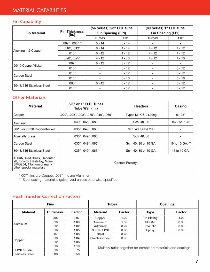
Fin Material Fin Thickness (in.)
(56 Series) 5/8” O.D. tube (89 Series) 1” O.D. tubeFin Spacing (FPI) Fin Spacing (FPI)
Turbex Flat Turbex Flat
Aluminum & Copper
.007”, .008” * 5 - 14 5 - 14 - -.010”, .012” 6 - 14 4 - 14 4 - 12 4 - 12
.016” 6 - 12 4 - 12 4 - 12 4 - 12.020”, .025” 4 - 12 4 - 10 4 - 12 4 - 10
90/10 Copper/Nickel.007” 6 - 12 5 - 12 - -.010” - 5 - 12 - 5 - 12
Carbon Steel.010” - 5 - 12 - 5 - 12.016” - 5 - 10 - 5 - 10
304 & 316 Stainless Steel.008” 6 - 12 5 - 12 - 5 - 12.010” - 5 - 12 - 5 - 12
Material 5/8” or 1” O.D. Tubes Tube Wall (in.) Headers Casing
Copper .020”, .025”, .028”, .035”, .049”, .065” Types M, K & L tubing 0.125”
Aluminum .049”, .065”, .083” Sch. 40, 80 .063” to .125”
90/10 or 70/30 Copper/Nickel .035”, .049”, .065” Sch. 40, Class 200 -
Admiralty Brass .035”, .049”, .065” Sch. 40, 80 -
Carbon Steel .035”, .049”, .065” Sch. 40, 80 or 10 GA. 16 to 10 GA. **
304 & 316 Stainless Steel .035”, .049”, .065” Sch. 40, 80 or 10 GA. 16 to 10 GA.
AL6XN, Red Brass, Capenter 20, Incoloy, Hastelloy, Monel, SMO254, Titanium or many other special materials
Contact Factory
*.007” fins are Copper, .008” fins are Aluminum** Steel casing material is galvanized unless otherwise specified
Heat Transfer Correction Factors
Fin Capability
Other Materials
Fins Tubes Coatings
Material Thickness Factor Material Factor Type Factor
Aluminum
.008 0.97 Copper 1.00 Tin Plating 1.00
.010 1.00 Aluminum 1.00 HDGAF 0.98
.012 1.02 Admiralty 0.99 Phenolic 0.98
.016 1.05 90/10 CU/NI 0.98 Epoxy 0.98
Copper
.007 1.00 Steel 0.98
.010 1.04 Stainless Steel 0.95
.012 1.06
.016 1.10CU/NI & Steel .010 0.75Stainless Steel .008 0.50
Multiply ratios together for combined materials and coatings.
MATERIAL CAPABILITIES

�
Assure maximum heat transfer and a strong structural fin and tube bundle that prevents coil failures due to tube sagging and tube vibrations. Coil cleaning is easier since a continuous path exists to clear debris.
Turbex FinConfigurated design for greater heat transfer and less surface.
Tube Sheets Extruded Hole/ Copper Ferrule InsertsOur standard tube sheets feature extruded tube holes to allow thermal
expansion and contraction of the tubes while preventing scoring with a raw sheet metal edge. Optionally, copper ferrules can be used, which provide a sacrificial bearing surface for the tubes to move against without contacting the sheet metal.
Staggered Tube DesignOur multiple row coils feature staggered tubes to maximize heat transfer efficiency.
Hairpin Tubes and Return BendsContinuous hairpin tubes offer maximum leak protection by eliminating joints within the circuit. When return bends must be used on our copper tube coils, they are sized one wall thickness heavier than the tube to provide superior erosion resistance.
Spun Tube EndsOur distributing steam coils feature tube ends which are spun down to close the tube completely without adding an end disc or cap. The tip of the spun end is then brazed to ensure closure thus eliminating concern of leakage.
Flat FinSmooth design offers lower air-side pressure drop and greater cleaning ability.
Heavy Gauge CasingsHeavy gauge galvanized or stainless steel casings are used to provide support while lifting and handling the coil. Bolts with nuts and lock washers or welding are used to construct the casing. Baffling and supports can be attached using self-tapping screws or optional duct mounting holes can be added to facilitate using bolts and nuts for installation.
Integrated Pitched CasingDRS Marlo’s steam and drainable fluid coils feature a heat transfer core that is pitched
within the casing to promote drainage even when the coil is
installed level.
Engineered Header SystemOur headers are designed to reduce the potential for leaks and provide connection locations that allow venting and draining at the highest and lowest points on the coil. Extruded tube holes increase surface contact for our braze joints, providing a strong bond with minimal potential for leaks.
CONSTRUCTION DETAILS

�
Circuiting Options
RIGHT HAND COIL - Opposite End Connections RIGHT HAND COIL - Same End Connections
Fluid 8W24-96-5608T-24.3-H-1.0-R-B 8 W 24 - 96 - 56 08 T - 24.3 - H - 1 - R - BCoils Typical Model Numbers (a) (b) (c) - (d) - (e) (f) (g) - (h) - (i) - (j) - (k) - (l)Steam Coils 2D16-60-5610F-10.2-H-B 2 D 16 - 60 - 56 10 F - 10.2 - H - B
Description(a) RowsinDirectionofAirflow (b) CoilType* (c) NumberofTubesHighinFaceofCoil (d) FinnedLength (e) TubeO.D.:56=5/8”;89=1.0” (f) FinSpacingInFinsPerInch(g) FinStyle:T(Turbex)orF(Flat)(h) FaceAreaofCoil(sqft)(i) AirflowDirection:H(horiz)orV(vert)(j) Serpentine(Circuit)(k) CoilHand:R(Right)orL(Left)(I) Joint construction: B (Brazed) or W (Welded)
Coil Model Nomenclature
* Coil Types W...........WaterE............EvaporatorP............Pitched&drainableJ,X,K....CleanableplugQ,Y,R....RemovableboxheaderA............AmmoniacoilC............CondensercoilD............5/8”tubedistributingsteamH............1.0”tubedistributingsteamS............5/8”tubeblaststeamV............1.0”tubeblaststeam
Coil Hand
Coil Hand is determined by position of outlet connection when facing entering air side.
Rows AvailableCircuits
1 Row/tubes, .25, .33, .50, 1.0
2 Row/tubes, .25, .33, .50, 1.0, 2.0
3 .25, .33, .50, .75, 1.0, 1.5, 3.0
4 .25, .33, .50, .667, 1.0, 2.0, 4.0
5 .25, .33, .50, .83, 1.0, 1.25
6 .25, .33, .50, .75, 1.0, 1.5, 2.0, 3.0
7 .25, .33, .50, 1.0
8 .25, .33, .50, 1.0, 1.33, 1.5, 2.0, 4.0
9 .25, .33, .50, .75, 1.0, 1.5, 3.0
10 .25, .33, .50, .83, 1.0, 1.25, 1.67, 2.0, 2.5
12 .25, .33, .50, .75, 1.0, 1.5, 2.0, 3.0, 4.0
16 .25, .33, .50, 1.0, 1.33, 1.5, 2.0, 4.0
Consult factory for additional row and circuit availability
Inlet
Outlet
Outlet
Inlet
Air Flow Air Flow

�0
Horizontal
When entering air temperature conditions require maximum heating, the dampers fully open and the upstream dampers direct all the entering air through the heating coil face.
Stratomizer Operation
Stratomizer dampered face and bypass coil provides a reliable method of preheating and tempering fresh outside air by maintaining full steam pressure or hot water flow to the coil at all times. By positioning dampers, proportioned volumes of air are either directed through the heating surface or bypassed to achieve the required discharge air temperature.
As the entering air temperature increases, the dampers are automatically repositioned, proportioning the correct amount of entering air through both the heating coil faces and bypasses.
When no heating is required, the dampers are closed and the upstream dampers direct all the entering air through the bypasses. The rear dampers enclose the heating cores minimizing temperature override.
Vertical
Stratomizer Features
• Vertical or horizontal tube orientation• 14-gauge galvanized or stainless steel casing• 16-gauge galvanized or stainless steel integral bypass baffles• Optional epoxy-painted casing or phenolic coatings• Downstream actuator mounting available for reduced width/height• Optional connection locations to simplify piping • Extruded anodized aluminum damper blades• Integral EPDM blade edge seals – silicone optional• “D” shaped damper shafts for positive torque without slipping• Stainless steel primary drive shafts • Oil-impregnated bronze bearings• Non-ferrous damper linkage – out of the air stream• Plate fin heat transfer cores available in custom materials• Distributing steam design on horizontal models• Floating header design • Three-year warranty
10°F 55°F
72°F
55°F
55°F
25°F
25°F
70°F
70°F
STRATOMIZER® CONSTRUCTION
Stratomizer®

��
BladesExtruded anodized aluminum damper blades with integral edge seals and “D”-shaped damper shafts to prevent slipping.
Casing14-gauge galvanized or stainless steel casing with 16-gauge integral bypass baffles.
Linkage Stainless steel and non-ferrous linkage located out of the air stream
Heating CorePlate fins provide excellent heat transfer while offering simple cleaning
ControlsPneumatic or electrical proportional actuators, including direct drive options
Floating HeaderVertical Stratomizers feature a floating header assembly designed to allow for thermal movement.
Stratomizer Model Number NomenclatureTypical Model : K72-56-2-10-T-R-0 Nomenclature: K 72 - 56 - 2 - 10 - T - R - 0 ↑ ↑ ↑ ↑ ↑ ↑ ↑ ↑ (a) (b) (c) (d) (e) (f) (g) (h)
Description(a) Model designation (A - F = Horizontal, G - N = Vertical orientation) (b) Finned length (c) Tube o.d. : 56 = 5/8”, 89=1.0” (d) Number of rows in direction of airflow (e) Fin Spacing in Fins Per Inch (f) Fin Style - T or F (Turbex or Flat) (g) Coil Hand - R or L - Right or Left (h) Serpentine (Circuit): 0 = Steam, .333, .375, .750, 1.00, 1.5 = Water
Horizontal Stratomizer NOMINAL FIN LENGTH 29 35 41 47 53 59 72 84 96 108 120
FACE SECTIONS
HEIGHT (INCHES)
WIDTH (INCHES)42 48 54 60 66 72 85 3/8 97 3/8 109 3/8 121 3/8 133 3/8
UNIT DESIGNATION
OUTLET AREA (FT2)NOM. WEIGHT (LBS)
A 3 27.004.57 5.53 6.49 7.45 8.41 9.36 11.50 13.42 15.33 17.25 19.17260 275 315 355 395 435 475 510 550 590 630
B 4 35.38-- 7.54 8.85 10.16 11.47 12.77 15.69 18.30 20.92 23.53 26.15-- 330 375 420 470 515 560 605 650 695 740
C 5 43.75-- 9.56 11.21 12.87 14.53 16.18 19.88 23.19 26.50 29.81 33.13-- 385 440 490 545 595 645 700 750 805 855
D 6 52.13-- 11.57 13.58 15.58 17.59 19.59 24.06 28.07 32.08 36.09 40.10-- 445 500 560 620 675 735 790 850 910 965
E 7 60.50-- 13.59 15.94 18.29 20.65 23.00 28.25 32.96 37.67 42.38 47.08-- 500 565 630 690 755 820 885 950 1015 1080
F 8 68.88-- 15.60 18.30 21.01 23.71 26.41 32.44 37.84 43.25 48.66 54.06-- 555 625 695 765 840 910 980 1050 1120 1190
Vertical Stratomizer NOMINAL FIN LENGTH 35 41 47 53 59 72 84 96 108
FACE SECTIONS
WIDTH (INCHES)
HEIGHT (INCHES)49.63 55.63 61.63 67.63 73.63 87.00 99.00 111.00 123.00
UNIT DESIGNATION
OUTLET AREA (FT2)NOM. WEIGHT (LBS)
G 4 35.887.66 8.99 10.32 11.65 12.98 15.94 18.89 -- --305 340 375 415 450 485 520 -- --
H 6 52.6311.69 13.72 15.74 17.77 19.80 24.31 28.36 32.42 --425 475 525 575 625 675 730 785 --
J 8 69.3815.72 18.44 21.17 23.89 26.62 32.69 38.14 43.58 49.03540 605 670 740 805 870 935 1000 1065
K 10 86.1319.75 23.17 26.59 30.01 33.43 41.06 47.91 54.75 61.59660 740 820 900 985 1065 1145 1225 1305
L 12 102.8823.77 27.89 32.01 36.13 40.25 49.44 57.68 65.92 74.16775 870 970 1065 1160 1255 1355 1455 1555
M 14 119.6327.80 32.62 37.44 42.26 47.07 57.81 67.45 77.08 86.72895 1005 1115 1230 1340 1450 1560 1670 1780
N 16 136.3831.83 37.35 42.86 48.38 53.89 66.19 77.22 88.25 99.281010 1135 1265 1390 1515 1645 1770 1895 2020
Subtract 6.625” for water coils

��
Contact Your Local Representative
Coil & Stratomizer Software
Also available online at www.marlocoil.com or on CD-Rom by contacting your local representative.
• Performance Selection & Ratings• Drawing Program• Available as a Library File for Integration into Host Programs• WindowsTM-Based Software
3 Year WarrantyDRS Marlo products are thoroughly tested at the factory and warranted against defective workmanship and materials for a period of thirty six (36) months from date of shipment. If a defect should develop within the warranty period, DRS Marlo will repair or replace, at our option, the defective item. Transportation, or removal and installation of repaired or replaced items, are not covered by this warranty. This warranty does not apply to fan belts, filters, gaskets, and other maintenance items, or buyer/user furnished components. The warranty is void if the product is modified without DRS Marlo’s written approval. No agent, salesman, or other representative, unless authorized in writing by an officer of the company, has any authority to waive, alter or enlarge the terms of this warranty.
DRS Marlo’s warranty extends to commonly supplied purchased components such as fans, electric motors, actuators, dampers, spring isolators, etc., even when the Original Equipment Manufacturer’s (OEM) warranty has expired.
DRS Marlo products purchased through OEM are warranted for a term not to exceed the warranty term of the OEM equipment or system. Additional restrictions may apply. Consult your OEM vendor for specific information regarding warranty.
MarloMetrics(TM)
DRS MARLO COIL6060 Hwy PPHigh Ridge, MO 63049www.marlocoil.com
636.677.6600Fax 636.677.1203www.drs.com
01/08
Related Documents