Antriebs-und Steuerungstechnik 101 Edition Operating and Display Units Control Terminal BT2 / BT5N / BT20N Programming (Part 1 and Part 2)

Welcome message from author
This document is posted to help you gain knowledge. Please leave a comment to let me know what you think about it! Share it to your friends and learn new things together.
Transcript

Antriebs-und Steuerungstechnik
101Edition
Operating and Display Units
Control Terminal BT2 / BT5N / BT20NProgramming (Part 1 and Part 2)
© 2000
by Robert Bosch GmbH, Erbach / GermanyAll rights reserved, including applications for protective rights.
Reproduction or distribution by any means subject to our prior written permission.
Discretionary charge 80,- DM
Operating and Display Units
Control Terminal BT2 / BT5N / BT20NProgramming (Part 1 and Part 2)1070 083 630-101 (00.05) GB
Software release: 1.3

Version 1.3 issued 17th April 2000
Programming
TesiMod
Operating Terminals

1070 083 630-101 (17.04.00)
Overall Table of Contents2
The information contained in this manual is subject to change without prior notice, thus, theSütron electronic GmbH assumes no obligation.No part of this manual may be dublicated, transmitted or reproduced in any form or by any means,electronic or mechanical, including photocopying, or be stored in any information storage andretrieval system, witout prior permission in writing from the Sütron electronic GmbH.
First edition Version 1.0 issued 1st May 1996Enlarged edition Version 1.1 issued 16th September 1997Revised edition Version 1.2 issued 17th November 1998Revised edition Version 1.3 issued 17th April 2000
Overall Table of Contents 3
1070 083 630-101 (17.04.00)
/000
-010
8/B
osch
_T_e
ng_V
13_3
0000
00Q
K0
1 TesiMod Operating Concept ......................................... 1-3
1.1 Operating Terminals ............................................................. 1-31.1.1 Loadable Protocol Drivers ............................................................... 1-31.1.2 Networking the Terminals ............................................................... 1-31.1.3 Programming Unit Interface ............................................................. 1-41.1.4 What is TesiMod and which functions does it provide? ....................... 1-41.1.5 Operating Modes .......................................................................... 1-41.1.5.1 Transparent-Mode ..................................................................... 1-41.1.5.2 Standard-Mode ......................................................................... 1-41.1.6 Costomized Definition .................................................................... 1-51.1.7 Storing the Customized Definition .................................................... 1-51.1.8 Addressing of the Variables ............................................................ 1-61.1.9 Data Release................................................................................. 1-61.1.10 Password Protection ....................................................................... 1-61.1.11 Editors ......................................................................................... 1-71.1.12 Help Texts .................................................................................... 1-71.1.13 Function Keys ............................................................................... 1-81.1.14 Soft Keys ...................................................................................... 1-81.1.15 Variables ..................................................................................... 1-81.1.16 Graphic ....................................................................................... 1-91.1.17 Recipes and Data Records .............................................................. 1-91.1.18 Messages ................................................................................... 1-101.1.19 System Messages......................................................................... 1-111.1.20 Programming System ................................................................... 1-11
1.2 Common Features ...............................................................1-121.2.1 Hardware .................................................................................. 1-121.2.2 Software .................................................................................... 1-12
2 Operating Modes ........................................................ 2-3
2.1 Setting the Operating Mode .................................................. 2-3
3 TesiMod Standard Mode.............................................. 3-7
3.1 Setting the Operating Mode .................................................. 3-7
3.2 Startup Process .................................................................... 3-83.2.1 Startup Process without a Valid User Description ................................ 3-8
3.3 Communication in the Standard Mode ................................... 3-9
3.4 Operating Concept ............................................................... 3-93.4.1 Hierarchical Mask Structure in TSdos................................................ 3-93.4.2 Mask Structure in TSwin ............................................................... 3-10

1070 083 630-101 (17.04.00)
Overall Table of Contents4
3.4.3 External Mask Selection................................................................ 3-113.4.4 Password Protection, Access Authorization ...................................... 3-113.4.4.1 Reactivating the Password Protection .......................................... 3-143.4.4.2 Password Management ............................................................ 3-143.4.4.3 Password Mask and Password Functionality ................................ 3-14
3.5 Masks .................................................................................3-153.5.1 Mask Parameters ......................................................................... 3-153.5.2 System Masks ............................................................................. 3-153.5.2.1 Setup Mask ............................................................................ 3-163.5.2.1.1 Password Protection - Setup Mask .......................................... 3-163.5.2.1.2 Function Without the Setup Mask .......................................... 3-173.5.2.2 Startup Mask .......................................................................... 3-173.5.2.3 Password Mask ....................................................................... 3-173.5.2.4 Node Mask, I/O Mask with Selection Text .................................. 3-183.5.2.5 I/O Mask .............................................................................. 3-193.5.2.6 Message Mask, Mask with a Message Field for Serial Messages .... 3-203.5.2.7 Status Message Mask ............................................................... 3-22
3.6 Variables ............................................................................3-233.6.1 Output Variables ......................................................................... 3-243.6.1.1 "Decimal Number" Representation ............................................. 3-273.6.1.1.1 "Standard" Variable Type ..................................................... 3-273.6.1.1.2 "Timer" Variable Type .......................................................... 3-273.6.1.1.3 "Counter" Variable Type ...................................................... 3-283.6.1.1.4 "BCD-Number" Variable Type ............................................... 3-293.6.1.2 "Alphanumerical" Representation .............................................. 3-293.6.1.3 "Selection Text" (Coded Text) Representation ............................... 3-293.6.1.4 "Selection Image" (Coded Image) Representation ......................... 3-303.6.1.5 "Floating Point Number" Representation ..................................... 3-313.6.1.6 "Hexadecimal Number" Representation ...................................... 3-313.6.1.7 "Binary Number" Representation ............................................... 3-323.6.1.8 Bar Representation .................................................................. 3-323.6.1.9 Curve Representation (Trendline) ................................................ 3-343.6.1.10 Selection Field (TSdos) Representation ........................................ 3-353.6.2 Input Variables ............................................................................ 3-353.6.3 System Variables ......................................................................... 3-383.6.3.1 Basic Functions ....................................................................... 3-383.6.3.2 Communication Area X2 .......................................................... 3-413.6.3.3 Error Statistics Interface X2 ....................................................... 3-433.6.3.4 Communication Area X3 .......................................................... 3-443.6.3.5 Real-Time Clock ...................................................................... 3-463.6.3.6 Serial Message System ............................................................. 3-483.6.3.7 Parallel Message System ........................................................... 3-503.6.3.8 Printer Control ........................................................................ 3-523.6.3.9 Menu Control / Keys ............................................................... 3-543.6.3.10 Password ............................................................................... 3-62
Overall Table of Contents 5
1070 083 630-101 (17.04.00)
/000
-010
8/B
osch
_T_e
ng_V
13_3
0000
00Q
K0
3.6.3.11 Recipes .................................................................................. 3-633.6.3.12 Running Time Meter ................................................................ 3-683.6.3.13 Loop-Through Operation .......................................................... 3-693.6.3.14 Loadable Font ......................................................................... 3-693.6.3.15 Maintenance .......................................................................... 3-703.6.3.16 Editors ................................................................................... 3-713.6.3.17 Help ...................................................................................... 3-713.6.4 Editors ....................................................................................... 3-723.6.4.1 Decimal Number Editor ............................................................ 3-743.6.4.2 Floating Point Number Editor .................................................... 3-763.6.4.3 Hexadecimal Editor ................................................................. 3-763.6.4.4 Alphanumerical Editor ............................................................. 3-763.6.4.5 Selection Text Editor (Coded Text) .............................................. 3-773.6.4.6 Selection Image Editor (Coded Image) ........................................ 3-773.6.4.7 Table Editor ............................................................................ 3-773.6.5 External Data Release................................................................... 3-803.6.6 PLC-Handshake ........................................................................... 3-813.6.7 Refreshing One-Time Output Data .................................................. 3-823.6.8 Modified Data ............................................................................ 3-823.6.8.1 Input Plausibility Check ............................................................ 3-83
3.7 Graphics .............................................................................3-843.7.1 Graphical Objects (TSdos) ............................................................ 3-843.7.2 Images (TSwin) ............................................................................ 3-843.7.3 Graphics on Operating Terminals .................................................. 3-853.7.3.1 Background Images ................................................................. 3-85
3.8 Recipes ...............................................................................3-863.8.1 Structure of a Recipe .................................................................... 3-873.8.2 Processing Recipes and Data Sets .................................................. 3-883.8.2.1 Selecting a Recipe ................................................................... 3-883.8.2.2 Selecting a Data Set ................................................................ 3-883.8.2.3 Copying a Data Set ................................................................. 3-883.8.2.4 Deleting a Data Set .................................................................. 3-893.8.2.5 Modifying a Data Set ............................................................... 3-893.8.3 Data Set Transfer to / from a Controller .......................................... 3-903.8.3.1 Transfer to a Controller ............................................................ 3-903.8.3.2 Transfer from a Controller ......................................................... 3-913.8.4 Transferring Data Sets to / from a PC ............................................. 3-923.8.4.1 Transfer to a PC ...................................................................... 3-933.8.4.2 Transfer from a PC .................................................................. 3-933.8.4.3 Structure of a Data Set File ....................................................... 3-933.8.5 Printing Data Sets ........................................................................ 3-953.8.6 Memory Requirements for Storing Data Sets ..................................... 3-96
3.9 TesiMod Message System ....................................................3-973.9.1 Internal Messages ........................................................................ 3-97
1070 083 630-101 (17.04.00)
Overall Table of Contents6
3.9.1.1 System Messages .................................................................... 3-973.9.1.1.1 Suppressing the Display of System Messages ......................... 3-1023.9.1.2 Error Messages ..................................................................... 3-1023.9.2 External Messages ..................................................................... 3-1073.9.2.1 Structure of an External Message ............................................. 3-1083.9.2.1.1 Assigning Message Numbers .............................................. 3-1083.9.2.1.2 Message Buffer Size .......................................................... 3-1083.9.2.1.3 Message Texts, Variables ................................................... 3-1083.9.2.1.4 Sorting Messages .............................................................. 3-1093.9.2.1.5 Message Priority for Direct Display ...................................... 3-1093.9.2.1.6 Printing the Message Memory ............................................. 3-1103.9.2.2 Message Mask, Status Message Mask ...................................... 3-1103.9.2.2.1 Direct Selection of the Message Mask .................................. 3-1113.9.2.2.2 Output Formats for Messages .............................................. 3-1113.9.2.2.3 Zooming Messages ........................................................... 3-1123.9.2.2.4 Acknowledging Messages .................................................. 3-1133.9.2.3 Serial Message System ........................................................... 3-1133.9.2.3.1 Full-Page Message Output ................................................... 3-1133.9.2.3.2 Messages Directly to a Logging Printer ................................. 3-1143.9.2.3.3 Erasing the Message Memory Externally ............................... 3-1143.9.2.3.4 Information about the Serial Message System ........................ 3-1143.9.2.4 Parallel Message System (Status Messages) ................................ 3-1153.9.2.4.1 Number of Bytes for Status Messages ................................... 3-1153.9.2.4.2 Image of the Status Messages .............................................. 3-1163.9.2.4.3 Time-Controlled Transfer of the Status Message ...................... 3-1173.9.2.4.4 Event-Controlled Transfer of the Status Message ..................... 3-117
3.10 Help System ......................................................................3-1173.10.1 Default Help Text ....................................................................... 3-1173.10.2 Help Text For Masks .................................................................. 3-1183.10.2.1 Help Text for the Message Mask .............................................. 3-1183.10.3 Help Text For Variables .............................................................. 3-118
3.11 Function Keys....................................................................3-1183.11.1 Direct Selector Keys ................................................................... 3-1183.11.2 Function Keys of the Controller .................................................... 3-1193.11.3 Soft Keys .................................................................................. 3-1193.11.3.1 Reaction Time of Function and Soft Keys .................................. 3-1203.11.3.2 Control Keys as Function Keys ................................................ 3-1203.11.4 Function Keys Controlling Parallel Outputs .................................... 3-1203.11.5 Status LEDs in the Function Keys .................................................. 3-120
3.12 System Parameters............................................................3-1213.12.1 System Parameters: General Parameters ........................................ 3-1223.12.2 System Parameters: Poll Area ...................................................... 3-1223.12.3 System Parameters: Terminal Clock .............................................. 3-1223.12.4 System Parameters: Running Time Meter ....................................... 3-122

Overall Table of Contents 7
1070 083 630-101 (17.04.00)
/000
-010
8/B
osch
_T_e
ng_V
13_3
0000
00Q
K0
3.12.5 System Parameters: Message System ............................................ 3-1223.12.6 System Parameters: Variant Buffer ................................................ 3-1233.12.7 System Parameters: Password Management ................................... 3-1233.12.8 System Parameters: Printer Interface ............................................. 3-1233.12.9 System Parameters: Gateway ...................................................... 3-1233.12.10 System Parameters: Data Set Transfer ............................................ 3-1233.12.11 System Parameters: Parallel Outputs ............................................. 3-123
3.13 Version Number ................................................................3-124
3.14 Running Time Meter ..........................................................3-124
3.15 Parallel Outputs ................................................................ 3-125
3.16 Screen Saver .....................................................................3-126
3.17 Image of the Mask Number ...............................................3-126
3.18 Image of the Mode Selector Switch .................................... 3-126
3.19 Terminal Clock ..................................................................3-1263.19.1 Image of Date and Time ............................................................. 3-127
3.20 Read Coordination Byte .....................................................3-1283.20.1 Editing Request Bit (Bit "EA") ....................................................... 3-1283.20.2 Editing Status Bit (Bit "EZ") .......................................................... 3-1283.20.3 Refresh Request Bit (Bit "RA") ..................................................... 3-1293.20.4 Liveness Flag (Bit "LM") ............................................................. 3-1293.20.5 Data Set Download Active (Bit "DDA") ......................................... 3-129
3.21 Write Coordination Byte .....................................................3-1303.21.1 External Data Release (Bit "ED") ................................................... 3-1303.21.2 Refresh Acknowledgement (Bit "RQ") ........................................... 3-1303.21.3 Resetting the Password ............................................................... 3-1303.21.4 Liveness Flag (Bit "LM") .............................................................. 3-1313.21.5 Data Set Download Release (Bit "DDF") ....................................... 3-131
3.22 Cyclic Poll Area .................................................................3-1323.22.1 Byte-Oriented ............................................................................ 3-1323.22.2 Word-Oriented ......................................................................... 3-1343.22.3 Image of the LEDs ...................................................................... 3-1343.22.4 Serial Message Channel ............................................................. 3-1353.22.5 Polling Time.............................................................................. 3-1353.22.6 Size of the Poll Area .................................................................. 3-135
3.23 Control Codes ....................................................................3-1363.23.1 Triggering Data Set Printouts ....................................................... 3-1363.23.2 Setting the Clock in the Operating Terminal .................................. 3-136

1070 083 630-101 (17.04.00)
Overall Table of Contents8
3.23.3 Transferring Data Sets from the Controller to the Terminal ................ 3-1363.23.4 Transferring Data Sets from the Terminal to the Controller ................ 3-1363.23.5 Transferring Data Sets from the Controller to the Terminal (Individually)3-1373.23.6 Refreshing the Message System ................................................... 3-137
3.24 Cyclic Variables .................................................................3-137
3.25 Interface Parameters X2, X3 ..............................................3-137
3.26 Variable Definition ............................................................3-1383.26.1 Variable Formats (TSdos) ............................................................ 3-1383.26.2 Variable List .............................................................................. 3-138
3.27 Application Programming ..................................................3-1403.27.1 Configuring the System .............................................................. 3-1403.27.2 TSdos and TSwin Programming Systems ....................................... 3-1413.27.3 Getting Started with Programming ............................................... 3-1443.27.3.1 Project Description ................................................................ 3-1443.27.3.2 Multilingual Projects ............................................................... 3-1443.27.3.3 Variants of a Project .............................................................. 3-1453.27.4 Project Documentation ............................................................... 3-1453.27.4.1 TSdos Print Files .................................................................... 3-1453.27.4.2 Hard Copies of the Masks in TSdos ......................................... 3-1463.27.4.3 Creating TSwin Documentation ............................................... 3-1463.27.5 Project Back-up ......................................................................... 3-1463.27.6 Optimizing the Transmission Rate ................................................ 3-146
3.28 Downloading the User Description ..................................... 3-1473.28.1 Downloading with Windows ...................................................... 3-1493.28.2 Application Memory .................................................................. 3-1493.28.3 Loading a User Description ......................................................... 3-1493.28.4 Activating the Download Function using the Software ..................... 3-1503.28.5 Activating the Download Function using the Hardware ................... 3-1503.28.6 Automatic Download Function..................................................... 3-1513.28.7 Download Cable ....................................................................... 3-152
3.29 Simulation without the Controller .......................................3-153
4 TesiMod Transparent Mode ......................................... 4-3
4.1 Setting the Operating Mode .................................................. 4-3
4.2 Start-up Processes ................................................................ 4-4
4.3 Communication in the Transparent Mode............................... 4-54.3.1 Interface Parameters ....................................................................... 4-54.3.2 Receive Buffer for the Communication Interface .................................. 4-5

Overall Table of Contents 9
1070 083 630-101 (17.04.00)
/000
-010
8/B
osch
_T_e
ng_V
13_3
0000
00Q
K0
4.4 Function Setup Menu ............................................................ 4-54.4.1 Adaptation of the Parameters in the Setup Menu ................................ 4-54.4.2 Example of a Properly Performed Modification! ................................. 4-64.4.3 Setup Menu .................................................................................. 4-7
4.5 Display ................................................................................ 4-84.5.1 Character Set, Character Attributes .................................................. 4-8
4.6 Keys .................................................................................... 4-84.6.1 Key Codes for the Terminals ............................................................ 4-9
4.7 Interface Control Characters .................................................4-104.7.1 LED Codes for the Operating Terminals .......................................... 4-114.7.2 Control Sequences for the Operating Terminals ................................ 4-11
4.8 Error Messages ...................................................................4-14
5 Controller and Bus Interfacing ..................................... 5-1
5.1 TesiMod - 3964/RK512 Interfacing ......................................5.1-35.1.1 General Information ................................................................... 5.1-35.1.2 Technical Description .................................................................. 5.1-35.1.3 Parameters Interface SER1 ........................................................... 5.1-45.1.3.1 Interface Parameters of the Communications Module ................... 5.1-45.1.3.2 PLC Configuration .................................................................. 5.1-45.1.4 Data Type Structure ..................................................................... 5.1-55.1.4.1 Data Types ............................................................................ 5.1-65.1.4.2 Special Simatic-Data Formats ................................................... 5.1-65.1.5 Additional Functions ................................................................... 5.1-75.1.6 Physical Interfacing..................................................................... 5.1-85.1.6.1 Connecting Cable TTY / 20 mA - Siemens CP523/525 ............ 5.1-105.1.6.2 Connecting Cable Universal Interface TTY / 20 mA -
Siemens CP523/525 ........................................................... 5.1-115.1.6.3 Connecting Cable RS232 - Siemens CP523/525 ..................... 5.1-125.1.6.4 Connecting Cable Universal Interface RS232c -
Siemens CP523/525 ........................................................... 5.1-135.1.6.5 Connecting Cable RS485 - Siemens CP524/525 ..................... 5.1-145.1.6.6 Connecting Cable Universal Interface RS485 -
Siemens CP524/525 ........................................................... 5.1-155.1.6.7 Connecting Cable RS485 - Helmholz SAS 523/525 ................ 5.1-165.1.6.8 Connecting Cable Universal Interface RS485 -
Helmholz SAS 523/525 ....................................................... 5.1-175.1.6.9 Connecting Cable RS485 - VIPA BGM79-43 ........................... 5.1-185.1.6.10 Connecting Cable Universal Interface RS485 - VIPA BGM79-43 5.1-195.1.6.11 Connecting Cable TTY / 20 mA - EBERLE PLS 514 - K43 .......... 5.1-205.1.6.12 Connecting Cable Universal Interface TTY / 20 mA -
EBERLE PLS 514 - K43 .......................................................... 5.1-21
1070 083 630-101 (17.04.00)
Overall Table of Contents10
5.1.6.13 Connecting Cable RS232 - EBERLE PLS 514 - K43 ................... 5.1-225.1.6.14 Connecting Cable Universal Interface RS232 -
EBERLE PLS 514 - K43 .......................................................... 5.1-235.1.7 3964 Procedure ...................................................................... 5.1-245.1.7.1 Block Check BCC ................................................................. 5.1-245.1.7.2 Logical Part of the Procedure 3964, RK512 ............................. 5.1-245.1.8 Message Request of Data ........................................................... 5.1-255.1.8.1 Structure Message Header (10 bytes) Request of Data ................ 5.1-255.1.8.2 Data Specification in the Message Header ............................... 5.1-265.1.8.3 Coordination Flag ................................................................ 5.1-265.1.8.4 Structure 4-Byte-Sized Response Message ................................. 5.1-275.1.9 Message Transmission of Data.................................................... 5.1-275.1.9.1 Structure Message Header (10bytes) Transmission of Data .......... 5.1-285.1.9.2 Special Features of the Protocol 3964R ................................... 5.1-285.1.9.3 Assignment of Bytes 1-4 ........................................................ 5.1-295.1.10 Protocol 3964R - Restrictions ...................................................... 5.1-295.1.11 Function Block for Siemens 115 U .............................................. 5.1-305.1.12 Application Example for CP525 in 115U .................................... 5.1-305.1.13 Initialization for module K43 in EBERLE PLS514............................ 5.1-315.1.14 Error Messages ........................................................................ 5.1-39
5.2 TesiMod - Bosch PU-Interfacing via BUEP19 .........................5.2-35.2.1 General Information ................................................................... 5.2-35.2.2 Technical Description .................................................................. 5.2-45.2.3 Parameters Interface X2 for PU-Interfacing ...................................... 5.2-45.2.3.1 Protocol Parameters Target Module............................................ 5.2-45.2.3.2 Protocol Parameter Block Check ............................................... 5.2-45.2.3.3 Protocol Parameter Coordination Flag ....................................... 5.2-55.2.4 Data Type Structure ..................................................................... 5.2-55.2.4.1 Data Types ............................................................................ 5.2-55.2.5 Additional Functions ................................................................... 5.2-65.2.6 Physical Interfacing..................................................................... 5.2-75.2.6.1 Connecting Cable TesiMod TTY / 20 mA - Bosch PU .................. 5.2-85.2.6.2 Connecting Cable Universal Interface TTY / 20 mA - Bosch PU..... 5.2-95.2.7 Error Messages ........................................................................ 5.2-10
5.3 TesiMod - DIN-Meßbus .......................................................5.3-35.3.1 TesiMod - DIN-Meßbus-Master ...................................................... 5.3-35.3.1.1 Process Computer as Bus Master ............................................... 5.3-35.3.1.2 Gateway as Bus Master ........................................................... 5.3-35.3.1.3 Poll Area .............................................................................. 5.3-45.3.1.4 Cache Function for Read-Only Data .......................................... 5.3-65.3.1.5 Status of the Network .............................................................. 5.3-75.3.1.6 Parameters Interface SER1 for PLC-Interfacing ............................. 5.3-75.3.1.7 Parameters Interface SER2 for DIN-Meßbus - Master .................... 5.3-75.3.1.7.1 Minimal Slave Number ....................................................... 5.3-85.3.1.7.2 Maximal Slave Number ...................................................... 5.3-8

Overall Table of Contents 11
1070 083 630-101 (17.04.00)
/000
-010
8/B
osch
_T_e
ng_V
13_3
0000
00Q
K0
5.3.1.7.3 Test Cycle for the Synchronization ........................................ 5.3-85.3.1.7.4 Cache Size ....................................................................... 5.3-85.3.1.7.5 Cache Address .................................................................. 5.3-85.3.1.7.6 Intervals for the Cache Update ............................................. 5.3-85.3.1.7.7 Network Status Address ...................................................... 5.3-85.3.1.8 Additional Error Messages ....................................................... 5.3-95.3.2 TesiMod DIN-Meßbus - Slave ...................................................... 5.3-105.3.2.1 General Information ............................................................. 5.3-105.3.2.2 Technical Description............................................................ 5.3-105.3.2.3 Parameters Interface SER1 for DIN-Meßbus -Slave ..................... 5.3-115.3.2.3.1 Timeout for Order-Reply .................................................... 5.3-115.3.2.3.2 Timeout for Cache-Update ................................................. 5.3-115.3.2.3.3 Slave Number ................................................................. 5.3-125.3.2.4 Data Types .......................................................................... 5.3-125.3.2.5 Additional Functions ............................................................. 5.3-125.3.2.6 Physical Interfacing .............................................................. 5.3-125.3.2.7 Bus Cable Gateway - Slave - Terminals .................................... 5.3-135.3.2.8 Error Messages .................................................................... 5.3-14
5.4 TesiMod - Bosch Interfacing via BUEP19E .............................5.4-35.4.1 General Information ................................................................... 5.4-35.4.2 Technical Description .................................................................. 5.4-45.4.3 Parameters Interface SER ............................................................. 5.4-45.4.3.1 Protocol Parameter Target Module ............................................. 5.4-45.4.3.2 Protocol Parameter Block Check ............................................... 5.4-45.4.3.3 Protocol Parameter Coordination Flag ....................................... 5.4-45.4.4 Data Type Structure ..................................................................... 5.4-45.4.4.1 Data Types ............................................................................ 5.4-55.4.5 Additional Functions ................................................................... 5.4-65.4.6 Physical Interfacing..................................................................... 5.4-65.4.6.1 Connecting Cable TTY / 20 mA - Bosch PLC ............................ 5.4-75.4.6.2 Connecting Cable Universal Interface TTY / 20 mA - Bosch PLC ... 5.4-85.4.6.3 Connecting Cable Universal Interface RS232 - Bosch CL150 ........ 5.4-95.4.6.4 Connecting Cable TTY / 20 mA - Bosch CL151 ....................... 5.4-105.4.6.5 Connecting Cable Universal Interface TTY / 20 mA -
Bosch CL151 ...................................................................... 5.4-115.4.7 Error Messages ........................................................................ 5.4-12
5.5 TesiMod - Profibus-DP - Interfacing .....................................5.5-35.5.1 Technical Description .................................................................. 5.5-35.5.2 Specification within the Profibus-DP .............................................. 5.5-35.5.3 Data Profile ............................................................................... 5.5-45.5.3.1 Structure of the Profile ............................................................. 5.5-45.5.3.2 Control Bytes ......................................................................... 5.5-55.5.3.3 User Data .............................................................................. 5.5-65.5.3.3.1 Reading and Writing Bytes .................................................. 5.5-65.5.3.3.2 Reading Bits ...................................................................... 5.5-6
1070 083 630-101 (17.04.00)
Overall Table of Contents12
5.5.3.3.3 Writing Bits ....................................................................... 5.5-65.5.4 Tasks of the Control Program........................................................ 5.5-75.5.5 Connection to Siemens-PLC.......................................................... 5.5-75.5.5.1 Parameterization of the IM308B ............................................... 5.5-75.5.5.1.1 Data Consistency ............................................................... 5.5-75.5.5.2 PLC Program ......................................................................... 5.5-85.5.5.2.1 FB110 - Evaluation Block .................................................... 5.5-85.5.5.2.2 FB111 - Reading from Data Block ....................................... 5.5-105.5.5.2.3 FB112 - Writing to Data Block ........................................... 5.5-105.5.5.3 Protocol Parameters .............................................................. 5.5-105.5.5.4 Programming the variables .................................................... 5.5-105.5.6 Connection to Bosch-PLC ........................................................... 5.5-115.5.6.1 Parameterization of the BM_DP12 .......................................... 5.5-115.5.6.2 PLC Program ....................................................................... 5.5-115.5.6.2.1 BT_MAIN - Evaluation Block .............................................. 5.5-125.5.6.2.2 BT_READ - Reading from Data Block .................................. 5.5-135.5.6.2.3 BT_WRITE - Writing to Data Block ...................................... 5.5-145.5.6.3 Protocol Parameters .............................................................. 5.5-145.5.6.4 Programming the variables .................................................... 5.5-145.5.7 Protocol Parameters .................................................................. 5.5-155.5.7.1 Response Timeout ................................................................. 5.5-155.5.7.2 Communication Set-up Delay ................................................. 5.5-155.5.7.3 Station Number ................................................................... 5.5-155.5.7.4 Telegram Length ................................................................... 5.5-155.5.7.5 Floating Point Format ............................................................ 5.5-155.5.7.6 Byte-Order for Word and Double Word .................................. 5.5-155.5.7.7 Address Width .................................................................... 5.5-165.5.8 Additional Functions ................................................................. 5.5-165.5.9 Physical Interfacing................................................................... 5.5-175.5.9.1 Connecting Cable ................................................................ 5.5-185.5.10 Error Messages ........................................................................ 5.5-195.5.11 Device-Master-Data-File .............................................................. 5.5-21
6 Index .......................................................................... 6-1
A Appendix A................................................................. 6-1
A.1 List of Accessories ................................................................. 6-1
TesiMod Operating Concept 1-1
1070 083 630-101 (17.04.00)
/000
-010
8/B
osch
_T_e
ng_V
13_3
0010
00Q
K0
Table of Contents
1 TesiMod Operating Concept ......................................... 1-3
1.1 Operating Terminals ............................................................. 1-31.1.1 Loadable Protocol Drivers ............................................................... 1-31.1.2 Networking the Terminals ............................................................... 1-31.1.3 Programming Unit Interface ............................................................. 1-41.1.4 What is TesiMod and which functions does it provide? ....................... 1-41.1.5 Operating Modes .......................................................................... 1-41.1.5.1 Transparent-Mode ..................................................................... 1-41.1.5.2 Standard-Mode ......................................................................... 1-41.1.6 Costomized Definition .................................................................... 1-51.1.7 Storing the Customized Definition .................................................... 1-51.1.8 Addressing of the Variables ............................................................ 1-61.1.9 Data Release................................................................................. 1-61.1.10 Password Protection ....................................................................... 1-61.1.11 Editors ......................................................................................... 1-71.1.12 Help Texts .................................................................................... 1-71.1.13 Function Keys ............................................................................... 1-81.1.14 Soft Keys ...................................................................................... 1-81.1.15 Variables ..................................................................................... 1-81.1.16 Graphic ....................................................................................... 1-91.1.17 Recipes and Data Records .............................................................. 1-91.1.18 Messages ................................................................................... 1-101.1.19 System Messages......................................................................... 1-111.1.20 Programming System ................................................................... 1-11
1.2 Common Features ...............................................................1-121.2.1 Hardware .................................................................................. 1-121.2.2 Software .................................................................................... 1-12

1070 083 630-101 (17.04.00)
TesiMod Operating Concept1-2

TesiMod Operating Concept 1-3
1070 083 630-101 (17.04.00)
/000
-010
8/B
osch
_T_e
ng_V
13_3
0010
00Q
K0
1 TesiMod Operating Concept
1.1 Operating Terminals
All of the terminals offer the same functions, they differ only in design, display size and numberof function keys. The aluminium front panel and zinc-coated plate steel casing ensure noiseimmunity, making the terminals suitable for employment even in a harsh industrial environment.All of the terminals are provided with an IP65 degree of protection on account of the sealed frontmounting.
Extensive tests have proven the terminals extremely reliable and ideal for industrial applications.Tests such as mechanical strength tests, electromagnetic compatibility tests, temperature andclimate tests ensure a high quality of the products.
All terminals are equipped with highly readable, multiple-line, backlit or luminescent displays (upto 16 lines and 42 characters) and are thus suitable for a wide scope of applications. The keyboardis protected by a front foil and is provided with mechanical short-stroke keys with defined tactiletouch. Function keys with integrated LEDs eliminate the need for additional external switches andpilot lamps. All function keys are supplied with blank identification strips for individual labelling.
The communication with the terminals is supported by standardized interfaces. A version withPROFIBUS-DP interface is available for each terminal.
1.1.1 Loadable Protocol Drivers
With a standard terminal it is possible to exchange data with any of the PLCs which are currentlysupported and which is not a fieldbus protocol. The interface standards TTY / 20 mA Current Loop,RS485 and RS232c are combined in one connector.For fieldbus connection you must order a terminal with the special interface PROFIBUS-DP.
The applications of all terminals include output, input and modification of data in PLCs,microprocessor-based controllers, process computers or PCs.
Communication occurs either by means of the controller-specific protocol or a standard protocol.A controller-specific protocol ensures access to all system and user data as well as inputs and outputs,flags, timers, counters etc. In case of connections to PLCs, the terminals are, in general, connectedvia the programming unit interface.
1.1.2 Networking the Terminals
Multipoint connections are supported, provided the transmission protocols allow this method ofconnection.With some protocols it is possible to address multiple CPUs on the network or in themounting rack. Only fieldbus connection allow multiple operating terminals to be connected to onePLC.

1070 083 630-101 (17.04.00)
TesiMod Operating Concept1-4
The DIN-Meßbus in accordance with the DIN 66348 offers a more cost-effective solution for suchrequirements. Multipoint connections of this type are configured such that one operating terminaloperates as bus master and as gateway to the controller. All other operating terminals operate asDIN-Meßbus slave stations. Addressing of the data occurs in accordance with the syntax of theconnected controller. The bus protocol allows access to all standard functions of the TesiMod.Appropriate measures ensure a high efficiency between the two protocols used. Every operatingterminal can be operated as bus master. The interface X3 of terminals operating as bus master is,however, not available for connecting a printer but is required for connecting the bus (RS485interface). This connection can be carried out in several different ways, depending on the terminaltype.
1.1.3 Programming Unit Interface
Since hardware and protocol software are already available in every PLC for the programming unit,there is no need for an additional communications processor, thus providing for a low-costconnection of the terminal to the PLC. The application programmer is not required to develop andinstall communications software for his PLC as would be the case with a communications module.The protocol software is integrated into the PLC's and terminal's operating system.
1.1.4 What is TesiMod and which functions does it provide?
With TesiMod, the Sütron electronics company has designed an operating concept offering everytechnical feature of an advanced operating technology. It is a standardized and functionally uniformoperating concept which completely frees the connected controller from operating tasks such asoperator guidance and data display. In standard mode, decoding of the keys or menu control throughthe connected controller is not required.
1.1.5 Operating Modes
Both modes of operation, the standard as well as the transparent mode of operation, are availablein every TesiMod operating terminal.
1.1.5.1 Transparent-Mode
TesiMod terminals operating in the transparent mode represent full-size ANSI-terminals. Every keygenerates a press and release code which is transmitted via the interface. ESC-sequences are usedfor controlling the display and LEDs. Various character sets and attributes are available dependingon the type of display.
1.1.5.2 Standard-Mode
The full performance of the terminal is reached in standard mode. The key decoding or the menucontrol with the connected PLC is not required in standard mode. Without much control requirementa operator guidance with password administration, recipe administration, scaling of variables,graphic elements, tables and messages is made. The user can be guide through the operating structurewith softkeys, selection menus, funktion keys or the PLC (compulsory).

TesiMod Operating Concept 1-5
1070 083 630-101 (17.04.00)
/000
-010
8/B
osch
_T_e
ng_V
13_3
0010
00Q
K0
1.1.6 Costomized Definition
The project data of the customized definition consist principally of three kinds of data.
Global data, valid for the whole project.Language specific data, only valid for a fixed language in a project.PLC specific data, only valid for the selected PLC in a project.
Global data:- System configurations- Graphics
Language specific data:- Mask definition- Text lists- Help text (help masks)
PLC specific data:- Communication configurations- Variable list
The splitting of the project data in three parts makes it easier to enlarge the project with a maskdefinition in an additional language or to change the connected PLC or PLC producer. The wholecustomized definition may be done with the confortable PC software (TSdos or TSwin).
Later the costomized definition appears for the operator only as a text, message,table,diagram,graphicand value which the terminal displays. The displayed elements are composed for one display page.This page is called mask. Mask types for different demands are developped for TSdos. In TSwinthe content of the mask defines the function.
1.1.7 Storing the Customized Definition
The customized definition of all operating and terminal functions is stored in a FLASH-Memory.Programming and erasing of this memory occurs directly in the terminal. A programming unit isnot needed for this process. The FLASH-Memory is programmable while being mounted in theterminal. It is not necessary to open the terminal.
It is, of course, possible to replace the FLASH-Memory with a UV-EPROM. UV-EPROMS can,however, neither be programmed nor be erased in the terminal. The FLASH-EPROM offers apower failure safe storage of masks and operator guidance without battery!

1070 083 630-101 (17.04.00)
TesiMod Operating Concept1-6
1.1.8 Addressing of the Variables
The variable listing serves as a reference listing for the connection to the controller hardware. Thisis were the symbolic names of the variables are assigned hardware addresses such as flags, inputs,outputs or data words. The assignment occurs in the notation of the corresponding controllermanufacturer.
1.1.9 Data Release
To change a value in the terminal the data release must be grant. It is possible to aktivate the datarelease for all variables in a mask automatically (mask parameters).If the data release is not automatically activated, the operator must request it with the data releasekey at the terminal. The status-LED of the data release key shows if the data release is grant (LEDon) or not (LED flashing).The PLC can deny the data release (external data release). For that create variables for the poll area(write coordination byte) and the read coordination byte. The bits in the variables must set or resetappropriate.
1.1.10 Password Protection
It is possible to assign up to eight passwords to protect data and the contents of masks. Each passwordis allocated a view and an edit level. Each mask is allocated a specific access level. Depending onthe password levels of the user, access to masks or even entire menu trees may be allowed orrestricted. Any information contained in a mask is subject to the same access authorization. Theaccess authorization of the passwords is defined in the TS software. The access authorization isreset when the terminal is initialized through the operator, from within the controller or when thepassword entered is incorrect. Default passwords and access levels are defined during theprogramming of the mask definition. The modification of passwords is possible in the operatingterminal. A master password can be defined which allows the default values to be restored. All masksand variables are accessible if a password is not assigned.

TesiMod Operating Concept 1-7
1070 083 630-101 (17.04.00)
/000
-010
8/B
osch
_T_e
ng_V
13_3
0010
00Q
K0
1.1.11 Editors
In the I/O-mask it is not only possible to modify controller variables, it is also allows the modificationof terminal-specific system variables.
For every type of data, a correspondingly powerful editor is available. All variables are checked forplausibility as they are entered. The limits are determined by the user in the list of variables. Inaddition, the user has the option of defining a variable-specific help text of the size of one display.This text may, for example, contain a description of the function of variables and their permissiblerange of values.
Variables are entered as follows: if the I/O mask contains an editable value, it is possible to switchto the editor by pressing the data release key (provided the external data release is given by the PLCand in case of password protection, the correct code word has been entered). Once in the edit mode,the LED of the data release key will light up and the cursor will be located on the first editable variable.Now a modification of this value is possible through the numerical keypad including the sign keys,decimal point and delete key. After pressing the enter key, the value is accepted. The value will thenbe checked for plausibility and a system error message will be generated, if necessary.
Particularly powerful editors such as the table editor and the selection field editor allow the handlingof larger amounts of data. The table editor permits entire columns of subscribed variables to beedited. For the column editor type, a large variety of individual editors are available for selectionsuch as the fixed point editor, floating point editor, coded text editor etc. It is also possible to selectdifferent variable sizes and variable types for each column.
Powerful editors require additional key functions such as PgUp, PgDn, column left, column rightetc. They are generated individually by means of system variables and soft keys.
1.1.12 Help Texts
A display-sized help text can be assigned to every mask and every editable value. If no such texthas been assigned, a default text applicable for the entire system will be displayed. The default helptext for masks and variables can be defined in the TS software.
A flashing help key indicates either a malfunction or receipt of a message. Upon pressing the helpkey, the system message received will be displayed.In case of an error, the enter key can not be used to exit the editing field, it can only be used to entera valid value.
The cursor keys, however, can be used to exit an editing field even if the value is invalid. In thiscase, however, the value which was entered last will be replaced by the old value (i.e. the originalvalue is restored). Within the editing mode, the cursor keys allow selection of editable fields. Theediting mode can be exited by pressing the data release key once more (the LED is off).
1070 083 630-101 (17.04.00)
TesiMod Operating Concept1-8
1.1.13 Function Keys
The function keys and their LEDs play an important role in the TesiMod operating concept, inaddition to the masks.Individually labelled identification stripes are available for designating the function keys as desired.The unit is delivered with labelled identification strips and blank identification strips. The functionkeys are programmable by the user. They can be used either as direct selector keys for choosingfurther masks and/or as control keys in the machine. The controller will evaluate the LEDs integratedinto the terminal´s cursor keys as functional feedback.
Function keys programmed as direct selector keys allow direct access to the masks or entire menustructures behind those masks. In addition, they permit the experienced operator a more speedyoperation compared with the menu structure.
It is also possible to assign function keys default assignments for an entire mask definition. However,this does not exclude a simultaneous use of the function keys as soft keys. The definition as softkeys possesses a higher priority than the default function.
Another factor in providing a more speedy operation is the editor. The editor memorizes the positionin a mask which was edited last and upon activating the mask again, the editor will return to thisposition.
1.1.14 Soft Keys
All function keys can also used as soft keys. Soft keys can change the function in one mask. Thetopical function must be displayed on the Display. For example: it is possible to switch a pump onand off with the same soft key.
1.1.15 Variables
The type of variables allowed such as bit, byte, word, double word or field is governed by theconnected controller. The concept allows direct as well as indirect read and write access to all typesof data available within a controller.
Scaling and formatting of the output and input of a variable is possible. The following data formatsare available: binary, integer, fixed point, floating point, alphanumerical and coded text. All dataformats and variable types can be used for input and output. The scaling facilitates the conversionof millimeter to inch, degree Celsius to degree Fahrenheit etc.
The input is possible in different formats. The output of variables can occur once or cyclic. Theoutput of editable variables can occur once or cyclic, too. The cycle time can be set via systemparameters within the programming system.
TesiMod Operating Concept 1-9
1070 083 630-101 (17.04.00)
/000
-010
8/B
osch
_T_e
ng_V
13_3
0010
00Q
K0
1.1.16 Graphic
The employment of the graphic displays is sufficient for easy graphic process visualising. Theenlarged diagnose possibilities, the easier and clearer process control and the language independenceof the symbols are important.Partly the translation in other languages is not necessary. Graphics enables an operator guidancewith pictograms and its possible to make graphic copys. The graphic display send a quick informationwith the supported trend displays if no exact numeric data required. Its easy understandable tovisualize the reaction of the operator, the PLC and the process. The used graphic provides a quickoverview about the process status in the unit or in parts of the unit. The continue of this possibilitysis almost leading to a textless, symbolic operator guidance.
A view Examples for graphic use:
- Graphic copy of processes- Liquid level indicators- Inpurity display in the machine image- Display a frequency distribution- Thermal characteristics- Transient reactions- Trend display- View the company logo- Unified mask backroundAll texts, variables and graphics can be positioned anywhere.Its possible to create a graphic in all the programs which supported from Windows95 andWindowsNT. The User has the option to choose between embedded objects and seperateadministrated objects.
1.1.17 Recipes and Data Records
With the term "recipes" we refer to the storage of data records in the operating terminal. Recipesconsist of the selected components and customizable texts.The creation of the contents of the recipes is subject to the same options available for the masks.The number of recipes in an operating terminal is theoretically limited to a maximum of 250 recipes.A recipe may contain maximum 250 data records.Every data record may contain:255 lines with255 variables and255 text elements.The limits of the system also depend on the memory available.
Recipes differ from masks in that they can be edited in an I/O mask within a selectable recipe windowregardless of their length. Setting of the position and size of the recipe window is possible in theTS software.
A mask may contain other input and output variables, in addition to the recipe. Recipes may contain

1070 083 630-101 (17.04.00)
TesiMod Operating Concept1-10
input variables only. The variables are stored in the battery-backed CMOS-RAM of the operatingterminal. The input variables can be formatted, scaled and be assigned help texts just like maskvariables.
Data records predefined in the TS software are stored in the Flash and can be copied into the RAMto be modified. Data records can be created, deleted, copied within the operating terminal and betransferred from and to the PLC. The data records are handled in the terminal memory in a dynamicfashion thus making optimal use of the memory area available.
The transmission of the data records to the controller can be effected either directly or via acommunications buffer. The transmission of the data record to the operating terminal is effectedin a direct manner. The handling of the recipes and addressing of the variables occurs independentlyfrom the language. The texts in the recipes are retrieved from the language-specific mask definition.The data records of a recipe are printable with the interface X3. It is posssible to transfer the datafrom PC to terminal and from terminal to PC with system variables.
1.1.18 Messages
Messages are operating states which transmitting to the terminal. Messages are stored in the messagememory either according to their priority or in chronological order. The current software versionallows management of approximately 3000 messages within the message buffer. The maximum sizeof the message memory can be predefined in the TS software. Statistics, messages, recipes andloadable character sets are stored in the CMOS-RAM memory.There are two methods of transmitting messages to the operating terminals, one being the paralleland the other being the sequential transmission. Both systems are treated with equal priority andcan be used simultaneously. In addition to the message text, it is also possible to integrate messagesof the size of one display into the system. Display-sized messages can be created and used like masks.
Every message text may contain one formatted and scaled variable. Upon receipt of a message, thecurrent value of the variable is entered into the protocol storage. This value will not be updated.
There is the option of processing the entire contents of the message memory or of processingindividual blocks or lines of the message memory. The second interface allows the entire messageincluding message number, date, time, message text and variable value to be printed out. The print-out can be obtained directly but may also be obtained at a later point of time.
TesiMod Operating Concept 1-11
1070 083 630-101 (17.04.00)
/000
-010
8/B
osch
_T_e
ng_V
13_3
0010
00Q
K0
1.1.19 System Messages
System messages are generated by the operating terminal as a result of various monitoring functions.The texts of these system messages are defined by the user. Each text may comprise up to the sizeof one display. Upon generation of a system message, the help key LED will begin to flash therebyproviding an optical signal. "Blank" system messages will automatically be suppressed by the system.
1.1.20 Programming System
Our extremely user-friendly and easy-to-use programming environment allows convenient use ofthe great variety of functions provided by our terminals. The program runs on all PCs withWindows95 or WindowsNT.
This program greatly facilitates the generation and management of your projects. If you have anyadditional questions or difficulties in operating this programming system, please make use of ourextensive help system or call our Hotline. Even while creating the program, the mask is displayedin its true format. Using the programming system, all terminals can be programmed and combinedwith all protocol formats. All terminals are programmed in the same manner and offer the samefunctions.
The definition of the masks and representation of the variables is carried out independently of theprotocol. The reference to the PLC is made only by the reference listing of the variable definition.
While generating the mask definition using the programming system, it is possible to operate theterminal without a PLC. This allows checking and testing of the masks and the operating interfacedirectly in the terminal.
If you wish to carry out initial tests, do not hesitate to contact us for a demo-software and demo-terminal.

1070 083 630-101 (17.04.00)
TesiMod Operating Concept1-12
Do you have any more questions?
If you have additional questions we will be glad to be of assistance.
Our Hotline number is: ++49 (6062) 78-426 !
1.2 Common Features
1.2.1 Hardware
- Multiple-lined, backlit or luminescent displays- Filters provide glare suppression and increase the contrast- Temperature compensation of the display (if required)- Function keys with integrated green LEDs- Identification strips for individual labelling of the function keys- Editing keys- Cursor keys- Mask memory programmable within the terminal (Flash-Memory)- Battery-backed RAM for message buffer- Universal interface- TTY /20 mA, RS485, RS232c or PROFIBUS-DP- Battery voltage monitoring function- Real time clock with date, time- User-mode switch
1.2.2 Software
- Functions have been standardized for all terminals- Two operating modes: standard and transparent mode- Application identifier- Free defineable operating system- Softkey function on all function keys- Password protection with different levels- Integrated help system- All variable formats- Pixelgraphic: Backround pictures, bar diagram, changing picture and curve display- All terminals with recipes- Loadable protocol driver for all important PLCs- Protocol independent hardware- Communication supervision- Connection of several terminals at one PG interface- PROFIBUS-DP or DIN-Meßbus connection- One programming software for all terminals

TesiMod Operating Modes 2-1
1070 083 630-101 (17.04.00)
/000
-010
8/B
osch
_T_e
ng_V
13_3
0020
00Q
K0
Table of Contents
2 Operating Modes ........................................................ 2-3
2.1 Setting the Operating Mode ................................................. 2-3

1070 083 630-101 (17.04.00)
TesiMod Operating Modes2-2

TesiMod Operating Modes 2-3
1070 083 630-101 (17.04.00)
/000
-010
8/B
osch
_T_e
ng_V
13_3
0020
00Q
K0
2 Operating Modes
There are two types of operating modes available in all TesiMod operating terminals, thestandard mode of operation and the transparent mode of operation.
TesiMod terminals operating in the transparent mode represent full-size ANSI-terminals. Eachkey generates a press and release code, which will be transmitted via the serial interface in theform of an ASCII character. The displays and the key LEDs are controlled via ESC sequences.The number of character sets and character attributes varies with the type of display. For adetailed description please refer to the chapter "Transparent Mode".
In the standard mode of operation, the entire operating system is integrated in the terminalthrough the TesiMod. The standardized operating concept completely frees the connectedcontroller from any operator guidance tasks as well as data display. In standard mode, a decodingof the keys or selection of masks from within the controller is not required.
2.1 Setting the Operating Mode
The operating mode can be set by means of the user-mode switch. The terminals are factory-setto the standard mode of operation. The user-mode switch of the BT5N is placed at the side ofthe unit. The user-mode switch of the other units is placed at the rear side.
User-mode switch 4 switches 8 switchesBT2 BT20NBT5N
The switches S5 to S8 can be used by the operator as needed. The switch positions are stored atinitialization time and afterwards they can be overtaken to the controller.
Legend of above table:I = Switch position ON- = Switch position OFFX = Switch position irrelevant
S1 S2 S3 S4 S5 S6 S7 S8 Function
I X - - X X X X Standard-Mode with PLC (delivery state)
I X I - X X X X Standard-Mode without PLC
- I - - X X X X Transparent-Mode with start and stop code ofthe keys
- - - I X X X X Transparent-Mode without stop code of the keys
I - - I X X X X Activate download (deletes application memory)und default contrast setting

1070 083 630-101 (17.04.00)
TesiMod Operating Modes2-4
Standard-Mode 3-1
1070 083 630-101 (17.04.00)
/000
-010
8/B
osch
_T_e
ng_V
13_3
0030
00Q
K0
Table of Contents
3 TesiMod Standard Mode .............................................. 3-7
3.1 Setting the Operating Mode ................................................. 3-7
3.2 Startup Process .................................................................... 3-83.2.1 Startup Process without a Valid User Description ............................... 3-8
3.3 Communication in the Standard Mode ................................. 3-9
3.4 Operating Concept ............................................................... 3-93.4.1 Hierarchical Mask Structure in TSdos ............................................... 3-93.4.2 Mask Structure in TSwin ............................................................... 3-103.4.3 External Mask Selection ............................................................... 3-113.4.4 Password Protection, Access Authorization ..................................... 3-113.4.4.1 Reactivating the Password Protection ......................................... 3-143.4.4.2 Password Management ........................................................... 3-143.4.4.3 Password Mask and Password Functionality ............................... 3-14
3.5 Masks ............................................................................... 3-153.5.1 Mask Parameters ........................................................................ 3-153.5.2 System Masks ............................................................................. 3-153.5.2.1 Setup Mask ............................................................................ 3-163.5.2.1.1 Password Protection - Setup Mask ......................................... 3-163.5.2.1.2 Function Without the Setup Mask .......................................... 3-173.5.2.2 Startup Mask .......................................................................... 3-173.5.2.3 Password Mask ...................................................................... 3-173.5.2.4 Node Mask, I/O Mask with Selection Text................................. 3-183.5.2.5 I/O Mask .............................................................................. 3-193.5.2.6 Message Mask, Mask with a Message Field for Serial Messages .. 3-203.5.2.7 Status Message Mask .............................................................. 3-22
3.6 Variables ........................................................................... 3-233.6.1 Output Variables ........................................................................ 3-243.6.1.1 "Decimal Number" Representation ............................................ 3-273.6.1.1.1 "Standard" Variable Type ................................................... 3-273.6.1.1.2 "Timer" Variable Type ......................................................... 3-273.6.1.1.3 "Counter" Variable Type ..................................................... 3-283.6.1.1.4 "BCD-Number" Variable Type .............................................. 3-293.6.1.2 "Alphanumerical" Representation ............................................. 3-293.6.1.3 "Selection Text" (Coded Text) Representation ............................. 3-293.6.1.4 "Selection Image" (Coded Image) Representation ....................... 3-303.6.1.5 "Floating Point Number" Representation .................................... 3-313.6.1.6 "Hexadecimal Number" Representation .................................... 3-31

1070 083 630-101 (17.04.00)
Standard-Mode3-2
3.6.1.7 "Binary Number" Representation .............................................. 3-323.6.1.8 Bar Representation .................................................................. 3-323.6.1.9 Curve Representation (Trendline) .............................................. 3-343.6.1.10 Selection Field (TSdos) Representation ....................................... 3-353.6.2 Input Variables ........................................................................... 3-353.6.3 System Variables ........................................................................ 3-383.6.3.1 Basic Functions ....................................................................... 3-383.6.3.2 Communication Area X2 ......................................................... 3-413.6.3.3 Error Statistics Interface X2....................................................... 3-433.6.3.4 Communication Area X3 ......................................................... 3-443.6.3.5 Real-Time Clock ...................................................................... 3-463.6.3.6 Serial Message System ............................................................ 3-483.6.3.7 Parallel Message System ......................................................... 3-503.6.3.8 Printer Control ........................................................................ 3-523.6.3.9 Menu Control / Keys .............................................................. 3-543.6.3.10 Password ............................................................................... 3-623.6.3.11 Recipes ................................................................................. 3-633.6.3.12 Running Time Meter ................................................................ 3-683.6.3.13 Loop-Through Operation .......................................................... 3-693.6.3.14 Loadable Font ........................................................................ 3-693.6.3.15 Maintenance .......................................................................... 3-703.6.3.16 Editors ................................................................................... 3-713.6.3.17 Help ..................................................................................... 3-713.6.4 Editors ....................................................................................... 3-723.6.4.1 Decimal Number Editor ........................................................... 3-743.6.4.2 Floating Point Number Editor ................................................... 3-763.6.4.3 Hexadecimal Editor ................................................................ 3-763.6.4.4 Alphanumerical Editor ............................................................. 3-763.6.4.5 Selection Text Editor (Coded Text) ............................................. 3-773.6.4.6 Selection Image Editor (Coded Image) ....................................... 3-773.6.4.7 Table Editor ........................................................................... 3-773.6.5 External Data Release.................................................................. 3-803.6.6 PLC-Handshake........................................................................... 3-813.6.7 Refreshing One-Time Output Data ................................................. 3-823.6.8 Modified Data ............................................................................ 3-823.6.8.1 Input Plausibility Check ............................................................ 3-83
3.7 Graphics ............................................................................ 3-843.7.1 Graphical Objects (TSdos) ........................................................... 3-843.7.2 Images (TSwin) ........................................................................... 3-843.7.3 Graphics on Operating Terminals ................................................. 3-853.7.3.1 Background Images ................................................................ 3-85
3.8 Recipes .............................................................................. 3-863.8.1 Structure of a Recipe ................................................................... 3-873.8.2 Processing Recipes and Data Sets ................................................. 3-883.8.2.1 Selecting a Recipe .................................................................. 3-88

Standard-Mode 3-3
1070 083 630-101 (17.04.00)
/000
-010
8/B
osch
_T_e
ng_V
13_3
0030
00Q
K0
3.8.2.2 Selecting a Data Set ................................................................ 3-883.8.2.3 Copying a Data Set ................................................................ 3-883.8.2.4 Deleting a Data Set ................................................................. 3-893.8.2.5 Modifying a Data Set .............................................................. 3-893.8.3 Data Set Transfer to / from a Controller ......................................... 3-903.8.3.1 Transfer to a Controller ............................................................ 3-903.8.3.2 Transfer from a Controller ........................................................ 3-913.8.4 Transferring Data Sets to / from a PC ............................................ 3-923.8.4.1 Transfer to a PC...................................................................... 3-933.8.4.2 Transfer from a PC .................................................................. 3-933.8.4.3 Structure of a Data Set File ....................................................... 3-933.8.5 Printing Data Sets ....................................................................... 3-953.8.6 Memory Requirements for Storing Data Sets ................................... 3-96
3.9 TesiMod Message System .................................................. 3-973.9.1 Internal Messages ....................................................................... 3-973.9.1.1 System Messages ................................................................... 3-973.9.1.1.1 Suppressing the Display of System Messages ....................... 3-1023.9.1.2 Error Messages .................................................................... 3-1023.9.2 External Messages .................................................................... 3-1073.9.2.1 Structure of an External Message ............................................ 3-1083.9.2.1.1 Assigning Message Numbers ............................................. 3-1083.9.2.1.2 Message Buffer Size ......................................................... 3-1083.9.2.1.3 Message Texts, Variables .................................................. 3-1083.9.2.1.4 Sorting Messages ............................................................. 3-1093.9.2.1.5 Message Priority for Direct Display ..................................... 3-1093.9.2.1.6 Printing the Message Memory ............................................ 3-1103.9.2.2 Message Mask, Status Message Mask ..................................... 3-1103.9.2.2.1 Direct Selection of the Message Mask ................................. 3-1113.9.2.2.2 Output Formats for Messages ............................................. 3-1113.9.2.2.3 Zooming Messages........................................................... 3-1123.9.2.2.4 Acknowledging Messages ................................................. 3-1133.9.2.3 Serial Message System .......................................................... 3-1133.9.2.3.1 Full-Page Message Output ................................................. 3-1133.9.2.3.2 Messages Directly to a Logging Printer ................................ 3-1143.9.2.3.3 Erasing the Message Memory Externally .............................. 3-1143.9.2.3.4 Information about the Serial Message System ....................... 3-1143.9.2.4 Parallel Message System (Status Messages) .............................. 3-1153.9.2.4.1 Number of Bytes for Status Messages .................................. 3-1153.9.2.4.2 Image of the Status Messages ............................................ 3-1163.9.2.4.3 Time-Controlled Transfer of the Status Message .................... 3-1173.9.2.4.4 Event-Controlled Transfer of the Status Message ................... 3-117
3.10 Help System .................................................................... 3-1173.10.1 Default Help Text ...................................................................... 3-1173.10.2 Help Text For Masks .................................................................. 3-1183.10.2.1 Help Text for the Message Mask ............................................. 3-118
1070 083 630-101 (17.04.00)
Standard-Mode3-4
3.10.3 Help Text For Variables ............................................................. 3-118
3.11 Function Keys .................................................................. 3-1183.11.1 Direct Selector Keys .................................................................. 3-1183.11.2 Function Keys of the Controller ................................................... 3-1193.11.3 Soft Keys ................................................................................. 3-1193.11.3.1 Reaction Time of Function and Soft Keys .................................. 3-1203.11.3.2 Control Keys as Function Keys ................................................ 3-1203.11.4 Function Keys Controlling Parallel Outputs ................................... 3-1203.11.5 Status LEDs in the Function Keys .................................................. 3-120
3.12 System Parameters .......................................................... 3-1213.12.1 System Parameters: General Parameters ...................................... 3-1223.12.2 System Parameters: Poll Area ..................................................... 3-1223.12.3 System Parameters: Terminal Clock ............................................. 3-1223.12.4 System Parameters: Running Time Meter ...................................... 3-1223.12.5 System Parameters: Message System ........................................... 3-1223.12.6 System Parameters: Variant Buffer ............................................... 3-1233.12.7 System Parameters: Password Management ................................. 3-1233.12.8 System Parameters: Printer Interface ............................................ 3-1233.12.9 System Parameters: Gateway ..................................................... 3-1233.12.10 System Parameters: Data Set Transfer .......................................... 3-1233.12.11 System Parameters: Parallel Outputs ............................................ 3-123
3.13 Version Number .............................................................. 3-124
3.14 Running Time Meter ......................................................... 3-124
3.15 Parallel Outputs .............................................................. 3-125
3.16 Screen Saver.................................................................... 3-126
3.17 Image of the Mask Number ............................................. 3-126
3.18 Image of the Mode Selector Switch .................................. 3-126
3.19 Terminal Clock ................................................................. 3-1263.19.1 Image of Date and Time ............................................................ 3-127
3.20 Read Coordination Byte ................................................... 3-1283.20.1 Editing Request Bit (Bit "EA") ...................................................... 3-1283.20.2 Editing Status Bit (Bit "EZ") ......................................................... 3-1283.20.3 Refresh Request Bit (Bit "RA") ..................................................... 3-1293.20.4 Liveness Flag (Bit "LM") ............................................................. 3-1293.20.5 Data Set Download Active (Bit "DDA") ........................................ 3-129
3.21 Write Coordination Byte .................................................. 3-1303.21.1 External Data Release (Bit "ED").................................................. 3-130
Standard-Mode 3-5
1070 083 630-101 (17.04.00)
/000
-010
8/B
osch
_T_e
ng_V
13_3
0030
00Q
K0
3.21.2 Refresh Acknowledgement (Bit "RQ")........................................... 3-1303.21.3 Resetting the Password .............................................................. 3-1303.21.4 Liveness Flag (Bit "LM") .............................................................. 3-1313.21.5 Data Set Download Release (Bit "DDF") ...................................... 3-131
3.22 Cyclic Poll Area ................................................................ 3-1323.22.1 Byte-Oriented ........................................................................... 3-1323.22.2 Word-Oriented ......................................................................... 3-1343.22.3 Image of the LEDs ..................................................................... 3-1343.22.4 Serial Message Channel ............................................................ 3-1353.22.5 Polling Time ............................................................................. 3-1353.22.6 Size of the Poll Area.................................................................. 3-135
3.23 Control Codes .................................................................. 3-1363.23.1 Triggering Data Set Printouts ...................................................... 3-1363.23.2 Setting the Clock in the Operating Terminal ................................. 3-1363.23.3 Transferring Data Sets from the Controller to the Terminal .............. 3-1363.23.4 Transferring Data Sets from the Terminal to the Controller .............. 3-1363.23.5 Transferring Data Sets from the Controller to the Terminal (Individually)3-1373.23.6 Refreshing the Message System .................................................. 3-137
3.24 Cyclic Variables ............................................................... 3-137
3.25 Interface Parameters X2, X3............................................ 3-137
3.26 Variable Definition .......................................................... 3-1383.26.1 Variable Formats (TSdos) ........................................................... 3-1383.26.2 Variable List ............................................................................. 3-138
3.27 Application Programming ................................................ 3-1403.27.1 Configuring the System .............................................................. 3-1403.27.2 TSdos and TSwin Programming Systems ...................................... 3-1413.27.3 Getting Started with Programming .............................................. 3-1443.27.3.1 Project Description ................................................................ 3-1443.27.3.2 Multilingual Projects .............................................................. 3-1443.27.3.3 Variants of a Project .............................................................. 3-1453.27.4 Project Documentation ............................................................... 3-1453.27.4.1 TSdos Print Files .................................................................... 3-1453.27.4.2 Hard Copies of the Masks in TSdos......................................... 3-1463.27.4.3 Creating TSwin Documentation ............................................... 3-1463.27.5 Project Back-up ......................................................................... 3-1463.27.6 Optimizing the Transmission Rate ............................................... 3-146
3.28 Downloading the User Description ................................... 3-1473.28.1 Downloading with Windows ...................................................... 3-1493.28.2 Application Memory ................................................................. 3-1493.28.3 Loading a User Description ........................................................ 3-1493.28.4 Activating the Download Function using the Software .................... 3-150

1070 083 630-101 (17.04.00)
Standard-Mode3-6
3.28.5 Activating the Download Function using the Hardware .................. 3-1503.28.6 Automatic Download Function .................................................... 3-1513.28.7 Download Cable ...................................................................... 3-152
3.29 Simulation without the Controller .................................... 3-153
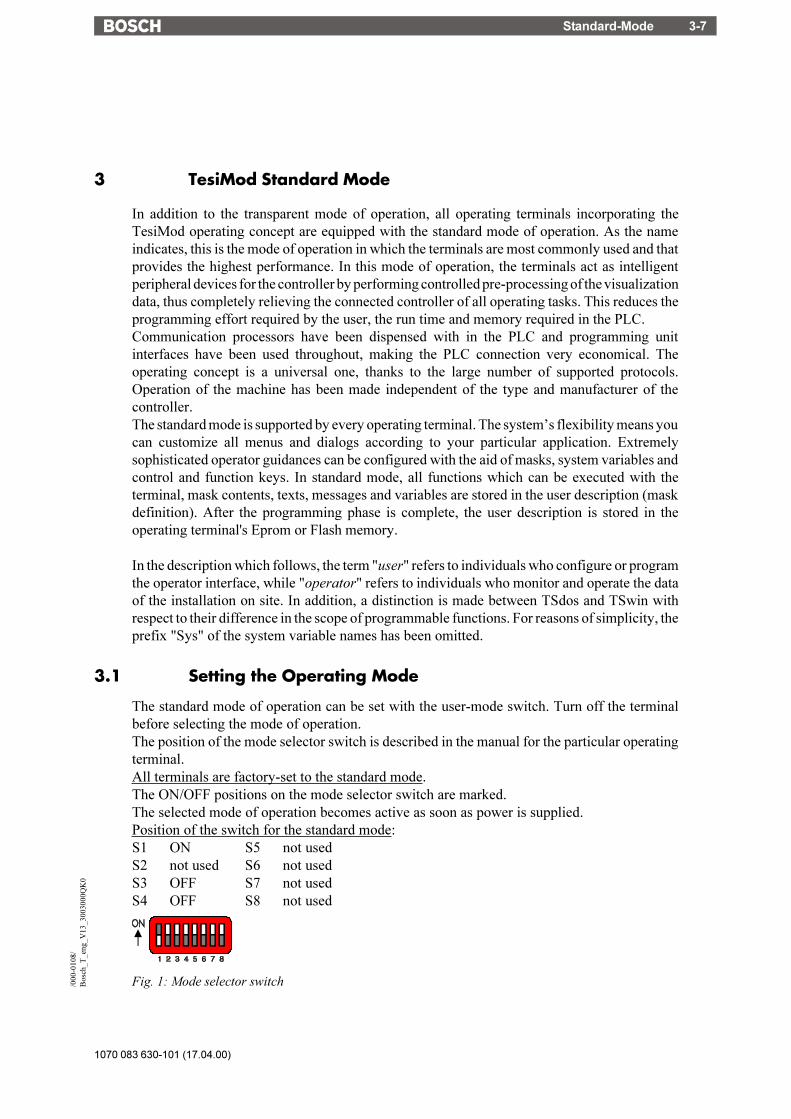
Standard-Mode 3-7
1070 083 630-101 (17.04.00)
/000
-010
8/B
osch
_T_e
ng_V
13_3
0030
00Q
K0
3 TesiMod Standard Mode
In addition to the transparent mode of operation, all operating terminals incorporating theTesiMod operating concept are equipped with the standard mode of operation. As the nameindicates, this is the mode of operation in which the terminals are most commonly used and thatprovides the highest performance. In this mode of operation, the terminals act as intelligentperipheral devices for the controller by performing controlled pre-processing of the visualizationdata, thus completely relieving the connected controller of all operating tasks. This reduces theprogramming effort required by the user, the run time and memory required in the PLC.Communication processors have been dispensed with in the PLC and programming unitinterfaces have been used throughout, making the PLC connection very economical. Theoperating concept is a universal one, thanks to the large number of supported protocols.Operation of the machine has been made independent of the type and manufacturer of thecontroller.The standard mode is supported by every operating terminal. The system�s flexibility means youcan customize all menus and dialogs according to your particular application. Extremelysophisticated operator guidances can be configured with the aid of masks, system variables andcontrol and function keys. In standard mode, all functions which can be executed with theterminal, mask contents, texts, messages and variables are stored in the user description (maskdefinition). After the programming phase is complete, the user description is stored in theoperating terminal's Eprom or Flash memory.
In the description which follows, the term "user" refers to individuals who configure or programthe operator interface, while "operator" refers to individuals who monitor and operate the dataof the installation on site. In addition, a distinction is made between TSdos and TSwin withrespect to their difference in the scope of programmable functions. For reasons of simplicity, theprefix "Sys" of the system variable names has been omitted.
3.1 Setting the Operating Mode
The standard mode of operation can be set with the user-mode switch. Turn off the terminalbefore selecting the mode of operation.The position of the mode selector switch is described in the manual for the particular operatingterminal.All terminals are factory-set to the standard mode.The ON/OFF positions on the mode selector switch are marked.The selected mode of operation becomes active as soon as power is supplied.Position of the switch for the standard mode:S1 ON S5 not usedS2 not used S6 not usedS3 OFF S7 not usedS4 OFF S8 not used
Fig. 1: Mode selector switch

1070 083 630-101 (17.04.00)
Standard-Mode3-8
3.2 Startup Process
All LEDs in the terminal are initially lit when the power is applied. A system-test is thenperformed that includes testing and initialization of the modules in the operating terminal.Various system and error messages may be output during this system-test. If the applicationmemory contains a valid user description, the first mask, the Startup Mask (TSdos), or the maskspecified in the language parameters as the mask to be used as the startup mask (TSwin) willappear on the display.This mask is displayed for 5 seconds (fixed time setting). This time can be used by the operatorto visually inspect the LEDs and the screen for proper functioning. After this time period, theMain Mask (TSdos) or the mask specified in the language parameters as the main mask isdisplayed. This mask is the first mask of the operator guidance.If the Enter key is pressed while the Startup Mask is displayed, the Setup Mask will appear onthe display. This Setup Mask can be used to set the parameters for the interface and the operatingterminal.If the Enter key is pressed before the Startup Mask is displayed, an error message will begenerated during the keyboard test.
........... The self-test performed on the keyboard during the terminal startuphas detected that a key is pressed. Comply with the request andrelease the key. If this message is generated when no key ispressed, this indicates a defective keyboard. Generally, themessage will disappear after releasing the key/keys.
A longer delay may occur before the Startup Mask is displayed if the statistics memory containsa large number of messages from the serial message system. This time period (initializationperiod) is required to set up the structures for message management, which will then enable fastersorting of messages later. During the initialization phase, the following message is displayed:
........... When the terminal is switched on, the messages that are present inthe terminal are sorted. This process requires a certain length oftime (initialization time).
3.2.1 Startup Process without a Valid User Description
The system-test performed on the application memory will detect whether a module is missing,defective or of the wrong type. This is then indicated to the operator by the following message:

Standard-Mode 3-9
1070 083 630-101 (17.04.00)
/000
-010
8/B
osch
_T_e
ng_V
13_3
0030
00Q
K0
If the memory test establishes that the right type of Flash memory is used but that it does notcontain a valid user description, the Flash memory will be erased and the terminal willautomatically switch to the download operating mode. The following messages appear on thedisplay indicating the various phases:
The message "Download" (TSdos) or "DOWNLOAD 1" (TSwin) remains on the display toindicate that the terminal is now ready to receive a valid user description via interface X3.
Until the memory contains a valid user description, communication with a controller connectedto the X2 interface will not take place, nor will the keyboard be operational. Once a valid userdescription has been downloaded, the terminal becomes active.
3.3 Communication in the Standard Mode
In standard mode, any interface except the interfaces for the logging printer and the paralleloutputs can be used for communication between the PLC (host computer, etc.) and the operatingterminal. The interface labeling, however, always depends on the connected counter part or thenetwork.See relevant chapters in the operating terminal manuals for a more detailed description of thevarious interfaces. For information on possible connections to various PLC types and networksrefer to the chapters 5.x on the controller and bus connections in this manual.To ensure a reliable connection, a 3 m long standard cable is available for every connection typeas an accessory.
3.4 Operating Concept
The operating concept of the TesiMod terminal has been designed to allow the operator to accessall masks - and thus all the data - quickly and easily.A number of means are available to the user to help guide the operator through the hierarchicalmask system.
3.4.1 Hierarchical Mask Structure in TSdos
The basic elements - the node mask and the I/O mask - provide the means for creating ahierarchically structured operator guidance. The mask parameters which can be set for each maskcan not just be used to select masks but also provide access to further menus. Figure 2 shows hownode masks are used to provide mask menus. The same functionality can be achieved with I/Omasks which have been set up with selection texts that will call up other masks.

1070 083 630-101 (17.04.00)
Standard-Mode3-10
Fig. 2: Hierarchical Mask Structure
The various mask types offer the following different means for establishing a connection to othermasks:Node masks: Cursor Right/Left/Home keys, function keys and selection itemsI/O masks: Cursor Right/Left/Home keys, function keys and selection textsMessage masks: Cursor home key and function keysStatus message masks: Cursor home key and function keys
The entire operator structure can be made subject to access control. Access to nodes and themasks behind this node can be prevented by implementing passwords. The direct selection ofmasks via function keys can also be controlled.The controller is notified whenever a new mask is called up. Process data required by the terminalin conjunction with masks and messages are automatically obtained from the controller. If anattempt is made to call up a password-protected mask, the associated password-mask will bedisplayed but data will not be retrieved from the controller.
3.4.2 Mask Structure in TSwin
In TSwin, a network of I/O masks without a real hierarchical structure is formed. I/O masks arelocated at the nodes in the network and contain a selection field which is used to call up othermasks by their names. It is possible to access any other I/O mask from an I/O mask by using thecontrol and function keys. This feature thus eliminates the difficulty of returning from messagemasks or status message masks.

Standard-Mode 3-11
1070 083 630-101 (17.04.00)
/000
-010
8/B
osch
_T_e
ng_V
13_3
0030
00Q
K0
3.4.3 External Mask Selection
Mask calls from the controller are handled in the same way as messages. This requires simplythat 8000H is added to the desired mask number prior to transfer.
When the same number is assigned to a mask and message, both the mask and the message arecalled up during external mask selections.This effect can be used to provide help in a mask. Otherwise, ensure that different numbers areused for masks and messages.
A mask called up externally is considered selected once the desired mask number appears in thevariable <Image of Mask Number>. The acknowledgement from the sequential data channel isnot a reliable confirmation of the mask output.
Example 1: Mask number and message number are not identicalA project comprises masks with numbers ranging from 100 to 200; the first message has thenumber 10.Mask 118 is to be called up by the controller.The following adding operation must be performed in the controller:118 + 8000H = 76H + 8000H = 8076H.The value 8076H must be written to the address of the serial message channel.Only mask 118 is displayed.
Example 2: Mask number and message number are identicalA project comprises masks with numbers ranging from 1 to 100; the first message has thenumber 10.Mask 50 and serial message 50 are to be called up by the controller.The following adding operation must be performed in the controller:
50 + 8000H = 32H + 8000H = 8032H.The value 8032H must be written to the address of the serial message channel.Both the mask 50 is displayed and message 50 are written to the message buffer.
3.4.4 Password Protection, Access Authorization
The TesiMod operating concept incorporates a password protection function. Password protectionprevents masks from being accessed and the data they contain from being altered without properauthorization. The protective function is available in every operating terminal. It is obtained byassigning access levels to masks and by using passwords.Unless otherwise specified by the programmer, the access levels of all masks automaticallydefault to the lowest level (=0), i.e. no password is required to access all masks with this accesslevel.Two authorization levels, referred to as the edit level and the view level, are assigned to everypassword.View level means that the next mask can be viewed after entering the password but the valuesin it can also not be edited.
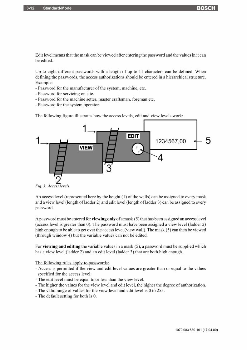
1070 083 630-101 (17.04.00)
Standard-Mode3-12
Edit level means that the mask can be viewed after entering the password and the values in it canbe edited.
Up to eight different passwords with a length of up to 11 characters can be defined. Whendefining the passwords, the access authorizations should be entered in a hierarchical structure.Example:- Password for the manufacturer of the system, machine, etc.- Password for servicing on site.- Password for the machine setter, master craftsman, foreman etc.- Password for the system operator.
The following figure illustrates how the access levels, edit and view levels work:
Fig. 3: Access levels
An access level (represented here by the height (1) of the walls) can be assigned to every maskand a view level (length of ladder 2) and edit level (length of ladder 3) can be assigned to everypassword.
A password must be entered for viewing only of a mask (5) that has been assigned an access level(access level is greater than 0). The password must have been assigned a view level (ladder 2)high enough to be able to get over the access level (view wall). The mask (5) can then be viewed(through window 4) but the variable values can not be edited.
For viewing and editing the variable values in a mask (5), a password must be supplied whichhas a view level (ladder 2) and an edit level (ladder 3) that are both high enough.
The following rules apply to passwords:- Access is permitted if the view and edit level values are greater than or equal to the values
specified for the access level.- The edit level must be equal to or less than the view level.- The higher the values for the view level and edit level, the higher the degree of authorization.- The valid range of values for the view level and edit level is 0 to 255.- The default setting for both is 0.

Standard-Mode 3-13
1070 083 630-101 (17.04.00)
/000
-010
8/B
osch
_T_e
ng_V
13_3
0030
00Q
K0
The Data Release key will have no function if pressed with an insufficient edit level. Thepassword can be entered in any I/O mask. Note that the Setup Mask is an exception. The systemvariable MskchgPasswd is designed to prompt for password entry. If the Password Editor isselected in the programming system, passwords will not appear as they are entered on theterminal. Instead the character "X" appears for every character that is entered.
Example:Enter PASSWORD: XXXX
This example illustrates hidden entry of a 4-digit number. If an invalid password is entered, theauthorization levels will automatically reset to 0.It is recommended that at least one password - the master password - is programmed with thehighest authorization level. The first password entered in the password list via the programmingsystem is the master password and as such has a special function. The master password is uniquein that it can not be changed on the operating terminal. Furthermore, it can be used to reset allmodified passwords to the default values entered in the programming system.
Example:Mask 5 access level = 10Mask 6 access level = 20Mask 7 access level = 30Password 4712 Edit level = 15 View level = 25
Once the password "4712" has been entered, the following accesses are permitted:- Mask 5 will be displayed, editing of values is authorized- Mask 6 will be displayed, editing of values is not authorized- Mask 7 will not be displayed, editing of values is not authorized
The access level for the Startup Mask is always 0.The Setup Mask is an exception with regards to the password and external data release functions.Since no communication is taking place when the Setup Mask is displayed, the external datarelease function is not applicable. To restrict access, passwords must be used. By defining thefirst editable variable in the Setup Mask as a Password Editor, all further variables can beprotected against unauthorized access. The view level does not apply when accessing the SetupMask. Viewing is always permitted if a value less than or equal to 254 is selected for the accesslevel of the Setup Mask.The edit level for all variables of the Setup Mask, with the exception of the Password Editor, isthe same as that defined as the access level.Access to the mask is always denied if an access level of 255 is defined for the setup mask. Thismeans that it will no longer be displayed during initialization of the terminal and can thereforenot be selected. However, all terminal-specific parameters can also be edited in any I/O mask.The new parameters become effective by restarting the terminal or with the system variable Boot.

1070 083 630-101 (17.04.00)
Standard-Mode3-14
3.4.4.1 Reactivating the Password Protection
The access authorization for a mask or variable (TSwin only) is reset whenever- the operating terminal is switched off and turned back on- an incorrect password is entered- bit 2 in the <Write Coordination Byte> is set- the system variable MskchgResPasswd is activated- the option Reset Password in the mask parameters of the password-protected mask is selected.
3.4.4.2 Password Management
Passwords are stored in the operating terminal's Flash memory. These are the default passwordsthat are used when the terminal is started up initially after a download. At the same time, thepasswords are stored in the operating terminal's RAM.The passwords stored in the flash memory can be reactivated by writing to the system variableFlashPasswd.
Every password (except for the master password = first password in the list) can be edited fromthe terminal. For this process, the password to be edited is written to the system variableMskchgPasswd first. The new password is then written twice to the system variableChangePasswd. If both entries for the new password are identical, the password will becomeeffective immediately; otherwise, a system message will be displayed and the password reset.Passwords are stored and compared as 11-character strings. The passwords are entered with theAlphanumerical Editor.Passwords are only globally programmable (not language-specifically).
3.4.4.3 Password Mask and Password Functionality
- It is possible to create a special mask which requests entry of a password (mask 3 in TSdos).This password mask is then displayed whenever an attempt is made to call up a password-protected mask without first entering a password with sufficient authorization. When apassword with sufficient authorization is entered into this mask, the previously selectedpassword-protected mask is called up once the Data Release key is pressed. There are norestrictions with respect to the remaining mask contents (texts, further variables, soft keys,etc.).
- You can specify for every mask separately whether the password protection is to bereactivated after the mask is exited.
- For those cases where no valid password has been entered, an option to exit the mask mustbe provided. The Cursor home key can be programmed to perform this function, for example.
- If no such mask has been created to prompt for password entry, the operator will be requiredto enter the password in masks specifically designed for this purpose.
- The entire password protection can be deactivated by setting the system variablePasswdInactive to the value 1. The operating terminal will then act as if all masks werecreated with an edit and view level of 0. The system variable is battery-backed, so deactivationwill therefore still be in effect after the operating terminal is restarted.

Standard-Mode 3-15
1070 083 630-101 (17.04.00)
/000
-010
8/B
osch
_T_e
ng_V
13_3
0030
00Q
K0
3.5 Masks
In conjunction with the TesiMod operating system, the term "mask" always refers to the contentsof one screen. The size of masks therefore varies from operating terminal to operating terminal.Masks with a specific functionality form the basic elements of the operator guidance. The firststep when programming a mask is to specify its functionality. The process of designing theoperator guidance is greatly simplified by the restricted number of different mask types.The following mask types are available in TSdos:
- Setup mask (system mask)- Startup mask (system mask)- Password mask (system mask)- Main mask (system mask)- I/O mask (user mask)- Node mask (user mask)- Message mask (user mask)- Status message mask (user mask)
3.5.1 Mask Parameters
The number of mask parameters that is available for a specific mask depends on the mask type.The mask parameters determine the functionality of the control keys in the operator guidance.Any mask parameters which are not required may remain unassigned. If no mask parameters atall are programmed, only the function keys or external mask selection can be used to exit the maskin question.The functionality of the control keys specified in the mask parameters is subject to access controlof the password system. This prevents unauthorized access to masks via the control keys.In addition to the control key functionality, the mask parameters also contain the access leveldefinition. The access level indicates the minimum value that a password (view level, edit level)must have to be authorized to access a mask and edit its values. The default value used for theaccess level is "0" (meaning free access).A selected Automatic Data Release option in the mask parameters will allow the operator tosupply input into the mask without having to press the Data Release key first.An option for automatic reactivation of the password protection is also available in the maskparameters to ensure that the password has to be reentered when a password-protected mask iscalled up again.
3.5.2 System Masks
System masks facilitate initial programming. They also get your system up and running directly.This makes the initialization phase an integral part of the user description. In TSdos, fixed masknumbers are assigned to system masks. In TSwin, any mask can be selected as a system mask.System masks are basically I/O type masks with a few restrictions. These restrictions result fromthe operator-prompted initialization phase and the fact that communication to the controller isnot yet established.

1070 083 630-101 (17.04.00)
Standard-Mode3-16
The system masks Setup Mask and Startup Mask can not be accessed via external mask selection!
The following TSdos system masks have a fixed function:Mask 1 Setup maskMask 2 Startup maskMask 3 Password maskMask 4 Main mask (first user mask)
3.5.2.1 Setup Mask
Only terminal-specific parameters can be defined in the Setup Mask. This is because nocommunication takes place with the connected controller while the Startup Mask and SetupMask are displayed. The external data release therefore has no function. To protect data, apassword must be assigned.
From the operator guidance, the Setup Mask and Startup Mask can be reached through thefunction keys, provided they have not been assigned an access level. After the masks are exited,however, the terminal is not reinitialized.
Examples of terminal-specific parameters:- Printer interface settings- Default contrast/default intensity setting of the display- Date and time settings- Activation of the download function.
Fig. 4: Example of a setup mask for the BT20
3.5.2.1.1 Password Protection - Setup Mask
The Setup Mask is an exception with regard to password protection.To password-protect the Setup Mask, the system variable MskchgPasswd must be set up as thefirst variable which can be edited in the Setup Mask. A password can be input regardless of theaccess level (with the exception of the access level 255).For the setup mask, the access level applies to the edit level only, meaning that its contents arealways visible to the operator.

Standard-Mode 3-17
1070 083 630-101 (17.04.00)
/000
-010
8/B
osch
_T_e
ng_V
13_3
0030
00Q
K0
3.5.2.1.2 Function Without the Setup Mask
If the Setup Mask is not needed, its access level can be set to the value 255, thus preventing accessto the Setup Mask via the Startup Mask (using the Data Release key).
3.5.2.2 Startup Mask
The startup mask is displayed for around 5 seconds after the terminal is switched on. This is afixed time setting; the startup process can not be changed.With regards to the mask design, the user can only design the text to be displayed in the mask.Any combination of characters, character sizes and text attributes can be chosen in theprogramming system for this purpose.Only system variables can be output in the Startup Mask. Variable input is not possible due tothe time restriction. While the Startup Mask is displayed, the Setup Mask can be called bypressing the Data Release key. However, this is not possible if the access level for the setup maskis set to 255.Some examples of information that may be chosen to be displayed in the Startup mask are listedbelow:- address for servicing- machine type- version number of the program
Fig. 5: Example of a startup mask for the BT20
3.5.2.3 Password Mask
The password mask is an I/O type of mask. In TSdos, the mask that prompts for password entry(password mask) when attempting to call up a password-protected mask always has the masknumber 3. The functionality is as illustrated in the password description.
Fig. 6: Example of a password mask for the BT20

1070 083 630-101 (17.04.00)
Standard-Mode3-18
3.5.2.4 Node Mask, I/O Mask with Selection Text
The node mask as a basic element of the operator guidance structure is now available in TSdosonly. This mask is no longer available in TSwin now that the same functionality can be achievedby using a selection text (linked to a text list and the system variable NewMask) together withthe automatic data release option.The node mask consists of a heading section and a selection part.The heading section is used to specify the menu heading and additional information on the menu.The number of display lines for the heading can be defined in the programming system.The text attribute selected for the heading will automatically be applied to all of the text elementsin the heading.The selection part describes the submenus that can be selected. These submenus can be selectedwith the Cursor up or Cursor down key and the selection can then be confirmed with the Enterkey. Access to the submenus can be protected with passwords.
Fig. 7: Optional control keys in the node mask
A node mask can also be exited with the Cursor left, Cursor right, Cursor home keys and anyfunction keys and soft keys that have been programmed accordingly. The cursor keys can be usedfor direct selection of menus at the same level. The Cursor home key may also be used to selecthigher-level menus.It is not possible to input or output variables in node masks. Node masks are only used to branchto further node masks or I/O masks. To function efficiently, an operator guidance shouldtherefore be made up of a combination of node masks and I/O masks.
Key Functions in the Node Mask
Key: Cursor up Moves the cursor up one selection itemKey: Cursor down Moves the cursor down one selection itemKey: Cursor left Can be programmed freely to select adjacent masksKey: Cursor right Can be programmed freely to select adjacent masksKey: Cursor home Can be programmed freely to select adjacent masks
Exits the node mask for the higher-level menuKey: Data Release No functionKey: Enter Initiates the jump to the selected maskKey: ?, Help Displays the help text specified for the mask for as long as the key is
held down

Standard-Mode 3-19
1070 083 630-101 (17.04.00)
/000
-010
8/B
osch
_T_e
ng_V
13_3
0030
00Q
K0
Fig. 8: Example of a node mask
3.5.2.5 I/O Mask
As a basic type of mask, the I/O mask offers a broad range of functions - enough in fact forconfiguring complete operator guidances based entirely on it.I/O masks provide the following options:- Selection of menus- Definition of data formats- Scaling of values- Output of values once or cyclically- Text display- Message output- Direct selection of up to five adjacent masks with the control keys- Display of large mask contents over several screen pages- Display of values in tables
Fig. 9: Possible control keys in the I/O mask
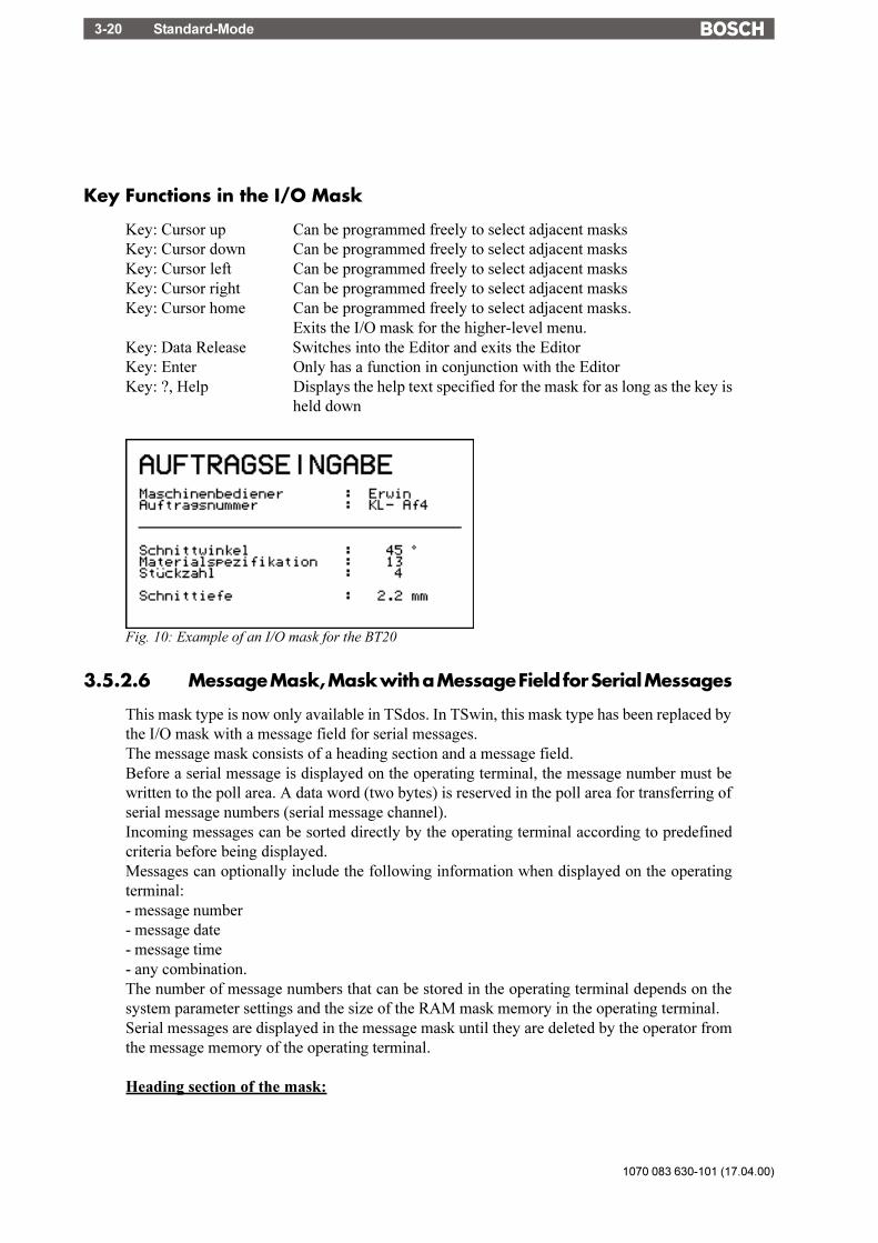
1070 083 630-101 (17.04.00)
Standard-Mode3-20
Key Functions in the I/O Mask
Key: Cursor up Can be programmed freely to select adjacent masksKey: Cursor down Can be programmed freely to select adjacent masksKey: Cursor left Can be programmed freely to select adjacent masksKey: Cursor right Can be programmed freely to select adjacent masksKey: Cursor home Can be programmed freely to select adjacent masks.
Exits the I/O mask for the higher-level menu.Key: Data Release Switches into the Editor and exits the EditorKey: Enter Only has a function in conjunction with the EditorKey: ?, Help Displays the help text specified for the mask for as long as the key is
held down
Fig. 10: Example of an I/O mask for the BT20
3.5.2.6 Message Mask, Mask with a Message Field for Serial Messages
This mask type is now only available in TSdos. In TSwin, this mask type has been replaced bythe I/O mask with a message field for serial messages.The message mask consists of a heading section and a message field.Before a serial message is displayed on the operating terminal, the message number must bewritten to the poll area. A data word (two bytes) is reserved in the poll area for transferring ofserial message numbers (serial message channel).Incoming messages can be sorted directly by the operating terminal according to predefinedcriteria before being displayed.Messages can optionally include the following information when displayed on the operatingterminal:- message number- message date- message time- any combination.The number of message numbers that can be stored in the operating terminal depends on thesystem parameter settings and the size of the RAM mask memory in the operating terminal.Serial messages are displayed in the message mask until they are deleted by the operator fromthe message memory of the operating terminal.
Heading section of the mask:
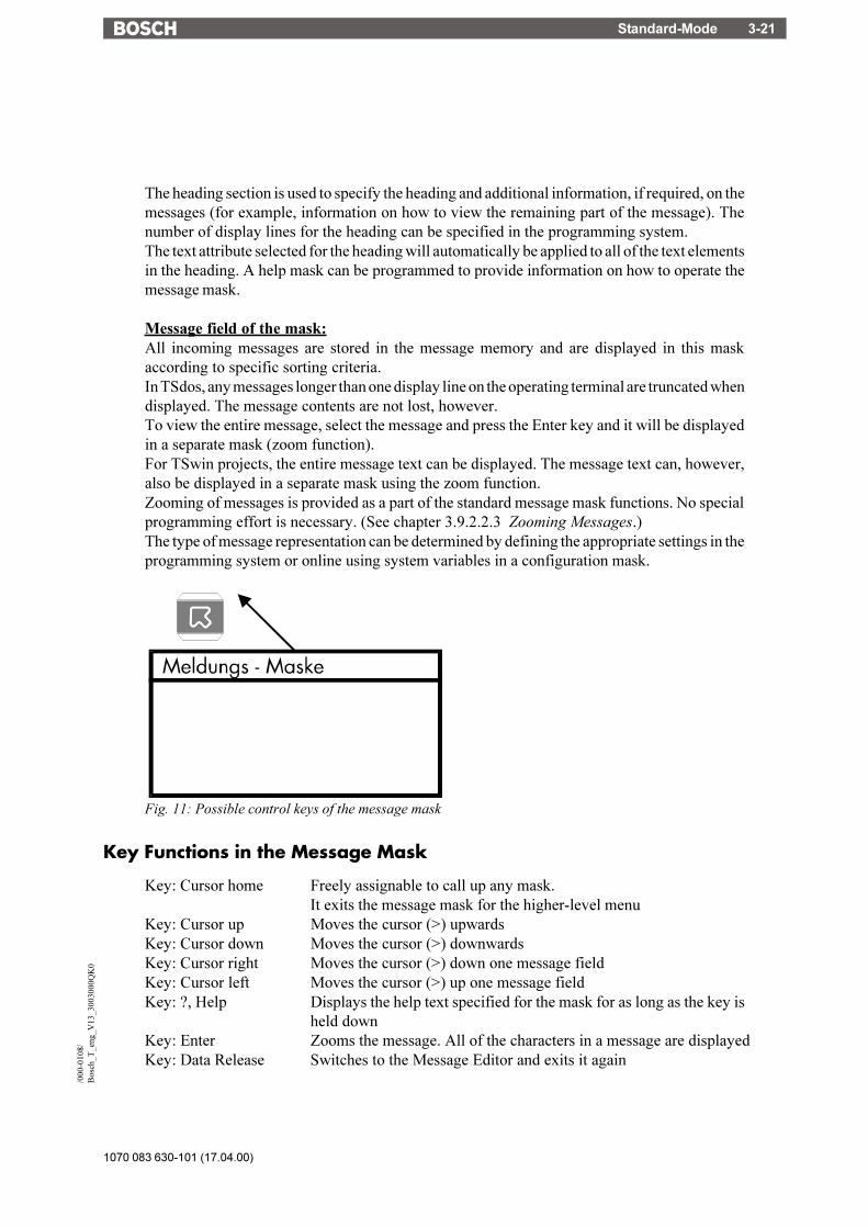
Standard-Mode 3-21
1070 083 630-101 (17.04.00)
/000
-010
8/B
osch
_T_e
ng_V
13_3
0030
00Q
K0
The heading section is used to specify the heading and additional information, if required, on themessages (for example, information on how to view the remaining part of the message). Thenumber of display lines for the heading can be specified in the programming system.The text attribute selected for the heading will automatically be applied to all of the text elementsin the heading. A help mask can be programmed to provide information on how to operate themessage mask.
Message field of the mask:All incoming messages are stored in the message memory and are displayed in this maskaccording to specific sorting criteria.In TSdos, any messages longer than one display line on the operating terminal are truncated whendisplayed. The message contents are not lost, however.To view the entire message, select the message and press the Enter key and it will be displayedin a separate mask (zoom function).For TSwin projects, the entire message text can be displayed. The message text can, however,also be displayed in a separate mask using the zoom function.Zooming of messages is provided as a part of the standard message mask functions. No specialprogramming effort is necessary. (See chapter 3.9.2.2.3 Zooming Messages.)The type of message representation can be determined by defining the appropriate settings in theprogramming system or online using system variables in a configuration mask.
Fig. 11: Possible control keys of the message mask
Key Functions in the Message Mask
Key: Cursor home Freely assignable to call up any mask.It exits the message mask for the higher-level menu
Key: Cursor up Moves the cursor (>) upwardsKey: Cursor down Moves the cursor (>) downwardsKey: Cursor right Moves the cursor (>) down one message fieldKey: Cursor left Moves the cursor (>) up one message fieldKey: ?, Help Displays the help text specified for the mask for as long as the key is
held downKey: Enter Zooms the message. All of the characters in a message are displayedKey: Data Release Switches to the Message Editor and exits it again
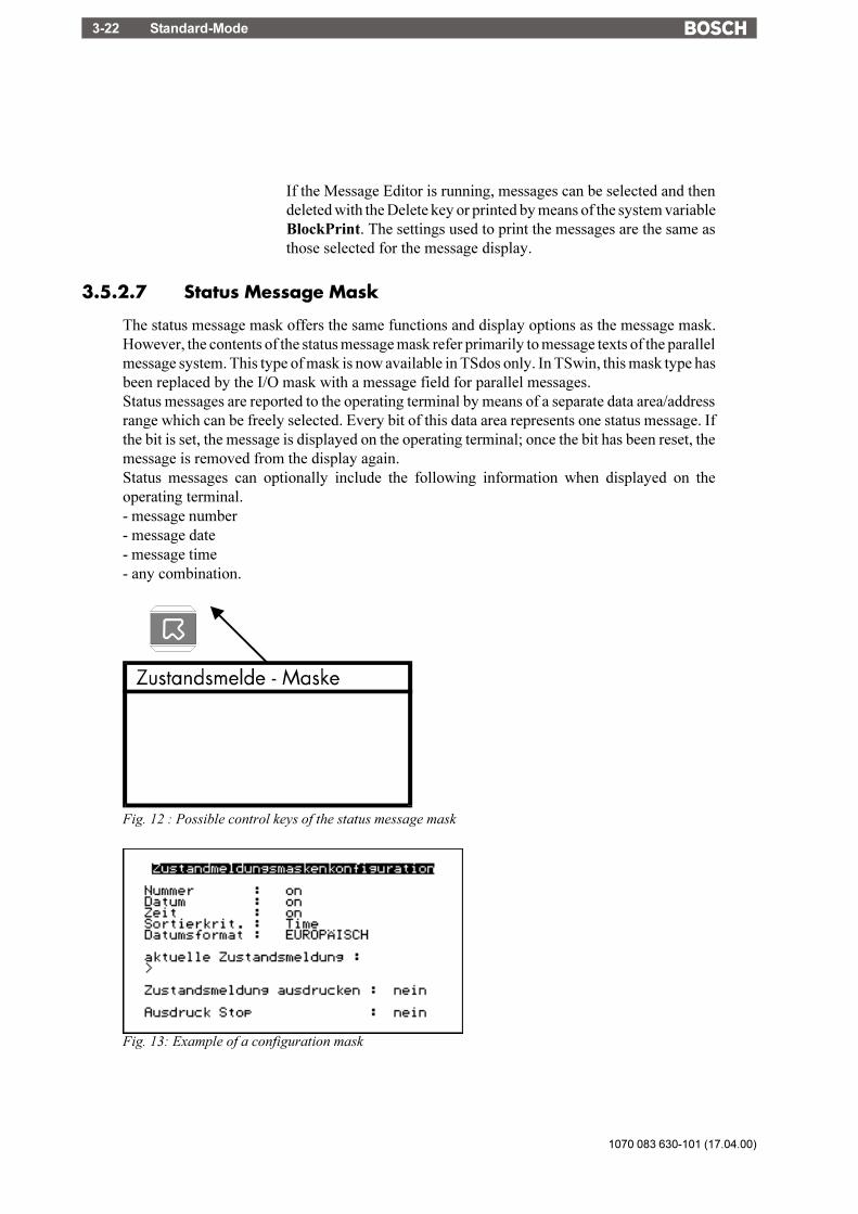
1070 083 630-101 (17.04.00)
Standard-Mode3-22
If the Message Editor is running, messages can be selected and thendeleted with the Delete key or printed by means of the system variableBlockPrint. The settings used to print the messages are the same asthose selected for the message display.
3.5.2.7 Status Message Mask
The status message mask offers the same functions and display options as the message mask.However, the contents of the status message mask refer primarily to message texts of the parallelmessage system. This type of mask is now available in TSdos only. In TSwin, this mask type hasbeen replaced by the I/O mask with a message field for parallel messages.Status messages are reported to the operating terminal by means of a separate data area/addressrange which can be freely selected. Every bit of this data area represents one status message. Ifthe bit is set, the message is displayed on the operating terminal; once the bit has been reset, themessage is removed from the display again.Status messages can optionally include the following information when displayed on theoperating terminal.- message number- message date- message time- any combination.
Fig. 12 : Possible control keys of the status message mask
Fig. 13: Example of a configuration mask

Standard-Mode 3-23
1070 083 630-101 (17.04.00)
/000
-010
8/B
osch
_T_e
ng_V
13_3
0030
00Q
K0
Fig. 14: Example of a status message mask
Key Functions in the Status Message Mask
Key: Cursor home Freely assignable to call up any mask.It exits the Message Mask for the higher-level menu
Key: Cursor up Moves the cursor (>) upwardsKey: Cursor down Moves the cursor (>) downwardsKey: Cursor right Moves the cursor (>) down one message fieldKey: Cursor left Moves the cursor (>) up one message fieldKey: ?, Help Displays the help text specified for the mask for as long as the key is
held downKey: Enter Zooms the message. All of the characters in a message are displayed.Key: Data Release Switches to the Message Editor and exits it.
If the Message Editor is running, messages can be selected and thenbe deleted with the Delete key or printed by means of the systemvariable BlockPrint. The settings used to print the messages are thesame as those selected for the message display.
3.6 Variables
The number of valid variable types is determined by the connected controller. All standardvariable types which are commonly used are supported by the operating terminals. The data typethat is used also determines the valid range of values and number of significant digits.
Variable Type Size Range of ValuesBit 1 bit [0, 1]Byte 1 byte [-128 to +127]Byte 1 byte [0 to 255]Word 2 bytes [-32768 to +32767]Word 2 bytes [0to 65535]Lword 4 bytes [-2147483648 to +2147483647]Lword 4 bytes [0 to 4294967295]Lword 4 bytes [±1.2 * 10-38 to ± 3.4 * 10+38]ASCII 42 bytes [0 to 255]

1070 083 630-101 (17.04.00)
Standard-Mode3-24
3.6.1 Output Variables
Output variables are numerical or alphanumerical data stored in the memory of the connectedcontroller. The variables are retrieved from the controller whenever required, and output on thedisplay at the programmed location according to the defined method of representation,formatting and scaling. Generally, a distinction is made between displaying one-time variables(variables are transferred only once and are then displayed) or at cyclic intervals (variables arecontinually updated while displayed). The character attributes that are available depend on thedisplay type of the operating terminal.
One-Time Output Variables or Cyclic Output Variables:
Pure output variables are transmitted by the controller only once and are displayed in the mask.This method offloads the communication process and is suitable for all variables such as setpointvalues, constant values and parameters that change either rarely or never. All output variablescan be displayed on a scaled and formatted basis.Cyclic output variables are used to display actual values, in other words values which varycontinually while a mask is displayed. The cycle time (and thus the intervals at which thedisplayed actual values are refreshed) corresponds to the polling time predefined by the user.Data transfer between the operating terminal and the PLC can be offloaded by usingvariables of the same data type only (data word, flag word, input word, flag word) and byusing continuous addresses within one mask.Cyclic output variables can also be scaled and formatted. Note that the display of floating pointnumbers requires more computing time when the values are scaled. These will therefore not bedisplayed in "real time". For this reason, the cycle times selected here should be > 500 ms.Also note that the larger the amount of cyclic data for transfer, the longer the response time tonew values from the PLC. As a result, longer polling times are required.
Formatted Output:
Formatting a numerical variable allows the display format of the variable to be adapted to theoutput range of values. Formatting includes the number of digits to be displayed, the number ofpost-decimal places (fractional digits) and whether signs are to be used or not. The number ofpost-decimal places gives the operator the impression that a division has been performed. Adivision is not actually carried out, however. The variable in the controller must be available inthe appropriate (higher) resolution.Example:Actual value of a length in the controller:Word variable Range of values 0 to 65535
Resolution 1/100 mm
Display of actual values on the operating terminal:Display range 0.00 to 655.35 mm

Standard-Mode 3-25
1070 083 630-101 (17.04.00)
/000
-010
8/B
osch
_T_e
ng_V
13_3
0030
00Q
K0
The output is in millimeters, so a conversion in the controller is not necessary. The followingformat has been selected in the variable definition:PLC address: Data type WordTSdos: Positive integer (without sign)TSwin: Decimal number (without sign)Length: 6 digitsPost-decimal places: 2 digits
Selecting "with sign" would cause the output to change as follows:
Display range -327.68 to 327.67 mm
Because of the sign, the output length has increased to 7 digits. The format specified in thevariable definition must be adapted accordingly.
Format Data type formatting scalingBinary Bit, Byte, Word, Lword x -Hexadecimal Byte, Word, Lword - xDecimal Bit, Byte, Word, Lword x xBCD Byte, Word, LWord - xFloating point Lword x xSelection text (coded text) Bit, Byte, Word x -Text ext. ASCII font - -
The format corresponds to scaling without the need for calculation.
Scaled Output
When a variable is scaled, its range of values can be adapted to the operator guidance. Scalingapplies to data input and output. The operands can be entered in the programming software.
Scaling for integers:
Operand Range of valuesFactor -32768 to +32767 (excluding the value 0!)Divisor 1 to +32767Summand -32768 to +32767
The operands factor and divisor must be >0!
Scaling for floating point numbers:
Operand Range of valuesFactor +/-999999999,99999999 (excluding the value 0!)Divisor +/-999999999,99999999 (excluding the value 0!)Summand +/-999999999,99999999

1070 083 630-101 (17.04.00)
Standard-Mode3-26
The operands are stored in IEEE-formatThe variable also retains its entire value range for formatting.
Formula for Scaling the Output:
Scaling is always performed on the variable in the operating terminal. Through scaling, themeasured values collected in the controller are adapted to the operator guidance. The outputrepresentation is determined by formula 1 only. Unlike the factor and divisor, the summand(representing an offset) can be set to the value 0.Before a variable or constant is output on the display, it is converted as follows:
Fig. 15: Formula 1
Output Representation Types:
Certain types of variables can be recognized more easily if they are displayed in their ownspecific format. A type-specific representation makes interpretation of the variable contenteasier. For this reason, a wide range of representation formats is provided.Examples:- Input statuses of an input module Binary representation- Filling level of a container Bar (bar chart)- Temperature Curve (line graph)- Valve states Graphics showing valves
Example of a coded text used for outputting an end position condition:
Binary Hex Decimal Selection Text (Coded Text)0 00 0 Not in end position1 20 32 In end position
Representation With Leading Zeros:
The option of displaying leading zeros can be used in conjunction with every integer. Leadingzeros are required in particular for displaying dates and times and hexadecimal or binary formats.The "Display Leading Zeros" option can be selected in the variable definition.
Representation without Representation withLeading Zeros Leading Zeros
Binary Number 10 0101 0010 0101Time 8: 2:33 08:02:33Date 5. 3.1997 05.03.1997

Standard-Mode 3-27
1070 083 630-101 (17.04.00)
/000
-010
8/B
osch
_T_e
ng_V
13_3
0030
00Q
K0
3.6.1.1 "Decimal Number" Representation
The decimal representation of numbers is the most frequently used representation method.TSwin differentiates between the following decimal number types of representation: Standard,Timer, Counter and BCD-Format.Decimal representation includes integers and floating point numbers.
3.6.1.1.1 "Standard" Variable Type
The positional significance of the displayed positions increases from right to left. Leading zerosor the decimal point can be displayed as an option. Decimal representation is suitable for the datatypes Bit, Byte, Word and Lword. The maximum length depends on the data type. There are noblanks between the characters. In the controller, this variable is in the binary format or specialtimer or counter formats.
103 102 101 100 10-1 10-2 Positional significance0 1 2 3 4 5 Display (123,45
D)
3.6.1.1.2 "Timer" Variable Type
The variable type Timer has a special function only when used in combination with Simatic S5controllers.The kind of formatting of the variable type Timer depends on the memory area of the PLC wherethe value was read. If the value is read directly from a timer word, the 10 bit binary time valuecontained in it and the 2-bit time base are converted to the time value to the base 10 ms. If readfrom a different memory area, i.e. data word (DW), flag word (MW), input word (EW) or outputword (AW), it is then assumed that the value is BCD-coded (3 digits BCD-code and 2 bit timebase). This value will also be converted to a time value to the base 10 ms.The resulting time value to the base 10 ms can now be formatted in the same way as a fixed pointnumber, i.e. use of post-decimal places is possible and scaling can be applied.
Example:A setpoint value is entered on the operating terminal: Address MW100The current actual value is displayed on the operating terminal: Address MW200
Representation Input Variable: Decimal Number / Timer / 7 Digits / 2 Post-DecimalPlaces /
Factor 1 /Divisor 1 / Summand 0Representation Output Variable: Decimal Number/ Timer / 6 Digits / 1 Post-Decimal
Place/Factor 1 / Divisor 10 / Summand 0
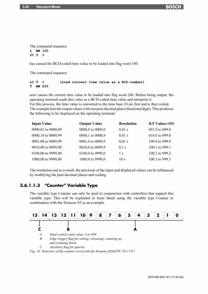
1070 083 630-101 (17.04.00)
Standard-Mode3-28
The command sequenceL MW 100SI T 1
has caused the BCD-coded time value to be loaded into flag word 100.
The command sequence
LC T 1 (Load current time value as a BCD-number)T MW 200
now causes the current time value to be loaded into flag word 200. Before being output, theoperating terminal reads this value as a BCD-coded time value and interprets it.For this process, the time value is converted to the time base 10 ms first and is then scaled.The example lists the output values with one post-decimal place (fractional digit). This producesthe following to be displayed on the operating terminal:
Input Value Output Value Resolution KT Values (S5)
0000,01 to 0000,09 0000,0 to 0000,0 0,01 s 001.0 to 009.0
0000,10 to 0000,99 0000,1 to 0000,9 0,01 s 010.0 to 099.0
0001,00 to 0009,99 0001,0 to 0009,9 0,01 s 100.0 to 999.0
0010,00 to 0099,90 0010,0 to 0099,9 0,1 s 100.1 to 999.1
0100,00 to 0999,00 0100,0 to 0999,0 1 s 100.2 to 999.2
1000,00 to 9990,00 1000,0 to 9990,0 10 s 100.3 to 999.3
The resolution and as a result, the precision of the input and displayed values can be influencedby modifying the post-decimal places and scaling.
3.6.1.1.3 "Counter" Variable Type
The variable type Counter can only be used in conjunction with controllers that support thisvariable type. This will be explained in more detail using the variable type Counter incombination with the Siemens S5 as an example.
A Dual-coded count value, 0 to 999B Edge trigger flag for setting, releasing, counting up
and counting downC Auxiliary flag for queries
Fig. 16: Structure of the counter word with the Siemens SIMATIC S5-115U

Standard-Mode 3-29
1070 083 630-101 (17.04.00)
/000
-010
8/B
osch
_T_e
ng_V
13_3
0030
00Q
K0
The kind of formatting of the variable type Counter depends on the memory area of the PLCwhere the value was read. If read directly from a counter word, the 10 bit binary count valuecontained in it will be displayed directly, so conversion is not necessary.If read from another memory area, i.e. data word (DW), flag word (MW), input word (EW) oroutput word (AW), it is assumed that the value is BCD-coded (3 digits BCD-code). The valuewill then be converted to a binary count value first.The resulting binary count value can then be formatted in the same way as an integer, i.e. scalingis possible.
3.6.1.1.4 "BCD-Number" Variable Type
The BCD format is partially used to represent numbers in the PLC. This output is required inspecial cases. The positional significance of the displayed digits increases from right to left. Thenumbers 0 to 9 are used for the representation; leading zeros can be included optionally. TheBCD mode of representation is suitable for the data types Byte, Word and Lword. The length islimited to a maximum of 8 digits. There are no blanks between the characters. The variable valueis stored in the controller in BCD format. The range of numbers for a byte is 00 to 99.
104 103 102 101 100 Positional significance0 1 2 3 4 Display (1234D)
3.6.1.2 "Alphanumerical" Representation
In the alphanumerical mode of representation, ASCII strings are read from the controller in byteformat and are represented on the display. The number of characters which can be displayeddepends on the capabilities of the type of terminal involved. One display line is the maximumpermissible length for a variable; longer texts are truncated. The address in the variable listindicates the beginning of the character string. A definition of the variable size is not includedand is not necessary. The alphanumerical representation provides another means of editing masktexts during runtime.
3.6.1.3 "Selection Text" (Coded Text) Representation
In the Selection Text (coded text - TSdos) mode of representation, a text string is assigned to anumerical value.This allows two different tasks to be performed:1. visualization or selection of statuses by means of text strings2. change of mask (TSwin).The selection text in TSwin is used the same way as the selection field in TSdos.In TSdos, the display of coded texts is limited to one line.
An example of using a one-line selection text is the option of selecting the parity for a serialinterface.

1070 083 630-101 (17.04.00)
Standard-Mode3-30
In this case, the text list will contain three entries:
Value Text0 No Parity1 Odd2 Even
A variable (ComParityA / ComParityB) is created in the mask.Only these three options are selectable on the operating terminal by means of the Standard orMix-Mode Editor; invalid inputs are therefore prevented.
Multiple-line selection texts are primarily used for menu control (replacing the node mask).Unlike one-line selection texts, multiple-line selection texts display the text list either in full orin part. If the value for the selection text field height is less than the number of text elements tobe displayed, the cursor keys can be used to scroll through the text elements. After the final textlist entry is reached, the selection proceeds with the first entry.To indicate that a text is selected, the entire selection text line is represented in the inverse format.With the representation type Selection Text, text lists are also used to assign mask names to themask numbers:
Value Text10 Machine parameters20 Serial message mask30 Status messages40 Message configuration50 Interface parameters
A variable (NewMask) of the type Selection Text is created in the Main Mask (mask 4) with themaximum height of 5 lines and a length of 25 characters. The values in the text list and the masknumbers must match.One of these entries can then be selected from the selection field displayed on the operatingterminal: the desired mask is then displayed.
3.6.1.4 "Selection Image" (Coded Image) Representation
In the Selection Image (coded image - TSdos) mode of representation, an image (pixel graphic)is assigned to a numerical value. This image is assigned in an image list. The image list is linkedto the variable whose values are to be represented as images. In this way, language-independentvisualization of operating states, inputs and outputs, etc. is possible.Numbers may be freely assigned to the images. They need not necessarily be contiguous or sortedin a consecutive order. In addition, a default image exists for every image list which is displayed,whenever the variable assumes a value that does not exist in the image list. The images used arecut to the size that applies to the output format. This representation is limited to bits, bytes orwords. Selection image variables can be both displayed and edited using the +/- key (as with theSelection Text Editor). Any modifications that are made are directly transferred to the controller.

Standard-Mode 3-31
1070 083 630-101 (17.04.00)
/000
-010
8/B
osch
_T_e
ng_V
13_3
0030
00Q
K0
The example below illustrates how images are assigned to numerical values:
Value Image Name120 Symbol134 Symbol27 Symbol31201 Symbol4
The names for the images represent the images in the image list. The actual list will looksomething like this:
This image list has been defined with four entries. The graphic selected by the controller will bedisplayed.
All of the images in an image list should have the same output size to ensure that they overwrite(overlap) each other completely. An I/O mask can contain multiple selection image variables.These selection image variables can be of the types: one-time output variable, cyclical outputvariable, or input variable. When the cyclical output of selection images ("animation") is chosen,it must be remembered that the rate of change will be slow due to the limitations of the hardwareperformance. The more images that are output, the smaller the output performance. The selectionimage variable should therefore mainly be used for switching states or nearly static processes.
3.6.1.5 "Floating Point Number" Representation
The rules that apply to the Floating Point Number mode of representation are basically the sameas those applying to the representation type Decimal Number - variable type Standard. The onlydifference is that with this representation type, the factor that is used to achieve scaling can bea floating point number; a divisor is therefore not required. With floating point numbers, thereciprocal value can also be generated, before the value is displayed.Not every controller type supports the floating point format. There are different floating pointformats available for processing in the controller (for example, the IEEE format).
3.6.1.6 "Hexadecimal Number" Representation
The hexadecimal representation of numbers is frequently used to display addresses when thePLC is programmed. This format is aimed for use by more experienced operators! The positionalsignificance of the displayed digits increases from right to left. Numbers are expressed by thecharacters 0 to 9 and A to F. Only capital letters and leading zeros are used for representation.The hexadecimal representation is suitable for the data types Byte, Word and Lword. The lengthis limited to a maximum of 8 digits. There are no blanks between the characters.
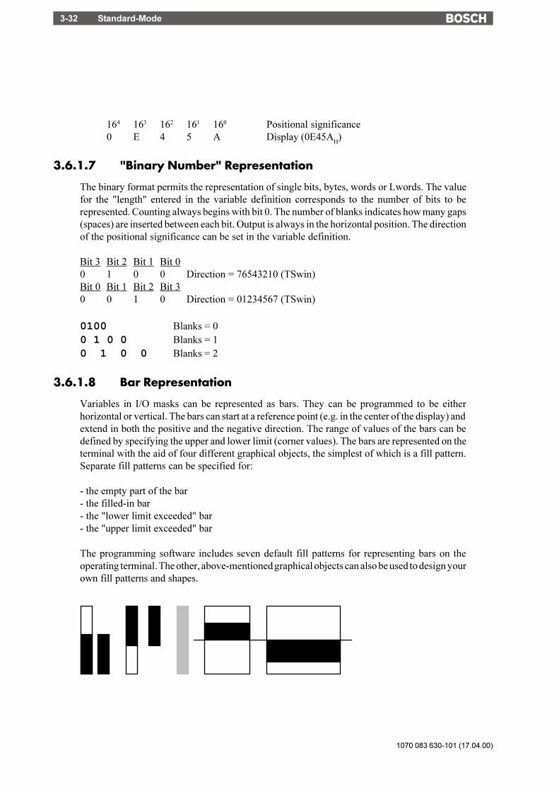
1070 083 630-101 (17.04.00)
Standard-Mode3-32
164 163 162 161 160 Positional significance0 E 4 5 A Display (0E45A
H)
3.6.1.7 "Binary Number" Representation
The binary format permits the representation of single bits, bytes, words or Lwords. The valuefor the "length" entered in the variable definition corresponds to the number of bits to berepresented. Counting always begins with bit 0. The number of blanks indicates how many gaps(spaces) are inserted between each bit. Output is always in the horizontal position. The directionof the positional significance can be set in the variable definition.
Bit 3 Bit 2 Bit 1 Bit 00 1 0 0 Direction = 76543210 (TSwin)Bit 0 Bit 1 Bit 2 Bit 30 0 1 0 Direction = 01234567 (TSwin)
0100 Blanks = 00 1 0 0 Blanks = 10 1 0 0 Blanks = 2
3.6.1.8 Bar Representation
Variables in I/O masks can be represented as bars. They can be programmed to be eitherhorizontal or vertical. The bars can start at a reference point (e.g. in the center of the display) andextend in both the positive and the negative direction. The range of values of the bars can bedefined by specifying the upper and lower limit (corner values). The bars are represented on theterminal with the aid of four different graphical objects, the simplest of which is a fill pattern.Separate fill patterns can be specified for:
- the empty part of the bar- the filled-in bar- the "lower limit exceeded" bar- the "upper limit exceeded" bar
The programming software includes seven default fill patterns for representing bars on theoperating terminal. The other, above-mentioned graphical objects can also be used to design yourown fill patterns and shapes.

Standard-Mode 3-33
1070 083 630-101 (17.04.00)
/000
-010
8/B
osch
_T_e
ng_V
13_3
0030
00Q
K0
Fig.17: Different forms of bar representation
Bar charts can be output once only, cyclically or after defined events (event-controlled). Theyare used purely to indicate actual values.
The range of values for outputs extends from -32768 to +32767.
Each bar varies between a lower limit and an upper limit. Outside these limits, it changes to thepredefined fill pattern for Upper or Lower Limit Exceeded.
Possible applications:- Vertical and horizontal trend displays- Visualized monitoring of limit values- Histograms- Filling-level indications
Example of a filling-level indication:
Bitmap: Bitmap: Intermediate Value Bitmap: Bitmap:
Lower Limit Exceeded Lower Limit Upper Limit Upper Limit
Exceeded
Fig. 18: Example of a filling-level indication
The bar mode of representation always means a slower output rate. Each bar therefore alwayscorresponds to an integer multiple of a character. The smallest possible bar is equivalent in sizeto a single character, while the largest bar covers the entire display. The bars �grow� one pixelat a time.
If your mask contains several bars, you should address the variables such that they can betransferred contiguously.
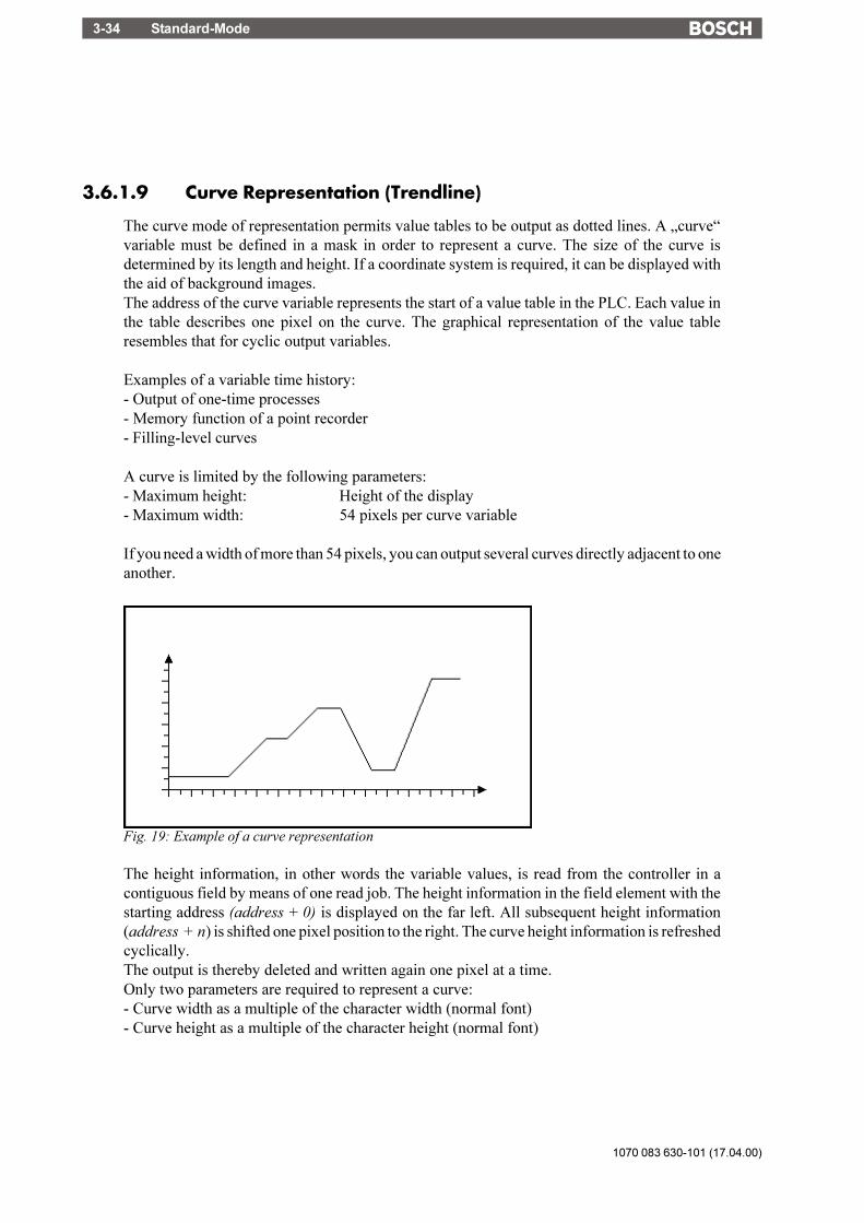
1070 083 630-101 (17.04.00)
Standard-Mode3-34
3.6.1.9 Curve Representation (Trendline)
The curve mode of representation permits value tables to be output as dotted lines. A �curve�variable must be defined in a mask in order to represent a curve. The size of the curve isdetermined by its length and height. If a coordinate system is required, it can be displayed withthe aid of background images.The address of the curve variable represents the start of a value table in the PLC. Each value inthe table describes one pixel on the curve. The graphical representation of the value tableresembles that for cyclic output variables.
Examples of a variable time history:- Output of one-time processes- Memory function of a point recorder- Filling-level curves
A curve is limited by the following parameters:- Maximum height: Height of the display- Maximum width: 54 pixels per curve variable
If you need a width of more than 54 pixels, you can output several curves directly adjacent to oneanother.
Fig. 19: Example of a curve representation
The height information, in other words the variable values, is read from the controller in acontiguous field by means of one read job. The height information in the field element with thestarting address (address + 0) is displayed on the far left. All subsequent height information(address + n) is shifted one pixel position to the right. The curve height information is refreshedcyclically.The output is thereby deleted and written again one pixel at a time.Only two parameters are required to represent a curve:- Curve width as a multiple of the character width (normal font)- Curve height as a multiple of the character height (normal font)

Standard-Mode 3-35
1070 083 630-101 (17.04.00)
/000
-010
8/B
osch
_T_e
ng_V
13_3
0030
00Q
K0
3.6.1.10 Selection Field (TSdos) Representation
The Selection Field mode of representation is comparable to coded text in that a text string isassigned to a numerical value from the controller. This facilitates visualization of operatingstates, inputs, outputs, etc. Unlike the coded text, the selection field displays the text list in fullor in parts. The chosen text is selected once the entire selection text line is displayed in the inverseformat.The example taken from the sample projects illustrates how the names of machine operators areassigned to numerical values. Numbers can be freely assigned to the texts. They need notnecessarily be contiguous or sorted in a consecutive order. Each line is stored in a text list of theprogramming system and can be used multiply. This representation is limited to bits, bytes andwords. The interpretation of Lword is possible, but requires considerable memory space.
Value Text9 Alfred1 Bernd7 Detlef4 Erwin2 << blanks were entered here!
The controller value contains the value = 7. Result:
Four entries have been defined for the selection field. If the controller addresses numbers thatare not defined in the text list, question marks (that fill the entire length of the field) appear onthe display.
Example: The variable contains the value = 5
whereas blanks are displayed for the value 2.
3.6.2 Input Variables
Input variables, when displayed for the first time (when the mask is activated), are treated in thesame way as one-time output variables, i. e. the same representation options are available. Thisincludes the scaling effect.
Scaling is performed on the value in the PLC.
Input variables can be modified in the terminal by means of Editors. Their functionality isdetermined by the type of Editor that is selected.The Editors that are supported for variable input are the same as those supported for variableoutput. Editing of the variables is subject to certain conditions which must take into considerationby the user when creating the project, such as the password protection and the external datarelease, for example.

1070 083 630-101 (17.04.00)
Standard-Mode3-36
The following must be observed when entering timers and counters:
TimerWhen writing to a timer variable, any scaling that may have been performed is first reversed togive the time value to the base 10 ms again. The BCD-coded value is then calculated so that thelowest possible time base is used.Avoid writing to a timer word in the PLC, as this has uncontrolled results on the controlbits.
CounterWhen writing to a counter variable, any scaling that may have been performed is first reversed.The BCD-coded value is then computed and transferred to the PLC.Avoid writing to a counter word in the PLC, as this has uncontrolled results on the controlbits.
Formula for Scaling Input Values
Input values transferred by the PLC are processed according to formula 1 before being displayed.After the values have been edited, they are processed in accordance with the inverse function(formula 2) before being transferred back to the PLC. The inverse function will automaticallybe generated in the terminal. Operands must be defined by the user on the basis of the values inthe PLC including the input value.
Input Value ofthe Unit
=Controller Value xFactor
Divisor- Summand
Fig. 20: Formula 2
During conversion, the last digit is automatically rounded. This must be kept in mindwhen defining the upper limit.
Input Value ofthe Unit <x Factor Divisor-Upper Limit( () )2/
Fig. 21: Formula 3
Plausibility Check
A plausibility check is performed on all input variables. As a part of this check, the entered valueis validated against the upper and lower limits specified in the variable definition. Systemmessages are generated if the entered value is outside these limits. In this case, the invalid valuewill not be transferred to the controller and the previous (valid) value will be retained.

Standard-Mode 3-37
1070 083 630-101 (17.04.00)
/000
-010
8/B
osch
_T_e
ng_V
13_3
0030
00Q
K0
If the system message texts "Value too large" and Value too small" are deleted, the followingapplies:- if the value drops below the limit, the value corresponding to the lower limit is used- if the value exceeds the upper limit, the value corresponding to the upper limit is used.A system message is not output during this process.
Help Text for Input Variables
A screen-sized help text can be created for each input variable. This help text can be displayedin the Editor by pressing the Help key. Important information to be inserted in a help text mayinclude the upper and lower limits, the impact of variables on the process to be carried out, orany interactions with other variables.
Fig. 22: Example of a help text for a variable
If a variable-specific help text is not defined, the default help text will be displayed instead. Thisis also a screen-sized text which can be edited in the programming software. If a default help textis not defined, a blank mask will be displayed.

1070 083 630-101 (17.04.00)
Standard-Mode3-38
3.6.3 System Variables
System variables can be used to control terminal-internal functions.System variables can be referenced to function keys and soft keys. They can also be used in masksas normal variables for input and output processes.
The following applies if a system variable is linked to a function key or soft key:- do not link a change of mask function and a system variable to the same key- it is not necessary that the same function key or soft key is used to set (1) and reset (0) a system
variable- jogging mode is obtained by using the same function key or soft key to set (1) and reset (0) a
system variable.
Do not include the names of system variables in the variable list. If the name of a system variableis referenced to a PLC address, it will loose its terminal-internal function.The following subchapters list the system variables, organized into separate groups of functionality,and describes their functions.In TSdos, all system variables are identified by the syllable Sys that precedes the variables. InTSwin, this syllable is not used. Within the following description, the syllable Sys is omitted.
3.6.3.1 Basic Functions
IntEraseEpromAllows the user description to be erased from the Flash memory and prepares the terminal fora new download via interface X3. There will be no communication with any connected PLCduring this process. Writing of a "1" to this variable erases the user description unconditionally.Subsequently, the variable is automatically reset to "0".
Data type: NumericEditor: Selection text (coded text), positive decimal numberOutput: ---Possible values: (0) Inactive Initial state
(1) Active Erases the user description
MainVersionAllows the user to display the current firmware version of the operating terminal.
Data type: AlphanumericEditor: ---Output: Alphanumeric, 8 charactersPossible values: Format specified by manufacturer
Standard-Mode 3-39
1070 083 630-101 (17.04.00)
/000
-010
8/B
osch
_T_e
ng_V
13_3
0030
00Q
K0
ComVersionIs used to display the type and version number of the current communication protocol.
Data type: AlphanumericEditor: ---Output: Alphanumeric, 8 charactersPossible values: Format specified by manufacturer
UserVersionIndicates the version number of the project description to the operator. The user enters thisnumber into the programming system during programming time.
Data type: NumericEditor: ---Output: Numeric, 3 digitsPossible values: ---
BootThis variable can be used to initiate the terminal to boot (system restart). The variable is suitablefor integrating the setup function into the regular operator guidance, making it possible to modifyterminal parameters which require a subsequent reinitialization (system restart) in any I/O mask.The terminal is booted if a "1" is written to this variable. Subsequently, the variable isautomatically reset to "0".
Data type: NumericEditor: Selection text (coded text), positive decimal numberOutput: ---Possible values: (0) Inactive Initial state
(1) Active System restart
LCDContrastIs used to adjust the contrast for terminals with liquid crystal displays.
Data type: NumericEditor: IntegerOutput: ---Possible values: -127 to +127 (to be limited further based on terminal type)

1070 083 630-101 (17.04.00)
Standard-Mode3-40
LCDBackgroundIs used to adjust the background of the display. This variable is only relevant for operatingterminals fitted with a corresponding display. For further information see the relevant technicalmanual.
Data type: NumericEditor: Selection text (coded text), positive decimal numberOutput: ---Possible values: (0) Normal representation
(1) Inverse background
LCDBackLightIs used to adjust the background lighting of the display. This variable is only relevant foroperating terminals fitted with a corresponding display. For further information see the relevanttechnical manual (available from firmware 6.40).
Data type: NumericEditor: AnyOutput: ---Possible values: (0) Background lighting OFF
(1 to x) Background lighting ON (dimmed)
TurnOnTempIs used to ensure that the liquid crystal display of the operating terminal is not turned on until acertain ambient temperature is reached. This variable is only relevant for operating terminalsprovided with a corresponding functionality in conjunction with the corresponding display. Forfurther information see the relevant technical manual (available from firmware 6.40).
Data type: NumericEditor: Selection text (coded text), positive decimal numberOutput: ---Possible values: (0) LCD-display OFF
(1 to x) value of the temperature at which the LCD-display is turned ON
OsLanguageWith multilingual user descriptions, this variable is used for online language selection.
Data type: NumericEditor: Selection text (coded text)Output: ---Possible values: (0) First language
(n) nth language

Standard-Mode 3-41
1070 083 630-101 (17.04.00)
/000
-010
8/B
osch
_T_e
ng_V
13_3
0030
00Q
K0
3.6.3.2 Communication Area X2
ComDataLenADefines the number of data bits for the communication via interface X2 (X2.1).
Data type: NumericEditor: Selection text (coded text), positive decimal numberOutput: ---Possible values: (0) 5bits/Char
(1) 6bits/Char(2) 7bits/Char(3) 8bits /Char
ComParityADetermines the creation of and check method of the parity for the communication via interfaceX2 (X2.1).
Data type: NumericEditor: Selection text (coded text), positive decimal numberOutput: ---Possible values: (0) No Parity
(1) Odd Parity(2) Even Parity.
ComStopBitsADefines the number of stop bits for the communication via interface X2 (X2.1).
Data type: NumericEditor: Selection text (coded text), positive decimal numberOutput: ---Possible values: (0) 1 bit
(1) 1.5 Bits(2) 2 bits

1070 083 630-101 (17.04.00)
Standard-Mode3-42
ComBaudrateADefines the baud rate for the communication via interface X2 (X2.1).
Data type: NumericEditor: Selection text (coded text), positive decimal numberOutput: ---Possible values: (0) 300 Bd
(1) 600 Bd(2) 1200 Bd(3) 2400 Bd(4) 4800 Bd(5) 9600 Bd(6) 19200 Bd(7) 38400 Bd(8) 57600 Bd (BT35 / BT35C / TP35 only)
ComHandshakeASpecifies the type of handshake for the communication via interface X2 (X2.1).
Data type: NumericEditor: Selection text (coded text), positive decimal numberOutput: ---Possible values: (0) No handshake
(1) RTS/CTS hardware handshake(2) XON/XOFF software handshake
ComDefaultAThis variable can be used to program new parameters for the interface (X2).
Data type: NumericEditor: Selection text (coded text), positive decimal numberOutput: ---Possible values: (0) Inactive Initial state
(1) Active The data entered into the associated system varia-bles are accepted as the new parameters.
(2) Active The data stored in the Flash memory by theprogramming software are accepted as the
new parameters.
ComTimeoutSpecifies the monitoring period for the interface X2 (X2.1). The value (0) deactivates the timeoutmonitoring function.
Data type: NumericEditor: Positive decimal numberOutput: ---Possible values: (0) Inactive Initial state
(1 to 65535) Timeout monitoring active (time in ms)
Standard-Mode 3-43
1070 083 630-101 (17.04.00)
/000
-010
8/B
osch
_T_e
ng_V
13_3
0030
00Q
K0
ComRetryTimeoutSpecifies the period of time, in milliseconds, that the terminal allows to elapse after an attemptto establish a connection via the communication interface X2 failed, before making anotherattempt. This allows the time period required for the PLC-specific powerup phase to be bridged,thereby avoiding the generation of an error message.
Data type: NumericEditor: Positive decimal numberOutput: ---Possible values: 0 to 65535 ms
ComSlaveNrContains the slave number used for the device on the network. This address can be used to addressthe operating terminal on the bus.
Data type: NumericEditor: Positive decimal numberOutput: Positive decimal numberPossible values: 0 to 255
3.6.3.3 Error Statistics Interface X2
ComParityCountError counter for monitoring of parity errors on the interface X2 to the PLC. Is erased on everydownload.
Data type: NumericEditor: (Possible)Output: Positive decimal numberPossible values: 0to 65535
ComOverrunCountError counter for monitoring of overrun errors on the interface X2 to the PLC. Is erased on everydownload.
Data type: NumericEditor: (Possible)Output: Positive decimal numberPossible values: 0 to 65535
ComFrameCountError counter for monitoring of framing errors on the interface X2 to the PLC. Is erased on everydownload.
Data type: NumericEditor: (Possible)Output: Positive decimal numberPossible values: 0 to 65535

1070 083 630-101 (17.04.00)
Standard-Mode3-44
ComStatisticsTabThe system variable points to the beginning of the protocol statistics table with 6 elements of 4bytes each.
Data type: Positive decimal numberEditor: ---Output: TablePossible values: ---
ComErrorTabThe system variable points to the beginning of a table with 16 elements which contain the mostrecent 16 communication errors.
Data type: Positive decimal numberEditor: ---Output: TablePossible values: ---
ComSubcodeTabThe system variable points to the beginning of a table with 16 elements which contain thesubcodes of the communication errors.
Data type: Positive decimal numberEditor: ---Output: TablePossible values: ---
3.6.3.4 Communication Area X3
ComDataLenBDefines the number of data bits on the interface (X3).
Data type: NumericEditor: Selection text (coded text), positive decimal numberOutput: ---Possible values (0) 5 bits/char
(1) 6 bits/char(2) 7 bits/char(3) 8 bits/char
Standard-Mode 3-45
1070 083 630-101 (17.04.00)
/000
-010
8/B
osch
_T_e
ng_V
13_3
0030
00Q
K0
ComParityBDetermines the creation of and check method for the parity bit for the interface (X3).
Data type: NumericEditor: Selection text (coded text), positive decimal numberOutput: ---Possible values: (0) No parity
(1) Odd parity(2) Even parity
ComStopBitsBDefines the number of stop bits on the interface (X3).
Data type: NumericEditor: Selection text (coded text), positive decimal numberOutput: ---Possible values: (0) 1 bit
(1) 1.5 bits(2) 2 bits
ComBaudrateBDefines the baud rate on the interface (X3).
Data type: NumericEditor: Selection text (coded text), positive decimal numberOutput: ---Possible values: (0) 300 Bd
(1) 600 Bd(2) 1200 Bd(3) 2400 Bd(4) 4800 Bd(5) 9600 Bd(6) 19200 Bd(7) 38400 Bd(8) 57600 Bd
ComHandshakeBSpecifies the type of handshake on the interface (X3).
Data type: NumericEditor: Selection text (coded text), positive decimal numberOutput: ---Data type: NumericEditor: Selection text (coded text), positive decimal numberOutput: ---

1070 083 630-101 (17.04.00)
Standard-Mode3-46
Possible values: (0) Inactive Initial state(1) Active The data entered into the associated system variables are
accepted as the new parameters.(1) Active The data stored in the Flash memory by the programming
software are accepted as the new parameters.
3.6.3.5 Real-Time Clock
RTCSecThis variable is used to display and set the seconds of the clock.
Data type: Positive decimal numberEditor: Positive decimal numberOutput: Positive decimal numberPossible values: 0 to 59
RTCMinThis variable is used to display and set the minutes of the clock.
Data type: Positive decimal numberEditor: Positive decimal numberOutput: Positive decimal numberPossible values: 0 to 59
RTCHourThis variable is used to display and set the hours of the clock.
Data type: Positive decimal numberEditor: Positive decimal numberOutput: Positive decimal numberPossible values: 0 to 23
RTCDayThis variable is used to display and set the day of the month.
Data type: Positive decimal numberEditor: Positive decimal numberOutput: Positive decimal numberPossible values: 0 to 31 (varies from month to month, clock corrects incorrect
entries on the next change of date)
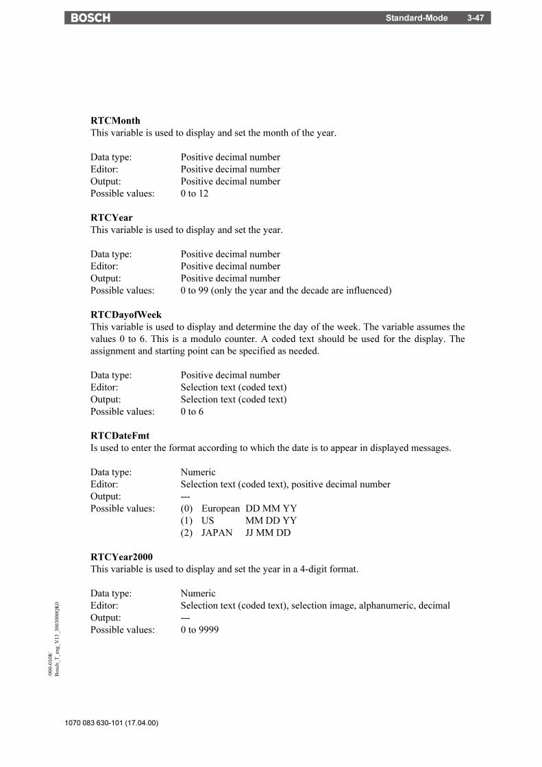
Standard-Mode 3-47
1070 083 630-101 (17.04.00)
/000
-010
8/B
osch
_T_e
ng_V
13_3
0030
00Q
K0
RTCMonthThis variable is used to display and set the month of the year.
Data type: Positive decimal numberEditor: Positive decimal numberOutput: Positive decimal numberPossible values: 0 to 12
RTCYearThis variable is used to display and set the year.
Data type: Positive decimal numberEditor: Positive decimal numberOutput: Positive decimal numberPossible values: 0 to 99 (only the year and the decade are influenced)
RTCDayofWeekThis variable is used to display and determine the day of the week. The variable assumes thevalues 0 to 6. This is a modulo counter. A coded text should be used for the display. Theassignment and starting point can be specified as needed.
Data type: Positive decimal numberEditor: Selection text (coded text)Output: Selection text (coded text)Possible values: 0 to 6
RTCDateFmtIs used to enter the format according to which the date is to appear in displayed messages.
Data type: NumericEditor: Selection text (coded text), positive decimal numberOutput: ---Possible values: (0) European DD MM YY
(1) US MM DD YY(2) JAPAN JJ MM DD
RTCYear2000This variable is used to display and set the year in a 4-digit format.
Data type: NumericEditor: Selection text (coded text), selection image, alphanumeric, decimalOutput: ---Possible values: 0 to 9999

1070 083 630-101 (17.04.00)
Standard-Mode3-48
3.6.3.6 Serial Message System
RepmanSortCritIs used to enter the sorting criterion for the serial message output.
Data type: NumericEditor: Selection text (coded text), positive decimal numberOutput: ---Possible values: (0) By priority of message number
(1) By time of arrival (newest first)(2) By time of arrival (oldest first)
ClearRepBufIs used to erase the entire serial message buffer. Optionally direct control via function keys, softkeys or Editor. If necessary, passwords or special masks should be implemented to controlerasure of the message buffer.
Data type: NumericEditor: Selection text (coded text), positive decimal numberOutput: ---Possible values: (0) Maintain data
(1) Erase message buffer
RepmanRepPrintSwitches the output of messages via the printer on and off.
Data type: NumericEditor: Selection text (coded text), positive decimal numberOutput: ---Possible values: (0) Off
(1) On
RepoutNrSwitches the output of the message number in the message mask on and off.
Data type: NumericEditor: Selection text (coded text), positive decimal numberOutput: ---Possible values: (0) Off
(1) On

Standard-Mode 3-49
1070 083 630-101 (17.04.00)
/000
-010
8/B
osch
_T_e
ng_V
13_3
0030
00Q
K0
RepoutDateSwitches the output of the date of the message in the message mask on and off.
Data type: NumericEditor: Selection text (coded text), positive decimal numberOutput: ---Possible values: (0) Off
(1) On
RepoutTimeSwitches the output of the time of the message in the message mask on and off.
Data type: NumericEditor: Selection text (coded text), positive decimal numberOutput: ---Possible values: (0) Off
(1) On
RepoutAnzYearDetermines the number of digits that is to be used to represent the year.
Data type: NumericEditor: Selection text (coded text), selection image, decimalOutput: ---Possible values: (0) year represented by 2 digits
(1) year represented by 4 digits
RepoutRepTextIs used to display the most current serial message. The message is displayed in the same way asit would appear in the message mask, i.e. in accordance with the selected message parameters.
Data type: AlphanumericEditor: ---Output: AlphanumericPossible values: Any
RepoutRepText21Is used to display the most current message of the serial message system - from the 21st digit witha variable length (20, 40 or 60). The message is displayed in the same way as it would appearin the message mask, i.e. in accordance with the selected message parameters.
Data type: AlphanumericEditor: ---Output: AlphanumericPossible values: Any

1070 083 630-101 (17.04.00)
Standard-Mode3-50
RepoutRepText41Is used to display the most current message of the serial message system - from the 41st digit witha variable length (40 or 60). The message is displayed in the same way as it would appear in themessage mask, i.e. in accordance with the selected message parameters.
Data type: AlphanumericEditor: ---Output: AlphanumericPossible values: Any
RepoutRepText61Is used to display the most current message of the serial message system - from the 61st digit.The last 20 characters of a message are displayed. The message is displayed in the same way asit would appear in the message mask, i.e. in accordance with the selected message parameters.
Data type: AlphanumericEditor: ---Output: AlphanumericPossible values: Any
3.6.3.7 Parallel Message System
RepmanSortCritPThis variable indicates to the terminal the sorting criterion according to which the messages areto be displayed. The default value is defined in the user description. This variable can be adaptedduring editing processes at a later date.
Data type: NumericEditor: Selection text (coded text), positive decimal numberOutput: ---Possible values: (0) By priority of message number
(1) By time of arrival (newest first)(2) By time of arrival (oldest first)
RepoutNrPThis variable indicates to the terminal whether or not the message number is to be displayed alongwith the message text of messages in the parallel message system. The default value is definedin the user description. This variable can be adapted during editing processes at a later date.
Data type: NumericEditor: Selection text (coded text), positive decimal numberOutput: ---Possible values: (0) Off
(1) On

Standard-Mode 3-51
1070 083 630-101 (17.04.00)
/000
-010
8/B
osch
_T_e
ng_V
13_3
0030
00Q
K0
RepoutDatePThis variable indicates to the terminal whether or not the date is to be displayed along with themessage text of messages in the parallel message system. The default value is defined in the userdescription. This variable can be adapted during editing processes at a later date.
Data type: NumericEditor: Selection text (coded text), positive decimal numberOutput: ---Possible values: (0) Off
(1) On
RepoutTimePThis variable indicates to the terminal whether or not the time is to be displayed along with themessage text of messages in the parallel message system. The default value is defined in the userdescription. This variable can be adapted during editing processes at a later date.
Data type: NumericEditor: Selection text (coded text), positive decimal numberOutput: ---Possible values: (0) Off
(1) On
RepoutAnzYearPDetermines the number of digits that is to be used to represent the year.
Data type: NumericEditor: Selection text (coded text), selection image, alphanumeric, binary, decimal,hexadecimalOutput: ---Possible values: (0) year represented by 2 digits
(1) year represented by 4 digits
RepoutRepTextPThe terminal uses this variable to display the most current message of the parallel messagesystem.
Data type: AlphanumericEditor: ---Output: AlphanumericPossible values: Any

1070 083 630-101 (17.04.00)
Standard-Mode3-52
RepoutRepTextP21Is used to display the most current message of the parallel message system - from the 21st digitwith a variable length (20, 40 or 60). The message is displayed in the same way as it would appearin the message mask, i.e. in accordance with the selected message parameters.
Data type: AlphanumericEditor: ---Output: AlphanumericPossible values: Any
RepoutRepTextP41Is used to display the most current message of the parallel message system - from the 41st digitwith a variable length (40 or 60). The message is displayed in the same way as it would appearin the message mask, i.e. in accordance with the selected message parameters.
Data type: AlphanumericEditor: ---Output: AlphanumericPossible values: Any
RepoutRepTextP61Is used to display the most current message of the parallel message system - from the 61st digit.The last 20 characters of a message are displayed. The message is displayed in the same way asit would appear in the message mask, i.e. in accordance with the selected message parameters.
Data type: AlphanumericEditor: ---Output: AlphanumericPossible values: Any
3.6.3.8 Printer Control
StopPrintWhen the system variable is activated, the print process currently in progress is terminated.
Data type: NumericEditor: Selection text (coded text), positive decimal number, soft key, functionkeyOutput: ---Possible values: (0) Initial state
(1) Terminate print process

Standard-Mode 3-53
1070 083 630-101 (17.04.00)
/000
-010
8/B
osch
_T_e
ng_V
13_3
0030
00Q
K0
BlockPrintUpon activation of this system variable, the block selected in the message mask is printed.
Data type: NumericEditor: Selection text (coded text), positive decimal number, soft key, functionkeyOutput: ---Possible values: (0) Initial state
(1) Print block
PrintAllRepUpon activation of this system variable, the entire serial message memory is printed. The outputis as predefined.
Data type: NumericEditor: Selection text (coded text), positive decimal number, soft key, functionkeyOutput: ---Possible values: (0) Initial state
(1) Formatted printout(2) Full-length printout
PrintAllStateUpon activation of this system variable, the entire parallel message memory (status messages)is printed.
Data type: NumericEditor: Selection text (coded text), positive decimal number, soft key, functionkeyOutput: ---Possible values: (0) Initial state
(2) Print message buffer
BlockPrintLongUpon activation of this system variable, the entire area selected in a message mask is printed infull length. The settings chosen at programming are ignored.
Data type: NumericEditor: Selection text (coded text), positive decimal number, soft key, functionkeyOutput: ---Possible values: (0) Initial state
(1) Print selected area

1070 083 630-101 (17.04.00)
Standard-Mode3-54
3.6.3.9 Menu Control / Keys
NewMaskIf a mask number is written to this system variable, the system will switch to the correspondingmask.
Data type: NumericEditor: Selection text (coded text), selection fieldOutput: ---Possible values: 1 to 9999
VarTablenR0Generates a consecutive numbering in tables beginning with the number "0". This systemvariable is also used to output constant table texts.
Data type: NumericEditor: ---Output: Selection text (coded text), positive decimal numberPossible values: 0 to n
VarTablenR1Generates a consecutive numbering in table beginning with the number "1". This system variableis also used to output constant table texts.
Data type: NumericEditor: ---Output: Selection text (coded text), positive decimal numberPossible values: 1 to n
HardCopyIs used to upload a hard copy in PCX or ASCII format via interface X3 to the connected PC.
Data type: NumericEditor: Selection text (coded text), positive decimal number, soft key, functionkeyOutput: ---Possible values: (0) Initial state
(1) Activate hard copy (always currently displayed screen)
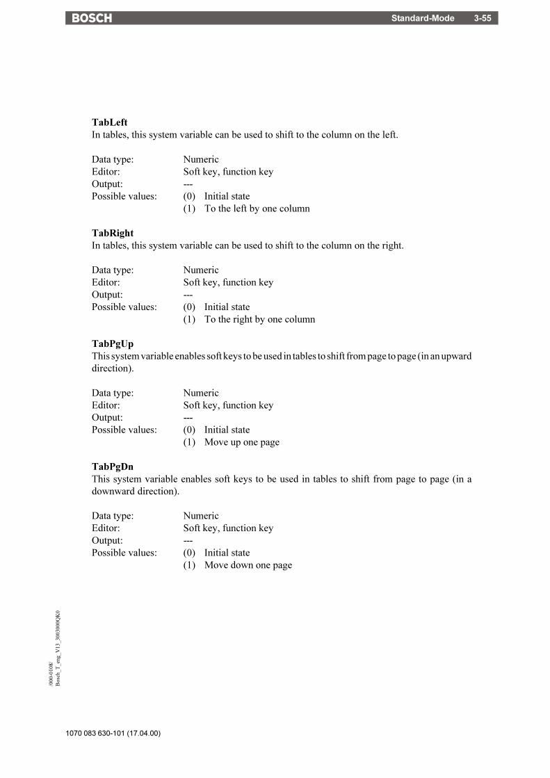
Standard-Mode 3-55
1070 083 630-101 (17.04.00)
/000
-010
8/B
osch
_T_e
ng_V
13_3
0030
00Q
K0
TabLeftIn tables, this system variable can be used to shift to the column on the left.
Data type: NumericEditor: Soft key, function keyOutput: ---Possible values: (0) Initial state
(1) To the left by one column
TabRightIn tables, this system variable can be used to shift to the column on the right.
Data type: NumericEditor: Soft key, function keyOutput: ---Possible values: (0) Initial state
(1) To the right by one column
TabPgUpThis system variable enables soft keys to be used in tables to shift from page to page (in an upwarddirection).
Data type: NumericEditor: Soft key, function keyOutput: ---Possible values: (0) Initial state
(1) Move up one page
TabPgDnThis system variable enables soft keys to be used in tables to shift from page to page (in adownward direction).
Data type: NumericEditor: Soft key, function keyOutput: ---Possible values: (0) Initial state
(1) Move down one page
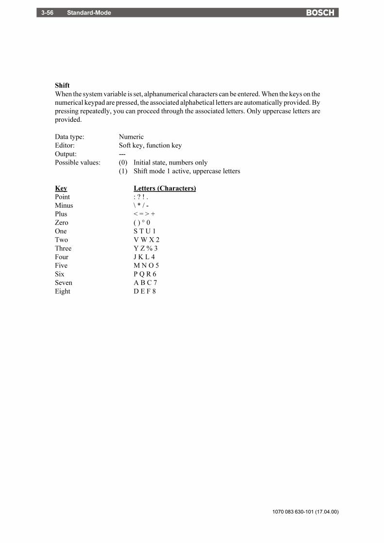
1070 083 630-101 (17.04.00)
Standard-Mode3-56
ShiftWhen the system variable is set, alphanumerical characters can be entered. When the keys on thenumerical keypad are pressed, the associated alphabetical letters are automatically provided. Bypressing repeatedly, you can proceed through the associated letters. Only uppercase letters areprovided.
Data type: NumericEditor: Soft key, function keyOutput: ---Possible values: (0) Initial state, numbers only
(1) Shift mode 1 active, uppercase letters
Key Letters (Characters)Point : ? ! .Minus \ * / -Plus < = > +Zero ( ) ° 0One S T U 1Two V W X 2Three Y Z % 3Four J K L 4Five M N O 5Six P Q R 6Seven A B C 7Eight D E F 8

Standard-Mode 3-57
1070 083 630-101 (17.04.00)
/000
-010
8/B
osch
_T_e
ng_V
13_3
0030
00Q
K0
ShiftCaseWhen the system variable is set, alphanumerical characters can be entered. When the keys on thenumerical keypad are pressed, the associated alphabetical letters are automatically provided. Bypressing repeatedly, you can proceed through the associated letters. Uppercase and lowercaseletters are provided.
Data type: NumericEditor: Soft key, Function keyOutput: ---Possible values: (0) Initial state, numbers only
(1) Shift Mode 2 active, lowercase and uppercase letters
Key Letters (Characters)Point : ? ! .Minus \ * / -Plus < = > +Zero ( ) ° 0One S T U s t u 1Two V W X v w x 2Three Y Z % y z % 3Four J K L j k l 4Five M N O m n o 5Six P Q R p q r 6Seven A B C a b c 7Eight D E F d e f 8

1070 083 630-101 (17.04.00)
Standard-Mode3-58
KeyCursLeftThis system variable allows soft keys to be used as a Cursor left key.
Data type: NumericEditor: Soft key, function keyOutput: ---Possible values: (0) Initial state
(1) Treat soft key as a Cursor left key.
KeyCursRightThis system variable allows soft keys to be used as a Cursor right key.
Data type: NumericEditor: Soft key, function keyOutput: ---Possible values: (0) Initial state
(1) Treat soft key as a Cursor right key
KeyCursUpThis system variable allows soft keys to be used as a Cursor up key.
Data type: NumericEditor: Soft key, function keyOutput: ---Possible values: (0) Initial state
(1) Treat soft key as a Cursor up key
KeyCursDownThis system variable allows soft keys to be used as a Cursor down key.
Data type: NumericEditor: Soft key, function keyOutput: ---Possible values: (0) Initial state
(1) Treat soft key as a Cursor down key
KeyHomeThis system variable allows soft keys to be used as a Cursor home key.
Data type: NumericEditor: Soft key, function keyOutput: ---Possible values: (0) Initial state
(1) Treat soft key as a Cursor home key

Standard-Mode 3-59
1070 083 630-101 (17.04.00)
/000
-010
8/B
osch
_T_e
ng_V
13_3
0030
00Q
K0
KeyHelpThis system variable allows soft keys to be used as a Help key.
Data type: NumericEditor: Soft key, function keyOutput: ---Possible values: (0) Initial state
(1) Treat soft key as a Help key
KeyDotThis system variable allows soft keys to be used as a Decimal point key.
Data type: NumericEditor: Soft key, function keyOutput: ---Possible values: (0) Initial state
(1) Treat soft key as a Decimal point key
KeyClearThis system variable allows soft keys to be used as a Delete key.
Data type: NumericEditor: Soft key, function keyOutput: ---Possible values: (0) Initial state
(1) Treat soft key as a Delete key
Key0This system variable allows soft keys to be used as the key 0 (zero).
Data type: NumericEditor: Soft key, function keyOutput: ---Possible values: (0) Initial state
(1) Treat soft key as the key 0
Key1This system variable allows soft keys to be used as the key 1 .
Data type: NumericEditor: Soft key, function keyOutput: ---Possible values: (0) Initial state
(1) Treat soft key as the key1

1070 083 630-101 (17.04.00)
Standard-Mode3-60
Key2This system variable allows soft keys to be used as the key 2.
Data type: NumericEditor: Soft key, function keyOutput: ---Possible values: (0) Initial state
(1) Treat soft key as the key 2
Key3This system variable allows soft keys to be used as the key 3.
Data type: NumericEditor: Soft key, function keyOutput: ---Possible values: (0) Initial state
(1) Treat soft key as the key 3
Key4This system variable allows soft keys to be used as the key 4.
Data type: NumericEditor: Soft key, function keyOutput: ---Possible values: (0) Initial state
(1) Treat soft key as the key 4
Key5This system variable allows soft keys to be used as the key 5.
Data type: NumericEditor: Soft key, function keyOutput: ---Possible values: (0) Initial state
(1) Treat soft key as the key 5
Key6This system variable allows soft keys to be used as the key 6.
Data type: NumericEditor: Soft key, function keyOutput: ---Possible values: (0) Initial state
(1) Treat soft key as the key 6

Standard-Mode 3-61
1070 083 630-101 (17.04.00)
/000
-010
8/B
osch
_T_e
ng_V
13_3
0030
00Q
K0
Key7This system variable allows soft keys to be used as the key 7.
Data type: NumericEditor: Soft key, function keyOutput: ---Possible values: (0) Initial state
(1 Treat soft key as the key 7
Key8This system variable allows soft keys to be used as the key 8.
Data type: NumericEditor: Soft key, function keyOutput: ---Possible values: (0) Initial state
(1 Treat soft key as the key 8
Key9This system variable allows soft keys to be used as the key 9.
Data type: NumericEditor: Soft key, function keyOutput: ---Possible values: (0) Initial state
(1) Treat soft key as the key 9
KeyPlusThis system variable allows soft keys to be used as a Plus key.
Data type: NumericEditor: Soft key, function keyOutput: ---Possible values: (0) Initial state
(1) Treat soft key as a Plus key
KeyMinusThis system variable allows soft keys to be used as a Minus key.
Data type: NumericEditor: Soft key, function keyOutput: ---Possible values: (0) Initial state
(1) Treat soft key as a Minus key
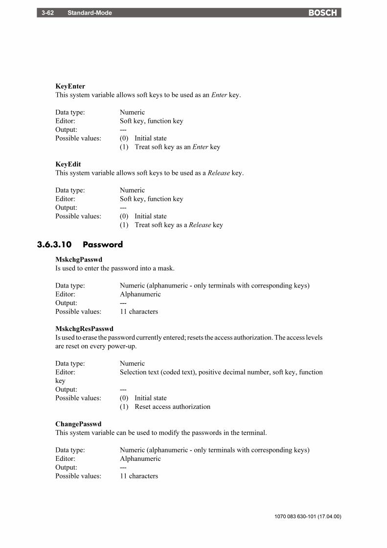
1070 083 630-101 (17.04.00)
Standard-Mode3-62
KeyEnterThis system variable allows soft keys to be used as an Enter key.
Data type: NumericEditor: Soft key, function keyOutput: ---Possible values: (0) Initial state
(1) Treat soft key as an Enter key
KeyEditThis system variable allows soft keys to be used as a Release key.
Data type: NumericEditor: Soft key, function keyOutput: ---Possible values: (0) Initial state
(1) Treat soft key as a Release key
3.6.3.10 Password
MskchgPasswdIs used to enter the password into a mask.
Data type: Numeric (alphanumeric - only terminals with corresponding keys)Editor: AlphanumericOutput: ---Possible values: 11 characters
MskchgResPasswdIs used to erase the password currently entered; resets the access authorization. The access levelsare reset on every power-up.
Data type: NumericEditor: Selection text (coded text), positive decimal number, soft key, functionkeyOutput: ---Possible values: (0) Initial state
(1) Reset access authorization
ChangePasswdThis system variable can be used to modify the passwords in the terminal.
Data type: Numeric (alphanumeric - only terminals with corresponding keys)Editor: AlphanumericOutput: ---Possible values: 11 characters

Standard-Mode 3-63
1070 083 630-101 (17.04.00)
/000
-010
8/B
osch
_T_e
ng_V
13_3
0030
00Q
K0
FlashPasswdThis system variable can be used to reset the passwords to the code values specified in theprogramming software. Useful in the case of a loss of the passwords. Make sure to make a noteof the master password first.
Data type: NumericEditor: Selection text (coded text), positive decimal number, soft key, functionkeyOutput: ---Possible values: (0) Initial state
(1) Reset passwords
PasswdlnactiveIs used to deactivate the password protection. The system variable is battery-backed. The mostrecent setting is retained when the device is turned off.
Data type: NumericEditor: Selection text (coded text), positive decimal numberOutput: ---Possible values: (0) Password protection active (initial state when first initialization)
(1) Password protection inactive (edit and view level = 255)
3.6.3.11 Recipes
SelectDSNrThis variable contains the number of the active data set. To edit the variable, the associatedSelection Text Editor must be used.
Data type: NumericEditor: Selection text (selection field for TSdos)Output: Positive decimal numberPossible values: 0 to 250
SelectDSNameThis variable contains the name of the active data set. To edit the variable, the associatedSelection Text Editor must be used.
Data type: AlphanumericEditor: Selection text (selection field for TSdos)Output: AlphanumericPossible values: 15 characters

1070 083 630-101 (17.04.00)
Standard-Mode3-64
DestDSNrWhen copying data sets, this variable contains the number of the destination data set.
Data type: NumericEditor: Positive decimal numberOutput: ---Possible values: 1 to 250
DSCopyThis variable can be used to copy the active data set to the destination specified in DestDSNr.
Data type: NumericEditor: Selection text (coded text), positive decimal number, soft key, functionkeyOutput: ---Possible values: (0) Initial state
(1) Copies to destination in DestDSNr(2) Copying and automatic search for a free data set(3) Copies to destination in DestDSNr and overwrites any existing data
set.
DSDeleteThis variable can be used to delete the active data set. The first data set from the same recipe willbecome the new active data set.
Data type: NumericEditor: Selection text (coded text), positive decimal number, soft key, functionkeyOutput: ---Possible values: (0) Initial state
(1) Deletes the data set
ActDSNameThis variable contains the name of the current data set. It can be read and in the case of RAM-data sets, it can additionally be written.
Data type: AlphanumericEditor: AlphanumericOutput: AlphanumericPossible values: 15 characters
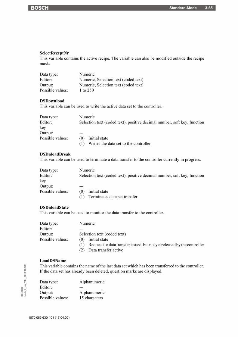
Standard-Mode 3-65
1070 083 630-101 (17.04.00)
/000
-010
8/B
osch
_T_e
ng_V
13_3
0030
00Q
K0
SelectRezeptNrThis variable contains the active recipe. The variable can also be modified outside the recipemask.
Data type: NumericEditor: Numeric, Selection text (coded text)Output: Numeric, Selection text (coded text)Possible values: 1 to 250
DSDownloadThis variable can be used to write the active data set to the controller.
Data type: NumericEditor: Selection text (coded text), positive decimal number, soft key, functionkeyOutput: ---Possible values: (0) Initial state
(1) Writes the data set to the controller
DSDnloadBreakThis variable can be used to terminate a data transfer to the controller currently in progress.
Data type: NumericEditor: Selection text (coded text), positive decimal number, soft key, functionkeyOutput: ---Possible values: (0) Initial state
(1) Terminates data set transfer
DSDnloadStateThis variable can be used to monitor the data transfer to the controller.
Data type: NumericEditor: ---Output: Selection text (coded text)Possible values: (0) Initial state
(1) Request for data transfer issued, but not yet released by the controller(2) Data transfer active
LoadDSNameThis variable contains the name of the last data set which has been transferred to the controller.If the data set has already been deleted, question marks are displayed.
Data type: AlphanumericEditor: ---Output: AlphanumericPossible values: 15 characters
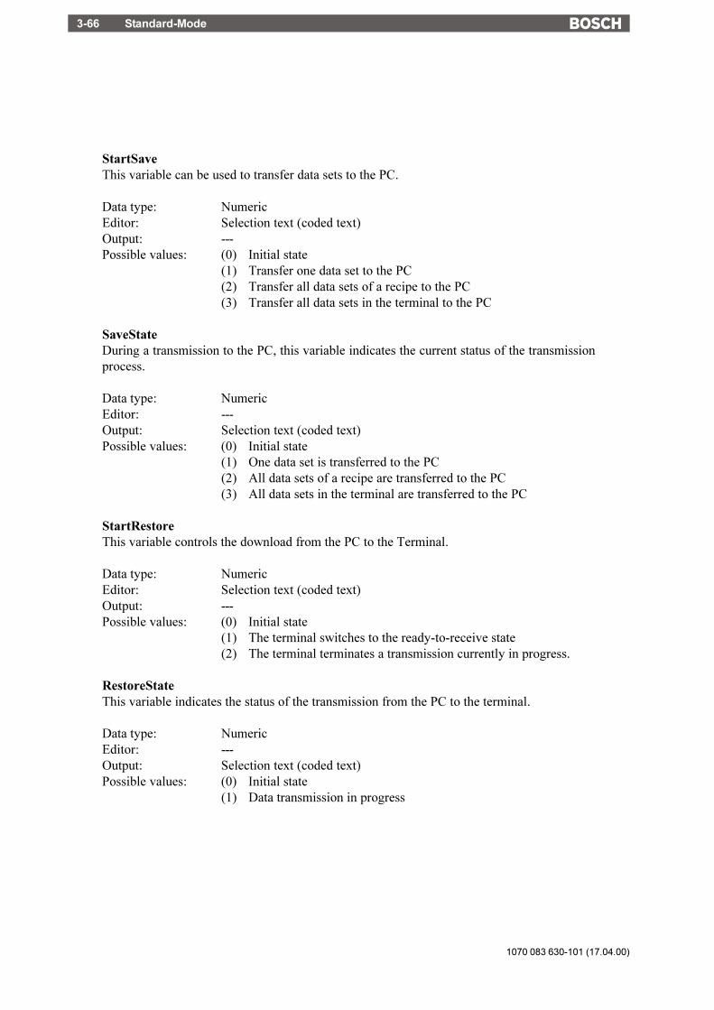
1070 083 630-101 (17.04.00)
Standard-Mode3-66
StartSaveThis variable can be used to transfer data sets to the PC.
Data type: NumericEditor: Selection text (coded text)Output: ---Possible values: (0) Initial state
(1) Transfer one data set to the PC(2) Transfer all data sets of a recipe to the PC(3) Transfer all data sets in the terminal to the PC
SaveStateDuring a transmission to the PC, this variable indicates the current status of the transmissionprocess.
Data type: NumericEditor: ---Output: Selection text (coded text)Possible values: (0) Initial state
(1) One data set is transferred to the PC(2) All data sets of a recipe are transferred to the PC(3) All data sets in the terminal are transferred to the PC
StartRestoreThis variable controls the download from the PC to the Terminal.
Data type: NumericEditor: Selection text (coded text)Output: ---Possible values: (0) Initial state
(1) The terminal switches to the ready-to-receive state(2) The terminal terminates a transmission currently in progress.
RestoreStateThis variable indicates the status of the transmission from the PC to the terminal.
Data type: NumericEditor: ---Output: Selection text (coded text)Possible values: (0) Initial state
(1) Data transmission in progress

Standard-Mode 3-67
1070 083 630-101 (17.04.00)
/000
-010
8/B
osch
_T_e
ng_V
13_3
0030
00Q
K0
RestoreLineNrThis variable indicates the current line number of the data set file. It is used to verify the progressof the receive process and in the case of an error, for error localization.
Data type: NumericEditor: ---Output: NumericPossible values: 1 to 255
StartRezPrintThis variable can be used to print data sets.
Data type: NumericEditor: Selection text (coded text)Output: ---Possible values: (0) Initial state
(1) Starts data set printout(2) Terminates print process
RezPrintStateWhen printing data sets, this variable indicates the current printing status.
Data type: NumericEditor: ---Output: Selection text (coded text)Possible values: (0) Initial state
(1) Data set printout in progress
StartUploadThis variable can be used to read, for the active recipe, a data set from the controller and to storeit in the terminal.
Data type: NumericEditor: Selection text (coded text)Output: ---Possible values: (0) Initial state
(1) Variables are read individually from their specified addresses(2) Variables are read as a block from the buffer specified for the recipe(3) Variables are read individually from their specified addresses.
A free data set is automatically being searched for.If no free data set is available, system message 18 is displayed.
(4) Variables are read as a block from the buffer specified for the recipe.A free data set is automatically being searched for.If no free data set is available, system message 18 is displayed.
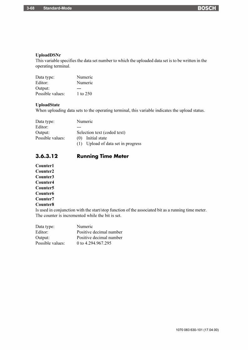
1070 083 630-101 (17.04.00)
Standard-Mode3-68
UploadDSNrThis variable specifies the data set number to which the uploaded data set is to be written in theoperating terminal.
Data type: NumericEditor: NumericOutput: ---Possible values: 1 to 250
UploadStateWhen uploading data sets to the operating terminal, this variable indicates the upload status.
Data type: NumericEditor: ---Output: Selection text (coded text)Possible values: (0) Initial state
(1) Upload of data set in progress
3.6.3.12 Running Time Meter
Counter1Counter2Counter3Counter4Counter5Counter6Counter7Counter8Is used in conjunction with the start/stop function of the associated bit as a running time meter.The counter is incremented while the bit is set.
Data type: NumericEditor: Positive decimal numberOutput: Positive decimal numberPossible values: 0 to 4.294.967.295

Standard-Mode 3-69
1070 083 630-101 (17.04.00)
/000
-010
8/B
osch
_T_e
ng_V
13_3
0030
00Q
K0
3.6.3.13 Loop-Through Operation
Pg2SpsActivates and deactivates the loop-through operation (toggle function). This function must beprovided by the PG protocol.
Data type: NumericEditor: Selection text (coded text), positive decimal numberOutput: ---Possible values: (0) Initial state
(1) First 1 activates, second 1 deactivates the loop-through operation
Pg2SpsStateIndicates the status of the loop-through operation.
Data type: NumericEditor: ---Output: Selection text (coded text)Possible values: (0) Initial state (OFF)
(1) Issue request for loop-through operation(2) Loop-through operation possible(3) Loop-through operation active
3.6.3.14 Loadable Font
ChrsetNameIs used to display the current font name.The name of the font is limited to a maximum length of 8 characters.
Data type: AlphanumericEditor: ---Output: ---Possible values: (Standard) Display using terminal font
(Font name) Display using own font

1070 083 630-101 (17.04.00)
Standard-Mode3-70
3.6.3.15 Maintenance
User1User2User3User4User5Universal variables that permit the user to store information in the terminal. The data are stored in thebattery-backed RAM.
Data type: AnyEditor: AnyOutput: AnyPossible values: 16 bit
LCDADCInputIs used to read the current input value from the AD-converter that is used for LCD contrast control. Thisvalue is only designed to be used for diagnosis purposes.
Data type: NumericEditor: AnyOutput: ---
LCDDACOutputIs used to read the current output value from the DA-converter that is used for LCD contrast control.This value is only designed to be used for diagnosis purposes.
Data type: NumericEditor: AnyOutput: ---
BreakThe current Editor is interrupted and the values entered are not transferred to the controller. Triggerthe Break function with a function key in a soft key.
Data type: NumericEditor: Function key, soft key, selection text, decimal number, binary number,
hexadecimal numberOutput: ---Possible values: (0) Initial state
(1) Editing process is terminated
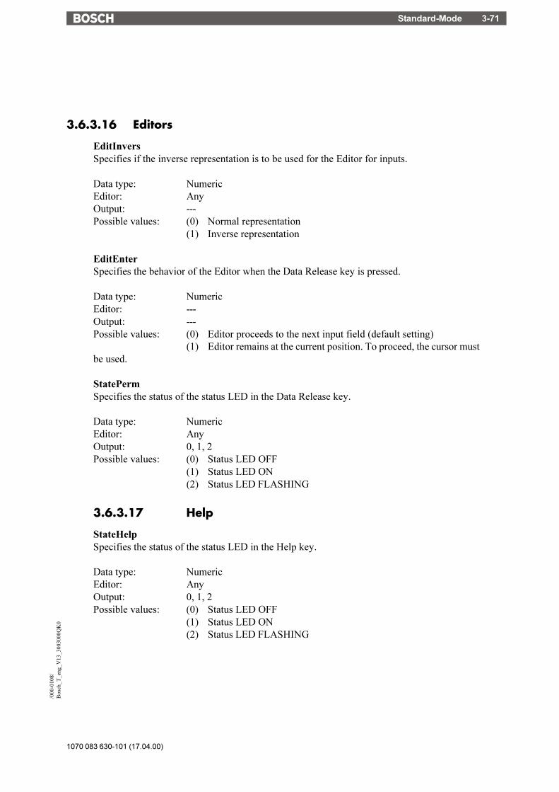
Standard-Mode 3-71
1070 083 630-101 (17.04.00)
/000
-010
8/B
osch
_T_e
ng_V
13_3
0030
00Q
K0
3.6.3.16 Editors
EditInversSpecifies if the inverse representation is to be used for the Editor for inputs.
Data type: NumericEditor: AnyOutput: ---Possible values: (0) Normal representation
(1) Inverse representation
EditEnterSpecifies the behavior of the Editor when the Data Release key is pressed.
Data type: NumericEditor: ---Output: ---Possible values: (0) Editor proceeds to the next input field (default setting)
(1) Editor remains at the current position. To proceed, the cursor mustbe used.
StatePermSpecifies the status of the status LED in the Data Release key.
Data type: NumericEditor: AnyOutput: 0, 1, 2Possible values: (0) Status LED OFF
(1) Status LED ON(2) Status LED FLASHING
3.6.3.17 Help
StateHelpSpecifies the status of the status LED in the Help key.
Data type: NumericEditor: AnyOutput: 0, 1, 2Possible values: (0) Status LED OFF
(1) Status LED ON(2) Status LED FLASHING

1070 083 630-101 (17.04.00)
Standard-Mode3-72
MessageIn the case of a system error, the number of the system message is written to this variable..
Data type: NumericEditor: AnyOutput: ---Possible values: (0) Initial state
(1 to 29) System message number
QuitMessageAcknowledges the system message that is currently displayed by the system variable Message.
Data type: NumericEditor: AnyOutput: ---Possible values: (0) Initial state
(1) Acknowledge
3.6.4 Editors
Various Editors are available in I/O masks for the various data types. With the term Editor, werefer to program parts designed to provide a convenient method of editing input variables. Thissequence control required for the editing process is completely integrated into the terminal. Anadditional "software" in the controller is not required for this purpose.The Editors are influenced by the:- data release (particularly from the connected controller)- cyclic value refreshing- the help system and- the plausibility check.The Editors are operated with the aid of editing and control keys. For details on the respectivefunctions consult the corresponding Editor description.The variables of the controllers can be modified using the Editors. Upon entry, the numericalvariables are checked for plausibility. The limits are determined by the user in the variabledefinition. It is also possible to include a variable-specific help text. This text may, for example,provide a description of the variable function and its valid range of values.
Variables are entered as follows:The Data Release key will allow the Editor to be activated if the I/O mask contains an editablevalue. When in the editing mode, the status LED in the Data Release key lights up and the cursorpoints at the first editable variable. This value can now be edited by using the numerical keyboardand/or the Plus/Minus keys. The value is stored by pressing the Enter key. The value is checkedfor plausibility during this process. If an error is detected, the status LED in the Help key willbegin to flash.

Standard-Mode 3-73
1070 083 630-101 (17.04.00)
/000
-010
8/B
osch
_T_e
ng_V
13_3
0030
00Q
K0
A flashing status LED in the Help key indicates a malfunction to the user. A description of themalfunction will be displayed if the Help key is pressed. In the case of an error, the Enter keycan not be used to exit the editing field.The control keys, on the contrary, can be used to exit an editing field even if the value is invalid.In this case, however, the last value which was entered will be discarded and the old value(original value) will be restored.In the editing mode, control keys can be used to select editable variables. If the Data Release keyis pressed again, the editing mode will be exited and the status LED will go off.The following Editors are currently available for selection in the variable definition:
TSdos Editors TSwin EditorsInteger Decimal Number / No Post-Decimal PlacesReal Decimal Number / Post-Decimal PlacesFloating Point Floating Point NumberSelection Item / Coded Text Selection TextCoded Image Selection ImageSelection Item Selection TextCurve Diagram CurveBeam Diagram BarAlphanumerical AlphanumericHexadecimal Hexadecimal NumberBinary Binary NumberBCD-Number Decimal Number / Attribute BCDTimer Decimal Number / Attribute TimerCounter Decimal Number / Attribute CounterPassword Alphanumeric / Password
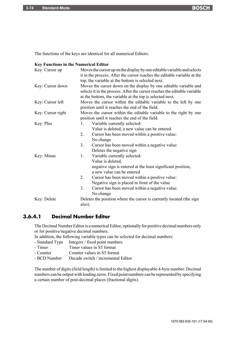
1070 083 630-101 (17.04.00)
Standard-Mode3-74
The functions of the keys are identical for all numerical Editors.
Key Functions in the Numerical EditorKey: Cursor up Moves the cursor up on the display by one editable variable and selects
it in the process. After the cursor reaches the editable variable at thetop, the variable at the bottom is selected next.
Key: Cursor down Moves the cursor down on the display by one editable variable andselects it in the process. After the cursor reaches the editable variableat the bottom, the variable at the top is selected next.
Key: Cursor left Moves the cursor within the editable variable to the left by oneposition until it reaches the end of the field.
Key: Cursor right Moves the cursor within the editable variable to the right by oneposition until it reaches the end of the field.
Key: Plus 1. Variable currently selected:Value is deleted, a new value can be entered
2. Cursor has been moved within a positive value:No change
3. Cursor has been moved within a negative value:Deletes the negative sign
Key: Minus 1. Variable currently selected:Value is deleted,negative sign is entered at the least significant position,a new value can be entered
2. Cursor has been moved within a positive value:Negative sign is placed in front of the value
3. Cursor has been moved within a negative value:No change
Key: Delete Deletes the position where the cursor is currently located (the signalso).
3.6.4.1 Decimal Number Editor
The Decimal Number Editor is a numerical Editor, optionally for positive decimal numbers onlyor for positive/negative decimal numbers.In addition, the following variable types can be selected for decimal numbers:- Standard Type Integers / fixed point numbers- Timer Timer values in S5 format- Counter Counter values in S5 format- BCD Number Decade switch / incremental Editor
The number of digits (field length) is limited to the highest displayable 4-byte number. Decimalnumbers can be output with leading zeros. Fixed point numbers can be represented by specifyinga certain number of post-decimal places (fractional digits).

Standard-Mode 3-75
1070 083 630-101 (17.04.00)
/000
-010
8/B
osch
_T_e
ng_V
13_3
0030
00Q
K0
Other selectable options are scaling factors, limits, message transfer mode and display attributes.This Editor can be used to access bit, byte, word and Lword variables. The maximum limits aredetermined by the memory map.
The variable types Timer and Counter are represented and can be edited on the operating terminalin the same way as the variable type Standard Type.
The variable type BCD-Number has a special feature.The Editor for BCD-numbers is also referred to as the �Decade Switch�.With scaled variables, the value in the PLC changes by +1/-1, although the input value which isactually displayed also depends on the defined scaling factor! This means that special care mustbe taken whenever scaling is required. The Editor is also suitable for making fine adjustmentsor as a decade switch with decimal carry-over.Possible Data Types:- Positive integers (no entry of signs)- Integers- Positive fixed point numbers (no entry of signs)- Fixed point numbers
Key Functions in the BCD-Number EditorKeys: 1 to 9 1.) Standard
Direct input of numerical values2.) Mix-Mode
Direct input of numerical values3.) Incremental
No FunctionKey: Plus 1.) Standard
No Function2.) Mix-Mode and Incremental
Increases the value at the cursor position and influences themore significant digits when the range is exceeded(with a dynamic repeat function)
Key: Minus 1.) StandardNo Function
2.) Mix-Mode and IncrementalReduces the value at the cursor position and influences themore significant digits when this value falls below the range(with a dynamic repeat function)
Key: Cursor left Moves the cursor within the editable variable to the left by oneposition until it reaches the end of the field.
Key: Cursor right Moves the cursor within the editable variable to the right by oneposition until it reaches the end of the field.

1070 083 630-101 (17.04.00)
Standard-Mode3-76
3.6.4.2 Floating Point Number Editor
The Floating-Point Number Editor supports Lword variables stored in IEEE format. Thisvariable type is not supported by every controller type. In this case, an alternative would be toresort to fixed point numbers in Lword format. Scaling factors are also suitable for displayingprecise fractional numbers.The functions of the control and editing keys are identical to those of the Decimal Number Editor.
3.6.4.3 Hexadecimal Editor
The Hexadecimal Editor permits inputs of hexadecimal values. The sign keys have a specialfunction here. Since there are no alphanumerical keys, alphanumerical characters can be enteredwith the sign keys instead.
Key Functions in the Hexadecimal EditorKeys: 1 to 9 Direct entry of numerical valuesKey: Plus Enters the ASCII-characters 0 to 9, A to F in ascending order at the
selected positionKey: Minus Enters the ASCII-characters F to A, 9 to 0 in descending order at
the selected positionKey: Cursor left Moves the cursor within the editable variable to the left by one
position until it reaches the end of the field.Key: Cursor right Moves the cursor within the editable variable to the right by one
position until it reaches the end of the field.
3.6.4.4 Alphanumerical Editor
Entering alphanumerical characters with the numerical keyboard is possible by means of aspecial Incremental Editor. This Editor permits text strings that consist of lower and upper-casealphanumerical characters to be edited.
Key Functions in the Alphanumerical EditorKeys: 1 to 9 Direct entry of the numbers 0 to 9.Key: Plus Enters the ASCII-characters 0 to 9, A to Z, a to z in ascending
order at the selected position.Key: Minus Enters the ASCII-characters z to a, Z to A, 9 to 0 in descending
order at the selected position.Key: Cursor left Moves the cursor within the editable variable to the left by one
position until it reaches the end of the field.Key: Cursor right Moves the cursor within the editable variable to the right by one
position until it reaches the end of the field.Delete Deletes the character at the cursor position. As the character is
deleted, the text to the right of the cursor is moved to the left byone character.

Standard-Mode 3-77
1070 083 630-101 (17.04.00)
/000
-010
8/B
osch
_T_e
ng_V
13_3
0030
00Q
K0
Field Type "Password"In conjunction with the field type Password, the Alphanumerical Editor allows hidden entry ofnumerical values for the password. The field type Password has the same functions as thestandard Alphanumerical Editor except that the characters do not appear when they are typed in.The entered character is represented by a letter "X". Entries are made in insert mode. Thefunction of the field type Password is linked to the system variable MskchgPasswd. To be ableto enter the password such that it also appears when it is entered, an alphanumerical variablewithout the field type Password must be used and linked to the system variable MskchgPasswd.
3.6.4.5 Selection Text Editor (Coded Text)
The Selection Text Editor offers texts contained in a text list for selection. Every text in a textlist is assigned to a numerical value. In the case of input variables, the numerical value associatedwith the corresponding text is written to the PLC variable. For output variables, the textassociated with the numerical value is displayed on the operating terminal.
Key Functions in the Selection Text EditorKey: Plus Selection in ascending order (after the final value is reached, the
value at top of the text list is selected next.)Key: Minus Selection in reversed order (after the first value is reached, the
value at the bottom of the text list is selected next.)
3.6.4.6 Selection Image Editor (Coded Image)
The Selection Image Editor offers images contained in an image list for selection. A numericalvalue is assigned to every image in an image list. In the case of input variables, the numericalvalue associated with the corresponding image is written to the PLC variable. For outputvariables, the image associated with the numerical value is displayed on the operating terminal.
Key Functions in the Editor for Coded ImagesKey: Plus Selection in ascending orderKey: Minus Selection in reversed order
3.6.4.7 Table Editor
Definition of Terms:Number of rows: Number of rows in the table that appear on the screen.Number of elements: Number of variables that are stored in the PLC for every column.Table offset: Offset of the variable represented in the first row in relation to the
top of the table.When a mask is refreshed, the table offset is always set to 0. Afterpaging down once, it is for example equal to the number of rows.The table offset is always the same for every column.
Single variable: Every variable in a mask located outside of the table.Column variable: Every variable placed in a table creates one column.Mask variable: Column variable or single variable.
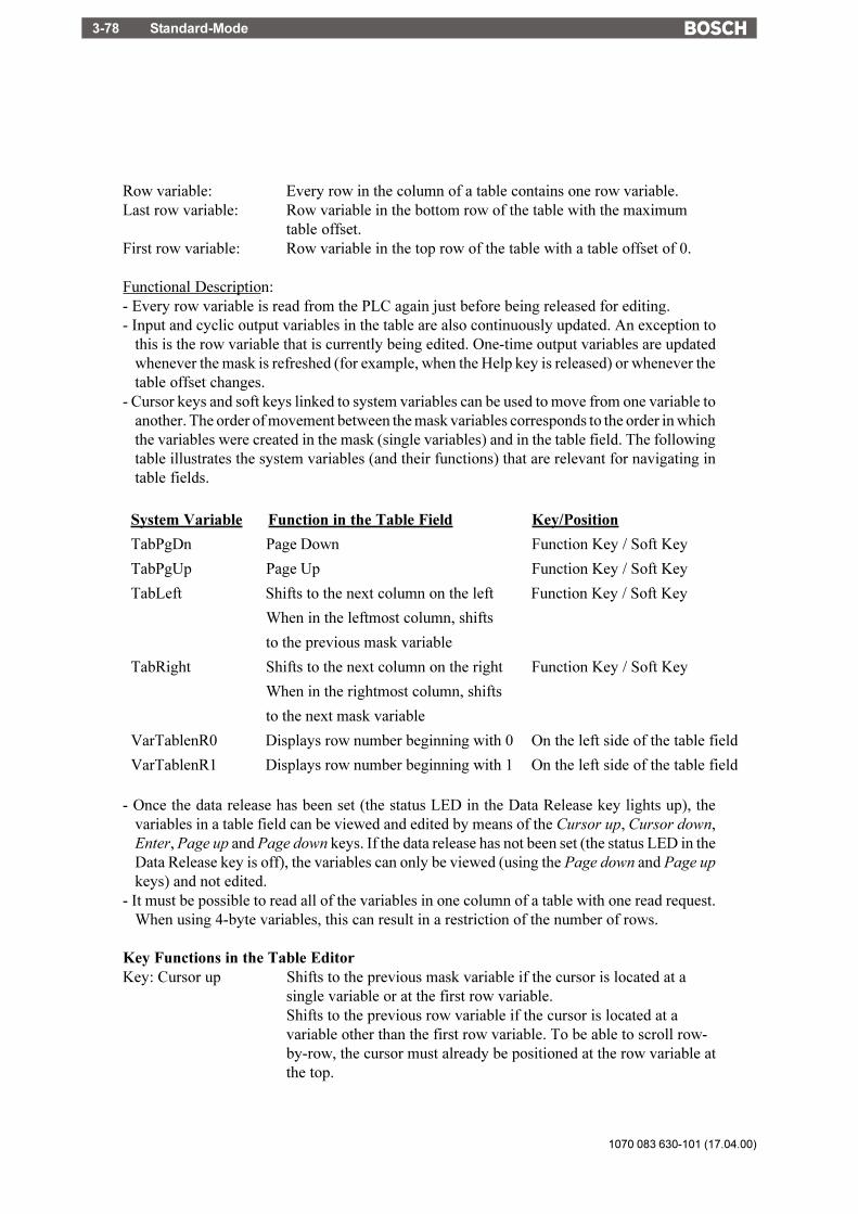
1070 083 630-101 (17.04.00)
Standard-Mode3-78
Row variable: Every row in the column of a table contains one row variable.Last row variable: Row variable in the bottom row of the table with the maximum
table offset.First row variable: Row variable in the top row of the table with a table offset of 0.
Functional Description:- Every row variable is read from the PLC again just before being released for editing.- Input and cyclic output variables in the table are also continuously updated. An exception to
this is the row variable that is currently being edited. One-time output variables are updatedwhenever the mask is refreshed (for example, when the Help key is released) or whenever thetable offset changes.
- Cursor keys and soft keys linked to system variables can be used to move from one variable toanother. The order of movement between the mask variables corresponds to the order in whichthe variables were created in the mask (single variables) and in the table field. The followingtable illustrates the system variables (and their functions) that are relevant for navigating intable fields.
System Variable Function in the Table Field Key/Position
TabPgDn Page Down Function Key / Soft Key
TabPgUp Page Up Function Key / Soft Key
TabLeft Shifts to the next column on the left Function Key / Soft Key
When in the leftmost column, shifts
to the previous mask variable
TabRight Shifts to the next column on the right Function Key / Soft Key
When in the rightmost column, shifts
to the next mask variable
VarTablenR0 Displays row number beginning with 0 On the left side of the table field
VarTablenR1 Displays row number beginning with 1 On the left side of the table field
- Once the data release has been set (the status LED in the Data Release key lights up), thevariables in a table field can be viewed and edited by means of the Cursor up, Cursor down,Enter, Page up and Page down keys. If the data release has not been set (the status LED in theData Release key is off), the variables can only be viewed (using the Page down and Page upkeys) and not edited.
- It must be possible to read all of the variables in one column of a table with one read request.When using 4-byte variables, this can result in a restriction of the number of rows.
Key Functions in the Table EditorKey: Cursor up Shifts to the previous mask variable if the cursor is located at a
single variable or at the first row variable.Shifts to the previous row variable if the cursor is located at avariable other than the first row variable. To be able to scroll row-by-row, the cursor must already be positioned at the row variable atthe top.
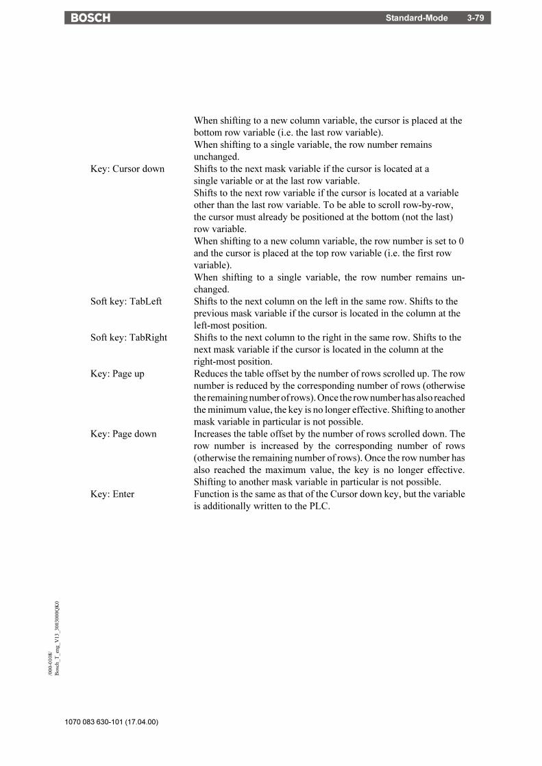
Standard-Mode 3-79
1070 083 630-101 (17.04.00)
/000
-010
8/B
osch
_T_e
ng_V
13_3
0030
00Q
K0
When shifting to a new column variable, the cursor is placed at thebottom row variable (i.e. the last row variable).When shifting to a single variable, the row number remainsunchanged.
Key: Cursor down Shifts to the next mask variable if the cursor is located at asingle variable or at the last row variable.Shifts to the next row variable if the cursor is located at a variableother than the last row variable. To be able to scroll row-by-row,the cursor must already be positioned at the bottom (not the last)row variable.When shifting to a new column variable, the row number is set to 0and the cursor is placed at the top row variable (i.e. the first rowvariable).When shifting to a single variable, the row number remains un-changed.
Soft key: TabLeft Shifts to the next column on the left in the same row. Shifts to theprevious mask variable if the cursor is located in the column at theleft-most position.
Soft key: TabRight Shifts to the next column to the right in the same row. Shifts to thenext mask variable if the cursor is located in the column at theright-most position.
Key: Page up Reduces the table offset by the number of rows scrolled up. The rownumber is reduced by the corresponding number of rows (otherwisethe remaining number of rows). Once the row number has also reachedthe minimum value, the key is no longer effective. Shifting to anothermask variable in particular is not possible.
Key: Page down Increases the table offset by the number of rows scrolled down. Therow number is increased by the corresponding number of rows(otherwise the remaining number of rows). Once the row number hasalso reached the maximum value, the key is no longer effective.Shifting to another mask variable in particular is not possible.
Key: Enter Function is the same as that of the Cursor down key, but the variableis additionally written to the PLC.

1070 083 630-101 (17.04.00)
Standard-Mode3-80
3.6.5 External Data Release
The PLC can prevent the input of variable values by the operator using the external data release.To be able to make use of this data release function, the following variables must have beencreated:- a variable for the Read coordination byte- a variable for the poll area.
When the Data Release key is pressed in an I/O mask, the terminal will enable the editing mode.If the controller has set the external data release, the status LED in the Data Release key lightsup. The external data release is controlled by bit 0 in the first byte of the cyclic poll area of thecontroller (see chapter Poll Area). Data editing is inhibited whenever the PLC sets this bit to 0.In this case, the status LED in the Data Release key will begin to flash.
Fig.23: Pulse diagram - external data releaseDR Key Data Release keyEA-Bit Editing request bit in the Read coordination byteED-Bit External data release in the Write coordination byteEZ-Bit Editing status bit in the Read coordination byteDR LED Status LED in the Data Release key
A flashing status LED in the Data Release key always indicates that no external data release hasbeen set. Editing is allowed if the PLC has set bit 0 to 1. In this case, the status LED in the DataRelease key will light up. A blinking cursor will appear in the first entry field in the mask. TheEditor specified by the user will be activated, depending on the selected variable.
(1) Windows is a registered trademark of the Microsoft Corporation

Standard-Mode 3-81
1070 083 630-101 (17.04.00)
/000
-010
8/B
osch
_T_e
ng_V
13_3
0030
00Q
K0
External data release handling:- The PLC controls the external data release by switching the ED bit in the Write coordination
byte.- If the Data Release key is pressed, the EA bit in the Read coordination byte will be set and the
status LED in the Data Release key will begin to flash.- Approximately 100 ms later, the terminal will read the Write coordination byte from the
controller. Editing is allowed if the external data release has been set (the ED bit in the Writecoordination byte is set). In this case, the status LED in the Data Release key will light up andthe EZ bit in the Read coordination byte will be set.
Editing is not allowed if the external data release has not been set (the ED bit in the Writecoordination byte is not set). In this case, the status LED in the Data Release key will continueto flash.
- During the editing process, the PLC can inhibit data entry at any time via the ED bit. Wheneverthe operating terminal detects that the ED bit has been reset, data input is inhibited, the statusLED in the Data Release key begins to flash and the EZ bit is also reset.
Whenever the operating terminal detects that the ED bit has been set, data input is allowed, thestatus LED in the Data Release key lights up and the EZ bit is also set.
- When the Data Release key is pressed again to exit the Editor, the last value that was edited isconfirmed (i.e. it is transferred to the controller); the EA bit and EZ bit in the Readcoordination byte are deleted.
3.6.6 PLC-Handshake
Handshake handling:- If the terminal writes to a variable for which the PLC handshake option has been selected, the
RA bit (refresh request bit) in the Read coordination byte will be set and data entry inhibited.- The PLC can now, for example, provide a new data set for other input variables. The PLC will
then set the RQ bit (refresh acknowledgement bit) in the Write coordination byte.- Once the operating terminal detects that the RQ bit has been set, the terminal reads every input
variable contained in the currently selected mask from the PLC again, then allows data inputsagain and resets the RA bit.
- If the RQ bit is already set when writing to the variable for which the PLC handshake optionhas been selected, then the other input variables will be refreshed immediately and data entrywill not be inhibited.

1070 083 630-101 (17.04.00)
Standard-Mode3-82
Fig. 24: Pulse diagram - PLC handshake
3.6.7 Refreshing One-Time Output Data
To refresh input or one-time output variables (variables are read only once and are displayed)that a mask contains, simply reactivate the mask (external mask selection).
3.6.8 Modified Data
The conditions that determine the transfer of modified data from the operating terminal to thecontroller are preset by the user in the variable definition. The following options are available,allowing the user to select the point of time at which the data are transferred:
- with the Enter key (standard)- with the +/- keys or the Enter key (Incremental Editor)- transfer continuously (upon modification), i.e. every intermediate status is transferred

Standard-Mode 3-83
1070 083 630-101 (17.04.00)
/000
-010
8/B
osch
_T_e
ng_V
13_3
0030
00Q
K0
In the Incremental Editor, every intermediate value is transferred.
The option to transfer continuously (upon every modification) is limited to values that arewithin the defined limits. If a value is entered that is outside the upper and lower limit, theoperator will get a system message to this effect.If a value with multiple digits is entered that- exceeds the upper limit
the digit entered most recently will not be transferred to the controller.
- falls below the lower limit,the previously valid value will be restored.
- falls below the lower limit (until the last digit has been entered) and then exceeds the upperlimit (after the last digit has been entered),the previously valid value will be restored.
3.6.8.1 Input Plausibility Check
The plausibility check is performed on every editable numerical variable. This requires that anupper and lower limit is specified in the variable definition. These limits are displayed in thecorresponding output format. System messages are generated when invalid values are entered.Further guidance can be found in the chapters Editors and System Messages.

1070 083 630-101 (17.04.00)
Standard-Mode3-84
3.7 Graphics
3.7.1 Graphical Objects (TSdos)
Images or other graphical information can be used in the terminal in the form of graphical objects.Each graphical object is based on a source image file stored in PCX format.
The images or graphics can be created using standard development tools, such as under Windows(1). Graphics programs that are already installed on the computer can also be used without anyproblem. The fact that standard tools can be used means that no additional operator training isnecessary. The bitmaps (graphics) to be used are managed as monochrome PCX files in the TSprogramming software. These bitmaps can be defined as a series of details if necessary.
The specified bitmaps are managed by the programming software as "graphical objects" in alibrary. Each graphical object must be programmed with a unique, symbolic name. The objectscan then be integrated into the masks or image lists by selecting these names.
The graphical objects are reusable and can be selected in a library list. They are thus madeavailable to the user automatically, not only in different masks but also in different projects. Theadvantage of project independence is that once a graphical object has been defined in the system,it remains permanently usable. A bitmap can be any size from font (e.g. 6 x 8, 6 x 9) to displaysize (e.g. 256 x 128, 240 x 128, 256 x 64). It is always an integer multiple of a character(character coordinates).
Graphical objects are always managed "language-neutrally". The advantage here is that the samegraphical objects are available in all languages.
A graphical object corresponds to a detail of the source image. This detail is defined relative tothe top left-hand corner of the source image by means of its height and width (character units).The graphical object can be addressed anywhere in the programming system by means of a freelydefinable, 8-character, symbolic name.
When the PCX file is assembled into a loadable user description, it is customized by theAssembler to the particular display and display controller and then compressed. The output timeand the amount of memory needed for the graphic are optimized at the same time. In order toshorten the CPU time, the bitmap object file is only generated if the PCX file acquires a morerecent date or if the terminal identifier in the object file is no longer the same as the terminal typefor which the Assembler is currently assembling.
3.7.2 Images (TSwin)
Any program installed by the user can be used by the programming software TSwin as a serverfor images.

Standard-Mode 3-85
1070 083 630-101 (17.04.00)
/000
-010
8/B
osch
_T_e
ng_V
13_3
0030
00Q
K0
Images can principally be made use of in two ways in TSwin:1.) Using existing images: The images created in another program can be selected. A copy ofthe source image will then be stored in the TSwin project database and converted to a pixelgraphics of the specified dimensions.2.) Creating new images: The program to be used to create the new image can be launchedfrom within TSwin. Once the image has been created, the server is exited and the image is storedin the TSwin project database. To display the image in TSwin and on the operating terminal, theimage is converted into a pixel graphics of the specified dimensions.
By double-clicking the image in TSwin with the mouse, the server program used to create theimage is opened automatically and the image can be edited. The scope of functions available todesign the images depends on the features provided by the server program. The placement ofimages in TSwin can be pixel or grid oriented depending on the operating terminal type.
3.7.3 Graphics on Operating Terminals
Graphics are linked into the user description in the form of static background images for eachI/O mask, dynamic variables on a bar chart, dotted lines on a curve or selection images. Thesebasic elements allow the user to design a customized, full-graphics user interface. The curves(trendlines), bar charts and selection images are updated cyclically, so that a simple kind ofanimation is also possible.
3.7.3.1 Background Images
Background images can be created for masks on the terminal with the aid of graphical objects.Up to ten different graphical objects can be specified as background images for each mask.Background images are defined by means of the name of the graphical object and its position inthe mask. You can also select display attributes for each background image. The followingattributes are available: normal, inverse or flashing. The size of the displayed image isdetermined by the definition of the graphical object.
Fig. 25: Example of coordinates
Background images are output on the display one at a time. Their order is determined in theprogramming system by the order in which they are entered. The images are copied to the displaymemory in the selected mode. The maximum resolution and size of the bitmaps for backgroundimages are equivalent to those of the type of display that is used. Splitting the images into modular

1070 083 630-101 (17.04.00)
Standard-Mode3-86
segments has the advantage that they can be reused within the system, which above all enablesmemory space to be optimized. Background images can be used for all static applications, suchas:- Fixed display arrangement- Representing the soft key row as icons- Coordinate systems- Information about production processes- Static images or icons- Representing overviews of plants or processesIf several different background images have been defined for a mask, they can also overlay oneanother. The write-over mode to be used for this process can be specified.
3.8 Recipes
Various logically related variables can be organized into units known as recipes. Unlike maskvariables, recipe variables are not transferred to the controller immediately after being entered,but are stored in the terminal as data sets. These data sets are protected against power failure. Thedata sets can be loaded to the controller as a unit as and when required.The maximum number of recipes that can be created at programming time is 250. For each recipe,up to 250 data sets can be created. The data sets can either be created at programming time andbe stored in the operating terminal's Flash memory together with the user description or can beentered online on the operating terminal and are then stored in the battery-backed RAM. Datasets stored in the Flash memory must be copied to the RAM first before they can be edited. Datasets that have been edited remain in the battery-backed RAM.
Example for the usage of recipes:Settings of a machine for manufacturing various products:
Variable Value UnitThe product clamp requires: Material ST37-3
Feedrate 25.00 mm/sSetpoint Value Axis 1 43.50 mmSetpoint Value Axis 2 56.30 mmCutting Angle 30 °Cutting Speed 110 mm/s
Variable Value UnitThe product shaft requires: Material X20Cr13
Feedrate 20.00 mm/sSetpoint Value Axis 1 45.60 mmSetpoint Value Axis 2 51.20 mmCutting Angle 45 °Cutting Speed 76 mm/s

Standard-Mode 3-87
1070 083 630-101 (17.04.00)
/000
-010
8/B
osch
_T_e
ng_V
13_3
0030
00Q
K0
The variables Material, Feedrate, Setpoint Value Axis 1, Setpoint Value Axis 2, Cutting Angleand Cutting Speed can be organized into the recipe "Machine Settings for Products". Thevariables Feedrate, Setpoint Value Axis 1 and Setpoint Value Axis 2 are defined as floating pointnumbers or fixed point numbers while the variable Cutting Angle is defined as an integer and thevariable Material as a selection text (coded text).The values for manufacturing the products Clamp and Shaft must be stored as data sets.Whenever another product is to be manufactured, the data set of the product to be manufacturednext can be loaded into the controller.The following check list contains all of the elements that are required and useful for creating andhandling a recipe with data sets:
- The recipe itself (texts and variables)- Data sets with data set number, data set name and variable offset- I/O mask for the recipe- Recipe field in the mask- Recipe buffer (address for the data area in the controller)- Variable Data Set Number for Transfer from the Terminal- Variable Recipe Number for Transfer from the Terminal- Variable Data Set Number for Request from the Controller- Variable Recipe Number for Request from the Controller- System variables:
Variable Name Linkage Partner DescriptionSelectDSNr Selection Text/Decimal Number Display/Selection of the Data Set NumberSelectDSName Selection Text Variable Display/Selection of the Data Set NameDestDSNr Positive Decimal Number Destination Data Set Number for Copy
ProcessDSCopy Soft Key/Selection Text Variable Activation of Data Set Copy ProcessDSDelete Soft Key/Selection Text Variable Deletion of Data SetDSDownload Soft Key/Selection Text Variable Loading of Data Set to ControllerActDSName Alphanumerical Variable Entering the Name for RAM-Data SetSelectRezeptNr Selection Text/Decimal Number Display/Selection of the Recipe NumberTabPgUp Soft Key Page upTabPgDn Soft Key Page downBreak Soft Key Cancel input
3.8.1 Structure of a Recipe
A recipe comprises a maximum of 255 variables. In addition, up to 255 explanatory texts can beprogrammed. The variables and texts can be spread out over a maximum of 255 lines (with eachline stretching across the entire width of the screen). A help text can be programmed for everyvariable.The recipe is displayed in a recipe field, within an I/O mask, that extends over the entire widthof the screen. The height of the recipe field can be as small as one line or as large as the entireheight of the screen. The Page up / Page down keys and the cursor keys can be used to scrollthrough long recipes in the recipe field.All one-line formats and Editors that are available in I/O masks can also be used for recipevariables. Multiple-line formats can not be used (for example, multiple-line selection fields,tables, etc.). In addition, neither variables nor texts can be displayed with the zoom option.

1070 083 630-101 (17.04.00)
Standard-Mode3-88
3.8.2 Processing Recipes and Data Sets
The majority of the operations described below refer to the active data set. In order to activatea data set, first select the recipe to which it belongs and then the data set itself. How to selectrecipes and data sets is explained in the next two sections.
3.8.2.1 Selecting a Recipe
All recipes are assigned a number from 1 to 250 when they are programmed.You can select a recipe as follows:
- By means of a fixed assignment between the recipe and a mask. Whenever this mask is opened,the recipe window will contain the recipe that was specified when the mask was originallyprogrammed. If a fixed assignment to a recipe has not been defined when the mask with therecipe window was programmed, the last recipe that was processed appears in this windowwhen the mask is opened.
- By means of the system variable SelectRezeptNr. This variable can be edited using any Editor.It is a good idea, however, to use a selection text (coded text) or a selection field (TSdos only)and assign meaningful names to each recipe number.
3.8.2.2 Selecting a Data Set
Data sets can be assigned both a number from 1 to 250 and a name.The data set numbers and names are allocated when the data sets are created, in other words eitherin the programming system for data sets stored in the Flash-Eprom or on the terminal in the caseof data sets stored in the RAM. The maximum data set name length is 15 characters. Data setnames need not necessarily be unique (though it is recommended that they are).
A data set can be selected in one of the following ways:- By selecting a new recipe. The associated data set with the lowest number is then selected for
it automatically.
- By means of the system variable SelectDSNr. This variable can only be edited as a selectiontext (coded text) or a selection field (TSdos only). In this case, only the numbers of those datasets that are available for the active recipe are displayed.
- By means of the system variable SelectDSName. This variable can only be edited as a selectiontext (coded text) or a selection field (TSdos only). In this case, only the names of those datasets that are available for the active recipe are displayed.
3.8.2.3 Copying a Data Set
Only the active data set can be copied. To do so, the number of the destination data set is writtento the system variable DestDSNr and then the value 1 to the system variable DSCopy.
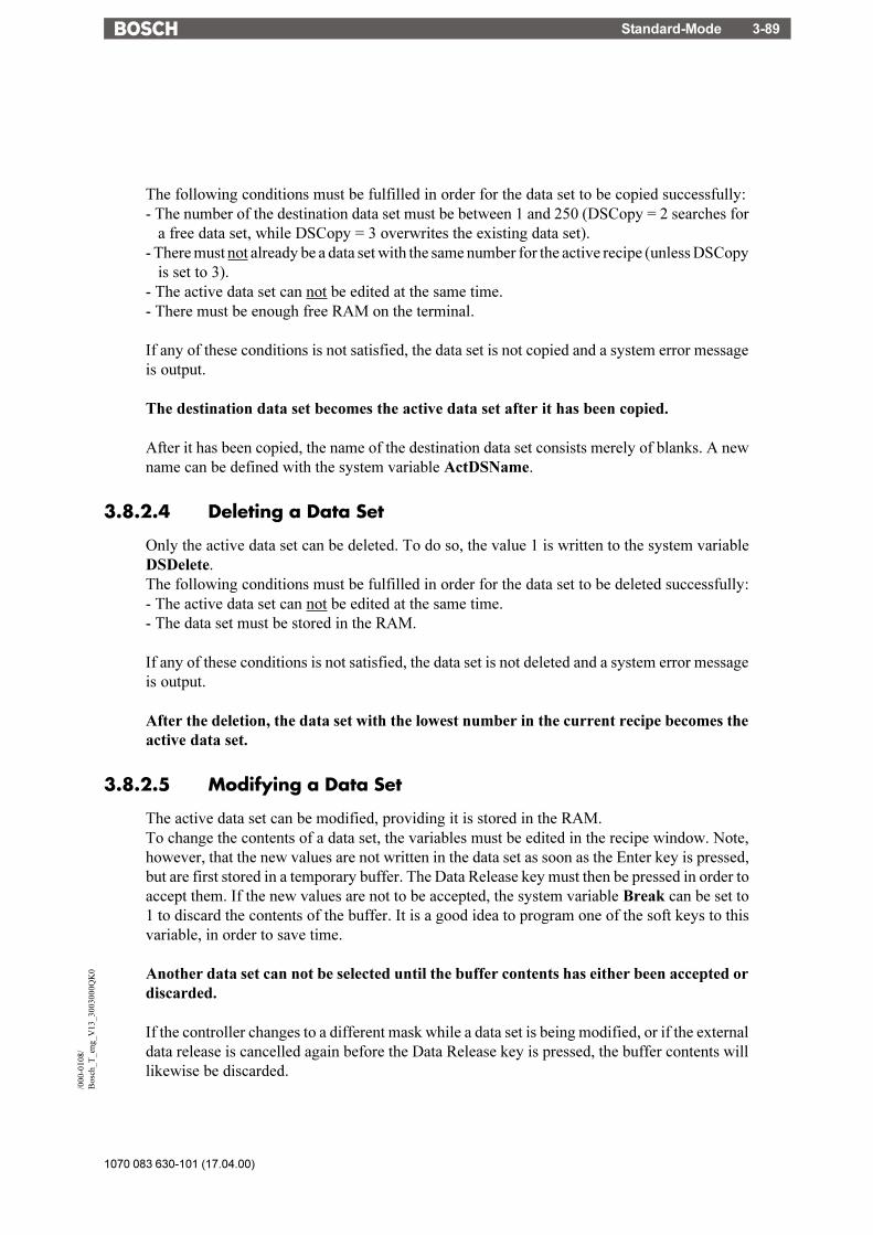
Standard-Mode 3-89
1070 083 630-101 (17.04.00)
/000
-010
8/B
osch
_T_e
ng_V
13_3
0030
00Q
K0
The following conditions must be fulfilled in order for the data set to be copied successfully:- The number of the destination data set must be between 1 and 250 (DSCopy = 2 searches for
a free data set, while DSCopy = 3 overwrites the existing data set).- There must not already be a data set with the same number for the active recipe (unless DSCopy
is set to 3).- The active data set can not be edited at the same time.- There must be enough free RAM on the terminal.
If any of these conditions is not satisfied, the data set is not copied and a system error messageis output.
The destination data set becomes the active data set after it has been copied.
After it has been copied, the name of the destination data set consists merely of blanks. A newname can be defined with the system variable ActDSName.
3.8.2.4 Deleting a Data Set
Only the active data set can be deleted. To do so, the value 1 is written to the system variableDSDelete.The following conditions must be fulfilled in order for the data set to be deleted successfully:- The active data set can not be edited at the same time.- The data set must be stored in the RAM.
If any of these conditions is not satisfied, the data set is not deleted and a system error messageis output.
After the deletion, the data set with the lowest number in the current recipe becomes theactive data set.
3.8.2.5 Modifying a Data Set
The active data set can be modified, providing it is stored in the RAM.To change the contents of a data set, the variables must be edited in the recipe window. Note,however, that the new values are not written in the data set as soon as the Enter key is pressed,but are first stored in a temporary buffer. The Data Release key must then be pressed in order toaccept them. If the new values are not to be accepted, the system variable Break can be set to1 to discard the contents of the buffer. It is a good idea to program one of the soft keys to thisvariable, in order to save time.
Another data set can not be selected until the buffer contents has either been accepted ordiscarded.
If the controller changes to a different mask while a data set is being modified, or if the externaldata release is cancelled again before the Data Release key is pressed, the buffer contents willlikewise be discarded.

1070 083 630-101 (17.04.00)
Standard-Mode3-90
The modified data set is not transferred to the controller automatically. An explicit commandfrom the operator or the controller is necessary first.
3.8.3 Data Set Transfer to / from a Controller
3.8.3.1 Transfer to a Controller
A data set can be transferred to the controller in the following ways:- The active data set can be transferred to the controller by setting the system variable
DSDownload to 1.- The controller can issue a request for any data set. It first sets the variable addresses for the
recipe and data set numbers to the required values. It then writes the value 7FFBH to theaddress of the serial signaling channel (see section 3.22 Cyclic Poll Area).
Start
Transfer recipe and dataset numbers to PLC
Recipe release flagset ?
Set Data Set-Download-Active-flag
Transfer datasetto controller
transfer checksum
Reset Data Set-Download-Active-flag
Reset recipe and dataset number
End
Request toterminate byoperator ?
no
yes
no
yes
Fig. 26: Data transfer sequence to the controller

Standard-Mode 3-91
1070 083 630-101 (17.04.00)
/000
-010
8/B
osch
_T_e
ng_V
13_3
0030
00Q
K0
The sequence of a terminal-initiated data set transfer is recapitulated below in chronologicalorder.The process is described from the point of view of the terminal:1. Transfers the recipe number to the variable addresses reserved for recipe numbers.
2. Transfers the data set number to the variable address reserved for data set numbers.
3. Waits until the data set transfer is released by the controller. For this process, the controllermust set the Data Download Release bit (DDF bit) in the Write coordination byte to logical1.Until this happens, the transfer can be cancelled again by setting the system variableDSDnloadBreak to 1. Once the transfer has been released by the controller, it can not becancelled again by resetting the Data Download Release bit in the Write coordination byte.
4. Sets the Data Download Active bit in the Read coordination byte.This bit can be used by the controller to identify an incomplete data set transfer(communication interrupted, power failure). An incomplete transfer is, however, repeatedthe next time the terminal is booted.
5. Transfers the data set to the recipe buffer defined in the controller. A separate recipe buffercan be programmed for each recipe. The recipe buffer must be at least one byte larger thanthe data set (on account of the checksum) and consist of an even number of bytes (in otherwords, an extra byte must be added if necessary).
6. Transfers the checksum. The byte-wise XOR checksum (for the complete data set) iswritten to the address that follows the last byte of the data set. It provides the controllerwith additional protection against errors caused by incompletely transferred data sets.
7. Resets the Data Download Active bit in the Read coordination byte.
8. Resets the recipe and data set numbers to the variables that have been programmed in thecontroller for this purpose. The recipe number is set to 0 and the data set number to 255.
The various steps in this process can be monitored by the operator with the aid of the systemvariable DSDnloadState.The name of the last data set to have been loaded in the controller is stored in the terminal foreach recipe. This name can be displayed for the active recipe with the system variableLoadDSName. If a data set has not yet been loaded in the controller for this recipe, or if the dataset which was loaded in the controller has already been deleted, a question mark appears on thedisplay instead.
3.8.3.2 Transfer from a Controller
Certain applications may require that individual data set values in the controller are modified (forexample, teaching) and that the modified data set is transferred back to the operating terminal.An option to transfer data sets from the controller to the terminal has therefore been provided.

1070 083 630-101 (17.04.00)
Standard-Mode3-92
A data set can be transferred from the controller to the terminal in either of the following ways:- By writing a value to the system variable StartUpload to initiate a data set read process for the
active recipe. If the value 1 is written to the system variable, the variables will be readindividually from the addresses specified during variable programming. If the value 2 is writtento the system variable, the variables will be read as a block from the data set buffer defined forthe recipe. The number under which the data set is to be stored in the terminal can be specifiedvia the system variable UploadDSNr. The default setting for this system variable is 0. If adestination data set number is not entered, the transferred data set will temporarily be storedunder the number 0 and will then have to be copied to a valid number (1-250).
- The PLC issues a request for a data set read process. For this process, the controller writes therecipe number and data set number (the same as those for the transfer to the controller onrequest by the controller) of the destination data set to the variable specified for this purpose.Subsequently, one of the message numbers
7FFDH (variables are read from their specified addresses individually) or7FFAH (variables are read from the defined data set buffer as a block)
must be transferred. After the data have been transferred successfully, the recipe number isoverwritten with 0. If there is no more free memory available in the operating terminal or ifthe specified data set number already exists in the Flash memory, the recipe number willbe overwritten with 255. The data set number will not be overwritten in either case.
If the newly read data set overwrites a data set that already exists in the RAM with the samenumber, its name will be used for the newly read data set. If a data set does not yet exist with thatnumber, the name will merely consist of blanks.
The read process can be monitored by the operator with the aid of the system variableUploadState.
3.8.4 Transferring Data Sets to / from a PC
It is possible to transfer data sets to or from a PC via the interface X3, in order to back up the datasets that have been stored in the terminal, process the data or supply the terminal with new datasets.It is also particularly important to back up the data sets if a new user description is loaded in theterminal, as all the data sets in the RAM are then deleted. If the recipe structure remainsunchanged, however, they can be reloaded into the terminal again after the user description hasbeen loaded. If changes have been made to the structure of any of the recipes (number ofvariables, position of the variables in the data set buffer, etc.), only the data sets of the other,unchanged recipes can be reloaded into the terminal.The data sets are transferred in a format that can be edited using a Text Editor (see section 3.8.4.3Structure of the Data Set File).The parameters for the X3 interface can be freely configured by means of the correspondingsystem variables. Merely make sure that the same parameters are set at the PC end. You can sendor receive at the PC end with any suitable program, such as Windows Terminal (1).
(1) Windows is a registered trademark of the Microsoft Corporation

Standard-Mode 3-93
1070 083 630-101 (17.04.00)
/000
-010
8/B
osch
_T_e
ng_V
13_3
0030
00Q
K0
3.8.4.1 Transfer to a PC
The transfer of data sets to the PC is initiated by writing a value to the system variable StartSave.The number of data sets that are transferred depends on the value that is written to the systemvariable. The following are valid values:System variable value = 1: Only the active data set is transferred.System variable value = 2: All of the data sets of the active recipe are transferred.System variable value = 3: All of the data sets of all recipes are transferred.
The process can be monitored by the operator with the aid of the system variable SaveState.
3.8.4.2 Transfer from a PC
The terminal is placed to the Ready-to-Receive state when the system variable StartRestore isset to 1. The data sets can then be sent by the PC. The terminal recognizes the end of the data settransfer automatically by analyzing the data it has received. It then returns to its normal state.To cancel the Ready-to-Receive state again without receiving data, the value of the systemvariable StartRestore must be changed to 2.The system variable RestoreState indicates whether or not the terminal is ready to receive.If a formatting error is detected in the received data, a system message to this effect is output andthe receive process is terminated. The position of the formatting error can be localized, at leastapproximately, with the aid of the system variable RestoreLineNr. This variable contains thenumber of the last line to have been received.Data sets can only be stored in the terminal if their structure is still identical to the data setstructure specified for the recipe concerned in the user description. This can be checked by theterminal on the basis of a version number (see Structure of Data Set File). If a data set which isfound to be invalid is received, it is rejected and a system message to this effect is output. Thereceive process is not terminated, however.If a data set with the same number as the transferred data set is already stored in the Flash-Eprom,the newly received data set is rejected without any warning to the operator.If a data set with the same number as the transferred data set is already stored in the RAM, aparameter setting in the received data (see Structure of Data Set File) determines whether or notthe existing data set is overwritten. If it is not supposed to be overwritten, and another data setwith the same number already exists in the terminal, the newly received data set is similarlyrejected without any warning to the operator.
3.8.4.3 Structure of a Data Set File
The data sets transferred to the PC are generally stored in a file.If this file is only used for backup purposes, the operator does not necessarily be familiar withits structure. In this case, the file can merely be transferred back to the terminal unchanged whenit is needed.If the data are to be processed further, for example, within the scope of production dataacquisition, the operator should understand the structure of the file.All of the data in the data set file are represented by a simple language specifically developedfor this purpose.

1070 083 630-101 (17.04.00)
Standard-Mode3-94
The following are elements of this language:
Key words: S + two further letters. They normally appear at the beginning of aline. Example: SDW or SFA
Decimal number: Any number of the digits 0-9, preceded by a negative sign whenrequired. Example: 999 or -1234567
Hexadecimal number: H + any number of the digits 0-9 or letters A-F or a-f.Example: H999 or H123abCD4
Hexadecimal string: C + any even number of the digits 0-9 or letters A-F or a-f.Example: C12 or CAAFF33
ASCII string: Any string of characters enclosed between two backslashcharacters (\) .
Example: \This is one ASCII string\Comment: Any string of characters enclosed between two dollar signs ($).
Comments can be inserted in the data set backup file at any posi-tion and can stretch across several lines.
Example: $This is a comment$
Any number of separators (blanks, tab characters or line feed characters) can be placed betweenthese language elements.
The above-mentioned language elements are used to create a file with the following structure:- Start of file identifier- Any number of data sets- End of file identifier
A data set consists of:- Data set header- Any number of data set variables- End of data set identifier
Start of file identifier:Key: SFAParameters: none (date and time are output by the terminal as a comment)
End of file identifier:Key: SFEParameters: none
Data set header:Key: SDKParameters: Recipe number, data set number, data set name (as an ASCII string), data set sizein bytes, recipe version number, write-over identifier

Standard-Mode 3-95
1070 083 630-101 (17.04.00)
/000
-010
8/B
osch
_T_e
ng_V
13_3
0030
00Q
K0
Data set variables:Key: SDWParameters: Offset of the variables in the recipe, variable size in bytes, value of the variables (asa hexadecimal string)
End of data set identifier:Key: SDEParameters: none
Explanations:Recipe Version Number:On creating or changing the recipe description in the programming system, this version numberis increased automatically whenever the structure of the data sets has changed. To be able to loada data set from the PC to the operating terminal, the downloaded version number and the versionnumber stored in the operating terminal for the recipe involved must match. The downloadeddata set will not be stored if they do not match.Write-over identifier:The value 1 means that the downloaded data set is to overwrite any data set with the same numberthat may already exist in the operating terminal. The value 0 means that the downloaded set isto be rejected if a data set with the same number already exists. Only those data sets can beoverwritten that are not stored in the Flash memory, i.e. that were loaded into the terminaltogether with the user description.
3.8.5 Printing Data Sets
The data set printout can be started from both the operating terminal and the controller.To be able to initiate a printout from the operating terminal, either the system variableStartRezPrint must be placed into a mask or a soft key must be assigned accordingly. The activedata set can be printed via the interface X3 by writing the value 1 to the system variable.Writing the value 2 to the same system variable will cancel the print process.A heading including the recipe number, data set number and data set name will be printed at thebeginning of each data set.The status of the print process can be indicated via the system variable RezPrintState.
To be able to control a print job from the controller, the data set number and recipe number mustbe entered into the appropriate variables first. The print job is then started by writing the value7FF8H to the address of the serial message channel. A value of 0 (zero) in the variable for therecipe number (for request from the terminal) will indicate that the data set is being printed.If another print job is currently being printed so that the printer can not print the specified dataset, the value 255 will be written to the variable for the recipe number (for request from theterminal).

1070 083 630-101 (17.04.00)
Standard-Mode3-96
3.8.6 Memory Requirements for Storing Data Sets
The RAM in the terminal that is not required by the system (approximately 110,000 bytes) is usedto store messages as well as data sets that have been stored in the RAM.The size of the message buffer is configurable. Each message takes up 24 bytes. This makes atotal of 12,000 bytes for the default message buffer size (500 messages), so that a further 98,000bytes are available for storing data sets.Space is also needed to store the data set name and management information (additional 28 bytesper data set).
Example:If the data set size is programmed as 22 bytes, a total of98,000 / (22 + 28) = 1960data sets can be saved in the RAM (message buffer size: 500). Other, fixed programmed data setscan also be stored in the Flash-Eprom.
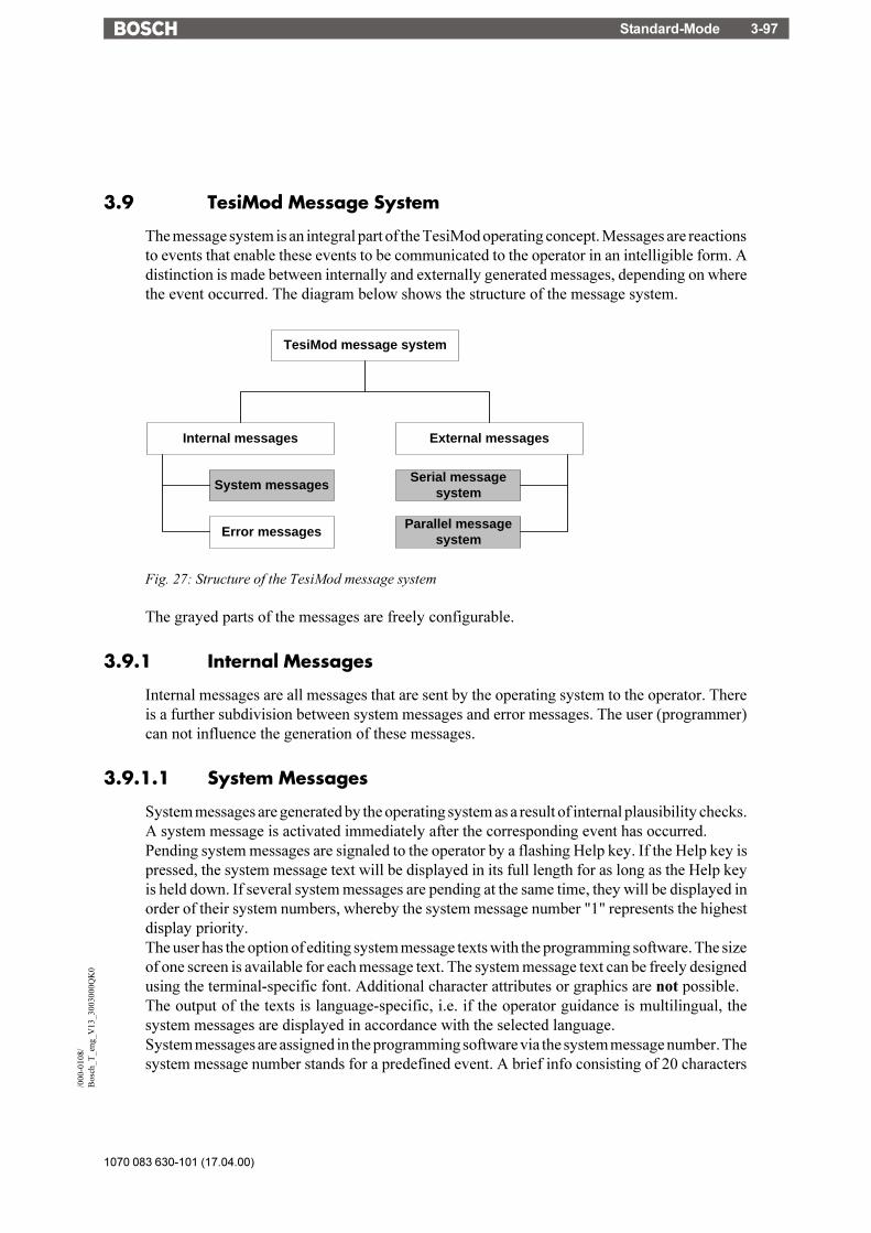
Standard-Mode 3-97
1070 083 630-101 (17.04.00)
/000
-010
8/B
osch
_T_e
ng_V
13_3
0030
00Q
K0
3.9 TesiMod Message System
The message system is an integral part of the TesiMod operating concept. Messages are reactionsto events that enable these events to be communicated to the operator in an intelligible form. Adistinction is made between internally and externally generated messages, depending on wherethe event occurred. The diagram below shows the structure of the message system.
TesiMod message system
Internal messages External messages
System messages
Error messages
Serial messagesystem
Parallel messagesystem
Fig. 27: Structure of the TesiMod message system
The grayed parts of the messages are freely configurable.
3.9.1 Internal Messages
Internal messages are all messages that are sent by the operating system to the operator. Thereis a further subdivision between system messages and error messages. The user (programmer)can not influence the generation of these messages.
3.9.1.1 System Messages
System messages are generated by the operating system as a result of internal plausibility checks.A system message is activated immediately after the corresponding event has occurred.Pending system messages are signaled to the operator by a flashing Help key. If the Help key ispressed, the system message text will be displayed in its full length for as long as the Help keyis held down. If several system messages are pending at the same time, they will be displayed inorder of their system numbers, whereby the system message number "1" represents the highestdisplay priority.The user has the option of editing system message texts with the programming software. The sizeof one screen is available for each message text. The system message text can be freely designedusing the terminal-specific font. Additional character attributes or graphics are not possible.The output of the texts is language-specific, i.e. if the operator guidance is multilingual, thesystem messages are displayed in accordance with the selected language.System messages are assigned in the programming software via the system message number. Thesystem message number stands for a predefined event. A brief info consisting of 20 characters

1070 083 630-101 (17.04.00)
Standard-Mode3-98
is used to provide an explanation of the system number. The length of the texts is designed toallow them to be displayed directly on one line, even on the smallest display in the TesiModoperating terminal series. When a selection is made in the programming software, the briefdescription is provided next to the number as a message name. A newly created system containsthe following system messages with brief infos:
System Message No. Brief Info1 Wrong format2 Value too large3 Value too small4 Replace battery5 Message overflow6 New message7 Message buffer full8 Invalid mask no9 Invalid message no
10 Print log invalid11 Interface in use12 Invalid password13 Password unchanged14 Overvoltage15 Data set protected16 Illegal data set17 Data set unknown18 Data set memory full19 Data set active20 Data set transfer21 Password missing22 Editing mode active23 Data set file error24 Data set format25 (Floating point) Number invalid26 Loop through active27 No data set address28 Recipe unknown29 Data set download
System Message 1 ................... "Wrong format"This text indicates that an attempt has been made to enter an invalid data format into a variablefield of the Numerical Editor. For example, the number of pre-decimal places entered exceeds thesetting specified in the user description.
System Message 2 ................... "Value too large"This indicates that an attempt has been made to enter a value into a variable field of the Editor thatexceeds the variable's upper limit. The upper limit is defined in the user description. If the text isdeleted from the system message, no system message will be displayed if a value is entered that istoo large. In this case, the maximum value that is valid is entered instead.
Standard-Mode 3-99
1070 083 630-101 (17.04.00)
/000
-010
8/B
osch
_T_e
ng_V
13_3
0030
00Q
K0
System Message 3 ................... "Value too small"This indicates that an attempt has been made to enter a value into a variable field of the Editor thatfalls below the variable's lower limit. The lower limit is defined in the user description. If the textis deleted from the system message, no system message will be displayed if a value is entered thatis too small. In this case, the minimum value that is valid is entered instead.
System Message 4 ................... "Replace battery"This text is displayed when a test performed on the battery indicates that its capacity has fallenbelow the limit values. This capacity test is repeated every 60 minutes. To retain the recipe dataand the data stored in the message memory, the battery must be replaced within 2-3 days of initialdisplay of this message. To avoid loss of data when replacing the battery, the information in therespective operating terminal manual must be complied with. The same message appears when thebattery is removed, switching the terminal off at this point will, however, result in the battery-backed data being lost.
System Message 5 ................... "Message overflow"This text indicates that the system is unable to process the external messages quickly enough. Upondisplay of this message, one message has already been lost
System Message 6 ................... "New message"This text is displayed when the Help key is pressed and the terminal has received a new externalmessage whose priority exceeds the programmed threshold value and no direct selector key hasbeen assigned to the message mask.
System Message 7 ................... "Message buffer full"This text is displayed as a warning that the next external messages may overwrite the oldest orlowest-priority messages (depending on the configuration).
System Message 8 ................... "Invalid mask no"This text is displayed to indicate that a non-existing mask number has been transmitted by the PLCvia the serial message channel.
System Message 9 ................... "Invalid message no"This text indicates that the PLC has attempted to activate a non-existing message number.
System Message 10 ................. "Print log invalid"The operator or the PLC has attempted to activate a non-existing print log.
System Message 11 ................. "Interface in use"Interface X3 is already being used by another print job. An attempt has been made to transmitdifferent types of data to the printer at the same time (e.g. to print recipes and messages).
System Message 12 ................. "Invalid Password"The operator has entered a password which does not exist in the password list. With this message,the previous access authorizations (view and edit level) are reset.
1070 083 630-101 (17.04.00)
Standard-Mode3-100
System Message 13 ................. "Password unchanged"The operator did not enter the same new password two times in a role.
System Message 14 ................. "Overvoltage"The system has detected that the supply voltage is too high. Switch the terminal off immediately toavoid damage. Check supply voltage.
System Message 15 ................. "Data set protected"An attempt has been made to modify individual values of a data set stored in the flash or to deletethe entire data set.
System Message 16 ................. "Illegal data set"The data set number specified as the destination for the data set copy process exists already or isoutside the valid range (for example, flash).
System Message 17 ................. "Data set unknown"A data set has been selected whose number does not exist in the data set list.
System Message 18 ................. "Data set memory full"An attempt has been made to create a new data set, but the data set memory is full.
System message 19.................. "Data set active"An attempt has been made to erase or to copy to the active data set or to select a data set eventhough the active data set is currently being edited.
System Message 20 ................. "Data set transfer"An attempt has been made to initiate a data set transfer to the controller even though the previouslyinitiated transfer has not yet been completed.
System Message 21 ................. "Password missing"An attempt has been made to switch to a password-protected mask or to edit a password-protectedmask without having entered a password with sufficient authorization.
System Message 22 ................. "Editing mode active"An attempt has been made to perform a change of mask while the terminal was in the editing mode.
System Message 23 ................. "Data set file error"The data set file loaded from the PC to the terminal contains a syntax error. The error can belocalized by means of the line number system variable.
System Message 24 ................. "Data set format"The size or internal version identifier of a data set loaded from the PC to the terminal and thecorresponding values in the programming software do not match.
System Message 25 ................. "(Floating point) Number invalid"The bit pattern read from the controller is not valid for a floating point number. The number isdisplayed as 0.0.
Standard-Mode 3-101
1070 083 630-101 (17.04.00)
/000
-010
8/B
osch
_T_e
ng_V
13_3
0030
00Q
K0
System Message 26 ................. "Loop-through active"The selected action was not performed due to an active loop-through operation.
System Message 27 ................. "No data set address"The addresses for the data set transfer did not exist at the time of the controller's request.
System Message 28 ................. "Recipe unknown"An attempt has been made to select a recipe that does not exist in the terminal.
System Message 29 ................. "Data set download"A data set transfer to the controller (download) has been initiated, but the Data Set DownloadRelease bit in the Write coordination byte (bit 4) has not yet been set by the controller.

1070 083 630-101 (17.04.00)
Standard-Mode3-102
3.9.1.1.1 Suppressing the Display of System Messages
The operating concept provides you the option of suppressing the display of system messages.The display of a system message can be prevented by erasing the system message in theprogramming software.
Example:System message 7 "Message buffer full" is to be suppressed. Older messages or messages witha lower priority are to be overwritten.The system message text in the programming software is erased.By suppressing the display of this system message, the user agrees that incoming messagesautomatically overwrite the oldest messages or those with the lowest priority once the messagebuffer is full.
3.9.1.2 Error Messages
The messages listed below are displayed by the operating system. The message texts are part ofthe operating system and are displayed in English. The size of the texts has been chosen in sucha way that they can be displayed on every terminal. The output of these texts can not besuppressed and their contents can not be modified. The term "error message" is used because theterminal does not operate in accordance with the true meaning of the TesiMod standard modewhile these messages are displayed. In addition to true system errors, various conditions andprocesses are also described.
................ This message is generated for all types of protocol and interfaceerrors. The error codes (CODE X) and SUBCODE (X) are proto-col-specific and are listed in the respective application documenta-tion. The connection with the communication partner has beeninterrupted. RETRIES displays the number of unsuccessful at-tempts to establish a connection. This number is incremented whilethe device is running. The number of retries depends on the proto-col that is being used.
................ This message may be displayed during a download. The S3 fileaddresses physical addresses in the terminal. The transmission isaborted as soon as invalid addresses are detected during thisprocess. The starting address of the invalid line in the S3 file isspecified in hexadecimal format.
................ Is displayed during a download if the Flash-Eprom can not beprogrammed. This message indicates that the application memoryis defective. The starting address of the invalid line in the S3 file isspecified in hexadecimal format.

Standard-Mode 3-103
1070 083 630-101 (17.04.00)
/000
-010
8/B
osch
_T_e
ng_V
13_3
0030
00Q
K0
................ An error has occurred during transmission of the user description.The error has either occurred during the serial transmission or theS3 file contains invalid lines or no valid S3 file has been transmit-ted. Recompile the application description and attempt to retrans-mit.
................ Error during transmission of the user description. An error wasdetected in the S3 file of the application description. More byteswere received in one of the transmission lines than specified in thebyte count.
................ Transmission format of the user description contains errors. Theoutput file used has not been generated by this programmingsystem. The transmitted file did not contain S0, S3 or S7 lines, noS3 format was used.
................ The mode selector switch S4 was at the "on" position when thesupply voltage for the terminal was switched on. The Flash datawill be retained if the following instructions are complied with.Switch the terminal off, set S4 to "off" position, switch terminal on- data will be retained and the terminal will function as before. IfS4 is set to the off-position while power is on - data will be lost,terminal switches to the download mode!
................ The version of the programming system and the operating softwareof the terminal do not match. This error occurs if the wrong operat-ing system version was selected for compilation of the user de-scription. The two program versions must match.
................ The protocol driver loaded via the programming system and theterminal�s operating system do not match. The two programversions must match.
................ The parameters of the interface X2 were modified. To achieve anoperational connection, both communication partners must be setto the new parameters. This message is used for informationalpurposes if the connection to the communication partner can not beestablished.
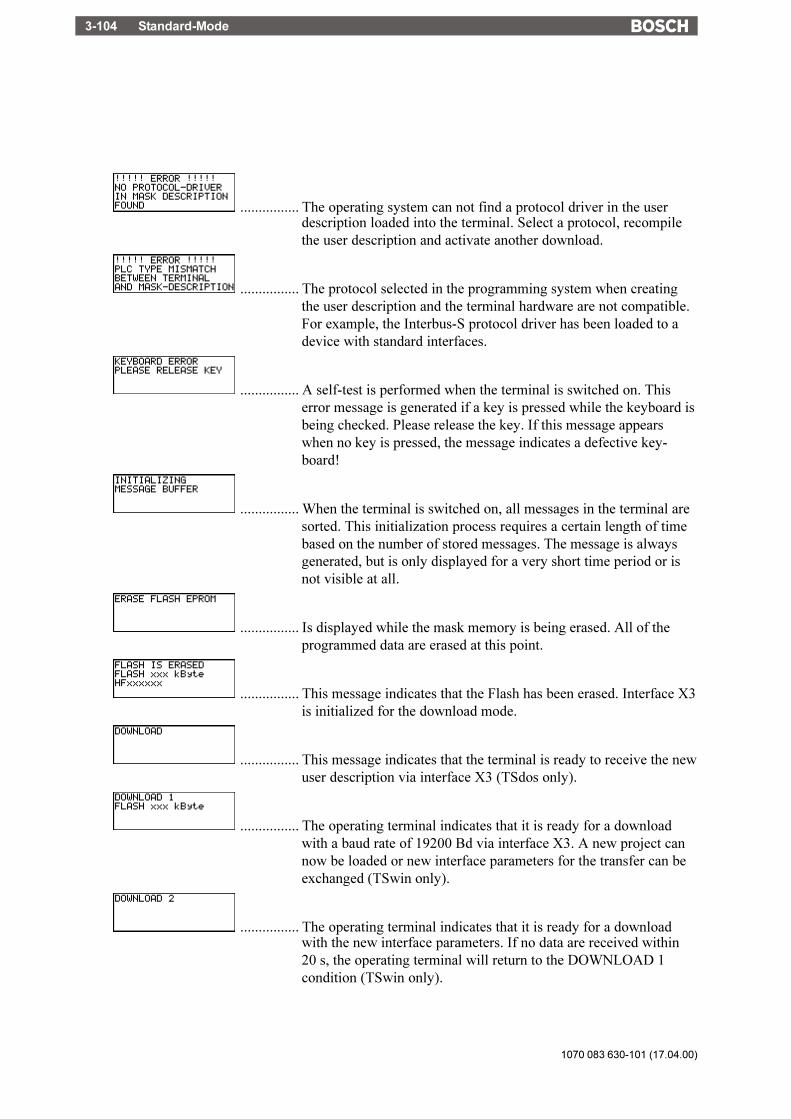
1070 083 630-101 (17.04.00)
Standard-Mode3-104
................ The operating system can not find a protocol driver in the userdescription loaded into the terminal. Select a protocol, recompilethe user description and activate another download.
................ The protocol selected in the programming system when creatingthe user description and the terminal hardware are not compatible.For example, the Interbus-S protocol driver has been loaded to adevice with standard interfaces.
................ A self-test is performed when the terminal is switched on. Thiserror message is generated if a key is pressed while the keyboard isbeing checked. Please release the key. If this message appearswhen no key is pressed, the message indicates a defective key-board!
................ When the terminal is switched on, all messages in the terminal aresorted. This initialization process requires a certain length of timebased on the number of stored messages. The message is alwaysgenerated, but is only displayed for a very short time period or isnot visible at all.
................ Is displayed while the mask memory is being erased. All of theprogrammed data are erased at this point.
................ This message indicates that the Flash has been erased. Interface X3is initialized for the download mode.
................ This message indicates that the terminal is ready to receive the newuser description via interface X3 (TSdos only).
................ The operating terminal indicates that it is ready for a downloadwith a baud rate of 19200 Bd via interface X3. A new project cannow be loaded or new interface parameters for the transfer can beexchanged (TSwin only).
................ The operating terminal indicates that it is ready for a downloadwith the new interface parameters. If no data are received within20 s, the operating terminal will return to the DOWNLOAD 1condition (TSwin only).

Standard-Mode 3-105
1070 083 630-101 (17.04.00)
/000
-010
8/B
osch
_T_e
ng_V
13_3
0030
00Q
K0
................ The operating terminal will reboot within the next few seconds.
................ The operating terminal reported its parameters during the startupprocess:- CPU frequency in MHz- Size of the Flash memory in Kbytes- Eprom version number XXXXXXXX- Loaded PLC driver YYYYYYYY
................ The Flash memory type used is being identified.
................ The voltage applied to the operating terminal is too high. Thismessage will not disappear until the specified supply voltage hasbeen reached.
................ Initialization of the serial interface (unit 0 or unit 1) failed.
................ The program level of the SUCOnet K card and the current protocoldriver are not compatible. Retrofit the operating terminal or use theappropriate driver version. The subcode specifies the level of theSUCOnet K card.
................ The program level of the keyboard card and the current firmwareare not compatible. Retrofit the operating terminal. The subcodespecifies the level of the keyboard card.
................ Indicates a successful update operation. The operating terminalreboots automatically.
................ A fatal error has been encountered. If this error message is gener-ated, make a note of the firmware level and the hardware versionand contact Sütron electronic GmbH, Kurze Straße 29, D-70794Filderstadt, hotline no.: ++49 / (0) 7 11 / 7 70 98 55.
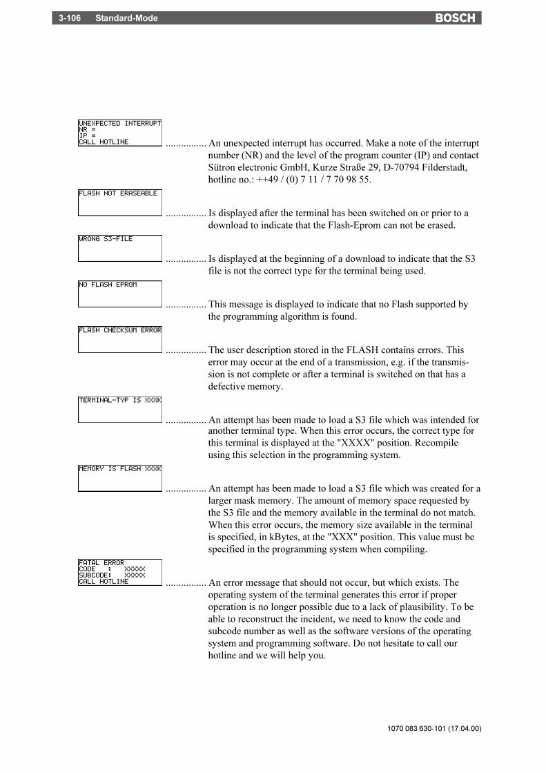
1070 083 630-101 (17.04.00)
Standard-Mode3-106
................ An unexpected interrupt has occurred. Make a note of the interruptnumber (NR) and the level of the program counter (IP) and contactSütron electronic GmbH, Kurze Straße 29, D-70794 Filderstadt,hotline no.: ++49 / (0) 7 11 / 7 70 98 55.
................ Is displayed after the terminal has been switched on or prior to adownload to indicate that the Flash-Eprom can not be erased.
................ Is displayed at the beginning of a download to indicate that the S3file is not the correct type for the terminal being used.
................ This message is displayed to indicate that no Flash supported bythe programming algorithm is found.
................ The user description stored in the FLASH contains errors. Thiserror may occur at the end of a transmission, e.g. if the transmis-sion is not complete or after a terminal is switched on that has adefective memory.
................ An attempt has been made to load a S3 file which was intended foranother terminal type. When this error occurs, the correct type forthis terminal is displayed at the "XXXX" position. Recompileusing this selection in the programming system.
................ An attempt has been made to load a S3 file which was created for alarger mask memory. The amount of memory space requested bythe S3 file and the memory available in the terminal do not match.When this error occurs, the memory size available in the terminalis specified, in kBytes, at the "XXX" position. This value must bespecified in the programming system when compiling.
................ An error message that should not occur, but which exists. Theoperating system of the terminal generates this error if properoperation is no longer possible due to a lack of plausibility. To beable to reconstruct the incident, we need to know the code andsubcode number as well as the software versions of the operatingsystem and programming software. Do not hesitate to call ourhotline and we will help you.

Standard-Mode 3-107
1070 083 630-101 (17.04.00)
/000
-010
8/B
osch
_T_e
ng_V
13_3
0030
00Q
K0
................ If this error message is displayed, contact Sütron electronic GmbH,Kurze Straße 29, D-70794 Filderstadt, hotline no.: ++49 / (0) 7 11 /7 70 98 55. Before calling, make a note of the firmware and hard-ware version. The operating system of the operating terminalswitches into an endless loop to prevent damage to the device.
................ A checksum error has been detected when checking the memoryareas of the recipe data sets. Either the battery or the RAM-memory is defective.
3.9.2 External Messages
External messages are generated by the connected controller and forwarded to the operatingterminal as information on the monitored process. The user can choose two separate messagesystems. Depending on the requirements, message transfers to the operating terminal can beeither serial or parallel, regardless of whether the messages are process or fault messages.
Messages can consist of the message text and a scaled and formatted variable. Every variable typeavailable in the system is valid.
The information in the message memory can be used for statistical evaluations. The message isassigned between the terminal and the controller by means of a message number. The associatedtexts and variable specifications are stored in the terminal together with the user description. Thefunction of a message and its contents are determined by the user when the user description iscreated in the programming system.
All of the external messages are stored in the message memory in chronological order or in orderof priority. With TSwin projects, parallel messages can optionally be stored in the serial messagememory and as a result also evaluated statistically. If the message contains a variable, its valuewill be frozen in the message memory.

1070 083 630-101 (17.04.00)
Standard-Mode3-108
3.9.2.1 Structure of an External Message
An external message is made up of:- a message number between 1 and 9999- a message text with up to 80 characters (TSdos) or- a message text with up to 255 characters (TSwin)- one variable at maximum.When creating a new application, existing messages (one or all) are reusable.
3.9.2.1.1 Assigning Message Numbers
With external messages, message numbers also determine the priority of a message, withmessage no. 1 being the highest and message no. 9999 being the lowest priority. It is notnecessary that message numbers are assigned contiguously; this allows messages with relatedcontents to be grouped.The assignment of message numbers for status messages always starts with "1". Make sure thatthe serial and parallel message system do not overlap. If the two message systems are to beindependent from one another, ensure that the message numbers for the serial system start abovethose for the status messages. In addition, message numbers and mask numbers must becoordinated accordingly when the programming is carried out (see chapter 3.9.2.3.1 Full-PageMessage Output).The system allows status message texts to be used in the serial message system.
3.9.2.1.2 Message Buffer Size
The total message buffer size is designed for management of up to 3000 messages. Such a largenumber of data requires a corresponding computing capacity when the messages are sorted,resorted and initialized. Since this large number may not always be needed, the user has theoption of setting the maximum system message buffer size to suit his own needs. The defaultbuffer size allows 500 entries.When determining the message buffer size, it must be considered that approximately 50 pagesof paper are needed when the entire message buffer containing 3000 messages is printed!The message buffer is output in the message mask. The message sorting criteria can be set viaa system variable.
3.9.2.1.3 Message Texts, Variables
The maximum text length including a formatted variable is 80 (TSdos) or 255 (TSwin)characters. The programming system does not allow longer texts to be input. All characters thatare available in the respective terminal can be used in standard size. One output variable can beincluded per message text. The variable output format is the same as that of one-time outputvariables (variables are transferred only once and are then displayed) in I/O masks. Individualmessages can for example be modified with coded text or used for several statuses. The outputformat of the message line can be modified online in a configuration mask for the message mask.The capabilities for serial and parallel messages are the same.
Standard-Mode 3-109
1070 083 630-101 (17.04.00)
/000
-010
8/B
osch
_T_e
ng_V
13_3
0030
00Q
K0
Example: Complete message format:
No. Date Time Text1 Variable Text21234 25:08:92 11:30:00 Temperature 285 °C at Meas.
Pt.07
The message consists of the following elements:1234 4-digit message number25.08.92 Date, is stored in the terminal when the message is recorded by the terminal11:30:00 Time, is stored in the terminal when the message is recorded by theterminalTemperature Text (1) preceding variable285 Value of the variable at the time of the message°C at Meas. Pt.07 Text (2) following variable
3.9.2.1.4 Sorting Messages
Messages can optionally be displayed in the message mask according to their time of arrival orpriority. The desired option can be selected when the system is programmed. If both possiblemessage systems are used, it is possible to select the settings separately. The settings are storedin the system variables RepmanRepSortCrit and RepmanSortCritP. They can be changedonline on the operating terminal using a configuration mask, for example. If a configurationoption is not offered on the operating terminal, the settings selected by the user will be used.
Sorting algorithm for the serial message system:0 - by priority1 - by time (newest first)2 - by time (oldest first)
Sorting algorithm for the parallel message system:0 - by priority1 - by time (newest first)2 - by time (oldest first)
3.9.2.1.5 Message Priority for Direct Display
The priority of a message is determined by its message number. The higher the message number,the lower the priority. The value that represents the upper limit for the message number that isto be signaled on arrival by a flashing LED or by outputting a system message can be entered,via the programming system, into the parameters file (TSdos) or the system parameters of themessage system (TSwin).
If the value = 0 is entered, newly received messages will be not be signaled.
1070 083 630-101 (17.04.00)
Standard-Mode3-110
3.9.2.1.6 Printing the Message Memory
The memory contents of the serial and parallel message systems can be printed either in full orin part.
The entire contents of the serial message memory are printed if the system variable PrintAllRepis set to 1 (formatted printout) or 2 (full-length printout).
The entire contents of the parallel message memory are printed if a soft key that is linked to thesystem variable PrintAllState is pressed.
To print the message memory in part, the messages to be printed must be selected in the messagemask. This is done by pressing the Data Release key in the message mask and selecting themessages in the message field using the Cursor up and Cursor down keys. The print job is startedby pressing a soft key linked to the system variable BlockPrint (prints visible part of the selectedblock) or BlockPrintLong (prints messages of the selected block in full length).The system variables can additionally be included in a configuration mask and be edited online.
3.9.2.2 Message Mask, Status Message Mask
In TSdos, the message mask is a special I/O mask which has been modified to accommodate theoutput of messages. In TSwin, the same functions are achieved by inserting a message field intoan I/O mask. The key assignment for a message mask or status message mask is specificallydesigned to allow convenient navigation within the extremely large message memory.
- Data release not active Cursor up: Moves the cursor up one message. Thecursor can be moved upwards until the topmessage is reached.
Cursor down: Moves the cursor down one message. Thecursor can be moved downwards until thebottom message is reached.
Cursor left: Moves the cursor up one screen (repeatfunction). The cursor can be moved upwardsuntil the message at the top is reached.
Cursor right: Moves the cursor down one screen (repeatfunction). The cursor can be moveddownwards until the message at the bottomis reached.
Minus: Moves the cursor to the bottom-mostmessage.
Plus: Moves the cursor to the top-most message.Delete: InactiveData Release: Enables the editing mode, provided the
external data release has been set and theentered password has a sufficient accesslevel.
Standard-Mode 3-111
1070 083 630-101 (17.04.00)
/000
-010
8/B
osch
_T_e
ng_V
13_3
0030
00Q
K0
Enter: The entire message at the cursor positionwill appear on the display.
- Data release active Cursor up: Selects individual messages from the currentcursor position on upwards.
Cursor down: Selects individual messages from the currentcursor position on downwards.
Cursor left: Selects messages in page-mode from thecurrent cursor position on upwards untilthe topmost message is reached. No repeatfunction.
Cursor right: Selects messages in page-mode from thecurrent cursor position on downwards untilthe bottommost message is reached. Norepeat function.
Delete: Deletes all selected message entries. If noselection is made, the message at the cursorposition will be deleted.
Minus: Selects all messages from the current cursorposition down to the last message.
Plus: Selects all messages from the current cursorposition up to the first message.
Data Release: Exits the editing mode, provided the externaldata release is still set.
3.9.2.2.1 Direct Selection of the Message Mask
In the programming software, a function key can be linked to a message mask. This function keycan then be used to switch to the message mask from within any mask. This provides anothermeans to reach the message mask, in addition to the access via a selection menu. In this case, thearrival of new messages will be signaled by the integrated function key LED which will beginto flash (instead of the Help key).Direct access to the message mask can be obtained by pressing the flashing function key. If thisfunction key is pressed again, the message mask will automatically be exited and the previousmask will reappear on the display.
3.9.2.2.2 Output Formats for Messages
The following information can be output with every external message:- Message number- Date- Time of day- Message text- Value of a variable at the time the message was generated (if available only)
Various system parameters are available to influence the representation of a message in the
1070 083 630-101 (17.04.00)
Standard-Mode3-112
message mask or the message printout. These parameters can be set in a configuration mask,provided such a mask is programmed.The selection or deselection of message elements is carried out by means of system variables.
Serial Messages Parallel Messages Influenced Element- RepoutNr RepoutNrP Message number- RepoutDate RepoutDateP Date- RepoutTime RepoutTimeP Time- RepoutAnzYear RepoutAnzYearP 2 or 4 digit representation of the year
This allows the length of the message line to be influenced. Modifications to the output formathave no impact on the stored information.
Possible output versions are as follows:
Complete message format:
No. Date Time Text1 Variable Text21234 25:08:92 11:30:00 Temperature 285 °C at Meas.
Pt.07
Versions:
1234 25:08:92 Temperature 285 °C at Meas. Pt.071234 11:30:00 Temperature 285 °C at Meas. Pt.071234 Temperature 285 °C at Meas. Pt.0725:08:92 11:30:00 Temperature 285 °C at Meas. Pt.0711:30:00 Temperature 285 °C at Meas. Pt.0725:08:92 Temperature 285 °C at Meas. Pt.07Temperature 285 °C at Meas. Pt.07
3.9.2.2.3 Zooming Messages
Messages are displayed in a one-line format in the message mask for the sake of clarity. In orderto display a longer message in its full length, the message must first be selected and then the Enterkey pressed.
Message mask line, for example on the BT20:
1234 25:08:92 11:30:00 The measuring point in
Zoomed view:
1234 25:08:92 11:30:00Measuring point 137 in the furnace has atemperature of 285 °C
Standard-Mode 3-113
1070 083 630-101 (17.04.00)
/000
-010
8/B
osch
_T_e
ng_V
13_3
0030
00Q
K0
The zoomed view remains active for as long as the Data Release key is held down. With smallerdisplays (for example, the BT5 with 4 x 20 characters) only the message text is zoomed. Theterminal type that is to be used must be considered when the text is programmed, to ensure thelines are wrapped correctly.
3.9.2.2.4 Acknowledging Messages
Message acknowledgement in the controller can be carried out by means of variables. VariousEditors or function keys (soft keys) are suitable for this purpose. The acknowledgement enablesthe controller to delete the message and verify the status of the process.
3.9.2.3 Serial Message System
A 2 byte compartment is used in the cyclic poll area for the transmission of serial messages. Thebyte order depends on the selected data type of the poll area (see Poll Area). The PLC stores a16 bit message number in this transmission compartment. The TesiMod operating terminal pollsthe entire poll area of the PLC at cyclic intervals and transmits the serial message in the process.Upon detecting a message (message number > 0), this message is stored in the internal messagememory of the operating terminal and the compartment in the PLC is reset to zero. The value 0in the compartment indicates to the PLC that the message has been fetched by the terminal. Thepolling time of the cyclic data area is configurable.The same procedure is used to address external masks and message masks. Whenever the numbertransmitted corresponds to a mask number, this mask is displayed. If a mask and a message textexist for this number, the mask (message mask, full-page fault message text) is displayed and theassociated message text is entered into the message memory.Make sure that the message number is always entered in the serial data compartment as a 16 bitcommand. As a result of asynchronous processing of some data transfer protocols, evaluationof the message number may lead to problems if the message number has been entered with single-byte commands.
3.9.2.3.1 Full-Page Message Output
The full-page message is a combination of message processing and external mask selection. Fora full-page message mask output, a mask and a message text must be programmed under the samenumber. The controller calls up the "external mask" through the serial message channel. Whenit is called up, the mask is displayed and the associated message text is entered into the messagememory. As the display contents can be chosen freely, it is possible to realize a message mask,a full-page error output or other contents types. To be able to return to the previous menu fromhere, at least one mask parameter must be programmed for "Previous mask". Message masks canalso consist of several masks or even complete structures for troubleshooting.It goes without saying that a separate, full-page help text can also be programmed for each full-page message.

1070 083 630-101 (17.04.00)
Standard-Mode3-114
3.9.2.3.2 Messages Directly to a Logging Printer
When serial messages are logged directly, the printer always runs synchronously. Every newmessage arriving via the serial message channel is printed immediately and is transferred to themessage memory in parallel. Here, attention must be paid that the printer can only process oneprint job at one time. Every print request must be ended before any further print request is startedby the system.The output of the messages to a printer can be influenced by the system variable RepmanRepPrint.The settings that apply when the formatted type of printout is selected are the same as thoseselected for the display of messages in the message mask.The settings for the printout can be changed on the terminal online.
As the output consists of a pure text file, the message can also be read by a host computer or aPC. With a further system variable PrintAllRepLong, the full length of the message can beoutput.
3.9.2.3.3 Erasing the Message Memory Externally
The internal message memory of the serial message system can be erased externally, that is fromthe controller. To do this, a symbolic variable name for the deletion variable must be specifiedin the Message System option of the parameters file using the programming software. Two bytesare needed in the controller for the variable.The terminal always checks the deletion variable in the controller once it has received thedeletion sequence (deletion code 7FFE
H via the serial message channel). The internal message
buffer is deleted if the deletion variable contains the bit pattern E216H. The deletion variable
increases protection against unintentional deletion.If deletion is not required, the variable should be reset or no symbolic name should be specifiedin the programming software.
3.9.2.3.4 Information about the Serial Message System
How do messages reach the terminal?In the controller, a word variable, as a part of the cyclic poll area, is reserved for the messagenumber. This variable is polled by the operating terminal. If the variable value is greater thanzero, this indicates that this is a numeric value of a message, i.e. the message number. Themessage number is placed into the terminal�s message memory and the variable in the controlleris overwritten with zero. This is treated as the acknowledgement for the controller that theterminal has fetched the message. The next serial transfer of messages can now take place.
How is a new message recognized?By flashing of the Help key or by a flashing function key, the terminal signals to the operator thata new message has been received. This visual indication only appears when a value has droppedbelow a limit (message priority for direct display).
How is the message mask configured?The message mask is preceded by an I/O mask, the configuration mask, and output formats canbe defined in it by means of various system variables.
Standard-Mode 3-115
1070 083 630-101 (17.04.00)
/000
-010
8/B
osch
_T_e
ng_V
13_3
0030
00Q
K0
How can the most current messages be output in any chosen I/O mask?A system variable RepoutRepText is available which always contains the message mostrecently received or the one with the highest priority. The content is retained up to the nextchange. The output is always left-justified and as defined in the configuration menu. There arealso the following system variables for complete or multiple-line output:
RepoutRepText21RepoutRepText41RepoutRepText61
See description of the system variables for more information.
Where are messages displayed?In the message mask. The message mask can be reached via the node mask, the I/O mask, controlkeys or soft keys.Owing to the fact that many control keys are used in the message mask, it can only be exited bypressing the Home key or function keys.
3.9.2.4 Parallel Message System (Status Messages)
The parallel message system complements the serial message system. The messages aretransmitted in parallel and are evaluated in the terminal. During this process, the current messagestatus is compared with the prior status in the terminal. These messages are automatically deletedfrom the memory once they are no longer pending. New messages are added to the memory. Thecurrent status of the messages can be output.Date and time are included in every message to indicate the point of time at which a message hasbeen generated.The message buffer length is limited to a maximum of- 64 data words or 128 bytes (TSdos) or- 256 bytes (TSwin).The length is to be set in the parameters file (TSdos) or in the system parameters for the messagesystem (TSwin) of the programming system. There may be restrictions regarding the lengthdepending on the protocol (see chapter on controller and bus connections).Status messages are retained in the message memory only as long as they are being reported bythe controller.Status messages can be transferred on a time or event controlled basis.
3.9.2.4.1 Number of Bytes for Status Messages
This parameter specifies the number of bytes to be transferred with the parallel message system.The size depends on the number of status messages. The absolute size also depends on the defineddata type (address). For example, if a word address has been defined and the number of bytes isodd, then this number will automatically be rounded up.

1070 083 630-101 (17.04.00)
Standard-Mode3-116
3.9.2.4.2 Image of the Status Messages
For status messages, the starting address of the storage area containing the message informationis entered here. The symbolic name is assigned to a fixed address. The assignment of messagenumber to bit information depends on the data type of the controller variable. The data type hasbeen processed in a protocol-specific manner since the structures of byte, word and Lword arenot identical in the supported controllers. It is important that once an assignment method ischosen, it is not changed!
Byte-oriented assignment:
Byte address + 0 Bit 7 Bit 6 Bit 5 Bit 4 Bit 3 Bit 2 Bit 1 Bit 0Byte address + 1 Bit 7 Bit 6 Bit 5 Bit 4 Bit 3 Bit 2 Bit 1 Bit 0Byte address + 2 Bit 7 Bit 6 Bit 5 Bit 4 Bit 3 Bit 2 Bit 1 Bit 0Byte address + 3 Bit 7 Bit 6 Bit 5 Bit 4 Bit 3 Bit 2 Bit 1 Bit 0 : :Byte address + n Bit 7 Bit 6 Bit 5 Bit 4 Bit 3 Bit 2 Bit 1 Bit 0
Message 1 = Byte 0, Bit 0Message 2 = Byte 0, Bit 1Message 3 = Byte 0, Bit 2
:Message 8 = Byte 0, Bit 7Message 9 = Byte 1, Bit 0Message 10 = Byte 1, Bit 1
Word-oriented assignment:
Word address + 0 Bit 15 Bit 14 Bit 13 Bit 12 ....Bit 3 Bit 2 Bit 1 Bit 0Word address + 1 Bit 15 Bit 14 Bit 13 Bit 12 ....Bit 3 Bit 2 Bit 1 Bit 0Word address + 2 Bit 15 Bit 14 Bit 13 Bit 12 ....Bit 3 Bit 2 Bit 1 Bit 0Word address + 3 Bit 15 Bit 14 Bit 13 Bit 12 ....Bit 3 Bit 2 Bit 1 Bit 0 : :Word address + n Bit 15 Bit 14 Bit 13 Bit 12 ....Bit 3 Bit 2 Bit 1 Bit 0
Message 1 = Word 0, Bit 0Message 2 = Word 0, Bit 1Message 3 = Word 0, Bit 2
:Message 16 = Word 0, Bit 15Message 17 = Word 1, Bit 0Message 18 = Word 1, Bit 1
The same rules apply to other data formats.
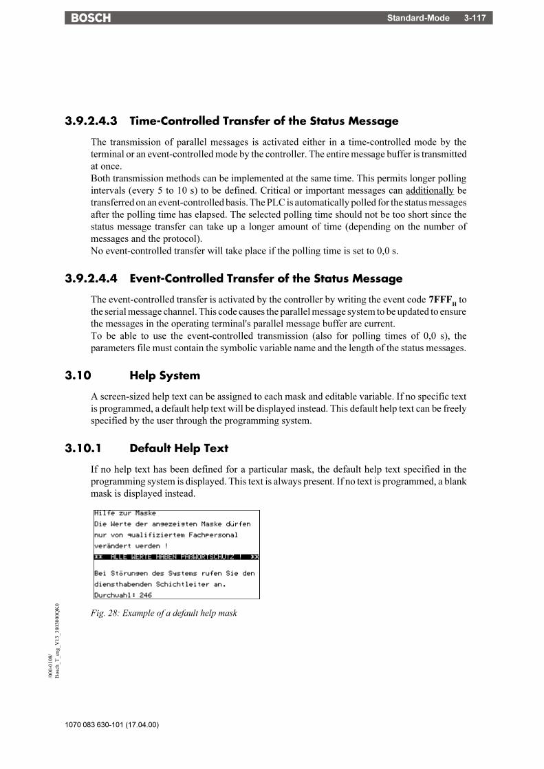
Standard-Mode 3-117
1070 083 630-101 (17.04.00)
/000
-010
8/B
osch
_T_e
ng_V
13_3
0030
00Q
K0
3.9.2.4.3 Time-Controlled Transfer of the Status Message
The transmission of parallel messages is activated either in a time-controlled mode by theterminal or an event-controlled mode by the controller. The entire message buffer is transmittedat once.Both transmission methods can be implemented at the same time. This permits longer pollingintervals (every 5 to 10 s) to be defined. Critical or important messages can additionally betransferred on an event-controlled basis. The PLC is automatically polled for the status messagesafter the polling time has elapsed. The selected polling time should not be too short since thestatus message transfer can take up a longer amount of time (depending on the number ofmessages and the protocol).No event-controlled transfer will take place if the polling time is set to 0,0 s.
3.9.2.4.4 Event-Controlled Transfer of the Status Message
The event-controlled transfer is activated by the controller by writing the event code 7FFFH tothe serial message channel. This code causes the parallel message system to be updated to ensurethe messages in the operating terminal's parallel message buffer are current.To be able to use the event-controlled transmission (also for polling times of 0,0 s), theparameters file must contain the symbolic variable name and the length of the status messages.
3.10 Help System
A screen-sized help text can be assigned to each mask and editable variable. If no specific textis programmed, a default help text will be displayed instead. This default help text can be freelyspecified by the user through the programming system.
3.10.1 Default Help Text
If no help text has been defined for a particular mask, the default help text specified in theprogramming system is displayed. This text is always present. If no text is programmed, a blankmask is displayed instead.
Fig. 28: Example of a default help mask

1070 083 630-101 (17.04.00)
Standard-Mode3-118
3.10.2 Help Text For Masks
A help mask can be created for every programmed mask. The link between the current mask andhelp text is specified in the parameter settings.All of the valid characters can be used to design the help mask. Help texts can be called up directlyby means of the Help key. As long as no data release has been requested, the help text for the maskis displayed. Once the data release is requested, the help text for the variable is shown.
3.10.2.1 Help Text for the Message Mask
Help masks can also be created for messages masks. Help texts are only available for the mask.Any variables that may be embedded can not be linked to a help mask.
3.10.3 Help Text For Variables
The functionality is the same as that of help texts for masks. It is, in particular, possible to displaythe valid range of values. The link between the help mask and the variable is specified in thevariable parameters.
3.11 Function Keys
Another important feature of the TesiMod operating concept, in addition to the masks, are thefunction keys and their LEDs. Function keys are user-programmable. They can be used as directselector keys for selecting more masks or as control keys for the machine. When used as controlkeys, the integrated LEDs provide feedback information.Programming the function keys as direct selector keys allows fast, direct access to the masks aswell as to entire menu structures.If the operating terminal is fitted with parallel outputs, 8 function keys can be assigned to theoutputs directly. The reaction time after pressing a key is approximately 30 ms. Before a functionkey signal is provided, the terminal debounces the key, thereby ensuring that it has actually been"pressed".In the programming system, the combination of direct selection and control can be programmedfor function keys and soft keys. Only the press codes of the keys should be evaluated in this modeof operation. This is because, depending on the length of time the key is pressed and the natureof the assigned mask, the stop code may have already changed!
3.11.1 Direct Selector Keys
Direct selector keys are function keys which have been programmed to directly call up a specificmask. Pressing this function key causes a new mask to be activated.This change of mask is not possible if the data release has been requested (status LED in the DataRelease key is flashing or lights up) in a mask without automatic data release.With direct selector keys, a speedy and convenient operation can be obtained.
Standard-Mode 3-119
1070 083 630-101 (17.04.00)
/000
-010
8/B
osch
_T_e
ng_V
13_3
0030
00Q
K0
3.11.2 Function Keys of the Controller
In addition to being programmed as direct selector keys, function keys can also trigger a functionin the PLC. This requires that instead of a change of mask, the symbolic name of a controllervariable is assigned to the function key. This assignment is performed in the user description.The function key can be defined to either "set" or "reset" a variable when pressed/released. If thekey is assigned the function "set" the specified value will be transmitted to the variable in thecontroller.If the number 1 is entered as a value,- a flag bit will be set to logical "1"- a flag byte will be set to the value 01H
- a flag word will be set to the value 0001H
- a double word will be set to the value 00000001H
For values greater than "1", at least a byte address must be specified for the variable. Valuesgreaterthan "1" can be assigned in TSwin only.If the number 3 is entered as a value,- a flag byte will be set to the value 03H
- a flag word will be set to the value 0003H
- a double word will be set to the value 00000003H
3.11.3 Soft Keys
In the TesiMod standard mode, soft keys are function keys that perform a mask-related function(they perform different functions in different masks). A description of the function that a soft keyperforms in a particular mask should be displayed in that mask. Several means are available todesign this description such as images, background images, selection images, static texts andselection texts (coded text).If a selection text (coded text) is used for labeling a soft key, the function key can be used formultiple functions in one and the same mask.The action to be performed is determined in the controller by linking the- mask number- number of the selection text (coded text)- variable value that is transferred with the soft key.The number of keys that can be used as soft keys depends on the type of operating terminal used.
Example: A soft key (F1) is to be capable to switch a pump off and on in mask 10
1. Create a text list (pump) with two entriesValue Text0 Switch Pump OFF1 Switch Pump ON
2. Define the variables- Soft key labeling M 100.0- Soft key status M 100.1- Image of the mask MW 110

1070 083 630-101 (17.04.00)
Standard-Mode3-120
3. Create the mask (number 10)- set up a controller variable (M 100.0) next to or above a function key: link a selection text variable for cyclic output with the text list (pump)- link the function key F1 of the mask with the variable Soft Key Status (M 100.1), (set/reset)
4. Create the PLC program to perform the following: O 32.0 is to be used to control the pump- Evaluate mask number (MW 110); (must have the value 10)- Create the edge evaluation for M 100.1- Create the ELTACO function for pump output O 32.0- Set flag M 100.0 to 0 when the pump is on- Set flag M 100.0 to 1 when the pump is off
3.11.3.1 Reaction Time of Function and Soft Keys
Whenever function keys need to influence PLC variables, they are given highest priority whentransferred via the protocol. The reaction times during the transfer procedure are protocol-specific and range from 60 to 120 ms. This is the period of time which elapses after a key hasbeen pressed until an output is set or reset in the PLC. The reaction time varies depending on theprotocol itself, the load on the protocol (cyclic data, etc.) and the cycle time of the PLC.Note that reaction times can be influenced by the polling times of the variables, messages andimages of the LEDs.
3.11.3.2 Control Keys as Function Keys
Control keys can alternatively be used as function keys to trigger certain actions in the PLC. Theycan be defined to carry out the same functions as function keys, i.e. they are capable of setting(value 1) or resetting (value 0) a variable (TSdos) or of assigning any values to it (TSwin). Thetransfer procedure is independent of the mask parameter assignment. Thus, if a control key is tocarry out a specific function in a mask, it should not be programmed as a "mask selector key" atthe same time (in other words, one which initiates a change of mask). The mask-specificevaluation is identical to that of the function keys.
3.11.4 Function Keys Controlling Parallel Outputs
Groups of 8 function keys can be linked to parallel outputs (semiconductor outputs). The keysare read in by the software, debounced and then mapped to the outputs. The reaction time to theoutputs is around 30 ms. As the keys act on the PLC very quickly and independently of theprotocol, they are ideal for controlling axes or for programming jogging mode.The power output allows direct control of PLC inputs.If a PLC variable has been programmed for the function key in addition to the output, it is ofcourse also sent to the controller, though with a small time delay.
3.11.5 Status LEDs in the Function Keys
A 2-bit information is provided in the cyclic poll area for each status LED in a function key. Oneof the two bits is responsible for activating or deactivating the corresponding status LED while
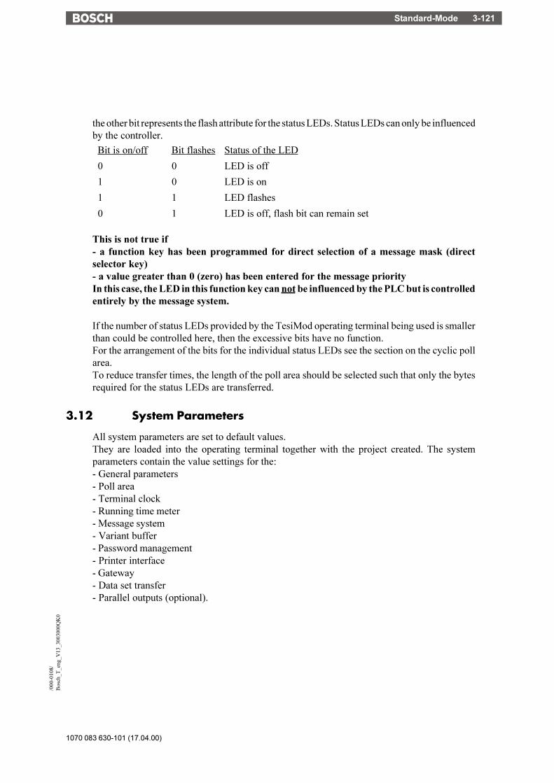
Standard-Mode 3-121
1070 083 630-101 (17.04.00)
/000
-010
8/B
osch
_T_e
ng_V
13_3
0030
00Q
K0
the other bit represents the flash attribute for the status LEDs. Status LEDs can only be influencedby the controller.
Bit is on/off Bit flashes Status of the LED
0 0 LED is off
1 0 LED is on
1 1 LED flashes
0 1 LED is off, flash bit can remain set
This is not true if- a function key has been programmed for direct selection of a message mask (directselector key)- a value greater than 0 (zero) has been entered for the message priorityIn this case, the LED in this function key can not be influenced by the PLC but is controlledentirely by the message system.
If the number of status LEDs provided by the TesiMod operating terminal being used is smallerthan could be controlled here, then the excessive bits have no function.For the arrangement of the bits for the individual status LEDs see the section on the cyclic pollarea.To reduce transfer times, the length of the poll area should be selected such that only the bytesrequired for the status LEDs are transferred.
3.12 System Parameters
All system parameters are set to default values.They are loaded into the operating terminal together with the project created. The systemparameters contain the value settings for the:- General parameters- Poll area- Terminal clock- Running time meter- Message system- Variant buffer- Password management- Printer interface- Gateway- Data set transfer- Parallel outputs (optional).

1070 083 630-101 (17.04.00)
Standard-Mode3-122
3.12.1 System Parameters: General Parameters
The general parameters refer to all generally applicable functions of the operating terminal.- Polling time for cyclic variables- Screensaver settings (optional)- Automatic download (TSwin only)- Symbolic addresses for: Image of the mask number
Image of the DIP switchRead coordination byteTable indexKeyboard image
3.12.2 System Parameters: Poll Area
System parameters for the poll area include the symbolic address of the variable, the polling timeand the size of the poll area.
3.12.3 System Parameters: Terminal Clock
System parameters that can be specified for the terminal clock are the symbolic addresses of thevariable, the polling time, the transfer parameters (date, time of day, day of week) and thevariables for setting the terminal clock from the controller end.
3.12.4 System Parameters: Running Time Meter
System parameters that can be specified for the running time meter are the addresses for thecontrol byte and reset byte as well as the polling time.
3.12.5 System Parameters: Message System
System parameters that can be specified for the message system are the general parameters.These include the size of the message buffer and the message priority for direct display of amessage.
Parameters that can additionally be specified for the serial message system are the parametersfor the logging printer and the symbolic name of the variable which can be used to deletemessages from within the controller.
Parameters that can be defined for the parallel message system are the size of the message buffer,the polling time and the symbolic name of the variable address.
Additional parameters for the serial and parallel message system are the sorting criteria and howthe messages are to be displayed.

Standard-Mode 3-123
1070 083 630-101 (17.04.00)
/000
-010
8/B
osch
_T_e
ng_V
13_3
0030
00Q
K0
3.12.6 System Parameters: Variant Buffer
System parameters available for the variant buffer are the symbolic name of the variable and thesize of the variant buffer.
3.12.7 System Parameters: Password Management
System parameters that can be defined for the password management are the passwordsthemselves, the corresponding authorization levels and the initialization values for the authorizationlevels.
3.12.8 System Parameters: Printer Interface
Parameters that are specified for the printer interface are the baud rate, parity, data bits, stop bitsand the handshake.
3.12.9 System Parameters: Gateway
Setting of the gateway parameters applies only to operating terminals that have been fitted withthe corresponding firmware.Parameters that can be defined for these operating terminals are:- Smallest possible slave number- Largest possible slave number- Polling time for text list- Cache size- Polling time for cache- Variable for cache address- Variable for network status address
3.12.10 System Parameters: Data Set Transfer
The following parameters are required to transfer data sets from the terminal to the controller:- Variable for recipe number- Variable for data set number
The following parameters are required to transfer data sets from the controller (on request):- Variable for recipe number- Variable for data set number
3.12.11 System Parameters: Parallel Outputs
System parameters for the parallel outputs are the symbolic name of the variable and the pollingtime of this variable. Every output can be enabled separately.
1070 083 630-101 (17.04.00)
Standard-Mode3-124
3.13 Version Number
The version number is reserved for the user. Valid values range from 0 to 255. The value is storedin a system variable. This system variable can be displayed by the user in any I/O mask.This variable has no further function in the operating terminal. Online editing of the versionnumber is not possible.
3.14 Running Time Meter
TesiMod operating terminals provide 8 running time meters to the user. In the programmingsoftware, enter a variable name for the control byte which constitutes the address at which thecontroller can influence the running time meters.Every bit of this control byte represents one running time meter. If a bit is set to logical 1, thecorresponding running time meter is incremented in accordance with the selected polling timecycle.
Fig. 29: Structure of the control byte
Example: A running time meter is to be set up for a maintenance interval of 50 hours.
Polling time for the counter: 60 seconds (the counter is increased by 1 every minute)
Setting: System variable Counter1Fixed point number (TSdos)Decimal number (TSwin)4 digits; 1 post-decimal place (fractional digit)Only positiveFactor 1; divisor 6, summand 0
The following is displayed on the terminal after 150 polling cycles:Format: 150 : 6 = 25Formatted display: 2.5 Hours
The precision in this example is +/- 6 minutes.
The variable "Reset Byte" can be used to reset each running time meter from the controller. Todo this, the bit for the running time meter in question must be set to logical 1.

Standard-Mode 3-125
1070 083 630-101 (17.04.00)
/000
-010
8/B
osch
_T_e
ng_V
13_3
0030
00Q
K0
7 6 5 4 3 2 1 0 Reset Byte
Running time meter 1
Running time meter 2
Running time meter 3
Running time meter 4
Running time meter 5
Running time meter 6
Running time meter 7
Running time meter 8Fig. 30: Structure of the reset byte
3.15 Parallel Outputs
The parallel outputs of the operating terminal can be addressed directly with the function keysand by the controller. To be able to operate the parallel outputs from the controller, a variablemust be defined for the control word. The word must be divided into two single bytes if thecontroller is only capable of accessing in byte mode. The byte order depends on the type ofcontroller.
15 14 13 12 11 10 9 8 7 6 5 4 3 2 1 0
A8Flashing
A7Flashing
A8Flashing
A5Flashing
A4Flashing
A3Flashing
A2Flashing
A1Flashing
A8On/Off
A7On/Off
A6On/Off
A5On/Off
A4On/Off
A3On/Off
A2On/Off
A1On/Off
Fig. 31: Structure of the Control Word
The structure of the control word illustrates that one bit pair always controls one output. Thefollowing truth table applies to every bit pair:
0 0
1 0 Output ON
Output OFF
1 1 Output FLASHES
Fig. 32: Truth table for Parallel Outputs
In addition to the variable name, the polling time must be specified in the programming softwareto determine the cyclic intervals at which the control word is to be polled.Outputs can also be addressed by means of function keys, provided this has been defined in theprogramming software. An output is being addressed (ON) as long as the function key is pressed.The programming software checks if the function keys and the controller want to access the sameoutputs.

1070 083 630-101 (17.04.00)
Standard-Mode3-126
3.16 Screen Saver
Some terminals are fitted with a screen saver. This function monitors all outputs to the display.If the system detects that nothing is being output to the display, a timeout begins to elapse. Afterthe timeout has elapsed, the display is blanked and the status LED in the Help key begins to flash.The display can be reactivated by pressing any key.Activation of the screen saver can be made dependent on the display of cyclic variables. In TSdosprojects, the screen saver can not be activated at all if cyclic data are displayed.The timeout can be defined in 0.1 second steps.If the timeout is set to 0, the screen saver remains deactivated.
3.17 Image of the Mask Number
The mask number is a mask-specific code which the terminal writes to the controller variableentered here.The terminal writes the mask number of the currently displayed mask into this variable whenevera new mask is activated. The variable is assigned in the variable list. In this list, a word addressof the controller must be assigned to the symbolic name. The respective mask number can thenbe read from this address and be processed further as required. A 16-bit variable must be reservedfor the mask number.Also see the evaluation of the function keys and soft keys, etc.
3.18 Image of the Mode Selector Switch
In standard mode, the image of the mode selector switch (user mode switch) is transmitted to thecontroller after the initialization phase is complete. The user has the option of evaluating anyunassigned DIP-switches in the controller. This allows the user to call up specific programs inthe controller or to create queries in a service routine.
3.19 Terminal Clock
Every operating terminal is fitted with a real-time clock. The parameters of this real-time clockcan be set in the system parameters.Once per poll cycle, the real-time clock stores the current time, date and day of the week to thedefined variable in the connected controller.The connected controller itself can also transfer its current time, date and day of the week to theterminal.This allows the time and clock in the controller, if any, to be synchronized or provides the real-time if controllers are not fitted with a clock.Formats and contents of the variables must be identical with those in chapter "Image of Date andTime". To cause the terminal to read this variable, the controller needs to transfer the control code7FF9H through the serial message channel.

Standard-Mode 3-127
1070 083 630-101 (17.04.00)
/000
-010
8/B
osch
_T_e
ng_V
13_3
0030
00Q
K0
3.19.1 Image of Date and Time
The time of day, the date and the day of week are stored in BCD-format.A maximum of 7 bytes of memory space is required. The address of the first byte is specified inthe variable list. The data contents are defined as illustrated below:
Fig. 33: Structure of the control byte for the time and date
The variable for the day of the week is calendar-independent and always runs modulo 6. Theassignment of a number to a particular day of the week can be specified by the user when he setsthe date and the text for the day.
Possible assignments in the text lists are:0 Sunday1 Monday2 Tuesday3 Wednesday4 Thursday5 Friday6 Saturday
When entering the date, the user is then responsible for setting the variable for the day of the weekto the correct value.Example:21.02.1997 (Friday) Day of the week in accordance with table above: 5

1070 083 630-101 (17.04.00)
Standard-Mode3-128
3.20 Read Coordination Byte
The term Read Coordination Byte indicates that the controller only reads this byte. It is onlywritten to by the operating terminal.This byte is used for the handshake and data coordination with the controller. For this purpose,the terminal reports its current status to the controller in the symbolic name entered here. Eachbit has its own specific function. The structure is as illustrated below:
Fig. 34: Structure of the Read coordination byte
The Read coordination byte is used to pass the status of the operating terminal to the controller.
For the functionality of the individual bits refer to the respective chapters.The terminal supports the <Read Coordination Byte> function only if the Write CoordinationByte has also been activated in the cyclic poll area. To activate both coordination bytes, the sizeof the poll area and the polling time must be specified during programming time. In addition, theaddresses of the Read coordination byte and poll area must be specified in the variable list.
3.20.1 Editing Request Bit (Bit "EA")
The editing request bit is used to signal to the controller that the value of a variable is to bemodified on the terminal. To do so, the operator presses the Data Release key. The status LEDin the Data Release key is flashing as long as the editing release has not been set by the controller.Once the controller has set the External Data Release bit in the Write Coordination Byte tological 1, the status LED in the Data Release key remains lit and the value can be modified bythe operator.
3.20.2 Editing Status Bit (Bit "EZ")
Once the controller has set the editing release, the editing status bit is automatically set tological 1 by the terminal. The bit is reset to logical 0 after the Enter key is pressed by the operator.

Standard-Mode 3-129
1070 083 630-101 (17.04.00)
/000
-010
8/B
osch
_T_e
ng_V
13_3
0030
00Q
K0
3.20.3 Refresh Request Bit (Bit "RA")
The refresh request function is set up by using an input variable with the PLC-Handshakeattribute. With this function, a data release for the next input variable in the same mask will notbe set until a refresh acknowledgement has been received from the controller.Upon request, the controller can then refresh the next variable (bit "RA" = 1) before sending arefresh acknowledgement (bit "RQ" in the Write coordination byte = 1), thereby ensuring thatthe value the operator works with is current.
3.20.4 Liveness Flag (Bit "LM")
With some communication protocols it is not possible to check, from the controller end, whetheror not the interface is in operating condition. This is why the liveness flag function has beenintroduced - a simple functionality that has proven to be very effective in practice.Whenever the PLC wants to know whether a connection is still established, it writes a logical 1,and later a logical 0, to bit 3 of the Write Coordination Byte.The operating terminal constantly monitors the liveness flag in the Write Coordination Byteand compares it with the status of the liveness flag in the Read Coordination Byte.As soon as a discrepancy occurs, the operating terminal copies the Liveness Flag Bit from theWrite Coordination Byte to the Read Coordination Byte.
The controller is now responsible for checking within a timeout whether both states are inagreement. The transfer times and polling times must be taken into account when defining thetimeout.
3.20.5 Data Set Download Active (Bit "DDA")
The Data Set Download Active bit remains set to logical 1 for as long as a data set is beingtransferred. The bit is reset after all of the data have been transferred. The controller can thenwork with the new values in the recipe.

1070 083 630-101 (17.04.00)
Standard-Mode3-130
3.21 Write Coordination Byte
The term Write Coordination Byte indicates that the controller writes to this byte.The operating terminal only reads this byte.Together with the Read Coordination Byte, this byte is used for the handshake and for datacoordination with the controller. Here, the controller reports its current status to the terminal. Theindividual bits are independent of one another. The Write Coordination Byte is the first byteof the cyclic poll area.
The structure is as illustrated below:
Fig. 35: Structure of the Write coordination byte
3.21.1 External Data Release (Bit "ED")
The external data release can be used to determine, from the controller end, the point of time fromwhich editing of the value of a variable is allowed on the terminal. A flashing Data Release keyLED on the operating terminal indicates that an external data release has not yet been set. Editingof the value is therefore still inhibited. Once the PLC has set the data release bit to logical 1, theData Release LED remains lit and a new value can be entered by the operator. After allmodifications have been made, the operating terminal sets the editing status bit back to logical0, thereby signaling that the editing process has been completed.
3.21.2 Refresh Acknowledgement (Bit "RQ")
The refresh request bit is used to indicate to the controller that the values of the variables in thecurrent mask are to be refreshed. After the values have successfully been transferred to theterminal, the controller sets the refresh acknowledgement bit to logical 1 to indicate that theprocess has been completed. See chapter 3.20.3 Refresh Request Bit (Bit "RA").
3.21.3 Resetting the Password
The password protection should be reactivated after the operator exits a password-protectedaccess level. This can be forced by the controller by setting the Reset Password bit to logical1.

Standard-Mode 3-131
1070 083 630-101 (17.04.00)
/000
-010
8/B
osch
_T_e
ng_V
13_3
0030
00Q
K0
3.21.4 Liveness Flag (Bit "LM")
See chapter Liveness Flag of the Read Coordination Byte (3.21.4).
3.21.5 Data Set Download Release (Bit "DDF")
The Data Set Download Release (DDF) bit allows the controller to determine the point of timefrom which transfer of a data set to the controller can begin.
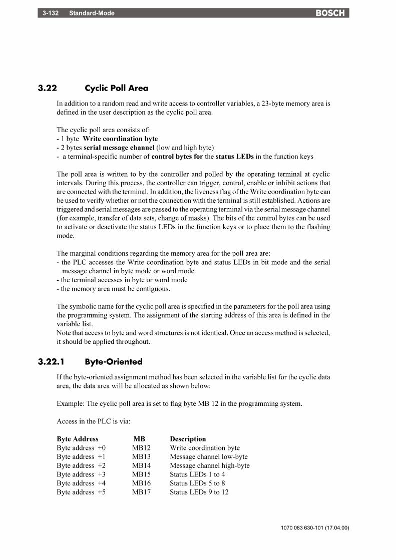
1070 083 630-101 (17.04.00)
Standard-Mode3-132
3.22 Cyclic Poll Area
In addition to a random read and write access to controller variables, a 23-byte memory area isdefined in the user description as the cyclic poll area.
The cyclic poll area consists of:- 1 byte Write coordination byte- 2 bytes serial message channel (low and high byte)- a terminal-specific number of control bytes for the status LEDs in the function keys
The poll area is written to by the controller and polled by the operating terminal at cyclicintervals. During this process, the controller can trigger, control, enable or inhibit actions thatare connected with the terminal. In addition, the liveness flag of the Write coordination byte canbe used to verify whether or not the connection with the terminal is still established. Actions aretriggered and serial messages are passed to the operating terminal via the serial message channel(for example, transfer of data sets, change of masks). The bits of the control bytes can be usedto activate or deactivate the status LEDs in the function keys or to place them to the flashingmode.
The marginal conditions regarding the memory area for the poll area are:- the PLC accesses the Write coordination byte and status LEDs in bit mode and the serial
message channel in byte mode or word mode- the terminal accesses in byte or word mode- the memory area must be contiguous.
The symbolic name for the cyclic poll area is specified in the parameters for the poll area usingthe programming system. The assignment of the starting address of this area is defined in thevariable list.Note that access to byte and word structures is not identical. Once an access method is selected,it should be applied throughout.
3.22.1 Byte-Oriented
If the byte-oriented assignment method has been selected in the variable list for the cyclic dataarea, the data area will be allocated as shown below:
Example: The cyclic poll area is set to flag byte MB 12 in the programming system.
Access in the PLC is via:
Byte Address MB DescriptionByte address +0 MB12 Write coordination byteByte address +1 MB13 Message channel low-byteByte address +2 MB14 Message channel high-byteByte address +3 MB15 Status LEDs 1 to 4Byte address +4 MB16 Status LEDs 5 to 8Byte address +5 MB17 Status LEDs 9 to 12

Standard-Mode 3-133
1070 083 630-101 (17.04.00)
/000
-010
8/B
osch
_T_e
ng_V
13_3
0030
00Q
K0
Byte address +6 MB18 Status LEDs 13 to 16Byte address +7 MB19 Status LEDs 17 to 20Byte address +8 MB20 Status LEDs 21 to 24Byte address +9 MB21 Status LEDs 25 to 28Byte address +10 MB22 Status LEDs 29 to 32
The size of the data area is 11 bytes.
The structure of the byte-oriented cyclic poll area is as shown below:
Fig. 36: Byte-oriented poll area
Bit 7 Bit 6 Bit 5 Bit 4 Bit 3 Bit 2 Bit 1 Bit 0
Byteaddress
+ 0not used not used not used DDF LM PL RQ ED
Byteaddress
+ 1serial message channel low byte
Byteaddress-
+ 2serial message channel high byte
Byteaddress
+ 3
LED 1on/off
LED 1flashing
LED 2on/off
LED 2flashing
LED 3on/off
LED 3flashing
LED 4on/off
LED 4flashing
Byteaddress
+ 4
LED 5on/off
LED 5flashing
LED 6on/off
LED 6flashing
LED 7on/off
LED 7flashing
LED 8on/off
LED 8flashing
Byteaddress
+ 5
LED 9on/off
LED 9flashing
LED 10on/off
LED 10flashing
LED 11on/off
LED 11flashing
LED 12on/off
LED 12flashing
Byteaddress
+ 6
LED 13on/off
LED 13flashing
LED 14on/off
LED 14flashing
LED 15on/off
LED 15flashing
LED 16on/off
LED 16flashing
Byteaddress
+ 7
LED 17on/off
LED 17flashing
LED 18on/off
LED 18flashing
LED 19on/off
LED 19flashing
LED 20on/off
LED 20flashing
Byteaddress
+ 8
LED 21on/off
LED 21flashing
LED 22on/off
LED 22flashing
LED 23on/off
LED 23flashing
LED 24on/off
LED 24flashing
Byteaddress
+ 9
LED 25on/off
LED 25flashing
LED 26on/off
LED 26flashing
LED 27on/off
LED 27flashing
LED 28on/off
LED 28flashing
Byteaddress
+ 10
LED 29on/off
LED 29flashing
LED 30on/off
LED 30flashing
LED 31on/off
LED 31flashing
LED 32on/off
LED 32flashing
Byteaddress
+ 11
LED 33on/off
LED 33flashing
LED 34on/off
LED 34flashing
LED 35on/off
LED 35flashing
LED 36on/off
LED 36flashing
Byteaddress
+ 12
LED 37on/off
LED 37flashing
LED 38on/off
LED 38flashing
LED 39on/off
LED 39flashing
LED 40on/off
LED 40flashing
Byteaddress
+ 13
LED 41on/off
LED 41flashing
LED 42on/off
LED 42flashing
LED 43on/off
LED 43flashing
LED 44on/off
LED 44flashing
Byteaddress
+ 14
LED 45on/off
LED 45flashing
LED 46on/off
LED 46flashing
LED 47on/off
LED 47flashing
LED 48on/off
LED 48flashing
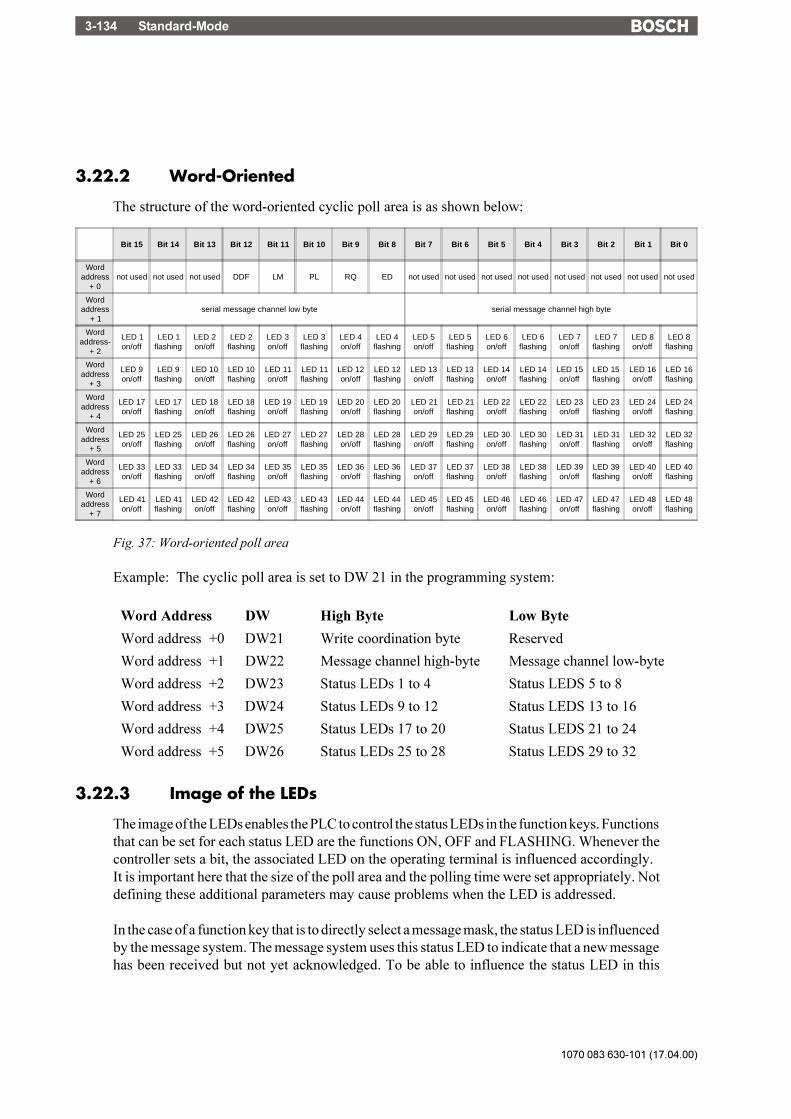
1070 083 630-101 (17.04.00)
Standard-Mode3-134
3.22.2 Word-Oriented
The structure of the word-oriented cyclic poll area is as shown below:
Fig. 37: Word-oriented poll area
Example: The cyclic poll area is set to DW 21 in the programming system:
Word Address DW High Byte Low Byte
Word address +0 DW21 Write coordination byte Reserved
Word address +1 DW22 Message channel high-byte Message channel low-byte
Word address +2 DW23 Status LEDs 1 to 4 Status LEDS 5 to 8
Word address +3 DW24 Status LEDs 9 to 12 Status LEDS 13 to 16
Word address +4 DW25 Status LEDs 17 to 20 Status LEDS 21 to 24
Word address +5 DW26 Status LEDs 25 to 28 Status LEDS 29 to 32
3.22.3 Image of the LEDs
The image of the LEDs enables the PLC to control the status LEDs in the function keys. Functionsthat can be set for each status LED are the functions ON, OFF and FLASHING. Whenever thecontroller sets a bit, the associated LED on the operating terminal is influenced accordingly.It is important here that the size of the poll area and the polling time were set appropriately. Notdefining these additional parameters may cause problems when the LED is addressed.
In the case of a function key that is to directly select a message mask, the status LED is influencedby the message system. The message system uses this status LED to indicate that a new messagehas been received but not yet acknowledged. To be able to influence the status LED in this
Bit 15 Bit 14 Bit 13 Bit 12 Bit 11 Bit 10 Bit 9 Bit 8 Bit 7 Bit 6 Bit 5 Bit 4 Bit 3 Bit 2 Bit 1 Bit 0
Wordaddress
+ 0not used not used not used DDF LM PL RQ ED not used not used not used not used not used not used not used not used
Wordaddress
+ 1serial message channel low byte serial message channel high byte
Wordaddress-
+ 2
LED 1on/off
LED 1flashing
LED 2on/off
LED 2flashing
LED 3on/off
LED 3flashing
LED 4on/off
LED 4flashing
LED 5on/off
LED 5flashing
LED 6on/off
LED 6flashing
LED 7on/off
LED 7flashing
LED 8on/off
LED 8flashing
Wordaddress
+ 3
LED 9on/off
LED 9flashing
LED 10on/off
LED 10flashing
LED 11on/off
LED 11flashing
LED 12on/off
LED 12flashing
LED 13on/off
LED 13flashing
LED 14on/off
LED 14flashing
LED 15on/off
LED 15flashing
LED 16on/off
LED 16flashing
Wordaddress
+ 4
LED 17on/off
LED 17flashing
LED 18on/off
LED 18flashing
LED 19on/off
LED 19flashing
LED 20on/off
LED 20flashing
LED 21on/off
LED 21flashing
LED 22on/off
LED 22flashing
LED 23on/off
LED 23flashing
LED 24on/off
LED 24flashing
Wordaddress
+ 5
LED 25on/off
LED 25flashing
LED 26on/off
LED 26flashing
LED 27on/off
LED 27flashing
LED 28on/off
LED 28flashing
LED 29on/off
LED 29flashing
LED 30on/off
LED 30flashing
LED 31on/off
LED 31flashing
LED 32on/off
LED 32flashing
Wordaddress
+ 6
LED 33on/off
LED 33flashing
LED 34on/off
LED 34flashing
LED 35on/off
LED 35flashing
LED 36on/off
LED 36flashing
LED 37on/off
LED 37flashing
LED 38on/off
LED 38flashing
LED 39on/off
LED 39flashing
LED 40on/off
LED 40flashing
Wordaddress
+ 7
LED 41on/off
LED 41flashing
LED 42on/off
LED 42flashing
LED 43on/off
LED 43flashing
LED 44on/off
LED 44flashing
LED 45on/off
LED 45flashing
LED 46on/off
LED 46flashing
LED 47on/off
LED 47flashing
LED 48on/off
LED 48flashing
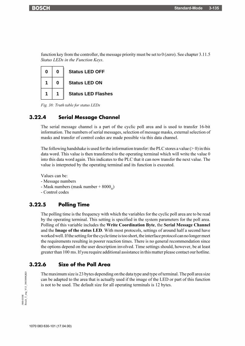
Standard-Mode 3-135
1070 083 630-101 (17.04.00)
/000
-010
8/B
osch
_T_e
ng_V
13_3
0030
00Q
K0
function key from the controller, the message priority must be set to 0 (zero). See chapter 3.11.5Status LEDs in the Function Keys.
0 0
1 0 Status LED ON
Status LED OFF
1 1 Status LED Flashes
Fig. 38: Truth table for status LEDs
3.22.4 Serial Message Channel
The serial message channel is a part of the cyclic poll area and is used to transfer 16-bitinformation. The numbers of serial messages, selection of message masks, external selection ofmasks and transfer of control codes are made possible via this data channel.
The following handshake is used for the information transfer: the PLC stores a value (> 0) in thisdata word. This value is then transferred to the operating terminal which will write the value 0into this data word again. This indicates to the PLC that it can now transfer the next value. Thevalue is interpreted by the operating terminal and its function is executed.
Values can be:- Message numbers- Mask numbers (mask number + 8000
H)
- Control codes
3.22.5 Polling Time
The polling time is the frequency with which the variables for the cyclic poll area are to be readby the operating terminal. This setting is specified in the system parameters for the poll area.Polling of this variable includes the Write Coordination Byte, the Serial Message Channeland the Image of the status LED. With most protocols, settings of around half a second haveworked well. If the setting for the cycle time is too short, the interface protocol can no longer meetthe requirements resulting in poorer reaction times. There is no general recommendation sincethe options depend on the user description involved. Time settings should, however, be at leastgreater than 100 ms. If you require additional assistance in this matter please contact our hotline.
3.22.6 Size of the Poll Area
The maximum size is 23 bytes depending on the data type and type of terminal. The poll area sizecan be adapted to the area that is actually used if the image of the LED or part of this functionis not to be used. The default size for all operating terminals is 12 bytes.

1070 083 630-101 (17.04.00)
Standard-Mode3-136
3.23 Control Codes
Control codes have already been mentioned in the previous sections which can be used to triggercertain actions or functions in the operating terminal. All of these actions are initiated by thecontroller by writing the desired control code to the serial message channel within the poll area.An explanation of these control codes is provided below.
3.23.1 Triggering Data Set Printouts
The following hex code can be used from the controller to cause the current data set to be outputto the printer connected to the operating terminal.
Hexadecimal code: 7FF8H
The operating terminal can indicate the status of the print process by writing either of two valuesto the address for the recipe number variable.
0 Data set printout ok.255 Data set with the desired data set number can not be printed.
3.23.2 Setting the Clock in the Operating Terminal
The following hex code can be used from the controller to cause the real-time clock in theoperating terminal to be set in accordance with the specifications in the defined control word.
Hexadecimal code: 7FF9H
3.23.3 Transferring Data Sets from the Controller to the Terminal
The following hex code can be used from the controller to initiate the transfer of a data set fromthe controller to the operating terminal. This requires that the recipe number and data set numberare specified by the controller first.The data sets are transferred as a block.
The following variables must be defined:- Recipe number for the Request from Controller (System Parameters: Data Set Transfer)- Data set number for the Request from Controller (System Parameters: Data Set Transfer)
Hexadecimal code: 7FFAH
3.23.4 Transferring Data Sets from the Terminal to the Controller
The following hex code can be used from the controller to initiate the transfer of a data set fromthe operating terminal to the controller. This requires that the recipe number and data set numberare specified by the controller first.

Standard-Mode 3-137
1070 083 630-101 (17.04.00)
/000
-010
8/B
osch
_T_e
ng_V
13_3
0030
00Q
K0
The following variables must be defined:- Recipe number for the Request from Controller (System Parameters: Data Set Transfer)- Data set number for the Request from Controller (System Parameters: Data Set Transfer)
Hexadecimal code: 7FFBH
3.23.5 Transferring Data Sets from the Controller to the Terminal(Individually)
The following hex code can be used from the controller to initiate the transfer of a data set fromthe controller to the operating terminal. This requires that the recipe number and data set numberare specified by the controller first.The data sets are transferred individually.
The following variables must be defined:- Recipe number for the Transfer from the terminal (System Parameters: Data Set Transfer)- Data set number for the Transfer from the terminal (System Parameters: Data Set Transfer)
Hexadecimal code: 7FFDH
3.23.6 Refreshing the Message System
The following hex code can be used from the controller to cause the operating terminal to readin the most recent parallel messages.This procedure can be used to achieve an event-controlled message system.
Hexadecimal code: 7FFFH
3.24 Cyclic Variables
The term Cyclic Variables refers to data which may change continuously while a mask isdisplayed, i.e. all types of ACTUAL VALUES. The terminal must therefore poll the controllerfor the current values at cyclic intervals. The time selected here specifies the intervals at whichthese mask values are refreshed.In addition to the cyclic variables, the terminal also polls the controller for the current status ofthe Write coordination byte, the serial message channel and the LEDs (update). This process iseither time or event controlled depending on the protocol. No polling will take place if the value= 0 is entered for the time period. If this variable is not polled, then an external control of the datarelease is not possible, for example.
3.25 Interface Parameters X2, X3
The interface parameters selected in the programming system are stored in the mask memory.It is, however, possible to modify the data in the operating terminal at a later date. Valuesmodified in the operating terminal are retained in the battery-backed RAM. When necessary, theoriginal settings can be restored at any time.

1070 083 630-101 (17.04.00)
Standard-Mode3-138
The parameters of the interface at connector X2 are determined by the protocol. Modificationsto any of these parameters could result in communication failures. Values that are not typical aredetected when the terminal is initialized and a message to this effect is generated.The parameters of the interface X3 are reserved for control of a printer and, when transferringhard copies, of a PC (hard copy function is not possible with operating terminals with 386processors). This process requires that the settings for both devices must match. The selectedparameters do not apply to the download. For the download, the system will automatically switchto the highest possible transmission rate.
3.26 Variable Definition
The variable definition contained in the user description defines the format, type, range of values,scaling and attribute of the representation. All controller-independent parameters are storedhere. For editable variables, it is additionally possible to influence the Editor and the transfermode to the controller. The variable definition contains the symbolic name of the variables, theformat definition and, if necessary, the text lists in the case of selection text variables (coded textvariables).
3.26.1 Variable Formats (TSdos)
The formats, once defined in a variable definition, are stored in the programming system witha format name. This allows different variables to be easily output with the same format withouthaving to reenter all of the parameters each time.
3.26.2 Variable List
The variable list contains the assignment of symbolic variable names to the destination hardware.Due to its design and proximity to the PLC, this file is always manufacturer-specific. In TSdos,this list contains the variable addressing and protocol-specific parameters, interface parameters,timeouts, etc. The file extension for the variable list in TSdos is .TSV.In TSwin, the variable list is a part of the database. Any number of variable lists can be created.The variable list contains only the required manufacturer-specific user description parts. Its sizeis therefore small in relation to the entire project. A project can be quickly adapted to other PLCspecifications by simply adapting the variable list to the PLC to be used.
A variable list can be created in the programming system in two ways.First method:TSdos:First, the entire operator guidance is entered, upon which the programming system will, whenprompted to do so, create a protocol-specific variable list that will contain all of the variablenames that have been used. After the list has been created, it will also be used as a name list whenthe masks are programmed. The list will not yet contain information on the controller�s hardwarereferences. This information will be supplied by the user when he enters this information intothe variable list in the manufacturer-specific notation. This method ensures that no variablesfrom the variable list are omitted.

Standard-Mode 3-139
1070 083 630-101 (17.04.00)
/000
-010
8/B
osch
_T_e
ng_V
13_3
0030
00Q
K0
TSwin:As a variable is defined in a mask (with or without address information) it is entered into thevariable list at the same time.
Second Method:TSdos:The user begins with generating the variable list with the symbolic names and all of the referenceson the basis of the PLC program. The same names can be used here as are used in the PLC. Whencreating masks, the programmer can simply refer to the name list and use the respective variablenames.TSwin:The first step can be to define the entries in the variable list or alternatively to insert them fromany suitable program via the clipboard. The entries will immediately be available in TSwin ona global basis.
A combination of the two methods can also be used.TSdos users who have the corresponding documentation or databases on their PLC programs attheir disposal can alternatively generate the variable list from this PLC documentation (print file)themselves. The structure of the list (TSV-file) corresponds to a simple text file. The demoscontain the definition in the form of comments. Note that the definition format varies with theprotocol used.
Example for a Siemens PLC with programming unit interfacing:
Mit "Co" beginnen alle Kommentarzeilen.Auszug aus einer Variablenliste:Co Für Siemens PG SchnittstelleCo Vp Siemens PG VariableCo Vp \Variablenname\,\Datentyp\,\Parameter 1\,\Parameter 2\Co oder für Siemens L1 SchnittstelleCo Vl Siemens L1 VariableCo Vl \Variablenname\,\Datentyp\,\Parameter 1\,\Parameter 2\,\Slave\Co
Co Datentyp : E,A,M,EB,EW,AB,AW,MB,MW,DW,DL,DR,t,zCo Parameter 1 : Bei Datentyp DW, DL, DR Bausteinnummer, sonstCo Byte oder WortoffsetCo Parameter 2 : Bei Datentyp E,A,M Bitnummer 0 bis .7Co Bei Datentyp DW,DR,DL DatenwortnummerCo sonst keine BedeutungCo Slave Adresse : Nur bei L1 Protokoll
Vp \Maskennummer\,\MW\,\76\,\0\Vp \ZyklischeDaten\,\MB\,\0\,\0\Vp \Dipschalter\,\MB\,\120\,\0\

1070 083 630-101 (17.04.00)
Standard-Mode3-140
3.27 Application Programming
The TesiMod operating concept is based on a mask structure that can be created by the user inaccordance with the requirements and on system variables that can influence important functionsin the operating terminal. Various types of masks are available to facilitate the creation ofsolutions for standard tasks.Every mask structure initially consists of 4 types of masks whose contents are user-configurable.
In TSwin, any I/O mask can be programmed as a system mask. In TSdos, the following are fixedmasks:- Setup mask (1)- Startup mask (2)- Password mask (3)- Main mask (4)
After being switched on, the operating terminal is initialized and displays the startup mask duringthis process. The setup mask can be called up by pressing the Enter key while the startup maskis displayed. The setup mask can be exited by pressing the Enter key again and the startup maskwill reappear.The next mask of the operating guidance that is displayed is the Main Mask (mask 4) whichrepresents the first mask of the user-programmed operator guidance. A menu with menu items(node mask) is normally set up in the main mask to allow selection of lower-level masks. Theuser has the option of specifying a full-page help text for every mask which can be displayed bythe operator with the Help key.The functions of the system variables are briefly described in chapter 3.6.3. Some of thesevariables are mentioned in the following chapters to be able to explain the applicationprogramming.
3.27.1 Configuring the System
To run the programming software, you will need a PC that complies with the requirementsdescribed in the software manual. One of the computer's serial interfaces (COM1 or COM2) isconnected with the interface X3 of the operating terminal using the download cable (availableas an accessory). The connection of the operating terminal to the PLC (using interface X2) isestablished with an additional, controller-specific interface cable. Care must be taken to ensurethat the correct type of interface cable is used and that the operating terminal is connected to apower source which complies with the technical specifications for the operating terminal.
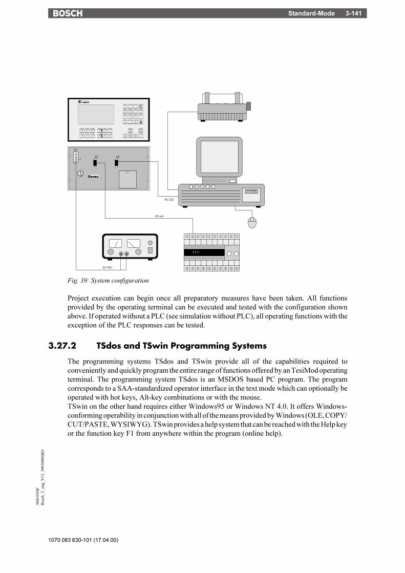
Standard-Mode 3-141
1070 083 630-101 (17.04.00)
/000
-010
8/B
osch
_T_e
ng_V
13_3
0030
00Q
K0
RS 232
20 mA
S P S
X3
X1
X2
24 VDC
Fig. 39: System configuration
Project execution can begin once all preparatory measures have been taken. All functionsprovided by the operating terminal can be executed and tested with the configuration shownabove. If operated without a PLC (see simulation without PLC), all operating functions with theexception of the PLC responses can be tested.
3.27.2 TSdos and TSwin Programming Systems
The programming systems TSdos and TSwin provide all of the capabilities required toconveniently and quickly program the entire range of functions offered by an TesiMod operatingterminal. The programming system TSdos is an MSDOS based PC program. The programcorresponds to a SAA-standardized operator interface in the text mode which can optionally beoperated with hot keys, Alt-key combinations or with the mouse.TSwin on the other hand requires either Windows95 or Windows NT 4.0. It offers Windows-conforming operability in conjunction with all of the means provided by Windows (OLE, COPY/CUT/PASTE, WYSIWYG). TSwin provides a help system that can be reached with the Help keyor the function key F1 from anywhere within the program (online help).

1070 083 630-101 (17.04.00)
Standard-Mode3-142
Compiler
File namex.tsm
File namex+1.tsm
File name.tsv File name.tsg
User program
Projekt.S3
Project file
Project.prj
Variables list ParameterMasks files
Fig. 40: Project files of the TSdos programming system

Standard-Mode 3-143
1070 083 630-101 (17.04.00)
/000
-010
8/B
osch
_T_e
ng_V
13_3
0030
00Q
K0
Project management LanguagesLanguage
parameters
Masks
Submasks
Help masks
Recipes
Messages
System messages
Global keys
Text lists
Communikationparameters
Controllers
Variables listGeneral
informationen
Projects
System parameters
Image lists
Images
Fonts
Colors
Fig. 41: Structure of the TSwin programming system
Information on how the TSdos programming system works and how it is operated is availablein a separate, extensive manual. An online help system that can be called up with the F1 keyprovides additional support on how to operate the software. The programming systems provideall of the functions required to perform the steps necessary to create a project. TSdos can be usedto create various mask, parameter and variable files and to organize them into a project.
The TSwin programming system operates similarly to a database. All project-related data arecollected in this database and are organized into a project.
This project can then be compiled into a S3 file and transferred to the terminal using the downloadfunction.

1070 083 630-101 (17.04.00)
Standard-Mode3-144
3.27.3 Getting Started with Programming
Demo projects are available to provide the user with an easy way of getting started with projectcreation. The demo projects are complete applications that illustrate all important programmingoptions.Contact out sales department if an application for your type of operating terminal is not available.
3.27.3.1 Project Description
The project description consists of:
at least the user description (one per language)a variable list (controller-specific)the global data (parameters)and, if used, parts of the graphical library.
The user description contains all of the controller-independent information. Symbolic names areinserted for all controller-specific variables.The assignment of these symbolic names to the hardware is specified in the variable list. Thismakes it possible to easily change to another controller manufacturer without having to recreatethe masks, variable definition or operating functionality. The adaptation to a different controllertype can be accomplished by simply replacing the variable list.
3.27.3.2 Multilingual Projects
The mask contents of a user description determines the language in which the texts are displayed.To make an operator interface available in multiple languages, the user description of eachlanguage is stored with a language number. The desired language can then be selected online viaa system variable using the assigned language number.The number of languages that can be stored is limited only by the size of the mask memory. Pleasenote that it is not necessary that the length of the texts, the variables and the number of masksare identical in the various languages.
The number of the currently active language is stored in the operating terminal and is retainedwhen the terminal is switched off. When booted again, the terminal defaults to the languagewhich was active when the terminal was turned off. In the case of a loss of data, the language thatcorresponds to the number 0 is automatically displayed.
The language can easily be selected on the operating terminal using a selection text. The languagecan then be selected with the Cursor up and Cursor down keys.
Overview of the required steps:1. Create a text list with the language name (Example: Deutsch, English, Française)2. Create the mask3. Create the variable in the mask:
OSLanguage, representation method, selection text, text list name as created in step 1.

Standard-Mode 3-145
1070 083 630-101 (17.04.00)
/000
-010
8/B
osch
_T_e
ng_V
13_3
0030
00Q
K0
Attention: Do not enter system variables in the variable list. This would result in the controlleraddresses being accessed instead of the internal operating terminal addresses.
3.27.3.3 Variants of a Project
The system variable OsLanguage also permits the management of variants. For example, if youdesign a machine with various options but do not want the operator of the machine to be distractedby these options, it is possible to select the appropriate variant online on the terminal.Example:VALUE FUNCTION 0 Variant 1 1 Variant 2 2 Variant 3
The variants may differ in operating structure, the number of masks as well as the variables used.The advantage is that the user description must be maintained only once for the entire system.Example:A possible application is when a system is to be operated with the metric and Anglo-Saxondimensions. In this case, the format and scaling of the variable inputs and outputs could beswitched from millimeter to inches along with the language.
3.27.4 Project Documentation
The programming software also allows the generation of extensive documentation on theproject. Detailed information on how to use variables, the scaling parameters, representationmethods, mask contents as well as the operator guidance facilitate verification of the userdescription.The documentation should cover any information necessary to recreate the user description inthe event of a loss of data.
3.27.4.1 TSdos Print Files
To obtain documentation on a project, print files (lists) with the following contents can be createdin TSdos:- User description- Documentation of individual masks- Parameter list- Variable list- MAP listThe lists are generated in either the standard ASCII format or extended ASCII format (IBMmode) and can then be output to a printer using the commands provided by the operating system.

1070 083 630-101 (17.04.00)
Standard-Mode3-146
3.27.4.2 Hard Copies of the Masks in TSdos
The primary purpose of hard copies of the display is to provide the user with an easy way to createdocumentation. The output of hard copies when using graphics displays has therefore beendesigned in such a way that they can be integrated into a documentation. The upload to the PCis carried out via the X3 interface.The file should then read in by a receiving program such as for example "Terminal" which isavailable under Windows 3.1x (1). The file will be in PCX format which can be imported intoand be processed by various graphics and desktop publishing programs.With the aid of the X3 interface it is possible to obtain a hard copy of each mask in the terminal.During such a process, graphics displays will transfer a PCX format while alphanumericaldisplays will transfer an ASCII format to the PC.The hard copy is activated with the system variable HardCopy. During the programming phaseyou may want to assign a function key to activate this system variable. This will allow the selectedmasks to be transferred to the PC by simply pressing the function key.The parameters defined for the X3 interface are valid and are not modified by the hard copyfunction.
3.27.4.3 Creating TSwin Documentation
TSwin offers extensive dialogs that allow those elements to be selected that are to bedocumented.The TSwin documentation can then be easily processed further using word processing programsor desktop publishing programs.
3.27.5 Project Back-up
A project is backed up by storing the source files onto various data mediums, as recommendedby the PC manufacturers. For information on the available options refer to your PC�s operatorsystem manual.
In addition, we recommend that the projects are printed using the documentation functions.
3.27.6 Optimizing the Transmission Rate
The TesiMod operating concept supports free access to various data types and data lengths.Although, the extent to which the various protocols actually support this free access variesgreatly. The firmware of the terminal optimizes the access method mask-specifically to achieveextremely short access times.This method means that an attempt is made to transmit several variables to the displaysimultaneously. The user can actively contribute to this process by keeping the number ofdifferent variable types used in one mask to a minimum and by addressing variables of one typecontiguously (small gaps are no problem!). This allows shorter refresh intervals and reduces theload on the interface.
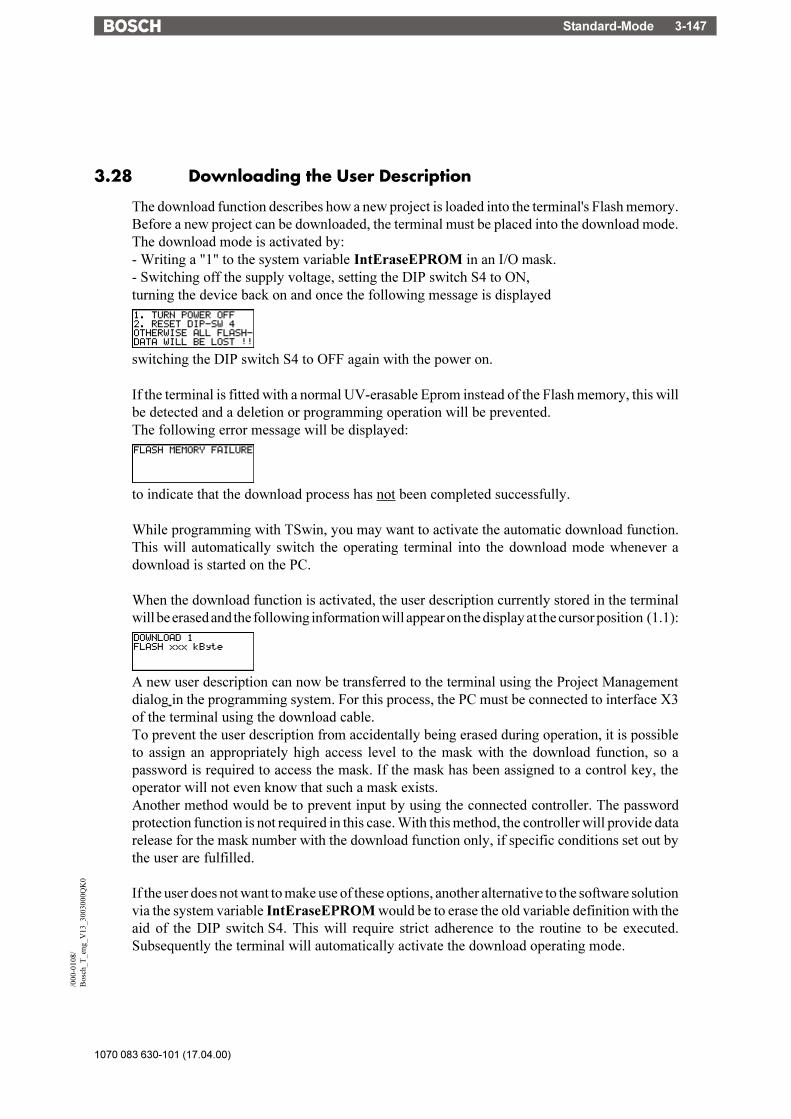
Standard-Mode 3-147
1070 083 630-101 (17.04.00)
/000
-010
8/B
osch
_T_e
ng_V
13_3
0030
00Q
K0
3.28 Downloading the User Description
The download function describes how a new project is loaded into the terminal's Flash memory.Before a new project can be downloaded, the terminal must be placed into the download mode.The download mode is activated by:- Writing a "1" to the system variable IntEraseEPROM in an I/O mask.- Switching off the supply voltage, setting the DIP switch S4 to ON,turning the device back on and once the following message is displayed
switching the DIP switch S4 to OFF again with the power on.
If the terminal is fitted with a normal UV-erasable Eprom instead of the Flash memory, this willbe detected and a deletion or programming operation will be prevented.The following error message will be displayed:
to indicate that the download process has not been completed successfully.
While programming with TSwin, you may want to activate the automatic download function.This will automatically switch the operating terminal into the download mode whenever adownload is started on the PC.
When the download function is activated, the user description currently stored in the terminalwill be erased and the following information will appear on the display at the cursor position (1.1):
A new user description can now be transferred to the terminal using the Project Managementdialog in the programming system. For this process, the PC must be connected to interface X3of the terminal using the download cable.To prevent the user description from accidentally being erased during operation, it is possibleto assign an appropriately high access level to the mask with the download function, so apassword is required to access the mask. If the mask has been assigned to a control key, theoperator will not even know that such a mask exists.Another method would be to prevent input by using the connected controller. The passwordprotection function is not required in this case. With this method, the controller will provide datarelease for the mask number with the download function only, if specific conditions set out bythe user are fulfilled.
If the user does not want to make use of these options, another alternative to the software solutionvia the system variable IntEraseEPROM would be to erase the old variable definition with theaid of the DIP switch S4. This will require strict adherence to the routine to be executed.Subsequently the terminal will automatically activate the download operating mode.
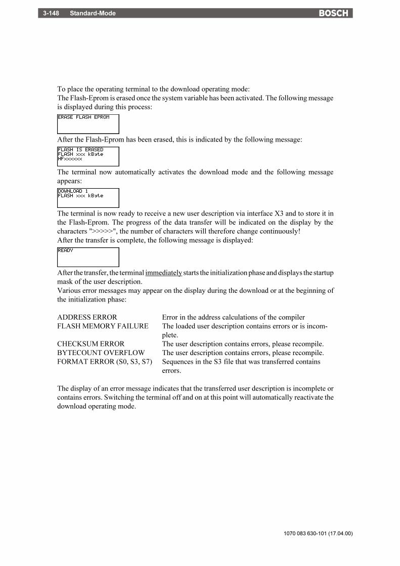
1070 083 630-101 (17.04.00)
Standard-Mode3-148
To place the operating terminal to the download operating mode:The Flash-Eprom is erased once the system variable has been activated. The following messageis displayed during this process:
After the Flash-Eprom has been erased, this is indicated by the following message:
The terminal now automatically activates the download mode and the following messageappears:
The terminal is now ready to receive a new user description via interface X3 and to store it inthe Flash-Eprom. The progress of the data transfer will be indicated on the display by thecharacters ">>>>>", the number of characters will therefore change continuously!After the transfer is complete, the following message is displayed:
After the transfer, the terminal immediately starts the initialization phase and displays the startupmask of the user description.Various error messages may appear on the display during the download or at the beginning ofthe initialization phase:
ADDRESS ERROR Error in the address calculations of the compilerFLASH MEMORY FAILURE The loaded user description contains errors or is incom-
plete.CHECKSUM ERROR The user description contains errors, please recompile.BYTECOUNT OVERFLOW The user description contains errors, please recompile.FORMAT ERROR (S0, S3, S7) Sequences in the S3 file that was transferred contains
errors.
The display of an error message indicates that the transferred user description is incomplete orcontains errors. Switching the terminal off and on at this point will automatically reactivate thedownload operating mode.

Standard-Mode 3-149
1070 083 630-101 (17.04.00)
/000
-010
8/B
osch
_T_e
ng_V
13_3
0030
00Q
K0
3.28.1 Downloading with Windows
The programming software does not necessarily have to be used for downloading. Anotheroption is to use the program Terminal that is available under MS Windows (group "Accessories").The following steps are required:1. Connect COM1 or COM2 of the PC with BTxx-X3 using the download cable2. Double-click the Terminal icon under Windows3. Set the parameters:Menu:Settings:
Communication: 19200Bd7 bitsodd parityxon/xoff1 stop bit
Transfers:Send text file:
(Enter file name) xxxxx.S3
3.28.2 Application Memory
A Flash memory or UV-Eprom can be used as an application memory. The terminal comes fittedwith a 128 kByte Flash memory. This Flash memory is installed in a 32-pin DIL-precision socketand can be replaced with the aid of an extraction tool. A standard UV-Eprom of appropriate sizeand access time can be used instead.The S3 file generated by the programming system can be processed by most Eprom programmingunits. UV-Eproms can neither be erased nor programmed in the terminal. Only Flash memoriesare designed to be programmed in the terminal.Flash memories can also be programmed with the aid of modern Eprom programming units, thismay eliminate the need for a download on site during servicing works.
3.28.3 Loading a User Description
To load the user description, a PC must be connected to interface X3 using the download cable.The terminal must then be placed to the download mode. The following message must appearon the display:
The terminal is now ready to receive a new user description via interface X3 and store it in theFlash memory.Now the download of an error-free user description "name S.3" must be activated using theProject Management dialog in the programming software.The progress of the data transfer will be indicated on the display by the characters ">>>>>", thenumber of characters will therefore change continuously.

1070 083 630-101 (17.04.00)
Standard-Mode3-150
The character "*" will be displayed in the programming system for every transmitted block.After the transmission is complete, the following is displayed
to indicate that the transfer has completed. After the transfer, the terminal immediately starts theinitialization phase and displays the startup mask of the user description.
3.28.4 Activating the Download Function using the Software
This requires that the terminal is placed to the download mode by activating an I/O mask andwriting a "1" to the system variable IntEraseEprom.In the event that you have decided not to use the system variable IntEraseEprom, the oldvariable definition must be erased with the DIP switch S4. This will require strict adherence tothe routine to be executed. Subsequently the terminal will automatically activate the downloadoperating mode.
3.28.5 Activating the Download Function using the Hardware
If the system variable responsible for erasing the Flash memory can not be activated in the masksor is not available at all, the Flash memory can still be erased by switching the mode selectorswitch to a defined position. This will cause the terminal to activate the download mode.Switch position to completely erase the Flash memory:
S1 ON S5 not used
S2 not used S6 not used
S3 OFF S7 not used
S4 ON S8 not used
Fig. 42: Mode selector switch
The following message is displayed once power has been applied the terminal:
This message is designed to prevent accidental erasure of the user description. The userdescription will be preserved if this message is complied with.Thus, turn off the power, reset the mode selector switch S4 and switch the terminal on again. Theterminal will continue to work with the current user description.Note that the contents of the Flash memory will be erased if the power is not turned off beforethe DIP switch S4 is reset.
Standard-Mode 3-151
1070 083 630-101 (17.04.00)
/000
-010
8/B
osch
_T_e
ng_V
13_3
0030
00Q
K0
3.28.6 Automatic Download Function
The Automatic Download option can only be selected when TSwin is used for programming. Toenable this function, the appropriate check box must be selected under "System Parameters","General Parameters".The user description that contains this function must initially be loaded into the terminal via aforced download (DIP switch S4 at the ON position). Every download thereafter is automaticallyinitiated by the PC wanting to load the S3 file of the new user description into the terminal. Adownload can be forced when the operating terminal is in full operation. During this process, all- message data in the message memory- all RAM-data sets that have not been backed-up- all system parameters that have been edited online (values of the system variable, interfaces,passwords, etc.) will be lost!

1070 083 630-101 (17.04.00)
Standard-Mode3-152
3.28.7 Download Cable
Pinning of the cable connecting interface X3 of the operating terminal to the PC (except BT2,BT5N and BT20N).
TesiMod PersonalOperating Terminal Computer
3 WHTD
2WHRD
5GNGND
5 GNGND
7 GYRTS
2 BNRD
8 YECTS
8GYCTS
3BNTD
7YERTS
1DCD
4DTR
6DSR
D-Subminiature D-SubminiatureMale Connector Female Connector9-pin 9-pin
The shield is connected to the metal casing on both ends.

Standard-Mode 3-153
1070 083 630-101 (17.04.00)
/000
-010
8/B
osch
_T_e
ng_V
13_3
0030
00Q
K0
Pinning of the cable connecting interface X3-SER2 of the operating terminal to the PC (BT2,BT5N and BT20N only).
TesiMod PersonalOperating Terminal BT2, BT5N, BT20N Computer
2 WHTD
2WHRD
5GYGND
7 GYGND
4 GNRTS
3 BNRD
5 YECTS
8GNCTS
3BNTD
7YERTS
1DCD
4DTR
6DSR
D-Subminiature D-SubminiatureMale Connector Female Connector25-pin 9-pin
The shield is connected to the metal casing on both ends.
3.29 Simulation without the Controller
The terminal can be operated without a controller by setting the DIP switch S3 to ON. The DIPswitch S3 will automatically set the external data release. It is possible to simulate the entireoperator guidance including help texts. The variables are automatically assigned to a commonvariable address in the terminal. This allows the Editors and their limits to be tested. The valuesare, however, not retained. There is no communication with the controller.

1070 083 630-101 (17.04.00)
Standard-Mode3-154
Transparent-Mode 4-1
1070 083 630-101 (17.04.00)
/000
-010
8/B
osch
_T_e
ng_V
13_3
0040
00Q
K0
Table of Contents
4 TesiMod Transparent Mode .......................................... 4-3
4.1 Setting the Operating Mode ................................................. 4-3
4.2 Start-up Processes ............................................................... 4-4
4.3 Communication in the Transparent Mode ............................. 4-54.3.1 Interface Parameters ...................................................................... 4-54.3.2 Receive Buffer for the Communication Interface ................................. 4-5
4.4 Function Setup Menu ........................................................... 4-54.4.1 Adaptation of the Parameters in the Setup Menu ............................... 4-54.4.2 Example of a Properly Performed Modification! ................................ 4-64.4.3 Setup Menu ................................................................................. 4-7
4.5 Display ................................................................................ 4-84.5.1 Character Set, Character Attributes ................................................. 4-8
4.6 Keys .................................................................................... 4-84.6.1 Key Codes for the Terminals ........................................................... 4-9
4.7 Interface Control Characters............................................... 4-104.7.1 LED Codes for the Operating Terminals ......................................... 4-114.7.2 Control Sequences for the Operating Terminals .............................. 4-11
4.8 Error Messages .................................................................. 4-14

1070 083 630-101 (17.04.00)
Transparent-Mode4-2

Transparent-Mode 4-3
1070 083 630-101 (17.04.00)
/000
-010
8/B
osch
_T_e
ng_V
13_3
0040
00Q
K0
4 TesiMod Transparent Mode
In the transparent mode the terminal works like a text display with printer port. The PLC has toprovide the terminal with all the symbols and control sequences which used to display the dataand values. Only important errors are displayed with a message (system message). All PLCcommunication parameters are adjustable in the setup mask.
4.1 Setting the Operating Mode
The user-mode switch must be used to select the mode of operation "transparent mode". Turnoff the terminal before selecting the mode of operation.The position of the mode selector switch is described in the manual for the particular operatingterminal.All terminals are factory-set to the standard mode.The ON/OFF positions on the mode selector switch are marked.
Position of the switch for transparent mode:
S1 OFF S5 not usedS2 not used S6 not usedS3 OFF S7 not usedS4 OFF S8 not used
Fig. 27: User-mode switch
The selected mode of operation is activated once power is applied to the terminal.

1070 083 630-101 (17.04.00)
Transparent-Mode4-4
4.2 Start-up Processes
The start-up processes are identical for all TesiMod operating terminals.After the voltage has been applied, the following message will be displayed:
Fig. 28: Start-up mask example
The message will be displayed in an one-line, centred format or in case of smaller-sizeddisplays in a two-line format. All LEDs will be activated while this message is beingdisplayed, allowing the operator time to perform a visual inspection. The message will bedisplayed for 2 sec. After this time period has elapsed, the message will be erased, the cursorwill be positioned at the top left of the display (position 1, and the characters received atinterface X2 will be interpreted and displayed.
Pressing the enter key immediately after the terminal has been switched on, while the promptis being displayed, will activate the setup mask, containing the terminal-specific parameters,on the display. All editable parameters will be displayed within one screen. Editing of theinterface parameters is possible after the data release key has been pressed, the integratedLED will be activated. The input via coded text (scroll bar) prevents incorrect input. The datainput is confirmed by pressing the data release key once more. The LED in the key will bedeactivated. Pressing of the enter key will reboot the terminal with the current values.
Pressing the enter key before the prompt "Press Enter to run Setup" is displayed, will resultin the generation of the following error message during the keyboard test.
Fig. 29: keyboard error mask
The self-test performed on the keyboard after having switched on the terminal has detectedthat a key is being pressed. Comply with the request and release the key. If the message isgenerated without any key being pressed, this indicates a defective keyboard!
Transparent-Mode 4-5
1070 083 630-101 (17.04.00)
/000
-010
8/B
osch
_T_e
ng_V
13_3
0040
00Q
K0
4.3 Communication in the Transparent Mode
In transparent mode, the communication is carried out via interface SER1 exclusively. Thisis where the controller or the higher-level computer must be connected, taking intoconsideration the hardware configuration. Adaptation of the transmission parameters to therequirements must be carried out in the setup mask.
4.3.1 Interface Parameters
Unless otherwise specified, the following interface default parameters are used:
Interface SER1 SER2
Baud rate 19200Bd 9600BdData bits 8-bit 7-bitStop bits 1-bit 1-bitParity none oddHandshake Xon/Xoff Xon/Xoff
The default parameters are stored in the Flash memory and are therefore not lost.
4.3.2 Receive Buffer for the Communication Interface
The receive buffer of the communication interface comprises a size of 256 bytes.
4.4 Function Setup Menu
The setup menu allows selection of the following parameters:- Parameters communication SER1- Parameters communication SER2- Date- Time- Default contrast
In addition, the version number of the operating system is displayed in the header line.
4.4.1 Adaptation of the Parameters in the Setup Menu
Within the setup mask, the parameters can be modified by means of an editor. Pressing of thedata release key allows changing into the editor. Modifying of the data is possible once theLED of the data release key has been activated. Modifying of the variable values is possiblethrough the + key and - key or the numerical keys. The input must be confirmed by pressingthe enter key. If supported by the display, the modified data will be displayed in an inverseformat. To prevent incorrect or unintentional modifications, the input must be carried out incompliance with a predefined sequence which must be strictly adhered to.
1070 083 630-101 (17.04.00)
Transparent-Mode4-6
4.4.2 Example of a Properly Performed Modification!
1. After having switched on the device, the enter key must be pressed immediately once theprompt is being displayed. The setup mask will appear on the display. This procedure mustbe carried out even if the parameters are to be viewed only.
2. It is possible to exit the menu by means of the enter key without modifying the menu. Uponpressing the data release key, the LED integrated in the key will be activated, thussignalling the editing mode within the transparent mode of operation.
3. The cursor will be positioned on the first editable variable and will be flashing. The cursorkeys allow selection of the variable to be modified.
4. Numerical values may now be entered through the numerical keypad, texts are selectedusing the +,- keys.
5. The enter key must be pressed following each input. After a valid input, the cursor willappear on the next editable input field.
6. In case of interface parameters, the variable to be modified must be set to "SETUPDATA", thereby preventing an accidental input. The selection "SETUP DATA" must bemade separately for the communication interface SER1 and the download-/printerinterface SER2.
7. Exiting of the editing mode is possible by pressing the data release key once more, the LEDwill be deactivated; any modified values will still be displayed in an inverse format.Repeated corrections are possible using the data release key.
8. The enter key allows exiting of the setup menu. The terminal will be rebooted and theselected parameters will become effective. The entire process may be repeated, ifnecessary, it will not be necessary to switch the terminal off.
The data are stored in a battery-backed RAM memory. The battery is monitored such that a lossof data is prevented and a message will be displayed whenever the capacity of the battery is belowthe required level.

Transparent-Mode 4-7
1070 083 630-101 (17.04.00)
/000
-010
8/B
osch
_T_e
ng_V
13_3
0040
00Q
K0
4.4.3 Setup Menu
The setup masks of the BT2 and BT5N contain exactly the same information. This informationis packed, thus permitting all parameters to be included into one mask.
1st line2nd line3rd line4th line
Fig. 30: setup mask
1st line XXXXXXXX Program VersionYYYYYYYY protocol driver
2nd line X2 Communication SER1300 Baud rate (19200)
(9600)(4800)(2400)(1200)(600)(300)
N Parity (O)dd(E)ven(N)one
5 Data bits (8)bit(7)bit(6)bit(5)bit
1 Stop bits (1)bit(1.5)bit(2)bit
N Handshake (N)one(R)TS/CTS(X)on/Xoff
I Acceptance (I)nactive(S)etup Data(D)efault Values
3rd line X3 Communication SER2(Structure same as line 2)

1070 083 630-101 (17.04.00)
Transparent-Mode4-8
4th line 777777 Date 010100 to 311299888888 Time 000000 to 2359599999 Contrast -125 to +125
4.5 Display
The first cursor position on the display is on the top left (X=1, Y=1). The number of permissiblerows and columns varies with the terminal type.
Lines: Columns:BT2 normal 4 20
BT5N normal 4 20
BT20N normal 16 40BT20N zoom 8 20
4.5.1 Character Set, Character Attributes
The displayable character set is listed in the hardware reference description of the respectiveterminal. Please note that it is not possible to address the extended ASCII character set in therange of 128
D..255
D, when selecting a character length of 7 bits.
4.6 Keys
A start and stop code is transmitted to the controller for each key that is being pressed. Pleaseconsult the table of the terminal for the respective code being generated. The transmission of thecharacters is effected in compliance with the conditions of the selected interface parameters.
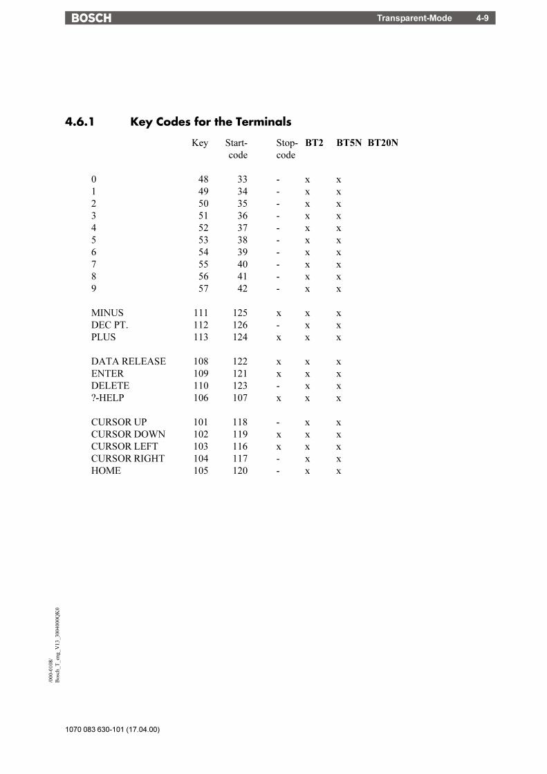
Transparent-Mode 4-9
1070 083 630-101 (17.04.00)
/000
-010
8/B
osch
_T_e
ng_V
13_3
0040
00Q
K0
4.6.1 Key Codes for the Terminals
Key Start- Stop- BT2 BT5N BT20Ncode code
0 48 33 - x x1 49 34 - x x2 50 35 - x x3 51 36 - x x4 52 37 - x x5 53 38 - x x6 54 39 - x x7 55 40 - x x8 56 41 - x x9 57 42 - x x
MINUS 111 125 x x xDEC PT. 112 126 - x xPLUS 113 124 x x x
DATA RELEASE 108 122 x x xENTER 109 121 x x xDELETE 110 123 - x x?-HELP 106 107 x x x
CURSOR UP 101 118 - x xCURSOR DOWN 102 119 x x xCURSOR LEFT 103 116 x x xCURSOR RIGHT 104 117 - x xHOME 105 120 - x x
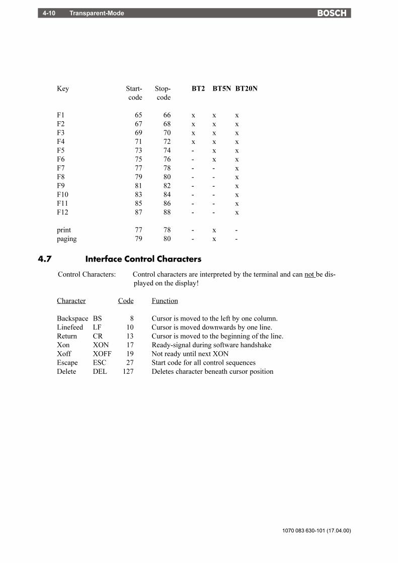
1070 083 630-101 (17.04.00)
Transparent-Mode4-10
Key Start- Stop- BT2 BT5N BT20Ncode code
F1 65 66 x x xF2 67 68 x x xF3 69 70 x x xF4 71 72 x x xF5 73 74 - x xF6 75 76 - x xF7 77 78 - - xF8 79 80 - - xF9 81 82 - - xF10 83 84 - - xF11 85 86 - - xF12 87 88 - - x
print 77 78 - x -paging 79 80 - x -
4.7 Interface Control Characters
Control Characters: Control characters are interpreted by the terminal and can not be dis-played on the display!
Character Code Function
Backspace BS 8 Cursor is moved to the left by one column.Linefeed LF 10 Cursor is moved downwards by one line.Return CR 13 Cursor is moved to the beginning of the line.Xon XON 17 Ready-signal during software handshakeXoff XOFF 19 Not ready until next XONEscape ESC 27 Start code for all control sequencesDelete DEL 127 Deletes character beneath cursor position
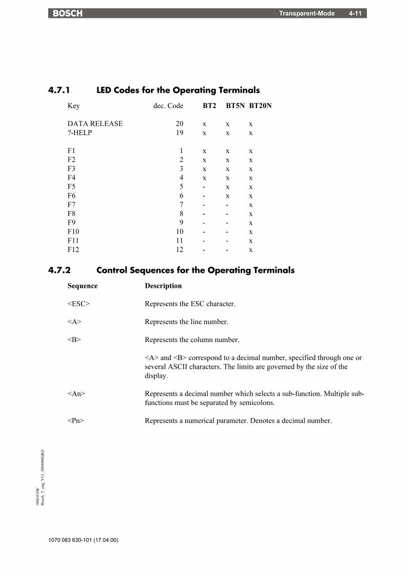
Transparent-Mode 4-11
1070 083 630-101 (17.04.00)
/000
-010
8/B
osch
_T_e
ng_V
13_3
0040
00Q
K0
4.7.1 LED Codes for the Operating Terminals
Key dec. Code BT2 BT5N BT20N
DATA RELEASE 20 x x x?-HELP 19 x x x
F1 1 x x xF2 2 x x xF3 3 x x xF4 4 x x xF5 5 - x xF6 6 - x xF7 7 - - xF8 8 - - xF9 9 - - xF10 10 - - xF11 11 - - xF12 12 - - x
4.7.2 Control Sequences for the Operating Terminals
Sequence Description
<ESC> Represents the ESC character.
<A> Represents the line number.
<B> Represents the column number.
<A> and <B> correspond to a decimal number, specified through one orseveral ASCII characters. The limits are governed by the size of thedisplay.
<An> Represents a decimal number which selects a sub-function. Multiple sub-functions must be separated by semicolons.
<Pn> Represents a numerical parameter. Denotes a decimal number.
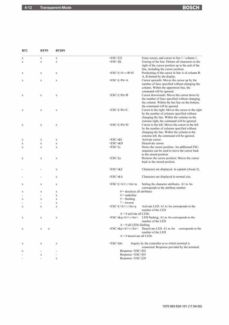
1070 083 630-101 (17.04.00)
Transparent-Mode4-12
BT2 BT5N BT20N____________________________________________________________________________________________________________________x x x <ESC>[2J Erase screen, and cursor in line 1 / column 1.x x x <ESC>[K Erasing of the line: Deletes all characters to the
right of the cursor position up to the end of theline, including the cursor position.
x x x <ESC>[<A>;<B>H Positioning of the cursor in line A of column B.A, B limited by the display.
x x x <ESC>[<Pn>A Cursor upwards: Moves the cursor up by thenumber of lines specified without changing thecolumn. Within the uppermost line, thecommand will be ignored.
x x x <ESC>[<Pn>B Cursor downwards: Moves the cursor down bythe number of lines specified without changingthe column. Within the last line on the bottom,the command will be ignored.
x x x <ESC>[<Pn>C Cursor to the right: Moves the cursor to the rightby the number of columns specified withoutchanging the line. Within the column on theextreme right, the command will be ignored.
x x x <ESC>[<Pn>D Cursor to the left: Moves the cursor to the leftby the number of columns specified withoutchanging the line. Within the column to theextreme left, the command will be ignored.
x x x <ESC>&C Activate cursor.x x x <ESC>&D Deactivate cursor.x x x <ESC>[s Stores the cursor position: An additional ESC-
sequence can be used to move the cursor backto the stored position.
x x x <ESC>[u Restores the cursor position: Moves the cursorback to the stored position.
- - x <ESC>&Z Characters are displayed in capitals (Zoom 2).
- - x <ESC>&A Characters are displayed in normal size.
x x x <ESC>[<A1>;<An>m Setting the character attributes. A1 to Ancorresponds to the attribute number
x x x 0 = deselects all attributes- - x 4 = underlinex x x 5 = flashing- - x 7 = inversex x x <ESC>[<A1>;<An>q Activate LED. A1 to An corresponds to the
number of the LEDA = 0 activate all LEDs
x x x <ESC>&q<A1>;<An>: LED flashing. A1 to An corresponds to thenumber of the LED
A = 0 all LEDs flashingx x x <ESC>&p<A1>;<An>: Deactivate LED. A1 to An corresponds to the
number of the LEDA = 0 deactivate all LEDs
x x x <ESC>[6n Inquiry by the controller as to which terminal isconnected. Response provided by the terminal:
x - - Response <ESC>[02- x - Response <ESC>[05- - x Response <ESC>[20

Transparent-Mode 4-13
1070 083 630-101 (17.04.00)
/000
-010
8/B
osch
_T_e
ng_V
13_3
0040
00Q
K0
BT2 BT5N BT20N____________________________________________________________________________________________________________________x x x <ESC>&t Display time at cursor position.
Format hh:mm:ss
x x x ESC>&d Display date at cursor position.Format TT.MM.JJ
x x x <ESC>&JJMMTThhmmssi Set Date / Time.JJ = YearMM = MonthTT = Dayhh = Hoursmm = Minutesss = Seconds
x x x <ESC>&u Transmit clock to interface X2. The responsefrom the terminal to this request has the sameformat as the setting for the date/time above.
Response: <ESC>&JJMMTThhmmssix x x <ESC>[<A>;<B>U Cyclic output of the time in line A and column
B is started. The output occurs in accordancewith the current character attributes.
x x x <ESC>[0;0U Cyclic output of the time is stopped.
x x x <ESC>&K Default value for the display's contrast setting.
x x x <ESC>&+ Increments the selected value by +1. Thecontrast becomes "brighter". The maximumtotal range of values is ±125. This range ofvalues is being limited to values appropriate forthe respective display.
x x x <ESC>&- Decrements the selected contrast value by -1.The contrast is "dimmed".

1070 083 630-101 (17.04.00)
Transparent-Mode4-14
4.8 Error Messages
Any error messages generated by the terminal are principally displayed on the top left of thedisplay. The error messages are generated by the terminal software in plain text. The errormessage is displayed once at the cursor position 1,1. The previous text will be overwritten. Themessage will not be deleted! - but will rather need to be overwritten by the user. This must betaken into consideration when creating the program. The following internal error text might bedisplayed:
LOW BAT Indicates that the capacity of the battery to back data is fallingbelow the required level. Upon initial display of this message, thebattery should be replaced within 3 days! A battery test is per-formed after the terminal has been switched on and every 60minutes thereafter.
FRAMING ERROR The data format of the characters received at the interface does notconform with the selected interface parameters. Check number ofdata bits, stop bits and parity bit.
PARITY ERROR A parity error has been detected regarding the characters receivedat the interface. This indicates a possible problem with the trans-mission line (character length, baud rate, interference, invalidinterface parameter etc.)
OVERRUN ERROR The terminal was unable to interpret and evaluate the charactersreceived at the interface. This indicates a possible error regardingthe handshake procedure between terminal and controller. Checkhardware or software handshake.
TRANSMIT ERROR On account of a blocked transmitter (no handshake enable signal),the terminal was unable to transmit the characters within thespecified timeout period. This indicates an error regarding thehandshake procedure between terminal and controller. Checkhardware or software handshake.
KEYBOARD ERRORPLEASE RELEASE KEY The self-test performed on the keyboard after having switched on
the terminal has detected that a key is being pressed. Please complywith the message. Display of this message without any key beingpressed indicates a defect in the keyboard!

Controller and Bus Interfacing 5-1
1070 083 630-101 (17.04.00)
/000
-010
8/B
osch
_T_e
ng_V
13_3
0050
00Q
K0
5 Controller and Bus Interfacing
5.1 TesiMod - 3964R Interfacing
5.2 TesiMod - BUEP19 Bosch PLC
5.3 TesiMod - DIN-Meßbus Master/Slave
5.4 TesiMod - BUEP19E Bosch PLC
5.5 TesiMod - PROFIBUS-DP

1070 083 630-101 (17.04.00)
Controller and Bus Interfacing5-2

3964 / RK512 Interfacing 5.1-1
1070 083 630-101 (17.04.00)
/000
-010
8/B
osch
_T_e
ng_V
13_3
0050
10Q
K0
Table of Contents
5.1 TesiMod - 3964/RK512 Interfacing ................................... 5.1-35.1.1 General Information ................................................................... 5.1-35.1.2 Technical Description ................................................................. 5.1-35.1.3 Parameters Interface SER1 .......................................................... 5.1-45.1.3.1 Interface Parameters of the Communications Module .................. 5.1-45.1.3.2 PLC Configuration .................................................................. 5.1-45.1.4 Data Type Structure .................................................................... 5.1-55.1.4.1 Data Types ........................................................................... 5.1-65.1.4.2 Special Simatic-Data Formats .................................................. 5.1-65.1.5 Additional Functions ................................................................... 5.1-75.1.6 Physical Interfacing .................................................................... 5.1-85.1.6.1 Connecting Cable TTY / 20 mA - Siemens CP523/525 ........... 5.1-105.1.6.2 Connecting Cable Universal Interface TTY / 20 mA -
Siemens CP523/525 ........................................................... 5.1-115.1.6.3 Connecting Cable RS232 - Siemens CP523/525 .................... 5.1-125.1.6.4 Connecting Cable Universal Interface RS232c -
Siemens CP523/525 ........................................................... 5.1-135.1.6.5 Connecting Cable RS485 - Siemens CP524/525 .................... 5.1-145.1.6.6 Connecting Cable Universal Interface RS485 -
Siemens CP524/525 ........................................................... 5.1-155.1.6.7 Connecting Cable RS485 - Helmholz SAS 523/525................ 5.1-165.1.6.8 Connecting Cable Universal Interface RS485 -
Helmholz SAS 523/525 ...................................................... 5.1-175.1.6.9 Connecting Cable RS485 - VIPA BGM79-43 ........................... 5.1-185.1.6.10 Connecting Cable Universal Interface RS485 -
VIPA BGM79-43 ................................................................. 5.1-195.1.6.11 Connecting Cable TTY / 20 mA - EBERLE PLS 514 - K43 .......... 5.1-205.1.6.12 Connecting Cable Universal Interface TTY / 20 mA -
EBERLE PLS 514 - K43 .......................................................... 5.1-215.1.6.13 Connecting Cable RS232 - EBERLE PLS 514 - K43 ................... 5.1-225.1.6.14 Connecting Cable Universal Interface RS232 -
EBERLE PLS 514 - K43 .......................................................... 5.1-235.1.7 3964 Procedure ..................................................................... 5.1-245.1.7.1 Block Check BCC ................................................................ 5.1-245.1.7.2 Logical Part of the Procedure 3964, RK512 ............................ 5.1-245.1.8 Message Request of Data.......................................................... 5.1-255.1.8.1 Structure Message Header (10 bytes) Request of Data .............. 5.1-255.1.8.2 Data Specification in the Message Header.............................. 5.1-265.1.8.3 Coordination Flag................................................................ 5.1-265.1.8.4 Structure 4-Byte-Sized Response Message ............................... 5.1-275.1.9 Message Transmission of Data .................................................. 5.1-275.1.9.1 Structure Message Header (10bytes) Transmission of Data ........ 5.1-285.1.9.2 Special Features of the Protocol 3964R .................................. 5.1-28
1070 083 630-101 (17.04.00)
3964 / RK512 Interfacing5.1-2
5.1.9.3 Assignment of Bytes 1-4........................................................ 5.1-295.1.10 Protocol 3964R - Restrictions ..................................................... 5.1-295.1.11 Function Block for Siemens 115 U .............................................. 5.1-305.1.12 Application Example for CP525 in 115U.................................... 5.1-305.1.13 Initialization for module K43 in EBERLE PLS514 ........................... 5.1-315.1.14 Error Messages........................................................................ 5.1-39

3964 / RK512 Interfacing 5.1-3
1070 083 630-101 (17.04.00)
/000
-010
8/B
osch
_T_e
ng_V
13_3
0050
10Q
K0
5.1 TesiMod - 3964/RK512 Interfacing
5.1.1 General Information
Via the serial procedure 3964, the operating terminals of the TesiMod series can be connectedto a programmable controller.
The logical part of the 3964 protocol, RK512, is adapted to the communication with a SiemensPLC via a CP525, or compatible, communications processor.
The hardware and software components of the TesiMod system are fully adapted to theparameters and marginal conditions of the protocol 3964/ RK512.
This offers the user of TesiMod operating terminals the following advantages:
- Random read and write access to any data within the PLC. Data of existing PLC programscan be displayed and modified directly in the operating terminal. It is not necessary to adaptthe PLC program to the operating terminal in any respect since it is not required thatcommunications data be stored in a specified address area or data type area.
- The TesiMod operating terminal automatically polls cyclic data in a free defined memoryarea.
- Simultaneous connection of theTesiMod operating terminal and the programming unit (PU)is possible.
- Only a minimum of configuration is required for the installation of the data handling blockrequired in the PLC in addition to the protocol function blocks.
- Minimal increase of the cycle time in the PLC.
- The protocol provides error control. Transmission errors are detected and, if possible,eliminated by repeating the transmission.
- A noise-immune interface hardware in accordance with the 20mA current loop interfacestandard permits the application even in a harsh industrial environment.
- The graphical operator guidance offers the user a maximum of assistance in defining thevariable addresses. The definitions (abbreviations) used here are identical with the defini-tions used within the PLC program.
5.1.2 Technical Description
The terminal is always the active partner which either requests data from or sends data to thepartner.

1070 083 630-101 (17.04.00)
3964 / RK512 Interfacing5.1-4
Direct read-access is possible to all PLC data.Direct write-access is limited to data blocks only.
The installation of the supplied function block allows an indirect write-access to all PLC datatypes.
All byte-structured data types can also be accessed in bit-mode.It is also possible to access all inidividual bytes of a data word within a data block.
5.1.3 Parameters Interface SER1
The following interfave parameters are available:
Baud rate: 300, 600, 1200, 2400, 4800, 9600, 19200 BaudParity: none, even, oddData length: 5, 6, 7, 8 BitsStop bits: 1, 1.5, 2 Stop bitsHandshake: no handshake, hardware handshake, software handshake
The fat printed settings are standard.
The following protocol parameter settings are also available for interface X2:- Communications block number- Data word offset- Coordination flag number- Coordination flag bit- Protocol with/without coordination flag- Block check- CPU number
5.1.3.1 Interface Parameters of the Communications Module
The interface parameters of the communications module must comply with the parameters of theTesiMod operating terminal.
5.1.3.2 PLC Configuration
To allow write-access to all PLC data, it is merely necessary to install the supplied function blockand to execute it at cyclic intervals.In addition, a coordination flag must be defined and a data block must be created as communi-cations block with a size of 128 bytes.This communications block and coordination flag must be specified to the supplied functionblock as parameter.

3964 / RK512 Interfacing 5.1-5
1070 083 630-101 (17.04.00)
/000
-010
8/B
osch
_T_e
ng_V
13_3
0050
10Q
K0
5.1.4 Data Type Structure
a) Alphanumerical TextsAre stored in the memory byte for byte in ascending address order.
b) CounterA distinction is made between variables which have been assigned a counter address andvariables which have been assigned another PLC address
Counter addressWhen accessing counter addresses, the count value is interpreted in the binary format, the controlbits of the counter are masked out. Therefore, to avoid control bits from being erased, counteraddresses should be accessed in the read-mode only.
All other addressesThe count value is interpreted in BCD-code. This allows the transfer of this value within the PLCprogram to the counter by means of the accumulator. This function should be used for indirectwrite-operations of count values since the values are available in the Siemens conformal format.
c) TimerTimer functions consist of a time value and a time base. The terminal operates with imaginaryunsigned 4-byte variables, even though the data stored in the PLC comprise only 2 bytes.
When read-accessing the timer, the terminal converts the time value and time base into aterminal-internal unsigned 4-byte number, which represents the time value in reference to thetime base of 0.01 second.
Ex.: A range of 10 (time base is 1.0 second) and a time value of 999, are represented or edited,respectively, in the terminal by the value 99900. Scaling of this value to other value ranges ispossible by specifying a factor and divisor within the variable definition.
Before writing a timer variable to the PLC, the time value and the smallest possible time baseare formed from the terminal-internal unsigned 4-byte value.
In addition, a distinction is made between variables which have been assigned a timer addressor another PLC address.
Timer addressWhen accessing timer addresses, the time value is interpreted binary format. To avoid timercontrol bits from being erased, this access should occur in the read-mode only.
All other addressesThe time value is interpreted BCD-coded.This access should be used for indirect write-operations of time values since the values are available in the Siemens conformal format.
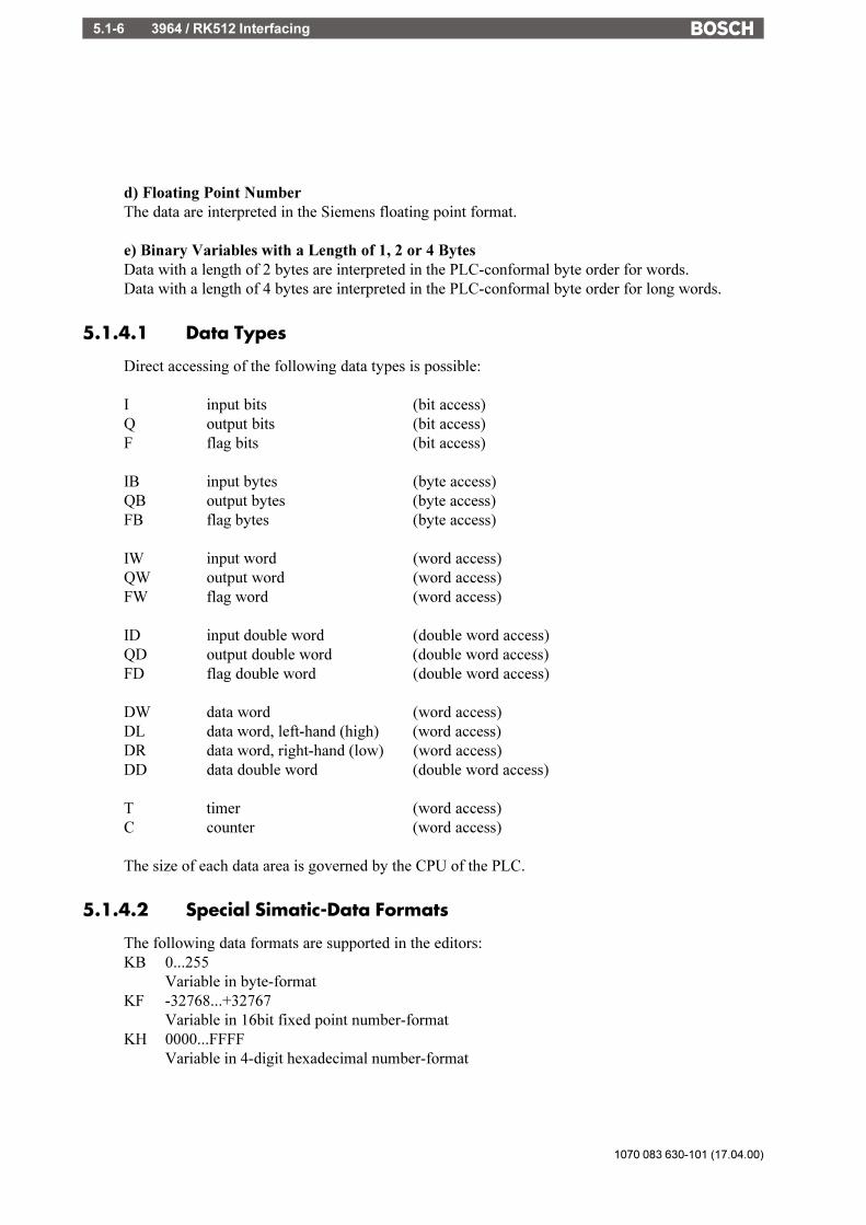
1070 083 630-101 (17.04.00)
3964 / RK512 Interfacing5.1-6
d) Floating Point NumberThe data are interpreted in the Siemens floating point format.
e) Binary Variables with a Length of 1, 2 or 4 BytesData with a length of 2 bytes are interpreted in the PLC-conformal byte order for words.Data with a length of 4 bytes are interpreted in the PLC-conformal byte order for long words.
5.1.4.1 Data Types
Direct accessing of the following data types is possible:
I input bits (bit access)Q output bits (bit access)F flag bits (bit access)
IB input bytes (byte access)QB output bytes (byte access)FB flag bytes (byte access)
IW input word (word access)QW output word (word access)FW flag word (word access)
ID input double word (double word access)QD output double word (double word access)FD flag double word (double word access)
DW data word (word access)DL data word, left-hand (high) (word access)DR data word, right-hand (low) (word access)DD data double word (double word access)
T timer (word access)C counter (word access)
The size of each data area is governed by the CPU of the PLC.
5.1.4.2 Special Simatic-Data Formats
The following data formats are supported in the editors:KB 0...255
Variable in byte-formatKF -32768...+32767
Variable in 16bit fixed point number-formatKH 0000...FFFF
Variable in 4-digit hexadecimal number-format
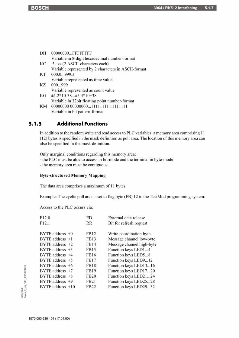
3964 / RK512 Interfacing 5.1-7
1070 083 630-101 (17.04.00)
/000
-010
8/B
osch
_T_e
ng_V
13_3
0050
10Q
K0
DH 00000000...FFFFFFFFVariable in 8-digit hexadecimal number-format
KC !!...zz (2 ASCII-characters each)Variable represented by 2 characters in ASCII-format
KT 000.0...999.3Variable represented as time value
KZ 000...999Variable represented as count value
KG ±1.2*10-38...±3.4*10+38Variable in 32bit floating point number-format
KM 00000000 00000000...11111111 11111111Variable in bit pattern-format
5.1.5 Additional Functions
In addition to the random write and read access to PLC variables, a memory area comprising 11(12) bytes is specified in the mask definition as poll area. The location of this memory area canalso be specified in the mask definition.
Only marginal conditions regarding this memory area:- the PLC must be able to access in bit-mode and the terminal in byte-mode- the memory area must be contiguous.
Byte-structured Memory Mapping
The data area comprises a maximum of 11 bytes
Example: The cyclic poll area is set to flag byte (FB) 12 in the TesiMod programming system.
Access to the PLC occurs via:
F12.0 ED External data releaseF12.1 RR Bit for refresh request
BYTE address +0 FB12 Write coordination byteBYTE address +1 FB13 Message channel low-byteBYTE address +2 FB14 Message channel high-byteBYTE address +3 FB15 Function keys LED1...4BYTE address +4 FB16 Function keys LED5...8BYTE address +5 FB17 Function keys LED9...12BYTE address +6 FB18 Function keys LED13...16BYTE address +7 FB19 Function keys LED17...20BYTE address +8 FB20 Function keys LED21...24BYTE address +9 FB21 Function keys LED25...28BYTE address +10 FB22 Function keys LED29...32

1070 083 630-101 (17.04.00)
3964 / RK512 Interfacing5.1-8
Word-structured Memory Mapping
The data area comprises a maximum of 6 words or 12 bytes.
Example: The cyclic data area is set to DW21 in the TesiMod programming system
Word address DW Highbyte Lowbyte
Word address +0 DW21 Write coordination byte ReservedWord address +1 DW22 Message channel high byte, Message channel low-
byteWord address +2 DW23 Function keys LED1...4 LED5...8Word address +3 DW24 Function keys LED9...12 LED13...16Word address +4 DW25 Function keys LED17...20 LED21...24Word address +5 DW26 Function keys LED25...28 LED29...32
5.1.6 Physical Interfacing
Pinning of the TesiMod 20mA current loop
Pin Designation Function1 Shield Shield2 T+ Transmit Data, Positive Polarity3 S1+ Power Source 2, Positive Polarity4 R+ Receive Data, Positive Polarity5 R- Receive Data, Negative Polarity6 S2+ Power Source 1, Positive Polarity7 T- Transmit Data, Negative Polarity8 S1- Power Sink 1, Negative Polarity9 S2- Power Sink 2, Negative Polarity
Pinning of the TesiMod RS232c interface
Pin Designation Function1 DCD Data Carrier Detect2 RD Receive Data3 TD Transmit Data4 DTR Data Terminal Ready5 GND Signal Ground6 DSR Data Set Ready7 RTS Request to Send8 CTS Clear to Send9 RI Ring Indicator
Italic printed pins are not available.
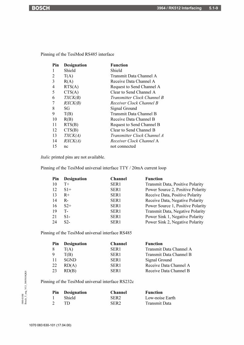
3964 / RK512 Interfacing 5.1-9
1070 083 630-101 (17.04.00)
/000
-010
8/B
osch
_T_e
ng_V
13_3
0050
10Q
K0
Pinning of the TesiMod RS485 interface
Pin Designation Function1 Shield Shield2 T(A) Transmit Data Channel A3 R(A) Receive Data Channel A4 RTS(A) Request to Send Channel A5 CTS(A) Clear to Send Channel A6 TXCK(B) Transmitter Clock Channel B7 RXCK(B) Receiver Clock Channel B8 SG Signal Ground9 T(B) Transmit Data Channel B10 R(B) Receive Data Channel B11 RTS(B) Request to Send Channel B12 CTS(B) Clear to Send Channel B13 TXCK(A) Transmitter Clock Channel A14 RXCK(A) Receiver Clock Channel A15 nc not connected
Italic printed pins are not available.
Pinning of the TesiMod universal interface TTY / 20mA current loop
Pin Designation Channel Function10 T+ SER1 Transmit Data, Positive Polarity12 S1+ SER1 Power Source 2, Positive Polarity13 R+ SER1 Receive Data, Positive Polarity14 R- SER1 Receive Data, Negative Polarity16 S2+ SER1 Power Source 1, Positive Polarity19 T- SER1 Transmit Data, Negative Polarity21 S1- SER1 Power Sink 1, Negative Polarity24 S2- SER1 Power Sink 2, Negative Polarity
Pinning of the TesiMod universal interface RS485
Pin Designation Channel Function8 T(A) SER1 Transmit Data Channel A9 T(B) SER1 Transmit Data Channel B11 SGND SER1 Signal Ground22 RD(A) SER1 Receive Data Channel A23 RD(B) SER1 Receive Data Channel B
Pinning of the TesiMod universal interface RS232c
Pin Designation Channel Function1 Shield SER2 Low-noise Earth2 TD SER2 Transmit Data
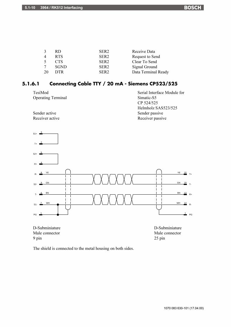
1070 083 630-101 (17.04.00)
3964 / RK512 Interfacing5.1-10
3 RD SER2 Receive Data4 RTS SER2 Request to Send5 CTS SER2 Clear To Send7 SGND SER2 Signal Ground20 DTR SER2 Data Terminal Ready
5.1.6.1 Connecting Cable TTY / 20 mA - Siemens CP523/525
TesiMod Serial Interface Module forOperating Terminal Simatic-S5
CP 524/525Helmholz SAS523/525
Sender active Sender passiveReceiver active Receiver passive
14WHR-
7 WHS1-
8 YER-
9 GNS2-
6 BNT-
4R+
5S2+
2T+
3S1+
10YET+
19GNT-
13BNR+
1PG
1PG
D-Subminiature D-SubminiatureMale connector Male connector9 pin 25 pin
The shield is connected to the metal housing on both sides.

3964 / RK512 Interfacing 5.1-11
1070 083 630-101 (17.04.00)
/000
-010
8/B
osch
_T_e
ng_V
13_3
0050
10Q
K0
5.1.6.2 Connecting Cable Universal Interface TTY / 20 mA - Sie-mens CP523/525
TesiMod Serial Interface Module forOperating Terminal Simatic-S5
CP 524/525Helmholz SAS523/525
Sender active Sender passiveReceiver active Receiver passive
14WHR-
21 WHS1-
13R+
16S2+
10T+
12S1+
1PG
10 GNS2-
4YETD-
2 BNT-
3 YER-
5GNTD+
6BNRD-
1PG
D-Subminiature D-SubminiatureMale connector Male connector25 pin 25 pin
The shield is connected to the metal housing on both sides.
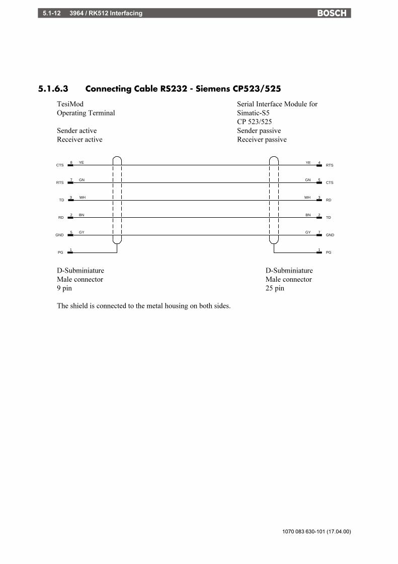
1070 083 630-101 (17.04.00)
3964 / RK512 Interfacing5.1-12
5.1.6.3 Connecting Cable RS232 - Siemens CP523/525
TesiMod Serial Interface Module forOperating Terminal Simatic-S5
CP 523/525Sender active Sender passiveReceiver active Receiver passive
3WHRD
3 WHTD
4YERTS
7 GNRTS
2 BNRD
5 GYGND
8 YECTS
5GNCTS
2BNTD
7GYGND
1PG
1PG
D-Subminiature D-SubminiatureMale connector Male connector9 pin 25 pin
The shield is connected to the metal housing on both sides.
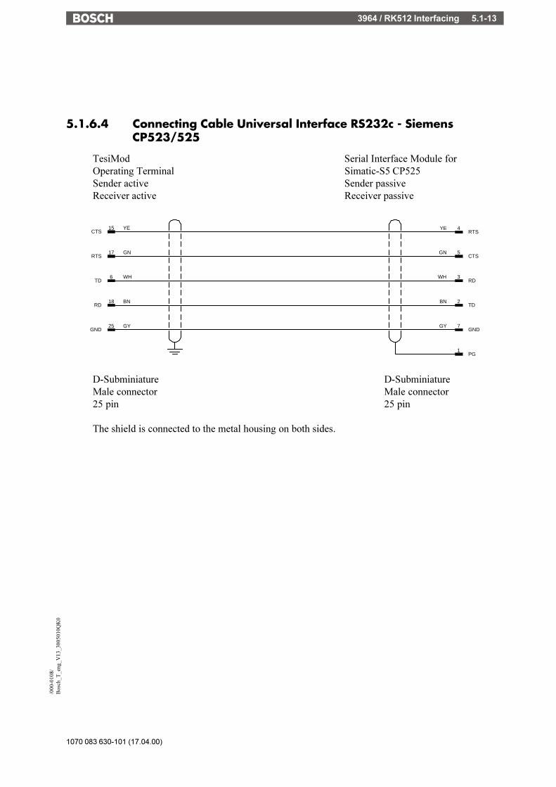
3964 / RK512 Interfacing 5.1-13
1070 083 630-101 (17.04.00)
/000
-010
8/B
osch
_T_e
ng_V
13_3
0050
10Q
K0
5.1.6.4 Connecting Cable Universal Interface RS232c - SiemensCP523/525
TesiMod Serial Interface Module forOperating Terminal Simatic-S5 CP525Sender active Sender passiveReceiver active Receiver passive
3WHRD
18 BNRD
17 GNRTS
15 YECTS
2BNTD
7GYGND
6 WHTD
25 GYGND
4YERTS
5GNCTS
1PG
D-Subminiature D-SubminiatureMale connector Male connector25 pin 25 pin
The shield is connected to the metal housing on both sides.
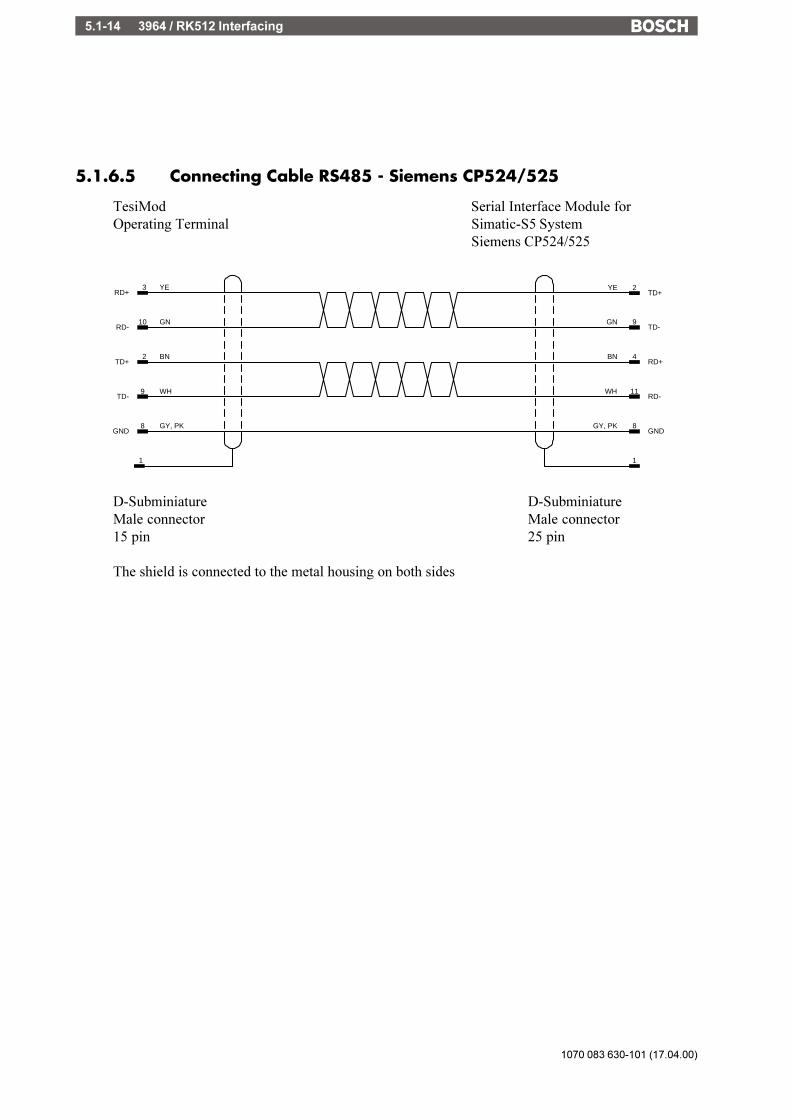
1070 083 630-101 (17.04.00)
3964 / RK512 Interfacing5.1-14
5.1.6.5 Connecting Cable RS485 - Siemens CP524/525
TesiMod Serial Interface Module forOperating Terminal Simatic-S5 System
Siemens CP524/525
11WHRD-
8GY, PKGND
9 WHTD-
8 GY, PKGND
10 GNRD-
2YETD+
2 BNTD+
3 YERD+
9GNTD-
4BNRD+
11
D-Subminiature D-SubminiatureMale connector Male connector15 pin 25 pin
The shield is connected to the metal housing on both sides

3964 / RK512 Interfacing 5.1-15
1070 083 630-101 (17.04.00)
/000
-010
8/B
osch
_T_e
ng_V
13_3
0050
10Q
K0
5.1.6.6 Connecting Cable Universal Interface RS485 - SiemensCP524/525
TesiMod Serial Interface Module forOperating Terminal Simatic-S5 System
Siemens CP524/525
23 GNR(B)
22 YER(A)
11WHRD+
7GY, PKGND
9 WHT(B)
11 GY, PKG/B
2YETD-
8 BNT(A)
9GNTD+
4BNRD-
1PG
1PG
D-Subminiature D-SubminiatureMale connector Male connector25 pin 25 pin
The shield is connected to the metal housing on both sides

1070 083 630-101 (17.04.00)
3964 / RK512 Interfacing5.1-16
5.1.6.7 Connecting Cable RS485 - Helmholz SAS 523/525
TesiMod Serial Interface Module forOperating Terminal Simatic-S5 System
SAS 523/525 Helmholz
7GY, PKGND
13WHRD-
8 GY, PKGND
9 WHTD-
10 GNRD-
19geTD+
2 BNTD+
3 YERD+
10gnTD-
14brRD+
1PG
1PG
D-Subminiature D-SubminiatureMale connector Male connector15 pin 25 pin
The shield is connected to the metal housing on both sides
CAUTION!At the SAS 525 the bridges of the termination resistors for Peer-to-Peer connection must beclosed as described in the manual of the PLCAt the TesiMod terminal the termination must be swiched to the ON-state.

3964 / RK512 Interfacing 5.1-17
1070 083 630-101 (17.04.00)
/000
-010
8/B
osch
_T_e
ng_V
13_3
0050
10Q
K0
5.1.6.8 Connecting Cable Universal Interface RS485 - HelmholzSAS 523/525
TesiMod Serial Interface Module forOperating Terminal Simatic-S5 System
SAS 523/525 Helmholz
23 GNR(B)
22 YER(A)
13WHRD+
7GY, PKGND
9 WHT(B)
11 GY, PKG/B
19YETD-
8 BNT(A)
10GNTD+
14BNRD-
11PG
D-Subminiature D-SubminiatureMale connector Male connector25 pin 25 pin
The shield is connected to the metal housing on both sides
CAUTION!At the SAS 525 the bridges of the termination resistors for Peer-to-Peer connection must beclosed as described in the manual of the PLCAt the TesiMod terminal the termination must be swiched to the ON-state.
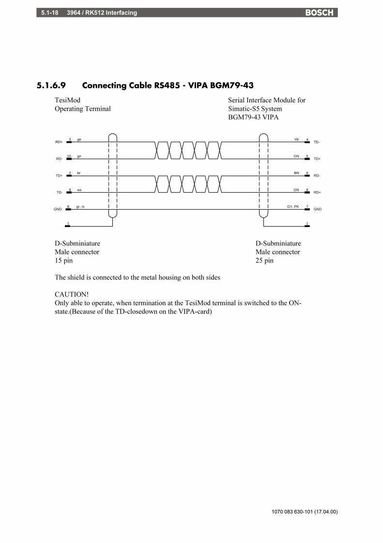
1070 083 630-101 (17.04.00)
3964 / RK512 Interfacing5.1-18
5.1.6.9 Connecting Cable RS485 - VIPA BGM79-43
TesiMod Serial Interface Module forOperating Terminal Simatic-S5 System
BGM79-43 VIPA
7GY, PKGND
8GNRD+
10 gnRD-
8 gr, rsGND
4YETD-
2 brTD+
9 wsTD-
3 geRD+
5GNTD+
6BNRD-
11
D-Subminiature D-SubminiatureMale connector Male connector15 pin 25 pin
The shield is connected to the metal housing on both sides
CAUTION!Only able to operate, when termination at the TesiMod terminal is switched to the ON-state.(Because of the TD-closedown on the VIPA-card)

3964 / RK512 Interfacing 5.1-19
1070 083 630-101 (17.04.00)
/000
-010
8/B
osch
_T_e
ng_V
13_3
0050
10Q
K0
5.1.6.10 Connecting Cable Universal Interface RS485 - VIPABGM79-43
TesiMod Serial Interface Module forOperating Terminal Simatic-S5 System
BGM79-43 VIPA
23 GNR(B)
22 YER(A)
8WHRD+
7GY, PKGND
9 WHT(B)
11 GY, PKG/B
4YETD-
8 BNT(A)
5GNTD+
6BNRD-
1PG
1PG
D-Subminiature D-SubminiatureMale connector Male connector25 pin 25 pin
The shield is connected to the metal housing on both sides
CAUTION!Only able to operate, when termination at the TesiMod terminal is switched to the ON-state.(Because of the TD-closedown on the VIPA-card)

1070 083 630-101 (17.04.00)
3964 / RK512 Interfacing5.1-20
5.1.6.11 Connecting Cable TTY / 20 mA - EBERLE PLS 514 - K43
TesiMod Module K43Operating Terminal for EBERLE PLS 514
7S1-
B3T+
B4T-
B5R+
B6R-
B56T-
B3
1PG
B4
B6
4R+
5S2+
2T+
3S1+
9S2-
8R-
D-Subminiature VG 95324 Plug ConnectorMale connector DIN 41612 DIN 416129 pin 42 pin 96 pin
The shield is connected to pin 1 / metal housing

3964 / RK512 Interfacing 5.1-21
1070 083 630-101 (17.04.00)
/000
-010
8/B
osch
_T_e
ng_V
13_3
0050
10Q
K0
5.1.6.12 Connecting Cable Universal Interface TTY / 20 mA - EBERLEPLS 514 - K43
TesiMod Module K43Operating Terminal for EBERLE PLS 514
21S1-
B3T+
B4T-
B5R+
B6R-
B519T-
B3
1PG
B4
B6
13R+
16S2+
10T+
12S1+
24S2-
14R-
D-Subminiature VG 95324 Plug ConnectorMale connector DIN 41612 DIN 4161225 pin 42 pin 96 pin
The shield is connected to pin 1 / metal housing

1070 083 630-101 (17.04.00)
3964 / RK512 Interfacing5.1-22
5.1.6.13 Connecting Cable RS232 - EBERLE PLS 514 - K43
TesiMod Module K43Operating Terminal for EBERLE PLS 514
GNDC14
C13RTS
C12CTS
C11RD
C10TD
C122TD
C14
4RTS
3RD
7GND
5CTS
C13
C11
C15
D-Subminiature VG 95324 Plug ConnectorMale connector DIN 41612 DIN 416129 pin 42 pin 96 pin
The shield is connected to the metal housing on both sides
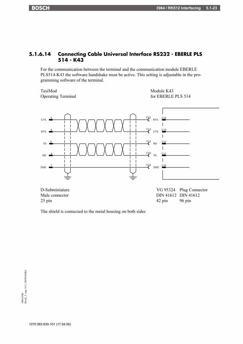
3964 / RK512 Interfacing 5.1-23
1070 083 630-101 (17.04.00)
/000
-010
8/B
osch
_T_e
ng_V
13_3
0050
10Q
K0
5.1.6.14 Connecting Cable Universal Interface RS232 - EBERLE PLS514 - K43
For the communication between the terminal and the communication module EBERLEPLS514-K43 the software handshake must be active. This setting is adjustable in the pro-gramming software of the terminal.
TesiMod Module K43Operating Terminal for EBERLE PLS 514
GNDC14
C13RTS
C12CTS
C11RD
C10TD
C122TD
C14
4RTS
3RD
7GND
5CTS
C13
C11
C15
D-Subminiature VG 95324 Plug ConnectorMale connector DIN 41612 DIN 4161225 pin 42 pin 96 pin
The shield is connected to the metal housing on both sides

1070 083 630-101 (17.04.00)
3964 / RK512 Interfacing5.1-24
5.1.7 3964 Procedure
To initiate the communication set-up, the active partner will transmit the signal STX (02h) uponwhich the partner will have to respond with DLE (10h) within the specified acknowledgementdelay period (2s).Subsequently, the procedure data are transmitted, the receipt of which is monitored by acharacter delay time (220ms).After the data have been transmitted, the passive partner will acknowledge the receipt with DLE.
In the event of errors, the pasive partner will transmit a NAK (15h).In the event of errors during the communication set-up, the active partner will make up to 3attempts to establish the communication.
If the passive partner transmits a NAK after receipt of the data, the active partner will make upto 6 attempts to establish the communication and to transmit the data.
Terminal BTxxactive partner passive partner
������� STX �������><������ DLE (NAK) �����- ������� Data �������> ������� DLE �������> ������� ETX �������> ����� BCC (selectable) ����><����� DLE (NAK) ������
Please note:
If the character 1016
is to be transmitted but not to be evaluated as a DLE, the transmitting devicewill add another 10
16.
If the receiving device detects a 1016
(DLE) twice, it will accept 1016
only once and will notevaluate it as a DLE control character.
5.1.7.1 Block Check BCC
With the block check method (3964R), a block check character is created and added to the endof the block.
The BCC is formed through a logic XOR of all characters with the exception of the start characterSTX (0216).
5.1.7.2 Logical Part of the Procedure 3964, RK512
A logical part, which complies with the Siemens protocol RK512 to a great extent, has priorityover the physical part of the procedure.This part governs the type and contents of the data part.

3964 / RK512 Interfacing 5.1-25
1070 083 630-101 (17.04.00)
/000
-010
8/B
osch
_T_e
ng_V
13_3
0050
10Q
K0
5.1.8 Message Request of Data
Terminal BTxxactive partner��������� request�������> passive partner
������� STX �������><������� DLE �������
���� Message header����> ������� DLE �������> ������� ETX �������> ����� BCC (selectable) ����><������� DLE �������<������� STX ������� ������� DLE �������>
<�� Message response ���-<������ Data ������-
<������� DLE �������<������� ETX �������<������� BCC ������� ������� DLE �������>
5.1.8.1 Structure Message Header (10 bytes) Request of Data
Function ASCII Hex Comment1. Byte Message 00 always 002. Byte identifier 00 always 00
3. Byte Data direction E 45 E = Request
4. Byte Command see below
5. Byte 2 Byte see below6. Byte Source
7. Byte 2 Byte see below8. Byte Number of bytes
9. Byte Coordination flag number FF indicates no10. Byte coordination flag bit FF Coord. flag

1070 083 630-101 (17.04.00)
3964 / RK512 Interfacing5.1-26
5.1.8.2 Data Specification in the Message Header
The data types of the PLC addressed by the terminal are implemented in the message header bythe Bytes 4 - 8 as illustrated below.
Source Access Data type Command Word-Parameter Byte-Parameter Number inTesiMod Byte 4 Byte 5+6 Byte 5 Byte 6 Byte 7+8
Input Bit E E Offset Bit-Nr 1 ByteOutput Bit A A Offset Bit-Nr 1 ByteFlag Bit M M Offset Bit-Nr 1 ByteInput Byte EB E Offset n BytesOutput Byte AB A Offset n BytesFlag Byte MB M Offset n BytesInput Word EW E Offset n BytesOutput Word AW A Offset n BytesFlag Byte MB M Offset n BytesInput D-Word ED E Offset n BytesOutput D-Word AD A Offset n BytesFlag D-Word MD M Offset n BytesD-Block Word DW D DB DW n WordsHigh-Byte DB Byte DL D DB DW 1 WordLow-Byte DB Byte DR D DB DW 1 WordD-Block D-Word DD D DB DW n WordsTimer Word T T Offset n WordsCounter Word Z Z Offset n Words
5.1.8.3 Coordination Flag
A flag bit is specified in the message header which is used by the receiving device to monitor thereceipt of data.The monitoring function is deactivated if the value for the coordination flag is FF16, FF16.
If a coordination flag is specified, it will be set in the passive partner upon receipt of data.Once this flag has been set, processing of the data received will be initiated.After the data have been processed, the flag will be reset again.If this flag is still set upon the receipt of data, the passive partner will transmit a response messageto the active partner thereby indicating the respective error.
NOTE:For connections to a Siemens communications module CP524/525, the coordination flag in DB1must be entered into the list of inter-processor communication flags.

3964 / RK512 Interfacing 5.1-27
1070 083 630-101 (17.04.00)
/000
-010
8/B
osch
_T_e
ng_V
13_3
0050
10Q
K0
5.1.8.4 Structure 4-Byte-Sized Response Message
Function ASCII Hex Comment1. Byte Message 00 always 002. Byte identifier 00 always 00
3. Byte always 00
4. Byte Error code xx
5.1.9 Message Transmission of Data
Terminal BTxxactive partner �������� transmit��������> passive partner
������� STX ������><������ DLE ������- ����Message header����> ������ Data ������>
������� DLE ������> ������� ETX ������> ���� BCC (selectable) ����><������ DLE ������-<������ STX ������-
������� DLE ������><�� Response Message ���
<������ DLE ������-<�������ETX ������-<������ BCC ������-
������� DLE ������>

1070 083 630-101 (17.04.00)
3964 / RK512 Interfacing5.1-28
5.1.9.1 Structure Message Header (10bytes) Transmission of Data
Function Ascii Hex Comment
1. Byte Message 00 always 002. Byte identifier 00 always 00
3. Byte Data direction A 41 A = Transmission4. Byte Command D 44 D = Data block
5. Byte 2 Byte Destination Data block6. Byte Data word
7. Byte 2 Byte number of data Number of words8. Byte
9. Byte Coordination flag number FF indicates without10. Byte Coordination flag bit FF Coord. flag
The destination for data to be transmitted is always a data block.
5.1.9.2 Special Features of the Protocol 3964R
A write-access to data is possible in data blocks only.I.e. only the data tpye DW allows a direct write-access to the respective destination.
To allow a write-access to all data yet, the data are transmitted to a defined data block, thecommunications block.
In this case, the destination, comprising 4 bytes, must be added in front of the data prior totransmission.

3964 / RK512 Interfacing 5.1-29
1070 083 630-101 (17.04.00)
/000
-010
8/B
osch
_T_e
ng_V
13_3
0050
10Q
K0
5.1.9.3 Assignment of Bytes 1-4
Destination Access Data type Command Data-Number Byte-Parameter Word-ParameterTesiMod Byte 1 Byte 2 Byte 3 Byte 4 Bytes 3+4
Input Bit I 10 1 Byte Bit-No. OffsetOutput Bit Q 11 1 Byte Bit-No. OffsetFlag Bit F 12 1 Byte Bit-No. OffsetInput Byte IB 1 n Bytes OffsetOutput Byte QB 2 n Bytes OffsetFlag Byte FB 3 n Bytes OffsetInput Word IW 1 n Bytes OffsetOutput Word QW 2 n Bytes OffsetFlag Word FW 3 n Bytes OffsetInput Word ID 1 n Bytes OffsetOutput Word QD 2 n Bytes OffsetFlag Word FD 3 n Bytes OffsetHIGH-Byte DB Byte DL 26 1 Byte DB DWLOW-Byte DB Byte DR 27 1 Byte DB DWCounter Word C 20 n Bytes OffsetTimer Word T 21 n Bytes Offset
A write-access to these data types is principally carried out with a coordination flag.Just like the communications block, the coordination flag must be defined such that the settingsin the terminal and passive device are in agreement.
Part of a program installed in the receiving device, denoted in the PLC as data handling block,will monitor the coordination flag.
If the coordination flag is set, the data will be processed by the data handling block in accordancewith the first 4 bytes in the communications block.After the data have been processed, the coordination flag will be erased thereby allowing furthertransmissions.
5.1.10 Protocol 3964R - Restrictions
The protocol 3964 allows data comprising a maximum of 128 bytes to be transmitted permessage. No further messages are transmitted or processed.

1070 083 630-101 (17.04.00)
3964 / RK512 Interfacing5.1-30
5.1.11 Function Block for Siemens 115 U
The supplied function block FB186 can be implemented in a Siemens 115 U.
The function block processes data from the terminal which are to be transmitted to the PLC.
The first 4 bytes of the data which are written to the defined communications data block areinterpreted in accordance with the table "Assignment of Bytes 1-4".
The function block FB186 supports the following commands from the table "Assignments ofBytes 1-4":
2 Output Byte3 Flag Byte
11 Output Bit12 Flag Bit.
When activating the function block, the communications data block and the coordination flagmust be specified as parameter. These parameters must comply with the settings in the terminal.
The defined communications data block must comprise a size of 128 bytes or 64 data words,respectively.
5.1.12 Application Example for CP525 in 115U
In this example:The communications data block is DB33 starting at DW0.The coordination flag is M100.3.Flag 50 is to be written to.
The coordination flag, also referred to as interprocessor communication flag by Siemens, mustbe activated on the CP525 via a hardware jumper (see reference material CP525).
In addition, the interprocessor communication flag must be defined in DB1 of the 115U. Anillustration is shown below:
DB1:DW 0: KH=4D41 \
1: KH=534B > "MASK01" Header identifier2. KH=3130 /
DW 3: KH=CA00 Output-interprocessorcommunication flag
4: KF=100 MB100
DW 5: KH=EEEE End identifier

3964 / RK512 Interfacing 5.1-31
1070 083 630-101 (17.04.00)
/000
-010
8/B
osch
_T_e
ng_V
13_3
0050
10Q
K0
The following structure must be implemented in OB1. This block is executed at cyclic intervals.
: .: .:SPA FB245 Execution of the RECEIVE-block
NAME:REC-ALL
ANZW:MW220 The interprocessor communication flag number isentered in the indication word parameter of the
. RECEIVE-block
.:L MB221 If the defined interprocessor communication flag is in
the LOW-Byte:L KF+100.!=F:S M 100.3 it must be set here.: .: .:SPA FB186 Evaluation block
Processes the data of the communcations data blockand resets flag 100.3.
5.1.13 Initialization for module K43 in EBERLE PLS514
The following settings are required to communicate with the module K43 in a EBERLE PLS 514:
For TTY connection:Baud rate: 9600Parity: evenDatabits: 8Stopbits: 1Handshake: no handshake
Coordination flag: noSpecial PLC communication: noDB: 0DW: 0Block check: yesCPU number inside PLC: 0Floating point numbers in the IEEE format: no
For RS232 connection:Baud rate: 9600Parity: evenDatabits: 8Stopbits: 1Handshake: hardware handshake

1070 083 630-101 (17.04.00)
3964 / RK512 Interfacing5.1-32
Coordination flag: noSpecial PLC communication: noDB: 0DW: 0Block check: yesCPU number inside PLC: 0Floating point numbers in the IEEE format: no
For timers, BCD numbers and counters always used double words (32 bit). For example DW0.
The values in the INI.IL file are used to initialize the K43 module. The values in this file are setas follows.
{Initialize the K43 module}
**********************************************************}
{ Communication data block: INI.PBS}
{ Version: 01 01}
{ No changes in the program}
{ **********************************************************}
{ }{ **********************************************************}{ Initialization of the K43}{ **********************************************************}
{ This program is the initialization for the }{ communication module K43.}{ The initialization starts as soon as the supply voltage }{ of the PLS 514 is switched on. }
{ The needed flags will initialized in the first cycle of the PLS 514 }{ and the initialization program initiates. }
{ The parameters for the K43 module are transmitted }{ in the initialization program. The initialization program }{ is not necessary if the default setting is used. }
{ After the initialization, the operating mode data exchange }{ with the K43 switches over automatically. }
{ The operating mode of the K43 depends on }{ the commando digit. }{ The commando digit is digit number 3 on layer 0. }

3964 / RK512 Interfacing 5.1-33
1070 083 630-101 (17.04.00)
/000
-010
8/B
osch
_T_e
ng_V
13_3
0050
10Q
K0
{ The function of the bits is shown below. }
{ Bit 3 2 1 0}{ _________________}{ ! ! ! ! !}{ ! X ! X ! X ! X !}{ ! ! ! ! !}{ ��������}{ ! ! ! !}{ ! }{ ! ! ! 0 = no SW-Reset }{ ! 1 ! 1 = SW-Reset }{ ! }{ ! ! X = no function }{ !}{ ! 0 = K 43 operating mode passive }{ ! 1 = K 43 transmission over V.24 TTY }
{ 0 = initialization }{ 1 = transmit data with K 43 active }
{ Reset of the initialization shift register and }{ the necessary flags in the first cycle. }{ To jumper the self-test of the interface module K43 }{ a closing delay in the PLS 514 is necessary. }{ The closing delay is managed with the auxiliary }{ counter #Z0 bis #Z2.}{ �����������������������}
L %ZK1LD %K 0=D INIREG=D Z0=D Z1=D Z2=D DW_ZV_0=D DW_ZV_1=D DW_ZV_2=D DW_ZV_3
L %MS10ZV Z0ZV Z1ZV Z2
L %K 1LD Z2GL %K 2LD INIREGGL %K 0S INIREG0
{ Initialize the protocol:}{ ===============================}
{ To initialize the protocols the digits }{ 0 .. 2 of layer 0 and the digits of layer 1}{ have the described meaning }
DAL K43_E0
L INIREG0A DACK

1070 083 630-101 (17.04.00)
3964 / RK512 Interfacing5.1-34
= %NOP
{ Definition of the commando digit 3 of layer 0 }{ ������������������������}
{ Setting the data transmission to the K43 on initialize mode }
{ Digit 0xx3}
{ Bit 3 2 1 0}{ _________________}{ ! ! ! ! !}{ ! X ! X ! X ! X !}{ ! ! ! ! !}{ ��������}{ ! ! ! !}{ ! }{ ! ! ! 0 = no SW-Reset }{ ! 1 ! 1 = SW-Reset }{ ! }{ ! 0 = K 43 operating mode passive }{ ! 1 = K 43 transmission over V.24 TTY }
{ 0 = initialization }{ 1 = transmit data with K43 active }
{ Input of the constant 00 in the digit 0xx3 }{ that means initialize of the K43 }{ without SW-Reset}{ Initialize protocol in accordance with layer 0, }{ digit 0...2 and layer 1, digit 0...7}
LD %K 0=D KOMMAND
{ Initialize with layer 0 digit 0,1 and 2:}{ ����������������������}{ Digit 0xx0}
{ Bit 3 2 1 0}{ _________________}{ ! ! ! ! !}{ ! X ! X ! X ! X !}{ ! ! ! ! !}{ ��������}{ ! ! ! !}{ ! }{ ! 0 0 0 = 110 Baud }{ ! 0 0 1 = 300 Baud }{ ! 0 1 0 = 600 Baud }{ ! 0 1 1 = 1200 Baud }{ ! 1 0 0 = 2400 Baud }{ ! 1 0 1 = 4800 Baud }{ ! 1 1 0 = 9600 Baud }{ ! 1 1 1 = 19200 Baud }
{ 0 = data format 7 Bit }{ 1 = data format 8 Bit }
{ Input of the constant 14 in the digit 0xx0 }{ that means 9600 baud, data format 8 bit}
LD %K 14=D Data00
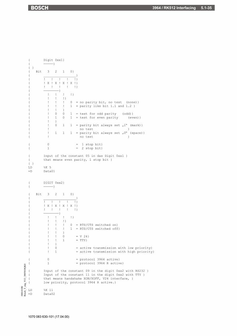
3964 / RK512 Interfacing 5.1-35
1070 083 630-101 (17.04.00)
/000
-010
8/B
osch
_T_e
ng_V
13_3
0050
10Q
K0
{ Digit 0xx1}{ �����}{ }{ Bit 3 2 1 0}{ _________________}{ ! ! ! ! !}{ ! X ! X ! X ! X !}{ ! ! ! ! !}{ ��������}{ ! ! ! !}{ ! ! !}{ ! ! ! 0 = no parity bit, no test (none)}{ ! ! ! 1 = parity like bit 1.1 and 1.2 }{ ! ! }{ ! 0 0 1 = test for odd parity (odd)}{ ! 1 0 1 = test for even parity (even)}{ ! }{ ! 0 1 1 = parity bit always set �1� (mark)}{ ! no test }{ ! 1 1 1 = parity bit always set �0� (space)}{ ! no test }
{ 0 = 1 stop bit}{ 1 = 2 stop bit}
{ Input of the constant 05 in das Digit 0xx1 }{ that means even parity, 1 stop bit }{ }LD %K 5=D Data01
{ DIGIT 0xx2}{ �����}
{ Bit 3 2 1 0}{ _________________}{ ! ! ! ! !}{ ! X ! X ! X ! X !}{ ! ! ! ! !}{ ��������}{ ! ! ! !}{ ! ! !}{ ! ! ! 0 = RTS/CTS switched on}{ ! ! ! 1 = RTS/CTS switched off}{ ! ! }{ ! ! 0 = V 24}{ ! ! 1 = TTY}{ ! }{ ! 0 = active transmission with low priority}{ ! 1 = active transmission with high priority}
{ 0 = protocol 3964 active}{ 1 = protocol 3964 R active}
{ Input of the constant 09 in the digit 0xx2 with RS232 }{ Input of the constant 11 in the digit 0xx2 with TTY }{ that means handshake XON/XOFF, V24 interface, }{ low priority, protocol 3964 R active.}
LD %K 11=D Data02

1070 083 630-101 (17.04.00)
3964 / RK512 Interfacing5.1-36
{ Initialize layer 1}{ ===========================}
{ The initialize of the data blocks is made in }{ hexadecimal code. }{ Two half bytes result in one character and }{ have to put in two digits.}{ }{ Initialize the data block number 0}{ ������������������}
{ Digit 1xx0 least significant half byte of the data block number 0}{ Digit 1xx1 more significant half byte of the data block number 0}{ }{ �> for example: 1st data block on 32 dec. => 20 hex. }{ }LD %K 0=D Data10LD %K 2=D Data11
{ Initialize the 1st data block}{ ������������������}{ }{ Digit 1xx2 least significant half byte of the 1st data block}{ Digit 1xx3 more significant half byte of the 1st data block}
{ �> for example: 1st data block on 33 dec. => 21 hex. }
LD %K 1=D Data12LD %K 2=D Data13
{ Initialize the 2nd data block}{ ������������������}
{ Digit 1xx4 least significant half byte of the 2nd data block}{ Digit 1xx5 more significant half byte of the 2nd data block}
{ �> for example: 2nd data block on 34 dec. => 22 hex. }{ }LD %K 2=D Data14LD %K 2=D Data15{ }{ Initialize the 3rd data block }{ �������������������}
{ Digit 1xx6 least significant half byte of the 3rd data block }{ Digit 1xx7 more significant half byte of the 3rd data block }{ }{ �> for example: 3rd data block on 35 dec. => 23 hex. }
LD %K 3=D Data16LD %K 2=D Data17
{ End the initialization }{ �������������}

3964 / RK512 Interfacing 5.1-37
1070 083 630-101 (17.04.00)
/000
-010
8/B
osch
_T_e
ng_V
13_3
0050
10Q
K0
SL INIREGDAS K43_E0DAS K43_E1DAL K43_E0R %NOP
{ Start data transmisssion }{ ==========================}
{ After initialization the data transmission is }{ enabled if the commando digit is set. }
{ Meaning of the commando digit during the data transmisssion }
{ Bit 3 2 1 0}{ _________________}{ ! ! ! ! !}{ ! X ! X ! X ! X !}{ ! ! ! ! !}{ ��������}{ ! ! ! !}{ ! }{ ! ! ! 0 = no SW-Reset }{ ! 1 ! 1 = SW-Reset }{ ! }{ ! 0 = K 43 operating mode passive }{ ! 1 = K 43 transmisssion over V.24 TTY }
{ 0 = initialization }{ 1 = data transmisssion with K43 active }
{ Definition of the commando digit 3 of layer 0 }{ with the constant 08 }{ that means data transmission with block transmission mode }{ �������������������������}
L INIREG1A DACK= %NOPLD %K 8
=D KOMMAND
{ Stepping the initialization }{ �����������������}
SL INIREGDAS K43_E0DAS K43_E1DAL K43_E0R %NOP
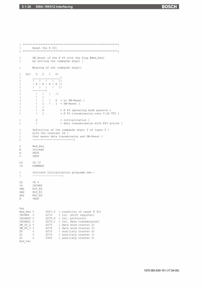
1070 083 630-101 (17.04.00)
3964 / RK512 Interfacing5.1-38
{ **********************************************************}{ Reset the K 43}{ **********************************************************}
{ SW_Reset of the K 43 with the flag #Bed_Res}{ by setting the commando digit }
{ Meaning of the commando digit}
{ Bit 3 2 1 0}{ _________________}{ ! ! ! ! !}{ ! X ! X ! X ! X !}{ ! ! ! ! !}{ ��������}{ ! ! ! !}{ ! }{ ! ! ! 0 = no SW-Reset }{ ! 1 ! 1 = SW-Reset }{ ! }{ ! 0 = K 43 operating mode passive }{ ! 1 = K 43 transmisssion over V.24 TTY }
{ 0 = initialization }{ 1 = data transmisssion with K43 active }
{ Definition of the commando digit 3 of layer 0 }{ with the constant 09 }{ that means data transmission and SW-Reset }{ �������������������������}
L Bed_ResA Inireg2A DACK= %NOP
LD %K 12=D KOMMAND
{ Initiate initialization programm new }{ ������������������}
LD %K 0=D INIREGDAS K43_E0DAS K43_E1DAL K43_E0R %NOP
VarBed_Res % 0007.0 { condition of reset K 43}INIREG % 0270 { ini. shift register}INIREG0 % 0270.0 { ini. protocols}INIREG1 % 0270.1 { ini. data transmission}DW_ZV_2 % 0273 { data word counter 2}DW_ZV_3 % 0274 { data word counter 3}Z0 % 0275 { auxiliary counter 0}Z1 % 0276 { auxiliary counter 1}Z2 % 0302 { auxiliary counter 2}End_Var
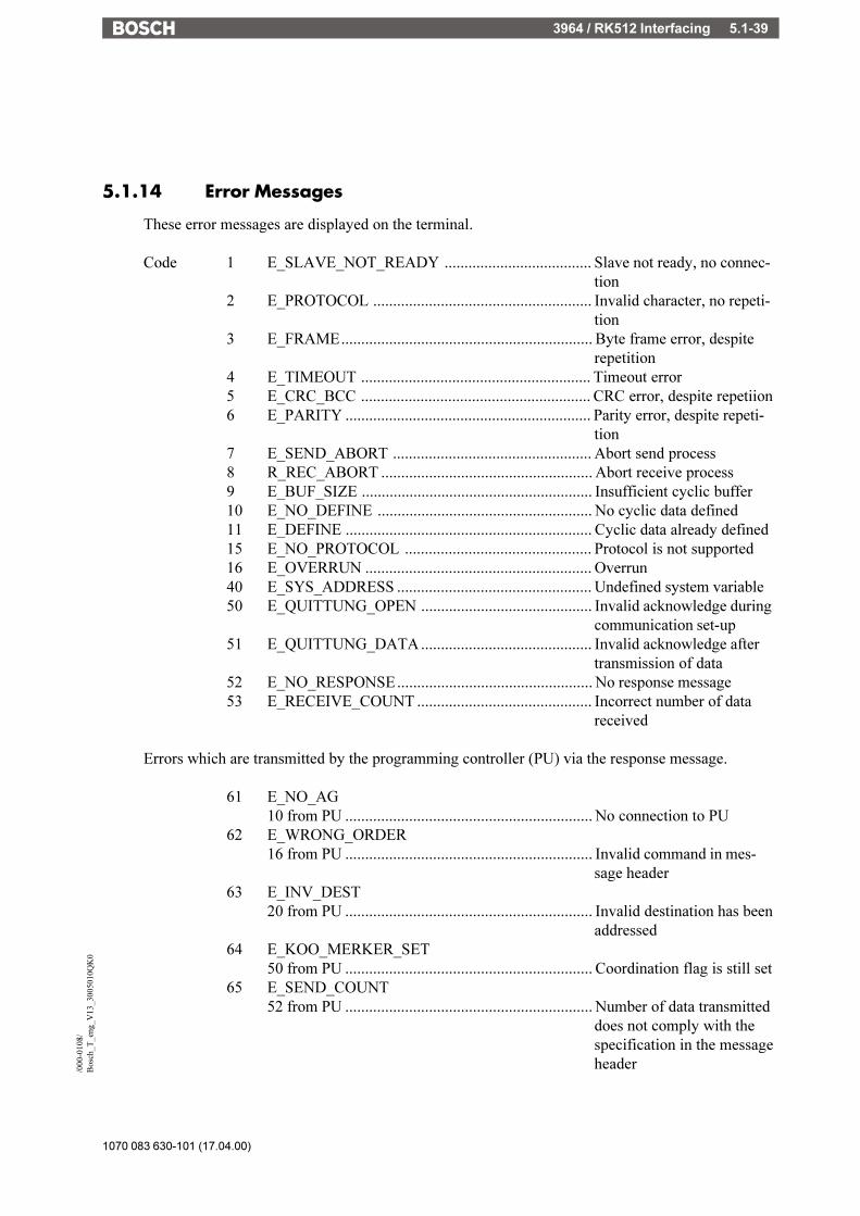
3964 / RK512 Interfacing 5.1-39
1070 083 630-101 (17.04.00)
/000
-010
8/B
osch
_T_e
ng_V
13_3
0050
10Q
K0
5.1.14 Error Messages
These error messages are displayed on the terminal.
Code 1 E_SLAVE_NOT_READY ..................................... Slave not ready, no connec-tion
2 E_PROTOCOL ....................................................... Invalid character, no repeti-tion
3 E_FRAME............................................................... Byte frame error, despiterepetition
4 E_TIMEOUT .......................................................... Timeout error5 E_CRC_BCC .......................................................... CRC error, despite repetiion6 E_PARITY .............................................................. Parity error, despite repeti-
tion7 E_SEND_ABORT .................................................. Abort send process8 R_REC_ABORT ..................................................... Abort receive process9 E_BUF_SIZE .......................................................... Insufficient cyclic buffer10 E_NO_DEFINE ...................................................... No cyclic data defined11 E_DEFINE .............................................................. Cyclic data already defined15 E_NO_PROTOCOL ............................................... Protocol is not supported16 E_OVERRUN ......................................................... Overrun40 E_SYS_ADDRESS ................................................. Undefined system variable50 E_QUITTUNG_OPEN ........................................... Invalid acknowledge during
communication set-up51 E_QUITTUNG_DATA........................................... Invalid acknowledge after
transmission of data52 E_NO_RESPONSE................................................. No response message53 E_RECEIVE_COUNT ............................................ Incorrect number of data
received
Errors which are transmitted by the programming controller (PU) via the response message.
61 E_NO_AG10 from PU .............................................................. No connection to PU
62 E_WRONG_ORDER16 from PU .............................................................. Invalid command in mes-
sage header63 E_INV_DEST
20 from PU .............................................................. Invalid destination has beenaddressed
64 E_KOO_MERKER_SET50 from PU .............................................................. Coordination flag is still set
65 E_SEND_COUNT52 from PU .............................................................. Number of data transmitted
does not comply with thespecification in the messageheader

1070 083 630-101 (17.04.00)
3964 / RK512 Interfacing5.1-40
66 E_SYNCH54 from PU .............................................................. Awaiting response message
70 E_AG....................................................................... The subcode contains theerror which is transmitted inthe response message by thePLC
Subcode10 ............................................................................. No connection to PU12 ............................................................................. Start address to high Using
co-ordination flag as datatype not allowed. CPU-no.to high
16 ............................................................................. Invalid Opcode20 ............................................................................. DB not available DB to
short50 ............................................................................. Co-ordination flag still set52 ............................................................................. More data received than
expected Less data receivedthen expected
54 ............................................................................. Synchonisation error (fol-lowing telegram expected)

Bosch PU (BUEP19) 5.2-1
1070 083 630-101 (17.04.00)
/000
-010
8/B
osch
_T_e
ng_V
13_3
0050
20Q
K0
Table of Contents
5.2 TesiMod - Bosch PU-Interfacing via BUEP19 ...................... 5.2-35.2.1 General Information ................................................................... 5.2-35.2.2 Technical Description ................................................................. 5.2-45.2.3 Parameters Interface X2 for PU-Interfacing ..................................... 5.2-45.2.3.1 Protocol Parameters Target Module .......................................... 5.2-45.2.3.2 Protocol Parameter Block Check .............................................. 5.2-45.2.3.3 Protocol Parameter Coordination Flag ...................................... 5.2-55.2.4 Data Type Structure .................................................................... 5.2-55.2.4.1 Data Types ........................................................................... 5.2-55.2.5 Additional Functions ................................................................... 5.2-65.2.6 Physical Interfacing .................................................................... 5.2-75.2.6.1 Connecting Cable TesiMod TTY / 20 mA - Bosch PU.................. 5.2-85.2.6.2 Connecting Cable Universal Interface TTY / 20 mA - Bosch PU ... 5.2-95.2.7 Error Messages........................................................................ 5.2-10

1070 083 630-101 (17.04.00)
Bosch PU (BUEP19)5.2-2
Bosch PU (BUEP19) 5.2-3
1070 083 630-101 (17.04.00)
/000
-010
8/B
osch
_T_e
ng_V
13_3
0050
20Q
K0
5.2 TesiMod - Bosch PU-Interfacing via BUEP19
5.2.1 General Information
TesiMod operating terminals allow for a simple connection to the Bosch PLCs thus makingTesiMod operating terminals the perfect man-machine-interface for your Bosch PLC.The TesiMod operating terminal is connected to the respective PLC-module.The data communication on the interface is handled by the PU protocol BUEP19. With the CPUsZE300 / ZE301 / R300 / R301 / R600 communication is possible with any system implementingthe BUEP19 protocol.
The hardware and software components of the TesiMod system are fully adapted to theparameters and marginal conditions of the PU interface.
This offers the user of TesiMod operating terminals the following advantages:
- Random write and read access to any data within the PLC. Data of existing PLC programscan be displayed and modified directly in the operating terminal. It is not necessary to adaptthe PLC program to the operating terminal in any respect since it is not required thatcommunications data be stored in a specified address area or data type area.
- The TesiMod operating terminal automatically polls cyclic data in the cyclic poll area. Thelocation of this poll area are custom assignable.
- No configuration required within the PLC.
- The PU protocol is handled entirely by the firmware of the PLC. A PLC program (functionblocks, etc.) in the PLC is not required for the handling of the communication.
- The protocol provides error control. Transmission errors are detected and, if possible,eliminated by repeating the transmission. An electrically isolated, noise-immune interfacehardware in accordance with the 20mA current loop interface standard permits the applica-tion even in a harsh industrial environment.
- The parameters of the communications interface are assigned in the TS programmingsoftware in a protocol-specific manner and are stored in the mask definition. Modifying ofthe parameters is also possible in the set-up mask or any other I/O mask of the terminal.
- The graphical operator guidance offers the user a maximum of assistance in defining thevariable addresses within the list of variables. The definitions (abbreviations) used here areidentical with the definitions used within the PLC program.

1070 083 630-101 (17.04.00)
Bosch PU (BUEP19)5.2-4
5.2.2 Technical Description
The interfacing of the TesiMod operating terminal to the Bosch PLCs is effected by means ofthe BUEP19 PU-protocol.
The PU protocol BUEP19 allows random read and write access to all PLC data. Any byte-structured data types can also be accessed in bit-mode. The size of the address area depends onthe respective PLC.
A read access must occur, before individual bits or bytes of a flag word can be accessed for a writeoperation. Subsequently, a write access is possible to the entire data structure. When accessingindividual bits or bytes, special care must be taken to ensure that neither the terminal nor the PLCmodify individual bits within one byte (or individual bits within one word, respectively).
The following byte order applies to the access in word-mode: HighByte-LowByte.
5.2.3 Parameters Interface X2 for PU-Interfacing
The TesiMod operating terminal adapts to the default parameters of the PU interface. It istherefore not necessary to modify the interface parameters in the PLC.To ensure a proper communication, the parameters must not be modified.
Baud rate: 9600 BaudParity: evenData length: 8Stopbits: 1Handshake: no handshake
5.2.3.1 Protocol Parameters Target Module
To ensure an error-free data transmission, the terminal must be informed of which module is tobe connected to interface X2.ZE300 / ZE301R300 / R301R600
5.2.3.2 Protocol Parameter Block Check
As a default, the protocol BUEP19 implements the data block check method CRC16.The programming device with a EP/AG module, however, uses a data block check method inaccordance with LRC8.To avoid difficulties during the development phase during which the PU and the terminal arealternately connected to the PLC, the terminal allows selection of the block check method LRC8.

Bosch PU (BUEP19) 5.2-5
1070 083 630-101 (17.04.00)
/000
-010
8/B
osch
_T_e
ng_V
13_3
0050
20Q
K0
5.2.3.3 Protocol Parameter Coordination Flag
The protocol permits defining of a coordination flag.
5.2.4 Data Type Structure
a) Alphanumerical TextIs stored in the memory byte for byte in ascending address order.
b) CounterThe count value is interpreted in binary format. The maximum value is 8191.
c) TimerTimer functions consist of a time value and a time base. The terminal operates with imaginaryunsigned 4-byte variables, even though the data stored in the PLC comprise only 2 bytes.
When read-accessing the timer, the terminal converts the time value and time base into aterminal-internal unsigned 4-byte number, which represents the time value in reference to thetime base of 0.01 second.Ex.: A range of 10 (time base is 1.0 second) and a time value of 999 , are represented or edited,respectively, in the terminal by the value 99900. Scaling of this value to other value ranges ispossible by specifying a factor and divisor within the variable definition.Before writing a timer variable to the PLC, the time value and the smallest possible time baseare formed from the terminal-internal unsigned 4-byte value.
d) Floating Point NumbersThe data are interpreted in the Siemens floating point format.
e) Binary Variables with a Length of 1, 2 or 4 BytesData with a length of 2 bytes are interpreted in the PLC-conformal byte order for words.Data with a length of 4 bytes are interpreted in the PLC-conformal byte order for long words.
5.2.4.1 Data Types
Direct accessing of the following data types is possible:The data types listed below can be accessed in bit, byte or word-mode. The access modes aredistinguished by the abbreviations BY, B and W.
I inputO outputM flag
The data types listed below can be accessed in word-mode only.
D data word (0 ... 510)DB data buffer (0 ... 510, only with ZE300)

1070 083 630-101 (17.04.00)
Bosch PU (BUEP19)5.2-6
T timer (R300 and R600 read-only)C counter (R300 and R600 read-only)
The size of each data area is governed by the CPU of the PLC.
5.2.5 Additional Functions
In addition to the random write and read access to PLC variables, a memory area comprising 12bytes is specified in the mask definition as poll area. The location of this memory area is specifiedin the mask definition.
Only marginal conditions regarding this memory area are that the PLC must be able to accessin bit-mode and the terminal in word-mode and the memory area must be contiguous.
The addresses M, D or DB can be accessed in word-mode.
The data area comprises a maximum of 6 words or 12 bytes.
Example: The cyclic data area is set to DW21 in the TesiMod programming system
Word address DW High byte Low byte
WORD address +0 DW21 Write coordination byte ReservedWORD address +1 DW22 Message channel high-byte Message channel low-byteWORD address +2 DW23 Function keys LED1...4 LED5...8WORD address +3 DW24 Function keys LED9...12 LED13...16WORD address +4 DW25 Function keys LED17...20 LED21...24WORD address +5 DW26 Function keys LED25...28 LED29...32
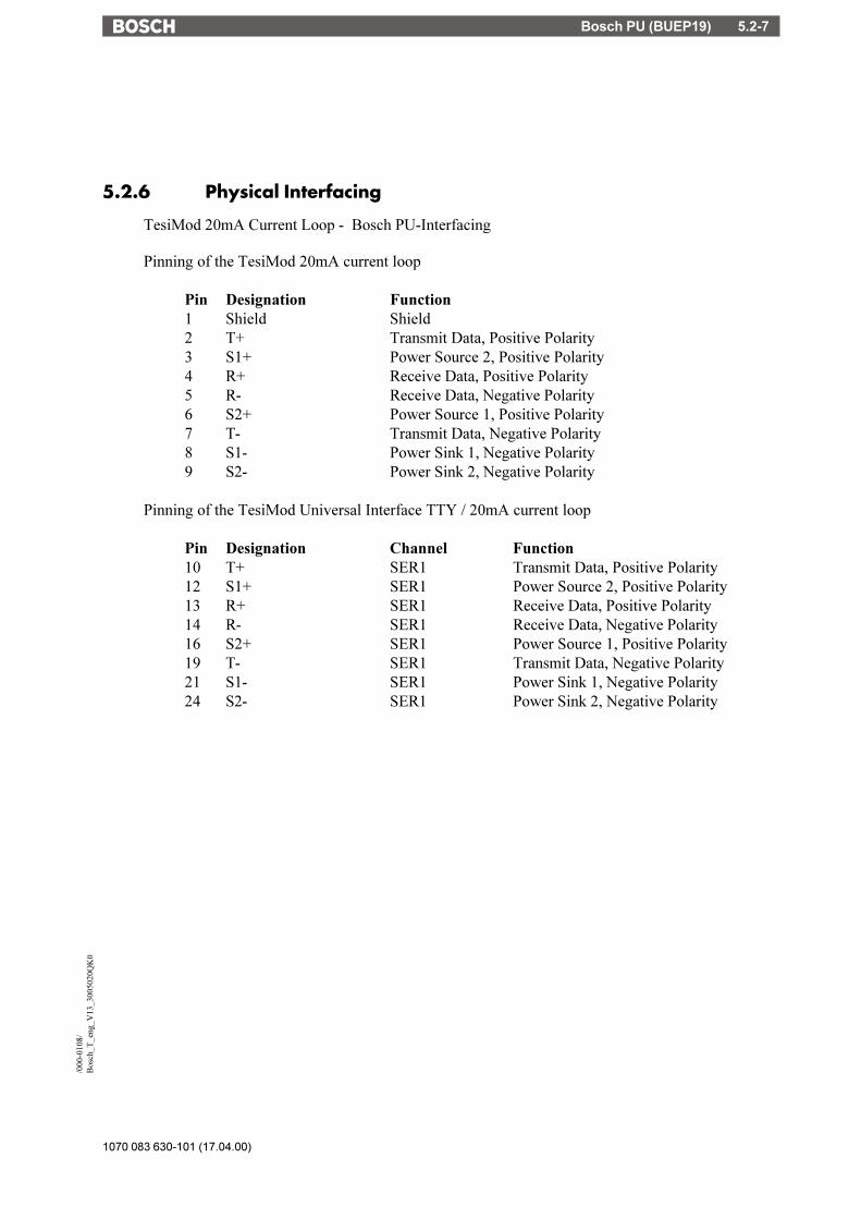
Bosch PU (BUEP19) 5.2-7
1070 083 630-101 (17.04.00)
/000
-010
8/B
osch
_T_e
ng_V
13_3
0050
20Q
K0
5.2.6 Physical Interfacing
TesiMod 20mA Current Loop - Bosch PU-Interfacing
Pinning of the TesiMod 20mA current loop
Pin Designation Function1 Shield Shield2 T+ Transmit Data, Positive Polarity3 S1+ Power Source 2, Positive Polarity4 R+ Receive Data, Positive Polarity5 R- Receive Data, Negative Polarity6 S2+ Power Source 1, Positive Polarity7 T- Transmit Data, Negative Polarity8 S1- Power Sink 1, Negative Polarity9 S2- Power Sink 2, Negative Polarity
Pinning of the TesiMod Universal Interface TTY / 20mA current loop
Pin Designation Channel Function10 T+ SER1 Transmit Data, Positive Polarity12 S1+ SER1 Power Source 2, Positive Polarity13 R+ SER1 Receive Data, Positive Polarity14 R- SER1 Receive Data, Negative Polarity16 S2+ SER1 Power Source 1, Positive Polarity19 T- SER1 Transmit Data, Negative Polarity21 S1- SER1 Power Sink 1, Negative Polarity24 S2- SER1 Power Sink 2, Negative Polarity

1070 083 630-101 (17.04.00)
Bosch PU (BUEP19)5.2-8
5.2.6.1 Connecting Cable TTY / 20 mA - Bosch PU
TesiMod Bosch PLCOperating Terminal e.g. ZE301Sender aktive Sender passiveReceiver aktive Receiver passive
D-Subminiature D-SubminiatureMale connector Male connector9 pin 25 pin
The shield is connected to the metal housing on both sides.At the side of the operating terminal pin 1 and pin7 are connected to the shield / metalhousing.

Bosch PU (BUEP19) 5.2-9
1070 083 630-101 (17.04.00)
/000
-010
8/B
osch
_T_e
ng_V
13_3
0050
20Q
K0
5.2.6.2 Connecting Cable Universal Interface TTY / 20 mA - BoschPU
TesiMod Bosch PLCOperating Terminal e.g. ZE301Sender aktive Sender passiveReceiver aktive Receiver passive
D-Subminiature D-SubminiatureMale connector Male connector25 pin 25 pin
The shield is connected to the metal housing on both sides.At the side of the operating terminal pin 1 and pin7 are connected to the shield / metalhousing.
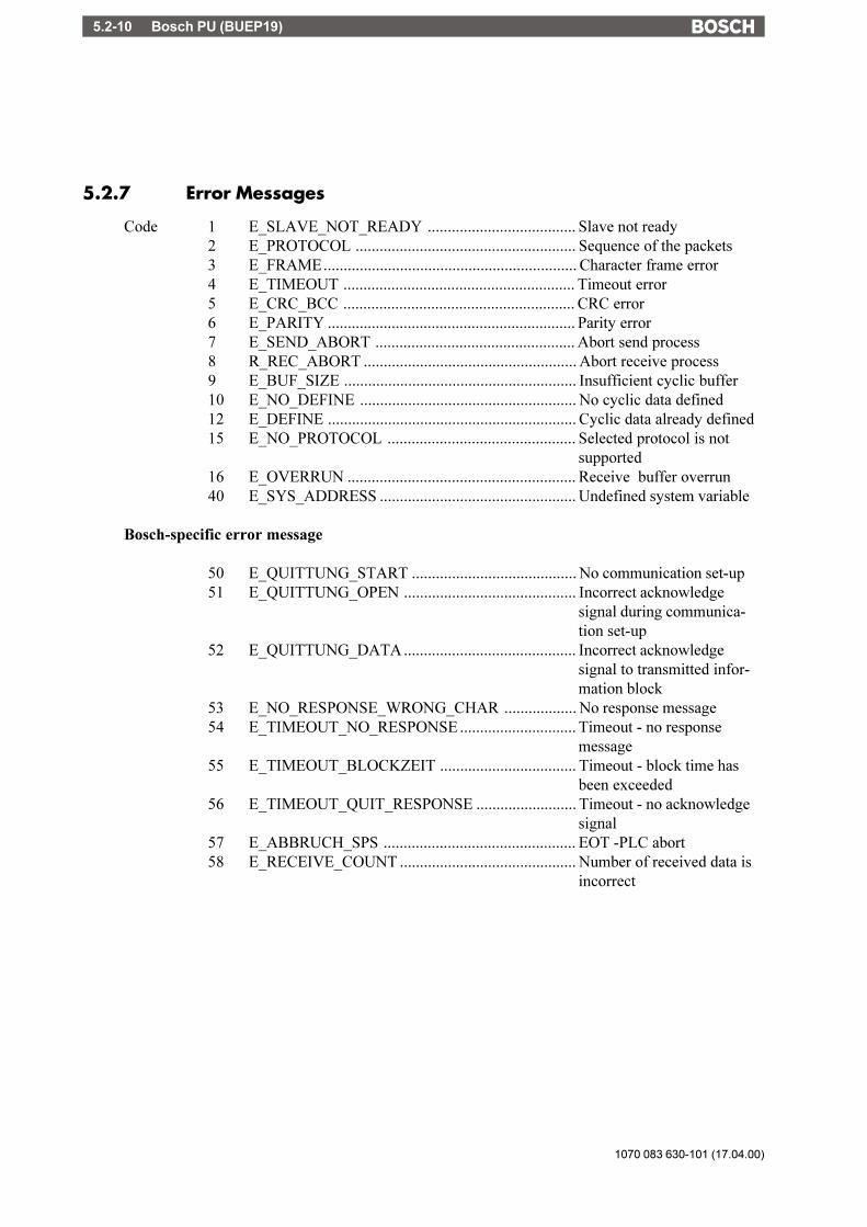
1070 083 630-101 (17.04.00)
Bosch PU (BUEP19)5.2-10
5.2.7 Error Messages
Code 1 E_SLAVE_NOT_READY ..................................... Slave not ready2 E_PROTOCOL ....................................................... Sequence of the packets3 E_FRAME............................................................... Character frame error4 E_TIMEOUT .......................................................... Timeout error5 E_CRC_BCC .......................................................... CRC error6 E_PARITY .............................................................. Parity error7 E_SEND_ABORT .................................................. Abort send process8 R_REC_ABORT ..................................................... Abort receive process9 E_BUF_SIZE .......................................................... Insufficient cyclic buffer10 E_NO_DEFINE ...................................................... No cyclic data defined12 E_DEFINE .............................................................. Cyclic data already defined15 E_NO_PROTOCOL ............................................... Selected protocol is not
supported16 E_OVERRUN ......................................................... Receive buffer overrun40 E_SYS_ADDRESS ................................................. Undefined system variable
Bosch-specific error message
50 E_QUITTUNG_START ......................................... No communication set-up51 E_QUITTUNG_OPEN ........................................... Incorrect acknowledge
signal during communica-tion set-up
52 E_QUITTUNG_DATA........................................... Incorrect acknowledgesignal to transmitted infor-mation block
53 E_NO_RESPONSE_WRONG_CHAR .................. No response message54 E_TIMEOUT_NO_RESPONSE ............................. Timeout - no response
message55 E_TIMEOUT_BLOCKZEIT .................................. Timeout - block time has
been exceeded56 E_TIMEOUT_QUIT_RESPONSE ......................... Timeout - no acknowledge
signal57 E_ABBRUCH_SPS ................................................ EOT -PLC abort58 E_RECEIVE_COUNT ............................................ Number of received data is
incorrect
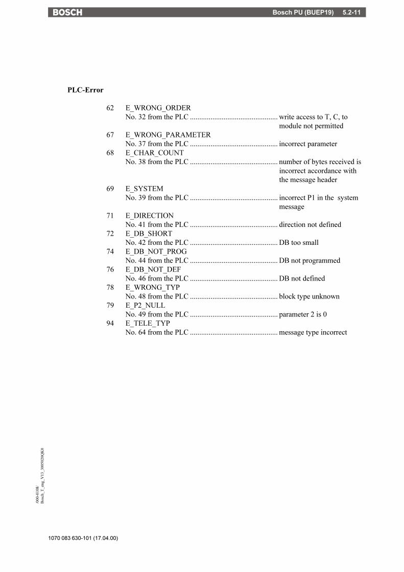
Bosch PU (BUEP19) 5.2-11
1070 083 630-101 (17.04.00)
/000
-010
8/B
osch
_T_e
ng_V
13_3
0050
20Q
K0
PLC-Error
62 E_WRONG_ORDERNo. 32 from the PLC ............................................... write access to T, C, to
module not permitted67 E_WRONG_PARAMETER
No. 37 from the PLC ............................................... incorrect parameter68 E_CHAR_COUNT
No. 38 from the PLC ............................................... number of bytes received isincorrect accordance withthe message header
69 E_SYSTEMNo. 39 from the PLC ............................................... incorrect P1 in the system
message71 E_DIRECTION
No. 41 from the PLC ............................................... direction not defined72 E_DB_SHORT
No. 42 from the PLC ............................................... DB too small74 E_DB_NOT_PROG
No. 44 from the PLC ............................................... DB not programmed76 E_DB_NOT_DEF
No. 46 from the PLC ............................................... DB not defined78 E_WRONG_TYP
No. 48 from the PLC ............................................... block type unknown79 E_P2_NULL
No. 49 from the PLC ............................................... parameter 2 is 094 E_TELE_TYP
No. 64 from the PLC ............................................... message type incorrect

1070 083 630-101 (17.04.00)
Bosch PU (BUEP19)5.2-12
DIN-Meßbus 5.3-1
1070 083 630-101 (17.04.00)
/000
-010
8/B
osch
_T_e
ng_V
13_3
0050
30Q
K0
Table of Contents
5.3 TesiMod - DIN-Meßbus ...................................................... 5.3-35.3.1 TesiMod - DIN-Meßbus-Master ..................................................... 5.3-35.3.1.1 Process Computer as Bus Master ............................................. 5.3-35.3.1.2 Gateway as Bus Master .......................................................... 5.3-35.3.1.3 Poll Area .............................................................................. 5.3-45.3.1.4 Cache Function for Read-Only Data ......................................... 5.3-65.3.1.5 Status of the Network ............................................................. 5.3-75.3.1.6 Parameters Interface SER1 for PLC-Interfacing ............................ 5.3-75.3.1.7 Parameters Interface SER2 for DIN-Meßbus - Master ................... 5.3-75.3.1.7.1 Minimal Slave Number ...................................................... 5.3-85.3.1.7.2 Maximal Slave Number ..................................................... 5.3-85.3.1.7.3 Test Cycle for the Synchronization ....................................... 5.3-85.3.1.7.4 Cache Size ....................................................................... 5.3-85.3.1.7.5 Cache Address ................................................................. 5.3-85.3.1.7.6 Intervals for the Cache Update ............................................ 5.3-85.3.1.7.7 Network Status Address ..................................................... 5.3-85.3.1.8 Additional Error Messages ...................................................... 5.3-95.3.2 TesiMod DIN-Meßbus - Slave .................................................... 5.3-105.3.2.1 General Information ............................................................. 5.3-105.3.2.2 Technical Description ........................................................... 5.3-105.3.2.3 Parameters Interface SER1 for DIN-Meßbus -Slave .................... 5.3-115.3.2.3.1 Timeout for Order-Reply ................................................... 5.3-115.3.2.3.2 Timeout for Cache-Update ................................................ 5.3-115.3.2.3.3 Slave Number ................................................................. 5.3-125.3.2.4 Data Types ......................................................................... 5.3-125.3.2.5 Additional Functions............................................................. 5.3-125.3.2.6 Physical Interfacing .............................................................. 5.3-125.3.2.7 Bus Cable Gateway - Slave - Terminals ................................... 5.3-135.3.2.8 Error Messages ................................................................... 5.3-14

1070 083 630-101 (17.04.00)
DIN-Meßbus5.3-2
DIN-Meßbus 5.3-3
1070 083 630-101 (17.04.00)
/000
-010
8/B
osch
_T_e
ng_V
13_3
0050
30Q
K0
5.3 TesiMod - DIN-Meßbus
TesiMod operating terminals allow for a simple interfacing to process computers or PLCs viathe DIN-Meßbus (DIN 66348 - part 2).The DIN-Meßbus has a master-slave type structure, i.e. the bus master polls the connected busslaves. Thus, within this description a distinction is made between the master and the slaveinterfacing.
5.3.1 TesiMod - DIN-Meßbus-Master
5.3.1.1 Process Computer as Bus Master
Any process computer complying with the following marginal conditions is suitable as busmaster:
- Communication in accordance with DIN66348 - part 2 (specifies the data transmission layers1 and 2 of the ISO/OSI - layer model)
- Interpretation of the data contents in compliance with the SÜTRON TesiBusspecification
The services (DIN-Meßbus-user data contents) are defined in an address-transparent manner. Anumber of different address formats are available for the interfacing. A SÜTRON-internaladdress format is used for indirect PLC interface connections whereas a linear, byte-structuredmemory addressing technique with an address area of 224 bits is implemented for regular processcomputer interface connections.
5.3.1.2 Gateway as Bus Master
The DIN-Meßbus allows a number of operating terminals to be connected to a PLC (via theprogramming unit interface) which is particularly interesting in applications where the PLC-interface itself represents only a point-to-point connection.
This requires the use of a gateway which is responsible for the adaptation of the protocol betweenthe DIN-Meßbus (TesiBus) and the respective PLC-protocol.
At the same time the gateway will function as the bus master on the DIN-Meßbus and poll theslave terminals at cyclic intervals.
The gateway offers all functions of a full-size terminal, however, due to the implementation ofthe DIN-Meßbus protocol on interface X3 the following functions are not available:
- Printing of messages- Printing of protocols- Printing of PCX-files
1070 083 630-101 (17.04.00)
DIN-Meßbus5.3-4
The gateway offers the following additional functions, which are not available in the standardTesiMod operating terminals:
- Extended poll area- Cache function for read-only data- Image of the network status
5.3.1.3 Poll Area
The cyclic poll area makes the following functions available on the master terminal or slaveterminal, respectively:
- Write Coordination byte (WCB)- Serial message channel- LEDs of the function keys
The functionality has been increased in comparison with the standard poll area of the direct PLC-interface connection. The mapping of this poll area to the functions of the terminal does not occurin a static fashion but is rather transmitted via the trigger byte in an event-controlled andslave-specific manner. I.e. the controller enters values into the poll area and transfers it to thegateway via bit 7 (value 0x80) of the trigger tyte. After the function has been executed, thegateway will write the return value and the code 0x40 back into the trigger byte. Subsequently,the data area will again be under the control of the PLC.

DIN-Meßbus 5.3-5
1070 083 630-101 (17.04.00)
/000
-010
8/B
osch
_T_e
ng_V
13_3
0050
30Q
K0
The poll area is classified as either byte-structured or word-structured depending on the specifiedaddress and has the following fixed structure:
TriggerByteReturn value
Slave number Function flag
Data 0
Data 2
Data 1
Data 3
Data 4 Data 5
Data 7Data 6
11
15 140 Wordstructure x7
Request by PLC
Data 8 Data 9
ReservedData 10
Word x
Word x+1
Word x+2
Word x+3
Word x+4
Word x+5
Word x+6
Word x+7
Highbyte Lowbyte
Byte y
Byte y+2
Byte y+4
Byte y+6
Byte y+8
Byte y+10
Byte y+12
Byte y+14
Byte y+1
Byte y+3
Byte y+5
Byte y+7
Byte y+9
Byte y+11
Byte y+13
Byte y+15
Byte structure y
Acknowledge by Gateway
The functions of the bytes are as listed below:
Slave number:0 Data are intended for the gateway itself1...31 Slave number to which the event will be transmitted by order-only
Function code:1 Transmit new WCB2 Transmit message3 Activate/deactivate LEDs
Return value:0 Ok-acknowledge signal1 Slave is not ready to receive2 General DIN-Meßbus error3 Invalid function code4 Slave not synchronized

1070 083 630-101 (17.04.00)
DIN-Meßbus5.3-6
Data contents:
Function transmit new Write Coordination Byte (WCB):Data 0 �> WCBData 1 �> free
Function transmit message:Data 0 �> Message number HighbyteData 1 �> Message number Lowbyte
Funtion activate LEDs:Data 0 �> LED 1...4Data 1 �> LED 5...8Data 2 �> LED 9...12Data 3 �> LED 13...16Data 4 �> LED 17...20Data 5 �> LED 21...24Data 6 �> LED 25...28Data 7 �> LED 29...32Data 8 �> LED 33...36Data 9 �> LED 37...40Data 10 �> LED 41...44
5.3.1.4 Cache Function for Read-Only Data
The cache function will poll a memory area of up to 62 bytes in the PLC and will then broadcastthe information to all connected slave-terminals at cyclic intervals . This greatly reduces the loadon the bus and allows simultaneous transmission of all data to the terminals.
Since the broadcast service on the communications layer 2 is not subject to monitoring, theslave-terminals implement a definable timeout to monitor the receipt of the broadcasted datapackets.
If a slave-terminal has a read request which is located within the cache area, no communicationwill be carried out via the gateway to the PLC, but the data are rather copied locally from of theterminal cache.
Variables which have been assigned the attribute display once and which are located within thecache area, will be displayed once more after receipt of the next cache packet. The gatewaytransmits the cache data in an equidistant fashion thus permitting the execution of a high-priorityand speedy output which is independent of the general cyclic output cycle.

DIN-Meßbus 5.3-7
1070 083 630-101 (17.04.00)
/000
-010
8/B
osch
_T_e
ng_V
13_3
0050
30Q
K0
5.3.1.5 Status of the Network
A 4-byte area is used by the gateway to transmit the status of the network to the PLC. Each slavewhich is detected in the network and which is synchronized, is represented by a bit which is setto �1�.
Please note carefully:During the synchronization of a slave (i.e. its bit is set from �0� �> �1�), the external datarelease for this slave will be reset and the function keys for this slave will be deactivated(the write coordination byte assumes the value �0�). In such an event, the PLC might be requiredto put the terminal back into the appropriate status via the poll area!
The figure below illustrates the general structure of the 4-byte area which is classified as eitherbyte-structured or word-structured depending on the specified address:
18
815 7 1
177 1
Word structure X
Byte structure y
916
1724 31 25
Byte y Byte y+1
Byte y+2 Byte y+3
Slave
SlaveSlave
Slave
Word x
Word x+1
5.3.1.6 Parameters Interface SER1 for PLC-Interfacing
The communication via interface SER1 is effected by the same communications protocolthrough the same loadable driver as is used for the communication via a comparable direct PLC-interface connections.
The respective interface parameters are listed in the corresponding section of chapter 5.
5.3.1.7 Parameters Interface SER2 for DIN-Meßbus - Master
The DIN-Meßbus - master interface connection requires setting of the following parameters forthe interface SER2:
Baud rate: 19200 BaudParity: evenData length: 7 bitsStop bits: 1 stop bitHandshake: no handshakeNote: It is also possible to select a smaller baud rate. The baud rate setting for the gateway andthe setting for the slave terminal must be in agreement.

1070 083 630-101 (17.04.00)
DIN-Meßbus5.3-8
5.3.1.7.1 Minimal Slave Number
This value specifies the lower limit for the slave numbers which the network will be scanned for.Range of values: 1...31
5.3.1.7.2 Maximal Slave Number
This value specifies the upper limit for the slave numbers which the network will be scanned for.The value must be greater than or be equal to the minimal slave number (see 5.3.1.7.1). Keepingthe number of non-existing slaves within the range of values to a minimum, will contribute toa more speedy synchronization of the slaves by the gateway.Range of values: 1...31
5.3.1.7.3 Test Cycle for the Synchronization
Specifies the period of time that is allowed to elapse between each test communication whenscanning the bus. The input must be equal to a multiple of 1/10 second.Range of values: 2...255.
5.3.1.7.4 Cache Size
Specifies in bytes the size of the read-only data cache. Defining a word-structured area as cacheaddress will require a cache size comprising an even number of bytes!Range of values: 0...62 bytes.
5.3.1.7.5 Cache Address
Specifies the cache address, i.e. the beginning of the read-only data cache. No address must bespecified here when operating the bus without the cache function.
The following address levels are possible as starting addresses :- Flag byte / flag word- Data word
If variables from other address types are to be cached, it will be necessary to copy them fromthe PLC to the cache address area.
5.3.1.7.6 Intervals for the Cache Update
This time period specifies the length of time in 1/10 second that is allowed to elapse between thecache update cycles.Range of values: 2...255
5.3.1.7.7 Network Status Address
Specifies the address to which a 4-byte sequence, representing the network status, is transmittedto the PLC. All commonly used PLC addresses are valid here. No address must be defined, ifthe network status is not to be transmitted to the PLC.

DIN-Meßbus 5.3-9
1070 083 630-101 (17.04.00)
/000
-010
8/B
osch
_T_e
ng_V
13_3
0050
30Q
K0
5.3.1.8 Additional Error Messages
Since the gateway represents a full-size terminal, all error messages which might be generatedwith the associated direct PLC-interfacing, could be generated here as well. For details on thesemessages see the respective sub-chapter 5.
The following additional messages might be generated for the gateway:
Code 41 E_CACHE_READ .................................................. Error during read-access tothe PLC-cache
42 E_EGB_READ ....................................................... Error during read-access tothe gateway-poll area
43 E_EGB_WRITE ...................................................... Error during write-access tothe gateway-poll area
44 E_NETZ_ADDRESS .............................................. The address-syntax (variabledefinition) of one of theslave-terminals does notmatch the PLC-protocol ofthe gateway.
45 E_NETZ_WRITE ................................................... Error during transmission ofthe network status to thePLC.
46 E_NO_GATEWAY_PARA .................................... No gateway parameters areavailable. If necessary, storeand compile files once moreusing a new TS program-ming software.
In the event of these error messages, the sub-code will always supply the error numbers of therespective communications protocol (see error numbers of the respective direct PLC-interfacingin the respective chapter).

1070 083 630-101 (17.04.00)
DIN-Meßbus5.3-10
5.3.2 TesiMod DIN-Meßbus - Slave
5.3.2.1 General Information
TesiMod operating terminals allow for a simple networking via the DIN-Meßbus regardless ofthe bus master being used. Every slave-terminal in the network has access to the data of the busmaster.
Connecting the slave-terminals to a PLC by means of a gateway , allows the masks and variabledefinitions to be created in accordance with the same procedure as is used with the direct PLC-interfacing. It is merely necessary to adapt the interface parameters to the DIN-Meßbus.
This offers the user of TesiMod operating terminals the following advantages:
- Random write and read access to any data within the PLC. Data of existing PLC programscan be displayed and modified directly in the operating terminal. It is not necessary to adaptthe PLC program in any respect since it is not required that communications data be storedin a specified address area or data type area.
- The transmission of messages, the write coordination byte as well as the status of the functionkey LEDs is effected by the bus master in the event-controlled mode.
- No configuration required within the PLC.
- The protocol provides error control. Transmission errors are detected and, if possible,eliminated by repeating the transmission. A noise-immune interface hardware in accordancewith the RS485 interface standard permits the application even in a harsh industrialenvironment.
- Interface parameters are stored in the mask definition. Altering of the parameters is alsopossible in the setup mask of the terminal at any time.
- The graphical operator guidance offers the user a maximum of assistance in defining thevariable addressses within the mask definition. The definitions (abbreviations) used here areidentical with the definitions used within a PLC program (e.g. F3 = flag 3).
5.3.2.2 Technical Description
The bus master (process computer or gateway to the PLC) is connected to the slave through theDIN-Meßbus (DIN 66348).
The services (user data of the DIN-Meßbus protocol) required for the exchange of data aredefined in the TesiBus specification.
To reduce the load on the bus, it is possible for each slave-terminal to be equipped with its own

DIN-Meßbus 5.3-11
1070 083 630-101 (17.04.00)
/000
-010
8/B
osch
_T_e
ng_V
13_3
0050
30Q
K0
read-only data cache. The address location as well as the size of this cache will be determinedby way of negotiation between bus master (gateway) and slave-terminal during the synchroni-zation process. The bus master broadcasts the cache data to each slave-terminal in an equidistantfashion. The cache data will then be stored locally by each slave-terminal.
If a slave-terminal has a read request which is located within the cache area, no communicationwill be carried out via the gateway to the PLC, but the data are rather copied locally from theterminal cache.
Variables which have been assigned the attribute display once and which are located within thecache area, will be displayed once more after receipt of the next cache packet. The gatewaytransmits the cache data in an equidistant fashion thus permitting the execution of a high-priorityand speedy output which is independent of the general cyclic output cycle.
5.3.2.3 Parameters Interface SER1 for DIN-Meßbus -Slave
The DIN-Meßbus - slave interfacing requires setting of the following parameters for the interfaceSER1:
Baud rate: 19200 BaudParity: evenData length: 7 bitsStop bits: 1 stop bitHandshake: no handshake
Note: It is also possible to select a smaller baud rate. The baud rate setting for the gateway andthe setting for the slave terminal must be in agreement.
5.3.2.3.1 Timeout for Order-Reply
Whenever the slave requires data from the controller, it will start a timer. This timer allowsmonitoring of the following two processes: whether the slave-terminal is polled by the masterand whether the response is received from the bus master within this period of time. Any valuewithin the range of 0...65000 milliseconds can be defined for the timeout. Specify a value of 0if you wish to work without the function timeout monitoring. The absolute time value dependson the number of stations in the network, it should, however, be equal to a value of approximately2000 to 5000 milliseconds.
5.3.2.3.2 Timeout for Cache-Update
Since the receiving station can not acknowledge the broadcast service, the slave-terminalemploys a timeout to monitor the point of time at which broadcasted data were received. Thiswill ensure that local cache data are not �of any given point of time in the past�. Any value withinthe range of 0...65000 milliseconds can be defined for the timeout. The value depends on thecache-update interval of the bus master (see gateway parameters). The default value shouldcorrespond to a value of 5000 milliseconds.
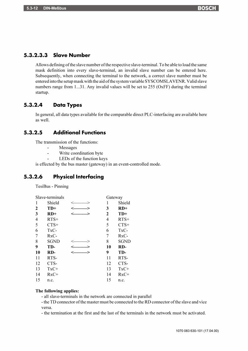
1070 083 630-101 (17.04.00)
DIN-Meßbus5.3-12
5.3.2.3.3 Slave Number
Allows defining of the slave number of the respective slave-terminal. To be able to load the samemask definition into every slave-terminal, an invalid slave number can be entered here.Subsequently, when connecting the terminal to the network, a correct slave number must beentered into the setup mask with the aid of the system variable SYSCOMSLAVENR. Valid slavenumbers range from 1...31. Any invalid values will be set to 255 (OxFF) during the terminalstartup.
5.3.2.4 Data Types
In general, all data types available for the comparable direct PLC-interfacing are available hereas well.
5.3.2.5 Additional Functions
The transmission of the functions:- Messages- Write coordination byte- LEDs of the function keys
is effected by the bus master (gateway) in an event-controlled mode.
5.3.2.6 Physical Interfacing
TesiBus - Pinning
Slave-terminals Gateway1 Shield <���> 1 Shield2 TD+ <���> 3 RD+3 RD+ <���> 2 TD+4 RTS+ 4 RTS+5 CTS+ 5 CTS+6 TxC- 6 TxC-7 RxC- 7 RxC-8 SGND <���> 8 SGND9 TD- <���> 10 RD-10 RD- <���> 9 TD-11 RTS- 11 RTS-12 CTS- 12 CTS-13 TxC+ 13 TxC+14 RxC+ 14 RxC+15 n.c. 15 n.c.
The following applies:- all slave-terminals in the network are connected in parallel- the TD connector of the master must be connected to the RD connector of the slave and viceversa.- the termination at the first and the last of the terminals in the network must be activated.

DIN-Meßbus 5.3-13
1070 083 630-101 (17.04.00)
/000
-010
8/B
osch
_T_e
ng_V
13_3
0050
30Q
K0
5.3.2.7 Bus Cable Gateway - Slave - Terminals

1070 083 630-101 (17.04.00)
DIN-Meßbus5.3-14
5.3.2.8 Error Messages
Code 30 E_SLAVE_NAK ..................................................... Even after a repeated at-tempt, slave was unable totransmit transmission data tomaster (NAK from themaster)
31 E_SLAVE_TIMEOUT ........................................... Even after a repeated at-tempt, slave was unable totransmit transmission data tomaster (TA has elapsed)
32 E_SEND_ORDER_TIMEOUT .............................. Slave was unable to transmitits order within the timeout.
33 E_ORDER_REPLY_TIMEOUT ............................ Slave has not received thereply to the transmittedorder within the timeout.
34 E_CACHE_TIMEOUT ........................................... Slave has not received thedata broadcasted by thecache within the timeout.
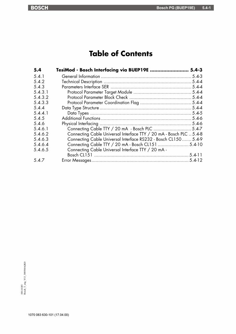
Bosch PG (BUEP19E) 5.4-1
1070 083 630-101 (17.04.00)
/001
-018
5/B
osch
_T_e
ng_V
13_3
0050
4AQ
K0
Table of Contents
5.4 TesiMod - Bosch Interfacing via BUEP19E .......................... 5.4-35.4.1 General Information ................................................................... 5.4-35.4.2 Technical Description ................................................................. 5.4-45.4.3 Parameters Interface SER ............................................................ 5.4-45.4.3.1 Protocol Parameter Target Module ........................................... 5.4-45.4.3.2 Protocol Parameter Block Check .............................................. 5.4-45.4.3.3 Protocol Parameter Coordination Flag ...................................... 5.4-45.4.4 Data Type Structure .................................................................... 5.4-45.4.4.1 Data Types ........................................................................... 5.4-55.4.5 Additional Functions ................................................................... 5.4-65.4.6 Physical Interfacing .................................................................... 5.4-65.4.6.1 Connecting Cable TTY / 20 mA - Bosch PLC ............................ 5.4-75.4.6.2 Connecting Cable Universal Interface TTY / 20 mA - Bosch PLC .. 5.4-85.4.6.3 Connecting Cable Universal Interface RS232 - Bosch CL150 ....... 5.4-95.4.6.4 Connecting Cable TTY / 20 mA - Bosch CL151 ....................... 5.4-105.4.6.5 Connecting Cable Universal Interface TTY / 20 mA -
Bosch CL151 ...................................................................... 5.4-115.4.7 Error Messages........................................................................ 5.4-12

1070 083 630-101 (17.04.00)
Bosch PG (BUEP19E)5.4-2

Bosch PG (BUEP19E) 5.4-3
1070 083 630-101 (17.04.00)
/001
-018
5/B
osch
_T_e
ng_V
13_3
0050
4AQ
K0
5.4 TesiMod - Bosch Interfacing via BUEP19E
5.4.1 General Information
TesiMod operating terminals allow for a simple connection to the Bosch PLCs thus makingTesiMod operating terminals the perfect man-machine-interface for your Bosch PLC.The TesiMod operating terminal is connected to the respective PLC-module.
The data communication on the interface is handled by the PU protocol BUEP19E. With thePLCs CL150, CL200, CL350, CL400, CL500 the communication is possible with the BUEP19Eprotocol.
The hardware and software components of the TesiMod system are fully adapted to theparameters and marginal conditions of the interface.
This offers the user of TesiMod operating terminals the following advantages:
- Random write and read access to any data within the PLC by a maximum of 4 different ZS500-modules. Data of existing PLC programs can be displayed and modified directly in theoperating terminal. It is not necessary to adapt the PLC program to the operating terminal inany respect since it is not required that communications data be stored in a specified addressarea or data type area.
- The TesiMod operating terminal automatically polls cyclic data in the cyclic poll area. Thesize and location of this poll area are custom assignable.
- No configuration required within the PLC.
- The PU protocol is handled entirely by the firmware of the PLC. A PLC program (functionblocks, etc.) in the PLC is not required for the handling of the communication.
- The protocol provides error control. Transmission errors are detected and, if possible,eliminated by repeating the transmission. An electrically isolated, noise-immune interfacehardware in accordance with the 20mA current loop interface standard permits the applica-tion even in a harsh industrial environment.
- The parameters of the communications interface X2 are assigned in the TS programmingsoftware in a protocol-specific manner and are stored in the mask definition. Modifying ofthe parameters is also possible in the set-up mask or any other I/O mask of the terminal.
- The graphical operator guidance offers the user a maximum of assistance in defining thevariable addresses within the list of variables. The definitions (abbreviations) used here areidentical with the definitions used within the PLC program.
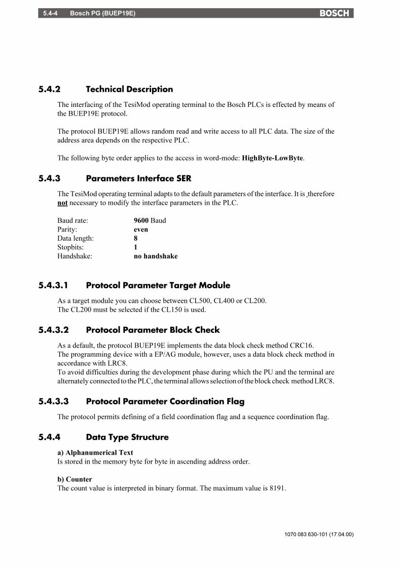
1070 083 630-101 (17.04.00)
Bosch PG (BUEP19E)5.4-4
5.4.2 Technical Description
The interfacing of the TesiMod operating terminal to the Bosch PLCs is effected by means ofthe BUEP19E protocol.
The protocol BUEP19E allows random read and write access to all PLC data. The size of theaddress area depends on the respective PLC.
The following byte order applies to the access in word-mode: HighByte-LowByte.
5.4.3 Parameters Interface SER
The TesiMod operating terminal adapts to the default parameters of the interface. It is thereforenot necessary to modify the interface parameters in the PLC.
Baud rate: 9600 BaudParity: evenData length: 8Stopbits: 1Handshake: no handshake
5.4.3.1 Protocol Parameter Target Module
As a target module you can choose between CL500, CL400 or CL200.The CL200 must be selected if the CL150 is used.
5.4.3.2 Protocol Parameter Block Check
As a default, the protocol BUEP19E implements the data block check method CRC16.The programming device with a EP/AG module, however, uses a data block check method inaccordance with LRC8.To avoid difficulties during the development phase during which the PU and the terminal arealternately connected to the PLC, the terminal allows selection of the block check method LRC8.
5.4.3.3 Protocol Parameter Coordination Flag
The protocol permits defining of a field coordination flag and a sequence coordination flag.
5.4.4 Data Type Structure
a) Alphanumerical TextIs stored in the memory byte for byte in ascending address order.
b) CounterThe count value is interpreted in binary format. The maximum value is 8191.

Bosch PG (BUEP19E) 5.4-5
1070 083 630-101 (17.04.00)
/001
-018
5/B
osch
_T_e
ng_V
13_3
0050
4AQ
K0
c) TimerTimer functions consist of a time value and a time base. The terminal operates with imaginaryunsigned 4-byte variables, even though the data stored in the PLC comprise only 2 bytes.
When read-accessing the timer, the terminal converts the time value and time base into aterminal-internal unsigned 4-byte number, which represents the time value in reference to thetime base of 0.01 second.Ex.: A range of 10 (time base is 1.0 second) and a time value of 999 , are represented or edited,respectively, in the terminal by the value 99900. Scaling of this value to other value ranges ispossible by specifying a factor and divisor within the variable definition.Before writing a timer variable to the PLC, the time value and the smallest possible time baseare formed from the terminal-internal unsigned 4-byte value.
d) Floating Point NumberThe data with a length of 4 bytes are interpreted in the IEEE floating point format.
e) Binary Variables with a Length of 1, 2 or 4 BytesData with a length of 2 bytes are interpreted in the PLC-conformal byte order for words.Data with a length of 4 bytes are interpreted in the PLC-conformal byte order for long words.
5.4.4.1 Data Types
Direct accessing of the following data types is possible:The data types listed below can be accessed in bit, byte or word-mode. The access modes aredistinguished by the abbreviations BY, B and W.The size of the data area depends on the PLC CPU.
Data type AccessT Timer (0 ... 127) Timer no. WZ Counter (0 ... 127) Counter no. WD Data block (0 ... 511) Byte-addr. W,ByDB Data buffer (0 ... 511) Byte-addr. W, ByM Flag (0 ... 255) Byte-addr. W, By, BE Input (0 ... 63) Byte-addr. W, By, BA Output (0 ... 63) Byte-addr. W, By, BBZ Status of the PLC RUN/STOP CL500/400 ByBZ Status of the PLC RUN/STOP CL200 WDF Data field (0 ... 24575) Byte-addr. W, By
If the size of of the data field is defined as a linear area the data field number must be set to 255.

1070 083 630-101 (17.04.00)
Bosch PG (BUEP19E)5.4-6
5.4.5 Additional Functions
In addition to the random write and read access to PLC variables, a memory area comprising 12bytes is specified in the mask definition as poll area. The location of this memory area can bespecified in the mask definition.
Only marginal conditions regarding this memory area are that the PLC must be able to accessin bit-mode and the terminal in word-mode and the memory area must be contiguous.
The data area comprises a maximum of 6 words or 12 bytes.Example: The cyclic data area is set to DW21 in the TesiMod programming system
WORD address DW High byte Low byte
WORD address +0 DW21 Write coordination byte ReservedWORD address +1 DW22 Message channel high-byte Message channel low-byteWORD address +2 DW23 Function keys LED1...4 LED5...8WORD address +3 DW24 Function keys LED9...12 LED13...16WORD address +4 DW25 Function keys LED17...20 LED21...24WORD address +5 DW26 Function keys LED25...28 LED29...32
5.4.6 Physical Interfacing
TesiMod 20mA Current Loop - Bosch PLC-Interfacing
Pin Designation Function1 Shield Shield2 T+ Transmit Data, Positive Polarity3 S1+ Power Source 2, Positive Polarity4 R+ Receive Data, Positive Polarity5 R- Receive Data, Negative Polarity6 S2+ Power Source 1, Positive Polarity7 T- Transmit Data, Negative Polarity8 S1- Power Sink 1, Negative Polarity9 S2- Power Sink 2, Negative Polarity
Pin assignment TesiMod Universal Interface TTY / 20 mA Current Loop
Pin Designation Channel Function10 T+ SER1 Transmit Data, Positive Polarity12 S1+ SER1 Power Source 2, Positive Polarity13 R+ SER1 Receive Data, Positive Polarity14 R- SER1 Receive Data, Negative Polarity16 S2+ SER1 Power Source 1, Positive Polarity19 T- SER1 Transmit Data, Negative Polarity21 S1- SER1 Power Sink 1, Negative Polarity24 S2- SER1 Power Sink 2, Negative Polarity

Bosch PG (BUEP19E) 5.4-7
1070 083 630-101 (17.04.00)
/001
-018
5/B
osch
_T_e
ng_V
13_3
0050
4AQ
K0
5.4.6.1 Connecting Cable TTY / 20 mA - Bosch PLC
TesiMod Bosch PLC, without CL150Operating Terminal PG-Interface X31Sender active Sender passiveReceiver active Receiver passive
12WHR-
7 WHS1-
8 YER-
9 GNS2-
6 BNT-
4R+
5S2+
2T+
3S1+
23YET+
13GNT-
22BNR+
1PG
D-Subminiature D-SubminiatureMale connector Male connector9 pin 25 pin
The shield is connected to the shield / metal housing on both sides.
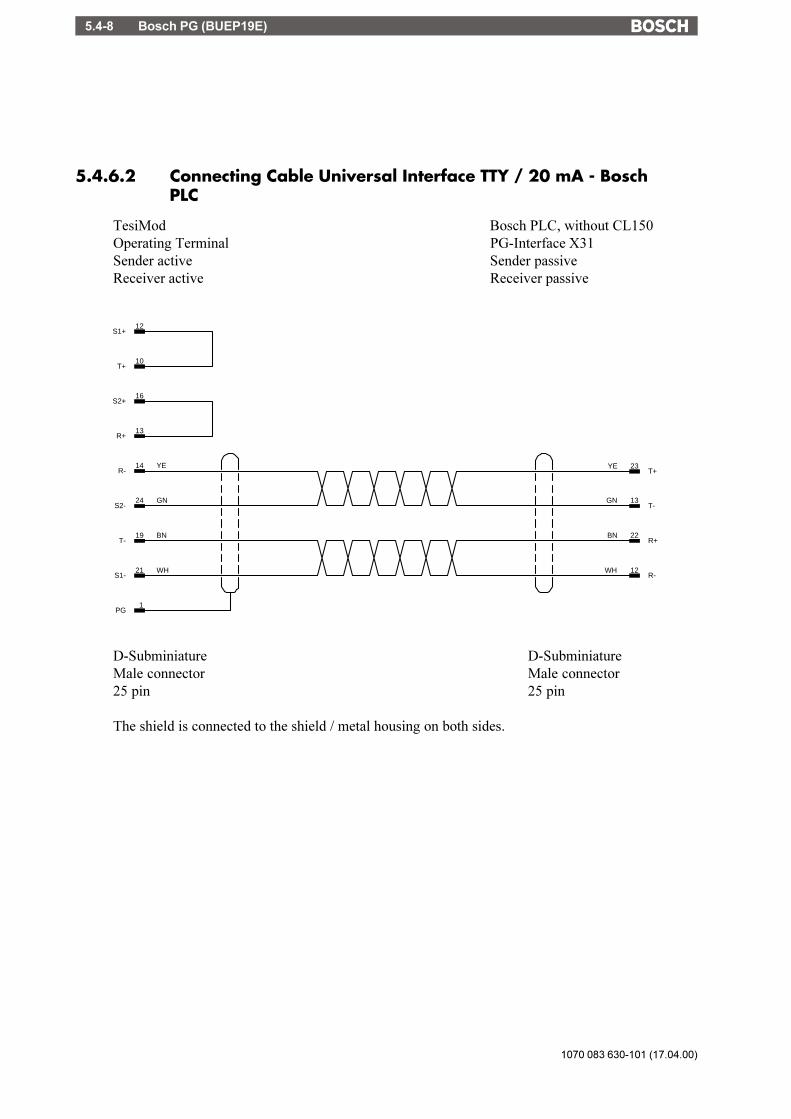
1070 083 630-101 (17.04.00)
Bosch PG (BUEP19E)5.4-8
5.4.6.2 Connecting Cable Universal Interface TTY / 20 mA - BoschPLC
TesiMod Bosch PLC, without CL150Operating Terminal PG-Interface X31Sender active Sender passiveReceiver active Receiver passive
19 BNT-
14 YER-
12WHR-
21 WHS1-
13R+
16S2+
10T+
12S1+
24 GNS2-
23YET+
13GNT-
22BNR+
1PG
D-Subminiature D-SubminiatureMale connector Male connector25 pin 25 pin
The shield is connected to the shield / metal housing on both sides.

Bosch PG (BUEP19E) 5.4-9
1070 083 630-101 (17.04.00)
/001
-018
5/B
osch
_T_e
ng_V
13_3
0050
4AQ
K0
5.4.6.3 Connecting Cable Universal Interface RS232 - Bosch CL150
TesiMod Bosch PLC CL150/CL151Operating Terminal BT2/BT5N/BT20N PG-Interface X31 (V24)
2WHRD
3BNTD
5GNGND
18 BNRD
6 WHTD
25 GNGND
D-Subminiature D-SubminiatureMale connector Male connector25 pin 9 pin
The shield is connected to the shield / metal housing on both sides.
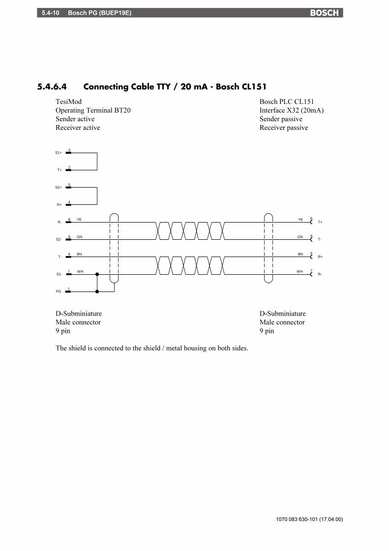
1070 083 630-101 (17.04.00)
Bosch PG (BUEP19E)5.4-10
5.4.6.4 Connecting Cable TTY / 20 mA - Bosch CL151
TesiMod Bosch PLC CL151Operating Terminal BT20 Interface X32 (20mA)Sender active Sender passiveReceiver active Receiver passive
9GNT-
6BNR+
7WHR-
8YET+
7 WHS1-
8 YER-
9 GNS2-
6 BNT-
4R+
5S2+
2T+
3S1+
1PG
D-Subminiature D-SubminiatureMale connector Male connector9 pin 9 pin
The shield is connected to the shield / metal housing on both sides.

Bosch PG (BUEP19E) 5.4-11
1070 083 630-101 (17.04.00)
/001
-018
5/B
osch
_T_e
ng_V
13_3
0050
4AQ
K0
5.4.6.5 Connecting Cable Universal Interface TTY / 20 mA - BoschCL151
TesiMod Bosch PLC CL151Operating Terminal BT2/BT5N/BT5/BT20N Interface X32 (20mA)Sender active Sender passiveReceiver active Receiver passive
9GNT-
6BNR+
7WHR-
8YET+
19 BNT-
14 YER-
21 WHS1-
13R+
16S2+
10T+
12S1+
24 GNS2-
1PG
D-Subminiature D-SubminiatureMale connector Male connector25 pin 9 pin
The shield is connected to the shield / metal housing on both sides.
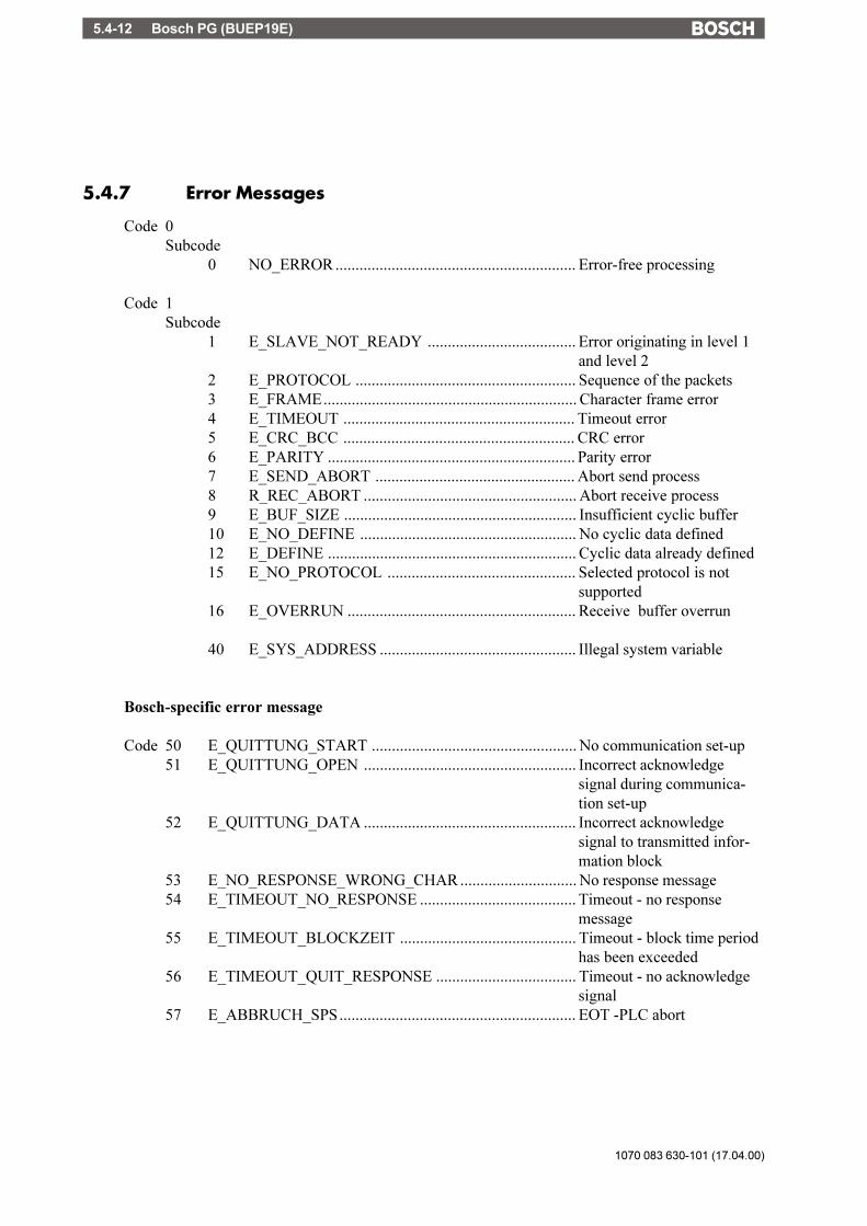
1070 083 630-101 (17.04.00)
Bosch PG (BUEP19E)5.4-12
5.4.7 Error Messages
Code 0Subcode
0 NO_ERROR ............................................................ Error-free processing
Code 1Subcode
1 E_SLAVE_NOT_READY ..................................... Error originating in level 1and level 2
2 E_PROTOCOL ....................................................... Sequence of the packets3 E_FRAME............................................................... Character frame error4 E_TIMEOUT .......................................................... Timeout error5 E_CRC_BCC .......................................................... CRC error6 E_PARITY .............................................................. Parity error7 E_SEND_ABORT .................................................. Abort send process8 R_REC_ABORT ..................................................... Abort receive process9 E_BUF_SIZE .......................................................... Insufficient cyclic buffer10 E_NO_DEFINE ...................................................... No cyclic data defined12 E_DEFINE .............................................................. Cyclic data already defined15 E_NO_PROTOCOL ............................................... Selected protocol is not
supported16 E_OVERRUN ......................................................... Receive buffer overrun
40 E_SYS_ADDRESS ................................................. Illegal system variable
Bosch-specific error message
Code 50 E_QUITTUNG_START ................................................... No communication set-up51 E_QUITTUNG_OPEN ..................................................... Incorrect acknowledge
signal during communica-tion set-up
52 E_QUITTUNG_DATA ..................................................... Incorrect acknowledgesignal to transmitted infor-mation block
53 E_NO_RESPONSE_WRONG_CHAR ............................. No response message54 E_TIMEOUT_NO_RESPONSE ....................................... Timeout - no response
message55 E_TIMEOUT_BLOCKZEIT ............................................ Timeout - block time period
has been exceeded56 E_TIMEOUT_QUIT_RESPONSE ................................... Timeout - no acknowledge
signal57 E_ABBRUCH_SPS........................................................... EOT -PLC abort
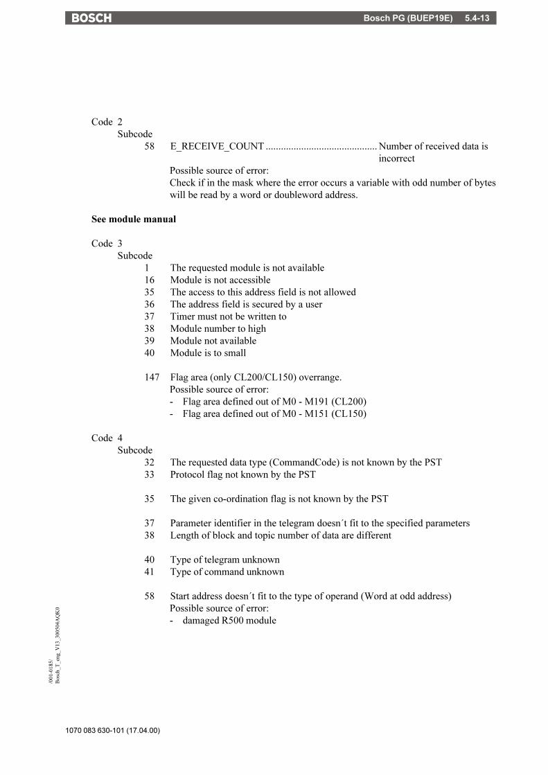
Bosch PG (BUEP19E) 5.4-13
1070 083 630-101 (17.04.00)
/001
-018
5/B
osch
_T_e
ng_V
13_3
0050
4AQ
K0
Code 2Subcode
58 E_RECEIVE_COUNT ............................................ Number of received data isincorrect
Possible source of error:Check if in the mask where the error occurs a variable with odd number of byteswill be read by a word or doubleword address.
See module manual
Code 3Subcode
1 The requested module is not available16 Module is not accessible35 The access to this address field is not allowed36 The address field is secured by a user37 Timer must not be written to38 Module number to high39 Module not available40 Module is to small
147 Flag area (only CL200/CL150) overrange.Possible source of error:- Flag area defined out of M0 - M191 (CL200)- Flag area defined out of M0 - M151 (CL150)
Code 4Subcode
32 The requested data type (CommandCode) is not known by the PST33 Protocol flag not known by the PST
35 The given co-ordination flag is not known by the PST
37 Parameter identifier in the telegram doesn´t fit to the specified parameters38 Length of block and topic number of data are different
40 Type of telegram unknown41 Type of command unknown
58 Start address doesn´t fit to the type of operand (Word at odd address)Possible source of error:- damaged R500 module

1070 083 630-101 (17.04.00)
Bosch PG (BUEP19E)5.4-14
59 Start address defined outside the address area60 Invalid parameter for specified command61 Invalid type of operand
64 The PST hasn´t received an identification telegram, yet
99 The given length of data is greater than the requested data area
210 Co-ordination flag is locked

PROFIBUS-DP 5.5-1
1070 083 630-101 (17.04.00)
/000
-010
8/B
osch
_T_e
ng_V
13_3
0050
50Q
K0
Table of Contents
5.5 TesiMod - Profibus-DP - Interfacing ................................... 5.5-35.5.1 Technical Description ................................................................. 5.5-35.5.2 Specification within the Profibus-DP .............................................. 5.5-35.5.3 Data Profile ............................................................................... 5.5-45.5.3.1 Structure of the Profile ............................................................ 5.5-45.5.3.2 Control Bytes......................................................................... 5.5-55.5.3.3 User Data ............................................................................. 5.5-65.5.3.3.1 Reading and Writing Bytes ................................................. 5.5-65.5.3.3.2 Reading Bits...................................................................... 5.5-65.5.3.3.3 Writing Bits ...................................................................... 5.5-65.5.4 Tasks of the Control Program ....................................................... 5.5-75.5.5 Connection to Siemens-PLC ......................................................... 5.5-75.5.5.1 Parameterization of the IM308B .............................................. 5.5-75.5.5.1.1 Data Consistency............................................................... 5.5-75.5.5.2 PLC Program ......................................................................... 5.5-85.5.5.2.1 FB110 - Evaluation Block .................................................... 5.5-85.5.5.2.2 FB111 - Reading from Data Block ...................................... 5.5-105.5.5.2.3 FB112 - Writing to Data Block........................................... 5.5-105.5.5.3 Protocol Parameters ............................................................. 5.5-105.5.5.4 Programming the variables ................................................... 5.5-105.5.6 Connection to Bosch-PLC ........................................................... 5.5-115.5.6.1 Parameterization of the BM_DP12 ......................................... 5.5-115.5.6.2 PLC Program ....................................................................... 5.5-115.5.6.2.1 BT_MAIN - Evaluation Block .............................................. 5.5-125.5.6.2.2 BT_READ - Reading from Data Block ................................. 5.5-135.5.6.2.3 BT_WRITE - Writing to Data Block ...................................... 5.5-145.5.6.3 Protocol Parameters ............................................................. 5.5-145.5.6.4 Programming the variables ................................................... 5.5-145.5.7 Protocol Parameters ................................................................. 5.5-155.5.7.1 Response Timeout ................................................................ 5.5-155.5.7.2 Communication Set-up Delay ................................................. 5.5-155.5.7.3 Station Number ................................................................... 5.5-155.5.7.4 Telegram Length .................................................................. 5.5-155.5.7.5 Floating Point Format ........................................................... 5.5-155.5.7.6 Byte-Order for Word and Double Word ................................. 5.5-155.5.7.7 Address Width .................................................................... 5.5-165.5.8 Additional Functions ................................................................. 5.5-165.5.9 Physical Interfacing .................................................................. 5.5-175.5.9.1 Connecting Cable................................................................ 5.5-185.5.10 Error Messages........................................................................ 5.5-195.5.11 Device-Master-Data-File ............................................................. 5.5-21

1070 083 630-101 (17.04.00)
PROFIBUS-DP5.5-2
PROFIBUS-DP 5.5-3
1070 083 630-101 (17.04.00)
/000
-010
8/B
osch
_T_e
ng_V
13_3
0050
50Q
K0
5.5 TesiMod - Profibus-DP - Interfacing
5.5.1 Technical Description
TesiMod operating terminals allow for a simple connection to the Profibus-DP thus makingTesiMod operating terminals the perfect man-machine-interface for systems using the Profibus-DP.Moreover it is possible to connect multiple operating terminals to one master controller.The speed-optimized PROFIBUS-DP is a variant of PROFIBUS that has been particularlytailored to suit the communication between automation systems and decentral peripherals.
The Profibus-DP implemented in the operating terminal complies with the standard DIN 19245part 1 and part 3 as well as the European field bus standard EN 50170.
The TesiMod operating terminal complies with the conditions specified by the standards thusallowing its trouble-free integration into the Profibus-DP as a slave.
An additional hardware is used to connect the operating terminal to the Profibus.
Located on this hardware is the ASIC SPC3 which handles the entire PROFIBUS-DP protocol,thus allowing transmission speeds of up to 12 MBaud.
The operating terminal is employed on the bus as if it were a decentral module with up to 32 inputsand outputs and therefore occupies between 8 and 32 bytes IN-data and between 8 and 32 bytesOUT-data. Via the bus, the input and output statuses are exchanged between the master andoperating terminal at cyclic intervals. The Profibus-DP protocol is a manufacturer or controller-neutral data transmission protocol. Because no hardware input and output statuses are transmit-ted in the operating terminal, a data profile must be specified between master and slave whichallows the corresponding partner to identify the type of the data that have been transmitted.
All services required for the operation of the operating terminal are initiated by the operatingterminal. The operating terminal has a client functionality.The controller simply reacts to requests from the operating terminal. The controller has aserver-functionality.If the operating terminal is integrated into the Profibus-DP, the master module needs to interpretthe arriving data in accordance with the specified profile and also needs to respond in accordancewith the profile.This is generally accomplished by a FB (function block) in the controller, which is capable ofreading the request from the IN-data and of writing a response to the OUT-data.
5.5.2 Specification within the Profibus-DP
The specification of the operating terminal in the PROFIBUS-DP is determined by the supplieddevice-master-data-file SUET081A.GSD (see 5.5.11).
Telegram LengthThe data length can be between 8 and 32 bytes or 4 and 16 words respectively. A fixed setting

1070 083 630-101 (17.04.00)
PROFIBUS-DP5.5-4
of this length can be specified by means of the TesiMod programming software and must be setin the master accordingly.
Station AddressThe station address can be preset by means of the TesiMod programming software or can be setvia the operating terminal to a value between 3 and 124.
Baud RateThe transmission rate is automatically detected. The maximum rate is 12 MBaud.
DiagnosisThe station-oriented diagnosis is implemented in the operating terminal.Five bytes of user diagnosis data are transmitted
- 1st byte Error number1 = Communication Error at OperatingTerminal
- 2nd and 3rd byte Communication Error Code- 4th and 5th byte Communication Error Subcode
Communication Code and Subcode are values that are also displayed at the operating terminal.
5.5.3 Data Profile
To allow a direct data access to the various data areas within a controller, a data profile must bedetermined between master and slave.
The first 4 bytes of the specified telegram length are used as follows:- Control and length of the telegram,- definition of the access and- definition of the data area
5.5.3.1 Structure of the Profile
Request-Telegram
Access Offset User Data User Data User Data
1st Byte 2nd ByteHighLow
Number
User Data nth Byte
Byte 1 Byte 2 Byte 3 Byte 4 Byte 5 Byte 6 Byte n
Response-Telegram
Access Returncode User Data User Data User Data
1st Byte 2nd ByteError0x00
Number
User Data nth Byte
Byte 1 Byte 2 Byte 3 Byte 4 Byte 5 Byte 6 Byte n

PROFIBUS-DP 5.5-5
1070 083 630-101 (17.04.00)
/000
-010
8/B
osch
_T_e
ng_V
13_3
0050
50Q
K0
5.5.3.2 Control Bytes
a) Byte 1
7 6 5 4 3 2 1 0
Number of the user data in byte
Sequence number of the telegram
Number:Contains the number of the user data transmitted.
Sequence Number:Allows the controller program to recognize whether a new request has arrived from the operatingterminal.b) Byte 2
7 6 5 4 3 2 1 0
reserved
Access:01 = Byte00 = Bit
10 = Word11 = Double Word
Read/Write:1 = Write0 = Read
Access:This value indicates whether bits, bytes, words or double words are read or written from thespecified data area.
Data Direction:Bit 7 marks the data direction, i.e. whether the controller is read from or written to.
c) Bytes 3 and 4These bytes are used to transmit the offset within the specified data area.

1070 083 630-101 (17.04.00)
PROFIBUS-DP5.5-6
5.5.3.3 User Data
The user data as of byte 5 up to telegram length are assigned in accordance with the access.
5.5.3.3.1 Reading and Writing Bytes
During read and write operations up to 28 bytes of user data can be transmitted - depending onthe telegram length and access.During write operations, the user data are located in the request telegram from byte 5 onwards.During read operations, the user data are located in the response telegram from byte 5 onwardsas well.
User Data User Data User Data
1. Byte 2. Byte n. Byte
Byte 5 Byte 6 Byte n
5.5.3.3.2 Reading Bits
During bit read-operations, a bit, a byte, a word or a double word is read depending on the addresswidth of the data area to be read (see 5.5.3.3.1). The requested bits are then masked out anddisplayed by the operating terminal.
5.5.3.3.3 Writing Bits
Only one bit is set or deleted at one time.The controller receives a bit mask and a logic information via the request telegram. The operatingterminal uses this bit mask and the logic information to set or delete the bit at the destinationaddress. The byte-order of the bit mask in the case of word addresses complies with the protocolparameter BYTE-ORDER.To a byte address
Bit Mask
Byte 5 Byte 6
Logic Instruction
0 = AND/ 1 = OR
To a word address
Bit Mask
Byte 5 Byte 6
Logic Instruction
0 = AND / 1 = OR
Bit Mask
Low High
Byte 7

PROFIBUS-DP 5.5-7
1070 083 630-101 (17.04.00)
/000
-010
8/B
osch
_T_e
ng_V
13_3
0050
50Q
K0
5.5.4 Tasks of the Control Program
The control program, generally consisting of a function block, is required to handle the requestsfrom the operating terminal in accordance with the data profile.
This process is controller-specific and is therefore described in the following chapters in acontroller-specific manner.
5.5.5 Connection to Siemens-PLC
The program of the PLC communicates with the Profibus-DP via the I/O-peripheral area.
An IN and OUT-data channel is assigned to every Profibus-station, to every connected operatingterminal.The assignment is performed via the parameterization of the Siemens PLCs Profibus-DB mastermodule.Two modules, the IM308B and IM308C, are used in the Siemens-S5 PLCs.
5.5.5.1 Parameterization of the IM308B
To parameterize the IM308B, a device-type-file is available for the COMET200 programmingsoftware. ( BT081ATD.200 )
The element "Configuration" allows the DP-Slave, i.e. the operating terminal, to be configured.The following parameters are set:1. Location of the operating terminal in the peripheral area, i.e. the I/O-addresses to beoccupied by the operating terminal.2. The DP-identifier via module 0
- I/O: X- Length: 4, 6, 8, 12, 14 and 16- Format: Word- Consistency: 0
3. Data for the parameterization telegram are not required, no entry.
This configuration is loaded to the IM308B by means of an EPROM-module. This EPROM alsocontains the entire parameterization of the master module.
5.5.5.1.1 Data Consistency
A data consistency over the entire specified length is required regarding the exchange of databetween the operating terminal and the master module.
The master module IM308B and IM308C ensure a consistency only up to a maximum data lengthof 1 word.
The selection of appropriate settings in the Profibus-DP driver of the TesiMod operatingterminals, however, allow a consistency of up to the maximum selectable data length of 32 bytes.
1070 083 630-101 (17.04.00)
PROFIBUS-DP5.5-8
5.5.5.2 PLC Program
Evaluation of the Control BytesThe peripheral area assigned to the operating terminal must be polled by the PLC program atcyclic intervals. By means of the sequence number, the PLC Program is capable of determiningwhether a new request has been received from the operating terminal.
This task is performed by the function block FB110.FB110 is parameterized with the peripheral address of every operating terminal, thus only oneFB is required even if multiple operating terminals are connected.
FB110 is also responsible for copying bytes 1 and 2 (without any changes) from the requesttelegram to the response telegram and for writing 0x00 to byte 3.
Processing the user dataThe processing of the user data is performed by separate read and write FBs that are called bythe FB110.
The read and write FBs process the user data in accordance with the data profile.
Error HandlingAny errors that have occurred can be entered in the return code, i.e. in byte 4 of the responsetelegram. If no error has occurred, byte 4 must be deleted.
Possible error: DB does not exist.
5.5.5.2.1 FB110 - Evaluation Block
The function block (FB) uses the flag words (FW) 246 - 254 as scratch flags.
Furthermore, the FB requires one (any) data word of a DB as parameter which is evaluated whenthe FB is called. This data word is used to store the telegram number.
FB110 checks the contents of byte 1 - bit 5..7 at cyclic intervals.If it contains the value 0, the telegram number memory is reset.A new request telegram has arrived from the operating terminal that must be evaluated andresponded to if byte 1 - bit 5--7 does not correspond with the contents of the telegram numbermemory.
For each operating terminal, the FB110 is called cyclically in the organization block OB1 withthe corresponding parameters.

PROFIBUS-DP 5.5-9
1070 083 630-101 (17.04.00)
/000
-010
8/B
osch
_T_e
ng_V
13_3
0050
50Q
K0
FB110 is calledBlock OB1
:SPA FB 110Name :PROFIBUSPEIN : KF +00128 Peripheral address inputsPAUS : KF +00128 Peripheral address outputsDBNR : DB 5 Auxiliary data word blockWDNR : DW 0 Auxiliary data word : :SPA FB 110Name :PROFIBUSPEIN : KF +00136 Peripheral address inputsPAUS : KF +00136 Peripheral address outputsDBNR : DB 5 Auxiliary data word blockWDNR : DW 1 Auxiliary data word : :BE
Structure of the FB110
Byte 1 .. 4
PW128
Terminal 1 Terminal 2
PW136
P-Area Inputs
MB253MB252MB251MB250
MB253MB252MB251MB250
0x00FB110
Scratch Flags
Scratch Flags
Byte 1 .. 4
PW128 PW136
P-Area Outputs
1070 083 630-101 (17.04.00)
PROFIBUS-DP5.5-10
5.5.5.2.2 FB111 - Reading from Data Block
This description for the function block is valid from Version 2.0 (PROF02ST.S5D).
The FB interprets the offset in bytes 3 and 4 of the telegram as follows:- Byte 3 contains the data block number,- Byte 4 contains the data word number within the DB.Bit 0 of the 2nd byte is interpreted as a byte identifier if there is a byte access to a word address.0 = DL - High byte, 1 = DR - Low byteThe numbering of the bytes in the telegram can you read in Chapter 5.5.3.1.
5.5.5.2.3 FB112 - Writing to Data Block
This description for the function block is valid from Version 2.0 (PROF02ST.S5D).
The FB interprets the offset in bytes 3 and 4 of the telegram as follows:- Byte 3 contains the data block number,- Byte 4 contains the data word number within the DB.Bit 0 of the 2nd byte is interpreted as a byte identifier if there is a byte access to a word address.0 = DL - high byte, 1 = DR - low byte
During a bit-access to the data word, bytes 5 and 6 contain the bit mask and byte 7 contains thelogic instruction.The numbering of the bytes in the telegram can you read in Chapter 5.5.3.1.
5.5.5.3 Protocol Parameters
Address Width: 2Byte Order: ( . )
5.5.5.4 Programming the variables
To programm a variable in the variable list the following values must be entered.In the column "parameter 1" a 4 digit hexadecimal number as address code must be entered. Thehigh byte transposed into the 3rd byte and the low byte in the 4th byte.The value in column "parameter 2" transposed at bit access in bit number 0..1 in the 5th..7th bytein the telegram.The value in column "parameter 2" transposed at byte access in byte number 0..1 in bit 0 oft the2nd byte.The numbering of the bytes in the telegram can you read in Chapter 5.5.3.1.

PROFIBUS-DP 5.5-11
1070 083 630-101 (17.04.00)
/000
-010
8/B
osch
_T_e
ng_V
13_3
0050
50Q
K0
Example of variable list:
Inputs in the variable list Access to addresses in the PLCVariable Access Variable Bit PLC access PLC addressname number numberVar1 DW 124BH 0 Double word DB18 DW75 + DW76Var2 W 124BH 0 Word DB18 DW75Var3 BY 124BH 0 Byte DB18 DL75Var4 BY 124BH 1 Byte DB18 DR75Var5 B 124BH 13 Bit DB18 DW75 bit 13
5.5.6 Connection to Bosch-PLC
The program of the PLC communicates with the Profibus-DP via the I/O-peripheral area.
An IN and OUT-data channel is assigned to every Profibus-station, every connected operatingterminal.The assignment is performed via the parameterization of the Bosch PLCs Profibus-DB mastermodule.The module MP-DP12 is used in Bosch-PLCs.
5.5.6.1 Parameterization of the BM_DP12
The parameterization of the BM_DP12 is performed with the Bosch DP-software.The supplied device-master-data-file SUET081A.GSD is read-in by the DP-software.This makes the data required for the parameterization of the BT-series available in the DP-software.
The BT-series must be configured with a data length of 8, 12 or 16 bytes.
5.5.6.2 PLC Program
Evaluation of the Control BytesThe peripheral area assigned to the operating terminal must be polled by the PLC program atcyclic intervals. By means of the sequence number, the PLC Program is capable of determiningwhether a new request has been received from the operating terminal.
This task is performed by the supplied PB - BT_MAIN.The BT_MAIN is parameterized with the peripheral address of every operating terminal, thusonly one BT_MAIN is required even if multiple operating terminals are connected.
BT_MAIN is also responsible for copying bytes 1 and 2 (without any changes) from the requesttelegram to the response telegram and for writing 0x00 to byte 3.
Processing of the user dataThe processing of the user data is performed by separate read and write PBs that are called bythe BT_MAIN.
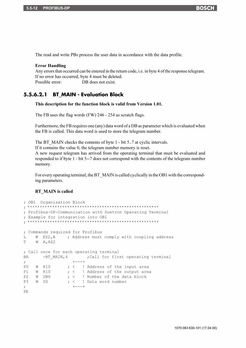
1070 083 630-101 (17.04.00)
PROFIBUS-DP5.5-12
The read and write PBs process the user data in accordance with the data profile.
Error HandlingAny errors that occurred can be entered in the return code, i.e. in byte 4 of the response telegram.If no error has occurred, byte 4 must be deleted.Possible error: DB does not exist.
5.5.6.2.1 BT_MAIN - Evaluation Block
This description for the function block is valid from Version 1.01.
The FB uses the flag words (FW) 246 - 254 as scratch flags.
Furthermore, the FB requires one (any) data word of a DB as parameter which is evaluated whenthe FB is called. This data word is used to store the telegram number.
The BT_MAIN checks the contents of byte 1 - bit 5..7 at cyclic intervals.If it contains the value 0, the telegram number memory is reset.A new request telegram has arrived from the operating terminal that must be evaluated andresponded to if byte 1 - bit 5--7 does not correspond with the contents of the telegram numbermemory.
For every operating terminal, the BT_MAIN is called cyclically in the OB1 with the correspond-ing parameters.
BT_MAIN is called
; OB1 Organization Block; *****************************************************; Profibus-DP-Communication with Suetron Operating Terminal; Example for integration into OB1; *****************************************************
; Commands required for ProfibusL W EZ2,A ; Address must comply with coupling addressT W A,AZ2
; Call once for each operating terminalBA -BT_MAIN,4 ;Call for first operating terminal; +---+P0 W K10 ; < ! Address of the input areaP1 W K10 ; < ! Address of the output areaP2 W DB0 ; < ! Number of the data blockP3 W D0 ; < ! Data word number; +---+PE

PROFIBUS-DP 5.5-13
1070 083 630-101 (17.04.00)
/000
-010
8/B
osch
_T_e
ng_V
13_3
0050
50Q
K0
Structure of the BT_MAIN
Byte 1 .. 4
EZ10
Terminal 1 Terminal 2
EZ20
0x00BT_MAIN
Byte 1 .. 4
AZ10 AZ20
EZ-Area Inputs
Scratch Flags
Scratch Flags
AZ-Area Outputs
MB253MB252MB251MB250
MB253MB252MB251MB250
5.5.6.2.2 BT_READ - Reading from Data Block
This description for the function block is valid from Version 1.01.
The FB interpretes the offset in bytes 3 and 4 in the telegram as follows:Byte 4 contains the data block number,Byte 3 contains the data word number inside the DB (0...255).
The FB doubles the data word number to a even numbered byte number in the DB.Bit 0 in the 2nd byte is interpreted as a byte number at a byte access in word addresses.0 = even address - low byte1 = odd address - high byte
The numbering of the bytes in the telegram can you read in Chapter 5.5.3.1.
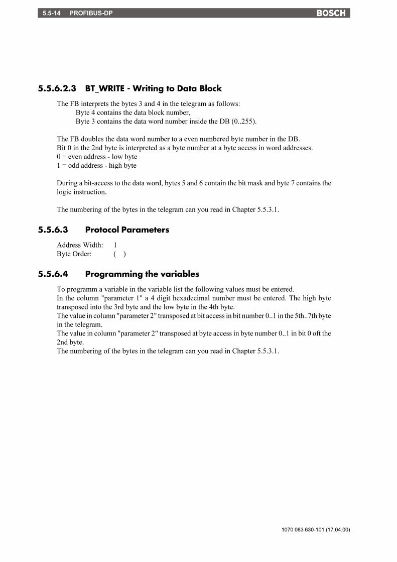
1070 083 630-101 (17.04.00)
PROFIBUS-DP5.5-14
5.5.6.2.3 BT_WRITE - Writing to Data Block
The FB interprets the bytes 3 and 4 in the telegram as follows:Byte 4 contains the data block number,Byte 3 contains the data word number inside the DB (0..255).
The FB doubles the data word number to a even numbered byte number in the DB.Bit 0 in the 2nd byte is interpreted as a byte number at a byte access in word addresses.0 = even address - low byte1 = odd address - high byte
During a bit-access to the data word, bytes 5 and 6 contain the bit mask and byte 7 contains thelogic instruction.
The numbering of the bytes in the telegram can you read in Chapter 5.5.3.1.
5.5.6.3 Protocol Parameters
Address Width: 1Byte Order: ( )
5.5.6.4 Programming the variables
To programm a variable in the variable list the following values must be entered.In the column "parameter 1" a 4 digit hexadecimal number must be entered. The high bytetransposed into the 3rd byte and the low byte in the 4th byte.The value in column "parameter 2" transposed at bit access in bit number 0..1 in the 5th..7th bytein the telegram.The value in column "parameter 2" transposed at byte access in byte number 0..1 in bit 0 oft the2nd byte.The numbering of the bytes in the telegram can you read in Chapter 5.5.3.1.

PROFIBUS-DP 5.5-15
1070 083 630-101 (17.04.00)
/000
-010
8/B
osch
_T_e
ng_V
13_3
0050
50Q
K0
Example of variable list:
Inputs in the variable list Access to addresses in the PLCVariable Access Variable Bit PLC access PLC addressname number numberVar1 DW 124BH 0 Double word DB18 D150 to D153Var2 W 124BH 0 Word DB18 D150 and D151Var3 BY 124BH 0 Byte DB18 D150Var4 BY 124BH 1 Byte DB18 D151Var5 B 124BH 5 Bit DB18 D150 bit 5Var6 B 124BH 13 Bit DB18 D151 bit 5
5.5.7 Protocol Parameters
5.5.7.1 Response Timeout
This parameter indicates the minimum intervals of time at which the operating terminal must bepolled by the master.The permissible range of values is 1ms... 65535 ms. The default value is 1000ms.
5.5.7.2 Communication Set-up Delay
This parameter indicates the period of time after which the operating terminal must be polled bythe master for the first time.The permissible range of values is 1000 ... 65535 ms. The default value is 5000ms.
5.5.7.3 Station Number
Any station number between 3 and 124 can be selected. The default value is station number 3.
5.5.7.4 Telegram Length
Can be set to a value between 8 and 32 bytes. The setting must comply with the configurationof the master module. The default value is 20 bytes.
5.5.7.5 Floating Point Format
With the value 0, the 4 byte number is interpreted in accordance with the Siemens format forfloating point numbers.With the value 1, the 4 byte number is interpreted in accordance with the IEEE format.
5.5.7.6 Byte-Order for Word and Double Word
High-low can selected for byte-order, otherwise the byte-order is selected by the TS-software.
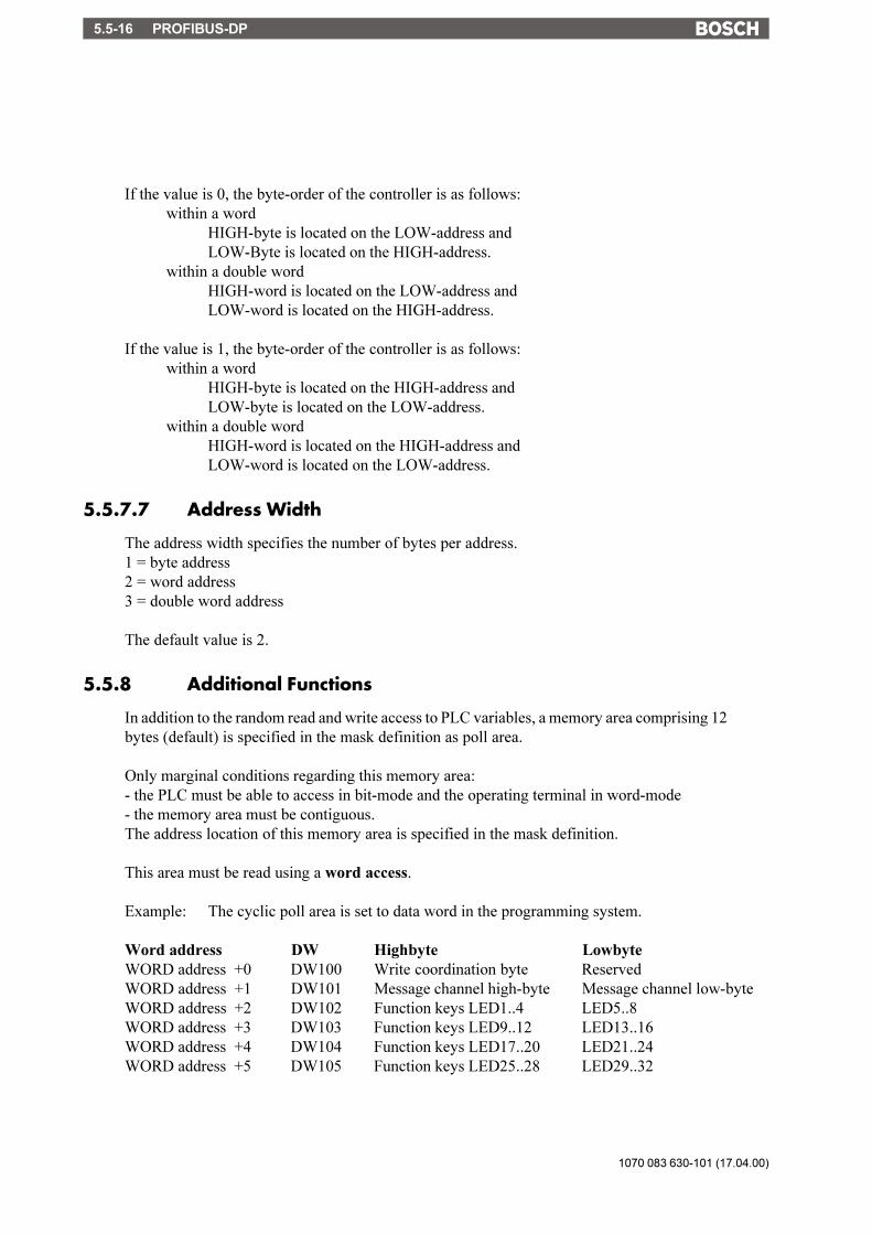
1070 083 630-101 (17.04.00)
PROFIBUS-DP5.5-16
If the value is 0, the byte-order of the controller is as follows:within a word
HIGH-byte is located on the LOW-address andLOW-Byte is located on the HIGH-address.
within a double wordHIGH-word is located on the LOW-address andLOW-word is located on the HIGH-address.
If the value is 1, the byte-order of the controller is as follows:within a word
HIGH-byte is located on the HIGH-address andLOW-byte is located on the LOW-address.
within a double wordHIGH-word is located on the HIGH-address andLOW-word is located on the LOW-address.
5.5.7.7 Address Width
The address width specifies the number of bytes per address.1 = byte address2 = word address3 = double word address
The default value is 2.
5.5.8 Additional Functions
In addition to the random read and write access to PLC variables, a memory area comprising 12bytes (default) is specified in the mask definition as poll area.
Only marginal conditions regarding this memory area:- the PLC must be able to access in bit-mode and the operating terminal in word-mode- the memory area must be contiguous.The address location of this memory area is specified in the mask definition.
This area must be read using a word access.
Example: The cyclic poll area is set to data word in the programming system.
Word address DW Highbyte LowbyteWORD address +0 DW100 Write coordination byte ReservedWORD address +1 DW101 Message channel high-byte Message channel low-byteWORD address +2 DW102 Function keys LED1..4 LED5..8WORD address +3 DW103 Function keys LED9..12 LED13..16WORD address +4 DW104 Function keys LED17..20 LED21..24WORD address +5 DW105 Function keys LED25..28 LED29..32

PROFIBUS-DP 5.5-17
1070 083 630-101 (17.04.00)
/000
-010
8/B
osch
_T_e
ng_V
13_3
0050
50Q
K0
5.5.9 Physical Interfacing
The interface complies with the standard specifications for Profibus-DP.
Assignment:
Pin Designation Function1 nc not connected2 nc not connected3 RxD/TxD-P Transmit / Receive Data -P4 CNTR-P *1) Control signal (Control-P)5 DGND *2) Data Reference Potential6 VP *3) Power Supply Plus7 nc not connected8 RxD/TxD-N Transmit / Receive Data -N9 CNTR-N Control signal (Control-N)Housing Shield Shield / Protective Ground
*1) Complies with the TTL-signal*2) Internally connected with the Shield / Protective Ground*3) +5V ±5% Output to supply a bus termination; maximum current is 10 mA.

1070 083 630-101 (17.04.00)
PROFIBUS-DP5.5-18
5.5.9.1 Connecting Cable
RXD/TXD - P
RXD/TXD - N
DGND
RXD/TXD - P
DGND
RXD/TXD - N
3
5
8
3
5
8
Protective Ground Protective Ground
Terminal Bus
If the wiring is performed in accordance with the figure shown above, the potential differencebetween the data reference potential DGND of all connections is not allowed to exceed+/- 7 Volts. Circulating currents through the shield of the bus cable are not allowed. If this cannot be ensured, provisions must be made for a potential equalization.
Principally, all cable types specified in EN 50170 as cable type A can be used.This allows the following cable lengths (depending on the baud rate):
Baud Rate (bps) Cable Length (m)9 600 1200
19 200 120093 750 1200
187 500 1000500 000 400
1 500 000 20012 000 000 100

PROFIBUS-DP 5.5-19
1070 083 630-101 (17.04.00)
/000
-010
8/B
osch
_T_e
ng_V
13_3
0050
50Q
K0
5.5.10 Error Messages
Code 1Subcode
1 E_SLAVE_NOT_READY ..................................... Slave not ready2 E_PROTOKOL ....................................................... Sequence of the packets3 E_FRAME............................................................... Protocol frame error4 E_TIMEOUT .......................................................... Timeout error5 E_CRC_BCC .......................................................... CRC error6 E_PARITIY ............................................................. Parity error7 E_SEND_ABORT .................................................. Send process aborted8 R_REC_ABORT ..................................................... Receive process aborted9 E_BUF_SIZE .......................................................... Insufficient cyclic buffer10 E_NO_DEFINE ...................................................... No cyclic data defned12 E_DEFINE .............................................................. Cyclic data already defined15 E_NO_PROTOCOL ............................................... Selected protocol is not
supported16 E_OVERRUN ......................................................... Receive overrun
40 E_SYS_ADDRESS ................................................. Undefined system variable
Code 50 Error during initialisation of the SPC3Subcode
1 IO_LENGTH_ERROR ........................................... Buffer too large2 INIT_ERROR...... No Initialisation of SPC34 MEM_FREE_ERROR ............................................ No memory available for
message buffer
Code 60 E_CONFIG_ERROR ........................................................ No configuration of master61 E_CONFIG_INPUT_LENGTH ........................................ Input-length invalid62 E_CONFIG_OUTPUT_LENGTH .................................... Output-length invalid63 E_CONFIG_FAULT ......................................................... Faulty configuration data.
New parameterizationnecessary
64 E_CONFIG_UPDATE ...................................................... Protocol chip needs configu-ration update. New pa-rameterization necessary
65 E_GO_OFFLINE .............................................................. No communication overprotocol chip. New pa-rameterization necessary
66 E_MAC_RESET ............................................................... Reset of protocol chip. Newparameterization necessary
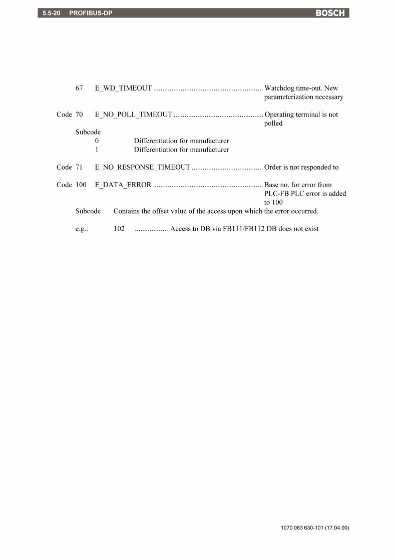
1070 083 630-101 (17.04.00)
PROFIBUS-DP5.5-20
67 E_WD_TIMEOUT ............................................................ Watchdog time-out. Newparameterization necessary
Code 70 E_NO_POLL_TIMEOUT ................................................. Operating terminal is notpolled
Subcode0 Differentiation for manufacturer1 Differentiation for manufacturer
Code 71 E_NO_RESPONSE_TIMEOUT ....................................... Order is not responded to
Code 100 E_DATA_ERROR ............................................................ Base no. for error fromPLC-FB PLC error is addedto 100
Subcode Contains the offset value of the access upon which the error occurred.
e.g.: 102 .................. Access to DB via FB111/FB112 DB does not exist

PROFIBUS-DP 5.5-21
1070 083 630-101 (17.04.00)
/000
-010
8/B
osch
_T_e
ng_V
13_3
0050
50Q
K0
5.5.11 Device-Master-Data-File
;====================================================================;=== ===;=== Fa. Sütron electronic GmbH ===;=== Kurze Straße 29 ===;=== 70794 Filderstadt ===;=== Tel.: 0711 / 77098-0 ===;=== Your contact: W. Ebinger, Extention 23 ===;=== ===;====================================================================;=== ===;=== Device-Master-Data-File: SUET081A.GSD ===;=== ===;=== Revision Level: GV1.0 - 15 July 1996 ===;=== ===;====================================================================;=== ===;=== Bus station, connecting an operating terminal ===;=== of the BT-series ===;=== ===;====================================================================;=== ===;=== Attention: ===;=== ================== ===;=== Improper modification of the parameters may lead to ===:=== an undefined system behaviour of the Profibus-DP-bus ===;=== and is done at one's own risk. ===;=== ===;====================================================================;====================================================================;#Profibus_DP;;********************************************************************; General Data;********************************************************************;; DP-Device TypeStation_Type = 0;; Name of the ManufacturerVendor_Name = "Suetron electronic, Filderstadt";; Name of the DeviceModel_Name = "BT-Serie";; Revision Level of the DP-DeviceRevision = "1.0";; Version Identifier of the DP-Device

1070 083 630-101 (17.04.00)
PROFIBUS-DP5.5-22
Revision_Number = 0x01;; Type NumberIdent_Number = 0x081A;; Release of the HardwareHardware_Release = "SWV1.0";; Release of the SoftwareSoftware_Release = "HWV1.0";; Protocol IdentifierProtocol_Ident = 0;; Supported Baud Rates9.6_supp = 119.2_supp = 193.75_supp = 1187.5_supp = 1500_supp = 11.5M_supp = 13M_supp = 16M_supp = 112M_supp = 1;; Maximum Protocol Processing TimeMaxTsdr_9.6 = 11MaxTsdr_19.2 = 11MaxTsdr_93.75= 11MaxTsdr_187.5 = 11MaxTsdr_500 = 11MaxTsdr_1.5M = 11MaxTsdr_3M = 11MaxTsdr_6M = 25MaxTsdr_12M = 50;;Level of the Repeater Control Signal CNTR-PRepeater_Ctrl_Sig = 2;;====================================================================; Specific Data of the Bus Station;====================================================================;; Automatic Recognition of the Baud RateAuto_Baud_supp = 1;; Type of Bus Station (modular or compact)Modular_Station = 1;; Maximum Number of Modules of a Modular Bus StationMax_Module = 1

PROFIBUS-DP 5.5-23
1070 083 630-101 (17.04.00)
/000
-010
8/B
osch
_T_e
ng_V
13_3
0050
50Q
K0
;; Maximum Length of the Input Data of the Bus Station in BytesMax_Input_Len = 32;; Maximum Length of the Output Data of the Bus Station in BytesMax_Output_Len = 32;; Maximum Length of the Input- and Output Data (Sum) in BytesMax_Data_Len = 64;; Module Identifier;Module = "8 Byte Daten E/A" 0x37EndModule;Module = "10 Byte Daten E/A" 0x39EndModule;Module = "12 Byte Daten E/A" 0x3BEndModule;Module = "14 Byte Daten E/A" 0x3DEndModule;Module = "16 Byte Daten E/A" 0x3FEndModule;Module = "4 Worte Daten E/A" 0x73EndModule;Module = "6 Worte Daten E/A" 0x75EndModule;Module = "8 Worte Daten E/A" 0x77EndModule;Module = "10 Worte Daten E/A" 0x79EndModule;Module = "12 Worte Daten E/A" 0x7BEndModule;Module = "14 Worte Daten E/A" 0x7DEndModule;Module = "16 Worte Daten E/A" 0x7FEndModule;; DP-Device does not support the Freeze-ModeFreeze_Mode_supp = 0;

1070 083 630-101 (17.04.00)
PROFIBUS-DP5.5-24
; DP-Device does not support the Sync-ModeSync_Mode_supp = 0;; DP-Device does not Support the Bus Station AddressingSet_Slave_Add_supp = 0;; Minimum Interval between two Accesses to the Bus StationMin_Slave_Intervall = 100;; Maximum Length of the Diagnosis Information (DiagData)Max_Diag_Data_Len = 12;; Class of Function: I/OSlave_Family = 3;============ End of Device-Master-Data-File===========================

Index 6-1
1070 083 630-101 (17.04.00)
/000
-010
8/B
osch
_T_e
ng_V
13_3
0060
00Q
K0
Symbole
3964 Procedure 5.1-243964/RK512 Protocol 5.1-3
A
Access Authorization 3-11Acknowledging Messages 3-113Activating the Download Function with the Hard-
ware 3-150Activating the Download Function with the Soft-
ware 3-150Additional Functions
byte-structured memory mapping 5.1-7word-structured memory mapping 5.1-8
Alphanumerical Editor 3-76Application Memory 3-149Application Programming 3-140Assigning Message Numbers 3-108Authorization Levels 3-11Automatic Download Function 3-151
B
Background Images 3-85Bosch-PLC Connection 5.5-11Bosch-Specific Error Message 5.2-10Bosch-specific error message 5.4-12
C
Character Set, Character Attributes 4-8Communication in the Standard Mode 3-9Communication in the Transparent Mode 4-5Configuration Mask 3-108Configuring the System 3-140Connecting Cable RS232
EBERLE PLS 514 - K43 5.1-22Siemens CP523/525 5.1-12
Connecting Cable RS485Helmholz SAS 523/525 5.1-16Siemens CP524/525 5.1-14VIPA BGM79-43 5.1-18
Connecting Cable TTY / 20 mABosch CL151 5.4-10Bosch PLC 5.4-7Bosch PU 5.2-8EBERLE PLS 514 - K4 5.1-20Siemens CP523/525 5.1-10
Connecting Cable Universal Interface
6 Index
RS232Bosch CL150 5.4-9EBERLE PLS 514 - K43 5.1-23
RS232cSiemens CP523/525 5.1-13
RS485Helmholz SAS 523/525 5.1-17Siemens CP524/525 5.1-15VIPA BGM79-43 5.1-19
TTY / 20 mABosch CL151 5.4-11Bosch PLC 5.4-8Bosch PU 5.2-9EBERLE PLS 514 - K43 5.1-21Siemens CP523/525 5.1-11
Control Characters 4-10Control Codes 3-136Control Keys as Function Keys 3-120Control Sequences 4-11Coordination Flag 5.1-26, 5.2-5, 5.4-4Cyclic Poll Area 3-132
byte-oriented 3-132word-oriented 3-134
Cyclic Variables 3-137
D
Data Records 1-9Data Set
copying a 3-88deleting a 3-89modifying a 3-89printing 3-95selecting a 3-88transfer to / from a controller 3-90triggering the printout of 3-136
Data Type Structure 5.1-5, 5.2-5, 5.4-4Data Types 5.1-6, 5.2-5Decimal Number Editor 3-74Default Help Text 3-117Definition Format 3-139DIN-Meßbus 5.3-3DIP Switch S4 3-147, 3-150Direct Selection of the Message Mask 3-111Direct Selector Keys 1-8, 3-118Display 4-8Documentation on TSwin, Creating 3-146Download 3-149Download Cable 3-147, 3-152

1070 083 630-101 (17.04.00)
Index6-2
Download with Windows 3-149Downloading the User Description 3-147
E
Editing Field 1-7Editing Mode 1-7Editors 1-7, 3-72Erasing the Message Memory 3-114Error Message 4-4, 4-14Error Messages 3-102, 3-148, 5.1-39, 5.2-10, 5.4-
12!!!!! ERROR !!!!! 3-104!!!!! WARNING!!!!! 3-103ADDRESS ERROR 3-102BYTECOUNT OVERFLOW 3-103CHECKSUM ERROR 3-103COMMUNICATION ERROR 3-102DATASET STORAGE FAILURE 3-107DIFFERENT DRIV VERS 3-103DIFFERENT MASK VERS 3-103DOWNLOAD 3-104ERASE FLASH EPROM 3-104FATAL ERROR 3-106FIRMWARE NOT CONFORM 3-107FLASH CHECKSUM ERROR 3-106FLASH IS ERASED 3-104FLASH MEMORY FAILURE 3-102FLASH NOT ERASEABLE 3-106FORMAT ERROR 3-103INITIALIZING MESSAGE BUFFER 3-104KEYBOARD ERROR 3-104MEMORY IS FLASH XXXXK 3-106NO FLASH EPROM 3-106TERMINAL-TYP IS XXXX 3-106TURN POWER OFF 3-103UNEXPECTED INTERRUPT 3-106WRONG S3-FILE 3-106
Error Messages, DIN-Meßbus 5.3-14Event-Controlled 3-117External Data Release 3-80External Mask Selection 3-11External Messages 3-107
F
Firmware 3-146Floating Point Number Editor 3-76Formatted Output of Variables 3-24Formula for Scaling Input Values 3-36Formula for Scaling the Output of Variables 3-26Full-page Message Output 3-113Function Block for Siemens 115 U 5.1-30
Function Keys 1-8, 3-118Function Keys Controlling Parallel Outputs 3-120Function Keys of the Controller 3-119Function without the Setup Mask 3-17Functional Feedback 1-8
G
Gateway as Bus Master 5.3-3Getting Started with Programming 3-144Graphical Objects 3-84Graphics 3-84Graphics on Operating Terminals 3-85
H
Help Key 3-72, 3-73Help System 3-117Help Text 1-7
for input variables 3-37for masks 3-118for the message mask 3-118for variables 3-118
Hexadecimal Editor 3-76Hierarchical Mask Structure in TSdos 3-9How to Operate TSdos 3-143
I
I/O Mask 3-19Identification Stripes 1-8Image of the Date and Time 3-127Image of the LEDs 3-134Image of the Mask Number 3-126Image of the Mode Selector Switch 3-126Image of the Status Messages 3-116Images 3-84Information about the Serial Message System 3-114Input Plausibility Check 3-83Input Variable
Counter 3-36Timer 3-36
Input Variables 3-35Interface Parameters 4-4
standard mode 3-137transparent mode 4-5
Interface Parameters of the Communications Mod-ule 5.1-4
Interface SER1 for DIN-Meßbus -Slave 5.3-11Interface SER1 for PLC-Interfacing 5.3-7Interface SER2 for DIN-Meßbus - Master 5.3-7Interfacing Profibus-DP 5.5-3Interfacing via BUEP19 5.2-3Interfacing via BUEP19E 5.4-3

Index 6-3
1070 083 630-101 (17.04.00)
/000
-010
8/B
osch
_T_e
ng_V
13_3
0060
00Q
K0
Internal Messages 3-97
K
KeyData Release 3-72
Key Codes 4-9Key Functions
editor for coded text 3-77in the I/O mask 3-20in the message mask 3-21in the node mask 3-18in the status message mask 3-23
Key Functions in the Alphanumerical Editor 3-76Key Functions in the BCD-number Editor 3-75Key Functions in the Hexadecimal Editor 3-76Key Functions in the Numerical Editor 3-74Keys 4-8
L
LED Codes 4-11Loading a User Description 3-149Logical Part of the Procedure 5.1-24
M
Marginal Conditions 3-132Mask Number 3-126Mask Parameters 3-15Mask Types 3-15Masks 3-15Master Password 3-13Memory Requirements for Storing Data Sets 3-96Message Header 5.1-25Message Mask 3-20, 3-108, 3-110Message Priority 3-109Message Request of Data 5.1-25Message Texts 3-108Message Transmission of Data 5.1-27Messages 1-10Messages Directly to a Logging Printer 3-114Messages, Sorted 3-109Modified Data 3-82Multilingual Projects 3-144
N
Node Mask 3-18Number of Bytes for Status Messages 3-115Number of Languages 3-144
O
One-time Output Variables/Cyclic Output Vari-
ables 3-24Operating Concept 1-3, 3-9Operating Modes 1-4, 2-3Operating Terminals 1-3Optimizing 3-146Output Formats for Messages 3-111Output Variables 3-24
P
Parallel Message System 3-115Parallel Outputs 3-125Parameters Interface SER 5.4-4Parameters Interface SER1 5.1-4Parameters Interface X2 5.2-4Password 3-12Password Editor 3-77Password Functionality 3-14Password Management 3-14Password Mask 3-14, 3-17
system mask 3-16Password Protection 1-6, 3-11
access level 3-11authorization level 3-11reactivating the 3-14setup mask 3-13, 3-16startup mask 3-13view level 3-11
Passwords 1-6Physical Interfacing 5.1-8Plausibility 3-72Plausibility Check
input variable 3-36PLC Configuration 5.1-4PLC-Handshake 3-81Polling Time 3-135Post-decimal Places 3-24Print Files, TSdos 3-145Printing the Message Memory 3-110Processing Recipes and Data Sets 3-88Programming Software 3-141Programming System 1-11Project Back-up 3-146Project Definition 3-144Project Documentation 3-145Protocol 3964R - Restrictions 5.1-29Protocol-specific Variable List 3-138
R
Range of Values 3-23, 3-24Reaction Time 3-120

1070 083 630-101 (17.04.00)
Index6-4
Read Coordination Byte 3-128data set download active 3-129editing request bit 3-128editing status bit 3-128liveness flag 3-129refresh request bit 3-129
Receive Buffer 4-5Recipe, Selecting a 3-88Recipes 1-9, 3-86Refresh Intervals 3-146Refreshing One-time Output Data 3-82Refreshing the Message System 3-137Representation of Output Variables 3-26Representation Type
alphanumerical 3-29bar 3-32
Representation typebinary number 3-32coded image 3-30coded text 3-29curve 3-34decimal number 3-27
BCD-number 3-29Counter 3-28Standard 3-27Timer 3-27
floating point number 3-31hexadecimal number 3-31selection field 3-35selection image 3-30selection text 3-29
Representation with leading zeros 3-26Response Message 5.1-27Running time meter 3-124
reset byte 3-124
S
Scaled Output of Variables 3-25Scaled Variable 1-10Screen Saver 3-126Selection Image Editor (Coded Image) 3-77Selection Text Editor (Coded Text) 3-77Serial Message Channel 3-135Serial Message System 3-113Setting the Clock in the Operating Terminal 3-136Setting the Operating Mode 2-3, 3-7SETUP DATA 4-6Setup Mask 3-16Setup Menu 4-5Setup Menu BT5N 4-7Siemens-PLC Connection 5.5-7
Simulation without the Controller 3-153Size of the Message Buffer 3-108Size of the Poll Area 3-135Soft Keys 3-119Special Features of the Protocol 3964R 5.1-28Special Simatic-Data Formats 5.1-6Standard Mode 3-7Start-up Processes 4-4Startup Mask 3-17Startup Process 3-8Startup Process without a Valid User Description 3-8Status LED
data release 3-80Status LEDs in the Function Keys 3-120Status Message Mask 3-22Status Message mask 3-110Status Messages 3-115Structure of a Data Set File 3-93Structure of a Recipe 3-87Structure of an External Message 3-108Symbolic Name 3-126System Masks 3-15
main mask 3-16setup mask 3-16startup mask 3-16
System Message(floating point) number invalid 3-100data set active 3-100data set download 3-101data set file error 3-100data set format 3-100data set memory full 3-100data set protected 3-100data set transfer 3-100data set unknown 3-100editing mode active 3-100illegal data set 3-100interface in use 3-99invalid mask no 3-99invalid message no 3-99invalid password 3-99loop-through active 3-101message buffer full 3-99message overflow 3-99new message 3-99no data set address 3-101overvoltage 3-100password missing 3-100password unchanged 3-100print log invalid 3-99recipe unknown 3-101

Index 6-5
1070 083 630-101 (17.04.00)
/000
-010
8/B
osch
_T_e
ng_V
13_3
0060
00Q
K0
replace battery 3-99suppressing the output 3-102value too large 3-98value too small 3-99wrong format 3-98
System Messages 1-11, 3-97System Numbers 3-97System Parameters 3-121
data set transfer 3-123gateway 3-123general parameters 3-122message system 3-122parallel outputs 3-123password management 3-123poll area 3-122printers interface 3-123running time meter 3-122terminal clock 3-122variant buffer 3-123
System Variables 3-38basic functions 3-38
Boot 3-39ComVersion 3-39handshake 3-135hard copy 3-146IntEraseEprom 3-38LCDBackground 3-40LCDBackLight 3-40LCDContrast 3-39MainVersion 3-38OsLanguage 3-40TurnOnTemp 3-40UserVersion 3-39
Communication Area X2 3-41communication area X2
ComBaudrateA 3-42ComDataLenA 3-41ComDefaultA 3-42ComHandshakeA 3-42ComParityA 3-41ComSlaveNr 3-43ComStopBitsA 3-41ComTimeout 3-42
communication area x2ComRetryTimeout 3-43
communication area X3 3-44ComBaudrateB 3-45ComDataLenB 3-44ComHandshakeB 3-45ComParityB 3-45ComStopBitsB 3-45
editors 3-71EditEnter 3-71EditInvers 3-71StatePerm 3-71
error statistics interface X2 3-43ComErrorTab 3-44ComFrameCount 3-43ComOverrunCount 3-43ComParityCount 3-43ComStatisticsTab 3-44ComSubcodeTab 3-44
help 3-71Message 3-72QuitMessage 3-72StateHelp 3-71
loadable font 3-69ChrsetName 3-69
loop-through operation 3-69Pg2Sps 3-69Pg2SpsState 3-69
maintenance 3-70Break 3-70LCDADCInput 3-70LCDADCOutput 3-70User1 3-70User2 3-70User3 3-70User4 3-70User5 3-70
menu control / keys 3-54HardCopy 3-54Key0 3-59Key1 3-59Key2 3-60Key3 3-60Key4 3-60Key5 3-60Key6 3-60Key7 3-61Key8 3-61Key9 3-61KeyClear 3-59KeyCursDown 3-58KeyCursLeft 3-58KeyCursRight 3-58KeyCursUp 3-58KeyDot 3-59KeyEdit 3-62KeyEnter 3-62KeyHelp 3-59KeyHome 3-58

1070 083 630-101 (17.04.00)
Index6-6
KeyMinus 3-61KeyPlus 3-61NewMask 3-54Shift 3-56ShiftCase 3-57TabLeft 3-55TabPgDn 3-55TabPgUp 3-55TabRight 3-55VarTablenR0 3-54VarTablenR1 3-54
parallel message system 3-50RepmanSortCritP 3-50RepoutAnzYearP 3-51RepoutDateP 3-51RepoutNrP 3-50RepoutRepTextP 3-51RepoutRepTextP21 3-52RepoutRepTextP41 3-52RepoutRepTextP61 3-52RepoutTimeP 3-51
password 3-62ChangePasswd 3-62FlashPasswd 3-63MskchgPasswd 3-62MskchgResPasswd 3-62Passwdlnactive 3-63
password protectionedit level 3-11
printer control 3-52BlockPrint 3-53BlockPrintLong 3-53PrintAllRep 3-53PrintAllState 3-53StopPrint 3-52
real-time clock 3-46RTCDateFmt 3-47RTCDay 3-46RTCDayofWeek 3-47RTCHour 3-46RTCMin 3-46RTCMonth 3-47RTCSec 3-46RTCYear 3-47RTCYear2000 3-47
recipes 3-63ActDSName 3-64DestDSNr 3-64DSCopy 3-64DSDelete 3-64DSDnloadBreak 3-65
DSDnloadState 3-65DSDownload 3-65LoadDSName 3-65RestoreLineNr 3-67RestoreState 3-66RezPrintState 3-67SaveState 3-66SelectDSName 3-63SelectDSNr 3-63SelectRezeptNr 3-65StartRestore 3-66StartRezPrint 3-67StartSave 3-66StartUpload 3-67UploadDSNr 3-68UploadState 3-68
running time meter 3-68Counter1 3-68Counter2 3-68Counter3 3-68Counter4 3-68Counter5 3-68Counter6 3-68Counter7 3-68Counter8 3-68
serial message system 3-48ClearRepBuf 3-48RepmanRepPrint 3-48RepmanSortCrit 3-48RepoutAnzYear 3-49RepoutDate 3-49RepoutNr 3-48RepoutRepText 3-49RepoutRepText21 3-49RepoutRepText41 3-50RepoutRepText61 3-50RepoutTime 3-49
T
Table Editor 3-77Terminal Clock 3-126TesiMod - 3964/RK512 Interfacing 5.1-3TesiMod Message System 3-97TesiMod Transparent Mode 4-3Time-Controlled 3-117Transfer from a Controller 3-91Transfer from a PC 3-93Transfer to a Controller 3-90Transfer to a PC 3-93Transferring Data Sets from Controller to Termi-
nal 3-136, 3-137

Index 6-7
1070 083 630-101 (17.04.00)
/000
-010
8/B
osch
_T_e
ng_V
13_3
0060
00Q
K0
Transferring Data Sets from Terminal to Control-ler 3-136
Transferring Data Sets to / from a PC 3-92Transmission Parameters 4-5Transmission Rate 3-146TSwin 3-141
U
User-Mode Switchstandard Mode 3-7transparent mode 4-3
V
Variable Definition 3-138Variable Formats 3-138Variable List 3-138Variable Type
ASCII 3-23bit 3-23byte 3-23Lword 3-23word 3-23
Variables 1-8, 3-23Variants of a Project 3-145Version Number 3-124
W
Write Coordination Byte 3-130data set download release 3-131external data release 3-130liveness flag 3-131refresh acknowledgement 3-130resetting the password 3-130
Z
Zooming Messages 3-112

1070 083 630-101 (17.04.00)
Index6-8

/000
-010
8/B
osch
_T_e
ng_V
13.3
0070
00Q
K0
1070 083 630-101 (17.04.00)
Appendix A A-1
A Appendix A
A.1 List of Accessories
Designation Length Order Number
Cable BT2/BT5/BT5N/BT20N <-> Bosch PLC (TTY/20mA) 3 metres 1070 917 855
Cable BT2/BT5/BT5N/BT20N <-> PC (Download) 3 metres 1070 917 856
Cable BT20 <-> Bosch PLC (TTY/20mA) 3 metres 1070 917 857
Cable BT20 <-> PC (Download) 3 metres 1070 917 858
Cable BT2/BT5N/BT20N <-> Bosch PLC (CL150-RS232c) 3 metres 1070 920 422
Cable BT2/BT5/BT5N/BT20N <-> Bosch PLC (CL151-TTY/20mA) 3 metres 1070 920 423

1070 083 630-101 (17.04.00)
Appendix AA-2
Bosch Automation Technology
We reserve the right to make technical alterations
Your concessionary
1070 083 630-101 (00.05) GB HB SP AT/PLS Printed in Germany
AustraliaRobert Bosch (Australia) Pty. Ltd.Head OfficeCnr. Centre - McNaughton RoadsP.O. Box 66AUS-3168 Clayton, VictoriaFax (03) 95 41 77 03
Great BritainRobert Bosch LimitedAutomation Technology DivisionMeridian SouthMeridian Business ParkGB-Braunstone Leicester LE3 2WYFax (01 16) 289 2878
CanadaRobert Bosch CorporationAutomation Technology Division6811 Century AvenueCAN-Mississauga, Ontario L5N 1R1Fax (905) 5 42-42 81
USARobert Bosch CorporationAutomation Technology DivisionFluid Power Products7505 Durand AvenueUSA-Racine, Wisconsin 53406Fax (414) 5 54-81 03
Robert Bosch CorporationAutomation Technology DivisionFactory Automation Products816 East Third StreetUSA-Buchanan, MI 49107Fax (616) 6 95-53 63
Robert Bosch CorporationAutomation Technology DivisionIndustrial Electronic Products40 Darling DriveUSA-Avon, CT 0 60 01-42 17Fax (860) 4 09-70 80
Robert Bosch GmbHGeschäftsbereichAutomationstechnikAntriebs- und SteuerungstechnikPostfach 11 62D-64701 ErbachFax +49 (0) 60 62 78-4 28
Related Documents