Lecture 3 Programming the 8051 Microcontroller Dr. Konstantinos Tatas

Welcome message from author
This document is posted to help you gain knowledge. Please leave a comment to let me know what you think about it! Share it to your friends and learn new things together.
Transcript
7/28/2019 Programming 8051 microcontroller
http://slidepdf.com/reader/full/programming-8051-microcontroller 1/121
Lecture 3
Programming the 8051 Microcontroller
Dr. Konstantinos Tatas
7/28/2019 Programming 8051 microcontroller
http://slidepdf.com/reader/full/programming-8051-microcontroller 2/121
ACOE343 - Embedded Real-Time Processor Systems -Frederick University
2
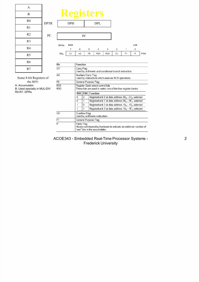
Registers A
B
R0
R1
R3
R4
R2
R5
R7
R6
DPH DPL
PC
DPTR
PC
Some 8051 16-bit Register
Some 8-bit Registers of
the 8051 A: Accumulator B: Used specially in MUL/DIVR0-R7: GPRs

7/28/2019 Programming 8051 microcontroller
http://slidepdf.com/reader/full/programming-8051-microcontroller 3/121
8051 Programming using
Assembly
7/28/2019 Programming 8051 microcontroller
http://slidepdf.com/reader/full/programming-8051-microcontroller 4/121
ACOE343 - Embedded Real-Time Processor Systems -Frederick University
4
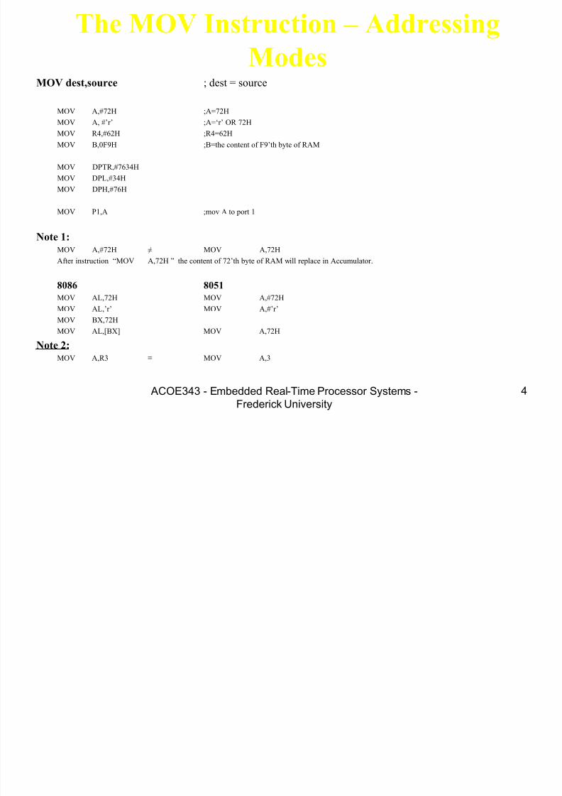
The MOV Instruction – Addressing
ModesMOV dest,source ; dest = source
MOV A,#72H ;A=72H
MOV A, #‟r‟ ;A=„r‟ OR 72H
MOV R4,#62H ;R4=62H
MOV B,0F9H ;B=the content of F9‟th byte of RAM
MOV DPTR,#7634H
MOV DPL,#34H
MOV DPH,#76H
MOV P1,A ;mov A to port 1
Note 1:MOV A,#72H ≠ MOV A,72H
After instruction “MOV A,72H ” the content of 72‟th byte of RAM will replace in Accumulator.
8086 8051
MOV AL,72H MOV A,#72H
MOV AL,‟r‟ MOV A,#‟r‟
MOV BX,72H
MOV AL,[BX] MOV A,72H
Note 2:MOV A,R3 ≡ MOV A,3
7/28/2019 Programming 8051 microcontroller
http://slidepdf.com/reader/full/programming-8051-microcontroller 5/121
ACOE343 - Embedded Real-Time Processor Systems -Frederick University
5
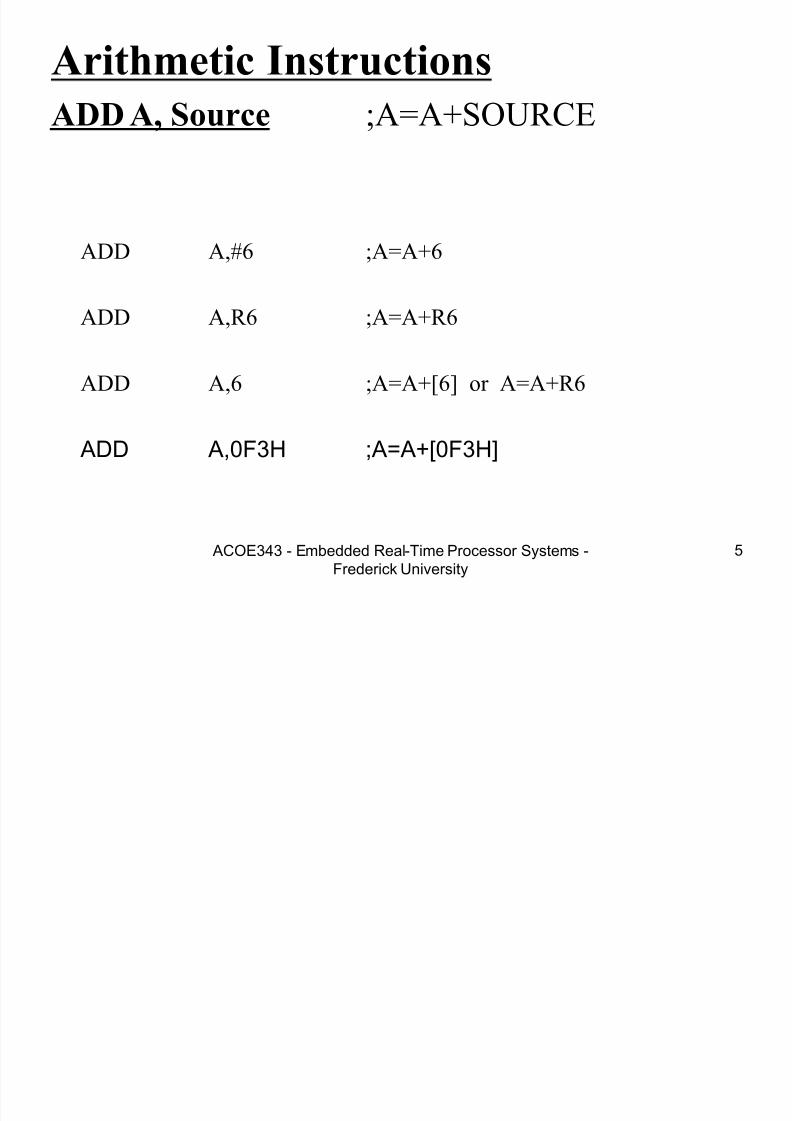
Arithmetic Instructions
ADD A, Source ;A=A+SOURCE
ADD A,#6 ;A=A+6
ADD A,R6 ;A=A+R6
ADD A,6 ;A=A+[6] or A=A+R6
ADD A,0F3H ;A=A+[0F3H]
7/28/2019 Programming 8051 microcontroller
http://slidepdf.com/reader/full/programming-8051-microcontroller 6/121
ACOE343 - Embedded Real-Time Processor Systems -Frederick University
6
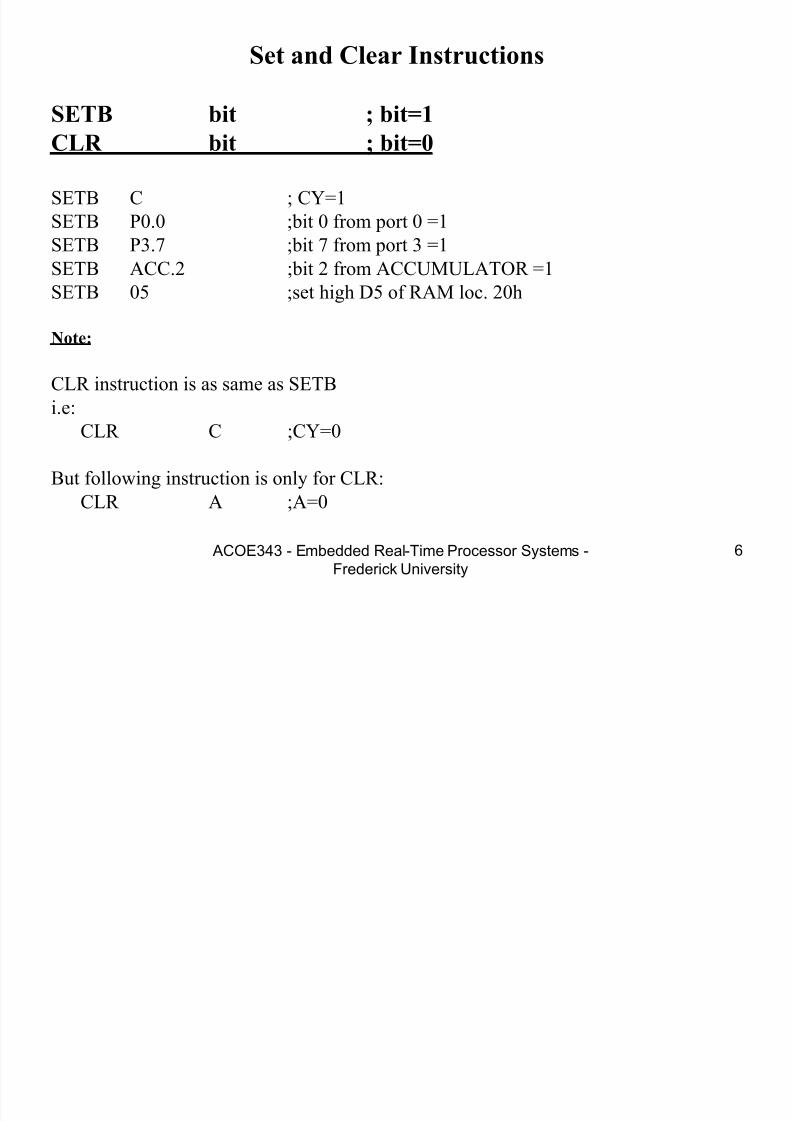
Set and Clear Instructions
SETB bit ; bit=1
CLR bit ; bit=0
SETB C ; CY=1
SETB P0.0 ;bit 0 from port 0 =1
SETB P3.7 ;bit 7 from port 3 =1
SETB ACC.2 ;bit 2 from ACCUMULATOR =1SETB 05 ;set high D5 of RAM loc. 20h
Note:
CLR instruction is as same as SETB
i.e:CLR C ;CY=0
But following instruction is only for CLR:
CLR A ;A=0

7/28/2019 Programming 8051 microcontroller
http://slidepdf.com/reader/full/programming-8051-microcontroller 7/121
ACOE343 - Embedded Real-Time Processor Systems -Frederick University
7
SUBB A,source ;A=A-source-CY
SETB C ;CY=1
SUBB A,R5 ;A=A-R5-1
ADC A,source ;A=A+source+CY
SETB C ;CY=1
ADC A,R5 ;A=A+R5+1
7/28/2019 Programming 8051 microcontroller
http://slidepdf.com/reader/full/programming-8051-microcontroller 8/121
ACOE343 - Embedded Real-Time Processor Systems -Frederick University
8
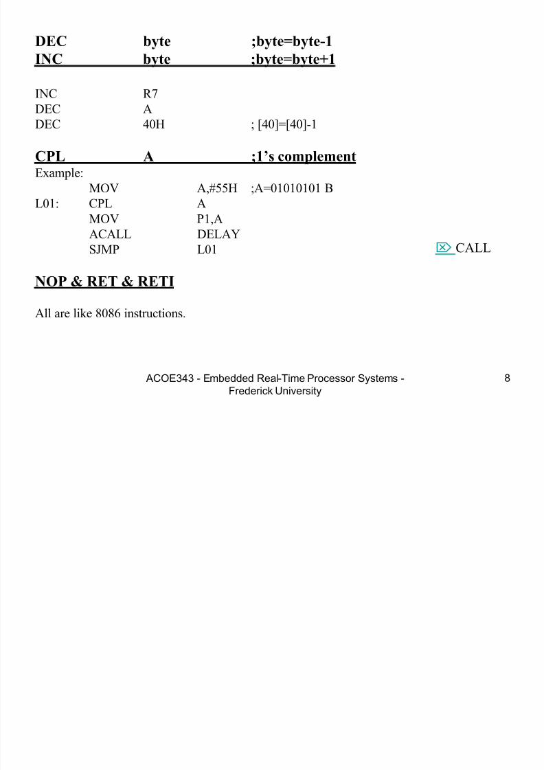
DEC byte ;byte=byte-1
INC byte ;byte=byte+1
INC R7DEC A
DEC 40H ; [40]=[40]-1
CPL A ;1’s complement Example:
MOV A,#55H ;A=01010101 BL01: CPL A
MOV P1,A
ACALL DELAY
SJMP L01
NOP & RET & RETI
All are like 8086 instructions.
CALL
7/28/2019 Programming 8051 microcontroller
http://slidepdf.com/reader/full/programming-8051-microcontroller 9/121
ACOE343 - Embedded Real-Time Processor Systems -Frederick University
9
Logic Instructions
ANL byte/bit
ORL byte/bit
XRL byte
EXAMPLE:
MOV R5,#89H
ANL R5,#08H
7/28/2019 Programming 8051 microcontroller
http://slidepdf.com/reader/full/programming-8051-microcontroller 10/121
ACOE343 - Embedded Real-Time Processor Systems -Frederick University
10
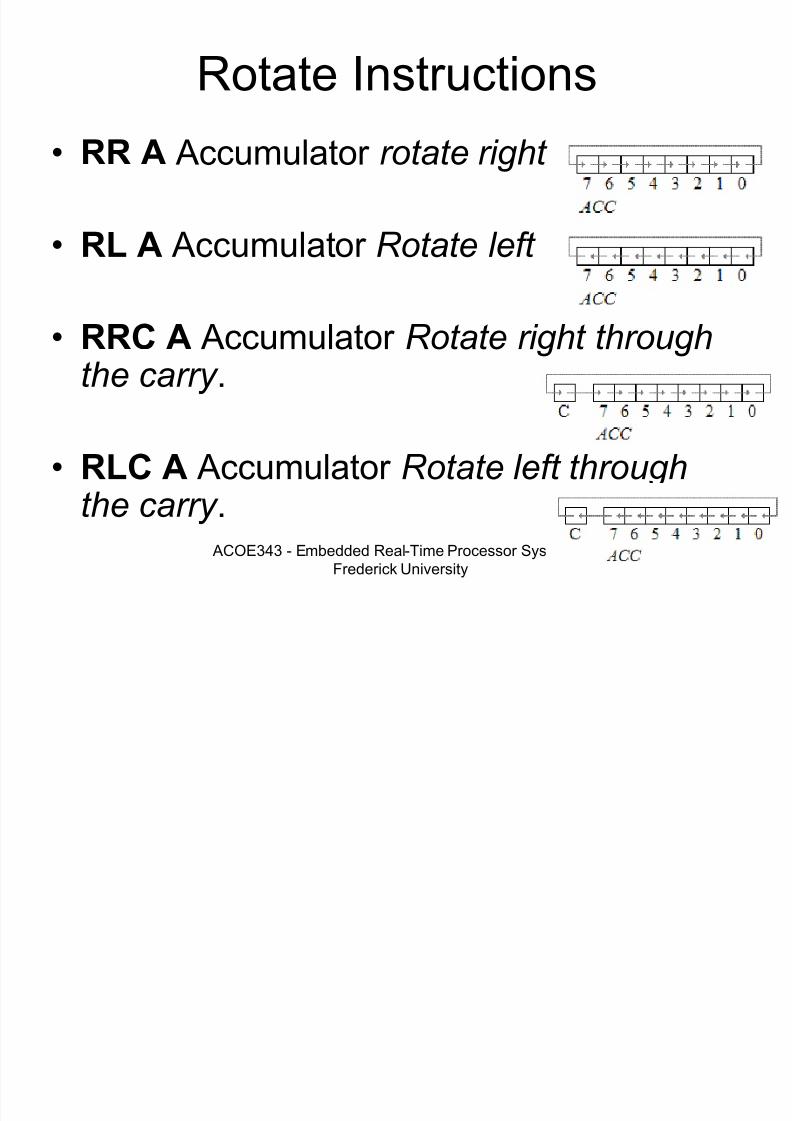
Rotate Instructions
• RR A Accumulator rotate right
• RL A Accumulator Rotate left
• RRC A Accumulator Rotate right throughthe carry .
• RLC A Accumulator Rotate left throughthe carry .

7/28/2019 Programming 8051 microcontroller
http://slidepdf.com/reader/full/programming-8051-microcontroller 11/121

7/28/2019 Programming 8051 microcontroller
http://slidepdf.com/reader/full/programming-8051-microcontroller 12/121
7/28/2019 Programming 8051 microcontroller
http://slidepdf.com/reader/full/programming-8051-microcontroller 13/121
ACOE343 - Embedded Real-Time Processor Systems -Frederick University
13
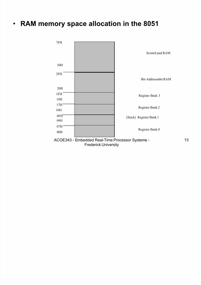
• RAM memory space allocation in the 8051
7FH
30H
2FH
20H
1FH
17H10H
0FH
07H
08H
18H
00HRegister Bank 0
(Stack) Register Bank 1
Register Bank 2
Register Bank 3
Bit-Addressable RAM
Scratch pad RAM

7/28/2019 Programming 8051 microcontroller
http://slidepdf.com/reader/full/programming-8051-microcontroller 14/121
ACOE343 - Embedded Real-Time Processor Systems -Frederick University
14
8051 Flag bits and the PSW register • PSW Register
CY AC F0 RS1 OVRS0 P--
CYPSW.7Carry flag
ACPSW.6 Auxiliary carry flag
--PSW.5 Available to the user for general purpose
RS1PSW.4 Register Bank selector bit 1
RS0PSW.3 Register Bank selector bit 0
OVPSW.2Overflow flag
--PSW.1User define bit PPSW.0 Parity flag Set/Reset odd/even parity
RS1 RS0 Register Bank Address
0 0 0 00H-07H
0 1 1 08H-0FH
1 0 2 10H-17H
1 1 3 18H-1FH
7/28/2019 Programming 8051 microcontroller
http://slidepdf.com/reader/full/programming-8051-microcontroller 15/121
ACOE343 - Embedded Real-Time Processor Systems -Frederick University
15
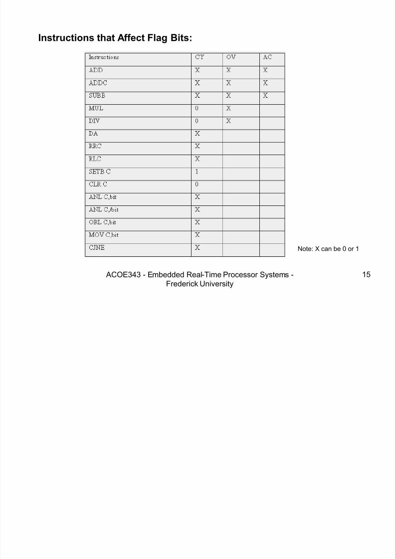
Instructions that Affect Flag Bits:
Note: X can be 0 or 1
7/28/2019 Programming 8051 microcontroller
http://slidepdf.com/reader/full/programming-8051-microcontroller 16/121
ACOE343 - Embedded Real-Time Processor Systems -Frederick University
16
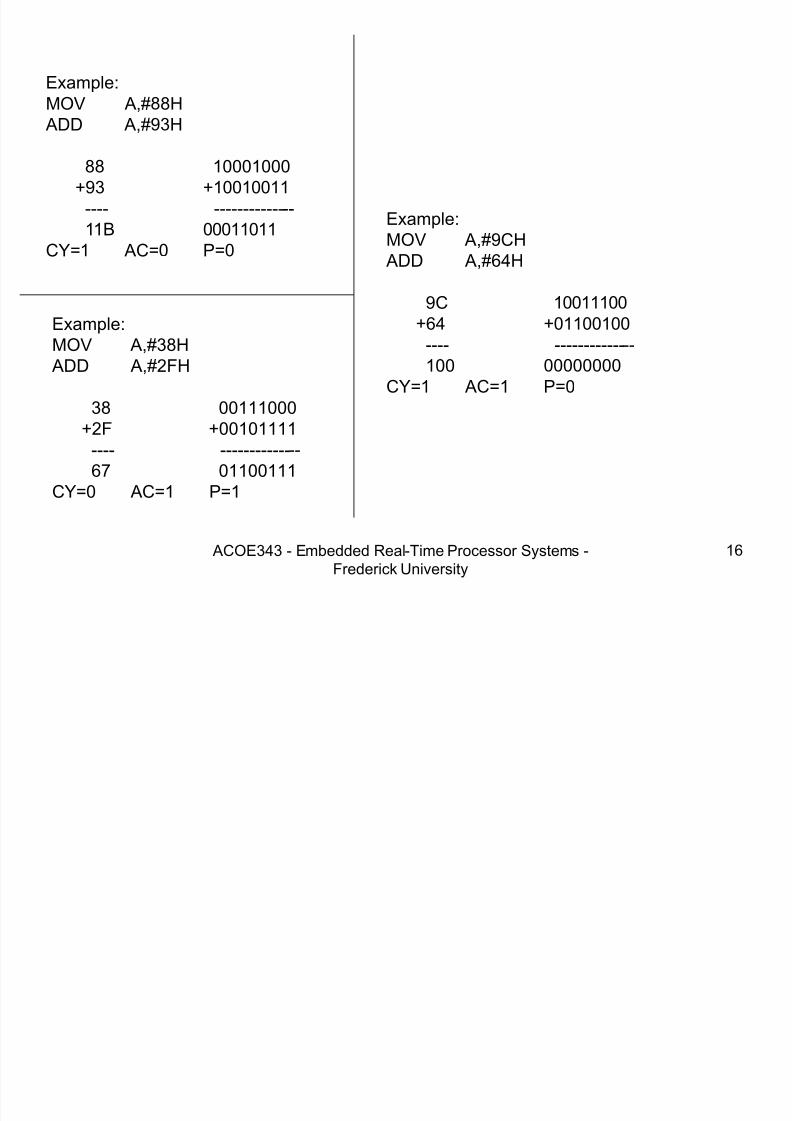
Example:MOV A,#38H
ADD A,#2FH
38 00111000+2F +00101111---- -------------- 67 01100111
CY=0 AC=1 P=1
Example:MOV A,#88H
ADD A,#93H
88 10001000 +93 +10010011
---- -------------- 11B 00011011
CY=1 AC=0 P=0
Example:MOV A,#9CH
ADD A,#64H
9C 10011100 +64 +01100100
---- -------------- 100 00000000
CY=1 AC=1 P=0

7/28/2019 Programming 8051 microcontroller
http://slidepdf.com/reader/full/programming-8051-microcontroller 17/121
ACOE343 - Embedded Real-Time Processor Systems -Frederick University
17
Addressing Modes
• Immediate
• Register
• Direct• Register Indirect
• Indexed
7/28/2019 Programming 8051 microcontroller
http://slidepdf.com/reader/full/programming-8051-microcontroller 18/121
ACOE343 - Embedded Real-Time Processor Systems -Frederick University 18
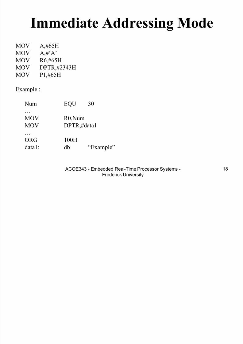
Immediate Addressing Mode
MOV A,#65H
MOV A,#‟A‟
MOV R6,#65H
MOV DPTR,#2343H
MOV P1,#65H
Example :
Num EQU 30
…
MOV R0,Num
MOV DPTR,#data1…
ORG 100H
data1: db “Example”

7/28/2019 Programming 8051 microcontroller
http://slidepdf.com/reader/full/programming-8051-microcontroller 19/121
ACOE343 - Embedded Real-Time Processor Systems -Frederick University 19
Example
• Write the decimal value 4 on the SSD inthe following figure. Switch the decimalpoint off.
7/28/2019 Programming 8051 microcontroller
http://slidepdf.com/reader/full/programming-8051-microcontroller 20/121
ACOE343 - Embedded Real-Time Processor Systems -Frederick University 20
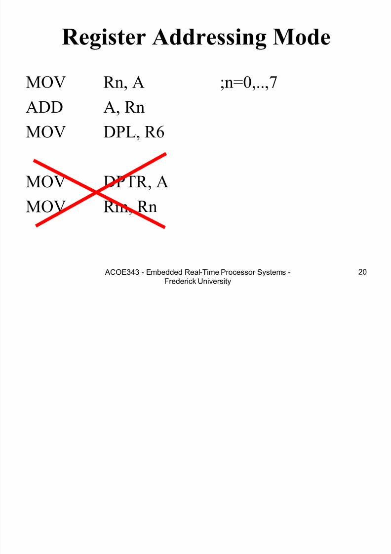
Register Addressing Mode
MOV Rn, A ;n=0,..,7
ADD A, Rn
MOV DPL, R6
MOV DPTR, A
MOV Rm, Rn
7/28/2019 Programming 8051 microcontroller
http://slidepdf.com/reader/full/programming-8051-microcontroller 21/121
ACOE343 - Embedded Real-Time Processor Systems -Frederick University 21
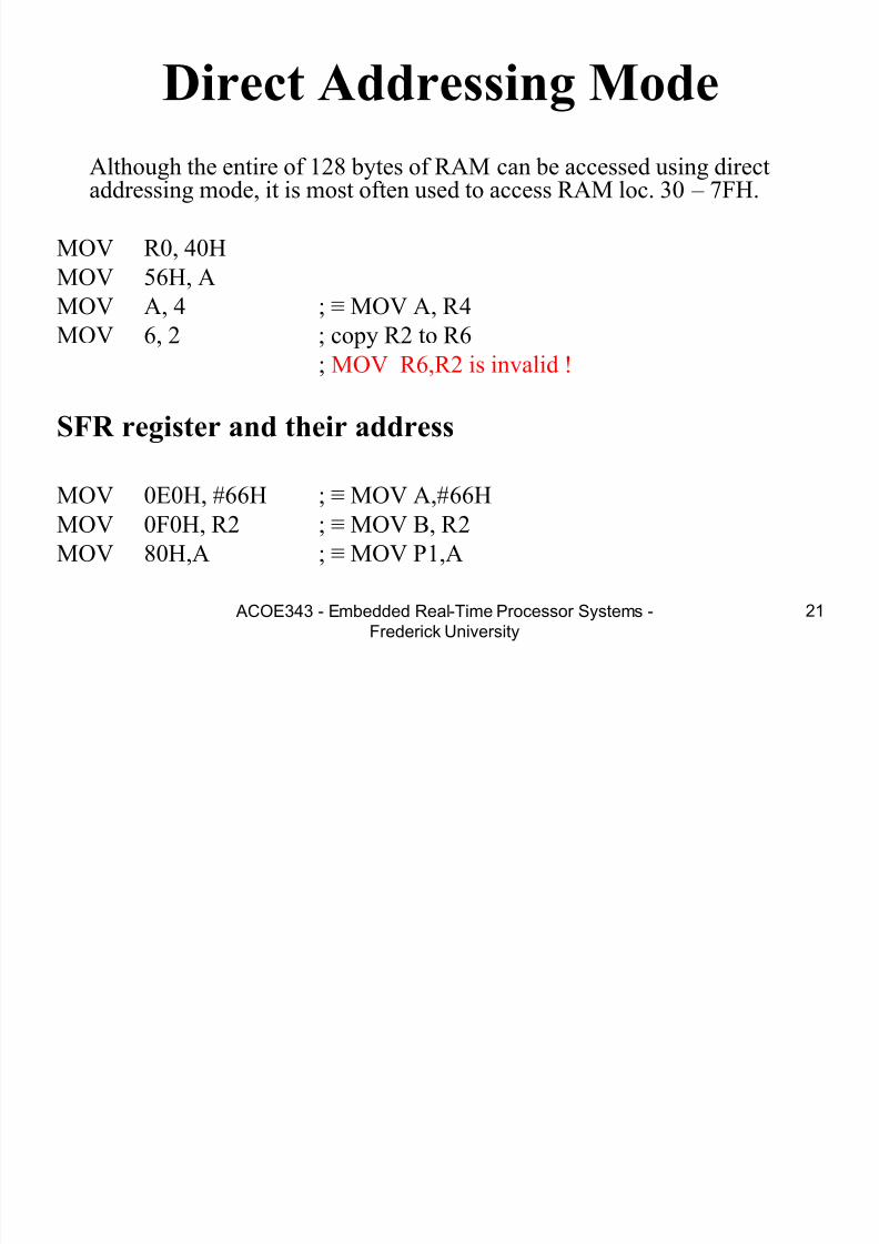
Direct Addressing Mode
Although the entire of 128 bytes of RAM can be accessed using directaddressing mode, it is most often used to access RAM loc. 30 – 7FH.
MOV R0, 40H
MOV 56H, A
MOV A, 4 ; ≡ MOV A, R 4MOV 6, 2 ; copy R2 to R6
; MOV R6,R2 is invalid !
SFR register and their address
MOV 0E0H, #66H ; ≡ MOV A,#66H
MOV 0F0H, R2 ; ≡ MOV B, R 2
MOV 80H,A ; ≡ MOV P1,A

7/28/2019 Programming 8051 microcontroller
http://slidepdf.com/reader/full/programming-8051-microcontroller 22/121
ACOE343 - Embedded Real-Time Processor Systems -Frederick University 22
Register Indirect Addressing Mode• In this mode, register is used as a pointer to the data.
MOV A,@Ri ; move content of RAM loc.Where address is held by Ri into A
( i=0 or 1 )MOV @R1,B
In other word, the content of register R0 or R1 is sources or target in MOV, ADD and SUBBinsructions.
Example:
Write a program to copy a block of 10 bytes from RAM location sterting at 37h to RAM
location starting at 59h.
Solution:
MOV R0,37h ; source pointer
MOV R1,59h ; dest pointer
MOV R2,10 ; counter
L1: MOV A,@R0
MOV @R1,A
INC R0
INC R1
DJNZ R2,L1
jump
7/28/2019 Programming 8051 microcontroller
http://slidepdf.com/reader/full/programming-8051-microcontroller 23/121
ACOE343 - Embedded Real-Time Processor Systems -Frederick University 23
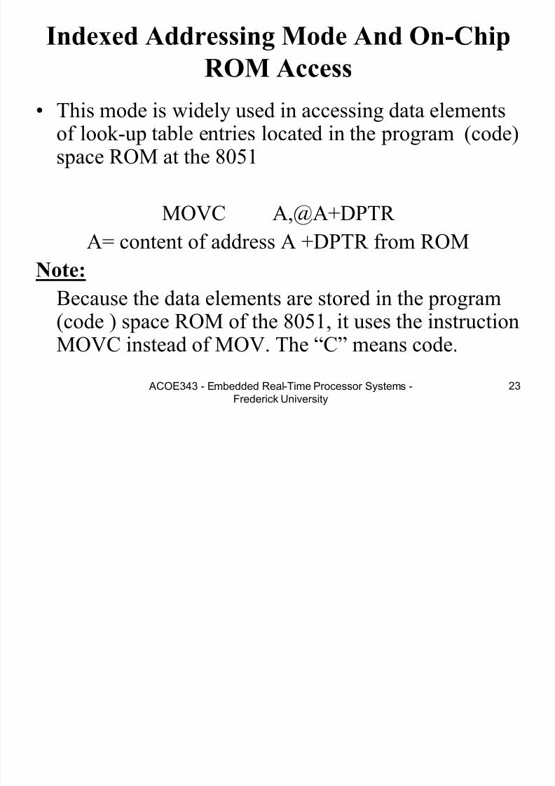
Indexed Addressing Mode And On-Chip
ROM Access
• This mode is widely used in accessing data elementsof look-up table entries located in the program (code)space ROM at the 8051
MOVC A,@A+DPTR
A= content of address A +DPTR from ROM
Note:
Because the data elements are stored in the program(code ) space ROM of the 8051, it uses the instructionMOVC instead of MOV. The “C” means code.

7/28/2019 Programming 8051 microcontroller
http://slidepdf.com/reader/full/programming-8051-microcontroller 24/121
ACOE343 - Embedded Real-Time Processor Systems -Frederick University 24
• Example:
Assuming that ROM space starting at 250h contains “Hello.”, write a program to transfer the bytes into RAM locations starting at 40h.
Solution:
ORG 0
MOV DPTR,#MYDATAMOV R0,#40H
L1: CLR A
MOVC A,@A+DPTR
JZ L2
MOV @R0,A
INC DPTR INC R0
SJMP L1
L2: SJMP L2
;-------------------------------------
ORG 250H
MYDATA: DB “Hello”,0
END
Notice the NULL character ,0, as end of string and how we use the JZ instruction todetect that.

7/28/2019 Programming 8051 microcontroller
http://slidepdf.com/reader/full/programming-8051-microcontroller 25/121

7/28/2019 Programming 8051 microcontroller
http://slidepdf.com/reader/full/programming-8051-microcontroller 26/121
ACOE343 - Embedded Real-Time Processor Systems -Frederick University 26
External Memory Addressing
• MOVX A, @R1 ; A [R1] (in externalmemory)
• MOVX A, @DPTR
• MOVX @DPTR, A

7/28/2019 Programming 8051 microcontroller
http://slidepdf.com/reader/full/programming-8051-microcontroller 27/121
ACOE343 - Embedded Real-Time Processor Systems -Frederick University 27
16-bit, BCD and Signed
Arithmetic in 8051Exercise:
Write a program to add n 16-bit number. Get n
from port 1. And sent Sum to SSDa) in hex
b) in decimal
Write a program to subtract P1 from P0 and sendresult to LCD
(Assume that “ACAL DISP” display A to SSD )

7/28/2019 Programming 8051 microcontroller
http://slidepdf.com/reader/full/programming-8051-microcontroller 28/121

7/28/2019 Programming 8051 microcontroller
http://slidepdf.com/reader/full/programming-8051-microcontroller 29/121
ACOE343 - Embedded Real-Time Processor Systems -Frederick University 29
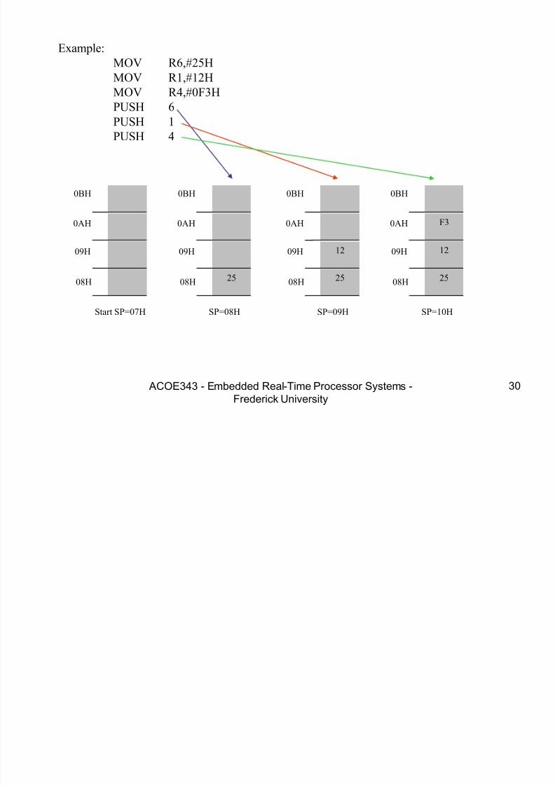
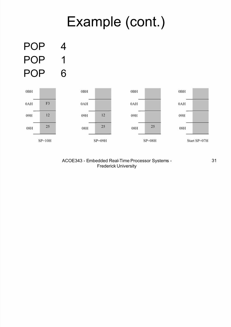
Stack in the 8051
• The register used to accessthe stack is called SP (stack
pointer) register.
• The stack pointer in the8051 is only 8 bits wide,which means that it can takevalue 00 to FFH. When8051 powered up, the SPregister contains value 07.
7FH
30H
2FH
20H
1FH
17H
10H
0FH
07H
08H
18H
00HRegister Bank 0
(Stack) Register Bank 1
Register Bank 2
Register Bank 3
Bit-Addressable RAM
Scratch pad RAM
7/28/2019 Programming 8051 microcontroller
http://slidepdf.com/reader/full/programming-8051-microcontroller 30/121
7/28/2019 Programming 8051 microcontroller
http://slidepdf.com/reader/full/programming-8051-microcontroller 31/121
7/28/2019 Programming 8051 microcontroller
http://slidepdf.com/reader/full/programming-8051-microcontroller 32/121
ACOE343 - Embedded Real-Time Processor Systems -Frederick University 32
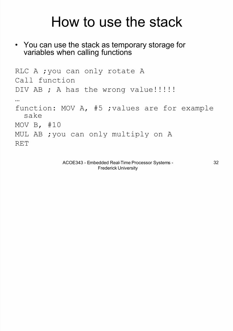
How to use the stack
• You can use the stack as temporary storage for variables when calling functions
RLC A ;you can only rotate A
Call functionDIV AB ; A has the wrong value!!!!!
…
function: MOV A, #5 ;values are for examplesake
MOV B, #10MUL AB ;you can only multiply on A
RET

7/28/2019 Programming 8051 microcontroller
http://slidepdf.com/reader/full/programming-8051-microcontroller 33/121
ACOE343 - Embedded Real-Time Processor Systems -Frederick University 33
Example (correct)
RLC A ;you can only rotate APUSH A ;saving A and B on the stack before
PUSH B ;calling function
Call function
POP B ;restoring B
POP A ;and A (POP in reverse order)DIV AB ; A has the wrong value!!!!!
…
function: MOV A, #5 ;values are for example sake
MOV B, #10
MUL AB ;you can only multiply on ARET
7/28/2019 Programming 8051 microcontroller
http://slidepdf.com/reader/full/programming-8051-microcontroller 34/121
ACOE343 - Embedded Real-Time Processor Systems -Frederick University 34
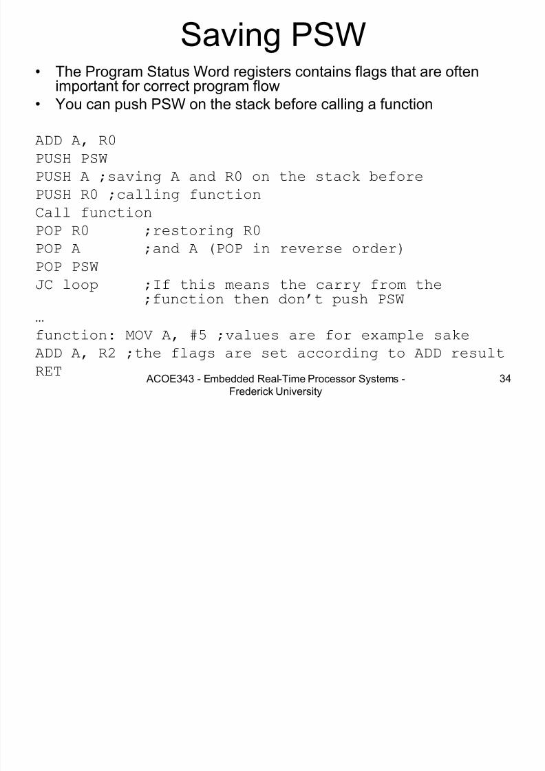
Saving PSW• The Program Status Word registers contains flags that are often
important for correct program flow• You can push PSW on the stack before calling a function
ADD A, R0
PUSH PSW
PUSH A ;saving A and R0 on the stack before
PUSH R0 ;calling functionCall function
POP R0 ;restoring R0
POP A ;and A (POP in reverse order)
POP PSW
JC loop ;If this means the carry from the;function then don’t push PSW
…
function: MOV A, #5 ;values are for example sake
ADD A, R2 ;the flags are set according to ADD result
RET
7/28/2019 Programming 8051 microcontroller
http://slidepdf.com/reader/full/programming-8051-microcontroller 35/121
ACOE343 - Embedded Real-Time Processor Systems -Frederick University 35
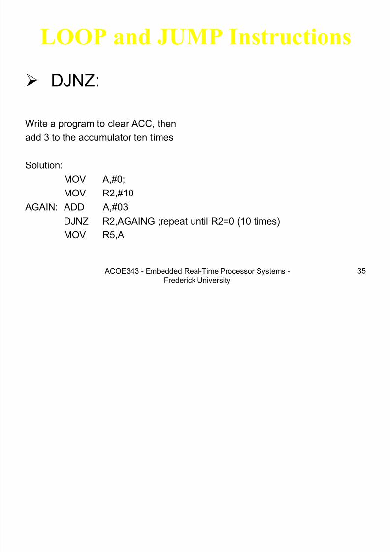
LOOP and JUMP Instructions
DJNZ:
Write a program to clear ACC, then
add 3 to the accumulator ten times
Solution:
MOV A,#0;
MOV R2,#10
AGAIN: ADD A,#03DJNZ R2,AGAING ;repeat until R2=0 (10 times)
MOV R5,A

7/28/2019 Programming 8051 microcontroller
http://slidepdf.com/reader/full/programming-8051-microcontroller 36/121
ACOE343 - Embedded Real-Time Processor Systems -Frederick University 36
• Other conditional jumps :
JZ Jump if A=0
JNZ Jump if A/=0
DJNZ Decrement and jump if A/=0
CJNE A,byte Jump if A/=byte
CJNE reg,#data Jump if byte/=#data
JC Jump if CY=1
JNC Jump if CY=0
JB Jump if bit=1
JNB Jump if bit=0
JBC Jump if bit=1 and clear bit
7/28/2019 Programming 8051 microcontroller
http://slidepdf.com/reader/full/programming-8051-microcontroller 37/121

7/28/2019 Programming 8051 microcontroller
http://slidepdf.com/reader/full/programming-8051-microcontroller 38/121
ACOE343 - Embedded Real-Time Processor Systems -Frederick University 38
CJNE , JNC
Exercise:
Write a program that compare R0,R1.If R0>R1 then send 1 to port 2,
else if R0<R1 then send 0FFh to port 2,
else send 0 to port 2.
7/28/2019 Programming 8051 microcontroller
http://slidepdf.com/reader/full/programming-8051-microcontroller 39/121
7/28/2019 Programming 8051 microcontroller
http://slidepdf.com/reader/full/programming-8051-microcontroller 40/121
ACOE343 - Embedded Real-Time Processor Systems -Frederick University 40
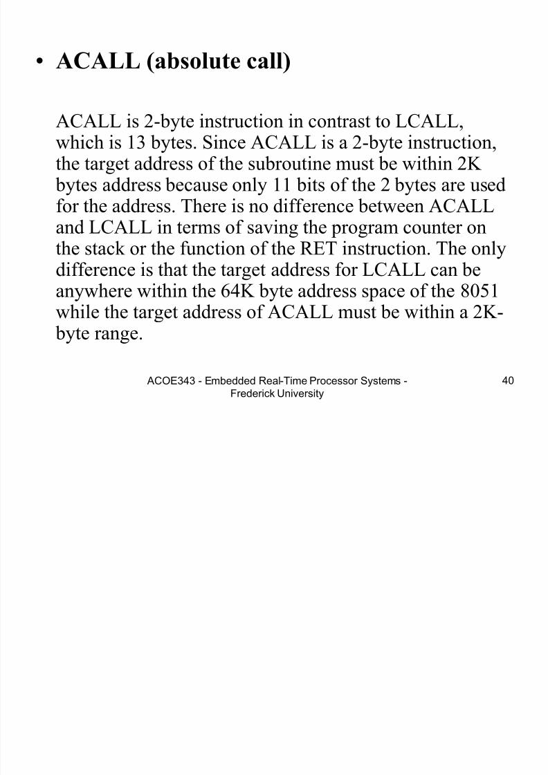
• ACALL (absolute call)
ACALL is 2-byte instruction in contrast to LCALL,which is 13 bytes. Since ACALL is a 2-byte instruction,the target address of the subroutine must be within 2K
bytes address because only 11 bits of the 2 bytes are usedfor the address. There is no difference between ACALLand LCALL in terms of saving the program counter onthe stack or the function of the RET instruction. The onlydifference is that the target address for LCALL can be
anywhere within the 64K byte address space of the 8051while the target address of ACALL must be within a 2K-
byte range.

7/28/2019 Programming 8051 microcontroller
http://slidepdf.com/reader/full/programming-8051-microcontroller 41/121
ACOE343 - Embedded Real-Time Processor Systems -Frederick University 41
Example
A B R5 R7 Address Data
ORG 0H
VAL1 EQU 05H
MOV R5,#25H
LOOP: MOV R7,#VAL1
MOV A,#0ADD A,R5
ADD A,#12H
RRC A
DJNZ A, LOOP
SETB ACC.3
CLR A
CJNE A, #0, LOOP
HERE: SJMP HERE
END

7/28/2019 Programming 8051 microcontroller
http://slidepdf.com/reader/full/programming-8051-microcontroller 42/121
ACOE343 - Embedded Real-Time Processor Systems -Frederick University42
I/O Port Programming
Port 1( pins 1-8)
• Port 1 is denoted by P1.
– P1.0 ~ P1.7
• We use P1 as examples to show the operations on ports.
– P1 as an output port (i.e., write CPU data to the external pin)
– P1 as an input port (i.e., read pin data into CPU bus)

7/28/2019 Programming 8051 microcontroller
http://slidepdf.com/reader/full/programming-8051-microcontroller 43/121
ACOE343 - Embedded Real-Time Processor Systems -Frederick University43
A Pin of Port 1
8051 IC
D Q
Clk Q
Vcc
Load(L1)
Read latch
Read pin
Write to latch
Internal CPU
bus
M1
P1.X pin
P1.X
TB1
TB2
P0.x
7/28/2019 Programming 8051 microcontroller
http://slidepdf.com/reader/full/programming-8051-microcontroller 44/121
ACOE343 - Embedded Real-Time Processor Systems -Frederick University
44
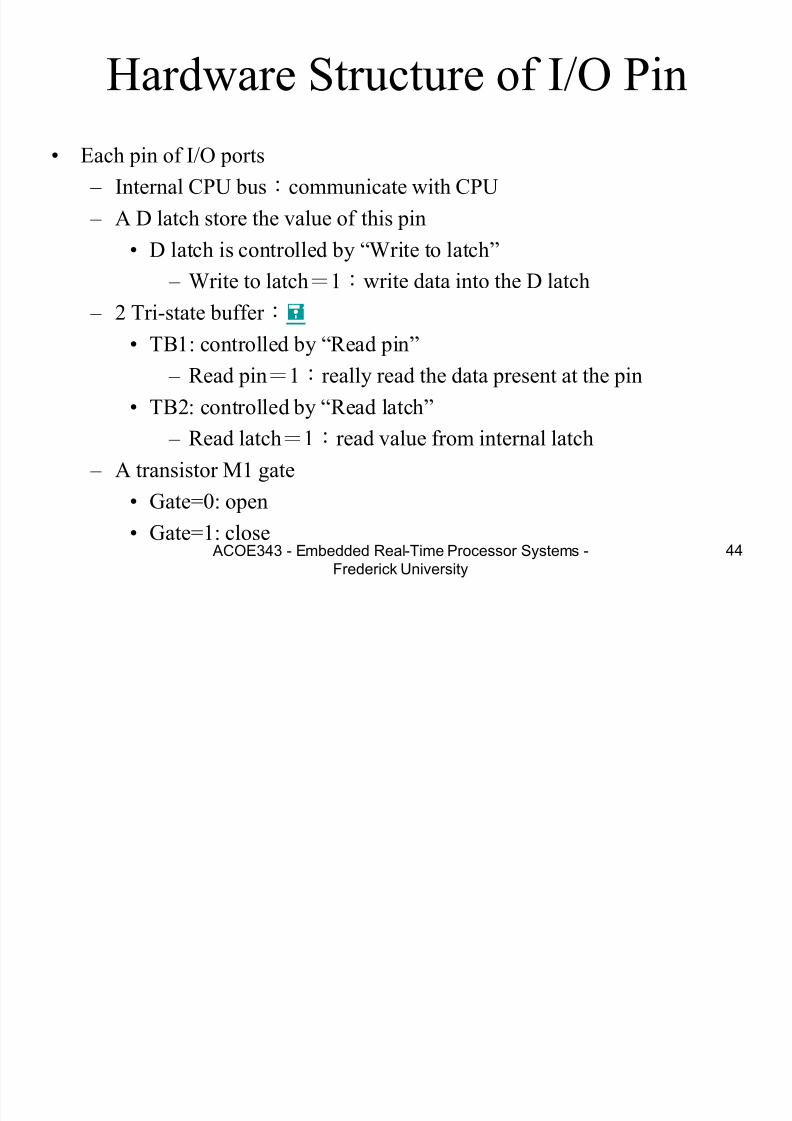
Hardware Structure of I/O Pin
• Each pin of I/O ports
– Internal CPU bus:communicate with CPU
– A D latch store the value of this pin
• D latch is controlled by “Write to latch”
– Write to latch=1:write data into the D latch – 2 Tri-state buffer :
• TB1: controlled by “Read pin”
– Read pin=1:really read the data present at the pin
• TB2: controlled by “Read latch”
– Read latch=1:read value from internal latch
– A transistor M1 gate
• Gate=0: open
• Gate=1: close

7/28/2019 Programming 8051 microcontroller
http://slidepdf.com/reader/full/programming-8051-microcontroller 45/121
ACOE343 - Embedded Real-Time Processor Systems -Frederick University
45
Tri-state Buffer
Output Input
Tri-state control
(active high)
L H Low
Highimpedance
(open-circuit)HH
L H
7/28/2019 Programming 8051 microcontroller
http://slidepdf.com/reader/full/programming-8051-microcontroller 46/121

7/28/2019 Programming 8051 microcontroller
http://slidepdf.com/reader/full/programming-8051-microcontroller 47/121
ACOE343 - Embedded Real-Time Processor Systems -Frederick University
47
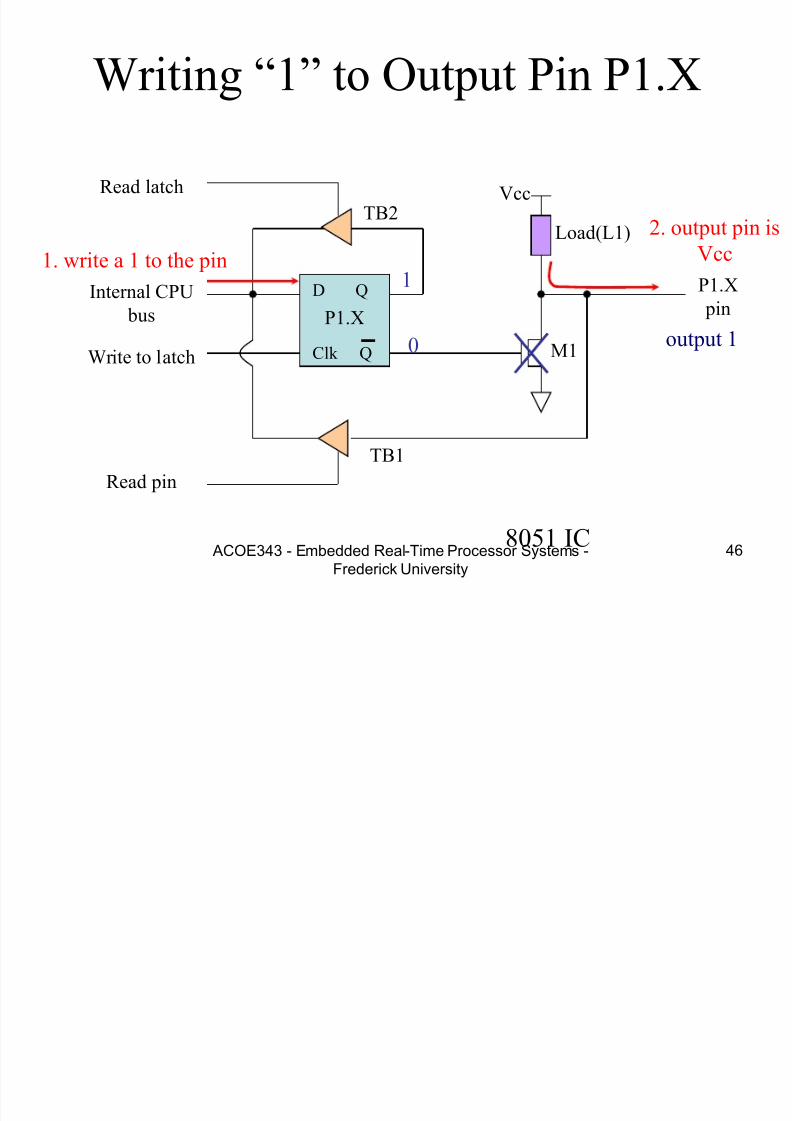
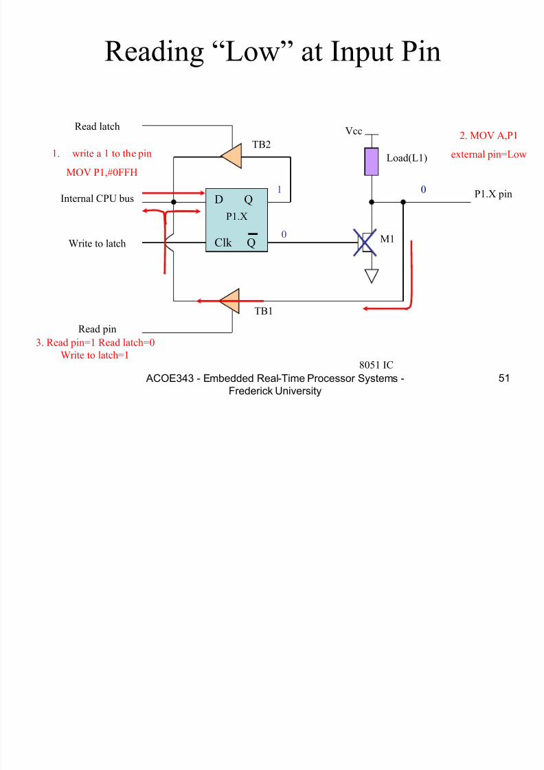
Writing “0” to Output Pin P1.X
D Q
Clk Q
Vcc
Load(L1)
Read latch
Read pin
Write to latch
Internal CPU
bus
M1
P1.X pin
P1.X
8051 IC
2. output pin is
ground1. write a 0 to the pin
0
1 output 0
TB1
TB2
7/28/2019 Programming 8051 microcontroller
http://slidepdf.com/reader/full/programming-8051-microcontroller 48/121
ACOE343 - Embedded Real-Time Processor Systems -Frederick University
48
Port 1 as Output(Write to a Port)
• Send data to Port 1:
MOV A,#55H
BACK: MOV P1,A
ACALL DELAY
CPL A
SJMP BACK
– Let P1 toggle.
– You can write to P1 directly.

7/28/2019 Programming 8051 microcontroller
http://slidepdf.com/reader/full/programming-8051-microcontroller 49/121
ACOE343 - Embedded Real-Time Processor Systems -Frederick University
49
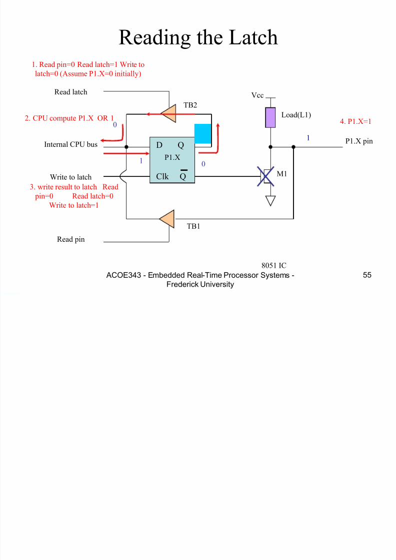
Reading Input v.s. Port Latch
• When reading ports, there are two possibilities: – Read the status of the input pin.(from external pin value)
• MOV A, PX
• JNB P2.1, TARGET ; jump if P2.1 is not set
• JB P2.1, TARGET ; jump if P2.1 is set
• Figures C-11, C-12
– Read the internal latch of the output port.
• ANL P1, A ; P1 ← P1 AND A
• ORL P1, A ; P1 ← P1 OR A
• INC P1 ; increase P1• Figure C-17
• Table C-6 Read-Modify-Write Instruction (or Table 8-5)
• See Section 8.3

7/28/2019 Programming 8051 microcontroller
http://slidepdf.com/reader/full/programming-8051-microcontroller 50/121
7/28/2019 Programming 8051 microcontroller
http://slidepdf.com/reader/full/programming-8051-microcontroller 51/121
7/28/2019 Programming 8051 microcontroller
http://slidepdf.com/reader/full/programming-8051-microcontroller 52/121
ACOE343 - Embedded Real-Time Processor Systems -Frederick University
52
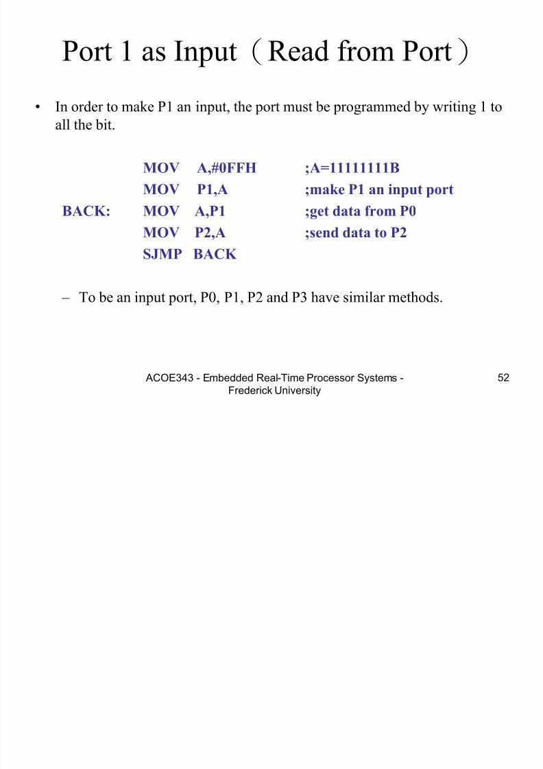
Port 1 as Input(Read from Port)
• In order to make P1 an input, the port must be programmed by writing 1 to
all the bit.
MOV A,#0FFH ;A=11111111B
MOV P1,A ;make P1 an input portBACK: MOV A,P1 ;get data from P0
MOV P2,A ;send data to P2
SJMP BACK
– To be an input port, P0, P1, P2 and P3 have similar methods.
7/28/2019 Programming 8051 microcontroller
http://slidepdf.com/reader/full/programming-8051-microcontroller 53/121
ACOE343 - Embedded Real-Time Processor Systems -Frederick University
53
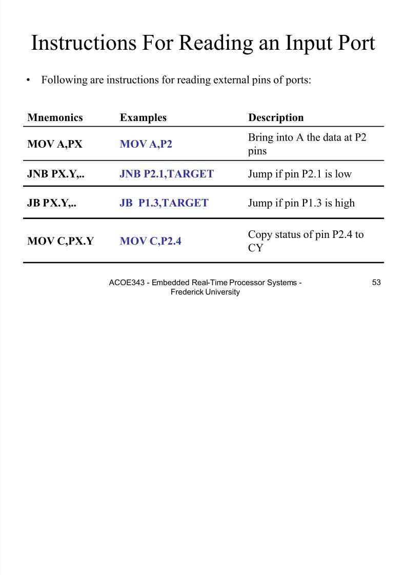
Instructions For Reading an Input Port
Mnemonics Examples Description
MOV A,PX MOV A,P2
Bring into A the data at P2
pins
JNB PX.Y,.. JNB P2.1,TARGET Jump if pin P2.1 is low
JB PX.Y,.. JB P1.3,TARGET Jump if pin P1.3 is high
MOV C,PX.Y MOV C,P2.4Copy status of pin P2.4 to
CY
• Following are instructions for reading external pins of ports:

7/28/2019 Programming 8051 microcontroller
http://slidepdf.com/reader/full/programming-8051-microcontroller 54/121
7/28/2019 Programming 8051 microcontroller
http://slidepdf.com/reader/full/programming-8051-microcontroller 55/121

7/28/2019 Programming 8051 microcontroller
http://slidepdf.com/reader/full/programming-8051-microcontroller 56/121
ACOE343 - Embedded Real-Time Processor Systems -Frederick University
56
Read-modify-write Feature
• Read-modify-write Instructions
– Table C-6
• This features combines 3 actions in a single instruction:
1. CPU reads the latch of the port2. CPU perform the operation
3. Modifying the latch
4. Writing to the pin
– Note that 8 pins of P1 work independently.

7/28/2019 Programming 8051 microcontroller
http://slidepdf.com/reader/full/programming-8051-microcontroller 57/121

7/28/2019 Programming 8051 microcontroller
http://slidepdf.com/reader/full/programming-8051-microcontroller 58/121
ACOE343 - Embedded Real-Time Processor Systems -Frederick University
58
Read-Modify-Write Instructions
ExampleMnemonics
SETB P1.4SETB PX.Y
CLR P1.3CLR PX.Y
MOV P1.2,CMOV PX.Y,C
DJNZ P1,TARGETDJNZ PX, TARGET
INC P1INC
CPL P1.2CPL
JBC P1.1, TARGETJBC PX.Y, TARGET
XRL P1,AXRL
ORL P1,AORL
ANL P1,A ANL
DEC P1DEC
7/28/2019 Programming 8051 microcontroller
http://slidepdf.com/reader/full/programming-8051-microcontroller 59/121

7/28/2019 Programming 8051 microcontroller
http://slidepdf.com/reader/full/programming-8051-microcontroller 60/121
ACOE343 - Embedded Real-Time Processor Systems -Frederick University
60
Other Pins
• P1, P2, and P3 have internal pull-up resisters.
– P1, P2, and P3 are not open drain.
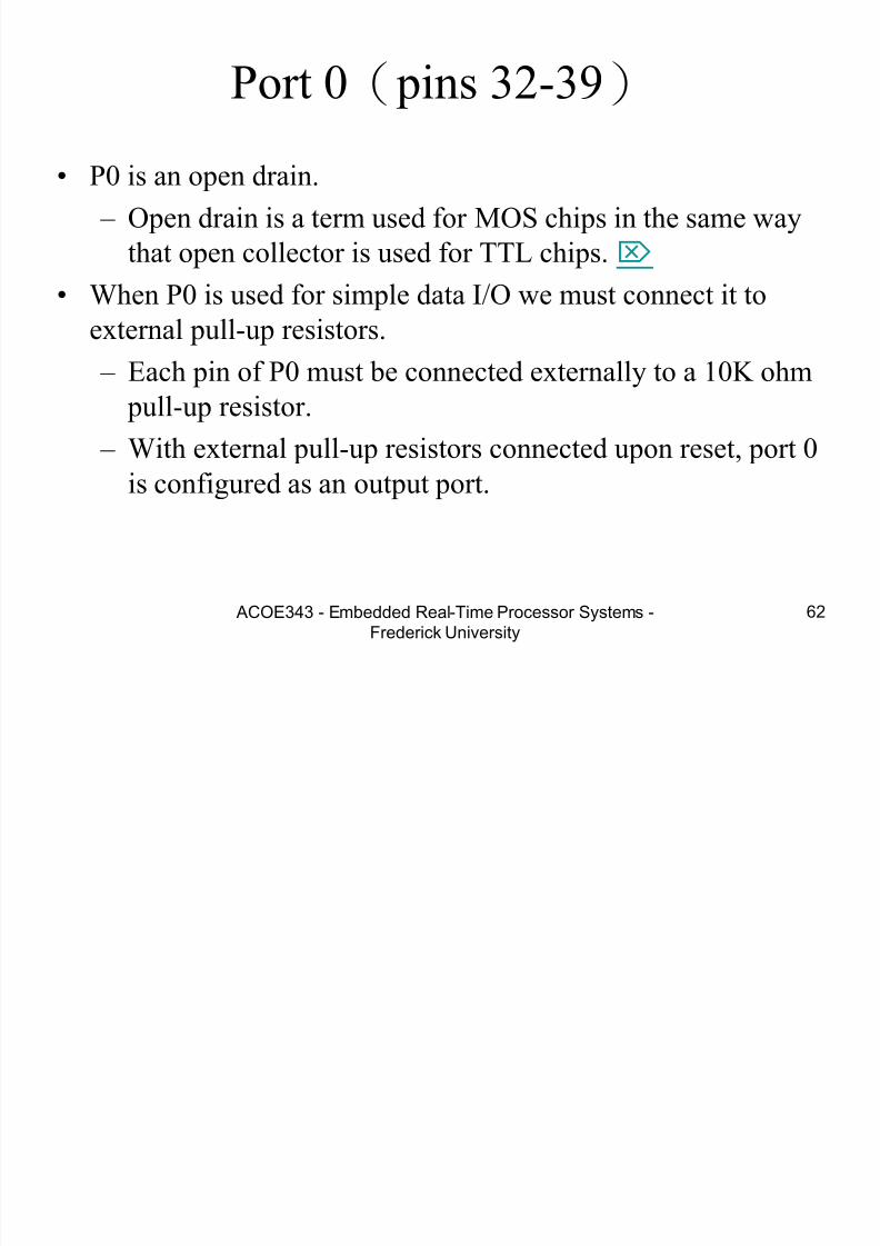
• P0 has no internal pull-up resistors and does not connects to
Vcc inside the 8051.
– P0 is open drain.
– Compare the figures of P1.X and P0.X.
• However, for a programmer, it is the same to program P0, P1,
P2 and P3.
• All the ports upon RESET are configured as output.

7/28/2019 Programming 8051 microcontroller
http://slidepdf.com/reader/full/programming-8051-microcontroller 61/121
7/28/2019 Programming 8051 microcontroller
http://slidepdf.com/reader/full/programming-8051-microcontroller 62/121
P 0 i h P ll U R i

7/28/2019 Programming 8051 microcontroller
http://slidepdf.com/reader/full/programming-8051-microcontroller 63/121
ACOE343 - Embedded Real-Time Processor Systems -Frederick University
63
Port 0 with Pull-Up Resistors
P0.0
P0.1P0.2P0.3P0.4P0.5P0.6
P0.7
DS5000
8751
8951
Vcc10 K
P or t
0
7/28/2019 Programming 8051 microcontroller
http://slidepdf.com/reader/full/programming-8051-microcontroller 64/121
ACOE343 - Embedded Real-Time Processor Systems -Frederick University
64
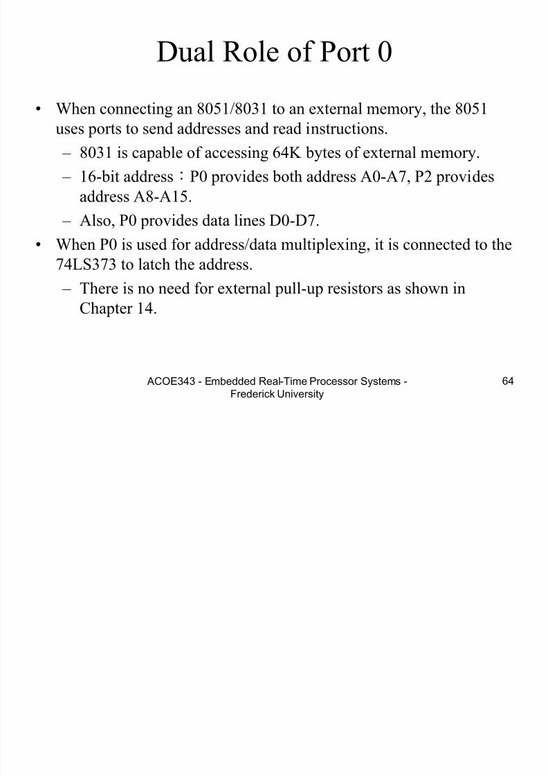
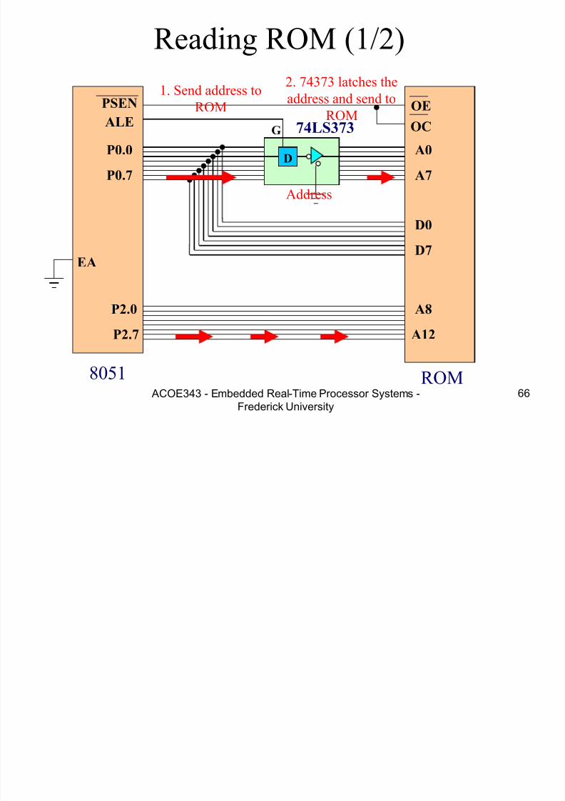
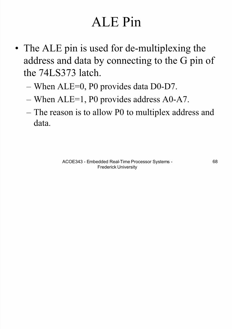
Dual Role of Port 0
• When connecting an 8051/8031 to an external memory, the 8051
uses ports to send addresses and read instructions.
– 8031 is capable of accessing 64K bytes of external memory.
– 16-bit address:P0 provides both address A0-A7, P2 provides
address A8-A15. – Also, P0 provides data lines D0-D7.
• When P0 is used for address/data multiplexing, it is connected to the
74LS373 to latch the address.
– There is no need for external pull-up resistors as shown inChapter 14.

7/28/2019 Programming 8051 microcontroller
http://slidepdf.com/reader/full/programming-8051-microcontroller 65/121
ACOE343 - Embedded Real-Time Processor Systems -Frederick University
65
74LS373
D
74LS373ALE
P0.0
P0.7
PSEN
A0
A7
D0
D7
P2.0
P2.7
A8
A15
OE
OC
EA
G
8051ROM
7/28/2019 Programming 8051 microcontroller
http://slidepdf.com/reader/full/programming-8051-microcontroller 66/121

7/28/2019 Programming 8051 microcontroller
http://slidepdf.com/reader/full/programming-8051-microcontroller 67/121
7/28/2019 Programming 8051 microcontroller
http://slidepdf.com/reader/full/programming-8051-microcontroller 68/121

7/28/2019 Programming 8051 microcontroller
http://slidepdf.com/reader/full/programming-8051-microcontroller 69/121

7/28/2019 Programming 8051 microcontroller
http://slidepdf.com/reader/full/programming-8051-microcontroller 70/121

7/28/2019 Programming 8051 microcontroller
http://slidepdf.com/reader/full/programming-8051-microcontroller 71/121

7/28/2019 Programming 8051 microcontroller
http://slidepdf.com/reader/full/programming-8051-microcontroller 72/121

7/28/2019 Programming 8051 microcontroller
http://slidepdf.com/reader/full/programming-8051-microcontroller 73/121
ACOE343 - Embedded Real-Time Processor Systems -
Frederick University
73
Generating longer delays
• Each register is 8 bits long, so it canincrement 256 times before overflowing
• For larger delays, or when interrupts are
required 8051 uses two timers

7/28/2019 Programming 8051 microcontroller
http://slidepdf.com/reader/full/programming-8051-microcontroller 74/121
7/28/2019 Programming 8051 microcontroller
http://slidepdf.com/reader/full/programming-8051-microcontroller 75/121

7/28/2019 Programming 8051 microcontroller
http://slidepdf.com/reader/full/programming-8051-microcontroller 76/121

7/28/2019 Programming 8051 microcontroller
http://slidepdf.com/reader/full/programming-8051-microcontroller 77/121
7/28/2019 Programming 8051 microcontroller
http://slidepdf.com/reader/full/programming-8051-microcontroller 78/121
Ti C l R i (TCON)
7/28/2019 Programming 8051 microcontroller
http://slidepdf.com/reader/full/programming-8051-microcontroller 79/121
ACOE343 - Embedded Real-Time Processor Systems -
Frederick University
79
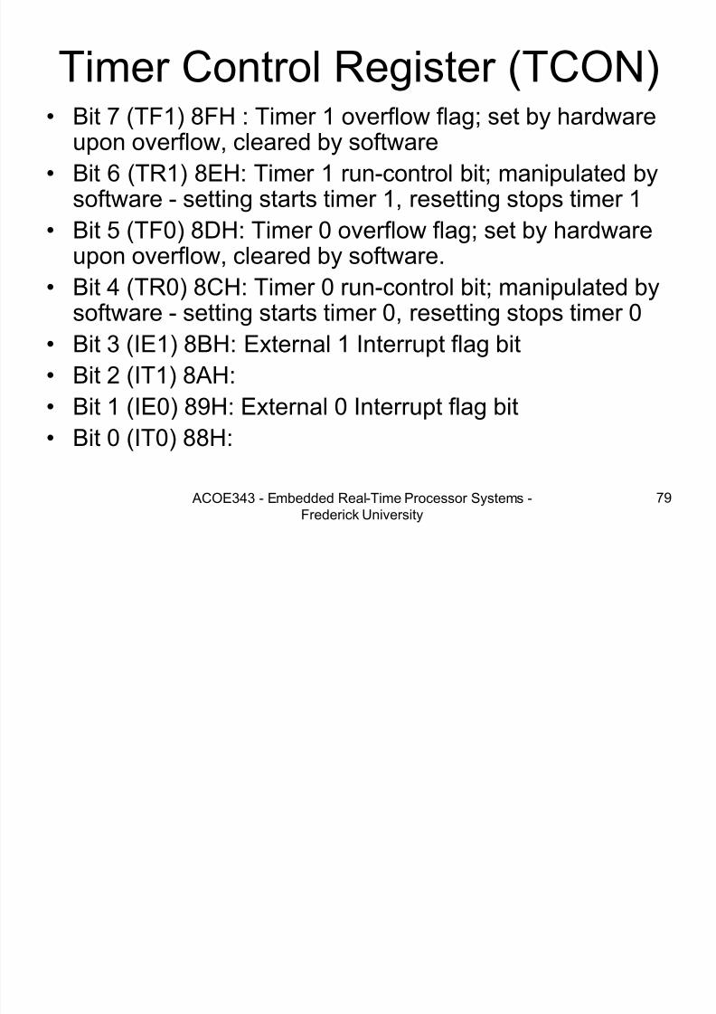
Timer Control Register (TCON)• Bit 7 (TF1) 8FH : Timer 1 overflow flag; set by hardware
upon overflow, cleared by software• Bit 6 (TR1) 8EH: Timer 1 run-control bit; manipulated by
software - setting starts timer 1, resetting stops timer 1
• Bit 5 (TF0) 8DH: Timer 0 overflow flag; set by hardware
upon overflow, cleared by software.• Bit 4 (TR0) 8CH: Timer 0 run-control bit; manipulated by
software - setting starts timer 0, resetting stops timer 0
• Bit 3 (IE1) 8BH: External 1 Interrupt flag bit
• Bit 2 (IT1) 8AH:• Bit 1 (IE0) 89H: External 0 Interrupt flag bit
• Bit 0 (IT0) 88H:
I iti li i d t i ti

7/28/2019 Programming 8051 microcontroller
http://slidepdf.com/reader/full/programming-8051-microcontroller 80/121
ACOE343 - Embedded Real-Time Processor Systems -
Frederick University
80
Initializing and stopping timers
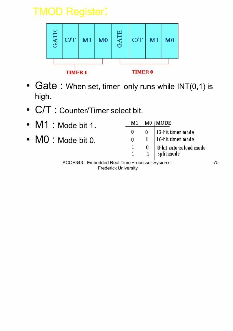
• MOV TMOD, #16H ;initialization
• SETB TR0 ;starting timersSETB TR1
• CLR TR0 ; stop timer 0CLR TR1 ; stop timer 1
• MOV R7, TH0 ; reading timers
• MOV R6, TL0

7/28/2019 Programming 8051 microcontroller
http://slidepdf.com/reader/full/programming-8051-microcontroller 81/121
G ti d l i th ti
7/28/2019 Programming 8051 microcontroller
http://slidepdf.com/reader/full/programming-8051-microcontroller 82/121
ACOE343 - Embedded Real-Time Processor Systems -
Frederick University
82
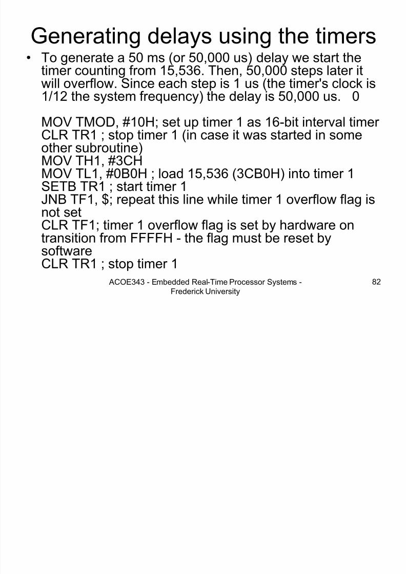
Generating delays using the timers• To generate a 50 ms (or 50,000 us) delay we start the
timer counting from 15,536. Then, 50,000 steps later itwill overflow. Since each step is 1 us (the timer's clock is1/12 the system frequency) the delay is 50,000 us. 0
MOV TMOD, #10H; set up timer 1 as 16-bit interval timer CLR TR1 ; stop timer 1 (in case it was started in some
other subroutine)MOV TH1, #3CHMOV TL1, #0B0H ; load 15,536 (3CB0H) into timer 1SETB TR1 ; start timer 1JNB TF1, $; repeat this line while timer 1 overflow flag is
not setCLR TF1; timer 1 overflow flag is set by hardware ontransition from FFFFH - the flag must be reset bysoftwareCLR TR1 ; stop timer 1
G ti l d l

7/28/2019 Programming 8051 microcontroller
http://slidepdf.com/reader/full/programming-8051-microcontroller 83/121
ACOE343 - Embedded Real-Time Processor Systems -
Frederick University
83
Generating long delays• If the microcontroller has a system clock frequency of 12 MHz then the longest delay
we can get from either of the timers is 65,536 usec.• To generate delays longer than this, we need to write a subroutine to generate a
delay of (for example) 50 ms and then call that subroutine a specific number of times.• ...
MOV TMOD, #10H; set up timer 1 as 16-bit interval timer
• fiftyMsDelay:CLR TR1 ; stop timer 1 (in case it was started in some other subroutine)MOV TH1, #3CH
MOV TL1, #0B0H ; load 15,536 (3CB0H) into timer 1SETB TR1 ; start timer 1JNB TF1, $; repeat this line while timer 1 overflow flag is not setCLR TF1; timer 1 overflow flag is set by hardware on transition from FFFFH - the flagmust be reset by softwareCLR TR1 ; stop timer 1RET
• oneSecDelay:PUSH PSW
PUSH AR0 ; save processor statusMOV R0, #20 ; move 20 (in decimal) into R0• loop:CALL fiftyMsDelay ; call the 50 ms delay
DJNZ R0, loop ; 20 times - resulting in a 1 second delayPOP AR0POP PSW ; retrieve processor statusRET

7/28/2019 Programming 8051 microcontroller
http://slidepdf.com/reader/full/programming-8051-microcontroller 84/121
7/28/2019 Programming 8051 microcontroller
http://slidepdf.com/reader/full/programming-8051-microcontroller 85/121
7/28/2019 Programming 8051 microcontroller
http://slidepdf.com/reader/full/programming-8051-microcontroller 86/121
7/28/2019 Programming 8051 microcontroller
http://slidepdf.com/reader/full/programming-8051-microcontroller 87/121
I t t S i R ti

7/28/2019 Programming 8051 microcontroller
http://slidepdf.com/reader/full/programming-8051-microcontroller 88/121
ACOE343 - Embedded Real-Time Processor Systems -
Frederick University
88
Interrupt Service Routines• ORG 0
JMP main
• ORG 0003H ; external interrupt 0 vector …. ; interrupt handler code for external interrupt 0RETI
ORG 0013H ; external interrupt 1 vector …. ;interrupt handler code for external interrupt 1RETI
ORG 0030H ; main programmain:SETB IT0 ; set external interrupt 0 as edge activated
SETB IT1 ; set external interrupt 1 as edge activatedSETB EX0 ; enable external interrupt 0SETB EX1 ; enable external interrupt 1SETB EA ; global interrupt enable…

7/28/2019 Programming 8051 microcontroller
http://slidepdf.com/reader/full/programming-8051-microcontroller 89/121

7/28/2019 Programming 8051 microcontroller
http://slidepdf.com/reader/full/programming-8051-microcontroller 90/121
7/28/2019 Programming 8051 microcontroller
http://slidepdf.com/reader/full/programming-8051-microcontroller 91/121
Keil C keywords
7/28/2019 Programming 8051 microcontroller
http://slidepdf.com/reader/full/programming-8051-microcontroller 92/121
ACOE343 - Embedded Real-Time Processor Systems -
Frederick University
92
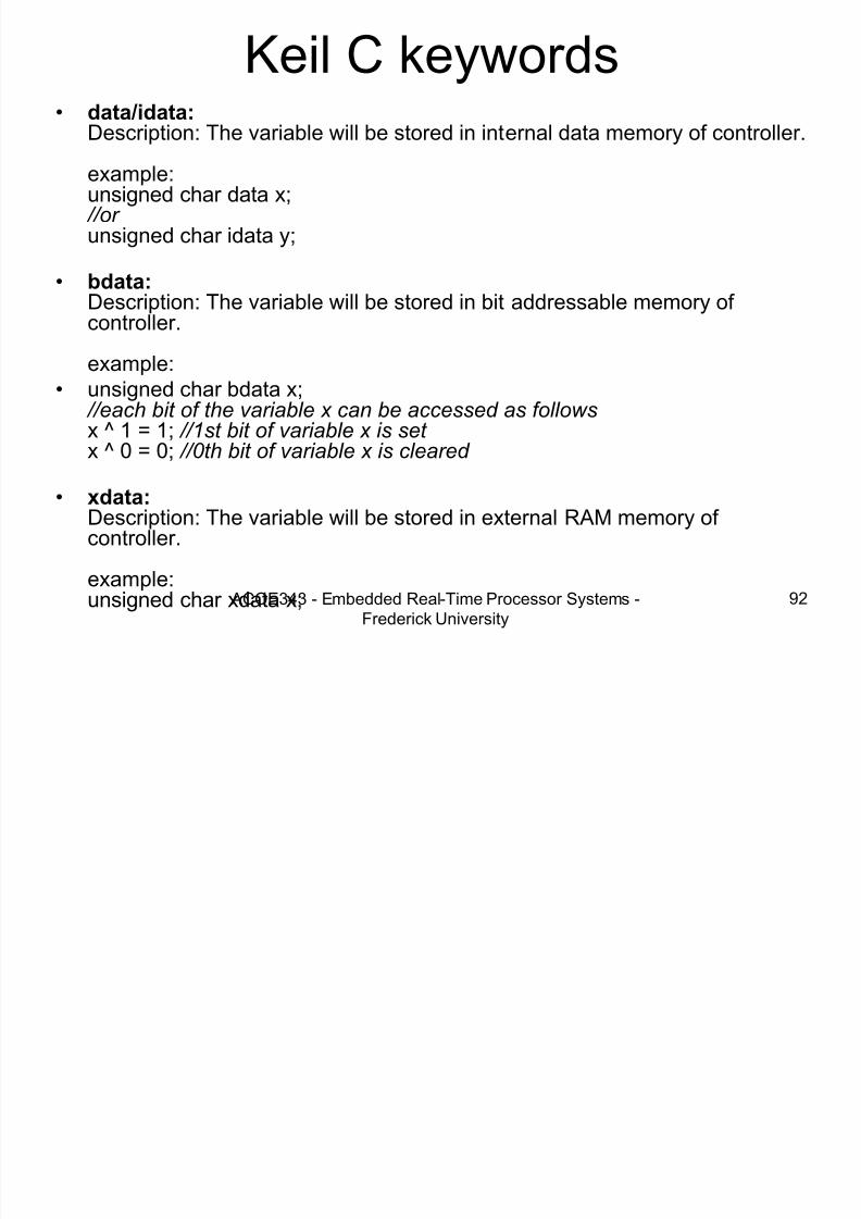
Keil C keywords• data/idata:
Description: The variable will be stored in internal data memory of controller.
example:unsigned char data x; //or unsigned char idata y;
• bdata: Description: The variable will be stored in bit addressable memory of controller.
example:• unsigned char bdata x;
//each bit of the variable x can be accessed as follows x ^ 1 = 1; //1st bit of variable x is set x ^ 0 = 0; //0th bit of variable x is cleared
• xdata: Description: The variable will be stored in external RAM memory of controller.
example:unsigned char xdata x;

7/28/2019 Programming 8051 microcontroller
http://slidepdf.com/reader/full/programming-8051-microcontroller 93/121

7/28/2019 Programming 8051 microcontroller
http://slidepdf.com/reader/full/programming-8051-microcontroller 94/121
7/28/2019 Programming 8051 microcontroller
http://slidepdf.com/reader/full/programming-8051-microcontroller 95/121
7/28/2019 Programming 8051 microcontroller
http://slidepdf.com/reader/full/programming-8051-microcontroller 96/121
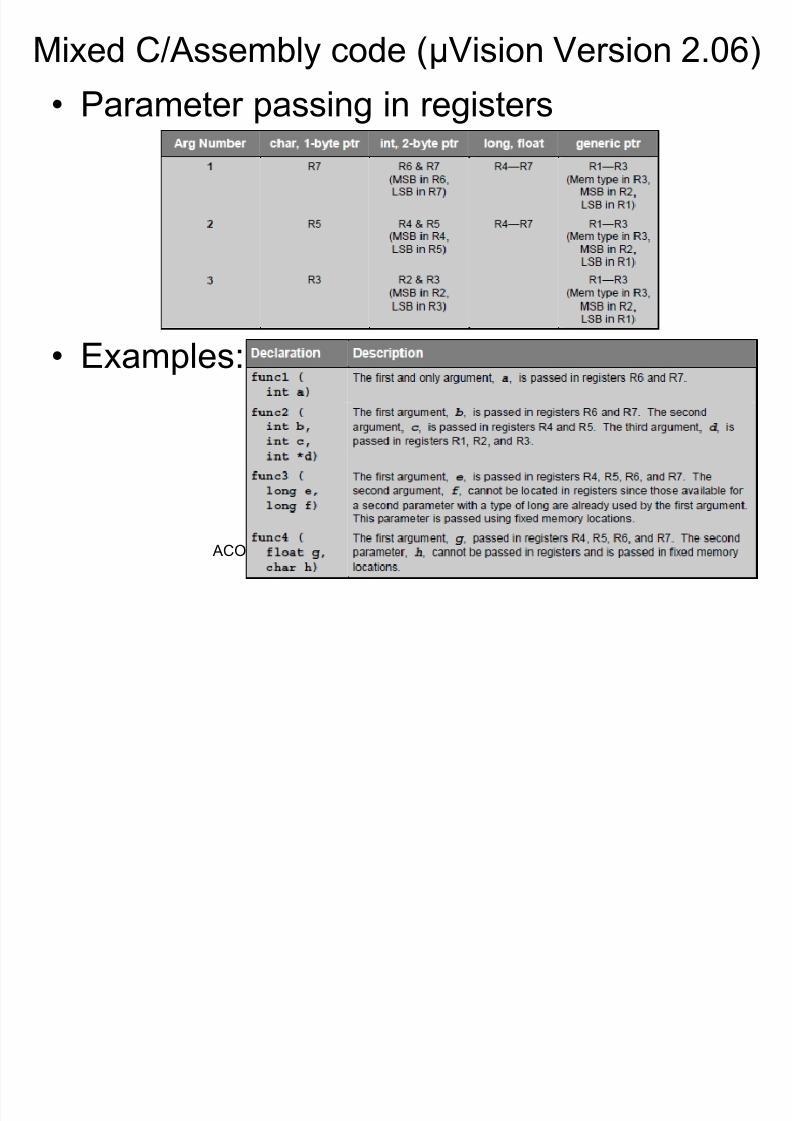
C and Assembly together
7/28/2019 Programming 8051 microcontroller
http://slidepdf.com/reader/full/programming-8051-microcontroller 97/121
ACOE343 - Embedded Real-Time Processor Systems -
Frederick University
97
C and Assembly together
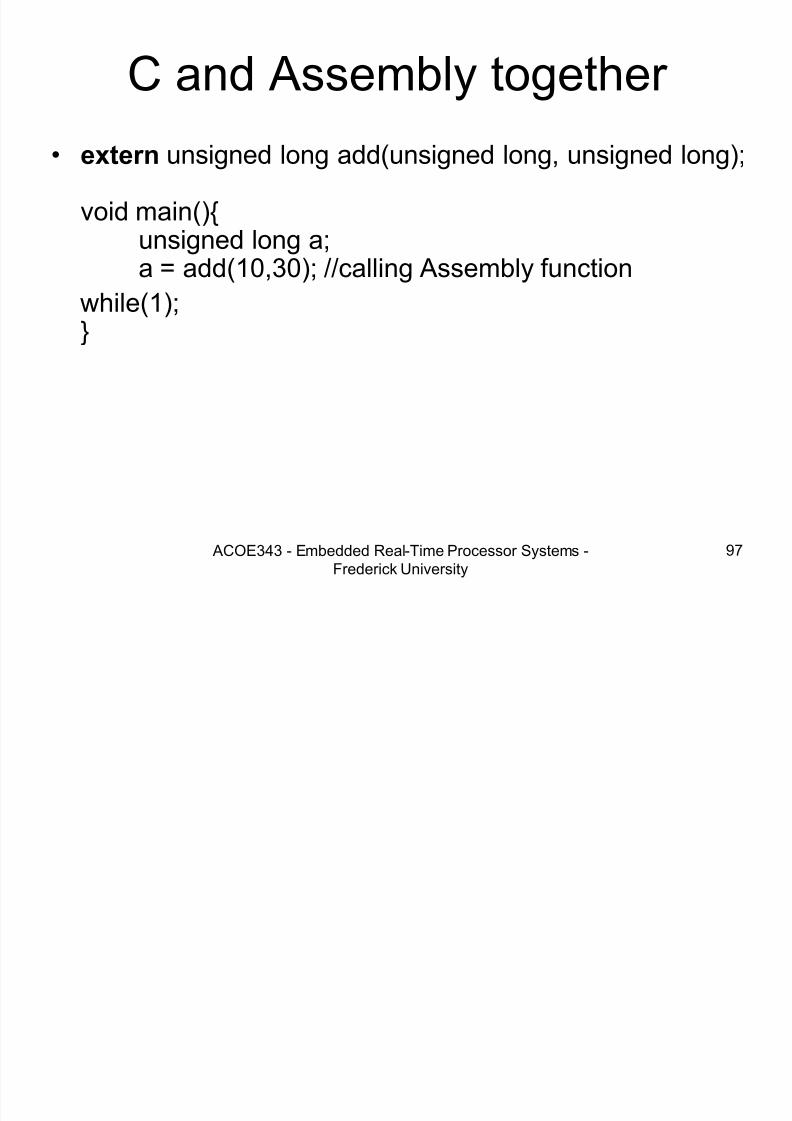
• extern unsigned long add(unsigned long, unsigned long);
void main(){unsigned long a;a = add(10,30); //calling Assembly function
while(1);}

7/28/2019 Programming 8051 microcontroller
http://slidepdf.com/reader/full/programming-8051-microcontroller 98/121

7/28/2019 Programming 8051 microcontroller
http://slidepdf.com/reader/full/programming-8051-microcontroller 99/121
Example 1
7/28/2019 Programming 8051 microcontroller
http://slidepdf.com/reader/full/programming-8051-microcontroller 100/121
ACOE343 - Embedded Real-Time Processor Systems -
Frederick University
100
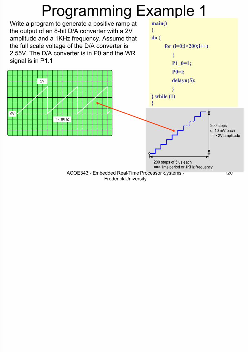
Example 1
• Generate a 5V peek-to-peek 200μs periodsquare waveform on the DAC output
7/28/2019 Programming 8051 microcontroller
http://slidepdf.com/reader/full/programming-8051-microcontroller 101/121
7/28/2019 Programming 8051 microcontroller
http://slidepdf.com/reader/full/programming-8051-microcontroller 102/121
7/28/2019 Programming 8051 microcontroller
http://slidepdf.com/reader/full/programming-8051-microcontroller 103/121
Function return values

7/28/2019 Programming 8051 microcontroller
http://slidepdf.com/reader/full/programming-8051-microcontroller 104/121
ACOE343 - Embedded Real-Time Processor Systems -
Frederick University
104
Function return values

7/28/2019 Programming 8051 microcontroller
http://slidepdf.com/reader/full/programming-8051-microcontroller 105/121

7/28/2019 Programming 8051 microcontroller
http://slidepdf.com/reader/full/programming-8051-microcontroller 106/121
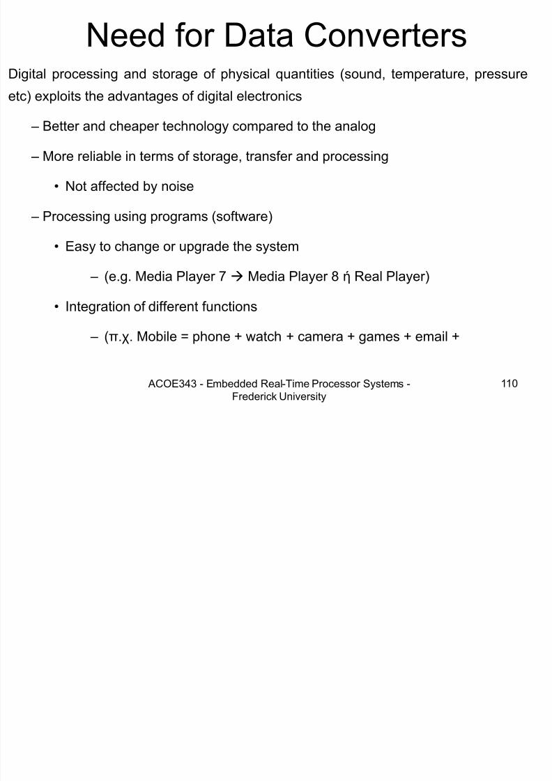
Data Converters

7/28/2019 Programming 8051 microcontroller
http://slidepdf.com/reader/full/programming-8051-microcontroller 107/121
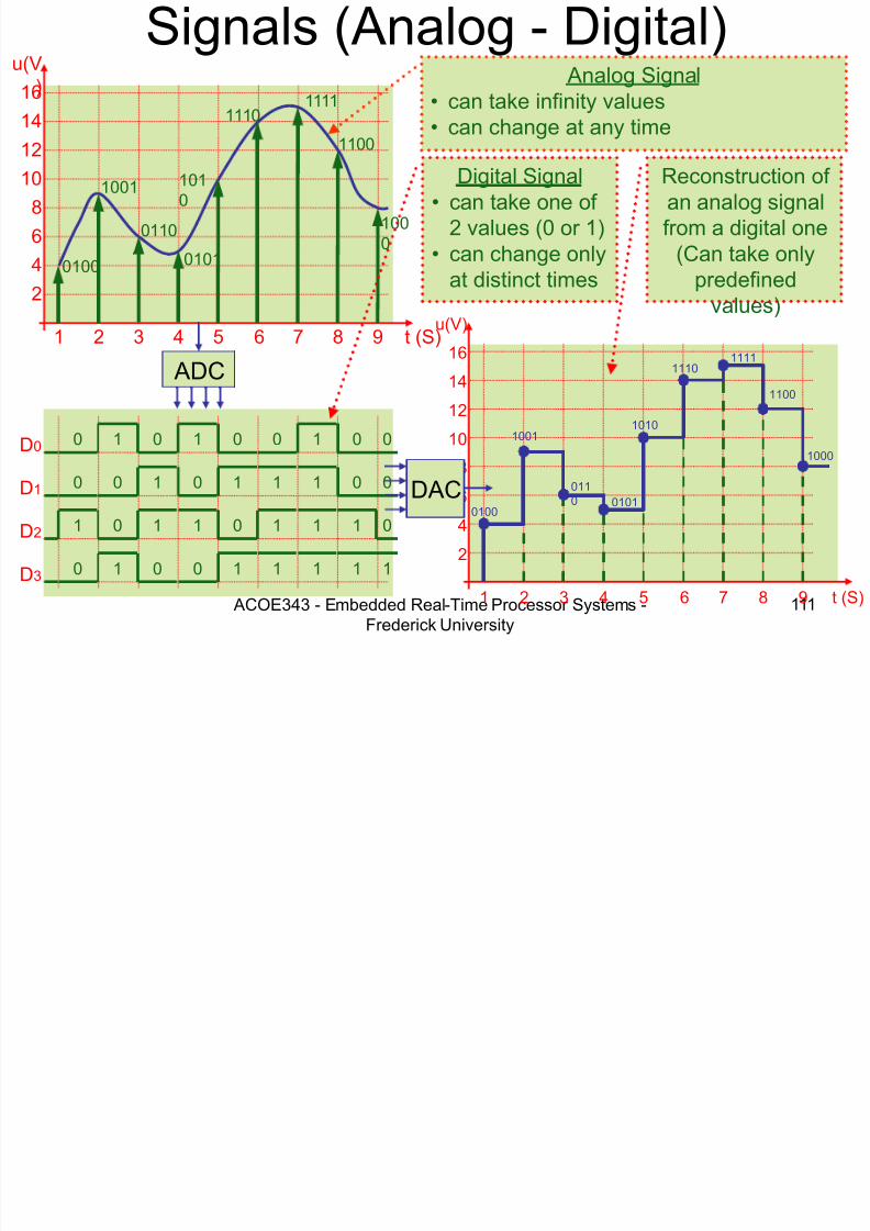
• Analog to Digital Converters(ADC) – Convert an analog quantity
(voltage, current) into adigital code
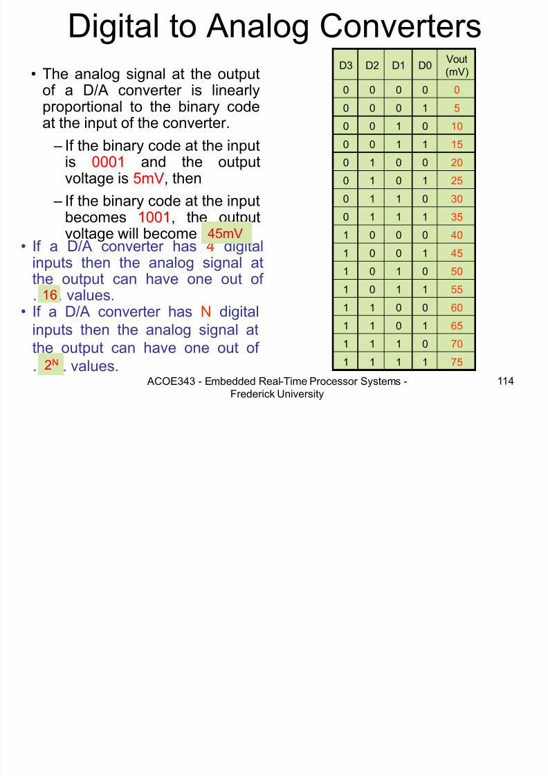
• Digital to Analog Converters
(DAC) – Convert a digital code into
an analog quantity (voltage,
current)
7/28/2019 Programming 8051 microcontroller
http://slidepdf.com/reader/full/programming-8051-microcontroller 108/121
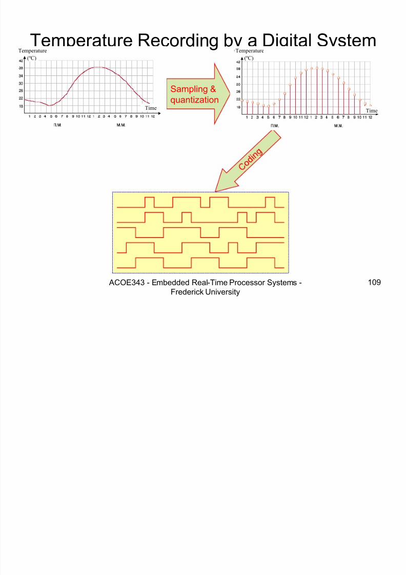
Temperature Recording by a Digital System
7/28/2019 Programming 8051 microcontroller
http://slidepdf.com/reader/full/programming-8051-microcontroller 109/121
ACOE343 - Embedded Real-Time Processor Systems -
Frederick University
109
Temperature Recording by a Digital System
Sampling &quantization
Temperature
(ºC)
Time
Temperature
(ºC)
Time
7/28/2019 Programming 8051 microcontroller
http://slidepdf.com/reader/full/programming-8051-microcontroller 110/121
7/28/2019 Programming 8051 microcontroller
http://slidepdf.com/reader/full/programming-8051-microcontroller 111/121
7/28/2019 Programming 8051 microcontroller
http://slidepdf.com/reader/full/programming-8051-microcontroller 112/121
7/28/2019 Programming 8051 microcontroller
http://slidepdf.com/reader/full/programming-8051-microcontroller 113/121
7/28/2019 Programming 8051 microcontroller
http://slidepdf.com/reader/full/programming-8051-microcontroller 114/121

7/28/2019 Programming 8051 microcontroller
http://slidepdf.com/reader/full/programming-8051-microcontroller 115/121
Characteristics of Data
7/28/2019 Programming 8051 microcontroller
http://slidepdf.com/reader/full/programming-8051-microcontroller 116/121
ACOE343 - Embedded Real-Time Processor Systems -
Frederick University
116
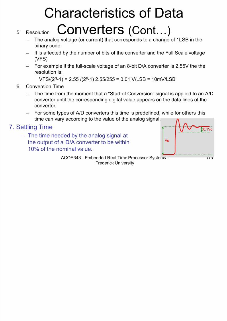
Converters (Cont…) 5. Resolution
– The analog voltage (or current) that corresponds to a change of 1LSB in the
binary code – It is affected by the number of bits of the converter and the Full Scale voltage
(VFS)
– For example if the full-scale voltage of an 8-bit D/A converter is 2.55V the theresolution is:
VFS/(2N-1) = 2.55 /(28-1) 2.55/255 = 0.01 V/LSB = 10mV/LSB
6. Conversion Time
– The time from the moment that a “Start of Conversion” signal is applied to an A/D
converter until the corresponding digital value appears on the data lines of theconverter.
– For some types of A/D converters this time is predefined, while for others thistime can vary according to the value of the analog signal.
0.1Vo
Vo
7. Settling Time
– The time needed by the analog signal atthe output of a D/A converter to be within10% of the nominal value.

7/28/2019 Programming 8051 microcontroller
http://slidepdf.com/reader/full/programming-8051-microcontroller 117/121
ADC TYPES
7/28/2019 Programming 8051 microcontroller
http://slidepdf.com/reader/full/programming-8051-microcontroller 118/121
ACOE343 - Embedded Real-Time Processor Systems -
Frederick University
118
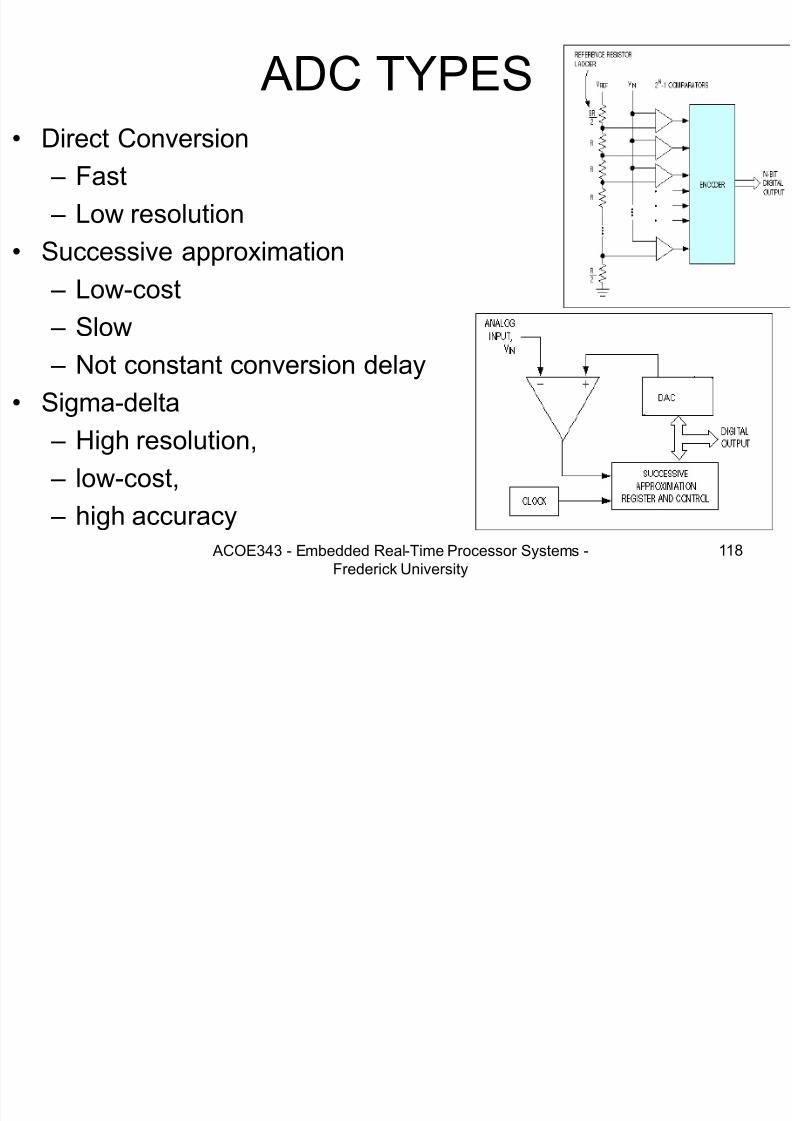
ADC TYPES• Direct Conversion
– Fast
– Low resolution
• Successive approximation
– Low-cost – Slow
– Not constant conversion delay
• Sigma-delta
– High resolution, – low-cost,
– high accuracy
Interfacing with Data Converters

7/28/2019 Programming 8051 microcontroller
http://slidepdf.com/reader/full/programming-8051-microcontroller 119/121
ACOE343 - Embedded Real-Time Processor Systems -
Frederick University
119
• Microprocessor compatible data converters are attached onthe microprocessor’s bus as standard I/O devices.
DAC
CS
Vout
D7
WR
D6D5D4D3D2D1D0 Vref
V(+)
V(-)
8 0 8 8 S y s t e m
D7D6D5D4D3
D2D1D0
A19
A0
WR
IO/M'
RD
A11 A10 A9 A8 A7 A6
A5 A4
Vout
1 0 K
1 0 K
+5V
7/28/2019 Programming 8051 microcontroller
http://slidepdf.com/reader/full/programming-8051-microcontroller 120/121
D/A Converters exampleWrite a program to generate the waveform, shown below, at the output of

7/28/2019 Programming 8051 microcontroller
http://slidepdf.com/reader/full/programming-8051-microcontroller 121/121
0
4
3
2
1
V (volts)
t (msec )1 5 6 7 8
Write a program to generate the waveform, shown below, at the output of
an 8-bit digital to analog converter. The period of the waveform should be
approximately 8 ms. Assume that a time delay function with a 1 μs
resolution is available. The full scale output of the converter is 5.12 V andthe address of the DAC is P0, while the WR signal is in P1.1.
C o
C o
Co
Assuming that an 8-bit A/D converter is used to interface a temperature sensor measuring temperature values in the temperature range 0 - 51.2
, specify: The resolution in of the system in
The digital output word for a temperature of 32 5
Related Documents