Programmer Manual TDS Family Digitizing Oscilloscopes (TDS 420A, 430A, 460A, 510A, 520C, 540C, 620B, 644B, 680B, 684B, 724C, 754C, & 784C) 070-9876-00

Welcome message from author
This document is posted to help you gain knowledge. Please leave a comment to let me know what you think about it! Share it to your friends and learn new things together.
Transcript
Programmer Manual
TDS Family Digitizing Oscilloscopes(TDS 420A, 430A, 460A, 510A, 520C, 540C, 620B, 644B, 680B, 684B, 724C, 754C, & 784C)
070-9876-00

Copyright � Tektronix, Inc. All rights reserved. Licensed software products are owned by Tektronix or its suppliers andare protected by United States copyright laws and international treaty provisions.
Use, duplication, or disclosure by the Government is subject to restrictions as set forth in subparagraph (c)(1)(ii) of theRights in Technical Data and Computer Software clause at DFARS 252.227-7013, or subparagraphs (c)(1) and (2) of theCommercial Computer Software – Restricted Rights clause at FAR 52.227-19, as applicable.
Tektronix products are covered by U.S. and foreign patents, issued and pending. Information in this publication supercedesthat in all previously published material. Specifications and price change privileges reserved.
Printed in the U.S.A.
Tektronix, Inc., P.O. Box 1000, Wilsonville, OR 97070–1000
TEKTRONIX and TEK are registered trademarks of Tektronix, Inc.

WARRANTY
Tektronix warrants that this product will be free from defects in materials and workmanship for a period of three (3) yearsfrom the date of shipment. If any such product proves defective during this warranty period, Tektronix, at its option, eitherwill repair the defective product without charge for parts and labor, or will provide a replacement in exchange for thedefective product.
In order to obtain service under this warranty, Customer must notify Tektronix of the defect before the expiration of thewarranty period and make suitable arrangements for the performance of service. Customer shall be responsible forpackaging and shipping the defective product to the service center designated by Tektronix, with shipping charges prepaid.Tektronix shall pay for the return of the product to Customer if the shipment is to a location within the country in which theTektronix service center is located. Customer shall be responsible for paying all shipping charges, duties, taxes, and anyother charges for products returned to any other locations.
This warranty shall not apply to any defect, failure or damage caused by improper use or improper or inadequatemaintenance and care. Tektronix shall not be obligated to furnish service under this warranty a) to repair damage resultingfrom attempts by personnel other than Tektronix representatives to install, repair or service the product; b) to repairdamage resulting from improper use or connection to incompatible equipment; or c) to service a product that has beenmodified or integrated with other products when the effect of such modification or integration increases the time ordifficulty of servicing the product.
THIS WARRANTY IS GIVEN BY TEKTRONIX WITH RESPECT TO THIS PRODUCT IN LIEU OF ANYOTHER WARRANTIES, EXPRESSED OR IMPLIED. TEKTRONIX AND ITS VENDORS DISCLAIM ANYIMPLIED WARRANTIES OF MERCHANTABILITY OR FITNESS FOR A PARTICULAR PURPOSE.TEKTRONIX’ RESPONSIBILITY TO REPAIR OR REPLACE DEFECTIVE PRODUCTS IS THE SOLE ANDEXCLUSIVE REMEDY PROVIDED TO THE CUSTOMER FOR BREACH OF THIS WARRANTY. TEKTRONIXAND ITS VENDORS WILL NOT BE LIABLE FOR ANY INDIRECT, SPECIAL, INCIDENTAL, ORCONSEQUENTIAL DAMAGES IRRESPECTIVE OF WHETHER TEKTRONIX OR THE VENDOR HASADVANCE NOTICE OF THE POSSIBILITY OF SUCH DAMAGES.
TDS Family Oscilloscope Programmer Manual i
Table of Contents
Getting StartedOverview of the Manual 1–1. . . . . . . . . . . . . . . . . . . . . . . . . . . . . . . . . . . . . . . . . . . . Setting Up Remote Communications 1–3. . . . . . . . . . . . . . . . . . . . . . . . . . . . . . . . . .
Syntax and CommandsCommand Syntax 2–1. . . . . . . . . . . . . . . . . . . . . . . . . . . . . . . . . . . . . . . . . . . . . . . . . Command and Query Structure 2–1. . . . . . . . . . . . . . . . . . . . . . . . . . . . . . . . . . . . . . Clearing the TDS Family Oscilloscope 2–4. . . . . . . . . . . . . . . . . . . . . . . . . . . . . . . . Command Entry 2–4. . . . . . . . . . . . . . . . . . . . . . . . . . . . . . . . . . . . . . . . . . . . . . . . . . Constructed Mnemonics 2–6. . . . . . . . . . . . . . . . . . . . . . . . . . . . . . . . . . . . . . . . . . . . Argument Types 2–8. . . . . . . . . . . . . . . . . . . . . . . . . . . . . . . . . . . . . . . . . . . . . . . . . . Syntax Diagrams 2–10. . . . . . . . . . . . . . . . . . . . . . . . . . . . . . . . . . . . . . . . . . . . . . . . .
Command Groups 2–11. . . . . . . . . . . . . . . . . . . . . . . . . . . . . . . . . . . . . . . . . . Acquisition Commands 2–13. . . . . . . . . . . . . . . . . . . . . . . . . . . . . . . . . . . . . . . . . . . . Alias Commands 2–14. . . . . . . . . . . . . . . . . . . . . . . . . . . . . . . . . . . . . . . . . . . . . . . . . Application Menu Commands 2–14. . . . . . . . . . . . . . . . . . . . . . . . . . . . . . . . . . . . . . . Calibration and Diagnostic Commands 2–15. . . . . . . . . . . . . . . . . . . . . . . . . . . . . . . . Cursor Commands 2–15. . . . . . . . . . . . . . . . . . . . . . . . . . . . . . . . . . . . . . . . . . . . . . . . Display Commands 2–16. . . . . . . . . . . . . . . . . . . . . . . . . . . . . . . . . . . . . . . . . . . . . . . File System Commands 2–18. . . . . . . . . . . . . . . . . . . . . . . . . . . . . . . . . . . . . . . . . . . . Hardcopy Commands 2–19. . . . . . . . . . . . . . . . . . . . . . . . . . . . . . . . . . . . . . . . . . . . . . Histogram Commands 2–19. . . . . . . . . . . . . . . . . . . . . . . . . . . . . . . . . . . . . . . . . . . . . Horizontal Commands 2–20. . . . . . . . . . . . . . . . . . . . . . . . . . . . . . . . . . . . . . . . . . . . . Limit Test Commands 2–22. . . . . . . . . . . . . . . . . . . . . . . . . . . . . . . . . . . . . . . . . . . . . Mask Commands 2–23. . . . . . . . . . . . . . . . . . . . . . . . . . . . . . . . . . . . . . . . . . . . . . . . . Measurement Commands 2–24. . . . . . . . . . . . . . . . . . . . . . . . . . . . . . . . . . . . . . . . . . . Miscellaneous Commands 2–26. . . . . . . . . . . . . . . . . . . . . . . . . . . . . . . . . . . . . . . . . . RS-232 Commands 2–27. . . . . . . . . . . . . . . . . . . . . . . . . . . . . . . . . . . . . . . . . . . . . . . Save and Recall Commands 2–28. . . . . . . . . . . . . . . . . . . . . . . . . . . . . . . . . . . . . . . . . Status and Error Commands 2–28. . . . . . . . . . . . . . . . . . . . . . . . . . . . . . . . . . . . . . . . Trigger Commands 2–29. . . . . . . . . . . . . . . . . . . . . . . . . . . . . . . . . . . . . . . . . . . . . . . . Vertical Commands 2–37. . . . . . . . . . . . . . . . . . . . . . . . . . . . . . . . . . . . . . . . . . . . . . . Waveform Commands 2–38. . . . . . . . . . . . . . . . . . . . . . . . . . . . . . . . . . . . . . . . . . . . . Zoom Commands 2–45. . . . . . . . . . . . . . . . . . . . . . . . . . . . . . . . . . . . . . . . . . . . . . . . .
Command Descriptions 2–47. . . . . . . . . . . . . . . . . . . . . . . . . . . . . . . . . . . . . .
Status and EventsRegisters 3–1. . . . . . . . . . . . . . . . . . . . . . . . . . . . . . . . . . . . . . . . . . . . . . . . . . . . . . . . Queues 3–5. . . . . . . . . . . . . . . . . . . . . . . . . . . . . . . . . . . . . . . . . . . . . . . . . . . . . . . . . Event Handling Sequence 3–6. . . . . . . . . . . . . . . . . . . . . . . . . . . . . . . . . . . . . . . . . . Synchronization Methods 3–7. . . . . . . . . . . . . . . . . . . . . . . . . . . . . . . . . . . . . . . . . . . Messages 3–12. . . . . . . . . . . . . . . . . . . . . . . . . . . . . . . . . . . . . . . . . . . . . . . . . . . . . . .
Table of Contents
ii TDS Family Oscilloscope Programmer Manual
Programming ExamplesCompiling the Example Programs 4–2. . . . . . . . . . . . . . . . . . . . . . . . . . . . . . . . . . . .
AppendicesAppendix A: Character Charts A–1. . . . . . . . . . . . . . . . . . . . . . . . . . . . . . . Appendix B: Reserved Words B–1. . . . . . . . . . . . . . . . . . . . . . . . . . . . . . . .
Appendix C: Interface Specifications C–1. . . . . . . . . . . . . . . . . . . . . . . . . . GPIB Function Subsets C–1. . . . . . . . . . . . . . . . . . . . . . . . . . . . . . . . . . . . . . . . . . . . Interface Messages C–2. . . . . . . . . . . . . . . . . . . . . . . . . . . . . . . . . . . . . . . . . . . . . . . .
Appendix D: Factory Initialization Settings D–1. . . . . . . . . . . . . . . . . . . . .
Glossary and Index
Table of Contents
TDS Family Oscilloscope Programmer Manual iii
List of Figures
Figure 1–1: Common Message Elements 1–1. . . . . . . . . . . . . . . . . . . . . . .
Figure 1–2: Functional Groupings and an Alphabetical List of Commands 1–2. . . . . . . . . . . . . . . . . . . . . . . . . . . . . . . . . . . . . . . . . . . . .
Figure 1–3: Service Requests (SRQs) Provide for Event (Interrupt)Driven Programs 1–2. . . . . . . . . . . . . . . . . . . . . . . . . . . . . . . . . . . . . . . .
Figure 1–4: The Disk That Accompanies This Manual 1–3. . . . . . . . . . . . Figure 1–5: GPIB Connector Location 1–3. . . . . . . . . . . . . . . . . . . . . . . . .
Figure 1–6: How to Stack GPIB Connectors 1–4. . . . . . . . . . . . . . . . . . . . Figure 1–7: Typical GPIB Network Configurations 1–5. . . . . . . . . . . . . .
Figure 1–8: Selecting the I/O System in the Main Menu 1–5. . . . . . . . . . .
Figure 1–9: Selecting the GPIB Address in the GPIB Configuration Side Menu 1–6. . . . . . . . . . . . . . . . . . . . . . . . . . . . . . . . . . . . . . . . . . . . .
Figure 2–1: Command Message Elements 2–2. . . . . . . . . . . . . . . . . . . . . .
Figure 2–2: Block Argument Example 2–10. . . . . . . . . . . . . . . . . . . . . . . . . Figure 2–3: Typical Syntax Diagrams 2–11. . . . . . . . . . . . . . . . . . . . . . . . . .
Figure 2–4: Displaying an Extended Acquisition Length Data 2–41. . . . . .
Figure 2–5: Message Window Coordinates 2–241. . . . . . . . . . . . . . . . . . . . . . Figure 2–6: LESSThan and MOREThan Arguments 2–294. . . . . . . . . . . . .
Figure 3–1: The Standard Event Status Register (SESR) 3–2. . . . . . . . . .
Figure 3–2: The Status Byte Register (SBR) 3–2. . . . . . . . . . . . . . . . . . . . . Figure 3–3: The Device Event Status Enable Register (DESER) 3–3. . . .
Figure 3–4: The Event Status Enable Register (ESER) 3–4. . . . . . . . . . . .
Figure 3–5: The Service Request Enable Register (SRER) 3–4. . . . . . . . . Figure 3–6: Status and Event Handling Process 3–6. . . . . . . . . . . . . . . . .
Figure 3–7: Command Processing Without Using Synchronization 3–8. Figure 3–8: Processing Sequence With Synchronization 3–8. . . . . . . . . . .
Figure 4–1: Equipment Needed to Run the Example Programs 4–1. . . . .

Table of Contents
iv TDS Family Oscilloscope Programmer Manual
List of Tables
Table 2–1: BNF Symbols and Meanings 2–1. . . . . . . . . . . . . . . . . . . . . . . . Table 2–2: Command Message Elements 2–2. . . . . . . . . . . . . . . . . . . . . . .
Table 2–3: Comparison of Header Off and On Responses 2–3. . . . . . . . . Table 2–4: Acquisition Commands 2–13. . . . . . . . . . . . . . . . . . . . . . . . . . . .
Table 2–5: Alias Commands 2–14. . . . . . . . . . . . . . . . . . . . . . . . . . . . . . . . . Table 2–6: Application Menu Commands 2–14. . . . . . . . . . . . . . . . . . . . . .
Table 2–7: Calibration and Diagnostic Commands 2–15. . . . . . . . . . . . . . Table 2–8: Cursor Commands 2–15. . . . . . . . . . . . . . . . . . . . . . . . . . . . . . . .
Table 2–9: Display Commands 2–16. . . . . . . . . . . . . . . . . . . . . . . . . . . . . . .
Table 2–10: File System Commands 2–18. . . . . . . . . . . . . . . . . . . . . . . . . . . Table 2–11: Hardcopy Commands 2–19. . . . . . . . . . . . . . . . . . . . . . . . . . . .
Table 2–12: Histogram Commands 2–19. . . . . . . . . . . . . . . . . . . . . . . . . . . Table 2–13: Horizontal Commands 2–20. . . . . . . . . . . . . . . . . . . . . . . . . . .
Table 2–14: Limit Test Commands 2–22. . . . . . . . . . . . . . . . . . . . . . . . . . . . Table 2–15: Mask Commands 2–23. . . . . . . . . . . . . . . . . . . . . . . . . . . . . . . .
Table 2–16: Measurement Commands 2–24. . . . . . . . . . . . . . . . . . . . . . . . . Table 2–17: Miscellaneous Commands 2–26. . . . . . . . . . . . . . . . . . . . . . . . .
Table 2–18: RS-232 Commands 2–27. . . . . . . . . . . . . . . . . . . . . . . . . . . . . .
Table 2–19: Save and Recall Commands 2–28. . . . . . . . . . . . . . . . . . . . . . . Table 2–20: Status and Error Commands 2–29. . . . . . . . . . . . . . . . . . . . . .
Table 2–21: Trigger Commands 2–30. . . . . . . . . . . . . . . . . . . . . . . . . . . . . . Table 2–22: Vertical Commands 2–37. . . . . . . . . . . . . . . . . . . . . . . . . . . . . .
Table 2–23: Extended-Acquisition-Length Mode Channels and RecordLengths 2–42. . . . . . . . . . . . . . . . . . . . . . . . . . . . . . . . . . . . . . . . . . . . . . .
Table 2–24: Waveform Commands 2–43. . . . . . . . . . . . . . . . . . . . . . . . . . . .
Table 2–25: Zoom Commands 2–45. . . . . . . . . . . . . . . . . . . . . . . . . . . . . . . . Table 2–26: Waveform Data Points Supported for Reference
Locations 2–63. . . . . . . . . . . . . . . . . . . . . . . . . . . . . . . . . . . . . . . . . . . . . . Table 2–27: Commands that Affect BUSY? Response 2–69. . . . . . . . . . . .
Table 2–28: Offset Ranges for the TDS 400A, 510A, 540C, 600B, 754C, &784C (All Channels) and the TDS 520C & 724C (Channel 1 & Channel 2) using a 1x Probe 2–74. . . . . . . . . . . . . . . . . .
Table 2–29: Offset Ranges for the TDS 520C & 724C (Aux 1 & Aux 2)using a 1x Probe 2–74. . . . . . . . . . . . . . . . . . . . . . . . . . . . . . . . . . . . . . . .
Table 2–30: DATa and WFMPre Parameter Settings 2–101. . . . . . . . . . . . .
Table of Contents
TDS Family Oscilloscope Programmer Manual v
Table 2–31: XY Format Pairs 2–123. . . . . . . . . . . . . . . . . . . . . . . . . . . . . . . .
Table 2–32: Record Length Values (<NR1>) 2–176. . . . . . . . . . . . . . . . . . . . Table 2–33: Commands that Generate an Operation Complete
Message 2–244. . . . . . . . . . . . . . . . . . . . . . . . . . . . . . . . . . . . . . . . . . . . . . . Table 2–34: Additional WFMPre Commands 2–352. . . . . . . . . . . . . . . . . . .
Table 3–1: SESR Bit Functions 3–2. . . . . . . . . . . . . . . . . . . . . . . . . . . . . . . Table 3–2: SBR Bit Functions 3–3. . . . . . . . . . . . . . . . . . . . . . . . . . . . . . . .
Table 3–3: No Event Messages 3–12. . . . . . . . . . . . . . . . . . . . . . . . . . . . . . . Table 3–4: Command Error Messages – CME Bit 5 3–12. . . . . . . . . . . . . .
Table 3–5: Execution Error Messages – EXE Bit 4 3–14. . . . . . . . . . . . . . . Table 3–6: Device Error Messages – DDE Bit 3 3–17. . . . . . . . . . . . . . . . .
Table 3–7: System Event Messages 3–17. . . . . . . . . . . . . . . . . . . . . . . . . . . .
Table 3–8: Execution Warning Messages – EXE Bit 4 3–18. . . . . . . . . . . . Table 3–9: Internal Warning Messages 3–19. . . . . . . . . . . . . . . . . . . . . . . .
Table A–1: The TDS Character Set A–1. . . . . . . . . . . . . . . . . . . . . . . . . . . .
Table A–2: ASCII & GPIB Code Chart A–2. . . . . . . . . . . . . . . . . . . . . . . . Table C–1: TDS Family Oscilloscope Standard Interface Message C–2. .
Table D–1: Factory Initialization Settings D–1. . . . . . . . . . . . . . . . . . . . . .
TDS Family Oscilloscope Programmer Manual vii
Preface
This programmer manual covers the TDS 420A, 430A, 460A, 510A, 520C,540C, 620B, 644B, 680B, 684B, 724C, 754C, & 784C. It also covers AdvancedDSP Math (optional on the TDS420A, 430A, 460A, 510A, 520C, 540C, 620B,& 680B), the RS-232/Centronics Interface (optional on the TDS 420A, 430A,460A, 510A, 520C, 540C, 620B, & 640B), and the Option 05 Video Trigger.This manual provides information on operating your oscilloscope using theGeneral Purpose Interface Bus (GPIB) interface.
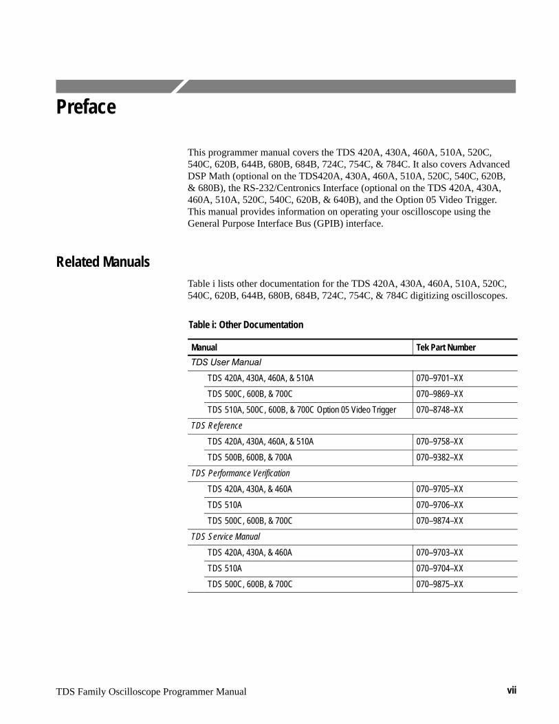
Related ManualsTable i lists other documentation for the TDS 420A, 430A, 460A, 510A, 520C,540C, 620B, 644B, 680B, 684B, 724C, 754C, & 784C digitizing oscilloscopes.
Table i: Other Documentation
Manual Tek Part Number
��� ���� �� �
TDS 420A, 430A, 460A, & 510A 070–9701–XX
TDS 500C, 600B, & 700C 070–9869–XX
TDS 510A, 500C, 600B, & 700C Option 05 Video Trigger 070–8748–XX
TDS Reference
TDS 420A, 430A, 460A, & 510A 070–9758–XX
TDS 500B, 600B, & 700A 070–9382–XX
TDS Performance Verification
TDS 420A, 430A, & 460A 070–9705–XX
TDS 510A 070–9706–XX
TDS 500C, 600B, & 700C 070–9874–XX
TDS Service Manual
TDS 420A, 430A, & 460A 070–9703–XX
TDS 510A 070–9704–XX
TDS 500C, 600B, & 700C 070–9875–XX
Preface
viii TDS Family Oscilloscope Programmer Manual
Default ModelThis manual documents the TDS 400A, TDS 510A, TDS 500C, TDS 600B, &TDS 700C Digitizing Oscilloscopes. Take special note of the followingconventions:
� Some TDS models have two auxiliary channels called AUX 1 and AUX 2,instead of CH 3 and CH 4. Some references to these channels default to CH 3 and CH 4.
� The TDS 684B display screen appears as the default screen wherever adisplay screen is illustrated in this manual.
Model ReferencesThis manual documents the TDS 400A, TDS 510A, TDS 500C, TDS 600B, &TDS 700C Digitizing Oscilloscopes. Take note of the following conventionsused when referencing these oscilloscopes:
� The name “TDS 400A” is used when providing information common to theTDS 420A, 430A, and TDS 460A model oscilloscopes.
� The name “TDS 500C” is used when providing information common to theTDS 520C and TDS 540C model oscilloscopes.
� The name “TDS 600B” is used when providing information common to theTDS 620B, TDS 644B, TDS 680B, and TDS 684B model oscilloscopes.
� The name “TDS 700C” is used when providing information common to theTDS 724C, TDS 754C, and TDS 784C model oscilloscopes.
TDS Family Oscilloscope Programmer Manual 1–1
Getting Started
You can write computer programs that remotely set the oscilloscope front panelcontrols or that take measurements and read those measurements for furtheranalysis or storage.
To help you get started with programmng the oscilloscope, this section includesthe following sections:
� Overview of the Manual – summarizes the type of programming informationcontained in each major section of this manual.
� Setting Up Remote Communications – describes how to physically connectthe oscilloscope to a controller and set the appropriate front panel controls.
Overview of the ManualThe information contained in each major section of this manual is describedbelow.
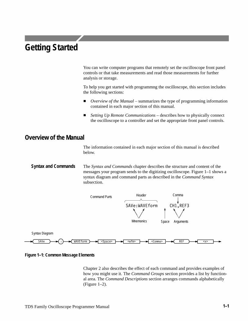
The Syntax and Commands chapter describes the structure and content of themessages your program sends to the digitizing oscilloscope. Figure 1–1 shows asyntax diagram and command parts as described in the Command Syntaxsubsection.
Comma
������������ ��� ��
Header
Mnemonics ArgumentsSpace
��������� � ������� � ���������� ������
Command Parts
Syntax Diagram
Figure 1–1: Common Message Elements
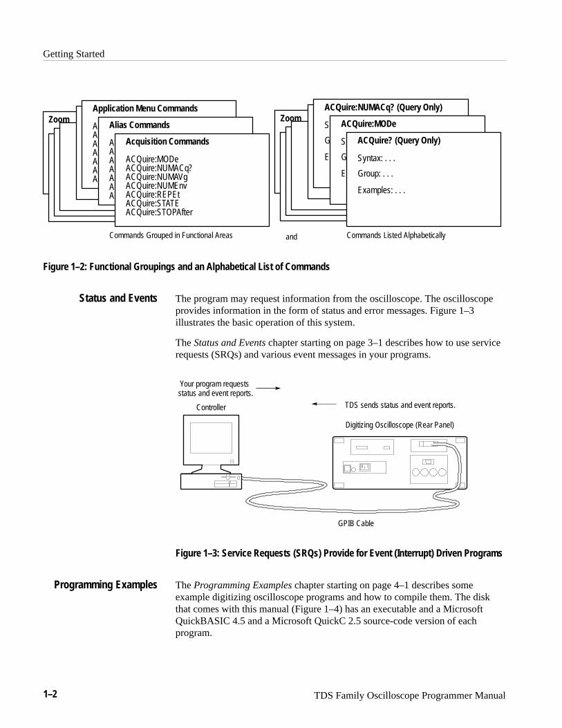
Chapter 2 also describes the effect of each command and provides examples ofhow you might use it. The Command Groups section provides a list by function-al area. The Command Descriptions section arranges commands alphabetically(Figure 1–2).
Syntax and Commands
Getting Started
1–2 TDS Family Oscilloscope Programmer Manual
ZoomZoom
Commands Grouped in Functional Areas Commands Listed Alphabetically
ACQuire? (Query Only)
Syntax: . . .
Group: . . .
Examples: . . .
ACQuire:MODe
S
G
E
ACQuire:NUMACq? (Query Only)
S
G
E
Acquisition Commands
ACQuire:MODeACQuire:NUMACq?ACQuire:NUMAVgACQuire:NUMEnvACQuire:REPEtACQuire:STATEACQuire:STOPAfter
Alias Commands
AAAAAAA
Application Menu Commands
AAAAAAA
and
Figure 1–2: Functional Groupings and an Alphabetical List of Commands
The program may request information from the oscilloscope. The oscilloscopeprovides information in the form of status and error messages. Figure 1–3illustrates the basic operation of this system.
The Status and Events chapter starting on page 3–1 describes how to use servicerequests (SRQs) and various event messages in your programs.
Digitizing Oscilloscope (Rear Panel)
Your program requestsstatus and event reports.
TDS sends status and event reports.
GPIB Cable
Controller
Figure 1–3: Service Requests (SRQs) Provide for Event (Interrupt) Driven Programs
The Programming Examples chapter starting on page 4–1 describes someexample digitizing oscilloscope programs and how to compile them. The diskthat comes with this manual (Figure 1–4) has an executable and a MicrosoftQuickBASIC 4.5 and a Microsoft QuickC 2.5 source-code version of eachprogram.
Status and Events
Programming Examples
Getting Started
TDS Family Oscilloscope Programmer Manual 1–3
TDS ExamplePrograms
Figure 1–4: The Disk That Accompanies This Manual
Setting Up Remote CommunicationsEven the best instrument control program will not do much if the instrument isnot connected to the controller.
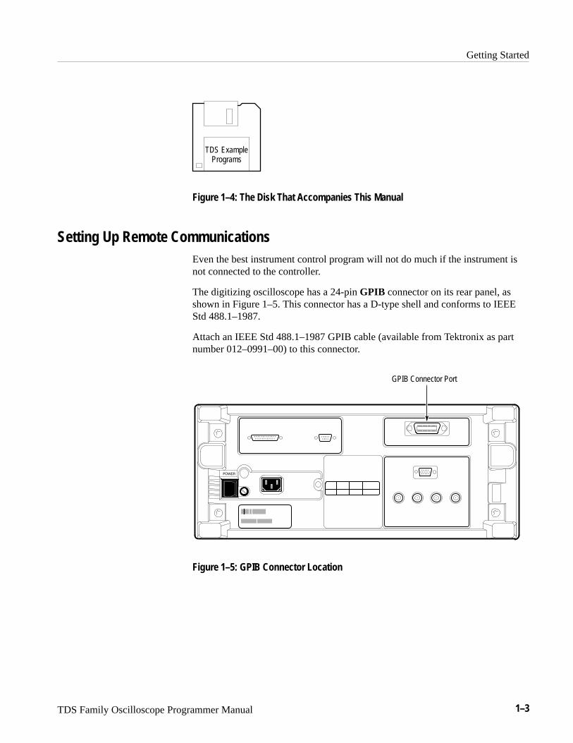
The digitizing oscilloscope has a 24-pin GPIB connector on its rear panel, asshown in Figure 1–5. This connector has a D-type shell and conforms to IEEEStd 488.1–1987.
Attach an IEEE Std 488.1–1987 GPIB cable (available from Tektronix as partnumber 012–0991–00) to this connector.
GPIB Connector Port
Figure 1–5: GPIB Connector Location
Getting Started
1–4 TDS Family Oscilloscope Programmer Manual
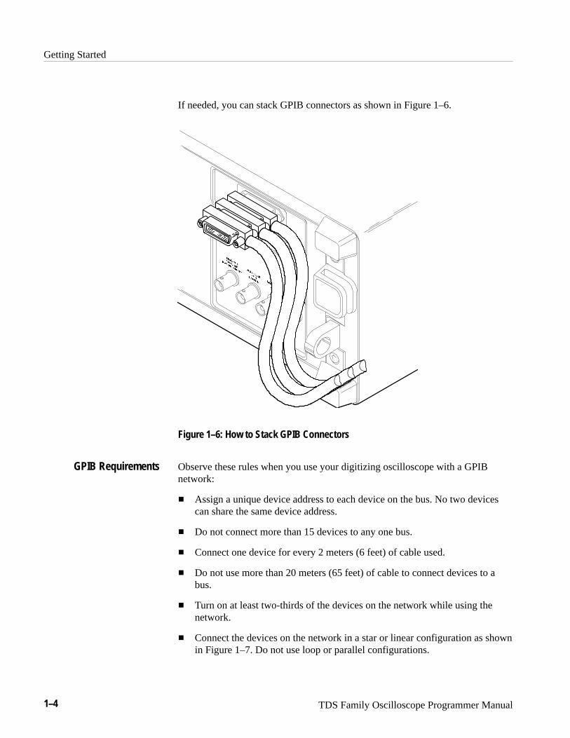
If needed, you can stack GPIB connectors as shown in Figure 1–6.
Figure 1–6: How to Stack GPIB Connectors
Observe these rules when you use your digitizing oscilloscope with a GPIBnetwork:
� Assign a unique device address to each device on the bus. No two devicescan share the same device address.
� Do not connect more than 15 devices to any one bus.
� Connect one device for every 2 meters (6 feet) of cable used.
� Do not use more than 20 meters (65 feet) of cable to connect devices to abus.
� Turn on at least two-thirds of the devices on the network while using thenetwork.
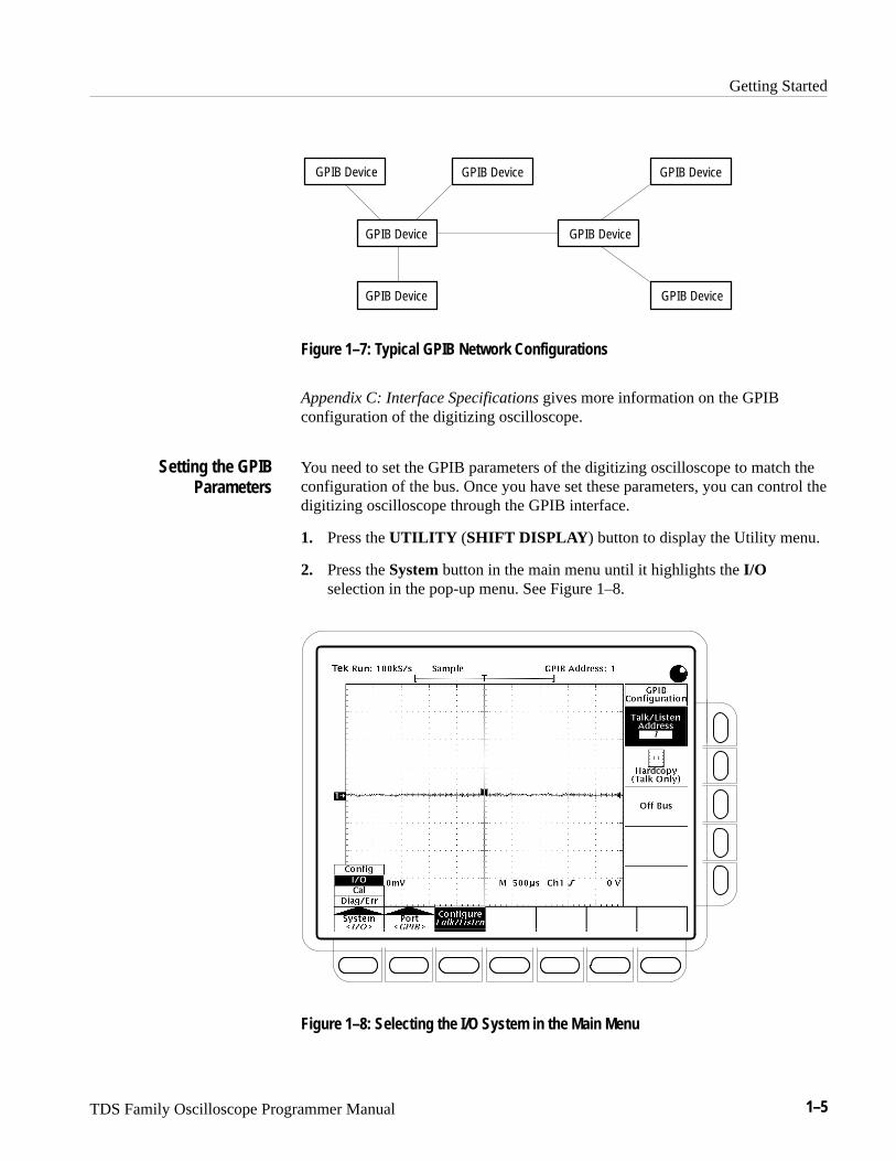
� Connect the devices on the network in a star or linear configuration as shownin Figure 1–7. Do not use loop or parallel configurations.
GPIB Requirements
Getting Started
TDS Family Oscilloscope Programmer Manual 1–5
GPIB Device
GPIB Device
GPIB Device
GPIB Device
GPIB Device
GPIB Device
GPIB Device
Figure 1–7: Typical GPIB Network Configurations
Appendix C: Interface Specifications gives more information on the GPIBconfiguration of the digitizing oscilloscope.
You need to set the GPIB parameters of the digitizing oscilloscope to match theconfiguration of the bus. Once you have set these parameters, you can control thedigitizing oscilloscope through the GPIB interface.
1. Press the UTILITY (SHIFT DISPLAY ) button to display the Utility menu.
2. Press the System button in the main menu until it highlights the I/Oselection in the pop-up menu. See Figure 1–8.
Figure 1–8: Selecting the I/O System in the Main Menu
Setting the GPIBParameters
Getting Started
1–6 TDS Family Oscilloscope Programmer Manual
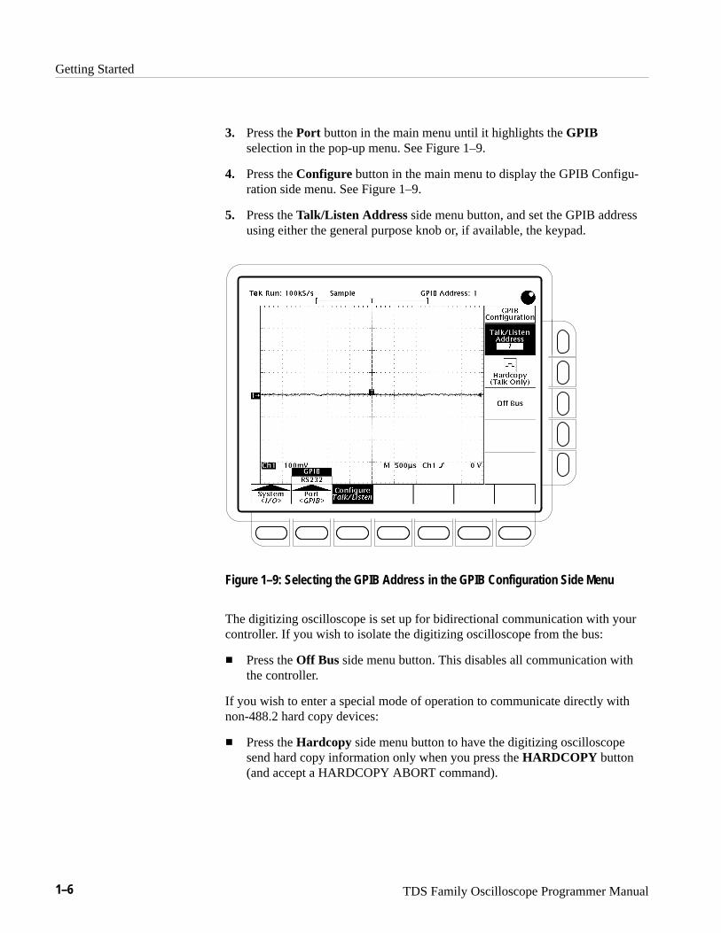
3. Press the Port button in the main menu until it highlights the GPIBselection in the pop-up menu. See Figure 1–9.
4. Press the Configure button in the main menu to display the GPIB Configu-ration side menu. See Figure 1–9.
5. Press the Talk/Listen Address side menu button, and set the GPIB addressusing either the general purpose knob or, if available, the keypad.
Figure 1–9: Selecting the GPIB Address in the GPIB Configuration Side Menu
The digitizing oscilloscope is set up for bidirectional communication with yourcontroller. If you wish to isolate the digitizing oscilloscope from the bus:
� Press the Off Bus side menu button. This disables all communication withthe controller.
If you wish to enter a special mode of operation to communicate directly withnon-488.2 hard copy devices:
� Press the Hardcopy side menu button to have the digitizing oscilloscopesend hard copy information only when you press the HARDCOPY button(and accept a HARDCOPY ABORT command).
TDS Family Oscilloscope Programmer Manual 2–1
Command Syntax
You can control the digitizing oscilloscope through the GPIB interface usingcommands and queries. This section describes the syntax these commands andqueries use. It also describes the conventions the digitizing oscilloscope uses toprocess them. The next section, entitled Command Groups, lists the commandsand queries themselves.
You transmit commands to the digitizing oscilloscope using the enhancedAmerican Standard Code for Information Interchange (ASCII) characterencoding. Appendix A: Character Charts on page A–2 contains a chart of theASCII character set.
This manual describes commands and queries using Backus-Naur Form (BNF)notation and syntax diagrams.
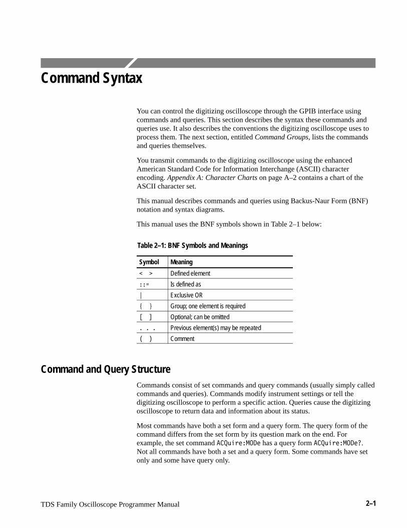
This manual uses the BNF symbols shown in Table 2–1 below:
Table 2–1: BNF Symbols and Meanings
Symbol Meaning
��� Defined element
��� Is defined as
� Exclusive OR
��� Group; one element is required
��� Optional; can be omitted
����� Previous element(s) may be repeated
��� Comment
Command and Query StructureCommands consist of set commands and query commands (usually simply calledcommands and queries). Commands modify instrument settings or tell thedigitizing oscilloscope to perform a specific action. Queries cause the digitizingoscilloscope to return data and information about its status.
Most commands have both a set form and a query form. The query form of thecommand differs from the set form by its question mark on the end. Forexample, the set command ������� �� has a query form ������� ���.Not all commands have both a set and a query form. Some commands have setonly and some have query only.
Command Syntax
2–2 TDS Family Oscilloscope Programmer Manual
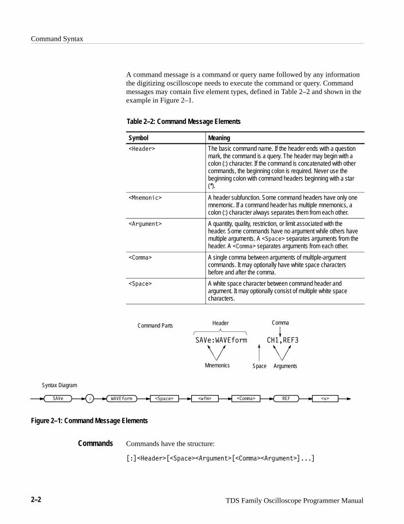
A command message is a command or query name followed by any informationthe digitizing oscilloscope needs to execute the command or query. Commandmessages may contain five element types, defined in Table 2–2 and shown in theexample in Figure 2–1.
Table 2–2: Command Message Elements
Symbol Meaning
� ���� � The basic command name. If the header ends with a questionmark, the command is a query. The header may begin with acolon (:) character. If the command is concatenated with othercommands, the beginning colon is required. Never use thebeginning colon with command headers beginning with a star(*).
���������� A header subfunction. Some command headers have only onemnemonic. If a command header has multiple mnemonics, acolon (:) character always separates them from each other.
� �"���!� A quantity, quality, restriction, or limit associated with theheader. Some commands have no argument while others havemultiple arguments. A ������� separates arguments from theheader. A ������ separates arguments from each other.
������ A single comma between arguments of multiple-argumentcommands. It may optionally have white space charactersbefore and after the comma.
������� A white space character between command header andargument. It may optionally consist of multiple white spacecharacters.
Comma
��������� � ������
Header
Mnemonics ArgumentsSpace
�#������ � ����� � ��� �$�������� ������
Command Parts
Syntax Diagram
Figure 2–1: Command Message Elements
Commands have the structure:
���� ���� ���������� �"���!��������� �"���!������
Commands
Command Syntax
TDS Family Oscilloscope Programmer Manual 2–3
A command header consists of one or more mnemonics arranged in a hierarchi-cal or tree structure. The first mnemonic is the base or root of the tree and eachsubsequent mnemonic is a level or branch off the previous one. Commands at ahigher level in the tree may affect those at a lower level. The leading colon (:)always returns you to the base of the command tree.
Queries have the structure:
� ����� �� '�
� ����� �� '����&�� ��'!*# $)����%##���'!*# $)������
You can specify a query command at any level within the command tree unlessotherwise noted. These branch queries return information about all the mnemon-ics below the specified branch or level. For example, � ��' -
# $)�� ��+��� ��,���� �)"%$ returns the starting point and direction ofthe edge of a delayed measurement, while � ��' # $)�� ��+��� ��,
returns the current settings of all delayed measurement parameters, and� ��' # $)�� ��+� returns all the measurement parameters for thespecified measurement.
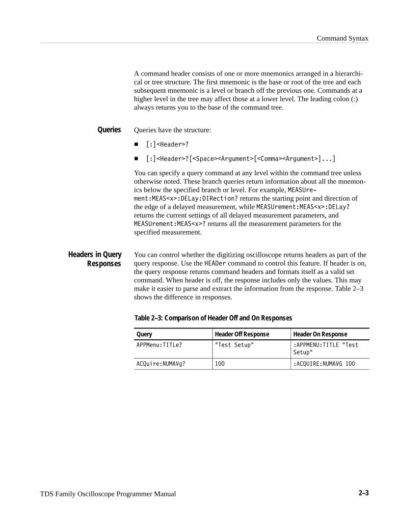
You can control whether the digitizing oscilloscope returns headers as part of thequery response. Use the � � ' command to control this feature. If header is on,the query response returns command headers and formats itself as a valid setcommand. When header is off, the response includes only the values. This maymake it easier to parse and extract the information from the response. Table 2–3shows the difference in responses.
Table 2–3: Comparison of Header Off and On Responses
Query Header Off Response Header On Response
��� $*����� �� () � )*&� ���� ������� �� ()
� )*&�
��*"' �����! ��� ������ ������ ���
Queries
Headers in QueryResponses
Command Syntax
2–4 TDS Family Oscilloscope Programmer Manual
Clearing the TDS Family OscilloscopeYou can clear the Output Queue and reset the digitizing oscilloscope to accept anew command or query by using the Device Clear (DCL) GPIB command.
Command EntryThe following rules apply:
� You can enter commands in upper or lower case.
� You can precede any command with white space characters. White spacecharacters include any combination of the ASCII control characters 00through 09 and 0B through 20 hexadecimal (0 through 9 and 11 through 32decimal).
� The digitizing oscilloscope ignores commands consisting of any combina-tion of white space characters and line feeds.
You can abbreviate many digitizing oscilloscope commands. Each commandlisting in the Commands section shows the minimum acceptable abbreviations incapitals. For example, you can enter the command ���"� ������#� simply as�������� or �����"��.
NOTE. Keep in mind that abbreviation rules change over time as new TDSmodels are introduced. Thus, for the most robust code, use the full spelling.Avoid using the command abbreviations.
If you use the ��� command to have command headers included as part ofquery responses, you can further control whether the returned headers areabbreviated or are full-length. The ����!� command lets you control this.
You can concatenate any combination of set commands and queries using asemicolon (;). The digitizing oscilloscope executes concatenated commands inthe order received.
When concatenating commands and queries, you must follow these rules:
1. Separate completely different headers by a semicolon and by the beginningcolon on all commands but the first. For example, the commands �� �$
�� ���� ������ and ���"� �������� �� would be concatenated into asingle command:
�� ��� ���� �����������"� �������� ��
Abbreviating Commands
Concatenating Commands

Command Syntax
TDS Family Oscilloscope Programmer Manual 2–5
2. If concatenated commands have headers that differ by only the last mnemon-ic, you can abbreviate the second command and eliminate the beginningcolon. For example, you can concatenate the commands ��+#( ����
�� $&' and ��+#( �����" �� into a single command:
��+#( ���� �� $&' � ����" ��
The longer version works equally well:
��+#( ���� �� $&' ����+#( �����" ��
3. Never precede a star (*) command with a colon:
��+#( ���� �� $&' �����
Any commands that follow will be processed as if the star command was notthere so
��+#( ���� �� $&' ����������" ��
will set the acquisition mode to envelope and set the number of acquisitionsfor averaging to 10.
4. When you concatenate queries, the responses to all the queries are concate-nated into a single response message. For example, if the display intensityfor text is 80% and for the waveform it is 90%, the concatenated query
���'$�,���� �)#*,�� �*��� !&(%
will return either ����������� ������� �� �������������� ���-
����� ���� �� if header is on or ����� if header is off.
5. Set commands and queries may be concatenated in the same message. Forexample,
��+#( ���� �����$�����"����
is a valid message that sets the acquisition mode to normal. The messagethen queries the number of acquisitions for averaging and the acquisitionstate. Concatenated commands and queries are executed in the orderreceived.
Here are some invalid concatenations:
� ����$�,���� �)#*,�� �* �����+#( �����" ��
(no colon before ��+#( )
� ����$�,���� �)#*,�� �* ������ !&(% ��
(extra colon before �� !&(% — could use ����$�,���� �)#*,��� !&(%instead)
Command Syntax
2–6 TDS Family Oscilloscope Programmer Manual
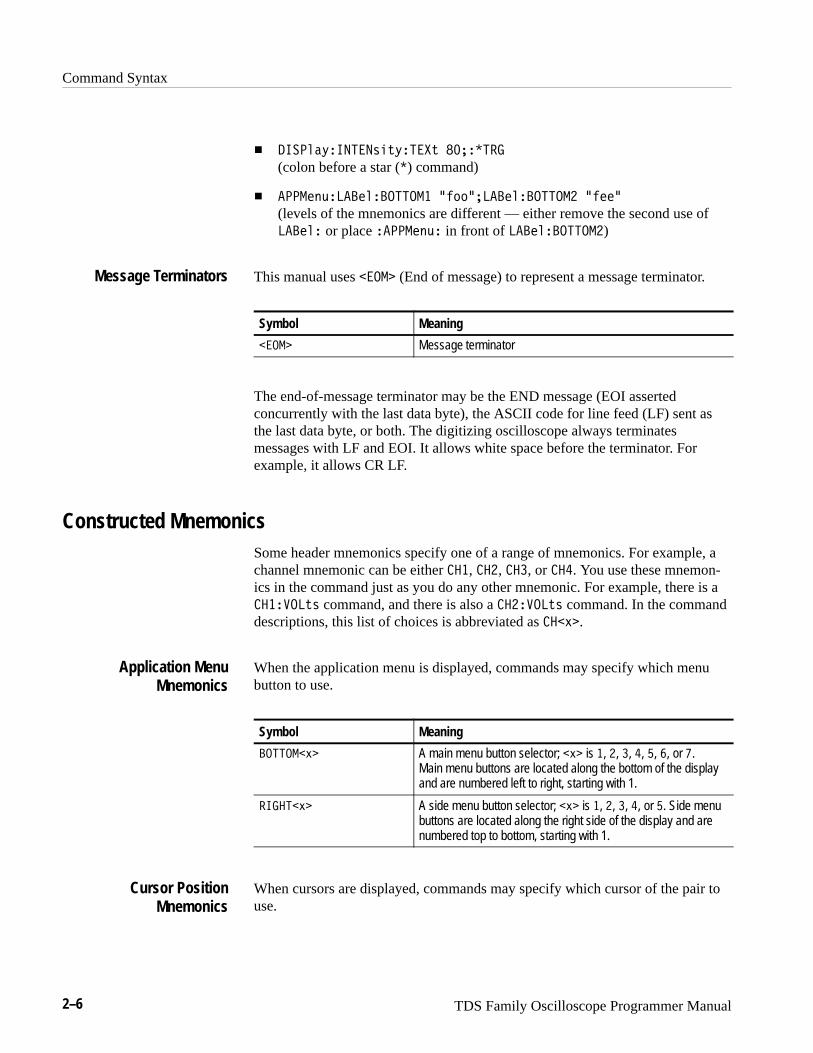
� ����'#. �� ��*&+. �"+ ��� � ��
(colon before a star (�) command)
� ����$(, ���$' �� ��� �%))�����$' �� ��� �%$$�
(levels of the mnemonics are different — either remove the second use of���$' or place ����$(, in front of ���$' �� ���)
This manual uses ����� (End of message) to represent a message terminator.
Symbol Meaning
����� Message terminator
The end-of-message terminator may be the END message (EOI assertedconcurrently with the last data byte), the ASCII code for line feed (LF) sent asthe last data byte, or both. The digitizing oscilloscope always terminatesmessages with LF and EOI. It allows white space before the terminator. Forexample, it allows CR LF.
Constructed MnemonicsSome header mnemonics specify one of a range of mnemonics. For example, achannel mnemonic can be either ���, ���, ���, or ���. You use these mnemon-ics in the command just as you do any other mnemonic. For example, there is a��� !��+* command, and there is also a ��� !��+* command. In the commanddescriptions, this list of choices is abbreviated as ���-�.
When the application menu is displayed, commands may specify which menubutton to use.
Symbol Meaning
�� ���-� A main menu button selector; �-� is �, �, �, �, , , or �.Main menu buttons are located along the bottom of the displayand are numbered left to right, starting with 1.
���� �-� A side menu button selector; �-� is �, �, �, �, or . Side menubuttons are located along the right side of the display and arenumbered top to bottom, starting with 1.
When cursors are displayed, commands may specify which cursor of the pair touse.
Message Terminators
Application MenuMnemonics
Cursor PositionMnemonics

Command Syntax
TDS Family Oscilloscope Programmer Manual 2–7
Symbol Meaning
����������� A cursor selector; ��� is either � or �.
Commands can specify which measurement to set or query as a mnemonic in theheader. Up to four automated measurements may be displayed with eachdisplayed waveform. The displayed measurements are specified in this way:
Symbol Meaning
����� A measurement specifier; ��� is either � [top], �, �, or�[bottom].
Commands specify the channel to use as a mnemonic in the header.
Symbol Meaning
����� A channel specifier; ��� is either �, �, �, or �.
For the TDS 520C, 620B, 680B, and 724C, ��� and ���represent the front-panel inputs labeled AUX 1 and AUX 2respectively.
Commands can specify the mathematical waveform to use as a mnemonic in theheader.
Symbol Meaning
������ A math waveform specifier; ��� is �, �, or �.
Commands can specify the reference waveform to use as a mnemonic in theheader.
Symbol Meaning
���� A reference waveform specifier; ��� is either �, �, �, or �.
In some commands, you can specify a waveform regardless of whether it is achannel waveform, a math waveform, or a reference waveform. Specify such awaveform as follows:
Measurement SpecifierMnemonics
Channel Mnemonics
Math WaveformMnemonics
Reference WaveformMnemonics
Waveform Mnemonics
Command Syntax
2–8 TDS Family Oscilloscope Programmer Manual
Symbol Meaning
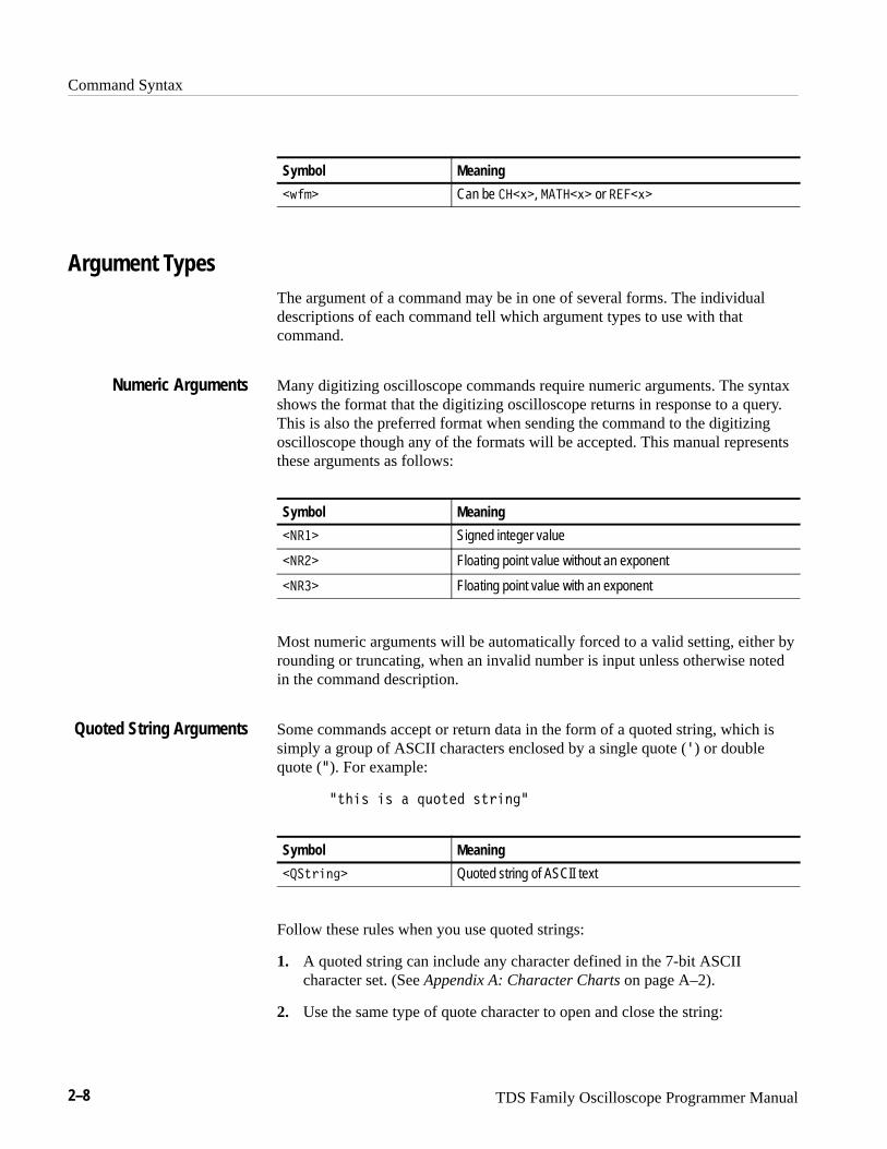
�#��� Can be �$�, �� �$� or ����$�
Argument TypesThe argument of a command may be in one of several forms. The individualdescriptions of each command tell which argument types to use with thatcommand.
Many digitizing oscilloscope commands require numeric arguments. The syntaxshows the format that the digitizing oscilloscope returns in response to a query.This is also the preferred format when sending the command to the digitizingoscilloscope though any of the formats will be accepted. This manual representsthese arguments as follows:
Symbol Meaning
����� Signed integer value
����� Floating point value without an exponent
����� Floating point value with an exponent
Most numeric arguments will be automatically forced to a valid setting, either byrounding or truncating, when an invalid number is input unless otherwise notedin the command description.
Some commands accept or return data in the form of a quoted string, which issimply a group of ASCII characters enclosed by a single quote (�) or doublequote (�). For example:
�!�� � � �"�!�� !�����
Symbol Meaning
���!����� Quoted string of ASCII text
Follow these rules when you use quoted strings:
1. A quoted string can include any character defined in the 7-bit ASCIIcharacter set. (See Appendix A: Character Charts on page A–2).
2. Use the same type of quote character to open and close the string:
Numeric Arguments
Quoted String Arguments
Command Syntax
TDS Family Oscilloscope Programmer Manual 2–9
�%��$ �$ � '���� $%#� ��
3. You can mix quotation marks within a string as long as you follow theprevious rule:
�%��$ �$ � �����"%����� $%#� ��
4. You can include a quote character within a string simply by repeating thequote. For example,
���#� �$ � �� ��#��
5. Strings can have upper or lower case characters.
6. If you use a GPIB network, you cannot terminate a quoted string with theEND message before the closing delimiter.
7. A carriage return or line feed imbedded in a quoted string does not terminatethe string, but is treated as just another character in the string.
8. The maximum length of a quoted string returned from a query is 1000characters.
Here are some invalid strings:
� �� '���� $%#� � �#�&�� %�
(quotes are not of the same type)
� �%�$%�����
(termination character is embedded in the string)
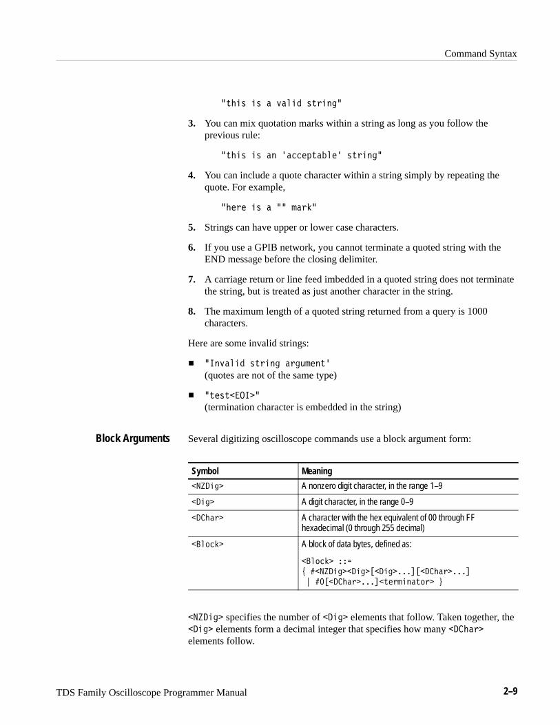
Several digitizing oscilloscope commands use a block argument form:
Symbol Meaning
��� �� A nonzero digit character, in the range 1–9
� �� A digit character, in the range 0–9
� ���# A character with the hex equivalent of 00 through FFhexadecimal (0 through 255 decimal)
���!�� A block of data bytes, defined as:
���!�� ��
( ���� ��� ���� �������� ���#����
) ���� ���#�����%�#�� �%!# *
��� �� specifies the number of � �� elements that follow. Taken together, the� �� elements form a decimal integer that specifies how many � ���#
elements follow.
Block Arguments
Command Syntax
2–10 TDS Family Oscilloscope Programmer Manual
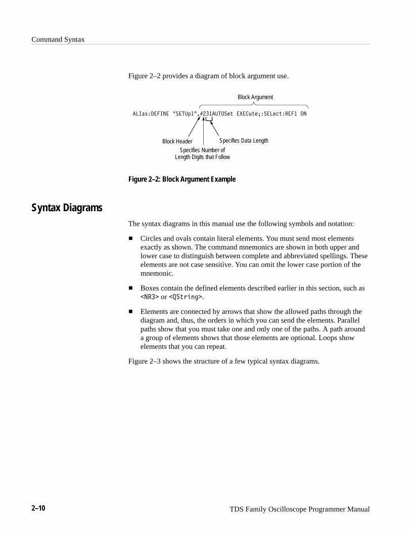
Figure 2–2 provides a diagram of block argument use.
����#������� &����!�������������$ ��� %$�������$����� ��
Block HeaderSpecifies Number of
Length Digits that Follow
Specifies Data Length
Block Argument
Figure 2–2: Block Argument Example
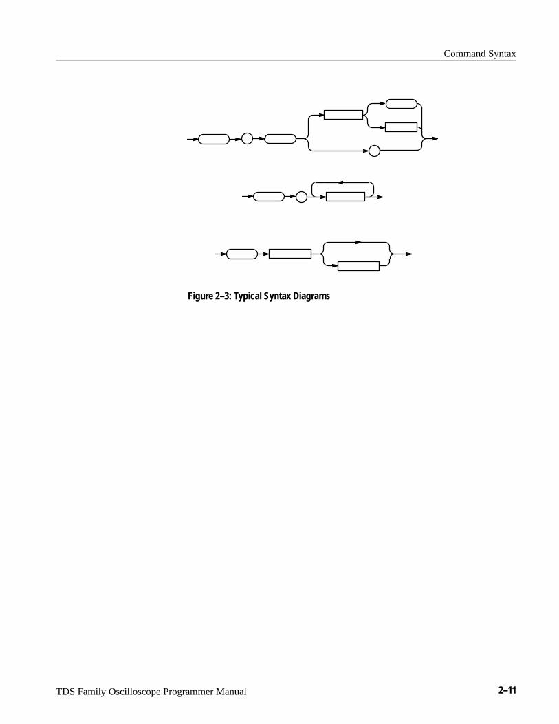
Syntax DiagramsThe syntax diagrams in this manual use the following symbols and notation:
� Circles and ovals contain literal elements. You must send most elementsexactly as shown. The command mnemonics are shown in both upper andlower case to distinguish between complete and abbreviated spellings. Theseelements are not case sensitive. You can omit the lower case portion of themnemonic.
� Boxes contain the defined elements described earlier in this section, such as���� or ��$"� ��.
� Elements are connected by arrows that show the allowed paths through thediagram and, thus, the orders in which you can send the elements. Parallelpaths show that you must take one and only one of the paths. A path arounda group of elements shows that those elements are optional. Loops showelements that you can repeat.
Figure 2–3 shows the structure of a few typical syntax diagrams.
Command Syntax
TDS Family Oscilloscope Programmer Manual 2–11
Figure 2–3: Typical Syntax Diagrams
TDS Family Oscilloscope Programmer Manual 2–13
Command Groups
This section lists TDS Family Oscilloscope commands in two ways. It firstpresents them by functional groups. It then lists them alphabetically. Thefunctional group list starts below. The alphabetical list provides more detail oneach command and starts on page 2–47.
The TDS Family Oscilloscope GPIB interface conforms to Tektronix standardcodes and formats and IEEE Std 488.2–1987 except where noted.
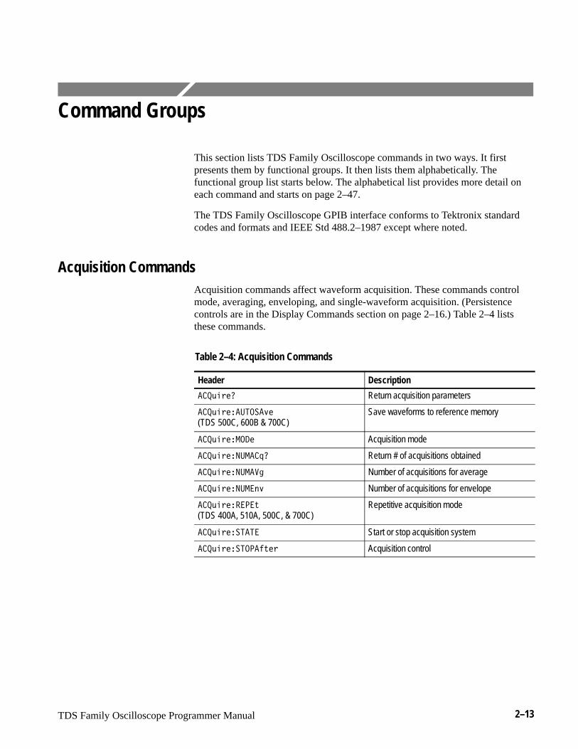
Acquisition CommandsAcquisition commands affect waveform acquisition. These commands controlmode, averaging, enveloping, and single-waveform acquisition. (Persistencecontrols are in the Display Commands section on page 2–16.) Table 2–4 liststhese commands.
Table 2–4: Acquisition Commands
Header Description
�������� Return acquisition parameters
����������� ��� (TDS 500C, 600B & 700C)
Save waveforms to reference memory
����������� Acquisition mode
��������������� Return # of acquisitions obtained
�������������� Number of acquisitions for average
�������������� Number of acquisitions for envelope
������������ (TDS 400A, 510A, 500C, & 700C)
Repetitive acquisition mode
�������� ���� Start or stop acquisition system
�������� ������ Acquisition control
Command Groups
2–14 TDS Family Oscilloscope Programmer Manual
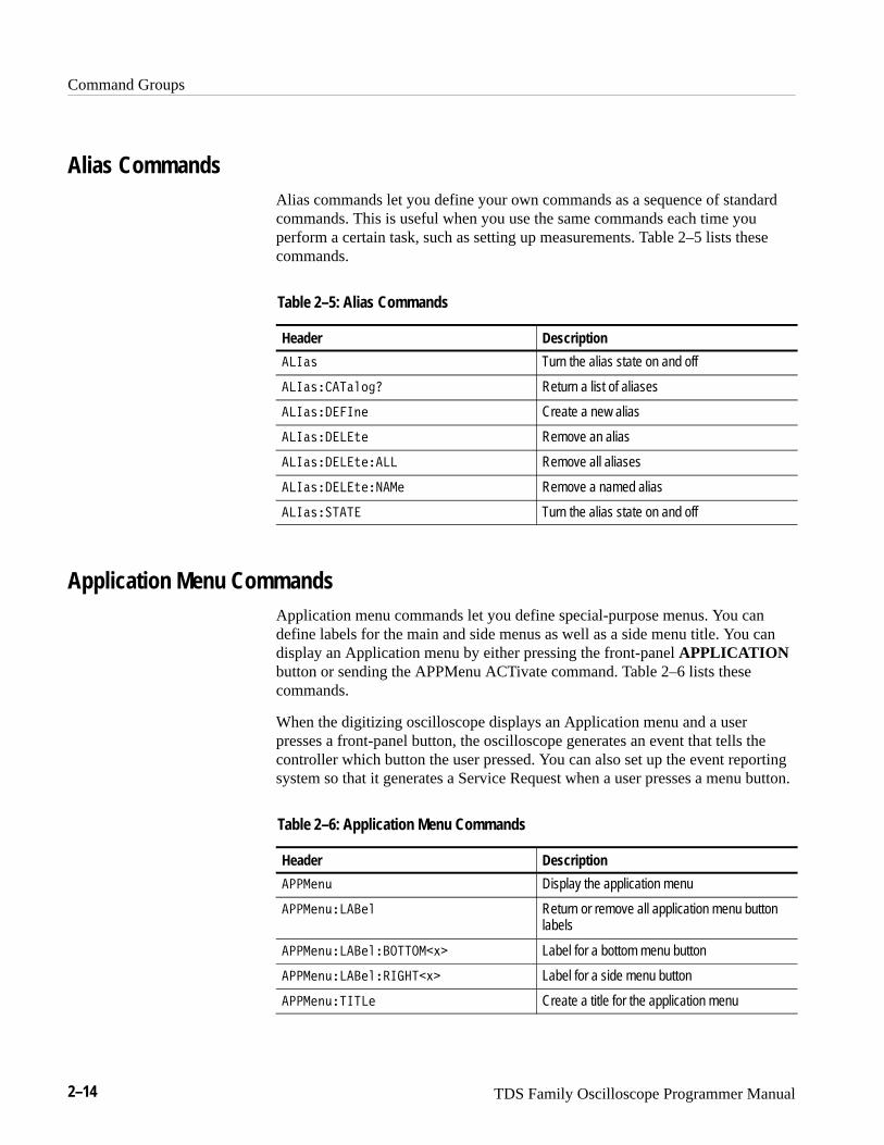
Alias CommandsAlias commands let you define your own commands as a sequence of standardcommands. This is useful when you use the same commands each time youperform a certain task, such as setting up measurements. Table 2–5 lists thesecommands.
Table 2–5: Alias Commands
Header Description
�� �� Turn the alias state on and off
�� ����������� Return a list of aliases
�� ���� �� Create a new alias
�� ������� Remove an alias
�� ����������� Remove all aliases
�� ������������ Remove a named alias
�� ������� Turn the alias state on and off
Application Menu CommandsApplication menu commands let you define special-purpose menus. You candefine labels for the main and side menus as well as a side menu title. You candisplay an Application menu by either pressing the front-panel APPLICATIONbutton or sending the APPMenu ACTivate command. Table 2–6 lists thesecommands.
When the digitizing oscilloscope displays an Application menu and a userpresses a front-panel button, the oscilloscope generates an event that tells thecontroller which button the user pressed. You can also set up the event reportingsystem so that it generates a Service Request when a user presses a menu button.
Table 2–6: Application Menu Commands
Header Description
������� Display the application menu
������������� Return or remove all application menu buttonlabels
����������������������� Label for a bottom menu button
��������������� ������ Label for a side menu button
��������� ��� Create a title for the application menu
Command Groups
TDS Family Oscilloscope Programmer Manual 2–15
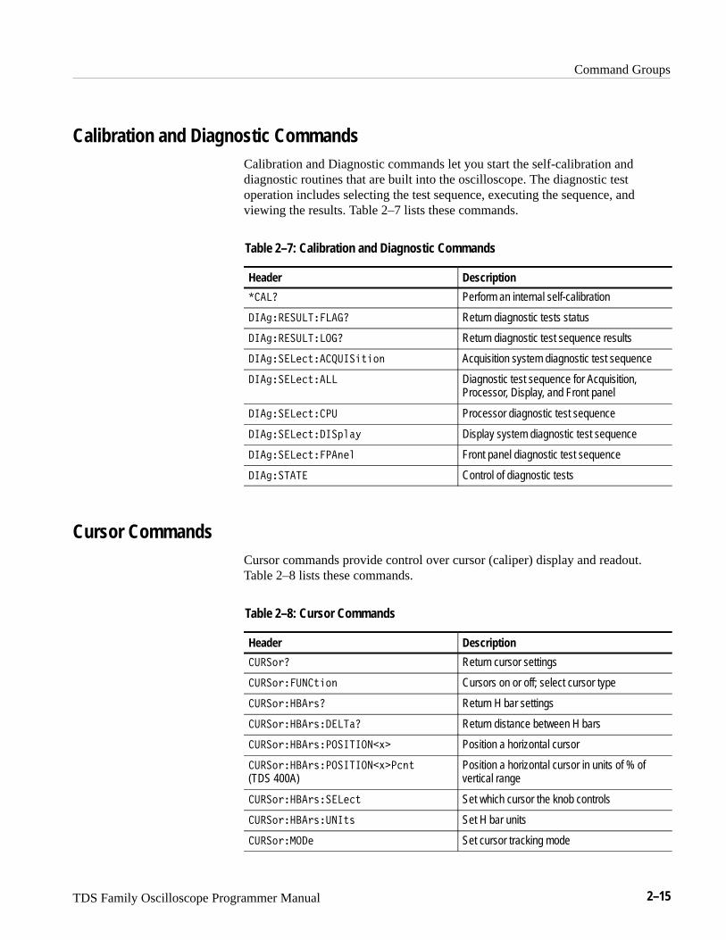
Calibration and Diagnostic CommandsCalibration and Diagnostic commands let you start the self-calibration anddiagnostic routines that are built into the oscilloscope. The diagnostic testoperation includes selecting the test sequence, executing the sequence, andviewing the results. Table 2–7 lists these commands.
Table 2–7: Calibration and Diagnostic Commands
Header Description
����� Perform an internal self-calibration
��������������� Return diagnostic tests status
�������������� Return diagnostic test sequence results
��������$��������$� � Acquisition system diagnostic test sequence
��������$���� Diagnostic test sequence for Acquisition,Processor, Display, and Front panel
��������$���� Processor diagnostic test sequence
��������$���!��& Display system diagnostic test sequence
��������$������� Front panel diagnostic test sequence
�������� Control of diagnostic tests
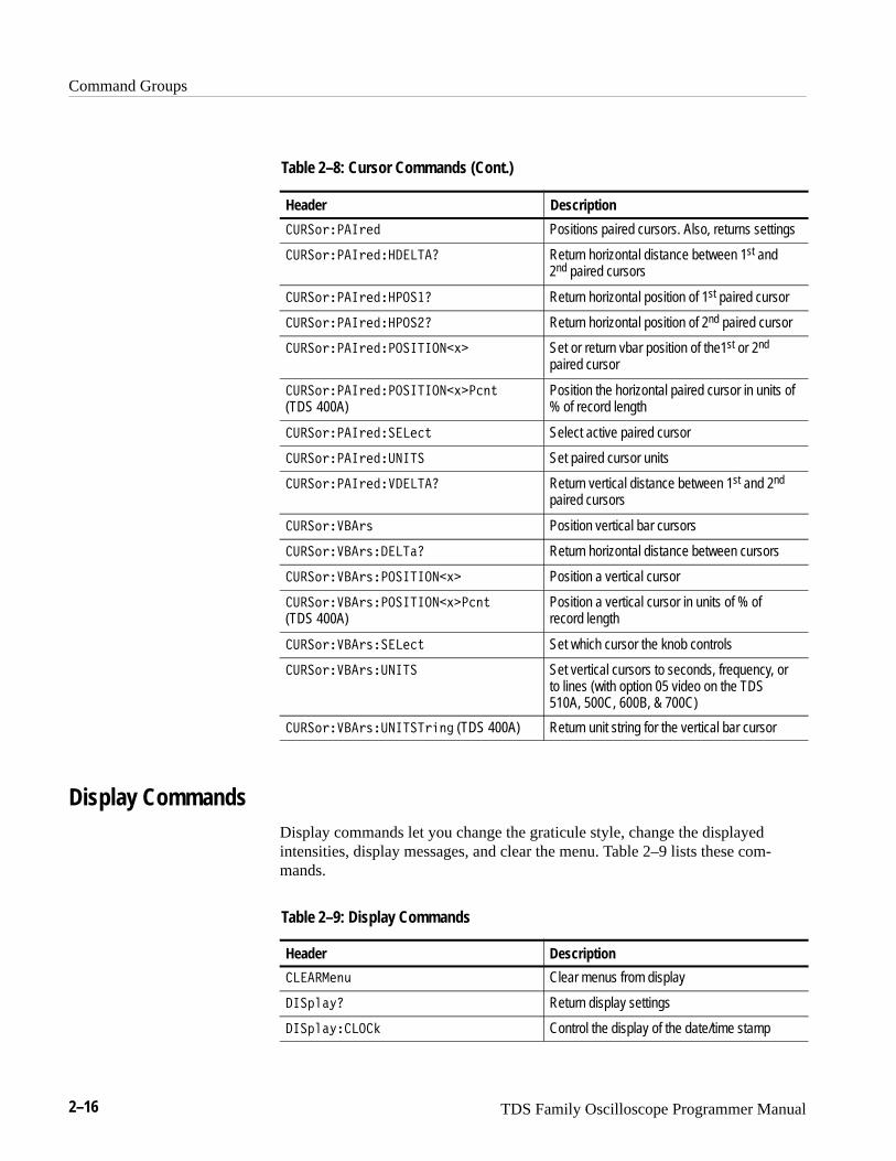
Cursor CommandsCursor commands provide control over cursor (caliper) display and readout.Table 2–8 lists these commands.
Table 2–8: Cursor Commands
Header Description
���� "� Return cursor settings
���� "�����$� � Cursors on or off; select cursor type
���� "� ��"#� Return H bar settings
���� "� ��"#����� Return distance between H bars
���� "� ��"#����������%� Position a horizontal cursor
���� "� ��"#����������%����$
(TDS 400A)Position a horizontal cursor in units of % ofvertical range
���� "� ��"#�����$ Set which cursor the knob controls
���� "� ��"#����$# Set H bar units
���� "���� Set cursor tracking mode
Command Groups
2–16 TDS Family Oscilloscope Programmer Manual
Table 2–8: Cursor Commands (Cont.)
Header Description
���!#��� #�� Positions paired cursors. Also, returns settings
���!#��� #��������� Return horizontal distance between 1st and2nd paired cursors
���!#��� #��������� Return horizontal position of 1st paired cursor
���!#��� #��������� Return horizontal position of 2nd paired cursor
���!#��� #������ � ���'� Set or return vbar position of the1st or 2nd
paired cursor
���!#��� #������ � ���'��� %
(TDS 400A)Position the horizontal paired cursor in units of% of record length
���!#��� #��������% Select active paired cursor
���!#��� #����� �� Set paired cursor units
���!#��� #��������� Return vertical distance between 1st and 2nd
paired cursors
���!#����#$ Position vertical bar cursors
���!#����#$������ Return horizontal distance between cursors
���!#����#$���� � ���'� Position a vertical cursor
���!#����#$���� � ���'��� %
(TDS 400A)Position a vertical cursor in units of % ofrecord length
���!#����#$������% Set which cursor the knob controls
���!#����#$��� �� Set vertical cursors to seconds, frequency, orto lines (with option 05 video on the TDS510A, 500C, 600B, & 700C)
���!#����#$��� ���#� � (TDS 400A) Return unit string for the vertical bar cursor
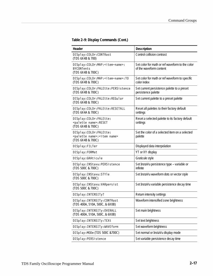
Display CommandsDisplay commands let you change the graticule style, change the displayedintensities, display messages, and clear the menu. Table 2–9 lists these com-mands.
Table 2–9: Display Commands
Header Description
������ & Clear menus from display
�"��(� Return display settings
�"��(���� Control the display of the date/time stamp
Command Groups
TDS Family Oscilloscope Programmer Manual 2–17
Table 2–9: Display Commands (Cont.)
Header Description
��$ �*����%������&'
(TDS 6X4B & 700)Control collision contrast
��$ �*����%�������'�!�"�!���
������"'&
(TDS 6X4B & 700C)
Set color for math or ref waveform to the colorof the waveform content
��$ �*����%�������'�!�"�!����� (TDS 6X4B & 700C)
Set color for math or ref waveform to specificcolor index
��$ �*����%�����''�������&'�"�� (TDS 6X4B & 700C)
Set current persistence palette to a presetpersistence palette
��$ �*����%�����''���� ( �% (TDS 6X4B & 700C)
Set current palette to a preset palette
��$ �*����%�����''���������� (TDS 6X4A & 700C)
Reset all palettes to their factory defaultsettings
��$ �*����%�����''��
�$� �''� "�!��������
(TDS 6X4B & 700C)
Reset a selected palette to its factory defaultsettings
��$ �*����%�����''��
�$� �''� "�!�����'�! "�!��
(TDS 6X4B & 700C)
Set the color of a selected item on a selectedpalette
��$ �*������% Displayed data interpolation
��$ �*������' YT or XY display
��$ �*� ��'��( � Graticule style
��$ �*����'�)(������&'�"��
(TDS 500C & 700C)Set InstaVu persistence type – variable orinfinite
��$ �*����'�)(���� �
(TDS 500C & 700C)Set InstaVu waveform dots or vector style
��$ �*����'�)(����$�%&�&'
(TDS 500C & 700C)Set InstaVu variable persistence decay time
��$ �*���������*� Return intensity settings
��$ �*���������*������&'
(TDS 400A, 510A, 500C, & 6X0B)Waveform intensified zone brightness
��$ �*���������*��������
(TDS 400A, 510A, 500C, & 6X0B)Set main brightness
��$ �*���������*����' Set text brightness
��$ �*���������*������#%! Set waveform brightness
��$ �*���� (TDS 500C &700C) Set normal or InstaVu display mode
��$ �*������&'�"�� Set variable persistence decay time
Command Groups
2–18 TDS Family Oscilloscope Programmer Manual
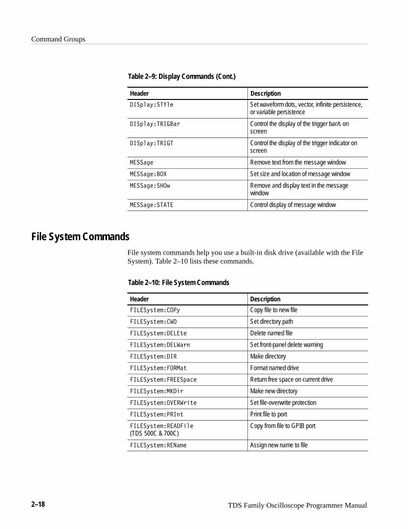
Table 2–9: Display Commands (Cont.)
Header Description
�� ��%������ Set waveform dots, vector, infinite persistence,or variable persistence
�� ��%������! Control the display of the trigger bar/s onscreen
�� ��%����� Control the display of the trigger indicator onscreen
������ Remove text from the message window
���������� Set size and location of message window
���������$ Remove and display text in the messagewindow
������������ Control display of message window
File System CommandsFile system commands help you use a built-in disk drive (available with the FileSystem). Table 2–10 lists these commands.
Table 2–10: File System Commands
Header Description
����%"#������% Copy file to new file
����%"#������ Set directory path
����%"#�������#� Delete named file
����%"#��������!� Set front-panel delete warning
����%"#����� Make directory
����%"#������ �# Format named drive
����%"#�������� ��� Return free space on current drive
����%"#��� ���! Make new directory
����%"#��������!�#� Set file-overwrite protection
����%"#������# Print file to port
����%"#����������� (TDS 500C & 700C)
Copy from file to GPIB port
����%"#��������� Assign new name to file
Command Groups
TDS Family Oscilloscope Programmer Manual 2–19
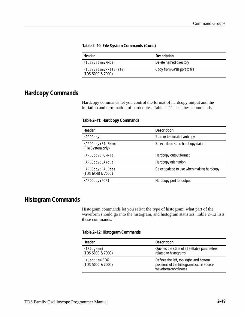
Table 2–10: File System Commands (Cont.)
Header Description
��� ���������� Delete named directory
��� ������������� (TDS 500C & 700C)
Copy from GPIB port to file
Hardcopy CommandsHardcopy commands let you control the format of hardcopy output and theinitiation and termination of hardcopies. Table 2–11 lists these commands.
Table 2–11: Hardcopy Commands
Header Description
������� Start or terminate hardcopy
������� ������� (File System only)
Select file to send hardcopy data to
������� �� ���� Hardcopy output format
������� ������ Hardcopy orientation
������� ������� (TDS 6X4B & 700C)
Select palette to use when making hardcopy
������� �� �� Hardcopy port for output
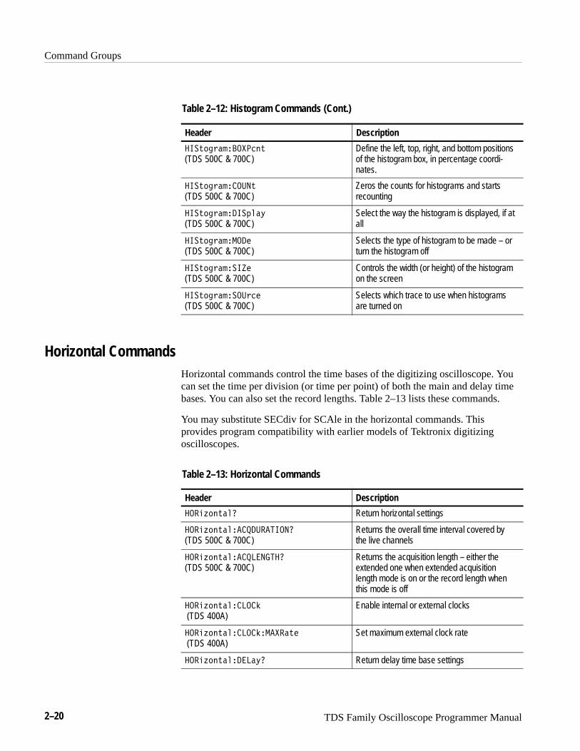
Histogram CommandsHistogram commands let you select the type of histogram, what part of thewaveform should go into the histogram, and histogram statistics. Table 2–12 liststhese commands.
Table 2–12: Histogram Commands
Header Description
���������
(TDS 500C & 700C)Queries the state of all settable parametersrelated to histograms
��������:BOX(TDS 500C & 700C)
Defines the left, top, right, and bottompositions of the histogram box, in sourcewaveform coordinates
Command Groups
2–20 TDS Family Oscilloscope Programmer Manual
Table 2–12: Histogram Commands (Cont.)
Header Description
�# �"���������#
(TDS 500C & 700C)Define the left, top, right, and bottom positionsof the histogram box, in percentage coordi-nates.
�# �"������ #
(TDS 500C & 700C)Zeros the counts for histograms and startsrecounting
�# �"�����!��$
(TDS 500C & 700C)Select the way the histogram is displayed, if atall
�# �"�������
(TDS 500C & 700C)Selects the type of histogram to be made – orturn the histogram off
�# �"������
(TDS 500C & 700C)Controls the width (or height) of the histogramon the screen
�# �"������"��
(TDS 500C & 700C)Selects which trace to use when histogramsare turned on
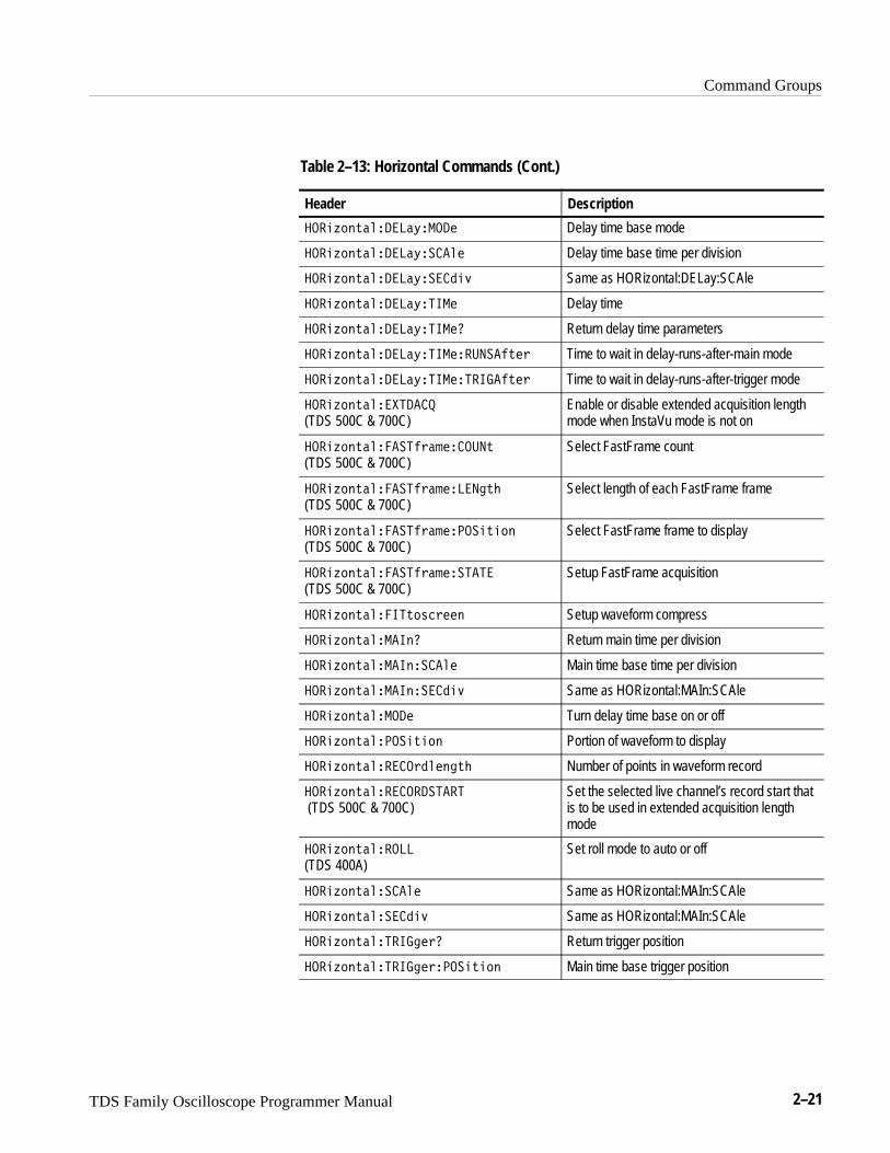
Horizontal CommandsHorizontal commands control the time bases of the digitizing oscilloscope. Youcan set the time per division (or time per point) of both the main and delay timebases. You can also set the record lengths. Table 2–13 lists these commands.
You may substitute SECdiv for SCAle in the horizontal commands. Thisprovides program compatibility with earlier models of Tektronix digitizingoscilloscopes.
Table 2–13: Horizontal Commands
Header Description
���% �#��� Return horizontal settings
���% �#������������ �
(TDS 500C & 700C)Returns the overall time interval covered bythe live channels
���% �#�������� ���
(TDS 500C & 700C)Returns the acquisition length – either theextended one when extended acquisitionlength mode is on or the record length whenthis mode is off
���% �#��������
(TDS 400A)Enable internal or external clocks
���% �#��������������#�
(TDS 400A)Set maximum external clock rate
���% �#�������$� Return delay time base settings
Command Groups
TDS Family Oscilloscope Programmer Manual 2–21
Table 2–13: Horizontal Commands (Cont.)
Header Description
���'! $�������&����� Delay time base mode
���'! $�������&������ Delay time base time per division
���'! $�������&������% Same as HORizontal:DELay:SCAle
���'! $�������&���� Delay time
���'! $�������&����� Return delay time parameters
���'! $�������&������� ���$�" Time to wait in delay-runs-after-main mode
���'! $�������&����������$�" Time to wait in delay-runs-after-trigger mode
���'! $����������
(TDS 500C & 700C)Enable or disable extended acquisition lengthmode when InstaVu mode is not on
���'! $��������"������� $ (TDS 500C & 700C)
Select FastFrame count
���'! $��������"������ �$�
(TDS 500C & 700C)Select length of each FastFrame frame
���'! $��������"��������$�!
(TDS 500C & 700C)Select FastFrame frame to display
���'! $��������"���������
(TDS 500C & 700C)Setup FastFrame acquisition
���'! $�����$!#�"�� Setup waveform compress
���'! $����� � Return main time per division
���'! $����� ������ Main time base time per division
���'! $����� ������% Same as HORizontal:MAIn:SCAle
���'! $������� Turn delay time base on or off
���'! $�������$�! Portion of waveform to display
���'! $�������"��� �$� Number of points in waveform record
���'! $��������������
(TDS 500C & 700C)Set the selected live channel’s record start thatis to be used in extended acquisition lengthmode
���'! $�������
(TDS 400A)Set roll mode to auto or off
���'! $�������� Same as HORizontal:MAIn:SCAle
���'! $��������% Same as HORizontal:MAIn:SCAle
���'! $��������"� Return trigger position
���'! $��������"�����$�! Main time base trigger position

Command Groups
2–22 TDS Family Oscilloscope Programmer Manual
Limit Test CommandsThe Limit Test commands let you automatically compare each incomingwaveform against a template waveform. You set an envelope of limits around awaveform and let the digitizing oscilloscope find the waveforms that fall outsidethose limits. When it finds such a waveform, it can generate a hardcopy, ring abell, stop and wait for your input, or any combination of these actions. Table 2–14 lists these commands.
Table 2–14: Limit Test Commands
Header Description
��������� Ring bell when limit exceeded
������ ���������� Template to compare waveform to
������ ������������
(TDS 510A, 500C, 600B, & 700C)Template to compare math waveform to
������������ Make hardcopy when limit exceeded
���������� Turn limit testing on or off
������������� Template to compare waveform to
������������������������� Reference storage for template waveform
��������������� ���� Template waveform source
��������������� ��������
�� �����
Tested waveform horizontal tolerance
��������������� ���������������� Tested waveform vertical tolerance
Command Groups
TDS Family Oscilloscope Programmer Manual 2–23
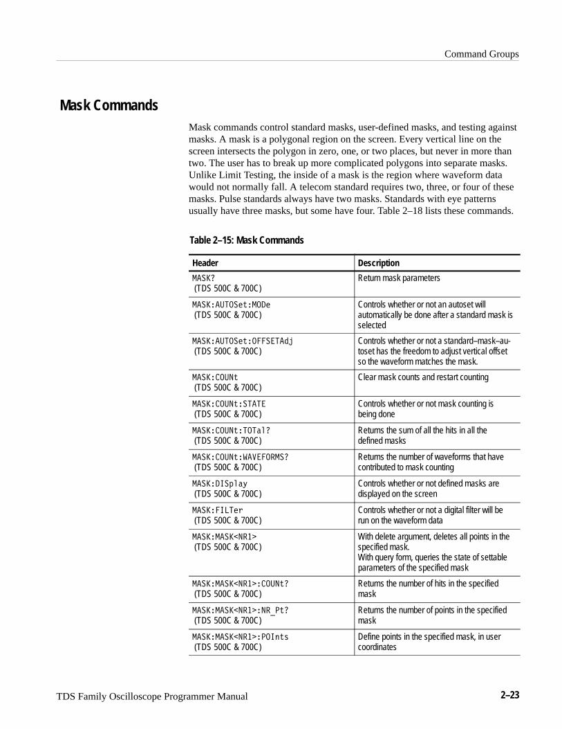
Mask CommandsMask commands control standard masks, user-defined masks, and testing againstmasks. A mask is a polygonal region on the screen. Every vertical line on thescreen intersects the polygon in zero, one, or two places, but never in more thantwo. The user has to break up more complicated polygons into separate masks.Unlike Limit Testing, the inside of a mask is the region where waveform datawould not normally fall. A telecom standard requires two, three, or four of thesemasks. Pulse standards always have two masks. Standards with eye patternsusually have three masks, but some have four. Table 2–18 lists these commands.
Table 2–15: Mask Commands
Header Description
�����
(TDS 500C & 700C)Return mask parameters
�����������"�����
(TDS 500C & 700C)Controls whether or not an autoset willautomatically be done after a standard mask isselected
�����������"�������
(TDS 500C & 700C)Controls whether or not a standard–mask–au-toset has the freedom to adjust vertical offsetso the waveform matches the mask.
���������"
(TDS 500C & 700C)Clear mask counts and restart counting
���������"�����
(TDS 500C & 700C)Controls whether or not mask counting isbeing done
���������"�������
(TDS 500C & 700C)Returns the sum of all the hits in all thedefined masks
���������"���������
(TDS 500C & 700C)Returns the number of waveforms that havecontributed to mask counting
�����������#
(TDS 500C & 700C)Controls whether or not defined masks aredisplayed on the screen
������ ��
(TDS 500C & 700C)Controls whether or not a digital filter will berun on the waveform data
��������������
(TDS 500C & 700C)With delete argument, deletes all points in thespecified mask.With query form, queries the state of settableparameters of the specified mask
�������������������"�
(TDS 500C & 700C)Returns the number of hits in the specifiedmask
�������������������"�
(TDS 500C & 700C)Returns the number of points in the specifiedmask
�������������������"!
(TDS 500C & 700C)Define points in the specified mask, in usercoordinates
Command Groups
2–24 TDS Family Oscilloscope Programmer Manual
Table 2–15: Mask Commands (Cont.)
Header Description
���������������������"'
(TDS 500C & 700C)Define points in a mask, in percentagecoordinates
�������%��
(TDS 500C & 700C)Select which trace will be compared againstthe mask(s), when counting is turned on
���������%�
(TDS 500C & 700C)Delete any currently existing mask/s andreplace with standard mask/s
������#& ' #"
(TDS 500C & 700C)Set the time base position to the value of theargument
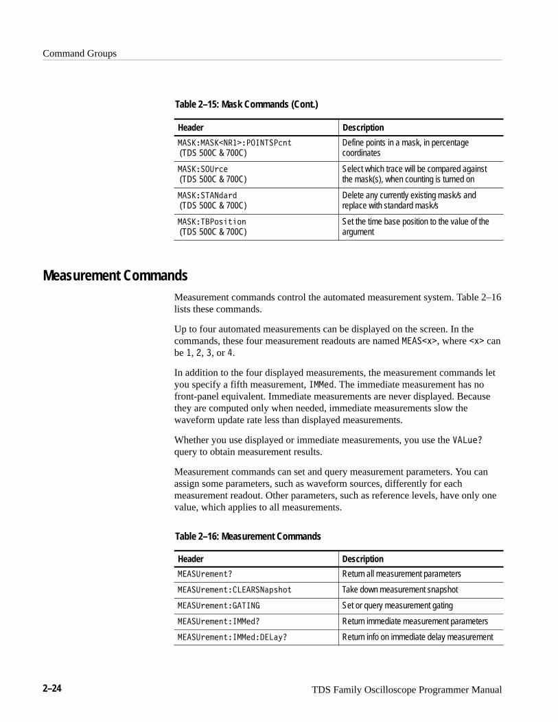
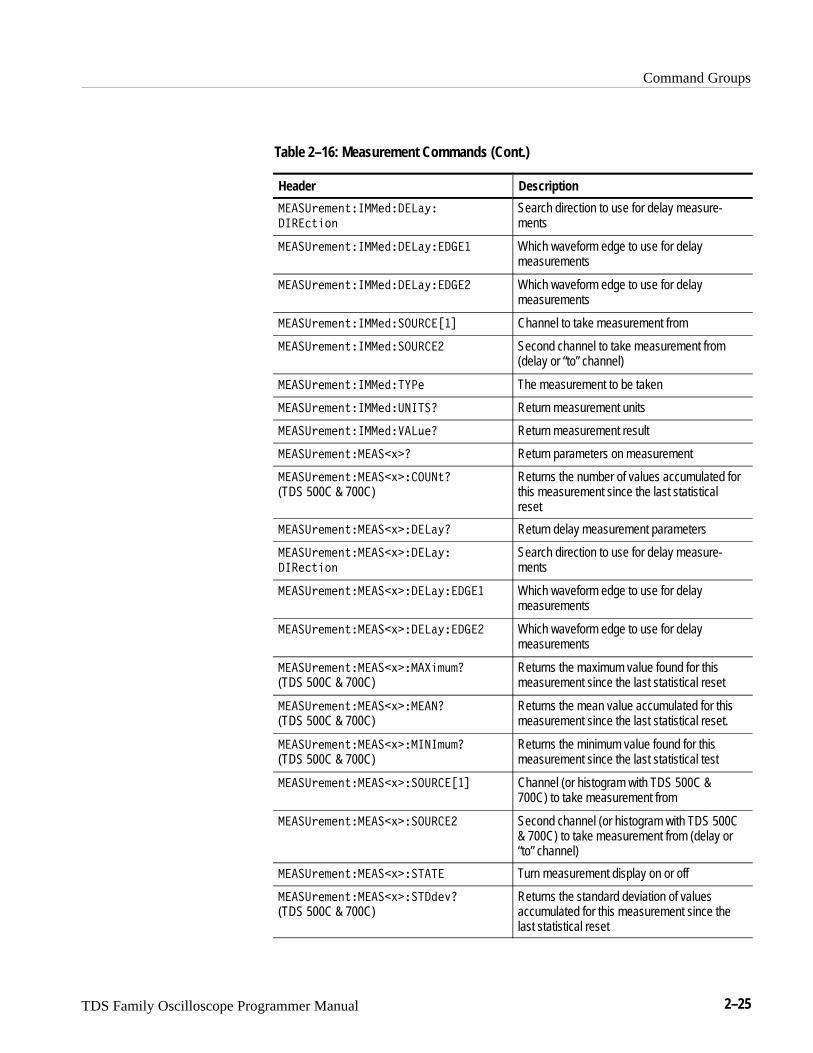
Measurement CommandsMeasurement commands control the automated measurement system. Table 2–16lists these commands.
Up to four automated measurements can be displayed on the screen. In thecommands, these four measurement readouts are named � ��)�, where �)� canbe �, �, �, or �.
In addition to the four displayed measurements, the measurement commands letyou specify a fifth measurement, �����. The immediate measurement has nofront-panel equivalent. Immediate measurements are never displayed. Becausethey are computed only when needed, immediate measurements slow thewaveform update rate less than displayed measurements.
Whether you use displayed or immediate measurements, you use the ��(��
query to obtain measurement results.
Measurement commands can set and query measurement parameters. You canassign some parameters, such as waveform sources, differently for eachmeasurement readout. Other parameters, such as reference levels, have only onevalue, which applies to all measurements.
Table 2–16: Measurement Commands
Header Description
� ��%�!�"'� Return all measurement parameters
� ��%�!�"'��� ����$&�#' Take down measurement snapshot
� ��%�!�"'������ Set or query measurement gating
� ��%�!�"'������� Return immediate measurement parameters
� ��%�!�"'�������� ��*� Return info on immediate delay measurement
Command Groups
TDS Family Oscilloscope Programmer Manual 2–25
Table 2–16: Measurement Commands (Cont.)
Header Description
����#� �!$������� �(�
���$�"!
Search direction to use for delay measure-ments
����#� �!$������� �(��� Which waveform edge to use for delaymeasurements
����#� �!$������� �(��� Which waveform edge to use for delaymeasurements
����#� �!$��������������� Channel to take measurement from
����#� �!$������������� Second channel to take measurement from(delay or “to” channel)
����#� �!$����������� The measurement to be taken
����#� �!$������������� Return measurement units
����#� �!$��������� %�� Return measurement result
����#� �!$�����'�� Return parameters on measurement
����#� �!$�����'������$�
(TDS 500C & 700C)Returns the number of values accumulated forthis measurement since the last statisticalreset
����#� �!$�����'�� �(� Return delay measurement parameters
����#� �!$�����'�� �(�
����$�"!
Search direction to use for delay measure-ments
����#� �!$�����'�� �(��� Which waveform edge to use for delaymeasurements
����#� �!$�����'�� �(��� Which waveform edge to use for delaymeasurements
����#� �!$�����'������ % �
(TDS 500C & 700C)Returns the maximum value found for thismeasurement since the last statistical reset
����#� �!$�����'������
(TDS 500C & 700C)Returns the mean value accumulated for thismeasurement since the last statistical reset.
����#� �!$�����'������ % �
(TDS 500C & 700C)Returns the minimum value found for thismeasurement since the last statistical test
����#� �!$�����'���������� Channel (or histogram with TDS 500C &700C) to take measurement from
����#� �!$�����'�������� Second channel (or histogram with TDS 500C& 700C) to take measurement from (delay or“to” channel)
����#� �!$�����'������ Turn measurement display on or off
����#� �!$�����'������&�
(TDS 500C & 700C)Returns the standard deviation of valuesaccumulated for this measurement since thelast statistical reset
Command Groups
2–26 TDS Family Oscilloscope Programmer Manual
Table 2–16: Measurement Commands (Cont.)
Header Description
�����&�#�$(������+������ The measurement to be taken
�����&�#�$(������+�������� Return units to use for measurement
�����&�#�$(������+�����)�� Return measurement result
�����&�#�$(�����%� Method for calculating reference levels
�����&�#�$(������*�"� Return reference levels
�����&�#�$(������*�"����%")(���� � The top level for risetime (90% level)
�����&�#�$(������*�"����%")(����� The low level for risetime (10% level)
�����&�#�$(������*�"����%")(���� Mid level for measurements
�����&�#�$(������*�"����%")(����� Mid level for delay measurements
�����&�#�$(������*�"�����%� Method to assign �� � and ���levels: either % or absolute volts
�����&�#�$(������*�"�����$(��� � The top level for risetime (90% level)
�����&�#�$(������*�"�����$(���� The low level for risetime (10% level)
�����&�#�$(������*�"�����$(��� Mid level for measurements
�����&�#�$(������*�"�����$(���� Mid level for delay measurements
�����&�#�$(������ %( Display measurement snapshot
�����&�#�$(������'(!�'����
(TDS 500C & 700C)Controls operation and display of measure-ment statistics
�����&�#�$(������'(!�'����� (!$�
(TDS 500C & 700C)Controls the responsiveness of mean andstandard deviation to waveform changes
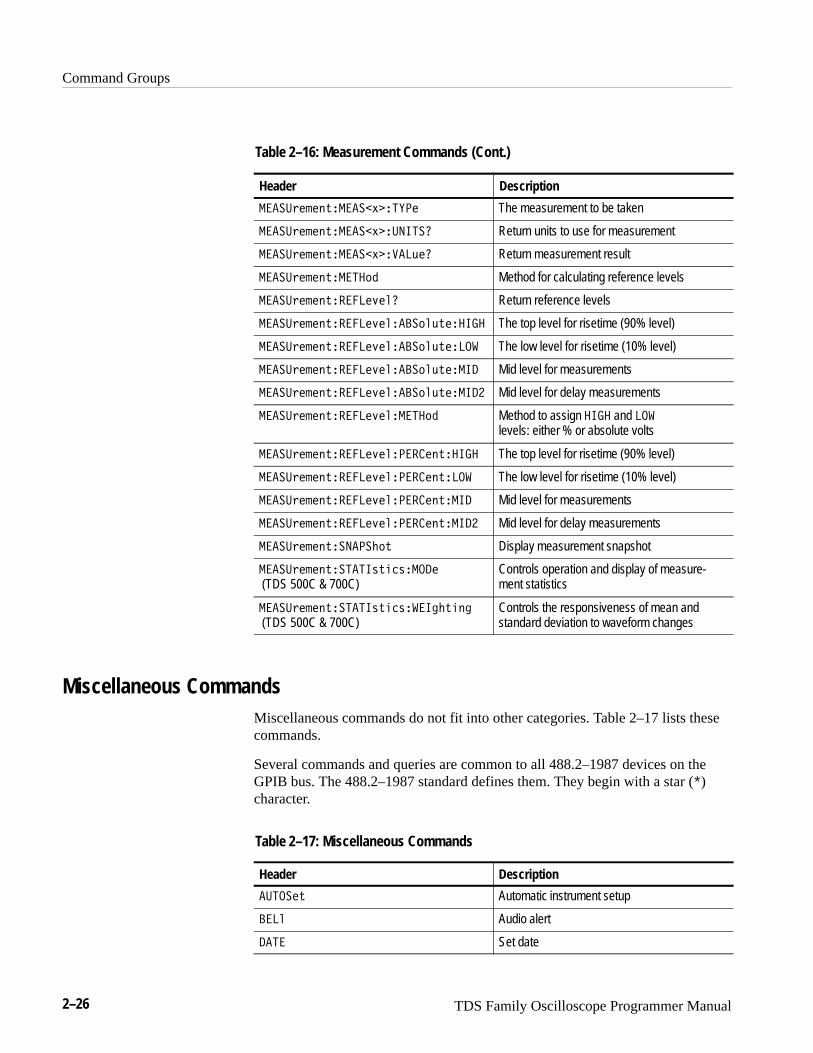
Miscellaneous CommandsMiscellaneous commands do not fit into other categories. Table 2–17 lists thesecommands.
Several commands and queries are common to all 488.2–1987 devices on theGPIB bus. The 488.2–1987 standard defines them. They begin with a star (�)character.
Table 2–17: Miscellaneous Commands
Header Description
������( Automatic instrument setup
���" Audio alert
��� Set date

Command Groups
TDS Family Oscilloscope Programmer Manual 2–27
Table 2–17: Miscellaneous Commands (Cont.)
Header Description
�� Define group execute trigger (GET)
���($&* Reset to factory default
� Same as HEADer
��& Return command header with query
���� Identification
����� Learn device setting
���! Lock front panel (local lockout)
��%�'' Change password for User Protected Data
�����$&� Access to change User Protected Data
�� No action; remark only
��� Same as *LRN?
�����)&� Initialize waveforms and setups
���� Set time
���� Perform Group Execute Trigger (GET)
����� Self-test
���$�! Unlock front panel (local lockout)
���$'� Return full command name or minimumspellings with query
RS-232 CommandsRS-232 commands allow you to utilize the serial communications port (availablewith the RS-232/Centronics Hardcopy Interface). Table 2–18 lists thesecommands.
Table 2–18: RS-232 Commands
Header Description
������ Return RS-232 parameters
���������� Set baud rate
������ ���"��� #� Set hard flagging
��������� (* Set parity
�����������"��� #� Set soft flagging
����������� (' Set # of stop bits

Command Groups
2–28 TDS Family Oscilloscope Programmer Manual
Save and Recall CommandsSave and Recall commands allow you to store and retrieve internal waveformsand settings. When you “save a setup,” you save all the settings of the digitizingoscilloscope. When you then “recall a setup,” the digitizing oscilloscope restoresitself to the state it was in when you originally saved that setting. Table 2–19lists these commands.
Table 2–19: Save and Recall Commands
Header Description
��� ����� Return number of allocated and unallocateddata points
��� ������������� Return number of allocated data points
��� ��������������� Return number of unallocated data points
��� ������������������ Specify the number of allocated data points
��������� Delete stored setup
������������ Delete stored waveform
���� Recall settings
������������� (TDS 500C & 700C) Replace the indicated channel’s live acquisi-tion data with data from indicated file
���������� Recall saved instrument settings
������������� (File System only)
Recall saved waveform
���� Save settings
������������ (TDS 500C & 700C) Write out acquisition data to the indicated file
��������� Save instrument settings
������������ Save waveform
�������������������� (Not on TDS 510A)
Specifies the file format for saved waveforms
Status and Error CommandsTable 2–20 lists the status and error commands the digitizing oscilloscopesupports. These commands let you determine the status of the digitizingoscilloscope and control events.
Several commands and queries used with the digitizing oscilloscope are commonto all devices on the GPIB bus. IEEE Std 488.2–1987 defines these commandsand queries. They begin with an asterisk (�).

Command Groups
TDS Family Oscilloscope Programmer Manual 2–29
Table 2–20: Status and Error Commands
Header Description
���� Return all events
����� Return scope status
��� Clear status
���� Device event status enable
���� Event status enable
����� Return standard event status register
������ Return event code
����� Return event code and message
������ Return number of events in queue
��� Identification
�� � Operation complete
�� �� (Not in TDS 400A) Return installed options
� �� Power-on status clear
� �� Query or set User Protected Data
���� Reset
���� Service request enable
����� Read status byte
���� Wait to continue
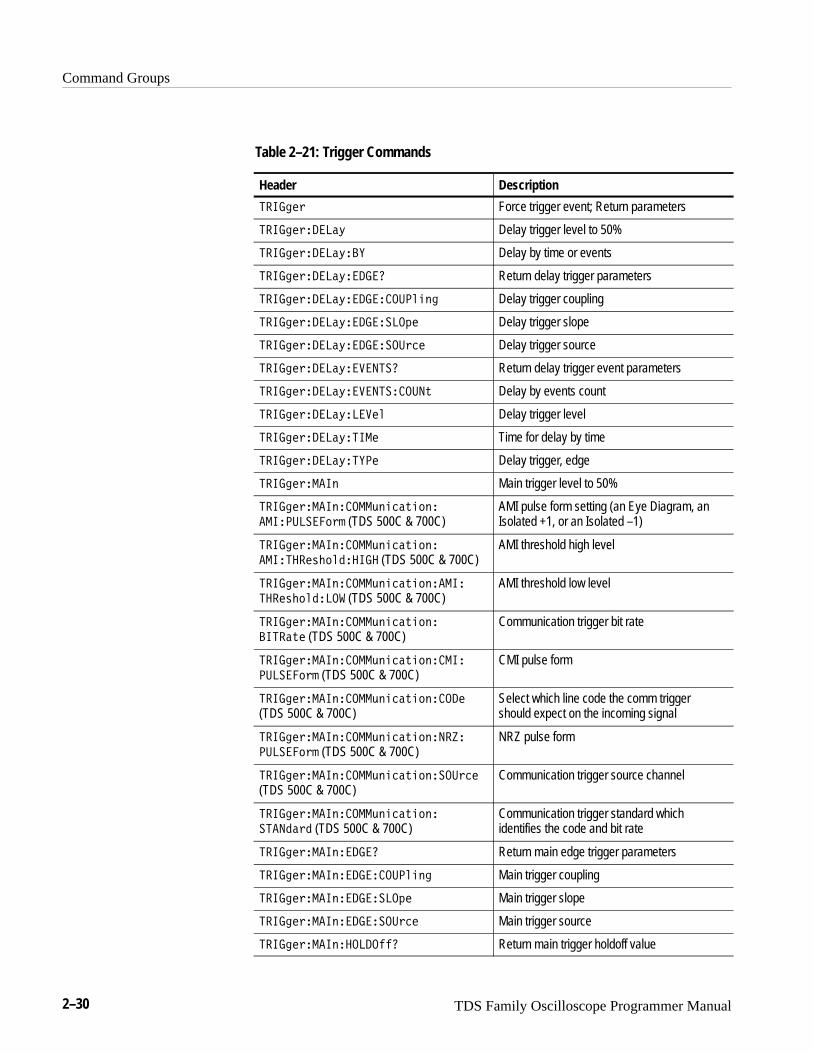
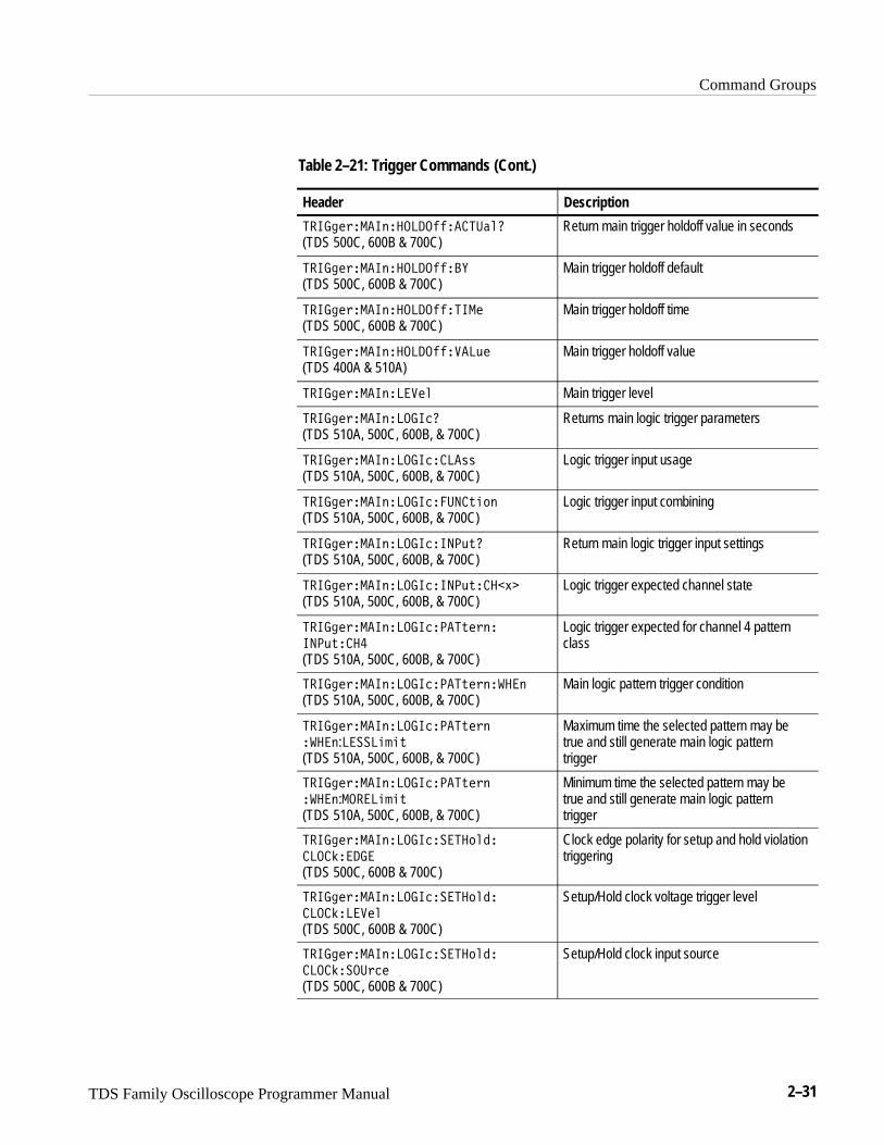
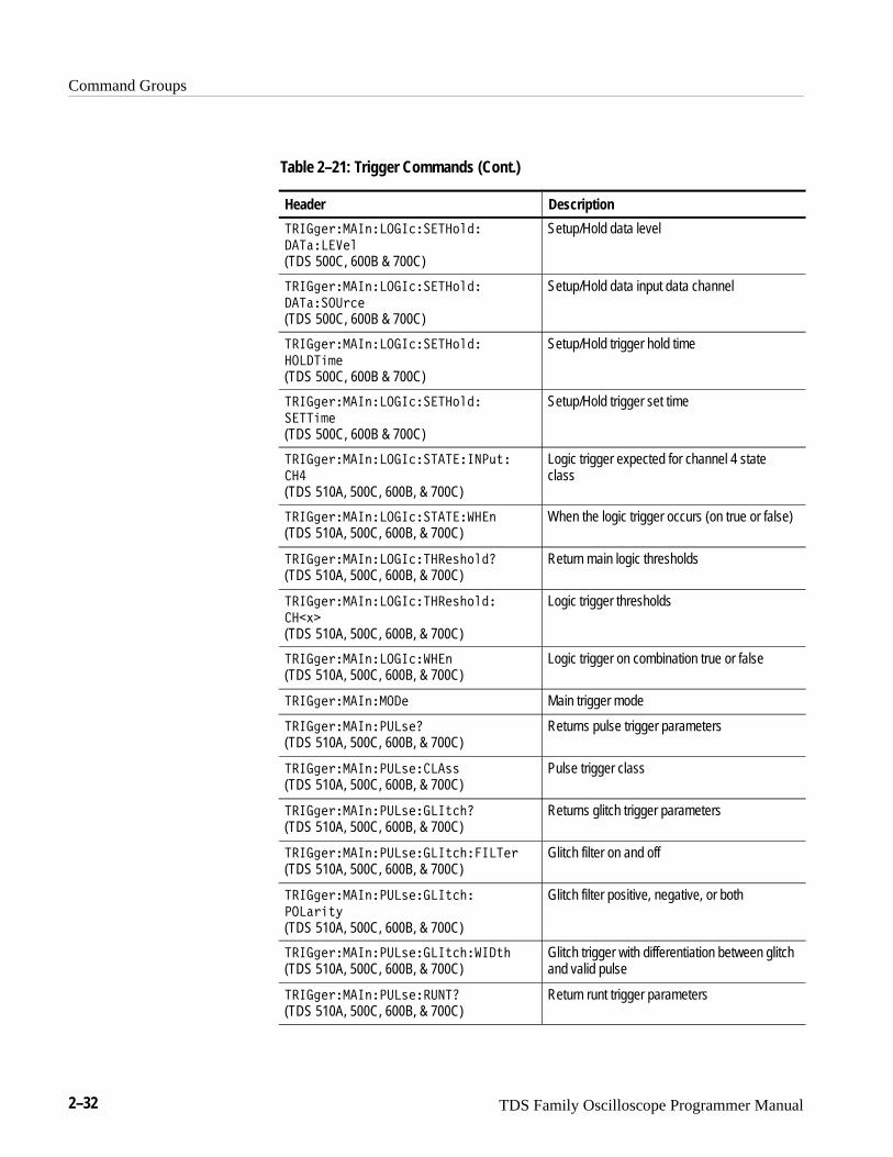
Trigger CommandsTrigger commands control all aspects of digitizing oscilloscope triggering. Table2–21 lists these commands.
There are two triggers, main and delayed. Where appropriate, the command sethas parallel constructions for each trigger.
You can set the main or delayed triggers to edge mode. Edge triggering lets youdisplay a waveform at or near the point where the signal passes through a voltagelevel of your choosing.
You can also set TDS 510A, 500C, 600B, and 700C main triggers to pulse andlogic modes. Pulse triggering lets the oscilloscope trigger whenever it detects apulse of a certain width or height. Logic triggering lets you logically combinethe signals on one or more channels. The digitizing oscilloscope then triggerswhen it detects a certain combination of signal levels.
Command Groups
2–30 TDS Family Oscilloscope Programmer Manual
Table 2–21: Trigger Commands
Header Description
�����& Force trigger event; Return parameters
�����&�����* Delay trigger level to 50%
�����&�����*��� Delay by time or events
�����&�����*����� Return delay trigger parameters
�����&�����*���������! #� Delay trigger coupling
�����&�����*��������%� Delay trigger slope
�����&�����*��������&�� Delay trigger source
�����&�����*�������� Return delay trigger event parameters
�����&�����*������������( Delay by events count
�����&�����*�����! Delay trigger level
�����&�����*��� � Time for delay by time
�����&�����*����� Delay trigger, edge
�����&� ��# Main trigger level to 50%
�����&� ��#��� )# ��( $#�
� ��������$&" (TDS 500C & 700C)AMI pulse form setting (an Eye Diagram, anIsolated +1, or an Isolated –1)
�����&� ��#��� )# ��( $#�
� �����'�$!��� (TDS 500C & 700C)AMI threshold high level
�����&� ��#��� )# ��( $#�� ��
���'�$!����� (TDS 500C & 700C)AMI threshold low level
�����&� ��#��� )# ��( $#�
�����(� (TDS 500C & 700C)Communication trigger bit rate
�����&� ��#��� )# ��( $#�� ��
������$&" (TDS 500C & 700C)CMI pulse form
�����&� ��#��� )# ��( $#�����
(TDS 500C & 700C)Select which line code the comm triggershould expect on the incoming signal
�����&� ��#��� )# ��( $#�����
������$&" (TDS 500C & 700C)NRZ pulse form
�����&� ��#��� )# ��( $#����&��
(TDS 500C & 700C)Communication trigger source channel
�����&� ��#��� )# ��( $#�
������&� (TDS 500C & 700C)Communication trigger standard whichidentifies the code and bit rate
�����&� ��#����� Return main edge trigger parameters
�����&� ��#���������! #� Main trigger coupling
�����&� ��#��������%� Main trigger slope
�����&� ��#��������&�� Main trigger source
�����&� ��#�������� Return main trigger holdoff value
Command Groups
TDS Family Oscilloscope Programmer Manual 2–31
Table 2–21: Trigger Commands (Cont.)
Header Description
���� �'����%� �����������#� (TDS 500C, 600B & 700C)
Return main trigger holdoff value in seconds
���� �'����%� �������� (TDS 500C, 600B & 700C)
Main trigger holdoff default
���� �'����%� ���������� (TDS 500C, 600B & 700C)
Main trigger holdoff time
���� �'����%� ���������*�
(TDS 400A & 510A)Main trigger holdoff value
���� �'����%����# Main trigger level
���� �'����%�������
(TDS 510A, 500C, 600B, & 700C)Returns main logic trigger parameters
���� �'����%����������((
(TDS 510A, 500C, 600B, & 700C)Logic trigger input usage
���� �'����%�����������)!&%
(TDS 510A, 500C, 600B, & 700C)Logic trigger input combining
���� �'����%����������*)�
(TDS 510A, 500C, 600B, & 700C)Return main logic trigger input settings
���� �'����%����������*)�� �+�
(TDS 510A, 500C, 600B, & 700C)Logic trigger expected channel state
���� �'����%����������)�'%�
���*)�� �
(TDS 510A, 500C, 600B, & 700C)
Logic trigger expected for channel 4 patternclass
���� �'����%����������)�'%�� %
(TDS 510A, 500C, 600B, & 700C)Main logic pattern trigger condition
���� �'����%����������)�'%
�� %:����!$!)(TDS 510A, 500C, 600B, & 700C)
Maximum time the selected pattern may betrue and still generate main logic patterntrigger
���� �'����%����������)�'%
�� %:����!$!)(TDS 510A, 500C, 600B, & 700C)
Minimum time the selected pattern may betrue and still generate main logic patterntrigger
���� �'����%��������� &#��
����"��
(TDS 500C, 600B & 700C)
Clock edge polarity for setup and hold violationtriggering
���� �'����%��������� &#��
����"����#
(TDS 500C, 600B & 700C)
Setup/Hold clock voltage trigger level
���� �'����%��������� &#��
����"����'��
(TDS 500C, 600B & 700C)
Setup/Hold clock input source
Command Groups
2–32 TDS Family Oscilloscope Programmer Manual
Table 2–21: Trigger Commands (Cont.)
Header Description
�� ���$��� "���� �����# ��
��������
(TDS 500C, 600B & 700C)
Setup/Hold data level
�� ���$��� "���� �����# ��
��������$��
(TDS 500C, 600B & 700C)
Setup/Hold data input data channel
�� ���$��� "���� �����# ��
������!�
(TDS 500C, 600B & 700C)
Setup/Hold trigger hold time
�� ���$��� "���� �����# ��
����!�
(TDS 500C, 600B & 700C)
Setup/Hold trigger set time
�� ���$��� "���� ������� ��'&�
���
(TDS 510A, 500C, 600B, & 700C)
Logic trigger expected for channel 4 stateclass
�� ���$��� "���� ���������"
(TDS 510A, 500C, 600B, & 700C)When the logic trigger occurs (on true or false)
�� ���$��� "���� ������%�# ��
(TDS 510A, 500C, 600B, & 700C)Return main logic thresholds
�� ���$��� "���� ������%�# ��
���(�
(TDS 510A, 500C, 600B, & 700C)
Logic trigger thresholds
�� ���$��� "���� ����"
(TDS 510A, 500C, 600B, & 700C)Logic trigger on combination true or false
�� ���$��� "����� Main trigger mode
�� ���$��� "����%��
(TDS 510A, 500C, 600B, & 700C)Returns pulse trigger parameters
�� ���$��� "����%�����%%
(TDS 510A, 500C, 600B, & 700C)Pulse trigger class
�� ���$��� "����%���� &���
(TDS 510A, 500C, 600B, & 700C)Returns glitch trigger parameters
�� ���$��� "����%���� &��� ���$
(TDS 510A, 500C, 600B, & 700C)Glitch filter on and off
�� ���$��� "����%���� &���
����$�&)
(TDS 510A, 500C, 600B, & 700C)
Glitch filter positive, negative, or both
�� ���$��� "����%���� &���� �&�
(TDS 510A, 500C, 600B, & 700C)Glitch trigger with differentiation between glitchand valid pulse
�� ���$��� "����%�������
(TDS 510A, 500C, 600B, & 700C)Return runt trigger parameters
Command Groups
TDS Family Oscilloscope Programmer Manual 2–33
Table 2–21: Trigger Commands (Cont.)
Header Description
������������� �������� ���!#
(TDS 510A, 500C, 600B, & 700C)Runt trigger positive, negative, or both
������������� ����������� �����
(TDS 510A, 500C, 600B, & 700C)Return runt trigger thresholds
������������� �������
���� ������ �� (TDS 500C, 600B & 700C)
Trigger level switching thresholds
������������� �������
���� ��������
(TDS 510A, 500C, 600B, & 700C)
Upper limit for runt pulse
������������� �������
���� ����� �
(TDS 510A, 500C, 600B, & 700C)
Lower limit for runt pulse
������������� ����������� (TDS 500C, 600B & 700C)
Runt pulse width type to check for
������������� ���������!�
(TDS 500C, 600B & 700C)Minimum width for valid main pulse runt trigger
������������� �������!��
��������
(TDS 500C, 600B & 700C)
Slew rate trigger delta time
������������� �������!��
� ���!#
(TDS 500C, 600B & 700C)
Slew rate trigger polarity
������������� �������!��
�����!��
(TDS 500C, 600B & 700C)
Return slew rate value
������������� �������!��
���� ������ ��
(TDS 500C, 600B & 700C)
Upper and lower slew rate trigger thresholds
������������� �������!��
���� ��������
(TDS 500C, 600B & 700C)
Upper limit for slew rate pulse
������������� �������!��
���� ����� �
(TDS 500C, 600B & 700C)
Lower limit for slew rate pulse
������������� �������!������
(TDS 500C, 600B & 700C)Slewing signal type to check for
������������� ��� ����
(TDS 510A, 500C, 600B, & 700C)Pulse trigger channel
������������� ����� "!�� ��$
�!#
(TDS 500C, 600B, & 700C)
Pulse timeout trigger polarity
Command Groups
2–34 TDS Family Oscilloscope Programmer Manual
Table 2–21: Trigger Commands (Cont.)
Header Description
�����%� ��"����&���� ��('��� �
(TDS 500C, 600B, & 700C)Pulse timeout trigger time
�����%� ��"����&�����'��
(TDS 510A, 500C, 600B, & 700C)Return trigger pulse width parameters
�����%� ��"����&�����'���� ! '
(TDS 510A, 500C, 600B, & 700C)Pulse trigger maximum pulse width
�����%� ��"����&�����'������ ! '
(TDS 510A, 500C, 600B, & 700C)Pulse trigger minimum pulse width
�����%� ��"����&�����'������% '*
(TDS 510A, 500C, 600B, & 700C)Pulse trigger positive, negative, or both
�����%� ��"����&�����'����"
(TDS 510A, 500C, 600B, & 700C)Pulse trigger when pulse detected or when notdetected
�����%� ��"����� Set main trigger to edge, logic, pulse, or, withoption 05, video type
�����%� ��"�����#�
(Option 05)Return video trigger parameters
�����%� ��"�����#���
(TDS 400A Option 05)Set video trigger delay mode
�����%� ��"�����#������
(Option 05)Set video trigger field
�����%� ��"�����#�������*$�
(TDS 510A, 500C, 600B, & 700C Option 05)Set video trigger field type
�����%� ��"�����#������#%!�'� (TDS 510A, 500C. 600B, & 700C Option 05)
Return FlexFormat parameters
�����%� ��"�����#������#%!�'�
���������
(TDS 510A, 500C, 600B, & 700C Option 05)
Set FlexFormat frames per second
�����%� ��"�����#������#%!�'�
������
(TDS 510A, 500C, 600B, & 700C Option 05)
Set FlexFormat video fields
�����%� ��"�����#������#%!�'�
�����
(TDS 510A, 500C, 600B, & 700C Option 05)
Set FlexFormat lines in a frame
�����%� ��"�����#������#%!�'�
���*"��) �'�
(TDS 510A, 500C, 600B, & 700C Option 05)
Set FlexFormat negative sync width
�����%� ��"�����#������#%!�'�
�����%'' !�
(TDS 510A, 500C, 600B, & 700C Option 05)
Set time from positive (+) edge of tri-syncpulse for the last line in the selected field tothe leading edge (–) of the first negativevertical sync pulse

Command Groups
TDS Family Oscilloscope Programmer Manual 2–35
Table 2–21: Trigger Commands (Cont.)
Header Description
�����$����!�����"� ���"$ �%�
�����#%� �
(TDS 510A, 500C, 600B, & 700C Option 05)
Set time from positive edge of tri-sync pulsefor the last line in the selected field (t0) totrailing edge (positive) of the first negativevertical sync pulse
�����$����!�����"�
���"$ �%������$%%� �
(TDS 510A, 500C, 600B, & 700C Option 05)
Set time from t0 to the leading edge (positive)of the second vertical sync pulse
�����$����!�����"�
���"$ �%������#%� �
(TDS 510A, 500C, 600B, & 700C Option 05)
Set time from t0 to trailing edge (positive) ofthe second negative vertical sync pulse
�����$����!�����"����'
(TDS 510A, 500C, 600B, & 700C Option 05)Select high definition TV format
�����$����!�����"��� �"���
(TDS 400A Option 05)Return video trigger holdoff
�����$����!�����"��� �"����� &� (TDS 400A Option 05)
Set video trigger holdoff value
�����$����!�����"������ ���
(TDS 400A Option 05)Select video trigger interlace format
�����$����!�����"� ���
(Option 05)Set video trigger delay in terms of a number oflines
�����$����!�����"� ����
(TDS 400A Option 05)Set video trigger delay in terms of a number oflines
�����$����!�����"�����
(TDS 510A, 500C, 600B, & 700C Option 05)Select color or mono NTSC
�����$����!�����"���
(TDS 510A, 500C, 600B, & 700C Option 05)Select color or mono PAL
�����$����!�����"�����
(TDS 400A Option 05)Set video trigger scan rate
�����$����!�����"�������$�"�
(TDS 400A Option 05)Set video trigger scan period
�����$����!�����"����$��
Option 05Select video trigger source
�����$����!�����"�������$�
(TDS 510A, 500C, 600B, & 700C Option 05)Select video trigger standard
�����$����!�����"�����
(Option 05)Select video trigger sync polarity
�����$����!�����"����%�
(TDS 400A Option 05)Select video trigger class
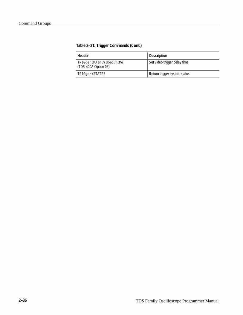
Command Groups
2–36 TDS Family Oscilloscope Programmer Manual
Table 2–21: Trigger Commands (Cont.)
Header Description
���� ���������� �����
(TDS 400A Option 05)Set video trigger delay time
���� ������� Return trigger system status
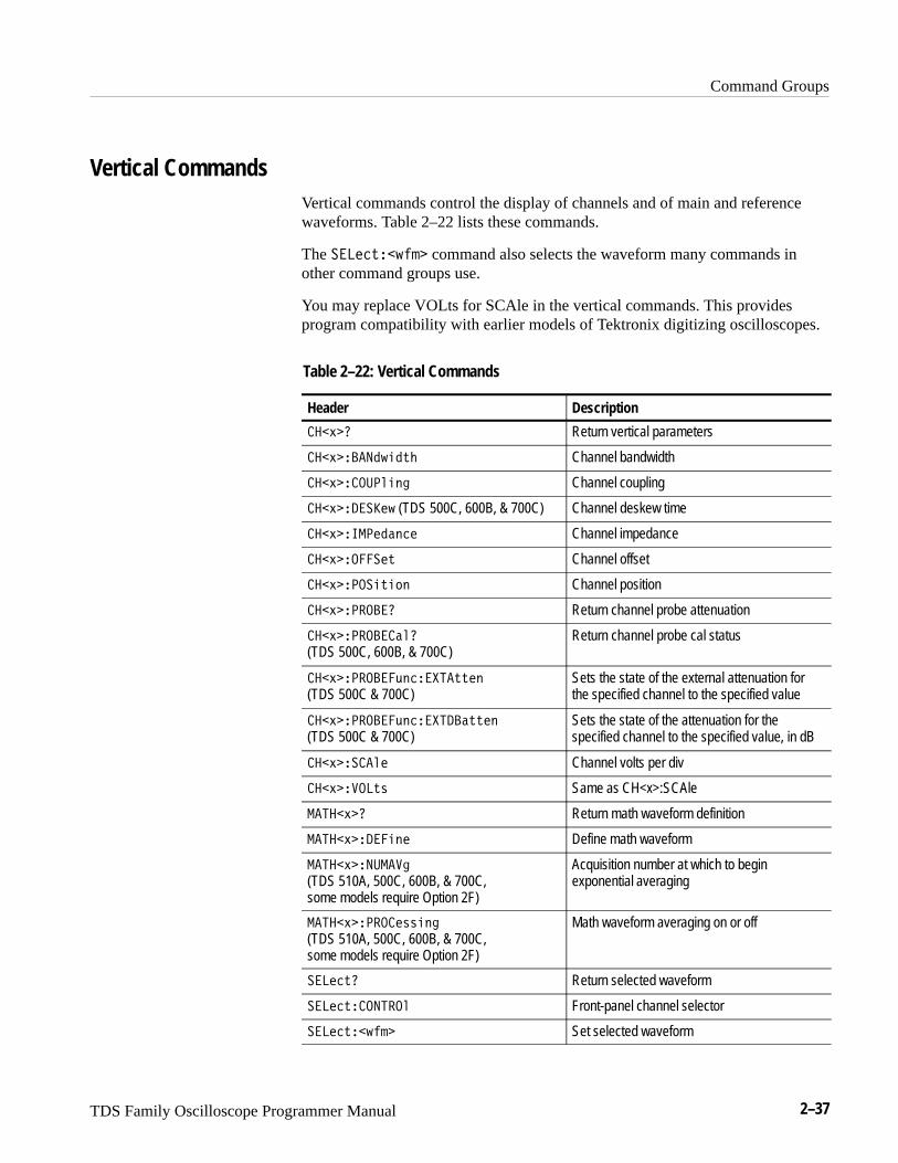
Command Groups
TDS Family Oscilloscope Programmer Manual 2–37
Vertical CommandsVertical commands control the display of channels and of main and referencewaveforms. Table 2–22 lists these commands.
The ����&��(�"� command also selects the waveform many commands inother command groups use.
You may replace VOLts for SCAle in the vertical commands. This providesprogram compatibility with earlier models of Tektronix digitizing oscilloscopes.
Table 2–22: Vertical Commands
Header Description
���)�� Return vertical parameters
���)������( �&� Channel bandwidth
���)������! #� Channel coupling
���)���� �( (TDS 500C, 600B, & 700C) Channel deskew time
���)��������#�� Channel impedance
���)�����& Channel offset
���)����� & $# Channel position
���)������� Return channel probe attenuation
���)��������!� (TDS 500C, 600B, & 700C)
Return channel probe cal status
���)������'#�����&&�#
(TDS 500C & 700C)Sets the state of the external attenuation forthe specified channel to the specified value
���)������'#�������&&�#
(TDS 500C & 700C)Sets the state of the attenuation for thespecified channel to the specified value, in dB
���)�����!� Channel volts per div
���)�����&% Same as CH<x>:SCAle
�����)�� Return math waveform definition
�����)��� #� Define math waveform
�����)��������
(TDS 510A, 500C, 600B, & 700C, some models require Option 2F)
Acquisition number at which to beginexponential averaging
�����)�������%% #�
(TDS 510A, 500C, 600B, & 700C, some models require Option 2F)
Math waveform averaging on or off
����&� Return selected waveform
����&�������! Front-panel channel selector
����&��(�"� Set selected waveform
Command Groups
2–38 TDS Family Oscilloscope Programmer Manual
Waveform CommandsWaveform commands let you transfer waveform data points to and from thedigitizing oscilloscope. Waveform data points are a collection of values thatdefine a waveform. One data value usually represents one data point in thewaveform record. When working with enveloped waveforms, each data value iseither the min or max of a min/max pair. Before you transfer waveform data, youmust specify the data format, record length, and waveform locations.
Table 2–24 lists these commands.
Acquired waveform data uses either one or two 8-bit data bytes to represent eachdata point. The number of bytes used depends on the acquisition mode specifiedwhen you acquired the data. Data acquired in SAMple, ENVelope, or PEAKde-tect mode uses one 8-bit byte per waveform data point. Data acquired in HIResor AVErage mode uses two 8-bit bytes per point. For more information on theacquisition modes see the ACQuire: MODe command on page 2–48.
The DATa:WIDth command lets you specify the number of bytes per data pointwhen transferring data to and from the digitizing oscilloscope. If you specify twobytes for data that uses only one, the least significant byte will be filled withzeros. If you specify one byte for data that uses two, the least significant bytewill be ignored.
The digitizing oscilloscope can transfer waveform data in either ASCII or binaryformat. You specify the format with the DATa:ENCdg command.
ASCII data — is represented by signed integer values. The range of the valuesdepends on the byte width specified. One byte wide data ranges from –128 to127. Two byte wide data ranges from –32768 to 32767.
Each data value requires two to seven characters. This includes one to fivecharacters to represent the value, another character, if the value is negative, torepresent a minus sign, and a comma to separate the data points.
An example ASCII waveform data string may look like this:
����������� ��������������������������������������
��������������������������������
Use ASCII to obtain more human readable and easier to format output thanbinary. However, it may require more bytes to send the same values with ASCIIthan it does with binary. This may reduce transmission speeds.
Binary data — can be represented by signed integer or positive integer values.The range of the values depends on the byte width specified. When the bytewidth is one, signed integer data ranges from –128 to 127, and positive integer
Waveform Data Formats
Command Groups
TDS Family Oscilloscope Programmer Manual 2–39
values range from 0 to 255. When the byte width is two, the values range from–32768 to 32767.
The defined binary formats also specify the order in which the bytes aretransferred. The four binary formats are RIBinary, RPBinary, SRIbinary, andSRPbinary.
RIBinary is signed integer where the most significant byte is transferred first,and RPBinary is positive integer where the most significant byte is transferredfirst. SRIbinary and SRPbinary correspond to RIBinary and RPBinary respec-tively but use a swapped byte order where the least significant byte is transferredfirst. The byte order is ignored when DATa:WIDth is set to 1.
You can transfer multiple points for each waveform record. You can transfer aportion of the waveform or you can transfer the entire record. The DATa:STARtand DATa:STOP commands let you specify the first and last data points of thewaveform record.
When transferring data into the digitizing oscilloscope, you must specify thelocation of the first data point within the waveform record. For example, whenyou set DATa:STARt to 1, data points will be stored starting with the first pointin the record, and when you set DATa:STARt to 500, data will be stored startingat the 500th point in the record. The digitizing oscilloscope will ignoreDATa:STOP when reading in data as it will stop reading data when it has nomore data to read or when it has reached the specified record length.
When transferring data from the digitizing oscilloscope, you must specify thefirst and last data points in the waveform record. Setting DATa:STARt to 1 andDATa:STOP to the record length will always return the entire waveform. You canalso use the vertical bar cursors to delimit the portion of the waveform that youwant to transfer. DATa:STARt and DATa:STOP can then be set to the currentcursor positions by sending the command DATa SNAp.
The DATa:SOUrce command specifies the data location when transferringwaveforms from the digitizing oscilloscope. You can transfer out multiplewaveforms at one time by specifying more than one source.
You can transfer in to the digitizing oscilloscope only one waveform at a time.Waveforms sent to the oscilloscope are always stored in one of the four referencememory locations. You can specify the reference memory location with theDATa:DESTination command. You must define the memory size for thespecified location before you store the data. The ALLOcate:WAVEFORM:REF<x> command lets you specify the memory size for eachreference location.
Waveform Data/RecordLengths
Waveform Data Locationsand Memory Allocation
Command Groups
2–40 TDS Family Oscilloscope Programmer Manual
Each waveform that you transfer has an associated waveform preamble thatcontains information such as the horizontal scale, the vertical scale, and othersettings in place when the waveform was created. Refer to the WFMPrecommands starting on page 2–345 for more information about the waveformpreamble.
Once you transfer the waveform data to the controller, you can convert the datapoints into voltage values for analysis using information from the waveformpreamble. The ������ program on the diskettes that come with this manualshows how you can scale data.
You can transfer waveforms from the digitizing oscilloscope to an externalcontroller using the following sequence:
1. Select the waveform source(s) using the DATa:SOUrce command. If youwant to transfer multiple waveforms, select more than one source.
2. Specify the waveform data format using DATa:ENCdg.
3. Specify the number of bytes per data point using DATa:WIDth.
4. Specify the portion of the waveform that you want to transfer usingDATa:STARt and DATa:STOP.
5. Transfer waveform preamble information using WFMPRe? query.
6. Transfer waveform data from the digitizing oscilloscope using the CURVe?query.
You can transfer waveform data to one of the four reference memory locations inthe digitizing oscilloscope using the following sequence:
1. Specify waveform reference memory using DATa:DESTination.
2. Specify the memory size for the reference location specified in Step 1 usingthe ALLOcate:WAVEFORM:REF<x> command.
3. Specify the waveform data format using DATa:ENCdg.
4. Specify the number of bytes per data point using DATa:WIDth.
5. Specify first data point in the waveform record using DATa:STARt.
6. Transfer waveform preamble information using WFMPRe:<wfm>.
7. Transfer waveform data to the digitizing oscilloscope using CURVe.
Waveform Preamble
Scaling Waveform Data
Transferring WaveformData from the TDS Family
Oscilloscope
Transferring WaveformData to the TDS Family
Oscilloscope
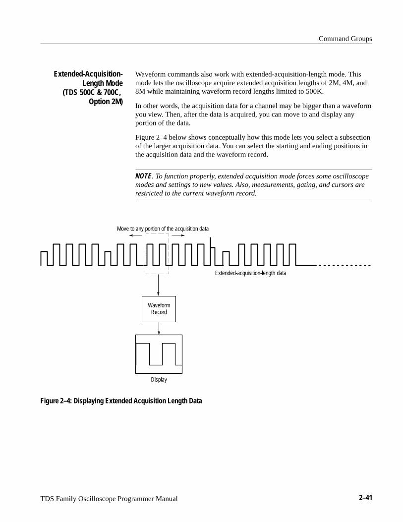
Command Groups
TDS Family Oscilloscope Programmer Manual 2–41
Waveform commands also work with extended-acquisition-length mode. Thismode lets the oscilloscope acquire extended acquisition lengths of 2M, 4M, and8M while maintaining waveform record lengths limited to 500K.
In other words, the acquisition data for a channel may be bigger than a waveformyou view. Then, after the data is acquired, you can move to and display anyportion of the data.
Figure 2–4 below shows conceptually how this mode lets you select a subsectionof the larger acquisition data. You can select the starting and ending positions inthe acquisition data and the waveform record.
NOTE. To function properly, extended acquisition mode forces some oscilloscopemodes and settings to new values. Also, measurements, gating, and cursors arerestricted to the current waveform record.
Extended-acquisition-length data
WaveformRecord
Display
Move to any portion of the acquisition data
Figure 2–4: Displaying Extended Acquisition Length Data
Extended-Acquisition-Length Mode
(TDS 500C & 700C, Option 2M)
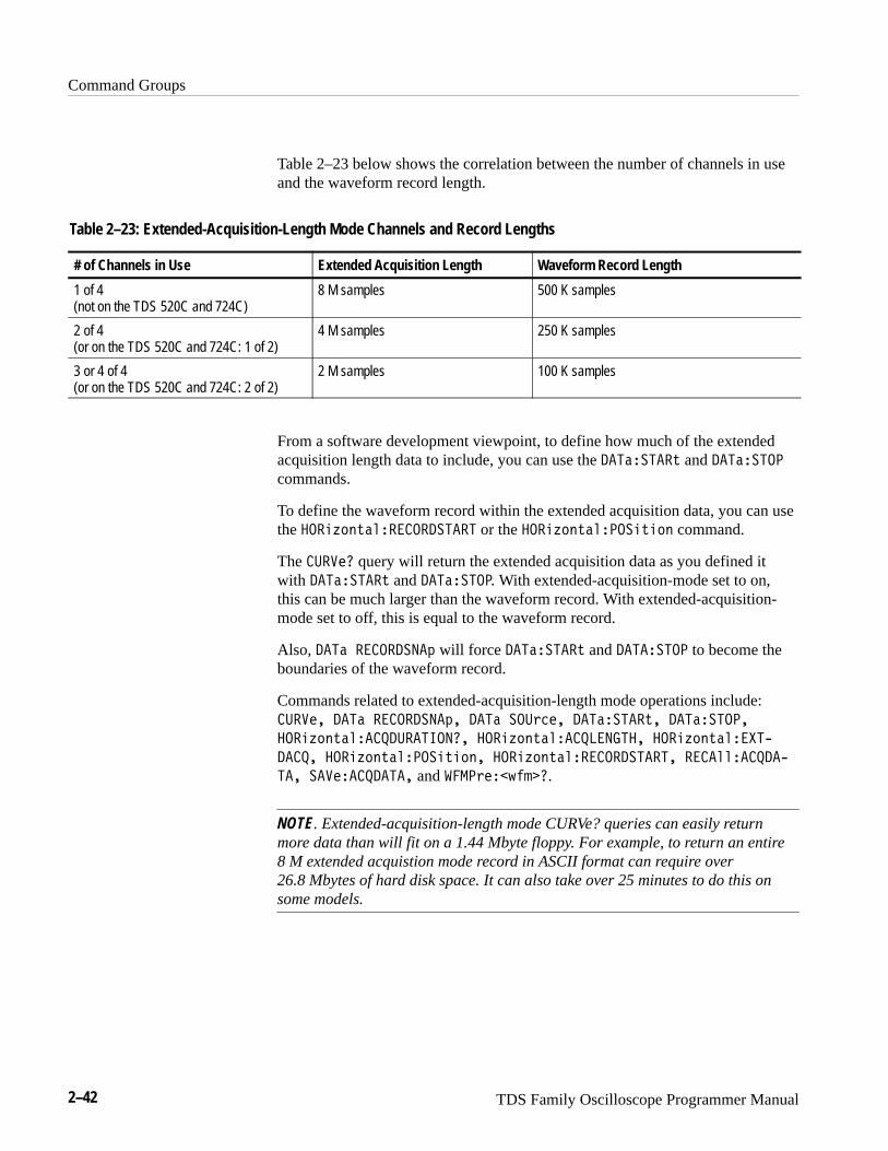
Command Groups
2–42 TDS Family Oscilloscope Programmer Manual
Table 2–23 below shows the correlation between the number of channels in useand the waveform record length.
Table 2–23: Extended-Acquisition-Length Mode Channels and Record Lengths
# of Channels in Use Extended Acquisition Length Waveform Record Length
1 of 4(not on the TDS 520C and 724C)
8 M samples 500 K samples
2 of 4 (or on the TDS 520C and 724C: 1 of 2)
4 M samples 250 K samples
3 or 4 of 4 (or on the TDS 520C and 724C: 2 of 2)
2 M samples 100 K samples
From a software development viewpoint, to define how much of the extendedacquisition length data to include, you can use the ��������' and ��������commands.
To define the waveform record within the extended acquisition data, you can usethe �� )$#'�!���������� or the �� )$#'�!���� ' $# command.
The ������ query will return the extended acquisition data as you defined itwith ��������' and ��������. With extended-acquisition-mode set to on,this can be much larger than the waveform record. With extended-acquisition-mode set to off, this is equal to the waveform record.
Also, ��� �������% will force ��������' and �������� to become theboundaries of the waveform record.
Commands related to extended-acquisition-length mode operations include:������ ��� �������%� ��� ���&��� ��������'� ���������
�� )$#'�!������������� �� )$#'�!�������� � �� )$#'�!���*
���� �� )$#'�!���� ' $#� �� )$#'�!����������� ���!!�����*
��� ������������ and ����&���(�"��.
NOTE. Extended-acquisition-length mode CURVe? queries can easily returnmore data than will fit on a 1.44 Mbyte floppy. For example, to return an entire8 M extended acquistion mode record in ASCII format can require over 26.8 Mbytes of hard disk space. It can also take over 25 minutes to do this onsome models.

Command Groups
TDS Family Oscilloscope Programmer Manual 2–43
Table 2–24: Waveform Commands
Header Description
����� Transfer waveform data
���� The format and location of the waveformdata that is transferred with the CURVecommand
����������#�&�$# Destination for waveforms sent to digitizingoscilloscope
���������� Waveform data encoding method
��������%�� Source of ������ data
���������& Starting point in waveform transfer
�������� Ending point in waveform transfer
����������& Same as DATa:DESTination
�������&� Byte width of waveform points
����%"� Return waveform preamble and data
��� %�� Return waveform format data
�� %������% Preamble bit width of waveform points.
�� %������"& Preamble binary encoding type
�� %�������% Preamble byte width of waveform points
�� %�������% Preamble byte order of waveform points
�� %������� Preamble checksum of waveform points
�� %������� Preamble encoding method
�� %����� & Number of points in the curve
�� %�� ���"& Format of curve points
�� %�� ����� Trigger position
�� %����� Curve identifier
�� %�����% Horizontal sampling interval
�� %����!& Horizontal scale factor
�� %������ Horizontal offset
�� %������& Horizontal units
�� %�����%$ Horizontal origin offset
�� %����!& Vertical scale factor
�� %������ Vertical offset
�� %������& Vertical units
�� %�����%$ Offset voltage
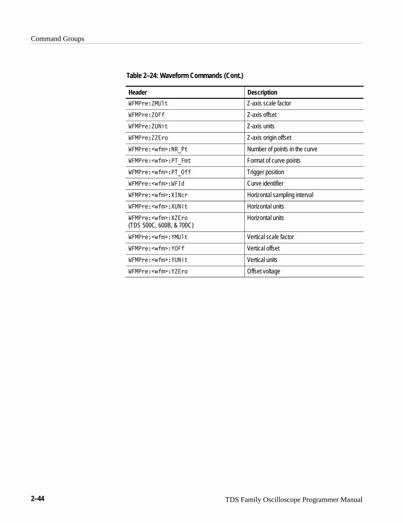
Command Groups
2–44 TDS Family Oscilloscope Programmer Manual
Table 2–24: Waveform Commands (Cont.)
Header Description
�������� �� Z-axis scale factor
��������� Z-axis offset
������� ��� Z-axis units
����������� Z-axis origin offset
���������������� Number of points in the curve
����������������� Format of curve points
���������������� Trigger position
���������������� Curve identifier
����������������� Horizontal sampling interval
������������� ��� Horizontal units
����������������� (TDS 500C, 600B, & 700C)
Horizontal units
�������������� �� Vertical scale factor
��������������� Vertical offset
������������� ��� Vertical units
����������������� Offset voltage
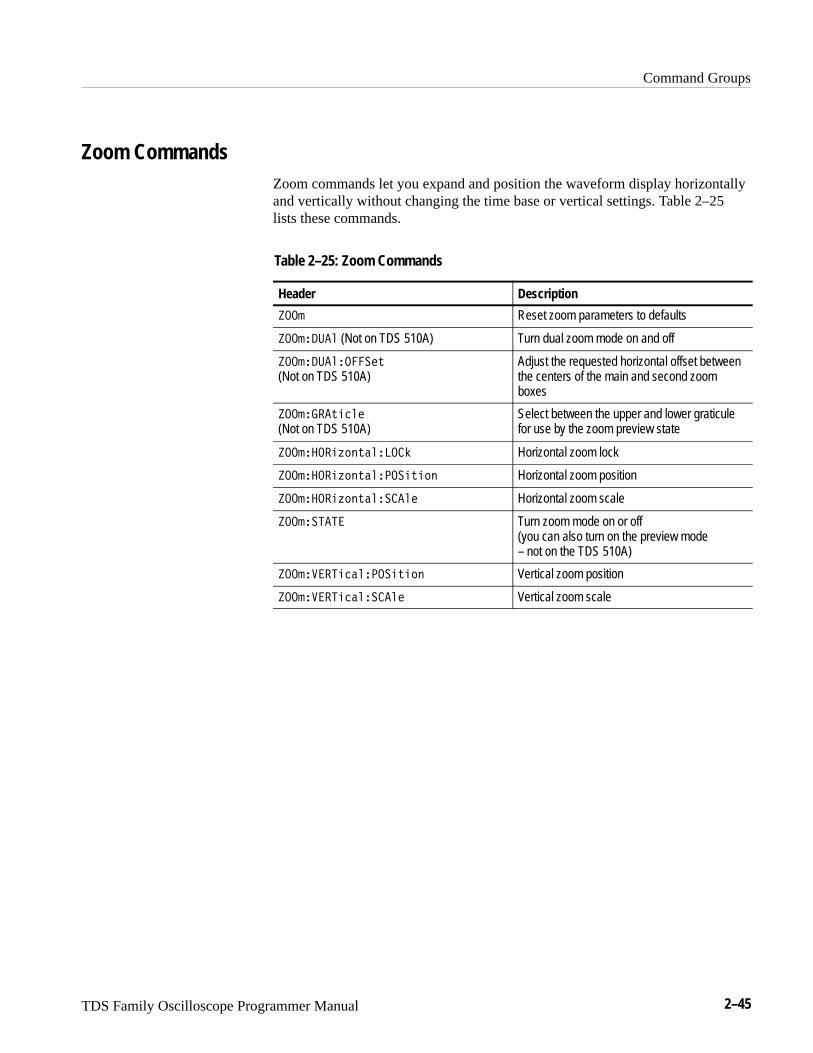
Command Groups
TDS Family Oscilloscope Programmer Manual 2–45
Zoom CommandsZoom commands let you expand and position the waveform display horizontallyand vertically without changing the time base or vertical settings. Table 2–25lists these commands.
Table 2–25: Zoom Commands
Header Description
�� Reset zoom parameters to defaults
������� (Not on TDS 510A) Turn dual zoom mode on and off
���������� �� (Not on TDS 510A)
Adjust the requested horizontal offset betweenthe centers of the main and second zoomboxes
����������� (Not on TDS 510A)
Select between the upper and lower graticulefor use by the zoom preview state
��������������� Horizontal zoom lock
�������������� ����� Horizontal zoom position
������������� ���� Horizontal zoom scale
��� ���� Turn zoom mode on or off(you can also turn on the preview mode – not on the TDS 510A)
������������� ����� Vertical zoom position
������������ ���� Vertical zoom scale
TDS Family Oscilloscope Programmer Manual 2–47
Command Descriptions
You can use commands to either set instrument features or query instrumentvalues. You can use some commands to do both, some to only set, and some toonly query. This manual marks set only commands with the words “No QueryForm” included with the command name. It marks query only commands with aquestion mark appended to the header, and includes the words “Query Only” inthe command name.
This manual spells out headers, mnemonics, and arguments with the minimalspelling shown in upper case. For example, to use the abbreviated form of theACQuire:MODe command just type ACQ:MOD.
ACQuire? (Query Only)Returns all the current acquisition parameters.
Acquisition
�������
������ �
�������
might return the string ����������������� ������������� �����
������������� �������� �������� � for the current acquisition parameters.
ACQuire:AUTOSAveTDS 500C, 600B & 700C Only
Saves waveforms in reference memory when acquisition completes. This isequivalent to setting Autosave Single Seq in the Acquire menu and thecorresponding side menu Off or On items.
When you start a Single Sequence with Autosave set to ON, the oscilloscopenulls out all existing reference waveforms. At the end of Single Sequence, theoscilloscope saves all displayed live channels to reference waveform memory. Itsaves references in the order Ch1 –> Ref1, Ch2 –> Ref2, Ch3 –> Ref3, Ch4 –>Ref4. The exact number of references saved may depend on the record lengthused.
Group
Syntax
Examples

Command Descriptions
2–48 TDS Family Oscilloscope Programmer Manual
When extended-acquisition-length mode is on, this command can still set andreturn values. However, this acquire:autosave feature will not actually workwhile extended-acquisition-length mode is on.
Acquisition
����������� ���� � � � � ����� �
����������� �����
�
������� � ��� ����
�������
�
�����
or ����� = 0 turns autosave off.
� or ����� � 0 turns autosave on.
���������� ��� � turns autosave mode on.
���������� ���
turns autosave mode off.
���������� ���� might return �, indicating that autosave mode is on.
ACQuire:MODeSets or queries the acquisition mode of the digitizing oscilloscope. This affectsall live waveforms. This command is equivalent to setting Mode in the Acquiremenu.
Waveforms are the displayed data point values taken from acquisition intervals.Each acquisition interval represents a time duration set by the horizontal scale(time per division). The digitizing oscilloscope sampling system always samplesat the maximum rate, and so an acquisition interval may include more than onesample.
The acquisition mode, which you set using this ACQuire:MODe command,determines how the final value of the acquisition interval is generated from themany data samples.
Group
Syntax
Arguments
Examples
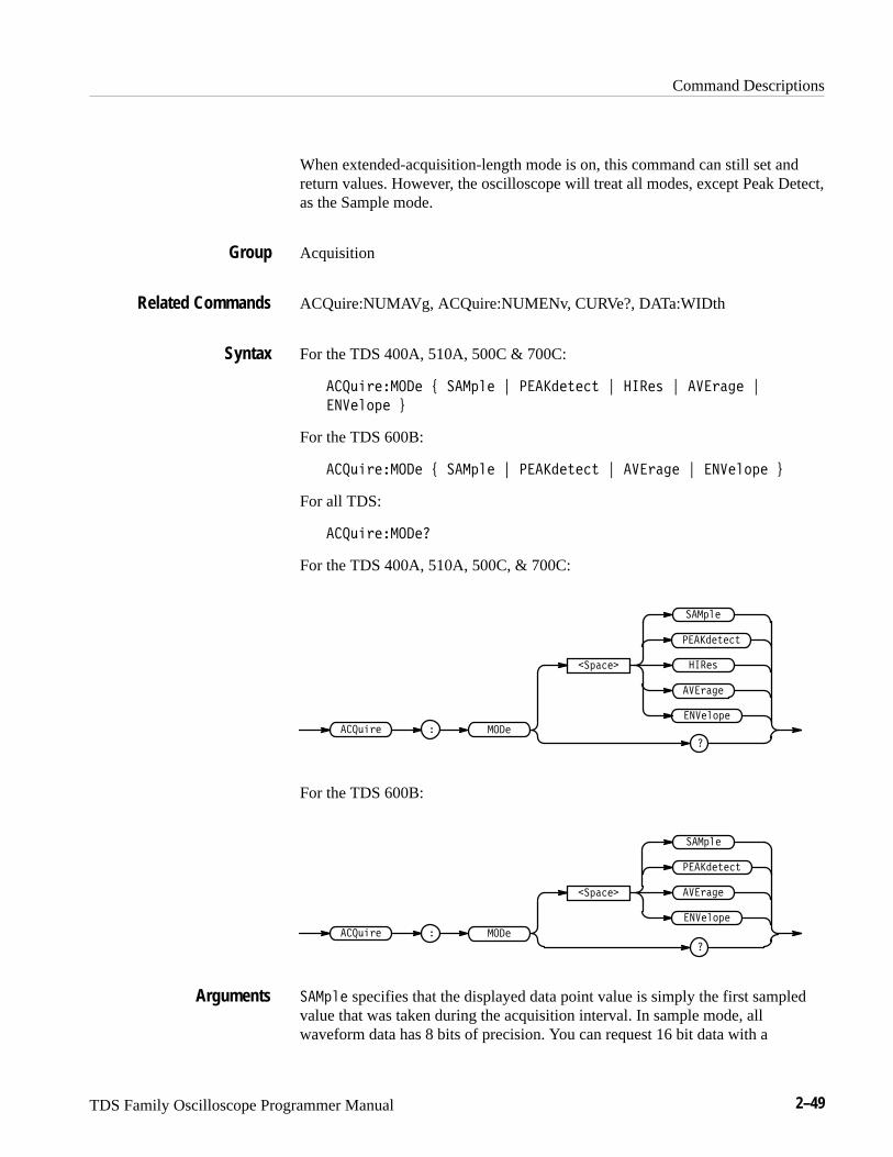
Command Descriptions
TDS Family Oscilloscope Programmer Manual 2–49
When extended-acquisition-length mode is on, this command can still set andreturn values. However, the oscilloscope will treat all modes, except Peak Detect,as the Sample mode.
Acquisition
ACQuire:NUMAVg, ACQuire:NUMENv, CURVe?, DATa:WIDth
For the TDS 400A, 510A, 500C & 700C:
���!���� ��� " �� ��� # ����� �� # ���� # ������ #
������� $
For the TDS 600B:
���!���� ��� " �� ��� # ����� �� # ������ # ������� $
For all TDS:
���!���� ����
For the TDS 400A, 510A, 500C, & 700C:
�������
����
���!��� � ���
�������
������
����� ��
�� ���
�
For the TDS 600B:
�������
������
���!��� � ���
�������
�
����� ��
�� ���
�� ��� specifies that the displayed data point value is simply the first sampledvalue that was taken during the acquisition interval. In sample mode, allwaveform data has 8 bits of precision. You can request 16 bit data with a
Group
Related Commands
Syntax
Arguments
Command Descriptions
2–50 TDS Family Oscilloscope Programmer Manual
CURVe? query, but the lower-order 8 bits of data will be zero. ������ is thedefault mode.
��������� specifies the display of the high-low range of the samples takenfrom a single waveform acquisition. The high-low range is displayed as avertical column that extends from the highest to the lowest value sampled duringthe acquisition interval. ��������� mode can reveal the presence of aliasing ornarrow spikes.
���� (for the TDS 400A, 510A, 500C, & 700C) specifies Hi Res mode, wherethe displayed data point value is the average of all the samples taken during theacquisition interval. This is a form of averaging, where the average comes from asingle waveform acquisition. The number of samples taken during the acquisi-tion interval determines the number of data values that compose the average.
������� specifies averaging mode, where the resulting waveform shows anaverage of ������ data points from several separate waveform acquisitions. Thenumber of waveform acquisitions that go into making up the average waveformis set or queried using the ACQuire:NUMAVg command.
� ������ specifies envelope mode, where the resulting waveform shows the��������� range of data points from several separate waveform acquisitions.The number of waveform acquisitions that go into making up the envelopewaveform is set or queried using the ACQuire:NUMENv command.
����������� � ������ sets the acquisition mode to display a waveform that is an envelope of manyindividual waveform acquisitions.
������������
might return � ������.
ACQuire:NUMACq? (Query Only)Indicates the number of acquisitions that have taken place since startingacquisition. This value is reset to zero when any Acquisition, Horizontal, orVertical arguments that affect the waveform are modified. The maximum numberof acquisitions that can be counted is 230–1. Counting stops when this number isreached. This is the same value that is displayed in the upper center of the screenwhen the acquisition system is stopped.
Acquisition
ACQuire:STATE
Examples
Group
Related Commands
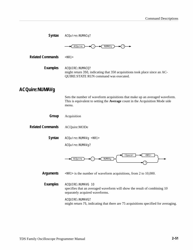
Command Descriptions
TDS Family Oscilloscope Programmer Manual 2–51
��������������
������� � ������
����
������ �������
might return ���, indicating that 350 acquisitions took place since an AC-QUIRE:STATE RUN command was executed.
ACQuire:NUMAVgSets the number of waveform acquisitions that make up an averaged waveform.This is equivalent to setting the Average count in the Acquisition Mode sidemenu.
Acquisition
ACQuire:MODe
�������������� ����
��������������
������
������ ����
��������
���� is the number of waveform acquisitions, from 2 to 10,000.
������ ������� ��
specifies that an averaged waveform will show the result of combining 10separately acquired waveforms.
������ �������
might return ��, indicating that there are 75 acquisitions specified for averaging.
Syntax
Related Commands
Examples
Group
Related Commands
Syntax
Arguments
Examples
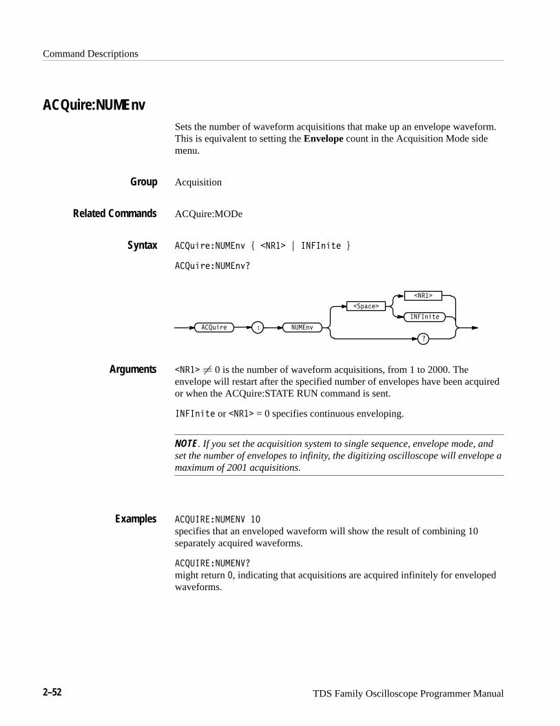
Command Descriptions
2–52 TDS Family Oscilloscope Programmer Manual
ACQuire:NUMEnvSets the number of waveform acquisitions that make up an envelope waveform.This is equivalent to setting the Envelope count in the Acquisition Mode sidemenu.
Acquisition
ACQuire:MODe
��������� �� � ����� � ��������
��������� ���
������ �
�����
�
�� ��
�������
��������
����� � 0 is the number of waveform acquisitions, from 1 to 2000. Theenvelope will restart after the specified number of envelopes have been acquiredor when the ACQuire:STATE RUN command is sent.
�������� or ����� = 0 specifies continuous enveloping.
NOTE. If you set the acquisition system to single sequence, envelope mode, andset the number of envelopes to infinity, the digitizing oscilloscope will envelope amaximum of 2001 acquisitions.
�������� �� ��
specifies that an enveloped waveform will show the result of combining 10separately acquired waveforms.
�������� ���
might return �, indicating that acquisitions are acquired infinitely for envelopedwaveforms.
Group
Related Commands
Syntax
Arguments
Examples

Command Descriptions
TDS Family Oscilloscope Programmer Manual 2–53
ACQuire:REPEt TDS 400A, 510A, 500C, & 700C Only
Controls repetitive signal acquisition. This is equivalent to setting RepetitiveSignal in the Acquire menu. When the digitizing oscilloscope is in real-timeoperation, this setting has no effect.
The ACQuire:REPEt command specifies the behavior of the acquisition systemduring equivalent-time (ET) operation. When repetitive mode is on, theacquisition system will continue to acquire waveform data until the waveformrecord is filled with acquired data. When repetitive mode is off and you specifysingle acquisition operation, only some of the waveform data points will be setwith acquired data, and the displayed waveform shows interpolated values forthe unsampled data points.
When extended-acquisition-length mode is on, this command can still set andreturn values. However, this acquire:repet feature will not actually work whileextended-acquisition-length mode is on.
Acquisition
ACQuire:STATE, ACQuire:STOPAfter
����������� � � � � ����� �
������������
�
������� � ���
�������
�
�����
or ����� = 0 turns repetitive mode off.
� or ����� � 0 turns repetitive mode on.
���������� � turns repetitive mode on.
����������
turns repetitive mode off.
Group
Related Commands
Syntax
Arguments
Examples
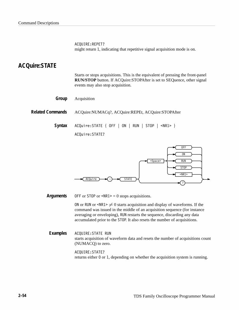
Command Descriptions
2–54 TDS Family Oscilloscope Programmer Manual
���������� might return �, indicating that repetitive signal acquisition mode is on.
ACQuire:STATEStarts or stops acquisitions. This is the equivalent of pressing the front-panelRUN/STOP button. If ACQuire:STOPAfter is set to SEQuence, other signalevents may also stop acquisition.
Acquisition
ACQuire:NUMACq?, ACQuire:REPEt, ACQuire:STOPAfter
����������� � ��� � � � �� � ���� � � ��� �
������������
������ � ����
���
�������
�
�
����
��
� ���
��� or ���� or � ��� = 0 stops acquisitions.
� or �� or � ��� � 0 starts acquisition and display of waveforms. If thecommand was issued in the middle of an acquisition sequence (for instanceaveraging or enveloping), �� restarts the sequence, discarding any dataaccumulated prior to the ����. It also resets the number of acquisitions.
���������� �� starts acquisition of waveform data and resets the number of acquisitions count(NUMACQ) to zero.
����������� returns either � or �, depending on whether the acquisition system is running.
Group
Related Commands
Syntax
Arguments
Examples

Command Descriptions
TDS Family Oscilloscope Programmer Manual 2–55
ACQuire:STOPAfterTells the digitizing oscilloscope when to stop taking acquisitions. This isequivalent to setting Stop After in the Acquire menu.
When extended-acquisition-length mode is on, this command can still set andreturn values. However, this acquire:stopafter feature will not actually workwhile extended-acquisition-length mode is on.
Acquisition
ACQuire:MODe, ACQuire:STATE, ACQuire:REPEt
���������� ������ � ������� �������� ��� !
���������� �������
���������� � �� ������
�������
�
�������
��������
������� specifies that the run and stop state should be determined by the userpressing the front-panel RUN/STOP button.
�������� specifies “single sequence” operation, where the digitizing oscillo-scope stops after it has acquired enough waveforms to satisfy the conditions ofthe acquisition mode. For example, if the acquisition mode is set to sample, andthe horizontal scale is set to a speed that allows real-time operation, then thedigitizing oscilloscope will stop after digitizing a waveform from a single triggerevent. However, if the acquisition mode is set to average 100 waveforms, thenthe digitizing oscilloscope will stop only after all 100 waveforms have beenacquired. The ACQuire: STATE command and the front-panel RUN/STOPbutton will also stop acquisition when the digitizing oscilloscope is in singlesequence mode.
��� specifies the digitizing oscilloscope stops after the limit test condition ismet.
Group
Related Commands
Syntax
Arguments
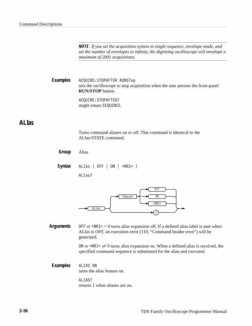
Command Descriptions
2–56 TDS Family Oscilloscope Programmer Manual
NOTE. If you set the acquisition system to single sequence, envelope mode, andset the number of envelopes to infinity, the digitizing oscilloscope will envelope amaximum of 2001 acquisitions.
�������������� �� ���� sets the oscilloscope to stop acquisition when the user presses the front-panelRUN/STOP button.
��������������� might return ��� �.
ALIasTurns command aliases on or off. This command is identical to theALIas:STATE command.
Alias
����� � � � � � � ��� �
������
�
�����
�������
�
� ���
�
� or � ��� = 0 turns alias expansion off. If a defined alias label is sent whenALIas is OFF, an execution error (110, “Command header error”) will begenerated.
� or � ��� � 0 turns alias expansion on. When a defined alias is received, thespecified command sequence is substituted for the alias and executed.
����� �
turns the alias feature on.
������
returns � when aliases are on.
Examples
Group
Syntax
Arguments
Examples
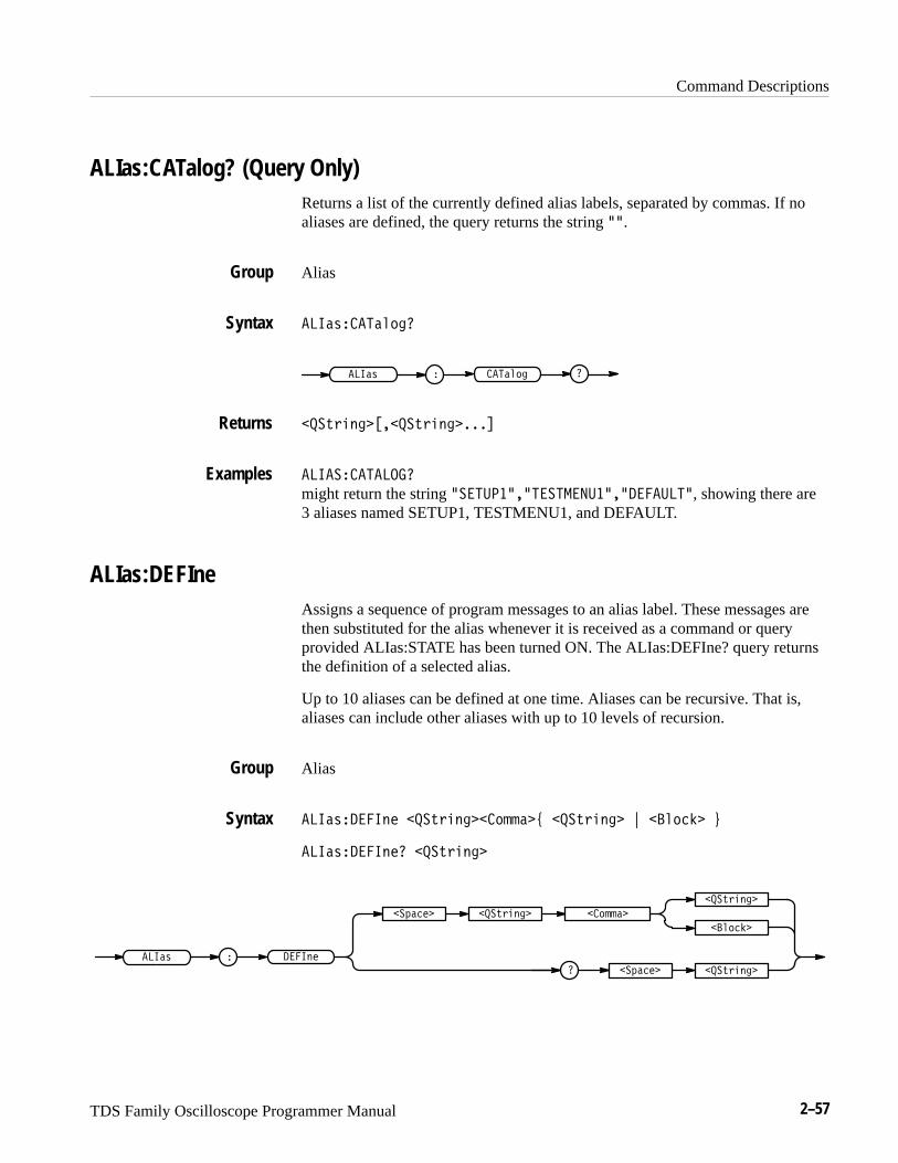
Command Descriptions
TDS Family Oscilloscope Programmer Manual 2–57
ALIas:CATalog? (Query Only)Returns a list of the currently defined alias labels, separated by commas. If noaliases are defined, the query returns the string ��.
Alias
���)����#&
���) � ���#&
���*(!% ������*(!% �����
���������
might return the string ���������������������� ������, showing there are3 aliases named SETUP1, TESTMENU1, and DEFAULT.
ALIas:DEFIneAssigns a sequence of program messages to an alias label. These messages arethen substituted for the alias whenever it is received as a command or queryprovided ALIas:STATE has been turned ON. The ALIas:DEFIne? query returnsthe definition of a selected alias.
Up to 10 aliases can be defined at one time. Aliases can be recursive. That is,aliases can include other aliases with up to 10 levels of recursion.
Alias
���)� ���%� ���*(!% ���&$$��+ ���*(!% � , ��#&�"� -
���)� ���%� ���*(!% �
���) � ���%�
��&$$�����*(!% ���'����
���*(!% �
��#&�"�
���*(!% ���'����
Group
Syntax
Returns
Examples
Group
Syntax
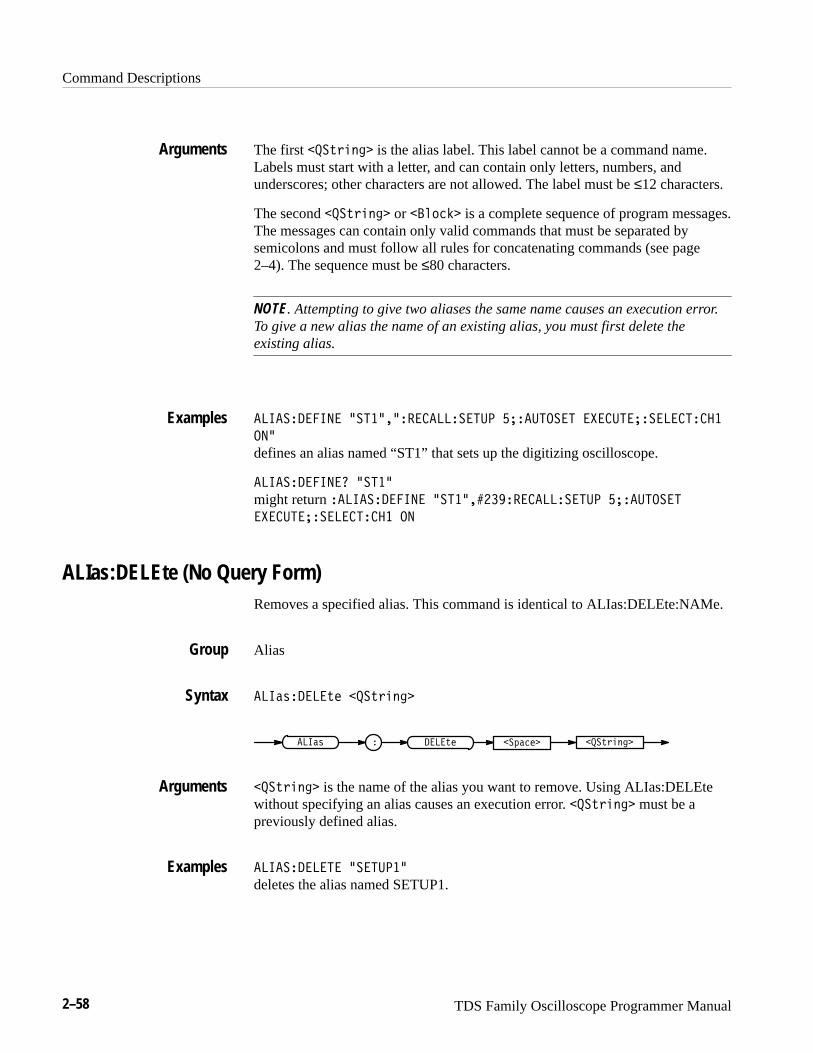
Command Descriptions
2–58 TDS Family Oscilloscope Programmer Manual
The first ���-+%($ is the alias label. This label cannot be a command name.Labels must start with a letter, and can contain only letters, numbers, andunderscores; other characters are not allowed. The label must be ≤12 characters.
The second ���-+%($ or ��')"& is a complete sequence of program messages.The messages can contain only valid commands that must be separated bysemicolons and must follow all rules for concatenating commands (see page2–4). The sequence must be ≤80 characters.
NOTE. Attempting to give two aliases the same name causes an execution error.To give a new alias the name of an existing alias, you must first delete theexisting alias.
����������� ������������������ ��������� � ���������������
���
defines an alias named “ST1” that sets up the digitizing oscilloscope.
������������ �����
might return ����������� �������������������� ���������
� ��������������� ��
ALIas:DELEte (No Query Form)Removes a specified alias. This command is identical to ALIas:DELEte:NAMe.
Alias
���!,����-# ���-+%($
���-+%($ ��*!"# ���!, ����-#
���-+%($ is the name of the alias you want to remove. Using ALIas:DELEtewithout specifying an alias causes an execution error. ���-+%($ must be apreviously defined alias.
����������� �������� deletes the alias named SETUP1.
Arguments
Examples
Group
Syntax
Arguments
Examples

Command Descriptions
TDS Family Oscilloscope Programmer Manual 2–59
ALIas:DELEte:ALL (No Query Form)Deletes all existing aliases.
Alias
��������������
����� � ���� � ���
�������������
deletes all aliases.
ALIas:DELEte:NAMe (No Query Form)Removes a specified alias. This command is identical to ALIas:DELEte.
Alias
������������� � ���������
����� � ���� � �� � ����������������
��������� is the name of the alias to remove. Using ALIas:DELEte:NAMewithout specifying an alias causes an execution error. ��������� must be apreviously defined alias.
������������ ��������� deletes the alias named STARTUP.
ALIas:STATETurns aliases on or off. This command is identical to the ALIas command.
Alias
���������� � ! �� ! ����� "
Group
Syntax
Examples
Group
Syntax
Arguments
Examples
Group
Syntax
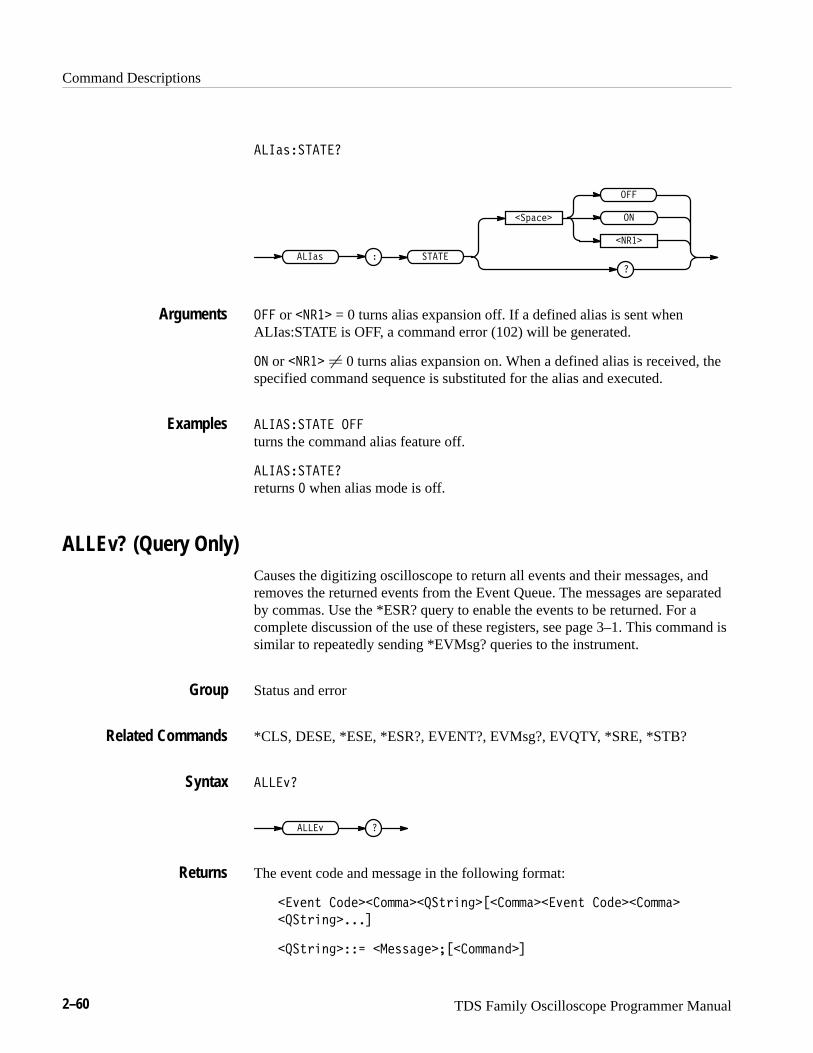
Command Descriptions
2–60 TDS Family Oscilloscope Programmer Manual
����%�����
��
����
��#���
����
���
����% �
��� or ���� = 0 turns alias expansion off. If a defined alias is sent whenALIas:STATE is OFF, a command error (102) will be generated.
�� or ���� � 0 turns alias expansion on. When a defined alias is received, thespecified command sequence is substituted for the alias and executed.
���������� ���
turns the command alias feature off.
����������
returns � when alias mode is off.
ALLEv? (Query Only)Causes the digitizing oscilloscope to return all events and their messages, andremoves the returned events from the Event Queue. The messages are separatedby commas. Use the *ESR? query to enable the events to be returned. For acomplete discussion of the use of these registers, see page 3–1. This command issimilar to repeatedly sending *EVMsg? queries to the instrument.
Status and error
*CLS, DESE, *ESE, *ESR?, EVENT?, EVMsg?, EVQTY, *SRE, *STB?
��� '
��� '
The event code and message in the following format:
� '�!& �"����" ����&$�!����" �� '�!& �"����" �
���&$�!�����
���&$�!���� ���%%�������" �!��
Arguments
Examples
Group
Related Commands
Syntax
Returns
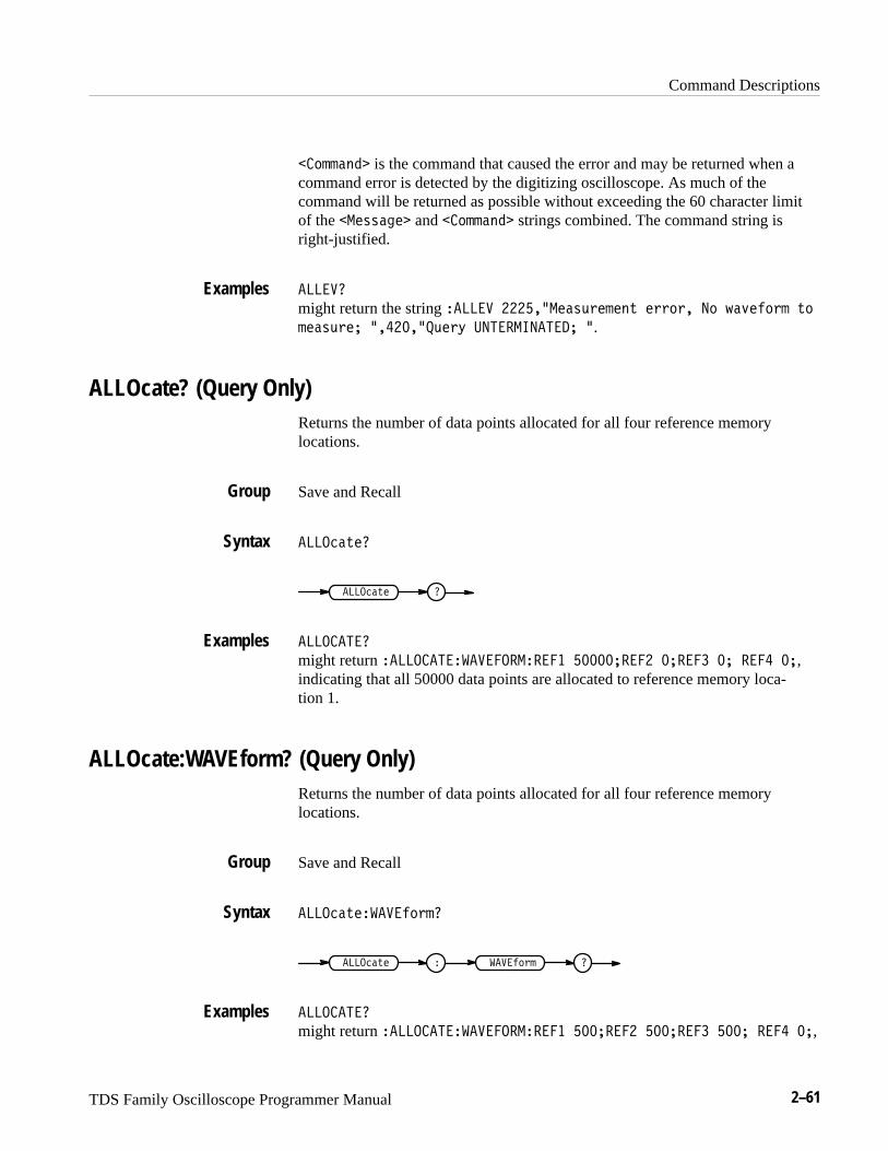
Command Descriptions
TDS Family Oscilloscope Programmer Manual 2–61
��'%%�&! is the command that caused the error and may be returned when acommand error is detected by the digitizing oscilloscope. As much of thecommand will be returned as possible without exceeding the 60 character limitof the ��"))�$" and ��'%%�&! strings combined. The command string isright-justified.
������
might return the string ����� ������"�)+("%"&* "(('(� �' -�,"#'(% *'
%"�)+("� ��������+"(. ������������� �.
ALLOcate? (Query Only)Returns the number of data points allocated for all four reference memorylocations.
Save and Recall
���� �*"�
���� �*" �
���������
might return �������������������� ��������� ������ �� ���� ��,indicating that all 50000 data points are allocated to reference memory loca-tion 1.
ALLOcate:WAVEform? (Query Only)Returns the number of data points allocated for all four reference memorylocations.
Save and Recall
���� �*"����#'(%�
����#'(% ����� �*"
���������
might return �������������������� ������� ������� ��� ���� ��,
Examples
Group
Syntax
Examples
Group
Syntax
Examples

Command Descriptions
2–62 TDS Family Oscilloscope Programmer Manual
indicating that 500 data points are allocated to each of the first three referencememory locations.
ALLOcate:WAVEform:FREE? (Query Only)Returns the approximate number of data points that have not been allocated.
Save and Recall
���������������� ���
������� �������� � ���
����� is the approximate number of data points available.
���������� ���� ���
might return ��� indicating that there are approximately 500 data pointsavailable for allocation. The extra 20 are used for administration purposes.
ALLOcate:WAVEform:REF<x>Sets or queries the number of waveform data points for the specified referencelocation. If an attempt is made to allocate memory when it is not available, anexecution error is generated and the memory is not allocated.
Save and Recall
������������������ � � �����
������������������ � �
������� �������� � ��
������� �����
� �
����� = 0 is returned when the reference location is empty.
Group
Syntax
Returns
Examples
Group
Syntax
Arguments

Command Descriptions
TDS Family Oscilloscope Programmer Manual 2–63
����� � 0 specifies the number of data points. Table 2–26 shows the number ofdata points supported for reference locations by TDS model. In the TDS 500Cand 600B all invalid values less than the maximum will be forced to the nexthighest valid value, and those higher than the maximum will be forced to themaximum. For example, 15002 points on a TDS 520C with option 1M willallocate 50000 points of data for the reference. No complete references are storedfor 500000 data points in the TDS 500C and TDS 700C.
Table 2–26: Waveform Data Points Supported for Reference Locations
Configuration
TDS 420A,TDS 430A,TDS 460A
TDS 510A,TDS 520C,TDS 724C, TDS 600B
TDS 540C,TDS 754C,TDS 784C
Standard 500,1000,2500,5000,15000,30000 (4 refs)
500,1000,2500,5000,1500050000
500,1000,2500,5000,15000
500,1000,2500,5000,15000,50000 (4 refs)
Option 1M(not on the TDS510A)or 2M(TDS 500C &700C only)
60000 (2 refs),120000 (1 ref)
TDS 520C &724C only:75000 (3 refs),100000 (2 refs),130000 (2 refs),250000 (1 ref)
75000 (3 refs),100000 (2 refs),130000 (2 refs),250000 (1 ref)500000 (no complete refs)
���������� ������ � ����
reserves 1,000 data points for REF2.
���������� ������ �
might return ���
APPMenuDisplays the user-definable Application menu, and the query returns the currentApplication menu labels and title. This is equivalent to pressing the front-panelAPPLICATION button.
Application Menu
CLEARMenu, *ESR, EVENT?
������ �������
Examples
Group
Related Commands
Syntax

Command Descriptions
2–64 TDS Family Oscilloscope Programmer Manual
��������
�������
�������
�
��������
�������� displays the Application menu. Use the CLEARMenu command todeactivate the Application menu.
Once the Application menu is activated, whenever a front-panel menu button ispressed an event is generated that tells which button was pressed. See page 3–17for event codes.
Menu button presses will also generate Service Requests when the URQ bit isenabled in DESER and ESER and the ESB bit is enabled in SRER. See page 3–1for a complete discussion of the use of these registers.
���� � ������
displays the application menu.
APPMenu:LABelRemoves all user-defined Application menu button labels from the display. TheAPPMenu:LABel? query returns all the current label settings.
Application Menu
������������� ����
��������������
����
������� � �����
�
�������
���� removes the main and side menu button labels from the display. Front-pa-nel bezel button presses will continue to generate events.
���� ������ ����
clears the user-defined menu labels from the display.
Arguments
Examples
Group
Syntax
Arguments
Examples

Command Descriptions
TDS Family Oscilloscope Programmer Manual 2–65
APPMenu:LABel:BOTTOM<x>Defines a label for the main menu button that is specified by <x>. Main menubuttons are located along the bottom of the display, and are numbered from 1 to7 starting with the left-most button.
Application Menu
������������������� �� ������
��������������������
����� � ���
� ����� �� ������
������� �
� �����
���
�� ������ is the menu button label and can include any of the characters shownin the TDS Character Chart in Appendix A. The maximum length of the label is1000 characters. The TDS displays the label in the area above the specified mainmenu button.
The TDS displays the label on a single line and centers it, both vertically andhorizontally, within the label area. You can embed a line feed character in thestring to position the label on multiple lines. You can also use white space tabcharacters to position the label within a line.
You can send a tab by transmitting a tab character (decimal 9) followed by twocharacters representing the most significant eight bits followed by the leastsignificant eight bits of a 16-bit number. The number specifies the pixel columnrelative to the left margin of the label area. For example, to tab to pixel 13, sendTAB (decimal 9), NUL (decimal 0), and CR (decimal 13).
The ESC @ character turns reverse video on and off, and can be embedded in thelabel string. The first ESC @ character displays all text following the ESC @ inreverse video until another ESC @ character is found in the string.
NOTE. The use of any undocumented codes may produce unpredictable results.
The label area is 45 pixels high and 90 pixels wide. The length of the label thatfits in the label area depends on the contents of the label, because the width ofcharacters varies. The label area is about 10 characters wide and 3 lines high. Fora complete list of character widths in pixels, see Table A–1 on page A–1.
If the label exceeds the limits of the label area, either horizontally or vertically,the portion of the label that exceeds the limits will not be displayed. The label
Group
Syntax
Arguments

Command Descriptions
2–66 TDS Family Oscilloscope Programmer Manual
itself is not altered. The entire label can be returned as a query responseregardless of what is displayed.
����������������� ��������
assigns the label “SETUP1” to the third main menu button.
APPMenu:LABel:RIGHT<x>Defines a label for the side menu button that is specified by <x>. Side menubuttons are located on the right side of the display, and are numbered from 1 to 5starting with the top-most button.
Application Menu
�����#�������� ��$� ���"!����
�����#�������� ��$��
��� � ��� �
�� ���� ���"!����
�
�����# �
�� ����
�$�
���"!���� is the menu button label and can include any of the characters shownin the TDS Character Chart in Appendix A. The maximum length of the label is1000 characters. The label is displayed in the area to the left of the specified sidemenu button. Refer to the APPMenu:LABel:BOTTOM<x> command on page2–65 for more information on defining menu labels.
The label area is 72 pixels high and 112 pixels wide. The length of the label thatfits in the label area depends on the contents of the label, because the width ofcharacters varies. The label area is about 12 characters wide and 4 lines high. Fora complete list of character widths in pixels, see Table A–1 on page A–1.
�������������� �� %���� ���
displays the label “TEST ON” next to the top side menu button.
APPMenu:TITLeSets or queries the user-defined application menu title. The title is displayedabove the side menu.
Examples
Group
Syntax
Arguments
Examples

Command Descriptions
TDS Family Oscilloscope Programmer Manual 2–67
Application Menu
APPMenu, APPMenu:LABel
������!����� ��� �����
������!������
����
������� ��� �����
�
������! �
��� ����� is the side menu title and can include any of the characters shown inthe TDS Character Chart in Appendix A. The maximum length of the title is1000 characters. The APPMenu:LABel:BOTTOM<x> command on page 2–65provides information on defining menu labels.
The label area is 40 pixels high and 112 pixels wide. The length of the label thatfits in the label area depends on the contents of the label, because the width ofcharacters varies. The label area is about 12 characters wide and 4 lines high. Fora complete list of character widths in pixels, see Table A–1 on page A–1.
���� ����� ��!� �� ���!�
displays the title “Custom Menu” on the screen.
���� ������
might return ���� �� !�� for the current application menu title.
AUTOSet (No Query Form)Causes the digitizing oscilloscope to adjust its vertical, horizontal, and triggercontrols to provide a stable display of the selected waveform. This is equivalentto pressing the front-panel AUTOSET button. For a detailed description of theautoset function, see Autoset in the Reference section of the User Manual foryour instrument.
This command will turn the extended-acquisition-length mode to off.
Miscellaneous
������ ��! �
Group
Related Commands
Syntax
Arguments
Examples
Group
Syntax
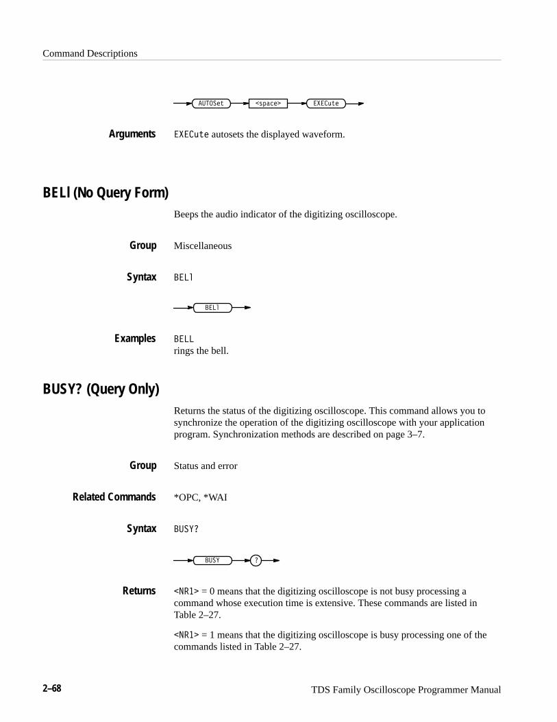
Command Descriptions
2–68 TDS Family Oscilloscope Programmer Manual
����������� �� �������
������� autosets the displayed waveform.
BELl (No Query Form)Beeps the audio indicator of the digitizing oscilloscope.
Miscellaneous
���
���
��
rings the bell.
BUSY? (Query Only)Returns the status of the digitizing oscilloscope. This command allows you tosynchronize the operation of the digitizing oscilloscope with your applicationprogram. Synchronization methods are described on page 3–7.
Status and error
*OPC, *WAI
�� ��
�� � �
���� = 0 means that the digitizing oscilloscope is not busy processing acommand whose execution time is extensive. These commands are listed inTable 2–27.
���� = 1 means that the digitizing oscilloscope is busy processing one of thecommands listed in Table 2–27.
Arguments
Group
Syntax
Examples
Group
Related Commands
Syntax
Returns

Command Descriptions
TDS Family Oscilloscope Programmer Manual 2–69
Table 2–27: Commands that Affect BUSY? Response
Operation Command
Single sequence acquisition ACQuire:STATE ON orACQuire:STATE RUN (when ACQuire:STOPAfter is set to SEQuence)
Hardcopy output HARDCopy STARt
�� ��
might return �, indicating that the instrument is busy.
*CAL? (Query Only)Instructs the digitizing oscilloscope to perform an internal self-calibration andreturn its calibration status.
NOTE. The self-calibration can take several minutes to respond. No othercommands will be executed until calibration is complete.
Calibration and Diagnostic
���
�� �
����� = 0 indicates that the calibration completed without any errors detected.
����� � 0 indicates that the calibration did not complete successfully.
���
performs an internal self-calibration and might return � to indicate that thecalibration was successful.
CH<x>? (Query Only)Returns the vertical parameters. Because CH<x>:SCAle and CH<x>:VOLts areidentical, only CH<x>:SCAle is returned.
Examples
Group
Syntax
Returns
Examples

Command Descriptions
2–70 TDS Family Oscilloscope Programmer Manual
Vertical
���/�
�� �/�
���
might return the string �������� ��������������� ������
������ �������������� ����������� ������������ ���� for chan-nel 1.
CH<x>:BANdwidthSets or queries the bandwidth setting of the specified channel. This is equivalentto setting Bandwidth in the Vertical menu.
Vertical
���/����$.($-' 1 ���*-0 2 ���$,%$ (TDS 400A, 510A) 2 ���&(&-0
(TDS 500C, 600B & 700C) 2 ���) 3
���/����$.($-'
���&(&-0
���$,%$
���$.($-'
��+"#%�
���)
�� � �
���*-0
���*-0 sets the channel bandwidth to 20 MHz.
���$,%$ sets the channel bandwidth to 100 MHz (TDS 400A, 510A).
���&(&-0 sets the channel bandwidth to 250 MHz (TDS 500C, 600B, & 700C).
���) sets the channel bandwidth to the full bandwidth of the digitizing oscillo-scope.
������������ �����!
sets the bandwidth of channel 2 to 20 MHz.
Group
Syntax
Examples
Group
Syntax
Arguments
Examples
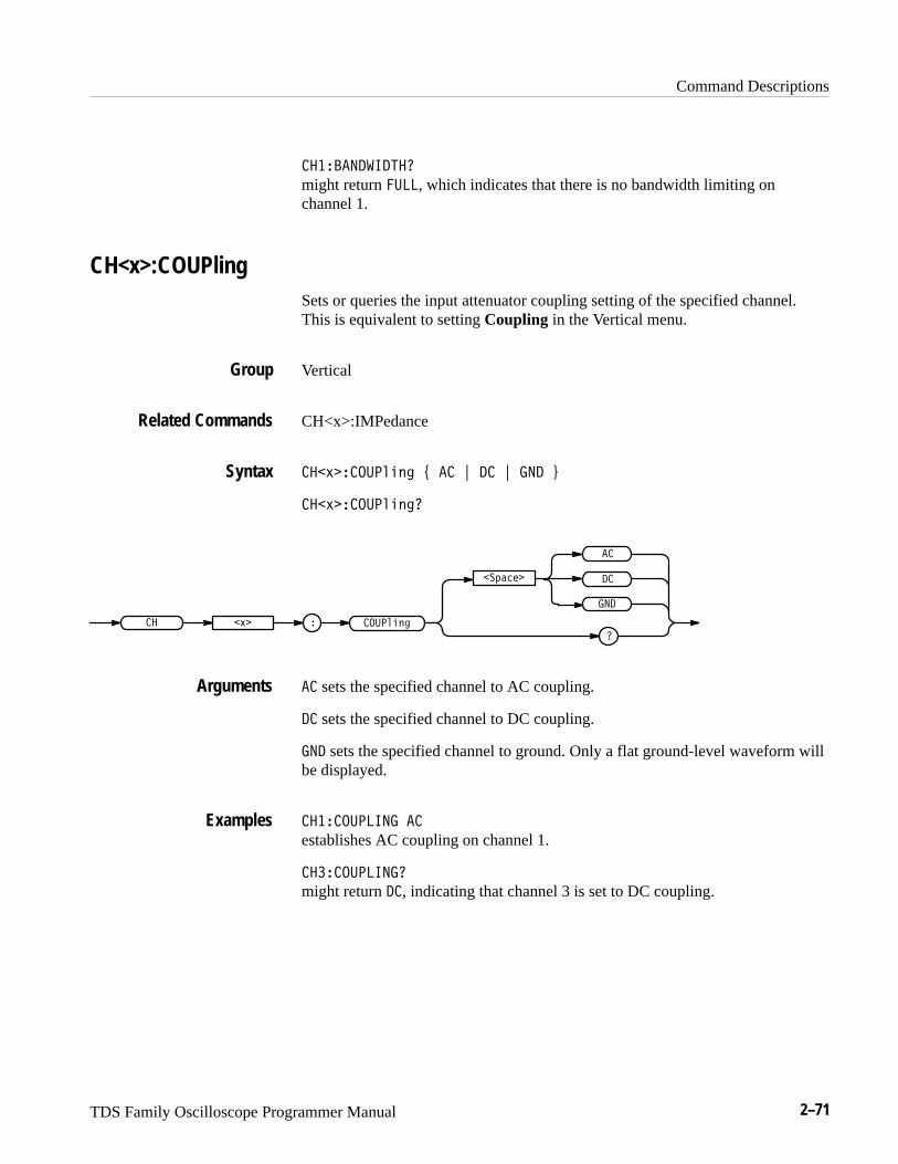
Command Descriptions
TDS Family Oscilloscope Programmer Manual 2–71
������������
might return ����, which indicates that there is no bandwidth limiting onchannel 1.
CH<x>:COUPlingSets or queries the input attenuator coupling setting of the specified channel.This is equivalent to setting Coupling in the Vertical menu.
Vertical
CH<x>:IMPedance
�� ��������� ! � " � " �� #
�� ����������
�
�
��
�
�������
�������
� �� �
� sets the specified channel to AC coupling.
� sets the specified channel to DC coupling.
�� sets the specified channel to ground. Only a flat ground-level waveform willbe displayed.
��������� �
establishes AC coupling on channel 1.
��������� �
might return �, indicating that channel 3 is set to DC coupling.
Group
Related Commands
Syntax
Arguments
Examples
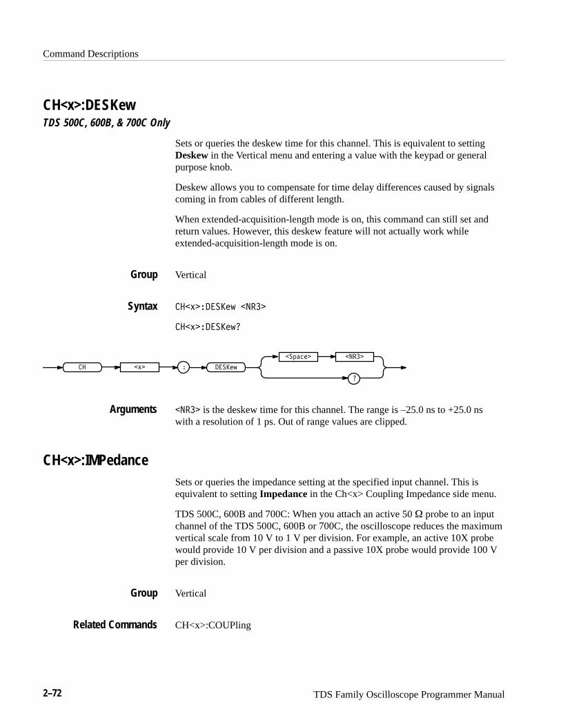
Command Descriptions
2–72 TDS Family Oscilloscope Programmer Manual
CH<x>:DESKewTDS 500C, 600B, & 700C Only
Sets or queries the deskew time for this channel. This is equivalent to settingDeskew in the Vertical menu and entering a value with the keypad or generalpurpose knob.
Deskew allows you to compensate for time delay differences caused by signalscoming in from cables of different length.
When extended-acquisition-length mode is on, this command can still set andreturn values. However, this deskew feature will not actually work whileextended-acquisition-length mode is on.
Vertical
���������� �� ��
�����������
� ��� � �����
�
������� �� ��
�� �� is the deskew time for this channel. The range is –25.0 ns to +25.0 nswith a resolution of 1 ps. Out of range values are clipped.
CH<x>:IMPedanceSets or queries the impedance setting at the specified input channel. This isequivalent to setting Impedance in the Ch<x> Coupling Impedance side menu.
TDS 500C, 600B and 700C: When you attach an active 50 � probe to an inputchannel of the TDS 500C, 600B or 700C, the oscilloscope reduces the maximumvertical scale from 10 V to 1 V per division. For example, an active 10X probewould provide 10 V per division and a passive 10X probe would provide 100 Vper division.
Vertical
CH<x>:COUPling
Group
Syntax
Arguments
Group
Related Commands
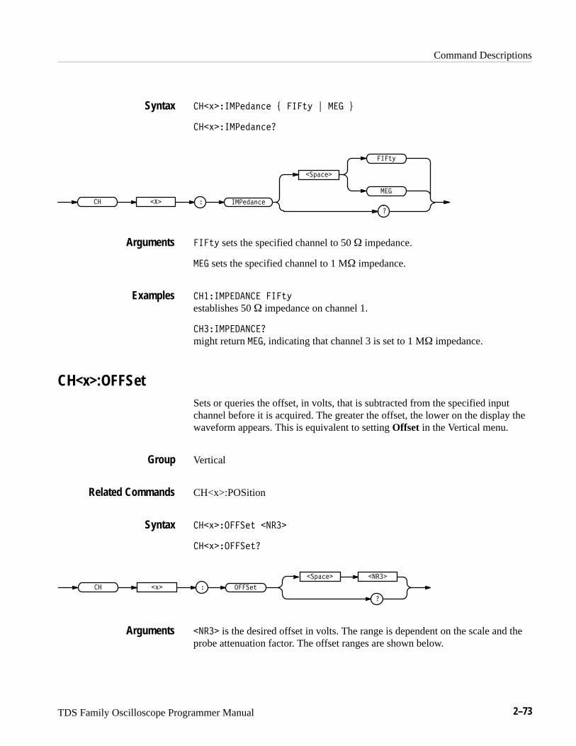
Command Descriptions
TDS Family Oscilloscope Programmer Manual 2–73
�������������� ����� ! �� "
���������������
�����
���������
�������
�
��
� ����
����� sets the specified channel to 50 � impedance.
�� sets the specified channel to 1 M� impedance.
���������� �����
establishes 50 � impedance on channel 1.
�����������
might return �� , indicating that channel 3 is set to 1 M� impedance.
CH<x>:OFFSetSets or queries the offset, in volts, that is subtracted from the specified inputchannel before it is acquired. The greater the offset, the lower on the display thewaveform appears. This is equivalent to setting Offset in the Vertical menu.
Vertical
CH<x>:POSition
����������� �����
������������
� ��� � ������
�
������� �����
����� is the desired offset in volts. The range is dependent on the scale and theprobe attenuation factor. The offset ranges are shown below.
Syntax
Arguments
Examples
Group
Related Commands
Syntax
Arguments

Command Descriptions
2–74 TDS Family Oscilloscope Programmer Manual
Table 2–28: Offset Ranges for the TDS 400A, 510A, 540C, 600B, 754C, & 784C (AllChannels) and the TDS 520C & 724C (Channel 1 & Channel 2) using a 1xProbe
CH<x>:SCAle OFFSet Range
1 mV/div – 99.5 mV/div ±1 V
100 mV/div – 995 mV/div ±10 V
1 V/div – 10 V/div ±100 V
Table 2–29: Offset Ranges for the TDS 520C & 724C (Aux 1 & Aux 2) using a 1xProbe
CH<x>:SCAle OFFSet Range
50 mV/div & 100 mV/div ±.5 V
500 mV/div & 1 V/div ±5.0 V
5 V/div & 10 V/div ±50 V
�������� �������
lowers the channel 1 displayed waveform by 0.5 volts.
���������
might return ��������, indicating that the current channel 1 offset is 0.5 volts.
CH<x>:POSitionSets or queries the vertical position of the specified channel. The position valueis applied to the signal before digitization. This is equivalent to setting Positionin the Vertical menu or adjusting the front-panel Vertical Position knob.
Vertical
CH<x>:OFFSet
����������� ����
������������
Examples
Group
Related Commands
Syntax
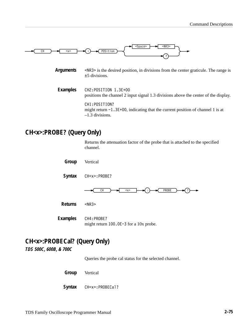
Command Descriptions
TDS Family Oscilloscope Programmer Manual 2–75
����!����� �"�
�� ���� �����
����� is the desired position, in divisions from the center graticule. The range is±5 divisions.
����������� �������
positions the channel 2 input signal 1.3 divisions above the center of the display.
�����������
might return ��������, indicating that the current position of channel 1 is at–1.3 divisions.
CH<x>:PROBE? (Query Only)Returns the attenuation factor of the probe that is attached to the specifiedchannel.
Vertical
���"������
�� �"� �����
�����
�������
might return �������� for a 10x probe.
CH<x>:PROBECal? (Query Only)TDS 500C, 600B, & 700C
Queries the probe cal status for the selected channel.
Vertical
���"���������
Arguments
Examples
Group
Syntax
Returns
Examples
Group
Syntax
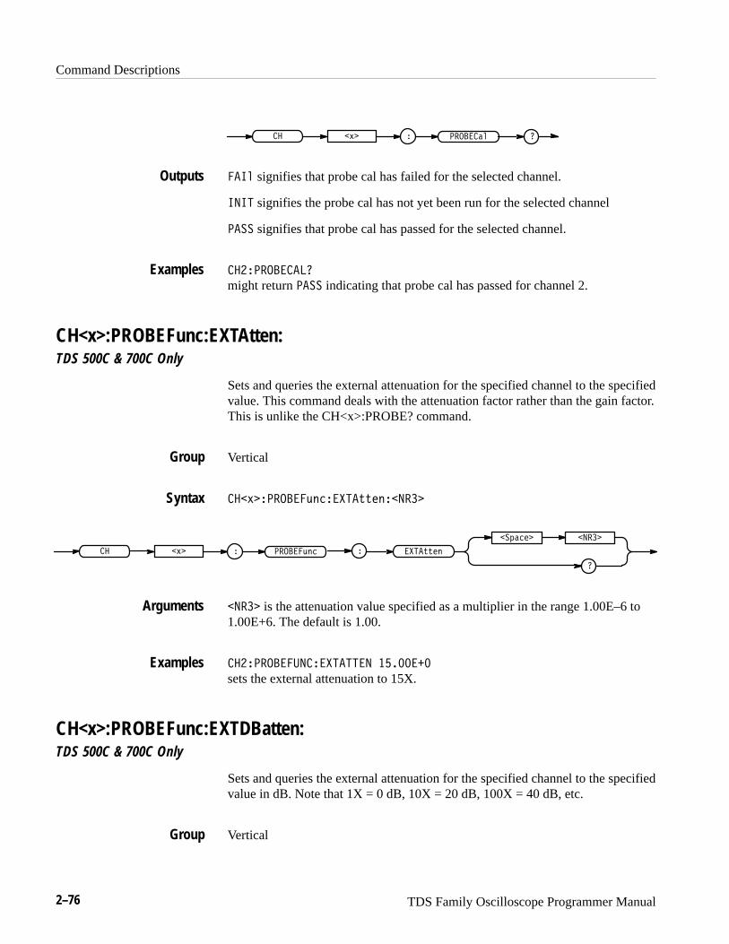
Command Descriptions
2–76 TDS Family Oscilloscope Programmer Manual
�������� �� %�
� � signifies that probe cal has failed for the selected channel.
���� signifies the probe cal has not yet been run for the selected channel
� �� signifies that probe cal has passed for the selected channel.
��������� ��
might return � �� indicating that probe cal has passed for channel 2.
CH<x>:PROBEFunc:EXTAtten:TDS 500C & 700C Only
Sets and queries the external attenuation for the specified channel to the specifiedvalue. This command deals with the attenuation factor rather than the gain factor.This is unlike the CH<x>:PROBE? command.
Vertical
��%�������$!���� ##�!����
������$!��� %� ��� ##�!
�
�"���� ����
���� is the attenuation value specified as a multiplier in the range 1.00E–6 to1.00E+6. The default is 1.00.
��������������� ���� ��������
sets the external attenuation to 15X.
CH<x>:PROBEFunc:EXTDBatten:TDS 500C & 700C Only
Sets and queries the external attenuation for the specified channel to the specifiedvalue in dB. Note that 1X = 0 dB, 10X = 20 dB, 100X = 40 dB, etc.
Vertical
Outputs
Examples
Group
Syntax
Arguments
Examples
Group
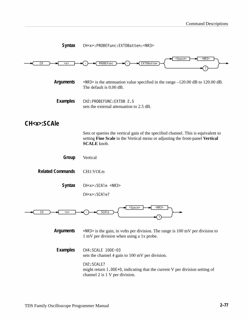
Command Descriptions
TDS Family Oscilloscope Programmer Manual 2–77
���' �������&# �������%%!#�����
������&# �� ��' ������%%!#�
�
��$� ! ����
���� is the attenuation value specified in the range –120.00 dB to 120.00 dB.The default is 0.00 dB.
������������������� ��
sets the external attenuation to 2.5 dB.
CH<x>:SCAleSets or queries the vertical gain of the specified channel. This is equivalent tosetting Fine Scale in the Vertical menu or adjusting the front-panel VerticalSCALE knob.
Vertical
CH1:VOLts
���' ����"! ����
���' ����"!�
�� �' � ���"!
�
��$� ! ����
���� is the gain, in volts per division. The range is 100 mV per division to1 mV per division when using a 1x probe.
�������� �������
sets the channel 4 gain to 100 mV per division.
����������
might return �������, indicating that the current V per division setting ofchannel 2 is 1 V per division.
Syntax
Arguments
Examples
Group
Related Commands
Syntax
Arguments
Examples

Command Descriptions
2–78 TDS Family Oscilloscope Programmer Manual
CH<x>:VOLtsSets or queries the vertical gain of the specified channel. This command isidentical to the CH<x>:SCAle command and is included for compatibilitypurposes. Only CH<x>:SCAle is returned in response to a CH<x>? query.
Vertical
CH1:SCAle
���#����! �����
���#����!
�� �#� ���!
������� �����
������� �������
sets the channel 4 gain to 100 mV per division.
��������
might return �������, indicating that the current V per division setting ofchannel 2 is 1 V per division.
CLEARMenu (No Query Form)Clears the current menu from the display. This command is equivalent topressing the CLEAR MENU button on the front panel.
Display
��������"
��������"
���������
clears the menu from the display.
Group
Related Commands
Syntax
Examples
Group
Syntax
Examples
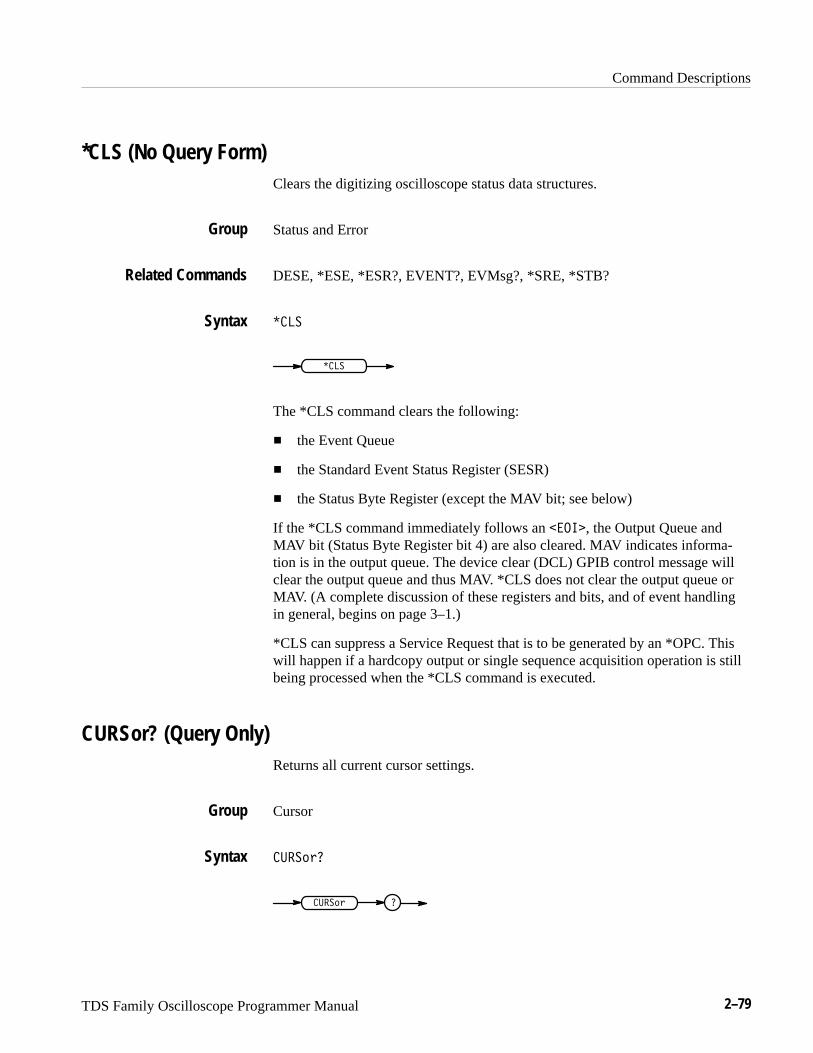
Command Descriptions
TDS Family Oscilloscope Programmer Manual 2–79
*CLS (No Query Form)Clears the digitizing oscilloscope status data structures.
Status and Error
DESE, *ESE, *ESR?, EVENT?, EVMsg?, *SRE, *STB?
����
����
The *CLS command clears the following:
� the Event Queue
� the Standard Event Status Register (SESR)
� the Status Byte Register (except the MAV bit; see below)
If the *CLS command immediately follows an ����, the Output Queue andMAV bit (Status Byte Register bit 4) are also cleared. MAV indicates informa-tion is in the output queue. The device clear (DCL) GPIB control message willclear the output queue and thus MAV. *CLS does not clear the output queue orMAV. (A complete discussion of these registers and bits, and of event handlingin general, begins on page 3–1.)
*CLS can suppress a Service Request that is to be generated by an *OPC. Thiswill happen if a hardcopy output or single sequence acquisition operation is stillbeing processed when the *CLS command is executed.
CURSor? (Query Only)Returns all current cursor settings.
Cursor
��� ��
��� � �
Group
Related Commands
Syntax
Group
Syntax
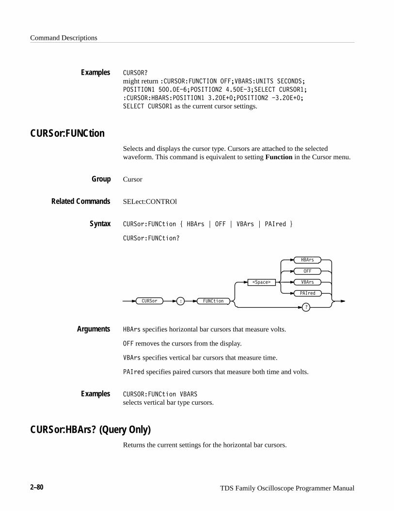
Command Descriptions
2–80 TDS Family Oscilloscope Programmer Manual
� ����� might return �� ������ ������ ��� !����� ���� �������
��������� ������� ��������� ����� ������ � �����
�� �������������������� ������� ��������� ��������
������ � ����� as the current cursor settings.
CURSor:FUNCtionSelects and displays the cursor type. Cursors are attached to the selectedwaveform. This command is equivalent to setting Function in the Cursor menu.
Cursor
SELect:CONTROl
� ��(*�� ��,&(' - ���*+ . ��� . !��*+ . ���*%$ /
� ��(*�� ��,&('�
� ��,&('� ��(* �
���*%$
��)"#%�
�
!��*+
���
���*+
���*+ specifies horizontal bar cursors that measure volts.
��� removes the cursors from the display.
!��*+ specifies vertical bar cursors that measure time.
���*%$ specifies paired cursors that measure both time and volts.
� ������ ��,&(' !����
selects vertical bar type cursors.
CURSor:HBArs? (Query Only)Returns the current settings for the horizontal bar cursors.
Examples
Group
Related Commands
Syntax
Arguments
Examples
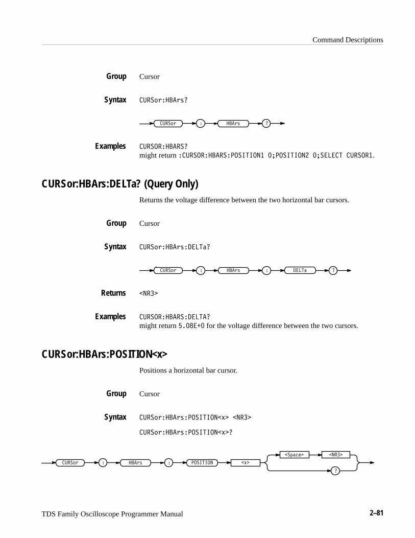
Command Descriptions
TDS Family Oscilloscope Programmer Manual 2–81
Cursor
����!#���#$�
����!# ���#$ �
������������
might return �������������������� ����������� �������� �������.
CURSor:HBArs:DELTa? (Query Only)Returns the voltage difference between the two horizontal bar cursors.
Cursor
����!#���#$������
����!# ���#$ ����� �
����
�����������������
might return ������ for the voltage difference between the two cursors.
CURSor:HBArs:POSITION<x>Positions a horizontal bar cursor.
Cursor
����!#���#$���������% ����
����!#���#$���������% �
����!# ���#$ �������� �%
�
��"�� ����
Group
Syntax
Examples
Group
Syntax
Returns
Examples
Group
Syntax
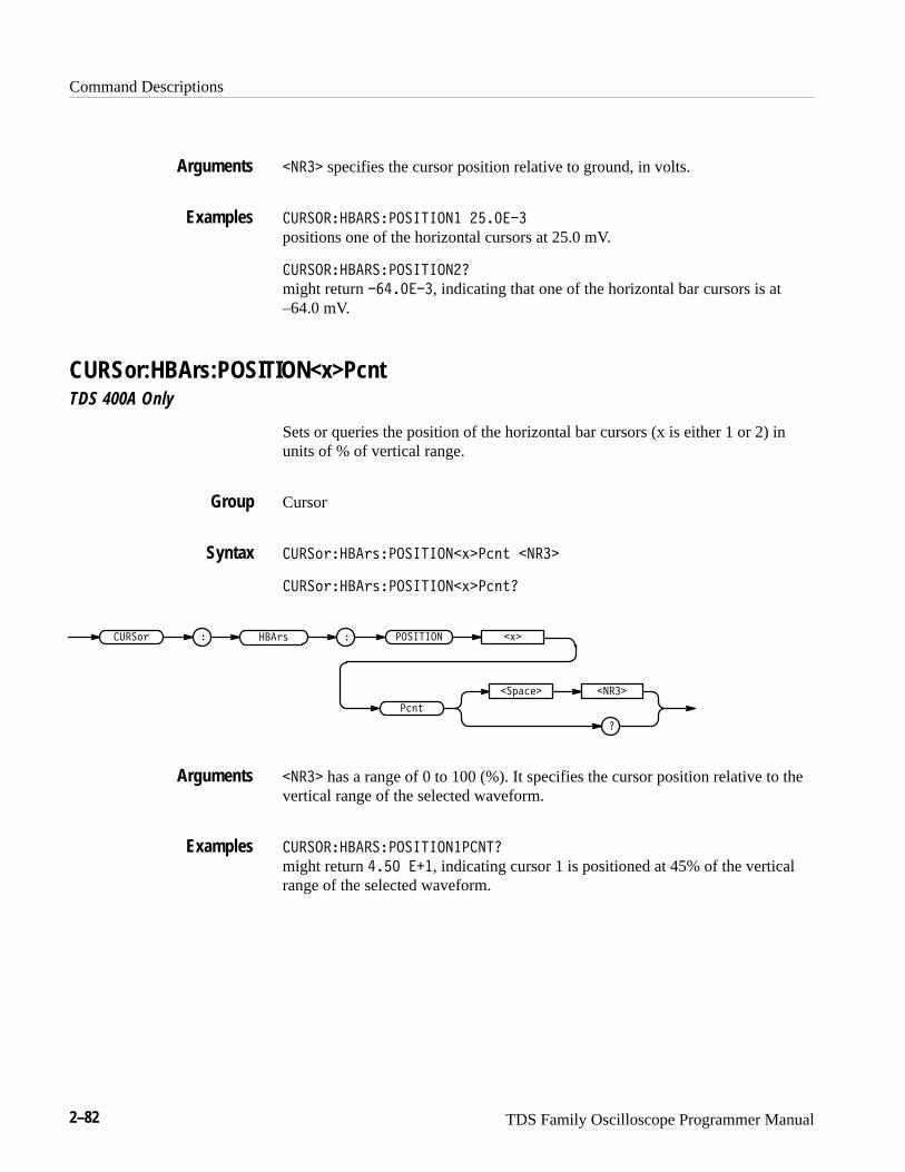
Command Descriptions
2–82 TDS Family Oscilloscope Programmer Manual
���� specifies the cursor position relative to ground, in volts.
���������������������� ������
positions one of the horizontal cursors at 25.0 mV.
�����������������������
might return �������, indicating that one of the horizontal bar cursors is at–64.0 mV.
CURSor:HBArs:POSITION<x>PcntTDS 400A Only
Sets or queries the position of the horizontal bar cursors (x is either 1 or 2) inunits of % of vertical range.
Cursor
����!#����#$��������� &��� % ����
����!#����#$��������� &��� %�
����!# � ���#$ � �������� &�
�
�"���� ����
�� %
���� has a range of 0 to 100 (%). It specifies the cursor position relative to thevertical range of the selected waveform.
���������������������������
might return �� ���, indicating cursor 1 is positioned at 45% of the verticalrange of the selected waveform.
Arguments
Examples
Group
Syntax
Arguments
Examples
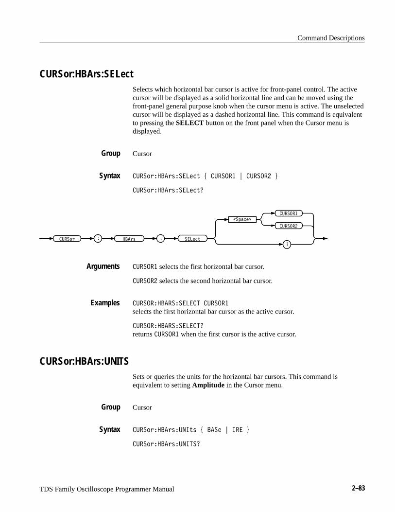
Command Descriptions
TDS Family Oscilloscope Programmer Manual 2–83
CURSor:HBArs:SELectSelects which horizontal bar cursor is active for front-panel control. The activecursor will be displayed as a solid horizontal line and can be moved using thefront-panel general purpose knob when the cursor menu is active. The unselectedcursor will be displayed as a dashed horizontal line. This command is equivalentto pressing the SELECT button on the front panel when the Cursor menu isdisplayed.
Cursor
����������������� � ������ � ������ �
������������������
����� � ���� � ������
�������
�
������
������
������ selects the first horizontal bar cursor.
������ selects the second horizontal bar cursor.
���������������� ������
selects the first horizontal bar cursor as the active cursor.
�����������������
returns ������ when the first cursor is the active cursor.
CURSor:HBArs:UNITSSets or queries the units for the horizontal bar cursors. This command isequivalent to setting Amplitude in the Cursor menu.
Cursor
������������� �� � ��� � �� �
������������� ���
Group
Syntax
Arguments
Examples
Group
Syntax
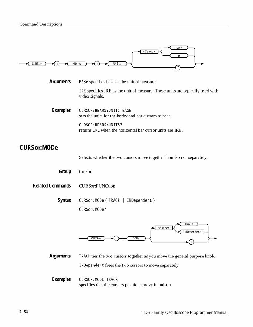
Command Descriptions
2–84 TDS Family Oscilloscope Programmer Manual
������ � ����� � �����
�������
�
��
����
���� specifies base as the unit of measure.
�� specifies IRE as the unit of measure. These units are typically used withvideo signals.
������������������ ���
sets the units for the horizontal bar cursors to base.
�������������������
returns �� when the horizontal bar cursor units are IRE.
CURSor:MODeSelects whether the two cursors move together in unison or separately.
Cursor
CURSor:FUNCtion
���������� { ����� ���������� }
�����������
�������
����������
������ � ����
�����
����� ties the two cursors together as you move the general purpose knob.
���������� frees the two cursors to move separately.
��������� ����
specifies that the cursors positions move in unison.
Arguments
Examples
Group
Related Commands
Syntax
Arguments
Examples
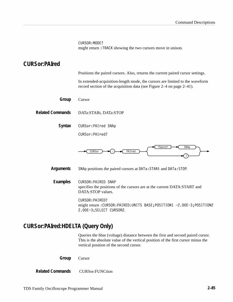
Command Descriptions
TDS Family Oscilloscope Programmer Manual 2–85
������������
might return ��� �� showing the two cursors move in unison.
CURSor:PAIredPositions the paired cursors. Also, returns the current paired cursor settings.
In extended-acquisition-length mode, the cursors are limited to the waveformrecord section of the acquisition data (see Figure 2–4 on page 2–41).
Cursor
DATa:STARt, DATa:STOP
����!#�� �# � �� "
����!#�� �# ��
����!# � � �# �
�
�"�� � �� "
�� " positions the paired cursors at � ����� �$ and � �������.
�������� ���� �� �
specifies the positions of the cursors are at the current DATA:START andDATA:STOP values.
�������� �����
might return ��������� ���������� � ����������� �����������������
������������� �������.
CURSor:PAIred:HDELTA (Query Only)Queries the hbar (voltage) distance between the first and second paired cursor.This is the absolute value of the vertical position of the first cursor minus thevertical position of the second cursor.
Cursor
CURSor:FUNCtion
Group
Related Commands
Syntax
Arguments
Examples
Group
Related Commands
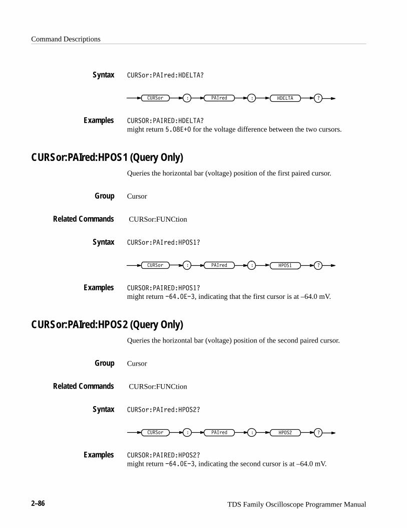
Command Descriptions
2–86 TDS Family Oscilloscope Programmer Manual
��������������������
������ � ������ � ������
��������������������
might return ������ for the voltage difference between the two cursors.
CURSor:PAIred:HPOS1 (Query Only)Queries the horizontal bar (voltage) position of the first paired cursor.
Cursor
CURSor:FUNCtion
�������������������
������ � ������ � �����
�������������������
might return �������, indicating that the first cursor is at –64.0 mV.
CURSor:PAIred:HPOS2 (Query Only)Queries the horizontal bar (voltage) position of the second paired cursor.
Cursor
CURSor:FUNCtion
�������������������
������ � ������ � �����
�������������������
might return �������, indicating the second cursor is at –64.0 mV.
Syntax
Examples
Group
Related Commands
Syntax
Examples
Group
Related Commands
Syntax
Examples
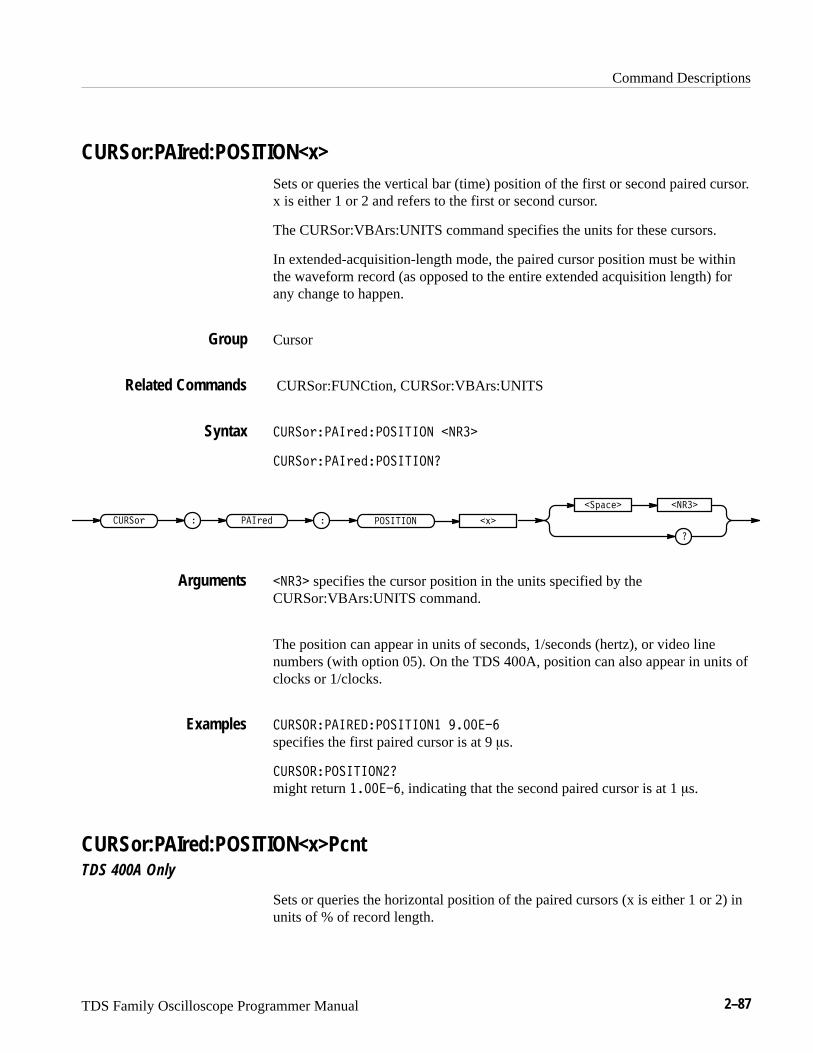
Command Descriptions
TDS Family Oscilloscope Programmer Manual 2–87
CURSor:PAIred:POSITION<x>Sets or queries the vertical bar (time) position of the first or second paired cursor.x is either 1 or 2 and refers to the first or second cursor.
The CURSor:VBArs:UNITS command specifies the units for these cursors.
In extended-acquisition-length mode, the paired cursor position must be withinthe waveform record (as opposed to the entire extended acquisition length) forany change to happen.
Cursor
CURSor:FUNCtion, CURSor:VBArs:UNITS
����� ��� ���������� �����
����� ��� ����������
����� ��� ��
������� �����
�������� �!�
����� specifies the cursor position in the units specified by the CURSor:VBArs:UNITS command.
The position can appear in units of seconds, 1/seconds (hertz), or video linenumbers (with option 05). On the TDS 400A, position can also appear in units ofclocks or 1/clocks.
��������������������� ������
specifies the first paired cursor is at 9 �s.
���������������
might return �������, indicating that the second paired cursor is at 1 �s.
CURSor:PAIred:POSITION<x>PcntTDS 400A Only
Sets or queries the horizontal position of the paired cursors (x is either 1 or 2) inunits of % of record length.
Group
Related Commands
Syntax
Arguments
Examples

Command Descriptions
2–88 TDS Family Oscilloscope Programmer Manual
Cursor
���� "���"�����������$����# �����
���� "���"�����������$����#
���� " ���"�� �������� �$�
��!���� �����
���#
����� has a range of 0 to 100 (%). It specifies the cursor position relative to therecord length of the selected waveform.
�������������������������
might return ��� ���, indicating cursor 1 is positioned at 45% of the recordlength of the selected waveform.
CURSor:PAIred:SELectSelects the active paired cursor. The active cursor appears as a solid vertical line.The unselected cursor appears as a dashed vertical line. This command isequivalent to pressing the SELECT button on the front panel when the Cursormenu is displayed.
Cursor
���� "���"�������# % ������� & ������� '
���� "���"�������#
���� " ���"�� �����#
��!����
�������
�������
������� specifies the first paired cursor.
������� specifies the second paired cursor.
Group
Syntax
Arguments
Examples
Group
Syntax
Arguments
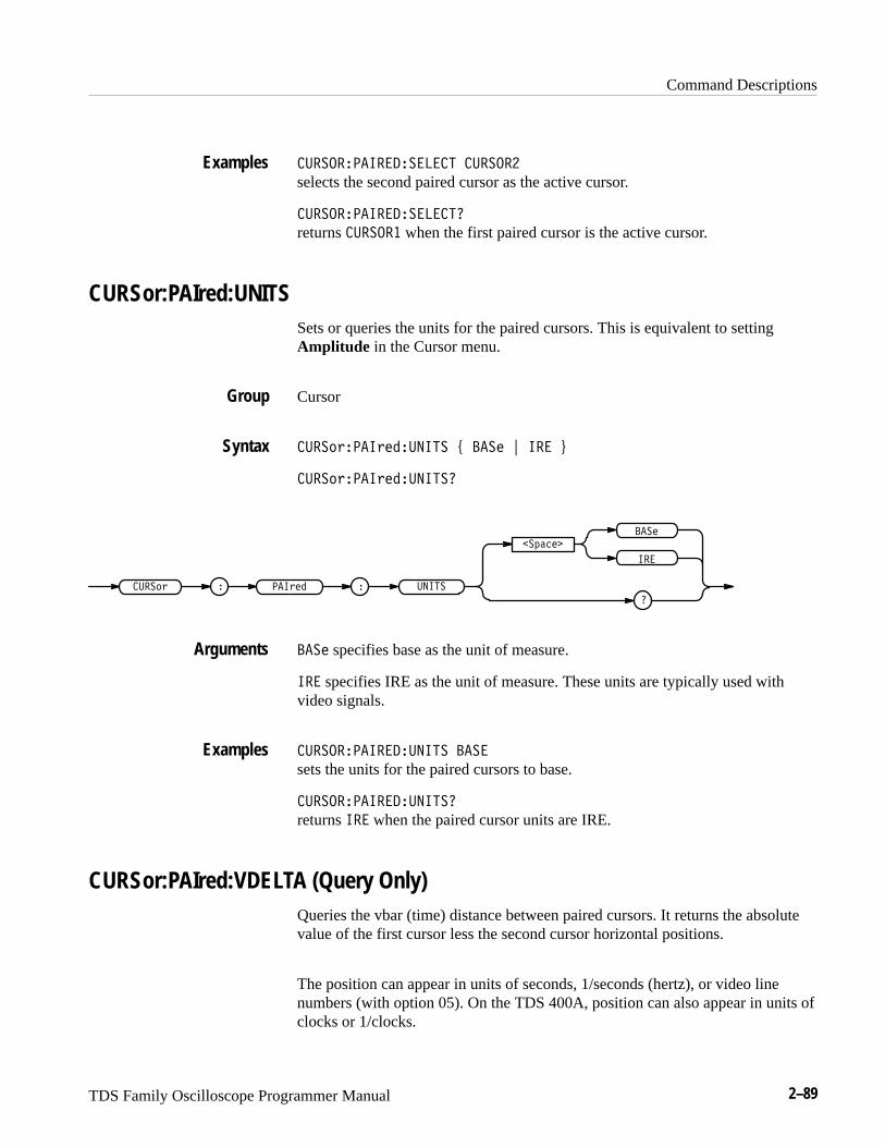
Command Descriptions
TDS Family Oscilloscope Programmer Manual 2–89
�������� ��������� ������
selects the second paired cursor as the active cursor.
�������� ����������
returns ������ when the first paired cursor is the active cursor.
CURSor:PAIred:UNITSSets or queries the units for the paired cursors. This is equivalent to settingAmplitude in the Cursor menu.
Cursor
�������� ������ �� � ��� � �� �
�������� ������ ���
����� � �� ��� � �� ��
�������
�
��
���
��� specifies base as the unit of measure.
�� specifies IRE as the unit of measure. These units are typically used withvideo signals.
�������� ������ �� ���
sets the units for the paired cursors to base.
�������� ������ ���
returns �� when the paired cursor units are IRE.
CURSor:PAIred:VDELTA (Query Only)Queries the vbar (time) distance between paired cursors. It returns the absolutevalue of the first cursor less the second cursor horizontal positions.
The position can appear in units of seconds, 1/seconds (hertz), or video linenumbers (with option 05). On the TDS 400A, position can also appear in units ofclocks or 1/clocks.
Examples
Group
Syntax
Arguments
Examples

Command Descriptions
2–90 TDS Family Oscilloscope Programmer Manual
Cursor
CURSor:FUNCtion
�����!����!����������
�����! � ���!�� � �������
���������������������
might return ���������, indicating that the time between the paired cursors is1.064 seconds.
CURSor:VBArsPositions the vertical bar cursors and the CURSor:VBArs? query returns thecurrent vertical bar cursor settings for horizontal position, delta, cursor selection,and units.
The position can appear in units of seconds, 1/seconds (hertz), or video linenumbers (with option 05). On the TDS 400A, position can also appear in units ofclocks or 1/clocks.
In extended-acquisition-length mode, the cursors are limited to the waveformrecord section of the acquisition data (see Figure 2–4 on page 2–41).
Cursor
DATa:STARt, DATa:STOP, MEASUrement:GATing
�����!�� �!" ���
�����!�� �!"�
�����! � � �!"
� ���
�
���
��� positions the vertical bar cursors at DATa:STARt and DATa:STOP.
Group
Related Commands
Syntax
Examples
Group
Related Commands
Syntax
Arguments
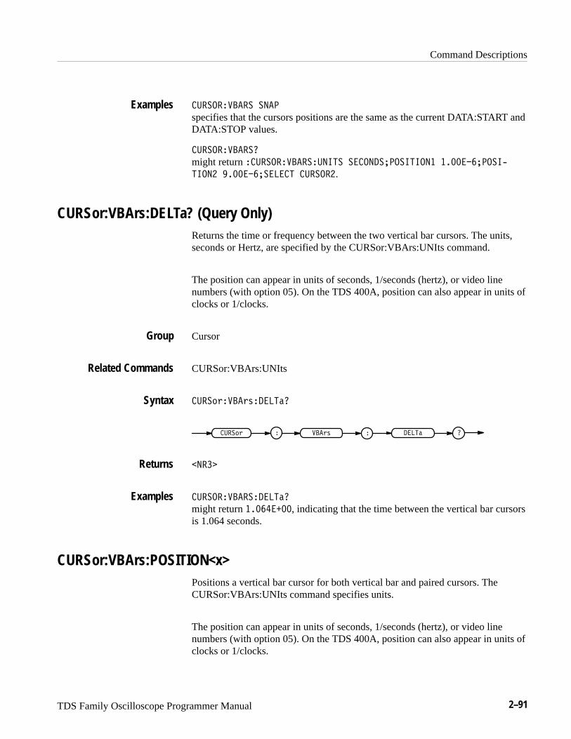
Command Descriptions
TDS Family Oscilloscope Programmer Manual 2–91
������������ ����
specifies that the cursors positions are the same as the current DATA:START andDATA:STOP values.
�������������
might return ������������������� ������� ��������� ������ ����$
����� ������ ������ �������.
CURSor:VBArs:DELTa? (Query Only)Returns the time or frequency between the two vertical bar cursors. The units,seconds or Hertz, are specified by the CURSor:VBArs:UNIts command.
The position can appear in units of seconds, 1/seconds (hertz), or video linenumbers (with option 05). On the TDS 400A, position can also appear in units ofclocks or 1/clocks.
Cursor
CURSor:VBArs:UNIts
����!"����"#����� �
����!" � ���"# � ���� �
�����
����������������� �
might return �������, indicating that the time between the vertical bar cursorsis 1.064 seconds.
CURSor:VBArs:POSITION<x>Positions a vertical bar cursor for both vertical bar and paired cursors. TheCURSor:VBArs:UNIts command specifies units.
The position can appear in units of seconds, 1/seconds (hertz), or video linenumbers (with option 05). On the TDS 400A, position can also appear in units ofclocks or 1/clocks.
Examples
Group
Related Commands
Syntax
Returns
Examples
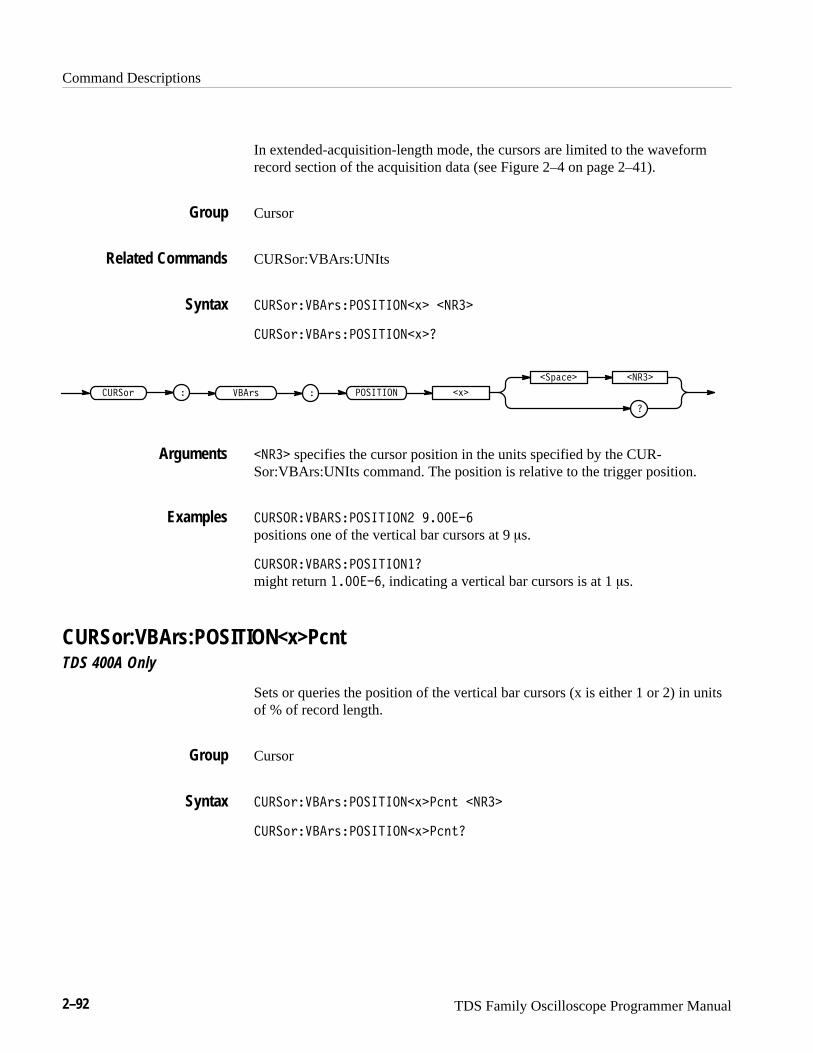
Command Descriptions
2–92 TDS Family Oscilloscope Programmer Manual
In extended-acquisition-length mode, the cursors are limited to the waveformrecord section of the acquisition data (see Figure 2–4 on page 2–41).
Cursor
CURSor:VBArs:UNIts
�����!���!"���������$� �����
�����!���!"���������$�
�����! ���!" �������� �$�
�� ���� �����
����� specifies the cursor position in the units specified by the CUR-Sor:VBArs:UNIts command. The position is relative to the trigger position.
�������������������� ������
positions one of the vertical bar cursors at 9 �s.
��������������������
might return �������, indicating a vertical bar cursors is at 1 �s.
CURSor:VBArs:POSITION<x>PcntTDS 400A Only
Sets or queries the position of the vertical bar cursors (x is either 1 or 2) in unitsof % of record length.
Cursor
�����!���!"���������$����# �����
�����!���!"���������$����#
Group
Related Commands
Syntax
Arguments
Examples
Group
Syntax
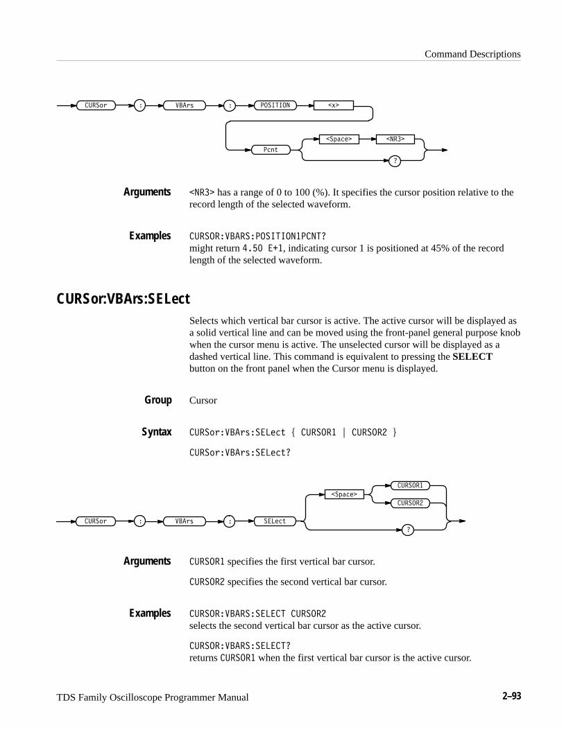
Command Descriptions
TDS Family Oscilloscope Programmer Manual 2–93
���� " ���"# �������� �%�
��!���� �����
���$
����� has a range of 0 to 100 (%). It specifies the cursor position relative to therecord length of the selected waveform.
������������������������
might return ��� ���, indicating cursor 1 is positioned at 45% of the recordlength of the selected waveform.
CURSor:VBArs:SELectSelects which vertical bar cursor is active. The active cursor will be displayed asa solid vertical line and can be moved using the front-panel general purpose knobwhen the cursor menu is active. The unselected cursor will be displayed as adashed vertical line. This command is equivalent to pressing the SELECTbutton on the front panel when the Cursor menu is displayed.
Cursor
���� "���"#�����$ & ������� ' ������� (
���� "���"#�����$
���� " ���"# �����$
��!����
�������
�������
������� specifies the first vertical bar cursor.
������� specifies the second vertical bar cursor.
����������������� �������
selects the second vertical bar cursor as the active cursor.
�����������������
returns ������� when the first vertical bar cursor is the active cursor.
Arguments
Examples
Group
Syntax
Arguments
Examples
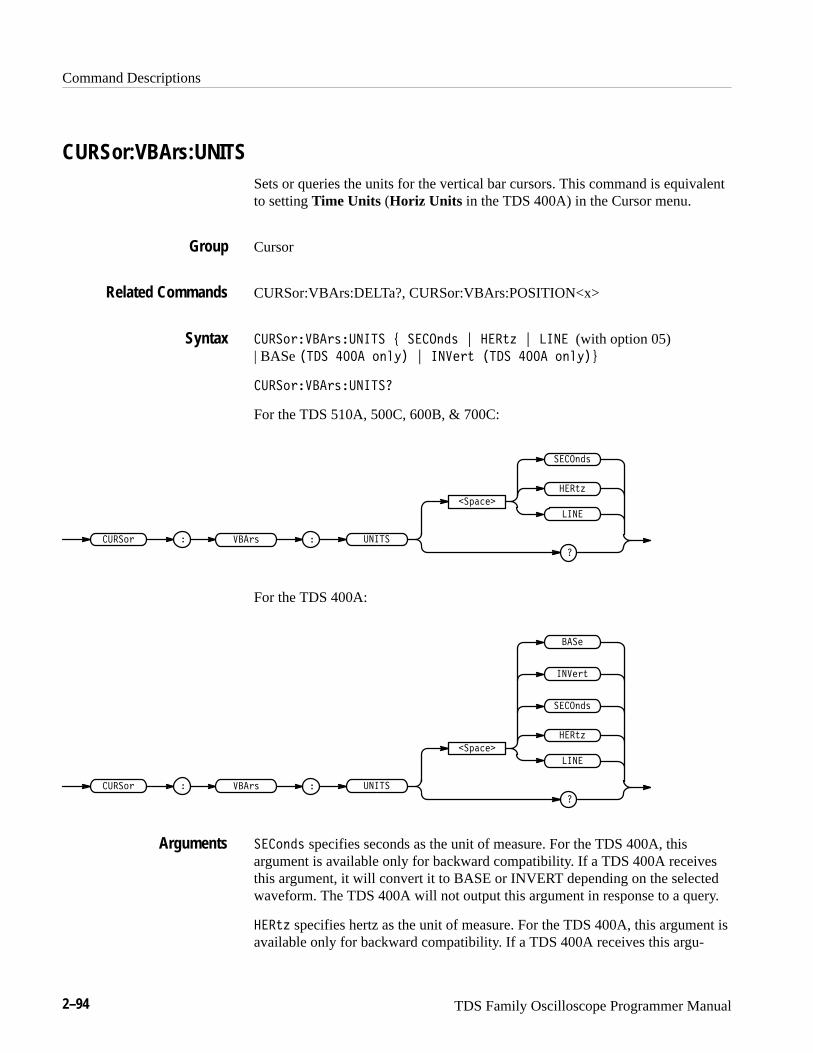
Command Descriptions
2–94 TDS Family Oscilloscope Programmer Manual
CURSor:VBArs:UNITSSets or queries the units for the vertical bar cursors. This command is equivalentto setting Time Units (Horiz Units in the TDS 400A) in the Cursor menu.
Cursor
CURSor:VBArs:DELTa?, CURSor:VBArs:POSITION<x>
�����!���!"������ & ������" ' ���#% ' ���� (with option 05) | BASe �� � ��� ���$� ' ����!# �� � ��� ���$�(
�����!���!"������
For the TDS 510A, 500C, 600B, & 700C:
�����! � ��!" � �����
����
���#%
�� ����
������"
For the TDS 400A:
�����! � ��!" � �����
����
���#%
�� ����
����!#
������"
���
������" specifies seconds as the unit of measure. For the TDS 400A, thisargument is available only for backward compatibility. If a TDS 400A receivesthis argument, it will convert it to BASE or INVERT depending on the selectedwaveform. The TDS 400A will not output this argument in response to a query.
���#% specifies hertz as the unit of measure. For the TDS 400A, this argument isavailable only for backward compatibility. If a TDS 400A receives this argu-
Group
Related Commands
Syntax
Arguments
Command Descriptions
TDS Family Oscilloscope Programmer Manual 2–95
ment, it will convert it to BASE or INVERT depending on the selected wave-form. The TDS 400A will not output this argument in response to a query.
�� specifies a video line as the unit of measure. This is most useful if youhave option 05 video trigger installed. On some models, if you do not haveoption 05, use of this argument will generate an error message. On the TDS400A, if you do not have option 05, the TDS 400A will use the NTSC standardfor converting from time to lines. In order for the measurement to be accurate inthe TDS 400A when TRIGGER:MAIN:VIDEO:SYSTEM is set to custom, youmust set TRIGGER:MAIN:VIDEO:SCANPERIOD.
���� (TDS 400A only) specifies the base (or natural) units of the waveform asthe unit of measurement. If internal clock is enabled, the base units are seconds.If external clock is enabled, the base units are clocks.
������ (TDS 400A only) specifies 1/ base (or natural) units of the waveform asthe unit of measurement. If internal clock is enabled, the base units are 1/seconds(hertz). If external clock is enabled, the base units are 1/clocks.
������������������ ������
sets the units for the vertical bar cursors to seconds.
�������������������
returns ���� when the vertical bar cursor units are hertz.
CURSor:VBArs:UNITSTring? (Query Only)TDS 400A Only
Queries the unit string as shown on screen for the vertical bar cursor readout.
Cursor
������������������������
������ � ����� � �����������
�����������������������
might return ����, indicating the units are milliseconds.
Examples
Group
Syntax
Examples
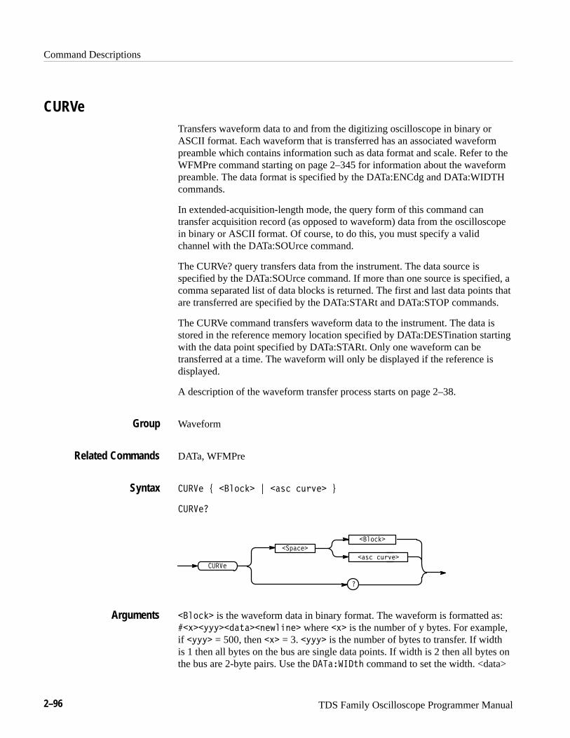
Command Descriptions
2–96 TDS Family Oscilloscope Programmer Manual
CURVeTransfers waveform data to and from the digitizing oscilloscope in binary orASCII format. Each waveform that is transferred has an associated waveformpreamble which contains information such as data format and scale. Refer to theWFMPre command starting on page 2–345 for information about the waveformpreamble. The data format is specified by the DATa:ENCdg and DATa:WIDTHcommands.
In extended-acquisition-length mode, the query form of this command cantransfer acquisition record (as opposed to waveform) data from the oscilloscopein binary or ASCII format. Of course, to do this, you must specify a validchannel with the DATa:SOUrce command.
The CURVe? query transfers data from the instrument. The data source isspecified by the DATa:SOUrce command. If more than one source is specified, acomma separated list of data blocks is returned. The first and last data points thatare transferred are specified by the DATa:STARt and DATa:STOP commands.
The CURVe command transfers waveform data to the instrument. The data isstored in the reference memory location specified by DATa:DESTination startingwith the data point specified by DATa:STARt. Only one waveform can betransferred at a time. The waveform will only be displayed if the reference isdisplayed.
A description of the waveform transfer process starts on page 2–38.
Waveform
DATa, WFMPre
���� % ������� & ���� � �!�� '
�����
����
� �����
�
���� � �!��
�������
������� is the waveform data in binary format. The waveform is formatted as:��#��$$$����������"����� where �#� is the number of y bytes. For example,if �$$$� = 500, then �#� = 3. �$$$� is the number of bytes to transfer. If widthis 1 then all bytes on the bus are single data points. If width is 2 then all bytes onthe bus are 2-byte pairs. Use the �������� command to set the width. <data>
Group
Related Commands
Syntax
Arguments
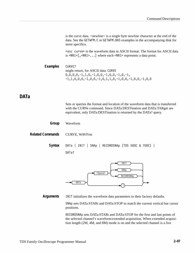
Command Descriptions
TDS Family Oscilloscope Programmer Manual 2–97
is the curve data. <newline> is a single byte newline character at the end of thedata. See the �������� or ���������� examples in the accompanying disk formore specifics.
�"'# #(&)$ is the waveform data in ASCII format. The format for ASCII datais ��� ���� ���! where each ��� represents a data point.
������
might return, for ASCII data: ������������������������������������
����������������������������������������
DATaSets or queries the format and location of the waveform data that is transferredwith the CURVe command. Since DATa:DESTination and DATa:TARget areequivalent, only DATa:DESTination is returned by the DATa? query.
Waveform
CURVE, WAVFrm
���" * ���� + ���% + ���������% ���� ��� � ����� ,
���"�
���"
��%"#$
�
����
���%
���������%
���� initializes the waveform data parameters to their factory defaults.
���% sets DATa:STARt and DATa:STOP to match the current vertical bar cursorpositions.
���������% sets DATa:STARt and DATa:STOP for the first and last points ofthe selected channel’s waveform/extended acquisition. When extended acquisi-tion length (2M, 4M, and 8M) mode is on and the selected channel is a live
Examples
Group
Related Commands
Syntax
Arguments
Command Descriptions
2–98 TDS Family Oscilloscope Programmer Manual
channel, this is how to set up to get a waveform’s data over GPIB. It also workswhen extended acquisition length mode is off.
� ���
assigns the current position of the vertical bar cursors to DATA:START andDATA:STOP.
�
might return the string � ����� � �������� ��������� ����� ������
��������� ������ ������ �� �
Examples
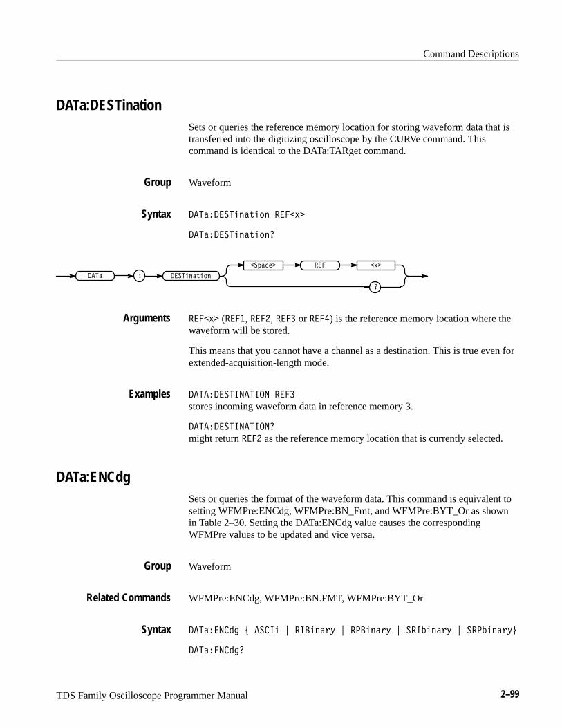
Command Descriptions
TDS Family Oscilloscope Programmer Manual 2–99
DATa:DESTinationSets or queries the reference memory location for storing waveform data that istransferred into the digitizing oscilloscope by the CURVe command. Thiscommand is identical to the DATa:TARget command.
Waveform
��� ������"��� ����#�
��� ������"���
�� � ������"���
�� ���� �#����
����#� (����, ����, ���� or ����) is the reference memory location where thewaveform will be stored.
This means that you cannot have a channel as a destination. This is true even forextended-acquisition-length mode.
�� ��������� ����
stores incoming waveform data in reference memory 3.
�� ���������
might return ���� as the reference memory location that is currently selected.
DATa:ENCdgSets or queries the format of the waveform data. This command is equivalent tosetting WFMPre:ENCdg, WFMPre:BN_Fmt, and WFMPre:BYT_Or as shownin Table 2–30. Setting the DATa:ENCdg value causes the correspondingWFMPre values to be updated and vice versa.
Waveform
WFMPre:ENCdg, WFMPre:BN.FMT, WFMPre:BYT_Or
�������� % ���� & ������!$ & ������!$ & �������!$ & �������!$'
��������
Group
Syntax
Arguments
Examples
Group
Related Commands
Syntax
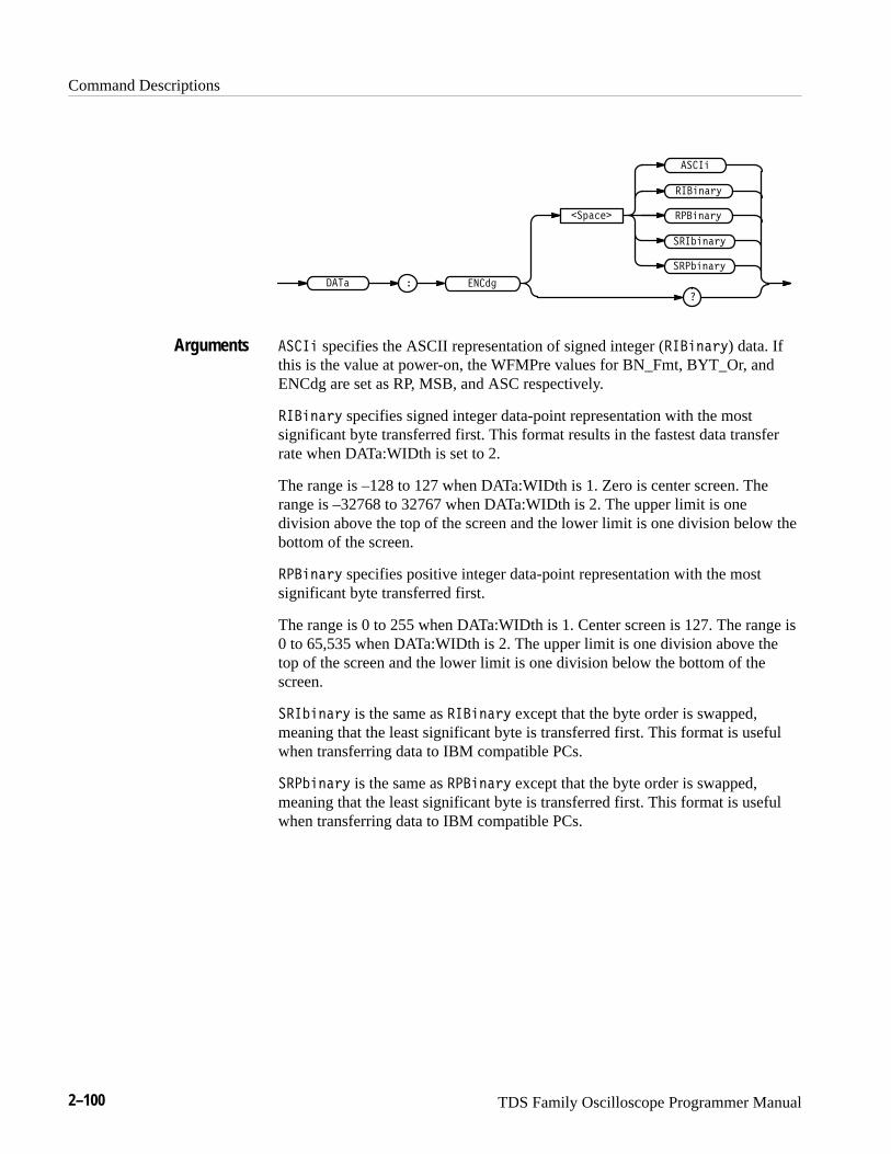
Command Descriptions
2–100 TDS Family Oscilloscope Programmer Manual
�������� �
�������
�
������
�������
����
� ������
� �������
���� specifies the ASCII representation of signed integer ( ������) data. Ifthis is the value at power-on, the WFMPre values for BN_Fmt, BYT_Or, andENCdg are set as RP, MSB, and ASC respectively.
������ specifies signed integer data-point representation with the mostsignificant byte transferred first. This format results in the fastest data transferrate when DATa:WIDth is set to 2.
The range is –128 to 127 when DATa:WIDth is 1. Zero is center screen. Therange is –32768 to 32767 when DATa:WIDth is 2. The upper limit is onedivision above the top of the screen and the lower limit is one division below thebottom of the screen.
������� specifies positive integer data-point representation with the mostsignificant byte transferred first.
The range is 0 to 255 when DATa:WIDth is 1. Center screen is 127. The range is0 to 65,535 when DATa:WIDth is 2. The upper limit is one division above thetop of the screen and the lower limit is one division below the bottom of thescreen.
� ������ is the same as ������ except that the byte order is swapped,meaning that the least significant byte is transferred first. This format is usefulwhen transferring data to IBM compatible PCs.
� ������� is the same as ������� except that the byte order is swapped,meaning that the least significant byte is transferred first. This format is usefulwhen transferring data to IBM compatible PCs.
Arguments

Command Descriptions
TDS Family Oscilloscope Programmer Manual 2–101
Table 2–30: DATa and WFMPre Parameter Settings
ATa N g e i g
WFMPre Settings
DATa:ENCdg Setting :ENCdg :BN_Fmt :BYT_Or
�� � �� N/A N/A
� ��!�#% � � � ���
����!�#% � � �� ���
�� ��!�#% � � � ���
�� ��!�#% � � �� ���
������� ��� ����
sets the data encoding format to be positive integer where the most significantbyte is transferred first.
��������
might return ���� ���� for the format of the waveform data.
DATa:SOUrceSets or queries the location of the waveform data that is transferred from theinstrument by the CURVe? query. The source data is always transferred in apredefined order regardless of the order they are specified using this command.The predefined order is CH1 through CH4, MATH1 through MATH3, and thenREF1 through REF4.
In extended-acquisition-length mode, the MATH1 through MATH3 sources cannot be used. Also, in this mode, CH1 through CH4 refer to extended-acquisition-length data. In contrast, when not in extended-acquisition-length mode, CH1through CH4 refer only to the waveform record. For more details, see page 2–41.
Waveform
�������#�� �$� ���" ���$� �����
�������#���
Examples
Group
Syntax
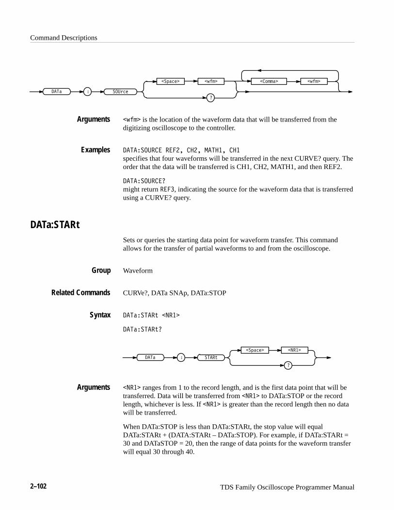
Command Descriptions
2–102 TDS Family Oscilloscope Programmer Manual
��������� �
�������
� ��� ������� � ���
� ��� is the location of the waveform data that will be transferred from thedigitizing oscilloscope to the controller.
�������� � ��� ���� ����� ���
specifies that four waveforms will be transferred in the next CURVE? query. Theorder that the data will be transferred is CH1, CH2, MATH1, and then REF2.
��������
might return � ��, indicating the source for the waveform data that is transferredusing a CURVE? query.
DATa:STARtSets or queries the starting data point for waveform transfer. This commandallows for the transfer of partial waveforms to and from the oscilloscope.
Waveform
CURVe?, DATa SNAp, DATa:STOP
�������� �����
��������
��� � ����
������� �����
����� ranges from 1 to the record length, and is the first data point that will betransferred. Data will be transferred from ����� to DATa:STOP or the recordlength, whichever is less. If ����� is greater than the record length then no datawill be transferred.
When DATa:STOP is less than DATa:STARt, the stop value will equalDATa:STARt + (DATA:STARt – DATa:STOP). For example, if DATa:STARt =30 and DATaSTOP = 20, then the range of data points for the waveform transferwill equal 30 through 40.
Arguments
Examples
Group
Related Commands
Syntax
Arguments
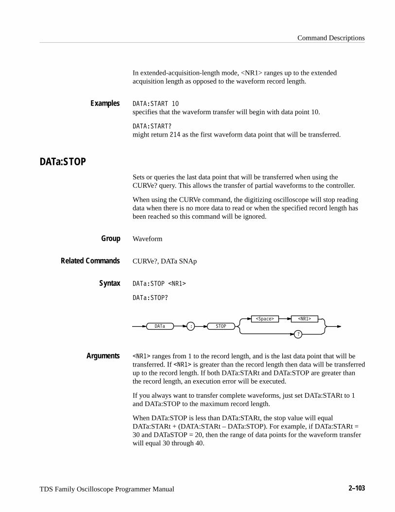
Command Descriptions
TDS Family Oscilloscope Programmer Manual 2–103
In extended-acquisition-length mode, <NR1> ranges up to the extendedacquisition length as opposed to the waveform record length.
������� ��
specifies that the waveform transfer will begin with data point 10.
�������
might return ��� as the first waveform data point that will be transferred.
DATa:STOPSets or queries the last data point that will be transferred when using theCURVe? query. This allows the transfer of partial waveforms to the controller.
When using the CURVe command, the digitizing oscilloscope will stop readingdata when there is no more data to read or when the specified record length hasbeen reached so this command will be ignored.
Waveform
CURVe?, DATa SNAp
������ � �����
������ �
��� � �� �
������� �����
����� ranges from 1 to the record length, and is the last data point that will betransferred. If ����� is greater than the record length then data will be transferredup to the record length. If both DATa:STARt and DATa:STOP are greater thanthe record length, an execution error will be executed.
If you always want to transfer complete waveforms, just set DATa:STARt to 1and DATa:STOP to the maximum record length.
When DATa:STOP is less than DATa:STARt, the stop value will equalDATa:STARt + (DATA:STARt – DATa:STOP). For example, if DATa:STARt =30 and DATaSTOP = 20, then the range of data points for the waveform transferwill equal 30 through 40.
Examples
Group
Related Commands
Syntax
Arguments
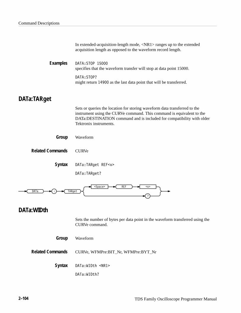
Command Descriptions
2–104 TDS Family Oscilloscope Programmer Manual
In extended-acquisition-length mode, <NR1> ranges up to the extendedacquisition length as opposed to the waveform record length.
��������� �����
specifies that the waveform transfer will stop at data point 15000.
���������
might return ����� as the last data point that will be transferred.
DATa:TARgetSets or queries the location for storing waveform data transferred to theinstrument using the CURVe command. This command is equivalent to theDATa:DESTINATION command and is included for compatibility with olderTektronix instruments.
Waveform
CURVe
����������� � ���
�����������
���� � ������
������ ��� �
DATa:WIDthSets the number of bytes per data point in the waveform transferred using theCURVe command.
Waveform
CURVe, WFMPre:BIT_Nr, WFMPre:BYT_Nr
���������� ����
����������
Examples
Group
Related Commands
Syntax
Group
Related Commands
Syntax
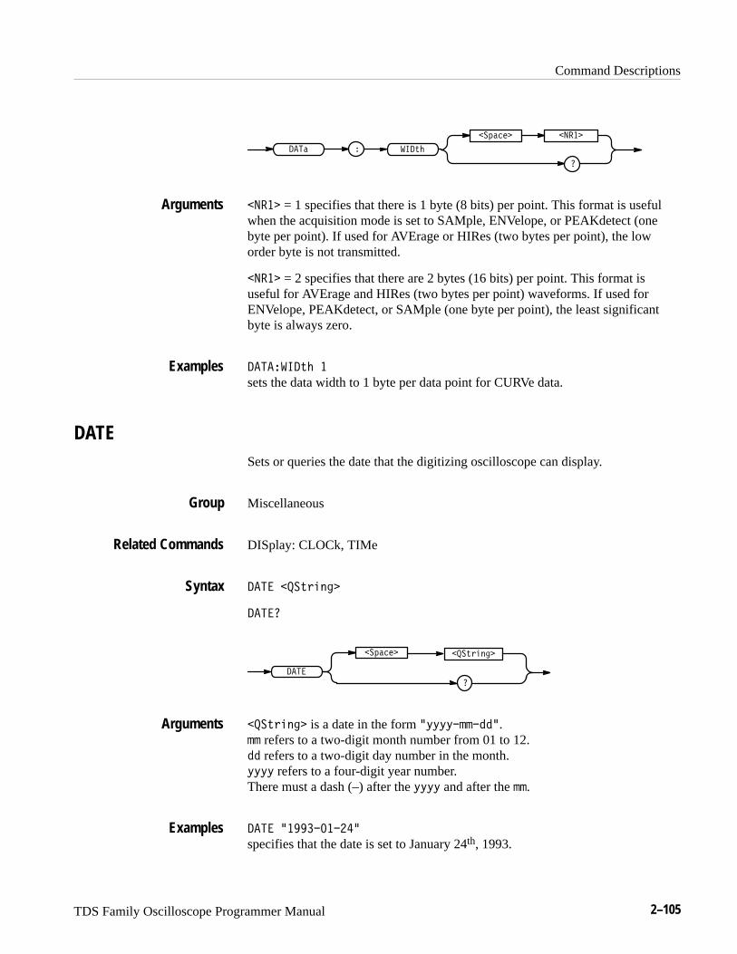
Command Descriptions
TDS Family Oscilloscope Programmer Manual 2–105
���� ���#�
��!���� �����
����� = 1 specifies that there is 1 byte (8 bits) per point. This format is usefulwhen the acquisition mode is set to SAMple, ENVelope, or PEAKdetect (onebyte per point). If used for AVErage or HIRes (two bytes per point), the loworder byte is not transmitted.
����� = 2 specifies that there are 2 bytes (16 bits) per point. This format isuseful for AVErage and HIRes (two bytes per point) waveforms. If used forENVelope, PEAKdetect, or SAMple (one byte per point), the least significantbyte is always zero.
�������#� �
sets the data width to 1 byte per data point for CURVe data.
DATESets or queries the date that the digitizing oscilloscope can display.
Miscellaneous
DISplay: CLOCk, TIMe
���� ���#"� ��
����
���#"� ��
����
��!����
���#"� �� is a date in the form %$$$$�������. �� refers to a two-digit month number from 01 to 12. �� refers to a two-digit day number in the month. $$$$ refers to a four-digit year number. There must a dash (–) after the $$$$ and after the ��.
���� ����������
specifies that the date is set to January 24th, 1993.
Arguments
Examples
Group
Related Commands
Syntax
Arguments
Examples

Command Descriptions
2–106 TDS Family Oscilloscope Programmer Manual
*DDTAllows the user to specify a command or a list of commands that are executedwhen the instrument receives a *TRG command or the GET GPIB interfacemessage. *DDT is just a special alias that *TRG uses.
Miscellaneous
ALIAS:DEFINE, *TRG
� � $ ��� ��� % ���#"���� &
� �
���#"����
� �
��!����
��� ���
��� ��� or ���#"���� is a complete sequence of program messages. Themessages can contain only valid commands that must be separated by semico-lons and must follow all rules for concatenating commands (see page 2–4). Thesequence must be ≤80 characters. ��� ��� format is always returned as a queryresponse.
� � ������������� �������������
specifies that the acquisition system will be started and the bell rings each time a*TRG command is sent.
DELEte:SETUp (No Query Form)Removes stored setups from memory and initializes the location with the factorydefault setup.
NOTE. The setup information cannot be recovered once it has been deleted.
Save and Recall
Group
Related Commands
Syntax
Arguments
Examples
Group

Command Descriptions
TDS Family Oscilloscope Programmer Manual 2–107
*RCL, RECAll:SETUp, *RST, *SAV, SAVe:SETUp, TEKSecure
� ��������� ����� ! "
� ��� � ����� �������
�����
����� is a value in the range 1 to 10, and specifies a setup storage location.Using an out-of-range value causes an execution error.
specifies all the stored setups.
� ���������
removes all stored setups. All ten storage locations are initialized to the factorydefault setup.
DELEte:WAVEform (No Query Form)Deletes one or all of the stored reference waveforms from memory. The memoryallocated for the reference location is then available for reallocation. Memorymust be reallocated for the deleted references before any waveform data can bestored in the reference location.
NOTE. The waveform data is not actually cleared from the reference location.
Save and Recall
RECAll:WAVEform, SAVe:WAVEform, TEKSecure
� ����������� ������ ! "
� ��� � �������
���
�������
���
������ (����, ����, ���� or ����) specifies one of the reference memorylocations.
specifies all the stored waveforms.
Related Commands
Syntax
Arguments
Examples
Group
Related Commands
Syntax
Arguments

Command Descriptions
2–108 TDS Family Oscilloscope Programmer Manual
�������������� ���
removes all the waveforms stored in reference memory.
�������������� ����
removes the waveform stored at REF2.
DESESets and queries the bits in the Device Event Status Enable Register (DESER).The DESER is the mask that determines whether events are reported to theStandard Event Status Register (SESR), and entered into the Event Queue. For amore detailed discussion of the use of these registers, see page 3–1.
Status and Error
*CLS, *ESE, *ESR?, EVENT?, EVMsg?, *SRE, *STB?
��� ����
���
���
������ ����
���� is a value in the range from 0 to 255. The binary bits of the DESER areset according to this value. For example, ��� ��� sets the DESER to the binaryvalue 11010001 (that is, the most significant bit in the register is set to 1, thenext most significant bit to 1, the next bit to 0, etc.).
The power-on default for DESER is all bits set if ���� is 1. If ���� is 0, theDESER maintains its value through a power cycle.
NOTE. Setting the DESER and the ESER to the same value allows only thosecodes to be entered into the Event Queue and summarized on the ESB bit (bit 5)of the Status Byte Register. Use the ���� command to set the ESER. A discussionof event handling begins on page 3–1.
��� ���
sets the DESER to binary 11010001, which enables the PON, URQ, EXE, andOPC bits.
Examples
Group
Related Commands
Syntax
Arguments
Examples
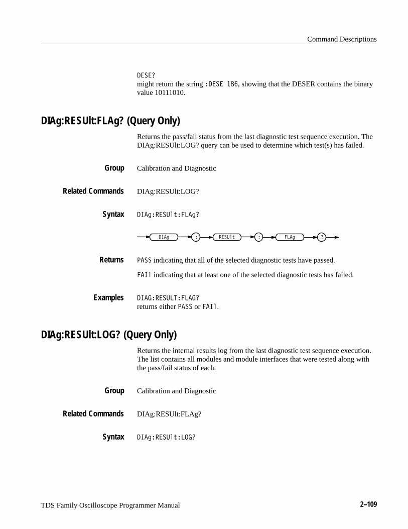
Command Descriptions
TDS Family Oscilloscope Programmer Manual 2–109
���
might return the string ��� ���, showing that the DESER contains the binaryvalue 10111010.
DIAg:RESUlt:FLAg? (Query Only)Returns the pass/fail status from the last diagnostic test sequence execution. TheDIAg:RESUlt:LOG? query can be used to determine which test(s) has failed.
Calibration and Diagnostic
DIAg:RESUlt:LOG?
����������� ���
� ��������� � � ��
���� indicating that all of the selected diagnostic tests have passed.
��� indicating that at least one of the selected diagnostic tests has failed.
�������� �� ���
returns either ���� or ���.
DIAg:RESUlt:LOG? (Query Only)Returns the internal results log from the last diagnostic test sequence execution.The list contains all modules and module interfaces that were tested along withthe pass/fail status of each.
Calibration and Diagnostic
DIAg:RESUlt:FLAg?
����������� ���
Group
Related Commands
Syntax
Returns
Examples
Group
Related Commands
Syntax
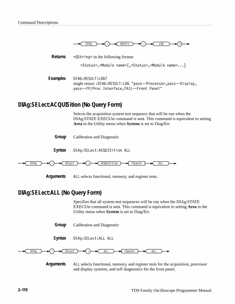
Command Descriptions
2–110 TDS Family Oscilloscope Programmer Manual
� ��" � �������$+
���+)#&" in the following format:
��+�+,*���'�,$ &�% ����+�+,*���'�,$ &�% ����
��������������
might return � �������������� �(�**���)'� **')�(�**�� #*($�-�
(�**������)'� �&+ )!�� ��������)'&+ ��& $�
DIAg:SELect:ACQUISition (No Query Form)Selects the acquisition system test sequence that will be run when theDIAg:STATE EXECUte command is sent. This command is equivalent to settingArea in the Utility menu when System is set to Diag/Err.
Calibration and Diagnostic
��"���� �+�������#+#'& ���
� ��� �+ ��" � ������#+#'& ��(�� ���
��� selects functional, memory, and register tests.
DIAg:SELect:ALL (No Query Form)Specifies that all system test sequences will be run when the DIAg:STATEEXECUte command is sent. This command is equivalent to setting Area in theUtility menu when System is set to Diag/Err.
Calibration and Diagnostic
��"���� �+���� ���
� ��� �+ ��" � ��(�� ������
��� selects functional, memory, and register tests for the acquisition, processorand display systems, and self diagnostics for the front panel.
Returns
Examples
Group
Syntax
Arguments
Group
Syntax
Arguments
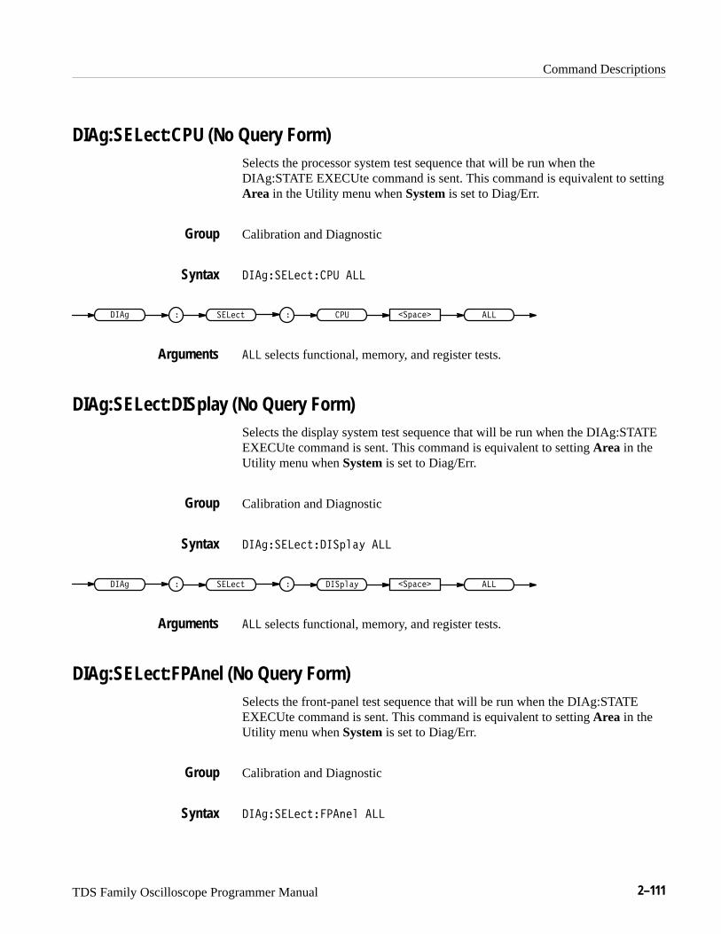
Command Descriptions
TDS Family Oscilloscope Programmer Manual 2–111
DIAg:SELect:CPU (No Query Form)Selects the processor system test sequence that will be run when theDIAg:STATE EXECUte command is sent. This command is equivalent to settingArea in the Utility menu when System is set to Diag/Err.
Calibration and Diagnostic
���� ��������� ���
� �������� � � ����� ������
��� selects functional, memory, and register tests.
DIAg:SELect:DISplay (No Query Form)Selects the display system test sequence that will be run when the DIAg:STATEEXECUte command is sent. This command is equivalent to setting Area in theUtility menu when System is set to Diag/Err.
Calibration and Diagnostic
���� ������� ���� ���
� �������� � � ����� ���� ����
��� selects functional, memory, and register tests.
DIAg:SELect:FPAnel (No Query Form)Selects the front-panel test sequence that will be run when the DIAg:STATEEXECUte command is sent. This command is equivalent to setting Area in theUtility menu when System is set to Diag/Err.
Calibration and Diagnostic
���� ����������� ���
Group
Syntax
Arguments
Group
Syntax
Arguments
Group
Syntax
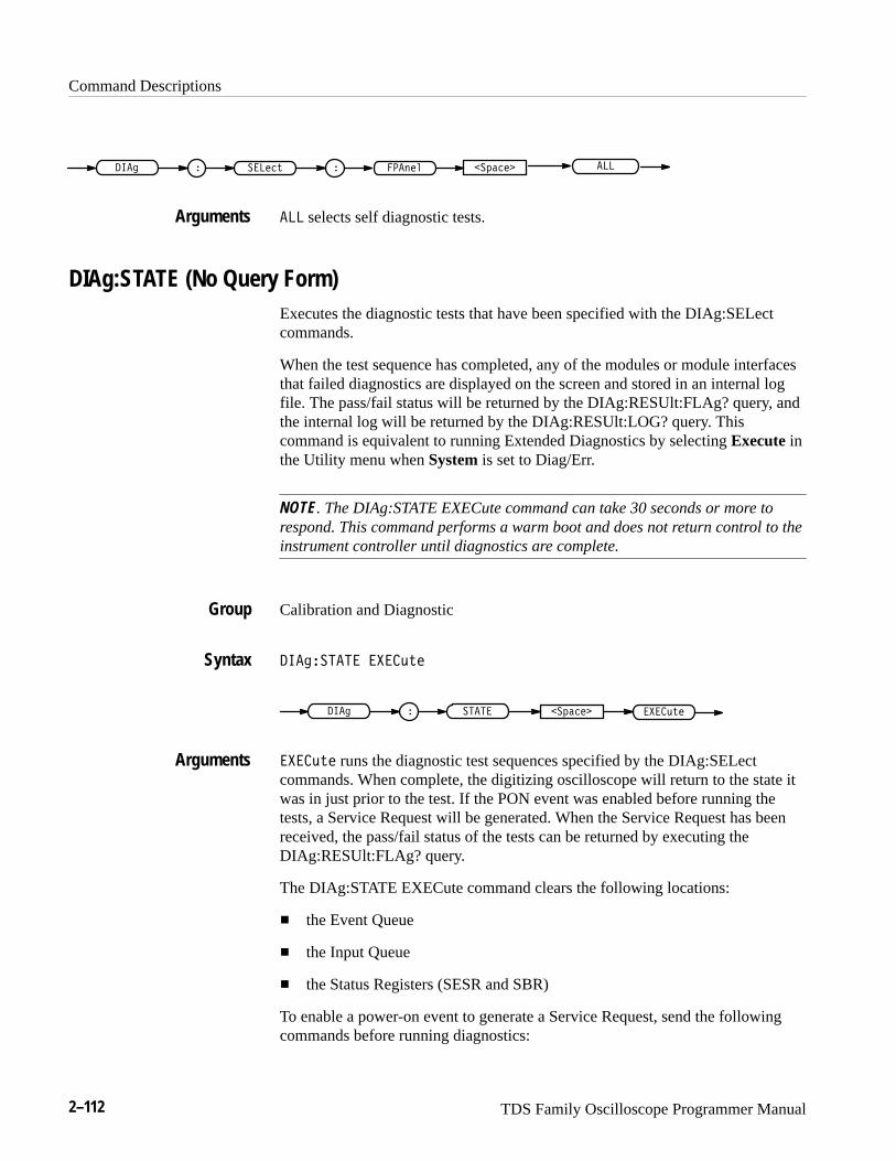
Command Descriptions
2–112 TDS Family Oscilloscope Programmer Manual
� �������� � � ���������� ���
��� selects self diagnostic tests.
DIAg:STATE (No Query Form)Executes the diagnostic tests that have been specified with the DIAg:SELectcommands.
When the test sequence has completed, any of the modules or module interfacesthat failed diagnostics are displayed on the screen and stored in an internal logfile. The pass/fail status will be returned by the DIAg:RESUlt:FLAg? query, andthe internal log will be returned by the DIAg:RESUlt:LOG? query. Thiscommand is equivalent to running Extended Diagnostics by selecting Execute inthe Utility menu when System is set to Diag/Err.
NOTE. The DIAg:STATE EXECute command can take 30 seconds or more torespond. This command performs a warm boot and does not return control to theinstrument controller until diagnostics are complete.
Calibration and Diagnostic
���� ���� �������
� ������� � ����� �������
������� runs the diagnostic test sequences specified by the DIAg:SELectcommands. When complete, the digitizing oscilloscope will return to the state itwas in just prior to the test. If the PON event was enabled before running thetests, a Service Request will be generated. When the Service Request has beenreceived, the pass/fail status of the tests can be returned by executing theDIAg:RESUlt:FLAg? query.
The DIAg:STATE EXECute command clears the following locations:
� the Event Queue
� the Input Queue
� the Status Registers (SESR and SBR)
To enable a power-on event to generate a Service Request, send the followingcommands before running diagnostics:
Arguments
Group
Syntax
Arguments
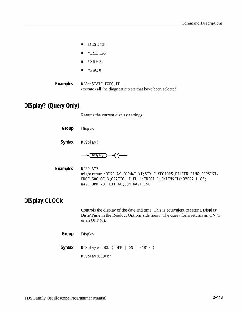
Command Descriptions
TDS Family Oscilloscope Programmer Manual 2–113
� DESE 128
� *ESE 128
� *SRE 32
� *PSC 0
���%������ �"�����
executes all the diagnostic tests that have been selected.
DISplay? (Query Only)Returns the current display settings.
Display
���('$)�
���('$) �
������#�
might return �������#������� #����#�� ������������� ���"��������-
���� ������������������ ���������� ����������#�� ����� ��
!� ����� ����"� ����������� ���
DISplay:CLOCkControls the display of the date and time. This is equivalent to setting DisplayDate/Time in the Readout Options side menu. The query form returns an ON (1)or an OFF (0).
Display
���('$)�����& * ��� + �� + ���� ,
���('$)�����&�
Examples
Group
Syntax
Examples
Group
Syntax
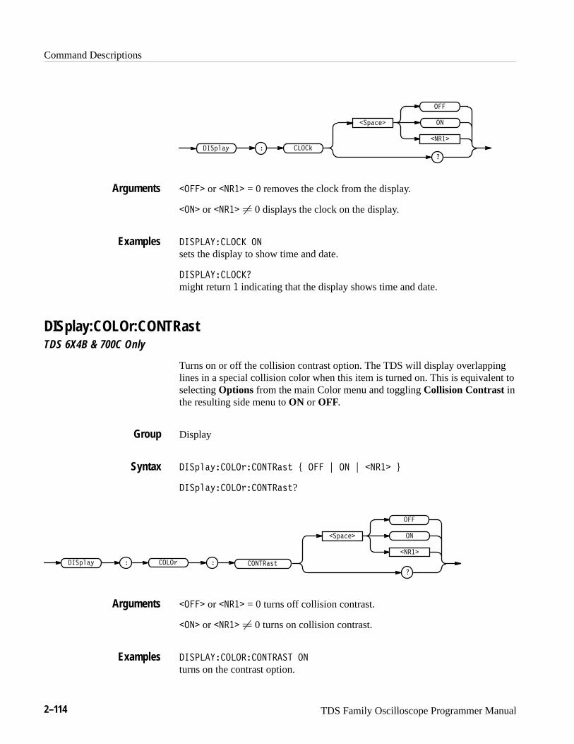
Command Descriptions
2–114 TDS Family Oscilloscope Programmer Manual
��
������ � � ���
�������
�
�����
�
��� or ����� = 0 removes the clock from the display.
���� or ����� � 0 displays the clock on the display.
��� ���� ��� ��
sets the display to show time and date.
��� ���� ����
might return � indicating that the display shows time and date.
DISplay:COLOr:CONTRast TDS 6X4B & 700C Only
Turns on or off the collision contrast option. The TDS will display overlappinglines in a special collision color when this item is turned on. This is equivalent toselecting Options from the main Color menu and toggling Collision Contrast inthe resulting side menu to ON or OFF.
Display
��������� ����������� � � �� ����� !
��������� �����������?
���������
�
�����
�
������ � �� �� � ��������
��� or ����� = 0 turns off collision contrast.
���� or ����� � 0 turns on collision contrast.
��� ����� ����������� ��
turns on the contrast option.
Arguments
Examples
Group
Syntax
Arguments
Examples
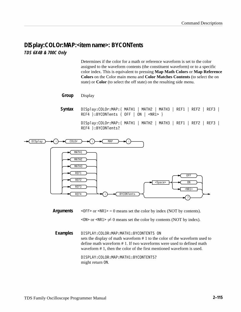
Command Descriptions
TDS Family Oscilloscope Programmer Manual 2–115
DISplay:COLOr:MAP:<item name>: BYCONTents TDS 6X4B & 700C Only
Determines if the color for a math or reference waveform is set to the colorassigned to the waveform contents (the constituent waveform) or to a specificcolor index. This is equivalent to pressing Map Math Colors or Map ReferenceColors on the Color main menu and Color Matches Contents (to select the onstate) or Color (to select the off state) on the resulting side menu.
Display
�� ��$�����!����% ���� & ���� & ���� & ���� & ���� & ���� &
���� '���������#" % ��� & �� & ����� '
�� ��$�����!����% ���� & ���� & ���� & ���� & ���� & ���� &
���� '���������#"
�� ��$ � ����! ��� �
����
����
����
����
����
����
� ��������#"
����
���� ����
�����
���
����� or ����� = 0 means set the color by index (NOT by contents).
���� or ����� � 0 means set the color by contents (NOT by index).
������������������������������ ��
sets the display of math waveform # 1 to the color of the waveform used todefine math waveform # 1. If two waveforms were used to defined mathwaveform # 1, then the color of the first mentioned waveform is used.
������������������������������
might return ��.
Group
Syntax
Arguments
Examples
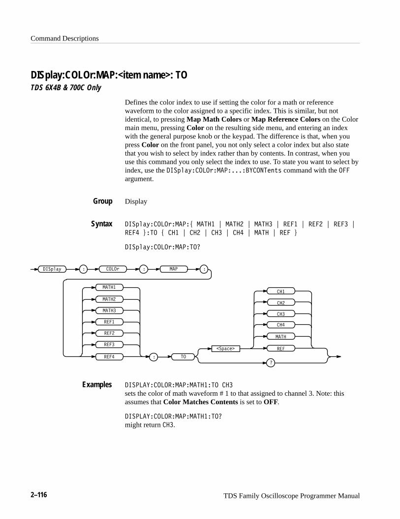
Command Descriptions
2–116 TDS Family Oscilloscope Programmer Manual
DISplay:COLOr:MAP:<item name>: TO TDS 6X4B & 700C Only
Defines the color index to use if setting the color for a math or referencewaveform to the color assigned to a specific index. This is similar, but notidentical, to pressing Map Math Colors or Map Reference Colors on the Colormain menu, pressing Color on the resulting side menu, and entering an indexwith the general purpose knob or the keypad. The difference is that, when youpress Color on the front panel, you not only select a color index but also statethat you wish to select by index rather than by contents. In contrast, when youuse this command you only select the index to use. To state you want to select byindex, use the ���!��%� ���"����������� ���� $# command with the ���argument.
Display
���!��%� ���"�����& ����� ' ����� ' ����� ' ���� ' ���� ' ���� '
���� (��� & �� ' �� ' �� ' �� ' ���� ' ��� (
���!��%� ���"�������
���!��% � ���" ���� �
����
����
����
�����
�����
����
� ��
�����
��!���
���
����
��
��
��
��
�������� ����������������� ��
sets the color of math waveform # 1 to that assigned to channel 3. Note: thisassumes that Color Matches Contents is set to OFF.
�������� �����������������
might return ��.
Group
Syntax
Examples
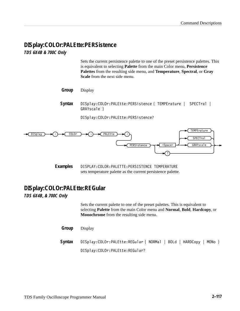
Command Descriptions
TDS Family Oscilloscope Programmer Manual 2–117
DISplay:COLOr:PALEtte:PERSistence TDS 6X4B & 700C Only
Sets the current persistence palette to one of the preset persistence palettes. Thisis equivalent to selecting Palette from the main Color menu, PersistencePalettes from the resulting side menu, and Temperature, Spectral, or GrayScale from the next side menu.
Display
� ��%�����!����##������"#���� & ���!�#$!� ')����!�� '
����"���� (
� ��%�����!����##������"#����?
����"������ ����
����!��
� ��% � ����! ���##�� �
�
����"#����
���!�#$!�
��������������������� ���� ��������
sets temperature palette as the current persistence palette.
DISplay:COLOr:PALEtte:REGular TDS 6X4B, & 700C Only
Sets the current palette to one of the preset palettes. This is equivalent toselecting Palette from the main Color menu and Normal, Bold, Hardcopy, orMonochrome from the resulting side menu.
Display
� ��%�����!����##����$��! & ������ ' ���� ' ����� % ' ���� (
� ��%�����!����##����$��!?
Group
Syntax
Examples
Group
Syntax
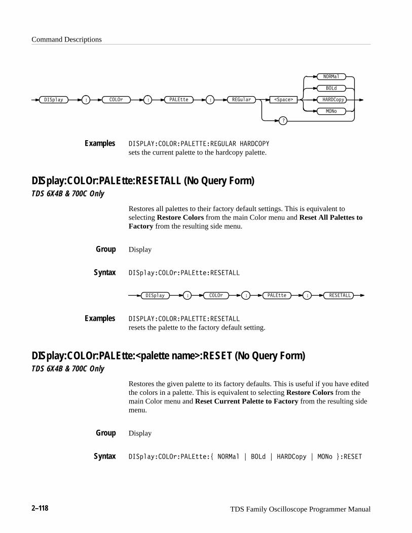
Command Descriptions
2–118 TDS Family Oscilloscope Programmer Manual
����
������
����" � ����� ��� �� � ��!���
����
������� ������"
�
������������������������ �������
sets the current palette to the hardcopy palette.
DISplay:COLOr:PALEtte:RESETALL (No Query Form) TDS 6X4B & 700C Only
Restores all palettes to their factory default settings. This is equivalent toselecting Restore Colors from the main Color menu and Reset All Palettes toFactory from the resulting side menu.
Display
����"���������� ��������
������ ����" � ����� ��� �� �
������������������������
resets the palette to the factory default setting.
DISplay:COLOr:PALEtte:<palette name>:RESET (No Query Form) TDS 6X4B & 700C Only
Restores the given palette to its factory defaults. This is useful if you have editedthe colors in a palette. This is equivalent to selecting Restore Colors from themain Color menu and Reset Current Palette to Factory from the resulting sidemenu.
Display
����"���������� ��# ������ $ ���� $ ������" $ ���� %����
Examples
Group
Syntax
Examples
Group
Syntax
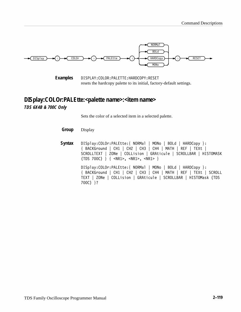
Command Descriptions
TDS Family Oscilloscope Programmer Manual 2–119
���&
����$*
���-*$2 � ����. ����00'�
���,
�����,-2 ���� � �
������"����������� ���������"�����
resets the hardcopy palette to its initial, factory-default settings.
DISplay:COLOr:PALEtte:<palette name>:<item name>TDS 6X4B & 700C Only
Sets the color of a selected item in a selected palette.
Display
���-*$2�����.�����00'�3 ����$* 4 ���, 4 ���& 4 �����,-2 5�
3 �����.,1+& 4 ��� 4 ��� 4 ��� 4 �� 4 �� � 4 ��� 4 �!0 4
������ �! 4 #��' 4 ����(/(,+ 4 ���0(%1*' 4 ��������� 4 ��� �����
� �� ���� 5 3 ���� � ���� � ���� 5
���-*$2�����.�����00'�3 ����$* 4 ���, 4 ���& 4 �����,-2 5�
3 �����.,1+& 4 ��� 4 ��� 4 ��� 4 �� 4 �� � 4 ��� 4 �!0 4 ������
�! 4 #��' 4 ����(/(,+ 4 ���0(%1*' 4 ��������� 4 ��� ��$/) � ��
���� 5�
Examples
Group
Syntax
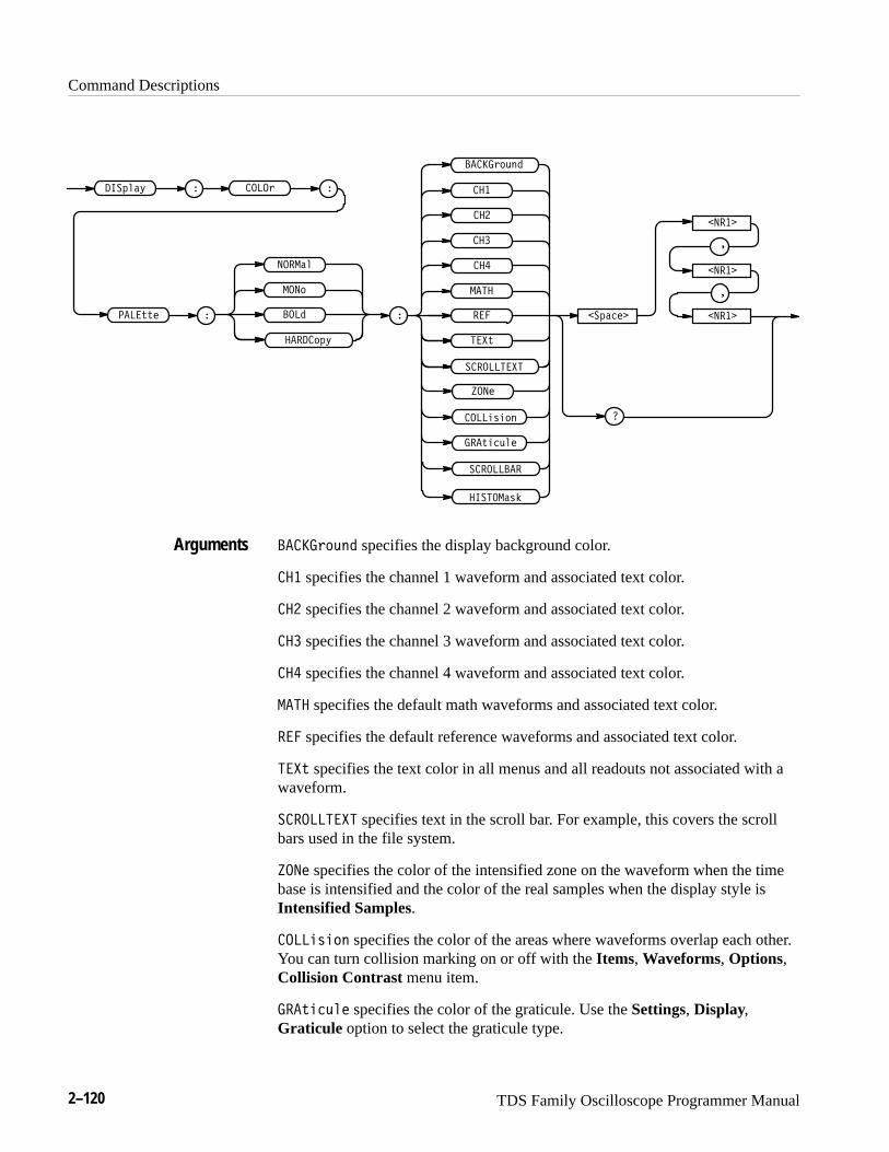
Command Descriptions
2–120 TDS Family Oscilloscope Programmer Manual
����(&+%
��������
��*"�+$!
����")"&%
��'$�, � ����(
���**!
�
�
���*
���
���
���
���!
���
���
���
����������
���
���&
�����$
�� �&',
� ��'��!�
�����
�����
�����
�
�
�������)#
����(&+% specifies the display background color.
��� specifies the channel 1 waveform and associated text color.
��� specifies the channel 2 waveform and associated text color.
��� specifies the channel 3 waveform and associated text color.
��� specifies the channel 4 waveform and associated text color.
��� specifies the default math waveforms and associated text color.
��� specifies the default reference waveforms and associated text color.
���* specifies the text color in all menus and all readouts not associated with awaveform.
���������� specifies text in the scroll bar. For example, this covers the scrollbars used in the file system.
���! specifies the color of the intensified zone on the waveform when the timebase is intensified and the color of the real samples when the display style isIntensified Samples.
����")"&% specifies the color of the areas where waveforms overlap each other.You can turn collision marking on or off with the Items, Waveforms, Options,Collision Contrast menu item.
��*"�+$! specifies the color of the graticule. Use the Settings, Display,Graticule option to select the graticule type.
Arguments

Command Descriptions
TDS Family Oscilloscope Programmer Manual 2–121
� ������� specifies the color of the scrollbar. For example, you will find ascrollbar in various file system menus.
�������#� (TDS 700C) specifies the color of the histogram’s box, the histogramitself, and masks, in the different palettes.
����� ����� ���� specifies the desired colors in terms of hue, lightnessand saturation values.
Hue is the wavelength of light reflected from the surface. It varies continuouslyalong the color spectrum as produced by a rainbow. Values range from 0 to 359.Sample values are: 0 = blue, 60 = magenta, 120 = red, 180 = yellow, 240 =green, 360 = cyan.
Lightness refers to the amount of light reflected from the surface. It varies fromblack, to the nominal color, to white. Values range from 0 to100. A value of 0results in black. A value of 50 provides the nominal color. A value of 100 resultsin white.
Saturation is the intensity of color. Completely desaturated color is gray.Completely saturated color of any hue is that color at its most intense. Valuesrange from 0 to 100. A value of 100 provides a pure color. A value of 0 providesgray.
�������� ���"�����$$������ ���� �� ����������
sets the CH1 color of the hardcopy palette to 120 hue, 50 lightness, and100 saturation. This provides a pure red.
DISplay:FILTerSets or queries the type of interpolation to use for the display. This command isequivalent to setting Filter in the Display menu.
Display
DISplay:STYle
���! �%������" & �����" ' ���� (
���! �%������"
Examples
Group
Related Commands
Syntax

Command Descriptions
2–122 TDS Family Oscilloscope Programmer Manual
������ � ����
�
� �
� ���
�������
� ��� specifies linear interpolation where acquired points are connected withstraight lines.
� � specifies sin(x)/x interpolation where acquired points are fit to a curve.
����������� � ���
sets the interpolation filter type to linear.
������������
returns either � ��� or � �, indicating the type of interpolation filter.
DISplay:FORMatSets or queries the display format. This command is equivalent to settingFormat in the Display menu.
Display
������������ � �� � �� �
�������������
������ � �����
�
��
��
�������
�� displays one waveform against another. The source pairs that make up an ��
trace are predefined and are listed in Table 2–31. Displaying one source causesits corresponding source to be displayed.
Arguments
Examples
Group
Syntax
Arguments
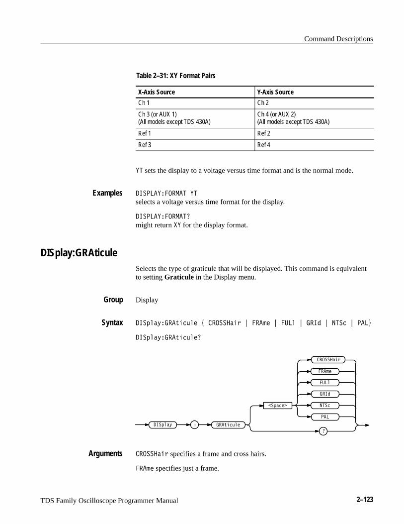
Command Descriptions
TDS Family Oscilloscope Programmer Manual 2–123
Table 2–31: XY Format Pairs
X-Axis Source Y-Axis Source
Ch 1 Ch 2
Ch 3 (or AUX 1) (All models except TDS 430A)
Ch 4 (or AUX 2) (All models except TDS 430A)
Ref 1 Ref 2
Ref 3 Ref 4
�� sets the display to a voltage versus time format and is the normal mode.
���� �������� ��
selects a voltage versus time format for the display.
���� ���������
might return �� for the display format.
DISplay:GRAticuleSelects the type of graticule that will be displayed. This command is equivalentto setting Graticule in the Display menu.
Display
������#���!��"�� $ �������� % ���� % � � % ��� % ���� % �� &
������#���!��"���
��!��"��������# �
���
�������
�
� �
����
��������
��
����
�������� specifies a frame and cross hairs.
���� specifies just a frame.
Examples
Group
Syntax
Arguments
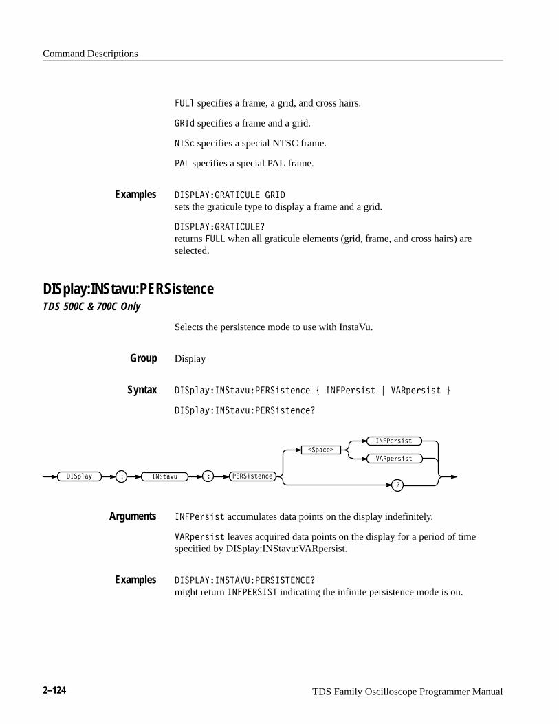
Command Descriptions
2–124 TDS Family Oscilloscope Programmer Manual
� � specifies a frame, a grid, and cross hairs.
���� specifies a frame and a grid.
���� specifies a special NTSC frame.
�� specifies a special PAL frame.
���� ���������� ����
sets the graticule type to display a frame and a grid.
���� ���������� �
returns � when all graticule elements (grid, frame, and cross hairs) areselected.
DISplay:INStavu:PERSistenceTDS 500C & 700C Only
Selects the persistence mode to use with InstaVu.
Display
������#���� �"!������ ���� $ �������� % ��������� &
������#���� �"!������ �����
��� �"!�
�������
�
��������
������#
���������
����� �����
�������� accumulates data points on the display indefinitely.
��������� leaves acquired data points on the display for a period of timespecified by DISplay:INStavu:VARpersist.
���� ��������������������
might return �������� indicating the infinite persistence mode is on.
Examples
Group
Syntax
Arguments
Examples
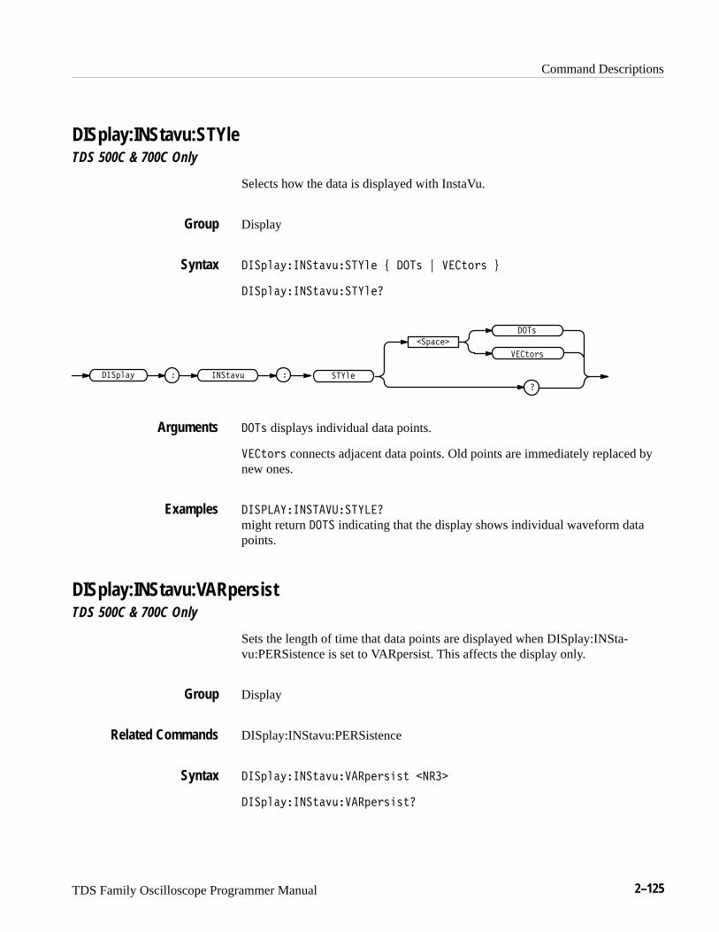
Command Descriptions
TDS Family Oscilloscope Programmer Manual 2–125
DISplay:INStavu:STYleTDS 500C & 700C Only
Selects how the data is displayed with InstaVu.
Display
�����"�� ���! ������ # ��� $ ������ %
�����"�� ���! �������
�������
�
���
������
������ ���! ������" �
��� displays individual data points.
������ connects adjacent data points. Old points are immediately replaced bynew ones.
�������� �����������
might return ��� indicating that the display shows individual waveform datapoints.
DISplay:INStavu:VARpersistTDS 500C & 700C Only
Sets the length of time that data points are displayed when DISplay:INSta-vu:PERSistence is set to VARpersist. This affects the display only.
Display
DISplay:INStavu:PERSistence
�����"�� ���! ����������� � ���
�����"�� ���! ������������
Group
Syntax
Arguments
Examples
Group
Related Commands
Syntax
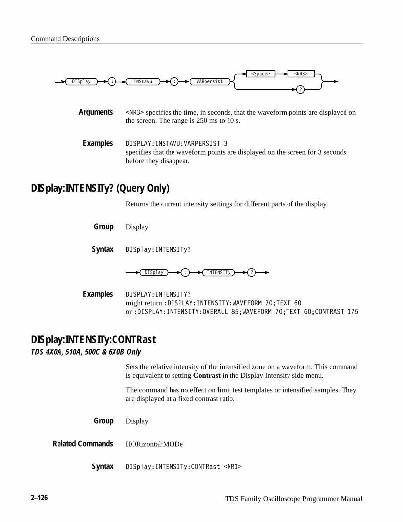
Command Descriptions
2–126 TDS Family Oscilloscope Programmer Manual
���&#'($()
��&!"#� �����
���)!+*���&%!,
����� specifies the time, in seconds, that the waveform points are displayed onthe screen. The range is 250 ms to 10 s.
������ ����������������� �
specifies that the waveform points are displayed on the screen for 3 secondsbefore they disappear.
DISplay:INTENSITy? (Query Only)Returns the current intensity settings for different parts of the display.
Display
���&%!,��������,
���&%!, ��������,
������ ��������
might return ������ �������� �������� ������ ��
or ������ �������� ������� ���������� ������ ���������� ���
DISplay:INTENSITy:CONTRastTDS 4X0A, 510A, 500C & 6X0B Only
Sets the relative intensity of the intensified zone on a waveform. This commandis equivalent to setting Contrast in the Display Intensity side menu.
The command has no effect on limit test templates or intensified samples. Theyare displayed at a fixed contrast ratio.
Display
HORizontal:MODe
���&%!,��������,�����!() �����
Arguments
Examples
Group
Syntax
Examples
Group
Related Commands
Syntax

Command Descriptions
TDS Family Oscilloscope Programmer Manual 2–127
����� ��������� ���������
����� � ��������
������ ����
�������� �
���� ranges from 100 to 250 percent.
������������������������� ���
sets the intensity of the intensified portion of a waveform.
DISplay:INTENSITy:OVERAllTDS 4X0A, 510A, 5X0C, & 6X0B Only
Sets the intensity of the entire display. This command is equivalent to settingOverall in the Display Intensity side menu.
Display
����� ��������� �������� ����
����� ��������� ��������
�������
������ ����
����� ��������� �
���� ranges from 20 to 100 percent.
������������������������ ��
sets the intensity of the display to the middle of the range.
������������������������
might return �� as the overall display intensity.
Arguments
Examples
Group
Syntax
Arguments
Examples
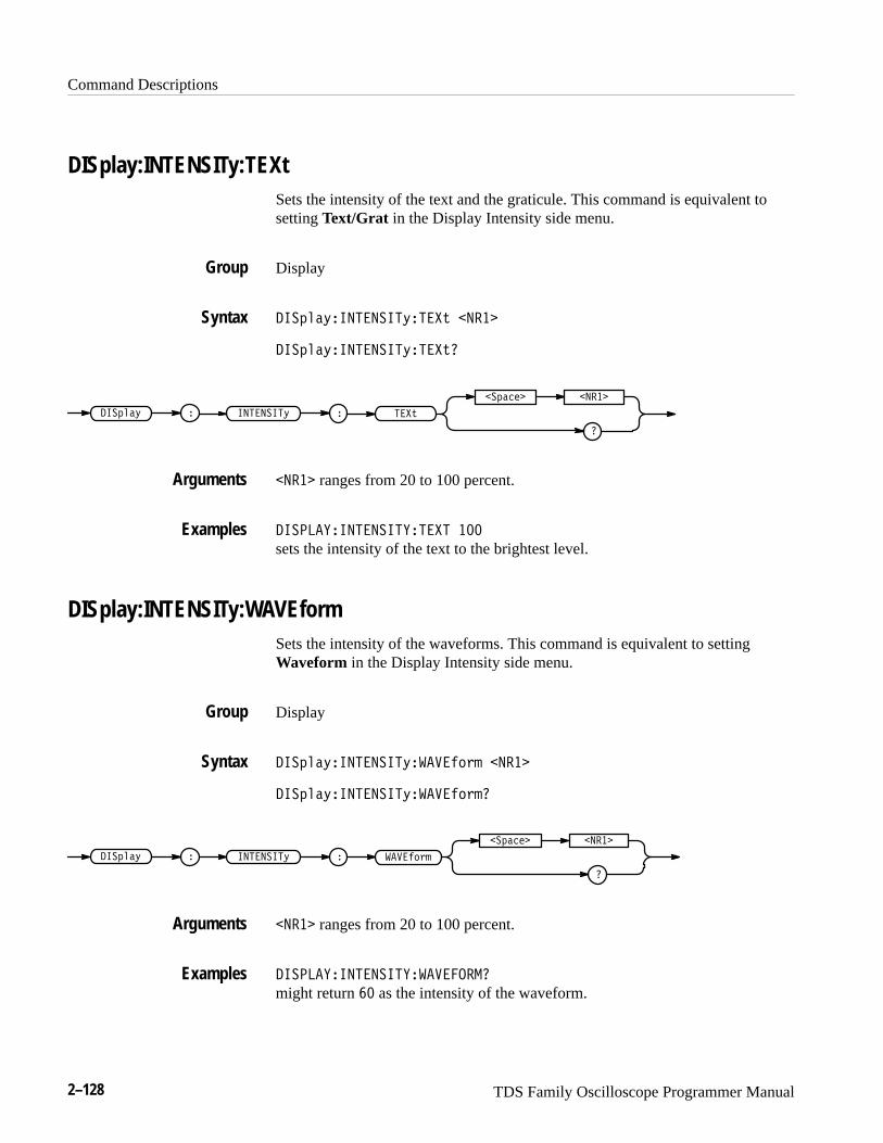
Command Descriptions
2–128 TDS Family Oscilloscope Programmer Manual
DISplay:INTENSITy:TEXtSets the intensity of the text and the graticule. This command is equivalent tosetting Text/Grat in the Display Intensity side menu.
Display
�!��$� ����� �$����# �����
�!��$� ����� �$����#�
�
�
��!���� �����
����� �$ ���# �!��$ �
����� ranges from 20 to 100 percent.
����� ����� ������� ���
sets the intensity of the text to the brightest level.
DISplay:INTENSITy:WAVEformSets the intensity of the waveforms. This command is equivalent to settingWaveform in the Display Intensity side menu.
Display
�!��$� ����� �$����� "� �����
�!��$� ����� �$����� "��
� ���� "�
�
��!���� �����
����� �$ �!��$ �
����� ranges from 20 to 100 percent.
����� ����� �����������
might return �� as the intensity of the waveform.
Group
Syntax
Arguments
Examples
Group
Syntax
Arguments
Examples
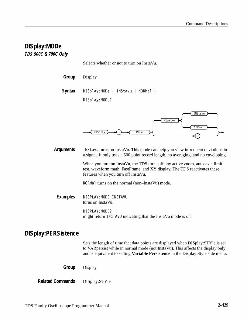
Command Descriptions
TDS Family Oscilloscope Programmer Manual 2–129
DISplay:MODeTDS 500C & 700C Only
Selects whether or not to turn on InstaVu.
Display
�������� �� � ������ � � ����
�������� ���
� �������� �
�������
�
� ����
������
������ turns on InstaVu. This mode can help you view infrequent deviations ina signal. It only uses a 500 point record length, no averaging, and no enveloping.
When you turn on InstaVu, the TDS turns off any active zoom, autosave, limittest, waveform math, FastFrame, and XY display. The TDS reactivates thesefeatures when you turn off InstaVu.
� ���� turns on the normal (non–InstaVu) mode.
������� �� ������
turns on InstaVu.
������� ���
might return ������ indicating that the InstaVu mode is on.
DISplay:PERSistenceSets the length of time that data points are displayed when DISplay:STYle is setto VARpersist while in normal mode (not InstaVu). This affects the display onlyand is equivalent to setting Variable Persistence in the Display Style side menu.
Display
DISplay:STYle
Group
Syntax
Arguments
Examples
Group
Related Commands
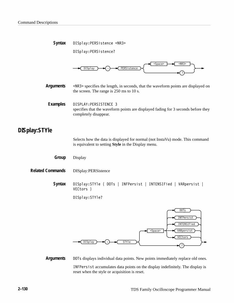
Command Descriptions
2–130 TDS Family Oscilloscope Programmer Manual
�����"����� !���� �����
�����"����� !�����
�����" � ���� !����
�
������� �����
����� specifies the length, in seconds, that the waveform points are displayed onthe screen. The range is 250 ms to 10 s.
��� ����������� �
specifies that the waveform points are displayed fading for 3 seconds before theycompletely disappear.
DISplay:STYleSelects how the data is displayed for normal (not InstaVu) mode. This commandis equivalent to setting Style in the Display menu.
Display
DISplay:PERSistence
�����"������ # �� $ ������ � ! $ ���������� $ ������ � ! $
��!�� %
�����"�������
����������
����������" �
������ � !
������ � !�������
�
��!��
��
�� displays individual data points. New points immediately replace old ones.
������ � ! accumulates data points on the display indefinitely. The display isreset when the style or acquisition is reset.
Syntax
Arguments
Examples
Group
Related Commands
Syntax
Arguments
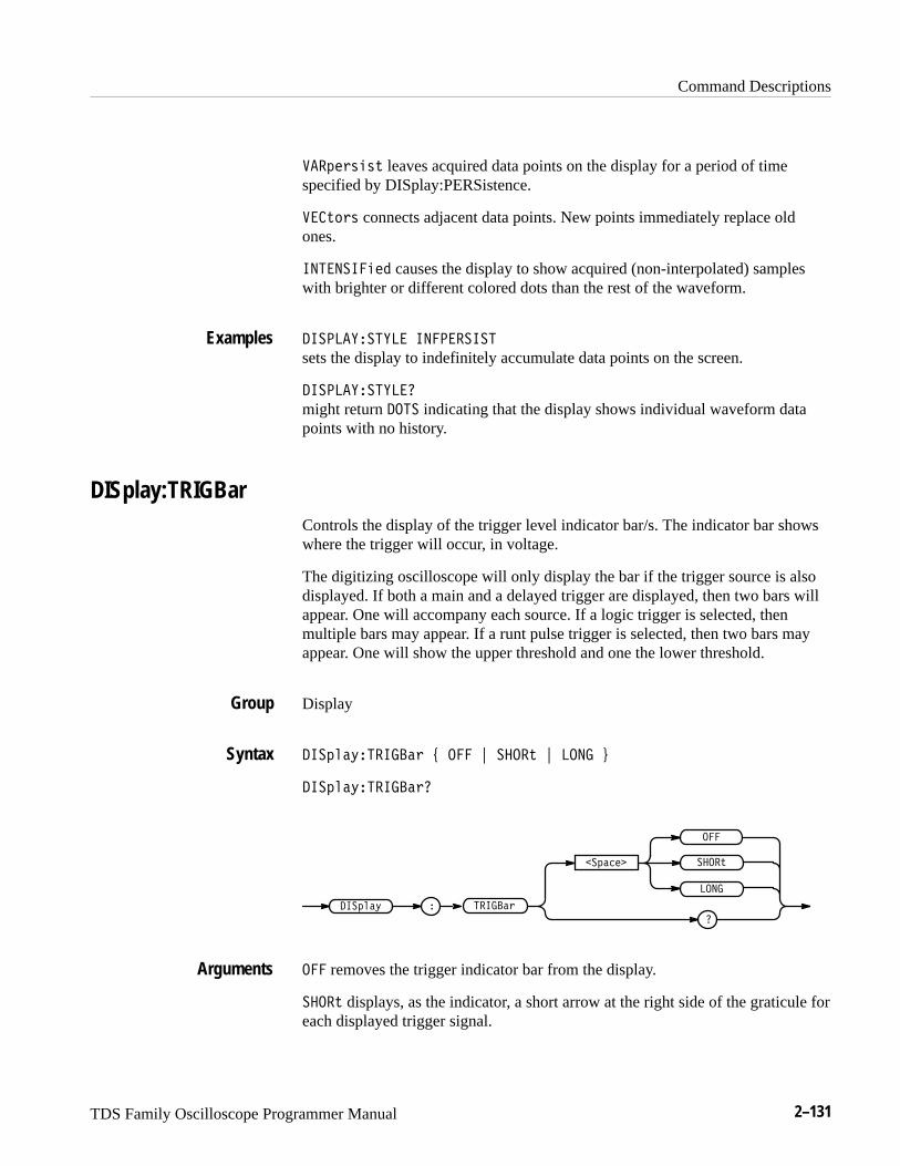
Command Descriptions
TDS Family Oscilloscope Programmer Manual 2–131
����� !�!" leaves acquired data points on the display for a period of timespecified by DISplay:PERSistence.
��"� ! connects adjacent data points. New points immediately replace oldones.
���������� causes the display to show acquired (non-interpolated) sampleswith brighter or different colored dots than the rest of the waveform.
����������� ���������
sets the display to indefinitely accumulate data points on the screen.
������������
might return ��� indicating that the display shows individual waveform datapoints with no history.
DISplay:TRIGBarControls the display of the trigger level indicator bar/s. The indicator bar showswhere the trigger will occur, in voltage.
The digitizing oscilloscope will only display the bar if the trigger source is alsodisplayed. If both a main and a delayed trigger are displayed, then two bars willappear. One will accompany each source. If a logic trigger is selected, thenmultiple bars may appear. If a runt pulse trigger is selected, then two bars mayappear. One will show the upper threshold and one the lower threshold.
Display
�����#������� $ ��� % � ��" % ���� &
�����#������� �
������
� ��"
�����# �
�������
�
���
����
��� removes the trigger indicator bar from the display.
� ��" displays, as the indicator, a short arrow at the right side of the graticule foreach displayed trigger signal.
Examples
Group
Syntax
Arguments
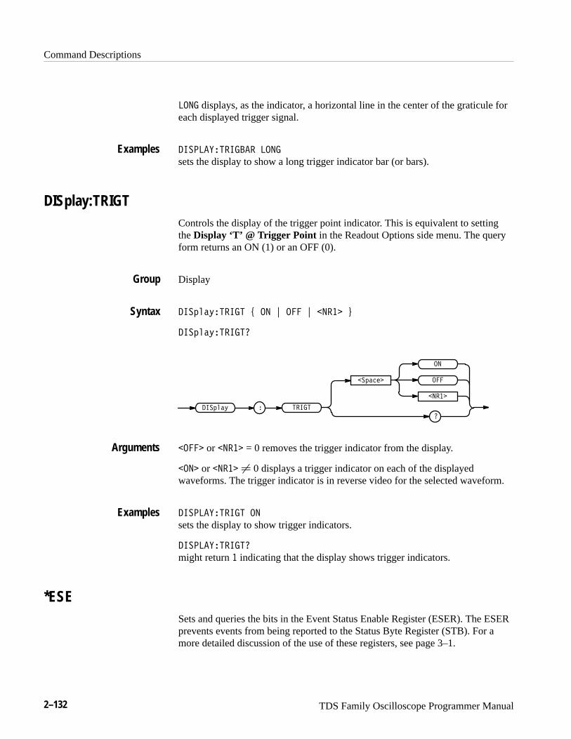
Command Descriptions
2–132 TDS Family Oscilloscope Programmer Manual
��� displays, as the indicator, a horizontal line in the center of the graticule foreach displayed trigger signal.
��� ���������� ���
sets the display to show a long trigger indicator bar (or bars).
DISplay:TRIGTControls the display of the trigger point indicator. This is equivalent to settingthe Display ‘T’ @ Trigger Point in the Readout Options side menu. The queryform returns an ON (1) or an OFF (0).
Display
������������ � �� � � � ����� �
�������������
�
������ � �����
�������
�
�����
��
��� or ����� = 0 removes the trigger indicator from the display.
���� or ����� � 0 displays a trigger indicator on each of the displayedwaveforms. The trigger indicator is in reverse video for the selected waveform.
��� �������� ��
sets the display to show trigger indicators.
��� ���������
might return � indicating that the display shows trigger indicators.
*ESESets and queries the bits in the Event Status Enable Register (ESER). The ESERprevents events from being reported to the Status Byte Register (STB). For amore detailed discussion of the use of these registers, see page 3–1.
Examples
Group
Syntax
Arguments
Examples
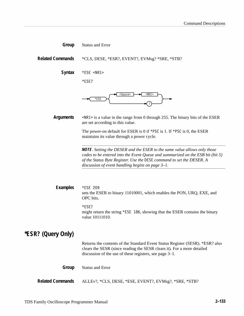
Command Descriptions
TDS Family Oscilloscope Programmer Manual 2–133
Status and Error
*CLS, DESE, *ESR?, EVENT?, EVMsg? *SRE, *STB?
���� ���
�����
�
����� ���
����
��� is a value in the range from 0 through 255. The binary bits of the ESERare set according to this value.
The power-on default for ESER is 0 if ���� is 1. If ���� is 0, the ESERmaintains its value through a power cycle.
NOTE. Setting the DESER and the ESER to the same value allows only thosecodes to be entered into the Event Queue and summarized on the ESB bit (bit 5)of the Status Byte Register. Use the ��� command to set the DESER. Adiscussion of event handling begins on page 3–1.
���� ���
sets the ESER to binary 11010001, which enables the PON, URQ, EXE, andOPC bits.
�����
might return the string ���� ���, showing that the ESER contains the binaryvalue 10111010.
*ESR? (Query Only)Returns the contents of the Standard Event Status Register (SESR). *ESR? alsoclears the SESR (since reading the SESR clears it). For a more detaileddiscussion of the use of these registers, see page 3–1.
Status and Error
ALLEv?, *CLS, DESE, *ESE, EVENT?, EVMsg?, *SRE, *STB?
Group
Related Commands
Syntax
Arguments
Examples
Group
Related Commands
Command Descriptions
2–134 TDS Family Oscilloscope Programmer Manual
� ��
�� �
� ��
might return the value ���, showing that the SESR contains binary 11010101.
EVENT? (Query Only)Returns from the Event Queue an event code that provides information about theresults of the last *ESR? read. EVENT? also removes the returned value fromthe Event Queue. A discussion of event handling begins on page 3–1.
Status and Error
ALLEv?, *CLS, DESE, *ESE, *ESR?, EVMsg?, *SRE, *STB?
����
����
����
might return the response ���� ���, showing that there was an error in acommand header.
EVMsg? (Query Only)Removes from the Event Queue a single event code associated with the results ofthe last *ESR? read, and returns the event code along with an explanatorymessage. A more detailed discussion of event handling begins on page 3–1.
Status and Error
ALLEv?, *CLS, DESE, *ESE, *ESR?, EVENT?, *SRE, *STB?
����
Syntax
Examples
Group
Related Commands
Syntax
Examples
Group
Related Commands
Syntax

Command Descriptions
TDS Family Oscilloscope Programmer Manual 2–135
���%�
The event code and message in the following format:
�'�"& �#����#!!����&$ "����'�"& �#����#!!����&$ "������
��&$ "����� ��%%������#!!�"���
where �#!!�"�� is the command that caused the error and may be returnedwhen a command error is detected by the digitizing oscilloscope. As much of thecommand will be returned as possible without exceeding the 60 character limitof the ��%%���� and �#!!�"�� strings combined. The command string isright-justified.
�����
might return the message ������ ������#!!�"� �����$ �$$#$�.
EVQty? (Query Only)Returns the number of event codes that are in the Event Queue. This is usefulwhen using the ALLEv? query since it lets you know exactly how many eventswill be returned.
Status and Error
ALLEv?, EVENT?, EVMsg?
���&(
���&(
����
�����
might return � as the number of event codes in the Event Queue.
Returns
Examples
Group
Related Commands
Syntax
Returns
Examples

Command Descriptions
2–136 TDS Family Oscilloscope Programmer Manual
FACtory (No Query Form)Resets the digitizing oscilloscope to its factory default settings. This command isequivalent to selecting Recall Factory Setup in the Waveform Save/Recallmenu.
Miscellaneous
*PSC, *RCL, RECAll:SETUp, *RST, *SAV, SAVe:SETUp
�������
�������
Setting the digitizing oscilloscope to factory default includes:
� Clears the Event Status Enable Register.
� Clears the Service Request Enable Register.
� Sets the Device Event Status Enable Register to 255.
� Sets the Power On Status Clear Flag to TRUE
� Purges all defined aliases.
� Enables all Command Headers (HEADer ON).
� Sets the macro defined by *DDT to a “zero-length field.”
� Clears the pending operation flag and associated operations.
The FACtory command does not alter the following:
� The state of the GPIB (IEEE Std 488.1-1987) interface.
� The selected GPIB address.
� Calibration data that affects device specifications.
� Protected user data.
� Stored settings.
� The current password (if implemented).
Group
Related Commands
Syntax
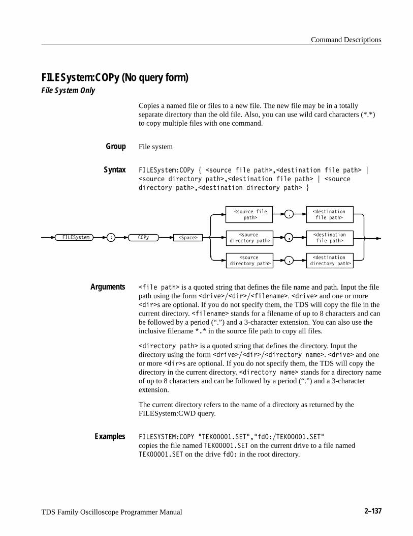
Command Descriptions
TDS Family Oscilloscope Programmer Manual 2–137
FILESystem:COPy (No query form)File System Only
Copies a named file or files to a new file. The new file may be in a totallyseparate directory than the old file. Also, you can use wild card characters (*.*)to copy multiple files with one command.
File system
��� �)%&� ���) * %"'$�� ���� #�&�����%&�!�&�"! ���� #�&�� +
%"'$�� ��$��&"$) #�&�����%&�!�&�"! ���� #�&�� + %"'$��
��$��&"$) #�&�����%&�!�&�"! ��$��&"$) #�&�� ,
��%&�!�&�"!���� #�&��
%"'$�� ����#�&��
��%&�!�&�"!���� #�&��
%"'$����$��&"$) #�&��
��%&�!�&�"!��$��&"$) #�&��
%"'$����$��&"$) #�&��
���)��� �)%&� �#���� ��
�
�
���� #�&�� is a quoted string that defines the file name and path. Input the filepath using the form �$�(�����$������!� ��. �$�(�� and one or more��$�s are optional. If you do not specify them, the TDS will copy the file in thecurrent directory. ����!� �� stands for a filename of up to 8 characters and canbe followed by a period (“.”) and a 3-character extension. You can also use theinclusive filename ��� in the source file path to copy all files.
��$��&"$) #�&�� is a quoted string that defines the directory. Input thedirectory using the form �$�(�����$����$��&"$) !� ��. �$�(�� and oneor more ��$�s are optional. If you do not specify them, the TDS will copy thedirectory in the current directory. ��$��&"$) !� �� stands for a directory nameof up to 8 characters and can be followed by a period (“.”) and a 3-characterextension.
The current directory refers to the name of a directory as returned by theFILESystem:CWD query.
��� ���� ����� -� �������� ���-����� �������� ��
copies the file named � �������� � on the current drive to a file named� �������� � on the drive ��� in the root directory.
Group
Syntax
Arguments
Examples
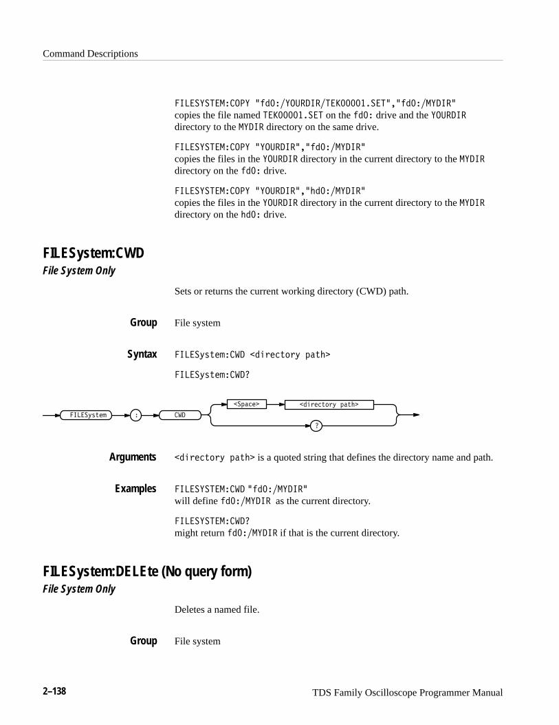
Command Descriptions
2–138 TDS Family Oscilloscope Programmer Manual
��������������� * �������� �����������������* ������ ���
copies the file named ������������ on the ��� drive and the ���� ��directory to the �� �� directory on the same drive.
��������������� *���� ����* ������ ���
copies the files in the ���� �� directory in the current directory to the �� ��
directory on the ��� drive.
��������������� *���� ����*!������ ���
copies the files in the ���� �� directory in the current directory to the �� ��
directory on the !��� drive.
FILESystem:CWDFile System Only
Sets or returns the current working directory (CWD) path.
File system
�����)'(�#��� �"&��($&) %�(!
�����)'(�#��� �
�
�%���
������)'(�# ��
�"&��($&) %�(!
�"&��($&) %�(! is a quoted string that defines the directory name and path.
������������� * ������ ���will define ������ �� as the current directory.
������������� �
might return ������ �� if that is the current directory.
FILESystem:DELEte (No query form)File System Only
Deletes a named file.
File system
Group
Syntax
Arguments
Examples
Group
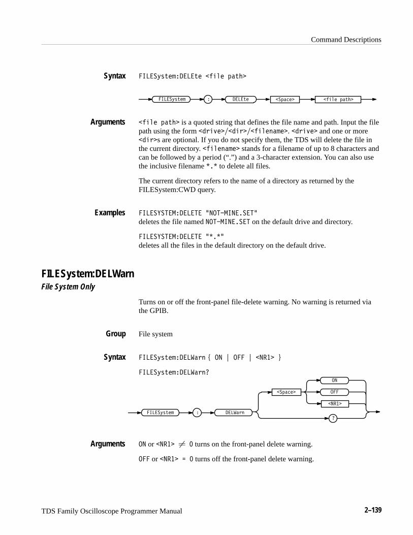
Command Descriptions
TDS Family Oscilloscope Programmer Manual 2–139
�����*'(�#����(� �!"� %�( �
����(������*'(�# �!"� %�( ��%����
�!"� %�( � is a quoted string that defines the file name and path. Input the filepath using the form �&!)����!&���!"�$�#��. �&!)�� and one or more�!&�s are optional. If you do not specify them, the TDS will delete the file inthe current directory. �!"�$�#�� stands for a filename of up to 8 characters andcan be followed by a period (“.”) and a 3-character extension. You can also usethe inclusive filename ��� to delete all files.
The current directory refers to the name of a directory as returned by theFILESystem:CWD query.
���������������� .�������������
deletes the file named ������������ on the default drive and directory.
���������������� .����
deletes all the files in the default directory on the default drive.
FILESystem:DELWarnFile System Only
Turns on or off the front-panel file-delete warning. No warning is returned viathe GPIB.
File system
�����*'(�#�����&$ + �� , ��� , ���� -
�����*'(�#�����&$
�%����
��
���
����
�����*'(�# �����&$
�� or ���� � � turns on the front-panel delete warning.
��� or ���� � � turns off the front-panel delete warning.
Syntax
Arguments
Examples
Group
Syntax
Arguments
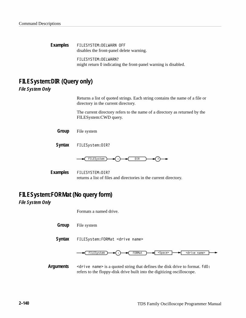
Command Descriptions
2–140 TDS Family Oscilloscope Programmer Manual
������ ������� �
disables the front-panel delete warning.
������ ��������
might return � indicating the front-panel warning is disabled.
FILESystem:DIR (Query only)File System Only
Returns a list of quoted strings. Each string contains the name of a file ordirectory in the current directory.
The current directory refers to the name of a directory as returned by theFILESystem:CWD query.
File system
���"� �������
� ������"� �� �
������ �����
returns a list of files and directories in the current directory.
FILESystem:FORMat (No query form)File System Only
Formats a named drive.
File system
���"� ����� � ����!� �����
� �� � ���"� �� ����!� ������������
����!� ����� is a quoted string that defines the disk drive to format. ����
refers to the floppy-disk drive built into the digitizing oscilloscope.
Examples
Group
Syntax
Examples
Group
Syntax
Arguments

Command Descriptions
TDS Family Oscilloscope Programmer Manual 2–141
� �������������� &�����
formats the media on drive fd0:.
FILESystem:FREESpace (Query only)File System Only
Returns the amount of freespace (in bytes) on the current drive.
File system
� ���%"#�������� ����
�� ���%"#�� ������ ���
� �������������� ����
might return � as the amount of freespace available if the drive was full.
FILESystem:MKDir (No query form)File System Only
Make a new directory.
File system
� ���%"#������! ���!��#�!% �#��
� ���!� ���%"#�� ���!��#�!% �#���� ����
���!��#�!% �#�� is a quoted string that defines the directory. Input thedirectory using the form ��!�$������!�����!��#�!% �����. ��!�$�� and oneor more ���!�s are optional. If you do not specify them, the TDS will create thedirectory in the current directory. ���!��#�!% ����� stands for a directory nameof up to 8 characters and can be followed by a period (“.”) and a 3-charextension.
The current directory refers to the name of a directory as returned by theFILESystem:CWD query.
Examples
Group
Syntax
Examples
Group
Syntax
Arguments
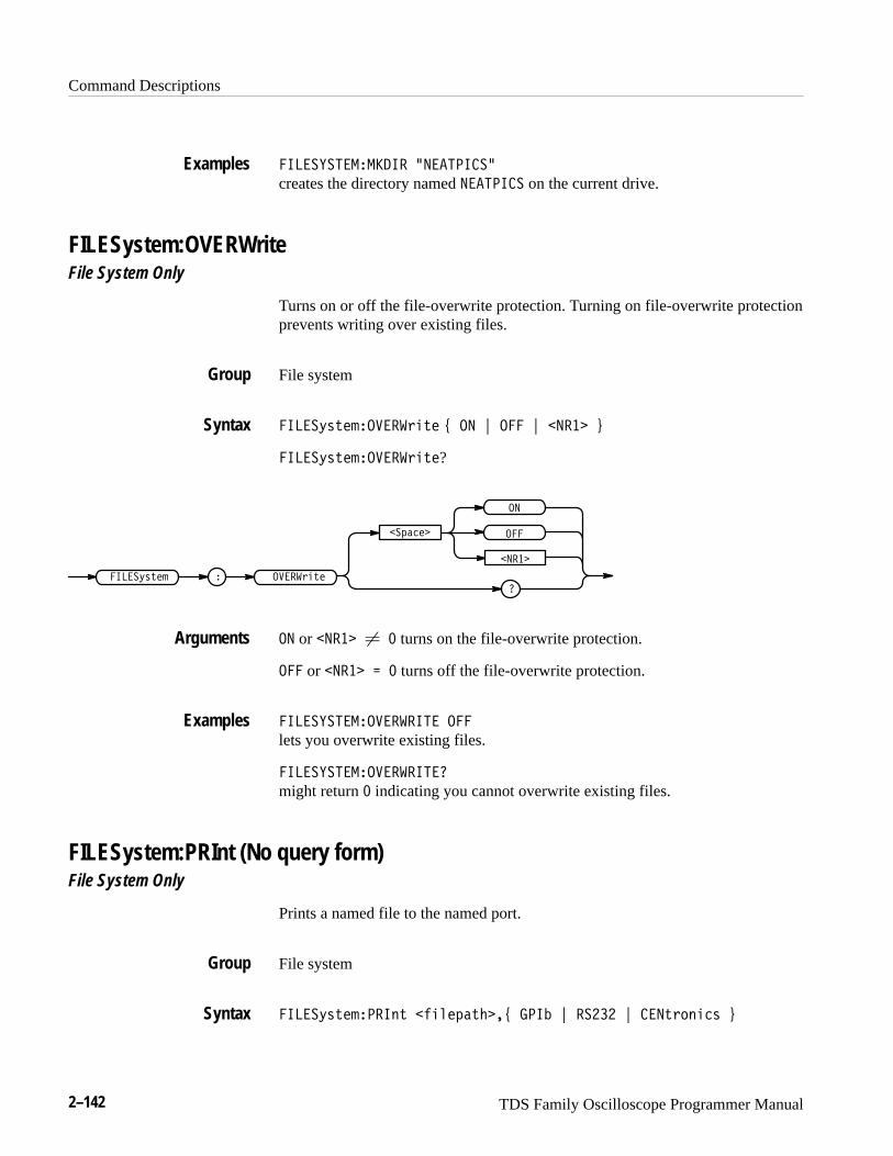
Command Descriptions
2–142 TDS Family Oscilloscope Programmer Manual
���������������� 3�� ������
creates the directory named �� ����� on the current drive.
FILESystem:OVERWriteFile System Only
Turns on or off the file-overwrite protection. Turning on file-overwrite protectionprevents writing over existing files.
File system
�����/-.#(������,&.# 0 �� 1 ��� 1 ���� 2
�����/-.#(������,&.#?
�+ "#�
��
�
���
����
������/-.#( �����,&.#
�� or ���� � � turns on the file-overwrite protection.
��� or ���� � turns off the file-overwrite protection.
�������������������� ���
lets you overwrite existing files.
���������������������
might return � indicating you cannot overwrite existing files.
FILESystem:PRInt (No query form)File System Only
Prints a named file to the named port.
File system
�����/-.#(����). $&'#+ .%��0 ���! 1 ����� 1 ���.,*)&"- 2
Examples
Group
Syntax
Arguments
Examples
Group
Syntax
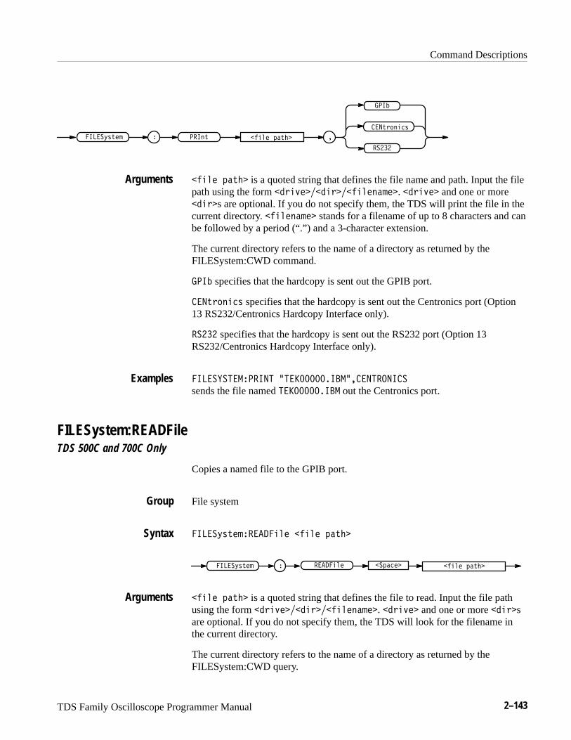
Command Descriptions
TDS Family Oscilloscope Programmer Manual 2–143
���-+)(% ,
�����
����
���(-�����/,-"' #%&" *�-$� �
#%&" *�-$� is a quoted string that defines the file name and path. Input the filepath using the form !+%."��!%+��#%&"(�'"�. !+%."� and one or more!%+�s are optional. If you do not specify them, the TDS will print the file in thecurrent directory. #%&"(�'"� stands for a filename of up to 8 characters and canbe followed by a period (“.”) and a 3-character extension.
The current directory refers to the name of a directory as returned by theFILESystem:CWD command.
���� specifies that the hardcopy is sent out the GPIB port.
���-+)(% , specifies that the hardcopy is sent out the Centronics port (Option13 RS232/Centronics Hardcopy Interface only).
����� specifies that the hardcopy is sent out the RS232 port (Option 13RS232/Centronics Hardcopy Interface only).
��������������� 0���������� �������������
sends the file named ���������� � out the Centronics port.
FILESystem:READFileTDS 500C and 700C Only
Copies a named file to the GPIB port.
File system
�����/,-"'�����%&" #%&" *�-$�
�����/,-"' #%&" *�-$��*� "������%&"
#%&" *�-$� is a quoted string that defines the file to read. Input the file pathusing the form !+%."��!%+��#%&"(�'"�. !+%."� and one or more !%+�sare optional. If you do not specify them, the TDS will look for the filename inthe current directory.
The current directory refers to the name of a directory as returned by theFILESystem:CWD query.
Arguments
Examples
Group
Syntax
Arguments
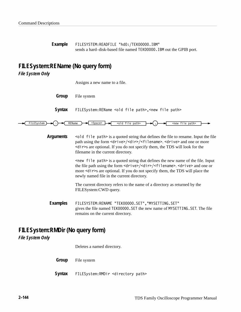
Command Descriptions
2–144 TDS Family Oscilloscope Programmer Manual
��� ���� ��� ���� +������ �����������
sends a hard–disk-based file named � ���������� out the GPIB port.
FILESystem:REName (No query form)File System Only
Assigns a new name to a file.
File system
��� �*&'�!�� ��!� �# � �� � $�'���"�) �� � $�'�
� � ��!���� �*&'�! �"�) �� � $�'��# � �� � $�'���$��� �
�# � �� � $�'� is a quoted string that defines the file to rename. Input the filepath using the form ��%�(�����%���� �"�!�. ��%�(� and one or more���%s are optional. If you do not specify them, the TDS will look for thefilename in the current directory.
�"�) �� � $�'� is a quoted string that defines the new name of the file. Inputthe file path using the form ��%�(�����%���� �"�!�. ��%�(� and one ormore ���%s are optional. If you do not specify them, the TDS will place thenewly named file in the current directory.
The current directory refers to the name of a directory as returned by theFILESystem:CWD query.
��� ���� ��� �� +� �������� ���+��� ������� ��
gives the file named � �������� � the new name of ��� ������� �. The fileremains on the current directory.
FILESystem:RMDir (No query form)File System Only
Deletes a named directory.
File system
��� �*&'�!�����% ���%��'#%* $�'�
Example
Group
Syntax
Arguments
Examples
Group
Syntax
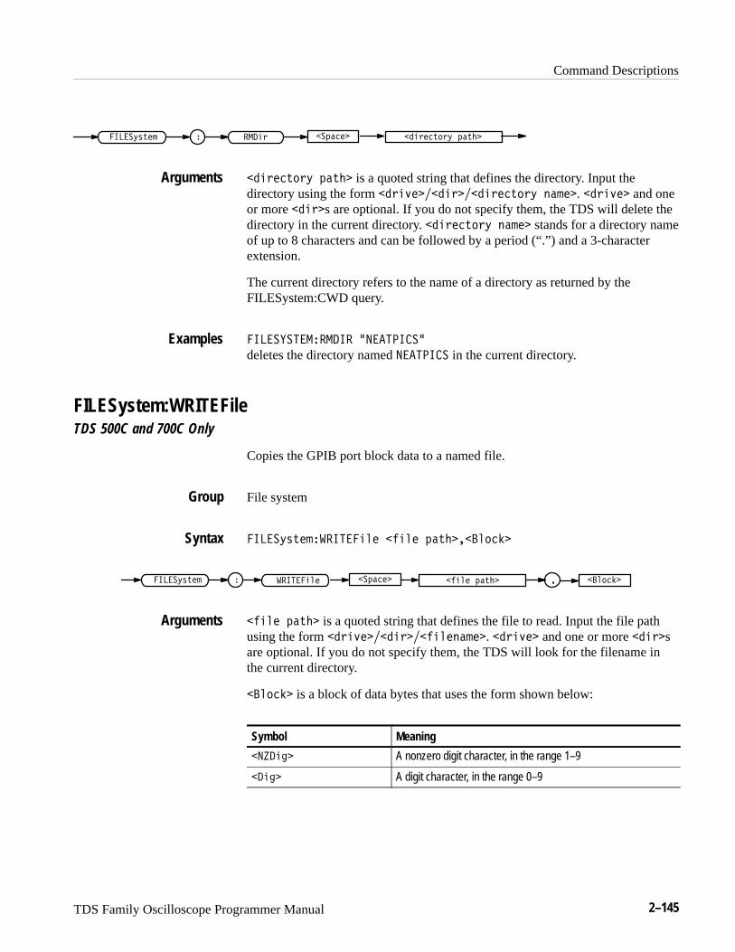
Command Descriptions
TDS Family Oscilloscope Programmer Manual 2–145
� ��� ' ����+()�# �� '��)%'+ &�)����&����
�� '��)%'+ &�)�� is a quoted string that defines the directory. Input thedirectory using the form ��' *����� '���� '��)%'+ $�#��. ��' *�� and oneor more �� '�s are optional. If you do not specify them, the TDS will delete thedirectory in the current directory. �� '��)%'+ $�#�� stands for a directory nameof up to 8 characters and can be followed by a period (“.”) and a 3-characterextension.
The current directory refers to the name of a directory as returned by theFILESystem:CWD query.
��������������� ,��������
deletes the directory named ������� in the current directory.
FILESystem:WRITEFileTDS 500C and 700C Only
Copies the GPIB port block data to a named file.
File system
����+()�#������ "� �� "� &�)����"%�!�
� ����+()�# �� "� &�)����&��������� "� � �"%�!�
�� "� &�)�� is a quoted string that defines the file to read. Input the file pathusing the form ��' *����� '���� "�$�#��. ��' *�� and one or more �� '�sare optional. If you do not specify them, the TDS will look for the filename inthe current directory.
�"%�!� is a block of data bytes that uses the form shown below:
Symbol Meaning
���� �� A nonzero digit character, in the range 1–9
�� �� A digit character, in the range 0–9
Arguments
Examples
Group
Syntax
Arguments
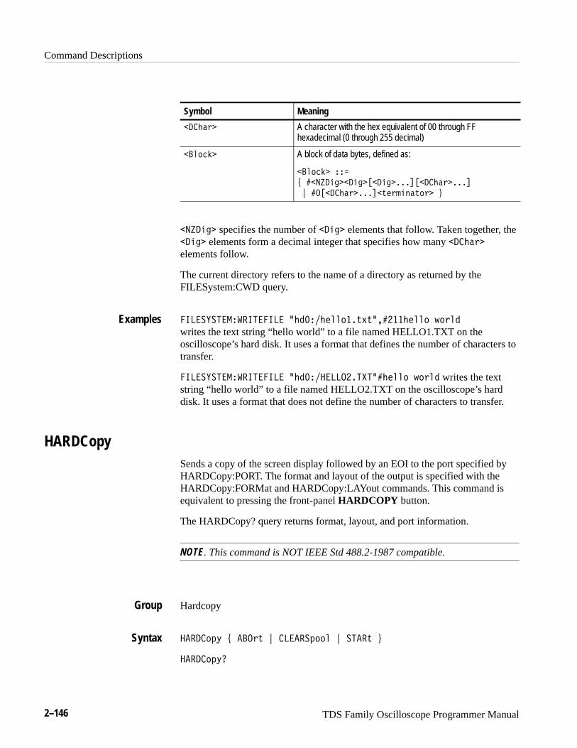
Command Descriptions
2–146 TDS Family Oscilloscope Programmer Manual
Symbol Meaning
���)$1 A character with the hex equivalent of 00 through FFhexadecimal (0 through 255 decimal)
��,/%+ A block of data bytes, defined as:
��,/%+ �
6 ���!�*( ��*( "��*( ���#"���)$1 ���#
7 ��"���)$1 ���#�2'1-*.$2/1 8
��!�*( specifies the number of ��*( elements that follow. Taken together, the��*( elements form a decimal integer that specifies how many ���)$1
elements follow.
The current directory refers to the name of a directory as returned by theFILESystem:CWD query.
����� ������������� 9)&��)',,/��242�����)',,/ 3/1,&
writes the text string “hello world” to a file named HELLO1.TXT on theoscilloscope’s hard disk. It uses a format that defines the number of characters totransfer.
����� ������������� 9)&�������������)',,/ 3/1,& writes the textstring “hello world” to a file named HELLO2.TXT on the oscilloscope’s harddisk. It uses a format that does not define the number of characters to transfer.
HARDCopySends a copy of the screen display followed by an EOI to the port specified byHARDCopy:PORT. The format and layout of the output is specified with theHARDCopy:FORMat and HARDCopy:LAYout commands. This command isequivalent to pressing the front-panel HARDCOPY button.
The HARDCopy? query returns format, layout, and port information.
NOTE. This command is NOT IEEE Std 488.2-1987 compatible.
Hardcopy
�����/05 6 ���12 7 ������0//, 7 ����2 8
�����/05�
Examples
Group
Syntax
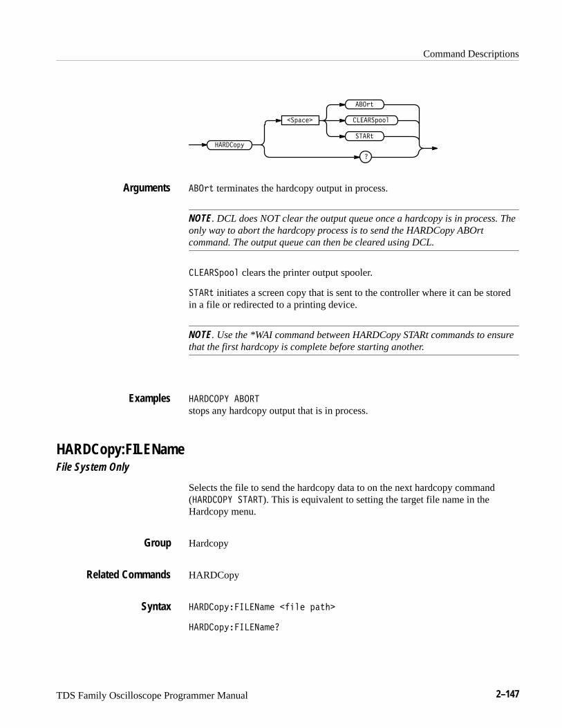
Command Descriptions
TDS Family Oscilloscope Programmer Manual 2–147
������"
�������
����!
�
��� !
���������
��� ! terminates the hardcopy output in process.
NOTE. DCL does NOT clear the output queue once a hardcopy is in process. Theonly way to abort the hardcopy process is to send the HARDCopy ABOrtcommand. The output queue can then be cleared using DCL.
��������� clears the printer output spooler.
����! initiates a screen copy that is sent to the controller where it can be storedin a file or redirected to a printing device.
NOTE. Use the *WAI command between HARDCopy STARt commands to ensurethat the first hardcopy is complete before starting another.
������� �����
stops any hardcopy output that is in process.
HARDCopy:FILENameFile System Only
Selects the file to send the hardcopy data to on the next hardcopy command(������� �����). This is equivalent to setting the target file name in theHardcopy menu.
Hardcopy
HARDCopy
������"�� ����� ����� ��!��
������"�� ������
Arguments
Examples
Group
Related Commands
Syntax
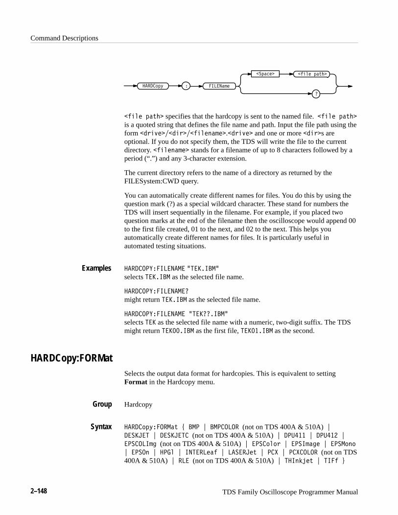
Command Descriptions
2–148 TDS Family Oscilloscope Programmer Manual
'*-& 1#3)�
�����#.&� ���015
�
�1#$&�
'*-& 1#3)� specifies that the hardcopy is sent to the named file.'*-& 1#3)�
is a quoted string that defines the file name and path. Input the file path using theform %2*4&��%*2��'*-&/#.&�.%2*4&� and one or more %*2�s areoptional. If you do not specify them, the TDS will write the file to the currentdirectory. '*-&/#.&� stands for a filename of up to 8 characters followed by aperiod (“.”) and any 3-character extension.
The current directory refers to the name of a directory as returned by theFILESystem:CWD query.
You can automatically create different names for files. You do this by using thequestion mark (?) as a special wildcard character. These stand for numbers theTDS will insert sequentially in the filename. For example, if you placed twoquestion marks at the end of the filename then the oscilloscope would append 00to the first file created, 01 to the next, and 02 to the next. This helps youautomatically create different names for files. It is particularly useful inautomated testing situations.
� �����"����� �� 9��������selects ������� as the selected file name.
� �����"����� ���
might return ������� as the selected file name.
� �����"����� �� 9����������
selects ��� as the selected file name with a numeric, two-digit suffix. The TDSmight return ��������� as the first file, ��������� as the second.
HARDCopy:FORMatSelects the output data format for hardcopies. This is equivalent to settingFormat in the Hardcopy menu.
Hardcopy
� ���015����#3 6 ��� 7 �������� (not on TDS 400A & 510A)7������� 7 �������� (not on TDS 400A & 510A)7 �� ��� 7 �� ��� 7
�������.( (not on TDS 400A & 510A)7 ����0-02 7 ����.#(& 7 ����0/0
7 ����/ 7 ���- 7 ������&#' 7 � ����&3 7 ��! 7 ��!����� (not on TDS400A & 510A) 7 ��� (not on TDS 400A & 510A)7 ���/,+&3 7 ���' 8
Examples
Group
Syntax
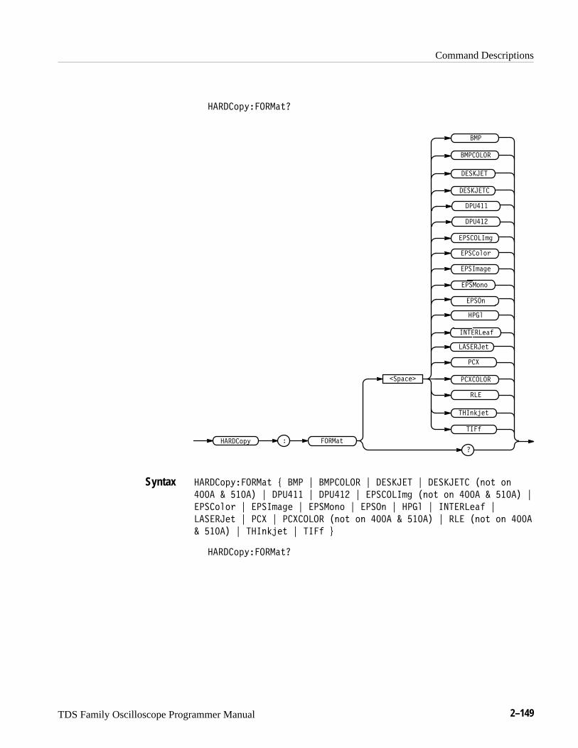
Command Descriptions
TDS Family Oscilloscope Programmer Manual 2–149
�����-.1����#0
���
��"�����
�� ���%#&
������%0
��,)(%0
����#0�����-.1
��.#$%�
��&
����,
���*
��"
����-*-/
����+#'%
����-,-
��������
������ �
���
��!���
��!���
�������+'
������
�����-.1����#0 2 ��� 3 �������� 3 ������ 3 ������ � �,-0 -,
���� � ���� 3 ��!��� 3 ��!��� 3 �������+' �,-0 -, ���� � ���� 3
����-*-/ 3 ����+#'% 3 ����-,- 3 ����, 3 ���* 3 �� ���%#& 3
������%0 3 ��" 3 ��"����� �,-0 -, ���� � ���� 3 ��� �,-0 -, ����
� ���� 3 ��,)(%0 3 ��& 4
�����-.1����#0
Syntax
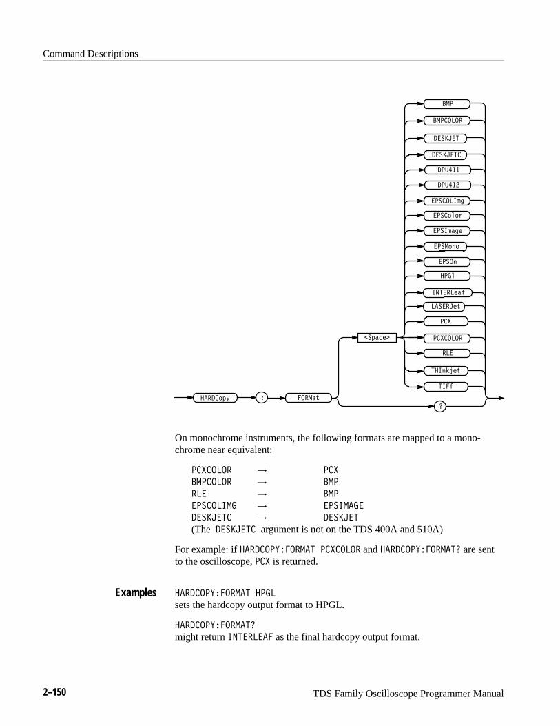
Command Descriptions
2–150 TDS Family Oscilloscope Programmer Manual
��
��������
��� ��!�"
�� ��!,
���(%$!,
�����,�����)*-
��*� !�
�
���"
���(
���&
���
���)&)+
���'�#!
���)()
�������
� ��� ��
��
������
������
������'#
� ��� �
On monochrome instruments, the following formats are mapped to a mono-chrome near equivalent:
�������� � ���
������� � ��
�� � ��
�������� � �����
� ��� �� � � ��� �
(The � ��� �� argument is not on the TDS 400A and 510A)
For example: if ������������� �������� and �������������� are sentto the oscilloscope, ��� is returned.
������������� ����
sets the hardcopy output format to HPGL.
��������������
might return ��� �� � as the final hardcopy output format.
Examples
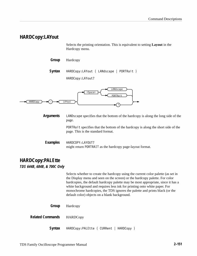
Command Descriptions
TDS Family Oscilloscope Programmer Manual 2–151
HARDCopy:LAYoutSelects the printing orientation. This is equivalent to setting Layout in theHardcopy menu.
Hardcopy
������ ������� ! �� ������ " �������� #
������ ��������
�������
�������
�
�� ������
������
��������
�� ������ specifies that the bottom of the hardcopy is along the long side of thepage.
�������� specifies that the bottom of the hardcopy is along the short side of thepage. This is the standard format.
���������������
might return �������� as the hardcopy page-layout format.
HARDCopy:PALEtteTDS 644B, 684B, & 700C Only
Selects whether to create the hardcopy using the current color palette (as set inthe Display menu and seen on the screen) or the hardcopy palette. For colorhardcopies, the default hardcopy palette may be most appropriate, since it has awhite background and requires less ink for printing onto white paper. Formonochrome hardcopies, the TDS ignores the palette and prints black (or thedefault color) objects on a blank background.
Hardcopy
HARDCopy
������ ������� ! ������� " ������ #
Group
Syntax
Arguments
Examples
Group
Related Commands
Syntax
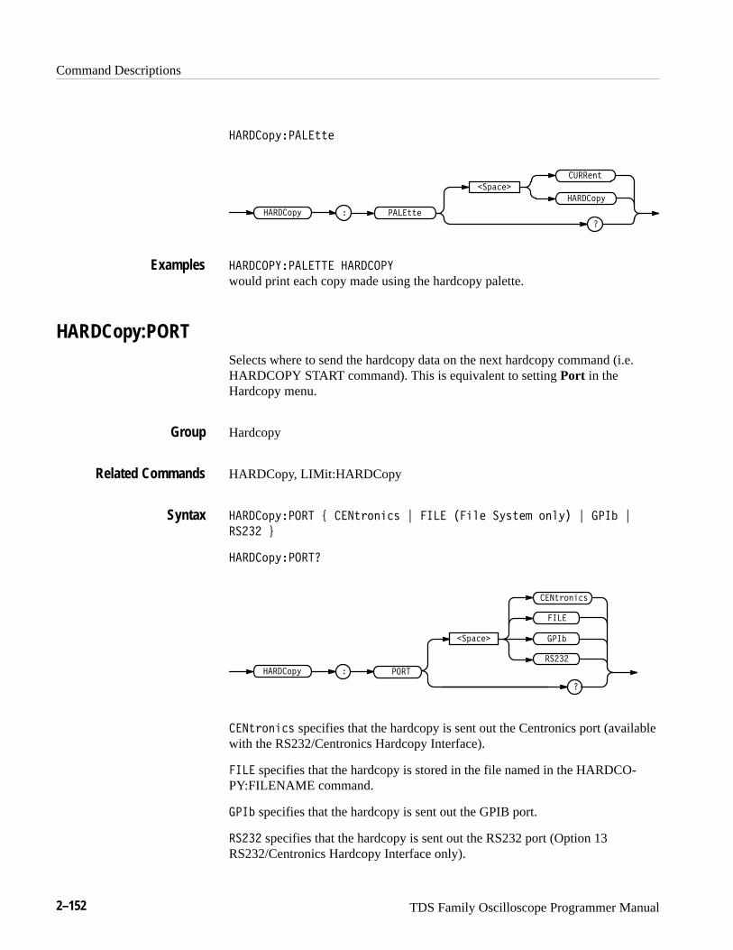
Command Descriptions
2–152 TDS Family Oscilloscope Programmer Manual
����#$(��� ''�
�� ''��
��$����
�����"'
����#$(
����#$(
���������� �� �������
would print each copy made using the hardcopy palette.
HARDCopy:PORTSelects where to send the hardcopy data on the next hardcopy command (i.e.HARDCOPY START command). This is equivalent to setting Port in theHardcopy menu.
Hardcopy
HARDCopy, LIMit:HARDCopy
����#$(����� ) � �'%#"��& * ��� ��� � �(&'�! #" (� * ���� *
����� +
����#$(�����
���������#$(
�����
� �'%#"��&
���
������$����
� �'%#"��& specifies that the hardcopy is sent out the Centronics port (availablewith the RS232/Centronics Hardcopy Interface).
��� specifies that the hardcopy is stored in the file named in the HARDCO-PY:FILENAME command.
���� specifies that the hardcopy is sent out the GPIB port.
����� specifies that the hardcopy is sent out the RS232 port (Option 13RS232/Centronics Hardcopy Interface only).
Examples
Group
Related Commands
Syntax
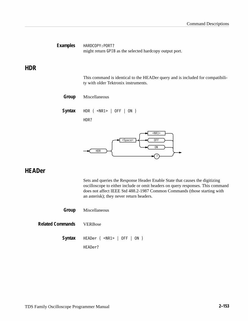
Command Descriptions
TDS Family Oscilloscope Programmer Manual 2–153
������������
might return ��� as the selected hardcopy output port.
HDRThis command is identical to the HEADer query and is included for compatibili-ty with older Tektronix instruments.
Miscellaneous
�� � ����� � ��� � �� �
���
�������
�����
��
��
���
�
HEADerSets and queries the Response Header Enable State that causes the digitizingoscilloscope to either include or omit headers on query responses. This commanddoes not affect IEEE Std 488.2-1987 Common Commands (those starting withan asterisk); they never return headers.
Miscellaneous
VERBose
����� � ����� � ��� � �� �
������
Examples
Group
Syntax
Group
Related Commands
Syntax
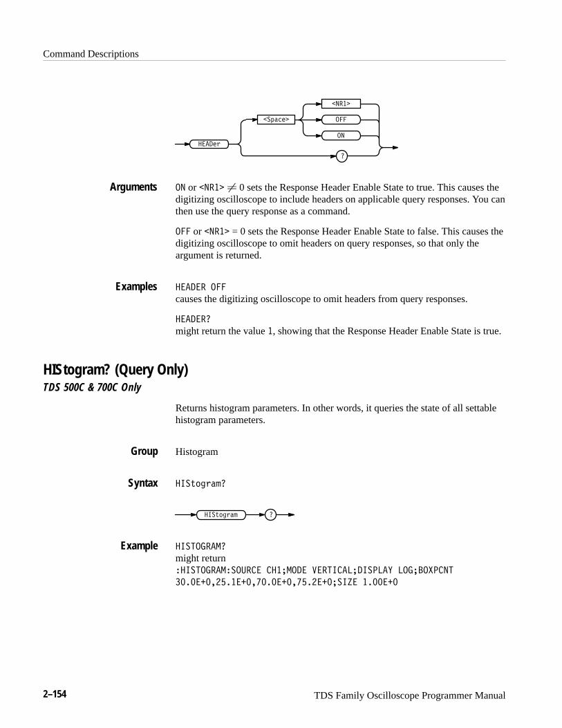
Command Descriptions
2–154 TDS Family Oscilloscope Programmer Manual
�,&'(�
����
����(-
��
���
�
�� or ���� � 0 sets the Response Header Enable State to true. This causes thedigitizing oscilloscope to include headers on applicable query responses. You canthen use the query response as a command.
��� or ���� = 0 sets the Response Header Enable State to false. This causes thedigitizing oscilloscope to omit headers on query responses, so that only theargument is returned.
������ ���
causes the digitizing oscilloscope to omit headers from query responses.
�������
might return the value �, showing that the Response Header Enable State is true.
HIStogram? (Query Only)TDS 500C & 700C Only
Returns histogram parameters. In other words, it queries the state of all settablehistogram parameters.
Histogram
���.+)-&*�
���.+)-&* �
��� ������
might return ���� ��������!��� �������� "�� �����������$ ������#���
������������������������������%� �������
Arguments
Examples
Group
Syntax
Example

Command Descriptions
TDS Family Oscilloscope Programmer Manual 2–155
HIStogram:BOXTDS 500C & 700C Only
Defines the left, top, right, and bottom positions of the histogram box, in sourcewaveform coordinates.
Histogram
���*& (�$���� ���� � ���� � ���� � ����
���"/&%*�#�����
����*& (�$ ��� ��'���
����
����
�
����
�
�
����
�
���� ") *!� #��* '&)"*"&% &� *!� !")*& (�$ �&.� "% )&+(��
-�,��&($ �&&(�"%�*�)
���� ") *!� *&' '&)"*"&% &� *!� !")*& (�$ �&.� "% )&+(��
-�,��&($ �&&(�"%�*�)
���� ") *!� (" !* '&)"*"&% &� *!� !")*& (�$ �&.� "% )&+(��
-�,��&($ �&&(�"%�*�)
���� ") *!� �&**&$ '&)"*"&% &� *!� !")*& (�$ �&.� "% )&+(��
-�,��&($ �&&(�"%�*�)
������������ ���� ����� ���� ���� would define the coordinates of the histogram box in source waveform coordi-nates.
Group
Syntax
Arguments
Examples
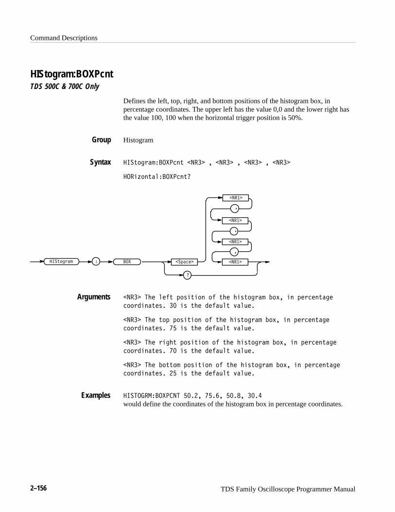
Command Descriptions
2–156 TDS Family Oscilloscope Programmer Manual
HIStogram:BOXPcntTDS 500C & 700C Only
Defines the left, top, right, and bottom positions of the histogram box, inpercentage coordinates. The upper left has the value 0,0 and the lower right hasthe value 100, 100 when the horizontal trigger position is 50%.
Histogram
���.*$,�( ���� ). ����� � ����� � ����� � �����
���&2*).�' ���� ).�
���.*$,�( ��� ��+� "�
�����
�����
�
�����
�
�
�����
�
����� �%" '"#. +*-&.&*) *# .%" %&-.*$,�( �*1� &) +", ").�$"
**,!&)�."-� �� &- .%" !"#�/'. 0�'/"�
����� �%" .*+ +*-&.&*) *# .%" %&-.*$,�( �*1� &) +", ").�$"
**,!&)�."-� � &- .%" !"#�/'. 0�'/"�
����� �%" ,&$%. +*-&.&*) *# .%" %&-.*$,�( �*1� &) +", ").�$"
**,!&)�."-� �� &- .%" !"#�/'. 0�'/"�
����� �%" �*..*( +*-&.&*) *# .%" %&-.*$,�( �*1� &) +", ").�$"
**,!&)�."-� � &- .%" !"#�/'. 0�'/"�
�������� ������� ���� ��� ���� ���� would define the coordinates of the histogram box in percentage coordinates.
Group
Syntax
Arguments
Examples
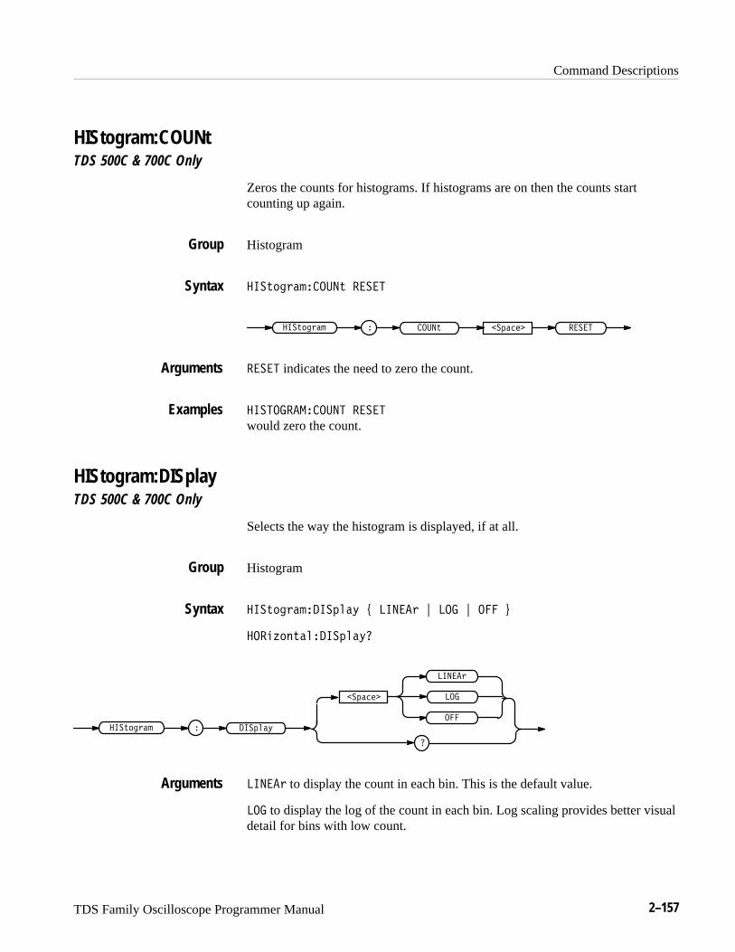
Command Descriptions
TDS Family Oscilloscope Programmer Manual 2–157
HIStogram:COUNtTDS 500C & 700C Only
Zeros the counts for histograms. If histograms are on then the counts startcounting up again.
Histogram
� �!�� �������! ���
� ����!� �!�� �� ����������
��� indicates the need to zero the count.
� ������������� ��� would zero the count.
HIStogram:DISplayTDS 500C & 700C Only
Selects the way the histogram is displayed, if at all.
Histogram
� �!�� ���� ����" $ � �� % ��� % � &
����#��!���� ����"�
� � ����"� �!�� ��
�
�������
�
���
� ��
� �� to display the count in each bin. This is the default value.
��� to display the log of the count in each bin. Log scaling provides better visualdetail for bins with low count.
Group
Syntax
Arguments
Examples
Group
Syntax
Arguments
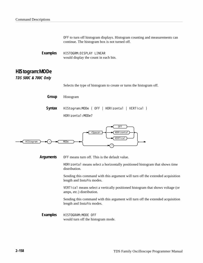
Command Descriptions
2–158 TDS Family Oscilloscope Programmer Manual
� to turn off histogram displays. Histogram counting and measurements cancontinue. The histogram box is not turned off.
������������ �� ����� would display the count in each bin.
HIStogram:MODeTDS 500C & 700C Only
Selects the type of histogram to create or turns the histogram off.
Histogram
���"��!������� $ � % ����#��"�� % �������� &
����#��"��������
� �������"��!��
�
�� ����
��������
�
����#��"��
� means turn off. This is the default value.
����#��"�� means select a horizontally positioned histogram that shows timedistribution.
Sending this command with this argument will turn off the extended acquisitionlength and InstaVu modes.
�������� means select a vertically positioned histogram that shows voltage (oramps, etc.) distribution.
Sending this command with this argument will turn off the extended acquisitionlength and InstaVu modes.
������������� � would turn off the histogram mode.
Examples
Group
Syntax
Arguments
Examples
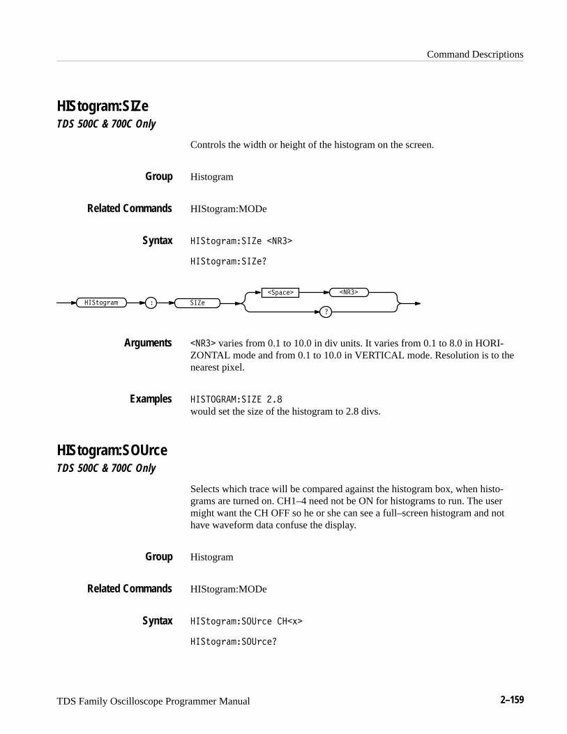
Command Descriptions
TDS Family Oscilloscope Programmer Manual 2–159
HIStogram:SIZeTDS 500C & 700C Only
Controls the width or height of the histogram on the screen.
Histogram
HIStogram:MODe
��� ���������� �����
��� ����������
� ������� �����
������� �����
����� varies from 0.1 to 10.0 in div units. It varies from 0.1 to 8.0 in HORI-ZONTAL mode and from 0.1 to 10.0 in VERTICAL mode. Resolution is to thenearest pixel.
����� ������� ��� would set the size of the histogram to 2.8 divs.
HIStogram:SOUrceTDS 500C & 700C Only
Selects which trace will be compared against the histogram box, when histo-grams are turned on. CH1–4 need not be ON for histograms to run. The usermight want the CH OFF so he or she can see a full–screen histogram and nothave waveform data confuse the display.
Histogram
HIStogram:MODe
��� ������������ ���!�
��� ������������
Group
Related Commands
Syntax
Arguments
Examples
Group
Related Commands
Syntax
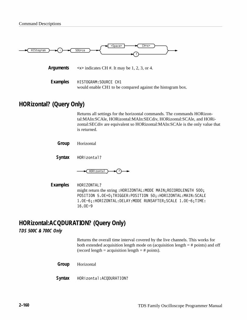
Command Descriptions
2–160 TDS Family Oscilloscope Programmer Manual
�� -$%���.+&-#)
��,#$% ���/
�
�/ indicates CH #. It may be 1, 2, 3, or 4.
����������� ��� ��� would enable CH1 to be compared against the histogram box.
HORizontal? (Query Only)Returns all settings for the horizontal commands. The commands HORizon-tal:MAIn:SCAle, HORizontal:MAIn:SECdiv, HORizontal:SCAle, and HORi-zontal:SECdiv are equivalent so HORizontal:MAIn:SCAle is the only value thatis returned.
Horizontal
���'0+*.#(�
���'0+*.#( �
����"������
might return the string ����"��������� ����������������� ����
�������� ���������������������� �������"��������������
�����������"���������!���� � ������������� �����������
������
HORizontal:ACQDURATION? (Query Only)TDS 500C & 700C Only
Returns the overall time interval covered by the live channels. This works forboth extended acquisition length mode on (acquisition length = # points) and off(record length = acquisition length = # points).
Horizontal
���'0+*.#(���� �������
Arguments
Examples
Group
Syntax
Examples
Group
Syntax
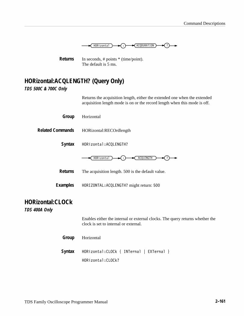
Command Descriptions
TDS Family Oscilloscope Programmer Manual 2–161
����������� ����������� �
In seconds, # points * (time/point).The default is 5 ms.
HORizontal:ACQLENGTH? (Query Only)TDS 500C & 700C Only
Returns the acquisition length, either the extended one when the extendedacquisition length mode is on or the record length when this mode is off.
Horizontal
HORizontal:RECOrdlength
�������������� ����
��� ��� ����������� �
The acquisition length. 500 is the default value.
��������� ���� ���� might return: ���
HORizontal:CLOCkTDS 400A Only
Enables either the internal or external clocks. The query returns whether theclock is set to internal or external.
Horizontal
������������ ��� �������� ! ������� "
������������ ����
Returns
Group
Related Commands
Syntax
Returns
Examples
Group
Syntax
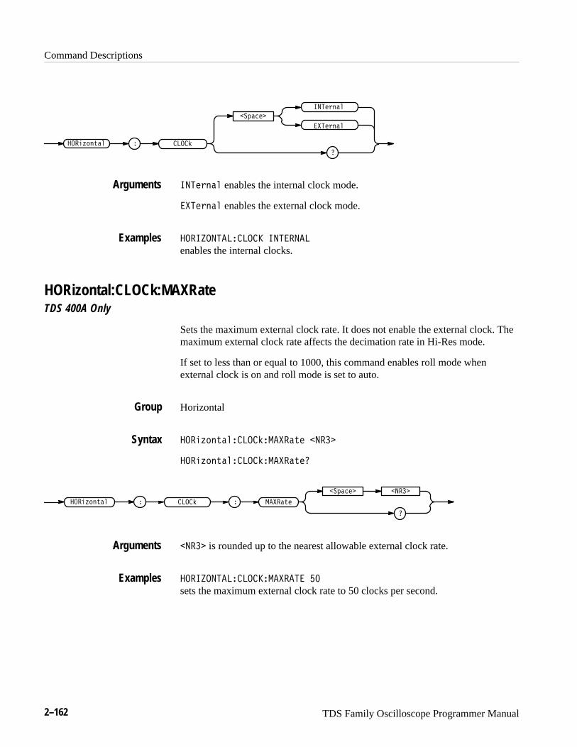
Command Descriptions
2–162 TDS Family Oscilloscope Programmer Manual
����
�� ����
�
���!���
����#��"��
����!���
���!��� enables the internal clock mode.
����!��� enables the external clock mode.
��� ��������� ������
enables the internal clocks.
HORizontal:CLOCk:MAXRateTDS 400A Only
Sets the maximum external clock rate. It does not enable the external clock. Themaximum external clock rate affects the decimation rate in Hi-Res mode.
If set to less than or equal to 1000, this command enables roll mode whenexternal clock is on and roll mode is set to auto.
Horizontal
����#��"�����������"� �����
����#��"�����������"��
� ����"�� �������#��"��
�
�� ���� �����
����� is rounded up to the nearest allowable external clock rate.
��� ��������������� ��
sets the maximum external clock rate to 50 clocks per second.
Arguments
Examples
Group
Syntax
Arguments
Examples

Command Descriptions
TDS Family Oscilloscope Programmer Manual 2–163
HORizontal:DELay? (Query Only)Returns all horizontal delayed time base parameters. The commands HORizon-tal:DELay:SECdiv and HORizontal:DELay:SCAle are identical so onlyHORizontal:DELay:SCAle will be returned.
Horizontal
HORizontal?, HORizontal:DELay:MODe?, HORizontal:DELay:SCAle?,HORizontal:DELay:SECdiv?, HORizontal:DELay:TIMe?
���#+&%)�$�����*�
� ����* ����#+&%)�$
�������� ����� ��
might return the delay parameters ��������� ����� ������ ���� �/
����� �� ����������� �������
HORizontal:DELay:MODeSelects the mode for the delayed time base. This is equivalent to setting TimeBase in the Horizontal menu.
Horizontal
HORizontal:DELay:TIMe
���#+&%)�$�����*����! , ���� ")!( - ���� ")!( .
���#+&%)�$�����*����!�
���!�
�'� !�
�
���� ")!(
���� ")!(
� ����*���#+&%)�$
���� ")!( specifies that the delayed time base runs a user-specified amount ofdelay time after the main trigger event.
Group
Related Commands
Syntax
Examples
Group
Related Commands
Syntax
Arguments
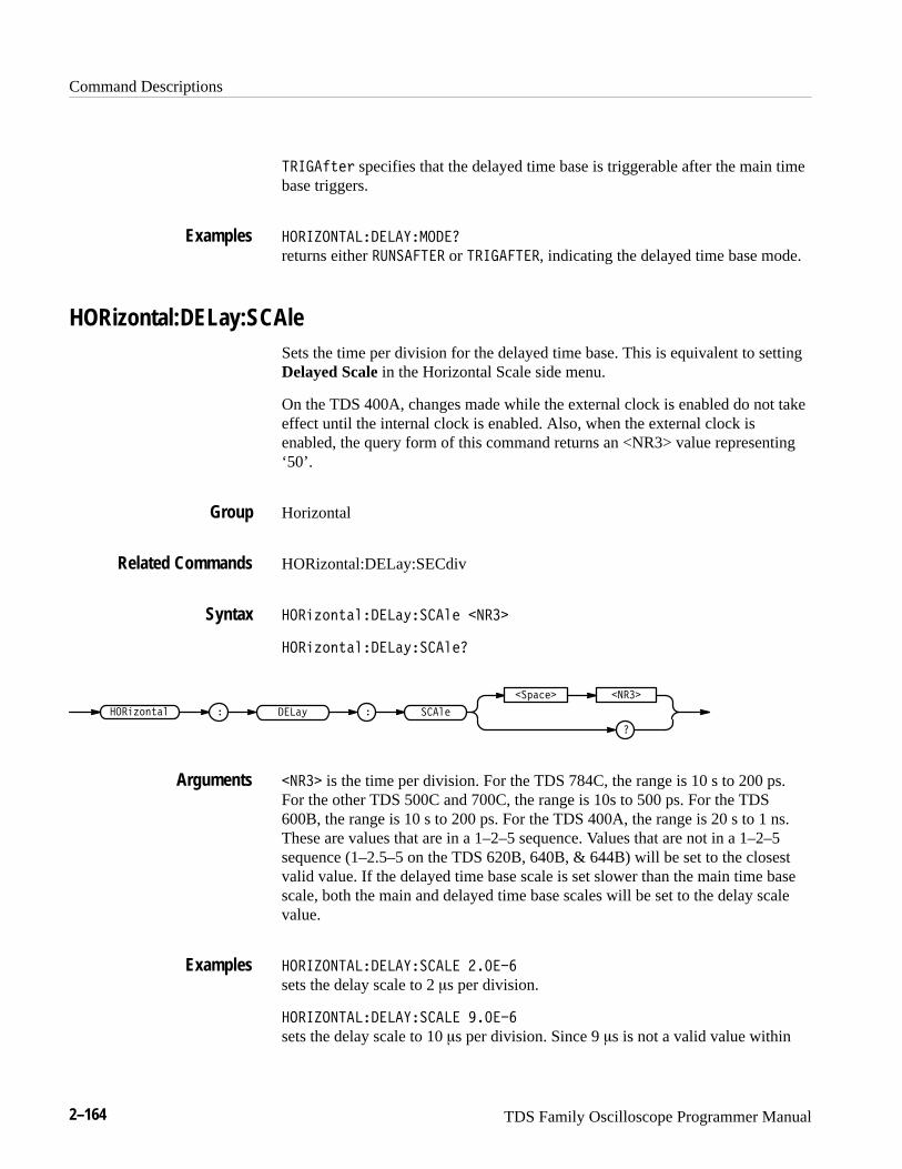
Command Descriptions
2–164 TDS Family Oscilloscope Programmer Manual
���� ")!( specifies that the delayed time base is triggerable after the main timebase triggers.
�������� ���� ������
returns either ���� ���� or ���� ����, indicating the delayed time base mode.
HORizontal:DELay:SCAleSets the time per division for the delayed time base. This is equivalent to settingDelayed Scale in the Horizontal Scale side menu.
On the TDS 400A, changes made while the external clock is enabled do not takeeffect until the internal clock is enabled. Also, when the external clock isenabled, the query form of this command returns an <NR3> value representing‘50’.
Horizontal
HORizontal:DELay:SECdiv
���#+&%)�$����*�� $! ����
���#+&%)�$����*�� $!�
�� $! ����*���#+&%)�$
�
�'� !� ����
���� is the time per division. For the TDS 784C, the range is 10 s to 200 ps.For the other TDS 500C and 700C, the range is 10s to 500 ps. For the TDS600B, the range is 10 s to 200 ps. For the TDS 400A, the range is 20 s to 1 ns.These are values that are in a 1–2–5 sequence. Values that are not in a 1–2–5sequence (1–2.5–5 on the TDS 620B, 640B, & 644B) will be set to the closestvalid value. If the delayed time base scale is set slower than the main time basescale, both the main and delayed time base scales will be set to the delay scalevalue.
�������� ���� ��� �� ������
sets the delay scale to 2 �s per division.
�������� ���� ��� �� ������
sets the delay scale to 10 �s per division. Since 9 �s is not a valid value within
Examples
Group
Related Commands
Syntax
Arguments
Examples
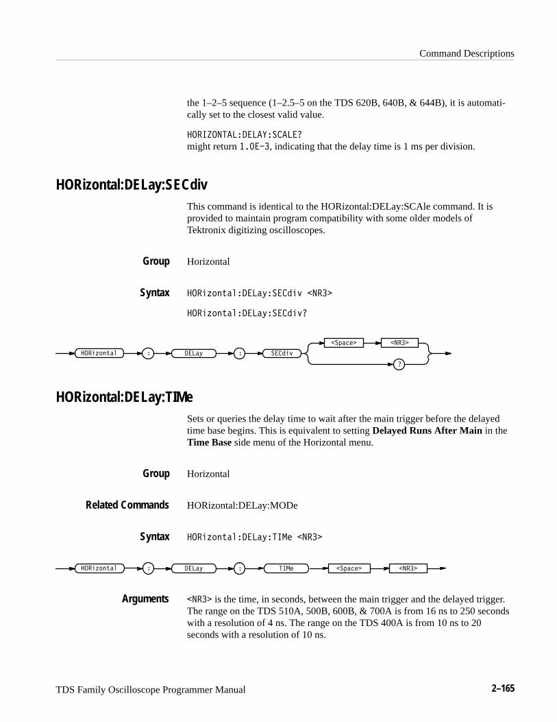
Command Descriptions
TDS Family Oscilloscope Programmer Manual 2–165
the 1–2–5 sequence (1–2.5–5 on the TDS 620B, 640B, & 644B), it is automati-cally set to the closest valid value.
����������� ����������
might return ������, indicating that the delay time is 1 ms per division.
HORizontal:DELay:SECdivThis command is identical to the HORizontal:DELay:SCAle command. It isprovided to maintain program compatibility with some older models ofTektronix digitizing oscilloscopes.
Horizontal
����&! #��� ���%������$ ����
����&! #��� ���%������$
� �����$� ���%����&! #��
��"��� ����
HORizontal:DELay:TIMeSets or queries the delay time to wait after the main trigger before the delayedtime base begins. This is equivalent to setting Delayed Runs After Main in theTime Base side menu of the Horizontal menu.
Horizontal
HORizontal:DELay:MODe
����&! #��� ���%����� ����
� ���% �����&! #�� ���� ������"���
���� is the time, in seconds, between the main trigger and the delayed trigger.The range on the TDS 510A, 500B, 600B, & 700A is from 16 ns to 250 secondswith a resolution of 4 ns. The range on the TDS 400A is from 10 ns to 20seconds with a resolution of 10 ns.
Group
Syntax
Group
Related Commands
Syntax
Arguments
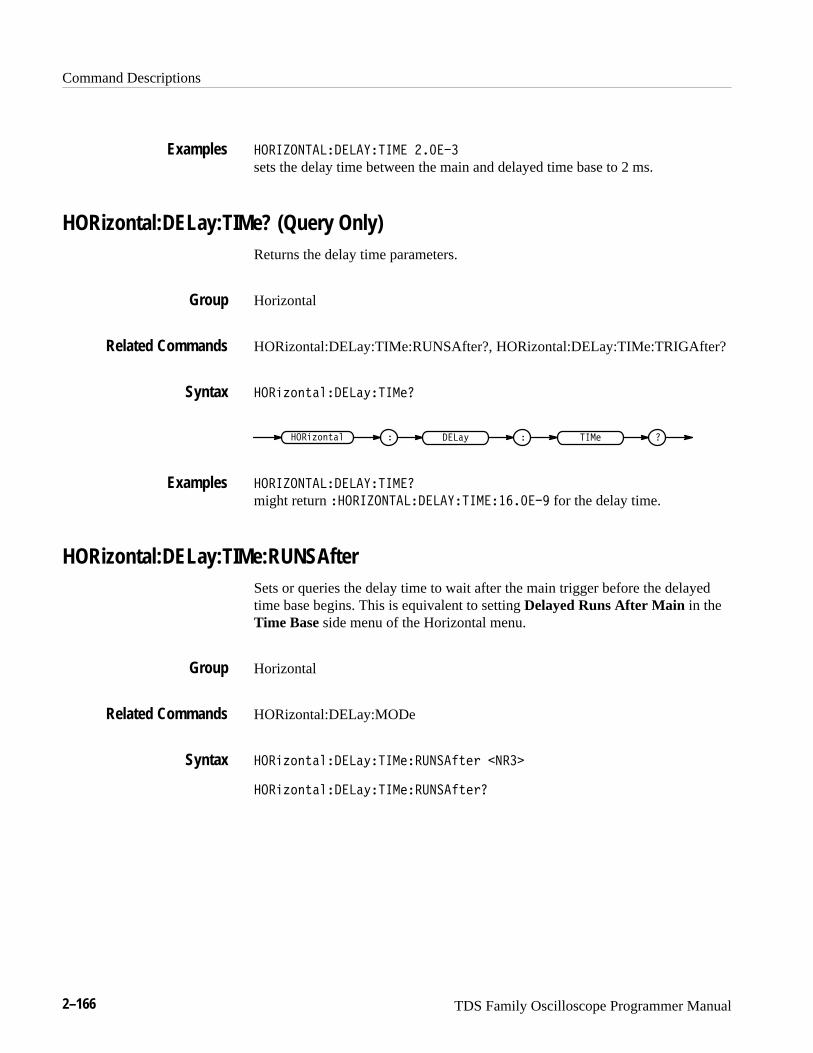
Command Descriptions
2–166 TDS Family Oscilloscope Programmer Manual
������������������� ������
sets the delay time between the main and delayed time base to 2 ms.
HORizontal:DELay:TIMe? (Query Only)Returns the delay time parameters.
Horizontal
HORizontal:DELay:TIMe:RUNSAfter?, HORizontal:DELay:TIMe:TRIGAfter?
��� '#"%�!����&����
����& ��� '#"%�! ����
�������������������
might return ������������������������� for the delay time.
HORizontal:DELay:TIMe:RUNSAfterSets or queries the delay time to wait after the main trigger before the delayedtime base begins. This is equivalent to setting Delayed Runs After Main in theTime Base side menu of the Horizontal menu.
Horizontal
HORizontal:DELay:MODe
��� '#"%�!����&����������%�$ �����
��� '#"%�!����&����������%�$
Examples
Group
Related Commands
Syntax
Examples
Group
Related Commands
Syntax
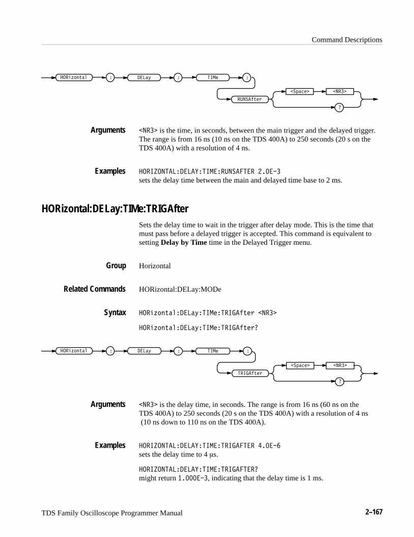
Command Descriptions
TDS Family Oscilloscope Programmer Manual 2–167
�����")!(
��'� !� �����
����* ���#+&%)�$ ���!
����� is the time, in seconds, between the main trigger and the delayed trigger.The range is from 16 ns (10 ns on the TDS 400A) to 250 seconds (20 s on theTDS 400A) with a resolution of 4 ns.
���������������������������� ������
sets the delay time between the main and delayed time base to 2 ms.
HORizontal:DELay:TIMe:TRIGAfterSets the delay time to wait in the trigger after delay mode. This is the time thatmust pass before a delayed trigger is accepted. This command is equivalent tosetting Delay by Time time in the Delayed Trigger menu.
Horizontal
HORizontal:DELay:MODe
���#+&%)�$����*���!�����")!( �����
���#+&%)�$����*���!�����")!(
���! ����*���#+&%)�$
�����")!(
��'� !� �����
����� is the delay time, in seconds. The range is from 16 ns (60 ns on the TDS 400A) to 250 seconds (20 s on the TDS 400A) with a resolution of 4 ns (10 ns down to 110 ns on the TDS 400A).
���������������������������� �����
sets the delay time to 4 �s.
����������������������������
might return ��������, indicating that the delay time is 1 ms.
Arguments
Examples
Group
Related Commands
Syntax
Arguments
Examples
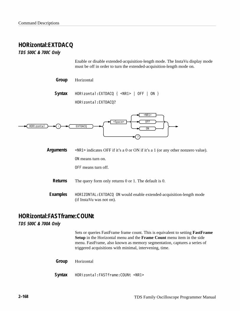
Command Descriptions
2–168 TDS Family Oscilloscope Programmer Manual
HORizontal:EXTDACQTDS 500C & 700C Only
Enable or disable extended-acquisition-length mode. The InstaVu display modemust be off in order to turn the extended-acquisition-length mode on.
Horizontal
����$ �#�������� % ����� & ��� & �� '
����$ �#���������
�����$ �#��
�
��!����
�����
��
���
�����
����� indicates OFF if it’s a 0 or ON if it’s a 1 (or any other nonzero value).
�� means turn on.
��� means turn off.
The query form only returns 0 or 1. The default is 0.
��� ������������ �� would enable extended-acquisition-length mode (if InstaVu was not on).
HORizontal:FASTframe:COUNt TDS 500C & 700A Only
Sets or queries FastFrame frame count. This is equivalent to setting FastFrameSetup in the Horizontal menu and the Frame Count menu item in the sidemenu. FastFrame, also known as memory segmentation, captures a series oftriggered acquisitions with minimal, intervening, time.
Horizontal
����$ �#��������"��������# �����
Group
Syntax
Arguments
Returns
Examples
Group
Syntax
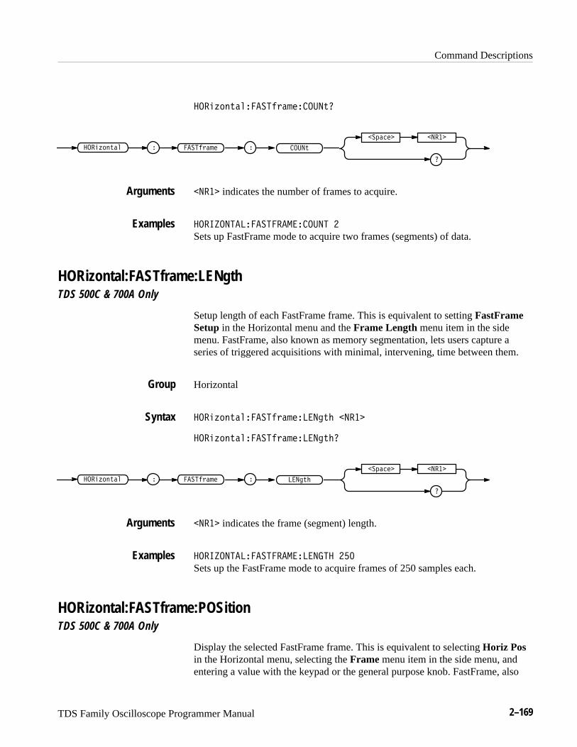
Command Descriptions
TDS Family Oscilloscope Programmer Manual 2–169
��� ($#'�!� ���&�"������'
�� ���&�"���� ($#'�! ����'
��%���� �����
����� indicates the number of frames to acquire.
���������� �� ��������� �
Sets up FastFrame mode to acquire two frames (segments) of data.
HORizontal:FASTframe:LENgth TDS 500C & 700A Only
Setup length of each FastFrame frame. This is equivalent to setting FastFrameSetup in the Horizontal menu and the Frame Length menu item in the sidemenu. FastFrame, also known as memory segmentation, lets users capture aseries of triggered acquisitions with minimal, intervening, time between them.
Horizontal
��� ($#'�!� ���&�"������'� �����
��� ($#'�!� ���&�"������'�
�� ���&�"���� ($#'�! ����'�
��%���� �����
����� indicates the frame (segment) length.
���������� �� ���������� ���
Sets up the FastFrame mode to acquire frames of 250 samples each.
HORizontal:FASTframe:POSition TDS 500C & 700A Only
Display the selected FastFrame frame. This is equivalent to selecting Horiz Posin the Horizontal menu, selecting the Frame menu item in the side menu, andentering a value with the keypad or the general purpose knob. FastFrame, also
Arguments
Examples
Group
Syntax
Arguments
Examples
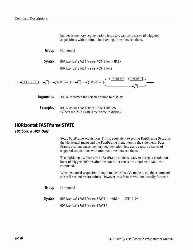
Command Descriptions
2–170 TDS Family Oscilloscope Programmer Manual
known as memory segmentation, lets users capture a series of triggeredacquisitions with minimal, intervening, time between them.
Horizontal
����&��$�������"��������$��� �����
����&��$�������"��������$����
�� ����"�������&��$�� ����$���
�
�� ���� �����
����� indicates the selected frame to display.
��� ���������������� � �� ��
Selects the 25th FastFrame frame to display.
HORizontal:FASTframe:STATE TDS 500C & 700A Only
Setup FastFrame acquisition. This is equivalent to setting FastFrame Setup inthe Horizontal menu and the FastFrame menu item in the side menu. Fast-Frame, also known as memory segmentation, lets users capture a series oftriggered acquisitions with minimal time between them.
The digitizing oscilloscope in FastFrame mode is ready to accept a continuousburst of triggers 400 ms after the controller sends the ��!%�"��#$�$� "%�
command.
When extended-acquisition-length mode or InstaVu mode is on, this commandcan still set and return values. However, this feature will not actually function.
Horizontal
����&��$�������"������� ' ����� ( ��� ( �� )
����&��$�������"��������
Group
Syntax
Arguments
Examples
Group
Syntax

Command Descriptions
TDS Family Oscilloscope Programmer Manual 2–171
�� �����������!�� �� �����
�
�������
�����
��
�
����� indicates OFF if it’s a 0 or ON if it’s a 1 (or any other nonzero value).
�� means turn on FastFrame.
� means turn off FastFrame.
The query form only returns 0 or 1.
��������������� ������� ��
turns on FastFrame.
HORizontal:FITtoscreenSetup horizontal waveform compress operation. This command is equivalent tosetting Record Length in the Horizontal menu and the Fit to screen menu itemin the side menu. Waveform compress lets you fit a captured waveform to thevisible screen. It provides the same functionality as if you were in zoom modeand changed the time per division until the waveform fit the screen.
In extended-acquisition-length mode, entering the zoom preview state causesfit-to-screen to be on. If the oscilloscope exits the extended-acquisition-lengthmode or the zoom preview state, the fit-to-screen mode returns back to its priorsetting.
Horizontal
���!�� ����� ������� " ����� # � # �� $
���!�� ����� ��������
����!�� ��
�
�������
�����
��
�
�� �������
����� indicates OFF if it’s a 0. It indicates ON if it’s a non-zero value.
Arguments
Examples
Group
Syntax
Arguments
Command Descriptions
2–172 TDS Family Oscilloscope Programmer Manual
�� means turn on waveform compress.
��� means turn off waveform compress.
������������������� ��
turns on waveform compress.
HORizontal:MAIn? (Query Only)Returns the time per division of the main time base. The commands HORizon-tal:MAIn:SECdiv and HORizontal:MAIn:SCAle are identical so only HORizon-tal:MAIn:SCAle will be returned.
Horizontal
HORizontal:SCAle, HORizontal:SECdiv, HORizontal:MAIn:SECdiv
��������������
� ��������� � ���
�������������
might return � ���������������� ������.
HORizontal:MAIn:SCAleSets the time per division for the main time base. This command is equivalent tosetting Main Scale in the Horizontal Scale side menu.
On the TDS 400A, changes made while the external clock is enabled do not takeeffect until the internal clock is enabled. Also, when the external clock isenabled, the query form of this command returns an <NR3> value representing‘50’.
Horizontal
HORizontal:DELay:SCAle, HORizontal:DELay:SECdiv, HORizon-tal:MAIn:SECdiv
Examples
Group
Related Commands
Syntax
Examples
Group
Related Commands

Command Descriptions
TDS Family Oscilloscope Programmer Manual 2–173
���"�� ����������� �����
���"�� �����������
� ���� ���"�� �� � ���
������� �����
����� is the time per division. For the TDS 400A series, the range is 20 s to 1 ns. For the TDS 510A, 500B, 600B, and 700A, the range is 10 s to 500 ps (or200 ps on the TDS 784A), in a 1–2–5 sequence.
In extended-acquisition-length mode, no matter what value you set, theoscilloscope will only use the closest real-time, non-interpolated value.
����������������� ����
sets the main scale to 2 �s per division.
HORizontal:MAIn:SECdivSets the time per division for the main time base. This command is identical tothe HORizontal:MAIn:SCAle command. It is provided to maintain programcompatibility with some older models of Tektronix digitizing oscilloscopes.
Horizontal
HORizontal:DELay:SCAle, HORizontal:DELay:SECdiv, HORizon-tal:MAIn:SCAle
���"�� ������������! �����
���"�� ������������!
���"�� �� � �����!� ���
������� �����
HORizontal:MODeSelects whether the horizontal display uses the main or delayed time base orboth. This command is equivalent to setting Time Base in the Horizontal menu.
Syntax
Arguments
Examples
Group
Related Commands
Syntax
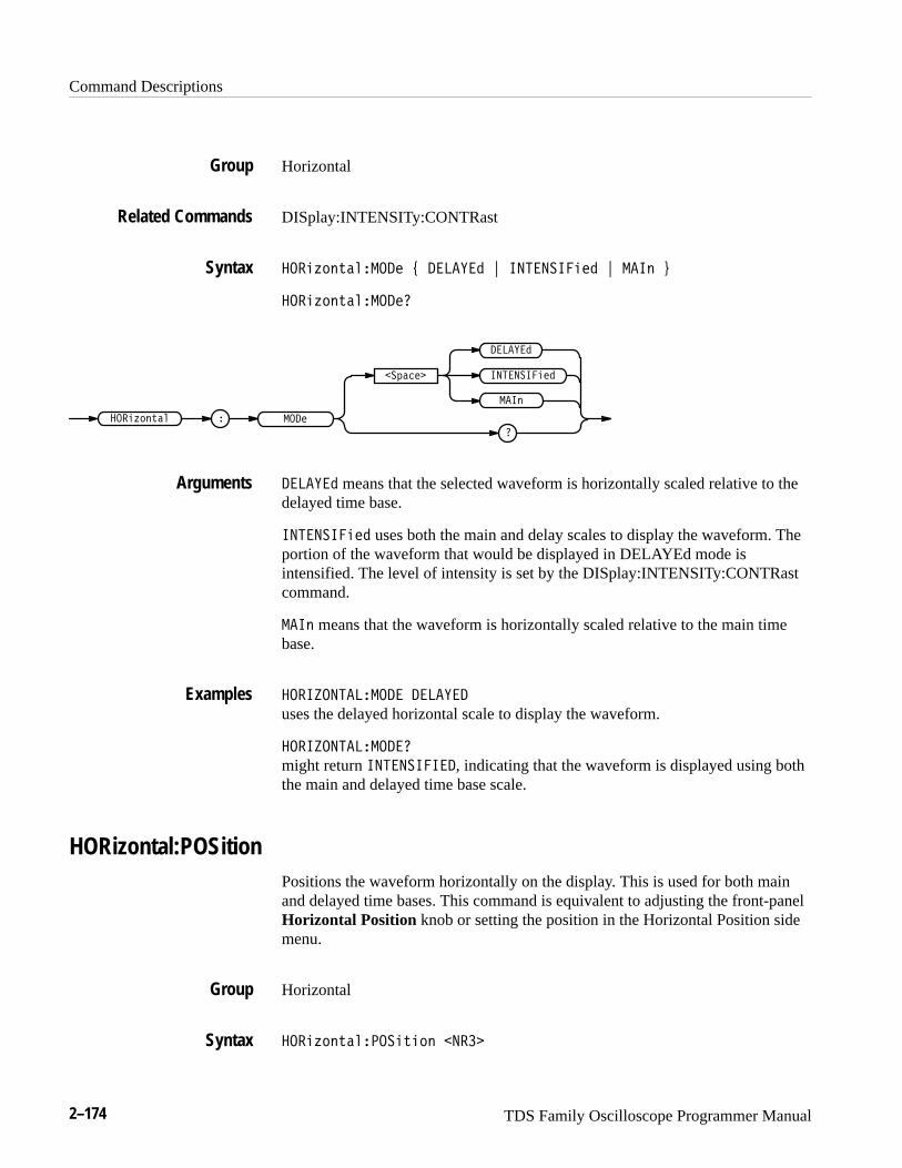
Command Descriptions
2–174 TDS Family Oscilloscope Programmer Manual
Horizontal
DISplay:INTENSITy:CONTRast
����!�� ������� " � ��� # ��������� # ���� $
����!�� ��������
���������
����
�������
�
� ���
�
����
����!�� ��
� ��� means that the selected waveform is horizontally scaled relative to thedelayed time base.
��������� uses both the main and delay scales to display the waveform. Theportion of the waveform that would be displayed in DELAYEd mode isintensified. The level of intensity is set by the DISplay:INTENSITy:CONTRastcommand.
���� means that the waveform is horizontally scaled relative to the main timebase.
��������� ���� � ���
uses the delayed horizontal scale to display the waveform.
��������� �����
might return ��������, indicating that the waveform is displayed using boththe main and delayed time base scale.
HORizontal:POSitionPositions the waveform horizontally on the display. This is used for both mainand delayed time bases. This command is equivalent to adjusting the front-panelHorizontal Position knob or setting the position in the Horizontal Position sidemenu.
Horizontal
����!�� ������� ��� �����
Group
Related Commands
Syntax
Arguments
Examples
Group
Syntax

Command Descriptions
TDS Family Oscilloscope Programmer Manual 2–175
���"��!�������!����
� ����!��� ���"��!��
�
�� ���� �����
����� is from 0 to 100, and is the percent of the waveform that is displayed leftof the center graticule.
In extended-acquisition-length mode, it is the percent of the acquisition that isdisplayed left of the center graticule.
����������������� ��
sets the horizontal position of the waveform such that 10% of the waveform is tothe left of screen center.
HORizontal:RECORDLengthSets the number of data points that are acquired for each record. This isequivalent to setting Record Length in the Horizontal menu.
When extended-acquisition-length mode is on, this command can still set andreturn values. However, this feature will not actually work while extended-ac-quisition-length mode is on.
Horizontal
���"��!������������!� �����
���"��!������������!��
� ���������!�
�
�� ���� �����
���"��!��
Table 2–32 shows supported values for <NR1>.
Arguments
Examples
Group
Syntax
Arguments
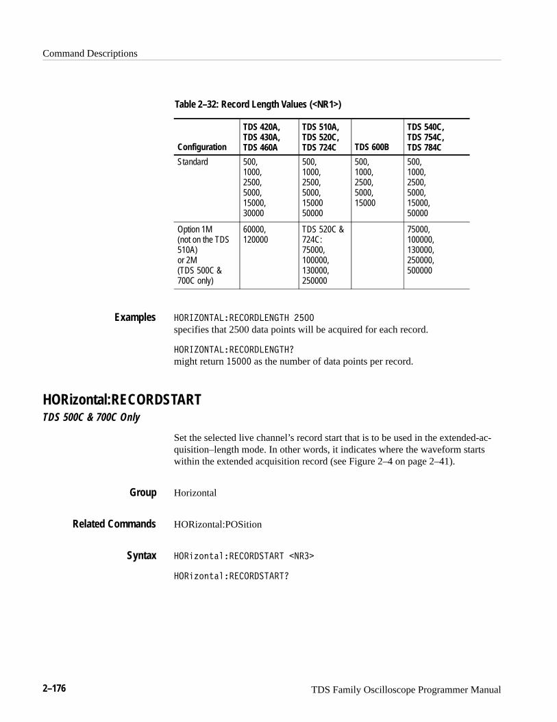
Command Descriptions
2–176 TDS Family Oscilloscope Programmer Manual
Table 2–32: Record Length Values (<NR1>)
Configuration
TDS 420A,TDS 430A,TDS 460A
TDS 510A,TDS 520C,TDS 724C TDS 600B
TDS 540C,TDS 754C,TDS 784C
Standard 500,1000,2500,5000,15000,30000
500,1000,2500,5000,1500050000
500,1000,2500,5000,15000
500,1000,2500,5000,15000,50000
Option 1M(not on the TDS510A)or 2M(TDS 500C &700C only)
60000,120000
TDS 520C &724C:75000,100000,130000,250000
75000,100000,130000,250000,500000
���������������� ������ ����
specifies that 2500 data points will be acquired for each record.
���������������� ������
might return ����� as the number of data points per record.
HORizontal:RECORDSTARTTDS 500C & 700C Only
Set the selected live channel’s record start that is to be used in the extended-ac-quisition–length mode. In other words, it indicates where the waveform startswithin the extended acquisition record (see Figure 2–4 on page 2–41).
Horizontal
HORizontal:POSition
���������������� ����� ����
���������������� �����
Examples
Group
Related Commands
Syntax
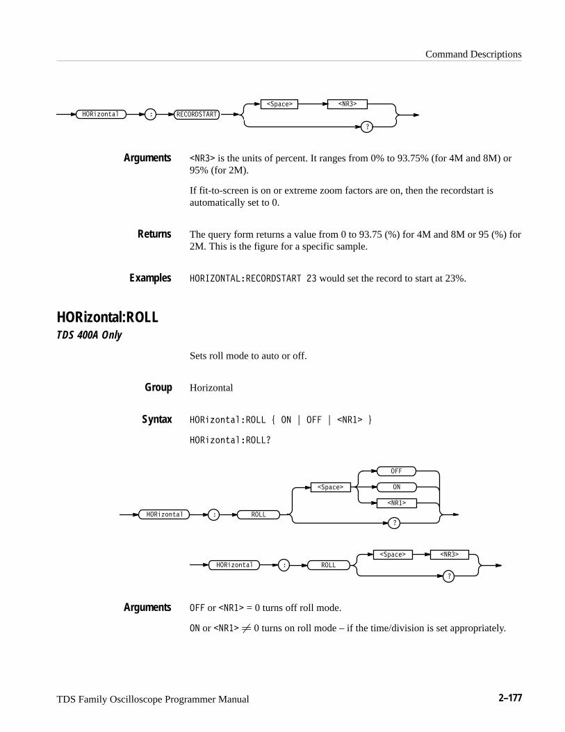
Command Descriptions
TDS Family Oscilloscope Programmer Manual 2–177
� ������������� �����
������� �����
�
����� is the units of percent. It ranges from 0% to 93.75% (for 4M and 8M) or95% (for 2M).
If fit-to-screen is on or extreme zoom factors are on, then the recordstart isautomatically set to 0.
The query form returns a value from 0 to 93.75 (%) for 4M and 8M or 95 (%) for2M. This is the figure for a specific sample.
������������������� �� would set the record to start at 23%.
HORizontal:ROLLTDS 400A Only
Sets roll mode to auto or off.
Horizontal
���� ���������� ! �� " � " ����� #
���� �����������
���������
�
�����
�
� �������� �����
� ����
�
������� �����
���� �����
� or ����� = 0 turns off roll mode.
�� or ����� � 0 turns on roll mode – if the time/division is set appropriately.
Arguments
Returns
Examples
Group
Syntax
Arguments

Command Descriptions
2–178 TDS Family Oscilloscope Programmer Manual
HORizontal:SCAleSets the time per division for the main time base and is identical to the HORi-zontal:MAIn:SCAle command. It is included here for compatibility purposes.
Horizontal
���������������� � ���
�����������������
� �����
�
������� � ���
����������
HORizontal:SECdivSets the time per division for the main time base and is identical to the HORi-zontal:MAIn:SCAle command. It is included here for compatibility purposes.
Horizontal
���������������� � ���
�����������������
� �����
�
������� � ���
����������
HORizontal:TRIGger? (Query Only)Returns the horizontal trigger parameter.
Horizontal
������������������
� ������ �����������
Group
Syntax
Group
Syntax
Group
Syntax
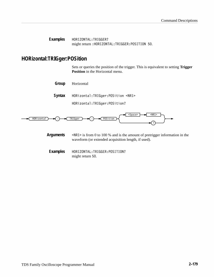
Command Descriptions
TDS Family Oscilloscope Programmer Manual 2–179
��� �������� ����
might return ���� �������� ������� � �� ��.
HORizontal:TRIGger:POSitionSets or queries the position of the trigger. This is equivalent to setting TriggerPosition in the Horizontal menu.
Horizontal
����!�� ����� ��������� ��� �����
����!�� ����� ��������� ����
� ���� ���
�
������� �����
� �� ��������!�� ��
����� is from 0 to 100 % and is the amount of pretrigger information in thewaveform (or extended acquisition length, if used).
��� �������� ������� � ���
might return ��.
Examples
Group
Syntax
Arguments
Examples
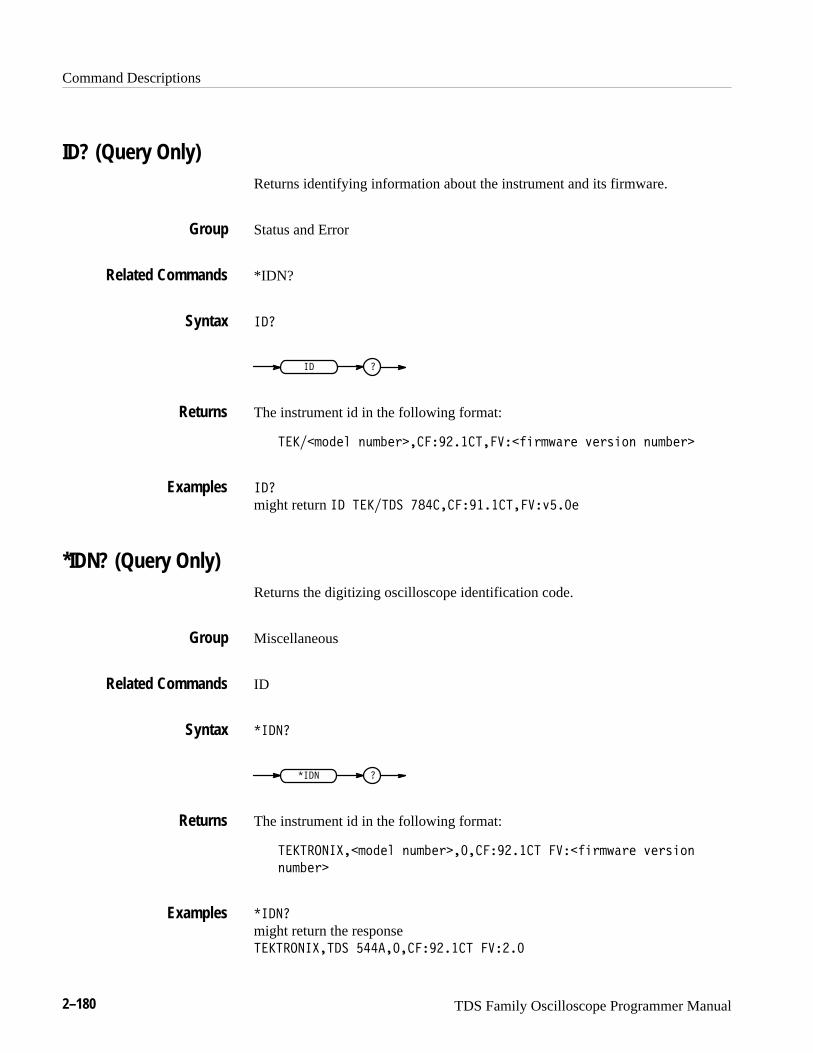
Command Descriptions
2–180 TDS Family Oscilloscope Programmer Manual
ID? (Query Only)Returns identifying information about the instrument and its firmware.
Status and Error
*IDN?
���
�� �
The instrument id in the following format:
�����')"#& (,'!#*����� ����������$%*'. *# -#*+%)( (,'!#*�
���
might return �� ������� ������� ���������-��#
*IDN? (Query Only)Returns the digitizing oscilloscope identification code.
Miscellaneous
ID
�����
���� �
The instrument id in the following format:
�����������')"#& (,'!#*������� ����� ����$%*'. *# -#*+%)(
(,'!#*�
�����
might return the response������������� ������� ����� ������
Group
Related Commands
Syntax
Returns
Examples
Group
Related Commands
Syntax
Returns
Examples

Command Descriptions
TDS Family Oscilloscope Programmer Manual 2–181
LIMit:BELlRings the bell when the waveform data exceeds the limits set in the limit test, ifthe limit state is on.
Limit Test
LIMit:COMPARE:CH<x>, LIMit:STATE
�� ������ � � � �� � ����� �
�� �������
������ ��
���������
�
�����
�
� or ����� = 0 turns off ringing the bell when any waveform data exceeds thelimits set by the limit test.
�� or ����� � 0 turns on ringing the bell.
�� ������ ��
specifies that the bell is to ring when any waveform data exceeds the limitsspecified in the limit test.
�� �������
returns either � or �, indicating whether the bell is to ring when any waveformdata exceeds the limits specified in the limit test.
LIMit:COMPARE:CH<x>Sets or queries the template against which to compare the waveform acquiredthrough the specified channel. The template can be a waveform saved in any ofthe reference locations REF1 through REF4, or none.
Limit Test
Group
Related Commands
Syntax
Arguments
Examples
Group
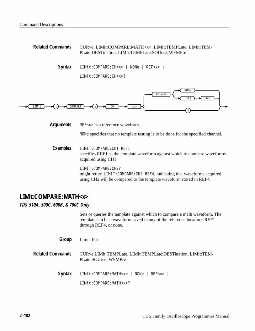
Command Descriptions
2–182 TDS Family Oscilloscope Programmer Manual
CURve, LIMit:COMPARE:MATH<x>, LIMit:TEMPLate, LIMit:TEM-PLate:DESTination, LIMit:TEMPLate:SOUrce, WFMPre
������������ ��� � ���� � ������
������������ ����
������ � ���
�������
�
����
��� ���
�����
������ is a reference waveform.
���� specifies that no template testing is to be done for the specified channel.
������������ � ����
specifies REF1 as the template waveform against which to compare waveformsacquired using CH1.
������������ ��
might return ������������ � ����, indicating that waveforms acquiredusing CH2 will be compared to the template waveform stored in REF4.
LIMit:COMPARE:MATH<x>TDS 510A, 500C, 600B, & 700C Only
Sets or queries the template against which to compare a math waveform. Thetemplate can be a waveform saved in any of the reference locations REF1through REF4, or none.
Limit Test
CURve,LIMit:TEMPLate, LIMit:TEMPLate:DESTination, LIMit:TEM-PLate:SOUrce, WFMPre
�������������� ��� � ���� � ������
�������������� ����
Related Commands
Syntax
Arguments
Examples
Group
Related Commands
Syntax
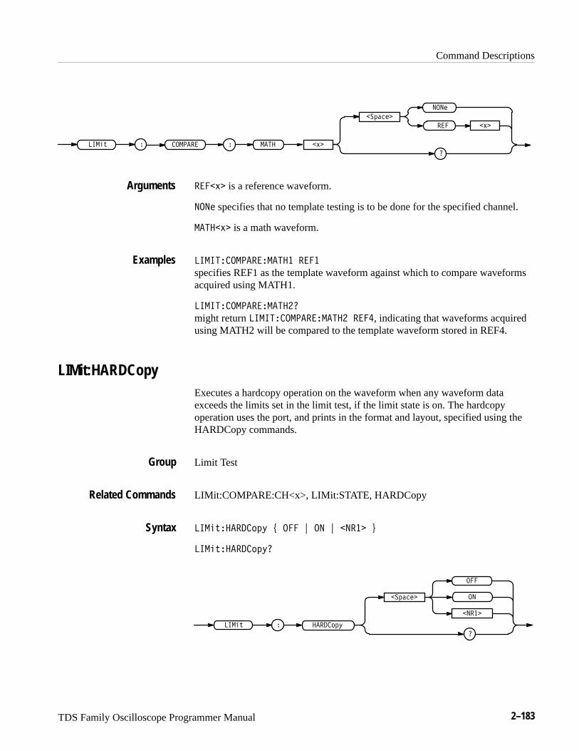
Command Descriptions
TDS Family Oscilloscope Programmer Manual 2–183
������ � ��� ���
�������
�
����
�� ���
�����
�� ��� is a reference waveform.
���� specifies that no template testing is to be done for the specified channel.
������ is a math waveform.
���������������� �� �
specifies REF1 as the template waveform against which to compare waveformsacquired using MATH1.
�����������������
might return ���������������� �� �, indicating that waveforms acquiredusing MATH2 will be compared to the template waveform stored in REF4.
LIMit:HARDCopyExecutes a hardcopy operation on the waveform when any waveform dataexceeds the limits set in the limit test, if the limit state is on. The hardcopyoperation uses the port, and prints in the format and layout, specified using theHARDCopy commands.
Limit Test
LIMit:COMPARE:CH<x>, LIMit:STATE, HARDCopy
����������� ! � " �� " ����� #
����������� �
����� ������
���������
�
�����
�
Arguments
Examples
Group
Related Commands
Syntax

Command Descriptions
2–184 TDS Family Oscilloscope Programmer Manual
�� or ����� � 0 turns on the hardcopy operation for the waveform when anywaveform data exceeds the limits set by the limit test.
��� or ����� = 0 turns off the hardcopy operation.
������ ����� ��
specifies that the hardcopy operation occurs for the waveform when anywaveform data exceeds the limits specified in the limit test.
������ ������
returns either � or �, indicating whether the hardcopy operation occurs for thewaveform when any waveform data exceeds the limits specified in the limit test.
LIMit:STATETurns limit testing on or off, or queries whether limit testing is in effect.
When extended–acquisition–length mode or InstaVu mode is on, this commandcan still set and return values. However, this feature will not actually function.
You cannot turn limit:state to on when extended–acquisition-length mode isalready on.
Limit Test
CURve, LIMit:BELl, LIMit:COMPARE:CH<x>, LIMit:HARDCopy, LIM-it:TEMPLate, WFMPre
����������� � ��� � �� � �����
������������
������ �����
���������
�
�����
���
��� or ����� = 0 turns off limit testing.
�� or ����� � 0 turns on limit testing.
Arguments
Examples
Group
Related Commands
Syntax
Arguments

Command Descriptions
TDS Family Oscilloscope Programmer Manual 2–185
��������� ��
specifies that limit testing of waveforms is in effect.
����������
returns either � or �, indicating whether limit testing of waveforms is in effect.
LIMit:TEMPLate (No Query Form)Creates a template which you can use for limit testing. You can compare thewaveform acquired through the specified channel against this template. Thetemplate can be a waveform saved in any of the reference locations REF1through REF4, or none.
Limit Test
LIMit:TEMPLate:DESTination, LIMit:TEMPLate:SOUrce
�������� ��� �����
���� � ��� ��� ������������
����� creates a template with the specified source waveform and tolerances, andstores it in the destination reference waveform to be used in limit testingcomparisons.
�������� ��� �����
creates a template with the specified source waveform and tolerances, and storesit in the destination reference waveform to be used in limit testing comparisons.
LIMit:TEMPLate:DESTinationSets or queries the destination reference waveform that the LIMit:TEMPLateSTORe command will use.
Limit Test
LIMit:COMPARE:CH<x>, LIMit:TEMPLate, LIMit:TEMPLate:SOUrce
�������� ������������� �����
Examples
Group
Related Commands
Syntax
Arguments
Examples
Group
Related Commands
Syntax
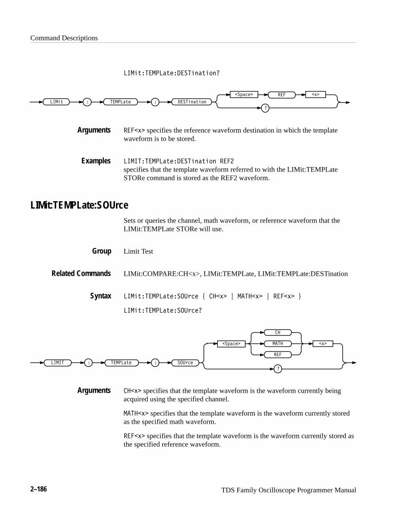
Command Descriptions
2–186 TDS Family Oscilloscope Programmer Manual
� ����������������������
�� ���
�������
�
��
����������������
���
�
����� specifies the reference waveform destination in which the templatewaveform is to be stored.
� � ������������������� ���
specifies that the template waveform referred to with the LIMit:TEMPLateSTORe command is stored as the REF2 waveform.
LIMit:TEMPLate:SOUrceSets or queries the channel, math waveform, or reference waveform that theLIMit:TEMPLate STORe will use.
Limit Test
LIMit:COMPARE:CH<x>, LIMit:TEMPLate, LIMit:TEMPLate:DESTination
� ������������������ ����� ! ������� ! ����� "
� �������������������
� � � � ������� �������
�����������
�
��
��
���
����� specifies that the template waveform is the waveform currently beingacquired using the specified channel.
������� specifies that the template waveform is the waveform currently storedas the specified math waveform.
����� specifies that the template waveform is the waveform currently stored asthe specified reference waveform.
Arguments
Examples
Group
Related Commands
Syntax
Arguments
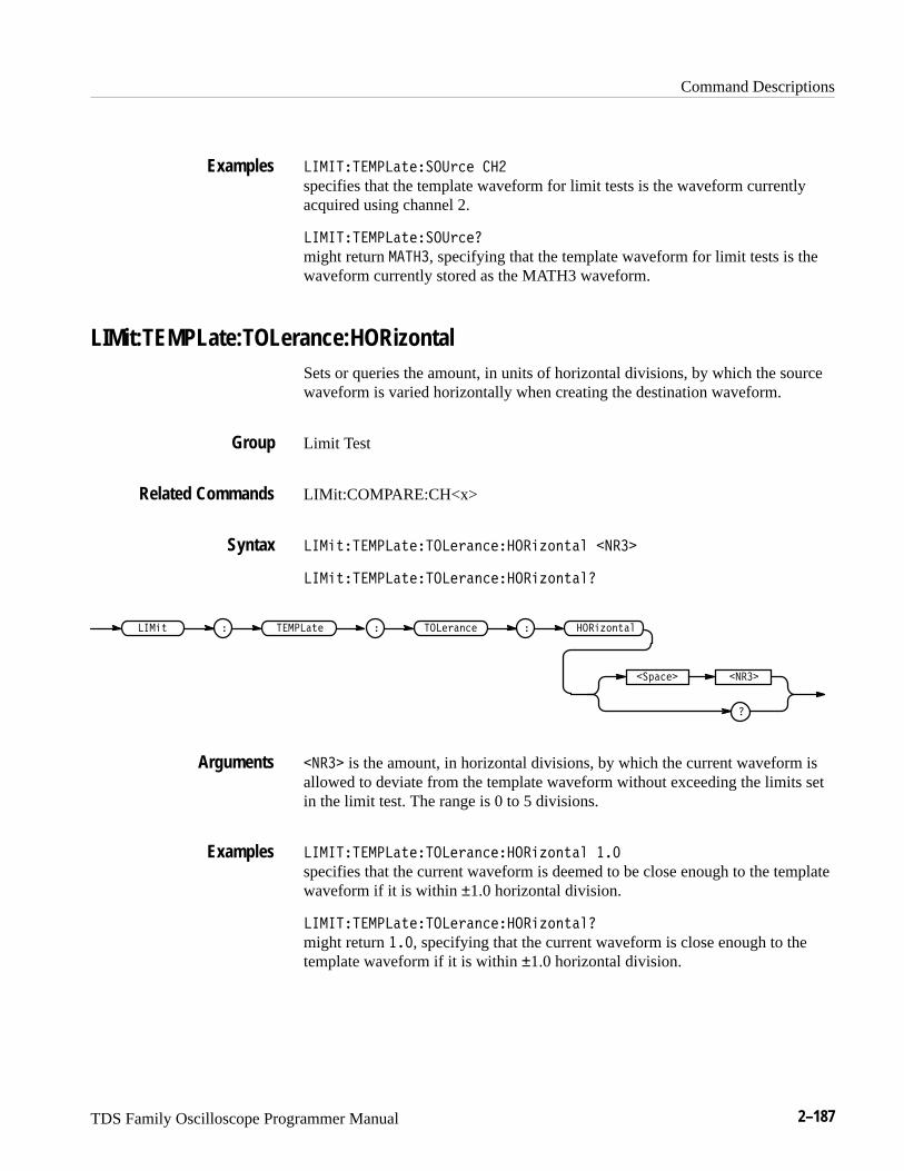
Command Descriptions
TDS Family Oscilloscope Programmer Manual 2–187
������� ����"�����!�� ���
specifies that the template waveform for limit tests is the waveform currentlyacquired using channel 2.
������� ����"�����!��
might return �����, specifying that the template waveform for limit tests is thewaveform currently stored as the MATH3 waveform.
LIMit:TEMPLate:TOLerance:HORizontalSets or queries the amount, in units of horizontal divisions, by which the sourcewaveform is varied horizontally when creating the destination waveform.
Limit Test
LIMit:COMPARE:CH<x>
����"�� ����"������!���������#��"�� ����
����"�� ����"������!���������#��"��
����" � � ����"� ����!����� ����#��"���
����
�� ���
���� is the amount, in horizontal divisions, by which the current waveform isallowed to deviate from the template waveform without exceeding the limits setin the limit test. The range is 0 to 5 divisions.
������� ����"������!���������#��"�� ���
specifies that the current waveform is deemed to be close enough to the templatewaveform if it is within ±1.0 horizontal division.
������� ����"������!���������#��"��
might return ���, specifying that the current waveform is close enough to thetemplate waveform if it is within ±1.0 horizontal division.
Examples
Group
Related Commands
Syntax
Arguments
Examples
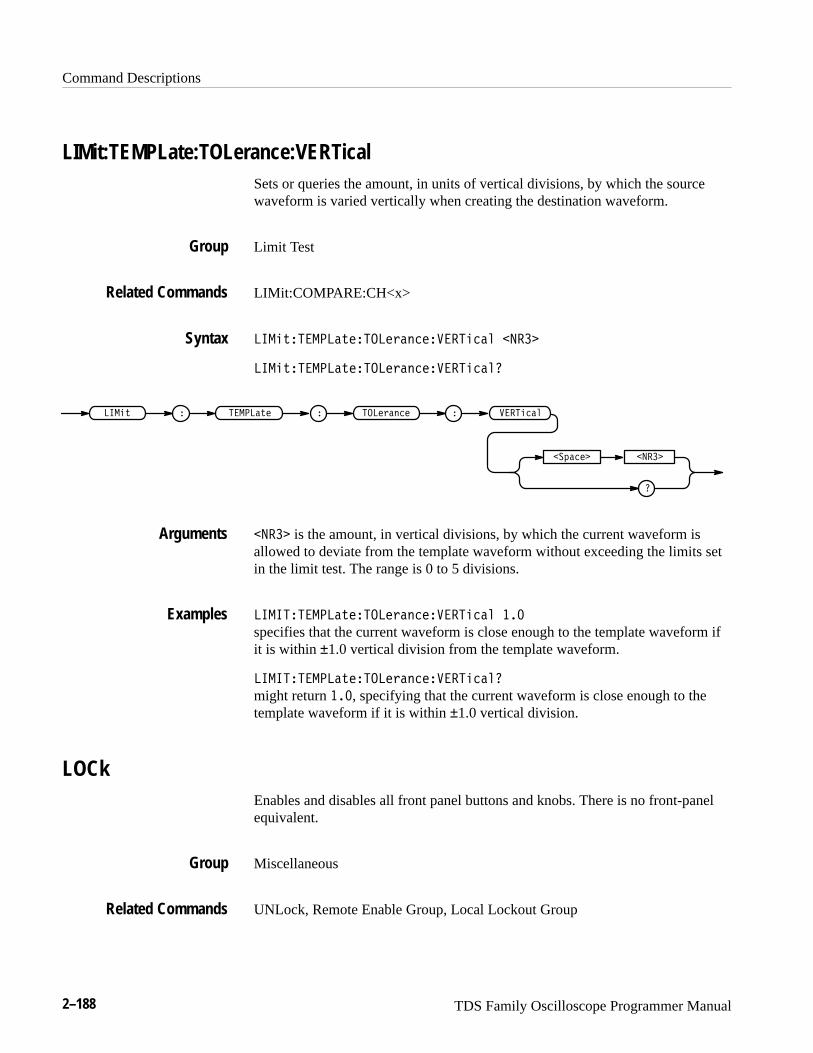
Command Descriptions
2–188 TDS Family Oscilloscope Programmer Manual
LIMit:TEMPLate:TOLerance:VERTicalSets or queries the amount, in units of vertical divisions, by which the sourcewaveform is varied vertically when creating the destination waveform.
Limit Test
LIMit:COMPARE:CH<x>
�� ���� ����������������������� �����
�� ���� �����������������������
�� �� � � ����� ���������� ��������
�����
�������
����� is the amount, in vertical divisions, by which the current waveform isallowed to deviate from the template waveform without exceeding the limits setin the limit test. The range is 0 to 5 divisions.
�� ���� ����������������������� ���
specifies that the current waveform is close enough to the template waveform ifit is within ±1.0 vertical division from the template waveform.
�� ���� �����������������������
might return ���, specifying that the current waveform is close enough to thetemplate waveform if it is within ±1.0 vertical division.
LOCkEnables and disables all front panel buttons and knobs. There is no front-panelequivalent.
Miscellaneous
UNLock, Remote Enable Group, Local Lockout Group
Group
Related Commands
Syntax
Arguments
Examples
Group
Related Commands
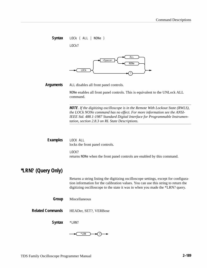
Command Descriptions
TDS Family Oscilloscope Programmer Manual 2–189
��� � � � �� �
����
� �����
�
�
��
���
� disables all front panel controls.
�� enables all front panel controls. This is equivalent to the UNLock ALLcommand.
NOTE. If the digitizing oscilloscope is in the Remote With Lockout State (RWLS),the LOCk NONe command has no effect. For more information see the ANSI-IEEE Std. 488.1-1987 Standard Digital Interface for Programmable Instrumen-tation, section 2.8.3 on RL State Descriptions.
��� �
locks the front panel controls.
����
returns �� when the front panel controls are enabled by this command.
*LRN? (Query Only)Returns a string listing the digitizing oscilloscope settings, except for configura-tion information for the calibration values. You can use this string to return thedigitizing oscilloscope to the state it was in when you made the *LRN? query.
Miscellaneous
HEADer, SET?, VERBose
���
�� �
Syntax
Arguments
Examples
Group
Related Commands
Syntax
Command Descriptions
2–190 TDS Family Oscilloscope Programmer Manual
NOTE. The *LRN? query always returns a string including command headers,regardless of the setting of the HEADer command. This is because the returnedstring is intended to be sent back to the digitizing oscilloscope as a commandstring. The VERBose command can still be used normally to specify whether thereturned headers should be abbreviated.
��$ �
a partial response might look like this:���#'�$��%&�&� ���!�� %��"��� '�� ( ��� '��(� � �
$�"�& ��%&!"��&�$ $' %&!"��������!!"�!"&�! ! ���
�!' & ��������%&�&� ���&�������$ ���(�$�!%� ��
��'$%!$��' �&�! !���(��$%�' �&% %��! �%�
"!%�&�! � ������ �"!%�&�! ������ �%����& �'$%!$��
MASK? (Query Only)TDS 500C & 700C Only
Returns the state of all settable mask parameters.
Mask
��%��
��%� �
<NR3>
�),+�
might return ���%����%���"!� &%"
������������������������������*�������*���������*�������
��������*��������������%����%��"!� &%"
����������������������������*���� � ��*���� ����*���� �
��*������ ��*��������*���� ����*������*�������*������*��
�����%����%��"!� &%"
������������������������� ��������*��������*���������*�������
�*�������*��������*������%����%���"!� &%"
�����������������%����%���"!� &%"
�����������������%����%� �"!� &%"
�����������������%����%���"!� &%"
Examples
Group
Syntax
Returns
Examples
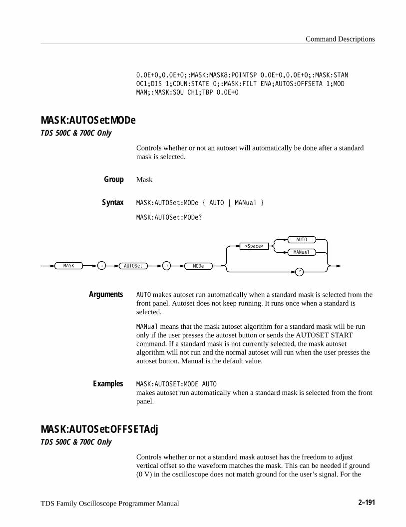
Command Descriptions
TDS Family Oscilloscope Programmer Manual 2–191
��������������� ���� ����������� ��������������� ����� �
������ �������� �� ��� ������� �� ����������� ����
� ��� ������ ������ ������
MASK:AUTOSet:MODeTDS 500C & 700C Only
Controls whether or not an autoset will automatically be done after a standardmask is selected.
Mask
� ��� ���� #���� % ��� & � �$�! '
� ��� ���� #���� �
�"�� �
�
���
� �$�!
���� #� �� � ��� �
��� makes autoset run automatically when a standard mask is selected from thefront panel. Autoset does not keep running. It runs once when a standard isselected.
� �$�! means that the mask autoset algorithm for a standard mask will be runonly if the user presses the autoset button or sends the AUTOSET STARTcommand. If a standard mask is not currently selected, the mask autosetalgorithm will not run and the normal autoset will run when the user presses theautoset button. Manual is the default value.
� ��� ����������� ���
makes autoset run automatically when a standard mask is selected from the frontpanel.
MASK:AUTOSet:OFFSETAdjTDS 500C & 700C Only
Controls whether or not a standard mask autoset has the freedom to adjustvertical offset so the waveform matches the mask. This can be needed if ground(0 V) in the oscilloscope does not match ground for the user’s signal. For the
Group
Syntax
Arguments
Examples
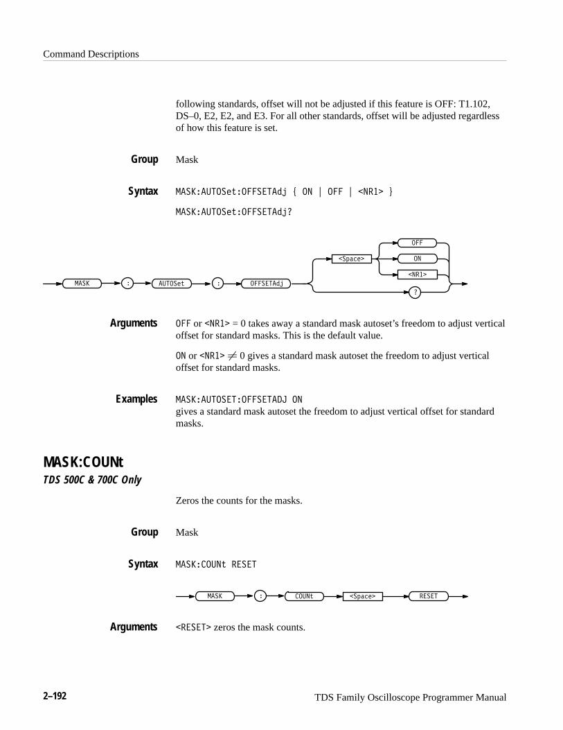
Command Descriptions
2–192 TDS Family Oscilloscope Programmer Manual
following standards, offset will not be adjusted if this feature is OFF: T1.102,DS–0, E2, E2, and E3. For all other standards, offset will be adjusted regardlessof how this feature is set.
Mask
��� ����������������� � �� � ��� � ����� �
��� ������������������
���������� � �
���������
�
�����
���
��������
��� or ����� = 0 takes away a standard mask autoset’s freedom to adjust verticaloffset for standard masks. This is the default value.
�� or ����� � 0 gives a standard mask autoset the freedom to adjust verticaloffset for standard masks.
��� ��������������� ��
gives a standard mask autoset the freedom to adjust vertical offset for standardmasks.
MASK:COUNtTDS 500C & 700C Only
Zeros the counts for the masks.
Mask
��� ������ ���
�������� � ����������
����� zeros the mask counts.
Group
Syntax
Arguments
Examples
Group
Syntax
Arguments
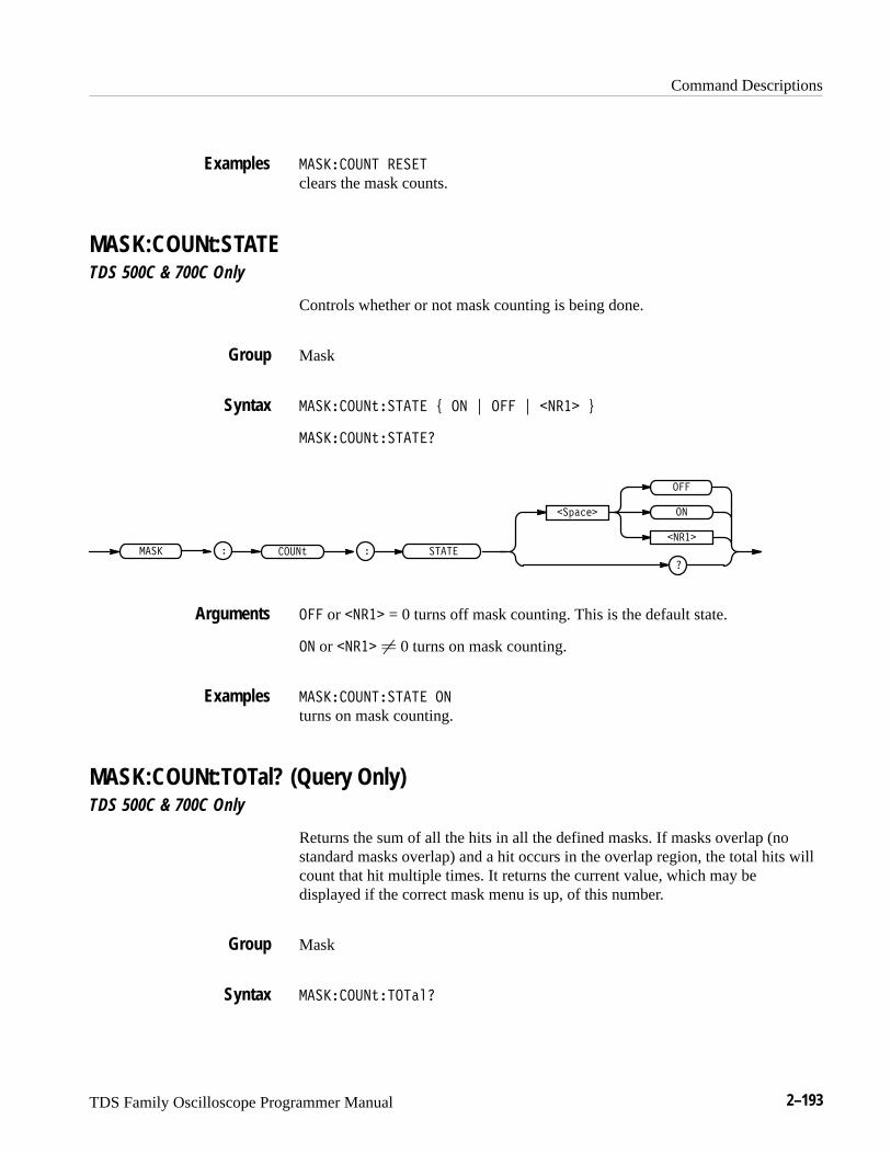
Command Descriptions
TDS Family Oscilloscope Programmer Manual 2–193
�������� � ���
clears the mask counts.
MASK:COUNt:STATETDS 500C & 700C Only
Controls whether or not mask counting is being done.
Mask
�������� ������ � � � � � � ��� �
�������� �������
��� ����� � �
� �������
�
� ���
�
����
� or � ��� = 0 turns off mask counting. This is the default state.
� or � ��� � 0 turns on mask counting.
�������� ������ �
turns on mask counting.
MASK:COUNt:TOTal? (Query Only)TDS 500C & 700C Only
Returns the sum of all the hits in all the defined masks. If masks overlap (nostandard masks overlap) and a hit occurs in the overlap region, the total hits willcount that hit multiple times. It returns the current value, which may bedisplayed if the correct mask menu is up, of this number.
Mask
�������� ��������
Examples
Group
Syntax
Arguments
Examples
Group
Syntax
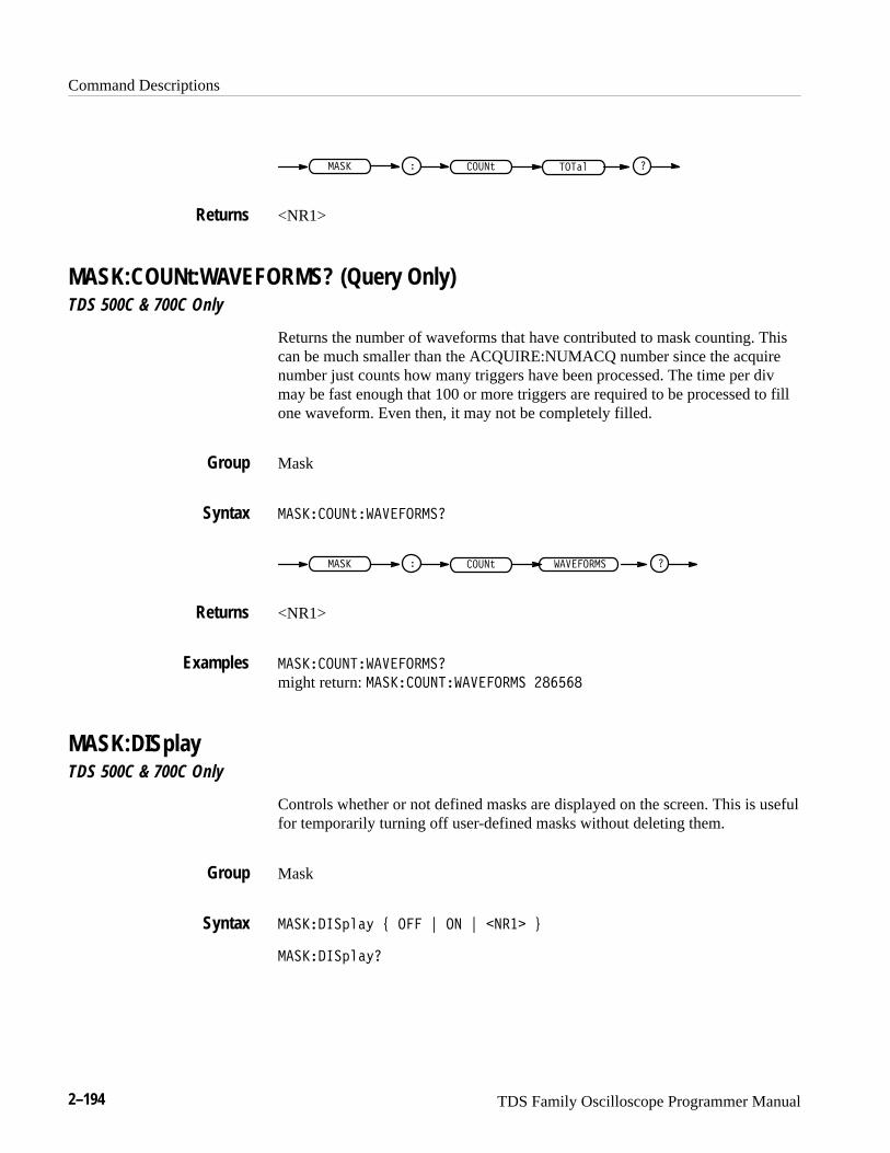
Command Descriptions
2–194 TDS Family Oscilloscope Programmer Manual
����� ���� � �����
<NR1>
MASK:COUNt:WAVEFORMS? (Query Only)TDS 500C & 700C Only
Returns the number of waveforms that have contributed to mask counting. Thiscan be much smaller than the ACQUIRE:NUMACQ number since the acquirenumber just counts how many triggers have been processed. The time per divmay be fast enough that 100 or more triggers are required to be processed to fillone waveform. Even then, it may not be completely filled.
Mask
��������������������
����� ���� � ���������
<NR1>
��������������������
might return: �������������������� ������
MASK:DISplayTDS 500C & 700C Only
Controls whether or not defined masks are displayed on the screen. This is usefulfor temporarily turning off user-defined masks without deleting them.
Mask
����� ������ ��� ! �� ! ���� "
����� ������
Returns
Group
Syntax
Returns
Examples
Group
Syntax

Command Descriptions
TDS Family Oscilloscope Programmer Manual 2–195
��
��� � ������
�������
�
�����
�
��� or ����� = 0 removes the masks from the display.
���� or ����� � 0 displays the masks on the display. This is the default value.
���������� ��
sets the display to show the defined masks.
�����������
might return � indicating that the display shows masks.
MASK:FILTerTDS 500C & 700C Only
Controls whether or not a digital filter will be run on the waveform data. Thefilter simulates expensive optical hardware. Different hardware would be usedfor each of the optical standards. The digital filter will run only if ENABLE isthe mode and one of the optical eye-pattern standard masks has been selected,and several other restrictions. These other restrictions are:
� One of the seven optical standards has been selected in the Measure/Masks/MaskType/Standard Mask menu. In other words, any of the three SONETSDH or any of the four fibre channel standards from the Fibre Chan menuare selected.
� The SONET/SDH MASK menu contains a provision for enabling ordisabling the filter. This selection must be ENABLE
� The time per division setting is the correct value for the mask which hasbeen selected
� The record length is equal to 500
� Only one channel is on. Mask autoset may force channels off in order toallow the mask to be turned on
� The oscilloscope bandwidth must be set to full
Mask
Arguments
Examples
Group
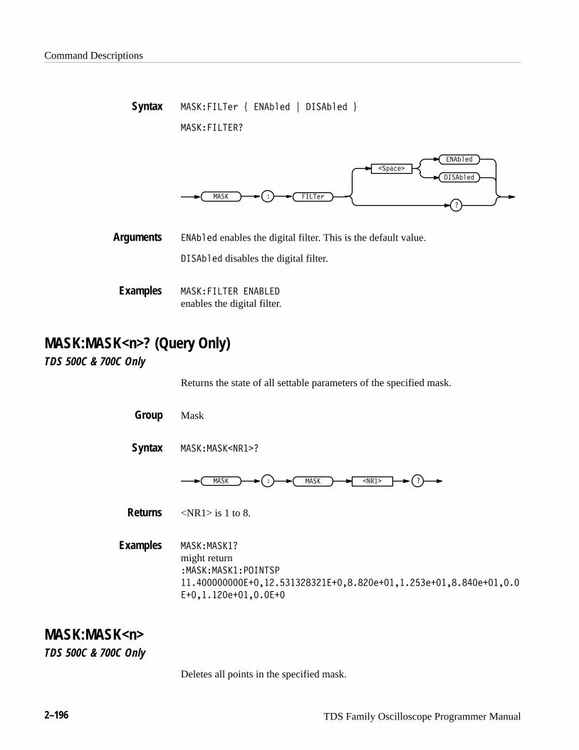
Command Descriptions
2–196 TDS Family Oscilloscope Programmer Manual
���������#& ' ��� $#" ( ���� $#" )
������������
�%�!#�
�
��� $#"
���� $#"
����#&���� �
��� $#" enables the digital filter. This is the default value.
���� $#" disables the digital filter.
����������� �������
enables the digital filter.
MASK:MASK<n>? (Query Only)TDS 500C & 700C Only
Returns the state of all settable parameters of the specified mask.
Mask
��������� �����
���� � �������� �
<NR1> is 1 to 8.
�����������
might return �������������������
�����������������������������������#��������#��������#�������
���������#����������
MASK:MASK<n>TDS 500C & 700C Only
Deletes all points in the specified mask.
Syntax
Arguments
Examples
Group
Syntax
Returns
Examples
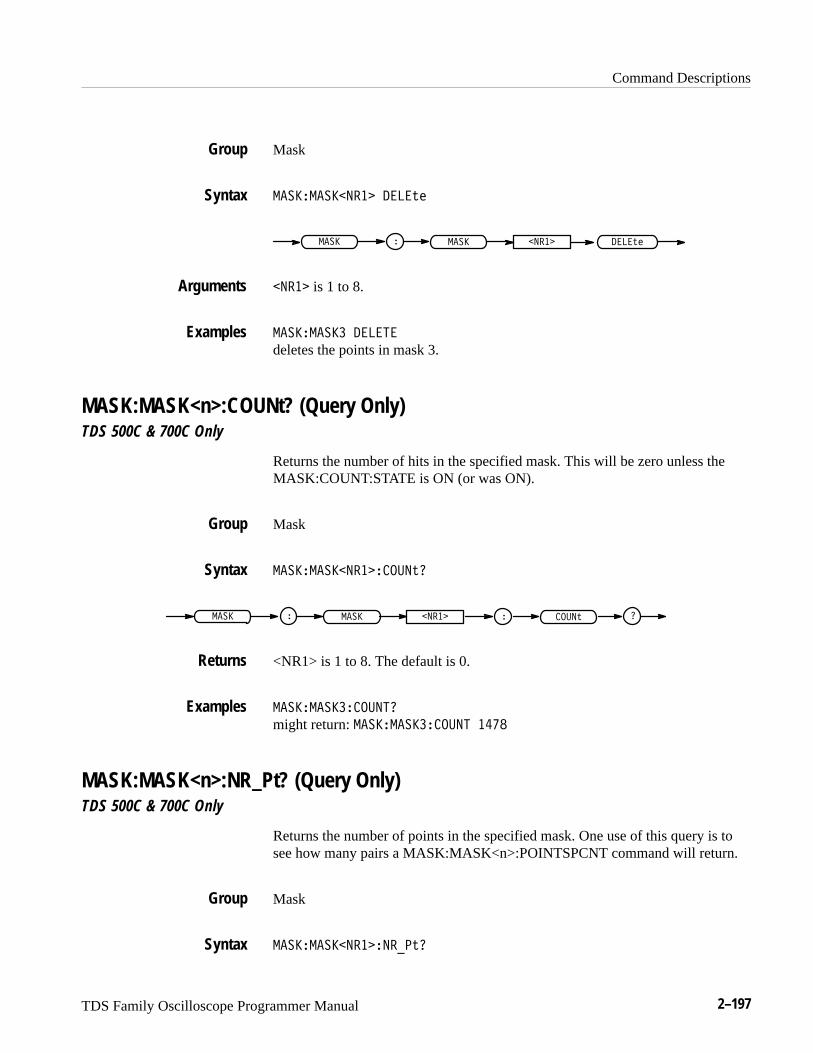
Command Descriptions
TDS Family Oscilloscope Programmer Manual 2–197
Mask
������������� �����
���� �������� � �����
���� is 1 to 8.
���������� �����
deletes the points in mask 3.
MASK:MASK<n>:COUNt? (Query Only)TDS 500C & 700C Only
Returns the number of hits in the specified mask. This will be zero unless theMASK:COUNT:STATE is ON (or was ON).
Mask
�������������������
���� �������� � ������
<NR1> is 1 to 8. The default is 0.
����������������
might return: ���������������� ����
MASK:MASK<n>:NR_Pt? (Query Only)TDS 500C & 700C Only
Returns the number of points in the specified mask. One use of this query is tosee how many pairs a MASK:MASK<n>:POINTSPCNT command will return.
Mask
�������������������
Group
Syntax
Arguments
Examples
Group
Syntax
Returns
Examples
Group
Syntax
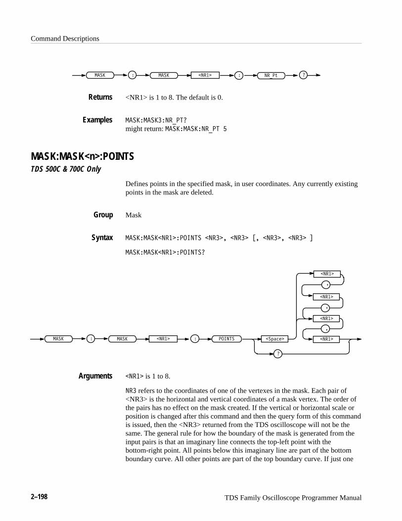
Command Descriptions
2–198 TDS Family Oscilloscope Programmer Manual
�� ����� �� � ������
<NR1> is 1 to 8. The default is 0.
��� ���������
might return: ��� �������� �
MASK:MASK<n>:POINTSTDS 500C & 700C Only
Defines points in the specified mask, in user coordinates. Any currently existingpoints in the mask are deleted.
Mask
��� �������������� ������ ����� �� ������ ����� �
��� ��������������
�������
�����
�����
�����
�
�
�����
�
�� ����� �� � �������
����� is 1 to 8.
��� refers to the coordinates of one of the vertexes in the mask. Each pair of<NR3> is the horizontal and vertical coordinates of a mask vertex. The order ofthe pairs has no effect on the mask created. If the vertical or horizontal scale orposition is changed after this command and then the query form of this commandis issued, then the <NR3> returned from the TDS oscilloscope will not be thesame. The general rule for how the boundary of the mask is generated from theinput pairs is that an imaginary line connects the top-left point with thebottom-right point. All points below this imaginary line are part of the bottomboundary curve. All other points are part of the top boundary curve. If just one
Returns
Examples
Group
Syntax
Arguments
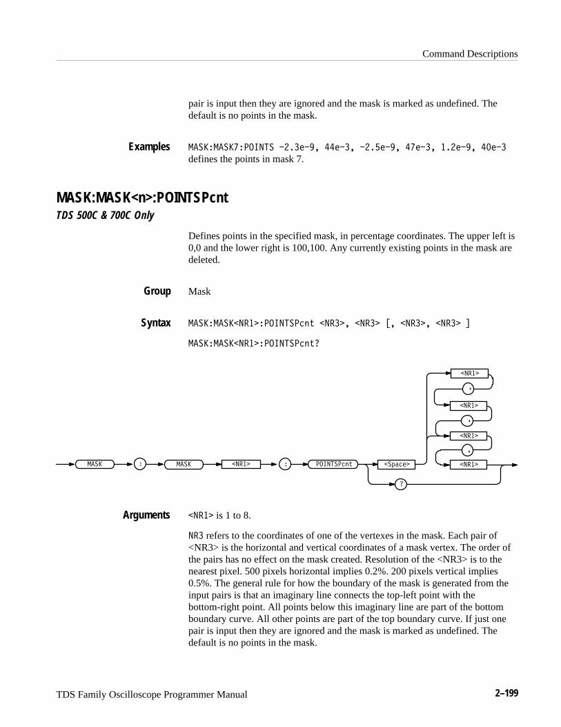
Command Descriptions
TDS Family Oscilloscope Programmer Manual 2–199
pair is input then they are ignored and the mask is marked as undefined. Thedefault is no points in the mask.
���� ����� ������ �������� ���� ������� ����� ������� ����
defines the points in mask 7.
MASK:MASK<n>:POINTSPcntTDS 500C & 700C Only
Defines points in the specified mask, in percentage coordinates. The upper left is0,0 and the lower right is 100,100. Any currently existing points in the mask aredeleted.
Mask
���� ��������� �������� " ������ ����� �� ������ ����� �
���� ��������� �������� "�
��!����
�����
�����
�
�����
�
�
�����
�
���� ��������� �������� "
����� is 1 to 8.
��� refers to the coordinates of one of the vertexes in the mask. Each pair of<NR3> is the horizontal and vertical coordinates of a mask vertex. The order ofthe pairs has no effect on the mask created. Resolution of the <NR3> is to thenearest pixel. 500 pixels horizontal implies 0.2%. 200 pixels vertical implies0.5%. The general rule for how the boundary of the mask is generated from theinput pairs is that an imaginary line connects the top-left point with thebottom-right point. All points below this imaginary line are part of the bottomboundary curve. All other points are part of the top boundary curve. If just onepair is input then they are ignored and the mask is marked as undefined. Thedefault is no points in the mask.
Examples
Group
Syntax
Arguments
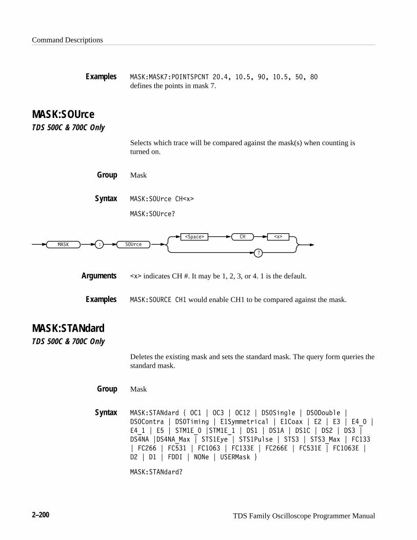
Command Descriptions
2–200 TDS Family Oscilloscope Programmer Manual
��������������� ���� ����� ���� �� ���� �� ��
defines the points in mask 7.
MASK:SOUrceTDS 500C & 700C Only
Selects which trace will be compared against the mask(s) when counting isturned on.
Mask
�������!0%' ���4�
�������!0%'�
� ��!0%'
��/#%'�
����
�
�� �4�
�4� indicates CH #. It may be 1, 2, 3, or 4. 1 is the default.
�������!��� ��� would enable CH1 to be compared against the mask.
MASK:STANdardTDS 500C & 700C Only
Deletes the existing mask and sets the standard mask. The query form queries thestandard mask.
Mask
������ ���& 6 ��� 7 ��� 7 ���� 7 ����)-(+' 7 ����.3$+' 7
����.-20# 7 ��� ),)-( 7 ���5,,'20)%#+ 7 ���.#4 7 �� 7 �� 7 ��"� 7
��"� 7 � 7 � ���"� 7� ���"� 7 ��� 7 ���� 7 ���� 7 ��� 7 ��� 7
����� 7�����"�#4 7 � ���5' 7 � ���3+1' 7 � �� 7 � ��"�#4 7 �����
7 ��� 7 ���� 7 ����� 7 ������ 7 ���� 7 ����� 7 ������ 7
�� 7 �� 7 ���� 7 ���' 7 !����#1* 8
������ ���&�
Examples
Group
Syntax
Arguments
Examples
Group
Syntax
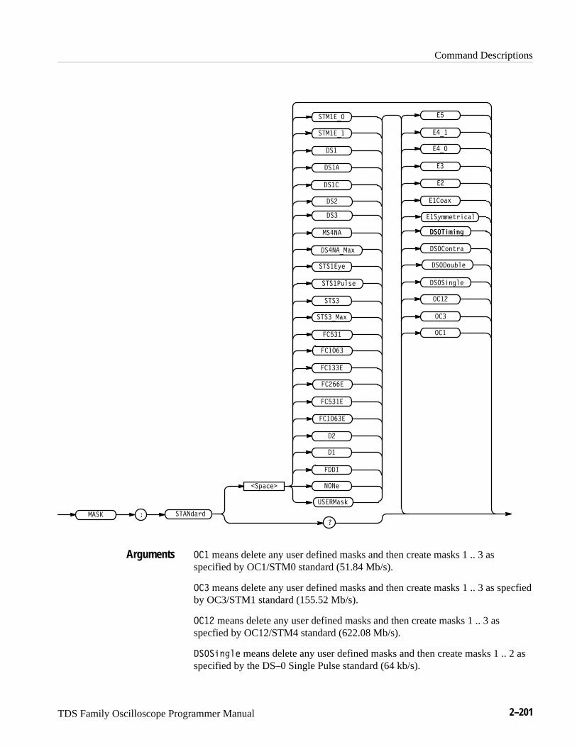
Command Descriptions
TDS Family Oscilloscope Programmer Manual 2–201
�����
�(��
����
�
���
��
������)�
��
� �����
� ����
� ����
� ����
� ����
� ���
�������-
����
�����.
�����
���
���
���
����
���
�������
�������
������*#
� �
� �
� ��
�� '�-
��
��
����
����
��
��������-
����"%"&!����"%"&!
��� '&+)�
����',�$
����"&!$
���.%% +)"��$
�����,$*
� � means delete any user defined masks and then create masks 1 .. 3 asspecified by OC1/STM0 standard (51.84 Mb/s).
� � means delete any user defined masks and then create masks 1 .. 3 as specfiedby OC3/STM1 standard (155.52 Mb/s).
� �� means delete any user defined masks and then create masks 1 .. 3 asspecfied by OC12/STM4 standard (622.08 Mb/s).
����"&!$ means delete any user defined masks and then create masks 1 .. 2 asspecified by the DS–0 Single Pulse standard (64 kb/s).
Arguments
Command Descriptions
2–202 TDS Family Oscilloscope Programmer Manual
������� means delete any user defined masks and then create masks 1 .. 2 asspecified by the DS–0 Double Pulse standard (64 kb/s).
�������� means delete any user defined masks and then create masks 1 .. 2 asspecified by the DS–0 Data Pulse, Contradirectional standard (64 kb/s).
�� ����� means delete any user defined masks and then create masks 1 .. 2 asspecified by the DS–0 Timing Pulse, Contradirectional standard (64 kb/s).
������������ means delete any user defined masks and then create masks 1 ..2 as specified by the E1 Symmetrical Pair standard (2.048 Mb/s).
����� means delete any user defined masks and then create masks 1 .. 2 asspecified by the E1 Coaxial Pair standard (2.048 Mb/s).
� means delete any user defined masks and then create masks 1 .. 2 as specifiedby the E2 standard (8.448 Mb/s).
� means delete any user defined masks and then create masks 1 .. 2 as specifiedby the E3 standard (34.368 Mb/s).
��� means delete any user defined masks and then create masks 1 .. 2 asspecified by the E4 Binary 0 standard (139.26 Mb/s).
��� means delete any user defined masks and then create masks 1 .. 2 asspecified by the E4 Binary 1 standard (139.26 Mb/s).
� means delete any user defined masks and then create masks 1 .. 2 as specifiedby the E5 CEPT standard (565 Mb/s).
� ���� means delete any user defined masks and then create masks 1 .. 2 asspecified by the G.703 Binary 0 standard (155.52 Mb/s). The SONET standardGR–253–CORE calls this mask STS–3. ANSI standard T1.102 has STS–3 eyepattern standards.
� ���� means delete any user defined masks and then create masks 1 .. 2 asspecified by the G.703 Binary 1 standard (155.52 Mb/s). The SONET standardGR–253–CORE calls this mask STS–3. ANSI standard T1.102 has STS–3 eyepattern standards.
�� means delete any user defined masks and then create masks 1 .. 2 asspecified by the DS1 standard (1.544 Mb/s).
��� means delete any user defined masks and then create masks 1 .. 2 asspecified by the DS1A standard (2.048 Mb/s).
��� means delete any user defined masks and then create masks 1 .. 2 asspecified by the DS1C standard (3.152 Mb/s).
�� means delete any user defined masks and then create masks 1 .. 2 asspecified by the DS2 standard (6.312 Mb/s).
Command Descriptions
TDS Family Oscilloscope Programmer Manual 2–203
�� means delete any user defined masks and then create masks 1 .. 2 asspecified by the DS3 standard (44.736 Mb/s).
���� means delete any user defined masks and then create masks 1 .. 4 asspecified by the DS4NA eye standard (139.26 Mb/s).
����� �� means delete any user defined masks and then create masks 1 .. 4 asspecified by the DS4NA Maximum equipment output eye standard (139.26 Mb/s).
������� means delete any user defined masks and then create masks 1 .. 4 asspecified by the STS–1 Eye standard (51.84 Mb/s).
��������� means delete any user defined masks and then create masks 1 .. 2 asspecified by the STS–1 Pulse standard (51.84 Mb/s).
���� means delete any user defined masks and then create masks 1 .. 4 asspecified by the STS–3 eye standard (155.52 Mb/s).
����� �� means delete any user defined masks and then create masks 1 .. 4 asspecified by the STS–3 Maximum equipment output eye standard (155.52 Mb/s).
���� means delete any user defined masks and then create masks 1 .. 3 asspecified by the Fibre Channel 133 Optical standard (132.7 Mb/s).
���� means delete any user defined masks and then create masks 1 .. 3 asspecified by the Fibre Channel 266 Optical standard (265.6 Mb/s).
���� means delete any user defined masks and then create masks 1 .. 3 asspecified by the Fibre Channel 531 Optical standard (531.2 Mb/s).
����� means delete any user defined masks and then create masks 1 .. 3 asspecified by the Fibre Channel 1063 Optical standard (1.0635 Gb/s).
����� means delete any user defined masks and then create masks 1 .. 3 asspecified by the Fibre Channel 133 Electrical standard (132.7 Mb/s).
����� means delete any user defined masks and then create masks 1 .. 3 asspecified by the Fibre Channel 266 Electrical standard (265.6 Mb/s).
����� means delete any user defined masks and then create masks 1 .. 3 asspecified by the Fibre Channel 531 Electrical standard (531.2 Mb/s).
������ means delete any user defined masks and then create masks 1 .. 3 asspecified by the Fibre Channel 1063 Electrical standard (1.0635 Gb/s).
� means delete any user defined masks and then create masks 1 .. 3 as impliedby the ANSI/SMPTE 259M 4fsc NTSC standard (143.1818 Mb/s).
� means delete any user defined masks and then create masks 1 .. 3 as impliedby the ANSI/SMPTE 259M 4:2:2 component serial video standard (270 Mb/s).
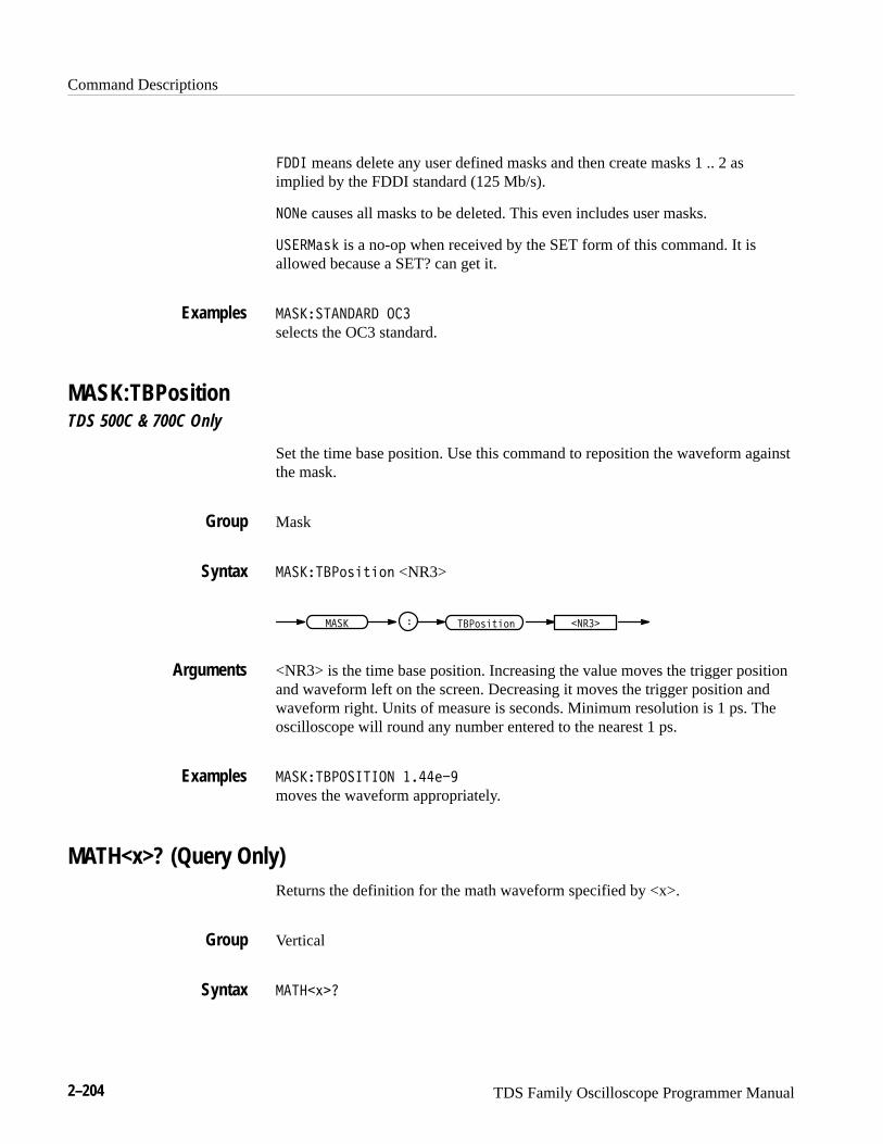
Command Descriptions
2–204 TDS Family Oscilloscope Programmer Manual
���� means delete any user defined masks and then create masks 1 .. 2 asimplied by the FDDI standard (125 Mb/s).
���� causes all masks to be deleted. This even includes user masks.
������# is a no-op when received by the SET form of this command. It isallowed because a SET? can get it.
������������� ���
selects the OC3 standard.
MASK:TBPositionTDS 500C & 700C Only
Set the time base position. Use this command to reposition the waveform againstthe mask.
Mask
������ �"#�$�"! <NR3>
������� � � �"#�$�"!
<NR3> is the time base position. Increasing the value moves the trigger positionand waveform left on the screen. Decreasing it moves the trigger position andwaveform right. Units of measure is seconds. Minimum resolution is 1 ps. Theoscilloscope will round any number entered to the nearest 1 ps.
������ �������� �������
moves the waveform appropriately.
MATH<x>? (Query Only)Returns the definition for the math waveform specified by <x>.
Vertical
����%�
Examples
Group
Syntax
Arguments
Examples
Group
Syntax
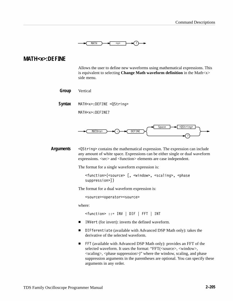
Command Descriptions
TDS Family Oscilloscope Programmer Manual 2–205
��� �)�
MATH<x>:DEFINEAllows the user to define new waveforms using mathematical expressions. Thisis equivalent to selecting Change Math waveform definition in the Math<x>side menu.
Vertical
����)���� ��� ���&$�!��
����)���� ���
���&$�!��
� �� ���
�#���
����)�
���&$�!�� contains the mathematical expression. The expression can includeany amount of white space. Expressions can be either single or dual waveformexpressions. <src> and <function> elements are case independent.
The format for a single waveform expression is:
��'!�&�"!���%"'$��� �� �(�!�"(�� �%�� �!��� �#��%�
%'##$�%%�"!���
The format for a dual waveform expression is:
�%"'$����"#�$�&"$��%"'$���
where:
��'!�&�"!� ��� ��� * �� * � * ���
� ����$& (for invert): inverts the defined waveform.
� �� ��$�!&��&� (available with Advanced DSP Math only): takes thederivative of the selected waveform.
� � (available with Advanced DSP Math only): provides an FFT of theselected waveform. It uses the format: “FFT(<source>, <window>,<scaling>, <phase suppression>)” where the window, scaling, and phasesuppression arguments in the parentheses are optional. You can specify thesearguments in any order.
Group
Syntax
Arguments
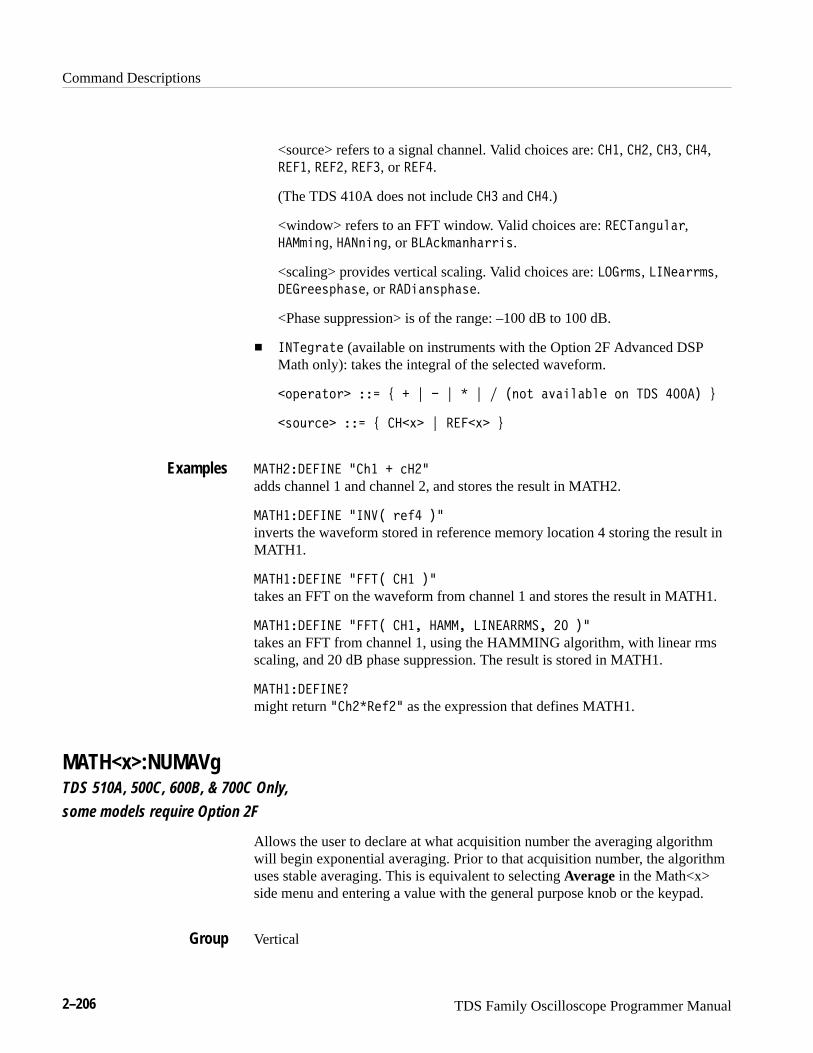
Command Descriptions
2–206 TDS Family Oscilloscope Programmer Manual
<source> refers to a signal channel. Valid choices are: ���, ���, �� , ���,!���, !���, !�� , or !���.
(The TDS 410A does not include �� and ���.)
<window> refers to an FFT window. Valid choices are: !��#%0*6.%3,���/,0*, ���0,0*, or ���'-/%0+%33,4.
<scaling> provides vertical scaling. Valid choices are: � �3/4, ���(%33/4,���3((42+%4(, or !��,%042+%4(.
<Phase suppression> is of the range: –100 dB to 100 dB.
� ��#(*3%5( (available on instruments with the Option 2F Advanced DSPMath only): takes the integral of the selected waveform.
�12(3%513� ��� 9 � : � : � : �015 %7%,.%&.( 10 #�" ��� ;
�4163'(� ��� 9 ���8� : !���8� ;
��#��������� ��+� � '���
adds channel 1 and channel 2, and stores the result in MATH2.
��#��������� ���$� 3()� ��
inverts the waveform stored in reference memory location 4 storing the result inMATH1.
��#��������� ���#� ��� ��
takes an FFT on the waveform from channel 1 and stores the result in MATH1.
��#��������� ���#� ���� ����� �����!!�"� � ��
takes an FFT from channel 1, using the HAMMING algorithm, with linear rmsscaling, and 20 dB phase suppression. The result is stored in MATH1.
��#����������
might return ��+��!()�� as the expression that defines MATH1.
MATH<x>:NUMAVgTDS 510A, 500C, 600B, & 700C Only,
some models require Option 2F
Allows the user to declare at what acquisition number the averaging algorithmwill begin exponential averaging. Prior to that acquisition number, the algorithmuses stable averaging. This is equivalent to selecting Average in the Math<x>side menu and entering a value with the general purpose knob or the keypad.
Vertical
Examples
Group
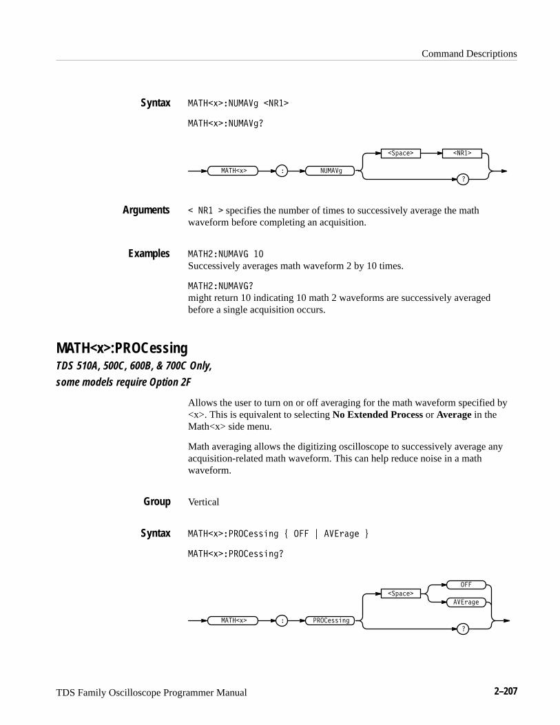
Command Descriptions
TDS Family Oscilloscope Programmer Manual 2–207
����!������� �����
����!��������
�
������������
����������!�
� ��� � specifies the number of times to successively average the mathwaveform before completing an acquisition.
��������� ��
Successively averages math waveform 2 by 10 times.
��������� �
might return 10 indicating 10 math 2 waveforms are successively averagedbefore a single acquisition occurs.
MATH<x>:PROCessingTDS 510A, 500C, 600B, & 700C Only,
some models require Option 2F
Allows the user to turn on or off averaging for the math waveform specified by<x>. This is equivalent to selecting No Extended Process or Average in theMath<x> side menu.
Math averaging allows the digitizing oscilloscope to successively average anyacquisition-related math waveform. This can help reduce noise in a mathwaveform.
Vertical
����!������ ��� " ��� # ������ $
����!������ ����
�������
�
���
������
���� ��������!�
Syntax
Arguments
Examples
Group
Syntax
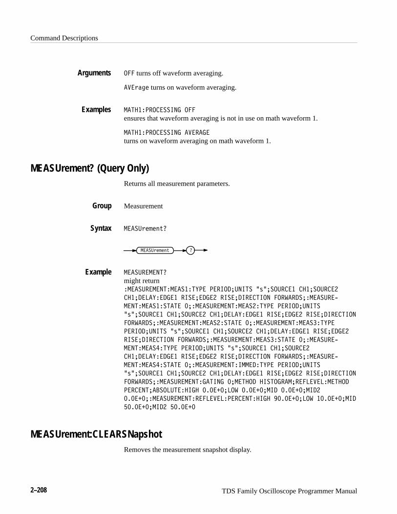
Command Descriptions
2–208 TDS Family Oscilloscope Programmer Manual
��� turns off waveform averaging.
�!�)$&% turns on waveform averaging.
���������������� ���
ensures that waveform averaging is not in use on math waveform 1.
���������������� �!�����
turns on waveform averaging on math waveform 1.
MEASUrement? (Query Only)Returns all measurement parameters.
Measurement
���� )%'%(+�
���� )%'%(+ �
���� �������
might return����� ��������������#�� ������ ���� �*� �� ���� ��� �� ����
��� ����#������ ���� ����� ���� ��������� ���"���� ����� ��,
���������������� � ����� ��������������#�� ������ ����
�*� �� ���� ��� �� ���� ��� ����#������ ���� ����� ���� ���������
���"���� ����� ������������������ � ����� ��������������#��
������ ���� �*� �� ���� ��� �� ���� ��� ����#������ ���� �����
���� ��������� ���"���� ����� ������������������ � ����� ��,
�����������#�� ������ ���� �*� �� ���� ��� �� ����
��� ����#������ ���� ����� ���� ��������� ���"���� ����� ��,
��������������� � ����� ��������������#�� ������ ����
�*� �� ���� ��� �� ���� ��� ����#������ ���� ����� ���� ���������
���"���� ����� ������������� � ������ ��������� �����!���������
������� ����� ������� ������ ��" ������ ��� ������ ����
������ ����� ������������!��������������� ������� ��" ������� ���
������ ���� ������
MEASUrement:CLEARSNapshotRemoves the measurement snapshot display.
Arguments
Examples
Group
Syntax
Example
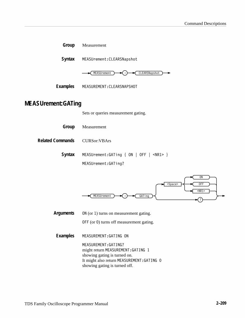
Command Descriptions
TDS Family Oscilloscope Programmer Manual 2–209
Measurement
����"����$�������!#� $
������!#� $����"����$ �
����������������� ��
MEASUrement:GATingSets or queries measurement gating.
Measurement
CURSor:VBArs
����"����$������� % �� & ��� & ����� '
����"����$��������
��!����
��
�
���
�����
����"����$ �������
�� (or �) turns on measurement gating.
��� (or �) turns off measurement gating.
��������������� ��
����������������
might return ��������������� �
showing gating is turned on.It might also return ��������������� �
showing gating is turned off.
Group
Syntax
Examples
Group
Related Commands
Syntax
Arguments
Examples

Command Descriptions
2–210 TDS Family Oscilloscope Programmer Manual
MEASUrement:IMMed? (Query Only)Returns all immediate measurement setup parameters.
Measurement
�����% " #'���� ��
��� �� ������% " #'
������������������
might return ����������������������� ������������ �&��������
��������� �������������� ���������� ����� �������� �������
MEASUrement:IMMed:DELay? (Query Only)Returns information about the immediate delay measurement.
Measurement
�����% " #'���� ������(�
�����% " #' � ��� � �� ����(
������������������������
might return ������������������������������ ���������� �����
�������� �������
MEASUrement:IMMed:DELay:DIREctionSets or queries the starting point and direction that determines the delay “to”edge when taking an immediate delay measurement. Use the MEASUre-ment:IMMed:SOURCE2 command to specify the delay “to” waveform.
Measurement
�����% " #'���� ������(������'!$# )����%�& * ����%�&+
�����% " #'���� ������(������'!$#�
Group
Syntax
Examples
Group
Syntax
Examples
Group
Syntax
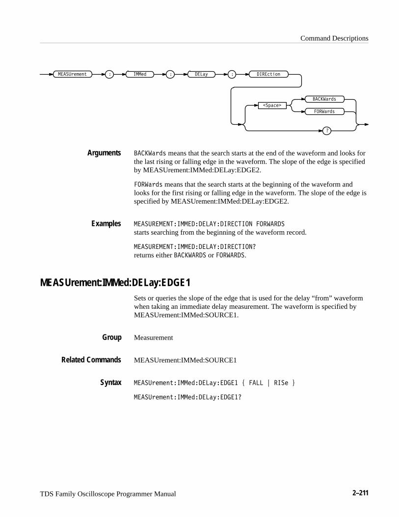
Command Descriptions
TDS Family Oscilloscope Programmer Manual 2–211
������ ������#��� % ���& � ����%�!
��"����
�
�����#�$
�����#�$
�����#�$ means that the search starts at the end of the waveform and looks forthe last rising or falling edge in the waveform. The slope of the edge is specifiedby MEASUrement:IMMed:DELay:EDGE2.
�����#�$ means that the search starts at the beginning of the waveform andlooks for the first rising or falling edge in the waveform. The slope of the edge isspecified by MEASUrement:IMMed:DELay:EDGE2.
����������������������������� �������
starts searching from the beginning of the waveform record.
������������������������������
returns either ������� or �������.
MEASUrement:IMMed:DELay:EDGE1Sets or queries the slope of the edge that is used for the delay “from” waveformwhen taking an immediate delay measurement. The waveform is specified byMEASUrement:IMMed:SOURCE1.
Measurement
MEASUrement:IMMed:SOURCE1
�����#��� %����������&�� �� ' ���� ( ���� )
�����#��� %����������&�� ���
Arguments
Examples
Group
Related Commands
Syntax
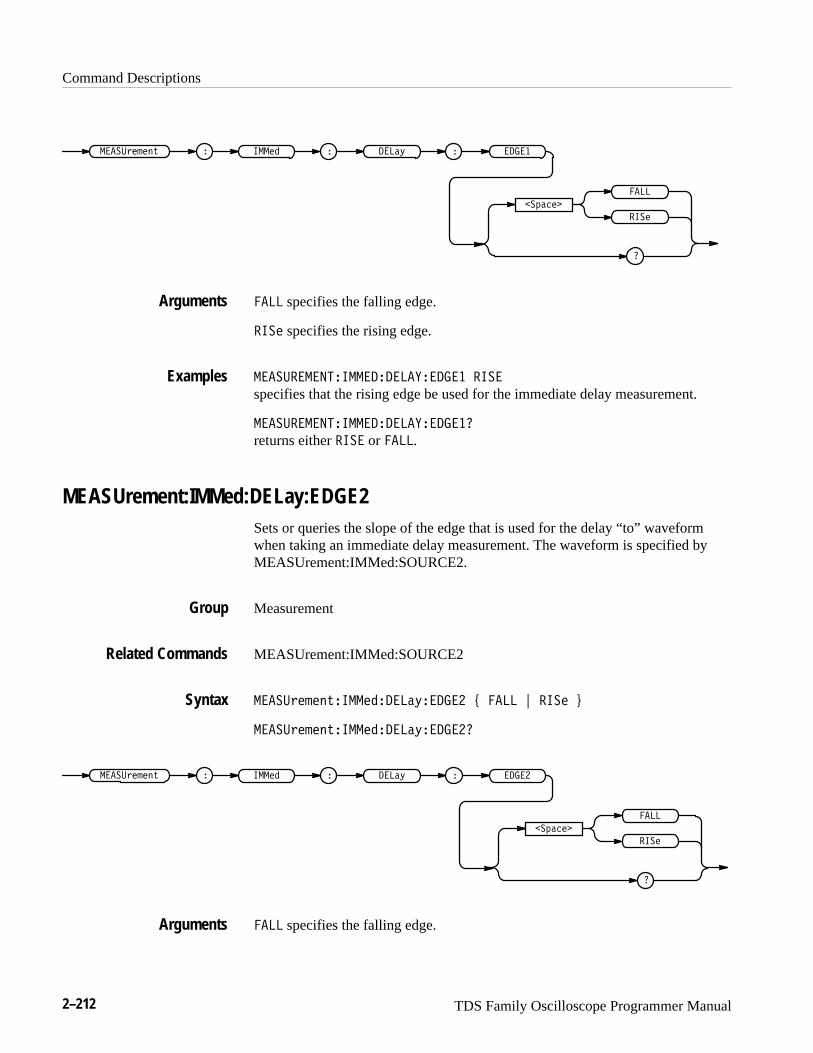
Command Descriptions
2–212 TDS Family Oscilloscope Programmer Manual
����� ����������� ��� � ��
�������
�
����
� ��
���� specifies the falling edge.
� �� specifies the rising edge.
��������� ��������� � �
specifies that the rising edge be used for the immediate delay measurement.
��������� ����������
returns either � � or ����.
MEASUrement:IMMed:DELay:EDGE2Sets or queries the slope of the edge that is used for the delay “to” waveformwhen taking an immediate delay measurement. The waveform is specified byMEASUrement:IMMed:SOURCE2.
Measurement
MEASUrement:IMMed:SOURCE2
����������� ����������� ���� ! � �� "
����������� ������������
����� ����������� ��� � ��
�������
�
����
� ��
���� specifies the falling edge.
Arguments
Examples
Group
Related Commands
Syntax
Arguments
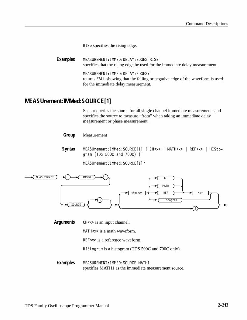
Command Descriptions
TDS Family Oscilloscope Programmer Manual 2–213
���# specifies the rising edge.
�� ���������������� ������ ����
specifies that the rising edge be used for the immediate delay measurement.
�� ���������������� �������
returns � �� showing that the falling or negative edge of the waveform is usedfor the immediate delay measurement.
MEASUrement:IMMed:SOURCE[1]Sets or queries the source for all single channel immediate measurements andspecifies the source to measure “from” when taking an immediate delaymeasurement or phase measurement.
Measurement
�� ��)#%#&*���#"��������� , ��+� - � ��+� - ���+� - ���*'/
$) % ���� ���� &" ����� .
�� ��)#%#&*���#"����������
����( !#�
�
� ��
+�
���#" �� ��)#%#&*
������
�
��
���*'$) %
��+� is an input channel.
� ��+� is a math waveform.
���+� is a reference waveform.
���*'$) % is a histogram (TDS 500C and 700C only).
�� ������������������� � ���
specifies MATH1 as the immediate measurement source.
Examples
Group
Syntax
Arguments
Examples
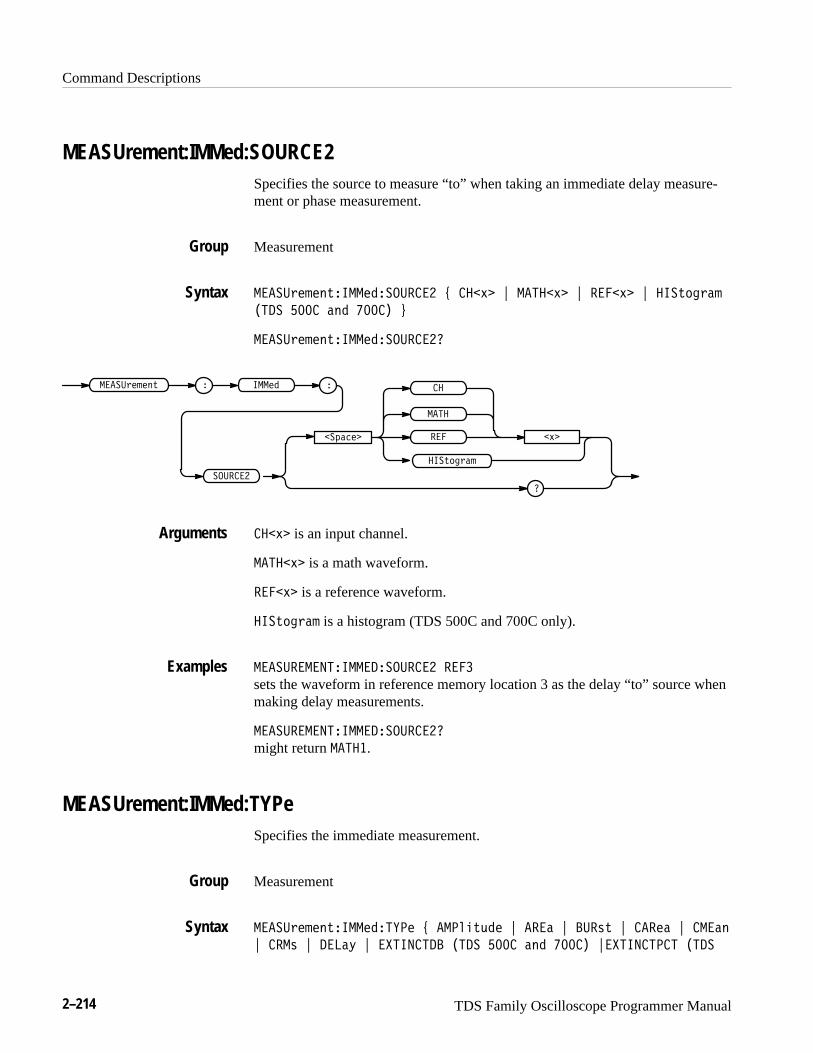
Command Descriptions
2–214 TDS Family Oscilloscope Programmer Manual
MEASUrement:IMMed:SOURCE2Specifies the source to measure “to” when taking an immediate delay measure-ment or phase measurement.
Measurement
�����,$($).���$#������� 2 ���0� 3 �����0� 3 ����0� 3 ���.*%,!(
���� ���� !)# ���� 4
�����,$($).���$#�������
�����+!"$�
����
�0�
���$# �����,$($).
�������
��
���.*%,!(
���0� is an input channel.
�����0� is a math waveform.
����0� is a reference waveform.
���.*%,!( is a histogram (TDS 500C and 700C only).
����������������������� ����
sets the waveform in reference memory location 3 as the delay “to” source whenmaking delay measurements.
�����������������������
might return �����.
MEASUrement:IMMed:TYPeSpecifies the immediate measurement.
Measurement
�����,$($).���$#� �$ 2 ���'&./#$ 3 ���! 3 ���-. 3 ���$! 3 ���!)
3 ���- 3 ���!1 3 ��������� ���� ���� !)# ���� 3���������� ����
Group
Syntax
Arguments
Examples
Group
Syntax

Command Descriptions
TDS Family Oscilloscope Programmer Manual 2–215
��� )2+ ���� ; �%!���!��!�� �!� ��� )2+ ���� ; ���� ;
����8,2*: ; ���� ; ��!6 �!� ��� )2+ ���� ; ��$ ; ��%.181 ;
���� ; ������� �!� ��� )2+ ���� ; ���.)2 �!� ��� )2+ ���� ;
����181 ; ��"7: ; ��#,56-337 ; �$�+7- ; ��"7: ; �����.76 �!�
��� )2+ ���� ; ����3+ ; ���6, ; ���4/ ; ��#,56-337 ; �$�+7- ;
�� , ; �� ; ����'���( �!� ��� )2+ ���� ; !�+,9 �!� ���
)2+ ���� ; $�#����� �!� ��� )2+ ���� <
��� "5,1,27����,+�!&�,�
���� "5,1,27 ���,+ � !&�,
� 4)*,
��#,56-337
�
����
����
����181
��$
���6
���0.78+,
����8,2*:
���)
���): ��"7:
��%.181
��"7:
�$�+7-
��#,56-337
�$�+7-
��
����3+
���4/
�� ,
����
�"�67
���,)
���6,
���)2
$�#�����
���.)2
!�+,9
����'���(
�����.76
�%!���!��!
�%!���!��
�������
�%!���!��!��
��!6
For more information on how measurements are derived, see Appendix B:Algorithms, in the related TDS Family User Manual.
���0.78+, is the high value minus the low value.
Arguments
Command Descriptions
2–216 TDS Family Oscilloscope Programmer Manual
���� is the area between the curve and ground over the entire waveform.
���� is the time from the first MidRef crossing to the last MidRef crossing.
����� (cycle area) is the area between the curve and ground over one cycle.
����� is the arithmetic mean over one cycle.
���� is the true Root Mean Square voltage over one cycle.
���" is the time between the MidRef crossings of two different waveforms.
�������� (TDS 500C and 700C) is 10.0 * log10(Extinction Ratio)
��������� (TDS 500C and 700C) is 100/Extinction Ratio
��������� (TDS 500C and 700C) is High/Low
�� is the time that it takes for the falling edge of a pulse to fall from a HighRefvalue to a LowRef value of its final value.
����!���" is the reciprocal of the period measured in hertz.
��� is the 100% reference level.
��� (TDS 500C and 700C) displays the number of acquired points within or onthe histogram box.
� is the 0% reference level.
�����!� is the highest amplitude (voltage).
���� for general purpose measurements, is the arithmetic mean over the entirewaveform. For histogram measurements, it is the average of all acquired pointswithin or on the histogram box.
������� (TDS 500C and 700C) is 10 * log10(MEAN/0.001) a value equal to
������ (TDS 500C and 700C) is the median of all acquired points within or onthe histogram box. Half of the acquired points are greater than and half less thanthis value.
���!� is the lowest amplitude (voltage).
��� " is the ratio of the negative pulse width to the signal period expressed as apercentage.
� ������� is the negative overshoot, expressed as:
NOVershoot� 100��(Low�Minimum)Amplitude
�

Command Descriptions
TDS Family Oscilloscope Programmer Manual 2–217
����' is the distance (time) between MidRef (usually 50%) amplitude points ofa negative pulse.
��') is the ratio of the positive pulse width to the signal period expressed as apercentage.
��� !'& (TDS 500C and 700C)�������� �� �� ��� �� �������� ������ ���� ������ ��� �� �� ������ �
���#� is the time, in seconds, it takes for one complete signal cycle to happen.
� �&� is the amount of shift, expressed in degrees, from the selected waveformto the designated waveform.
���$" is the absolute difference between the maximum and minimum amplitude.It can be used with both general purpose and histogram measurements. Forhistogram measurements, it is the value of the highest nonzero bin minus thevalue of the lowest nonzero bin.
����%& ##' is the positive overshoot, expressed as:
POVershoot� 100��(Maximum� High)Amplitude
�
����' is the distance (time) between MidRef (usually 50%) amplitude points ofa positive pulse.
���� is the time that it takes for the leading edge of a pulse to rise from a lowreference value to a high reference value of its final value.
��� is the true Root Mean Square voltage.
���������� (TDS 500C and 700C) is the percentage of points in the histogramwhich are within 1, 2, or 3 standard deviations of the histogram mean. In anormal distribution, 66% of the points are within �1 standard deviation, 95% ofthe points are within �2 standard deviations, and 97.5% of the points are within�3 standard deviations of the histogram mean.
����( (TDS 500C and 700C) is the standard deviation of all acquired pointswithin or on the histogram box.
�������� (TDS 500C and 700C) is the number of waveforms that havecontributed to the histogram. A waveform is counted even if no points werewithin the histogram box.
���������������� �������
defines the immediate measurement to be a frequency measurement.Examples

Command Descriptions
2–218 TDS Family Oscilloscope Programmer Manual
MEASUrement:IMMed:UNITS? (Query Only)Returns the units for the immediate measurement.
Measurement
MEASUrement:IMMed:TYPe
��������� � ������� ���
���������� ���� � �� �� �
��� ����� returns ��� for volts, ��� for seconds, ��"� for hertz, ���� forvolts2,or ��� for percent.
On the TDS 400A, ��� ����� also returns ��� for clocks, ���� for volt-clocks,or ���� for 1/clks.
����������� ������ ���
might return ���, indicating that the units for the immediate measurement areseconds.
MEASUrement:IMMed:VALue? (Query Only)Immediately executes the immediate measurement specified by the MEASUre-ment:IMMed:TYPe command. The measurement is taken on the source(s)specified by a MEASUrement:IMMed:SOURCE command.
Measurement
��������� � �������!��
���������� ���� � ��!� �
�����
Group
Related Commands
Syntax
Returns
Examples
Group
Syntax
Returns
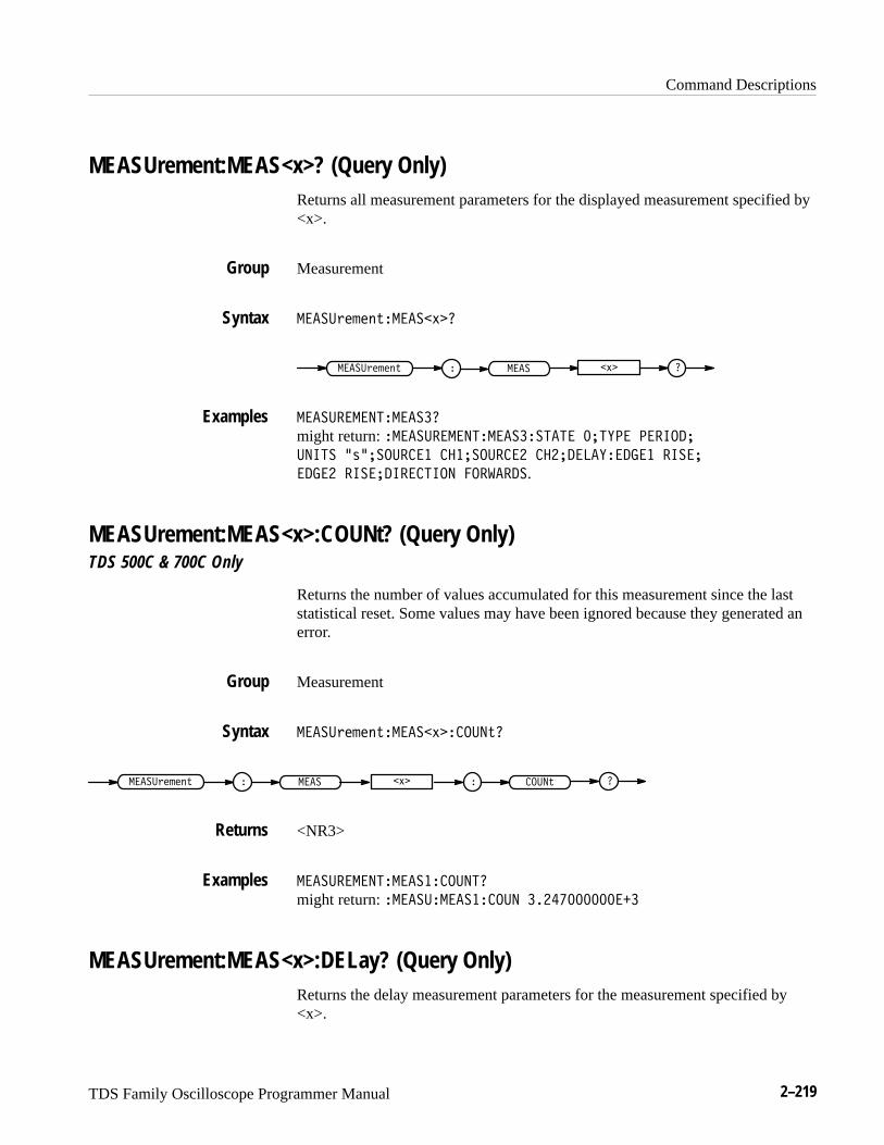
Command Descriptions
TDS Family Oscilloscope Programmer Manual 2–219
MEASUrement:MEAS<x>? (Query Only)Returns all measurement parameters for the displayed measurement specified by<x>.
Measurement
���� &#$#%(����� )��
����� &#$#%( ���� )� �
���� �������������
might return: ����� ������������������ ���"�� �������
���� �'���� ���� ������ ���� ��������"������ �����
����� �������������� ���!����.
MEASUrement:MEAS<x>:COUNt? (Query Only)TDS 500C & 700C Only
Returns the number of values accumulated for this measurement since the laststatistical reset. Some values may have been ignored because they generated anerror.
Measurement
���� &#$#%(����� )���� �(�
����� &#$#%( ���� )� �� �� �(
<NR3>
���� ��������������� ���
might return: ����� ��������� � ������������
MEASUrement:MEAS<x>:DELay? (Query Only)Returns the delay measurement parameters for the measurement specified by<x>.
Group
Syntax
Examples
Group
Syntax
Returns
Examples
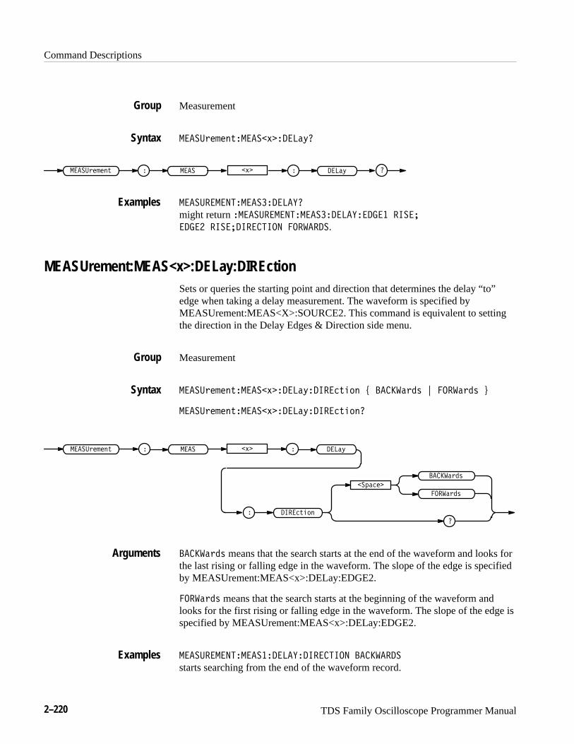
Command Descriptions
2–220 TDS Family Oscilloscope Programmer Manual
Measurement
����& " #(�����)�� ���*
�����& " #( ��� �)� � ���*
���������������� ���
might return ����������������� ����� ��� �����
� ��� ����� �������� ����� �.
MEASUrement:MEAS<x>:DELay:DIREctionSets or queries the starting point and direction that determines the delay “to”edge when taking a delay measurement. The waveform is specified byMEASUrement:MEAS<X>:SOURCE2. This command is equivalent to settingthe direction in the Delay Edges & Direction side menu.
Measurement
����& " #(�����)�� ���*� ����(!$# + �����&�' , �����&�' -
����& " #(�����)�� ���*� ����(!$#
�����& " #( ��� �)� � ���*
� ����(!$#
��%�� �
�����&�'
�����&�'
�����&�' means that the search starts at the end of the waveform and looks forthe last rising or falling edge in the waveform. The slope of the edge is specifiedby MEASUrement:MEAS<x>:DELay:EDGE2.
�����&�' means that the search starts at the beginning of the waveform andlooks for the first rising or falling edge in the waveform. The slope of the edge isspecified by MEASUrement:MEAS<x>:DELay:EDGE2.
���������������� ���� �������� ����� �
starts searching from the end of the waveform record.
Group
Syntax
Examples
Group
Syntax
Arguments
Examples
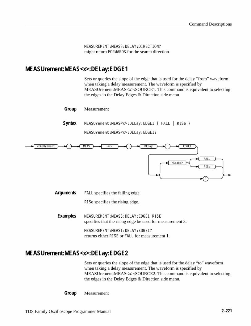
Command Descriptions
TDS Family Oscilloscope Programmer Manual 2–221
�������������������������������
might return ������� for the search direction.
MEASUrement:MEAS<x>:DELay:EDGE1Sets or queries the slope of the edge that is used for the delay “from” waveformwhen taking a delay measurement. The waveform is specified byMEASUrement:MEAS<x>:SOURCE1. This command is equivalent to selectingthe edges in the Delay Edges & Direction side menu.
Measurement
���������� ������!�����"�� �� # ���� $ ���� %
���������� ������!�����"�� ���
����� ����������� ���" � � ���!�
�������
�
����
����
���� specifies the falling edge.
���� specifies the rising edge.
������������������������ �� ����
specifies that the rising edge be used for measurement 3.
������������������������ ���
returns either ���� or ���� for measurement 1.
MEASUrement:MEAS<x>:DELay:EDGE2Sets or queries the slope of the edge that is used for the delay “to” waveformwhen taking a delay measurement. The waveform is specified byMEASUrement:MEAS<x>:SOURCE2. This command is equivalent to selectingthe edges in the Delay Edges & Direction side menu.
Measurement
Group
Syntax
Arguments
Examples
Group
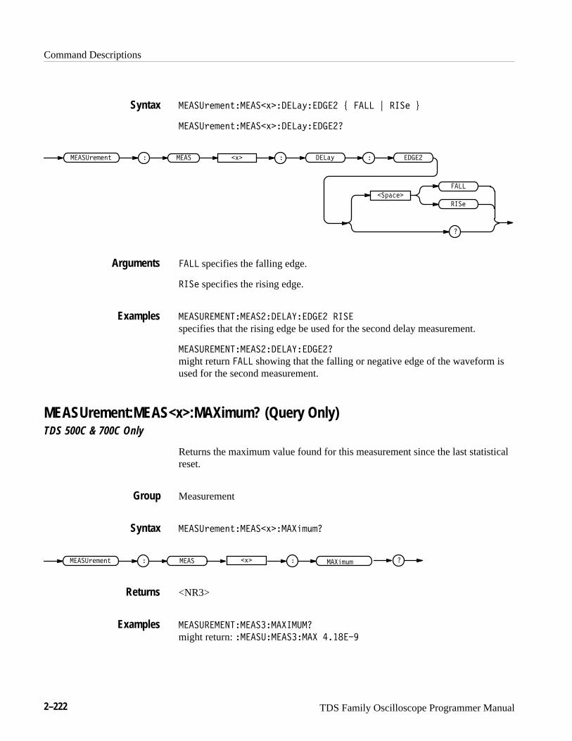
Command Descriptions
2–222 TDS Family Oscilloscope Programmer Manual
�����$�!�"%�����'�����(����� ) ���� * ���� +
�����$�!�"%�����'�����(�����
���� �����$�!�"% ����( ������'�
��#����
����
����
���� specifies the falling edge.
���� specifies the rising edge.
�������������������������� ����
specifies that the rising edge be used for the second delay measurement.
��������������������������
might return ���� showing that the falling or negative edge of the waveform isused for the second measurement.
MEASUrement:MEAS<x>:MAXimum? (Query Only)TDS 500C & 700C Only
Returns the maximum value found for this measurement since the last statisticalreset.
Measurement
�����$�!�"%�����'���� !&!
�����$�!�"% ���� �'� ��� !&!
<NR3>
�����������������������
might return: ������������� ������
Syntax
Arguments
Examples
Group
Syntax
Returns
Examples
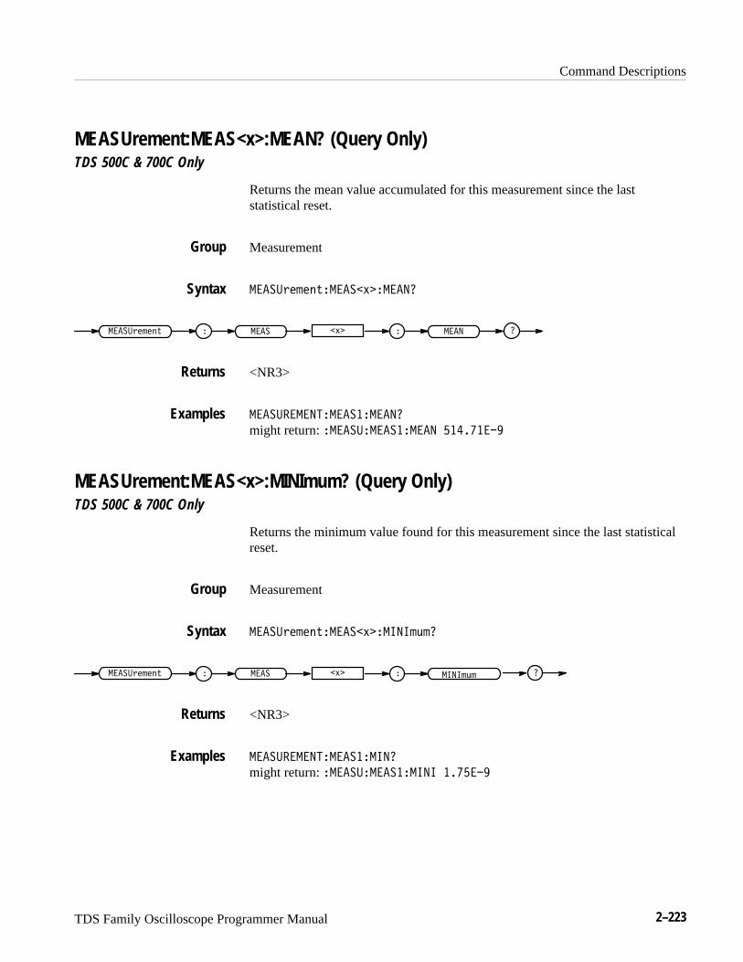
Command Descriptions
TDS Family Oscilloscope Programmer Manual 2–223
MEASUrement:MEAS<x>:MEAN? (Query Only)TDS 500C & 700C Only
Returns the mean value accumulated for this measurement since the laststatistical reset.
Measurement
�� ���������� ����� ��
�� �������� �� � �� � �� �
<NR3>
�� ���������� ���� ��
might return: �� ���� ���� � ���������
MEASUrement:MEAS<x>:MINImum? (Query Only)TDS 500C & 700C Only
Returns the minimum value found for this measurement since the last statisticalreset.
Measurement
�� ���������� �����������
�� �������� �� � �� � �������
<NR3>
�� ���������� ������
might return: �� ���� ������ �������
Group
Syntax
Returns
Examples
Group
Syntax
Returns
Examples
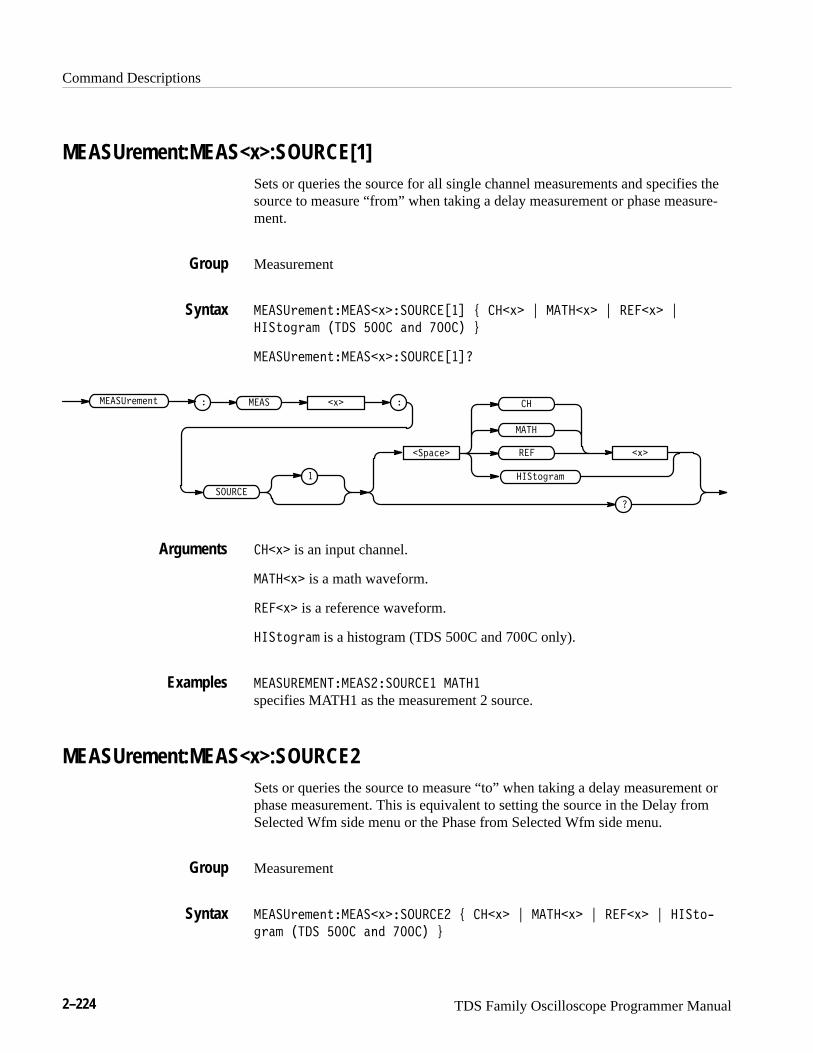
Command Descriptions
2–224 TDS Family Oscilloscope Programmer Manual
MEASUrement:MEAS<x>:SOURCE[1]Sets or queries the source for all single channel measurements and specifies thesource to measure “from” when taking a delay measurement or phase measure-ment.
Measurement
�� ��& " #'�� �(���������� ) ��(� * � ��(� * ���(� *
���'$!&�" ���� ���� �#� ������+
�� ��& " #'�� �(�����������
����%�� �
�
� ��
(�
�� ��& " #'
������
�
��
���'$!&�"
�� � (�
��(� is an input channel.
� ��(� is a math waveform.
���(� is a reference waveform.
���'$!&�" is a histogram (TDS 500C and 700C only).
�� ���������� ��������� � ���
specifies MATH1 as the measurement 2 source.
MEASUrement:MEAS<x>:SOURCE2Sets or queries the source to measure “to” when taking a delay measurement orphase measurement. This is equivalent to setting the source in the Delay fromSelected Wfm side menu or the Phase from Selected Wfm side menu.
Measurement
�� ��& " #'�� �(�������� ) ��(� * � ��(� * ���(� * ���'$,
!&�" ���� ���� �#� ����� +
Group
Syntax
Arguments
Examples
Group
Syntax
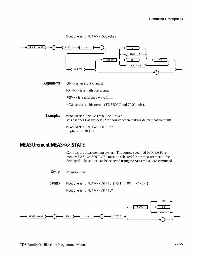
Command Descriptions
TDS Family Oscilloscope Programmer Manual 2–225
��������������� ���������
����������
�
��
� �
����������
��������
� ���� � �
������
� � is an input channel.
�� � � is a math waveform.
���� � is a reference waveform.
�������� is a histogram (TDS 500C and 700C only).
���������������������� � �
sets channel 1 as the delay “to” source when making delay measurements.
�����������������������
might return �� �.
MEASUrement:MEAS<x>:STATEControls the measurement system. The source specified by MEASUre-ment:MEAS<x>:SOURCE1 must be selected for the measurement to bedisplayed. The source can be selected using the SELect:CH<x> command.
Measurement
��������������� ������ ! ��� " �� " ����� #
��������������� �������
��
�����
���� ����������� ����� �
�������
���
�
Arguments
Examples
Group
Syntax
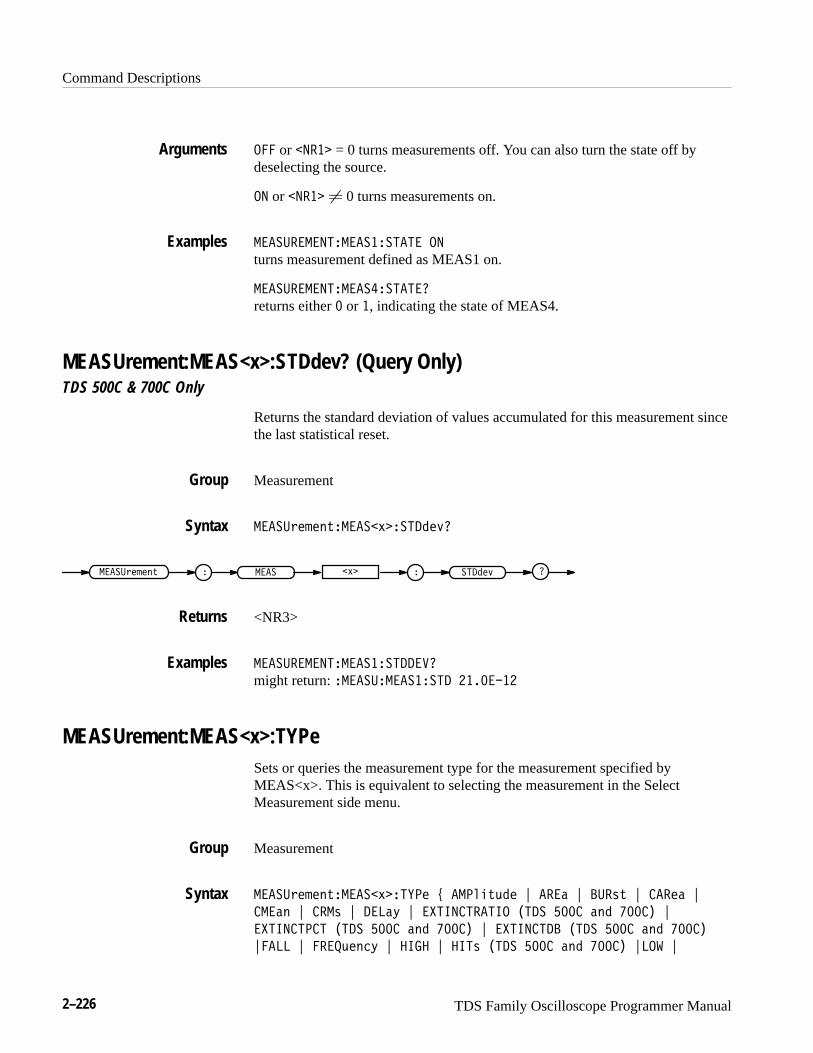
Command Descriptions
2–226 TDS Family Oscilloscope Programmer Manual
��� or ���� = 0 turns measurements off. You can also turn the state off bydeselecting the source.
�� or ���� � 0 turns measurements on.
��� "�����!���� �� !�!� ��
turns measurement defined as MEAS1 on.
��� "�����!���� � !�!��
returns either � or �, indicating the state of MEAS4.
MEASUrement:MEAS<x>:STDdev? (Query Only)TDS 500C & 700C Only
Returns the standard deviation of values accumulated for this measurement sincethe last statistical reset.
Measurement
��� "/*-*.1���� 4�� !�)*3�
���� "/*-*.1 ��� 4� �� !�)*3
<NR3>
��� "�����!���� �� !���#�
might return: ���� "���� �� !� ��������
MEASUrement:MEAS<x>:TYPeSets or queries the measurement type for the measurement specified byMEAS<x>. This is equivalent to selecting the measurement in the SelectMeasurement side menu.
Measurement
��� "/*-*.1���� 4��!&�* 6 ���,+12)* 7 ���' 7 �"�01 7 ���*' 7
���'. 7 ���0 7 ���'5 7 �%!���!��!�� �!� ��� '.) ����� 7
�%!���!��! �!� ��� '.) ����� 7 �%!���!�� �!� ��� '.) �����
7���� 7 ����2*.(5 7 ���� 7 ��!0 �!� ��� '.) ����� 7��$ 7
Arguments
Examples
Group
Syntax
Returns
Examples
Group
Syntax
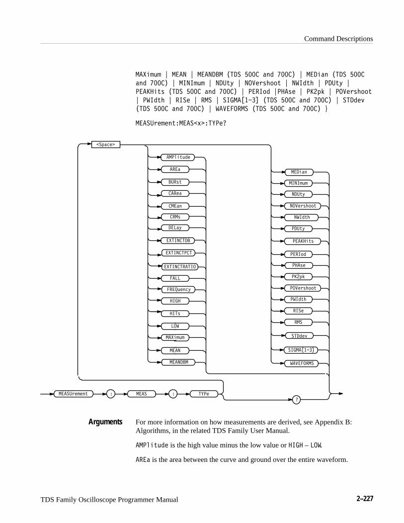
Command Descriptions
TDS Family Oscilloscope Programmer Manual 2–227
��%.181 < ���� < ������� �!� ��� )2+ ���� < ���.)2 �!� ���
)2+ ���� < ����181 < ��"7; < ��#,56-337 < �$�+7- < ��"7; <
�����.76 �!� ��� )2+ ���� < ����3+ <���6, < ���4/ < ��#,56-337
< �$�+7- < �� , < �� < ����'���( �!� ��� )2+ ���� < !�+,9
�!� ��� )2+ ���� < $�#����� �!� ��� )2+ ���� =
��� "5,1,27���� �: �!&�,�
���� "5,1,27 ��� � !&�,
� 4)*,
��#,56-337
�
����
����
����181
��$
���6
���0.78+,
����8,2*;
���)
���); ��"7;
��%.181
��"7;
�$�+7-
��#,56-337
�$�+7-
��
����3+
���4/
�� ,
����
�"�67
���,)
���6,
���)2
$�#�����
���.)2
!�+,9
����'���(
�����.76
�%!���!��!
�%!���!��
�������
�%!���!��!��
��!6
For more information on how measurements are derived, see Appendix B:Algorithms, in the related TDS Family User Manual.
���0.78+, is the high value minus the low value or ���� – ��$.
���) is the area between the curve and ground over the entire waveform.
Arguments

Command Descriptions
2–228 TDS Family Oscilloscope Programmer Manual
��� ! is the time from the first MidRef crossing to the last MidRef crossing.
����� (cycle area) is the area between the curve and ground over one cycle.
����� is the arithmetic mean over one cycle.
��� is the true Root Mean Square voltage over one cycle.
���# is the time between the MidRef crossings of two different waveforms.
�������� (TDS 500C and 700C) is 10.0 * log10(Extinction Ratio)
��������� (TDS 500C and 700C) is 100/Extinction Ratio
��������� (TDS 500C and 700C) is High/Low
�� is the time that it takes for the falling edge of a pulse to fall from a HighRefvalue to a LowRef value of its final value.
����"���# is the reciprocal of the period measured in hertz.
��� is the 100% reference level.
�� (TDS 500C and 700C) displays the number of acquired point within or onthe histogram box.
� is the 0% reference level.
�����"� is the highest amplitude (voltage).
���� for general purpose measurements, is the arithmetic mean over the entirewaveform. For histogram measurements, it is the average of all acquired pointswithin or on the histogram box.
������� (TDS 500C and 700C) is 10 * log10(MEAN/0.001) a value equal to
������ (TDS 500C and 700C) is the median of all acquired points within or onthe histogram box. Half of the acquired points are greater than and half less thanthis value.
���"� is the lowest amplitude (voltage).
���!# is the ratio of the negative pulse width to the signal period expressed as apercentage.
� ��� ���! is the negative overshoot, expressed as:
NOVershoot� 100��(Low�Minimum)Amplitude
�
���!� is the distance (time) between MidRef (usually 50%) amplitude points ofa negative pulse.
Command Descriptions
TDS Family Oscilloscope Programmer Manual 2–229
���%' is the ratio of the positive pulse width to the signal period expressed as apercentage.
�����%$ (TDS 500C and 700C)������� �� ����� �� �� �� �� �������� �� �� ��������
�� !� is the time, in seconds, it takes for one complete signal cycle to happen.
���$� is the amount of shift, expressed in degrees, from the selected waveformto the designated waveform.
���" is the absolute difference between the maximum and minimum amplitude.It can be used with both general purpose and histogram measurements. Forhistogram measurements, it is the value of the highest nonzero bin minus thevalue of the lowest nonzero bin.
����#$�!!% is the positive overshoot, expressed as:
POVershoot� 100��(Maximum� High)Amplitude
�
�� �%� is the distance (time) between MidRef (usually 50%) amplitude points ofa positive pulse.
� �� is the time that it takes for the leading edge of a pulse to rise from a lowreference value to a high reference value of its final value.
��� is the true Root Mean Square voltage.
� �������� (TDS 500C and 700C) is the percentage of points in the histogramwhich are within 1, 2, or 3 standard deviations of the histogram mean. In anormal distribution, 66% of the points are within +–1 standard deviation, 95% ofthe points are within +–2 standard deviations, and 97.5% of the points are within+–3 standard deviations of the histogram mean.
�����& (TDS 500C and 700C) is the standard deviation of all acquired pointswithin or on the histogram box.
������� (TDS 500C and 700C) is the number of waveforms that havecontributed to the histogram. A waveform is counted even if no points werewithin the histogram box.
����������������� ���
specifies MEAS3 to calculate the Root Mean Square voltage.Examples
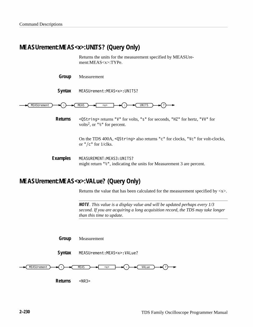
Command Descriptions
2–230 TDS Family Oscilloscope Programmer Manual
MEASUrement:MEAS<x>:UNITS? (Query Only)Returns the units for the measurement specified by MEASUre-ment:MEAS<x>:TYPe.
Measurement
�������������!��������
��� ���������� ������!� �
��������� returns ��� for volts, ��� for seconds, ���� for hertz, ���� forvolts2, or ��� for percent.
On the TDS 400A, ��������� also returns ��� for clocks, ���� for volt-clocks,or ���� for 1/clks.
������������������
might return ���, indicating the units for Measurement 3 are percent.
MEASUrement:MEAS<x>:VALue? (Query Only)Returns the value that has been calculated for the measurement specified by <x>.
NOTE. This value is a display value and will be updated perhaps every 1/3second. If you are acquiring a long acquisition record, the TDS may take longerthan this time to update.
Measurement
�������������!��� ��
��������� � �� ��!� � � �
�����
Group
Syntax
Returns
Examples
Group
Syntax
Returns

Command Descriptions
TDS Family Oscilloscope Programmer Manual 2–231
MEASUrement:METHodSets or queries the method used to calculate the 0% and 100% reference level.This is equivalent to setting the High-Low Setup in the Measure menu.
Measurement
����� ����!������� $ ���!�� �� % �����# &
����� ����!��������
����� ����! � ������
�������
�
�����#
���!�� ��
���!�� �� sets the high and low waveform levels statistically using a histogramalgorithm.
�����# sets the high and low waveform levels to MAX and MIN, respectively.
������������������ ��������
specifies that the high and low reference levels are set statistically.
�������������������
returns ������ when the reference levels are set to MIN and MAX.
MEASUrement:REFLevel? (Query Only)Returns the reference levels.
Measurement
����� ����!��� �"���
����� ����! � �� �"�� �
Group
Syntax
Arguments
Examples
Group
Syntax
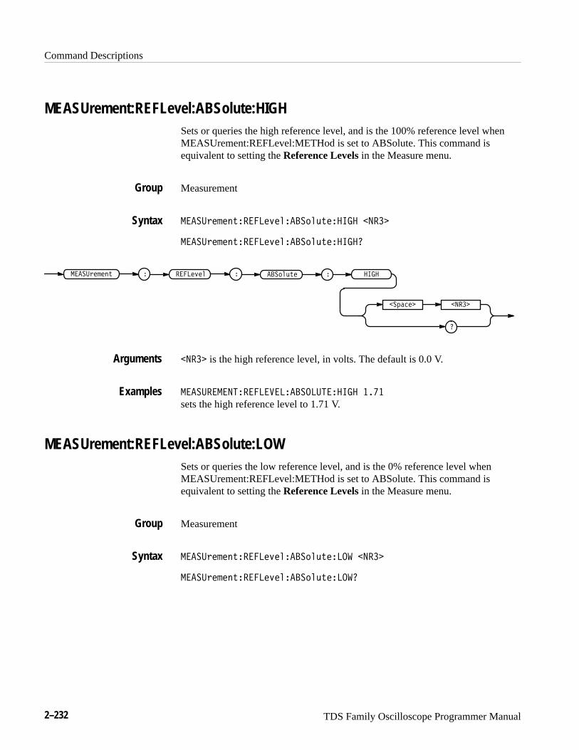
Command Descriptions
2–232 TDS Family Oscilloscope Programmer Manual
MEASUrement:REFLevel:ABSolute:HIGHSets or queries the high reference level, and is the 100% reference level whenMEASUrement:REFLevel:METHod is set to ABSolute. This command isequivalent to setting the Reference Levels in the Measure menu.
Measurement
����#��� $��� ��&�����!�%$������ �����
����#��� $��� ��&�����!�%$������
����
��"���� �����
����#��� $ � �� ��&�� � ��!�%$� �
����� is the high reference level, in volts. The default is 0.0 V.
������������� ������������������ ����
sets the high reference level to 1.71 V.
MEASUrement:REFLevel:ABSolute:LOWSets or queries the low reference level, and is the 0% reference level whenMEASUrement:REFLevel:METHod is set to ABSolute. This command isequivalent to setting the Reference Levels in the Measure menu.
Measurement
����#��� $��� ��&�����!�%$����� �����
����#��� $��� ��&�����!�%$�����
Group
Syntax
Arguments
Examples
Group
Syntax
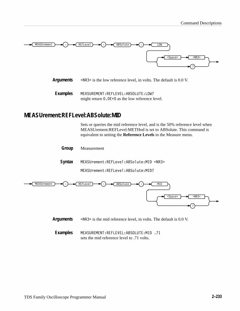
Command Descriptions
TDS Family Oscilloscope Programmer Manual 2–233
���
�
�#��� ���
�����$� �!% � �����'�� � � �"�&%� �
��� is the low reference level, in volts. The default is 0.0 V.
���������������������� �����������
might return ������ as the low reference level.
MEASUrement:REFLevel:ABSolute:MIDSets or queries the mid reference level, and is the 50% reference level whenMEASUrement:REFLevel:METHod is set to ABSolute. This command isequivalent to setting the Reference Levels in the Measure menu.
Measurement
�����$� �!%������'���� �"�&%����� ���
�����$� �!%������'���� �"�&%������
���
�
�#��� ���
�����$� �!% � �����'�� � � �"�&%� �
��� is the mid reference level, in volts. The default is 0.0 V.
���������������������� ���������� ���
sets the mid reference level to .71 volts.
Arguments
Examples
Group
Syntax
Arguments
Examples
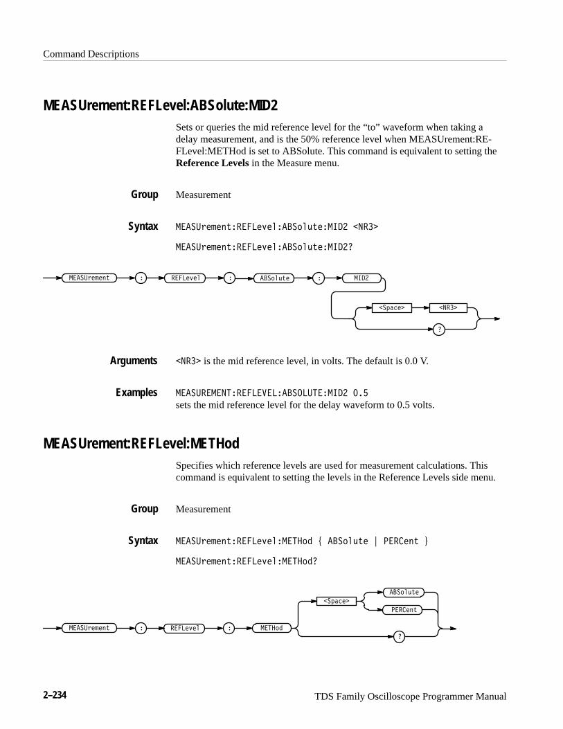
Command Descriptions
2–234 TDS Family Oscilloscope Programmer Manual
MEASUrement:REFLevel:ABSolute:MID2Sets or queries the mid reference level for the “to” waveform when taking adelay measurement, and is the 50% reference level when MEASUrement:RE-FLevel:METHod is set to ABSolute. This command is equivalent to setting theReference Levels in the Measure menu.
Measurement
�����& " #'����� ) !����$!(' ����� ����
�����& " #'����� ) !����$!(' �����
����
��%�� ����
�����& " #' � ���� ) ! � ���$!(' �
���� is the mid reference level, in volts. The default is 0.0 V.
���������������������������������� ���
sets the mid reference level for the delay waveform to 0.5 volts.
MEASUrement:REFLevel:METHodSpecifies which reference levels are used for measurement calculations. Thiscommand is equivalent to setting the levels in the Reference Levels side menu.
Measurement
�����& " #'����� ) !�����$� * ���$!(' + ��� #' ,
�����& " #'����� ) !�����$�
����$������& " #' � ���� ) ! �
��%��
���$!('
��� #'
Group
Syntax
Arguments
Examples
Group
Syntax
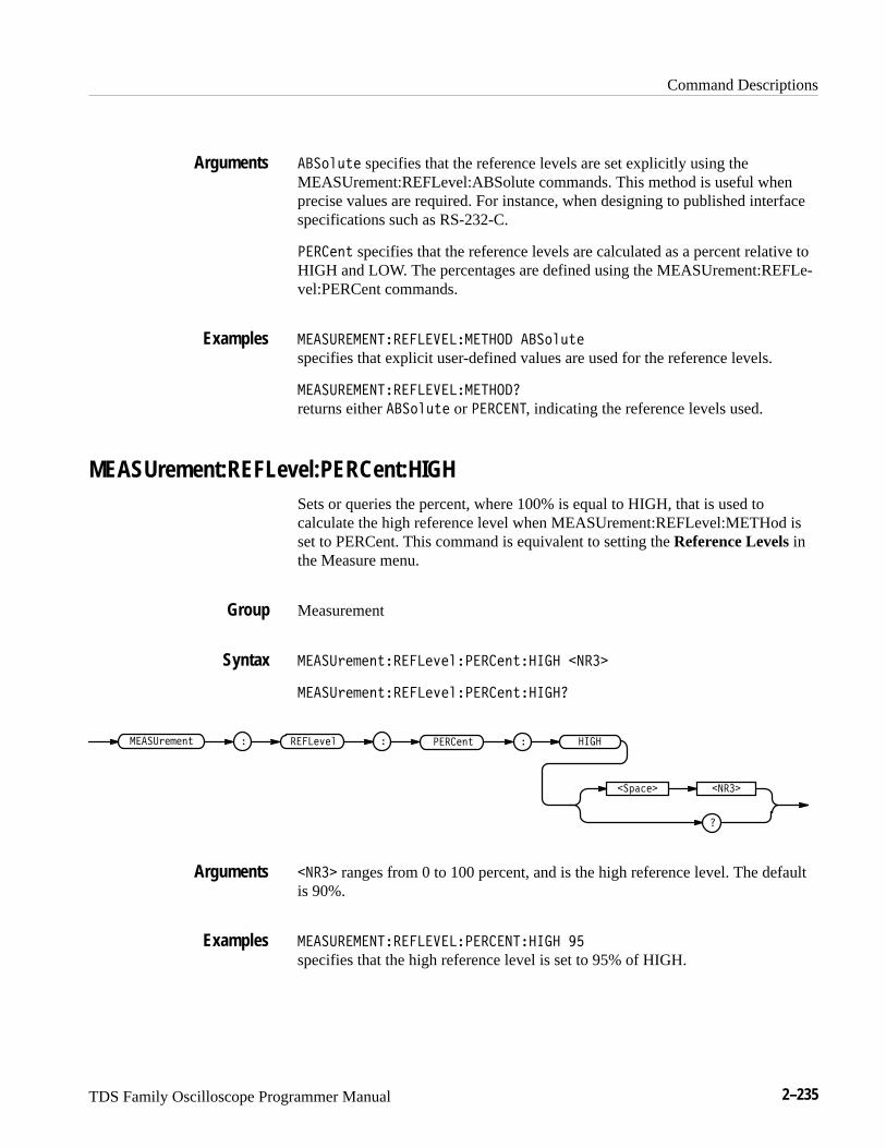
Command Descriptions
TDS Family Oscilloscope Programmer Manual 2–235
�"�&%� specifies that the reference levels are set explicitly using theMEASUrement:REFLevel:ABSolute commands. This method is useful whenprecise values are required. For instance, when designing to published interfacespecifications such as RS-232-C.
� ���!% specifies that the reference levels are calculated as a percent relative toHIGH and LOW. The percentages are defined using the MEASUrement:REFLe-vel:PERCent commands.
� ��� � ���� �� � ��� ���� �"�&%�
specifies that explicit user-defined values are used for the reference levels.
� ��� � ���� �� � ��� �����
returns either �"�&%� or � �� ��, indicating the reference levels used.
MEASUrement:REFLevel:PERCent:HIGHSets or queries the percent, where 100% is equal to HIGH, that is used tocalculate the high reference level when MEASUrement:REFLevel:METHod isset to PERCent. This command is equivalent to setting the Reference Levels inthe Measure menu.
Measurement
� ��$� �!%�� ���'���� ���!%����� �����
� ��$� �!%�� ���'���� ���!%������
����
�
��#���� �����
� ��$� �!% � � ���'�� � � ���!% �
����� ranges from 0 to 100 percent, and is the high reference level. The defaultis 90%.
� ��� � ���� �� � ��� �� ������� ��
specifies that the high reference level is set to 95% of HIGH.
Arguments
Examples
Group
Syntax
Arguments
Examples
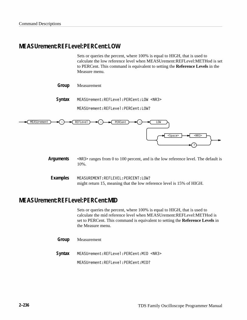
Command Descriptions
2–236 TDS Family Oscilloscope Programmer Manual
MEASUrement:REFLevel:PERCent:LOWSets or queries the percent, where 100% is equal to HIGH, that is used tocalculate the low reference level when MEASUrement:REFLevel:METHod is setto PERCent. This command is equivalent to setting the Reference Levels in theMeasure menu.
Measurement
��������� ��� �!�������� � �� �����
��������� ��� �!�������� � ���
��
�
������� �����
��������� � �� �!�� � ����� �
����� ranges from 0 to 100 percent, and is the low reference level. The default is10%.
����������� � ������� ���
might return 15, meaning that the low reference level is 15% of HIGH.
MEASUrement:REFLevel:PERCent:MIDSets or queries the percent, where 100% is equal to HIGH, that is used tocalculate the mid reference level when MEASUrement:REFLevel:METHod isset to PERCent. This command is equivalent to setting the Reference Levels inthe Measure menu.
Measurement
��������� ��� �!�������� ��� �����
��������� ��� �!�������� ����
Group
Syntax
Arguments
Examples
Group
Syntax
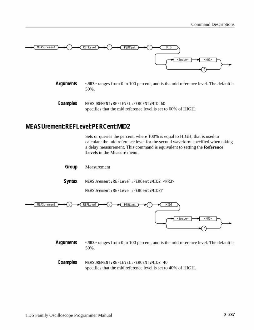
Command Descriptions
TDS Family Oscilloscope Programmer Manual 2–237
��
�� ��� ����
�����!����" � �����#�� � ������" �
���� ranges from 0 to 100 percent, and is the mid reference level. The default is50%.
������������������������������� ��
specifies that the mid reference level is set to 60% of HIGH.
MEASUrement:REFLevel:PERCent:MID2Sets or queries the percent, where 100% is equal to HIGH, that is used tocalculate the mid reference level for the second waveform specified when takinga delay measurement. This command is equivalent to setting the ReferenceLevels in the Measure menu.
Measurement
�����!����"������#���������"��� � ����
�����!����"������#���������"��� �
�� �
�� ��� ����
�����!����" � �����#�� � ������" �
���� ranges from 0 to 100 percent, and is the mid reference level. The default is50%.
������������������������������� � ��
specifies that the mid reference level is set to 40% of HIGH.
Arguments
Examples
Group
Syntax
Arguments
Examples
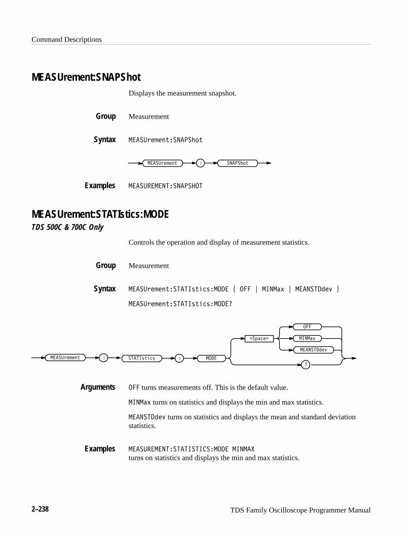
Command Descriptions
2–238 TDS Family Oscilloscope Programmer Manual
MEASUrement:SNAPShotDisplays the measurement snapshot.
Measurement
��� ����"��������"
�������" ��� ����" �
���� �����������
MEASUrement:STATIstics:MODETDS 500C & 700C Only
Controls the operation and display of measurement statistics.
Measurement
��� ����"������!"��!� �� % � & �� �$ & �������# '
��� ����"������!"��!� ���
�� �$
� � ��� ����" ��
�������
�
�
�����!"��!
�������#
� turns measurements off. This is the default value.
�� �$ turns on statistics and displays the min and max statistics.
�������# turns on statistics and displays the mean and standard deviationstatistics.
���� �������������� �� �� ��
turns on statistics and displays the min and max statistics.
Group
Syntax
Examples
Group
Syntax
Arguments
Examples
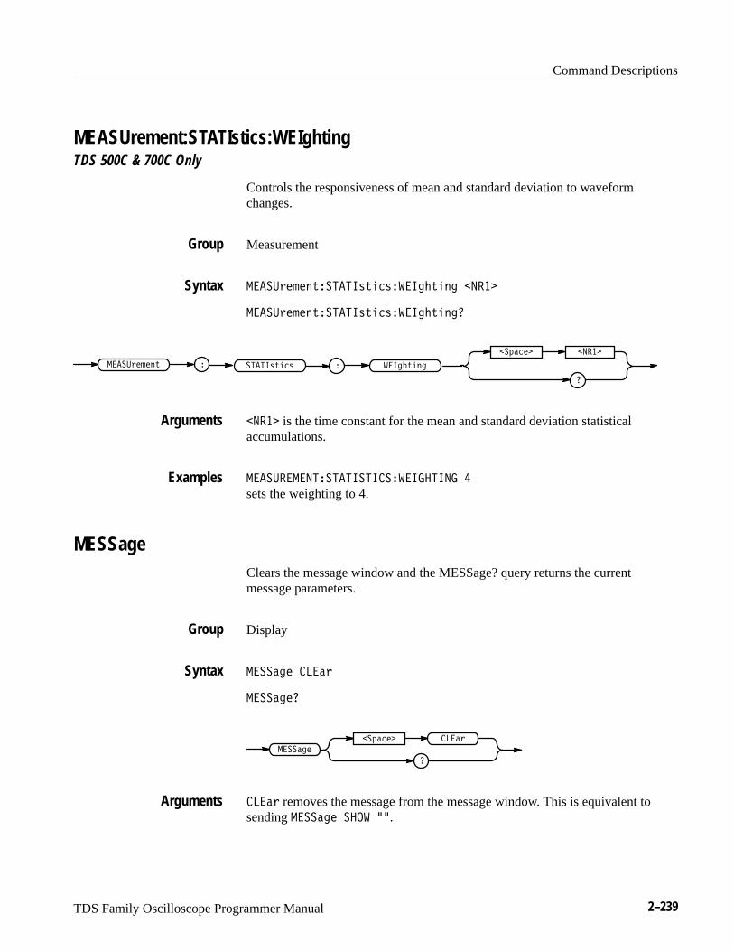
Command Descriptions
TDS Family Oscilloscope Programmer Manual 2–239
MEASUrement:STATIstics:WEIghtingTDS 500C & 700C Only
Controls the responsiveness of mean and standard deviation to waveformchanges.
Measurement
����!����#�����"#��"������#��� �����
����!����#�����"#��"������#����
� �����!����# ����"#��"
�
�� ���� �����
�����#���
����� is the time constant for the mean and standard deviation statisticalaccumulations.
������������������������ ���� �
sets the weighting to 4.
MESSageClears the message window and the MESSage? query returns the currentmessage parameters.
Display
������� ���!
��������
��������� ����
�
���!
���! removes the message from the message window. This is equivalent tosending ������� � �� ��.
Group
Syntax
Arguments
Examples
Group
Syntax
Arguments

Command Descriptions
2–240 TDS Family Oscilloscope Programmer Manual
���� � ����
clears the message from the window.
MESSage:BOXDefines the size and position of the message window. This command does notdisplay the window unless MESSage:STATE is ON.
Display
���������� �������������������
�����������
���
�������
�
�������
���� ���� ���� ����
���� and ���� = 0 to 640, and are pixel positions along the horizontal axis. ����
defines the left and ���� defines the right side of the window.
���� and ���� = 0 to 480, and are pixel positions along the vertical axis. ����
defines the top and ���� defines the bottom of the window. The reserved heightof all characters is 15 pixels so the window must be at least that high to fullydisplay characters. For a complete list of character widths in pixels, see TableA–1 on page A–1. Shorter windows clip characters.
Figure 3-1 shows the coordinate system relative to the screen.
Examples
Group
Syntax
Arguments
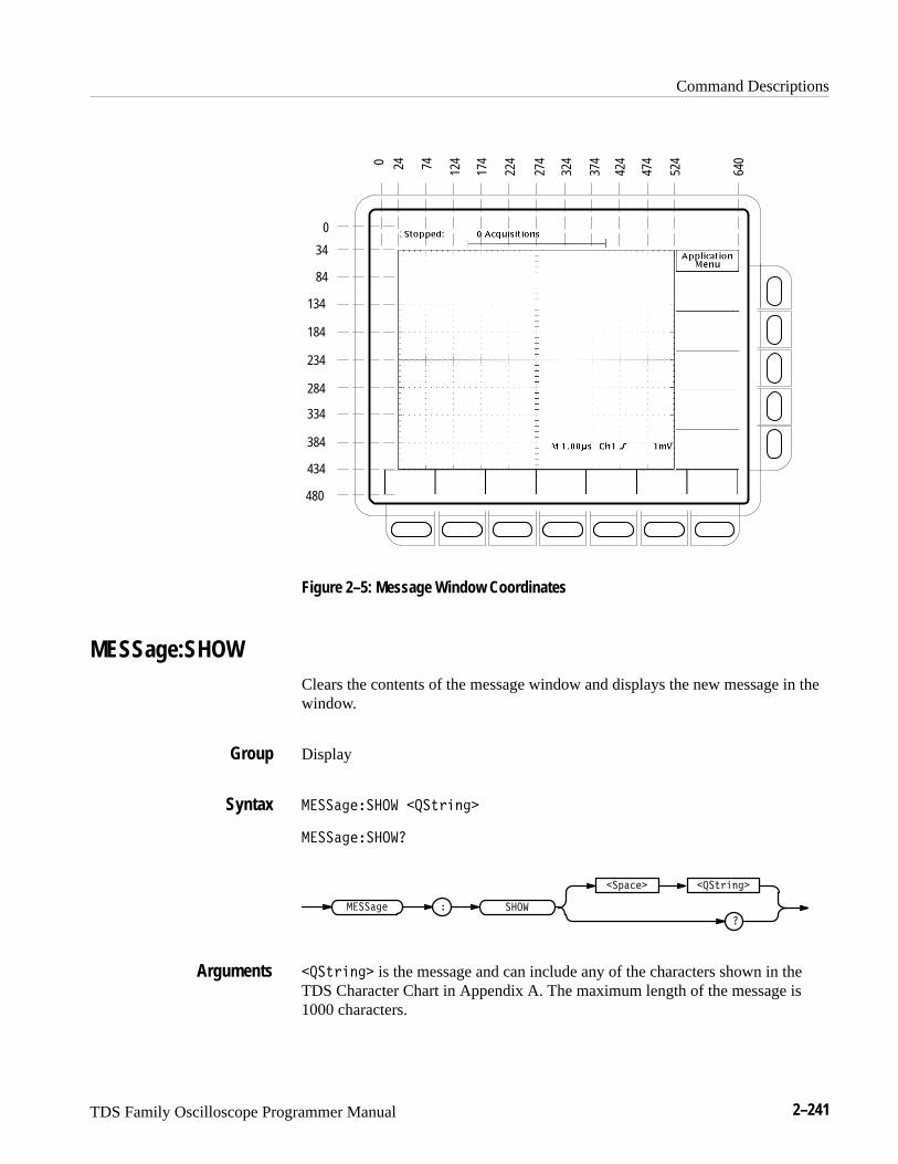
Command Descriptions
TDS Family Oscilloscope Programmer Manual 2–241
0
34
84
480
134
184
234
284
334
384
434
0 24 74 124
174
224
274
324
374
424
474
524
640
Figure 2–5: Message Window Coordinates
MESSage:SHOWClears the contents of the message window and displays the new message in thewindow.
Display
���� ������ ��������
���� �������
����
��� ���
�
���� ��
��������
�������� is the message and can include any of the characters shown in theTDS Character Chart in Appendix A. The maximum length of the message is1000 characters.
Group
Syntax
Arguments
Command Descriptions
2–242 TDS Family Oscilloscope Programmer Manual
The message is left-justified, and is displayed on a single line starting with thetop most line in the window. A line feed character can be embedded in the stringto position the message on multiple lines. You can also use white space and tabcharacters to position the message within a line.
You can send a tab by transmitting a tab character (decimal 9) followed by twocharacters representing the most significant eight bits followed by the leastsignificant eight bits of a 16-bit number. The number specifies the pixel columnrelative to the left margin of the label area. For example, to tab to pixel 13, sendTAB (decimal 9), NUL (decimal 0), and CR (decimal 13).
The ESC character followed by the @ character turns inverse video on or off andcan be embedded in the message string. The first ESC character followed by a @character displays all the text that follows in inverse video until another ESCcharacter followed by a @ character is found in the string.
NOTE. The use of any escape codes other than those described above mayproduce unpredictable results.
The label area is the height and width you have set using the MESSage:Boxcommand. The length of the label that fits in the label area depends on thecontents of the label because the width of characters varies. For a complete list ofcharacter widths in pixels, see Table A–1 on page A–1.
If the message exceeds the limits of the window, either horizontally or vertically,the portion of the message that exceeds the limits will not be displayed. Themessage string itself is not altered. The entire message can be returned as a queryresponse regardless of what is displayed in the window.
��������� ����� ������
displays “Hello world” in the upper left corner of the box (you can define thebox size with the MESSAGE BOX command).
��������� ����� ��������� ��� �����
displays “Hello world ... hello” in the upper left corner of the box and the word“world” is displayed in inverse video. In this example, � stands for the escapecharacter. The escape character may appear differently for you depending on yourGPIB talker-listener program.
MESSage:STATEControls the display of the message window.
Display
Examples
Group
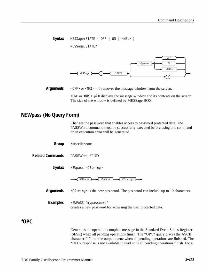
Command Descriptions
TDS Family Oscilloscope Programmer Manual 2–243
����������� # $ � $ ����� %
������������
���������� �
�������
�
�
�����
� � or ����� = 0 removes the message window from the screen.
� �� or ����� � 0 displays the message window and its contents on the screen.The size of the window is defined by MESSage:BOX.
NEWpass (No Query Form)Changes the password that enables access to password protected data. ThePASSWord command must be successfully executed before using this commandor an execution error will be generated.
Miscellaneous
PASSWord, *PUD
������ ��� �����
������ ������� ��� �����
��� ����� is the new password. The password can include up to 10 characters.
������ ��"����!����
creates a new password for accessing the user protected data.
*OPCGenerates the operation complete message in the Standard Event Status Register(SESR) when all pending operations finish. The *OPC? query places the ASCIIcharacter “1” into the output queue when all pending operations are finished. The*OPC? response is not available to read until all pending operations finish. For a
Syntax
Arguments
Group
Related Commands
Syntax
Arguments
Examples

Command Descriptions
2–244 TDS Family Oscilloscope Programmer Manual
complete discussion of the use of these registers and the output queue, see page3–1.
Status and Error
BUSY?, *WAI
����
�����
����
�
The *OPC command allows you to synchronize the operation of the digitizingoscilloscope with your application program. Synchronization methods aredescribed starting on page 3–7. Table 2–33 shows commands that generate anOperation Complete message.
Table 2–33: Commands that Generate an Operation Complete Message
Operation Command
Automatic scope adjustment AUTOSet EXECute
Internal self-calibration *CAL
Single sequence acquisition ACQuire:STATE ON orACQuire:STATE RUN (when ACQuire:STOPAfter is set toSEQuence)
Hardcopy output HARDCopy STARt
*OPT? (Query Only)Not on TDS 400A
Returns a list of options installed in your digitizing oscilloscope.
Status and Error
�����
Group
Related Commands
Syntax
Group
Syntax
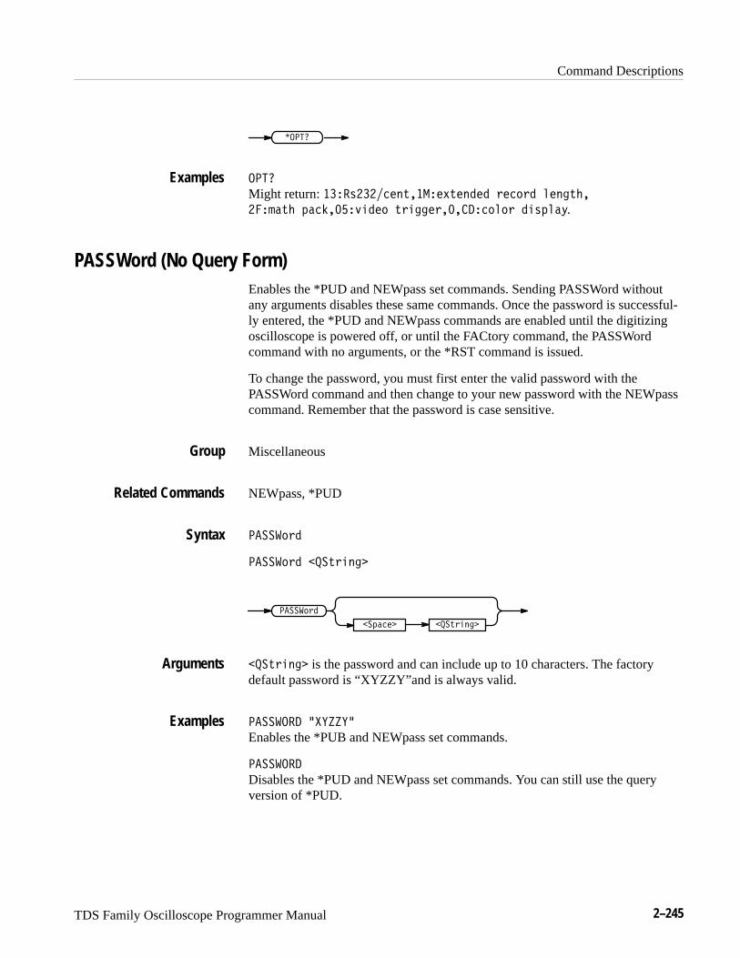
Command Descriptions
TDS Family Oscilloscope Programmer Manual 2–245
�����
����
Might return: ���,����!(-����!/-!( ! +!�)+ &!("-#�
���'�-# *��%���.$ !) -+$""!+�������)&)+ $,*&�0.
PASSWord (No Query Form)Enables the *PUD and NEWpass set commands. Sending PASSWord withoutany arguments disables these same commands. Once the password is successful-ly entered, the *PUD and NEWpass commands are enabled until the digitizingoscilloscope is powered off, or until the FACtory command, the PASSWordcommand with no arguments, or the *RST command is issued.
To change the password, you must first enter the valid password with thePASSWord command and then change to your new password with the NEWpasscommand. Remember that the password is case sensitive.
Miscellaneous
NEWpass, *PUD
�����)+
�����)+ ���-+$("
���-+$("
�����)+
��*��!
���-+$(" is the password and can include up to 10 characters. The factorydefault password is “XYZZY”and is always valid.
�������� �������
Enables the *PUB and NEWpass set commands.
��������
Disables the *PUD and NEWpass set commands. You can still use the queryversion of *PUD.
Examples
Group
Related Commands
Syntax
Arguments
Examples
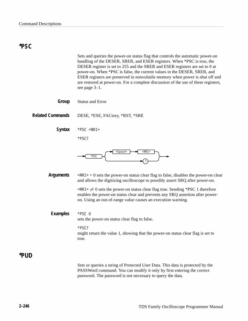
Command Descriptions
2–246 TDS Family Oscilloscope Programmer Manual
*PSCSets and queries the power-on status flag that controls the automatic power-onhandling of the DESER, SRER, and ESER registers. When *PSC is true, theDESER register is set to 255 and the SRER and ESER registers are set to 0 atpower-on. When *PSC is false, the current values in the DESER, SRER, andESER registers are preserved in nonvolatile memory when power is shut off andare restored at power-on. For a complete discussion of the use of these registers,see page 3–1.
Status and Error
DESE, *ESE, FACtory, *RST, *SRE
��� ����
����
���
�
��� ��� ����
���� = 0 sets the power-on status clear flag to false, disables the power-on clearand allows the digitizing oscilloscope to possibly assert SRQ after power-on.
���� � 0 sets the power-on status clear flag true. Sending *PSC 1 thereforeenables the power-on status clear and prevents any SRQ assertion after power-on. Using an out-of-range value causes an execution warning.
��� �
sets the power-on status clear flag to false.
����
might return the value 1, showing that the power-on status clear flag is set totrue.
*PUDSets or queries a string of Protected User Data. This data is protected by thePASSWord command. You can modify it only by first entering the correctpassword. The password is not necessary to query the data.
Group
Related Commands
Syntax
Arguments
Examples
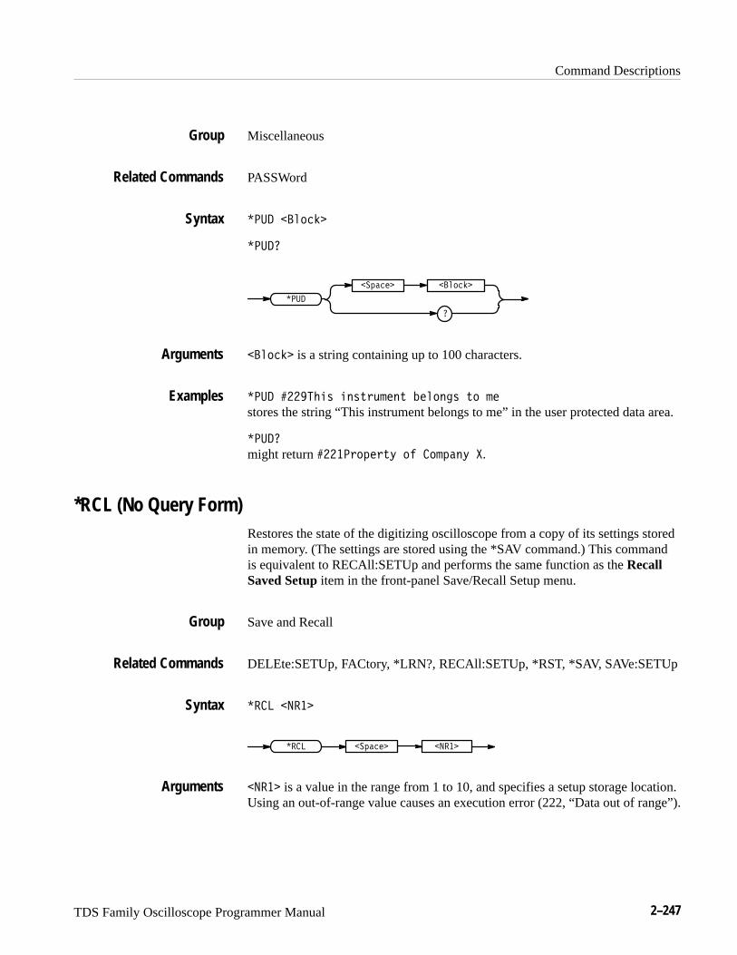
Command Descriptions
TDS Family Oscilloscope Programmer Manual 2–247
Miscellaneous
PASSWord
���� ��!���
����
����
��"���� ��!���
��!��� is a string containing up to 100 characters.
���� �������$ � $%#&�� % ���! �$ %! ��
stores the string “This instrument belongs to me” in the user protected data area.
����
might return �����#!"�#%' !� �!�"� ' �.
*RCL (No Query Form)Restores the state of the digitizing oscilloscope from a copy of its settings storedin memory. (The settings are stored using the *SAV command.) This commandis equivalent to RECAll:SETUp and performs the same function as the RecallSaved Setup item in the front-panel Save/Recall Setup menu.
Save and Recall
DELEte:SETUp, FACtory, *LRN?, RECAll:SETUp, *RST, *SAV, SAVe:SETUp
��� �����
�������� ��"����
����� is a value in the range from 1 to 10, and specifies a setup storage location.Using an out-of-range value causes an execution error (222, “Data out of range”).
Group
Related Commands
Syntax
Arguments
Examples
Group
Related Commands
Syntax
Arguments
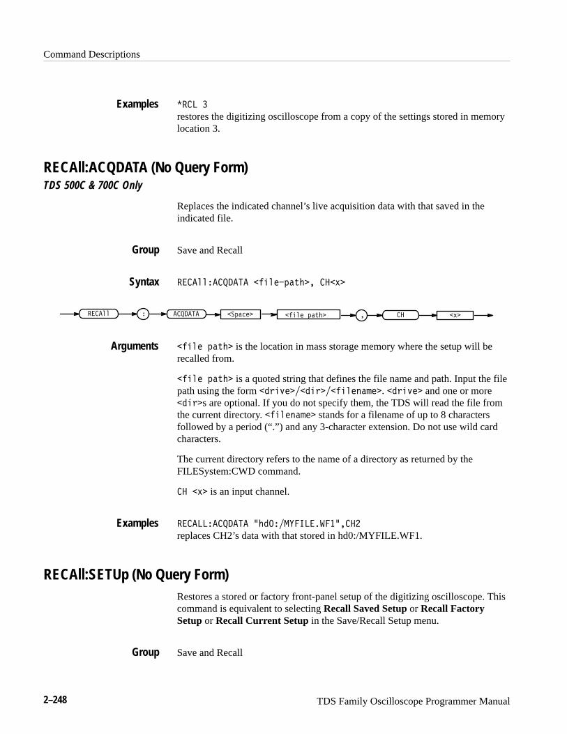
Command Descriptions
2–248 TDS Family Oscilloscope Programmer Manual
���� �
restores the digitizing oscilloscope from a copy of the settings stored in memorylocation 3.
RECAll:ACQDATA (No Query Form)TDS 500C & 700C Only
Replaces the indicated channel’s live acquisition data with that saved in theindicated file.
Save and Recall
����%%�������� "$%!�(�*#�� �� ,�
"$%! (�*#� �(��!�����%% � ������� �� ,��
"$%! (�*#� is the location in mass storage memory where the setup will berecalled from.
"$%! (�*#� is a quoted string that defines the file name and path. Input the filepath using the form )$+!�� $)�� "$%!'�&!�. )$+!� and one or more $)�s are optional. If you do not specify them, the TDS will read the file fromthe current directory. "$%!'�&!� stands for a filename of up to 8 charactersfollowed by a period (“.”) and any 3-character extension. Do not use wild cardcharacters.
The current directory refers to the name of a directory as returned by theFILESystem:CWD command.
�� ,� is an input channel.
�������������� -# ����������������
replaces CH2’s data with that stored in hd0:/MYFILE.WF1.
RECAll:SETUp (No Query Form)Restores a stored or factory front-panel setup of the digitizing oscilloscope. Thiscommand is equivalent to selecting Recall Saved Setup or Recall FactorySetup or Recall Current Setup in the Save/Recall Setup menu.
Save and Recall
Examples
Group
Syntax
Arguments
Examples
Group
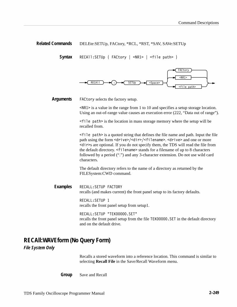
Command Descriptions
TDS Family Oscilloscope Programmer Manual 2–249
DELEte:SETUp, FACtory, *RCL, *RST, *SAV, SAVe:SETUp
����������# ( �%"$' ) ���� ) ����� #�%� *
����� #�%�
��#�������� �
�%"$'
����#
����
�%"$' selects the factory setup.
���� is a value in the range from 1 to 10 and specifies a setup storage location.Using an out-of-range value causes an execution error (222, “Data out of range”).
����� #�%� is the location in mass storage memory where the setup will berecalled from.
����� #�%� is a quoted string that defines the file name and path. Input the filepath using the form ��$�&�����$������!� �. ��$�&� and one or more���$s are optional. If you do not specify them, the TDS will read the file fromthe default directory. �����!� � stands for a filename of up to 8 charactersfollowed by a period (“.”) and any 3-character extension. Do not use wild cardcharacters.
The default directory refers to the name of a directory as returned by theFILESystem:CWD command.
����������� �����
recalls (and makes current) the front panel setup to its factory defaults.
����������� �
recalls the front panel setup from setup1.
����������� +�������������
recalls the front panel setup from the file ������������ in the default directoryand on the default drive.
RECAll:WAVEform (No Query Form)File System Only
Recalls a stored waveform into a reference location. This command is similar toselecting Recall File in the Save/Recall Waveform menu.
Save and Recall
Related Commands
Syntax
Arguments
Examples
Group
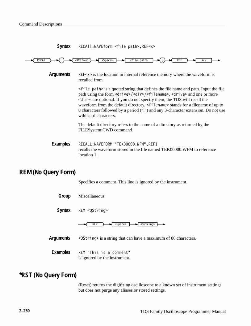
Command Descriptions
2–250 TDS Family Oscilloscope Programmer Manual
� ��!!���� �$&" � !� %�(��� �*
� ��!! � ��� �$&" � !� %�(� � � *��%���
� �* is the location in internal reference memory where the waveform isrecalled from.
� !� %�(� is a quoted string that defines the file name and path. Input the filepath using the form �& )��� &�� !�#�"�. �& )� and one or more� &s are optional. If you do not specify them, the TDS will recall thewaveform from the default directory. � !�#�"� stands for a filename of up to8 characters followed by a period (“.”) and any 3-character extension. Do not usewild card characters.
The default directory refers to the name of a directory as returned by theFILESystem:CWD command.
� �������� ���� +� ������������� ��
recalls the waveform stored in the file named TEK00000.WFM to referencelocation 1.
REM (No Query Form)Specifies a comment. This line is ignored by the instrument.
Miscellaneous
� � ��(& #�
� � �%��� ��(& #�
��(& #� is a string that can have a maximum of 80 characters.
� � ��� ' ' � �$""�#(�
is ignored by the instrument.
*RST (No Query Form)(Reset) returns the digitizing oscilloscope to a known set of instrument settings,but does not purge any aliases or stored settings.
Syntax
Arguments
Examples
Group
Syntax
Arguments
Examples
Command Descriptions
TDS Family Oscilloscope Programmer Manual 2–251
Status and Error
FACtory, *PSC, *RCL, RECAll:SETUp, *SAV, SAVe:SETUp
� ��
� ��
*RST returns the instrument settings to the factory defaults (see Appendix D:Factory Initialization Settings).
The *RST command does not alter the following:
� The state of the IEEE Std 488.1–1987 interface.
� The selected IEEE Std 488.1–1987 address of the digitizing oscilloscope.
� Calibration data that affect device specifications.
� The Output Queue.
� The Service Request Enable Register setting.
� The Standard Event Status Enable Register setting.
� The Power-on status clear flag setting.
� Alias definitions.
� Stored settings.
� The *PUD? response.
RS232:BAUdRS-232/Centronics Hardcopy Interface Only
Sets or queries RS-232-C interface transmission speed.
RS232
�������� �� ��
��������
Group
Related Commands
Syntax
Group
Syntax

Command Descriptions
2–252 TDS Family Oscilloscope Programmer Manual
� ���
�"����
�
�����
����
���� where ���� can be 300, 600, 1200, 2400, 4800, 9600 or 19200.
������� �� ����
sets the transmission rate to 9600 baud.
RS232:HARDFlaggingRS-232/Centronics Hardcopy Interface Only
Sets or queries the input and output hard flagging over the RS-232 port. It usesthe RFR (Ready For Receive) and CTS (Clear To Send) lines to control datatransmission. On output, the oscilloscope transmits data only when CTS isasserted. When CTS is not asserted, the oscilloscope stops transmitting data. Oninput, it asserts RFR until the receive queue is full. Then it unasserts RFR to stoptransmission from an external printer. CTS remains unasserted until the receivequeue is not full. At that time, CTS is asserted again to restart transmission.
RS232
������� ��� ����!� # �� $ ��� $ ���� %
������� ��� ����!��
������ � ��� ����!�
�"����
��
�
���
����
��� or ����� � turn on hardflagging.
���� or ���� � turn off hardflagging.
������� ���� ����� ��
turns on hard flagging.
Arguments
Examples
Group
Syntax
Arguments
Examples
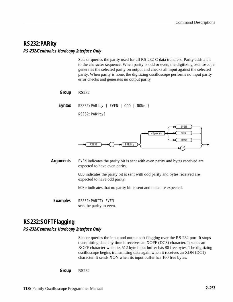
Command Descriptions
TDS Family Oscilloscope Programmer Manual 2–253
RS232:PARityRS-232/Centronics Hardcopy Interface Only
Sets or queries the parity used for all RS-232-C data transfers. Parity adds a bitto the character sequence. When parity is odd or even, the digitizing oscilloscopegenerates the selected parity on output and checks all input against the selectedparity. When parity is none, the digitizing oscilloscope performs no input parityerror checks and generates no output parity.
RS232
������������ � �� � � � �� �
�������������
������ ������
�������
�
� ��
��
�� indicates the parity bit is sent with even parity and bytes received areexpected to have even parity.
indicates the parity bit is sent with odd parity and bytes received areexpected to have odd parity.
� �� indicates that no parity bit is sent and none are expected.
������������ ��
sets the parity to even.
RS232:SOFTFlaggingRS-232/Centronics Hardcopy Interface Only
Sets or queries the input and output soft flagging over the RS-232 port. It stopstransmitting data any time it receives an XOFF (DC3) character. It sends anXOFF character when its 512 byte input buffer has 80 free bytes. The digitizingoscilloscope begins transmitting data again when it receives an XON (DC1)character. It sends XON when its input buffer has 100 free bytes.
RS232
Group
Syntax
Arguments
Examples
Group
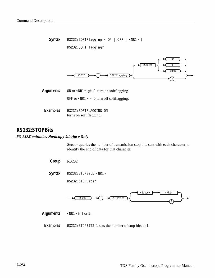
Command Descriptions
2–254 TDS Family Oscilloscope Programmer Manual
�������� � ������� ! �� " � " ���� #
�������� � �������
������ �� � �������
������
��
�
����
�� or ���� � � turn on softflagging.
� or ���� � � turn off softflagging.
�������� � ������� ��
turns on soft flagging.
RS232:STOPBitsRS-232/Centronics Hardcopy Interface Only
Sets or queries the number of transmission stop bits sent with each character toidentify the end of data for that character.
RS232
������������ � ����
������������ �
������ ��
������
�����
����
���� is 1 or 2.
�������������� � sets the number of stop bits to 1.
Syntax
Arguments
Examples
Group
Syntax
Arguments
Examples
Command Descriptions
TDS Family Oscilloscope Programmer Manual 2–255
RS232? (Query Only)RS-232/Centronics Hardcopy Interface Only
Queries the RS232 settings.
RS232
�����
�����
None
����� queries for RS232 settings.
It might return:
����� ���� ���� ������������ ���� ������������ ��� ������
����� �������� �
*SAV (No Query Form)(Save) stores the state of the digitizing oscilloscope into a specified memorylocation. You can later use the *RCL command to restore the digitizingoscilloscope to this saved state. This is equivalent to selecting the Save CurrentSetup in the Save/Recall Setup menu.
Save and Recall
DELEte:SETUp, FACtory, *RCL, RECAll:SETUp, SAVe:SETUp
���� �����
��������� ��# !"�
����� is a value in the range from 1 to 10 and specifies a location. Using anout-of-range value causes an execution error. Any settings that have been storedpreviously at this location will be overwritten.
Group
Syntax
Arguments
Examples
Group
Related Commands
Syntax
Arguments
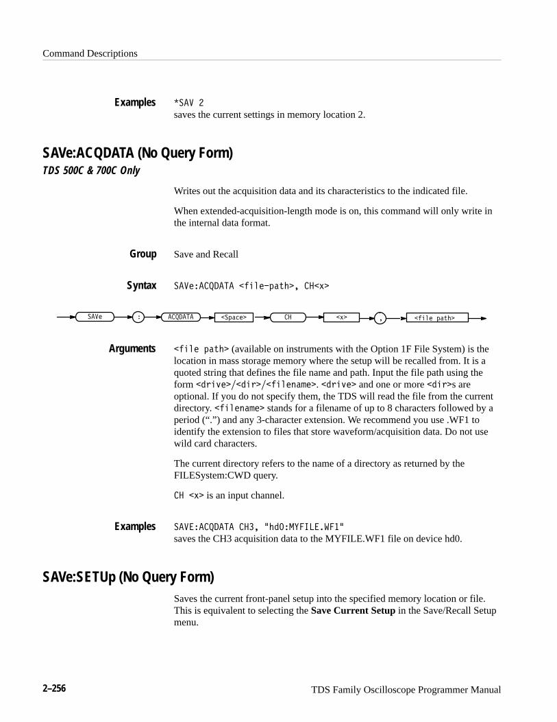
Command Descriptions
2–256 TDS Family Oscilloscope Programmer Manual
����
saves the current settings in memory location 2.
SAVe:ACQDATA (No Query Form)TDS 500C & 700C Only
Writes out the acquisition data and its characteristics to the indicated file.
When extended-acquisition-length mode is on, this command will only write inthe internal data format.
Save and Recall
���!�������� "$%!�(�*#�� �� ,�
"$%! (�*#� �(��!����! � ������� �� ,� �
"$%! (�*#� (available on instruments with the Option 1F File System) is thelocation in mass storage memory where the setup will be recalled from. It is aquoted string that defines the file name and path. Input the file path using theform )$+!�� $)�� "$%!'�&!�. )$+!� and one or more $)�s areoptional. If you do not specify them, the TDS will read the file from the currentdirectory. "$%!'�&!� stands for a filename of up to 8 characters followed by aperiod (“.”) and any 3-character extension. We recommend you use .WF1 toidentify the extension to files that store waveform/acquisition data. Do not usewild card characters.
The current directory refers to the name of a directory as returned by theFILESystem:CWD query.
�� ,� is an input channel.
������������ ���� �# ������������
saves the CH3 acquisition data to the MYFILE.WF1 file on device hd0.
SAVe:SETUp (No Query Form)Saves the current front-panel setup into the specified memory location or file.This is equivalent to selecting the Save Current Setup in the Save/Recall Setupmenu.
Examples
Group
Syntax
Arguments
Examples
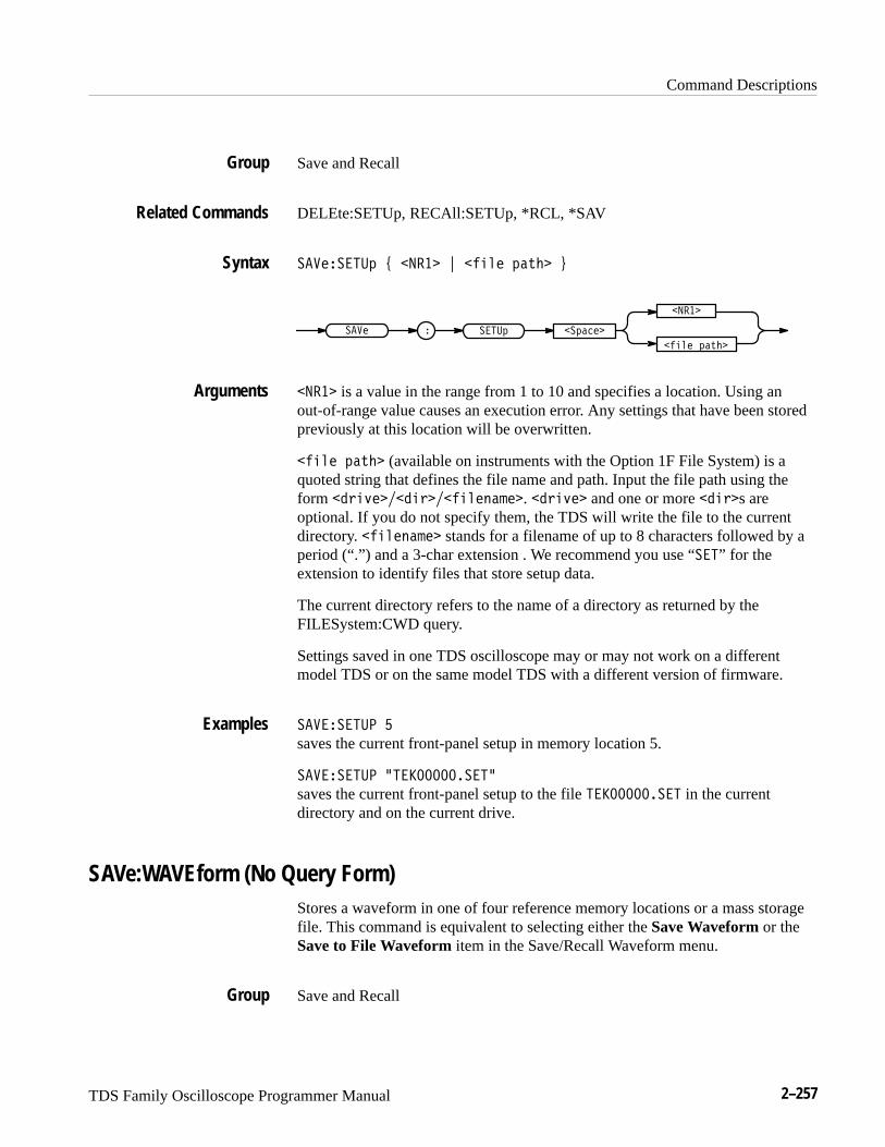
Command Descriptions
TDS Family Oscilloscope Programmer Manual 2–257
Save and Recall
DELEte:SETUp, RECAll:SETUp, *RCL, *SAV
��������� " � �� # ����� �� � $
� ��
��� � ����� ������
����� �� �
� �� is a value in the range from 1 to 10 and specifies a location. Using anout-of-range value causes an execution error. Any settings that have been storedpreviously at this location will be overwritten.
����� �� � (available on instruments with the Option 1F File System) is aquoted string that defines the file name and path. Input the file path using theform ����!����������������. ����!� and one or more ����s areoptional. If you do not specify them, the TDS will write the file to the currentdirectory. ��������� stands for a filename of up to 8 characters followed by aperiod (“.”) and a 3-char extension . We recommend you use “���” for theextension to identify files that store setup data.
The current directory refers to the name of a directory as returned by theFILESystem:CWD query.
Settings saved in one TDS oscilloscope may or may not work on a differentmodel TDS or on the same model TDS with a different version of firmware.
��������� �
saves the current front-panel setup in memory location 5.
��������� %������������%
saves the current front-panel setup to the file ������������ in the currentdirectory and on the current drive.
SAVe:WAVEform (No Query Form)Stores a waveform in one of four reference memory locations or a mass storagefile. This command is equivalent to selecting either the Save Waveform or theSave to File Waveform item in the Save/Recall Waveform menu.
Save and Recall
Group
Related Commands
Syntax
Arguments
Examples
Group
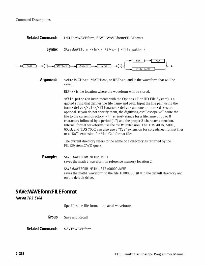
Command Descriptions
2–258 TDS Family Oscilloscope Programmer Manual
DELEte:WAVEform, SAVE:WAVEform:FILEFormat
����������#%! (�!�* ���) + �� � $�&� ,
�� � $�&�(�!���� � �����#%! �$���
��� )
�
(�! is CH<x>, MATH<x>, or REF<x>, and is the waveform that will besaved.
���) is the location where the waveform will be stored.
�� � $�&� (on instruments with the Options 1F or HD File System) is aquoted string that defines the file name and path. Input the file path using theform �%�'����%��� �"�!�. �%�'� and one or more ��%s areoptional. If you do not specify them, the digitizing oscilloscope will write thefile to the current directory. �� �"�!� stands for a filename of up to 8characters followed by a period (“.”) and the proper 3-character extension.Internal format waveforms use the “���” extension. The TDS 400A, 500C,600B, and TDS 700C can also use a “���” extension for spreadsheet format filesor a “ ��” extension for MathCad format files.
The current directory refers to the name of a directory as returned by theFILESystem:CWD query.
������������� ����������
saves the math 2 waveform in reference memory location 2.
������������� ������-������������-
saves the math1 waveform to the file ������������ in the default directory andon the default drive.
SAVe:WAVEform:FILEFormatNot on TDS 510A
Specifies the file format for saved waveforms.
Save and Recall
SAVE:WAVEform
Related Commands
Syntax
Arguments
Examples
Group
Related Commands

Command Descriptions
TDS Family Oscilloscope Programmer Manual 2–259
����������!��� �!��"# ������� $ ���������" $ ������� %
����������!��� �!��"�
���������"�� ����
�
�������
�������
� �!��"���� � �����!� �
������� specifies the internal format. Internal format files usually have a .wfmextension.
When Extended-Acquisition-Length mode is on, the convention is to use a .wf1extension. Also, the oscilloscope will only use this internal format with thismode.
���������" specifies the spreadsheet format. Spreadsheet format files usuallyhave a .CSV extension.
������� specifies the MathCad format. MathCad format files usually have a.DAT extension.
If you are writing a MathCad program, you should be aware that the TDS-MathCad file has the following features:
� ASCII format
� first four values contain header information
� first header value holds the TDS waveform record length
� second header value holds time, in seconds, between samples
� third header value holds the trigger position(expressed as an index in the data position. For extended-acquisition-lengthrecords, the index reported can be outside the waveform because the triggercan be outside the waveform. If before the waveform, it’s negative. If after,it’s a large positive)
� fourth header value refers to the fractional trigger position
� delimiters are carriage returns
������������ ����� ��������
specifies the waveform, when saved, will be stored in a spreadsheet-compatibleformat.
Syntax
Arguments
Examples
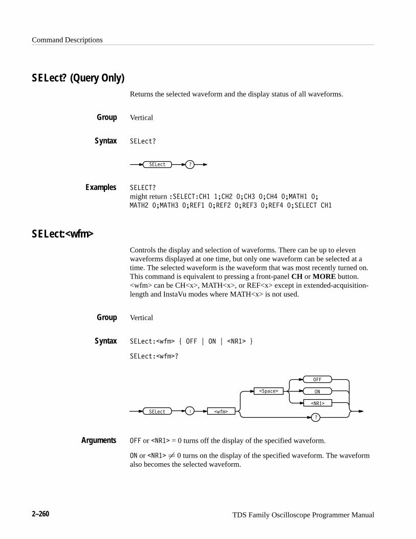
Command Descriptions
2–260 TDS Family Oscilloscope Programmer Manual
SELect? (Query Only)Returns the selected waveform and the display status of all waveforms.
Vertical
�������
������ �
���� ��
might return ����� �� �� �� �� �� �� �� �� ������� ��
����� ������� ������ ������ ������ ������ ������ � ��
SELect:<wfm>Controls the display and selection of waveforms. There can be up to elevenwaveforms displayed at one time, but only one waveform can be selected at atime. The selected waveform is the waveform that was most recently turned on.This command is equivalent to pressing a front-panel CH or MORE button.<wfm> can be CH<x>, MATH<x>, or REF<x> except in extended-acquisition-length and InstaVu modes where MATH<x> is not used.
Vertical
���������� ��� ! �� ! ��� "
�����������
�������
�����
���
�
��
���
���
��� or ��� = 0 turns off the display of the specified waveform.
�� or ��� � 0 turns on the display of the specified waveform. The waveformalso becomes the selected waveform.
Group
Syntax
Examples
Group
Syntax
Arguments
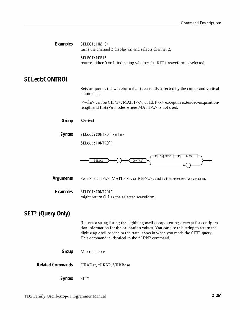
Command Descriptions
TDS Family Oscilloscope Programmer Manual 2–261
� ���� ��
turns the channel 2 display on and selects channel 2.
� ������
returns either � or �, indicating whether the REF1 waveform is selected.
SELect:CONTROlSets or queries the waveform that is currently affected by the cursor and verticalcommands.
<wfm> can be CH<x>, MATH<x>, or REF<x> except in extended-acquisition-length and InstaVu modes where MATH<x> is not used.
Vertical
� ���������� �����
� �����������
� ������� ���
�
������� �����
����� is CH<x>, MATH<x>, or REF<x>, and is the selected waveform.
� ������� �
might return �� as the selected waveform.
SET? (Query Only)Returns a string listing the digitizing oscilloscope settings, except for configura-tion information for the calibration values. You can use this string to return thedigitizing oscilloscope to the state it was in when you made the SET? query.This command is identical to the *LRN? command.
Miscellaneous
HEADer, *LRN?, VERBose
���
Examples
Group
Syntax
Arguments
Examples
Group
Related Commands
Syntax

Command Descriptions
2–262 TDS Family Oscilloscope Programmer Manual
&�' �
NOTE. The SET? query always returns a string with command headers,regardless of the setting of the HEADer command. This is because the returnedstring is intended to be able to be sent back to the digitizing oscilloscope as acommand string. The VERBose command can still be used to specify whether thereturned headers should be abbreviated or full length.
&�'�
a partial return string may look like this:���$(�%��&'"#��'�% %(!&'"#�&'�'� �� "�� &� #���!( �!) ���!( �)�
� �%�#�' ����## �!(�'�'�� ��5521.-6143 /37���������"''" �
����"''" ����"''" ����"''" � ����"''" � ����"''" ����"''" �
���%���'� ���%���' ��� %���' ���%���'� ���%���'� ���������%
���)�%�"&� �������&�&'�'� �����&#��,��"% �' ,'�&',�� )��'"%&�
���'�% &�!+�#�%&�&'�!�� ���������%�'��(�� �(���'%��' ���!'�!&�8
',�")�%��� ���*�)��"% ���'�+' ���"!'%�&' ����� �&&����&�"*
�0/224��&'�'� ���"+ ���������������"�� !"!�� ���%��"#,��"% �'
�#&� ����#"%' �#�����,"(' #"%'%��'�
*SRE(Service Request Enable) sets and queries the bits in the Service Request EnableRegister (SRER). For a complete discussion of the use of these registers, seepage 3–1.
Status and Error
*CLS, DESE, *ESE, *ESR?, EVENT?, EVMSg?, FACtory, *PSC, *STB?
�&%� �!%��
�&%��
�
�&5-./� �!%��
�&%�
�!%�� is a value in the range from 0 to 255. The binary bits of the SRER are setaccording to this value. Using an out-of-range value causes an execution error.
Examples
Group
Related Commands
Syntax
Arguments
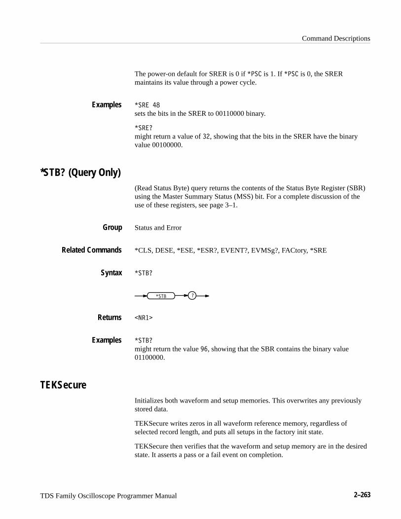
Command Descriptions
TDS Family Oscilloscope Programmer Manual 2–263
The power-on default for SRER is 0 if ���� is 1. If ���� is 0, the SRERmaintains its value through a power cycle.
���� ��
sets the bits in the SRER to 00110000 binary.
�����
might return a value of ��, showing that the bits in the SRER have the binaryvalue 00100000.
*STB? (Query Only)(Read Status Byte) query returns the contents of the Status Byte Register (SBR)using the Master Summary Status (MSS) bit. For a complete discussion of theuse of these registers, see page 3–1.
Status and Error
*CLS, DESE, *ESE, *ESR?, EVENT?, EVMSg?, FACtory, *SRE
��� �
��� �
����
��� �
might return the value �, showing that the SBR contains the binary value01100000.
TEKSecureInitializes both waveform and setup memories. This overwrites any previouslystored data.
TEKSecure writes zeros in all waveform reference memory, regardless ofselected record length, and puts all setups in the factory init state.
TEKSecure then verifies that the waveform and setup memory are in the desiredstate. It asserts a pass or a fail event on completion.
Examples
Group
Related Commands
Syntax
Returns
Examples
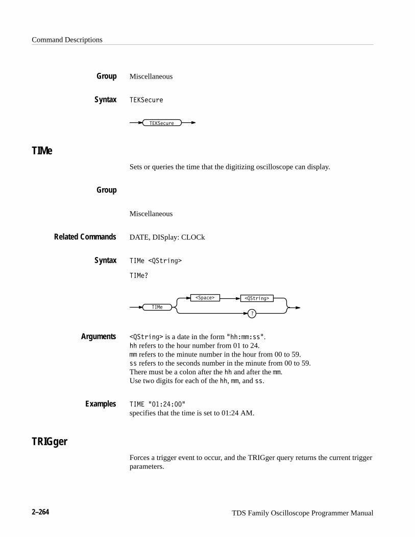
Command Descriptions
2–264 TDS Family Oscilloscope Programmer Manual
Miscellaneous
�� ������
�� ������
TIMeSets or queries the time that the digitizing oscilloscope can display.
Miscellaneous
DATE, DISplay: CLOCk
���� ��������
����
��������
����
������
�������� is a date in the form ����������.�� refers to the hour number from 01 to 24.�� refers to the minute number in the hour from 00 to 59.�� refers to the seconds number in the minute from 00 to 59. There must be a colon after the �� and after the ��. Use two digits for each of the ��, ��, and ��.
���� ����������
specifies that the time is set to 01:24 AM.
TRIGgerForces a trigger event to occur, and the TRIGger query returns the current triggerparameters.
Group
Syntax
Group
Related Commands
Syntax
Arguments
Examples
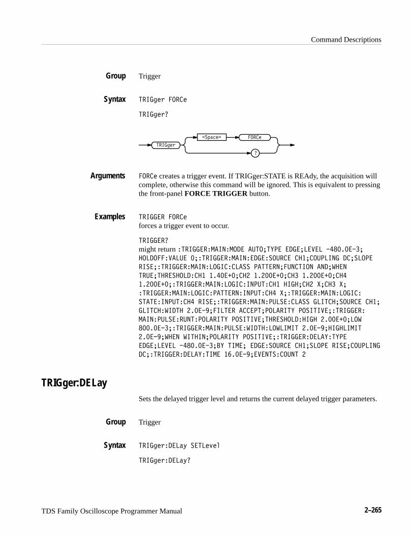
Command Descriptions
TDS Family Oscilloscope Programmer Manual 2–265
Trigger
" ��+*. �� �*
" ��+*.�
" ��+*.
�� �*
�
�!-()*�
�� �* creates a trigger event. If TRIGger:STATE is REAdy, the acquisition willcomplete, otherwise this command will be ignored. This is equivalent to pressingthe front-panel FORCE TRIGGER button.
" ���� �� �* forces a trigger event to occur.
" ���� �
might return " ���� ���� ���� �#"��"'�� �������$�� ���������
������� $��#� �� " ���� ���� ���� !�# �� ������#����� ���!����
�!�� " ���� ���� ����� ���!! ��""� ���#��"��� ����%���
" #��"� �!���� ��� ���������� ������������ �����������
��������� " ���� ���� ����� ���#" ��� �������� &���� &�
" ���� ���� ����� ��""� � ���#" �� &� " ���� ���� �����
!"�"� ���#" �� �!�� " ���� ���� �#�!� ���!! ���"���!�# �� ����
���"�� %��"� ����������"� �����"����� �"' ��!�"�$�� " ����
���� �#�!� #�" ���� �"' ��!�"�$��"� �!���� ���� ����������%
��������� " ���� ���� �#�!� %��"� ��%����" ���������������"
�������%��� %�"�������� �"' ��!�"�$�� " ���� ����' "'��
�������$�� ����������' "���� ���� !�# �� ����!���� �!����#�����
��� " ���� ����' "��� ��������$��"! ��#�" �
TRIGger:DELaySets the delayed trigger level and returns the current delayed trigger parameters.
Trigger
" ��+*. ���(0 !�"�*/*,
" ��+*. ���(0�
Group
Syntax
Arguments
Examples
Group
Syntax
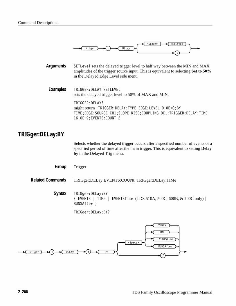
Command Descriptions
2–266 TDS Family Oscilloscope Programmer Manual
����&$+ ���".
����$-$(
�
��*"#$
����$-$( sets the delayed trigger level to half way between the MIN and MAXamplitudes of the trigger source input. This is equivalent to selecting Set to 50%in the Delayed Edge Level side menu.
�����������! ����� ��
sets the delayed trigger level to 50% of MAX and MIN.
�����������!�
might return �����������!�!�� ������� �� ��������!
��������������� ��������� ������������� ��������������!����
�������� ��������� �
TRIGger:DELay:BYSelects whether the delayed trigger occurs after a specified number of events or aspecified period of time after the main trigger. This is equivalent to setting Delayby in the Delayed Trig menu.
Trigger
TRIGger:DELay:EVENTS:COUNt, TRIGger:DELay:TIMe
����&$+���".�!
/ � ���� 0 ���$ 0 � �����')$ (TDS 510A, 500C, 600B, & 700C only) 0
�����%,$+ 1
����&$+���".�!�
� �����')$
���".����&$+
��*"#$
�
���$
�!
� ����
�����%,$+
Arguments
Examples
Group
Related Commands
Syntax
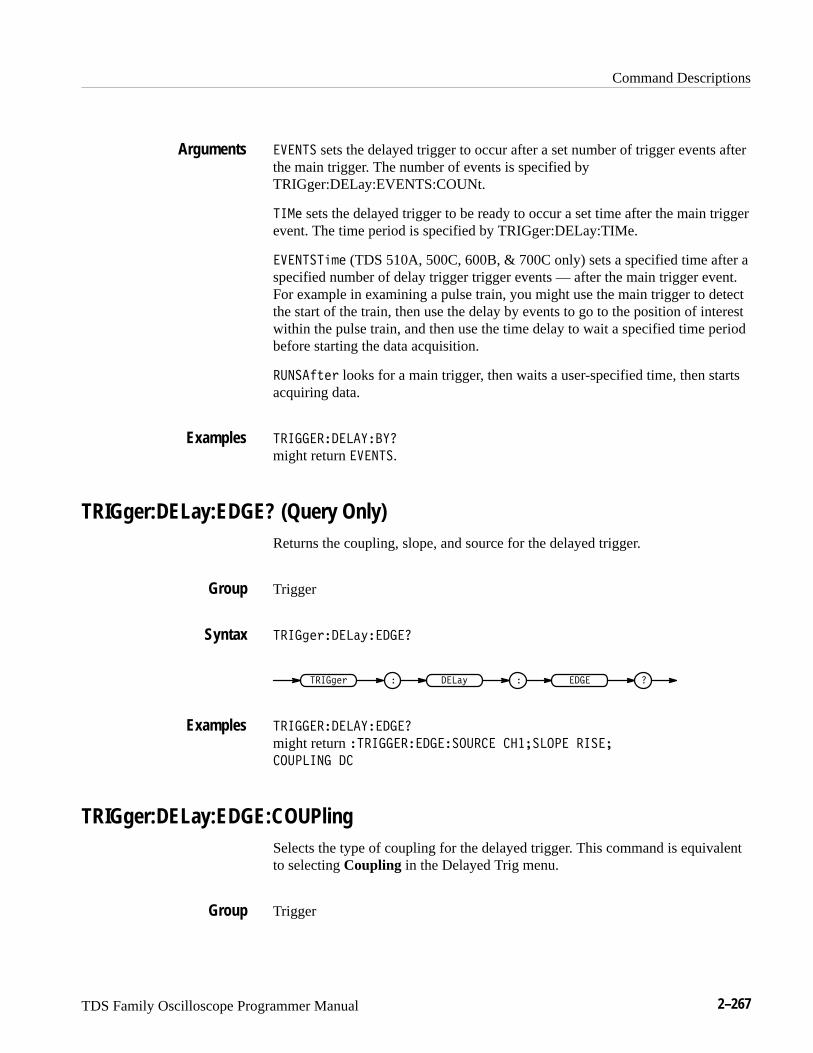
Command Descriptions
TDS Family Oscilloscope Programmer Manual 2–267
���� sets the delayed trigger to occur after a set number of trigger events afterthe main trigger. The number of events is specified byTRIGger:DELay:EVENTS:COUNt.
� �� sets the delayed trigger to be ready to occur a set time after the main triggerevent. The time period is specified by TRIGger:DELay:TIMe.
�������� (TDS 510A, 500C, 600B, & 700C only) sets a specified time after aspecified number of delay trigger trigger events — after the main trigger event.For example in examining a pulse train, you might use the main trigger to detectthe start of the train, then use the delay by events to go to the position of interestwithin the pulse train, and then use the time delay to wait a specified time periodbefore starting the data acquisition.
������ �� looks for a main trigger, then waits a user-specified time, then startsacquiring data.
�� �����������
might return ����.
TRIGger:DELay:EDGE? (Query Only)Returns the coupling, slope, and source for the delayed trigger.
Trigger
�� �������!���
�� ���� � � ���! �
�� ����������
might return ��� ����������� �������� � ��
����� �� �
TRIGger:DELay:EDGE:COUPlingSelects the type of coupling for the delayed trigger. This command is equivalentto selecting Coupling in the Delayed Trig menu.
Trigger
Arguments
Examples
Group
Syntax
Examples
Group
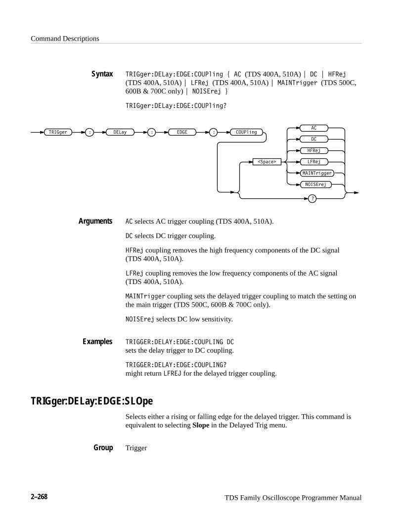
Command Descriptions
2–268 TDS Family Oscilloscope Programmer Manual
�� ���"����#���������� � $ �� (TDS 400A, 510A) % �� % ����
(TDS 400A, 510A) % ���� (TDS 400A, 510A) % �� ��"����" (TDS 500C,600B & 700C only) % �� �"�� &
�� ���"����#���������� ��
������ ��� ���" � � �����# �
��!����
�
�� �"��
����
����
��
��
�� ��"����"
�� selects AC trigger coupling (TDS 400A, 510A).
�� selects DC trigger coupling.
���� coupling removes the high frequency components of the DC signal (TDS 400A, 510A).
���� coupling removes the low frequency components of the AC signal (TDS 400A, 510A).
�� ��"����" coupling sets the delayed trigger coupling to match the setting onthe main trigger (TDS 500C, 600B & 700C only).
�� �"�� selects DC low sensitivity.
�� ����������������� �� ��
sets the delay trigger to DC coupling.
�� ����������������� ���
might return ��� for the delayed trigger coupling.
TRIGger:DELay:EDGE:SLOpeSelects either a rising or falling edge for the delayed trigger. This command isequivalent to selecting Slope in the Delayed Trig menu.
Trigger
Syntax
Arguments
Examples
Group

Command Descriptions
TDS Family Oscilloscope Programmer Manual 2–269
�� �������� ��������� ! � �� " ��� #
�� �������� ����������
� ��� �� ���� �� �
�������
�
���
� �����
� ��
��� specifies to trigger on the falling or negative edge of a signal.
� �� specifies to trigger on the rising or positive edge of a signal.
�� �����������������
might return � �, indicating that the delayed trigger occurs on the rising edge.
TRIGger:DELay:EDGE:SOUrceSelects the source for the delayed trigger. This command is equivalent toselecting Source in the Delayed Trig menu.
Trigger
�� �������� ���������� ! �������� (not available on TDS 520C &724C) " ����� #
�� �������� �����������
� ��� �� ���� ��
�������
�
� ������
��������
�
�� ���
�������� specifies an external trigger using the Auxiliary Trigger Inputconnector that is located on the rear panel of the instrument. The TDS 520C &724C do not have an Auxiliary Trigger input and so do not support thisargument.
Syntax
Arguments
Examples
Group
Syntax
Arguments
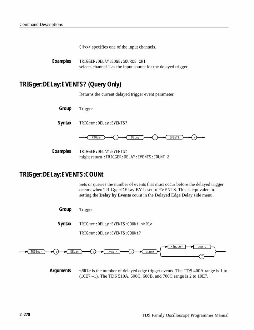
Command Descriptions
2–270 TDS Family Oscilloscope Programmer Manual
��� specifies one of the input channels.
���������������������� �
selects channel 1 as the input source for the delayed trigger.
TRIGger:DELay:EVENTS? (Query Only)Returns the current delayed trigger event parameter.
Trigger
����������� ��������
� ��� ������� � ������ �
��������������������
might return ������������������������� �
TRIGger:DELay:EVENTS:COUNtSets or queries the number of events that must occur before the delayed triggeroccurs when TRIGger:DELay:BY is set to EVENTS. This is equivalent tosetting the Delay by Events count in the Delayed Edge Delay side menu.
Trigger
����������� ������������ �����
����������� �������������
�
������� �����
����� ��� ������� � ������ �
����� is the number of delayed edge trigger events. The TDS 400A range is 1 to(10E7 –1). The TDS 510A, 500C, 600B, and 700C range is 2 to 10E7.
Examples
Group
Syntax
Examples
Group
Syntax
Arguments

Command Descriptions
TDS Family Oscilloscope Programmer Manual 2–271
����� ��� ��� � ��������� �
specifies that the delayed trigger will occur four trigger events after the maintrigger.
����� ��� ��� � ���������
might return �, indicating that two events must occur after the main triggerbefore the delayed trigger can occur.
TRIGger:DELay:LEVelSelects the level of the delayed trigger. This command is equivalent to settingLEVel in the Delayed Trig menu.
Trigger
��������� �� �� ��� ! �� " ��� " ����� #
��������� �� �� ���
������� � �� �� � ���
�������
��
���
�����
�� specifies a preset ECL level of –1.3 V.
��� specifies a preset TTL level of 1.4 V.
����� is the delayed trigger level, in volts.
����� ��� ���� � � � ��
sets the delayed trigger level to 2 mV.
TRIGger:DELay:TIMeSets or queries the delay time when HORizontal:DELay:MODe is set toTRIGAfter. This command is identical to the HORizontal:DELay:TIME:TRIG-After command, and is equivalent to setting the Delay by Time value in theDelayed Edge Delay side menu.
When HORizontal:DELay:MODe is set to RUNSAfter, the delay time is set bythe HORizontal:DELay:TIME:RUNSAfter command.
Examples
Group
Syntax
Arguments
Examples

Command Descriptions
2–272 TDS Family Oscilloscope Programmer Manual
Trigger
HORizontal:DELay:MODe, HORizontal:DELay:TIME:RUNSAfter, HORizontal:DELay:TIME:TRIGAfter
��� �������������� �����
��� ��������������
��� ��� � ������
������� �����
����
����� is the delay time, in seconds.
��� ������������ ����
sets the delay time to 4 �s.
TRIGger:DELay:TYPeSets or queries the type of delayed trigger.
Trigger
��� �������������� �� �
��� ��������������
��� ��� � ������
�������
����
�� �
�� � is a normal trigger. A trigger event occurs when a signal passes through aspecified voltage level in a specified direction. Use the TRIGger:DELay:LEVeland TRIGger:DELay:EDGE:SLOpe commands to set the voltage level anddirection respectively.
��� ������������
always returns �� � as the type of delayed trigger.
Group
Related Commands
Syntax
Arguments
Examples
Group
Syntax
Arguments
Examples

Command Descriptions
TDS Family Oscilloscope Programmer Manual 2–273
TRIGger:MAInSets the main trigger level and returns the current main trigger parameters.
Trigger
�����"� ��� �����%��
�����"� ����
�����" � ���
�����%��
�
��!����
�����%�� sets the main trigger level to half way between the MIN and MAXamplitudes of the trigger source input. This is equivalent to pressing thefront-panel SET LEVel TO 50% button.
This argument works differently with AMI Communications Triggering settings.Specifically, when AMI is chosen, this command measures the peak-to-peaklevel and sets an upper threshold value at 75% and a lower threshold value at25% of the peak-to-peak value. If the pulse form is CMI, NRZ, or an EyeDiagram, the level is set to 50%.
������ ��� ��������
sets the main trigger level mid way between MAX and MIN.
TRIGger:MAIn:COMMunication:AMI:PULSEFormTDS 500C & 700C Only
Sets or queries the communication trigger AMI pulse form to one of threepossibilities.
Trigger
�����"� ������ $����#� ��� ������� "� & ������� ' ������� '
�������"�� (
�����"� ������ $����#� ��� ������� "��
Group
Syntax
Arguments
Examples
Group
Syntax
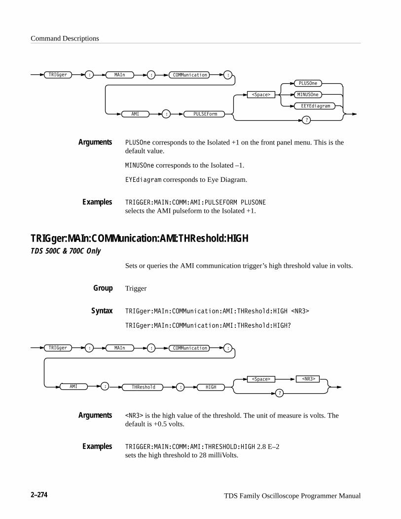
Command Descriptions
2–274 TDS Family Oscilloscope Programmer Manual
������% � ����" �
��$����
�����"�
�
������"�
����("���'�#"
���
�����%�!
� �����#%!
�����"� corresponds to the Isolated +1 on the front panel menu. This is thedefault value.
������"� corresponds to the Isolated –1.
�����%�! corresponds to Eye Diagram.
����������������������������� ������
selects the AMI pulseform to the Isolated +1.
TRIGger:MAIn:COMMunication:AMI:THReshold:HIGHTDS 500C & 700C Only
Sets or queries the AMI communication trigger’s high threshold value in volts.
Trigger
������%����"�����("���'�#"������ ��&�# �� �� �����
������%����"�����("���'�#"������ ��&�# �� �� �
������% � ����" �
��$����
�
����("���'�#"
�� �� ��&�# �
�����
��� �
����� is the high value of the threshold. The unit of measure is volts. Thedefault is +0.5 volts.
���������������������� �� ��� �� 2.8 E–2sets the high threshold to 28 milliVolts.
Arguments
Examples
Group
Syntax
Arguments
Examples

Command Descriptions
TDS Family Oscilloscope Programmer Manual 2–275
TRIGger:MAIn:COMMunication:AMI:THReshold:LOWTDS 500C & 700C Only
Sets or queries the AMI communication trigger’s low threshold value in volts.
Trigger
������"���������%����$� ������� ��#� ������ �����
������"���������%����$� ������� ��#� �������
������" � ����� �
��!����
�
���%����$� �
����� ��#� ��
�����
��� �
����� is the low value of the threshold. The unit of measure is volts. The defaultis –0.5 volts.
���������������������� ��� ������ 2.8 E–2sets the low threshold to 28 milliVolts.
TRIGger:MAIn:COMMunication:BITRateTDS 500C & 700C Only
Sets or queries the communication trigger signal bit rate. If this commandchanges the bit rate, the command then also causes the communication standardto set to “custom”. If both the TRIGger:MAIn;COMMunication:STANDardcommand and the TRIGger:MAIn;COMMunication:BITRate command are used,the last one executed takes precedence.
Trigger
������"���������%����$� �������$� & ����� '
������"���������%����$� �������$��
Group
Syntax
Arguments
Examples
Group
Syntax

Command Descriptions
2–276 TDS Family Oscilloscope Programmer Manual
����#") � �&
�(� "�
�
����+&$ �*$'&
�����*"
����
����is the bit rate in bits per second. The default is 1.544e+6.
�������� ���������� �� ����� ���
sets the bit rate to 105.3 Mb/s.
TRIGger:MAIn:COMMunication:CMI:PULSEFormTDS 500C & 700C Only
Sets or queries the communication trigger CMI pulse form to one of threepossibilities.
Trigger
����#")� �&����+&$ �*$'&���������')% , �����&" - ������&" -
���!$�#)�% - ���� .
����#")� �&����+&$ �*$'&���������')%�
����#") � �&
�(� "�
�
������&"
����+&$ �*$'&
���
���!$�#)�%
������')%
�����&"
����
�����&" corresponds to triggering on a positive mark. This is the default value.
������&" corresponds to triggering on a negative mark.
���!$�#)�% selects an Eye Diagram image.
���� corresponds to triggering on a Zero bit.
Arguments
Examples
Group
Syntax
Arguments
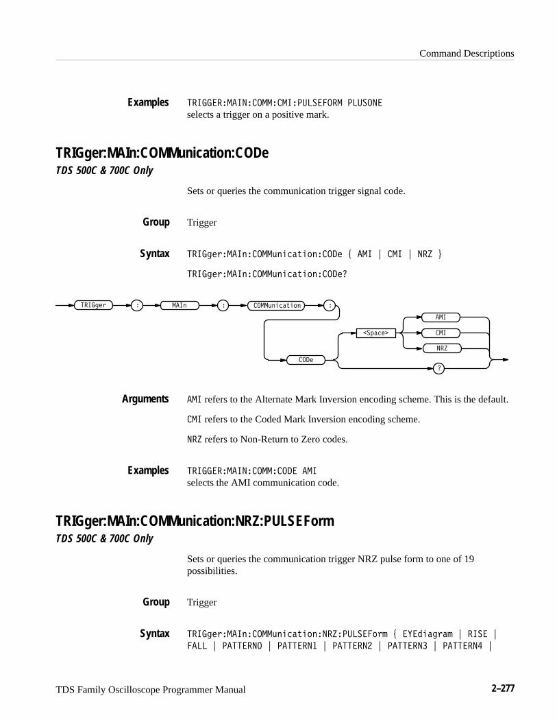
Command Descriptions
TDS Family Oscilloscope Programmer Manual 2–277
������������������������������� �������
selects a trigger on a positive mark.
TRIGger:MAIn:COMMunication:CODeTDS 500C & 700C Only
Sets or queries the communication trigger signal code.
Trigger
����! '����$�����)$"��("%$��� * ��� + ��� + ��� ,
����! '����$�����)$"��("%$���
����! ' � ����$ �
��&��
���
���
����)$"��("%$
���
��
��� refers to the Alternate Mark Inversion encoding scheme. This is the default.
��� refers to the Coded Mark Inversion encoding scheme.
��� refers to Non-Return to Zero codes.
�������������������� � ���
selects the AMI communication code.
TRIGger:MAIn:COMMunication:NRZ:PULSEFormTDS 500C & 700C Only
Sets or queries the communication trigger NRZ pulse form to one of 19possibilities.
Trigger
����! '����$�����)$"��("%$�����������%'# * ����"�!'�# + ���� +
���� + �������� + �������� + �������� + �������� + �������� +
Examples
Group
Syntax
Arguments
Examples
Group
Syntax
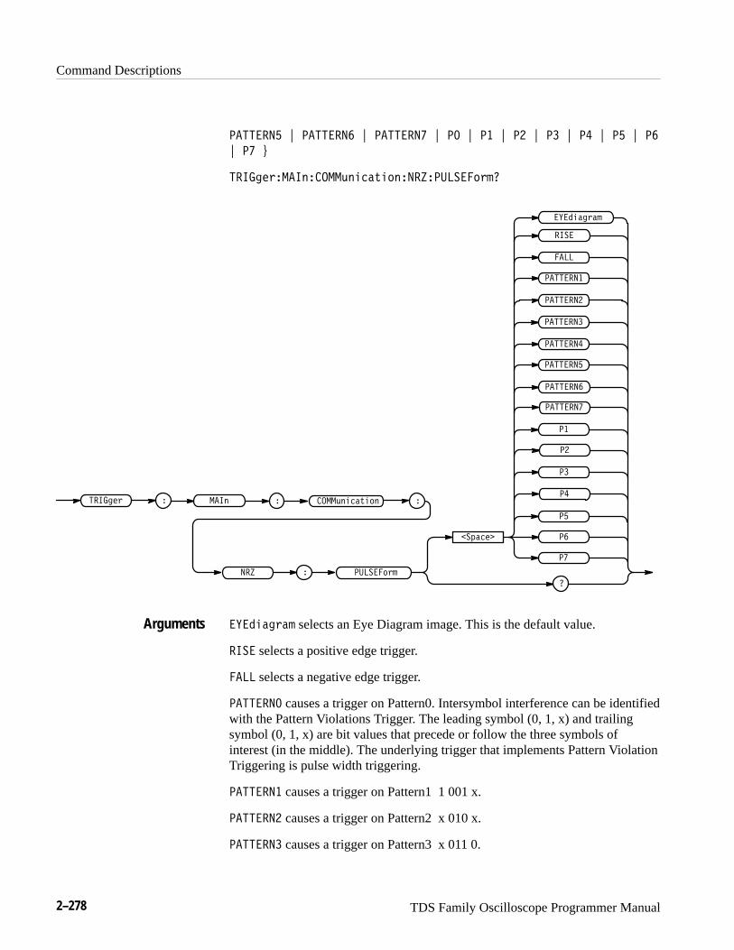
Command Descriptions
2–278 TDS Family Oscilloscope Programmer Manual
�������� , �������� , ������� , �� , �� , �� , �� , �� , �� , ��
, � -
����#")���&����+&$ �*$'&���������')%
����#") ���&
��(� "�
��
��
����+&$ �*$'&
���
���!$�#)�%
������')%
��
��
��
��
�������
��������
��������
��������
��������
��������
��������
����
����
�
���!$�#)�% selects an Eye Diagram image. This is the default value.
���� selects a positive edge trigger.
���� selects a negative edge trigger.
�������� causes a trigger on Pattern0. Intersymbol interference can be identifiedwith the Pattern Violations Trigger. The leading symbol (0, 1, x) and trailingsymbol (0, 1, x) are bit values that precede or follow the three symbols ofinterest (in the middle). The underlying trigger that implements Pattern ViolationTriggering is pulse width triggering.
�������� causes a trigger on Pattern1 1 001 x.
�������� causes a trigger on Pattern2 x 010 x.
�������� causes a trigger on Pattern3 x 011 0.
Arguments

Command Descriptions
TDS Family Oscilloscope Programmer Manual 2–279
�������� causes a trigger on Pattern4 x 100 1.
�������� causes a trigger on Pattern5 x 101 x.
�������� causes a trigger on Pattern6 0 110 x.
������� causes a trigger on Pattern7 0 111 0.
�� is a synonym for PATTERN0.
�� is a synonym for PATTERN1.
�� is a synonym for PATTERN2.
�� is a synonym for PATTERN3.
�� is a synonym for PATTERN4.
�� is a synonym for PATTERN5.
�� is a synonym for PATTERN6.
� is a synonym for PATTERN7.
����������������� ��������� ����������
selects a trigger on an Eye Diagram image.
TRIGger:MAIn:COMMunication:SOUrceTDS 500C & 700C Only
Sets or queries the source for the main communication trigger. This is equivalentto selecting the source in the Communication Source side menu.
Trigger
����$#)���&����+&%"!*%'&���)"# ���,�
����$#)���&����+&%"!*%'&���)"#
��(!"#� �,���
����$#) ���& ���)"#����+&%"!*%'&
Examples
Group
Syntax

Command Descriptions
2–280 TDS Family Oscilloscope Programmer Manual
��(� specifies one of the input channels.
�������� ���������� ���������� ���
selects Channel 2 as the source for the main communication trigger.
TRIGger:MAIn:COMMunication:STANdardTDS 500C & 700C Only
Sets or queries the communication trigger standard which identifies the code andbit rate.
Trigger
���� �%� �#����'#!��&!$#�� ���%� ) ��� * ��� * ���� * ��� *
��� * ���� * �� * �� * �� * �� * �� * ���� * ���� * ��� * ��� *
���� * ����� * ����� * ����� * ����� * ������ * ���� * �� * �� *
����$" +
���� �%� �#����'#!��&!$#�� ���%��
Arguments
Examples
Group
Syntax

Command Descriptions
TDS Family Oscilloscope Programmer Manual 2–281
������$ � ����! �
�#���
��
�
��
����
������$�
���&!���%�"!
� ����
� ���
� ���
� ���
�����
� ��
� �
� �
����
����
��
��
��
��
��
�����
���
���
���
����
���
���"
��� refers to DS1 (1.544 Mb/s) AMI standard.
���� refers to DS1A (2.048 Mb/s) AMI standard.
��� refers to DS1C (3.152 Mb/s) AMI standard.
��� refers to DS2 (6.312 Mb/s) AMI standard.
��� refers to DS3 (44.736 Mb/s) AMI standard.
����� refers to DS4NA (139.26 Mb/s) CMI standard.
Arguments
Command Descriptions
2–282 TDS Family Oscilloscope Programmer Manual
�� refers to E1 (2.048 Mb/s) AMI standard.
�� refers to E2 (8.44 Mb/s) AMI standard.
�� refers to E3 (34.368 Mb/s) AMI standard.
�� refers to E4 (139.26 Mb/s) CMI standard.
�� refers to E5 or CEPT (565 Mb/s) NRZ standard.
���� refers to STS–1 (51.84 Mb/s) AMI standard.
���� refers to STS–3 (155.52 Mb/s) CMI standard.
��� refers to OC1/STM0 (51.84 Mb/s) CMI standard.
��� refers to OC3/STM1 (155.52 Mb/s) NRZ standard.
���� refers to OC12/STM4 (622.08 Mb/s) NRZ standard.
����� refers to STM1E (155.52 Mb/s) CMI standard.
����� refers to FC133 (132.7 Mb/s) NRZ standard.
����� refers to FC266 (265.6 Mb/s) NRZ standard.
����� refers to FC531 (531.2 Mb/s) NRZ standard.
������ refers to FC1063 (1.063 Gb/s) NRZ standard.
� � refers to FDDI (125 Mb/s) NRZ standard.
� refers to 4:2:2 or D1 (270 Mb/s) NRZ standard.
� refers to 4fsc NTSC or D2 (143.18 Mb/s) NRZ standard.
������ can take a non-standard, floating-point bit rate. <NR3>.
������������������� �� ��
selects the E4 communication standard.
TRIGger:MAIn:EDGE? (Query Only)Returns the trigger coupling, source, and slope for the main edge trigger.
Trigger
������������ ��
Examples
Group
Syntax
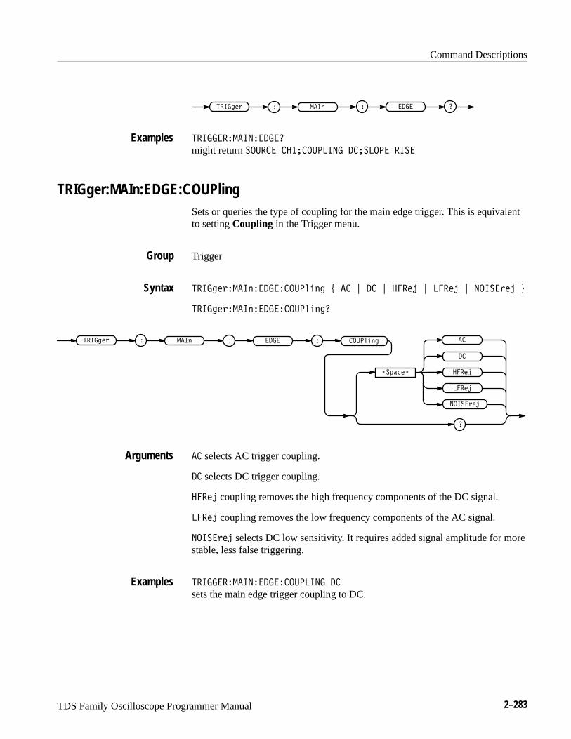
Command Descriptions
TDS Family Oscilloscope Programmer Manual 2–283
� ��� ��� ��" � � ��
��� ��������� ��
might return ����� ��������� ������ ����
TRIGger:MAIn:EDGE:COUPlingSets or queries the type of coupling for the main edge trigger. This is equivalentto setting Coupling in the Trigger menu.
Trigger
��� ��"���� �� ������� � # � $ $ ����� $ ����� $ �����"�� %
��� ��"���� �� ������� ��
����� ���� ��" � � � ���� �
�����
��!����
�
�����"��
�����
�
� selects AC trigger coupling.
selects DC trigger coupling.
����� coupling removes the high frequency components of the DC signal.
����� coupling removes the low frequency components of the AC signal.
�����"�� selects DC low sensitivity. It requires added signal amplitude for morestable, less false triggering.
��� ��������� ��������
sets the main edge trigger coupling to DC.
Examples
Group
Syntax
Arguments
Examples
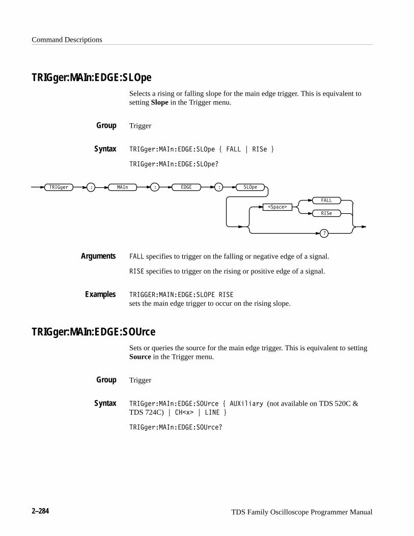
Command Descriptions
2–284 TDS Family Oscilloscope Programmer Manual
TRIGger:MAIn:EDGE:SLOpeSelects a rising or falling slope for the main edge trigger. This is equivalent tosetting Slope in the Trigger menu.
Trigger
�� ��� ��� ���������� # ��� $ � �� %
�� ��� ��� �����������
� �� ��� ��� �� �
�������
�
���
� ��
� �����
��� specifies to trigger on the falling or negative edge of a signal.
� � specifies to trigger on the rising or positive edge of a signal.
�� ������ ��������� � �
sets the main edge trigger to occur on the rising slope.
TRIGger:MAIn:EDGE:SOUrceSets or queries the source for the main edge trigger. This is equivalent to settingSource in the Trigger menu.
Trigger
�� ��� ��� �������� �� # ������� " (not available on TDS 520C &TDS 724C)$ ���!� $ � � %
�� ��� ��� �������� ���
Group
Syntax
Arguments
Examples
Group
Syntax
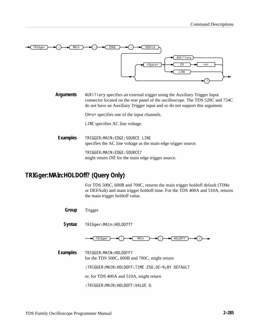
Command Descriptions
TDS Family Oscilloscope Programmer Manual 2–285
����
� � �(����%#* ���� �� ���*"#
�)!"#�
�
��&'&!*,
�� +�
��&'&!*, specifies an external trigger using the Auxiliary Trigger Inputconnector located on the rear panel of the oscilloscope. The TDS 520C and 724Cdo not have an Auxiliary Trigger input and so do not support this argument.
��+� specifies one of the input channels.
���� specifies AC line voltage.
��������� �������������� ����
specifies the AC line voltage as the main edge trigger source.
��������� ���������������
might return ��� for the main edge trigger source.
TRIGger:MAIn:HOLDOff? (Query Only)For TDS 500C, 600B and 700C, returns the main trigger holdoff default (TIMeor DEFAult) and main trigger holdoff time. For the TDS 400A and 510A, returnsthe main trigger holdoff value.
Trigger
����%#*�� �(������$$�
� � �(����%#* � ������$$
��������� �����������
for the TDS 500C, 600B and 700C, might return
���������� ��������������� ��������� ��� ���
or, for TDS 400A and 510A, might return
���������� ������������ ��� �.
Arguments
Examples
Group
Syntax
Examples

Command Descriptions
2–286 TDS Family Oscilloscope Programmer Manual
TRIGger:MAIn:HOLDOff:ACTUal? (Query Only)TDS 500C, 600B and 700C Only
Returns the main trigger holdoff value in seconds. This is equivalent to selectingMode & Holdoff from the main Trigger menu and viewing the value in the sidemenu Holdoff Default or Holdoff Time items (whichever is highlighted).
Trigger
������ ������ �������������
� ���������� � � ����� �������
������������ �������������
might return 4E–6 showing the holdoff time is set to 4 �s.
TRIGger:MAIn:HOLDOff:BYTDS 500C, 600B & 700C Only
Sets or queries the main trigger holdoff default. This is equivalent to selectingMode & Holdoff from the main Trigger menu, then setting Default Holdoff orHoldoff (Time) in the resulting side menu.
Trigger
������ ������ �������� # ���� $ ��"�! %
������ ������ ���������
� ���������� ����� �
�������
�
����
��"�!
�
��
���� enables the user to set the holdoff time.
��"�! automatically calculates a holdoff time to use. This time is typicallyequivalent to the greater of � screen (5 divisions) of time or 250 ns. Themaximum value is 12 seconds. For example, if the oscilloscope is set to
Group
Syntax
Examples
Group
Syntax
Arguments
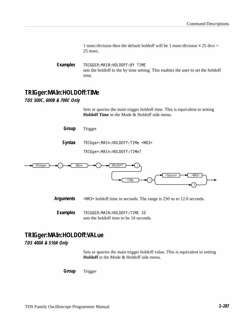
Command Descriptions
TDS Family Oscilloscope Programmer Manual 2–287
1 msec/division then the default holdoff will be 1 msec/division × 25 divs =25 msec.
����������������� �� ����
sets the holdoff to the by time setting. This enables the user to set the holdofftime.
TRIGger:MAIn:HOLDOff:TIMeTDS 500C, 600B & 700C Only
Sets or queries the main trigger holdoff time. This is equivalent to settingHoldoff Time in the Mode & Holdoff side menu.
Trigger
������ ����������������� �����
������ ������������������
� ��������� ������� ��
���� �
�����
�
�������
����� holdoff time in seconds. The range is 250 ns to 12.0 seconds.
����������������� ����� ��
sets the holdoff time to be 10 seconds.
TRIGger:MAIn:HOLDOff:VALueTDS 400A & 510A Only
Sets or queries the main trigger holdoff value. This is equivalent to settingHoldoff in the Mode & Holdoff side menu.
Trigger
Examples
Group
Syntax
Arguments
Examples
Group
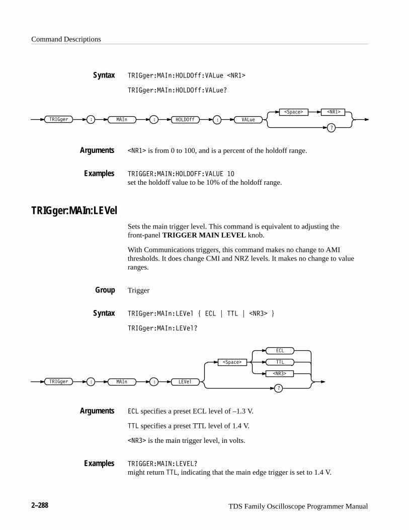
Command Descriptions
2–288 TDS Family Oscilloscope Programmer Manual
������"��� �����������#� �����
������"��� �����������#��
�����
������" � ��� ������� ��#��
�
��!����
����� is from 0 to 100, and is a percent of the holdoff range.
����������������� ����� ��
set the holdoff value to be 10% of the holdoff range.
TRIGger:MAIn:LEVelSets the main trigger level. This command is equivalent to adjusting thefront-panel TRIGGER MAIN LEVEL knob.
With Communications triggers, this command makes no change to AMIthresholds. It does change CMI and NRZ levels. It makes no change to valueranges.
Trigger
������"��� ������ $ �� % ��� % ����� &
������"��� �������
������" � ��� �����
��!����
��
�
���
�����
�� specifies a preset ECL level of –1.3 V.
��� specifies a preset TTL level of 1.4 V.
����� is the main trigger level, in volts.
������������������
might return ���, indicating that the main edge trigger is set to 1.4 V.
Syntax
Arguments
Examples
Group
Syntax
Arguments
Examples
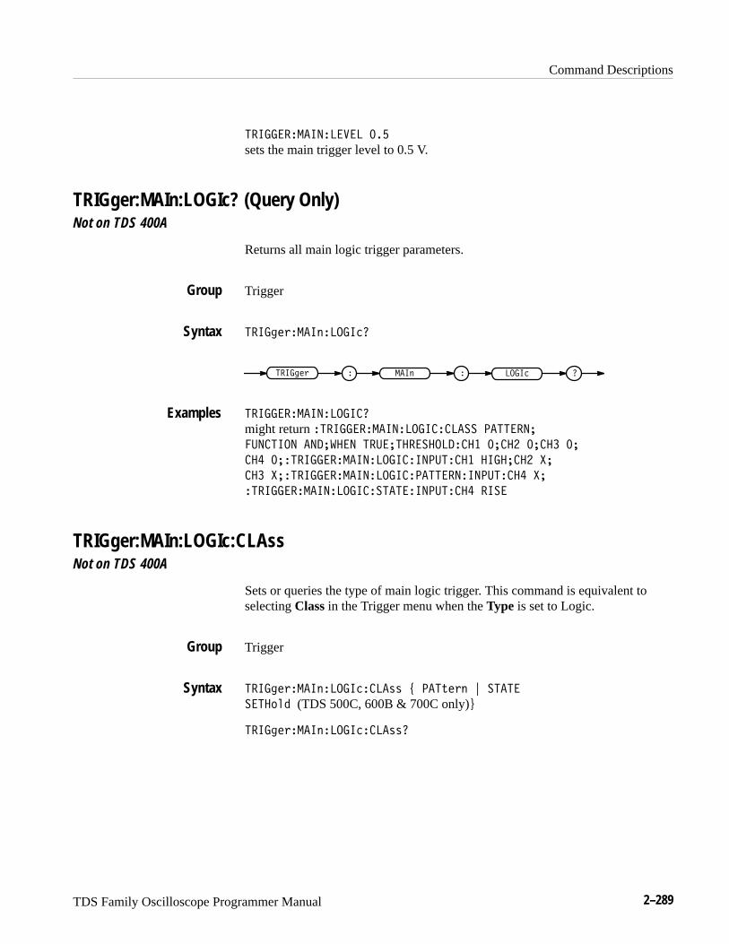
Command Descriptions
TDS Family Oscilloscope Programmer Manual 2–289
���������������� ���
sets the main trigger level to 0.5 V.
TRIGger:MAIn:LOGIc? (Query Only)Not on TDS 400A
Returns all main logic trigger parameters.
Trigger
����#"'���%���� �
���%����#"' �����
��������������� �
might return ��������������� ���� �������
��� ���� ������� ������������� �� � �� � �� �
�� ���������������� ����� �� ���� �� �
�� ���������������� ������������ �� �
��������������� ���������� �� ����
TRIGger:MAIn:LOGIc:CLAssNot on TDS 400A
Sets or queries the type of main logic trigger. This command is equivalent toselecting Class in the Trigger menu when the Type is set to Logic.
Trigger
����#"'���%���� ��(( * ���)"'% + �����
����&$! (TDS 500C, 600B & 700C only),
����#"'���%���� ��((�
Group
Syntax
Examples
Group
Syntax
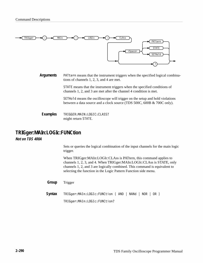
Command Descriptions
2–290 TDS Family Oscilloscope Programmer Manual
� �� ��� ���! ��� � �
�� ����
�
����
������
� ���""
���#�!�
���#�!� means that the instrument triggers when the specified logical combina-tions of channels 1, 2, 3, and 4 are met.
���� means that the instrument triggers when the specified conditions ofchannels 1, 2, and 3 are met after the channel 4 condition is met.
������ means the oscilloscope will trigger on the setup and hold violationsbetween a data source and a clock source (TDS 500C, 600B & 700C only).
�� ������ ����� ��������
might return ����.
TRIGger:MAIn:LOGIc:FUNCtionNot on TDS 400A
Sets or queries the logical combination of the input channels for the main logictrigger.
When TRIGger:MAIn:LOGIc:CLAss is PATtern, this command applies tochannels 1, 2, 3, and 4. When TRIGger:MAIn:LOGIc:CLAss is STATE, onlychannels 1, 2, and 3 are logically combined. This command is equivalent toselecting the function in the Logic Pattern Function side menu.
Trigger
�� ���!��� ����� �����#��� $ ��� % ���� % ��� % �� &
�� ���!��� ����� �����#����
Arguments
Examples
Group
Syntax

Command Descriptions
TDS Family Oscilloscope Programmer Manual 2–291
���
�����$����
��
��
� ��"���� �% ����� �� ����&!#"
�� specifies that the instrument will trigger if all the conditions are true.
��� specifies that the instrument will trigger if any of the conditions are false.
��� specifies that the instrument will trigger if all of the conditions are false.
�� specifies that the instrument will trigger if any of the conditions are true.
����� �������������������� ���
sets the logical combination of channels to be true when none of the conditionsare true.
����� ��������������������
might return ���.
TRIGger:MAIn:LOGIc:INPut? (Query Only)Not on TDS 400A
Returns the main logic trigger input for all channels.
Trigger
���� �%���"����������'&
���� �% � � �������" � ���'&
����� �����������������
might return ������ ��������������������� �������� ����� �
Arguments
Examples
Group
Syntax
Examples

Command Descriptions
2–292 TDS Family Oscilloscope Programmer Manual
TRIGger:MAIn:LOGIc:INPut:CH<x>Not on TDS 400A
Sets or queries the main logic trigger input for the specified channel. Thechannel is specified by <x> and is 1, 2, or 3. This is equivalent to setting theinputs in the Logic Pattern Inputs side menu.
Trigger
TRIGger:MAIn:LOGIc:CLAss
������������ ������� �����!� " ��� # �� # � $
������������ ������� �����!��
�������
�
���
�
��
������ � � �������
��� � �
�
�� �!�
��� specifies logic high.
�� specifies logic low.
� specifies a do not care state.
���������� ������������� ��
sets the main logic trigger input to logic low for channel 2.
TRIGger:MAIn:LOGIc:PATtern:INPut:CH4Not on TDS 400A
Sets or queries the main logic trigger input for channel 4. These are the inputsused when TRIGger:MAIn:LOGIc:CLAss is set to PATtern. This is equivalent tosetting the channel 4 input in the Logic Pattern Inputs side menu.
Trigger
TRIGger:MAIn:LOGIc:CLAss
Group
Related Commands
Syntax
Arguments
Examples
Group
Related Commands
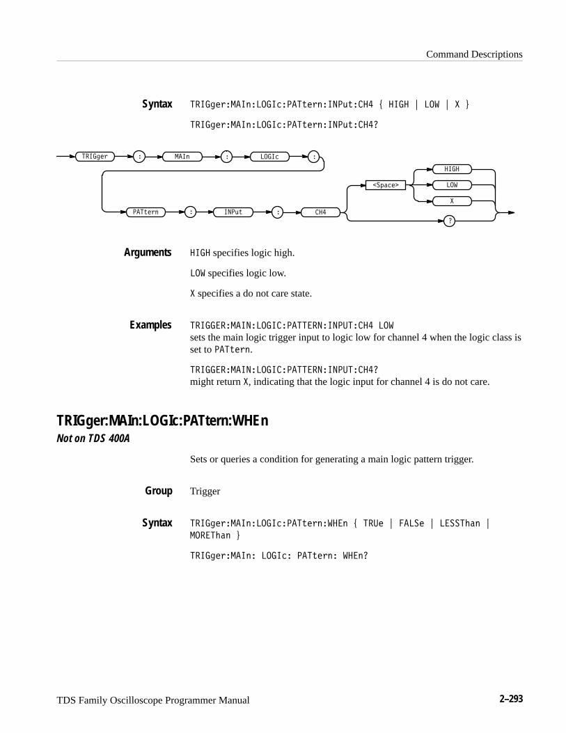
Command Descriptions
TDS Family Oscilloscope Programmer Manual 2–293
�� ��� ��� ����� �����!� �� ��"!���� # � �� $ ��� $ � %
�� ��� ��� ����� �����!� �� ��"!�����
���!� �
�������
�
� ��
�
���
�� ��� � � ��� ��� �
��"! �
�
����
� �� specifies logic high.
��� specifies logic low.
� specifies a do not care state.
�� ������ ����� ��������� �������� ���
sets the main logic trigger input to logic low for channel 4 when the logic class isset to ���!� �.
�� ������ ����� ��������� ���������
might return �, indicating that the logic input for channel 4 is do not care.
TRIGger:MAIn:LOGIc:PATtern:WHEnNot on TDS 400A
Sets or queries a condition for generating a main logic pattern trigger.
Trigger
�� ��� ��� ����� �����!� ����� # ���� $ ���� $ ������� $
������� %
�� ��� ��� �� ��� �� ���!� �� ����
Syntax
Arguments
Examples
Group
Syntax

Command Descriptions
2–294 TDS Family Oscilloscope Programmer Manual
��������
�������
� ��
�������
�
����� ��������� ��� �� ���!� �
�����
���� specifies the trigger to occur when the pattern becomes true.
� �� specifies the trigger to occur when the pattern becomes false.
������� specifies trigger to occur if the specific pattern is true less than theLESSLimit. (see Figure 2–6 and ����� ������ �������"
!� ������� ��� ���!) Trigger is evaluated at the true-false transition.
�������� specifies trigger to occur if the specific pattern is true longer than themore limit. (see Figure 2–6 and ����� ������ �������!� ����������� �"
��!) Trigger is evaluated at the true-false transition.
Specified PatternResult
MORELimit LESSLimitto
Figure 2–6: LESSThan and MOREThan Arguments
TRIGger:MAIn:LOGIc:PATtern:WHEn:LESSLimitNot on TDS 400A
Sets or queries the maximum time the selected pattern may be true and stillgenerate a main logic pattern trigger.
Trigger
����� ������ �������!� ������� ��� ���! �����
����� ������ ���� ���!� �� ����� ��� ���!�
Arguments
Group
Syntax
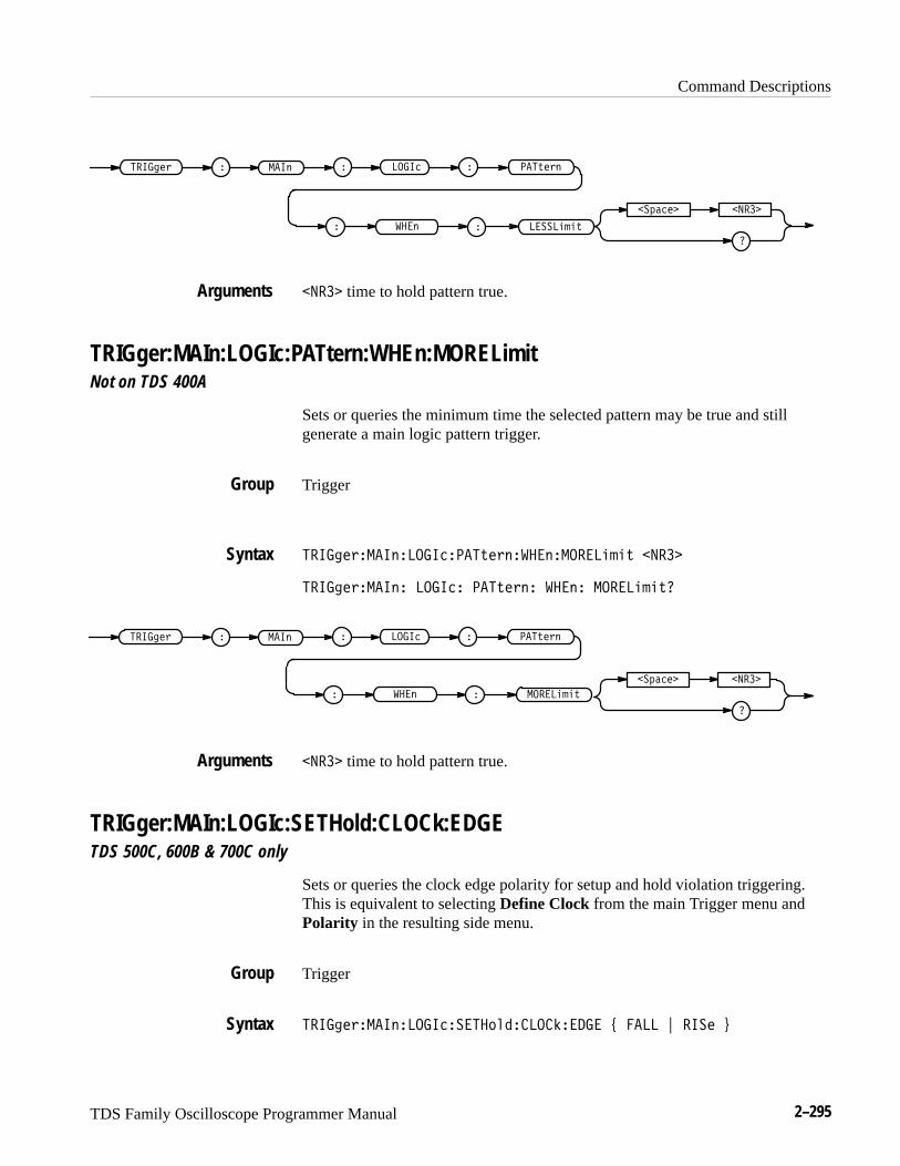
Command Descriptions
TDS Family Oscilloscope Programmer Manual 2–295
����� �%
� ���!������$ ����� �� ���%�$!
� !�
�����
�
�
��#����
����� time to hold pattern true.
TRIGger:MAIn:LOGIc:PATtern:WHEn:MORELimitNot on TDS 400A
Sets or queries the minimum time the selected pattern may be true and stillgenerate a main logic pattern trigger.
Trigger
������$����!����������%�$!�� !������ �% �����
������$����!� ������ ���%�$!� � !� ����� �%�
����� �%
� ���!������$ ����� �� ���%�$!
� !�
�����
�
�
��#����
����� time to hold pattern true.
TRIGger:MAIn:LOGIc:SETHold:CLOCk:EDGETDS 500C, 600B & 700C only
Sets or queries the clock edge polarity for setup and hold violation triggering.This is equivalent to selecting Define Clock from the main Trigger menu andPolarity in the resulting side menu.
Trigger
������$����!��������� "���������� & ���� ' ���� (
Arguments
Group
Syntax
Arguments
Group
Syntax
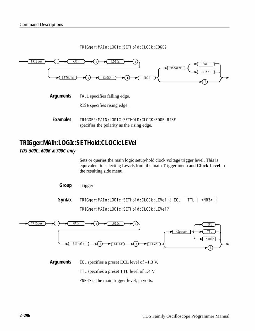
Command Descriptions
2–296 TDS Family Oscilloscope Programmer Manual
������"�������������� �����������
�� ��
��!����
�
����
����
������" � � ���������
����� �
�
��
���� specifies falling edge.
���� specifies rising edge.
�������������������� ���������� ���
specifies the polarity as the rising edge.
TRIGger:MAIn:LOGIc:SETHold:CLOCk:LEVelTDS 500C, 600B & 700C only
Sets or queries the main logic setup/hold clock voltage trigger level. This isequivalent to selecting Levels from the main Trigger menu and Clock Level inthe resulting side menu.
Trigger
������"�������������� ������������� # �� $ ��� $ ����� %
������"�������������� ��������������
�����
���
��
�����
��!����
�
������" � � ���������
�
�
�� �� �����
�� specifies a preset ECL level of –1.3 V.
��� specifies a preset TTL level of 1.4 V.
����� is the main trigger level, in volts.
Arguments
Examples
Group
Syntax
Arguments

Command Descriptions
TDS Family Oscilloscope Programmer Manual 2–297
������������������������� ������������ ���
sets the main logic trigger setup/hold clock level to 1.4 volts.
TRIGger:MAIn:LOGIc:SETHold:CLOCk:SOUrceTDS 500C, 600B & 700C Only
Sets or queries the source for the clock for the main logic trigger setup/holdinput. The channel is specified by <x> and is 1, 2, 3, or 4. This is equivalent toselecting Define Clock from the main Trigger menu and CH1, CH2, CH3, orCH4 in the resulting side menu.
Trigger
TRIGger:MAIn:LOGIc:CLAss
����! '����$�����������%#������"����'� � ���(
����! '����$�����������%#������"����'�
��&�� ����
����! ' � � ��������$ ����%#��
����" � ���'�
���( specifies one of the input channels (CH1, CH2, CH3, or CH4).
������������������������� ������������� ���
selects Channel 2 as the clock source for the main logic trigger setup/hold.
TRIGger:MAIn:LOGIc:SETHold:DATa:LEVelTDS 500C, 600B & 700C only
Sets or queries the main logic set/hold data level. This is equivalent to selectingLevels from the main Trigger menu and Data Level in the resulting side menu.
Trigger
����! '����$�����������%#�� ������� # ) ��� * ��� * ���� +
Examples
Group
Related Commands
Syntax
Arguments
Examples
Group
Syntax
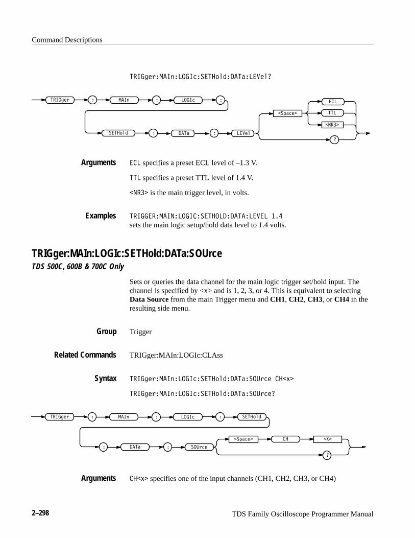
Command Descriptions
2–298 TDS Family Oscilloscope Programmer Manual
������$���!�������� ��" ������� ��
�����
��#����
��
���
������$ � � �������!
�
�
� ��" � ��� � �� �
�� specifies a preset ECL level of –1.3 V.
��� specifies a preset TTL level of 1.4 V.
����� is the main trigger level, in volts.
����� ������������� ���������� � � ���
sets the main logic setup/hold data level to 1.4 volts.
TRIGger:MAIn:LOGIc:SETHold:DATa:SOUrceTDS 500C, 600B & 700C Only
Sets or queries the data channel for the main logic trigger set/hold input. Thechannel is specified by <x> and is 1, 2, 3, or 4. This is equivalent to selectingData Source from the main Trigger menu and CH1, CH2, CH3, or CH4 in theresulting side menu.
Trigger
TRIGger:MAIn:LOGIc:CLAss
������$���!�������� ��" ���������$�� ���%�
������$���!�������� ��" ���������$��
��#���� �����
������$ � � �������! � ��" ��
��� � ���$���
���%� specifies one of the input channels (CH1, CH2, CH3, or CH4)
Arguments
Examples
Group
Related Commands
Syntax
Arguments
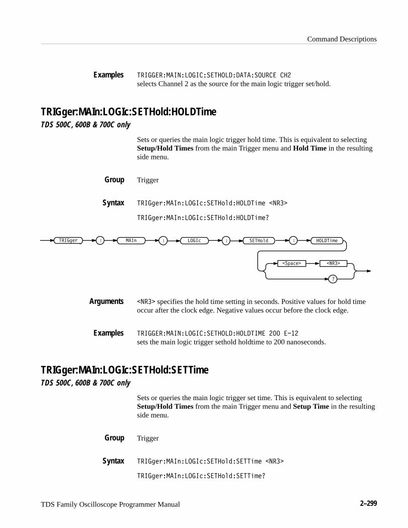
Command Descriptions
TDS Family Oscilloscope Programmer Manual 2–299
������������������������� � ���������� ���
selects Channel 2 as the source for the main logic trigger set/hold.
TRIGger:MAIn:LOGIc:SETHold:HOLDTimeTDS 500C, 600B & 700C only
Sets or queries the main logic trigger hold time. This is equivalent to selectingSetup/Hold Times from the main Trigger menu and Hold Time in the resultingside menu.
Trigger
������%����"�����������# ����� ��!� ����
������%����"�����������# ����� ��!�
������% � � ��������" ��
��$��� ����
��� ��!�����# �
���� specifies the hold time setting in seconds. Positive values for hold timeoccur after the clock edge. Negative values occur before the clock edge.
������������������������� ���� ���� ��� ����
sets the main logic trigger sethold holdtime to 200 nanoseconds.
TRIGger:MAIn:LOGIc:SETHold:SETTimeTDS 500C, 600B & 700C only
Sets or queries the main logic trigger set time. This is equivalent to selectingSetup/Hold Times from the main Trigger menu and Setup Time in the resultingside menu.
Trigger
������%����"�����������# �������!� ����
������%����"�����������# �������!�
Examples
Group
Syntax
Arguments
Examples
Group
Syntax
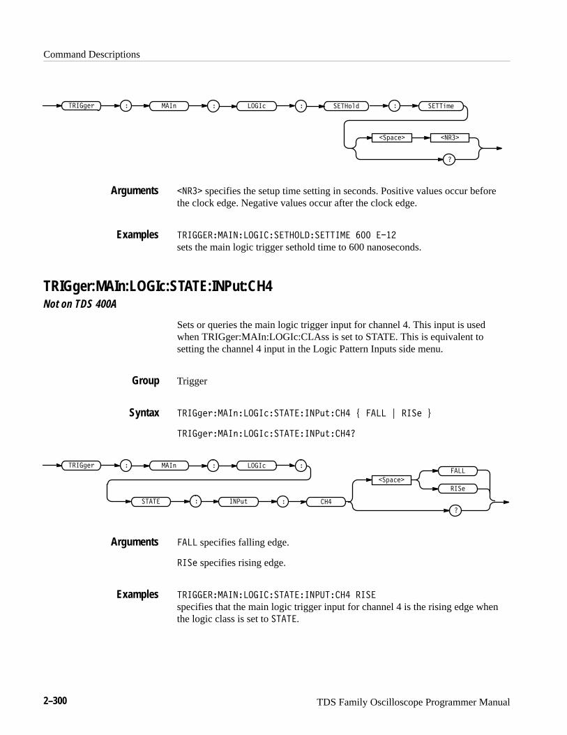
Command Descriptions
2–300 TDS Family Oscilloscope Programmer Manual
����"!) ������ �&
�
�(��!� ����
����#%!����'$
���� specifies the setup time setting in seconds. Positive values occur beforethe clock edge. Negative values occur after the clock edge.
�������� ��������������������� ��� ����
sets the main logic trigger sethold time to 600 nanoseconds.
TRIGger:MAIn:LOGIc:STATE:INPut:CH4Not on TDS 400A
Sets or queries the main logic trigger input for channel 4. This input is usedwhen TRIGger:MAIn:LOGIc:CLAss is set to STATE. This is equivalent tosetting the channel 4 input in the Logic Pattern Inputs side menu.
Trigger
����"!)� �&������� �����+*��� , � �� - ���! .
����"!)� �&������� �����+*����
�� ��
�(��!�
�
� ��
���!
����"!) ������ �&
���+*
���
� �� specifies falling edge.
���! specifies rising edge.
�������� ��������� ���������� ����
specifies that the main logic trigger input for channel 4 is the rising edge whenthe logic class is set to �� ��.
Arguments
Examples
Group
Syntax
Arguments
Examples
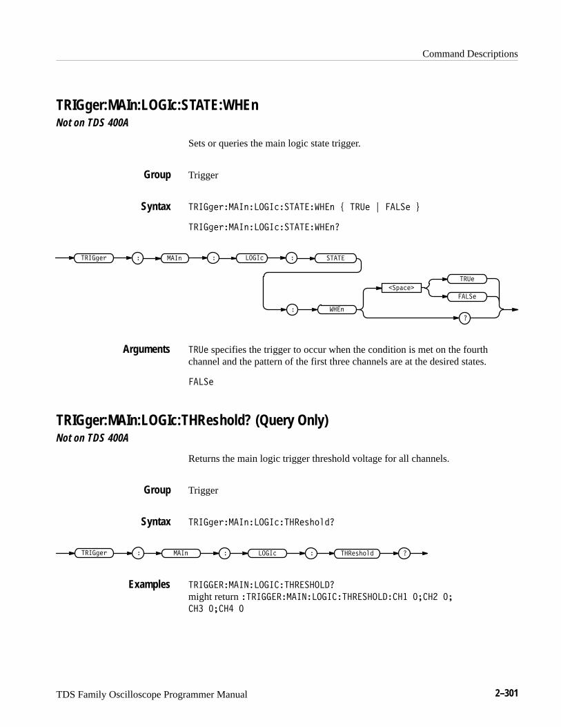
Command Descriptions
TDS Family Oscilloscope Programmer Manual 2–301
TRIGger:MAIn:LOGIc:STATE:WHEnNot on TDS 400A
Sets or queries the main logic state trigger.
Trigger
����! '����$����������������$ ) ��� * ���� +
����! '����$����������������$�
� ���$����! ' ����� �� �����
�&��
�
���
����
���$�
��� specifies the trigger to occur when the condition is met on the fourthchannel and the pattern of the first three channels are at the desired states.
����
TRIGger:MAIn:LOGIc:THReshold? (Query Only)Not on TDS 400A
Returns the main logic trigger threshold voltage for all channels.
Trigger
����! '����$���������� ("%#��
��� ("%#�����! ' � � ��������$ � �
����������������� �����������
might return ������������������ ����������� �� �� �� ��
�� �� �� �
Group
Syntax
Arguments
Group
Syntax
Examples
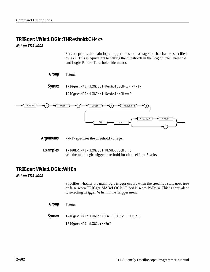
Command Descriptions
2–302 TDS Family Oscilloscope Programmer Manual
TRIGger:MAIn:LOGIc:THReshold:CH<x>Not on TDS 400A
Sets or queries the main logic trigger threshold voltage for the channel specifiedby <x>. This is equivalent to setting the thresholds in the Logic State Thresholdand Logic Pattern Threshold side menus.
Trigger
������%���"�����������& #!�����'� �����
������%���"�����������& #!�����'�
��$���� �����
������% � � �������" ��
�� �'�
����& #!�
����� specifies the threshold voltage.
����� ��������������� ��������� ��
sets the main logic trigger threshold for channel 1 to .5 volts.
TRIGger:MAIn:LOGIc:WHEnNot on TDS 400A
Specifies whether the main logic trigger occurs when the specified state goes trueor false when TRIGger:MAIn:LOGIc:CLAss is set to PATtern. This is equivalentto selecting Trigger When in the Trigger menu.
Trigger
������%���"��������� " ( ���� ) ���� *
������%���"��������� "
Group
Syntax
Arguments
Examples
Group
Syntax
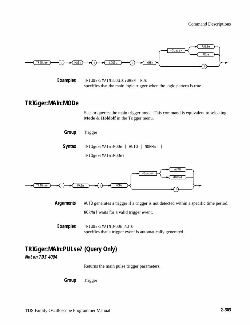
Command Descriptions
TDS Family Oscilloscope Programmer Manual 2–303
�� ���� � � ��� ��� � �
�������
�
����
����
���
�� ������ ����� ����� ���
specifies that the main logic trigger when the logic pattern is true.
TRIGger:MAIn:MODeSets or queries the main trigger mode. This command is equivalent to selectingMode & Holdoff in the Trigger menu.
Trigger
�� ������� ������ � ���� ������ !
�� ������� �������
�������
�
����
������
������ ���� � ��� �
���� generates a trigger if a trigger is not detected within a specific time period.
������ waits for a valid trigger event.
�� ������ ����� ����
specifies that a trigger event is automatically generated.
TRIGger:MAIn:PULse? (Query Only)Not on TDS 400A
Returns the main pulse trigger parameters.
Trigger
Examples
Group
Syntax
Arguments
Examples
Group

Command Descriptions
2–304 TDS Family Oscilloscope Programmer Manual
'%��/.5�!��2�$( 6.�
'%��/.5 � � $( 6.!��2 �
'%����%�!��"�$( &��
might return �'%����%�!��"�$( &��� �&& � �'���&#(%�� ���
� �'���*��'� �������� '�% ����$'�$# �%�'+ $#&�'�)���'%����%�
!��"�$( &��%("'�$# �%�'+ $#&�'�)��'�%�&�# ������ ����� #*
�������'%����%�!��"�$( &��*��'�� #* �!�' ���������� �!�'
������*��" *�'��"�$# �%�'+ $#&�'�)� as the current main pulse triggerparameters.
TRIGger:MAIn:PULse:CLAssNot on TDS 400A
Sets or queries the type of pulse to trigger on. This command is equivalent toselecting Class in the Trigger menu.
Trigger
'%��/.5�!��2�$( 6.�� �66 : � �7-0 ; %("' ; *��70 ;
& �*%,7. �'�& �� �� � �� 3219� ; '�!�#87 �'�& �� ���
�� 3219� <
'%��/.5�!��2�$( 6.�� �66�
�&4,-.�
*��70
�
'%��/.5 � � $( 6.!��2 �
� �66
& �*%,7.
'�!�#87
%("'
� �7-0
� �7-0 triggers when a pulse is found that is of the specified polarity and width.These are set with the commands TRIGger:MAIn:PULse:GLItch:POLarity andTRIGger:MAIn:PULse:GLItch:WIDth.
%("' triggers when a pulse crosses the first preset voltage threshold but does notcross the second preset threshold before recrossing the first. The thresholds areset with the TRIGger:MAIn:PULse:RUNT:THReshold:LOW and TRIG-
Syntax
Examples
Group
Syntax
Arguments
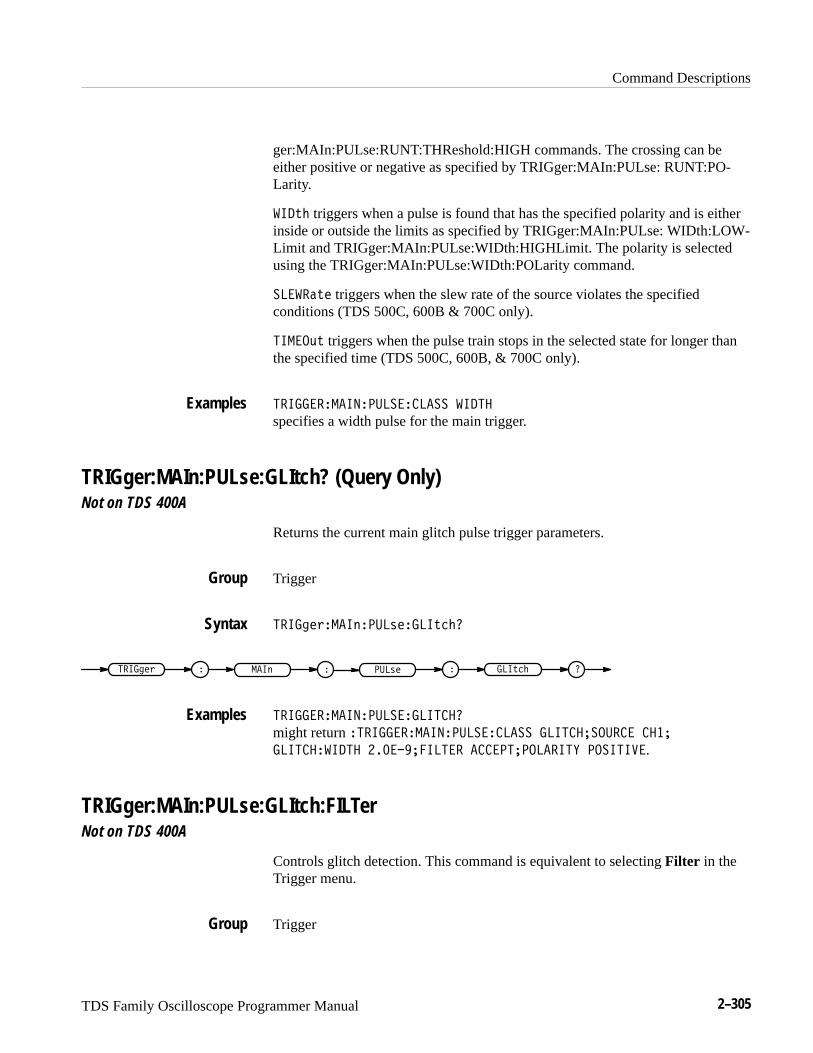
Command Descriptions
TDS Family Oscilloscope Programmer Manual 2–305
ger:MAIn:PULse:RUNT:THReshold:HIGH commands. The crossing can beeither positive or negative as specified by TRIGger:MAIn:PULse: RUNT:PO-Larity.
�� '# triggers when a pulse is found that has the specified polarity and is eitherinside or outside the limits as specified by TRIGger:MAIn:PULse: WIDth:LOW-Limit and TRIGger:MAIn:PULse:WIDth:HIGHLimit. The polarity is selectedusing the TRIGger:MAIn:PULse:WIDth:POLarity command.
������'! triggers when the slew rate of the source violates the specifiedconditions (TDS 500C, 600B & 700C only).
�����(' triggers when the pulse train stops in the selected state for longer thanthe specified time (TDS 500C, 600B, & 700C only).
������������������������ �� ��
specifies a width pulse for the main trigger.
TRIGger:MAIn:PULse:GLItch? (Query Only)Not on TDS 400A
Returns the current main glitch pulse trigger parameters.
Trigger
����"!%����$����&!����' #
����"!% � � ���&!���$ ���' # �
�������������������������
might return ������������������������� ������������ ���
��������� �� ������������ �������������� ��������.
TRIGger:MAIn:PULse:GLItch:FILTerNot on TDS 400A
Controls glitch detection. This command is equivalent to selecting Filter in theTrigger menu.
Trigger
Examples
Group
Syntax
Examples
Group
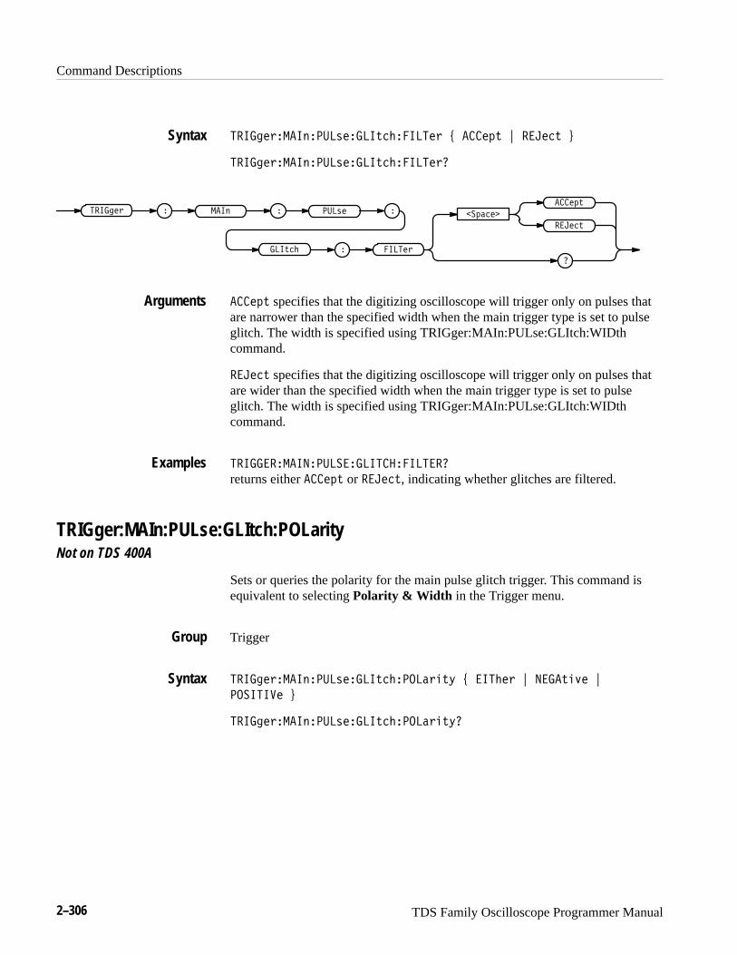
Command Descriptions
2–306 TDS Family Oscilloscope Programmer Manual
����� ���������!����"������� % �����" & �� ��" '
����� ���������!����"������� �
�����"����� � � ���!����� �
� ���� ��"��
�� ��"
�������
�
�����" specifies that the digitizing oscilloscope will trigger only on pulses thatare narrower than the specified width when the main trigger type is set to pulseglitch. The width is specified using TRIGger:MAIn:PULse:GLItch:WIDthcommand.
�� ��" specifies that the digitizing oscilloscope will trigger only on pulses thatare wider than the specified width when the main trigger type is set to pulseglitch. The width is specified using TRIGger:MAIn:PULse:GLItch:WIDthcommand.
�����������������������������
returns either �����" or �� ��", indicating whether glitches are filtered.
TRIGger:MAIn:PULse:GLItch:POLarityNot on TDS 400A
Sets or queries the polarity for the main pulse glitch trigger. This command isequivalent to selecting Polarity & Width in the Trigger menu.
Trigger
����� ���������!����"������� �"$ % ����� & ���"�#� &
�������� '
����� ���������!����"������� �"$�
Syntax
Arguments
Examples
Group
Syntax
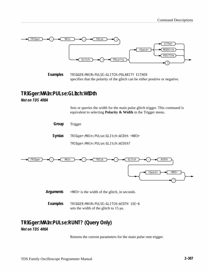
Command Descriptions
TDS Family Oscilloscope Programmer Manual 2–307
��%��
���" &
�������
����(#)
����! & � ���$
����&#(*
� ���' �
����(�"
���������������������������������� ������
specifies that the polarity of the glitch can be either positive or negative.
TRIGger:MAIn:PULse:GLItch:WIDthNot on TDS 400A
Sets or queries the width for the main pulse glitch trigger. This command isequivalent to selecting Polarity & Width in the Trigger menu.
Trigger
����! &����$����' ����(�"��� (" ����
����! &����$����' ����(�"��� ("
��%�� ����
����! & � � ���' ���$ ���(�" �� �� ("
���� is the width of the glitch, in seconds.
���������������������������� �� �����
sets the width of the glitch to 15 �s.
TRIGger:MAIn:PULse:RUNT? (Query Only)Not on TDS 400A
Returns the current parameters for the main pulse runt trigger.
Examples
Group
Syntax
Arguments
Examples
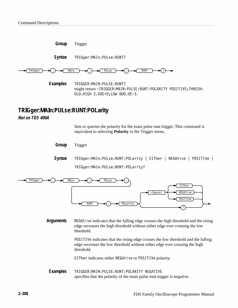
Command Descriptions
2–308 TDS Family Oscilloscope Programmer Manual
Trigger
����#"(���&���)"����
����#"( ���)"���& ����
��������������������
might return ���������������������������� ��������������0
������� ���������� ��������.
TRIGger:MAIn:PULse:RUNT:POLarityNot on TDS 400A
Sets or queries the polarity for the main pulse runt trigger. This command isequivalent to selecting Polarity in the Trigger menu.
Trigger
����#"(���&���)"������� (%*, - ���$"( . ����*%+" . �������" /
����#"(���&���)"������� (%*,
����*%+"��' !"�
���$"(
�������"
����#"( ���)"���&
���� ��� (%*,
����*%+" indicates that the falling edge crosses the high threshold and the risingedge recrosses the high threshold without either edge ever crossing the lowthreshold.
�������" indicates that the rising edge crosses the low threshold and the fallingedge recrosses the low threshold without either edge ever crossing the highthreshold.
���$"( indicates either ����*%+" or �������" polarity.
���������������������������� ��������
specifies that the polarity of the main pulse runt trigger is negative.
Group
Syntax
Examples
Group
Syntax
Arguments
Examples
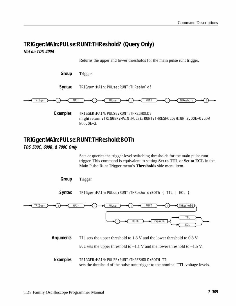
Command Descriptions
TDS Family Oscilloscope Programmer Manual 2–309
TRIGger:MAIn:PULse:RUNT:THReshold? (Query Only)Not on TDS 400A
Returns the upper and lower thresholds for the main pulse runt trigger.
Trigger
����$#*���'���+#�������#+%(&"
����$#* ���+#���' ���� ���#+%(&"
�����������������������������
might return ��������������������������������� ����������
��������.
TRIGger:MAIn:PULse:RUNT:THReshold:BOThTDS 500C, 600B, & 700C Only
Sets or queries the trigger level switching thresholds for the main pulse runttrigger. This command is equivalent to setting Set to TTL or Set to ECL in theMain Pulse Runt Trigger menu’s Thresholds side menu item.
Trigger
����$#*���'���+#�������#+%(&"���% , ��� - ��� .
����$#* ���+#���' ���� ���#+%(&"
��) !#�
���
���
���%
��� sets the upper threshold to 1.8 V and the lower threshold to 0.8 V.
��� sets the upper threshold to –1.1 V and the lower threshold to –1.5 V.
��������������������������������� ���
sets the threshold of the pulse runt trigger to the nominal TTL voltage levels.
Group
Syntax
Examples
Group
Syntax
Arguments
Examples
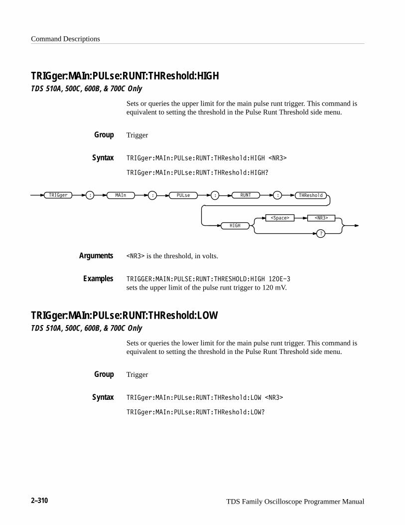
Command Descriptions
2–310 TDS Family Oscilloscope Programmer Manual
TRIGger:MAIn:PULse:RUNT:THReshold:HIGHTDS 510A, 500C, 600B, & 700C Only
Sets or queries the upper limit for the main pulse runt trigger. This command isequivalent to setting the threshold in the Pulse Runt Threshold side menu.
Trigger
������%����"����&�����������& #!������ ����
������%����"����&�����������& #!������
������% � � ���&����" ���� ��
��$��� ����
����
����& #!�
���� is the threshold, in volts.
����� ����������� ��������� ���������� ��� ��
sets the upper limit of the pulse runt trigger to 120 mV.
TRIGger:MAIn:PULse:RUNT:THReshold:LOWTDS 510A, 500C, 600B, & 700C Only
Sets or queries the lower limit for the main pulse runt trigger. This command isequivalent to setting the threshold in the Pulse Runt Threshold side menu.
Trigger
������%����"����&�����������& #!����� ����
������%����"����&�����������& #!�����
Group
Syntax
Arguments
Examples
Group
Syntax
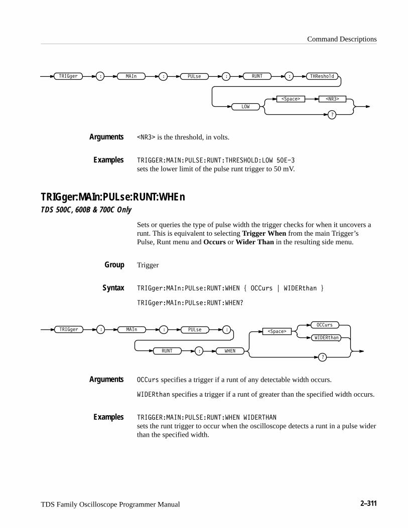
Command Descriptions
TDS Family Oscilloscope Programmer Manual 2–311
����& #!�������% � � ���&���" ���� ��
��$���� �����
���
����� is the threshold, in volts.
����� ���������� ��������� ��������� �� ��
sets the lower limit of the pulse runt trigger to 50 mV.
TRIGger:MAIn:PULse:RUNT:WHEnTDS 500C, 600B & 700C Only
Sets or queries the type of pulse width the trigger checks for when it uncovers arunt. This is equivalent to selecting Trigger When from the main Trigger’sPulse, Runt menu and Occurs or Wider Than in the resulting side menu.
Trigger
������%���"����&��������� � ) ���(%& * ��� �' �" +
������%���"����&��������� �
���(%&������% � � ���&���" �
� �� �����
��� �' �"
��$����
���(%& specifies a trigger if a runt of any detectable width occurs.
��� �' �" specifies a trigger if a runt of greater than the specified width occurs.
����� ���������� �������� � ��� ����
sets the runt trigger to occur when the oscilloscope detects a runt in a pulse widerthan the specified width.
Arguments
Examples
Group
Syntax
Arguments
Examples
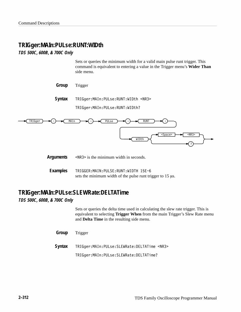
Command Descriptions
2–312 TDS Family Oscilloscope Programmer Manual
TRIGger:MAIn:PULse:RUNT:WIDthTDS 500C, 600B, & 700C Only
Sets or queries the minimum width for a valid main pulse runt trigger. Thiscommand is equivalent to entering a value in the Trigger menu’s Wider Thanside menu.
Trigger
������#����!����$����������%� ����
������#����!����$����������%�
������# � � ���$����! ���� ��
��"��� ����
���%�
���� is the minimum width in seconds.
����� ����������� ����������� �� ��
sets the minimum width of the pulse runt trigger to 15 �s.
TRIGger:MAIn:PULse:SLEWRate:DELTATimeTDS 500C, 600B, & 700C Only
Sets or queries the delta time used in calculating the slew rate trigger. This isequivalent to selecting Trigger When from the main Trigger’s Slew Rate menuand Delta Time in the resulting side menu.
Trigger
������#����!����$���� ���%��� ����� � ����
������#����!����$���� ���%��� ����� �
Group
Syntax
Arguments
Examples
Group
Syntax
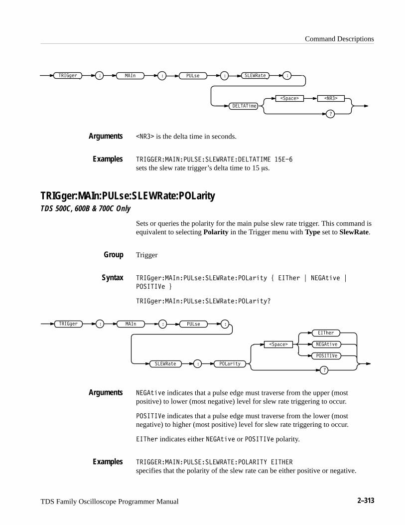
Command Descriptions
TDS Family Oscilloscope Programmer Manual 2–313
���� �& � � ���'����$ �� ���(� ��
��%��� ����
� ����"#�
���� is the delta time in seconds.
����� ����������� ��� ���� �� ������ �� ��
sets the slew rate trigger’s delta time to 15 �s.
TRIGger:MAIn:PULse:SLEWRate:POLarityTDS 500C, 600B & 700C Only
Sets or queries the polarity for the main pulse slew rate trigger. This command isequivalent to selecting Polarity in the Trigger menu with Type set to SlewRate.
Trigger
���� �&����$����'���� ���(������&"(* + ��!�& , � ��(")� ,
�������� -
���� �&����$����'���� ���(������&"(*
��%���
��!�&
��������
� ��(")�
���� �& � ���$
����&"(*
� ���'� �
��� ���(�
� ��(")� indicates that a pulse edge must traverse from the upper (mostpositive) to lower (most negative) level for slew rate triggering to occur.
�������� indicates that a pulse edge must traverse from the lower (mostnegative) to higher (most positive) level for slew rate triggering to occur.
��!�& indicates either � ��(")� or �������� polarity.
����� ����������� ��� ���� ��������� ��� �
specifies that the polarity of the slew rate can be either positive or negative.
Arguments
Examples
Group
Syntax
Arguments
Examples

Command Descriptions
2–314 TDS Family Oscilloscope Programmer Manual
TRIGger:MAIn:PULse:SLEWRate:SLEWRate? (Query Only)TDS 500C, 600B, & 700C Only
Returns the slew rate value. This is the
((Upper Threshold – Lower Threshold) / Delta Time)
The value is limited to the three most significant digits.
Trigger
��� ��"��� ����#��������$�����%"�$��
��� ��" � � ���#��� � �������$�� ������$�
��� �����������������������������
returns the slew rate. It is given as an appropriate amount of volts per second.For example, ������ would represent a slew rate of 1.2 megavolts/second.
TRIGger:MAIn:PULse:SLEWRate:THReshold:BOThTDS 500, 600B, & 700C Only
Sets the upper and lower slew rate trigger thresholds. This is equivalent toselecting Thresholds from the main Trigger’s Slew Rate menu and entering avalue in the resulting side menu’s High Threshold or Low Threshold items.
Trigger
��� ��"��� ����#��������$������#�!������ & ��� ' ��� (
����#�!����� ��" � � ���#��� ��
���
������$�
���
���
��� sets the upper threshold to 1.8 V and the lower threshold to 0.8 V.
��� sets the upper threshold to –1.1 V and the lower threshold to –1.5 V.
Group
Syntax
Examples
Group
Syntax
Arguments

Command Descriptions
TDS Family Oscilloscope Programmer Manual 2–315
������������������������������������ ����� ���
sets the trigger threshold to TTL.
TRIGger:MAIn:PULse:SLEWRate:THReshold:HIGHTDS 500C, 600B, & 700C Only
Sets or queries the upper (most positive) limit of the two threshold levels that apulse edge must traverse for the slew rate trigger to occur. This command isequivalent to setting the higher threshold in the Pulse Slew Rate Trigger’sThresholds side menu item.
Trigger
���� �&����#����'��������(������'!$"������ ����
���� �&����#����'��������(������'!$"������
���� �& � � ���'����# ��
��%��� ����
����
����'!$"�������(�
���� is the threshold, in volts.
������������������������������������ ����� ������
sets the upper limit of the pulse slew rate trigger to 120 mV.
TRIGger:MAIn:PULse:SLEWRate:THReshold:LOWTDS 500C, 600B, & 700C Only
Sets or queries the lower (most negative) limit of the two threshold levels that apulse edge must traverse for the slew rate trigger to occur. This command isequivalent to setting the lower threshold in the Pulse Slew Rate Trigger’sThresholds side menu item.
Trigger
���� �&����#����'��������(������'!$"����� ����
Examples
Group
Syntax
Arguments
Examples
Group
Syntax

Command Descriptions
2–316 TDS Family Oscilloscope Programmer Manual
������%���"����&��������'������& #!�����
����& #!�������% � � ���&���" ��
��$���� �����
���
������'�
����� is the threshold, in volts.
��������������������������������������� �����
sets the lower limit of the pulse slew rate trigger to 50 mV.
TRIGger:MAIn:PULse:SLEWRate:WHEnTDS 500C, 600B, & 700C Only
Sets or queries whether to check for a slewing signal that is faster or slower thanthe specified delta time. This is equivalent to selecting Trigger When from themain Trigger’s Slew Rate menu and entering a value in the resulting side menu’sTrig if Less Than or Trig if Greater Than items.
Trigger
������%���"����&��������'�����" ( ����' �" ) ������' �" *
������%���"����&��������'�����"
����' �"������% � � ���&���" �
� ����������'�
������' �"
��$����
����' �" sets the trigger to occur when the slew is faster than the setvolts/second rate.
������' �" sets the trigger to occur when the slew is slower than the setvolts/second rate.
Arguments
Examples
Group
Syntax
Arguments
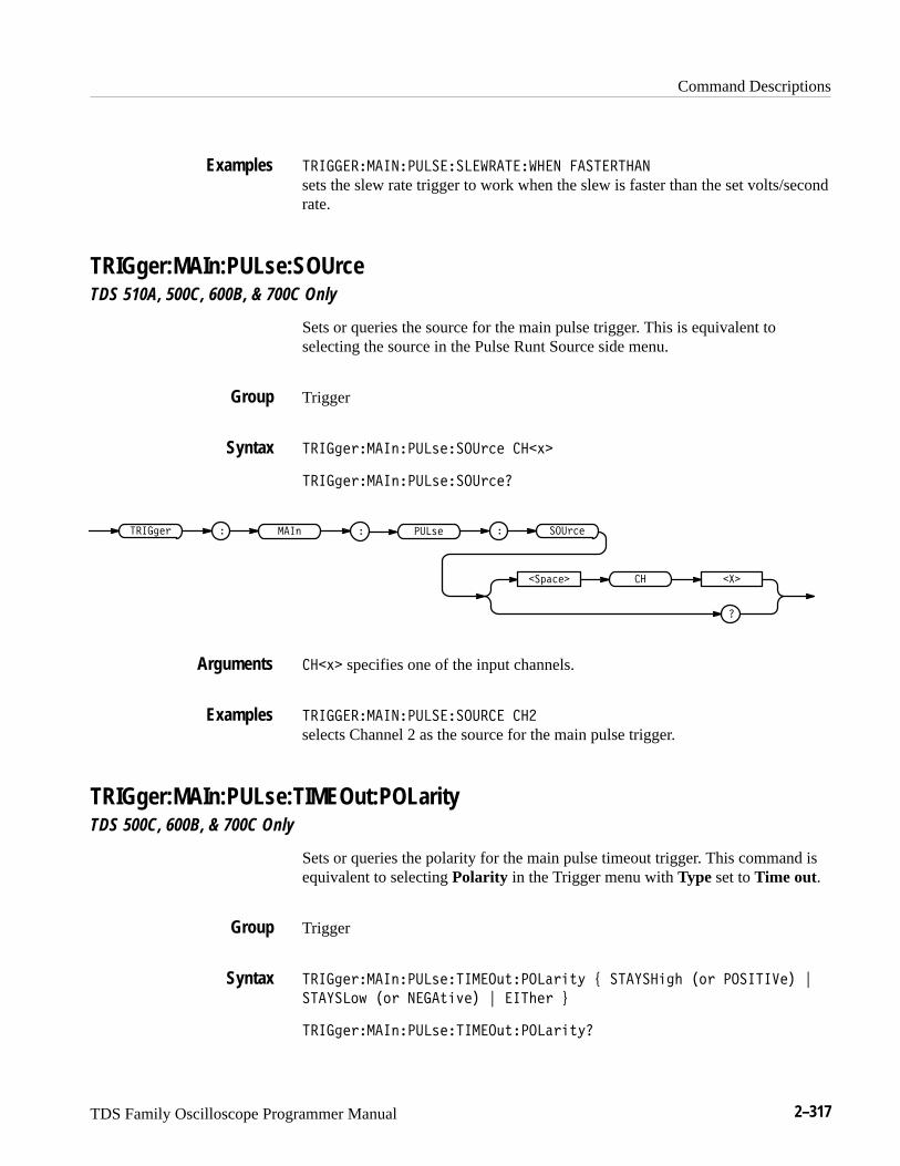
Command Descriptions
TDS Family Oscilloscope Programmer Manual 2–317
��� ������������������������� ��������
sets the slew rate trigger to work when the slew is faster than the set volts/secondrate.
TRIGger:MAIn:PULse:SOUrceTDS 510A, 500C, 600B, & 700C Only
Sets or queries the source for the main pulse trigger. This is equivalent toselecting the source in the Pulse Runt Source side menu.
Trigger
��� �&���#����'�����&�� ��,�
��� �&���#����'�����&���
�
��%���� ����
��� �& � � ���'���# ���&���
��,� specifies one of the input channels.
��� ������������������ ��
selects Channel 2 as the source for the main pulse trigger.
TRIGger:MAIn:PULse:TIMEOut:POLarityTDS 500C, 600B, & 700C Only
Sets or queries the polarity for the main pulse timeout trigger. This command isequivalent to selecting Polarity in the Trigger menu with Type set to Time out.
Trigger
��� �&���#����'�������)(�����&"(- . �����" ! �$& ��������� /
�����$+ �$& �� ("*�� / ���!�& 0
��� �&���#����'�������)(�����&"(-�
Examples
Group
Syntax
Arguments
Examples
Group
Syntax
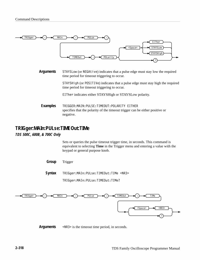
Command Descriptions
2–318 TDS Family Oscilloscope Programmer Manual
�������
�����
�
��������
�������%
����� � ���
���� �"&
� ���!� �
��� ��#"
�������% (or ���"�$�) indicates that a pulse edge must stay low the requiredtime period for timeout triggering to occur.
�������� (or ��������) indicates that a pulse edge must stay high the requiredtime period for timeout triggering to occur.
����� indicates either STAYSHigh or STAYSLow polarity.
������ ������������ ������������� �����
specifies that the polarity of the timeout trigger can be either positive ornegative.
TRIGger:MAIn:PULse:TIMEOut:TIMeTDS 500C, 600B, & 700C Only
Sets or queries the pulse timeout trigger time, in seconds. This command isequivalent to selecting Time in the Trigger menu and entering a value with thekeypad or general purpose knob.
Trigger
����� � �������!���� ��#"��� � �����
����� � �������!���� ��#"��� ��
�
������� �����
����� � � ���!� ��� �� ��#" �� �� �
����� is the timeout time period, in seconds.
Arguments
Examples
Group
Syntax
Arguments
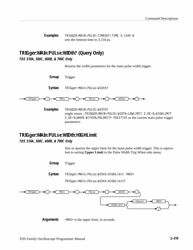
Command Descriptions
TDS Family Oscilloscope Programmer Manual 2–319
������������������������������� �������
sets the timeout time to 3.134 �s.
TRIGger:MAIn:PULse:WIDth? (Query Only)TDS 510A, 500C, 600B, & 700C Only
Returns the width parameters for the main pulse width trigger.
Trigger
����%$+����)����,$� ��-&�
����%$+ � � ���,$���) ��-& ��
������������������� �����
might return �������������������� ������� ����� ���������������
������ ��� �������������! �������� as the current main pulse triggerparameters.
TRIGger:MAIn:PULse:WIDth:HIGHLimitTDS 510A, 500C, 600B, & 700C Only
Sets or queries the upper limit for the main pulse width trigger. This is equiva-lent to setting Upper Limit in the Pulse Width Trig When side menu.
Trigger
����%$+����)����,$� ��-&������'('- ����
����%$+����)����,$� ��-&������'('-�
�
�*"#$� ����
����%$+ � � ���,$���) ��-& �
�����'('-
�
���� is the upper limit, in seconds.
Examples
Group
Syntax
Examples
Group
Syntax
Arguments
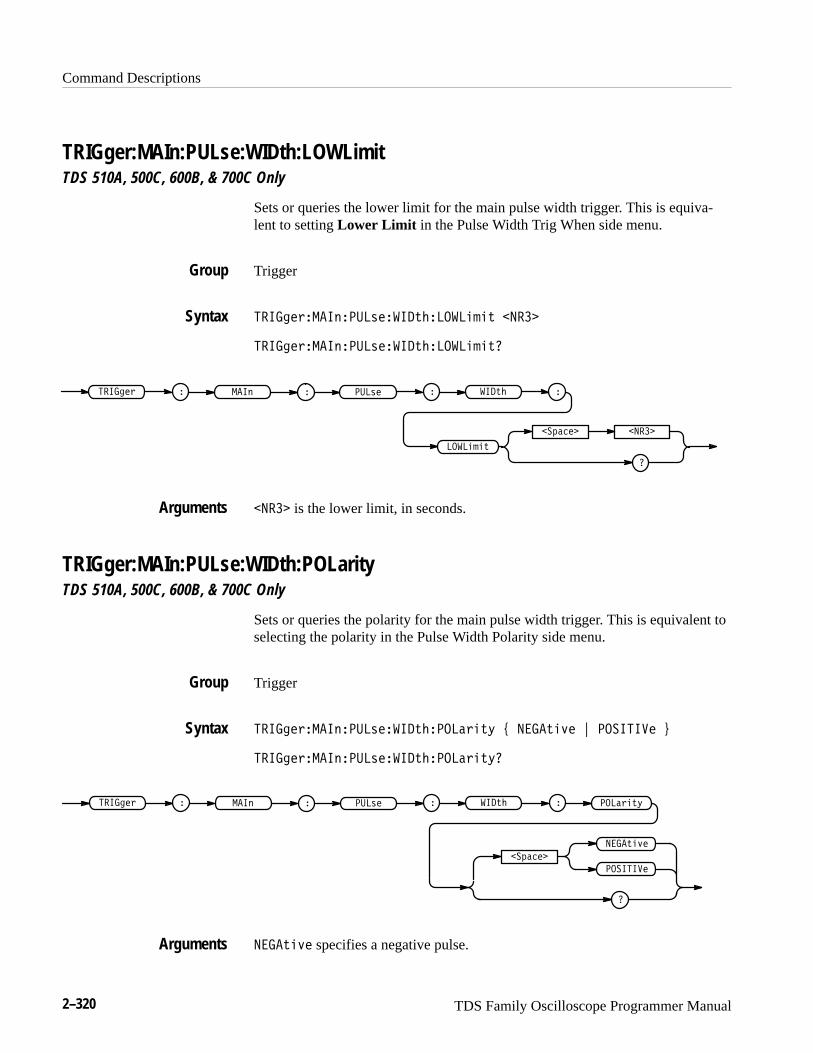
Command Descriptions
2–320 TDS Family Oscilloscope Programmer Manual
TRIGger:MAIn:PULse:WIDth:LOWLimitTDS 510A, 500C, 600B, & 700C Only
Sets or queries the lower limit for the main pulse width trigger. This is equiva-lent to setting Lower Limit in the Pulse Width Trig When side menu.
Trigger
����� � �������!�����"���������" �����
����� � �������!�����"���������"�
�
������� �����
����� � � ���!� ��� ���"� �
�������"
�
����� is the lower limit, in seconds.
TRIGger:MAIn:PULse:WIDth:POLarityTDS 510A, 500C, 600B, & 700C Only
Sets or queries the polarity for the main pulse width trigger. This is equivalent toselecting the polarity in the Pulse Width Polarity side menu.
Trigger
����� � �������!�����"������ �"$ % ��"�#� & �������� '
����� � �������!�����"������ �"$�
����� � � ���!� ��� ���"� � ���� �"$
�������
�
�
��������
��"�#�
��"�#� specifies a negative pulse.
Group
Syntax
Arguments
Group
Syntax
Arguments
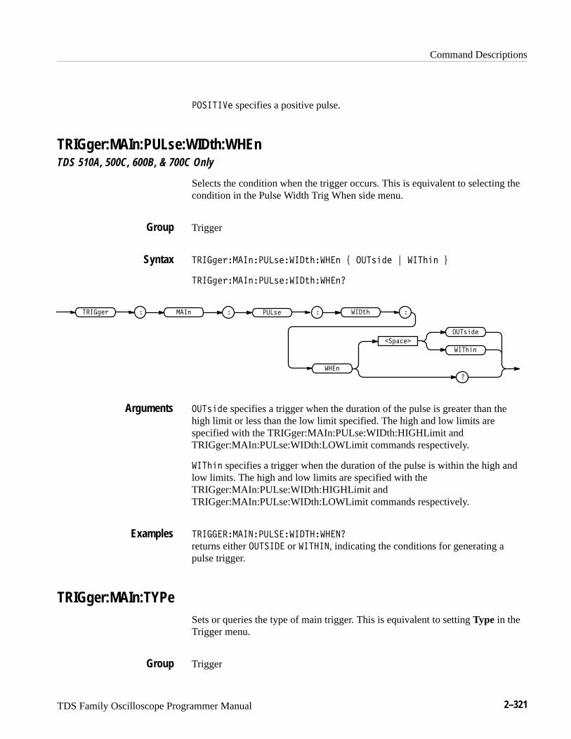
Command Descriptions
TDS Family Oscilloscope Programmer Manual 2–321
�������� specifies a positive pulse.
TRIGger:MAIn:PULse:WIDth:WHEnTDS 510A, 500C, 600B, & 700C Only
Selects the condition when the trigger occurs. This is equivalent to selecting thecondition in the Pulse Width Trig When side menu.
Trigger
����� � �������!�����"����� # ���!��� $ ������ %
����� � �������!�����"������
�������
�
����� � �
���!���
������
���!� ��� ���"� �
���
�
���!��� specifies a trigger when the duration of the pulse is greater than thehigh limit or less than the low limit specified. The high and low limits arespecified with the TRIGger:MAIn:PULse:WIDth:HIGHLimit andTRIGger:MAIn:PULse:WIDth:LOWLimit commands respectively.
������ specifies a trigger when the duration of the pulse is within the high andlow limits. The high and low limits are specified with theTRIGger:MAIn:PULse:WIDth:HIGHLimit andTRIGger:MAIn:PULse:WIDth:LOWLimit commands respectively.
������ �������������������
returns either ������� or �����, indicating the conditions for generating apulse trigger.
TRIGger:MAIn:TYPeSets or queries the type of main trigger. This is equivalent to setting Type in theTrigger menu.
Trigger
Group
Syntax
Arguments
Examples
Group
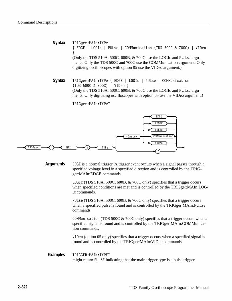
Command Descriptions
2–322 TDS Family Oscilloscope Programmer Manual
���� �%����"�����
) ���� * ����� * ���&� * ���("!��'!#" ���� ��� � ��� � * ����#
+
(Only the TDS 510A, 500C, 600B, & 700C use the LOGIc and PULse argu-ments. Only the TDS 500C and 700C use the COMMunication argument. Onlydigitizing oscilloscopes with option 05 use the VIDeo argument.)
���� �%����"����� ) ���� * ����� * ���&� * ���("!��'!#"
���� ��� � ��� � * ����# +
(Only the TDS 510A, 500C, 600B, & 700C use the LOGIc and PULse argu-ments. Only digitizing oscilloscopes with option 05 use the VIDeo argument.)
���� �%����"������
���� �% �
�$���
�
���&�
����#
� �������"
����
����
���("!��'!#"
���� is a normal trigger. A trigger event occurs when a signal passes through aspecified voltage level in a specified direction and is controlled by the TRIG-ger:MAIn:EDGE commands.
����� (TDS 510A, 500C, 600B, & 700C only) specifies that a trigger occurswhen specified conditions are met and is controlled by the TRIGger:MAIn:LOG-Ic commands.
���&� (TDS 510A, 500C, 600B, & 700C only) specifies that a trigger occurswhen a specified pulse is found and is controlled by the TRIGger:MAIn:PULsecommands.
���("!��'!#" (TDS 500C & 700C only) specifies that a trigger occurs when aspecified signal is found and is controlled by the TRIGger:MAIn:COMMunica-tion commands.
����# (option 05 only) specifies that a trigger occurs when a specified signal isfound and is controlled by the TRIGger:MAIn:VIDeo commands.
������������������
might return ����� indicating that the main trigger type is a pulse trigger.
Syntax
Syntax
Arguments
Examples

Command Descriptions
TDS Family Oscilloscope Programmer Manual 2–323
TRIGger:MAIn:VIDeo? (Query Only)Option 05 Only
Returns the main video trigger parameters.
Trigger
" ��)(-����*�$��(+�
" ��)(- � � $��(+���* �
" ���� ������$�����
might return: �"!�����������#�� ���������������� ��������������� �������������������������������
�� ���� as the current main video trigger parameters.
TRIGger:MAIn:VIDeo:BYTDS 400A Option 05 Only
Sets or queries the video trigger delay mode. This is equivalent to using theVideo TV Delay Mode side menu.
Trigger
" ��)(-����*�$��(+��% . "��( / ����! / ���� 0
" ��)(-����*�$��(+��%�
�!,&'(�
�
" ��)(- � �
"��(
����
$��(+���* �%�
����!
TIMe specifies a delay by time.
LINES specifies a delay by a number of video lines. For the TDS 400A, thisargument is available only for backward compatibility. If the TDS 400A receives
Group
Syntax
Examples
Group
Syntax
Arguments

Command Descriptions
2–324 TDS Family Oscilloscope Programmer Manual
this argument, it will convert it to LINE. The TDS 400A will not output thisargument in response to a query.
LINE specifies a delay by a number of video lines.
TRIGGER:MAIN:VIDEO:BY TIMEspecifies a delay by time.
TRIGger:MAIn:VIDeo:FIELDTDS 400A Option 05 Only
Sets or queries the field the video trigger acts on. This is equivalent to using theVideo Scan side menu when Class is NOT set to Custom.
Trigger
�� ������� ��� ���� � !$� " �� " ��� " � �� " � �� "
� �� ���$#
�� ������� ��� ���� ��
� �� ���
�� ���� � � � ���� � � ��
�������
� ��
�
� ��
���
��
�
ODD specifies interlaced video field 1.
EVEN specifies interlaced video field 2.
ALL specifies alternating both video field 1 and video field 2.
FIELD1 specifies interlaced video field 1. For the TDS 400A, this argument isavailable only for backward compatibility. If the TDS 400A receives thisargument, it will convert it to ODD. The TDS 400A will not output thisargument in response to a query.
FIELD2 specifies interlaced video field 2. For the TDS 400A, this argument isavailable only for backward compatibility. If the TDS 400A receives this
Examples
Group
Syntax
Arguments
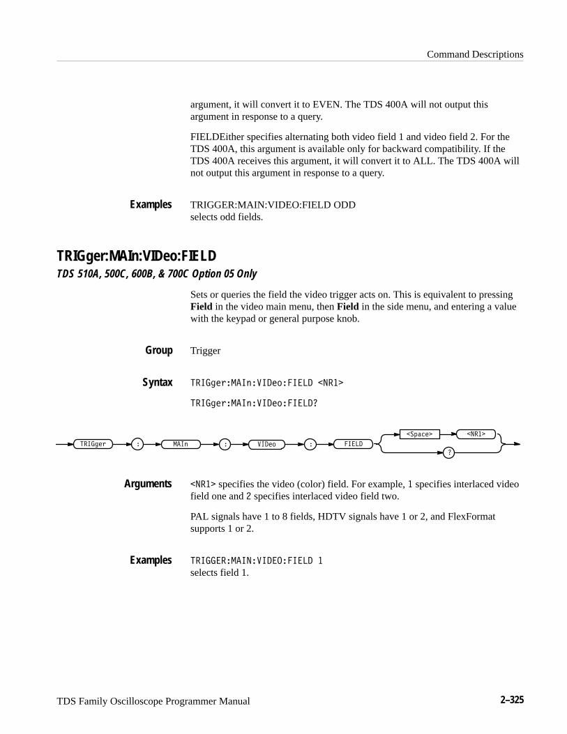
Command Descriptions
TDS Family Oscilloscope Programmer Manual 2–325
argument, it will convert it to EVEN. The TDS 400A will not output thisargument in response to a query.
FIELDEither specifies alternating both video field 1 and video field 2. For theTDS 400A, this argument is available only for backward compatibility. If theTDS 400A receives this argument, it will convert it to ALL. The TDS 400A willnot output this argument in response to a query.
TRIGGER:MAIN:VIDEO:FIELD ODDselects odd fields.
TRIGger:MAIn:VIDeo:FIELDTDS 510A, 500C, 600B, & 700C Option 05 Only
Sets or queries the field the video trigger acts on. This is equivalent to pressingField in the video main menu, then Field in the side menu, and entering a valuewith the keypad or general purpose knob.
Trigger
�� ������� ��� ���� � �����
�� ������� ��� ���� ��
�� ���� � � � ���� � � ��
�������
�
�����
����� specifies the video (color) field. For example, � specifies interlaced videofield one and � specifies interlaced video field two.
PAL signals have 1 to 8 fields, HDTV signals have 1 or 2, and FlexFormatsupports 1 or 2.
�� ������ ��� ��� � �
selects field 1.
Examples
Group
Syntax
Arguments
Examples

Command Descriptions
2–326 TDS Family Oscilloscope Programmer Manual
TRIGger:MAIn:VIDeo:FIELDTypeTDS 510A, 500C, 600B, & 700C Option 05 Only
Sets or queries the field the video trigger acts on. This is equivalent to pressingField in the video main menu and then Field, Odd, Even or All in the sidemenu.
Trigger
�����"� �������� ������$!� %(�� ���� & ��� & ���� & ���('
�����"� �������� ������$!��
�����" � � ���� ��� �
��!����
���
�
����
���
�� ����
�����$!�
NUMERic specifies a selected line in the selected field. If you send thiscommand when the mode is MONO or SECAM, the digitizing oscilloscope willgenerate an SRQ.
ALL specifies a selected line in all fields.
EVEN specifies a selected line in even fields.
ODD specifies a selected line in odd fields.
������ ������������������ ���
selects a selected line in all fields.
TRIGger:MAIn:VIDeo:FLEXformat? (Query Only)TDS 510A, 500C, 600B, & 700C Option 05 Only
Returns the main flexible-format video trigger parameters.
Trigger
�����"� �������� ����� "��#�
Group
Syntax
Arguments
Examples
Group
Syntax
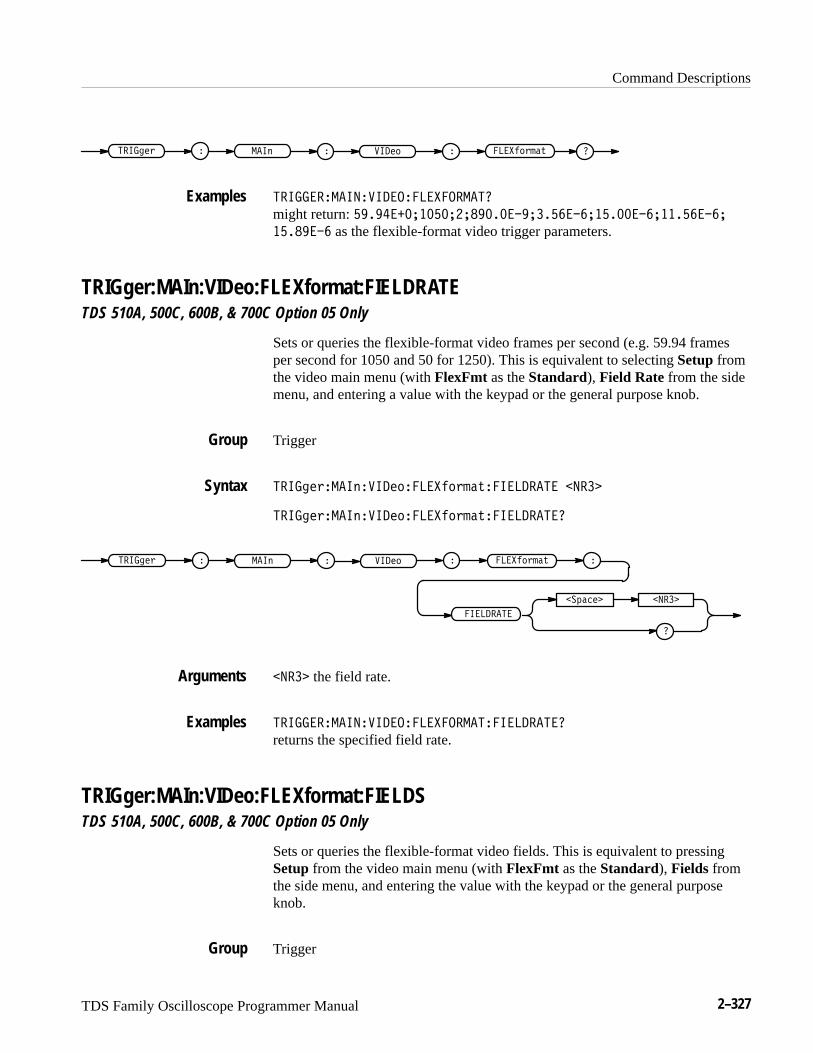
Command Descriptions
TDS Family Oscilloscope Programmer Manual 2–327
����&$+ � � ��$)���( ����!%)+'",�
������������� ��������!�������
might return: � ����������� ����� ��������������������������� ��� as the flexible-format video trigger parameters.
TRIGger:MAIn:VIDeo:FLEXformat:FIELDRATETDS 510A, 500C, 600B, & 700C Option 05 Only
Sets or queries the flexible-format video frames per second (e.g. 59.94 framesper second for 1050 and 50 for 1250). This is equivalent to selecting Setup fromthe video main menu (with FlexFmt as the Standard), Field Rate from the sidemenu, and entering a value with the keypad or the general purpose knob.
Trigger
����&$+����(� ��$)����!%)+'",���������� �����
����&$+����(� ��$)����!%)+'",�����������
���������
�
��*"#$� �����
����&$+ � � ��$)���( � ���!%)+'", �
����� the field rate.
������������� ��������!�����������������
returns the specified field rate.
TRIGger:MAIn:VIDeo:FLEXformat:FIELDSTDS 510A, 500C, 600B, & 700C Option 05 Only
Sets or queries the flexible-format video fields. This is equivalent to pressingSetup from the video main menu (with FlexFmt as the Standard), Fields fromthe side menu, and entering the value with the keypad or the general purposeknob.
Trigger
Examples
Group
Syntax
Arguments
Examples
Group
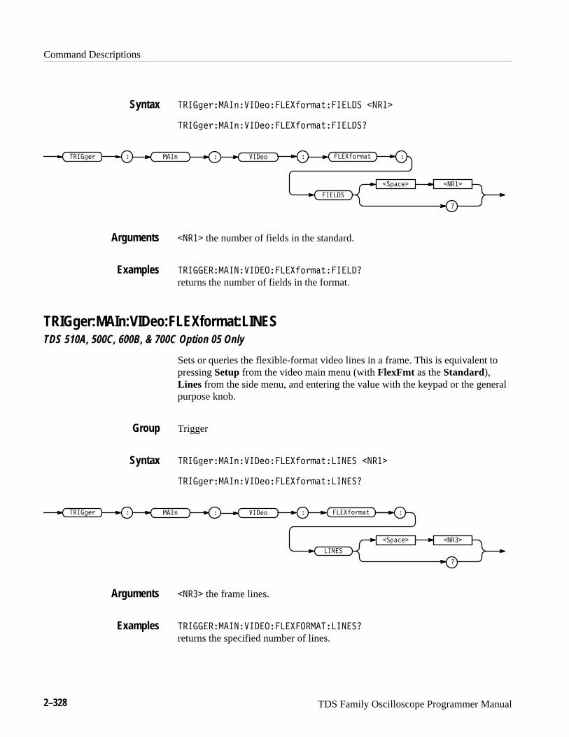
Command Descriptions
2–328 TDS Family Oscilloscope Programmer Manual
�� ��� ��� ��� �������� ��!�� �� �����
�� ��� ��� ��� �������� ��!�� ���
�
������� �����
�� ��� � � � ���� � �
� ��
����� ��! �
����� the number of fields in the standard.
�� ������ ��� ������� ��!�� ��
returns the number of fields in the format.
TRIGger:MAIn:VIDeo:FLEXformat:LINESTDS 510A, 500C, 600B, & 700C Option 05 Only
Sets or queries the flexible-format video lines in a frame. This is equivalent topressing Setup from the video main menu (with FlexFmt as the Standard),Lines from the side menu, and entering the value with the keypad or the generalpurpose knob.
Trigger
�� ��� ��� ��� �������� ��!�� �� �����
�� ��� ��� ��� �������� ��!�� ���
����� ��!
�
������� �����
�� ��� � � � ���� � �
� ��
�
����� the frame lines.
�� ������ ��� ������������� ���
returns the specified number of lines.
Syntax
Arguments
Examples
Group
Syntax
Arguments
Examples

Command Descriptions
TDS Family Oscilloscope Programmer Manual 2–329
TRIGger:MAIn:VIDeo:FLEXformat:NEGSyncwidthTDS 510A, 500C, 600B, & 700C Option 05 Only
Sets or queries the flexible-format negative sync width. The HDTV horizontalsync is a tri-level sync. The first of the two consecutive sync pulses used isnegative and the second is positive. The positive sync pulse starts on the risingedge of the negative sync. The two pulses have the same width such thatspecifying the negative pulse is only required. Setting the width is equivalent topressing Setup from the video main menu (with FlexFmt as the Standard),Sync Width from the side menu, and entering the value with the keypad or thegeneral purpose knob.
Trigger
��� �'����$����%������%'#�(��� �*$�)"�(! �����
��� �'����$����%������%'#�(��� �*$�)"�(!�
�����%'#�(
�� �*$�)"�(!
�
��&���� �����
��� �' � � ���%���$ � �
����� the negative sync width.
��� �������������������������� ��������
returns the specified flexible-format negative sync width.
TRIGger:MAIn:VIDeo:FLEXformat:V1STArttimeTDS 510A, 500C, 600B, & 700C Option 05 Only
Sets or queries the time from the positive edge of the tri-sync pulse for the lastline in the selected field (t0) to the leading edge (negative) of the first negativevertical sync pulse. This is equivalent to selecting Setup from the video mainmenu (with FlexFmt as the Standard), pressing V1 Start Time in the sidemenu, and entering a value with the keypad or the general purpose knob.
Trigger
��� �'����$����%������%'#�(������'(("#� �����
Group
Syntax
Arguments
Examples
Group
Syntax
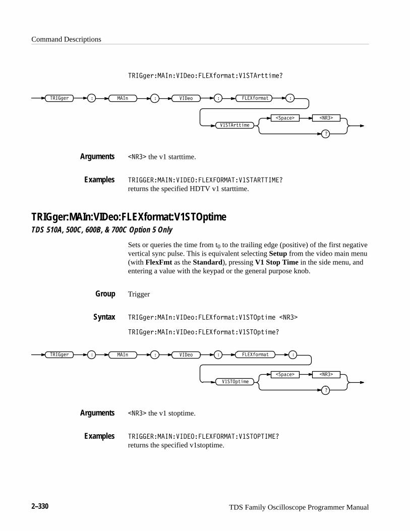
Command Descriptions
2–330 TDS Family Oscilloscope Programmer Manual
�� ���"��� ��� � ����� "��#������"##����
���� "��#
�����"##���
�
��!���� �����
�� ���" � � � � �� � � �
����� the v1 starttime.
�� ������ ��� �������������������� ��
returns the specified HDTV v1 starttime.
TRIGger:MAIn:VIDeo:FLEXformat:V1STOptimeTDS 510A, 500C, 600B, & 700C Option 5 Only
Sets or queries the time from t0 to the trailing edge (positive) of the first negativevertical sync pulse. This is equivalent selecting Setup from the video main menu(with FlexFmt as the Standard), pressing V1 Stop Time in the side menu, andentering a value with the keypad or the general purpose knob.
Trigger
�� ���"��� ��� � ����� "��#������!#��� �����
�� ���"��� ��� � ����� "��#������!#����
�����!#���
�
��!���� �����
�� ���" � � � � �� � � ���� "��# �
����� the v1 stoptime.
�� ������ ��� ������������������� ��
returns the specified v1stoptime.
Arguments
Examples
Group
Syntax
Arguments
Examples
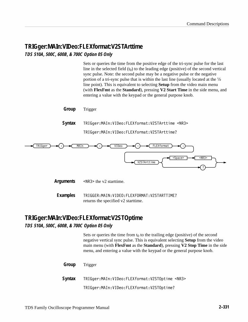
Command Descriptions
TDS Family Oscilloscope Programmer Manual 2–331
TRIGger:MAIn:VIDeo:FLEXformat:V2STArttimeTDS 510A, 500C, 600B, & 700C Option 05 Only
Sets or queries the time from the positive edge of the tri-sync pulse for the lastline in the selected field (t0) to the leading edge (positive) of the second verticalsync pulse. Note: the second pulse may be a negative pulse or the negativeportion of a tri-sync pulse that is within the last line (usually located at the �
line point). This is equivalent to selecting Setup from the video main menu(with FlexFmt as the Standard), pressing V2 Start Time in the side menu, andentering a value with the keypad or the general purpose knob.
Trigger
�� ���!��� ��� ��������!��"������!""��� �����
�� ���!��� ��� ��������!��"������!""����
�����!��"
�����!""���
�
�� ���� �����
�� ���! � � � ���� � � �
����� the v2 starttime.
�� ������ ��� �������������������� ��
returns the specified v2 starttime.
TRIGger:MAIn:VIDeo:FLEXformat:V2STOptimeTDS 510A, 500C, 600B, & 700C Option 05 Only
Sets or queries the time from t0 to the trailing edge (positive) of the secondnegative vertical sync pulse. This is equivalent selecting Setup from the videomain menu (with FlexFmt as the Standard), pressing V2 Stop Time in the sidemenu, and entering a value with the keypad or the general purpose knob.
Trigger
�� ���!��� ��� ��������!��"������ "��� �����
�� ���!��� ��� ��������!��"������ "����
Group
Syntax
Arguments
Examples
Group
Syntax

Command Descriptions
2–332 TDS Family Oscilloscope Programmer Manual
�����')#$
�
�'�� � ����
����" ( ��� &� �% ����!&($�)
���� the v2 stoptime.
�������� ��������������� ������������
returns the specified v2 stoptime.
TRIGger:MAIn:VIDeo:HDTvTDS 510A, 500C, 600B, & 700C Option 05 Only
Sets or queries the high definition TV frame rate. This is equivalent to togglingHDTV from the Video main-menu Standard pop-up, pressing Format, and thenselecting a frame rate from the side menu.
Trigger
����" (� �%��� &���* ����
����" (� �%��� &���*�
����" ( ��� &� �%
�'�� �
�
����
���*
���� specifies the frame rate. More precisely, ��� selects a 787/59.94/2:1format. ���� selects a 1050/59.94/2:1 format. ���� selects a 1125/60/2:1 format.���� selects a 1250/50/2:1 format.
TRIGGER:MAIN:VIDEO:HDTV 787specifies 787/59.94/2:1 format.
Arguments
Examples
Group
Syntax
Arguments
Examples
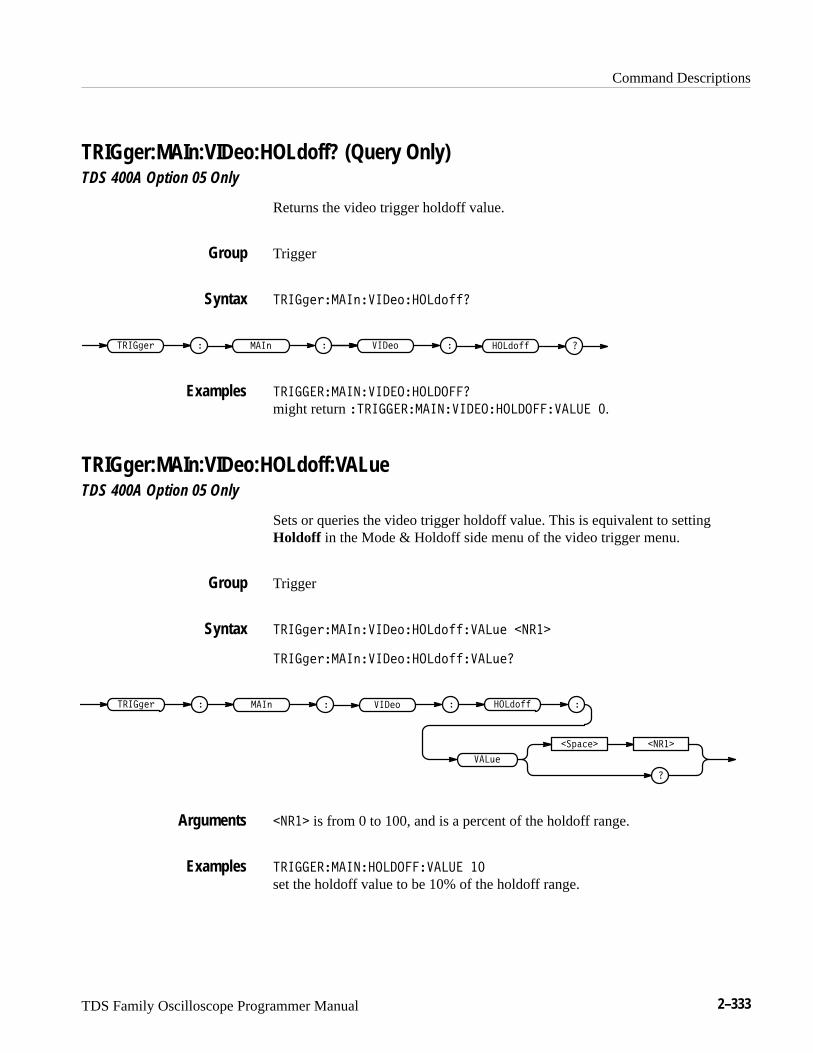
Command Descriptions
TDS Family Oscilloscope Programmer Manual 2–333
TRIGger:MAIn:VIDeo:HOLdoff? (Query Only)TDS 400A Option 05 Only
Returns the video trigger holdoff value.
Trigger
������!����������� �������
� ����������! � � ������� ����
���������������� ������
might return ����������������� ���������� �.
TRIGger:MAIn:VIDeo:HOLdoff:VALueTDS 400A Option 05 Only
Sets or queries the video trigger holdoff value. This is equivalent to settingHoldoff in the Mode & Holdoff side menu of the video trigger menu.
Trigger
������!����������� ����������"� �����
������!����������� ����������"��
�
�� ���� �����
������! � � �������� ������ �
���"�
�
����� is from 0 to 100, and is a percent of the holdoff range.
������������ ���������� ��
set the holdoff value to be 10% of the holdoff range.
Group
Syntax
Examples
Group
Syntax
Arguments
Examples
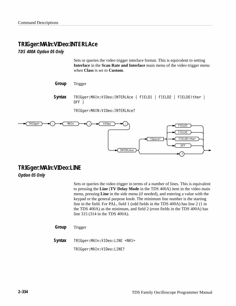
Command Descriptions
2–334 TDS Family Oscilloscope Programmer Manual
TRIGger:MAIn:VIDeo:INTERLAceTDS 400A Option 05 Only
Sets or queries the video trigger interlace format. This is equivalent to settingInterlace in the Scan Rate and Interlace main menu of the video trigger menuwhen Class is set to Custom.
Trigger
�� ������� ��� ��� ������� ! � �� " � �� " � �� ��� "
��� #
�� ������� ��� ��� ��������
� �� ���
�� ���� � � � ���� �
�������
�
�������
�
� ��
���
� ��
TRIGger:MAIn:VIDeo:LINEOption 05 Only
Sets or queries the video trigger in terms of a number of lines. This is equivalentto pressing the Line (TV Delay Mode in the TDS 400A) item in the video mainmenu, pressing Line in the side menu (if needed), and entering a value with thekeypad or the general purpose knob. The minimum line number is the startingline in the field. For PAL, field 1 (odd fields in the TDS 400A) has line 2 (1 inthe TDS 400A) as the minimum, and field 2 (even fields in the TDS 400A) hasline 315 (314 in the TDS 400A).
Trigger
�� ������� ��� ���� � �����
�� ������� ��� ���� ��
Group
Syntax
Group
Syntax

Command Descriptions
TDS Family Oscilloscope Programmer Manual 2–335
�
������� �����
�� ���� � � � ��� � � ���
����� specifies a number of lines to delay by.
�� ������ ��� ���� �� �
selects 5 lines for the desired delay period.
TRIGger:MAIn:VIDeo:LINESTDS 400A Option 05 Only
Sets or queries the video trigger delay in terms of a number of lines. This isequivalent to entering data in the Line item in the Video TV Delay Mode sidemenu. This command is available for backwards compatibility.
Trigger
�� ������ ��� ���� ��� �����
�� ������ ��� ���� ����
�
������� �����
�� ���� � � � ��� � � ����
<NR3> specifies a number of lines to delay by.
TRIGGER:MAIN:VIDEO:LINES 5selects 5 lines for the desired delay period.
TRIGger:MAIn:VIDeo:NTScTDS 510A, 500C, 600B, & 700C Option 05 Only
Sets or queries the NTSC mode selection. This is equivalent to choosing525/NTSC in the video main-menu pop-up, Mode in the main menu, and a sidemenu item (NTSC or Mono).
Trigger
Arguments
Examples
Group
Syntax
Arguments
Examples
Group
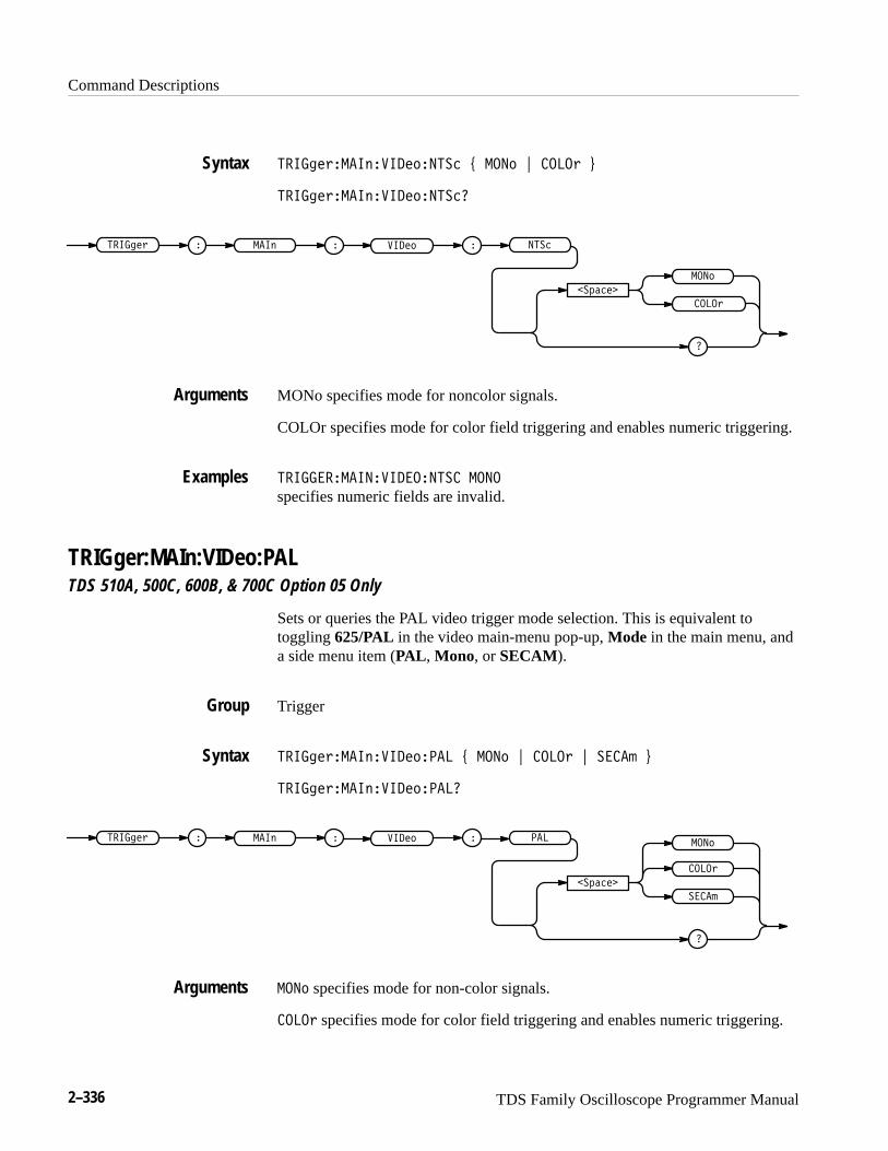
Command Descriptions
2–336 TDS Family Oscilloscope Programmer Manual
������� �������������� � ��� � �����
������� ���������������
�������
�
������ � �
���
�����
����� ��� �����
MONo specifies mode for noncolor signals.
COLOr specifies mode for color field triggering and enables numeric triggering.
����� ������������� ���
specifies numeric fields are invalid.
TRIGger:MAIn:VIDeo:PALTDS 510A, 500C, 600B, & 700C Option 05 Only
Sets or queries the PAL video trigger mode selection. This is equivalent totoggling 625/PAL in the video main-menu pop-up, Mode in the main menu, anda side menu item (PAL , Mono, or SECAM).
Trigger
������� ������������� � ��� � ����� � ����
������� ��������������
�������
�
������ � �
�����
����� ��� ���� ���
����
��� specifies mode for non-color signals.
����� specifies mode for color field triggering and enables numeric triggering.
Syntax
Arguments
Examples
Group
Syntax
Arguments
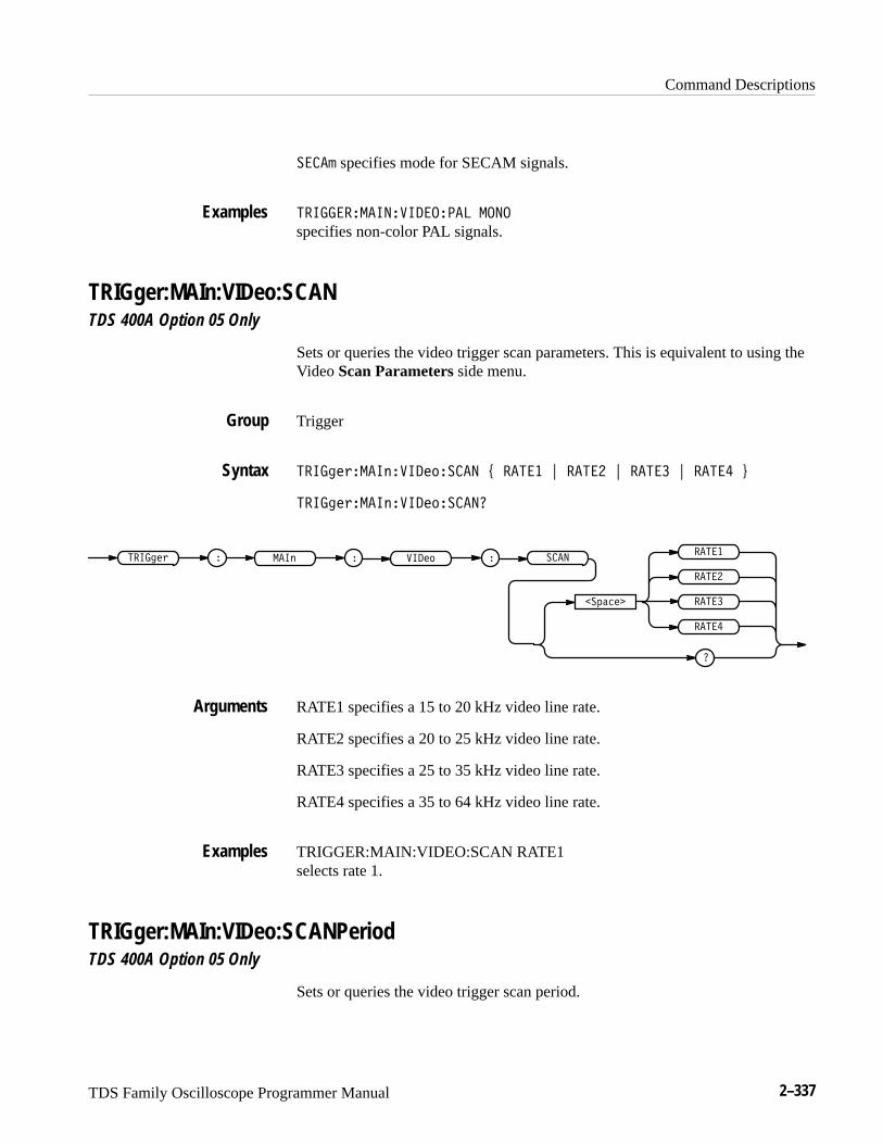
Command Descriptions
TDS Family Oscilloscope Programmer Manual 2–337
� �� specifies mode for SECAM signals.
����� ��������� ���� ����
specifies non-color PAL signals.
TRIGger:MAIn:VIDeo:SCANTDS 400A Option 05 Only
Sets or queries the video trigger scan parameters. This is equivalent to using theVideo Scan Parameters side menu.
Trigger
������!�������������� " �� � # �� � # �� � # �� � $
������!��������������
������! � � �������� ����
�� ����
�� �
�� �
�� �
�� �
RATE1 specifies a 15 to 20 kHz video line rate.
RATE2 specifies a 20 to 25 kHz video line rate.
RATE3 specifies a 25 to 35 kHz video line rate.
RATE4 specifies a 35 to 64 kHz video line rate.
TRIGGER:MAIN:VIDEO:SCAN RATE1selects rate 1.
TRIGger:MAIn:VIDeo:SCANPeriodTDS 400A Option 05 Only
Sets or queries the video trigger scan period.
Examples
Group
Syntax
Arguments
Examples
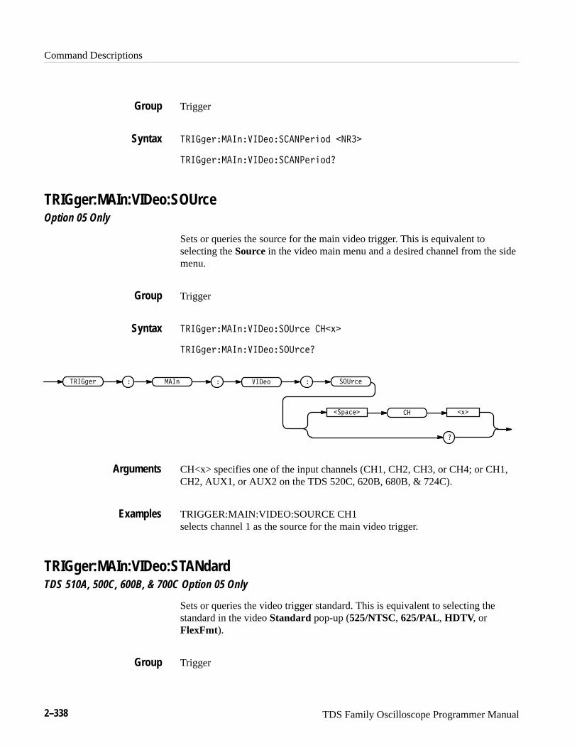
Command Descriptions
2–338 TDS Family Oscilloscope Programmer Manual
Trigger
������� ������������������� �����
������� ��������������������
TRIGger:MAIn:VIDeo:SOUrceOption 05 Only
Sets or queries the source for the main video trigger. This is equivalent toselecting the Source in the video main menu and a desired channel from the sidemenu.
Trigger
������� ��������������� ��� �
������� ����������������
�������
�
������ � �
��
���� ��� �������
� �
CH<x> specifies one of the input channels (CH1, CH2, CH3, or CH4; or CH1,CH2, AUX1, or AUX2 on the TDS 520C, 620B, 680B, & 724C).
TRIGGER:MAIN:VIDEO:SOURCE CH1selects channel 1 as the source for the main video trigger.
TRIGger:MAIn:VIDeo:STANdardTDS 510A, 500C, 600B, & 700C Option 05 Only
Sets or queries the video trigger standard. This is equivalent to selecting thestandard in the video Standard pop-up (525/NTSC, 625/PAL, HDTV, orFlexFmt).
Trigger
Group
Syntax
Group
Syntax
Arguments
Examples
Group
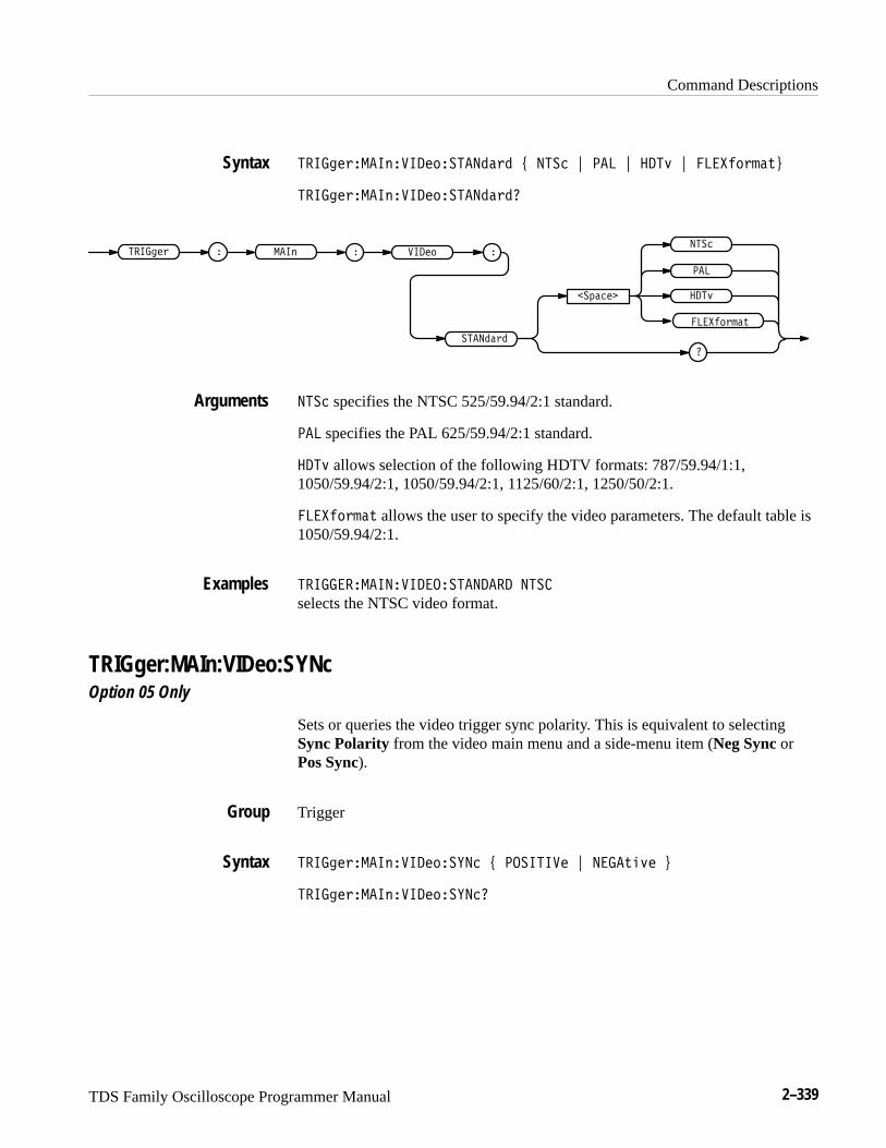
Command Descriptions
TDS Family Oscilloscope Programmer Manual 2–339
�� ���$��� !�� ��"�������$� ' ���� ( ��� ( ���& ( ���"$ �%)
�� ���$��� !�� ��"�������$��
���"$ �%
�� ���$ � � � ��"�� ! �
��#����
���
�
���&
����
������$�
���� specifies the NTSC 525/59.94/2:1 standard.
��� specifies the PAL 625/59.94/2:1 standard.
���& allows selection of the following HDTV formats: 787/59.94/1:1,1050/59.94/2:1, 1050/59.94/2:1, 1125/60/2:1, 1250/50/2:1.
���"$ �% allows the user to specify the video parameters. The default table is1050/59.94/2:1.
�� ������ ��� ����������� ����
selects the NTSC video format.
TRIGger:MAIn:VIDeo:SYNcOption 05 Only
Sets or queries the video trigger sync polarity. This is equivalent to selectingSync Polarity from the video main menu and a side-menu item (Neg Sync orPos Sync).
Trigger
�� ���$��� !�� ��"����� ' ��� � �� ( ���%�&� )
�� ���$��� !�� ��"������
Syntax
Arguments
Examples
Group
Syntax
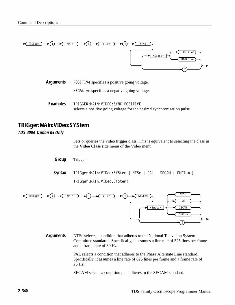
Command Descriptions
2–340 TDS Family Oscilloscope Programmer Manual
�������
�
����� � �
��������
��!�"�
����� ��� �����
�������� specifies a positive going voltage.
��!�"� specifies a negative going voltage.
����� ������������� �������
selects a positive going voltage for the desired synchronization pulse.
TRIGger:MAIn:VIDeo:SYStemTDS 400A Option 05 Only
Sets or queries the video trigger class. This is equivalent to selecting the class inthe Video Class side menu of the Video menu.
Trigger
����� � �������������!�� # ���� $ ��� $ ��� $ ������ %
����� � �������������!���
����� � � ����� ��� ���!���
�������
���
�
������
���
����
NTSc selects a condition that adheres to the National Television SystemCommittee standards. Specifically, it assumes a line rate of 525 lines per frameand a frame rate of 30 Hz.
PAL selects a condition that adheres to the Phase Alternate Line standard.Specifically, it assumes a line rate of 625 lines per frame and a frame rate of25 Hz.
SECAM selects a condition that adheres to the SECAM standard.
Arguments
Examples
Group
Syntax
Arguments

Command Descriptions
TDS Family Oscilloscope Programmer Manual 2–341
CUSTom selects a condition that adheres to the frequency range of the videosignal as you have defined them from the available ranges.
������� �������� ����
selects triggering to occur on an NTSC compatible signal.
TRIGger:MAIn:VIDeo:TIMeTDS 400A Option 05 Only
Sets or queries the video trigger delay time. This is equivalent to entering thetime in the Delay by Time item of the Video TV Delay Mode side menu.
Trigger
�������� ����������� � �����
�������� ����������� ��
�
������� �����
������� � � ���� ��� �� ��
<NR3> specifies a delay time.
TRIGGER:MAIN:VIDEO:TIME 5E–6selects 5 �s for the desired delay time.
TRIGger:STATE? (Query Only)Returns the current state of the triggering system.
Trigger
�������������
����������� � �
Examples
Group
Syntax
Arguments
Examples
Group
Syntax

Command Descriptions
2–342 TDS Family Oscilloscope Programmer Manual
���� indicates that the instrument is acquiring pretrigger information. Alltriggers are ignored when TRIGger:STATE is ARMING.
���� indicates that the digitizing oscilloscope is in auto mode and acquires dataeven in the absence of a trigger.
��������� (TDS 500C and 700C only) indicates that the instrument is inFastFrame mode. This means normal trigger status monitoring is turned off. Thedigitizing oscilloscope will not return armed, partial, ready, trigger, or auto whilein this state.
������ (TDS 500C and 700C only) indicates that the instrument is in InstaVumode.
������ indicates that the main trigger has occurred and the digitizing oscillo-scope is waiting for trigger(s) for the delay by events.
����� indicates that all pretrigger information has been acquired and thedigitizing oscilloscope is ready to accept a trigger.
���� indicates that the digitizing oscilloscope is in save mode and is notacquiring data.
������ indicates that the digitizing oscilloscope has seen a trigger and isacquiring the posttrigger information.
�������������
might return ����, indicating that pretrigger data is being acquired.
*TRG (No Query Form)(Trigger) executes commands that are defined by *DDT.
The Group Execute Trigger (GET) interface message has the same effect as the*TRG command.
Miscellaneous
Alias commands, *DDT
����
����
Returns
Examples
Group
Related Commands
Syntax

Command Descriptions
TDS Family Oscilloscope Programmer Manual 2–343
� ��
immediately executes all commands that have been defined by *DDT.
*TST? (Query Only)(Self-Test) Tests the GPIB interface and returns a 0.
Miscellaneous
� � �
� � �
���� and is always 0.
UNLock (No Query Form)Unlocks the front panel. This command is equivalent to LOCk NONe.
NOTE. If the digitizing oscilloscope is in the Remote With Lockout State (RWLS),the UNLOCk command has no effect. For more information see the ANSI-IEEEStd. 488.1-1987 Standard Digital Interface for Programmable Instrumentation,section 2.8.3 on RL State Descriptions.
Miscellaneous
LOCk
���� �
���� ��������
� specifies all front-panel buttons and knobs.
Examples
Group
Syntax
Returns
Group
Related Commands
Syntax
Arguments
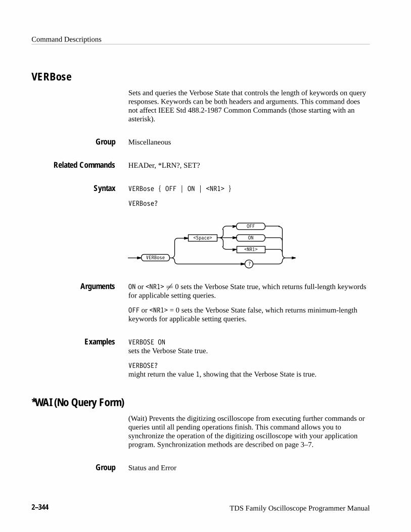
Command Descriptions
2–344 TDS Family Oscilloscope Programmer Manual
VERBoseSets and queries the Verbose State that controls the length of keywords on queryresponses. Keywords can be both headers and arguments. This command doesnot affect IEEE Std 488.2-1987 Common Commands (those starting with anasterisk).
Miscellaneous
HEADer, *LRN?, SET?
������ � �� � � ���� �
�������
�������
�
��
������
����
or ���� � 0 sets the Verbose State true, which returns full-length keywordsfor applicable setting queries.
�� or ���� = 0 sets the Verbose State false, which returns minimum-lengthkeywords for applicable setting queries.
�����
sets the Verbose State true.
������
might return the value �, showing that the Verbose State is true.
*WAI (No Query Form)(Wait) Prevents the digitizing oscilloscope from executing further commands orqueries until all pending operations finish. This command allows you tosynchronize the operation of the digitizing oscilloscope with your applicationprogram. Synchronization methods are described on page 3–7.
Status and Error
Group
Related Commands
Syntax
Arguments
Examples
Group
Command Descriptions
TDS Family Oscilloscope Programmer Manual 2–345
BUSY?, *OPC
����
����
WAVFrm? (Query Only)Returns WFMPre? and CURVe? data for the waveform or waveforms asspecified by the DATa:SOUrce command. This command is equivalent tosending WFMPre?; CURVe?
TDS 400A: when the TDS 400A is in external clock mode, the time-per-div fieldwill contain �� ��������.
Waveform
CURVe?, DATa:SOUrce, WFMPre?
������
����� �
WFMPre? (Query Only)Returns the waveform formatting data for the first ordered waveform as specifiedby the DATa:SOUrce command. The channel and math waveforms selected bythe ����� ���� command must be displayed.
TDS 400A: when the TDS 400A is in external clock mode, the time-per-div fieldwill contain �� ��������.
Waveform
WAVFrm?
������
Related Commands
Syntax
Group
Related Commands
Syntax
Group
Related Commands
Syntax
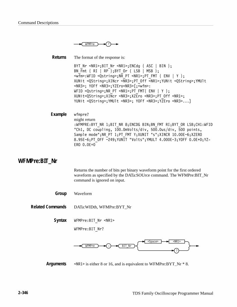
Command Descriptions
2–346 TDS Family Oscilloscope Programmer Manual
*� #>4 �
The format of the response is:
�,'0!> �!%����'0!> �!%���!�36 D �&� E ��! F�
�!0�:@ D %� E %# F��,'0"> D �&� E &� F�
�C5:��*��� �$?@>8;6��!%0#' �!%��#'0� ' D �!) E , F�
+(!8@ �$&@>8;6��+�!2> �!%���#'0"55 �!%��,(!8@ �$&@>8;6��, (9@
�!%��� ,"�5 �!%���,-�><�!%��.��C5:��
*��� �$?@>8;6��!%0#' �!%��#'0� 'D �!) E , F�
+(!8@�$&@>8;6��+�!2> �!%���+-�>< �!%���#'0"55 �!%��
,(!8@ �$&@>8;6��, (9@ �!%��� ,"�5 �!%���,-�>< �!%�����/
C5:=>4�
might return�*� #%���,'0!% ���'0!% ���!��� ��!��!0� ' %���,'0"% �&�����*���
��7� �� 2<A=98;6� ����:)<9@?�38B� ����A?�38B� �� =<8;@?�
&1:=94 :<34��!%0#' �#'0� ' ,�+(!�' �?��+�!�% ��������+-�%"
��� ����#'0"�� ����,(!�' �)<9@?��, (�' ���������,"�� �������,-G
�%" ������
WFMPre:BIT_NrReturns the number of bits per binary waveform point for the first orderedwaveform as specified by the DATa:SOUrce command. The WFMPre:BIT_Nrcommand is ignored on input.
Waveform
DATa:WIDth, WFMPre:BYT_Nr
*� #>4���'0!> �!%�
*� #>4���'0!>�
�
�&=124� �!%�
*� #>4 � ��'0!>
�!%� is either 8 or 16, and is equivalent to WFMPre:BYT_Nr * 8.
Returns
Example
Group
Related Commands
Syntax
Arguments
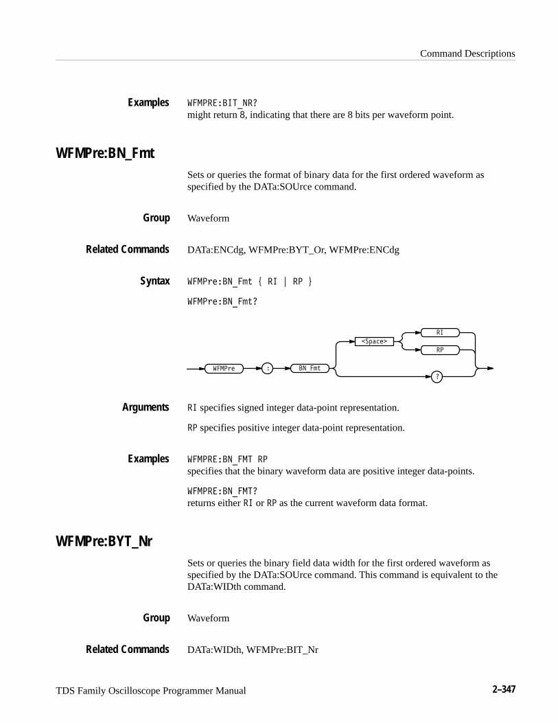
Command Descriptions
TDS Family Oscilloscope Programmer Manual 2–347
�� ���������
might return �, indicating that there are 8 bits per waveform point.
WFMPre:BN_FmtSets or queries the format of binary data for the first ordered waveform asspecified by the DATa:SOUrce command.
Waveform
DATa:ENCdg, WFMPre:BYT_Or, WFMPre:ENCdg
�� �������� � � � � �
�� ���������
�� ��
�������
�
�
� �����
�
� specifies signed integer data-point representation.
� specifies positive integer data-point representation.
�� �������� �
specifies that the binary waveform data are positive integer data-points.
�� ���������
returns either � or � as the current waveform data format.
WFMPre:BYT_NrSets or queries the binary field data width for the first ordered waveform asspecified by the DATa:SOUrce command. This command is equivalent to theDATa:WIDth command.
Waveform
DATa:WIDth, WFMPre:BIT_Nr
Examples
Group
Related Commands
Syntax
Arguments
Examples
Group
Related Commands
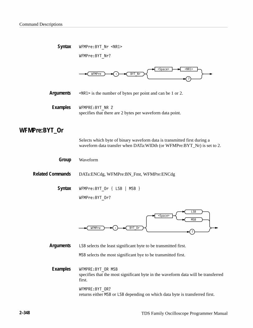
Command Descriptions
2–348 TDS Family Oscilloscope Programmer Manual
���������� � � ���
���������� ��
�
������� � ���
����� � ���� �
� ��� is the number of bytes per point and can be 1 or 2.
��������� � �
specifies that there are 2 bytes per waveform data point.
WFMPre:BYT_OrSelects which byte of binary waveform data is transmitted first during awaveform data transfer when DATa:WIDth (or WFMPre:BYT_Nr) is set to 2.
Waveform
DATa:ENCdg, WFMPre:BN_Fmt, WFMPre:ENCdg
������������ � ��� � ��� �
�������������
�����
�������
�
���
� ������
���
��� selects the least significant byte to be transmitted first.
��� selects the most significant bye to be transmitted first.
����������� ���
specifies that the most significant byte in the waveform data will be transferredfirst.
������������
returns either ��� or ��� depending on which data byte is transferred first.
Syntax
Arguments
Examples
Group
Related Commands
Syntax
Arguments
Examples
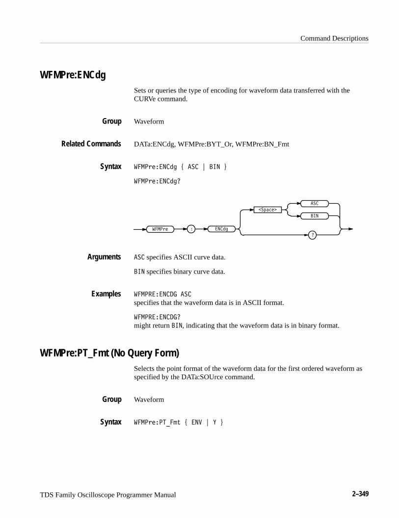
Command Descriptions
TDS Family Oscilloscope Programmer Manual 2–349
WFMPre:ENCdgSets or queries the type of encoding for waveform data transferred with theCURVe command.
Waveform
DATa:ENCdg, WFMPre:BYT_Or, WFMPre:BN_Fmt
����������� ! ��� " � � #
������������
������
�������
�
���
� ����
� �
��� specifies ASCII curve data.
� � specifies binary curve data.
��������� ���
specifies that the waveform data is in ASCII format.
����������
might return � �, indicating that the waveform data is in binary format.
WFMPre:PT_Fmt (No Query Form)Selects the point format of the waveform data for the first ordered waveform asspecified by the DATa:SOUrce command.
Waveform
������������ ! �� " � #
Group
Related Commands
Syntax
Arguments
Examples
Group
Syntax
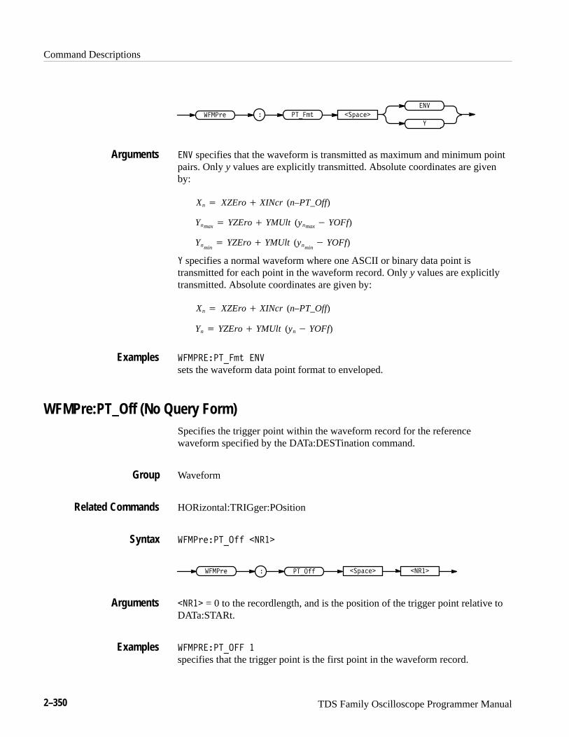
Command Descriptions
2–350 TDS Family Oscilloscope Programmer Manual
�
������ � �����
��
� ������
�� specifies that the waveform is transmitted as maximum and minimum pointpairs. Only y values are explicitly transmitted. Absolute coordinates are givenby:
Xn� XZEro� XINcr (n–PT_Off)
Ynmax� YZEro� YMUlt (ynmax� YOFf)
Ynmin� YZEro� YMUlt (ynmin
� YOFf)
� specifies a normal waveform where one ASCII or binary data point istransmitted for each point in the waveform record. Only y values are explicitlytransmitted. Absolute coordinates are given by:
Xn� XZEro� XINcr (n–PT_Off)
Yn� YZEro� YMUlt (yn� YOFf)
������������� ��
sets the waveform data point format to enveloped.
WFMPre:PT_Off (No Query Form)Specifies the trigger point within the waveform record for the referencewaveform specified by the DATa:DESTination command.
Waveform
HORizontal:TRIGger:POsition
������������ ����
������ � ����� � ����� ����
���� = 0 to the recordlength, and is the position of the trigger point relative toDATa:STARt.
������������ �
specifies that the trigger point is the first point in the waveform record.
Arguments
Examples
Group
Related Commands
Syntax
Arguments
Examples

Command Descriptions
TDS Family Oscilloscope Programmer Manual 2–351
WFMPre:XINcr (No Query Form)Specifies the horizontal sampling interval for the reference waveform specifiedby the DATa:DESTination command.
Waveform
����������� ����
������ � ���� � ����� ����
���� is the sampling interval in seconds per point.
WFMPre:YMUlt (No Query Form)Specifies the vertical scale factor for the reference waveform specified by theDATa:DESTination command.
Waveform
������������ ����
������ � ����� � ����� ����
���� is the vertical scale factor in YUNits (usually volts) per division.
WFMPre:YOFf (No Query Form)Specifies the offset of the vertical component for the reference waveformspecified by the DATa:DESTination command.
Waveform
���������� ����
������ � ��� � ����� ����
Group
Syntax
Arguments
Group
Syntax
Arguments
Group
Syntax
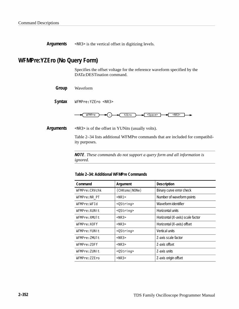
Command Descriptions
2–352 TDS Family Oscilloscope Programmer Manual
����� is the vertical offset in digitizing levels.
WFMPre:YZEro (No Query Form)Specifies the offset voltage for the reference waveform specified by theDATa:DESTination command.
Waveform
� �*�����*( �����
� �*� � ���*( ��)���� �����
����� is of the offset in YUNits (usually volts).
Table 2–34 lists additional WFMPre commands that are included for compatibil-ity purposes.
NOTE. These commands do not support a query form and all information isignored.
Table 2–34: Additional WFMPre Commands
Command Argument Description
� �*������"$ -��+&(.����/ Binary curve error check
� �*������� ����� Number of waveform points
� �*����� ���,*#'!� Waveform identifier
� �*�����#, ���,*#'!� Horizontal units
� �*��� �%, ����� Horizontal (X-axis) scale factor
� �*���� ����� Horizontal (X-axis) offset
� �*�����#, ���,*#'!� Vertical units
� �*��� �%, ����� Z-axis scale factor
� �*���� ����� Z-axis offset
� �*�����#, ���,*#'!� Z-axis units
� �*�����*( ����� Z-axis origin offset
Arguments
Group
Syntax
Arguments

Command Descriptions
TDS Family Oscilloscope Programmer Manual 2–353
NOTE. When returning WFMPRE:<wfm> information from the oscilloscope,<wfm> specifies the waveform source (CH<x>, MATH<x>, or REF<x>). Thesource must also be set using the DAta:SOUrce command. When sendingWFMPRE:<wfm> information to the scope, the <wfm> specification is ignoredand the reference location specified by DATa:DESTination is used instead.
WFMPre:<wfm>? (Query Only)Returns the waveform formatting data for first ordered waveform as specified bythe DATa:SOUrce command. Channel and math waveforms must be displayedbefore they can be queried. Querying an invalid reference waveform generates anexecution error.
In extended-acquisition-length mode, it will return the acquisition recordinformation as opposed to the waveform record information.
Waveform
'�� ;1��@27��
'�� ;1 � �@27� �
The format of the response is:
�@27��'��� �!<=;583���"- $ ��"�� $-��$ A ��& B ) C�
(%�5= �!#=;583��(��/; ��"��� $-�22 ��"��)%�5= �!#=;583��)�%6=
��"���)��2 ��"���)*�;9 ��"��
+��@27��'��� �!<=;583���"- $ ��"��
$-��$ A ��& B ) C�(%�5= �!#=;583��(��/; ��"���(*�;9 ��"���
$-�22 ��"��)%�5= �!#=;583��)�%6= ��"���)��2 ��"���
)*�;9 ��"�����,
'�� "�����
might return �'�� "�����'��� ��4� �� /9>:6583� ����7&96=<�05?� ����><�05?�
�� :958=<� #.7:61 7901���"- $ � $-��$ )�(%��$ �<��(���"
��������(*�"� �� ���� $-��� ����)%��$ �&96=<��)�%�$
���������)��� �������)*�"� �������
Group
Syntax
Returns
Example
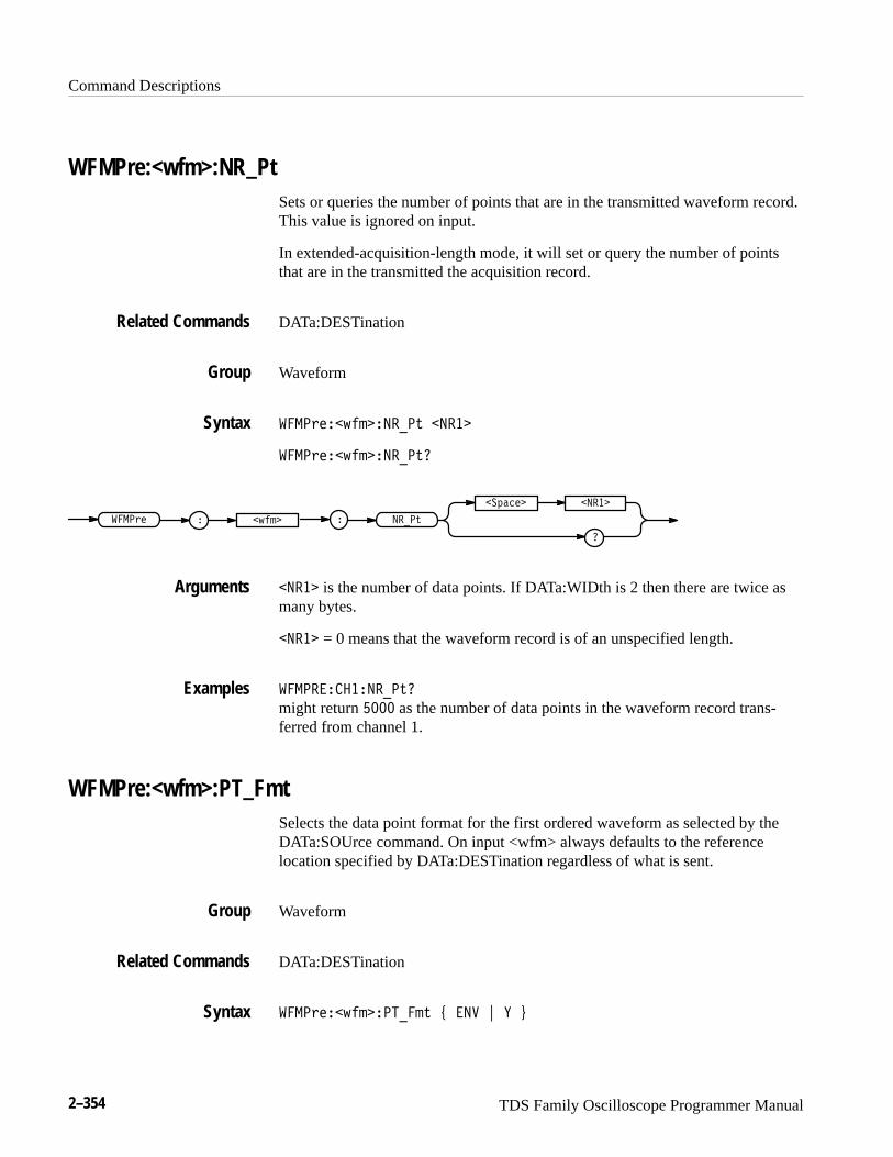
Command Descriptions
2–354 TDS Family Oscilloscope Programmer Manual
WFMPre:<wfm>:NR_PtSets or queries the number of points that are in the transmitted waveform record.This value is ignored on input.
In extended-acquisition-length mode, it will set or query the number of pointsthat are in the transmitted the acquisition record.
DATa:DESTination
Waveform
�� ��������������� �����
�� ����������������
�
������� �����
�� ��� � ������ �����
����� is the number of data points. If DATa:WIDth is 2 then there are twice asmany bytes.
����� = 0 means that the waveform record is of an unspecified length.
�� ������������
might return ���� as the number of data points in the waveform record trans-ferred from channel 1.
WFMPre:<wfm>:PT_FmtSelects the data point format for the first ordered waveform as selected by theDATa:SOUrce command. On input <wfm> always defaults to the referencelocation specified by DATa:DESTination regardless of what is sent.
Waveform
DATa:DESTination
�� ���������������� �� ! � "
Related Commands
Group
Syntax
Arguments
Examples
Group
Related Commands
Syntax
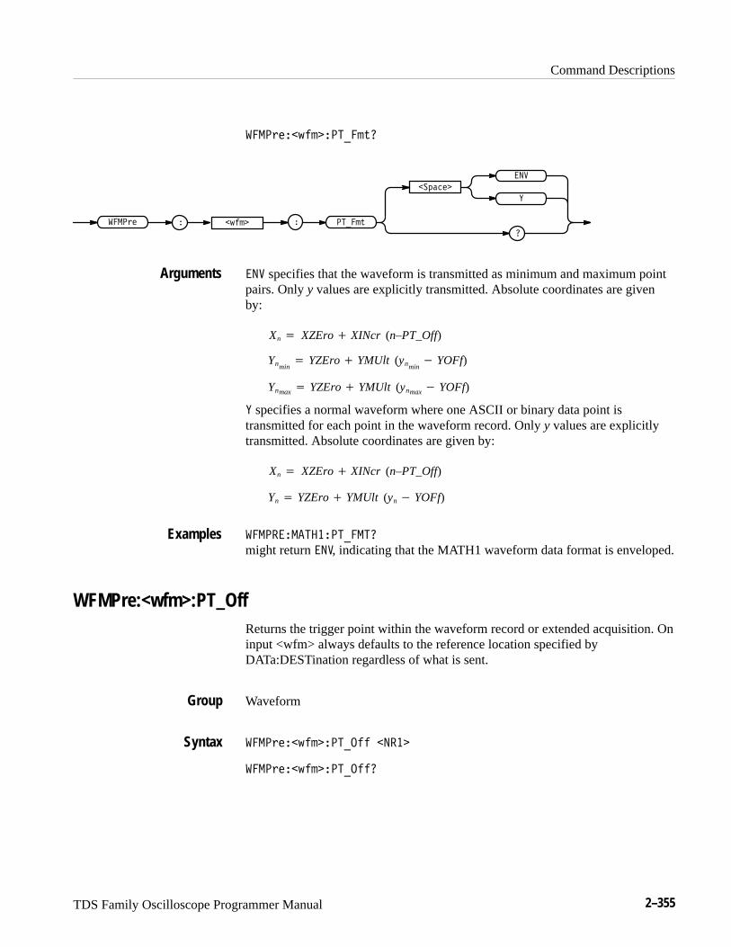
Command Descriptions
TDS Family Oscilloscope Programmer Manual 2–355
������������������
�������
�
���
�����
�
����� �� �����
��� specifies that the waveform is transmitted as minimum and maximum pointpairs. Only y values are explicitly transmitted. Absolute coordinates are givenby:
Xn� XZEro� XINcr (n–PT_Off)
Ynmin� YZEro� YMUlt (ynmin
� YOFf)
Ynmax� YZEro� YMUlt (ynmax� YOFf)
� specifies a normal waveform where one ASCII or binary data point istransmitted for each point in the waveform record. Only y values are explicitlytransmitted. Absolute coordinates are given by:
Xn� XZEro� XINcr (n–PT_Off)
Yn� YZEro� YMUlt (yn� YOFf)
�����������������
might return ���, indicating that the MATH1 waveform data format is enveloped.
WFMPre:<wfm>:PT_OffReturns the trigger point within the waveform record or extended acquisition. Oninput <wfm> always defaults to the reference location specified by DATa:DESTination regardless of what is sent.
Waveform
��������������� �� �����
��������������� ���
Arguments
Examples
Group
Syntax
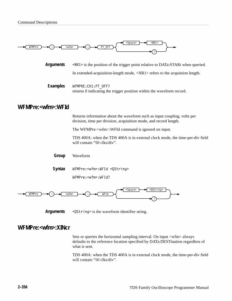
Command Descriptions
2–356 TDS Family Oscilloscope Programmer Manual
�
�� ���� �����
� �!� � �#��� � ������
����� is the position of the trigger point relative to DATa:STARt when queried.
In extended-acquisition-length mode, <NR1> refers to the acquistion length.
� ������������
returns � indicating the trigger position within the waveform record.
WFMPre:<wfm>:WFIdReturns information about the waveform such as input coupling, volts perdivision, time per division, acquisition mode, and record length.
The WFMPre:<wfm>:WFId command is ignored on input.
TDS 400A: when the TDS 400A is in external clock mode, the time-per-div fieldwill contain “50 clks/div”.
Waveform
� �!���#������� ���"!����
� �!���#��������
���"!����
�
�� ����
� �!� � �#��� � ���
���"!���� is the waveform identifier string.
WFMPre:<wfm>:XINcrSets or queries the horizontal sampling interval. On input <wfm> alwaysdefaults to the reference location specified by DATa:DESTination regardless ofwhat is sent.
TDS 400A: when the TDS 400A is in external clock mode, the time-per-div fieldwill contain “50 clks/div”.
Arguments
Examples
Group
Syntax
Arguments
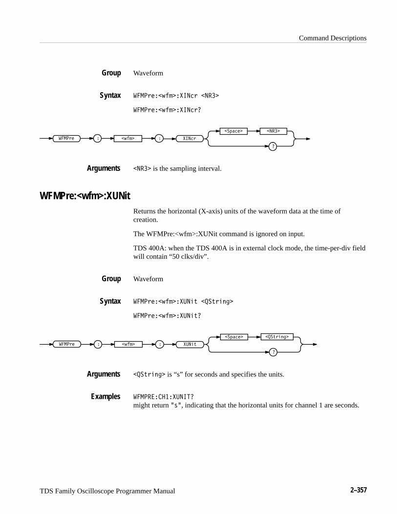
Command Descriptions
TDS Family Oscilloscope Programmer Manual 2–357
Waveform
����!���$����� ��! �����
����!���$����� ��!�
�
�� ���� �����
����!� � �$��� � � ��!
����� is the sampling interval.
WFMPre:<wfm>:XUNitReturns the horizontal (X-axis) units of the waveform data at the time ofcreation.
The WFMPre:<wfm>:XUNit command is ignored on input.
TDS 400A: when the TDS 400A is in external clock mode, the time-per-div fieldwill contain “50 clks/div”.
Waveform
����!���$��������# ���#!����
����!���$��������#�
���#!����
�
�� ����
����!� � �$��� � ����#
���#!���� is “s” for seconds and specifies the units.
������������ ��
might return �"�, indicating that the horizontal units for channel 1 are seconds.
Group
Syntax
Arguments
Group
Syntax
Arguments
Examples
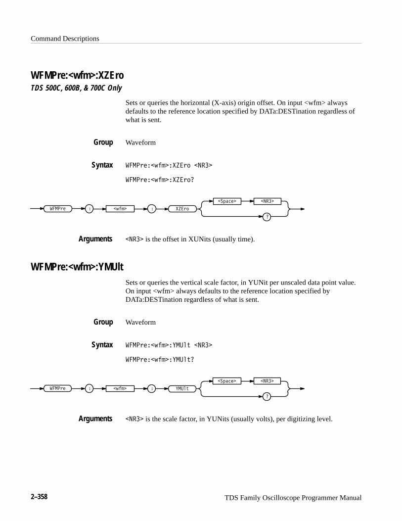
Command Descriptions
2–358 TDS Family Oscilloscope Programmer Manual
WFMPre:<wfm>:XZEroTDS 500C, 600B, & 700C Only
Sets or queries the horizontal (X-axis) origin offset. On input <wfm> alwaysdefaults to the reference location specified by DATa:DESTination regardless ofwhat is sent.
Waveform
����������������� ����
������������������
�
� ����� ����
����� � ����� � �����
���� is the offset in XUNits (usually time).
WFMPre:<wfm>:YMUltSets or queries the vertical scale factor, in YUNit per unscaled data point value.On input <wfm> always defaults to the reference location specified byDATa:DESTination regardless of what is sent.
Waveform
���������������� ����
�����������������
�
� ����� ����
����� � ����� � ����
���� is the scale factor, in YUNits (usually volts), per digitizing level.
Group
Syntax
Arguments
Group
Syntax
Arguments
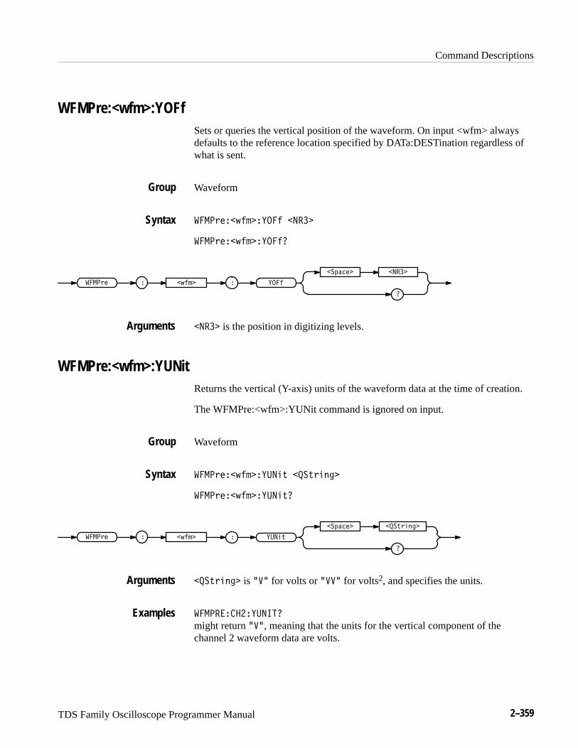
Command Descriptions
TDS Family Oscilloscope Programmer Manual 2–359
WFMPre:<wfm>:YOFfSets or queries the vertical position of the waveform. On input <wfm> alwaysdefaults to the reference location specified by DATa:DESTination regardless ofwhat is sent.
Waveform
����#���%� ������ �����
����#���%� �������
�
��"���� �����
����#� � �%� � � ����
����� is the position in digitizing levels.
WFMPre:<wfm>:YUNitReturns the vertical (Y-axis) units of the waveform data at the time of creation.
The WFMPre:<wfm>:YUNit command is ignored on input.
Waveform
����#���%� ������$ ���$#�!��
����#���%� ������$�
���$#�!��
�
��"����
����#� � �%� � � ����$
���$#�!�� is ��� for volts or ���� for volts2, and specifies the units.
������������ ��
might return ���, meaning that the units for the vertical component of thechannel 2 waveform data are volts.
Group
Syntax
Arguments
Group
Syntax
Arguments
Examples
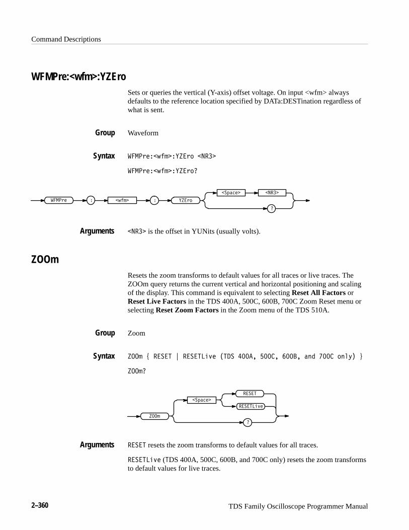
Command Descriptions
2–360 TDS Family Oscilloscope Programmer Manual
WFMPre:<wfm>:YZEroSets or queries the vertical (Y-axis) offset voltage. On input <wfm> alwaysdefaults to the reference location specified by DATa:DESTination regardless ofwhat is sent.
Waveform
����+#��-$' ����+) ����
����+#��-$' ����+)�
�
��* !# ����
����+# � �-$' � ���+)
���� is the offset in YUNits (usually volts).
ZOOmResets the zoom transforms to default values for all traces or live traces. TheZOOm query returns the current vertical and horizontal positioning and scalingof the display. This command is equivalent to selecting Reset All Factors orReset Live Factors in the TDS 400A, 500C, 600B, 700C Zoom Reset menu orselecting Reset Zoom Factors in the Zoom menu of the TDS 510A.
Zoom
���' / ����� 0 ������%,# ���� ����� ����� ���� (" ��� )(&.� 1
���'�
��* !#
�
�����
���'
������%,#
����� resets the zoom transforms to default values for all traces.
������%,# (�DS 400A, 500C, 600B, and 700C only) resets the zoom transformsto default values for live traces.
Group
Syntax
Arguments
Group
Syntax
Arguments
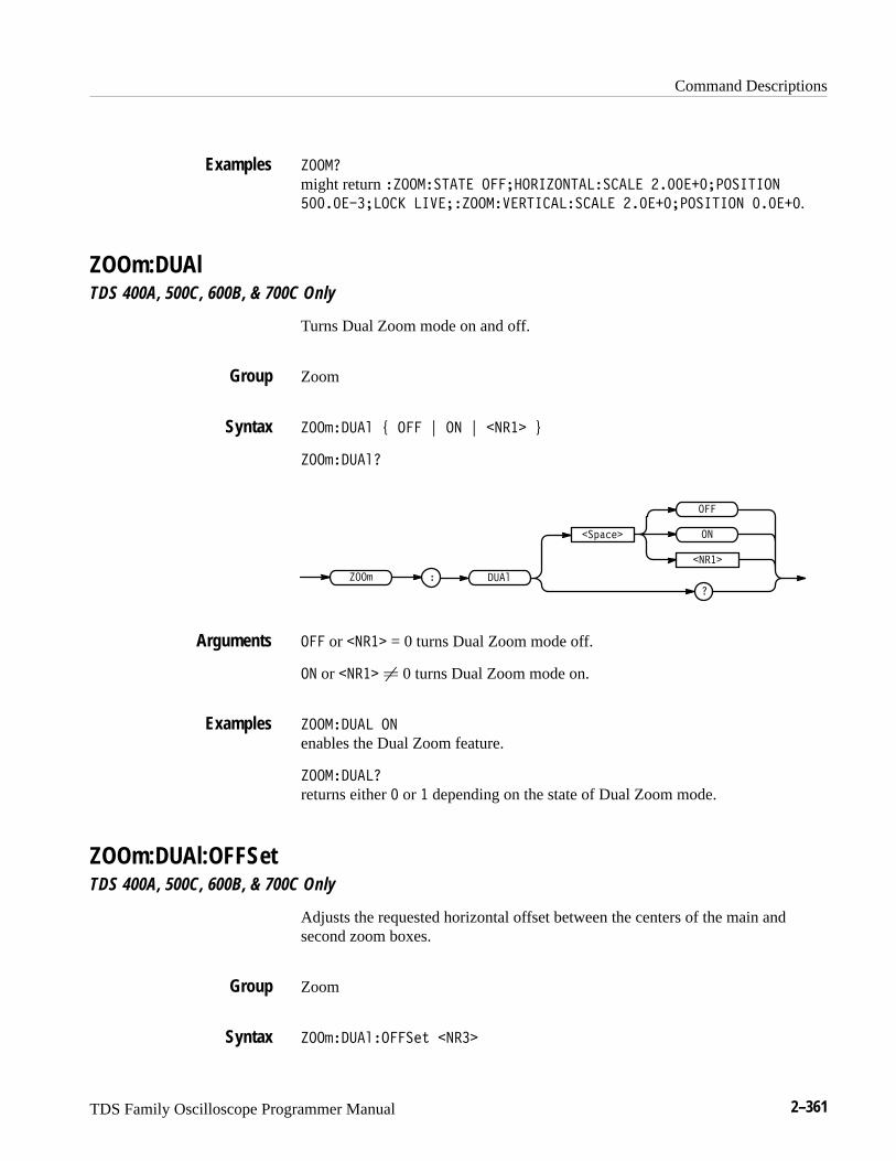
Command Descriptions
TDS Family Oscilloscope Programmer Manual 2–361
!����
might return !�������� ��������!���������� ����������������
������������ �� ��!��� ������������ ��������������� ������.
ZOOm:DUAlTDS 400A, 500C, 600B, & 700C Only
Turns Dual Zoom mode on and off.
Zoom
!��&���% ) ��� * �� * ���� +
!��&���%�
!��&
��'"#$
�
���
����
��
���%
��� or ���� = 0 turns Dual Zoom mode off.
�� or ���� � 0 turns Dual Zoom mode on.
!������� ��
enables the Dual Zoom feature.
!��������
returns either � or � depending on the state of Dual Zoom mode.
ZOOm:DUAl:OFFSetTDS 400A, 500C, 600B, & 700C Only
Adjusts the requested horizontal offset between the centers of the main andsecond zoom boxes.
Zoom
!��&���%����$( ����
Examples
Group
Syntax
Arguments
Examples
Group
Syntax
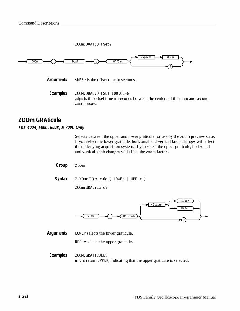
Command Descriptions
2–362 TDS Family Oscilloscope Programmer Manual
���#����"����� &�
�
�$�� ���
���# � ����" ���� &
��� is the offset time in seconds.
���������������� ��������
adjusts the offset time in seconds between the centers of the main and secondzoom boxes.
ZOOm:GRAticuleTDS 400A, 500C, 600B, & 700C Only
Selects between the upper and lower graticule for use by the zoom preview state.If you select the lower graticule, horizontal and vertical knob changes will affectthe underlying acquisition system. If you select the upper graticule, horizontaland vertical knob changes will affect the zoom factors.
Zoom
ZOOm:GRAticule ( ����% ) ��� % *
���#����&!�'" �
�$��
�
����%
���&!�'"
��� %
���# �
����% selects the lower graticule.
��� % selects the upper graticule.
���������� ����
might return �����, indicating that the upper graticule is selected.
Arguments
Examples
Group
Syntax
Arguments
Examples
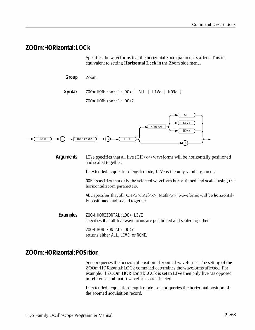
Command Descriptions
TDS Family Oscilloscope Programmer Manual 2–363
ZOOm:HORizontal:LOCkSpecifies the waveforms that the horizontal zoom parameters affect. This isequivalent to setting Horizontal Lock in the Zoom side menu.
Zoom
�������� ���������� ! ��� " ��� " ���� #
�������� �����������
�������
�
���� � �
���
����
������� �����
���
��� specifies that all live (CH<x>) waveforms will be horizontally positionedand scaled together.
In extended-acquisition-length mode, LIVe is the only valid argument.
���� specifies that only the selected waveform is positioned and scaled using thehorizontal zoom parameters.
��� specifies that all (CH<x>, Ref<x>, Math<x>) waveforms will be horizontal-ly positioned and scaled together.
��� �������������� ���
specifies that all live waveforms are positioned and scaled together.
��� ���������������
returns either ���, ���, or ����.
ZOOm:HORizontal:POSitionSets or queries the horizontal position of zoomed waveforms. The setting of theZOOm:HORizontal:LOCk command determines the waveforms affected. Forexample, if ZOOm:HORizontal:LOCk is set to LIVe then only live (as opposedto reference and math) waveforms are affected.
In extended-acquisition-length mode, sets or queries the horizontal position ofthe zoomed acquisition record.
Group
Syntax
Arguments
Examples
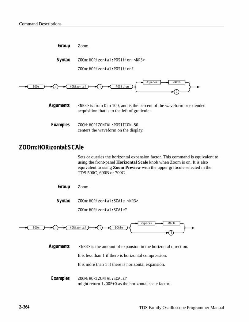
Command Descriptions
2–364 TDS Family Oscilloscope Programmer Manual
Zoom
���������$! #�������#�! ���
���������$! #�������#�! �
�
�"��� ���
���� � �����$! #�� ����#�!
��� is from 0 to 100, and is the percent of the waveform or extendedacquisition that is to the left of graticule.
������������������������ ��
centers the waveform on the display.
ZOOm:HORizontal:SCAleSets or queries the horizontal expansion factor. This command is equivalent tousing the front-panel Horizontal Scale knob when Zoom is on. It is alsoequivalent to using Zoom Preview with the upper graticule selected in the TDS 500C, 600B or 700C.
Zoom
���������$! #���� ��� ���
���������$! #���� ����
�
�"��� ���
���� � �����$! #�� � ���
��� is the amount of expansion in the horizontal direction.
It is less than 1 if there is horizontal compression.
It is more than 1 if there is horizontal expansion.
����������������� ����
might return ������� as the horizontal scale factor.
Group
Syntax
Arguments
Examples
Group
Syntax
Arguments
Examples
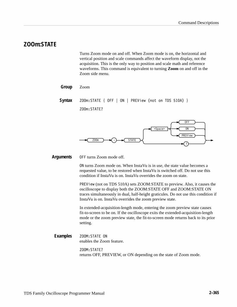
Command Descriptions
TDS Family Oscilloscope Programmer Manual 2–365
ZOOm:STATETurns Zoom mode on and off. When Zoom mode is on, the horizontal andvertical position and scale commands affect the waveform display, not theacquisition. This is the only way to position and scale math and referencewaveforms. This command is equivalent to turning Zoom on and off in theZoom side menu.
Zoom
��������� " ��� # �� # �� ���! ��� �� ��� ����� $
���������
����
������
���
�
��
����
�� ���!
��� turns Zoom mode off.
�� turns Zoom mode on. When InstaVu is in use, the state value becomes arequested value, to be restored when InstaVu is switched off. Do not use thiscondition if InstaVu is on. InstaVu overrides the zoom on state.
�� ���! (not on TDS 510A) sets ZOOM:STATE to preview. Also, it causes theoscilloscope to display both the ZOOM:STATE OFF and ZOOM:STATE ONtraces simultaneously in dual, half-height graticules. Do not use this condition ifInstaVu is on. InstaVu overrides the zoom preview state.
In extended-acquisition-length mode, entering the zoom preview state causesfit-to-screen to be on. If the oscilloscope exits the extended-acquisition-lengthmode or the zoom preview state, the fit-to-screen mode returns back to its priorsetting.
��������� ��
enables the Zoom feature.
���������
returns OFF, PREVIEW, or ON depending on the state of Zoom mode.
Group
Syntax
Arguments
Examples

Command Descriptions
2–366 TDS Family Oscilloscope Programmer Manual
ZOOm:VERTical:POSitionSets or queries the vertical position of waveforms.
Zoom
������ �����������"� � ����
������ �����������"� �
��!��� ����
���� � �� ������ ����"� �
���� is the vertical position in divisions.
������ ���������������
might return ������� ��������������� ��� ��
ZOOm:VERTical:SCAleSets or queries the vertical expansion and compression factor.
Zoom
ACQuire:MODe
������ ������������ ����
������ ������������
��!��� ����
���� � �� ������ �����
���� is the amount of vertical expansion or compression.
������ �����������
might return ������� ����������� ��� ��
Group
Syntax
Arguments
Examples
Group
Related Commands
Syntax
Arguments
Examples

TDS Family Oscilloscope Programmer Manual 3–1
Status and Events
The digitizing oscilloscope provides a status and event reporting system for theGPIB interface. This system informs you of certain significant events that occurwithin the digitizing oscilloscope.
The digitizing oscilloscope status handling system consists of five 8-bit registersand two queues. This section describes these registers and components. It alsoexplains how the event handling system operates.
RegistersThe registers in the event handling system fall into two functional groups:
� Status Registers contain information about the status of the digitizingoscilloscope. They include the Standard Event Status Register (SESR) andthe Status Byte Register (SBR).
� Enable Registers determine whether selected types of events are reported tothe Status Registers and the Event Queue. They include the Device EventStatus Enable Register (DESER), the Event Status Enable Register (ESER),and the Service Request Enable Register (SRER).
The Standard Event Status Register (SESR) and the Status Byte Register (SBR)record certain types of events that may occur while the digitizing oscilloscope isin use. IEEE Std 488.2–1987 defines these registers.
Each bit in a Status Register records a particular type of event, such as anexecution error or service request. When an event of a given type occurs, thedigitizing oscilloscope sets the bit that represents that type of event to a value ofone. (You can disable bits so that they ignore events and remain at zero. See theEnable Registers section on page 3–3.) Reading the status registers tells youwhat types of events have occurred.
The Standard Event Status Register (SESR). The SESR, shown in Figure 3–1,records eight types of events that can occur within the digitizing oscilloscope.Use the *ESR? query to read the SESR register. Reading the register clears thebits of the register so that the register can accumulate information about newevents.
Status Registers
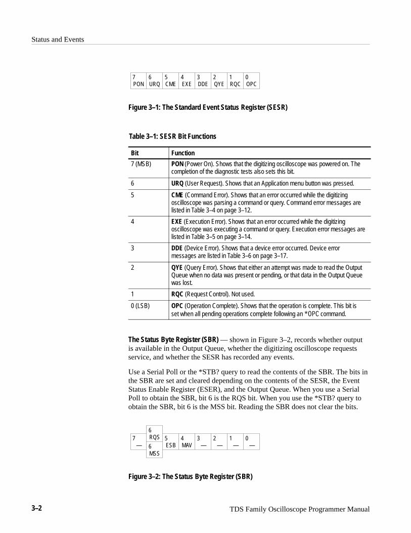
Status and Events
3–2 TDS Family Oscilloscope Programmer Manual
PON URQ CME EXE DDE QYE RQC OPC7 6 5 4 3 2 1 0
Figure 3–1: The Standard Event Status Register (SESR)
Table 3–1: SESR Bit Functions
Bit Function
7 (MSB) PON (Power On). Shows that the digitizing oscilloscope was powered on. Thecompletion of the diagnostic tests also sets this bit.
6 URQ (User Request). Shows that an Application menu button was pressed.
5 CME (Command Error). Shows that an error occurred while the digitizingoscilloscope was parsing a command or query. Command error messages arelisted in Table 3–4 on page 3–12.
4 EXE (Execution Error). Shows that an error occurred while the digitizingoscilloscope was executing a command or query. Execution error messages arelisted in Table 3–5 on page 3–14.
3 DDE (Device Error). Shows that a device error occurred. Device errormessages are listed in Table 3–6 on page 3–17.
2 QYE (Query Error). Shows that either an attempt was made to read the OutputQueue when no data was present or pending, or that data in the Output Queuewas lost.
1 RQC (Request Control). Not used.
0 (LSB) OPC (Operation Complete). Shows that the operation is complete. This bit isset when all pending operations complete following an ���� command.
The Status Byte Register (SBR) — shown in Figure 3–2, records whether outputis available in the Output Queue, whether the digitizing oscilloscope requestsservice, and whether the SESR has recorded any events.
Use a Serial Poll or the *STB? query to read the contents of the SBR. The bits inthe SBR are set and cleared depending on the contents of the SESR, the EventStatus Enable Register (ESER), and the Output Queue. When you use a SerialPoll to obtain the SBR, bit 6 is the RQS bit. When you use the *STB? query toobtain the SBR, bit 6 is the MSS bit. Reading the SBR does not clear the bits.
—RQS
ESB MAV — — — —MSS
76
5 4 3 2 1 06
Figure 3–2: The Status Byte Register (SBR)
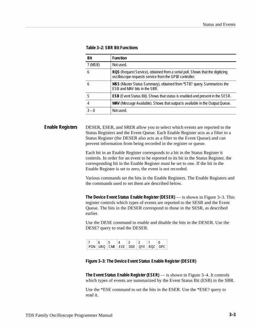
Status and Events
TDS Family Oscilloscope Programmer Manual 3–3
Table 3–2: SBR Bit Functions
Bit Function
7 (MSB) Not used.
6 RQS (Request Service), obtained from a serial poll. Shows that the digitizingoscilloscope requests service from the GPIB controller.
6 MSS (Master Status Summary), obtained from *STB? query. Summarizes theESB and MAV bits in the SBR.
5 ESB (Event Status Bit). Shows that status is enabled and present in the SESR.
4 MAV (Message Available). Shows that output is available in the Output Queue.
3 – 0 Not used.
DESER, ESER, and SRER allow you to select which events are reported to theStatus Registers and the Event Queue. Each Enable Register acts as a filter to aStatus Register (the DESER also acts as a filter to the Event Queue) and canprevent information from being recorded in the register or queue.
Each bit in an Enable Register corresponds to a bit in the Status Register itcontrols. In order for an event to be reported to its bit in the Status Register, thecorresponding bit in the Enable Register must be set to one. If the bit in theEnable Register is set to zero, the event is not recorded.
Various commands set the bits in the Enable Registers. The Enable Registers andthe commands used to set them are described below.
The Device Event Status Enable Register (DESER) — is shown in Figure 3–3. Thisregister controls which types of events are reported to the SESR and the EventQueue. The bits in the DESER correspond to those in the SESR, as describedearlier.
Use the DESE command to enable and disable the bits in the DESER. Use theDESE? query to read the DESER.
PON URQ CME EXE DDE QYE RQC OPC7 6 5 4 3 2 1 0
Figure 3–3: The Device Event Status Enable Register (DESER)
The Event Status Enable Register (ESER) — is shown in Figure 3–4. It controlswhich types of events are summarized by the Event Status Bit (ESB) in the SBR.
Use the *ESE command to set the bits in the ESER. Use the *ESE? query toread it.
Enable Registers
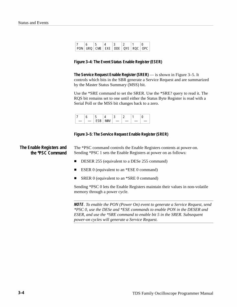
Status and Events
3–4 TDS Family Oscilloscope Programmer Manual
PON URQ CME EXE DDE QYE RQC OPC7 6 5 4 3 2 1 0
Figure 3–4: The Event Status Enable Register (ESER)
The Service Request Enable Register (SRER) — is shown in Figure 3–5. Itcontrols which bits in the SBR generate a Service Request and are summarizedby the Master Status Summary (MSS) bit.
Use the *SRE command to set the SRER. Use the *SRE? query to read it. TheRQS bit remains set to one until either the Status Byte Register is read with aSerial Poll or the MSS bit changes back to a zero.
— — ESB MAV — — — —7 6 5 4 3 2 1 0
Figure 3–5: The Service Request Enable Register (SRER)
The *PSC command controls the Enable Registers contents at power-on.Sending *PSC 1 sets the Enable Registers at power on as follows:
� DESER 255 (equivalent to a DESe 255 command)
� ESER 0 (equivalent to an *ESE 0 command)
� SRER 0 (equivalent to an *SRE 0 command)
Sending *PSC 0 lets the Enable Registers maintain their values in non-volatilememory through a power cycle.
NOTE. To enable the PON (Power On) event to generate a Service Request, send*PSC 0, use the DESe and *ESE commands to enable PON in the DESER andESER, and use the *SRE command to enable bit 5 in the SRER. Subsequentpower-on cycles will generate a Service Request.
The Enable Registers andthe *PSC Command
Status and Events
TDS Family Oscilloscope Programmer Manual 3–5
QueuesThe digitizing oscilloscope status and event reporting system contains twoqueues: the Output Queue and the Event Queue.
The digitizing oscilloscope stores query responses in the Output Queue. Itempties this queue each time it receives a new command or query message afteran <EOM>. The controller must read a query response before it sends the nextcommand (or query) or it will lose responses to earlier queries.
WARNING. When a controller sends a query, an <EOM>, and a second query,the digitizing scope normally clears the first response and outputs the secondwhile reporting a Query Error (QYE bit in the ESER) to indicate the lostresponse. A fast controller, however, may receive a part or all of the firstresponse as well. To avoid this situation, the controller should always read theresponse immediately after sending any terminated query message or send aDCL (Device Clear) before sending the second query.
The Event Queue stores detailed information on up to 20 events. If more than 20events stack up in the Event Queue, the 20th event is replaced by event code350, “Too many events.”
Read the Event Queue with the EVENT? query (which returns only the eventnumber), with the EVMSG? query (which returns the event number and a textdescription of the event), or with the ALLEV? query (which returns all the eventnumbers along with a description of the event). Reading an event removes itfrom the queue.
Before reading an event from the Event Queue, you must use the *ESR? query toread the summary of the event from the SESR. This makes the events summa-rized by the *ESR? read available to the EVENT? and EVMSG? queries, andempties the SESR.
Reading the SESR erases any events that were summarized by previous *ESR?reads but not read from the Event Queue. Events that follow an *ESR? read areput in the Event Queue but are not available until *ESR? is used again.
The Output Queue
The Event Queue

Status and Events
3–6 TDS Family Oscilloscope Programmer Manual
Event Handling SequenceFigure 3–6, on page 3–6, shows how to use the status and event handlingsystem. In the explanation that follows, numbers in parentheses refer to numbersin Figure 3–6.
Device Event Status Enable Register(DESER)
Read using DESE?Write using DESE
Standard Event Status Register(SESR)
Read using *ESR?Cannot be written
Event Status Enable Register(ESER)
Read using *ESE?Write using *ESE
Status Byte Register(SBR)
Read using *STB?Cannot be written
Service Request Enable Register(SRER)
Read using *SRE?Write using *SRE
EventQueue
OutputQueue
EventEventEvent
ByteByteByte
1
2
3
4
67
5
PON URQ CME EXE DDE QYE RQC OPC7 6 5 4 3 2 1 0
PON URQ CME EXE DDE QYE RQC OPC7 6 5 4 3 2 1 0
PON URQ CME EXE DDE QYE RQC OPC7 6 5 4 3 2 1 0
—RQS
ESB MAV — — — —MSS
76
5 4 3 2 1 06
— — ESB MAV — — — —7 6 5 4 3 2 1 0
Figure 3–6: Status and Event Handling Process
When an event occurs, a signal is sent to the DESER (1). If that type of event isenabled in the DESER (that is, if the bit for that event type is set to 1), theappropriate bit in the SESR is set to one, and the event is recorded in the EventQueue (2). If the corresponding bit in the ESER is also enabled (3), then the ESBbit in the SBR is set to one (4).
Status and Events
TDS Family Oscilloscope Programmer Manual 3–7
When output is sent to the Output Queue, the MAV bit in the SBR is set toone (5).
When a bit in the SBR is set to one and the corresponding bit in the SRER isenabled (6), the MSS bit in the SBR is set to one and a service request isgenerated (7).
Synchronization MethodsAlthough most GPIB commands are completed almost immediately after beingreceived by the digitizing oscilloscope, some commands start a process thatrequires more time. For example, once a HARDCOPY START command isexecuted it may be a few seconds before the hardcopy operation is complete.Rather than remain idle while the operation is in process, the digitizingoscilloscope will continue processing other commands. This means that someoperations will not be completed in the order that they were sent.
Sometimes the result of an operation depends on the result of an earlieroperation. A first operation must complete before the next one gets processed.The digitizing oscilloscope status and event reporting system provide ways to dothis.
For example, a typical application might involve acquiring a single-sequencewaveform and then taking a measurement on the acquired waveform. You coulduse the following command sequence to do this:
/** Set up single-sequence acquisition **/������ � ��
������������������ ���
��������� �����������
��������������� �����
/** Acquire waveform data **/����������� ��
/** Set up the measurement parameters **/���������������� �������
������������������ � �
/** Take amplitude measurement on acquired data **/������������������
The acquisition of the waveform requires extended processing time. It may notfinish before the digitizing oscilloscope takes an amplitude measurement (SeeFigure 3–7). This can result in an incorrect amplitude value.

Status and Events
3–8 TDS Family Oscilloscope Programmer Manual
�����������������������
Processing Time
Acquiring Waveform Data
������������ ��
Figure 3–7: Command Processing Without Using Synchronization
To ensure the digitizing oscilloscope completes waveform acquisition beforetaking the measurement on the acquired data, you can synchronize the program.Figure 3–8 shows the desired processing sequence.
�����������������������
Processing Time
Acquiring Waveform Data
������������ ��
Figure 3–8: Processing Sequence With Synchronization
You can use four commands to synchronize the operation of the digitizingoscilloscope with your application program: *WAI, BUSY?, *OPC, and *OPC?.
You can force commands to execute sequentially by using the *WAI command.This command forces completion of the previous commands before processingnew ones.
The same command sequence using the *WAI command for synchronizationlooks like this:
/* Set up single-sequence acquisition */�������� ��
������������������ �� ���
���������� ������������
���������������� �������
/* Acquire waveform data */������������ ��
/* Set up the measurement parameters */��������������������� ��������
���������������������� ��
/* Wait until the acquisition is complete before taking the measurement */����
Using the *WAI Command
Status and Events
TDS Family Oscilloscope Programmer Manual 3–9
/* Take amplitude measurement on acquired data */�����������������������
Though *WAI is one of the easiest ways to achieve synchronization, it is also themost costly. The processing time of the digitizing oscilloscope is slowed since itis processing a single command at a time. This time could be spent doing othertasks.
The controller can continue to write commands to the input buffer of thedigitizing oscilloscope, but the commands will not be processed by the digitizingoscilloscope until all operations in process are complete. If the input bufferbecomes full, the controller will be unable to write more commands to the buffer.This can cause a time-out.
The BUSY? query allows you to find out whether the digitizing oscilloscope isbusy processing a command that has an extended processing time such assingle-sequence acquisition.
The same command sequence using the BUSY? query for synchronization lookslike this:
/* Set up single-sequence acquisition */�������� ��
������������������ �� ���
���������� ������������
���������������� �������
/* Acquire waveform data */������������ ��
/* Set up the measurement parameters */��������������������� ��������
���������������������� ��
/* Wait until the acquisition is complete before taking the measurement */� !#� ����� "��& #%%&!$�
/* Take amplitude measurement on acquired data */�����������������������
This sequence lets you create your own wait loop rather than using the *WAIcommand. The BUSY? query helps you avoid time-outs caused by writing toomany commands to the input buffer. The controller is still tied up, though, andthe repeated BUSY? query will result in more bus traffic.
If the corresponding status registers are enabled, the *OPC command sets theOPC bit in the Standard Event Status Register (SESR) when an operation iscomplete. You achieve synchronization by using this command with either aserial poll or service request handler.
Using the BUSY Query
Using the *OPC Command
Status and Events
3–10 TDS Family Oscilloscope Programmer Manual
Serial Poll Method. Enable the OPC bit in the Device Event Status EnableRegister (DESER) and the Event Status Enable Register (ESER) using the DESEand *ESE commands. When the operation is complete, the OPC bit in theStandard Event Status Register (SESR) will be enabled and the Event Status Bit(ESB) in the Status Byte Register will be enabled.
The same command sequence using the *OPC command for synchronizationwith serial polling looks like this:
/* Set up single-sequence acquisition */���������� ��
���� ���������� ������ ���
��������� � �����
��������������� ��������
/* Enable the status registers */ ��� �
���� �
���� �
/* Acquire waveform data */����������� ��
/* Set up the measurement parameters */��������������� ����� ������ �
��������������� ������� ���
/* Wait until the acquisition is complete before taking the measurement. */����
�$%'" ,"+%!' *)'' � �� &""* '))*%(#
/* Take amplitude measurement on acquired data */��������������� �����
This technique requires less bus traffic than did looping on ����.
Service Request Method. Enable the OPC bit in the Device Event Status EnableRegister (DESER) and the Event Status Enable Register (ESER) using the DESEand *ESE commands. You can also enable service requests by setting the ESBbit in the Service Request Enable Register (SRER) using the *SRE command.When the operation is complete, a Service Request will be generated.
The same command sequence using the *OPC command for synchronizationlooks like this:
/* Set up single-sequence acquisition */���������� ��
���� ���������� ������ ���
��������� � �����
��������������� ��������
/* Enable the status registers */ ��� �
Status and Events
TDS Family Oscilloscope Programmer Manual 3–11
���� �
���� ��
/* Acquire waveform data */� ���������� ��
/* Set up the measurement parameters */����������������� �� ���������
�������������������� � ��
/* Wait until the acquisition is complete before taking the measurement */���
�0.'0", #"- -.5 $. $)&&%0%-2 2"1*1 13#( "1 2"+* 2. .2(%0
$%4)#%1� �(% ���� 5(%- )2 #.,%1� )-2%003/21 2(.1% 2"1*1 "-$
0%230-1 #.-20.+ 2. 2()1 2"1*�
/* Take amplitude measurement on acquired data */����������������������
This technique is more efficient but requires more sophisticated programming.
The *OPC? query places a 1 in the Output Queue once an operation is complete.A timeout could occur if you try to read the output queue before there is any datain it.
The same command sequence using the *OPC? query for synchronization lookslike this:
/* Set up single-sequence acquisition */���� � �� ��
����!������� ��������� ��
� ��������� ������
� �������������� ������ �
/* Acquire waveform data */� ���������� ��
/* Set up the measurement parameters */����������������� �� ���������
�������������������� � ��
/* Wait until the acquisition is complete before taking the measurement */��� �
�")2 &.0 0%"$ &0., �32/32 �3%3%�
/* Take amplitude measurement on acquired data */����������������������
This is the simplest approach. It requires no status handling or loops. However,you must set the controller time-out for longer than the acquisition operation.
Using the *OPC? Query

Status and Events
3–12 TDS Family Oscilloscope Programmer Manual
MessagesTables 3–3 through 3–9 list all the programming interface messages thedigitizing oscilloscope generates in response to commands and queries.
For most messages, a secondary message from the digitizing oscilloscope givesmore detail about the cause of the error or the meaning of the message. Thismessage is part of the message string, and is separated from the main message bya semicolon.
Each message is the result of an event. Each type of event sets a specific bit inthe SESR and is controlled by the equivalent bit in the DESER. Thus, eachmessage is associated with a specific SESR bit. In the message tables that follow,the associated SESR bit is specified in the table title, with exceptions noted withthe error message text.
Table 3–3 shows the messages when the system has no events or status to report.These have no associated SESR bit.
Table 3–3: No Event Messages
Code Message
0 No events to report – queue empty
1 No events to report – new events pending *ESR?
Table 3–4 shows the error messages generated by improper command syntax.Check that the command is properly formed and that it follows the rules inCommand Syntax starting on page 2–1.
Table 3–4: Command Error Messages – CME Bit 5
Code Message
100 Command error
101 Invalid character
102 Syntax error
103 Invalid separator
104 Data type error
105 GET not allowed
106 Invalid program data separator
108 Parameter not allowed
109 Missing parameter
110 Command header error
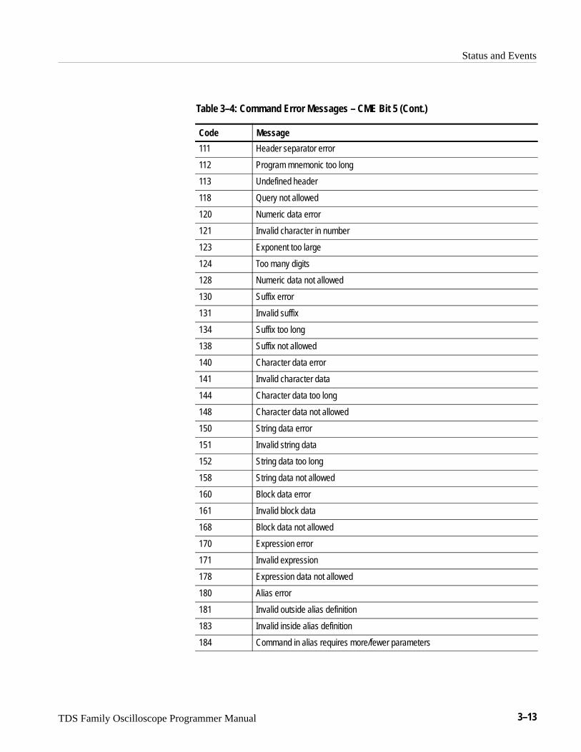
Status and Events
TDS Family Oscilloscope Programmer Manual 3–13
Table 3–4: Command Error Messages – CME Bit 5 (Cont.)
Code Message
111 Header separator error
112 Program mnemonic too long
113 Undefined header
118 Query not allowed
120 Numeric data error
121 Invalid character in number
123 Exponent too large
124 Too many digits
128 Numeric data not allowed
130 Suffix error
131 Invalid suffix
134 Suffix too long
138 Suffix not allowed
140 Character data error
141 Invalid character data
144 Character data too long
148 Character data not allowed
150 String data error
151 Invalid string data
152 String data too long
158 String data not allowed
160 Block data error
161 Invalid block data
168 Block data not allowed
170 Expression error
171 Invalid expression
178 Expression data not allowed
180 Alias error
181 Invalid outside alias definition
183 Invalid inside alias definition
184 Command in alias requires more/fewer parameters

Status and Events
3–14 TDS Family Oscilloscope Programmer Manual
Table 3–5 lists the execution errors that are detected during execution of acommand. In these error messages, you should read “macro” as “alias.”
Table 3–5: Execution Error Messages – EXE Bit 4
Code Message
200 Execution error
201 Invalid while in local
202 Settings lost due to rtl
210 Trigger error
211 Trigger ignored
212 Arm ignored
220 Parameter error
221 Settings conflict
222 Data out of range
223 Too much data
224 Illegal parameter value
230 Data corrupt or stale
240 Hardware error
241 Hardware missing
242 Hardware configuration error
243 Hardware I/O device error
250 Mass storage error
251 Missing mass storage
252 Missing media
253 Corrupt media
254 Media full
255 Directory full
256 File name not found
257 File name error
258 Media protected
260 Expression error
261 Math error in expression
2200 Measurement error, Measurement system error
2201 Measurement error, Zero period
2202 Measurement error, No period found

Status and Events
TDS Family Oscilloscope Programmer Manual 3–15
Table 3–5: Execution Error Messages – EXE Bit 4 (Cont.)
Code Message
2203 Measurement error, No period, second waveform
2204 Measurement error, Low signal amplitude
2205 Measurement error, Low amplitude, second waveform
2206 Measurement error, Invalid gate
2207 Measurement error, Measurement overflow
2208 Measurement error, Waveform does not cross Mid Ref
2209 Measurement error, No second Mid Ref crossing
2210 Measurement error, No Mid Ref crossing, second waveform
2211 Measurement error, No backwards Mid Ref crossing
2212 Measurement error, No negative crossing
2213 Measurement error, No positive crossing
2214 Measurement error, No crossing
2215 Measurement error, No crossing, second waveform
2216 Measurement error, No crossing, target waveform
2217 Measurement error, Constant waveform
2218 Measurement error, Unused
2219 Measurement error, No valid edge – No arm sample
2220 Measurement error, No valid edge – No arm cross
2221 Measurement error, No valid edge – No trigger cross
2222 Measurement error, No valid edge – No second cross
2223 Measurement error, Waveform mismatch
2224 Measurement error, WAIT calculating
2225 Measurement error, No waveform to measure
2226 Null Waveform
2227 Positive and Negative Clipping
2228 Measurement error, Positive Clipping
2229 Measurement error, Negative Clipping
2230 Measurement error, High Ref < Low Ref
2235 Math error, Invalid math description
2236 Math error, Reference waveform is invalid
2237 Out of acquisition memory
2238 Too many channels need to be acquired

Status and Events
3–16 TDS Family Oscilloscope Programmer Manual
Table 3–5: Execution Error Messages – EXE Bit 4 (Cont.)
Code Message
2239 EAL turned off(EAL = extended-acquisition-length mode)
2240 Invalid password
2241 Waveform requested is invalid
2242 Data start and stop > record length
2243 Waveform requested is not a data source
2244 Waveform requested is not turned on
2245 Saveref error, Selected channel is turned off
2246 Saveref error, Selected channel data invalid
2247 Saveref error, Out of reference memory
2248 Saveref error, Source reference data invalid
2249 Reference deletion error, Waveform in use for math
2258 Acq must be stopped
2259 File too big
2260 Calibration error
2270 Alias error
2271 Alias syntax error
2272 Alias execution error
2273 Illegal alias label
2274 Alias parameter error
2275 Alias definition too long
2276 Alias expansion error
2277 Alias redefinition not allowed
2278 Alias header not found
2279 Alias label too long
2280 Alias table full
2281 Wrong configuration
2285 TekSecure� Pass
2286 TekSecure� Fail
2290 Limit error, Reference in use
2291 Limit error, Reference data invalid
2292 Limit error, Out of reference memory
2293 Limit error, Selected channel is turned off
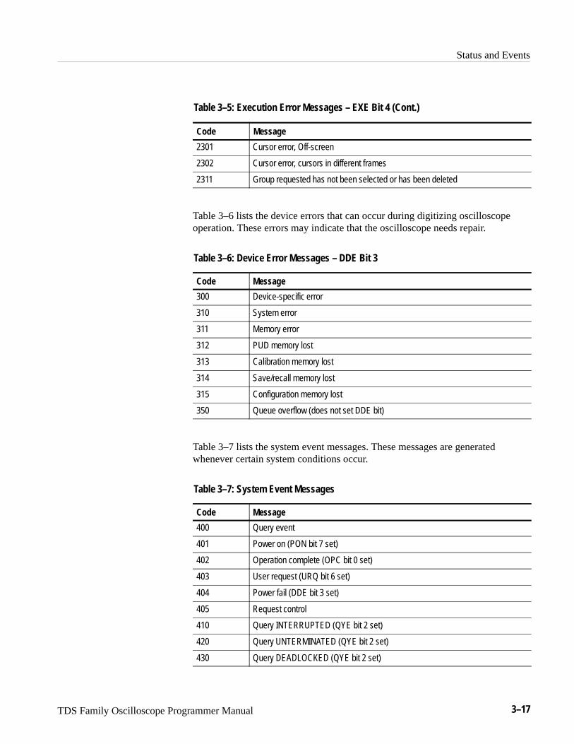
Status and Events
TDS Family Oscilloscope Programmer Manual 3–17
Table 3–5: Execution Error Messages – EXE Bit 4 (Cont.)
Code Message
2301 Cursor error, Off-screen
2302 Cursor error, cursors in different frames
2311 Group requested has not been selected or has been deleted
Table 3–6 lists the device errors that can occur during digitizing oscilloscopeoperation. These errors may indicate that the oscilloscope needs repair.
Table 3–6: Device Error Messages – DDE Bit 3
Code Message
300 Device-specific error
310 System error
311 Memory error
312 PUD memory lost
313 Calibration memory lost
314 Save/recall memory lost
315 Configuration memory lost
350 Queue overflow (does not set DDE bit)
Table 3–7 lists the system event messages. These messages are generatedwhenever certain system conditions occur.
Table 3–7: System Event Messages
Code Message
400 Query event
401 Power on (PON bit 7 set)
402 Operation complete (OPC bit 0 set)
403 User request (URQ bit 6 set)
404 Power fail (DDE bit 3 set)
405 Request control
410 Query INTERRUPTED (QYE bit 2 set)
420 Query UNTERMINATED (QYE bit 2 set)
430 Query DEADLOCKED (QYE bit 2 set)
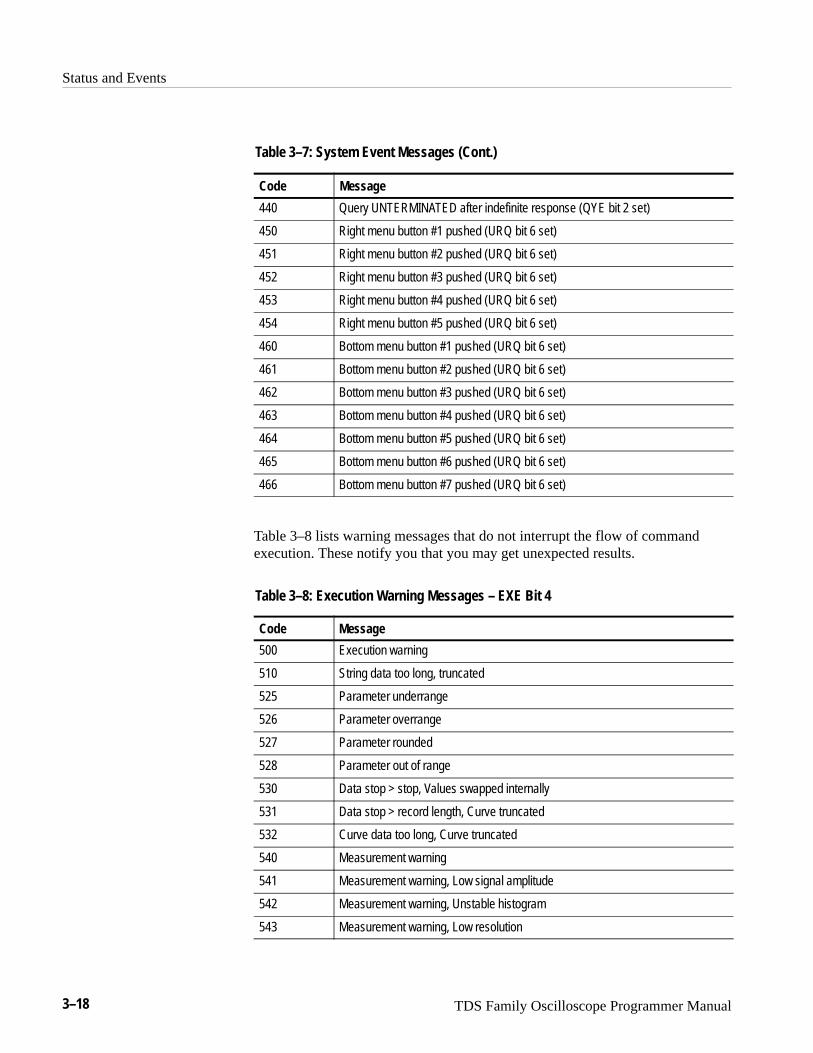
Status and Events
3–18 TDS Family Oscilloscope Programmer Manual
Table 3–7: System Event Messages (Cont.)
Code Message
440 Query UNTERMINATED after indefinite response (QYE bit 2 set)
450 Right menu button #1 pushed (URQ bit 6 set)
451 Right menu button #2 pushed (URQ bit 6 set)
452 Right menu button #3 pushed (URQ bit 6 set)
453 Right menu button #4 pushed (URQ bit 6 set)
454 Right menu button #5 pushed (URQ bit 6 set)
460 Bottom menu button #1 pushed (URQ bit 6 set)
461 Bottom menu button #2 pushed (URQ bit 6 set)
462 Bottom menu button #3 pushed (URQ bit 6 set)
463 Bottom menu button #4 pushed (URQ bit 6 set)
464 Bottom menu button #5 pushed (URQ bit 6 set)
465 Bottom menu button #6 pushed (URQ bit 6 set)
466 Bottom menu button #7 pushed (URQ bit 6 set)
Table 3–8 lists warning messages that do not interrupt the flow of commandexecution. These notify you that you may get unexpected results.
Table 3–8: Execution Warning Messages – EXE Bit 4
Code Message
500 Execution warning
510 String data too long, truncated
525 Parameter underrange
526 Parameter overrange
527 Parameter rounded
528 Parameter out of range
530 Data stop > stop, Values swapped internally
531 Data stop > record length, Curve truncated
532 Curve data too long, Curve truncated
540 Measurement warning
541 Measurement warning, Low signal amplitude
542 Measurement warning, Unstable histogram
543 Measurement warning, Low resolution

Status and Events
TDS Family Oscilloscope Programmer Manual 3–19
Table 3–8: Execution Warning Messages – EXE Bit 4 (Cont.)
Code Message
544 Measurement warning, Uncertain edge
545 Measurement warning, Invalid in minmax
546 Measurement warning, Need 3 edges
547 Measurement warning, Clipping positive/negative
548 Measurement warning, Clipping positive
549 Measurement warning, Clipping negative
550 InstaVu active – deactivate to see change
551 InstaVu active – deactivate to use math
552 EAL on – turn off to see change(EAL = extended-acquisition-length mode)
553 EAL on – turn off to use math(EAL = extended-acquisition-length mode)
570 Saveref warning, decimated 500K waveform to 250K Ref (TDS 700A)
571 Option 05 not present
572 Option 2F not present
Table 3–9 shows internal errors that indicate an internal fault in the digitizingoscilloscope.
Table 3–9: Internal Warning Messages
Code Message
600 Internal warning
620 Internal warning, Bad thermistor
630 Internal warning, 50 � overload
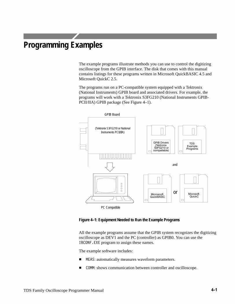
TDS Family Oscilloscope Programmer Manual 4–1
Programming Examples
The example programs illustrate methods you can use to control the digitizingoscilloscope from the GPIB interface. The disk that comes with this manualcontains listings for these programs written in Microsoft QuickBASIC 4.5 andMicrosoft QuickC 2.5.
The programs run on a PC-compatible system equipped with a Tektronix(National Instruments) GPIB board and associated drivers. For example, theprograms will work with a Tektronix S3FG210 (National Instruments GPIB-PCII/IIA) GPIB package (See Figure 4–1).
(Tektronix S3FG210 or NationalInstruments PCII/IIA)
or
PC Compatible
and
GPIB Board
Figure 4–1: Equipment Needed to Run the Example Programs
All the example programs assume that the GPIB system recognizes the digitizingoscilloscope as DEV1 and the PC (controller) as GPIB0. You can use the�������� program to assign these names.
The example software includes:
� ����: automatically measures waveform parameters.
� ���: shows communication between controller and oscilloscope.

Programming Examples
4–2 TDS Family Oscilloscope Programmer Manual
� �����: reads a waveform from an oscilloscope and stores it in a file.
� ������: uses cursors to measure waveform parameters.
� ��: a talker-listener program.
Compiling the Example ProgramsThe example programs diskette contains programs written in MicrosoftQuickBASIC 4.5 and Microsoft QuickC 2.5.
Executable versions of the programs are in the PROGRAMS directory. Sourceversions are in the SOURCES directory. Within this directory, the QuickBASICprograms are in the Q-BASIC subdirectory and the QuickC programs are in theQUICK-C subdirectory.
A ������ file in each directory explains how to build executable code from thesource files provided.
The QuickC directory also comes with sample MAKE files and sampleexecutable files. These have the suffix ��� .
If you wish to develop code, you will need to use files that come with theGPIB system. Specifically, the QuickBASIC programs use ����������
and ��������. The QuickC programs use ����� and ��������.
NOTE. The programs you compile in the Sources directory work with theTektronix S3FG210 (National Instruments GPIB-PCII-IIA) GPIB system. It maytake extra steps or changes to get them to work with older Tektronix GURU andother GPIB systems.
To make an executable for any example, perform the following:
1. Install QuickC. Select the SMALL memory model. Be sure to set up yourpath so DOS can access the QuickC directory.
2. Install the Tektronix S3FG210 (National Instruments GPIB-PCII/IIA) GPIBboard and drivers. Remember to identify the GPIB device as DEV1. You canuse the ���������� program to do this.
3. Copy the files from the examples diskette to your hard disk. You might alsocreate a special directory to store them. For example, if the current drive ishard disk C, you want to store the examples in drive C, and the examplesdiskette is in drive B, you might type:
����! �#�� ��"
Compiling and LinkingYour Example Quick-C
Programs
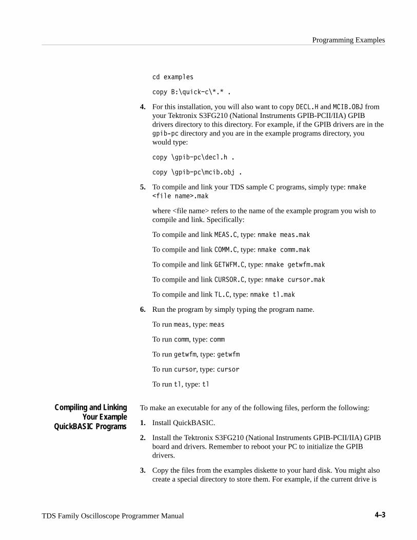
Programming Examples
TDS Family Oscilloscope Programmer Manual 4–3
�� �1�'*&�-
�)*2 ��+/#�%������ �
4. For this installation, you will also want to copy ����� and ����� fromyour Tektronix S3FG210 (National Instruments GPIB-PCII/IIA) GPIBdrivers directory to this directory. For example, if the GPIB drivers are in the!*#�3*� directory and you are in the example programs directory, youwould type:
�)*2 �!*#��*�����&�" �
�)*2 �!*#��*��'�#��)�$ �
5. To compile and link your TDS sample C programs, simply type: ('�%�
� #&� (�'���'�%
where <file name> refers to the name of the example program you wish tocompile and link. Specifically:
To compile and link �����, type: ('�%� '��-�'�%
To compile and link ����, type: ('�%� �)''�'�%
To compile and link ���� ��, type: ('�%� !�.0 '�'�%
To compile and link ������, type: ('�%� �/,-),�'�%
To compile and link ���, type: ('�%� .&�'�%
6. Run the program by simply typing the program name.
To run '��-, type: '��-
To run �)'', type: �)''
To run !�.0 ', type: !�.0 '
To run �/,-),, type: �/,-),
To run .&, type: .&
To make an executable for any of the following files, perform the following:
1. Install QuickBASIC.
2. Install the Tektronix S3FG210 (National Instruments GPIB-PCII/IIA) GPIBboard and drivers. Remember to reboot your PC to initialize the GPIBdrivers.
3. Copy the files from the examples diskette to your hard disk. You might alsocreate a special directory to store them. For example, if the current drive is
Compiling and LinkingYour Example
QuickBASIC Programs
Programming Examples
4–4 TDS Family Oscilloscope Programmer Manual
hard disk C, you want to store the examples in drive C, and the examplesdiskette is in drive B, you might type:
)'!%. "3�),("/
! "3�),("/
+,4 ���-���/% ���� �
4. For this installation, you will also want to copy ���� ����� and ��������from your Tektronix S3FG210 (National Instruments GPIB-PCII/IIA) GPIBdrivers directory to the directory your example programs are in. Forexample, if the GPIB drivers are in the $,%��, directory and you are in theexample programs directory, you would type:
+,4 �$,%��, �-�!" (���/ �
+,4 �$,%��, �-�%��+�& �
5. Perform the following two steps for example programs:
a. Compile the program by using the following command:
� �+ #%("���/�
where #%(" is one of the example program names.
To compile ��������, type: � �+ )"�/���/�
To compile �������, type: � �+ +))���/�
To compile ����������, type: � �+ $"02#)���/�
To compile ���������, type: � �+ 1./+.���/�
To compile ������, type: � �+ 0(���/�
b. Link the compiled program with the qbib.obj module to create theexecutable program (file.EXE) by using the following command:
(%*' #%("�+�&�-�%��+�&�
where #%(" is one of the above program names.
To link ��������, type: (%*' )"�/�+�&�-�%��+�&�
To link �������, type: (%*' +))�+�&�-�%��+�&�
To link ����������, type: (%*' $"02#)�+�&�-�%��+�&�
To link ���������, type: (%*' 1./+.�+�&�-�%��+�&�
To link ������, type: (%*' 0(�+�&�-�%��+�&�
Programming Examples
TDS Family Oscilloscope Programmer Manual 4–5
��������� is a collection of input/output routines used by the otherprograms and is included for proper file compilation.
6. Run the program by simply typing the program name.
To run ����, type: ����
To run ����, type: ����
To run ������, type: ������
To run ������, type: ������
To run ��, type: ��
NOTE. The example programs disable front-panel operation while they arerunning and reenable it when they terminate. If your program terminatesprematurely, front-panel operation may remain disabled. To reenable front-paneloperation, do one of the following: cycle power on the digitizing oscilloscope orsend the GPIB command ���� � to unlock the front panel. You can send the���� � command with the TL program included in your sample programsdisk.
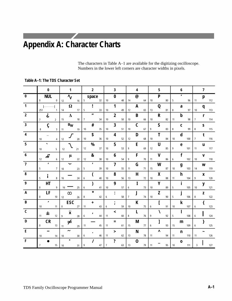
TDS Family Oscilloscope Programmer Manual A–1
Appendix A: Character Charts
The characters in Table A–1 are available for the digitizing oscilloscope.Numbers in the lower left corners are character widths in pixels.
Table A–1: The TDS Character Set
0 1 2 3 4 5 6 7
0 NUL0 0
12 16
space5 32
010 48
@14 64
P10 80
‘5 96
p11 112
1 251 1
�14 17
!5 33
110 49
A12 65
Q13 81
a8 97
q10 113
2 7 2
�
�15 18
”7 34
210 50
B10 66
R10 82
b11 98
r7 114
3 Ç 8 3
�� 11 19
#10 35
310 51
C10 67
S9 83
c8 99
s8 115
4 10 4
�� 12 20
$10 36
410 52
D12 68
T10 84
d10 100
t7 116
5 10 5
12 21
%12 37
510 53
E9 69
U12 85
e9 101
u11 117
6 12 6
�12 22
&12 38
610 54
F9 70
V11 86
f6 102
v10 118
7 ‘5 7
10 23
’5 39
710 55
G11 71
W15 87
g10 103
w14 119
8 5 8
� 16 24
(6 40
810 56
H13 72
X10 88
h11 104
x9 120
9 HT0 9
16 25
)6 41
910 57
I6 73
Y10 89
i5 105
y10 121
A LF0 10
12 26
*8 42
:6 58
J7 74
Z10 90
j5 106
z8 122
B 10 11
ESC0 27
+11 43
;6 59
K10 75
[6 91
k10 107
{6 123
C 11 12
9 28
� ,6 44
<11 60
L8 76
\9 92
l5 108
6 124
D CR0 13
11 29
—11 45
=11 61
M15 77
]6 93
m15 109
}6 125
E 10 14
10 30� .
6 46>
11 62N
13 78^
11 94n
11 110~
11 126
F �7 15
10 31
/9 47
?7 63
O13 79
_11 95
o10 111
3 127
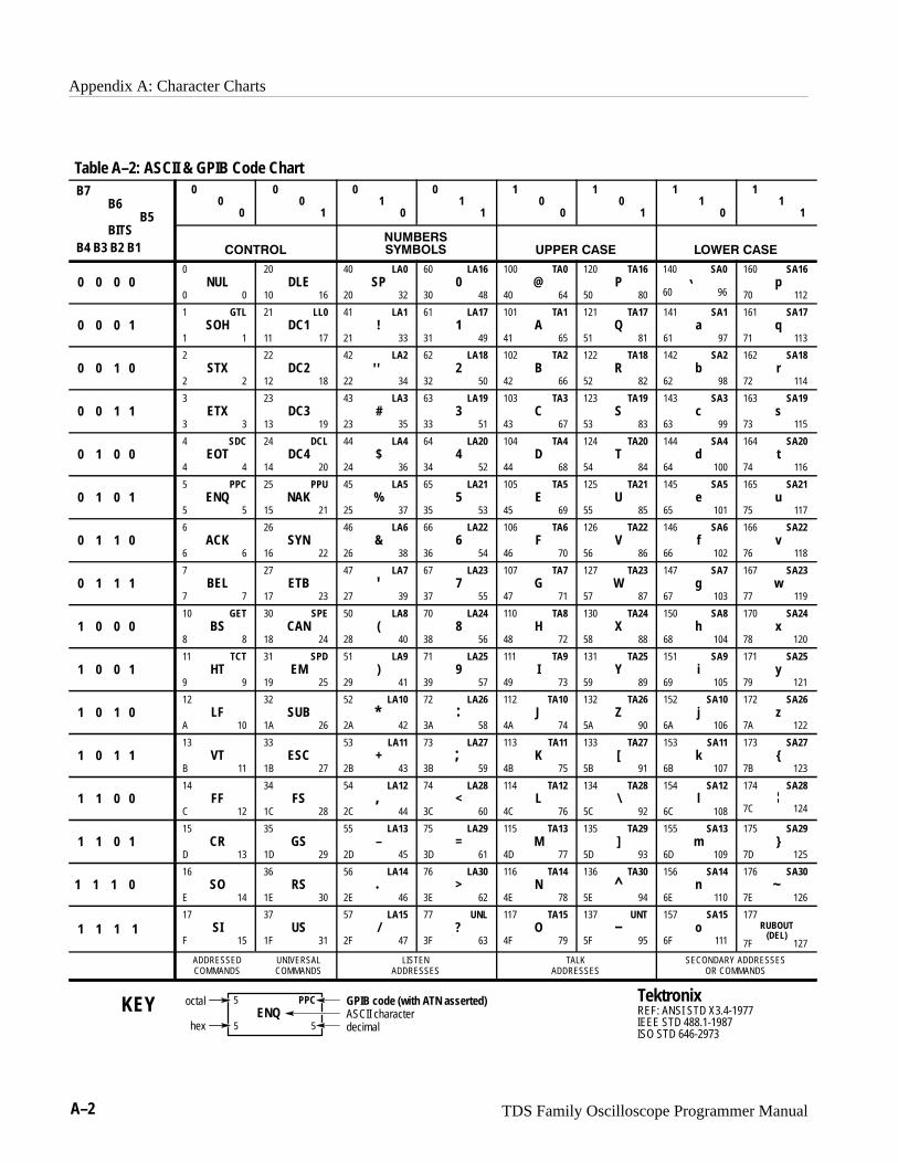
Appendix A: Character Charts
A–2 TDS Family Oscilloscope Programmer Manual
Table A–2: ASCII & GPIB Code ChartB7
B6B5
T
00
0
00
1
01
0
01
1
10
0
10
1
11
0
11
1
BITSB4 B3 B2 B1 �� ��
�������
������ ��� ���� ���� ����
0 0 0 00
NUL0 0
20DLE
10 16
40 LA0SP
20 32
60 LA160
30 48
100 TA0@
40 64
120 TA16P
50 80
140 SA0
60 96
160 SA16p
70 112
0 0 0 11 GTL
SOH1 1
21 LL0DC1
11 17
41 LA1!
21 33
61 LA171
31 49
101 TA1A
41 65
121 TA17Q
51 81
141 SA1a
61 97
161 SA17q
71 113
0 0 1 02
STX2 2
22DC2
12 18
42 LA2
22 34�
62 LA182
32 50
102 TA2B
42 66
122 TA18R
52 82
142 SA2b
62 98
162 SA18r
72 114
0 0 1 13
ETX3 3
23DC3
13 19
43 LA3#
23 35
63 LA193
33 51
103 TA3C
43 67
123 TA19S
53 83
143 SA3c
63 99
163 SA19s
73 115
0 1 0 04 SDC
EOT4 4
24 DCLDC4
14 20
44 LA4$
24 36
64 LA204
34 52
104 TA4D
44 68
124 TA20T
54 84
144 SA4d
64 100
164 SA20t
74 116
0 1 0 15 PPC
ENQ5 5
25 PPUNAK
15 21
45 LA5%
25 37
65 LA215
35 53
105 TA5E
45 69
125 TA21U
55 85
145 SA5e
65 101
165 SA21u
75 117
0 1 1 06
ACK6 6
26SYN
16 22
46 LA6&
26 38
66 LA226
36 54
106 TA6F
46 70
126 TA22V
56 86
146 SA6f
66 102
166 SA22v
76 118
0 1 1 17
BEL7 7
27ETB
17 23
47 LA7
27 39�
67 LA237
37 55
107 TA7G
47 71
127 TA23W
57 87
147 SA7g
67 103
167 SA23w
77 119
1 0 0 010 GET
BS8 8
30 SPECAN
18 24
50 LA8(
28 40
70 LA248
38 56
110 TA8H
48 72
130 TA24X
58 88
150 SA8h
68 104
170 SA24x
78 120
1 0 0 111 TCT
HT9 9
31 SPDEM
19 25
51 LA9)
29 41
71 LA259
39 57
111 TA9I
49 73
131 TA25Y
59 89
151 SA9i
69 105
171 SA25y
79 121
1 0 1 012
LFA 10
32SUB
1A 26
52 LA10
2A 42*
72 LA26
3A 58:
112 TA10J
4A 74
132 TA26Z
5A 90
152 SA10j
6A 106
172 SA26z
7A 122
1 0 1 113
VTB 11
33ESC
1B 27
53 LA11+
2B 43
73 LA27
3B 59;
113 TA11K
4B 75
133 TA27[
5B 91
153 SA11k
6B 107
173 SA27{
7B 123
1 1 0 014
FFC 12
34FS
1C 28
54 LA12
2C 44,
74 LA28<
3C 60
114 TA12L
4C 76
134 TA28\
5C 92
154 SA12l
6C 108
174 SA28
7C 124
1 1 0 115
CRD 13
35GS
1D 29
55 LA13–
2D 45
75 LA29=
3D 61
115 TA13M
4D 77
135 TA29]
5D 93
155 SA13m
6D 109
175 SA29}
7D 125
1 1 1 016
SOE 14
36RS
1E 30
56 LA14
2E 46.
76 LA30>
3E 62
116 TA14N
4E 78
136 TA30
5E 94^
156 SA14n
6E 110
176 SA30
7E 126~
1 1 1 117
SIF 15
37US
1F 31
57 LA15/
2F 47
77 UNL?
3F 63
117 TA15O
4F 79
137 UNT
5F 95–
157 SA15o
6F 111
177
7F 127
RUBOUT(DEL)
ADDRESSEDCOMMANDS
UNIVERSALCOMMANDS
LISTENADDRESSES
TALKADDRESSES
SECONDARY ADDRESSESOR COMMANDS
TektronixREF: ANSI STD X3.4-1977IEEE STD 488.1-1987ISO STD 646-2973
5 PPCENQ
5 5
GPIB code (with ATN asserted)
hex
octal
decimalASCII characterKEY
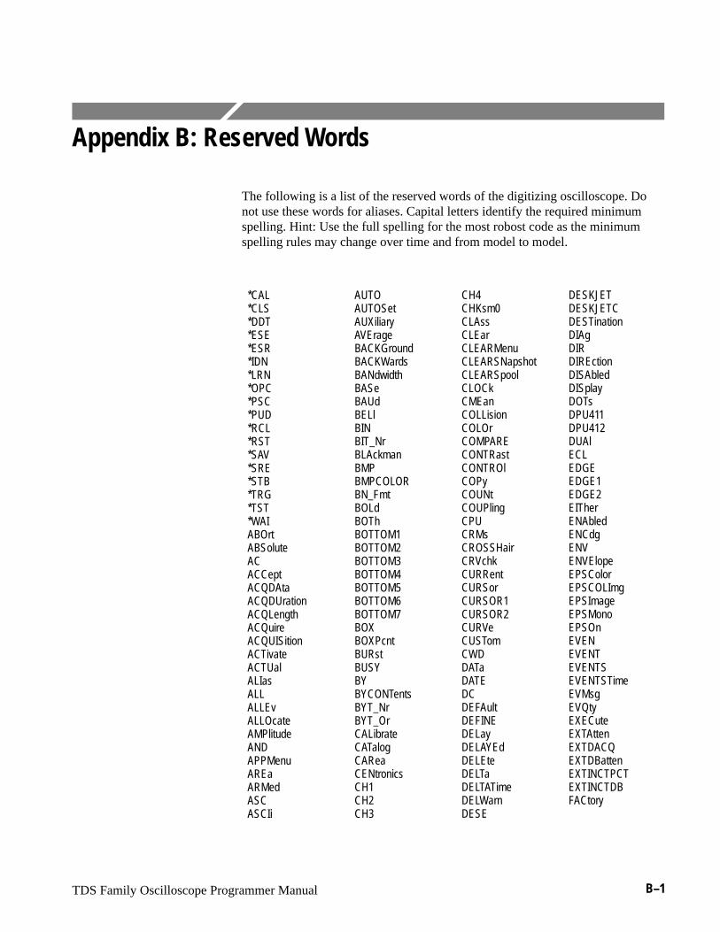
TDS Family Oscilloscope Programmer Manual B–1
Appendix B: Reserved Words
The following is a list of the reserved words of the digitizing oscilloscope. Donot use these words for aliases. Capital letters identify the required minimumspelling. Hint: Use the full spelling for the most robost code as the minimumspelling rules may change over time and from model to model.
*CAL*CLS*DDT*ESE*ESR*IDN*LRN*OPC*PSC*PUD*RCL*RST*SAV*SRE*STB*TRG*TST*WAIABOrtABSoluteACACCeptACQDAtaACQDUrationACQLengthACQuireACQUISitionACTivateACTUalALIasALLALLEvALLOcateAMPlitudeANDAPPMenuAREaARMedASCASCIi
AUTOAUTOSetAUXiliaryAVErageBACKGroundBACKWardsBANdwidthBASeBAUdBELlBINBIT_NrBLAckmanBMPBMPCOLORBN_FmtBOLdBOThBOTTOM1BOTTOM2BOTTOM3BOTTOM4BOTTOM5BOTTOM6BOTTOM7BOXBOXPcntBURstBUSYBYBYCONTentsBYT_NrBYT_OrCALibrateCATalogCAReaCENtronicsCH1CH2CH3
CH4CHKsm0CLAssCLEarCLEARMenuCLEARSNapshotCLEARSpoolCLOCkCMEanCOLLisionCOLOrCOMPARECONTRastCONTROlCOPyCOUNtCOUPlingCPUCRMsCROSSHairCRVchkCURRentCURSorCURSOR1CURSOR2CURVeCUSTomCWDDATaDATEDCDEFAultDEFINEDELayDELAYEdDELEteDELTaDELTATimeDELWarnDESE
DESKJETDESKJETCDESTinationDIAgDIRDIREctionDISAbledDISplayDOTsDPU411DPU412DUAlECLEDGEEDGE1EDGE2EITherENAbledENCdgENVENVElopeEPSColorEPSCOLImgEPSImageEPSMonoEPSOnEVENEVENTEVENTSEVENTSTimeEVMsgEVQtyEXECuteEXTAttenEXTDACQEXTDBattenEXTINCTPCTEXTINCTDBFACtory
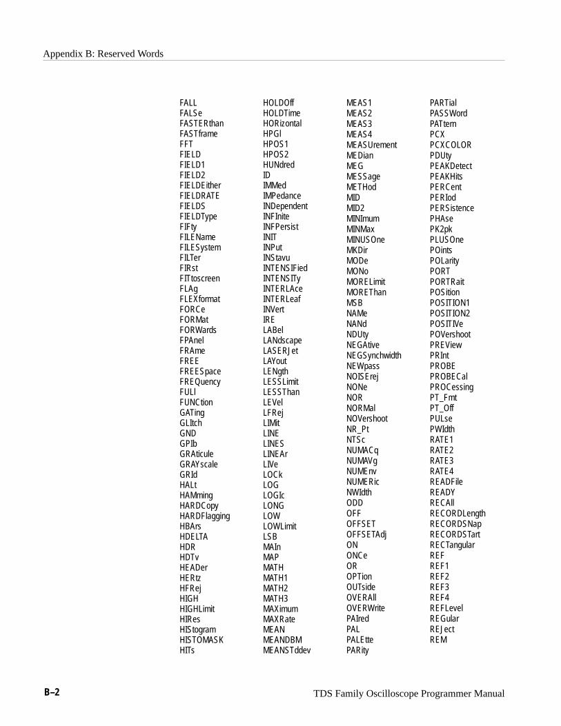
Appendix B: Reserved Words
B–2 TDS Family Oscilloscope Programmer Manual
FALLFALSeFASTERthanFASTframeFFTFIELDFIELD1FIELD2FIELDEitherFIELDRATEFIELDSFIELDTypeFIFtyFILENameFILESystemFILTerFIRstFITtoscreenFLAgFLEXformatFORCeFORMatFORWardsFPAnelFRAmeFREEFREESpaceFREQuencyFULlFUNCtionGATingGLItchGNDGPIbGRAticuleGRAYscaleGRIdHALtHAMmingHARDCopyHARDFlaggingHBArsHDELTAHDRHDTvHEADerHERtzHFRejHIGHHIGHLimitHIResHIStogramHISTOMASKHITs
HOLDOff HOLDTimeHORizontalHPGlHPOS1HPOS2HUNdredIDIMMedIMPedanceINDependentINFIniteINFPersistINITINPutINStavuINTENSIFiedINTENSITyINTERLAceINTERLeafINVertIRELABelLANdscapeLASERJetLAYoutLENgthLESSLimitLESSThanLEVelLFRejLIMitLINELINESLINEArLIVeLOCkLOGLOGIcLONGLOWLOWLimitLSBMAInMAPMATHMATH1MATH2MATH3MAXimumMAXRateMEANMEANDBMMEANSTddev
MEAS1MEAS2MEAS3MEAS4MEASUrementMEDianMEGMESSageMETHodMIDMID2MINImumMINMaxMINUSOneMKDirMODeMONoMORELimitMOREThanMSBNAMeNANdNDUtyNEGAtiveNEGSynchwidthNEWpassNOISErejNONeNORNORMalNOVershootNR_PtNTScNUMACqNUMAVgNUMEnvNUMERicNWIdthODDOFFOFFSETOFFSETAdjONONCeOROPTionOUTsideOVERAllOVERWritePAIredPALPALEttePARity
PARTialPASSWordPATternPCXPCXCOLORPDUtyPEAKDetectPEAKHitsPERCentPERIodPERSistencePHAsePK2pkPLUSOnePOintsPOLarityPORTPORTRaitPOSitionPOSITION1POSITION2POSITIVePOVershootPREViewPRIntPROBEPROBECalPROCessingPT_FmtPT_OffPULsePWIdthRATE1RATE2RATE3RATE4READFileREADYRECAllRECORDLengthRECORDSNapRECORDSTartRECTangularREFREF1REF2REF3REF4REFLevelREGularREJectREM
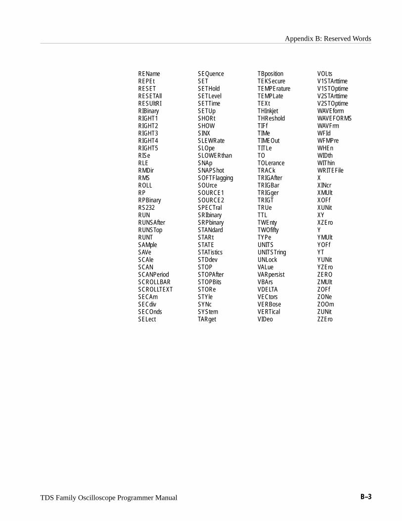
Appendix B: Reserved Words
TDS Family Oscilloscope Programmer Manual B–3
RENameREPEtRESETRESETAllRESUltRIRIBinaryRIGHT1RIGHT2RIGHT3RIGHT4RIGHT5RISeRLERMDirRMSROLLRPRPBinaryRS232RUNRUNSAfterRUNSTopRUNTSAMpleSAVeSCAleSCANSCANPeriod SCROLLBARSCROLLTEXTSECAmSECdivSECOndsSELect
SEQuenceSETSETHoldSETLevelSETTimeSETUpSHORtSHOWSINXSLEWRateSLOpeSLOWERthanSNApSNAPShotSOFTFlaggingSOUrceSOURCE1SOURCE2SPECTralSRIbinarySRPbinarySTANdardSTARtSTATESTATisticsSTDdevSTOPSTOPAfterSTOPBitsSTOReSTYleSYNcSYStemTARget
TBpositionTEKSecureTEMPEratureTEMPLateTEXtTHInkjetTHResholdTIFfTIMeTIMEOutTITLeTOTOLeranceTRACkTRIGAfterTRIGBarTRIGgerTRIGTTRUeTTLTWEntyTWOfiftyTYPeUNITSUNITSTringUNLockVALueVARpersistVBArsVDELTAVECtorsVERBoseVERTicalVIDeo
VOLtsV1STArttimeV1STOptimeV2STArttimeV2STOptimeWAVEformWAVEFORMSWAVFrmWFIdWFMPreWHEnWIDthWIThinWRITEFileXXINcrXMUltXOFfXUNitXYXZEroYYMUltYOFfYTYUNitYZEroZEROZMUltZOFfZONeZOOmZUNitZZEro
TDS Family Oscilloscope Programmer Manual C–1
Appendix C: Interface Specifications
This appendix describes details of the GPIB remote interface of the digitizingoscilloscope. Normally, you will not need this information to use the digitizingoscilloscope, but the information is useful when connecting to controllers ofunusual configuration.
GPIB Function SubsetsThe digitizing oscilloscope supports many GPIB function subsets, as listedbelow. Some of the listings describe subsets that the digitizing oscilloscope doesnot support.
� SH1 (Source Handshake). The digitizing oscilloscope can transmit multilinemessages across the GPIB.
� AH1 (Acceptor Handshake). The digitizing oscilloscope can receivemultiline messages across the GPIB.
� T5 (Talker). The digitizing oscilloscope becomes a talker when its talkaddress is sent with the ATN (Attention) line asserted. It can send bothresponse data and status information when responding to a serial poll. Itceases to be a talker when the talk address if another device is sent with ATNasserted. The digitizing oscilloscope has talk-only capability for hardcopyoperation.
� L4 (Listener). The digitizing oscilloscope becomes a listener when its listenaddress is sent with the ATN (Attention) line asserted. The digitizingoscilloscope does not have listen-only capability.
� SR1 (Service Request). The digitizing oscilloscope asserts an SRQ (ServiceRequest) line to notify the controller when it requires service.
� RL1 (Remote/Local). The digitizing oscilloscope responds to both the GTL(Go To Local) and LLO (Local Lock Out) interface messages.
� PP0 (Parallel Poll). The digitizing oscilloscope has no parallel poll capabili-ty. It does not respond to the following interface messages: PPC, PPD, PPE,and PPU. The digitizing oscilloscope does not send out a status messagewhen the ATN (Attention) and EOI (End or Identify) lines are assertedsimultaneously.
� DC1 (Device Clear). The digitizing oscilloscope responds to the DCL(Device Clear) and, when made a listener, the SDC (Selected Device Clear)interface messages.
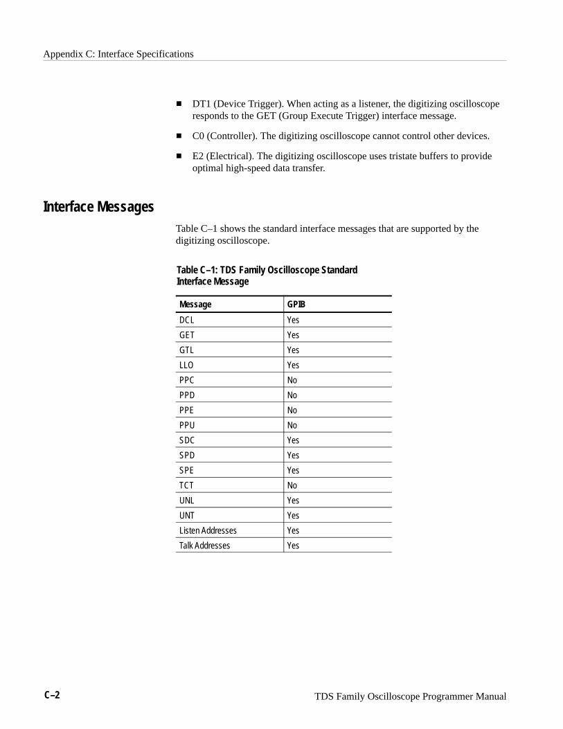
Appendix C: Interface Specifications
C–2 TDS Family Oscilloscope Programmer Manual
� DT1 (Device Trigger). When acting as a listener, the digitizing oscilloscoperesponds to the GET (Group Execute Trigger) interface message.
� C0 (Controller). The digitizing oscilloscope cannot control other devices.
� E2 (Electrical). The digitizing oscilloscope uses tristate buffers to provideoptimal high-speed data transfer.
Interface MessagesTable C–1 shows the standard interface messages that are supported by thedigitizing oscilloscope.
Table C–1: TDS Family Oscilloscope StandardInterface Message
Message GPIB
DCL Yes
GET Yes
GTL Yes
LLO Yes
PPC No
PPD No
PPE No
PPU No
SDC Yes
SPD Yes
SPE Yes
TCT No
UNL Yes
UNT Yes
Listen Addresses Yes
Talk Addresses Yes
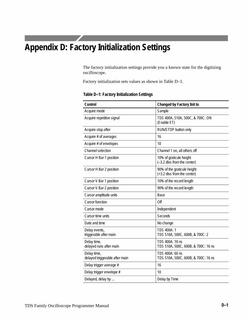
TDS Family Oscilloscope Programmer Manual D–1
Appendix D: Factory Initialization Settings
The factory initialization settings provide you a known state for the digitizingoscilloscope.
Factory initialization sets values as shown in Table D–1.
Table D–1: Factory Initialization Settings
Control Changed by Factory Init to
Acquire mode Sample
Acquire repetitive signal TDS 400A, 510A, 500C, & 700C: ON (Enable ET)
Acquire stop after RUN/STOP button only
Acquire # of averages 16
Acquire # of envelopes 10
Channel selection Channel 1 on, all others off
Cursor H Bar 1 position 10% of graticule height (–3.2 divs from the center)
Cursor H Bar 2 position 90% of the graticule height(+3.2 divs from the center)
Cursor V Bar 1 position 10% of the record length
Cursor V Bar 2 position 90% of the record length
Cursor amplitude units Base
Cursor function Off
Cursor mode Independent
Cursor time units Seconds
Date and time No change
Delay events, triggerable after main
TDS 400A: 1TDS 510A, 500C, 600B, & 700C: 2
Delay time,delayed runs after main
TDS 400A: 10 nsTDS 510A, 500C, 600B, & 700C: 16 ns
Delay time,delayed triggerable after main
TDS 400A: 60 nsTDS 510A, 500C, 600B, & 700C: 16 ns
Delay trigger average # 16
Delay trigger envelope # 10
Delayed, delay by ... Delay by Time

Appendix D: Factory Initialization Settings
D–2 TDS Family Oscilloscope Programmer Manual
Table D–1: Factory Initialization Settings (Cont.)
Control Changed by Factory Init to
Delayed edge trigger coupling(TDS 400A only)
DCMain Trigger
Delayed edge trigger level 0 V
Delayed edge trigger slope Rising
Delayed edge trigger source Channel 1
Delayed, time base mode Delayed Runs After Main
Deskew, Channel/Probe 0 seconds
Display clock No Change
Display color – collision contrast TDS 644B, 684B, & 700C:Off
Display color – map math colors TDS 644B, 684B, & 700C:Color ‘Math’
Display color – map reference colors TDS 644B, 684B, & 700C:Color ‘Ref’
Display color – palette TDS 644B, 684B, & 700C:Normal
Display color – palette colors TDS 644B, 684B, & 700C:The colors of each palette are reset to factoryhue, saturation, and lightness (HLS) values
Display color – persistence palette TDS 644B, 684B, & 700C:Temperature
Display format YT
Display graticule type Full
Display instavu persistence TDS 500C & 700C: Varpersist
Display instavu style TDS 500C & 700C: Vectors
Display instavu varpersist TDS 500C & 700C: 500 e–3
Display intensity – contrast TDS 400A, 500C, 620B, & 680B: 175%TDS 510A: 150%
Display intensity – overall TDS 400A, 510A, 500C, 620B, & 680A: 85%
Display intensity – text TDS 644B, 684B, & 700C: 100%TDS 400A, 510A, 500C, 620B, & 680B: 60%
Display intensity – waveform TDS 644B, 684B, & 700C: 100%TDS 400A, 510A, 500C, 620B, & 680B: 75%
Display interpolation filter Sin(x)/x
Display mode Normal
Display style Vectors
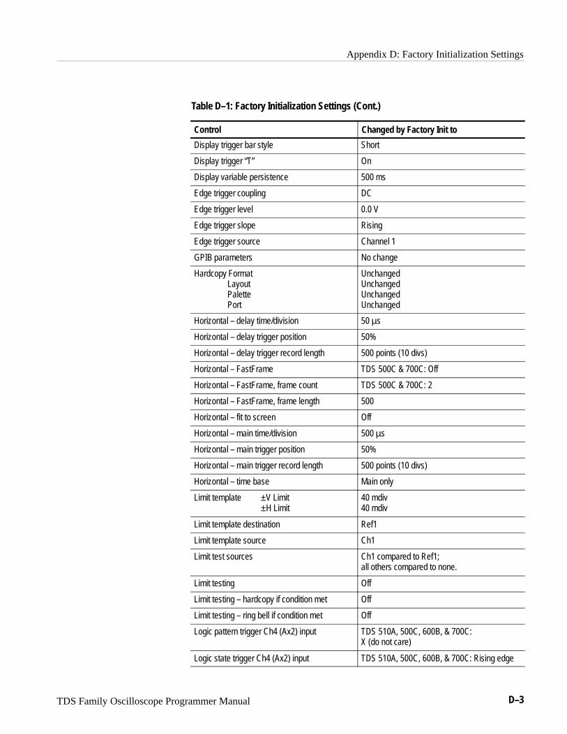
Appendix D: Factory Initialization Settings
TDS Family Oscilloscope Programmer Manual D–3
Table D–1: Factory Initialization Settings (Cont.)
Control Changed by Factory Init to
Display trigger bar style Short
Display trigger “T” On
Display variable persistence 500 ms
Edge trigger coupling DC
Edge trigger level 0.0 V
Edge trigger slope Rising
Edge trigger source Channel 1
GPIB parameters No change
Hardcopy FormatLayoutPalettePort
UnchangedUnchangedUnchangedUnchanged
Horizontal – delay time/division 50 �s
Horizontal – delay trigger position 50%
Horizontal – delay trigger record length 500 points (10 divs)
Horizontal – FastFrame TDS 500C & 700C: Off
Horizontal – FastFrame, frame count TDS 500C & 700C: 2
Horizontal – FastFrame, frame length 500
Horizontal – fit to screen Off
Horizontal – main time/division 500 �s
Horizontal – main trigger position 50%
Horizontal – main trigger record length 500 points (10 divs)
Horizontal – time base Main only
Limit template ±V Limit±H Limit
40 mdiv40 mdiv
Limit template destination Ref1
Limit template source Ch1
Limit test sources Ch1 compared to Ref1; all others compared to none.
Limit testing Off
Limit testing – hardcopy if condition met Off
Limit testing – ring bell if condition met Off
Logic pattern trigger Ch4 (Ax2) input TDS 510A, 500C, 600B, & 700C: X (do not care)
Logic state trigger Ch4 (Ax2) input TDS 510A, 500C, 600B, & 700C: Rising edge
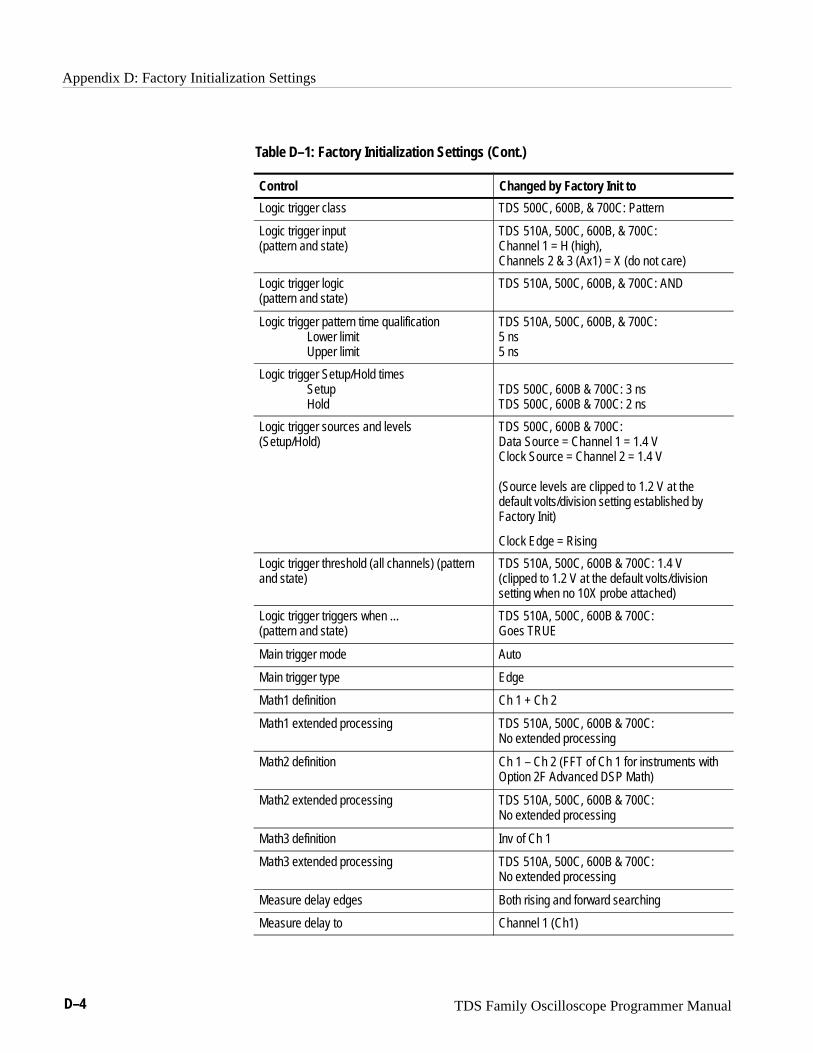
Appendix D: Factory Initialization Settings
D–4 TDS Family Oscilloscope Programmer Manual
Table D–1: Factory Initialization Settings (Cont.)
Control Changed by Factory Init to
Logic trigger class TDS 500C, 600B, & 700C: Pattern
Logic trigger input (pattern and state)
TDS 510A, 500C, 600B, & 700C:Channel 1 = H (high),Channels 2 & 3 (Ax1) = X (do not care)
Logic trigger logic (pattern and state)
TDS 510A, 500C, 600B, & 700C: AND
Logic trigger pattern time qualificationLower limitUpper limit
TDS 510A, 500C, 600B, & 700C:5 ns5 ns
Logic trigger Setup/Hold times SetupHold
TDS 500C, 600B & 700C: 3 nsTDS 500C, 600B & 700C: 2 ns
Logic trigger sources and levels (Setup/Hold)
TDS 500C, 600B & 700C:Data Source = Channel 1 = 1.4 VClock Source = Channel 2 = 1.4 V
(Source levels are clipped to 1.2 V at thedefault volts/division setting established byFactory Init)
Clock Edge = Rising
Logic trigger threshold (all channels) (patternand state)
TDS 510A, 500C, 600B & 700C: 1.4 V (clipped to 1.2 V at the default volts/divisionsetting when no 10X probe attached)
Logic trigger triggers when ...(pattern and state)
TDS 510A, 500C, 600B & 700C:Goes TRUE
Main trigger mode Auto
Main trigger type Edge
Math1 definition Ch 1 + Ch 2
Math1 extended processing TDS 510A, 500C, 600B & 700C:No extended processing
Math2 definition Ch 1 – Ch 2 (FFT of Ch 1 for instruments withOption 2F Advanced DSP Math)
Math2 extended processing TDS 510A, 500C, 600B & 700C:No extended processing
Math3 definition Inv of Ch 1
Math3 extended processing TDS 510A, 500C, 600B & 700C:No extended processing
Measure delay edges Both rising and forward searching
Measure delay to Channel 1 (Ch1)

Appendix D: Factory Initialization Settings
TDS Family Oscilloscope Programmer Manual D–5
Table D–1: Factory Initialization Settings (Cont.)
Control Changed by Factory Init to
Measure gating Off
Measure high ref 90% and 0 V (units)
Measure high-low setup Histogram
Measure low ref 10% and 0 V (units)
Measure mid ref 50% and 0 V (units)
Measure mid2 ref 50% and 0 V (units)
Pulse glitch filter state TDS 510A, 500C, 600B & 700C: On (Accept glitch)
Pulse glitch trigger polarity TDS 510A, 500C, 600B & 700C: Positive
Pulse glitch width TDS 510A, 500C, 600B & 700C: 2.0 ns
Pulse runt high threshold TDS 510A, 500C, 600B & 700C: 1.2 V
Pulse runt low threshold TDS 510A, 500C, 600B & 700C: 0.8 V
Pulse runt trigger polarity TDS 510A, 500C, 600B & 700C: Positive
Pulse runt triggers when ... TDS 510A, 500C, 600B & 700C: Occurs
Pulse runt width TDS 510A, 500C, 600B & 700C: 2.0 ns
Pulse slew rate delta time 2.0 ns
Pulse slew rate polarity Positive
Pulse slew rate thresholdsUpperLower
Trig if faster than1.80 V800 mV
Pulse slew rate triggers when ... Trig if faster than
Pulse timeout polarity TDS 500C & 600B: Either
Pulse timeout time TDS 500C & 600B: 2.0 ns
Pulse trigger class TDS 510A, 500C, 600B & 700C: Glitch
Pulse trigger level TDS 510A, 500C, 600B & 700C: 0.0 V
Pulse trigger source(Glitch, runt, and width, and timeout)
TDS 500C, 600B, & 700C:Channel 1 (Ch1)
Pulse width lower limit TDS 510A, 500C, 600B & 700C: 2.0 ns
Pulse width trigger polarity TDS 510A, 500C, 600B & 700C: Positive
Pulse width trigger when TDS 510A, 500C, 600B & 700C: Within limits
Pulse width upper limit TDS 510A, 500C, 600B & 700C: 2.0 ns
Repetitive signal TDS 500C & 700C: On
RS-232 parameters No change
Saved setups No change
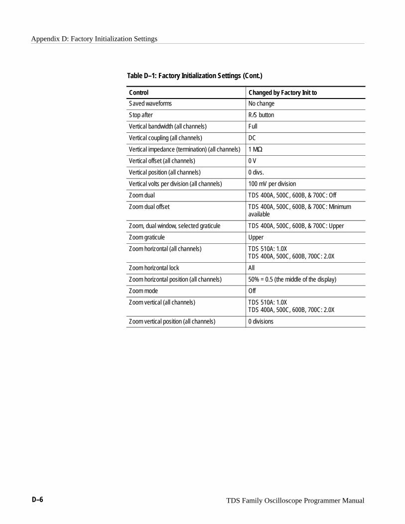
Appendix D: Factory Initialization Settings
D–6 TDS Family Oscilloscope Programmer Manual
Table D–1: Factory Initialization Settings (Cont.)
Control Changed by Factory Init to
Saved waveforms No change
Stop after R/S button
Vertical bandwidth (all channels) Full
Vertical coupling (all channels) DC
Vertical impedance (termination) (all channels) 1 M�
Vertical offset (all channels) 0 V
Vertical position (all channels) 0 divs.
Vertical volts per division (all channels) 100 mV per division
Zoom dual TDS 400A, 500C, 600B, & 700C: Off
Zoom dual offset TDS 400A, 500C, 600B, & 700C: Minimumavailable
Zoom, dual window, selected graticule TDS 400A, 500C, 600B, & 700C: Upper
Zoom graticule Upper
Zoom horizontal (all channels) TDS 510A: 1.0XTDS 400A, 500C, 600B, 700C: 2.0X
Zoom horizontal lock All
Zoom horizontal position (all channels) 50% = 0.5 (the middle of the display)
Zoom mode Off
Zoom vertical (all channels) TDS 510A: 1.0XTDS 400A, 500C, 600B, 700C: 2.0X
Zoom vertical position (all channels) 0 divisions
TDS Family Oscilloscope Programmer Manual Glossary–1
Glossary
ASCIIAcronym for the American Standard Code for Information Interchange.Controllers transmit commands to the digitizing oscilloscope using ASCIIcharacter encoding.
AddressA 7-bit code that identifies an instrument on the communication bus. Thedigitizing oscilloscope must have a unique address for the controller torecognize and transmit commands to it.
Backus-Naur Form (BNF)A standard notation system for command syntax diagrams. The syntaxdiagrams in this manual use BNF notation.
ControllerA computer or other device that sends commands to and accepts responsesfrom the digitizing oscilloscope.
EOIA mnemonic referring to the control line “End or Identify” on the GPIBinterface bus. One of the two possible end-of-message terminators.
EOMA generic acronym referring to the end-of-message terminator. Theend-of-message terminator can be either an EOI or the ASCII code for linefeed (LF).
Equivalent-time sampling (ET)A sampling mode in which the oscilloscope acquires signals over manyrepetitions of the event. The TDS Family Series Digitizing Oscilloscopes usea type of equivalent time sampling called random equivalent time sampling.It utilizes an internal clock that runs asynchronously with respect to the inputsignal and the signal trigger. The oscilloscope takes samples continuously,independent of the trigger position, and displays them based on the timedifference between the sample and the trigger. Although the samples aretaken sequentially in time, they are random with respect to the trigger.
Extended–acquisition–length modeAn acquisition mode with which the oscilloscope can acquire signals of 2M,4M, and 8M while maintaining waveform lengths limited to 500K. In otherwords, the acquisition data for a channel may be bigger than a waveform,Then, after the data is acquired, you can move to and display any portion ofthe data.
Glossary
Glossary–2 TDS Family Oscilloscope Programmer Manual
Real-time samplingA sampling mode where the digitizing oscilloscope samples fast enough tocompletely fill a waveform record from a single trigger event. Use real-timesampling to capture single-shot or transient events.
GPIBAcronym for General Purpose Interface Bus, the common name for thecommunications interface system defined in IEEE Std 488.
IEEEAcronym for the Institute for Electrical and Electronic Engineers.
QuickBASICA computer language (distributed by Microsoft) that is based on theBeginner’s All-Purpose Symbolic Instruction Code.
QuickCA computer language (distributed by Microsoft) that is based on C.
TEKSecureA Tektronix custom command that initializes both waveform and setupmemories. This overwrites any previously stored data.

TDS Family Oscilloscope Programmer Manual Index–1
IndexNumbers2 + 2 channel operation, viii
AAbbreviating, command, 2–4ACQUIRE?, 2–47ACQUIRE:AUTOSAVE, 2–47ACQUIRE:MODE, 2–48ACQUIRE:NUMACQ?, 2–50ACQUIRE:NUMAVG, 2–51ACQUIRE:NUMENV, 2–52ACQUIRE:REPET, 2–53ACQUIRE:STATE, 2–54ACQUIRE:STOPAFTER, 2–55Acquisition command group, 2–13, 2–14Acquisition commands
ACQUIRE?, 2–47ACQUIRE:AUTOSAVE, 2–47ACQUIRE:MODE, 2–48ACQUIRE:NUMACQ?, 2–50ACQUIRE:NUMAVG, 2–51ACQUIRE:NUMENV, 2–52ACQUIRE:REPET, 2–53ACQUIRE:STATE, 2–54ACQUIRE:STOPAFTER, 2–55
Address, Definition of, Glossary–1ALIAS, 2–56Alias commands
ALIAS, 2–56ALIAS:CATALOG?, 2–57ALIAS:DEFINE, 2–57ALIAS:DELETE, 2–58ALIAS:DELETE:ALL, 2–59ALIAS:DELETE:NAME, 2–59ALIAS:STATE, 2–59
ALIAS:CATALOG?, 2–57ALIAS:DEFINE, 2–57ALIAS:DELETE, 2–58ALIAS:DELETE:ALL, 2–59ALIAS:DELETE:NAME, 2–59ALIAS:STATE, 2–59ALLEV?, 2–60ALLOCATE?, 2–61ALLOCATE:WAVEFORM?, 2–61ALLOCATE:WAVEFORM:FREE?, 2–62ALLOCATE:WAVEFORM:REF<x>, 2–62Application menu command group, 2–14
Application menu commandsAPPMENU, 2–63APPMENU:LABEL, 2–64APPMENU:LABEL:BOTTOM, 2–65APPMENU:LABEL:RIGHT, 2–66APPMENU:LABEL:TITLE, 2–66
APPMENU, 2–63APPMENU:LABEL, 2–64APPMENU:LABEL:BOTTOM, 2–65APPMENU:LABEL:RIGHT, 2–66APPMENU:LABEL:TITLE, 2–66Argument, command, 2–2ASCII, 2–1, Glossary–1Audio indicator, 2–68AUTOSET, 2–67
BBackus-Naur Form, 2–1
Definition of, Glossary–1BELL, 2–68Block, command argument, 2–9BNF, Glossary–1BNF (Backus-Naur form), 2–1Break, 2–4BUSY?, 2–68
C*CAL?, 2–69Calibration and diagnostic command group, 2–15Calibration and diagnostic commands
*CAL?, 2–69DIAG:RESULT:FLAG?, 2–109DIAG:RESULT:LOG?, 2–109DIAG:SELECT:ACQUISITION, 2–110DIAG:SELECT:ALL, 2–110DIAG:SELECT:CPU, 2–111DIAG:SELECT:DISPLAY, 2–111DIAG:SELECT:FPANEL, 2–111DIAG:STATE, 2–112
CH<x>?, 2–69CH<x>:BANDWIDTH, 2–70CH<x>:COUPLING, 2–71CH<x>:DESKEW, 2–72CH<x>:IMPEDANCE, 2–72CH<x>:OFFSET, 2–73CH<x>:POSITION, 2–74

Index
Index–2 TDS Family Oscilloscope Programmer Manual
CH<x>:PROBE?, 2–75CH<x>:PROBECAL?, 2–75CH<x>:PROBEFUNC:EXTATTEN, 2–76CH<x>:PROBEFUNC:EXTDBATTEN, 2–76CH<x>:SCALE, 2–77CH<x>:VOLTS, 2–78Channel, command mnemonic, 2–7CH<x>, command mnemonic, 2–7Clear Status, 2–79CLEARMENU, 2–78*CLS, 2–79Command
Abbreviating, 2–4Argument, 2–2Block argument, 2–9Common, 2–26, 2–28Concatenating, 2–4Header, 2–2Message, 2–2Mnemonic, 2–2Query, 2–1Rules for forming, 2–1Separator, 2–2Set, 2–1Syntax, 2–1
BNF (Backus-Naur form), 2–1Command argument
Numeric, 2–8Quoted string, 2–8
Command Descriptions, 1–1Command group
Acquisition, 2–13, 2–14Application menu, 2–14Calibration and diagnostic, 2–15Cursor, 2–15Display, 2–16File system, 2–18Hardcopy, 2–19Horizontal, 2–20Limit test, 2–22Measurement, 2–24Miscellaneous, 2–26RS-232, 2–23, 2–27Save and recall, 2–28Status and error, 2–28Trigger, 2–29Vertical, 2–37Waveform, 2–38Zoom, 2–45
Command Groups, 1–1Command mnemonic
Channel, 2–7CH<x>, 2–7
Cursor position, 2–6Math waveform, 2–7MATH<x>, 2–7Measurement specifier, 2–7MEAS<x>, 2–7POSITION<x>, 2–6Reference waveform, 2–7REF<x>, 2–7Waveform, 2–7<wfm>, 2–7
Command syntax, 2–1BNF (Backus-Naur form), 2–1
Commands, 1–1Parts of, 1–1Syntax diagrams, 1–1
Common command, 2–26, 2–28Common GPIB commands
*CAL?, 2–69*CLS, 2–79
Communication trigger, 2–273, 2–274, 2–275, 2–276,2–277, 2–279, 2–280, 2–322
Concatenating, command, 2–4Configuration, Command query, 2–180Controller, Definition of, Glossary–1Cursor command group, 2–15Cursor commands
CURSOR?, 2–79CURSOR:FUNCTION, 2–80CURSOR:HBARS?, 2–80CURSOR:HBARS:DELTA?, 2–81CURSOR:HBARS:POSITION<x>, 2–81CURSOR:HBARS:POSITION<x>PCNT, 2–82CURSOR:HBARS:SELECT, 2–83CURSOR:HBARS:UNITS, 2–83CURSOR:MODE, 2–84CURSOR:PAIRED, 2–85CURSOR:PAIRED:HDELTA, 2–85CURSOR:PAIRED:HPOS1, 2–86CURSOR:PAIRED:HPOS2, 2–86CURSOR:PAIRED:POSITION<x>, 2–87CURSOR:PAIRED:POSITION<x>PCNT, 2–87CURSOR:PAIRED:SELECT, 2–88CURSOR:PAIRED:UNITS, 2–89CURSOR:PAIRED:VDELTA, 2–89CURSOR:VBARS, 2–90CURSOR:VBARS:DELTA?, 2–91CURSOR:VBARS:POSITION<x>, 2–91CURSOR:VBARS:POSITION<x>PCNT, 2–92CURSOR:VBARS:SELECT, 2–93CURSOR:VBARS:UNITS, 2–94CURSOR:VBARS:UNITSTring, 2–95
Cursor position, command mnemonic, 2–6CURSOR?, 2–79

Index
TDS Family Oscilloscope Programmer Manual Index–3
CURSOR:FUNCTION, 2–80CURSOR:HBARS?, 2–80CURSOR:HBARS:DELTA?, 2–81CURSOR:HBARS:POSITION<x>, 2–81CURSOR:HBARS:POSITION<x>PCNT, 2–82CURSOR:HBARS:SELECT, 2–83CURSOR:HBARS:UNITS, 2–83CURSOR:MODE, 2–84CURSOR:PAIRED, 2–85CURSOR:PAIRED:HDELTA, 2–85CURSOR:PAIRED:HPOS1, 2–86CURSOR:PAIRED:HPOS2, 2–86CURSOR:PAIRED:POSITION<x>, 2–87CURSOR:PAIRED:POSITION<x>PCNT, 2–87CURSOR:PAIRED:SELECT, 2–88CURSOR:PAIRED:UNITS, 2–89CURSOR:PAIRED:VDELTA, 2–89CURSOR:VBARS, 2–90CURSOR:VBARS:DELTA?, 2–91CURSOR:VBARS:POSITION<x>, 2–91CURSOR:VBARS:POSITION<x>PCNT, 2–92CURSOR:VBARS:SELECT, 2–93CURSOR:VBARS:UNITS, 2–94CURSOR:VBARS:UNITSTring, 2–95CURVE, 2–96
DDATA, 2–97DATA:DESTINATION, 2–99DATA:ENCDG, 2–99DATA:SOURCE, 2–101DATA:START, 2–102DATA:STOP, 2–103DATA:TARGET, 2–104DATA:WIDTH, 2–104DATE, 2–105DCL, C–2*DDT, 2–106Default Model(s), viiiDelayed trigger, 2–265, 2–266, 2–267, 2–268, 2–269,
2–270, 2–271, 2–272DELETE:SETUP, 2–106DELETE:WAVEFORM, 2–107DESE command, 2–108, 3–3DESER register, 2–108, 2–246, 3–3Device Clear, 2–4, C–2DIAG:RESULT:FLAG?, 2–109DIAG:RESULT:LOG?, 2–109DIAG:SELECT:ACQUISITION, 2–110DIAG:SELECT:ALL, 2–110DIAG:SELECT:CPU, 2–111
DIAG:SELECT:DISPLAY, 2–111DIAG:SELECT:FPANEL, 2–111DIAG:STATE, 2–112Diagram, syntax, 2–10Disks included with this manual, 1–2Display command group, 2–16Display commands
CLEARMENU, 2–78DISPLAY?, 2–113DISPLAY:CLOCK, 2–113DISPLAY:COLOR:CONTRAST, 2–114DISPLAY:COLOR:MAP:item name:TO, 2–116DISPLAY:COLOR:MAP:item:BYCONTENTS,
2–115DISPLAY:COLOR:PALETTE:palette name:item
name, 2–119DISPLAY:COLOR:PALETTE:palette name:RESET,
2–118DISPLAY:COLOR:PALETTE:PERSISTENCE,
2–117DISPLAY:COLOR:PALETTE:REGULAR, 2–117DISPLAY:COLOR:PALETTE:RESETALL, 2–118DISPLAY:DATE/TIME. See DISPLAY:CLOCKDISPLAY:FILTER, 2–121DISPLAY:FORMAT, 2–122DISPLAY:GRATICULE, 2–123DISPLAY:INSTAVU:PERSISTENCE, 2–124DISPLAY:INSTAVU:STYLE, 2–125DISPLAY:INSTAVU:VARPERSIST, 2–125DISPLAY:INTENSITY?, 2–126DISPLAY:INTENSITY:CONTRAST, 2–126DISPLAY:INTENSITY:OVERALL, 2–127DISPLAY:INTENSITY:TEXT, 2–128DISPLAY:INTENSITY:WAVEFORM, 2–128DISPLAY:MODE, 2–129DISPLAY:PERSISTENCE, 2–129DISPLAY:STYLE, 2–130DISPLAY:TRIGBAR, 2–131DISPLAY:TRIGT, 2–132MESSAGE, 2–239MESSAGE:BOX, 2–240MESSAGE:SHOW, 2–241MESSAGE:STATE, 2–242
DISPLAY?, 2–113DISPLAY:CLOCK, 2–113DISPLAY:COLOR:CONTRAST, 2–114DISPLAY:COLOR:MAP:item name:TO, 2–116DISPLAY:COLOR:MAP:item:BYCONTENTS, 2–115DISPLAY:COLOR:PALETTE:palette name:item name,
2–119DISPLAY:COLOR:PALETTE:palette name:RESET,
2–118
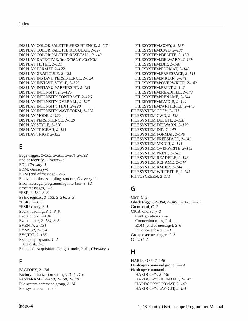
Index
Index–4 TDS Family Oscilloscope Programmer Manual
DISPLAY:COLOR:PALETTE:PERSISTENCE, 2–117DISPLAY:COLOR:PALETTE:REGULAR, 2–117DISPLAY:COLOR:PALETTE:RESETALL, 2–118DISPLAY:DATE/TIME. See DISPLAY:CLOCKDISPLAY:FILTER, 2–121DISPLAY:FORMAT, 2–122DISPLAY:GRATICULE, 2–123DISPLAY:INSTAVU:PERSISTENCE, 2–124DISPLAY:INSTAVU:STYLE, 2–125DISPLAY:INSTAVU:VARPERSIST, 2–125DISPLAY:INTENSITY?, 2–126DISPLAY:INTENSITY:CONTRAST, 2–126DISPLAY:INTENSITY:OVERALL, 2–127DISPLAY:INTENSITY:TEXT, 2–128DISPLAY:INTENSITY:WAVEFORM, 2–128DISPLAY:MODE, 2–129DISPLAY:PERSISTENCE, 2–129DISPLAY:STYLE, 2–130DISPLAY:TRIGBAR, 2–131DISPLAY:TRIGT, 2–132
EEdge trigger, 2–282, 2–283, 2–284, 2–322End or Identify, Glossary–1EOI, Glossary–1EOM, Glossary–1EOM (end of message), 2–6Equivalent-time sampling, random, Glossary–1Error message, programming interface, 3–12Error messages, 1–2*ESE, 2–132, 3–3ESER register, 2–132, 2–246, 3–3*ESR?, 2–133*ESR? query, 3–1Event handling, 3–1, 3–6Event query, 2–134Event queue, 2–134, 3–5EVENT?, 2–134EVMSG?, 2–134EVQTY?, 2–135Example programs, 1–2
On disk, 1–2Extended–Acquisition–Length mode, 2–41, Glossary–1
FFACTORY, 2–136Factory initialization settings, D–1–D–6FASTFRAME, 2–168, 2–169, 2–170File system command group, 2–18File system commands
FILESYSTEM:COPY, 2–137FILESYSTEM:CWD, 2–138FILESYSTEM:DELETE, 2–138FILESYSTEM:DELWARN, 2–139FILESYSTEM:DIR, 2–140FILESYSTEM:FORMAT, 2–140FILESYSTEM:FREESPACE, 2–141FILESYSTEM:MKDIR, 2–141FILESYSTEM:OVERWRITE, 2–142FILESYSTEM:PRINT, 2–142FILESYSTEM:READFILE, 2–143FILESYSTEM:RENAME, 2–144FILESYSTEM:RMDIR, 2–144FILESYSTEM:WRITEFILE, 2–145
FILESYSTEM:COPY, 2–137FILESYSTEM:CWD, 2–138FILESYSTEM:DELETE, 2–138FILESYSTEM:DELWARN, 2–139FILESYSTEM:DIR, 2–140FILESYSTEM:FORMAT, 2–140FILESYSTEM:FREESPACE, 2–141FILESYSTEM:MKDIR, 2–141FILESYSTEM:OVERWRITE, 2–142FILESYSTEM:PRINT, 2–142FILESYSTEM:READFILE, 2–143FILESYSTEM:RENAME, 2–144FILESYSTEM:RMDIR, 2–144FILESYSTEM:WRITEFILE, 2–145FITTOSCREEN, 2–171
GGET, C–2Glitch trigger, 2–304, 2–305, 2–306, 2–307Go to local, C–2GPIB, Glossary–2
Configurations, 1–4Connection rules, 1–4EOM (end of message), 2–6Function subsets, C–1
Group execute trigger, C–2GTL, C–2
HHARDCOPY, 2–146Hardcopy command group, 2–19Hardcopy commands
HARDCOPY, 2–146HARDCOPY:FILENAME, 2–147HARDCOPY:FORMAT, 2–148HARDCOPY:LAYOUT, 2–151

Index
TDS Family Oscilloscope Programmer Manual Index–5
HARDCOPY:PALETTE, 2–151HARDCOPY:PORT, 2–152
HARDCOPY:FILENAME, 2–147HARDCOPY:FORMAT, 2–148HARDCOPY:LAYOUT, 2–151HARDCOPY:PALETTE, 2–151HARDCOPY:PORT, 2–152HDR, 2–153HEADER, 2–153Header
Command, 2–2, 2–153Included in query response, 2–153, 2–344
Histogram commandsHISTOGRAM?, 2–154HISTOGRAM:BOX, 2–155HISTOGRAM:BOXPCNT, 2–156HISTOGRAM:COUNT, 2–157HISTOGRAM:DISPLAY, 2–157HISTOGRAM:MODE, 2–158HISTOGRAM:SIZE, 2–159HISTOGRAM:SOURCE, 2–159
HISTOGRAM?, 2–154HISTOGRAM:BOX, 2–155HISTOGRAM:BOXPCNT, 2–156HISTOGRAM:COUNT, 2–157HISTOGRAM:DISPLAY, 2–157HISTOGRAM:MODE, 2–158HISTOGRAM:SIZE, 2–159HISTOGRAM:SOURCE, 2–159Horizontal command group, 2–20Horizontal commands
HORIZONTAL?, 2–160HORIZONTAL:ACQDURATION?, 2–160HORIZONTAL:ACQLENGTH?, 2–161HORIZONTAL:CLOCK, 2–161HORIZONTAL:CLOCK:MAXRATE, 2–162HORIZONTAL:DELAY?, 2–163HORIZONTAL:DELAY:MODE, 2–163HORIZONTAL:DELAY:SCALE, 2–164HORIZONTAL:DELAY:SECDIV, 2–165HORIZONTAL:DELAY:TIME, 2–165HORIZONTAL:DELAY:TIME?, 2–166HORIZONTAL:DELAY:TIME:RUNSAFTER,
2–166HORIZONTAL:DELAY:TIME:TRIGAFTER, 2–167HORIZONTAL:EXTDACQ, 2–168HORIZONTAL:FASTFRAME:COUNT, 2–168HORIZONTAL:FASTFRAME:LENGTH, 2–169HORIZONTAL:FASTFRAME:POSITION, 2–169HORIZONTAL:FASTFRAME:STATE, 2–170HORIZONTAL:FITTOSCREEN, 2–171HORIZONTAL:MAIN?, 2–172
HORIZONTAL:MAIN:SCALE, 2–172HORIZONTAL:MAIN:SECDIV, 2–173HORIZONTAL:MODE, 2–173HORIZONTAL:POSITION, 2–174HORIZONTAL:RECORDLENGTH, 2–175HORIZONTAL:RECORDSTART, 2–176HORIZONTAL:ROLL, 2–177HORIZONTAL:SCALE, 2–178HORIZONTAL:SECDIV, 2–178HORIZONTAL:TRIGGER?, 2–178HORIZONTAL:TRIGGER:POSITION, 2–179
HORIZONTAL?, 2–160HORIZONTAL:ACQDURATION?, 2–160HORIZONTAL:ACQLENGTH?, 2–161HORIZONTAL:CLOCK, 2–161HORIZONTAL:CLOCK:MAXRATE, 2–162HORIZONTAL:DELAY?, 2–163HORIZONTAL:DELAY:MODE, 2–163HORIZONTAL:DELAY:SCALE, 2–164HORIZONTAL:DELAY:SECDIV, 2–165HORIZONTAL:DELAY:TIME, 2–165HORIZONTAL:DELAY:TIME?, 2–166HORIZONTAL:DELAY:TIME:RUNSAFTER, 2–166HORIZONTAL:DELAY:TIME:TRIGAFTER, 2–167HORIZONTAL:EXTDACQ, 2–168HORIZONTAL:FASTFRAME:COUNT, 2–168HORIZONTAL:FASTFRAME:LENGTH, 2–169HORIZONTAL:FASTFRAME:POSITION, 2–169HORIZONTAL:FASTFRAME:STATE, 2–170HORIZONTAL:FITTOSCREEN, 2–171HORIZONTAL:MAIN?, 2–172HORIZONTAL:MAIN:SCALE, 2–172HORIZONTAL:MAIN:SECDIV, 2–173HORIZONTAL:MODE, 2–173HORIZONTAL:POSITION, 2–174HORIZONTAL:RECORDLENGTH, 2–175HORIZONTAL:RECORDSTART, 2–176HORIZONTAL:ROLL, 2–177HORIZONTAL:SCALE, 2–178HORIZONTAL:SECDIV, 2–178HORIZONTAL:TRIGGER?, 2–178HORIZONTAL:TRIGGER:POSITION, 2–179
IID?, 2–180*IDN?, 2–180IEEE, Glossary–2IEEE Std 488.2-1987, 1–3, 2–1, 2–26, 2–28Instrument setup, 1–3Interface message, C–2
Index
Index–6 TDS Family Oscilloscope Programmer Manual
LLimit test command group, 2–22Limit Test commands
LIMIT:BELL, 2–181LIMIT:COMPARE:CH<x>, 2–181LIMIT:COMPARE:MATH<x>, 2–182LIMIT:HARDCOPY, 2–183LIMIT:STATE, 2–184LIMIT:TEMPLATE, 2–185LIMIT:TEMPLATE:DESTINATION, 2–185LIMIT:TEMPLATE:SOURCE, 2–186LIMIT:TEMPLATE:TOLERANCE: VERTICAL,
2–188LIMIT:TEMPLATE:TOLERANCE:HORIZONTAL,
2–187LIMIT:BELL, 2–181LIMIT:COMPARE:CH<X>, 2–181LIMIT:COMPARE:MATH<X>, 2–182LIMIT:HARDCOPY, 2–183LIMIT:STATE, 2–184LIMIT:TEMPLATE, 2–185LIMIT:TEMPLATE:DESTINATION, 2–185LIMIT:TEMPLATE:SOURCE, 2–186LIMIT:TEMPLATE:TOLERANCE: VERTICAL,
2–188LIMIT:TEMPLATE:TOLERANCE:HORIZONTAL,
2–187LLO, C–2Local lock out, C–2LOCK, 2–188Logic trigger, 2–289, 2–290, 2–291, 2–292, 2–293,
2–294, 2–295, 2–296, 2–297, 2–298, 2–299,2–300, 2–301, 2–302, 2–322
*LRN?, 2–189
MManual trigger, Simulation with command, 2–342Mask commands
MASK?, 2–190MASK:AUTOSET:MODE, 2–191MASK:AUTOSET:OFFSETADJ, 2–191MASK:COUNT, 2–192MASK:COUNT:STATE, 2–193MASK:COUNT:TOTAL, 2–193MASK:COUNT:WAVEFORMS, 2–194MASK:DISPLAY. See DISPLAY:CLOCKMASK:FILTER, 2–195MASK:MASK<n>, 2–196MASK:MASK<n> POINTSPcnt, 2–199MASK:MASK<n>?, 2–196
MASK:MASK<n>:POINTS, 2–198MASK:MASK<n>COUNt?, 2–197MASK:MASK<n>NR_PT?, 2–197MASK:SOURCE, 2–200MASK:STANDARD, 2–200MASK:TBPOSITION, 2–204
MASK?, 2–190MASK:AUTOSET:MODE, 2–191MASK:AUTOSET:OFFSETADJ, 2–191MASK:COUNT, 2–192MASK:COUNT:STATE, 2–193MASK:COUNT:TOTAL, 2–193MASK:COUNT:WAVEFORMS, 2–194MASK:DISPLAY. See DISPLAY:CLOCKMASK:FILTER, 2–195MASK:MASK<n>, 2–196MASK:MASK<n> POINTSPcnt, 2–199MASK:MASK<n>?, 2–196MASK:MASK<n>:POINTS, 2–198MASK:MASK<n>COUNt?, 2–197MASK:MASK<n>NR_PT?, 2–197MASK:SOURCE, 2–200MASK:STANDARD, 2–200MASK:TBPOSITION, 2–204Math waveform, command mnemonic, 2–7MATH<x>?, 2–204MATH<x>:DEFINE, 2–205MATH<x>:NUMAVg, 2–206MATH<x>:PROCessing, 2–207MATH<x>, command mnemonic, 2–7Measurement command group, 2–24Measurement commands
MEASUREMENT?, 2–208MEASUREMENT:CLEARSNAPSHOT, 2–208MEASUREMENT:GATING, 2–209MEASUREMENT:IMMED?, 2–210MEASUREMENT:IMMED:DELAY?, 2–210MEASUREMENT:IMMED:DELAY:DIRECTION,
2–210MEASUREMENT:IMMED:DELAY:EDGE1, 2–211MEASUREMENT:IMMED:DELAY:EDGE2, 2–212MEASUREMENT:IMMED:SOURCE1, 2–213MEASUREMENT:IMMED:SOURCE2, 2–214MEASUREMENT:IMMED:TYPE, 2–214MEASUREMENT:IMMED:UNITS?, 2–218MEASUREMENT:IMMED:VALUE?, 2–218MEASUREMENT:MEAS<x>?, 2–219MEASUREMENT:MEAS<x>: DELAY?, 2–219MEASUREMENT:MEAS<x>: DELAY:DIREC-
TION?, 2–220MEASUREMENT:MEAS<x>: DELAY:EDGE1,
2–221
Index
TDS Family Oscilloscope Programmer Manual Index–7
MEASUREMENT:MEAS<x>: DELAY:EDGE2,2–221
MEASUREMENT:MEAS<x>: DELAY:SOURCE1,2–224
MEASUREMENT:MEAS<x>: DELAY:SOURCE2,2–224
MEASUREMENT:MEAS<x>: STATE, 2–225MEASUREMENT:MEAS<x>: TYPE, 2–226MEASUREMENT:MEAS<x>: UNITS?, 2–230MEASUREMENT:MEAS<x>: VALUES?, 2–230MEASUREMENT:MEAS<x>:COUNT?, 2–219MEASUREMENT:MEAS<x>:MAXIMUM?, 2–222MEASUREMENT:MEAS<x>:MEAN?, 2–223MEASUREMENT:MEAS<x>:MIN?, 2–223MEASUREMENT:MEAS<x>:STDDEV?, 2–226MEASUREMENT:METHOD, 2–231MEASUREMENT:REFLEVEL?, 2–231MEASUREMENT:REFLEVEL: ABSO-
LUTE:HIGH, 2–232MEASUREMENT:REFLEVEL: ABSOLUTE:MID,
2–233MEASUREMENT:REFLEVEL: ABSO-
LUTE:MID2, 2–234MEASUREMENT:REFLEVEL: METHOD, 2–234MEASUREMENT:REFLEVEL: PERCENT:HIGH,
2–235MEASUREMENT:REFLEVEL: PERCENT:LOW,
2–236MEASUREMENT:REFLEVEL: PERCENT:MID,
2–236MEASUREMENT:REFLEVEL: PERCENT:MID2,
2–237MEASUREMENT:REFLEVEL:ABSOLUTE:LOW,
2–232MEASUREMENT:SNAPSHOT, 2–238MEASUREMENT:STATISTICS:MODE, 2–238MEASUREMENT:STATISTICS:WEIGHTING,
2–239Measurement specifier, command mnemonic, 2–7MEASUREMENT?, 2–208MEASUREMENT:CLEARSNAPSHOT, 2–208MEASUREMENT:GATING, 2–209MEASUREMENT:IMMED?, 2–210MEASUREMENT:IMMED:DELAY?, 2–210MEASUREMENT:IMMED:DELAY:DIRECTION,
2–210MEASUREMENT:IMMED:DELAY:EDGE1, 2–211MEASUREMENT:IMMED:DELAY:EDGE2, 2–212MEASUREMENT:IMMED:SOURCE1, 2–213MEASUREMENT:IMMED:SOURCE2, 2–214MEASUREMENT:IMMED:TYPE, 2–214MEASUREMENT:IMMED:UNITS?, 2–218
MEASUREMENT:IMMED:VALUE?, 2–218MEASUREMENT:MEAS<x>?, 2–219MEASUREMENT:MEAS<x>: DELAY?, 2–219MEASUREMENT:MEAS<x>: DELAY:DIRECTION?,
2–220MEASUREMENT:MEAS<x>: DELAY:EDGE1, 2–221MEASUREMENT:MEAS<x>: DELAY:EDGE2, 2–221MEASUREMENT:MEAS<x>: DELAY:SOURCE1,
2–224MEASUREMENT:MEAS<x>: DELAY:SOURCE2,
2–224MEASUREMENT:MEAS<x>: STATE, 2–225MEASUREMENT:MEAS<x>: TYPE, 2–226MEASUREMENT:MEAS<x>: UNITS?, 2–230MEASUREMENT:MEAS<x>: VALUES?, 2–230MEASUREMENT:MEAS<x>:COUNT?, 2–219MEASUREMENT:MEAS<x>:MAXIMUM?, 2–222MEASUREMENT:MEAS<x>:MEAN?, 2–223MEASUREMENT:MEAS<x>:MIN?, 2–223MEASUREMENT:MEAS<x>:STDDEV?, 2–226MEASUREMENT:METHOD, 2–231MEASUREMENT:REFLEVEL?, 2–231MEASUREMENT:REFLEVEL:ABSOLUTE:HIGH,
2–232MEASUREMENT:REFLEVEL:ABSOLUTE:LOW,
2–232MEASUREMENT:REFLEVEL:ABSOLUTE:MID,
2–233MEASUREMENT:REFLEVEL:ABSOLUTE:MID2,
2–234MEASUREMENT:REFLEVEL:METHOD, 2–234MEASUREMENT:REFLEVEL:PERCENT:HIGH,
2–235MEASUREMENT:REFLEVEL:PERCENT:LOW,
2–236MEASUREMENT:REFLEVEL:PERCENT:MID,
2–236MEASUREMENT:REFLEVEL:PERCENT:MID2,
2–237MEASUREMENT:SNAPSHOT, 2–238MEASUREMENT:STATISTICS:MODE, 2–238MEASUREMENT:STATISTICS:WEIGHTING, 2–239MEAS<x>, command mnemonic, 2–7MESSAGE, 2–239Message
Command, 2–2Command terminator, 2–6Handling, 3–1Table of program messages, 3–12
MESSAGE:BOX, 2–240MESSAGE:SHOW, 2–241MESSAGE:STATE, 2–242

Index
Index–8 TDS Family Oscilloscope Programmer Manual
Messages, Status and error, 1–2Miscellaneous, LOCK, 2–188Miscellaneous command group, 2–26Miscellaneous commands
AUTOSET, 2–67BELL, 2–68DATE, 2–105*DDT, 2–106FACTORY, 2–136HDR, 2–153HEADER, 2–153*IDN?, 2–180*LRN?, 2–189NEWPASS, 2–243PASSWORD, 2–245*PUD, 2–246REM, 2–250SET, 2–261TEKSECURE, 2–263TIME, 2–264*TRG, 2–342UNLOCK, 2–343VERBOSE, 2–344
Mnemonic, command, 2–2Models, Manual references to, viii
NNEWPASS, 2–243Numeric, command argument, 2–8
O*OPC, 2–243Operation complete command, 2–243Operation complete wait, 2–344*OPT, 2–244Option Identification Query, 2–244Output queue, 3–5
PParallel poll, C–2Parts of commands, 1–1PASSWORD, 2–245Pattern trigger, 2–292, 2–293, 2–294, 2–295POSITION<x>, command mnemonic, 2–6Power-on status clear command, 2–246PPC, C–2PPD, C–2PPE, C–2
PPU, C–2Programming Examples, 1–2, 4–1*PSC, 2–246*PSC command, 3–4*PUD, 2–246Pulse trigger, 2–303, 2–304, 2–305, 2–306, 2–307,
2–308, 2–309, 2–310, 2–311, 2–312, 2–313, 2–314,2–315, 2–316, 2–317, 2–318, 2–319, 2–320,2–321, 2–322
QQuery, Header in query response, 2–153, 2–344Query command, 2–1Queue
Event, 3–5Output, 3–5
QuickBASIC, 4–1, Glossary–2QuickC, 4–1, Glossary–2Quoted string, command argument, 2–8
R*RCL, 2–247Real-time sampling, Glossary–2Recall setting command, 2–247RECALL:ACQDATA, 2–248RECALL:SETUP, 2–248RECALL:WAVEFORM, 2–249Reference waveform, command mnemonic, 2–7REF<x>, command mnemonic, 2–7Register
DESER, 2–108, 2–246, 3–3ESER, 2–132, 2–246, 3–3SBR, 2–263, 3–2SESR, 2–79, 2–133, 2–243, 3–1SRER, 2–246, 2–262, 3–4
REM, 2–250Reset
Command, 2–250Factory, 2–136
RS-232 command group, 2–23, 2–27RS-232 commands
RS232?, 2–255RS232:BAUD, 2–251RS232:HARDFLAGGING, 2–252RS232:PARITY, 2–253RS232:SOFTFLAGGING, 2–253RS232:STOPBITS, 2–254
RS232?, 2–255RS232: BAUD, 2–251

Index
TDS Family Oscilloscope Programmer Manual Index–9
RS232:HARDFLAGGING, 2–252RS232:PARITY, 2–253RS232:SOFTFLAGGING, 2–253RS232:STOPBITS, 2–254*RST, 2–250Rules, command forming, 2–1Runt trigger, 2–304, 2–307, 2–308, 2–309, 2–310,
2–311, 2–312
S*SAV, 2–255Save and recall command group, 2–28Save and recall commands
ALLOCATE?, 2–61ALLOCATE:WAVEFORM?, 2–61ALLOCATE:WAVEFORM:FREE?, 2–62ALLOCATE:WAVEFORM:REF<x>, 2–62DELETE:SETUP, 2–106DELETE:WAVEFORM, 2–107*RCL, 2–247RECALL:ACQDATA, 2–248RECALL:SETUP, 2–248RECALL:WAVEFORM, 2–249*SAV, 2–255SAVE:ACQDATA, 2–256SAVE:SETUP, 2–256SAVE:WAVEFORM, 2–257SAVE:WAVEFORM:FILEFORMT, 2–258
Save setting command, 2–255SAVE:ACQDATA, 2–256SAVE:SETUP, 2–256SAVE:WAVEFORM, 2–257SAVE:WAVEFORM:FILEFORMT, 2–258SBR register, 2–263, 3–2SDC, C–2SELECT?, 2–260SELECT:<wfm>, 2–260SELECT:CONTROL?, 2–261Selected device clear, C–2Self test, 2–343Separator, command, 2–2Serial poll, 3–2
Disable, C–2Enable, C–2
Service request enable command, 2–262Service request enable register, 2–262Service Requests, 1–2SESR register, 2–79, 2–133, 2–243, 3–1Set command, 2–1SET?, 2–261Sethold trigger, 2–295, 2–296, 2–297, 2–298, 2–299
SettingCommand query, 2–189Query, 2–189Recall command, 2–247Save command, 2–255
Setup, Instrument preparation, 1–3Slewrate trigger, 2–304, 2–312, 2–313, 2–314, 2–315,
2–316SPD, C–2SPE, C–2*SRE command, 2–262, 3–4SRER register, 2–246, 2–262, 3–4SRQ, 1–2State trigger, 2–300, 2–301Status, 3–1Status and error command group, 2–28Status and error commands
*OPT, 2–244ALLEV?, 2–60BUSY?, 2–68*CLS, 2–79DESE, 2–108, 3–3*ESE, 2–132, 3–3*ESR?, 2–133, 3–1EVENT?, 2–134EVMSG?, 2–134EVQTY?, 2–135ID?, 2–180*OPC, 2–243*PSC, 2–246, 3–4*RST, 2–250*SRE, 2–262, 3–4*STB?, 2–263, 3–2*TST?, 2–343*WAI, 2–344
Status and Events, 1–2*STB?, 2–263*STB? query, 3–2Syntax
BNF (Backus-Naur form), 2–1Command, 2–1Diagram, 2–10
Syntax and Commands, 1–1Syntax diagrams, 1–1
TTable, programming message, 3–12TCT, C–2Tek Standard Codes and Formats 1989, 2–28TEKSECURE, 2–263TEKSecure, Glossary–2
Index
Index–10 TDS Family Oscilloscope Programmer Manual
Terminator, command message, 2–6TIME, 2–264Time base, Manual trigger simulation, 2–342Timeout trigger, 2–317, 2–318*TRG, 2–342TRIGGER, 2–264Trigger command group, 2–29Trigger commands
TRIGGER, 2–264TRIGGER:DELAY, 2–265TRIGGER:DELAY:BY, 2–266TRIGGER:DELAY:EDGE?, 2–267TRIGGER:DELAY:EDGE:COUPLING, 2–267TRIGGER:DELAY:EDGE:SLOPE, 2–268TRIGGER:DELAY:EDGE:SOURCE, 2–269TRIGGER:DELAY:EVENTS?, 2–270TRIGGER:DELAY:EVENTS:COUNT, 2–270TRIGGER:DELAY:LEVEL, 2–271TRIGGER:DELAY:TIME, 2–271TRIGGER:DELAY:TYPE, 2–272TRIGGER:MAIN, 2–273TRIGGER:MAIN:COMMUNICATION:AMI:PUL-
SEFORM, 2–273TRIGGER:MAIN:COMMUNICATION:BITRATE,
2–275TRIGGER:MAIN:COMMUNICATION:CMI:PUL-
SEFORM, 2–276TRIGGER:MAIN:COMMUNICATION:CODE,
2–277TRIGGER:MAIN:COMMUNICATION:NRZ:PUL-
SEFORM, 2–277TRIGGER:MAIN:COMMUNICATION:SOURCE,
2–279TRIGGER:MAIN:COMMUNICATION:STAN-
DARD, 2–280TRIGGER:MAIN:COMMUNICATION:THRESH-
OLD:HIGH, 2–274TRIGGER:MAIN:COMMUNICATION:THRESH-
OLD:LOW, 2–275TRIGGER:MAIN:EDGE?, 2–282TRIGGER:MAIN:EDGE:COUPLING, 2–283TRIGGER:MAIN:EDGE:SLOPE, 2–284TRIGGER:MAIN:EDGE:SOURCE, 2–284TRIGGER:MAIN:HOLDOFF?, 2–285TRIGGER:MAIN:HOLDOFF:ACTUAL?, 2–286TRIGGER:MAIN:HOLDOFF:BY, 2–286TRIGGER:MAIN:HOLDOFF:TIME, 2–287TRIGGER:MAIN:HOLDOFF:VALUE, 2–287TRIGGER:MAIN:LEVEL, 2–288TRIGGER:MAIN:LOGIC?, 2–289TRIGGER:MAIN:LOGIC:CLASS, 2–289TRIGGER:MAIN:LOGIC:CLOCK:LEVEL, 2–296
TRIGGER:MAIN:LOGIC:DATA:LEVEL, 2–297TRIGGER:MAIN:LOGIC:FUNCTION, 2–290TRIGGER:MAIN:LOGIC:INPUT?, 2–291TRIGGER:MAIN:LOGIC:INPUT: CH<x>?, 2–292TRIGGER:MAIN:LOGIC:PATTERN: INPUT:CH4?,
2–292TRIGGER:MAIN:LOGIC:PATTERN: WHEN,
2–293TRIGGER:MAIN:LOGIC:PATTERN:
WHEN:LESSLIMIT, 2–294TRIGGER:MAIN:LOGIC:PATTERN: WHEN:MO-
RELIMIT, 2–295TRIGGER:MAIN:LOGIC:SE-
THOLD:CLOCK:EDGE, 2–295TRIGGER:MAIN:LOGIC:SE-
THOLD:CLOCK:SOURCE, 2–297TRIGGER:MAIN:LOGIC:SE-
THOLD:DATA:SOURCE, 2–298TRIGGER:MAIN:LOGIC:SETHOLD:HOLDTIME,
2–299TRIGGER:MAIN:LOGIC:SETHOLD:SETTIME,
2–299TRIGGER:MAIN:LOGIC:STATE: INPUT:CH4?,
2–300TRIGGER:MAIN:LOGIC:STATE:WHEN, 2–301TRIGGER:MAIN:LOGIC:THRESHOLD?, 2–301TRIGGER:MAIN:LOGIC:THRESHOLD:CH<x>,
2–302TRIGGER:MAIN:LOGIC:WHEN, 2–302TRIGGER:MAIN:MODE, 2–303TRIGGER:MAIN:PULSE?, 2–303TRIGGER:MAIN:PULSE:CLASS, 2–304TRIGGER:MAIN:PULSE:GLITCH?, 2–305TRIGGER:MAIN:PULSE:GLITCH:FILTER, 2–305TRIGGER:MAIN:PULSE:GLITCH:POLARITY,
2–306TRIGGER:MAIN:PULSE:GLITCH:WIDTH, 2–307TRIGGER:MAIN:PULSE:RUNT?, 2–307TRIGGER:MAIN:PULSE:RUNT:POLARITY,
2–308TRIGGER:MAIN:PULSE:RUNT:THRESHOLD?,
2–309TRIGGER:MAIN:PULSE:RUNT:THRESH-
OLD:BOTH, 2–309TRIGGER:MAIN:PULSE:RUNT:THRESH-
OLD:HIGH, 2–310TRIGGER:MAIN:PULSE:RUNT:THRESH-
OLD:LOW, 2–310TRIGGER:MAIN:PULSE:RUNT:WHEN, 2–311TRIGGER:MAIN:PULSE:RUNT:WIDTH, 2–312

Index
TDS Family Oscilloscope Programmer Manual Index–11
TRIGGER:MAIN:PULSE:SLEWRATE: THRESH-OLD:HIGH, 2–315
TRIGGER:MAIN:PULSE:SLEWRATE:DELTA-TIME, 2–312
TRIGGER:MAIN:PULSE:SLEWRATE:POLARITY,2–313
TRIGGER:MAIN:PULSE:SLEWRATE:SLEW-RATE, 2–314
TRIGGER:MAIN:PULSE:SLEWRATE:THRESH-OLD:BOTH, 2–314
TRIGGER:MAIN:PULSE:SLEWRATE:THRESH-OLD:LOW, 2–315
TRIGGER:MAIN:PULSE:SLEWRATE:WHEN,2–316
TRIGGER:MAIN:PULSE:SOURCE, 2–317TRIGGER:MAIN:PULSE:TIMEOUT:POLARITY,
2–317TRIGGER:MAIN:PULSE:TIMEOUT:TIME, 2–318TRIGGER:MAIN:PULSE:WIDTH?, 2–319TRIGGER:MAIN:PULSE:WIDTH:HIGHLIMIT,
2–319TRIGGER:MAIN:PULSE:WIDTH:LOWLIMIT,
2–320TRIGGER:MAIN:PULSE:WIDTH:POLARITY,
2–320TRIGGER:MAIN:PULSE:WIDTH:WHEN, 2–321TRIGGER:MAIN:TYPE, 2–321TRIGGER:MAIN:VIDEO?, 2–323TRIGGER:MAIN:VIDEO:BY, 2–323TRIGGER:MAIN:VIDEO:FIELD, 2–324, 2–325TRIGGER:MAIN:VIDEO:FIELDTYPE, 2–326TRIGGER:MAIN:VIDEO:FLEXFORMAT?, 2–326TRIGGER:MAIN:VIDEO:FLEXFORMAT:FIELD,
2–327TRIGGER:MAIN:VIDEO:FLEXFORMAT:FRAM-
ERATE, 2–327TRIGGER:MAIN:VIDEO:FLEXFORMAT:LINES,
2–328TRIGGER:MAIN:VIDEO:FLEXFORMAT:NEG-
SYNCWIDTH, 2–329TRIGGER:MAIN:VIDEO:FLEXFOR-
MAT:V1STARTTIME, 2–329TRIGGER:MAIN:VIDEO:FLEXFOR-
MAT:V1STOPTIME, 2–330TRIGGER:MAIN:VIDEO:FLEXFOR-
MAT:V2STARTTIME, 2–331TRIGGER:MAIN:VIDEO:FLEXFOR-
MAT:V2STOPTIME, 2–331TRIGGER:MAIN:VIDEO:HDTV, 2–332TRIGGER:MAIN:VIDEO:HOLDOFF?, 2–333TRIGGER:MAIN:VIDEO:HOLDOFF:VALUE,
2–333, 2–334
TRIGGER:MAIN:VIDEO:LINE, 2–334TRIGGER:MAIN:VIDEO:LINES, 2–335TRIGGER:MAIN:VIDEO:NTSC, 2–335TRIGGER:MAIN:VIDEO:PAL, 2–336TRIGGER:MAIN:VIDEO:SCAN, 2–337TRIGGER:MAIN:VIDEO:SCANPERIOD, 2–337TRIGGER:MAIN:VIDEO:SOURCE, 2–338TRIGGER:MAIN:VIDEO:STANDARD, 2–338TRIGGER:MAIN:VIDEO:SYNC, 2–339TRIGGER:MAIN:VIDEO:SYSTEM, 2–340TRIGGER:MAIN:VIDEO:TIME, 2–341TRIGGER:STATE?, 2–341
TRIGGER:DELAY, 2–265TRIGGER:DELAY:BY, 2–266TRIGGER:DELAY:EDGE?, 2–267TRIGGER:DELAY:EDGE:COUPLING, 2–267TRIGGER:DELAY:EDGE:SLOPE, 2–268TRIGGER:DELAY:EDGE:SOURCE, 2–269TRIGGER:DELAY:EVENTS?, 2–270TRIGGER:DELAY:EVENTS:COUNT, 2–270TRIGGER:DELAY:LEVEL, 2–271TRIGGER:DELAY:TIME, 2–271TRIGGER:DELAY:TYPE, 2–272TRIGGER:MAIN, 2–273TRIGGER:MAIN:COMMUNICATION:AMI:PULSE-
FORM, 2–273TRIGGER:MAIN:COMMUNICATION:BITRATE,
2–275TRIGGER:MAIN:COMMUNICATION:CMI:PULSE-
FORM, 2–276TRIGGER:MAIN:COMMUNICATION:CODE, 2–277TRIGGER:MAIN:COMMUNICATION:NRZ:PULSE-
FORM, 2–277TRIGGER:MAIN:COMMUNICATION:SOURCE,
2–279TRIGGER:MAIN:COMMUNICATION:STANDARD,
2–280TRIGGER:MAIN:COMMUNICATION:THRESH-
OLD:HIGH, 2–274TRIGGER:MAIN:COMMUNICATION:THRESH-
OLD:LOW, 2–275TRIGGER:MAIN:EDGE?, 2–282TRIGGER:MAIN:EDGE:COUPLING, 2–283TRIGGER:MAIN:EDGE:SLOPE, 2–284TRIGGER:MAIN:EDGE:SOURCE, 2–284TRIGGER:MAIN:HOLDOFF?, 2–285TRIGGER:MAIN:HOLDOFF:ACTUAL?, 2–286TRIGGER:MAIN:HOLDOFF:BY, 2–286TRIGGER:MAIN:HOLDOFF:TIME, 2–287TRIGGER:MAIN:HOLDOFF:VALUE, 2–287TRIGGER:MAIN:LEVEL, 2–288TRIGGER:MAIN:LOGIC?, 2–289
Index
Index–12 TDS Family Oscilloscope Programmer Manual
TRIGGER:MAIN:LOGIC:CLASS, 2–289TRIGGER:MAIN:LOGIC:FUNCTION, 2–290TRIGGER:MAIN:LOGIC:INPUT?, 2–291TRIGGER:MAIN:LOGIC:INPUT: CH<x>?, 2–292TRIGGER:MAIN:LOGIC:PATTERN: INPUT:CH4?,
2–292TRIGGER:MAIN:LOGIC:PATTERN: WHEN, 2–293TRIGGER:MAIN:LOGIC:PATTERN: WHEN:LESSLI-
MIT, 2–294TRIGGER:MAIN:LOGIC:PATTERN: WHEN:MORE-
LIMIT, 2–295TRIGGER:MAIN:LOGIC:SETHOLD:CLOCK:EDGE,
2–295TRIGGER:MAIN:LOGIC:SETHOLD:CLOCK:LEV-
EL, 2–296TRIGGER:MAIN:LOGIC:SE-
THOLD:CLOCK:SOURCE, 2–297TRIGGER:MAIN:LOGIC:SETHOLD:DATA:LEVEL,
2–297TRIGGER:MAIN:LOGIC:SE-
THOLD:DATA:SOURCE, 2–298TRIGGER:MAIN:LOGIC:SETHOLD:HOLDTIME,
2–299TRIGGER:MAIN:LOGIC:SETHOLD:SETTIME,
2–299TRIGGER:MAIN:LOGIC:STATE: INPUT:CH4?,
2–300TRIGGER:MAIN:LOGIC:STATE:WHEN, 2–301TRIGGER:MAIN:LOGIC:THRESHOLD?, 2–301TRIGGER:MAIN:LOGIC:THRESHOLD<x>, 2–302TRIGGER:MAIN:LOGIC:WHEN, 2–302TRIGGER:MAIN:MODE, 2–303TRIGGER:MAIN:PULSE?, 2–303TRIGGER:MAIN:PULSE:CLASS, 2–304TRIGGER:MAIN:PULSE:GLITCH?, 2–305TRIGGER:MAIN:PULSE:GLITCH:FILTER, 2–305TRIGGER:MAIN:PULSE:GLITCH:POLARITY,
2–306TRIGGER:MAIN:PULSE:GLITCH:WIDTH, 2–307TRIGGER:MAIN:PULSE:RUNT?, 2–307TRIGGER:MAIN:PULSE:RUNT:POLARITY, 2–308TRIGGER:MAIN:PULSE:RUNT:THRESHOLD?,
2–309TRIGGER:MAIN:PULSE:RUNT:THRESH-
OLD:BOTH, 2–309TRIGGER:MAIN:PULSE:RUNT:THRESH-
OLD:HIGH, 2–310TRIGGER:MAIN:PULSE:RUNT:THRESHOLD:LOW,
2–310TRIGGER:MAIN:PULSE:RUNT:WHEN, 2–311TRIGGER:MAIN:PULSE:RUNT:WIDTH, 2–312
TRIGGER:MAIN:PULSE:SLEWRATE:DELTATIME,2–312
TRIGGER:MAIN:PULSE:SLEWRATE:POLARITY,2–313
TRIGGER:MAIN:PULSE:SLEWRATE:SLEWRATE?,2–314
TRIGGER:MAIN:PULSE:SLEWRATE:THRESH-OLD:BOTH, 2–314
TRIGGER:MAIN:PULSE:SLEWRATE:THRESH-OLD:HIGH, 2–315
TRIGGER:MAIN:PULSE:SLEWRATE:THRESH-OLD:LOW, 2–315
TRIGGER:MAIN:PULSE:SLEWRATE:WHEN, 2–316TRIGGER:MAIN:PULSE:SOURCE, 2–317TRIGGER:MAIN:PULSE:TIMEOUT:POLARITY,
2–317TRIGGER:MAIN:PULSE:TIMEOUT:TIME, 2–318TRIGGER:MAIN:PULSE:WIDTH?, 2–319TRIGGER:MAIN:PULSE:WIDTH:HIGHLIMIT,
2–319TRIGGER:MAIN:PULSE:WIDTH:LOWLIMIT, 2–320TRIGGER:MAIN:PULSE:WIDTH:POLARITY, 2–320TRIGGER:MAIN:PULSE:WIDTH:WHEN, 2–321TRIGGER:MAIN:TYPE, 2–321TRIGGER:MAIN:VIDEO?, 2–323TRIGGER:MAIN:VIDEO:BY, 2–323TRIGGER:MAIN:VIDEO:FIELD, 2–324, 2–325TRIGGER:MAIN:VIDEO:FIELDTYPE, 2–326TRIGGER:MAIN:VIDEO:FLEXFORMAT?, 2–326TRIGGER:MAIN:VIDEO:FLEXFORMAT:FIELD,
2–327TRIGGER:MAIN:VIDEO:FLEXFORMAT:FRAMER-
ATE, 2–327TRIGGER:MAIN:VIDEO:FLEXFORMAT:LINES,
2–328TRIGGER:MAIN:VIDEO:FLEXFORMAT:NEG-
SYNCWIDTH, 2–329TRIGGER:MAIN:VIDEO:FLEXFORMAT:V1START-
TIME, 2–329TRIGGER:MAIN:VIDEO:FLEXFORMAT:V1STOP-
TIME, 2–330TRIGGER:MAIN:VIDEO:FLEXFORMAT:V2START-
TIME, 2–331TRIGGER:MAIN:VIDEO:FLEXFORMAT:V2STOP-
TIME, 2–331TRIGGER:MAIN:VIDEO:HDTV, 2–332TRIGGER:MAIN:VIDEO:HOLDOFF?, 2–333TRIGGER:MAIN:VIDEO:HOLDOFF:VALUE, 2–333,
2–334TRIGGER:MAIN:VIDEO:LINE, 2–334TRIGGER:MAIN:VIDEO:LINES, 2–335
Index
TDS Family Oscilloscope Programmer Manual Index–13
TRIGGER:MAIN:VIDEO:NTSC, 2–335TRIGGER:MAIN:VIDEO:PAL, 2–336TRIGGER:MAIN:VIDEO:SCAN, 2–337TRIGGER:MAIN:VIDEO:SCANPERIOD, 2–337TRIGGER:MAIN:VIDEO:SOURCE, 2–338TRIGGER:MAIN:VIDEO:STANDARD, 2–338TRIGGER:MAIN:VIDEO:SYNC, 2–339TRIGGER:MAIN:VIDEO:SYSTEM, 2–340TRIGGER:MAIN:VIDEO:TIME, 2–341TRIGGER:STATE?, 2–341*TST? query, 2–343
UUNL, C–2Unlisten, C–2UNLOCK, 2–343UNT, C–2Untalk, C–2
VVERBOSE, 2–344Vertical
MATH<x>?, 2–204MATH<x>:DEFINE, 2–205MATH<x>:NUMAVg, 2–206MATH<x>:PROCessing, 2–207
Vertical bar cursors, 2–90Vertical command group, 2–37Vertical commands
CH<x>?, 2–69CH<x>:BANDWIDTH, 2–70CH<x>:COUPLING, 2–71CH<x>:DESKEW, 2–72CH<x>:IMPEDANCE, 2–72CH<x>:OFFSET, 2–73CH<x>:POSITION, 2–74CH<x>:PROBE?, 2–75CH<x>:PROBECAL?, 2–75CH<x>:PROBEFUNC:EXTATTEN, 2–76CH<x>:PROBEFUNC:EXTDBATTEN, 2–76CH<x>:SCALE, 2–77CH<x>:VOLTS, 2–78SELECT?, 2–260SELECT:<wfm>, 2–260SELECT:CONTROL?, 2–261
Video trigger, 2–322, 2–323, 2–324, 2–325, 2–326,2–327, 2–328, 2–329, 2–330, 2–331, 2–332,2–333, 2–334, 2–335, 2–336, 2–337, 2–338,2–339, 2–340, 2–341
W*WAI, 2–344Wait for operation complete, 2–344Warranted Characteristics, Listed, 2–42Waveform, command mnemonic, 2–7Waveform command group, 2–38Waveform commands
CURVE, 2–96DATA, 2–97DATA:DESTINATION, 2–99DATA:ENCDG, 2–99DATA:SOURCE, 2–101DATA:START, 2–102DATA:STOP, 2–103DATA:TARGET, 2–104DATA:WIDTH, 2–104WAVFRM?, 2–345WFMPRE?, 2–345WFMPRE:<wfm>?, 2–353WFMPRE:<wfm>:NR_PT, 2–354WFMPRE:<wfm>:PT_FMT, 2–354WFMPRE:<wfm>:PT_OFF, 2–355WFMPRE:<wfm>:WFID, 2–356WFMPRE:<wfm>:XINCR, 2–356WFMPRE:<wfm>:XUNIT, 2–357WFMPRE:<wfm>:XZERO, 2–358WFMPRE:<wfm>:YMULT, 2–358WFMPRE:<wfm>:YOFF, 2–359WFMPRE:<wfm>:YUNIT, 2–359WFMPRE:<wfm>:YZERO, 2–360WFMPRE:BIT_NR, 2–346WFMPRE:BN_FMT, 2–347WFMPRE:BYT_NR, 2–347WFMPRE:BYT_OR, 2–348WFMPRE:CRVCHK, 2–352WFMPRE:ENCDG, 2–349WFMPRE:NR_PT, 2–352WFMPRE:PT_FMT, 2–349WFMPRE:PT_OFF, 2–350WFMPRE:WFID, 2–352WFMPRE:XINCR, 2–351WFMPRE:XMULT, 2–352WFMPRE:XOFF, 2–352WFMPRE:XUNIT, 2–352WFMPRE:YMULT, 2–351WFMPRE:YOFF, 2–351WFMPRE:YUNIT, 2–352WFMPRE:YZERO, 2–352WFMPRE:ZMULT, 2–352WFMPRE:ZOFF, 2–352WFMPRE:ZUNIT, 2–352
Index
Index–14 TDS Family Oscilloscope Programmer Manual
WFMPRE:ZZERO, 2–352WAVFRM?, 2–345<wfm>, command mnemonic, 2–7WFMPRE?, 2–345WFMPRE:<wfm>?, 2–353WFMPRE:<wfm>:NR_PT, 2–354WFMPRE:<wfm>:PT_FMT, 2–354WFMPRE:<wfm>:PT_OFF, 2–355WFMPRE:<wfm>:WFID, 2–356WFMPRE:<wfm>:XINCR, 2–356WFMPRE:<wfm>:XUNIT, 2–357WFMPRE:<wfm>:XZERO, 2–358WFMPRE:<wfm>:YMULT, 2–358WFMPRE:<wfm>:YOFF, 2–359WFMPRE:<wfm>:YUNIT, 2–359WFMPRE:<wfm>:YZERO, 2–360WFMPRE:BIT_NR, 2–346WFMPRE:BN_FMT, 2–347WFMPRE:BYT_NR, 2–347WFMPRE:BYT_OR, 2–348WFMPRE:CRVCHK, 2–352WFMPRE:ENCDG, 2–349WFMPRE:NR_PT, 2–352WFMPRE:PT_FMT, 2–349WFMPRE:PT_OFF, 2–350WFMPRE:WFID, 2–352WFMPRE:XINCR, 2–351WFMPRE:XMULT, 2–352WFMPRE:XOFF, 2–352WFMPRE:XUNIT, 2–352WFMPRE:YMULT, 2–351WFMPRE:YOFF, 2–351
WFMPRE:YUNIT, 2–352WFMPRE:YZERO, 2–352WFMPRE:ZMULT, 2–352WFMPRE:ZOFF, 2–352WFMPRE:ZUNIT, 2–352WFMPRE:ZZERO, 2–352Width trigger, 2–304, 2–319, 2–320, 2–321
ZZOOM, 2–360Zoom command group, 2–45Zoom commands
ZOOM, 2–360ZOOM:DUAL, 2–361ZOOM:DUAL:OFFSET, 2–361ZOOM:GRATICULE, 2–362ZOOM:HORIZONTAL:LOCK, 2–363ZOOM:HORIZONTAL:POSITION, 2–363ZOOM:HORIZONTAL:SCALE, 2–364ZOOM:STATE, 2–365ZOOM:VERTICAL:POSITION, 2–366ZOOM:VERTICAL:SCALE, 2–366
ZOOM GRATICULE, 2–362ZOOM:DUAL, 2–361ZOOM:DUAL:OFFSET, 2–361ZOOM:HORIZONTAL:LOCK, 2–363ZOOM:HORIZONTAL:POSITION, 2–363ZOOM:HORIZONTAL:SCALE, 2–364ZOOM:STATE, 2–365ZOOM:VERTICAL:POSITION, 2–366ZOOM:VERTICAL:SCALE, 2–366
Related Documents