Programmable Valve Terminal Type 03 SB 60/SF 60 Control Block Electronics Manual SLC embedded Festo SB/SF 60 using SLC 500 technology licenced from Allen-Bradley (SB 60 control block compatible with SLC 5/02, DeviceNet interface compatible with 1747-SDN) 184 573 (US) 0503b VISB/SF 60 I

Welcome message from author
This document is posted to help you gain knowledge. Please leave a comment to let me know what you think about it! Share it to your friends and learn new things together.
Transcript
Programmable Valve Terminal Type 03SB 60/SF 60 Control Block
Electronics Manual
SLC embeddedFesto SB/SF 60 using SLC 500 technology licenced from Allen-Bradley
(SB 60 control block compatible with SLC 5/02, DeviceNet interface compatible with 1747-SDN)
184 573 (US) 0503b
VISB/SF 60
I

VISB/SF 60
II 0503b
Important user information
Dear customer,
Because of the variety of uses for the products de-scribed in this manual, those responsible for the appli-cation and use of this control equipment must satisfythemselves that all necessary steps have been taken toassure that each application and use meets all perform-ance and safety requirements, including any applicablelaws, regulations, codes and standards.
This manual contains information about Festo valve ter-minals and Allen-Bradley SLC systems, reprinted withkind permission by Allen-Bradley. The illustrations,charts, sample programs and layout examples shown inthis manual are intended soley for purpose of example.Since there are many variables and requirements asso-ciated with any particular installation, Allen-Bradley andFesto do not assume responsibility or liability (to includeintellectual property liability) for actual use based uponthe examples shown in this publication.
The conditions of delivery and of payment of Festo AG& Co., to which reference is made here, also apply.
Quick guideVISB/SF 60
VISB/SF 60 9804a III
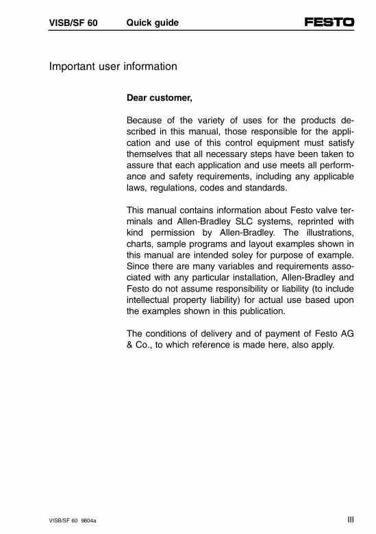
Quick guide to SB/SF 60 installation
This quick guide offers you an overview of the stepsnecessary for installing a programmable valve terminalwith the SB/SF 60 control block.
1. Assembling the components and fitting the terminal
Installing Manual
Electronic components SB/SF 60 manual, chapter 2.2, 5.2, 6.2and 7.2
MIDI/MAXI valves Festo Pneumatics manual type 03MIDI/MAXIOrder no. 152771
ISO 5599-2 valves Festo Pneumatics manual type 04-BISO 5599-2Order no. 163941
CPV valves Festo Pneumatics manual type 10 CPVOrder no. 165200
CPA valves Festo Pneumatics manual type 12 CPAOrder no. 173515
2. Installing the pneumatic connections
Installing Manual
MIDI/MAXI valves Festo Pneumatics manual type 03MIDI/MAXIOrder no. 152771
ISO 5599-2 valves Festo Pneumatics manual type 04-BISO 5599-2Order no. 163941
CPV valves Festo Pneumatics manual type 10 CPVOrder no. 165200
CPA valves Festo Pneumatics manual type 12 CPAOrder no. 173515
Quick guideVISB/SF 60
IV VISB/SF 60 9804a
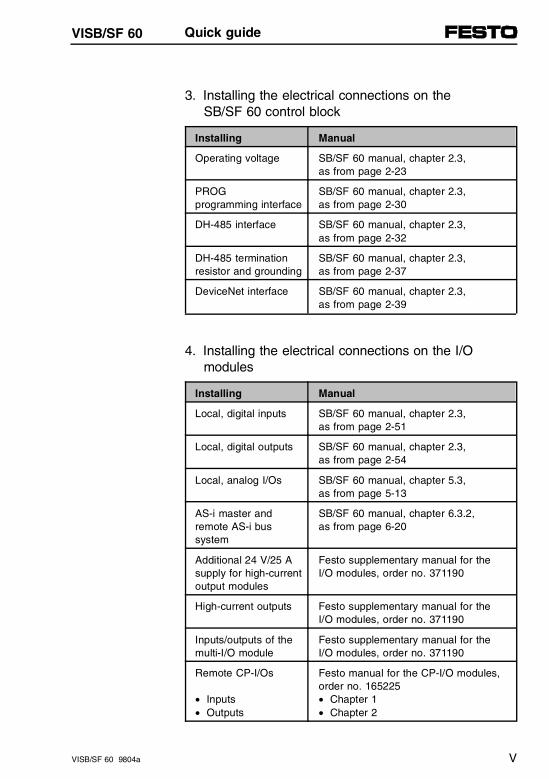
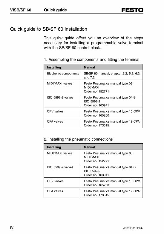
3. Installing the electrical connections on the SB/SF 60 control block
Installing Manual
Operating voltage SB/SF 60 manual, chapter 2.3, as from page 2-23
PROG programming interface
SB/SF 60 manual, chapter 2.3, as from page 2-30
DH-485 interface SB/SF 60 manual, chapter 2.3, as from page 2-32
DH-485 termination resistor and grounding
SB/SF 60 manual, chapter 2.3, as from page 2-37
DeviceNet interface SB/SF 60 manual, chapter 2.3, as from page 2-39
4. Installing the electrical connections on the I/O modules
Installing Manual
Local, digital inputs SB/SF 60 manual, chapter 2.3, as from page 2-51
Local, digital outputs SB/SF 60 manual, chapter 2.3, as from page 2-54
Local, analog I/Os SB/SF 60 manual, chapter 5.3, as from page 5-13
AS-i master and remote AS-i bus system
SB/SF 60 manual, chapter 6.3.2, as from page 6-20
Additional 24 V/25 Asupply for high-currentoutput modules
Festo supplementary manual for the I/O modules, order no. 371190
High-current outputs Festo supplementary manual for the I/O modules, order no. 371190
Inputs/outputs of themulti-I/O module
Festo supplementary manual for the I/O modules, order no. 371190
Remote CP-I/Os
• Inputs• Outputs
Festo manual for the CP-I/O modules,order no. 165225• Chapter 1• Chapter 2
Quick guideVISB/SF 60
VISB/SF 60 9804a V
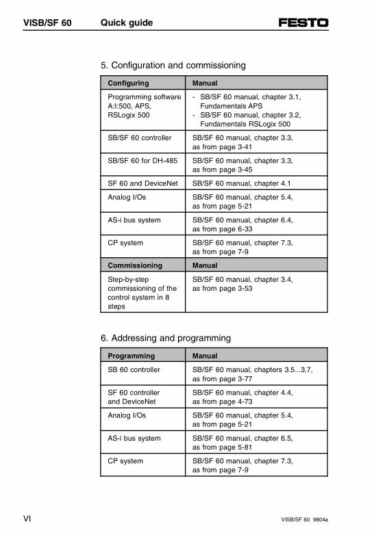
5. Configuration and commissioning
Configuring Manual
Programming softwareA:I:500, APS, RSLogix 500
- SB/SF 60 manual, chapter 3.1, Fundamentals APS
- SB/SF 60 manual, chapter 3.2,Fundamentals RSLogix 500
SB/SF 60 controller SB/SF 60 manual, chapter 3.3, as from page 3-41
SB/SF 60 for DH-485 SB/SF 60 manual, chapter 3.3, as from page 3-45
SF 60 and DeviceNet SB/SF 60 manual, chapter 4.1
Analog I/Os SB/SF 60 manual, chapter 5.4, as from page 5-21
AS-i bus system SB/SF 60 manual, chapter 6.4, as from page 6-33
CP system SB/SF 60 manual, chapter 7.3, as from page 7-9
Commissioning Manual
Step-by-stepcommissioning of thecontrol system in 8steps
SB/SF 60 manual, chapter 3.4, as from page 3-53
6. Addressing and programming
Programming Manual
SB 60 controller SB/SF 60 manual, chapters 3.5...3.7,as from page 3-77
SF 60 controller and DeviceNet
SB/SF 60 manual, chapter 4.4,as from page 4-73
Analog I/Os SB/SF 60 manual, chapter 5.4,as from page 5-21
AS-i bus system SB/SF 60 manual, chapter 6.5,as from page 5-81
CP system SB/SF 60 manual, chapter 7.3,as from page 7-9
Quick guideVISB/SF 60
VI VISB/SF 60 9804a
Authors: E. Klotz, J. Müller, C. Waldeck, A. Ziegele, R. Höhn
Editors: H. J. Drung, M. HolderLayout: Festo AG & Co., Dept. PV-IDMTypesetting: Sturz / Reutlingen
Edition: 0503b
© (Festo AG & Co., D-73726 Esslingen, 1998)Federal Republic of GermanyThe copying, distribution and utilization of this docu-ment as well as the communication of its contents toothers without expressed authorization is prohibited. Of-fenders will be held liable for the payment of damages.All rights reserved, in particular the right to carry outpatent, utility or ornamental design registrations.
Prin
ted
on 1
00 %
rec
ycle
d pa
per
VISB/SF 60
VISB/SF 60 0503b VII
WINtelligent series is a registred trademark of Rock-well Software Inc.
Trademarknotices
RSLogix, A.I. series, Advance Interface (A.I.) seriesare trademarks of Rockwell Software Inc.
PLC, PLC-5 are registred trademarks of Allen-BradleyInc.
Data Highway Plus, DH+, PanelView, SLC, SLC 5/02,SLC 5/04, SLC 500 are trademarks of Allen-BradleyInc.
All other trademarks are the property of their respec-tive holders and are hereby acknowledged.
Order No.: 184 573Title: Manual Reference: P.BE-VISB/SF 60-03-US
VISB/SF 60
VIII VISB/SF 60 9804a
Advantages of programmable valve terminals
Many control tasks in the field of pneumatics (e.g. withcylinders, sensors, analog I/Os) can be automated with-out requiring a full control cabinet. A valve terminal withintegrated controller (control block with SLC 500 tech-nology) having the command store and function rangeof a powerful mini-controller allows ease of program-ming using the Allen-Bradley A.I. 500 APS or RSLogix500 programming software. There are two designs ofcontrol block:
– SB 60-03 for valve terminals types 03...05, 10 and 12
– SF 60-03 (like SB 60, but with DeviceNet interface)
Benefits of the programmable valve terminal with con-trol block:
– Integrated PLC (SLC 500 technology) with additionalintegrated 1747-AIC (isolated link coupler) and powersupply
– SF 60 with integrated DeviceNet interface (scanner)for up to 63 DeviceNet devices
– IP65 rating – no control cabinet enclosure necessary
– Independent local control
– Communication via DH-485 network or DeviceNet
– Pre-assembled and pre-tested unit for less wiring andtubing complexity
More advantages on the next page.
VISB/SF 60
VISB/SF 60 9804a IX
Up to 268 local inputs and 254 local outputs are physi-cally available including:
– Numerous valve types: - MIDI (up to 500 l/min), - MAXI (up to1250 l/min), - ISO 5599-2 size 1,2,3 (up to 1200/2300/4500 l/min),- CPV10,14,18 (up to 400/800/1600 l/min), - CPA10,14 (up to 300/650 l/min), - proportional pneumatics (for controlling cylinder velocity or pressure)
– up to 26 locally fitted valves (MIDI, MAXI, ISO)
– up to 96 digital electrical inputs, e.g., for sensors
– up to 48 digital electrical outputs, e.g., for electricalactuators
– up to 9 analog I/Os
– up to 64 remote CP I/Os on one CP interface
– up to 124 remote AS-i- I/Os on one AS-i master.
VISB/SF 60
X VISB/SF 60 9804a
Contents
Chapter 1 User instructions and system summary contain general information on the programmable valveterminal with integrated Allen-Bradley controller.
Chapter 2 System description of valve terminal contains the system description of your valve terminaltype 03 or 04-B (assembly, installation, addressing).
Chapter 3 System description of SB 60 control block contains all PLC-specific information for stand-aloneoperation and communication over the DH-485 network.
Chapter 4 System description of SF 60 DeviceNet interfacecontains additional information for the DeviceNet masterand slave modes.
Chapter 5 Description of analog modulescontains all information about the actuation of theanalog modules.
Chapter 6 Description of AS-i master contains all information about the actuation of an AS-i bus system.
Chapter 7 Description of CP interface contains all information about the actuation of a CP system.
Appendix A Technical appendix, circuit examples
Appendix B Summary of error messages
Appendix C Optimizing configuration/performance
Appendix D Glossary / Index
CD-ROM Festo Valve Terminals - Utilities, contains s.g.- EDS files, Icons/Bitmaps- FST AS-i Software Tool for AS-i master
CD-ROM Interactive Documentation SB/SF 60
Reference card Contains all the program commands and I/O addresses
VISB/SF 60
VISB/SF 60 9804a XI

VISB/SF 60
XII VISB/SF 60 9804a
Contents
PROGRAMMABLE VALVE TERMINAL TYPE 03SB 60/SF 60 CONTROL BLOCK
ELECTRONICS MANUAL
Important user information . . . . . . . . . . . . . . . . . . . . . . . . . . . . . . . IIIQuick guide to SB/SF 60 installation . . . . . . . . . . . . . . . . . . . . . . IVAdvantages of programmable valve terminals. . . . . . . . . . . . . . . IXContents . . . . . . . . . . . . . . . . . . . . . . . . . . . . . . . . . . . . . . . . . . . . XI
1. User instructions and system overview
1.1 User instructions . . . . . . . . . . . . . . . . . . . . . . . . . . . . . . . . . . . . 1-1
1.1.1 General safety instructions. . . . . . . . . . . . . . . . . . . . . . . . . . . . . . 1-1Intended use. . . . . . . . . . . . . . . . . . . . . . . . . . . . . . . . . . . . . . . . . 1-1Target group. . . . . . . . . . . . . . . . . . . . . . . . . . . . . . . . . . . . . . . . . 1-2Danger categories . . . . . . . . . . . . . . . . . . . . . . . . . . . . . . . . . . . . 1-3Pictograms . . . . . . . . . . . . . . . . . . . . . . . . . . . . . . . . . . . . . . . . . . 1-4
1.1.2 References to documentation . . . . . . . . . . . . . . . . . . . . . . . . . . . 1-6Basic Manuals from Allen-Bradley . . . . . . . . . . . . . . . . . . . . . . . . 1-6Manuals for the Festo SB/SF 60 . . . . . . . . . . . . . . . . . . . . . . . . . 1-7Notes for this manual . . . . . . . . . . . . . . . . . . . . . . . . . . . . . . . . . . 1-8Service . . . . . . . . . . . . . . . . . . . . . . . . . . . . . . . . . . . . . . . . . . . . 1-10
1.2 System overview . . . . . . . . . . . . . . . . . . . . . . . . . . . . . . . . . . . 1-11
Allen-Bradley and Festo. . . . . . . . . . . . . . . . . . . . . . . . . . . . . . . 1-11Allen-Bradley automation technology. . . . . . . . . . . . . . . . . . . . . 1-12SLC 5/02 and SB/SF 60 system structure. . . . . . . . . . . . . . . . . 1-14
1.2.1 Application examples SB/SF 60. . . . . . . . . . . . . . . . . . . . . . . . . 1-22SB 60 valve terminal in stand-alone mode . . . . . . . . . . . . . . . . 1-22SB 60 valve terminal in the DH-485 network. . . . . . . . . . . . . . . 1-24SF 60 valve terminal as master on DeviceNet . . . . . . . . . . . . . 1-26SF 60 valve terminal as stand-alone slave on DeviceNet . . . . . . . . . . . . . . . . . . . . . . . . . . . . . . . . . . . . . . . 1-28
VISB/SF 60
VISB/SF 60 9804a XIII
Valve terminal with analog modules. . . . . . . . . . . . . . . . . . . . . 1-30Valve terminal with AS-i master . . . . . . . . . . . . . . . . . . . . . . . . 1-32Valve terminal with CP interface . . . . . . . . . . . . . . . . . . . . . . . 1-34
1.2.2 System operation with display and control units . . . . . . . . . . . 1-36Easy operation . . . . . . . . . . . . . . . . . . . . . . . . . . . . . . . . . . . . . 1-36User friendly operation . . . . . . . . . . . . . . . . . . . . . . . . . . . . . . . 1-38
1.3 System limits and planning aspects . . . . . . . . . . . . . . . . . . 1-41
1.3.1 System limits. . . . . . . . . . . . . . . . . . . . . . . . . . . . . . . . . . . . . . . 1-41SB/SF 60 without DeviceNet . . . . . . . . . . . . . . . . . . . . . . . . . . 1-41SF 60 with DeviceNet. . . . . . . . . . . . . . . . . . . . . . . . . . . . . . . . 1-42
1.3.2 Planning aspects for type 03…05 valve terminals . . . . . . . . . 1-44Planning aspect 1Common voltage supply for all outputs . . . . . . . . . . . . . . . . . . 1-45Planning aspect 2 Separate voltage supply for individual high-current output modules . . . . . . . . . . . . . . . . . . . . . . . . . . . . . . . . . . . . . 1-47Planning aspect 3 Possible combinations of I/O modules . . . . . . . . . . . . . . . . . . . 1-51
VISB/SF 60
XIV VISB/SF 60 9804a
2. System description of type 03 valve terminal
2.1 Components . . . . . . . . . . . . . . . . . . . . . . . . . . . . . . . . . . . . . . . . 2-1
Structure of type 03 valve terminal . . . . . . . . . . . . . . . . . . . . . . . 2-1
2.2 Assembly. . . . . . . . . . . . . . . . . . . . . . . . . . . . . . . . . . . . . . . . . . . 2-5
2.2.1 Mounting the components . . . . . . . . . . . . . . . . . . . . . . . . . . . . . . 2-5Input/output modules . . . . . . . . . . . . . . . . . . . . . . . . . . . . . . . . . . 2-7End plates . . . . . . . . . . . . . . . . . . . . . . . . . . . . . . . . . . . . . . . . . . 2-9Top-hat rail clamping unit. . . . . . . . . . . . . . . . . . . . . . . . . . . . . . 2-12
2.2.2. Mounting the valve terminal . . . . . . . . . . . . . . . . . . . . . . . . . . . . 2-13Wall mounting. . . . . . . . . . . . . . . . . . . . . . . . . . . . . . . . . . . . . . . 2-13Top-hat rail mounting . . . . . . . . . . . . . . . . . . . . . . . . . . . . . . . . . 2-15
2.3 Electrical connections . . . . . . . . . . . . . . . . . . . . . . . . . . . . . . . 2-19
2.3.1 Opening and closing the control block. . . . . . . . . . . . . . . . . . . . 2-19Control block layout . . . . . . . . . . . . . . . . . . . . . . . . . . . . . . . . . . 2-21
2.3.2 Connecting operating voltages. . . . . . . . . . . . . . . . . . . . . . . . . . 2-23Calculating current draw. . . . . . . . . . . . . . . . . . . . . . . . . . . . . . . 2-25Pin assignments for the supply voltage connection. . . . . . . . . . 2-27Protective grounding . . . . . . . . . . . . . . . . . . . . . . . . . . . . . . . . . 2-28
2.3.3 The DH-485 interfaces on the SB/SF 60. . . . . . . . . . . . . . . . . . 2-29
2.3.4 Connecting up the PROG programming interface. . . . . . . . . . . 2-30Pin assignments for Festo programming cable . . . . . . . . . . . . . 2-31
2.3.5 Connecting up the DH-485 interfaces (DH-485 with galvanic isolation). . . . . . . . . . . . . . . . . . . . . . . . . 2-32Cable and plugs/sockets for the DH-485 connection variants . . . . . . . . . . . . . . . . . . . . . . . . . . . . . . . . . . 2-36Connecting the SB/SF 60 to the DH-485 interface of a 1747-AIC (via the 6-pin A-B terminal) . . . . . . . . . 2-38DH-485 termination resistor and grounding. . . . . . . . . . . . . . . . 2-39
VISB/SF 60
VISB/SF 60 9804a XV
2.3.6 Connecting the DeviceNet interface (SF 60 only) . . . . . . . . . . 2-41Pin assignments for the DeviceNet interface. . . . . . . . . . . . . . 2-44Wiring notes for Allen-Bradley DeviceNet . . . . . . . . . . . . . . . . 2-45Allen-Bradley DeviceNet cable System . . . . . . . . . . . . . . . . . . 2-46DeviceNet termination resistor . . . . . . . . . . . . . . . . . . . . . . . . . 2-48
2.3.7 Connecting the input/output modules. . . . . . . . . . . . . . . . . . . . 2-49Connecting the input modules (PNP/NPN) . . . . . . . . . . . . . . . 2-49Pin allocation . . . . . . . . . . . . . . . . . . . . . . . . . . . . . . . . . . . . . . 2-51Connecting up the output modules (PNP) . . . . . . . . . . . . . . . . 2-52Pin assignment . . . . . . . . . . . . . . . . . . . . . . . . . . . . . . . . . . . . . 2-54Short circuit/overload . . . . . . . . . . . . . . . . . . . . . . . . . . . . . . . . 2-55DUO cable . . . . . . . . . . . . . . . . . . . . . . . . . . . . . . . . . . . . . . . . 2-56Designation of inputs and outputs . . . . . . . . . . . . . . . . . . . . . . 2-57
2.4 Addressing . . . . . . . . . . . . . . . . . . . . . . . . . . . . . . . . . . . . . . . 2-59
General . . . . . . . . . . . . . . . . . . . . . . . . . . . . . . . . . . . . . . . . . . . 2-59Determining configuration data. . . . . . . . . . . . . . . . . . . . . . . . . 2-60Addressing the valve terminal . . . . . . . . . . . . . . . . . . . . . . . . . 2-61Basic rules type 03. . . . . . . . . . . . . . . . . . . . . . . . . . . . . . . . . . 2-62Address assignment after extension/conversion . . . . . . . . . . . 2-65Allocation of the local I/Os on the SB/SF 60 . . . . . . . . . . . . . . 2-67Allocation table of all I/Os on SB/SF 60. . . . . . . . . . . . . . . . . . 2-69
2.5 Technical data . . . . . . . . . . . . . . . . . . . . . . . . . . . . . . . . . . . . . 2-71
VISB/SF 60
XVI VISB/SF 60 9804a
3. Description of SB 60 control block
3.1 APS and A.I. 500 Fundamentals . . . . . . . . . . . . . . . . . . . . . . . . 3-1
Create a new file . . . . . . . . . . . . . . . . . . . . . . . . . . . . . . . . . . . . . 3-3Configure I/O . . . . . . . . . . . . . . . . . . . . . . . . . . . . . . . . . . . . . . . . 3-7Return to an existing file . . . . . . . . . . . . . . . . . . . . . . . . . . . . . . 3-12Enter the ladder program . . . . . . . . . . . . . . . . . . . . . . . . . . . . . 3-13Downloading the program to the controller . . . . . . . . . . . . . . . . 3-15Testing the program . . . . . . . . . . . . . . . . . . . . . . . . . . . . . . . . . . 3-20
3.2 Fundamentals of RSLogix 500 . . . . . . . . . . . . . . . . . . . . . . . . 3-21
File New (create a new file) . . . . . . . . . . . . . . . . . . . . . . . . . . . . 3-23I/O configuration . . . . . . . . . . . . . . . . . . . . . . . . . . . . . . . . . . . . . 3-27Open File (open an existing program) . . . . . . . . . . . . . . . . . . . . 3-30Enter a program in offline mode . . . . . . . . . . . . . . . . . . . . . . . . 3-30Download to the processor . . . . . . . . . . . . . . . . . . . . . . . . . . . . 3-33Testing a program in the processor. . . . . . . . . . . . . . . . . . . . . . 3-35
3.3 Configuring the controller . . . . . . . . . . . . . . . . . . . . . . . . . . . . 3-37
General. . . . . . . . . . . . . . . . . . . . . . . . . . . . . . . . . . . . . . . . . . . . 3-37Configuring the terminal for DH-485 . . . . . . . . . . . . . . . . . . . . . 3-39Configuring the SB/SF 60 . . . . . . . . . . . . . . . . . . . . . . . . . . . . . 3-40Configuring the interrupt service routine (ISR) . . . . . . . . . . . . . 3-41Configuring the M-files . . . . . . . . . . . . . . . . . . . . . . . . . . . . . . . . 3-41Configuring the G-files . . . . . . . . . . . . . . . . . . . . . . . . . . . . . . . . 3-43NOMINAL/ACTUAL comparison . . . . . . . . . . . . . . . . . . . . . . . . 3-47
3.4 Start-up up the control system. . . . . . . . . . . . . . . . . . . . . . . . 3-49
3.4.1 Inspect your installation . . . . . . . . . . . . . . . . . . . . . . . . . . . . . . . 3-51
3.4.2. Disconnect motion-causing devices. . . . . . . . . . . . . . . . . . . . . . 3-52
3.4.3 Initialize and test your processor . . . . . . . . . . . . . . . . . . . . . . . . 3-54
3.4.4 Test your inputs . . . . . . . . . . . . . . . . . . . . . . . . . . . . . . . . . . . . . 3-57
3.4.5 Test your outputs . . . . . . . . . . . . . . . . . . . . . . . . . . . . . . . . . . . . 3-61
3.4.6 Enter and test your program . . . . . . . . . . . . . . . . . . . . . . . . . . . 3-65
VISB/SF 60
VISB/SF 60 9804a XVII
3.4.7 Observe control motion . . . . . . . . . . . . . . . . . . . . . . . . . . . . . . 3-70
3.4.8 Conduct dry run of your application (if possible without tooling/workpieces) . . . . . . . . . . . . . . . . . . 3-72
3.5 Programming. . . . . . . . . . . . . . . . . . . . . . . . . . . . . . . . . . . . . . 3-73
3.5.1 General . . . . . . . . . . . . . . . . . . . . . . . . . . . . . . . . . . . . . . . . . . . 3-73Chapter summary . . . . . . . . . . . . . . . . . . . . . . . . . . . . . . . . . . . 3-73Programming environment . . . . . . . . . . . . . . . . . . . . . . . . . . . . 3-74Principle of the control sequence . . . . . . . . . . . . . . . . . . . . . . . 3-75
3.5.2 Processor functions . . . . . . . . . . . . . . . . . . . . . . . . . . . . . . . . . 3-78General performance features . . . . . . . . . . . . . . . . . . . . . . . . . 3-78Maintenance-free operation . . . . . . . . . . . . . . . . . . . . . . . . . . . 3-79Interrupts. . . . . . . . . . . . . . . . . . . . . . . . . . . . . . . . . . . . . . . . . . 3-80Fault interrupts . . . . . . . . . . . . . . . . . . . . . . . . . . . . . . . . . . . . . 3-80Selectable Timed Interrupt (STI) . . . . . . . . . . . . . . . . . . . . . . . 3-84
3.5.3 SB/SF 60 instruction set. . . . . . . . . . . . . . . . . . . . . . . . . . . . . . 3-85
3.6 Function of the Festo Peripheral Module (FPM) . . . . . . . . . 3-89
3.6.1 General . . . . . . . . . . . . . . . . . . . . . . . . . . . . . . . . . . . . . . . . . . . 3-89Chapter summary . . . . . . . . . . . . . . . . . . . . . . . . . . . . . . . . . . . 3-89
3.6.2 Addressing of the I/Os . . . . . . . . . . . . . . . . . . . . . . . . . . . . . . . 3-90SB/SF 60 I/O allocation table . . . . . . . . . . . . . . . . . . . . . . . . . . 3-91Bit addressing of the local I/Os . . . . . . . . . . . . . . . . . . . . . . . . 3-94Bit addressing of the remote I/Os . . . . . . . . . . . . . . . . . . . . . . 3-98
3.6.3 Working with the M-files . . . . . . . . . . . . . . . . . . . . . . . . . . . . . 3-102General . . . . . . . . . . . . . . . . . . . . . . . . . . . . . . . . . . . . . . . . . . 3-102Configuration of the M-files . . . . . . . . . . . . . . . . . . . . . . . . . . 3-104Overview of M-files . . . . . . . . . . . . . . . . . . . . . . . . . . . . . . . . . 3-105M-file (Inputs) . . . . . . . . . . . . . . . . . . . . . . . . . . . . . . . . . . . . . 3-106M0-file (Outputs) . . . . . . . . . . . . . . . . . . . . . . . . . . . . . . . . . . . 3-108Configuration of I/O interrupt source 0 in the M0-file (M0:1.0) . . . . . . . . . . . . . . . . . . . . . . . . . . . . . . 3-109
VISB/SF 60
XVIII VISB/SF 60 9804a
3.6.4 Special configurations of the FPM . . . . . . . . . . . . . . . . . . . . . . 3-110Programming I/O interrupts (ISR) . . . . . . . . . . . . . . . . . . . . . . 3-111Configure fault interrupts . . . . . . . . . . . . . . . . . . . . . . . . . . . . . 3-115
3.7 Diagnostics and error handling . . . . . . . . . . . . . . . . . . . . . . 3-117
Diagnostics overview . . . . . . . . . . . . . . . . . . . . . . . . . . . . . . . . 3-117
3.7.1 Local diagnostics . . . . . . . . . . . . . . . . . . . . . . . . . . . . . . . . . . . 3-118SB 60 control block . . . . . . . . . . . . . . . . . . . . . . . . . . . . . . . . . 3-118Valves . . . . . . . . . . . . . . . . . . . . . . . . . . . . . . . . . . . . . . . . . . . 3-122I/O modules . . . . . . . . . . . . . . . . . . . . . . . . . . . . . . . . . . . . . . . 3-123
3.7.2 Diagnostics by program . . . . . . . . . . . . . . . . . . . . . . . . . . . . . . 3-125Error states at the valve terminal . . . . . . . . . . . . . . . . . . . . . . . 3-125Allen-Bradley fault categories. . . . . . . . . . . . . . . . . . . . . . . . . . 3-126Fault codes of the Festo Peripheral Module . . . . . . . . . . . . . . 3-127Status word: (I:1.0). . . . . . . . . . . . . . . . . . . . . . . . . . . . . . . . . . 3-129
3.7.3 Expanded diagnostics using M-files. . . . . . . . . . . . . . . . . . . . . 3-130Short circuit/overload on local output (M1:1.4) . . . . . . . . . . . . 3-130CP System (M1:1.8...M1:1.11). . . . . . . . . . . . . . . . . . . . . . . . . 3-131Analog modules (M1:1.12...M1:1.20) . . . . . . . . . . . . . . . . . . . . 3-132Failure of an AS-i slave (M1:1.21...M1:1.22) . . . . . . . . . . . . . . 3-133
VISB/SF 60
VISB/SF 60 9804a XIX
4. Description of DeviceNet interface SF 60 (DeviceNet Scanner)
4.1 DeviceNet system overview . . . . . . . . . . . . . . . . . . . . . . . . . . 4-1
4.1.1 Chapter summary . . . . . . . . . . . . . . . . . . . . . . . . . . . . . . . . . . . . 4-1Requirements . . . . . . . . . . . . . . . . . . . . . . . . . . . . . . . . . . . . . . . 4-2Related publications on DeviceNet . . . . . . . . . . . . . . . . . . . . . . 4-3Internet Information on DeviceNet . . . . . . . . . . . . . . . . . . . . . . . 4-4Interactive documentation on the SB/SF 60 . . . . . . . . . . . . . . . 4-4
4.1.2 Characteristics of the SF 60 with DeviceNet Scanner. . . . . . . . 4-5
4.1.3 DeviceNetManager software (DN-MGR) . . . . . . . . . . . . . . . . . . 4-8
4.1.4 Planning aspects for DeviceNet . . . . . . . . . . . . . . . . . . . . . . . . 4-11
4.1.5 Planning aspects for the SF 60 . . . . . . . . . . . . . . . . . . . . . . . . 4-13SF 60 as master on the DeviceNet . . . . . . . . . . . . . . . . . . . . . 4-13SF 60 as active slave on the DeviceNet . . . . . . . . . . . . . . . . . 4-13SF 60 in multi-master mode (dual mode) . . . . . . . . . . . . . . . . 4-14
4.2 Configuration of the SF 60 . . . . . . . . . . . . . . . . . . . . . . . . . . 4-15
4.2.1 I/O configuration . . . . . . . . . . . . . . . . . . . . . . . . . . . . . . . . . . . . 4-15
4.2.2 Configuring the M0/M1 files . . . . . . . . . . . . . . . . . . . . . . . . . . . 4-17
4.2.3 Optimizing the scan time . . . . . . . . . . . . . . . . . . . . . . . . . . . . 4-18M0/M1 files . . . . . . . . . . . . . . . . . . . . . . . . . . . . . . . . . . . . . . . . 4-18Scanned I/O words. . . . . . . . . . . . . . . . . . . . . . . . . . . . . . . . . . 4-19
4.3 Configuring the DeviceNet . . . . . . . . . . . . . . . . . . . . . . . . . . 4-21
4.3.1 Installing the EDS files . . . . . . . . . . . . . . . . . . . . . . . . . . . . . . . 4-21
4.3.2 Create a new project . . . . . . . . . . . . . . . . . . . . . . . . . . . . . . . . 4-24Notes on DeviceNetManager version 3.004 . . . . . . . . . . . . . . 4-28
4.3.3 Going online with your SF 60. . . . . . . . . . . . . . . . . . . . . . . . . . 4-29Setting the network data rate and node address of your SF 60 . . . . . . . . . . . . . . . . . . . . . . . . . . . . . . . . . . . . . . 4-31
VISB/SF 60
XX VISB/SF 60 9804a
4.3.4 Configuring the DeviceNet Scanner and the network . . . . . . . . 4-34Accessing the module configuration screen ("Project View") . . 4-36Accessing the "Module Configuration" screen. . . . . . . . . . . . . . 4-38Setting the operational parameters of the SF 60. . . . . . . . . . . . 4-39
4.3.5 Working with the "SF60 Scan List Editor" . . . . . . . . . . . . . . . . . 4-44The "SF60 Scan List Editor" screen . . . . . . . . . . . . . . . . . . . . . 4-45Removing devices from the Scan List . . . . . . . . . . . . . . . . . . . . 4-46Viewing device information in the Scan List . . . . . . . . . . . . . . . 4-47Adding devices to the Scan List from the "SF60 Scan List Editor" screen . . . . . . . . . . . . . . . . . . . . . . . . . 4-51Configuring a device in the Scan List . . . . . . . . . . . . . . . . . . . . 4-53Using the Slave Mode function . . . . . . . . . . . . . . . . . . . . . . . . . 4-56Determining data mapping preferences with Auto Map. . . . . . . 4-57
4.3.6 About the Datatable Map . . . . . . . . . . . . . . . . . . . . . . . . . . . . . . 4-60Using the Datatable Map for custom editing . . . . . . . . . . . . . . . 4-62Mapping specific bits to specific device memory locations . . . . 4-65
4.3.7 Saving configuration and downloading into the SF 60 scanner . . . . . . . . . . . . . . . . . . . . . . . . . . . . . . . . . . . . . . 4-69
File names . . . . . . . . . . . . . . . . . . . . . . . . . . . . . . . . . . . . . . . . . 4-69Downloading configuration data into the scanner . . . . . . . . . . . 4-70What’s next?. . . . . . . . . . . . . . . . . . . . . . . . . . . . . . . . . . . . . . . . 4-71If you encounter error messages . . . . . . . . . . . . . . . . . . . . . . . . 4-71
4.4 Communication and Programming . . . . . . . . . . . . . . . . . . . . 4-73
4.4.1 Communication overview . . . . . . . . . . . . . . . . . . . . . . . . . . . . . . 4-73
4.4.2 Communicating with DeviceNet devices . . . . . . . . . . . . . . . . . . 4-75
4.4.3 Communicating with your SF 60 processor. . . . . . . . . . . . . . . . 4-77Understanding the data organization of the scanner. . . . . . . . . 4-78Input and Output Image Tables . . . . . . . . . . . . . . . . . . . . . . . . . 4-79Addressing with SF 60 on the DeviceNet . . . . . . . . . . . . . . . . . 4-80
4.4.4 Uploading input data from the SF 60 scanner to the SF 60 processor. . . . . . . . . . . . . . . . . . . . . . . . . . . . . . . . . . . . . 4-84Input image table . . . . . . . . . . . . . . . . . . . . . . . . . . . . . . . . . . . . 4-84Scanner status register . . . . . . . . . . . . . . . . . . . . . . . . . . . . . . . 4-85
VISB/SF 60
VISB/SF 60 9804a XXI
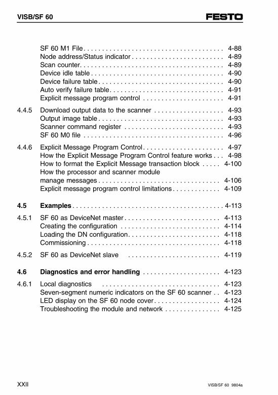
SF 60 M1 File . . . . . . . . . . . . . . . . . . . . . . . . . . . . . . . . . . . . . . 4-88Node address/Status indicator . . . . . . . . . . . . . . . . . . . . . . . . . 4-89Scan counter. . . . . . . . . . . . . . . . . . . . . . . . . . . . . . . . . . . . . . . 4-89Device idle table . . . . . . . . . . . . . . . . . . . . . . . . . . . . . . . . . . . . 4-90Device failure table . . . . . . . . . . . . . . . . . . . . . . . . . . . . . . . . . . 4-90Auto verify failure table. . . . . . . . . . . . . . . . . . . . . . . . . . . . . . . 4-91Explicit message program control . . . . . . . . . . . . . . . . . . . . . . 4-91
4.4.5 Download output data to the scanner . . . . . . . . . . . . . . . . . . . 4-93Output image table . . . . . . . . . . . . . . . . . . . . . . . . . . . . . . . . . . 4-93Scanner command register . . . . . . . . . . . . . . . . . . . . . . . . . . . 4-93SF 60 M0 file . . . . . . . . . . . . . . . . . . . . . . . . . . . . . . . . . . . . . . 4-96
4.4.6 Explicit Message Program Control . . . . . . . . . . . . . . . . . . . . . . 4-97How the Explicit Message Program Control feature works . . . 4-98How to format the Explicit Message transaction block . . . . . 4-100How the processor and scanner module manage messages . . . . . . . . . . . . . . . . . . . . . . . . . . . . . . . . . 4-106Explicit message program control limitations . . . . . . . . . . . . . 4-109
4.5 Examples . . . . . . . . . . . . . . . . . . . . . . . . . . . . . . . . . . . . . . . . . 4-113
4.5.1 SF 60 as DeviceNet master . . . . . . . . . . . . . . . . . . . . . . . . . . 4-113Creating the configuration . . . . . . . . . . . . . . . . . . . . . . . . . . . 4-114Loading the DN configuration. . . . . . . . . . . . . . . . . . . . . . . . . 4-118Commissioning . . . . . . . . . . . . . . . . . . . . . . . . . . . . . . . . . . . . 4-118
4.5.2 SF 60 as DeviceNet slave . . . . . . . . . . . . . . . . . . . . . . . . . 4-119
4.6 Diagnostics and error handling . . . . . . . . . . . . . . . . . . . . . 4-123
4.6.1 Local diagnostics . . . . . . . . . . . . . . . . . . . . . . . . . . . . . . . . 4-123Seven-segment numeric indicators on the SF 60 scanner . . 4-123LED display on the SF 60 node cover . . . . . . . . . . . . . . . . . . 4-124Troubleshooting the module and network . . . . . . . . . . . . . . . 4-125
VISB/SF 60
XXII VISB/SF 60 9804a
5. Description of analog modules
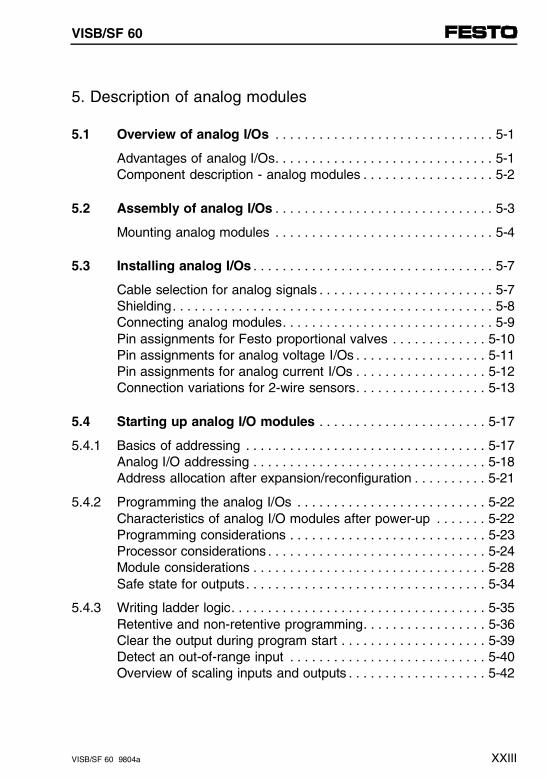
5.1 Overview of analog I/Os . . . . . . . . . . . . . . . . . . . . . . . . . . . . . . 5-1
Advantages of analog I/Os. . . . . . . . . . . . . . . . . . . . . . . . . . . . . . 5-1Component description - analog modules . . . . . . . . . . . . . . . . . . 5-2
5.2 Assembly of analog I/Os . . . . . . . . . . . . . . . . . . . . . . . . . . . . . . 5-3
Mounting analog modules . . . . . . . . . . . . . . . . . . . . . . . . . . . . . . 5-4
5.3 Installing analog I/Os . . . . . . . . . . . . . . . . . . . . . . . . . . . . . . . . . 5-7
Cable selection for analog signals . . . . . . . . . . . . . . . . . . . . . . . . 5-7Shielding. . . . . . . . . . . . . . . . . . . . . . . . . . . . . . . . . . . . . . . . . . . . 5-8Connecting analog modules. . . . . . . . . . . . . . . . . . . . . . . . . . . . . 5-9Pin assignments for Festo proportional valves . . . . . . . . . . . . . 5-10Pin assignments for analog voltage I/Os . . . . . . . . . . . . . . . . . . 5-11Pin assignments for analog current I/Os . . . . . . . . . . . . . . . . . . 5-12Connection variations for 2-wire sensors. . . . . . . . . . . . . . . . . . 5-13
5.4 Starting up analog I/O modules . . . . . . . . . . . . . . . . . . . . . . . 5-17
5.4.1 Basics of addressing . . . . . . . . . . . . . . . . . . . . . . . . . . . . . . . . . 5-17Analog I/O addressing . . . . . . . . . . . . . . . . . . . . . . . . . . . . . . . . 5-18Address allocation after expansion/reconfiguration . . . . . . . . . . 5-21
5.4.2 Programming the analog I/Os . . . . . . . . . . . . . . . . . . . . . . . . . . 5-22Characteristics of analog I/O modules after power-up . . . . . . . 5-22Programming considerations . . . . . . . . . . . . . . . . . . . . . . . . . . . 5-23Processor considerations . . . . . . . . . . . . . . . . . . . . . . . . . . . . . . 5-24Module considerations . . . . . . . . . . . . . . . . . . . . . . . . . . . . . . . . 5-28Safe state for outputs. . . . . . . . . . . . . . . . . . . . . . . . . . . . . . . . . 5-34
5.4.3 Writing ladder logic. . . . . . . . . . . . . . . . . . . . . . . . . . . . . . . . . . . 5-35Retentive and non-retentive programming. . . . . . . . . . . . . . . . . 5-36Clear the output during program start . . . . . . . . . . . . . . . . . . . . 5-39Detect an out-of-range input . . . . . . . . . . . . . . . . . . . . . . . . . . . 5-40Overview of scaling inputs and outputs . . . . . . . . . . . . . . . . . . . 5-42
VISB/SF 60
VISB/SF 60 9804a XXIII
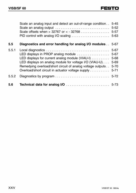
Scale an analog input and detect an out-of-range condition . . 5-45Scale an analog output . . . . . . . . . . . . . . . . . . . . . . . . . . . . . . 5-52Scale offsets when > 32767 or < - 32768 . . . . . . . . . . . . . . . . 5-57PID control with analog I/O scaling . . . . . . . . . . . . . . . . . . . . . 5-63
5.5 Diagnostics and error handling for analog I/O modules . . 5-67
5.5.1 Local diagnostics . . . . . . . . . . . . . . . . . . . . . . . . . . . . . . . . . . . 5-67LED displays in PROP analog module . . . . . . . . . . . . . . . . . . 5-67LED displays for current analog module (VIAU-I) . . . . . . . . . . 5-68LED displays on analog module for voltage I/O (VIAU-U). . . . 5-69Remedying overload/short circuit of analog voltage outputs . . 5-70Overload/short circuit in actuator voltage supply . . . . . . . . . . . 5-71
5.5.2 Diagnostics by program . . . . . . . . . . . . . . . . . . . . . . . . . . . . . . 5-72
5.6 Technical data for analog I/O . . . . . . . . . . . . . . . . . . . . . . . . 5-73
VISB/SF 60
XXIV VISB/SF 60 9804a
6. Description of AS-i master
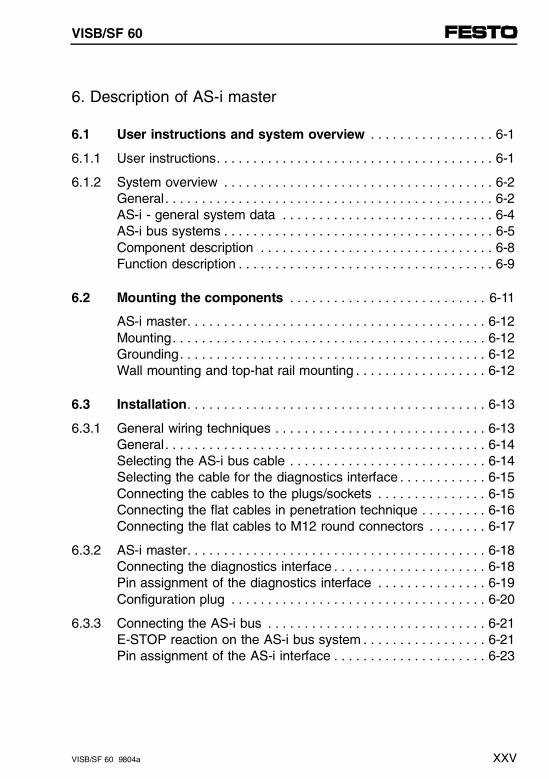
6.1 User instructions and system overview . . . . . . . . . . . . . . . . . 6-1
6.1.1 User instructions. . . . . . . . . . . . . . . . . . . . . . . . . . . . . . . . . . . . . . 6-1
6.1.2 System overview . . . . . . . . . . . . . . . . . . . . . . . . . . . . . . . . . . . . . 6-2General. . . . . . . . . . . . . . . . . . . . . . . . . . . . . . . . . . . . . . . . . . . . . 6-2AS-i - general system data . . . . . . . . . . . . . . . . . . . . . . . . . . . . . 6-4AS-i bus systems . . . . . . . . . . . . . . . . . . . . . . . . . . . . . . . . . . . . . 6-5Component description . . . . . . . . . . . . . . . . . . . . . . . . . . . . . . . . 6-8Function description . . . . . . . . . . . . . . . . . . . . . . . . . . . . . . . . . . . 6-9
6.2 Mounting the components . . . . . . . . . . . . . . . . . . . . . . . . . . . 6-11
AS-i master. . . . . . . . . . . . . . . . . . . . . . . . . . . . . . . . . . . . . . . . . 6-12Mounting. . . . . . . . . . . . . . . . . . . . . . . . . . . . . . . . . . . . . . . . . . . 6-12Grounding. . . . . . . . . . . . . . . . . . . . . . . . . . . . . . . . . . . . . . . . . . 6-12Wall mounting and top-hat rail mounting . . . . . . . . . . . . . . . . . . 6-12
6.3 Installation. . . . . . . . . . . . . . . . . . . . . . . . . . . . . . . . . . . . . . . . . 6-13
6.3.1 General wiring techniques . . . . . . . . . . . . . . . . . . . . . . . . . . . . . 6-13General. . . . . . . . . . . . . . . . . . . . . . . . . . . . . . . . . . . . . . . . . . . . 6-14Selecting the AS-i bus cable . . . . . . . . . . . . . . . . . . . . . . . . . . . 6-14Selecting the cable for the diagnostics interface . . . . . . . . . . . . 6-15Connecting the cables to the plugs/sockets . . . . . . . . . . . . . . . 6-15Connecting the flat cables in penetration technique . . . . . . . . . 6-16Connecting the flat cables to M12 round connectors . . . . . . . . 6-17
6.3.2 AS-i master. . . . . . . . . . . . . . . . . . . . . . . . . . . . . . . . . . . . . . . . . 6-18Connecting the diagnostics interface . . . . . . . . . . . . . . . . . . . . . 6-18Pin assignment of the diagnostics interface . . . . . . . . . . . . . . . 6-19Configuration plug . . . . . . . . . . . . . . . . . . . . . . . . . . . . . . . . . . . 6-20
6.3.3 Connecting the AS-i bus . . . . . . . . . . . . . . . . . . . . . . . . . . . . . . 6-21E-STOP reaction on the AS-i bus system . . . . . . . . . . . . . . . . . 6-21Pin assignment of the AS-i interface . . . . . . . . . . . . . . . . . . . . . 6-23
VISB/SF 60
VISB/SF 60 9804a XXV
6.3.4 Connecting the AS-i power unit . . . . . . . . . . . . . . . . . . . . . . . . 6-24General . . . . . . . . . . . . . . . . . . . . . . . . . . . . . . . . . . . . . . . . . . . 6-24Placement on the AS-i bus. . . . . . . . . . . . . . . . . . . . . . . . . . . . 6-26Advantages of the Festo AS-i combi power unit . . . . . . . . . . . 6-28
6.4 Start-up . . . . . . . . . . . . . . . . . . . . . . . . . . . . . . . . . . . . . . . . . . 6-31
6.4.1 Before start-up . . . . . . . . . . . . . . . . . . . . . . . . . . . . . . . . . . . . . 6-31General . . . . . . . . . . . . . . . . . . . . . . . . . . . . . . . . . . . . . . . . . . . 6-31ID code and I/O code . . . . . . . . . . . . . . . . . . . . . . . . . . . . . . . . 6-35Addressing AS-i slaves. . . . . . . . . . . . . . . . . . . . . . . . . . . . . . . 6-37Addressing with the AS-i addresser . . . . . . . . . . . . . . . . . . . . . 6-38Check list before start-up . . . . . . . . . . . . . . . . . . . . . . . . . . . . . 6-40Preparing for start-up . . . . . . . . . . . . . . . . . . . . . . . . . . . . . . . . 6-42
6.4.2 Simple start-up with the configuration plug . . . . . . . . . . . . . . . 6-45
6.4.3 User-friendly start-up using the AS-i Software Tool. . . . . . . . . 6-49Minimum requirements for the AS-i Software Tool . . . . . . . . . 6-51Installing the AS-i Software Tool . . . . . . . . . . . . . . . . . . . . . . . 6-53Starting the AS-i Software Tool . . . . . . . . . . . . . . . . . . . . . . . . 6-55Menu "AS-i Software Tool" (main menu) . . . . . . . . . . . . . . . . . 6-56Help window . . . . . . . . . . . . . . . . . . . . . . . . . . . . . . . . . . . . . . . 6-56Menu "Program settings" . . . . . . . . . . . . . . . . . . . . . . . . . . . . . 6-58Function "Reset master". . . . . . . . . . . . . . . . . . . . . . . . . . . . . . 6-60Menu "Project management" . . . . . . . . . . . . . . . . . . . . . . . . . . 6-62Menu "Project designing AS-i slaves" (configuration) . . . . . . . 6-64Function "NOMINAL-ACTUAL comparison". . . . . . . . . . . . . . . 6-67Menu "Assign/modify slave address" . . . . . . . . . . . . . . . . . . . . 6-69Menu "AS-i online" (online mode) . . . . . . . . . . . . . . . . . . . . . . 6-73Window "AS-i master error status". . . . . . . . . . . . . . . . . . . . . . 6-75Window "Transfer parameter" . . . . . . . . . . . . . . . . . . . . . . . . . 6-77
6.4.4 Final steps for start-up . . . . . . . . . . . . . . . . . . . . . . . . . . . . . . . 6-79AS-i bus . . . . . . . . . . . . . . . . . . . . . . . . . . . . . . . . . . . . . . . . . . 6-79SB/SF 60 valve terminal. . . . . . . . . . . . . . . . . . . . . . . . . . . . . . 6-80
VISB/SF 60
XXVI VISB/SF 60 9804a
6.5 Addressing and programming . . . . . . . . . . . . . . . . . . . . . . . . 6-81
6.5.1 Addressing the AS-i bus system . . . . . . . . . . . . . . . . . . . . . . . . 6-81Address range of the AS-i I/Os . . . . . . . . . . . . . . . . . . . . . . . . . 6-81Addressing example. . . . . . . . . . . . . . . . . . . . . . . . . . . . . . . . . . 6-84AS-i allocation table (can be copied for use). . . . . . . . . . . . . . . 6-89
6.5.2 Programming the AS-i bus system . . . . . . . . . . . . . . . . . . . . . . 6-90Send AS-i slave parameters . . . . . . . . . . . . . . . . . . . . . . . . . . . 6-90Generating I/O interrupts from the AS-i bus system . . . . . . . . . 6-93Power-on response . . . . . . . . . . . . . . . . . . . . . . . . . . . . . . . . . . 6-94Response to missing AS-i supply voltage . . . . . . . . . . . . . . . . . 6-97Response to hardware error . . . . . . . . . . . . . . . . . . . . . . . . . . . 6-98Response to participant error. . . . . . . . . . . . . . . . . . . . . . . . . . . 6-98
6.6 Overview of diagnostics possibilities . . . . . . . . . . . . . . . . . 6-101
6.6.1 Local diagnostics . . . . . . . . . . . . . . . . . . . . . . . . . . . . . . . . . . . 6-102LED displays on the AS-i master. . . . . . . . . . . . . . . . . . . . . . . 6-102LED displays on the AS-i slaves . . . . . . . . . . . . . . . . . . . . . . . 6-103AS-i Software Tool . . . . . . . . . . . . . . . . . . . . . . . . . . . . . . . . . . 6-104
6.6.2 AS-i specific error handling . . . . . . . . . . . . . . . . . . . . . . . . . . . 6-107Localizing defective slaves. . . . . . . . . . . . . . . . . . . . . . . . . . . . 6-107Addressing using the AS-i addresser . . . . . . . . . . . . . . . . . . . 6-108Addressing with the AS-i Software Tool . . . . . . . . . . . . . . . . . 6-109Addressing using autoprogramming. . . . . . . . . . . . . . . . . . . . . 6-111Diagnostics through AS-i master status bits (I:1.21/0...3) . . . . 6-113Diagnostics through status word I:1.0 (common error bit I:1/1) . . . . . . . . . . . . . . . . . . . . . . . . . . . . . . 6-115Diagnostics through M-files (M1:1.21 and M1:1.22) . . . . . . . . 6-116
6.7 Technical data. . . . . . . . . . . . . . . . . . . . . . . . . . . . . . . . . . . . . 6-117
VISB/SF 60
VISB/SF 60 9804a XXVII
7. Description of CP interface
7.1 User instructions and system overview . . . . . . . . . . . . . . . . 7-1
Information about this manual . . . . . . . . . . . . . . . . . . . . . . . . . . 7-1System overview. . . . . . . . . . . . . . . . . . . . . . . . . . . . . . . . . . . . . 7-3Description of components . . . . . . . . . . . . . . . . . . . . . . . . . . . . . 7-4
7.2 Installation . . . . . . . . . . . . . . . . . . . . . . . . . . . . . . . . . . . . . . . . . 7-5
General instructions . . . . . . . . . . . . . . . . . . . . . . . . . . . . . . . . . . 7-5
7.3 Start-up . . . . . . . . . . . . . . . . . . . . . . . . . . . . . . . . . . . . . . . . . . . 7-7
Preparing the CP system . . . . . . . . . . . . . . . . . . . . . . . . . . . . . . 7-7Power-up reaction of the CP system SB/SF 60. . . . . . . . . . . . . 7-8Operating response of the CP system with SB/SF60 . . . . . . . 7-10Address range of the CP system . . . . . . . . . . . . . . . . . . . . . . . 7-12Basic rules for addressing the CP system. . . . . . . . . . . . . . . . 7-14Address assignment after extension or conversion . . . . . . . . . 7-16
7.4 Diagnostics and error handling . . . . . . . . . . . . . . . . . . . . . . 7-19
LED display of CP interface . . . . . . . . . . . . . . . . . . . . . . . . . . . 7-19Response of the CP system to faults. . . . . . . . . . . . . . . . . . . . 7-19Diagnostics of the CP system . . . . . . . . . . . . . . . . . . . . . . . . . 7-22
VISB/SF 60
XXVIII VISB/SF 60 9804a
A. General wiring cable length and grounding
A.1 General wiring techniques . . . . . . . . . . . . . . . . . . . . . . . . . . . A-1
Connecting cables to the plugs/sockets . . . . . . . . . . . . . . . . . . A-2
A.2 Cable length and wire gauge . . . . . . . . . . . . . . . . . . . . . . . . . A-5
Using the graphs . . . . . . . . . . . . . . . . . . . . . . . . . . . . . . . . . . . . A-6Using the formulae . . . . . . . . . . . . . . . . . . . . . . . . . . . . . . . . . . . A-8
A.3 Wiring examples . . . . . . . . . . . . . . . . . . . . . . . . . . . . . . . . . . . A-11
Protection ground . . . . . . . . . . . . . . . . . . . . . . . . . . . . . . . . . . . A-11Operating voltage connection type 03 . . . . . . . . . . . . . . . . . . . A-13Operating voltage connection type 04-B . . . . . . . . . . . . . . . . . A-14Operating voltage connection type 05 . . . . . . . . . . . . . . . . . . . A-154-input module (PNP). . . . . . . . . . . . . . . . . . . . . . . . . . . . . . . . A-168-input module (PNP). . . . . . . . . . . . . . . . . . . . . . . . . . . . . . . . A-174-input module (NPN) . . . . . . . . . . . . . . . . . . . . . . . . . . . . . . . A-188-input module (NPN) . . . . . . . . . . . . . . . . . . . . . . . . . . . . . . . A-194-output module (PNP) . . . . . . . . . . . . . . . . . . . . . . . . . . . . . . A-20
A.4 Accessories . . . . . . . . . . . . . . . . . . . . . . . . . . . . . . . . . . . . . . A-21
DeviceNet bus connection . . . . . . . . . . . . . . . . . . . . . . . . . . . . A-21
B. Error messages
B.1 Error messages for the SLC 5/02 CPU . . . . . . . . . . . . . . . . . B-1
B.2 Error messages for the Festo Peripheral Module (FPM) . . . B-3
Recoverable user faults . . . . . . . . . . . . . . . . . . . . . . . . . . . . . . . B-3Non-recoverable user faults . . . . . . . . . . . . . . . . . . . . . . . . . . . . B-4Non-user faults . . . . . . . . . . . . . . . . . . . . . . . . . . . . . . . . . . . . . . B-4
B.3 Error messages for the SF 60 DeviceNet Scanner. . . . . . . . B-5
VISB/SF 60
VISB/SF 60 9804a XXIX
C. Optimizing the configuration
C.1 Principles of the control cycle . . . . . . . . . . . . . . . . . . . . . . . . C-1
C.2 Estimating the scan time . . . . . . . . . . . . . . . . . . . . . . . . . . . . . C-5
C.2.1 Estimating the scan time of the SLC cycle . . . . . . . . . . . . . . . . C-5
C.2.2 Estimating the scan time of the Festo Peripheral Module . . . . . C-8
C.3 Optimizing the scan time. . . . . . . . . . . . . . . . . . . . . . . . . . . . C-11
C.3.1 Optimizing the scan time when configuring . . . . . . . . . . . . . . . C-11Configuration of the scanned input/output words. . . . . . . . . . . C-12Short formula for scan time . . . . . . . . . . . . . . . . . . . . . . . . . . . C-13
C.3.2 Optimizing the scan time using I/O interrupts . . . . . . . . . . . . . C-14Minimum pulse width . . . . . . . . . . . . . . . . . . . . . . . . . . . . . . . . C-15Maximum response time . . . . . . . . . . . . . . . . . . . . . . . . . . . . . C-16Pulse interval (cutoff frequency). . . . . . . . . . . . . . . . . . . . . . . . C-18
C.3.3 Calculation examples . . . . . . . . . . . . . . . . . . . . . . . . . . . . . . . . C-19Estimating the SLC 5/02 processor scan time(without force) . . . . . . . . . . . . . . . . . . . . . . . . . . . . . . . . . . . . . . C-19Estimate the peripheral cycle (Festo Peripheral Module) . . . . C-19Estimating total cycle time . . . . . . . . . . . . . . . . . . . . . . . . . . . . C-21
C.4 Estimation of memory usage . . . . . . . . . . . . . . . . . . . . . . . . C-23
Total memory usage. . . . . . . . . . . . . . . . . . . . . . . . . . . . . . . . . C-23Example of calculation . . . . . . . . . . . . . . . . . . . . . . . . . . . . . . . C-25
D. Glossary, Index
D.1 Glossary. . . . . . . . . . . . . . . . . . . . . . . . . . . . . . . . . . . . . . . . . . . D-1
D.2 Index. . . . . . . . . . . . . . . . . . . . . . . . . . . . . . . . . . . . . . . . . . . . . D-13
VISB/SF 60
XXX VISB/SF 60 9804a
Chapter 1
User instructions and system overview
1. User instructions and system overview
VISB/SF 60 9804a 1-I
Contents
1. User instructions and system overview
1.1 User instructions . . . . . . . . . . . . . . . . . . . . . . . . . . . . . . . . . . . 1-1
1.1.1 General Safety Instructions . . . . . . . . . . . . . . . . . . . . . . . . . . . . 1-1Intended Use . . . . . . . . . . . . . . . . . . . . . . . . . . . . . . . . . . . . . . . 1-1Target group . . . . . . . . . . . . . . . . . . . . . . . . . . . . . . . . . . . . . . . . 1-2Danger categories . . . . . . . . . . . . . . . . . . . . . . . . . . . . . . . . . . . 1-3Pictograms . . . . . . . . . . . . . . . . . . . . . . . . . . . . . . . . . . . . . . . . . 1-4
1.1.2 References to documentation. . . . . . . . . . . . . . . . . . . . . . . . . . . 1-6Basic Manuals from Allen-Bradley . . . . . . . . . . . . . . . . . . . . . . . 1-6Manuals for the Festo SB/SF 60 . . . . . . . . . . . . . . . . . . . . . . . . 1-7Notes for this manual . . . . . . . . . . . . . . . . . . . . . . . . . . . . . . . . . 1-8Service . . . . . . . . . . . . . . . . . . . . . . . . . . . . . . . . . . . . . . . . . . . 1-10
1.2 System overview. . . . . . . . . . . . . . . . . . . . . . . . . . . . . . . . . . . . 1-11
Allen-Bradley and Festo . . . . . . . . . . . . . . . . . . . . . . . . . . . . . . 1-11Allen-Bradley automation technology . . . . . . . . . . . . . . . . . . . . 1-12SLC 5/02 and SB/SF 60 system structure. . . . . . . . . . . . . . . . 1-14
1.2.1 Application examples SB/SF 60. . . . . . . . . . . . . . . . . . . . . . . . 1-22SB 60 valve terminal in stand-alone mode . . . . . . . . . . . . . . . 1-22SB 60 valve terminal in the DH-485 network. . . . . . . . . . . . . . 1-24SF 60 valve terminal as master on DeviceNet . . . . . . . . . . . . 1-26SF 60 valve terminal as stand-alone slave on DeviceNet . . . . . . . . . . . . . . . . . . . . . . . . . . . . . . . . . . . . . . 1-28Valve terminal with analog modules. . . . . . . . . . . . . . . . . . . . . 1-30Valve terminal with AS-i master . . . . . . . . . . . . . . . . . . . . . . . . 1-32Valve terminal with CP interface . . . . . . . . . . . . . . . . . . . . . . . 1-34
1.2.2 System operation with display and control units . . . . . . . . . . . 1-36Easy operation . . . . . . . . . . . . . . . . . . . . . . . . . . . . . . . . . . . . . 1-36User friendly operation . . . . . . . . . . . . . . . . . . . . . . . . . . . . . . . 1-38
1. User instructions and system overview
1-II VISBSF 60 9804a
1.3 System limits and planning aspects . . . . . . . . . . . . . . . . . . . 1-41
1.3.1 System limits . . . . . . . . . . . . . . . . . . . . . . . . . . . . . . . . . . . . . . . 1-41SB/SF 60 without DeviceNet . . . . . . . . . . . . . . . . . . . . . . . . . . . 1-41SF 60 with DeviceNet . . . . . . . . . . . . . . . . . . . . . . . . . . . . . . . . 1-42
1.3.2 Planning aspects for type 03…05 valve terminals . . . . . . . . . . 1-44Planning aspect 1Common voltage supply for all outputs . . . . . . . . . . . . . . . . . . . 1-45Planning aspect 2 Separate voltage supply for individual high-current output modules. . . . . . . . . . . . . . . . . . . . . . . . . . . . . . . . . . . . . . 1-47Planning aspect 3 Possible combinations of I/O modules. . . . . . . . . . . . . . . . . . . . 1-51
1. User instructions and system overview
VISB/SF 60 9804a 1-III

1. User instructions and system overview
1-IV VISBSF 60 9804a
1.1 User instructions
1.1.1 General safety instructions
Intended use
The valve terminal documented in this manual is onlyintended for the following use:
– Control of pneumatic and electric actuators (valves and output modules)
– Interrogation of electric sensor signals through the input module.
Use the valve terminal only as follows:
– in keeping with intended use
– in faultless technical condition
– without modifications.
When connecting standard trade components, such assensors and actuators, given limits for pressures, tem-peratures, electrical data, torques, etc. should be ob-served.
Note trade association regulations, technical monitoringbodies, VDE conditions or relevant national conditions.
1.1 User instructions
VISB/SF 60 9804a 1-1
Target group
This manual is intended for the exclusive use of trainedspecialists in control and automation (technology), whohave experience in installation, commissioning, pro-gramming and diagnosis of programmable logic control-lers (PLC) and field bus systems.
In particular, this manual assumes basic knowledge ofprogramming and commissioning of Allen-Bradley con-trollers with the software packages
– A.I. 500 or
– APS or
– RSLogix 500
First time users should in addition consult the relevantbasic manuals from Rockwell Automation/Allen-Bradley.Familiarity with the contents of these basic manuals isassumed.
1.1 User instructions
1-2 VISB/SF 60 9804a

Danger categories
This manual contains notes concerning possible dan-gers which may occur if the product is not used cor-rectly.
A distinction is made between the following instructions:
WARNING... means that serious injury can occur if these instructions are not observed.
CAUTION... means that injury or serious damage can occur if these instructions are not observed.
PLEASE NOTE ... means that damage can occur if these instructions are not followed.
1.1 User instructions
VISB/SF 60 9804a 1-3
Pictograms
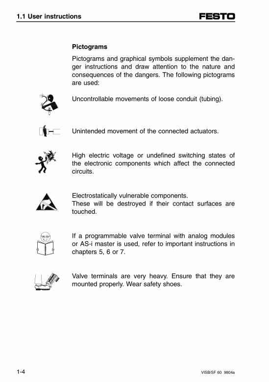
Pictograms and graphical symbols supplement the dan-ger instructions and draw attention to the nature andconsequences of the dangers. The following pictogramsare used:
Uncontrollable movements of loose conduit (tubing).
Unintended movement of the connected actuators.
High electric voltage or undefined switching states ofthe electronic components which affect the connectedcircuits.
Electrostatically vulnerable components.These will be destroyed if their contact surfaces aretouched.
If a programmable valve terminal with analog modulesor AS-i master is used, refer to important instructions inchapters 5, 6 or 7.
Valve terminals are very heavy. Ensure that they aremounted properly. Wear safety shoes.
1.1 User instructions
1-4 VISB/SF 60 9804a
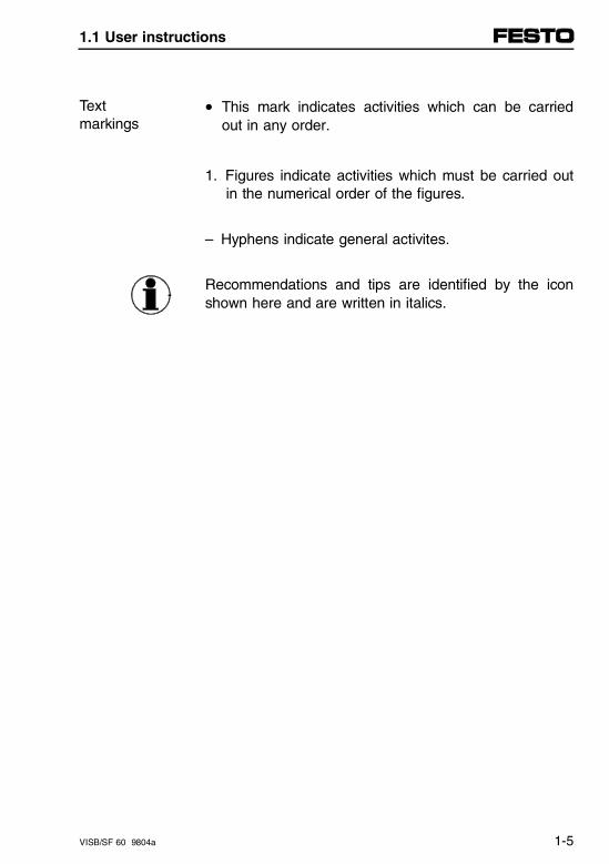
• This mark indicates activities which can be carriedout in any order.
Textmarkings
1. Figures indicate activities which must be carried outin the numerical order of the figures.
– Hyphens indicate general activites.
Recommendations and tips are identified by the iconshown here and are written in italics.
1.1 User instructions
VISB/SF 60 9804a 1-5
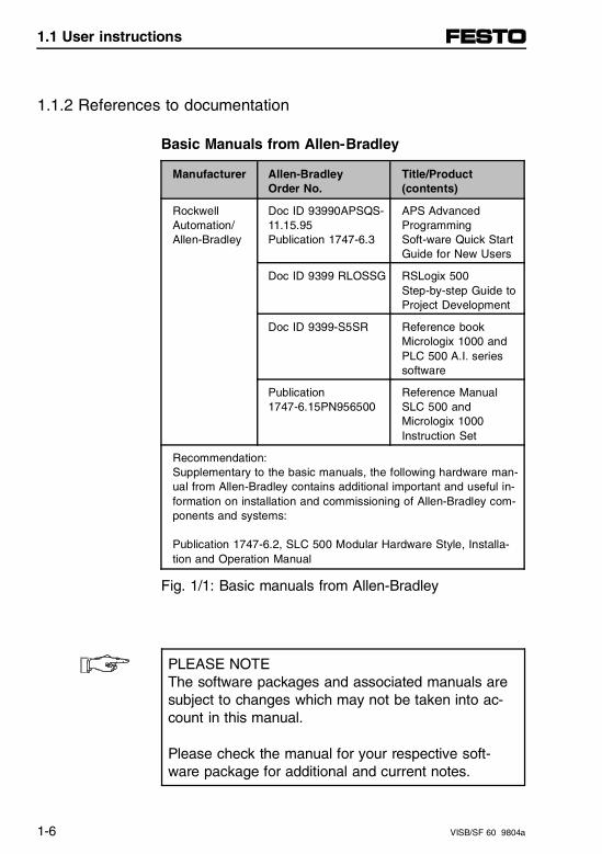
1.1.2 References to documentation
Basic Manuals from Allen-Bradley
Manufacturer Allen-Bradley Order No.
Title/Product(contents)
Rockwell Automation/ Allen-Bradley
Doc ID 93990APSQS-11.15.95Publication 1747-6.3
APS Advanced Programming Soft-ware Quick StartGuide for New Users
Doc ID 9399 RLOSSG RSLogix 500 Step-by-step Guide toProject Development
Doc ID 9399-S5SR Reference bookMicrologix 1000 andPLC 500 A.I. seriessoftware
Publication 1747-6.15PN956500
Reference ManualSLC 500 and Micrologix 1000 Instruction Set
Recommendation:Supplementary to the basic manuals, the following hardware man-ual from Allen-Bradley contains additional important and useful in-formation on installation and commissioning of Allen-Bradley com-ponents and systems:
Publication 1747-6.2, SLC 500 Modular Hardware Style, Installa-tion and Operation Manual
Fig. 1/1: Basic manuals from Allen-Bradley
PLEASE NOTEThe software packages and associated manuals aresubject to changes which may not be taken into ac-count in this manual.
Please check the manual for your respective soft-ware package for additional and current notes.
1.1 User instructions
1-6 VISB/SF 60 9804a
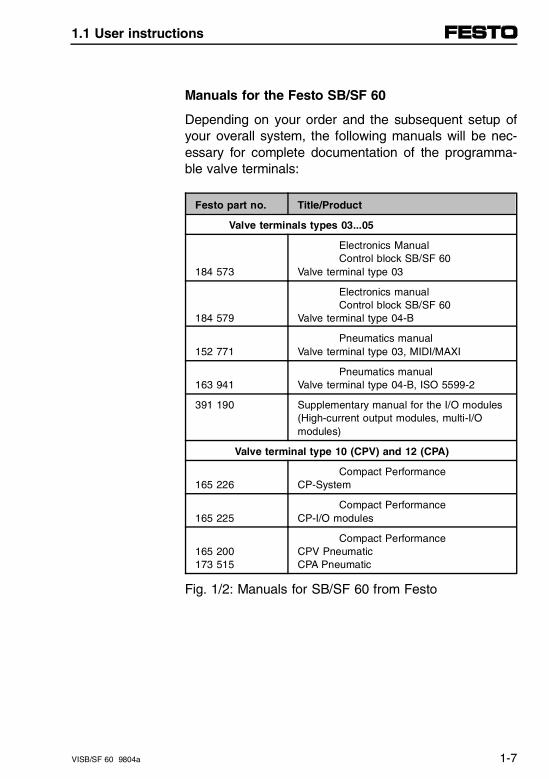
Manuals for the Festo SB/SF 60
Depending on your order and the subsequent setup ofyour overall system, the following manuals will be nec-essary for complete documentation of the programma-ble valve terminals:
Festo part no. Title/Product
Valve terminals types 03...05
184 573
Electronics Manual Control block SB/SF 60
Valve terminal type 03
184 579
Electronics manualControl block SB/SF 60
Valve terminal type 04-B
152 771Pneumatics manual
Valve terminal type 03, MIDI/MAXI
163 941Pneumatics manual
Valve terminal type 04-B, ISO 5599-2
391 190 Supplementary manual for the I/O modules(High-current output modules, multi-I/Omodules)
Valve terminal type 10 (CPV) and 12 (CPA)
165 226Compact Performance
CP-System
165 225Compact Performance
CP-I/O modules
165 200173 515
Compact PerformanceCPV PneumaticCPA Pneumatic
Fig. 1/2: Manuals for SB/SF 60 from Festo
1.1 User instructions
VISB/SF 60 9804a 1-7
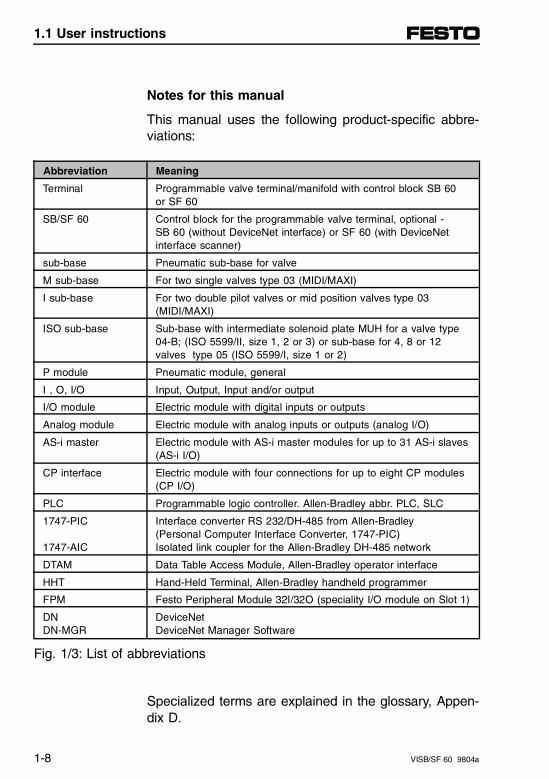
Notes for this manual
This manual uses the following product-specific abbre-viations:
Abbreviation Meaning
Terminal Programmable valve terminal/manifold with control block SB 60 or SF 60
SB/SF 60 Control block for the programmable valve terminal, optional - SB 60 (without DeviceNet interface) or SF 60 (with DeviceNet interface scanner)
sub-base Pneumatic sub-base for valve
M sub-base For two single valves type 03 (MIDI/MAXI)
I sub-base For two double pilot valves or mid position valves type 03(MIDI/MAXI)
ISO sub-base Sub-base with intermediate solenoid plate MUH for a valve type04-B; (ISO 5599/II, size 1, 2 or 3) or sub-base for 4, 8 or 12valves type 05 (ISO 5599/I, size 1 or 2)
P module Pneumatic module, general
I , O, I/O Input, Output, Input and/or output
I/O module Electric module with digital inputs or outputs
Analog module Electric module with analog inputs or outputs (analog I/O)
AS-i master Electric module with AS-i master modules for up to 31 AS-i slaves(AS-i I/O)
CP interface Electric module with four connections for up to eight CP modules(CP I/O)
PLC Programmable logic controller. Allen-Bradley abbr. PLC, SLC
1747-PIC
1747-AIC
Interface converter RS 232/DH-485 from Allen-Bradley (Personal Computer Interface Converter, 1747-PIC) Isolated link coupler for the Allen-Bradley DH-485 network
DTAM Data Table Access Module, Allen-Bradley operator interface
HHT Hand-Held Terminal, Allen-Bradley handheld programmer
FPM Festo Peripheral Module 32I/32O (speciality I/O module on Slot 1)
DNDN-MGR
DeviceNet DeviceNet Manager Software
Fig. 1/3: List of abbreviations
Specialized terms are explained in the glossary, Appen-dix D.
1.1 User instructions
1-8 VISB/SF 60 9804a
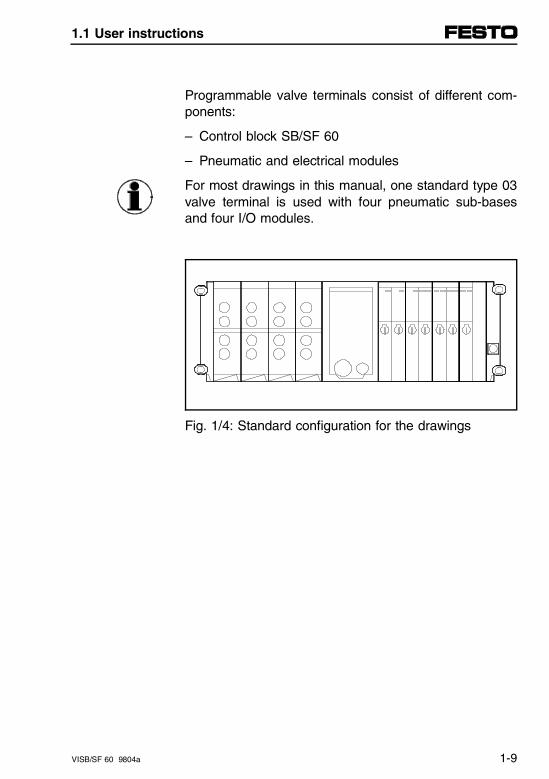
Programmable valve terminals consist of different com-ponents:
– Control block SB/SF 60
– Pneumatic and electrical modules
For most drawings in this manual, one standard type 03valve terminal is used with four pneumatic sub-basesand four I/O modules.
Fig. 1/4: Standard configuration for the drawings
1.1 User instructions
VISB/SF 60 9804a 1-9
Service
In the event of technical problems with Festo products(e.g., SB/SF 60 valve terminal, Festo cables), pleasecontact your local Festo service location (addressessee on the CD-ROM 128048 "Interactive Documenta-tion SB/SF 60").
In the even of technical problems with Allen-Bradleyproducts (e.g., software, networks) please contact yourlocal Allen-Bradley software office or your distributor:
– Rockwell Software Inc.Tel. USA 414-321-8000
– Allen-Bradley Inc.Tel. USA 440-646-5000
1.1 User instructions
1-10 VISB/SF 60 9804a
1.2 System overview
Allen-Bradley and Festo
The SB/SF 60 programmable valve terminal representsa close cooperation between Allen-Bradley, marketleader in control technology, and Festo, market leaderin intelligent pneumatics. Allen-Bradley SLC 500 tech-nology is used in the programmable valve terminal, pro-viding all customers an optimal and perfect solution tocontrolling predominantly pneumatic automation tasks.
This also means the experienced Allen-Bradley usercan continue to use his familiar accessories as well astested techniques and aids from the Allen-Bradley line,resulting in efficient and effective solutions with the newSB 60 or SF 60 programmable valve terminals fromFesto.
The following pages show in individual steps how theprogrammable valve terminal can be integrated into theAllen-Bradley hierarchy of automation solutions, andwhat numerous and innovative possibilities are avail-able with this installation-saving Festo technology.
1.2 System overview
VISB/SF 60 9804a 1-11
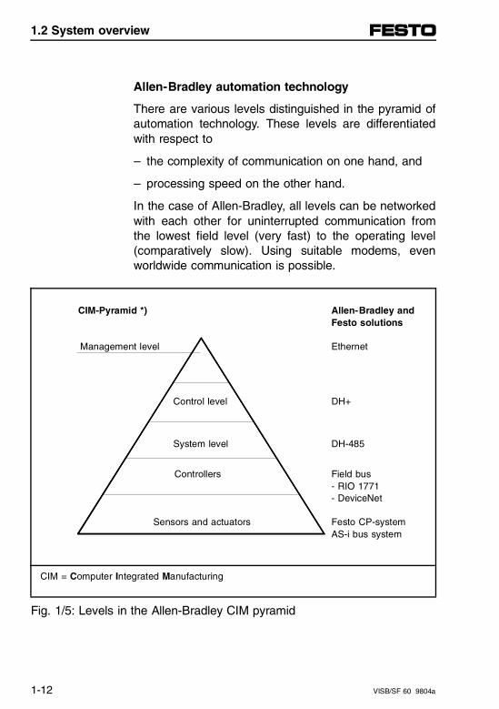
Allen-Bradley automation technology
There are various levels distinguished in the pyramid ofautomation technology. These levels are differentiatedwith respect to
– the complexity of communication on one hand, and
– processing speed on the other hand.
In the case of Allen-Bradley, all levels can be networkedwith each other for uninterrupted communication fromthe lowest field level (very fast) to the operating level(comparatively slow). Using suitable modems, evenworldwide communication is possible.
CIM-Pyramid *)
Management level
Allen-Bradley and Festo solutions
Ethernet
Control level DH+
System level DH-485
Controllers
Sensors and actuators
Field bus- RIO 1771- DeviceNet
Festo CP-systemAS-i bus system
CIM = Computer Integrated Manufacturing
Fig. 1/5: Levels in the Allen-Bradley CIM pyramid
1.2 System overview
1-12 VISB/SF 60 9804a
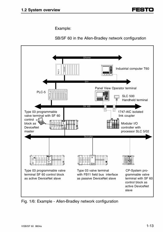
Example:
SB/SF 60 in the Allen-Bradley network configuration
Industrial computer T60
Panel View Operator terminalPLC-5
SLC 500 Handheld terminal
Type 03 programmable 1747-AIC isolatedvalve terminal with SF 60 link couplercontrolblock as Modular I/ODeviceNet controller withmaster processor SLC 5/02
Type 03 programmable valve Type 03 valve terminal CP-System pro-terminal SF 60 control block with FB11 field bus interface grammable valveas active DeviceNet slave as passive DeviceNet slave terminal with SF 60
control block as active DeviceNet slave
Fig. 1/6: Example - Allen-Bradley network configuration
1.2 System overview
VISB/SF 60 9804a 1-13
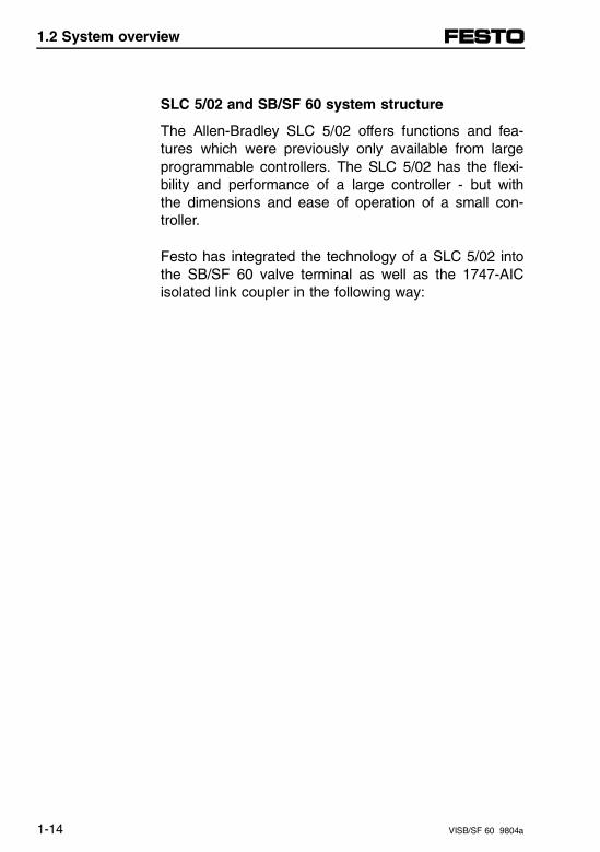
SLC 5/02 and SB/SF 60 system structure
The Allen-Bradley SLC 5/02 offers functions and fea-tures which were previously only available from largeprogrammable controllers. The SLC 5/02 has the flexi-bility and performance of a large controller - but withthe dimensions and ease of operation of a small con-troller.
Festo has integrated the technology of a SLC 5/02 intothe SB/SF 60 valve terminal as well as the 1747-AICisolated link coupler in the following way:
1.2 System overview
1-14 VISB/SF 60 9804a
1 2 3 4 5 6
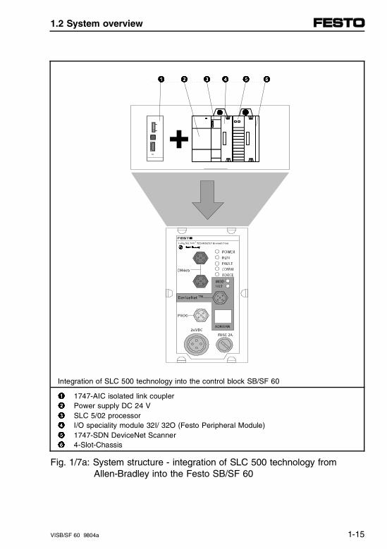
Integration of SLC 500 technology into the control block SB/SF 60
1 1747-AIC isolated link coupler2 Power supply DC 24 V3 SLC 5/02 processor4 I/O speciality module 32I/ 32O (Festo Peripheral Module) 5 1747-SDN DeviceNet Scanner6 4-Slot-Chassis
Fig. 1/7a: System structure - integration of SLC 500 technology from Allen-Bradley into the Festo SB/SF 60
1.2 System overview
VISB/SF 60 9804a 1-15
The 1747-AIC integrated link coupler represents a spe-cial feature. The three connections to the 1747-AIChave been integrated as follows:
– The DH-485 INTFC interface is provided twice on thecontrol block. These two M12 connections are inter-nally parallel connected to each other. This meansthe DH-485 network can be connected to IP65 byT-TAP or daisy-chained.
– The PERIPHERAL (J2) programming interface is al-so integrated and can be connected to IP65. This in-terface is internally supplied with 24 V from the con-trol block.
– The CPU (J1) interface of the 1747-AIC is alreadyinternally connected to the processor module and isnot therefore provided separately.
PLEASE NOTEThis means the PROG interface of the valve terminalmust not be connected to the CPU interface of a1747-AIC, as communications errors could result.
The following illustration provides an overview of the1747-AIC integrated network coupler:
1.2 System overview
1-16 VISB/SF 60 9804a
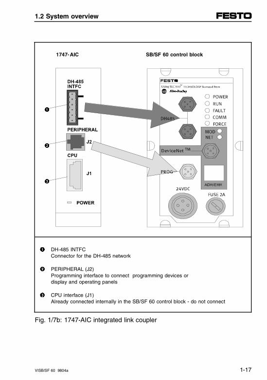
1747-AIC SB/SF 60 control block
1
2
3
1 DH-485 INTFC Connector for the DH-485 network
2 PERIPHERAL (J2)Programming interface to connect programming devices ordisplay and operating panels
3 CPU interface (J1)Already connected internally in the SB/SF 60 control block - do not connect
Fig. 1/7b: 1747-AIC integrated link coupler
1.2 System overview
VISB/SF 60 9804a 1-17
This means the SB/SF 60 programmable valve terminalcorresponds to a technologically leading control systemfrom Allen-Bradley, which is in itself flexible and incor-porates all the advantages of large controllers while stillbeing easy to use. The SB/SF 60 programmable valveterminal has an IP65 rating and can be used outside acontrol cabinet.
The following illustration shows in a schematic repre-sentation of the SB/SF 60 control block the integratedcomponents of the SLC 5/02 and the likewise inte-grated 1747-AIC:
1.2 System overview
1-18 VISB/SF 60 9804a
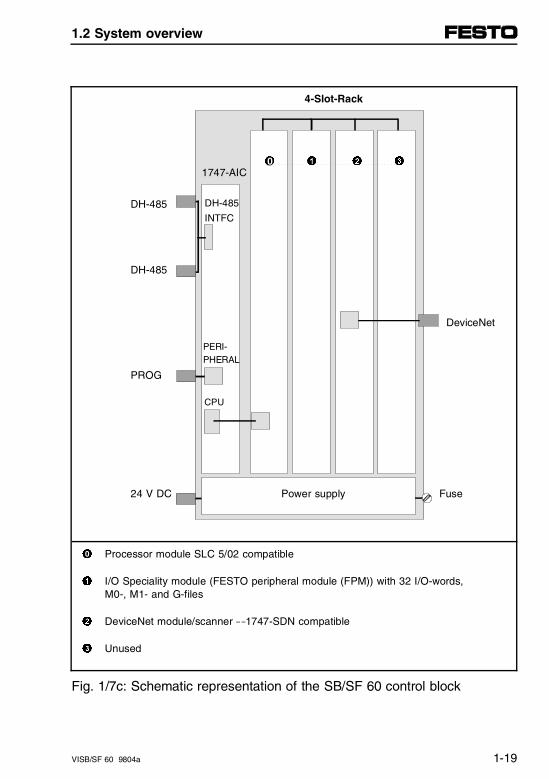
4-Slot-Rack
DH-485
DH-485
DeviceNet
PROG
24 V DC Fuse
1 Processor module SLC 5/02 compatible
1 I/O Speciality module (FESTO peripheral module (FPM)) with 32 I/O-words, M0-, M1- and G-files
2 DeviceNet module/scanner - 1747-SDN compatible
3 Unused
Fig. 1/7c: Schematic representation of the SB/SF 60 control block
Power supply
CPU
PERI-PHERAL
1 1 2 3
1747-AIC
DH-485
INTFC
0
0
1.2 System overview
VISB/SF 60 9804a 1-19
For programming you will require a programmer, e.g.,an HHT or a PC (with A.I. 500, APS or RSLogix 500software and provisions for the DH-485 network). Theprogrammer can be connected directly on the controlblock to the PROG interface (DH-485 interface with 24V supply for the programmer).
The following possibilities are available for using theSB/SF 60:
– PC (with A.I. 500, APS or RSLogix 500 softwarefrom A-B)
– Data table access module (DTAM) from A-B
– Hand-Held Terminals HHT from A-B
– Simple pushbuttons (START/STOP).
1.2 System overview
1-20 VISB/SF 60 9804a
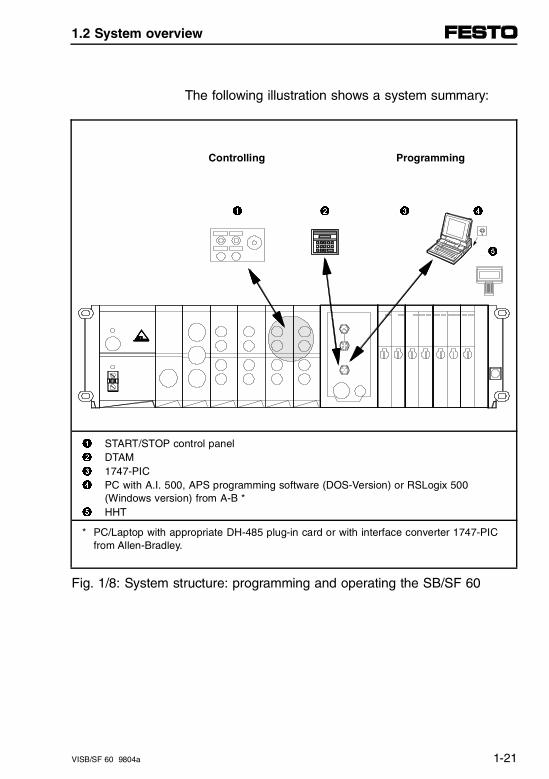
The following illustration shows a system summary:
Controlling Programming
1 2 3 4
5
1 START/STOP control panel2 DTAM3 1747-PIC4 PC with A.I. 500, APS programming software (DOS-Version) or RSLogix 500
(Windows version) from A-B *5 HHT
* PC/Laptop with appropriate DH-485 plug-in card or with interface converter 1747-PICfrom Allen-Bradley.
Fig. 1/8: System structure: programming and operating the SB/SF 60
1.2 System overview
VISB/SF 60 9804a 1-21
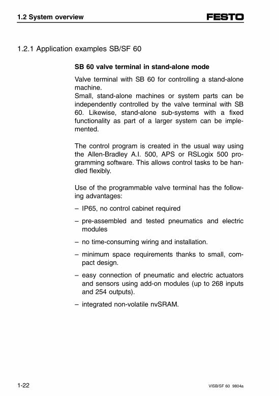
1.2.1 Application examples SB/SF 60
SB 60 valve terminal in stand-alone mode
Valve terminal with SB 60 for controlling a stand-alonemachine.Small, stand-alone machines or system parts can beindependently controlled by the valve terminal with SB60. Likewise, stand-alone sub-systems with a fixedfunctionality as part of a larger system can be imple-mented.
The control program is created in the usual way usingthe Allen-Bradley A.I. 500, APS or RSLogix 500 pro-gramming software. This allows control tasks to be han-dled flexibly.
Use of the programmable valve terminal has the follow-ing advantages:
– IP65, no control cabinet required
– pre-assembled and tested pneumatics and electricmodules
– no time-consuming wiring and installation.
– minimum space requirements thanks to small, com-pact design.
– easy connection of pneumatic and electric actuatorsand sensors using add-on modules (up to 268 inputsand 254 outputs).
– integrated non-volatile nvSRAM.
1.2 System overview
1-22 VISB/SF 60 9804a
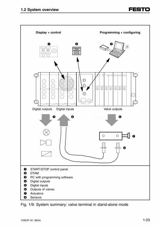
Display + control Programming + configuring
1 2 3
Digital outputs Digital inputs Valve outputs
4 5 6
7
8
1 START/STOP control panel2 DTAM3 PC with programming software4 Digital outputs5 Digital inputs6 Outputs of valves7 Actuators8 Sensors
Fig. 1/9: System summary: valve terminal in stand-alone mode
1.2 System overview
VISB/SF 60 9804a 1-23
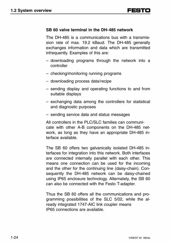
SB 60 valve terminal in the DH-485 network
The DH-485 is a communications bus with a transmis-sion rate of max. 19.2 kBaud. The DH-485 generallyexchanges information and data which are transmittedinfrequently. Examples of this are:
– downloading programs through the network into acontroller
– checking/monitoring running programs
– downloading process data/recipe
– sending display and operating functions to and fromsuitable displays
– exchanging data among the controllers for statisticaland diagnostic purposes
– sending service data and status messages
All controllers in the PLC/SLC families can communi-cate with other A-B components on the DH-485 net-work, as long as they have an appropriate DH-485 in-terface available.
The SB 60 offers two galvanically isolated DH-485 in-terfaces for integration into this network. Both interfacesare connected internally parallel with each other. Thismeans one connection can be used for the incomingand the other for the continuing line (daisy-chain). Con-sequently the DH-485 network can be daisy-chainedusing IP65 enclosure technology. Alternately, the SB 60can also be connected with the Festo T-adapter.
Thus the SB 60 offers all the communications and pro-gramming possibilities of the SLC 5/02, while the al-ready integrated 1747-AIC link coupler means IP65 connections are available.
1.2 System overview
1-24 VISB/SF 60 9804a
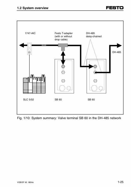
1747-AIC Festo T-adapter DH-485(with or without daisy-chained drop cable)
DH-485
SLC 5/02 SB 60 SB 60
Fig. 1/10: System summary: Valve terminal SB 60 in the DH-485 network
1.2 System overview
VISB/SF 60 9804a 1-25
SF 60 valve terminal as master on DeviceNet
The SF 60 valve terminal incorporates a DeviceNet in-terface for controlling complex systems. This interfaceis identical to the Allen-Bradley 1747-SDN scanner withrespect to function, performance and operation.
In addition to the valves and local in- and outputs,which are directly mounted, any DeviceNet participantscan be connected to the programmable valve terminalwith integrated DeviceNet interface. This permits auto-mation tasks to be managed in which a larger numberof pneumatic components and electrical sensors andother actuators are used. Likewise, stand-alone subsys-tems with self-contained functionality as part of a largersystem can be implemented.
Use of the programmable valve terminal with DeviceNetoffers the following advantages:
– all the possibilities of the SB 60 in stand-alone modeare fully retained
– any DeviceNet participants with enhancing functiona-lities can be added
– DeviceNet interface is integrated with IP65 rating
– ease of installation and easily expandable with up to63 DeviceNet participants
– simple configuration of the slaves using Allen-BradleyDeviceNet-Manager software.
1.2 System overview
1-26 VISB/SF 60 9804a
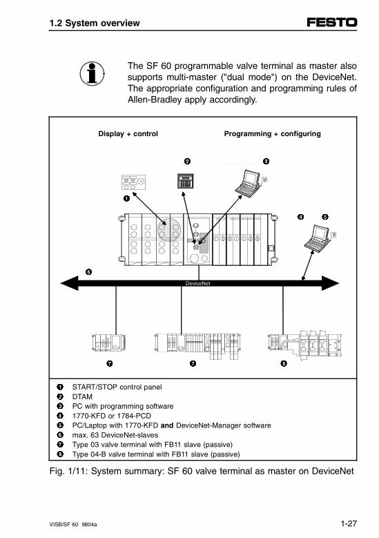
The SF 60 programmable valve terminal as master alsosupports multi-master ("dual mode") on the DeviceNet.The appropriate configuration and programming rules ofAllen-Bradley apply accordingly.
Display + control Programming + configuring
2 3
1
4 5
6
7 7 8
1 START/STOP control panel2 DTAM3 PC with programming software4 1770-KFD or 1784-PCD5 PC/Laptop with 1770-KFD and DeviceNet-Manager software6 max. 63 DeviceNet-slaves7 Type 03 valve terminal with FB11 slave (passive) 8 Type 04-B valve terminal with FB11 slave (passive)
Fig. 1/11: System summary: SF 60 valve terminal as master on DeviceNet
1.2 System overview
VISB/SF 60 9804a 1-27
SF 60 valve terminal as stand-alone slave on DeviceNet
A valve terminal with SF 60 connected as a slave to theDeviceNet control the function units of the system itselfand communicates on DeviceNet with a host master.
When using the programmable valve terminal as aslave, the process configuration or technological con-figuration of a machine or system can be emulatedthrough segmenting in the PLC. All stand-alone mod-ules or function units thereby have their own controlprograms for controlling sub-areas.
Use of the programmable valve terminal as stand-aloneslave offers the following advantages:
– possibilities of the SB 60 in stand-alone mode remainfully intact
– modular configuration of the system/machine
– function modules of system or machine can be indivi-dually linked
– convenient partial start-up is possible
– high degree of system availability resulting fromstand-alone sub-areas
– local display and operation possible
– fast communication transmission
1.2 System overview
1-28 VISB/SF 60 9804a
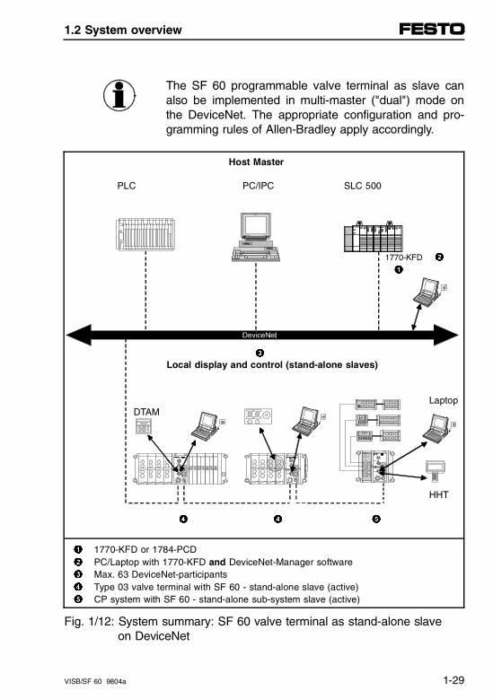
The SF 60 programmable valve terminal as slave canalso be implemented in multi-master ("dual") mode onthe DeviceNet. The appropriate configuration and pro-gramming rules of Allen-Bradley apply accordingly.
Host Master
PLC PC/IPC SLC 500
1770-KFD 2 1
3 Local display and control (stand-alone slaves)
Laptop DTAM
HHT
4 4 5
1 1770-KFD or 1784-PCD2 PC/Laptop with 1770-KFD and DeviceNet-Manager software3 Max. 63 DeviceNet-participants4 Type 03 valve terminal with SF 60 - stand-alone slave (active)5 CP system with SF 60 - stand-alone sub-system slave (active)
Fig. 1/12: System summary: SF 60 valve terminal as stand-alone slave on DeviceNet
1.2 System overview
VISB/SF 60 9804a 1-29
Valve terminal with analog modules
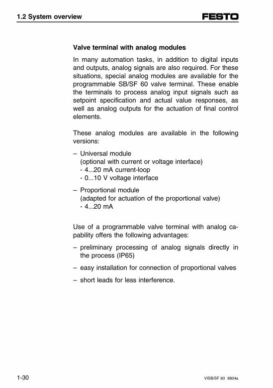
In many automation tasks, in addition to digital inputsand outputs, analog signals are also required. For thesesituations, special analog modules are available for theprogrammable SB/SF 60 valve terminal. These enablethe terminals to process analog input signals such assetpoint specification and actual value responses, aswell as analog outputs for the actuation of final controlelements.
These analog modules are available in the followingversions:
– Universal module(optional with current or voltage interface)- 4...20 mA current-loop- 0...10 V voltage interface
– Proportional module(adapted for actuation of the proportional valve)- 4...20 mA
Use of a programmable valve terminal with analog ca-pability offers the following advantages:
– preliminary processing of analog signals directly inthe process (IP65)
– easy installation for connection of proportional valves
– short leads for less interference.
1.2 System overview
1-30 VISB/SF 60 9804a
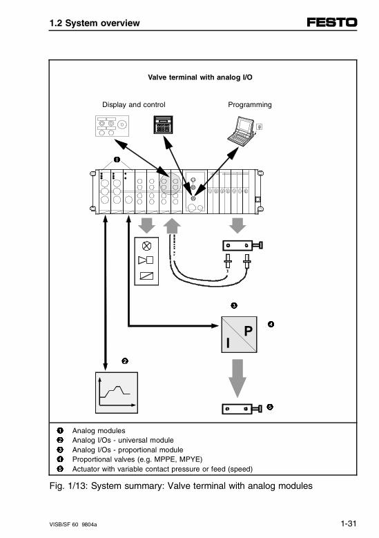
Valve terminal with analog I/O
Display and control Programming
1
3
4
2
5
1 Analog modules2 Analog I/Os - universal module3 Analog I/Os - proportional module4 Proportional valves (e.g. MPPE, MPYE)5 Actuator with variable contact pressure or feed (speed)
Fig. 1/13: System summary: Valve terminal with analog modules
1.2 System overview
VISB/SF 60 9804a 1-31
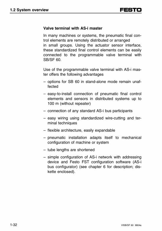
Valve terminal with AS-i master
In many machines or systems, the pneumatic final con-trol elements are remotely distributed or arranged in small groups. Using the actuator sensor interface,these standardized final control elements can be easilyconnected to the programmable valve terminal withSB/SF 60.
Use of the programmable valve terminal with AS-i mas-ter offers the following advantages
– options for SB 60 in stand-alone mode remain unaf-fected
– easy-to-install connection of pneumatic final controlelements and sensors in distributed systems up to100 m (without repeater)
– connection of any standard AS-i bus participants
– easy wiring using standardized wire-cutting and ter-minal techniques
– flexible architecture, easily expandable
– pneumatic installation adapts itself to mechanicalconfiguration of machine or system
– tube lengths are shortened
– simple configuration of AS-i network with addressingdevice and Festo FST configuration software (AS-ibus configurator) (see chapter 6 for description; dis-kette enclosed).
1.2 System overview
1-32 VISB/SF 60 9804a
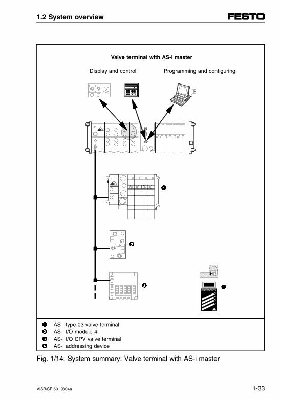
Valve terminal with AS-i master
Display and control Programming and configuring
1
1 AS-i type 03 valve terminal2 AS-i I/O module 4I3 AS-i I/O CPV valve terminal4 AS-i addressing device
Fig. 1/14: System summary: Valve terminal with AS-i master
3
2
4
1.2 System overview
VISB/SF 60 9804a 1-33
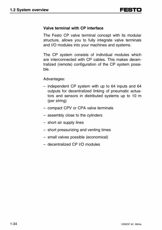
Valve terminal with CP interface
The Festo CP valve terminal concept with its modularstructure, allows you to fully integrate valve terminalsand I/O modules into your machines and systems.
The CP system consists of individual modules whichare interconnected with CP cables. This makes decen-tralized (remote) configuration of the CP system possi-ble.
Advantages:
– independent CP system with up to 64 inputs and 64outputs for decentralized linking of pneumatic actua-tors and sensors in distributed systems up to 10 m(per string)
– compact CPV or CPA valve terminals
– assembly close to the cylinders
– short air supply lines
– short pressurizing and venting times
– small valves possible (economical)
– decentralized CP I/O modules
1.2 System overview
1-34 VISB/SF 60 9804a
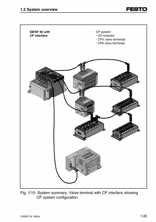
SB/SF 60 with CP system:CP interface - I/O modules
- CPV valve terminals - CPA valve terminals
Fig. 1/15: System summary: Valve terminal with CP interface showing CP system configuration
1.2 System overview
VISB/SF 60 9804a 1-35
1.2.2 System operation with display and control units
Easy operation
Easy system operation for the SB/SF 60 is accom-plished as follows:
– simple START/STOP pushbuttons with indicatorlights, preferably connected with a few cables to thedigital I/Os on the valve terminal.
– pushbutton stations with multiple buttons/indicatorlights preferably connected to the multi-I/O module(12 inputs, 8 outputs) of the valve terminal using a25-pin multi-conductor cable.
1.2 System overview
1-36 VISB/SF 60 9804a
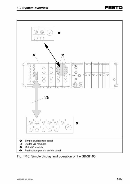
1
3 2
4
1 Simple pushbutton panel2 Digital I/O modules3 Multi-I/O module4 Pushbutton panel / switch panel
Fig. 1/16: Simple display and operation of the SB/SF 60
1.2 System overview
VISB/SF 60 9804a 1-37
User friendly operation
The SB/SF 60 programmable valve terminal permitstwo connection options:
– direct connection through the PROG interface of thevalve terminal (DH-485 with 24 V supply for the oper-ator terminal, corresponds to the "peripheral" inter-face on the 1747-AIC), or
– indirect connection through the DH-485 interface(s)of the valve terminal (corresponds to the "DH-485"interface on the 1747-AIC). The operator terminalcan be connected at any desired location in the net-work through an 1747-AIC to the DH-485 network.
This means all A-B components can be implementedand operated via a user friendly interface, includingvarying opportunities from text displays to full colorgraphical interfaces (examples):
– DTAM, DTAM Plus, DTAM Micro (or compatible)
– PanelView 550, 600 or 900 (or compatible)
– Hand-Held Terminal
– PC with appropriate software.
The following illustration provides an overview:
1.2 System overview
1-38 VISB/SF 60 9804a
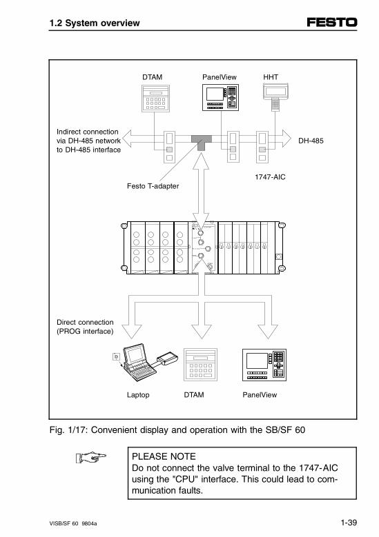
DTAM PanelView HHT
Indirect connectionvia DH-485 network DH-485to DH-485 interface
1747-AICFesto T-adapter
Direct connection(PROG interface)
Laptop DTAM PanelView
Fig. 1/17: Convenient display and operation with the SB/SF 60
PLEASE NOTEDo not connect the valve terminal to the 1747-AICusing the "CPU" interface. This could lead to com-munication faults.
1.2 System overview
VISB/SF 60 9804a 1-39

1.2 System overview
1-40 VISB/SF 60 9804a
1.3 System limits and planning aspects
1.3.1 System limits
In theory, a fully-implemented, complete system withthe SB/SF 60 programmable valve terminal can look asfollows:
SB/SF 60 without DeviceNet
Up to 268 digital inputs and 254 outputs, also 9 analoginputs and 9 outputs, specifically:
– 96 digital inputs and 74 digital outputs (incl. valves)and
– CP interface with up to 64 CP inputs and 64 CP outputs and
– AS-i master with up to 31 AS-i slaves (max. 124 AS-i inputs and 124 AS-i outputs)
– max. 9 proportional analog modules or 3 universalanalog modules
A display and control unit (DCU) connected directly tothe valve terminal.
1.3 System limits and planning aspects
VISB/SF 60 9804a 1-41
SF 60 with DeviceNet
Local I/Os as above, but in addition with up to 63 DeviceNet participants as slaves, e.g.,
– Festo valve terminals with FB11 DeviceNet nodes aspassive slaves with max. 64 inputs and 64 outputseach
– Festo SF 60 valve terminals as active slaves for de-central pre-processing. Each SF 60 slave can againprocess up to 268 digital, local inputs and 254 out-puts.
In practice, the above number of devices and/or inputsand outputs is limited by the size of the program mem-ory (4 kBytes for commands) and the cycle time (4.8 ms/1 kByte of instructions).
The number of controllable inputs and outputs is alwaysdependent on the complexity of the control problem andthe use of peripheral equipment. For any larger applica-tions, the memory requirement and the cycle timeshould be estimated on an individual basis (see Appen-dix C).
1.3 System limits and planning aspects
1-42 VISB/SF 60 9804a
Recommendation:
– Optimize the update cycles of the processor for smallvalve terminals (e.g. up to 64 I/Os) if necessary ac-cording to Appendix C. This will allow you to handlea 5...10 times faster application.
– Note also the execution times and the memory requi-rement of the individual programming commands ofAllen-Bradley and the programming of the interruptinputs (see also chapter 3.5 in this manual).
– Use the freely configurable interrupt inputs of theFesto Peripheral Module to monitor time-critical sig-nals and process states as an I/O interrupt.
1.3 System limits and planning aspects
VISB/SF 60 9804a 1-43
1.3.2 Planning aspects for type 03…05 valve terminals
This chapter contains some hints for the following plan-ning aspects when using modular valve terminals:
– Planning aspect 1Common voltage supply to all outputs, i.e., the E-STOP function for all outputs is implemented viaPin 2 of the node/adapter block (valve and electricmodules).
– Planning aspect 2Separate voltage supplies for individual high-currentoutput modules, i.e., the auxiliary power supply incombination with the high-current outputs enablesthem to operate independently of the E-STOP func-tion.
– Planning aspect 3Possible combinations of I/O modules. Notes forplanning the sequence for assembly of I/O modulesand for combining these modules on a valve termi-nal.
1.3 System limits and planning aspects
1-44 VISB/SF 60 9804a
Planning aspect 1Common voltage supply for all outputs
This involves all components of the valve terminal beingsupplied with a 24 V power supply via pins 1 and 2 onthe node/adapter blocks.
– Pin 1: 24 V (± 25 %), max. 2.2 A Operating voltage for the internal electronics of theSB/SF 60 node, all I/O modules, as well as thePROG interface. 24 V DC power supply to all in-puts/sensor (PNP and NPN).
– Pin 2: 24 V (± 10 %), max. 10 AOperating voltage for the valve and electrical outputs.Please note that when the valves are switched off(e.g., during E-STOP) all the electrical outputs arealso switched off.
1.3 System limits and planning aspects
VISB/SF 60 9804a 1-45
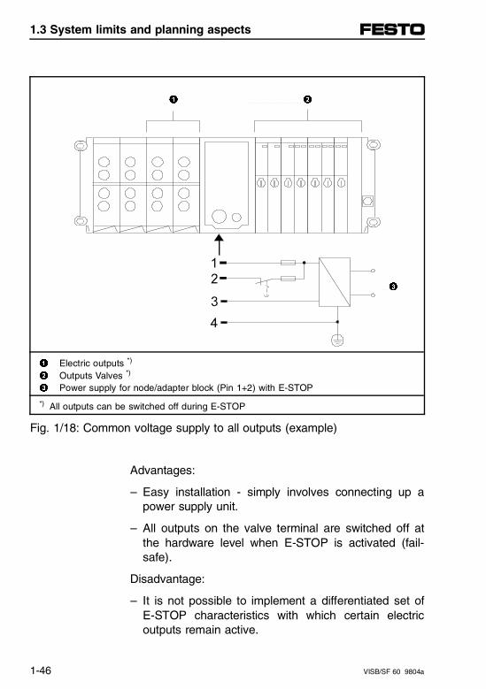
1 2
3
1 Electric outputs *)
2 Outputs Valves *) 3 Power supply for node/adapter block (Pin 1+2) with E-STOP
*) All outputs can be switched off during E-STOP
Fig. 1/18: Common voltage supply to all outputs (example)
Advantages:
– Easy installation - simply involves connecting up apower supply unit.
– All outputs on the valve terminal are switched off atthe hardware level when E-STOP is activated (fail-safe).
Disadvantage:
– It is not possible to implement a differentiated set ofE-STOP characteristics with which certain electricoutputs remain active.
1.3 System limits and planning aspects
1-46 VISB/SF 60 9804a
Planning aspect 2 Separate voltage supply for individual high-currentoutput modules
This involves fitting at least one module for a 24 V aux-iliary power supply to the left side of the node. Thismodule provides electrical isolation of the electrical I/Oside. The high-current output modules are fitted to theleft side of the auxiliary power supply unit and are onlysupplied from their 24 V power source.
A combination of PNP and NPN high-current outputmodules is permitted.
– Pin 1: 24 V (± 25 %), max. 2.2 A Operating voltage for the internal electronics of theSB/SF 60 node, all I/O modules, as well as thePROG interface. 24 V DC power supply to all in-puts/sensors (PNP and NPN).
– Pin 2: 24 V (± 10 %), max. 10 A Operating voltage for the valves and only for theelectric outputs (0.5 A). Note that, when the valvesare switched off (e.g., during E-STOP), only theseelectric outputs (0.5 A) are actually switched off.
1.3 System limits and planning aspects
VISB/SF 60 9804a 1-47

Voltage supply from auxiliary power supply:
– Terminal 2: 24 V (± 25 %), max. 25 A Operating voltage for all high-current outputs (PNP orNPN, 2 A) mounted to the left of the respective auxil-iary power supply (power supply ends with last high-current output module).
Due to the auxiliary power supply, the operating voltageof the high-current outputs is entirely separate from pin2 on the node. Output modules (0.5 A) mounted to theleft of the last high-current module are still supplied withpower from pin 2 of the SB/SF 60.
1.3 System limits and planning aspects
1-48 VISB/SF 60 9804a
Advantages:
– Additional 25 A per auxiliary power supply are avail-able for loads with high current consumption (e.g. hy-draulic valves).
– Modules with four high-current outputs (HC-OUTPUT,each with optional 2 A PNP or NPN): these can ob-tain their current from the auxiliary power supply onthe right side.
– Electric high-current outputs to the left of the auxiliarypower supply can remain active when the E-STOP isactive.
– Multiple auxiliary power supplies per terminal arepossible.
Disadvantages:
– An auxiliary power supply unit occupies the space ofone I/O module (max. 12 modules).
– If the high-current outputs to the left of the auxiliarypower supply are also switched off during E-STOP, itmay be necessary to provide additional appropriateinstallations.
1.3 System limits and planning aspects
VISB/SF 60 9804a 1-49
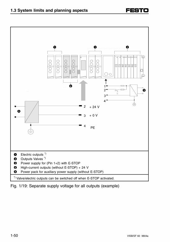
1 1 2
4
3
+ 24 V5
+ 0 V
PE
1 Electric outputs *)
2 Outputs Valves *)
3 Power supply for (Pin 1+2) with E-STOP4 High-current outputs (without E-STOP) + 24 V5 Power pack for auxiliary power supply (without E-STOP)
*) Valve/electric outputs can be switched off when E-STOP activated.
Fig. 1/19: Separate supply voltage for all outputs (example)
1.3 System limits and planning aspects
1-50 VISB/SF 60 9804a
Planning aspect 3 Possible combinations of I/O modules
A wide range of universal and special I/O modules areavailable for modular valve terminals and these can becombined in virtually any sequence (see the followingillustration).Note the permissible combinations during the planningstage, or when converting these terminals. The basicrule is: max. 12 electric modules per terminal.
The following applies to individual electric modules:
– Digital PNP modules (4I, 8I and 4O) in any combina-tion and at any position (figure 5).
– Digital NPN input modules (4I, 8I) in any combinationand at any position (figure 5).
– Analog I/O modules (PROP; UNIVERSAL) in anycombination and at any position (figure 4), but max.9 analog channels.
– Multi-I/O modules (PNP, NPN) with 12I and 8O permodule; in any combination and at any position. Thismodule uses 3 module slots. This means that to-gether with the multi-I/O modules (3 slots each) cor-respondingly fewer other modules can be installed(max. 12 module slots = 3 + 9 or 2 x 3 + 6 or 3 x 3 +3 or 4 x 3).
1.3 System limits and planning aspects
VISB/SF 60 9804a 1-51
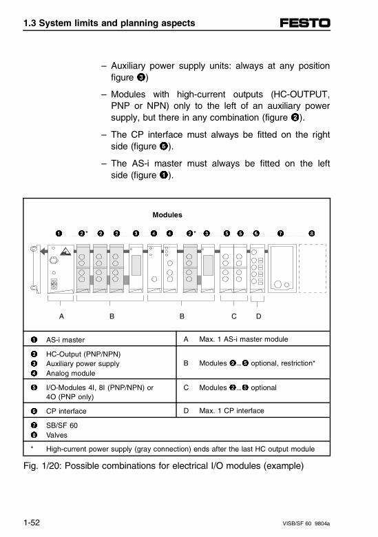
– Auxiliary power supply units: always at any positionfigure 3)
– Modules with high-current outputs (HC-OUTPUT,PNP or NPN) only to the left of an auxiliary powersupply, but there in any combination (figure 2).
– The CP interface must always be fitted on the rightside (figure 6).
– The AS-i master must always be fitted on the leftside (figure 1).
Modules
1 2* 2 2 3 4 4 2* 3 5 5 6 7 8
A B B C D
1 AS-i master A Max. 1 AS-i master module
2 HC-Output (PNP/NPN) 3 Auxiliary power supply 4 Analog module
B Modules 2...5 optional, restriction*
5 I/O-Modules 4I, 8I (PNP/NPN) or 4O (PNP only)
C Modules 2...5 optional
6 CP interface D Max. 1 CP interface
7 SB/SF 608 Valves
* High-current power supply (gray connection) ends after the last HC output module
Fig. 1/20: Possible combinations for electrical I/O modules (example)
1.3 System limits and planning aspects
1-52 VISB/SF 60 9804a
Additional information on the individual modules will befound in:
– Chapter 2 for the I/O modules
– "Supplementary Manual for the I/O Modules" for theauxiliary power supply, the high-current output mod-ules, and the multi-I/O modules.
– Chapter 5 for the analog I/O modules
– Chapter 6 for the AS-i master
– Chapter 7 for the CP interface
1.3 System limits and planning aspects
VISB/SF 60 9804a 1-53

1.3 System limits and planning aspects
1-54 VISB/SF 60 9804a
Chapter 2
System description of type 03 valve terminal
2. System description of type 03 valve terminal
VISB/SF 60-03 9804a 2-I
Contents
2. System description of type 03 valve terminal
2.1 Components . . . . . . . . . . . . . . . . . . . . . . . . . . . . . . . . . . . . . . . 2-1
Structure of type 03 valve terminal . . . . . . . . . . . . . . . . . . . . . . 2-1
2.2 Assembly . . . . . . . . . . . . . . . . . . . . . . . . . . . . . . . . . . . . . . . . . . 2-5
2.2.1 Mounting the components . . . . . . . . . . . . . . . . . . . . . . . . . . . . . 2-5Input/output modules . . . . . . . . . . . . . . . . . . . . . . . . . . . . . . . . . 2-7End plates. . . . . . . . . . . . . . . . . . . . . . . . . . . . . . . . . . . . . . . . . . 2-9Top-hat rail clamping unit . . . . . . . . . . . . . . . . . . . . . . . . . . . . . 2-12
2.2.2. Mounting the valve terminal . . . . . . . . . . . . . . . . . . . . . . . . . . . 2-13Wall mounting. . . . . . . . . . . . . . . . . . . . . . . . . . . . . . . . . . . . . . 2-13Top-hat rail mounting . . . . . . . . . . . . . . . . . . . . . . . . . . . . . . . . 2-15
2.3 Electrical connections . . . . . . . . . . . . . . . . . . . . . . . . . . . . . . 2-19
2.3.1 Opening and closing the control block . . . . . . . . . . . . . . . . . . . 2-19Control block layout . . . . . . . . . . . . . . . . . . . . . . . . . . . . . . . . . 2-21
2.3.2 Connecting operating voltages . . . . . . . . . . . . . . . . . . . . . . . . . 2-23Calculating current draw. . . . . . . . . . . . . . . . . . . . . . . . . . . . . . 2-25Pin assignments for the supply voltage connection. . . . . . . . . 2-27Protective grounding. . . . . . . . . . . . . . . . . . . . . . . . . . . . . . . . . 2-28
2.3.3 The DH-485 interfaces on the SB/SF 60 . . . . . . . . . . . . . . . . . 2-29
2.3.4 Connecting up the PROG programming interface . . . . . . . . . . 2-30Pin assignments for Festo programming cable . . . . . . . . . . . . 2-31
2. System description of type 03 valve terminal
2-II VISB/SF 60-03 9804a
2.3.5 Connecting up the DH-485 interfaces (DH-485 with galvanic isolation). . . . . . . . . . . . . . . . . . . . . . . . . 2-32Cable and plugs/sockets for the DH-485 connection variants . . . . . . . . . . . . . . . . . . . . . . . . . . . . . . . . . . 2-36Connecting the SB/SF 60 to the DH-485 interface of a 1747-AIC (via the 6-pin A-B terminal) . . . . . . . . . 2-38DH-485 termination resistor and grounding. . . . . . . . . . . . . . . . 2-39
2.3.6 Connecting the DeviceNet interface (SF 60 only) . . . . . . . . . . . 2-41Pin assignments for the DeviceNet interface. . . . . . . . . . . . . . . 2-44Wiring notes for Allen-Bradley DeviceNet . . . . . . . . . . . . . . . . . 2-45Allen-Bradley DeviceNet cable System . . . . . . . . . . . . . . . . . . . 2-46DeviceNet termination resistor . . . . . . . . . . . . . . . . . . . . . . . . . . 2-48
2.3.7 Connecting the input/output modules. . . . . . . . . . . . . . . . . . . . . 2-49Connecting the input modules (PNP/NPN) . . . . . . . . . . . . . . . . 2-49Pin allocation . . . . . . . . . . . . . . . . . . . . . . . . . . . . . . . . . . . . . . . 2-51Connecting up the output modules (PNP) . . . . . . . . . . . . . . . . . 2-52Pin assignment. . . . . . . . . . . . . . . . . . . . . . . . . . . . . . . . . . . . . . 2-54Short circuit/overload . . . . . . . . . . . . . . . . . . . . . . . . . . . . . . . . . 2-55DUO cable . . . . . . . . . . . . . . . . . . . . . . . . . . . . . . . . . . . . . . . . . 2-56Designation of inputs and outputs . . . . . . . . . . . . . . . . . . . . . . . 2-57
2.4 Addressing . . . . . . . . . . . . . . . . . . . . . . . . . . . . . . . . . . . . . . . . 2-59
General. . . . . . . . . . . . . . . . . . . . . . . . . . . . . . . . . . . . . . . . . . . . 2-59Determining configuration data . . . . . . . . . . . . . . . . . . . . . . . . . 2-60Addressing the valve terminal . . . . . . . . . . . . . . . . . . . . . . . . . . 2-61Basic rules type 03. . . . . . . . . . . . . . . . . . . . . . . . . . . . . . . . . . . 2-62Address assignment after extension/conversion . . . . . . . . . . . . 2-65Allocation of the local I/Os on the SB/SF 60 . . . . . . . . . . . . . . . 2-67Allocation table of all I/Os on SB/SF 60 . . . . . . . . . . . . . . . . . . 2-69
2.5 Technical data. . . . . . . . . . . . . . . . . . . . . . . . . . . . . . . . . . . . . . 2-71
2. System description of type 03 valve terminal
VISB/SF 60-03 9804a 2-III

2. System description of type 03 valve terminal
2-IV VISB/SF 60-03 9804a
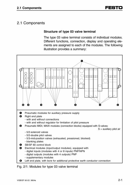
2.1 Components
Structure of type 03 valve terminal
The type 03 valve terminal consists of individual modules.Different functions, connection, display and operating ele-ments are assigned to each of the modules. The followingillustration provides a summary:
1
6 5 4 3 3 3 2
1 Pneumatic modules for auxiliary pressure supply2 Right end plate
- with and without connections- with and without regulator for limitation of pilot pressure
3 Pneumatic MIDI, MAXI modules (connection blocks) equipped with S-valves: S = auxiliary pilot air- 5/2-solenoid valves - 5/2-double pilot valves - 5/3-mid-position valves (exhausted, pressioned, blocked)- blanking plates
4 SB/SF 60 control block5 Electrical modules (input/output modules), equipped with
- digital inputs (modules with 4 or 8 inputs) PNP/NPN- digital outputs (modules with 4 outputs) PNP- supplementary modules
6 Left end plate, with bore for additional protective earth conductor connection
Fig. 2/1: Modules for type 03 valve terminal
2.1 Components
VISB/SF 60-03 9804a 2-1
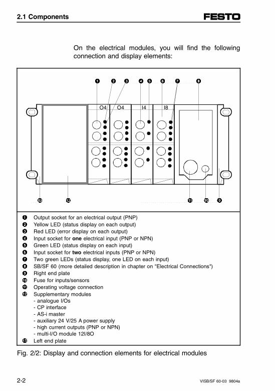
On the electrical modules, you will find the followingconnection and display elements:
1 2 3 4 5 6 7 8
O4 O4 I4 I8
# " ! 0 9
1 Output socket for an electrical output (PNP)2 Yellow LED (status display on each output)3 Red LED (error display on each output)4 Input socket for one electrical input (PNP or NPN)5 Green LED (status display on each input)6 Input socket for two electrical inputs (PNP or NPN)7 Two green LEDs (status display, one LED on each input)8 SB/SF 60 (more detailed description in chapter on "Electrical Connections")9 Right end plate0 Fuse for inputs/sensors! Operating voltage connection" Supplementary modules
- analogue I/Os- CP interface- AS-i master - auxiliary 24 V/25 A power supply - high current outputs (PNP or NPN)- multi-I/O module 12I/8O
# Left end plate
Fig. 2/2: Display and connection elements for electrical modules
2.1 Components
2-2 VISB/SF 60-03 9804a
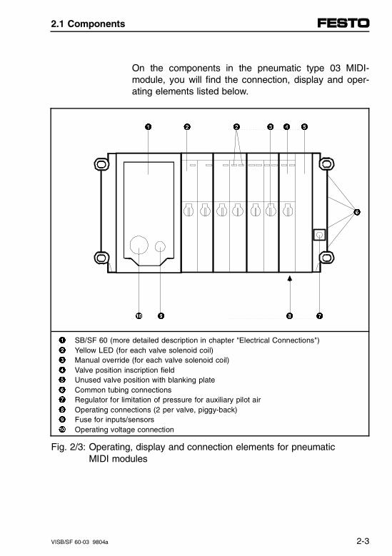
On the components in the pneumatic type 03 MIDI-module, you will find the connection, display and oper-ating elements listed below.
1 2 2 3 4 5
6
0 9 8 7
1 SB/SF 60 (more detailed description in chapter "Electrical Connections")2 Yellow LED (for each valve solenoid coil)3 Manual override (for each valve solenoid coil)4 Valve position inscription field5 Unused valve position with blanking plate6 Common tubing connections7 Regulator for limitation of pressure for auxiliary pilot air8 Operating connections (2 per valve, piggy-back)9 Fuse for inputs/sensors0 Operating voltage connection
Fig. 2/3: Operating, display and connection elements for pneumatic MIDI modules
2.1 Components
VISB/SF 60-03 9804a 2-3
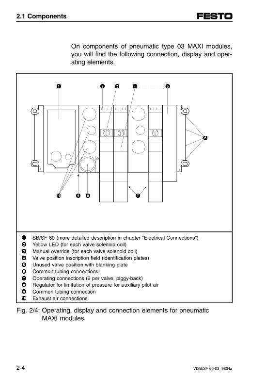
On components of pneumatic type 03 MAXI modules,you will find the following connection, display and oper-ating elements.
1 2 3 4 5
6
0 9 8 7
1 SB/SF 60 (more detailed description in chapter "Electrical Connections")2 Yellow LED (for each valve solenoid coil)3 Manual override (for each valve solenoid coil)4 Valve position inscription field (identification plates)5 Unused valve position with blanking plate6 Common tubing connections7 Operating connections (2 per valve, piggy-back)8 Regulator for limitation of pressure for auxiliary pilot air9 Common tubing connection0 Exhaust air connections
Fig. 2/4: Operating, display and connection elements for pneumatic MAXI modules
2.1 Components
2-4 VISB/SF 60-03 9804a
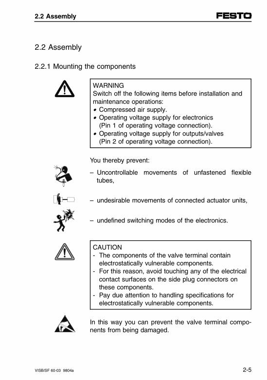
2.2 Assembly
2.2.1 Mounting the components
WARNING Switch off the following items before installation andmaintenance operations:• Compressed air supply.• Operating voltage supply for electronics
(Pin 1 of operating voltage connection).• Operating voltage supply for outputs/valves
(Pin 2 of operating voltage connection).
You thereby prevent:
– Uncontrollable movements of unfastened flexibletubes,
– undesirable movements of connected actuator units,
– undefined switching modes of the electronics.
CAUTION- The components of the valve terminal contain
electrostatically vulnerable components.- For this reason, avoid touching any of the electrical
contact surfaces on the side plug connectors onthese components.
- Pay due attention to handling specifications for electrostatically vulnerable components.
In this way you can prevent the valve terminal compo-nents from being damaged.
2.2 Assembly
VISB/SF 60-03 9804a 2-5
PLEASE NOTETreat all modules and components on the valve ter-minals with care.
Pay particular attention to the following:• Threaded connectors must not be distorted or
subject to mechanical tension.• Screws must be inserted correctly (otherwise
threads can be damaged).• Comply with specified tightening torques and avoid
offset between the modules (IP65).• Connection faces must be clean (to prevent
leakage and contact faults).• The contacts on the valve solenoid coils must not
be bent (not resistant to reciprocal loading, i.e. break when being bent back).
With modules and components ordered at a laterdate, please comply with assembly instructions inproduct pack.
2.2 Assembly
2-6 VISB/SF 60-03 9804a
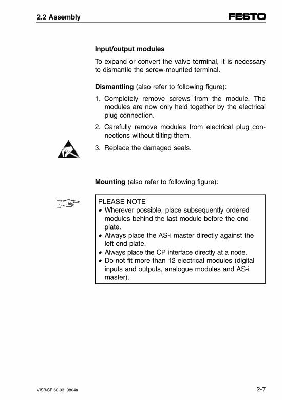
Input/output modules
To expand or convert the valve terminal, it is necessaryto dismantle the screw-mounted terminal.
Dismantling (also refer to following figure):
1. Completely remove screws from the module. Themodules are now only held together by the electricalplug connection.
2. Carefully remove modules from electrical plug con-nections without tilting them.
3. Replace the damaged seals.
Mounting (also refer to following figure):
PLEASE NOTE• Wherever possible, place subsequently ordered
modules behind the last module before the endplate.
• Always place the AS-i master directly against theleft end plate.
• Always place the CP interface directly at a node.• Do not fit more than 12 electrical modules (digital
inputs and outputs, analogue modules and AS-i master).
2.2 Assembly
VISB/SF 60-03 9804a 2-7
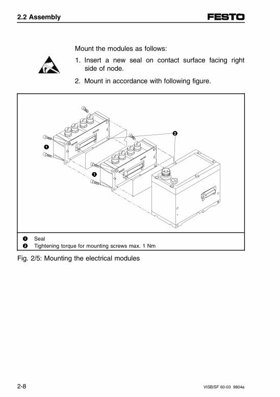
Mount the modules as follows:
1. Insert a new seal on contact surface facing rightside of node.
2. Mount in accordance with following figure.
2
1
1
1 Seal2 Tightening torque for mounting screws max. 1 Nm
Fig. 2/5: Mounting the electrical modules
2.2 Assembly
2-8 VISB/SF 60-03 9804a
End plates
You require a right and a left end plate to form a me-chanical end to the terminal. These end plates performthe following functions:
– Ensure protection class IP65 is provided.
– Contain connections and contacts for the protectiveearthing.
– Contain bores for wall mounting and the top-hat railclamping unit.
Three versions of the right end plate are available:
– MIDI:with common tubing connections for compressed airsupply of pneumatic modules and built-in regulatorfor the auxiliary pilot air (5 bar),
– MIDI/MAXI:with common tubing connections for the compressedair supply of the pneumatic modules without regula-tor.
– MAXI:without common tubing connections
CAUTIONPrior to reassembly, earth the right end plate. Thisenables you to avoid surface voltages on the metalsurface when faults occur.
2.2 Assembly
VISB/SF 60-03 9804a 2-9
Earth the end plates as follows:
• Right end plate:To earth the right end plate, connect preassembledcable on inside to the corresponding contacts on thepneumatic modules and/or the SB/SF 60 (refer to fol-lowing figure).
• Left end plate:The left end plate is connected conductively to theother components by means of preassembled springcontacts.
PLEASE NOTEFor instructions on earthing the entire valve terminal,please consult the chapter "Electrical connections."
2.2 Assembly
2-10 VISB/SF 60-03 9804a
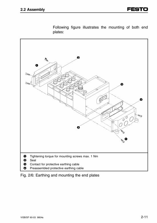
Following figure illustrates the mounting of both endplates:
2
1
3
4
2
1
1 Tightening torque for mounting screws max. 1 Nm2 Seal3 Contact for protective earthing cable4 Preassembled protective earthing cable
Fig. 2/6: Earthing and mounting the end plates
2.2 Assembly
VISB/SF 60-03 9804a 2-11
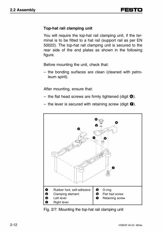
Top-hat rail clamping unit
You will require the top-hat rail clamping unit, if the ter-minal is to be fitted to a hat rail (support rail as per EN50022). The top-hat rail clamping unit is secured to therear side of the end plates as shown in the followingfigure.
Before mounting the unit, check that:
– the bonding surfaces are clean (cleaned with petro-leum spirit).
After mounting, ensure that:
– the flat head screws are firmly tightened (digit 6).
– the lever is secured with retaining screw (digit 7).
1 Rubber foot, self-adhesive2 Clamping element3 Left lever4 Right lever
5 O-ring6 Flat had screw7 Retaining screw
Fig. 2/7: Mounting the top-hat rail clamping unit
2
3
6
54
7
1
2.2 Assembly
2-12 VISB/SF 60-03 9804a
2.2.2. Mounting the valve terminal
Wall mounting
PLEASE NOTEOn long valve terminals, place additional mountingbrackets about every 200 mm.This avoids any risk of:- overloading the retaining lugs on the end plates- sagging the valve terminal- natural resonances
Proceed as follows:
• Establish the weight of your valve terminal(weigh or calculate).
General rule:
MIDI MAXI
Per pneumatic module 0.8 kg (1.76 lb.) 1.2 kg (2.64 lb.)
Per SB/SF 60 1.0 kg (2.2 lb.) 1.0 kg (2.2 lb.)
Per electronics module 0.4 kg (0.88 lb.) 0.4 kg (0.88 lb.)
2.2 Assembly
VISB/SF 60-03 9804a 2-13
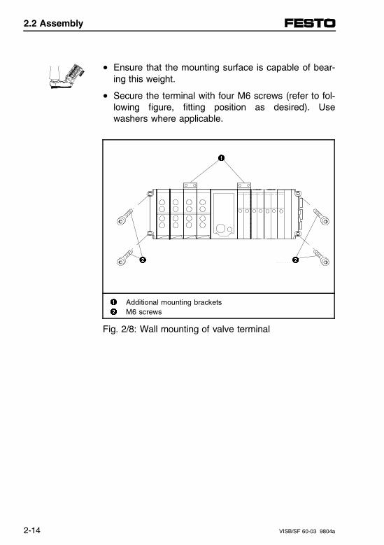
• Ensure that the mounting surface is capable of bear-ing this weight.
• Secure the terminal with four M6 screws (refer to fol-lowing figure, fitting position as desired). Usewashers where applicable.
1
2 2
1 Additional mounting brackets2 M6 screws
Fig. 2/8: Wall mounting of valve terminal
2.2 Assembly
2-14 VISB/SF 60-03 9804a
Top-hat rail mounting
The terminal is suitable for mounting on a top-hat rail(support rail as per EN 50022). For this purpose, youwill find a guide groove on the back of every module forattaching the module to the top-hat rail.
CAUTION• Top-hat rail mounting without a top-hat rail
clamping unit is not permitted.• With angled fitting positions or oscillating loads,
also secure top-hat rail clamping unit to prevent itfrom slipping and with screws provided (figure digit7) to prevent it from releasing/opening accidentally.
– With horizontal fitting position and non-moving load,the top-hat rail clamping unit can be secured ade-quately without screws (7).
– If your valve terminal does not have a top-hat rail clamping unit, this can be ordered and mounted at a later date.
– The use of MIDI or MAXI clamping units depends onthe end plates provided (MIDI/MAXI).
2.2 Assembly
VISB/SF 60-03 9804a 2-15
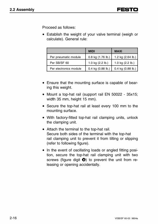
Proceed as follows:
• Establish the weight of your valve terminal (weigh orcalculate). General rule:
MIDI MAXI
Per pneumatic module 0.8 kg (1.76 lb.) 1.2 kg (2.64 lb.)
Per SB/SF 60 1.0 kg (2.2 lb.) 1.0 kg (2.2 lb.)
Per electronics module 0.4 kg (0.88 lb.) 0.4 kg (0.88 lb.)
• Ensure that the mounting surface is capable of bear-ing this weight.
• Mount a top-hat rail (support rail EN 50022 - 35x15;width 35 mm, height 15 mm).
• Secure the top-hat rail at least every 100 mm to themounting surface.
• With factory-fitted top-hat rail clamping units, unlockthe clamping unit.
• Attach the terminal to the top-hat rail. Secure both sides of the terminal with the top-hatrail clamping unit to prevent it from tilting or slipping(refer to following figure).
• In the event of oscillating loads or angled fitting posi-tion, secure the top-hat rail clamping unit with twoscrews (figure digit 4) to prevent the unit from re-leasing or opening accidentally.
2.2 Assembly
2-16 VISB/SF 60-03 9804a
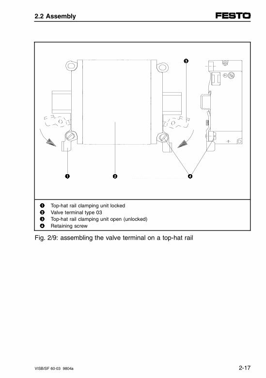
3
1 2 4
1 Top-hat rail clamping unit locked2 Valve terminal type 033 Top-hat rail clamping unit open (unlocked)4 Retaining screw
Fig. 2/9: assembling the valve terminal on a top-hat rail
2.2 Assembly
VISB/SF 60-03 9804a 2-17

2.2 Assembly
2-18 VISB/SF 60-03 9804a
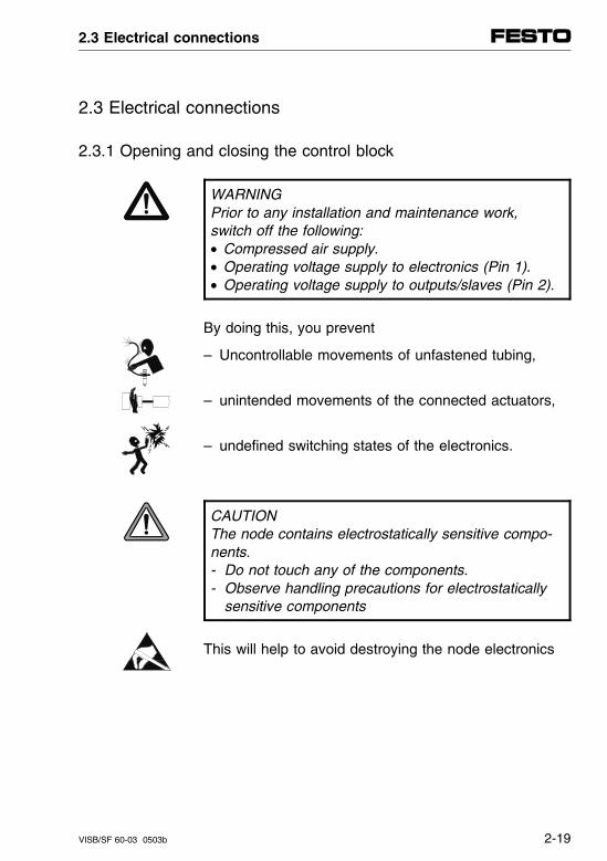
2.3 Electrical connections
2.3.1 Opening and closing the control block
WARNINGPrior to any installation and maintenance work,switch off the following:• Compressed air supply.• Operating voltage supply to electronics (Pin 1).• Operating voltage supply to outputs/slaves (Pin 2).
By doing this, you prevent
– Uncontrollable movements of unfastened tubing,
– unintended movements of the connected actuators,
– undefined switching states of the electronics.
CAUTIONThe node contains electrostatically sensitive compo-nents.- Do not touch any of the components.- Observe handling precautions for electrostatically
sensitive components
This will help to avoid destroying the node electronics
2.3 Electrical connections
VISB/SF 60-03 0503b 2-19
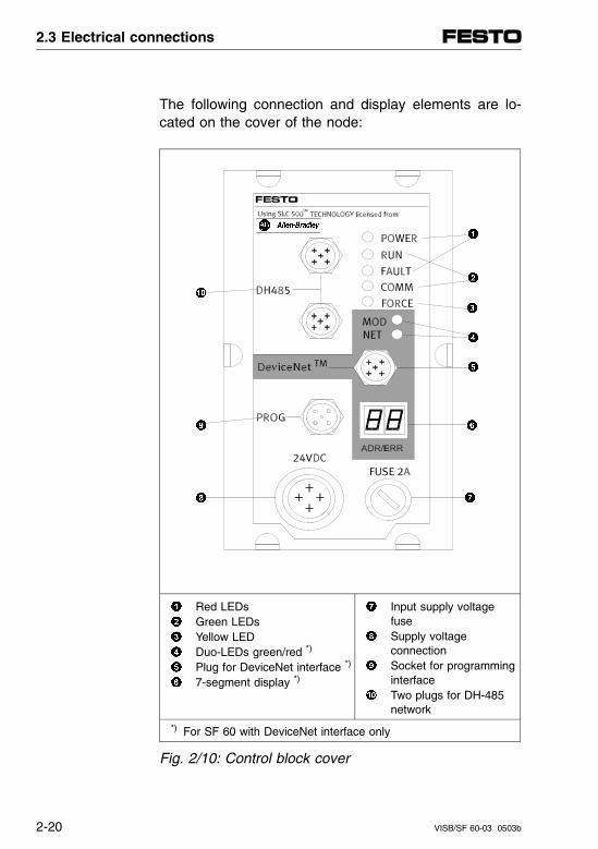
The following connection and display elements are lo-cated on the cover of the node:
Red LEDs Green LEDs Yellow LED Duo-LEDs green/red *)
Plug for DeviceNet interface *)
7-segment display *)
Input supply voltage fuse
Supply voltage connection
Socket for programming interface
Two plugs for DH-485network
*) For SF 60 with DeviceNet interface only
Fig. 2/10: Control block cover
2.3 Electrical connections
2-20 VISB/SF 60-03 0503b
The cover is connected with the internal circuit boardsvia the supply voltage cable and can therefore not be completely removed.
• Opening:Remove the cover screws. Carefully lift up the cover.Do not damage the cable by stressing it mechan-ically.
• Closing:Reposition the cover. Guide the supply voltage cableback into the housing so that it will not be pinched.Tighten the Philips head screws using a Philipsscrewdriver.
Control block layout
Up to five circuit boards may be contained in the controlblock. Board 2 contains plugs and two DIL switches forsetting the bus termination options for DH-485; onBoard 3 are five LED’s for status display. Board 4 (SF 60 only) contains two LED’s, one connec-tor and two 7-segment displays for the DeviceNet inter-face.
2.3 Electrical connections
VISB/SF 60-03 0503b 2-21
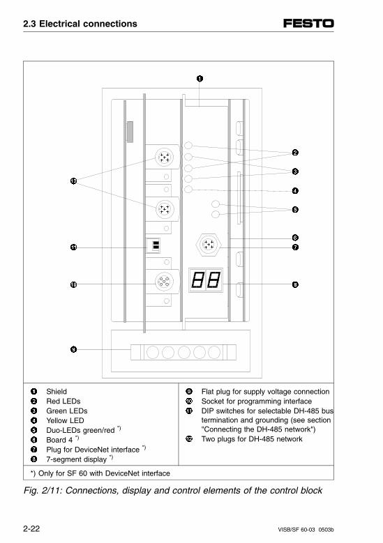
Shield Red LEDs Green LEDs Yellow LED Duo-LEDs green/red *)
Board 4 *)
Plug for DeviceNet interface *)
7-segment display *)
Flat plug for supply voltage connection Socket for programming interface DIP switches for selectable DH-485 bus
termination and grounding (see section"Connecting the DH-485 network")
Two plugs for DH-485 network
*) Only for SF 60 with DeviceNet interface
Fig. 2/11: Connections, display and control elements of the control block
2.3 Electrical connections
2-22 VISB/SF 60-03 0503b

2.3.2 Connecting operating voltages
WARNING
• Use only PELV circuits as per IEC/DIN EN 60204-1(Protective Extra-Low Voltage, PELV) for the electri-cal supply.Consider also the general requirements for PELV cir-cuits in accordance with IEC/DIN EN 60204-1.
• Use power supplies which guarantee reliable electri-cal isolation of the operating voltage as per IEC/DINEN 60204-1.
By the use of PELV circuits, protection against electricshock (protection against direct and indirect contact) isguaranteed in accordance with IEC/EN 60204-1. (Elec-trical equipment for machines, General requirements).
CAUTIONThe operating voltage supply of outputs and valves(Pin 2) must be fused externally with maximum 10 A.Using external fusing, you avoid functional damageto valve terminals in the event of a short circuit.
2.3 Electrical connections
VISB/SF 60-03 0503b 2-23
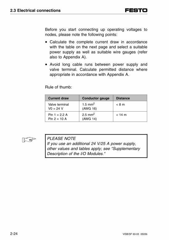
Before you start connecting up operating voltages tonodes, please note the following points:
• Calculate the complete current draw in accordancewith the table on the next page and select a suitablepower supply as well as suitable wire gauges (referalso to Appendix A).
• Avoid long cable runs between power supply andvalve terminal. Calculate permitted distance whereappropriate in accordance with Appendix A.
Rule of thumb:
Current draw Conductor gauge Distance
Valve terminal V0 = 24 V
1.5 mm2
(AWG 16)< 8 m
Pin 1 = 2.2 A Pin 2 = 10 A
2.5 mm2 (AWG 14)
< 14 m
PLEASE NOTEIf you use an additional 24 V/25 A power supply,other values and tables apply; see "SupplementaryDescription of the I/O Modules."
2.3 Electrical connections
2-24 VISB/SF 60-03 0503b
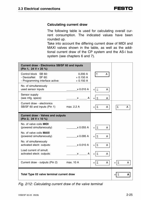
Calculating current draw
The following table is used for calculating overall cur-rent consumption. The indicated values have beenrounded up.Take into account the differing current draw of MIDI andMAXI valves shown in the table, as well as the addi-tional current draw of the CP system and the AS-i bussystem (see chapters 6 and 7).
Current draw - Electronics SB/SF 60 and inputs(Pin 1, 24 V • 25 %)
Control block SB 60: 0.200 A- DeviceNet SF 60: + 0.150 A- Programming interface active: + 0.150 A
A
No. of simultaneouslyused sensor inputs _______x 0.010 A + A
Sensor supply(see mfg. specs) _______x _____ A + Σ A
Current draw - electronicsSB/SF 60 and inputs (Pin 1) max. 2.2 A = Σ A Σ A
Current draw - Valves and outputs(Pin 2, 24 V • 10 %)
No. of valve coils MIDI(powered simultaneously) _______x 0.055 A + Σ A
No. of valve coils MAXI(powered simultaneously) _______x 0.095 A + Σ A
No. of simultaneouslyactivated electr. outputs: _______x 0.010 A + Σ A
Load current of simult.activated electr. outputs: _______x _____ A + Σ A
Current draw - outputs (Pin 2) max. 10 A = Σ A + Σ A
Total Type 03 valve terminal current draw + Σ A
Fig. 2/12: Calculating current draw of the valve terminal
2.3 Electrical connections
VISB/SF 60-03 0503b 2-25
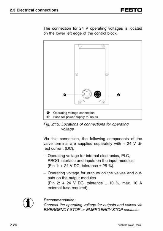
The connection for 24 V operating voltages is locatedon the lower left edge of the control block.
Operating voltage connection Fuse for power supply to inputs
Fig. 2/13: Locations of connections for operating voltage
Via this connection, the following components of thevalve terminal are supplied separately with + 24 V di-rect current (DC):
– Operating voltage for internal electronics, PLC,PROG interface and inputs on the input modules(Pin 1: + 24 V DC, tolerance ± 25 %)
– Operating voltage for outputs on the valves and out-puts on the output modules (Pin 2: + 24 V DC, tolerance ± 10 %, max. 10 Aexternal fuse required).
Recommendation: Connect the operating voltage for outputs and valves viaEMERGENCY-STOP or EMERGENCY-STOP contacts.
2.3 Electrical connections
2-26 VISB/SF 60-03 0503b
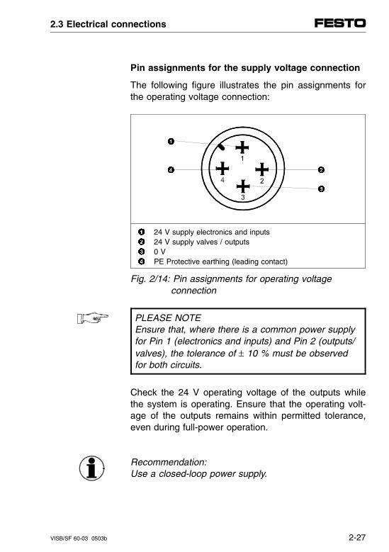
Pin assignments for the supply voltage connection
The following figure illustrates the pin assignments forthe operating voltage connection:
24 V supply electronics and inputs 24 V supply valves / outputs 0 V PE Protective earthing (leading contact)
Fig. 2/14: Pin assignments for operating voltage connection
PLEASE NOTEEnsure that, where there is a common power supplyfor Pin 1 (electronics and inputs) and Pin 2 (outputs/valves), the tolerance of ± 10 % must be observedfor both circuits.
Check the 24 V operating voltage of the outputs whilethe system is operating. Ensure that the operating volt-age of the outputs remains within permitted tolerance,even during full-power operation.
Recommendation:Use a closed-loop power supply.
2.3 Electrical connections
VISB/SF 60-03 0503b 2-27

Protective grounding
The valve terminal has the following protective ground-ing terminals:
– on the operating voltage connection (Pin 4, leading contact)
– on the left end plate (M4 thread).
PLEASE NOTE• Always connect a protective ground conductor to
pin 4 of the operating voltage terminal.
• Ensure that the housing of the valve terminal andthe power supply ground on pin 4 share the samepotential and that no compensating current can flow.
• Connect up an earth ground with adequate cablegauge to the left end plate if the valve terminal is not mounted on a grounded machine rack.
• Note the connection example illustrated in Appendix A.
By doing this, you prevent:
– Interference from electromagnetic sources.
2.3 Electrical connections
2-28 VISB/SF 60-03 0503b
2.3.3 The DH-485 interfaces on the SB/SF 60
In the Allen-Bradley DH-485 network, programming de-vices, controls and other participants are generally con-nected to the DH-485 network via a 1747-AIC isolatedlink coupler.
In the case of the Festo SB/SF 60, a 1747-AIC hasbeen fully integrated into the control block. This meansall DH-485 interfaces can be directly connected at theSB/SF 60 with IP65 protection. The additional 1747-AICis not required.
PLEASE NOTEPlease note that the PROG and DH-485 interfaceson the SB/SF 60 have different pin configurationsand signals.- PROG interface on the SB/SF 60:
Programming interface with 24 V supply for the pro-grammer. This interface corresponds to the "Peri-pheral" interface of the 1747-AIC and is not galvani-cally isolated. Here the SB/SF 60 can be directly programmed and operated.
- DH-485 interfaces on the SB/SF 60:These DH-485 interfaces correspond to the DH-485interface of the 1747-AIC. They are galvanically iso-lated and provide direct connection to the DH-485network (optional per T-TAP/drop cable or daisy-chain). As is usual with the SLC 500, the SB/SF 60can be programmed and operated over the networkindirectly from any point in the DH-485.
The "CPU" interface on the 1747-AIC is already inter-nally connected to the SB/SF 60.• Do not connect the valve terminal to the "CPU"
interface of a 1747-AIC. This could lead to com-munications errors.
2.3 Electrical connections
VISB/SF 60-03 0503b 2-29
2.3.4 Connecting up the PROG programming interface
To program the valve terminal you need:
– an Allen-Bradley programmer, e.g., Hand-Held Termi-nal HHT or a PC/laptop with DH-485 interface (DH-485 PC card or 1747-PIC)
– shielded connection cable, e.g., Festo programmingcable KSB60-M12-3, part no. 171 173.
Connect the programming cable as follows:
• 5-pin connector to the programming interface of thevalve terminal (PROG)
• 8-pin SDL connector to the PC card or the 1747-PIC.
2.3 Electrical connections
2-30 VISB/SF 60-03 0503b
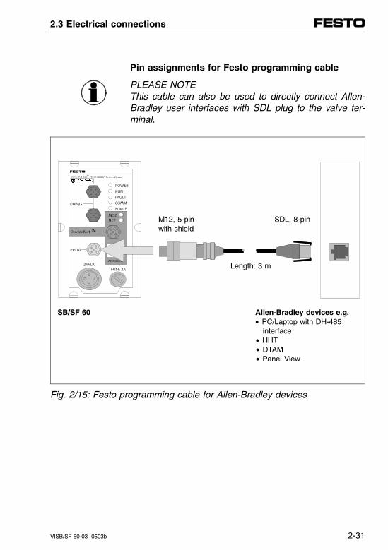
Pin assignments for Festo programming cable
PLEASE NOTEThis cable can also be used to directly connect Allen-Bradley user interfaces with SDL plug to the valve ter-minal.
M12, 5-pin SDL, 8-pin with shield
Length: 3 m
SB/SF 60 Allen-Bradley devices e.g. • PC/Laptop with DH-485 interface
• HHT • DTAM
• Panel View
Fig. 2/15: Festo programming cable for Allen-Bradley devices
2.3 Electrical connections
VISB/SF 60-03 0503b 2-31
2.3.5 Connecting up the DH-485 interfaces (DH-485 with galvanic isolation)
PLEASE NOTENote the cable specifications!During data transmission, signal reflections and signal attenuation occurs, especially at high datarates. Both can cause transmission errors. Causesof reflections can be:- missing or incorrect termination resistor- shunts.
Causes for signal attenuation can be:- transmitting over long distances- inappropriate cable.
Please note the cable specifications and installationnotes for the DH-485 network from Allen-Bradley.
The following cable can be used universally up to the maximum length for DH-485, which is 1219 m (4000 ft.):
– Belden #9842; twisted-pair, double shielded cablewith a fifth conductor as drain.
2.3 Electrical connections
2-32 VISB/SF 60-03 0503b
To connect the programmable valve terminal to the DH-485, there are two plugs on the control block. Oneof these connections is for the input, the other for theextension of the DH-485. The signal lines of both plugsare connected parallel to each other internally. Theseinterfaces correspond to the "DH-485" connection of a1747-AIC.
This permits two connection variations:
– Daisy-chaining the DH-485 from terminal to terminal.Here both plugs are needed.
– Connecting the DH-485 using a T-adapter. The re-maining connection may not be used and should beclosed off with a cap (IP65).
Recommendation:Mount the T-adapter directly on the valve terminal. Ifthis is not possible, maintain the max. permissible dis-tance between T-adapter and DH-485 interface of 30 cm in order to avoid signal reflections.
Use the pre-assembled Festo T-adapter FB-TA-M12-5POL, part no. 171175.
2.3 Electrical connections
VISB/SF 60-03 0503b 2-33
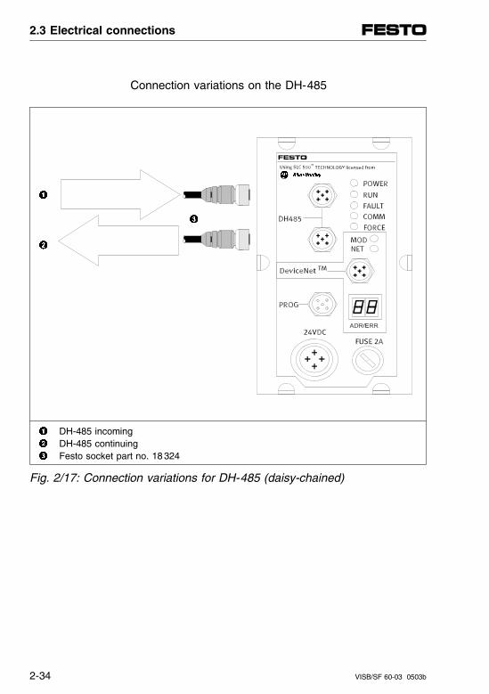
Connection variations on the DH-485
DH-485 incoming DH-485 continuing Festo socket part no. 18 324
Fig. 2/17: Connection variations for DH-485 (daisy-chained)
2.3 Electrical connections
2-34 VISB/SF 60-03 0503b
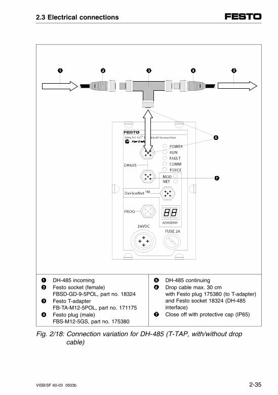
DH-485 incoming Festo socket (female)
FBSD-GD-9-5POL, part no. 18324 Festo T-adapter
FB-TA-M12-5POL, part no. 171175 Festo plug (male)
FBS-M12-5GS, part no. 175380
DH-485 continuing Drop cable max. 30 cm
with Festo plug 175380 (to T-adapter)and Festo socket 18324 (DH-485 interface)
Close off with protective cap (IP65)
Fig. 2/18: Connection variation for DH-485 (T-TAP, with/without drop cable)
2.3 Electrical connections
VISB/SF 60-03 0503b 2-35
Cable and plugs/sockets for the DH-485 connectionvariants
Depending on the connection variant selected, you willrequire different plugs/sockets on the ends of the cables. The following variants are described below:
DH-485 looped through (daisy-chained, see table, column 1)
DH-485 via Festo T-adapter (see table, column 2)
Connecting the SB/SF 60 to the DH-485 interface of a 1747-AIC (see following section)
2.3 Electrical connections
2-36 VISB/SF 60-03 0503b
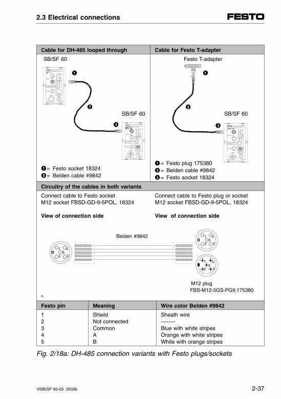
Cable for DH-485 looped through Cable for Festo T-adapter
SB/SF 60
SB/SF 60
= Festo socket 18324= Belden cable #9842
Festo T-adapter
SB/SF 60
= Festo plug 175380= Belden cable #9842= Festo socket 18324
Circuitry of the cables in both variants
Connect cable to Festo socket Connect cable to Festo plug or socketM12 socket FBSD-GD-9-5POL, 18324 M12 socket FBSD-GD-9-5POL, 18324
View of connection side View of connection side
Belden #9842
M12 plug FBS-M12-5GS-PG9,175380
^
Festo pin Meaning Wire color Belden #9842
12345
ShieldNot connectedCommonAB
Sheath wire--------Blue with white stripesOrange with white stripesWhite with orange stripes
Fig. 2/18a: DH-485 connection variants with Festo plugs/sockets
2.3 Electrical connections
VISB/SF 60-03 0503b 2-37
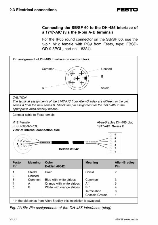
Connecting the SB/SF 60 to the DH-485 interface ofa 1747-AIC (via the 6-pin A-B terminal)
For the IP65 round connector on the SB/SF 60, use the5-pin M12 female with PG9 from Festo, type: FBSD-GD-9-5POL, part no. 18324).
Pin assignment of DH-485 interface on control block
Common Unused
B
A Shield
CAUTIONThe terminal assignments of the 1747-AIC from Allen-Bradley are different in the old series A from the new series B. Check the pin assignment for the 1747-AIC in the appropriate Allen-Bradley manual.
Connect cable to Festo female
M12 Female Allen-Bradley DH-485 plugFBSD-GD-9-5POL 1747-AIC Series BView of internal connection side
Belden #9842
FestoPin
Meaning Color Belden #9842
Meaning Allen-BradleyPin
12345
ShieldUnusedCommonAB
Drain
Blue with white stripesOrange with white stripesWhite with orange stripes
Shield
CommonA *B *TerminationChassis Ground
2
35461
* In the old series from Allen-Bradley this inscription is swapped.
Fig. 2/18b: Pin assignments of the DH-485 interfaces (plug)
2.3 Electrical connections
2-38 VISB/SF 60-03 0503b
DH-485 termination resistor and grounding
A termination resistor is required on both ends of theDH-485 network. In the case of the SB/SF 60, this isalready integrated and can be implemented using DIPswitch no. 1.
DH-485terminationresistor
PLEASE NOTESwitch the termination resistor on if the SB/SF 60 islocated at the end of a DH-485 network.
At one end of the DH-485 network the coupling be-tween shield and earth is required in order to ensureproper grounding of the data cable shield. In the SB/SF60, a corresponding coupling is already integrated andcan be implemented using DIP switch no. 2.
DH-485grounding
PLEASE NOTEThe DIL switch in the node represents a connectionto the valve terminal housing.Therefore be sure before switching on that first theentire valve terminal is properly grounded to the machine frame.
Recommendation: Ground the shield to the end of the DH-485 where yourmachine/system is best grounded.
2.3 Electrical connections
VISB/SF 60-03 0503b 2-39
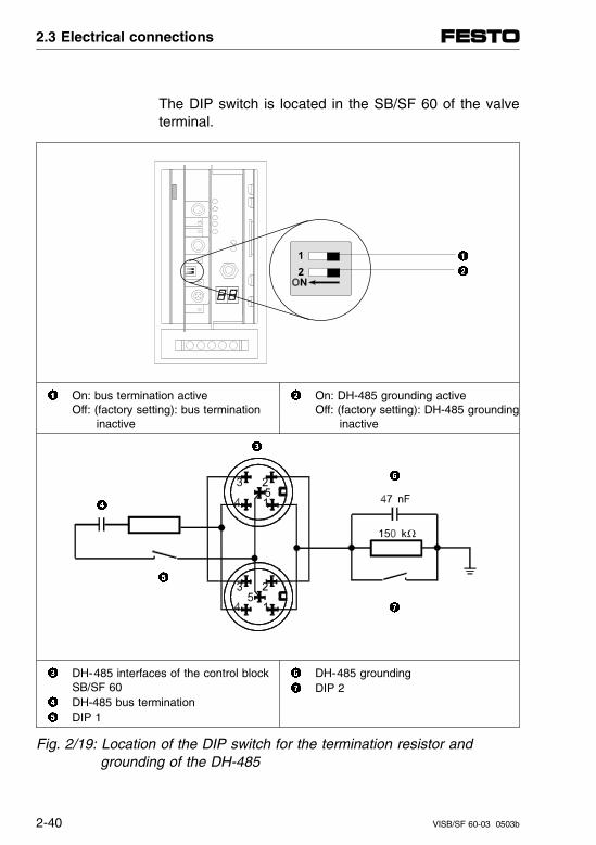
The DIP switch is located in the SB/SF 60 of the valveterminal.
On: bus termination activeOff: (factory setting): bus termination
inactive
On: DH-485 grounding activeOff: (factory setting): DH-485 grounding
inactive
DH-485 interfaces of the control blockSB/SF 60
DH-485 bus termination DIP 1
DH-485 grounding DIP 2
Fig. 2/19: Location of the DIP switch for the termination resistor and grounding of the DH-485
2.3 Electrical connections
2-40 VISB/SF 60-03 0503b
2.3.6 Connecting the DeviceNet interface (SF 60 only)
Important DeviceNet guidelines and installation instruc-tions can be found in the basic manual "DeviceNet Cable System, Planning and Installation Manual" fromAllen-Bradley. You can order this book from Allen-Brad-ley under publication no. DN-6.7.2 or load it as a PDFfile from the Internet.In the following it is assumed that the user is familiarwith these basic DeviceNet principles.
DN-6.7.2
There is a bus interface (plug) on the node for connect-ing the valve terminal to DeviceNet.
The two bus lines, the supply voltage (+ 24 V and 0 V)for the bus interface and the cable shield are con-nected to this plug. The hardware basis for the bus in-terface is CAN-bus. It is typical for this bus that the businterface is supplied with voltage via the bus plug.
The bus connection is best made using a stub line witha 5-pin M12 female with PG9 fitting. These can be or-dered from Festo (type: FBSD-GD-9-5POL), part no.18324). Or, pre-assembled bus cable from other manu-facturers is available (see Appendix A, Accessories).
The following overview shows the basic bus connec-tion.
2.3 Electrical connections
VISB/SF 60-03 0503b 2-41
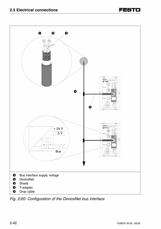
+ 24 V
0 V
Bus
Bus interface supply voltage DeviceNet Shield T-adapter Drop cable
Fig. 2/20: Configuration of the DeviceNet bus interface
2.3 Electrical connections
2-42 VISB/SF 60-03 0503b
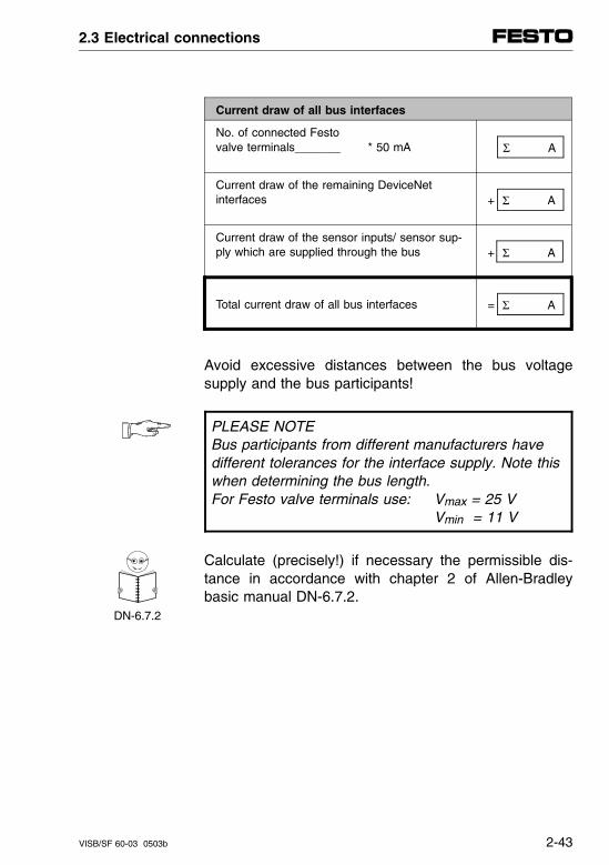
Current draw of all bus interfaces
No. of connected Festo valve terminals_______ * 50 mA Σ A
Current draw of the remaining DeviceNet interfaces + Σ A
Current draw of the sensor inputs/ sensor sup-ply which are supplied through the bus + Σ A
Total current draw of all bus interfaces = Σ A
Avoid excessive distances between the bus voltagesupply and the bus participants!
PLEASE NOTEBus participants from different manufacturers havedifferent tolerances for the interface supply. Note thiswhen determining the bus length. For Festo valve terminals use: Vmax = 25 V
Vmin = 11 V
Calculate (precisely!) if necessary the permissible dis-tance in accordance with chapter 2 of Allen-Bradleybasic manual DN-6.7.2.
DN-6.7.2
2.3 Electrical connections
VISB/SF 60-03 0503b 2-43
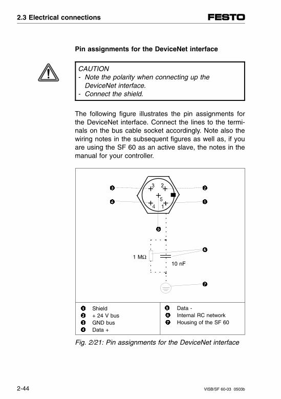
Pin assignments for the DeviceNet interface
CAUTION- Note the polarity when connecting up the
DeviceNet interface.- Connect the shield.
The following figure illustrates the pin assignments forthe DeviceNet interface. Connect the lines to the termi-nals on the bus cable socket accordingly. Note also thewiring notes in the subsequent figures as well as, if youare using the SF 60 as an active slave, the notes in themanual for your controller.
1 MΩ10 nF
Shield + 24 V bus GND bus Data +
Data - Internal RC network Housing of the SF 60
Fig. 2/21: Pin assignments for the DeviceNet interface
2.3 Electrical connections
2-44 VISB/SF 60-03 0503b
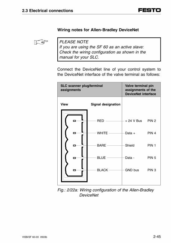
Wiring notes for Allen-Bradley DeviceNet
PLEASE NOTEIf you are using the SF 60 as an active slave:Check the wiring configuration as shown in the manual for your SLC.
Connect the DeviceNet line of your control system tothe DeviceNet interface of the valve terminal as follows:
SLC scanner plug/terminal assignments
Valve terminal pinassignments of theDeviceNet interface
View Signal designation
RED
WHITE
BARE
BLUE
BLACK
+ 24 V Bus PIN 2
Data + PIN 4
Shield PIN 1
Data - PIN 5
GND bus PIN 3
Fig.: 2/22a: Wiring configuration of the Allen-Bradley DeviceNet
2.3 Electrical connections
VISB/SF 60-03 0503b 2-45
Allen-Bradley DeviceNet cable System
A typical DeviceNet topology of Allen-Bradley is basedon a DeviceNet main cable (trunk line) with terminatingresistors at both ends as well as at least one powersupply box for the 24 V voltage supply. By means ofbranches, e.g. through T-port taps or device box taps, aDeviceNet slave can be connected with a branch cable(drop line).
The SF 60 with DeviceNet Scanner is a standardizedDeviceNet slave just like the PC with DeviceNet man-ager software necessary for the configuration.
2.3 Electrical connections
2-46 VISB/SF 60-03 0503b
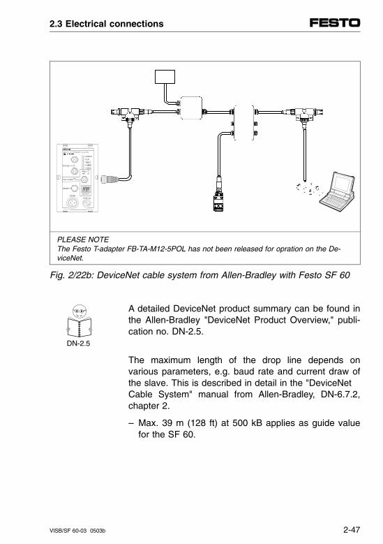
PLEASE NOTEThe Festo T-adapter FB-TA-M12-5POL has not been released for opration on the De-viceNet.
Fig. 2/22b: DeviceNet cable system from Allen-Bradley with Festo SF 60
A detailed DeviceNet product summary can be found inthe Allen-Bradley "DeviceNet Product Overview," publi-cation no. DN-2.5.
DN-2.5
The maximum length of the drop line depends onvarious parameters, e.g. baud rate and current draw ofthe slave. This is described in detail in the "DeviceNet Cable System" manual from Allen-Bradley, DN-6.7.2,chapter 2.
– Max. 39 m (128 ft) at 500 kB applies as guide valuefor the SF 60.
2.3 Electrical connections
VISB/SF 60-03 0503b 2-47
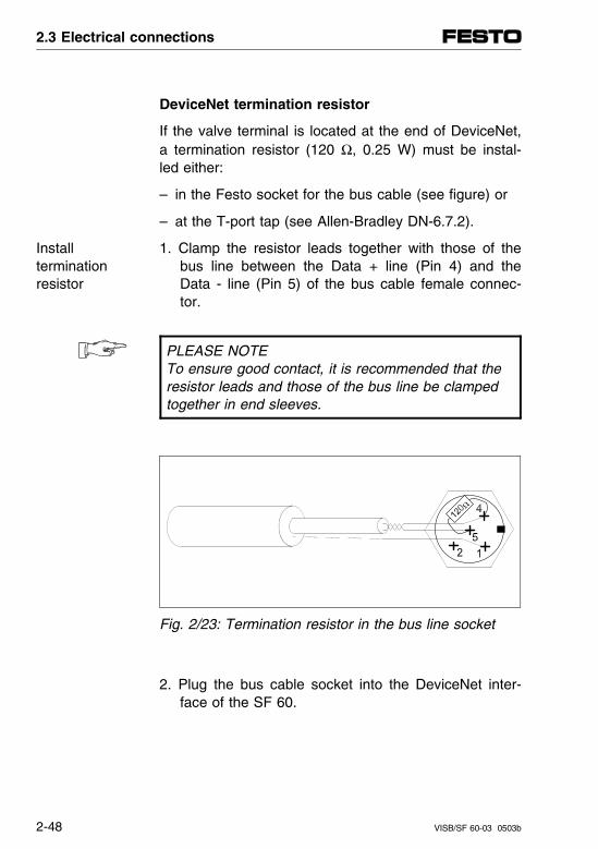
DeviceNet termination resistor
If the valve terminal is located at the end of DeviceNet,a termination resistor (120 Ω, 0.25 W) must be instal-led either:
– in the Festo socket for the bus cable (see figure) or
– at the T-port tap (see Allen-Bradley DN-6.7.2).
1. Clamp the resistor leads together with those of thebus line between the Data + line (Pin 4) and theData - line (Pin 5) of the bus cable female connec-tor.
Install terminationresistor
PLEASE NOTETo ensure good contact, it is recommended that theresistor leads and those of the bus line be clampedtogether in end sleeves.
Fig. 2/23: Termination resistor in the bus line socket
2. Plug the bus cable socket into the DeviceNet inter-face of the SF 60.
2.3 Electrical connections
2-48 VISB/SF 60-03 0503b
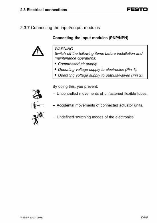
2.3.7 Connecting the input/output modules
Connecting the input modules (PNP/NPN)
WARNINGSwitch off the following items before installation andmaintenance operations:• Compressed air supply.• Operating voltage supply to electronics (Pin 1).• Operating voltage supply to outputs/valves (Pin 2).
By doing this, you prevent:
– Uncontrolled movements of unfastened flexible tubes.
– Accidental movements of connected actuator units.
– Undefined switching modes of the electronics.
2.3 Electrical connections
VISB/SF 60-03 0503b 2-49
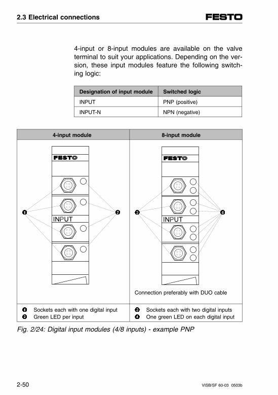
4-input or 8-input modules are available on the valveterminal to suit your applications. Depending on the ver-sion, these input modules feature the following switch-ing logic:
Designation of input module Switched logic
INPUT PNP (positive)
INPUT-N NPN (negative)
4-input module 8-input module
Connection preferably with DUO cable
Sockets each with one digital input Green LED per input
Sockets each with two digital inputs One green LED on each digital input
Fig. 2/24: Digital input modules (4/8 inputs) - example PNP
2.3 Electrical connections
2-50 VISB/SF 60-03 0503b
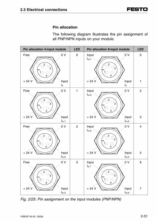
Pin allocation
The following diagram illustrates the pin assignment ofall PNP/NPN inputs on your module.
Pin allocation 4-input module LED Pin allocation 8-input module LED
Free 0 V
+ 24 V InputIx
0 Input 0 VIx+1
+ 24 V InputIx
0
1
Free 0 V
+ 24 V InputIx+1
1 Input 0 VIx+3
+ 24 V InputIx+2
2
3
Free 0 V
+ 24 V InputIx+2
2 Input 0 VIx+5
+ 24 V InputIx+4
4
5
Free 0 V
+ 24 V InputIx+3
3 Input 0 VIx-7
+ 24 V InputIx+6
6
7
Fig. 2/25: Pin assignment on the input modules (PNP/NPN)
2
3
41
2
3
41
2
3
41
2
3
41
2
3
41
2
3
41
2
3
41
2
3
41
2.3 Electrical connections
VISB/SF 60-03 0503b 2-51
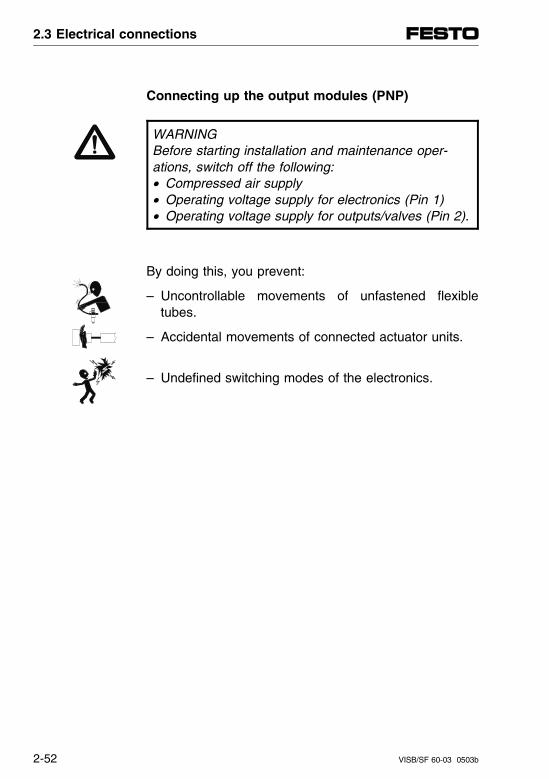
Connecting up the output modules (PNP)
WARNINGBefore starting installation and maintenance oper-ations, switch off the following:• Compressed air supply• Operating voltage supply for electronics (Pin 1)• Operating voltage supply for outputs/valves (Pin 2).
By doing this, you prevent:
– Uncontrollable movements of unfastened flexibletubes.
– Accidental movements of connected actuator units.
– Undefined switching modes of the electronics.
2.3 Electrical connections
2-52 VISB/SF 60-03 0503b
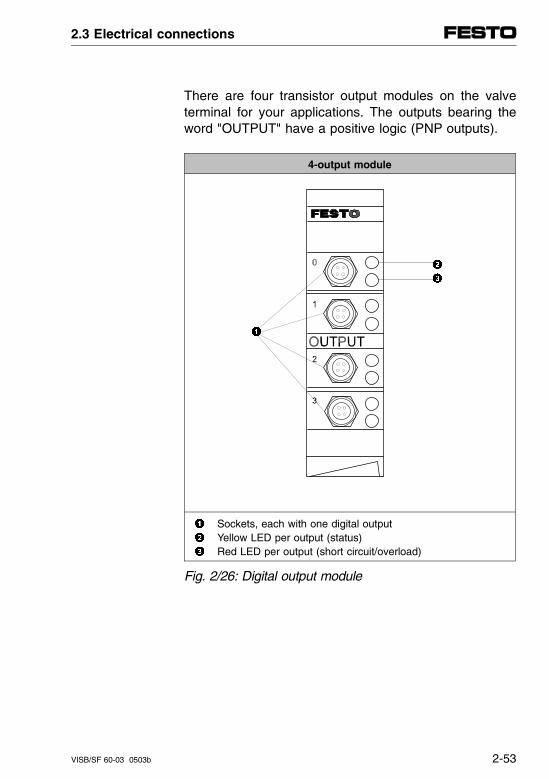
There are four transistor output modules on the valveterminal for your applications. The outputs bearing theword "OUTPUT" have a positive logic (PNP outputs).
4-output module
Sockets, each with one digital output Yellow LED per output (status) Red LED per output (short circuit/overload)
Fig. 2/26: Digital output module
2.3 Electrical connections
VISB/SF 60-03 0503b 2-53
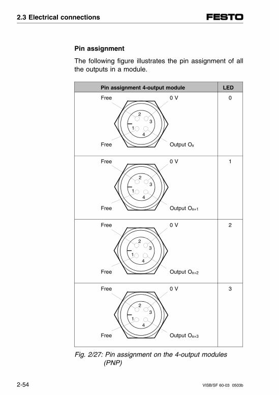
Pin assignment
The following figure illustrates the pin assignment of allthe outputs in a module.
Pin assignment 4-output module LED
Free 0 V
Free Output Ox
0
Free 0 V
Free Output Ox+1
1
Free 0 V
Free Output Ox+2
2
Free 0 V
Free Output Ox+3
3
Fig. 2/27: Pin assignment on the 4-output modules (PNP)
2
3
41
2
3
41
2
3
41
2
3
41
2.3 Electrical connections
2-54 VISB/SF 60-03 0503b
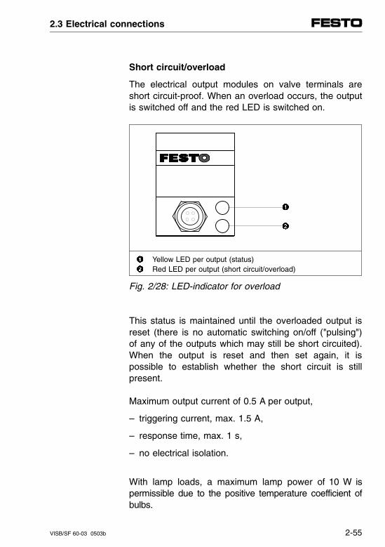
Short circuit/overload
The electrical output modules on valve terminals areshort circuit-proof. When an overload occurs, the outputis switched off and the red LED is switched on.
Yellow LED per output (status) Red LED per output (short circuit/overload)
Fig. 2/28: LED-indicator for overload
This status is maintained until the overloaded output isreset (there is no automatic switching on/off ("pulsing")of any of the outputs which may still be short circuited).When the output is reset and then set again, it ispossible to establish whether the short circuit is stillpresent.
Maximum output current of 0.5 A per output,
– triggering current, max. 1.5 A,
– response time, max. 1 s,
– no electrical isolation.
With lamp loads, a maximum lamp power of 10 W ispermissible due to the positive temperature coefficient ofbulbs.
2.3 Electrical connections
VISB/SF 60-03 0503b 2-55
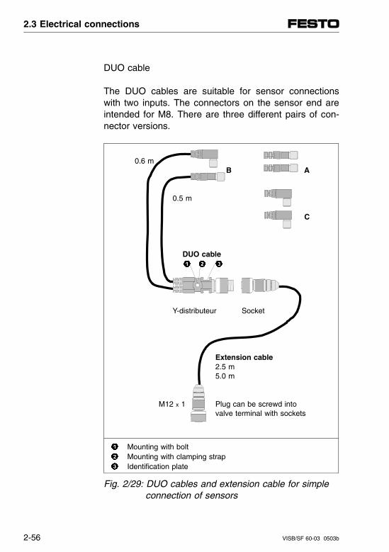
DUO cable
The DUO cables are suitable for sensor connectionswith two inputs. The connectors on the sensor end areintended for M8. There are three different pairs of con-nector versions.
0.6 mB A
0.5 m
C
DUO cable
Y-distributeur Socket
Extension cable2.5 m5.0 m
M12 x 1 Plug can be screwd intovalve terminal with sockets
Mounting with bolt Mounting with clamping strap Identification plate
Fig. 2/29: DUO cables and extension cable for simple connection of sensors
2.3 Electrical connections
2-56 VISB/SF 60-03 0503b
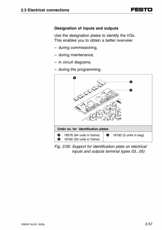
Designation of inputs and outputs
Use the designation plates to identify the I/Os.This enables you to obtain a better overview:
– during commissioning,
– during maintenance,
– in circuit diagrams,
– during the programming.
Order no. for identification plates
18576 (64 units in frame) 18182 (20 units in frame)
18183 (5 units in bag)
Fig. 2/30: Support for identification plate on electrical inputs and outputs terminal types 03...05)
2.3 Electrical connections
VISB/SF 60-03 0503b 2-57

Connection instructions for the supplementary mo-dules can be found in the following chapters:- High current outputs and multi I/O module:
"Suplementary Description I/O Modules"- Analog I/Os: Chapter 5- AS-i master: Chapter 6- CP interface: Chapter 7 and description of the
CP system under "Installation and Start-up"
2.3 Electrical connections
2-58 VISB/SF 60-03 0503b
2.4 Addressing
General
Before programming, create an assignment list of allconnected inputs and outputs. This list will help youlater when addressing or programming. Addressing ofthe valve terminal requires an exact procedure, as dif-ferent specifications are required because of the modu-lar structure.
See the following locations for detailed notes on ad-dressing the supplementary modules:
– Analog inputs and outputs in chapter 5
– AS-i master/AS-i bus system in chapter 6
– CP interface/CP system in chapter 7 as well as in thedescription of the CP system "Installation and Com-missioning."
When extending or reconfiguring the terminal, note themechanical limits (12 I/O, 13 P modules) and thereforethe addressing limits, namely:- 96 local inputs or 74 local outputs without CP and
AS-i master, or- 268 local inputs or 254 local outputs with CP and
AS-i master.
2.4 Addressing
VISB/SF 60-03 9804a 2-59
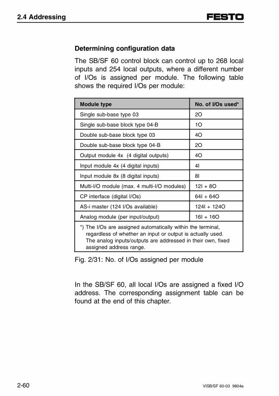
Determining configuration data
The SB/SF 60 control block can control up to 268 localinputs and 254 local outputs, where a different numberof I/Os is assigned per module. The following tableshows the required I/Os per module:
Module type No. of I/Os used*
Single sub-base type 03 2O
Single sub-base block type 04-B 1O
Double sub-base block type 03 4O
Double sub-base block type 04-B 2O
Output module 4x (4 digital outputs) 4O
Input module 4x (4 digital inputs) 4I
Input module 8x (8 digital inputs) 8I
Multi-I/O module (max. 4 multi-I/O modules) 12I + 8O
CP interface (digital I/Os) 64I + 64O
AS-i master (124 I/Os available) 124I + 124O
Analog module (per input/output) 16I + 16O
*) The I/Os are assigned automatically within the terminal, regardless of whether an input or output is actually used. The analog inputs/outputs are addressed in their own, fixed assigned address range.
Fig. 2/31: No. of I/Os assigned per module
In the SB/SF 60, all local I/Os are assigned a fixed I/Oaddress. The corresponding assignment table can befound at the end of this chapter.
2.4 Addressing
2-60 VISB/SF 60-03 9804a
Addressing the valve terminal
Addressing the inputs and outputs of a modular valveterminal depends on how the terminal is configured.The following configuration variations are distinguished:
– valves and digital I/O modules
– valves only
– I/O modules only
When addressing these modules and configuration vari-ations, the following rules are in effect:
If two addresses are assigned for one valve location,the following applies:- lower value address ⇒ pilot solenoid 14- higher value address ⇒ pilot solenoid 12
2.4 Addressing
VISB/SF 60-03 9804a 2-61
Basic rules type 03
1. Outputs: Addressing of the outputs is independent of the inputs.
1.1 Addressing of the valves:- Address assignment uninterrupted ascending- Count direction starting at SB/SF 60 to right- S sub-bases blocks always use 2 addresses- D sub-bases blocks always use 4 addresses- A maximum of 26 valve solenoid coils can be
addressed.
1.2 Addressing the output modules: Addressing of the electrical outputs is indepen-
dent from that of the valves. - Address assignment uninterrupted low to high. - Count direction starting at SB/SF 60 to left - On the individual modules, count is from top to bottom - Digital output modules always use 4 addresses.
2.4 Addressing
2-62 VISB/SF 60-03 9804a
2. Inputs: Address assignment of the inputs is independent of the outputs.
2.1 Address assignment of the input modules: - Address assignment uninterrupted ascending- Count direction starting at SB/SF 60 to left- On the individual modules from top to bottom- 4-input modules use 4 addresses- 8-input modules use 8 addresses
When the operating voltage is switched on, the valveterminal automatically recognizes all pneumatic mod-ules present (max. 13) and all I/O modules (max. 12)and assigns the appropriate local addresses to them. Ifone valve position remains unoccupied (cover plate) orif an electrical input/output is not connected, the corre-sponding address is still assigned. The following figureillustrates the address assignment for configuration withvalves, inputs and outputs:
2.4 Addressing
VISB/SF 60-03 9804a 2-63
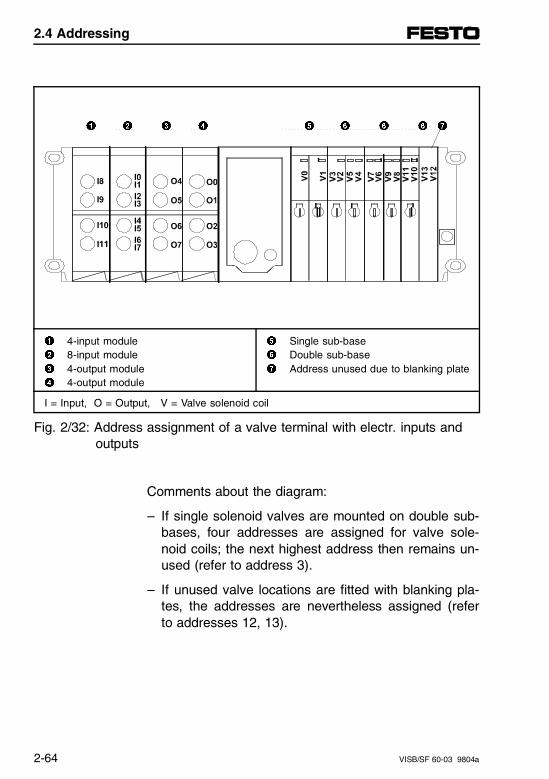
1 2 3 4 5 6 6 6 7
1 4-input module2 8-input module3 4-output module4 4-output module
5 Single sub-base6 Double sub-base 7 Address unused due to blanking plate
I = Input, O = Output, V = Valve solenoid coil
Fig. 2/32: Address assignment of a valve terminal with electr. inputs and outputs
Comments about the diagram:
– If single solenoid valves are mounted on double sub-bases, four addresses are assigned for valve sole-noid coils; the next highest address then remains un-used (refer to address 3).
– If unused valve locations are fitted with blanking pla-tes, the addresses are nevertheless assigned (referto addresses 12, 13).
2.4 Addressing
2-64 VISB/SF 60-03 9804a
Address assignment after extension/conversion
One special feature of modular valve terminals is theirflexibility. If the requirements for the machine vary, theconfiguration of the terminal can be modified to suit.
CAUTIONIn case of later extensions or conversions of the terminals, input/output addresses can become displaced. This applies in the following cases:- one or more pneumatic sub-bases is/are added or
removed at a later date,- a pneumatic sub-base with single solenoid valves
is replaced by a new sub-base with double solenoidvalves or vice-versa,
- additional input/output modules are inserted be-tween SB/SF 60 and existing input/output modules,
- existing 4-input modules are replaced by 8-inputmodules - or vice-versa.
When extending or converting the valve terminal, notethe mechanical limits (12 I/O modules, 13 P-modules)and therefore the limit of- 96 local inputs or 74 local outputs without
CP interface and AS-i master, or- 268 local inputs or 254 local outputs with
CP interface and AS-i master.
2.4 Addressing
VISB/SF 60-03 9804a 2-65
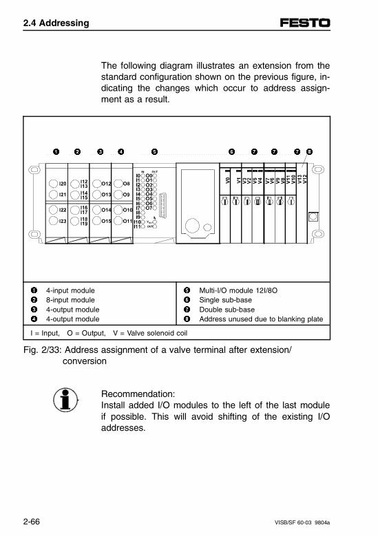
The following diagram illustrates an extension from thestandard configuration shown on the previous figure, in-dicating the changes which occur to address assign-ment as a result.
1 2 3 4 5 6 7 7 7 8
1 4-input module2 8-input module3 4-output module4 4-output module
5 Multi-I/O module 12I/8O6 Single sub-base7 Double sub-base8 Address unused due to blanking plate
I = Input, O = Output, V = Valve solenoid coil
Fig. 2/33: Address assignment of a valve terminal after extension/ conversion
Recommendation:Install added I/O modules to the left of the last moduleif possible. This will avoid shifting of the existing I/Oaddresses.
2.4 Addressing
2-66 VISB/SF 60-03 9804a
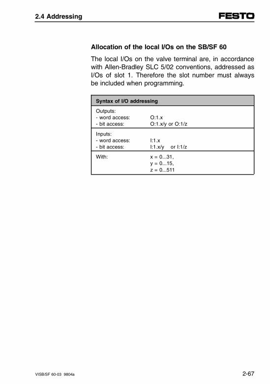
Allocation of the local I/Os on the SB/SF 60
The local I/Os on the valve terminal are, in accordancewith Allen-Bradley SLC 5/02 conventions, addressed asI/Os of slot 1. Therefore the slot number must alwaysbe included when programming.
Syntax of I/O addressing
Outputs:- word access:- bit access:
O:1.xO:1.x/y or O:1/z
Inputs:- word access:- bit access:
I:1.xI:1.x/y or I:1/z
With: x = 0...31,y = 0...15,z = 0...511
2.4 Addressing
VISB/SF 60-03 9804a 2-67
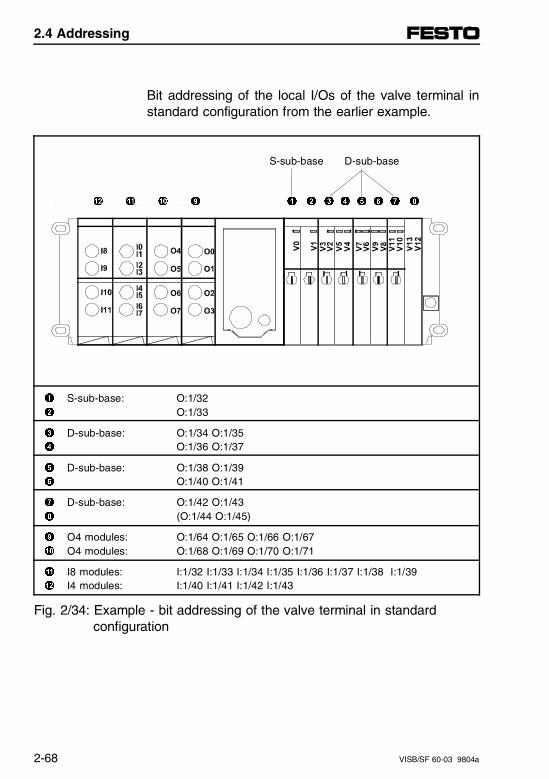
Bit addressing of the local I/Os of the valve terminal instandard configuration from the earlier example.
S-sub-base D-sub-base
" ! 0 9 1 2 3 4 5 6 7 8
1 S-sub-base: O:1/322 O:1/33
3 D-sub-base: O:1/34 O:1/354 O:1/36 O:1/37
5 D-sub-base: O:1/38 O:1/396 O:1/40 O:1/41
7 D-sub-base: O:1/42 O:1/438 (O:1/44 O:1/45)
9 O4 modules: O:1/64 O:1/65 O:1/66 O:1/670 O4 modules: O:1/68 O:1/69 O:1/70 O:1/71
! I8 modules: I:1/32 I:1/33 I:1/34 I:1/35 I:1/36 I:1/37 I:1/38 I:1/39 " I4 modules: I:1/40 I:1/41 I:1/42 I:1/43
Fig. 2/34: Example - bit addressing of the valve terminal in standard configuration
2.4 Addressing
2-68 VISB/SF 60-03 9804a
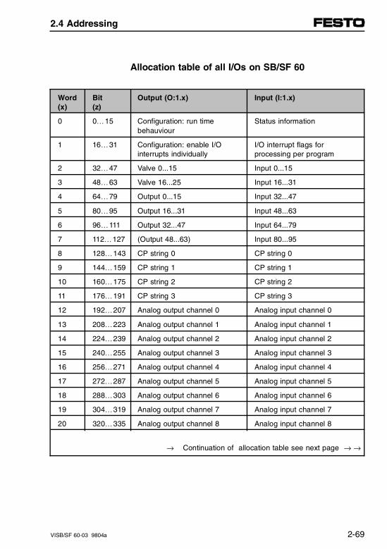
Allocation table of all I/Os on SB/SF 60
Word(x)
Bit(z)
Output (O:1.x) Input (I:1.x)
0 0…15 Configuration: run time behauviour
Status information
1 16…31 Configuration: enable I/Ointerrupts individually
I/O interrupt flags forprocessing per program
2 32…47 Valve 0...15 Input 0...15
3 48…63 Valve 16...25 Input 16...31
4 64…79 Output 0...15 Input 32...47
5 80…95 Output 16...31 Input 48...63
6 96…111 Output 32...47 Input 64...79
7 112…127 (Output 48...63) Input 80...95
8 128…143 CP string 0 CP string 0
9 144…159 CP string 1 CP string 1
10 160…175 CP string 2 CP string 2
11 176…191 CP string 3 CP string 3
12 192…207 Analog output channel 0 Analog input channel 0
13 208…223 Analog output channel 1 Analog input channel 1
14 224…239 Analog output channel 2 Analog input channel 2
15 240…255 Analog output channel 3 Analog input channel 3
16 256…271 Analog output channel 4 Analog input channel 4
17 272…287 Analog output channel 5 Analog input channel 5
18 288…303 Analog output channel 6 Analog input channel 6
19 304…319 Analog output channel 7 Analog input channel 7
20 320…335 Analog output channel 8 Analog input channel 8
→ Continuation of allocation table see next page → →
2.4 Addressing
VISB/SF 60-03 9804a 2-69
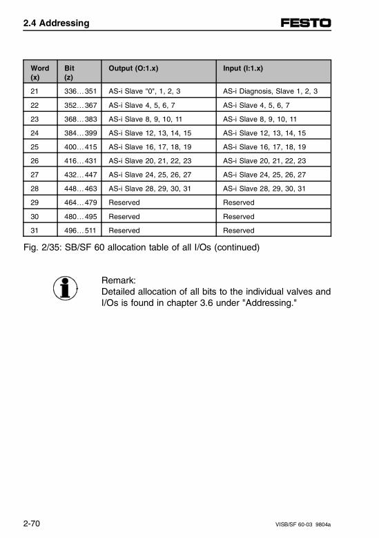
Word(x)
Bit(z)
Output (O:1.x) Input (I:1.x)
21 336…351 AS-i Slave "0", 1, 2, 3 AS-i Diagnosis, Slave 1, 2, 3
22 352…367 AS-i Slave 4, 5, 6, 7 AS-i Slave 4, 5, 6, 7
23 368…383 AS-i Slave 8, 9, 10, 11 AS-i Slave 8, 9, 10, 11
24 384…399 AS-i Slave 12, 13, 14, 15 AS-i Slave 12, 13, 14, 15
25 400…415 AS-i Slave 16, 17, 18, 19 AS-i Slave 16, 17, 18, 19
26 416…431 AS-i Slave 20, 21, 22, 23 AS-i Slave 20, 21, 22, 23
27 432…447 AS-i Slave 24, 25, 26, 27 AS-i Slave 24, 25, 26, 27
28 448…463 AS-i Slave 28, 29, 30, 31 AS-i Slave 28, 29, 30, 31
29 464…479 Reserved Reserved
30 480…495 Reserved Reserved
31 496…511 Reserved Reserved
Fig. 2/35: SB/SF 60 allocation table of all I/Os (continued)
Remark:Detailed allocation of all bits to the individual valves andI/Os is found in chapter 3.6 under "Addressing."
2.4 Addressing
2-70 VISB/SF 60-03 9804a
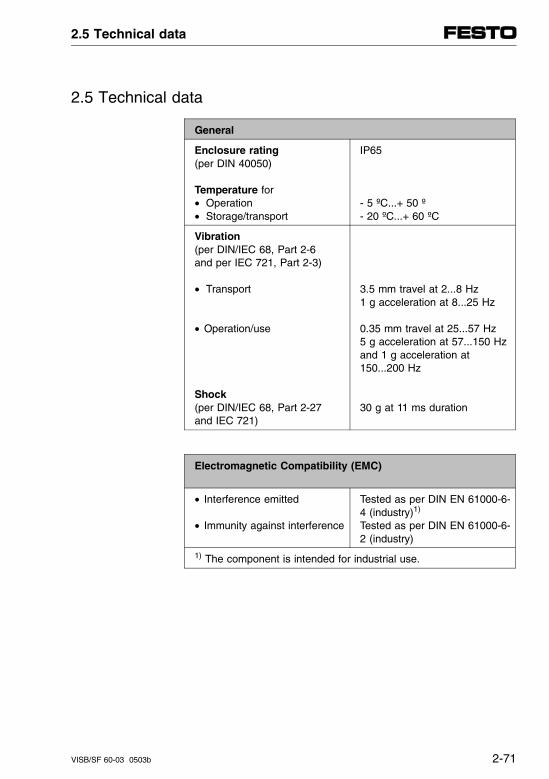
2.5 Technical data
General
Enclosure rating(per DIN 40050)
Temperature for• Operation• Storage/transport
IP65
- 5 ºC...+ 50 º- 20 ºC...+ 60 ºC
Vibration(per DIN/IEC 68, Part 2-6 and per IEC 721, Part 2-3)
• Transport
• Operation/use
Shock(per DIN/IEC 68, Part 2-27 and IEC 721)
3.5 mm travel at 2...8 Hz 1 g acceleration at 8...25 Hz
0.35 mm travel at 25...57 Hz5 g acceleration at 57...150 Hzand 1 g acceleration at150...200 Hz
30 g at 11 ms duration
Electromagnetic Compatibility (EMC)
• Interference emitted
• Immunity against interference
Tested as per DIN EN 61000-6-4 (industry)1)
Tested as per DIN EN 61000-6-2 (industry)
1) The component is intended for industrial use.
2.5 Technical data
VISB/SF 60-03 0503b 2-71
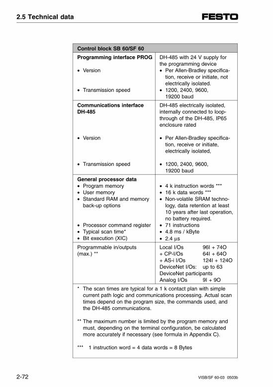
Control block SB 60/SF 60
Programming interface PROG
• Version
• Transmission speed
DH-485 with 24 V supply forthe programming device• Per Allen-Bradley specifica-
tion, receive or initiate, not electrically isolated.
• 1200, 2400, 9600, 19200 baud
Communications interfaceDH-485
• Version
• Transmission speed
DH-485 electrically isolated,internally connected to loop-through of the DH-485, IP65enclosure rated
• Per Allen-Bradley specifica-tion, receive or initiate,electrically isolated,
• 1200, 2400, 9600, 19200 baud
General processor data• Program memory• User memory• Standard RAM and memory
back-up options
• Processor command register• Typical scan time* • Bit execution (XIC)
• 4 k instruction words ***• 16 k data words ***• Non-volatile SRAM techno-
logy, data retention at least 10 years after last operation,no battery required.
• 71 instructions• 4.8 ms / kByte• 2.4 μs
Programmable in/outputs(max.) **
Local I/Os 96I + 74O+ CP-I/Os 64I + 64O+ AS-i I/Os 124I + 124O DeviceNet I/Os: up to 63DeviceNet participantsAnalog I/Os 9I + 9O
* The scan times are typical for a 1 k contact plan with simple current path logic and communications processing. Actual scantimes depend on the program size, the commands used, and the DH-485 communications.
** The maximum number is limited by the program memory andmust, depending on the terminal configuration, be calculated more accurately if necessary (see formula in Appendix C).
*** 1 instruction word = 4 data words = 8 Bytes
2.5 Technical data
2-72 VISB/SF 60-03 0503b
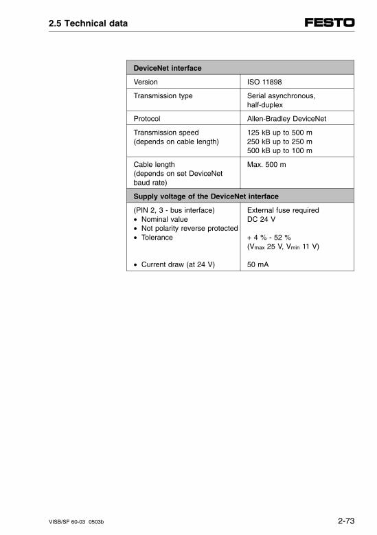
DeviceNet interface
Version ISO 11898
Transmission type Serial asynchronous, half-duplex
Protocol Allen-Bradley DeviceNet
Transmission speed(depends on cable length)
125 kB up to 500 m 250 kB up to 250 m500 kB up to 100 m
Cable length(depends on set DeviceNetbaud rate)
Max. 500 m
Supply voltage of the DeviceNet interface
(PIN 2, 3 - bus interface)• Nominal value• Not polarity reverse protected• Tolerance
• Current draw (at 24 V)
External fuse requiredDC 24 V
+ 4 % - 52 % (Vmax 25 V, Vmin 11 V)
50 mA
2.5 Technical data
VISB/SF 60-03 0503b 2-73
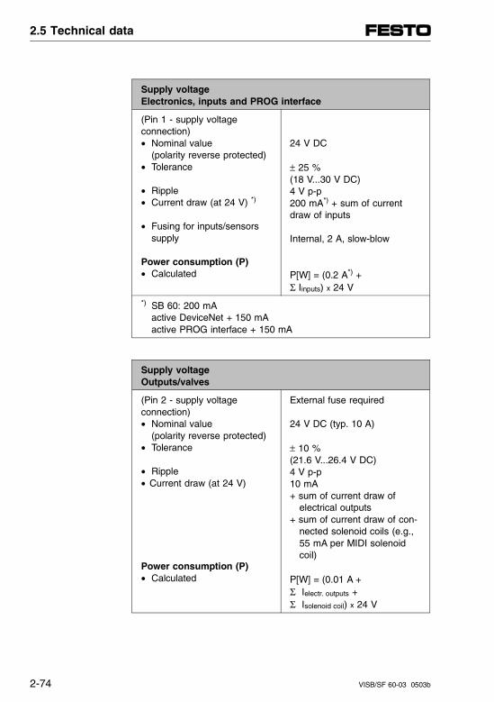
Supply voltageElectronics, inputs and PROG interface
(Pin 1 - supply voltage connection)• Nominal value
(polarity reverse protected)• Tolerance
• Ripple• Current draw (at 24 V) *)
• Fusing for inputs/sensorssupply
Power consumption (P)• Calculated
24 V DC
± 25 %(18 V...30 V DC)4 V p-p200 mA*) + sum of currentdraw of inputs
Internal, 2 A, slow-blow
P[W] = (0.2 A*) + Σ Iinputs) x 24 V
*) SB 60: 200 mAactive DeviceNet + 150 mAactive PROG interface + 150 mA
Supply voltageOutputs/valves
(Pin 2 - supply voltage connection)• Nominal value
(polarity reverse protected)• Tolerance
• Ripple• Current draw (at 24 V)
Power consumption (P)• Calculated
External fuse required
24 V DC (typ. 10 A)
± 10 % (21.6 V...26.4 V DC)4 V p-p10 mA+ sum of current draw of electrical outputs+ sum of current draw of con- nected solenoid coils (e.g., 55 mA per MIDI solenoid coil)
P[W] = (0.01 A + Σ Ielectr. outputs + Σ Isolenoid coil) x 24 V
2.5 Technical data
2-74 VISB/SF 60-03 0503b
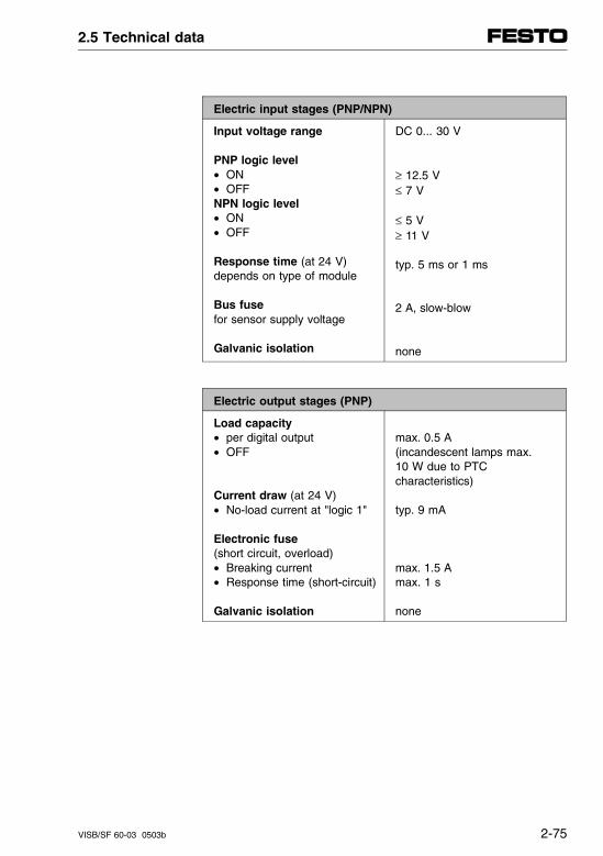
Electric input stages (PNP/NPN)
Input voltage range
PNP logic level• ON• OFFNPN logic level• ON• OFF
Response time (at 24 V)depends on type of module
Bus fuse for sensor supply voltage
Galvanic isolation
DC 0... 30 V
≥ 12.5 V≤ 7 V
≤ 5 V≥ 11 V
typ. 5 ms or 1 ms
2 A, slow-blow
none
Electric output stages (PNP)
Load capacity• per digital output• OFF
Current draw (at 24 V)• No-load current at "logic 1"
Electronic fuse (short circuit, overload)• Breaking current• Response time (short-circuit)
Galvanic isolation
max. 0.5 A(incandescent lamps max. 10 W due to PTCcharacteristics)
typ. 9 mA
max. 1.5 Amax. 1 s
none
2.5 Technical data
VISB/SF 60-03 0503b 2-75

2.5 Technical data
2-76 VISB/SF 60-03 0503b
Chapter 3
Description of SB 60 control block
3. Description of SB 60 control block
VISB/SF 60 9804a 3-I
Contents
3. Description of SB 60 control block
3.1 APS and A.I. 500 Fundamentals . . . . . . . . . . . . . . . . . . . . . . . 3-1
Create a new file . . . . . . . . . . . . . . . . . . . . . . . . . . . . . . . . . . . . 3-3Configure I/O . . . . . . . . . . . . . . . . . . . . . . . . . . . . . . . . . . . . . . . 3-7Return to an existing file . . . . . . . . . . . . . . . . . . . . . . . . . . . . . 3-12Enter the ladder program . . . . . . . . . . . . . . . . . . . . . . . . . . . . 3-13Downloading the program to the controller . . . . . . . . . . . . . . . 3-15Testing the program . . . . . . . . . . . . . . . . . . . . . . . . . . . . . . . . . 3-20
3.2 Fundamentals of RSLogix 500 . . . . . . . . . . . . . . . . . . . . . . . 3-21
File New (create a new file) . . . . . . . . . . . . . . . . . . . . . . . . . . . 3-23I/O configuration . . . . . . . . . . . . . . . . . . . . . . . . . . . . . . . . . . . . 3-27Open File (open an existing program) . . . . . . . . . . . . . . . . . . . 3-30Enter a program in offline mode. . . . . . . . . . . . . . . . . . . . . . . . 3-30Download to the processor. . . . . . . . . . . . . . . . . . . . . . . . . . . . 3-33Testing a program in the processor . . . . . . . . . . . . . . . . . . . . . 3-35
3.3 Configuring the controller . . . . . . . . . . . . . . . . . . . . . . . . . . 3-37
General . . . . . . . . . . . . . . . . . . . . . . . . . . . . . . . . . . . . . . . . . . . 3-37Configuring the terminal for DH-485 . . . . . . . . . . . . . . . . . . . . 3-39Configuring the SB/SF 60. . . . . . . . . . . . . . . . . . . . . . . . . . . . . 3-40Configuring the interrupt service routine (ISR). . . . . . . . . . . . . 3-41Configuring the M-files . . . . . . . . . . . . . . . . . . . . . . . . . . . . . . . 3-41Configuring the G-files . . . . . . . . . . . . . . . . . . . . . . . . . . . . . . . 3-43NOMINAL/ACTUAL comparison . . . . . . . . . . . . . . . . . . . . . . . 3-47
3.4 Start-up up the control system . . . . . . . . . . . . . . . . . . . . . . . 3-49
3.4.1 Inspect your installation . . . . . . . . . . . . . . . . . . . . . . . . . . . . . . 3-51
3.4.2. Disconnect motion-causing devices . . . . . . . . . . . . . . . . . . . . . 3-52
3.4.3 Initialize and test your processor . . . . . . . . . . . . . . . . . . . . . . . 3-54
3. Description of SB 60 control block
3-II VISB/SF 60 9804a
3.4.4 Test your inputs . . . . . . . . . . . . . . . . . . . . . . . . . . . . . . . . . . . . . 3-57
3.4.5 Test your outputs . . . . . . . . . . . . . . . . . . . . . . . . . . . . . . . . . . . . 3-61
3.4.6 Enter and test your program . . . . . . . . . . . . . . . . . . . . . . . . . . . 3-65
3.4.7 Observe control motion . . . . . . . . . . . . . . . . . . . . . . . . . . . . . . . 3-70
3.4.8 Conduct dry run of your application (if possible without tooling/workpieces) . . . . . . . . . . . . . . . . . . . 3-72
3.5 Programming . . . . . . . . . . . . . . . . . . . . . . . . . . . . . . . . . . . . . . 3-73
3.5.1 General. . . . . . . . . . . . . . . . . . . . . . . . . . . . . . . . . . . . . . . . . . . . 3-73Chapter summary. . . . . . . . . . . . . . . . . . . . . . . . . . . . . . . . . . . . 3-73Programming environment . . . . . . . . . . . . . . . . . . . . . . . . . . . . . 3-74Principle of the control sequence. . . . . . . . . . . . . . . . . . . . . . . . 3-75
3.5.2 Processor functions . . . . . . . . . . . . . . . . . . . . . . . . . . . . . . . . . . 3-78General performance features . . . . . . . . . . . . . . . . . . . . . . . . . . 3-78Maintenance-free operation . . . . . . . . . . . . . . . . . . . . . . . . . . . . 3-79Interrupts . . . . . . . . . . . . . . . . . . . . . . . . . . . . . . . . . . . . . . . . . . 3-80Fault interrupts . . . . . . . . . . . . . . . . . . . . . . . . . . . . . . . . . . . . . . 3-80Selectable Timed Interrupt (STI) . . . . . . . . . . . . . . . . . . . . . . . . 3-84
3.5.3 SB/SF 60 instruction set . . . . . . . . . . . . . . . . . . . . . . . . . . . . . . 3-85
3.6 Function of the Festo Peripheral Module (FPM). . . . . . . . . . 3-89
3.6.1 General. . . . . . . . . . . . . . . . . . . . . . . . . . . . . . . . . . . . . . . . . . . . 3-89Chapter summary. . . . . . . . . . . . . . . . . . . . . . . . . . . . . . . . . . . . 3-89
3.6.2 Addressing of the I/Os . . . . . . . . . . . . . . . . . . . . . . . . . . . . . . . . 3-90SB/SF 60 I/O allocation table. . . . . . . . . . . . . . . . . . . . . . . . . . . 3-91Bit addressing of the local I/Os . . . . . . . . . . . . . . . . . . . . . . . . . 3-94Bit addressing of the remote I/Os . . . . . . . . . . . . . . . . . . . . . . . 3-98
3.6.3 Working with the M-files. . . . . . . . . . . . . . . . . . . . . . . . . . . . . . 3-102General. . . . . . . . . . . . . . . . . . . . . . . . . . . . . . . . . . . . . . . . . . . 3-102Configuration of the M-files . . . . . . . . . . . . . . . . . . . . . . . . . . . 3-104Overview of M-files. . . . . . . . . . . . . . . . . . . . . . . . . . . . . . . . . . 3-105
3. Description of SB 60 control block
VISB/SF 60 9804a 3-III
M-file (Inputs) . . . . . . . . . . . . . . . . . . . . . . . . . . . . . . . . . . . . . 3-106M0-file (Outputs) . . . . . . . . . . . . . . . . . . . . . . . . . . . . . . . . . . . 3-108Configuration of I/O interrupt source 0 in the M0-file (M0:1.0). . . . . . . . . . . . . . . . . . . . . . . . . . . . . . . . . . . . 3-109
3.6.4 Special configurations of the FPM . . . . . . . . . . . . . . . . . . . . . 3-110Programming I/O interrupts (ISR) . . . . . . . . . . . . . . . . . . . . . 3-111Configure fault interrupts . . . . . . . . . . . . . . . . . . . . . . . . . . . . 3-115
3.7 Diagnostics and error handling . . . . . . . . . . . . . . . . . . . . . . 3-117
Diagnostics overview . . . . . . . . . . . . . . . . . . . . . . . . . . . . . . . 3-117
3.7.1 Local diagnostics . . . . . . . . . . . . . . . . . . . . . . . . . . . . . . . . . . 3-118SB 60 control block . . . . . . . . . . . . . . . . . . . . . . . . . . . . . . . . 3-118Valves . . . . . . . . . . . . . . . . . . . . . . . . . . . . . . . . . . . . . . . . . . 3-122I/O modules . . . . . . . . . . . . . . . . . . . . . . . . . . . . . . . . . . . . . . 3-123
3.7.2 Diagnostics by program . . . . . . . . . . . . . . . . . . . . . . . . . . . . . 3-125Error states at the valve terminal . . . . . . . . . . . . . . . . . . . . . . 3-125Allen-Bradley fault categories. . . . . . . . . . . . . . . . . . . . . . . . . 3-126Fault codes of the Festo Peripheral Module . . . . . . . . . . . . . 3-127Status word: (I:1.0) . . . . . . . . . . . . . . . . . . . . . . . . . . . . . . . . . 3-129
3.7.3 Expanded diagnostics using M-files . . . . . . . . . . . . . . . . . . . . 3-130Short circuit/overload on local output (M1:1.4) . . . . . . . . . . . 3-130CP System (M1:1.8...M1:1.11) . . . . . . . . . . . . . . . . . . . . . . . . 3-131Analog modules (M1:1.12...M1:1.20) . . . . . . . . . . . . . . . . . . . 3-132Failure of an AS-i slave (M1:1.21...M1:1.22) . . . . . . . . . . . . . 3-133
3. Description of SB 60 control block
3-IV VISB/SF 60 9804a
3.1 APS and A.I. 500 Fundamentals
This chapter explains as an example how to apply Advanced Programming Software (APS) to:
– Create a new file
– Configure I/O
– Return to an existing file
– Enter a program
– Download a program to the controller
– Testing the program
These steps must be carried out in similar form in theA.I. 500 programming software. Detailed informationcan be found in the A.I. 500 manual.
3.1 APS and A.I. 500 Fundamentals
VISB/SF 60 9804a 3-1
The step-by-step and complete configuration of theSB/SF 60 controller as well as start-up of the entirevalve terminal is described in chapter 3.3 and 3.4.
PLEASE NOTENote that the software packages are subject tochanges which are not taken into account in this description.
The examples used here for the screen displayswere taken from the English APS version 6.03.
Additional and current information can be found inthe manual for your APS programming software andA.I. 500.
3.1 APS and A.I. 500 Fundamentals
3-2 VISB/SF 60 9804a
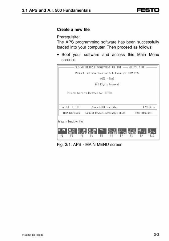
Create a new file
Prerequisite: The APS programming software has been successfullyloaded into your computer. Then proceed as follows:
• Boot your software and access this Main Menuscreen:
Fig. 3/1: APS - MAIN MENU screen
3.1 APS and A.I. 500 Fundamentals
VISB/SF 60 9804a 3-3
Depending on whether there is already one or moreprogram files in the APS, select from the followingsteps. Proceed as follows:
Case A: No current program file present(the status line "Current Offline File:" is empty):
• Press F3 OFFLINE PRG/DOC to create a new program file (offline). Confirm the question CREATE NEW ARCHIVE FILE with F8 YES.
Case B: There is a current program file (the status line "Current Offline File:" contains a program file name and there is one or more program files present)
• Press F3 OFFLINE PRG/DOC. Press F4 CHANGE FILE. You get a window in which all program files are listed. Press F6 CREATE FILE.
3.1 APS and A.I. 500 Fundamentals
3-4 VISB/SF 60 9804a
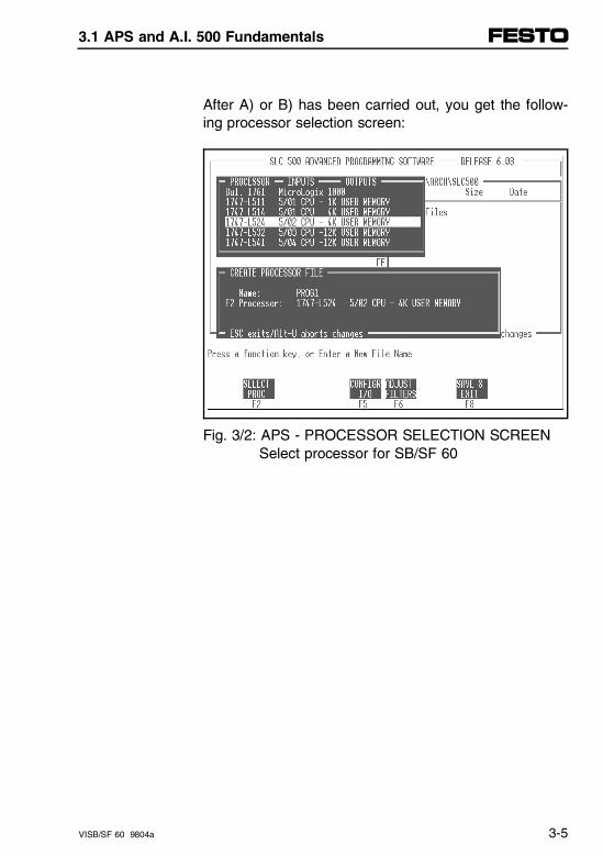
After A) or B) has been carried out, you get the follow-ing processor selection screen:
Fig. 3/2: APS - PROCESSOR SELECTION SCREEN Select processor for SB/SF 60
3.1 APS and A.I. 500 Fundamentals
VISB/SF 60 9804a 3-5
• Type the name of the file you want to create (e.g.,PROG1) and press [ENTER]. For practical purposesyou should use names which describe your system.In this chapter, PROG1 is used as the processorname.
• Identify the type of processor you are using in theupper pop-up window. Use the cursor keys to high-light the processor and press [ENTER].
For the Festo SB/SF 60 programmable valve terminal,the following selection is necessary: 1747-L5245/02 CPU - 4 K USER MEMORY
After you have finished your entry, the selected proces-sor appears in the lower window.
Now you are ready to configure the I/O of your SLCcontrol system. You do this by telling the software whathardware your system is using.
3.1 APS and A.I. 500 Fundamentals
3-6 VISB/SF 60 9804a
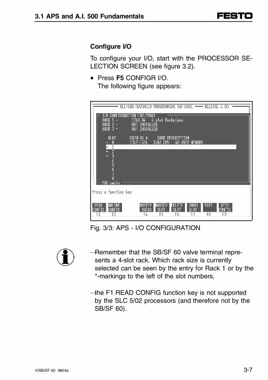
Configure I/O
To configure your I/O, start with the PROCESSOR SE-LECTION SCREEN (see figure 3.2).
• Press F5 CONFIGR I/O. The following figure appears:
Fig. 3/3: APS - I/O CONFIGURATION
-Remember that the SB/SF 60 valve terminal repre-sents a 4-slot rack. Which rack size is currently selected can be seen by the entry for Rack 1 or by the*-markings to the left of the slot numbers,
- the F1 READ CONFIG function key is not supportedby the SLC 5/02 processors (and therefore not by theSB/SF 60).
3.1 APS and A.I. 500 Fundamentals
VISB/SF 60 9804a 3-7
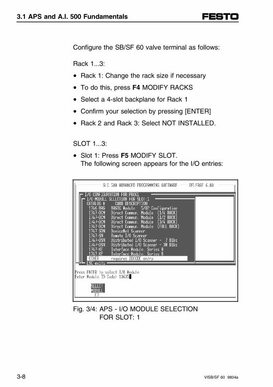
Configure the SB/SF 60 valve terminal as follows:
Rack 1...3:
• Rack 1: Change the rack size if necessary
• To do this, press F4 MODIFY RACKS
• Select a 4-slot backplane for Rack 1
• Confirm your selection by pressing [ENTER]
• Rack 2 and Rack 3: Select NOT INSTALLED.
SLOT 1...3:
• Slot 1: Press F5 MODIFY SLOT. The following screen appears for the I/O entries:
Fig. 3/4: APS - I/O MODULE SELECTION FOR SLOT: 1
3.1 APS and A.I. 500 Fundamentals
3-8 VISB/SF 60 9804a
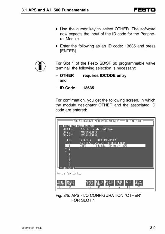
• Use the cursor key to select OTHER. The softwarenow expects the input of the ID code for the Periphe-ral Module.
• Enter the following as an ID code: 13635 and press[ENTER]
For Slot 1 of the Festo SB/SF 60 programmable valveterminal, the following selection is necessary:
– OTHER requires IDCODE entry and
– ID-Code 13635
For confirmation, you get the following screen, in whichthe module designator OTHER and the associated IDcode are entered:
Fig. 3/5: APS - I/O CONFIGURATION "OTHER" FOR SLOT 1
3.1 APS and A.I. 500 Fundamentals
VISB/SF 60 9804a 3-9
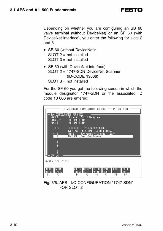
Depending on whether you are configuring an SB 60valve terminal (without DeviceNet) or an SF 60 (withDeviceNet interface), you enter the following for slots 2and 3:
• SB 60 (without DeviceNet):SLOT 2 = not installed SLOT 3 = not installed
• SF 60 (with DeviceNet interface):SLOT 2 = 1747-SDN DeviceNet Scanner (ID-CODE 13606)SLOT 3 = not installed
For the SF 60 you get the following screen in which themodule designator 1747-SDN or the associated IDcode 13 606 are entered:
Fig. 3/6: APS - I/O CONFIGURATION "1747-SDN" FOR SLOT 2
3.1 APS and A.I. 500 Fundamentals
3-10 VISB/SF 60 9804a
After configuring the slots for your valve terminal cor-rectly, to return to the main menu press:
• EXIT F8SAVE & EXIT F8You get the prompt: NEW ARCHIVE FILE CREATED.
• SAVE TO FILE F9. You get the prompt: NEW CONFIGURATION SAVED TO FILE.
• ESC and, if a current program file is present: RETURN TO MAIN MENU F3, to return to the mainmenu of the APS.
3.1 APS and A.I. 500 Fundamentals
VISB/SF 60 9804a 3-11
Return to an existing file
If you have already created the program file for yourapplication and want to add or edit ladder logic, returnto it from the main menu screen as follows:
• To return to a program file offline, press OFFLINEPRG/DOC F3. You get the PROGRAM DIRECTORYFOR PROCESSORS screen.
• Get the list of existing program files by pressingCHANGE FILE F4. You get pop-up window with thelist of existing program files.
• Cursor to the file you want to open and press OFF-LINE PRG / DOC F1.The screen displays the name of the subject file inthe header and removes the pop-up window.
• To open the file so you can write or edit your ladderlogic, press MONITOR FILE F8. The screen displaysthe ladder logic of the subject program file.To edit the logic, use function keys and follow theprompts as needed.
• When finished programming, press EXIT F3.
• If you want to save your work, press SAVE F2.Then, follow the prompts and use function keys asneeded to save the file.
3.1 APS and A.I. 500 Fundamentals
3-12 VISB/SF 60 9804a
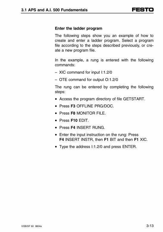
Enter the ladder program
The following steps show you an example of how tocreate and enter a ladder program. Select a programfile according to the steps described previously, or cre-ate a new program file.
In the example, a rung is entered with the followingcommands:
– XIC command for input I:1.2/0
– OTE command for output O:1.2/0
The rung can be entered by completing the followingsteps:
• Access the program directory of file GETSTART.
• Press F3 OFFLINE PRG/DOC.
• Press F8 MONITOR FILE.
• Press F10 EDIT.
• Press F4 INSERT RUNG.
• Enter the input instruction on the rung: PressF4 INSERT INSTR, then F1 BIT and then F1 XIC.
• Type the address I:1.2/0 and press ENTER.
3.1 APS and A.I. 500 Fundamentals
VISB/SF 60 9804a 3-13
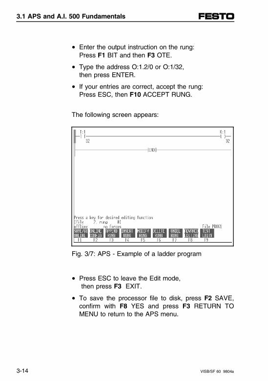
• Enter the output instruction on the rung: Press F1 BIT and then F3 OTE.
• Type the address O:1.2/0 or O:1/32, then press ENTER.
• If your entries are correct, accept the rung: Press ESC, then F10 ACCEPT RUNG.
The following screen appears:
Fig. 3/7: APS - Example of a ladder program
• Press ESC to leave the Edit mode, then press F3 EXIT.
• To save the processor file to disk, press F2 SAVE,confirm with F8 YES and press F3 RETURN TOMENU to return to the APS menu.
3.1 APS and A.I. 500 Fundamentals
3-14 VISB/SF 60 9804a
Downloading the program to the controller
Once you have created a program, you must reset thecontroller and download the program to it. Proceed asfollows:
• Verify that the online configuration of your soft-ware/PC is set properly (see manual of your pro-gramming software).
• Select if necessary the corresponding communica-tions driver in F2 ONLINE CONFIG menu.
For additional information, see your Allen-Bradley man-ual.
• Go to the main menu.
• Press F1 ONLINE.
If the message MESSAGE TIMEOUTS - LOSS OFCOMMUNICATIONS appears, one or more of the On-line Configuration parameters is incorrect and/or thereis an improper connection between the computer andthe processor. Check the connection and correctly set the parametersfor Online Configuration if necessary.
3.1 APS and A.I. 500 Fundamentals
VISB/SF 60 9804a 3-15
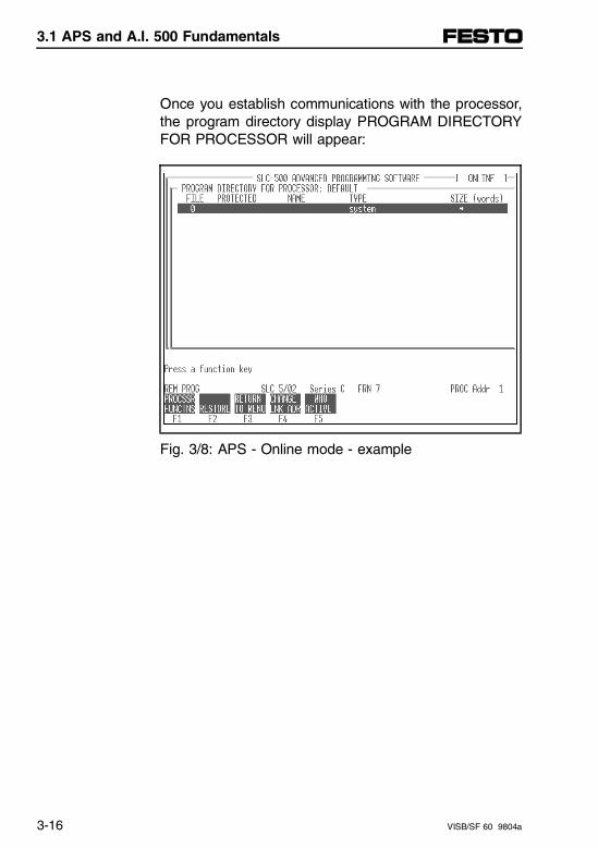
Once you establish communications with the processor,the program directory display PROGRAM DIRECTORYFOR PROCESSOR will appear:
Fig. 3/8: APS - Online mode - example
3.1 APS and A.I. 500 Fundamentals
3-16 VISB/SF 60 9804a
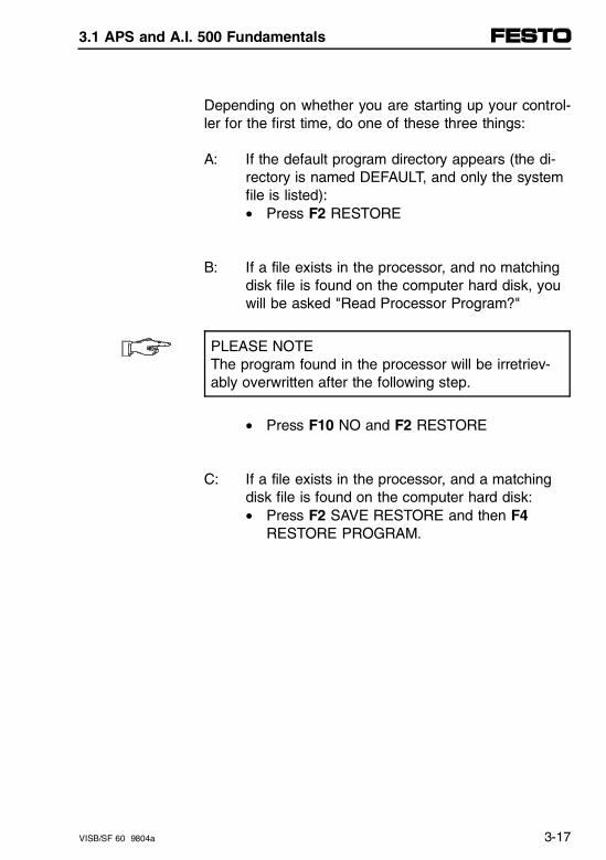
Depending on whether you are starting up your control-ler for the first time, do one of these three things:
A: If the default program directory appears (the di-rectory is named DEFAULT, and only the system file is listed):• Press F2 RESTORE
B: If a file exists in the processor, and no matchingdisk file is found on the computer hard disk, you will be asked "Read Processor Program?"
PLEASE NOTEThe program found in the processor will be irretriev-ably overwritten after the following step.
• Press F10 NO and F2 RESTORE
C: If a file exists in the processor, and a matching disk file is found on the computer hard disk:• Press F2 SAVE RESTORE and then F4
RESTORE PROGRAM.
3.1 APS and A.I. 500 Fundamentals
VISB/SF 60 9804a 3-17
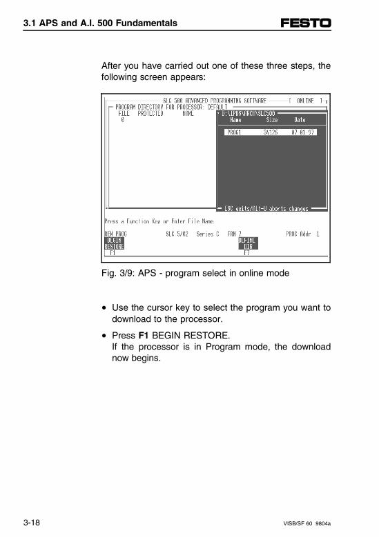
After you have carried out one of these three steps, thefollowing screen appears:
Fig. 3/9: APS - program select in online mode
• Use the cursor key to select the program you want todownload to the processor.
• Press F1 BEGIN RESTORE. If the processor is in Program mode, the downloadnow begins.
3.1 APS and A.I. 500 Fundamentals
3-18 VISB/SF 60 9804a
If the processor is in RUN mode, the question appears:"Change Processor Mode to Program?"
• Then press F8 YES to start the download process.
Once the download process is complete, the followingprompt appears:"Press Any Key to Continue."
• Press any key.The display PROGRAM DIRECTORY FOR PROCESSOR: "Filename" appears.
Now you can test the downloaded program in theprocessor.
3.1 APS and A.I. 500 Fundamentals
VISB/SF 60 9804a 3-19
Testing the program
Once you have created a program and downloaded itto the processor, you can monitor and test it in theprocessor. Proceed as follows:
• Go to the PROGRAM DIRECTORY FOR PROCES-SOR: "Filename" screen (see figure 3/8).
• Use the cursor key to select your program.Press F8 MONITOR FILE.
• The ladder program is displayed.
WARNINGBefore you test a program in the processor note thatmovements of the actuators during start-up tests cancause fatal injury!• Before beginning with further start-up steps, verify
that all actuators are disconnected from their powersources.
• Observe the instructions in chapter 3.4.2, "Disconnecting Power Sources from all Actuators."
• Switch your processor over to the Run Mode. To dothis, press:F1 CHANGE MODE, then F3 RUN MODE and F8YES.
The status line now displays REM RUN (instead ofPROGRAM). If you get an error message, remedythe error accordingly.
• Now you can test your program.
3.1 APS and A.I. 500 Fundamentals
3-20 VISB/SF 60 9804a
3.2 Fundamentals of RSLogix 500
This chapter describes use of the RSLogix 500 (Rock-well Programming Software for SLC 500 Family) soft-ware, and is divided into the following sections:
– File New
– I/O Configuration
– Open File
– Enter a program in offline mode
– Download to the processor
– Testing program in the processor
3.2 Fundamentals of RSLogix 500
VISB/SF 60 9804a 3-21
Full configuration of the SB/SF 60 controller and com-missioning of the complete valve terminal are describedin chapter 3.3 and 3.4.
PLEASE NOTEBe aware that the software packages are subject tochanges which are not reflected in this description.
The examples used here for the screen displayswere taken from the English RSLogix 500 version2.0.
Additional and current information can be found inthe "Reference Manual for your programming soft-ware."
3.2 Fundamentals of RSLogix 500
3-22 VISB/SF 60 9804a
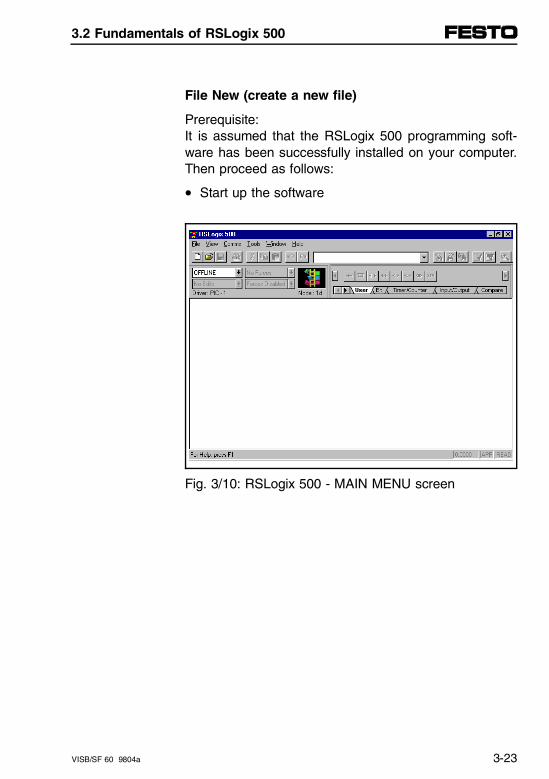
File New (create a new file)
Prerequisite:It is assumed that the RSLogix 500 programming soft-ware has been successfully installed on your computer.Then proceed as follows:
• Start up the software
Fig. 3/10: RSLogix 500 - MAIN MENU screen
3.2 Fundamentals of RSLogix 500
VISB/SF 60 9804a 3-23
• Select NEW in the FILE menu. A dialog box appearsin which you can select the processor type used andcan assign a processor name.
• For the SB/SF 60 make the following selection:1747-L524 5/02 CPU - 4 K Mem.
For the Festo SB/SF 60 programmable valve terminal,the following selection is necessary:1747-L524 5/02 CPU - 4 K Mem.
3.2 Fundamentals of RSLogix 500
3-24 VISB/SF 60 9804a
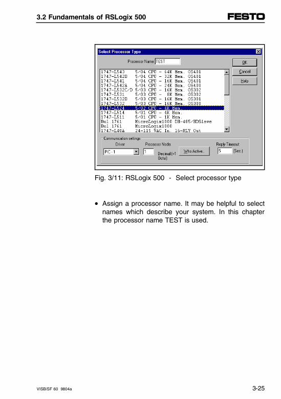
Fig. 3/11: RSLogix 500 - Select processor type
• Assign a processor name. It may be helpful to selectnames which describe your system. In this chapterthe processor name TEST is used.
3.2 Fundamentals of RSLogix 500
VISB/SF 60 9804a 3-25
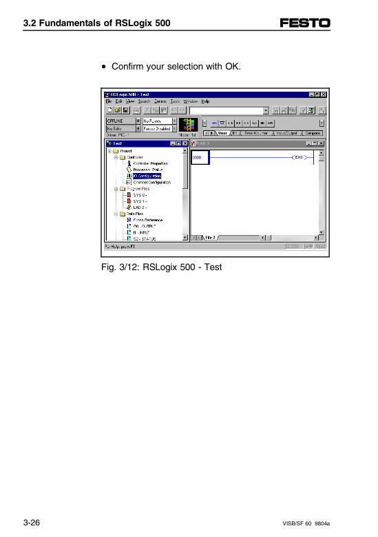
• Confirm your selection with OK.
Fig. 3/12: RSLogix 500 - Test
3.2 Fundamentals of RSLogix 500
3-26 VISB/SF 60 9804a
I/O configuration
In order to configure the corresponding rack as well asthe I/O, you must be in the I/O CONFIGURATION dia-log box.
• Open the I/O CONFIGURATION dialog box bydouble clicking on the I/O CONFIGURATION icon inthe PROJECT TREE window (Test).
The READ I/O and POWER SUPPLY commands arenot supported by the SLC 5/02 processors (and there-fore not by the SB/SF 60).
Configure the SB/SF 60 valve terminal as follows
Racks 1...3 (upper dialog box):
• Rack 1: For the SB/SF 60 always select a 1746-A4 4-slot rack.
• Racks 2...3: For the expansion racks, select NOT INSTALLED.
3.2 Fundamentals of RSLogix 500
VISB/SF 60 9804a 3-27
Slot 1...3 (lower dialog box):
Slot 0 is already configured as processor type 5/02
• Slot 1: Select the digit 1 with the cursor keys or the mouse.The line becomes colored.
• Activate slot 1 with a double click
• In the CURRENT CARDS AVAILABLE dialog boxselect the I/O card type "Others" by double clicking.
You are prompted to enter the required ID number forthe SB/SF 60.
For SLOT 1 in the Festo Peripheral Module the follow-ing selection is necessary:
– OTHER Requires I/O Card Type ID and
– ID-Code 13635
• Confirm your selection with OK.
As confirmation you get the following screen in whichthe module designation OTHER and the associated IDcode are entered:
3.2 Fundamentals of RSLogix 500
3-28 VISB/SF 60 9804a
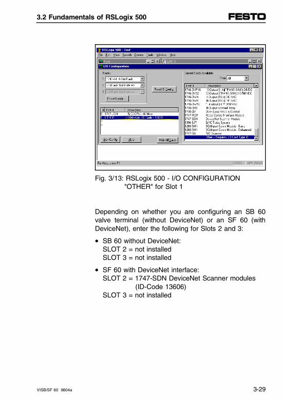
Fig. 3/13: RSLogix 500 - I/O CONFIGURATION "OTHER" for Slot 1
Depending on whether you are configuring an SB 60valve terminal (without DeviceNet) or an SF 60 (withDeviceNet), enter the following for Slots 2 and 3:
• SB 60 without DeviceNet:SLOT 2 = not installedSLOT 3 = not installed
• SF 60 with DeviceNet interface:SLOT 2 = 1747-SDN DeviceNet Scanner modules (ID-Code 13606)SLOT 3 = not installed
3.2 Fundamentals of RSLogix 500
VISB/SF 60 9804a 3-29
After all the slots have been correctly configured for thevalve terminal:
• Close the I/O CONFIGURATION window.
Recommendation:Save your configuration in the FILE menu using theSAVE AS option in your project directory. This stores anew project file.
Open File (open an existing program)
To change an already existing program, select the pro-gram as follows:
• Go back to the main menu (figure 3/10) and use theOPEN command in the FILE menu to select an al-ready existing project.
Enter a program in offline mode
The following steps show an example of how a ladderprogram can be created and entered. The exampleuses a rung entered using the following commands:
– XIC command for input I:1.2/0
– OTE command for output O:1.2/0
Program changes are only possible in Offline mode.
3.2 Fundamentals of RSLogix 500
3-30 VISB/SF 60 9804a
The rung is entered in the following steps:
• Go to the main menu (figure 3/10).
• Activate the LAD 2 icon in the project window. Thisopens the LAD 2 dialog box. This dialog box LAD 2is the main program of your contact plan.
• Enter a rung using the EDIT menu and the INSERTRUNG instruction or using the instruction set sym-bols.
The commands for your run can be entered in the AS-CII Editing Mode or using icons in your User Toolbar. Inthe following the editing is described using the ASCIIEditing Mode.
• Activate the ASCII EDIT MODE command in theEDIT menu (or use CTRL-A). A dialog box for yourcommands appears.
• Enter the following commands:XIC I:1.2/0 OTE O:1.2/0
• Finish the entry with ENTER.
• Save your file in the FILE menu using the SAVE in-struction.
3.2 Fundamentals of RSLogix 500
VISB/SF 60 9804a 3-31
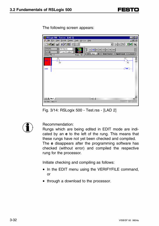
The following screen appears:
Fig. 3/14: RSLogix 500 - Test.rss - [LAD 2]
Recommendation:Rungs which are being edited in EDIT mode are indi-cated by an e to the left of the rung. This means thatthese rungs have not yet been checked and compiled. The e disappears after the programming software haschecked (without error) and compiled the respectiverung for the processor.
Initiate checking and compiling as follows:
• In the EDIT menu using the VERIFYFILE command,or
• through a download to the processor.
3.2 Fundamentals of RSLogix 500
3-32 VISB/SF 60 9804a
Download to the processor
After you have created a program, you must reset theprocessor and download the program to it. Proceed asfollows:
• Verify that the online configuration of your soft-ware/PC is properly set.
Read the description for your WINtelligent communica-tions software.
• Open the CHANNEL Configuration dialog box for thenecessary processor settings by double clicking onthe CHANNEL Configuration icon in the project win-dow.
• Download the current program to the processor. Todo this, select DOWNLOAD in the list field (upperleft). The current program is now compiled anddownloaded to the processor.
If there is already a program in the processor, you areprompted accordingly before downloading and you areasked to confirm.
CAUTIONIf you confirm the download, the program alreadyexisting in the processor is irretrievably overwritten.
3.2 Fundamentals of RSLogix 500
VISB/SF 60 9804a 3-33
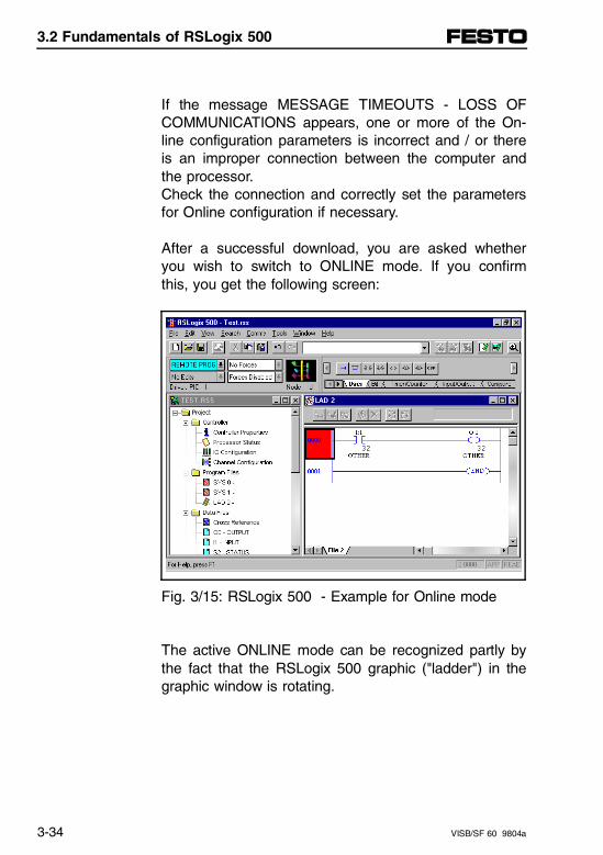
If the message MESSAGE TIMEOUTS - LOSS OFCOMMUNICATIONS appears, one or more of the On-line configuration parameters is incorrect and / or thereis an improper connection between the computer andthe processor.Check the connection and correctly set the parametersfor Online configuration if necessary.
After a successful download, you are asked whetheryou wish to switch to ONLINE mode. If you confirmthis, you get the following screen:
Fig. 3/15: RSLogix 500 - Example for Online mode
The active ONLINE mode can be recognized partly bythe fact that the RSLogix 500 graphic ("ladder") in thegraphic window is rotating.
3.2 Fundamentals of RSLogix 500
3-34 VISB/SF 60 9804a
Testing a program in the processor
After you have created a program and downloaded it tothe processor, you can monitor it and test it in the proc-essor. Proceed as follows:
• Verify that the is in ONLINE mode.
• Repeat the previously described steps if necessary,
or
• select the program located in the processor using theOPEN command in the FILE window and click onONLINE in the list field at upper left.
The current processor mode status is now displayed inthe list field (REMOTE PROG).
• Put your processor into Run Mode.To do this, click on RUN in the list field at upper left.The list field now shows REMOTE RUN (instead ofREMOTE PROG).
3.2 Fundamentals of RSLogix 500
VISB/SF 60 9804a 3-35
If you get an error message, remove the cause of theerror.
WARNINGBefore you test a program in the processor, note thatmovements of the actuators during start-up tests cancause fatal injury!• Before beginning with further start-up steps, verify
that all actuators are disconnected from their powersources.
• Observe the instructions in chapter 3.4.2, "Disconnecting Power Sources from all Actuators."
• Now you may test your program.
3.2 Fundamentals of RSLogix 500
3-36 VISB/SF 60 9804a
3.3 Configuring the controller
General
This chapter describes basic steps for the overall con-trol system. Solid knowledge of how to operate andprogram with the A.I. 500, APS or RSLogix 500 soft-ware packages is assumed.
The SB/SF 60 incorporates Allen-Bradley SLC 500technology and is therefore configured identically. TheSB/SF 60 represents a 4-slot rack which has an SLC5/02 processor with 4 k of memory in Slot 0.
Slot 1 has an I/O special module (Festo Peripheral Mo-dule FPM) which needs to be configured, and whichmakes available the corresponding functionality of G-,M0 and M1 files. In addition, the SF 60 also offers aDeviceNet scanner. Otherwise Slots 2 and 3 are notused. The necessary entries for configuration of theSB/SF 60 are described in more detail in the following.
3.3 Configuring the controller
VISB/SF 60 9804a 3-37
Configuration, programming and operation of the SB/SF 60 can be done as desired using the following inter-faces:
– PROG interface directly on the SB/SF 60 (DH-485with supply voltage, corresponds to "Peripheral" on a1747-AIC).
– Indirectly through the DH-485 network. Connect theSB/SF 60 through its DH-485 interface(s) to the DH-485 network. Configure the SB/SF 60 for the DH-485network according to the steps on the following page.
PLEASE NOTEDo not connect the SB/SF 60 to the "CPU" interfaceof an 1747-AIC. Otherwise transmission errors will result.
The following Allen-Bradley products are suitable forstart-up and programming:
– A.I. 500 programming software
– APS programming software
– RSLogix 500 programming software
– Hand-Held Terminal (HHT)
Knowledge of how to use these products is assumedfor the following steps.
3.3 Configuring the controller
3-38 VISB/SF 60 9804a
Configuring the terminal for DH-485
If you wish to configure the valve terminal through theDH-485 network, you must first prepare the terminal forDH-485 communication.
Prerequisite:
1. You must be familiar with the necessary steps forconfiguring a DH-485 network in your programmingsoftware.
2. The valve terminal is properly connected to the DH-485 network.
3. Every slave on the DH-485 has its own address(node address).
4. All slaves are set at the same baud rate.
The SB/SF 60 is set at the factory as follows:- Node address 1- 19.2 kBaud
Then proceed as follows:
• Set the baud rate on the programmer at the (default)value of the SB/SF 60.
• Create online connection to SB/SF 60 (e.g. viaPROG interface and with "WHO" command).
• Set online parameters to desired values (node ad-dress, baud rate, max. poll address).
• Switch off the SB/SF 60 and then switch it on again.The modified parameters are then saved.
3.3 Configuring the controller
VISB/SF 60 9804a 3-39
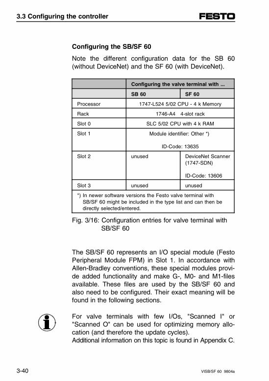
Configuring the SB/SF 60
Note the different configuration data for the SB 60(without DeviceNet) and the SF 60 (with DeviceNet).
Configuring the valve terminal with ...
SB 60 SF 60
Processor 1747-L524 5/02 CPU - 4 k Memory
Rack 1746-A4 4-slot rack
Slot 0 SLC 5/02 CPU with 4 k RAM
Slot 1 Module identifier: Other *)
ID-Code: 13635
Slot 2 unused DeviceNet Scanner(1747-SDN)
ID-Code: 13606
Slot 3 unused unused
*) In newer software versions the Festo valve terminal with SB/SF 60 might be included in the type list and can then be directly selected/entered.
Fig. 3/16: Configuration entries for valve terminal with SB/SF 60
The SB/SF 60 represents an I/O special module (FestoPeripheral Module FPM) in Slot 1. In accordance withAllen-Bradley conventions, these special modules provi-de added functionality and make G-, M0- and M1-filesavailable. These files are used by the SB/SF 60 andalso need to be configured. Their exact meaning will befound in the following sections.
For valve terminals with few I/Os, "Scanned I" or"Scanned O" can be used for optimizing memory allo-cation (and therefore the update cycles).Additional information on this topic is found in Appendix C.
3.3 Configuring the controller
3-40 VISB/SF 60 9804a
Configuring the interrupt service routine (ISR)
If later you want to process I/O interrupts in your pro-gram, you must at this point define a correspondingsub-program. This sub-program (Interrupt Service Rou-tine ISR) is then run by the processor for each I/O in-terrupt.
• Enter the program file number: Range 3...255
Further information about the possibilities with I/O inter-rupts is to be found in chapter 3.6.4.
Configuring the M-files
The M-files are used by the SB/SF 60 for the followingfunctions:
– Defining freely programmable I/O interrupt input
– Sending AS-i slave parameters
– Enhanced diagnostic and error message querying,e.g., short circuit in local outputs, diagnostics of theCP system and the analog modules, NOMINAL/AC-TUAL comparison of valve terminal structure (NOMI-NAL structure only for already configured G-file).
3.3 Configuring the controller
VISB/SF 60 9804a 3-41
This means with the SB/SF 60 you are able to programa flexible interrupt response and carry out a differenti-ated diagnostic routine of multiple error messages afterpower-up (including NOMINAL/ACTUAL comparison)and output an appropriate error message.
• Configure the M-files as followsM0-file size: 32M1-file size: 32
The M0-files can be either
– written by transfering blocks of data (e.g. COP, MOV),
or
– set/reset bit for bit
The M1-files can be either
– read by transfering blocks of data (e.g. COP, MOV),
or
– queried bit for bit.
The exact meaning of the M-files and their use in theprogram are described in greater detail in chapter 3.6.3"Working with the M-files." The NOMINAL/ACTUALcomparison is described in the following chapter "Con-figuring the G-files."
3.3 Configuring the controller
3-42 VISB/SF 60 9804a
Configuring the G-files
The G-file can be used for entering/saving the NOMI-NAL structure of the valve terminal, and for comparingthis with the ACTUAL structure when the unit isswitched on. The words G:1.1 and G:1.2 in the G-fileare used for this. The SB/SF 60 is therefore able todetect any possible deviations after power-up and out-puts a corresponding error message.
• Configure the G-file as follows:G-File size: 3
- If you do not configure the G-file (default: size=0), noNOMINAL/ACTUAL comparison will be carried out after power-up.
-The word G:1.0 is automatically configured and cannot be changed (default: 32 I/O words)
The individual words in the G-files have the followingmeaning for the SB/SF 60:
3.3 Configuring the controller
VISB/SF 60 9804a 3-43
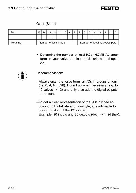
G:1.1 (Slot 1)
Bit 15 14 13 12 11 10 9 8 7 6 5 4 3 2 1 0
Meaning Number of local inputs Number of local valves/outputs
• Determine the number of local I/Os (NOMINAL struc-ture) in your valve terminal as described in chapter2.4.
Recommendation:
-Always enter the valve terminal I/Os in groups of four(i.e. 0, 4, 8, …96). Round up when necessary (e.g. for10 valves → 12) and only then add the digital outputsto the total.
-To get a clear representation of the I/Os divided ac-cording to High-Byte and Low-Byte, it is advisable toconvert and input the I/Os in hex. Example: 20 inputs and 36 outputs (dec) → 1424 (hex).
3.3 Configuring the controller
3-44 VISB/SF 60 9804a
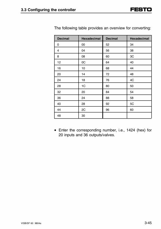
The following table provides an overview for converting:
Decimal Hexadecimal Decimal Hexadecimal
0 00 52 34
4 04 56 38
8 08 60 3C
12 0C 64 40
16 10 68 44
20 14 72 48
24 18 76 4C
28 1C 80 50
32 20 84 54
36 24 88 58
40 28 92 5C
44 2C 96 60
48 30
• Enter the corresponding number, i.e., 1424 (hex) for20 inputs and 36 outputs/valves.
3.3 Configuring the controller
VISB/SF 60 9804a 3-45
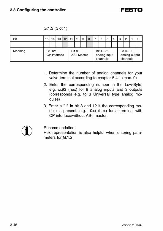
G:1.2 (Slot 1)
Bit 15 14 13 12 11 10 9 8 7 6 5 4 3 2 1 0
Meaning Bit 12: CP interface
Bit 8: AS-i-Master
Bit 4...7:analog inputchannels
Bit 0...3:analog outputchannels
1. Determine the number of analog channels for yourvalve terminal according to chapter 5.4.1 (max. 9)
2. Enter the corresponding number in the Low-Byte,e.g. xx93 (hex) for 9 analog inputs and 3 outputs(corresponds e.g. to 3 Universal type analog mo-dules)
3. Enter a "1" in bit 8 and 12 if the corresponding mo-dule is present, e.g. 10xx (hex) for a terminal withCP interface/without AS-i master.
Recommendation:Hex representation is also helpful when entering para-meters for G:1.2.
3.3 Configuring the controller
3-46 VISB/SF 60 9804a
NOMINAL/ACTUAL comparison
Since the G-file cannot be directly read out from theprogram, the data for the NOMINAL structure are auto-matically sent from the processor into the M1-file ac-cording to M1:1.30 and M1:1.31. For this the M-filesmust already be configured.
If the G-file was configured at power-up, the processorautomatically determines the ACTUAL structure andstores the result in the M1-file under M1:1.28 andM1:1.29. This makes the NOMINAL and ACTUAL struc-ture ready for later queries as well.
Recommendation:
• Use hex representation at first for the processing.
• If you do not wish to manually determine the NOMI-NAL structure of the valve terminal, read out the AC-TUAL structure from the M1-file after power-up andenter these values into the G-file.
3.3 Configuring the controller
VISB/SF 60 9804a 3-47
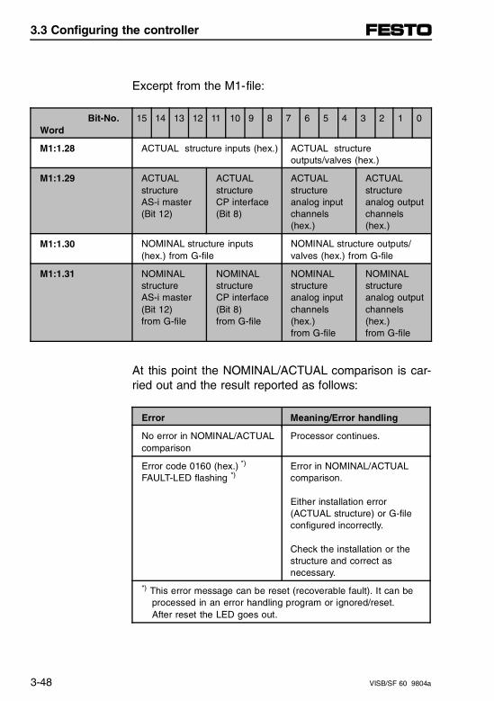
Excerpt from the M1-file:
Bit-No.Word
15 14 13 12 11 10 9 8 7 6 5 4 3 2 1 0
M1:1.28 ACTUAL structure inputs (hex.) ACTUAL structureoutputs/valves (hex.)
M1:1.29 ACTUALstructure AS-i master(Bit 12)
ACTUALstructure CP interface(Bit 8)
ACTUALstructureanalog inputchannels(hex.)
ACTUALstructureanalog outputchannels(hex.)
M1:1.30 NOMINAL structure inputs(hex.) from G-file
NOMINAL structure outputs/valves (hex.) from G-file
M1:1.31 NOMINALstructure AS-i master(Bit 12) from G-file
NOMINALstructure CP interface(Bit 8)from G-file
NOMINALstructureanalog inputchannels(hex.)from G-file
NOMINALstructureanalog outputchannels(hex.)from G-file
At this point the NOMINAL/ACTUAL comparison is car-ried out and the result reported as follows:
Error Meaning/Error handling
No error in NOMINAL/ACTUALcomparison
Processor continues.
Error code 0160 (hex.) *)
FAULT-LED flashing *)Error in NOMINAL/ACTUALcomparison.
Either installation error(ACTUAL structure) or G-fileconfigured incorrectly.
Check the installation or thestructure and correct asnecessary.
*) This error message can be reset (recoverable fault). It can beprocessed in an error handling program or ignored/reset. After reset the LED goes out.
3.3 Configuring the controller
3-48 VISB/SF 60 9804a

3.4 Start -up up the control system
WARNINGBefore you start up the control system:- make sure you are completely familiar with all the
control components and programming resp. ope-rating techniques,
- make sure you are completely familiar with your particular machine or installation.
Recommendation:Proceed carefully and systematically with start-up, fol-lowing all eight of the steps described in this chapter.This will help you avoid potentially serious personalrisks or damage to the equipment.
Follow the general recommendations and regulationspertaining to "Equipment and machine safety" for yourregion, e.g.:
– Europe: EN 60204 "Machine Safety; Electrical Equip-ment on Machines" (similar/modified IEC 204-1). Alsonote any country-specific additions/modifications.
– USA: NFPA 70E, "Electrical Safety Requirements forEmployee Workplaces."
3.4 Start-up up the control system
VISB/SF 60 9804a 3-49
This chapter describes initial start-up of your systemand is divided into the following eight steps:
1. Inspect your installation
2. Disconnect motion-causing devices
3. Initialize and test your processor
4. Test your inputs
5. Test your outputs
6. Enter and test your program
7. Observe control motion
8. Conduct a dry run of your application (if possiblewithout tooling/workpieces).
This step-for-step procedure systematizes troubleshoot-ing at start-up, for example wiring mistakes, devicefaults, or programming errors.
3.4 Start-up up the control system
3-50 VISB/SF 60 9804a
3.4.1 Inspect your installation
By checking the entire physical installation before start-up, you can often avoid serious problems in later tests.
Recommendation:
• Verify that the SB/SF 60 processor and all the otherdevices in the system are securely mounted or at-tached
• Check the entire wiring, including:- central power supply for the system- E-STOP relays and switching circuits- electrical inputs- electrical outputs- pneumatic tubing
• Verify that all the connections are correct and that noconnections are missing. Check whether all cablesare secure in their terminals or connection points.Check any strain reliefs.
• Measure the system power supply and ensure thatthe operating voltage is within the indicated toler-ances for the processor and the electrical inputs andoutputs (see Technical Data).
3.4 Start-up up the control system
VISB/SF 60 9804a 3-51
3.4.2. Disconnect motion-causing devices
In this test step the SB/SF 60 is switched on. As a pro-tective measure, you must verify that none of the actua-tors can be activated.
• It is preferable to disconnect motor connections be-fore the motor switch or directly on the motor. Thenwhile testing you can determine whether the motorswitches are correctly wired and functional withoutactually turning the motors.
• Switch off the compressed air supply and hydraulicsupply.
• For individually supplied devices (pneumatic/hy-draulic valves, motors, relays, etc.):Disconnect the circuit as close as possible to the re-spective device. Remove e.g. the solenoid coils fromthe valves and leave the solenoid coils connected.Then while testing you can determine whether thesolenoid coils are correctly wired and functional with-out causing movement of the actuators.
• All valves on the valve terminal have an LED. If thecorrect voltage is present on Pin 2 of the supply vol-tage connector, you can determine when testingwhether the valves are correctly addressed.
3.4 Start-up up the control system
3-52 VISB/SF 60 9804a
In some cases it may not be practical to disconnect andtest the devices as just described.
• In these cases disconnect the output circuits at a dif-ferent but effective point. To test the switching cir-cuits it is however always best to disconnect them asclosely as possible to the actuator.
3.4 Start-up up the control system
VISB/SF 60 9804a 3-53
3.4.3 Initialize and test your processor
WARNINGBefore you proceed to initialize the processor:• Verify that all the actuators are disconnected from
their energy supply and that no unintended machinemotion can occur.
• Only then proceed to initialize the processor.
Proceed with processor initialization as follows:
Switch on the supply voltage for the SB/SF 60 node. Ifthe installation is correct, the SB/SF 60 processor goesinto the following default setting (factory setting):
– Processor Name = "DEFAULT"
– Mode = Program Mode or Fault Mode(S:1/0 - S1:/4 = 0 0001) or (S:1/0 - S1:/4 = 0 0001 and S:1/13 = 1
– Watchdog values = 100 ms(S:3H = 0000 1010)
– I/O Slot enabled = ALL ENABLED(S:11/1 to S:12/14 set to 1)
– Node address = 1 (channel 1 = DH-485)(S:15L = 0000 0001)
– Baud rate = 19.2 kBaud (channel 1 = DH-485)(S:15H = 0000 0100)
3.4 Start-up up the control system
3-54 VISB/SF 60 9804a
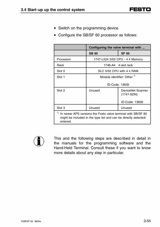
• Switch on the programming device.
• Configure the SB/SF 60 processor as follows:
Configuring the valve terminal with ...
SB 60 SF 60
Processor 1747-L524 5/02 CPU - 4 k Memory
Rack 1746-A4 4-slot rack
Slot 0 SLC 5/02 CPU with 4 k RAM
Slot 1 Module identifier: Other *)
ID-Code: 13635
Slot 2 Unused DeviceNet Scanner(1747-SDN)
ID-Code: 13606
Slot 3 Unused Unused
*) In newer APS versions the Festo valve terminal with SB/SF 60might be included in the type list and can be directly selected/entered.
This and the following steps are described in detail inthe manuals for the programming software and theHand-Held Terminal. Consult these if you want to knowmore details about any step in particular.
3.4 Start-up up the control system
VISB/SF 60 9804a 3-55
• Assign a name to your program. After the program isdownloaded to the processor, the processor alsogets this name.
• Program a test program (rung) not affecting machineoperation.
• Save the program and processor configuration data.
• Transfer the configuration data and the test programto the SB/SF 60 processor. The CPU LED goes out.
• Set the SB/SF 60 processor to RUN mode.The RUN status LED comes on if there are no errorsand the SB/SF 60 processor is working normally.Otherwise, check the notes on diagnostics in the "Di-agnostics" chapter at the end of this chapter.
• Start the test program (rung). If the simple test pro-gram runs faultlessly, you may assume that all es-sential processor functions are working properly.Otherwise, check the notes on diagnostics in the "Di-agnostics" chapter at the end of this chapter.
3.4 Start-up up the control system
3-56 VISB/SF 60 9804a
3.4.4 Test your inputs
After the processor has been successfully initializedand tested, you may begin to test the inputs.
• Establish an online connection between the pro-gramming device and the SB/SF 60. Switch theSB/SF 60 processor to Scan Test Mode. This waythe processor can scan the inputs/outputs and pro-grams but not turn on any physical outputs.
• Monitor the data in Data file 1 (data field for inputs).All configured inputs should now be displayed.
• Verify that Slot 1 (inputs/outputs for the Festo valveterminal) is displayed.
• Select the sensor which is connected to the firstinput of the input modules.
• Manually open and close the addressed input device.
CAUTIONNever reach into the machine to move an actuator.Otherwise you will cause unintended machine operation.
3.4 Start-up up the control system
VISB/SF 60 9804a 3-57
• Observe the associated bit status in the display ofthe programming device and the LED on the inputmodule or sensor. The allocation table of the valveterminal I/O can be found in chapter 3.6 of this chap-ter.
A. If the sensor/switch is closed and the sensor si-gnal is present on the valve terminal input, the associated bit is set and the status LED is on.
B. If the sensor/switch is opened and there is no sensor signal present on the valve terminal input, the associated bit is reset and the status LED is off.
• Use this procedure to test all the valve terminal in-puts.
If any inputs do not respond as expected, refer to thefollowing start-up notes.
3.4 Start-up up the control system
3-58 VISB/SF 60 9804a
Start-up notes - inputs:
• Check whether the processor is in Continuous ScanMode (see status line in the programming tool).
• If the status of the input bit and that of the associ-ated input LED do not agree, check the status fileS:11 and S:12 I/O slot enables. The bits S:11/0 toS:11/15 and S:12/0 to S:12/14 must be at logic 1.This means all I/O slots are enabled.
• Check the power supply and verify that the operatingvoltage for the valve terminal is within tolerance (Pin1 for the input modules).
• Switch the operating voltage off if necessary andcheck the wiring between the power supply and thevalve terminal, and check for good connections in theconnectors/terminals.
3.4 Start-up up the control system
VISB/SF 60 9804a 3-59
• Switch the operating voltage on again and check atthe valve terminal input module whether the inputsare getting the correct supply voltage.
A. If the measured voltage at the inputs is 0 V:Check the fuse on the SB/SF 60 valve terminal.Insert or replace the fuse if necessary.
B. If the measured voltage at the inputs is the wrongvalue, the voltage drop on the cable between po-wer supply and valve terminal may be too high. If not, replace input module.
• If the inputs have the correct supply value and thestatus of LED and bit still does not agree:Check the input current from sensor to module ac-cording to the module technical data. If the current iswithin tolerance, replace input module; otherwise,check sensor.
• If all tests to this point are Ok, check and if necess-ary replace sensor/device on input
3.4 Start-up up the control system
3-60 VISB/SF 60 9804a
3.4.5 Test your outputs
Test the outputs according to the following steps onlyafter the inputs have been tested and correct functionverified.
WARNINGMovement of the actuators during start-up tests cancause fatal injury!• Before and during performing the following steps,
verify that all actuators are disconnected from the energy supply.
• Read the notes in Section 3.4.2, "Disconnect motion-causing devices."
• Switch the processor into PROGRAM mode.
• Create a test program (rung) for all the valve terminaloutputs. Example:
COP
SOURCE #B3.0
DEST #O:1.0
Length 32
• Save the test program and configuration for theSB/SF 60 processor.
3.4 Start-up up the control system
VISB/SF 60 9804a 3-61
• Transfer the test program to the processor.
• Switch the processor to RUN mode.
• Monitor the data from data file B3 on the programm-ing device.
• Enter into file B3 the address of the output to be set.This selects the output to be tested.
• At the address prompt enter: "1" for the address oroutput you wish to set.
• Observe the status LED of the output on the valve oroutput module.The LED should be on. If you want to test the con-nected actuator for function, switch its supply on afterverifying that no dangerous motion will result.
• Reset the output. The status LED and the actuatorshould also reset themselves.
• If the first output has been successfully tested, con-tinue as just described for all the outputs.
If any outputs do not respond as expected, refer to thefollowing start-up notes.
3.4 Start-up up the control system
3-62 VISB/SF 60 9804a
Start-up notes - outputs
• Verify that the processor is in RUN mode.
• Check whether the addressing of the outputs is cor-rect in your test program.
• Use a programming device to check the data file ofthe outputs and the associated bit data file. Ascertainwhether the status of the bits agrees in both files.
If the status of the bits and the status of the outputLED agree, but the actuator does not respond cor-rectly, go to the next point.
If the status of the output LED does not agree withthe associated bit, check the status files S:11 andS:12 I/O slot enables. Bits S:11/0 to S:11/15 and S:12/0 to S:12/14 shouldbe at logic "1." This means all I/O slots are enabled.
3.4 Start-up up the control system
VISB/SF 60 9804a 3-63
• Check the voltage on the output of the valve terminaland at the actuator.Check voltage on Pin 2 of the operating voltage onthe valves. If the voltage is in tolerance and the valvedoes not switch:perform additional tests on the valve terminal, thevalve, and the tubing according to your "PneumaticsManual." Replace a defective valve if necessary.
• Check the voltage for the output modules directly atthe corresponding output of the valve terminal.
• Switch the output off and then test the wiring to theconnected actuator. Check for good connections inthe connectors/terminals.
• If all tests to this point are OK, check actuator atoutput and replace if necessary.
Additional information about troubleshooting can befound in the Diagnostics chapter.
3.4 Start-up up the control system
3-64 VISB/SF 60 9804a
3.4.6 Enter and test your program
After you have tested all the inputs and outputs, werecommend the following steps for safe and successfulstart-up of your specific user programs.
Additional information can be found in the manual foryour Hand-Held Terminal, or for the programming soft-ware.
• Verify the program in Offline mode. After you haveentered the program in the Offline File Edit Mode,you can begin with checking it.Look through all commands and paths again care-fully, and check them for any possible errors. In theOffline Edit File Mode you can use the cursor keys oruse the Find function of the programming device togo through the program step-by-step.
Verify program
• Compare the program in the Offline memory step-by-step with your written program documents. The mostcommon mistakes to be found this way are:- commands addressed incorrectly,- forgotten/omitted commands,- double-assigned output addresses for output com- mands.
3.4 Start-up up the control system
VISB/SF 60 9804a 3-65
• Transfer the program to the processor.Transferprogram
1. Switch the programming device to Online.
2. Switch the processor to PROGRAM Mode
3. Select the "Download" function on the Hand-HeldTerminal or the "Restore" function in the program-ming software.
• Check that the program was sent.
1. Select the Monitor File Function.
2. Go through the program with the cursor and verifythat you have downloaded the correct program into the processor.
3.4 Start-up up the control system
3-66 VISB/SF 60 9804a
• Conduct a step-by-step program test (7 steps):Step-by-steptest
1. Select the Monitor File Function and place the cursor on the first path.
2. Select Test Mode.
3. Select Single Scan Test (SSN). In this mode theprocessor runs a single operating cycle: - reads the inputs- executes the ladder program- updates all the output data (without energizing
the output circuits). This means the Monitor File Function can be used to determine the status of the outputs, even if they are not actually set. Timers are changed by at least 10 ms per cycle.
3.4 Start-up up the control system
VISB/SF 60 9804a 3-67
4. Simulate the input signals corresponding to the pro-gram conditions in order to be able to execute thecurrent program path. If it is not possible to activate the correspondingsensor, simulate the input using the Force Function.
Step-by-steptest
CAUTIONNever reach into the machine to move an actuator.Otherwise you will cause unintended machine oper-ation.
5. Perform a Single Operating Scan as described in themanual for the programming device.
6. Check whether the desired effects of this programsection as well as all the higher level logical eventstook place.
7. Select the next path and test it, followed by all re-maining paths.
3.4 Start-up up the control system
3-68 VISB/SF 60 9804a
• Perform a continuous program test (6 steps).Continuoustest
After all the paths and program steps have been testedin the Single Scan Rung Test and proper func-tion of the program are verified, it makes sense to perform a continuous program test. In this mode theRUN Mode of the processor is simulated without actually switching the outputs.Proceed as follows:
1. Switch your programming device online with the pro-cessor/controller.
2. Monitor the file.
3. Select test mode.
4. Select continuous scan test.
5. Simulate the input signals in order to meet the in-dexing conditions of the program.
6. Check whether the desired effects for each programfunction as well as additional system functions tookplace.
CAUTIONNever reach into the machine to move an actuator.Otherwise you will cause unintended machine oper-ation.
3.4 Start-up up the control system
VISB/SF 60 9804a 3-69
3.4.7 Observe control motion
After you have tested all the program sequences, youcan begin to test and start-up the motion sequences.
Recommendation:The start-up phase should include if possible all per-sons who are familiar with programming, installation,design and maintenance of the machine or system.This will ensure that the best and safest decisions canbe made concerning the testing of the overall system.
The following steps are intentionally very general in na-ture. They must be modified and adapted to the ma-chine or system in concrete situations as necessary.Basically, as few outputs as possible should be turnedon, so that the resulting motion sequences can be fol-lowed. Then additional actuators can be switched on.This process also allows any problems to be more eas-ily detected and rectified under controlled conditions. Inthe following section one motion segment per start-upstep will be described.
3.4 Start-up up the control system
3-70 VISB/SF 60 9804a
CAUTIONMake sure that during the following start-up proce-dure, a person is always ready to actuate the E-STOP switch.
The E-STOP switch opens the master control relayand thereby disconnects the electrical energy supplyof the machine. This circuit must be hardwired only,it must not be programmed!
Proceed as follows:
• Decide which actuator is to be tested first and recon-nect its wiring.
• Switch the processor to Run Mode and observe theactuator.
• Simulate the necessary input signals for meeting theindexing conditions of the program. If it is not practi-cal to manually activate on input device, use theforce function to simulate the proper input condition.
• Repeat these steps for each actuator.
CAUTIONNever reach into the machine to move an actuator.Otherwise you will cause unintended machine oper-ation.
3.4 Start-up up the control system
VISB/SF 60 9804a 3-71

3.4.8 Conduct dry run of your application (if possible without tooling/workpieces)
CAUTIONMake sure that during the following start-up proce-dure, a person is always ready to actuate the E-STOP switch.
The E-STOP switch opens the master control relayand thereby disconnects the electrical energy supplyof the machine. This circuit must be hardwired only,it must not be programmed!
After you have tested the control system and the pro-gram, perform a dry run of the entire system. Supply allthe actuators associated with your machine or systemwith power.
During this dry run all program functions and outputsare tested, but if possible without workpieces in the ma-chine.
This completes your start-up, the machine or system isnow ready to operate.
3.4 Start-up up the control system
3-72 VISB/SF 60 9804a
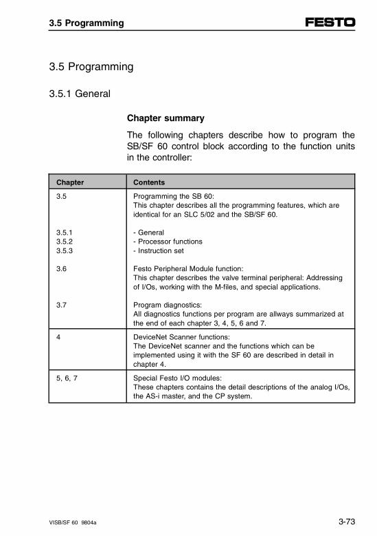
3.5 Programming
3.5.1 General
Chapter summary
The following chapters describe how to program theSB/SF 60 control block according to the function unitsin the controller:
Chapter Contents
3.5
3.5.13.5.23.5.3
3.6
3.7
Programming the SB 60:This chapter describes all the programming features, which areidentical for an SLC 5/02 and the SB/SF 60.
- General- Processor functions- Instruction set
Festo Peripheral Module function:This chapter describes the valve terminal peripheral: Addressingof I/Os, working with the M-files, and special applications.
Program diagnostics:All diagnostics functions per program are allways summarized atthe end of each chapter 3, 4, 5, 6 and 7.
4 DeviceNet Scanner functions:The DeviceNet scanner and the functions which can beimplemented using it with the SF 60 are described in detail in chapter 4.
5, 6, 7 Special Festo I/O modules:These chapters contains the detail descriptions of the analog I/Os,the AS-i master, and the CP system.
3.5 Programming
VISB/SF 60 9804a 3-73

Programming environment
The following user programs and data files are avail-able for programming:
– A.I. 500
– Advanced Programming Software (APS)
– RSLogix 500
– Hand-Held Terminal (HHT)
The same programming language is always used,namely ladder logic. The user program can be read andmodified by any of the above programming tools.
Programming can be done on the programming inter-face (PROG) or on the DH-485 network. Multiple proc-essors can be programmed and managed from a cen-tral location using this network.
3.5 Programming
3-74 VISB/SF 60 9804a
Principle of the control sequence
The SB/SF 60 is compatible with an Allen-Bradley SLC5/02 controller. The principle control sequences there-fore correspond with the SLC 5/02 and consist of multi-ple steps.
First you use the programming software to create acontrol program and download it to the processor. Thisladder logic program is based as a rule on the relaycircuit diagrams for your machine or system, and con-tains control commands which refer directly to this oneapplication.
Then you switch the processor with its loaded programinto RUN Mode. This initiates a program sequence.This program sequence consists of many individualcommand steps (operations) which are executed oneafter the other until the program logic causes a change.
The following illustration shows a simplified repre-sentation of the operating cycle. A detailled repre-sentation for the SB/SF 60 is contained in Appendix C.
3.5 Programming
VISB/SF 60 9804a 3-75
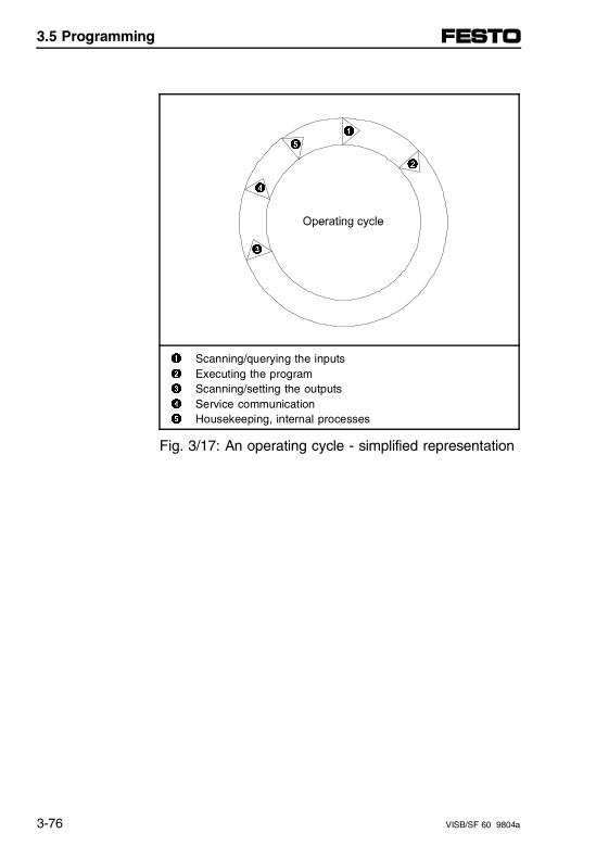
1 Scanning/querying the inputs2 Executing the program3 Scanning/setting the outputs4 Service communication5 Housekeeping, internal processes
Fig. 3/17: An operating cycle - simplified representation
1
2
5
4
3
3.5 Programming
3-76 VISB/SF 60 9804a
Notes on figure:
1. Scanning/querying the inputsDuring this time interval all the inputs are scannedand the current values read. The time is typicallygiven in ms.
2. Executing the programThis phase represents the time which the processorrequires to execute the instructions in the controlprogram. This time can vary significantly and de-pends among other things on which program instruc-tions were used and whether the condition of an in-struction for the execution time is TRUE or FALSE.
Subroutines and interrupts within a program sequencecan cause variations in the sequence and processing ofthe program instructions.
3. Scanning/setting the outputsDuring this time interval all the output data arescanned and the current values written to the out-puts. The time is typically given in ms.
4. Service communicationIncluded in this time interval of the program run isthe communication with other devices, for examplethe HHT or PC over the DH-485 or PROG inter-faces.
5. Housekeeping, internal processesThis time is required among other things for internalmemory management and for updating timers andcounters.
3.5 Programming
VISB/SF 60 9804a 3-77
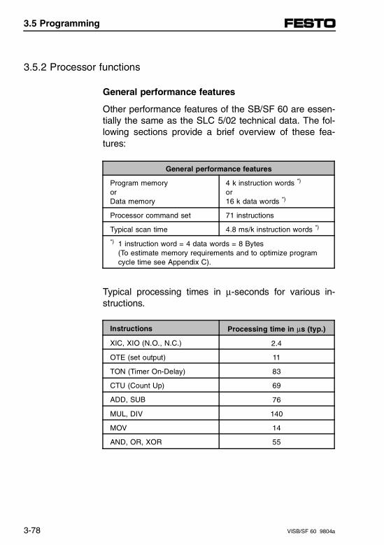
3.5.2 Processor functions
General performance features
Other performance features of the SB/SF 60 are essen-tially the same as the SLC 5/02 technical data. The fol-lowing sections provide a brief overview of these fea-tures:
General performance features
Program memory orData memory
4 k instruction words *)
or16 k data words *)
Processor command set 71 instructions
Typical scan time 4.8 ms/k instruction words *)
*) 1 instruction word = 4 data words = 8 Bytes(To estimate memory requirements and to optimize program cycle time see Appendix C).
Typical processing times in µ-seconds for various in-structions.
Instructions Processing time in µs (typ.)
XIC, XIO (N.O., N.C.) 2.4
OTE (set output) 11
TON (Timer On-Delay) 83
CTU (Count Up) 69
ADD, SUB 76
MUL, DIV 140
MOV 14
AND, OR, XOR 55
3.5 Programming
3-78 VISB/SF 60 9804a
The SB/SF 60 has program files 2…255 available forprogramming. A nesting depth of up to 8 subroutines ispossible.
Nesting depth
The Festo Peripheral Module in Slot 1 makes 32 inputsand 32 outputs available.
I/O files
The M0-files and M1-files make special configurationand diagnostic possibilities available. They are de-scribed in this and in the next chapter in greater detail.
M-files
To verify the NOMINAL/ACTUAL structure of the valveterminal, an optional G-file can be configured for Slot 1.
G-file
Maintenance-free operation
The SB/SF 60 employs a new generation of RAM com-ponents (nvSRAM). These components retain data for10 years after the last write access (self-maintainingand maintenance-free). The SB/SF 60 therefore re-quires no battery for data retention - in contrast to theAllen-Bradley SLC 5/02.
3.5 Programming
VISB/SF 60 9804a 3-79
Interrupts
The SB/SF 60 permits 3 different types of interrupts tobe processed. Three basic categories of interrupts aredistinguished:
1. Fault interrupts
2. Selectable Timed Interrupts (STI)
3. I/O interrupts (ISR)These are dependent on the I/O module. The Pe-ripheral Module occupying Slot 1 offers eight I/O in-terrupts - see chapter 3.6.
Interrupt processing for the SB/SF 60 can be individu-ally adapted to each process.
Fault interrupts
When a fault interrupt occurs (User Fault), the proces-sor cycle is interrupted and a specific subroutine (thefault handling routing) is run. This offers the possibilityof responding to faulty system conditions more directlyand specifically.
Allen-Bradley differentiates among three types of faultinterrupts:
– recoverable user faults
– non-recoverable user faults
– non-user faults
3.5 Programming
3-80 VISB/SF 60 9804a
In case of a recoverable user fault, you may either:Recoverableuser faults
– recover the fault to prevent a fault message or stop-ping of the program, or
– generate an error message and stop the program.
These error messages are distinguished as follows:Non-recover-able userfaults
– For non-recoverable user faults, the fault handlingroutine is run once and after that the program is al-ways stopped.
– For non-user faults the program is stopped immedi-ately and the fault handling routine is not started.
The SB/SF 60 with the Festo Peripheral Module offersa number of common error messages (status wordI:1.0, error codes 0160…0169 hex). You may configurethese as error interrupts. The common error messagesare recoverable error messages and are described inchapters 3.6.4, "Setting Fault Response" and 3.7.2 "Di-agnostics per Program" in greater detail.
3.5 Programming
VISB/SF 60 9804a 3-81
The error handling routine is entered in the form of aladder logic subroutine and then specified in word S:29of the status file.
Function
When an error occurs, the processor reads S:29 andexecutes the subroutine specified in this address. A re-coverable fault can be cleared in this routine, wherebyerror bit S:1/13 must be reset.
Recommendation:Program a branch distributor in your error handling rou-tine by processing the error code (S2:6). In the follow-ing subroutine you can localize the cause of the errormore precisely by processing status word I:1.0 and theM1-file (see chapter 3.6.3, "Working with M-files." Toupdate the status word, use the IIM instruction (Immedi-ate Input Masked).
The following illustration shows a programming exam-ple:
3.5 Programming
3-82 VISB/SF 60 9804a
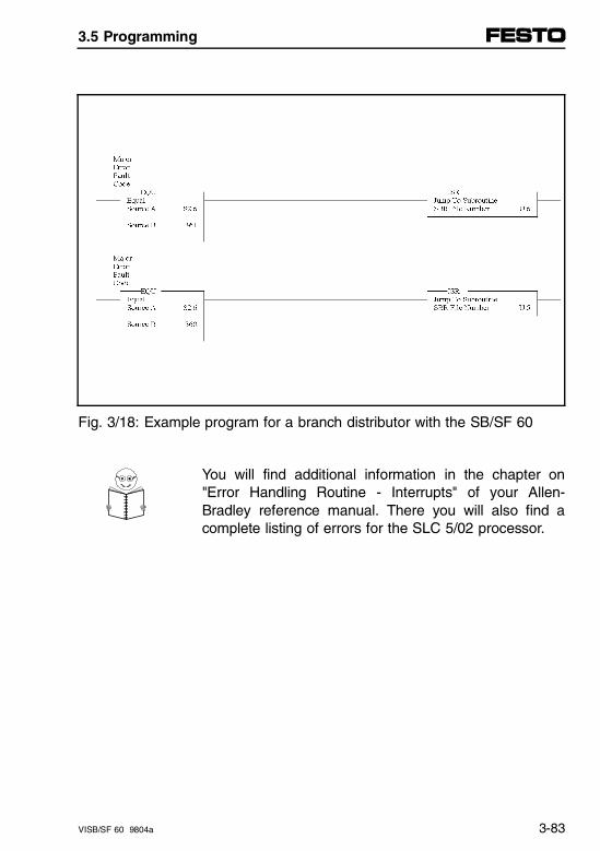
Fig. 3/18: Example program for a branch distributor with the SB/SF 60
You will find additional information in the chapter on"Error Handling Routine - Interrupts" of your Allen-Bradley reference manual. There you will also find acomplete listing of errors for the SLC 5/02 processor.
3.5 Programming
VISB/SF 60 9804a 3-83
Selectable Timed Interrupt (STI)
This interrupt permits time-based interruptions of theprocessor cycle for processing a subroutine (STI = Se-lectable Timed Interrupt) in the range of 10…2550 msand in steps of 10 ms. Applications include for examplefeedback tasks or diagnostic querying.
Finally the processor continues running the programfrom the point where the interruption took place.
See the chapter on "Selectable Timed Interrupt Over-view" in your Allen-Bradley reference manual for addi-tional information.
3.5 Programming
3-84 VISB/SF 60 9804a
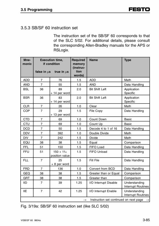
3.5.3 SB/SF 60 instruction set
The instruction set of the SB/SF 60 corresponds to thatof the SLC 5/02. For additional details, please consultthe corresponding Allen-Bradley manuals for the APS orRSLogix.
Mne-monic
Execution time, if condition
false in µs true in µs
Required memory(instruc-
tionwords)
Name Type
ADD 7 76 1.5 ADD Math
AND 7 55 1.5 AND Data Handling
BSL 36 89+ 14 per word
2.0 Bit Shift Left ApplicationSpecific
BSR 36 83+ 14 per word
2.0 Bit Shift Left ApplicationSpecific
CLR 7 26 1.0 Clear Math
COP 7 29+ 13 per word
1.5 File Copy Data Handling
CTD 7 69 1.0 Count Down Basic
CTU 7 69 1.0 Count Up Basic
DCD 7 50 1.5 Decode 4 to 1 of 16 Data Handling
DDV 7 392 1.0 Double Divide Math
DIV 7 242 1.5 Divide Math
EQU 38 38 1.5 Equal Comparison
FFL 51 150 1.5 FIFO Load Data Handling
FFU 51 150 + 11x
position value1.5 FIFO Unload Data Handling
FLL 7 25+ 8 per word
1.5 Fill File Data Handling
FRD 7 136 1.0 Convert from BCD Data Handling
GEQ 38 38 1.5 Greater than or Equal Comparison
GRT 38 38 1.5 Greater than Comparison
IID 7 39 1.25 I/O Interrupt Disable UnderstandingInterrupt Routines
IIE 7 42 1.25 I/O Interrupt Enable UnderstandingInterrupt Routines
→ Instruction set continued on next page →
Fig. 3/19a: SB/SF 60 instruction set (like SLC 5/02)
3.5 Programming
VISB/SF 60 9804a 3-85
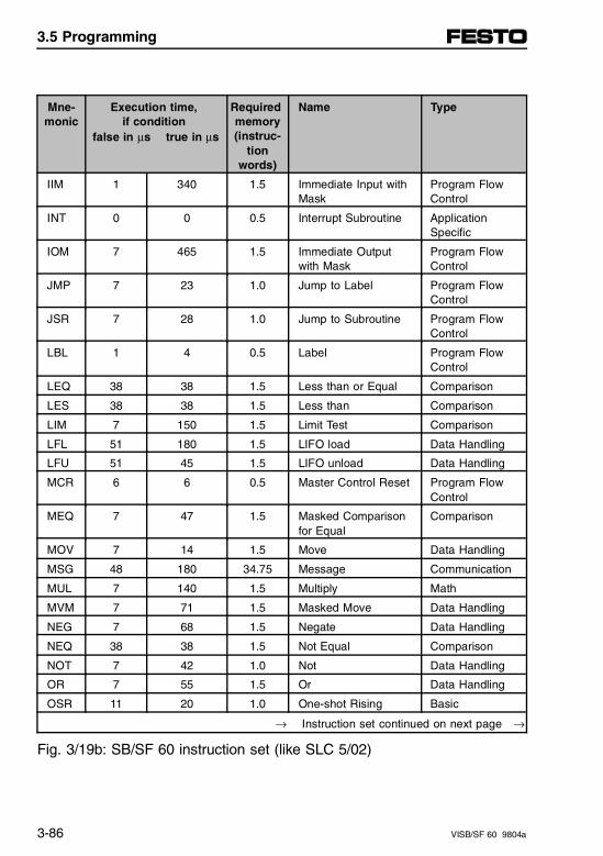
Mne-monic
Execution time, if condition
false in µs true in µs
Required memory(instruc-
tionwords)
Name Type
IIM 1 340 1.5 Immediate Input withMask
Program FlowControl
INT 0 0 0.5 Interrupt Subroutine ApplicationSpecific
IOM 7 465 1.5 Immediate Outputwith Mask
Program FlowControl
JMP 7 23 1.0 Jump to Label Program FlowControl
JSR 7 28 1.0 Jump to Subroutine Program FlowControl
LBL 1 4 0.5 Label Program FlowControl
LEQ 38 38 1.5 Less than or Equal Comparison
LES 38 38 1.5 Less than Comparison
LIM 7 150 1.5 Limit Test Comparison
LFL 51 180 1.5 LIFO load Data Handling
LFU 51 45 1.5 LIFO unload Data Handling
MCR 6 6 0.5 Master Control Reset Program FlowControl
MEQ 7 47 1.5 Masked Comparisonfor Equal
Comparison
MOV 7 14 1.5 Move Data Handling
MSG 48 180 34.75 Message Communication
MUL 7 140 1.5 Multiply Math
MVM 7 71 1.5 Masked Move Data Handling
NEG 7 68 1.5 Negate Data Handling
NEQ 38 38 1.5 Not Equal Comparison
NOT 7 42 1.0 Not Data Handling
OR 7 55 1.5 Or Data Handling
OSR 11 20 1.0 One-shot Rising Basic
→ Instruction set continued on next page →
Fig. 3/19b: SB/SF 60 instruction set (like SLC 5/02)
3.5 Programming
3-86 VISB/SF 60 9804a
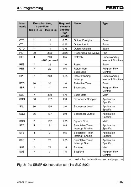
Mne-monic
Execution time, if condition
false in µs true in µs
Required memory(instruc-
tionwords)
Name Type
OTE 11 11 0.75 Output Energize Basic
OTL 11 11 0.75 Output Latch Basic
OTU 11 11 0.75 Output Unlatch Basic
PID 90 3600 23.25 Proportional Derivative PID
REF 4 240+180 per word
0.5 Refresh UnderstandingInterrupt Routines
RES 7 26 1.0 Reset Basic
RET 7 20 0.5 Return fromSubroutine
Program FlowControl
RPI 7 240 1.25 Reset PendingInterrupt
UnderstandingInterrupt Routines
RTO 30 30 1.0 Retentive Timer Basic
SBR 1 4 0.5 Subroutine Program FlowControl
SCL 7 480 1.75 Scale Data Math
SQC 36 137 2.0 Sequencer Compare ApplicationSpecific
SQL 36 135 2.0 Sequencer Load ApplicationSpecific
SQO 36 137 2.0 Sequencer Output ApplicationSpecific
SQR 7 162 1.25 Square Root Math
STD 4 9 0.5 Selectable TimerInterrupt Disable
ApplicationSpecific
STE 4 9 0.5 Selectable TimerInterrupt Enable
ApplicationSpecific
STS 7 72 1.25 Selectable TimerInterrupt Start
ApplicationSpecific
SUB 7 77 1.5 Subtract Math
SUS 7 7 1.5 Suspend Program FlowControl
→ Instruction set continued on next page →
Fig. 3/19c: SB/SF 60 instruction set (like SLC 5/02)
3.5 Programming
VISB/SF 60 9804a 3-87
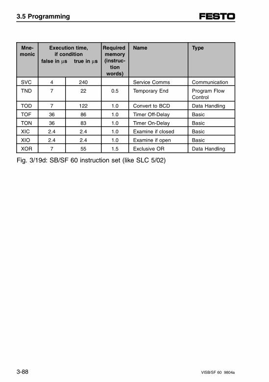
Mne-monic
Execution time, if condition
false in µs true in µs
Required memory(instruc-
tionwords)
Name Type
SVC 4 240 Service Comms Communication
TND 7 22 0.5 Temporary End Program FlowControl
TOD 7 122 1.0 Convert to BCD Data Handling
TOF 36 86 1.0 Timer Off-Delay Basic
TON 36 83 1.0 Timer On-Delay Basic
XIC 2.4 2.4 1.0 Examine if closed Basic
XIO 2.4 2.4 1.0 Examine if open Basic
XOR 7 55 1.5 Exclusive OR Data Handling
Fig. 3/19d: SB/SF 60 instruction set (like SLC 5/02)
3.5 Programming
3-88 VISB/SF 60 9804a
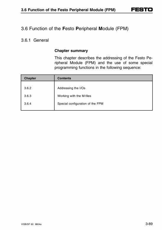
3.6 Function of the Festo Peripheral Module (FPM)
3.6.1 General
Chapter summary
This chapter describes the addressing of the Festo Pe-ripheral Module (FPM) and the use of some specialprogramming functions in the following sequence:
Chapter Contents
3.6.2
3.6.3
3.6.4
Addressing the I/Os
Working with the M-files
Special configuration of the FPM
3.6 Function of the Festo Peripheral Module (FPM)
VISB/SF 60 9804a 3-89
3.6.2 Addressing of the I/Os
The following illustration shows the complete addressrange of the FPM with 32 I/O words. This is followed bya bit-by-bit representation of all I/Os, arranged accord-ing to the individual function groups of the valve termi-nal.
– Up to the 96 local inputs, 26 solenoid coils and 48outputs (directly fitted valves, digital inputs and out-puts).
– Up to 9 analog channels (directly fitted analog mod-ules with analog inputs and outputs).
– Up to 64 CP inputs and 64 CP outputs (decentrallyfitted I/Os of the CP system, consisting of CP valvesand digital CP I/Os).
– Up to 124 AS-i inputs and 124 AS-i outputs (decen-trally fitted I/Os of the AS-i bus system with any num-ber of AS-i slaves).
Additional overviews of the address space are shown in
– Chapter 4, for the SF 60 with DeviceNet controller.
– Chapter 5, when analog modules are used
– Chapter 6, when an AS-i master is used.
– Chapter 7, when a CP interface is used.
– Reference card with the complete I/O overview in theAppendix.
3.6 Function of the Festo Peripheral Module (FPM)
3-90 VISB/SF 60 9804a
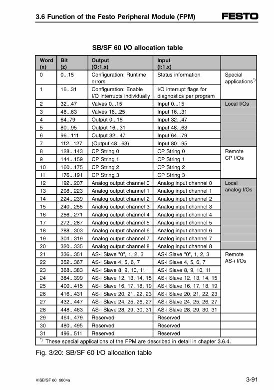
SB/SF 60 I/O allocation table
Word(x)
Bit (z)
Output (O:1.x)
Input (I:1.x)
0 0...15 Configuration: Runtime errors
Status information Specialapplications*)
1 16...31 Configuration: EnableI/O interrupts individually
I/O interrupt flags fordiagnostics per program
2 32...47 Valves 0...15 Input 0...15 Local I/Os
3 48...63 Valves 16...25 Input 16...31
4 64..79 Output 0...15 Input 32...47
5 80...95 Output 16...31 Input 48...63
6 96...111 Output 32...47 Input 64...79
7 112...127 (Output 48...63) Input 80...95
8 128...143 CP String 0 CP String 0 Remote CP I/Os9 144...159 CP String 1 CP String 1
10 160...175 CP String 2 CP String 2
11 176...191 CP String 3 CP String 3
12 192...207 Analog output channel 0 Analog input channel 0 Local analog I/Os13 208...223 Analog output channel 1 Analog input channel 1
14 224...239 Analog output channel 2 Analog input channel 2
15 240...255 Analog output channel 3 Analog input channel 3
16 256...271 Analog output channel 4 Analog input channel 4
17 272...287 Analog output channel 5 Analog input channel 5
18 288...303 Analog output channel 6 Analog input channel 6
19 304...319 Analog output channel 7 Analog input channel 7
20 320...335 Analog output channel 8 Analog input channel 8
21 336...351 AS-i Slave "0", 1, 2, 3 AS-i Slave "0", 1, 2, 3 RemoteAS-i I/Os22 352...367 AS-i Slave 4, 5, 6, 7 AS-i Slave 4, 5, 6, 7
23 368...383 AS-i Slave 8, 9, 10, 11 AS-i Slave 8, 9, 10, 11
24 384...399 AS-i Slave 12, 13, 14, 15 AS-i Slave 12, 13, 14, 15
25 400...415 AS-i Slave 16, 17, 18, 19 AS-i Slave 16, 17, 18, 19
26 416...431 AS-i Slave 20, 21, 22, 23 AS-i Slave 20, 21, 22, 23
27 432...447 AS-i Slave 24, 25, 26, 27 AS-i Slave 24, 25, 26, 27
28 448...463 AS-i Slave 28, 29, 30, 31 AS-i Slave 28, 29, 30, 31
29 464...479 Reserved Reserved
30 480...495 Reserved Reserved
31 496...511 Reserved Reserved*) These special applications of the FPM are described in detail in chapter 3.6.4.
Fig. 3/20: SB/SF 60 I/O allocation table
3.6 Function of the Festo Peripheral Module (FPM)
VISB/SF 60 9804a 3-91
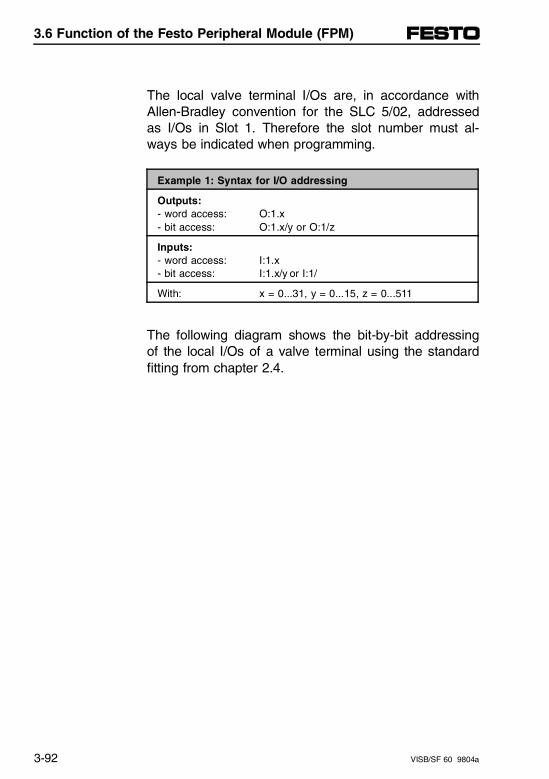
The local valve terminal I/Os are, in accordance withAllen-Bradley convention for the SLC 5/02, addressedas I/Os in Slot 1. Therefore the slot number must al-ways be indicated when programming.
Example 1: Syntax for I/O addressing
Outputs:- word access: O:1.x- bit access: O:1.x/y or O:1/z
Inputs:- word access: I:1.x- bit access: I:1.x/y or I:1/
With: x = 0...31, y = 0...15, z = 0...511
The following diagram shows the bit-by-bit addressingof the local I/Os of a valve terminal using the standardfitting from chapter 2.4.
3.6 Function of the Festo Peripheral Module (FPM)
3-92 VISB/SF 60 9804a
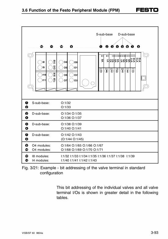
S-sub-base D-sub-base
" ! 0 9 1 2 3 4 5 6 7 8
1 S-sub-base: O:1/322 O:1/33
3 D-sub-base: O:1/34 O:1/354 O:1/36 O:1/37
5 D-sub-base: O:1/38 O:1/396 O:1/40 O:1/41
7 D-sub-base: O:1/42 O:1/438 (O:1/44 O:1/45)
9 O4 modules: O:1/64 O:1/65 O:1/66 O:1/670 O4 modules: O:1/68 O:1/69 O:1/70 O:1/71
! I8 modules: I:1/32 I:1/33 I:1/34 I:1/35 I:1/36 I:1/37 I:1/38 I:1/39" I4 modules: I:1/40 I:1/41 I:1/42 I:1/43
Fig. 3/21: Example - bit addressing of the valve terminal in standard configuration
This bit addressing of the individual valves and all valveterminal I/Os is shown in greater detail in the followingtables.
3.6 Function of the Festo Peripheral Module (FPM)
VISB/SF 60 9804a 3-93
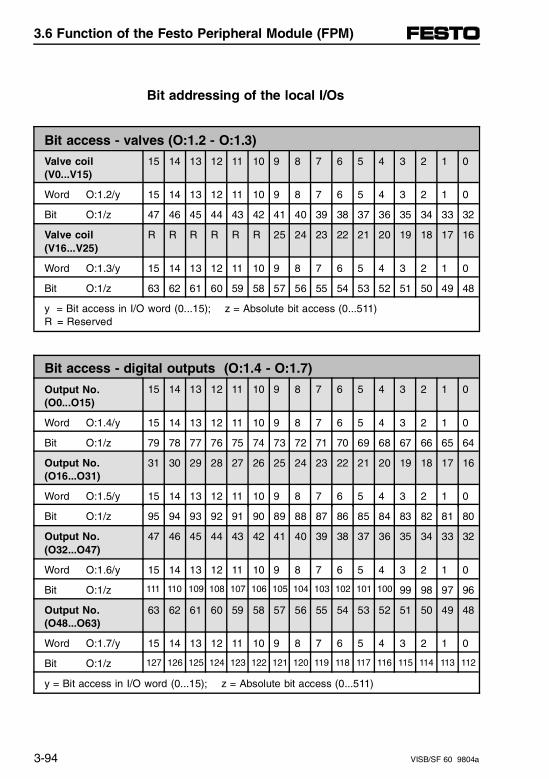
Bit addressing of the local I/Os
Bit access - valves (O:1.2 - O:1.3)
Valve coil(V0...V15)
15 14 13 12 11 10 9 8 7 6 5 4 3 2 1 0
Word O:1.2/y 15 14 13 12 11 10 9 8 7 6 5 4 3 2 1 0
Bit O:1/z 47 46 45 44 43 42 41 40 39 38 37 36 35 34 33 32
Valve coil(V16...V25)
R R R R R R 25 24 23 22 21 20 19 18 17 16
Word O:1.3/y 15 14 13 12 11 10 9 8 7 6 5 4 3 2 1 0
Bit O:1/z 63 62 61 60 59 58 57 56 55 54 53 52 51 50 49 48
y = Bit access in I/O word (0...15); z = Absolute bit access (0...511)R = Reserved
Bit access - digital outputs (O:1.4 - O:1.7)
Output No.(O0...O15)
15 14 13 12 11 10 9 8 7 6 5 4 3 2 1 0
Word O:1.4/y 15 14 13 12 11 10 9 8 7 6 5 4 3 2 1 0
Bit O:1/z 79 78 77 76 75 74 73 72 71 70 69 68 67 66 65 64
Output No.(O16...O31)
31 30 29 28 27 26 25 24 23 22 21 20 19 18 17 16
Word O:1.5/y 15 14 13 12 11 10 9 8 7 6 5 4 3 2 1 0
Bit O:1/z 95 94 93 92 91 90 89 88 87 86 85 84 83 82 81 80
Output No.(O32...O47)
47 46 45 44 43 42 41 40 39 38 37 36 35 34 33 32
Word O:1.6/y 15 14 13 12 11 10 9 8 7 6 5 4 3 2 1 0
Bit O:1/z 111 110 109 108 107 106 105 104 103 102 101 100 99 98 97 96
Output No.(O48...O63)
63 62 61 60 59 58 57 56 55 54 53 52 51 50 49 48
Word O:1.7/y 15 14 13 12 11 10 9 8 7 6 5 4 3 2 1 0
Bit O:1/z 127 126 125 124 123 122 121 120 119 118 117 116 115 114 113 112
y = Bit access in I/O word (0...15); z = Absolute bit access (0...511)
3.6 Function of the Festo Peripheral Module (FPM)
3-94 VISB/SF 60 9804a
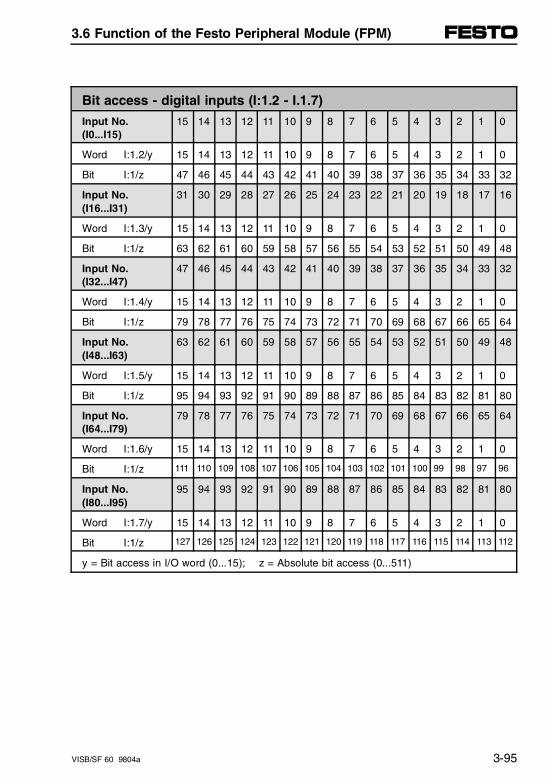
Bit access - digital inputs (I:1.2 - I.1.7)
Input No.(I0...I15)
15 14 13 12 11 10 9 8 7 6 5 4 3 2 1 0
Word I:1.2/y 15 14 13 12 11 10 9 8 7 6 5 4 3 2 1 0
Bit I:1/z 47 46 45 44 43 42 41 40 39 38 37 36 35 34 33 32
Input No.(I16...I31)
31 30 29 28 27 26 25 24 23 22 21 20 19 18 17 16
Word I:1.3/y 15 14 13 12 11 10 9 8 7 6 5 4 3 2 1 0
Bit I:1/z 63 62 61 60 59 58 57 56 55 54 53 52 51 50 49 48
Input No.(I32...I47)
47 46 45 44 43 42 41 40 39 38 37 36 35 34 33 32
Word I:1.4/y 15 14 13 12 11 10 9 8 7 6 5 4 3 2 1 0
Bit I:1/z 79 78 77 76 75 74 73 72 71 70 69 68 67 66 65 64
Input No.(I48...I63)
63 62 61 60 59 58 57 56 55 54 53 52 51 50 49 48
Word I:1.5/y 15 14 13 12 11 10 9 8 7 6 5 4 3 2 1 0
Bit I:1/z 95 94 93 92 91 90 89 88 87 86 85 84 83 82 81 80
Input No.(I64...I79)
79 78 77 76 75 74 73 72 71 70 69 68 67 66 65 64
Word I:1.6/y 15 14 13 12 11 10 9 8 7 6 5 4 3 2 1 0
Bit I:1/z 111 110 109 108 107 106 105 104 103 102 101 100 99 98 97 96
Input No.(I80...I95)
95 94 93 92 91 90 89 88 87 86 85 84 83 82 81 80
Word I:1.7/y 15 14 13 12 11 10 9 8 7 6 5 4 3 2 1 0
Bit I:1/z 127 126 125 124 123 122 121 120 119 118 117 116 115 114 113 112
y = Bit access in I/O word (0...15); z = Absolute bit access (0...511)
3.6 Function of the Festo Peripheral Module (FPM)
VISB/SF 60 9804a 3-95
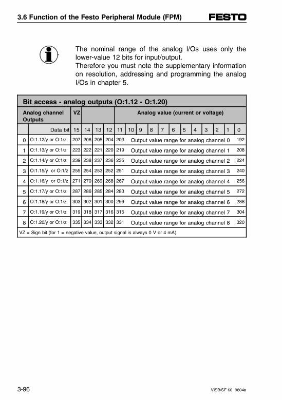
The nominal range of the analog I/Os uses only thelower-value 12 bits for input/output.Therefore you must note the supplementary informationon resolution, addressing and programming the analogI/Os in chapter 5.
Bit access - analog outputs (O:1.12 - O:1.20)
Analog channelOutputs
VZ
Analog value (current or voltage)
Data bit 15 14 13 12 11 10 9 8 7 6 5 4 3 2 1 0
0 O:1.12/y or O:1/z 207 206 205 204 203 Output value range for analog channel 0 192
1 O:1.13/y or O:1/z 223 222 221 220 219 Output value range for analog channel 1 208
2 O:1.14/y or O:1/z 239 238 237 236 235 Output value range for analog channel 2 224
3 O:1.15/y or O:1/z 255 254 253 252 251 Output value range for analog channel 3 240
4 O:1.16/y or O:1/z 271 270 269 268 267 Output value range for analog channel 4 256
5 O:1.17/y or O:1/z 287 286 285 284 283 Output value range for analog channel 5 272
6 O:1.18/y or O:1/z 303 302 301 300 299 Output value range for analog channel 6 288
7 O:1.19/y or O:1/z 319 318 317 316 315 Output value range for analog channel 7 304
8 O:1.20/y or O:1/z 335 334 333 332 331 Output value range for analog channel 8 320
VZ = Sign bit (for 1 = negative value, output signal is always 0 V or 4 mA)
3.6 Function of the Festo Peripheral Module (FPM)
3-96 VISB/SF 60 9804a
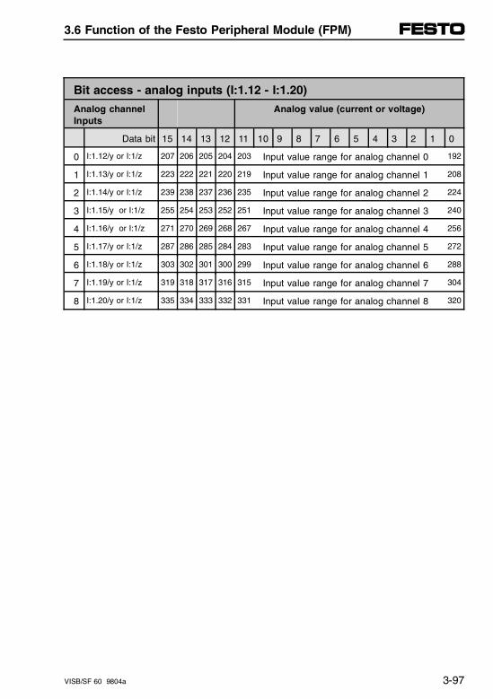
Bit access - analog inputs (I:1.12 - I:1.20)
Analog channelInputs
Analog value (current or voltage)
Data bit 15 14 13 12 11 10 9 8 7 6 5 4 3 2 1 0
0 I:1.12/y or I:1/z 207 206 205 204 203 Input value range for analog channel 0 192
1 I:1.13/y or I:1/z 223 222 221 220 219 Input value range for analog channel 1 208
2 I:1.14/y or I:1/z 239 238 237 236 235 Input value range for analog channel 2 224
3 I:1.15/y or I:1/z 255 254 253 252 251 Input value range for analog channel 3 240
4 I:1.16/y or I:1/z 271 270 269 268 267 Input value range for analog channel 4 256
5 I:1.17/y or I:1/z 287 286 285 284 283 Input value range for analog channel 5 272
6 I:1.18/y or I:1/z 303 302 301 300 299 Input value range for analog channel 6 288
7 I:1.19/y or I:1/z 319 318 317 316 315 Input value range for analog channel 7 304
8 I:1.20/y or I:1/z 335 334 333 332 331 Input value range for analog channel 8 320
3.6 Function of the Festo Peripheral Module (FPM)
VISB/SF 60 9804a 3-97
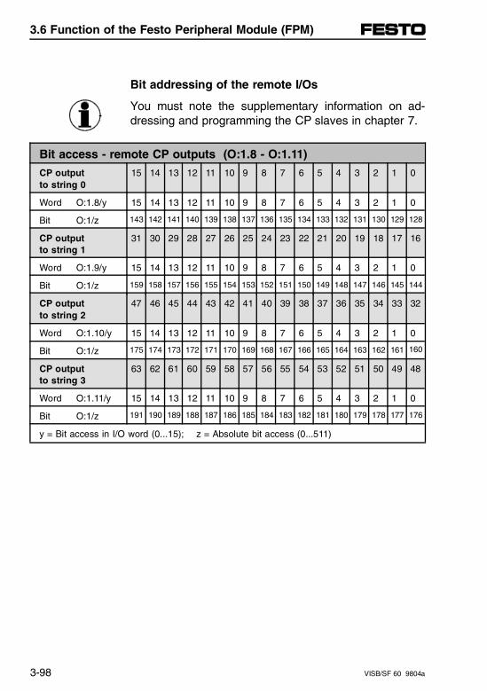
Bit addressing of the remote I/Os
You must note the supplementary information on ad-dressing and programming the CP slaves in chapter 7.
Bit access - remote CP outputs (O:1.8 - O:1.11)
CP output to string 0
15 14 13 12 11 10 9 8 7 6 5 4 3 2 1 0
Word O:1.8/y 15 14 13 12 11 10 9 8 7 6 5 4 3 2 1 0
Bit O:1/z 143 142 141 140 139 138 137 136 135 134 133 132 131 130 129 128
CP outputto string 1
31 30 29 28 27 26 25 24 23 22 21 20 19 18 17 16
Word O:1.9/y 15 14 13 12 11 10 9 8 7 6 5 4 3 2 1 0
Bit O:1/z 159 158 157 156 155 154 153 152 151 150 149 148 147 146 145 144
CP outputto string 2
47 46 45 44 43 42 41 40 39 38 37 36 35 34 33 32
Word O:1.10/y 15 14 13 12 11 10 9 8 7 6 5 4 3 2 1 0
Bit O:1/z 175 174 173 172 171 170 169 168 167 166 165 164 163 162 161 160
CP outputto string 3
63 62 61 60 59 58 57 56 55 54 53 52 51 50 49 48
Word O:1.11/y 15 14 13 12 11 10 9 8 7 6 5 4 3 2 1 0
Bit O:1/z 191 190 189 188 187 186 185 184 183 182 181 180 179 178 177 176
y = Bit access in I/O word (0...15); z = Absolute bit access (0...511)
3.6 Function of the Festo Peripheral Module (FPM)
3-98 VISB/SF 60 9804a
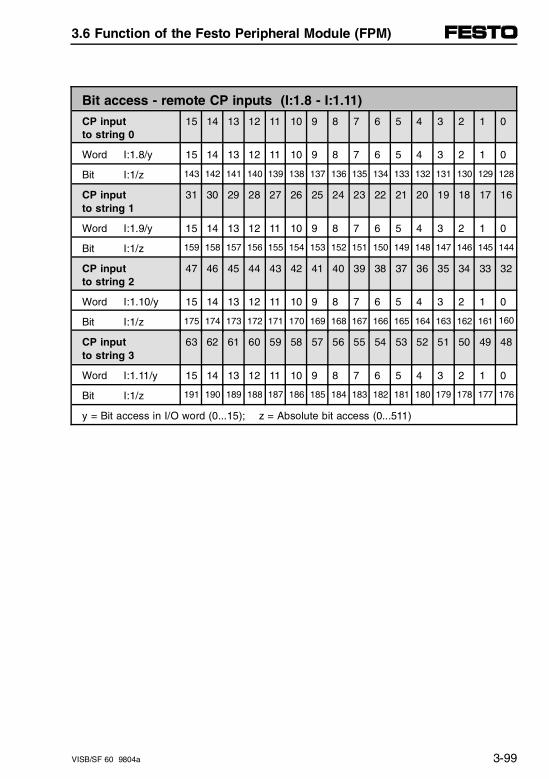
Bit access - remote CP inputs (I:1.8 - I:1.11)
CP input to string 0
15 14 13 12 11 10 9 8 7 6 5 4 3 2 1 0
Word I:1.8/y 15 14 13 12 11 10 9 8 7 6 5 4 3 2 1 0
Bit I:1/z 143 142 141 140 139 138 137 136 135 134 133 132 131 130 129 128
CP inputto string 1
31 30 29 28 27 26 25 24 23 22 21 20 19 18 17 16
Word I:1.9/y 15 14 13 12 11 10 9 8 7 6 5 4 3 2 1 0
Bit I:1/z 159 158 157 156 155 154 153 152 151 150 149 148 147 146 145 144
CP inputto string 2
47 46 45 44 43 42 41 40 39 38 37 36 35 34 33 32
Word I:1.10/y 15 14 13 12 11 10 9 8 7 6 5 4 3 2 1 0
Bit I:1/z 175 174 173 172 171 170 169 168 167 166 165 164 163 162 161 160
CP inputto string 3
63 62 61 60 59 58 57 56 55 54 53 52 51 50 49 48
Word I:1.11/y 15 14 13 12 11 10 9 8 7 6 5 4 3 2 1 0
Bit I:1/z 191 190 189 188 187 186 185 184 183 182 181 180 179 178 177 176
y = Bit access in I/O word (0...15); z = Absolute bit access (0...511)
3.6 Function of the Festo Peripheral Module (FPM)
VISB/SF 60 9804a 3-99
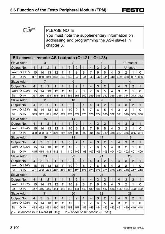
PLEASE NOTEYou must note the supplementary information on addressing and programming the AS-i slaves in chapter 6.
Bit access - remote AS-i outputs (O:1.21 - O:1.28)Slave Addr. 3 2 1 "0" master
Output No. 4 3 2 1 4 3 2 1 4 3 2 1 UnusedWord O:1.21/y 15 14 13 12 11 1 9 8 7 6 5 4 3 2 1 0Bit O:1/x 351 350 349 348 347 346 345 344 343 342 341 340 439 338 337 336
Slave Addr. 7 6 5 4
Output No. 4 3 2 1 4 3 2 1 4 3 2 1 4 3 2 1Word O:1.22/y 15 14 13 12 11 10 9 8 7 6 5 4 3 2 1 0Bit O:1/x 367 366 365 364 363 362 361 360 359 358 357 356 355 354 343 352
Slave Addr. 11 10 9 8
Output No. 4 3 2 1 4 3 2 1 4 3 2 1 4 3 2 1Word O:1.23/y 15 14 13 12 11 10 9 8 7 6 5 4 3 2 1 0Bit O:1/x 383 382 381 380 379 378 377 376 375 374 373 372 371 370 369 368
Slave Addr. 15 14 13 12
Output No. 4 3 2 1 4 3 2 1 4 3 2 1 4 3 2 1Word O:1.24/y 15 14 13 12 11 10 9 8 7 6 5 4 3 2 1 0Bit O:1/x 399 398 397 396 395 394 393 392 391 390 389 388 387 386 385 384
Slave Addr. 19 18 17 16
Output No. 4 3 2 1 4 3 2 1 4 3 2 1 4 3 2 1Word O:1.25/y 15 14 13 12 11 10 9 8 7 6 5 4 3 2 1 0Bit O:1/x 415 414 413 412 411 410 409 408 407 406 405 404 403 402 401 400
Slave Addr. 23 22 21 20
Output No. 4 3 2 1 4 3 2 1 4 3 2 1 4 3 2 1Word O:1.26/y 15 14 13 12 11 10 9 8 7 6 5 4 3 2 1 0Bit O:1/x 431 430 429 428 427 426 425 424 423 422 421 420 419 418 417 416
Slave Addr. 27 26 24 25
Output No. 4 3 2 1 4 3 2 1 4 3 2 1 4 3 2 1Word O:1.27/y 15 14 13 12 11 10 9 8 7 6 5 4 3 2 1 0Bit O:1/x 447 446 445 444 443 442 441 440 439 438 437 436 435 434 433 432
Slave Addr. 31 30 29 28
Output No. 4 3 2 1 4 3 2 1 4 3 2 1 4 3 2 1Word O:1.28/y 15 14 13 12 11 10 9 8 7 6 5 4 3 2 1 0Bit O:1/x 463 462 461 460 459 458 457 456 455 454 453 452 451 450 449 448
y = Bit access in I/O word (0...15); z = Absolute bit access (0...511)
3.6 Function of the Festo Peripheral Module (FPM)
3-100 VISB/SF 60 9804a
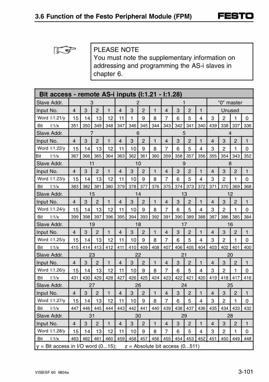
PLEASE NOTEYou must note the supplementary information on addressing and programming the AS-i slaves in chapter 6.
Bit access - remote AS-i inputs (I:1.21 - I:1.28)Slave Addr. 3 2 1 "0" master
Input No. 4 3 2 1 4 3 2 1 4 3 2 1 UnusedWord I:1.21/y 15 14 13 12 11 1 9 8 7 6 5 4 3 2 1 0Bit I:1/x 351 350 349 348 347 346 345 344 343 342 341 340 439 338 337 336
Slave Addr. 7 6 5 4
Input No. 4 3 2 1 4 3 2 1 4 3 2 1 4 3 2 1Word I:1.22/y 15 14 13 12 11 10 9 8 7 6 5 4 3 2 1 0
Bit I:1/x 367 366 365 364 363 362 361 360 359 358 357 356 355 354 343 352
Slave Addr. 11 10 9 8
Input No. 4 3 2 1 4 3 2 1 4 3 2 1 4 3 2 1Word I:1.23/y 15 14 13 12 11 10 9 8 7 6 5 4 3 2 1 0Bit I:1/x 383 382 381 380 379 378 377 376 375 374 373 372 371 370 369 368
Slave Addr. 15 14 13 12
Input No. 4 3 2 1 4 3 2 1 4 3 2 1 4 3 2 1Word I:1.24/y 15 14 13 12 11 10 9 8 7 6 5 4 3 2 1 0Bit I:1/x 399 398 397 396 395 394 393 392 391 390 389 388 387 386 385 384
Slave Addr. 19 18 17 16
Input No. 4 3 2 1 4 3 2 1 4 3 2 1 4 3 2 1Word I:1.25/y 15 14 13 12 11 10 9 8 7 6 5 4 3 2 1 0Bit I:1/x 415 414 413 412 411 410 409 408 407 406 405 404 403 402 401 400
Slave Addr. 23 22 21 20
Input No. 4 3 2 1 4 3 2 1 4 3 2 1 4 3 2 1Word I:1.26/y 15 14 13 12 11 10 9 8 7 6 5 4 3 2 1 0Bit I:1/x 431 430 429 428 427 426 425 424 423 422 421 420 419 418 417 416
Slave Addr. 27 26 24 25
Input No. 4 3 2 1 4 3 2 1 4 3 2 1 4 3 2 1Word I:1.27/y 15 14 13 12 11 10 9 8 7 6 5 4 3 2 1 0Bit I:1/x 447 446 445 444 443 442 441 440 439 438 437 436 435 434 433 432
Slave Addr. 31 30 29 28
Input No. 4 3 2 1 4 3 2 1 4 3 2 1 4 3 2 1Word I:1.28/y 15 14 13 12 11 10 9 8 7 6 5 4 3 2 1 0Bit I:1/x 463 462 461 460 459 458 457 456 455 454 453 452 451 450 449 448
y = Bit access in I/O word (0...15); z = Absolute bit access (0...511)
3.6 Function of the Festo Peripheral Module (FPM)
VISB/SF 60 9804a 3-101
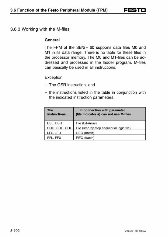
3.6.3 Working with the M-files
General
The FPM of the SB/SF 60 supports data files M0 andM1 in its data range. There is no table for these files inthe processor memory. The M0 and M1-files can be ad-dressed and processed in the ladder program. M-filescan basically be used in all instructions.
Exception:
– The OSR instruction, and
– the instructions listed in the table in conjunction withthe indicated instruction parameters.
The instructions ...
... in connection with parameter (file indicator #) can not use M-files
BSL. BSR File (Bit-Array)
SQO. SQC. SQL File (step-by-step sequential logic file)
LFL. LFU LIFO (batch)
FFL. FFU FIFO (batch)
3.6 Function of the Festo Peripheral Module (FPM)
3-102 VISB/SF 60 9804a
The use of M0 and M1-files is module-dependent in Al-len-Bradley controllers. The SB/SF 60 supports the fol-lowing functions in the M-files:
M0-file (outputs, written by processor)
– Configuration of the freely selectable interrupt source 0
– Parameterizing of AS-i slaves
M1-file (inputs, read by processor)
– Expanded diagnostic information of the connectedperipherals (valve terminal).
– Displays of NOMINAL/ACTUAL configuration of thevalve terminal.
These M-files can be processed word-by-word and bit-by-bit.
Recommendation:Process the M-files in longer time intervals of e.g. 2...5seconds or only when there are modifications to the pa-rameters. You can thereby considerably optimize yourprogram running time, as the transfer commands forthe 32 words of the M-files require a great deal of time.
3.6 Function of the Festo Peripheral Module (FPM)
VISB/SF 60 9804a 3-103
Configuration of the M-files
For the M-files to be available, the following parametersmust be set when configuring the SB/SF 60 for Slot 1using the programming device (see also chapter 3.3"Configuration"):
M0-file Size = 32 wordsM1-file Size = 32 words
Recommendation:To make the contents of the M-files accessible from theprogramming device, copy the contents of the ladderprogram into an integer file.
3.6 Function of the Festo Peripheral Module (FPM)
3-104 VISB/SF 60 9804a
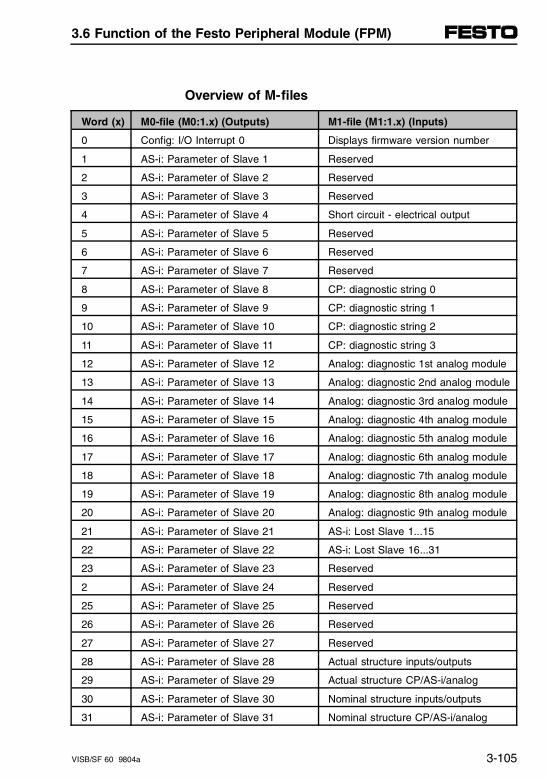
Overview of M-files
Word (x) M0-file (M0:1.x) (Outputs) M1-file (M1:1.x) (Inputs)
0 Config: I/O Interrupt 0 Displays firmware version number
1 AS-i: Parameter of Slave 1 Reserved
2 AS-i: Parameter of Slave 2 Reserved
3 AS-i: Parameter of Slave 3 Reserved
4 AS-i: Parameter of Slave 4 Short circuit - electrical output
5 AS-i: Parameter of Slave 5 Reserved
6 AS-i: Parameter of Slave 6 Reserved
7 AS-i: Parameter of Slave 7 Reserved
8 AS-i: Parameter of Slave 8 CP: diagnostic string 0
9 AS-i: Parameter of Slave 9 CP: diagnostic string 1
10 AS-i: Parameter of Slave 10 CP: diagnostic string 2
11 AS-i: Parameter of Slave 11 CP: diagnostic string 3
12 AS-i: Parameter of Slave 12 Analog: diagnostic 1st analog module
13 AS-i: Parameter of Slave 13 Analog: diagnostic 2nd analog module
14 AS-i: Parameter of Slave 14 Analog: diagnostic 3rd analog module
15 AS-i: Parameter of Slave 15 Analog: diagnostic 4th analog module
16 AS-i: Parameter of Slave 16 Analog: diagnostic 5th analog module
17 AS-i: Parameter of Slave 17 Analog: diagnostic 6th analog module
18 AS-i: Parameter of Slave 18 Analog: diagnostic 7th analog module
19 AS-i: Parameter of Slave 19 Analog: diagnostic 8th analog module
20 AS-i: Parameter of Slave 20 Analog: diagnostic 9th analog module
21 AS-i: Parameter of Slave 21 AS-i: Lost Slave 1...15
22 AS-i: Parameter of Slave 22 AS-i: Lost Slave 16...31
23 AS-i: Parameter of Slave 23 Reserved
2 AS-i: Parameter of Slave 24 Reserved
25 AS-i: Parameter of Slave 25 Reserved
26 AS-i: Parameter of Slave 26 Reserved
27 AS-i: Parameter of Slave 27 Reserved
28 AS-i: Parameter of Slave 28 Actual structure inputs/outputs
29 AS-i: Parameter of Slave 29 Actual structure CP/AS-i/analog
30 AS-i: Parameter of Slave 30 Nominal structure inputs/outputs
31 AS-i: Parameter of Slave 31 Nominal structure CP/AS-i/analog
3.6 Function of the Festo Peripheral Module (FPM)
VISB/SF 60 9804a 3-105
M-file (Inputs)
Firmware version no. in M1-file (M1:1.0):Data word 0 of the M1-file can be used to read out thefirmware version of the Festo Peripheral Module. Thisversion number does not refer to the SLC 5/02 proces-sor.
M1:10
Diagnostic information in M1-file (M1.4...1.22):The M1-file contains much diagnostic information(M1:1.4...1.22) concerning the peripheral. For additionaldescriptions of its meaning, see chapter 3.7.3 "Ex-panded diagnostics using M-files."
M1:14M1:22
3.6 Function of the Festo Peripheral Module (FPM)
3-106 VISB/SF 60 9804a
Display NOMINAL/ACTUAL structure in M1-file(M1:1.28...1.31):Data words 28...31 of the M1-file contain informationabout the NOMINAL/ACTUAL structure of the valve ter-minal. For additional information, see chapter 3.3 "G-files and NOMINAL/ACTUAL Comparison."
M1:1.28M1:1.31
The data of the G-file cannot be read by the processor.These data can be read by means of parallel entries inM1:1.28...M1:1.31. NOMINAL/ACTUAL comparisonscan therefore be programmed during program runningtime.
For additional information concerning processing of M-files, see the Allen-Bradley reference manual in thechapter "M0 and M1 Data Files - Speciality I/O Mod-ules."
3.6 Function of the Festo Peripheral Module (FPM)
VISB/SF 60 9804a 3-107
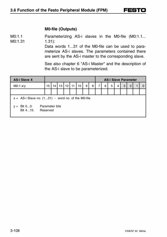
M0-file (Outputs)
Parameterizing AS-i slaves in the M0-file (M0:1.1...1.31):Data words 1...31 of the M0-file can be used to para-meterize AS-i slaves. The parameters contained thereare sent by the AS-i master to the corresponding slave.
M0:1.1M0:1.31
See also chapter 6 "AS-i Master" and the description ofthe AS-i slave to be parameterized.
AS-i Slave X AS-i Slave Parameter
M0:1.x/y 15 14 13 12 11 10 9 8 7 6 5 4 3 2 1 0
x = AS-i Slave no. (1...31) - word no. of the M0-file
y = Bit 0...3: Parameter bitsBit 4...15: Reserved
3.6 Function of the Festo Peripheral Module (FPM)
3-108 VISB/SF 60 9804a
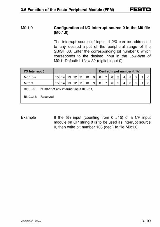
Configuration of I/O interrupt source 0 in the M0-file(M0:1.0)
M0:1.0
The interrupt source of input I:1.2/0 can be addressedto any desired input of the peripheral range of theSB/SF 60. Enter the corresponding bit number 0 whichcorresponds to the desired input in the Low-byte ofM0:1. Default: I:1/z = 32 (digital input 0).
I/O Interrupt 0 Desired input number (I:1/z)
M0:1.0/y 15 14 13 12 11 10 9 8 7 6 5 4 3 2 1 0
M0:1/z 15 14 13 12 11 10 9 8 7 6 5 4 3 2 1 0
Bit 0...8: Number of any interrupt input (0...511)
Bit 9...15: Reserved
If the 5th input (counting from 0…15) of a CP inputmodule on CP string 0 is to be used as interrupt source0, then write bit number 133 (dec.) to file M0:1.0.
Example
3.6 Function of the Festo Peripheral Module (FPM)
VISB/SF 60 9804a 3-109
3.6.4 Special configurations of the FPM
The valve terminal offers the following configurations inthese four I/O words:
– O:1.1 Configure I/O interrupts
– I:1.1 Scan I/O interrupt flags
– O:1.0 Configure runtime behavior
– I:1.0 Read out status information from the valve terminal (group fault messages).
These special configurations permit very convenientprogramming for some applications, for example time-critical I/O interrupts or expanded diagnostics capability.
3.6 Function of the Festo Peripheral Module (FPM)
3-110 VISB/SF 60 9804a
Programming I/O interrupts (ISR)
This function allows interruption of the normal processcycle for processing a specific subroutine (InterruptService Routine ISR). The SB/SF 60 makes 8 interruptinputs in input word I:1.2/0...7 available. The interruptscan be triggered by either a rising or falling edge. Withthe I/O interrupts fast programming reactions can beachieved by means of clever programming.
8 Interrupt inputs
Input I:1.2/0 has a special feature. It is freely program-mable and enables the user to include critical process-ing states - even from remote inputs of the CP or AS-ibus system - as I/O interrupts in the program. Interruptinput I:1.2/0 in the M-file can be addressed to any de-sired input of the controller peripheral area (defaultI:1/32).
When configuring the SB/SF 60 using the programmingdevice, the Program File Number of the ISR must al-ready be specified in the range 3...255. This subroutineis always run by the processor when an I/O interrupt isgenerated through the peripheral of the SB/SF 60. See also chapter 3.3 "Configuring the Controller."
ConfigureI/O interrupts
3.6 Function of the Festo Peripheral Module (FPM)
VISB/SF 60 9804a 3-111
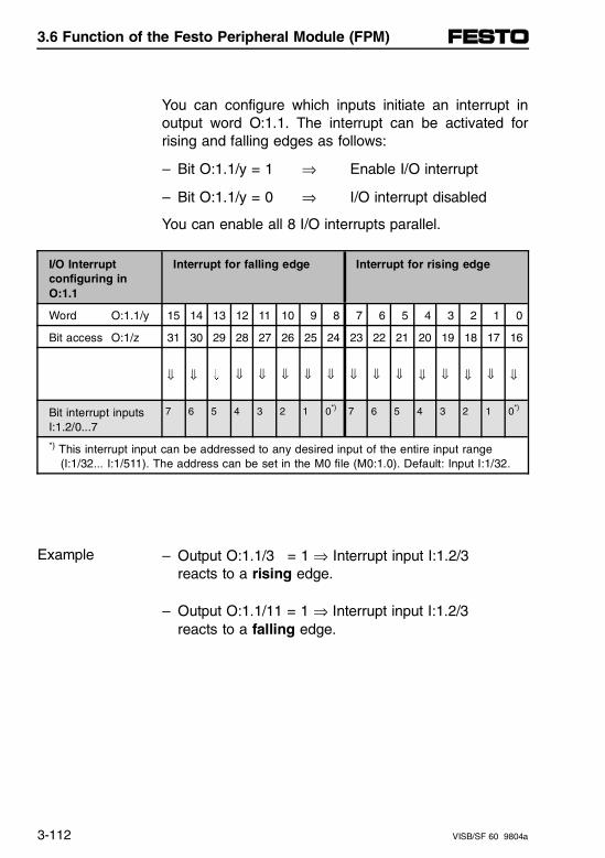
You can configure which inputs initiate an interrupt inoutput word O:1.1. The interrupt can be activated forrising and falling edges as follows:
– Bit O:1.1/y = 1 ⇒ Enable I/O interrupt
– Bit O:1.1/y = 0 ⇒ I/O interrupt disabled
You can enable all 8 I/O interrupts parallel.
I/O Interruptconfiguring inO:1.1
Interrupt for falling edge Interrupt for rising edge
Word O:1.1/y 15 14 13 12 11 10 9 8 7 6 5 4 3 2 1 0
Bit access O:1/z 31 30 29 28 27 26 25 24 23 22 21 20 19 18 17 16
⇓ ⇓ Ç ⇓ ⇓ ⇓ ⇓ ⇓ ⇓ ⇓ ⇓ ⇓ ⇓ ⇓ ⇓ ⇓
Bit interrupt inputsI:1.2/0...7
7 6 5 4 3 2 1 0*) 7 6 5 4 3 2 1 0*)
*) This interrupt input can be addressed to any desired input of the entire input range (I:1/32... I:1/511). The address can be set in the M0 file (M0:1.0). Default: Input I:1/32.
– Output O:1.1/3 = 1 ⇒ Interrupt input I:1.2/3 reacts to a rising edge.
Example
– Output O:1.1/11 = 1 ⇒ Interrupt input I:1.2/3reacts to a falling edge.
3.6 Function of the Festo Peripheral Module (FPM)
3-112 VISB/SF 60 9804a
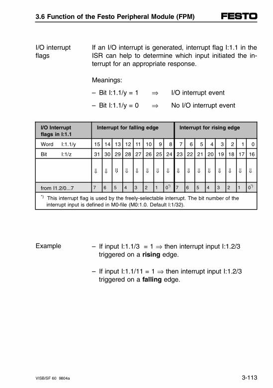
If an I/O interrupt is generated, interrupt flag I:1.1 in theISR can help to determine which input initiated the in-terrupt for an appropriate response.
Meanings:
I/O interruptflags
– Bit I:1.1/y = 1 ⇒ I/O interrupt event
– Bit I:1.1/y = 0 ⇒ No I/O interrupt event
I/O Interruptflags in I:1.1
Interrupt for falling edge Interrupt for rising edge
Word I:1.1/y 15 14 13 12 11 10 9 8 7 6 5 4 3 2 1 0
Bit I:1/z 31 30 29 28 27 26 25 24 23 22 21 20 19 18 17 16
⇓ ⇓ Ç ⇓ ⇓ ⇓ ⇓ ⇓ ⇓ ⇓ ⇓ ⇓ ⇓ ⇓ ⇓ ⇓
from I1.2/0...7 7 6 5 4 3 2 1 0*) 7 6 5 4 3 2 1 0*)
*) This interrupt flag is used by the freely-selectable interrupt. The bit number of the interrupt input is defined in M0-file (M0:1.0. Default I:1/32).
– If input I:1.1/3 = 1 ⇒ then interrupt input I:1.2/3 triggered on a rising edge.
Example
– If input I:1.1/11 = 1 ⇒ then interrupt input I:1.2/3 triggered on a falling edge.
3.6 Function of the Festo Peripheral Module (FPM)
VISB/SF 60 9804a 3-113
– The Interrupt subroutine (INT) instruction should bethe first instruction in your ISR.
– Use the instruction IIM (Immediate Input Masked) asthe next instruction to obtain a current table of theinterrupt flags in I:1.1.
– An I/O interrupt cannot be influenced by a FORCE.
Additional information can be found in the chapter "I/OInterrupts" of your Allen-Bradley manual.
Rules of thumb for interrupt processing times:I/O interruptprocessingtime
– The processing time for an I/O interrupt depends onthe system design of the valve terminal.
– The processing time is independent of the size of thecontrol program.
The exact values can be calculated (see Appendix C).
3.6 Function of the Festo Peripheral Module (FPM)
3-114 VISB/SF 60 9804a
Configure fault interrupts
The common errors, which are to trigger an error mes-sage (recoverable user fault) of the Festo PeripheralModule, are configured in output word O:1.0 (runtimeerror 0160...0169 hex).
Bit O:1.0/y = 1 ⇒ Fault interrupt enabled
Bit O:1.0/y = 0 ⇒ Fault interrupt disabled (Default)
PLEASE NOTE- Bit O:1.0/4 is used to activate all three undervol-
tage messages VVal, VSen and VOutIf you set this bit, you will trigger an error interruptwhen the operating voltages are switched off at Pin 1 or Pin 2 of the valve terminal.
- Bit O:1.0/8 is used to activate all four group faults in the CP Strings 0...3.
3.6 Function of the Festo Peripheral Module (FPM)
VISB/SF 60 9804a 3-115
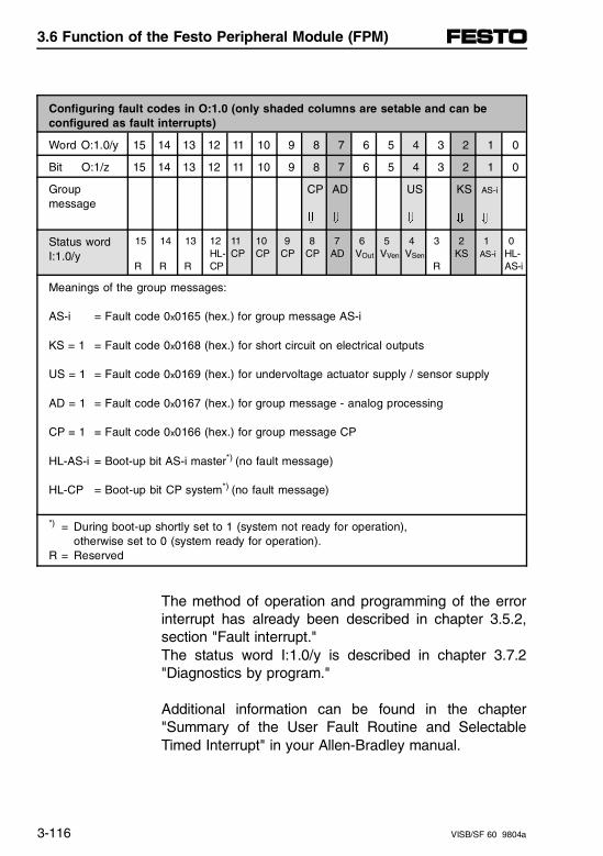
Configuring fault codes in O:1.0 (only shaded columns are setable and can be configured as fault interrupts)
Word O:1.0/y 15 14 13 12 11 10 9 8 7 6 5 4 3 2 1 0
Bit O:1/z 15 14 13 12 11 10 9 8 7 6 5 4 3 2 1 0
Groupmessage
CP
Ç
AD
Ç
US
Ç
KS
Ç
AS-i
Ç
Status wordI:1.0/y
15
R
14
R
13
R
12HL-CP
11CP
10CP
9CP
8CP
7AD
6VOut
5VVen
4VSen
3
R
2KS
1AS-i
0HL-AS-i
Meanings of the group messages:
AS-i = Fault code 0x0165 (hex.) for group message AS-i
KS = 1 = Fault code 0x0168 (hex.) for short circuit on electrical outputs
US = 1 = Fault code 0x0169 (hex.) for undervoltage actuator supply / sensor supply
AD = 1 = Fault code 0x0167 (hex.) for group message - analog processing
CP = 1 = Fault code 0x0166 (hex.) for group message CP
HL-AS-i = Boot-up bit AS-i master*) (no fault message)
HL-CP = Boot-up bit CP system*) (no fault message)
*) = During boot-up shortly set to 1 (system not ready for operation), otherwise set to 0 (system ready for operation).
R = Reserved
The method of operation and programming of the errorinterrupt has already been described in chapter 3.5.2,section "Fault interrupt."The status word I:1.0/y is described in chapter 3.7.2"Diagnostics by program."
Additional information can be found in the chapter"Summary of the User Fault Routine and SelectableTimed Interrupt" in your Allen-Bradley manual.
3.6 Function of the Festo Peripheral Module (FPM)
3-116 VISB/SF 60 9804a
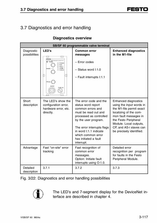
3.7 Diagnostics and error handling
Diagnostics overview
SB/SF 60 programmable valve terminal
Diagnosticpossibilities
LED’s Common error messages
– Error codes
– Status word I:1.0
– Fault interrupts I:1.1
Enhanced diagnosticsin the M1-file
Short description
The LED’s show theconfiguration error,hardware error, etc.directly.
The error code and thestatus word reportcommon errors andmust be read out andprocessed as controlledby the user program.
The error interrupts flagsin word I:1.1 indicatewhich common errorhas initiated a faultinterrupt.
Enhanced diagnosticsusing the input words inthe M1-file permit exactlocalizing of the com-mon fault messages inthe Festo PeripheralModule. Local outputs,CP, and AS-i slaves canbe precisely identified.
Advantage Fast "on-site" errortracking
Fast recognition ofcommon error messages. Option: Initiate faultinterrupts using O:1.0.
Detailed errorrecognition per programfor faults in the FestoPeripheral Module.
Detailed description
3.7.1 3.7.2 3.7.3
Fig. 3/22: Diagnostics and error handling possibilities
The LED’s and 7-segment display for the DeviceNet in-terface are described in chapter 4.
24VDCFUSE 2A
POWERRUN
COMMFAULT
FORCE
TMUsing SLC 500TECHNO LOGY licensed f rom
DH485
PROG
3.7 Diagnostics and error handling
VISB/SF 60 9804a 3-117
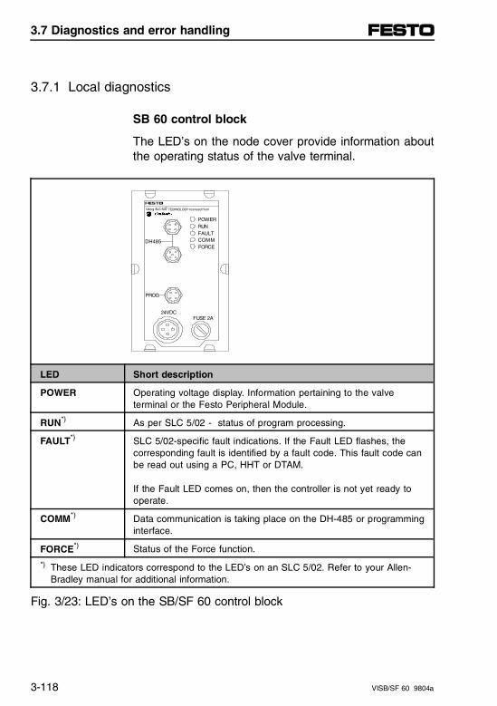
3.7.1 Local diagnostics
SB 60 control block
The LED’s on the node cover provide information aboutthe operating status of the valve terminal.
LED Short description
POWER Operating voltage display. Information pertaining to the valveterminal or the Festo Peripheral Module.
RUN*) As per SLC 5/02 - status of program processing.
FAULT*) SLC 5/02-specific fault indications. If the Fault LED flashes, thecorresponding fault is identified by a fault code. This fault code canbe read out using a PC, HHT or DTAM.
If the Fault LED comes on, then the controller is not yet ready tooperate.
COMM*) Data communication is taking place on the DH-485 or programminginterface.
FORCE*) Status of the Force function.
*) These LED indicators correspond to the LED’s on an SLC 5/02. Refer to your Allen-Bradley manual for additional information.
Fig. 3/23: LED’s on the SB/SF 60 control block
24VDCFUSE 2A
POWERRUN
COMMFAULT
FORCE
TMUsing SLC 500 TECHNOLOGY licensed from
DH485
PROG
3.7 Diagnostics and error handling
3-118 VISB/SF 60 9804a
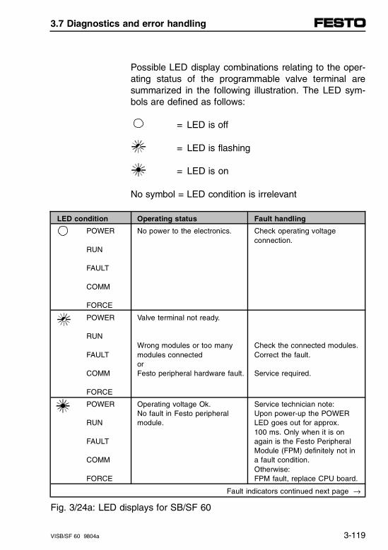
Possible LED display combinations relating to the oper-ating status of the programmable valve terminal aresummarized in the following illustration. The LED sym-bols are defined as follows:
= LED is off
= LED is flashing
= LED is on
No symbol = LED condition is irrelevant
LED condition Operating status Fault handling
POWER
RUN
FAULT
COMM
FORCE
No power to the electronics. Check operating voltageconnection.
POWER
RUN
FAULT
COMM
FORCE
Valve terminal not ready.
Wrong modules or too manymodules connectedorFesto peripheral hardware fault.
Check the connected modules.Correct the fault.
Service required.
POWER
RUN
FAULT
COMM
FORCE
Operating voltage Ok.No fault in Festo peripheralmodule.
Service technician note: Upon power-up the POWERLED goes out for approx. 100 ms. Only when it is onagain is the Festo PeripheralModule (FPM) definitely not ina fault condition. Otherwise: FPM fault, replace CPU board.
Fault indicators continued next page →
Fig. 3/24a: LED displays for SB/SF 60
3.7 Diagnostics and error handling
VISB/SF 60 9804a 3-119
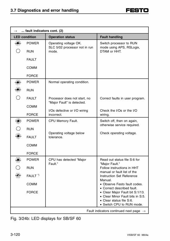
→ ... fault indicators cont. (2)
LED condition Operation status Fault handling
POWER
RUN
FAULT
COMM
FORCE
Operating voltage OK.SLC 5/02 processor not in runmode.
Switch processor to RUNmode using APS, RSLogix,DTAM or HHT.
POWER
RUN
FAULT
COMM
FORCE
Normal operating condition.
Processor does not start, no"Major Fault" is detected.
I/Os defective or I/O wiringincorrect.
Correct faults in user program.
Check the I/Os or the I/Owiring.
POWER
RUN
FAULT
COMM
FORCE
CPU Memory Fault.
Operating voltage below tolerance.
Switch off, then on again, otherwise service required.
Check operating voltage.
POWER
RUN
FAULT *)
COMM
FORCE
CPU has detected "MajorFault."
Read out status file S:6 for"Major Fault."Follow instructions in HHTmanual or fault list of the Instruction Set Reference Manual.• Observe Festo fault codes.• Correct described fault.• Clear Major Fault bit S:1/13.• Clear Minor Fault bits in S:5.• Clear status file S:6.• Switch CPU to RUN mode.
Fault indicators continued next page →
Fig. 3/24b: LED displays for SB/SF 60
3.7 Diagnostics and error handling
3-120 VISB/SF 60 9804a
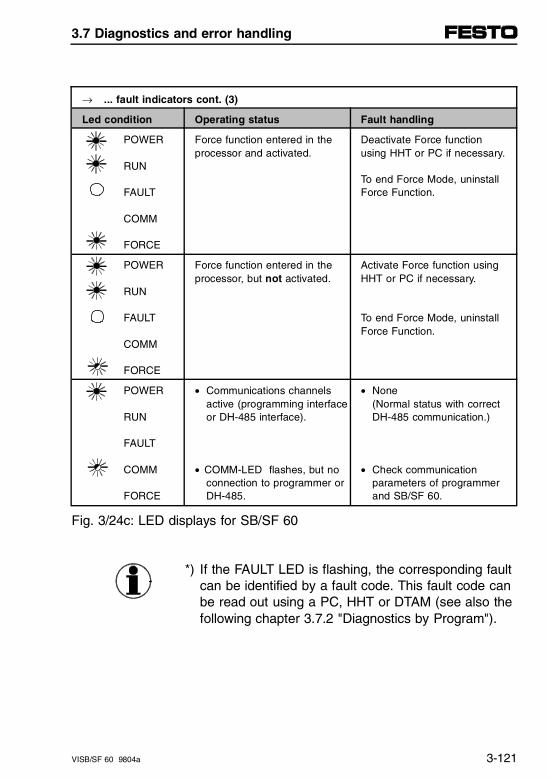
→ ... fault indicators cont. (3)
Led condition Operating status Fault handling
POWER
RUN
FAULT
COMM
FORCE
Force function entered in theprocessor and activated.
Deactivate Force functionusing HHT or PC if necessary.
To end Force Mode, uninstall Force Function.
POWER
RUN
FAULT
COMM
FORCE
Force function entered in theprocessor, but not activated.
Activate Force function usingHHT or PC if necessary.
To end Force Mode, uninstallForce Function.
POWER
RUN
FAULT
COMM
FORCE
• Communications channels active (programming interfaceor DH-485 interface).
• COMM-LED flashes, but noconnection to programmer orDH-485.
• None(Normal status with correct DH-485 communication.)
• Check communication parameters of programmer and SB/SF 60.
Fig. 3/24c: LED displays for SB/SF 60
*) If the FAULT LED is flashing, the corresponding faultcan be identified by a fault code. This fault code canbe read out using a PC, HHT or DTAM (see also the following chapter 3.7.2 "Diagnostics by Program").
3.7 Diagnostics and error handling
VISB/SF 60 9804a 3-121
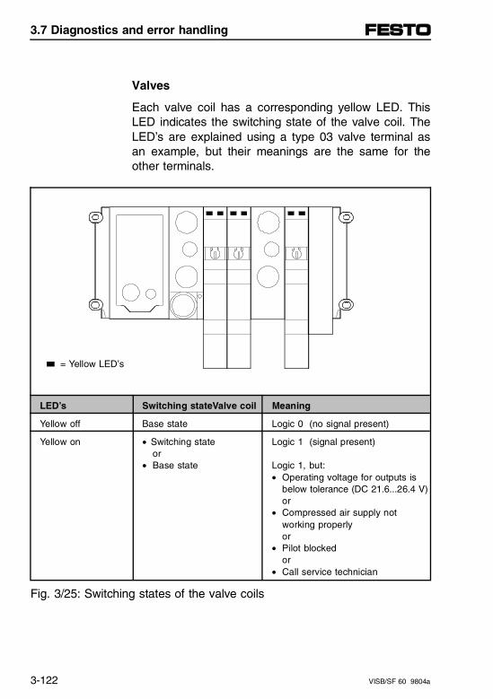
Valves
Each valve coil has a corresponding yellow LED. ThisLED indicates the switching state of the valve coil. TheLED’s are explained using a type 03 valve terminal asan example, but their meanings are the same for theother terminals.
= Yellow LED’s
LED’s Switching stateValve coil Meaning
Yellow off Base state Logic 0 (no signal present)
Yellow on • Switching stateor
• Base state
Logic 1 (signal present)
Logic 1, but:• Operating voltage for outputs is
below tolerance (DC 21.6...26.4 V)or
• Compressed air supply not working properlyor
• Pilot blockedor
• Call service technician
Fig. 3/25: Switching states of the valve coils
3.7 Diagnostics and error handling
3-122 VISB/SF 60 9804a
I/O modules
Adjacent to the respective connection points on the I/Omodules are one or two LED’s (state indicators) withthe following colors:
– green (state of a digital input)
– yellow (state of a digital output)
– red (digital output fault).
The yellow and green LED’s indicate the presence of asignal on the corresponding input or output. The redLED’s indicate a short circuit or overload condition forthe associated output.
3.7 Diagnostics and error handling
VISB/SF 60 9804a 3-123
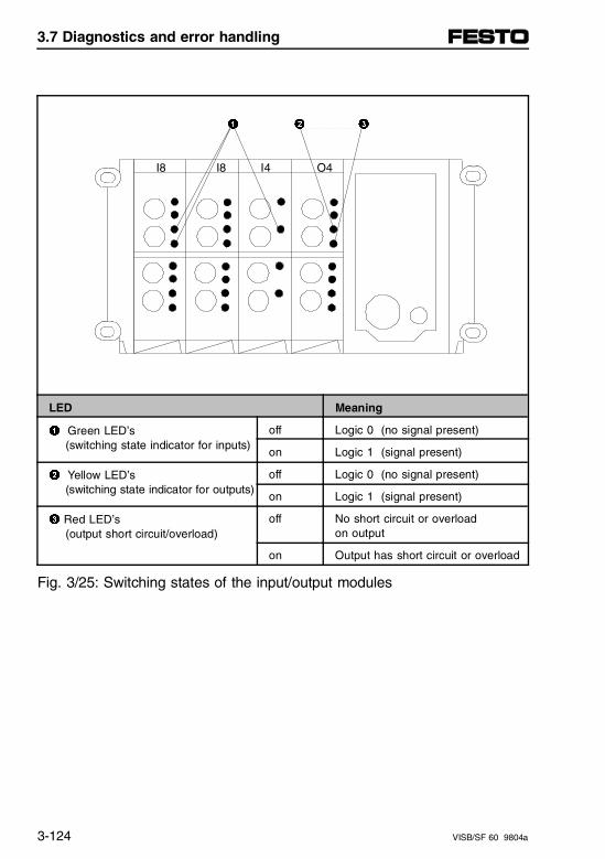
1 2 3
I8 I8 I4 O4
LED Meaning
1 Green LED’s (switching state indicator for inputs)
off Logic 0 (no signal present)
on Logic 1 (signal present)
2 Yellow LED’s (switching state indicator for outputs)
off Logic 0 (no signal present)
on Logic 1 (signal present)
3 Red LED’s (output short circuit/overload)
off No short circuit or overload on output
on Output has short circuit or overload
Fig. 3/25: Switching states of the input/output modules
3.7 Diagnostics and error handling
3-124 VISB/SF 60 9804a
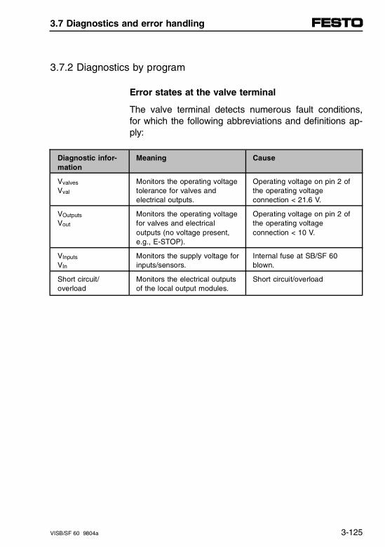
3.7.2 Diagnostics by program
Error states at the valve terminal
The valve terminal detects numerous fault conditions,for which the following abbreviations and definitions ap-ply:
Diagnostic infor-mation
Meaning Cause
Vvalves Vval
Monitors the operating voltagetolerance for valves andelectrical outputs.
Operating voltage on pin 2 ofthe operating voltageconnection < 21.6 V.
VOutputs
Vout
Monitors the operating voltagefor valves and electricaloutputs (no voltage present,e.g., E-STOP).
Operating voltage on pin 2 ofthe operating voltageconnection < 10 V.
VInputs
VIn
Monitors the supply voltage forinputs/sensors.
Internal fuse at SB/SF 60blown.
Short circuit/overload
Monitors the electrical outputsof the local output modules.
Short circuit/overload
3.7 Diagnostics and error handling
VISB/SF 60 9804a 3-125
Allen-Bradley fault categories
Allen-Bradley controllers differentiate among three faultcategories:
– User Faults (recoverable):Fault can be reset in an error handling routine andignored.
– User Faults (non-recoverable):An error handling routine is run once. Then the run-ning program or processor stops.
– Non-User Faults: Fault stops the running program or processor imme-diately.
The corresponding faults generate a fault code. TheFAULT LED on the node comes on if the fault has notfirst been reset. The following distinctions are to bemade for the programmable valve terminal with SB/SF60 control block:
Fault codeSB/SF 60
3.7 Diagnostics and error handling
3-126 VISB/SF 60 9804a
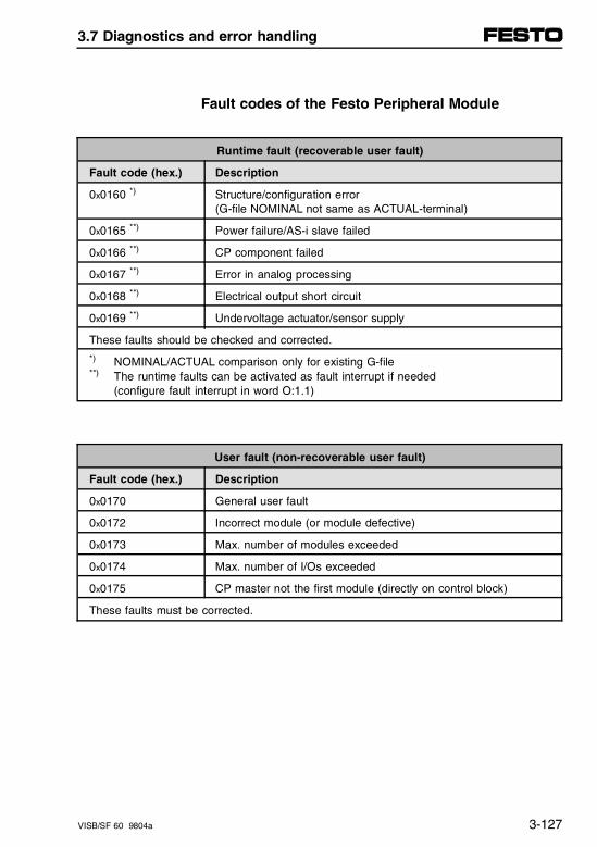
Fault codes of the Festo Peripheral Module
Runtime fault (recoverable user fault)
Fault code (hex.) Description
0x0160 *) Structure/configuration error (G-file NOMINAL not same as ACTUAL-terminal)
0x0165 **) Power failure/AS-i slave failed
0x0166 **) CP component failed
0x0167 **) Error in analog processing
0x0168 **) Electrical output short circuit
0x0169 **) Undervoltage actuator/sensor supply
These faults should be checked and corrected.
*) NOMINAL/ACTUAL comparison only for existing G-file**) The runtime faults can be activated as fault interrupt if needed
(configure fault interrupt in word O:1.1)
User fault (non-recoverable user fault)
Fault code (hex.) Description
0x0170 General user fault
0x0172 Incorrect module (or module defective)
0x0173 Max. number of modules exceeded
0x0174 Max. number of I/Os exceeded
0x0175 CP master not the first module (directly on control block)
These faults must be corrected.
3.7 Diagnostics and error handling
VISB/SF 60 9804a 3-127
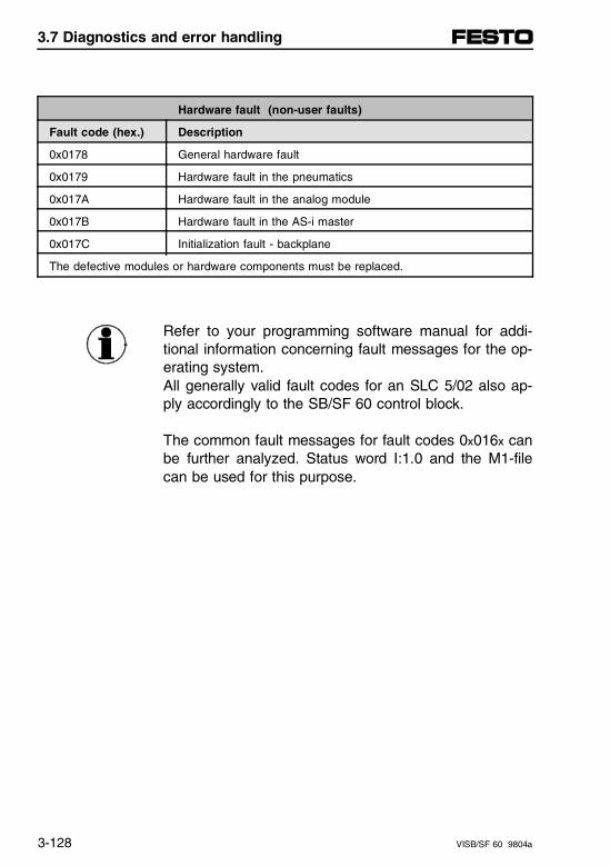
Hardware fault (non-user faults)
Fault code (hex.) Description
0x0178 General hardware fault
0x0179 Hardware fault in the pneumatics
0x017A Hardware fault in the analog module
0x017B Hardware fault in the AS-i master
0x017C Initialization fault - backplane
The defective modules or hardware components must be replaced.
Refer to your programming software manual for addi-tional information concerning fault messages for the op-erating system.All generally valid fault codes for an SLC 5/02 also ap-ply accordingly to the SB/SF 60 control block.
The common fault messages for fault codes 0x016x canbe further analyzed. Status word I:1.0 and the M1-filecan be used for this purpose.
3.7 Diagnostics and error handling
3-128 VISB/SF 60 9804a
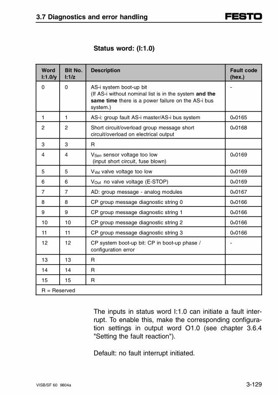
Status word: (I:1.0)
WordI:1.0/y
Bit No.I:1/z
Description Fault code(hex.)
0 0 AS-i system boot-up bit(If AS-i without nominal list is in the system and thesame time there is a power failure on the AS-i bus system.)
-
1 1 AS-i: group fault AS-i master/AS-i bus system 0x0165
2 2 Short circuit/overload group message shortcircuit/overload on electrical output
0x0168
3 3 R
4 4 VSen sensor voltage too low (input short circuit, fuse blown)
0x0169
5 5 VVal valve voltage too low 0x0169
6 6 VOut no valve voltage (E-STOP) 0x0169
7 7 AD: group message - analog modules 0x0167
8 8 CP group message diagnostic string 0 0x0166
9 9 CP group message diagnostic string 1 0x0166
10 10 CP group message diagnostic string 2 0x0166
11 11 CP group message diagnostic string 3 0x0166
12 12 CP system boot-up bit: CP in boot-up phase /configuration error
-
13 13 R
14 14 R
15 15 R
R = Reserved
The inputs in status word I:1.0 can initiate a fault inter-rupt. To enable this, make the corresponding configura-tion settings in output word O1.0 (see chapter 3.6.4"Setting the fault reaction").
Default: no fault interrupt initiated.
3.7 Diagnostics and error handling
VISB/SF 60 9804a 3-129
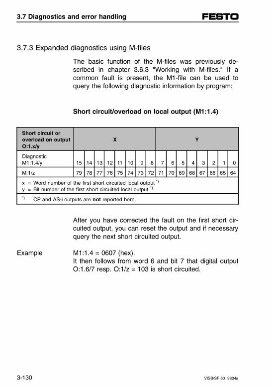
3.7.3 Expanded diagnostics using M-files
The basic function of the M-files was previously de-scribed in chapter 3.6.3 "Working with M-files." If acommon fault is present, the M1-file can be used toquery the following diagnostic information by program:
Short circuit/overload on local output (M1:1.4)
Short circuit oroverload on outputO:1.x/y
X Y
Diagnostic M1:1.4/y 15 14 13 12 11 10 9 8 7 6 5 4 3 2 1 0
M:1/z 79 78 77 76 75 74 73 72 71 70 69 68 67 66 65 64
x = Word number of the first short circuited local output *)
y = Bit number of the first short circuited local output *)
*) CP and AS-i outputs are not reported here.
After you have corrected the fault on the first short cir-cuited output, you can reset the output and if necessaryquery the next short circuited output.
M1:1.4 = 0607 (hex). It then follows from word 6 and bit 7 that digital outputO:1.6/7 resp. O:1/z = 103 is short circuited.
Example
3.7 Diagnostics and error handling
3-130 VISB/SF 60 9804a
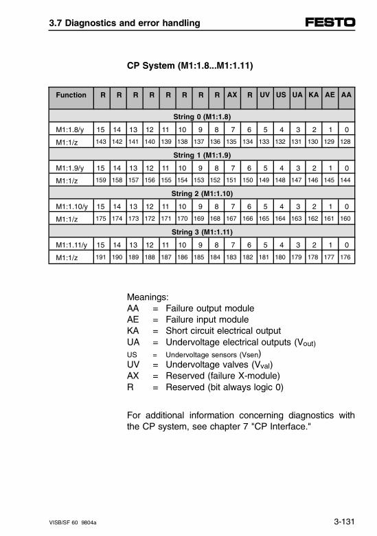
CP System (M1:1.8...M1:1.11)
Function R R R R R R R R AX R UV US UA KA AE AA
String 0 (M1:1.8)
M1:1.8/y 15 14 13 12 11 10 9 8 7 6 5 4 3 2 1 0
M1:1/z 143 142 141 140 139 138 137 136 135 134 133 132 131 130 129 128
String 1 (M1:1.9)
M1:1.9/y 15 14 13 12 11 10 9 8 7 6 5 4 3 2 1 0
M1:1/z 159 158 157 156 155 154 153 152 151 150 149 148 147 146 145 144
String 2 (M1:1.10)
M1:1.10/y 15 14 13 12 11 10 9 8 7 6 5 4 3 2 1 0
M1:1/z 175 174 173 172 171 170 169 168 167 166 165 164 163 162 161 160
String 3 (M1:1.11)
M1:1.11/y 15 14 13 12 11 10 9 8 7 6 5 4 3 2 1 0
M1:1/z 191 190 189 188 187 186 185 184 183 182 181 180 179 178 177 176
Meanings:AA = Failure output moduleAE = Failure input moduleKA = Short circuit electrical outputUA = Undervoltage electrical outputs (Vout)
US = Undervoltage sensors (Vsen)UV = Undervoltage valves (Vval)AX = Reserved (failure X-module)R = Reserved (bit always logic 0)
For additional information concerning diagnostics withthe CP system, see chapter 7 "CP Interface."
3.7 Diagnostics and error handling
VISB/SF 60 9804a 3-131
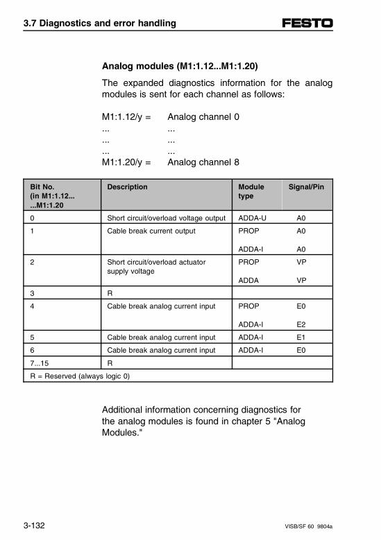
Analog modules (M1:1.12...M1:1.20)
The expanded diagnostics information for the analogmodules is sent for each channel as follows:
M1:1.12/y = Analog channel 0... ...... ...... ...M1:1.20/y = Analog channel 8
Bit No.(in M1:1.12......M1:1.20
Description Moduletype
Signal/Pin
0 Short circuit/overload voltage output ADDA-U A0
1 Cable break current output PROP
ADDA-I
A0
A0
2 Short circuit/overload actuatorsupply voltage
PROP
ADDA
VP
VP
3 R
4 Cable break analog current input PROP
ADDA-I
E0
E2
5 Cable break analog current input ADDA-I E1
6 Cable break analog current input ADDA-I E0
7...15 R
R = Reserved (always logic 0)
Additional information concerning diagnostics for the analog modules is found in chapter 5 "Analog Modules."
3.7 Diagnostics and error handling
3-132 VISB/SF 60 9804a
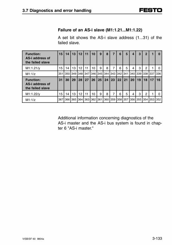
Failure of an AS-i slave (M1:1.21...M1:1.22)
A set bit shows the AS-i slave address (1...31) of thefailed slave.
Function:AS-i address ofthe failed slave
15 14 13 12 11 10 9 8 7 6 5 4 3 2 1 0
M1:1.21/y 15 14 13 12 11 10 9 8 7 6 5 4 3 2 1 0
M1:1/z 351 350 349 348 347 346 345 344 343 342 341 340 339 338 337 336
Function: AS-i address ofthe failed slave
31 30 29 28 27 26 25 24 23 22 21 20 19 18 17 16
M1:1.22/y 15 14 13 12 11 10 9 8 7 6 5 4 3 2 1 0
M1:1/z 367 366 365 364 363 362 361 360 359 358 357 356 355 354 353 352
Additional information concerning diagnostics of the AS-i master and the AS-i bus system is found in chap-ter 6 "AS-i master."
3.7 Diagnostics and error handling
VISB/SF 60 9804a 3-133

3.7 Diagnostics and error handling
3-134 VISB/SF 60 9804a
Chapter 4
Description of DeviceNet interface SF 60 (DeviceNet Scanner)
4. Description of DeviceNet interface SF 60
VISB/SF 60 9804a 4-I
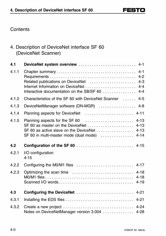
Contents
4. Description of DeviceNet interface SF 60 (DeviceNet Scanner)
4.1 DeviceNet system overview . . . . . . . . . . . . . . . . . . . . . . . . . . 4-1
4.1.1 Chapter summary . . . . . . . . . . . . . . . . . . . . . . . . . . . . . . . . . . . . 4-1Requirements . . . . . . . . . . . . . . . . . . . . . . . . . . . . . . . . . . . . . . . 4-2Related publications on DeviceNet . . . . . . . . . . . . . . . . . . . . . 4-3Internet Information on DeviceNet . . . . . . . . . . . . . . . . . . . . . . . 4-4Interactive documentation on the SB/SF 60 . . . . . . . . . . . . . . . 4-4
4.1.2 Characteristics of the SF 60 with DeviceNet Scanner . . . . . . 4-5
4.1.3 DeviceNetManager software (DN-MGR) . . . . . . . . . . . . . . . . . 4-8
4.1.4 Planning aspects for DeviceNet . . . . . . . . . . . . . . . . . . . . . . 4-11
4.1.5 Planning aspects for the SF 60 . . . . . . . . . . . . . . . . . . . . . . 4-13SF 60 as master on the DeviceNet . . . . . . . . . . . . . . . . . . . . . 4-13SF 60 as active slave on the DeviceNet . . . . . . . . . . . . . . . . . 4-13SF 60 in multi-master mode (dual mode) . . . . . . . . . . . . . . . 4-14
4.2 Configuration of the SF 60 . . . . . . . . . . . . . . . . . . . . . . . . . . 4-15
4.2.1 I/O configuration 4-15
4.2.2 Configuring the M0/M1 files . . . . . . . . . . . . . . . . . . . . . . . . . . 4-17
4.2.3 Optimizing the scan time . . . . . . . . . . . . . . . . . . . . . . . . . . . . 4-18M0/M1 files . . . . . . . . . . . . . . . . . . . . . . . . . . . . . . . . . . . . . . . . 4-18Scanned I/O words. . . . . . . . . . . . . . . . . . . . . . . . . . . . . . . . . . 4-19
4.3 Configuring the DeviceNet . . . . . . . . . . . . . . . . . . . . . . . . . . 4-21
4.3.1 Installing the EDS files . . . . . . . . . . . . . . . . . . . . . . . . . . . . . . . 4-21
4.3.2 Create a new project . . . . . . . . . . . . . . . . . . . . . . . . . . . . . . . . 4-24Notes on DeviceNetManager version 3.004 . . . . . . . . . . . . . . 4-28
4. Description of DeviceNet interface SF 60
4-II VISB/SF 60 9804a
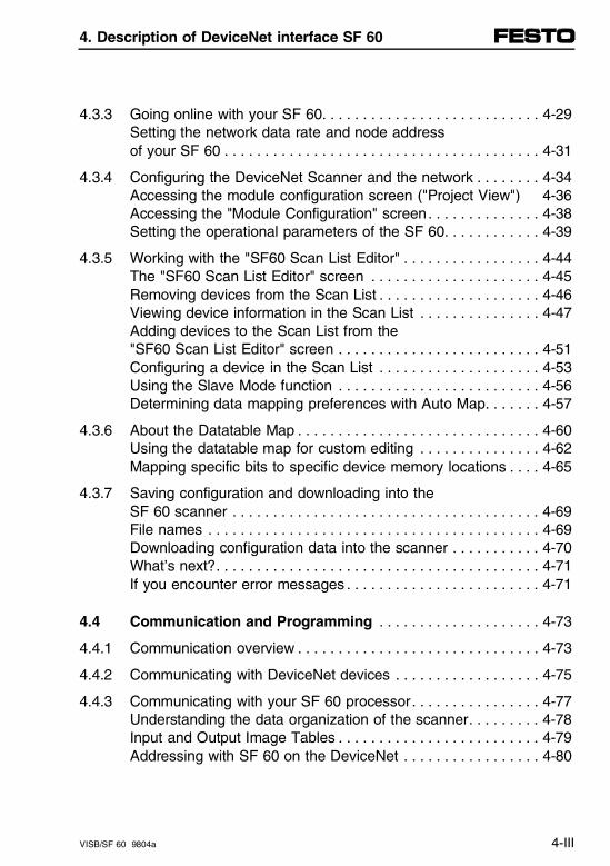
4.3.3 Going online with your SF 60. . . . . . . . . . . . . . . . . . . . . . . . . . . 4-29Setting the network data rate and node address of your SF 60 . . . . . . . . . . . . . . . . . . . . . . . . . . . . . . . . . . . . . . . 4-31
4.3.4 Configuring the DeviceNet Scanner and the network . . . . . . . . 4-34Accessing the module configuration screen ("Project View") 4-36Accessing the "Module Configuration" screen. . . . . . . . . . . . . . 4-38Setting the operational parameters of the SF 60. . . . . . . . . . . . 4-39
4.3.5 Working with the "SF60 Scan List Editor" . . . . . . . . . . . . . . . . . 4-44The "SF60 Scan List Editor" screen . . . . . . . . . . . . . . . . . . . . . 4-45Removing devices from the Scan List . . . . . . . . . . . . . . . . . . . . 4-46Viewing device information in the Scan List . . . . . . . . . . . . . . . 4-47Adding devices to the Scan List from the "SF60 Scan List Editor" screen . . . . . . . . . . . . . . . . . . . . . . . . . 4-51Configuring a device in the Scan List . . . . . . . . . . . . . . . . . . . . 4-53Using the Slave Mode function . . . . . . . . . . . . . . . . . . . . . . . . . 4-56Determining data mapping preferences with Auto Map. . . . . . . 4-57
4.3.6 About the Datatable Map . . . . . . . . . . . . . . . . . . . . . . . . . . . . . . 4-60Using the datatable map for custom editing . . . . . . . . . . . . . . . 4-62Mapping specific bits to specific device memory locations . . . . 4-65
4.3.7 Saving configuration and downloading into the SF 60 scanner . . . . . . . . . . . . . . . . . . . . . . . . . . . . . . . . . . . . . . 4-69
File names . . . . . . . . . . . . . . . . . . . . . . . . . . . . . . . . . . . . . . . . . 4-69Downloading configuration data into the scanner . . . . . . . . . . . 4-70What’s next?. . . . . . . . . . . . . . . . . . . . . . . . . . . . . . . . . . . . . . . . 4-71If you encounter error messages . . . . . . . . . . . . . . . . . . . . . . . . 4-71
4.4 Communication and Programming . . . . . . . . . . . . . . . . . . . . 4-73
4.4.1 Communication overview . . . . . . . . . . . . . . . . . . . . . . . . . . . . . . 4-73
4.4.2 Communicating with DeviceNet devices . . . . . . . . . . . . . . . . . . 4-75
4.4.3 Communicating with your SF 60 processor. . . . . . . . . . . . . . . . 4-77Understanding the data organization of the scanner. . . . . . . . . 4-78Input and Output Image Tables . . . . . . . . . . . . . . . . . . . . . . . . . 4-79Addressing with SF 60 on the DeviceNet . . . . . . . . . . . . . . . . . 4-80
4. Description of DeviceNet interface SF 60
VISB/SF 60 9804a 4-III
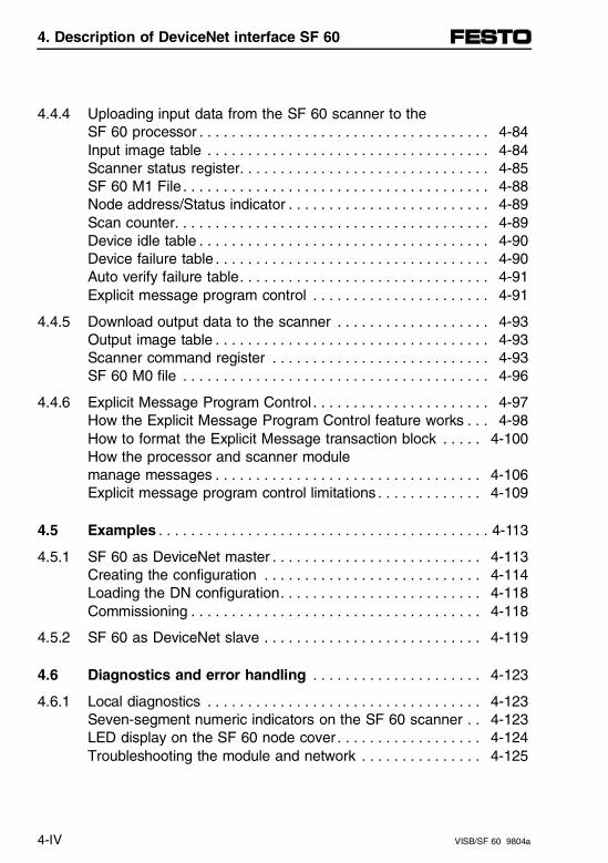
4.4.4 Uploading input data from the SF 60 scanner to the SF 60 processor . . . . . . . . . . . . . . . . . . . . . . . . . . . . . . . . . . . . 4-84Input image table . . . . . . . . . . . . . . . . . . . . . . . . . . . . . . . . . . . 4-84Scanner status register. . . . . . . . . . . . . . . . . . . . . . . . . . . . . . . 4-85SF 60 M1 File . . . . . . . . . . . . . . . . . . . . . . . . . . . . . . . . . . . . . . 4-88Node address/Status indicator . . . . . . . . . . . . . . . . . . . . . . . . . 4-89Scan counter. . . . . . . . . . . . . . . . . . . . . . . . . . . . . . . . . . . . . . . 4-89Device idle table . . . . . . . . . . . . . . . . . . . . . . . . . . . . . . . . . . . . 4-90Device failure table . . . . . . . . . . . . . . . . . . . . . . . . . . . . . . . . . . 4-90Auto verify failure table. . . . . . . . . . . . . . . . . . . . . . . . . . . . . . . 4-91Explicit message program control . . . . . . . . . . . . . . . . . . . . . . 4-91
4.4.5 Download output data to the scanner . . . . . . . . . . . . . . . . . . . 4-93Output image table . . . . . . . . . . . . . . . . . . . . . . . . . . . . . . . . . . 4-93Scanner command register . . . . . . . . . . . . . . . . . . . . . . . . . . . 4-93SF 60 M0 file . . . . . . . . . . . . . . . . . . . . . . . . . . . . . . . . . . . . . . 4-96
4.4.6 Explicit Message Program Control . . . . . . . . . . . . . . . . . . . . . . 4-97How the Explicit Message Program Control feature works . . . 4-98How to format the Explicit Message transaction block . . . . . 4-100How the processor and scanner module manage messages . . . . . . . . . . . . . . . . . . . . . . . . . . . . . . . . . 4-106Explicit message program control limitations . . . . . . . . . . . . . 4-109
4.5 Examples . . . . . . . . . . . . . . . . . . . . . . . . . . . . . . . . . . . . . . . . . 4-113
4.5.1 SF 60 as DeviceNet master . . . . . . . . . . . . . . . . . . . . . . . . . . 4-113Creating the configuration . . . . . . . . . . . . . . . . . . . . . . . . . . . 4-114Loading the DN configuration. . . . . . . . . . . . . . . . . . . . . . . . . 4-118Commissioning . . . . . . . . . . . . . . . . . . . . . . . . . . . . . . . . . . . . 4-118
4.5.2 SF 60 as DeviceNet slave . . . . . . . . . . . . . . . . . . . . . . . . . . . 4-119
4.6 Diagnostics and error handling . . . . . . . . . . . . . . . . . . . . . 4-123
4.6.1 Local diagnostics . . . . . . . . . . . . . . . . . . . . . . . . . . . . . . . . . . 4-123Seven-segment numeric indicators on the SF 60 scanner . . 4-123LED display on the SF 60 node cover . . . . . . . . . . . . . . . . . . 4-124Troubleshooting the module and network . . . . . . . . . . . . . . . 4-125
4. Description of DeviceNet interface SF 60
4-IV VISB/SF 60 9804a
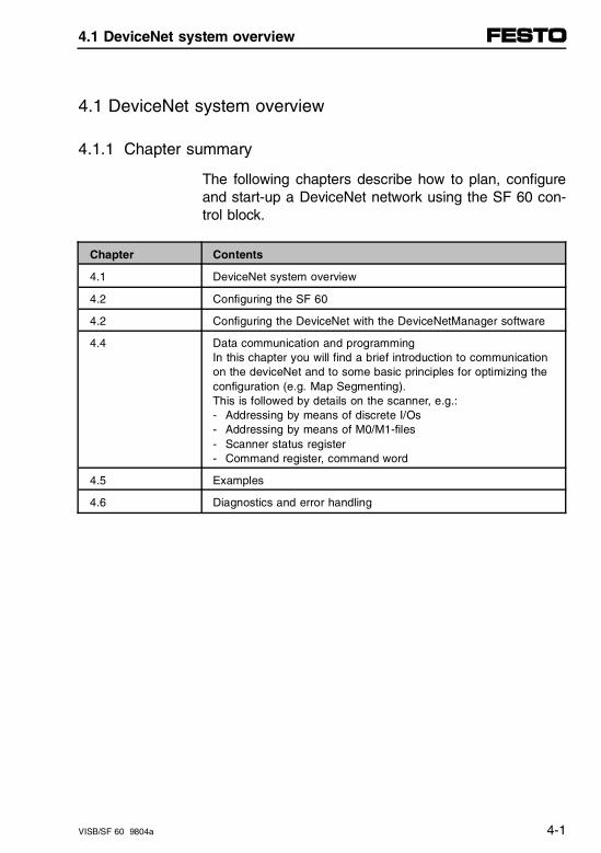
4.1 DeviceNet system overview
4.1.1 Chapter summary
The following chapters describe how to plan, configureand start-up a DeviceNet network using the SF 60 con-trol block.
Chapter Contents
4.1 DeviceNet system overview
4.2 Configuring the SF 60
4.2 Configuring the DeviceNet with the DeviceNetManager software
4.4 Data communication and programmingIn this chapter you will find a brief introduction to communicationon the deviceNet and to some basic principles for optimizing theconfiguration (e.g. Map Segmenting).This is followed by details on the scanner, e.g.:- Addressing by means of discrete I/Os - Addressing by means of M0/M1-files- Scanner status register- Command register, command word
4.5 Examples
4.6 Diagnostics and error handling
4.1 DeviceNet system overview
VISB/SF 60 9804a 4-1
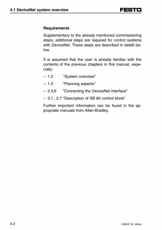
Requirements
Supplementary to the already mentioned commissioningsteps, additional steps are required for control systemswith DeviceNet. These steps are described in detalil be-low.
It is assumed that the user is already familiar with thecontents of the previous chapters in this manual, expe-cially:
– 1.2 "System overview"
– 1.3 "Planning aspects"
– 2.3.6 "Connecting the DeviceNet interface"
– 3.1...3.7 "Description of SB 60 control block"
Further important information can be found in the ap-propriate manuals from Allen-Bradley.
4.1 DeviceNet system overview
4-2 VISB/SF 60 9804a
Related publications on DeviceNet
When you first establish a DeviceNet network, first readthrough the basic instruction manual "DeviceNet CableSystems, Planning and Installation Manual," DN-6.7.2from Allen-Bradley. Here you will find important informa-tion on the designs of network parts, cables, plugs andthe complete bus topology.
A-B DN-6.7.2
You can order this manual from Allen-Bradley under thenumber specified or load it from the Internet as a PDFfile.
Organization Title Publication Number
Allen-Bradley Planning and Installation Manual DN-6.7.2
Allen-Bradley DeviceNet Product Overview DN-2.5
Allen-Bradley DeviceNetManager Software, User Manual 1787-6.5.3
Further useful information and help for project planningand parameter setting on a DeviceNet can be found inthe online manual (help) of your DeviceNetManagersoftware.
4.1 DeviceNet system overview
VISB/SF 60 9804a 4-3
Internet Information on DeviceNet
The Internet addresses specified were correct at thedate of printing. The companies reserve the right tomodify the addresses and service offers.
http://www.ab.com Homepage of Allen-Bradley/Rockwell International Corporation. Offers variousinformation about Products&Services.
http://www.odva.org Homepage of the Open DeviceNet VendorAssociation, Inc.
http://www.ab.com/networks/devicenet.html Technical Support of Rockwell Automationpermits download of Electronic DataSheets (EDS files), Application notes andvarious documents. See yourDeviceNetManager software manual foruser name and password information.
http://www.theautomationbookstore.com The Automation Bookstore of RockwellAutomation. Offers a showroom &download of documents for variousproducts of Rockwell Automation.
Interactive documentation on the SB/SF 60
An introduction to the method of operation and possibili-ties of the SF 60 in the DeviceNet can be found on theaccompanying CD-ROM "Interactive DocumentationSB/SF 60," Festo part no. 128048.
4.1 DeviceNet system overview
4-4 VISB/SF 60 9804a
4.1.2 Characteristics of the SF 60 with DeviceNet Scanner
The implementation and integration of the SF 60DeviceNet Scanner has been made in close coopera-tion with Allen-Bradley. The scanner is based on thesame circuitry as the 1747-SDN (hardware status: se-ries B, firmware release 3.3). The SF 60 DeviceNetScanner differs in constructional form and pin technol-ogy. In this way a great deal of compatibility is guaran-teed.
Chapter 1.2
As with the 1747-SDN, there are two LEDs for thestatus display, as well as an address and error mes-sage display.
The DeviceNet Scanner in the SF 60 extends the pos-sibilities of the integrated controller. Due to the openstandard of DeviceNet, a lot of manufacturers offer de-vices which are compatible with DeviceNet. These de-vices can be included in the control network of theSF 60. A summary of these devices can be found inInternet under the homepage of:
– Allen-Bradley/Rockwell International Corporation
– Open DeviceNet Vendor Association
4.1 DeviceNet system overview
VISB/SF 60 9804a 4-5
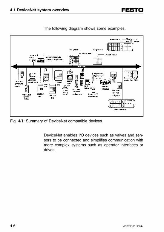
The following diagram shows some examples.
Fig. 4/1: Summary of DeviceNet compatible devices
DeviceNet enables I/O devices such as valves and sen-sors to be connected and simplifies communication withmore complex systems such as operator interfaces ordrives.
4.1 DeviceNet system overview
4-6 VISB/SF 60 9804a
As regards the SF 60, the connected DeviceNet de-vices are addressed via a discrete address rangeand/or by M-files. The integrated DeviceNet Scannerrepresents a transparent link between the SF 60 andthe DeviceNet devices. Its main task is to represent theI/O information of the DeviceNet devices in the addressrange of the Sf 60. Operating and error states areshown by means of LEDs and a display, as with the1747-SDN.
The integrated DeviceNet Scanner can be configuredand operated in a simple way as master or slave or indual mode. In dual mode the SF 60 is master of a cer-tain group of slaves and at the same time it is itself aslave of another master. In this way an SF 60 can alsobe used as an efficient, independent subsystem in alarger DeviceNet network.
During a configuration phase, the I/O ranges be as-signed by DeviceNet devices to any addresses in thecontroller. A clear overview of the DeviceNet system isthereby achieved. Configuration of the DeviceNet Scan-ner is made via the DeviceNetManager software.
4.1 DeviceNet system overview
VISB/SF 60 9804a 4-7
4.1.3 DeviceNetManager software (DN-MGR)
The software resides on a host computer - an integralpart of the DeviceNet network. It is designed to becompatible with the DeviceNet specifications Volumes Iand II.
For the SF 60 you will require the DN-MGR softwareversion 3.004 or higher.
Within the DN-MGR software the control systems aredivided into projects. The software provides a projectstructure as a method of organizing your work, allowingyou to:
– organize data
– perform offline and online configuration
– save network information
– store data in a convenient user-oriented format
– recall previously saved settings for later use
– group devices in a logical manner
– add names and identification labels to networks anddevices
4.1 DeviceNet system overview
4-8 VISB/SF 60 9804a
You will require the following devices in order to config-ure the DeviceNet Scanner:
– PC with Windows 3.1, Windows 95 or Windows NT,if necessary with PCMCIA-Port.
– DeviceNetManager for Windows Software: Cat. no.1787-MGR, Version 3.004 (or higher). ManufacturerRockwell Automation, Allen-Bradley (containsDeviceNetManager Software User Manual Pub. no.1787-6.5.3)
– Communication adapter 1770-KFD RS 232 or 1784-PCD PCMCIA card. Manufacturer: Rockwell Auto-mation, Allen-Bradley.
Recommendation:
As you will require both the DeviceNetManager (withcommunication adapter 1770-KFD) as well as the pro-gramming software (with interface converter 1747-PIC)for commisissioning the SF 60, you should ideally use aPC with two serial interfaces or work with two PCs par-allel.
4.1 DeviceNet system overview
VISB/SF 60 9804a 4-9
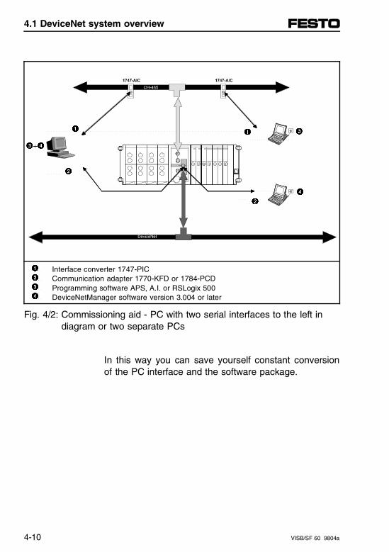
3+4
1 1
3
2
4 2
1 2 3 4
Interface converter 1747-PICCommunication adapter 1770-KFD or 1784-PCDProgramming software APS, A.I. or RSLogix 500DeviceNetManager software version 3.004 or later
Fig. 4/2: Commissioning aid - PC with two serial interfaces to the left indiagram or two separate PCs
In this way you can save yourself constant conversionof the PC interface and the software package.
4.1 DeviceNet system overview
4-10 VISB/SF 60 9804a
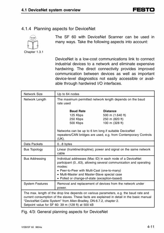
4.1.4 Planning aspects for DeviceNet
The SF 60 with DeviceNet Scanner can be used inmany ways. Take the following aspects into account:
Chapter 1.3.1
DeviceNet is a low-cost communications link to connectindustrial devices to a network and eliminate expensivehardwiring. The direct connectivity provides improvedcommunication between devices as well as importantdevice-level diagnostics not easily accessible or avail-able through hardwired I/O interfaces.
Network Size Up to 64 nodes
Network Length The maximum permitted network length depends on the baud rate used
Baud Rate Distance125 Kbps 500 m (1.640 ft)250 Kbps 250 m (820 ft)500 Kbps 100 m (328 ft)
Networks can be up to 6 km long if suitable DeviceNetrepeaters/CAN bridges are used, e.g. from Contemporary Controls(UK).
Data Packets 0...8 bytes
Bus Topology Linear (trunkline/dropline); power and signal on the same networkcable
Bus Addressing Individual addresses (Mac ID) in each node of a DeviceNetparticipant (0...63), allowing several communication and operatingmodes: • Peer-to-Peer with Multi-Cast (one-to-many) • Multi-Master and Master-Slave special case • Polled or change-of-state (exception-based)
System Features Removal and replacement of devices from the network underpower.
The max. length of the drop line depends on various parameters, e.g. the baud rate andcurrent consumption of the slaves. These facts are explained in detail in the basic manual"DeviceNet Cable System" from Allen-Bradley, DN-6.7.2, chapter 2.Setpoint value for SF 60: 39 m (128 ft) at 500 kB
Fig. 4/3: General planning aspects for DeviceNet
4.1 DeviceNet system overview
VISB/SF 60 9804a 4-11
Careful planning facilitates later use of the DeviceNet.Planning before configuring the scanner helps youmake sure that you can:
– use the scanner memory and the bandwidth of theDeviceNet efficiently
– cater for device-specific needs and requirements
– give priority to critical I/O transfers
– leave room for expansion
A very important question to answer is "What is on yournetwork?" You should be familiar with the following:
– communication requirements
– I/O importance and size
– frequency of message delivery
Additionally, you should ask "How might this networkappear in the future?" At this point in your planning, it isadvantageous for you to have some idea of how thenetwork could be expanded. When mapping your I/Odata, you have the opportunity to allot room for futureI/Os. This can save time and effort in the future.
4.1 DeviceNet system overview
4-12 VISB/SF 60 9804a
4.1.5 Planning aspects for the SF 60
SF 60 as master on the DeviceNet
The programmable valve terminal controls your con-nected I/Os and all DeviceNet slaves. The advantagesof this are:
– Any DeviceNet slave of any other manufacturer canbe included, thereby extending the various functionsof the valve terminal.
– Physical limitations imposed by systems or buildingscan be overcome.
– Flexibly extendable up to 63 DN slaves.
– High communication speed in the master-slave net-work.
SF 60 as active slave on the DeviceNet
The programmable valve terminal permits decentralpre-processing. The advantages of this are:
– The central controller is relieved and communicationin the DeviceNet network is reduced.
– Modular structure of the machine is possible. Thecomplete system is simpler and clearer.
– High system availability thanks to independent arearanges.
– User-friendly partial commissioning is possible.
4.1 DeviceNet system overview
VISB/SF 60 9804a 4-13
SF 60 in multi-master mode (dual mode)
In this configuration, the SF 60 is configured not only asmaster for a certain number of slaves, but also as theslave of another master. You should determine the as-signment of DN slaves to various masters in theDeviceNetManager software. The Allen-Bradley configu-ration and programming rules also apply accordingly tothe SF 60. The advantages are:
– In complex systems, independently controlled partsof the system can be grouped together as functiongroups or manufacturing cells. The complete systemcan then be structured more clearly and at a laterstage programmed and operated more individually.
– The efficiency of the complete system can be in-creased with several masters. Complex control pro-cedures can be distributed amongst several proces-sors.
– Important functions in the system can be designedredundantly.
4.1 DeviceNet system overview
4-14 VISB/SF 60 9804a
4.2 Configuration of the SF 60
4.2.1 I/O configuration
As already described in chapter 3, the integratedDeviceNet Scanner in the SF 60 corresponds to a"1747-SDN in slot 2 of an SLC 4-slot rack." The I/Oconfiguration of the SF 60 controller is made with theAllen-Bradley programming software.
Chapter 3.1
and 3.2
• Always proceed as described for the SB 60.
• In the case of the SF 60, also select for slot 2 the1747-SDN DeviceNet Scanner (ID code 13606, seefollowing diagram).
4.2 Configuration of the SF 60
VISB/SF 60 9804a 4-15
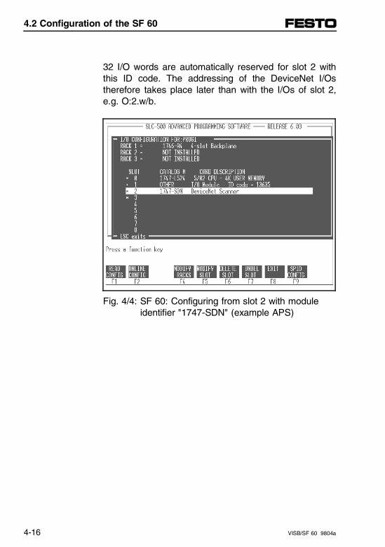
32 I/O words are automatically reserved for slot 2 withthis ID code. The addressing of the DeviceNet I/Ostherefore takes place later than with the I/Os of slot 2,e.g. O:2.w/b.
Fig. 4/4: SF 60: Configuring from slot 2 with module identifier "1747-SDN" (example APS)
4.2 Configuration of the SF 60
4-16 VISB/SF 60 9804a
4.2.2 Configuring the M0/M1 files
With your programming software (e.g. Advanced Pro-gramming Software - APS) you can configure furtherM0 and M1 files also for slot 2. When you have config-ured the DeviceNet Scanner for slot 2, the appropriatefunctions become available at the lower edge of theAPS screen. The procedure is the same as with allother modules, but must be carried out this time for IDcode 13606. Proceed as follows in order to configurethe M0 and M1 files:
1. Press F9 (SPIO CONFIG).
2. Press F5 (ADVNCD SETUP).
3. Press F5 (M0 file size). Then enter 256 (number ofwords required in the M0 file).
4. Press F6 (M1 file size). Then enter 256 (number ofwords required in the M1 file).
For more information on how to configure a DeviceNetslave, refer to the Allen-Bradley "DeviceNetManagerSoftware User Manual."
4.2 Configuration of the SF 60
VISB/SF 60 9804a 4-17
4.2.3 Optimizing the scan time
M0/M1 files
Minimize the number of accesses to M files.
The 256 M0 and M1 files of the DeviceNet Scannermodule are data files for slot 2. There is no image forthese files in the processor memory.
If the M files are accessed frequently with the Transfercommands, the SLC cycle time may be considerablyincreased (see also the detailed explanations in the"Reference Manual" for your programming software, Ap-pendix F, Allen-Bradley Publication 1747-6.15).
4.2 Configuration of the SF 60
4-18 VISB/SF 60 9804a
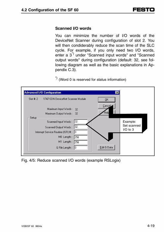
Scanned I/O words
You can minimize the number of I/O words of theDeviceNet Scanner during configuration of slot 2. Youwill then condiderably reduce the scan time of the SLCcycle. For example, if you only need two I/O words,enter a 3*) under "Scanned input words" and "Scannedoutput words" during configuration (default: 32, see fol-lowing diagram as well as the basic explanations in Ap-pendix C.3).
*) (Word 0 is reserved for status information)
Example: Set scanned I/O to 3
Fig. 4/5: Reduce scanned I/O words (example RSLogix)
4.2 Configuration of the SF 60
VISB/SF 60 9804a 4-19

4.2 Configuration of the SF 60
4-20 VISB/SF 60 9804a
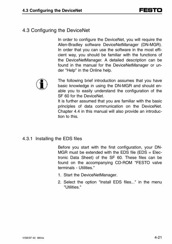
4.3 Configuring the DeviceNet
In order to configure the DeviceNet, you will require theAllen-Bradley software DeviceNetManager (DN-MGR).In order that you can use the software in the most effi-cient way, you should be familiar with the functions ofthe DeviceNetManager. A detailed description can befound in the manual for the DeviceNetManager or un-der "Help" in the Online help.
The following brief introduction assumes that you havebasic knowledge in using the DN-MGR and should en-able you to easily understand the configuration of theSF 60 for the DeviceNet.It is further assumed that you are familiar with the basicprinciples of data communication on the DeviceNet.Chapter 4.4 in this manual will also provide an introduc-tion to this.
4.3.1 Installing the EDS files
Before you start with the first configuration, your DN-MGR must be extended with the EDS file (EDS = Elec-tronic Data Sheet) of the SF 60. These files can befound on the accompanying CD-ROM "FESTO valveterminals - Utilities."
1. Start the DeviceNetManager.
2. Select the option "Install EDS files..." in the menu"Utilities."
4.3 Configuring the DeviceNet
VISB/SF 60 9804a 4-21
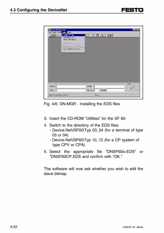
Fig. 4/6: DN-MGR - Installing the EDS files
3. Insert the CD-ROM "Utilities" for the SF 60.
4. Switch to the directory of the EDS files: - Device.Net\ISF60\Typ 03_04 (for a terminal of type 03 or 04)- Device.Net\ISF60\Typ 10_12 (for a CP system of type CPV or CPA)
5. Select the appropriate file "DNSF60io.EDS" or"DNSF60CP.EDS and confirm with "OK."
The software will now ask whether you wish to edit theslave bitmap.
4.3 Configuring the DeviceNet
4-22 VISB/SF 60 9804a
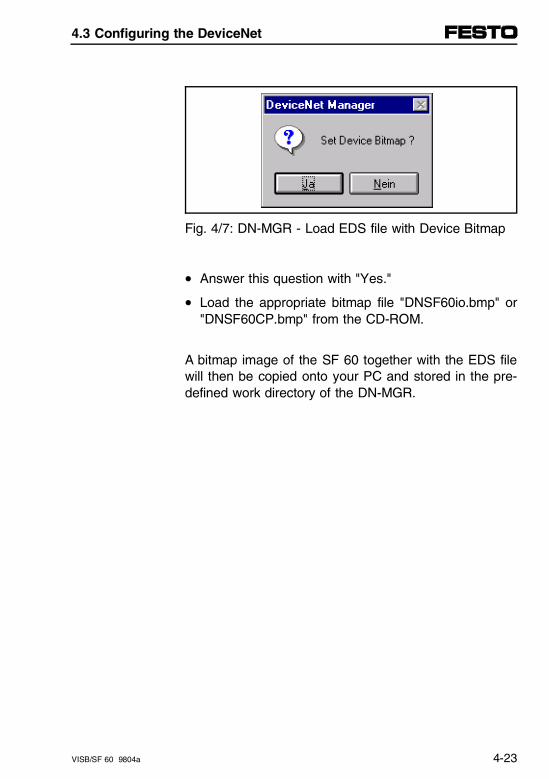
Fig. 4/7: DN-MGR - Load EDS file with Device Bitmap
• Answer this question with "Yes."
• Load the appropriate bitmap file "DNSF60io.bmp" or"DNSF60CP.bmp" from the CD-ROM.
A bitmap image of the SF 60 together with the EDS filewill then be copied onto your PC and stored in the pre-defined work directory of the DN-MGR.
4.3 Configuring the DeviceNet
VISB/SF 60 9804a 4-23
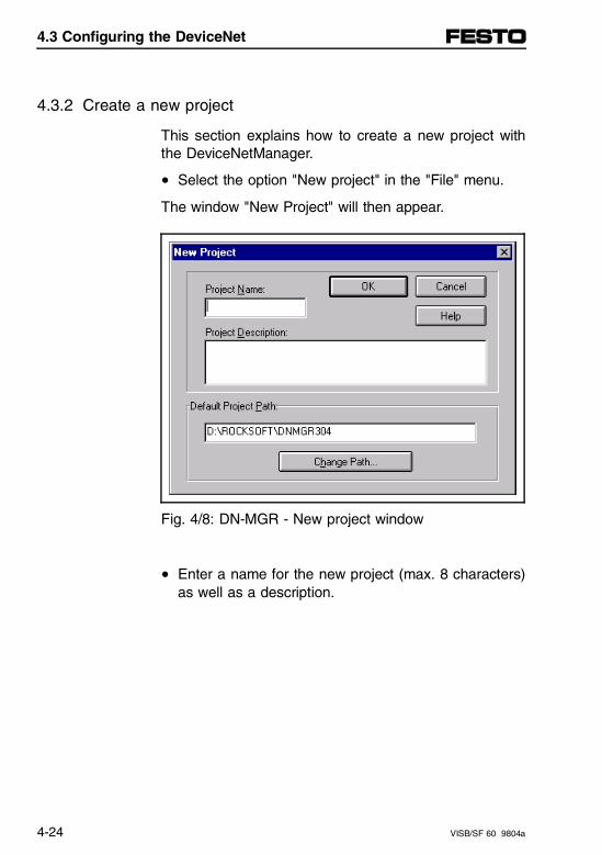
4.3.2 Create a new project
This section explains how to create a new project withthe DeviceNetManager.
• Select the option "New project" in the "File" menu.
The window "New Project" will then appear.
Fig. 4/8: DN-MGR - New project window
• Enter a name for the new project (max. 8 characters)as well as a description.
4.3 Configuring the DeviceNet
4-24 VISB/SF 60 9804a
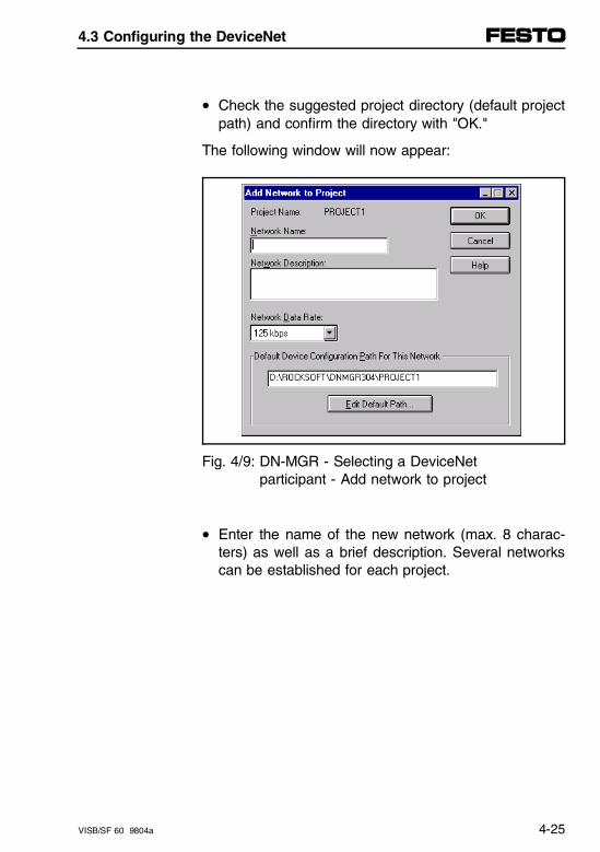
• Check the suggested project directory (default projectpath) and confirm the directory with "OK."
The following window will now appear:
Fig. 4/9: DN-MGR - Selecting a DeviceNet participant - Add network to project
• Enter the name of the new network (max. 8 charac-ters) as well as a brief description. Several networkscan be established for each project.
4.3 Configuring the DeviceNet
VISB/SF 60 9804a 4-25
The baud rate set under "Network data rate" will alwaysbe shown later in other windows. This indicates thebaud rate for which the current project has been de-signed.
The baud rate of the scanner and other DeviceNetslaves may have to be modified in online mode and viathe option "Node commissioning" (see chapter 4.3.3"Going on-line with your SF 60").
• Enter the desired baud rate and confirm with "OK."
The planning window will then appear.
4.3 Configuring the DeviceNet
4-26 VISB/SF 60 9804a
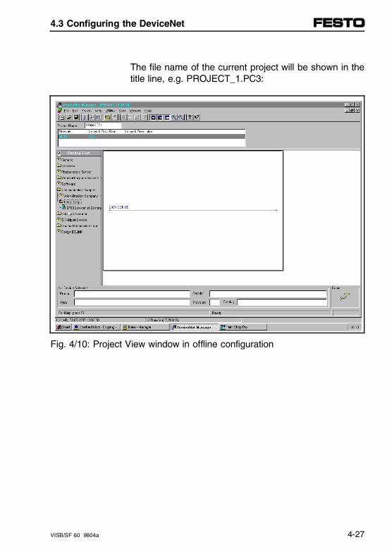
The file name of the current project will be shown in thetitle line, e.g. PROJECT_1.PC3:
Fig. 4/10: Project View window in offline configuration
4.3 Configuring the DeviceNet
VISB/SF 60 9804a 4-27
• Double click "Communication adapter" in the slavelist (Device list) and then double click "Festo Corpor-ation" in order to open the selection list of the avail-able Festo DeviceNet Scanners.
• Click the entry "SF 60 scanner 1747 - SDN Type"and move the symbol to the right into the project win-dow.
Information on the selected device will be requested Ina further window. When you enter and confirm this in-formation, the selected scanner will be connected to theDeviceNet.
Notes on DeviceNetManager version 3.004
This version also loads the image of an SLC 500 if youhave correctly installed file SF60.bmp. However, as theEDS file (SF60.EDS) has been installed correctly, youcan work further despite the incorrect bitmap repre-sentation.
According to Allen-Bradley this error will be rectified inthe next version of the DeviceNetManager.
4.3 Configuring the DeviceNet
4-28 VISB/SF 60 9804a
4.3.3 Going online with your SF 60
Requirements for online mode:
– The network including SF 60 and all DeviceNetslaves must be installed correctly and supplied withvoltage.
– The communication interface (e.g. 1770-KFD or1784-PCD) must be installed correctly and be readyfor operation.
Chapter 2.3
Further instructions can be found in the manual for theDeviceNetManager
Activate the online mode as follows:
• Select the option "Setup online connection..." in the "Utilities" menu or
• Click the button
4.3 Configuring the DeviceNet
VISB/SF 60 9804a 4-29
• Follow the instructions in the following menus:
The set baud rate of the DN-MGR must agree with thecurrent baud rate of the DN slave (e.g. SF 60 scanner).
Standard baud rate of the SF 60: 125 kbit/s
When the SF 60 is switched on, the SF 60 Scanner willshow the DeviceNet baud rate and the DeviceNet nodeaddress on the seven-segment display (see also chap-ter 4.6.1).
• Set the baud rate of the DN-MGR at first to thestandard baud rate of the DN slave.
If the desired connection can be established, an appro-priate symbol will be shown at the lower edge of yourscreen.
4.3 Configuring the DeviceNet
4-30 VISB/SF 60 9804a
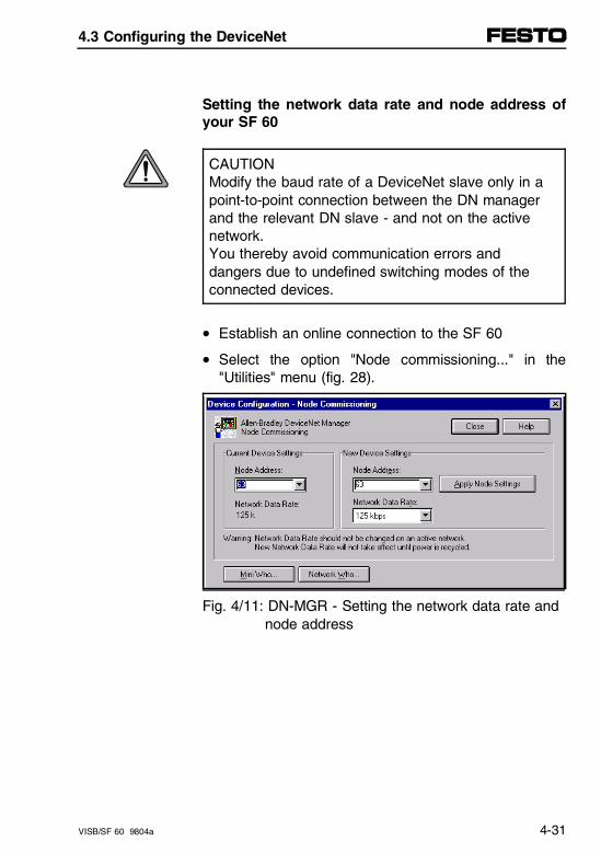
Setting the network data rate and node address ofyour SF 60
CAUTIONModify the baud rate of a DeviceNet slave only in apoint-to-point connection between the DN managerand the relevant DN slave - and not on the activenetwork. You thereby avoid communication errors anddangers due to undefined switching modes of theconnected devices.
• Establish an online connection to the SF 60
• Select the option "Node commissioning..." in the"Utilities" menu (fig. 28).
Fig. 4/11: DN-MGR - Setting the network data rate and node address
4.3 Configuring the DeviceNet
VISB/SF 60 9804a 4-31
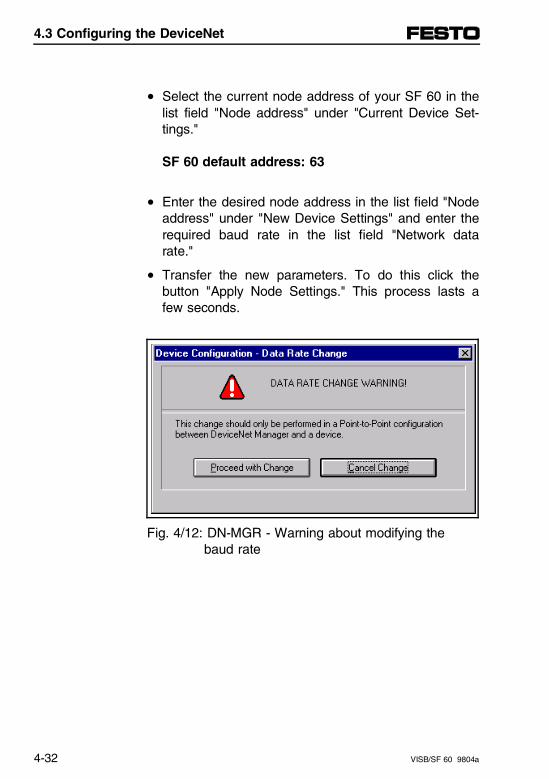
• Select the current node address of your SF 60 in thelist field "Node address" under "Current Device Set-tings."
SF 60 default address: 63
• Enter the desired node address in the list field "Nodeaddress" under "New Device Settings" and enter therequired baud rate in the list field "Network datarate."
• Transfer the new parameters. To do this click thebutton "Apply Node Settings." This process lasts afew seconds.
Fig. 4/12: DN-MGR - Warning about modifying the baud rate
4.3 Configuring the DeviceNet
4-32 VISB/SF 60 9804a
– A modified baud rate will not become effective untilyour SF 60 is switched on again (Power-Up).
– In order that the DeviceNet can be commissionedfaultlessly and without any problems, the same baudrate must be set for all slaves.
– The network baud rate should not be changed on anactive network.
Concluding steps
• In order to transfer the new settings, switch theSF 60 off and then on again.
• Reset the baud rate of the DN-MGR to the originalvalue.
4.3 Configuring the DeviceNet
VISB/SF 60 9804a 4-33
4.3.4 Configuring the DeviceNet Scanner and the network
You can configure the DeviceNet Scanner either in on-line or offline mode.
Online configuration
A new SF 60 scanner configuration cannot be loaded inRUN mode of the processor. For this purpose you mustswitch to PROGRAM mode with the programming soft-ware or with the HHT.
1. Load the settings:- from a previously saved file,- from a previously saved file referenced in a
project,- from the non-volatile memory of the SF 60
scanner module (SDN), or
Onlineconfiguration
Create an online connection between the com-plete and correctly connected DeviceNet and the SF 60. Then select the option "Start Online Build" in the "Utilities" menu.
2. Save the modifications/settings in the SF 60.
3. (Optional) Save the settings in a file. This file can be available "stand alone" or associated with a project.
4.3 Configuring the DeviceNet
4-34 VISB/SF 60 9804a
1. Create a (new) project.Offlineconfiguration
2. Enter all device data and configuration settings.
3. Save the entries made in the individual editors inyour project. (The settings are saved with the fileextensions .sm4, .sl4, .lr4 or .mr4 depending on theconfiguration screen. These extensions are requiredfor the appropriate assignment of the files).
The offline configuration is explained below using anexample.
4.3 Configuring the DeviceNet
VISB/SF 60 9804a 4-35
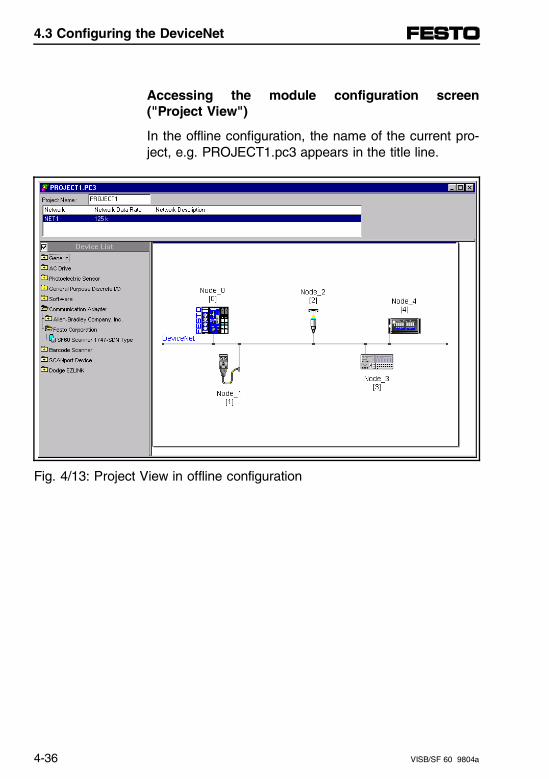
Accessing the module configuration screen("Project View")
In the offline configuration, the name of the current pro-ject, e.g. PROJECT1.pc3 appears in the title line.
Fig. 4/13: Project View in offline configuration
4.3 Configuring the DeviceNet
4-36 VISB/SF 60 9804a
When there are several scanners in the screen, the de-vices each have a color to match the relevant scanner.A device highlighted in red belongs to the scan list inthe scanner highlighted in red.You will also see from the number, which appears in theupper right-hand corner of a device, the scanner (or thenode address) to which the device belongs.
The colors are arbitrary and indicate nothing more thanthe scanner/device relationship.If you place the mouse cursor on the relevant device, ayellow box will appear with the relevant product infor-mation.
To access the "Module Configuration" from this projectview, double-click on the scanner icon (in online con-figuration also from "Network Who").
4.3 Configuring the DeviceNet
VISB/SF 60 9804a 4-37
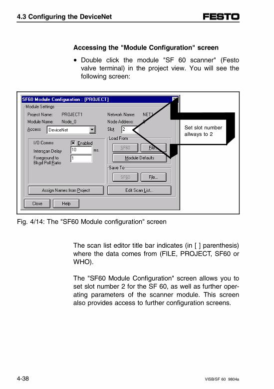
Accessing the "Module Configuration" screen
• Double click the module "SF 60 scanner" (Festovalve terminal) in the project view. You will see thefollowing screen:
Set slot number
allways to 2
Fig. 4/14: The "SF60 Module configuration" screen
The scan list editor title bar indicates (in [ ] parenthesis)where the data comes from (FILE, PROJECT, SF60 orWHO).
The "SF60 Module Configuration" screen allows you toset slot number 2 for the SF 60, as well as further oper-ating parameters of the scanner module. This screenalso provides access to further configuration screens.
4.3 Configuring the DeviceNet
4-38 VISB/SF 60 9804a
Setting the operational parameters of the SF 60
1. Click on the "I/O Comms" check box to enable theI/O communications. This indicates to the scannerwhether you want it to exchange I/O data. If thescanner is enabled, it is able to actively transmit andreceive data to and from network.
PLEASE NOTEYour scanner cannot transmit or receive anything onthe network if this box is not marked with a check-mark.
2. Enter the time the scanner waits between scans inthe "Interscan Delay" edit box. The delay can be se-lected from 2 to 9000 milliseconds. The presetting is10 milliseconds.
3. Enter the ratio of foreground to background pollswith which the slave can be scanned (between 1and 65535) in the "Foreground to Bkgd Poll Ratio"edit box.
4.3 Configuring the DeviceNet
VISB/SF 60 9804a 4-39
Devices can be polled at fixed intervals (background),e.g. every 5 cycles, instead of every scan (foreground).This interval is defined as the ratio between "Fore-ground and background scans." Whether a device is polled every scan or at a back-ground rate is determined in the "Edit Device I/O pa-rameters" screen discussed in chapter 4.3.5, section"Configuring a Device in the Scan List."
Chapter 4.3.5
All DN slaves which you later configure in that screenat "background poll rate" will be accessed with the de-fined ratio between foreground and background scans.
For example, if the value of 5 is set, the scanner willpoll the selected device(s) once every six scans. De-fault: 1 (= poll every scan cycle).
4.3 Configuring the DeviceNet
4-40 VISB/SF 60 9804a
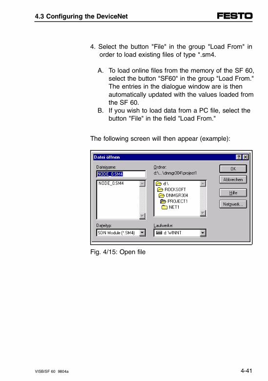
4. Select the button "File" in the group "Load From" inorder to load existing files of type *.sm4.
A. To load online files from the memory of the SF 60,select the button "SF60" in the group "Load From." The entries in the dialogue window are is then automatically updated with the values loaded from the SF 60.
B. If you wish to load data from a PC file, select thebutton "File" in the field "Load From."
The following screen will then appear (example):
Fig. 4/15: Open file
4.3 Configuring the DeviceNet
VISB/SF 60 9804a 4-41
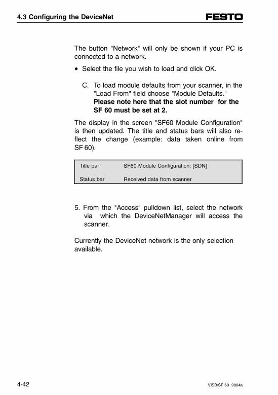
The button "Network" will only be shown if your PC isconnected to a network.
• Select the file you wish to load and click OK.
C. To load module defaults from your scanner, in the"Load From" field choose "Module Defaults." Please note here that the slot number for the SF 60 must be set at 2.
The display in the screen "SF60 Module Configuration"is then updated. The title and status bars will also re-flect the change (example: data taken online fromSF 60).
Title bar SF60 Module Configuration: [SDN]
Status bar Received data from scanner
5. From the "Access" pulldown list, select the networkvia which the DeviceNetManager will access thescanner.
Currently the DeviceNet network is the only selectionavailable.
4.3 Configuring the DeviceNet
4-42 VISB/SF 60 9804a
6. Enter your scanner’s slot characteristics in the "Slot"edit box.
The slot number for the SF 60 is always 2.
7. Save your data. Select one of the following in thefield "Save to":
• "SF60," if you wish to save the data in the SF 60scanner.1)
• "File," if you wish to save the data in a PC file.
8. Assigning names from the project
You can assign the names of the current project, module and network to the configuration file.
• If you wish to assign these names, click "AssignNames from Project."
The new names will be shown immediately in thescreen "SF60 Module Configuration."
You can only assign names from a project when youaccess the "Module Configuration" screen through the"Project View" screen (not the "Network Who" screen).
1) This induces a flash-memory update if the scanner is
in idle mode.
4.3 Configuring the DeviceNet
VISB/SF 60 9804a 4-43
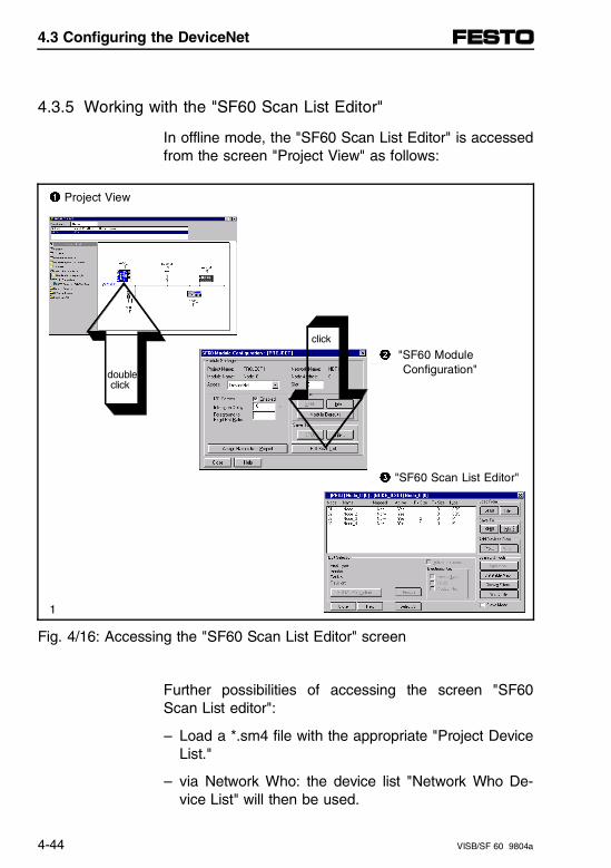
4.3.5 Working with the "SF60 Scan List Editor"
In offline mode, the "SF60 Scan List Editor" is accessedfrom the screen "Project View" as follows:
1 Project View
click
2 "SF60 Module
double Configuration"
click
3 "SF60 Scan List Editor"
1
Fig. 4/16: Accessing the "SF60 Scan List Editor" screen
Further possibilities of accessing the screen "SF60Scan List editor":
– Load a *.sm4 file with the appropriate "Project DeviceList."
– via Network Who: the device list "Network Who De-vice List" will then be used.
4.3 Configuring the DeviceNet
4-44 VISB/SF 60 9804a
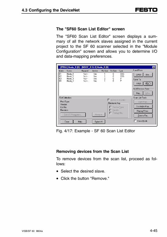
The "SF60 Scan List Editor" screen
The "SF60 Scan List Editor" screen displays a sum-mary of all the network slaves assigned in the currentproject to the SF 60 scanner selected in the "ModuleConfiguration" screen and allows you to determine I/Oand data-mapping preferences.
Fig. 4/17: Example - SF 60 Scan List Editor
Removing devices from the Scan List
To remove devices from the scan list, proceed as fol-lows:
• Select the desired slave.
• Click the button "Remove."
4.3 Configuring the DeviceNet
VISB/SF 60 9804a 4-45

The "SF60 Scan List Editor" screen supports a multiple-selection method, even if the slaves are not consecu-tive in the list. The selected slaves can then be proc-essed simultaneously.
• Select slaves 1 and 2, then skip to nodes 5 and 10.(The selected slaves need not be consecutive.)When you have selected all the desired slaves, pro-ceed as follows:
Example:
• Select the desired function.
Activate the check box "Slave Mode" at the lower rightof your screen, if you wish to enable the SF 60 scannerto be placed in another scanner’s scan list as a slavedevice (multi-master mode or dual mode).
4.3 Configuring the DeviceNet
4-46 VISB/SF 60 9804a
Viewing device information in the Scan List
Further information can be found in your DeviceNet-Manager Software online help.
File commands can be used online and offline. How-ever, if you are offline, you must save or load your con-figuration settings from a file or save them in a file.Loading and saving in the SF 60 is only possible online.
1. Select the file type to be loaded (*.sl4 extension):A. To load data from your scanner’s non-volatile
memory, in the "Load From" field, choose "SF60." The screen is then automatically updated with the
values received from the SF 60.B. If you wish to load data from a PC file, in the
"Load From" field, choose "File."
The following screen will appear (example):
4.3 Configuring the DeviceNet
VISB/SF 60 9804a 4-47
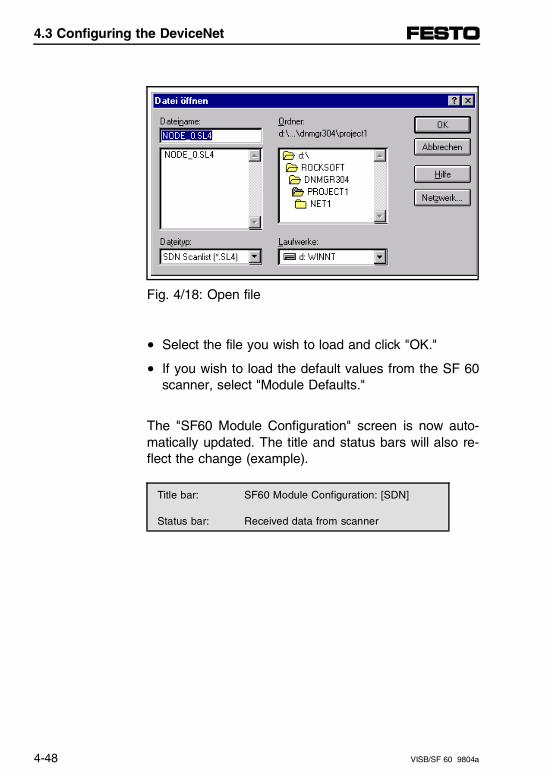
Fig. 4/18: Open file
• Select the file you wish to load and click "OK."
• If you wish to load the default values from the SF 60scanner, select "Module Defaults."
The "SF60 Module Configuration" screen is now auto-matically updated. The title and status bars will also re-flect the change (example).
Title bar: SF60 Module Configuration: [SDN]
Status bar: Received data from scanner
4.3 Configuring the DeviceNet
4-48 VISB/SF 60 9804a
2. Select the file you wish to load and choose OK.
3. Activate the "Active in Scanlist" check box to includethe device in the scan cycle.
4. Click on the appropriate check boxes in the "Elec-tronic Key" group that you wish to facilitate device-record keying. The SF 60 scanner will then comparethis device information during operation.
This device information is in a list of criteria that youcan customize to fit your application’s specificneeds. The information marked with an "X" isdefined as active parameters. The information ishierarchical in descending order. For example, youcannot select the information "Vendor" if you havealready activated the information "Device Type."
5. If only certain slaves are to be shown in the "SF60Scan List Editor" screen, you should select "DisplayFilters."
4.3 Configuring the DeviceNet
VISB/SF 60 9804a 4-49
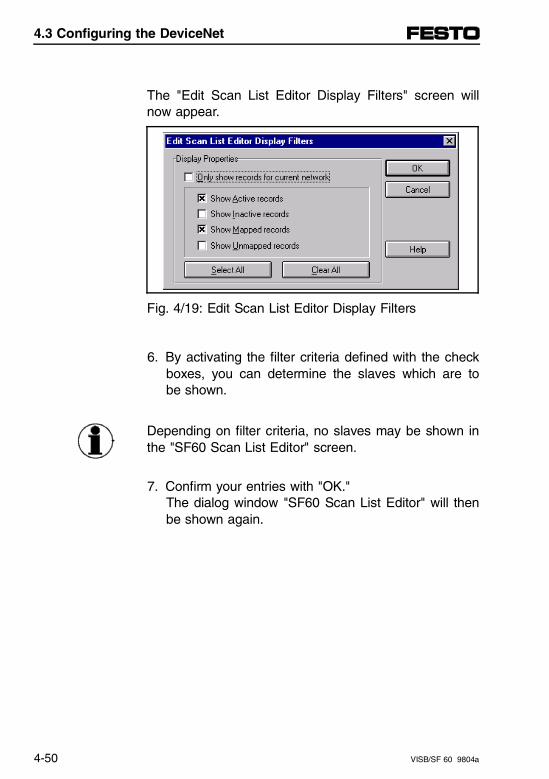
The "Edit Scan List Editor Display Filters" screen willnow appear.
Fig. 4/19: Edit Scan List Editor Display Filters
6. By activating the filter criteria defined with the checkboxes, you can determine the slaves which are tobe shown.
Depending on filter criteria, no slaves may be shown inthe "SF60 Scan List Editor" screen.
7. Confirm your entries with "OK."The dialog window "SF60 Scan List Editor" will thenbe shown again.
4.3 Configuring the DeviceNet
4-50 VISB/SF 60 9804a
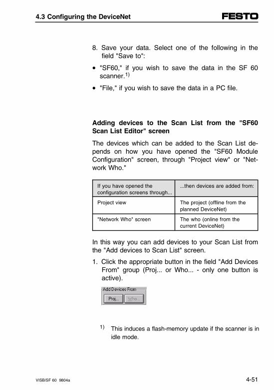
8. Save your data. Select one of the following in thefield "Save to":
• "SF60," if you wish to save the data in the SF 60scanner.1)
• "File," if you wish to save the data in a PC file.
Adding devices to the Scan List from the "SF60Scan List Editor" screen
The devices which can be added to the Scan List de-pends on how you have opened the "SF60 ModuleConfiguration" screen, through "Project view" or "Net-work Who."
If you have opened theconfiguration screens through...
...then devices are added from:
Project view The project (offline from theplanned DeviceNet)
"Network Who" screen The who (online from thecurrent DeviceNet)
In this way you can add devices to your Scan List fromthe "Add devices to Scan List" screen.
1. Click the appropriate button in the field "Add DevicesFrom" group (Proj... or Who... - only one button isactive).
1) This induces a flash-memory update if the scanner is inidle mode.
4.3 Configuring the DeviceNet
VISB/SF 60 9804a 4-51
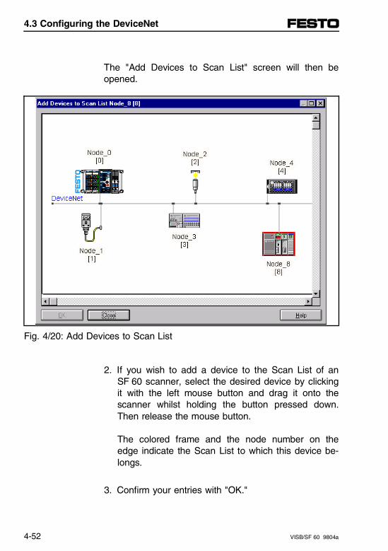
The "Add Devices to Scan List" screen will then beopened.
Fig. 4/20: Add Devices to Scan List
2. If you wish to add a device to the Scan List of anSF 60 scanner, select the desired device by clickingit with the left mouse button and drag it onto thescanner whilst holding the button pressed down.Then release the mouse button.
The colored frame and the node number on theedge indicate the Scan List to which this device be-longs.
3. Confirm your entries with "OK."
4.3 Configuring the DeviceNet
4-52 VISB/SF 60 9804a
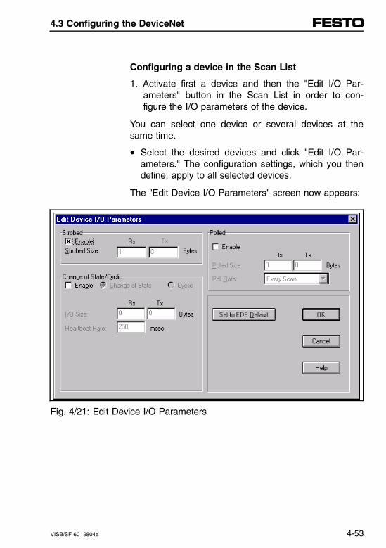
Configuring a device in the Scan List
1. Activate first a device and then the "Edit I/O Par-ameters" button in the Scan List in order to con-figure the I/O parameters of the device.
You can select one device or several devices at thesame time.
• Select the desired devices and click "Edit I/O Par-ameters." The configuration settings, which you thendefine, apply to all selected devices.
The "Edit Device I/O Parameters" screen now appears:
Fig. 4/21: Edit Device I/O Parameters
4.3 Configuring the DeviceNet
VISB/SF 60 9804a 4-53
2. Click on the "Enabled" check box in the appropriatefield, depending on the transmission process of yourdevice ("strobed," "polled," "change-of-state" or "cy-clic").
If you select "Change of state/Cyclic," one of the optionfields "Change of State" or "Cyclic" must be activated,depending upon your device.
For this communication type Define the followinginformation
Strobed(parallel access of all devices)
Strobed size
Polled(access one device point-to-point)
Polled sizes and profil rate
Change-of-state(only with change of state)
I/O size and heartbeat
Cyclic(time cyclic)
I/O size and send rate
Select "Set to EDS default" in order to load the defaultvalues from the EDS file.
PLEASE NOTEThis option is only available to the SF 60 if the EDSfiles have been installed correctly.
4.3 Configuring the DeviceNet
4-54 VISB/SF 60 9804a
3. Click "OK."
You return to the "SF60 Scan List Editor" screen.
4. Save your data. Select one of the following in thefield "Save to":
• "SF60," if you wish to save the data in the SF 60scanner.1)
• "File," if you wish to save the data in a PC file.
1) This induces a flash-memory update if the scanner is in idle mode. The new DeviceNet configuration is then
loaded into the scanner. If the processor is then switched to the RUN mode, the new DeviceNet confi-guration then becomes active.
4.3 Configuring the DeviceNet
VISB/SF 60 9804a 4-55
Using the Slave Mode function
1. Double click on the SF 60 scanner you wish to actin slave mode.
2. Select "Edit Scan List."
3. Click on the check box "Slave Mode." The SF 60scanner will then be entered in the device list.
4. Mark the SF 60 scanner in the device list and select"Edit I/O Parameters."
Please note that you are now editing the SF 60 as aslave device.The SF60 as slave supports all four types of communi-cation (strobed, polled, change-of-state and cyclic).
The next steps are identical to those configuration stepsfor all other slaves in the scan list, therefore refer to theprevious section "Configuring a Device in the ScanList."
The following entries must be made for an SF 60 asslave (examlple for polled):
– Activate polled
– Polled size. Enter here the number of input/outputbytes which you require for communication with theSF 60 (Rx = input bytes, Tx = output bytes).Please note that I/Os in the SF 60 as slave cannotbe processed directly by the master, as the data ofthe master must be copied from Slot 2 to the localaddress range of Slot 1 by the slave processor.
– Polled rate: Every scan
The SF 60 as slave can then be assigned to anotherDeviceNet master.
4.3 Configuring the DeviceNet
4-56 VISB/SF 60 9804a
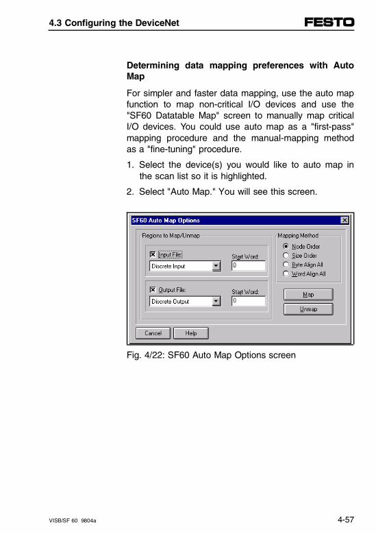
Determining data mapping preferences with AutoMap
For simpler and faster data mapping, use the auto mapfunction to map non-critical I/O devices and use the"SF60 Datatable Map" screen to manually map criticalI/O devices. You could use auto map as a "first-pass"mapping procedure and the manual-mapping methodas a "fine-tuning" procedure.
1. Select the device(s) you would like to auto map inthe scan list so it is highlighted.
2. Select "Auto Map." You will see this screen.
Fig. 4/22: SF60 Auto Map Options screen
4.3 Configuring the DeviceNet
VISB/SF 60 9804a 4-57
If you have a device that has already been mapped,you have the option to reverse the process. Unmapdoes not delete the selected device from the scan list,but only removes any data mapping for the selecteddevice.
3. Click on the "Input File" and/or "Output File" checkbox, depending on your device.
File type Designates
Input File (inputs) Locations of the processor towhich the selected device’sdata is mapped
Output File (outputs) Locations of the processorwhere the output data of theselected device resides
4. From the appropriate pulldown list, depending uponwhat you selected in the above step, select the ap-propriate area to which you wish to map the se-lected device’s input and/or output data.
4.3 Configuring the DeviceNet
4-58 VISB/SF 60 9804a
5. Enter the word at which the data begins in the "StartWord" edit box.
Word 0 is reserved for processor/scanner specific com-munication. The software will automatically allocate thisword as a part of its mapping routine.
6. Click on the radio button next to the desired map-ping method.
This mapping method Maps
Node order Your devices according to their node address (lowest tohighest address)
Size order Your devices according to thesize of their I/O data (largest tosmallest)
Byte Align All All data on byte boundaries in incrementing node addressorder
Word Align All All data on word boundaries inincrementing node addressorder
7. To map the selected device’s data, select "Map."
You then return to the "SF60 Scan List Editor" screen.
4.3 Configuring the DeviceNet
VISB/SF 60 9804a 4-59
4.3.6 About the Datatable Map
The "Datatable Map" screen facilitates customized datamapping. You can specify exact memory locations anddata sizes (in bits) for your I/O data communication. Inaddition, it provides a useful browsing tool for scan listDatatable Map viewing.
Three types of symbols are displayed in the DatatableMap:
This symbol Meaning
R Reserved locations such as the modulestatus word
X Duplicate mapping condition. This will occur ifyou map more than one bit to the same bitlocation, mapping one on top of the other.
- Unmapped bit
4.3 Configuring the DeviceNet
4-60 VISB/SF 60 9804a
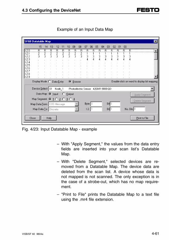
Example of an Input Data Map
Fig. 4/23: Input Datatable Map - example
– With "Apply Segment," the values from the data entryfields are inserted into your scan list’s DatatableMap.
– With "Delete Segment," selected devices are re-moved from a Datatable Map. The device data aredeleted from the scan list. A device whose data isnot mapped is not scanned. The only exception is inthe case of a strobe-out, which has no map require-ment.
– "Print to File" prints the Datatable Map to a text fileusing the .mr4 file extension.
4.3 Configuring the DeviceNet
VISB/SF 60 9804a 4-61
Using the Datatable Map for custom editing
You can select specific bits of input data and map themto specific scanner memory locations by following thesedirections.
1. To edit the Datatable Map, click on the radio buttonnext to "Data Entry."
You now enter the "SF60 Datatable Map" screen underbrowse mode by default.
2. Select a device to edit from the "Device Select" pull-down list.
The device which appears in the "Device Select" fieldwill be edited.
3. Click on the appropriate radio button in the "DataMap" field, to specify whether you are mapping inputor output data.
4. Click on the appropriate radio button in the "MapSegment" field.
You can map input data using up to four map seg-ments.
4.3 Configuring the DeviceNet
4-62 VISB/SF 60 9804a
5. Click on the desired input data’s location in the "MapData To" pulldown list.
This indicates to the scanner which type of messagewill arrive – strobe, poll, change-of-state, or cyclic.This entry must match the type of communicationyou selected when defining the device’s communica-tion characteristics in the "Edit I/O Parameters"screen.
6. Determine the position of the input data by indicatingin the "Byte" and "Bit" edit boxes, where the map-ping of the input bits is to start in the DeviceNetmessage.
You must indicate the exact byte and bit location.
7. Indicate the desired location in your scanner’s mem-ory where you want to store the input data, by click-ing this position in the "Map Data From" pulldownlist.
8. Enter the input data’s mapping location by indicatingthe word and bit at which the data begins in yourscanner’s memory in the "N*" and "Bit" edit boxes.
4.3 Configuring the DeviceNet
VISB/SF 60 9804a 4-63
9. Enter the size of the input data which you are map-ping to the memory location in the "Map Data To"field in the "No. Bits" edit box.
The input value must be equal to or less than thestrobe, poll, change-of-state, or cyclic receive value en-tered in the "Edit I/O Parameters" screen when thecommunication characteristics were defined.
Each scanned device can have as many as 255 bytesof input data; however, you can map only as many as128 bytes per map segment. You must use more thanone map segment for a device with more than 128bytes of input data.
4.3 Configuring the DeviceNet
4-64 VISB/SF 60 9804a
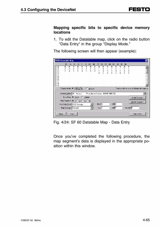
Mapping specific bits to specific device memorylocations
1. To edit the Datatable map, click on the radio button"Data Entry" in the group "Display Mode."
The following screen will then appear (example):
Fig. 4/24: SF 60 Datatable Map - Data Entry
Once you’ve completed the following procedure, themap segment’s data is displayed in the appropriate po-sition within this window.
4.3 Configuring the DeviceNet
VISB/SF 60 9804a 4-65

2. Select a device to edit in the "Device Select" pull-down list.
The device which appears in the "Device Select" fieldwill be edited.
3. Click on the radio button "Output" in the "Data Map"group.
The output data map appears in the map tool’s displaywindow.
4. Click on the appropriate radio button in the "MapSegment" field.
Each scanned device can have as many as 255 bytesof output data; however, you can map only as many as128 bytes per map segment.
Therefore, you must use more than one map segmentfor a device with more than 128 bytes of output data.
5. Click on the desired type of message for the outputdata in the pulldown list.
4.3 Configuring the DeviceNet
4-66 VISB/SF 60 9804a
You must determine the type of message with whichthe output data is to be sent to your device.
6. Determine the position of the output data by indicat-ing in the "Byte" and "Bit" edit boxes, where themapping of the outut bits is to begin in the De-viceNet message.
You must indicate the exact byte and bit location.
7. Select the desired location in your scanner’s mem-ory from where the output data are to be retrieved,by clicking this position in the "Map Data From" pull-down list.
You can choose a discrete or block transfer location.
If you are mapping from a discrete Datatable, do notexceed the discrete I/O capability of your scanner’s ad-dress density (slot-addressing mode). You can thenavoid error messages and incorrectly assigned data.
8. Enter the output data’s mapping location by indicat-ing the word and bit at which the data begins in yourscanner’s memory in the "N*" and "Bit" edit boxes.
The radix for discrete I/O is octal while the radix forblock transfers is decimal.
4.3 Configuring the DeviceNet
VISB/SF 60 9804a 4-67
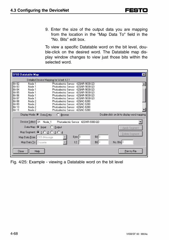
9. Enter the size of the output data you are mappingfrom the location in the "Map Data To" field in the"No. Bits" edit box.
To view a specific Datatable word on the bit level, dou-ble-click on the desired word. The Datatable map dis-play window changes to view just those bits within theselected word.
Fig. 4/25: Example - viewing a Datatable word on the bit level
4.3 Configuring the DeviceNet
4-68 VISB/SF 60 9804a
4.3.7 Saving configuration and downloading into the SF 60 scanner
File names
When you save "SF60 Module Configuration" or "SF60Scan List Editor" information to a file, each is given aspecific extension.
– MCC data is stored in .sm4 files
– Scan list data is stored in .sl4 files
– Scan list reports are stored in .lr4 files
– Scan list map reports are stored in .mr4 files
– Custom launch data is stored in .clc files
When you access the scanner configuration screensfrom Project View, the scanner files will be stored at theproject level.
When you access the scanner configuration screensfrom Network Who, you can select where to store thescanner files. This is because there is no project dataattached to Network Who.
4.3 Configuring the DeviceNet
VISB/SF 60 9804a 4-69
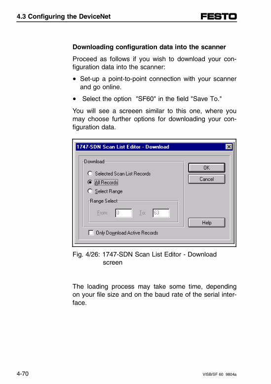
Downloading configuration data into the scanner
Proceed as follows if you wish to download your con-figuration data into the scanner:
• Set-up a point-to-point connection with your scannerand go online.
• Select the option "SF60" in the field "Save To."
You will see a screeen similar to this one, where youmay choose further options for downloading your con-figuration data.
Fig. 4/26: 1747-SDN Scan List Editor - Download screen
The loading process may take some time, dependingon your file size and on the baud rate of the serial inter-face.
4.3 Configuring the DeviceNet
4-70 VISB/SF 60 9804a
What’s next?
If you need further information, continue on to the scanlist file examples in chapter 4.5.
• Example of a Scan List for an SF 60 as DN master
• Example of a Scan List for an SF 60 as active DNslave
If you encounter error messages
If you encounter error messages while building yourscanlist file, refer to the User Manual of yourDeviceNetManager Software or to the online help.
4.3 Configuring the DeviceNet
VISB/SF 60 9804a 4-71

4.3 Configuring the DeviceNet
4-72 VISB/SF 60 9804a
4.4 Communication and Programming
4.4.1 Communication overview
In a typical configuration, the scanner acts as an inter-face between DeviceNet devices and the processor.The scanner communicates with DeviceNet devices us-ing the DeviceNet protocol to:
– read inputs from a device,
– write outputs to a device,
– download configuration data,
– monitor a device’s operational status.
SF 60 scanner communication with the processor is inthe form of M1/M0 file transfers and/or discrete I/O.Information exchanged includes:
– device I/O data
– status information
– configuration data
4.4 Communication and Programming
VISB/SF 60 9804a 4-73
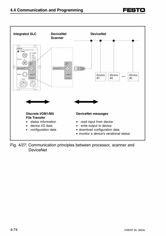
Integrated SLC DeviceNet DeviceNet Scanner
Discrete I/OM1/M0 DeviceNet messagesFile Transfer• status information • read input from device• device I/O data • write output to device• configuration data • download configuration data
• monitor a device’s oerational status
Fig. 4/27: Communication principles between processor, scanner and DeviceNet
4.4 Communication and Programming
4-74 VISB/SF 60 9804a
4.4.2 Communicating with DeviceNet devices
Your scanner communicates with scanned devices viastrobe or poll messages. It uses these messages to so-licit data from or deliver data to each scanned device.Data received from the scanned devices (input data), isorganized by the scanner and made available to yourprocessor. Data received from your processor (outputdata), is organized in the scanner and sent on to yourdevices.
All data sent and received on a DeviceNet network is inbyte lengths. A device may, for example, produce only2 bits of input information. Since the minimum data sizeon a DeviceNet network is one byte, the two bits ofinformation are included in the data byte produced bythe device. In this case (only 2 bits of input informa-tion), the upper six bits are insignificant.
4.4 Communication and Programming
VISB/SF 60 9804a 4-75
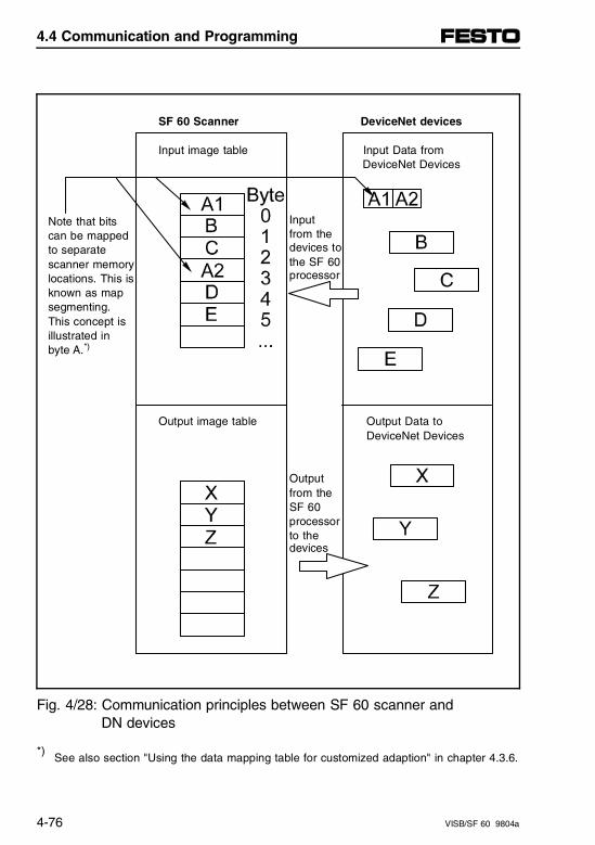
SF 60 Scanner DeviceNet devices
Input image table Input Data from DeviceNet Devices
Note that bits Inputcan be mapped from theto separate devices to
scanner memory the SF 60
locations. This is processor
known as map segmenting. This concept is illustrated in byte A.*)
Output image table Output Data to DeviceNet Devices
Outputfrom theSF 60processorto thedevices
Fig. 4/28: Communication principles between SF 60 scanner and DN devices
*) See also section "Using the data mapping table for customized adaption" in chapter 4.3.6.
4.4 Communication and Programming
4-76 VISB/SF 60 9804a
4.4.3 Communicating with your SF 60 processor
Your processor communicates with the SF 60scanner inone of three transfer forms:
– via M1 file transfer reads,
– M0 file transfer writes and
– DIO transfers (discrete I/O transfers).
Discrete I/O read or write is used for:
– fast read and write of device data
– writing the command register to control the basicfunctions of the scanner
– reading the status register to access basic informa-tion of the scanner’s operation mode
M0/M1 files are used to:
– transfer large quantities of data
– set or obtain detailed scanner control information
4.4 Communication and Programming
VISB/SF 60 9804a 4-77
Input data, gathered from the network’s devices, is or-ganized within the scanner and made available for theprocessor to "read."
The scanner does not send data to your processor.Data transfer between your scanner and the SLC 500processor must be initiated by the processor.
Output data is sent, or "written," to the scanner by yourprocessor. This data is organized into the scannerwhich in turn passes the data on to your scanned de-vices via strobe or poll messages.
Understanding the data organization of the scanner
The scanner has four data areas which can be used totransfer data, status and command information betweenthe scanner and the processor:
– SF 60 input image table
– SF 60 output image table
– SF 60 M1 file
– SF 60 M0 file
4.4 Communication and Programming
4-78 VISB/SF 60 9804a
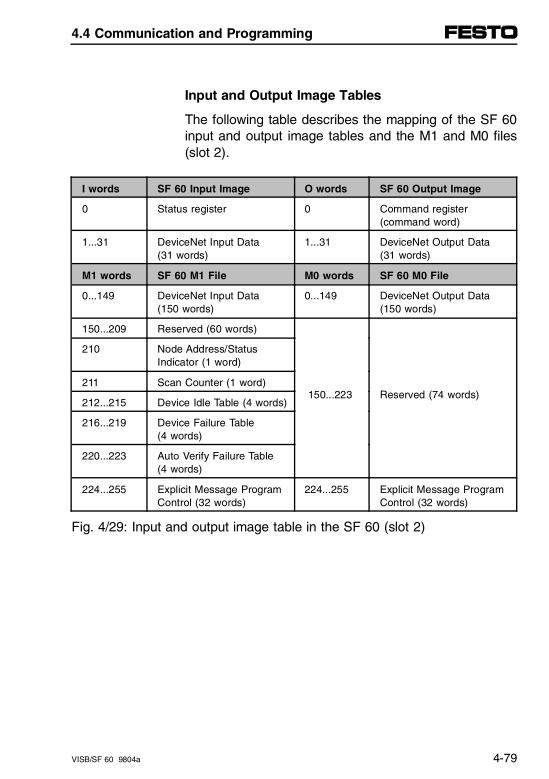
Input and Output Image Tables
The following table describes the mapping of the SF 60input and output image tables and the M1 and M0 files(slot 2).
I words SF 60 Input Image O words SF 60 Output Image
0 Status register 0 Command register(command word)
1...31 DeviceNet Input Data (31 words)
1...31 DeviceNet Output Data (31 words)
M1 words SF 60 M1 File M0 words SF 60 M0 File
0...149 DeviceNet Input Data(150 words)
0...149 DeviceNet Output Data(150 words)
150...209 Reserved (60 words)
150...223 Reserved (74 words)
210 Node Address/StatusIndicator (1 word)
211 Scan Counter (1 word)
212...215 Device Idle Table (4 words)
216...219 Device Failure Table (4 words)
220...223 Auto Verify Failure Table(4 words)
224...255 Explicit Message ProgramControl (32 words)
224...255 Explicit Message ProgramControl (32 words)
Fig. 4/29: Input and output image table in the SF 60 (slot 2)
4.4 Communication and Programming
VISB/SF 60 9804a 4-79

Addressing with SF 60 on the DeviceNet
The following possibilities are available on slot 2 of theSF 60 for addressing on the DeviceNet:
– I/O image tables for cyclic communication
– M0/M1 files for acyclic communication
The addressing differs between passive and activeslaves as follows:
Passive slaves, e.g. Festo valve terminals with FB11,are addressed by the master (direct addressing). If theequpment fitted onto a passive slave changes, the ad-dressing in the master must be adapted to reflect thischange.
Active slaves, e.g. Festo valve terminals type SF 60 inslave mode, have a built-in PLC and are addressedand controlled independently by the programs in thisPLC.
The master cannot gain direct access to the local I/Oson these slaves. Only indirect addressing/communica-tion is possible. In the active slave, a "Copy Program"must copy the data received by the master on slot 2(with the SF 60 e.g. in I:2.2) to the address range ofthe local outputs on slot 1 (with the SF 60 e.g. toO:1.2).
Advantage:If the equipment fitted onto an active slave changes,only the addressing in the slave needs to be adapted,the other addressing in the master is not affected.
The following diagrams illustrate typical allocations ofI/Os between master and slaves as well as their ad-dressing.
4.4 Communication and Programming
4-80 VISB/SF 60 9804a
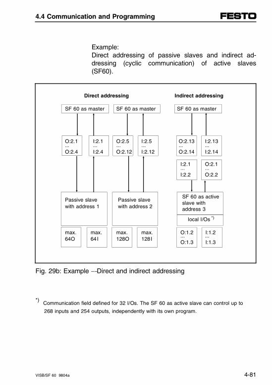
Example:Direct addressing of passive slaves and indirect ad-dressing (cyclic communication) of active slaves(SF60).
Direct addressing Indirect addressing
SF 60 as master SF 60 as master SF 60 as master
O:2.1 I:2.1 O:2.5 I:2.5 O:2.13 I:2.13... ... ... ... ... ...O:2.4 I:2.4 O:2.12 I:2.12 O:2.14 I:2.14
I:2.1 O:2.1 ... ... I:2.2 O:2.2
Passive slave Passive slave SF 60 as active
with address 1 with address 2 slave with
address 3
local I/Os *)
max. max. max. max. O:1.2 I:1.264O 64I 128O 128I
... ... O:1.3 I:1.3
Fig. 29b: Example - Direct and indirect addressing
*) Communication field defined for 32 I/Os. The SF 60 as active slave can control up to
268 inputs and 254 outputs, independently with its own program.
4.4 Communication and Programming
VISB/SF 60 9804a 4-81
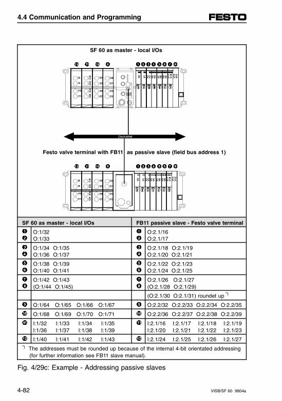
SF 60 as master - local I/Os
" ! 0 9 12 3 4 5 6 7 8
Festo valve terminal with FB11 as passive slave (field bus address 1)
" ! 0 9 12 3 4 5 6 7 8
SF 60 as master - local I/Os FB11 passive slave - Festo valve terminal
1 2
O:1/32O:1/33
1 2
O:2.1/16O:2.1/17
3 4
O:1/34 O:1/35 O:1/36 O:1/37
3 4
O:2.1/18 O:2.1/19O:2.1/20 O:2.1/21
5 6
O:1/38 O:1/39O:1/40 O:1/41
5 6
O:2.1/22 O:2.1/23O:2.1/24 O:2.1/25
7 8
O:1/42 O:1/43(O:1/44 O:1/45)
7 8
O:2.1/26 O:2.1/27(O:2.1/28 O:2.1/29)
(O:2.1/30 O:2.1/31) roundet up *)
9 O:1/64 O:1/65 O:1/66 O:1/67 9 O:2.2/32 O:2.2/33 O:2.2/34 O:2.2/35
0 O:1/68 O:1/69 O:1/70 O:1/71 0 O:2.2/36 O:2.2/37 O:2.2/38 O:2.2/39
! I:1/32 I:1/33 I:1/34 I:1/35I:1/36 I:1/37 I:1/38 I:1/39
! I:2.1/16 I:2.1/17 I:2.1/18 I:2.1/19I:2.1/20 I:2.1/21 I:2.1/22 I:2.1/23
" I:1/40 I:1/41 I:1/42 I:1/43 " I:2.1/24 I:2.1/25 I:2.1/26 I:2.1/27*) The addresses must be rounded up because of the internal 4-bit orientated addressing (for further information see FB11 slave manual).
Fig. 4/29c: Example - Addressing passive slaves
4.4 Communication and Programming
4-82 VISB/SF 60 9804a

4.4 Communication and Programming
VISB/SF 60 9804a 4-83
4.4.4 Uploading input data from the SF 60 scanner to the SF 60 processor
The SF 60 processor reads input data from the scannerusing two methods:
– via the input image table
– via M1 file transfer
Input image table
The input image table is a 32-word table for the scan-ner in slot 2 that is updated by the processor with eachprogram scan. The first word (word 0) is reserved forthe scanner status register. The remaining 31 wordscan be used to transfer DeviceNet input data to theSF 60 input image table. The addressing format is:
I:2.w/b
Where
2 = slot 2 (SF 60 scanner communicates only via slot 2)
w = element/word (0...31)
b = bit (0...15)
4.4 Communication and Programming
4-84 VISB/SF 60 9804a
Scanner status register
The scanner status register is located at word I:2.0.
Bits 0...5 echo back to the processor the current stateof bits 0...5 of the scanner command register. The ech-oes verify that the commands triggered by the com-mand register were executed.
The scanner sets the remaining bits when it detects aproblem. The bits latch in the ON state until the prob-lem clears.
Bits 6 and 8 indicate that you should read the devicefailure table for more specific information about whichdevices failed.
The SF 60 program can monitor the bits in the scannerstatus register and set the appropriate bits of the scan-ner command register to automatically control the oper-ating mode of the scanner should a device failure oc-cur.
Example:You can use bit 6 to keep the scanner port in the idlemode until the bit clears. When the bit clears, this indi-cates that all devices in the scanner’s scan list are upand available. When the devices are available, you canput the scanner in "Run" mode. If a device failure isdetected, you can put the communication into the idlemode, so that all DN slaves go to a safe state.
4.4 Communication and Programming
VISB/SF 60 9804a 4-85
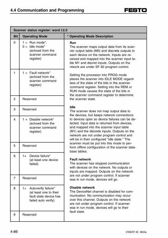
Scanner status register: word I:2.0
Bit Operating Mode * Operating Mode Description
0 1 = Run mode*, 0 = Idle mode*
(echoed from the scanner command register)
1 1 = Fault network* (echoed from the scanner command register)
2 Reserved
3 Reserved
4 1 = Disable network*(echoed from the scanner commandregister)
5 Reserved
6 1= Device failure* (at least one device failed)
7 Reserved
8 1= Autoverify failure* (at least one to theirfault state device hasfailed auto verify)
9 Reserved
Run The scanner maps output data from its scan-ner output table (M0) and discrete outputs toeach device on the network. Inputs are re-ceived and mapped into the scanner input ta-ble M1 and discret inputs. Outputs on thentwork are under SF 60 program control.
Setting the processor into PROG modeplaces the scanner into IDLE MODE regard-less of the state of the bits in the scannercommand register. Setting into the REM orRUN mode causes the state of the bits inthe scanner command register to determinethe scanner state.
IdleThe scanner does not map output data tothe devices, but keeps network connectionsto devices open so device failures can be de-tected. Input data is returned from devices,and mapped into the scanner input table(M1) and the discrete inputs. Outputs on thenetwork are not under program control andwill be in their configured "idle state." Thescanner must be put into this mode to per-form offline configuration of the scanner data-base tables.
Fault networkThe scanner has stopped communicationwith devices on the network. No outputs orinputs are mapped. Outputs on the networkare not under program control. If scannerwas in run mode, devices will go.
Disable networkThe DeviceNet channel is disabled for com-munication. No communication may occurover this channel. Outputs on the networkare not under program control. If scannerwas in run mode, devices will go to theirfault state.
4.4 Communication and Programming
4-86 VISB/SF 60 9804a
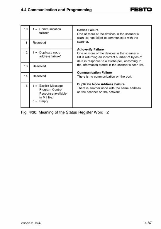
10 1 = Communication failure*
11 Reserved
12 1 = Duplicate node address failure*
13 Reserved
14 Reserved
15 1 = Explicit Message Program Control Response available in M1 file.
0 = Empty
Fig. 4/30: Meaning of the Status Register Word I:2
Device FailureOne or more of the devices in the scanner’sscan list has failed to communicate with thescanner.
Autoverify FailureOne or more of the devices in the scanner’slist is returning an incorrect number of bytes ofdata in response to a strobe/poll, according tothe information stored in the scanner’s scan list.
Communication FailureThere is no communication on the port.
Duplicate Node Address FailureThere is another node with the same addressas the scanner on the network.
4.4 Communication and Programming
VISB/SF 60 9804a 4-87
SF 60 M1 File
The SF 60 M1 file is a 256-word file that can be usedto transfer a large quantity of information to the scannerwith a single SF 60 instruction. Transferring data usingthis file takes more time than using the input image ta-ble.
The first 150 words are used for data transfer from thescanner. The remaining 106 words are reserved for:
– Node status
– Scan counter
– Device idle table
– Device failure table
– Auto verify table
– Explicit message program control
4.4 Communication and Programming
4-88 VISB/SF 60 9804a
Node address/Status indicator
Word 210 is used for node address and scanner diag-nostic information displayed in numeric codes. The de-scriptions of these codes are listed in Appendix B. Appendix B
Scan counter
Word 211 is used for the scanner scan counter. Thescanner increments this counter whenever a scan ofthe DeviceNet devices is completed. The counter rollsover when it reaches a maximum value of 65535. It islocated at M1:2.211.
4.4 Communication and Programming
VISB/SF 60 9804a 4-89
Device idle table
Words 212 through 215 in the M1 file are used for thedevice idle table. The scanner tracks devices in idlemode by assigning one of the 64 bits in the table toeach device on the network. The bits are assigned inconsecutive order to consecutive device addressesstarting at node 0 at M1.2.212/0.
Device failure table
Words 216 through 219 in the M1 file are used for thedevice failure table. The scanner tracks device failuresby assigning one of the 64 bits in the table to eachdevice on the network. The bits are assigned in con-secutive order to consecutive device addresses startingat node 0 at M1.2.216/0.
4.4 Communication and Programming
4-90 VISB/SF 60 9804a
Auto verify failure table
Words 220 through 223 in the M1 file are used for theauto verify failure table. The auto verify failure table isused to verify that data size received from the devicematches the setting in the scanner input data map. Thescanner tracks auto verify failures by assigning one ofthe 64 bits in the table to each device on the network.The bits are assigned in consecutive order to consecu-tive device addresses starting with node 0 atM1:2.220/0. If the bit is set, the corresponding nodehas failed to verify.
Explicit message program control
Words 224 through 255 are used for Explicit MessageProgram Control. Use this feature to configure deviceparameters on your DeviceNet network via the M0 andM1 files in the SF 60 processor that is controlling thesedevices. This feature is described in detail in the sec-tion "Explicit Message Program Control" later in thischapter.
4.4 Communication and Programming
VISB/SF 60 9804a 4-91

4.4 Communication and Programming
4-92 VISB/SF 60 9804a
4.4.5 Download output data to the scanner
The SF 60 processor writes output data to the scannerusing two methods:
– output image table
– M0 file transfer
Output image table
The output image table is a 32-word table for the scan-ner slot 2 that is updated from the processor with eachprogram scan. The first word (word 0) of this table isreserved for the scanner command register. The re-maining 31 words can be used to transfer data from theSF 60 output table to the DeviceNet nodes.
Scanner command register
The scanner command register is located at word 0 inthe output image area for the slot 2. To execute a com-mand, set the appropriate bits in the scanner commandword using SF 60 ladder instructions. The following ta-ble describes the functionality of the command registerbits.
4.4 Communication and Programming
VISB/SF 60 9804a 4-93
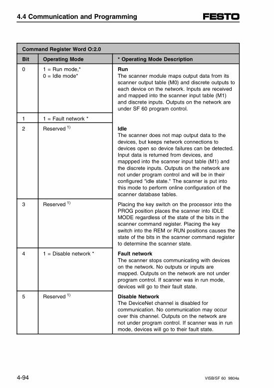
Command Register Word O:2.0
Bit Operating Mode * Operating Mode Description
0 1 = Run mode,*0 = Idle mode*
RunThe scanner module maps output data from itsscanner output table (M0) and discrete outputs to each device on the network. Inputs are receivedand mapped into the scanner input table (M1)and discrete inputs. Outputs on the network areunder SF 60 program control.
1 1 = Fault network *
2 Reserved 1) IdleThe scanner does not map output data to thedevices, but keeps network connections todevices open so device failures can be detected.Input data is returned from devices, andmappped into the scanner input table (M1) andthe discrete inputs. Outputs on the network arenot under program control and will be in theirconfigured "idle state." The scanner is put intothis mode to perform online configuration of thescanner database tables.
3 Reserved 1) Placing the key switch on the processor into thePROG position places the scanner into IDLEMODE regardless of the state of the bits in thescanner command register. Placing the keyswitch into the REM or RUN positions causes thestate of the bits in the scanner command registerto determine the scanner state.
4 1 = Disable network * Fault networkThe scanner stops communicating with deviceson the network. No outputs or inputs aremapped. Outputs on the network are not underprogram control. If scanner was in run mode,devices will go to their fault state.
5 Reserved 1) Disable Network The DeviceNet channel is disabled forcommunication. No communication may occurover this channel. Outputs on the network arenot under program control. If scanner was in runmode, devices will go to their fault state.
4.4 Communication and Programming
4-94 VISB/SF 60 9804a
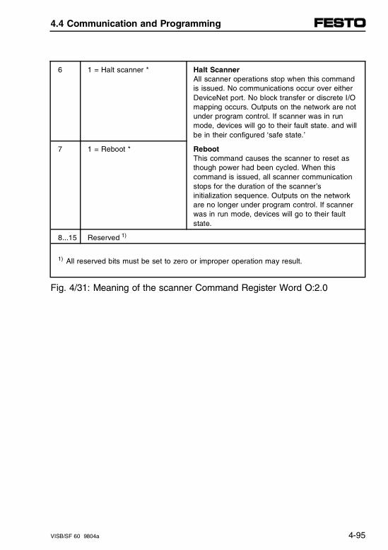
6 1 = Halt scanner * Halt ScannerAll scanner operations stop when this commandis issued. No communications occur over eitherDeviceNet port. No block transfer or discrete I/Omapping occurs. Outputs on the network are notunder program control. If scanner was in runmode, devices will go to their fault state. and willbe in their configured ‘safe state.’
7 1 = Reboot * RebootThis command causes the scanner to reset asthough power had been cycled. When thiscommand is issued, all scanner communicationstops for the duration of the scanner’sinitialization sequence. Outputs on the networkare no longer under program control. If scannerwas in run mode, devices will go to their faultstate.
8...15 Reserved 1)
1) All reserved bits must be set to zero or improper operation may result.
Fig. 4/31: Meaning of the scanner Command Register Word O:2.0
4.4 Communication and Programming
VISB/SF 60 9804a 4-95
SF 60 M0 file
The SF 60 M0 file is a 256 word file that can be usedto transfer a large quantity of information to the scannerwith a single SF 60 instruction. Transferring data usingthis file can take several scans and more time than us-ing the output image table. The first 150 words areused for sending data to DeviceNet nodes. The next 74words are reserved for future use and the last 32 wordsare used for explicit message program control.
For a detailed description of the mapping of input andoutput image tables, refer to the section "Understandingthe data organisation of the scanner" earlier in thischapter.
For a detailed description of the M0/M1 files, refer tothe Reference Manual of your programming software,Appendix F.
4.4 Communication and Programming
4-96 VISB/SF 60 9804a
4.4.6 Explicit Message Program Control
Use the "Explicit Message Program Control" feature toconfigure device parameters on your DeviceNet net-work via the M0 and M1 files in the SF 60 processorthat is controlling these devices.
You can use Explicit Message Program Control onlywith devices that are slaves of your SF 60 scannerModule. These slave devices must be mapped in thescanner module’s scan list.
Use the Explicit Message Program Control feature to:
– transmit configuration data from your scanner moduleto its slave devices on your DeviceNet network
– receive status and diagnostics from these devices onyour DeviceNet network
– make runtime adjustments to device parameters ac-cording to changing conditions detected by yourprocessor.
4.4 Communication and Programming
VISB/SF 60 9804a 4-97
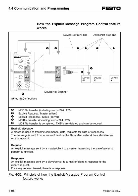
How the Explicit Message Program Control featureworks
DeviceNet trunk line DeviceNet drop line
4 1
2 3
DeviceNet Scanner5
SF 60 SLCembedded
1 2 3 4 5
MC0 file transfer (including words 224...255)Explicit Request / Master (client)Explicit Response / Slave (server)MC1file transfer (including words 224...255)MC1 file transfer is completed. TXID’s are deleted and can be reused.
Explicit MessageA message used to transmit commands, data, requests for data or responses. The message is sent from a master/client on the DeviceNet network to a slave/server on that network.
RequestAn explicit message sent by a master/client to a server requesting the slave/server to perform a function.
ResponseAn explicit message sent by a slave/server to a master/client in response to the client’s request. For every request issued, there is a response.
Fig. 4/32: Principle of how the Explicit Message Program Control feature works
4.4 Communication and Programming
4-98 VISB/SF 60 9804a
1. Format an M0 file transfer in the processor to sendan Explicit Message Request to the scanner module(download).
2. The scanner module transmits the Explicit MessageRequest to the slave device over the DeviceNet net-work.
3. The slave device transmits the Explicit Message Re-sponse back to the scanner and is queued into a filetransfer buffer.
4. The processor uses an M1 file transfer to retrievethe Explicit Message Response from the scanner’sbuffer (upload).
5. Format an M0 file transfer with a "Delete Response"Command and the current transaction ID read instep 4. The transaction IDs are deleted and can bereused.
The scanner module requires a precisely-formatted M0and M1 file transfer size of 32 words including words224...255. The scanner module uses the file memorycontent as a client/server request.
4.4 Communication and Programming
VISB/SF 60 9804a 4-99
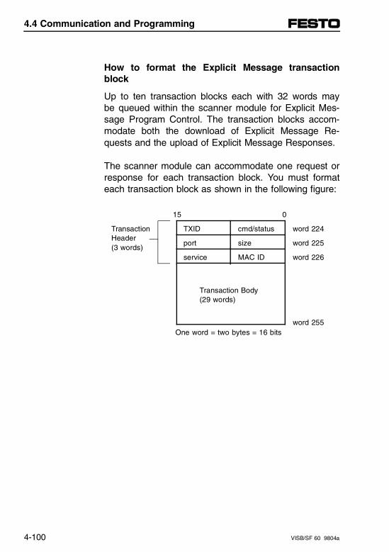
How to format the Explicit Message transactionblock
Up to ten transaction blocks each with 32 words maybe queued within the scanner module for Explicit Mes-sage Program Control. The transaction blocks accom-modate both the download of Explicit Message Re-quests and the upload of Explicit Message Responses.
The scanner module can accommodate one request orresponse for each transaction block. You must formateach transaction block as shown in the following figure:
15 0
TransactionHeader (3 words)
TXID cmd/status word 224
port size word 225
service MAC ID word 226
Transaction Body (29 words)
word 255 One word = two bytes = 16 bits
4.4 Communication and Programming
4-100 VISB/SF 60 9804a
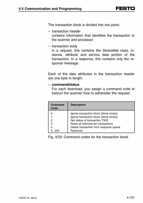
The transaction block is divided into two parts:
– transaction header contains information that identifies the transaction tothe scanner and processor
– transaction bodyin a request, this contains the DeviceNet class, in-stance, attribute and service data portion of thetransaction. In a response, this contains only the re-sponse message.
Each of the data attributes in the transaction headerare one byte in length:
– command/statusFor each download, you assign a command code toinstruct the scanner how to administer the request:
CommandCode
Description
012345...255
Ignore transaction block (block empty)Ignore transaction block (block empty)Get status of transaction TXIDReset all client/server transactionsDelete transaction from response queueReserved
Fig. 4/33: Command codes for the transaction block
4.4 Communication and Programming
VISB/SF 60 9804a 4-101
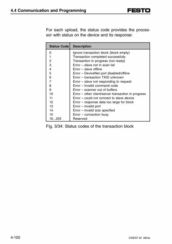
For each upload, the status code provides the proces-sor with status on the device and its response:
Status Code Description
012345678910111213141516...255
Ignore transaction block (block empty)Transaction completed successfullyTransaction in progress (not ready)Error – slave not in scan listError – slave offlineError – DeviceNet port disabled/offlineError – transaction TXID unknownError – slave not responding to requestError – Invalid command codeError – scanner out of buffersError – other client/server transaction in progressError – could not connect to slave deviceError – response data too large for blockError – invalid portError – invalid size specifiedError – connection busyReserved
Fig. 3/34: Status codes of the transaction block
4.4 Communication and Programming
4-102 VISB/SF 60 9804a
– TXID (transaction ID)when you create and download a request to thescanner, the processor’s "Ladder Logic" program as-signs a TXID to the transaction. This is a one-byteinteger in the range of 1 to 255. The scanner usesthis value to track the transaction to completion, andreturns the value with the response that matches therequest downloaded by the processor. The "Ladderlogic" program monitors rollover and usage of TXIDvalues.
– sizethe size of the transaction body in bytes. The trans-action body can be as many as 29 words (58 bytes)in length. If the size exceeds 29 words, an error codewill be returned.
– portthe DeviceNet port (zero) where the transaction isrouted.
4.4 Communication and Programming
VISB/SF 60 9804a 4-103
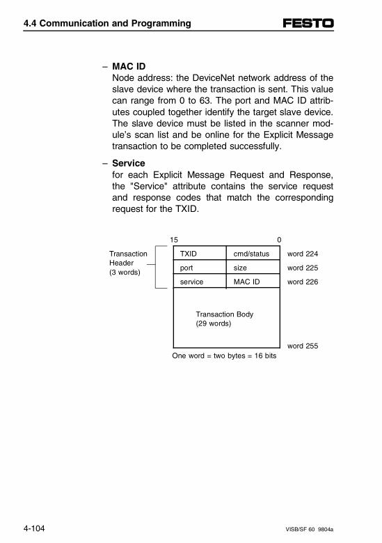
– MAC IDNode address: the DeviceNet network address of theslave device where the transaction is sent. This valuecan range from 0 to 63. The port and MAC ID attrib-utes coupled together identify the target slave device.The slave device must be listed in the scanner mod-ule’s scan list and be online for the Explicit Messagetransaction to be completed successfully.
– Servicefor each Explicit Message Request and Response,the "Service" attribute contains the service requestand response codes that match the correspondingrequest for the TXID.
15 0
TransactionHeader (3 words)
TXID cmd/status word 224
port size word 225
service MAC ID word 226
Transaction Body (29 words)
word 255 One word = two bytes = 16 bits
4.4 Communication and Programming
4-104 VISB/SF 60 9804a
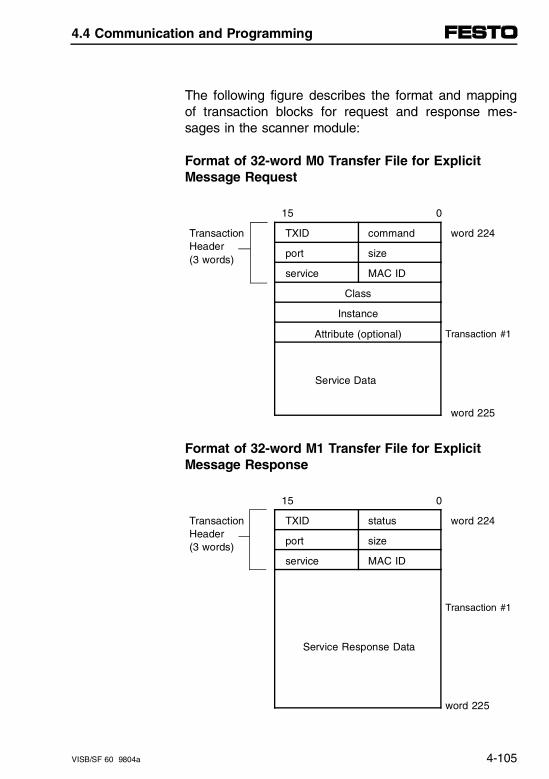
The following figure describes the format and mappingof transaction blocks for request and response mes-sages in the scanner module:
Format of 32-word M0 Transfer File for Explicit Message Request
15 0
TransactionHeader (3 words)
TXID command word 224
port size
service MAC ID
Class
Instance
Attribute (optional) Transaction #1
Service Data
word 225
Format of 32-word M1 Transfer File for ExplicitMessage Response
15 0
TransactionHeader (3 words)
TXID status word 224
port size
service MAC ID
Service Response Data
Transaction #1
word 225
4.4 Communication and Programming
VISB/SF 60 9804a 4-105
How the processor and scanner module managemessages
File transfer operations between the processor and thescanner always originate in the processor. The scannermodule can only wait for the processor to download atransaction block to the scanner or request an uploadof a transaction block from the scanner.
Once an Explicit Message Request transaction block isdownloaded to the scanner module, a "Ladder logic"program in the processor polls the scanner module forthe transaction block containing the Explicit MessageResponse for that request. This is done by the proces-sor with an M1 file transfer on the scanner module. De-pending on the network load, the scanner could take afew seconds to complete the request. When a responseis loaded, bit 15 of the scanner status register is set to1. The program may have to poll the scanner module anumber of times before the scanner returns a Re-sponse Transaction Block.
The scanner module recognizes I/O data and control ashigher priorities over explicit messaging on DeviceNet.
4.4 Communication and Programming
4-106 VISB/SF 60 9804a
Message lengths and slave device types impact trans-action message completion times. If the processor hasqueued multiple Explicit Message Transactions to thescanner module for multiple slave devices, the transac-tions with the slaves may not complete in the order inwhich the requests were received. The slave responsesare queued to the 32 word M1 file transfer in the orderin which they are received. As response transactionblocks are uploaded, the processor’s program matchesthe responses to the requests using the TXID field.
4.4 Communication and Programming
VISB/SF 60 9804a 4-107
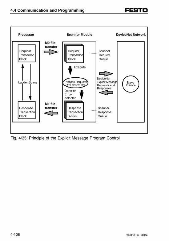
Processor Scanner Module DeviceNet Network
M0 file transfer
Request Request Scanner Transaction Transaction Request Block Block Queue
Execute
Process Requests
DeviceNet
Ladder Scans and responses Explicit Message Slave
Requests and
Device
Done or Responses
Error- detected
M1 file Response transfer Response Scanner Transaction Transaction Response Block Blocks Queue
Fig. 4/35: Principle of the Explicit Message Program Control
4.4 Communication and Programming
4-108 VISB/SF 60 9804a
Explicit message program control limitations
– The processor is always the DeviceNet client and theslave is always the DeviceNet server.
– A maximum of ten Explicit Message Request Trans-action Blocks with the execute command can bequeued to the scanner module at any time. For ex-ample, ten M0 file transfers containing one transac-tion each, can be queued at any time. The scannermodule receives and deletes any additional cli-ent/server requests with the execute command overthe maximum of ten.
As transactions are removed from the queue and re-sponse transaction blocks are returned to the proces-sor, additional transaction blocks can be issued in theirplace, as long as the total does not exceed ten.
– The scanner module supports one transaction blockper upload and download.
– Request Transaction Blocks can only be queued forslave devices of the scanner module and must ap-pear in the scanner module’s scan list.
4.4 Communication and Programming
VISB/SF 60 9804a 4-109
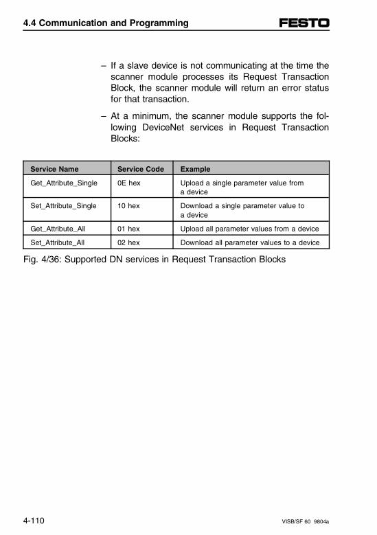
– If a slave device is not communicating at the time thescanner module processes its Request TransactionBlock, the scanner module will return an error statusfor that transaction.
– At a minimum, the scanner module supports the fol-lowing DeviceNet services in Request TransactionBlocks:
Service Name Service Code Example
Get_Attribute_Single 0E hex Upload a single parameter value from a device
Set_Attribute_Single 10 hex Download a single parameter value to a device
Get_Attribute_All 01 hex Upload all parameter values from a device
Set_Attribute_All 02 hex Download all parameter values to a device
Fig. 4/36: Supported DN services in Request Transaction Blocks
4.4 Communication and Programming
4-110 VISB/SF 60 9804a
– All transaction blocks are processed, therefore, anunused transaction block must be left blank.
– Client/Server commands and requests with transac-tion IDs that are in use are ignored by the scannermodule.
– If a slave device returns a DeviceNet error in re-sponse to the request downloaded from the proces-sor, the scanner recognizes the error as a successfultransaction (status code =1).
A failure to respond to the request within the conditionsspecified (number of retries or timeout period specified)for the Explicit Message Connection is recognized bythe scanner module as an error. The error code is re-turned in the status attribute of the transaction header.
4.4 Communication and Programming
VISB/SF 60 9804a 4-111

4.4 Communication and Programming
4-112 VISB/SF 60 9804a
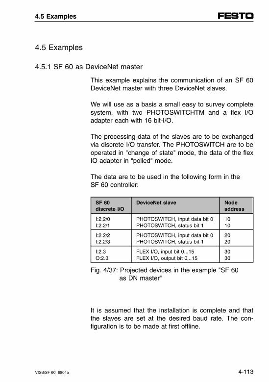
4.5 Examples
4.5.1 SF 60 as DeviceNet master
This example explains the communication of an SF 60DeviceNet master with three DeviceNet slaves.
We will use as a basis a small easy to survey completesystem, with two PHOTOSWITCHTM and a flex I/Oadapter each with 16 bit-I/O.
The processing data of the slaves are to be exchangedvia discrete I/O transfer. The PHOTOSWITCH are to beoperated in "change of state" mode, the data of the flexIO adapter in "polled" mode.
The data are to be used in the following form in the SF 60 controller:
SF 60 discrete I/O
DeviceNet slave Nodeaddress
I:2.2/0I:2.2/1
PHOTOSWITCH, input data bit 0PHOTOSWITCH, status bit 1
1010
I:2.2/2I:2.2/3
PHOTOSWITCH, input data bit 0PHOTOSWITCH, status bit 1
2020
I:2.3O:2.3
FLEX I/O, input bit 0...15FLEX I/O, output bit 0...15
3030
Fig. 4/37: Projected devices in the example "SF 60 as DN master"
It is assumed that the installation is complete and thatthe slaves are set at the desired baud rate. The con-figuration is to be made at first offline.
4.5 Examples
VISB/SF 60 9804a 4-113
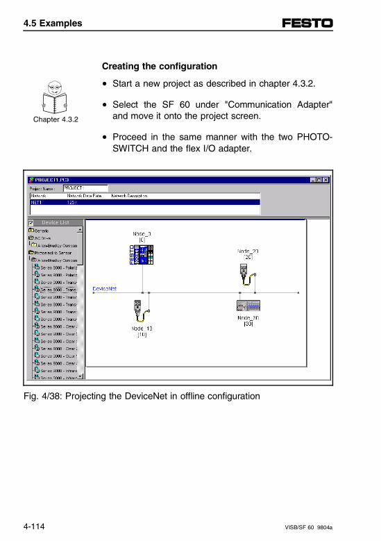
Creating the configuration
• Start a new project as described in chapter 4.3.2.
• Select the SF 60 under "Communication Adapter"and move it onto the project screen. Chapter 4.3.2
• Proceed in the same manner with the two PHOTO-SWITCH and the flex I/O adapter.
Fig. 4/38: Projecting the DeviceNet in offline configuration
4.5 Examples
4-114 VISB/SF 60 9804a
• In order to configure the slaves "double click" on theSF 60. The "SF60 Module Configuration" window willthen open. Use the default settings or modify themaccording to your needs. Enter slot = 2 which is as-signed by the DeviceNet Scanner.
• Open the "SF60 Scan List Editor." No slaves havebeen entered.
• Select "Add Devices from Project." You can assignboth slaves to the SF 60 scanner in this window bypulling with the mouse. Both slaves receive a framein the same color as your scanner. When you exitthe window with "OK," both slaves will be in the"SF60 Scan List Editor" window.
Now the slaves must be configured and their data as-signed.
4.5 Examples
VISB/SF 60 9804a 4-115
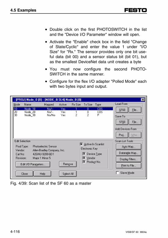
• Double click on the first PHOTOSWITCH in the listand the "Device I/O Parameter" window will open.
• Activate the "Enable" check box in the field "Changeof State/Cyclic" and enter the value 1 under "I/OSize" for "Rx." The sensor provides only one bit use-ful data (bit 00) and a sensor status bit (bit 01), butas the smallest DeviceNet data unit creates a byte
• You must now configure the second PHOTO-SWITCH in the same manner.
• Configure for the flex I/O adapter "Polled Mode" eachwith two bytes input and output.
Fig. 4/39: Scan list of the SF 60 as a master
4.5 Examples
4-116 VISB/SF 60 9804a
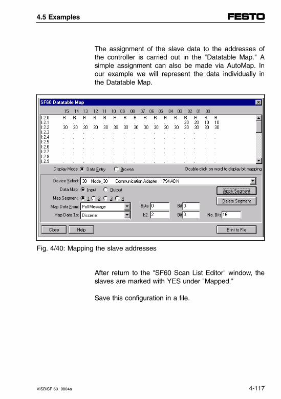
The assignment of the slave data to the addresses ofthe controller is carried out in the "Datatable Map." Asimple assignment can also be made via AutoMap. Inour example we will represent the data individually inthe Datatable Map.
Fig. 4/40: Mapping the slave addresses
After return to the "SF60 Scan List Editor" window, theslaves are marked with YES under "Mapped."
Save this configuration in a file.
4.5 Examples
VISB/SF 60 9804a 4-117
Loading the DN configuration
When you have built up the online connection to yourSF 60 with the DN-MGR, you can load the configura-tion from this menu into your scanner.
Commissioning
In order that your scanner can exchange data in theRUN mode of the controller, you must switch it fromIDLE mode to RUN mode. To do this you must set bitO:2.0/0 in your user program to 1. (Command register/command word, see chapter 4.4.5).
Chapter 4.4.5
4.5 Examples
4-118 VISB/SF 60 9804a
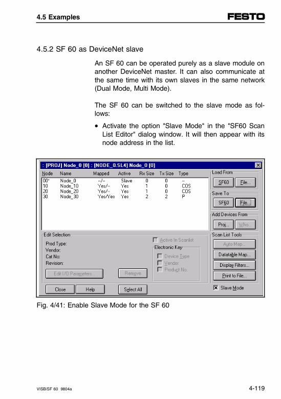
4.5.2 SF 60 as DeviceNet slave
An SF 60 can be operated purely as a slave module onanother DeviceNet master. It can also communicate atthe same time with its own slaves in the same network(Dual Mode, Multi Mode).
The SF 60 can be switched to the slave mode as fol-lows:
• Activate the option "Slave Mode" in the "SF60 ScanList Editor" dialog window. It will then appear with itsnode address in the list.
Fig. 4/41: Enable Slave Mode for the SF 60
4.5 Examples
VISB/SF 60 9804a 4-119
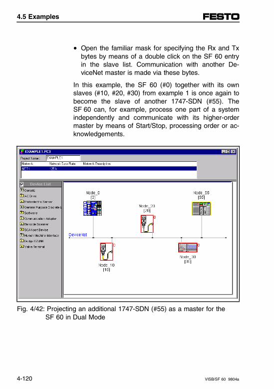
• Open the familiar mask for specifying the Rx and Txbytes by means of a double click on the SF 60 entryin the slave list. Communication with another De-viceNet master is made via these bytes.
In this example, the SF 60 (#0) together with its ownslaves (#10, #20, #30) from example 1 is once again tobecome the slave of another 1747-SDN (#55). TheSF 60 can, for example, process one part of a systemindependently and communicate with its higher-ordermaster by means of Start/Stop, processing order or ac-knowledgements.
Fig. 4/42: Projecting an additional 1747-SDN (#55) as a master for the SF 60 in Dual Mode
4.5 Examples
4-120 VISB/SF 60 9804a
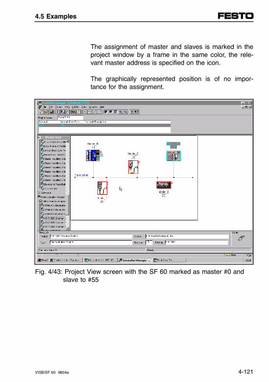
The assignment of master and slaves is marked in theproject window by a frame in the same color, the rele-vant master address is specified on the icon.
The graphically represented position is of no impor-tance for the assignment.
Fig. 4/43: Project View screen with the SF 60 marked as master #0 and slave to #55
4.5 Examples
VISB/SF 60 9804a 4-121
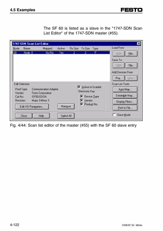
The SF 60 is listed as a slave in the "1747-SDN ScanList Editor" of the 1747-SDN master (#55).
Fig. 4/44: Scan list editor of the master (#55) with the SF 60 slave entry
4.5 Examples
4-122 VISB/SF 60 9804a
4.6 Diagnostics and error handling
4.6.1 Local diagnostics
Seven-segment numeric indicators on the SF 60scanner
When you apply operating voltage, the module numericindicators cycle through the following displays:
1. Seven-segment lamp test (88)
2. Firmware major revision(01 through 7F hexadecimal)
3. Firmware minor revision(01 through FF hexadecimal)
4. Baud rate(indicates 00 for the default of 125, 01 for 250 or 02for 500 Kbits/s)
5. Node address(00 to 63 with 63 as the default)
Use the DeviceNetManager software to change thebaud rate and node address.
Refer to the "Numeric Code Display Summary" table inAppendix B for a complete listing of numeric displays.
Appendix B
4.6 Diagnostics and error handling
VISB/SF 60 9804a 4-123
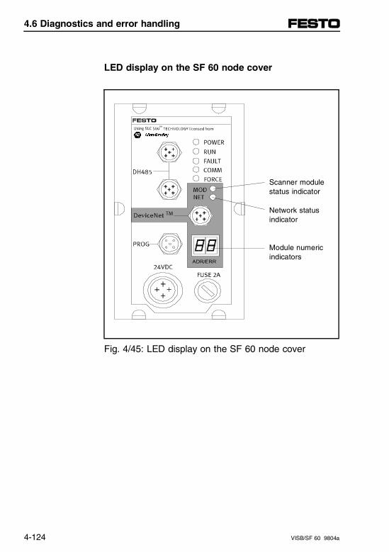
LED display on the SF 60 node cover
Scanner module status indicator
Network statusindicator
Module numeric indicators
Fig. 4/45: LED display on the SF 60 node cover
4.6 Diagnostics and error handling
4-124 VISB/SF 60 9804a
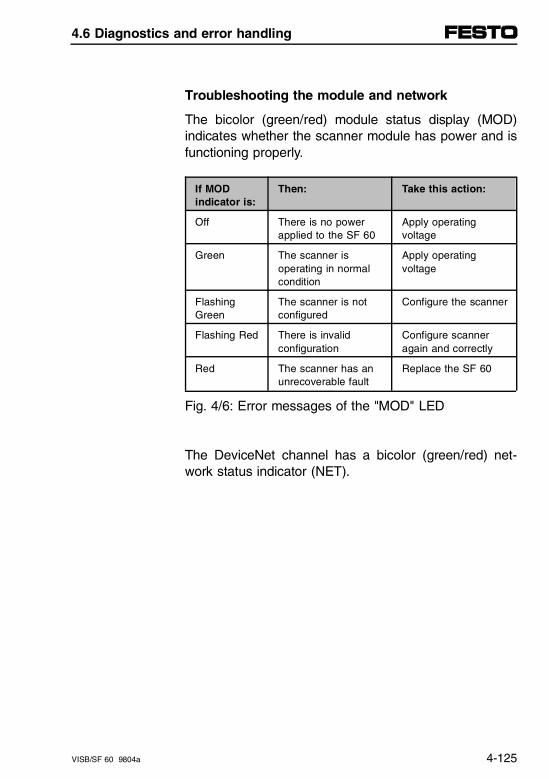
Troubleshooting the module and network
The bicolor (green/red) module status display (MOD)indicates whether the scanner module has power and isfunctioning properly.
If MOD indicator is:
Then: Take this action:
Off There is no power applied to the SF 60
Apply operating voltage
Green The scanner isoperating in normalcondition
Apply operating voltage
FlashingGreen
The scanner is notconfigured
Configure the scanner
Flashing Red There is invalid configuration
Configure scanneragain and correctly
Red The scanner has anunrecoverable fault
Replace the SF 60
Fig. 4/6: Error messages of the "MOD" LED
The DeviceNet channel has a bicolor (green/red) net-work status indicator (NET).
4.6 Diagnostics and error handling
VISB/SF 60 9804a 4-125
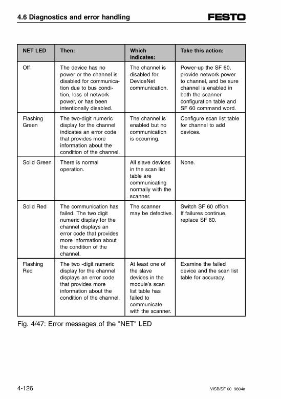
NET LED Then: WhichIndicates:
Take this action:
Off The device has nopower or the channel isdisabled for communica-tion due to bus condi-tion, loss of networkpower, or has beenintentionally disabled.
The channel isdisabled forDeviceNetcommunication.
Power-up the SF 60,provide network powerto channel, and be surechannel is enabled inboth the scannerconfiguration table andSF 60 command word.
FlashingGreen
The two-digit numericdisplay for the channelindicates an error codethat provides moreinformation about thecondition of the channel.
The channel isenabled but nocommunicationis occurring.
Configure scan list tablefor channel to adddevices.
Solid Green There is normaloperation.
All slave devicesin the scan listtable arecommunicatingnormally with thescanner.
None.
Solid Red The communication hasfailed. The two digitnumeric display for thechannel displays anerror code that providesmore information aboutthe condition of thechannel.
The scannermay be defective.
Switch SF 60 off/on. If failures continue,replace SF 60.
FlashingRed
The two -digit numericdisplay for the channeldisplays an error codethat provides moreinformation about thecondition of the channel.
At least one ofthe slave devices in themodule’s scanlist table hasfailed tocommunicatewith the scanner.
Examine the faileddevice and the scan listtable for accuracy.
Fig. 4/47: Error messages of the "NET" LED
4.6 Diagnostics and error handling
4-126 VISB/SF 60 9804a

The SF 60 uses numeric displays to indicate diagnosticinformation about the status of your module. The dis-play flashes at 1 second intervals. Refer to the "Nu-meric Code Display Summary" table in Appendix B fora complete listing of numeric displays.
Appendix B
4.6 Diagnostics and error handling
VISB/SF 60 9804a 4-127

4.6 Diagnostics and error handling
4-128 VISB/SF 60 9804a
Chapter 5
Description of analog modules
5. Description of analog modules
VISB/SF 60 9804a 5-I

Contents
5. Description of analog modules
5.1 Overview of analog I/Os. . . . . . . . . . . . . . . . . . . . . . . . . . . . . . 5-1
Advantages of analog I/Os. . . . . . . . . . . . . . . . . . . . . . . . . . . . . 5-1Component description - analog modules . . . . . . . . . . . . . . . . . 5-2
5.2 Assembly of analog I/Os . . . . . . . . . . . . . . . . . . . . . . . . . . . . . 5-3
Mounting analog modules . . . . . . . . . . . . . . . . . . . . . . . . . . . . . 5-4
5.3 Installing analog I/Os . . . . . . . . . . . . . . . . . . . . . . . . . . . . . . . . 5-7
Cable selection for analog signals . . . . . . . . . . . . . . . . . . . . . . . 5-7Shielding . . . . . . . . . . . . . . . . . . . . . . . . . . . . . . . . . . . . . . . . . . . 5-8Connecting analog modules . . . . . . . . . . . . . . . . . . . . . . . . . . . . 5-9Pin assignments for Festo proportional valves . . . . . . . . . . . . 5-10Pin assignments for analog voltage I/Os . . . . . . . . . . . . . . . . . 5-11Pin assignments for analog current I/Os . . . . . . . . . . . . . . . . . 5-12Connection variations for 2-wire sensors . . . . . . . . . . . . . . . . . 5-13
5.4 Starting up analog I/O modules . . . . . . . . . . . . . . . . . . . . . . 5-17
5.4.1 Basics of addressing . . . . . . . . . . . . . . . . . . . . . . . . . . . . . . . . 5-17Analog I/O addressing . . . . . . . . . . . . . . . . . . . . . . . . . . . . . . . 5-18Address allocation after expansion/reconfiguration . . . . . . . . . 5-21
5.4.2 Programming the analog I/Os . . . . . . . . . . . . . . . . . . . . . . . . . 5-22Characteristics of analog I/O modules after power-up. . . . . . . 5-22Programming considerations . . . . . . . . . . . . . . . . . . . . . . . . . . 5-23Processor considerations . . . . . . . . . . . . . . . . . . . . . . . . . . . . . 5-24Module considerations . . . . . . . . . . . . . . . . . . . . . . . . . . . . . . . 5-28Safe state for outputs . . . . . . . . . . . . . . . . . . . . . . . . . . . . . . . . 5-34
5. Description of analog modules
5-II VISB/SF 60 9804a
5.4.3 Writing ladder logic. . . . . . . . . . . . . . . . . . . . . . . . . . . . . . . . . . . 5-35Retentive and non-retentive programming. . . . . . . . . . . . . . . . . 5-36Clear the output during program start . . . . . . . . . . . . . . . . . . . . 5-39Detect an out-of-range input . . . . . . . . . . . . . . . . . . . . . . . . . . . 5-40Overview of scaling inputs and outputs . . . . . . . . . . . . . . . . . . . 5-42Scale an analog input and detect an out-of-range condition. . . 5-45Scale an analog output . . . . . . . . . . . . . . . . . . . . . . . . . . . . . . . 5-52Scale offsets when > 32767 or < - 32768 . . . . . . . . . . . . . . . . . 5-57PID control with analog I/O scaling . . . . . . . . . . . . . . . . . . . . . . 5-63
5.5 Diagnostics and error handling for analog I/O modules . . . 5-67
5.5.1 Local diagnostics . . . . . . . . . . . . . . . . . . . . . . . . . . . . . . . . . . . . 5-67LED displays in PROP analog module . . . . . . . . . . . . . . . . . . . 5-67LED displays for current analog module (VIAU-I) . . . . . . . . . . . 5-68LED displays on analog module for voltage I/O (VIAU-U) . . . . 5-69Remedying overload/short circuit of analog voltage outputs . . . 5-70Overload/short circuit in actuator voltage supply . . . . . . . . . . . . 5-71
5.5.2 Diagnostics by program . . . . . . . . . . . . . . . . . . . . . . . . . . . . . . . 5-72
5.6 Technical data for analog I/O . . . . . . . . . . . . . . . . . . . . . . . . . 5-73
5. Description of analog modules
VISB/SF 60 9804a 5-III

5. Description of analog modules
5-IV VISB/SF 60 9804a
5.1 Overview of analog I/Os
Advantages of analog I/Os
Analog modules with analog I/Os offer the following ad-vantages:
– Optimal connection of Festo proportional valves(MPPE or MPYE). These valves offer the followingpossibilities:
• MPPE:This valve allows the pressure at the valve output to be set proportional to the analog input signal,thereby permitting the cylinder force to be varied.
• MPYE:This valve changes the flow (l/min) proportional to the analog input signal. The flow determines cylinder velocity.
– Individual and universal adaptability for detecting andprocessing analog signals.
– Detection and processing of analog current and volt-age signals.
– Very easy programming and diagnostics.
– Later expansion/reconfiguration possible.
5.1 Overview of analog I/Os
VISB/SF 60 9804a 5-1
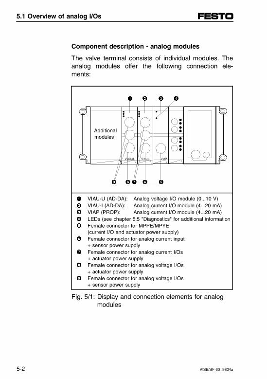
Component description - analog modules
The valve terminal consists of individual modules. Theanalog modules offer the following connection ele-ments:
1 2 3 4
••
Additional modules
9 8 7 6 5
1 VIAU-U (AD-DA): Analog voltage I/O module (0...10 V)2 VIAU-I (AD-DA): Analog current I/O module (4...20 mA)3 VIAP (PROP): Analog current I/O module (4...20 mA)4 LEDs (see chapter 5.5 "Diagnostics" for additional information5 Female connector for MPPE/MPYE
(current I/O and actuator power supply)6 Female connector for analog current input
+ sensor power supply7 Female connector for analog current I/Os
+ actuator power supply8 Female connector for analog voltage I/Os
+ actuator power supply9 Female connector for analog voltage I/Os
+ sensor power supply
Fig. 5/1: Display and connection elements for analogmodules
5.1 Overview of analog I/Os
5-2 VISB/SF 60 9804a
5.2 Assembly of analog I/Os
WARNINGBefore starting assembly work, switch off the following:• Compressed air supply• Operating voltage supply to outputs (Pin 2)• Operating voltage supply to electronics (Pin 1)
By doing this, you prevent:
– Uncontrollable movements of loosened flexible tubes.
– Accidental movements of connector actuator units.
– Undefined switching states of the electronics.
CAUTIONThe components of the valve terminal contain partswhich are vulnerable to electrostatic interference.• For this reason, do not touch any contact surfaces
on side connectors of these components.• Comply with the handling specifications for
electrostatically vulnerable components
You thereby avoid destroying the valve terminal compo-nents.
5.2 Assembly of analog I/Os
VISB/SF 60 9804a 5-3
Mounting analog modules
PLEASE NOTEThe analog modules are designed for mounting onthe SB/SF 60 as follows:− 9 analog input and output channels each are
available. A VIAP module (PROP) occupies one I/Ochannel each. The VIAU modules (AD-DA) occupythree input channels and one output channel each.Note these limits when performing later expansions.
− Do not mount a total of more than 12 electric modules per valve terminal.
- Mount modules ordered at a later date to the left ofthe last analog module.
You prevent:
– Addressing and system faults
– A displacement of I/O addresses for I/O moduleswhich have already been installed.
5.2 Assembly of analog I/Os
5-4 VISB/SF 60 9804a
PLEASE NOTEHandle all modules and components on valve terminals with care. Pay particular attention to the following points:- Connect modules without distortion and mechanical
stress.- Precise location of screws (to avoid thread dam-
age).- Compliance with specified torques.- Prevention of offset between the modules (IP65).- Clean connection faces (prevention of leakage and
contact faults).
In the case of modules and components added later tothe system, please note the assembly instructions en-closed in the product package.
To expand or reconfigure the valve terminal, it is neces-sary to dismantle the screw-mounted terminal.
Disassemble (also refer to following illustration):
• Completely unfasten screws in corresponding mo-dules. The modules are now only held together bythe electrical plug connection.
• Pull the modules carefully off the electrical plug con-nectors without tilting them.
• Replace the damaged seals.
5.2 Assembly of analog I/Os
VISB/SF 60 9804a 5-5
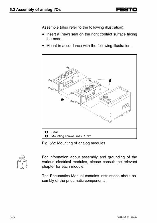
Assemble (also refer to the following illustration):
• Insert a (new) seal on the right contact surface facingthe node.
• Mount in accordance with the following illustration.
1
2
1 Seal2 Mounting screws, max. 1 Nm
Fig. 5/2: Mounting of analog modules
For information about assembly and grounding of thevarious electrical modules, please consult the relevantchapter for each module.
The Pneumatics Manual contains instructions about as-sembly of the pneumatic components.
5.2 Assembly of analog I/Os
5-6 VISB/SF 60 9804a
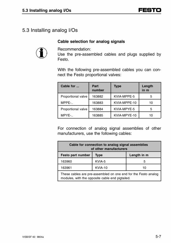
5.3 Installing analog I/Os
Cable selection for analog signals
Recommendation:Use the pre-assembled cables and plugs supplied byFesto.
With the following pre-assembled cables you can con-nect the Festo proportional valves:
Cable for ... Partnumber
Type Length in m
Proportional valve 163882 KVIA-MPPE-5 5
MPPE-.. 163883 KVIA-MPPE-10 10
Proportional valve 163884 KVIA-MPYE-5 5
MPYE-.. 163885 KVIA-MPYE-10 10
For connection of analog signal assemblies of othermanufacturers, use the following cables:
Cable for connection to analog signal assemblies of other manufacturers
Festo part number Type Length in m
163960 KVIA-5 5
163961 KVIA-10 10
These cables are pre-assembled on one end for the Festo analogmodules, with the opposite cable end pigtailed.
5.3 Installing analog I/Os
VISB/SF 60 9804a 5-7
If you wish to assemble your own cables, use only thefollowing cable and plugs for carrying analog signals:
– Shielded cable
– Twisted-pair cable(input wires paired with input wires, output wirespaired with output wires and supply wires).
– Connectors with metal housing
The following connectors are suitable:
BinderMiniature round plug connector,per DIN 45322,6-pin with gold contacts Binder order numbers:99-5621-19-06 (PG9)99-5121-19-06 (PG7)
AMPMiniature round plug connector,per DIN 45322,6-pin with gold contactsAMP order number:212 437-4 with appropriate ferrule and contacts
Shielding
PLEASE NOTEConnect the shield on one end only, to the plug casing to the analog module.
By doing this, you prevent:
– Faults caused by electromagnetic interference.
5.3 Installing analog I/Os
5-8 VISB/SF 60 9804a
Connecting analog modules
WARNINGBefore any installation and maintenance work, switchoff the following:- Compressed air supply- Operating voltage supply for electronics (Pin 1) - Operating voltage supply for outputs/valves (Pin 2).
By doing this, you prevent:
– Uncontrollable movements of loosened flexible tubes.
– Accidental movements of connected actuators.
– Undefined switching states of the electronics.
PLEASE NOTEEnsure that unused lines of voltage inputs connectedto the I/O plug of the analog module are short-circuited.
By doing this, you prevent:
– Faults caused by electromagnetic interference.
5.3 Installing analog I/Os
VISB/SF 60 9804a 5-9
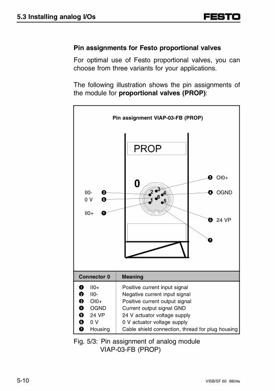
Pin assignments for Festo proportional valves
For optimal use of Festo proportional valves, you canchoose from three variants for your applications.
The following illustration shows the pin assignments ofthe module for proportional valves (PROP):
Pin assignment VIAP-03-FB (PROP)
3 OI0+
II0- 2 4 OGND0 V 6
II0+ 1
5 24 VP
7
Connector 0 Meaning
1 II0+ Positive current input signal2 II0- Negative current input signal3 OI0+ Positive current output signal4 OGND Current output signal GND5 24 VP 24 V actuator voltage supply6 0 V 0 V actuator voltage supply7 Housing Cable shield connection, thread for plug housing
Fig. 5/3: Pin assignment of analog module VIAP-03-FB (PROP)
5.3 Installing analog I/Os
5-10 VISB/SF 60 9804a
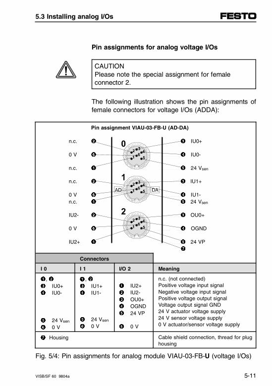
Pin assignments for analog voltage I/Os
CAUTIONPlease note the special assignment for female connector 2.
The following illustration shows the pin assignments offemale connectors for voltage I/Os (ADDA):
Pin assignment VIAU-03-FB-U (AD-DA)
n.c. 2 3 IU0+
0 V 6 4 IU0-
n.c. 1 5 24 Vsen
n.c. 2 3 IU1+
0 V 6 4 IU1- n.c. 1 5 24 Vsen
IU2- 2 3 OU0+
0 V 6 4 OGND
IU2+ 1 5 24 VP 7
Connectors
I 0 I 1 I/O 2 Meaning
1, 23 IU0+4 IU0-
5 24 Vsen
6 0 V
, 23 IU1+4 IU1-
5 24 Vsen
6 0 V
1 IU2+2 IU2-3 OU0+4 OGND5 24 VP
6 0 V
n.c. (not connected)Positive voltage input signalNegative voltage input signalPositive voltage output signalVoltage output signal GND24 V actuator voltage supply24 V sensor voltage supply0 V actuator/sensor voltage supply
7 Housing Cable shield connection, thread for plughousing
Fig. 5/4: Pin assignments for analog module VIAU-03-FB-U (voltage I/Os)
1
5.3 Installing analog I/Os
VISB/SF 60 9804a 5-11
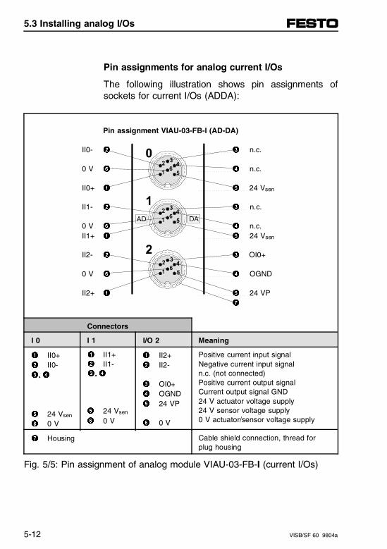
Pin assignments for analog current I/Os
The following illustration shows pin assignments ofsockets for current I/Os (ADDA):
Pin assignment VIAU-03-FB-I (AD-DA)
II0- 2 3 n.c.
0 V 6 4 n.c.
II0+ 1 5 24 Vsen
II1- 2 3 n.c.
0 V 6 4 n.c.II1+ 1 5 24 Vsen
II2- 2 3 OI0+
0 V 6 4 OGND
II2+ 1 5 24 VP 7
Connectors
I 0 I 1 I/O 2 Meaning
1 II0+2 II0-3, 4
5 24 Vsen
6 0 V
II1+ II1-
5 24 Vsen
6 0 V
1 II2+2 II2-
3 OI0+4 OGND5 24 VP
6 0 V
Positive current input signalNegative current input signaln.c. (not connected)Positive current output signalCurrent output signal GND24 V actuator voltage supply24 V sensor voltage supply0 V actuator/sensor voltage supply
7 Housing Cable shield connection, thread for plug housing
Fig. 5/5: Pin assignment of analog module VIAU-03-FB-I (current I/Os)
1
2
3, 4
5.3 Installing analog I/Os
5-12 VISB/SF 60 9804a
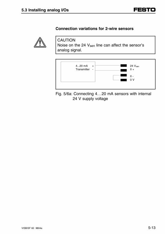
Connection variations for 2-wire sensors
CAUTIONNoise on the 24 Vsen line can affect the sensor’sanalog signal.
4...20 mA + 24 Vsen
Transmitter - II +
II -0 V
Fig. 5/6a: Connecting 4…20 mA sensors with internal 24 V supply voltage
5.3 Installing analog I/Os
VISB/SF 60 9804a 5-13
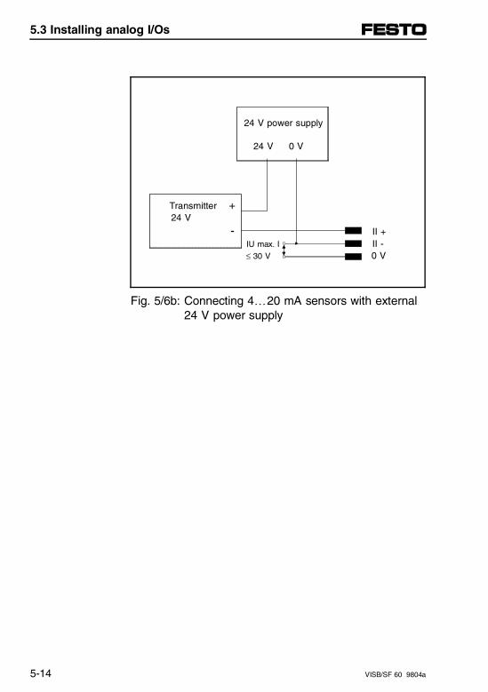
24 V power supply
24 V 0 V
Transmitter + 24 V
- II + IU max. I II -
≤ 30 V 0 V
Fig. 5/6b: Connecting 4…20 mA sensors with external 24 V power supply
5.3 Installing analog I/Os
5-14 VISB/SF 60 9804a
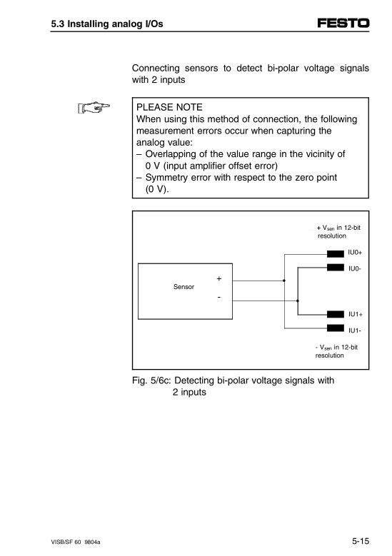
Connecting sensors to detect bi-polar voltage signalswith 2 inputs
PLEASE NOTEWhen using this method of connection, the followingmeasurement errors occur when capturing theanalog value:– Overlapping of the value range in the vicinity of
0 V (input amplifier offset error)– Symmetry error with respect to the zero point
(0 V).
+ Vsen in 12-bit resolution
IU0+
IU0-
+ Sensor
-
IU1+
IU1-
- Vsen in 12-bit resolution
Fig. 5/6c: Detecting bi-polar voltage signals with 2 inputs
5.3 Installing analog I/Os
VISB/SF 60 9804a 5-15

5.3 Installing analog I/Os
5-16 VISB/SF 60 9804a
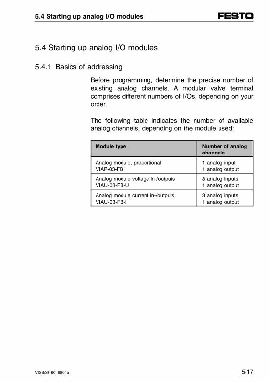
5.4 Starting up analog I/O modules
5.4.1 Basics of addressing
Before programming, determine the precise number ofexisting analog channels. A modular valve terminalcomprises different numbers of I/Os, depending on yourorder.
The following table indicates the number of availableanalog channels, depending on the module used:
Module type Number of analogchannels
Analog module, proportionalVIAP-03-FB
1 analog input1 analog output
Analog module voltage in-/outputsVIAU-03-FB-U
3 analog inputs1 analog output
Analog module current in-/outputsVIAU-03-FB-I
3 analog inputs1 analog output
5.4 Starting up analog I/O modules
VISB/SF 60 9804a 5-17
Analog I/O addressing
The maximum number of analog inputs/outputs is lim-ited by:- The maximum permissible number of electrical
modules (12).- The maximum current draw for outputs (10 A).- The limits of the address range for analog I/Os:
a maximum of 9 analog modules may be addressed.
The address allocation of inputs/outputs of a modularvalve terminal depends on the equipment fitted on theterminal. Detailed information about addressing rules forvalves and digital I/Os can be found in chapter 2, chap-ter 2.4 "Addressing."
The rules described below apply to address allocationof valve terminals with analog I/Os.
1. The addresses of analog I/Os are allocated separ-ately from digital I/Os.
Rules of addressing
2. The addressing (counting) of analog inputs and out-puts respectively is performed separately. - Counting mode starting at control block from right to left.- Address assignment in ascending numerical order.- On each individual module, counting runs from top to bottom.
5.4 Starting up analog I/O modules
5-18 VISB/SF 60 9804a
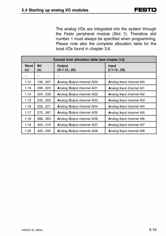
The analog I/Os are integrated into the system throughthe Festo peripheral module (Slot 1). Therefore slotnumber 1 must always be specified when programming.Please note also the complete allocation table for thelocal I/Os found in chapter 3.6.
Excerpt from allocation table (see chapter 3.6)
Word (x)
Bit (z)
Output (O:1.12...20)
Input (I:1.12...20)
-- -- -- --
1.12 192...207 Analog Output channel AO0 Analog Input channel AI0
1.13 208...223 Analog Output channel AO1 Analog Input channel AI1
1.14 224...239 Analog Output channel AO2 Analog Input channel AI2
1.15 240...255 Analog Output channel AO3 Analog Input channel AI3
1.16 256...271 Analog Output channel AO4 Analog Input channel AI4
1.17 272...287 Analog Output channel AO5 Analog Input channel AI5
1.18 288...303 Analog Output channel AO6 Analog Input channel AI6
1.19 304...319 Analog Output channel AO7 Analog Input channel AI7
1.20 320...335 Analog Output channel AO8 Analog Input channel AI8
5.4 Starting up analog I/O modules
VISB/SF 60 9804a 5-19
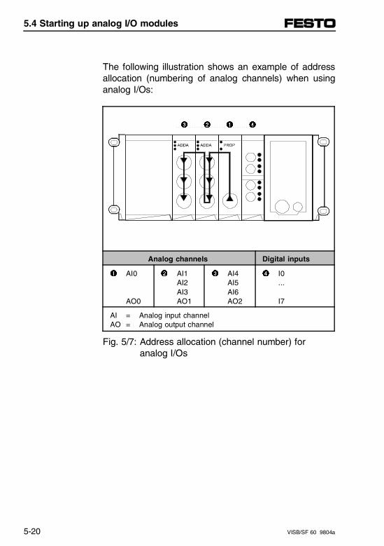
The following illustration shows an example of addressallocation (numbering of analog channels) when usinganalog I/Os:
3 2 1 4
Analog channels Digital inputs
1 AI0
AO0
2 AI1AI2AI3AO1
3 AI4AI5AI6AO2
4 I0...
I7
AI = Analog input channelAO = Analog output channel
Fig. 5/7: Address allocation (channel number) foranalog I/Os
5.4 Starting up analog I/O modules
5-20 VISB/SF 60 9804a
Address allocation after expansion/reconfiguration
A special feature of the modular valve terminal is itsflexibility. If the machine requirements change, the ter-minal structure may likewise be changed.
CAUTIONIn case of later expansions or reconfigurations to theterminal, channel numbers may be shifted for analoginputs and outputs.
This definitely applies in the following cases:- If additional analog input/output modules are
inserted between the node and existing analoginput/output modules.
- If existing analog input/output modules (e.g., proportional modules) are replaced with universal I/O modules (or vice versa).
5.4 Starting up analog I/O modules
VISB/SF 60 9804a 5-21
5.4.2 Programming the analog I/Os
The following sections contain specific informationabout the analog I/Os:
– Characteristics after power-up
– General notes on programming
– Processor fundamentals
– Module fundamentals (resolution, conversion, proc-essing of the analog I/Os)
– Power-down characteristics of the outputs (savestate).
Characteristics of analog I/O modules afterpower-up
When the operating voltage is switched on, the follow-ing data access options in the analog I/O modules areavailable.
Input signals (data):
– Immediate access possible through the input words
Output signals (data):
– Processor in STOP mode: 0 V or 4 mA
– Processor in RUN mode: current output value in theoutput word is immediately output.
5.4 Starting up analog I/O modules
5-22 VISB/SF 60 9804a
Programming considerations
This section describes concepts that you need to un-derstand how to program an analog module in anSB/SF 60 system, and is divided into the followingsteps:
− Processor update of analog I/O data− Monitoring analog I/O data− Addressing analog I/O image words
Processorconsiderations
- Resolution of the module’s I/O channel converters- Converting analog input data− Computing the analog input signal level− Converting the analog output data− Computing the analog output signal level
Moduleconsiderations
− Power-down characteristics of the outputs (save state)
Power-down
5.4 Starting up analog I/O modules
VISB/SF 60 9804a 5-23
Processor considerations
Knowing how the processor works helps you program itmore effectively.
Analog input and output image words are updated bythe processor once every processor scan when theprocessor scans data and program files in succession.
ProcessorUpdate ofAnalog I/OData
Processor scan time depends largely on the size ofyour program files: the greater the number of program-ming instructions, the longer the time to scan the pro-gram. In addition, the instructions have different execu-tion times.
Shorter access times to the analog channels can beobtained by using the IIM and IOM instructions.
– For information on processor scan time and instruc-tion execution time, refer to the table "Instruction SetSB/SF 60" in chapter 3.5.
– A detailed description of the update cycles for theanalog I/Os, separate for programming and periph-eral cycles can be found in Appendix C.
5.4 Starting up analog I/O modules
5-24 VISB/SF 60 9804a
You can monitor analog input and output data in binaryor decimal format with the programming software. Youselect the format by its radix. The default radix is binary.Binary data is presented in 2’s-complement format.Changing the radix to decimal lets you view analog I/Odata as decimal representations of integer words.
Monitoringanalog I/Odata
If you are using the Hand-Held Terminal (HHT) or theData Table Access Module (DTAM) to monitor analogI/O data, the binary radix is the only available option. Toobtain analog I/O data in decimal, you must copy theanalog values per program into an integer file, so that itcan be displayed there in decimal representation.
5.4 Starting up analog I/O modules
VISB/SF 60 9804a 5-25
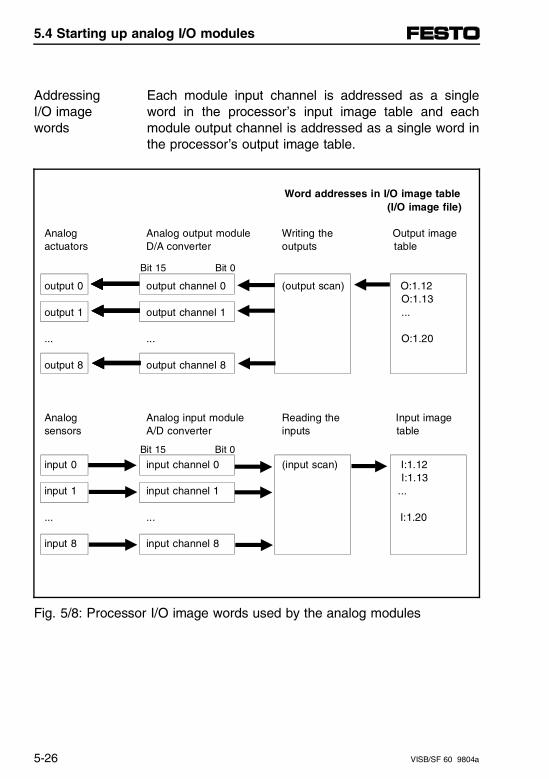
Each module input channel is addressed as a singleword in the processor’s input image table and eachmodule output channel is addressed as a single word inthe processor’s output image table.
AddressingI/O imagewords
Word addresses in I/O image table (I/O image file)
Analog Analog output module Writing the Output image actuators D/A converter outputs table
Bit 15 Bit 0
output 0 output channel 0 (output scan) O:1.12 O:1.13
output 1 output channel 1 ...
... ... O:1.20
output 8 output channel 8
Analog Analog input module Reading the Input image sensors A/D converter inputs table
Bit 15 Bit 0
input 0 input channel 0 (input scan) I:1.12 I:1.13
input 1 input channel 1 ...
... ... I:1.20
input 8 input channel 8
Fig. 5/8: Processor I/O image words used by the analog modules
5.4 Starting up analog I/O modules
5-26 VISB/SF 60 9804a
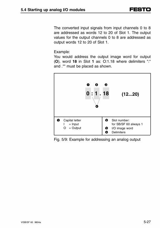
The converted input signals from input channels 0 to 8are addressed as words 12 to 20 of Slot 1. The outputvalues for the output channels 0 to 8 are addressed asoutput words 12 to 20 of Slot 1.
Example:You would address the output image word for output(O), word 18 in Slot 1 as: O:1.18 where delimiters ":"and ."" must be placed as shown.
1 2 3
(12...20)
4
1 Capital letterI = InputO = Output
2 Slot number: for SB/SF 60 always 1
3 I/O image word4 Delimiters
Fig. 5/9: Example for addressing an analog output
0 : 1 . 18
5.4 Starting up analog I/O modules
VISB/SF 60 9804a 5-27
Module considerations
The module’s I/O channel converters affect the resolu-tion of I/O data and bit usage in I/O image words. Weshow you how to compute I/O signal levels.
The module’s I/O channel converters use the lower 12bits of an input or output word when converting analogto digital input data and digital to analog output data.The following bit maps show the bits used in input andoutput image words:
Used bits
5.4 Starting up analog I/O modules
5-28 VISB/SF 60 9804a
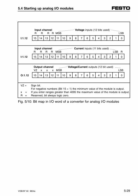
Input channel Voltage inputs (12 bits used) R R R R MSB LSB
I:1.12 15 14 13 12 11 10 9 8 7 6 5 4 3 2 1 0
Input channel Current inputs (11 bits used) R R R R MSB LSB R
I:1.12 15 14 13 12 11 10 9 8 7 6 5 4 3 2 1 0
Output channel Voltage/Current outputs (12 bit used) VZ x x x MSB LSB
O:1.12 15 14 13 12 11 10 9 8 7 6 5 4 3 2 1 0
VZ = Sign bit. For negative numbers (Bit 15 = 1) the minimum value of the module is output.
x = If you enter ranges greater than 4095 the maximum value of the module is output.R = Reserved, bit always logic zero.
Fig. 5/10: Bit map in I/O word of a converter for analog I/O modules
5.4 Starting up analog I/O modules
VISB/SF 60 9804a 5-29
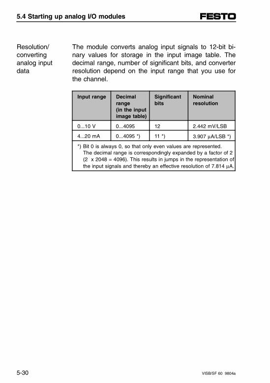
The module converts analog input signals to 12-bit bi-nary values for storage in the input image table. Thedecimal range, number of significant bits, and converterresolution depend on the input range that you use forthe channel.
Resolution/convertinganalog inputdata
Input range Decimalrange(in the inputimage table)
Significantbits
Nominalresolution
0...10 V 0...4095 12 2.442 mV/LSB
4...20 mA 0...4095 *) 11 *) 3.907 µA/LSB *)
*) Bit 0 is always 0, so that only even values are represented.The decimal range is correspondingly expanded by a factor of 2(2 x 2048 = 4096). This results in jumps in the representation ofthe input signals and thereby an effective resolution of 7.814 µA.
5.4 Starting up analog I/O modules
5-30 VISB/SF 60 9804a
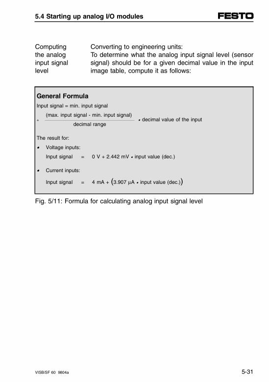
Converting to engineering units:To determine what the analog input signal level (sensorsignal) should be for a given decimal value in the inputimage table, compute it as follows:
Computingthe analoginput signallevel
General FormulaInput signal = min. input signal
(max. input signal - min. input signal) + • decimal value of the input
decimal range
The result for:
• Voltage inputs:
Input signal = 0 V + 2.442 mV • input value (dec.)
• Current inputs:
Input signal = 4 mA + (3.907 µA • input value (dec.))
Fig. 5/11: Formula for calculating analog input signal level
5.4 Starting up analog I/O modules
VISB/SF 60 9804a 5-31
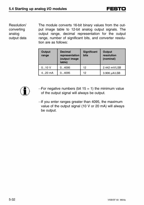
The module converts 16-bit binary values from the out-put image table to 12-bit analog output signals. Theoutput range, decimal representation for the outputrange, number of significant bits, and converter resolu-tion are as follows:
Resolution/convertinganalogoutput data
Output range
Decimal representation(output imagetable)
Significantbits
Outputresolution(nominal)
0...10 V 0...4095 12 2.442 mV/LSB
4...20 mA 0...4095 12 3.906 µA/LSB
-For negative numbers (bit 15 = 1) the minimum valueof the output signal will always be output.
- If you enter ranges greater than 4095, the maximumvalue of the output signal (10 V or 20 mA) will alwaysbe output.
5.4 Starting up analog I/O modules
5-32 VISB/SF 60 9804a
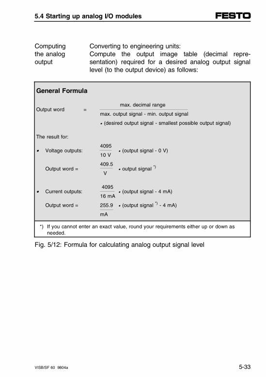
Converting to engineering units:Compute the output image table (decimal repre-sentation) required for a desired analog output signallevel (to the output device) as follows:
Computingthe analogoutput
General Formula
max. decimal range Output word =
max. output signal - min. output signal
• (desired output signal - smallest possible output signal)
The result for:
4095• Voltage outputs: • (output signal - 0 V)
10 V
409.5Output word = • output signal *)
V
4095• Current outputs: • (output signal - 4 mA)
16 mA
Output word = 255.9 • (output signal *) - 4 mA)
mA
*) If you cannot enter an exact value, round your requirements either up or down as needed.
Fig. 5/12: Formula for calculating analog output signal level
5.4 Starting up analog I/O modules
VISB/SF 60 9804a 5-33
Safe state for outputs
Whenever the SB/SF 60 is not in RUN mode, the ana-log module’s outputs are automatically forced to 0 voltsor 4 milliamps. This occurs when the processor is inone of the following modes:
– FAULT
– PROGRAM
– TEST
WARNINGWhen designing and installing the SB/SF 60 system,place devices connected to analog output channelsin a safe state whenever the analog output is zero (± the offset error).
Determine which output conditions must be held ONfor a safe state.
5.4 Starting up analog I/O modules
5-34 VISB/SF 60 9804a
5.4.3 Writing ladder logic
This chapter presents the following programming exam-ples:
– Retentive and non-retentive programming
– Detect an out-of-range input
– General scaling of analog inputs and outputs
– Scale analog inputs and detect an out-of-range condition
– Scale analog outputs
– Scale offsets when > 32767 or < - 32768
– PID control with analog I/O scaling
PLEASE NOTEThe following programming examples are based onsuggestions from Allen-Bradley and are for instruc-tional purposes only. Because of the many variables and requirements as-sociated with any application, the Allen-Bradley Com-pany and Festo cannot assume responsibility or lia-bility for actual use based on these examples.
5.4 Starting up analog I/O modules
VISB/SF 60 9804a 5-35
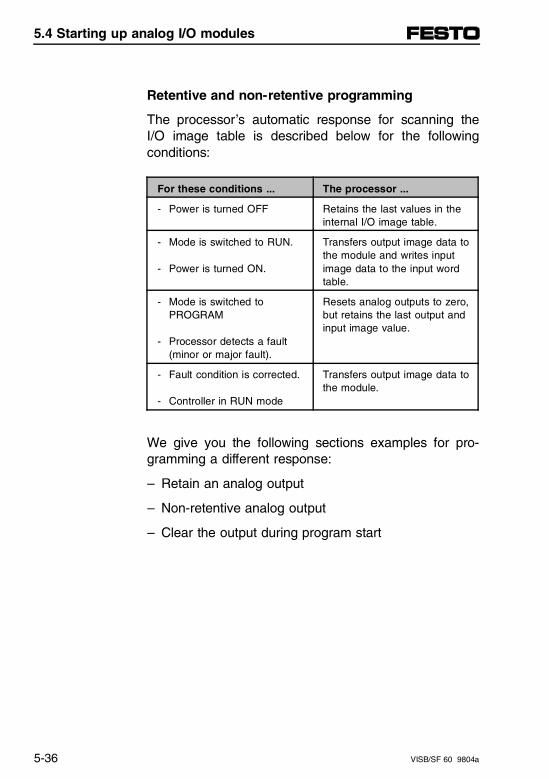
Retentive and non-retentive programming
The processor’s automatic response for scanning theI/O image table is described below for the followingconditions:
For these conditions ... The processor ...
- Power is turned OFF Retains the last values in theinternal I/O image table.
- Mode is switched to RUN.
- Power is turned ON.
Transfers output image data tothe module and writes inputimage data to the input wordtable.
- Mode is switched to PROGRAM
- Processor detects a fault (minor or major fault).
Resets analog outputs to zero,but retains the last output andinput image value.
- Fault condition is corrected.
- Controller in RUN mode
Transfers output image data tothe module.
We give you the following sections examples for pro-gramming a different response:
– Retain an analog output
– Non-retentive analog output
– Clear the output during program start
5.4 Starting up analog I/O modules
5-36 VISB/SF 60 9804a
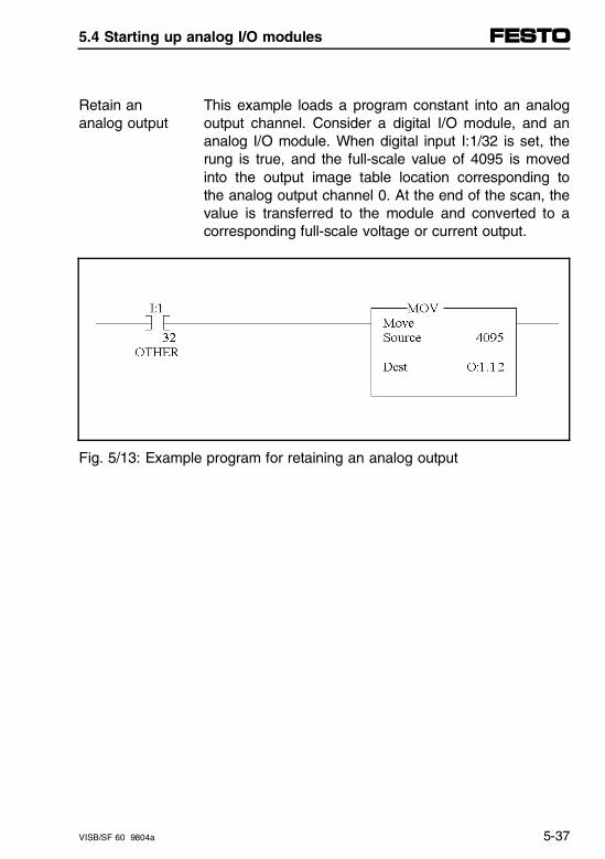
This example loads a program constant into an analogoutput channel. Consider a digital I/O module, and ananalog I/O module. When digital input I:1/32 is set, therung is true, and the full-scale value of 4095 is movedinto the output image table location corresponding tothe analog output channel 0. At the end of the scan, thevalue is transferred to the module and converted to acorresponding full-scale voltage or current output.
Retain ananalog output
Fig. 5/13: Example program for retaining an analog output
5.4 Starting up analog I/O modules
VISB/SF 60 9804a 5-37
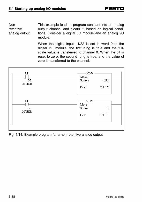
This example loads a program constant into an analogoutput channel and clears it, based on logical condi-tions. Consider a digital I/O module and an analog I/Omodule.
Non-retentiveanalog output
When the digital input I:1/32 is set in word 0 of thedigital I/O module, the first rung is true and the full-scale value is transferred to channel 0. When the bit isreset to zero, the second rung is true, and the value ofzero is transferred to the channel.
Fig. 5/14: Example program for a non-retentive analog output
5.4 Starting up analog I/O modules
5-38 VISB/SF 60 9804a
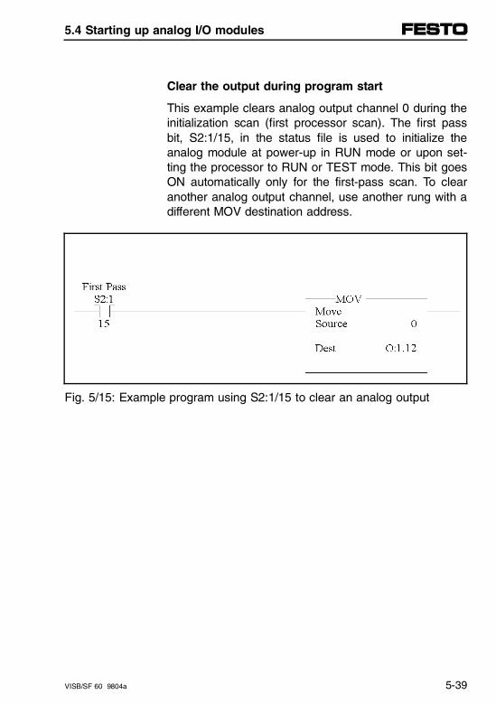
Clear the output during program start
This example clears analog output channel 0 during theinitialization scan (first processor scan). The first passbit, S2:1/15, in the status file is used to initialize theanalog module at power-up in RUN mode or upon set-ting the processor to RUN or TEST mode. This bit goesON automatically only for the first-pass scan. To clearanother analog output channel, use another rung with adifferent MOV destination address.
Fig. 5/15: Example program using S2:1/15 to clear an analog output
5.4 Starting up analog I/O modules
VISB/SF 60 9804a 5-39
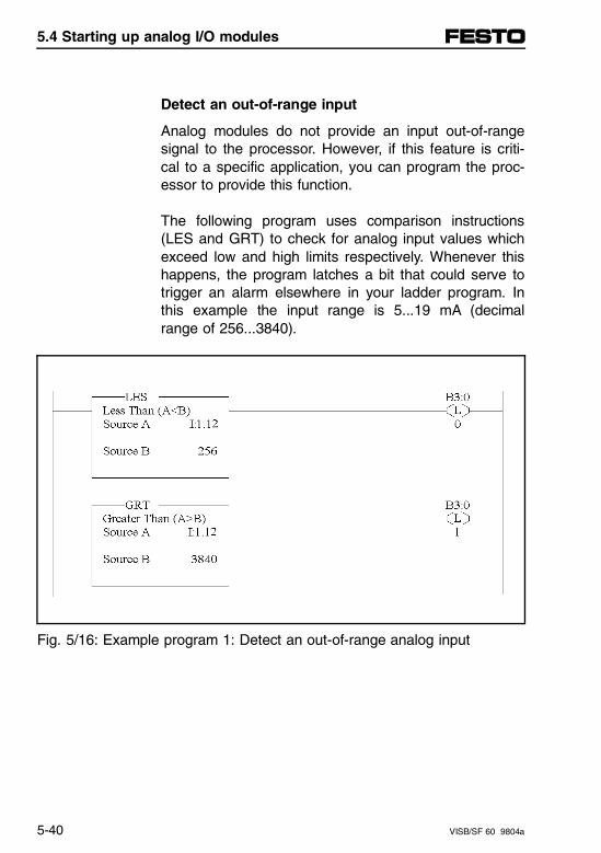
Detect an out-of-range input
Analog modules do not provide an input out-of-rangesignal to the processor. However, if this feature is criti-cal to a specific application, you can program the proc-essor to provide this function.
The following program uses comparison instructions(LES and GRT) to check for analog input values whichexceed low and high limits respectively. Whenever thishappens, the program latches a bit that could serve totrigger an alarm elsewhere in your ladder program. Inthis example the input range is 5...19 mA (decimalrange of 256...3840).
Fig. 5/16: Example program 1: Detect an out-of-range analog input
5.4 Starting up analog I/O modules
5-40 VISB/SF 60 9804a
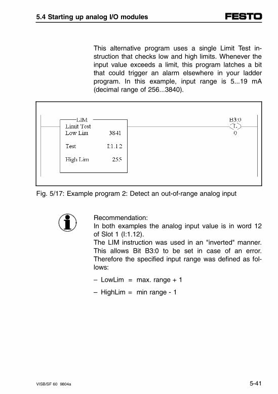
This alternative program uses a single Limit Test in-struction that checks low and high limits. Whenever theinput value exceeds a limit, this program latches a bitthat could trigger an alarm elsewhere in your ladderprogram. In this example, input range is 5...19 mA(decimal range of 256...3840).
Fig. 5/17: Example program 2: Detect an out-of-range analog input
Recommendation:In both examples the analog input value is in word 12of Slot 1 (I:1.12).The LIM instruction was used in an "inverted" manner.This allows Bit B3:0 to be set in case of an error.Therefore the specified input range was defined as fol-lows:
– LowLim = max. range + 1
– HighLim = min range - 1
5.4 Starting up analog I/O modules
VISB/SF 60 9804a 5-41
Overview of scaling inputs and outputs
Scaling is the application of a ratio on the variable to bescaled, where the ratio is the scaled range (∆Y) to the(decimal/binary) input range (∆X).
The purpose for scaling values when programming ana-log I/O modules is to change data format.
When you scale ... ... you start with this dataformat ...
... and typically change theformat to:
... inputs Decimal input range in rawcounts (from the module’s A/Dconverter).
Engineering units such as PSI(stored in the data table).
… outputs Integer values from the datatable (or from the input imagetable).
Decimal output range in rawcounts to match the module’soutput range.
... on a linear graph ∆X ∆Y
We illustrate input and output scaling, the source andtype of data to be scaled, and the type and destinationof the scaled data as follows:
5.4 Starting up analog I/O modules
5-42 VISB/SF 60 9804a
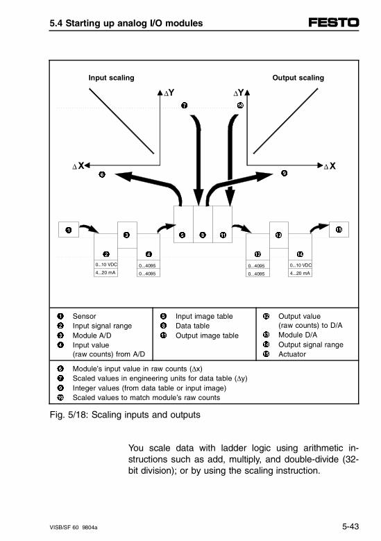
Input scaling Output scaling
7 0
9 6
1
3 5 8 ! #
%
2 4 " $
1 Sensor 2 Input signal range 3 Module A/D 4 Input value
(raw counts) from A/D
5 Input image table8 Data table! Output image table
" Output value (raw counts) to D/A# Module D/A$ Output signal range% Actuator
6 Module’s input value in raw counts (∆x)7 Scaled values in engineering units for data table (∆y)9 Integer values (from data table or input image)0 Scaled values to match module’s raw counts
Fig. 5/18: Scaling inputs and outputs
You scale data with ladder logic using arithmetic in-structions such as add, multiply, and double-divide (32-bit division); or by using the scaling instruction.
0...10 VDC
4...20 mA
0...4095
0...4095
0...10 VDC
4...20 mA
0...4095
0...4095
5.4 Starting up analog I/O modules
VISB/SF 60 9804a 5-43
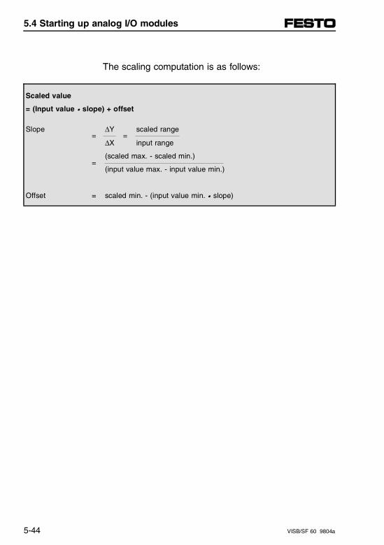
The scaling computation is as follows:
Scaled value
= (Input value • slope) + offset
Slope ∆Y scaled range = = ∆X input range
(scaled max. - scaled min.)=
(input value max. - input value min.)
Offset = scaled min. - (input value min. • slope)
5.4 Starting up analog I/O modules
5-44 VISB/SF 60 9804a
Scale an analog input and detect an out-of-rangecondition
The following example shows input range checking andscaling the analog input to engineering units.
We are making the following assumptions:
– A pressure sensor with a 0...10 V DC output is wiredto input channel 1.
– The sensor signal voltage is proportional to a rangeof 100... 500 PSI (6.89 - 34.474 bar)
– The process pressure must stay between 275 and300 PSI (18.96...20.68 bar). If the pressure deviatesfrom this range, your logic sets an alarm bit.
– Data is presented in PSI for monitoring and displaypurposes.
5.4 Starting up analog I/O modules
VISB/SF 60 9804a 5-45
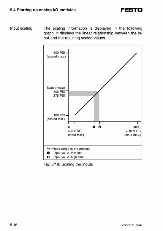
The scaling information is displayed in the followinggraph. It displays the linear relationship between the in-put and the resulting scaled values.
Input scaling
500 PSI(scaled max.)
Scaled value300 PSI275 PSI
100 PSI(scaled min.)
0 1 2 4095 = 0 V DC = 10 V DC(input min.) (input max.)
Permitted range in the process1 Input value, low limit2 Input value, high limit
Fig. 5/19: Scaling the inputs
5.4 Starting up analog I/O modules
5-46 VISB/SF 60 9804a
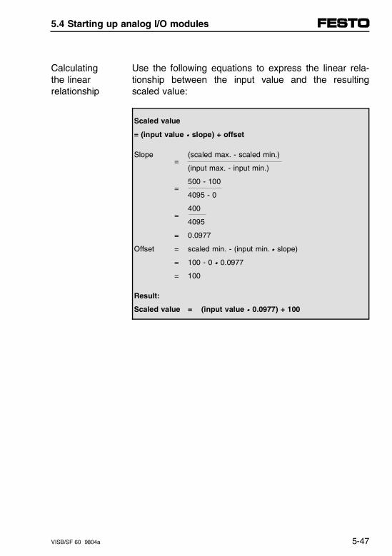
Use the following equations to express the linear rela-tionship between the input value and the resultingscaled value:
Calculatingthe linearrelationship
Scaled value = (input value • slope) + offset
Slope (scaled max. - scaled min.)=
(input max. - input min.)
500 - 100 =
4095 - 0
400=
4095
= 0.0977
Offset = scaled min. - (input min. • slope)
= 100 - 0 • 0.0977
= 100
Result:
Scaled value = (input value • 0.0977) + 100
5.4 Starting up analog I/O modules
VISB/SF 60 9804a 5-47

Use the following equation to compute low and highout-of-range limits (data from previous example: offset= 100, slope = 0.0977).
Calculatingthe out-of-range limits
Input value (scaled value - offset)=
slope
Low limit (275 - 100) = = 1750 (dec.)
0.0977
High limit (300 - 100) = = 2750 (dec.)
0.0977
We present two examples for programming the proces-sor.
Ladder logic
The first example uses standard math instructions avail-able in any SLC 500 processor. This ladder logic pre-vents a processor fault by unlatching the mathematicaloverflow bit S2:5/0 before the end of the scan.
5.4 Starting up analog I/O modules
5-48 VISB/SF 60 9804a
The second example uses the scaling instruction (SCL)available in SLC 5/02 (and later) processors.
PLEASE NOTEThe rate parameter is calculated by multiplying theslope by 10000. If the slope exceeds 3.2767, youcannot use SCL, since otherwise the permissible pro-cessor range is exceeded.
In our example the Rate Parameter is
Rate = 0.0977 • 10000 = 977
Therefore you can use SCL.
5.4 Starting up analog I/O modules
VISB/SF 60 9804a 5-49
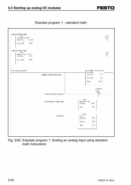
Example program 1 - standard math:
Fig. 5/20: Example program 1: Scaling an analog input using standard math instructions
5.4 Starting up analog I/O modules
5-50 VISB/SF 60 9804a
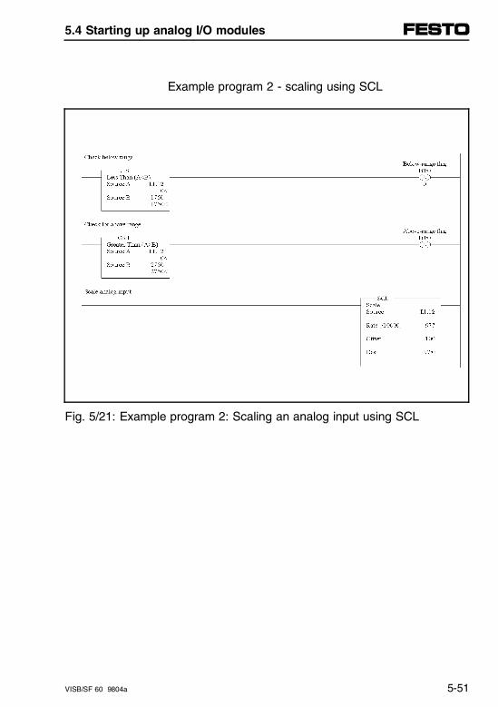
Example program 2 - scaling using SCL
Fig. 5/21: Example program 2: Scaling an analog input using SCL
5.4 Starting up analog I/O modules
VISB/SF 60 9804a 5-51
Scale an analog output
The following example shows the scaling of analog out-put values to engineering units for monitoring or control-ling purposes.
We are making the following assumptions:
– An actuator of a flow control valve is wired to outputchannel 0.
– The actuator accepts a 4...20 mA signal for a0...100 % of valve opening.
– The actuator can not receive a signal out of the4...20 mA range.
– The percentage of valve opening is manually input tothe processor.
5.4 Starting up analog I/O modules
5-52 VISB/SF 60 9804a
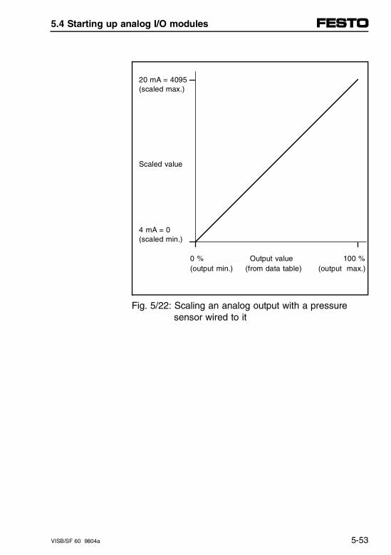
20 mA = 4095(scaled max.)
Scaled value
4 mA = 0(scaled min.)
0 % Output value 100 %(output min.) (from data table) (output max.)
Fig. 5/22: Scaling an analog output with a pressure sensor wired to it
5.4 Starting up analog I/O modules
VISB/SF 60 9804a 5-53
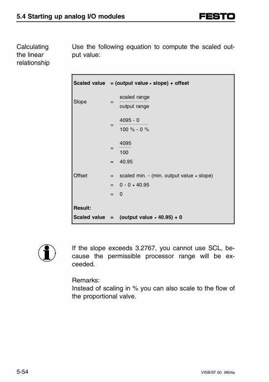
Use the following equation to compute the scaled out-put value:
Calculatingthe linearrelationship
Scaled value = (output value • slope) + offset
scaled range Slope =
output range
4095 - 0=
100 % - 0 %
4095=
100
= 40.95
Offset = scaled min. - (min. output value • slope)
= 0 - 0 • 40.95
= 0
Result:
Scaled value = (output value • 40.95) + 0
If the slope exceeds 3.2767, you cannot use SCL, be-cause the permissible processor range will be ex-ceeded.
Remarks:Instead of scaling in % you can also scale to the flow ofthe proportional valve.
5.4 Starting up analog I/O modules
5-54 VISB/SF 60 9804a
The out-of-range limits are predetermined because anyvalue less than 0% is 0 and any value greater than100 % is 4095. The ladder logic checks for out-of-rangelimits to verify that not less than 4 mA and not morethan 20 mA is delivered to the analog output channel.
Ladder logic
The percentage of valve opening may be entered intoprocessor memory by:
– Entering the data through a DTAM or HHT
– MOVing the data from a keypad.
The percentage of valve opening may be displayed foran operator interface by:
– Monitoring the data through a DTAM of HHT
– MOVing the data through the output module to adata display (text display, dataliner)
– Converting the data to BCD and MOVing it to anLED display.
5.4 Starting up analog I/O modules
VISB/SF 60 9804a 5-55
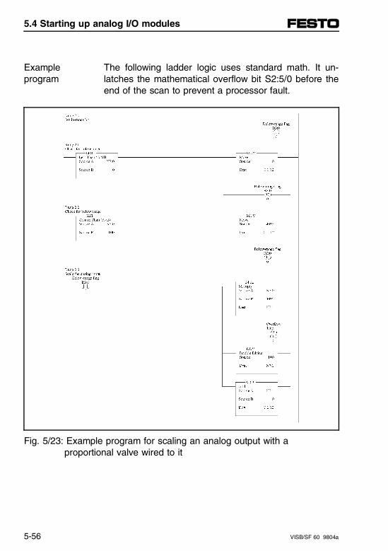
The following ladder logic uses standard math. It un-latches the mathematical overflow bit S2:5/0 before theend of the scan to prevent a processor fault.
Exampleprogram
Fig. 5/23: Example program for scaling an analog output with a proportional valve wired to it
5.4 Starting up analog I/O modules
5-56 VISB/SF 60 9804a
Scale offsets when > 32767 or < - 32768
Some applications may produce an offset greater than32767 or less than - 32768, the largest value that canbe stored in a 16-bit integer or processed by the SLCprocessor.
If so, you may reduce the magnitude of the offset byshifting the linear relationship along the input valueaxis. When you compute linear relationships, you willsee how the offset is reduced in this manner. The fol-lowing example applies to a 0.5...9.5 V DC outputscaled from a narrow input range of 90...100 %.
5.4 Starting up analog I/O modules
VISB/SF 60 9804a 5-57
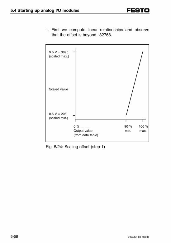
1. First we compute linear relationships and observethat the offset is beyond -32768.
9.5 V = 3890(scaled max.)
Scaled value
0.5 V = 205(scaled min.)
0 % 90 % 100 % Output value min. max.
(from data table)
Fig. 5/24: Scaling offset (step 1)
5.4 Starting up analog I/O modules
5-58 VISB/SF 60 9804a
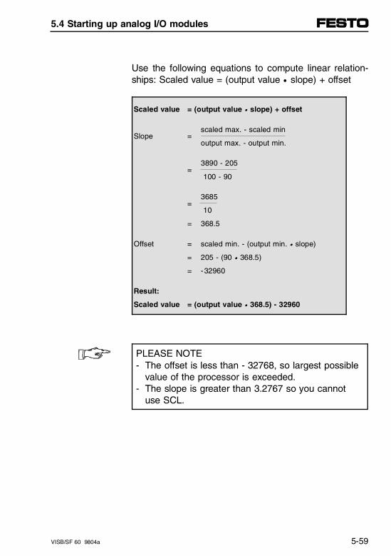
Use the following equations to compute linear relation-ships: Scaled value = (output value • slope) + offset
Scaled value = (output value • slope) + offset
scaled max. - scaled minSlope =
output max. - output min.
3890 - 205=
100 - 90
3685=
10
= 368.5
Offset = scaled min. - (output min. • slope)
= 205 - (90 • 368.5)
= -32960
Result:
Scaled value = (output value • 368.5) - 32960
PLEASE NOTE- The offset is less than - 32768, so largest possible
value of the processor is exceeded.- The slope is greater than 3.2767 so you cannot
use SCL.
5.4 Starting up analog I/O modules
VISB/SF 60 9804a 5-59
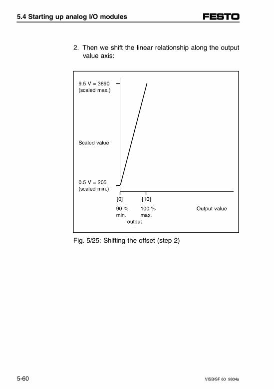
2. Then we shift the linear relationship along the outputvalue axis:
9.5 V = 3890(scaled max.)
Scaled value
0.5 V = 205(scaled min.)
[0] [10]
90 % 100 % Output value min. max.
output
Fig. 5/25: Shifting the offset (step 2)
5.4 Starting up analog I/O modules
5-60 VISB/SF 60 9804a
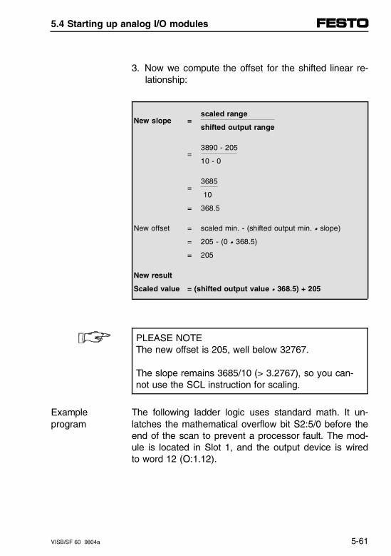
3. Now we compute the offset for the shifted linear re-lationship:
scaled rangeNew slope =
shifted output range
3890 - 205=
10 - 0
3685=
10
= 368.5
New offset = scaled min. - (shifted output min. • slope)
= 205 - (0 • 368.5)
= 205
New result
Scaled value = (shifted output value • 368.5) + 205
PLEASE NOTEThe new offset is 205, well below 32767.
The slope remains 3685/10 (> 3.2767), so you can-not use the SCL instruction for scaling.
The following ladder logic uses standard math. It un-latches the mathematical overflow bit S2:5/0 before theend of the scan to prevent a processor fault. The mod-ule is located in Slot 1, and the output device is wiredto word 12 (O:1.12).
Exampleprogram
5.4 Starting up analog I/O modules
VISB/SF 60 9804a 5-61
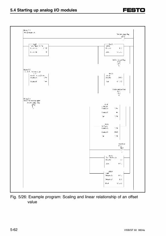
Fig. 5/26: Example program: Scaling and linear relationship of an offset value
5.4 Starting up analog I/O modules
5-62 VISB/SF 60 9804a
PID control with analog I/O scaling
With the combination of PID and SCL (scale) instruc-tions or PID and standard math instructions, you canwrite and display ladder logic in engineering units suchas PSI or °C. Do this as follows:
1. Scale the analog input PV (Process Variable) by cal-culating the slope (or rate) of the analog input range.For example, an input range such as 0...10 V or4...20 mA corresponding to a scaled range of0...4095. You would scale the 0...4095 against0...16383 for a slope of 4 (SCL Rate Parameter40000).
PLEASE NOTENote that the Rate Parameter is computed internallyas follows:
Rate = slope • 10000
If the slope is greater than 3.2767, you can nolonger use the SCL instruction, since the permissiblerange of 32767 is exceeded.
Therefore use the standard math instructions.
5.4 Starting up analog I/O modules
VISB/SF 60 9804a 5-63
2. Scale the analog output CV (Control Variable) bycalculating the slope (or rate) of the analog outputrange. For example, an output range such as4...20 mA or 0...10 V has a corresponding decimal(scaled) range of 0...4095. For a slope of 0.25 thevalue range of the PID instruction (0...16383) wouldbe scaled correspondingly to the value range of theanalog outputs (0...4095, SCL rate parameter 2500).
3. Now you can enter the PID parameters in engineer-ing units into the PID instruction. For example, if the4...20 mA analog input range represents 0...300PSI, enter 0 as the minimum (Smin) and 300 as themaximum (Smax). You can also enter setpoints anddeadband in engineering units. The data monitorscreen for PID will display these parameters in thesame engineering units.
The example program shows a PID control logic withscaled analog I/O, usable for both scaled voltage inputand output 0...10 V DC or 4...20 mA.
Exampleprogram
5.4 Starting up analog I/O modules
5-64 VISB/SF 60 9804a
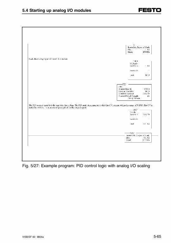
Fig. 5/27: Example program: PID control logic with analog I/O scaling
5.4 Starting up analog I/O modules
VISB/SF 60 9804a 5-65

5.4 Starting up analog I/O modules
5-66 VISB/SF 60 9804a
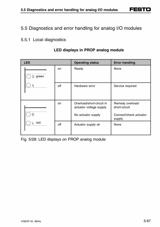
5.5 Diagnostics and error handling for analog I/O modules
5.5.1 Local diagnostics
LED displays in PROP analog module
LED Operating status Error handling
green
on Ready None
off Hardware error Service required
red
on Overload/short-circuit inactuator voltage supply
No actuator supply
Remedy overload/short-circuit
Connect/check actuatorsupply
off Actuator supply ok None
Fig. 5/28: LED displays on PROP analog module
5.5 Diagnostics and error handling for analog I/O modules
VISB/SF 60 9804a 5-67
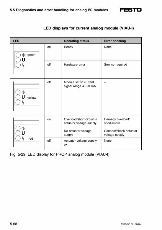
LED displays for current analog module (VIAU-I)
LED Operating status Error handling
green
on Ready None
off Hardware error Service required
yellow
off Module set to currentsignal range 4...20 mA
--
red
on Overload/short-circuit inactuator voltage supply
No actuator voltage supply
Remedy overload/short-circuit
Connect/check actuatorvoltage supply
off Actuator voltage supplyok
None
Fig. 5/29: LED display for PROP analog module (VIAU-I)
5.5 Diagnostics and error handling for analog I/O modules
5-68 VISB/SF 60 9804a
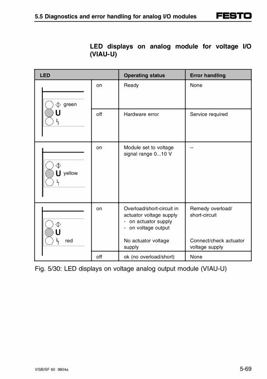
LED displays on analog module for voltage I/O(VIAU-U)
LED Operating status Error handling
green
on Ready None
off Hardware error Service required
yellow
on Module set to voltagesignal range 0...10 V
--
red
on Overload/short-circuit inactuator voltage supply- on actuator supply- on voltage output
No actuator voltage supply
Remedy overload/short-circuit
Connect/check actuatorvoltage supply
off ok (no overload/short) None
Fig. 5/30: LED displays on voltage analog output module (VIAU-U)
5.5 Diagnostics and error handling for analog I/O modules
VISB/SF 60 9804a 5-69
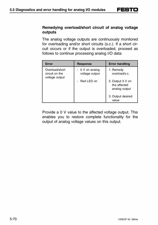
Remedying overload/short circuit of analog voltageoutputs
The analog voltage outputs are continuously monitoredfor overloading and/or short circuits (s.c.). If a short cir-cuit occurs or if the output is overloaded, proceed asfollows to continue processing analog I/O data:
Error Response Error handling
Overload/short circuit on the voltage output
- 0 V on analogvoltage output
- Red LED on
1. Remedy overload/s.c.
2. Output 0 V onthe affected analog output
3. Output desiredvalue
Provide a 0 V value to the affected voltage output. Thisenables you to restore complete functionality for theoutput of analog voltage values on this output.
5.5 Diagnostics and error handling for analog I/O modules
5-70 VISB/SF 60 9804a
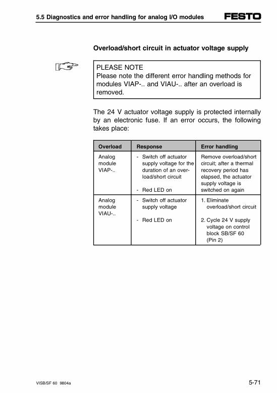
Overload/short circuit in actuator voltage supply
PLEASE NOTEPlease note the different error handling methods formodules VIAP-.. and VIAU-.. after an overload isremoved.
The 24 V actuator voltage supply is protected internallyby an electronic fuse. If an error occurs, the followingtakes place:
Overload Response Error handling
Analog module VIAP-..
- Switch off actuatorsupply voltage for theduration of an over-load/short circuit
- Red LED on
Remove overload/shortcircuit; after a thermalrecovery period haselapsed, the actuatorsupply voltage isswitched on again
Analog module VIAU-..
- Switch off actuatorsupply voltage
- Red LED on
1. Eliminate overload/short circuit
2. Cycle 24 V supplyvoltage on controlblock SB/SF 60(Pin 2)
5.5 Diagnostics and error handling for analog I/O modules
VISB/SF 60 9804a 5-71
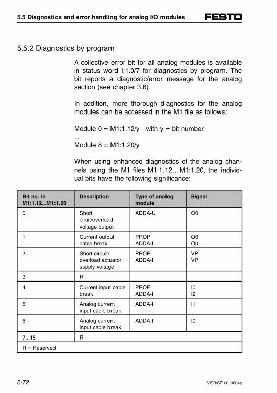
5.5.2 Diagnostics by program
A collective error bit for all analog modules is availablein status word I:1.0/7 for diagnostics by program. Thebit reports a diagnostic/error message for the analogsection (see chapter 3.6).
In addition, more thorough diagnostics for the analogmodules can be accessed in the M1 file as follows:
Module 0 = M1:1.12/y with y = bit number...Module 8 = M1:1.20/y
When using enhanced diagnostics of the analog chan-nels using the M1 files M1:1.12…M1:1.20, the individ-ual bits have the following significance:
Bit no. in M1:1.12...M1:1.20
Description Type of analogmodule
Signal
0 Shortciruit/overloadvoltage output
ADDA-U O0
1 Current outputcable break
PROPADDA-I
O0O0
2 Short circuit/overload actuatorsupply voltage
PROPADDA-I
VPVP
3 R
4 Current input cablebreak
PROPADDA-I
I0I2
5 Analog currentinput cable break
ADDA-I I1
6 Analog currentinput cable break
ADDA-I I0
7...15 R
R = Reserved
5.5 Diagnostics and error handling for analog I/O modules
5-72 VISB/SF 60 9804a
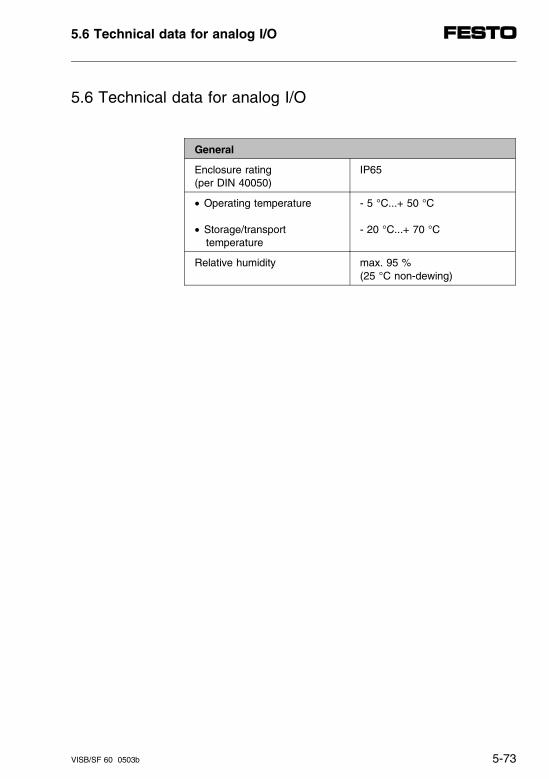
5.6 Technical data for analog I/O
General
Enclosure rating(per DIN 40050)
IP65
• Operating temperature
• Storage/transport temperature
- 5 °C...+ 50 °C
- 20 °C...+ 70 °C
Relative humidity max. 95 % (25 °C non-dewing)
5.6 Technical data for analog I/O
VISB/SF 60 0503b 5-73
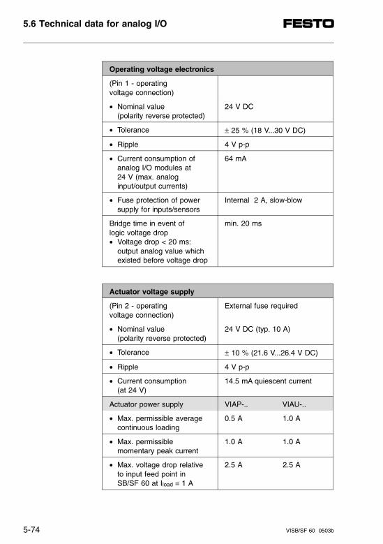
Operating voltage electronics
(Pin 1 - operating voltage connection)
• Nominal value(polarity reverse protected)
24 V DC
• Tolerance ± 25 % (18 V...30 V DC)
• Ripple 4 V p-p
• Current consumption of analog I/O modules at 24 V (max. analog input/output currents)
64 mA
• Fuse protection of power supply for inputs/sensors
Internal 2 A, slow-blow
Bridge time in event of logic voltage drop• Voltage drop < 20 ms:
output analog value which existed before voltage drop
min. 20 ms
Actuator voltage supply
(Pin 2 - operating voltage connection)
External fuse required
• Nominal value(polarity reverse protected)
24 V DC (typ. 10 A)
• Tolerance ± 10 % (21.6 V...26.4 V DC)
• Ripple 4 V p-p
• Current consumption (at 24 V)
14.5 mA quiescent current
Actuator power supply VIAP-.. VIAU-..
• Max. permissible averagecontinuous loading
0.5 A 1.0 A
• Max. permissible momentary peak current
1.0 A 1.0 A
• Max. voltage drop relative to input feed point in SB/SF 60 at Iload = 1 A
2.5 A 2.5 A
5.6 Technical data for analog I/O
5-74 VISB/SF 60 0503b
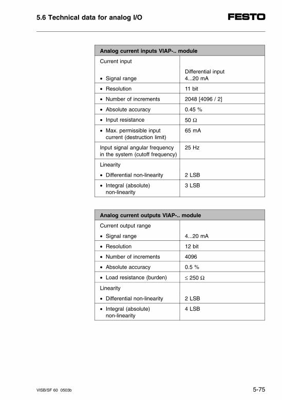
Analog current inputs VIAP-.. module
Current input
• Signal rangeDifferential input4...20 mA
• Resolution 11 bit
• Number of increments 2048 [4096 / 2]
• Absolute accuracy 0.45 %
• Input resistance 50 Ω
• Max. permissible input current (destruction limit)
65 mA
Input signal angular frequencyin the system (cutoff frequency)
25 Hz
Linearity
• Differential non-linearity 2 LSB
• Integral (absolute) non-linearity
3 LSB
Analog current outputs VIAP-.. module
Current output range
• Signal range 4...20 mA
• Resolution 12 bit
• Number of increments 4096
• Absolute accuracy 0.5 %
• Load resistance (burden) ≤ 250 Ω
Linearity
• Differential non-linearity 2 LSB
• Integral (absolute) non-linearity
4 LSB
5.6 Technical data for analog I/O
VISB/SF 60 0503b 5-75
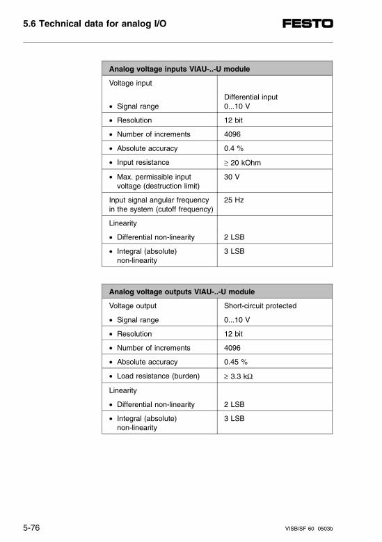
Analog voltage inputs VIAU-..-U module
Voltage input
• Signal rangeDifferential input0...10 V
• Resolution 12 bit
• Number of increments 4096
• Absolute accuracy 0.4 %
• Input resistance ≥ 20 kOhm
• Max. permissible input voltage (destruction limit)
30 V
Input signal angular frequencyin the system (cutoff frequency)
25 Hz
Linearity
• Differential non-linearity 2 LSB
• Integral (absolute) non-linearity
3 LSB
Analog voltage outputs VIAU-..-U module
Voltage output Short-circuit protected
• Signal range 0...10 V
• Resolution 12 bit
• Number of increments 4096
• Absolute accuracy 0.45 %
• Load resistance (burden) ≥ 3.3 kΩ
Linearity
• Differential non-linearity 2 LSB
• Integral (absolute) non-linearity
3 LSB
5.6 Technical data for analog I/O
5-76 VISB/SF 60 0503b

Analog current inputs VIAP-..-I module
Current input
• Signal rangeDifferential input4...20 mA
• Resolution 11 bit
• Number of increments 2048 [4096 / 2]
• Absolute accuracy 0.45 %
• Input resistance 50 Ω
• Max. permissible input current (destruction limit)
65 mA
Input signal angular frequencyin the system (cutoff frequency)
25 Hz
Linearity
• Differential non-linearity 2 LSB
• Integral (absolute) non-linearity
3 LSB
Analog current outputs VIAP-..-I module
Current output range
• Signal range 4...20 mA
• Resolution 12 bit
• Number of increments 4096
• Absolute accuracy 0.5 %
• Load resistance (burden) ≤ 250 Ω
Linearity
• Differential non-linearity 2 LSB
• Integral (absolute) non-linearity
4 LSB
5.6 Technical data for analog I/O
VISB/SF 60 0503b 5-77
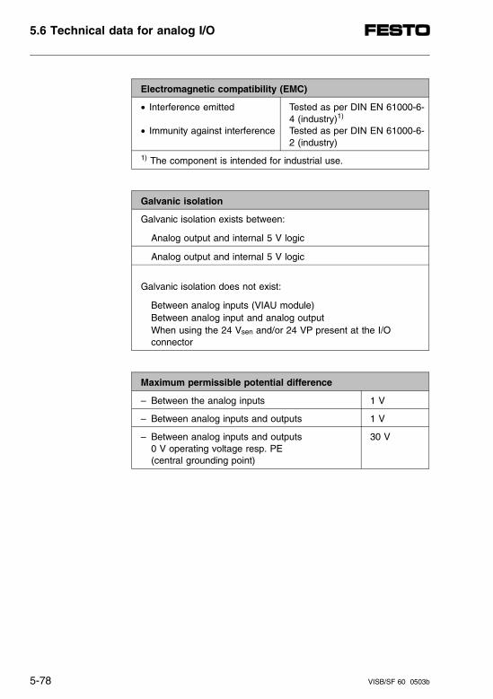
Electromagnetic compatibility (EMC)
• Interference emitted
• Immunity against interference
Tested as per DIN EN 61000-6-4 (industry)1)
Tested as per DIN EN 61000-6-2 (industry)
1) The component is intended for industrial use.
Galvanic isolation
Galvanic isolation exists between:
Analog output and internal 5 V logic
Analog output and internal 5 V logic
Galvanic isolation does not exist:
Between analog inputs (VIAU module) Between analog input and analog output When using the 24 Vsen and/or 24 VP present at the I/O
connector
Maximum permissible potential difference
– Between the analog inputs 1 V
– Between analog inputs and outputs 1 V
– Between analog inputs and outputs0 V operating voltage resp. PE (central grounding point)
30 V
5.6 Technical data for analog I/O
5-78 VISB/SF 60 0503b
Chapter 6
Description of AS-i master
6. Description of AS-i master
VISB/SF 60 9804a 6-I
Contents
6. Description of AS-i master
6.1 User instructions and system overview . . . . . . . . . . . . . . . . 6-1
6.1.1 User instructions . . . . . . . . . . . . . . . . . . . . . . . . . . . . . . . . . . . . . 6-1
6.1.2 System overview. . . . . . . . . . . . . . . . . . . . . . . . . . . . . . . . . . . . . 6-2General . . . . . . . . . . . . . . . . . . . . . . . . . . . . . . . . . . . . . . . . . . . . 6-2AS-i - general system data. . . . . . . . . . . . . . . . . . . . . . . . . . . . . 6-4AS-i bus systems . . . . . . . . . . . . . . . . . . . . . . . . . . . . . . . . . . . . 6-5Component description. . . . . . . . . . . . . . . . . . . . . . . . . . . . . . . . 6-8Function description . . . . . . . . . . . . . . . . . . . . . . . . . . . . . . . . . . 6-9
6.2 Mounting the components. . . . . . . . . . . . . . . . . . . . . . . . . . . . 6-11
AS-i master . . . . . . . . . . . . . . . . . . . . . . . . . . . . . . . . . . . . . . . . 6-12Mounting . . . . . . . . . . . . . . . . . . . . . . . . . . . . . . . . . . . . . . . . . . 6-12Grounding . . . . . . . . . . . . . . . . . . . . . . . . . . . . . . . . . . . . . . . . . 6-12Wall mounting and top-hat rail mounting . . . . . . . . . . . . . . . . . 6-12
6.3 Installation . . . . . . . . . . . . . . . . . . . . . . . . . . . . . . . . . . . . . . . . 6-13
6.3.1 General wiring techniques . . . . . . . . . . . . . . . . . . . . . . . . . . . . 6-13General . . . . . . . . . . . . . . . . . . . . . . . . . . . . . . . . . . . . . . . . . . . 6-14Selecting the AS-i bus cable . . . . . . . . . . . . . . . . . . . . . . . . . . 6-14Selecting the cable for the diagnostics interface . . . . . . . . . . . 6-15Connecting the cables to the plugs/sockets. . . . . . . . . . . . . . . 6-15Connecting the flat cables in penetration technique . . . . . . . . 6-16Connecting the flat cables to M12 round connectors . . . . . . . 6-17
6.3.2 AS-i master . . . . . . . . . . . . . . . . . . . . . . . . . . . . . . . . . . . . . . . . 6-18Connecting the diagnostics interface . . . . . . . . . . . . . . . . . . . . 6-18Pin assignment of the diagnostics interface. . . . . . . . . . . . . . . 6-19Configuration plug. . . . . . . . . . . . . . . . . . . . . . . . . . . . . . . . . . . 6-20
6. Description of AS-i master
6-II VISB/SF 60 9804a
6.3.3 Connecting the AS-i bus . . . . . . . . . . . . . . . . . . . . . . . . . . . . . . 6-21E-STOP reaction on the AS-i bus system . . . . . . . . . . . . . . . . . 6-21Pin assignment of the AS-i interface . . . . . . . . . . . . . . . . . . . . . 6-23
6.3.4 Connecting the AS-i power unit . . . . . . . . . . . . . . . . . . . . . . . . . 6-24General. . . . . . . . . . . . . . . . . . . . . . . . . . . . . . . . . . . . . . . . . . . . 6-24Placement on the AS-i bus . . . . . . . . . . . . . . . . . . . . . . . . . . . . 6-26Advantages of the Festo AS-i combi power unit . . . . . . . . . . . . 6-28
6.4 Start-up . . . . . . . . . . . . . . . . . . . . . . . . . . . . . . . . . . . . . . . . . . . 6-31
6.4.1 Before start-up . . . . . . . . . . . . . . . . . . . . . . . . . . . . . . . . . . . . . . 6-31General. . . . . . . . . . . . . . . . . . . . . . . . . . . . . . . . . . . . . . . . . . . . 6-31ID code and I/O code. . . . . . . . . . . . . . . . . . . . . . . . . . . . . . . . . 6-35Addressing AS-i slaves . . . . . . . . . . . . . . . . . . . . . . . . . . . . . . . 6-37Addressing with the AS-i addresser. . . . . . . . . . . . . . . . . . . . . . 6-38Check list before start-up . . . . . . . . . . . . . . . . . . . . . . . . . . . . . . 6-40Preparing for start-up . . . . . . . . . . . . . . . . . . . . . . . . . . . . . . . . . 6-42
6.4.2 Simple start-up with the configuration plug . . . . . . . . . . . . . . . . 6-45
6.4.3 User-friendly start-up using the AS-i Software Tool . . . . . . . . . 6-49Minimum requirements for the AS-i Software Tool . . . . . . . . . . 6-51Installing the AS-i Software Tool . . . . . . . . . . . . . . . . . . . . . . . . 6-53Starting the AS-i Software Tool . . . . . . . . . . . . . . . . . . . . . . . . . 6-55Menu "AS-i Software Tool" (main menu) . . . . . . . . . . . . . . . . . . 6-56Help window. . . . . . . . . . . . . . . . . . . . . . . . . . . . . . . . . . . . . . . . 6-56Menu "Program settings" . . . . . . . . . . . . . . . . . . . . . . . . . . . . . . 6-58Function "Reset master". . . . . . . . . . . . . . . . . . . . . . . . . . . . . . . 6-60Menu "Project management" . . . . . . . . . . . . . . . . . . . . . . . . . . . 6-62Menu "Project designing AS-i slaves" (configuration) . . . . . . . . 6-64Function "NOMINAL-ACTUAL comparison" . . . . . . . . . . . . . . . 6-67Menu "Assign/modify slave address". . . . . . . . . . . . . . . . . . . . . 6-69Menu "AS-i online" (online mode) . . . . . . . . . . . . . . . . . . . . . . . 6-73Window "AS-i master error status". . . . . . . . . . . . . . . . . . . . . . . 6-75Window "Transfer parameter" . . . . . . . . . . . . . . . . . . . . . . . . . . 6-77
6. Description of AS-i master
VISB/SF 60 9804a 6-III
6.4.4 Final steps for start-up . . . . . . . . . . . . . . . . . . . . . . . . . . . . . . . 6-79AS-i bus . . . . . . . . . . . . . . . . . . . . . . . . . . . . . . . . . . . . . . . . . . 6-79SB/SF 60 valve terminal. . . . . . . . . . . . . . . . . . . . . . . . . . . . . . 6-80
6.5 Addressing and programming . . . . . . . . . . . . . . . . . . . . . . . 6-81
6.5.1 Addressing the AS-i bus system . . . . . . . . . . . . . . . . . . . . . . . 6-81Address range of the AS-i I/Os . . . . . . . . . . . . . . . . . . . . . . . . 6-81Addressing example . . . . . . . . . . . . . . . . . . . . . . . . . . . . . . . . . 6-84AS-i allocation table (can be copied for use) . . . . . . . . . . . . . . 6-89
6.5.2 Programming the AS-i bus system. . . . . . . . . . . . . . . . . . . . . . 6-90Send AS-i slave parameters. . . . . . . . . . . . . . . . . . . . . . . . . . . 6-90Generating I/O interrupts from the AS-i bus system . . . . . . . . 6-93Power-on response. . . . . . . . . . . . . . . . . . . . . . . . . . . . . . . . . . 6-94Response to missing AS-i supply voltage . . . . . . . . . . . . . . . . 6-97Response to hardware error. . . . . . . . . . . . . . . . . . . . . . . . . . . 6-98Response to participant error . . . . . . . . . . . . . . . . . . . . . . . . . . 6-98
6.6 Overview of diagnostics possibilities . . . . . . . . . . . . . . . . 6-101
6.6.1 Local diagnostics . . . . . . . . . . . . . . . . . . . . . . . . . . . . . . . . . . 6-102LED displays on the AS-i master . . . . . . . . . . . . . . . . . . . . . . 6-102LED displays on the AS-i slaves . . . . . . . . . . . . . . . . . . . . . . 6-103AS-i Software Tool . . . . . . . . . . . . . . . . . . . . . . . . . . . . . . . . . 6-104
6.6.2 AS-i specific error handling . . . . . . . . . . . . . . . . . . . . . . . . . . 6-107Localizing defective slaves . . . . . . . . . . . . . . . . . . . . . . . . . . . 6-107Addressing using the AS-i addresser. . . . . . . . . . . . . . . . . . . 6-108Addressing with the AS-i Software Tool. . . . . . . . . . . . . . . . . 6-109Addressing using autoprogramming. . . . . . . . . . . . . . . . . . . . 6-111Diagnostics through AS-i master status bits (I:1.21/0...3) . . . 6-113Diagnostics through status word I:1.0 (common error bit I:1/1) . . . . . . . . . . . . . . . . . . . . . . . . . . . . . 6-115Diagnostics through M-files (M1:1.21 and M1:1.22) . . . . . . . 6-116
6.7 Technical data . . . . . . . . . . . . . . . . . . . . . . . . . . . . . . . . . . . . . 6-117
6. Description of AS-i master
6-IV VISB/SF 60 9804a
6.1 User instructions and system overview
6.1.1 User instructions
This description supplements the documentation foryour valve terminal with the necessary information concerning the AS-i master and AS-i bus system.
– The pictogram shown at left indicates places with im-portant information in chapters 1...3.
In-depth information and basic knowledge on the AS-ibus system and its specifications can be found in vari-ous publications, such as the book:"AS-i - The Actuator-Sensor-Interface for Automation,"by Werner Kriesel and Otto W. Madelung. (Hanser-Ver-lag, English Edition ISBN 3-446-18265-9).
6.1 User instructions and system overview
VISB/SF 60 9804a 6-1
6.1.2 System overview
General
AS-i - the actuator-sensor-interface - is a bus system atthe lowest level of automation systems. This bus sys-tem offers the following:
– Low cost networking of individual binary sensors andactuators.
– Flexible installation in decentral systems spacedapart.
– Very simple and fast (real time) protocol.
– Data and power supply transmitted on one cable.
AS-i can therefore be used as an installation-savingvariant or as a subsystem for existing field bus sys-tems.
6.1 User instructions and system overview
6-2 VISB/SF 60 9804a
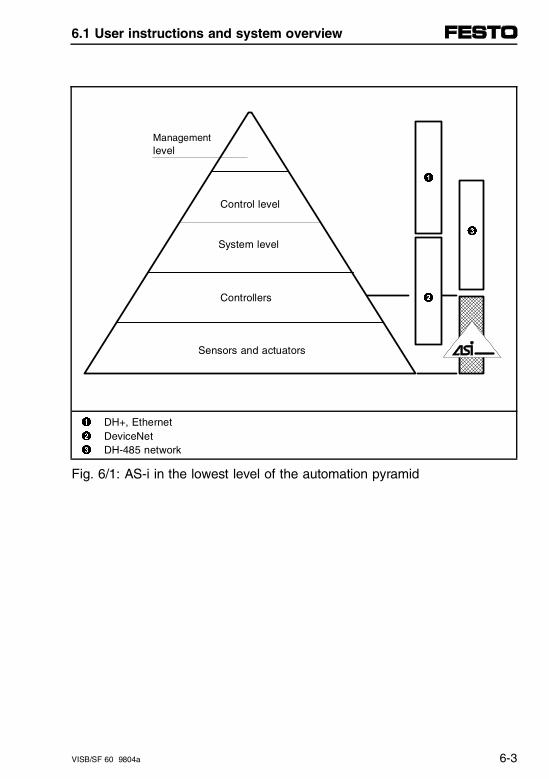
Managementlevel
1
Control level
3 System level
Controllers 2
Sensors and actuators
1 DH+, Ethernet2 DeviceNet3 DH-485 network
Fig. 6/1: AS-i in the lowest level of the automation pyramid
6.1 User instructions and system overview
VISB/SF 60 9804a 6-3
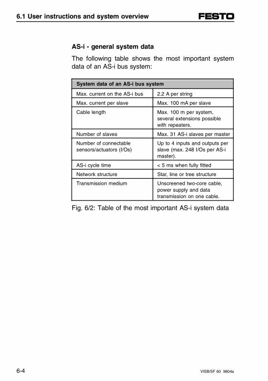
AS-i - general system data
The following table shows the most important systemdata of an AS-i bus system:
System data of an AS-i bus system
Max. current on the AS-i bus 2.2 A per string
Max. current per slave Max. 100 mA per slave
Cable length Max. 100 m per system,several extensions possiblewith repeaters.
Number of slaves Max. 31 AS-i slaves per master
Number of connectable sensors/actuators (I/Os)
Up to 4 inputs and outputs perslave (max. 248 I/Os per AS-imaster).
AS-i cycle time < 5 ms when fully fitted
Network structure Star, line or tree structure
Transmission medium Unscreened two-core cable,power supply and datatransmission on one cable.
Fig. 6/2: Table of the most important AS-i system data
6.1 User instructions and system overview
6-4 VISB/SF 60 9804a
AS-i bus systems
In many cases it is more efficient to use AS-i-capablepneumatics. Here are some examples:
– Critical transmission paths are offered.
– Small groups of valves can be controlled.
– Actuators and sensors are distributed at great dis-tances in the machine/assembly.
Suitable areas of application are e.g.:
– Conveyor belts
– Conveying technology
– Mounting and packing lines.
The requirements for setting up and commissioning anAS-i bus system are shown in the following illustration.
6.1 User instructions and system overview
VISB/SF 60 9804a 6-5
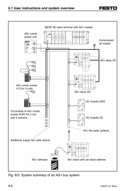
SB/SF 60 valve terminal with AS-i master
AS-i combi power unit
Compressed air supply
AS-i slave 4O
AS-i combi socket 4 O for 4 coils
AS-i slave 4O
I/O module 2I2O
I/O-module 4I AS-i combi socket 2I/2O for 2 coiland 2 sensors I/O module 4O
AS-i flat cable (yellow)
Additional supply flat cable (black)
AS-i adresser AS-i slave with set slave address
Fig. 6/3: System summary of an AS-i bus system
6.1 User instructions and system overview
6-6 VISB/SF 60 9804a
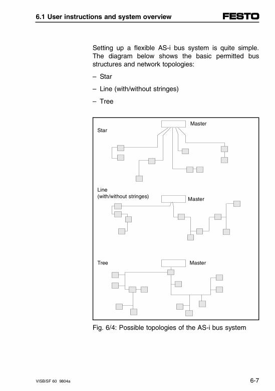
Setting up a flexible AS-i bus system is quite simple.The diagram below shows the basic permitted busstructures and network topologies:
– Star
– Line (with/without stringes)
– Tree
MasterStar
Line (with/without stringes) Master
Tree Master
Fig. 6/4: Possible topologies of the AS-i bus system
6.1 User instructions and system overview
VISB/SF 60 9804a 6-7
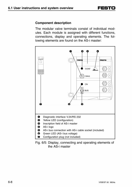
Component description
The modular valve terminals consist of individual mod-ules. Each module is assigned with different functions,connections, display and operating elements. The fol-lowing elements are found on the AS-i master:
1 Diagnostic interface V.24/RS 2322 Yellow LED (configuration)3 Inscription field of AS-i master4 AS-i logo5 AS-i bus connection with AS-i cable socket (included)6 Green LED (AS-i bus voltage)7 Configuration plug (not included)
Fig. 6/5: Display, connecting and operating elements ofthe AS-i master
7 6 5
1 2 3 4
6.1 User instructions and system overview
6-8 VISB/SF 60 9804a
Function description
The Festo AS-i master fulfills the following functions:
– It controls data transmission on the AS-i bus system.
– It controls data exchange with the control block of thevalve terminal.
– It adapts the addresses of all AS-i slaves to the ad-dressing scheme of the SB/SF 60 control block.
– It enables important start-up functions of the AS-i bussystem, e.g.:- configuration of the AS-i bus system,- parametrizing of AS-i slaves- automatic new addressing of replaced AS-i slaves,- changing/assigning of the AS-i slave address.
– It enables the diagnostics of the AS-i bus via:- the integrated diagnostic interface and a PC,- the integrated PLC.
6.1 User instructions and system overview
VISB/SF 60 9804a 6-9

1
SB/SF 60 valve terminal with AS-i master
2 3
5 4
5
1 Configuration, diagnostics and start-up with PC and the AS-i Software Tool2 V.24/RS 232 diagnostics interface3 Data exchange with the control block SB/SF 604 AS-i bus cable5 Data transmission to all AS-i bus slaves
Fig. 6/6: Function summary of the AS-i master
6.1 User instructions and system overview
6-10 VISB/SF 60 9804a
6.2 Mounting the components
WARNINGBefore mounting the components, switch off the following:• Compressed air supply• Power supply for the outputs (Pin 2)• Power supply for the electronic components (Pin 1)
In this way you can avoid:
– Uncontrolled movements of loose tubing,
– undesired movements of the connected actuators,
– undefined switching states of the electronic components.
CAUTIONThe valve terminal contains electrostatically vulner-able components.• Do not therefore touch the electrical contact
surfaces of the plugs on the side of the components.• Observe the instructions for handling electrostati-
caly vulnerable components.
In this way you can avoid damage to the valve terminalcomponents.
Observe the mounting instructions in chapter 2.
6.2 Mounting the components
VISB/SF 60 9804a 6-11
AS-i master
PLEASE NOTE• Always place the AS-i master directly next to the
left-hand end plate.• Do not mount more than 12 electrical modules
(incl. AS-i master).• Observe the addressing limits of the AS-i bus
system in the case of extension or conversion.
Mounting
The AS-i master is fitted with three M4 socket headscrews.
Grounding
The AS-i master is grounded via pre-assembled springcontacts.
Wall mounting and top-hat rail mounting
When calculating the total weight (general rule de-scribed in valve terminal manual), take into considera-tion that approximately 600 g must be added for theAS-i master.
6.2 Mounting the components
6-12 VISB/SF 60 9804a
6.3 Installation
6.3.1 General wiring techniques
WARNINGBefore mounting the components, switch off the following:• Compressed air supply• Power supply for the outputs (Pin 2)• Power supply for the electronic components (Pin 1)• Power supply for the AS-i bus system (AS-i power
supply).• Additional supply to the AS-i bus system
In this way you can avoid:
– Uncontrolled movements of loose tubing,
– undesired movements of the connected actuators,
– undefined switching states of the electronic components.
6.3 Installation
VISB/SF 60 0503b 6-13
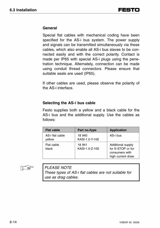
General
Special flat cables with mechanical coding have beenspecified for the AS-i bus system. The power supplyand signals can be transmitted simultaneously via thesecables, which also enable all AS-i bus slaves to be con-nected easily and with the correct polarity. Contact ismade per IP65 with special AS-i plugs using the pene-tration technique. Alternately, connection can be madeusing conduit thread connectors. Please ensure thatsuitable seals are used (IP65).
If other cables are used, please observe the polarity ofthe AS-i interface.
Selecting the AS-i bus cable
Festo supplies both a yellow and a black cable for theAS-i bus and the additional supply. Use the cables asfollows:
Flat cable Part no./type Application
AS-i flat cableyellow
18 940KASI-1.5-Y-100
AS-i bus
Flat cableblack
18 941KASI-1.5-Z-100
Additional supplyfor E-STOP or forconsumers withhigh current draw.
PLEASE NOTEThese types of AS-i flat cables are not suitable foruse as drag cables.
6.3 Installation
6-14 VISB/SF 60 0503b
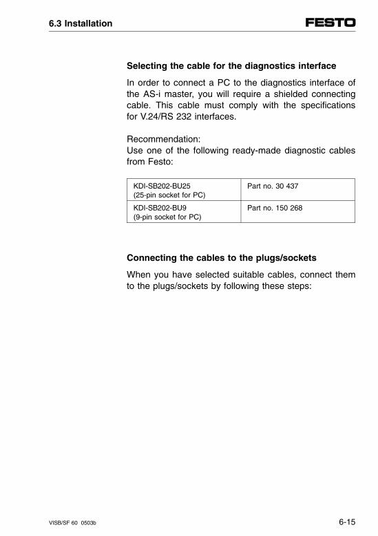
Selecting the cable for the diagnostics interface
In order to connect a PC to the diagnostics interface ofthe AS-i master, you will require a shielded connectingcable. This cable must comply with the specificationsfor V.24/RS 232 interfaces.
Recommendation:Use one of the following ready-made diagnostic cablesfrom Festo:
KDI-SB202-BU25(25-pin socket for PC)
Part no. 30 437
KDI-SB202-BU9(9-pin socket for PC)
Part no. 150 268
Connecting the cables to the plugs/sockets
When you have selected suitable cables, connect themto the plugs/sockets by following these steps:
6.3 Installation
VISB/SF 60 0503b 6-15
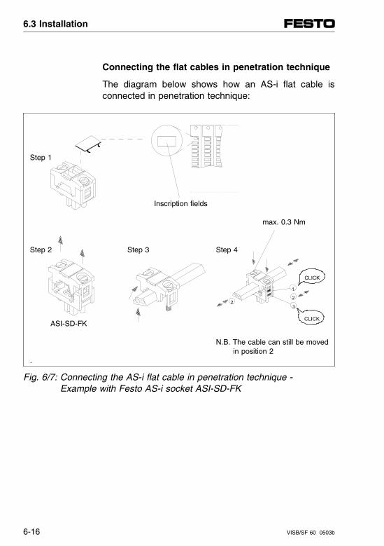
Connecting the flat cables in penetration technique
The diagram below shows how an AS-i flat cable isconnected in penetration technique:
Step 1
Inscription fields
max. 0.3 Nm
Step 2 Step 3 Step 4
ASI-SD-FK
N.B. The cable can still be moved in position 2
.
Fig. 6/7: Connecting the AS-i flat cable in penetration technique - Example with Festo AS-i socket ASI-SD-FK
6.3 Installation
6-16 VISB/SF 60 0503b
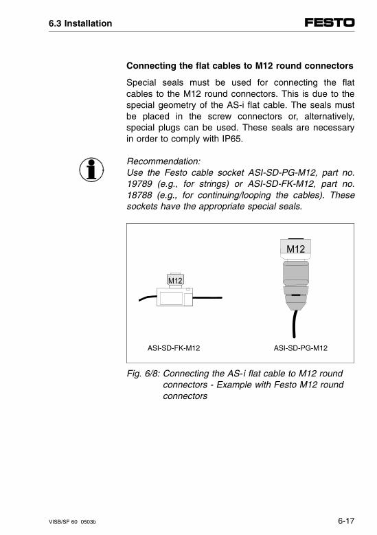
Connecting the flat cables to M12 round connectors
Special seals must be used for connecting the flatcables to the M12 round connectors. This is due to thespecial geometry of the AS-i flat cable. The seals mustbe placed in the screw connectors or, alternatively,special plugs can be used. These seals are necessaryin order to comply with IP65.
Recommendation:Use the Festo cable socket ASI-SD-PG-M12, part no.19789 (e.g., for strings) or ASI-SD-FK-M12, part no.18788 (e.g., for continuing/looping the cables). Thesesockets have the appropriate special seals.
ASI-SD-FK-M12 ASI-SD-PG-M12
Fig. 6/8: Connecting the AS-i flat cable to M12 roundconnectors - Example with Festo M12 roundconnectors
6.3 Installation
VISB/SF 60 0503b 6-17
6.3.2 AS-i master
Connecting the diagnostics interface
PLEASE NOTEThe baud rate of the diagnostics interface of the AS-i master is fixed at 9600 baud.
• Set the baud rate on your PC to 9600 baud.
• Connect the Festo diagnostics cable to the diagnos-tics interface as follows:
- 4-pin round connector to the diagnostics interface of the AS-i master;
- 25-pin or 9-pin socket to the serial V.24/RS 232interface of your PC (COMx).
6.3 Installation
6-18 VISB/SF 60 0503b
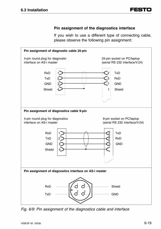
Pin assignment of the diagnostics interface
If you wish to use a different type of connecting cable,please observe the following pin assignment:
Pin assignment of diagnostic cable 25-pin
4-pin round plug for diagnostic 25-pin socket on PC/laptop interface on AS-i master (serial RS 232 interface/V.24)
Shield 4 1 Shield
Pin assignment of diagnostics cable 9-pin
4-pin round plug for diagnostics 9-pin socket on PC/laptop interface on AS-i master (serial RS 232 interface/V.24)
Shield 4
Pin assignment of diagnostics interface on AS-i master
RxD Shield
TxD GND
Fig. 6/9: Pin assignment of the diagnostics cable and interface
GND 3 5 GND
RxD 1 3 TxD
TxD 2 2 RxD
GND 3 7 GND
RxD 1 2 TxD
TxD 2 3 RxD
32
41
6.3 Installation
VISB/SF 60 0503b 6-19
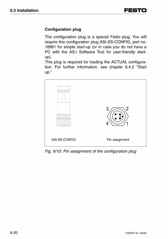
Configuration plug
The configuration plug is a special Festo plug. You willrequire this configuration plug ASI-SS-CONFIG, part no.18961 for simple start-up (or in case you do not have aPC with the AS-i Software Tool for user-friendly start-up).This plug is required for loading the ACTUAL configura-tion. For further information, see chapter 6.4.2 "Startup."
ASI-SS-CONFIG Pin assignment
Fig. 6/10: Pin assignment of the configuration plug
1
23
4
6.3 Installation
6-20 VISB/SF 60 0503b
6.3.3 Connecting the AS-i bus
E-STOP reaction on the AS-i bus system
A bus system should not, if possible, be switched off inthe event of an E-STOP. Otherwise important functionswill be lost, e.g.:
– Data transfer to the bus slaves
– Displays of processing states
Since however, power supply and data transfer takeplace on a common cable on the AS-i bus system, out-puts connected to the bus cannot be switched off sep-arately by hardware.
CAUTION– Outputs which are supplied with voltage via the
AS-i bus system cannot be switched off with hardware during an E-STOP.
– If the AS-i master fails during operation, the out-puts are reset or retain their last state, depending on the slave (see description of slaves)
– If the AS-i voltage to a slave is interrupted, the outputs are switched off.
6.3 Installation
VISB/SF 60 0503b 6-21
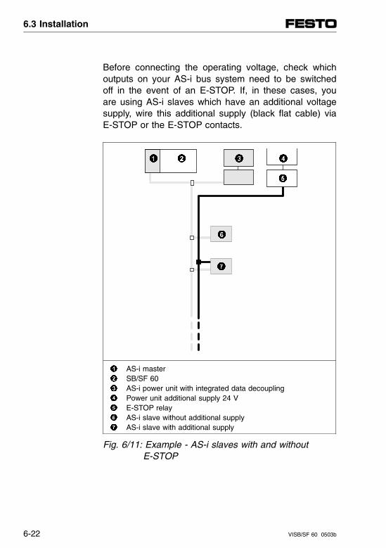
Before connecting the operating voltage, check whichoutputs on your AS-i bus system need to be switchedoff in the event of an E-STOP. If, in these cases, youare using AS-i slaves which have an additional voltagesupply, wire this additional supply (black flat cable) viaE-STOP or the E-STOP contacts.
AS-i master SB/SF 60 AS-i power unit with integrated data decoupling Power unit additional supply 24 V E-STOP relay AS-i slave without additional supply AS-i slave with additional supply
Fig. 6/11: Example - AS-i slaves with and without E-STOP
6.3 Installation
6-22 VISB/SF 60 0503b
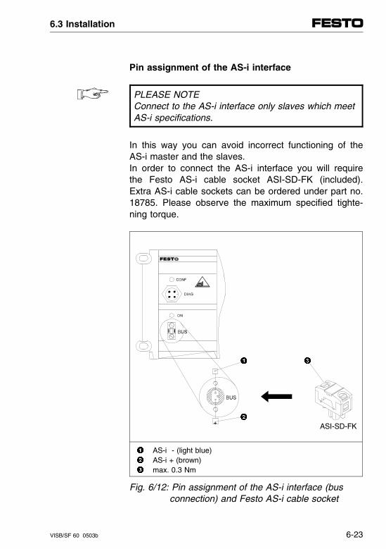
Pin assignment of the AS-i interface
PLEASE NOTEConnect to the AS-i interface only slaves which meetAS-i specifications.
In this way you can avoid incorrect functioning of theAS-i master and the slaves.In order to connect the AS-i interface you will requirethe Festo AS-i cable socket ASI-SD-FK (included).Extra AS-i cable sockets can be ordered under part no.18785. Please observe the maximum specified tighte-ning torque.
ASI-SD-FK
AS-i - (light blue) AS-i + (brown) max. 0.3 Nm
Fig. 6/12: Pin assignment of the AS-i interface (bus connection) and Festo AS-i cable socket
6.3 Installation
VISB/SF 60 0503b 6-23

6.3.4 Connecting the AS-i power unit
WARNING
• Use only PELV circuits as per IEC/DIN EN 60204-1(Protective Extra-Low Voltage, PELV) for the electri-cal supply.Consider also the general requirements for PELV cir-cuits in accordance with IEC/DIN EN 60204-1.
• Use power supplies which guarantee reliable electri-cal isolation of the operating voltage as per IEC/DINEN 60204-1.
By the use of PELV circuits, protection against electricshock (protection against direct and indirect contact) isguaranteed in accordance with IEC/EN 60204-1. (Elec-trical equipment for machines, General requirements).
General
Special power units for AS-i bus systems permit thesimultaneous transmission of power supply and signalson one cable. When selecting these devices, pleasecheck that they have the AS-i logo.
Recommendation:Use the Festo AS-i combi-power unit ASI-CNT-115/230VAC, part no. 18 949.
6.3 Installation
6-24 VISB/SF 60 0503b
The Festo AS-i combi power unit offers the followingadvantages:
– It is sufficiently isolated as per IEC/DIN EN 60204-1.
– It meets EMC Directives of the EC (CE Marking).
– It has an integrated AS-i supply module with data decoupling.
– It contains an additional 24 V output (6 A) for E-STOP circuits and slaves with high current con-sumption.
Please observe on the following pages the recommen-dations for placing the AS-i power unit and the furtherpoints for designing the bus system.
6.3 Installation
VISB/SF 60 0503b 6-25
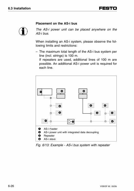
Placement on the AS-i bus
The AS-i power unit can be placed anywhere on theAS-i bus.
When installing an AS-i system, please observe the fol-lowing limits and restrictions:
– The maximum total length of the AS-i bus system perline (incl. strings) is 100 m.If repeaters are used, additional lines of 100 m arepossible. An additional AS-i power unit is required foreach line.
AS-i master AS-i power unit with integrated data decoupling Repeater AS-i slave
Fig. 6/13: Example - AS-i bus system with repeater
6.3 Installation
6-26 VISB/SF 60 0503b
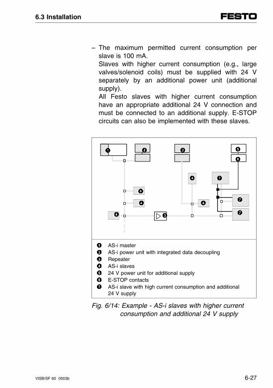
– The maximum permitted current consumption perslave is 100 mA.Slaves with higher current consumption (e.g., largevalves/solenoid coils) must be supplied with 24 Vseparately by an additional power unit (additionalsupply).All Festo slaves with higher current consumptionhave an appropriate additional 24 V connection andmust be connected to an additional supply. E-STOPcircuits can also be implemented with these slaves.
AS-i master AS-i power unit with integrated data decoupling Repeater AS-i slaves 24 V power unit for additional supply E-STOP contacts AS-i slave with high current consumption and additional
24 V supply
Fig. 6/14: Example - AS-i slaves with higher current consumption and additional 24 V supply
6.3 Installation
VISB/SF 60 0503b 6-27
– The maximum current capacity of the AS-i bus sys-tem per line is 2.2 A.
Recommendation: select a favorable placement of the AS-i power unit
within the AS-i bus system.Arrange slaves with higher current consumption in the
vicinity of the power unit.
If in doubt, you should make a critical examination ofthe current distribution and the voltage conditions at themost remote point of the AS-i bus system (lines).
Advantages of the Festo AS-i combi power unit
The Festo AS-i combi power unit supplies the AS-ioperating voltage according to the AS-i specificationand an additional 24 V supply (output voltage increasedto 26 V to compensate for voltage drop). This 24 Vsupply is suitable for E-STOP circuits or as an addi-tional supply for devices with high current consumption.The technical specifications of the combi power unit arelisted in chapter 6.6.
6.3 Installation
6-28 VISB/SF 60 0503b
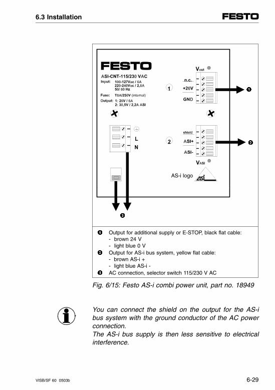
AS-i logo
Output for additional supply or E-STOP, black flat cable:- brown 24 V- light blue 0 V
Output for AS-i bus system, yellow flat cable:- brown AS-i +- light blue AS-i -
AC connection, selector switch 115/230 V AC
Fig. 6/15: Festo AS-i combi power unit, part no. 18949
You can connect the shield on the output for the AS-ibus system with the ground conductor of the AC powerconnection.The AS-i bus supply is then less sensitive to electricalinterference.
6.3 Installation
VISB/SF 60 0503b 6-29

6.3 Installation
6-30 VISB/SF 60 0503b
6.4 Start -up
6.4.1 Before start-up
General
Before starting up the AS-i bus system, there are someimportant points you must observe. The following pointsshould help you in avoiding mistakes and in observingimportant items.
All AS-i slaves are delivered with slave address 00 ifnot specified otherwise. Before connecting the slaves tothe AS-i bus, you must assign a slave address (1...31)to each slave. You may use the Festo addresser or theAS-i Software-Tool for this purpose. You must also ob-serve the instructions in the documentation for eachslave.
AddressingAS-i slaves
6.4 Start-up
VISB/SF 60 9804a 6-31
CAUTIONDuring start-up, a slave which still has slave address00 will be ignored by the master. This means thatthis slave will not be included in the ACTUAL list, theinputs will not be read and the outputs will not be set.There will not be an error message from the master.
If, during start-up or operation, another correctly ad-dressed slave fails (with identical I/O and ID codes),autoprogramming (see chapter 6.5 "Addressing withAutoprogramming") will take place on the slave with ad-dress 00 and all I/Os will be activated immediately.
Slave failure
6.4 Start-up
6-32 VISB/SF 60 9804a
The slave addresses may only be assigned once on anAS-i bus system. Addresses which are assigned twicewill result in errors during start-up and undefined proc-essing states.
Assigningslaveaddresses
CAUTIONDuring start-up and operation, undefined switchingstates may occur at the outputs if slave addressesare assigned twice.Under certain circumstances, outputs will be set par-allel or reset.Avoid double-assigned slave addresses.
The slave addresses may be assigned in any desiredsequence. They need not be consecutive.
6.4 Start-up
VISB/SF 60 9804a 6-33

The voltage supply to the AS-i slaves is always madevia the yellow bus cable. This cable is connected to theAS-i power unit for this purpose.
Planning thevoltagesupply
Slaves with high current consumption or with E-STOPfunction must be supplied by means of an additionalconnection and a separate power unit.
The voltage supplies must be switched on either to-gether or in the following sequence:1. AS-i bus2. AS-i master (via SB/SF 60 control block)
Configuration of the bus systems includes the assign-ment of all slaves to the host controller. The followingsteps are required when configuring the SB/SF 60 withAS-i master:
Planning theconfiguration
1. Configuration of the AS-i master within the terminal(addresses and number of AS-i slaves, ID and I/Ocodes, NOMINAL-ACTUAL comparison on the AS-ibus system).
2. Configuration of the terminal (incl. AS-i master) andthe SB/SF 60 controller. Option: Expanding the G file by entering the "AS-i master" (see chapter 3.3).
6.4 Start-up
6-34 VISB/SF 60 9804a
ID code and I/O code
AS-i specifications and AS-i profiles have been deter-mined for clearly identifying an AS-i slave. All manufac-turers have to adopt these specifications with an openbus system. An AS-i slave is clearly designated bymeans of an ID code and an I/O code. These codesare stored permanently in the slave by the manufac-turer and also printed on the type plate. They give thefollowing information:
The ID code tells us what type of slave this is (e.g., asimple I/O module, intelligent sensor or motor switch).The ID code also determines the profiles (e.g., data bitsand parameter bits) which are used by this slave. TheID code thereby supports the interchangeability of vari-ous manufacturers and is usually specified in hexadeci-mal form (e.g., FH).
ID code
– The AS-i master recognizes all ID codes automat-ically and then makes available the correct protocolvariant.
– Slaves with ID code FH:- do not conform with any AS-i profile- are defined individually between manufacturer
and user.
6.4 Start-up
VISB/SF 60 9804a 6-35
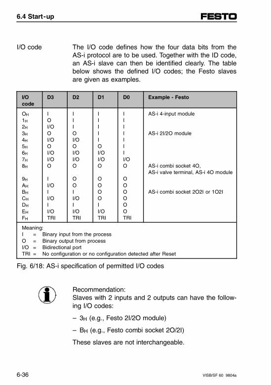
The I/O code defines how the four data bits from theAS-i protocol are to be used. Together with the ID code,an AS-i slave can then be identified clearly. The tablebelow shows the defined I/O codes; the Festo slavesare given as examples.
I/O code
I/Ocode
D3 D2 D1 D0 Example - Festo
OH
1H
2H
3H
4H
5H
6H
7H
8H
9H
AH
BH
CH
DH
EH
FH
IOI/OOI/OOI/OI/OO
II/OII/OII/OTRI
IIIOI/OOI/OI/OO
OOII/OII/OTRI
IIIIIOI/OI/OO
OOOOII/OTRI
IIIIIIII/OO
OOOOOOTRI
AS-i 4-input module
AS-i 2I/2O module
AS-i combi socket 4O,AS-i valve terminal, AS-i 4O module
AS-i combi socket 2O2I or 1O2I
Meaning:I = Binary input from the processO = Binary output from processI/O = Bidirectional portTRI = No configuration or no configuration detected after Reset
Fig. 6/18: AS-i specification of permitted I/O codes
Recommendation:Slaves with 2 inputs and 2 outputs can have the follow-ing I/O codes:
– 3H (e.g., Festo 2I/2O module)
– BH (e.g., Festo combi socket 2O/2I)
These slaves are not interchangeable.
6.4 Start-up
6-36 VISB/SF 60 9804a
Addressing AS-i slaves
The Festo AS-i master in combination with the SB/SF60 control block and the AS-i Software Tool providestwo possibilities for addressing AS-i slaves:
• With the AS-i addresser, i.e., the AS-i slave ad-dresses are set on each slave using the AS-i ad-dresser.
• Without the AS-i addresser. Here in the AS-i busconfigurator of the AS-i Software Tool the AS-i slaveaddresses are set individually for all slaves (see de-scription of the AS-i Software Tool in chapter 6.4.3).
Then a comparison between NOMINAL and ACTUALconfiguration can take place, the ACTUAL configurationcan be accepted as the NOMINAL configuration, andstart-up of the AS-i bus system can be completed.
Recommendation:Autoprogramming permits automatic configuration ofany defective/replaced slave on an already operationalAS-i bus. Autoprogramming is described in chapter6.6.2 "Diagnostics and Error Handling."
6.4 Start-up
VISB/SF 60 9804a 6-37
Addressing with the AS-i addresser
For this you need an AS-i addresser, e.g., the Festoaddresser part no. 18959.
PLEASE NOTEAddress each individual AS-i slave before installingon the AS-i bus.
Then proceed as follows (see also following illustration):
1. Connect the AS-i addresser to the AS-i slave (seedescription of your AS-i slave if necessary).
2. Read out the current address of the slave (for newslaves, usually address #00).
3. Assign an unused AS-i address to the slave (1...31);address #07 is shown in the illustration.
4. Install the addressed slave on the AS-i bus.
6.4 Start-up
6-38 VISB/SF 60 9804a
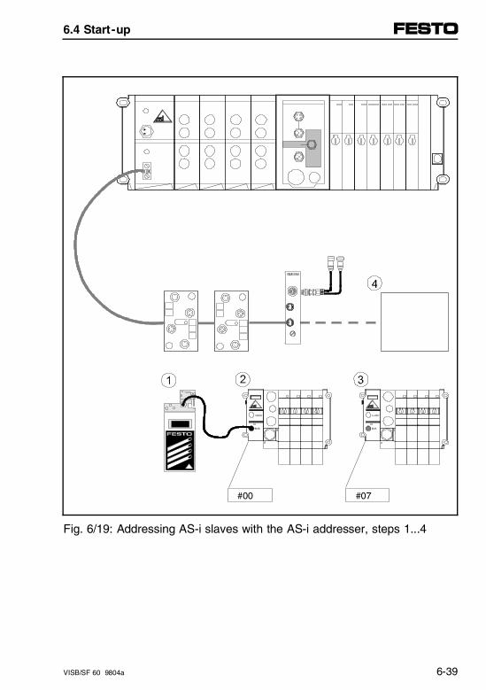
#00 #07
Fig. 6/19: Addressing AS-i slaves with the AS-i addresser, steps 1...4
6.4 Start-up
VISB/SF 60 9804a 6-39
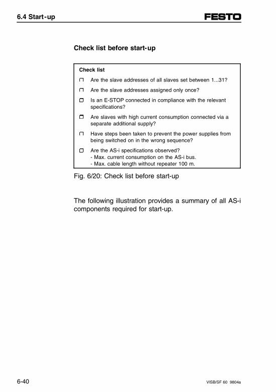
Check list before start-up
Check list
r Are the slave addresses of all slaves set between 1...31?
r Are the slave addresses assigned only once?
r Is an E-STOP connected in compliance with the relevant specifications?
r Are slaves with high current consumption connected via a separate additional supply?
r Have steps been taken to prevent the power supplies from being switched on in the wrong sequence?
r Are the AS-i specifications observed?- Max. current consumption on the AS-i bus.- Max. cable length without repeater 100 m.
Fig. 6/20: Check list before start-up
The following illustration provides a summary of all AS-icomponents required for start-up.
6.4 Start-up
6-40 VISB/SF 60 9804a
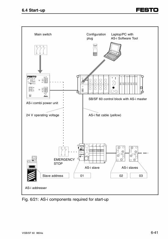
Main switch Configuration Laptop/PC with plug AS-i Software Tool
SB/SF 60 control block with AS-i master AS-i combi power unit
24 V operating voltage AS-i flat cable (yellow)
EMERGENCY STOP
AS-i slave AS-i slaves
Slave address 01 02 03
AS-i addresser
Fig. 6/21: AS-i components required for start-up
6.4 Start-up
VISB/SF 60 9804a 6-41
Preparing for start-up
WARNING– Ensure that when starting up no outputs will be
unintentionally activated and that automatic programstarts can not initiate any critical situations.
– Observe the prevailing safety regulations in yourcountry for machines and systems, and familiarizeyourself with the start-up instructions in the manualfor your controller.
This will help to prevent any unintended movements ofthe actuators.
The AS-i bus and the AS-i master must always be con-figured before starting up a valve terminal. The FestoAS-i master provides two possibilities for start-up:
ConfiguringAS-i master
• Simple start-up:Automatic transfer of the ACTUAL configuration toNOMINAL configuration using the configuration plug(see chapter 6.4.2).
6.4 Start-up
6-42 VISB/SF 60 9804a
• User-friendly start-up:Generate a NOMINAL configuration list using the AS-i Software Tool on a PC. Check the bus configu-ration with a NOMINAL-ACTUAL comparison throughthe diagnostics interface of the AS-i master (seechapter 6.4.3).
For the AS-i Software Tool you need an IBM-compatiblePC equipped as follows:
– 286 or higher, capable of running DOS V3.0 orhigher.
– RS 232/V.24 interface (COMx) and connection cablefor the diagnostics interface of the AS-i master.
For both start-up variants the following applies:The AS-i master stores information about the con-nected/identifiable slaves in the EEPROM. The following are stored under the slave address:- ID code- I/O codeThese are recalled later automatically during protocolconstruction and addressing.
6.4 Start-up
VISB/SF 60 9804a 6-43

6.4 Start-up
6-44 VISB/SF 60 9804a
6.4.2 Simple start-up with the configuration plug
CAUTIONWhen using the "simple start-up" method, unin-tended switching states and addressing errors mayoccur when turning on the operating voltage if the in-stallation (ACTUAL) configuration has not been pre-pared properly.Use caution when putting your AS-i bus system andyour pneumatic equipment into operation.
With the simple start-up method, the ACTUAL configu-ration on the AS-i bus is transferred to the AS-i masteras the NOMINAL configuration.Before turning on the supply voltage, make sure of thefollowing:
– All slaves are properly connected to the AS-i bus.
– AS-i addresses are unambiguously and correctly set.
This will ensure that the NOMINAL configuration canproceed easily and with no mistakes.
6.4 Start-up
VISB/SF 60 9804a 6-45
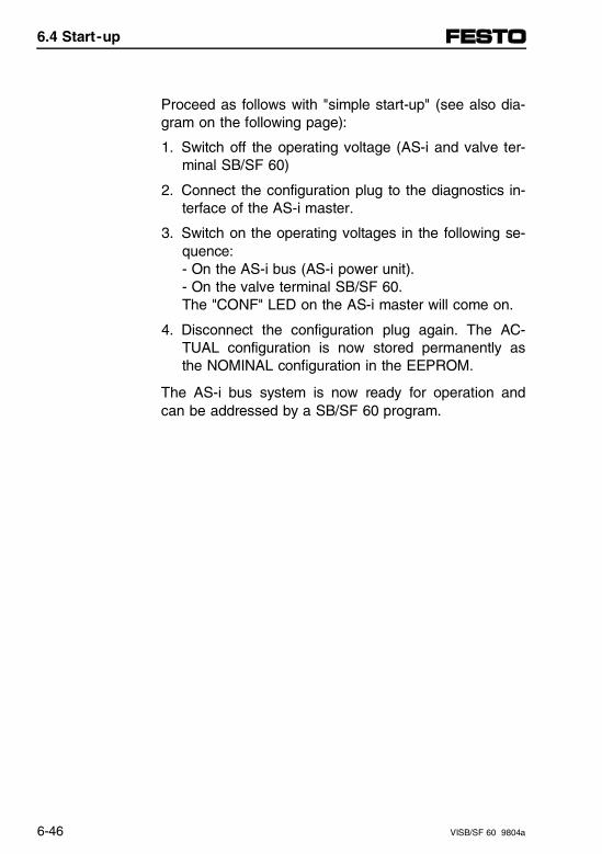
Proceed as follows with "simple start-up" (see also dia-gram on the following page):
1. Switch off the operating voltage (AS-i and valve ter-minal SB/SF 60)
2. Connect the configuration plug to the diagnostics in-terface of the AS-i master.
3. Switch on the operating voltages in the following se-quence:- On the AS-i bus (AS-i power unit).- On the valve terminal SB/SF 60.The "CONF" LED on the AS-i master will come on.
4. Disconnect the configuration plug again. The AC-TUAL configuration is now stored permanently asthe NOMINAL configuration in the EEPROM.
The AS-i bus system is now ready for operation andcan be addressed by a SB/SF 60 program.
6.4 Start-up
6-46 VISB/SF 60 9804a
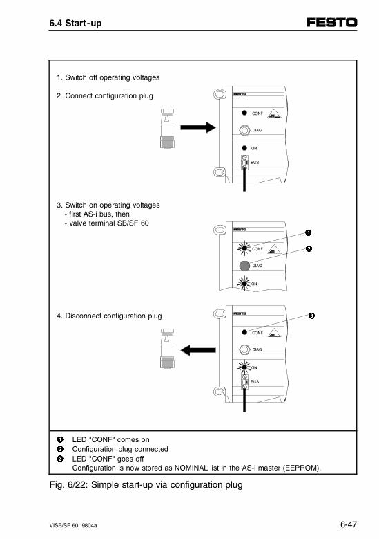
1. Switch off operating voltages
2. Connect configuration plug
3. Switch on operating voltages- first AS-i bus, then- valve terminal SB/SF 60
1
2
4. Disconnect configuration plug 3
1 LED "CONF" comes on2 Configuration plug connected3 LED "CONF" goes off
Configuration is now stored as NOMINAL list in the AS-i master (EEPROM).
Fig. 6/22: Simple start-up via configuration plug
6.4 Start-up
VISB/SF 60 9804a 6-47
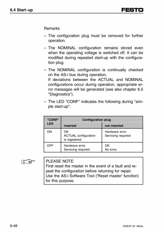
Remarks
– The configuration plug must be removed for furtheroperation.
– The NOMINAL configuration remains stored evenwhen the operating voltage is switched off. It can bemodified during repeated start-up with the configura-tion plug.
– The NOMINAL configuration is continually checkedon the AS-i bus during operation.If deviations between the ACTUAL and NOMINALconfigurations occur during operation, appropriate er-ror messages will be generated (see also chapter 6.5"Diagnostics").
– The LED "CONF" indicates the following during "sim-ple start-up":
"CONF"LED
Configuration plug
inserted not inserted
ON OKACTUAL configuration is registered
Hardware errorServicing required
OFF Hardware errorServicing required
OKNo error
PLEASE NOTEFirst reset the master in the event of a fault and re-peat the configuration before returning for repair.Use the AS-i Software Tool (‘Reset master’ function)for this purpose.
6.4 Start-up
6-48 VISB/SF 60 9804a
6.4.3 User-friendly start-up using the AS-i Software Tool
The AS-i Software Tool is on the enclosed CD-ROM"Utilities" (example for diskette drive D):- D:\ASI\asitool.DE\*.* files for the German version of
the software- D:\ASI\asitool.GB\*.* files for the English version of
the software
PLEASE NOTEThe following description of the AS-i Software Tool isdirected exclusively at technicians who are trained incontrol and automation technology and who alreadyhave experience with the installation and operationof PC software.
6.4 Start-up
VISB/SF 60 9804a 6-49
The AS-i Software Tool is intended for user-friendly pro-ject planning and start-up of the AS-i bus system. Thefollowing possibilities are offered:
– Project planning and configuration of the AS-i bussystem on a PC
– Loading the configuration data from the PC into theAS-i master
– Addressing the slaves connected to the AS-i network
– Testing the AS-i inputs and outputs in online mode
– Displaying the AS-i error messages (plain text)
– Transferring slave parameters to AS-i slaves de-signed for this purpose (e.g., for testing sensors)
– Reset the AS-i master (e.g., after changing the con-trol block).
6.4 Start-up
6-50 VISB/SF 60 9804a
Minimum requirements for the AS-i Software Tool
The following conditions must be met before the AS-iSoftware Tool can be used:
– A PC/laptop, DOS version 3.0 or higher must beavailable for installing the AS-i Software Tool.
– A valve terminal with SB/SF 60 control block, AS-imaster and AS-i bus system must be installed andfunctional.
– The diagnostics interface of the AS-i master must beconnected to the RS 232 interface of the PC (seechapter 6.3.2 "Installing the AS-i master").
CAUTIONBefore starting the software, set the controller toSTOP.In many cases (i.e., online mode, NOMINAL-AC-TUAL comparison, programming addresses), there isno data transfer between the AS-i master and thecontrol block.The AS-i outputs of all AS-i slaves are set at zeroin these cases by the AS-i master.When the AS-i Software Tool is exited (F8), the con-trol block establishes communication with the AS-i master immediately.If control programs now run, the AS-i inputs and out-puts will be processed immediately.
6.4 Start-up
VISB/SF 60 9804a 6-51
Recommendation:
-Always exit the AS-i Software Tool with the F8 func-tion key.
- Leave the plug of the diagnostics cable inserted whilethe software is running.Otherwise the AS-i master will remain permanentlyblocked (STOP status), as an important "End" controlcharacter is not sent from the AS-i Software Tool.
6.4 Start-up
6-52 VISB/SF 60 9804a

Installing the AS-i Software Tool
Proceed as follows:
– Create a directory on the hard disk of your PC forinstalling the AS-i Software Tool (e.g., C:\FST-ASI).Select on the CD-ROM the directory with the desiredlanguage:- German: directory ASI\ASITOOL.DE or- English: directory ASI\ASITOOL.GB.
– Copy the files ASITOOL.EXE and ASITOOL.HLPfrom the enclosed CD-ROM into the created directoryon your hard disk.
– Start the software under DOS directly from your di-rectory with "ASITOOL" (or under Windows in theDOS window). If you wish to work under DOS withthe mouse, you must load the mouse driver.
6.4 Start-up
VISB/SF 60 9804a 6-53
Recommendation:
-During operation the AS-i Software Tool will createthe files ASITOOL.CFG (program configuration) andASI-TOOL.ASI (project management) as well as a filefor each project <project name>.PRJ.
- If "File" is specified for the printer interface, this filewill have the name <project name>.DOK.
These files are also stored in the project directory.
Some of the program functions listed below can beprocessed without the AS-i master being connected(e.g., project planning of the AS-i slaves); others onlywith the AS-i master or AS-i bus system connected(e.g., online mode).
6.4 Start-up
6-54 VISB/SF 60 9804a
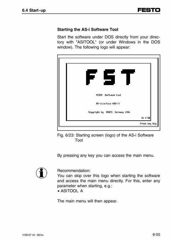
Starting the AS-i Software Tool
Start the software under DOS directly from your direc-tory with "ASITOOL" (or under Windows in the DOSwindow). The following logo will appear:
Fig. 6/23: Starting screen (logo) of the AS-i Software Tool
By pressing any key you can access the main menu.
Recommendation:You can skip over this logo when starting the softwareand access the main menu directly. For this, enter anyparameter when starting, e.g.:• ASITOOL A
The main menu will then appear.
6.4 Start-up
VISB/SF 60 9804a 6-55
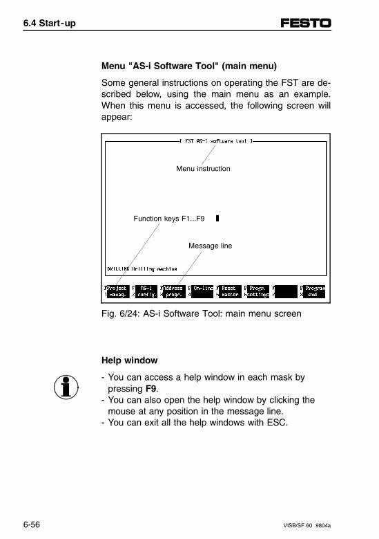
Menu "AS-i Software Tool" (main menu)
Some general instructions on operating the FST are de-scribed below, using the main menu as an example.When this menu is accessed, the following screen willappear:
Fig. 6/24: AS-i Software Tool: main menu screen
Help window
- You can access a help window in each mask by pressing F9.
- You can also open the help window by clicking themouse at any position in the message line.
- You can exit all the help windows with ESC.
Menu instruction
Function keys F1...F9
Message line
6.4 Start-up
6-56 VISB/SF 60 9804a
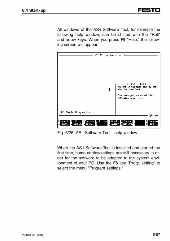
All windows of the AS-i Software Tool, for example thefollowing help window, can be shifted with the "Roll"and arrow keys. When you press F9 "Help," the follow-ing screen will appear:
Fig. 6/25: AS-i Software Tool - help window
When the AS-i Software Tool is installed and started thefirst time, some entries/settings are still necessary in or-der for the software to be adapted to the system envi-ronment of your PC. Use the F6 key "Progr. setting" toselect the menu "Program settings."
6.4 Start-up
VISB/SF 60 9804a 6-57
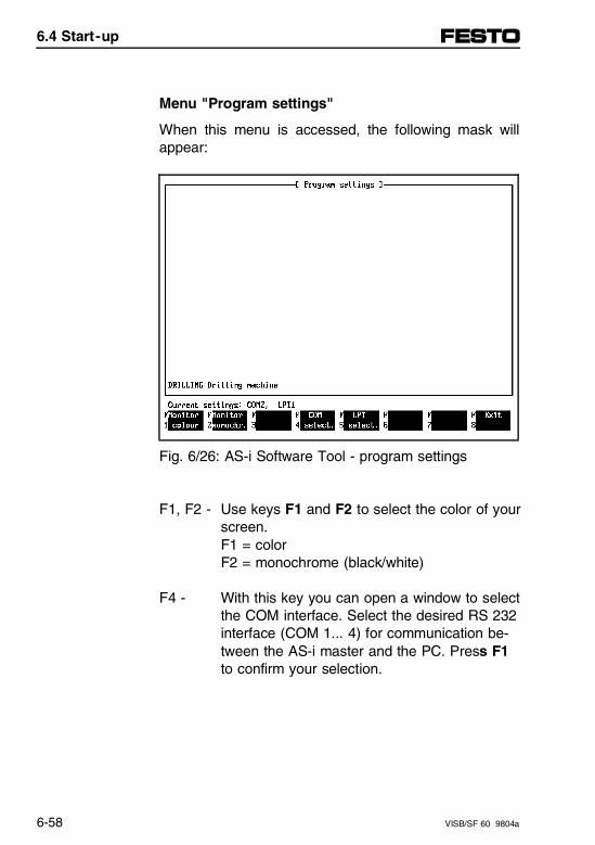
Menu "Program settings"
When this menu is accessed, the following mask willappear:
Fig. 6/26: AS-i Software Tool - program settings
F1, F2 - Use keys F1 and F2 to select the color of yourscreen.F1 = colorF2 = monochrome (black/white)
F4 - With this key you can open a window to select the COM interface. Select the desired RS 232 interface (COM 1... 4) for communication be-tween the AS-i master and the PC. Press F1 to confirm your selection.
6.4 Start-up
6-58 VISB/SF 60 9804a
F5 - With this key you can open a window to select the LPT interface. Select the desired interface for your printer. Press F1 to transfer your selection.
Printing to a file:Select the option "?" (File) in order to print to a file. When you later create a project, a print file will be stored under the name <Project name> in the project directory. You can process this file further with an editor.If you print several times to the print file during a project, all individual project printouts will be placed in a row. If you do not wish this, you must first delete the print file before each printout.
F8 - With this key you can return to the main menu. At the same time the configuration data will be stored in the file ASITOOL.CFG.
6.4 Start-up
VISB/SF 60 9804a 6-59
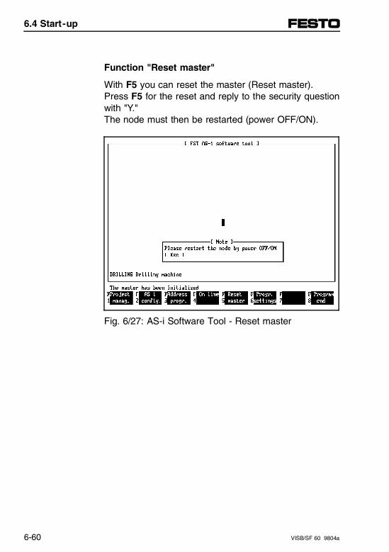
Function "Reset master"
With F5 you can reset the master (Reset master).Press F5 for the reset and reply to the security questionwith "Y."The node must then be restarted (power OFF/ON).
Fig. 6/27: AS-i Software Tool - Reset master
6.4 Start-up
6-60 VISB/SF 60 9804a
PLEASE NOTEYou must perform a reset master in order to drivethe AS-i master when the node has been changed(in order that the AS-i master can set itself auto-matically to the node).You can drive the AS-i master except for the SB/SF 60 also on nodes FB9, FB13 or SB/SF 50(version: December 1997) with the AS-i SoftwareTool.
When the program settings have been made, you mustselect a project or create a project (only when a projectis created can the AS-i configuration be carried out). Todo this press F1 "Project management" in the mainmenu.
6.4 Start-up
VISB/SF 60 9804a 6-61
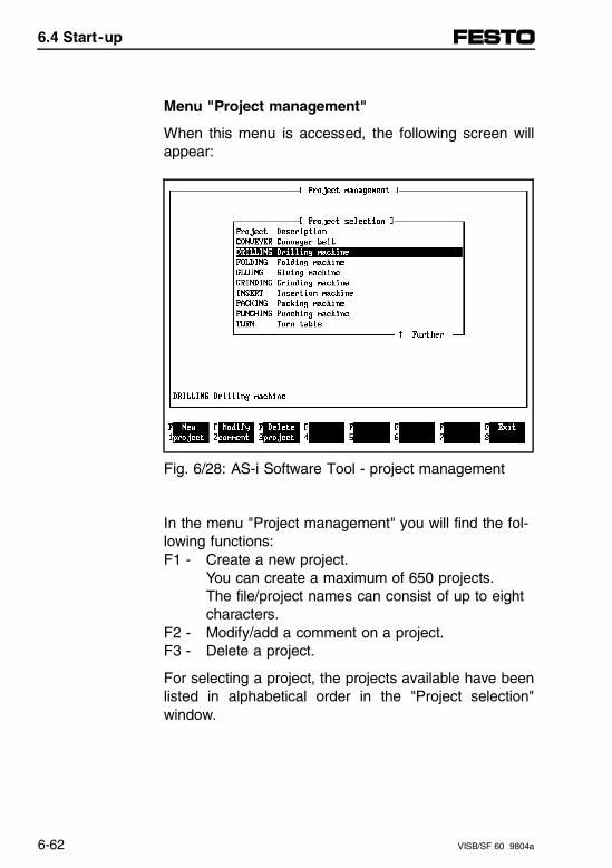
Menu "Project management"
When this menu is accessed, the following screen willappear:
Fig. 6/28: AS-i Software Tool - project management
In the menu "Project management" you will find the fol-lowing functions:F1 - Create a new project.
You can create a maximum of 650 projects.The file/project names can consist of up to eight characters.
F2 - Modify/add a comment on a project.F3 - Delete a project.
For selecting a project, the projects available have beenlisted in alphabetical order in the "Project selection"window.
6.4 Start-up
6-62 VISB/SF 60 9804a
If there are more than nine projects, you can scroll withthe arrow keys in the project selection. If you have cre-ated several projects, it is better to enter the projectnames (or the first letters of the names) on the key-board. This program will then skip directly to this posi-tion.
Once you have created or selected a project, you canuse your AS-i bus system in order to:
– Design (even if you do not yet have the AS-i bussystem).
– Configure (AS-i bus system must be connected).
To do this press F2 "AS-i config" in the main menu.
6.4 Start-up
VISB/SF 60 9804a 6-63
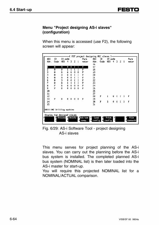
Menu "Project designing AS-i slaves"(configuration)
When this menu is accessed (use F2), the followingscreen will appear:
Fig. 6/29: AS-i Software Tool - project designing AS-i slaves
This menu serves for project planning of the AS-islaves. You can carry out the planning before the AS-ibus system is installed. The completed planned AS-ibus system (NOMINAL list) is then later loaded into theAS-i master for start-up.You will require this projected NOMINAL list for aNOMINAL/ACTUAL comparison.
6.4 Start-up
6-64 VISB/SF 60 9804a
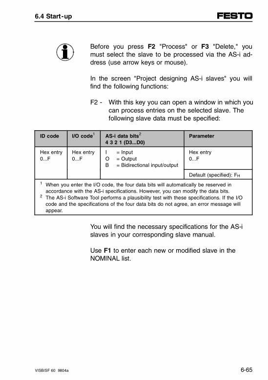
Before you press F2 "Process" or F3 "Delete," youmust select the slave to be processed via the AS-i ad-dress (use arrow keys or mouse).
In the screen "Project designing AS-i slaves" you willfind the following functions:
F2 - With this key you can open a window in which youcan process entries on the selected slave. The following slave data must be specified:
ID code I/O code1 AS-i data bits2 4 3 2 1 (D3...D0)
Parameter
Hex entry0...F
Hex entry0...F
I = InputO = OutputB = Bidirectional input/output
Hex entry0...F
Default (specified): FH
1 When you enter the I/O code, the four data bits will automatically be reserved in accordance with the AS-i specifications. However, you can modify the data bits.
2 The AS-i Software Tool performs a plausibility test with these specifications. If the I/Ocode and the specifications of the four data bits do not agree, an error message will appear.
You will find the necessary specifications for the AS-islaves in your corresponding slave manual.
Use F1 to enter each new or modified slave in theNOMINAL list.
6.4 Start-up
VISB/SF 60 9804a 6-65
If you wish to configure additional slaves, press F2. Thedata of the last processed slave are entered in the line.You can assign the parameters 0…F (hex) to slaves forparameter processing. If, after the configuration has been loaded, your hostcontroller sends (other) parameters to this slave, thevalues of the controller will have priority. If an AS-islave does not use the parameter processing, you mustenter FH (default value).
F3 - Use F3 to delete the selected slave from the pro-ject planning list.
F4 - For the function "NOMINAL-ACTUAL comparison,"an AS-i bus system must be installed and the AS-i master must be connected to the PC. The installed AS-i slaves are read (ACTUAL) and compared with the project-planned slaves (NOMI-NAL). The following screen will appear if there are discrepancies:
6.4 Start-up
6-66 VISB/SF 60 9804a
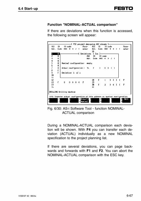
Function "NOMINAL-ACTUAL comparison"
If there are deviations when this function is accessed,the following screen will appear:
Fig. 6/30: AS-i Software Tool - function NOMINAL- ACTUAL comparison
During a NOMINAL-ACTUAL comparison each devia-tion will be shown. With F4 you can transfer each de-viation (ACTUAL) individually as a new NOMINALspecification to the project planning list.
If there are several deviations, you can page back-wards and forwards with F1 and F2. You can abort theNOMINAL-ACTUAL comparison with the ESC key.
6.4 Start-up
VISB/SF 60 9804a 6-67
F5 - With F5 you can load the planned NOMINAL listinto the AS-i master. The list is stored all the plan-ned slave data in the EEPROM of the AS-i master.
F6 - Use F6 to print out the planned slaves or save afile for further processing in your project documen-tation. If you print several projects in the print file, all the individual printouts will be placed in a row an will be available for further processing. If you wish to process additional projects in individual print files, you must delete the last created print file before each printout (under DOS or Windows).
F8 - F8 is used for saving and/or exiting the "Configur-ation/designing AS-i slaves" menu. You then return to the main menu.
6.4 Start-up
6-68 VISB/SF 60 9804a
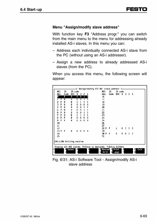
Menu "Assign/modify slave address"
With function key F3 "Address progr." you can switchfrom the main menu to the menu for addressing alreadyinstalled AS-i slaves. In this menu you can:
– Address each individually connected AS-i slave fromthe PC (without using an AS-i addresser).
– Assign a new address to already addressed AS-islaves (from the PC).
When you access this menu, the following screen willappear:
Fig. 6/31: AS-i Software Tool - Assign/modify AS-i slave address
6.4 Start-up
VISB/SF 60 9804a 6-69
When the menu is accessed, a NOMINAL-ACTUALcomparison will be carried out. Already planned slaveswill be marked with "P" and displayed immediately. Ifthe installation on the AS-i bus is different, questionmarks will appear and the F5 "NOMINAL ID/IO" func-tion will become active. The following example showshow you should assign a slave with a new address:
F2 - Selects the slave which has been selected with the cursor or the mouse key.
F5 - With F5 "NOMINAL ID/IO" you can display thedata of the planned slave for checking purposes.
Deviations between NOMINAL and ACTUAL havethe following causes:– Incorrect slave installed– Incorrect project planning
You must always correct the deviation. To do this,proceed as follows:• Remove the incorrectly installed slave.• Replace it with the planned slave type,
or • transfer the installed slave to the planned NO-
MINAL list. To do this carry out a NOMINAL/ACTUAL comparison again.Then use F4 to transfer the differing slave.
6.4 Start-up
6-70 VISB/SF 60 9804a
F6 - With function key F6 you can print the design listor write it to a file.
F8 - With function key F8 you can return to the main menu.
Example (assigning a slave with a new address).
– ACTUAL address (factory setting): 0
– NOMINAL address: 20
– General procedure:1. Assign new slave address.2. Enter new slave in project planning list.
Proceed as follows:
1. Assign new slave address
• Select with arrow key or mouse slave 0 which is tobe modified.
• Select it with F2 "Select" (the selected line will bemarked with another color on the screen, see pre-vious illustration).
• Now select the desired (destination) address 20 (arrow key or mouse).
• Now use F3 to "Modify address" to transfer slave 0to address 20.
6.4 Start-up
VISB/SF 60 9804a 6-71
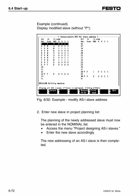
Example (continued).Display modified slave (without "P"):
Fig. 6/32: Example - modify AS-i slave address
2. Enter new slave in project planning list:
The planning of the newly addressed slave must nowbe entered in the NOMINAL list.• Access the menu "Project designing AS-i slaves."• Enter the new slave accordingly.
The new addressing of an AS-i slave is then comple-ted.
6.4 Start-up
6-72 VISB/SF 60 9804a
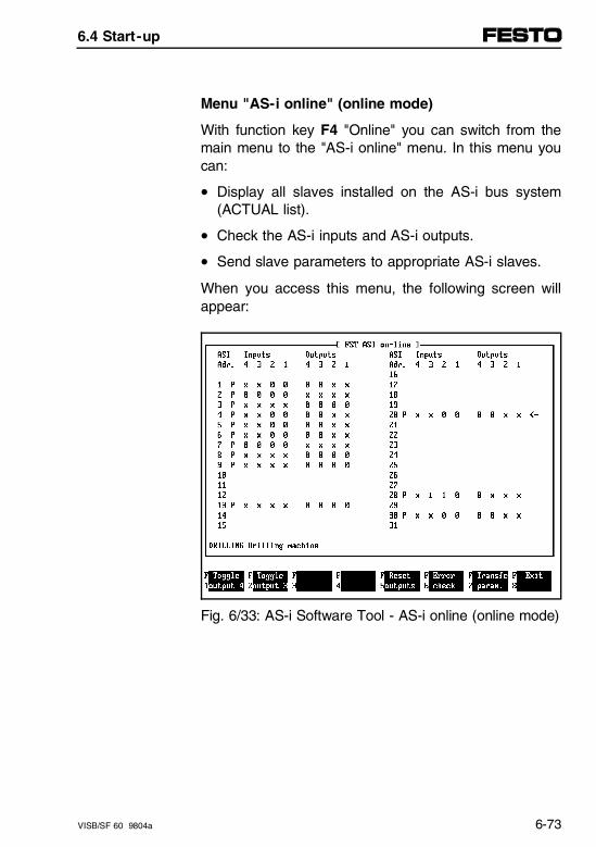
Menu "AS-i online" (online mode)
With function key F4 "Online" you can switch from themain menu to the "AS-i online" menu. In this menu youcan:
• Display all slaves installed on the AS-i bus system(ACTUAL list).
• Check the AS-i inputs and AS-i outputs.
• Send slave parameters to appropriate AS-i slaves.
When you access this menu, the following screen willappear:
Fig. 6/33: AS-i Software Tool - AS-i online (online mode)
6.4 Start-up
VISB/SF 60 9804a 6-73
Please note that the ACTUAL installation will be shownwhen this menu is accessed. By means of the "P" nextto the AS-i address, you can recognize whether or notthe slave has been planned.
WARNING- Set outputs in online mode only if you are sure of
their effect/reaction.- If the system is switched on, the outputs will react
immediately to your entry on the screen.- When you switch the outputs on and off, make
sure that there is no risk of injury to persons or ofdamage to the machine.
In order to set a desired output, you must move thearrow at the side of the screen to the desired slave.Now you can set or reset the desired outputs (O1...O4)with keys F1 to F4.
The function keys have the following meanings:
F1 - To set an output, move the arrow at the side ofF2 - the screen to the desired outputs (O1…O4) using,F3 - function keys F1 to F4. F4 -
F5 - With this function key you can reset all the AS-i slave outputs.
F6 - With function key F6 the last error status will be read from the AS-i master and displayed (beforethe online connection was made).
6.4 Start-up
6-74 VISB/SF 60 9804a
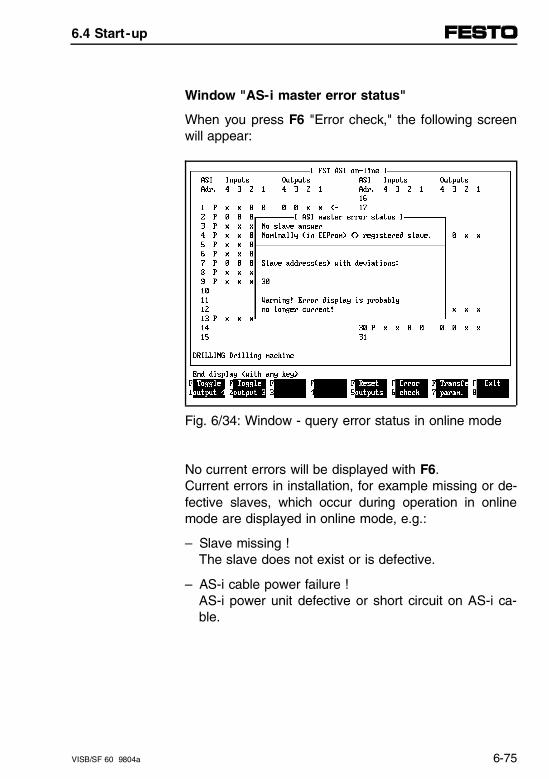
Window "AS-i master error status"
When you press F6 "Error check," the following screenwill appear:
Fig. 6/34: Window - query error status in online mode
No current errors will be displayed with F6.Current errors in installation, for example missing or de-fective slaves, which occur during operation in onlinemode are displayed in online mode, e.g.:
– Slave missing !The slave does not exist or is defective.
– AS-i cable power failure !AS-i power unit defective or short circuit on AS-i ca-ble.
6.4 Start-up
VISB/SF 60 9804a 6-75
F7 - With function key F7 you can send slave parame-ters to appropriate slaves, e.g., to a sensor, the switching gap of which can be modified with para-meters. Parameters from 0…F (hex) can be transferred inonline mode (see following illustration).
6.4 Start-up
6-76 VISB/SF 60 9804a
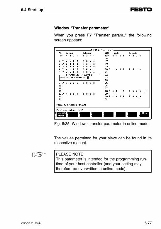
Window "Transfer parameter"
When you press F7 "Transfer param.," the followingscreen appears:
Fig. 6/35: Window - transfer parameter in online mode
The values permitted for your slave can be found in itsrespective manual.
PLEASE NOTEThis parameter is intended for the programming run-time of your host controller (and your setting maytherefore be overwritten in online mode).
6.4 Start-up
VISB/SF 60 9804a 6-77
F8 - Use F8 to return to the main menu.
You have now learned all the necessary steps for user-friendly start-up using the AS-i Software Tool. Use F8 inthe main menu to exit the AS-i Software Tool.
CAUTIONWhen you exit with F8, the connection between theAS-i master and the SB/SF 60 will be restored. If aPLC program is running, the AS-i inputs/outputs willbe processed immediately.
PLEASE NOTELeave the plug connected while the AS-i SoftwareTool is running.Otherwise the AS-i master will remain permanentlyblocked (STOP status), as an important "End" con-trol character is not sent.
– Always exit the AS-i Software Tool with F8 and dis-connect the diagnostics cable.
6.4 Start-up
6-78 VISB/SF 60 9804a
6.4.4 Final steps for start-up
AS-i bus
Once you have loaded your NOMINAL configurationinto the AS-i master, you must perform the followingsteps before you can operate the controller:
• Check that the AS-i bus system is correctly installedand that the correct NOMINAL list is stored in theAS-i master (see: menu "Assign/modify address").
• Remove the configuration plug or PC from the diag-nostics interface.
CAUTIONOnce the diagnostics interface is enabled again, anycurrently running programs/data will be transferredimmediately to the AS-i outputs. Make sure that thisaction does not trigger any undesired movements ofthe connected actuators.
6.4 Start-up
VISB/SF 60 9804a 6-79
SB/SF 60 valve terminal
Perform the following steps:
• Determine the necessary configuration entries for theG-file. If you want to carry out a NOMINAL-ACTUALcomparison upon power-up: Enter the AS-i master now in the G-file (see alsochapter 3.4, "Configuring G-files").
• Turn on the AS-i power unit and the SB/SF 60.
• Test and start-up the overall system.
Please refer to chapter 3 for the essential data and pro-cedures for commissioning the complete system.
6.4 Start-up
6-80 VISB/SF 60 9804a
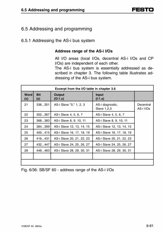
6.5 Addressing and programming
6.5.1 Addressing the AS-i bus system
Address range of the AS-i I/Os
All I/O areas (local I/Os, decentral AS-i I/Os and CPI/Os) are independent of each other. The AS-i bus system is essentially addressed as de-scribed in chapter 3. The following table illustrates ad-dressing of the AS-i bus system.
Excerpt from the I/O table in chapter 3.6
Word (x)
Bit(z)
Output (O:1.x)
Input (I:1.x)
21 336...351 AS-i Slave "0," 1, 2, 3 AS-i diagnostic, Slave 1,2,3
DecentralAS-i I/Os
22 352...367 AS-i Slave 4, 5, 6, 7 AS-i Slave 4, 5, 6, 7
23 368...383 AS-i Slave 8, 9, 10, 11 AS-i Slave 8, 9, 10, 11
24 384...399 AS-i Slave 12, 13, 14, 15 AS-i Slave 12, 13, 14, 15
25 400...415 AS-i Slave 16, 17, 18, 19 AS-i Slave 16, 17, 18, 19
26 416...431 AS-i Slave 20, 21, 22, 23 AS-i Slave 20, 21, 22, 23
27 432...447 AS-i Slave 24, 25, 26, 27 AS-i Slave 24, 25, 26, 27
28 448...463 AS-i Slave 28, 29, 30, 31 AS-i Slave 28, 29, 30, 31
Fig. 6/36: SB/SF 60 - address range of the AS-i I/Os
6.5 Addressing and programming
VISB/SF 60 9804a 6-81
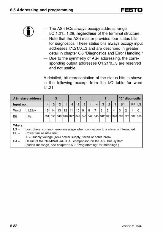
- The AS-i I/Os always occupy address rangeI/O:1.21...1.28, regardless of the terminal structure.
- Note that the AS-i master provides four status bits for diagnostics. These status bits always occupy input addresses I:1.21/0...3 and are described in greater detail in chapter 6.6 "Diagnostics and Error Handling."
- Due to the symmetry of AS-i addressing, the corre-sponding output addresses O1.21/0...3 are reservedand not usable.
A detailed, bit representation of the status bits is shownin the following excerpt from the I/O table for wordI:1.21:
AS-i slave address 3 2 1 "0" diagnostic
Input no. 4 3 2 1 4 3 2 1 4 3 2 1 S/I PF LS
Word I:1.21/y 15 14 13 12 11 10 9 8 7 6 5 4 3 2 1 0
Bit I:1/z 351 350 349 348 347 346 345 344 343 342 341 340 339 328 337 336
Where:LS = Lost Slave; common error message when connection to a slave is interrupted.PF = Power failure AS-i line;
AS-i supply voltage (AS-i power supply) failed or cable break.S/I = Result of the NOMINAL-ACTUAL comparison on the AS-i bus system
(coded message, see chapter 6.5.2 "Programming" for meanings )
6.5 Addressing and programming
6-82 VISB/SF 60 9804a
– To avoid addressing mistakes, obtain a detailed over-view of the address range and the I/O allocation ofall AS-i slaves (see example 1 and the following tables).
Tips for AS-iaddressingoverview
– The large AS-i allocation table serves as a templatefor copying and will help you to allocate the inputsand outputs of the slaves to the I/O words of thecontroller.
6.5 Addressing and programming
VISB/SF 60 9804a 6-83
Addressing example
The following example for addressing and working withFesto tables makes the following assumptions:
– Four AS-i slaves with addresses 1, 2, 3 and 7 as wellas the master are connected to one valve terminal.
– The ID and I/O codes of the slaves are determined inorder to later assign the physical location of the AS-iI/Os.
– The slaves are first entered in a short I/O table. Herethe physically present inputs and outputs are exactlydetermined and assigned to the respective word inthe controller. (This intermediate step is for clarifica-tion purposes. Later you can perform the allocationdirectly in the AS-i allocation table).
– Then the installed AS-i I/Os, separated by bits intoinputs and outputs, are entered in the AS-i allocationtable, which makes exact addressing easier.
6.5 Addressing and programming
6-84 VISB/SF 60 9804a
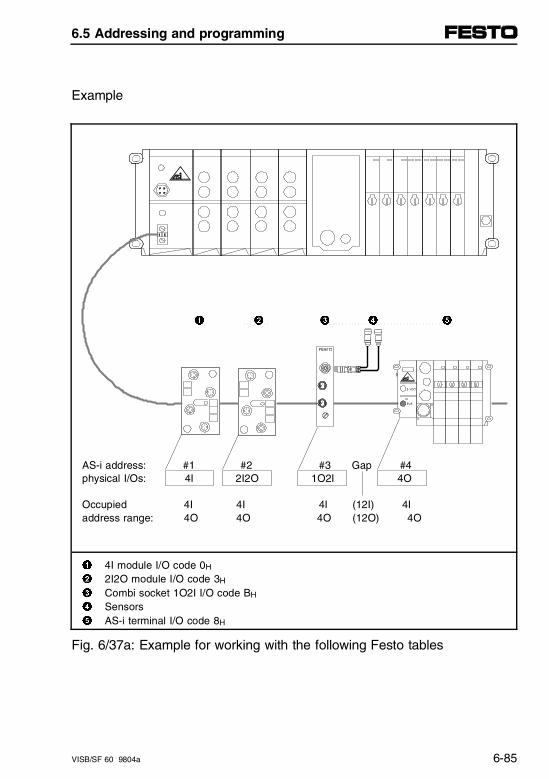
Example
1 2 3 4 5
AS-i address: #1 #2 #3 Gap #4physical I/Os: 4I 2I2O 1O2I 4O
Occupied 4I 4I 4I (12I) 4Iaddress range: 4O 4O 4O (12O) 4O
1 4I module I/O code 0H
2 2I2O module I/O code 3H
3 Combi socket 1O2I I/O code BH
4 Sensors5 AS-i terminal I/O code 8H
Fig. 6/37a: Example for working with the following Festo tables
6.5 Addressing and programming
VISB/SF 60 9804a 6-85
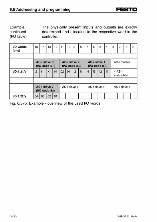
The physically present inputs and outputs are exactlydetermined and allocated to the respective word in thecontroller.
Examplecontinued(I/O table)
I/O words(bits)
15 14 13 12 11 10 9 8 7 6 5 4 3 2 1 0
AS-i slave 3(I/O code BH)
AS-i slave 2(I/O code 3H)
AS-i slave 1(I/O code 0H)
AS-i master
I/O:1.21/y I2 I1 X 01 02 01 I2 I1 I4 I3 I2 I1 4 AS-i status bits
AS-i slave 7 (I/O code 8H)
AS-i slave 6 AS-i slave 5 AS-i slave 4
I/O:1.22/y 04 03 02 01
Fig. 6/37b: Example - overview of the used I/O words
6.5 Addressing and programming
6-86 VISB/SF 60 9804a
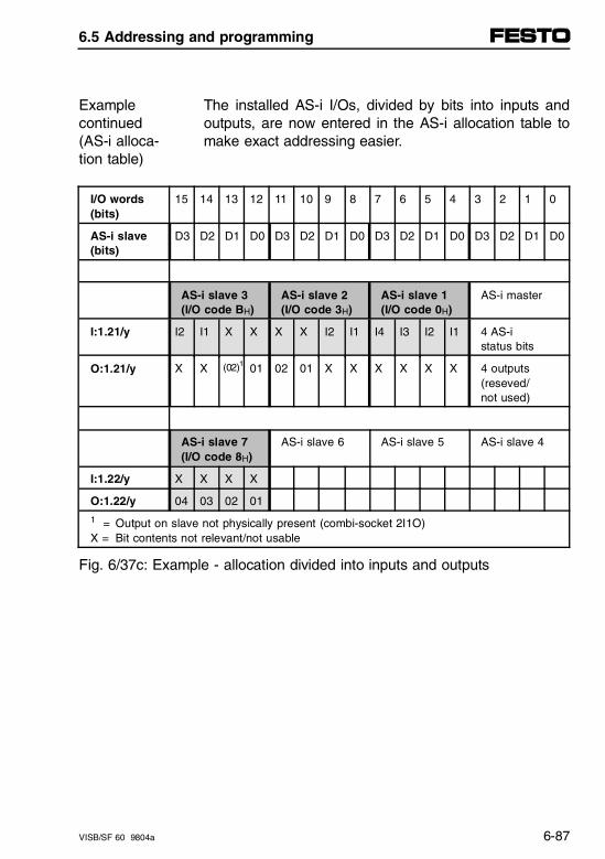
The installed AS-i I/Os, divided by bits into inputs andoutputs, are now entered in the AS-i allocation table tomake exact addressing easier.
Examplecontinued(AS-i alloca-tion table)
I/O words(bits)
15 14 13 12 11 10 9 8 7 6 5 4 3 2 1 0
AS-i slave(bits)
D3 D2 D1 D0 D3 D2 D1 D0 D3 D2 D1 D0 D3 D2 D1 D0
AS-i slave 3(I/O code BH)
AS-i slave 2(I/O code 3H)
AS-i slave 1(I/O code 0H)
AS-i master
I:1.21/y I2 I1 X X X X I2 I1 I4 I3 I2 I1 4 AS-i status bits
O:1.21/y X X (02)1 01 02 01 X X X X X X 4 outputs (reseved/not used)
AS-i slave 7 (I/O code 8H)
AS-i slave 6 AS-i slave 5 AS-i slave 4
I:1.22/y X X X X
O:1.22/y 04 03 02 01
1 = Output on slave not physically present (combi-socket 2I1O)X = Bit contents not relevant/not usable
Fig. 6/37c: Example - allocation divided into inputs and outputs
6.5 Addressing and programming
VISB/SF 60 9804a 6-87
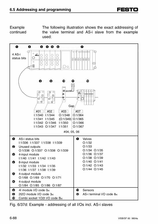
The following illustration shows the exact addressing ofthe valve terminal and AS-i slave from the exampleused:
Examplecontinued
1 2 3 4 5 6 7
4 AS-istatus bits
8 9 0 ! "
Gap
#01 #02 #03 #07 I:1/340 I:1/344 O:1/348 O:1/364 I:1/341 I:1/345 (O:1/349) O:1/365 I:1/342 O:1/346 I:1/350 O:1/366 I:1/343 O:1/347 I:1/351 O:1/367
1 AS-i status bitsI:1/336 I:1/337 I:1/338 I:1/339
2 Unused outputsO:1/336 O:1/337 O:1/338 O:1/339
3 4-input moduleI:1/40 I:1/41 I:1/42 I:1/43
4 8-input moduleI:1/32 I:1/33 I:1/34 I:1/35I:1/36 I:1/37 I:1/38 I:1/39
5 4-output moduleO:1/68 O:1/69 O:1/70 O:1/71
6 4-output moduleO:1/84 O:1/85 O:1/86 O:1/87
7 ValvesO:1/32O:1/33O:1/34 O:1/35O:1/36 O:1/37O:1/38 O:1/39O:1/40 O:1/41O:1/42 O:1/43O:1/44 O:1/45
8 4I module I/O code 0H
9 2I2O module I/O code 3H
0 Combi socket 1O2I I/O code BH
! Sensors" AS-i terminal I/O code 8H
Fig. 6/37d: Example - addressing of all I/Os incl. AS-i slaves
#04, 05, 06
6.5 Addressing and programming
6-88 VISB/SF 60 9804a
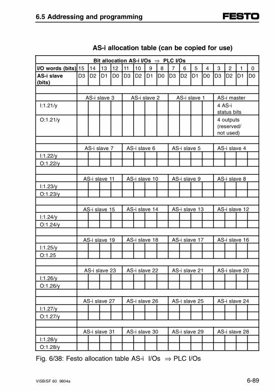
AS-i allocation table (can be copied for use)
Bit allocation AS-i I/Os ⇒ PLC I/Os I/O words (bits) 15 14 13 12 11 10 9 8 7 6 5 4 3 2 1 0AS-i slave(bits)
D3 D2 D1 D0 D3 D2 D1 D0 D3 D2 D1 D0 D3 D2 D1 D0
AS-i slave 3 AS-i slave 2 AS-i slave 1 AS-i master
I:1.21/y 4 AS-i status bits
O:1.21/y 4 outputs (reserved/not used)
AS-i slave 7 AS-i slave 6 AS-i slave 5 AS-i slave 4I:1.22/y
O:1.22/y
AS-i slave 11 AS-i slave 10 AS-i slave 9 AS-i slave 8I:1.23/y
O:1.23/y
AS-i slave 15 AS-i slave 14 AS-i slave 13 AS-i slave 12
I:1.24/y
O:1.24/y
AS-i slave 19 AS-i slave 18 AS-i slave 17 AS-i slave 16
I:1.25/y
O:1.25
AS-i slave 23 AS-i slave 22 AS-i slave 21 AS-i slave 20
I:1.26/y
O:1.26/y
AS-i slave 27 AS-i slave 26 AS-i slave 25 AS-i slave 24
I:1.27/y
O:1.27/y
AS-i slave 31 AS-i slave 30 AS-i slave 29 AS-i slave 28
I:1.28/y
O:1.28/y
Fig. 6/38: Festo allocation table AS-i I/Os ⇒ PLC I/Os
6.5 Addressing and programming
VISB/SF 60 9804a 6-89
6.5.2 Programming the AS-i bus system
Send AS-i slave parameters
You can conveniently send the parameters to suitableAS-i slaves from within a program using the M0-filesM0:1.1...M0:1.31. One word per slave is allocated in theM0-file. To send parameters, the four lowest bits (0...3)are used.
During start -up you have two possibilities for influencingthe slave parameters:
– in online mode of the AS-i software tool.
– with the appropriate test programs.
Keep in mind that slave parameters set in online modecan later be overwritten by the running program.
WARNING- Change only parameters if you know the effects.- When the system is switched on, the corresponding
slaves respond immediately to your screen entry!- Ensure that when changing slave parameters, no
danger to persons or equipment could result.
6.5 Addressing and programming
6-90 VISB/SF 60 9804a
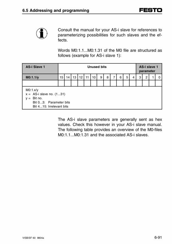
Consult the manual for your AS-i slave for references toparameterizing possibilities for such slaves and the ef-fects.
Words M0:1.1...M0:1.31 of the M0 file are structured asfollows (example for AS-i slave 1):
AS-i Slave 1 Unused bits AS-i slave 1parameter
M0:1.1/y 15 14 13 12 11 10 9 8 7 6 5 4 3 2 1 0
M0:1.x/yx = AS-i slave no. (1...31)y = Bit no.
Bit 0...3: Parameter bitsBit 4...15: Irrelevant bits
The AS-i slave parameters are generally sent as hexvalues. Check this however in your AS-i slave manual.The following table provides an overview of the M0-filesM0:1.1...M0:1.31 and the associated AS-i slaves.
6.5 Addressing and programming
VISB/SF 60 9804a 6-91
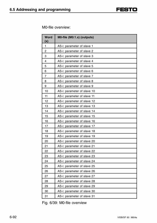
M0-file overview:
Word(x)
M0-file (M0:1.x) (outputs)
1 AS-i: parameter of slave 1
2 AS-i: parameter of slave 2
3 AS-i: parameter of slave 3
4 AS-i: parameter of slave 4
5 AS-i: parameter of slave 5
6 AS-i: parameter of slave 6
7 AS-i: parameter of slave 7
8 AS-i: parameter of slave 8
9 AS-i: parameter of slave 9
10 AS-i: parameter of slave 10
11 AS-i: parameter of slave 11
12 AS-i: parameter of slave 12
13 AS-i: parameter of slave 13
14 AS-i: parameter of slave 14
15 AS-i: parameter of slave 15
16 AS-i: parameter of slave 16
17 AS-i: parameter of slave 17
18 AS-i: parameter of slave 18
19 AS-i: parameter of slave 19
20 AS-i: parameter of slave 20
21 AS-i: parameter of slave 21
22 AS-i: parameter of slave 22
23 AS-i: parameter of slave 23
24 AS-i: parameter of slave 24
25 AS-i: parameter of slave 25
26 AS-i: parameter of slave 26
27 AS-i: parameter of slave 27
28 AS-i: parameter of slave 28
29 AS-i: parameter of slave 29
30 AS-i: parameter of slave 30
31 AS-i: parameter of slave 31
Fig. 6/39: M0-file overview
6.5 Addressing and programming
6-92 VISB/SF 60 9804a
Generating I/O interrupts from the AS-i bus system
As already described in chapter 3.6, the SB/SF 60 pro-vides a freely configurable I/O interrupt input. All physi-cal inputs of the SB/SF 60 can generate an I/O inter-rupt through this input. This also applies to AS-i inputs.
A cross the heavily branched AS-i bus system it istherefore possible to interrogate critical system states orprocessing conditions at distances of up to 100 m, andto generate faster controller responses per I/O interrupt.Proceed generally as follows:
Example for AS-i input I4 of slave 31 (bit 483):
• Enter the input address (483 dec) in the M0-file(M0:1.0).
• Configure the interrupt input in output word O:1.1/0(example uses the rising edge).
• Once an I/O interrupt has been generated, you usethe subroutine to query the interrupt flags (in inputword I:1.0). In bit I:1/0 you determine whether thefreely programmable input (AS-i input 483 in ourexample) has responded to a rising edge.
6.5 Addressing and programming
VISB/SF 60 9804a 6-93
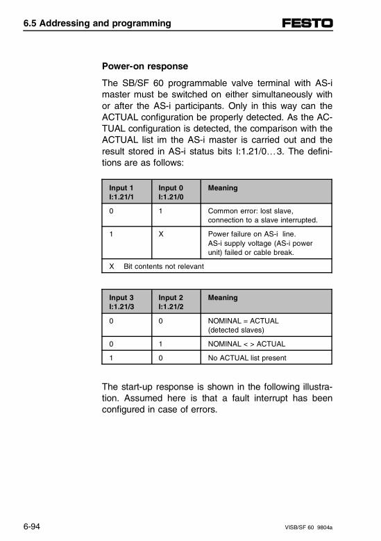
Power-on response
The SB/SF 60 programmable valve terminal with AS-imaster must be switched on either simultaneously withor after the AS-i participants. Only in this way can theACTUAL configuration be properly detected. As the AC-TUAL configuration is detected, the comparison with theACTUAL list im the AS-i master is carried out and theresult stored in AS-i status bits I:1.21/0…3. The defini-tions are as follows:
Input 1I:1.21/1
Input 0I:1.21/0
Meaning
0 1 Common error: lost slave,connection to a slave interrupted.
1 X Power failure on AS-i line.AS-i supply voltage (AS-i powerunit) failed or cable break.
X Bit contents not relevant
Input 3I:1.21/3
Input 2I:1.21/2
Meaning
0 0 NOMINAL = ACTUAL(detected slaves)
0 1 NOMINAL < > ACTUAL
1 0 No ACTUAL list present
The start-up response is shown in the following illustra-tion. Assumed here is that a fault interrupt has beenconfigured in case of errors.
6.5 Addressing and programming
6-94 VISB/SF 60 9804a
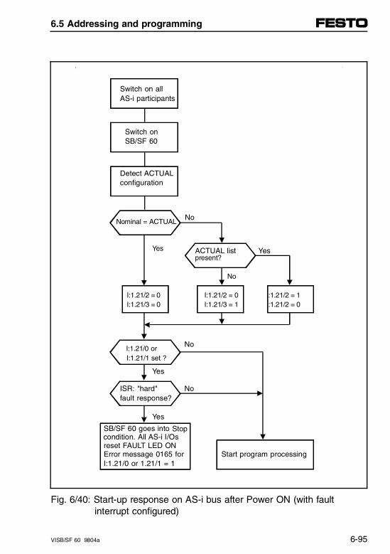
Switch on all AS-i participants
Switch on SB/SF 60
Detect ACTUAL configuration
Nominal = ACTUAL No
Yes ACTUAL list Yespresent ?
No
I:1.21/2 = 0 I:1.21/2 = 0 I:1.21/2 = 1 I:1.21/3 = 0 I:1.21/3 = 1 I:1.21/2 = 0
No I:1.21/0 or I:1.21/1 set ?
Yes
ISR: "hard" Nofault response?
Yes SB/SF 60 goes into Stop condition. All AS-i I/Os reset FAULT LED ON Error message 0165 for Start program processing I:1.21/0 or 1.21/1 = 1
Fig. 6/40: Start-up response on AS-i bus after Power ON (with fault interrupt configured)
6.5 Addressing and programming
VISB/SF 60 9804a 6-95
- The NOMINAL configuration must be created usingthe AS-i Software Tool or the configuration plug be-fore starting-up the AS-i system.
- The NOMINAL/ACTUAL comparison must be pro-cessed in the program. Only in this way can the corresponding error messages or other responses be generated.
Recommendation:Always work with a NOMINAL list.
6.5 Addressing and programming
6-96 VISB/SF 60 9804a
Response to missing AS-i supply voltage
If supply voltage is absent from the AS-i line (powerfailure), input bit I:1.21/1will be set. In this case thestatus of input bit I:1.21/0 (common report, single-errorAS-i slave) is irrevelant. You can specify the error re-sponse for power failure on the AS-i line by configuringthe error response in bit O:1.0/1 as follows:
– Fault interrupt is generated (default: not generated).
– Error handling routine is executed.
In your error handling routine you may select:
– Hard response:Controller goes into FAULT condition, all ouputs areswitched off.
– Soft response:Error is handled in the user program.
6.5 Addressing and programming
VISB/SF 60 9804a 6-97
Response to hardware error
If the AS-i master fails, error message 017B is gener-ated and the FAULT LED comes on. This error mes-sage represents a non-recoverable fault and stops thecontroller immediately.The AS-i master must be replaced.
Response to participant error
Errors may occur in the AS-i participants during opera-tion. Typical participant errors are:
– AS-i supply voltage for the participant below toler-ance.
– Short circuit on an AS-i output.
– Hardware error (slave defective).
The common error bit I:1.21/0 is set when an error oc-curs in an AS-i participant.The defective participant can be localized as follows:
– M1:1.21 and 1.22 (localizing single errors).
– AS-i Software Tool in online mode.All faulty AS-i participants are designated with an "E"behind the AS-i address.
6.5 Addressing and programming
6-98 VISB/SF 60 9804a
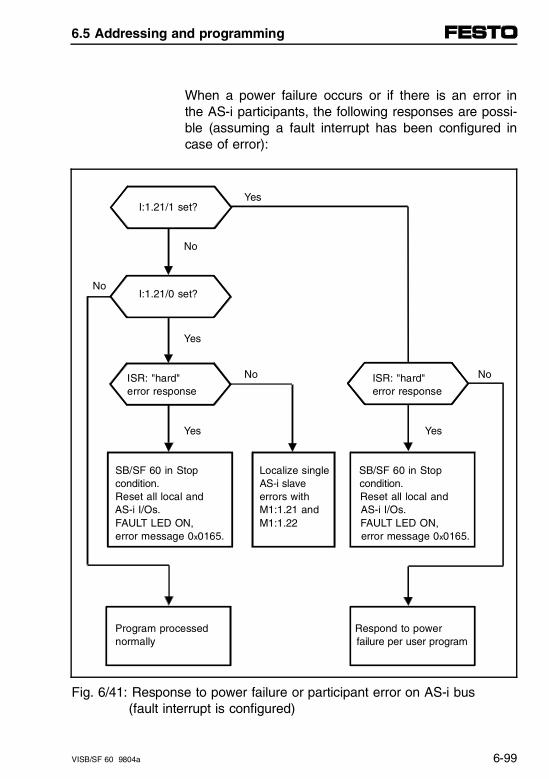
When a power failure occurs or if there is an error inthe AS-i participants, the following responses are possi-ble (assuming a fault interrupt has been configured incase of error):
YesI:1.21/1 set?
No
NoI:1.21/0 set?
Yes
ISR: "hard" No ISR: "hard" No
error response error response
Yes Yes
SB/SF 60 in Stop Localize single SB/SF 60 in Stop condition. AS-i slave condition. Reset all local and errors with Reset all local and AS-i I/Os. M1:1.21 and AS-i I/Os. FAULT LED ON, M1:1.22 FAULT LED ON, error message 0x0165. error message 0x0165.
Program processed Respond to power normally failure per user program
Fig. 6/41: Response to power failure or participant error on AS-i bus (fault interrupt is configured)
6.5 Addressing and programming
VISB/SF 60 9804a 6-99

6.5 Addressing and programming
6-100 VISB/SF 60 9804a
6.6 Overview of diagnostics possibilities
The following possibilities are available for diagnosticson the AS-i bus and for localizing defective slaves:
– Local LED displays
– Diagnostics in the online mode of the AS-i SoftwareTool
– Diagnostics using status bits of the AS-i master(I:1.21/0…3)
– Diagnostics using status word I:1.0 (common error bitI:1/1)
– Diagnostics using M files M1:1/21 and 1/22.
These possibilities are described in the following.
6.6 Overview of diagnostics possibilities
VISB/SF 60 9804a 6-101
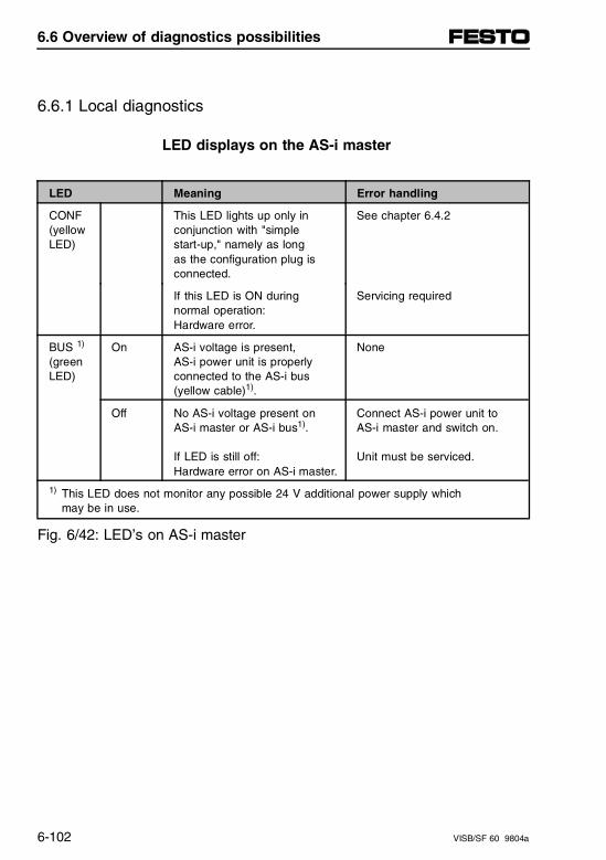
6.6.1 Local diagnostics
LED displays on the AS-i master
LED Meaning Error handling
CONF(yellowLED)
This LED lights up only inconjunction with "simple start-up," namely as long as the configuration plug isconnected.
See chapter 6.4.2
If this LED is ON during normal operation: Hardware error.
Servicing required
BUS 1)
(greenLED)
On AS-i voltage is present, AS-i power unit is properlyconnected to the AS-i bus(yellow cable)1).
None
Off No AS-i voltage present on AS-i master or AS-i bus1).
If LED is still off:Hardware error on AS-i master.
Connect AS-i power unit to AS-i master and switch on.
Unit must be serviced.
1) This LED does not monitor any possible 24 V additional power supply which may be in use.
Fig. 6/42: LED’s on AS-i master
6.6 Overview of diagnostics possibilities
6-102 VISB/SF 60 9804a
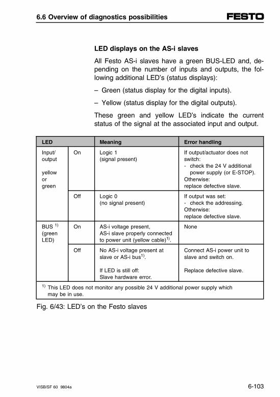
LED displays on the AS-i slaves
All Festo AS-i slaves have a green BUS-LED and, de-pending on the number of inputs and outputs, the fol-lowing additional LED’s (status displays):
– Green (status display for the digital inputs).
– Yellow (status display for the digital outputs).
These green and yellow LED’s indicate the currentstatus of the signal at the associated input and output.
LED Meaning Error handling
Input/output
yelloworgreen
On Logic 1 (signal present)
If output/actuator does notswitch:- check the 24 V additional
power supply (or E-STOP).Otherwise:replace defective slave.
Off Logic 0 (no signal present)
If output was set:- check the addressing.Otherwise:replace defective slave.
BUS 1)
(greenLED)
On AS-i voltage present,AS-i slave properly connectedto power unit (yellow cable)1).
None
Off No AS-i voltage present atslave or AS-i bus1).
If LED is still off:Slave hardware error.
Connect AS-i power unit toslave and switch on.
Replace defective slave.
1) This LED does not monitor any possible 24 V additional power supply which may be in use.
Fig. 6/43: LED’s on the Festo slaves
6.6 Overview of diagnostics possibilities
VISB/SF 60 9804a 6-103
AS-i Software Tool
CAUTIONBefore you start the software:Set the SB/SF 60 controller to STOP.In many cases (e.g., online mode, NOMINAL-AC-TUAL comparison, programming addresses) no datatransfer takes place between the AS-i master andthe node.The AS-i outputs on all AS-i slaves are in thesecases set by the AS-i master to zero.After exiting the AS-i Software Tool the SB/SF 60 re-sumes communication with the AS-i master immedi-ately.If control programs are now running, the AS-i inputsand outputs will be immediately processed.
The AS-i Software Tool offers several additional func-tions which provide quick and user-friendly diagnosticsof all the connected AS-i slaves. Proceed as follows:
1. Set SB/SF 60 to STOP
2. Connect PC to the AS-i master diagnostics interfaceas described in chapter 6.4.3
3. Start the AS-i Software Tool
4. For diagnostics select a menu:- AS-i online, or- project planning AS-i slaves.
6.6 Overview of diagnostics possibilities
6-104 VISB/SF 60 9804a
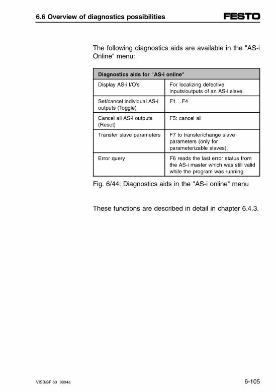
The following diagnostics aids are available in the "AS-iOnline" menu:
Diagnostics aids for "AS-i online"
Display AS-i I/O’s For localizing defectiveinputs/outputs of an AS-i slave.
Set/cancel individual AS-ioutputs (Toggle)
F1…F4
Cancel all AS-i outputs(Reset)
F5: cancel all
Transfer slave parameters F7 to transfer/change slaveparameters (only forparameterizable slaves).
Error query F6 reads the last error status fromthe AS-i master which was still validwhile the program was running.
Fig. 6/44: Diagnostics aids in the "AS-i online" menu
These functions are described in detail in chapter 6.4.3.
6.6 Overview of diagnostics possibilities
VISB/SF 60 9804a 6-105
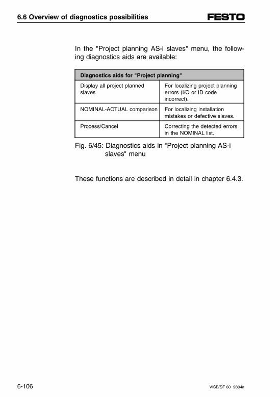
In the "Project planning AS-i slaves" menu, the follow-ing diagnostics aids are available:
Diagnostics aids for "Project planning"
Display all project plannedslaves
For localizing project planningerrors (I/O or ID codeincorrect).
NOMINAL-ACTUAL comparison For localizing installationmistakes or defective slaves.
Process/Cancel Correcting the detected errorsin the NOMINAL list.
Fig. 6/45: Diagnostics aids in "Project planning AS-i slaves" menu
These functions are described in detail in chapter 6.4.3.
6.6 Overview of diagnostics possibilities
6-106 VISB/SF 60 9804a

6.6.2 AS-i specific error handling
Localizing defective slaves
The following possibilities are available for localizing de-fective slaves:
– Local LED displays
– Diagnostics in the online mode of the AS-i SoftwareTool
– Diagnostics using M-files (M1:1.21 and M1:1.22).
If you have localized a defective slave and have to re-place it, the new slave will generally come with address0 factory set. The following options are available for ad-dressing the new slave:
– New addressing using the AS-i addresser
– New addressing using the AS-i Software Tool
– Autoprogramming over slave address 0.
6.6 Overview of diagnostics possibilities
VISB/SF 60 9804a 6-107
Addressing using the AS-i addresser
You can always use this method when there are one ormore slaves defective on the AS-i bus.
WARNINGObserve the following when replacing defectiveslaves:• Switch off all supply voltages to the AS-i bus sys-
tem before performing the replacement.• Replace a defective slave only with one which has
an identical I/O and ID code.Only in this way will safe and error-free function ofyour AS-i bus system be assured.
Then proceed as follows:
1. Switch off supply voltages to the AS-i bus system.
2. Remove the defective slave from the AS-i bus andnote its slave address.
3. Use the AS-i addresser to set the address of thedefective slave on the new slave.
4. Install the new slave on the AS-i bus completely.
5. Switch on the supply voltages to the AS-i bus sys-tem again.
6.6 Overview of diagnostics possibilities
6-108 VISB/SF 60 9804a
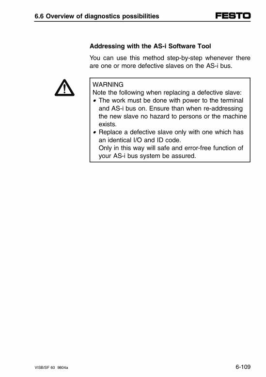
Addressing with the AS-i Software Tool
You can use this method step-by-step whenever thereare one or more defective slaves on the AS-i bus.
WARNINGNote the following when replacing a defective slave:• The work must be done with power to the terminal
and AS-i bus on. Ensure than when re-addressingthe new slave no hazard to persons or the machineexists.
• Replace a defective slave only with one which hasan identical I/O and ID code.Only in this way will safe and error-free function ofyour AS-i bus system be assured.
6.6 Overview of diagnostics possibilities
VISB/SF 60 9804a 6-109

Then proceed as follows:
1. Remove the defective slave from the AS-i bus andnote its slave address.
2. Fully install the new slave on the AS-i bus.
3. Start the AS-i Software Tool and select the "Assign/change AS-i slave address" menu.- The new slave appears with AS-i address 0.- At the location of the (removed) defective slave a question mark appears.
Now proceed as follows:• Select slave 0• Select with F2• Select the address of the defective slave• Use F3 to confirm the new slave
4. Only now install a new slave (if needed) by repeat-ing these steps.
6.6 Overview of diagnostics possibilities
6-110 VISB/SF 60 9804a
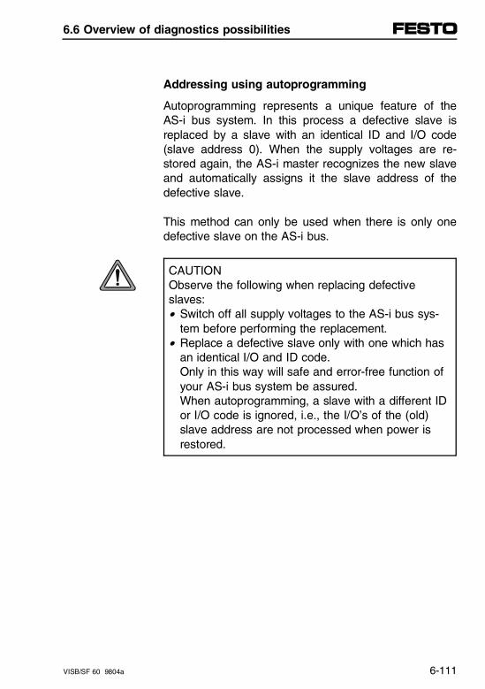
Addressing using autoprogramming
Autoprogramming represents a unique feature of theAS-i bus system. In this process a defective slave isreplaced by a slave with an identical ID and I/O code(slave address 0). When the supply voltages are re-stored again, the AS-i master recognizes the new slaveand automatically assigns it the slave address of thedefective slave.
This method can only be used when there is only onedefective slave on the AS-i bus.
CAUTIONObserve the following when replacing defectiveslaves:• Switch off all supply voltages to the AS-i bus sys-
tem before performing the replacement.• Replace a defective slave only with one which has
an identical I/O and ID code.Only in this way will safe and error-free function ofyour AS-i bus system be assured.When autoprogramming, a slave with a different IDor I/O code is ignored, i.e., the I/O’s of the (old)slave address are not processed when power is restored.
6.6 Overview of diagnostics possibilities
VISB/SF 60 9804a 6-111
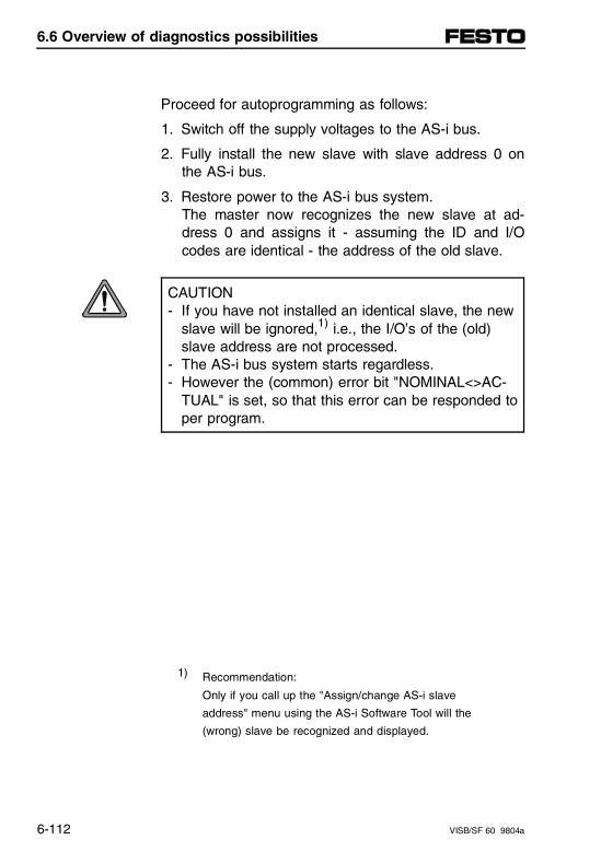
Proceed for autoprogramming as follows:
1. Switch off the supply voltages to the AS-i bus.
2. Fully install the new slave with slave address 0 onthe AS-i bus.
3. Restore power to the AS-i bus system.The master now recognizes the new slave at ad-dress 0 and assigns it - assuming the ID and I/Ocodes are identical - the address of the old slave.
CAUTION- If you have not installed an identical slave, the new
slave will be ignored,1) i.e., the I/O’s of the (old)slave address are not processed.
- The AS-i bus system starts regardless.- However the (common) error bit "NOMINAL<>AC-
TUAL" is set, so that this error can be responded toper program.
1) Recommendation:
Only if you call up the "Assign/change AS-i slave
address" menu using the AS-i Software Tool will the
(wrong) slave be recognized and displayed.
6.6 Overview of diagnostics possibilities
6-112 VISB/SF 60 9804a
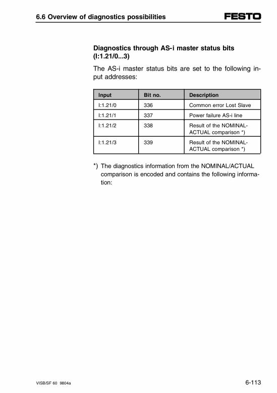
Diagnostics through AS-i master status bits(I:1.21/0...3)
The AS-i master status bits are set to the following in-put addresses:
Input Bit no. Description
I:1.21/0 336 Common error Lost Slave
I:1.21/1 337 Power failure AS-i line
I:1.21/2 338 Result of the NOMINAL-ACTUAL comparison *)
I:1.21/3 339 Result of the NOMINAL-ACTUAL comparison *)
*) The diagnostics information from the NOMINAL/ACTUALcomparison is encoded and contains the following informa-tion:
6.6 Overview of diagnostics possibilities
VISB/SF 60 9804a 6-113
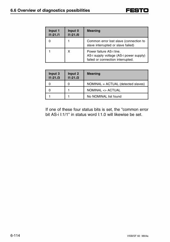
Input 1I1:21./1
Input 0I1:21./0
Meaning
0 1 Common error lost slave (connection toslave interrupted or slave failed)
1 X Power failure AS-i line.AS-i supply voltage (AS-i power supply)failed or connection interrupted.
Input 3I1:21./3
Input 2I1:21./2
Meaning
0 0 NOMINAL = ACTUAL (detected slaves)
0 1 NOMINAL <> ACTUAL
1 1 No NOMINAL list found
If one of these four status bits is set, the "common errorbit AS-i I:1/1" in status word I:1.0 will likewise be set.
6.6 Overview of diagnostics possibilities
6-114 VISB/SF 60 9804a
Diagnostics through status word I:1.0 (common error bit I:1/1)
If you have set bit O:1/1 when you configured the errorresponse, this common error bit I:1/1 generates a re-coverable fault. The error message can be processedand reset in the error handling program.
If the error message is not reset, error code 0165 hexis generated and the FAULT LED comes on.
6.6 Overview of diagnostics possibilities
VISB/SF 60 9804a 6-115
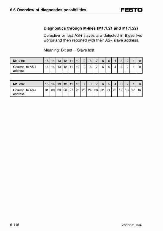
Diagnostics through M-files (M1:1.21 and M1:1.22)
Defective or lost AS-i slaves are detected in these twowords and then reported with their AS-i slave address.
Meaning: Bit set = Slave lost
M1:21/x 15 14 13 12 11 10 9 8 7 6 5 4 3 2 1 0
Corresp. to AS-i address
15 14 13 12 11 10 9 8 7 6 5 4 3 2 1 0
M1:22/x 15 14 13 12 11 10 9 8 7 6 5 4 3 2 1 0
Corresp. to AS-i address
31 30 29 28 27 26 25 24 23 22 21 20 19 18 17 16
6.6 Overview of diagnostics possibilities
6-116 VISB/SF 60 9804a
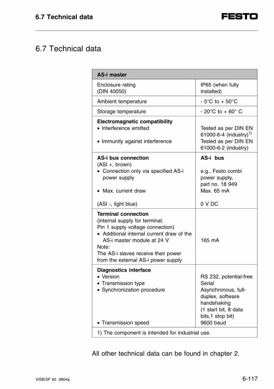
6.7 Technical data
AS-i master
Enclosure rating (DIN 40050)
IP65 (when fullyinstalled)
Ambient temperature - 5°C to + 50°C
Storage temperature - 20°C to + 60° C
Electromagnetic compatibility• Interference emitted
• Immunity against interference
Tested as per DIN EN61000-6-4 (industry)1)
Tested as per DIN EN61000-6-2 (industry)
AS-i bus connection(ASI +, brown)• Connection only via specified AS-i
power supply
• Max. current draw
(ASI -, light blue)
AS-i bus
e.g., Festo combipower supply, part no. 18 949Max. 65 mA
0 V DC
Terminal connection(internal supply for terminal; Pin 1 supply voltage connection)• Additional internal current draw of the
AS-i master module at 24 VNote:The AS-i slaves receive their powerfrom the external AS-i power supply
165 mA
Diagnostics interface• Version• Transmission type• Synchronization procedure
• Transmission speed
RS 232, potential-freeSerialAsynchronous, full-duplex, softwarehandshaking (1 start bit, 8 databits,1 stop bit)9600 baud
1) The component is intended for industrial use.
All other technical data can be found in chapter 2.
6.7 Technical data
VISB/SF 60 9804a 6-117
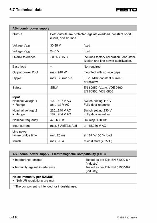
AS-i combi power supply
Output
Voltage Vout1
Both outputs are protected against overload, constant shortcircuit, and no-load.
30.55 V fixed
Voltage Vout2 24.0 V fixed
Overall tolerance - 3 % + 15 % Includes factory calibration, load stabi-lization and line power stabilization.
Base load -- Not required
Output power Pout max. 240 W mounted with no side gaps
Ripple max. 50 mV p-p 0...20 MHz constant current or resistive
Safety SELV EN 60950 (Vout2), VDE 0160EN 60950, VDE 0805
InputNominal voltage 1• Range
100...127 V AC Switch setting 115 V88...132 V AC Fully data retentive
Nominal voltage 2• Range
220...240 V AC Switch setting 230 V187...264 V AC Fully data retentive
Nominal frequency 47...63 Hz DC resp. 400 Hz
Input current max. 6 Aeff/2.8 Aeff at 115.230 V AC
Line power failure bridge time min. 20 ms at 187 V/100 % load
Inrush max. 25 A at cold start (+ 25°C)
AS-i combi power supply - Electromagnetic Compatibility (EMC)
• Interference emitted
• Immunity against interference
Tested as per DIN EN 61000-6-4(industry)1)
Tested as per DIN EN 61000-6-2(industry)
Noise immunity per NAMUR• NAMUR regulations are met
1) The component is intended for industrial use.
6.7 Technical data
6-118 VISB/SF 60 9804a
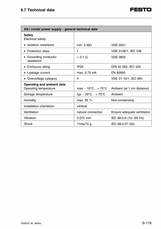
AS-i combi power supply - general technical data
SafetyElectrical safety
• Isolation resistance min. 5 MΩ VDE 0551
• Protection class I VDE 0106/1, IEC 536
• Grounding conductor resistance
< 0.1 Ω VDE 0805
• Enclosure rating IP20 DIN 40 050, IEC 529
• Leakage current max. 0.75 mA EN 60950
• Overvoltage category II VDE 01 10/1, IEC 664
Operating and ambient dataOperating temperature max. - 10°C…+ 70°C Ambient (at 1 cm distance)
Storage temperature typ. - 20°C…+ 70°C Ambient
Humidity max. 95 % Non-condensing
Installation orientation vertical
Ventilation natural convection Ensure adequate ventilation
Vibration 0.075 mm IEC 68-2-6 (10...60 Hz)
Shock 11ms/15 g IEC 68-2-27 (3x)
6.7 Technical data
VISB/SF 60 9804a 6-119

6.7 Technical data
6-120 VISB/SF 60 9804a
Chapter 7
Description of CP interface
7. Description of CP interface
VISB/SF 60 9804a 7-I
Contents
7. Description of CP interface
7.1 User instructions and system overview . . . . . . . . . . . . . . . . 7-1
Information about this manual . . . . . . . . . . . . . . . . . . . . . . . . . . 7-1System overview. . . . . . . . . . . . . . . . . . . . . . . . . . . . . . . . . . . . . 7-3Description of components . . . . . . . . . . . . . . . . . . . . . . . . . . . . . 7-4
7.2 Installation . . . . . . . . . . . . . . . . . . . . . . . . . . . . . . . . . . . . . . . . . 7-5
General instructions . . . . . . . . . . . . . . . . . . . . . . . . . . . . . . . . . . 7-5
7.3 Start-up . . . . . . . . . . . . . . . . . . . . . . . . . . . . . . . . . . . . . . . . . . . 7-7
Preparing the CP system . . . . . . . . . . . . . . . . . . . . . . . . . . . . . . 7-7Power-up reaction of the CP system SB/SF 60. . . . . . . . . . . . . 7-8Operating response of the CP system with SB/SF 60. . . . . . . 7-10Address range of the CP system . . . . . . . . . . . . . . . . . . . . . . . 7-12Basic rules for addressing the CP system. . . . . . . . . . . . . . . . 7-14Address assignment after extension or conversion . . . . . . . . . 7-16
7.4 Diagnostics and error handling . . . . . . . . . . . . . . . . . . . . . . 7-19
LED display of CP interface . . . . . . . . . . . . . . . . . . . . . . . . . . . 7-19Response of the CP system to faults. . . . . . . . . . . . . . . . . . . . 7-19Diagnostics of the CP system . . . . . . . . . . . . . . . . . . . . . . . . . 7-22
7. Description of CP interface
7-II VISB/SF 60 9804a
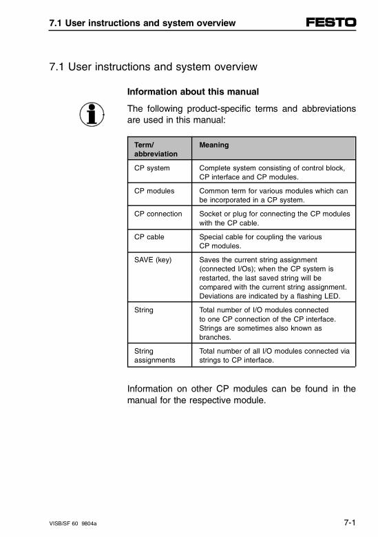
7.1 User instructions and system overview
Information about this manual
The following product-specific terms and abbreviationsare used in this manual:
Term/abbreviation
Meaning
CP system Complete system consisting of control block,CP interface and CP modules.
CP modules Common term for various modules which canbe incorporated in a CP system.
CP connection Socket or plug for connecting the CP moduleswith the CP cable.
CP cable Special cable for coupling the various CP modules.
SAVE (key) Saves the current string assignment(connected I/Os); when the CP system isrestarted, the last saved string will becompared with the current string assignment.Deviations are indicated by a flashing LED.
String Total number of I/O modules connected to one CP connection of the CP interface.Strings are sometimes also known asbranches.
String assignments
Total number of all I/O modules connected viastrings to CP interface.
Information on other CP modules can be found in themanual for the respective module.
7.1 User instructions and system overview
VISB/SF 60 9804a 7-1
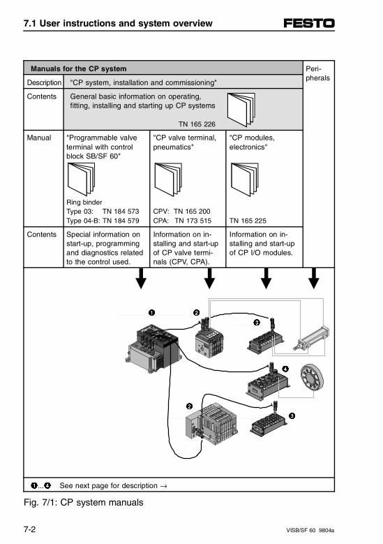
Manuals for the CP system Peri-pherals
Description "CP system, installation and commissioning"
Contents General basic information on operating, fitting, installing and starting up CP systems
TN 165 226
Manual "Programmable valveterminal with controlblock SB/SF 60"
Ring binderType 03: TN 184 573Type 04-B: TN 184 579
"CP valve terminal,pneumatics"
CPV: TN 165 200CPA: TN 173 515
"CP modules, electronics"
TN 165 225
Contents Special information onstart-up, programmingand diagnostics relatedto the control used.
Information on in-stalling and start-upof CP valve termi-nals (CPV, CPA).
Information on in-stalling and start-upof CP I/O modules.
1 2
3
4
2
3
1...4 See next page for description →
Fig. 7/1: CP system manuals
7.1 User instructions and system overview
7-2 VISB/SF 60 9804a
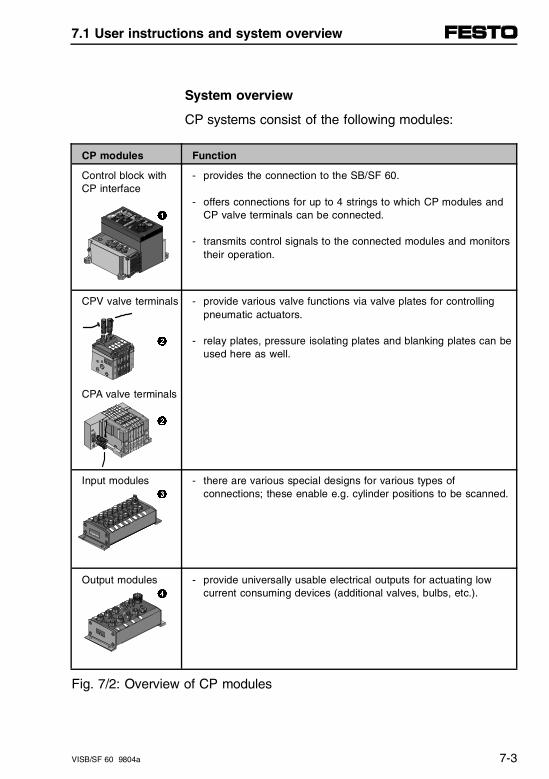
System overview
CP systems consist of the following modules:
CP modules Function
Control block with CP interface
1
- provides the connection to the SB/SF 60.
- offers connections for up to 4 strings to which CP modules andCP valve terminals can be connected.
- transmits control signals to the connected modules and monitorstheir operation.
CPV valve terminals
2
CPA valve terminals
2
- provide various valve functions via valve plates for controllingpneumatic actuators.
- relay plates, pressure isolating plates and blanking plates can beused here as well.
Input modules 3
- there are various special designs for various types of connections; these enable e.g. cylinder positions to be scanned.
Output modules 4
- provide universally usable electrical outputs for actuating low current consuming devices (additional valves, bulbs, etc.).
Fig. 7/2: Overview of CP modules
7.1 User instructions and system overview
VISB/SF 60 9804a 7-3
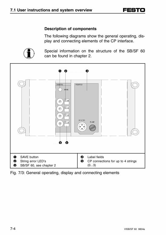
Description of components
The following diagrams show the general operating, dis-play and connecting elements of the CP interface.
Special information on the structure of the SB/SF 60can be found in chapter 2.
1 2 3
5 4
1 SAVE button2 String error LED’s 3 SB/SF 60, see chapter 2
4 Label fields5 CP connections for up to 4 strings
(0...3)
Fig. 7/3: General operating, display and connecting elements
7.1 User instructions and system overview
7-4 VISB/SF 60 9804a
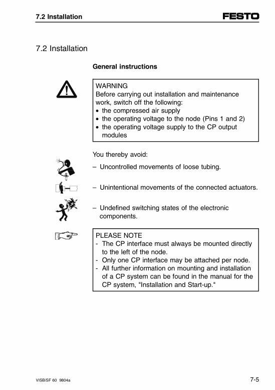
7.2 Installation
General instructions
WARNINGBefore carrying out installation and maintenancework, switch off the following:• the compressed air supply• the operating voltage to the node (Pins 1 and 2)• the operating voltage supply to the CP output
modules
You thereby avoid:
– Uncontrolled movements of loose tubing.
– Unintentional movements of the connected actuators.
– Undefined switching states of the electronic components.
PLEASE NOTE- The CP interface must always be mounted directly
to the left of the node.- Only one CP interface may be attached per node.- All further information on mounting and installation
of a CP system can be found in the manual for theCP system, "Installation and Start-up."
7.2 Installation
VISB/SF 60 9804a 7-5

7.2 Installation
7-6 VISB/SF 60 9804a
7.3 Start - up
Preparing the CP system
PLEASE NOTEBefore starting up a CP system, prepare it first forstart-up (see "CP system" manual).
Before starting up the CP system, proceed as follows:
1. Connect the operating voltage for the node.
2. Connect the CP modules.
3. Switch on the operating voltage
4. Save the string assignment by pressing the SAVEkey on the CP module.
7.3 Start - up
VISB/SF 60 9804a 7-7
Power-up reaction of the CP system SB/SF 60
When the CP system is switched on, there is a startingphase during which the string assignment is deter-mined. If there is no difference between this and thesaved string assignment, the system starts operatingimmediately and resets the boot-up bit input I:1.0/12.
If there is a difference (e.g., during first start-up), thecorresponding LED’s on the CP interface and the oper-ating LED on the CP modules will flash. The boot-up bitinput I:1.0/12 for the CP system remains set until:
– The string assignment is corrected (manual errorelimination), or
– the SAVE key on the CP interface is pressed.
7.3 Start - up
7-8 VISB/SF 60 9804a
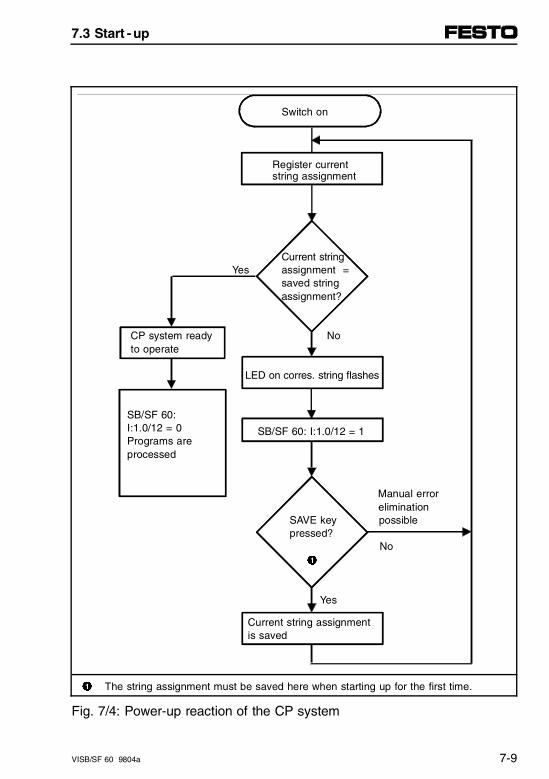
Switch on
Register current string assignment
Current string
Yes assignment = saved string assignment?
CP system ready No to operate
LED on corres. string flashes
SB/SF 60: I:1.0/12 = 0 SB/SF 60: I:1.0/12 = 1 Programs are processed
Manual error elimination
SAVE key possiblepressed?
No 1
Yes
Current string assignment is saved
1 The string assignment must be saved here when starting up for the first time.
Fig. 7/4: Power-up reaction of the CP system
7.3 Start - up
VISB/SF 60 9804a 7-9
Operating response of the CP system with SB/SF 60
Observe here also the information in the manual foryour CP system - Installation and start-up, section "Re-placing modules during operation."
CP errors are recoverable user faults. This means youcan configure the operating error response in outputword O1.0.
O:1.0/8 = 1Hard response
– CP error generates a fault interrupt.
– Error code 0166 (hex).
– FAULT LED flashes
– Error handling routine is invoked. Further diagnosticsare possible using the status word I:1.0 and the M1-file (see chapter 3.6.3, "Working with M-files" and 3.7"Diagnostics").
Additional steps:
A: CP error is not recovered. Program/process is stopped.B: CP error is recovered.
Program/process continues (see also soft error response).
7.3 Start - up
7-10 VISB/SF 60 9804a
O:1.0/8 = 0Soft response(default)
– The CP error is simply entered in the status wordI:1.0 and in the M-file. Error handling in the programis possible.
If soft error response is set or was programmed, one ormore modules can be temporarily disconnected fromthe CP system during operation (failure of a module)and/or replaced by one or more modules of the sametype. In this case:
– the corresponding string LED comes on,
– the corresponding common error bit input I:1.0/8...1in the status word is set.
The corresponding module is no longer operated, butdata continues to be exchanged with the other function-ing modules, i.e., CP inputs and outputs can be proc-essed as follows:
– In the user program, assuming "soft error response"was set or programmed.
– By "forcing."
When the module is reconnected, it will operate again.
7.3 Start - up
VISB/SF 60 9804a 7-11
If one of more modules of different types are replaced,normal operation will only continue if the SAVE key onthe CP interface is pressed.
Other diagnostic messages from the module are dis-played with the common error bit I:1.0/8...11 and can bemore closely defined by invoking the M1-filesM:1.8...1.11 (see Diagnostics section).
Address range of the CP system
The available address range is independent of thehardware configuration of the modular constructedvalve terminals.
Contrary to the general CP manual "Installation andStart-up," fixed addresses for the CP system are re-served in the address range of the SB/SF 60.These addresses (I/O words 1.8...1.11) are fixed allo-cated to the CP system and are independent of the ad-dress space of the local I/Os (I/O words 1.2...1.7).
7.3 Start - up
7-12 VISB/SF 60 9804a
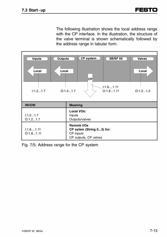
The following illustration shows the local address rangewith the CP interface. In the illustration, the structure ofthe valve terminal is shown schematically followed bythe address range in tabular form.
Inputs Outputs CP system SB/SF 60 Valves
Local Local Local
CP
I:1.8....1.11I:1.2...1.7 O:1.4...1.7 O:1.8...1.11 O:1.2...1.3
IW/OW Meaning
I:1.2...1.7O:1.2...1.7
Local I/Os:InputsOutputs/valves
I:1.8....1.11O:1.8...1.11
Remote I/OsCP sytem (String 0...3) for:CP inputsCP outputs, CP valves
Fig. 7/5: Address range for the CP system
7.3 Start - up
VISB/SF 60 9804a 7-13
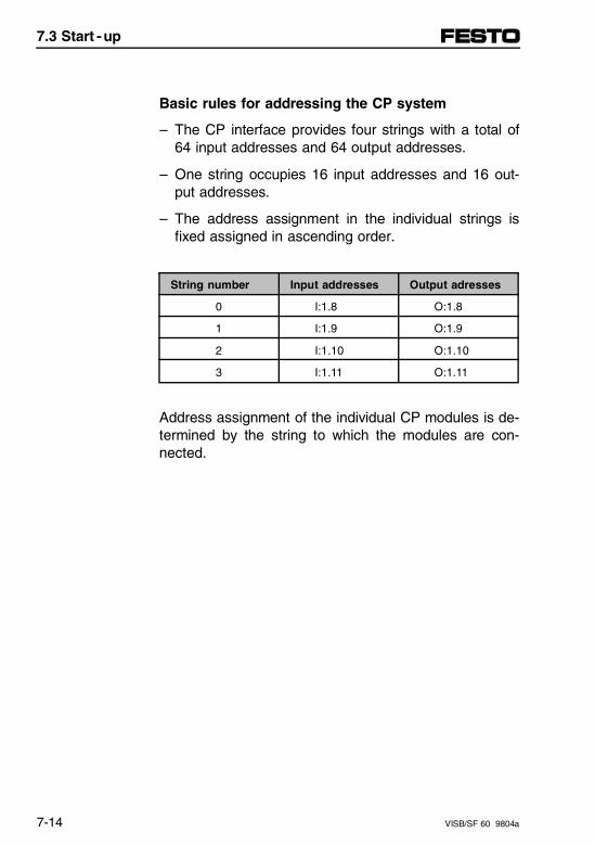
Basic rules for addressing the CP system
– The CP interface provides four strings with a total of64 input addresses and 64 output addresses.
– One string occupies 16 input addresses and 16 out-put addresses.
– The address assignment in the individual strings isfixed assigned in ascending order.
String number Input addresses Output adresses
0 I:1.8 O:1.8
1 I:1.9 O:1.9
2 I:1.10 O:1.10
3 I:1.11 O:1.11
Address assignment of the individual CP modules is de-termined by the string to which the modules are con-nected.
7.3 Start - up
7-14 VISB/SF 60 9804a
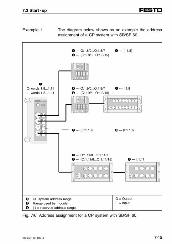
The diagram below shows as an example the addressassignment of a CP system with SB/SF 60.
Example 1
2 --- O:1.8/0...O:1.8/7 3 --- (I:1.8)3 --- (O:1.8/8...O:1.8/15)
1 O-words 1.8...1.11 2 --- O:1.9/0...O:1.9/7 2 --- I:1.9 I- words 1.8...1.11 3 --- (O:1.9/8...O:1.9/15)
3 --- (O:1.10) 3 --- (I:1.10)
2 --- O:1.11/0...O:1.11/73 --- (O:1.11/8...O:1.11/15) 2 --- I:1.11
1 CP system address range2 Range used by module3 ( ) = reserved address range
O = OutputI = Input
Fig. 7/6: Address assignment for a CP system with SB/SF 60
7.3 Start - up
VISB/SF 60 9804a 7-15
Address assignment after extension or conversion
CAUTIONObserve the following if the string assignment ofyour CP system is modified at a later stage:
- The input and output addresses of the CP moduleswill be modified if the CP modules are connected toa different string.
A special feature of the CP system is its flexibility. If thedemands placed on your machine change, you can re-move or add further modules.The input and output addresses of already used mod-ules will not be modified, providing these remain con-nected to the same string.
The following diagram shows as an example the newaddress assignment after modification of the string asshown in the previous illustration.
Example 2
Compared with the previous illustration, Strings 0 and 2have been extended by the addition of further modules.On String 0 a CP valve terminal with 4 valve locationshas been replaced by a terminal with 8 valve locations.Please note that the assignment of the input and outputaddresses on the strings has not changed.
7.3 Start - up
7-16 VISB/SF 60 9804a
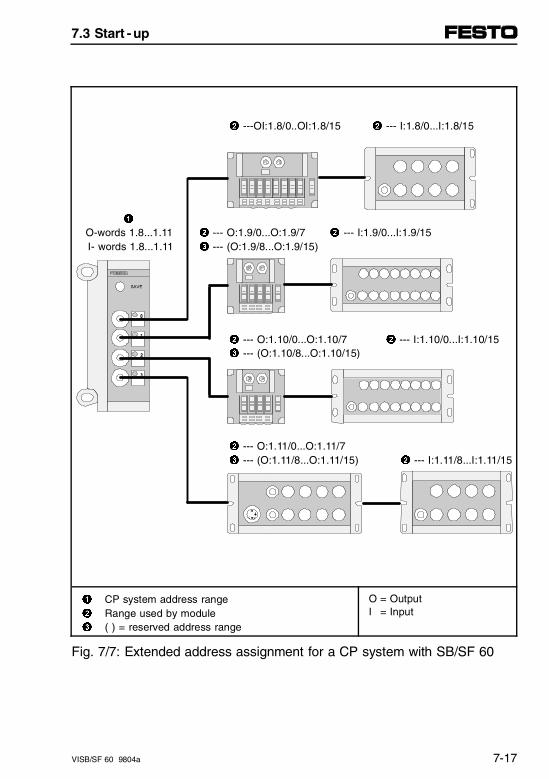
2 ---OI:1.8/0..OI:1.8/15 2 --- I:1.8/0...I:1.8/15
1 O-words 1.8...1.11 2 --- O:1.9/0...O:1.9/7 2 --- I:1.9/0...I:1.9/15 I- words 1.8...1.11 3 --- (O:1.9/8...O:1.9/15)
2 --- O:1.10/0...O:1.10/7 2 --- I:1.10/0...I:1.10/153 --- (O:1.10/8...O:1.10/15)
2 --- O:1.11/0...O:1.11/73 --- (O:1.11/8...O:1.11/15) 2 --- I:1.11/8...I:1.11/15
1 CP system address range2 Range used by module3 ( ) = reserved address range
O = OutputI = Input
Fig. 7/7: Extended address assignment for a CP system with SB/SF 60
7.3 Start - up
VISB/SF 60 9804a 7-17

7.3 Start - up
7-18 VISB/SF 60 9804a
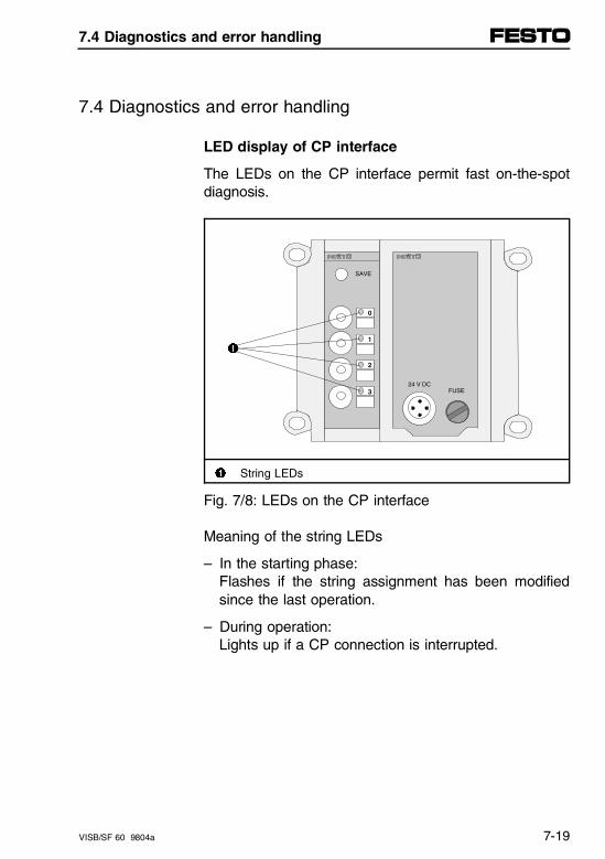
7.4 Diagnostics and error handling
LED display of CP interface
The LEDs on the CP interface permit fast on-the-spotdiagnosis.
1
1 String LEDs
Fig. 7/8: LEDs on the CP interface
Meaning of the string LEDs
– In the starting phase:Flashes if the string assignment has been modifiedsince the last operation.
– During operation:Lights up if a CP connection is interrupted.
0
1
2
324 V DC
FUSE
SAVE
7.4 Diagnostics and error handling
VISB/SF 60 9804a 7-19

Response of the CP system to faults
If there is a fault on a CP module during operation(e.g., cable break), the corresponding string LED willlight up. The status LED on the associated CP modulewill go out. All properly working modules remain readyfor operation.
Faults in the CP system can also be analyzed by soft-ware. The following possibilities exist:
– Common error bit per CP stringI:1.0/8...11 = 1
– Expanded diagnostic "single error per string"M1:1.8...1.11
The common error bit can be more precisely localizedin the program using files M1:1.8...1.11. These possibili-ties are described more closely in the following.
You can restore a defective connection during opera-tion, or replace the defective module without affectingoperation of the remaining modules in the other strings.When the connection has been restored or after re-placement, the appropriate module will automatically beready to operate again.
7.4 Diagnostics and error handling
7-20 VISB/SF 60 9804a
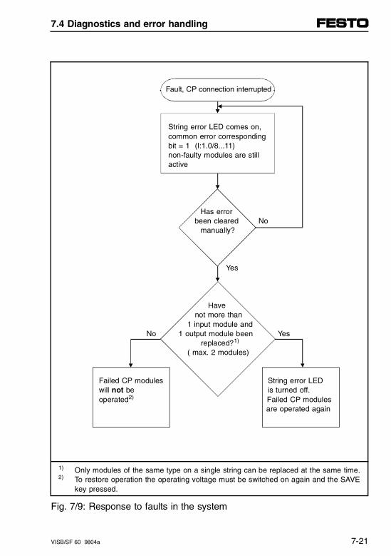
Fault, CP connection interrupted
String error LED comes on, common error corresponding bit = 1 (I:1.0/8...11) non-faulty modules are still active
Has error been cleared No
manually?
Yes
Have not more than
1 input module and No 1 output module been Yes
replaced?1)
( max. 2 modules)
Failed CP modules String error LED will not be is turned off. operated2) Failed CP modules
are operated again
1) Only modules of the same type on a single string can be replaced at the same time. 2) To restore operation the operating voltage must be switched on again and the SAVE
key pressed.
Fig. 7/9: Response to faults in the system
7.4 Diagnostics and error handling
VISB/SF 60 9804a 7-21
Diagnostics of the CP system
Diagnostics information for the CP system is repre-sented in the following variants:
– Boot-up bit I:1.0/12
– Common error per CP string, I:1.0/8...11
– Error code 0x0166 (hex), FAULT LED
– Expanded diagnostics per CP string, M1:1.8...1.11.
These variants are described in greater detail in the fol-lowing.
The bit is set for approx. 2 s during the boot-up phaseof the CP system and then reset. The bit stays set if,after the operating voltage is turned on, the currentstring configuration (ACTUAL) deviates from the storedconfiguration (NOMINAL).
Boot-up bitI:1.0/12
The error is recoverable and can then be optionallyprocessed or ignored.
Error clearing:
• Check the string configuration and correct it asnecessary.
• Press the SAVE key on the CP interface. The cur-rent string configuration is stored as NOMINAL, andbit I:1.0/12 is reset.
7.4 Diagnostics and error handling
7-22 VISB/SF 60 9804a
The respective bit is set as soon as an error occurs inthe associated CP string.The error is recoverable, and can then be optionallyprocessed or ignored.The exact cause of the error can be analyzed using theexpanded diagnostics in the M files M1:1.8...1.11.
Commonerror bit perCP string(I:1.0/8...11)
Error removal:
• Analyze the error in the CP string more precisely (lo-cally or using M1:1.8...1.11).
• Remove the error.
Once the error has been removed, the correspondingerror bits are automatically reset.
This is generated whenever one of the four common er-rors I:1.0/8...11 occurs and an error interrupt was con-figured. - The fault LED on the control block comes on. - The error handling routine is invoked.
Error code0x0166(Fault LED)
The error is recoverable and can then be optionallyprocessed or ignored.Error handling see common error bit per CP string.
7.4 Diagnostics and error handling
VISB/SF 60 9804a 7-23
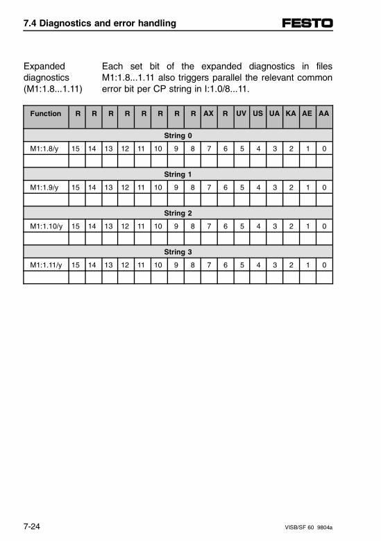
Each set bit of the expanded diagnostics in filesM1:1.8...1.11 also triggers parallel the relevant commonerror bit per CP string in I:1.0/8...11.
Expandeddiagnostics(M1:1.8...1.11)
Function R R R R R R R R AX R UV US UA KA AE AA
String 0
M1:1.8/y 15 14 13 12 11 10 9 8 7 6 5 4 3 2 1 0
String 1
M1:1.9/y 15 14 13 12 11 10 9 8 7 6 5 4 3 2 1 0
String 2
M1:1.10/y 15 14 13 12 11 10 9 8 7 6 5 4 3 2 1 0
String 3
M1:1.11/y 15 14 13 12 11 10 9 8 7 6 5 4 3 2 1 0
7.4 Diagnostics and error handling
7-24 VISB/SF 60 9804a
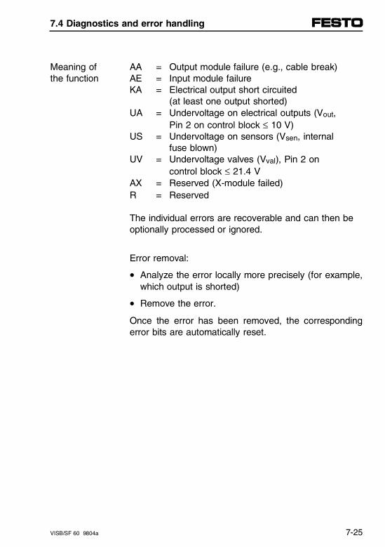
AA = Output module failure (e.g., cable break)AE = Input module failureKA = Electrical output short circuited
(at least one output shorted)UA = Undervoltage on electrical outputs (Vout,
Pin 2 on control block ≤ 10 V)US = Undervoltage on sensors (Vsen, internal
fuse blown)UV = Undervoltage valves (Vval), Pin 2 on
control block ≤ 21.4 VAX = Reserved (X-module failed)R = Reserved
Meaning ofthe function
The individual errors are recoverable and can then beoptionally processed or ignored.
Error removal:
• Analyze the error locally more precisely (for example,which output is shorted)
• Remove the error.
Once the error has been removed, the correspondingerror bits are automatically reset.
7.4 Diagnostics and error handling
VISB/SF 60 9804a 7-25

7.4 Diagnostics and error handling
7-26 VISB/SF 60 9804a
Appendix A
General wiringcable length and grounding
Appendix A
VISB/SF 60 9804a A-I
Contents
A. General wiring cable length and grounding
A.1 General wiring techniques. . . . . . . . . . . . . . . . . . . . . . . . . . . . A-1
Connecting cables to the plugs/sockets. . . . . . . . . . . . . . . . . . . A-2
A.2 Cable length and wire gauge . . . . . . . . . . . . . . . . . . . . . . . . . A-5
Using the graphs . . . . . . . . . . . . . . . . . . . . . . . . . . . . . . . . . . . . A-6Using the formulae . . . . . . . . . . . . . . . . . . . . . . . . . . . . . . . . . . . A-8
A.3 Wiring examples . . . . . . . . . . . . . . . . . . . . . . . . . . . . . . . . . . . A-11
Protection ground . . . . . . . . . . . . . . . . . . . . . . . . . . . . . . . . . . . A-11Operating voltage connection type 03 . . . . . . . . . . . . . . . . . . . A-13Operating voltage connection type 04-B . . . . . . . . . . . . . . . . . A-14Operating voltage connection type 05 . . . . . . . . . . . . . . . . . . . A-154-input module (PNP) . . . . . . . . . . . . . . . . . . . . . . . . . . . . . . . . A-168-input module (PNP) . . . . . . . . . . . . . . . . . . . . . . . . . . . . . . . . A-174-input module (NPN). . . . . . . . . . . . . . . . . . . . . . . . . . . . . . . . A-188-input module (NPN). . . . . . . . . . . . . . . . . . . . . . . . . . . . . . . . A-194-output module (PNP). . . . . . . . . . . . . . . . . . . . . . . . . . . . . . . A-20
A.4 Accessories. . . . . . . . . . . . . . . . . . . . . . . . . . . . . . . . . . . . . . . A-21
DeviceNet bus connection . . . . . . . . . . . . . . . . . . . . . . . . . . . . A-21
Appendix A
A-II VISB/SF 60 9804a
A.1 General wiring techniques
WARNINGBefore installation and maintenance operations,switch off the following items:• Compressed air supply• Operating voltage supply to electronics (Pin 1)• Operating voltage supply to outputs/valves (Pin 2)
By doing this, you avoid:
– Uncontrolled movements from loosened flexible tubes
– Accidental movements from connected actuator units
– Undefined switching states of the electronics.
A.1 General wiring techniques
VISB/SF 60 9804a A-1
Connecting cables to the plugs/sockets
CAUTIONThe position of the pins on the plugs differs from thaton the sockets.– The connections on the input and output modules
are designed as sockets.– The connections on the diagnostics interface and
the operating voltage connection are designed asplugs.
For Pin assignments, please refer to the followingchapters.
Once you have selected appropriate cables, connectthem to the plugs/sockets in accordance with the sub-sequent steps 1...7.
1. Open the plug/socket as follows (refer to diagram):
• Power supply socket:Insert the power supply socket into the operatingvoltage connection on the valve terminal. Unscrew the housing from the socket.Remove the connection part from the socket, locatedin the operating voltage connection.
• Sensor connector/diagnostics socket:Unfasten the middle knurled nut.
A.1 General wiring techniques
A-2 VISB/SF 60 9804a
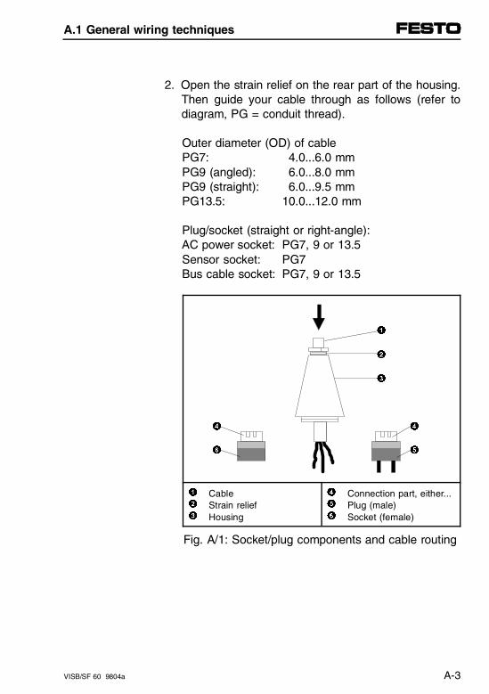
2. Open the strain relief on the rear part of the housing.Then guide your cable through as follows (refer todiagram, PG = conduit thread).
Outer diameter (OD) of cable PG7: 4.0...6.0 mm PG9 (angled): 6.0...8.0 mm PG9 (straight): 6.0...9.5 mm PG13.5: 10.0...12.0 mm
Plug/socket (straight or right-angle): AC power socket: PG7, 9 or 13.5 Sensor socket: PG7 Bus cable socket: PG7, 9 or 13.5
1
2
3
4 4
6 5
1
2
3
CableStrain reliefHousing
4
5
6
Connection part, either...Plug (male)Socket (female)
Fig. A/1: Socket/plug components and cable routing
A.1 General wiring techniques
VISB/SF 60 9804a A-3
3. Strip 5 mm of the insulation from the lead ends.
4. Fit the stranded ends with end sleeves.
5. Connect up the ends of the cables.
6. Reconnect the AC power section to the housing onthe plug/socket and screw the two parts together.Then retract the cable until there are no cable loopsin the housing.
7. Tighten the strain relief.
A.1 General wiring techniques
A-4 VISB/SF 60 9804a

A.2 Cable length and wire gauge
The following information assumes a knowledge of thechapters entitled "Installation" in this manual and is in-tended exclusively for specialist personnel with trainingin electrical engineering.
A load-dependent voltage drop occurs on all three linesof the operating voltage supply to a valve terminal. Thiscan cause the voltage on Pin 1 or Pin 2 of the operat-ing voltage connection to fall outside the permissibletolerance range.
Recommendation:
• Avoid long cable runs between power supply andvalve terminal.
• Calculate the appropriate cable length and wiregauge according to the following graphs or formulae.Bear in mind that the graphs – supply approximate values for cross sections 1.5 and 2.5 mm2
– The formulae supply precise values for any cross section.
The following graphs and formulae assume that thelead cross sections for the operating voltage supply(Pins 1, 2 and 3) are identical.
A.2 Cable length and wire gauge
VISB/SF 60 9804a A-5

Using the graphs
Proceed as follows:
1. Calculate the maximum current consumption for out-puts/valves (I2).
2. Calculate the lowest voltage to be anticipated duringoperation (VOmin) on the power supply unit. Takeinto account:– the load-dependency of the power supply unit– fluctuations in the AC supply.
3. Read off the permissible cable length from the rele-vant table for your cross section/gauge.Example for 1.5 mm2:VOmin = 22.8 V, I2 = 2 A; Lmax = 25 m
A.2 Cable length and wire gauge
A-6 VISB/SF 60 9804a
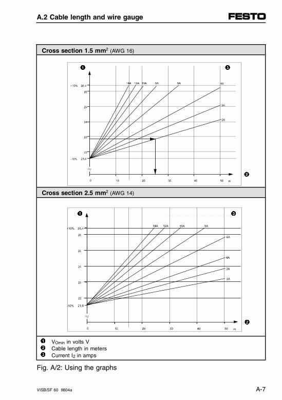
Cross section 1.5 mm2 (AWG 16)
1 3
2
Cross section 2.5 mm2 (AWG 14)
1 3
2
1
2
3
VOmin in volts VCable length in metersCurrent I2 in amps
Fig. A/2: Using the graphs
A.2 Cable length and wire gauge
VISB/SF 60 9804a A-7
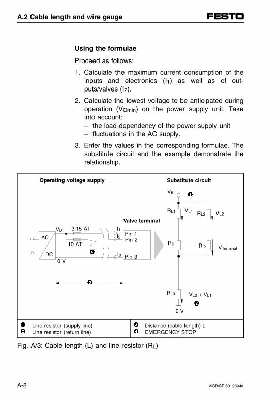
Using the formulae
Proceed as follows:
1. Calculate the maximum current consumption of theinputs and electronics (I1) as well as of out-puts/valves (I2).
2. Calculate the lowest voltage to be anticipated duringoperation (VOmin) on the power supply unit. Takeinto account:– the load-dependency of the power supply unit– fluctuations in the AC supply.
3. Enter the values in the corresponding formulae. Thesubstitute circuit and the example demonstrate therelationship.
Operating voltage supply
Valve terminal
VTerminal
Substitute circuit
1
2
Line resistor (supply line)Line resistor (return line)
3
4
Distance (cable length) LEMERGENCY STOP
Fig. A/3: Cable length (L) and line resistor (RL)
AC
DC0 V
VB 3.15 AT
10 AT
I1I2 Pin 1
Pin 2
Pin 3
RL0 VL2 + VL1
RI2RI1
VB
RL1 VL1 VL2RL2
I0
0 V
3
1
4
2
A.2 Cable length and wire gauge
A-8 VISB/SF 60 9804a
Formula for max. cable length:
L ≤ (VOmin − VVALVEmin) ⋅ A ⋅ κCu
2 ⋅ I2 + I1
Key to terms:
• VTERMINAL = 24 V ± 10%, minimal: VTERMINALmin ≥ 21.6 V
• VOmin = minimum operating voltagepower supply (at power supply unit)
• Current I1 = current for electronic components andinputs
• Current I2 = current for outputs/valves
• A = wire cross-section(uniform size, e.g., 1.5 mm2)
• κ = wire conductance
(uniform size e.g. κCu = 56 mmm 2 ⋅ Ω
)
Example:I1 = 1 A; I2 = 5 A; Vo = 24 V; VTERMINALmin = 21.6 V ;
κCu = 56 mmm 2 ⋅ Ω
;
result of example:L ≤ 18 m for A = 1.5 mm2
L ≤ 30 m for A = 2.5 mm2
A.2 Cable length and wire gauge
VISB/SF 60 9804a A-9

A.2 Cable length and wire gauge
A-10 VISB/SF 60 9804a
A.3 Wiring examples
Protection ground
The following diagram shows the connection of a com-mon 24 V power supply for Pin 1 and Pin 2. Pleasenote that:
– the power supply of outputs/valves must be protectedagainst short circuits (s.c.)/overloads externally with amaximum fuse rating of 10 A
– the power supply for electronic components and in-puts must be protected against short circuits(s.c.)/overloads externally with a maximum fuse rat-ing of 3.15 A
– the common tolerance 24 V DC ± 10 % must be ob-served
– when both AC ground cables are connected, com-pensation circuits must be prevented, e.g., by usinglines with appropriate cross-sections for potentialcompensation.
A.3 Wiring examples
VISB/SF 60 9804a A-11
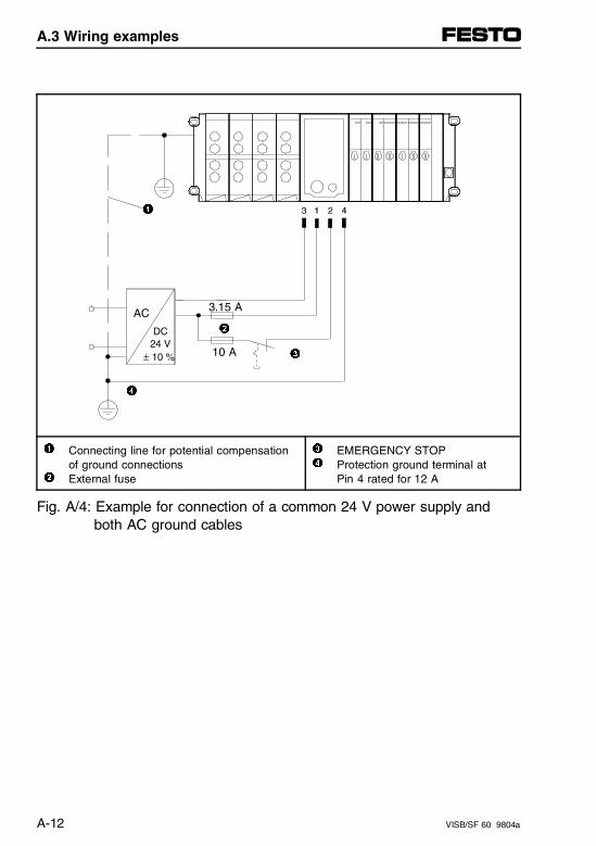
1
2
3
4
1
2
Connecting line for potential compensationof ground connectionsExternal fuse
34
EMERGENCY STOPProtection ground terminal at Pin 4 rated for 12 A
Fig. A/4: Example for connection of a common 24 V power supply andboth AC ground cables
10 A
AC
DC 24 V± 10 %
3.15 A
A.3 Wiring examples
A-12 VISB/SF 60 9804a
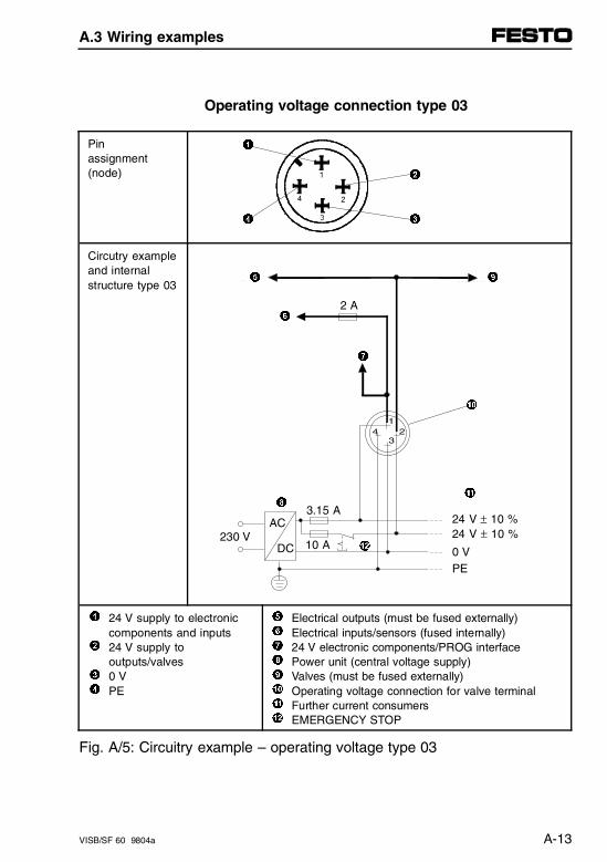
Operating voltage connection type 03
Pinassignment(node)
1
2
4 3
Circutry exampleand internal structure type 03
5 9
6
7
0
8 !
"
1
2
34
24 V supply to electroniccomponents and inputs24 V supply tooutputs/valves0 VPE
567890!"
Electrical outputs (must be fused externally)Electrical inputs/sensors (fused internally)24 V electronic components/PROG interfacePower unit (central voltage supply)Valves (must be fused externally)Operating voltage connection for valve terminalFurther current consumersEMERGENCY STOP
Fig. A/5: Circuitry example – operating voltage type 03
34 2
1
230 VAC
DC
3.15 A
10 A
24 V ± 10 %24 V ± 10 %
0 VPE
2 A
A.3 Wiring examples
VISB/SF 60 9804a A-13
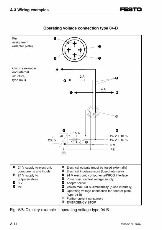
Operating voltage connection type 04-B
Pinassignment(adapter plate)
1
2
4 3
Circutry exampleand internal structure,type 04-B
5
9 6
7 0
!
8 "
#
1
2
34
24 V supply to electroniccomponents and inputs24 V supply tooutputs/valves0 VPE
567890!
"#
Electrical outputs (must be fused externally)Electrical inputs/sensors (fused internally)24 V electronic components/PROG interfacePower unit (central voltage supply)Adapter cableValves max. 50 % simultaneity (fused internally)Operating voltage connection for adapter plate(type 04-B)Further current consumersEMERGENCY STOP
Fig. A/6: Circuitry example – operating voltage type 04-B
34 2
1
230 VAC
DC
3.15 A
10 A
24 V ± 10 %24 V ± 10 %
0 V
PE
2 A
4 A
A.3 Wiring examples
A-14 VISB/SF 60 9804a

Operating voltage connection type 05
Pinassignment(adapter plate)
1
2
4 3
Circutry exampleand internal structure,type 05
5
9 6
7 0
!
8 "
#
1
2
34
24 V supply to electroniccomponents and inputs24 V supply tooutputs/valves0 VPE
567890!"#
Electrical outputs (must be fused externally)Electrical inputs/sensors (fused internally)24 V electronic components/PROG interfacePower unit (central voltage supply)Adapter cableValves max. 50 % simultaneity (fused internally)Operating voltage connection for adapter plateFurther current consumersEMERGENCY STOP
Fig. A/7: Circuitry example – operating voltage type 05
34 2
1
230 VAC
DC
3.15 A
10 A
24 V ± 10 %24 V ± 10 %
0 V
PE
2 A
4 A
A.3 Wiring examples
VISB/SF 60 9804a A-15
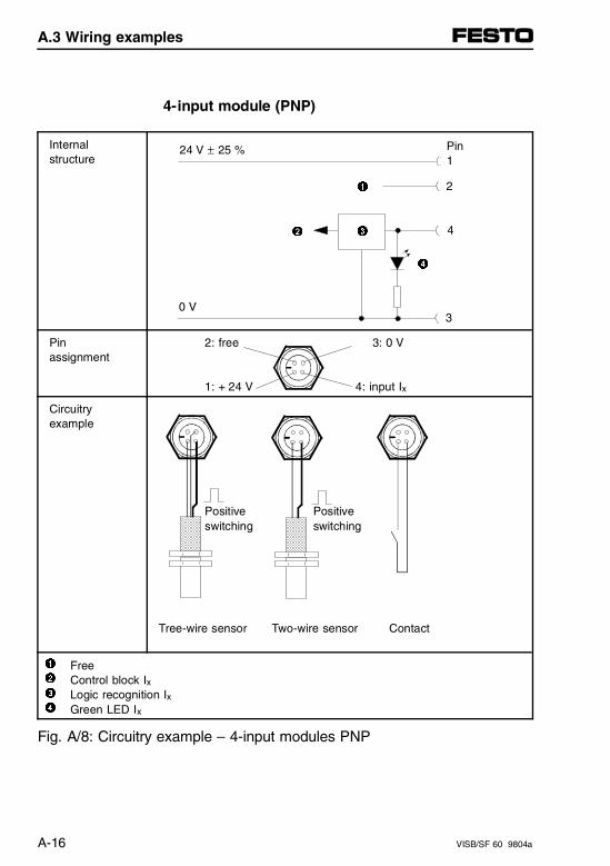
4-input module (PNP)
Internalstructure
1
2
4
Pinassignment
2: free 3: 0 V
1: + 24 V 4: input Ix
Circuitry example
Positive Positiveswitching switching
Tree-wire sensor Two-wire sensor Contact
1234
FreeControl block IxLogic recognition IxGreen LED Ix
Fig. A/8: Circuitry example – 4-input modules PNP
Pin1
24 V ± 25 %
0 V
2
43
3
A.3 Wiring examples
A-16 VISB/SF 60 9804a
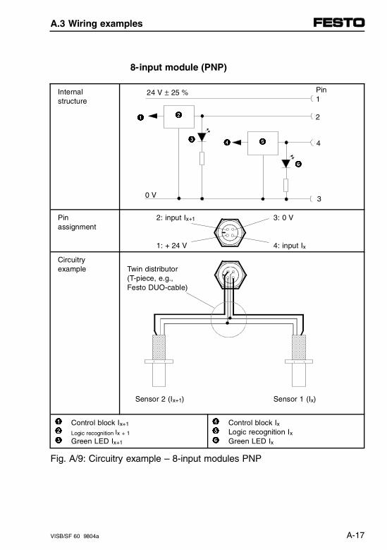
8-input module (PNP)
Internalstructure
1
Pinassignment
2: input Ix+1 3: 0 V
1: + 24 V 4: input Ix
Circuitryexample Twin distributor
(T-piece, e.g., Festo DUO-cable)
Sensor 2 (Ix+1) Sensor 1 (Ix)
123
Control block Ix+1
Logic recognition Ix + 1
Green LED Ix+1
456
Control block IxLogic recognition IxGreen LED Ix
Fig. A/9: Circuitry example – 8-input modules PNP
5
24 V ± 25 %
0 V
2
4
6
3
Pin1
4
3
2
A.3 Wiring examples
VISB/SF 60 9804a A-17
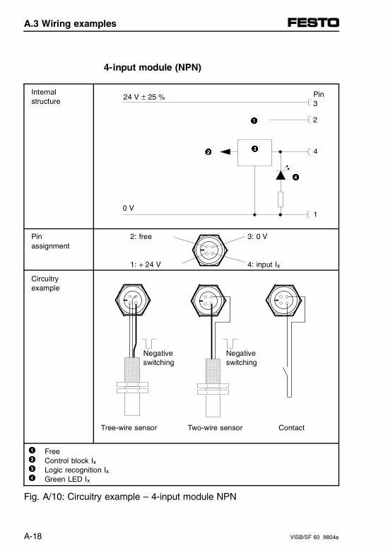
4-input module (NPN)
Internalstructure
1
2
4
Pinassignment
2: free 3: 0 V
1: + 24 V 4: input Ix
Circuitryexample
Negative Negative switching switching
Tree-wire sensor Two-wire sensor Contact
1234
FreeControl block IxLogic recognition Ix
Green LED Ix
Fig. A/10: Circuitry example – 4-input module NPN
Pin3
4
1
3
0 V
2
24 V ± 25 %
A.3 Wiring examples
A-18 VISB/SF 60 9804a
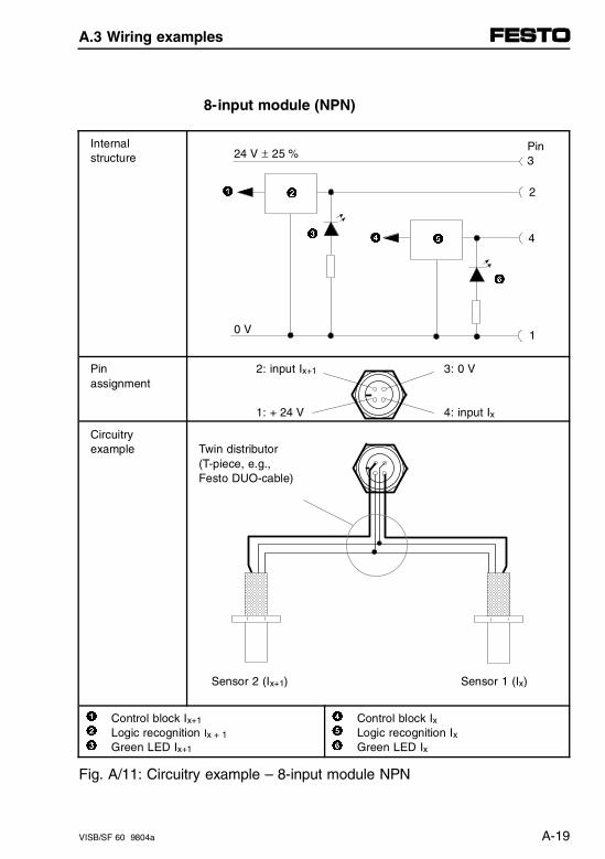
8-input module (NPN)
Internalstructure
Pinassignment
2: input Ix+1 3: 0 V
1: + 24 V 4: input Ix
Circuitryexample Twin distributor
(T-piece, e.g., Festo DUO-cable)
Sensor 2 (Ix+1) Sensor 1 (Ix)
123
Control block Ix+1 Logic recognition Ix + 1
Green LED Ix+1
456
Control block Ix Logic recognition IxGreen LED Ix
Fig. A/11: Circuitry example – 8-input module NPN
5
1
24 V ± 25 %
0 V
2
4
6
3
Pin3
4
1
2
A.3 Wiring examples
VISB/SF 60 9804a A-19
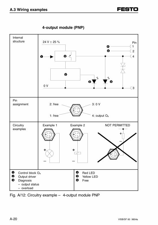
4-output module (PNP)
Internalstructure
Pinassignment 2: free 3: 0 V
1: free 4: output Ox
Circuitryexamples
Example 1 Example 2 NOT PERMITTED
123
Control block Ox Output driverDiagnosis– output status– overload
456
Red LEDYellow LEDFree
Fig. A/12: Circuitry example – 4-output module PNP
4
1
24 V ± 25 %
0 V
2
6
5
6
Pin1
4
3
2
3
A.3 Wiring examples
A-20 VISB/SF 60 9804a
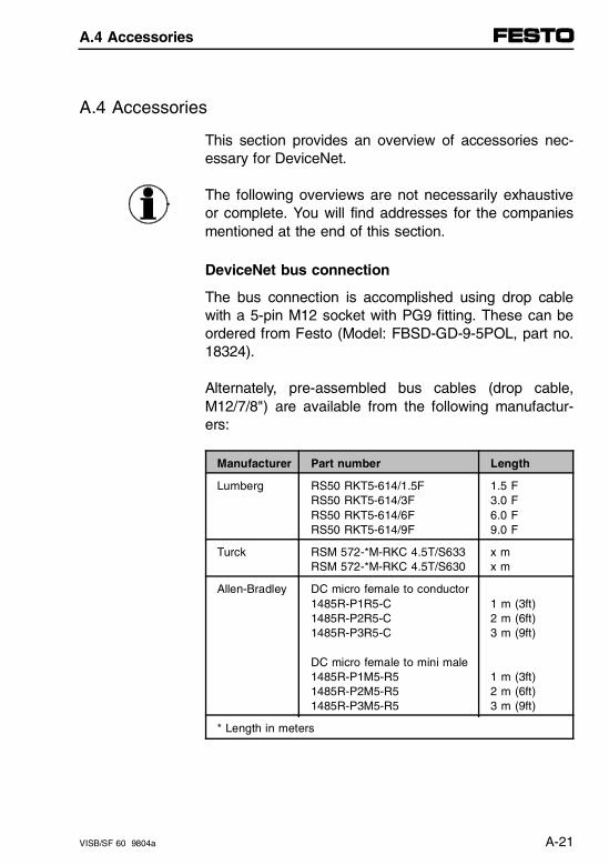
A.4 Accessories
This section provides an overview of accessories nec-essary for DeviceNet.
The following overviews are not necessarily exhaustiveor complete. You will find addresses for the companiesmentioned at the end of this section.
DeviceNet bus connection
The bus connection is accomplished using drop cablewith a 5-pin M12 socket with PG9 fitting. These can beordered from Festo (Model: FBSD-GD-9-5POL, part no.18324).
Alternately, pre-assembled bus cables (drop cable,M12/7/8") are available from the following manufactur-ers:
Manufacturer Part number Length
Lumberg RS50 RKT5-614/1.5F RS50 RKT5-614/3F RS50 RKT5-614/6F RS50 RKT5-614/9F
1.5 F 3.0 F 6.0 F 9.0 F
Turck RSM 572-*M-RKC 4.5T/S633RSM 572-*M-RKC 4.5T/S630
x m x m
Allen-Bradley DC micro female to conductor1485R-P1R5-C1485R-P2R5-C1485R-P3R5-C
DC micro female to mini male1485R-P1M5-R51485R-P2M5-R51485R-P3M5-R5
1 m (3ft)2 m (6ft)3 m (9ft)
1 m (3ft)2 m (6ft)3 m (9ft)
* Length in meters
A.4 Accessories
VISB/SF 60 9804a A-21
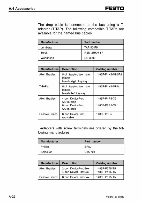
The drop cable is connected to the bus using a T-adapter (T-TAP). The following compatible T-TAPs areavailable for the named bus cables:
Manufacturer Part number
Lumberg TAP 50-RK
Turck RSM-2RKM 57
Woodhead DN 3000
Manufactures Description Catalog number
Allen Bradley 5-pin tapping tee male,female, female rigth keyway
1485P-P1N5-MN5R1
T-TAPs 5-pin tapping tee male,female, female left keyway
1485P-P1N5-MN5L1
Allen Bradley 4-port DevicePort w/2 m drop8-port DevicePortw/2 m drop
1485P-P4R5-C2
1485P-P8R5-C2
Passive Boxes 8-port DevicePortw/o cable
1485P-P8R5
T-adapters with screw terminals are offered by the fol-lowing manufactures:
Manufacturer Part number
Phillips BR50
Selectron CTA 701
Manufactures Description Catalog number
Allen Bradley 2-port DevicePort Box4-port DevicePort Box
1485P-P2T5-T51485P-P4T5-T5
Passive Boxes 8-port DevicePort Box 1485P-P8T5-T5
A.4 Accessories
A-22 VISB/SF 60 9804a

Addresses:
Manufacturer Addresses
Allen-Bradley United StatesAllen-Bradley Headquarters1201 South Second StreetMilwaukeeWI 53204
GermanyEurope HeadquartersAllen-Bradley Robert-Bosch-Straße 563303 Dreieich
GermanyAllen-Bradley GmbHDüsseldorfer Straße 1542781 Haan-Gruiten
Woodhead Industries Inc.
United StatesDaniel Woodhead3411 Woodhead DriveNorthbrook, Illinois 60062
CanadaWoodhead Canada Ltd. Company1090 Brevik PlaceMississauga, OntarioCanada L4W 3Y5
United KingdomAero-Motive (U.K.) Ltd.9. Rassau Industrial EstateEbbw Vale, Gwent,NP3 5SD, U.K
GermanyH.F. Vogel GmbHTullastraße 9 75196 Remchingen
Lumberg United StatesLumberg Inc.11351 Business Center DriveUSA-Richmond,VA 23236
A.4 Accessories
VISB/SF 60 9804a A-23
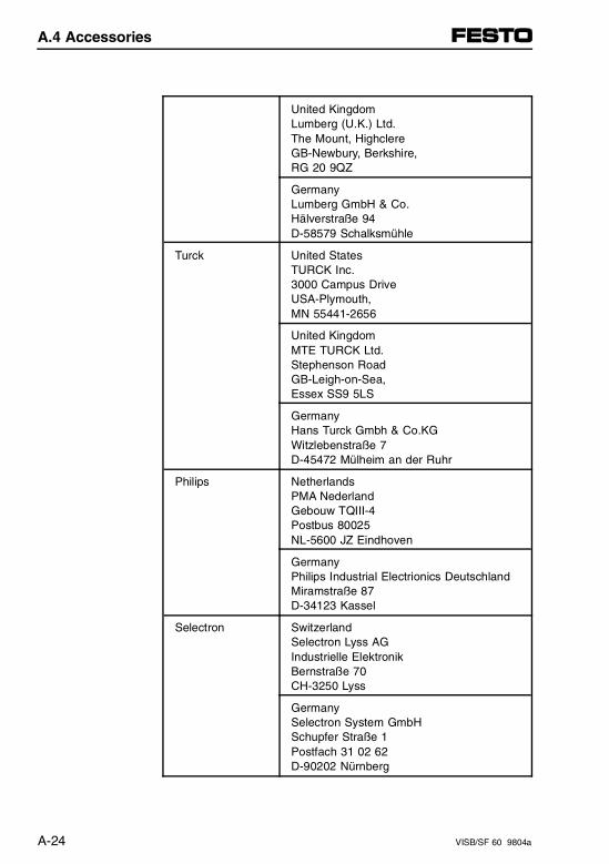
United KingdomLumberg (U.K.) Ltd.The Mount, HighclereGB-Newbury, Berkshire,RG 20 9QZ
GermanyLumberg GmbH & Co.Hälverstraße 94D-58579 Schalksmühle
Turck United StatesTURCK Inc.3000 Campus DriveUSA-Plymouth,MN 55441-2656
United KingdomMTE TURCK Ltd.Stephenson RoadGB-Leigh-on-Sea,Essex SS9 5LS
GermanyHans Turck Gmbh & Co.KGWitzlebenstraße 7D-45472 Mülheim an der Ruhr
Philips NetherlandsPMA NederlandGebouw TQIII-4Postbus 80025NL-5600 JZ Eindhoven
GermanyPhilips Industrial Electrionics DeutschlandMiramstraße 87D-34123 Kassel
Selectron SwitzerlandSelectron Lyss AG Industrielle ElektronikBernstraße 70CH-3250 Lyss
GermanySelectron System GmbHSchupfer Straße 1Postfach 31 02 62D-90202 Nürnberg
A.4 Accessories
A-24 VISB/SF 60 9804a
Appendix B
Error messages
Appendix B
VISB/SF 60 9804a B-I
Contents
B. Error messages
B.1 Error messages for the SLC 5/02 CPU. . . . . . . . . . . . . . . . . . B-1
B.2 Error messages for the Festo Peripheral Module (FPM) . . . B-3
Recoverable user faults . . . . . . . . . . . . . . . . . . . . . . . . . . . . . . . B-3Non-recoverable user faults . . . . . . . . . . . . . . . . . . . . . . . . . . . . B-4Non-user faults . . . . . . . . . . . . . . . . . . . . . . . . . . . . . . . . . . . . . . B-4
B.3 Error messages for the SF 60 DeviceNet Scanner . . . . . . . . B-5
Appendix B
B-II VISB/SF 60 9804a
B.1 Error messages for the SLC 5/02 CPU
The SLC 5/02 processor embedded in the SB/SF 60can generate the same general error messages as anAllen-Bradley SLC 5/02 programmable controller.
Error messages for the operating system and the programming software can be found in the referencemanual for your programming software.The generally valid error codes of an SLC 5/02 applycorrespondingly to the SB/SF 60.
B.1 Error messages for the SLC 5/02 CPU
VISB/SF 60 9804a B-1

B.1 Error messages for the SLC 5/02 CPU
B-2 VISB/SF 60 9804a
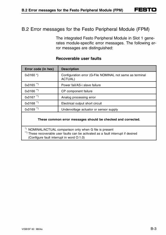
B.2 Error messages for the Festo Peripheral Module (FPM)
The integrated Festo Peripheral Module in Slot 1 gene-rates module-specific error messages. The following er-ror messages are distinguished:
Recoverable user faults
Error code (in hex) Description
0x0160 *) Configuration error (G-File NOMINAL not same as terminalACTUAL)
0x0165 **) Power fail/AS-i slave failure
0x0166 **) CP component failure
0x0167 **) Analog processing error
0x0168 **) Electrical output short circuit
0x0169 **) Undervoltage actuator or sensor supply
These common error messages should be checked and corrected.
*) NOMINAL/ACTUAL comparison only when G file is present**) These recoverable user faults can be activated as a fault interrupt if desired
(Configure fault interrupt in word O:1.0)
B.2 Error messages for the Festo Peripheral Module (FPM)
VISB/SF 60 9804a B-3
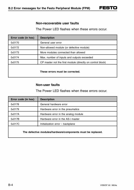
Non-recoverable user faults
The Power LED flashes when these errors occur.
Error code (in hex) Description
0x0170 General user error
0x0172 Non-allowed module (or defective module)
0x0173 More modules connected than allowed
0x0174 Max. number of inputs and outputs exceeded
0x0175 CP master not the first module (directly on control block)
These errors must be corrected.
Non-user faults
The Power LED flashes when these errors occur.
Error code (in hex) Description
0x0178 General hardware error
0x0179 Hardware error in the pneumatics
0x017A Hardware error in the analog module
0x017B Hardware error in the AS-i master
0x017C Initialization error – backplane
The defective modules/hardware/components must be replaced.
B.2 Error messages for the Festo Peripheral Module (FPM)
B-4 VISB/SF 60 9804a
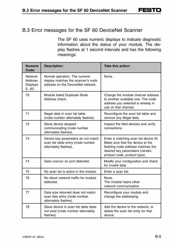
B.3 Error messages for the SF 60 DeviceNet Scanner
The SF 60 uses numeric displays to indicate diagnosticinformation about the status of your module. The dis-play flashes at 1 second intervals and has the followingmeanings:
NumericCode:
Description: Take this action:
NetworkAddressDisplays0...63
Normal operation. The numericdisplay matches the scanner’s nodeaddress on the DeviceNet network.
None.
70 Module failed Duplicate NodeAddress check .
Change the module channel addressto another available one. The nodeaddress you selected is already inuse on that channel.
71 Illegal data in scan list table (node number alternately flashes).
Reconfigure the scan list table andremove any illegal data.
72 Slave device stopped communicating (node number alternately flashes).
Inspect the field devices and verifyconnections.
73 Device key parameters do not matchscan list table entry (node numberalternately flashes).
Enter a matching scan list device ID.Make sure that the device at theflashing node address matches thedesired key parameters (vendor,product code, product type).
74 Data overrun on port detected. Modify your configuration and checkfor invalid data.
75 No scan list is active in the module. Enter a scan list.
76 No direct network traffic for moduledetected.
None. The module hears other network communication.
77 Data size returned does not matchscan lists entry (node numberalternately flashes).
Reconfigure your module andchange the addressing.
78 Slave device in scan list table doesnot exist (node number alternatelyflashes).
Add the device to the network, ordelete the scan list entry for thatdevice.
B.3 Error messages for the SF 60 DeviceNet Scanner
VISB/SF 60 9804a B-5
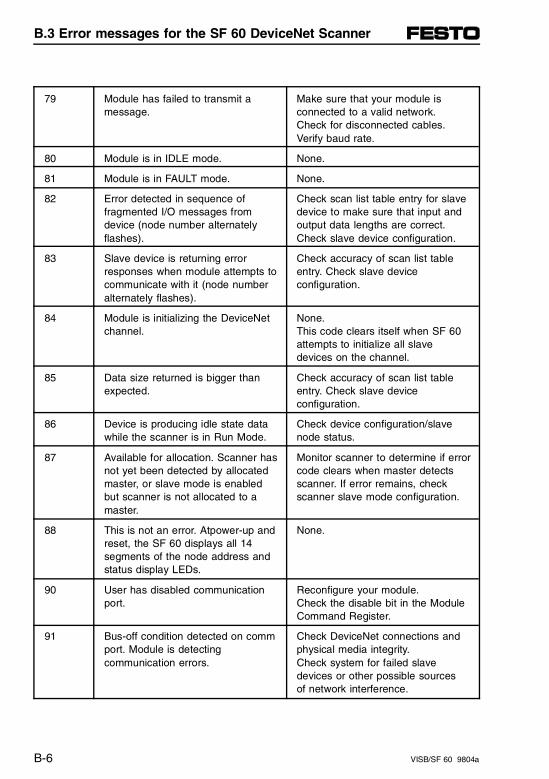
79 Module has failed to transmit amessage.
Make sure that your module isconnected to a valid network. Check for disconnected cables.Verify baud rate.
80 Module is in IDLE mode. None.
81 Module is in FAULT mode. None.
82 Error detected in sequence offragmented I/O messages fromdevice (node number alternatelyflashes).
Check scan list table entry for slavedevice to make sure that input andoutput data lengths are correct.Check slave device configuration.
83 Slave device is returning errorresponses when module attempts tocommunicate with it (node numberalternately flashes).
Check accuracy of scan list tableentry. Check slave deviceconfiguration.
84 Module is initializing the DeviceNetchannel.
None. This code clears itself when SF 60attempts to initialize all slavedevices on the channel.
85 Data size returned is bigger thanexpected.
Check accuracy of scan list tableentry. Check slave deviceconfiguration.
86 Device is producing idle state datawhile the scanner is in Run Mode.
Check device configuration/slavenode status.
87 Available for allocation. Scanner hasnot yet been detected by allocatedmaster, or slave mode is enabledbut scanner is not allocated to amaster.
Monitor scanner to determine if errorcode clears when master detectsscanner. If error remains, checkscanner slave mode configuration.
88 This is not an error. Atpower-up andreset, the SF 60 displays all 14segments of the node address andstatus display LEDs.
None.
90 User has disabled communicationport.
Reconfigure your module. Check the disable bit in the ModuleCommand Register.
91 Bus-off condition detected on commport. Module is detectingcommunication errors.
Check DeviceNet connections andphysical media integrity. Check system for failed slavedevices or other possible sources of network interference.
B.3 Error messages for the SF 60 DeviceNet Scanner
B-6 VISB/SF 60 9804a
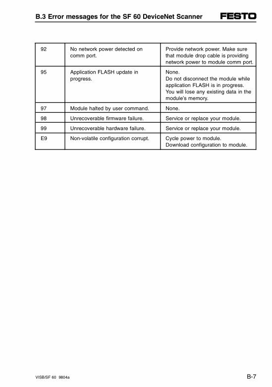
92 No network power detected oncomm port.
Provide network power. Make surethat module drop cable is providingnetwork power to module comm port.
95 Application FLASH update inprogress.
None. Do not disconnect the module whileapplication FLASH is in progress.You will lose any existing data in themodule’s memory.
97 Module halted by user command. None.
98 Unrecoverable firmware failure. Service or replace your module.
99 Unrecoverable hardware failure. Service or replace your module.
E9 Non-volatile configuration corrupt. Cycle power to module. Download configuration to module.
B.3 Error messages for the SF 60 DeviceNet Scanner
VISB/SF 60 9804a B-7

B.3 Error messages for the SF 60 DeviceNet Scanner
B-8 VISB/SF 60 9804a

Appendix C
Optimizing the configuration
Appendix C
VISB/SF 60 9804a C-I
Contents
C. Optimizing the configuration
C.1 Principles of the control cycle . . . . . . . . . . . . . . . . . . . . . . . . C-1
C.2 Estimating the scan time . . . . . . . . . . . . . . . . . . . . . . . . . . . . . C-5
C.2.1 Estimating the scan time of the SLC cycle . . . . . . . . . . . . . . . . C-5C.2.2 Estimating the scan time of the Festo Peripheral Module . . . . . C-8
C.3 Optimizing the scan time. . . . . . . . . . . . . . . . . . . . . . . . . . . . C-11
C.3.1 Optimizing the scan time when configuring . . . . . . . . . . . . . . . C-11Configuration of the scanned input/output words. . . . . . . . . . . C-12Short formula for scan time . . . . . . . . . . . . . . . . . . . . . . . . . . . C-13
C.3.2 Optimizing the scan time using I/O interrupts . . . . . . . . . . . . . C-14Minimum pulse width . . . . . . . . . . . . . . . . . . . . . . . . . . . . . . . . C-15Maximum response time . . . . . . . . . . . . . . . . . . . . . . . . . . . . . C-16Pulse interval (cutoff frequency). . . . . . . . . . . . . . . . . . . . . . . . C-18
C.3.3 Calculation examples . . . . . . . . . . . . . . . . . . . . . . . . . . . . . . . . C-19Estimating the SLC 5/02 processor scan time(without force) . . . . . . . . . . . . . . . . . . . . . . . . . . . . . . . . . . . . . . C-19Estimate the peripheral cycle (Festo Peripheral Module) . . . . C-19Estimating total cycle time . . . . . . . . . . . . . . . . . . . . . . . . . . . . C-21
C.4 Estimation of memory usage . . . . . . . . . . . . . . . . . . . . . . . . C-23
Total memory usage. . . . . . . . . . . . . . . . . . . . . . . . . . . . . . . . . C-23Example of calculation . . . . . . . . . . . . . . . . . . . . . . . . . . . . . . . C-25
Appendix C
C-II VISB/SF 60 9804a
C.1 Principles of the control cycle
To supplement the simplified representation of the oper-ating cycle contained in chapter 3.5, here you will find adetailed description for the SB/SF 60. Especially thescan time for the I/Os (querying the inputs, setting theoutputs) consists of several individual time cycleswhose time behavior needs to be considered individu-ally. An aid for estimating the scan time is provided bythe two tables in the next section:
• Table - Scan time for the SLC cycle
• Table - Scan time for the Festo Peripheral Module.
To determine the scan time for the overall system, youmust add all the time cycles from the beginning of asignal transmission to its conclusion. The following fig-ure illustrates this schematically.
For a configuration with several analog modules:− One analog module is scanned per peripheral cycle. − Since the SLC cycle is generally much longer than
the peripheral cycle, all analog modules are scannedduring an SLC cycle.
This means that as a rule, the analog input values areup-to-date when the processor scans the input maps.
C.1 Principles of the control cycle
VISB/SF 60 9804a C-1
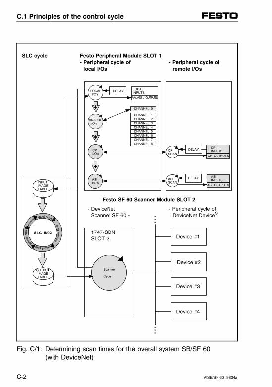
SLC cycle Festo Peripheral Module SLOT 1- Peripheral cycle of - Peripheral cycle of local I/Os remote I/Os
Festo SF 60 Scanner Module SLOT 2
- DeviceNet - Peripheral cycle of Scanner SF 60 - DeviceNet Devices
1747-SDN SLOT 2 Device #1
Device #2
Device #3
Device #4
Fig. C/1: Determining scan times for the overall system SB/SF 60 (with DeviceNet)
C.1 Principles of the control cycle
C-2 VISB/SF 60 9804a
1. Scan time for the SLC cycleThe processing performance of the SB/SF 60 corre-sponds to the performance of an SLC 5/02. To esti-mate the processor scan time, you may use thecorresponding Worksheet C from the Allen-Bradleyreference manual (for 1747-L524) or the simplifiedtable for the valve terminal (see chapter C.3). Thescan time of the SLC cycle can be optimized in theconfiguration menus of the programming software(see chapter C.3 "Optimizing Scan Time"). Notes toillustration:
Notes toillustration
2. Scan time of the Festo peripheral moduleThe speciality I/O module integrated into theSB/SF60 processes the peripheral modules asyn-chronous to the SLC processor. Due to the modu-larity of the valve terminal, the processing times ofthe peripheral cycle will vary (depending on thestructure of the terminal and the differences betweenindividual Festo I/O modules).
3. Analog modules (PROP, ADDA)One analog module (ADDA or PROP) per peripheralcycle is processed. Since the peripheral cycle isgenerally faster than the SLC cycle, all the analogmodules are usually scanned during an SLC cycle.This fact (and the overall system cycle time) in-fluences the transmittable pulse interval (cutoff fre-quency) of the analog modules in the system at ap-prox. 25 Hz.
C.1 Principles of the control cycle
VISB/SF 60 9804a C-3
4. CP module The CP cycle is invoked once within the peripheralcycle and processes two CP strings each time it iscalled. This means the entire CP system requirestwo peripheral cycles. An additional time windowpermits a CP module call only every 2 ms, so thateven with fast peripheral cycles, at least 4 ms arerequired for the entire CP system.
Notes toillustration(cont.)
5. AS-i masterThe AS-i master processes the AS-i bus system au-tonomously and runs asynchronous with the periph-eral cycle. The AS-i cycle depends on the number ofAS-i slaves, but lasts a maximum of 5 ms.
6. DeviceNet ScannerThe SF 60 DeviceNet Scanner processes the De-viceNet network autonomously and runs asyn-chronous with the peripheral cycle. The DeviceNetcycle does not depend on the number of DN slaves.
C.1 Principles of the control cycle
C-4 VISB/SF 60 9804a
C.2 Estimating the scan time
The scan time of an input or the setting of an outputdepends on the structure of the valve terminal and con-sists of the following time cycles:
– SLC cycle (program processing, communication, administration)
– Cycle of the local valve terminal I/O’s (cycle of theFesto Peripheral Module, divided according to digitaland analog I/O’s)
– Cycle of decentral I/O modules (e.g., AS-i bus system and CP system, if applicable)
– Time delay (debouncing) for input modules
C.2.1 Estimating the scan time of the SLC cycle
The processing performance of the SB/SF 60 corre-sponds to that of an SLC 5/02. The scan times can bedetermined and estimated using the following simplifiedtable:
C.2 Estimating the scan time
VISB/SF 60 9804a C-5

Supplement to the table under C.2.1 (Estimating thescan time of the SLC cycle / see page C-6). Points 1and 2 must be replaced by:
Estimating the scan time of the SLC cycleRefer to the Allen-Bradley reference manual for details
minimum maximum
1. Estimate the input scan time (in µs)Festo I/O special module:• Min. = number of scanned input words x 157 µs
Festo SF 60 DeviceNet Scanner module:• Min. = number of scanned input words x 157 µs
subtotal sum Min.
• Maximum scan time = subtotal sum + 120 µs
______ µs
______ µs µs
______ µs
2. Estimate the output scan time (in µs)Festo I/O special module:• Min. = number of scanned output words x 135 µs
Festo SF 60 DeviceNet Scanner module:• Min. = number of scanned output words x 135 µs
subtotal sum Min.
• Maximum scan time = subtotal sum + 120 µs
______ µs
______ µs µs
______ µs
3. Estimate the program scan time This estimate assumes that all instructions are carried out once per scan.
3.1 Count the rungs of the ladder programand multiply the result by 6(or x 66 if single-step mode is active)
______ µs ______ µs
3.2 Calculate the program execution time, if all instructions are true (see instruction set) ______ µs ______ µs
C.2 Estimating the scan time
C-6 VISB/SF 60 9804a
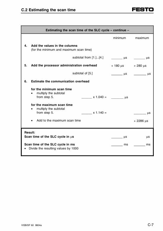
Estimating the scan time of the SLC cycle – continue –
minimum maximum
4. Add the values in the columns (for the minimum and maximum scan time)
subtotal from [1.]...[4.] µs µs
5. Add the processor administration overhead
subtotal of [5.]
+ 180 µs
µs
+ 280 µs
µs
6. Estimate the communication overhead
for the minimum scan time• multiply the subtotal
from step 5. ______ x 1.040 =
for the maximum scan time• multiply the subtotal
from step 5. ______ x 1.140 =
• Add to the maximum scan time
_______ µs
_______ µs
+ 2286 µs
Result:Scan time of the SLC cycle in µs
Scan time of the SLC cycle in ms• Divide the resulting values by 1000
µs
ms
µs
ms
C.2 Estimating the scan time
VISB/SF 60 9804a C-7

C.2.2 Estimating the scan time of the Festo Peripheral Module
Due to the modularity of the valve terminal and the dif-ferences between the individual Festo modules, theprocessing times will vary depending on the terminalstructure.
Estimating the scan time of the Festo Peripheral Module(peripheral cycle)
minimum maximum
1. Basic overhead 285 µs 685 µs
2. Valves• per 8 valves solenoids: ______ x 75 µs ________ µs ________ µs
3. Input modules• 4-input modules ______ x 40 µs
• 8-input modules ______ x 40 µs
________ µs
________ µs
________ µs
________ µs
4. Output modules• 4-output modules ______ x 85 µs ________ µs ________ µs
5. Multi-I/O modules• per multi-I/O module ______ x 170 µs ________ µs ________ µs
6. Analog modules• Basic overhead if only PROP modules used minimum: 1 x 250 µs maximum: 1 x 460 µs
• Basic overhead, if only ADDA modules are used minimum: 1 x 650 µs maximum: 1 x 965 µs
• Basic overhead, if PROP/ADDA are mixed minimum: 1 x 300 µs maximum: 1 x 975 µs
________ µs
________ µs
________ µs
________ µs
________ µs
________ µs
C.2 Estimating the scan time
C-8 VISB/SF 60 9804a
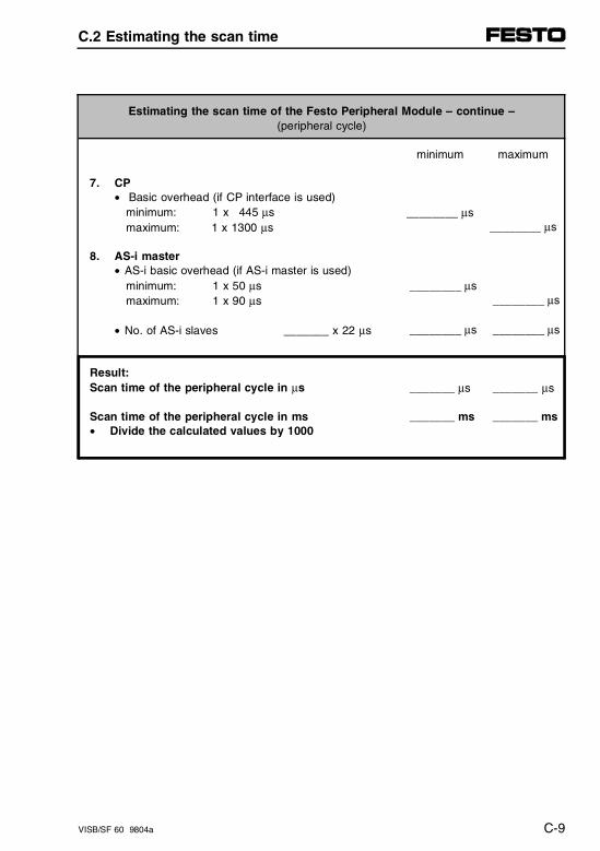
Estimating the scan time of the Festo Peripheral Module – continue –(peripheral cycle)
minimum maximum
7. CP• Basic overhead (if CP interface is used) minimum: 1 x 445 µs maximum: 1 x 1300 µs
________ µs________ µs
8. AS-i master• AS-i basic overhead (if AS-i master is used) minimum: 1 x 50 µs maximum: 1 x 90 µs
• No. of AS-i slaves _______ x 22 µs
________ µs
________ µs
________ µs
________ µs
Result:Scan time of the peripheral cycle in µs
Scan time of the peripheral cycle in ms• Divide the calculated values by 1000
_______ µs
_______ ms
_______ µs
_______ ms
C.2 Estimating the scan time
VISB/SF 60 9804a C-9

C.2 Estimating the scan time
C-10 VISB/SF 60 9804a
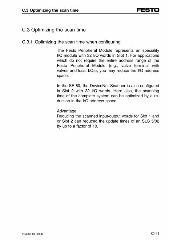
C.3 Optimizing the scan time
C.3.1 Optimizing the scan time when configuring
The Festo Peripheral Module represents an specialityI/O module with 32 I/O words in Slot 1. For applicationswhich do not require the entire address range of theFesto Peripheral Module (e.g., valve terminal withvalves and local I/Os), you may reduce the I/O addressspace.
In the SF 60, the DeviceNet Scanner is also configuredin Slot 2 with 32 I/O words. Here also, the scanningtime of the complete system can be optimized by a re-duction in the I/O address space.
Advantage: Reducing the scanned input/output words for Slot 1 andor Slot 2 can reduced the update times of an SLC 5/02by up to a factor of 10.
C.3 Optimizing the scan time
VISB/SF 60 9804a C-11
Configuration of the scanned input/output words
You make this reduction when configuring the controller.
• Under "Scanned input/output words" for Slot 1 and/orSlot 2, enter the actual number of I/O words used.The number of input words and output words ndo notneed to be identical. If for example a valve terminalhas more inputs than outputs, various entries for theI- and O-words are possible.
• After reducing the I/O words, determine the newscan time for the "scanned input/output words" of theFesto I/O special module.
• For full calculation, use the table "SLC Cycle Time"from chapter C.2 or the following short formula fordetermining the savings in scan time.
C.3 Optimizing the scan time
C-12 VISB/SF 60 9804a
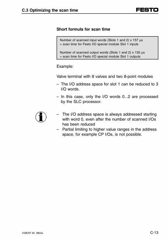
Short formula for scan time
Number of scanned input words (Slots 1 and 2) x 157 µs = scan time for Festo I/O special module Slot 1 inputs
Number of scanned output words (Slots 1 and 2) x 135 µs = scan time for Festo I/O special module Slot 1 outputs
Example:
Valve terminal with 8 valves and two 8-point modules
– The I/O address space for slot 1 can be reduced to 3I/O words.
– In this case, only the I/O words 0...2 are processedby the SLC processor.
– The I/O address space is always addressed startingwith word 0, even after the number of scanned I/Oshas been reduced
– Partial limiting to higher value ranges in the addressspace, for example CP I/Os, is not possible.
C.3 Optimizing the scan time
VISB/SF 60 9804a C-13
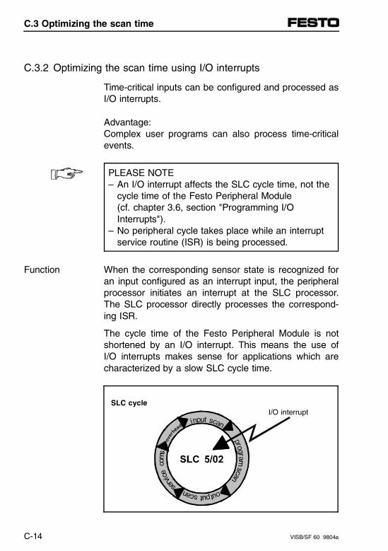
C.3.2 Optimizing the scan time using I/O interrupts
Time-critical inputs can be configured and processed asI/O interrupts.
Advantage:Complex user programs can also process time-criticalevents.
PLEASE NOTE– An I/O interrupt affects the SLC cycle time, not the
cycle time of the Festo Peripheral Module (cf. chapter 3.6, section "Programming I/O Interrupts").
– No peripheral cycle takes place while an interruptservice routine (ISR) is being processed.
When the corresponding sensor state is recognized foran input configured as an interrupt input, the peripheralprocessor initiates an interrupt at the SLC processor.The SLC processor directly processes the correspond-ing ISR.
Function
The cycle time of the Festo Peripheral Module is notshortened by an I/O interrupt. This means the use ofI/O interrupts makes sense for applications which arecharacterized by a slow SLC cycle time.
SLC cycleI/O interrupt
C.3 Optimizing the scan time
C-14 VISB/SF 60 9804a
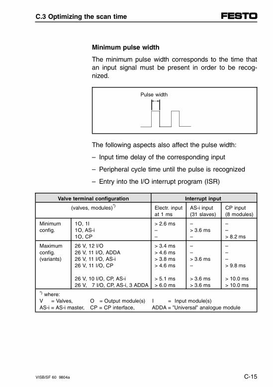
Minimum pulse width
The minimum pulse width corresponds to the time thatan input signal must be present in order to be recog-nized.
Pulse width
The following aspects also affect the pulse width:
– Input time delay of the corresponding input
– Peripheral cycle time until the pulse is recognized
– Entry into the I/O interrupt program (ISR)
Valve terminal configuration Interrupt input
(valves, modules)*) Electr. inputat 1 ms
AS-i input(31 slaves)
CP input (8 modules)
Minimum config.
1O, 1I1O, AS-i1O, CP
> 2.6 ms––
–> 3.6 ms–
––> 8.2 ms
Maximumconfig. (variants)
26 V, 12 I/O 26 V, 11 I/O, ADDA26 V, 11 I/O, AS-i26 V, 11 I/O, CP
26 V, 10 I/O, CP, AS-i 26 V, 7 I/O, CP, AS-i, 3 ADDA
> 3.4 ms> 4.6 ms> 3.8 ms> 4.6 ms
> 5.1 ms> 6.0 ms
––> 3.6 ms–
> 3.6 ms> 3.6 ms
–––> 9.8 ms
> 10.0 ms> 10.0 ms
*) where:V = Valves, O = Output module(s) I = Input module(s)AS-i = AS-i master, CP = CP interface, ADDA = ”Universal” analogue module
C.3 Optimizing the scan time
VISB/SF 60 9804a C-15
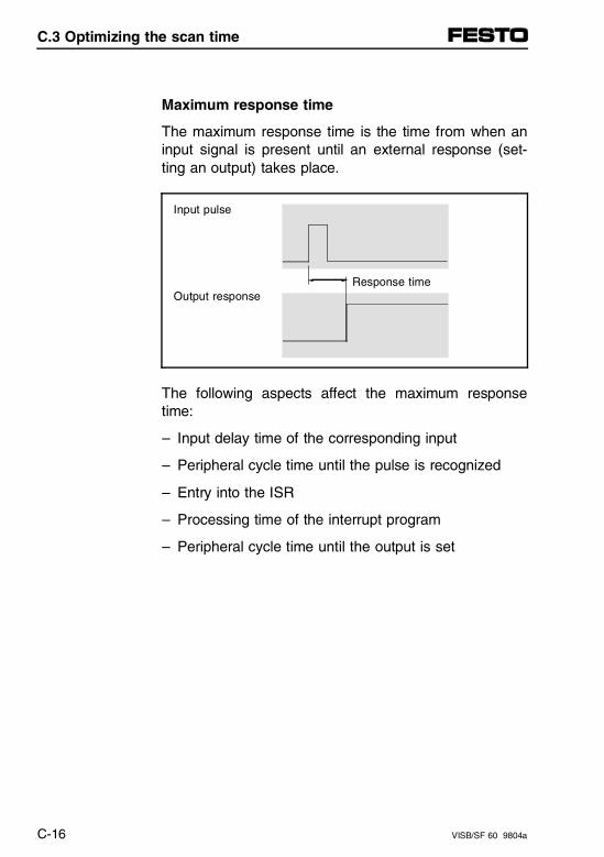
Maximum response time
The maximum response time is the time from when aninput signal is present until an external response (set-ting an output) takes place.
Input pulse
Response timeOutput response
The following aspects affect the maximum responsetime:
– Input delay time of the corresponding input
– Peripheral cycle time until the pulse is recognized
– Entry into the ISR
– Processing time of the interrupt program
– Peripheral cycle time until the output is set
C.3 Optimizing the scan time
C-16 VISB/SF 60 9804a
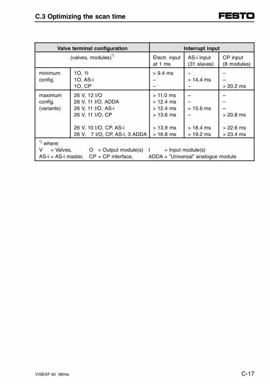
Valve terminal configuration Interrupt input
(valves, modules)*) Electr. inputat 1 ms
AS-i input(31 slaves)
CP input (8 modules)
minimum config.
1O, 1I1O, AS-i1O, CP
> 9.4 ms––
–> 14.4 ms–
––> 20.2 ms
maximumconfig. (variants)
26 V, 12 I/O 26 V, 11 I/O, ADDA26 V, 11 I/O, AS-i26 V, 11 I/O, CP
26 V, 10 I/O, CP, AS-i 26 V, 7 I/O, CP, AS-i, 3 ADDA
> 11.0 ms> 12.4 ms> 12.4 ms> 13.6 ms
> 13.9 ms> 16.8 ms
––> 15.6 ms–
> 18.4 ms> 19.2 ms
–––> 20.8 ms
> 22.6 ms> 23.4 ms
*) where:V = Valves, O = Output module(s) I = Input module(s)AS-i = AS-i master, CP = CP interface, ADDA = ”Universal” analogue module
C.3 Optimizing the scan time
VISB/SF 60 9804a C-17
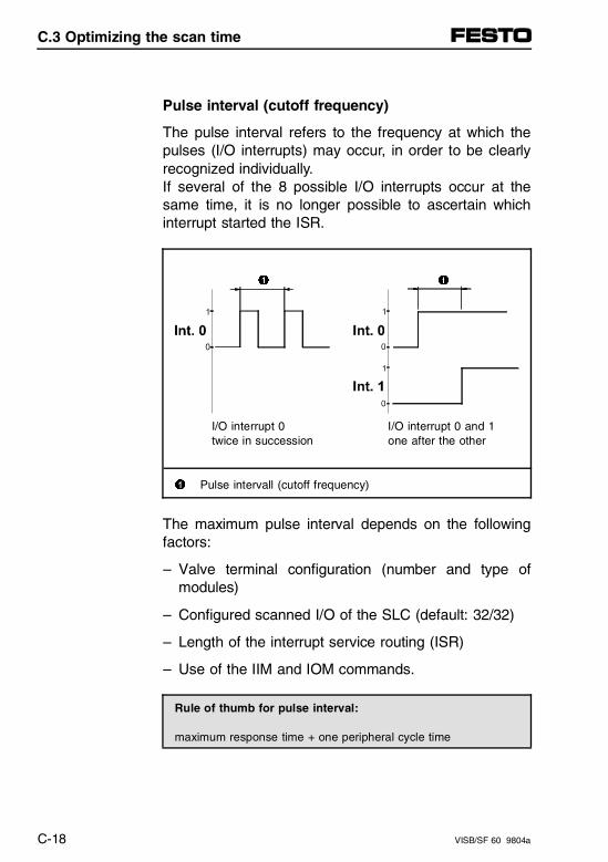
Pulse interval (cutoff frequency)
The pulse interval refers to the frequency at which thepulses (I/O interrupts) may occur, in order to be clearlyrecognized individually.If several of the 8 possible I/O interrupts occur at thesame time, it is no longer possible to ascertain whichinterrupt started the ISR.
1 1
I/O interrupt 0 I/O interrupt 0 and 1 twice in succession one after the other
1 Pulse intervall (cutoff frequency)
The maximum pulse interval depends on the followingfactors:
– Valve terminal configuration (number and type ofmodules)
– Configured scanned I/O of the SLC (default: 32/32)
– Length of the interrupt service routing (ISR)
– Use of the IIM and IOM commands.
Rule of thumb for pulse interval:
maximum response time + one peripheral cycle time
C.3 Optimizing the scan time
C-18 VISB/SF 60 9804a
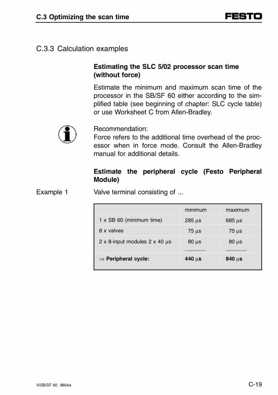
C.3.3 Calculation examples
Estimating the SLC 5/02 processor scan time(without force)
Estimate the minimum and maximum scan time of theprocessor in the SB/SF 60 either according to the sim-plified table (see beginning of chapter: SLC cycle table)or use Worksheet C from Allen-Bradley.
Recommendation:Force refers to the additional time overhead of the proc-essor when in force mode. Consult the Allen-Bradleymanual for additional details.
Estimate the peripheral cycle (Festo PeripheralModule)
Valve terminal consisting of ...Example 1
minimum maximum
1 x SB 60 (minimum time) 285 µs 685 µs
8 x valves 75 µs 75 µs
2 x 8-input modules 2 x 40 µs 80 µs_______
80 µs_______
⇒ Peripheral cycle: 440 µs 840 µs
C.3 Optimizing the scan time
VISB/SF 60 9804a C-19
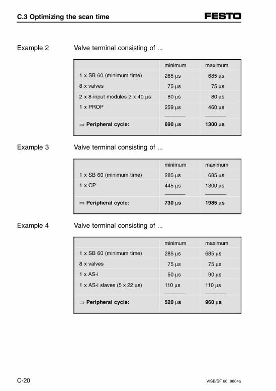
Valve terminal consisting of ...Example 2
minimum maximum
1 x SB 60 (minimum time) 285 µs 685 µs
8 x valves 75 µs 75 µs
2 x 8-input modules 2 x 40 µs 80 µs 80 µs
1 x PROP 259 µs_______
460 µs_______
⇒ Peripheral cycle: 690 µs 1300 µs
Valve terminal consisting of ...Example 3
minimum maximum
1 x SB 60 (minimum time) 285 µs 685 µs
1 x CP 445 µs_______
1300 µs_______
⇒ Peripheral cycle: 730 µs 1985 µs
Valve terminal consisting of ...Example 4
minimum maximum
1 x SB 60 (minimum time) 285 µs 685 µs
8 x valves 75 µs 75 µs
1 x AS-i 50 µs 90 µs
1 x AS-i slaves (5 x 22 µs) 110 µs_______
110 µs_______
⇒ Peripheral cycle: 520 µs 960 µs
C.3 Optimizing the scan time
C-20 VISB/SF 60 9804a
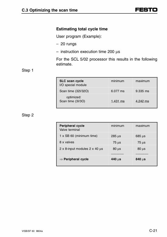
Estimating total cycle time
User program (Example):
– 20 rungs
– instruction execution time 200 µs
For the SCL 5/02 processor this results in the followingestimate.
Step 1
SLC scan cycleI/O special module
minimum maximum
Scan time (32I/32O) 6.077 ms 9.335 ms
optimized:Scan time (3I/3O) 1.431 ms 4.242 ms
Step 2
Peripheral cycleValve terminal
minimum maximum
1 x SB 60 (minimum time) 285 µs 685 µs
8 x valves 75 µs 75 µs
2 x 8-input modules 2 x 40 µs 80 µs_______
80 µs_______
⇒ Peripheral cycle 440 µs 840 µs
C.3 Optimizing the scan time
VISB/SF 60 9804a C-21
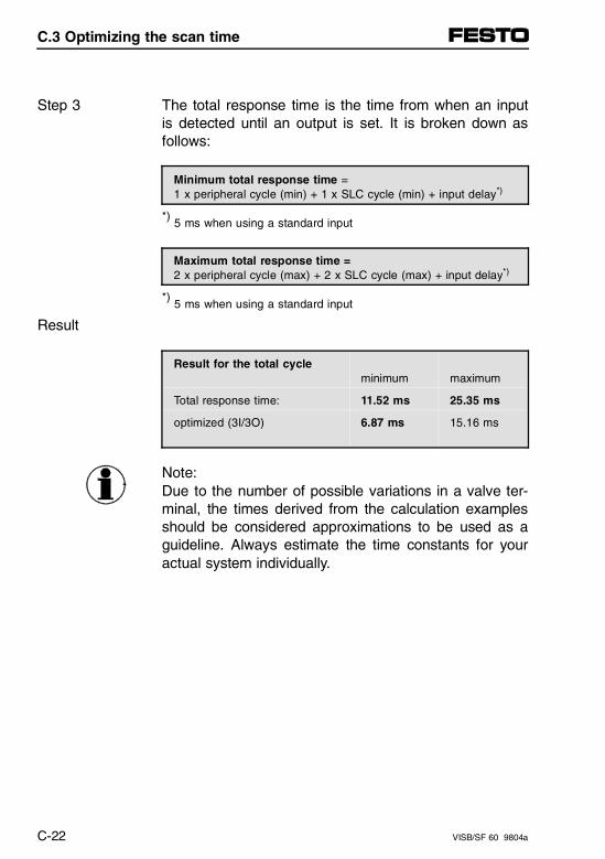
The total response time is the time from when an inputis detected until an output is set. It is broken down asfollows:
Step 3
Minimum total response time = 1 x peripheral cycle (min) + 1 x SLC cycle (min) + input delay*)
*) 5 ms when using a standard input
Maximum total response time = 2 x peripheral cycle (max) + 2 x SLC cycle (max) + input delay*)
*) 5 ms when using a standard input
Result
Result for the total cycleminimum maximum
Total response time: 11.52 ms 25.35 ms
optimized (3I/3O) 6.87 ms 15.16 ms
Note:Due to the number of possible variations in a valve ter-minal, the times derived from the calculation examplesshould be considered approximations to be used as aguideline. Always estimate the time constants for youractual system individually.
C.3 Optimizing the scan time
C-22 VISB/SF 60 9804a
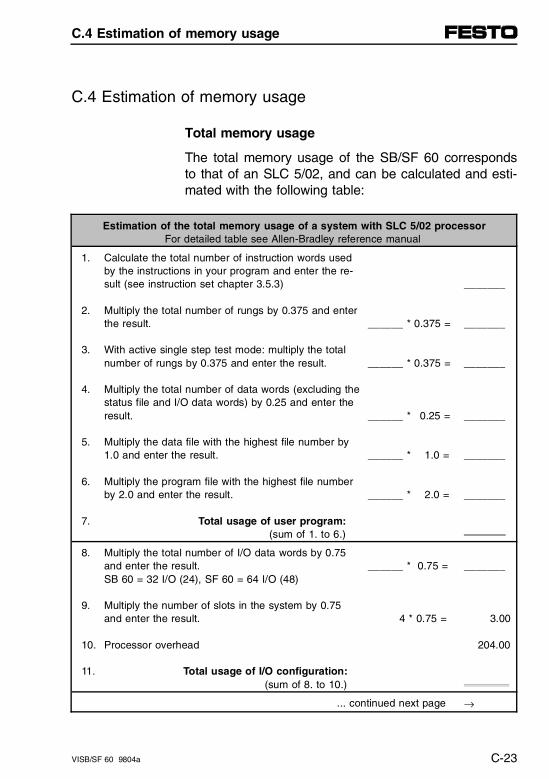
C.4 Estimation of memory usage
Total memory usage
The total memory usage of the SB/SF 60 correspondsto that of an SLC 5/02, and can be calculated and esti-mated with the following table:
Estimation of the total memory usage of a system with SLC 5/02 processorFor detailed table see Allen-Bradley reference manual
1. Calculate the total number of instruction words used by the instructions in your program and enter the re-sult (see instruction set chapter 3.5.3)
2. Multiply the total number of rungs by 0.375 and enterthe result.
3. With active single step test mode: multiply the total number of rungs by 0.375 and enter the result.
4. Multiply the total number of data words (excluding the status file and I/O data words) by 0.25 and enter the result.
5. Multiply the data file with the highest file number by 1.0 and enter the result.
6. Multiply the program file with the highest file number by 2.0 and enter the result.
7. Total usage of user program: (sum of 1. to 6.)
______ * 0.375 =
______ * 0.375 =
______ * 0.25 =
______ * 1.0 =
______ * 2.0 =
_______
_______
_______
_______
_______
_______
8. Multiply the total number of I/O data words by 0.75 and enter the result.SB 60 = 32 I/O (24), SF 60 = 64 I/O (48)
9. Multiply the number of slots in the system by 0.75 and enter the result.
10. Processor overhead
11. Total usage of I/O configuration: (sum of 8. to 10.)
______ * 0.75 =
4 * 0.75 =
_______
3.00
204.00
... continued next page →
C.4 Estimation of memory usage
VISB/SF 60 9804a C-23
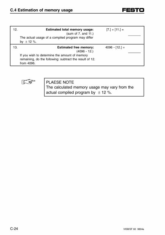
12. Estimated total memory usage: (sum of 7. and 11.)
The actual usage of a compiled program may differ by ± 12 %.
[7.] + [11.] =
13. Estimated free memory: (4096 - 12.)
If you wish to determine the amount of memory remaining, do the following: subtract the result of 12. from 4096.
4096 - [12.] =
PLAESE NOTEThe calculated memory usage may vary from the actual compiled program by ± 12 %.
C.4 Estimation of memory usage
C-24 VISB/SF 60 9804a
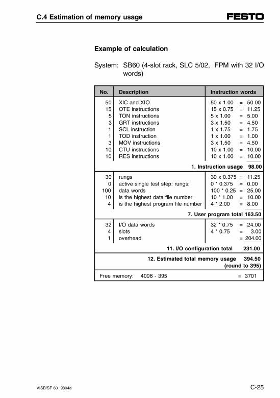
Example of calculation
System: SB60 (4-slot rack, SLC 5/02, FPM with 32 I/Owords)
No. Description Instruction words
5015
5 3 1 1 3
1010
XIC and XIOOTE instructionsTON instructionsGRT instructionsSCL instructionTOD instructionMOV instructionsCTU instructionsRES instructions
50 x 1.00 = 50.0015 x 0.75 = 11.255 x 1.00 = 5.003 x 1.50 = 4.501 x 1.75 = 1.751 x 1.00 = 1.003 x 1.50 = 4.5010 x 1.00 = 10.0010 x 1.00 = 10.00
1. Instruction usage 98.00
30 0 100 10 4
rungsactive single test step: rungs:data words is the highest data file number is the highest program file number
30 x 0.375 = 11.250 * 0.375 = 0.00100 * 0.25 = 25.0010 * 1.00 = 10.004 * 2.00 = 8.00
7. User program total 163.50
32 4 1
I/O data wordsslotsoverhead
32 * 0.75 = 24.004 * 0.75 = 3.00
= 204.00
11. I/O configuration total 231.00
12. Estimated total memory usage 394.50 (round to 395)
Free memory: 4096 - 395 = 3701
C.4 Estimation of memory usage
VISB/SF 60 9804a C-25

C.4 Estimation of memory usage
C-26 VISB/SF 60 9804a
Appendix D
Glossary, Index
Appendix D
VISB/SF 60 9804a D-I
Contents
D. Glossary, Index
D.1 Glossary . . . . . . . . . . . . . . . . . . . . . . . . . . . . . . . . . . . . . . . . . . . . . D-1
D.2 Index . . . . . . . . . . . . . . . . . . . . . . . . . . . . . . . . . . . . . . . . . . . . . . . D-13
Appendix D
D-II VISB/SF 60 9804a
D.1 Glossary
A
Actuator
A device for using control information to influence ma-chines and systems (control device).
Autonomous
Programmable valve terminals have an integrated PLCand are therefore independent of a host. Once a pro-grammable valve terminal is started up, it will run with-out any external device and is in this sense autono-mous.
B
Baud rate
The speed of communication between devices on anetwork. All devices must communicate at the samebaud rate, otherwise communications errors will result.
Bi-directional, uni-directional transmission
Bi-directional signal transmission in both directions, sothat a participant is both sender as well as receiver.The opposite of this is uni-directional.
Bus participant
Fieldbus participant or device which can send, receiveor amplify data over the bus, for example master sta-tion, slave station, repeater, etc. In the case of theSB/SF 60, there are participants on the DH-485 net-work, DeviceNet, or the AS-i bus system.
D.1 Glossary
VISB/SF 60 9804a D-1
C
Centralized control
A fieldbus system is centrally controlled when only onemaster control the information on the bus and overseesthe actions of all inputs and outputs. If passive valveterminals with FB11 are used on DeviceNet, then sucha centrally controlled system will be present.
Communication
The link between two or more members of a system forexchanging information.
Conformance
Common response on an interface in agreement withconditions according to a standard.
Control block
The control block is the intelligent part of the program-mable valve terminal and contains the electronics (PLC)for turning the standard valve terminal into a program-mable one. The control block has an enclosure rating ofIP65, allowing it to be installed directly on the machine.
Cycle time
The time necessary in a periodically repeating processfor a single cycle, e.g., in the master-slave process it isthe time between two successive queries of the sameslave or sensor/actuator.
D.1 Glossary
D-2 VISB/SF 60 9804a
D
DH+
Data Highway Plus. This Allen-Bradley network enablescommunication between equally authorized participants,e.g., controllers. Communication is based on the princi-ple of token passing, whereby one network participantafter the other is given authorization for the ”master”function. DH+ enables online programming and was de-signed for networks with smaller numbers of networknodes (participants). DH+ supports up to 64 participants.
DH-485 network
The DH-485 network is a grouping of devices, all ofwhich exchange data over the same cable. Communi-cation is based on the EIA Standard for RS-485 inter-faces and employs a special Allen-Bradley protocol.Especially suitable for industrial networks due to higerresistance to interference voltages.
Diagnostics
Detection, localizing, classifying, displaying and furtherprocessing of faults, disturbances and messages.
Diagnostics provides monitoring functions which runautomatically while the equipment is in operation.
Diagnostics interface
The diagnostics interface of the AS-i master is the con-nection to the following device:
– PC/laptop with RS 232 interface and AS-i SoftwareTool
The diagnostics interface conforms to V.24/RS232.
D.1 Glossary
VISB/SF 60 9804a D-3
E
EEPROM (E2PROM, Electrically Erasable PROM
An electrically erasable, non-volatile semiconductormemory (PROM).
F
Festo Software Tools
FST – software packages from Festo for menu andmouse-driven configuration of the AS-i master/AS-i bussystem.
Fieldbus
A serial bus system for exchanging information betweenspatially widely separated parts of a procedure ormanufacturing process. Sensors, actuators and control-lers with varying degrees of complexity are located atdecentralized stations of the process. The main advan-tages when using a fieldbus are the reduction in parallelcabling, relieving of the host controller by means of de-centralized pre-processing, and the elimination of prob-lems in analog value signal transmission when digitizingin the fieldbus participant. The SF 60 includes aDeviceNet (fieldbus) interface.
Fieldbus address
The address is required for identifying the participantsin the fieldbus system. The fieldbus address is set onthe respective fieldbus participant using addressswitches or per software. In the case of SB/SF 60(field-) bus addresses are required for the DH-485 net-work, DeviceNet, and the AS-i bus system.
D.1 Glossary
D-4 VISB/SF 60 9804a
Fieldbus interface
The fieldbus interface allows an electronic controller(e.g., PLC, PC, programmable valve terminal) to beconnected to a fieldbus system. The fieldbus interfacemust be configured for the specific fieldbus in order tosupport the physical and logical functions of that bussystem. A corresponding interface for the DH-485 net-work is integrated into the SB/SF 60. The supplemen-tary AS-i master module permits an AS-i bus system tobe interfaced with the SB/SF 60.
I
Image table
Two kinds are distinguished, an output image table(write operation) and an input image table (read opera-tion).In order to achieve time-based switching of the inputsand outputs (local I/Os and fieldbus I/Os), they are reador set only at a defined point in time. In the operatingsystem of the SLC 5/02 (and therefore of the SB/SF60), this is always done once per processor cycle.
Initiator
A participant on the DH-485 network which is designedfor the ”Master” function is also referred to as an ”initia-tor” in Allen-Bradley terminology. When an initiator hasthe token it can send messages and request repliesfrom any node on the DH-485 network. A personalcomputer running your programming software is an in-itiator on the data link. Likewise, the SLC 5/04, SLC5/03 and SLC 5/02 – and therefore the SB/SF 60 aswell – can also be initiators.
D.1 Glossary
VISB/SF 60 9804a D-5
Instruction set
Encompasses all instructions (commands) which canbe programmed in ladder logic for the programmablevalve terminal. The instruction set for the SB/SF 60 in-cludes the entire set for an Allen-Bradley SLC 5/02.
Interface
A circuit that permits communication between the cen-tral processing unit and a field input or output device.
Interrupt
Interruption of a process or program by an externalevent. An interrupt conditional event always has thehighest priority and is processed immediately. Only thenis the process or program resumed from the point ofthe interrupt.
Isolated Link Coupler
This coupler has an electrically isolated interface forconnecting SLC 500 controllers (or programming de-vices) to the DH-485 network cable.An isolated link coupler is integrated into the SB/SF 60.The SB/SF 60 can therefore be connected directly toappropriate programming or operating devices. In addi-tion, the SB/SF 60 can be connected to the DH-485network.
D.1 Glossary
D-6 VISB/SF 60 9804a
L
Ladder diagram
An industry standard for representing relay logic controlsystems. The diagram resembles a ladder in that thevertical supports of the ladder appear as power feedand return buses, and the horizontal rungs of the ladderappear as series and/or parallel circuits connectedacross the power lines.
M
Multi-Master network
Refers to a network in which multiple masters can initi-ate and initialize a communications link simultaneously.The SF 60, for example, is multi-master capable onDeviceNet (dual mode).
N
Network
A series of stations (nodes) connected by some type ofcommunication medium. A network may be made up ofa single link or multiple links.
nvSRAM
A non-volatile, static random access memory which pro-vides data retention for as long as 10 years after supplyvoltage is turned off to the main device. This memorydevice allows the SB/SF 60 to operate completely with-out a battery backup.
D.1 Glossary
VISB/SF 60 9804a D-7
O
Off-line/on-line
Off-line means that a component has no direct link to a(central) function unit, so that data to be input are bufferstored and only later loaded into the central unit.
Opposite: On-line with direct transmission.
Operating system
The operating system is a component of every com-puter system, and determines its performance and areaof use. The operating system of the programmablevalve terminal controls the processor, and manages theuser and program memories as well as the peripheraldevices which are connected to the interface (program-ming devices, HHT, and other operating and monitoringdevices).
P
Power failure
Loss of supply voltage. A finer definition must be madehere in the context of the AS-i bus. The ”Power failure”message is always issued when no AS-i supply voltageis present on the AS-i master. This can be due to thefollowing causes:
– AS-i flat cable to AS-i master broken.
– AS-i power unit defective.
Profile
The profile of a communications system represents forspecial application areas a selection of functions andfeatures taken from an overall specification.
D.1 Glossary
D-8 VISB/SF 60 9804a
Programmable valve terminal
The programmable comprises:
– a standard valve terminal
– a control unit (control block).
The control block contains the complete control elec-tronics, i.e., the PLC, memory devices (RAM andnvSRAM) and the operating system. So equipped theprogrammable valve terminal is capable of solving auto-mation tasks locally.
Protocol
The "language" or packaging of information that istransmitted across a network.
R
RAM (Random Access Memory)
A memory system that permits the random accessing ofany storage location for the purpose of either storing orretrieving information. Since these memories lose theirretention ability when power to the main device isturned off, their contents must be stored in anothermemory device (EEPROM, hard disk) or battery buff-ered so that the data are not lost. The SB/SF 60 em-ploys an nvSRAM for storing data.
Redundancy
The presence of a larger number of means (e.g., AS-islaves, AS-i bus segments) than are necessary formeeting the basic function requirements (reserve units).
D.1 Glossary
VISB/SF 60 9804a D-9
Response time
The time between when a signal is generated at thedata source (e.g., sensor) until this signal is detected atan input or processing device (e.g., PLC).
RS 232
An internationally standardized format for data transmis-sion between various devices (PCs, printers, operator’sterminals, etc.). Data are transmitted to the AS-i masterover an RS 232 interface (diagnostics interface) accord-ing to the following specifications: serial, asynchronous,full-duplex, and with software handshake. The transmis-sion speed is fixed at 9600 baud.
S
Sensor
A device used to gather information by the conversionof a physical occurrence to an electrical signal.
Signal delay
At an input, the time required to detect and transmit thechanged status of a sensor to the logic circuits (re-sponse delay).
At an output, the time required to transmit the changedstatus of the logic circuits to the physical output.
Slave
Participant on a bus system. AS-i slaves exchange dataon the AS-i bus system with the AS-i master. Depend-ing on their ID and I/O code, they include several inputsand outputs.
D.1 Glossary
D-10 VISB/SF 60 9804a
Status word
When a fault occurs, the status word provides importantinformation concerning the connected peripheral (e.g.,AS-i master or other terminal modules). This status in-formation can be processed in the program. Diagnos-tics therefore allows errors to be represented in plaintext in a text display. Additional diagnostics can be donein the SB/SF 60 using the M files.
T
Termination resistor
Resistor network for terminating the DH-485 orDeviceNet. Termination resistors are generally requiredon cable or segment ends.
Toggle
Constant turning on and off of an output (setting, reset-ting).
Topology
Topology is the permissible network structure of a bussystem. The topology of the AS-i bus system can beselected as desired (star, line or tree structure).
U
User program
Program for a control system, such as a PLC, writtenfor or by a user, by means of which a special controltask is handled for the user. In the SB/SF 60 valve ter-minal, user programs are written in ladder logic and canbe stored in non-volatile nvSRAM.
D.1 Glossary
VISB/SF 60 9804a D-11

D.1 Glossary
D-12 VISB/SF 60 9804a
D.2 Index
1747-AIC . . . . . . . . . . . . . . . . . . . . . . . . . . . . . . . . . 2-38
AAccessories
Programming cable . . . . . . . . . . . . . . . . . . . . . . 2-31Addressing
Allocation list of all I/Os . . . . . . . . . . . . . . . . . . . 2-69Analog I/Os . . . . . . . . . . . . . . . . . . . . . . . . . . . . 5-18Basic rules . . . . . . . . . . . . . . . . . . . . . . . . . . . . . 2-62CP system . . . . . . . . . . . . . . . . . . . . . . . . . . . . . 7-12DeviceNet . . . . . . . . . . . . . . . . . . . . . . . . . . . . . 4-79Example. . . . . . . . . . . . . . . . . . . . . . . . . . 2-64, 2-66Example SB/SF 60 . . . . . . . . . . . . . . . . . . . . . . 2-68SB/SF 60 . . . . . . . . . . . . . . . . . . . . . . . . . . . . . . 2-67Valve terminal . . . . . . . . . . . . . . . . . . . . . . . . . . 2-59Valves (pilot solenoid) . . . . . . . . . . . . . . . . . . . . 2-61
Allen-Bradley1747-AIC . . . . . . . . . . . . . . . . . . . . . . . . . . . . . . 1-16APS and A.I. 500. . . . . . . . . . . . . . . . . . . . . . . . . 3-1Automation technology . . . . . . . . . . . . . . . . . . . 1-12CIM pyramid . . . . . . . . . . . . . . . . . . . . . . . . . . . 1-12DeviceNet . . . . . . . . . . . . . . . . . . . . . . . . . . . . . 2-45DeviceNet cable system . . . . . . . . . . . . . 2-46, 2-48Estimation of memory usage. . . . . . . . . . . . . . . C-23Network configuration . . . . . . . . . . . . . . . . . . . . 1-13Optimizing the scan time . . . . . . . . . . . . . . . . . . C-11Principle of the control sequence . . . . . . . . . . . 3-75Principles of the control cycle . . . . . . . . . . . . . . . C-1Programming . . . . . . . . . . . . . . . . . . . . . . . . . . . 1-20RSLogix . . . . . . . . . . . . . . . . . . . . . . . . . . . . . . . 3-21Scan time of the SLC cycle. . . . . . . . . . . . . . . . . C-5SLC 5/02 system structure . . . . . . . . . . . . . . . . 1-14SLC embedded . . . . . . . . . . . . . . . . . . . . . . . . . 1-15Wiring notes. . . . . . . . . . . . . . . . . . . . . . . 2-45, 2-47
D.2 Index
VISB/SF 60 9804a D-13
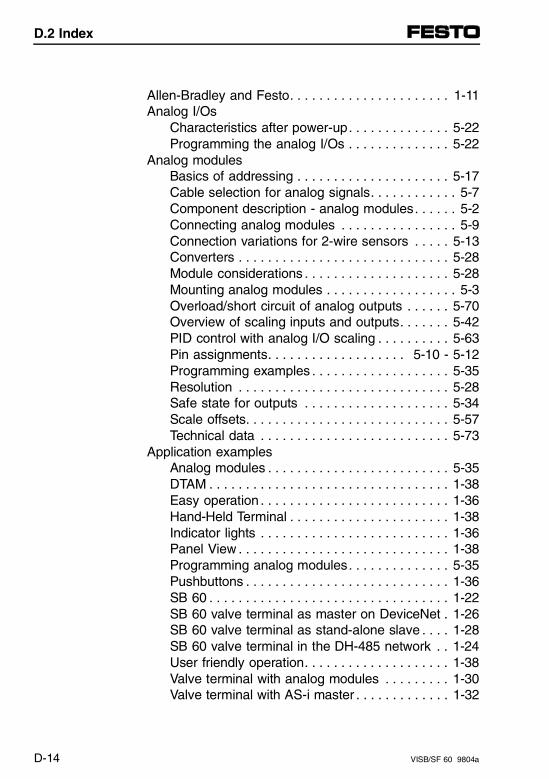
Allen-Bradley and Festo. . . . . . . . . . . . . . . . . . . . . . 1-11Analog I/Os
Characteristics after power-up. . . . . . . . . . . . . . 5-22Programming the analog I/Os . . . . . . . . . . . . . . 5-22
Analog modulesBasics of addressing . . . . . . . . . . . . . . . . . . . . . 5-17Cable selection for analog signals. . . . . . . . . . . . 5-7Component description - analog modules. . . . . . 5-2Connecting analog modules . . . . . . . . . . . . . . . . 5-9Connection variations for 2-wire sensors . . . . . 5-13Converters . . . . . . . . . . . . . . . . . . . . . . . . . . . . . 5-28Module considerations . . . . . . . . . . . . . . . . . . . . 5-28Mounting analog modules . . . . . . . . . . . . . . . . . . 5-3Overload/short circuit of analog outputs . . . . . . 5-70Overview of scaling inputs and outputs. . . . . . . 5-42PID control with analog I/O scaling . . . . . . . . . . 5-63Pin assignments. . . . . . . . . . . . . . . . . . . 5-10 - 5-12Programming examples . . . . . . . . . . . . . . . . . . . 5-35Resolution . . . . . . . . . . . . . . . . . . . . . . . . . . . . . 5-28Safe state for outputs . . . . . . . . . . . . . . . . . . . . 5-34Scale offsets. . . . . . . . . . . . . . . . . . . . . . . . . . . . 5-57Technical data . . . . . . . . . . . . . . . . . . . . . . . . . . 5-73
Application examplesAnalog modules . . . . . . . . . . . . . . . . . . . . . . . . . 5-35DTAM . . . . . . . . . . . . . . . . . . . . . . . . . . . . . . . . . 1-38Easy operation . . . . . . . . . . . . . . . . . . . . . . . . . . 1-36Hand-Held Terminal . . . . . . . . . . . . . . . . . . . . . . 1-38Indicator lights . . . . . . . . . . . . . . . . . . . . . . . . . . 1-36Panel View . . . . . . . . . . . . . . . . . . . . . . . . . . . . . 1-38Programming analog modules. . . . . . . . . . . . . . 5-35Pushbuttons . . . . . . . . . . . . . . . . . . . . . . . . . . . . 1-36SB 60 . . . . . . . . . . . . . . . . . . . . . . . . . . . . . . . . . 1-22SB 60 valve terminal as master on DeviceNet . 1-26SB 60 valve terminal as stand-alone slave . . . . 1-28SB 60 valve terminal in the DH-485 network . . 1-24User friendly operation. . . . . . . . . . . . . . . . . . . . 1-38Valve terminal with analog modules . . . . . . . . . 1-30Valve terminal with AS-i master . . . . . . . . . . . . . 1-32
D.2 Index
D-14 VISB/SF 60 9804a
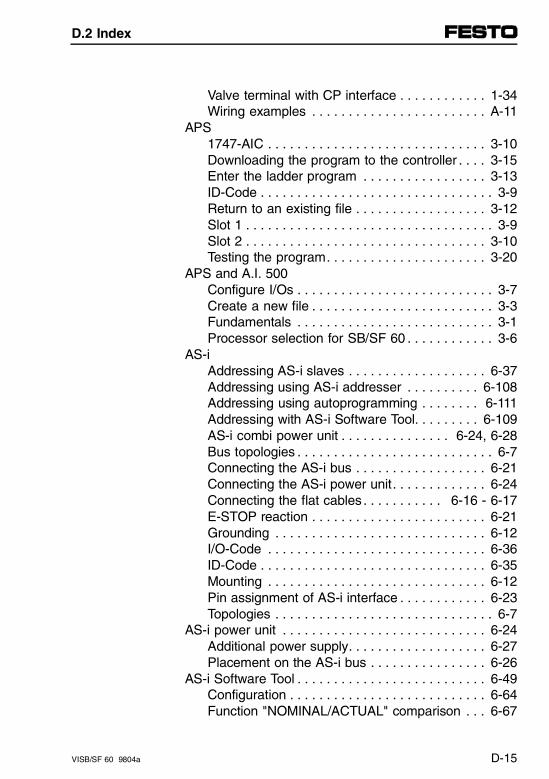
Valve terminal with CP interface . . . . . . . . . . . . 1-34Wiring examples . . . . . . . . . . . . . . . . . . . . . . . . A-11
APS1747-AIC . . . . . . . . . . . . . . . . . . . . . . . . . . . . . . 3-10Downloading the program to the controller . . . . 3-15Enter the ladder program . . . . . . . . . . . . . . . . . 3-13ID-Code . . . . . . . . . . . . . . . . . . . . . . . . . . . . . . . . 3-9Return to an existing file . . . . . . . . . . . . . . . . . . 3-12Slot 1 . . . . . . . . . . . . . . . . . . . . . . . . . . . . . . . . . . 3-9Slot 2 . . . . . . . . . . . . . . . . . . . . . . . . . . . . . . . . . 3-10Testing the program. . . . . . . . . . . . . . . . . . . . . . 3-20
APS and A.I. 500Configure I/Os . . . . . . . . . . . . . . . . . . . . . . . . . . . 3-7Create a new file . . . . . . . . . . . . . . . . . . . . . . . . . 3-3Fundamentals . . . . . . . . . . . . . . . . . . . . . . . . . . . 3-1Processor selection for SB/SF 60 . . . . . . . . . . . . 3-6
AS-iAddressing AS-i slaves . . . . . . . . . . . . . . . . . . . 6-37Addressing using AS-i addresser . . . . . . . . . . 6-108Addressing using autoprogramming . . . . . . . . 6-111Addressing with AS-i Software Tool. . . . . . . . . 6-109AS-i combi power unit . . . . . . . . . . . . . . . 6-24, 6-28Bus topologies . . . . . . . . . . . . . . . . . . . . . . . . . . . 6-7Connecting the AS-i bus . . . . . . . . . . . . . . . . . . 6-21Connecting the AS-i power unit. . . . . . . . . . . . . 6-24Connecting the flat cables . . . . . . . . . . . 6-16 - 6-17E-STOP reaction . . . . . . . . . . . . . . . . . . . . . . . . 6-21Grounding . . . . . . . . . . . . . . . . . . . . . . . . . . . . . 6-12I/O-Code . . . . . . . . . . . . . . . . . . . . . . . . . . . . . . 6-36ID-Code . . . . . . . . . . . . . . . . . . . . . . . . . . . . . . . 6-35Mounting . . . . . . . . . . . . . . . . . . . . . . . . . . . . . . 6-12Pin assignment of AS-i interface . . . . . . . . . . . . 6-23Topologies . . . . . . . . . . . . . . . . . . . . . . . . . . . . . . 6-7
AS-i power unit . . . . . . . . . . . . . . . . . . . . . . . . . . . . 6-24Additional power supply. . . . . . . . . . . . . . . . . . . 6-27Placement on the AS-i bus . . . . . . . . . . . . . . . . 6-26
AS-i Software Tool . . . . . . . . . . . . . . . . . . . . . . . . . . 6-49Configuration . . . . . . . . . . . . . . . . . . . . . . . . . . . 6-64Function "NOMINAL/ACTUAL" comparison . . . 6-67
D.2 Index
VISB/SF 60 9804a D-15
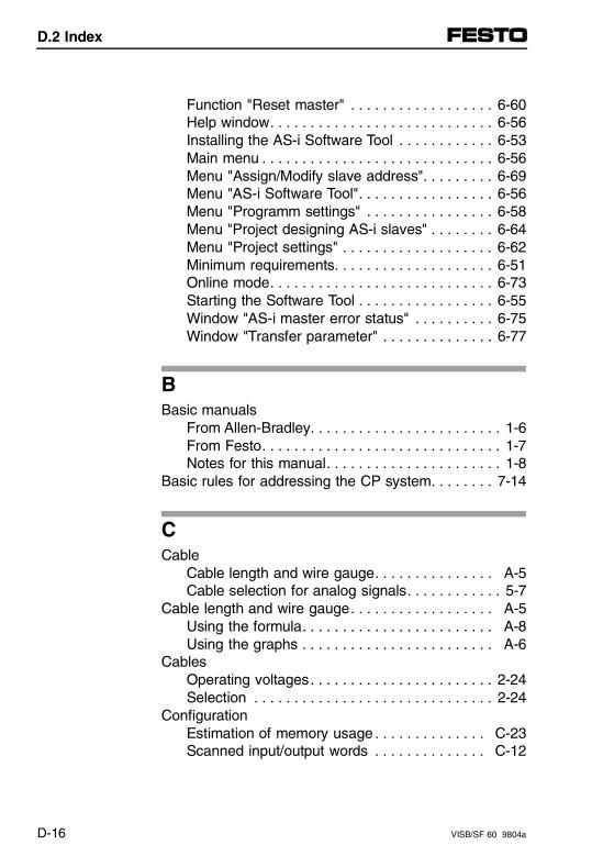
Function "Reset master" . . . . . . . . . . . . . . . . . . 6-60Help window. . . . . . . . . . . . . . . . . . . . . . . . . . . . 6-56Installing the AS-i Software Tool . . . . . . . . . . . . 6-53Main menu . . . . . . . . . . . . . . . . . . . . . . . . . . . . . 6-56Menu "Assign/Modify slave address". . . . . . . . . 6-69Menu "AS-i Software Tool". . . . . . . . . . . . . . . . . 6-56Menu "Programm settings" . . . . . . . . . . . . . . . . 6-58Menu "Project designing AS-i slaves" . . . . . . . . 6-64Menu "Project settings" . . . . . . . . . . . . . . . . . . . 6-62Minimum requirements. . . . . . . . . . . . . . . . . . . . 6-51Online mode. . . . . . . . . . . . . . . . . . . . . . . . . . . . 6-73Starting the Software Tool . . . . . . . . . . . . . . . . . 6-55Window "AS-i master error status" . . . . . . . . . . 6-75Window "Transfer parameter" . . . . . . . . . . . . . . 6-77
BBasic manuals
From Allen-Bradley. . . . . . . . . . . . . . . . . . . . . . . . 1-6From Festo. . . . . . . . . . . . . . . . . . . . . . . . . . . . . . 1-7Notes for this manual. . . . . . . . . . . . . . . . . . . . . . 1-8
Basic rules for addressing the CP system. . . . . . . . 7-14
CCable
Cable length and wire gauge. . . . . . . . . . . . . . . A-5Cable selection for analog signals. . . . . . . . . . . . 5-7
Cable length and wire gauge. . . . . . . . . . . . . . . . . . A-5Using the formula. . . . . . . . . . . . . . . . . . . . . . . . A-8Using the graphs . . . . . . . . . . . . . . . . . . . . . . . . A-6
CablesOperating voltages. . . . . . . . . . . . . . . . . . . . . . . 2-24Selection . . . . . . . . . . . . . . . . . . . . . . . . . . . . . . 2-24
ConfigurationEstimation of memory usage . . . . . . . . . . . . . . C-23Scanned input/output words . . . . . . . . . . . . . . C-12
D.2 Index
D-16 VISB/SF 60 9804a
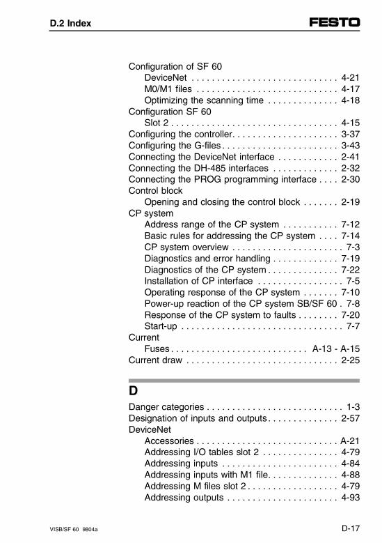
Configuration of SF 60DeviceNet . . . . . . . . . . . . . . . . . . . . . . . . . . . . . 4-21M0/M1 files . . . . . . . . . . . . . . . . . . . . . . . . . . . . 4-17Optimizing the scanning time . . . . . . . . . . . . . . 4-18
Configuration SF 60Slot 2 . . . . . . . . . . . . . . . . . . . . . . . . . . . . . . . . . 4-15
Configuring the controller. . . . . . . . . . . . . . . . . . . . . 3-37Configuring the G-files . . . . . . . . . . . . . . . . . . . . . . . 3-43Connecting the DeviceNet interface . . . . . . . . . . . . 2-41Connecting the DH-485 interfaces . . . . . . . . . . . . . 2-32Connecting the PROG programming interface . . . . 2-30Control block
Opening and closing the control block . . . . . . . 2-19CP system
Address range of the CP system . . . . . . . . . . . 7-12Basic rules for addressing the CP system . . . . 7-14CP system overview . . . . . . . . . . . . . . . . . . . . . . 7-3Diagnostics and error handling . . . . . . . . . . . . . 7-19Diagnostics of the CP system . . . . . . . . . . . . . . 7-22Installation of CP interface . . . . . . . . . . . . . . . . . 7-5Operating response of the CP system . . . . . . . 7-10Power-up reaction of the CP system SB/SF 60 . 7-8Response of the CP system to faults . . . . . . . . 7-20Start-up . . . . . . . . . . . . . . . . . . . . . . . . . . . . . . . . 7-7
CurrentFuses . . . . . . . . . . . . . . . . . . . . . . . . . . . A-13 - A-15
Current draw . . . . . . . . . . . . . . . . . . . . . . . . . . . . . . 2-25
DDanger categories . . . . . . . . . . . . . . . . . . . . . . . . . . . 1-3Designation of inputs and outputs . . . . . . . . . . . . . . 2-57DeviceNet
Accessories . . . . . . . . . . . . . . . . . . . . . . . . . . . . A-21Addressing I/O tables slot 2 . . . . . . . . . . . . . . . 4-79Addressing inputs . . . . . . . . . . . . . . . . . . . . . . . 4-84Addressing inputs with M1 file. . . . . . . . . . . . . . 4-88Addressing M files slot 2 . . . . . . . . . . . . . . . . . . 4-79Addressing outputs . . . . . . . . . . . . . . . . . . . . . . 4-93
D.2 Index
VISB/SF 60 9804a D-17
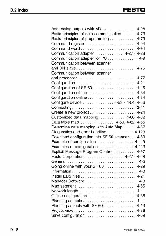
Addressing outputs with M0 file. . . . . . . . . . . . . 4-96Basic principles of data communication . . . . . . 4-73Basic principles of programming . . . . . . . . . . . . 4-73Command register . . . . . . . . . . . . . . . . . . . . . . . 4-94Command word . . . . . . . . . . . . . . . . . . . . . . . . . 4-94Communication adapter. . . . . . . . . . . . . 4-27 - 4-28Communication adapter for PC . . . . . . . . . . . . . . 4-9Communication between scanner and DN slave . . . . . . . . . . . . . . . . . . . . . . . . . . . 4-75Communication between scanner and processor . . . . . . . . . . . . . . . . . . . . . . . . . . 4-77Configuration . . . . . . . . . . . . . . . . . . . . . . . . . . . 4-21Configuration of SF 60. . . . . . . . . . . . . . . . . . . . 4-15Configuration offline . . . . . . . . . . . . . . . . . . . . . . 4-34Configuration online . . . . . . . . . . . . . . . . . . . . . . 4-34Configure device . . . . . . . . . . . . . . 4-53 - 4-54, 4-56Connecting . . . . . . . . . . . . . . . . . . . . . . . . . . . . . 2-41Create a new project . . . . . . . . . . . . . . . . . . . . . 4-24Customized data mapping . . . . . . . . . . . . 4-60, 4-62Data table map . . . . . . . . . . . . . . . 4-60, 4-62, 4-65Determine data mapping with Auto Map . . . . . . 4-57Diagnostics and error handling . . . . . . . . . . . . 4-123Download configuration into SF 60 scanner . . . 4-69Example of configuration . . . . . . . . . . . . . . . . . 4-119Examples of configuration . . . . . . . . . . . . . . . . 4-113Explicit Message Program Control . . . . . . . . . . 4-97Festo Corporation . . . . . . . . . . . . . . . . . 4-27 - 4-28General . . . . . . . . . . . . . . . . . . . . . . . . . . . . . . . . 4-5Going online with your SF 60 . . . . . . . . . . . . . . 4-29Information . . . . . . . . . . . . . . . . . . . . . . . . . . . . . . 4-3Install EDS files . . . . . . . . . . . . . . . . . . . . . . . . . 4-21Manager Software . . . . . . . . . . . . . . . . . . . . . . . . 4-8Map segment . . . . . . . . . . . . . . . . . . . . . . . . . . . 4-65Network length . . . . . . . . . . . . . . . . . . . . . . . . . . 4-11Offline configuration . . . . . . . . . . . . . . . . . . . . . . 4-36Planning aspects . . . . . . . . . . . . . . . . . . . . . . . . 4-11Planning aspects with SF 60 . . . . . . . . . . . . . . . 4-13Project view . . . . . . . . . . . . . . . . . . . . . . . . . . . . 4-36Save configuration . . . . . . . . . . . . . . . . . . . . . . . 4-69
D.2 Index
D-18 VISB/SF 60 9804a
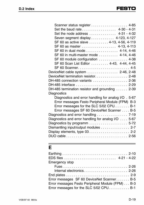
Scanner status register . . . . . . . . . . . . . . . . . . . 4-85Set the baud rate. . . . . . . . . . . . . . . . . . 4-30 - 4-31Set the node address . . . . . . . . . . . . . . 4-31 - 4-32Seven segment display . . . . . . . . . . . . 4-123, 4-127SF 60 as active slave . . . . . . . . . . 4-13, 4-56, 4-119SF 60 as master . . . . . . . . . . . . . . . . . . 4-13, 4-113SF 60 in dual mode . . . . . . . . . . . . . . . . . 4-14, 4-46SF 60 in multi-master mode . . . . . . . . . . 4-14, 4-46SF 60 module configuration . . . . . . . . . . . . . . . 4-38SF 60 Scan List Editor . . . . . . . . . 4-43, 4-44, 4-45SF 60 Scanner. . . . . . . . . . . . . . . . . . . . . . . . . . . 4-5
DeviceNet cable system . . . . . . . . . . . . . . . . 2-46, 2-48DeviceNet termination resistor. . . . . . . . . . . . . . . . . 2-48DH-485 connection variants . . . . . . . . . . . . . . . . . . 2-36DH-485 interface . . . . . . . . . . . . . . . . . . . . . . . . . . . 2-29DH-485 termination resistor and grounding . . . . . . 2-39Diagnostics
Diagnostics and error handling for analog I/O . 5-67Error messages Festo Peripheral Module (FPM) B-3Error messages for the SLC 5/02 CPU. . . . . . . . B-1Error messages SF 60 DeviceNet Scanner . . . . B-5
Diagnostics and error handling . . . . . . . . . . . . . . . . 7-19Diagnostics and error handling for analog I/O . . . . 5-67Diagnostics by programm . . . . . . . . . . . . . . . . . . . . 5-72Dismantling input/output modules . . . . . . . . . . . . . . . 2-7Display elements, type 03 . . . . . . . . . . . . . . . . . . . . . 2-2DUO cable . . . . . . . . . . . . . . . . . . . . . . . . . . . . . . . . 2-56
EEarthing . . . . . . . . . . . . . . . . . . . . . . . . . . . . . . . . . . 2-10EDS files . . . . . . . . . . . . . . . . . . . . . . . . . . . 4-21 - 4-22Emergency stop
Fuse. . . . . . . . . . . . . . . . . . . . . . . . . . . . . . . . . . 2-26Internal electronics. . . . . . . . . . . . . . . . . . . . . . . 2-26
End plates . . . . . . . . . . . . . . . . . . . . . . . . . . . . . . . . . 2-9Error messages SF 60 DeviceNet Scanner . . . . . . . B-5Error messages Festo Peripheral Module (FPM) . . . B-3Error messages for the SLC 5/02 CPU. . . . . . . . . . . B-1
D.2 Index
VISB/SF 60 9804a D-19
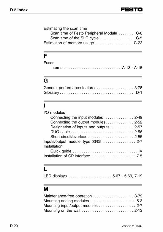
Estimating the scan timeScan time of Festo Peripheral Module . . . . . . . C-8Scan time of the SLC cycle . . . . . . . . . . . . . . . . C-5
Estimation of memory usage . . . . . . . . . . . . . . . . . C-23
FFuses
Internal . . . . . . . . . . . . . . . . . . . . . . . . . . A-13 - A-15
GGeneral performance features . . . . . . . . . . . . . . . . . 3-78Glossary . . . . . . . . . . . . . . . . . . . . . . . . . . . . . . . . . . D-1
II/O modules
Connecting the input modules . . . . . . . . . . . . . . 2-49Connecting the output modules. . . . . . . . . . . . . 2-52Designation of inputs and outputs . . . . . . . . . . . 2-57DUO cable . . . . . . . . . . . . . . . . . . . . . . . . . . . . . 2-56Short circuit/overload . . . . . . . . . . . . . . . . . . . . . 2-55
Inputs/output module, type 03/05 . . . . . . . . . . . . . . . 2-7Installation
Quick guide . . . . . . . . . . . . . . . . . . . . . . . . . . . . . . IVInstallation of CP interface. . . . . . . . . . . . . . . . . . . . . 7-5
LLED displays . . . . . . . . . . . . . . . . . . . . 5-67 - 5-69, 7-19
MMaintenance-free operation . . . . . . . . . . . . . . . . . . . 3-79Mounting analog modules . . . . . . . . . . . . . . . . . . . . . 5-3Mounting input/output modules . . . . . . . . . . . . . . . . . 2-7Mounting on the wall . . . . . . . . . . . . . . . . . . . . . . . . 2-13
D.2 Index
D-20 VISB/SF 60 9804a
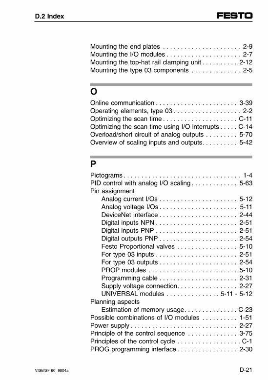
Mounting the end plates . . . . . . . . . . . . . . . . . . . . . . 2-9Mounting the I/O modules . . . . . . . . . . . . . . . . . . . . . 2-7Mounting the top-hat rail clamping unit . . . . . . . . . . 2-12Mounting the type 03 components . . . . . . . . . . . . . . 2-5
OOnline communication . . . . . . . . . . . . . . . . . . . . . . . 3-39Operating elements, type 03 . . . . . . . . . . . . . . . . . . . 2-2Optimizing the scan time . . . . . . . . . . . . . . . . . . . . . C-11Optimizing the scan time using I/O interrupts . . . . . C-14Overload/short circuit of analog outputs . . . . . . . . . 5-70Overview of scaling inputs and outputs. . . . . . . . . . 5-42
PPictograms . . . . . . . . . . . . . . . . . . . . . . . . . . . . . . . . . 1-4PID control with analog I/O scaling . . . . . . . . . . . . . 5-63Pin assignment
Analog current I/Os . . . . . . . . . . . . . . . . . . . . . . 5-12Analog voltage I/Os . . . . . . . . . . . . . . . . . . . . . . 5-11DeviceNet interface . . . . . . . . . . . . . . . . . . . . . . 2-44Digital inputs NPN . . . . . . . . . . . . . . . . . . . . . . . 2-51Digital inputs PNP . . . . . . . . . . . . . . . . . . . . . . . 2-51Digital outputs PNP . . . . . . . . . . . . . . . . . . . . . . 2-54Festo Proportional valves . . . . . . . . . . . . . . . . . 5-10For type 03 inputs . . . . . . . . . . . . . . . . . . . . . . . 2-51For type 03 outputs . . . . . . . . . . . . . . . . . . . . . . 2-54PROP modules . . . . . . . . . . . . . . . . . . . . . . . . . 5-10Programming cable . . . . . . . . . . . . . . . . . . . . . . 2-31Supply voltage connection. . . . . . . . . . . . . . . . . 2-27UNIVERSAL modules . . . . . . . . . . . . . . . 5-11 - 5-12
Planning aspectsEstimation of memory usage. . . . . . . . . . . . . . . C-23
Possible combinations of I/O modules . . . . . . . . . . 1-51Power supply . . . . . . . . . . . . . . . . . . . . . . . . . . . . . . 2-27Principle of the control sequence . . . . . . . . . . . . . . 3-75Principles of the control cycle . . . . . . . . . . . . . . . . . . C-1PROG programming interface . . . . . . . . . . . . . . . . . 2-30
D.2 Index
VISB/SF 60 9804a D-21
Programming . . . . . . . . . . . . . . . . . . . . . . . . . . . . . . 1-20Programming cable . . . . . . . . . . . . . . . . . . . . . . . . . 2-31Programming examples . . . . . . . . . . . . . . . . . . . . . . 5-35Programming the analog I/Os . . . . . . . . . . . . . . . . . 5-22Protective grounding types 03/05 . . . . . . . . . . . . . . 2-28
RRSLogix
1747-SDN . . . . . . . . . . . . . . . . . . . . . . . . . . . . . 3-29Create a new file . . . . . . . . . . . . . . . . . . . . . . . . 3-23Download to the processor . . . . . . . . . . . . . . . . 3-33Enter a program. . . . . . . . . . . . . . . . . . . . . . . . . 3-30Fundamentals . . . . . . . . . . . . . . . . . . . . . . . . . . 3-21I/O configuration. . . . . . . . . . . . . . . . . . . . . . . . . 3-27ID-Code . . . . . . . . . . . . . . . . . . . . . . . . . . . . . . . 3-28Open a program. . . . . . . . . . . . . . . . . . . . . . . . . 3-30Select processor for SB/SF 60 . . . . . . . . . . . . . 3-24Slot 1 . . . . . . . . . . . . . . . . . . . . . . . . . . . . . . . . . 3-28Slot 2 . . . . . . . . . . . . . . . . . . . . . . . . . . . . . . . . . 3-29Testing a program . . . . . . . . . . . . . . . . . . . . . . . 3-35
SSafe state for outputs
Analog modules . . . . . . . . . . . . . . . . . . . . . . . . . 5-34SB/SF 60
Address range of the CP system . . . . . . . . . . . 7-12Advantages of analog I/Os . . . . . . . . . . . . . . . . . 5-1Analog modules . . . . . . . . . . . . . . . . . . . . . . . . . . 5-1As master on DeviceNet . . . . . . . . . . . . . . . . . . 1-26As stand-alone slave on DeviceNet . . . . . . . . . 1-28Basic rules for addressing the PC system . . . . 7-14Characteristics after power-up. . . . . . . . . . . . . . 5-22Configuring the controller. . . . . . . . . . . . . . . . . . 3-37Configuring the G-files . . . . . . . . . . . . . . . . . . . . 3-43Configuring the interrupt service routine . . . . . . 3-41Configuring the M-files. . . . . . . . . . . . . . . . . . . . 3-41Configuring the SB/SF 60 . . . . . . . . . . . . . . . . . 3-40
D.2 Index
D-22 VISB/SF 60 9804a
Configuring the terminal for DH-485 . . . . . . . . . 3-39Connection possibilities . . . . . . . . . . . . . . . . . . . 2-20CP system overview . . . . . . . . . . . . . . . . . . . . . . 7-3Current draw . . . . . . . . . . . . . . . . . . . . . . . . . . . 2-25DeviceNet interface . . . . . . . . . . . . . . . . . . . . . . 2-41DH-485 interface . . . . . . . . . . . . . . . . . . . . . . . . 2-29Diagnostics and error handling for analog I/O . 5-67Diagnostics by programm . . . . . . . . . . . . . . . . . 5-72Diagnostics of the CP system . . . . . . . . . . . . . . 7-22E-STOP function . . . . . . . . . . . . . . . . . . . . . . . . 1-44Error messages SF 60 DeviceNet Scanner. . . . B-5Error messages Festo Peripheral Module (FPM) B-3Error messages for the SLC 5/02 CPU. . . . . . . . B-1Estimation of memory usage. . . . . . . . . . . . . . . C-23General performance features. . . . . . . . . . . . . . 3-78In the DH-485 network . . . . . . . . . . . . . . . . . . . 1-24LED displays . . . . . . . . . . . . . . . . . . . . . . . . . . . 2-20Maintenance-free opreation. . . . . . . . . . . . . . . . 3-79NOMINAL/ACTUAL comparison . . . . . . . . . . . . 3-47Opening and closing the control block . . . . . . . 2-19Operating response of the CP system . . . . . . . 7-10Optimizing the scan time . . . . . . . . . . . . . . . . . . C-11Optimizing the scan time using I/O interrupts . . C-14PID control with analog I/O scaling . . . . . . . . . . 5-63Planning aspects . . . . . . . . . . . . . . 1-41, 1-44, 1-51Possible combinations of I/O modules . . . . . . . 1-51Power-up reaction of the CP system SB/SF 60 . 7-8Principle of the control sequence . . . . . . . . . . . 3-75Processor functions . . . . . . . . . . . . . . . . . . . . . . 3-78PROG programming interface. . . . . . . . . . . . . . 2-30Programming examples. . . . . . . . . . . . . . . . . . . 5-35Programming the analog I/Os . . . . . . . . . . . . . . 5-22Response of the CP system to faults . . . . . . . . 7-20Safe state for outputs . . . . . . . . . . . . . . . . . . . . 5-34Scan time of the Festo Peripheral Module . . . . . C-8Scan time of the SLC cycle. . . . . . . . . . . . . . . . . C-5Scanned input/output words . . . . . . . . . . . . . . . C-12Seven-segment display . . . . . . . . . . . . . . . . . . . 2-20Stand-alone mode . . . . . . . . . . . . . . . . . . . . . . . 1-22
D.2 Index
VISB/SF 60 9804a D-23
Start-up the control system . . . . . . . . . . . . . . . . 3-49System limits . . . . . . . . . . . . . . . . . . . . . . . . . . . 1-41Technical data . . . . . . . . . . . . . . . . . . . . . . . . . . 2-71With analog modules . . . . . . . . . . . . . . . . . . . . . 1-30With AS-i master . . . . . . . . . . . . . . . . . . . . . . . . 1-32With CP interface. . . . . . . . . . . . . . . . . . . . . . . . 1-34
SB/SF 60 Principles of the control cycle . . . . . . . . . . . . . . C-1
Scale offsets. . . . . . . . . . . . . . . . . . . . . . . . . . . . . . . 5-57Scanned input/output words . . . . . . . . . . . . . . . . . C-12Service . . . . . . . . . . . . . . . . . . . . . . . . . . . . . . . . . . . 1-10Seven segment display . . . . . . . . . . . . . . . . . . . . . 4-123Short circuit
Overload on type 03 output . . . . . . . . . . . . . . . . 2-55Start-up the control system . . . . . . . . . . . . . . . . . . . 3-49Structure of type 03 valve terminal . . . . . . . . . . . . . . 2-1
TTarget group . . . . . . . . . . . . . . . . . . . . . . . . . . . . . . . . 1-2Technical data . . . . . . . . . . . . . . . . . . . . . . . . 2-71, 5-73Text markings . . . . . . . . . . . . . . . . . . . . . . . . . . . . . . . 1-5Top-hat rail clamping . . . . . . . . . . . . . . . . . . . . . . . . 2-15Top-hat rail clamping unit . . . . . . . . . . . . . . . . . . . . . 2-12
UUser information
Benefits . . . . . . . . . . . . . . . . . . . . . . . . . . . . . . . . . IXIntended use . . . . . . . . . . . . . . . . . . . . . . . . . . . . 1-1Valve terminal. . . . . . . . . . . . . . . . . . . . . . . . . . . . . IX
VValve terminal
Advantages of analog I/Os . . . . . . . . . . . . . . . . . 5-1CP system overview . . . . . . . . . . . . . . . . . . . . . . 7-3Current draw . . . . . . . . . . . . . . . . . . . . . . . . . . . 2-25
D.2 Index
D-24 VISB/SF 60 9804a
Diagnostics and error handling for analog I/O . 5-67Diagnostics by programm . . . . . . . . . . . . . . . . . 5-72I/O modules . . . . . . . . . . . . . . . . . . . . . . . . . . . . . 2-2Maintenance-free operation. . . . . . . . . . . . . . . . 3-79MAXI valves. . . . . . . . . . . . . . . . . . . . . . . . . . . . . 2-4MIDI valves . . . . . . . . . . . . . . . . . . . . . . . . . . . . . 2-3Mounting the components . . . . . . . . . . . . . . . . . . 2-5Structure . . . . . . . . . . . . . . . . . . . . . . . . . . . . . . . 2-1Technical data . . . . . . . . . . . . . . . . . . . . . . . . . . 2-71
VoltagesConnecting. . . . . . . . . . . . . . . . . . . . . . . . . . . . . 2-23
WWiring examples . . . . . . . . . . . . . . . . . . . . . . . . . . . A-11Writing ladder logic . . . . . . . . . . . . . . . . . . . . . . . . . 5-35
D.2 Index
VISB/SF 60 9804a D-25

D.2 Index
D-26 VISB/SF 60 9804a
Related Documents