1 FlneT ek *AE110A (10 points) *AE120A (20 points) *AE140A (40 points) Principle The sequential collector uses a microprocessor to control the pulse jets of a diaphragm valve through the electrical solenoid of the valve. The controller has 2 rows of 7 segment digital display. The first row displays the diaphragm valve number to be activated next, the 2nd row displays the time left before it activates the next valve. The pulse jet timing, duration of each pulse jet and the number of valves to be controlled could be set to user's requirements. Also, the controller is able to be programmed to automatically execute the pulse jet cycle even after the system shuts down. The user just needs to configure all settings through the buttons on the face of the board. The controller is both user-friendly and serves a wide range of applications and will definitely satisfy all requirements of the user. The programmable sequential controller is designed specifically for use with pneumatic dust collector systems. It is used to control the solenoid of the diaphragm valve in order to program the pulse jet sequence of the valves. LED lights serve as indication of status of pulse position and timing. Both the pulse jet timing and duration of each pulse jet could be adjusted by the logic circuitry. The controller has 2 independent "ON" and "OFF" methods, the 1st is when the AC power supply is cut off, the controller will shut down. When the AC supply is reconnected, the controller will automatically revert to its initial default settings. The 2nd method is to employ the use of the controller's remote contacts (R,C,A) as the controlling signal. Features 1 1 1 1 Digital Display, provides ease of operation and clear display of operation status. Microprocessor: Accurate and precise operation. Remote Control: Convenient control through remote means. Able to automatically execute the pulse jet cycle even after the system shuts down so as to prevent residue sticking unto cloth filter. Option: Water-proof and dust-proof enclosure, to extend lifespan of the controller. 1 PROGRAMMABLE SEQUENTIAL CONTROLLER

Welcome message from author
This document is posted to help you gain knowledge. Please leave a comment to let me know what you think about it! Share it to your friends and learn new things together.
Transcript

1
F ll n eT e k
*AE110A (10 points)
*AE120A (20 points)
*AE140A (40 points)
Principle
The sequential collector uses a microprocessor to control the pulse jets of a diaphragm valve through the electrical solenoid of the valve. The controller has 2 rows of 7 segment digital display. The first row displays the diaphragm valve number to be activated next, the 2nd row displays the time left before it activates the next valve. The pulse jet timing, duration of each pulse jet and the number of valves to be controlled could be set to user's requirements. Also, the controller is able to be programmed to automatically execute the pulse jet cycle even after the system shuts down. The user just needs to configure all settings through the buttons on the face of the board. The controller is both user-friendly and serves a wide range of applications and will definitely satisfy all requirements of the user.
The programmable sequential controller is designed specifically for use with pneumatic dust collector systems. It is used to control the solenoid of the diaphragm valve in order to program the pulse jet sequence of the valves. LED lights serve as indication of status of pulse position and timing.Both the pulse jet timing and duration of each pulse jet could be adjusted by the logic circuitry. The controller has 2 independent "ON" and "OFF" methods, the 1st is when the AC power supply is cut off, the controller will shut down. When the AC supply is reconnected, the controller will automatically revert to its initial default settings. The 2nd method is to employ the use of the controller's remote contacts (R,C,A) as the controlling signal.
Features
1
1
1
1
Digital Display, provides ease of operation and clear display of operation status.Microprocessor: Accurate and precise operation.Remote Control: Convenient control through remote means.Able to automatically execute the pulse jet cycle even after the system shuts down so as to prevent residue sticking unto cloth filter.Option: Water-proof and dust-proof enclosure, to extend lifespan of the controller.
1
PROGRAMMABLESEQUENTIAL CONTROLLER
2F ll n eT e k
220V
110V2
110V220V
JS1
ON
OFF
31
AC1
AC2
FAN.A
R.C A
4
5
6
COM
AC06
AC07
AC08
AC09
AC10F l n eT e k
COM
AC01
AC02
AC03
AC04
AC05
6
F l n eT e k
ON
OFF
220V
110V2
110V220V JS1
3
COM
AC01
AC02
AC03
AC04
AC05
6
COM
AC11
AC12
AC13
AC14
AC15
66
COM
AC16
AC17
AC18
AC19
AC20
6
COM
AC06
AC07
AC08
AC09
AC10
1AC1
AC2
FAN.A
R.C A
4
5
*AE110A *AE120A
220V
110V2
31
110V220V
AC1
AC2
FAN.A
R.C A
COM
AC40
AC39
AC38
AC37
AC36
COM
AC35
AC34
AC33
AC32
AC31
COM
AC30
AC29
AC28
AC27
AC26
COM AC25 AC24 AC23 AC22 AC21
J2
JS1
COM
AC16
AC17
AC18
AC19
AC20
COM
AC11
AC12
AC13
AC14
AC15
COM
AC06
AC07
AC08
AC09
AC10
COM
AC01
AC02
AC03
AC04
AC05
F l n eT e k
4
5
6
6
6
6
6
6
6
6
...
*AE140A
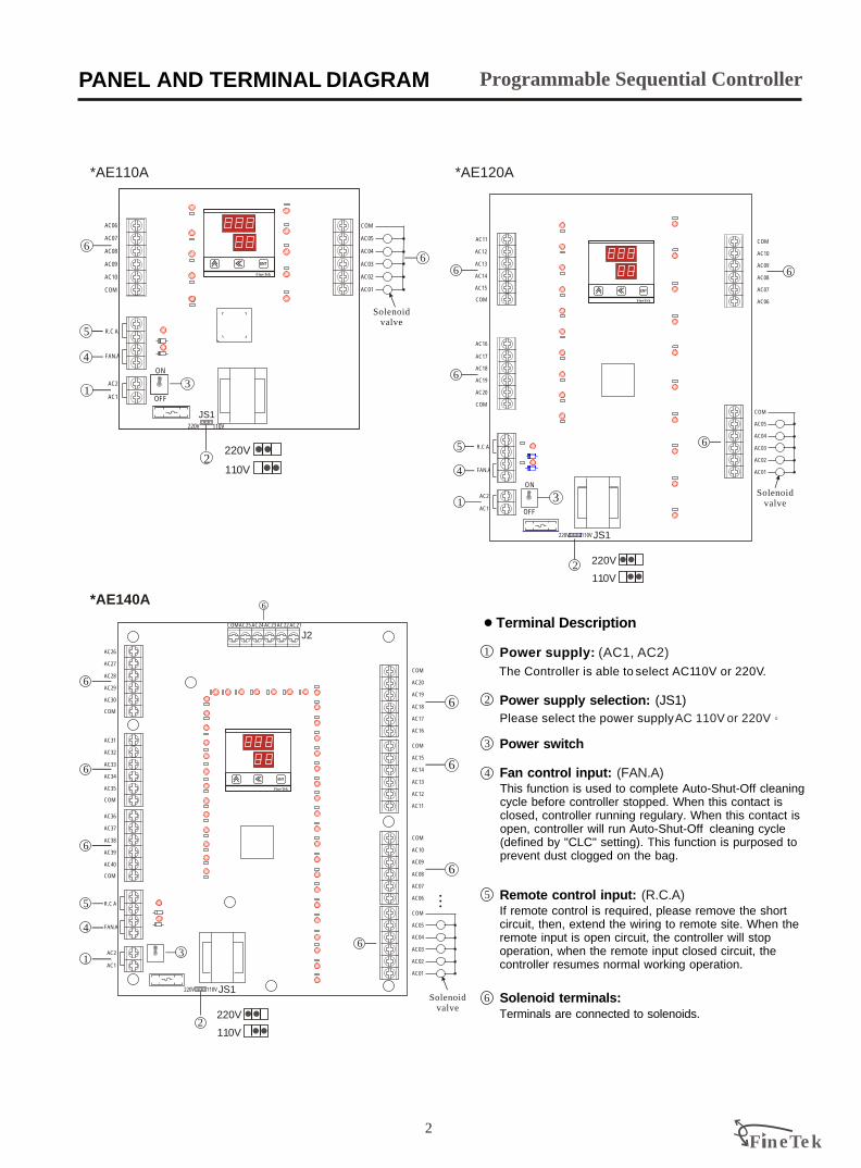
Programmable Sequential ControllerPANEL AND TERMINAL DIAGRAM
The Controller is able to select AC110V or 220V.
Power supply: (AC1, AC2)1
2
AC 110V or 220VPlease select the power supply
Solenoid terminals:6
5
4 Fan control input: (FAN.A)This function is used to complete Auto-Shut-Off cleaningcycle before controller stopped. When this contact is closed, controller running regulary. When this contact isopen, controller will run Auto-Shut-Off cleaning cycle(defined by "CLC" setting). This function is purposed toprevent dust clogged on the bag.
If remote control is required, please remove the short circuit, then, extend the wiring to remote site. When the remote input is open circuit, the controller will stop operation, when the remote input closed circuit, the controller resumes normal working operation.
Remote control input: (R.C.A)
Power supply selection: (JS1)
3
Terminals are connected to solenoids.
1 Terminal Description
Power switch
Solenoid valve
Solenoid valve
Solenoid valve
~ / /
X.X X X.X X X. XX X.X X
X X X X X X X XX X X X
X.X X
X X X
X X X X X X X XX X X X X X X
X X X X X X X XX X X X X X XF l n eT e k
F ll n eT e k3
Programmable Sequential Controller
~ S
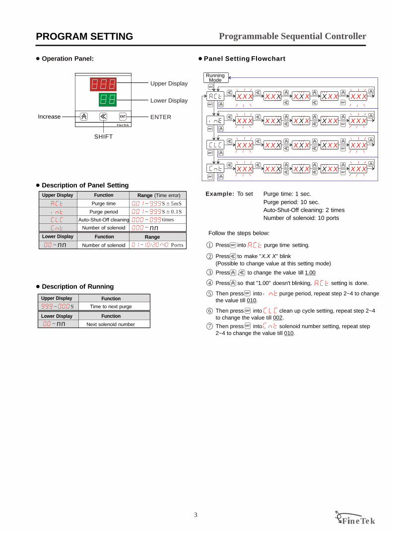
1 Description of Running
Function
Function
Upper Display
Lower Display
Time to next purge
Next solenoid number~ nn
~ SA5mS
~ SA0.1S
~ times
~ nn
Ports~
Purge time
Purge period
Range (Time error)Function
1 Description of Panel Setting
RangeFunction
Upper Display
Lower Display
Number of solenoid
Auto-Shut-Off cleaning
Number of solenoidnn
ENTER
SHIFT
Increase
Upper Display
Lower Display
1 Operation Panel: 1 Panel Setting Flowchart
Running Mode
2
4
6
Press into purge time setting.1
Press , to change the value till 1.003
5
7
Follow the steps below:
Example: Purge time: 1 sec.
Purge period: 10 sec.
Number of solenoid: 10 ports
Auto-Shut-Off cleaning: 2 times
To set
Press to make "X.X X" blink
(Possible to change value at this setting mode)
Press so that "1.00" doesn't blinking, setting is done.
Then press into purge period, repeat step 2~4 to change the value till 010. .Then press into clean up cycle setting, repeat step 2~4 to change the value till 002.
Then press into solenoid number setting, repeat step 2~4 to change the value till 010.
PROGRAM SETTING

160
137.7
73.4
140 160
70.070.6
82.6
7-f4.2
1 Dimensions
97.9 83.8
116.1
65.9
265.0
132.2
59.7
30.7
32.4
205.0
181.7
41.0
68.5 43.9
10-f4.2
54.8
78.0
137.7
38.0
106.4
106.2 48.2107.2
108.5
240.0
86.174.8
180.0
106.2 54.7
10-f4.2
4 Specifications
*AE110A (10 point) *AE120A (20 point)
*AE140A (40 point)
F ll n eT e k
*CASE (Optional)
Material: ABS
Dimension: 230x300x86.5mm
4
Programmable Sequential ControllerSPECIFICATIONS / DIMENSIONS
1
1
1
1
1
1 B
1
1
1
Power supply: 110V/220V, A20% 50Hz/60Hz
Interval adjustable range: 1s~999s
Spray time adjustable range: 10ms~9.99s
Fuse: 3A
Number of sequence: 1~10 / 20 / 40
Points
Ambient temperature : 0 ~70 C
Indication: 2 Sets of digital display
Input: 3 Push buttons
Delay between stage: 0~99 times
Controller electrical
Controller
F ll n eT e k5
Programmable Sequential ControllerTROUBLESHOOTING
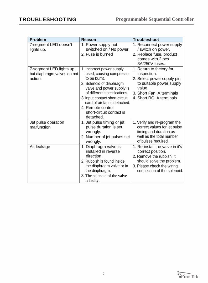
Problem Reason Troubleshoot 7-segment LED doesn't lights up.
1. Power supply not switched on / No power. 2. Fuse is burned
1. Reconnect power supply / switch on power.2. Replace fuse, product comes with 2 pcs 3A/250V fuses.
7-segment LED lights up but diaphragm valves do not action.
1. Incorrect power supply used, causing compressor to be burnt. 2. Solenoid of diaphragm valve and power supply is of different specifications. 3. Input contact short-circuit
card of air fan is detached. 4. Remote control short-circuit contact is detached.
1. Return to factory for inspection.
2. Select power supply pin to suitable power supply value. 3. Short Fan .A terminals 4. Short RC .A terminals
Jet pulse operation malfunction
1. Jet pulse timing or jet pulse duration is set wrongly.2. Number of jet pulses set wrongly.
1. Verify and re-program the correct values for jet pulse timing and duration as well as the total number of pulses required.
Air leakage 1. Diaphragm valve is installed in reverse direction.2. Rubbish is found inside the diaphragm valve or in the diaphragm.3. The solenoid of the valve
is faulty.
1. Re-install the valve in it's correct position.2. Remove the rubbish, it should solve the problem.3. Please check the wiring connection of the solenoid.

* AE410A (10 points)
L1L1
66
1010
99
88
77
11
55
44
33
22
COMCOM
P2P2
P1P1
L2L2
REMOTECONTROL
110/220V50/60Hz
ON
92 3 4 5 6 7 8
STEP Switch
2
8
14
20
25 30 36
42
48
54
60
PULSEFREQUENCY
PULSEDURATION
20
40
55
75
90 110 130
145
165
185
200SECONDS MILLISECONDS
Co.,Ltd
SER NO:
110V 220V
F l n eT e k
2
1
3
5
6 7
4
F ll n eT e k6
ON OFF
Sequential Controller
1 Connections
5. Spray time adjustableAdjust  to the value required for how long the solenoid valves remain in operation
6. After the various settings are done, please start operation by switching on the power supply.
1. Power Supply SelectionÁ is used for selection of power supply, factory default is set at 220V. If the power supply is 110V, just transfer the jumper connection from 220V end to 110V end.
2. WiringA. Live wire of the power supply must be connected to L1 terminal, the neutral wire must be connected to L2 terminal.
B. Common wire of solenoid must be connected to COM terminal whereas the others are connected to their respective terminals 1~10.
C. Remote control à is used for long distance control or cascading control. If neither of these controls are required, do not remove the shorting metallic strip at terminals P1 and P2.
3. Step SwitchAdjust Ä to indicate the numbers of solenoid steps to action. Controller will action from solenoid 1 ~ required solenoid number and will repeat itself continuously.
4. Interval adjustableAdjust À to the value required for the time delay between each individual valve operations.
PANEL AND TERMINAL DIAGRAM
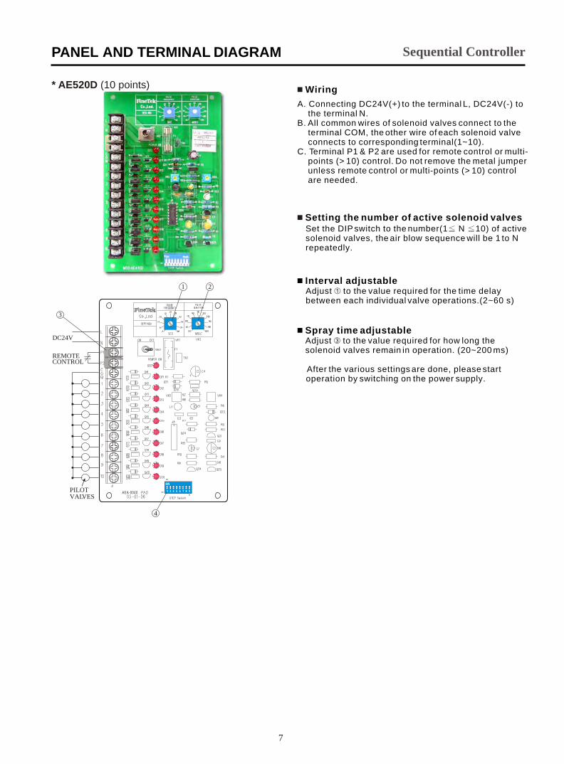
* AE520D (10 points)
ON
2 3 4 5 6 7 8 9
1
DC24V
REMOTECONTROL
PILOTVALVES
2
3
4
AEA-0040
4 Wiring
4 Setting the number of active solenoid valvesSet the DIP switch to the number(1 N 10) of active solenoid valves, the air blow sequence will be 1 to N repeatedly.
A. Connecting DC24V(+) to the terminal L, DC24V(-) to the terminal N.
B. All common wires of solenoid valves connect to the terminal COM, the other wire of each solenoid valve connects to corresponding terminal(1~10).
C. Terminal P1 & P2 are used for remote control or multi-points (> 10) control. Do not remove the metal jumper unless remote control or multi-points (> 10) control are needed.
4 Spray time adjustableAdjust  to the value required for how long the solenoid valves remain in operation. (20~200 ms)
After the various settings are done, please start
operation by switching on the power supply.
4 Interval adjustableAdjust À to the value required for the time delay between each individual valve operations.(2~60 s)
Sequential Controller
7
PANEL AND TERMINAL DIAGRAM
F ll n eT e k8
113
98
13
6
14
9
M4x4
1 Dimensions
146
133
18
6
17
3
75
CASE
1 Optional
103
87
16
2
15
2
M4x4
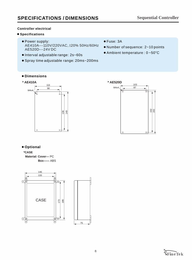
* AE410A * AE520D
*CASE
Material: Cover--- PC
Box------ ABS
1
1
1
Power supply:
Interval adjustable range: 2s~60s
Spray time adjustable range: 20ms~200ms
AE410A---110V/220VAC, 20% 50Hz/60Hz AE520D---24V DC
Sequential Controller
1
1
1 B
Fuse: 3A
Number of sequence: 2~10 points
Ambient temperature : 0 ~50 C
SPECIFICATIONS / DIMENSIONS
1 Specifications
Controller electrical
Related Documents