CHAPTER: 3 PROGRAMMABLE PERIPHERAL INTERFACE & ELECTROMECHANICAL DEVICES INTERFACING 1

Welcome message from author
This document is posted to help you gain knowledge. Please leave a comment to let me know what you think about it! Share it to your friends and learn new things together.
Transcript

CHAPTER: 3
PROGRAMMABLE PERIPHERAL
INTERFACE & ELECTROMECHANICAL
DEVICES INTERFACING
1

Introduction to 8255 PPI
The Intel 8255A is a high-performance, general purpose programmable I/O device
is designed for use with all Intel and most other microprocessors
The 82C55 is a popular interfacing component, that can interface any TTL-compatible I/O device to a microprocessor.
It provides 24 I/O pins
Can be individually programmed in 2 groups of 12
Used in 3 major modes of operation
Each group of 12 I/O pins may be programmed in sets of 4 and 8 to be inputs or outputs
2

Introduction to 8255 PPI
The 8255 is a widely used, programmable
parallel I/O device.
It can be programmed to transfer data under
various conditions, from simple I/O to interrupt
I/O.
It is flexible, versatile and economical (when
multiple I/O ports are required).
It is an important general purpose I/O device
that can be used with almost any microprocessor.
3

.
4

Control Logic of 8255
Th :is signal enables the Read operation.
When the signal is low, microprocessor reads
data from a selected I/O port of 8255.
:This is an input line driven by the
microprocessor. A low on this line indicates write
operation.
5

Control Logic of 8255 6
8255A BLOCK DIAGRAM AND
FUNCTIONAL DESCRIPTION
It has a 40 pins of 4 groups.
1. Data bus buffer
2. Read Write control logic
3. Group A and Group B controls
4. Port A, B and C
7

8255A BLOCK DIAGRAM AND FUNCTIONAL
DESCRIPTION
8

Contd… Data Bus Buffer
This 3-state bidirectional 8-bit buffer is used to interface the
8255A to the system data bus
Data is transmitted or received by the buffer upon execution of
input or output instructions by the CPU
Control words and status information are also transferred through
the data bus buffer
Read/Write and Control Logic
manage all of the internal and external transfers of both Data
and Control or Status words.
It accepts inputs from the CPU Address and Control busses and in
turn, issues commands to both of the Control Groups.
9

Contd…
Group A and Group B Controls
These block receive control from the CPU and issues commands to their respective ports.
The control word contains information such as
“mode”, “bit set”, “bit reset”, etc
Each of the Control blocks (Group A and Group B)
accepts ``commands'' from the Read/Write Control Logic,
receives ``control words'' from the internal data bus
issues the proper commands to its associated ports
Control Group A - Port A and Port C upper (C7-C4)
Control Group B - Port B and Port C lower (C3-C0)
10

Ports A, B, and C
The 8255A contains three 8-bit ports (A, B, and C)
All can be configured in a wide variety of functional characteristics
each has its own special features or “personality” to further enhances the power and flexibility of the 8255A
Port A: One 8-bit data output latch/buffer and one 8-bit input latch buffer
Port B: One 8-bit data input/output latch/buffer
Port C: One 8-bit data output latch/buffer and one 8-bit data input buffer (no latch for input) This port can be divided into two 4-bit ports under the mode
control
11

Control register controls the overall operation of
8255
All three ports A, B and C are grouped into two
Group B
Group A
Port A Upper C Port B Lower C

8255A OPERATIONAL DESCRIPTION
These are two basic modes of operation of 8255.
I/O mode and
Bit Set-Reset mode (BSR).
In I/O mode, the 8255 ports work as programmable I/O ports, while in BSR mode only port C (PC0-PC7) can be used to set or reset its individual port bits.
Under the I/O mode of operation, further there are three modes of operation of 8255, so as to support different types of applications,
mode 0,
mode 1 and
mode 2.
13

Contd.
.
14

Contd.
.
15

Port C
D7 D6 D5 D4 D3 D2 D1
D
8255
Port B
CU
CL
Port A
Mode 0
Simple I/O
for Ports
A, B & C
Mode 1
HS mode
for Ports
A and/or B
Port C bits
are used for
HS
Mode 2
Bidirectional
Data mode for Port
A
B can in mode 0/1
Port C bits are used
for HS
BSR Mode
Bit Set/Reset
For Port C
No Effect on
I/O Mode
0/1
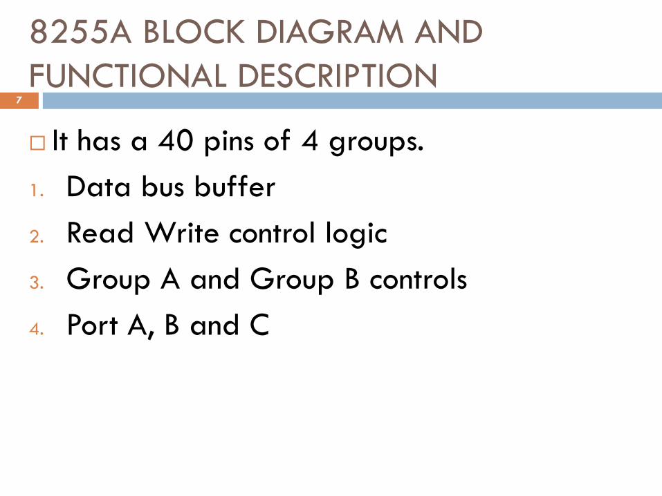
Basic Mode Definitions and Bus Int
Mode 0
Basic I/O
Mode 1
Strobe I/O
Mode 2
Bi-Dir Bus
17

Contd…
The modes for Port A and Port B can be separately
defined, while Port C is divided into two portions as
required by the Port A and Port B definitions
Modes may be combined so that their functional
definition can be suited to almost any I/O structure
For instance
Group B can be programmed in Mode 0 to monitor
simple switch closings or display computational results,
Group A could be programmed in Mode 1 to monitor a
keyboard or tape reader on an interrupt-driven basis
18

Control word and control register
CONTROL WORD: control word format for I/O
mode is shown in fig below. It is essential to understand this format.
In interfacing applications
we have to determine the control word for programming the ports for input or output and write it into the CONTROLREGISTER before the data transfer program
This way of determining and writing the CONTROL WORD is called I/O programming.
19

20
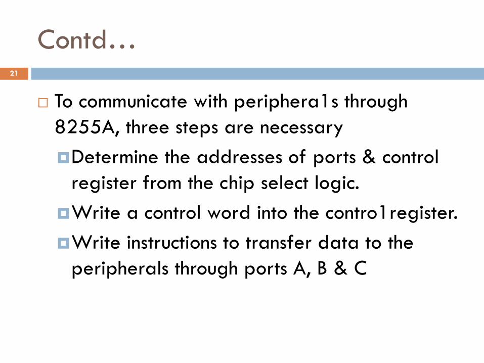
Contd…
To communicate with periphera1s through
8255A, three steps are necessary
Determine the addresses of ports & control
register from the chip select logic.
Write a control word into the contro1register.
Write instructions to transfer data to the
peripherals through ports A, B & C
21

Mode 0: Simple Input or Output
Ports A, B &C are programmed for simple I/O.
Data can be simply read from and written to the
input and output ports respectively, after
appropriate initialization.
Outputs are latched.
Inputs are -not latched.
Ports do not have handshake or interrupt
capability.
It is used when timing characteristics of I/O devices
is well known.
22

Contd.
.
23

Contd.
.
24

Contd.
.
25

Contd.
.
26

Contd.
.
27

Contd.
.
28

Contd.
.
29

Contd.
.
30

Contd.
.
31
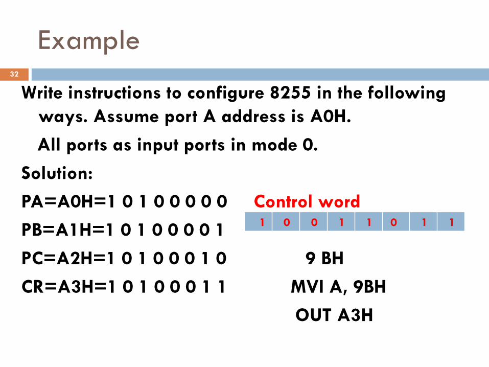
Example
Write instructions to configure 8255 in the following
ways. Assume port A address is A0H.
All ports as input ports in mode 0.
Solution:
PA=A0H=1 0 1 0 0 0 0 0 Control word
PB=A1H=1 0 1 0 0 0 0 1
PC=A2H=1 0 1 0 0 0 1 0 9 BH
CR=A3H=1 0 1 0 0 0 1 1 MVI A, 9BH
OUT A3H
1 0 0 1 1 0 1 1
32

Exercise
Write instructions to configure 8255 in the following
ways. Assume port A address is A0H.
1. All ports as output ports in mode 0.
2. PA-O/P, PB-I/P , PCL and PCU-O/P in mode 0
3. Configure Port A as input in Mode 0, Port B as
output in mode 0, Port C (Lower) as output and
Port C (Upper) as input ports.
33
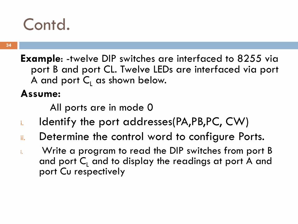
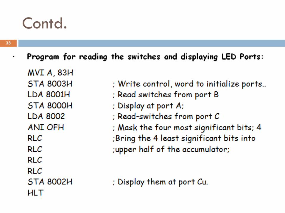
Contd.
Example: -twelve DIP switches are interfaced to 8255 via port B and port CL. Twelve LEDs are interfaced via port A and port CL as shown below.
Assume:
All ports are in mode 0
i. Identify the port addresses(PA,PB,PC, CW)
ii. Determine the control word to configure Ports.
i. Write a program to read the DIP switches from port B and port CL and to display the readings at port A and port Cu respectively
34

35

Contd.
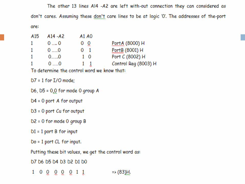
Identify the port addresses.
Determine the control word to configure port A-& port Cu for output and port B and port CL for input.
Write a program to read the DIP switches from port B and port CL and to display the readings at port A and port Cu respectively
From the circuit, observe-that the control--signals MEMR and MEMW are connected
This indicates to us that the devices-are interfaced in MEMORY MAPPED MODE
So, they will have 16-bit addresses. CS is connected to Al5 through an inverter. So A15 must be at logic high level for the 8255A to be selected.
36
37
Contd.
.
38

Mode 1 – Input/output with Handshake
In mode 0, which is used for simple I/O, it is assumed
that the peripheral devices are always ready
The microprocessor, therefore, need not to check their
status before transferring data to and from
However this is not the case always
Sometimes in order to check the-status, the Mp and the
peripherals exchange a few signals prior to actual data
transfer
These signals are called hand shake signals
The 8255A's capability to transfer data with handshake is
provided in its mode 1 operation
39

Contd…
Feature of Mode 1:
This functional configuration provides a means for transferring I/O data to or from a specified port in conjunction with strobes or “handshaking” signals.
Port A and port B function as 8-bit I/O ports.
Each port uses three bits from port C as handshake signals. The remaining two bits from port C can be used for simple I/O.
Input-data and output data are latched.
used when timing characteristics of I/O devices is not well known, or used when I/O devices supply or receive data at irregular intervals.
40

Mode 1 input Control Signals
When port A and port B are configured as
input ports, they use three bits each from port C
as handshake signals.
Port A uses PC3, PC4 and PC5 bits and port B
uses PC0, PC1 and PC2 bits.
These are shown in figure. These control signals
are named STB, IBF and INTR. The purpose, of
these signals is as follows.
41

Contd.
.
Fig: Mode 1 Input
Configuration
42
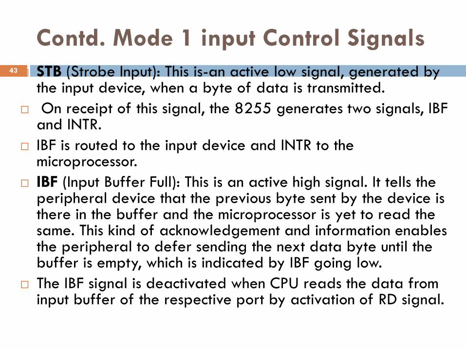
Contd. Mode 1 input Control Signals
STB (Strobe Input): This is-an active low signal, generated by the input device, when a byte of data is transmitted.
On receipt of this signal, the 8255 generates two signals, IBF and INTR.
IBF is routed to the input device and INTR to the microprocessor.
IBF (Input Buffer Full): This is an active high signal. It tells the peripheral device that the previous byte sent by the device is there in the buffer and the microprocessor is yet to read the same. This kind of acknowledgement and information enables the peripheral to defer sending the next data byte until the buffer is empty, which is indicated by IBF going low.
The IBF signal is deactivated when CPU reads the data from input buffer of the respective port by activation of RD signal.
43

Contd. Mode 1 input Control Signals
INTR (Interrupt Request): This is an output signal
generated by 8255 in response to IBF, STB and INTE
(Interrupt enable).
This is used to interrupt the microprocessor to read the
data byte from the buffer.
INTE: It is an internal flip-flop for enabling or disabling
INTR signal.
The two flip-flops INTEA and INTEB are set/reset by
using the BSR mode.
44

Contd. Mode 1 input Control Signals
MODE 1 Control word : To configure port A and port B
as input ports, the mode 1 control word is as follows.
45

Contd. Mode 1 input Control Signals
MODE 1 Status word :The status word is constituted by
port C bits. When the microprocessor reads port C, the
status word is placed in accumulator.
Then the microprocessor can examine the bits to
determine the status. The status word is shown below.
46

Mode 1 Output Control Signals
When port A and/or port B are configured as output ports, both of
them use bits from port C as handshake signals. These handshake
signals -are as follows, and are shown in below.
Fig : Mode 1 Output
Configuration
47

Contd. Mode 1 Output Control Signals
OBF: (Output Buffer Full) -This is an active low
signal generated by 8255A to indicate to the
peripheral that the microprocessor has written
one byte of data into the output port and that it is
ready to be read by the device from the port.
ACK: (Acknowledge): This is an input signal from
the peripheral to 8255, indicating that it has
received the byte from the port.
It is active low.
48

Contd. Mode 1 Output Control Signals
INTR: (Interrupt Request) - This is an output signal generated by 8255.
It is set by OBF, ACK and INTE.
It can be used to interrupt the MPU for the next data byte.
INTE: (Interrupt Enable): This is an internal flip-flop to enable interrupts.
The two flip-flows INTEA and INTEB are controlled by the bits PC6 and PC2 respectively through BSR mode.
PC4, PC5: These two lines can be setup either as input or output.
49

Contd. Mode 1 Output Control Signals
MODE 1 Control word : To configure port A and port B
as Output ports, the mode 1 control word is as follows.
50

Contd. Mode 1 Output Control Signals
MODE 1 Status word : The status word is accessed by
issuing a read to port C.
To configure port A and port B as Output ports, the
mode 1 control word is as follows.
51

Exercise
Write instructions to configure 8255 in the following
ways. Assume port A address is A0H.
1. PA-I/P, PB-O/P in mode 1
2. Configure Port A as input in Mode 1, Port B as
output in mode 1, Port C7-6 as input ports.
52

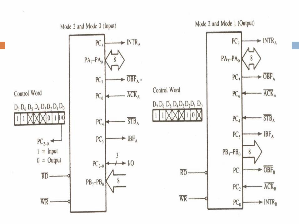
Mode 2 – Strobed Bidirectional Bus I/O
This functional configuration provides a means for communicating with a peripheral device or structure on a single 8-bit bus for both transmitting and receiving data (bidirectional bus I/O).
“Handshaking” signals are provided to maintain proper bus flow discipline in a similar manner to MODE.
It is used with an I/O device that receives data some times and sends data sometimes.
Ex. Hard disk drive.
Mode 2 operation is useful when timing characteristics of I/O devices is not well known, or when I/O devices supply or receive data at irregular intervals.
53

Contd. Mode 2 – Strobed Bidirectional
Bus I/O
Port A can be configured as the bidirectional port and Port B either in mode 0 or mode 1.
Port A uses five signals from Port C as handshake signals for data transfer.
The remaining three lines from Port C can be used either as simple I/O or as handshake signals for Port B.
Used in Group A only.
One 8-bit, bi-directional bus Port (Port A) and a 5-bit control Port (Port C).
Both Inputs and Outputs are latched.
54
Contd.
.
55
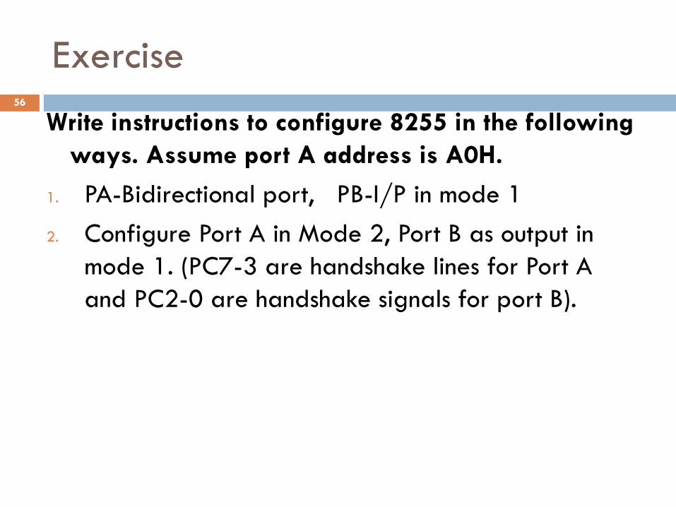
Exercise
Write instructions to configure 8255 in the following
ways. Assume port A address is A0H.
1. PA-Bidirectional port, PB-I/P in mode 1
2. Configure Port A in Mode 2, Port B as output in
mode 1. (PC7-3 are handshake lines for Port A
and PC2-0 are handshake signals for port B).
56
Bit Set/Reset, Control word and control
register
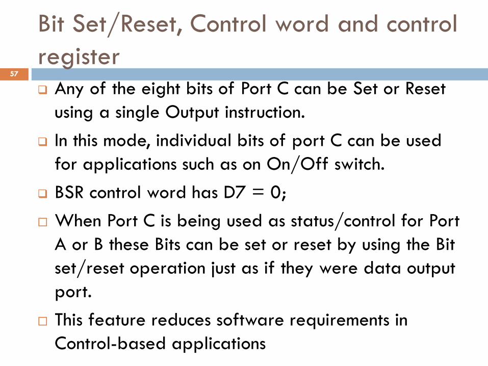
Any of the eight bits of Port C can be Set or Reset
using a single Output instruction.
In this mode, individual bits of port C can be used
for applications such as on On/Off switch.
BSR control word has D7 = 0;
When Port C is being used as status/control for Port
A or B these Bits can be set or reset by using the Bit
set/reset operation just as if they were data output
port.
This feature reduces software requirements in
Control-based applications
57

Contd.
.
Fig: BSR Control Word Format in the BSR Mode
58
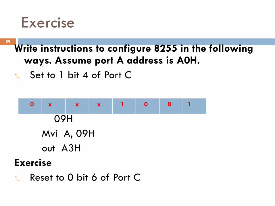
Exercise
Write instructions to configure 8255 in the following ways. Assume port A address is A0H.
1. Set to 1 bit 4 of Port C
09H
Mvi A, 09H
out A3H
Exercise
1. Reset to 0 bit 6 of Port C
0 x x x 1 0 0 1
59

Exercise
1. Write instructions to configure 8255 in the following ways. To set PC4 and PC6 pins of port C for 5 mse and reset it after that.
Assume :
- port A address is B0H. And
- delay routine is available.
2. Write a program to blink Port C bit 0 of the 8255 infinitely . Assume address of control word register of 8255 is 83H.
Assume: Delay routine is available.
- 8086 microprocessor
60

Exercise
1. Consider the interface circuit shown in fig (a) below
write a BSR control word subroutine to set PC7 and
PC3 and reset them after 10 ms.
Assume that delay routine is available.
61
Related Documents