59 800-262-IDEC (4332) • USA & Canada MicroSmart Pentra Series Programmable Logic Controllers OI Touchscreens PLCs Automation Software Power Supplies Sensors Communication Barriers The Power to Control. Anywhere. Anytime. Power, Performance, Connectivity Maximize efficiency and cut development time! MicroSmart Pentra PLCs com- bine advanced networking capabilities with unparalleled power, performance and connectivity. Designed to meet all your communication requirements, now and in the future, MicroSmart Pentra PLCs give you the flexibility to expand your system with as many as fifteen modules! Our new Embedded Ethernet PLC with built-in Modbus TCP also lets you remotely monitor status in real-time, receive email alerts and customize your own web page. Safety All MicroSmart Pentra PLCs meet the highest standards for safety including: cULus listed for Class 1 Division 2 hazardous locations*, CE compliant, as well as certified for marine use by ABS, DNV, and Lloyd’s Registry*. *Not applicable for all models. Visit www.IDEC.com/approvals for details. The MicroSmart Pentra PLC Family: Everything you need in a controller Embedded Ethernet Port Email and text notifications Modbus TCP, RTU and ASCII USB programming port Seven communication ports NEW Advanced PID control modules User web page NEW 4-pt. analog output module MicroSmart Pentra Series

Welcome message from author
This document is posted to help you gain knowledge. Please leave a comment to let me know what you think about it! Share it to your friends and learn new things together.
Transcript

59800-262-IDEC (4332) • USA & Canada
MicroSmart Pentra SeriesProgrammable Logic ControllersOI Touchscreens
PLCsAutom
ation Software
Power Supplies
SensorsCom
munication
Barriers
The Power to Control. Anywhere. Anytime.
Power, Performance, Connectivity
Maximize efficiency and cut development time! MicroSmart Pentra PLCs com-bine advanced networking capabilities with unparalleled power, performance and connectivity. Designed to meet all your communication requirements, now and in the future, MicroSmart Pentra PLCs give you the flexibility to expand your system with as many as fifteen modules! Our new Embedded Ethernet PLC with built-in Modbus TCP also lets you remotely monitor status in real-time, receive email alerts and customize your own web page.
Safety
All MicroSmart Pentra PLCs meet the highest standards for safety including: cULus listed for Class 1 Division 2 hazardous locations*, CE compliant, as well as certified for marine use by ABS, DNV, and Lloyd’s Registry*.
*Not applicable for all models. Visit www.IDEC.com/approvals for details.
The MicroSmart Pentra PLC Family: Everything you need in a controller
Embedded Ethernet Port Email and text notifications
Modbus TCP, RTU and ASCII USB programming port
Seven communication ports NEW Advanced PID control modules
User web page NEW 4-pt. analog output module
MicroSmart Pentra Series
OI T
ouch
scre
ens
PLCs
Auto
mat
ion
Softw
are
Pow
er S
uppl
ies
Sens
ors
Com
mun
icat
ion
Barr
iers
MicroSmart Pentra Series Programmable Logic Controllers
60 www.IDEC.com
MicroSmart Pentra Performance
Embedded Ethernet Port
Internet
Remote Access and ControlThe new MicroSmart Pentra PLC with an embedded Ethernet port, you can configure the MicroSmart Pentra PLC for remote monitoring and control. Using WindLDR software, you can remotely monitor or update the PLC programs without having to be near the PLC.
Web Server FunctionsUsing standard web browsers like Internet Explorer or Firefox, you can remotely log-in and access web pages that are stored directly on the MicroSmart Pentra PLC. Up to 1 MB of memory is dedicated for web page storage! Use the built-in web pages or create your own using an HTML editor.
14 Simultaneous ConnectionsThe new embedded Ethernet Pentra supports up to 14 simultaneous connections through its Ethernet port. Through the Ethernet port, the embedded Ethernet Pentra can be configured to communicate to WindLDR for maintenance communications, to an Operator Interface touchscreen, and to VFD using Modbus TCP communications, all simultaneously.
Embedded USB Maintenance Port
The new MicroSmart Pentra PLC with an embedded Ethernet PLC port also has an embedded mini-B USB port for maintenance.
You can now easily connect your PC to this PLC using a standard USB cable.
61800-262-IDEC (4332) • USA & Canada
MicroSmart Pentra SeriesProgrammable Logic ControllersOI Touchscreens
PLCsAutom
ation Software
Power Supplies
SensorsCom
munication
Barriers
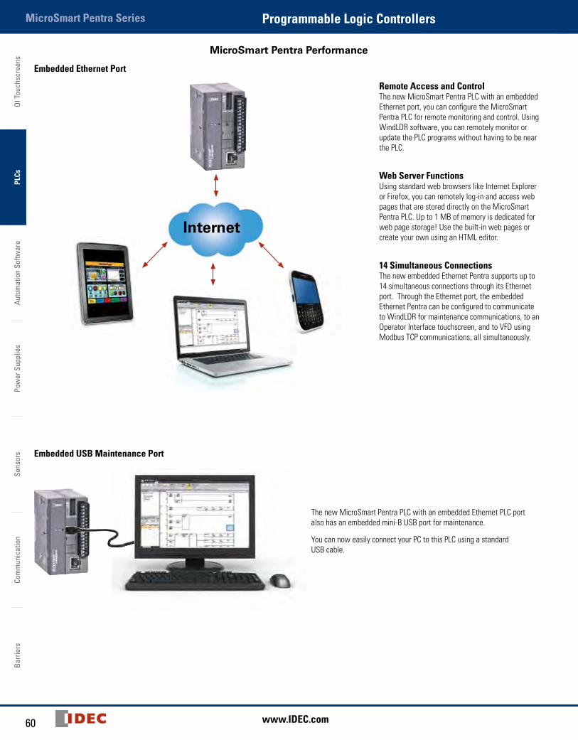
Modbus TCP, RTU and ASCII
SCADA Supervisory Controls
WindLDR SoftwareMonitor & Update Program
Web Browser - RemoteMonitor & Control
Modbus TCPClient
Ethernet
TCP
Modbus TCPServer 1
Modbus TCP Server 2
Modbus TCPServer 3
Modbus TCP Server 255
VFD
OI Touchscreen
OI Touchscreen
Pentra
Pentra Modbus RTU/ASCIIRS485
Pentra with Radio Modem
Temperature Controller
Pentra with Radio Modem
Using intuitive WindLDR software, you can configure the MicroSmart Pentra to be a Master or Slave device on a Modbus network. All MicroSmart Pentra PLCs support Modbus RTU/ASCII protocols and our CPU with embedded Ethernet port also supports Modbus TCP protocol.
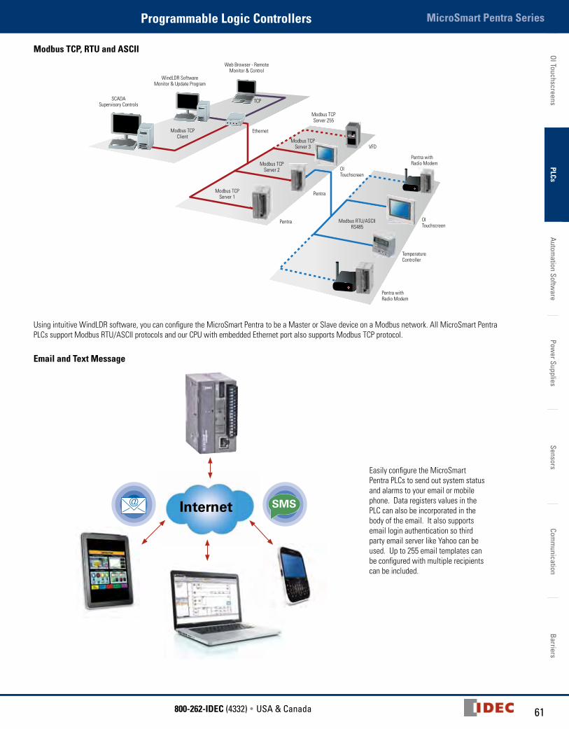
Email and Text Message
Internet SMS
Easily configure the MicroSmart Pentra PLCs to send out system status and alarms to your email or mobile phone. Data registers values in the PLC can also be incorporated in the body of the email. It also supports email login authentication so third party email server like Yahoo can be used. Up to 255 email templates can be configured with multiple recipients can be included.
OI T
ouch
scre
ens
PLCs
Auto
mat
ion
Softw
are
Pow
er S
uppl
ies
Sens
ors
Com
mun
icat
ion
Barr
iers
MicroSmart Pentra Series Programmable Logic Controllers
62 www.IDEC.com
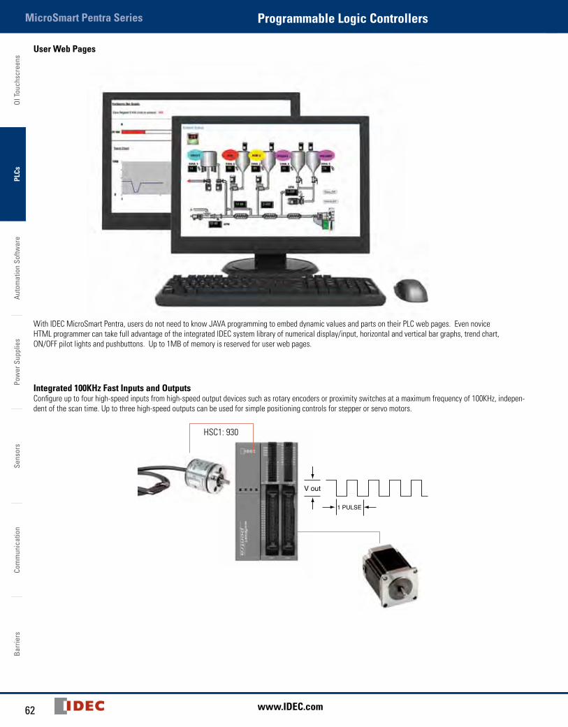
User Web Pages
With IDEC MicroSmart Pentra, users do not need to know JAVA programming to embed dynamic values and parts on their PLC web pages. Even novice HTML programmer can take full advantage of the integrated IDEC system library of numerical display/input, horizontal and vertical bar graphs, trend chart, ON/OFF pilot lights and pushbuttons. Up to 1MB of memory is reserved for user web pages.
Integrated 100KHz Fast Inputs and OutputsConfigure up to four high-speed inputs from high-speed output devices such as rotary encoders or proximity switches at a maximum frequency of 100KHz, indepen-dent of the scan time. Up to three high-speed outputs can be used for simple positioning controls for stepper or servo motors.
V out
1 PULSE
HSC1: 930
63800-262-IDEC (4332) • USA & Canada
MicroSmart Pentra SeriesProgrammable Logic ControllersOI Touchscreens
PLCsAutom
ation Software
Power Supplies
SensorsCom
munication
Barriers
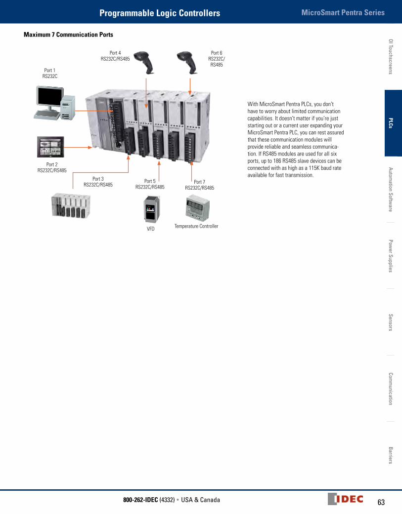
Maximum 7 Communication Ports
VFD Temperature Controller
Port 4RS232C/RS485
Port 1RS232C
Port 2RS232C/RS485
Port 3RS232C/RS485
Port 5RS232C/RS485
Port 7RS232C/RS485
Port 6RS232C/RS485
With MicroSmart Pentra PLCs, you don’t have to worry about limited communication capabilities. It doesn’t matter if you’re just starting out or a current user expanding your MicroSmart Pentra PLC, you can rest assured that these communication modules will provide reliable and seamless communica-tion. If RS485 modules are used for all six ports, up to 186 RS485 slave devices can be connected with as high as a 115K baud rate available for fast transmission.
OI T
ouch
scre
ens
PLCs
Auto
mat
ion
Softw
are
Pow
er S
uppl
ies
Sens
ors
Com
mun
icat
ion
Barr
iers
MicroSmart Pentra Series Programmable Logic Controllers
64 www.IDEC.com
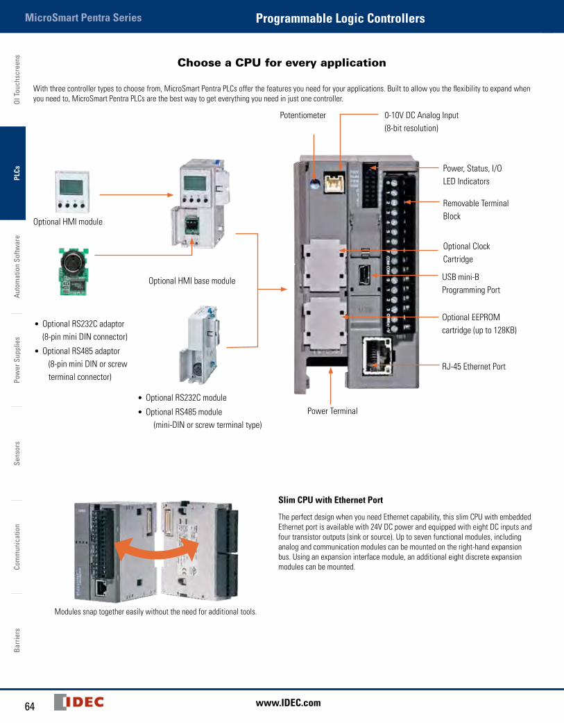
Choose a CPU for every application
With three controller types to choose from, MicroSmart Pentra PLCs offer the features you need for your applications. Built to allow you the flexibility to expand when you need to, MicroSmart Pentra PLCs are the best way to get everything you need in just one controller.
• Optional RS232C adaptor (8-pin mini DIN connector)
• Optional RS485 adaptor (8-pin mini DIN or screw terminal connector)
Potentiometer 0-10V DC Analog Input (8-bit resolution)
Power, Status, I/O LED Indicators
Removable Terminal Block
Optional Clock Cartridge
Optional HMI module
Optional HMI base module
• Optional RS232C module
• Optional RS485 module (mini-DIN or screw terminal type)
USB mini-B Programming Port
Optional EEPROM cartridge (up to 128KB)
RJ-45 Ethernet Port
Power Terminal
Modules snap together easily without the need for additional tools.
Slim CPU with Ethernet Port
The perfect design when you need Ethernet capability, this slim CPU with embedded Ethernet port is available with 24V DC power and equipped with eight DC inputs and four transistor outputs (sink or source). Up to seven functional modules, including analog and communication modules can be mounted on the right-hand expansion bus. Using an expansion interface module, an additional eight discrete expansion modules can be mounted.

65800-262-IDEC (4332) • USA & Canada
MicroSmart Pentra SeriesProgrammable Logic ControllersOI Touchscreens
PLCsAutom
ation Software
Power Supplies
SensorsCom
munication
Barriers
Potentiometer
0-10V DC Analog Input (8-bit resolution)
RS232C port
Optional Clock Cartridge
Screw Terminal or MIL connector termination
Optional EEPROM cartridge
•OptionalRS232Cadaptor (8-pin mini DIN connector)•OptionalRS485adaptor (8-pin mini DIN or screw terminal connector)
Potentiometer (x2) Optional HMI module
•OptionalEEPROMcartridge•OptionalClockCartridge
RS232C port
Power, Status, I/OLED Indicators
Slim CPU
If you don’t need Ethernet, but still want a high-performance CPU, the Mi-croSmart Pentra slim CPU is your best choice! Available with 24V DC power, this controller has all the functionalities you need in 16 and 32 I/O configura-tions. Each 16 I/O CPU is equipped with eight DC inputs, two transistor outputs (sink or source) and six relay outputs, while the 32 I/O CPU is equipped with 16 DC inputs and 16 transistor outputs (sink or source).
All-in-One CPU
Available with 12V DC, 24V DC and 100-240V AC power, you can choose from 10, 16 and 24 I/O configurations. The 10 I/O CPU is equipped with six DC inputs and four relay outputs, while the 16 I/O CPU is equipped with nine DC inputs and seven relay outputs. The 24 I/O CPU is equipped with 14 DC inputs and ten relay outputs. The 24 I/O CPU (24V DC and 100-240V AC models) can also be expanded with a maximum of four functional or discreet expansion modules.
OI T
ouch
scre
ens
PLCs
Auto
mat
ion
Softw
are
Pow
er S
uppl
ies
Sens
ors
Com
mun
icat
ion
Barr
iers
MicroSmart Pentra Series Programmable Logic Controllers
66 www.IDEC.com
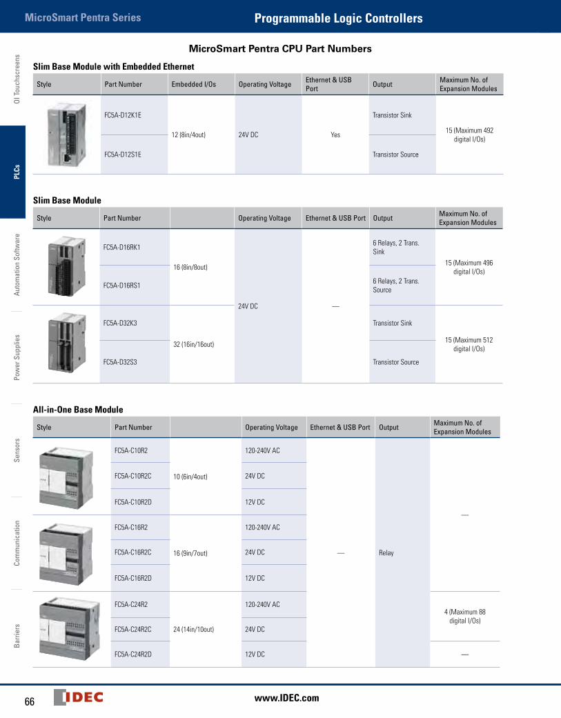
MicroSmart Pentra CPU Part Numbers
Slim Base Module with Embedded Ethernet
Style Part Number Embedded I/Os Operating Voltage Ethernet & USB Port Output Maximum No. of
Expansion Modules
FC5A-D12K1E
12 (8in/4out) 24V DC Yes
Transistor Sink
15 (Maximum 492 digital I/Os)
FC5A-D12S1E Transistor Source
Slim Base Module
Style Part Number Operating Voltage Ethernet & USB Port Output Maximum No. of Expansion Modules
FC5A-D16RK1
16 (8in/8out)
24V DC —
6 Relays, 2 Trans. Sink
15 (Maximum 496 digital I/Os)
FC5A-D16RS1 6 Relays, 2 Trans. Source
FC5A-D32K3
32 (16in/16out)
Transistor Sink
15 (Maximum 512 digital I/Os)
FC5A-D32S3 Transistor Source
All-in-One Base Module
Style Part Number Operating Voltage Ethernet & USB Port Output Maximum No. of Expansion Modules
FC5A-C10R2
10 (6in/4out)
120-240V AC
— Relay
—
FC5A-C10R2C 24V DC
FC5A-C10R2D 12V DC
FC5A-C16R2
16 (9in/7out)
120-240V AC
FC5A-C16R2C 24V DC
FC5A-C16R2D 12V DC
FC5A-C24R2
24 (14in/10out)
120-240V AC4 (Maximum 88
digital I/Os)FC5A-C24R2C 24V DC
FC5A-C24R2D 12V DC —
67800-262-IDEC (4332) • USA & Canada
MicroSmart SeriesProgrammable Logic ControllersOI Touchscreens
PLCsAutom
ation Software
Power Supplies
SensorsCom
munication
Barriers
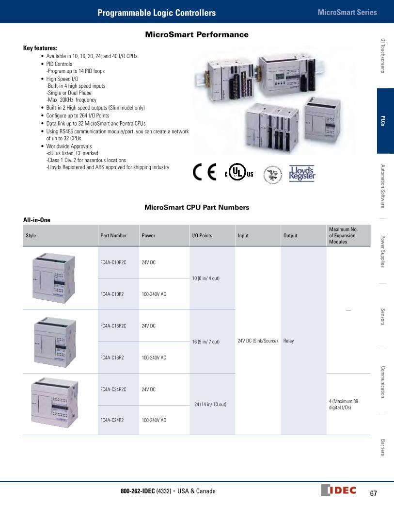
MicroSmart Performance
Key features:• Available in 10, 16, 20, 24, and 40 I/O CPUs.• PID Controls
-Program up to 14 PID loops• High Speed I/O
-Built-in 4 high speed inputs -Single or Dual Phase -Max. 20KHz frequency
• Built-in 2 High speed outputs (Slim model only)• Configure up to 264 I/O Points• Data link up to 32 MicroSmart and Pentra CPUs• Using RS485 communication module/port, you can create a network
of up to 32 CPUs.• Worldwide Approvals
-cULus listed, CE marked -Class 1 Div. 2 for hazardous locations -Lloyds Registered and ABS approved for shipping industry
MicroSmart CPU Part Numbers
All-in-One
Style Part Number Power I/O Points Input OutputMaximum No. of Expansion Modules
FC4A-C10R2C 24V DC
10 (6 in/ 4 out)
24V DC (Sink/Source) Relay
—
FC4A-C10R2 100-240V AC
FC4A-C16R2C 24V DC
16 (9 in/ 7 out)
FC4A-C16R2 100-240V AC
FC4A-C24R2C 24V DC
24 (14 in/ 10 out) 4 (Maximum 88 digital I/Os)
FC4A-C24R2 100-240V AC
MicroSmart Series
OI T
ouch
scre
ens
PLCs
Auto
mat
ion
Softw
are
Pow
er S
uppl
ies
Sens
ors
Com
mun
icat
ion
Barr
iers
MicroSmart Series Programmable Logic Controllers
68 www.IDEC.com
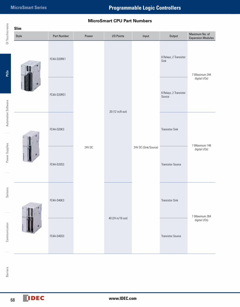
MicroSmart CPU Part Numbers
Slim
Style Part Number Power I/O Points Input Output Maximum No. of Expansion Modules
FC4A-D20RK1
24V DC
20 (12 in/8 out)
24V DC (Sink/Source)
6 Relays, 2 Transistor Sink
7 (Maximum 244 digital I/Os)
FC4A-D20RS1 6 Relays, 2 Transistor Source
FC4A-D20K3 Transistor Sink
7 (Maximum 148 digital I/Os)
FC4A-D20S3 Transistor Source
FC4A-D40K3
40 (24 in/16 out)
Transistor Sink
7 (Maximum 264 digital I/Os)
FC4A-D40S3 Transistor Source

69800-262-IDEC (4332) • USA & Canada
MicroSmart FamilyProgrammable Logic ControllersOI Touchscreens
PLCsAutom
ation Software
Power Supplies
SensorsCom
munication
Barriers
Digital I/O Expansion Modules
Key features:• 15 modules to choose from• Available with Screw or MIL connectors• Easy snap-on• Available 8, 16 or 32 point modules• Up to 512 I/O can be configured in the Pentra and 264 I/O in the
MicroSmart system
Input Modules
Style Part Number Input Input Points Terminal
FC4A-N08A11 100-120V AC
8
Removable Screw TerminalsFC4A-N08B1
24V DC
FC4A-N16B1
16
FC4A-N16B3
MIL Connector (ribbon cable)
FC4A-N32B3 32
MicroSmart Family
OI T
ouch
scre
ens
PLCs
Auto
mat
ion
Softw
are
Pow
er S
uppl
ies
Sens
ors
Com
mun
icat
ion
Barr
iers
MicroSmart Family Programmable Logic Controllers
70 www.IDEC.com
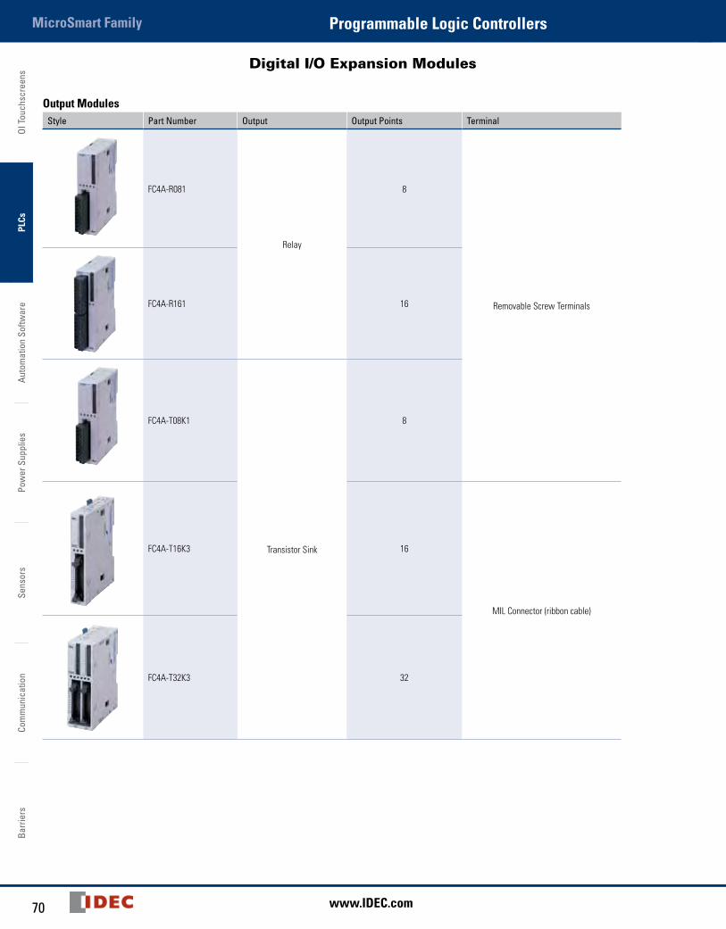
Digital I/O Expansion Modules
Output ModulesStyle Part Number Output Output Points Terminal
FC4A-R081
Relay
8
Removable Screw TerminalsFC4A-R161 16
FC4A-T08K1
Transistor Sink
8
FC4A-T16K3 16
MIL Connector (ribbon cable)
FC4A-T32K3 32

71800-262-IDEC (4332) • USA & Canada
MicroSmart FamilyProgrammable Logic ControllersOI Touchscreens
PLCsAutom
ation Software
Power Supplies
SensorsCom
munication
Barriers
Digital I/O Expansion Modules
Output Modules (cont.)
Style Part Number Output Output Points Terminal
FC4A-T08S1
Transistor Source
8 Removable Screw Terminals
FC4A-T16S3 16
MIL Connector (ribbon cable)
FC4A-T32S3 32
Combination I/O Modules Style Part Number Input Output I/O Points Terminal
FC4A-M08BR1
24V DC (Sink/Source) Relay
8 (4 in/4 out) Removable Screw Terminals
FC4A-M24BR2 24 (16 in/ 8 out) Wire Spring Clamp
OI T
ouch
scre
ens
PLCs
Auto
mat
ion
Softw
are
Pow
er S
uppl
ies
Sens
ors
Com
mun
icat
ion
Barr
iers
MicroSmart Family Programmable Logic Controllers
72 www.IDEC.com
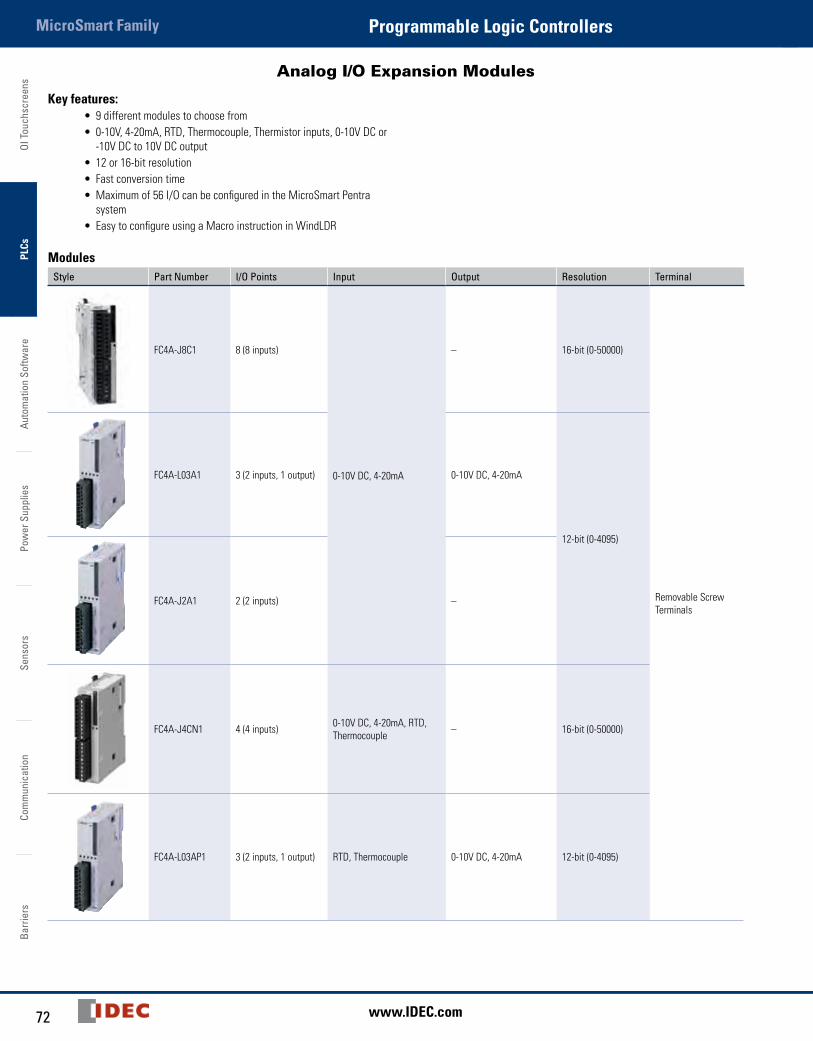
Analog I/O Expansion Modules
Key features:• 9 different modules to choose from • 0-10V, 4-20mA, RTD, Thermocouple, Thermistor inputs, 0-10V DC or
-10V DC to 10V DC output• 12 or 16-bit resolution• Fast conversion time• Maximum of 56 I/O can be configured in the MicroSmart Pentra
system• Easy to configure using a Macro instruction in WindLDR
Modules
Style Part Number I/O Points Input Output Resolution Terminal
FC4A-J8C1 8 (8 inputs)
0-10V DC, 4-20mA
– 16-bit (0-50000)
Removable Screw Terminals
FC4A-L03A1 3 (2 inputs, 1 output) 0-10V DC, 4-20mA
12-bit (0-4095)
FC4A-J2A1 2 (2 inputs) –
FC4A-J4CN1 4 (4 inputs) 0-10V DC, 4-20mA, RTD, Thermocouple – 16-bit (0-50000)
FC4A-L03AP1 3 (2 inputs, 1 output) RTD, Thermocouple 0-10V DC, 4-20mA 12-bit (0-4095)
73800-262-IDEC (4332) • USA & Canada
MicroSmart FamilyProgrammable Logic ControllersOI Touchscreens
PLCsAutom
ation Software
Power Supplies
SensorsCom
munication
Barriers
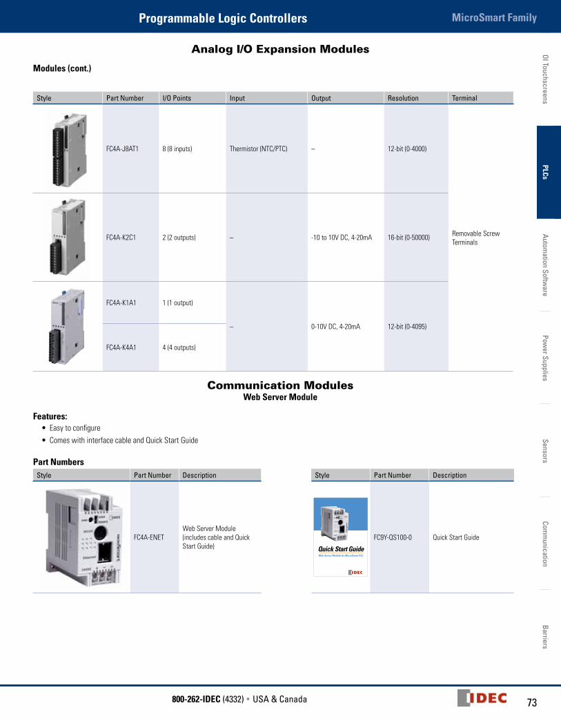
Analog I/O Expansion Modules
Modules (cont.)
Style Part Number I/O Points Input Output Resolution Terminal
FC4A-J8AT1 8 (8 inputs) Thermistor (NTC/PTC) – 12-bit (0-4000)
Removable Screw Terminals
FC4A-K2C1 2 (2 outputs) – -10 to 10V DC, 4-20mA 16-bit (0-50000)
FC4A-K1A1 1 (1 output)
– 0-10V DC, 4-20mA 12-bit (0-4095)
FC4A-K4A1 4 (4 outputs)
Communication Modules Web Server Module
Features:• Easy to configure• Comes with interface cable and Quick Start Guide
Part NumbersStyle Part Number Description Style Part Number Description
FC4A-ENETWeb Server Module (includes cable and Quick Start Guide) Quick Start Guide
Web Server Module for MicroSmart PLC
FC9Y-QS100-0 Quick Start Guide
OI T
ouch
scre
ens
PLCs
Auto
mat
ion
Softw
are
Pow
er S
uppl
ies
Sens
ors
Com
mun
icat
ion
Barr
iers
MicroSmart Family Programmable Logic Controllers
74 www.IDEC.com
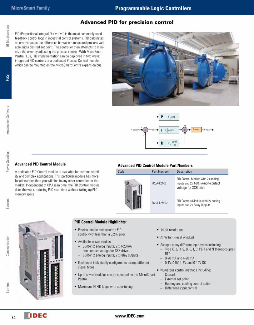
Advanced PID for precision control
PID (Proportional Integral Derivative) is the most commonly used feedback control loop in industrial control systems. PID calculates an error value as the difference between a measured process vari-able and a desired set point. The controller then attempts to mini-mize the error by adjusting the process control. With MicroSmart Pentra PLCs, PID implementation can be deployed in two ways: integrated PID controls or a dedicated Process Control module, which can be mounted on the MicroSmart Pentra expansion bus.
Advanced PID Control Module
A dedicated PID Control module is available for extreme stabil-ity and complex applications. This particular module has more functionalities than you will find in any other controller on the market. Independent of CPU scan time, the PID Control module does the work, reducing PLC scan time without taking up PLC memory space.
Setpoint+
–
Process OutputError
P
I
D K d
K e(t)
de(t)dt
p
Advanced PID Control Module Part NumbersStyle Part Number Description
FC5A-F2M2PID Control Module with 2x analog inputs and 2x 4-20mA/non-contact voltage for SSR drive
FC5A-F2MR2 PID Controls Module with 2x analog inputs and 2x Relay Outputs
PID Control Module Highlights:
• Precise, stable and accurate PID control with less than a 0.2% error
• Available in two models: – Built-in 2 analog inputs, 2 x 4-20mA/ non-contact voltage for SSR drive – Built-in 2 analog inputs, 2 x relay outputs
• Each input individually configured to accept different signal types
• Up to seven modules can be mounted on the MicroSmart Pentra
• Maximum 14 PID loops with auto-tuning
• 14-bit resolution
• ARW (anti-reset windup)
• Accepts many different input types including: – Type K, J, R, S, B, E, T, C, PL-II and N thermocouples – RTD – 0-20 mA and 4-20 mA – 0-1V, 0-5V, 1-5V, and 0-10V DC
• Numerous control methods including: – Cascade – External set point – Heating and cooling control action – Difference input control
75800-262-IDEC (4332) • USA & Canada
MicroSmart FamilyProgrammable Logic ControllersOI Touchscreens
PLCsAutom
ation Software
Power Supplies
SensorsCom
munication
Barriers
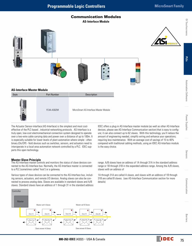
Communication Modules AS-Interface Module
AS-Interface Master ModuleStyle Part Number Description
FC4A-AS62M MicroSmart AS-Interface Master Module
The Actuator Sensor-interface (AS-Interface) is the simplest and most cost-effective of the PLC-based , industrial-networking protocols. AS-Interface is a truly open, low-cost electromechanical connection system designed to operate over a two-wire cable carrying data and power over a distance of up to 100m. It is especially suitable for lower levels of plant automation where simple - often binary (On/Off) - field devices such as switches, sensors, and actuators need to interoperate in a local area automation network controlled by a PLC. IDEC sup-ports this open technology.
IDEC offers a plug-in AS-Interface master module (as well as other AS-Interface devices, please see AS-Interface Communication section) that is easy to config-ure; it can also connect up to 62 slaves. With this technology, you’ll reduce the amount of engineering needed, simplify wiring and enhance your operations; requiring less maintenance. With an average cost of savings of 15 to 40% compared with traditional cabling methods, using an IDEC AS-Interface module is the easy choice.
Master-Slave PrincipleThe AS-Interface master controls and monitors the status of slave devices con-nected to the AS-Interface bus. Normally, the AS-Interface master is connected to a PLC (sometimes called ‘host’) or a gateway.
Various types of slave devices can be connected to the AS-Interface bus, includ-ing sensors, actuators, and remote I/O devices. Analog slaves can also be con-nected to process analog data. Slaves are available in standard slaves and A/B slaves. Standard slaves have an address of 1 through 31 in the standard address
range. A/B slaves have an address of 1A through 31A in the standard address range or 1B through 31B in the expanded address range. Among the A/B slaves, slaves with an address of
1A through 31A are called A slaves, and slaves with an address of 1B through 31B are called B slaves. (see AS-Interface Communication section for more details)
Controller
MasterMaster call A-Slaves Master call B-Slaves
Slave answer A-Slaves Slave answer B-Slaves
Slave 1A Slave 2A Slave 31A Slave 1B Slave 2B
Slave 1A Slave 2A Slave 31A Slave 1B Slave 2B

OI T
ouch
scre
ens
PLCs
Auto
mat
ion
Softw
are
Pow
er S
uppl
ies
Sens
ors
Com
mun
icat
ion
Barr
iers
MicroSmart Family Programmable Logic Controllers
76 www.IDEC.com
Communication Module
Style Part Number Description
FC5A-SIF4
RS485 Communication Module for MicroSmart Pentra configure as port
3 to 7
FC5A-SIF2
RS232 Communication Module for MicroSmart Pentra configure as port
3 to 7
Communicate with up to seven different serial devicesOnly IDEC offers communication modules that enable you to configure up to seven serial devices! Now you can connect your operator interface, PC, barcode reader, RFID equipment, printer and more. Just imagine the possibilities.
Using the MicroSmart Pentra slim CPU,you can configure up to seven communication ports. Using the All-in-one MicroSmart Pentra you can communicate with up to five serial devices.
77800-262-IDEC (4332) • USA & Canada
MicroSmart FamilyProgrammable Logic ControllersOI Touchscreens
PLCsAutom
ation Software
Power Supplies
SensorsCom
munication
Barriers
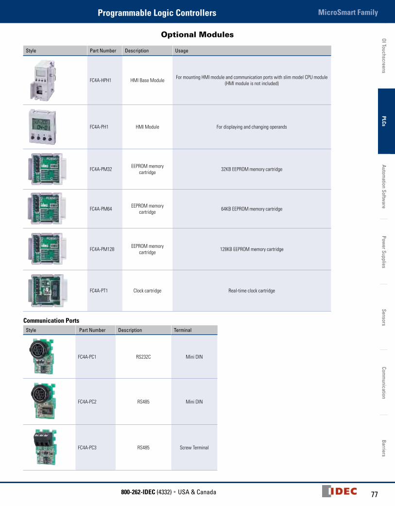
Optional Modules
Style Part Number Description Usage
FC4A-HPH1 HMI Base Module For mounting HMI module and communication ports with slim model CPU module(HMI module is not included)
FC4A-PH1 HMI Module For displaying and changing operands
FC4A-PM32 EEPROM memory cartridge 32KB EEPROM memory cartridge
FC4A-PM64 EEPROM memory cartridge 64KB EEPROM memory cartridge
FC4A-PM128 EEPROM memory cartridge 128KB EEPROM memory cartridge
FC4A-PT1 Clock cartridge Real-time clock cartridge
Communication Ports
Style Part Number Description Terminal
FC4A-PC1 RS232C Mini DIN
FC4A-PC2 RS485 Mini DIN
FC4A-PC3 RS485 Screw Terminal
OI T
ouch
scre
ens
PLCs
Auto
mat
ion
Softw
are
Pow
er S
uppl
ies
Sens
ors
Com
mun
icat
ion
Barr
iers
MicroSmart Family Programmable Logic Controllers
78 www.IDEC.com
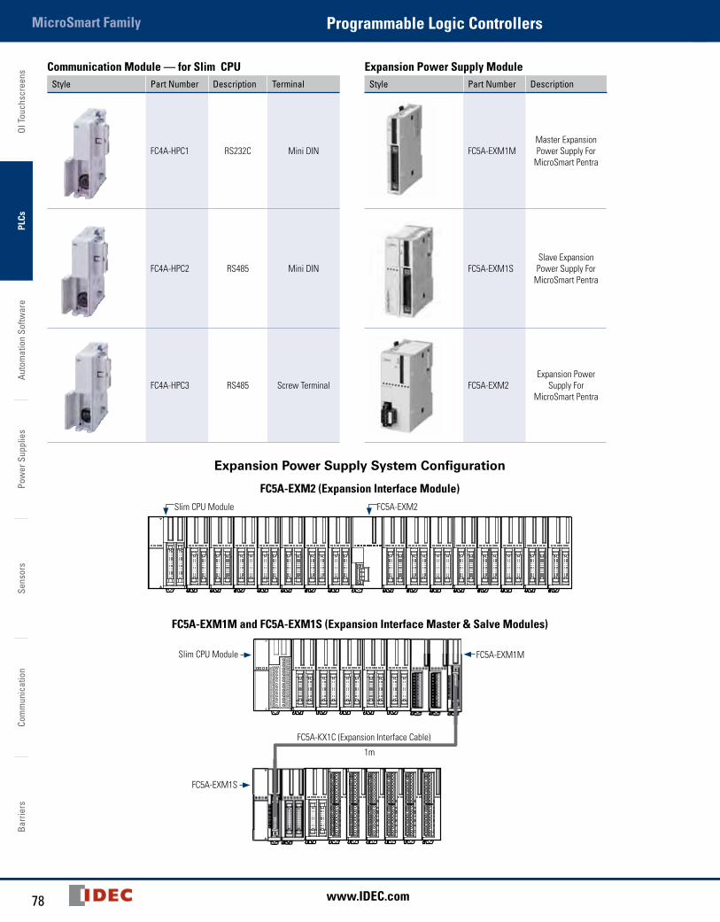
Communication Module — for Slim CPUStyle Part Number Description Terminal
FC4A-HPC1 RS232C Mini DIN
FC4A-HPC2 RS485 Mini DIN
FC4A-HPC3 RS485 Screw Terminal
Expansion Power Supply ModuleStyle Part Number Description
FC5A-EXM1MMaster Expansion Power Supply For
MicroSmart Pentra
FC5A-EXM1SSlave Expansion Power Supply For
MicroSmart Pentra
FC5A-EXM2Expansion Power
Supply For MicroSmart Pentra
Expansion Power Supply System Configuration
FC5A-EXM2 (Expansion Interface Module)Slim CPU Module FC5A-EXM2
FC5A-EXM1M and FC5A-EXM1S (Expansion Interface Master & Salve Modules)
Slim CPU Module FC5A-EXM1M
FC5A-EXM1S
FC5A-KX1C (Expansion Interface Cable)
1m

79800-262-IDEC (4332) • USA & Canada
MicroSmart FamilyProgrammable Logic ControllersOI Touchscreens
PLCsAutom
ation Software
Power Supplies
SensorsCom
munication
Barriers
Cables
Communication Cables
Appearance Part Number Length Expanded
Description
FC4A-KC4CA 5ft. (1.53m)
Programming cable (Maintenance/User
Communication Mode selectable)
FC4A-USB 6ft. (1.83m) USB to Serial Converter
FC4A-KC3C 0.33ft. (100mm)
Web Server Module interface cable
HG9Z-XCM2A 6ft. (1.83m)USB programming
cable for embedded Ethernet CPU
Appearance Part Number Length Expanded
Description
FC2A-KM1C 9.84 Ft. (3m)
Modem cable. Used to connect a modem to the MicroSmart
RS232C port.
FC2A-KP1C 9.84 Ft. (3m)
User communica-tion cable. Used
to connect RS232C equipment to the
MicroSmart RS232C port.
FC5A-KX1C 3.28 Ft. (1m)
MicroSmart Pentra expansion power supply interface cable. Used to
connect expansion interface master
and expansion slave modules.
MIL Connector Cables (use with Breakout Modules)Use with Part Number Model Length Use with Part Number Model Length
CPU Module (26-wire)BX1D-S26A, BX1D-T26A
FC9Z-H050B26
Non-shielded
1.64ft. (0.5m)
I/O Expansion Modules (20-wire)BX1D-S20A,BX1D-T20A
FC9Z-H050B20
Non-shielded
1.64ft. (0.5m)
FC9Z-H100B26 3.28ft. (1m) FC9Z-H100B20 3.28ft. (1m)
FC9Z-H200B26 6.56ft (2m) FC9Z-H200B20 6.56ft (2m)
FC9Z-H300B26 9.85ft. (3m) FC9Z-H300B20 9.85ft. (3m)
FC9Z-H050A26
Shielded
1.64ft. (0.5m) FC9Z-H050A20
Shielded
1.64ft. (0.5m)
FC9Z-H100A26 3.28ft. (1m) FC9Z-H100A20 3.28ft. (1m)
FC9Z-H200A26 6.56ft (2m) FC9Z-H200A20 6.56ft (2m)
FC9Z-H300A26 9.85ft. (3m) FC9Z-H300A20 9.85ft. (3m)
FC9Z-H100C26A Shielded Single Connectors 5ft. (1.5m) FC9Z-H100C20A Shielded Single
Connectors 5ft. (1.5m)
Breakout ModulesUse with Part Number Descrption
26-wire MIL connector cable BX1D-S26A 26-terminal breakout module
BX1D-T26A 26-terminal touch-down terminal breakout module
20-wire MIL connector cable BX1D-S20A 20-terminal breakout module
BX1D-T20A 20-terminal touch-down terminal breakout module

OI T
ouch
scre
ens
PLCs
Auto
mat
ion
Softw
are
Pow
er S
uppl
ies
Sens
ors
Com
mun
icat
ion
Barr
iers
MicroSmart Family Programmable Logic Controllers
80 www.IDEC.com
Accessories
Part Number Use with Description
FC4A-PMT13
CPU module
13-position left-side terminal block for FC4A-D20RK1/-D20RS1 CPU
FC5A-PMT13 13-position left-side terminal block for FC5A-D16RK1/-D16RS1 CPU
FC4A-PMTS16 16-position right-side terminal block for FC4A-D20RS1 and FC5A-D16RS1 CPU
FC4A-PMTK16 16-position right-side terminal block for FC4A-D20RK1 and FC5A-D16RK1 CPU
FC4A-PMT11I/O expansion modules
11-position terminal block for 8-pt I/O expansion modules
FC4A-PMT10 10-position terminal block for 16-pt I/O expansion modules
FC4A-PMC20 20-position connector socket for MIL connector I/O expansion modules
FC4A-PMC26 26-position connector socket for MIL connector CPU modules
FC4A-PSP1 Direct mounting strips for mounting on a panel
FC4A-PMAC2 Analog voltage input cable for slim CPU
FC4A-DS824-SW14 14-pt input simulator switch for 24 I/O CPU
FC4A-DS824-SW9 9-pt input simulator switch for 16 I/O CPU
FC4A-DS824-SW6 6-pt input simulator switch for 10 I/O CPU
FC9Y-B812-0A MicroSmart user manual
FC9Y-B1138-0 MicroSmart Pentra user manual
SW1A-WIC Automation Organizer Software Suite
RV8H Series 6mm Interface Relays
Key FeaturesRV8H• Space-saving 6mm width• Only 70mm in height from DIN rail• Gold-plated contacts• Pre-assembled relay and DIN mount socket• Universal screw terminals (flat and Phillips)• Universal AC/DC socket with built-in surge suppression and green LED• Lever for easy locking and removal of relay• Wide input voltage range: 6 to 240V• High dielectric strength and impulse withstand voltages• Sensitive coil 170mW• Reverse Polarity protected• 400V AC maximum switching voltage• 1500VA maximum switching power• RoHS compliant
(when using combination of RV1H relay and SV1H socket)
Part NumbersCoil Voltage Part Number
DC
6V RV8H-L-D6
9V RV8H-L-D9
12V RV8H-L-D12
18V RV8H-L-D18
24V RV8H-L-D24
AC/DC
12V RV8H-L-AD12
18V RV8H-L-AD18
24V RV8H-L-AD24
48V RV8H-L-AD48
60V RV8H-L-AD60
110V - 125V RV8H-L-AD110
220V - 240V RV8H-L-AD220Standard stock models in bold.
AccessoriesItem Color Part Number
Jumper (20 combs) 1
Black SV9Z-J20B
Gray SV9Z-J20W
Blue SV9Z-J20S
Spacer (circuit separator) 2 - SV9Z-SAW
Marking plate (10 pcs) - SV9Z-PW10
1. Jumper combs come with 20 points, if shorter lengths are needed simply cut off the excess points.2. Width of spacer: 2mmNote: When using a cut jumper, please use a spacer on the cut side. For additional information see instruction sheet.
81800-262-IDEC (4332) • USA & Canada
MicroSmart FamilyProgrammable Logic ControllersOI Touchscreens
PLCsAutom
ation Software
Power Supplies
SensorsCom
munication
Barriers
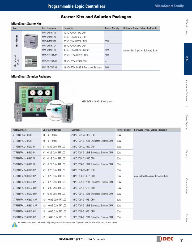
Starter Kits and Solution Packages
MicroSmart Starter KitsItem Part Numbers Controller Power Supply Software (Prog. Cables Included)
Mic
roSm
art
MM-SMART-10 10 I/O FC4A-C10R2 CPU –
Automation Organizer Software Suite
MM-SMART-16 16 I/O FC4A-C16R2 CPU –
MM-SMART-20 20 I/O FC4A-D20RK1 CPU 15W
MM-SMART-24 24 I/O FC4A-C24R2 CPU –
MM-SMART-40 40 I/O FC4A-D40K3 Slim CPU 15W
Mic
roSm
art
Pent
ra
MM-PENTRA-16 16 I/Os FC5A-D16RS1 CPU 30W
MM-PENTRA-24 24 I/Os FC5A-C24R2 CPU –
MM-PENTRA-12 12 I/Os FC5A-D12S1E Embedded Ethernet 30W
MicroSmart Solution Packages
KIT-PENTRA-12-HG3G-AHP shown
Part Numbers Operator Interface Controller Power Supply Software (Prog. Cables Included)
KIT-PENTRA-24-HG1F 4.6" HG1F Mono 24 I/O FC5A-C24R2C CPU 60W
Automation Organizer Software Suite
KIT-PENTRA-12-HG1F 4.6" HG1F Mono 12 I/O FC5A-D12S1E Embedded Ethernet CPU 60W
KIT-PENTRA-24-HG2G-M 5.7" HG2G Color TFT LCD 24 I/O FC5A-C24R2C CPU 60W
KIT-PENTRA-12-HG2G-M 5.7" HG2G Color TFT LCD 12 I/O FC5A-D12S1E Embedded Ethernet CPU 60W
KIT-PENTRA-24-HG2G-TE 5.7" HG2G Color TFT LCD 24 I/O FC5A-C24R2C CPU 60W
KIT-PENTRA-12-HG2G-TE 5.7" HG2G Color TFT LCD 12 I/O FC5A-D12S1E Embedded Ethernet CPU 60W
KIT-PENTRA-24-HG2G-HP 5.7" HG2G Color TFT LCD 24 I/O FC5A-C24R2C CPU 60W
KIT-PENTRA-16-HG2G-HP 5.7" HG2G Color TFT LCD 16 I/O FC5A-D16RS1 CPU 60W
KIT-PENTRA-12-HG2G-HP 5.7" HG2G Color TFT LCD 12 I/O FC5A-D12S1E Embedded Ethernet CPU 60W
KIT-PENTRA-16-HG3G-8HP 8.4" HG3G Color TFT LCD 16 I/O FC5A-D16RS1 CPU 60W
KIT-PENTRA-12-HG3G-8HP 8.4" HG3G Color TFT LCD 12 I/O FC5A-D12S1E Embedded Ethernet CPU 60W
KIT-PENTRA-16-HG3G-AHP 10.4" HG3G Color TFT LCD 16 I/O FC5A-D16RS1 CPU 60W
KIT-PENTRA-12-HG3G-AHP 10.4" HG3G Color TFT LCD 12 I/O FC5A-D12S1E Embedded Ethernet CPU 60W
KIT-PENTRA-16-HG4G-HP 12.1" HG4G Color TFT LCD 16 I/O FC5A-D16RS1 CPU 60W
KIT-PENTRA-12-HG4G-HP 12.1" HG4G Color TFT LCD 12 I/O FC5A-D12S1E Embedded Ethernet CPU 60W
OI Touchscreens have black bezels. All packages come with Automation Organizer software suite and communication cables.
OI T
ouch
scre
ens
PLCs
Auto
mat
ion
Softw
are
Pow
er S
uppl
ies
Sens
ors
Com
mun
icat
ion
Barr
iers
MicroSmart Family Programmable Logic Controllers
82 www.IDEC.com
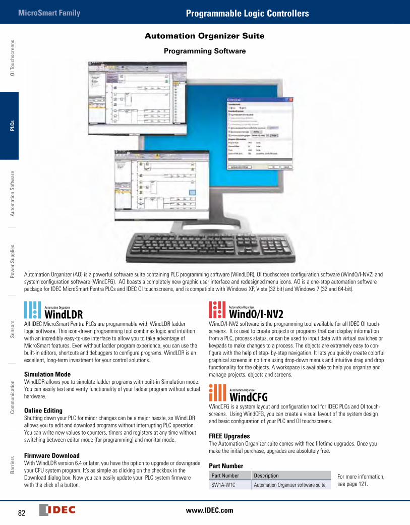
Automation Organizer Suite
Programming Software
Automation Organizer (AO) is a powerful software suite containing PLC programming software (WindLDR), OI touchscreen configuration software (WindO/I-NV2) and system configuration software (WindCFG). AO boasts a completely new graphic user interface and redesigned menu icons. AO is a one-stop automation software package for IDEC MicroSmart Pentra PLCs and IDEC OI touchscreens, and is compatible with Windows XP, Vista (32 bit) and Windows 7 (32 and 64-bit).
All IDEC MicroSmart Pentra PLCs are programmable with WindLDR ladder logic software. This icon-driven programming tool combines logic and intuition with an incredibly easy-to-use interface to allow you to take advantage of MicroSmart features. Even without ladder program experience, you can use the built-in editors, shortcuts and debuggers to configure programs. WindLDR is an excellent, long-term investment for your control solutions.
Simulation ModeWindLDR allows you to simulate ladder programs with built-in Simulation mode. You can easily test and verify functionality of your ladder program without actual hardware.
Online EditingShutting down your PLC for minor changes can be a major hassle, so WindLDR allows you to edit and download programs without interrupting PLC operation. You can write new values to counters, timers and registers at any time without switching between editor mode (for programming) and monitor mode.
Firmware DownloadWith WindLDR version 6.4 or later, you have the option to upgrade or downgrade your CPU system program. It’s as simple as clicking on the checkbox in the Download dialog box. Now you can easily update your PLC system firmware with the click of a button.
WindO/I-NV2 software is the programming tool available for all IDEC OI touch-screens. It is used to create projects or programs that can display information from a PLC, process status, or can be used to input data with virtual switches or keypads to make changes to a process. The objects are extremely easy to con-figure with the help of step- by-step navigation. It lets you quickly create colorful graphical screens in no time using drop-down menus and intuitive drag and drop functionality for the objects. A workspace is available to help you organize and manage projects, objects and screens.
WindCFG is a system layout and configuration tool for IDEC PLCs and OI touch-screens. Using WindCFG, you can create a visual layout of the system design and basic configuration of your PLC and OI touchscreens.
FREE UpgradesThe Automation Organizer suite comes with free lifetime upgrades. Once you make the initial purchase, upgrades are absolutely free.
Part NumberPart Number Description
SW1A-W1C Automation Organizer software suite
For more information, see page 121.
83800-262-IDEC (4332) • USA & Canada
MicroSmart FamilyProgrammable Logic ControllersOI Touchscreens
PLCsAutom
ation Software
Power Supplies
SensorsCom
munication
Barriers
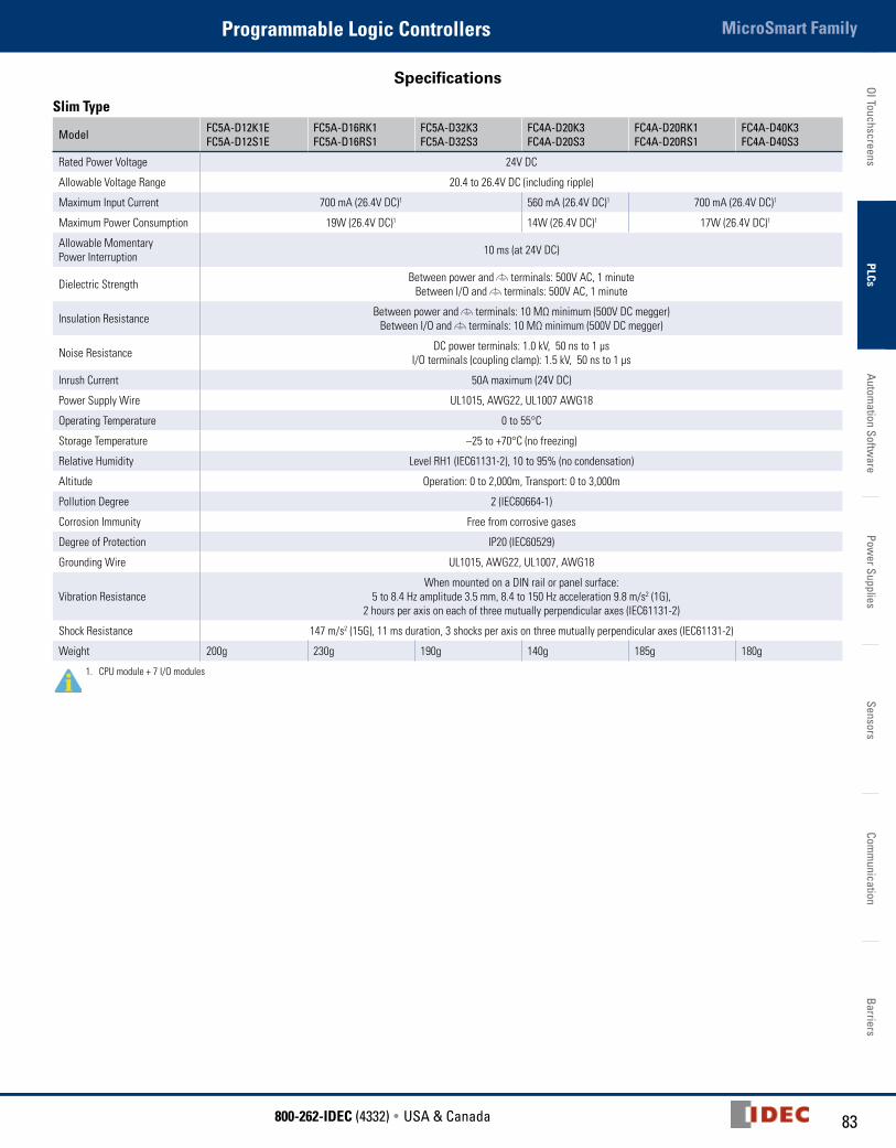
Specifications
Slim Type
Model FC5A-D12K1EFC5A-D12S1E
FC5A-D16RK1 FC5A-D16RS1
FC5A-D32K3 FC5A-D32S3
FC4A-D20K3 FC4A-D20S3
FC4A-D20RK1 FC4A-D20RS1
FC4A-D40K3 FC4A-D40S3
Rated Power Voltage 24V DC
Allowable Voltage Range 20.4 to 26.4V DC (including ripple)
Maximum Input Current 700 mA (26.4V DC)1 560 mA (26.4V DC)1 700 mA (26.4V DC)1
Maximum Power Consumption 19W (26.4V DC)1 14W (26.4V DC)1 17W (26.4V DC)1
Allowable Momentary Power Interruption 10 ms (at 24V DC)
Dielectric Strength Between power and terminals: 500V AC, 1 minute Between I/O and terminals: 500V AC, 1 minute
Insulation Resistance Between power and terminals: 10 MΩ minimum (500V DC megger) Between I/O and terminals: 10 MΩ minimum (500V DC megger)
Noise Resistance DC power terminals: 1.0 kV, 50 ns to 1 µs I/O terminals (coupling clamp): 1.5 kV, 50 ns to 1 µs
Inrush Current 50A maximum (24V DC)
Power Supply Wire UL1015, AWG22, UL1007 AWG18
Operating Temperature 0 to 55°C
Storage Temperature –25 to +70°C (no freezing)
Relative Humidity Level RH1 (IEC61131-2), 10 to 95% (no condensation)
Altitude Operation: 0 to 2,000m, Transport: 0 to 3,000m
Pollution Degree 2 (IEC60664-1)
Corrosion Immunity Free from corrosive gases
Degree of Protection IP20 (IEC60529)
Grounding Wire UL1015, AWG22, UL1007, AWG18
Vibration ResistanceWhen mounted on a DIN rail or panel surface:
5 to 8.4 Hz amplitude 3.5 mm, 8.4 to 150 Hz acceleration 9.8 m/s2 (1G), 2 hours per axis on each of three mutually perpendicular axes (IEC61131-2)
Shock Resistance 147 m/s2 (15G), 11 ms duration, 3 shocks per axis on three mutually perpendicular axes (IEC61131-2)
Weight 200g 230g 190g 140g 185g 180g
1. CPU module + 7 I/O modules
OI T
ouch
scre
ens
PLCs
Auto
mat
ion
Softw
are
Pow
er S
uppl
ies
Sens
ors
Com
mun
icat
ion
Barr
iers
MicroSmart Family Programmable Logic Controllers
84 www.IDEC.com
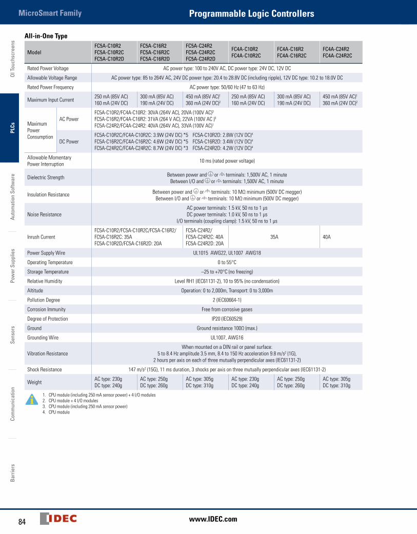
All-in-One Type
ModelFC5A-C10R2 FC5A-C10R2CFC5A-C10R2D
FC5A-C16R2 FC5A-C16R2CFC5A-C16R2D
FC5A-C24R2 FC5A-C24R2CFC5A-C24R2D
FC4A-C10R2 FC4A-C10R2C
FC4A-C16R2 FC4A-C16R2C
FC4A-C24R2 FC4A-C24R2C
Rated Power Voltage AC power type: 100 to 240V AC, DC power type: 24V DC, 12V DC
Allowable Voltage Range AC power type: 85 to 264V AC, 24V DC power type: 20.4 to 28.8V DC (including ripple), 12V DC type: 10.2 to 18.0V DC
Rated Power Frequency AC power type: 50/60 Hz (47 to 63 Hz)
Maximum Input Current 250 mA (85V AC) 160 mA (24V DC)
300 mA (85V AC) 190 mA (24V DC)
450 mA (85V AC)1 360 mA (24V DC)2
250 mA (85V AC) 160 mA (24V DC)
300 mA (85V AC) 190 mA (24V DC)
450 mA (85V AC)1 360 mA (24V DC)2
Maximum Power Consumption
AC PowerFC5A-C10R2/FC4A-C10R2: 30VA (264V AC), 20VA (100V AC)3 FC5A-C16R2/FC4A-C16R2: 31VA (264 V AC), 22VA (100V AC )3 FC5A-C24R2/FC4A-C24R2: 40VA (264V AC), 33VA (100V AC)1
DC PowerFC5A-C10R2C/FC4A-C10R2C: 3.9W (24V DC) *5 FC5A-C10R2D: 2.8W (12V DC)4
FC5A-C16R2C/FC4A-C16R2C: 4.6W (24V DC) *5 FC5A-C16R2D: 3.4W (12V DC)4 FC5A-C24R2C/FC4A-C24R2C: 8.7W (24V DC) *3 FC5A-C24R2D: 4.2W (12V DC)4
Allowable Momentary Power Interruption 10 ms (rated power voltage)
Dielectric Strength Between power and or terminals: 1,500V AC, 1 minuteBetween I/O and or terminals: 1,500V AC, 1 minute
Insulation Resistance Between power and or terminals: 10 MΩ minimum (500V DC megger)Between I/O and or terminals: 10 MΩ minimum (500V DC megger)
Noise ResistanceAC power terminals: 1.5 kV, 50 ns to 1 µs DC power terminals: 1.0 kV, 50 ns to 1 µs
I/O terminals (coupling clamp): 1.5 kV, 50 ns to 1 µs
Inrush CurrentFC5A-C10R2/FC5A-C10R2C/FC5A-C16R2/FC5A-C16R2C: 35AFC5A-C10R2D/FC5A-C16R2D: 20A
FC5A-C24R2/ FC5A-C24R2C: 40AFC5A-C24R2D: 20A
35A 40A
Power Supply Wire UL1015 AWG22, UL1007 AWG18
Operating Temperature 0 to 55°C
Storage Temperature –25 to +70°C (no freezing)
Relative Humidity Level RH1 (IEC61131-2), 10 to 95% (no condensation)
Altitude Operation: 0 to 2,000m, Transport: 0 to 3,000m
Pollution Degree 2 (IEC60664-1)
Corrosion Immunity Free from corrosive gases
Degree of Protection IP20 (IEC60529)
Ground Ground resistance 100Ω (max.)
Grounding Wire UL1007, AWG16
Vibration ResistanceWhen mounted on a DIN rail or panel surface:
5 to 8.4 Hz amplitude 3.5 mm, 8.4 to 150 Hz acceleration 9.8 m/s2 (1G), 2 hours per axis on each of three mutually perpendicular axes (IEC61131-2)
Shock Resistance 147 m/s2 (15G), 11 ms duration, 3 shocks per axis on three mutually perpendicular axes (IEC61131-2)
Weight AC type: 230g DC type: 240g
AC type: 250g DC type: 260g
AC type: 305g DC type: 310g
AC type: 230g DC type: 240g
AC type: 250g DC type: 260g
AC type: 305g DC type: 310g
1. CPU module (including 250 mA sensor power) + 4 I/O modules 2. CPU module + 4 I/O modules3. CPU module (including 250 mA sensor power)4. CPU module

85800-262-IDEC (4332) • USA & Canada
MicroSmart FamilyProgrammable Logic ControllersOI Touchscreens
PLCsAutom
ation Software
Power Supplies
SensorsCom
munication
Barriers
Slim Type Function Specifications
Model FC5A-D12K1EFC5A-D12S1E
FC5A-D16RK1 FC5A-D16RS1
FC5A-D32K3 FC5A-D32S3
FC4A-D20K3 FC4A-D20S3
FC4A-D20RK1 FC4A-D20RS1
FC4A-D40K3 FC4A-D40S3
Control System Stored program system
Instruction Words42 basic 35 basic
152 advanced 126 advanced 130 advanced 53 advanced 72 advanced
Program Capacity 1 127.8 KB (21,300 steps) 62.4 KB (10,400 steps) 27 KB
(4,500 steps) 31.2 KB (5,200 steps) 2
User Program Storage Flash ROM (10,000 times rewritable) EEPROM (10,000 times rewritable)
Processing Time
Basic Instruction 83 µs (1,000 steps) 1.65 ms (1,000 steps)
END Processing 3 0.35 ms 0.64 ms
Expandable I/O Modules 7 modules + additional 8 modules using the expansion interface module 7 modules
I/O Points
Input 8 Expansion: 224Additional: 256
8 Expansion: 224Additional: 256
16 Expansion: 224Additional: 256
12Expansion: 128
12Expansion: 224
24Expansion: 224
Output 4 8 16 8 8 16
Internal Relay 2,048 points 1,024 points
Shift Register 256 points 128 points
Data Register 42,000 points 42,000 points 4 1,300 points
Expansion Data Register 6,000 points — 6,000 points
Counter 256 points 100 points
Timer (1-sec, 100-ms, 10-ms, 1-ms) 256 points 100 points
RAM
Bac
kup
Backup Data Internal relay, shift register, counter, data register, expansion data register
Backup Duration Approx. 30 days (typical) at 25°C after backup battery fully charged
Battery Lithium secondary battery
Charging Time Approx. 15 hours for charging from 0% to 90% of full charge
Battery Life 5 years in cycles of 9-hour charging and 15-hour discharging
Replaceability Not possible to replace battery
Self-diagnostic Function Power failure, watchdog timer, data link connection, user program ROM sum check, timer/counter preset value sum check, user program RAM sum check, keep data, user program syntax, user program writing, CPU module, clock IC, I/O bus initialize, user program execution
Input Filter Without filter, 3 to 15 ms (selectable in increments of 1 ms)
Catch Input/Interrupt Input
Four inputs(I2 and I5) Minimum turn on pulse width: 40 µs maximum Minimum turn off pulse width: 150 µs maximum (I3 and I4) Minimum turn on pulse width: 5 µs maximum Minimum turn off pulse width: 5 µs maximum
Four inputs (I2 through I5) Minimum turn on pulse width: 40 µs maximumMinimum turn off pulse width: 150 µs maximum
High
-spe
ed
Coun
ter
Maximum Counting Frequency and High-speed Counter Points
Total 4 points Single/two-phase selectable: 100 kHz (2 points) Single-phase: 100 kHz (2 points)
Total 4 points Single/two-phase selectable: 20 kHz (2 points) Single-phase: 5 kHz (2 points)
Counting Range 0 to 4,294,967,295 (32 bits) 0 to 65,535 (16 bits)
Operation Mode Rotary encoder mode and adding counter mode
Analog Potentiometer
Quantity 1 point
Data Range 0 to 255
Analog Voltage Input
Quantity 1 point
Input Voltage Range 0 to 10V DC
Input Impedance Approx. 100 kΩ
Data Range 0 to 255 (8 bits)
Pulse Output
Quantity 3 points 2 points 3 points 2 points
Maximum Frequency 100 kHz 20 kHz
Note: The maximum number of relay outputs that can be turned on simultaneously is 54 including those on the CPU module. Modem communication not possible on FC5A-D12K1E/D12S1E modules. 1. 1 step equals 6 bytes.2. Expandable up to 62.4 KB when a memory cartridge is used. 3. Not including expansion I/O service time, clock function processing time, data link processing time, and interrupt processing time.4. Extra data registers D10000 through D49999 are enabled using WindLDR Function Area Settings, then run-time program download cannot be used.5. Maintenance communication (change monitor device values, upload/download user programs, download system program)6. Maintenance communication, user communication, modem communication, data link, Modbus ASCII/RTU master/slave communication (FC5A only).
OI T
ouch
scre
ens
PLCs
Auto
mat
ion
Softw
are
Pow
er S
uppl
ies
Sens
ors
Com
mun
icat
ion
Barr
iers
MicroSmart Family Programmable Logic Controllers
86 www.IDEC.com
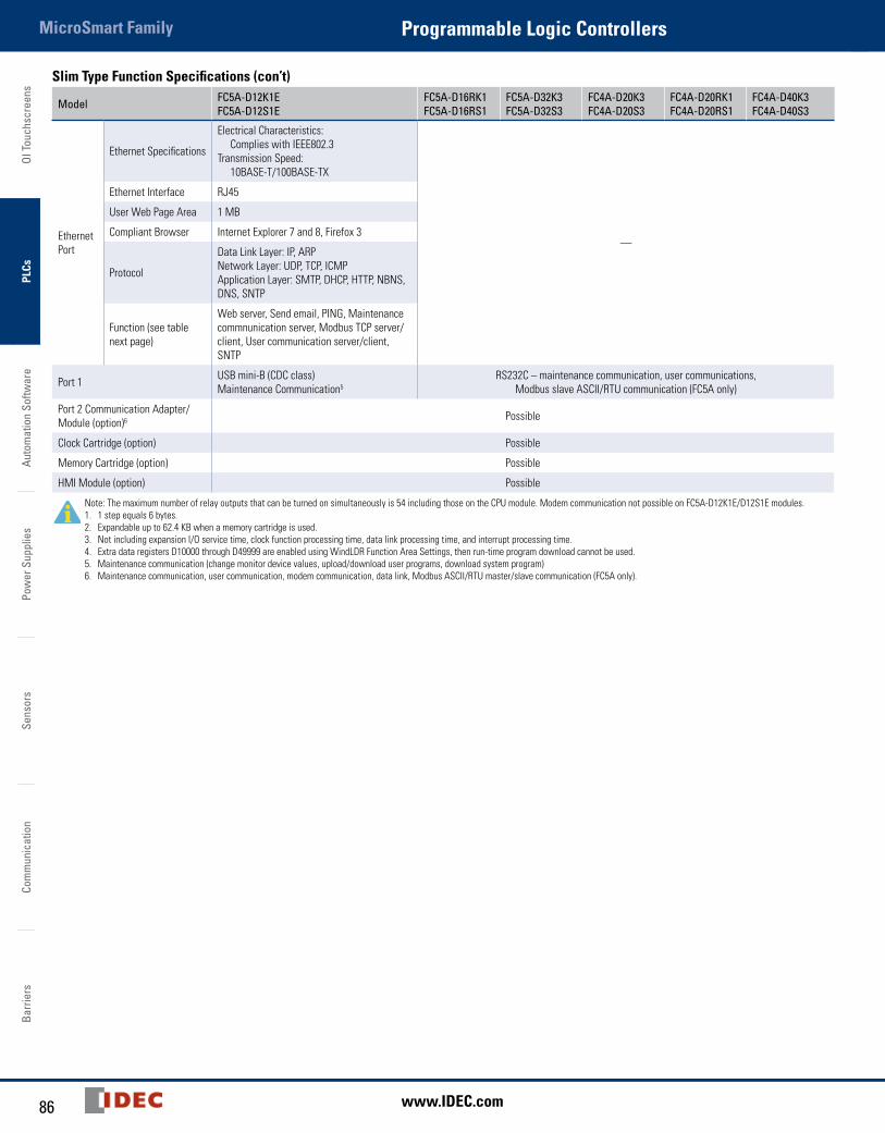
Slim Type Function Specifications (con’t)
Model FC5A-D12K1EFC5A-D12S1E
FC5A-D16RK1 FC5A-D16RS1
FC5A-D32K3 FC5A-D32S3
FC4A-D20K3 FC4A-D20S3
FC4A-D20RK1 FC4A-D20RS1
FC4A-D40K3 FC4A-D40S3
Ethernet Port
Ethernet Specifications
Electrical Characteristics: Complies with IEEE802.3Transmission Speed: 10BASE-T/100BASE-TX
—
Ethernet Interface RJ45
User Web Page Area 1 MB
Compliant Browser Internet Explorer 7 and 8, Firefox 3
Protocol
Data Link Layer: IP, ARPNetwork Layer: UDP, TCP, ICMPApplication Layer: SMTP, DHCP, HTTP, NBNS, DNS, SNTP
Function (see table next page)
Web server, Send email, PING, Maintenance commnunication server, Modbus TCP server/client, User communication server/client, SNTP
Port 1 USB mini-B (CDC class)Maintenance Communication5
RS232C – maintenance communication, user communications, Modbus slave ASCII/RTU communication (FC5A only)
Port 2 Communication Adapter/Module (option)6 Possible
Clock Cartridge (option) Possible
Memory Cartridge (option) Possible
HMI Module (option) Possible
Note: The maximum number of relay outputs that can be turned on simultaneously is 54 including those on the CPU module. Modem communication not possible on FC5A-D12K1E/D12S1E modules. 1. 1 step equals 6 bytes.2. Expandable up to 62.4 KB when a memory cartridge is used. 3. Not including expansion I/O service time, clock function processing time, data link processing time, and interrupt processing time.4. Extra data registers D10000 through D49999 are enabled using WindLDR Function Area Settings, then run-time program download cannot be used.5. Maintenance communication (change monitor device values, upload/download user programs, download system program)6. Maintenance communication, user communication, modem communication, data link, Modbus ASCII/RTU master/slave communication (FC5A only).
87800-262-IDEC (4332) • USA & Canada
MicroSmart FamilyProgrammable Logic ControllersOI Touchscreens
PLCsAutom
ation Software
Power Supplies
SensorsCom
munication
Barriers
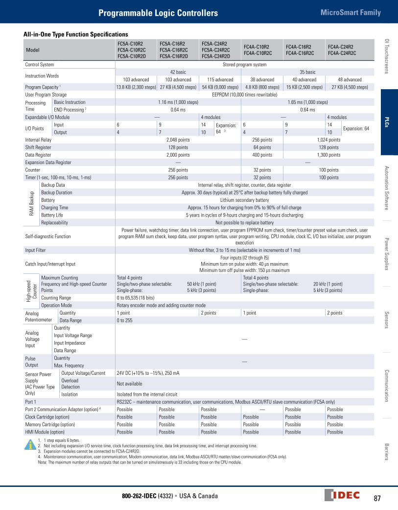
All-in-One Type Function Specifications
ModelFC5A-C10R2 FC5A-C10R2CFC5A-C10R2D
FC5A-C16R2 FC5A-C16R2CFC5A-C16R2D
FC5A-C24R2 FC5A-C24R2CFC5A-C24R2D
FC4A-C10R2 FC4A-C10R2C
FC4A-C16R2 FC4A-C16R2C
FC4A-C24R2 FC4A-C24R2C
Control System Stored program system
Instruction Words42 basic 35 basic
103 advanced 103 advanced 115 advanced 38 advanced 40 advanced 48 advancedProgram Capacity 1 13.8 KB (2,300 steps) 27 KB (4,500 steps) 54 KB (9,000 steps) 4.8 KB (800 steps) 15 KB (2,500 steps) 27 KB (4,500 steps)User Program Storage EEPROM (10,000 times rewritable)
Processing Time
Basic Instruction 1.16 ms (1,000 steps) 1.65 ms (1,000 steps)END Processing 2 0.64 ms 0.64 ms
Expandable I/O Module — 4 modules — 4 modules
I/O PointsInput 6 9 14 Expansion:
64 3
6 9 14Expansion: 64
Output 4 7 10 4 7 10Internal Relay 2,048 points 256 points 1,024 pointsShift Register 128 points 64 points 128 pointsData Register 2,000 points 400 points 1,300 pointsExpansion Data Register — —Counter 256 points 32 points 100 pointsTimer (1-sec, 100-ms, 10-ms, 1-ms) 256 points 32 points 100 points
RAM
Bac
kup
Backup Data Internal relay, shift register, counter, data registerBackup Duration Approx. 30 days (typical) at 25°C after backup battery fully chargedBattery Lithium secondary batteryCharging Time Approx. 15 hours for charging from 0% to 90% of full charge Battery Life 5 years in cycles of 9-hours charging and 15-hours dischargingReplaceability Not possible to replace battery
Self-diagnostic Function Power failure, watchdog timer, data link connection, user program EPPROM sum check, timer/counter preset value sum check, user
program RAM sum check, keep data, user program syntax, user program writing, CPU module, clock IC, I/O bus initialize, user program execution
Input Filter Without filter, 3 to 15 ms (selectable in increments of 1 ms)
Catch Input/Interrupt InputFour inputs (I2 through I5)
Minimum turn on pulse width: 40 µs maximum Minimum turn off pulse width: 150 µs maximum
High
-spe
ed
Coun
ter
Maximum Counting Frequency and High-speed Counter Points
Total 4 points Single/two-phase selectable: 50 kHz (1 point) Single-phase: 5 kHz (3 points)
Total 4 points Single/two-phase selectable: 20 kHz (1 point) Single-phase: 5 kHz (3 points)
Counting Range 0 to 65,535 (16 bits)Operation Mode Rotary encoder mode and adding counter mode
Analog Potentiometer
Quantity 1 point 2 points 1 point 2 pointsData Range 0 to 255
Analog Voltage Input
Quantity
—Input Voltage RangeInput ImpedanceData Range
Pulse Output
Quantity—
Max. Frequency
Sensor Power Supply (AC Power Type Only)
Output Voltage/Current 24V DC (+10% to –15%), 250 mAOverload Detection Not available
Isolation Isolated from the internal circuitPort 1 RS232C – maintenance communication, user communications, Modbus ASCII/RTU slave communication (FC5A only)Port 2 Communication Adapter (option) 4 Possible Possible Possible — Possible PossibleClock Cartridge (option) Possible Possible Possible Possible Possible PossibleMemory Cartridge (option) Possible Possible Possible Possible Possible PossibleHMI Module (option) Possible Possible Possible Possible Possible Possible
1. 1 step equals 6 bytes.2. Not including expansion I/O service time, clock function processing time, data link processing time, and interrupt processing time.3. Expansion modules cannot be connected to FC5A-C24R2D.4. Maintenance communication, user communication, Modem communication, data link, Modbus ASCII/RTU master/slave communication (FC5A only).Note: The maximum number of relay outputs that can be turned on simulatneously is 33 including those on the CPU module.

OI T
ouch
scre
ens
PLCs
Auto
mat
ion
Softw
are
Pow
er S
uppl
ies
Sens
ors
Com
mun
icat
ion
Barr
iers
MicroSmart Family Programmable Logic Controllers
88 www.IDEC.com
Communication Port (Port 1) SpecificationsCPU Module FC5A-D12K1E/D12S1E Slim CPU All-in-One CPU
Standards USB 2.0 EIA RS232C
Maximum Baud Rate USB 2.0 FC5A: 57,600 bps (maintenance communication) FC4A: 19,200 bps (maintenance communication)
Cable HG9Z-XCM2A FC2A-KC4C, FC2A-KP1C, FC4A-KC1C, FC4A-KC2C
Isolation between Internal Circuit and Communication Port Not isolated Not isolated
Slim Type Input Specifications
Model FC5A-D12K1EFC5A-D12S1E
FC4A-D20K3 FC4A-D20S3
FC5A-D16RK1 FC5A-D16RS1
FC4A-D20RK1 FC4A-D20RS1
FC5A-D32K3 FC5A-D32S3
FC4A-D40K3 FC4A-D40S3
Input Points 8 (8/1 common)
12 (12/1 common)
8 (8/1 common)
12 (12/1 common)
16 (8/1 common)
24 (12/1 common)
Rated Input Voltage 24V DC sink/source input signal
Input Voltage Range 20.4 to 26.4V DC
Rated Input Current
FC5A I0, I1, I3, I4, I6, I7: 4.5 mA/point (24V DC) I2, I5, I10 to I17: 7 mA/point (24V DC) FC4A I0, I1, I6, I7: 5 mA/point (24V DC) I2 to I5, I10 to I27: 7 mA/point (24V DC)
Input Impedance
FC5A I0, I1, I3, I4, I6, I7: 4.9 kΩ I2, I5, I10 to I17: 3.4 kΩ FC4A I0, I1, I6, I7: 5.7 kΩ I2 to I5, I10 to I27: 3.4 kΩ
Turn ON Time
FC5A I0, I1, I3, I4, I6, I7: 5 µs + filter value I2 and I5: 35 µs + filter value I10 to I17: 40 µs + filter value FC4A I0, I1, I6, I7: 35 µs + filter value I2 to I5: 35 µs + filter value I10 to I27: 40 µs + filter value
Turn OFF Time
FC5A I0, I1, I3, I4, I6, I7: 5 µs + filter value I2 and I5: 150 µs + filter value I10 to I17: 150 µs + filter value FC4A I0, I1, I6, I7: 45 µs + filter value I2 to I5: 150 µs + filter value I10 to I27: 150 µs + filter value
ConnectorOn Mother Board
MC1.5/16-G-3.81BK(Phoenix Contact)
FL26A2MA (Oki Electric Cable)
MC1.5/13-G-3.81BK (Phoenix Contact)
FL26A2MA (Oki Electric Cable)
Insertion Durability 100 times minimum
Isolation Between input terminals: Optocoupler isolatedInternal circuit: Not isolated
Input Type Type 1 (IEC61131-2)
External Load for I/O Interconnection Not needed
Single Determination Method Static
Effect of Improper Input Connection
Both sinking and sourcing input signals can be connected, therefore reverse connection does not cause permanent damage. If any input exceeding the rated value is applied, permanent damage may be caused.
Cable Length 3m in compliance with electromagnetic immunity
89800-262-IDEC (4332) • USA & Canada
MicroSmart FamilyProgrammable Logic ControllersOI Touchscreens
PLCsAutom
ation Software
Power Supplies
SensorsCom
munication
Barriers
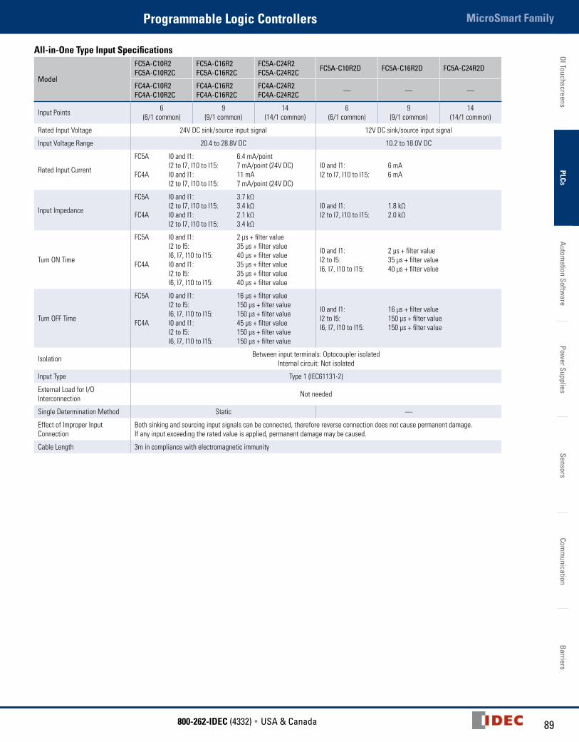
All-in-One Type Input Specifications
Model
FC5A-C10R2 FC5A-C10R2C
FC5A-C16R2 FC5A-C16R2C
FC5A-C24R2 FC5A-C24R2C FC5A-C10R2D FC5A-C16R2D FC5A-C24R2D
FC4A-C10R2 FC4A-C10R2C
FC4A-C16R2 FC4A-C16R2C
FC4A-C24R2 FC4A-C24R2C — — —
Input Points 6 (6/1 common)
9 (9/1 common)
14 (14/1 common)
6 (6/1 common)
9 (9/1 common)
14 (14/1 common)
Rated Input Voltage 24V DC sink/source input signal 12V DC sink/source input signal
Input Voltage Range 20.4 to 28.8V DC 10.2 to 18.0V DC
Rated Input Current
FC5A I0 and I1: 6.4 mA/point I2 to I7, I10 to I15: 7 mA/point (24V DC)FC4A I0 and I1: 11 mA I2 to I7, I10 to I15: 7 mA/point (24V DC)
I0 and I1: 6 mA I2 to I7, I10 to I15: 6 mA
Input Impedance
FC5A I0 and I1: 3.7 kΩ I2 to I7, I10 to I15: 3.4 kΩ FC4A I0 and I1: 2.1 kΩ I2 to I7, I10 to I15: 3.4 kΩ
I0 and I1: 1.8 kΩ I2 to I7, I10 to I15: 2.0 kΩ
Turn ON Time
FC5A I0 and I1: 2 µs + filter value I2 to I5: 35 µs + filter value I6, I7, I10 to I15: 40 µs + filter value FC4A I0 and I1: 35 µs + filter value I2 to I5: 35 µs + filter value I6, I7, I10 to I15: 40 µs + filter value
I0 and I1: 2 µs + filter valueI2 to I5: 35 µs + filter value I6, I7, I10 to I15: 40 µs + filter value
Turn OFF Time
FC5A I0 and I1: 16 µs + filter value I2 to I5: 150 µs + filter value I6, I7, I10 to I15: 150 µs + filter valueFC4A I0 and I1: 45 µs + filter value I2 to I5: 150 µs + filter value I6, I7, I10 to I15: 150 µs + filter value
I0 and I1: 16 µs + filter valueI2 to I5: 150 µs + filter valueI6, I7, I10 to I15: 150 µs + filter value
Isolation Between input terminals: Optocoupler isolatedInternal circuit: Not isolated
Input Type Type 1 (IEC61131-2)
External Load for I/O Interconnection Not needed
Single Determination Method Static —
Effect of Improper Input Connection
Both sinking and sourcing input signals can be connected, therefore reverse connection does not cause permanent damage. If any input exceeding the rated value is applied, permanent damage may be caused.
Cable Length 3m in compliance with electromagnetic immunity
OI T
ouch
scre
ens
PLCs
Auto
mat
ion
Softw
are
Pow
er S
uppl
ies
Sens
ors
Com
mun
icat
ion
Barr
iers
MicroSmart Family Programmable Logic Controllers
90 www.IDEC.com
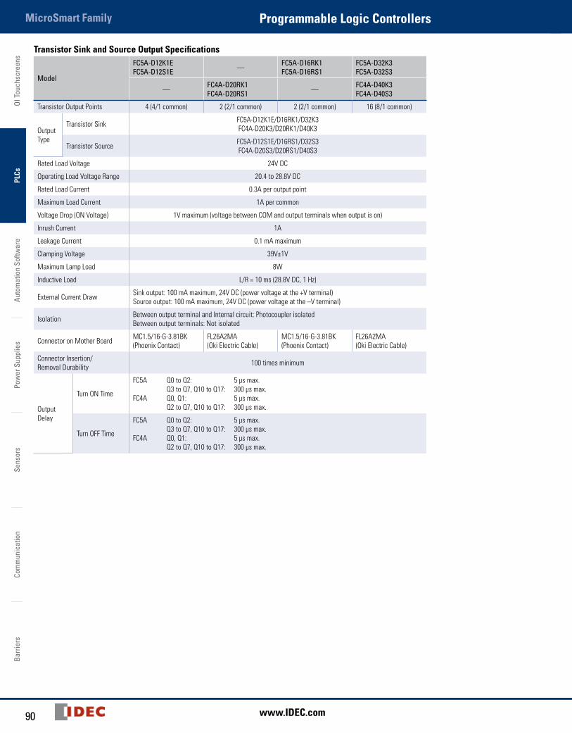
Transistor Sink and Source Output Specifications
Model
FC5A-D12K1EFC5A-D12S1E — FC5A-D16RK1
FC5A-D16RS1FC5A-D32K3 FC5A-D32S3
— FC4A-D20RK1 FC4A-D20RS1 — FC4A-D40K3
FC4A-D40S3
Transistor Output Points 4 (4/1 common) 2 (2/1 common) 2 (2/1 common) 16 (8/1 common)
Output Type
Transistor Sink FC5A-D12K1E/D16RK1/D32K3 FC4A-D20K3/D20RK1/D40K3
Transistor Source FC5A-D12S1E/D16RS1/D32S3 FC4A-D20S3/D20RS1/D40S3
Rated Load Voltage 24V DC
Operating Load Voltage Range 20.4 to 28.8V DC
Rated Load Current 0.3A per output point
Maximum Load Current 1A per common
Voltage Drop (ON Voltage) 1V maximum (voltage between COM and output terminals when output is on)
Inrush Current 1A
Leakage Current 0.1 mA maximum
Clamping Voltage 39V±1V
Maximum Lamp Load 8W
Inductive Load L/R = 10 ms (28.8V DC, 1 Hz)
External Current Draw Sink output: 100 mA maximum, 24V DC (power voltage at the +V terminal)Source output: 100 mA maximum, 24V DC (power voltage at the –V terminal)
Isolation Between output terminal and Internal circuit: Photocoupler isolatedBetween output terminals: Not isolated
Connector on Mother Board MC1.5/16-G-3.81BK (Phoenix Contact)
FL26A2MA (Oki Electric Cable)
MC1.5/16-G-3.81BK (Phoenix Contact)
FL26A2MA (Oki Electric Cable)
Connector Insertion/Removal Durability 100 times minimum
Output Delay
Turn ON Time
FC5A Q0 to Q2: 5 µs max. Q3 to Q7, Q10 to Q17: 300 µs max.FC4A Q0, Q1: 5 µs max. Q2 to Q7, Q10 to Q17: 300 µs max.
Turn OFF Time
FC5A Q0 to Q2: 5 µs max. Q3 to Q7, Q10 to Q17: 300 µs max.FC4A Q0, Q1: 5 µs max. Q2 to Q7, Q10 to Q17: 300 µs max.

91800-262-IDEC (4332) • USA & Canada
MicroSmart FamilyProgrammable Logic ControllersOI Touchscreens
PLCsAutom
ation Software
Power Supplies
SensorsCom
munication
Barriers
Relay Output Specifications
Model
FC5A-C10R2 FC5A-C10R2CFC5A-C10R2D
FC5A-C16R2 FC5A-C16R2CFC5A-C16R2D
FC5A-C24R2 FC5A-C24R2CFC5A-C24R2D
FC5A-D16RK1 FC5A-D16RS1
FC4A-C10R2 FC4A-C10R2C
FC4A-C16R2 FC4A-C16R2C
FC4A-C24R2 FC4A-C24R2C
FC4A-D20RK1 FC4A-D20RS1
Relay Output Points 4 7 10 6
Output Points per Common Line
COM0 3 4 4 —
COM1 1 2 4 3
COM2 — 1 1 2
COM3 — — 1 1
Output Type 1NO
Maximum Load Current 2A per point8A per common line
Minimum Switching Load 1 mA/ 5V DC (reference value)
Initial Contact Resistance 30 mΩ maximum
Electrical Life 100,000 operations minimum (rated load 1,800 operations/hour)
Mechanical Life 20,000,000 operations minimum (no load 18,000 operations/hour)
Rated Load 240V AC/2A (resistive load, inductive load cos ø = 0.4)30V DC/2A (resistive load, inductive load L/R =7 ms)
Dielectric Strength Between output and terminals: 1,500V AC, 1 minuteBetween output terminal and internal circuit: 1,500V AC, 1 minuteBetween output terminals (COMs): 1,500V AC, 1 minute
Connector on Mother Board — *1
Connector Insertion/Removal Durability — 100 times minimum
1. MC1.5/16-G-3.81BK (Phoenix Contact)
OI T
ouch
scre
ens
PLCs
Auto
mat
ion
Softw
are
Pow
er S
uppl
ies
Sens
ors
Com
mun
icat
ion
Barr
iers
MicroSmart Family Programmable Logic Controllers
92 www.IDEC.com
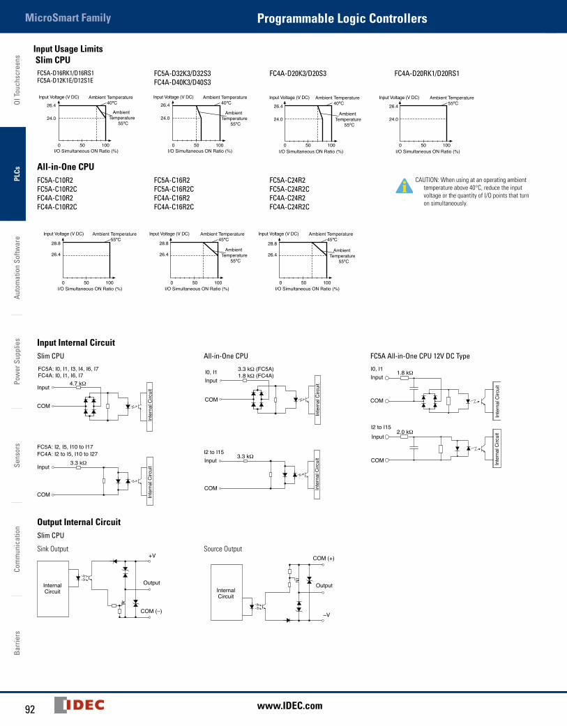
Input Usage Limits Slim CPU
FC5A-D16RK1/D16RS1FC5A-D12K1E/D12S1E
FC5A-D32K3/D32S3FC4A-D40K3/D40S3
FC4A-D20K3/D20S3 FC4A-D20RK1/D20RS1
Input Voltage (V DC)Input Voltage (V DC)Input Voltage (V DC) Input Voltage (V DC)Ambient Temperature 40ºC
Ambient Temperature 40ºC
Ambient Temperature 40ºC
Ambient Temperature
55ºC
Ambient Temperature
55ºC
Ambient Temperature
55ºC
Ambient Temperature 55ºC
I/O Simultaneous ON Ratio (%) I/O Simultaneous ON Ratio (%)I/O Simultaneous ON Ratio (%)
26.4
24.0
26.4
24.0
26.4
24.0
26.4
24.0
I/O Simultaneous ON Ratio (%)0 50 100 0 50 100 0 50 100 0 50 100
All-in-One CPUFC5A-C10R2FC5A-C10R2CFC4A-C10R2FC4A-C10R2C
FC5A-C16R2FC5A-C16R2CFC4A-C16R2FC4A-C16R2C
FC5A-C24R2FC5A-C24R2CFC4A-C24R2FC4A-C24R2C
CAUTION: When using at an operating ambient temperature above 40°C, reduce the input voltage or the quantity of I/O points that turn on simultaneously.
28.8
26.4
28.8
26.4
28.8
26.4
Input Voltage (V DC) Input Voltage (V DC) Input Voltage (V DC)Ambient Temperature 55ºC
Ambient Temperature 45ºC
Ambient Temperature 45ºC
Ambient Temperature
55ºC
Ambient Temperature
55ºC
I/O Simultaneous ON Ratio (%) I/O Simultaneous ON Ratio (%) I/O Simultaneous ON Ratio (%)0 50 100 0 50 100 0 50 100
Input Internal CircuitSlim CPU All-in-One CPU FC5A All-in-One CPU 12V DC Type
4.7 kΩ
FC4A: I0, I1, I6, I7FC5A: I0, I1, I3, I4, I6, I7
COM
Input
Inte
rnal
Circ
uit
Input
3.3 kΩ (FC5A)1.8 kΩ (FC4A)I0, I1
COM
Inte
rnal
Circ
uit
1.8 kΩInputI0, I1
COM
Inte
rnal
Circ
uit
Inte
rnal
Circ
uit2.0 kΩ
InputI2 to I15
COM
COM
Input3.3 kΩ
FC4A: I2 to I5, I10 to I27FC5A: I2, I5, I10 to I17
Inte
rnal
Circ
uit
COM
Input3.3 kΩ
I2 to I15
Inte
rnal
Circ
uit
Output Internal CircuitSlim CPU
Sink Output
InternalCircuit
+V
Output
COM (–)
Source Output
InternalCircuit
–V
Output
COM (+)
93800-262-IDEC (4332) • USA & Canada
MicroSmart FamilyProgrammable Logic ControllersOI Touchscreens
PLCsAutom
ation Software
Power Supplies
SensorsCom
munication
Barriers
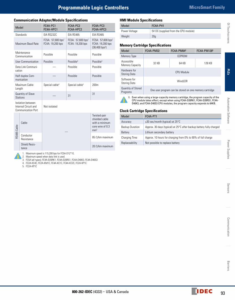
Communication Adapter/Module Specifications
Model FC4A-PC1 FC4A-HPC1
FC4A-PC2 FC4A-HPC2
FC4A-PC3 FC4A-HPC3
Standards EIA RS232C EIA RS485 EIA RS485
Maximum Baud RateFC5A: 57,600 bps1 FC4A: 19,200 bps
FC5A: 57,600 bps1 FC4A: 19,200 bps
FC5A: 57,600 bps1 FC4A: 19,200 bps (38,400 bps2)
MaintenanceCommunication Possible Possible Possible
User Communication Possible Possible3 Possible3
Data Link Communi-cation
— Possible Possible
Half-duplex Com-munication
— Possible Possible
Maximum Cable Length
Special cable4 Special cable5 200m
Quantity of Slave Stations — 31 31
Isolation between Internal Circuit and Communication Port
Not isolated
RS48
5 Ca
ble
Cable
—
Twisted-pair shielded cable with a minimum core wire of 0.3 mm2
Conductor Resistance 85 Ω/km maximum
Shield Resis-tance 20 Ω/km maximum
1. Maximum speed is 115,200 bps for FC5A-D12*1E.2. Maximum speed when data link is used.3. FC5A (all types), FC4A-D20RK1, FC4A-D20RS1, FC4A-D40K3, FC4A-D40S34. FC2A-KC4C, FC2A-KM1C, FC4A-KC1C, FC4A-KC2C, FC2A-KP1C5. FC2A-KP1C
HMI Module SpecificationsModel FC4A-PH1
Power Voltage 5V DC (supplied from the CPU module)
Weight 20g
Memory Cartridge SpecificationsModel FC4A-PM32 FC4A-PM646 FC4A-PM1286
Memory Type EEPROM
Accessible Memory Capacity 32 KB 64 KB 128 KB
Hardware for Storing Data CPU Module
Software for Storing Data WindLDR
Quantity of Stored Programs One user program can be stored on one memory cartridge
6. Even when using a large-capacity memory cartridge, the program capacity of the CPU module takes effect, except when using FC4A-D20RK1, FC4A-D20RS1, FC4A-D40K3, and FC4A-D40S3 CPU modules, the program capacity expands to 64KB.
Clock Cartridge SpecificationsModel FC4A-PT1
Accuracy ±30 sec/month (typical) at 25°C
Backup Duration Approx. 30 days (typical) at 25°C after backup battery fully charged
Battery Lithium secondary battery
Charging Time Approx. 10 hours for charging from 0% to 90% of full charge
Replaceability Not possible to replace battery
OI T
ouch
scre
ens
PLCs
Auto
mat
ion
Softw
are
Pow
er S
uppl
ies
Sens
ors
Com
mun
icat
ion
Barr
iers
MicroSmart Family Programmable Logic Controllers
94 www.IDEC.com
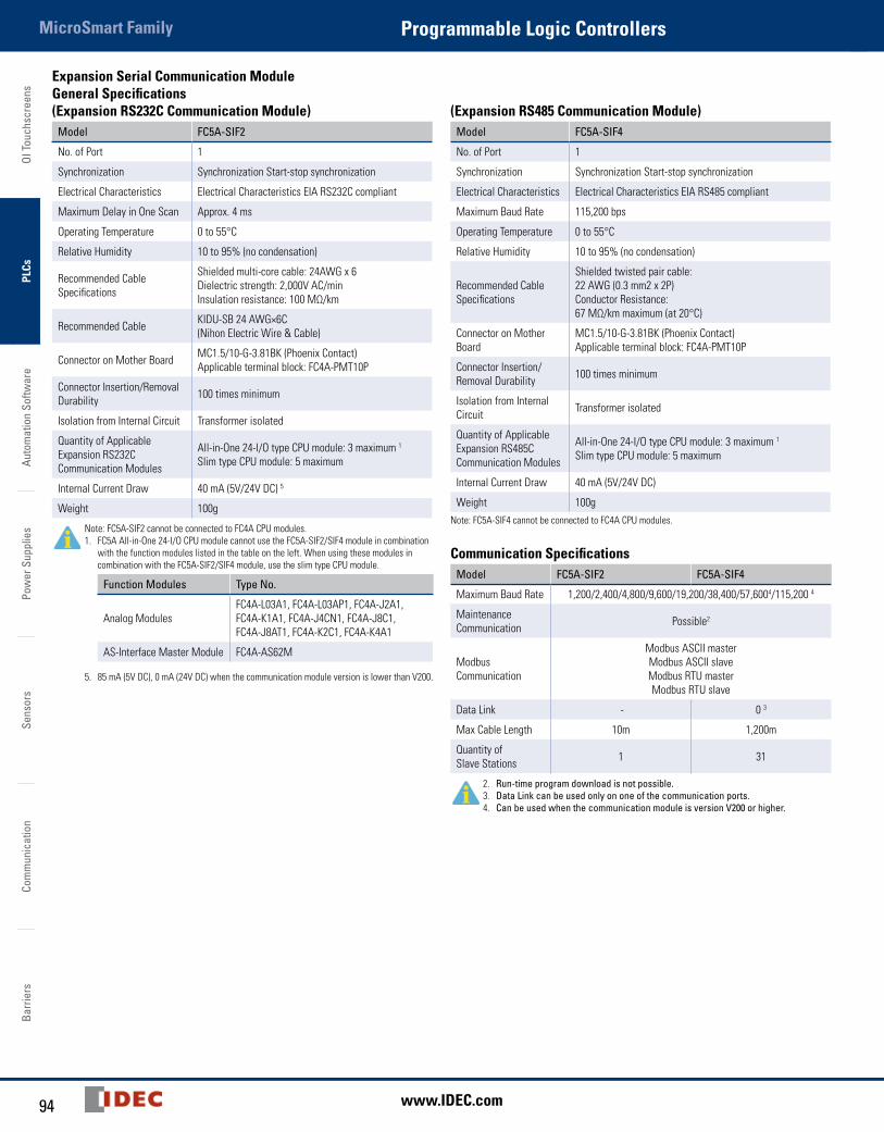
Expansion Serial Communication Module General Specifications (Expansion RS232C Communication Module)
Model FC5A-SIF2
No. of Port 1
Synchronization Synchronization Start-stop synchronization
Electrical Characteristics Electrical Characteristics EIA RS232C compliant
Maximum Delay in One Scan Approx. 4 ms
Operating Temperature 0 to 55°C
Relative Humidity 10 to 95% (no condensation)
Recommended Cable Specifications
Shielded multi-core cable: 24AWG x 6Dielectric strength: 2,000V AC/minInsulation resistance: 100 MΩ/km
Recommended Cable KIDU-SB 24 AWG×6C (Nihon Electric Wire & Cable)
Connector on Mother Board MC1.5/10-G-3.81BK (Phoenix Contact)Applicable terminal block: FC4A-PMT10P
Connector Insertion/Removal Durability 100 times minimum
Isolation from Internal Circuit Transformer isolated
Quantity of Applicable Expansion RS232C Communication Modules
All-in-One 24-I/O type CPU module: 3 maximum 1
Slim type CPU module: 5 maximum
Internal Current Draw 40 mA (5V/24V DC) 5
Weight 100g
Note: FC5A-SIF2 cannot be connected to FC4A CPU modules.1. FC5A All-in-One 24-I/O CPU module cannot use the FC5A-SIF2/SIF4 module in combination
with the function modules listed in the table on the left. When using these modules in combination with the FC5A-SIF2/SIF4 module, use the slim type CPU module.
Function Modules Type No.
Analog ModulesFC4A-L03A1, FC4A-L03AP1, FC4A-J2A1, FC4A-K1A1, FC4A-J4CN1, FC4A-J8C1, FC4A-J8AT1, FC4A-K2C1, FC4A-K4A1
AS-Interface Master Module FC4A-AS62M
5. 85 mA (5V DC), 0 mA (24V DC) when the communication module version is lower than V200.
(Expansion RS485 Communication Module)Model FC5A-SIF4
No. of Port 1
Synchronization Synchronization Start-stop synchronization
Electrical Characteristics Electrical Characteristics EIA RS485 compliant
Maximum Baud Rate 115,200 bps
Operating Temperature 0 to 55°C
Relative Humidity 10 to 95% (no condensation)
Recommended Cable Specifications
Shielded twisted pair cable: 22 AWG (0.3 mm2 x 2P)Conductor Resistance: 67 MΩ/km maximum (at 20°C)
Connector on Mother Board
MC1.5/10-G-3.81BK (Phoenix Contact)Applicable terminal block: FC4A-PMT10P
Connector Insertion/ Removal Durability 100 times minimum
Isolation from Internal Circuit Transformer isolated
Quantity of Applicable Expansion RS485CCommunication Modules
All-in-One 24-I/O type CPU module: 3 maximum 1
Slim type CPU module: 5 maximum
Internal Current Draw 40 mA (5V/24V DC)
Weight 100gNote: FC5A-SIF4 cannot be connected to FC4A CPU modules.
Communication SpecificationsModel FC5A-SIF2 FC5A-SIF4
Maximum Baud Rate 1,200/2,400/4,800/9,600/19,200/38,400/57,6004/115,200 4
Maintenance Communication Possible2
Modbus Communication
Modbus ASCII masterModbus ASCII slaveModbus RTU masterModbus RTU slave
Data Link - 0 3
Max Cable Length 10m 1,200m
Quantity of Slave Stations 1 31
2. Run-time program download is not possible.3. Data Link can be used only on one of the communication ports.4. Can be used when the communication module is version V200 or higher.
95800-262-IDEC (4332) • USA & Canada
MicroSmart FamilyProgrammable Logic ControllersOI Touchscreens
PLCsAutom
ation Software
Power Supplies
SensorsCom
munication
Barriers
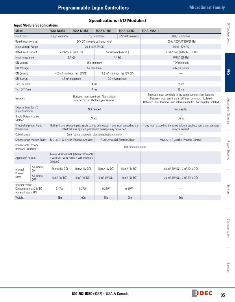
Specifications (I/O Modules)Input Module Specifications
Model FC4A-N08B1 FC4A-N16B1 FC4A-N16B3 FC4A-N32B3 FC4A-N08A11
Input Points 8 (8/1 common) 16 (16/1 common) 32 (16/1 common) 8 (4/1 common)
Rated Input Voltage 24V DC sink/source input signal 100 to 120V AC (50/60 Hz)
Input Voltage Range 20.4 to 28.8V DC 85 to 132V AC
Rated Input Current 7 mA/point (24V DC) 5 mA/point (24V DC) 17 mA/point (120V AC, 60 Hz)
Input Impedance 3.4 kΩ 4.4 kΩ 0.8 kΩ (60 Hz)
ON Voltage 15V minimum 79V minimum
OFF Voltage 5V maximum 20V maximum
ON Current 4.2 mA minimum (at 15V DC) 3.2 mA minimum (at 15V DC) —
OFF Current 1.2 mA maximum 0.9 mA maximum —
Turn ON Time 4 ms 25 ms
Turn OFF Time 4 ms 30 ms
Isolation Between input terminals: Not isolatedInternal circuit: Photocoupler isolated
Between input terminals in the same common: Not isolatedBetween input terminals in different commons: Isolated
Between input terminals and internal circuits: Photocoupler isolated
External Load for I/O Interconnection Not needed Not needed
Single Determination Method Static Static
Effect of Improper Input Connection
Both sink and source input signals can be connected. If any input exceeding the rated value is applied, permanent damage may be caused.
If any input exceeding the rated value is applied, permanent damage may be caused.
Cable Length 3m in compliance with electromagnetic immunity —
Connector on Mother Board MC1.5/10-G-3.81BK (Phoenix Contact) FL20A2MA (Oki Electric Cable) MC1.5/11-G-3.81BK (Phoenix Contact)
Connector Insertion/ Removal Durability 100 times minimum
Applicable Ferrule1-wire: AI 0.5-8 WH (Phoenix Contact) 2-wire: AI-TWIN 2×0.5-8 WH (Phoenix Contact)
— —
Internal Current Draw
All Inputs ON 25 mA (5V DC) 40 mA (5V DC) 35 mA (5V DC) 65 mA (5V DC) 60 mA (5V DC), 0 mA (24V DC)
All Inputs OFF 5 mA (5V DC) 5 mA (5V DC) 5 mA (5V DC) 10 mA (5V DC) 30 mA (5V DC), 0 mA (24V DC)
Internal Power Consumption (at 24V DC while all inputs ON)
0.17W 0.27W 0.24W 0.44W —
Weight 85g 100g 65g 100g 80g

OI T
ouch
scre
ens
PLCs
Auto
mat
ion
Softw
are
Pow
er S
uppl
ies
Sens
ors
Com
mun
icat
ion
Barr
iers
MicroSmart Family Programmable Logic Controllers
96 www.IDEC.com
Transistor Output Module Specifications
Model FC4A-T08K1 FC4A-T08S1
FC4A-T16K3 FC4A-T16S3
FC4A-T32K3 FC4A-T32S3
Output Points 8 (8/1 common) 16 (16/1 common) 32 (16/1 common)
Output Type FC4A-T0K0: Transistor sink output FC4A-T0S0: Transistor source output
Rated Load Voltage 24V DC
Operating Load Voltage Range 20.4 to 28.8V DC
Maximum Load Current0.3A per point 0.1A per point
3A per common 1A per common
Voltage Drop (ON Voltage)
1V maximum (voltage between COM and output terminals when output is on)
Inrush Current 1A maximum
Clamping Voltage 39V±1V
Maximum Lamp Load 8W
Inductive Load L/R = 10 ms (28.8V DC, 1 Hz)
External Current Draw
FC4A-T0K0: 100 mA maximum, 24V DC (power voltage at the +V terminal)
FC4A-T0S0: 100 mA maximum, 24V DC (power voltage at the –V terminal)
IsolationBetween output terminal and internal circuit:
Photocoupler isolatedBetween output terminals: Not isolated
Connector on Mother Board
MC1.5/10-G-3.81BK (Phoenix Contact) FL20A2MA (Oki Electric Cable)
Connector Insertion/ Removal Durability 100 times minimum
Applicable Ferrule
1-wire: AI 0.5-8 WH (Phoenix Contact) 2-wire: AI-TWIN 2×0.5-8 WH (Phoe-nix Contact)
—
Internal Current Draw
All outputs ON
10 mA (5V DC) 20 mA (24V DC)
10 mA (5V DC) 40 mA (24V DC)
20 mA (5V DC) 70 mA (24V DC)
All outputs OFF
5 mA (5V DC) 0 mA (24V DC)
5 mA (5V DC) 0 mA (24V DC)
10 mA (5V DC) 0 mA (24V DC)
Internal Power Con-sumption (at 24V DC while all outputs ON)
0.55W 1.03W 1.82W
Output Delay
Turn ON Time 300 µs maximum
Turn OFF Time 300 µs maximum
Weight 85g 70g 105g
Relay Output Module SpecificationsModel FC4A-R081 FC4A-R161
Output Points 8 (4/1 common) 16 (8/1 common)
Output Type 1NO
Maximum Load Current2A per point
7A per common 8A per common
Minimum Switching Load 1 mA/ 5V DC (reference value)
Initial Contact Resistance 30 mΩ maximum
Electrical Life 100,000 operations minimum(rated load 1,800 operations/hour)
Mechanical Life 20,000,000 operations minimum(no load 18,000 operations/hour)
Rated Load 240V AC/2A (resistive load, inductive load cos ø = 0.4)30V DC/2A (resistive load, inductive load L/R = 7 ms)
Dielectric Strength
Between output and or terminals: 1,500V AC, 1 minuteBetween output terminal and internal circuit:
1,500V AC, 1 minuteBetween output terminals (COMs): 1,500V AC, 1 minute
ConnectorOn Mother Board
MC1.5/11-G-3.81BK (Phoenix Contact)
MC1.5/10-G-3.81BK (Phoenix Contact)
Connector Insertion/ Removal Durability 100 times minimum
Applicable Ferrule 1-wire: AI 0.5-8 WH (Phoenix Contact) 2-wire: AI-TWIN 2×0.5-8 WH (Phoenix Contact)
Internal Current Draw
All outputs ON 30 mA (5V DC) 40 mA (24V DC)
45 mA (5V DC) 75 mA (24V DC)
All outputs OFF
5 mA (5V DC) 0 mA (24V DC)
5 mA (5V DC) 0 mA (24V DC)
Internal Power Consump-tion (at 24V DC while all outputs ON)
1.16W 2.10W
Weight 110g 145g

97800-262-IDEC (4332) • USA & Canada
MicroSmart FamilyProgrammable Logic ControllersOI Touchscreens
PLCsAutom
ation Software
Power Supplies
SensorsCom
munication
Barriers
Mixed I/O Module SpecificationsModel FC4A-M08BR1 FC4A-M24BR2
Inpu
t Spe
cific
atio
ns
Input Points 4 (4/1 common) 16 (16/1 common)
Rated Input Voltage 24V DC sink/source input signal
Input Voltage Range 20.4 to 28.8V DC
Rated Input Current 7 mA/point (24V DC)
Input Impedance 3.4 kΩ
ON Voltage 15V minimum
OFF Voltage 5V maximum
ON Current 4.2 mA minimum (at 15V DC)
OFF Current 1.2 mA maximum
Turn ON Time 4 ms (24V DC)
Turn OFF Time 4 ms (24V DC)
Isolation Between input terminals: Not isolatedInternal circuit: Photocoupler isolated
External Load for I/O Interconnection Not needed
Signal Determination Method Static
Effect of Improper Input Connection Both sinking and sourcing input signals can be connected. If any input exceeding the rated value is applied, permanent damage may be caused.
Cable Length 3m in compliance with electromagnetic immunity
Outp
ut S
peci
ficat
ions
Output Points 4 (4/1 common) 8 (4/1 common)
Output Type 1NO
Maximum Load Current 2A per point7A per common
Minimum Switching Load 1 mA/ 5V DC (reference value)
Initial Contact Resistance 30 mΩ maximum
Electrical Life 100,000 operations minimum (rated load 1,800 operations/hour)
Mechanical Life 20,000,000 operations minimum (no load 18,000 operations/hour)
Rated Load 240V AC/2A (resistive load, inductive load cos ø = 0.4)30V DC/2A (resistive load, inductive load L/R = 7 ms)
Dielectric StrengthBetween output and or terminals: 1,500V AC, 1 minuteBetween output terminal and internal circuit: 1,500V AC, 1 minuteBetween output terminals (COMs): 1,500V AC, 1 minute
Connector on Mother Board MC1.5/11-G-3.81BK (Phoenix Contact)
Input: F6018-17P (Fujicon) Output: F6018-11P (Fujicon)
Connector Insertion/Removal Durability 100 times minimum Not removable
Applicable Ferrule 1-wire: AI 0.5-8 WH (Phoenix Contact), 2-wire: AI-TWIN 2×0.5-8 WH (Phoenix Contact)
Internal Current DrawAll I/Os ON 25 mA (5V DC), 20 mA (24V DC) 65 mA (5V DC), 45 mA (24V DC)
All I/Os OFF 5 mA (5V DC), 0 mA (24V DC) 10 mA (5V DC), 0 mA (24V DC)
Internal Power Consumption (at 24V DC while all I/Os are ON) 0.65W 1.52W
Weight 95g 140g
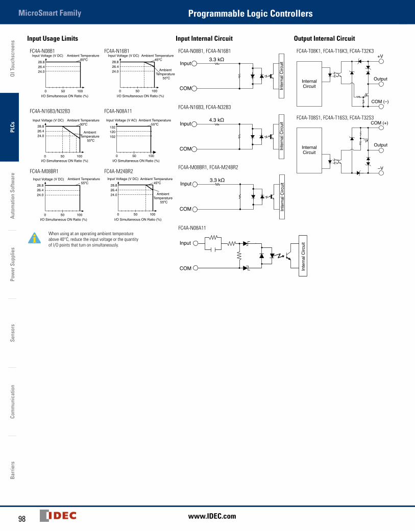
OI T
ouch
scre
ens
PLCs
Auto
mat
ion
Softw
are
Pow
er S
uppl
ies
Sens
ors
Com
mun
icat
ion
Barr
iers
MicroSmart Family Programmable Logic Controllers
98 www.IDEC.com
Input Usage Limits Input Internal Circuit Output Internal Circuit
FC4A-N08B1
28.826.424.0
28.826.424.0
28.826.424.0
28.826.424.0
28.826.424.0
0 50 100
0 50 100
0 50 100
0 50 100
0 50 100
0 50 100
Input Voltage (V DC) Input Voltage (V DC)
Input Voltage (V DC)
Input Voltage (V DC) Input Voltage (V DC)
Ambient Temperature 55ºC
Ambient Temperature 45ºC
AmbientTemperature
55ºC
AmbientTemperature
55ºC
AmbientTemperature
55ºC
Ambient Temperature 55ºC
Ambient Temperature 45ºC
Ambient Temperature 30ºC
I/O Simultaneous ON Ratio (%) I/O Simultaneous ON Ratio (%)
I/O Simultaneous ON Ratio (%)
I/O Simultaneous ON Ratio (%) I/O Simultaneous ON Ratio (%)
I/O Simultaneous ON Ratio (%)
Ambient Temperature55ºC
Input Voltage (V AC)
132120102
FC4A-N16B1
28.826.424.0
28.826.424.0
28.826.424.0
28.826.424.0
28.826.424.0
0 50 100
0 50 100
0 50 100
0 50 100
0 50 100
0 50 100
Input Voltage (V DC) Input Voltage (V DC)
Input Voltage (V DC)
Input Voltage (V DC) Input Voltage (V DC)
Ambient Temperature 55ºC
Ambient Temperature 45ºC
AmbientTemperature
55ºC
AmbientTemperature
55ºC
AmbientTemperature
55ºC
Ambient Temperature 55ºC
Ambient Temperature 45ºC
Ambient Temperature 30ºC
I/O Simultaneous ON Ratio (%) I/O Simultaneous ON Ratio (%)
I/O Simultaneous ON Ratio (%)
I/O Simultaneous ON Ratio (%) I/O Simultaneous ON Ratio (%)
I/O Simultaneous ON Ratio (%)
Ambient Temperature55ºC
Input Voltage (V AC)
132120102
FC4A-N16B3/N32B3
28.826.424.0
28.826.424.0
28.826.424.0
28.826.424.0
28.826.424.0
0 50 100
0 50 100
0 50 100
0 50 100
0 50 100
0 50 100
Input Voltage (V DC) Input Voltage (V DC)
Input Voltage (V DC)
Input Voltage (V DC) Input Voltage (V DC)
Ambient Temperature 55ºC
Ambient Temperature 45ºC
AmbientTemperature
55ºC
AmbientTemperature
55ºC
AmbientTemperature
55ºC
Ambient Temperature 55ºC
Ambient Temperature 45ºC
Ambient Temperature 30ºC
I/O Simultaneous ON Ratio (%) I/O Simultaneous ON Ratio (%)
I/O Simultaneous ON Ratio (%)
I/O Simultaneous ON Ratio (%) I/O Simultaneous ON Ratio (%)
I/O Simultaneous ON Ratio (%)
Ambient Temperature55ºC
Input Voltage (V AC)
132120102
FC4A-N08A11
28.826.424.0
28.826.424.0
28.826.424.0
28.826.424.0
28.826.424.0
0 50 100
0 50 100
0 50 100
0 50 100
0 50 100
0 50 100
Input Voltage (V DC) Input Voltage (V DC)
Input Voltage (V DC)
Input Voltage (V DC) Input Voltage (V DC)
Ambient Temperature 55ºC
Ambient Temperature 45ºC
AmbientTemperature
55ºC
AmbientTemperature
55ºC
AmbientTemperature
55ºC
Ambient Temperature 55ºC
Ambient Temperature 45ºC
Ambient Temperature 30ºC
I/O Simultaneous ON Ratio (%) I/O Simultaneous ON Ratio (%)
I/O Simultaneous ON Ratio (%)
I/O Simultaneous ON Ratio (%) I/O Simultaneous ON Ratio (%)
I/O Simultaneous ON Ratio (%)
Ambient Temperature55ºC
Input Voltage (V AC)
132120102
FC4A-M08BR1
28.826.424.0
28.826.424.0
28.826.424.0
28.826.424.0
28.826.424.0
0 50 100
0 50 100
0 50 100
0 50 100
0 50 100
0 50 100
Input Voltage (V DC) Input Voltage (V DC)
Input Voltage (V DC)
Input Voltage (V DC) Input Voltage (V DC)
Ambient Temperature 55ºC
Ambient Temperature 45ºC
AmbientTemperature
55ºC
AmbientTemperature
55ºC
AmbientTemperature
55ºC
Ambient Temperature 55ºC
Ambient Temperature 45ºC
Ambient Temperature 30ºC
I/O Simultaneous ON Ratio (%) I/O Simultaneous ON Ratio (%)
I/O Simultaneous ON Ratio (%)
I/O Simultaneous ON Ratio (%) I/O Simultaneous ON Ratio (%)
I/O Simultaneous ON Ratio (%)
Ambient Temperature55ºC
Input Voltage (V AC)
132120102
FC4A-M24BR2
28.826.424.0
28.826.424.0
28.826.424.0
28.826.424.0
28.826.424.0
0 50 100
0 50 100
0 50 100
0 50 100
0 50 100
0 50 100
Input Voltage (V DC) Input Voltage (V DC)
Input Voltage (V DC)
Input Voltage (V DC) Input Voltage (V DC)
Ambient Temperature 55ºC
Ambient Temperature 45ºC
AmbientTemperature
55ºC
AmbientTemperature
55ºC
AmbientTemperature
55ºC
Ambient Temperature 55ºC
Ambient Temperature 45ºC
Ambient Temperature 30ºC
I/O Simultaneous ON Ratio (%) I/O Simultaneous ON Ratio (%)
I/O Simultaneous ON Ratio (%)
I/O Simultaneous ON Ratio (%) I/O Simultaneous ON Ratio (%)
I/O Simultaneous ON Ratio (%)
Ambient Temperature55ºC
Input Voltage (V AC)
132120102
When using at an operating ambient temperature above 40°C, reduce the input voltage or the quantity of I/O points that turn on simultaneously.
FC4A-N08B1, FC4A-N16B1
COM
Input3.3 kΩ
Inte
rnal
Circ
uit
FC4A-N16B3, FC4A-N32B3
COM
4.3 kΩ
Inte
rnal
Circ
uitInput
FC4A-M08BR1, FC4A-M24BR2
COM
3.3 kΩ
Inte
rnal
Circ
uitInput
FC4A-N08A11
COM
Input
Inte
rnal
Circ
uit
FC4A-T08K1, FC4A-T16K3, FC4A-T32K3+V
Output
COM (–)
InternalCircuit
FC4A-T08S1, FC4A-T16S3, FC4A-T32S3
–V
Output
COM (+)
InternalCircuit
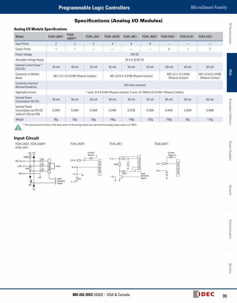
99800-262-IDEC (4332) • USA & Canada
MicroSmart FamilyProgrammable Logic ControllersOI Touchscreens
PLCsAutom
ation Software
Power Supplies
SensorsCom
munication
Barriers
Specifications (Analog I/O Modules)
Analog I/O Module Specifications
Model FC4A-L03A1 FC4A-L03AP1 FC4A-J2A1 FC4A-J4CN1 FC4A-J8C1 FC4A-J8AT1 FC4A-K4A1 FC4A-K1A1 FC4A-K2C1
Input Points 2 2 2 4 8 8 — — —
Output Points 1 1 — — — — 4 1 2
Power Voltage 24V DC
Allowable Voltage Range 20.4 to 28.8V DC
External Current Draw *(24V DC) 45 mA 40 mA 35 mA 55 mA 50 mA 55 mA 130 mA 40 mA 85 mA
Connector on Mother Board MC1.5/11-G-3.81BK (Phoenix Contact) MC1.5/10-G-3.81BK (Phoenix Contact) MC1.5/11-G-3.81BK
(Phoenix Contact)MC1.5/10-G-3.81BK
(Phoenix Contact)
Connector Insertion/Removal Durability 100 times minimum
Applicable Ferrule 1-wire: AI 0.5-8 WH (Phoenix Contact), 2-wire: AI-TWIN 2×0.5-8 WH (Phoenix Contact)
Internal Power Consumption (5V DC) 50 mA 50 mA 50 mA 50 mA 40 mA 45 mA 65 mA 50 mA 60 mA
Internal Power Consumption (at 24V DC while all I/Os are ON)
0.34W 0.34W 0.34W 0.34W 0.27W 0.30W 0.44W 0.34W 0.40W
Weight 85g 85g 85g 140g 140g 125g 100g 85g 110g
* The external current draw is the value when all the analog inputs are used and the analog output value is at 100%.
Input CircuitFC4A-L03A1, FC4A-L03AP1FC4A-J2A1
FC4A-J4CN1 FC4A-J8C1 FC4A-J8AT1
NC (A)1 kΩ
15MΩ
+ (B’)
– (B)
1 kΩ
1 kΩ10Ω
+V2 +V1
–V1
InputSelectionSignal
Input
Mul
tiple
xer CS
−
I−7Ω
CurrentSource
Inte
rnal
Circ
uit
+100Ω
−
+
10kΩ
Inte
rnal
Circ
uit
InputSelection Signal
A
B
Inte
rnal
Circ
uit
CurrentSource

OI T
ouch
scre
ens
PLCs
Auto
mat
ion
Softw
are
Pow
er S
uppl
ies
Sens
ors
Com
mun
icat
ion
Barr
iers
MicroSmart Family Programmable Logic Controllers
100 www.IDEC.com
Analog Input Specifications (1)Model FC4A-L03A1, FC4A-J2A1 FC4A-L03AP1
Input Signal Type Voltage Input0 to 10V DC
Current Input4 to 20 mA
Resistance ThermometerPt100 3-wire type (–100 to 500°C)
ThermocoupleType K (0 to 1,300°C) Type J (0 to 1,200°C) Type T (0 to 400°C)
Input Impedance 1 MΩ minimum 10Ω 1 MΩ minimum 1 MΩ minimum
Input Detection Current — — 1.0 mA maximum —
AD Conversion
Sampling Duration Time 10 ms maximum 20 ms maximum 10 ms maximum
Sampling Repetition Time 20 ms maximum 40 ms maximum 20 ms maximum
Total Input System Transfer Time 60 ms + 1 scan time 80 ms + 1 scan time 60 ms + 1 scan time
Type of Input Single-ended input Differential input
Operating Mode Self-scan
Conversion Method ∑ ∆ type ADC
Input Error
Maximum Error at 25°C ±0.2% of full scale±0.2% of full scale plus cold junction compensation error (±4°C maximum)
Temperature Coefficient ±0.006% of full scale /°C
Repeatability after Stabilization Time ±0.5% of full scale
Non-linearity ±0.2% of full scale
Maximum Error ±1% of full scale
Data
Digital Resolution 4096 increments (12 bits) 6,000 increments (14 bits)Type K: 13,000 increments (14 bits)Type J: 12,000 increments (14 bits)Type T: 4,000 increments (14 bits)
Input Value of LSB 2.5 mV 4 µA 0.1°CType K: 0.1°CType J: 0.1°CType T: 0.1°C
Data Type in Application Program
Default: 0 to 4,095 Optional: –32,768 to 32,767 (selectable for each channel)1
Monotonicity Yes
Input Data Out of Range Detectable 2
Noise Resistance
Maximum Temporary Deviation during Electrical Noise Tests ±3% maximum when a 500V clamp voltage is applied to the power supply and I/O lines 3
Input Filter No
Recommended Cable for Noise Immunity Twisted pair shielded cable —
Crosstalk 2 LSB maximum
Isolation Between input and power circuit: IsolatedBetween input and internal circuit: Photocoupler-isolated
Effect of Improper Input Connection No damage
Maximum Permanent Allowed Overload (No Damage) 13V DC 40 mA —
Selection of Analog Input Signal Type Using programming software
Calibration or Verification to Maintain Rated Accuracy Impossible
1: The data processed in the analog I/O module can be linear-converted to a value between –32,768 and 32,767. The optional range designation, and analog I/O data minimum and maximum values can be selected using data registers allocated to analog I/O modules.
2: When an error is detected, a corresponding error code is stored to a data register allocated to analog I/O operating status.3: The accuracy of the thermocouple input is not guaranteed when noise is applied.
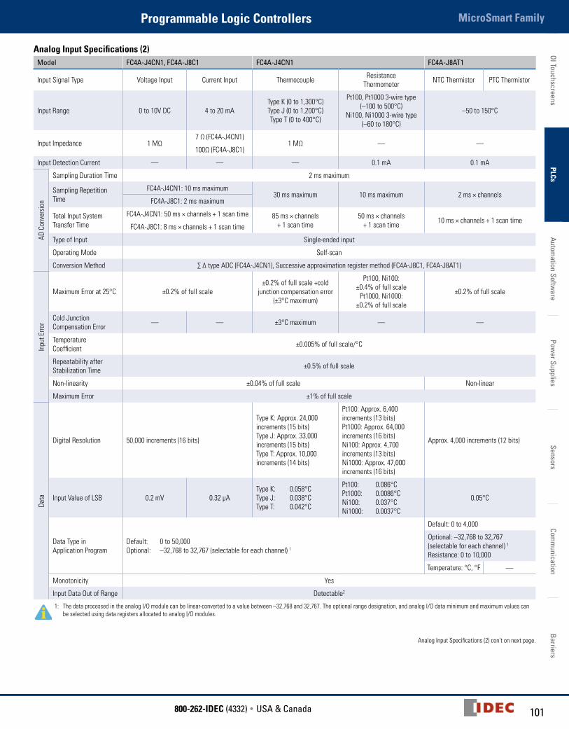
101800-262-IDEC (4332) • USA & Canada
MicroSmart FamilyProgrammable Logic ControllersOI Touchscreens
PLCsAutom
ation Software
Power Supplies
SensorsCom
munication
Barriers
Analog Input Specifications (2)Model FC4A-J4CN1, FC4A-J8C1 FC4A-J4CN1 FC4A-J8AT1
Input Signal Type Voltage Input Current Input Thermocouple Resistance Thermometer NTC Thermistor PTC Thermistor
Input Range 0 to 10V DC 4 to 20 mAType K (0 to 1,300°C) Type J (0 to 1,200°C) Type T (0 to 400°C)
Pt100, Pt1000 3-wire type (–100 to 500°C)
Ni100, Ni1000 3-wire type (–60 to 180°C)
–50 to 150°C
Input Impedance 1 MΩ7 Ω (FC4A-J4CN1)
1 MΩ — —100Ω (FC4A-J8C1)
Input Detection Current — — — 0.1 mA 0.1 mA
AD C
onve
rsio
n
Sampling Duration Time 2 ms maximum
Sampling Repetition Time
FC4A-J4CN1: 10 ms maximum30 ms maximum 10 ms maximum 2 ms × channels
FC4A-J8C1: 2 ms maximum
Total Input System Transfer Time
FC4A-J4CN1: 50 ms × channels + 1 scan time 85 ms × channels+ 1 scan time
50 ms × channels+ 1 scan time 10 ms × channels + 1 scan time
FC4A-J8C1: 8 ms × channels + 1 scan time
Type of Input Single-ended input
Operating Mode Self-scan
Conversion Method ∑ ∆ type ADC (FC4A-J4CN1), Successive approximation register method (FC4A-J8C1, FC4A-J8AT1)
Inpu
t Erro
r
Maximum Error at 25°C ±0.2% of full scale±0.2% of full scale +cold
junction compensation error (±3°C maximum)
Pt100, Ni100: ±0.4% of full scale
Pt1000, Ni1000:±0.2% of full scale
±0.2% of full scale
Cold Junction Compensation Error — — ±3°C maximum — —
Temperature Coefficient ±0.005% of full scale/°C
Repeatability after Stabilization Time ±0.5% of full scale
Non-linearity ±0.04% of full scale Non-linear
Maximum Error ±1% of full scale
Data
Digital Resolution 50,000 increments (16 bits)
Type K: Approx. 24,000 increments (15 bits)Type J: Approx. 33,000 increments (15 bits)Type T: Approx. 10,000 increments (14 bits)
Pt100: Approx. 6,400 increments (13 bits)Pt1000: Approx. 64,000 increments (16 bits)Ni100: Approx. 4,700 increments (13 bits)Ni1000: Approx. 47,000 increments (16 bits)
Approx. 4,000 increments (12 bits)
Input Value of LSB 0.2 mV 0.32 µAType K: 0.058°CType J: 0.038°CType T: 0.042°C
Pt100: 0.086°CPt1000: 0.0086°CNi100: 0.037°CNi1000: 0.0037°C
0.05°C
Data Type in Application Program
Default: 0 to 50,000 Optional: –32,768 to 32,767 (selectable for each channel) 1
Default: 0 to 4,000
Optional: –32,768 to 32,767 (selectable for each channel) 1
Resistance: 0 to 10,000
Temperature: °C, °F —
Monotonicity Yes
Input Data Out of Range Detectable2
1: The data processed in the analog I/O module can be linear-converted to a value between –32,768 and 32,767. The optional range designation, and analog I/O data minimum and maximum values can be selected using data registers allocated to analog I/O modules.
Analog Input Specifications (2) con’t on next page.
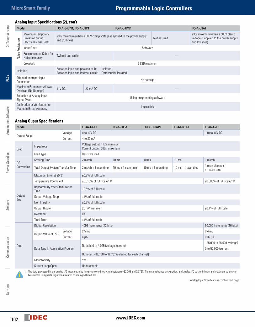
OI T
ouch
scre
ens
PLCs
Auto
mat
ion
Softw
are
Pow
er S
uppl
ies
Sens
ors
Com
mun
icat
ion
Barr
iers
MicroSmart Family Programmable Logic Controllers
102 www.IDEC.com
Analog Input Specifications (2), con’tModel FC4A-J4CN1, FC4A-J8C1 FC4A-J4CN1 FC4A-J8AT1
Noi
se R
esis
tanc
e
Maximum Temporary Deviation during Electrical Noise Tests
±3% maximum (when a 500V clamp voltage is applied to the power supply and I/O lines) Not assured
±3% maximum (when a 500V clamp voltage is applied to the power supply and I/O lines)
Input Filter Software
Recommended Cable for Noise Immunity Twisted pair cable —
Crosstalk 2 LSB maximum
Isolation Between input and power circuit: IsolatedBetween input and internal circuit: Optocoupler-isolated
Effect of Improper Input Connection No damage
Maximum Permanent AllowedOverload (No Damage) 11V DC 22 mA DC —
Selection of Analog Input Signal Type Using programming software
Calibration or Verification to Maintain Rated Accuracy Impossible
Analog Ouput SpecificationsModel FC4A-K4A1 FC4A-L03A1 FC4A-L03AP1 FC4A-K1A1 FC4A-K2C1
Output RangeVoltage 0 to 10V DC –10 to 10V DC
Current 4 to 20 mA
LoadImpedance Voltage output: 1 kΩ minimum
Current output: 300Ω maximum
Load Type Resistive load
DA Conversion
Settling Time 2 ms/ch 10 ms 10 ms 10 ms 1 ms/ch
Total Output System Transfer Time 2 ms/ch + 1 scan time 10 ms + 1 scan time 10 ms + 1 scan time 10 ms + 1 scan time 1 ms × channels + 1 scan time
Output Error
Maximum Error at 25°C ±0.2% of full scale
Temperature Coefficient ±0.015% of full scale/°C ±0.005% of full scale/°C
Repeatability after Stabilization Time ±0.5% of full scale
Output Voltage Drop ±1% of full scale
Non-lineality ±0.2% of full scale
Output Ripple 20 mV maximum ±0.1% of full scale
Overshoot 0%
Total Error ±1% of full scale
Data
Digital Resolution 4096 increments (12 bits) 50,000 increments (16 bits)
Output Value of LSBVoltage 2.5 mV 0.4 mV
Current 4 µA 0.32 µA
Data Type in Application ProgramDefault: 0 to 4,095 (voltage, current)
–25,000 to 25,000 (voltage)
0 to 50,000 (current)
Optional: –32,768 to 32,767 (selected for each channel)1
Monotonicity Yes
Current Loop Open Undetectable
1: The data processed in the analog I/O module can be linear-converted to a value between –32,768 and 32,767. The optional range designation, and analog I/O data minimum and maximum values can be selected using data registers allocated to analog I/O modules.
Analog Input Specifications con’t on next page.

103800-262-IDEC (4332) • USA & Canada
MicroSmart FamilyProgrammable Logic ControllersOI Touchscreens
PLCsAutom
ation Software
Power Supplies
SensorsCom
munication
Barriers
Analog Ouput Specifications, con’tModel FC4A-K4A1 FC4A-L03A1 FC4A-L03AP1 FC4A-K1A1 FC4A-K2C1
NoiseResistance
Maximum Temporary Deviation during Electrical Noise Tests ±3% maximum when a 500V clamp voltage is applied to the power and I/O lines
Recommended Cable for Noise Immunity Twisted pair shielded cable Twisted pair cable
Crosstalk 2LSB maximum None 2 LSB maximum
IsolationBetween output and power circuit Isolated
Between output and internal circuit Photocoupler-isolated
Effect of Improper Output Connection No damage
Selection of Analog Output Signal Type Using software programming
Calibration or Verification to Maintain Rated Accuracy Impossible
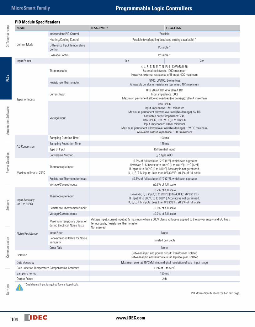
OI T
ouch
scre
ens
PLCs
Auto
mat
ion
Softw
are
Pow
er S
uppl
ies
Sens
ors
Com
mun
icat
ion
Barr
iers
MicroSmart Family Programmable Logic Controllers
104 www.IDEC.com
PID Module SpecificationsModel FC5A-F2MR2 FC5A-F2M2
Control Mode
Independent PID Control Possible
Heating/Cooling Control Possible (overlappling deadband settings available) *
Difference Input Temperature Control Possible *
Cascade Control Possible *
Input Points 2ch 2ch
Types of Inputs
ThermocoupleK, J, R, S, B, E, T, N, PL-II, C (W/Re5-26)
External resistance: 100Ω maximumHowever, external resistance of B input: 40Ω maximum
Resistance Thermometer Pt100, JPt100, 3-wire typeAllowable conductor resistance (per wire): 10Ω maximum
Current Input0 to 20 mA DC, 4 to 20 mA DC
Input impedance: 50ΩMaximum permanent allowed overload (no damage): 50 mA maximum
Voltage Input
0 to 1V DCInput impedance: 1MΩ minimum
Maximum permanent allowed overload (No damage): 5V DC Allowable output impedance: 2 kΩ0 to 5V DC, 1 to 5V DC, 0 to 10V DCInput impedance: 100kΩ minimum
Maximum permanent allowed overload (No damage): 15V DC maximumAllowable output impedance: 100Ω maximum
AD Conversion
Sampling Duration Time 100 ms
Sampling Repetition Time 125 ms
Type of Input Differential input
Conversion Method ∑ ∆ type ADC
Maximum Error at 25°C
Thermocouple Input
±0.2% of full scale or ±2°C (4°F), whichever is greaterHowever, R, S inputs: 0 to 200°C (0 to 400°F): ±6°C (12°F)B input: 0 to 300°C (0 to 600°F) Accuracy is not guranteed.
K, J, E, T, N inputs: Less than 0°C (32°F): ±0.4% of full scale
Resistance Thermometer Input ±0.1% of full scale or ±1°C (2°F), whichever is greater
Voltage/Current Inputs ±0.2% of full scale
Input Accuracy (at 0 to 55°C)
Thermocouple Input
±0.7% of full scaleHowever, R, S input,:0 to 200°C (0 to 400°F): ±6°C (12°F)
B input: 0 to 300°C (0 to 600°F) Accuracy is not guranteed.K, J, E, T, N inputs: Less than 0°C (32°F): ±0.9% of full scale
Resistance Thermometer Input ±0.6% of full scale
Voltage/Current Inputs ±0.7% of full scale
Noise Resistance
Maximum Temporary Deviation during Electrical Noise Tests
Voltage input, current input ±3% maximum when a 500V clamp voltage is applied to the power supply and I/O linesTermocouple, Resistance ThermometerNot assured
Input Filter None
Recommended Cable for Noise Immunity Twisted pair cable
Cross Talk None
Isolation Between input and power circuit: Transformer IsolatedBetween input and internal circuit: Optocoupler isolated
Data Accuracy Maximum error at 25°C±Minimum digital resolution of each input range
Cold Junction Temperature Compensation Accuracy ±1°C at 0 to 55°C
Sampling Period 125 ms
Output Points 2ch
*Dual channel input is required for one loop circuit.
PID Module Specifications con’t on next page.

105800-262-IDEC (4332) • USA & Canada
MicroSmart FamilyProgrammable Logic ControllersOI Touchscreens
PLCsAutom
ation Software
Power Supplies
SensorsCom
munication
Barriers
PID Module Specifications, con’tModel FC5A-F2MR2 FC5A-F2M2
Output
Relay output 1NORated load 5A 250V AC/30V DC (resistive load)3A 250V AC (inductive load cos ø=0.4)Minimum open/closed load: 10 mA 5V DCElectrical life: 100,000 cycles (at the maximum rating of resistive load)
Non-contact voltage output (for SSR drive) 12V DC±15%Maximum 40 mA (short circuit protected)Leakage current: 0.3 mA maximumAnalog current output4 to 20 mA DCMaximum Error: ±0.5% Full Scale at 25°C ±1.0% Full Scale at 55°CLoad resistance: 550Ω maximumAnalog output digital resolution: 1,000LSB input value: 0.016 mA
Noise Resistance
Maximum Temporary Deviation during Electrical Noise Tests — ±3% maximum when a 500V clamp voltage is applied to
the power supply and I/O lines
Recommended Cable for Noise Immunity — Twisted pair cable
Cross Talk — None
Isolation Between output and power circuit: Transformer Isolated Between output and power circuit: Transformer IsolatedBetween output and internal circuit: Optocoupler isolated
Power Voltage 24V DC (External power), 5V DC (Internal power)
Allowable Voltage Range 20.4 to 28.8V DC
External Power Consumption Approx. 3.5W maximum
Internal Power Consumption (at 24V DC while all I/Os are on) 65mA (5V DC)
Connector on Mother Board Input: F6018-17P (Fujicon) Output: F6018-11P (Fujicon)
Weight (approx.) 140g
Input RangeInput Input Range (Digital Resolution) Input Value of LSB
Input Type
K-200 to 1,370°C -328 to 2,498°F 1°C (°F)
-200.0 to 400.0°C -328.0 to 752.0°F 0.1°C (°F)
J -200 to 1,000°C -328 to 1,832°F 1°C (°F)
R 0 to 1,760°C 32 to 3,200°F 1°C (°F)
S 0 to 1,760°C 32 to 3,200°F 1°C (°F)
B 0 to 1,820°C 32 to 3,308°F 1°C (°F)
E -200 to 800°C -328 to 1,472°F 1°C (°F)
T -200.0 to 400.0°C -328.0 to 752.0°F 0.1°C (°F)
N -200 to 1,300°C -328 to 2,372°F 1°C (°F)
PL-II 0 to 1,390°C 32 to 2,534°F 1°C (°F)
C (W/Re5-26) 0 to 2,315°C 32 to 4,199°F 1°C (°F)
Pt100-200.0 to 850.0°C -328.0 to 1,562.0°F 0.1°C (°F)
-200 to 850°C -328 to 1,562°F 1°C (°F)
JPt100-200.0 to 500.0°C -328.0 to 932.0°F 0.1°C (°F)
-200 to 500°C -328 to 932°F 1°C (°F)
4 to 20mA DC -2,000 to 10,000 (12,000 increments) 1.333 μA
0 to 20mA DC -2,000 to 10,000 (12,000 increments) 1.666 μA
0 to 1V DC -2,000 to 10,000 (12,000 increments) 0.083 mA
0 to 5V DC -2,000 to 10,000 (12,000 increments) 0.416 mA
1 to 5V DC -2,000 to 10,000 (12,000 increments) 0.333 mA
0 to 10V DC -2,000 to 10,000 (12,000 increments) 0.833 mA
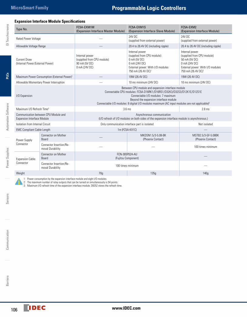
OI T
ouch
scre
ens
PLCs
Auto
mat
ion
Softw
are
Pow
er S
uppl
ies
Sens
ors
Com
mun
icat
ion
Barr
iers
MicroSmart Family Programmable Logic Controllers
106 www.IDEC.com
Expansion Interface Module Specifications
Type No. FC5A-EXM1M (Expansion Interface Master Module)
FC5A-EXM1S(Expansion Interface Slave Module)
FC5A-EXM2(Expansion Interface Module)
Rated Power Voltage — 24V DC (supplied from external power)
24V DC (supplied from external power)
Allowable Voltage Range — 20.4 to 26.4V DC (including ripple) 20.4 to 26.4V DC (including ripple)
Current Draw(Internal Power/External Power)
Internal power (supplied from CPU module):90 mA (5V DC)0 mA (24V DC)
Internal power (supplied from CPU module):0 mA (5V DC)0 mA (24V DC)External power: With I/O modules 750 mA (26.4V DC)1
Internal power (supplied from CPU module):50 mA (5V DC)0 mA (24V DC)External power: With I/O modules750 mA (26.4V DC)1
Maximum Power Consumption (External Power)1 — 19W (26.4V DC) 19W (26.4V DC)
Allowable Momentary Power Interruption — 10 ms minimum (24V DC) 10 ms minimum (24V DC)
I/O Expansion
Between CPU module and expansion interface moduleConnectable CPU modules: FC5A-D16RK1/D16RS1/D32K3/D32S3/D12K1E/D12S1E
Connectable I/O modules: 7 maximumBeyond the expansion interface module
Connectable I/O modules: 8 digital I/O modules maximum (AC input modules are not applicable)2
Maximum I/O Refresh Time3 3.6 ms 2.8 ms
Communication between CPU Module and Expansion Interface Module
Asynchronous communication (I/O refresh of I/O modules on both sides of the expansion interface module is asynchronous.)
Isolation from Internal Circuit Only communication interface part is isolated Not isolated
EMC Compliant Cable Length 1m (FC5A-KX1C) —
Power Supply Connector
Connector on Mother Board — MKDSN1.5/3-5.08-BK
(Phoenix Contact)MSTB2.5/3-GF-5.08BK
(Phoenix Contact)
Connector Insertion/Re-moval Durability — — 100 times minimum
Expansion Cable Connector
Connector on Mother Board
FCN-365P024-AU (Fujitsu Component) —
Connector Insertion/Re-moval Durability 100 times minimum —
Weight 70g 135g 140g
1: Power consumption by the expansion interface module and eight I/O modules.2: The maximum number of relay outputs that can be turned on simultaneously is 54 points.3: Maximum I/O refresh time of the expansion interface module. D8252 stores the refresh time.
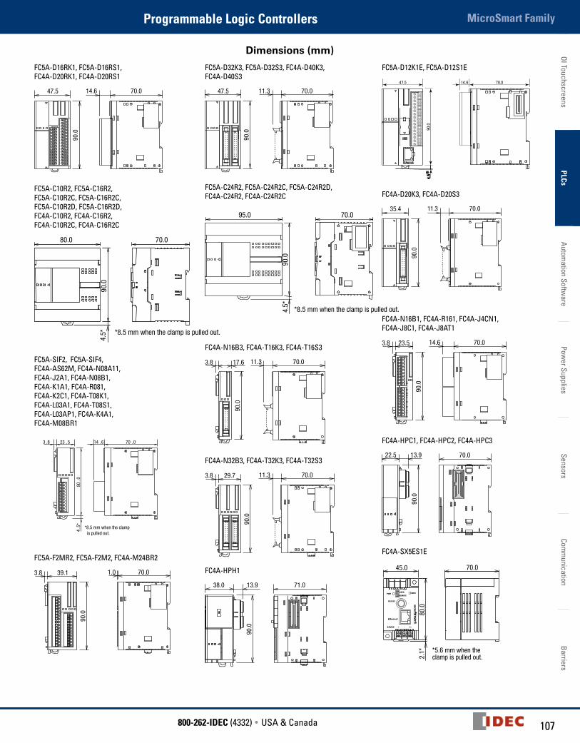
107800-262-IDEC (4332) • USA & Canada
MicroSmart FamilyProgrammable Logic ControllersOI Touchscreens
PLCsAutom
ation Software
Power Supplies
SensorsCom
munication
Barriers
Dimensions (mm)
FC5A-D16RK1, FC5A-D16RS1, FC4A-D20RK1, FC4A-D20RS1
47.5
90.0
70.014.6
FC5A-C10R2, FC5A-C16R2, FC5A-C10R2C, FC5A-C16R2C, FC5A-C10R2D, FC5A-C16R2D, FC4A-C10R2, FC4A-C16R2, FC4A-C10R2C, FC4A-C16R2C
80.0 70.0
90.0
4.5* *8.5 mm when the clamp is pulled out.
FC5A-SIF2, FC5A-SIF4, FC4A-AS62M, FC4A-N08A11, FC4A-J2A1, FC4A-N08B1, FC4A-K1A1, FC4A-R081, FC4A-K2C1, FC4A-T08K1, FC4A-L03A1, FC4A-T08S1, FC4A-L03AP1, FC4A-K4A1, FC4A-M08BR1
4.5
*
*8.5 mm when the clamp is pulled out.
23 .5 14 .6 70 .0
90.0
3 .8
6.3
23.5
3.0
90.0
103.
0
2-ø4.3
FC5A-F2MR2, FC5A-F2M2, FC4A-M24BR2
70.01.039.13.8
90.0
FC5A-D32K3, FC5A-D32S3, FC4A-D40K3, FC4A-D40S3
47.5
90.0
70.011.3
35.4
90.0
70.011.3
FC5A-C24R2, FC5A-C24R2C, FC5A-C24R2D, FC4A-C24R2, FC4A-C24R2C
95.0 70.0
90.0
4.5*
*8.5 mm when the clamp is pulled out.
FC4A-N16B3, FC4A-T16K3, FC4A-T16S3
70.011.317.63.8
90.0
FC4A-N32B3, FC4A-T32K3, FC4A-T32S3
70.011.329.73.8
90.0
FC4A-HPH1
71.0
90.0
38.0 13.9
FC5A-D12K1E, FC5A-D12S1E
FC4A-D20K3, FC4A-D20S3
35.4
90.0
70.011.3
FC4A-N16B1, FC4A-R161, FC4A-J4CN1, FC4A-J8C1, FC4A-J8AT1
70.014.623.53.8
90.0
FC4A-HPC1, FC4A-HPC2, FC4A-HPC3
70.0
90.0
22.5 13.9
FC4A-SX5ES1E
45.0
80.0
70.0
2.1* *5.6 mm when the
clamp is pulled out.
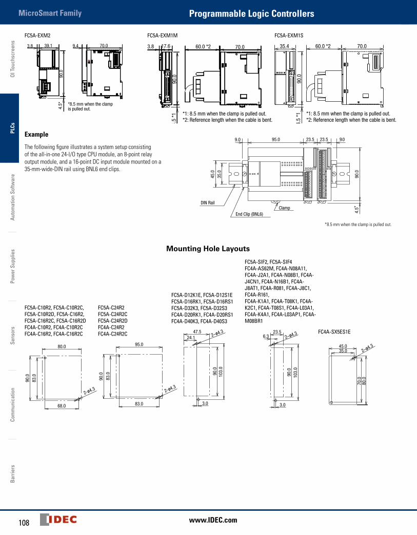
OI T
ouch
scre
ens
PLCs
Auto
mat
ion
Softw
are
Pow
er S
uppl
ies
Sens
ors
Com
mun
icat
ion
Barr
iers
MicroSmart Family Programmable Logic Controllers
108 www.IDEC.com
FC5A-EXM2
39.1 9.4 70.0
90.0
3.8
4.5* *8.5 mm when the clamp
is pulled out.
FC5A-EXM1M
17.6
90.0
3.8 60.0 *2 70.0
4.5
*1 *1: 8.5 mm when the clamp is pulled out.*2: Reference length when the cable is bent.
FC5A-EXM1S
35.4
90.0
60.0 *2 70.0
4.5
*1 *1: 8.5 mm when the clamp is pulled out.*2: Reference length when the cable is bent.
Example
The following figure illustrates a system setup consisting of the all-in-one 24-I/O type CPU module, an 8-point relay output module, and a 16-point DC input module mounted on a 35-mm-wide-DIN rail using BNL6 end clips.
95.0
DIN Rail
End Clip (BNL6)
23.5 23.5 9.09.0
90.0
45.0
35.0
Clamp
4.5*
*8.5 mm when the clamp is pulled out.
Mounting Hole Layouts
FC5A-C10R2, FC5A-C10R2C, FC5A-C10R2D, FC5A-C16R2, FC5A-C16R2C, FC5A-C16R2D FC4A-C10R2, FC4A-C10R2C FC4A-C16R2, FC4A-C16R2C
90.0
83.0
68.0
80.0
2-ø4.3
FC5A-C24R2 FC5A-C24R2C FC5A-C24R2D FC4A-C24R2 FC4A-C24R2C
90.0
83.0
83.0
95.0
2-ø4.3
FC5A-D12K1E, FC5A-D12S1E FC5A-D16RK1, FC5A-D16RS1 FC5A-D32K3, FC5A-D32S3 FC4A-D20RK1, FC4A-D20RS1 FC4A-D40K3, FC4A-D40S3
90.0
103.
0
47.524.1 2–ø4.3
3.0
FC5A-SIF2, FC5A-SIF4 FC4A-AS62M, FC4A-N08A11, FC4A-J2A1, FC4A-N08B1, FC4A-J4CN1, FC4A-N16B1, FC4A-J8AT1, FC4A-R081, FC4A-J8C1, FC4A-R161, FC4A-K1A1, FC4A-T08K1, FC4A-K2C1, FC4A-T08S1, FC4A-L03A1, FC4A-K4A1, FC4A-L03AP1, FC4A-M08BR1
23.56.3
3.0
90.0
103.
0
2–ø4.3 FC4A-SX5ES1E
45.035.0
80.0
70.0
2–ø4.3
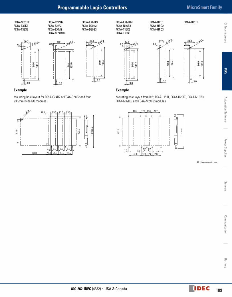
109800-262-IDEC (4332) • USA & Canada
MicroSmart FamilyProgrammable Logic ControllersOI Touchscreens
PLCsAutom
ation Software
Power Supplies
SensorsCom
munication
Barriers
FC4A-N32B3 FC4A-T32K3 FC4A-T32S3
FC5A-F2MR2 FC5A-F2M2 FC5A-EXM2 FC4A-M24BR2
FC5A-EXM1S FC4A-D20K3 FC4A-D20S3
FC5A-EXM1M FC4A-N16B3 FC4A-T16K3 FC4A-T16S3
FC4A-HPC1 FC4A-HPC2 FC4A-HPC3
FC4A-HPH1
29.76.3
3.0
90.0
103.
0
2–ø4.3 39.16.3
3.0
90.0
103.
0
2–ø4.3
103.
090
.0
35.424.1
3.0
2-ø4.3
90.0
103.
0
17.66.3 2–ø4.3
3.0
22.54.8
3.0
90.0
103.
0
2–ø4.3 38.020.3
3.0
90.0
103.
0
2–ø4.3
Example
Mounting hole layout for FC5A-C24R2 or FC4A-C24R2 and four 23.5mm-wide I/O modules
23.5 23.5 23.512.3
15.3 23.5 23.5 23.583.0
3.0 3.0 3.0 3.0
103.
0
83.0
10–ø
4.3
113.
0±0.
2Example
Mounting hole layout from left, FC4A-HPH1, FC4A-D20K3, FC4A-N16B3, FC4A-N32B3, and FC4A-M24R2 modules
41.8
3.0 3.03.0
3.03.0
41.8 17.6 17.6 29.7
103.
0
17.6 17.6 29.7
113.
0±0.
2
All dimensions in mm.
Related Documents