J&L Nuclear Instruments and Methods in Physics Research A 356 (19951457-467 NUCLEAR . -- l!!B g ELSEYIER INSTRUMENTS 8 METHODS IN PHYSICS RESEARCH Sectton A Programmable active memories in real-time tasks: implementing data-driven triggers for LHC experiments D. Belosloudtsev a, P. Bertin f, R.K. Bock b, * , P. Boucard f, V. Dijrsing d, P. Kammel ‘, S. Khabarov a, F. Klefenz d, W. Krischer b, A. Kugel d, L. Lundheim b-1,R. Mtinner d, L. Moll e, K.H. Noffz d, A. Reinsch ‘, D. Ronein f, M. Shand f, J. Vuillemin f, R. Zoz d a Joint Institute for Nuclear Research, Dubna, Russian Federation ’ CERN. European Organisation for Nuclear Research, Geneva, Switzerland ’ Institutfiir Informatik, Unit~ersitiit Jena, Jena. Germany ’ Institut fir Informatik V, Universitiit Mannheim, Mannheim, Germany e Ecole Nationale Superieure des Tele’communications, Paris, France f Digital Equipment Corporation, Paris Research Laboratory, Rueil-Malmaison, France Received 3 October 1994; revised form received 4 November 1994 Abstract The future Large Hadron Collider (LHC), to be built at CERN, presents among other technological challenges a formidable problem of real-time data analysis. At a primary event rate of 40 MHz, a multi-stage trigger system has to analyze data to decide which is the fraction of events that should be preserved on permanent storage for further analysis. We report on implementations of local algorithms for feature extraction as part of triggering, using the detectors of the proposed ATLAS experiment as a model. The algorithms were implemented for a decision frequency of 100 kHz, on different data-driven programmable devices based on structures of field-programmable gate arrays and memories. The implementa- tions were demonstrated at full speed with emulated input, and were also integrated into a prototype detector running in a test beam at CERN, in June 1994. 1. Introduction: the LHC triggering challenge The community of High Energy Physics has just de- cided to go forward with the next generation collider to be built at CERN, the “Large Hadron Collider” or LHC. This new instrument will allow the international commu- nity of researchers to explore unknown areas of physics at the smallest scale, as it collides two counter-rotating beams of protons each at an energy of 7000 GeV, not attainable today. The development of critical components for this collider, to be installed in the existing LEP underground ring, is well advanced: in particular, the critical supercon- ducting magnets with fields around 9 T have been industri- ally produced and successfully tested. Experimentation in that ring is expected to start at the beginning of the next century, in an optimistic scenario around the year 2002. * Corresponding author. ’ On leave from SwTrtindelag College, Trondheim, with sup- port from Norges forskningsrid. One characteristic property of the future collider [I] arises from the fact that the collisions giving clues to the physics of interest are rare, and in particular the ratio between the interesting and the overall collision rate is very small, like one in a million. The accelerator builders, therefore, put their ingenuity to work for achieving the highest possible “luminosity”, i.e. beam density and colli- sion rate. They do this by fine focusing the largest possible number of protons into packets (“bunches”) which follow each other at very short time intervals (25 ns - correspond- ing to not a very long inter-bunch distance, about 8 m at the speed of light). The detectors studying the collisions will then have to deal with very high rates of events and must attempt to achieve a time separation that takes advan- tage of the bunch structure - the limit being that some of the physics processes put to use in detectors take longer than the bunch separation. Although only partially true at high luminosity (multi- ple collisions will occur in a single bunch crossing, and appear as one “supercollision”), let us assume that the problem of separating collisions recorded in the detector into individual signals can be solved. There remains yet another challenge, though: to use the signals from a single 0168-9002/95/$09.50 0 1995 Elsevier Science B.V. All rights reserved .SSDI 0168-9002(94)01397-7

Welcome message from author
This document is posted to help you gain knowledge. Please leave a comment to let me know what you think about it! Share it to your friends and learn new things together.
Transcript
J&L Nuclear Instruments and Methods in Physics Research A 356 (19951457-467 NUCLEAR . --
l!!B g
ELSEYIER
INSTRUMENTS 8 METHODS IN PHYSICS RESEARCH
Sectton A
Programmable active memories in real-time tasks: implementing data-driven triggers for LHC experiments
D. Belosloudtsev a, P. Bertin f, R.K. Bock b, * , P. Boucard f, V. Dijrsing d, P. Kammel ‘, S. Khabarov a, F. Klefenz d, W. Krischer b, A. Kugel d, L. Lundheim b-1, R. Mtinner d,
L. Moll e, K.H. Noffz d, A. Reinsch ‘, D. Ronein f, M. Shand f, J. Vuillemin f, R. Zoz d
a Joint Institute for Nuclear Research, Dubna, Russian Federation
’ CERN. European Organisation for Nuclear Research, Geneva, Switzerland ’ Institutfiir Informatik, Unit~ersitiit Jena, Jena. Germany
’ Institut fir Informatik V, Universitiit Mannheim, Mannheim, Germany e Ecole Nationale Superieure des Tele’communications, Paris, France
f Digital Equipment Corporation, Paris Research Laboratory, Rueil-Malmaison, France
Received 3 October 1994; revised form received 4 November 1994
Abstract The future Large Hadron Collider (LHC), to be built at CERN, presents among other technological challenges a
formidable problem of real-time data analysis. At a primary event rate of 40 MHz, a multi-stage trigger system has to
analyze data to decide which is the fraction of events that should be preserved on permanent storage for further analysis. We report on implementations of local algorithms for feature extraction as part of triggering, using the detectors of the proposed ATLAS experiment as a model. The algorithms were implemented for a decision frequency of 100 kHz, on different data-driven programmable devices based on structures of field-programmable gate arrays and memories. The implementa- tions were demonstrated at full speed with emulated input, and were also integrated into a prototype detector running in a
test beam at CERN, in June 1994.
1. Introduction: the LHC triggering challenge
The community of High Energy Physics has just de- cided to go forward with the next generation collider to be built at CERN, the “Large Hadron Collider” or LHC. This new instrument will allow the international commu- nity of researchers to explore unknown areas of physics at the smallest scale, as it collides two counter-rotating beams
of protons each at an energy of 7000 GeV, not attainable today. The development of critical components for this collider, to be installed in the existing LEP underground ring, is well advanced: in particular, the critical supercon- ducting magnets with fields around 9 T have been industri-
ally produced and successfully tested. Experimentation in that ring is expected to start at the beginning of the next century, in an optimistic scenario around the year 2002.
* Corresponding author.
’ On leave from SwTrtindelag College, Trondheim, with sup-
port from Norges forskningsrid.
One characteristic property of the future collider [I]
arises from the fact that the collisions giving clues to the physics of interest are rare, and in particular the ratio between the interesting and the overall collision rate is very small, like one in a million. The accelerator builders, therefore, put their ingenuity to work for achieving the highest possible “luminosity”, i.e. beam density and colli-
sion rate. They do this by fine focusing the largest possible
number of protons into packets (“bunches”) which follow each other at very short time intervals (25 ns - correspond- ing to not a very long inter-bunch distance, about 8 m at the speed of light). The detectors studying the collisions will then have to deal with very high rates of events and
must attempt to achieve a time separation that takes advan- tage of the bunch structure - the limit being that some of
the physics processes put to use in detectors take longer than the bunch separation.
Although only partially true at high luminosity (multi- ple collisions will occur in a single bunch crossing, and appear as one “supercollision”), let us assume that the problem of separating collisions recorded in the detector into individual signals can be solved. There remains yet another challenge, though: to use the signals from a single
0168-9002/95/$09.50 0 1995 Elsevier Science B.V. All rights reserved
.SSDI 0168-9002(94)01397-7
458 D. Belosloudrsec~ et ai. / Nstci. Ins&. and Meth. in Phys. Res. A 3556 (I 9951 45 7-16 7
collision, or at least a subset of them, for deciding if the
collision at hand should be analyzed in more detail and eventually recorded. The detectors are, of course, con-
structed to provide signals corresponding to the signatures of interesting collisions, in nearly all cases characterized
by high transverse momenta and by the occurrence of leptons (electrons, muons, tau-s, and neutrinos). This selec- tion procedure of entire collisions is called “triggering”,
and is familiar to physicists from past experiments, albeit at rates much lower than those imposed by the LHC. Our
present contribution discusses briefly the structure of trig- gers at the LHC, and a specific implementation possibility of one critical trigger part.
2. Trigger structure
Physics at the LHC will start with a primary event rate of 40 MHz, the bunch crossing frequency. Each event is characterized by several Mbytes of information, once it is fully digitized. In real time at high frequency before rate-reducing triggers, this volume of information is trans- mitted (in analog or digital form) in parallel into many
thousands of individual buffers, with characteristics spe- cific to the different subdetectors. The task of the trigger is
to find the small number of interesting physics events, not more than a few (to be specific, certainly less than a hundred) per second.
2.1. Overall structure
A succession of event selection algorithms is applied; close to the detectors they have to run at bunch crossing frequency and must be simple enough to be implemented in custom-made or specifically adapted hardware, with
limited or no programmability. As there is a finite latency, viz. delay between the availability of data and a final “yes/no” decision, transmission and operations have to
be pipelined and all data stored in a buffer, to avoid dead
time. As the successive stages of event selection reduce the
rates, algorithms of increasing complexity and imple- mented in processors of some generality become necessary
and possible. We concentrate in this paper on an imple- mentation of “second-level” algorithms, where the as- sumed input rate of events does not exceed 100 kHz. The algorithms to be implemented at this level in order to achieve another rate reduction of a factor of - 100, are experiment-dependent, examples are discussed below.
This somewhat idealized trigger structure is completed
by a “third-level” trigger. We assume that it can be implemented as a group of general-purpose processors, each of which is served a full event (- 1000 events/s), and executes high-level code that allows a final data reduction in real time. See Fig. 1.
2.2. Structure of the second-level trigger, functional
In R&D work over the last few years ‘, several guid- ing principles have emerged which are by now quite
generally accepted. One of them is the fundamental Re- gion-of-Interest (Rod concept for level-2 triggering, very critical at least at high luminosity (viz. at high level-l rates). The RoI concept relies on the level-l trigger to identify those parts of the detector containing candidate
features (electrons, photons, muons, jets). Only the data fraction in this candidate region (of order a few % of the
total) is considered relevant and is moved to the level-2 processors; the restricted readout alleviates the very strin- gent bandwidth requirements on providing data for algo-
rithms from distributed buffers, at high frequency. Simul- taneously, the RoI concept considerably simplifies algo- rithms: local algorithms convert limited data from a single
subdetector into variables containing the relevant physics message (“features”), in order to confirm or disprove a hypothesis known from level-l.
We can decompose the problem of second-level trigger- ing in some detail, using as model the detector design as
pursued in the ongoing work on LHC experimental propos- als (two proton-proton experiments are planned, they are known under the names ATLAS and CMS). This structur- ing of the problem is vital to limit the choices of transmis-
sion and processing technology, and to introduce the use of natural parallelism. We consider three phases:
Phase 1 consists of the buffering of level-l selected
data, and the collection of regions of interest. Raw detector data, after a level-l (Lll trigger has occurred, are transmit- ted via cables or fibers and collected in multiple local non-overlapping memory modules, the L2 buffers, which hold information over the duration of level-2 (L2) opera- tion. A device guided by Ll, the Rol-builder, indicates regions of interest, which in general extend across the
boundaries of physical L2 buffers. The data pertaining to RoI-s can be selected making use of both the subdetector
and the RoI parallelisms, we term this RoI collection. Phase 2 consists of “feature extraction”, or local pro-
cessing of the data in a single RoI of a subdetector. On data collected for a single RoI, a relatively simple feature extraction algorithm can perform a local pre-processing function. Features are variables containing the relevant
physics message, like cluster or track parameters that can be used to corroborate or disprove the different physics hypotheses. Feature extraction algorithms have a locality that permits to exploit the natural double parallelism of RoIs and subdetectors. Future simulation will have to show
’ This work is executed in various R&D projects reviewed by
the “Detector Research and Development Committee” (DRDC).
Second-level triggers are specifically studied by the project called
EAST or RDll.
D. Belosloudtseu et al. /Nucl. Ins&. and Meth. in Phys. Res. A 356 (1995) 457-467 459
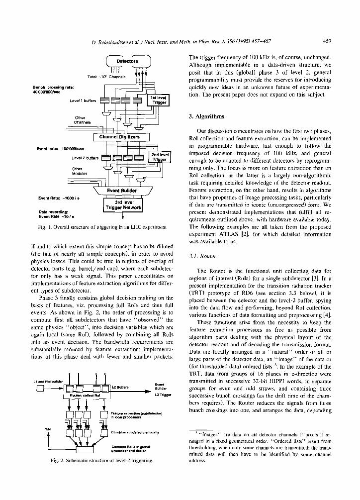
Y-n-T Total: -108 Channels
Bunch crossing rate: 4o’ooomo/~c
Level 1 buffers
Other
Level 2 buffers
Event Builder
Event Rate: -1000 Is
Data recording: Event Rate -10 I g
Fig. 1. Overall structure of triggering in an LHC experiment
if and to which extent this simple concept has to be diluted (the fate of nearly all simple concepts), in order to avoid physics losses. This could be true in regions of overlap of
detector parts (e.g. barrel/end cap), where each subdetec- tor only has a weak signal. This paper concentrates on implementations of feature extraction algorithms for differ-
ent types of subdetector. Phase 3 finally contains global decision making on the
basis of features, viz. processing full RoIs and then full events. As shown in Fig. 2, the order of processing is to combine first all subdetectors that have “observed” the
same physics “object”, into decision variables which are
again local (same RoI), followed by combining all RoIs
into an event decision. The bandwidth requirements are substantially reduced by feature extraction; implementa- tions of this phase deal with fewer and smaller packets.
Fig. 2. Schematic structure of level-2 triggering.
The trigger frequency of 100 kHz is, of course, unchanged.
Although implementable in a data-driven structure, we
posit that in this (global) phase 3 of level 2, general programmability must provide the reserves for introducing
quickly new ideas in an unknown future of experimenta- tion. The present paper does not expand on this subject.
3. Algorithms
Our discussion concentrates on how the first two phases,
Rol collection and feature extraction, can be implemented in programmable hardware, fast enough to follow the imposed decision frequency of 100 kHz, and general
enough to be adapted to different detectors by reprogram-
ming only. The focus is more on feature extraction than on Rol collection, as the latter is a largely non-algorithmic
task requiring detailed knowledge of the detector readout. Feature extraction, on the other hand, results in algorithms that have properties of image processing tasks, particularly if data are transmitted in iconic (uncompressed) form. We present demonstrated implementations that fulfill all re-
quirements outlined above, with hardware available today. The following examples are all taken from the proposed experiment ATLAS [2], for which detailed information was available to us.
3.1. Router
The Router is the functional unit collecting data for regions of interest (RoIs) for a single subdetector [3]. In a present implementation for the transition radiation tracker (TRT) prototype of RD6 (see section 3.3 below), it is placed between the detector and the level-2 buffer, spying into the data flow and performing, beyond RoI collection. various functions of data formatting and preprocessing [4].
These functions arise from the necessity to keep the
feature extraction processors as free as possible from
algorithm parts dealing with the physical layout of the detector readout and of decoding the transmission format. Data are locally arranged in a “natural” order of all or
large parts of the detector data, an “image” of the data or (for thresholded data) ordered lists ‘. In the example of the TRT, data from groups of 16 planes in z-direction were transmitted in successive 32-bit HIPPI words, in separate
groups for even and odd straws, and containing three successive bunch crossings (as the drift time of the cham- bers requires). The Router reduces the signals from three bunch crossings into one, and arranges the data, depending
3,, Images” are data on all detector channels (“pixels”) ar-
ranged in a fixed geometrical order. “Ordered lists“ result from
thresholding. when only some channels are transmitted; the trans-
mitted data will then have to be identified by some channel
address.
JhO D. Belosloudtsec et ai. /Nucl. frtstr. and Meth. in Phys. Res. A 356 (1995) 457-467
on straw signal amplitudes, into two binary images in memory corresponding to data with low and high thresh- old. Only the part of the image corresponding to an Rol (indicated from level l’s RoI builder) has to be transmitted to the feature extractor.
For a later generalization of this Router unit to other and larger detectors the challenge consists in routing infor-
mation from hundreds of data carriers (fibers) and buffers to a single output per RoI. A data-driven implementation
using specialized connections and programmable devices
(FPGAs) has been proposed [5]. A particular difficulty
arises from thresholded data transmitted in lists of dynamic length, as is necessary for low-occupancy devices like the
Si tracker (SCT). Potentially, these data can be accumu-
lated for each RoI in a variable-length list, one for every potential part of the RoI. Only the parts corresponding to active RoIs will then be combined and transmitted for feature extraction.
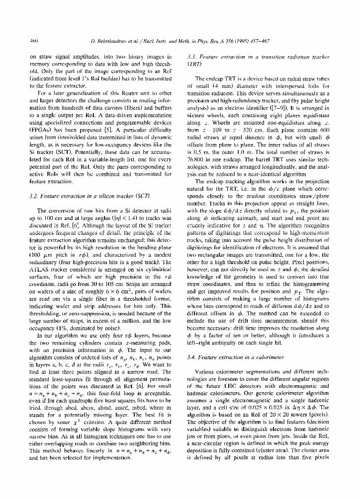
3.2. Feature extraction in a silicon tracker (XT)
The conversion of raw hits from a Si detector at radii
up to 100 cm and at large angles (]n] < 1.4) to tracks was discussed in Ref. [6]. Although the layout of the Si tracker
undergoes frequent changes of detail, the principle of the feature extraction algorithm remains unchanged: this detec- tor is powerful by its high resolution in the bending plane
(100 pm pitch in r$), and characterized by a modest redundancy (four high-precision hits in a good track). The ATLAS tracker considered is arranged on six cylindrical surfaces, four of which are high precision in the r+ coordinate, radii go from 30 to 105 cm. Strips are arranged on wafers of a size of roughly 6 X 6 cm’, pairs of wafers
are read out via a single fiber in a thresholded format, indicating wafer and strip addresses for hits only. This
thresholding, or zero-suppression, is needed because of the large number of strips, in excess of a million, and the low occupancy (1%. dominated by noise).
In our algorithm we use only four r4 layers, because the two remaining cylinders contain z-measuring pads, with no precision information in 4. The input to our
algorithm consists of ordered lists of n,, n,,, n,, rr,, points in layers a, b, c, d at the radii r,, r,,, rc, rd. We want to find at least three points aligned in a narrow road. The standard least-squares fit through all alignment permuta- tions of the points was discussed in Ref. [6]. For small n = “a + nb + n, + rzd, this four-fold loop is acceptable, even if for each quadruple five least squares fits have to be tried, through .abcd, abcm, abmd, amcd, mbcd, where m stands for a potentially missing layer. The best fit is chosen by some xZ criterion. A quite different method consists of forming variable slope histograms with very narrow bins. As in all histogram techniques one has to use either overlapping roads or combine two neighboring bins. This method behaves linearly in n = n, + rrb + n, + n,,, and has been selected for implementation.
3.3. Feature extracriotl in a trar~sitiot~ radiation tracker
(TRT)
The endcap TRT is a device based on radial straw tubes of small (4 mm) diameter with interspersed foils for transition radiation. This device serves simultaneously as a precision and high-redundancy tracker, and (by pulse height
analysis) as an electron identifier ([7-91). It is arranged in sixteen wheels, each containing eight planes equidistant
along z. Wheels are mounted non-equidistant along 2, from z = 109 to z = 320 cm. Each plane contains 600 radial straws at equal distance in 4, but with small 4
offsets from plane to plane. The inner radius of all straws
is 0.5 m. the outer 1.0 m. The total number of straws is 76800 in one endcap. The barrel TRT uses similar tech- nologies. with straws arranged longitudinally, and the anal- ysis can be reduced to a near-identical algorithm
The endcap tracking algorithm works in the projection natural for the TRT, i.e. in the d/z plane which corre- sponds closely to the readout coordinates straw/plane
number. Tracks in this projection appear as straight lines, with the slope d4/dz directly related to p7. the position along 4 indicating azimuth, and start and end point are
crudely indicative for z and n. The algorithm recognizes patterns of digitizings that correspond to high-momentum
tracks, taking into account the pulse height distribution of digitizings for identification of electrons. It is assumed that two rectangular images are transmitted, one for a low, the other for a high threshold on pulse height. Pixel positions, however, can not directly be used as z and 4; the detailed knowledge of the geometry is used to convert into true straw coordinates, and thus to refine the histogramming and get improved results for position and pT. The algo-
rithm consists of making a large number of histograms
whose bins correspond to roads of different d 4/d z and to different offsets in 4. The method can be extended to include the use of drift time measurement. should this become necessary: drift time improves the resolution along
4 by a factor of ten or better. although it introduces a left-right ambiguity on each single hit.
3.4. Feature extraction in a calorimeter
Various calorimeter segmentations and different tech- nologies are foreseen to cover the different angular regions of the future LHC detectors with electromagnetic and hadronic calorimeters. Our generic calorimeter algorithm assumes a single electromagnetic and a single hadronic layer, and a cell size of 0.025 X 0.025 in An X A~#J. The algorithm is based on an RoI of 20 X 20 towers (pixels). The objective of the algorithm is to find features (decision variables) suitable to distinguish electrons from hadronic jets or from pions, or even pions from jets. Inside the RoI. a near-circular region is defined in which the peak energy deposition is fully contained (cluster area). The cluster area is defined by all pixels at radius less than five pixels
D. BelosloudtseLI et al. / Nucl. Instr. and Meth. in Phys. Res. A 3.56 (1995) 457-467 461
distant from the cluster center, defined as center of gravity
X , y,, (obtained from summed electromagnetic and
hcamdronic cells with energy E,,,):
C( X&J) c( Yl.jEi.j) X cm = CE; j ’ ‘Cm =
CEi,j ’
summed over the RoI.
Simple variables like hadronic energy fraction over the
cluster area, or more complicated features like the second
moment of the cluster radius in two dimensions weighted with energy, or energy sums in different ring-shaped zones
and longitudinal volumes of fine granularity, are then calculated over the cluster area. These features are derived from the ones used in off-line programs, and contain relevant information for electron/pion/jet discrimination
that can not be explored in a level-l algorithm. In a simulation [lo] the analysis over an RoI of An X A 4 = 0.5 X 0.5 gives a factor around ten in background rate reduc- tion, disregarding information from other detectors (reject- ing the background of level-l-accepted QCD jets in an electron sample). Feature output also includes the position of the cluster area, refining the position resolution inside
the RoI.
4. Implementing functions in programmable hardware
Two opposite and extreme ways seem possible to im- plement a specific high-speed digital processing task. The apparently simplest is to program some general-purpose processor to perform the processing at hand. In this soft- ware approach, one effectively maps the algorithm of interest onto a fured machine architecture. The structure of that machine has been highly optimized by its manufac- turer to process arbitrary code. In many cases, it is poorly suited to the specific algorithm. This is particularly true if
the algorithm includes low-level bit handling as in our
case. On the other hand, a general-purpose processor can be programmed to process any computable function, and thus is infinitely flexible. Due to high-volume production, such solutions may still be cost-effective overall.
The opposite extreme is to design custom circuitry for the specific algorithm. In this hardware approach, the
entire machine structure is tailored to the application. The result is much more efficient in execution time, with less actual circuitry than what general-purpose computers re- quire. The drawback of the hardware approach is that a specific architecture is limited to processing a single or a small number of specified algorithms. If we add special- purpose hardware to a universal machine, say for image processing tasks, we may speed up the processor, but we know well that this is limited to the fraction of the code concerned (Amdahl’s law of disappointing returns).
This paper discusses an alternative architecture offering the best from both worlds: software versatility and hard-
ware performance. One such device has been used for RoI
collection in a very scaled-down case, and has served to understand the principle of generalizing the data collection of subsets of a very large (multi-crate) data acquisition system. Two devices have been used for feature extraction, DECPeRLe-1 and Enable.‘They differ in that DECPeRLe-1 was conceived with multiple applications in mind, whereas Enable is a configuration optimized for a specific algo-
rithm. On both devices, pipelined algorithms were imple-
mented that could keep up with the required data flow
corresponding to a decision frequency of 100 kHz. Excel- lent adaptability was demonstrated in the number of imple-
mented algorithms on DECPeRLe-1.
4.1. General-purpose machines bused on FPGAs
We describe an architecture called Programmable Ac- tive Memories (PAMs), which should be seen as a novel form of universal hardware co-processor ‘. Based on Field Programmable Gate Array (FPGA) technology, a PAM can be dynamically configured into a large number of devices of very different performance and software charac- teristics. The first commercial FPGA was introduced in 1986 by XiIinx [ll]. This revolutionary component has a
large internal configuration memory; in download mode,
this memory can be written into from some external device. Once configured, an FPGA behaves like a regular
application-specific integrated circuit (ASIC). Any syn- chronous digital circuit can be emulated on a large enough FPGA or array of FPGAs, through a suitable configura- tion. PAM programming thus is an alternative to classical gate-array and full-custom ASIC design, but also has aspects of high-level programming.
An FPGA is simply a regular mesh of n X m simple programmable logic units, “gates”. It is a [lirtuul circuit which behaves like a specific ASIC if fed with the proper configuration bits. A PAM implements, from multiple
FPGAs, a uirtuul machine dynamically configurable as a
large number of specific hardware devices. A generic PAM consists of a matrix of FPGAs connected through links to a host processor. The host downloads configura- tion bit streams into the PAM, making it behave electri- cally and logically like a machine defined by the specific bit stream. It may operate in stand-alone mode, or commu- nicate with some external system through links. It may operate as a co-processor under host control, specialized to
4 To justify the name PAM, note that a PAM is attached to
some high-speed bus of a host computer, like any RAM memory
module. The processor can write into, and read from the PAM.
Unlike RAM however, a PAM processes data between write and
read instructions, which makes it “active” memory. The specific
processing is determined by the contents of its configuration bit
stream, which can be updated by the host in a matter of millisec-
onds, thus the “programmable” qualifier.
462 D. Belosloudtsec et al. /Nuci. Ins&. and Meth. in Phys. Res. A 356 (1995) 457-467
speed-up some crucial computation. It may operate as both, and connect the host to some external system. like an audio or video device, a specific particle detector, or some other PAM.
The reprogramming facility means that prototypes can
quickly be made, tested and corrected. The development
cycle of circuits with FPGA technology is typically mea- sured in weeks, as opposed to months for hardwired gate
array techniques. FPGAs, however, are not only used for prototypes, they also get directly incorporated in many production units. In all branches of the electronics industry
other than the mass market, the use of FPGAs has been increasing, despite the fact that their cost is higher than ASKS in volume production. In 1992/93, FPGAs were
the fastest growing part of the semiconductor industry, increasing output by 40%, compared with 10% for chips overall. As a consequence, FPGAs are at the leading edge of silicon devices. The future development of the technol-
ogy has been analyzed in Refs. [12,13]. A current World Wide Web site lists more than 40 different FPGA-based
computer architectures, spread all over the world: http://bongo.cc.utexas.edu/ N guccione/HW_list.html.
The prediction is that the leading edge FPGA of 1992 with 400 gates operating at 25 MHz, will by the year 2001
contain 25k gates operating at 200 MHz.
4.2. A general PAM realization: DECPeRLe-I
DECPeRLe1 is a specific PAM implementation; it was built as an experimental device at Digital’s Paris Research
Laboratory in 1992. Over a dozen copies operate at various scientific centers in the world. We review here the impor-
tant general architectural features of PAMs using the ex-
Host adapter
adrN
ndrE
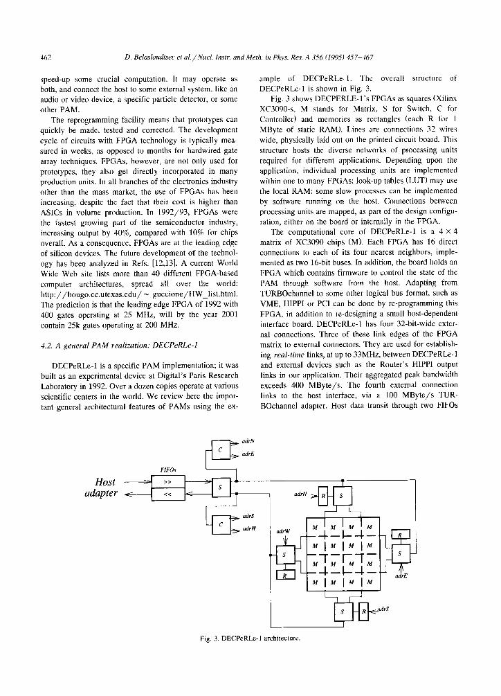
ample of DECPeRLe-I. The overall structure of DECPeRLe-1 is shown in Fig. 3.
Fig. 3 shows DECPERLE-l’s FPGAs as squares (Xilinx XC3090-s, M stands for Matrix, S for Switch, C for Controller) and memories as rectangles (each R for 1
MByte of static RAM). Lines are connections 32 wires wide, physically laid out on the printed circuit board. This
structure hosts the diverse networks of processing units
required for different applications. Depending upon the application, individual processing units are implemented within one to many FPGAs; look-up tables (LUT) may use the local RAM; some slow processes can be implemented by software running on the host. Connections between
processing units are mapped, as part of the design configu- ration, either on the board or internally in the FPGA.
The computational core of DECPeRLe-1 is a 4 X 4 matrix of XC3090 chips (M). Each FPGA has 16 direct connections to each of its four nearest neighbors, imple- mented as two 16-bit buses. In addition, the board holds an
FPGA which contains firmware to control the state of the
PAM through software from the host. Adapting from TURBOchannel to some other logical bus format, such as
VME, HIPPI or PC1 can be done by re-programming this
FPGA. in addition to re-designing a small host-dependent interface board. DECPeRLe-1 has four 32-bit-wide exter- nal connections. Three of these link edges of the FPGA matrix to external connectors. They are used for establish- ing real-time links, at up to 33MHz, between DECPeRLe-1 and external devices such as the Router’s HIPPI output links in our application. Their aggregated peak bandwidth exceeds 400 MByte/s. The fourth external connection
links to the host interface, via a 100 MByte/s TUR- BOchannel adapter. Host data transit through two FIFOs
I
Fig. 3. DECPeRLs-1 architecture.
D. Belosloudtseu et al. / Nuct. Instr. and Meth. in Phys. Res. A 356 (1995) 457-467 463
and a switch FPGA, so that synchronisation between host
and PAM is through data. PAM designs are synchronous circuits: all registers are
updated on each cycle of the same global clock. The maximum speed of a design is directly determined by its critical path. As this varies from one PAM design to
another. the clock distribution speed can be programmed as part of the design configuration; fine tuning is possible
with increments of about O.Ol%, for frequencies up to 100 MHz. A typical DECPeRLe-1 design receives a logically uninterrupted flow of data, through the input FIFO. It
performs some processing, and delivers its results through the output FIFO. The host or attached special hardware is responsible for filling and emptying the other side of both FIFOs. Firmware automatically halts the application clock when DECPeRLe-1 attempts to read an empty FIFO or to write into a full one, effectively providing fully automatic and transparent flow-control. The full firmware functional- ity may be controlled through host software. Most of it is
also available to the hardware design. This allows a design to synchronize with some of the external links. Dynamic
tuning of the clock is also possible, e.g. in designs where a slow and infrequent operation coexists with fast and fre- quent operations. A thorough presentation of the issues
involved in PAM design, with alternative implementation choices, is given by Bertin in Ref. [14].
A PAM program consists of three parts: the driuing software, which runs on the host and controls the PAM hardware: the logic equations describing the synchronous hardware implemented on the PAM board, and the place- ment and routing direct&s that guide the implementation of the logic equations onto the PAM board. The driving
software is written in C or C + + and is linked to a
runtime library encapsulating a device driver. The logic equations and the placement and routing directives are generated algorithmically by a C + + program. As a
deliberate choice of methodology, all PAM design circuits are digital and synchronous. Asynchronous features, such as RAM write pulses, FIFO flag decoding, or clock tuning, are pushed into the firmware where they get implemented once and for all.
A full DECPeRLe-1 design is a large piece of “hard- ware”. The designer encodes, through a stream of 1.5 Mbits, the logic equations, the placement and the routing of fifteen thousand gates, to express the “algorithm”. We chose a C + + library as basis, which enables one to describe the design algorithmically at the structural level, and supply geometric information to guide the final imple- mentation. This type of low-level description is made convenient by the use of basic programming concepts such as arrays, loops, procedures and data abstraction. A second library facilitates the writing of driver software and pro- vides simulation support. In addition, powerful debugging and optimization tools have been developed, enabling the designer to visualize in detail the states of every flip-flop in every FPGA of a PAM board.
Our experience with these programming tools is that
PAM programming is far easier than ASK development;
complex applications spanning dozens of chips can be developed even by newcomers in a matter of a few months.
4.3. Implementing the trigger algorithms in DECPeRLe-1
The general-purpose idea underlying the DECPeRLe-1
board has been demonstrated by mapping all currently defined ATLAS feature extraction algorithms (see Chapter 3) onto this device. The following remarks concern these implementations, and their limitations.
Feature extraction in a silicon tracker (SCT) For all existing implementations of the SCT algorithm,
the same minimal specifications have been used. The task is to find the best track in a set of 64 slopes x 32 4 intercepts, assuming an occupancy of 1% equivalent to
about 30 active pixels per RoI. Software implementations in general-purpose processors are currently 2 or 3 orders of
magnitude slower than the required 100 kHz. Using the
simple histogramming algorithm based on sequential pro- cessing of the list of active pixels, DECPeRLe-1 can keep up with this rate. As the algorithm computation time grows linearly with the number of hits, bursts of high-occupancy images can be absorbed by buffering. The histogram solu- tion uses look-up tables, resulting in flexibility of the
search patterns used. In the implementation on DECPeRLe-1 described in Ref. [15], a 64 X 16 histogram containing 4 bits for each search pattern (1 for each row) is filled by a look-up table while the coordinates of hits
arrive one per clock cycle. The histogram peak is extracted by shift-registers and max-units. At 23 MHz, with an event
frequency of 100 kHz. it is possible to process 230 pixels per event. The circuit also provides all the needed func-
tionality to do multiple passes and extract the best of all the passes. It is also possible to do a zoom after the first pass around the best track to increase the overall precision. Thus, in two passes, a full 64 X 32 grid can be scanned with an average of 115 pixels per event, which is faster than the required performance.
Feature extraction in a transition radiation tracker (TRT) The TRT prototype for our DECPeRLe-1 test run con-
tained two sectors covering an angle (4) of about 30” (32
straws), each sector made of 16 planes spaced along z. An RoI for the prototype was assumed to be 32 x 16 straws (in z X 4); a typical RoI in a future endcap TRT is expected to consist of 16 straws in the & direction and most of the 128 planes. As described in Section 3.3. the aim of the feature extraction task is to identify a straight line in the z-4 plane of the Rol. Based on the number of low and high threshold hits along the track, an electron identification can be made. As for the SCT implementa- tion, the track finding is done by histogramming and peak finding. Instead of using lookup tables, the histogramming
464 D. Belosloudtsec et al. /Nucl. instr. and Meth. in Phys. Res. A 356 11995) 457-467
is performed by a “Fast Hough Transform”. The FHT is a variation of the Hough Transform, and has been fully
described in Ref. [16]. The algorithm uses a 128 X 128 pixel grid covering the
RoI, giving a 4 resolution of l/8 of the inter-straw
distance. The found track is defined by two numbers referring to this grid (see also Ref. [17]), the $ offset (or intercept) denoting the pixel where the line enters the RoI, and the slope expressing how many pixels the line ascends or descends across the RoI. Searching for nearly horizontal tracks, the present implementation is limited to slopes 0, f 1, i: 2, . . . i 15. The output of the algorithm consist of 4
words: track intercept (7 bits), track slope (5 bits), number of low threshold hits along the track (6 bits), and number
of high threshold hits along the track (6 bits). These data are packed into one 32-bit word, and written into the
output FIFO of DECPeRLe-1, subsequently read by the host program. This makes it just possible to fit a his-
togrammer using 31 slopes and 128 intercepts in one DECPeRLe-1 board, with a total of 31 X 128 = 3968 pos-
sible patterns in the pixel grid described above, close to the maximum that can be handled by DECPeRLe-1. A 64-bit sequential processor would need to run at a clock rate of more than 1 GHz (with matched input) to achieve the same
computational result. Using a wider range of slopes (0, i2, f 4, . . . . f 30
pixels), the number of intercepts would be reduced to 64. In a full TRT detector, the RoI will consist of 80-100 planes, giving 3 times the volume of data as in the present
prototype. In addition, drift time data may be included.
The PAM provided by DECPeRLe-1 will not be able to handle this data rate. As faster and larger PAMs are likely
be available in near future, we are confident that a similar implementation for a full detector RoI is a realistic possi-
bility.
Feature extraction in a calorimeter
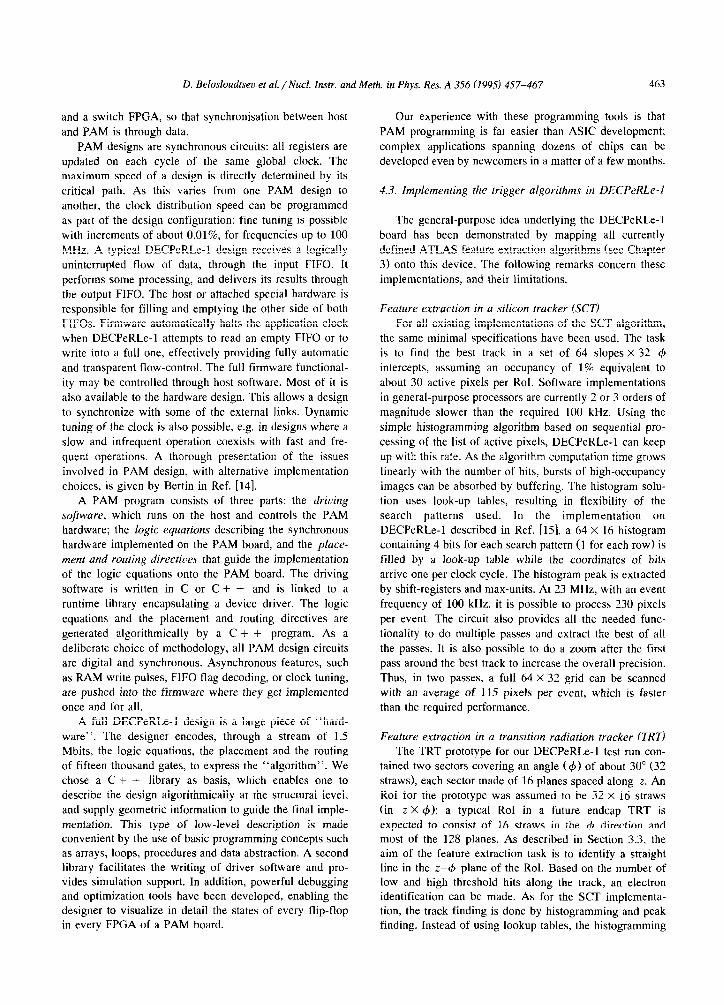
The calorimeter algorithm appears as an ideal image processing application. We have implemented the algo- rithm as a double-pass operation, due to the need to find
n 16b
center-of-gravity values first. In a high-level language
algorithm, the two passes could be combined, if no numer- ical problems arise; on an FPGA-based device, high-preci- sion multiplication would be unduly penalized. The high
input bandwidth (160 MByte/s) and the (self-imposed) low latency constraint constitute a serious challenge to any
implementation. In a previous benchmark exercise [ 181, the possible implementations of the calorimeter algorithm have been discussed at length: PAMs are the only structure found to meet the requirements.
This algorithm was implemented on DECPeRLe-1 with input from the host. Using the external I/O capabilities described for the TRT, detector data input could use two off-the-shelf HIPPI-to-TURBOchannel interface boards
plugged directly onto DECPeRLe-1. The data path inside DECPeRLe-1 uses only about 25% of DECPeRLe-l’s
logic and all the RAM resources, for a virtual computing power of 39 Giga-operations/s (binary). The initial input of 2 X 32 bit at 25 MHz is reduced to two 16-bit pipelines
at 50 MHz, after summing E,, and Ehad. The total
accumulation of E,., and x,,,E, , is done in carry-save accumulators. Meanwhile, the raw data (E,, and E,,,) are stored in an intermediate memory. The masking/summing operations on clusters are performed by using, in a second pipeline, matrices pre-computed for all possible positions of the center of gravity (a relatively small number, due to the limited size of RoI and cluster).
4.4. A PAM realization for a specific problem: Enable
The Enable Machine is a systolic second-level trigger
processor for feature extraction in the transition radiation
tracker (TRT) of ATLAS/LHC [19,20]. Designed at the University of Mannheim for a benchmark exercise pub- lished previously [ 181, the concepts provided by the FPGA matrix made the Enable Machine the only candidate which satisfied all given requirements (DECPeRLe-1 was intro- duced later). The Enable architecture is specifically tai-
lored to this application so as to fit the required full-scale TRT functionality on a single PAM board. This is achieved
Decision T
1ooKHz
lb
Fig. 4. Calorimeter data path.
D. Belosloudtseu et al. /Nucl. Instr. and Meth. in Phys. Res. A 356 (1995) 457-467 465
by two PAM matrices of a total of 36 FPGAs, handling the
two input images in parallel. Enable can be seen, however,
as a PAM implementation optimized for a general class of systolic algorithms with similarities in the data flow. All algorithms implemented so far for the different ATLAS
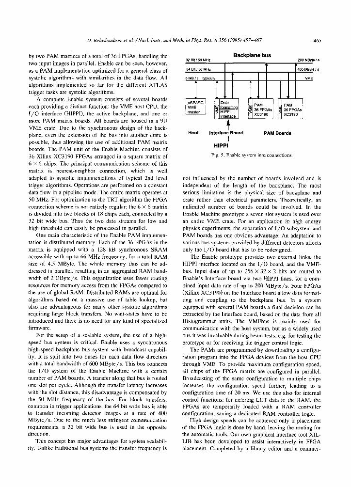
trigger tasks are systolic algorithms. A complete Enable system consists of several boards
each providing a distinct function: the VME host CPU, the I/O interface (HIPPI), the active backplane, and one or more PAM matrix boards. All boards are housed in a 9U VME crate. Due to the synchronous design of the back-
plane, even the extension of the bus into another crate is possible, thus allowing the use of additional PAM matrix boards. The PAM unit of the Enable Machine consists of
36 Xilinx XC3190 FPGAs arranged in a square matrix of 6 X 6 chips. The principal communication scheme of this
matrix is nearest-neighbor connection, which is well adapted to systolic implementations of typical 2nd level
trigger algorithms. Operations are performed on a constant data flow in a pipeline mode. The entire matrix operates at 50 MHz. For optimization to the TRT algorithm the FPGA
connection scheme is not entirely regular; the 6 X 6 matrix is divided into two blocks of 18 chips each, connected by a 32 bit wide bus. Thus the two data streams for low and high threshold can easily be processed in parallel.
One main characteristic of the Enable PAM implemen- tation is distributed memory. Each of the 36 FPGAs in the matrix is equipped with a 128 kB synchronous SRAM
accessible with up to 66 MHz frequency, for a total RAM size of 4.5 MByte. The whole memory thus can be ad- dressed in parallel, resulting in an aggregated RAM band-
width of 2 GByte/s. This organization uses fewer routing resources for memory access from the FPGAs compared to
the use of global RAM. Distributed RAMS are optimal for algorithms based on a massive use of table lookup, but also are advantageous for many other systolic algorithms requiring large block transfers. No wait-states have to be introduced and there is no need for any kind of specialized firmware.
For the setup of a scalable system, the use of a high-
speed bus system is critical. Enable uses a synchronous high-speed backplane bus system with broadcast capabil-
ity. It is split into two buses for each data flow direction with a total bandwidth of 600 MByte/s. This bus connects the I/O system of the Enable Machine with a certain number of PAM boards. A transfer along that bus is routed one slot per cycle. Although the transfer latency increases
with the slot distance, this disadvantage is compensated by the 50 MHz frequency of the bus. For block transfers, common in trigger applications, the 64 bit wide bus is able to transfer incoming detector images at a rate of 400 MByte/s. Due to the much less stringent communication requirements, a 32 bit wide bus is used in the opposite direction.
This concept has major advantages for system scalabil- ity. Unlike traditional bus systems the transfer frequency is
Backplane bus
Host Interface Board PAM Boards I
HIPPI
Fig. 5. Enable system interconnections
not influenced by the number of boards involved and is independent of the length of the backplane. The most serious limitation is the physical size of backplane and
crate rather than electrical parameters. Theoretically, an unlimited number of boards could be involved. In the Enable Machine prototype a seven slot system is used over an entire VME crate. For an application in high energy physics experiments, the separation of l/O subsystem and PAM boards has one obvious advantage: An adaptation to
various bus systems provided by different detectors affects only the I/O board that has to be redesigned.
The Enable prototype provides two external links, the
HIPPI interface located on the I/O board, and the VME- bus. Input data of up to 256 X 32 X 2 bits are routed to
Enable’s interface board via two HIPPI lines, for a com- bined input data rate of up to 200 MByte/s. Four FPGAs
(Xilinx XC31901 on the Interface board allow data format- ting and coupling to the backplane bus. In a system equipped with several PAM boards a final decision can be extracted by the Interface board, based on the data from all Histogrammer units. The VMEbus is mainly used for communication with the host system, but as a widely used bus it was invaluable during beam tests, e.g. for testing the
prototype or for receiving the trigger control logic.
The PAMs are programmed by downloading a configu- ration program into the FPGA devices from the host CPU through VME. To provide maximum configuration speed, all chips of the FPGA matrix are configured in parallel. Broadcasting of the same configuration to multiple chips increases the configuration speed further, leading to a
configuration time of 20 ms. We use this also for internal control functions: for entering LUT data to the RAM, the FPGAs are temporarily loaded with a RAM controller configuration, saving a dedicated RAM controller logic.
High design speeds can be achieved only if placement of the FPGA logic is done by hand, leaving the routing for the automatic tools. Our own graphical interface tool XIL- LIB has been developed to assist interactively in FPGA placement. Completed by a library editor and a commer-
466 D. Belosloudtsec et al./Nucl. Ins@. and Meth. in Phys. Res. A 356 (1995) 457-467
cial schematic layout tool (PADS) for creating the netlist lel. All of these search roads belong to the relevant part of of the connections, we have a powerful toolset for creating the image, tracks at the edges with less than a minimal and updating FPGA designs. The preplaced FPGA design contribution to the image (here 32 pixels) are ignored. is routed by the standard tools (APR). A library generator Because the latency depends linearly on the image size, allows to preserve user-optimized design elements; a large Enable is able to process full detector images (128 planes) number of re-usable library elements is already available. within 3.5 ps. For a Rol size of the TRT prototype XILLIB interfaces to several commercial software tools; ( 16 X 32 pixels of 2 bits) up to 12 RoIs could be processed our experience shows that this fast placement tool in- on one PAM board, corresponding to about 4800 search creases the design speed and flexibility considerably. roads at 100 kHz.
Enable also provides powerful tools for off-line design
verification and on-line debugging. A special microcon-
troller-based test environment has been developed. to be fully integrated into the simulation software. Simulations
run transparently on a software basis, or are executed on a test board. Running a design at full speed for a given number of clock cycles and analyzing the internal states
results in much shorter time for design verification than full software simulation. By performing such tests with
various clock frequencies a close estimation of the timing constraints of the actual design can be obtained. In on-line
debugging data are collected from different stages of En- able’s data path and checked while the Enable Machine is operating. Data may be captured on the (HIPPI) input lines or as they travel from the Enable input board to the Enable
backplane; they are copied to FIFOs on-the-fly, and read by the controlling CPU.
4.5. implementing the TRT algorithm on Enable
A different algorithm could be implemented if TRT
drift time information had to be considered, to obtain higher precision in the trigger. In this alternative, detector
data are assumed to arrive as a list of 16-bit coordinates from hits (pixel addresses), and a massive LUT converts each hit into histogram channel numbers. Again using a
general Hough transform for arbitrary search patterns, every pixel addresses one RAM word, each data bit of this
word corresponds to one histogram channel. The total number of possible histogram channels depends on the width of the RAM data path. Enable’s distributed RAM
provides a possible scaleable implementation for this algo- rithm. The list of hits is routed systolically through the FPGA matrix configured as a linear string of FPGAs. Each FPGA maps the hits onto its dedicated RAM and builds up
part of the Hough space. Each RAM may process approxi- mately 8 banks of histogram channels serially which leads to more than 3000 search roads per PAM matrix board at
100 kHz.
Enable allows maximum flexibility in the pattern defi- nition by using an algorithm based on histogramming along pre-defined search roads that correspond to general template matching. The search patterns are stored in the distributed memory and do not have to be straight or curved lines; nearly arbitrary road shapes can be pro- grammed. The non-equidistant planes along z and the
small r$ offsets inside planes, damaged straws or other unpredictable image distortions are handled in this way.
5. Test runs including Router, DECPeRLe-1 and En-
able
Prototypes of a data-driven Router and an Enable Ma- chine were built and used in 1992/93 with the TRT prototype of RD6. A DECPeRLe-1 board was acquired in
1993.
In the first step two histograms are accumulated from the images corresponding to the two energy thresholds. In a second step the track with the highest electron probabil- ity is determined, using a weighting function (implemented as table lookup) for corresponding histogram channels in the two images; the maximum of this function is evaluated. Simulations have shown that fine-tuning of this function (e.g. dependent on luminosity) is important for maximum trigger efficiency. Each three FPGAs form a processing unit with two FPGAs calculating histograms for two slopes and 20 offsets (low and high threshold), and the third FPGA calculating the weighted maximum. The distributed RAM allows to run all of these units locally and in parallel.
We have used multiple runs in the laboratory using our
own hardware emulator SLATE [21] to test the functioning of the components at full speed. with programmed simu- lated TRT data. We have also connected the Router to- gether with Enable [22] or DECPeRLe-1 in turn, to a prototype TRT detector running during beam test periods in September 1993 and June 1994. Although parasitic to
detector tests, both setups were able to take tens of thou- sands of individual events on tape. The Router demon- strated that its input board was operating in a fully trans- parent way to the detector’s data taking, and showed its programmability by supplying data in different formats to the feature extraction devices.
Built to the specifications of the early TRT benchmark algorithm, Enable handles image sizes up to 255 X 32 pixels of 2 bits each. 400 search roads can be processed in one PAM board for each low and high threshold in paral-
The TRT output, preprocessed by the Router, consists of two images, one for the high and one for the low threshold signal. Each image has 16 32-bit words, each word corresponding to output from 32 straws. The Router was connected to the feature extractors by two HIPPI lines. using for DECPeRLe-1 two commercially available
D. Belosloudtseo et al. /Nucl. Instr. and Meth. in Phys. Res. A 356 (1995) 457-467 467
HIPPI-to-TURBOchannel Interface boards (HTI). The HTI
units could be directly plugged into DECPeRLe-l’s exten-
sion slots, so the DECPeRLe-1 board could be used with- out any hardware changes, only loading the necessary configuration file. Enable has its own HIPPI input board.
During the 1994 beam run the Enable Machine was integrated in the test detector data acquisition system supplied by project RD13. The Enable VME crate was coupled to the data acquisition crate via a VIC bus module containing 4 MByte of memory. During accelerator bursts the memory was filled by Enable data. In the time gap
between bursts the data acquisition system read this buffer. In debug mode the Enable Machine provides data output
of several kBytes per event. These data contain the full histogram content and preprocessed event data from differ-
ent stages within the machine. This feature has success- fully been used for a detailed analysis of the electronics. Off-line analysis verified that both the z-4 corner turning
and the histogrammer produced correct results. During the tests of DECPeRLe-1 an incompatiblility
between the Router and the HTI boards was discovered. causing word losses at the end of each accelerator burst; less than a percent of the events was lost. Events that were successfully transmitted to DECPeRLe-1 were subjected to
off-line analysis after the tests. Data from DECPeRLe-1 were transmitted by Ethernet at the end of each accelerator
burst, and read out together with the raw detector data (a direct connection between DECPeRLe-1 and the DAQ crate was established through VME-based software only
later). The results were associated by event number, and compared bit-by-bit to the output of a simulation program fed with the raw data; a 100% correspondence was found.
6. Conclusions
The concept of programmable active memories (PAMs) has been presented as a general alternative for low-level
and l/O-intensive computing tasks. Two feature extraction devices in this technology were realized for trigger tasks at
a 100 kHz event rate. Both were benchmarked to be far superior in performance to conventional general-purpose and parallel machines in many aspects. The Enable Ma- chirze is a TRT-specialized PAM realization. Its power is in the bandwidth of the distributed RAM and of the I/O system. DECPeRLE-1 has been built for more general applicability, and several trigger algorithms have been
implemented on this device. Parallel synchronous bus sys-
tems with high bandwidth are used in both systems. High flexibility is obtained through the reprogrammability of the basic elements, and by the scalable design. Software tools assure short development times for designs or design changes.
The devices were extensively tested with high-speed input emulating LHC conditions, and were also run as part of beam tests of a TRT detector prototype, using a region-
of-interest (ROD collecting device also based on FPGAs;
they behaved as specified. We have thus demonstrated
with PAM implementations a fully programmable concept which can implement data-driven processing tasks in the second-level trigger, for all presently proposed detector parts and in existing technology. The field-programmable gate array technology used in PAMs is evolving fast. Plans exist in industry for designing larger and faster PAMs, able
to cope with a variety of general image processing prob- lems.
References
[II
Dl
[31
[41
151
161
[71
k31 [91
DO1
1111
[121
[131
iI41
[151
[I61
[1Jl
11Rl
[191
I201
1211
La
Y. Baconnier et al. feds.), CERN/AC/93-03 (1993).
ATLAS, CERN/LHCC/92-4 (1992) and CERN/LHCC 94-
43 (1994).
P. Kammel. A. Reinsch and V. Doming. EAST note 93-13
(1993) (internal).
R.K. Bock, V. Doming. N. Gorbunov. V. Karjavin and A.
Reinsch, EAST note 92-09 (1992) (internal).
P. Kammel, R.K. Bock, V. Dorsing and A. Reinsch, EAST
note 94-14 (1994) (internal).
K. Borer et al.. Nucl. Instr. and Meth. A 336 (1993) 59.
J. Shank et al., Nucl. Instr. and Meth. A 309 (1991) 377.
RD6. CERN/DRDC/93-46 (1993) (Status Report).
M. Stavrianakov, A straw transition radiation tracker for the
LHC, 27th Int. Conf. on High-Energy Physics, Glasgow, July
10-17. 1994. to be published.
G. Klyuchnikov et al., EAST Note 92-23 (1992), and AT-
LAS DAQ Note 007 (1992) (internal).
W.S. Carter, K. Duong, R.H. Freeman, H.C. Hsich, J.Y. Ja.
J.E. Mahoney, L.T. Ngo and S.L. Szc, in: IEEE 1986
Custom Integrated Circuits Conf. (1986) pp. 233-235.
J.E. Vuillemin. in: Programming Languages and System
Architectures. ed. J. Gutknecht. LNCS 782 (Springer, 1994)
pp. 69-86.
J. Vuillemin et al., accepted for publication in IEEE Trans.
VLSI.
P. Bertin, These de Doctorat, Universitc Paris 7, 75005 Paris,
France. 1993.
W. Krischer and L. MoIl. CERN/EAST note 94-21 (1994)
(internal).
J.E. Vuillemin, Int. Conf. on Application-specific Array Pro-
cessors. San Francisco, August 1994. to be published; and J. Vuillemin, CERN/EAST Note 94-12 (1994) (internal).
L. Lundhcim, L. Mall, P. Boucard and J. Vuillemin,
CERN/EAST note 94-20 (1994) (internal).
J. Badicr et al., IEEE Trans. Nucl. Sci. NS-40 (1993) 45.
F. KIefenz, K.H. Noffz, R. Zoz and R. Manner. Proc. IEEE
Nucl. Sci. Symp., San Francisco, CA, USA, 1993. pp. 62-64. F. Klefenz. R. Zoz. K.-H. Noffz and R. Manner, Proc. Comp.
in High Energy Physics, Annecy, France, CERN Rep. 92-07
(1992) pp. 7999802.
B. Green et al.. CERN 92-07 (1992); and E. Denes. EAST
note 92-20 (1992) (internal).
K.H. Noffz. R. Zoz. A. Kugel, F. Klefenz and R. Manner. to
appear in Proc. Comp. in High Energy Physics, San Fran-
cisco, CA, USA, 1994. to be published.
Related Documents