Profibus BTL Bus Coupler BNI PBS-551-000-Z001 BNI PBS-552-000-Z001 Condensed Guide English

Welcome message from author
This document is posted to help you gain knowledge. Please leave a comment to let me know what you think about it! Share it to your friends and learn new things together.
Transcript

Profibus BTL Bus CouplerBNI PBS-551-000-Z001BNI PBS-552-000-Z001
Condensed Guide
English

www.balluff.com
www.balluff.com
Profibus BTL Bus CouplerBNI PBS-551-… / BNI PBS-552-…
3
3
4
2
1 User Instructions 4
1.1 About this guide 41.2 Structure of the guide 41.3 Typographical conventions 41.4 Symbols 51.5 Abbreviations 5
Safety 6
2.1 Intended use 62.2 General safety notes 62.3 Meaning of the warnings 6
Getting Started 7
3.1 Connection overview 73.2 Mechanical connection 83.3 Electrical connection 83.4 Bus connection 103.5 Sensor connection 113.6 Replacing BNI PBS modules 11
Technical Data 12
4.1 Dimensions 124.2 Mechanical data 124.3 Electrical data 124.4 Operating conditions 124.5 Function indicators 13
Appendix 15
Ordering codes 15
Profibus BTL Bus CouplerBNI PBS-551-… / BNI PBS-552-…
4
User Instructions
This Guide describes the Balluff Network Interface BNI PBS-55x-... for use as a decentral in- and output module for connecting to a Profibus-DP network. In addition to interfaces for digital and analog input signals, these modules include P-111 interfaces for connecting Balluff BTL linear displacement transducers.
NoteA detailed operating manual for the BNI PBS-... can be found on the Internet at www.balluff.com.
The Guide is organized so that the sections build on one another.Section 2: Basic safety information.Section 3: The main steps for installing the device.Section 4: Technical data for the device.
The following typographical conventions are used in this Guide:
Enumerations are shown as a list with em-dashes.Entry 1, –entry 2. –
Action instructions are indicated by a preceding triangle. The result of an action is shown by an arrow.
Action instruction 1. ►Action result. ⇒
Action instruction 2. ►
Numbers:Decimal numbers are shown without additional indicators (e.g. 123), –Hexadecimal numbers are shown with the additional indicator – hex (e.g. 00hex).
Directory paths:References to paths in which data are stored or are to be saved to are shown in small caps (e.g. Project:\Data tyPes\User DefineD).
Cross-references indicate where additional information on the topic can be found (see Section 4 "Technical Data“).
1.1 About this guide
1.2 Structure of the guide
1.3 Typographical conventions
Enumerations
Actions
Syntax
Cross-references
1
www.balluff.com
Profibus BTL Bus CouplerBNI PBS-551-… / BNI PBS-552-…
5
User Instructions
Attention!This symbol indicates a safety instruction that must be followed.
NoteThis symbol indicates general notes.
BCD Binary coded switchBNI Balluff Network InterfaceBTL Balluff Micropulse transducerEMC Electromagnetic CompatibilityFE Function ground
P111 Interface for Balluff BTL linear displacement transducern.c. Electronic plugs, e.g.: Stands for 'not connected'
1.4 Symbols
1.5 Abbreviations
1
Profibus BTL Bus CouplerBNI PBS-551-… / BNI PBS-552-…
6
The BNI PBS-... serves as a decentral input module for connecting to a Profibus-DP network. It may be used only for this purpose in an industrial environment corresponding to Class A of the EMC Law.
Installation and startupInstallation and startup are to be performed only by trained specialists. Any damage resulting from unauthorized manipulation or improper use voids the manufacturer's guarantee and warranty.The device is an equipment in accordance with EMC Class A. Such equipment may generate RF noise. The operator must take precautionary measures accordingly.The device must be powered only using an approved power supply (see Section 4 "Technical Data“). Only approved cables may be used.
Operation and testingThe operator is responsible for observing local prevailing safety regulations.When defects and non-clearable faults in the device occur, take it out of service and secure against unauthorized use. Approved use is ensured only when the housing is fully installed.
Attention!The pictogram used with the word "Caution" warns of a possible hazardous situation affecting the health of persons or equipment damage. Ignoring these warnings may result in personal injury or equipment damage.
Always observe the described measures for preventing this danger. ►
2.1 Intended use
2.2 General safety notes
2.3 Meaning of the warnings
Safety2
www.balluff.com
Profibus BTL Bus CouplerBNI PBS-551-… / BNI PBS-552-…
7
Getting Started3
3.1 Connection overview
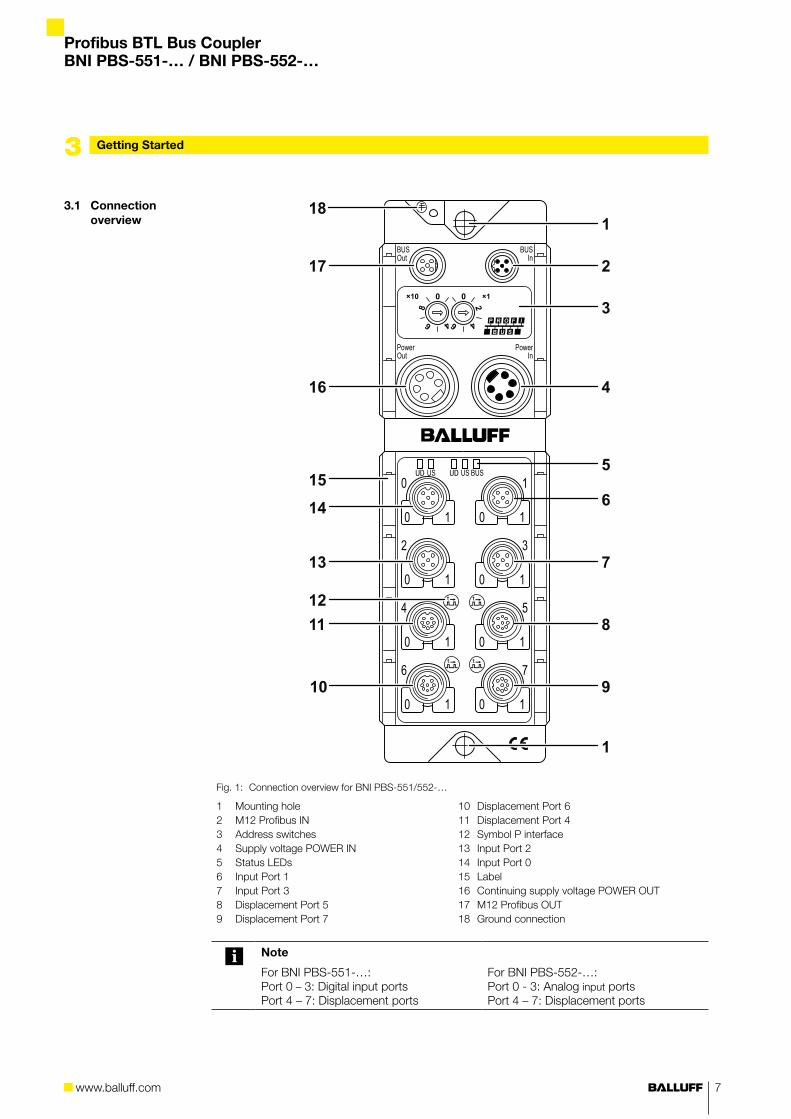
Fig. 1: Connection overview for BNI PBS-551/552-…
1 Mounting hole2 M12 Profibus IN3 Address switches4 Supply voltage POWER IN5 Status LEDs 6 Input Port 17 Input Port 38 Displacement Port 59 Displacement Port 7
10 Displacement Port 611 Displacement Port 412 Symbol P interface13 Input Port 214 Input Port 015 Label 16 Continuing supply voltage POWER OUT17 M12 Profibus OUT18 Ground connection
Note
For BNI PBS-551-…:Port 0 – 3: Digital input portsPort 4 – 7: Displacement ports
For BNI PBS-552-…:Port 0 - 3: Analog input portsPort 4 – 7: Displacement ports
Profibus BTL Bus CouplerBNI PBS-551-… / BNI PBS-552-…
8
3.2 Mechanical connection
3.3 Electrical connection
Supply voltage
The BNI PBS-... is attached using two max. M6 screws and two washers. ►
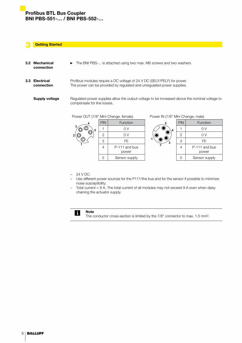
Profibus modules require a DC voltage of 24 V DC (SELF/PELF) for power.The power can be provided by regulated and unregulated power supplies.
Regulated power supplies allow the output voltage to be increased above the nominal voltage to compensate for line losses.
Power OUT (7/8" Mini Change, female) Power IN (7/8" Mini Change, male)
PIN Function PIN Function
1 0 V 1 0 V
2 0 V 2 0 V
3 FE 3 FE
4 P-111 and bus power
4 P-111 and bus power
5 Sensor supply 5 Sensor supply
24 V DC. –Use different power sources for the P111/the bus and for the sensor if possible to minimize –noise susceptibility.Total current < 9 A. The total current of all modules may not exceed 9 A even when daisy –chaining the actuator supply.
NoteThe conductor cross-section is limited by the 7/8" connector to max. 1.5 mm².
Getting Started3
www.balluff.com
Profibus BTL Bus CouplerBNI PBS-551-… / BNI PBS-552-…
9
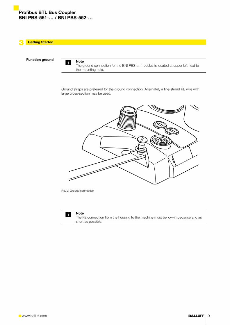
Function ground NoteThe ground connection for the BNI PBS-... modules is located at upper left next to the mounting hole.
Ground straps are preferred for the ground connection. Alternately a fine-strand PE wire with large cross-section may be used.
Fig. 2: Ground connection
NoteThe FE connection from the housing to the machine must be low-impedance and as short as possible.
Getting Started3
Profibus BTL Bus CouplerBNI PBS-551-… / BNI PBS-552-…
10
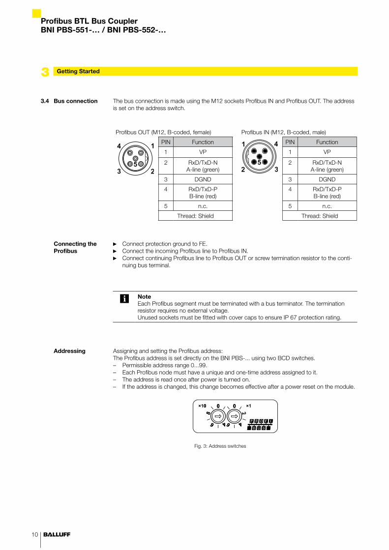
The bus connection is made using the M12 sockets Profibus IN and Profibus OUT. The address is set on the address switch.
Profibus OUT (M12, B-coded, female) Profibus IN (M12, B-coded, male)
PIN Function PIN Function
1 VP 1 VP
2 RxD/TxD-N A-line (green)
2 RxD/TxD-N A-line (green)
3 DGND 3 DGND
4 RxD/TxD-P B-line (red)
4 RxD/TxD-P B-line (red)
5 n.c. 5 n.c.
Thread: Shield Thread: Shield
Connect protection ground to FE. ►Connect the incoming Profibus line to Profibus IN. ►Connect continuing Profibus line to Profibus OUT or screw termination resistor to the conti- ►nuing bus terminal.
NoteEach Profibus segment must be terminated with a bus terminator. The termination resistor requires no external voltage. Unused sockets must be fitted with cover caps to ensure IP 67 protection rating.
Assigning and setting the Profibus address:The Profibus address is set directly on the BNI PBS-... using two BCD switches.
Permissible address range 0...99. –Each Profibus node must have a unique and one-time address assigned to it. –The address is read once after power is turned on. –If the address is changed, this change becomes effective after a power reset on the module. –
Fig. 3: Address switches
Getting Started3
3.4 Bus connection
Connecting the Profibus
Addressing
www.balluff.com
Profibus BTL Bus CouplerBNI PBS-551-… / BNI PBS-552-…
11
Getting Started3
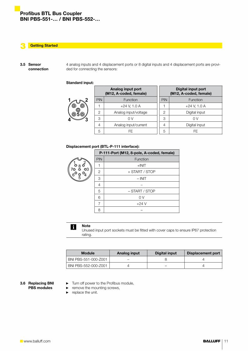
4 analog inputs and 4 displacement ports or 8 digital inputs and 4 displacement ports are provi-ded for connecting the sensors:
Standard input:
Analog input port (M12, A-coded, female)
Digital input port (M12, A-coded, female)
PIN Function PIN Function
1 +24 V, 1.0 A 1 +24 V, 1.0 A
2 Analog input/voltage 2 Digital input
3 0 V 3 0 V
4 Analog input/current 4 Digital input
5 FE 5 FE
Displacement port (BTL-P-111 interface):
P-111-Port (M12, 8-pole, A-coded, female)
PIN Function
1 +INIT
2 + START / STOP
3 – INIT
4 –
5 – START / STOP
6 0 V
7 +24 V
8 –
NoteUnused input port sockets must be fitted with cover caps to ensure IP67 protection rating.
Module Analog input Digital input Displacement port
BNI PBS-551-000-Z001 – 8 4
BNI PBS-552-000-Z001 4 – 4
Turn off power to the Profibus module, ►remove the mounting screws, ►replace the unit. ►
3.5 Sensor connection
3.6 Replacing BNI PBS modules
Profibus BTL Bus CouplerBNI PBS-551-… / BNI PBS-552-…
12
Technical Data4
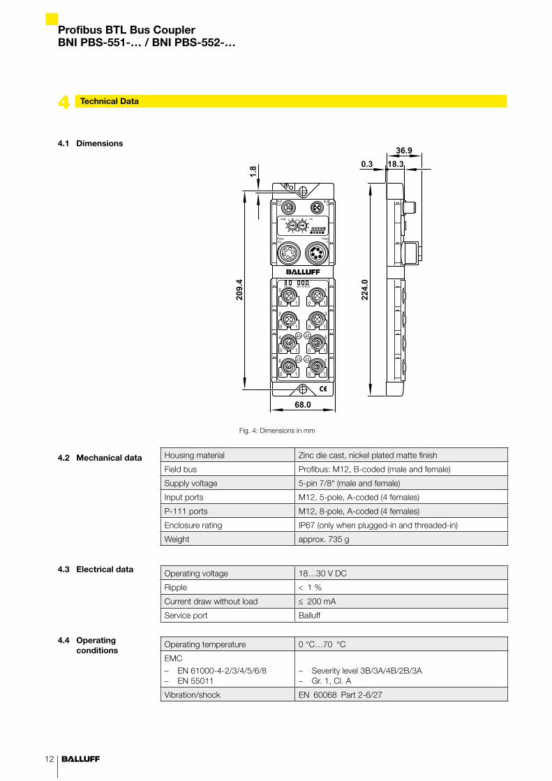
4.1 Dimensions
4.2 Mechanical data
4.3 Electrical data
4.4 Operating conditions
Fig. 4: Dimensions in mm
Housing material Zinc die cast, nickel plated matte finish
Field bus Profibus: M12, B-coded (male and female)
Supply voltage 5-pin 7/8“ (male and female)
Input ports M12, 5-pole, A-coded (4 females)
P-111 ports M12, 8-pole, A-coded (4 females)
Enclosure rating IP67 (only when plugged-in and threaded-in)
Weight approx. 735 g
Operating voltage 18…30 V DC
Ripple < 1 %
Current draw without load ≤ 200 mA
Service port Balluff
Operating temperature 0 °C…70 °C
EMC
EN 61000-4-2/3/4/5/6/8 –EN 55011 –
Severity level 3B/3A/4B/2B/3A –Gr. 1, Cl. A –
Vibration/shock EN 60068 Part 2-6/27
www.balluff.com
Profibus BTL Bus CouplerBNI PBS-551-… / BNI PBS-552-…
13
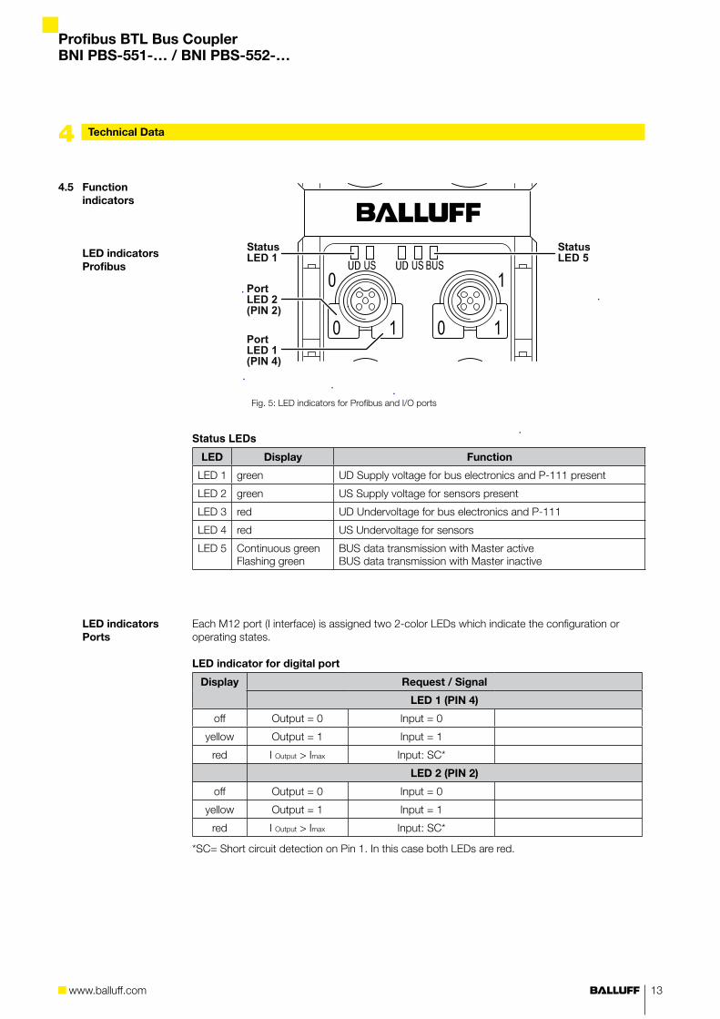
Fig. 5: LED indicators for Profibus and I/O ports
Status LEDs
LED Display Function
LED 1 green UD Supply voltage for bus electronics and P-111 present
LED 2 green US Supply voltage for sensors present
LED 3 red UD Undervoltage for bus electronics and P-111
LED 4 red US Undervoltage for sensors
LED 5 Continuous greenFlashing green
BUS data transmission with Master activeBUS data transmission with Master inactive
Each M12 port (I interface) is assigned two 2-color LEDs which indicate the configuration or operating states.
LED indicator for digital port
Display Request / Signal
LED 1 (PIN 4)
off Output = 0 Input = 0
yellow Output = 1 Input = 1
red I Output > Imax Input: SC*
LED 2 (PIN 2)
off Output = 0 Input = 0
yellow Output = 1 Input = 1
red I Output > Imax Input: SC*
*SC= Short circuit detection on Pin 1. In this case both LEDs are red.
4.5 Function indicators
LED indicators Profibus
LED indicators Ports
Technical Data4
Profibus BTL Bus CouplerBNI PBS-551-… / BNI PBS-552-…
14
Technical Data
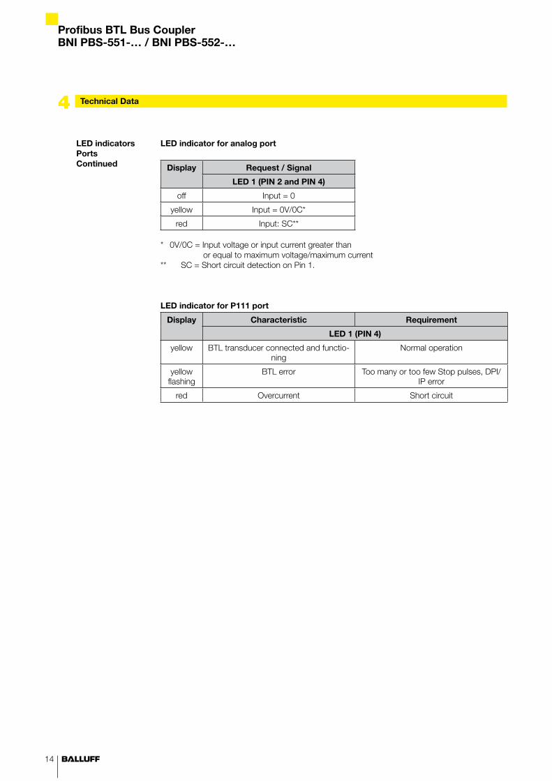
LED indicator for analog port
Display Request / Signal
LED 1 (PIN 2 and PIN 4)
off Input = 0
yellow Input = 0V/0C*
red Input: SC**
* 0V/0C = Input voltage or input current greater than or equal to maximum voltage/maximum current
** SC = Short circuit detection on Pin 1.
LED indicator for P111 port
Display Characteristic Requirement
LED 1 (PIN 4)
yellow BTL transducer connected and functio-ning
Normal operation
yellow flashing
BTL error Too many or too few Stop pulses, DPI/IP error
red Overcurrent Short circuit
4
LED indicators PortsContinued
www.balluff.com
Profibus BTL Bus CouplerBNI PBS-551-… / BNI PBS-552-…
15
Appendix
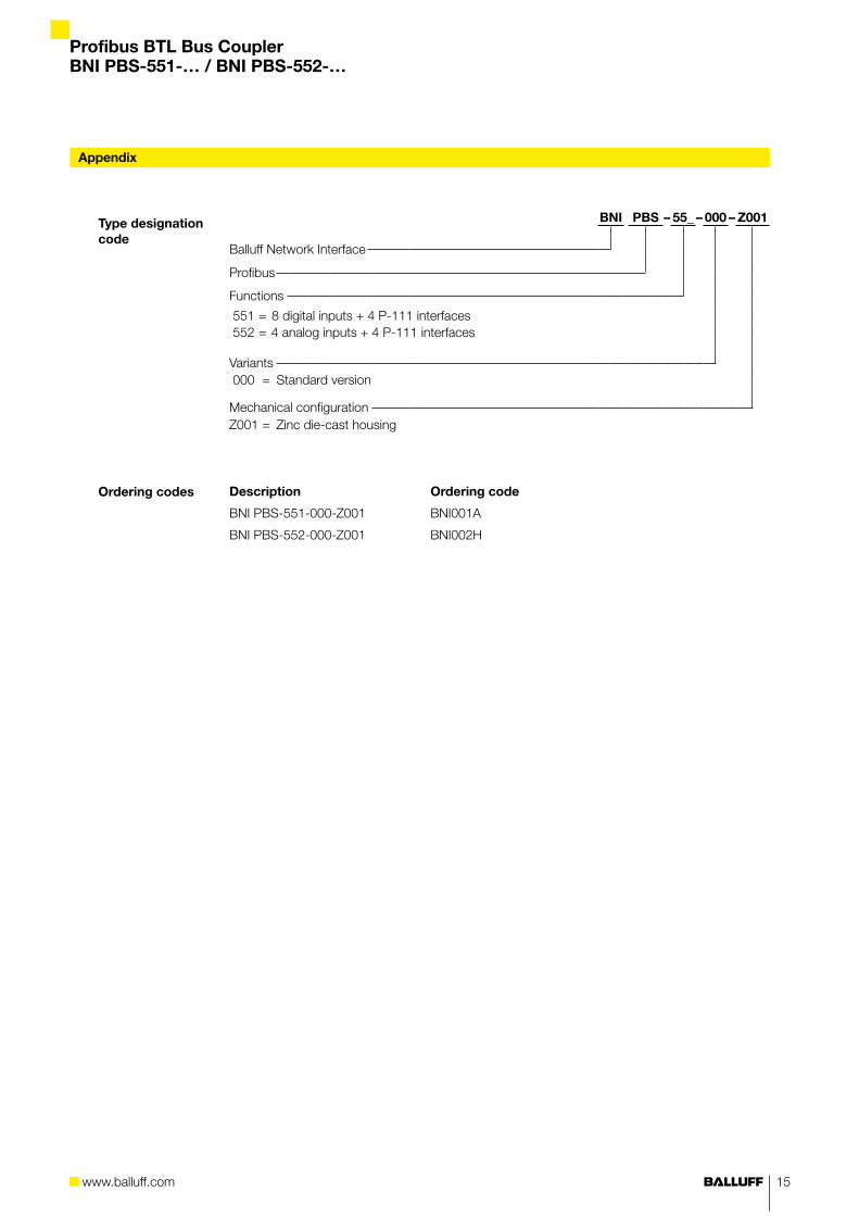
BNI PBS – 55_ – 000 – Z001
Balluff Network Interface
Profibus
Functions
551 = 8 digital inputs + 4 P-111 interfaces 552 = 4 analog inputs + 4 P-111 interfaces
Variants 000 = Standard version
Mechanical configurationZ001 = Zinc die-cast housing
Description Ordering code
BNI PBS-551-000-Z001 BNI001A
BNI PBS-552-000-Z001 BNI002H
Type designation code
Ordering codes

Balluff GmbH Schurwaldstraße 973765 Neuhausen a.d.F.GermanyTel. +49 7158 173-0Fax +49 7158 [email protected]
www.balluff.com
www.balluff.com No.
859
321
E |
00.0
0000
0 | E
ditio
n 09
03 |
Rep
lace
s ed
ition
081
1 | S
ubje
cts
to m
odifi
catio
n.
Related Documents