PRODUCTS FOR THE ELECTRONIC INDUSTRY PCB Separators PCB Magazines Universal cutter FS100 Edition 8.2

Products Electronic Industry
Oct 24, 2014
Welcome message from author
This document is posted to help you gain knowledge. Please leave a comment to let me know what you think about it! Share it to your friends and learn new things together.
Transcript
PRODUCTS FOR THE ELECTRONIC INDUSTRY
PCB SeparatorsPCB Magazines
Universal cutter FS100Edition 8.2
cab | 2
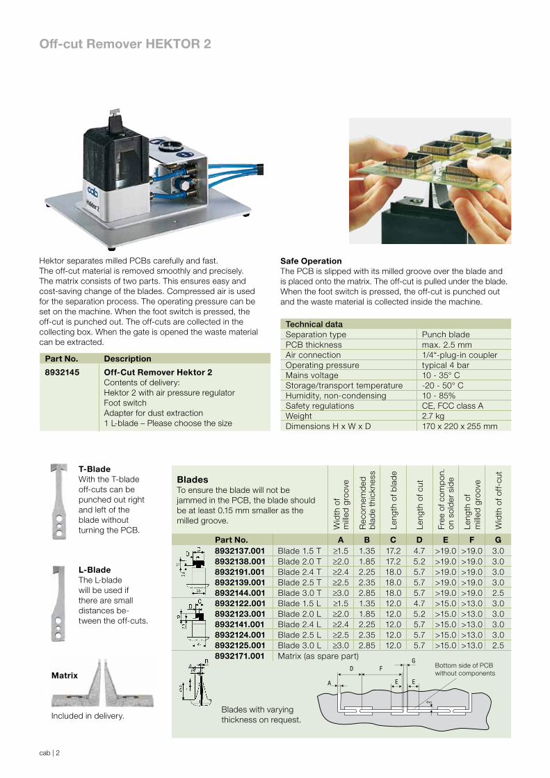
T-BladeWith the T-bladeoff-cuts can bepunched out rightand left of theblade withoutturning the PCB.
L-BladeThe L-blade will be used ifthere are smalldistances be-tween the off-cuts.
Safe OperationThe PCB is slipped with its milled groove over the blade and is placed onto the matrix. The off-cut is pulled under the blade. When the foot switch is pressed, the off-cut is punched out and the waste material is collected inside the machine.
Hektor separates milled PCBs carefully and fast. The off-cut material is removed smoothly and precisely. The matrix consists of two parts. This ensures easy and cost-saving change of the blades. Compressed air is used for the separation process. The operating pressure can be set on the machine. When the foot switch is pressed, the off-cut is punched out. The off-cuts are collected in the collecting box. When the gate is opened the waste material can be extracted.
Off-cut Remover HEKTOR 2
Matrix
Included in delivery.
Technical dataSeparation type Punch bladePCB thickness max. 2.5 mmAir connection 1/4“-plug-in couplerOperating pressure typical 4 barMains voltage 10 - 35° CStorage/transport temperature -20 - 50° CHumidity, non-condensing 10 - 85%Safety regulations CE, FCC class AWeight 2.7 kgDimensions H x W x D 170 x 220 x 255 mm
Part No. Description
8932145 Off-Cut Remover Hektor 2Contents of delivery:Hektor 2 with air pressure regulatorFoot switchAdapter for dust extraction1 L-blade – Please choose the size
BladesTo ensure the blade will not be jammed in the PCB, the blade should be at least 0.15 mm smaller as the milled groove.
Wid
th o
f m
illed
gro
ove
Rec
omem
ded
bla
de
thic
knes
s
Leng
th o
f bla
de
Leng
th o
f cut
Free
of c
omp
on.
on s
old
er s
ide
Leng
th o
f m
illed
gro
ove
Wid
th o
f off-
cut
Part No. A B C D E F G8932137.001 Blade 1.5 T ≥1.5 1.35 17.2 4.7 >19.0 >19.0 3.08932138.001 Blade 2.0 T ≥2.0 1.85 17.2 5.2 >19.0 >19.0 3.08932191.001 Blade 2.4 T ≥2.4 2.25 18.0 5.7 >19.0 >19.0 3.08932139.001 Blade 2.5 T ≥2.5 2.35 18.0 5.7 >19.0 >19.0 3.08932144.001 Blade 3.0 T ≥3.0 2.85 18.0 5.7 >19.0 >19.0 2.58932122.001 Blade 1.5 L ≥1.5 1.35 12.0 4.7 >15.0 >13.0 3.08932123.001 Blade 2.0 L ≥2.0 1.85 12.0 5.2 >15.0 >13.0 3.08932141.001 Blade 2.4 L ≥2.4 2.25 12.0 5.7 >15.0 >13.0 3.08932124.001 Blade 2.5 L ≥2.5 2.35 12.0 5.7 >15.0 >13.0 3.08932125.001 Blade 3.0 L ≥3.0 2.85 12.0 5.7 >15.0 >13.0 2.58932171.001 Matrix (as spare part)
A
D
E E
2
FG
Bottom side of PCB without components
Blades with varying thickness on request.
cab | 3
1
2
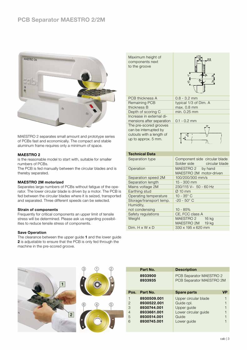
PCB Separator MAESTRO 2/2M
3 2
5
1
46
Part No. Description
89339008933935
PCB Separator MAESTRO 2PCB Separator MAESTRO 2M
Pos. Part No. Spare parts VP
123456
8930509.0018930522.0018930744.0018933661.0018930514.0018930745.001
Upper circular bladeGuide cpl.Upper guideLower circular guideGuideLower guide
111111
Maximum height ofcomponents nextto the groove
PCB thickness A 0.8 - 3.2 mmRemaining PCBthickness B
typical 1/3 of Dim. Amax. 0.8 mm
Depth of scoring C min. 0.25 mmIncrease in external di-mensions after separation 0.1 - 0.2 mmThe pre-scored groovescan be interrupted bycutouts with a length of up to approx. 5 mm.
MAESTRO 2 separates small amount and prototype series of PCBs fast and economically. The compact and stable aluminum frame requires only a minimum of space.
MAESTRO 2 is the reasonable model to start with, suitable for smaller numbers of PCBs.The PCB is fed manually between the circular blades and is thereby separated.
MAESTRO 2M motorized Separates large numbers of PCBs without fatigue of the ope-rator. The lower circular blade is driven by a motor. The PCB is fed between the circular blades where it is seized, transported and separated. Three different speeds can be selected.
Strain of componentsFrequently for critical components an upper limit of tensile stress will be determined. Please ask us regarding possibil-ities to reduce tensile stress of components. Save OperationThe clearance between the upper guide 1 and the lower guide 2 is adjustable to ensure that the PCB is only fed through the machine in the pre-scored groove.
Technical DataSeparation type Component side circular blade
Solder side circular bladeOperation MAESTRO 2 by hand
MAESTRO 2M motor-drivenSeparation speed 2M 100/200/300 mm/sSeparation length 15 - 300 mmMains voltage 2M 230/115 V~ 50 - 60 HzEarthing stud Ø 10 mmOperating temperature 10 - 35° CStorage/transport temp. -20 - 50° CHumidity, not condensing 10 - 85%Safety regulations CE, FCC class AWeight MAESTRO 2 16 kg
MAESTRO 2M 19 kgDim. H x W x D 330 x 195 x 620 mm
cab | 4
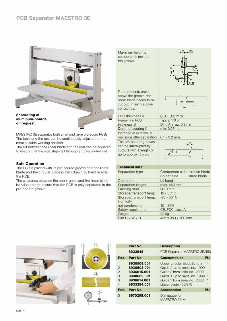
MAESTRO 3E separates both small and large pre-scord PCBs. The table and the rest can be continuously adjusted to the most suitable working position. The slit between the linear blade and the rest can be adjusted to ensure that the side strips fall through and are sorted out.
Safe OperationThe PCB is placed with its pre-scored groove onto the linear blade and the circular blade is then drawn by hand across the PCB.The clearance between the upper guide and the linear blade ist adustable to ensure that the PCB is only separated in the pre-scored groove.
2 1 3
5
4
PCB Separator MAESTRO 3E
Separating ofaluminum-boards on request
Part No. Description
8933945 PCB Separator MAESTRO 3E/450
Pos. Part No. Consumables PU
122334
8930509.0018930603.0018936615.0018930602.0018936614.0018933394.001
Upper circular bladeSchutz Guide 2 up to serial no. 1999Guide 2 from serial no. 2000Guide 1 up to serial no. 1999Guide 1 from serial no. 2000Linear blade 450/370
111111
Pos. Part No. Accessories PU
5 8970208.001 Dial gauge forMAESTRO 3/4M 1
Maximum height ofcomponents next tothe groove.
If components project above the groove, the linear blade needs to be cut out. In such a case contact us.
PCB thickness A 0.8 - 3.2 mmRemaining PCBthickness B
typical 1/3 of Dim. A, max. 0.8 mm
Depth of scoring C min. 0.25 mmIncrease in external di-mensions after separation 0.1 - 0.2 mmThe pre-scored groovescan be interrupted bycutouts with a length of up to approx. 5 mm.
Technical dataSeparation type Component side circular blade
Solder side linear bladeOperation by handSeparation length max. 450 mmEarthing stud Ø 10 mmStorage/transport temp. 10 - 35° CStorage/transport temp. -20 - 50° CHumidity, not condensing 10 - 85%Safety regulations CE, FCC class AWeight 22 kgDim H x W x D 455 x 350 x 700 mm

cab | 5
MAESTRO 4M separates both small and large PCBs fast and economically. To optimize operation, the separation length can be programmed with the control keys.
Safe OperationThe PCB is placed with its pre-scored groove onto the linear blade. When the foot switch is pressed, the blade carrier with the circular blade moves across the PCB, separating it into individual units.The clearance between the upper guide and the linear blade is adjustable to ensure that the PCB is only separated in the pre-scored groove. The table can be continuously adjusted with the rotary knob whenever required while the rest can be adjusted in three steps to the most suitable working position.
Picture: MAESTRO 4M
PCB Separator MAESTRO 4M
Separating of aluminum-boards on request
If components project above the groove, the linear blade needs to be cut out. In such a case, contact us.
PCB thickness A 0.8 - 3.2 mmRemaining PCBthickness B
typical 1/3 ofDim. A, max. 0.8 mm
Depth of scoring C min. 0.25 mmIncrease in external di-mensions after separation 0.1 - 0.2 mmThe pre-scored groovescan be interrupted bycutouts with a length of up to approx. 5 mm.

cab | 6
Sideways transport of separated boardsSideways transport of singled boards. No overlapping of separted boards. Stop of the boards by sensor barrier on the end of the conveyor. Transport length adjustable in 50 mm steps.
MAESTRO 4M/450MAESTRO 4M/450 cleanComponent height at the edge on the PCB max. 40 mm.
MAESTRO 4M/70/370MAESTRO 4M/70/520Component height at the edge on the PCB max. 70 mm
F G
K
F G
PCB Separator MAESTRO 4M
clean-VersionMAESTRO 4M clean is prepared mechanically for dustextraction to remove dust particals with special linear blade.
31
4
2
7 8
5 6 9
Technical data PCB SeparatorSeparation type Component side circular blade
Solder side linear bladeOperation Optimized motor drivenSeparation speed 300/500 mm/sMains voltage 230/115 V~ 50 - 60 HzEarthing stud Ø 10 mmOperating temperature 10 - 35° CStorage/transport temp. -20 - 50° CHumidity,not condensing 10 - 85%Safety regulations CE, FCC class ATechnical data Conveyor BeltMaterial of conveyor belt AntistaticDirection of belt travel To the rightBelt speed 5/6/7/8/9 m/min.Light barrier Can be activated for belt stoppageSafety regulations CE, FCC class Awidth of belt 170 mmWeight 14 kg
Maximum height ofcomponents next to thegroove
Table 5 - 35Conveyor belt 5 - 17
Len
gth
of
dev
ice
Hig
ht
of
dev
ice
Sep
arat
ion
len
gth
Co
mp
on
ent
hei
gh
tb
efo
re t
he
gro
ove
Co
mp
on
ent
hei
gh
tb
ehin
d t
he
gro
ove
ma
x. b
oar
d d
epth
Wei
gh
t in
kg
Part No. Descriptions F G J K
89339558933950893396089339658933905
MAESTRO 4M/450MAESTRO 4M/450 cleanMAESTRO 4M/600MAESTRO 4M/70/370MAESTRO 4M/70/520
702702852702852
434434434492492
450450600370520
4040407070
3434346464
200200200200200
3839464048
89312408932150
Conveyor belt 450Conveyor belt 600
12001350
200200
Pos. Part No. Consumables PU
12233456778
8930509.0018930603.0018936615.0018930602.0018936614.0018933933.0018930756.0018930755.0018933394.0018933682.0018933931.001
Upper circular bladeGuide 2 up to serial no. 1999Guide 2 from serial no. 2000Guide 1 up to serial no. 1999Guide 1 from serial no. 2000Circular blade passage height 70 m Guide 2/70Guide 1/70Linear blade 450/370Linear blade 600/520Linear blade 450/370 clean
11111111111
Pos. Part No. Accessories PU
9 8970208.001 Dial gauge for MAESTRO 3/4M 1
H

cab | 7
PCB Separator MAESTRO 5L
MAESTRO 5L with base frameis used most economically whenever large numbers of pre-scored PCBs need to be separated. The well-arranged control panel ensures easy operation.
Machine with base frame - adjustable in height for optimal modification for each application.
PCB thickness A 1.0 - 3.2 mmRemaining PCBthickness B
typical 1/3 of Dim. A min. 0.3 mm, max. 0.6 mm
Depth of scoring C min. 0.3 mmIncrease in external di-mensions after separation 0.1 - 0.2 mm
The pre-scored groovescan be interrupted bycutouts with a length of up to approx. 5 mm.

cab | 8
PCB Separator MAESTRO 5L
Technical DataSeparation type Component side circular blade
Solder side circular bladeOperation motorizedSeparation speed 100 - 220 mm/s
in 10 stepsLength of PCB panelwith light barrier activatedbei with light barrier de-activated
100 - 570 mm> 100 mm
Width of PCB panels max. 310 mmWidth off-cut min. 3 mmHeight of components Component max. 30 mm
Solder side max. 10 mmNumber of circular blades max. 11 on each shaftWidth of PCBs 10 - 300 mmDisplay - Separation speed
- Separated lenght or numbers of PCB panels
Keys - Start, stop, reverse- Setting of separated speed
Monitoring - Detection of separation lenght- Accumulation in front of and behind the blades- Stop the end of the
Interfaces conveyor belt- Remote start/stop- SMEMA (round 14 pins)
Mains voltage 230 /115 V~ 50 - 60 HzOperating temperature 10 - 35° CStorage/transport temp. -20 - 50° CHumidity not condensing 10 - 85%Weight 63 kgDimensions with base frame height width dept
750 - 1000 mm440 mm1100 mm
Part No. Description
8934520 PCB Separator MAESTRO 5LContents of delivery:MAESTRO 5L with baseprepared for dust extractionCircular blades on customer requestService tools
Part No. Consumables PU
8934803.001 Circular blade width 8 mm 1
MAESTRO 5LPCB panels with maximum width of 310 mm can be separated by up to 11 pairs of circular blades simultane ously.Configuration of the blades is adjusted to your individual PCB also the cover and the guide.Sensors are used to monitor the separating process.The PCBs are placed by either by hand or they feed automa-tically by a loading station. The machine can also be installed in an assembling line. The SMEMA interface is the standard connection for use. New: every machine is automatically prepa-red for dust extraction and with cleaning brushes for rear-end conveyor.For PCB panel widths larger than 310 mm on request.
cab | 9
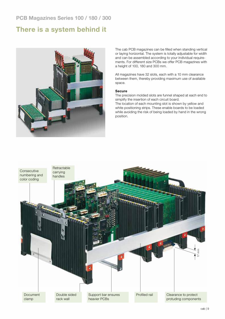
The cab PCB magazines can be filled when standing vertical or laying horizontal. The system is totally adjustable for width and can be assembled according to your individual require-ments. For different size PCBs we offer PCB magazines with a height of 100, 180 and 300 mm.
All magazines have 32 slots, each with a 10 mm clearance between them, thereby providing maximum use of available space.
SecureThe precision molded slots are funnel shaped at each end to simplify the insertion of each circuit board. The location of each mounting slot is shown by yellow and white positioning strips. These enable boards to be loaded while avoiding the risk of being loaded by hand in the wrong position.
17 m
m
Consecutivenumbering andcolor coding
Retractablecarryinghandles
Documentclamp
Support bar ensuresheavier PCBs
Profiled rail Clearance to protectprotuding components
Double sidedrack wall
There is a system behind it
PCB Magazines Series 100 / 180 / 300

cab | 10
Fast and easy assemblyThe magazine walls can be secured to the profiled rails in any position required. Two identically sized circuit boards are inserted between the walls, into the adjustment slots at the extreme ends of each wall. The second wall is then pressed firmly onto the boards and screwed tight.
Rigid and stableThe magazine walls are constructed in sandwich form, and are therefore particularly rigid. For heavy mechanical and thermical force the magazine walls can additionally be reinforced by the use of a steel rod.
Slot lockTo prevent damage to the PCB board during insertion, we offer slot locks which cover slots not in use.
StackableAt the corners of each magazine are male and female connectors which allow the racks to be stacked upon an-other. The lower edge of each maga-zine-side has a molded recess which allows the magazine to be gripped and lifted without problem.
Vertical mountingBefore soldering, the circuit board must be stored horizontally. The magazine can therefore stand vertically.
Transport containersFor transport purposes, the PCB maga-zines can be loaded into containers. These containers have norm sizes of 600 x 400 mm and 400 x 300 mm. Retracetable handles enable the maga-zines to be removed with ease.
PCB Magazines Series 100 / 180 / 300

cab | 11
Flexing of the magazine walls under loadingWhen the PCB Magazine is correctly assembled, each side wall may flex less than 1,0 mm, to ensure a secure mounting of the PCB. The measurements were using 16 circuit boards, with a clearance of 20 mm between each other, and a weight per board of 500 g. Upon request, a copy of the test report is available.
Critical loading can occur as follows:
1. When the magazine is laid on its side on a flat surface, and then lifted.
2. When being transported in the vertical position, and the position is changed to the horizontal.
x = 36 + D1 x = 52 + D1 + D2 x = 69 + D1 + D2 + D3 x ≥ 73 + D1 + D2 x ≥ 110 + D1 + D2 + D3
Delivery program
with 32 slots
PCB Magazines Series 100 / 180 / 300
Technical Data 100 180 300Material PolypropyleneColor black
Surface resistanceas per DIN EN
61340-5-1< 109
DimensionsSlot width mm 2.8 4.0 3.5Slot depth mm 2.0 2.5 2.5Ammount 32 32 32Distance of PCBs mm 10 10 10Flexing with a total load of 8 kgTemperature 23°C not reinforced 1.0 0.8 0.4Temperature 23°C with reinforced 0.5 0.4 -Temperature 70°C not reinforced - - 0.8Temperature 70°C with reinforced 0.9 0.7 -
Part No. Description8910063 PCB Magazine
Testset 100
e.g. for 100 mm wide PCBsContents: 4 Side Walls 100 2 Profiled Rails 369 mm long 1 Document Clamp
Weight: 1.4 kg
Part No. Description8910064 PCB Magazine
Testset 180
e.g. for 100 mm wide PCBs.Contents: 4 Side Walls 180 2 Profiled Rails 369 mm long 1 Document Clamp 1 Set Carrying HandlesWeight: 2.5 kg
Part No. Description8910065 PCB Magazine
Testset 300
e.g. for 233.4 mm wide PCBs.Contents: 2 Side Walls 300 4 Profiled Rails 269 mm long 1 Document Clamp 1 Set Carrying HandlesWeight: 2 kg
The length of profiled rail (Dimension X) is calculated based upon the dimensions as shown below.
Dimension D = PCB WidthDimension X = Length of Profiled Rail
cab | 12
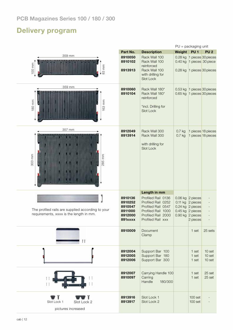
Part No. Description Weight PU 1 PU 2
89100508910102
8913913
Rack Wall 100Rack Wall 100reinforcedRack Wall 100with drilling forSlot Lock
0.28 kg0.40 kg
0.28 kg
1 pieces1 pieces
1 pieces
30 pieces30 piece
30 pieces
89100608910104
Rack Wall 180*Rack Wall 180*reinforced
*incl. Drilling forSlot Lock
0.53 kg0.65 kg
1 pieces1 pieces
30 pieces30 pieces
89120498913914
Rack Wall 300Rack Wall 300
with drilling forSlot Lock
0.7 kg0.7 kg
1 pieces1 pieces
18 pieces18 pieces
Length in mm
89101368910252891054789110008912000891xxxx
Profiled Rail 0136Profiled Rail 0252Profiled Rail 0547Profiled Rail 1000Profiled Rail 2000Profiled Rail xxx
0.06 kg0.11 kg0.24 kg0.45 kg0.90 kg
2 pieces2 pieces2 pieces2 pieces2 pieces2 pieces
------
8910009 DocumentClamp
1 set 25 sets
891200489120058912006
Support Bar 100Support Bar 180Support Bar 300
1 set1 set1 set
10 set10 set10 set
89120078910097
Carrying Handle 100Carring Handle 180/300
1 set1 set
25 set25 set
89139168913917
Slot Lock 1Slot Lock 2
100 set100 set
--
pictures increased
The profiled rails are supplied according to yourrequirements, xxxx is the length in mm.
100
mm
359 mm
83
mm
180
mm
163
mm
359 mm
30
3 m
m
285
mm
357 mm
Slot Lock 1 Slot Lock 2
Delivery program
PCB Magazines Series 100 / 180 / 300
PU = packaging unit

cab | 13
Automation Requires PrecisionPrecision, stability and flexible handling are important features for the use of the PCB Magazines in automated assembly lines.
The stable and robust frame construction guarantees a long lasting use of the cab magazine in your production. The rack walls are manufactured from conductive material.
Metal magazineFor high mechanical or temperature use we offer the magazine with metal rack walls.
1 Locking knob for stacking purposes
2 Transport safety
3 Consecutive numbering on therack walls for easy feeding
4 The precision spindles ensure theparallelism of the rack walls duringadustment
5 The gear belt allows for quickadjustments in seconds
for automated assembly lines
PCB Magazines Series 600 / 700

cab | 14
Series 600 - Width adjustment by screw clampThe series 600 is cost effective alterna-tive with a simple width adjustment. By backing off the four screw clamps the moveable rack wall can be pushed to the necessary PCB width.
Series 700 - Width adjustment by gear beltHandling different PCB sizes the maga-zines have to be adjusted to the PCB width quite often. The PCB Magazines of the series 700 are adjusted to the necessary PCB width within seconds.
Magazine locked Magazine unlocked
StackableThe magazines can be stacked and secured space saving by four support guides on the top of the plate.
ReversibleThrough to the vertical symmetry all magazines can be placed upside down to work on double sided PCBs. The stacking locator knobs must be replaced.
Transport safetyTo secure the PCBs while transporting the magazine, a safety bar is mounted on the front and back side of the rack wall.
PCB Magazines Series 600 / 700
Protection coverPermastat® ESD protection cover, robust and tear proof. Protection of inserted boards against pollution.

cab | 15
65W
L
DA
BB
'
49 x
10,
0
H3,
4
105
3
C
E'
EDimensioned drawing
PCB Magazines Serie 600 / 700

cab | 16
Delivery program / Dimensions
PCB Magazines Serie 600 / 700
The PCB-magazines xxx.1 and xxx.2 are delivered half-assembled. Assembled magazines can be ordered with additional article numbers. The magazines xxx.3 are delivered assembled.
DL31001 Assembled with staple neps
DL 31002 Assembled for reserve operation
ESD Protection coverColor: pink, Thickness: 150 µm (PU = 10 pcs.)
Type Art.-No.
601/701 8916411602/702 8916412603/703 8916413704 8916414706/716 8916416707/717 8916417
Protection cover also forother models on request.
Type ArticleNo.
Temperature PCB Cover/basem.
Amm
Bmm
B‘mm
Emm
E‘mm
Pit
ch
Inse
rtio
ns
Sc
rew
s
Gea
r b
elt
Sta
cka
ble
Rev
erse
op
eati
on
Inse
rtio
ns
Am
bie
nt
Wei
gh
t Externalmeasurements
Dye
cas
tal
um
iniu
m
Ste
el s
hee
tWidthD
LengthC
Lmm
Wmm
Hmm
min.mm
max.mm
max.mm mmC° C° kg
601.1601.2601.3
891760189166018915601
60130200
50100200
5,65,96,9
355 320 563 40 250 342 - 34 34 34 9 9 10 50 -
602.1602.2602.3
891760289166028915602
60130200
50100200
5,86,17,2
400 320 563 40 250 387 - 34 34 34 9 9 10 50 -
603.1603.2603.3
891760389166038915603
60130200
50100200
6,26,57,6
400 380 563 40 310 387 - 34 34 34 9 9 10 50 -
701.1701.2701.3
891770189167018915701
60130200
50 80100
5,65,96,9
355 320 563 40 250 342 - 34 34 34 9 9 10 50 -
702.1702.2702.3
891770289167028915702
60130200
50 80100
5,86,17,2
400 320 563 40 250 387 - 34 34 34 9 9 10 50 -
703.1703.2703.3
891770389167038915703
60130200
50 80100
6,26,57,6
400 380 563 40 310 387 - 34 34 34 9 9 10 50 -
704.1704.2704.3
891770489167048915704
60130200
50 80100
7,88,09,5
460 400 563 10 330 447 - 34 34 34 9 9 10 50 -
705.2705.3
89167058915705
130200
80100
8,710,1
535 380 570 10 310 522 - 34 41 34 16 9 10 50 - -
715.2715.3
89167158915715
130200
80100
8,710,1
535 380 563 10 310 522 - 34 34 34 9 9 10 50 -
706.2706.3
89167068915706
130200
80100
9,510,9
535 460 570 10 390 522 - 34 41 34 16 9 10 50 - -
716.2716.3
89167168915716
130200
80100
9,510,9
535 460 563 10 390 522 - 34 34 34 9 9 10 50 -
707.2707.3
89167078915707
130200
80100
9,711,1
535 530 570 10 460 522 - 34 34 41 9 16 10 50 - -
717.2717.3
89167178915717
130200
80100
9,711,1
535 530 563 10 460 522 - 34 34 34 9 9 10 50 -
708.2708.3
89167088915708
130200
80100
9,611,0
535 470 570 10 400 522 - 34 41 34 16 9 10 50 - -
718.2718.3
89167188915718
130200
80100
9,611,0
535 470 563 10 400 522 - 34 34 34 9 9 10 50 -
709.2 8916718 130 80 9,6 535 580 570 10 510 522 - 34 41 34 16 9 10 50 - -
719.2 8915718 130 80 9,6 535 580 563 10 510 522 - 34 34 34 9 9 10 50 -
Material Surface Series side wall resistance
60x.1 70x.1 Polystyrene as per DIN EN 60x.2 70x.2 Polycarbonate 61340-5-1 60x.3 70x.3 Metal* < 109
*Measured from rack wall to frame
ESD Protection cover Permastat conductive discharge
cab | 17
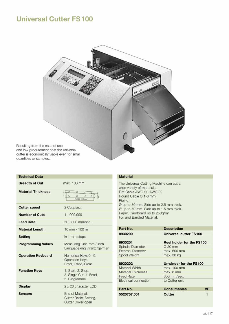
Universal Cutter FS100
Part No. Description
8930200 Universal cutter FS100
8930201 Reel holder for the FS100Spindle Diameter Ø 20 mmExternal Diameter max. 600 mmSpool Weight max. 30 kg
8930202 Unwinder for the FS100Material Width max. 100 mmMaterial Thickness max. 8 mmFeed Rate 300 mm/sec.Electrical connection to Cutter unit
Part No. Consumables VP
5520757.001 Cutter 1
Material
The Universal Cutting Machine can cut awide variety of materials:Flat Cable AWG 22-AWG 32Round Cable Ø 1-6 mm Piping,Ø up to 30 mm. Side up to 2.5 mm thick.Ø up to 50 mm. Side up to 1.5 mm thick.Paper, Cardboard up to 250g/m2
Foil and Banded Material.
Technical Data
Breadth of Cut max. 100 mm
Material Thickness
Cutter speed 2 Cuts/sec.
Number of Cuts 1 - 999.999
Feed Rate 50 - 300 mm/sec.
Material Length 10 mm - 100 m
Setting in 1 mm steps
Programming Values Measuring Unit mm / Inch Language engl./franz./german
Operation Keyboard Numerical Keys 0...9, Operation Keys, Enter, Erase, Clear
Function Keys 1. Start, 2. Stop, 3. Single Cut, 4. Feed, 5. Programme
Display 2 x 20 character LCD
Sensors End of Material, Cutter Basic, Setting, Cutter Cover open
FS 100: 110 mm
2,5
7
Resulting from the ease of useand low procurement cost the universalcutter is economicaly viable even for smallquantities or samples.

cab | 18
EconomicalResulting from its ease of use and low procurement costs, the Universal Cutter is economicaly viable even for small quantities or samples. It can cut up to 6.100 pieces per hour. When used for just one hour per month, it pays for itself by saving the 5 –10 hours which would be required to cut the same quantity by hand.
Highest Quality of CutSelf-sharpening blades guarantee more than one million cutting cycles when used correctly. The upper blade can be swung up by hand. A material blockage can easily be cleared.The blades can also be easily exchanged or cleaned.Each blade has two cutting edges. Simply by turning them over, the life of the blades is doubled. Both feed rollers are motor driven to protect the material surface and ensure precise lengths of cut material.
Easy OperationThe Universal Cutter is controlled by a microprocessor,therefore its use is easy and comfortable. A two row Liquid Crystal Display shows all values, conditions and faults.The operator is led step-by-step through the programme. The length of material required, the number of cuts, and the feed rate are requested consecutively. The length of material provided by the test cut can be checked immediately using the built-in tape measure. Any alteration can then be made before starting automatic operation.
The Reel holderenables reels or spools of up to 600 mm in diameter and up to 30 kg in weight to be used.
The unwinderprovides an addi-tional material feed and is recommendedfor reels or spools which weighmore than 4 kg. Thereby any variation in the length of cut material will be avoided.
Universal cutter FS100

www.cab.de
HeadquartersinGermany cabsubsidiaries
350distributionpartners inmorethan80countries.
cabisrepresentedineveryactivecommercialcenter-worldwide.
Edition 8.2
ThisdocumentationandanytranslationshereofarethepropertyofcabGmbH&CoKG.Thereplication,processing,reproductionordistributioninwholeorinpartsrequiresourpriorwrittenconsent.©Copyrightbeicab/9008452.
All delivery, design and technical specifications are compiled to the best of our current knowledge and are subject to change without prior notice.
Germany
cab Produkttechnik
GmbH & Co KG
Postfach 1904
76007 Karlsruhe
Wilhelm-Schickard-Str. 14
76131 Karlsruhe
Telefon +49 721 6626-0
Telefax +49 721 6626-249
www.cab.de
France
cab technologies s.a.r.l.
67350 Niedermodern
Téléphone +33 388 722 501
www.cab.de/fr
USA
cab Technology Inc.
Tyngsboro MA, 01879
Phone +1 978 649 0293
www.cab.de/us
South Africa
cab Technology (Pty.) Ltd.
2125 Randburg
Phone +27 11-886-3580
www.cab.de/za
Asia
cab Technology Co, Ltd.
Junghe, Taipei, Taiwan
Phone +886 2 8227 3966
www.cab.de/tw
China
cab (Shanghai) Trading Co., Ltd
Phone +86 21 6236-3161
www.cab.de/cn
Related Documents


