Productivity and Injectivity of Horizohtal Wells Contract NO. DEFG22-93BC14862 Department of Petroleum Engineering Stanford University Stanford, CA 94305 Contract Date: March 10, 1993 Anticipated Completion: March 10, 1998 Principal Investigator: Khalid Aziz Co-Investigat or: Research Associate: Sepehr Arbabi Administrative Assistant: Marilyn Smith Technical Project Manager (DOE): Thomas B. Reid Thomas A. Hewett Quarterly Rep or t Reporting Period: January 1, 1996 - March 31, 1996 “U.S./DOE patent clearance is Q& required prior to the publication of this document”

Welcome message from author
This document is posted to help you gain knowledge. Please leave a comment to let me know what you think about it! Share it to your friends and learn new things together.
Transcript
Productivity and Injectivity of Horizohtal Wells
Contract NO. DEFG22-93BC14862
Department of Petroleum Engineering Stanford University Stanford, CA 94305
Contract Date: March 10, 1993 Anticipated Completion: March 10, 1998
Principal Investigator: Khalid Aziz
Co-Invest igat or:
Research Associate: Sepehr Arbabi
Administrative Assistant: Marilyn Smith
Technical Project Manager (DOE): Thomas B. Reid
Thomas A. Hewett
Quarterly Rep or t Reporting Period: January 1, 1996 - March 31, 1996
“U.S./DOE patent clearance is Q& required prior to the publication of this document”

DISCLAIMER
Portions of this document may be illegible in electronic image products, Images are produced from the best available original document ,
Summary of Technical Progress
A number of activities have been carried out in the last three months. A list outlining these efforts is presented below.
The Third Annual Report of the project was completed and submitted to the US. DOE.
0 A detailed report on the development and testing of the Stanford mechanistic multi- phase flow model has been written. Another comprehensive report on the recently developed general model for single phase wellbore flow is in preparation. These two documents will soon be submitted as technical reports to the U.S. DOE. Work on the design of the next phase of the wellbore experiments using wire-wrapped screens has commenced.
0 Example flow problems are being solved by the three-dimensional flexible grid sim- ulator (Flex) as testing and documentation of this code continues.
0 Work on the application of horizontal wells in gas condensate reservoirs has pro- gressed. The available methods and models are being critically evaluated with the aid of simulation runs.
0 Research work on developing coarse grid methods to study cresting in horizontal wells has continued. Correlations for optimum grid size, breakthrough time, and post breakthrough behavior (i.e.; water-oil ratio) are being developed and tested for the problem of water cresting.
0 Work on coupling between reservoir and the wellbore is progressing. The previous constraint of using a constant productivity index has been removed. A simple model for computing the optimum well length based on maximizing net revenue has been developed. The coupling method is now being generalized to the more realistic situations of pseudo steady-state and transient behavior.
0 Work on obtaining exact well models for a horizontal well or a well of any general profile has continued. The developed code has been successfully evaluated against a commercial simulator (Eclipse) and other in-house simulators for many test prob- lems. The code is currently being extended to handle cases involving many wells.
This quarterly report briefly describes the progress made on the last activity listed above.
1

Well Indices for Horizontal Wells (Tasks 1 and 4)
Introduction A reservoir simulator solves the flow equations numerically on grids defining a reservoir region. However, when a well is located in a grid-block, the block pressure is not equal to the well pressure. In order to join the well to the grid blocks in which the well is located, it is usual to use a single phase model to obtain the appropriate Well Index. The Well Index is based on the concept of an effective well radius at which the pressure of the block applies. This approach requires the flow in the area around the well to be radial. Peaceman [l] has proposed more general expressions for the effective radius, but all based on 2D flow.
As reservoirs are generally thin, a horizontal well cannot be far from the top or bottom boundary. In the case of multilateral wells, the situation is even worse, since the flow is perturbed not only by the boundaries but also by the other wells. Moreover, horizontal wells can be efficient in low permeability reservoirs, where the steady-state (or pseudo- steady-state) regime does not establish rapidly. This means that a single constant value for the well index cannot be used for all times.
The objective of this study is then to evaluate well indices for different configurations of horizontal wells. The well index will be computed for a homogeneous anisotropic single-phase flow and will then be reintroduced in the simulator for the full three-phase study.
The well index relates the pressure in the block to the pressure in the well for a given flow rate (see definition below). If these two pressures are known, the well index can be deduced easily. The block pressure can be evaluated by a simulator. The well pressure for a three-dimensional single-phase flow is not known analytically in general, but can be computed by the semi-analytical method described briefly below.
Well Pressure Calculation The method to evaluate the pressure in a three-dimensional, homogeneous, anisotropic single-phase flow has been described by Economides et al. [Z]. The well is modeled as a line-source in a parallelepipedic reservoir. It need not be a straight line and in fact can take on any arbitrary shape. Instead of trying to compute the solution in one step using the method of images for instance, the problem is split into three parts. The idea is to consider the well as a series of point sources infinitely close to one another. Therefore, we need to compute the well-known instantaneous point source solution, then integrate it over time to obtain the continuous point source solution. The line source solution is the summation of these functions along the well path. The integrations requires a little care but can be implemented easily using a Fortran program.
The significant advantage of this method is that any profile can be considered. More- over, using the superposition principle, it is also very easy to model more complicated
2
well configurations, such as multilateral wells for instance.
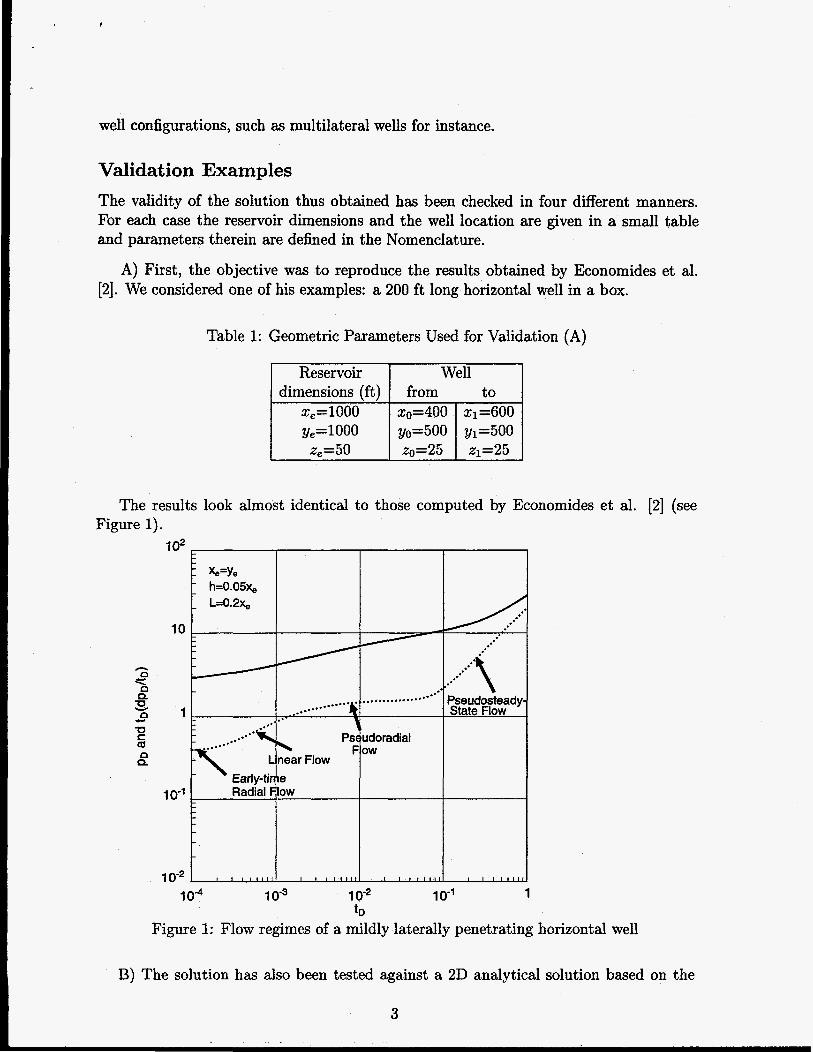
Validat ion Examples The validity of the solution thus obtained has been checked in four different manners. For each case the reservoir dimensions and the well location are given in a small table and parameters therein are defined in the Nomenclature.
A) First, the objective was to reproduce the results obtained by Ekonomides et al. [2]. We considered one of his examples: a 200 ft long horizontal well in a box.
Table 1: Geometric Parameters Used for Validation (A)
The results look almost identical to those computed by Economides et al. [Z] (see Figure 1).
10
lo-'
10"
&=Ye h=0.05& I- L=0.2x,
Early-tii
S Pseudosteady State Flow
10"' 10-3 1 o-2 10' 1 tD
Figure 1: Flow regimes of a mildly laterally penetrating horizontal well
B) The solution has also been tested against a 2D analytical solution based on the
3

method of images. This time using a fully penetrating horizontal well in the same reser- voir, the two results are identical (Figure 2).
Table 2: Geometric Parameters Used for Validation (B)
10
a 1 P
lo-'
10-2 1 o4 1 0-3 10" 1 0-' 1
tD Figure 2: Comparison between a classical 2D solver and the 3D solution for one fully penetrating well (2D problem) in the middle of the reservoir
C) Using the 2D solver we also compared the results in the case of two horizontal wells in the same reservoir, an injector and a producer, distance of 500 ft apart. Here again the results are identical (Figure 3).
D) Finally, we compared the results with a numerical simulator, Eclipse. We modeled an isolated well far from the boundaries, completed throughout the reservoir. The well is fully penetrating.
The results are shown in Figure 4, where we observe very good agreement. All the validation tests were performed using the rock and fluid properties given in
Table 5 below.
4

1 o4 10-3 1 0-* lo-’ 1 tD
Figure 3: Comparison between a classical 2D solver and the 3D solution for an injector and a producer
6000
5980 l
5960 I
5940 L
5920 L e
5900 Y
R
- 30 semi-analytical solution . . . . . . . . . Eclipse
0 20 40 60 80 100 t (days)
Figure 4: Comparison between Eclipse and the 3D solution for a single fully penetrating well
5

Table 3: Geometric Parameters Used for Validation (C)
Table 4: Geometric Parameters Used for Validation (D)
Reservoir Well
Xe=lOOO zO=O x1=1000 y,=9950 yo=4975 y1=4975
dimensions (ft) from to
xe=9950 ~0=4975 ~1=4975
Well Index Definition To compute the bottomhole pressure from the well block pressure, a simulator uses a weZZ index which only depends on the well block properties and on the well geometry.
For each phase p , the flow rate is proportional to the difference in pressure between the block and the well according to the relation:
Provided that the flow is approximately radial around the well, it is easy to show that there is an efective radius, TO such that:
W I = 8 k h / l n - c3 where 8 is the angle open to flow.
Peaceman [l] derived the following expression for TO (for a well parallel to the x-axis):
Most reservoir simulators use this expression to compute the well pressure. However
i) it is exact only for single phase flow, ii) the permeability must be uniform in the horizontal and vertical directions,
its validity is based on the following assumptions:
6
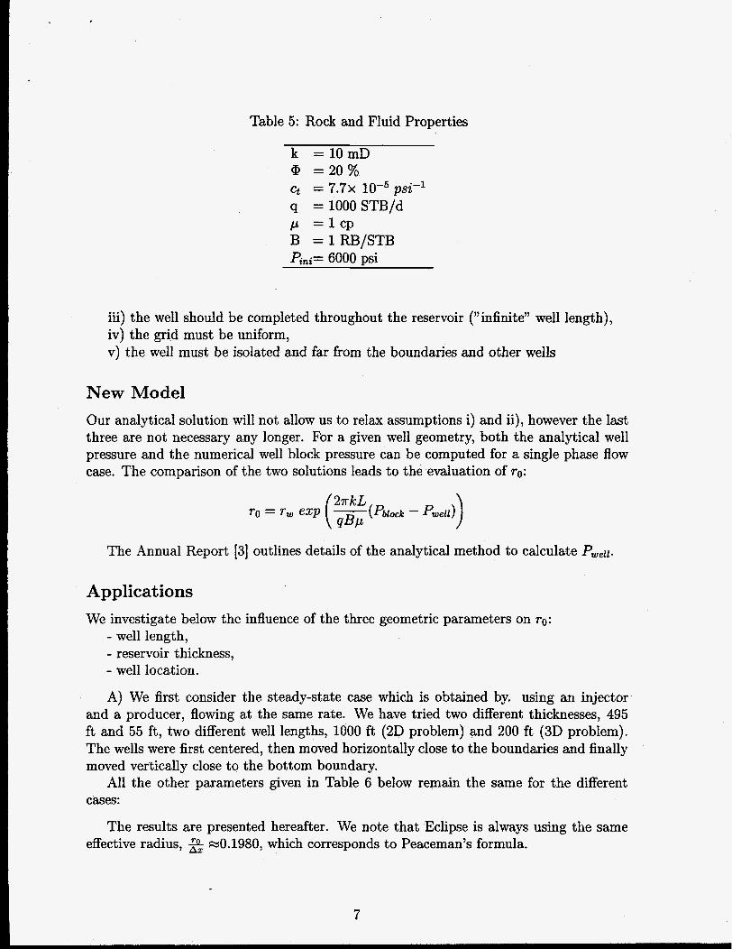
Table 5: Rock and Fluid Properties
k = 1 0 m D @ = 2 0 % ct = 7 . 7 ~ 10-5 psi-l q = lOOOSTB/d /A = l c p B = l R B / S T B P&= 6000 psi
iii) the well should be completed throughout the reservoir (”infinite” well length), iv) the grid must be uniform, v) the well must be isolated and far from the boundaries and other wells
New Model Our analytical solution will not allow us to relax assumptions i) and ii), however the last three are not necessary any longer. For a given well geometry, both the analytical well pressure and the numerical well block pressure can be computed for a single phase flow case. The comparison of the two solutions leads to the evaluation of ro:
The Annual Report [3] outlines details of the analytical method to calculate Pwell.
Applications We investigate below the influence of the three geometric parameters on ro:
- well length, - reservoir thickness, - well location.
A) We first consider the steady-state case which is obtained by. using an injector and a producer, flowing at the same rate. We have tried two different thicknesses, 495 ft and 55 ft, two different well lengths, 1000 ft (2D problem) and 200 ft (3D problem). The wells were first centered, then moved horizontally close to the boundaries and finally moved vertically close to the bottom boundary.
All the other parameters given in Table 6 below remain the same for the different cases:
The results are presented hereafter. We note that Eclipse is always using the same effective radius, 2 e o . 1980, which corresponds to Peaceman’s formula.
7
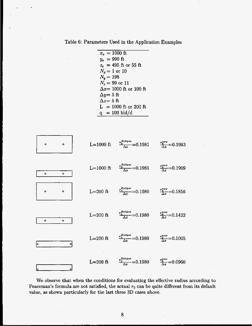
Table 6: Parameters Used in the Application Examples
xe = 1000 ft & = 990 ft z, = 495 ft or 55 ft Nx= 1 or 10 Ny= 198 N, = 99 or 11 Ax= 1000 ft or 100 ft Ay= 5 ft, Az= 5 f t L = 1000 f t or 200 ft q = 100 bbl/d
0 0 ,.Eclipse
L=lOOOft O A X =0.1981 g = O . 1983
I 0 0
,,Eclipse L=lOOO ft OLlrX =0.1981 E = o . 1909
I 1 0 0 I
0 0
,.Eclipse n L=200 f t A x =0.1980
,.Eclipse n =0.1980 L=200 ft A x
,.Eclipse 4 =0.1980
A x L=200 ft
,.Eclipse n =0.1980 L=200 f t A x
=O. 1856
g = O . 1422
g = 0 . 1 0 0 5
g = 0 . 0 9 6 0
We observe that when the conditions for evaluating the effective radius according to Peaceman’s formula are not satisfied, the actual ro can be quite different from its default value, as shown particularly for the last three 3D cases above.
8
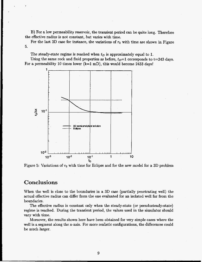
B) For a low permeability reservoir, the transient period can be quite long. Therefore
For the last 3D case for instance, the variations of TO with time are shown in Figure the effective radius is not constant, but varies with time.
5.
The steady-state regime is reached when t~ is approximately equal to 1. Using the same rock and fluid properties as before, t D = l corresponds to t=243 days.
For a permeability 10 times lower (k=l mD), this would become 2433 days!
X s P
1
lo-’
1 o-2
. . . . . .. . . . .
1 0-3 10” lo-’ 1 10 tD
Figure 5: Variations of TO with time for Eclipse and for the new model for a 3D problem
Conclusions When the well is close to the boundaries in a 3D case (partially penetrating well) the actual effective radius can differ from the one evaluated for an isolated well far from the boundaries.
The effective radius is constant only when the steady-state (or pseudosteady-state) regime is reached. During the transient period, the values used in the simulator should vary with time.
Moreover, the results shown here have been obtained for very simple cases where the well is a segment along the x-axis. For more realistic configurations, the differences could be much larger.
9

. c
Nomenclature B Formation volume factor, resbbl/STB
c Total compressibility k Permeability, mD IC, ICv IC, L Well length, ft P Pressure Pini Initial pressure q Flow rate, STB/day T, Wellbore radius, ft ro Effective well radius, ft t Time, hrs x e Extent of the reservoir in x-direction, ft xo x location of heel of the horizontal well, f t x1 x location of toe of the horizontal well, ft ye Extent of the reservoir in y-direction, ft yo y location of heel of the horizontal well, f t y1 y location of toe of the horizontal well, f t ze Extent of the reservoir in z-direction, ft zo z location of heel of the horizontal well, f t zI z location of toe of the horizontal well, ft Nv Number of simulation blocks in the y-direction N, Number of simulation blocks in the z-direction Ax Simulation gridblock size in the x-direction Ay Simulation gridblock size in the y-direction Az Simulation gridblock size in the z-direction @ Porosity p Viscosity
Rock compressibility, psi-l
Permeability in the x-direction, mD Permeability in the y-direction, mD Permeability in the z-direction, mD
Subscripts D Dimensionless w Well
10

References [l] Peaceman, D. W.: “Interpretation of Well-Block Pressures in Numerical Reservoir
Simulation,” SPEJ (June 1978) 183
[2] Economides, M.J., Brand, C.W. and nick, T.P.: “Well Configurations in Anisotropic Reservoirs”, paper SPE 27980 presented at the University of Tulsa Petroleum Engineering Symposium, Tulsa, Aug. 29-31 (1994)
[3] Aziz, K. et al.: Productivity and Injectivity of Horizontal Wells, 3rd Anmal Report to US Dept. Of Energy, Stanford University, 51-53, (1996)
DISCLAIMER
This report was prepared as an account of work sponsored by an agency of the United States Government. Neither the United States Government nor any agency thereof, nor any of their employees, makes any warranty, express or implied, or assumes any legal liability or responsi- bility for the accuracy, completeness, or usefulness of any information, apparatus, product, or process disclosed, or represents that its use would not infringe privately owned rights. Refer- ence herein to any specific commercial product, process, or service by trade name, trademark, manufacturer, or otherwise does not necessarily constitute or imply its endorsement, recom- mendation, or favoring by the United States Government or any agency thereof. The views and opinions of authors expressed herein do not necessarily state or reflect those of the United States Government or any agency thereof.
11
Related Documents