ORIGINAL PAPER Productivity Analysis of Draglines Operating in Horizontal and Vertical Tandem Mode of Operation in a Coal Mine— A Case Study Piyush Rai • Umakant Yadav • Ashok Kumar Received: 6 April 2009 / Accepted: 21 March 2011 / Published online: 3 May 2011 Ó Springer Science+Business Media B.V. 2011 Abstract The tandem operation of draglines is in use in some of the major Indian opencast coalmines owing to the favourable geo-mining conditions, technical suitability, efficiency and economic viabil- ity. In view of the importance of tandem operation, the present study has been undertaken in a large Indian opencast coalmine in order to critically investigate the horizontal and vertical tandem oper- ation of draglines on moderately strong and high sandstone benches (35–42 m), overlying a 15–18 m thick coal seam. The study has revealed that although the preparation of balancing diagram for planning of dragline operations is the first and the most important step, its actual implementation is equally important. Marked discrepancies in the productivity parameters as envisaged by the balancing diagram and as observed in the field studies, have been investigated and reported. The study also propounds the impor- tance of appraisal of dragline productivity parame- ters, such as, cycle time, swing angle, seating position, availability, utilization, etc., in the field scale. Irrespective of the mode of operation (hori- zontal or vertical tandem), the study moots the concept of computation of the weighted cycle time and overall cycle time vis-a `-vis swing angle variation for the draglines operating in field. The results drawn from the case study have been discussed in terms of cycle time computations, annual output computation and evaluation of earthmoving efficiency for the horizontal and vertical tandem modes of operation. Keywords Tandem operation Dragline balancing diagram Weighted cycle time Swing angle Loose muck Blasted muck 1 Introduction The walking draglines offer several merits in open pit mining project where long reach, deep digging and high output are essential requisites and the volume of overburden (O/B) to be handled is many times in comparison to the volume of mineable mineral. For instance, a 1 m thick coal seam may have 30 m thick O/B cover which may still be an economic P. Rai (&) Department of Mining Engineering, Institute of Technology, Banaras Hindu University, Varanasi 221 005, India e-mail: [email protected]; [email protected] P. Rai Department of Energy and Resources Engineering, Chonnam National University, Gwangju, South Korea U. Yadav Corporate Office, Northern Coalfields Ltd. (a subsidiary of Coal India Ltd.), Singrauli, Dist. Sidhi, Madhya Pradesh, India A. Kumar Pakri Barawdih Project, National Thermal Power Corporation, Dist. Ranchi, Jharkhand, India 123 Geotech Geol Eng (2011) 29:493–504 DOI 10.1007/s10706-011-9398-9

Welcome message from author
This document is posted to help you gain knowledge. Please leave a comment to let me know what you think about it! Share it to your friends and learn new things together.
Transcript
ORIGINAL PAPER
Productivity Analysis of Draglines Operating in Horizontaland Vertical Tandem Mode of Operation in a Coal Mine—A Case Study
Piyush Rai • Umakant Yadav • Ashok Kumar
Received: 6 April 2009 / Accepted: 21 March 2011 / Published online: 3 May 2011
� Springer Science+Business Media B.V. 2011
Abstract The tandem operation of draglines is in
use in some of the major Indian opencast coalmines
owing to the favourable geo-mining conditions,
technical suitability, efficiency and economic viabil-
ity. In view of the importance of tandem operation,
the present study has been undertaken in a large
Indian opencast coalmine in order to critically
investigate the horizontal and vertical tandem oper-
ation of draglines on moderately strong and high
sandstone benches (35–42 m), overlying a 15–18 m
thick coal seam. The study has revealed that although
the preparation of balancing diagram for planning of
dragline operations is the first and the most important
step, its actual implementation is equally important.
Marked discrepancies in the productivity parameters
as envisaged by the balancing diagram and as
observed in the field studies, have been investigated
and reported. The study also propounds the impor-
tance of appraisal of dragline productivity parame-
ters, such as, cycle time, swing angle, seating
position, availability, utilization, etc., in the field
scale. Irrespective of the mode of operation (hori-
zontal or vertical tandem), the study moots the
concept of computation of the weighted cycle time
and overall cycle time vis-a-vis swing angle variation
for the draglines operating in field. The results drawn
from the case study have been discussed in terms of
cycle time computations, annual output computation
and evaluation of earthmoving efficiency for the
horizontal and vertical tandem modes of operation.
Keywords Tandem operation � Dragline balancing
diagram �Weighted cycle time � Swing angle � Loose
muck � Blasted muck
1 Introduction
The walking draglines offer several merits in open pit
mining project where long reach, deep digging and
high output are essential requisites and the volume of
overburden (O/B) to be handled is many times in
comparison to the volume of mineable mineral. For
instance, a 1 m thick coal seam may have 30 m thick
O/B cover which may still be an economic
P. Rai (&)
Department of Mining Engineering, Institute
of Technology, Banaras Hindu University,
Varanasi 221 005, India
e-mail: [email protected];
P. Rai
Department of Energy and Resources Engineering,
Chonnam National University, Gwangju, South Korea
U. Yadav
Corporate Office, Northern Coalfields Ltd.
(a subsidiary of Coal India Ltd.), Singrauli, Dist.
Sidhi, Madhya Pradesh, India
A. Kumar
Pakri Barawdih Project, National Thermal Power
Corporation, Dist. Ranchi, Jharkhand, India
123
Geotech Geol Eng (2011) 29:493–504
DOI 10.1007/s10706-011-9398-9
proposition with application of draglines. Further,
absence of auxiliary haulage units, higher mineral
recovery, easy maneuverability, low maintenance
costs and operational advantages under adverse pit
conditions are also cited as the merits of deploying
draglines (Chugh 1980).
In the past two decades, draglines have especially
gained vast popularity in India for O/B stripping in
opencast coalmines. At present, Indian coalmines
have about 43 draglines in operation, which handle
almost 22% of the O/B. The bucket sizes of these
draglines range from 5 to 30 m3 (Balamadeswaran
et al. 2004). However, it must be clearly understood
that dragline is the single most expensive piece of
equipment to be deployed by any opencast mine,
hence, it is imperative to keep a strict vigil on the
performance of this equipment under the prevalent
operating conditions.
Considering the importance of the dragline oper-
ations and the costs involved therein, the present
work aims at critically investigating the dragline
performance in two different modes of tandem
operation, namely horizontal tandem (HT) and ver-
tical tandem (VT) operation (on same O/B strata and
under similar conditions). The study is based on
rigorous field monitoring in order to quantitatively
assess the key productivity parameters, while plan-
ning the tandem operations.
1.1 Objectives of the Study
The specific objectives of the present case study are
enumerated as follows:
1. To construct the balancing diagram for HT as
well as VT modes of operation under given field
conditions and to subsequently compute the
annual output by using the constructed balancing
diagram.
2. To compute some important productivity param-
eters, through field studies, for cut widths of 90
and 85 m, as practiced in field for HT and VT
modes of operation, respectively.
3. To study and establish the relationship between
varying swing components and the overall cycle
time of the draglines operating in tandem (HT as
well as VT).
4. To investigate the influence of overall cycle time,
availability, utilization and cut width on the
performance parameters of draglines in the HT
and VT modes of operation.
5. To assess the possible reasons for variation in
the productivity parameters as obtained from the
constructed balancing diagram, vis-a-vis the
actual operation in field.
2 Case Description
The present case study has been carried out in mine A
of a major opencast coalmine of Northern Coalfields
Ltd., Singrauli, India. The mine A is divided by a
central entry into two operating sections along the
East–West strike of the property. In one of the sections,
which will henceforth be named as mine 1, draglines
were operating in the HT mode of operation, whereas,
in another section, which will henceforth be named as
mine 2, draglines were operating in VT mode of
operation. Draglines operated on drilled and blasted
high O/B benches, which consisted of medium to fine
grained sandstone. The thickness of underlying coal
seam ranged from 15 to 18 m. The draglines casted the
overburden into previously cut void created after
extraction of the underlying coal seam.
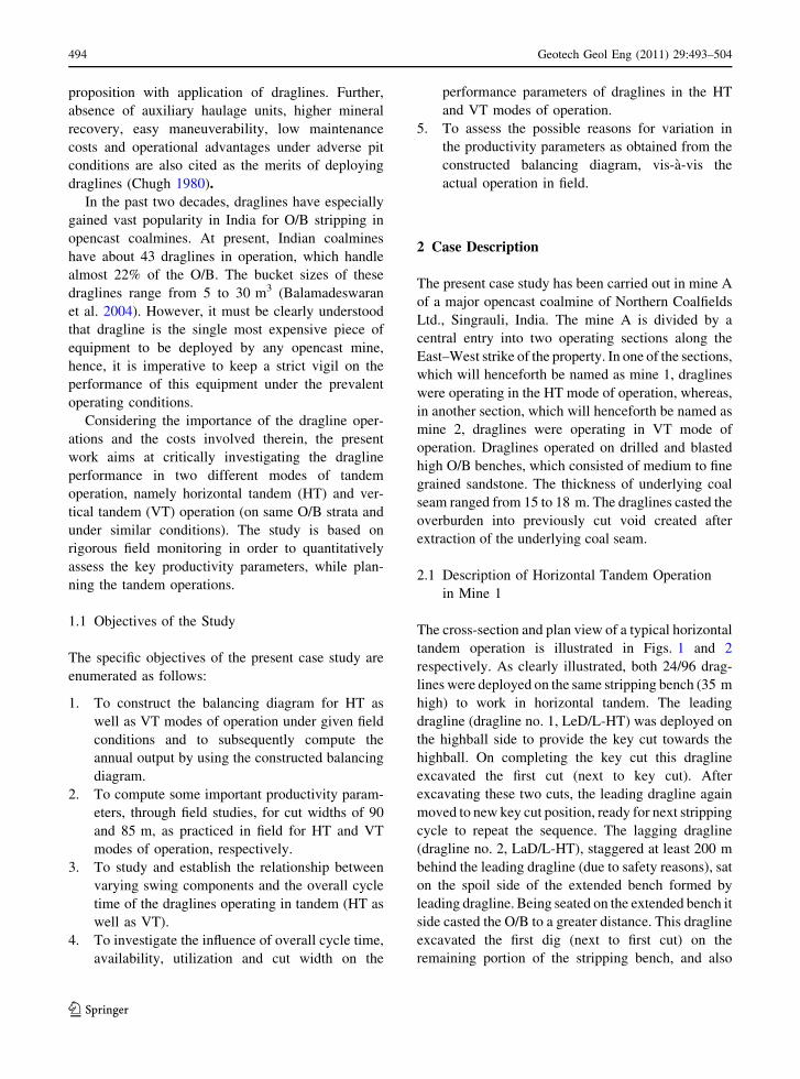
2.1 Description of Horizontal Tandem Operation
in Mine 1
The cross-section and plan view of a typical horizontal
tandem operation is illustrated in Figs. 1 and 2
respectively. As clearly illustrated, both 24/96 drag-
lines were deployed on the same stripping bench (35 m
high) to work in horizontal tandem. The leading
dragline (dragline no. 1, LeD/L-HT) was deployed on
the highball side to provide the key cut towards the
highball. On completing the key cut this dragline
excavated the first cut (next to key cut). After
excavating these two cuts, the leading dragline again
moved to new key cut position, ready for next stripping
cycle to repeat the sequence. The lagging dragline
(dragline no. 2, LaD/L-HT), staggered at least 200 m
behind the leading dragline (due to safety reasons), sat
on the spoil side of the extended bench formed by
leading dragline. Being seated on the extended bench it
side casted the O/B to a greater distance. This dragline
excavated the first dig (next to first cut) on the
remaining portion of the stripping bench, and also
494 Geotech Geol Eng (2011) 29:493–504
123
re-handled the loose overburden to finally expose the
coal seam fully as per the designed balancing diagram
parameters. Both draglines advanced along the strike
away from the central entry towards the boundary of
the pit to make cuts. A coal rib, of 5 m width
(triangular section) at the bottom, and up to full seam
thickness was left against the spoil heap.
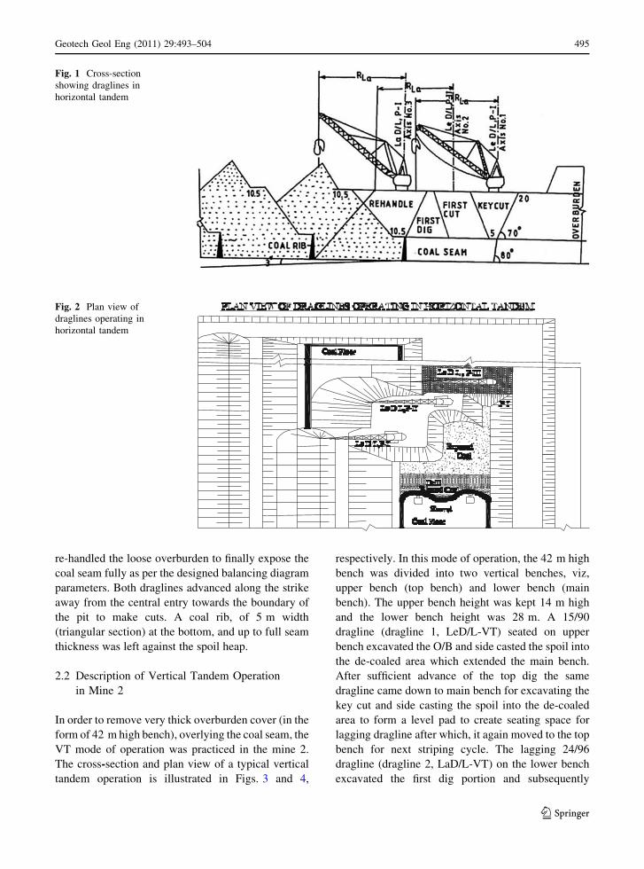
2.2 Description of Vertical Tandem Operation
in Mine 2
In order to remove very thick overburden cover (in the
form of 42 m high bench), overlying the coal seam, the
VT mode of operation was practiced in the mine 2.
The cross-section and plan view of a typical vertical
tandem operation is illustrated in Figs. 3 and 4,
respectively. In this mode of operation, the 42 m high
bench was divided into two vertical benches, viz,
upper bench (top bench) and lower bench (main
bench). The upper bench height was kept 14 m high
and the lower bench height was 28 m. A 15/90
dragline (dragline 1, LeD/L-VT) seated on upper
bench excavated the O/B and side casted the spoil into
the de-coaled area which extended the main bench.
After sufficient advance of the top dig the same
dragline came down to main bench for excavating the
key cut and side casting the spoil into the de-coaled
area to form a level pad to create seating space for
lagging dragline after which, it again moved to the top
bench for next striping cycle. The lagging 24/96
dragline (dragline 2, LaD/L-VT) on the lower bench
excavated the first dig portion and subsequently
Fig. 1 Cross-section
showing draglines in
horizontal tandem
Fig. 2 Plan view of
draglines operating in
horizontal tandem
Geotech Geol Eng (2011) 29:493–504 495
123
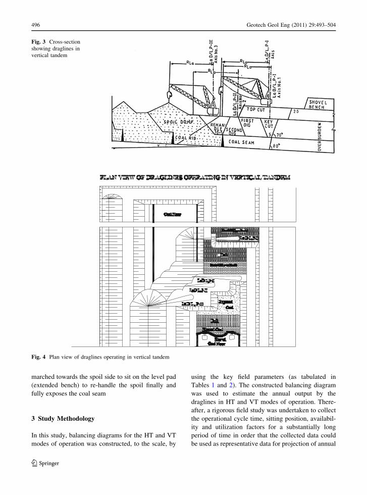
marched towards the spoil side to sit on the level pad
(extended bench) to re-handle the spoil finally and
fully exposes the coal seam
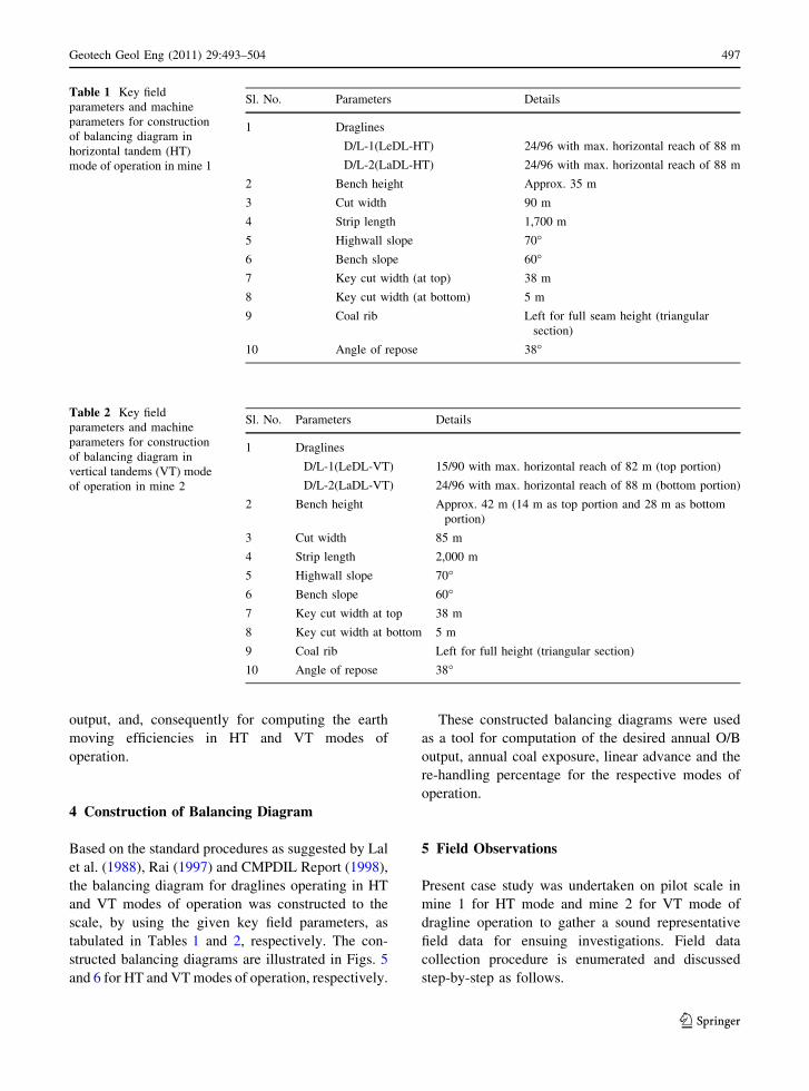
3 Study Methodology
In this study, balancing diagrams for the HT and VT
modes of operation was constructed, to the scale, by
using the key field parameters (as tabulated in
Tables 1 and 2). The constructed balancing diagram
was used to estimate the annual output by the
draglines in HT and VT modes of operation. There-
after, a rigorous field study was undertaken to collect
the operational cycle time, sitting position, availabil-
ity and utilization factors for a substantially long
period of time in order that the collected data could
be used as representative data for projection of annual
Fig. 3 Cross-section
showing draglines in
vertical tandem
Fig. 4 Plan view of draglines operating in vertical tandem
496 Geotech Geol Eng (2011) 29:493–504
123
output, and, consequently for computing the earth
moving efficiencies in HT and VT modes of
operation.
4 Construction of Balancing Diagram
Based on the standard procedures as suggested by Lal
et al. (1988), Rai (1997) and CMPDIL Report (1998),
the balancing diagram for draglines operating in HT
and VT modes of operation was constructed to the
scale, by using the given key field parameters, as
tabulated in Tables 1 and 2, respectively. The con-
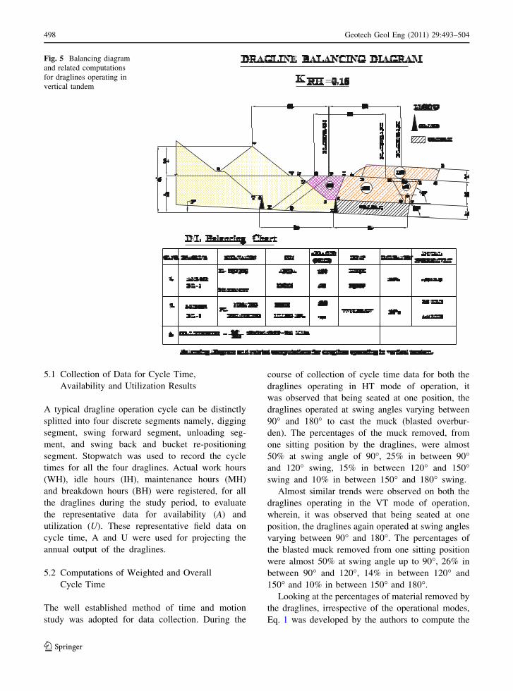
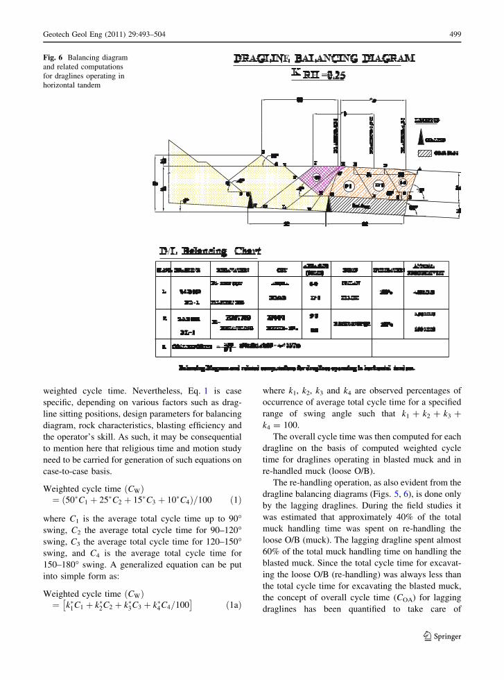
structed balancing diagrams are illustrated in Figs. 5
and 6 for HT and VT modes of operation, respectively.
These constructed balancing diagrams were used
as a tool for computation of the desired annual O/B
output, annual coal exposure, linear advance and the
re-handling percentage for the respective modes of
operation.
5 Field Observations
Present case study was undertaken on pilot scale in
mine 1 for HT mode and mine 2 for VT mode of
dragline operation to gather a sound representative
field data for ensuing investigations. Field data
collection procedure is enumerated and discussed
step-by-step as follows.
Table 1 Key field
parameters and machine
parameters for construction
of balancing diagram in
horizontal tandem (HT)
mode of operation in mine 1
Sl. No. Parameters Details
1 Draglines
D/L-1(LeDL-HT) 24/96 with max. horizontal reach of 88 m
D/L-2(LaDL-HT) 24/96 with max. horizontal reach of 88 m
2 Bench height Approx. 35 m
3 Cut width 90 m
4 Strip length 1,700 m
5 Highwall slope 70�6 Bench slope 60�7 Key cut width (at top) 38 m
8 Key cut width (at bottom) 5 m
9 Coal rib Left for full seam height (triangular
section)
10 Angle of repose 38�
Table 2 Key field
parameters and machine
parameters for construction
of balancing diagram in
vertical tandems (VT) mode
of operation in mine 2
Sl. No. Parameters Details
1 Draglines
D/L-1(LeDL-VT) 15/90 with max. horizontal reach of 82 m (top portion)
D/L-2(LaDL-VT) 24/96 with max. horizontal reach of 88 m (bottom portion)
2 Bench height Approx. 42 m (14 m as top portion and 28 m as bottom
portion)
3 Cut width 85 m
4 Strip length 2,000 m
5 Highwall slope 70�6 Bench slope 60�7 Key cut width at top 38 m
8 Key cut width at bottom 5 m
9 Coal rib Left for full height (triangular section)
10 Angle of repose 38�
Geotech Geol Eng (2011) 29:493–504 497
123
5.1 Collection of Data for Cycle Time,
Availability and Utilization Results
A typical dragline operation cycle can be distinctly
splitted into four discrete segments namely, digging
segment, swing forward segment, unloading seg-
ment, and swing back and bucket re-positioning
segment. Stopwatch was used to record the cycle
times for all the four draglines. Actual work hours
(WH), idle hours (IH), maintenance hours (MH)
and breakdown hours (BH) were registered, for all
the draglines during the study period, to evaluate
the representative data for availability (A) and
utilization (U). These representative field data on
cycle time, A and U were used for projecting the
annual output of the draglines.
5.2 Computations of Weighted and Overall
Cycle Time
The well established method of time and motion
study was adopted for data collection. During the
course of collection of cycle time data for both the
draglines operating in HT mode of operation, it
was observed that being seated at one position, the
draglines operated at swing angles varying between
90� and 180� to cast the muck (blasted overbur-
den). The percentages of the muck removed, from
one sitting position by the draglines, were almost
50% at swing angle of 90�, 25% in between 90�and 120� swing, 15% in between 120� and 150�swing and 10% in between 150� and 180� swing.
Almost similar trends were observed on both the
draglines operating in the VT mode of operation,
wherein, it was observed that being seated at one
position, the draglines again operated at swing angles
varying between 90� and 180�. The percentages of
the blasted muck removed from one sitting position
were almost 50% at swing angle up to 90�, 26% in
between 90� and 120�, 14% in between 120� and
150� and 10% in between 150� and 180�.
Looking at the percentages of material removed by
the draglines, irrespective of the operational modes,
Eq. 1 was developed by the authors to compute the
Fig. 5 Balancing diagram
and related computations
for draglines operating in
vertical tandem
498 Geotech Geol Eng (2011) 29:493–504
123
weighted cycle time. Nevertheless, Eq. 1 is case
specific, depending on various factors such as drag-
line sitting positions, design parameters for balancing
diagram, rock characteristics, blasting efficiency and
the operator’s skill. As such, it may be consequential
to mention here that religious time and motion study
need to be carried for generation of such equations on
case-to-case basis.
Weighted cycle time CWð Þ¼ 50�C1 þ 25�C2 þ 15�C3 þ 10�C4ð Þ=100 ð1Þ
where C1 is the average total cycle time up to 90�swing, C2 the average total cycle time for 90–120�swing, C3 the average total cycle time for 120–150�swing, and C4 is the average total cycle time for
150–180� swing. A generalized equation can be put
into simple form as:
Weighted cycle time CWð Þ¼ k�1C1 þ k�2C2 þ k�3C3 þ k�4C4=100� �
ð1aÞ
where k1, k2, k3 and k4 are observed percentages of
occurrence of average total cycle time for a specified
range of swing angle such that k1 ? k2 ? k3 ?
k4 = 100.
The overall cycle time was then computed for each
dragline on the basis of computed weighted cycle
time for draglines operating in blasted muck and in
re-handled muck (loose O/B).
The re-handling operation, as also evident from the
dragline balancing diagrams (Figs. 5, 6), is done only
by the lagging draglines. During the field studies it
was estimated that approximately 40% of the total
muck handling time was spent on re-handling the
loose O/B (muck). The lagging dragline spent almost
60% of the total muck handling time on handling the
blasted muck. Since the total cycle time for excavat-
ing the loose O/B (re-handling) was always less than
the total cycle time for excavating the blasted muck,
the concept of overall cycle time (COA) for lagging
draglines has been quantified to take care of
Fig. 6 Balancing diagram
and related computations
for draglines operating in
horizontal tandem
Geotech Geol Eng (2011) 29:493–504 499
123
fractional cycle time in the loose and the blasted
muck portions. The COA as quantified by Eq. 2, is
case specific.
Overall cycle time COAð Þ ¼ 0:4�CWLð Þ þ 0:6�CWBð Þð2Þ
where CWL is the weighted cycle time for re-handled
muck (loose O/B) and CWB is the weighted cycle
time for blasted muck. A generalized equation can be
put into simple form as:
Overall cycle time COAð Þ ¼ kCWL þ 1� kð ÞCWB
ð2bÞ
where k is fraction of time spent for re-handling the
loose muck by lagging draglines. Further, since the
leading dragline always operated on the blasted muck
only, the overall cycle time for leading draglines COA
will always equal to CW.
5.3 Evaluation of Availability and Utilization
After collection of field data on WH, BH and IH, the
availability, utilization and availability-cum-utiliza-
tion factor, for all the draglines under study, were
evaluated by using the standard equations given
below:
Availability factor Að Þ ¼ SSH � MHþ BHð ÞSSH
ð3Þ
Utilization factor Uð Þ ¼ SSH � MHþ BHþ IHð ÞSSH
ð4ÞAvailability - cum - utilization factor Kð Þ ¼ A� U
ð5Þ
where SSH is the scheduled shift hour (in a specified
period, where 1 shift = 8 h), MH the maintenance
hour, IH the idle hour and BH is the breakdown hour.
5.4 Projection of Annual Output
On the basis of the collected field data, the projected
annual output (P1) for each dragline was computed by
using the standard Eq. 6 as given below (CMPDIL
norms 1998).
P1 ¼ B=Cð Þ�K�S�F�M�N�h N�s N�d 60�60 M m3� �
ð6Þ
where B is the bucket capacity of dragline (m3), C the
overall cycle time of dragline (s), K the availability-
cum-utilization factor, S the swell factor for loose, easy
digging sandstone (0.719), F the fill factor for loose,
easy digging sandstone (0.933), M the machine travel-
ling and positioning factor (0.8), Nh the number of hours
in a shift (8 h), Ns the number of shifts in a day (3 shifts),
and Nd is the number of days in a year (365 days).
In order to compute the annual outputs for the
draglines under study, the individual values of overall
cycle time (COA), A and U were substituted for each
dragline as per the recorded field observations. Remain-
ing factors in Eq. 6 were substituted as per the Central
Mine Planning & Design Institute Ltd. (CMPDIL)
norms as given above within the parentheses.
5.5 Computation of Efficiency for Draglines
The computation of earthmoving efficiency for each
dragline was done by using Eq. 7, as suggested by
Rai (1997).
Efficiency of dragline gð Þ
¼ Computed annual output P1ð Þ � 100
Annual output as per the balancing diagram ðP2Þð7Þ
The determination of annual output as per the balanc-
ing diagram (P2) was done from the prepared balancing
diagram as per the balancing results given in Figs. 5
and 6 for HT and VT modes of operation, respectively.
5.6 Computation of Coal Exposure
The coal exposed by the draglines working in tandem
operation was estimated by using the generalized
Eq. 8 as per the balancing diagram concept.
CE ¼ PFD=Að Þ �W � T � D� R M teð Þ ð8Þ
where CE is the coal exposure (M te), PFD the annual
output of the lagging dragline from the first dig (M
m3), A the area of first dig (m2), W the cut width (m),
T the thickness of coal seam (m), D the specific
gravity of coal, and R is the recovery factor.
In Eq. 8 the term (PFD/A) represents the annual
linear advance of the draglines (more specifically
lagging draglines). In the above equation, the value of
W was fixed as per the mode of operation (90 and
85 m for HT and VT operation, respectively) and the
500 Geotech Geol Eng (2011) 29:493–504
123
value of T was taken as 18 m for HT operation and
15 m for VT mode. D was taken as 1.52 for the given
field conditions, whereas, the value of R was assumed
as 0.9. Thereby, on substituting the values of the
linear advance (PFD/A), as obtained from the balanc-
ing diagram the coal exposure value was obtained
(refer to balancing results as given in Figs. 5 and 6).
6 Results and Discussion
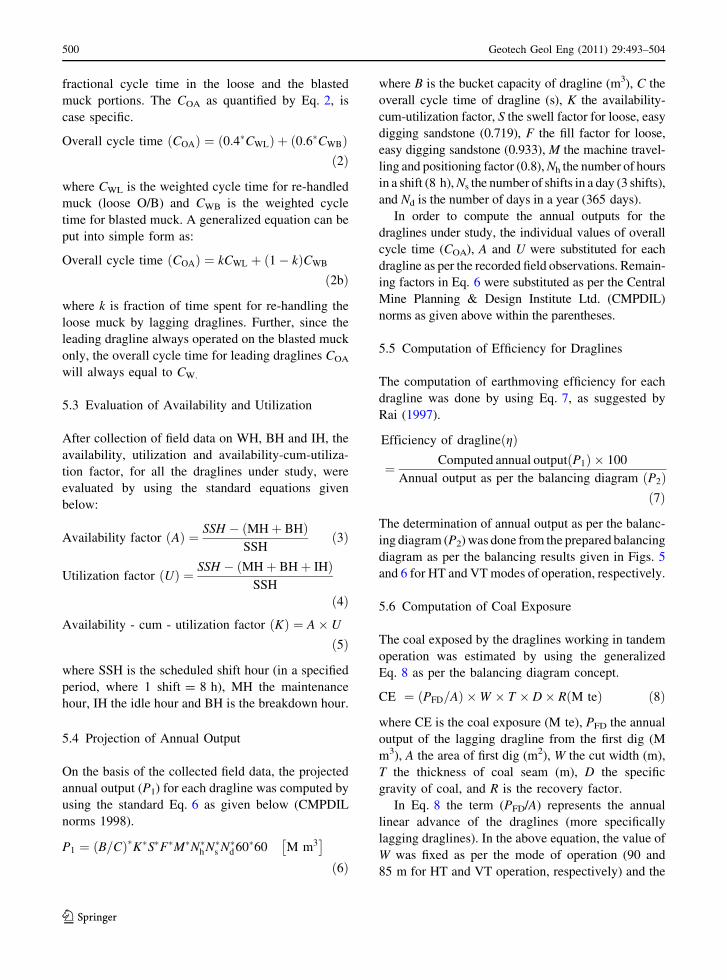
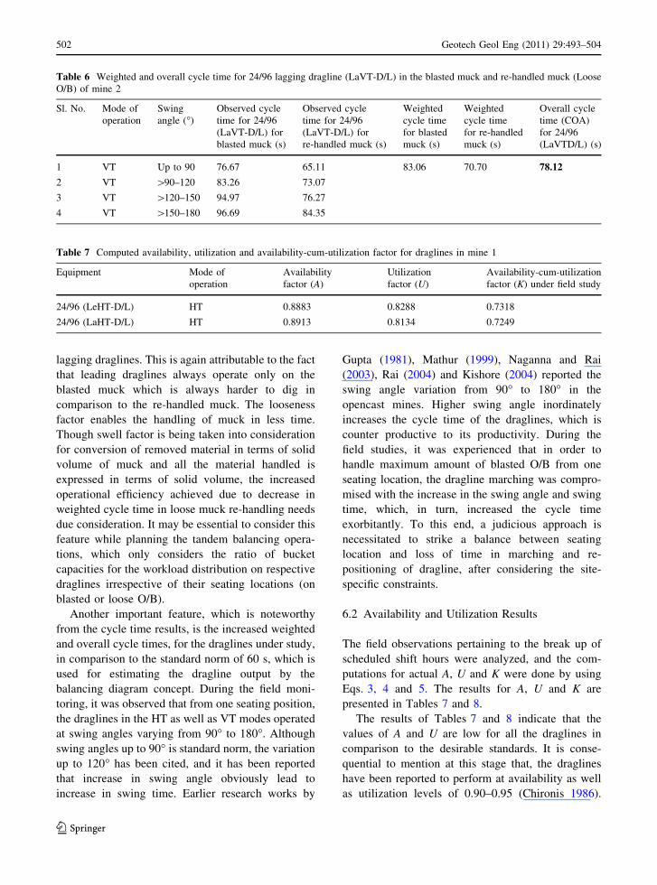
6.1 Cycle Time Results
Overall cycle time (COA) for individual draglines was
computed on the basis of weighted values at different
swing angles for blasted muck and re-handled muck
(loose O/B), by using Eqs. 1 and 2, respectively. The
cycle time results are tabulated in Tables 3, 4, 5, 6.
Cycle time results, as tabulated in Tables 3, 4, 5, 6,
reveal that, irrespective of the operational mode of
draglines, weighted cycle time on re-handled muck is
less than weighted cycle time on blasted muck. This
is due to the easier diggability in the re-handled muck
owing to its looseness. Hence, it implies that a greater
volume of muck can be handled by lagging draglines
as besides operating on the blasted muck in the first
dig area, they operate on the loose muck also.
Further, overall cycle time results, as seen in above
tables, also clearly indicate that the leading draglines
have higher overall cycle time in comparison to
Table 3 Weighted and overall cycle time results for 24/96 leading dragline (LeHT-D/L) working in HT mode in the blasted muck of
mine 1
Sl. No. Mode of
operation
Swing angle (�) Observed cycle time
for 24/96 (LeHT-D/L) (s)
Weighted cycle
time (CW) (s)
Overall cycle time (COA)
for 24/96 (LeHT-D/L) (s)a
1 HT Up to 90 74.58 81.48 81.48
2 HT [90–120 81.80
3 HT [120–150 91.89
4 HT [150–180 99.53
a In the HT as well as the VT modes of operation since the leading draglines (Le D/L) operate on the blasted muck hence, CW = COA
(since k = 0)
Table 4 Weighted and overall cycle time for 24/96 lagging dragline (LaHT-D/L) working in HT mode in the blasted muck and re-
handled muck (loose O/B) for mine 1
Sl. No. Mode of
operation
Swing
angle (�)
Observed cycle
time for 24/96
(LaHT-D/L) for
blasted muck (s)
Observed cycle
time for 24/96
(LaHTD/L) for
re-handled muck (s)
Weighted
cycle time
for blasted
muck (s)
Weighted
cycle time
for re-handled
muck (s)
Overall cycle
time (COA)
for 24/96
(LaHT-D/L) (s)
1 HT Up to 90 74.96 65.11 81.16 71.25 77.20
2 HT [90–120 81.68 73.93
3 HT [120–150 89.45 78.57
4 HT [150–180 98.40 84.29
Table 5 Weighted and overall cycle time for 15/90 leading dragline (LeVT-D/L) working in VT mode in the blasted muck of mine 2
Sl. No. Mode of
operation
Swing angle (�) Observed cycle time
for 15/90 (LeVT-D/L) (s)
Weighted cycle
time (CW) (s)
Overall cycle time (COA)
for 15/90 (LeVT-D/L) (s)a
1 VT Up to 90 74.58 80.58 80.58
2 VT [90–120 81.03
3 VT [120–150 89.38
4 VT [150–180 96.26
a In the HT as well as the VT modes of operation since the leading draglines (Le D/L) operate on the blasted muck hence, CW = COA
(since k = 0)
Geotech Geol Eng (2011) 29:493–504 501
123
lagging draglines. This is again attributable to the fact
that leading draglines always operate only on the
blasted muck which is always harder to dig in
comparison to the re-handled muck. The looseness
factor enables the handling of muck in less time.
Though swell factor is being taken into consideration
for conversion of removed material in terms of solid
volume of muck and all the material handled is
expressed in terms of solid volume, the increased
operational efficiency achieved due to decrease in
weighted cycle time in loose muck re-handling needs
due consideration. It may be essential to consider this
feature while planning the tandem balancing opera-
tions, which only considers the ratio of bucket
capacities for the workload distribution on respective
draglines irrespective of their seating locations (on
blasted or loose O/B).
Another important feature, which is noteworthy
from the cycle time results, is the increased weighted
and overall cycle times, for the draglines under study,
in comparison to the standard norm of 60 s, which is
used for estimating the dragline output by the
balancing diagram concept. During the field moni-
toring, it was observed that from one seating position,
the draglines in the HT as well as VT modes operated
at swing angles varying from 90� to 180�. Although
swing angles up to 90� is standard norm, the variation
up to 120� has been cited, and it has been reported
that increase in swing angle obviously lead to
increase in swing time. Earlier research works by
Gupta (1981), Mathur (1999), Naganna and Rai
(2003), Rai (2004) and Kishore (2004) reported the
swing angle variation from 90� to 180� in the
opencast mines. Higher swing angle inordinately
increases the cycle time of the draglines, which is
counter productive to its productivity. During the
field studies, it was experienced that in order to
handle maximum amount of blasted O/B from one
seating location, the dragline marching was compro-
mised with the increase in the swing angle and swing
time, which, in turn, increased the cycle time
exorbitantly. To this end, a judicious approach is
necessitated to strike a balance between seating
location and loss of time in marching and re-
positioning of dragline, after considering the site-
specific constraints.
6.2 Availability and Utilization Results
The field observations pertaining to the break up of
scheduled shift hours were analyzed, and the com-
putations for actual A, U and K were done by using
Eqs. 3, 4 and 5. The results for A, U and K are
presented in Tables 7 and 8.
The results of Tables 7 and 8 indicate that the
values of A and U are low for all the draglines in
comparison to the desirable standards. It is conse-
quential to mention at this stage that, the draglines
have been reported to perform at availability as well
as utilization levels of 0.90–0.95 (Chironis 1986).
Table 6 Weighted and overall cycle time for 24/96 lagging dragline (LaVT-D/L) in the blasted muck and re-handled muck (Loose
O/B) of mine 2
Sl. No. Mode of
operation
Swing
angle (�)
Observed cycle
time for 24/96
(LaVT-D/L) for
blasted muck (s)
Observed cycle
time for 24/96
(LaVT-D/L) for
re-handled muck (s)
Weighted
cycle time
for blasted
muck (s)
Weighted
cycle time
for re-handled
muck (s)
Overall cycle
time (COA)
for 24/96
(LaVTD/L) (s)
1 VT Up to 90 76.67 65.11 83.06 70.70 78.12
2 VT [90–120 83.26 73.07
3 VT [120–150 94.97 76.27
4 VT [150–180 96.69 84.35
Table 7 Computed availability, utilization and availability-cum-utilization factor for draglines in mine 1
Equipment Mode of
operation
Availability
factor (A)
Utilization
factor (U)
Availability-cum-utilization
factor (K) under field study
24/96 (LeHT-D/L) HT 0.8883 0.8288 0.7318
24/96 (LaHT-D/L) HT 0.8913 0.8134 0.7249
502 Geotech Geol Eng (2011) 29:493–504
123
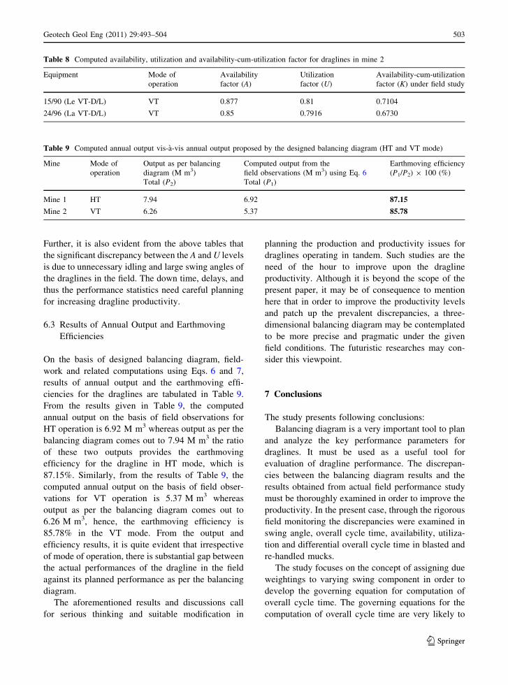
Further, it is also evident from the above tables that
the significant discrepancy between the A and U levels
is due to unnecessary idling and large swing angles of
the draglines in the field. The down time, delays, and
thus the performance statistics need careful planning
for increasing dragline productivity.
6.3 Results of Annual Output and Earthmoving
Efficiencies
On the basis of designed balancing diagram, field-
work and related computations using Eqs. 6 and 7,
results of annual output and the earthmoving effi-
ciencies for the draglines are tabulated in Table 9.
From the results given in Table 9, the computed
annual output on the basis of field observations for
HT operation is 6.92 M m3 whereas output as per the
balancing diagram comes out to 7.94 M m3 the ratio
of these two outputs provides the earthmoving
efficiency for the dragline in HT mode, which is
87.15%. Similarly, from the results of Table 9, the
computed annual output on the basis of field obser-
vations for VT operation is 5.37 M m3 whereas
output as per the balancing diagram comes out to
6.26 M m3, hence, the earthmoving efficiency is
85.78% in the VT mode. From the output and
efficiency results, it is quite evident that irrespective
of mode of operation, there is substantial gap between
the actual performances of the dragline in the field
against its planned performance as per the balancing
diagram.
The aforementioned results and discussions call
for serious thinking and suitable modification in
planning the production and productivity issues for
draglines operating in tandem. Such studies are the
need of the hour to improve upon the dragline
productivity. Although it is beyond the scope of the
present paper, it may be of consequence to mention
here that in order to improve the productivity levels
and patch up the prevalent discrepancies, a three-
dimensional balancing diagram may be contemplated
to be more precise and pragmatic under the given
field conditions. The futuristic researches may con-
sider this viewpoint.
7 Conclusions
The study presents following conclusions:
Balancing diagram is a very important tool to plan
and analyze the key performance parameters for
draglines. It must be used as a useful tool for
evaluation of dragline performance. The discrepan-
cies between the balancing diagram results and the
results obtained from actual field performance study
must be thoroughly examined in order to improve the
productivity. In the present case, through the rigorous
field monitoring the discrepancies were examined in
swing angle, overall cycle time, availability, utiliza-
tion and differential overall cycle time in blasted and
re-handled mucks.
The study focuses on the concept of assigning due
weightings to varying swing component in order to
develop the governing equation for computation of
overall cycle time. The governing equations for the
computation of overall cycle time are very likely to
Table 8 Computed availability, utilization and availability-cum-utilization factor for draglines in mine 2
Equipment Mode of
operation
Availability
factor (A)
Utilization
factor (U)
Availability-cum-utilization
factor (K) under field study
15/90 (Le VT-D/L) VT 0.877 0.81 0.7104
24/96 (La VT-D/L) VT 0.85 0.7916 0.6730
Table 9 Computed annual output vis-a-vis annual output proposed by the designed balancing diagram (HT and VT mode)
Mine Mode of
operation
Output as per balancing
diagram (M m3)
Computed output from the
field observations (M m3) using Eq. 6
Earthmoving efficiency
(P1/P2) 9 100 (%)
Total (P2) Total (P1)
Mine 1 HT 7.94 6.92 87.15
Mine 2 VT 6.26 5.37 85.78
Geotech Geol Eng (2011) 29:493–504 503
123
be case specific as they depend on the geo-mining
conditions, degree of fragmentation, machine related
parameters, and, above all the management decisions.
However, the critical investigations of cycle time vis-
a-vis swing variation would be of immense value to
the field planners and operators to clearly investigate
and optimize the cycle time for enhanced
productivity.
Looking at the differential overall cycle times for
the leading and lagging draglines, it may be reason-
able to give due cognizance to overall cycle time
while working on the blasted muck, and, while
working on the re-handling portion of the blasted
muck (which is quite loose and easier to handle).
The swing angle is one of the major contributors
towards the enhanced overall cycle time, hence
efforts must be made to minimize the swing angle
instead of minimizing the marching of draglines.
Unnecessarily trying to reduce the dragline marching
results into excessive swing angle and swinging time,
which unnecessarily escalates the overall cycle time.
Availability and utilization of the draglines must
be properly recorded, documented and monitored on
a regular basis in order to facilitate continual
improvement in the productivity of capital-intensive
draglines.
Acknowledgments The author wishes to convey immense
gratitude towards the staff and management of the Northern
Coalfields Ltd. (NCL), Singrauli, Dist. (MP), India, for
providing their permission and excellent support during the
fieldwork.
References
Balamadeswaran P, Sen P, Mishra AK (2004) Blasting prac-
tices in Indian dragline benches: a review. Minetech J
CMPDIL 25(4):36–44
Chironis NP (1986) Smaller versatile draglines operating in
tandem reach deep seams efficiently. Coal Age 9(12):
48–50
Chugh YP (1980) Surface mining of minerals by draglines in
the USA. Transaction of mining metallurgy (Sectional
Mining Industry). The Institution of Mining and Metal-
lurgy, London, pp A198–A204
CMPDIL Report (1998, April). Operational plan for Jayant
opencast mine, pp 2–20
Gupta RK (1981). Dragline productivity in opencast mines.
Project report, Department of Mining Engineering, BHU,
Varanasi, unpublished
Kishore N (2004). Planning of tandem dragline operations in
opencast mines. PhD thesis, Department of Mining
Engineering, Banaras Hindu University, Varanasi
Lal M, Agrawal MR, Rai RL (1988). Suggested method of
working for Jayant opencast mine operation of dragline in
tandem. In: National symposium on mine planning and
design. BHU, Varanasi, pp 1.01–1.10
Mathur SP (1999) Coal mining in India. M.S. Enterprises,
Bilaspur, pp 96–105
Naganna M, Rai P (2003) Swing time study on large capacity
draglines. CMTM J Indian Inst Coal Manage 8(3):2–5
Rai VK (1997). Balancing diagram—a basic planning tool for
dragline operation. In: Proceedings of the national semi-
nar on emerging technology in surface mines and envi-
ronmental challenges, Mangalore, India, pp 85–89
Rai P (2004) Performance assessment of draglines in opencast
mines. Indian J Eng Mater Sci 11:493–498
504 Geotech Geol Eng (2011) 29:493–504
123
Related Documents