Productivity+™ Active Editor Pro probe software for machine tools Productivity+™ Active Editor Pro is a PC based software solution which provides an easy-to-use platform for integrating measurement capability and advanced, intelligent process control functionality across the key stages of machining programs, encompassing predictive process setting, active in-process control and informative reporting. Features and benefits • Add intelligence to your process: cutting programs automatically adapt based on inspection results • Point and click programming from solid models, or program manually without models • Full multi-axis support for milling machines, including spindle orientating machine configurations • Embed macro programs and custom calculations into the probe routine • Integrated tool setting • Comprehensive CAD/CAM compatibility • Dynamic help, instructional dialogs and wizards • Probe cycle simulation • Extensive database of Renishaw probes • Construct points, lines, circles and planes from measured features • Data reporting via RS232/write to file (controller dependent) • Automatic recovery from false triggers and reseat errors Data sheet Productivity+™ Active Editor Pro probe software for machine tools

Welcome message from author
This document is posted to help you gain knowledge. Please leave a comment to let me know what you think about it! Share it to your friends and learn new things together.
Transcript
Productivity+™ Active Editor Pro probe software for machine tools
Productivity+™ Active Editor Pro is a PC based software solution which provides an easy-to-use platform for integrating measurement capability and advanced, intelligent process control functionality across the key stages of machining programs, encompassing predictive process setting, active in-process control and informative reporting.
Features and benefits• Add intelligence to your process:
cutting programs automatically adapt based on inspection results
• Point and click programming from solid models, or program manually without models
• Full multi-axis support for milling machines, including spindle orientating machine configurations
• Embed macro programs and custom calculations into the probe routine
• Integrated tool setting• Comprehensive CAD/CAM
compatibility• Dynamic help, instructional dialogs
and wizards• Probe cycle simulation• Extensive database of Renishaw probes• Construct points, lines, circles and
planes from measured features• Data reporting via RS232/write to file
(controller dependent)
• Automatic recovery from false triggers and reseat errors
Data sheetProductivity+™ Active Editor Pro probe software for machine tools
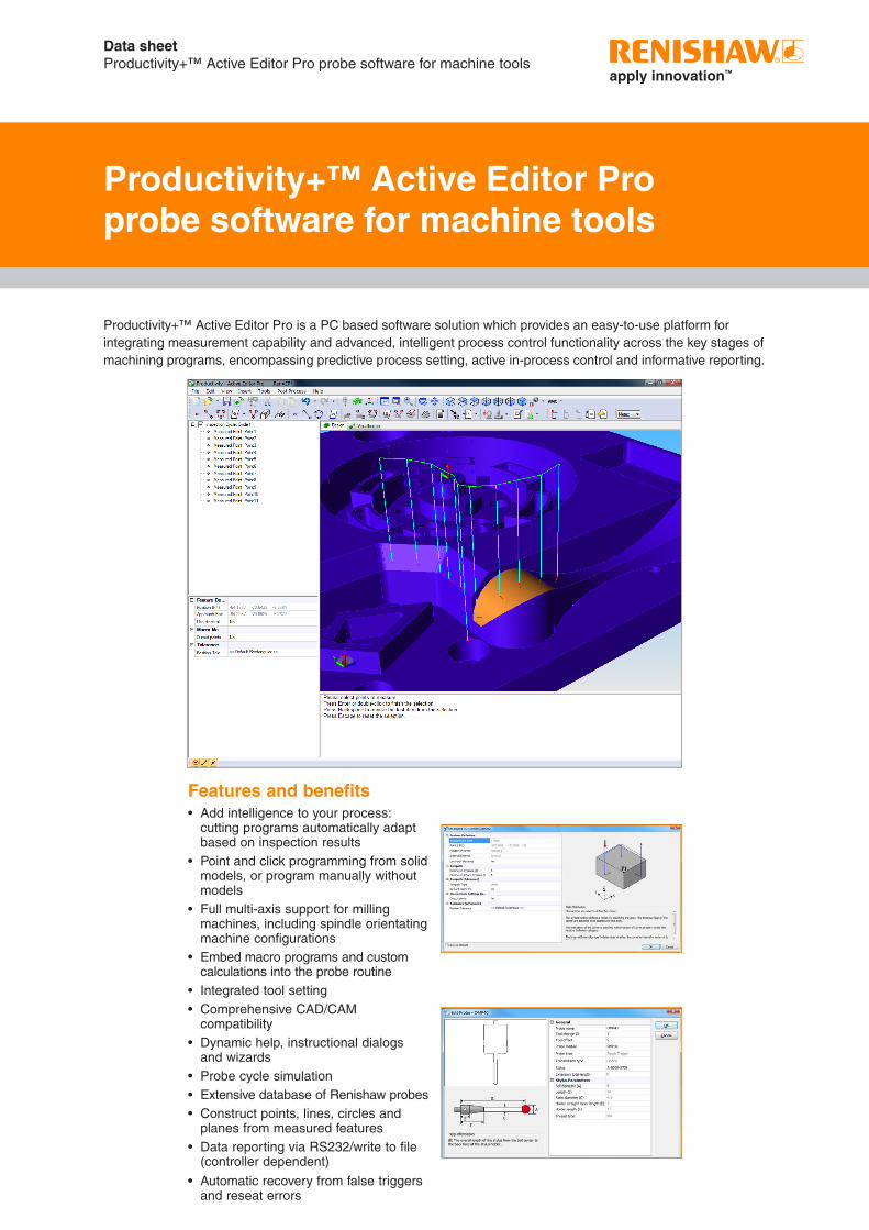
Creating a new part fileProductivity+ Active Editor Pro contains a New Part File Wizard that guides users through the steps required to create a new session, including, where necessary, measurement units, importing an existing NC machining program, and importing a solid model.
NC program files can also be imported (or pasted from the clipboard) during programming using the G-Code Block icon.
Any imported programs can easily be split or re-combined to accommodate the required probing strategy.
VisualisationThe visualisation feature allows on-screen simulation of programmed probe cycles. When a probe/component collision is detected, the probe is highlighted in red and a collision log is generated (visible in the Prompt Viewer).
Choose to visualise an entire program, or select an individual program statement at which simulation will commence.
Data sheetProductivity+™ Active Editor Pro probe software for machine tools
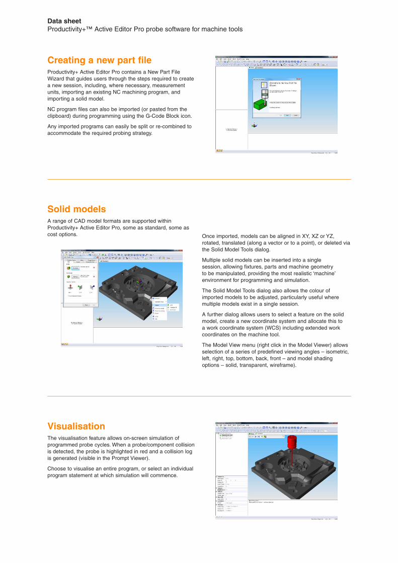
Once imported, models can be aligned in XY, XZ or YZ, rotated, translated (along a vector or to a point), or deleted via the Solid Model Tools dialog.
Multiple solid models can be inserted into a single session, allowing fixtures, parts and machine geometry to be manipulated, providing the most realistic ‘machine’ environment for programming and simulation.
The Solid Model Tools dialog also allows the colour of imported models to be adjusted, particularly useful where multiple models exist in a single session.
A further dialog allows users to select a feature on the solid model, create a new coordinate system and allocate this to a work coordinate system (WCS) including extended work coordinates on the machine tool.
The Model View menu (right click in the Model Viewer) allows selection of a series of predefined viewing angles – isometric, left, right, top, bottom, back, front – and model shading options – solid, transparent, wireframe).
Solid modelsA range of CAD model formats are supported within Productivity+ Active Editor Pro, some as standard, some as cost options.
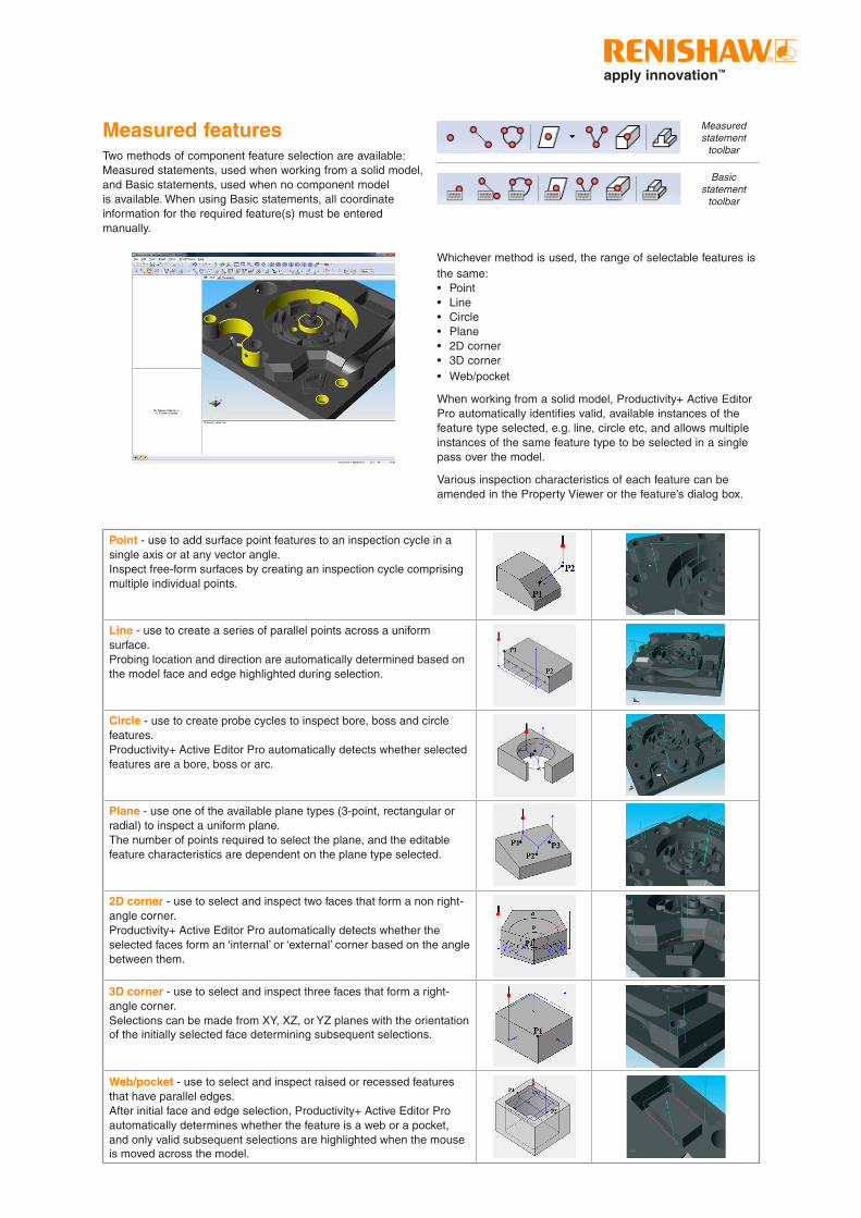
Whichever method is used, the range of selectable features is the same:• Point• Line• Circle• Plane• 2D corner• 3D corner• Web/pocket
When working from a solid model, Productivity+ Active Editor Pro automatically identifies valid, available instances of the feature type selected, e.g. line, circle etc, and allows multiple instances of the same feature type to be selected in a single pass over the model.
Various inspection characteristics of each feature can be amended in the Property Viewer or the feature’s dialog box.
Measured featuresTwo methods of component feature selection are available: Measured statements, used when working from a solid model, and Basic statements, used when no component model is available. When using Basic statements, all coordinate information for the required feature(s) must be entered manually.
Measured statement
toolbar
Basic statement
toolbar
Point - use to add surface point features to an inspection cycle in a single axis or at any vector angle.Inspect free-form surfaces by creating an inspection cycle comprising multiple individual points.
Line - use to create a series of parallel points across a uniform surface.Probing location and direction are automatically determined based on the model face and edge highlighted during selection.
Circle - use to create probe cycles to inspect bore, boss and circle features.Productivity+ Active Editor Pro automatically detects whether selected features are a bore, boss or arc.
Plane - use one of the available plane types (3-point, rectangular or radial) to inspect a uniform plane.The number of points required to select the plane, and the editable feature characteristics are dependent on the plane type selected.
2D corner - use to select and inspect two faces that form a non right-angle corner.Productivity+ Active Editor Pro automatically detects whether the selected faces form an ‘internal’ or ‘external’ corner based on the angle between them.
3D corner - use to select and inspect three faces that form a right-angle corner.Selections can be made from XY, XZ, or YZ planes with the orientation of the initially selected face determining subsequent selections.
Web/pocket - use to select and inspect raised or recessed features that have parallel edges.After initial face and edge selection, Productivity+ Active Editor Pro automatically determines whether the feature is a web or a pocket, and only valid subsequent selections are highlighted when the mouse is moved across the model.
Constructed featuresConstructed feature functionality allows the generation of ‘virtual’ point, line, circle and plane features using previously determined position data. These constructed features may then be reported on or used within logic conditions and to perform update operations.
The number of ‘child’ features required to create a constructed feature is dependent on feature type and construction method.
The most flexible of these elements, Constructed Points, can be created using nine different methods, the most simple being ‘Offset from origin’, creating a point at a user defined X, Y, Z offset from the coordinate system (0, 0, 0) position.
Other available Constructed Point methods are:• Offset from position• Midpoint between positions• Line line intersection• Intersection of 3 planes• Line plane intersection• Closest position on line• Closest position on plane• Line line intersection on plane
Data sheetProductivity+™ Active Editor Pro probe software for machine tools
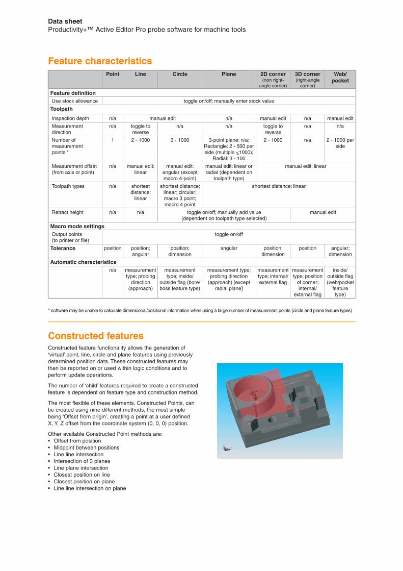
* software may be unable to calculate dimensional/positional information when using a large number of measurement points (circle and plane feature types)
Point Line Circle Plane 2D corner (non right-
angle corner)
3D corner (right-angle
corner)
Web/pocket
Feature definitionUse stock allowance toggle on/off; manually enter stock value
Toolpath
Inspection depth n/a manual edit n/a manual edit n/a manual edit
Measurement direction
n/a toggle to reverse
n/a n/a toggle to reverse
n/a n/a
Number of measurement points *
1 2 - 1000 3 - 1000 3-point plane: n/a;Rectangle: 2 - 500 per side (multiple <1000);
Radial: 3 - 100
2 - 1000 n/a 2 - 1000 per side
Measurement offset (from axis or point)
n/a manual edit: linear
manual edit: angular (except macro 4-point)
manual edit: linear or radial (dependent on
toolpath type)
manual edit: linear
Toolpath types n/a shortest distance;
linear
shortest distance; linear; circular; macro 3 point; macro 4 point
shortest distance; linear
Retract height n/a n/a toggle on/off; manually add value(dependent on toolpath type selected)
manual edit
Macro mode settingsOutput points (to printer or file)
toggle on/off
Tolerance position position; angular
position; dimension
angular position; dimension
position angular; dimension
Automatic characteristicsn/a measurement
type; probing direction
(approach)
measurement type; inside/
outside flag (bore/boss feature type)
measurement type; probing direction
(approach) [except radial plane]
measurement type; internal/external flag
measurement type; position
of corner; internal/
external flag
inside/outside flag (web/pocket
feature type)
Feature characteristics
Custom macrosCustom macros extend Productivity+ capability by integrating bespoke on-machine functionality with programmed probing cycles. Data can be passed to a macro on a machine tool, and results used in reports and for constructing logic statements.
Custom macros can be generated to solve a wide range of customer requirements that are not possible with Productivity+ alone, and can utilise either measured data inputs, such as Line1.Midpoint, or manually entered numerical (integers, rational, irrational) and text data.
Condition builderThe Condition Builder function allows the addition of logic statements incorporating defined conditions such as If…Then, Else and Else…If to probing programs. The machine tool can then make intelligent decisions about subsequent machining operations and updates based on the results returned.
Goto and Label elements allow the combined, posted program to ‘jump’ to a specific, identified location within the program to, for example, re-machine a feature or raise an alarm and reject the component.
Machine updateThe machine update command provides the ability to automatically update offsets and parameters from probed features.
Available updates are:• WCS update• Tool length• Tool diameter• Machine variable• Rotation update
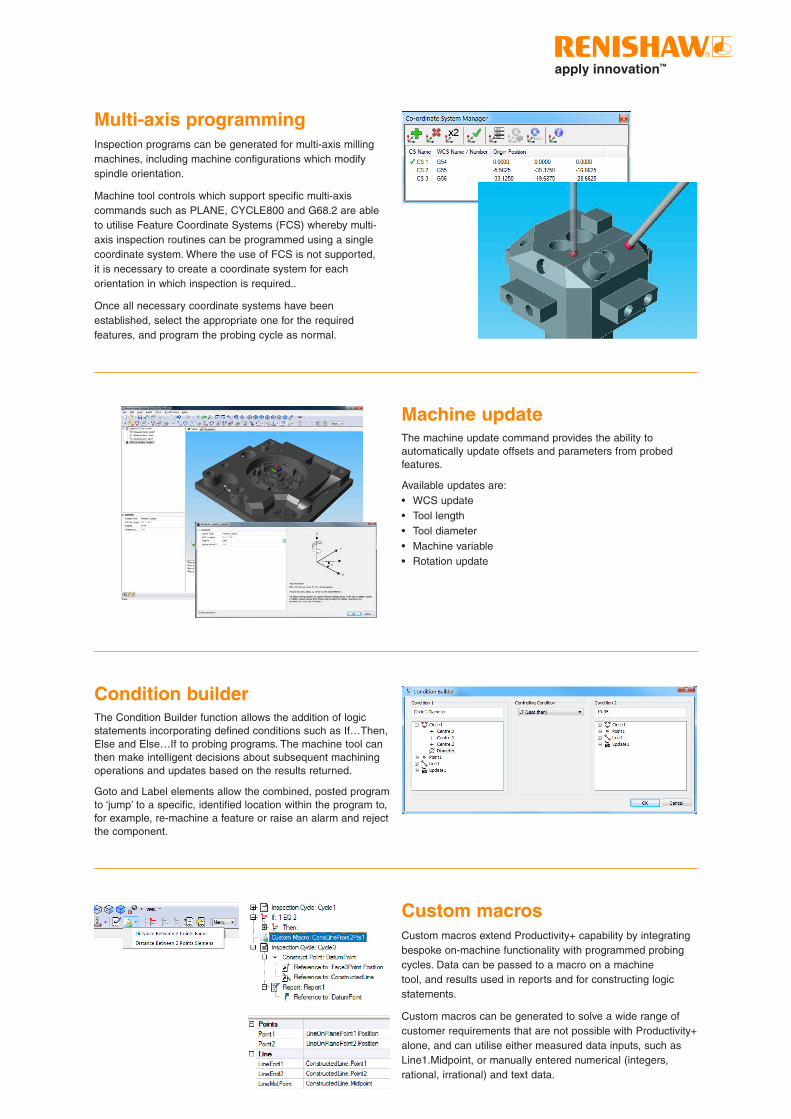
Multi-axis programmingInspection programs can be generated for multi-axis milling machines, including machine configurations which modify spindle orientation.
Machine tool controls which support specific multi-axis commands such as PLANE, CYCLE800 and G68.2 are able to utilise Feature Coordinate Systems (FCS) whereby multi-axis inspection routines can be programmed using a single coordinate system. Where the use of FCS is not supported, it is necessary to create a coordinate system for each orientation in which inspection is required..
Once all necessary coordinate systems have been established, select the appropriate one for the required features, and program the probing cycle as normal.
Post processingProductivity+ Active Editor Pro uses a post processor tool to generate a program that can run on a machine tool.
The resulting program contains machining and inspection commands, and all necessary macros. Once generated, simply load the program onto the machine tool, select the correct program name/number, and run as usual.
Tool settingUtilisation of the tool setting option within Productivity+ Active Editor Pro requires tool setting macros to be installed on your machine controller.
Both contact and non-contact methods of tool setting are supported.
Data sheetProductivity+™ Active Editor Pro probe software for machine tools
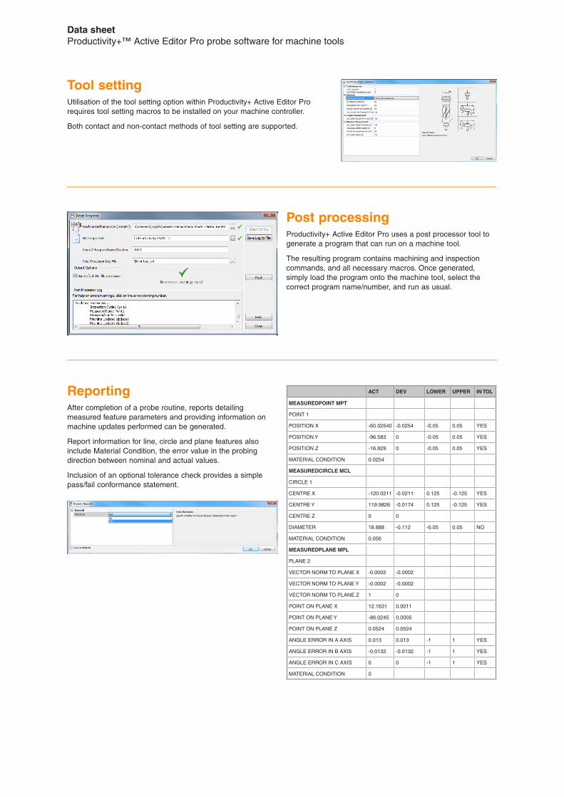
ReportingAfter completion of a probe routine, reports detailing measured feature parameters and providing information on machine updates performed can be generated.
Report information for line, circle and plane features also include Material Condition, the error value in the probing direction between nominal and actual values.
Inclusion of an optional tolerance check provides a simple pass/fail conformance statement.
ACT DEV LOWER UPPER IN TOL
MEASUREDPOINT MPT
POINT 1
POSITION X -60.02540 -0.0254 -0.05 0.05 YES
POSITION Y -96.583 0 -0.05 0.05 YES
POSITION Z -16.929 0 -0.05 0.05 YES
MATERIAL CONDITION 0.0254
MEASUREDCIRCLE MCL
CIRCLE 1
CENTRE X -120.0211 -0.0211 0.125 -0.125 YES
CENTRE Y 119.9826 -0.0174 0.125 -0.125 YES
CENTRE Z 0 0
DIAMETER 18.888 -0.112 -0.05 0.05 NO
MATERIAL CONDITION 0.056
MEASUREDPLANE MPL
PLANE 2
VECTOR NORM TO PLANE X -0.0002 -0.0002
VECTOR NORM TO PLANE Y -0.0002 -0.0002
VECTOR NORM TO PLANE Z 1 0
POINT ON PLANE X 12.1631 0.0011
POINT ON PLANE Y -86.0245 0.0005
POINT ON PLANE Z 0.0524 0.0524
ANGLE ERROR IN A AXIS 0.013 0.013 -1 1 YES
ANGLE ERROR IN B AXIS -0.0132 -0.0132 -1 1 YES
ANGLE ERROR IN C AXIS 0 0 -1 1 YES
MATERIAL CONDITION 0
* macro 3 point and macro 4 point† available properties are subject to custom macro functionality‡ dependent on probing direction; axes refer to machine orientation
Feature X, Y, Z position Dimensions Angle around X/Y/Z axis
Feature angle Surface vector
Measured point , touch point position , material condition
Constructed point , offset point position
Measured line , start, mid and end point positions
Measured circle*/arc/constructed circle
, circle centre point , diameter or radius
Measured 3-point plane
, centroid of points , , X, Y, Z position
Measured rectangular plane
, centroid of points , , X, Y, Z position
Measured radial plane , centroid of points (3 points only)
, , X, Y, Z position
Constructed plane , centroid of points (3 points only)
, , X, Y, Z position
Measured 2D corner , corner position at line intersection
, between lines
Measured 3D corner , corner position at surface intersection
Web/pocket (no ends), midpoint between 2 sides
+ midpoint at start and end points
, width
Web/pocket (measured ends)
, midpoint between 4 sides + measured start and end
points, length and width
Custom macro† , , , , ,
Feature properties suitable for machine variable updates and logic
Feature
Axes available for WCS setting and updates‡
Single axis X and Y X and Z Y and Z X, Y and Z Position reference
Measured point , , , , , , touch point
Constructed point , , , , , , offset point
Measured line , , , midpoint
Measured circle*/arc/constructed circle
, X or Y only , , centre point
Measured 3-point plane
, , , , , , centroid of points
Measured rectangular plane
, , , , , , centroid of points
Measured radial plane , Z only , centroid of points
Constructed plane , , , , , , centroid of points
Measured 2D corner , X or Y only , , line intersection point
Measured 3D corner , , , , , , surface inspection point
Web/pocket (no ends) , X or Y only , midpoint between 2 sides
Web/pocket (measured ends)
, X or Y only , , midpoint between 4 sides
Feature properties suitable for WCS setting and updates
* macro 3 point and macro 4 point† available properties are subject to custom macro functionality
Data sheetProductivity+™ Active Editor Pro probe software for machine tools
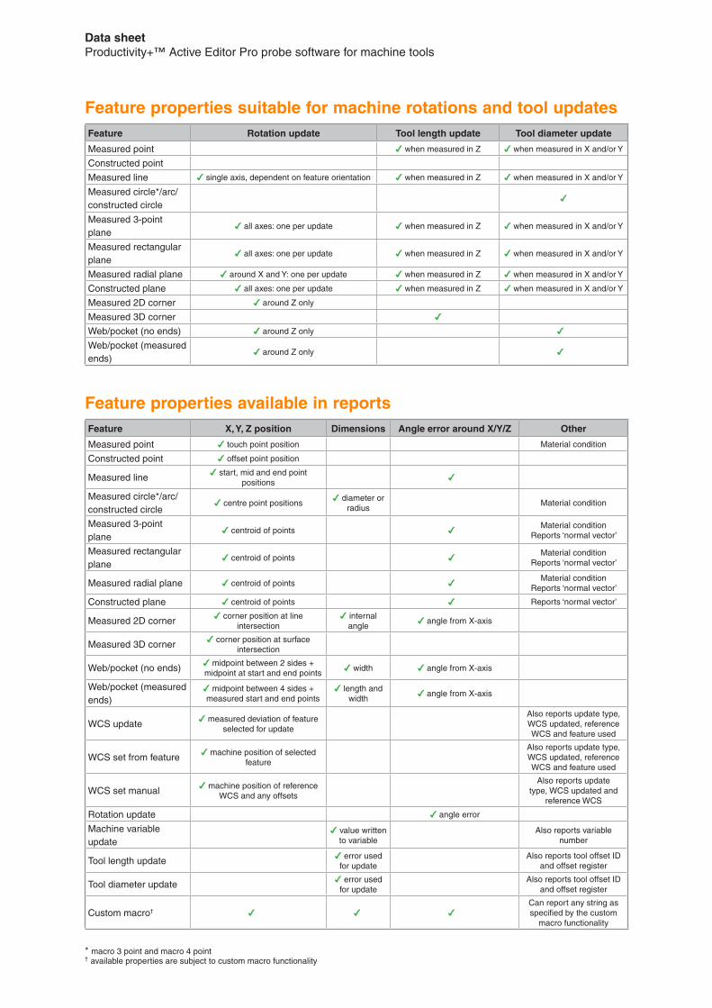
Feature Rotation update Tool length update Tool diameter update
Measured point , when measured in Z , when measured in X and/or Y
Constructed point
Measured line , single axis, dependent on feature orientation , when measured in Z , when measured in X and/or Y
Measured circle*/arc/constructed circle
,
Measured 3-point plane
, all axes: one per update , when measured in Z , when measured in X and/or Y
Measured rectangular plane
, all axes: one per update , when measured in Z , when measured in X and/or Y
Measured radial plane , around X and Y: one per update , when measured in Z , when measured in X and/or Y
Constructed plane , all axes: one per update , when measured in Z , when measured in X and/or Y
Measured 2D corner , around Z only
Measured 3D corner ,
Web/pocket (no ends) , around Z only ,
Web/pocket (measured ends)
, around Z only ,
Feature properties suitable for machine rotations and tool updates
Feature X, Y, Z position Dimensions Angle error around X/Y/Z Other
Measured point , touch point position Material condition
Constructed point , offset point position
Measured line , start, mid and end point positions
,
Measured circle*/arc/constructed circle
, centre point positions, diameter or
radiusMaterial condition
Measured 3-point plane
, centroid of points ,Material condition
Reports ‘normal vector’
Measured rectangular plane
, centroid of points ,Material condition
Reports ‘normal vector’
Measured radial plane , centroid of points ,Material condition
Reports ‘normal vector’
Constructed plane , centroid of points , Reports ‘normal vector’
Measured 2D corner , corner position at line intersection
, internal angle
, angle from X-axis
Measured 3D corner , corner position at surface intersection
Web/pocket (no ends) , midpoint between 2 sides + midpoint at start and end points
, width , angle from X-axis
Web/pocket (measured ends)
, midpoint between 4 sides + measured start and end points
, length and width
, angle from X-axis
WCS update , measured deviation of feature selected for update
Also reports update type, WCS updated, reference WCS and feature used
WCS set from feature , machine position of selected feature
Also reports update type, WCS updated, reference WCS and feature used
WCS set manual , machine position of reference WCS and any offsets
Also reports update type, WCS updated and
reference WCS
Rotation update , angle error
Machine variable update
, value written to variable
Also reports variable number
Tool length update , error used for update
Also reports tool offset ID and offset register
Tool diameter update , error used for update
Also reports tool offset ID and offset register
Custom macro† , , ,Can report any string as specified by the custom
macro functionality
Feature properties available in reports

Supported controllers, CAD formats and languagesMost machine tool controllers that support probing run this software, including:
• Brother• Fanuc• Haas• Heidenhain• Hitachi Seicos• Hurco• Makino• Mazak• Mitsubishi Meldas• Mori Seiki• Okuma• Siemens• Yasnac
Work to support additional controllers is on-going.
Productivity+ Active Editor Pro operates with the following CAD formats:
• IGES• Parasolid• STEP• ACIS*• AutoDesk Inventor*• CATIA*• Creo Elements/Pro (Pro/E)*• SolidWorks*
• NX/Unigraphics*
* Cost option
Continuous development work means other formats may be available - please contact [email protected] for details.
Productivity+ Active Editor Pro software is supported in the following languages:
• English• Czech• French• German• Italian• Japanese• Korean• Simplified Chinese• Spanish• Traditional Chinese
Recommended probing systemsRenishaw recommends the use of non-lobing probes such as the OMP400 or RMP600, for the best metrology performance. Use of Renishaw probes that do not contain strain-gauge technology will result in decreased performance.Renishaw does not support the use of non-Renishaw probes with this software.
System requirements
Recommended PC specification
Operating system Microsoft Windows 7 (64-bit) or later
Processor 2.0 GHz Intel Core 2 Duo (or equivalent)
Memory 4 GB RAM and 1 GB hard disk space
Graphics card NVIDIA GeForce 5 series (or later)
Other DVD drive for software installation
Please note that due to the constantly changing nature of PC specifications, this information is given as a recommendation only of the system and hardware requirements. In general we recommend a ‘CAD ready’ PC – one that is specified as capable of running CAD/CAM software.
For larger CAD files, a faster processor, more RAM and a more powerful graphics cards will provide better performance.

Renishaw plc
New Mills, Wotton-under-Edge, Gloucestershire, GL12 8JR United Kingdom
T +44 (0) 1453 524524 F +44 (0) 1453 524901 E [email protected]
www.renishaw.com
Part numbers for Productivity+™ Active Editor Pro probe software for machine toolsParts list – please quote relevant part number(s) when ordering
Part number Description
Software
A-4007-1400 Productivity+ Active Editor Pro software
Software packages
A-5226-5001 Productivity+ Active Editor Pro + Fanuc Macro B post
A-5226-5002 Productivity+ Active Editor Pro + Haas post
A-5226-5003 Productivity+ Active Editor Pro + Hitachi Seicos post
A-5226-5004 Productivity+ Active Editor Pro + Makino post
A-5226-5005 Productivity+ Active Editor Pro + Mazak ISO post
A-5226-5006 Productivity+ Active Editor Pro + Mitsubishi Meldas post
A-5226-5007 Productivity+ Active Editor Pro + Yasnac post
A-5226-5010 Productivity+ Active Editor Pro + Heidenhain i530 post
A-5226-5013 Productivity+ Active Editor Pro + Okuma OSP200 post
A-5226-5016 Productivity+ Active Editor Pro + Mori Seiki post
A-5226-5017 Productivity+ Active Editor Pro + Siemens 810D and 840D post
A-5226-5026 Productivity+ Active Editor Pro + Hurco Winmax post
A-5226-5027 Productivity+ Active Editor Pro + Brother post
A-5226-5028 Productivity+ Active Editor Pro + Heidenhain 426/430 post
A-5226-5029 Productivity+ Active Editor Pro + Mazak Integrex multi-tasking post
A-5226-5030 Productivity+ Active Editor Pro + Heidenhain 6xx post
A-4007-8999 Free 90-day trial software - English
Part number Description
CAD importers
A-5226-0007 Creo Elements/Pro (Pro/E) CAD importer
A-5226-0008 CATIA CAD importer
A-5226-0009 NX/Unigraphics CAD importer
A-5226-0010 ACIS CAD importer
A-5226-0011 SolidWorks CAD importer
A-5226-0012 AutoDesk Inventor CAD importer
A-5226-0020 3 or more CAD importers†
Post processors
A-4007-5100 Fanuc Macro B post
A-4007-5200 Haas post
A-4007-5300 Hitachi Seicos post
A-4007-5400 Makino post
A-4007-5500 Mazak ISO post
A-4007-5600 Mitsubishi Meldas post
A-4007-5700 Yasnac post
A-4007-5900 Brother 32B post
A-4007-6000 Heidenhain i530 post
A-4007-6300 Okuma OSP200 post
A-4007-6600 Mori Seiki post
A-4007-6700 Siemens 810D and 840D post
A-4007-6800 Hurco Winmax post
A-4007-6900 Heidenhain 426/430 post
A-4007-7100 Mazak Integrex multi-tasking post
A-4007-7200 Heidenhain 6xx post
† This is the most economical option when working with multiple CAD formats, and supports the use of all listed CAD formats
For worldwide contact details, visit www.renishaw.com/contact
RENISHAW HAS MADE CONSIDERABLE EFFORTS TO ENSURE THE CONTENT OF THIS DOCUMENT IS CORRECT AT THE DATE OF PUBLICATION BUT MAKES NO WARRANTIES OR REPRESENTATIONS REGARDING THE CONTENT. RENISHAW EXCLUDES LIABILITY, HOWSOEVER ARISING, FOR ANY INACCURACIES IN THIS DOCUMENT.
© 2006–2017 Renishaw plc. All rights reserved. Renishaw reserves the right to change specifications without notice.RENISHAW and the probe symbol used in the RENISHAW logo are registered trade marks of Renishaw plc in the United Kingdom and other countries. apply innovation and names and designations of other Renishaw products and technologies are trade marks of Renishaw plc or its subsidiaries.All other brand names and product names used in this document are trade names, trade marks or registered trade marks of their respective owners.
Part no.: H-2000-2341-08-AIssued: 11.2017
*H-2000-2341-08*
Related Documents


![#] +e A ) - 日本弁護士連合会│Japan Federation of … ý Â Â Ë Â Â Ä Â Â Â Å 1 ý Â Â Ë Â Â Ä Â Â Â Å 5U ÊKS 1 ý Â Â Ë Â Â Ä Â Â Â Å1 ý Â](https://static.cupdf.com/doc/110x72/5ce9840888c993c0208d8cce/-e-a-japan-federation-of-y-a-a-e-a-a-ae.jpg)