England PlymoVent Ltd Marley Way, Southam Road Banbury, OX16 2RA, England Tel: +44 1295 25 93 11 Fax: +44 1295 27 17 50 [email protected] Sales office PlymoVent AB Tangenten 2, Industrigatan 26, SE-212 14 MALMÖ, Sweden Tel: +46 40 30 31 30 Fax: +46 40 30 31 40 [email protected] PlymoVent Corp. 115 Melrich Road Cranbury, New Jersey 08512, USA Tel. +1 (609) 395-3500 Fax. +1 (609) 655-0919 [email protected] Year established: 1989 PlymoVent Canada Inc. 24-1200 Aerowood Dr. Mississauga, ON L4W 257, Canada Tel: +1 (905) 564-4748 Fax: +1 (905) 564-4609 [email protected] Product User Manual Straight rail– STP Table of contents: page PUM_STP_070822_EN THIS MANUAL SHOULD BE HANDED OVER AND KEPT BY THE SERVICE DEPARTMENT AFTER THE INSTALLATION! Thank you for buying this product. Before you take it out of its box and start to use it, please read this product manual and follow the instructions carefully. Technical description ...................................... 2 Advantages ................................................... 2 Delivery ........................................................ 2 Specification ................................................ 2 Component parts, crabs .................................. 3 Space requirement ......................................... 3 Pressure loss and calculation .......................... 4 Practical example........................................... 5 Mounting instruction ................................. 6-20 Maintenance instruction ........................... 21-24 Spare part drawing and list ...................... 25-32

Welcome message from author
This document is posted to help you gain knowledge. Please leave a comment to let me know what you think about it! Share it to your friends and learn new things together.
Transcript
EnglandPlymoVent Ltd Marley Way, Southam Road Banbury, OX16 2RA, England Tel: +44 1295 25 93 11 Fax: +44 1295 27 17 50 [email protected]
Sales officePlymoVent ABTangenten 2, Industrigatan 26,SE-212 14 MALMÖ, Sweden Tel: +46 40 30 31 30 Fax: +46 40 30 31 40 [email protected]
PlymoVent Corp. 115 Melrich RoadCranbury, New Jersey 08512, USATel. +1 (609) 395-3500 Fax. +1 (609) [email protected] Year established: 1989
PlymoVent Canada Inc. 24-1200 Aerowood Dr. Mississauga, ON L4W 257, CanadaTel: +1 (905) 564-4748Fax: +1 (905) [email protected]
Product User ManualStraight rail– STP
Table of contents: page
PUM_STP_070822_EN
ThIS MANUAL ShOULD BE hANDED OVER AND kEPT BY ThE SERVICE DEPARTMENT AFTER ThE INSTALLATION!
Thank you for buying this product. Before you take it out of its box and start to use it, please read this
product manual and follow the instructions carefully.
Technical description ...................................... 2Advantages ................................................... 2Delivery ........................................................ 2Specification ................................................ 2Component parts, crabs .................................. 3Space requirement ......................................... 3Pressure loss and calculation .......................... 4Practical example ........................................... 5Mounting instruction ................................. 6-20Maintenance instruction ........................... 21-24Spare part drawing and list ...................... 25-32

Art. No.
STP/ENG/2/32
© Copyright 2008: All rights reserved. All information within this printed matter may not be reproduced,
handed over, copied, xeroxed or translated into another language in any form or means without written
permission from PlymoVent AB. PlymoVent AB reserves the right to make design changes.
BSAB no: T3.1Ser .no: STPDate: Apr-01Replace:Jan-98
technical description
Straight rail – STP
Straight rail for mobile exhaust gas extractionOffers a complete solution to exhaust gas problems when vehicles are run in a straight, distinct distance indoors. The system consists of crabs equipped with exhaust hoses, running along an extraction rail mounted to the ceiling. The straight rail system is extendable according to requirements and can be designed to indefinite length. The system offers an energy saving and economical solution to vehicle work-shops, loading bays and service halls as well as to other workshops with mobile pollution loads. A balancer attached to the crab supports the exhaust hose and lifts up the hose when not in use hence giving free walking and driving space under the hose. The system allows several crabs if required.
Advantages• Modularsystem.• Greatflexibilityforindefiniteexpansion.• Easilycombinablewithloopedrailsystems.• Automaticdisconnectionfromthevehicle'sexhaustpipeatan appointed position by use of the Grabber nozzle.
DeliveryThe track is delivered in parts together with mounting instructions. Fan, fan-control device and compressed air supply to be added individually depending on application.
Part. no Rail length Duct con-nection
1.pcs
2.pcs
2.pcs
2.pcs
3.pcs
3.pcs
4.pcs
4.pcs
4.pcs
5,8m
8,7m
11,6m
14,5m
17,4m
20,3m
23,2m
26,1m
29m
Modell
Straight Rail System Straight Rail System
Straight Rail System
Straight Rail System
Straight Rail System
Straight Rail System
Straight Rail System
Straight Rail System
Straight Rail System
STP-6
STP-9
STP-12
STP-15
STP-18
STP-21
STP-24
STP-27
STP-30

1
2
3
46
5
9
1 2
3
45
6
2500 2500
Min400
1800
5000
250
850
Measurements in mm.
5000 5000
Min400
1800
5000
250
850
Measurements in mm.
STP/ENG/3/32
Internal crab External crab
5 m hose 7.5 m hose
1. Profile2. Crab (internal and external) 3. Balancer4. Exhaust hose5. Quick release coupling6. Suspension halter9. Grabber
MountingMessure the mounting heightThe height of the rail is determined by the ceiling height and the vehicle height, the Straight rail should not be positioned under a level of 3,5-5 m. The rail should be positioned 1-1,5 m from the gate opening and 0,5 m to the side of the vehicle. For more information ask for Straight Rail Mounting instruction.
Flexible support systemThe standard STP support system, included in all models. The support has a number of parts to make it complete; e.g. Supportpipe,flexibleandfixedconstructioncouplingsto fit the existing wall and ceiling structure. Maximum distance between support legs is 6,0 m.
Space requirementsThetopfaceoftherailistobesituated5metresoverthefloorinordertoallow2metresfreespacebelowtheliftedhose.
Components parts; CrabThe straight rail can be equipped with either an internal and external crab. The internal crab can only be used in connection with straight rails and offers the most economical solutions. If future demands require a looped rail you chould choose an external crab. The external crab is less sensitive to uneven loads thanks to its wheel suspension.
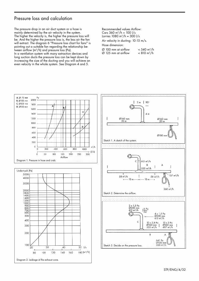
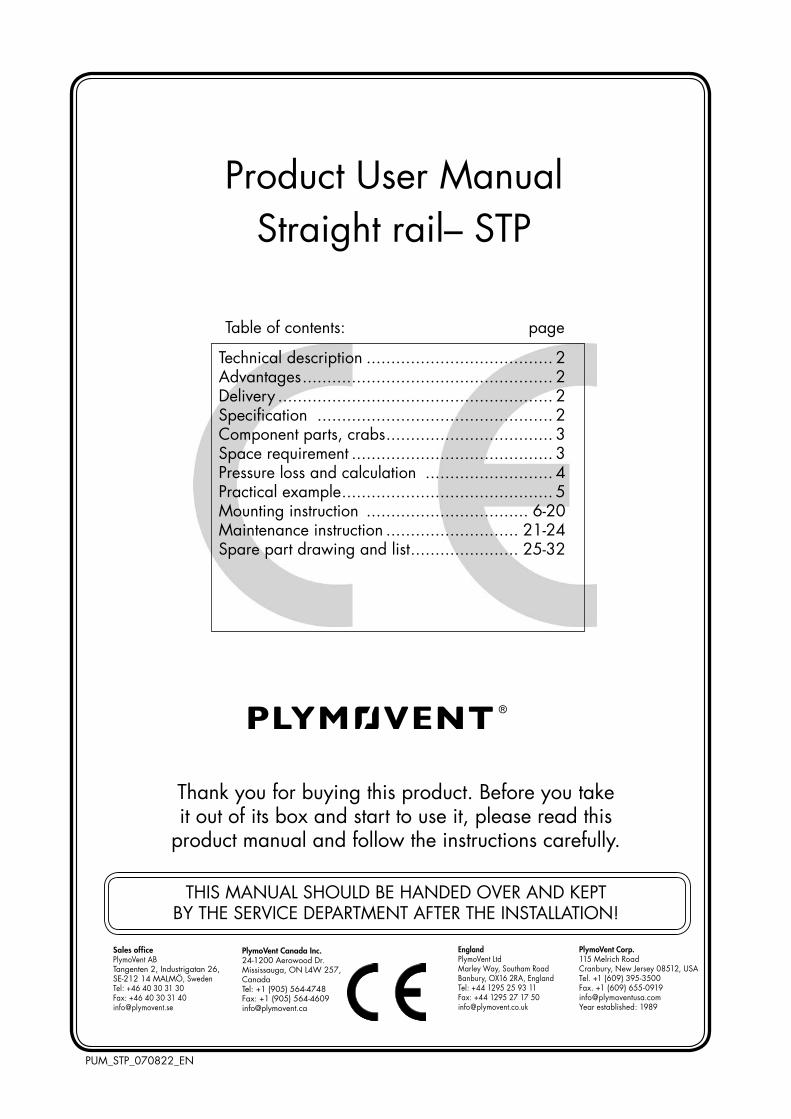
Diagram 1. Pressure in hose and crab.Airflow
Diagram 2. Leakage at the exhaust cone.
Sketch 3. Decide on the pressure loss.
Sketch2.Determinetheairflow.
Sketch 1. A sketch of the system.
STP/ENG/4/32
The pressure drop in an air duct system or a hose is mainly determined by the air velocity in the system. The higher the velocity is, the higher the pressure loss will be. And the higher the pressure loss is, the less air the fan will extract. The diagram 6 "Pressure loss chart for fans" is pointing out a suitable fan regarding the relationship be-tweenairflow(m3/h) and pressure loss (Pa).In a ventilation system with many extraction devices and long suction ducts the pressure loss can be kept down by in-creasing the size of the ducting and you will achieve an even velocity in the whole system. See Diagram 4 and 5.
Pressure loss and calculation
RecommendedvaluesAirflow:Cars 360 m3/h = 100 l/sLorries 1080 m3/h = 300 l/sAir velocity in ducting: 10 -15 m/s.hose dimension:Ø100mmatairflow <540m3/hØ125mmatairflow <810m3/h
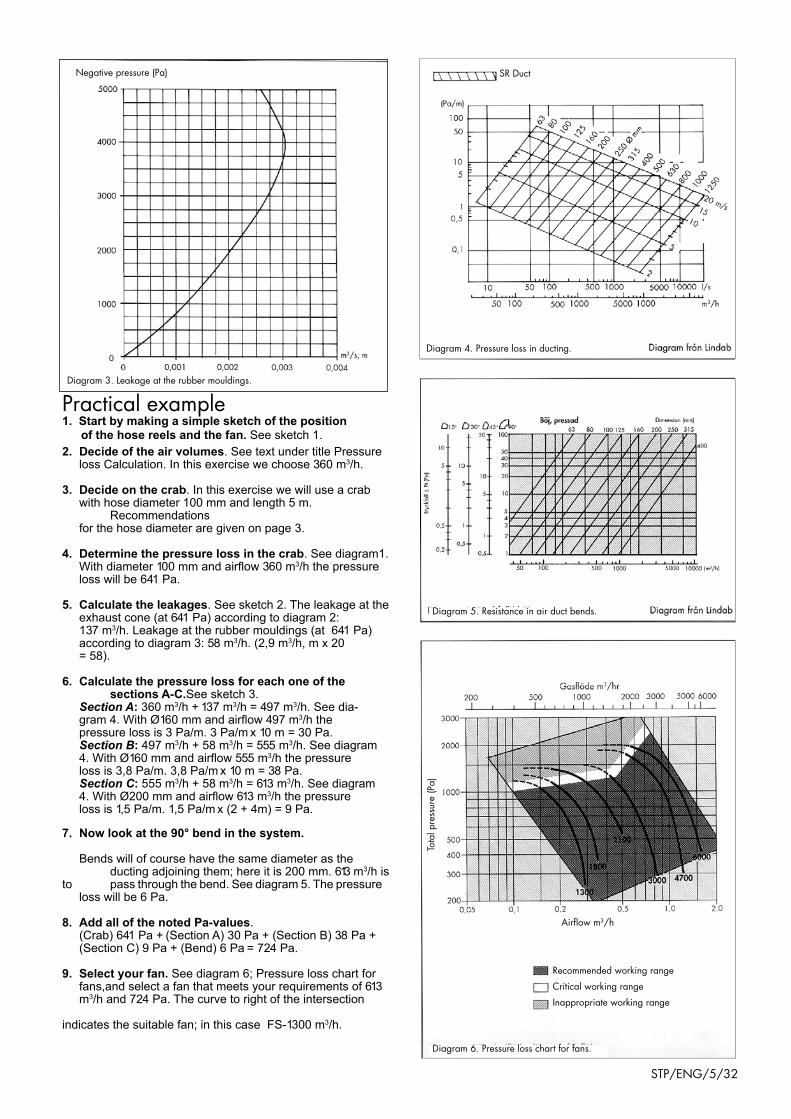
Diagram 6. Pressure loss chart for fans.
Recommended working range
Critical working range
Inappropriate working range
Diagram 5. Resistance in air duct bends.
Diagram 4. Pressure loss in ducting.
Diagram 3. Leakage at the rubber mouldings.
Negative pressure (Pa) SR Duct
Airflowm3/h
Tota
l pre
ssur
e (P
a)
STP/ENG/5/32
Practical example 1. Start by making a simple sketch of the position
of the hose reels and the fan. See sketch 1.2. Decide of the air volumes. See text under title Pressure loss Calculation. In this exercise we choose 360 m3/h.
3. Decide on the crab. In this exercise we will use a crab with hose diameter 100 mm and length 5 m. Recommendations for the hose diameter are given on page 3.
4. Determine the pressure loss in the crab. See diagram1. With diameter 100 mm and airflow 360 m3/h the pressure loss will be 641 Pa.
5. Calculate the leakages. See sketch 2. The leakage at the exhaust cone (at 641 Pa) according to diagram 2: 137 m3/h. Leakage at the rubber mouldings (at 641 Pa) according to diagram 3: 58 m3/h. (2,9 m3/h, m x 20 = 58).
6. Calculate the pressure loss for each one of the sections A-C.See sketch 3. Section A: 360 m3/h + 137 m3/h = 497 m3/h. See dia- gram 4. With Ø160 mm and airflow 497 m3/h the pressure loss is 3 Pa/m. 3 Pa/m x 10 m = 30 Pa. Section B: 497 m3/h + 58 m3/h = 555 m3/h. See diagram 4. With Ø160 mm and airflow 555 m3/h the pressure loss is 3,8 Pa/m. 3,8 Pa/m x 10 m = 38 Pa. Section C: 555 m3/h + 58 m3/h = 613 m3/h. See diagram 4. With Ø200 mm and airflow 613 m3/h the pressure loss is 1,5 Pa/m. 1,5 Pa/m x (2 + 4m) = 9 Pa.
7. Now look at the 90° bend in the system. Bends will of course have the same diameter as the ducting adjoining them; here it is 200 mm. 613 m3/h is to pass through the bend. See diagram 5. The pressure loss will be 6 Pa.
8. Add all of the noted Pa-values. (Crab) 641 Pa + (Section A) 30 Pa + (Section B) 38 Pa + (Section C) 9 Pa + (Bend) 6 Pa = 724 Pa.
9. Select your fan. See diagram 6; Pressure loss chart for fans,and select a fan that meets your requirements of 613 m3/h and 724 Pa. The curve to right of the intersection indicates the suitable fan; in this case FS-1300 m3/h.

1
3
2 2
STP/ENG/6/32
© Copyright 2008: All rights reserved. All information within this printed matter may not be reproduced,
handed over, copied, xeroxed or translated into another language in any form or means without written
permission from PlymoVent AB. PlymoVent AB reserves the right to make design changes.
DRIVE-ThRU MEASUREMENT PROCEDURE
plan VieW
MOUNTING INSTRUCTION
1. Exhaust pipe:
2. Gate:
3. Distance entrance gate-exit gate:
Determine the position of the exhaust pipe (1) on the vehicle, which side and diameter.
The gate (2) height and width is measured. Check what type of gate, slidegate or overhead gate.
Check at what height the STP-track can be installed. Measure the distance between the entrance gate and exit gate (3) to determine required length of STP. The required length is determined by taking the distance entrance gate-exit gate minus 3.0m.
BSAB no: T3.1Ser .no: STPDate: Apr-01Replace:Jan-98

3
6
4
1
5
2
STP/ENG/7/32
© Copyright 2008: All rights reserved. All information within this printed matter may not be reproduced,
handed over, copied, xeroxed or translated into another language in any form or means without written
permission from PlymoVent AB. PlymoVent AB reserves the right to make design changes.
stp-tracK location procedUre
plan VieW
side VieW
MOUNTING INSTRUCTION
1. STP profile: 2. Exhaust pipe:
3. Door:
4. height of track:
5. Distance to vehicle:
6. The longitudinal track:
TheSTP-track(1)ismountedataheight(4)of3.5-4.5movertheflooronthesidewherethevehiclesexhaustpipe(2) is situated.
The track is often mounted immediately beside the door (3).
The STP-track is placed 400-600 mm (5) from the truck-side of the vehicle and approx. 1500 mm (6) from the door.
BSAB no: T3.1Ser .no: STPDate: Apr-01Replace:Jan-98

1
3
2
STP/ENG/8/32
© Copyright 2008: All rights reserved. All information within this printed matter may not be reproduced,
handed over, copied, xeroxed or translated into another language in any form or means without written
permission from PlymoVent AB. PlymoVent AB reserves the right to make design changes.
Vertical sUspensions
MOUNTING INSTRUCTION
1. STP profile
2. Vertical support leg (Not standard supply)
3. Side brace
Putthecomponentsoftherailundertheintendedposition,alternativelymarkthefloor.
Check possible support leg position with a maximum distance of 6 m between each support.
(Check space availability for coiled airhose and its supports at air refilling for Grabber.)
Mark up in a line and bolt or weld the vertical support legs.
Each vertical support leg must be side braced.
BSAB no: T3.1Ser .no: STPDate: Apr-01Replace:Jan-98

2
Ø 12 mm
2 11
5
3
4
6Max. 6
m
STP/ENG/9/32
© Copyright 2008: All rights reserved. All information within this printed matter may not be reproduced,
handed over, copied, xeroxed or translated into another language in any form or means without written
permission from PlymoVent AB. PlymoVent AB reserves the right to make design changes.
hORISONTAL (WALL) SUSPENSIONS
MOUNTING INSTRUCTION
1. STP profile
2. horizontal support leg (Standard supply)
3. Side brace (Not standard supply)
4. Turnable double construction coupling (Not standard supply)
5. Turnable construction coupling wall (Not standard supply)
6. Fixed construction coupling wall (Not standard supply)
Putthecomponentsoftherailundertheintendedposition,alternativelymarkthefloor.Check possible support leg position with a maximum distance of 6 m between each support.(Check space availability for coiled airhose and its support.)Mark up in a line and bolt or weld the horizontal support legs.Each horizontal support leg must be side braced upwards or downwards.
BSAB no: T3.1Ser .no: STPDate: Apr-01Replace:Jan-98

© Copyright 2008: All rights reserved. All information within this printed matter may not be reproduced,
handed over, copied, xeroxed or translated into another language in any form or means without written
permission from PlymoVent AB. PlymoVent AB reserves the right to make design changes.
21
100
65 65
115
60Ø 10,.5
22 22
22
STP/ENG/10/32
SPLICING ThE PROFILE
MOUNTING INSTRUCTION
1. STP profile
2. Splicing sleeve
Put the components of the rail under the intended position on trestles or similar with the open side downwards.
Line and fix the rail profiles so that the extended rail edges are joined to a continuous length.
Fix the splicing sleeve with a clamp or similar, drill according to the drawing below with a 10.5 mm drill and mount the splicing sleeve to one of the rail profiles.
Assemble the other rail profile, straighten the splicing sleeve, drill and mount together. Every splice is mounted together with 12 pcs of 10x25 mm bolts.
Grind the edges inside the splice where the internal crab will travel to achieve smooth running.
BSAB no: T3.1Ser .no: STPDate: Apr-01Replace:Jan-98

3
2
4
1
STP/ENG/11/32
© Copyright 2008: All rights reserved. All information within this printed matter may not be reproduced,
handed over, copied, xeroxed or translated into another language in any form or means without written
permission from PlymoVent AB. PlymoVent AB reserves the right to make design changes.
MOUNTING INSTRUCTIONBSAB no: T3.1Ser .no: STPDate: Apr-01Replace:Jan-98
MoUntinG oF rUBBer seal
1. STR profile
2. Rubber seal
3. Tool no. 11600
4. Tool no. 11601
Turn the rail profile with the opening upwards.
If the seal must be joined it must be done before mounting. The rubber seal should overlap and be cut together with a sharp knife. The rubber seal ends are to be fixed together with glue; Loctite no. 495 or similar rubber glue.
NOTE! The rubber seal is to be greased with liquid soap before mounting.
The rubber seal is mounted with tool no. 11600.
The rubber seal is easily mounted with tool no. 11601, the rail profile hanging in its support legs.

1
2
60 mm500 m
m
3
STP/ENG/12/32
© Copyright 2008: All rights reserved. All information within this printed matter may not be reproduced,
handed over, copied, xeroxed or translated into another language in any form or means without written
permission from PlymoVent AB. PlymoVent AB reserves the right to make design changes.
BSAB no: T3.1Ser .no: STPDate: Apr-01Replace:Jan-98
dUct connection
1. STR profile:
2. Connection socket, d=200 mm:
3. End socket with duct connection, d=160 mm:
The rail is connected to the fan and the duct system by the connection socket (2) or the end connection socket (3).
The connection socket is mounted by cutting a hole with a length of 500 mm in the rail profile´s side. The connection socket is mounted with a rivet or self drilled screws and sealed with elastic compound.
The end socket with duct connection, d=160 mm, is mounted according to "Mounting instruction; End sockets and suspensions"
MOUNTING INSTRUCTION
3
2
1
Max 4 mØ8,5 60
115
22mm
2 15mm
STP/ENG/13/32
© Copyright 2008: All rights reserved. All information within this printed matter may not be reproduced,
handed over, copied, xeroxed or translated into another language in any form or means without written
permission from PlymoVent AB. PlymoVent AB reserves the right to make design changes.
MOUNTING INSTRUCTIONBSAB no: T3.1Ser .no: STPDate: Apr-01Replace:Jan-01
MoUntinG oF end socKets and sUspensions
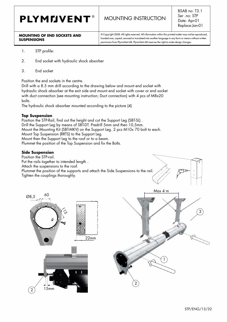
1. STP profile:
2. End socket with hydraulic shock absorber
3. End socket
Position the end sockets in the centre.Drill with a 8.5 mm drill according to the drawing below and mount end socket with hydraulic shock absorber at the exit side and mount end socket with cover or end socket with duct connection (see mounting instruction; Duct connection) with 4 pcs of M8x20 bolts. The hydraulic shock absorber mounted according to the picture (4)
top suspensionPosition the STP-Rail, find out the height and cut the Support Leg (SBT-SL) .Drill the Support Leg by means of SBT-DT. Predrill 5mm and then 10,5mm.Mount the Mounting kit (SBT-MkV) on the Support Leg. 2 pcs M10x 70 bolt to each.Mount Top Suspension (RRTS) to the Support Leg.Mount then the Support Leg to the roof or to a beam.Plummet the position of the Top Suspension and fix the Bolts.
side suspensionPosition the STP-rail.Put the rails together to intended length .Attach the suspensions to the roof.Plummet the position of the supports and attach the Side Suspensions to the rail.Tighten the couplings thoroughly.
1
2
AB
C
STP/ENG/14/32
© Copyright 2008: All rights reserved. All information within this printed matter may not be reproduced,
handed over, copied, xeroxed or translated into another language in any form or means without written
permission from PlymoVent AB. PlymoVent AB reserves the right to make design changes.liFtinG the rail
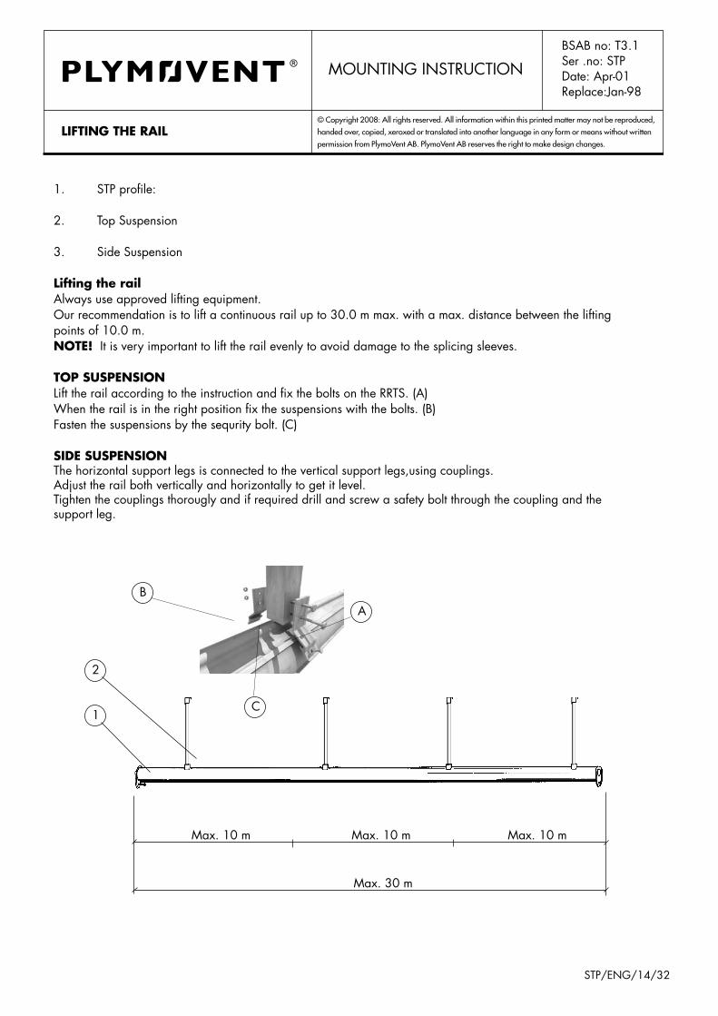
1. STP profile:
2. Top Suspension
3. Side Suspension
lifting the railAlways use approved lifting equipment.Our recommendation is to lift a continuous rail up to 30.0 m max. with a max. distance between the lifting points of 10.0 m.note! It is very important to lift the rail evenly to avoid damage to the splicing sleeves.
top sUspensionLift the rail according to the instruction and fix the bolts on the RRTS. (A)When the rail is in the right position fix the suspensions with the bolts. (B)Fasten the suspensions by the sequrity bolt. (C)
side sUspensionThe horizontal support legs is connected to the vertical support legs,using couplings.Adjust the rail both vertically and horizontally to get it level.Tighten the couplings thorougly and if required drill and screw a safety bolt through the coupling and the support leg.
MOUNTING INSTRUCTIONBSAB no: T3.1Ser .no: STPDate: Apr-01Replace:Jan-98
Max. 30 m
Max. 10 m Max. 10 m Max. 10 m
1
2
425 mm
1000 mm
STP/ENG/15/32
© Copyright 2008: All rights reserved. All information within this printed matter may not be reproduced,
handed over, copied, xeroxed or translated into another language in any form or means without written
permission from PlymoVent AB. PlymoVent AB reserves the right to make design changes.
BSAB no: T3.1Ser .no: STPDate: Apr-01Replace:Jan-98
MOUNTING INSTRUCTION
MoUntinG oF airline sUspensions
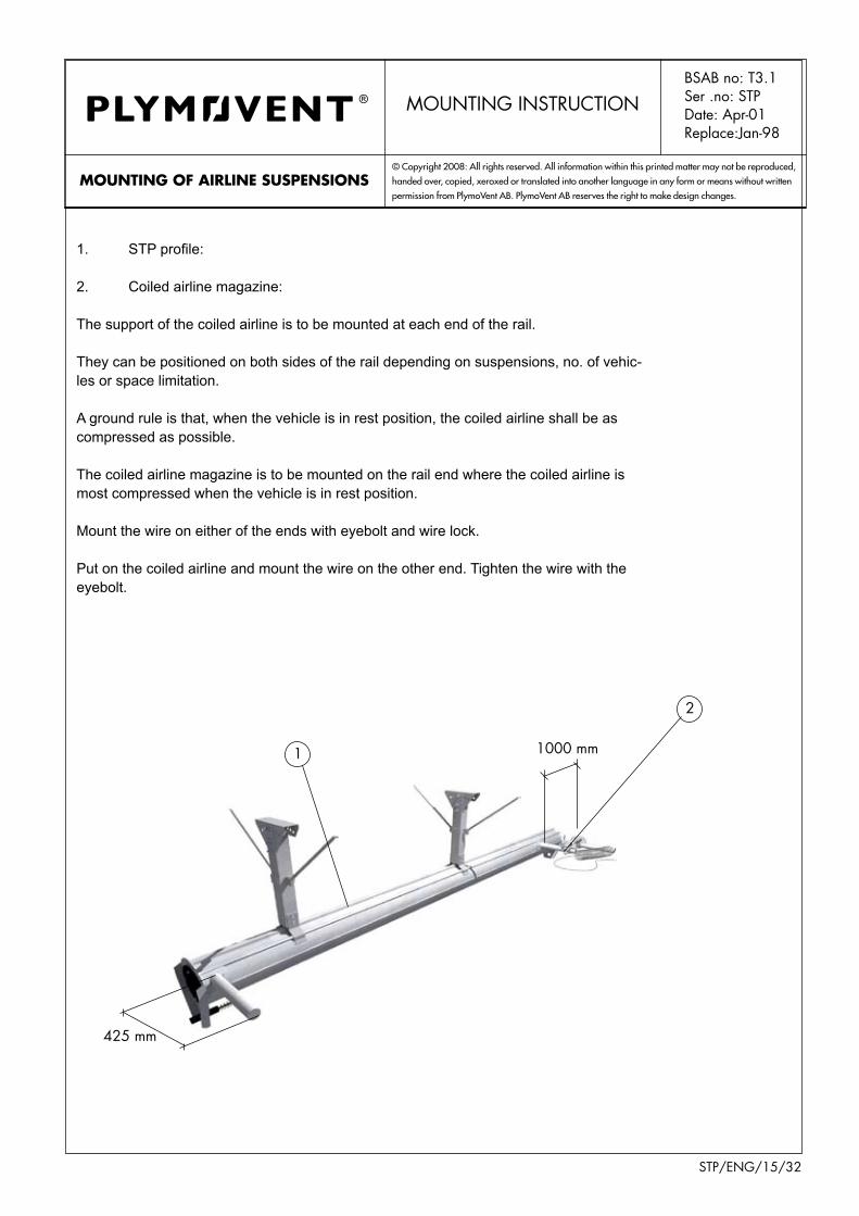
1. STP profile:
2. Coiled airline magazine:
The support of the coiled airline is to be mounted at each end of the rail.
They can be positioned on both sides of the rail depending on suspensions, no. of vehic-les or space limitation.
A ground rule is that, when the vehicle is in rest position, the coiled airline shall be as compressed as possible.
The coiled airline magazine is to be mounted on the rail end where the coiled airline is most compressed when the vehicle is in rest position.
Mount the wire on either of the ends with eyebolt and wire lock.
Put on the coiled airline and mount the wire on the other end. Tighten the wire with the eyebolt.

2
1
3
4
5
STP/ENG/16/32
© Copyright 2008: All rights reserved. All information within this printed matter may not be reproduced,
handed over, copied, xeroxed or translated into another language in any form or means without written
permission from PlymoVent AB. PlymoVent AB reserves the right to make design changes.
BSAB no: T3.1Ser .no: STRDate: Jan -01Replace:Jun-95
MOUNTING INSTRUCTION
MoUntinG oF internal craB
1. STP profile:
2. Internal Crab:
3. End socket:
4. Bringer arm:
5. Coiled air hose:
Take off the end socket from the rail end.Put the internal crab in the profile.Refit the end socket.Mount the bringer arm on the internal crab. It is important to achieve as much space as possible for the coiled airline. For example, if the coiled airline is running back from crab and exit side, the coiled airline shall be mounted in the front of the crab close to the exit side.

4 3
1
2
5
6
STP/ENG/17/32
© Copyright 2008: All rights reserved. All information within this printed matter may not be reproduced,
handed over, copied, xeroxed or translated into another language in any form or means without written
permission from PlymoVent AB. PlymoVent AB reserves the right to make design changes.
BSAB no: T3.1Ser .no: STRDate: Jan -01Replace:Jun-95
MOUNTING INSTRUCTION
hose aliGnMent/MoUntinGprocedUre
1. STP hose assembly:
2. Grabber nozzle:
3. MFD valve:
4. Suspension halter:
5. Internal crab:
6. Balancer:
The exhaust hose assembly shall be aligned at installation as follows:TheexhausthoseassemblyisstraightenedoutonthefloorwiththeGrabberpointingupwardsto the gate. Reposition if necessary and align the Grabber (2), the MFD valve (3) and the hose saddle (4).
The compressed air hoses are to be taken through the rubber grommets on the suction cone.
The STR hose assembly is mounted to the suction cone with a hose clamp with the Grabber pointing upwards to the gate.
The balancer is mounted at the front of the crab according to the drawing below.
The suspension halter is to be hanged in the safety link on the balancer.

1
3
6
3
2
4
52
8
7
STP/ENG/18/32
© Copyright 2008: All rights reserved. All information within this printed matter may not be reproduced,
handed over, copied, xeroxed or translated into another language in any form or means without written
permission from PlymoVent AB. PlymoVent AB reserves the right to make design changes.coMpressed air control deVice
BSAB no: T3.1Ser .no: STRDate: Jan -01Replace:Jun-95
MOUNTING INSTRUCTION
1. Release valve:
2. Unregulated air for release valve (approx. 6.0bar):
3. Regulated air for Grabber (coloured hose 0.5-1.0bar):
4. Regulator with manometer:
5. Compressed air feeder (approx. 6.0 bar):
6.ManualFillDeflationValve,MFDvalve:
The coiled air hose is to be mounted on the support pipe of the magasine without disturbing its natural coiled shape (7).Connect the other end of the coiled air hose to the bringer arm (8).The two first coils on the air hose are to be taped together at each end to unload the fittings.Compressed air, approx. 6.0 bar, is to be connected to the coiled air hose (5).Unregulated air, white air hose, (2) is to be connected from the release valve (1) through the rubber grommet at the suction cone, down through the exhaust hose and out through the brass grommet to the top of the MFD valve (6).Regulated air, yellow air hose (3), is to be connected from the regulator (4) through the rubber grommet at the suction cone, down through the exhaust hose and through the brass grommet to the side of the MFD valve (6).From the MFD valve (6) an 8 mm, black air hose, is connected to the Grabber.

1
2
2
1
1
2
1
2
STP/ENG/19/32
© Copyright 2008: All rights reserved. All information within this printed matter may not be reproduced,
handed over, copied, xeroxed or translated into another language in any form or means without written
permission from PlymoVent AB. PlymoVent AB reserves the right to make design changes.
BSAB no: T3.1Ser .no: STRDate: Jan -01Replace:Jun-95
MOUNTING INSTRUCTION
trip plate For disconnect ValVe
1. STP profile:
2. Trip plate:
The trip plate activating the release valve on the crab is to be mounted as shown below about 3.0 m from the rail exit end.At start up and adjustment of the system the trip plate is to be moved to a position where disconnection of the Grabber is achieved just by the gate of a normal call out.
Internal crab
External crab
1
2
3
180°
STP/ENG/20/32
© Copyright 2008: All rights reserved. All information within this printed matter may not be reproduced,
handed over, copied, xeroxed or translated into another language in any form or means without written
permission from PlymoVent AB. PlymoVent AB reserves the right to make design changes.
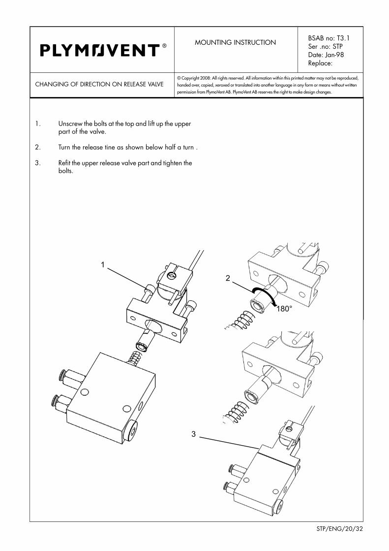
ChANGING OF DIRECTION ON RELEASE VALVE
1. Unscrew the bolts at the top and lift up the upper part of the valve.
2. Turn the release tine as shown below half a turn .
3. Refit the upper release valve part and tighten the bolts.
MOUNTING INSTRUCTIONBSAB no: T3.1Ser .no: STPDate: Jan-98Replace:
1
2
4
5
3
STP/ENG/21/32
© Copyright 2008: All rights reserved. All information within this printed matter may not be reproduced,
handed over, copied, xeroxed or translated into another language in any form or means without written
permission from PlymoVent AB. PlymoVent AB reserves the right to make design changes.
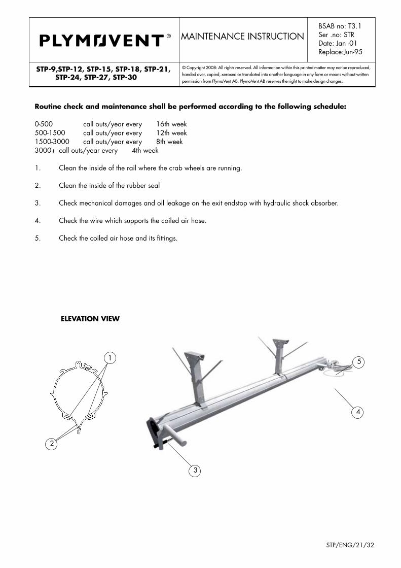
eleVation VieW
routine check and maintenance shall be performed according to the following schedule:
0-500 call outs/year every 16th week500-1500 call outs/year every 12th week1500-3000 call outs/year every 8th week3000+ call outs/year every 4th week
1. Clean the inside of the rail where the crab wheels are running.
2. Clean the inside of the rubber seal
3. Check mechanical damages and oil leakage on the exit endstop with hydraulic shock absorber. 4. Check the wire which supports the coiled air hose.
5. Check the coiled air hose and its fittings.
stp-9,stp-12, stp-15, stp-18, stp-21, stp-24, stp-27, stp-30
BSAB no: T3.1Ser .no: STRDate: Jan -01Replace:Jun-95
MAINTENANCE INSTRUCTION
6
7
7
STP/ENG/22/32
© Copyright 2008: All rights reserved. All information within this printed matter may not be reproduced,
handed over, copied, xeroxed or translated into another language in any form or means without written
permission from PlymoVent AB. PlymoVent AB reserves the right to make design changes.
STP / STP-12, STP-15, STP-18, STP-21, STP-24, STP-27, STP-30
serVice and MaintenanceBSAB no: T3.1Ser .no: STPDate: Jan-98Replace:
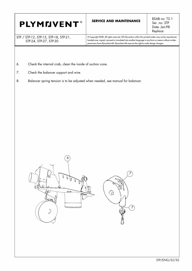
6. Check the internal crab, clean the inside of suction cone.
7. Check the balancer support and wire.
8. Balancer spring tension is to be adjusted when needed, see manual for balancer.

10
9
11
STP/ENG/23/32
© Copyright 2008: All rights reserved. All information within this printed matter may not be reproduced,
handed over, copied, xeroxed or translated into another language in any form or means without written
permission from PlymoVent AB. PlymoVent AB reserves the right to make design changes.
STP / STP-12, STP-15, STP-18, STP-21, STP-24, STP-27, STP-30
serVice and MaintenanceBSAB no: T3.1Ser .no: STPDate: Jan-98Replace:
9. Check the mechanical attachments, fittings, release valve, regulator and the airlines on the crab.
10. Check, adjust if needed the pressure on the regulator to be 0.5- max. 1.0 bar.
11. Take down the hose assembly from the balancer and check exhaust hose, compressed air hoses, suspension halter, MFD valve, safety disconnect coupling and Grabber. The safety disconnect coupling shall be taken apart and cleaned. Line up the hose assembly before connecting it to the balancer, see hose alignment procedure in mounting instructions.

13
2 6
4
0,5 mm
2
5
STP/ENG/24/32
© Copyright 2008: All rights reserved. All information within this printed matter may not be reproduced,
handed over, copied, xeroxed or translated into another language in any form or means without written
permission from PlymoVent AB. PlymoVent AB reserves the right to make design changes.crab
Check every 3 month:
1. Clean the rail where the crab wheels are running.
2. Clean the inside of the rubber seal and lubricate withteflon/siliconspraywhenrequired.
3. Check the internal crab, clean the inside of the suction cone.
4. Clean the rollers on the suction cone and grease moderately with thin oil.
5. Check the rubber shock absorber on the crab for damages and their position.
6. Check and/or adjust the open gap between the profile rail and the travelling crab wheel. This must be done at the point on the rail where it has its largest cross section, normally by the splicing sleeve. The axel (1) at the guide wheels (2) are exentric and should be turned to achieve correct tolerance, approximate 0.5 mm on both sides. Lock the axel with the locking plate (3). By adjustement, the suction cone (5) position must be centered in the ope-ning of the suction rail (4)..
serVice and Maintenance
Travelling direc-tion
BSAB no: T3.1Ser .no: STPDate: Jan-98Replace:

32 4
108
17
65
9
16
1214
15
13
STP/ENG/25/32
© Copyright 2008: All rights reserved. All information within this printed matter may not be reproduced,
handed over, copied, xeroxed or translated into another language in any form or means without written
permission from PlymoVent AB. PlymoVent AB reserves the right to make design changes.
SPARE PART DRAWING BSAB no: T3.1Ser .no: STPDate: Jan-98Replace:
See Separate manual for SDCA

SPARE PARTS LISTDate: Dec -00Replace:Aug-98
STP-WITH GRABBER
Produkt No: DecriptionA All models All models of STPB Hose 100 - Grabber 100C Hose 100 - Grabber 120D Hose 100 - Grabber 160E Hose 125 - Grabber 160F Hose 150 - Grabber 160G
Abreviations X = Order as requiered, state requiered length.
Pos Art. No: A B C D E F G H I Description Note1 50195-1011 1 1 1 Exhaust Hose 100 L=6m/20ft1 50295-1011 1 Exhaust Hose 125 L=6m/20ft1 50395-1011 1 Exhaust Hose 150 L=6m/20ft2 987 842 1 1 1 Exhaust Hose 100 L=0,6m/2ft2 988 576 1 Exhaust Hose 125 L=0,6m/2ft2 988 766 1 Exhaust Hose 150 L=0,6m/2ft3 4-1415 1 Grabber Bend 100/100, 4"/4"3 4-1416 1 Grabber Bend 100/120, 4"/4,75"3 4-1417 1 Grabber Bend 100/160, 4"/6,25"3 4-1418 1 Grabber Bend 125/160, 5"/6,25"3 4-1366 1 Grabber Bend 150/160, 6"/625"4 991 232 1 Grabber 100 / 4"4 991 141 1 Grabber 120 / 4,75"4 991 299 1 1 1 Grabber 160 / 6,25"5 512 616 1 1 1 Hose saddle 100 / 4"5 512 624 1 Hose saddle 125 / 5"5 512 632 1 Hose saddle 150 / 6"6 985 887 X Compr. air hose white 6mm7 985 895 X Compr. air hose yellow 6mm8 985 960 X Compr.air hose black 8mm9 961 441 3 3 3 Hose clamp 100 / 4"9 961 458 3 Hose clamp 125 / 5"9 961 474 3 Hose clamp 150 / 6"10 961 441 1 Hose clamp-Grabber 100 / 4"10 961 458 1 Hose clamp-Grabber 120 / 4,75"10 961 474 1 1 1 Hose clamp-Grabber 160 / 6,25"11 90025-1011 1 1 1 Safety disc.coupling 100 / 4"11 90030-1011 1 Safety disc.coupling 125 / 5"11 90035-1011 1 Safety disc.coupling 150 / 6"12 993 329 X MFD-Valve13 516 740 X MFD-Valve compl.w fittings14 518 856 X MFD-Valve bracket15 993 881 X MFD-Safety disc.fitting16 993329-Z X MFD-Knob
When ordering spare parts please quote:•Product No. (see label) • Batch No • Description • Part No • QuantityFor example: STP-15, 00040, Grabber 160 991299 , 1 pc
© Copyright: All right reserved. All information within this printed matter may not be reproduced, handed over, copied, xeroxed or translated into another language, in any form or any means without written permission from PlymoVent AB. PlymoVent AB reserves the right to make design changes.
STP/ENG/26/32

17
19
26
23
21
24
20
18
27
STP/ENG/27/32
© Copyright 2008: All rights reserved. All information within this printed matter may not be reproduced,
handed over, copied, xeroxed or translated into another language in any form or means without written
permission from PlymoVent AB. PlymoVent AB reserves the right to make design changes.
SPARE PART DRAWING
ic/icca
BSAB no: T3.1Ser .no: STPDate: Jan-98Replace:
BSAB No: T3.1SPARE PARTS LIST Ser. No: ICCA / RR
Date: May -07Replace:Mar-05
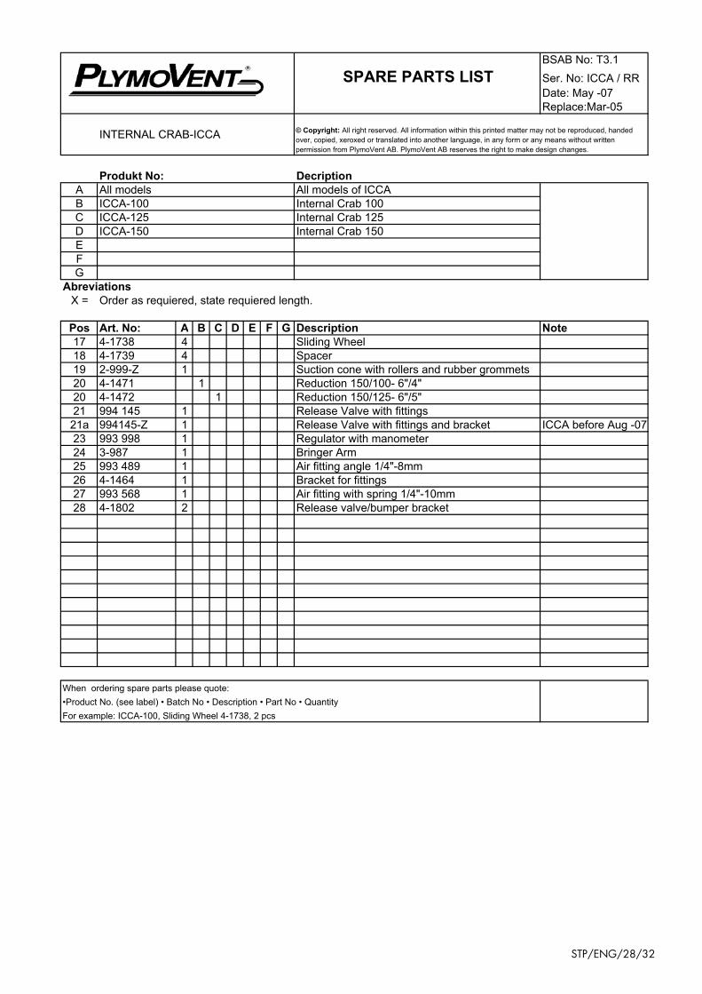
INTERNAL CRAB-ICCA
Produkt No: DecriptionA All models All models of ICCAB ICCA-100 Internal Crab 100C ICCA-125 Internal Crab 125D ICCA-150 Internal Crab 150EFG
Abreviations X = Order as requiered, state requiered length.
Pos Art. No: A B C D E F G Description Note17 4-1738 4 Sliding Wheel18 4-1739 4 Spacer19 2-999-Z 1 Suction cone with rollers and rubber grommets20 4-1471 1 Reduction 150/100- 6"/4"20 4-1472 1 Reduction 150/125- 6"/5"21 994 145 1 Release Valve with fittings21a 994145-Z 1 Release Valve with fittings and bracket ICCA before Aug -0723 993 998 1 Regulator with manometer24 3-987 1 Bringer Arm25 993 489 1 Air fitting angle 1/4"-8mm26 4-1464 1 Bracket for fittings27 993 568 1 Air fitting with spring 1/4"-10mm28 4-1802 2 Release valve/bumper bracket
When ordering spare parts please quote:•Product No. (see label) • Batch No • Description • Part No • QuantityFor example: ICCA-100, Sliding Wheel 4-1738, 2 pcs
© Copyright: All right reserved. All information within this printed matter may not be reproduced, handed over, copied, xeroxed or translated into another language, in any form or any means without written permission from PlymoVent AB. PlymoVent AB reserves the right to make design changes.
STP/ENG/28/32

34
32
33
35
31
30
36
37
38
STP/ENG/29/32
© Copyright 2008: All rights reserved. All information within this printed matter may not be reproduced,
handed over, copied, xeroxed or translated into another language in any form or means without written
permission from PlymoVent AB. PlymoVent AB reserves the right to make design changes.
SPARE PART DRAWINGSTP- EXTERNAL CRAB
BSAB no: T3.1Ser .no: STPDate: Jan-98Replace:
external crab ec
BSAB No: T3.1
SPARE PARTS LIST Ser. No: EC / RR STP-EXTERNAL CRAB Date: Oct -07
Replace: Apr -01
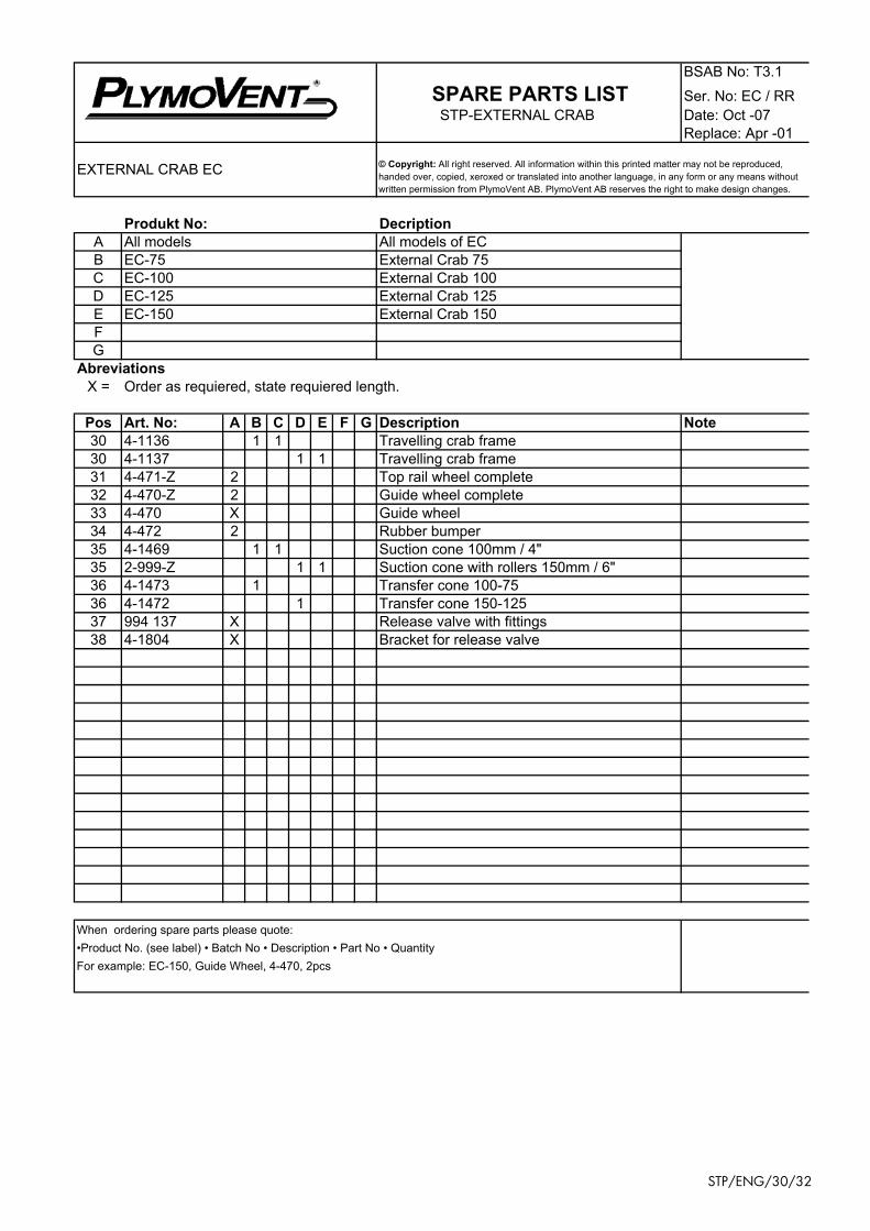
Produkt No: DecriptionA All models All models of ECB EC-75 External Crab 75C EC-100 External Crab 100D EC-125 External Crab 125E EC-150 External Crab 150FG
Abreviations X = Order as requiered, state requiered length.
Pos Art. No: A B C D E F G Description Note30 4-1136 1 1 Travelling crab frame30 4-1137 1 1 Travelling crab frame31 4-471-Z 2 Top rail wheel complete32 4-470-Z 2 Guide wheel complete33 4-470 X Guide wheel34 4-472 2 Rubber bumper35 4-1469 1 1 Suction cone 100mm / 4"35 2-999-Z 1 1 Suction cone with rollers 150mm / 6"36 4-1473 1 Transfer cone 100-7536 4-1472 1 Transfer cone 150-12537 994 137 X Release valve with fittings38 4-1804 X Bracket for release valve
When ordering spare parts please quote:•Product No. (see label) • Batch No • Description • Part No • QuantityFor example: EC-150, Guide Wheel, 4-470, 2pcs
EXTERNAL CRAB EC © Copyright: All right reserved. All information within this printed matter may not be reproduced, handed over, copied, xeroxed or translated into another language, in any form or any means without written permission from PlymoVent AB. PlymoVent AB reserves the right to make design changes.
STP/ENG/30/32

47
43
37
48 3839
45
46
44
40
41
42
STP/ENG/31/32
© Copyright 2008: All rights reserved. All information within this printed matter may not be reproduced,
handed over, copied, xeroxed or translated into another language in any form or means without written
permission from PlymoVent AB. PlymoVent AB reserves the right to make design changes.
STP / STP-12, STP-15, STP-18, STP-21, STP-24, STP-27, STP-30
SPARE PART DRAWINGBSAB no: T3.1Ser .no: STPDate: Jan-98Replace:

SPARE PARTS LISTDate: Dec -00Replace:Aug-98
STP-RAIL
Produkt No: DecriptionA All models All models of STPB STP-6 STP-Rail L=5,8m/ 19,ftC STP-9 STP-Rail L=8,8m/ 28,2ftD STP-12 STP-Rail L=11,6m/ 37,1ftE STP-15 STP-Rail L=14,6m/ 46,7ftF STP-18 STP-Rail L=17,4m/ 55,7ftG STP-21 STP-Rail L=20,4m/ 65,3ftH STP-24 STP-Rail L=23,2m/ 74,2ftI STP-27 STP-Rail L=26,2m/ 83,8ftJ STP-30 STP-Rail L=29m/ 92,8ft
Abreviations X = Order as requiered, state requiered length.
Pos Art. No: A B C D E F G H I J Description Note37 3-986 1 Wire suspension38 4-1204 1 Wire suspension magazine39 3-523 1 Suspension magazine40 921 080 1 Suspension magazine41 949 594 1 Eye bolt42 962 290 2 Wire Lock43 968 628 1 Shock- absorber44 90100-1011 1 Balancer BR-30045 90100-007 1 Spring balancer46 90100-010 1 Wire balancer47 8860-1011 1 1 1 1 Wire L=17m / 56ft47 8870-1011 1 1 1 1 1 Wire L=32m / 102ft48 8880-1011 1 1 1 1 Coiled air-line L=16m / 53ft48 8890-1011 1 1 1 1 1 Coiled air-line L=31m / 102ft49 4-1803 1 Disconnect plate
When ordering spare parts please quote:•Product No. (see label) • Batch No • Description • Part No • QuantityFor example: STP-15 Wire suspension 3-986
© Copyright: All right reserved. All information within this printed matter may not be reproduced, handed over, copied, xeroxed or translated into another language, in any form or any means without written permission from PlymoVent AB. PlymoVent AB reserves the right to make design changes.
STP/ENG/32/32
Related Documents