toll free 1-800-268-0967 • www.thermo-kinetics.com Thermowells are principally used with Thermocouples, RTDs (Resistance Temperature Detectors) and Bimetal Thermometers in applications where it is necessary to measure temperature at high pressure (above 75 psig) or in hostile environments. Thermowells are machined from solid barstock. Safe working pressures depend on the well material, operating temperature and the velocity of the flowing medium. Tapered wells are used in many process applications and provide greater strength, faster response times and more resistance to vibration than straight wells. The taper provides a higher natural frequency which permits use at higher fluid velocities. The reduced tip on a straight well improves response time when it is used with a length sensitive sensor such as an RTD or Bimetal Thermometer. Thermowells are more likely to fail from vibratory stress than from the effects of temperature and pressure. ASME calculations can be used to determine if the selected thermowell dimensions are adequate to withstand the specified service conditions of temperature, pressure, velocity and vibration. Thermo-Kinetics stocks a complete range of standard thermowells to meet most applications. Flanged, Socket Weld, Van Stone, Ground Joint and Weld-in thermowells are also available. Special wells in various materials, sheaths and coatings are also available to meet unique requirements. A Material Selection Guide is included in this Product Reference Guide. PRODUCT REFERENCE GUIDE Thermowells ® Registered Trademark of Thermo-Kinetics Company Limited Toronto • Montréal • Québec • Calgary • Edmonton • Vancouver Please visit our website for our other Product Literature Guides : T-PAK ® Thermocouples, Resistance Temperature Detectors, Industrial Thermocouples, Protection Tubes, Calibration Services

Welcome message from author
This document is posted to help you gain knowledge. Please leave a comment to let me know what you think about it! Share it to your friends and learn new things together.
Transcript
t o l l f r e e 1 - 8 0 0 - 2 6 8 - 0 9 6 7 • w w w . t h e r m o - k i n e t i c s . c o m
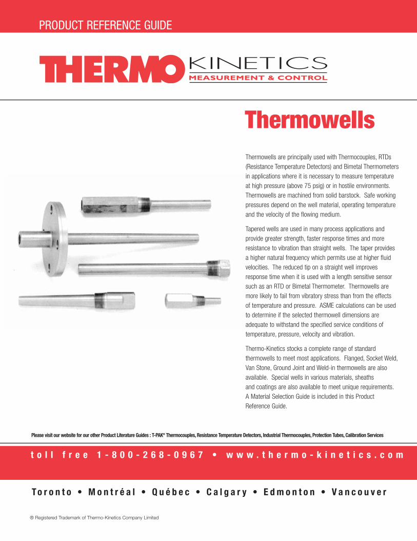
Thermowells are principally used with Thermocouples, RTDs(Resistance Temperature Detectors) and Bimetal Thermometersin applications where it is necessary to measure temperatureat high pressure (above 75 psig) or in hostile environments.Thermowells are machined from solid barstock. Safe workingpressures depend on the well material, operating temperatureand the velocity of the flowing medium.
Tapered wells are used in many process applications and provide greater strength, faster response times and moreresistance to vibration than straight wells. The taper providesa higher natural frequency which permits use at higher fluid velocities. The reduced tip on a straight well improvesresponse time when it is used with a length sensitive sensorsuch as an RTD or Bimetal Thermometer. Thermowells aremore likely to fail from vibratory stress than from the effects of temperature and pressure. ASME calculations can be usedto determine if the selected thermowell dimensions areadequate to withstand the specified service conditions oftemperature, pressure, velocity and vibration.
Thermo-Kinetics stocks a complete range of standardthermowells to meet most applications. Flanged, Socket Weld,Van Stone, Ground Joint and Weld-in thermowells are alsoavailable. Special wells in various materials, sheaths and coatings are also available to meet unique requirements.A Material Selection Guide is included in this ProductReference Guide.
PRODUCT REFERENCE GUIDE
Thermowells
® Registered Trademark of Thermo-Kinetics Company Limited
To r o n t o • M o n t r é a l • Q u é b e c • C a l g a r y • E d m o n t o n • V a n c o u v e r
Please visit our website for our other Product Literature Guides : T-PAK® Thermocouples, Resistance Temperature Detectors, Industrial Thermocouples, Protection Tubes, Calibration Services
Thermowells1.800.268.0967 • www.thermo-kinetics.com
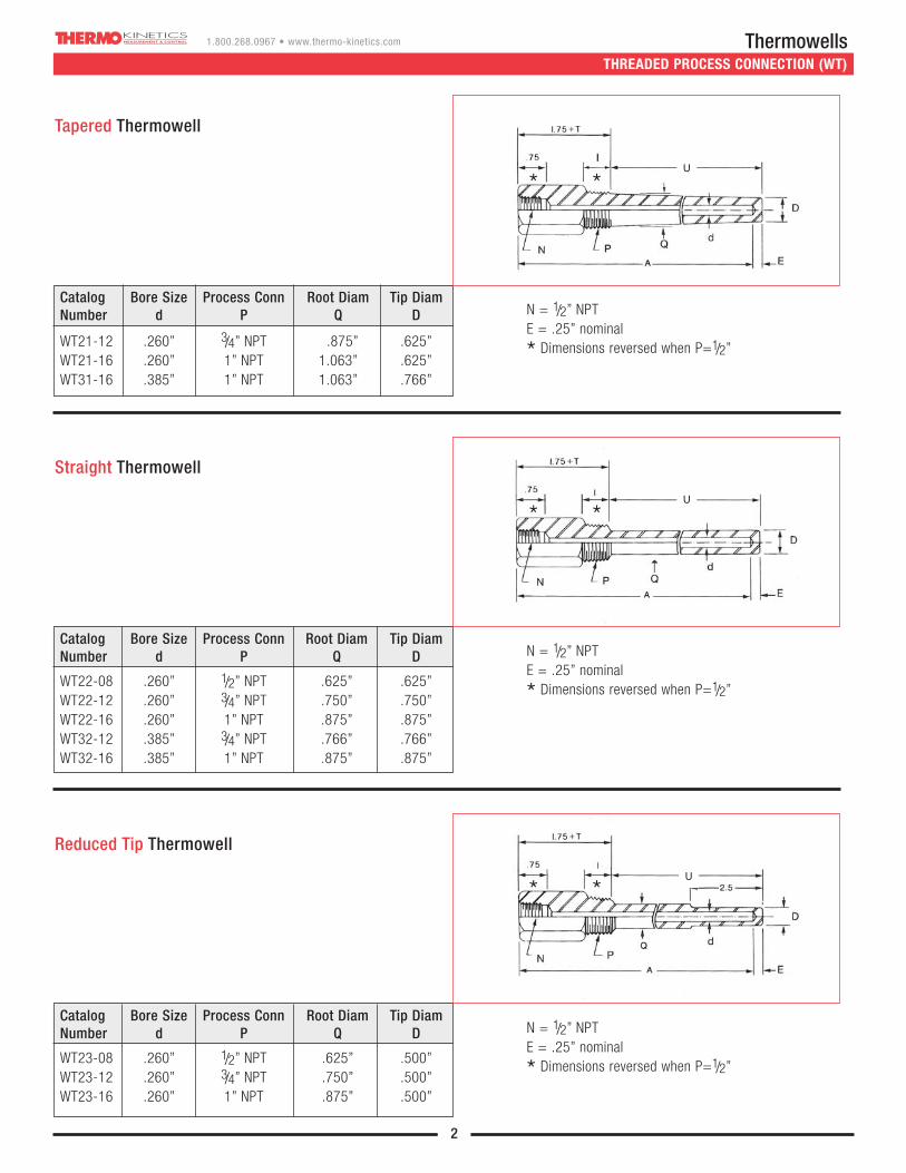
THREADED PROCESS CONNECTION (WT)
Tapered Thermowell
N = 1/2” NPTE = .25” nominal
* Dimensions reversed when P=1/2”
Catalog Bore Size Process Conn Root Diam Tip DiamNumber d P Q D
WT21-12 .260” 3/4” NPT .875” .625”WT21-16 .260” 1” NPT 1.063” .625”WT31-16 .385” 1” NPT 1.063” .766”
Straight Thermowell
N = 1/2” NPTE = .25” nominal
* Dimensions reversed when P=1/2”
Catalog Bore Size Process Conn Root Diam Tip DiamNumber d P Q D
WT22-08 .260” 1/2” NPT .625” .625”WT22-12 .260” 3/4” NPT .750” .750”WT22-16 .260” 1” NPT .875” .875”WT32-12 .385” 3/4” NPT .766” .766”WT32-16 .385” 1” NPT .875” .875”
Reduced Tip Thermowell
N = 1/2” NPTE = .25” nominal
* Dimensions reversed when P=1/2”
Catalog Bore Size Process Conn Root Diam Tip DiamNumber d P Q D
WT23-08 .260” 1/2” NPT .625” .500”WT23-12 .260” 3/4” NPT .750” .500”WT23-16 .260” 1” NPT .875” .500”
2
* *
* *
* *
U
U
U
Thermowells1.800.268.0967 • www.thermo-kinetics.com
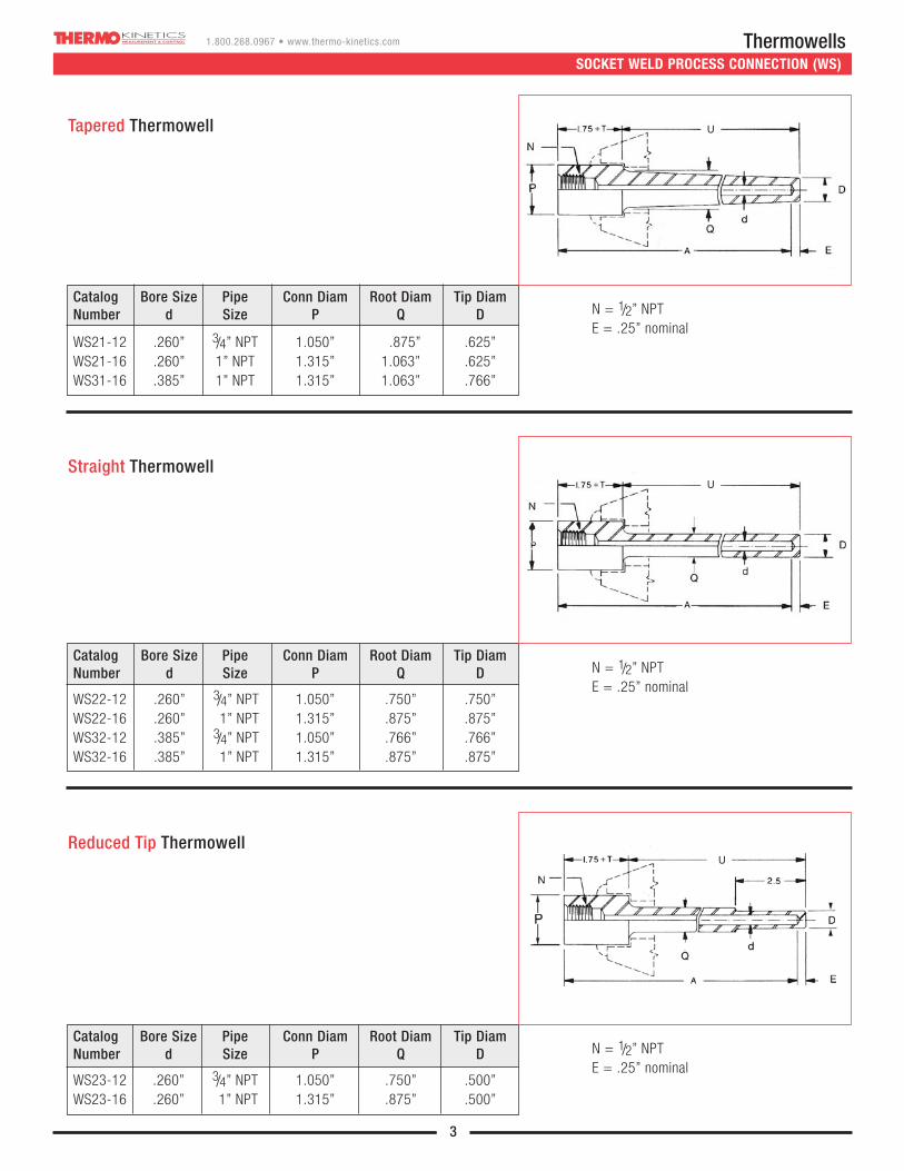
SOCKET WELD PROCESS CONNECTION (WS)
3
Tapered Thermowell
N = 1/2” NPTE = .25” nominal
Catalog Bore Size Pipe Conn Diam Root Diam Tip DiamNumber d Size P Q D
WS21-12 .260” 3/4” NPT 1.050” .875” .625”WS21-16 .260” 1” NPT 1.315” 1.063” .625”WS31-16 .385” 1” NPT 1.315” 1.063” .766”
Straight Thermowell
N = 1/2” NPTE = .25” nominal
Catalog Bore Size Pipe Conn Diam Root Diam Tip DiamNumber d Size P Q D
WS22-12 .260” 3/4” NPT 1.050” .750” .750”WS22-16 .260” 1” NPT 1.315” .875” .875”WS32-12 .385” 3/4” NPT 1.050” .766” .766”WS32-16 .385” 1” NPT 1.315” .875” .875”
Reduced Tip Thermowell
N = 1/2” NPTE = .25” nominal
Catalog Bore Size Pipe Conn Diam Root Diam Tip DiamNumber d Size P Q D
WS23-12 .260” 3/4” NPT 1.050” .750” .500”WS23-16 .260” 1” NPT 1.315” .875” .500”
U
U
U

Thermowells1.800.268.0967 • www.thermo-kinetics.com
4
Tapered Thermowell
N = 1/2” NPTE = .25” nominal
Catalog Bore Size Flange Root Diam Tip DiamNumber d Size Q D
3/4” .750” .625”WF21 .260” 1” .875” .625”
11/2” & > 1.063” .625”
3/4” .750” .625”WF31 .385” 1” .875” .766”
11/2” & > 1.063” .766”
N = 1/2” NPTE = .25” nominal
N = 1/2” NPTE = .25” nominal
Straight Thermowell
Reduced Tip Thermowell
FLANGED PROCESS CONNECTION (WF)
U
U
U
Catalog Bore Size Flange Root Diam Tip DiamNumber d Size Q D
3/4” .750” .750”WF22 .260” 1” & > .750” .750”
WF32 .385”3/4” .750” .750”
1” & > .875” .875”
Catalog Bore Size Flange Root Diam Tip DiamNumber d Size Q D
WF23 .260” 3/4” .750” .500”
Thermowells1.800.268.0967 • www.thermo-kinetics.com
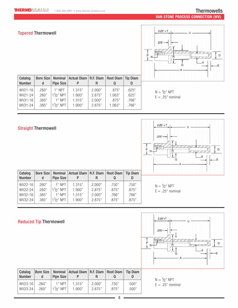
VAN STONE PROCESS CONNECTION (WV)
5
Tapered Thermowell
N = 1/2” NPTE = .25” nominal
Catalog Bore Size Nominal Actual Diam R.F. Diam Root Diam Tip DiamNumber d Pipe Size P R Q D
WV21-16 .260” 1” NPT 1.315” 2.000” .875” .625”WV21-24 .260” 11/2” NPT 1.900” 2.875” 1.063” .625”WV31-16 .385” 1” NPT 1.315” 2.000” .875” .766”WV31-24 .385” 11/2” NPT 1.900” 2.875” 1.063” .766”
N = 1/2” NPTE = .25” nominal
Catalog Bore Size Nominal Actual Diam R.F. Diam Root Diam Tip DiamNumber d Pipe Size P R Q D
WV22-16 .260” 1” NPT 1.315” 2.000” .750” .750”WV22-24 .260” 11/2” NPT 1.900” 2.875” .875” .875”WV32-16 .385” 1” NPT 1.315” 2.000” .766” .766”WV32-24 .385” 11/2” NPT 1.900” 2.875” .875” .875”
N = 1/2” NPTE = .25” nominal
Catalog Bore Size Nominal Actual Diam R.F. Diam Root Diam Tip DiamNumber d Pipe Size P R Q D
WV23-16 .260” 1” NPT 1.315” 2.000” .750” .500”WV23-24 .260” 11/2” NPT 1.900” 2.875” .875” .500”
Straight Thermowell
Reduced Tip Thermowell
U
U
U
Thermowells1.800.268.0967 • www.thermo-kinetics.com
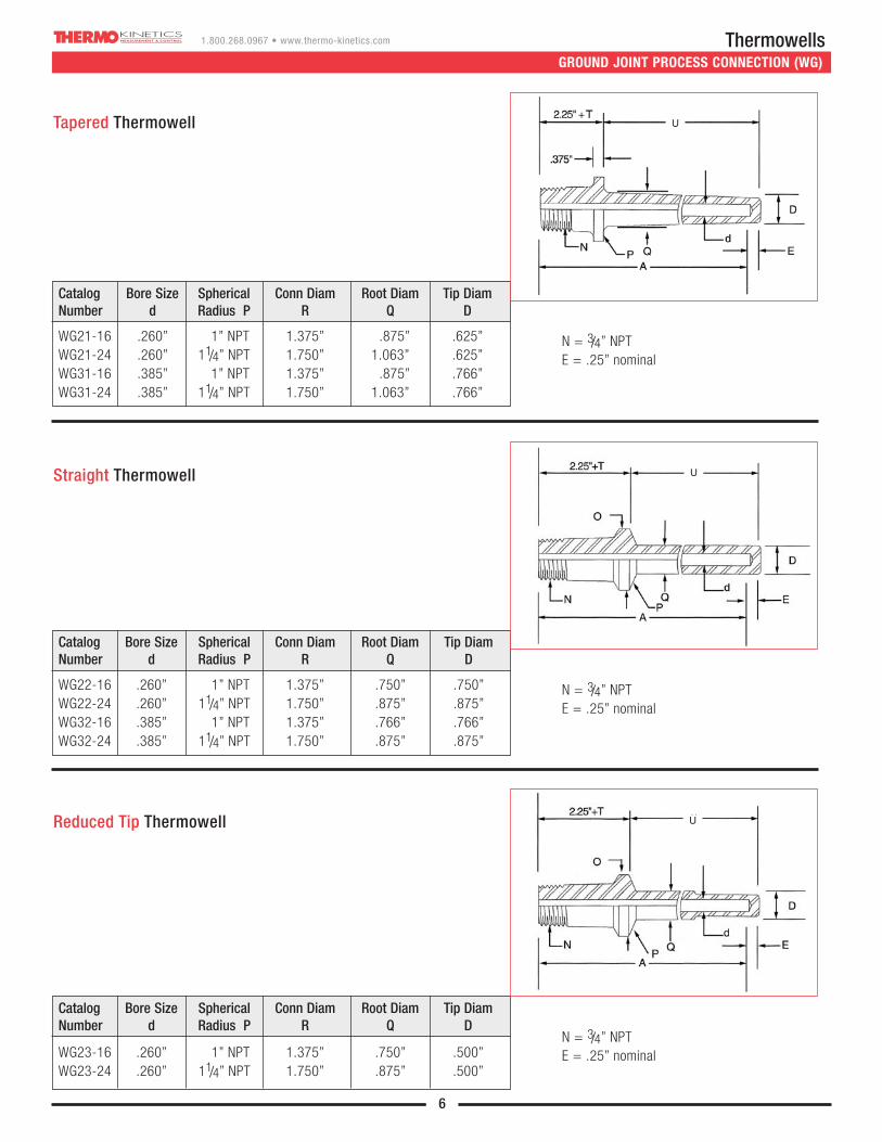
GROUND JOINT PROCESS CONNECTION (WG)
6
Tapered Thermowell
N = 3/4” NPTE = .25” nominal
Catalog Bore Size Spherical Conn Diam Root Diam Tip DiamNumber d Radius P R Q D
WG21-16 .260” 1” NPT 1.375” .875” .625”WG21-24 .260” 11/4” NPT 1.750” 1.063” .625”WG31-16 .385” 1” NPT 1.375” .875” .766”WG31-24 .385” 11/4” NPT 1.750” 1.063” .766”
N = 3/4” NPTE = .25” nominal
Catalog Bore Size Spherical Conn Diam Root Diam Tip DiamNumber d Radius P R Q D
WG22-16 .260” 1” NPT 1.375” .750” .750”WG22-24 .260” 11/4” NPT 1.750” .875” .875”WG32-16 .385” 1” NPT 1.375” .766” .766”WG32-24 .385” 11/4” NPT 1.750” .875” .875”
N = 3/4” NPTE = .25” nominal
Catalog Bore Size Spherical Conn Diam Root Diam Tip DiamNumber d Radius P R Q D
WG23-16 .260” 1” NPT 1.375” .750” .500”WG23-24 .260” 11/4” NPT 1.750” .875” .500”
Straight Thermowell
Reduced Tip Thermowell
U
U
U

Thermowells1.800.268.0967 • www.thermo-kinetics.com
WELD-IN PROCESS CONNECTION (WW)
7
Tapered Thermowell
N = 1/2” NPTE = .25” nominal
“U” Length: ± .063” for “U” < 25” Bore Concentricity: .0015”drift/in, .035” max
Overall Length: Nominal Stem Diameter: ± .010”
Outside Diameter: +0/-.032” Tip Thickness: .250” ± .063”
Bore Diameter: +.005/-.003” Instrument Connection: 1/2” - 14 NPT, 5/8” deep
Bore Depth: +.030/-0” Surface Finish: 16-32 RMS
Catalog Bore Size Nominal Root Diam Tip DiamNumber d Size P Q D
WW21-24 .260” 11/2” NPT 1.500” .625”WW31-24 .385” 11/2” NPT 1.500” .766”
STANDARD MANUFACTURING TOLERANCES
THERMOWELL IMMERSION LENGTH
The insertion length (“U” length) of a thermowell should be long enough to permit the entire length of the sensing element to project into the medium being measured in order to prevent errors resulting from insufficient immersion.
For liquids, insertion length = sensitive length + 2 diameters
For air & gases, insertion length = sensitive length + 4 diameters
Pipes should be insulated to minimize heat loss due to heat flow along the thermowell.For higher velocities, refer to chart on page 9 or the calculations on our web site.
U
Thermowells1.800.268.0967 • www.thermo-kinetics.com
8
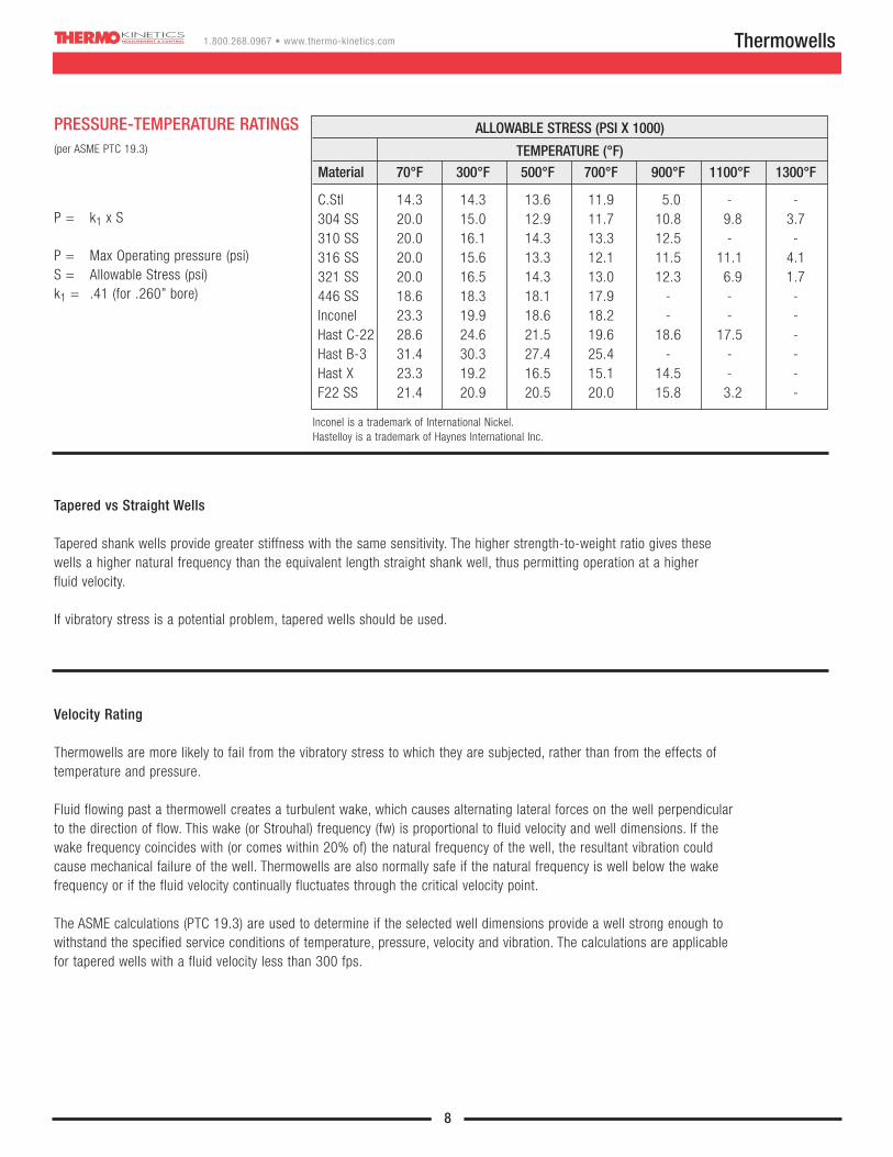
P = k1 x S
P = Max Operating pressure (psi)S = Allowable Stress (psi)k1 = .41 (for .260” bore)
(per ASME PTC 19.3)
Inconel is a trademark of International Nickel.Hastelloy is a trademark of Haynes International Inc.
ALLOWABLE STRESS (PSI X 1000)
TEMPERATURE (°F)
Material 70°F 300°F 500°F 700°F 900°F 1100°F 1300°F
C.Stl 14.3 14.3 13.6 11.9 5.0 - -304 SS 20.0 15.0 12.9 11.7 10.8 9.8 3.7310 SS 20.0 16.1 14.3 13.3 12.5 - -316 SS 20.0 15.6 13.3 12.1 11.5 11.1 4.1321 SS 20.0 16.5 14.3 13.0 12.3 6.9 1.7446 SS 18.6 18.3 18.1 17.9 - - -Inconel 23.3 19.9 18.6 18.2 - - -Hast C-22 28.6 24.6 21.5 19.6 18.6 17.5 -Hast B-3 31.4 30.3 27.4 25.4 - - -Hast X 23.3 19.2 16.5 15.1 14.5 - -F22 SS 21.4 20.9 20.5 20.0 15.8 3.2 -
PRESSURE-TEMPERATURE RATINGS
Tapered vs Straight Wells
Tapered shank wells provide greater stiffness with the same sensitivity. The higher strength-to-weight ratio gives thesewells a higher natural frequency than the equivalent length straight shank well, thus permitting operation at a higher fluid velocity.
If vibratory stress is a potential problem, tapered wells should be used.
Velocity Rating
Thermowells are more likely to fail from the vibratory stress to which they are subjected, rather than from the effects oftemperature and pressure.
Fluid flowing past a thermowell creates a turbulent wake, which causes alternating lateral forces on the well perpendicularto the direction of flow. This wake (or Strouhal) frequency (fw) is proportional to fluid velocity and well dimensions. If thewake frequency coincides with (or comes within 20% of) the natural frequency of the well, the resultant vibration couldcause mechanical failure of the well. Thermowells are also normally safe if the natural frequency is well below the wakefrequency or if the fluid velocity continually fluctuates through the critical velocity point.
The ASME calculations (PTC 19.3) are used to determine if the selected well dimensions provide a well strong enough towithstand the specified service conditions of temperature, pressure, velocity and vibration. The calculations are applicablefor tapered wells with a fluid velocity less than 300 fps.
Thermowells1.800.268.0967 • www.thermo-kinetics.com
9
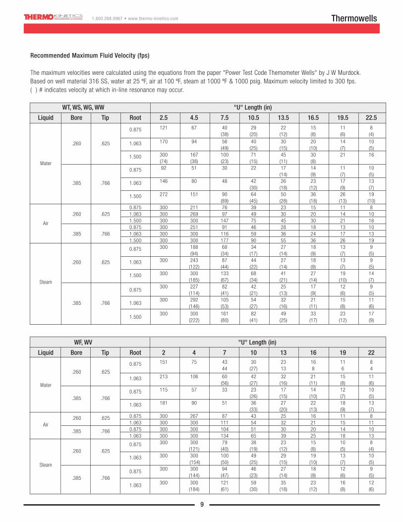
WT, WS, WG, WW "U" Length (in)
Liquid Bore Tip Root 2.5 4.5 7.5 10.5 13.5 16.5 19.5 22.5
121 67 40 29 22 15 11 80.875(38) (20) (12) (8) (6) (4)
170 94 56 40 30 20 14 10.260 .625 1.063(49) (25) (15) (10) (7) (5)
300 167 100 71 45 30 21 161.500 (74) (38) (23) (15) (11) (8)Water92 51 30 22 17 14 11 100.875
(14) (9) (7) (5)146 80 48 42 26 23 17 13.385 .766 1.063
(30) (18) (12) (9) (7)272 151 90 64 50 36 26 191.500
(89) (45) (28) (18) (13) (10)0.875 300 211 76 39 23 15 11 8
.260 .625 1.063 300 269 97 49 30 20 14 10
Air 1.500 300 300 147 75 45 30 21 160.875 300 251 91 46 28 18 13 10
.385 .766 1.063 300 300 116 59 36 24 17 131.500 300 300 177 90 55 36 26 19
300 188 68 34 27 18 13 90.875(94) (34) (17) (14) (9) (7) (5)
300 243 87 44 27 18 13 9.260 .625 1.063(122) (44) (22) (14) (9) (7) (5)
300 300 133 68 41 27 19 141.500(185) (67) (34) (21) (14) (10) (7)Steam
0.875300 227 82 42 25 17 12 9
(114) (41) (21) (13) (9( (6) (5)
.385 .766 1.063300 292 105 54 32 21 15 11
(146) (53) (27) (16) (11) (8) (6)
1.500300 300 161 82 49 33 23 17
(222) (80) (41) (25) (17) (12) (9)
Recommended Maximum Fluid Velocity (fps)
The maximum velocities were calculated using the equations from the paper "Power Test Code Themometer Wells" by J W Murdock.Based on well material 316 SS, water at 25 ºF, air at 100 ºF, steam at 1000 ºF & 1000 psig. Maximum velocity limited to 300 fps.( ) # indicates velocity at which in-line resonance may occur.
WF, WV "U" Length (in)
Liquid Bore Tip Root 2 4 7 10 13 16 19 22151 75 43 30 23 16 11 80.875
44 (27) 13 8 6 4.260 .625
213 106 60 42 32 21 15 111.063(56) (27) (16) (11) (8) (6)Water
115 57 33 23 17 14 12 100.875(26) (15) (10) (7) (5).385 .766
181 90 51 36 27 22 18 131.063(33) (20) (13) (9) (7)
0.875 300 267 87 43 25 16 11 8.260 .6251.063 300 300 111 54 32 21 15 11Air0.875 300 300 104 51 30 20 14 10.385 .7661.063 300 300 134 65 39 25 18 13
300 300 79 38 23 15 10 80.875(121) (40) (19) (12) (8) (5) (4).260 .625
300 300 100 49 29 19 13 10
Steam1.063
(154) (50) (25) (15) (10) (7) (5)
0.875 300 300 94 46 27 18 12 9
.385 .766 (144) (47) (23) (14) (9) (6) (5)
1.063 300 300 121 59 35 23 16 12(184) (61) (30) (18) (12) (8) (6)

Thermowells1.800.268.0967 • www.thermo-kinetics.com
10
TANTALUM SHEATH
Tantalum sheaths protect Thermowells in corrosive processessuch as chlorine, bromine, hydrochloric, nitric and sulphuricacids. Tantalum’s high thermal conductivity and the thin-walldesign of the sheath allow for rapid heat transfer. Since corrosionis not a problem with tantalum, it is best suited for Thermowellsimmersed directly into the process. The sheath covers the wettedparts of the well and must be ordered with the well to ensurecorrect fit. Standard thickness is .013” with a .015” flange. Whenusing a sheath, a lower grade material may be used for the well.
Option code A is for tantalum, code B for user specified material. Other sheath materials include titanium, zirconium, and molybdenum.
Applies to straight wells only.
PROTECTIVE COATINGS
Chemical corrosion resistance can be improved by the addition of a fluoroplastic protective coating such as Teflon, to thethermowell. Teflon’s ability to tolerate harsh chemicalenvironments, makes it ideal for use in highly corrosiveapplications such as acid and caustics, food and beverage,pharmaceuticals, etc, where the temperature is less than 200°C(400°F). The Teflon coating is applied to the wetted parts of thethermowell (most commonly to flanged or Van Stone type) and is approximately 8 – 10 mil thick.
Option code C specifies Teflon coating; code E is for userspecified material. Other protective coatings are materials such as Kynar, Tantalum, Hastelloy C are available.
Hard facing the thermowell with wear resistant material such asstellite, can enhance wear resistance and minimize erosion due to particle bombardment encountered in processes such as coalpulverizing, decoking, etc.
The hard face coating is usually applied on the finisheddimensions of the well, and is approximately 1/32” thick (therefore the well OD will be 1/16” larger).
Option code D is for Stellite #6 coating; code E allows for user specified coating. Other hard face coatings can include: tungsten carbide, metco, alumina ceramic, boron nitride, chromeoxide. Specify coating material, length to be coated, thickness of coating and finish to be applied to coating.
Teflon is a trademark of E I du PontKynar is a trademark of Pennwalt Corp.Stellite is a trade name of Deloro StelliteHastelloy is a trademark of Haynes International Inc.
*Coating thickness**Coated length
Thermowells1.800.268.0967 • www.thermo-kinetics.com
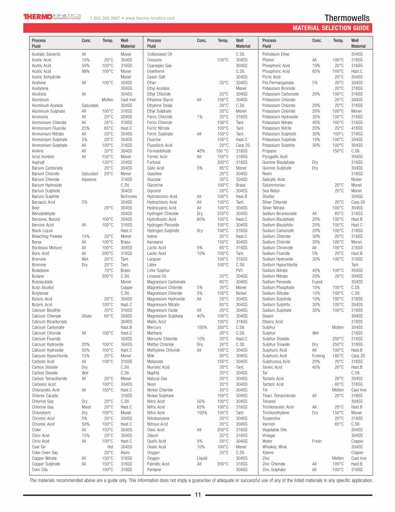
MATERIAL SELECTION GUIDE
11
Process Conc. Temp. Well Fluid Material
Acetate Solvents All MonelAcetic Acid 10% 20°C 304SSAcetic Acid 50% 100°C 316SSAcetic Acid 99% 100°C MonelAcetic Anhydride MonelAcetone All 100°C 304SSAcetylene 304SSAlcohols All 304SSAluminum Molten Cast IronAluminum Acetate Saturated 304SSAluminum Sulphate All 100°C 316SSAmmonia All 20°C 304SSAmmonium Chloride All 20°C 316SSAmmonium Fluoride 25% 65°C Hast.CAmmonium Nitrate All 20°C 304SSAmmonium Sulphate 5% 20°C 304SSAmmonium Sulphate All 100°C 316SSAniline All 20°C 304SSAmyl Acetate All 150°C MonelAsphalt 120°C 304SSBarium Carbonate 20°C 304SSBarium Chloride Saturated 20°C MonelBarium Chloride Aqueous 316SSBarium Hydroxide C.Stl.Barium Sulphide 304SSBarium Sulphite NichromeBaroacic Acid 5% 304SSBeer 20°C 304SSBenzaldehyde 304SSBenzene, Benzol 100°C 304SSBenzoic Acid All 100°C 316SSBlack Liquor Hast.CBleaching Powder 15% 20°C MonelBorax All 100°C BrassBordeaux Mixture All 100°C 304SSBoric Acid All 200°C 316SSBromine Wet 20°C Tant.Bromine Dry 20°C Tant.Butadiene 70°C BrassButane 200°C C.Stl.Butylacetate MonelButyl Alcohol CopperButylenes C.Stl.Butyric Acid 20°C 304SSButyric Acid 100°C Hast.CCalcium Bisulfite 20°C 316SSCalcium Chlorate Dilute 65°C 304SSCalcium Bicarbonate 304SSCalcium Carbonate Hast.BCalcium Chloride All 100°C Hast.CCalcium Fluoride 304SSCalcium Hydroxide 20% 100°C 304SSCalcium Hydroxide 50% 100°C Hast.CCalcium Hypochlorite 15% 20°C MonelCarbolic Acid All 100°C 316SSCarbon Dioxide Dry C.Stl.Carbon Dioxide Wet C.Stl.Carbon Tetrachloride All 20°C MonelCarbonic Acid 100°C 304SSChloracetic Acid All 150°C Hast.CChlorex Caustic 316SSChlorine Gas Dry 20°C C.Stl.Chlorine Gas Moist 20°C Hast.CChloroform Dry 100°C MonelChromic Acid 5% 20°C 304SSChromic Acid 50% 100°C Hast.CCider All 150°C 304SSCitric Acid 15% 20°C 304SSCitric Acid All 100°C Hast.CCoal Tar Hot 304SSCoke Oven Gas 20°C Alum.Copper Nitrate All 150°C 316SSCopper Sulphate All 150°C 316SSCorn Oils 100°C 316SS
Process Conc. Temp. Well Fluid Material
Cottenseed Oil C.Stl.Creosols 100°C 304SSCyanogen Gas 304SSDowtherm C.Stl.Epson Salt 304SSEther 20°C 304SSEthyl Acetate MonelEthyl Chloride 20°C 304SSEthylene Glycol All 100°C 304SSEthylene Oxide 20°C C.Stl.Ethyl Sulphate 20°C MonelFerric Chloride 1% 20°C 316SSFerric Chloride 100°C Tant.Ferric Nitrate 100°C Tant.Ferric Sulphate All 150°C Tant.Fluorine 100°C Hast.CFluosilicic Acid 20°C Carp.20Formaldehyde 40% 100 °C 316SSFormic Acid All 150°C 316SSFurfural 200°C 316SSGalic Acid 5% 65°C MonelGasoline 20°C 304SSGlucose 20°C 304SSGlycerine 100°C BrassGlycerol 20°C 304SSHydrobromic Acid All 100°C Hast.BHydrochloric Acid All 100°C Tant.Hydrocyanic Acid All 100°C 304SSHydrogen Chloride Dry 250°C 304SSHydrofluoric Acid 60% 100°C Hast.CHydrogen Peroxide 100°C 304SSHydrogen Sulphide Dry 100°C 316SSIodine 20°C Hast.CKerosene 150°C 304SSLactic Acid 5% 65°C 316SSLactic Acid 10% 100°C Tant.Lacquer 100°C 316SSLatex 100°C C.Stl.Lime Sulphur PVCLinseed Oil 20°C 304SSMagnesium Carbonate 65°C 304SSMagnesium Chloride 5% 20°C MonelMagnesium Chloride 5% 100°C NickelMagnesium Hydroxide All 20°C 304SSMagnesium Nitrate 65°C 304SSMagnesium Oxide All 20°C 304SSMagnesium Sulphate 40% 100°C 304SSMailic Acid 100°C 316SSMercury 100% 350°C C.Stl.Methane 20°C C.Stl.Mercuric Chloride 10% 20°C Hast.CMethyl Chloride Dry 20°C C.Stl.Methylene Chloride All 100°C 304SSMilk 80°C 304SSMolasses 150°C 304SSMuriatic Acid 20°C Tant.Naphta 20°C 304SSNatural Gas 20°C 304SSNeon 20°C 304SSNickel Chloride 20°C 304SSNickel Sulphate 100°C 304SSNitric Acid 50% 100°C 304SSNitric Acid 65% 100°C 316SSNitric Acid 100% 100°C Tant.Nitrobenzene 20°C 304SSNitrous Acid 20°C 304SSOleic Acid All 200°C 316SSOleum 20°C 316SSOxalic Acid 5% 20°C 304SSOxalic Acid 10% 100°C MonelOxygen 20°C C.Stl.Oxygen Liquid 304SSPalmitic Acid All 200°C 316SSPentane 304SS
Process Conc. Temp. Well Fluid Material
Petroleum Ether 304SSPhenol All 100°C 316SSPhosphoric Acid 10% 20°C 316SSPhosphoric Acid 85% 100°C Hast.CPicric Acid 20°C 304SSPot.Permanganate 5% 20°C 304SSPotassium Bromide 20°C 316SSPotassium Carbonate 20% 100°C 316SSPotassium Chlorate 20°C 304SSPotassium Chloride 20% 20°C 316SSPotassium Chloride 20% 100°C MonelPotassium Hydroxide 30% 100°C 316SSPotassium Nitrate 40% 100°C 316SSPotassium Nitrite 20% 20°C 416SSPotassium Sulphate 30% 100°c 316SSPotassium Sulphide 10% 100°C 304SSPotassium Sulphite 30% 100°C 304SSPropane 150°C C.Stl.Pyrogallic Acid 304SSQuinine Bisulphate Dry 316SSQuinine Sulphate Dry 304SSResin 316SSSalicylic Acid NickelSalommoniac 20°C MonelSea Water 20°C MonelShellac 304SSSilver Chloride 20°C Carp.20Silver Nitrate 100°C 304SSSodium Bicarbonate All 65°C 316SSSodium Bisulphate 20% 100°C Hast.BSodium Bisulphite 20% 100°C Hast.CSodium Carbonate 20% 100°C 316SSSodium Chloride 30% 20°C 316SSSodium Chloride 30% 100°C MonelSodium Chromate All 100°C 316SSSodium Fluoride 5% 20°C Hast.BSodium Hydroxide 30% 100°C 316SSSodium Hypochlorite Tant.Sodium Nitrate 40% 100°C 304SSSodium Nitrate 20% 20°C 304SSSodium Peroxide Fused 304SSSodium Phosphate 10% 100°C C.Stl.Sodium Silicate 10% 100°C C.Stl.Sodium Sulphide 10% 100°C 316SSSodium Sulphite 30% 100°C 304SSSodium Sulphate 30% 100°C 316SSSteam 304SSStearic Acid 316SSSulphur Molten 304SSSulphur Wet 316SSSulphur Dioxide 250°C 316SSSulphur Trioxide Dry 250°C 316SSSulphuric Acid All 100°C Hast.BSulphuric Acid Fuming 185°C Carp.20Sulphurous Acid 20% 20°C 316SSTannic Acid 40% 20°C Hast.BTar C.Stl.Tartaric Acid 20°C 304SSTartaric Acid 65°C 316SSTin Molten Cast IronTinan. Tetrachloride All 20°C 316SSToluene 304SSTrichloracetic Acid All 20°C Hast.BTrichlorethylene Dry 150°C MonelTurpentine 20°C 316SSVarnish 65°C C.Stl.Vegetable Oils 304SSVinegar 304SSWater Fresh CopperWhiskey, Wine 304SSXylene CopperZinc Molten Cast IronZinc Chloride All 100°C Hast.BZinc Sulphate All 100°C 316SS
The materials recommended above are a guide only. This information does not imply a guarantee of adequate or successful use of any of the listed materials in any specific application.
Thermowells1.800.268.0967 • www.thermo-kinetics.com
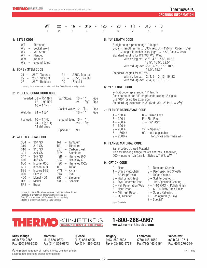
ORDERING INFORMATION
1: STYLE CODE
WT – Threaded WS – Socket WeldWV – Van StoneWF – FlangedWW – Weld-InWG – Ground Joint
2: BORE / STEM CODE
21 – .260”, Tapered 31 – .385”, Tapered22 – .260”, Straight 32 – .385”, Straight23 – .260”, Reduced 99 – SpecialIf root/tip dimensions are not standard. Use Code 99 and specify details.
3: PROCESS CONNECTION CODE
Threaded: 08 – 1/2” NPT Van Stone: 16 – 1” Pipe12 – 3/4” NPT 24 – 11/2” Pipe16 – 1” NPT
Socket Weld: 12 – 3/4” PipeWeld-In: 24 – 11/2” 16 – 1” Pipe
Flanged: 16 – 1” Flg Ground Joint: 16 – 1”24 – 11/2” Flg 20 – 11/4”All std sizes
Special:* 99
4: WELL MATERIAL CODE
304 – 304 SS TAT – Tantalum310 – 310 SS TIT – Titanium316 – 316 SS CST – Carbon Steel321 – 321 SS ALM – Aluminum347 – 347 SS HSB – Hastelloy B-3446 – 446 SS HSX – Hastelloy X600 – Inconel 600 HSC – Hastelloy C-22601 – Inconel 601 TEF – Teflon825 – Incoloy 825 KYN – Kynar020 – Carp 20 PVC – PVC400 – Monel 400 ZIR – Zirconium NIK – Nickel XXX – Special*BRS – Brass
Inconel, Incoloy & Monel are trademarks of International NickelHastelloy is a trademark of Haynes International Inc.Carp 20 is a trademark of Carpenter Technology Corp.Stellite is a trademark name of Deloro Stellite
5: “U” LENGTH CODE
3-digit code representing “U” lengthCode = length in mm x .3937 (eg: U = 150mm; Code = 059)
= length in inches x 10 (eg: U = 7.5”, Code = 075)Standard lengths for WT, WS, WG, WW:
with no lag ext: 2.5”, 4.5”, 7.5”, 10.5”, 13.5”, 16.5”, 22.5”
with std lag ext: 2.5”, 4.5”, 7.5”, 10.5”, 13.5”, 19.5”
Standard lengths for WF, WV:with no lag ext: 2, 4, 7, 10, 13, 16, 22with std lag ext: 2, 4, 7, 10, 13, 19
6: “T” LENGTH CODE
2-digit code representing “T” lengthCode same as for “U” length code (except 2 digits)Use “00” for no lag extensionStandard lag extension is 3” (Code 30); 2” for U = 21/2”
7: FLANGE RATING/FACE CODE
1 – 150 # R – Raised Face3 – 300 # F – Flat Face4 – 400 # J – Ring Joint6 – 600 #9 – 900 # XX – Special*5 – 1500 # 00 – not applicable2 – 2500 # (for Styles other than WF)
8: FLANGE MATERIAL CODE
Same codes as Well Material(Use for backing flange for WV and WG, if required)000 – none or n/a (use for Styles WT, WS, WW)
9: OPTION CODE
0 – None A – Tantalum Sheath1 – Brass Plug/Chain B – User Specified Sheath2 – SS Plug/Chain C – Teflon Coated3 – Hydrostatic Test D – Stellite Coated4 – Dye Penetrant Test E – User Specified Coating5 – Full Penetration Weld F – 4-10 RMS Hi Polish Finish6 – Heat Treat G – 6-100 RMS Satin Finish7 – Mill Test Report H – Stress Relieving8 – O2 Cleaned J – Radiograph (X-Ray)
S – Special**specify details
WF 22 - 16 - 316 - 125 - 20 - 1R - 316 - 01 2 3 4 5 6 7 8 9
12
Mississauga(905) 670-2266Fax (905) 670-8530
Montréal(514) 856-0370Fax (514) 856-0373
Québec(418) 655-6505Fax (514) 856-0373
Calgary(403) 252-2522Fax (403) 252-2778
Edmonton(780) 448-1580Fax (780) 463-5164
Vancouver(604) 231-0711Fax (604) 270-3644
® Registered Trademark of Thermo-Kinetics Company Limited. TW1 - 510Specifications subject to change without notice.
1-800-268-0967www.thermo-kinetics.com
Related Documents