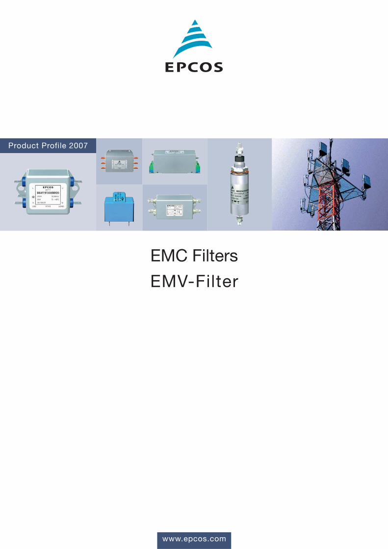
www.epcos.com Product Profile 2007 EMC Filters EMV-Filter

Welcome message from author
This document is posted to help you gain knowledge. Please leave a comment to let me know what you think about it! Share it to your friends and learn new things together.
Transcript
www.epcos.com
Product Profile 2007
EMC Filters
EMV-Filter
With its broad portfolio in electronic components EPCOS provides one-stop
shopping for a comprehensive range of products and is market leader in Europe and
number two worldwide. We offer manufacturers in the automotive electronics,
industrial electronics, IT and telecommunications, and the consumer electronics
industries both standard components as well as customized solutions. Our products
include capacitors and inductors, ceramic components, modules, and surface
acoustic wave components.
EPCOS is an innovative and technology-driven company with a global presence able
to provide local development support in the early phases of new projects. We have
design, manufacturing and marketing facilities in Europe, Asia and the Americas.
We are continually improving our processes and our mastery of them – and thus the
quality of our products and services. The Group has been ISO TS 16949-accredited
since the beginning of 2004.
Bei elektronischen Bauelementen bietet EPCOS mit seinem breiten Produktportfolio
ein umfassendes Angebot aus einer Hand und ist Marktführer in Europa und weltweit
die Nummer Zwei. Herstellern von Automobil-, Industrie- und Konsum-Elektronik sowie
von Informations- und Kommunikationstechnik bieten wir sowohl Standardprodukte
als auch maßgeschneiderte Lösungen. Dazu zählen Kondensatoren, Induktivitäten,
keramische Bauelemente, Oberflächenwellen-Komponenten und Module.
EPCOS ist ein global aufgestellter technologisch kompetenter und innovationsstarker
Partner, der seine Kunden vor Ort bereits in der Frühphase ihrer neuen Projekte
unterstützt. Wir verfügen über Entwicklungs-, Produktions- und Vertriebsstätten in
Europa, Asien sowie in Nord- und Südamerika.
Unsere Prozesse und deren Beherrschung verbessern wir kontinuierlich – und damit
die Qualität unserer Produkte und Dienstleistungen. Die Konzernzertifizierung nach
ISO TS 16949 besteht seit Anfang 2004.
EPCOS AG2
Welcome to the World of Electronic Components
EMC Filters EMV-Filter
Contents / InhaltImportant notes Wichtige Hinweise 4
Preview Vorwort 5
Selector guide Übersicht 6
Filters for power lines Filter für Netzanwendungenn 1-line filters n 1-Leiter-Filter
(feedthrough components) (Durchführungsbauelemente) 10n 2-line filters n 2-Leiter-Filter 14n 3-line filters n 3-Leiter-Filter 24n 4-line filters n 4-Leiter-Filter 36n Filters for regenerative converters n Filter für rückspeisefähige Umrichter 40n Customer-specific filters n Kundenspezifische Filter 41
Filters for shielded rooms Filter für geschirmte Räume 42n Filtes for power lines n Filter für Netzleitungen 43n Filters for communication lines n Filter für Kommunikationsleitungen 45
Services Dienstleistungen 47Accredited EMC laboratory Akkreditiertes EMV-Labor 48
Mounting instructions Einbauhinweise 50
Components for discrete Bauelemente für diskrete filter solutions Filterlösungen 57
Environmental protection Umweltschutz 60
Cautions and warnings Warn- und Sicherheitshinweise 61
Appendix Anhangn Symbols and terms n Symbole und Begriffe 62n Index of types n Bauformenverzeichnis 62
3EPCOS AG
4 EPCOS AG
Important NotesWichtige Hinweise
Gen
eral
Please read Important notes on page 4 and Cautions and warnings on page 61.Bitte beachten Sie die Seite 4 Wichtige Hinweise sowie die Warn- und Sicherheitshinweise auf Seite 61.
The following applies to all products named in this publication:
1. Some parts of this publication contain statements about the
suitability of our products for certain areas of application.
These statements are based on our knowledge of typicalrequirements that are often placed on our products in the areasof application concerned. We nevertheless expressly point outthat such statements cannot be regarded as binding
statements about the suitability of our products for a parti-
cular customer application. As a rule, EPCOS is either un-familiar with individual customer applications or less familiar withthem than the customers themselves. For these reasons, it isalways ultimately incumbent on the customer to check anddecide whether an EPCOS product with the properties describedin the product specification is suitable for use in a particularcustomer application.
2. We also point out that in individual cases, a malfunction of
electronic components or failure before the end of their
usual service life cannot be completely ruled out in
the current state of the art, even if they are operated as
specified. In customer applications requiring a very high level ofoperational safety and especially in customer applications inwhich the malfunction or failure of an electronic component couldendanger human life or health (e.g. in accident prevention or life-saving systems), it must therefore be ensured by means of suit-able design of the customer application or other action taken bythe customer (e.g. installation of protective circuitry or redun-dancy) that no injury or damage is sustained by third parties in the event of malfunction or failure of an electronic component.
3. The warnings, cautions and product-specific notes must be
observed.
4. In order to satisfy certain technical requirements, some of the
products described in this publication may contain sub-
stances subject to restrictions in certain jurisdictions (e.g.
because they are classed as “hazardous”). Useful informationon this will be found in our Material Data Sheets on the Internet(www.epcos.com/material). Should you have any more detailedquestions, please contact our sales offices.
5. We constantly strive to improve our products. Consequently, the
products described in this publication may change from time
to time. The same is true of the corresponding product specifica-tions. Please check therefore to what extent product descriptionsand specifications contained in this publication are still applicablebefore or when you place an order.
We also reserve the right to discontinue production and
delivery of products. Consequently, we cannot guarantee thatall products named in this publication will always be available.
6. Unless otherwise agreed in individual contracts, all orders are
subject to the current version of the “General Terms of
Delivery for Products and Services in the Electrical Industry”
published by the German Electrical and Electronics Industry
Association (ZVEI).
7. The trade names EPCOS, BAOKE, Alu-X, CeraDiode, CSSP,MiniBlue, MLSC, MotorCap, PhaseCap, PhaseMod, SIFERRIT, SIFI, SIKOREL, SilverCap, SIMID, SineFormer,SIOV, SIP5D, SIP5K, ThermoFuse, WindCap are trademarks registered or pending in Europe and in othercountries. Further information will be found on the Internet at www.epcos.com/trademarks.
Für alle in dieser Publikation genannten Produkte gilt:
1. Diese Publikation enthält an einigen Stellen Aussagen über die
Eignung unserer Produkte für bestimmte Anwendungs-
gebiete. Diese Aussagen basieren auf unserer Kenntnis vontypischen Anforderungen, die auf den genannten Anwen-dungsgebieten häufig an unsere Produkte gestellt werden. Wirweisen aber ausdrücklich darauf hin, dass derartige Aussagen
nicht als verbindliche Aussagen zur Eignung unserer
Produkte für eine bestimmte Kundenanwendung zu werten
sind. In aller Regel kennt EPCOS die einzelne Kunden-anwendung entweder nicht oder ist mit der Anwendung undihren Anforderungen weniger vertraut als der Kunde selbst. Esobliegt deshalb letztlich immer dem Kunden, zu prüfen und zu entscheiden, ob ein EPCOS-Produkt mit seinenin der Produktspezifikation beschriebenen Eigenschaften für denEinsatz in der jeweiligen individuellen Kundenanwendunggeeignet ist.
2. Außerdem weisen wir darauf hin, dass nach dem derzeitigen
Stand der Technik selbst bei spezifikationsgemäßem Betrieb
in Einzelfällen eine Fehlfunktion elektronischer Bauele-
mente oder ein Ausfall vor Ende ihrer üblichen Lebensdauer
nicht vollständig auszuschließen ist. Bei Kundenanwendun-gen, welche ein sehr hohes Maß an Betriebssicherheit erfordernund insbesondere bei Kundenanwendungen, bei denen eineFehlfunktion oder ein Ausfall eines elektronischen Bauelementeszu einer Gefährdung von Gesundheit oder Leben von Menschenführen könnte (z. B. unfallverhütende oder lebensschützendeSysteme), muss deshalb durch geeignete Konstruktion derKundenanwendung oder durch sonstige kundenseitige Maß-nahmen (z. B. durch Einbau von Schutzschaltungen oder Re-dundanzen) dafür gesorgt werden, dass auch bei Fehlfunktionoder Ausfall eines elektronischen Bauelementes keine Verletzungvon Rechtsgütern Dritter eintritt.
3. Die Warn- und Sicherheitshinweise sowie produktspezi-
fischen Anmerkungen sind unbedingt zu beachten.
4. Um bestimmten technischen Anforderungen gerecht zu werden,können einige der in dieser Publikation aufgeführten
Produkte Substanzen enthalten, die nach länderspezifischen
Regelungen Restriktionen unterliegen (z. B. weil sie als
„gefährlich“ eingestuft werden). Nützliche Informationen da-zu enthalten unsere Materialdatenblätter im Internet (www.epcos.de/material). Bei weitergehenden Fragen wendenSie sich bitte an unsere Vertriebsbüros.
5. Wir bemühen uns laufend, unsere Produkte zu verbessern.Infolge dessen ändern sich die in dieser Publikation be-
schriebenen Produkte von Zeit zu Zeit. Gleiches gilt auch fürdie entsprechenden Produktspezifikationen. Vergewissern Siesich deshalb vor oder bei Ihrer Bestellung, inwieweit die in dervorliegenden Publikation angegebenen Produktbeschreibungenund Produktspezifikationen noch gelten.
Im übrigen behalten wir uns vor, die Produktion und Lieferung
von Produkten einzustellen. Eine Gewähr für die dauerhafteVerfügbarkeit aller in dieser Publikation genannten Produktekönnen wir deshalb nicht übernehmen.
6. Außer in Fällen, in denen abweichende individualvertraglicheVereinbarungen getroffen werden, gelten für Bestellungen die
jeweils aktuell vom Zentralverband Elektrotechnik- und
Elektronikindustrie e.V. (ZVEI) herausgegebenen „Allge-
meinen Lieferbedingungen für Erzeugnisse und Leistungen
der Elektroindustrie“.
7. Die Bezeichnungen EPCOS, BAOKE, Alu-X, CeraDiode, CSSP,MiniBlue, MLSC, MotorCap, PhaseCap, PhaseMod, SIFERRIT, SIFI, SIKOREL, SilverCap, SIMID, SineFormer,SIOV, SIP5D, SIP5K, ThermoFuse, WindCap sind in Europaund in anderen Ländern registrierte oder zum Schutz
angemeldete Marken. Weitere Informationen hierzu finden Sie im Internet unter www.epcos.de/trademarks.

EPCOS AG 5
PreviewVorwort
Gen
eral
Please read Important notes on page 4 and Cautions and warnings on page 61.Bitte beachten Sie die Seite 4 Wichtige Hinweise sowie die
Warn- und Sicherheitshinweise auf Seite 61.
Electromagnetic compatibility is indispensable in today‘sproducts, and EMC components are the key to ensuringit. This publication is intended to help you choose the rightsolutions, and presents our broad selection of chokes andfilters for power line applications. We produce thesecomponents in Heidenheim (Germany), Szombathely(Hungary) and Hongqi (China).
When it comes to EMC, think EPCOS. Because EPCOSoffers you the world‘s biggest selection of EMC com-ponents, from arresters through chokes, filters andcapacitors to varistors.
Our applications engineers develop individual EMCsolutions for our customers, and support them withmeasurements – including on-site. Our test engineersconduct measurements and tests to international EMC standards in our own accredited laboratory inRegensburg, Germany. Tests from this laboratory can beused for the CE conformity declaration.
EPCOS is an EMC solution provider, supporting ourcustomers throughout the entire product developmentcycle – from the design phase up to volume production.We offer solutions and make recommendations foroptimization. In brief, EMC from a single source!
Let our creativity and competence contribute to yoursuccess.
Wenn es darum geht, die elektromagnetische Verträglich-keit (EMV) sicherzustellen, sind EMV-Bauelemente unver-zichtbare Schlüsselprodukte. Diese Broschüre hilft Ihnenbei der Wahl der passenden EMV-Filter bzw. EMV-Dros-seln. Wir fertigen diese Bauelemente in Heidenheim(Deutschland), Szombathely (Ungarn) und Hongqi (China).
In Sachen EMV sind Sie bei EPCOS immer an der richti-gen Adresse. EPCOS bietet das weltweit größte Spektruman EMV-Bauelementen: Von Ableitern über Drosseln,Filtern und Kondensatoren bis hin zu Varistoren. Darüberhinaus entwickeln unsere Applikationsingenieure für un-sere Kunden auch individuelle EMV-Lösungen und unter-stützen mit Messungen – auch vor Ort. Außerdem führenunsere Messingenieure in einem eigenen, akkreditiertenEMV-Labor in Regensburg protokollierte Messungen undPrüfungen nach internationalen EMV-Normen durch. Prüf-berichte unseres Labors können für die CE-Konformitäts-erklärung herangezogen werden.
Wir verstehen uns als EMV-Solution-Provider und unter-stützen Sie von Beginn an im gesamten Entwicklungs-zyklus Ihres Gerätes von der Konzeptionsphase bis zurSerienfertigung. Wir bieten Ihnen Lösungen an und erar-beiten Optimierungsvorschläge, kurz: EMV aus einerHand!
Nutzen deshalb auch Sie unsere Kreativität und jahrzehn-telange Kompetenz für Ihren Erfolg.

6 EPCOS AG
Selector GuideÜbersicht
Gen
eral
Please read Important notes on page 4 and Cautions and warnings on page 61.Bitte beachten Sie die Seite 4 Wichtige Hinweise sowie die Warn- und Sicherheitshinweise auf Seite 61.
Terminal type:
Tab connectors Axial leads
Soldering tags Threaded studs
1-line filters (feedthrough components)1-Leiter-Filter (Durchführungsbauelemente)
Type IR VR CR Insertion loss in the PageBauform frequency range (Hz) Seite
Einfügungsdämpfungim Frequenzbereich (Hz)
105 106 107
A V AC µF
Feedthrough filtersDurchführungsfilter
B85321A*+160 16 16 250 2 x 0.0025 10
B85321A*+160 20 25 250, 2 x 0.0025 10500
B85321A*A250 30 25, 250 2 x 0.1 … 11B85321A*A750 75 2 x 1.0
B85321A*A101… A630 55 63 … 250 2 x 0.5 … 11500 2 x 4.7
Feedthrough capacitorsDurchführungskondensatoren
B85121A*+160 16 16 75 … 0.00125 … 12440 1.0
B85121A*+250 20 25 75 … 0.01 … 12440 1.0
B85111A*B500 24 50 250 0.05 13
B85121A*A250 30 25, 250 0.1 … 13B85121A*A750 75 1.0
B85121A*A101… A630 55 63 … 250 0.5 … 13200 4.7
LegendLegende
Term
ina
l typ
eA
nsc
hlu
ssa
rt
Dia
me
ter
Du
rch
me
sse
r
Anschlussart:
Flachstecker Axiale Drähte
Lötfahnen Gewindebolzen

EPCOS AG 7
Gen
eral
Please read Important notes on page 4 and Cautions and warnings on page 61.Bitte beachten Sie die Seite 4 Wichtige Hinweise sowie die
Warn- und Sicherheitshinweise auf Seite 61.
Design:C = Compact filter RF = RF-proof metal case P = PCB filter
Terminal type:
Tab connectors IEC connectors Litz wires
Pins Threaded studs
Busbars Terminal blocks
Selector GuideÜbersicht
2-line filters 2-Leiter-Filter
Type IR VR Insertion loss in the PageBauform frequency range (Hz) Seite
Einfügungsdämpfungim Frequenzbereich (Hz)
105 106 107
A V
SIFI F, G, H 3 … 250 AC/DC TT/TN C 14B84111F … 36B84113H
SIFI A … E 1 … 250 AC/DC TT/TN C 16B84111A … 20B84115E P
B84142A*R122 8 … 300 AC/DC TT/TN C 19180
B84142A*R123 12 … 520 AC/DC TT/TN C 19100
B84142A*R000 10 … 250 AC/DC TT/TN C 2060
B84142A*G075 60
B84142B*R000 8 … 250 AC/DC TT/TN C 2025
B84142A*S002 250 … 750 DC — C 211000
B84142A*S003 250 … 1000 DC — C 211000
B84142A*S018 250 … 2000 DC — C 211000
B84103 1 … 250 AC TT/TN C 226
B84110A 0.5 … 250 AC/DC TT/TN P 226
B84110B 1.4 250 AC/DC TT/TN P 23
B84299K006* 2 … 250 AC/DC TT/TN C 2336
LegendLegende
Lin
e c
on
ne
cti
on
Ne
tza
rt
De
sig
nB
au
art
Term
ina
l typ
eA
nsc
hlu
ssa
rt
Bauart:C = Kompaktfilter RF = HF-dichtes Metallgehäuse P = Leiterplattenfilter
Anschlussart:
Flachstecker IEC-Stecker Litzen
Stifte Gewindebolzen
Stromschienen Reihenklemmen
8 EPCOS AG
Selector GuideÜbersicht
Gen
eral
Please read Important notes on page 4 and Cautions and warnings on page 61.Bitte beachten Sie die Seite 4 Wichtige Hinweise sowie die Warn- und Sicherheitshinweise auf Seite 61.
Design:C = Compact filter B = Book-size filter FP = Footprint filter
Terminal type:
Litz wires Terminal blocks Busbars
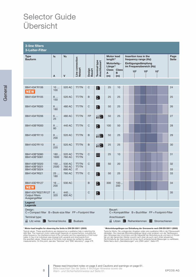
3-line filters 3-Leiter-Filter
Type IR VR Motor lead Insertion loss in the PageBauform length1) frequency range (Hz) Seite
Motorleitg.- EinfügungsdämpfungLänge1) im Frequenzbereich (Hz)Class ClassA B 105 106 107
A V (m) (m)
B84143A*R106 10 … 520 AC TT/TN C 25 10 24100
B84143A*R105 8 … 520 AC TT/TN B 25 25 25150
B84143A*R000 8 … 480 AC TT/TN C 50 25 26180
B84143A*R206 6 … 480 AC TT/TN FP 50 25 2725
B84143B*R000 8 … 440 AC TT/TN C 100 50 2880
B84143B*R110 8 … 520 AC TT/TN B 50 25 29200
B84143G*R110 8 … 520 AC TT/TN B 25 25 30220
B84143B*S080 180 … 520 AC TT/TN C 25 10 31B84143B*S081 1600 760 AC TT/TN
B84143B*S020 150 … 530 AC TT/TN C 50 20 32B84143B*S021 2500 760 AC TT/TNB84143B*S024 690 AC IT 33
B84143A*R021 25 … 760 AC TT/TN C 50 25 33180
B84143D*R127 16 … 530 AC B 300 100... 34200 200
B84143V*R027/R127 6 … 440… C 35Output filters 320 600 ACAusgangsfilter
LegendLegende
Lin
e c
on
ne
cti
on
Ne
tza
rt
De
sig
nB
au
art
Term
ina
l typ
eA
nsc
hlu
ssa
rt
Bauart:C = Kompaktfilter B = Buchfilter FP = Footprint-Filter
Anschlussart:
Litzen Reihenklemmen Stromschienen
1) Motor-lead lengths for observing the limits to DIN EN 55011 (2003)
Typical values. These specifications are designed as a qualitative help in selecting theright filter. The maximum motor cable length depends on several factors, including thepulse frequency, the interference level of the converter and the capacitance of the motorcable: it may in an individual case diverge both upwards and downwards from the specified values. Observance of the limits must always be verified by relevantmeasurements. On this point, see also “Services” and “EMC laboratory”, page 47ff.
1) Motorleitungslängen zur Einhaltung der Grenzwerte nach DIN EN 55011 (2003)
Typische Werte. Die vorliegenden Angaben sollen eine qualitative Hilfe in der Filterauswahldarstellen. Die maximale Motorleitungslänge hängt unter anderem von der Taktfrequenz,dem Störpegel des Umrichters und der Kapazität der Motorleitung ab und kann im Einzel-fall von den genannten Werten sowohl nach oben als auch nach unten abweichen. Die Einhaltung der Grenzwerte ist immer durch entsprechende Messungen zu verifizieren.Siehe hierzu auch „Dienstleistungen“ und „EMV-Labor“, Seite 47ff.
EPCOS AG 9
Selector GuideÜbersicht
Gen
eral
Please read Important notes on page 4 and Cautions and warnings on page 61.Bitte beachten Sie die Seite 4 Wichtige Hinweise sowie die
Warn- und Sicherheitshinweise auf Seite 61.
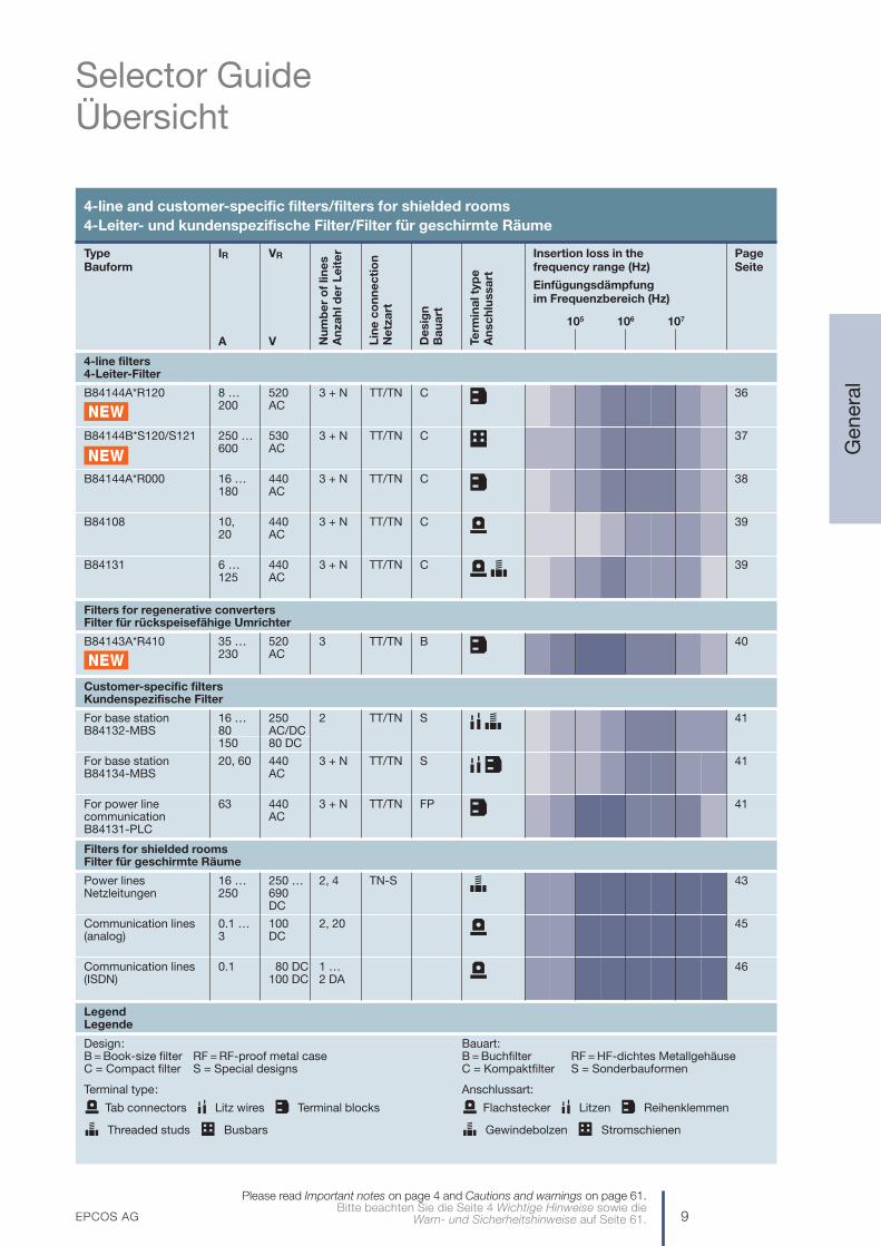
4-line and customer-specific filters/filters for shielded rooms4-Leiter- und kundenspezifische Filter/Filter für geschirmte Räume
Type IR VR Insertion loss in the PageBauform frequency range (Hz) Seite
Einfügungsdämpfungim Frequenzbereich (Hz)
105 106 107
A V
4-line filters4-Leiter-Filter
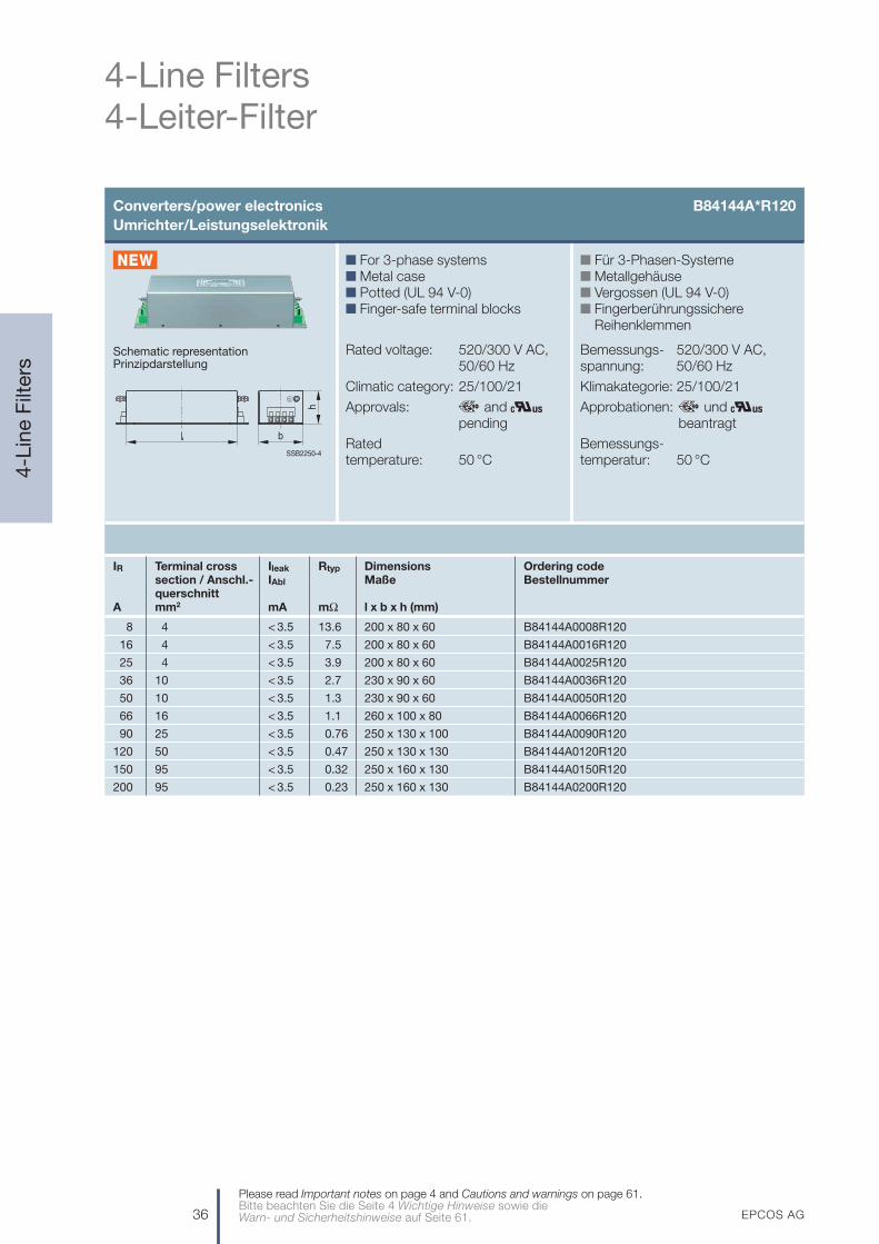
B84144A*R120 8 … 520 3 + N TT/TN C 36200 AC
B84144B*S120/S121 250 … 530 3 + N TT/TN C 37600 AC
B84144A*R000 16 … 440 3 + N TT/TN C 38180 AC
B84108 10, 440 3 + N TT/TN C 3920 AC
B84131 6 … 440 3 + N TT/TN C 39125 AC
Filters for regenerative convertersFilter für rückspeisefähige Umrichter
B84143A*R410 35 … 520 3 TT/TN B 40230 AC
Customer-specific filtersKundenspezifische Filter
For base station 16 … 250 2 TT/TN S 41B84132-MBS 80 AC/DC
150 80 DC
For base station 20, 60 440 3 + N TT/TN S 41B84134-MBS AC
For power line 63 440 3 + N TT/TN FP 41communication ACB84131-PLC
Filters for shielded roomsFilter für geschirmte Räume
Power lines 16 … 250 … 2, 4 TN-S 43Netzleitungen 250 690
DC
Communication lines 0.1 … 100 2, 20 45(analog) 3 DC
Communication lines 0.1 80 DC 1 … 46(ISDN) 100 DC 2 DA
LegendLegende
Nu
mb
er
of
line
sA
nza
hl d
er
Le
ite
r
Lin
e c
on
ne
cti
on
Ne
tza
rt
De
sig
nB
au
art
Term
ina
l typ
eA
nsc
hlu
ssa
rt
Design:B = Book-size filter RF = RF-proof metal case C = Compact filter S = Special designs
Terminal type:
Tab connectors Litz wires Terminal blocks
Threaded studs Busbars
Bauart:B = Buchfilter RF = HF-dichtes Metallgehäuse C = Kompaktfilter S = Sonderbauformen
Anschlussart:
Flachstecker Litzen Reihenklemmen
Gewindebolzen Stromschienen

10 EPCOS AG
1-Line Filters1-Leiter-Filter
1-L
ine
Filt
ers
Please read Important notes on page 4 and Cautions and warnings on page 61.Bitte beachten Sie die Seite 4 Wichtige Hinweise sowie die Warn- und Sicherheitshinweise auf Seite 61.
Feedthrough filters B85321Durchführungsfilter
Schematic representationsPrinzipdarstellungen
n Solderless MKP technologyn Dielectric: metallized
polypropylenen Dry, self-healingn Metal case, potted (UL 94 V-0)n Central screw fixingn Terminals: see table
Standards: to EN 133200
Climatic category: 40/085/56
Rated temperature: 40 °C
Cap. tolerance: ±20%
n Lötfreie MKP-Technologien Dielektrikum: Metallisiertes
Polypropylenn Trocken, selbstheilendn Metallgehäuse, vergossen
(UL 94 V-0)n Zentrale Schraubbefestigungn Anschlüsse: siehe Tabelle
Vorschriften: gemäß EN 133200
Klimakategorie: 40/085/56
Bemessungs-temperatur: 40 °C
Kap.-Toleranz: ±20%SSB2072-M
ø d
SSB2074-4
ø d
IR CR VR Vtest Insertion loss / Terminals Dimensions Ordering code ApprovalsEinfügungsdämpfg. Anschlüsse Maße Bestellnummer Appro-typ. @ 50 Ω (dB) bationen
A µF V AC V DC V DC 100 kHz 100 MHz ø d x l (mm)
Case diameter 16 mmGehäusedurchmesser 16 mm
16 2 x 250 600 2700 – > 80 M2 16 x 80 B85321A2502X160 x0.0025
2 x 250 600 2700 – > 80 Soldering tag / 16 x 80 B85321A2502Y160 x0.0025 Lötfahne
2 x 250 600 2700 – > 80 Leads / Drähte 16 x 155 B85321A2502Z160 x0.0025 ø 2 mm
2 x 250 600 2700 – > 80 Tab connector / 16 x 90 B85321A2502W160 x0.0025 Flachstecker
6.3 mm
Case diameter 20 mmGehäusedurchmesser 20 mm
25 2 x 250 600 2700 – > 80 M4 20 x 93 B85321A2502A160 x0.0025
2 x 250 600 2700 – > 80 Leads / Drähte 20 x 155 B85321A2502B160 x0.0025 ø 2 mm
2 x 500 700 3000 – > 80 B85321A4502C160 x0.0025

EPCOS AG 11
1-Line Filters1-Leiter-Filter
1-L
ine
Filt
ers
Please read Important notes on page 4 and Cautions and warnings on page 61.Bitte beachten Sie die Seite 4 Wichtige Hinweise sowie die
Warn- und Sicherheitshinweise auf Seite 61.
Feedthrough filters B85321Durchführungsfilter
IR CR VR Vtest Insertion loss / Terminals Dimensions Ordering code ApprovalsEinfügungsdämpfg. Anschlüsse Maße Bestellnummer Appro-typ. @ 50 Ω (dB) bationen
A µF V AC V DC V DC 100 kHz 100 MHz ø d x l (mm)
Case diameter 30 mmGehäusedurchmesser 30 mm
25 2 x 0.1 250 600 3000 10 > 100 M6 30 x 130 B85321A2204A250 x
2 x 0.5 250 600 2000 25 > 100 M6 30 x 130 B85321A2105A250 x
2 x 1.0 250 500 1700 30 > 100 M6 30 x 130 B85321A2205A250 x
75 2 x 0.1 250 600 3000 10 > 100 M6 30 x 130 B85321A2204A750 x
2 x 0.5 250 600 2000 25 > 100 M6 30 x 130 B85321A2105A750 –
2 x 1.0 250 500 1700 30 > 100 M6 30 x 130 B85321A2205A750 x
Case diameter 55 mmGehäusedurchmesser 55 mm
63 2 x 0.5 250 600 3000 25 > 100 M6 55 x 166 B85321A2105A630 x
2 x 1.0 250 600 2500 30 > 100 M6 55 x 166 B85321A2205A630 x
2 x 2.0 250 600 2500 35 > 100 M6 55 x 166 B85321A2405A630 x
2 x 4.7 250 350 1700 40 > 100 M6 55 x 166 B85321A2945A630 x
100 2 x 0.5 250 600 3000 25 > 100 M8 55 x 180 B85321A2105A101 x
2 x 1.0 250 600 2500 30 > 100 M8 55 x 180 B85321A2205A101 x
2 x 2.0 250 600 2500 35 > 100 M8 55 x 180 B85321A2405A101 x
2 x 4.7 250 350 1700 40 > 100 M8 55 x 180 B85321A2945A101 x
200 2 x 0.5 250 600 3000 25 > 100 M10 55 x 185 B85321A2105A201 x
2 x 1.0 250 600 2500 30 > 100 M10 55 x 185 B85321A2205A201 x
2 x 2.0 250 600 2500 35 > 100 M10 55 x 185 B85321A2405A201 x
2 x 4.7 250 350 1700 40 > 100 M10 55 x 185 B85321A2945A201 x
300 2 x 0.5 250 600 3000 25 > 100 M12 55 x 195 B85321A2105A301 x
2 x 1.0 250 600 2500 30 > 100 M12 55 x 195 B85321A2205A301 x
2 x 2.0 250 600 2500 35 > 100 M12 55 x 195 B85321A2405A301 x
2 x 4.7 250 350 1700 40 > 100 M12 55 x 195 B85321A2945A301 x
400 2 x 0.5 250 600 3000 25 > 100 M16 55 x 245 B85321A2105A401 –
2 x 1.0 250 600 2500 30 > 100 M16 55 x 245 B85321A2205A401 –
2 x 2.0 250 600 2500 35 > 100 M16 55 x 245 B85321A2405A401 –
2 x 4.7 250 350 1650 40 > 100 M16 55 x 245 B85321A2945A401 –
500 2 x 0.5 250 600 3000 25 > 100 M18 55 x 250 B85321A2105A501 –
2 x 1.0 250 600 2500 30 > 100 M18 55 x 250 B85321A2205A501 –
2 x 2.0 250 600 2500 35 > 100 M18 55 x 250 B85321A2405A501 –
2 x 4.7 250 350 1650 40 > 100 M18 55 x 250 B85321A2945A501 –

12 EPCOS AG
1-Line Filter Components1-Leiter-Filterbauelemente
1-L
ine
Filt
ers
Please read Important notes on page 4 and Cautions and warnings on page 61.Bitte beachten Sie die Seite 4 Wichtige Hinweise sowie die Warn- und Sicherheitshinweise auf Seite 61.
IR CR VR Vtest Insertion loss / Terminals Dimensions Ordering code ApprovalsEinfügungsdämpfg. Anschlüsse Maße Bestellnummer Appro-typ. @ 50 Ω (dB) bationen
A µF V AC V DC V DC 100 kHz 100 MHz ø d x l (mm)
Case diameter 16 mmGehäusedurchmesser 16 mm
16 0.00125 250 600 4000 – 35 16 x 135 B85121A2122C160 x
0.0025 440 600 4350 – 45 B85121A4252C160 x
0.005 250 600 4000 – 40 B85121A2502C160 x
0.010 250 600 1750 – 55 B85121A2103C160 x
0.025 250 600 1750 – 55 B85121A2253C160 x
0.05 250 600 1750 1 52 B85121A2503C160 x
0.1 110 160 800 4 60 B85121A1104C160 –
1.0 75 160 350 25 85 16 x 155 B85121A0105B160 –
Case diameter 20 mmGehäusedurchmesser 20 mm
25 0.035 250 600 4000 1 55 M4 20 x 90 B85121A2353A250 x
0.010 250 600 4000 – 55 20 x 155 B85121A2103B250 x
0.025 250 600 4000 – 55 B85121A2253B250 x
0.035 250 600 4000 1 55 B85121A2353B250 x
0.035 440 600 4350 1 55 B85121A4353B250 x
0.05 250 600 4000 2 60 B85121A2503B250 x
0.05 440 600 4000 2 60 B85121A4503B250 x
1.0 75 160 480 25 85 B85121A0105B250 –
Feedthrough capacitors B85121Durchführungskondensatoren
SSB2072-M
ø d
SSB2074-4
ø d
n Solderless MKP technologyn Dielectric: metallized
polypropylenen Dry, self-healingn Metal case, potted (UL 94 V-0)n Central screw fixingn Terminals: threaded stud;
axial leads
Standards: to IEC 60384-14
Climatic category: 40/085/56
Rated temperature: 40 °C
Cap. tolerance: ±20%
n Lötfreie MKP-Technologien Dielektrikum: Metallisiertes
Polypropylenn Trocken, selbstheilendn Metallgehäuse, vergossen
(UL 94 V-0)n Zentrale Schraubbefestigungn Anschlüsse: Gewindebolzen;
axiale Anschlussdrähte
Vorschriften: gem. IEC 60384-14
Klimakategorie: 40/085/56
Bemessungs-temperatur: 40 °C
Kap.-Toleranz: ±20%
Leads / Drähteø 2 mm
Leads / Drähteø 2 mm
Schematic representationsPrinzipdarstellungen

EPCOS AG 13
1-Line Filter Components1-Leiter-Filterbauelemente
1-L
ine
Filt
ers
Please read Important notes on page 4 and Cautions and warnings on page 61.Bitte beachten Sie die Seite 4 Wichtige Hinweise sowie die
Warn- und Sicherheitshinweise auf Seite 61.
Feedthrough capacitors B85121Durchführungskondensatoren
IR CR VR Vtest Insertion loss / Terminals Dimensions Ordering code ApprovalsEinfügungsdämpfg. Anschlüsse Maße Bestellnummer Appro-typ. @ 50 Ω (dB) bationen
A µF V AC V DC V DC 100 kHz 100 MHz ø d x l (mm)
50 0.05 250 600 3000 2 60 M6 24 x 86 B85111A2503B500 x
Feedthrough capacitors B85111Durchführungskondensatoren
Like B85121 (see page 12) but housing with external screwthread
Wie B85121 (siehe Seite 12), jedoch Gehäuse mit Außengewinde
SSB2084-B
M6
M24 x
1.5
86
IR CR VR Vtest Insertion loss / Terminals Dimensions Ordering code ApprovalsEinfügungsdämpfg. Anschlüsse Maße Bestellnummer Appro-typ. @ 50 Ω (dB) bationen
A µF V AC V DC V DC 100 kHz 100 MHz ø d x l (mm)
Case diameter 30 mmGehäusedurchmesser 30 mm
25 0.1 250 600 3000 5 60 M6 30 x 110 B85121A2104A250 x
0.5 250 600 2500 15 80 M6 30 x 110 B85121A2504A250 x
1.0 250 600 2000 25 85 M6 30 x 110 B85121A2105A250 x
75 0.1 250 600 3000 5 60 M6 30 x 110 B85121A2104A750 x
0.5 250 600 2500 15 80 M6 30 x 110 B85121A2504A750 x
1.0 250 600 2000 25 85 M6 30 x 110 B85121A2105A750 x
Case diameter 55 mmGehäusedurchmesser 55 mm
63 0.5 250 600 3000 15 80 M6 55 x 100 B85121A2504A630 x
1.0 250 600 2500 25 85 M6 55 x 100 B85121A2105A630 x
2.0 250 600 2500 30 > 90 M6 55 x 130 B85121A2205A630 x
4.7 250 600 2000 35 > 90 M6 55 x 130 B85121A2475A630 x
100 0.5 250 600 3000 15 80 M8 55 x 110 B85121A2504A101 x
1.0 250 600 2500 25 85 M8 55 x 110 B85121A2105A101 x
2.0 250 600 2500 30 > 90 M8 55 x 140 B85121A2205A101 x
4.7 250 600 2000 35 > 90 M8 55 x 140 B85121A2475A101 x
200 0.5 250 600 3000 15 80 M10 55 x 120 B85121A2504A201 x
1.0 250 600 2500 25 85 M10 55 x 120 B85121A2105A201 x
2.0 250 600 2500 30 > 90 M10 55 x 150 B85121A2205A201 x
4.7 250 600 2000 35 > 90 M10 55 x 150 B85121A2475A201 x
14 EPCOS AG
2-Line Filters2-Leiter-Filter
2-L
ine
Filt
ers
Please read Important notes on page 4 and Cautions and warnings on page 61.Bitte beachten Sie die Seite 4 Wichtige Hinweise sowie die Warn- und Sicherheitshinweise auf Seite 61.
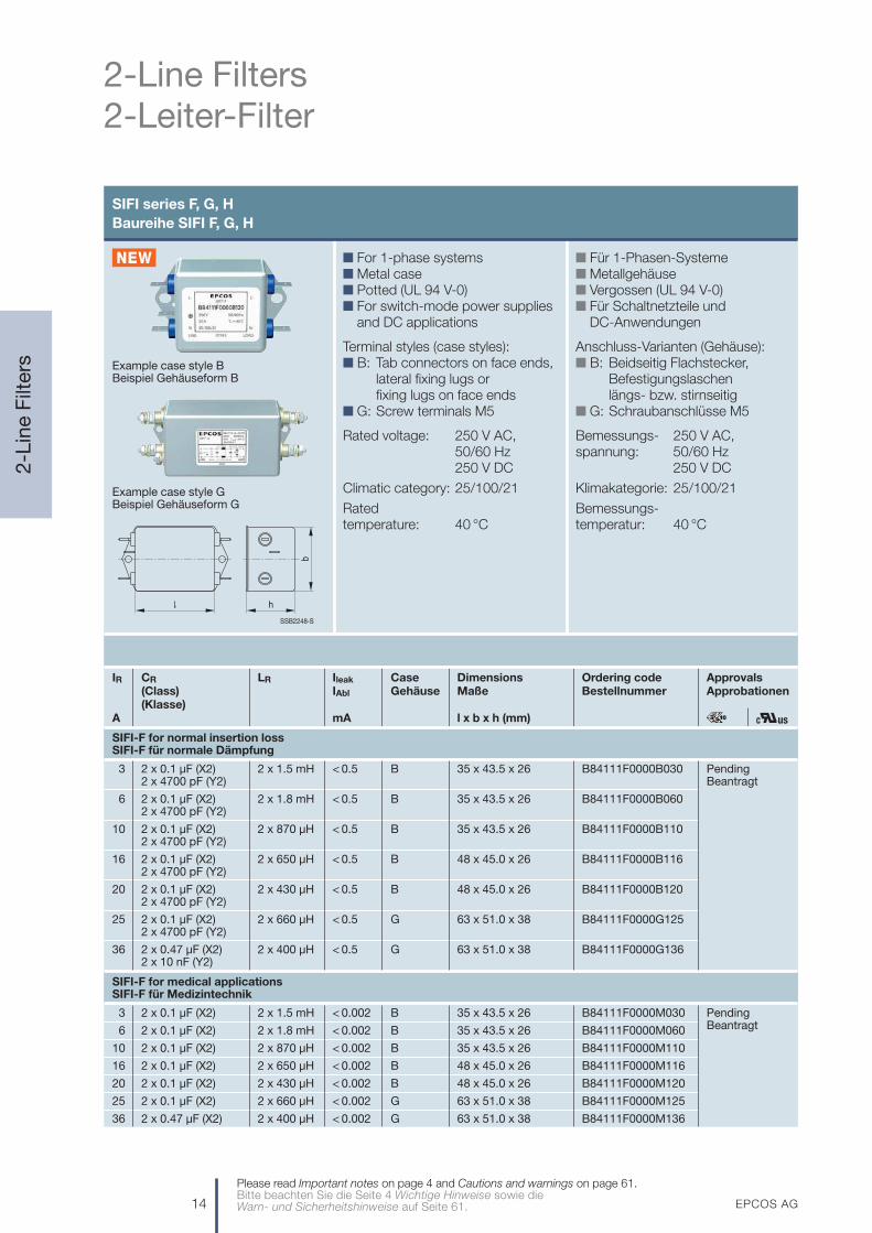
SIFI series F, G, HBaureihe SIFI F, G, H
n For 1-phase systemsn Metal casen Potted (UL 94 V-0)n For switch-mode power supplies
and DC applications
Terminal styles (case styles):n B: Tab connectors on face ends,
lateral fixing lugs or fixing lugs on face ends
n G: Screw terminals M5
Rated voltage: 250 V AC, 50/60 Hz250 V DC
Climatic category: 25/100/21
Rated temperature: 40 °C
n Für 1-Phasen-Systemen Metallgehäusen Vergossen (UL 94 V-0)n Für Schaltnetzteile und
DC-Anwendungen
Anschluss-Varianten (Gehäuse):n B: Beidseitig Flachstecker,
Befestigungslaschen längs- bzw. stirnseitig
n G: Schraubanschlüsse M5
Bemessungs- 250 V AC, spannung: 50/60 Hz
250 V DC
Klimakategorie: 25/100/21
Bemessungs-temperatur: 40 °C
SSB2248-S
h
b
Example case style G Beispiel Gehäuseform G
Example case style B Beispiel Gehäuseform B
IR CR LR Ileak Case Dimensions Ordering code Approvals(Class) IAbl Gehäuse Maße Bestellnummer Approbationen(Klasse)
A mA l x b x h (mm)
SIFI-F for normal insertion lossSIFI-F für normale Dämpfung
3 2 x 0.1 µF (X2) 2 x 1.5 mH < 0.5 B 35 x 43.5 x 26 B84111F0000B030 Pending2 x 4700 pF (Y2) Beantragt
6 2 x 0.1 µF (X2) 2 x 1.8 mH < 0.5 B 35 x 43.5 x 26 B84111F0000B0602 x 4700 pF (Y2)
10 2 x 0.1 µF (X2) 2 x 870 µH < 0.5 B 35 x 43.5 x 26 B84111F0000B1102 x 4700 pF (Y2)
16 2 x 0.1 µF (X2) 2 x 650 µH < 0.5 B 48 x 45.0 x 26 B84111F0000B1162 x 4700 pF (Y2)
20 2 x 0.1 µF (X2) 2 x 430 µH < 0.5 B 48 x 45.0 x 26 B84111F0000B1202 x 4700 pF (Y2)
25 2 x 0.1 µF (X2) 2 x 660 µH < 0.5 G 63 x 51.0 x 38 B84111F0000G1252 x 4700 pF (Y2)
36 2 x 0.47 µF (X2) 2 x 400 µH < 0.5 G 63 x 51.0 x 38 B84111F0000G1362 x 10 nF (Y2)
SIFI-F for medical applicationsSIFI-F für Medizintechnik
3 2 x 0.1 µF (X2) 2 x 1.5 mH < 0.002 B 35 x 43.5 x 26 B84111F0000M030 Pending
6 2 x 0.1 µF (X2) 2 x 1.8 mH < 0.002 B 35 x 43.5 x 26 B84111F0000M060 Beantragt
10 2 x 0.1 µF (X2) 2 x 870 µH < 0.002 B 35 x 43.5 x 26 B84111F0000M110
16 2 x 0.1 µF (X2) 2 x 650 µH < 0.002 B 48 x 45.0 x 26 B84111F0000M116
20 2 x 0.1 µF (X2) 2 x 430 µH < 0.002 B 48 x 45.0 x 26 B84111F0000M120
25 2 x 0.1 µF (X2) 2 x 660 µH < 0.002 G 63 x 51.0 x 38 B84111F0000M125
36 2 x 0.47 µF (X2) 2 x 400 µH < 0.002 G 63 x 51.0 x 38 B84111F0000M136

EPCOS AG 15
2-Line Filters2-Leiter-Filter
2-L
ine
Filt
ers
Please read Important notes on page 4 and Cautions and warnings on page 61.Bitte beachten Sie die Seite 4 Wichtige Hinweise sowie die
Warn- und Sicherheitshinweise auf Seite 61.
SIFI series F, G, HBaureihe SIFI F, G, H
IR CR LR Ileak Case Dimensions Ordering code Approvals(Class) IAbl Gehäuse Maße Bestellnummer Approbationen(Klasse)
A mA l x b x h (mm)
SIFI-G for enhanced insertion lossSIFI-G für erhöhte Dämpfung
3 2 x 0.22 µF (X2) 2 x 10 mH < 0.5 B 63 x 51 x 29 B84112G0000B030 x x+2 x 4700 pF (Y2)
6 2 x 0.47 µF (X2) 2 x 3.3 mH < 0.5 B 63 x 51 x 29 B84112G0000B060 x x+2 x 4700 pF (Y2)
10 2 x 0.68 µF (X2) 2 x 1.8 mH < 0.5 B 63 x 51 x 29 B84112G0000B110 x x+2 x 4700 pF (Y2)
16 2 x 0.47 µF (X2) 2 x 1.8 mH < 0.5 B 63 x 51 x 29 B84112G0000B116 x x+2 x 4700 pF (Y2)
20 2 x 1.0 µF (X2) 2 x 1.8 mH < 0.5 G 91 x 51 x 43 B84112G0000G120 x x+2 x 4700 pF (Y2)
25 2 x 1.0 µF (X2) 2 x 1.6 mH < 0.5 G 91 x 51 x 43 B84112G0000G125 x x+2 x 4700 pF (Y2)
36 2 x 1.5 µF (X2) 2 x 0.75 mH < 0.5 G 91 x 51 x 43 B84112G0000G136 x x+2 x 4700 pF (Y2)
SIFI-H for very high insertion lossSIFI-H für sehr hohe Dämpfung
3 2 x 1.0 µF (X2) 4 x 5.9 mH < 0.5 B 63 x 51 x 38 B84113H0000B030 x x+2 x 4700 pF (Y2)
6 2 x 1.0 µF (X2) 4 x 3.6 mH < 0.5 B 63 x 51 x 38 B84113H0000B060 x x+2 x 4700 pF (Y2)
10 2 x 1.5 µF (X2) 4 x 3.9 mH < 0.5 B 91 x 51 x 43 B84113H0000B110 x x+2 x 4700 pF (Y2)
16 2 x 1.5 µF (X2) 4 x 1.3 mH < 0.5 B 91 x 51 x 43 B84113H0000B116 x x+2 x 4700 pF (Y2)
20 2 x 2.2 µF (X2) 4 x 1.2 mH < 3.5 G 133 x 58 x 53 B84113H0000G120 x x+2 x 22 nF (Y2)
25 2 x 2.2 µF (X2) 4 x 0.8 mH < 3.5 G 133 x 58 x 53 B84113H0000G125 x x+2 x 22 nF (Y2)
36 2 x 3.3 µF (X2) 4 x 0.5 mH < 3.5 G 133 x 58 x 53 B84113H0000G136 x x+2 x 22 nF (Y2)

16 EPCOS AG
2-Line Filters2-Leiter-Filter
2-L
ine
Filt
ers
Please read Important notes on page 4 and Cautions and warnings on page 61.Bitte beachten Sie die Seite 4 Wichtige Hinweise sowie die Warn- und Sicherheitshinweise auf Seite 61.
SIFI series A … E: Reliable solutions for standard applicationsBaureihe SIFI A … E: Bewährte Lösungen für Standardanwendungen
Example case style B Beispiel Gehäuseform B
IR CR LR Ileak Case Dimensions Ordering code Approvals(Class) IAbl Gehäuse Maße Bestellnummer Approbationen(Klasse)
A mA l x b x h (mm)
SIFI-A for normal insertion lossSIFI-A für normale Dämpfung
1 2 x 0.1 µF (X2) 2 x 1.5 mH < 0.5 A 50.0 x 45.0 x 22.3 B84111A0000A010 x x x
+ < 0.5 K 63.5 x 51.0 x 32.0 B84111A0000K010 x x x
2 x 4700 pF (Y2)
2 2 x 0.1 µF (X2) 2 x 1.5 mH < 0.5 A 50.0 x 45.0 x 22.3 B84111A0000A020 x x x
+
2 x 4700 pF (Y2)
3 2 x 0.1 µF (X2) 2 x 1.5 mH < 0.5 A 50.0 x 45.0 x 22.3 B84111A0000A030 x x x
+ < 0.5 K 63.5 x 51.0 x 32.0 B84111A0000K030 x x x
2 x 4700 pF (Y2) < 0.5 L 50.0 x 45.0 x 28.6 B84111A0000L030 x x x
6 2 x 0.1 µF (X2) 2 x 1.8 mH < 0.5 A 50.0 x 45.0 x 28.6 B84111A0000A060 x x x
+ < 0.5 B 50.0 x 45.0 x 28.6 B84111A0000B060 x x x
2 x 4700 pF (Y2) < 0.5 K 63.5 x 51.0 x 32.0 B84111A0000K060 x x x
< 0.5 L 50.0 x 45.0 x 28.6 B84111A0000L060 x x x
10 2 x 0.1 µF (X2) 2 x 820 µH < 0.5 A 50.0 x 45.0 x 28.6 B84111A0000A110 x x x
+ < 0.5 B 50.0 x 45.0 x 28.6 B84111A0000B110 x x x
2 x 4700 pF (Y2) < 0.5 L 50.0 x 45.0 x 28.6 B84111A0000L110 x x x
20 2 x 0.1 µF (X2) 2 x 470 µH < 0.5 A 50.8 x 63.5 x 38.1 B84111A0000A120 x x x
+ < 0.5 B 50.8 x 63.5 x 38.1 B84111A0000B120 x x x
2 x 4700 pF (Y2)
n Für 1-Phasen-Systemen Metallgehäusen Vergossen (UL 94 V-0)n Gehäuse B auch für
Hutschienenmontagen Für Schaltnetzteile und
DC-Anwendungen
Anschluss-Varianten (Gehäuse):n A: Beidseitig Flachstecker, Be-
festigungslaschen längsseitign B: Beidseitig Flachstecker, Be-
festigungslaschen stirnseitign K: Netzseitig IEC-Stecker,
lastseitig Flachsteckern L: Beidseitig Litzenanschlüsse
und Befestigungslaschen n P: Anschlussstifte im Rastermaß
Bemessungs- 250 V AC, spannung: 50/60 Hz
250 V DC
Klimakategorie: 25/085/21
Bemessungs-temperatur: 40 °C
n For 1-phase systemsn Metal casen Potted (UL 94 V-0)n Case B also for assembly on
top-hat railsn For switch-mode power supplies
and DC applications
Terminal styles (case styles):n A: Tab connectors on face ends,
lateral fixing lugsn B: Tab connectors on face ends,
fixing lugs on face endsn K: IEC connector on line side,
tab connector on load siden L: Litz wires on face ends,
fixing lugs on face endsn P: Pins fitting standard PCB grid
Rated voltage: 250 V AC, 50/60 Hz250 V DC
Climatic category: 25/085/21
Rated temperature: 40 °C
SSB1886-2
h
b

EPCOS AG 17
2-Line Filters2-Leiter-Filter
2-L
ine
Filt
ers
Please read Important notes on page 4 and Cautions and warnings on page 61.Bitte beachten Sie die Seite 4 Wichtige Hinweise sowie die
Warn- und Sicherheitshinweise auf Seite 61.
SIFI series A … E: Reliable solutions for standard applicationsBaureihe SIFI A … E: Bewährte Lösungen für Standardanwendungen
IR CR LR Ileak Case Dimensions Ordering code Approvals(Class) IAbl Gehäuse Maße Bestellnummer Approbationen(Klasse)
A mA l x b x h (mm)
SIFI-B for enhanced insertion lossSIFI-B für erhöhte Dämpfung
1 2 x 0.15 µF (X2) 2 x 10 mH < 0.5 A 50.0 x 45.0 x 28.6 B84112B0000A010 x x x
+ < 0.5 B 50.0 x 45.0 x 28.6 B84112B0000B010 x x x
2 x 4700 pF (Y2) < 0.5 K 63.5 x 51.0 x 32.0 B84112B0000K010 x x x
< 0.5 L 50.0 x 45.0 x 28.6 B84112B0000L010 x x x
2 2 x 0.15 µF (X2) 2 x 10 mH < 0.5 A 50.0 x 45.0 x 28.6 B84112B0000A020 x x x
+ < 0.5 B 50.0 x 45.0 x 28.6 B84112B0000B020 x x x
2 x 4700 pF (Y2) < 0.5 L 50.0 x 45.0 x 28.6 B84112B0000L020 x x x
3 2 x 0.22 µF (X2) 2 x 10 mH < 0.5 A 63.5 x 50.8 x 28.6 B84112B0000A030 x x x
+ < 0.5 B 63.5 x 50.8 x 28.6 B84112B0000B030 x x x
2 x 4700 pF (Y2) < 0.5 K 79.5 x 50.8 x 32.0 B84112B0000K030 x x x
< 0.5 L 63.5 x 50.8 x 28.6 B84112B0000L030 x x x
< 0.5 P 63.4 x 50.8 x 28.6 B84112B0000P030 x x x
6 2 x 0.33 µF (X2) 2 x 3.3 mH < 0.5 A 63.5 x 50.8 x 28.6 B84112B0000A060 x x x
+ < 0.5 B 63.5 x 50.8 x 28.6 B84112B0000B060 x x x
2 x 4700 pF (Y2) < 0.5 K 79.5 x 50.8 x 32.0 B84112B0000K060 x x x
< 0.5 L 63.5 x 50.8 x 28.6 B84112B0000L060 x x x
10 2 x 0.47 µF (X2) 2 x 1.8 mH < 0.5 A 63.5 x 50.8 x 38.1 B84112B0000A110 x x x
+ < 0.5 B 63.5 x 50.8 x 38.1 B84112B0000B110 x x x
2 x 4700 pF (Y2) < 0.5 L 63.5 x 50.8 x 38.1 B84112B0000L110 x x x
20 2 x 0.68 µF (X2) 2 x 1.8 mH < 0.5 A 99.0 x 84.0 x 38.1 B84112B0000A120 x x x
+ < 0.5 B 99.0 x 84.0 x 38.1 B84112B0000B120 x x x
2 x 4700 pF (Y2)
SIFI-C for very high insertion lossSIFI-C für sehr hohe Dämpfung
3 2 x 0.47 µF (X2) 4 x 4.7 mH < 0.5 A 63.5 x 50.8 x 38.1 B84113C0000A030 x x x
+ < 0.5 B 63.5 x 50.8 x 38.1 B84113C0000B030 x x x
2 x 4700 pF (Y2) < 0.5 K 63.5 x 50.8 x 38.0 B84113C0000K030 x x x
< 0.5 L 63.5 x 50.8 x 38.1 B84113C0000L030 x x x
6 2 x 0.47 µF (X2) 4 x 4.7 mH < 0.5 A 133 x 50.8 x 44.5 B84113C0000A060 x x x
+ < 0.5 B 133 x 50.8 x 44.5 B84113C0000B060 x x x
2 x 4700 pF (Y2) < 0.5 L 133 x 50.8 x 44.5 B84113C0000L060 x x x
10 2 x 0.47 µF (X2) 4 x 3.6 mH < 0.5 A 133 x 50.8 x 44.5 B84113C0000A110 x x x
+ < 0.5 B 133 x 50.8 x 44.5 B84113C0000B110 x x x
2 x 4700 pF (Y2) < 0.5 L 133 x 50.8 x 44.5 B84113C0000L110 x x x

18 EPCOS AG
2-Line Filters2-Leiter-Filter
2-L
ine
Filt
ers
Please read Important notes on page 4 and Cautions and warnings on page 61.Bitte beachten Sie die Seite 4 Wichtige Hinweise sowie die Warn- und Sicherheitshinweise auf Seite 61.
SIFI series A … E: Reliable solutions for standard applicationsBaureihe SIFI A … E: Bewährte Lösungen für Standardanwendungen
IR CR LR Ileak Case Dimensions Ordering code Approvals(Class) IAbl Gehäuse Maße Bestellnummer Approbationen(Klasse)
A mA l x b x h (mm)
SIFI-D for high insertion lossSIFI-D für hohe Dämpfung
1 2 x 0.47 µF (X2) 2 x 5.6 mH < 0.5 A 63.5 x 50.8 x 28.6 B84114D0000A010 x x x
+ < 0.5 B 63.5 x 50.8 x 28.6 B84114D0000B010 x x x
2 x 4700 pF (Y2) < 0.5 K 79.5 x 50.8 x 32.0 B84114D0000K010 x x x
< 0.5 L 63.5 x 50.8 x 28.6 B84114D0000L010 x x x
2 2 x 0.47 µF (X2) 2 x 5.6 mH < 0.5 A 63.5 x 50.8 x 28.6 B84114D0000A020 x x x
+ < 0.5 B 63.5 x 50.8 x 28.6 B84114D0000B020 x x x
2 x 4700 pF (Y2) < 0.5 L 63.5 x 50.8 x 28.6 B84114D0000L020 x x x
3 2 x 0.47 µF (X2) 2 x 5.6 mH < 0.5 A 63.5 x 50.8 x 28.6 B84114D0000A030 x x x
+ < 0.5 B 63.5 x 50.8 x 28.6 B84114D0000B030 x x x
2 x 4700 pF (Y2) < 0.5 K 79.5 x 50.8 x 32.0 B84114D0000K030 x x x
< 0.5 L 63.5 x 50.8 x 28.6 B84114D0000L030 x x x
6 2 x 0.47 µF (X2) 2 x 4.7 mH < 0.5 A 75.5 x 50.8 x 31.8 B84114D0000A060 x x x
+ < 0.5 B 75.5 x 50.8 x 31.8 B84114D0000B060 x x x
2 x 4700 pF (Y2) < 0.5 K 92.5 x 50.8 x 32.0 B84114D0000K060 x x x
< 0.5 L 75.5 x 50.8 x 31.8 B84114D0000L060 x x x
10 2 x 0.68 µF (X2) 2 x 4.7 mH < 0.5 A 92.0 x 50.8 x 44.5 B84114D0000A110 x x x
+ < 0.5 B 92.0 x 50.8 x 44.5 B84114D0000B110 x x x
2 x 4700 pF (Y2) < 0.5 L 92.0 x 50.8 x 44.5 B84114D0000L110 x x x
SIFI-E for very high insertion loss, even in the range below 100 kHzSIFI-E für sehr hohe Dämpfung auch im Bereich unter 100 kHz
3 0.47 µF (X2) 2 x 270 µH < 0.5 A 63.5 x 50.8 x 38.1 B84115E0000A030 x x x
+ + < 0.5 B 63.5 x 50.8 x 38.1 B84115E0000B030 x x x
2 x 4700 pF (Y2) 2 x 16 mH < 0.5 K 79.5 x 50.8 x 38.0 B84115E0000K030 x x x
6 0.47 µF (X2) 2 x 100 µH < 3.5 A 133 x 50.8 x 44.5 B84115E0000A060 x x x
+ + < 3.5 B 133 x 50.8 x 44.5 B84115E0000B060 x x x
2 x 22 nF (Y2) 2 x 4.7 mH < 3.5 K 133 x 50.8 x 44.5 B84115E0000K060 x x x
10 0.47 µF (X2) 2 x 47 µH < 3.5 A 133 x 50.8 x 44.5 B84115E0000A110 x x x
+ + < 3.5 B 133 x 50.8 x 44.5 B84115E0000B110 x x x
2 x 22 nF (Y2) 2 x 3.6 mH

EPCOS AG 19
2-Line Filters2-Leiter-Filter
2-L
ine
Filt
ers
Please read Important notes on page 4 and Cautions and warnings on page 61.Bitte beachten Sie die Seite 4 Wichtige Hinweise sowie die
Warn- und Sicherheitshinweise auf Seite 61.
For converters and power electronics B84142A*R122/R123Für Umrichter und Leistungselektronik
Schematic representationPrinzipdarstellung
VR IR Terminal cross Ileak Rtyp Dimensions Ordering code ApprovalsAC/DC section / Anschl.- IAbl Maße Bestellnummer Approbationen
querschnittV A mm2 mA mΩ l x b x h (mm)
For converters and power electronics B84142A*R122Für Umrichter und Leistungselektronik B84142A*R122
300 8 4 < 33 15 133.7 x 51.4 x 63 B84142A0008R122 x
16 4 < 33 9 199.5 x 46.4 x 70 B84142A0016R122 x
30 10 < 33 5 200 x 58 x 90 B84142A0030R122 x
42 10 < 60 4 200 x 58 x 90 B84142A0042R122 x
55 10 < 60 3 200 x 58 x 90 B84142A0055R122 x
75 16 < 60 1.5 200 x 58 x 141.5 B84142A0075R122 x
100 35 < 110 1.1 240 x 80 x 135 B84142A0100R122 x
130 50 < 110 0.7 240 x 90 x 150 B84142A0130R122 x
180 95 < 110 0.5 240 x 90 x 150 B84142A0180R122 x
VR IR IR Terminal cross Ileak Rtyp Dimensions Ordering codeAC/DC 70 °C 50 °C section / Anschl.- IAbl Maße Bestellnummer
querschnittV A A mm2 mA mΩ l x b x h (mm)
For converters and power electronics B84142A*R123Für Umrichter und Leistungselektronik B84142A*R123
520 12 15 4 < 120 11.0 200 x 58 x 121.5 B84142A0012R123
25 32 10 < 120 2.5 200 x 58 x 141.5 B84142A0025R123
38 48 10 < 120 2.4 200 x 58 x 141.5 B84142A0038R123
50 64 35 < 120 1.4 240 x 80 x 135 B84142A0050R123
75 96 35 < 120 1.2 240 x 80 x 135 B84142A0075R123
100 128 50 < 120 0.7 240 x 90 x 150 B84142A0100R123
n Für 1-Phasen-Systemen Metallgehäusen Fingerberührungssichere
Reihenklemmenn Auch für DC-Anwendungen
Bemessungs- 300 V AC, 50/60 Hzspannung: 300 V DC
520 V AC, 50/60 Hz520 V DC
Klima-kategorie: 25/100/21
Bemessungs-temperatur: 50 °C (R122)
70 °C (R123)
n For 1-phase systemsn Metal casen Finger-safe terminal blocksn Also for DC applications
Rated voltage: 300 V AC, 50/60 Hz300 V DC520 V AC, 50/60 Hz520 V DC
Climatic category: 25/100/21
Rated temperature: 50 °C (R122)
70 °C (R123)
SSB1967-2
b
h

20 EPCOS AG
2-Line Filters2-Leiter-Filter
2-L
ine
Filt
ers
Please read Important notes on page 4 and Cautions and warnings on page 61.Bitte beachten Sie die Seite 4 Wichtige Hinweise sowie die Warn- und Sicherheitshinweise auf Seite 61.
For converters and power electronics B84142A*R000/G075Für Umrichter und Leistungselektronik B84142B*R000
Schematic representationsPrinzipdarstellungen
IR Terminal cross Ileak Rtyp Dimensions Terminals Ordering code Approvalssection / Anschl.- IAbl Maße Anschlüsse Bestellnummer Approbationenquerschnitt
A mm2 mA mΩ l x b x h (mm)
B84142A*R000
10 4 < 8 18 133 x 50.8 x 44.5 B84142A0010R000 x x
20 4 < 8 10 99 x 84 x 68 B84142A0020R000 x x
30 6 < 8 5 99 x 84 x 68 B84142A0030R000 x x
40 6 < 17 3.6 99 x 84 x 68 B84142A0040R000 x x
50 16 < 26 1.8 180 x 85 x 60 B84142A0050R000 x x
60 16 < 26 1.4 180 x 85 x 60 B84142A0060R000 x x
B84142A*G075
60 – < 26 1.4 180 x 85 x 60 M6 B84142A0060G075 – –
B84142B*R000
8 4 < 3.5 42 121 x 86 x 61 B84142B0008R000 x –
12 4 < 3.5 30 121 x 86 x 61 B84142B0012R000 x –
16 4 < 3.5 21 121 x 86 x 61 B84142B0016R000 x –
25 10 < 3.5 9 156 x 86 x 81 B84142B0025R000 x –
n Für 1-Phasen-Systemen Metallgehäusen Fingerberührungssichere
Reihenklemmen;Schraubanschlüsse M6
n Auch für DC-Anwendungen
Bemessungs-spannung: 250 V AC, 50/60 Hz
250 V DC
Klima-kategorie: 25/100/21
25/085/21 (G075)
Bemessungs-temperatur: 40 °C
n For 1-phase systemsn Metal casen Finger-safe terminal blocks;
screw terminals M6n Also for DC applications
Rated voltage: 250 V AC, 50/60 Hz
250 V DC
Climatic category: 25/100/21
25/085/21 (G075)
Rated temperature: 40 °C
SSB1887-A
b
h
LINE LOAD
Marking
Finger-safe terminal blocks / Fingerberührungs-sichereReihenklemmen
Finger-safe terminal blocks / Fingerberührungs-sichereReihenklemmen
B84142A*R000/G075
B84142B*R000
SSB1985-Z
Marking
LOADLINE
b
h

EPCOS AG 21
2-Line Filters2-Leiter-Filter
2-L
ine
Filt
ers
Please read Important notes on page 4 and Cautions and warnings on page 61.Bitte beachten Sie die Seite 4 Wichtige Hinweise sowie die
Warn- und Sicherheitshinweise auf Seite 61.
Converter in traction systems B84142A*S002/S003/S018Umrichter in Traktionssystemen
n Power line filters for DC systemsn Metal casen Busbars, tin-plated
Rated voltage: 750 … 2000 V DC
Climatic category: 40/100/21
Rated temperature: 60 °C
n Netzfilter für Gleichspannungn Metallgehäusen Stromschienen, galv. verzinnt
Bemessungs-spannung: 750 … 2000 V DC
Klimakategorie: 40/100/21
Bemessungs-temperatur: 60 °C
VR IR Rtyp Dimensions Ordering codeMaße Bestellnummer
V DC A µΩ l x b x h (mm)
750 250 63 300 x 140 x 116 B84142A0250S002
500 57 300 x 140 x 116 B84142A0500S002
1000 33 350 x 210 x 126 B84142A1000S002
1000 250 63 300 x 140 x 116 B84142A0250S003
500 57 300 x 140 x 116 B84142A0500S003
1000 33 350 x 210 x 126 B84142A1000S003
2000 250 63 300 x 140 x 116 B84142A0250S018
500 57 300 x 140 x 116 B84142A0500S018
1000 33 350 x 210 x 126 B84142A1000S018
SSB1889-R
b
h
+
_
+
_Marking
LINE LOAD
Schematic representationPrinzipdarstellung
22 EPCOS AG
2-Line Filters2-Leiter-Filter
2-L
ine
Filt
ers
Please read Important notes on page 4 and Cautions and warnings on page 61.Bitte beachten Sie die Seite 4 Wichtige Hinweise sowie die Warn- und Sicherheitshinweise auf Seite 61.
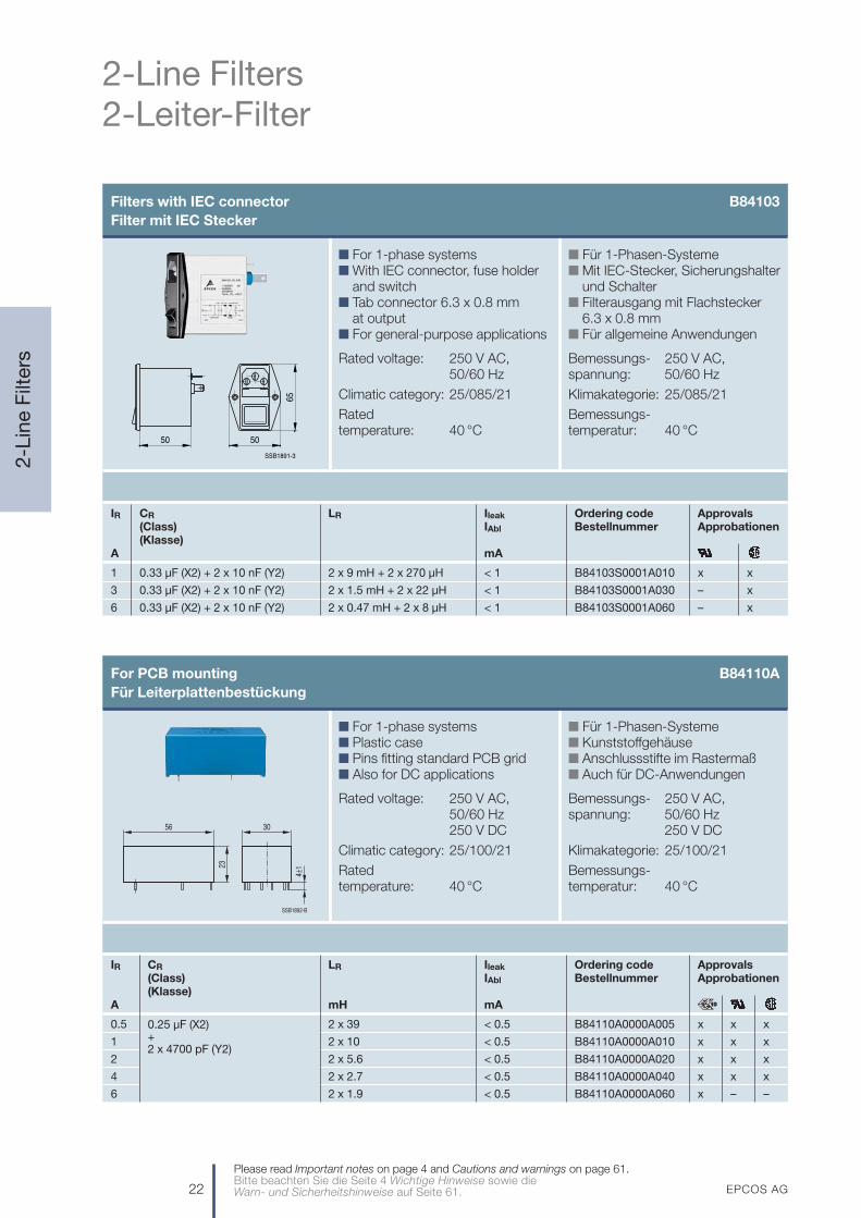
Filters with IEC connector B84103Filter mit IEC Stecker
n For 1-phase systemsn With IEC connector, fuse holder
and switchn Tab connector 6.3 x 0.8 mm
at outputn For general-purpose applications
Rated voltage: 250 V AC, 50/60 Hz
Climatic category: 25/085/21
Rated temperature: 40 °C
n Für 1-Phasen-Systemen Mit IEC-Stecker, Sicherungshalter
und Schaltern Filterausgang mit Flachstecker
6.3 x 0.8 mmn Für allgemeine Anwendungen
Bemessungs- 250 V AC,spannung: 50/60 Hz
Klimakategorie: 25/085/21
Bemessungs-temperatur: 40 °C
IR CR LR Ileak Ordering code Approvals(Class) IAbl Bestellnummer Approbationen(Klasse)
A mA
1 0.33 µF (X2) + 2 x 10 nF (Y2) 2 x 9 mH + 2 x 270 µH < 1 B84103S0001A010 x x
3 0.33 µF (X2) + 2 x 10 nF (Y2) 2 x 1.5 mH + 2 x 22 µH < 1 B84103S0001A030 – x
6 0.33 µF (X2) + 2 x 10 nF (Y2) 2 x 0.47 mH + 2 x 8 µH < 1 B84103S0001A060 – x
SSB1891-3
50 50
65
For PCB mounting B84110A Für Leiterplattenbestückung
n For 1-phase systemsn Plastic casen Pins fitting standard PCB gridn Also for DC applications
Rated voltage: 250 V AC, 50/60 Hz250 V DC
Climatic category: 25/100/21
Rated temperature: 40 °C
n Für 1-Phasen-Systemen Kunststoffgehäusen Anschlussstifte im Rastermaßn Auch für DC-Anwendungen
Bemessungs- 250 V AC, spannung: 50/60 Hz
250 V DC
Klimakategorie: 25/100/21
Bemessungs-temperatur: 40 °C
IR CR LR Ileak Ordering code Approvals(Class) IAbl Bestellnummer Approbationen(Klasse)
A mH mA
0.5 2 x 39 < 0.5 B84110A0000A005 x x x
1 2 x 10 < 0.5 B84110A0000A010 x x x
2 2 x 5.6 < 0.5 B84110A0000A020 x x x
4 2 x 2.7 < 0.5 B84110A0000A040 x x x
6 2 x 1.9 < 0.5 B84110A0000A060 x – –
SSB1892-B
30
23
56
4±1
0.25 µF (X2)+2 x 4700 pF (Y2)
EPCOS AG 23
2-Line Filters2-Leiter-Filter
2-L
ine
Filt
ers
Please read Important notes on page 4 and Cautions and warnings on page 61.Bitte beachten Sie die Seite 4 Wichtige Hinweise sowie die
Warn- und Sicherheitshinweise auf Seite 61.
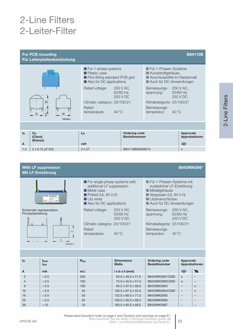
With LF suppression B84299K006*Mit LF-Entstörung
n For single-phase systems withadditional LF suppression
n Metal casen Potted (UL 94 V-0)n Litz wiresn Also for DC applications
Rated voltage: 250 V AC, 50/60 Hz250 V DC
Climatic category: 25/100/21
Rated temperature: 40 °C
n Für 1-Phasen-Systeme mit zusätzlicher LF-Entstörung
n Metallgehäusen Vergossen (UL 94 V-0)n Litzenanschlüssen Auch für DC-Anwendungen
Bemessungs- 250 V AC,spannung: 50/60 Hz
250 V DC
Klimakategorie: 25/100/21
Bemessungs-temperatur: 40 °C
IR Ileak Rtyp Dimensions Ordering code ApprovalsIAbl Maße Bestellnummer Approbationen
A mA mΩ l x b x h (mm)
2 < 3.5 530 65.0 x 45.0 x 51.0 B84299K0061C000 x –
4 < 3.5 150 75.0 x 45.0 x 51.0 B84299K0062C000 x –
6 < 3.5 100 84.5 x 67.0 x 50.0 B84299K0063 – x
10 < 3.5 45 100.5 x 67.0 x 55.0 B84299K0064C000 – x
16 < 3.5 35 132.0 x 68.0 x 71.0 B84299K0065 – –
25 < 3.5 25 183.0 x 85.0 x 68.5 B84299K0066 – –
36 < 10 10 183.0 x 85.0 x 68.5 B84299K0067 – –
Schematic representationPrinzipdarstellung
SSB1894-S
b
h
For PCB mounting B84110B Für Leiterplattenbestückung
n For 1-phase systemsn Plastic casen Pins fitting standard PCB gridn Also for DC applications
Rated voltage: 250 V AC, 50/60 Hz250 V DC
Climatic category: 25/100/21
Rated temperature: 40 °C
n Für 1-Phasen-Systemen Kunststoffgehäusen Anschlussstifte im Rastermaßn Auch für DC-Anwendungen
Bemessungs- 250 V AC,spannung: 50/60 Hz
250 V DC
Klimakategorie: 25/100/21
Bemessungs-temperatur: 40 °C
IR CR LR Ordering code Approvals(Class) Bestellnummer Approbationen(Klasse)
A mH
1.4 2 x 0.15 µF (X2) 2 x 27 B84110B0000A014 x
SSB1893-J
3431
334±1
24 EPCOS AG
3-Line Filters3-Leiter-Filter
3-L
ine
Filt
ers
Please read Important notes on page 4 and Cautions and warnings on page 61.Bitte beachten Sie die Seite 4 Wichtige Hinweise sowie die Warn- und Sicherheitshinweise auf Seite 61.
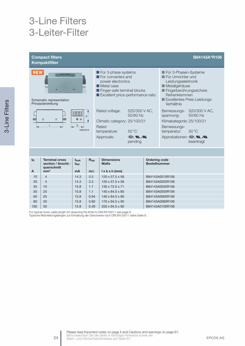
Compact filters B84143A*R106Kompaktfilter
IR Terminal cross Ileak Rtyp Dimensions Ordering codesection / Anschl.- IAbl Maße Bestellnummerquerschnitt
A mm2 mA mΩ l x b x h (mm)
10 4 14.3 5.5 120 x 57.5 x 58 B84143A0010R106
20 4 14.3 3.3 120 x 57.5 x 58 B84143A0020R106
35 10 15.8 1.7 130 x 72.5 x 71 B84143A0035R106
50 25 15.8 1.1 140 x 84.5 x 80 B84143A0050R106
65 25 15.8 0.94 140 x 84.5 x 80 B84143A0065R106
80 50 15.8 0.60 170 x 94.5 x 90 B84143A0080R106
100 50 15.8 0.48 200 x 94.5 x 90 B84143A0100R106
n Für 3-Phasen-Systemen Für Umrichter und
Leistungselektronikn Metallgehäusen Fingerberührungssichere
Reihenklemmenn Exzellentes Preis-Leistungs-
Verhältnis
Bemessungs- 520/300 V AC,spannung: 50/60 Hz
Klimakategorie: 25/100/21
Bemessungs-temperatur: 50 °C
Approbationen: , , beantragt
n For 3-phase systemsn For converters and
power electronicsn Metal casen Finger-safe terminal blocksn Excellent price-performance ratio
Rated voltage: 520/300 V AC, 50/60 Hz
Climatic category: 25/100/21
Rated temperature: 50 °C
Approvals: , , pending
Schematic representationPrinzipdarstellung
SSB2246-B
b
h
For typical motor cable length for observing the limits to DIN EN 55011 see page 8.Typische Motorleitungslängen zur Einhaltung der Grenzwerte nach DIN EN 55011 siehe Seite 8.

EPCOS AG 25
3-Line Filters3-Leiter-Filter
3-L
ine
Filt
ers
Please read Important notes on page 4 and Cautions and warnings on page 61.Bitte beachten Sie die Seite 4 Wichtige Hinweise sowie die
Warn- und Sicherheitshinweise auf Seite 61.
Book-size filters B84143A*R105Buchfilter
IR Terminal cross Ileak Rtyp Dimensions Ordering code Approvalssection / Anschl.- IAbl Maße Bestellnummer Approbationenquerschnitt
A mm2 mA mΩ l x b x h (mm)
8 4 < 13 16 133.7 x 51.4 x 63 B84143A0008R105 x x x
16 4 < 15 9 199.5 x 46.4 x 70 B84143A0016R105 x x x
25 4 < 15 5 199.5 x 46.4 x 83 B84143A0025R105 x x x
36 10 < 15 4 200 x 58 x 90 B84143A0036R105 x x x
50 10 < 15 2 200 x 58 x 90 B84143A0050R105 x x x
66 16 < 16 1.5 200 x 58 x 141.5 B84143A0066R105 x x x
90 35 < 18 1.1 240 x 80 x 135 B84143A0090R105 x x x
120 35 < 18 0.90 240 x 90 x 150 B84143A0120R105 x x x
150 50 < 18 0.55 240 x 90 x 150 B84143A0150R105 x x x
n Für 3-Phasen-Systemen Für Umrichter und
Leistungselektronikn Metallgehäusen Fingerberührungssichere
Reihenklemmenn Exzellentes Preis-Leistungs-
Verhältnis
Bemessungs- 520/300 V AC,spannung: 50/60 Hz
Klimakategorie: 25/100/21
Bemessungs-temperatur: 40 °C
n For 3-phase systemsn For converters and
power electronicsn Metal casen Finger-safe terminal blocksn Excellent price-performance ratio
Rated voltage: 520/300 V AC, 50/60 Hz
Climatic category: 25/100/21
Rated temperature: 40 °C
Schematic representationPrinzipdarstellung
SSB1967-2
b
h
For typical motor cable length for observing the limits to DIN EN 55011 see page 8.Typische Motorleitungslängen zur Einhaltung der Grenzwerte nach DIN EN 55011 siehe Seite 8.
For low leakage filters see page 26.Ableitstromarme Filter siehe Seite 26.

26 EPCOS AG
3-Line Filters3-Leiter-Filter
3-L
ine
Filt
ers
Please read Important notes on page 4 and Cautions and warnings on page 61.Bitte beachten Sie die Seite 4 Wichtige Hinweise sowie die Warn- und Sicherheitshinweise auf Seite 61.
Compact filters B84143A*R000Kompaktfilter
IR Terminal cross Ileak Rtyp Dimensions Ordering code Approvalssection / Anschl.- IAbl Maße Bestellnummer Approbationenquerschnitt
A mm2 mA mΩ l x b x h (mm) (440/250 V AC)
8 4 < 3.5 40 141 x 86 x 81 B84143A0008R000 x
12 4 < 3.5 20 141 x 86 x 81 B84143A0012R000 x
16 4 < 3.5 15 141 x 86 x 81 B84143A0016R000 x
25 10 < 3.5 8 166 x 126 x 91 B84143A0025R000 x
36 10 < 3.5 3.8 166 x 126 x 91 B84143A0036R000 x
50 10 < 6 2.0 166 x 126 x 91 B84143A0050R000 x
80 25 < 6 1.0 221 x 141 x 141 B84143A0080R000 x
120 50 < 6 0.75 261 x 141 x 141 B84143A0120R000 x
150 50 < 6 0.4 261 x 141 x 141 B84143A0150R000 x
180 95 < 6 0.4 301 x 141 x 141 B84143A0180R000 x
n Für 3-Phasen-Systemen Für Umrichter und
Leistungselektronikn Metallgehäusen Fingerberührungssichere
Reihenklemmenn Ableitstromarm
Bemessungs- 480/275 V AC,spannung: 50/60 Hz
Klimakategorie: 25/100/21
Bemessungs-temperatur: 40 °C
n For 3-phase systemsn For converters and
power electronicsn Metal casen Finger-safe terminal blocksn Low leakage current
Rated voltage: 480/275 V AC, 50/60 Hz
Climatic category: 25/100/21
Rated temperature: 40 °C
Schematic representationPrinzipdarstellung
For filters for higher currents see B84143B*S080, page 31.Filter für höhere Ströme siehe B84143B*S080, Seite 31.
For filters for compact dimensions see B84143A*R105, page 25.Filter für kompakte Abmessungen siehe B84143A*R105, Seite 25.
For typical motor cable length for observing the limits to DIN EN 55011 see page 8.Typische Motorleitungslängen zur Einhaltung der Grenzwerte nach DIN EN 55011 siehe Seite 8.
SSB1888-I
LINE LOAD
h
Marking
b

EPCOS AG 27
3-Line Filters3-Leiter-Filter
3-L
ine
Filt
ers
Please read Important notes on page 4 and Cautions and warnings on page 61.Bitte beachten Sie die Seite 4 Wichtige Hinweise sowie die
Warn- und Sicherheitshinweise auf Seite 61.
Footprint filters B84143A*R206Footprintfilter
IR Terminal cross Ileak Rtyp Dimensions Ordering code Approvalssection / Anschl.- IAbl Maße Bestellnummer Approbationenquerschnitt
A mm2 mA mΩ l x b x h (mm)
6 2.5 < 3.5 72 174 x 73 x 43.5 B84143A0006R206 x
12 2.5 < 3.5 21 187 x 149 x 43 B84143A0012R206 x
25 4 < 6 8.5 219 x 185 x 55 B84143A0025R206 x
n Für 3-Phasen-Systemen Metallgehäusen Fingerberührungssichere
Reihenklemmen/Litzenn Ableitstromarm
Bemessungs- 480/275 V AC,spannung: 50/60 Hz
Klimakategorie: 25/100/21
Bemessungs-temperatur: 40 °C
n For 3-phase systemsn Metal casen Finger-safe terminal blocks/
litz wiresn Low leakage current
Rated voltage: 480/275 V AC, 50/60 Hz
Climatic category: 25/100/21
Rated temperature: 40 °C
Schematic representationPrinzipdarstellung
For typical motor cable length for observing the limits to DIN EN 55011 see page 8.Typische Motorleitungslängen zur Einhaltung der Grenzwerte nach DIN EN 55011 siehe Seite 8.
SSB1895-1
h
LOADMarking
LINE
b

28 EPCOS AG
3-Line Filters3-Leiter-Filter
3-L
ine
Filt
ers
Please read Important notes on page 4 and Cautions and warnings on page 61.Bitte beachten Sie die Seite 4 Wichtige Hinweise sowie die Warn- und Sicherheitshinweise auf Seite 61.
Compact filters (two stage) B84143B*R000Kompaktfilter (zweistufig)
IR Terminal cross Ileak Rtyp Dimensions Ordering codesection / Anschl.- IAbl Maße Bestellnummerquerschnitt
A mm2 mA mΩ l x b x h (mm)
8 4 < 3.5 80 171 x 126 x 81 B84143B0008R000
12 4 < 3.5 40 171 x 126 x 81 B84143B0012R000
16 4 < 3.5 25 171 x 126 x 81 B84143B0016R000
25 10 < 3.5 10 231 x 126 x 91 B84143B0025R000
36 10 < 3.5 5.0 231 x 126 x 91 B84143B0036R000
50 10 < 6 3.5 231 x 126 x 91 B84143B0050R000
80 25 < 6 2.0 331 x 141 x 141 B84143B0080R000
n Für 3-Phasen-Systemen Für Umrichter und
Leistungselektronikn Metallgehäusen Fingerberührungssichere
Reihenklemmenn Ableitstromarm
Bemessungs- 440/250 V AC,spannung: 50/60 Hz
Klimakategorie: 25/100/21
Bemessungs-temperatur: 40 °C
n For 3-phase systemsn For converters and
power electronicsn Metal casen Finger-safe terminal blocksn Low leakage current
Rated voltage: 440/250 V AC, 50/60 Hz
Climatic category: 25/100/21
Rated temperature: 40 °C
Schematic representationPrinzipdarstellung
For higher currents see B84143B*R110, page 29.Für höhere Ströme siehe B84143B*R110, Seite 29.
For typical motor cable length for observing the limits to DIN EN 55011 see page 8.Typische Motorleitungslängen zur Einhaltung der Grenzwerte nach DIN EN 55011 siehe Seite 8.
SSB1888-I
LINE LOAD
h
Marking
b
EPCOS AG 29
3-Line Filters3-Leiter-Filter
3-L
ine
Filt
ers
Please read Important notes on page 4 and Cautions and warnings on page 61.Bitte beachten Sie die Seite 4 Wichtige Hinweise sowie die
Warn- und Sicherheitshinweise auf Seite 61.
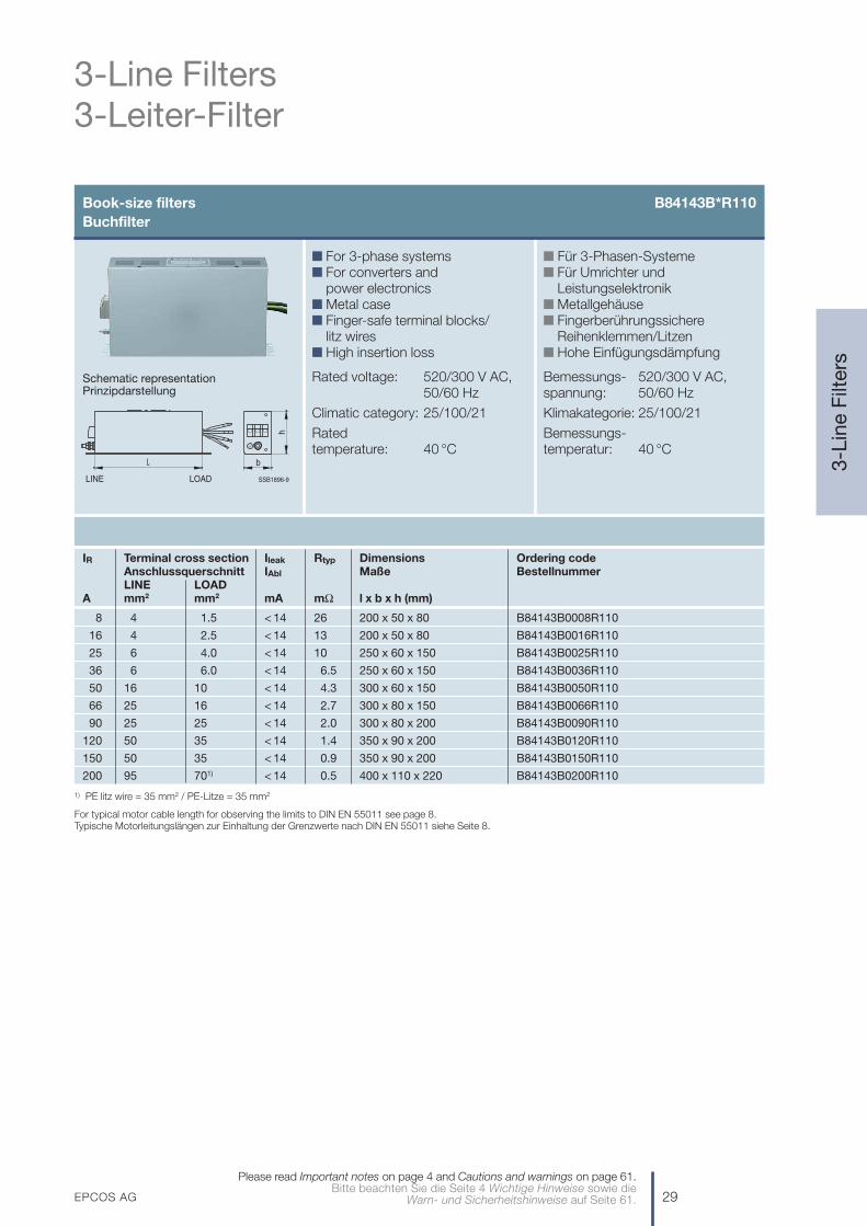
Book-size filters B84143B*R110Buchfilter
IR Terminal cross section Ileak Rtyp Dimensions Ordering codeAnschlussquerschnitt IAbl Maße BestellnummerLINE LOAD
A mm2 mm2 mA mΩ l x b x h (mm)
8 4 1.5 < 14 26 200 x 50 x 80 B84143B0008R110
16 4 2.5 < 14 13 200 x 50 x 80 B84143B0016R110
25 6 4.0 < 14 10 250 x 60 x 150 B84143B0025R110
36 6 6.0 < 14 6.5 250 x 60 x 150 B84143B0036R110
50 16 10 < 14 4.3 300 x 60 x 150 B84143B0050R110
66 25 16 < 14 2.7 300 x 80 x 150 B84143B0066R110
90 25 25 < 14 2.0 300 x 80 x 200 B84143B0090R110
120 50 35 < 14 1.4 350 x 90 x 200 B84143B0120R110
150 50 35 < 14 0.9 350 x 90 x 200 B84143B0150R110
200 95 701) < 14 0.5 400 x 110 x 220 B84143B0200R110
n Für 3-Phasen-Systemen Für Umrichter und
Leistungselektronikn Metallgehäusen Fingerberührungssichere
Reihenklemmen/Litzenn Hohe Einfügungsdämpfung
Bemessungs- 520/300 V AC,spannung: 50/60 Hz
Klimakategorie: 25/100/21
Bemessungs-temperatur: 40 °C
n For 3-phase systemsn For converters and
power electronicsn Metal casen Finger-safe terminal blocks/
litz wiresn High insertion loss
Rated voltage: 520/300 V AC, 50/60 Hz
Climatic category: 25/100/21
Rated temperature: 40 °C
Schematic representationPrinzipdarstellung
1) PE litz wire = 35 mm2 / PE-Litze = 35 mm2
For typical motor cable length for observing the limits to DIN EN 55011 see page 8.Typische Motorleitungslängen zur Einhaltung der Grenzwerte nach DIN EN 55011 siehe Seite 8.
SSB1896-9
b
h
LINE LOAD

30 EPCOS AG
3-Line Filters3-Leiter-Filter
3-L
ine
Filt
ers
Please read Important notes on page 4 and Cautions and warnings on page 61.Bitte beachten Sie die Seite 4 Wichtige Hinweise sowie die Warn- und Sicherheitshinweise auf Seite 61.
Book-size filters B84143G*R110Buchfilter
IR Terminal cross section Ileak Rtyp Dimensions Ordering code ApprovalsAnschlussquerschnitt IAbl Maße Bestellnummer ApprobationenLINE LOAD
A mm2 mm2 mA mΩ l x b x h (mm) (480 V)1)
8 4 1.5 < 6 40 200 x 50 x 80 B84143G0008R110 x
20 4 2.5 < 6 10 200 x 50 x 80 B84143G0020R110 x
25 4 2.5 < 6 10 200 x 50 x 80 B84143G0025R110 –
36 6 6.0 < 16 5.2 250 x 60 x 150 B84143G0036R110 x
50 16 10 < 16 2.4 300 x 60 x 150 B84143G0050R110 x
66 25 16 < 16 1.8 300 x 80 x 150 B84143G0066R110 x
90 25 25 < 16 1.2 300 x 80 x 150 B84143G0090R110 x
120 50 35 < 16 1.0 350 x 90 x 200 B84143G0120R110 x
150 50 35 < 16 0.7 350 x 90 x 200 B84143G0150R110 x
220 95 70 < 16 0.4 400 x 110 x 220 B84143G0220R110 x
n Für 3-Phasen-Systemen Für Umrichter und
Leistungselektronikn Metallgehäusen Fingerberührungssichere
Reihenklemmen/Litzen
Bemessungs- 520/300 V AC,spannung: 50/60 Hz
Klimakategorie: 25/100/21
Bemessungs-temperatur: 40 °C
n For 3-phase systemsn For converters and
power electronicsn Metal casen Finger-safe terminal blocks/
litz wires
Rated voltage: 520/300 V AC, 50/60 Hz
Climatic category: 25/100/21
Rated temperature: 40 °C
Schematic representationPrinzipdarstellung
1) For 520 V pending / Für 520 V in Vorbereitung
For typical motor cable length for observing the limits to DIN EN 55011 see page 8.Typische Motorleitungslängen zur Einhaltung der Grenzwerte nach DIN EN 55011 siehe Seite 8.
SSB1896-9
b
h
LINE LOAD
EPCOS AG 31
3-Line Filters3-Leiter-Filter
3-L
ine
Filt
ers
Please read Important notes on page 4 and Cautions and warnings on page 61.Bitte beachten Sie die Seite 4 Wichtige Hinweise sowie die
Warn- und Sicherheitshinweise auf Seite 61.
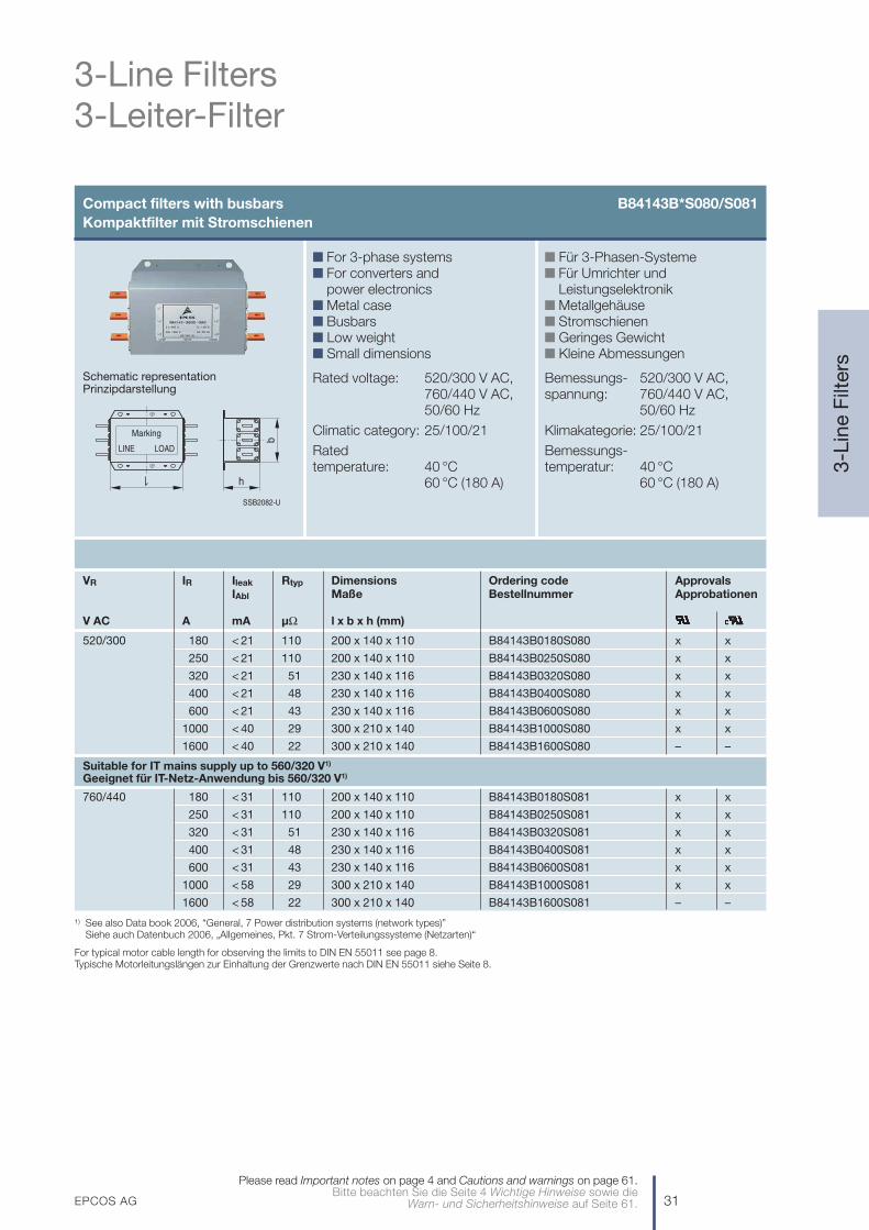
Compact filters with busbars B84143B*S080/S081Kompaktfilter mit Stromschienen
Schematic representationPrinzipdarstellung
VR IR Ileak Rtyp Dimensions Ordering code ApprovalsIAbl Maße Bestellnummer Approbationen
V AC A mA µΩ l x b x h (mm)
520/300 180 < 21 110 200 x 140 x 110 B84143B0180S080 x x
250 < 21 110 200 x 140 x 110 B84143B0250S080 x x
320 < 21 51 230 x 140 x 116 B84143B0320S080 x x
400 < 21 48 230 x 140 x 116 B84143B0400S080 x x
600 < 21 43 230 x 140 x 116 B84143B0600S080 x x
1000 < 40 29 300 x 210 x 140 B84143B1000S080 x x
1600 < 40 22 300 x 210 x 140 B84143B1600S080 – –
Suitable for IT mains supply up to 560/320 V1)
Geeignet für IT-Netz-Anwendung bis 560/320 V1)
760/440 180 < 31 110 200 x 140 x 110 B84143B0180S081 x x
250 < 31 110 200 x 140 x 110 B84143B0250S081 x x
320 < 31 51 230 x 140 x 116 B84143B0320S081 x x
400 < 31 48 230 x 140 x 116 B84143B0400S081 x x
600 < 31 43 230 x 140 x 116 B84143B0600S081 x x
1000 < 58 29 300 x 210 x 140 B84143B1000S081 x x
1600 < 58 22 300 x 210 x 140 B84143B1600S081 – –
n Für 3-Phasen-Systemen Für Umrichter und
Leistungselektronikn Metallgehäusen Stromschienenn Geringes Gewichtn Kleine Abmessungen
Bemessungs- 520/300 V AC,spannung: 760/440 V AC,
50/60 Hz
Klimakategorie: 25/100/21
Bemessungs-temperatur: 40 °C
60 °C (180 A)
n For 3-phase systemsn For converters and
power electronicsn Metal casen Busbarsn Low weightn Small dimensions
Rated voltage: 520/300 V AC,760/440 V AC,50/60 Hz
Climatic category: 25/100/21
Rated temperature: 40 °C
60 °C (180 A)SSB2082-U
Marking
LINE LOAD
h
b
1) See also Data book 2006, “General, 7 Power distribution systems (network types)”Siehe auch Datenbuch 2006, „Allgemeines, Pkt. 7 Strom-Verteilungssysteme (Netzarten)“
For typical motor cable length for observing the limits to DIN EN 55011 see page 8.Typische Motorleitungslängen zur Einhaltung der Grenzwerte nach DIN EN 55011 siehe Seite 8.
32 EPCOS AG
3-Line Filters3-Leiter-Filter
3-L
ine
Filt
ers
Please read Important notes on page 4 and Cautions and warnings on page 61.Bitte beachten Sie die Seite 4 Wichtige Hinweise sowie die Warn- und Sicherheitshinweise auf Seite 61.
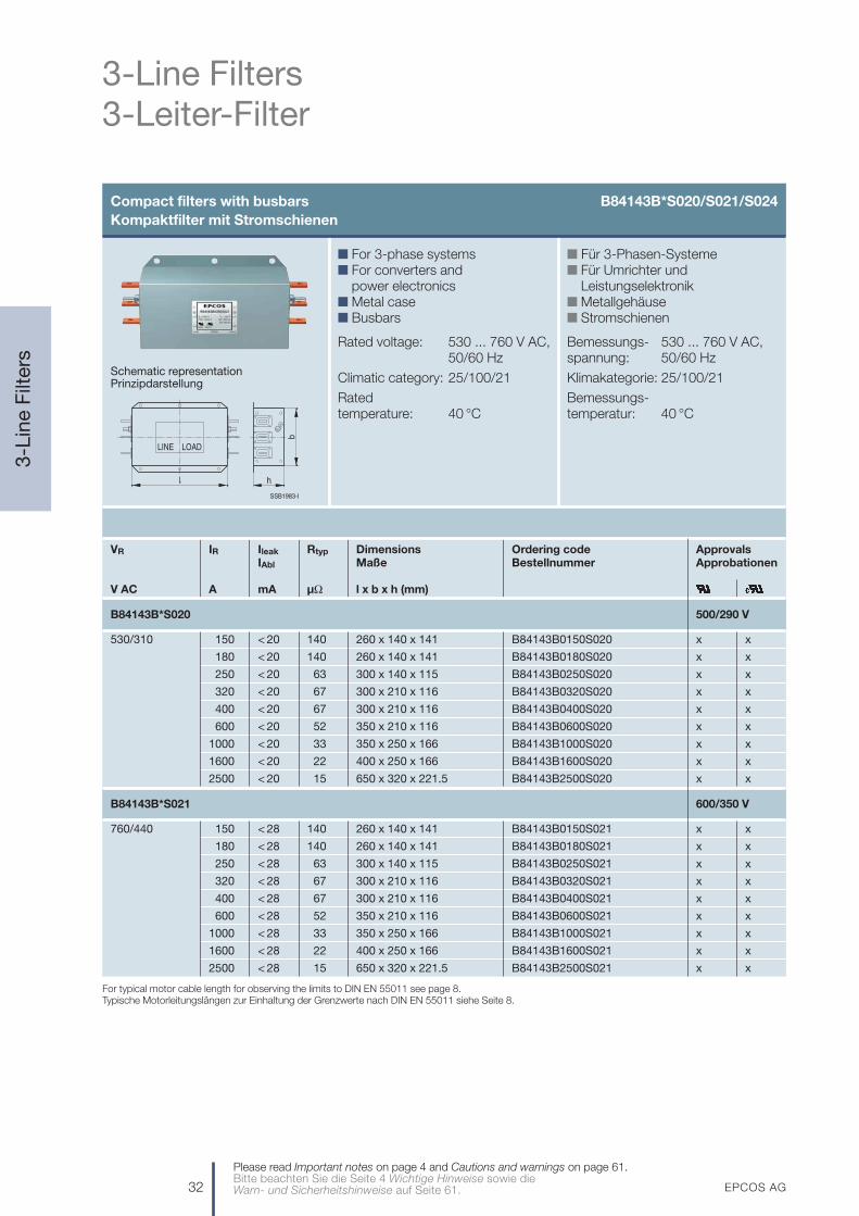
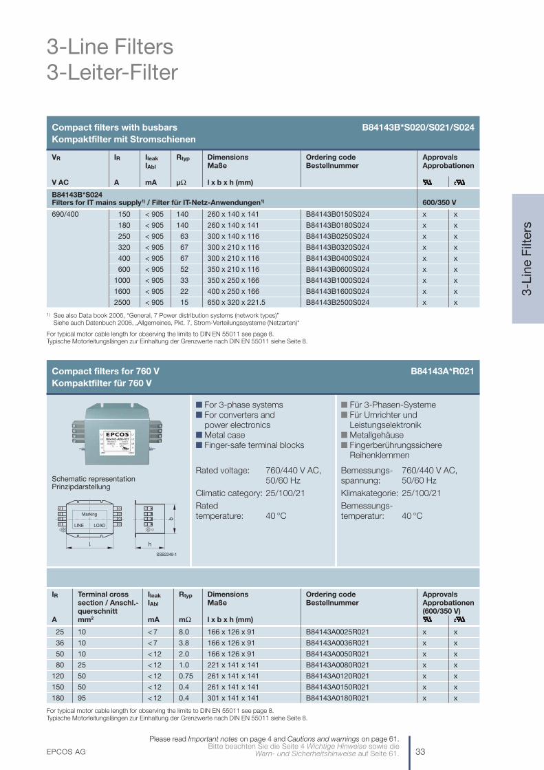
Compact filters with busbars B84143B*S020/S021/S024Kompaktfilter mit Stromschienen
Schematic representationPrinzipdarstellung
VR IR Ileak Rtyp Dimensions Ordering code ApprovalsIAbl Maße Bestellnummer Approbationen
V AC A mA µΩ l x b x h (mm)
B84143B*S020 500/290 V
530/310 150 < 20 140 260 x 140 x 141 B84143B0150S020 x x
180 < 20 140 260 x 140 x 141 B84143B0180S020 x x
250 < 20 63 300 x 140 x 115 B84143B0250S020 x x
320 < 20 67 300 x 210 x 116 B84143B0320S020 x x
400 < 20 67 300 x 210 x 116 B84143B0400S020 x x
600 < 20 52 350 x 210 x 116 B84143B0600S020 x x
1000 < 20 33 350 x 250 x 166 B84143B1000S020 x x
1600 < 20 22 400 x 250 x 166 B84143B1600S020 x x
2500 < 20 15 650 x 320 x 221.5 B84143B2500S020 x x
B84143B*S021 600/350 V
760/440 150 < 28 140 260 x 140 x 141 B84143B0150S021 x x
180 < 28 140 260 x 140 x 141 B84143B0180S021 x x
250 < 28 63 300 x 140 x 115 B84143B0250S021 x x
320 < 28 67 300 x 210 x 116 B84143B0320S021 x x
400 < 28 67 300 x 210 x 116 B84143B0400S021 x x
600 < 28 52 350 x 210 x 116 B84143B0600S021 x x
1000 < 28 33 350 x 250 x 166 B84143B1000S021 x x
1600 < 28 22 400 x 250 x 166 B84143B1600S021 x x
2500 < 28 15 650 x 320 x 221.5 B84143B2500S021 x x
n Für 3-Phasen-Systemen Für Umrichter und
Leistungselektronikn Metallgehäusen Stromschienen
Bemessungs- 530 ... 760 V AC,spannung: 50/60 Hz
Klimakategorie: 25/100/21
Bemessungs-temperatur: 40 °C
n For 3-phase systemsn For converters and
power electronicsn Metal casen Busbars
Rated voltage: 530 ... 760 V AC,50/60 Hz
Climatic category: 25/100/21
Rated temperature: 40 °C
SSB1983-I
b
h
LOADLINE
For typical motor cable length for observing the limits to DIN EN 55011 see page 8.Typische Motorleitungslängen zur Einhaltung der Grenzwerte nach DIN EN 55011 siehe Seite 8.
EPCOS AG 33
3-Line Filters3-Leiter-Filter
3-L
ine
Filt
ers
Please read Important notes on page 4 and Cautions and warnings on page 61.Bitte beachten Sie die Seite 4 Wichtige Hinweise sowie die
Warn- und Sicherheitshinweise auf Seite 61.
Compact filters with busbars B84143B*S020/S021/S024Kompaktfilter mit Stromschienen
Compact filters for 760 V B84143A*R021Kompaktfilter für 760 V
IR Terminal cross Ileak Rtyp Dimensions Ordering code Approvalssection / Anschl.- IAbl Maße Bestellnummer Approbationenquerschnitt (600/350 V)
A mm2 mA mΩ l x b x h (mm)
25 10 < 7 8.0 166 x 126 x 91 B84143A0025R021 x x
36 10 < 7 3.8 166 x 126 x 91 B84143A0036R021 x x
50 10 < 12 2.0 166 x 126 x 91 B84143A0050R021 x x
80 25 < 12 1.0 221 x 141 x 141 B84143A0080R021 x x
120 50 < 12 0.75 261 x 141 x 141 B84143A0120R021 x x
150 50 < 12 0.4 261 x 141 x 141 B84143A0150R021 x x
180 95 < 12 0.4 301 x 141 x 141 B84143A0180R021 x x
n Für 3-Phasen-Systemen Für Umrichter und
Leistungselektronikn Metallgehäusen Fingerberührungssichere
Reihenklemmen
Bemessungs- 760/440 V AC,spannung: 50/60 Hz
Klimakategorie: 25/100/21
Bemessungs-temperatur: 40 °C
n For 3-phase systemsn For converters and
power electronicsn Metal casen Finger-safe terminal blocks
Rated voltage: 760/440 V AC, 50/60 Hz
Climatic category: 25/100/21
Rated temperature: 40 °C
Schematic representationPrinzipdarstellung
For typical motor cable length for observing the limits to DIN EN 55011 see page 8.Typische Motorleitungslängen zur Einhaltung der Grenzwerte nach DIN EN 55011 siehe Seite 8.
LINE LOAD
Marking
SSB2249-1
h
b
VR IR Ileak Rtyp Dimensions Ordering code ApprovalsIAbl Maße Bestellnummer Approbationen
V AC A mA µΩ l x b x h (mm)
B84143B*S024Filters for IT mains supply1) / Filter für IT-Netz-Anwendungen1) 600/350 V
690/400 150 < 905 140 260 x 140 x 141 B84143B0150S024 x x
180 < 905 140 260 x 140 x 141 B84143B0180S024 x x
250 < 905 63 300 x 140 x 116 B84143B0250S024 x x
320 < 905 67 300 x 210 x 116 B84143B0320S024 x x
400 < 905 67 300 x 210 x 116 B84143B0400S024 x x
600 < 905 52 350 x 210 x 116 B84143B0600S024 x x
1000 < 905 33 350 x 250 x 166 B84143B1000S024 x x
1600 < 905 22 400 x 250 x 166 B84143B1600S024 x x
2500 < 905 15 650 x 320 x 221.5 B84143B2500S024 x x
1) See also Data book 2006, “General, 7 Power distribution systems (network types)”Siehe auch Datenbuch 2006, „Allgemeines, Pkt. 7, Strom-Verteilungssysteme (Netzarten)“
For typical motor cable length for observing the limits to DIN EN 55011 see page 8.Typische Motorleitungslängen zur Einhaltung der Grenzwerte nach DIN EN 55011 siehe Seite 8.
34 EPCOS AG
3-Line Filters3-Leiter-Filter
3-L
ine
Filt
ers
Please read Important notes on page 4 and Cautions and warnings on page 61.Bitte beachten Sie die Seite 4 Wichtige Hinweise sowie die Warn- und Sicherheitshinweise auf Seite 61.
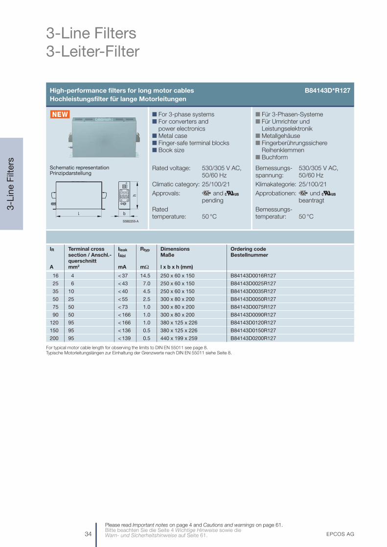
High-performance filters for long motor cables B84143D*R127Hochleistungsfilter für lange Motorleitungen
IR Terminal cross Ileak Rtyp Dimensions Ordering codesection / Anschl.- IAbl Maße Bestellnummerquerschnitt
A mm2 mA mΩ l x b x h (mm)
16 4 < 37 14.5 250 x 60 x 150 B84143D0016R127
25 6 < 43 7.0 250 x 60 x 150 B84143D0025R127
35 10 < 40 4.5 250 x 60 x 150 B84143D0035R127
50 25 < 55 2.5 300 x 80 x 200 B84143D0050R127
75 50 < 73 1.0 300 x 80 x 200 B84143D0075R127
90 50 < 166 1.0 300 x 80 x 200 B84143D0090R127
120 95 < 166 1.0 380 x 125 x 226 B84143D0120R127
150 95 < 136 0.5 380 x 125 x 226 B84143D0150R127
200 95 < 139 0.5 440 x 199 x 259 B84143D0200R127
n Für 3-Phasen-Systemen Für Umrichter und
Leistungselektronikn Metallgehäusen Fingerberührungssichere
Reihenklemmenn Buchform
Bemessungs- 530/305 V AC,spannung: 50/60 Hz
Klimakategorie: 25/100/21
Approbationen: und beantragt
Bemessungs-temperatur: 50 °C
n For 3-phase systemsn For converters and
power electronicsn Metal casen Finger-safe terminal blocksn Book size
Rated voltage: 530/305 V AC, 50/60 Hz
Climatic category: 25/100/21
Approvals: and pending
Rated temperature: 50 °C
Schematic representationPrinzipdarstellung
For typical motor cable length for observing the limits to DIN EN 55011 see page 8.Typische Motorleitungslängen zur Einhaltung der Grenzwerte nach DIN EN 55011 siehe Seite 8.
SSB2255-A
h
b

EPCOS AG 35
3-Line Filters3-Leiter-Filter
3-L
ine
Filt
ers
Please read Important notes on page 4 and Cautions and warnings on page 61.Bitte beachten Sie die Seite 4 Wichtige Hinweise sowie die
Warn- und Sicherheitshinweise auf Seite 61.
Output filters B84143V*R027/R127Ausgangsfilter
Schematic representationPrinzipdarstellung
VR IR Terminal cross Ploss1) Rtyp Dimensions Ordering code Approvals
section / Anschl.- PV1) Maße Bestellnummer Approbationen
querschnittV AC (50/60 Hz) A mm2 W mΩ l x b x h (mm)
Converter pulse frequency: 6 … 16 kHzPulsfrequenz: 6 … 16 kHz
440 6 4 29 200 350 x 95 x 80 B84143V0006R027
12 4 37 66 350 x 95 x 115 B84143V0012R027
16 4 49 49 350 x 95 x 115 B84143V0016R027
25 6 65 27 350 x 95 x 150 B84143V0025R027
35 6 70 15 350 x 130 x 150 B84143V0035R027
Converter pulse frequency: 4 … 8 kHzPulsfrequenz: 4 … 8 kHz
520 11 4 50 46 260 x 120 x 160 B84143V0011R127 x x
16 6 70 32 300 x 120 x 190 B84143V0016R127 x x
33 10 120 20 360 x 150 x 240 B84143V0033R127 x x
66 25 180 15 500 x 210 x 280 B84143V0066R127 x x
95 50 250 8 620 x 250 x 360 B84143V0095R127 x x
180 150 400 6 800 x 310 x 375 B84143V0180R127 x x
Converter pulse frequency: 2 … 4 kHzPulsfrequenz: 2 … 4 kHz
600 320 150 ... 300 750 4 953 x 443 x 424.5 B84143V0320R127
n Für 3-Phasen-Systemen Metallgehäusen Fingerberührungssichere
Reihenklemmen bzw. geschirmteKabel auf der Umrichterseite (für 320-A-Filter)
n du/dt-Filter auf Anfrage
Bemessungs- 440 … 600 V AC,spannung: 50/60 Hz
Motorfrequenz: 0 … 100 Hz
Klimakategorie: 25/100/21
Bemessungs-temperatur: 40 °C
n For 3-phase systemsn Metal casen Finger-safe terminal blocks or
shielded cable on converter side(for 320-A filter)
n dv/dt filters on request
Rated voltage: 440 … 600 V AC,50/60 Hz
Converter outputfrequency: 0 … 100 Hz
Climatic category: 25/100/21
Rated temperature: 40 °C
1) Losses at sine-wave voltage.Verluste bei Sinusspannung.
SSB1897-H
h
b
36 EPCOS AG
4-Line Filters4-Leiter-Filter
4-L
ine
Filt
ers
Please read Important notes on page 4 and Cautions and warnings on page 61.Bitte beachten Sie die Seite 4 Wichtige Hinweise sowie die Warn- und Sicherheitshinweise auf Seite 61.
Converters/power electronics B84144A*R120Umrichter/Leistungselektronik
IR Terminal cross Ileak Rtyp Dimensions Ordering codesection / Anschl.- IAbl Maße Bestellnummerquerschnitt
A mm2 mA mΩ l x b x h (mm)
8 4 < 3.5 13.6 200 x 80 x 60 B84144A0008R120
16 4 < 3.5 7.5 200 x 80 x 60 B84144A0016R120
25 4 < 3.5 3.9 200 x 80 x 60 B84144A0025R120
36 10 < 3.5 2.7 230 x 90 x 60 B84144A0036R120
50 10 < 3.5 1.3 230 x 90 x 60 B84144A0050R120
66 16 < 3.5 1.1 260 x 100 x 80 B84144A0066R120
90 25 < 3.5 0.76 250 x 130 x 100 B84144A0090R120
120 50 < 3.5 0.47 250 x 130 x 130 B84144A0120R120
150 95 < 3.5 0.32 250 x 160 x 130 B84144A0150R120
200 95 < 3.5 0.23 250 x 160 x 130 B84144A0200R120
n Für 3-Phasen-Systemen Metallgehäusen Vergossen (UL 94 V-0)n Fingerberührungssichere
Reihenklemmen
Bemessungs- 520/300 V AC,spannung: 50/60 Hz
Klimakategorie: 25/100/21
Approbationen: und beantragt
Bemessungs-temperatur: 50 °C
n For 3-phase systemsn Metal casen Potted (UL 94 V-0)n Finger-safe terminal blocks
Rated voltage: 520/300 V AC, 50/60 Hz
Climatic category: 25/100/21
Approvals: and pending
Rated temperature: 50 °C
Schematic representationPrinzipdarstellung
b
SSB2250-4
h

EPCOS AG 37
4-Line Filters4-Leiter-Filter
4-L
ine
Filt
ers
Please read Important notes on page 4 and Cautions and warnings on page 61.Bitte beachten Sie die Seite 4 Wichtige Hinweise sowie die
Warn- und Sicherheitshinweise auf Seite 61.
Converters/power electronics B84144B*S120/S121Umrichter/Leistungselektronik
Schematic representationPrinzipdarstellung
IR Ileak Rtyp Dimensions Ordering codeIAbl Maße Bestellnummer
A mA µΩ l x b x h (mm)
250 < 3 68 301.5 x 180 x 126 B84144B0250S120
400 < 3 59 351.5 x 210 x 149.5 B84144B0400S120
600 < 3 59 351.5 x 210 x 149.5 B84144B0600S120
High performance
250 < 6 68 301.5 x 180 x 126 B84144B0250S121
400 < 6 59 351.5 x 210 x 149.5 B84144B0400S121
600 < 6 59 351.5 x 210 x 149.5 B84144B0600S121
n Für 3-Phasen-Systemen Metallgehäusen Vergossen (UL 94 V-0)n Stromschienen
Bemessungs- 530/305 V AC,spannung: 50/60 Hz
Klimakategorie: 25/100/21
Bemessungs-temperatur: 40 °C
n For 3-phase systemsn Metal casen Potted (UL 94 V-0)n Busbars
Rated voltage: 530/305 V AC, 50/60 Hz
Climatic category: 25/100/21
Rated temperature: 40 °C
SSB2251-C
h
b

38 EPCOS AG
4-Line Filters4-Leiter-Filter
4-L
ine
Filt
ers
Please read Important notes on page 4 and Cautions and warnings on page 61.Bitte beachten Sie die Seite 4 Wichtige Hinweise sowie die Warn- und Sicherheitshinweise auf Seite 61.
Converters/power electronics B84144A*R000Umrichter/Leistungselektronik
IR Terminal cross Ileak Rtyp Dimensions Ordering code Approvalssection / Anschl.- IAbl Maße Bestellnummer Approbationenquerschnitt
A mm2 mA mΩ l x b x h (mm)
16 4 < 3.5 10 141 x 86 x 81 B84144A0016R000 x
25 10 < 3.5 6 166 x 126 x 91 B84144A0025R000 x
36 10 < 3.5 3.5 166 x 126 x 91 B84144A0036R000 x
50 10 < 6 1.3 166 x 126 x 91 B84144A0050R000 x
80 25 < 6 0.7 221 x 141 x 141 B84144A0080R000 x
120 50 < 6 0.5 261 x 141 x 141 B84144A0120R000 x
150 50 < 6 0.35 261 x 141 x 141 B84144A0150R000 x
180 95 < 6 0.25 301 x 141 x 141 B84144A0180R000 x
n Für 3-Phasen-Systemen Metallgehäusen Gewindebuchsen für
HF-dichten Einbaun Fingerberührungssichere
Reihenklemmen
Bemessungs- 440/250 V AC,spannung: 50/60 Hz
Klimakategorie: 25/100/21
Bemessungs-temperatur: 40 °C
n For 3-phase systemsn Metal casen Threaded bushes for
RF-tight installationn Finger-safe terminal blocks
Rated voltage: 440/250 V AC, 50/60 Hz
Climatic category: 25/100/21
Rated temperature: 40 °C
Schematic representationPrinzipdarstellung
SSB2252-K
Marking
LOADLINE
h
b
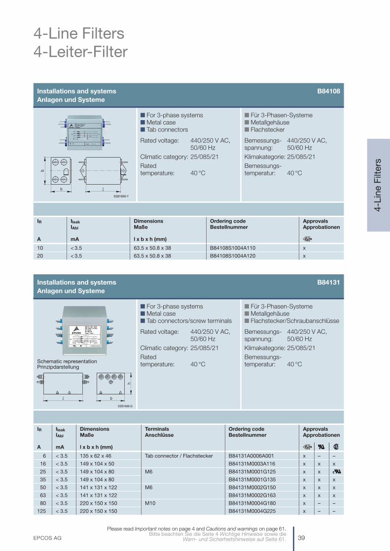
n For 3-phase systemsn Metal casen Tab connectors
Rated voltage: 440/250 V AC, 50/60 Hz
Climatic category: 25/085/21
Rated temperature: 40 °C
n Für 3-Phasen-Systemen Metallgehäusen Flachstecker
Bemessungs- 440/250 V AC,spannung: 50/60 Hz
Klimakategorie: 25/085/21
Bemessungs-temperatur: 40 °C
SSB1899-Y
b
h
EPCOS AG 39
4-Line Filters4-Leiter-Filter
4-L
ine
Filt
ers
Please read Important notes on page 4 and Cautions and warnings on page 61.Bitte beachten Sie die Seite 4 Wichtige Hinweise sowie die
Warn- und Sicherheitshinweise auf Seite 61.
Installations and systems B84108Anlagen und Systeme
Installations and systems B84131Anlagen und Systeme
n For 3-phase systemsn Metal casen Tab connectors/screw terminals
Rated voltage: 440/250 V AC, 50/60 Hz
Climatic category: 25/085/21
Rated temperature: 40 °C
n Für 3-Phasen-Systemen Metallgehäusen Flachstecker/Schraubanschlüsse
Bemessungs- 440/250 V AC,spannung: 50/60 Hz
Klimakategorie: 25/085/21
Bemessungs-temperatur: 40 °CSchematic representation
Prinzipdarstellung
IR Ileak Dimensions Terminals Ordering code ApprovalsIAbl Maße Anschlüsse Bestellnummer Approbationen
A mA l x b x h (mm)
6 < 3.5 135 x 62 x 46 Tab connector / Flachstecker B84131A0006A001 x – –
16 < 3.5 149 x 104 x 50 B84131M0003A116 x x x
25 < 3.5 149 x 104 x 80 M6 B84131M0001G125 x x
35 < 3.5 149 x 104 x 80 B84131M0001G135 x x x
50 < 3.5 141 x 131 x 122 M6 B84131M0002G150 x x x
63 < 3.5 141 x 131 x 122 B84131M0002G163 x x x
80 < 3.5 220 x 150 x 150 M10 B84131M0004G180 x – –
125 < 3.5 220 x 150 x 150 B84131M0004G225 x – –
SSB1898-Q
h
b
IR Ileak Dimensions Ordering code ApprovalsIAbl Maße Bestellnummer Approbationen
A mA l x b x h (mm)
10 < 3.5 63.5 x 50.8 x 38 B84108S1004A110 x
20 < 3.5 63.5 x 50.8 x 38 B84108S1004A120 x

40 EPCOS AG
Filters for Regenerative ConvertersFilter für rückspeisefähige Umrichter
Filt
ers
for
Co
nve
rter
s
Please read Important notes on page 4 and Cautions and warnings on page 61.Bitte beachten Sie die Seite 4 Wichtige Hinweise sowie die Warn- und Sicherheitshinweise auf Seite 61.
n For 3-phase systemsn 3-line filtersn Metal casen Finger-safe terminal blocks
Rated voltage: 520/300 V AC, 50/60 Hz
Climatic category: 25/100/21
Rated temperature: 50 °C
n Für 3-Phasen-Systemen 3-Leiter-Filtern Metallgehäusen Fingerberührungssichere
Reihenklemmen
Bemessungs- 520/300 V AC,spannung: 50/60 Hz
Klimakategorie: 25/100/21
Bemessungs-temperatur: 50 °C
For AFE converters B84143A*R410Für AFE Umrichter
IR Ileak Ordering codeIAbl Bestellnummer
A mA
35 ... 230 < 300 Upon request / Auf Anfrage

EPCOS AG 41
Customer-Specific FiltersKundenspezifische Filter
Cust
om
er-S
pec
ific
Please read Important notes on page 4 and Cautions and warnings on page 61.Bitte beachten Sie die Seite 4 Wichtige Hinweise sowie die
Warn- und Sicherheitshinweise auf Seite 61.
For base stations B84132-MBS/B84134-MBSFür Mobilfunk-Basisstationen
Type VR IR Terminal cross Ileak Rtyp Anschlüsse Ordering codeTyp section / Anschluss- IAbl Maße Bestellnummer
querschnittV mm2 mA mΩ l x b x h (mm)
B84132-MBS 250 16 4 17 4.8 Litz wires / threaded studs On request
2 lines AC/DC 25 4 17 2.9 Litzen / Gewindebolzen Auf Anfrage
50 8.35 17 0.8
80 25 17 0.7
80 DC 150 70 – 0.39
B84134-MBS 440/250 20 4 1.35 6.1 Litz wires / terminal blocks On request
4 lines AC 60 16 5 1.0 Litzen / Reihenklemmen Auf Anfrage
n 2- und 4-Leiter-Filtern Metallgehäusen Litzenanschlüsse und Gewinde-
bolzen bzw. Fingerberührungs-sichere Reihenklemmen
B84132-MBS:Bemessungs- 250 V DC/AC, spannung: 50/60 Hz;
80 V DCBemessungstemperatur: 60 °C
B84134-MBS:Bemessungs- 440/250 V AC,spannung: 50/60 HzBemessungstemperatur: 70 °C
Klimakategorie: 25/100/21
n 2- and 4-line filtersn Metal casen Litz wires and threaded studs/
Finger-safe terminal blocks
B84132-MBS:Rated voltage: 250 V DC/AC,
50/60 Hz;80 V DC
Rated temperature: 60 °C
B84134-MBS:Rated voltage: 440/250 V AC,
50/60 HzRated temperature: 70 °C
Climatic category: 25/100/21
n For 3-phase systemsn 4-line filtersn Metal casen Footprint filtersn Terminals to custom specification
Rated voltage: 440/250 V AC, 50/60 Hz
Climatic category: 25/100/21
n Für 3-Phasen-Systemen 4-Leiter-Filtern Metallgehäusen Footprintfiltern Anschlüsse nach Kundenwunsch
Bemessungs- 440/250 V AC,spannung: 50/60 Hz
Klimakategorie: 25/100/21
For power line communication B84131-PLCFür Power Line Communication
IR Ileak Rtyp Ordering codeIAbl Bestellnummer
A mA mΩ
63 440 1.9 On request / Auf Anfrage

42 EPCOS AG
Filters for Shielded RoomsFilter für geschirmte Räume
Shie
lded
Ro
om
s
Please read Important notes on page 4 and Cautions and warnings on page 61.Bitte beachten Sie die Seite 4 Wichtige Hinweise sowie die Warn- und Sicherheitshinweise auf Seite 61.
GeneralAllgemein
Filters for power linesFilter für Netzleitungen
Filters for communication, telephone and control linesFilter für Kommunikationsleitungen, Telefon- und Steuerleitungen
EMP protection unitsEMP-Schutzeinheiten
n Multistage filters with very high attenuation of – 100 dB from 150 kHz to 40 GHz or – 100 dB from 14 kHz to 40 GHz depending on the type
n RF-tight case made of corrosion-resistant magneticstainless steel
n Terminal boxes remain 100% RF-tight even withfrequent opening
n Attenuation specifications at full load (CISPR 17, MIL-STD-220 A)
n For operating frequencies of 50 Hz, 60 Hz or 400 Hz(with corresponding current derating)
n Filters also available with 40 or 100 kA EMPprotection
n Supplied complete with all required assemblymaterials
These universal filters attenuate common and differen-tial-mode interference currents equally well. The high at-tenuation characteristic remains stable at high leakagecurrents through the loads (e.g. LISN, V-Network). Nocoupling between the lines, hence ideal for almost allapplications.
Construction with current-compensated chokes thatessentially attenuate common-mode interference cur-rents. Thanks to the filter circuit, these series assures asignificantly lower leakage current.
n Multistage filters with very high attenuation n Stopband attenuation of 100 dB from 10 kHz to
40 GHz depending on the typen RF-tight casen Also available with integrated EMP protectionn For a wide range of analog data and
ISDN systems
EMP protection units combine the benefits of gas-filledsurge arresters (extremely high discharge capacity) andvaristors (high response speed). The arresters are inte-grated in receptacles and can be tested and replacedas required.
n Mehrstufig aufgebaute Filter mit sehr hoherDämpfung, typabhängig– 100 dB von 150 kHz bis 40 GHz oder – 100 dB von 14 kHz bis 40 GHz
n Hochfrequenzdichte Gehäuse aus korrosionsfreiem,magnetischem Edelstahl
n Anschlusskammern sind auch bei mehrmaligemÖffnen noch 100% HF-dicht
n Dämpfungsangaben bei Volllast (CISPR 17, MIL-STD-220 A)
n Für Betriebsfrequenz 50 Hz, 60 Hz oder 400 Hz (bei entsprechendem Stromderating)
n Filter auch mit EMP-Schutz 40 kA oder 100 kAlieferbar
n Lieferung komplett mit allem erforderlichen Montagematerial
Diese Universalfilter mit Einzeldrosseln bedämpfenGleich- und Gegentakt-Störströme gleichermaßen. Beihohen Ableitströmen durch die Verbraucher (z.B. Netz-nachbildung) bleibt die hohe Dämpfungscharakteristikstabil. Keine Verkopplung zwischen den Leitungen, da-her für fast alle Anwendungen ideal.
Aufbau mit stromkompensierten Drosseln, die imWesentlichen die Gleichtakt-Störströme bedämpfen.Durch die Filterschaltung ergibt sich bei diesen Reihenein deutlich niedrigerer Ableitstrom
n Mehrstufig aufgebaute Filter mit sehr hoherDämpfung
n Sperrdämpfung je nach Typ 100 dB ab 10 kHz bis40 GHz
n Hochfrequenzdichte Gehäusen Auch mit integriertem EMP-Schutz lieferbarn Für eine Vielzahl analoger Daten- und ISDN-Systeme
EMP-Schutzeinheiten kombinieren die Vorzüge vonedelgasgefüllten Überspannungsableitern (extrem ho-hes Ableitvermögen) und Varistoren (hohe Ansprechge-schwindigkeit). Die Ableiter sind in Stecksockeln ein-gebaut und bei Bedarf prüf- und austauschbar.
Filters with low leakage current – B84261 and B84263 seriesFilter mit ableitstromarmer Schaltung – Serie B84261 und B84263
Filters with single chokes – B84299C/D seriesFilter mit Einzeldrosseln – Serie B84299C/D

EPCOS AG 43
Filters for Shielded RoomsFilter für geschirmte Räume
Shie
lded
Ro
om
s
Please read Important notes on page 4 and Cautions and warnings on page 61.Bitte beachten Sie die Seite 4 Wichtige Hinweise sowie die
Warn- und Sicherheitshinweise auf Seite 61.
For power linesFür Netzleitungen
n 2- and 4-line filtersn Stop band attenuation up to
40 GHz
Rated frequency: 50/60 Hz400 Hz (withvoltage derating)
Test voltage: 1200 V DC/2 s
Climatic category: 25/085/56
n 2- und 4-Leiter-Filtern Sperrdämpfung bis 40 GHz
Bemessungs- 50/60 Hzfrequenz: 400 Hz (mit
Spannungsderating)
Prüfspannung: 1200 V DC/2 s
Klimakategorie: 25/085/56
SGR0099-8
bh
h
Version "C"
Version "D"
Schematic representationPrinzipdarstellung
Filters with single chokesFilter mit Einzeldrosseln
Lines VR IR Rmax Ploss Dimensions Ordering code1)
Leiter PV Maße Bestellnummer1)
V DC A mΩ W l x b x h (mm)
Insertion loss = 100 dB from 150 kHzEinfügungsdämpfung = 100 dB ab 150 kHz
2 250 2 x 16 < 25 < 15 500 x 174 x 112.5 B84299*2160B001
2 x 32 < 12 < 25 650 x 174 x 112.5 B84299*2320B001
2 x 63 < 4 < 32 850 x 288 x 152.5 B84299*1630B001
2 x 100 < 2 < 40 850 x 288 x 152.5 B84299*1101B001
4 440/250 4 x 16 < 25 < 20 500 x 304 x 112.5 B84299*2160E001
4 x 32 < 12 < 40 650 x 304 x 112.5 B84299*2320E001
4 x 63 < 4 < 50 850 x 288 x 152.5 B84299*1630E001
4 x 100 < 2 < 60 850 x 288 x 152.5 B84299*1101E001
440/250 4 x 150 < 0.9 < 60 1070 x 288 x 152.5 B84299*1151E001
4 x 250 < 0.3 < 60 1200 x 288 x 152.5 B84299*1251E001
690/400 4 x 32 < 12 < 40 650 x 304 x 112.5 B84299*2320E601
4 x 63 < 4 < 50 850 x 288 x 152.5 B84299*1630E601
4 x 100 < 2 < 60 850 x 288 x 152.5 B84299*1101E601
4 x 150 < 0.9 < 60 1070 x 288 x 152.5 B84299*1151E601
4 x 250 < 0.3 < 60 1200 x 288 x 152.5 B84299*1251E601
1) *: “C”: both sides with cable fitting and/or connection to shield by fitting (Example: B84299C2160B001)“D”: for direct connection to shield by integrated flange on case bottom (Example: B84299D2160B001)
1) *: „C“: beidseitig mit Kabelverschraubung bzw. Anschluss mit Anschlussarmatur (Beispiel: B84299C2160B001)„D“: für Direktanschluss an die Schirmwand über integrierten Flansch im Gehäuseboden (Beispiel: B84299D2160B001)
fi
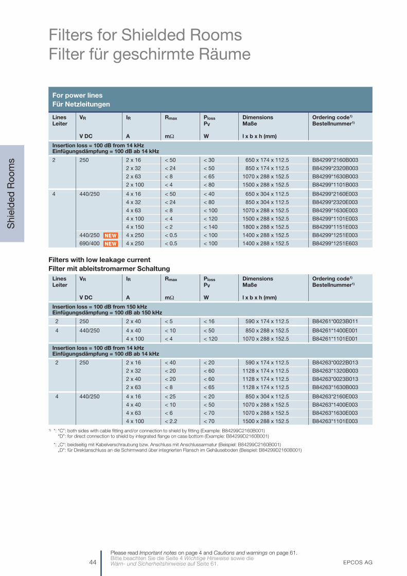
44 EPCOS AG
Filters for Shielded RoomsFilter für geschirmte Räume
Shie
lded
Ro
om
s
Please read Important notes on page 4 and Cautions and warnings on page 61.Bitte beachten Sie die Seite 4 Wichtige Hinweise sowie die Warn- und Sicherheitshinweise auf Seite 61.
For power linesFür Netzleitungen
Lines VR IR Rmax Ploss Dimensions Ordering code1)
Leiter PV Maße Bestellnummer1)
V DC A mΩ W l x b x h (mm)
Insertion loss = 100 dB from 14 kHzEinfügungsdämpfung = 100 dB ab 14 kHz
2 250 2 x 16 < 50 < 30 650 x 174 x 112.5 B84299*2160B003
2 x 32 < 24 < 50 850 x 174 x 112.5 B84299*2320B003
2 x 63 < 8 < 65 1070 x 288 x 152.5 B84299*1630B003
2 x 100 < 4 < 80 1500 x 288 x 152.5 B84299*1101B003
4 440/250 4 x 16 < 50 < 40 650 x 304 x 112.5 B84299*2160E003
4 x 32 < 24 < 80 850 x 304 x 112.5 B84299*2320E003
4 x 63 < 8 < 100 1070 x 288 x 152.5 B84299*1630E003
4 x 100 < 4 < 120 1500 x 288 x 152.5 B84299*1101E003
4 x 150 < 2 < 140 1800 x 288 x 152.5 B84299*1151E003
440/250 4 x 250 < 0.5 < 100 1400 x 288 x 152.5 B84299*1251E003
690/400 4 x 250 < 0.5 < 100 1400 x 288 x 152.5 B84299*1251E603
1) *: “C”: both sides with cable fitting and/or connection to shield by fitting (Example: B84299C2160B001)“D”: for direct connection to shield by integrated flange on case bottom (Example: B84299D2160B001)
1) *: „C“: beidseitig mit Kabelverschraubung bzw. Anschluss mit Anschlussarmatur (Beispiel: B84299C2160B001)„D“: für Direktanschluss an die Schirmwand über integrierten Flansch im Gehäuseboden (Beispiel: B84299D2160B001)
Filters with low leakage currentFilter mit ableitstromarmer Schaltung
Lines VR IR Rmax Ploss Dimensions Ordering code1)
Leiter PV Maße Bestellnummer1)
V DC A mΩ W l x b x h (mm)
Insertion loss = 100 dB from 150 kHzEinfügungsdämpfung = 100 dB ab 150 kHz
2 250 2 x 40 < 5 < 16 590 x 174 x 112.5 B84261*0023B011
4 440/250 4 x 40 < 10 < 50 850 x 288 x 152.5 B84261*1400E001
4 x 100 < 4 < 120 1070 x 288 x 152.5 B84261*1101E001
Insertion loss = 100 dB from 14 kHzEinfügungsdämpfung = 100 dB ab 14 kHz
2 250 2 x 16 < 40 < 20 590 x 174 x 112.5 B84263*0022B013
2 x 32 < 20 < 60 1128 x 174 x 112.5 B84263*1320B003
2 x 40 < 20 < 60 1128 x 174 x 112.5 B84263*0023B013
2 x 63 < 8 < 65 1128 x 174 x 112.5 B84263*1630B003
4 440/250 4 x 16 < 25 < 20 850 x 304 x 112.5 B84263*2160E003
4 x 40 < 10 < 50 1070 x 288 x 152.5 B84263*1400E003
4 x 63 < 6 < 70 1070 x 288 x 152.5 B84263*1630E003
4 x 100 < 2.2 < 70 1500 x 288 x 152.5 B84263*1101E003
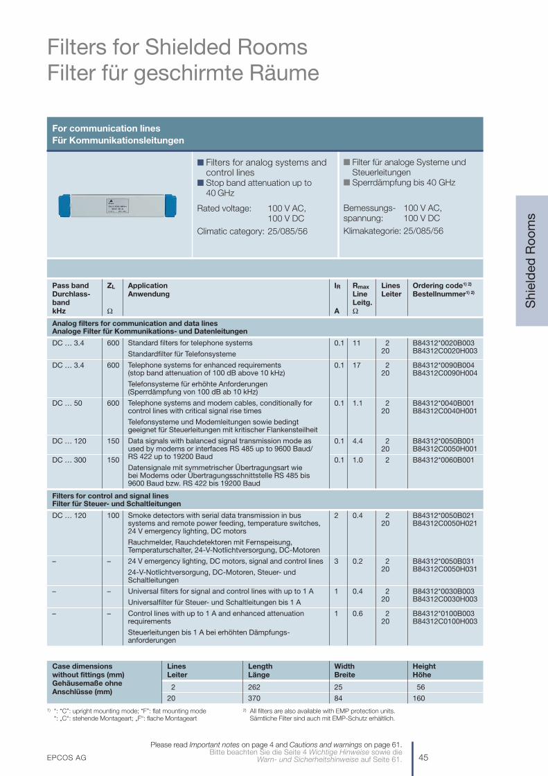
EPCOS AG 45
Filters for Shielded RoomsFilter für geschirmte Räume
Shie
lded
Ro
om
s
Please read Important notes on page 4 and Cautions and warnings on page 61.Bitte beachten Sie die Seite 4 Wichtige Hinweise sowie die
Warn- und Sicherheitshinweise auf Seite 61.
For communication lines Für Kommunikationsleitungen
n Filters for analog systems andcontrol lines
n Stop band attenuation up to 40 GHz
Rated voltage: 100 V AC,100 V DC
Climatic category: 25/085/56
n Filter für analoge Systeme undSteuerleitungen
n Sperrdämpfung bis 40 GHz
Bemessungs- 100 V AC,spannung: 100 V DC
Klimakategorie: 25/085/56
Pass band ZL Application IR Rmax Lines Ordering code1) 2)
Durchlass- Anwendung Line Leiter Bestellnummer1) 2)
band Leitg.kHz Ω A Ω
Analog filters for communication and data linesAnaloge Filter für Kommunikations- und Datenleitungen
DC … 3.4 600 0.1 11 2 B84312*0020B00320 B84312C0020H003
DC … 3.4 600 0.1 17 2 B84312*0090B00420 B84312C0090H004
DC … 50 600 0.1 1.1 2 B84312*0040B00120 B84312C0040H001
DC … 120 150 0.1 4.4 2 B84312*0050B00120 B84312C0050H001
DC … 300 150 0.1 1.0 2 B84312*0060B001
Filters for control and signal linesFilter für Steuer- und Schaltleitungen
DC … 120 100 2 0.4 2 B84312*0050B02120 B84312C0050H021
– – 3 0.2 2 B84312*0050B03120 B84312C0050H031
– – 1 0.4 2 B84312*0030B00320 B84312C0030H003
– – 1 0.6 2 B84312*0100B00320 B84312C0100H003
Smoke detectors with serial data transmission in bussystems and remote power feeding, temperature switches,24 V emergency lighting, DC motors
Rauchmelder, Rauchdetektoren mit Fernspeisung,Temperaturschalter, 24-V-Notlichtversorgung, DC-Motoren
24 V emergency lighting, DC motors, signal and control lines
24-V-Notlichtversorgung, DC-Motoren, Steuer- undSchaltleitungen
Universal filters for signal and control lines with up to 1 A
Universalfilter für Steuer- und Schaltleitungen bis 1 A
Control lines with up to 1 A and enhanced attenuationrequirements
Steuerleitungen bis 1 A bei erhöhten Dämpfungs-anforderungen
Standard filters for telephone systems
Standardfilter für Telefonsysteme
Telephone systems for enhanced requirements (stop band attenuation of 100 dB above 10 kHz)
Telefonsysteme für erhöhte Anforderungen (Sperrdämpfung von 100 dB ab 10 kHz)
Telephone systems and modem cables, conditionally forcontrol lines with critical signal rise times
Telefonsysteme und Modemleitungen sowie bedingtgeeignet für Steuerleitungen mit kritischer Flankensteilheit
Data signals with balanced signal transmission mode asused by modems or interfaces RS 485 up to 9600 Baud/RS 422 up to 19200 Baud
Datensignale mit symmetrischer Übertragungsart wie bei Modems oder Übertragungsschnittstelle RS 485 bis9600 Baud bzw. RS 422 bis 19200 Baud
Lines Length Width HeightLeiter Länge Breite Höhe
2 262 25 56
20 370 84 160
Case dimensions without fittings (mm)Gehäusemaße ohne Anschlüsse (mm)
1) *: “C”: upright mounting mode; “F”: flat mounting mode 2) All filters are also available with EMP protection units.1) *: „C“: stehende Montageart; „F“: flache Montageart 2) Sämtliche Filter sind auch mit EMP-Schutz erhältlich.
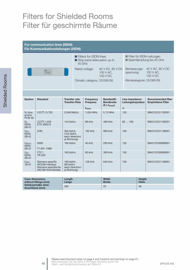
46 EPCOS AG
Filters for Shielded RoomsFilter für geschirmte Räume
Shie
lded
Ro
om
s
Please read Important notes on page 4 and Cautions and warnings on page 61.Bitte beachten Sie die Seite 4 Wichtige Hinweise sowie die Warn- und Sicherheitshinweise auf Seite 61.
For communication lines (ISDN)Für Kommunikationsleitungen (ISDN)
n Filters for ISDN linesn Stop band attenuation up to
40 GHz
Rated voltage: 42 V AC, 80 V DC 100 V AC,100 V DC
Climatic category: 25/085/56
n Filter für ISDN-Leitungenn Sperrdämpfung bis 40 GHz
Bemessungs- 42 V AC, 80 V DCspannung: 100 V AC,
100 V DC
Klimakategorie: 25/085/56
System Standard Transfer rate Frequency Bandwidth Line impedance Recommended filterTransfer-Rate Frequenz Bandbreite Leitungsimpedanz Empfohlene Filter
(5 x fmeas)fmeas Ω
S2 bzw. CCITT, G.703 2.048 Mbit/s 1.024 MHz 5.12 MHz 120 B84312C0112E001and/orPCM 30
S0 CCITT, I.430 144 kbit/s 96 kHz 480 kHz 85 … 160 B84312C0110E001ISDN, ETS 3000122B+D
UP0 ZVEI 304 kbit/s 192 kHz 960 kHz 100 B84312C0114B001ISDN, (152 kbit/s 2B+D each direction/
je Richtung)
U2B1Q ANSI 160 kbit/s 40 kHz 200 kHz 135 B84312C0060B001ISDN,2B+D T1.601-1988
Uk0 FTZ 1 160 kbit/s 60 kHz 300 kHz 150 B84312C0060B001ISDN, TR 2202B+D
U200 Siemens-specific 160 kbit/s 128 kHz 640 kHz 130 B84312C0114B0011B+D HICOM interface (80 kbit/s
Siemens-spezifische each direction/HICOM-Schnittstelle je Richtung)
Length Width HeightLänge Breite Höhe
262 25 56
Case dimensions without fittings (mm)Gehäusemaße ohne Anschlüsse (mm)

EPCOS AG 47
Services Dienstleistungen
Ser
vice
s
Please read Important notes on page 4 and Cautions and warnings on page 61.Bitte beachten Sie die Seite 4 Wichtige Hinweise sowie die
Warn- und Sicherheitshinweise auf Seite 61.
EMC components and services from one sourceEMV-Bauelemente und -Dienstleistungen aus einer Hand
Consulting by EPCOS engineers
Beratung durch EPCOS-Ingenieure
Precompliance measure-ments in EMC laboratoryduring development
EntwicklungsbegleitendeMessungen im EMV-Labor
Solving problems by on-site measurements
Problemlösungen durchMessungen vor Ort
Customer-specific filter adaption
Kundenspezifische Filter-anpassung
Rapid and flexible supply of laboratory samples
Kurzfristige und flexibleBereitstellung von Labormustern
Rapid supply of standardcomponents and filters
Kurzfristige Versorgungmit Standardbauele-menten und -filtern
EMC solution optimized to applications and costs
Anwendungs- und kostenoptimierte EMV-Lösung
Test report as a basis for the declaration of CE conformity
Prüfbericht als Grundlage zur CE-Konformitätserklärung
Final test in the EMC laboratory
Abschlussprüfung im EMV-Labor
EPCOS increasingly uses simulation models to support selection and optimization of filters. Line simulation during design is based on SPICE.
Zur Unterstützung von Filterauswahl und -optimierung setzt EPCOS zunehmend Simulationsmodelle ein. Basis der entwicklungs-
begleitenden Leitungs-Simulation ist SPICE.
Development stage of customer
equipment
Entwicklungs-phase des
Kundengerätes
ss
ss
s
s
s
ss

48 EPCOS AG
Accredited EMC LaboratoryAkkreditiertes EMV-Labor
EM
C L
abo
rato
ry
The EPCOS EMC Laboratory in Regensburg offers com-prehensive, in-depth EMC services: from consulting andpre-compliance investigations on prototypes to conformi-ty testing of series-production equipment.
The excellently equipped laboratory, combined with ourmany years’ experience and EMC expertise, as well asour active participation in national and internationalstandardization bodies, provide a solid foundation formeeting our customers’ requirements. Investigations per-formed side by side with the development process deter-mine the measures required to observe the EMC limits:these measures are documented in the measurement re-port in a manner that is transparent for the developers.
A test report provides proof of compliance with the rele-vant standards and is the basis for the customer’sdeclaration of conformity.
The EMC laboratory in Regensburg has been an accred-ited test laboratory and member of the competent bodyof Siemens AG since October 1994. Accreditation inaccordance with the guidelines of the German Accredita-tion Council (DAR) now meets the current EN ISO IEC17025 quality standard for laboratories as the basis forguaranteed independence, impartiality and integrity of itsmeasurement and test results.
Installations
The EMC laboratory has a semi-anechoic chamber forfieldstrength measurements in accordance with the re-levant standards at a measurement distance of 10 mbetween the antenna and the equipment under test.Special facilities such as large entrances, exhaust gasextraction, power supplies up to 100 A as well as resistiveand inductive (motor) loads permit the testing of evenbulky or high-powered equipment.
Das EPCOS-EMV-Labor in Regensburg bietet umfassen-de und fundierte EMV-Dienstleistungen: Von der entwick-lungsbegleitenden Beratung und Schulung über EMV-Messungen und -Prüfungen an Prototypen bis zu denAbnahmemessungen der Seriengeräte.
Die hochwertige Ausstattung des Labors, kombiniert mitunserer langjährigen Erfahrung und hohen EMV-Kompe-tenz sowie die aktive Mitarbeit in nationalen und interna-tionalen EMV-Normungsgremien bilden eine solide Grund-lage, um den Anforderungen unserer Kunden gerecht zuwerden. Entwicklungsbegleitende Untersuchungen ermit-teln die notwendigen Maßnahmen zur Einhaltung derEMV-Grenzwerte, die für den Entwickler nachvollziehbarim Messbericht dokumentiert werden.
Ein Prüfbericht, der die EMV-Prüfungen am Serienstand desGerätes umfasst, stellt den Nachweis für die Übereinstim-mung mit den gültigen Normen und Vorschriften dar und istGrundlage für die Konformitätserklärung des Kunden.
Das EMV-Labor in Regensburg ist seit 1994 als Prüflaborakkreditiert und Mitglied der Zuständigen Stelle derSiemens AG. Die Akkreditierung nach den Richtlinien desDeutschen Akkreditierungsrates (DAR) erfolgt heute nachder aktuellen Qualitätsnorm für Labore DIN EN ISO IEC17025. Auf dieser Grundlage werden konsequent Unab-hängigkeit, Unparteilichkeit und Integrität der Mess- undPrüfergebnisse sichergestellt.
Einrichtungen
Das EMV-Labor verfügt über eine Absorberhalle mit re-flektierendem Boden für Feldstärkemessungen nach deneinschlägigen Normen bei einem Messabstand von 10 mzwischen Antenne und Prüfling. Spezielle Einrichtungenwie z. B. große Tore, Abgasabsaugung, Stromversorgun-gen bis 100 A sowie ohmsche und motorische Lasten er-lauben die Prüfung auch großvolumiger oder leistungs-starker Geräte und Anlagen.
Please read Important notes on page 4 and Cautions and warnings on page 61.Bitte beachten Sie die Seite 4 Wichtige Hinweise sowie die Warn- und Sicherheitshinweise auf Seite 61.

EPCOS AG 49
Accredited EMC LaboratoryAkkreditiertes EMV-Labor
EM
C L
abo
rato
ry
Please read Important notes on page 4 and Cautions and warnings on page 61.Bitte beachten Sie die Seite 4 Wichtige Hinweise sowie die
Warn- und Sicherheitshinweise auf Seite 61.
Germany Europe WorldDeutschland Europa Welt
Generic standardsFachgrundnormen
Emission DIN EN 61000-6-3/-4 EN 61000-6-3/-4 IEC 61000-6-3/-4Aussendung
Immunity DIN EN 61000-6-1/-2 EN 61000-6-1/-2 IEC 61000-6-1/-2Störfestigkeit
Basic standardsGrundnormen
Measuring Emission DIN EN 55016-1-x EN 55016-1-x CISPR 16-1-xMessgeräte Aussendung
Measuring methods Emission DIN EN 55016-2-x EN 55016-2-x CISPR 16-2-xMessverfahren Aussendung
Harmonics Emission DIN EN 61000-3-2 EN 61000-3-2 IEC 61000-3-2Oberschwingungen Aussendung
Flicker Emission DIN EN 61000-3-3 EN 61000-3-3 IEC 61000-3-3Aussendung
ESD Immunity DIN EN 61000-4-2 EN 61000-4-2 IEC 61000-4-2Störfestigkeit
RF fields Immunity DIN EN 61000-4-3 EN 61000-4-3 IEC 61000-4-3Hochfrequente Felder Störfestigkeit
Fast transients (burst) Immunity DIN EN 61000-4-4 EN 61000-4-4 IEC 61000-4-4Schnelle Transienten (Burst) Störfestigkeit
Surge Immunity DIN EN 61000-4-5 EN 61000-4-5 IEC 61000-4-5Störfestigkeit
RF fields, induced Immunity DIN EN 61000-4-6 EN 61000-4-6 IEC 61000-4-6Hochfrequente Felder, induziert Störfestigkeit
Voltage dips, variations, short interruptions Immunity DIN EN 61000-4-11 EN 61000-4-11 IEC 61000-4-11Spannungseinbrüche, -schwankungen, StörfestigkeitKurzzeitunterbrechungen
Product family standardsProduktfamiliennormen
ISM equipment Emission DIN EN 55011 EN 55011 CISPR 11ISM-Geräte Aussendung
Domestic appliances Emission DIN EN 55014-1 EN 55014-1 CISPR 14-1Hausgeräte Aussendung
Lighting Emission DIN EN 55015 EN 55015 CISPR 15Leuchten Aussendung
Radio and TV equipment Emission DIN EN 55013 EN 55013 CISPR 13Radio- und TV-Geräte Aussendung
ITE equipment Emission DIN EN 55022 EN 55022 CISPR 22ITE-Geräte Aussendung
Vehicles Emission DIN EN 55025 EN 550251) CISPR 25Fahrzeuge Aussendung
1) The EU Motor Vehicle Directive (95/54/EC) also contains limit values and interference immunity requirements.Die EU-Kfz-Richtlinie (95/54/EG) enthält auch Grenzwerte und Störfestigkeitsanforderungen.
EMC standardsEMV-Grundlagen

50 EPCOS AG
Mounting InstructionsEinbauhinweise
Mo
untin
g In
stru
ctio
ns
EMC cannot be assured by the use of EMC filters alone.Every system should be considered as an integratedwhole and careful planning and preparation are requiredto ensure success. Measures such as shielded motorcables, grounding and spatial separation are mandatoryparts of an integrated concept.
Plan your EMC!
n Identify interference sources (with interference emis-sions) and disturbed equipment (electrical equipmentor components with limited interference immunity).
n Assign interference sources and disturbed equipmentto specific zones and separate them spatially fromeach other.
n Plan the cabling in wiring categories in accordancewith interference emissions and interference immunity.
EMC is an indispensable quality feature!
The legally stipulated protection objectives and technicalrisks must be taken into consideration as early as the de-velopment stage of the system.In order to achieve electromagnetic compatibility of theoverall system the following points must be observed:
The filter case should be connected across a large areato ground and to the other equipment (Fig. 1).
For example, a blank metal mounting plate should beprovided jointly for filters and converters. It should bewell grounded and connected to the switch cabinet viaa large-area low-inductance connection. If necessary,use short copper tapes and EMC seals (e.g. connec-tion to switch cabinet doors).
1
EMV ist nicht allein durch die Verwendung von EMV-Fil-tern zu erreichen. Sie ist als ganzheitliches System zubetrachten und erfordert zu ihrer Sicherstellung umsichti-ge Planung und Vorbereitungen. Maßnahmen wie z. B.geschirmte Motorleitungen, Massung und räumlicheTrennung gehören zwangsläufig zu einem ganzheitlichenKonzept dazu.
Planen Sie EMV!
n Bestimmen Sie Störquellen (mit Störaussendung) undStörsenken (elektrische Betriebsmittel oder Bauele-mente mit begrenzter Störfestigkeit).
n Ordnen Sie Störquellen und Störsenken Zonen zu (Ein-bauorte), und trennen Sie diese räumlich voneinander.
n Planen Sie die Verkabelung in Verdrahtungskategorienentsprechend Störaussendung und Störfestigkeit.
Die EMV ist ein unverzichtbares Qualitätsmerkmal.
Bereits bei der Entwicklung des Systems sind die ge-setzlich geregelten Schutzanforderungen und die techni-schen Risiken zu berücksichtigen.Für die Herstellung der elektromagnetischen Verträglich-keit des Gesamtsystems sind nachfolgende Hinweise vonBedeutung:
Das Filtergehäuse sollte großflächig mit Masse und den anderen Betriebsmitteln verbunden werden (Bild 1).
Zum Beispiel eine metallisch blanke Montageplatte fürFilter und Umrichter gemeinsam vorsehen, gut erdenund mit dem Schaltschrank großflächig und induk-tivitätsarm verbinden. Gegebenenfalls kurze Masse-bänder und EMV-Dichtungen verwenden (z.B. Verbin-dung zu Schaltschranktüren).
1
Please read Important notes on page 4 and Cautions and warnings on page 61.Bitte beachten Sie die Seite 4 Wichtige Hinweise sowie die Warn- und Sicherheitshinweise auf Seite 61.
Please read Important notes on page 4 and Cautions and warnings on page 61.Bitte beachten Sie die Seite 4 Wichtige Hinweise sowie die Warn- und Sicherheitshinweise auf Seite 61.
Filter
EMC filterEMV-Filter
Fig. / Bild 1

Mounting InstructionsEinbauhinweise
Unterscheiden Sie zwischen
– der Schutzleiterverbindung des EMV-Filters, welcheder Schutzmaßnahme zum Schutz gegen gefährli-che Körperströme dient und
– der großflächigen Massung des Filters, die für dieEntstörfunktion des Filters notwendig ist.
Wir empfehlen bei Betriebsströmen >250 A die PE-Verbindung zwischen Einspeisung (Filter: Netz/Line)und Ausgang (Filter: Last/Load) nicht über die PE-Bolzen im Filtergehäuse auszuführen. Grund dafür istdie eingeschränkte Fläche des Kabelschuhs am PE-Anschluss zum Filtergehäuse. Vorzugsweise istder PE-Leiter der Einspeisung mit dem PE-Leiter desAusgangs auf einer Schutzleiteranschlussschiene zuverbinden, auf welcher ebenfalls der bzw. die PE-An-schlüsse des EMV-Filters verschaltet werden. DieAnzahl der notwendigen PE-Verbindungen zum Filterhängen vom Querschnitt und dem erforderlichen KU-Faktor ab, welcher sich aus der Höhe des Ableit-stroms ergibt. Die Schutzleiterverbindungen müssenden in der IEC 60364-5-54 definierten Anforderungengenügen. Bei Strömen >1000 A und/oder Kurz-schluss-Strömen >25 kA ist ein „Durchschleifen“ desPE-Leiters über das Filtergehäuse nicht zulässig.
Schaffen Sie in Ihrem System Verbindungen mit glei-chem Bezugspotential zur Reduzierung der galvanischgekoppelten Störungen. Alle metallischen Bezugspo-tentiale von Gehäusen, Maschinen- und Anlagenteilensollten niederohmig, hochfrequenztauglich und mög-lichst vermascht verbunden werden (Bild 2).
3
2A distinction should be made between
– the protective earth connection of the EMC filter, which is used to secure protection against hazardousbody currents, and
– the large-area grounding of the filter, which is re-quired for its interference suppression function.
For operating currents greater than 250 A, we recom-mend the PE connection to be set up between the feed(filter: line) and output (filter: load) not via the PEterminal bolt in the filter housing. This is because of therestricted area of the cable lug of the PE connection tothe filter housing. Ideally, the PE feed line should beconnected with the PE output line to a PE busbarwhich also carries the PE terminal(s) of the EMC filter.The number of necessary PE connections to the filterdepends on the cross section and the required KUfactor as a function of the magnitude of the leakagecurrent. The PE conductor connections must satisfythe requirements defined in IEC 60364-5-54. Forcurrents >1000 A and/or short-circuit currents >25 kA,it is not permissible to loop the PE conductor throughthe filter housing.
In your system, set up connections at the same refe-rence potential in order to reduce galvanically coupledinterference. All metallic reference potentials of hou-sings, machines and installations should be linked via a low-impedance connection suited for RF andintermeshed as far as possible (Fig. 2).
3
2
EPCOS AG 51
Please read Important notes on page 4 and Cautions and warnings on page 61.Bitte beachten Sie die Seite 4 Wichtige Hinweise sowie die
Warn- und Sicherheitshinweise auf Seite 61.
SSB1828-A L = Length / LängeB = Width / Breite
Electrically conducting braided tapeElektrisch leitendes Flechtband
Tube connectionRohrverbindung
Welded studsGeschweißte Bolzen
Protective earthSchutzleiter
Grid / Gitter L < 3B
Mo
untin
g In
stru
ctio
ns
Fig. / Bild 2 Fig. / Bild 3

52 EPCOS AG
Mounting InstructionsEinbauhinweise
Mo
untin
g In
stru
ctio
ns
Set up large-area metallic connections, use equipo-tential busbars and set up short connections to groundvia flat ribbon cables (Fig. 2).
The following conditions apply:– Large-area ground connection– Low-inductance connection
(preferably a copper ribbon and not circularconductors)
– Short connections (rule of thumb: length L divided bywidth B < 3) (Fig. 3)
Keep cables from the interference source as short aspossible!
Examples:– Short connection from the converter to the EMC
filter; ideally a flange mounted filter to avoid emis-sions.
– Connection cables of minimum length between con-verter output and motor (also to reduce asymmetri-cal currents caused by the parasitic capacitancesof the cable shield).
Interference-carrying cables must be shielded!
Examples:– Connection cables between frequency converter
and motor, if no corresponding output filter is used.– Connection cables filter and converter on the line
side, where not directly flanged on.– It should be noted that the shielding effect of different
cables can differ widely (foil shield, braided shieldwith various degree of coverage, combinations).
Connect shielded cables on both sides and across alarge-area with reference potential, as far as possibledirectly or close to the input or output sides of thehousing (Fig. 4).
6
5
4
Schaffen Sie großflächige metallische Verbindungen,nutzen Sie Potentialausgleichs-Schienen und stellenSie kurze Verbindungen über Flachband-Erdungs-kabel her (Bild 2).
Es gilt:– Großflächig leitende Befestigung– Niederinduktive Verbindung (einem rechteckigem
Kupfer-Flachband ist der Vorzug gegenüber Rund-leiter zu geben)
– Kurze Verbindungen (Faustregel: Länge dividiertdurch Breite < 3) (Bild 3)
Halten Sie Leitungen von der Störquelle möglichstkurz!
Beispiele:– Kurze Verbindung vom Umrichter zum EMV-Filter;
idealerweise angeflanschte Filter zur Vermeidung vonAbstrahlungen.
– Möglichst kurze Verbindungsleitungen zwischenUmrichterausgang und Motor (auch zur Verringerungvon asymmetrischen Strömen durch die parasitärenKapazitäten des Kabelschirms).
Störbehaftete Leitungen müssen geschirmt werden!
Beispiele:
– Verbindungsleitungen zwischen Frequenzumrichterund Motor, wenn kein entsprechendes Ausgangs-filter verwendet wird.
– Verbindung zwischen Filter und Umrichter netzseitig,soweit nicht direkt angeflanscht.
– Bitte beachten Sie, dass die Schirmwirkung unter-schiedlicher Kabel stark voneinander abweicht(Folienschirm, Schirmgeflecht unterschiedlicherÜberdeckung, Kombinationen).
Verbinden Sie geschirmte Leitungen beidseitig undgroßflächig mit Bezugspotential, möglichst direkt odernahe der Gehäuseein- bzw. -austrittsstelle (Bild 4).
6
5
4
Please read Important notes on page 4 and Cautions and warnings on page 61.Bitte beachten Sie die Seite 4 Wichtige Hinweise sowie die Warn- und Sicherheitshinweise auf Seite 61.
PG fitting
PG-Verschraubung
SSB1673-S
360° Contact
Kontakt
SSB1827-ASSB1827-D
SSB1827-B
Ground / Erde
Best terminal/ Am besten
Correct / Korrekt
Fig. / Bild 4 Fig. / Bild 5
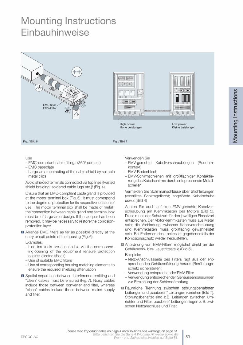
Use– EMC-compliant cable fittings (360º contact)– EMC baseplate– Large-area contacting of the cable shield by suitable
metal clips
Avoid shielded terminals connected via top lines (twistedshield braiding; soldered cable lugs etc.)! (Fig. 4)
Ensure that an EMC-compliant cable gland is providedat the motor terminal box (Fig. 5). It must correspondto the degree of protection for its respective location ofuse. The motor terminal box shall be made of metall,the connection between cable gland and terminal boxmust be of large-area design. If the lacquer has beenremoved, it may be necessary to restore the corrosion-protection layer.
Arrange EMC filters as far as possible directly at theentry or exit points of the housing (Fig. 6).
Examples:– Line terminals are accessable via the correspond-
ing opening of the equipment (ensure protectionagainst electric shock)
– Use of suitable EMC filters– Use of corresponding housing matching elements to
ensure the required shielding attenuation
Spatial separation between interference-emitting and“clean” cables must be ensured (Fig. 7). Noisy cablesinclude those between converter and filter, whereas“clean” cables include those between mains supplyand filter.
8
7
Verwenden Sie– EMV-gerechte Kabelverschraubungen (Rundum-
kontakt)– EMV-Bodenblech– EMV-Schirmschienen mit großflächiger Kontaktie-
rung des Kabelschirms durch entsprechende Metall-schellen
Vermeiden Sie Schirmanschlüsse über Stichleitungen(verdrilltes Schirmgeflecht; angelötete Kabelschuheusw.)! (Bild 4)
Achten Sie auch auf eine EMV-gerechte Kabelver-schraubung am Klemmkasten des Motors (Bild 5).Diese muss der Schutzart für den jeweiligen Einsatzortentsprechen. Der Motorklemmkasten muss aus Metallsein; die Verbindung zwischen Kabelverschraubungund Klemmkasten muss großflächig gewährleistetsein. Bei Entfernen des Lackes ist gegebenenfalls derKorrosionsschutz wieder herzustellen.
Anordnung von EMV-Filtern möglichst direkt an derGehäuseein- bzw. -austrittsstelle (Bild 6).
Beispiele:– Netz-Anschlussseite des Filters ragt aus der ent-
sprechenden Gehäuseöffnung heraus (Berührungs-schutz sicherstellen!)
– Verwendung entsprechender EMV-Filter– Verwendung entsprechender Gehäuseanpassungen
zur Erreichung der Schirmdämpfung
Räumliche Trennung zwischen störungsbehaftetenLeitungen und „sauberen“ Leitungen vorsehen (Bild 7).Störungsbehaftet sind z.B. Leitungen zwischen Um-richter und Filter, „saubere“ Leitungen liegen z.B. zwi-schen Netzanschluss und Filter.
8
7
EPCOS AG 53
Mounting InstructionsEinbauhinweise
Mo
untin
g In
stru
ctio
ns
Please read Important notes on page 4 and Cautions and warnings on page 61.Bitte beachten Sie die Seite 4 Wichtige Hinweise sowie die
Warn- und Sicherheitshinweise auf Seite 61.
Filter
EMC filterEMV-Filter
High powerHohe Leistungen
Low powerKleine Leistungen
Fig. / Bild 6 Fig. / Bild 7
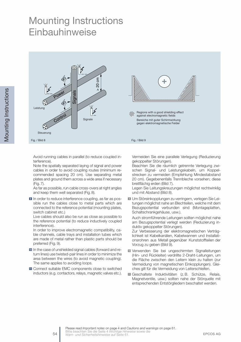
54 EPCOS AG
Mounting InstructionsEinbauhinweise
Mo
untin
g In
stru
ctio
ns
Avoid running cables in parallel (to reduce coupled in-terference).Note the spatially separated laying of signal and powercables in order to avoid coupling routes (minimum re-commended spacing 20 cm). Use separating metalplates and ground them across a wide area if necessary(Fig. 7).As far as possible, run cable cross-overs at right anglesand keep them well separated (Fig. 8).
In order to reduce interference coupling, as far as pos-sible run the cables close to metal parts which areconnected to the reference potential (mounting plates,switch cabinet etc.)Live cables should also be run as close as possible tothe reference potential (to reduce inductively coupledinterference).In order to improve electromagnetic compatibility, ca-ble channels, cable trays and installation tubes whichare made of metal rather than plastic parts should bepreferred (Fig. 9).
In the case of unshielded signal cables (forward and re-turn lines) use twisted-pair lines in order to minimize thearea between the wires (to avoid magnetic coupling).The same applies to avoiding loops.
Connect suitable EMC components close to switchedinductors (e.g. contactors, relays, magnetic valves etc.).
11
10
9
Vermeiden Sie eine parallele Verlegung (Reduzierunggekoppelter Störungen).Beachten Sie die räumlich getrennte Verlegung zwi-schen Signal- und Leistungskabeln, um Koppel-strecken zu vermeiden (Empfehlung Mindestabstand20 cm). Gegebenenfalls Trennbleche vorsehen; diesebreitflächig erden (Bild 7).Legen Sie Leitungskreuzungen möglichst rechtwinkligund mit Abstand (Bild 8).
Um Störeinkopplungen zu verringern, verlegen Sie Lei-tungen möglichst nahe an Blechteilen, welche mit demBezugspotential verbunden sind (Montageplatten,Schaltschrankgehäuse, usw.).
Auch stromführende Leitungen sollten möglichst naheam Bezugspotential verlegt werden (Reduzierung in-duktiv gekoppelter Störungen).Zur Verbesserung der elektromagnetischen Verträg-lichkeit ist Kabelkanälen, Kabelwannen und Installati-onsrohren aus Metall gegenüber Kunststoffteilen derVorzug zu geben (Bild 9).
Verwenden Sie bei ungeschirmten Signalleitungen(Hin- und Rückleiter) verdrillte 2-Draht-Leitungen, umdie Fläche zwischen den Leitern klein zu halten (zurVermeidung von magnetischen Einkopplungen). Glei-ches gilt für die Vermeidung von Leiterschleifen.
Geschaltete Induktivitäten (z.B. Schütze, Relais,Magnetventile, usw.) sollten nahe der Störquelle mitentsprechenden Entstörgliedern beschaltet werden.
11
10
9
Please read Important notes on page 4 and Cautions and warnings on page 61.Bitte beachten Sie die Seite 4 Wichtige Hinweise sowie die Warn- und Sicherheitshinweise auf Seite 61.
Leistung
Steuerung
Signale
Regions with a good shielding effectagainst electromagnetic fields
Bereiche mit guter Schirmwirkung gegen elektromagnetische Felder
Fig. / Bild 8 Fig. / Bild 9
EPCOS AG 55
Mounting InstructionsEinbauhinweise
Mo
untin
g In
stru
ctio
ns
For control signals in the vicinity of high interferencelevels, use transmission techniques such as:
– Differential-mode transmission systems with twisted-pair lines in conjunction with data line chokes (seealso our data book “Chokes and Inductors”).
– Transmission of digital signals acc. to the RS-422standard or in extreme cases crossing the interfer-ence region with fiber-optic cables.
Note the mounting position of the filters! The as-sembly must always take care not to impair naturalconvection. This includes the use of ventilation slits inthe filter housing and sufficient spacing to the othercomponents. Over-head mounting is never permissi-ble. In the event of unusual mounting situations, thethermal conditions shall be checked after coordinationwith EPCOS.
Noise minimization
A choke made of highly diverse core materials re-presents a significant frequency-dependent filter com-ponent. Electro-acoustic effects must inevitably beexpected in AC applications. The materials and pro-cessing used generate (for industrial sector) suitablenoise levels by operation in networks with harmonicscomplying to EN 50160. However, these can rise sig-nificantly in the event of higher harmonic components.For sensitive applications such as office installation,therefore, customers should contact EPCOS for advice.
Length of motor cables and motor types used (Fig. 10).
For converter applications, output voltages are gene-rated that typically have almost rectangular wave-forms. These are essentially characterized by the riserate expressed as the dv/dt value and the switchingfrequency of the converter. The cables and motors pre-sent in the output network of the converter with theirinductive and capacitive components significantlydetermine the EMC properties of the system. Thusresonances of the cable/motor combination are oftenreflected in the resonance of the interference voltagemeasurement at the converter input.
15
14
13
12 Verwenden Sie für Steuersignale in der Umgebunghoher Störpegel entsprechende Schaltungstechnik,z.B.:
– Symmetrische Übertragungssysteme mit verdrill-ten Leitungspaaren in Verbindung mit Datenlei-tungsdrosseln (siehe auch unser Datenbuch„Drosseln und Induktivitäten“),
– Übertragung von Digitalsignalen entspr. RS-422-Standard oder in extremen Fällen Durchqueren desStörbereiches mittels Lichtleiter.
Beachten Sie die Einbaulage der Filter! Die Monta-ge muss grundsätzlich so erfolgen, dass die natürlicheKonvektion nicht beeinträchtigt wird. Dazu gehört dieBerücksichtigung von Lüftungsschlitzen im Filterge-häuse und der ausreichende Abstand zu anderen Ein-bauten. Überkopfmontage ist grundsätzlich ausge-schlossen. Bei besonderen Einbausituationen ist inRücksprache mit EPCOS eine Prüfung der thermi-schen Bedingungen erforderlich.
Geräuschminimierung
Ein wesentliches frequenzabhängiges Filterbauele-ment ist die Drossel mit sehr unterschiedlichen Kern-materialien. In Wechselspannungsapplikationen istzwangsläufig mit elektroakustischen Effekten zurechnen. Die eingesetzten Materialien und Verar-beitungstechnologien erzeugen bei Einhaltung derOberschwingungsanteile entsprechend der Norm EN 50160 für den Einsatz im Industriebereich an-gemessene Geräuschpegel. Diese können jedoch bei höheren Oberschwingungsanteilen deutlich an-steigen. Bei sensiblen Applikationen, wie der Montageim Büro, sollte die Beratung von EPCOS in Anspruchgenommen werden.
Motorleitungen und Motortypen (Bild 10).
Bei Umrichterapplikationen werden Ausgangsspan-nungen erzeugt, welche nahezu rechteckige Kurven-formen besitzen. Diese werden im Wesentlichen durchdie Anstiegsgeschwindigkeit als du/dt-Wert und dieSchaltfrequenz des Umrichters charakterisiert. Die imAusgangsnetzwerk des Umrichters liegenden Kabelund Motoren mit ihren induktiven und kapazitivenKomponenten bestimmen die EMV-Eigenschaften desSystems wesentlich. So sind Resonanzen der Kombi-nation von Kabel und Motor in vielen Fällen als Reso-nanz der Störspannungsmessung am Umrichterein-gang wiederzufinden.
15
14
13
12
Please read Important notes on page 4 and Cautions and warnings on page 61.Bitte beachten Sie die Seite 4 Wichtige Hinweise sowie die
Warn- und Sicherheitshinweise auf Seite 61.
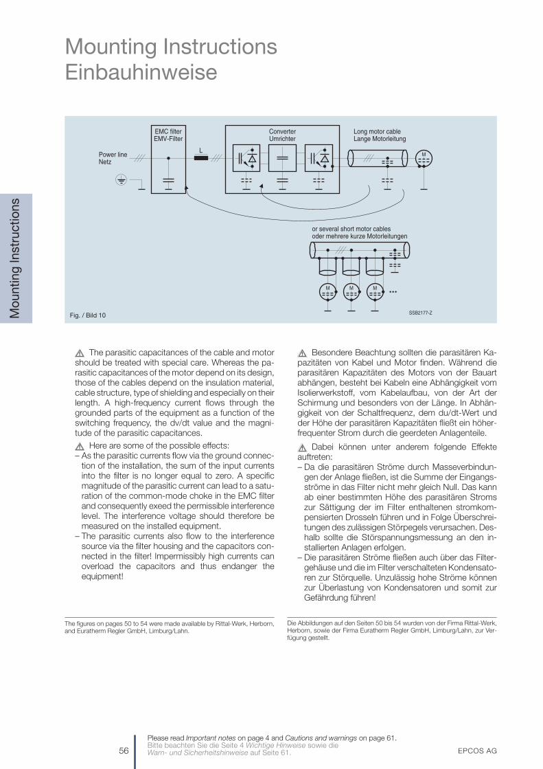
56 EPCOS AG
Mounting InstructionsEinbauhinweise
Mo
untin
g In
stru
ctio
ns
The parasitic capacitances of the cable and motorshould be treated with special care. Whereas the pa-rasitic capacitances of the motor depend on its design,those of the cables depend on the insulation material,cable structure, type of shielding and especially on theirlength. A high-frequency current flows through thegrounded parts of the equipment as a function of theswitching frequency, the dv/dt value and the magni-tude of the parasitic capacitances.
Here are some of the possible effects:– As the parasitic currents flow via the ground connec-
tion of the installation, the sum of the input currentsinto the filter is no longer equal to zero. A specificmagnitude of the parasitic current can lead to a satu-ration of the common-mode choke in the EMC filterand consequently exeed the permissible interferencelevel. The interference voltage should therefore bemeasured on the installed equipment.
– The parasitic currents also flow to the interferencesource via the filter housing and the capacitors con-nected in the filter! Impermissibly high currents canoverload the capacitors and thus endanger theequipment!
The figures on pages 50 to 54 were made available by Rittal-Werk, Herborn,and Euratherm Regler GmbH, Limburg/Lahn.
Besondere Beachtung sollten die parasitären Ka-pazitäten von Kabel und Motor finden. Während dieparasitären Kapazitäten des Motors von der Bauartabhängen, besteht bei Kabeln eine Abhängigkeit vomIsolierwerkstoff, vom Kabelaufbau, von der Art derSchirmung und besonders von der Länge. In Abhän-gigkeit von der Schaltfrequenz, dem du/dt-Wert undder Höhe der parasitären Kapazitäten fließt ein höher-frequenter Strom durch die geerdeten Anlagenteile.
Dabei können unter anderem folgende Effekteauftreten:– Da die parasitären Ströme durch Masseverbindun-
gen der Anlage fließen, ist die Summe der Eingangs-ströme in das Filter nicht mehr gleich Null. Das kannab einer bestimmten Höhe des parasitären Stromszur Sättigung der im Filter enthaltenen stromkom-pensierten Drosseln führen und in Folge Überschrei-tungen des zulässigen Störpegels verursachen. Des-halb sollte die Störspannungsmessung an den in-stallierten Anlagen erfolgen.
– Die parasitären Ströme fließen auch über das Filter-gehäuse und die im Filter verschalteten Kondensato-ren zur Störquelle. Unzulässig hohe Ströme könnenzur Überlastung von Kondensatoren und somit zurGefährdung führen!
Die Abbildungen auf den Seiten 50 bis 54 wurden von der Firma Rittal-Werk,Herborn, sowie der Firma Euratherm Regler GmbH, Limburg/Lahn, zur Ver-fügung gestellt.
Please read Important notes on page 4 and Cautions and warnings on page 61.Bitte beachten Sie die Seite 4 Wichtige Hinweise sowie die Warn- und Sicherheitshinweise auf Seite 61.
SSB2177-Z
L
Converter
Power line
EMC filter
M
Long motor cable
or several short motor cables
M
MM
Netz
Umrichter Lange Motorleitung
oder mehrere kurze Motorleitungen
EMV-Filter
Fig. / Bild 10

EPCOS AG 57
Components for Discrete Filter SolutionsBauelemente für diskrete Filterlösungen
Dis
cret
eFi
lter
Sol
utio
ns
Please read Important notes on page 4 and Cautions and warnings on page 61.Bitte beachten Sie die Seite 4 Wichtige Hinweise sowie die
Warn- und Sicherheitshinweise auf Seite 61.
Chokes for power linesDrosseln für Netzanwendungen
0.0
01
0.0
10
0.1
0
1.0
10
100
0.1
0
1.0
10
100
Type Version VR LR (mH) IR (A)Bauform
V AC
Asymmetrical interferencesAsymmetrische Störungen
Current- B82720S Double 250compensated Zweifachring core chokes
StromkompensierteRingkern-Drosseln
B82720A Double 250B82720K Zweifach
B82791H Double 250B82791G Zweifach
B82721... Double 250B82725 Zweifach
B82726S Double 250Zweifach
B82747 Triple 440Dreifach
B82745 Triple 440Dreifach
B82765 Quad 440Vierfach
Current- B82731... Double 250compensated B82734 ZweifachD core chokes
StromkompensierteD-Kern-Drosseln
Current- B82731T Double 250compensated ZweifachE core chokes
StromkompensierteE-Kern-Drosseln
Current- B82732F Double 250compensated B82733F ZweifachFC core chokes
StromkompensierteFC-Kern-Drosseln

58 EPCOS AG
Components for Discrete Filter SolutionsBauelemente für diskrete Filterlösungen
Dis
cret
eFi
lter
Sol
utio
ns
Please read Important notes on page 4 and Cautions and warnings on page 61.Bitte beachten Sie die Seite 4 Wichtige Hinweise sowie die Warn- und Sicherheitshinweise auf Seite 61.
Chokes for power linesDrosseln für Netzanwendungen
0.0
01
0.0
10
0.1
0
1.0
10
100
0.1
0
1.0
10
100
Ring core chokeswith powder core
Ringkerndrosselnmit Pulverkern
Type Version VR LR (mH) IR (A)Bauform
V AC
Symmetrical interferencesSymmetrische Störungen
I core chokes B82502 Single and 500Stabkerndrosseln B82522 Double
Ein- undzweifach
B82503 Single and 400B82523 Double
Ein- undzweifach
B82504 Single 500B82505 EinfachB82506
B82623 Double 250B82424 Zweifach
B82615 Single and 250B82625 Double
Ein- undzweifach
B82617 Single and 250B82627 Double
Ein- undzweifach
Sine-wave chokes B82614 Single 250Sinusdrosseln Einfach
Detailed information about power line chokesAusführliche Informationen über Netzdrosseln
Brochures Ordering code Online informationBroschüren Bestellnummer www.epcos.com
Product Profile: EPC:30002-7400 Product catalog / Product searchChokes and Inductors Product group: Inductors/ChokesDrosseln und Induktivitäten
Produkt-Katalog / Produkt-SucheProduktgruppe: Induktivitäten/Drosseln
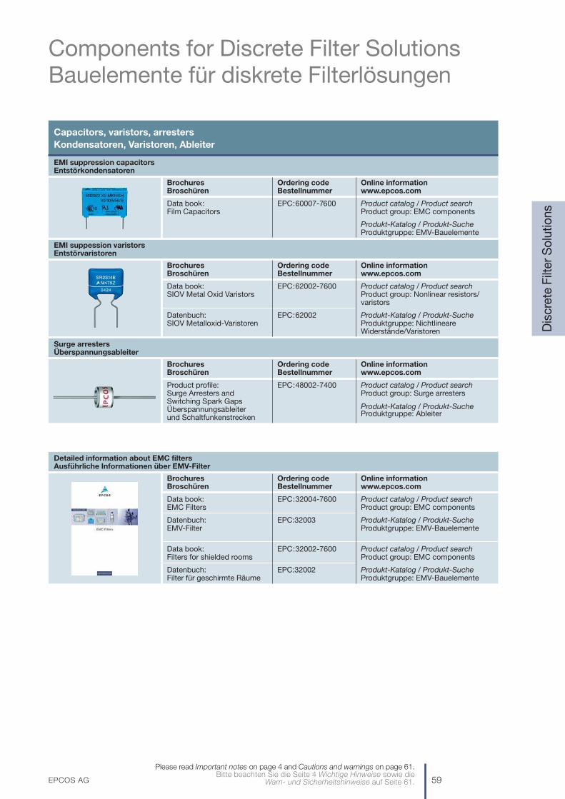
EPCOS AG 59
Components for Discrete Filter SolutionsBauelemente für diskrete Filterlösungen
Dis
cret
eFi
lter
Sol
utio
ns
Please read Important notes on page 4 and Cautions and warnings on page 61.Bitte beachten Sie die Seite 4 Wichtige Hinweise sowie die
Warn- und Sicherheitshinweise auf Seite 61.
Capacitors, varistors, arresters Kondensatoren, Varistoren, Ableiter
EMI suppression capacitorsEntstörkondensatoren
Brochures Ordering code Online informationBroschüren Bestellnummer www.epcos.com
Data book: EPC:60007-7600 Product catalog / Product searchFilm Capacitors Product group: EMC components
Produkt-Katalog / Produkt-SucheProduktgruppe: EMV-Bauelemente
EMI suppession varistorsEntstörvaristoren
Brochures Ordering code Online informationBroschüren Bestellnummer www.epcos.com
Data book: EPC:62002-7600 Product catalog / Product searchSIOV Metal Oxid Varistors Product group: Nonlinear resistors/
varistors
Datenbuch: EPC:62002 Produkt-Katalog / Produkt-SucheSIOV Metalloxid-Varistoren Produktgruppe: Nichtlineare
Widerstände/Varistoren
Surge arrestersÜberspannungsableiter
Brochures Ordering code Online informationBroschüren Bestellnummer www.epcos.com
Product profile: EPC:48002-7400 Product catalog / Product searchSurge Arresters and Product group: Surge arrestersSwitching Spark GapsÜberspannungsableiter Produkt-Katalog / Produkt-Suche
und Schaltfunkenstrecken Produktgruppe: Ableiter
Detailed information about EMC filtersAusführliche Informationen über EMV-Filter
Brochures Ordering code Online informationBroschüren Bestellnummer www.epcos.com
Data book: EPC:32004-7600 Product catalog / Product searchEMC Filters Product group: EMC components
Datenbuch: EPC:32003 Produkt-Katalog / Produkt-SucheEMV-Filter Produktgruppe: EMV-Bauelemente
Data book: EPC:32002-7600 Product catalog / Product searchFilters for shielded rooms Product group: EMC components
Datenbuch: EPC:32002 Produkt-Katalog / Produkt-SucheFilter für geschirmte Räume Produktgruppe: EMV-Bauelemente
60 EPCOS AG
Environmental ProtectionUmweltschutz
Envi
ronm
enta
l
Please read Important notes on page 4 and Cautions and warnings on page 61.Bitte beachten Sie die Seite 4 Wichtige Hinweise sowie die Warn- und Sicherheitshinweise auf Seite 61.
Global environmental management
With our global environmental management in accordancewith ISO 14001 we are protecting the environment to thesame high standard in all parts of the world. The samerequirements are placed on every EPCOS site; externalinstitutes ensure, at regular intervals, that they are beingobserved.
As well as satisfying both statutory requirements and thoseimposed by the relevant authorities, our environmental man-agement system aims to utilize natural resources efficiently.For that reason, we use our technological expertise todesign and manufacture our passive electronic componentsin the most environmentally compatible way possible. Weare continuously optimizing our products and processes inorder to use materials in a way that minimizes the impact onresources, to use substitutes for hazardous materialswherever possible, and to reduce waste to a minimum.
An obligatory list of materials and substances has its foun-dations in our environmental management system, andthis guarantees that a consistent procedure is applied to allEPCOS products. We are, moreover, active on a largenumber of committees, working groups and commissionsassociated with the electronics industry, with the aim ofpushing forward the standardization of material data sheetsfor passive electronic components. The materials containedin our products are listed in detail on this material datasheets, so that customers, in turn, can satisfy the environ-mental conditions imposed upon them.
RoHS compatibility
All EMC filters in this publication are RoHS-compatible.The following definition applies here:
RoHS-compatible is defined as being compatible with thefollowing documents:
DIRECTIVE 2002/95/EC OF THE EUROPEAN PARLIA-MENT AND OF THE COUNCIL dated 13 February 2003restricting the use of certain hazardous substances inelectrical and electronic equipment.
According to 2005/618/EC dated August 18th, 2005,amending Directive 2002/95/EC of the EuropeanParliament and of the Council for the purpose of estab-lishing the maximum concentration levels for certain haz-ardous substances in electrical and electronic equipment,a maximum concentration value of 0.1% by weight inhomogeneous materials for lead, mercury, hexavalentchromium, polybrominated biphenyls (PBB) and poly-brominated diphenylethers (PBDE), and of 0.01% byweight in homogeneous materials for cadmium, shall betolerated.
It should be noted that the concentration levels specifiedabove may be exceeded for some products or productgroups in the event of technical necessity and on the basisof the exceptional stipulations of the Annex to2005/95/EU including relevant extensions by decision ofthe Commission.
Globales Umweltmanagement
Mit unserem globalen Umweltmanagement nach ISO 14001sorgen wir für Umweltschutz auf weltweit gleich hohemNiveau. Für alle EPCOS-Standorte gelten dieselbenAnforderungen, deren Einhaltung in regelmäßigenAbständen von externen Instituten geprüft wird.
Neben dem Erfüllen behördlicher und gesetzlicherAuflagen ist es das Ziel unseres Umweltmanagements,natürliche Ressourcen effizient einzusetzen. Dazu ge-stalten wir auf der Grundlage unserer Technologie-kompetenz unsere passiven elektronischen Bauelementeund deren Herstellung so umweltverträglich wie möglich.Unsere Produkte und Prozesse optimieren wir kontinuierlichhinsichtlich eines Ressourcen schonenden Material-einsatzes, substituieren Gefahrenstoffe nach Möglichkeitund reduzieren Abfälle auf ein Minimum.
In unserem Umweltmanagement-System ist eine ver-bindliche Material- und Substanzliste verankert, die fürEPCOS-Produkte ein einheitliches Vorgehen garantiert.Darüber hinaus sind wir in zahlreichen Gremien,Arbeitsgruppen und Kommissionen der Elektronik-industrie tätig, um die Standardisierung von Material-datenblättern passiver elektronischer Bauelementevoranzutreiben. Die Inhaltsstoffe unserer Produkte sind insolchen Materialdatenblättern detailliert aufgeführt, damitKunden wiederum die an sie gestellten Umweltauflagenerfüllen können.
RoHS-Kompatibilität
Alle EMV-Filter in dieser Publikation sind RoHS-kompati-bel. Hierzu gilt folgende Definition:
RoHS-kompatibel bedeutet, dass die Anforderungenfolgender Dokumente erfüllt werden:
Richtlinie 2002/95/EG des Europäischen Parlaments unddes Rates vom 13. Februar 2003 zur Beschränkung derVerwendung bestimmter gefährlicher Stoffe in Elektro-und Elektronikgeräten.
Gemäß der Entscheidung 2005/618/EG vom 18. August2005, die die Richtlinie 2002/95/EG des EuropäischenParlaments und des Rates zum Zwecke der Festlegungmaximaler Konzentrationswerte für bestimmte gefähr-liche Stoffe in Elektro- und Elektronikgeräten ergänzt, wirdin homogenen Materialien eine maximale Konzentrationbezogen auf das Gewicht von 0,1% für Blei, Quecksilber,sechswertiges Chrom, polybromierte Biphenyle (PBB)und polybromierte Diphenylether (PBDE) sowie 0,01% fürCadmium toleriert.
Zu beachten ist, dass falls technisch notwendig und unter Berücksichtigung der Ausnahmeregelungen desAnhangs der 2005/95/EU inkl. der entsprechendenErweiterungen durch Kommissionsentscheid, die o.a.Stoffkonzentrationen bei einzelnen Produkten oderProduktgruppen überschritten werden können.
EPCOS AG 61
Cautions and WarningsWarn- und Sicherheitshinweise
Please read Important notes on page 4 and Cautions and warnings on page 61.Bitte beachten Sie die Seite 4 Wichtige Hinweise sowie die
Warn- und Sicherheitshinweise auf Seite 61.
Gen
eral
n Please note Cautions and warnings in our data book“EMC Filters”, edition 2006 and in the Internet.
n Please read all safety and warning notes carefullybefore installing the EMC filter and putting it into oper-ation. The same applies to the warning signs on thefilter. Please ensure that the signs are not removed northeir legibility impaired by external influences.
n It shall be ensured that only qualified persons (electric-ity specialists) are engaged on work such as planning,assembly, installation, operation, repair and mainte-nance. They must be provided with the correspondingdocumentation.
n Danger of electric shock! EMC filters contain compo-nents that store an electric charge. Dangerous voltagescan continue to exist at the filter terminals for longerthan five minutes even after the power has beenswitched off.
n The protective earth connections shall be the first to bemade when the EMC filter is installed and the last to bedisconnected. Depending on the magnitude of theleakage currents, the particular specifications for mak-ing the protective-earth connection must be observed.
n Impermissible overloading of the EMC filter, such aswith circuits able to cause resonances, impermissiblevoltages at higher frequencies etc. can lead to bodily in-jury and death as well as cause substantial materialdamages (e.g. destruction of the filter housing).
n EMC filters must be protected in the application againstimpermissible exceeding of the rated currents by over-current protective.
n In case of leakage currents > 3.5 mA you shall mountthe PE conductor stationary with the required crosssection before beginning of operation and save itagainst disconnecting.For leakage currents IL1) < 10 mA the PE conductormust have a KU value 2) of 4.5; for leakage currents IL ≥ 10 mA the PE conductor musthave a KU value of 6.
1) IL = leakage current let-go2) The KU value (symbol KU) is a classification parameter of safety-referred
failure types designed to ensure protection against hazardous body currentsand excessive heating.A value of KU = 4.5 with respect to interruptions is attained:– with a permanently connected protective earth circuit ≥ 1.5 mm2
– with a protective earth circuit ≥ 2.5 mm2 connected via shroud connec-tors (IEC 60309-2).
KU = 6 with respect to interruptions is achieved for fixed-connection lines≥ 10 mm2 where the type of connection and line layout correspond to therequirements for PEN conductors as specified in relevant standards.
n Bitte beachten Sie auch die Generellen Sicherheitshin-weise in unserem Datenbuch „EMV-Filter“, Ausgabe2006 bzw. Cautions and warnings im Internet.
n Bitte lesen Sie vor der Installation und Inbetriebnahmedes EMV-Filters alle Sicherheits- und Warnhinweisesorgfältig durch. Dieses gilt auch für die am Filter ange-brachten Warnschilder. Bitte achten Sie darauf, dassdie Schilder nicht entfernt werden oder die Lesbarkeitdurch äußere Einflüsse beeinträchtigt wird.
n Es ist zu gewährleisten, dass nur qualifizierte Personen(entsprechend Definition Elektrofachkräfte) mit denArbeiten Planung, Montage, Installation, Inbetriebnah-me, Reparatur und Wartung beauftragt werden. DiesenPersonen sind die entsprechenden Unterlagen zur Ver-fügung zu stellen.
n Gefährdung durch elektrischen Schlag: EMV-Filter ent-halten ladungsspeichernde Bauelemente. An denFilteranschlüssen können auch nach Abschalten derNetzspannung länger als 5 Minuten gefährliche Span-nungen anliegen.
n Bei der Installation des EMV-Filters sind grundsätzlichdie Schutzleiterverbindungen als erstes anzuschließen.Bei der Deinstallation sind sie als letztes zu entfernen.In Abhängigkeit der Höhe der Ableitströme sind die be-sonderen Vorschriften für die Ausführung der Schutz-leiterverbindung zu beachten.
n Unzulässige Überlastung der EMV-Filter, wie z. B. durchresonanzfähige Kreise und unzulässige höherfrequenteSpannungsbelastungen, können zu schweren Körper-verletzungen und Tod sowie erheblichen Sachschädenführen (z. B. durch Bersten des Filtergehäuses).
n EMV-Filter sind in der Applikation durch geeigneteÜberstromschutzeinrichtungen gegen unzulässigeÜberschreitung der Bemessungströme zu schützen.
n Im Fall von Ableitströmen > 3,5 mA muss vor der In-betriebnahme der Schutzleiter mit dem vorgeschriebe-nen Leiterquerschnitt angeschlossen und gegenLockern gesichert werden! Mindestforderung für denSchutzleiter:KU-Wert1) = 4,5 für Ableitströme IL2) < 10 mA bzw. KU-Wert = 6 für IL ≥ 10 mA.
1) Der KU–Wert ist eine Klassifizierungsgröße von sicherheitsbezogenenAusfallarten zum Schutz gegen gefährliche Körperströme und zu hoheErwärmung.Ein Wert von KU = 4,5 in Bezug auf Unterbrechung wird erreicht:– bei fest angeschlossener Schutzleiterverbindung ≥ 1,5 mm2
– bei einer Schutzleiterverbindung ≥ 2,5 mm2 über Steckverbinder für industrielle Anlagen (IEC 60309-2).
KU = 6 in Bezug auf Unterbrechung wird erreicht bei fest angeschlossenenLeitern ≥ 10 mm2, wobei Anschlussart und Verlegung den Anforderungenfür PEN-Leitern gemäß gültigen Normen entsprechen.
2) IL = Ableitstrom – Loslassen (let-go)

62 EPCOS AG
AppendixAnhang
Ap
pen
dix
Please read Important notes on page 4 and Cautions and warnings on page 61.Bitte beachten Sie die Seite 4 Wichtige Hinweise sowie die Warn- und Sicherheitshinweise auf Seite 61.
Index of typesBauformenverzeichnis
Type Page Type Page Type PageBauform Seite Bauform Seite Bauform Seite
B84103 22
B84108 39
B84110A 22
B84110B 23
B84111A 16
B84111F 14
B84112B 17
B84112G 15
B84113C 17
B84113H 15
B84114D 18
B84115E 18
B84131 39
B84131-PLC 41
B84132-MBS 41
B84134-MBS 41
B84142A*G075 20
B84142A*R000 20
B84142A*R122 19
B84142A*R123 19
B84142A*S002 21
B84142A*S003 21
B84142A*S018 21
B84142B*R000 20
B84143A*R000 26
B84143A*R021 33
B84143A*R105 25
B84143A*R106 24
B84143A*R206 27
B84143A*R410 40
B84143B*R000 28
B84143B*R110 29
B84143B*S020 32
B84143B*S021 32
B84143B*S024 33
B84143B*S080 31
B84143B*S081 31
B84143D*R127 34
B84143G*R110 30
B84143V*R027 35
B84143V*R127 35
B84144A*R000 38
B84144A*R120 36
B84144B*S120 37
B84144B*S121 37
B84261C,D 44
B84263C,D 44
B84299C,D 43, 44
B84299K0061 … B84299K0067 23
B84312 45, 46
B85111 13
B85121 12, 13
B85321 10, 11
Symbols and termsSymbole und Begriffe
Symbol Term Bedeutung
CR Rated capacitance Bemessungskapazität
fmeas Measuring frequency Messfrequenz
Ileak / IAbl Leakage current of filter Filter-Ableitstrom
IR Rated current Bemessungsstrom
LR Rated inductance Bemessungsinduktivität
Ploss / PV Power loss Verlustleistung
Rmax DC resistance, maximum value Gleichstromwiderstand, max. Wert
Rtyp DC resistance, typical value Gleichstromwiderstand, typischer Wert
Vtest Test voltage Prüfspannung
VR Rated voltage Bemessungsspannung
ZL Line impedance Leitungsimpedanz

Get in Contact
Europe
Austria, Bulgaria, Montenegro,Romania, SerbiaEPCOS OHGViennaT +43 51 70 72 56 30F +43 51 70 75 56 [email protected]
Czech RepublicEPCOS s.r.o.PragueT +420 2 33 03 22 81F +420 2 33 03 22 [email protected]
FinlandEPCOS Nordic OYEspooT +358 10 5 11 32 00F +358 10 5 11 22 [email protected]
France, Belgium, Luxembourg,Malta, NetherlandsEPCOS SASSaint-Denis/FranceT +33 1 49 46 67 89F +33 1 49 46 67 [email protected]
Germany, Liechtenstein,SwitzerlandEPCOS AGCustomer ServiceMunichT (D) 0180 500 33 48
(0.14 Euro/min.)(CH) 08 48 37 26 71
F +49 89 63 62 80 [email protected]
GreeceEPCOS OHGViennaT +43 51 70 72 56 30F +43 51 70 75 56 [email protected]
HungaryEPCOS ElektronikaiAlkatrész Kft.BudapestT +36 1 436 07 20F +36 1 436 07 [email protected]
ItalySiemens S. p. A.Settore EPCOSMilanT +39 02 24 36 42 65F +39 02 24 36 44 [email protected]
Poland, Latvia, LithuaniaSiemens Sp.z.o.oEPCOS DivisionWarsawT +48 22 8 70 91 51F +48 22 8 70 91 [email protected]
PortugalEPCOS 2 Portugal LDAÉvoraT +351 91 75 67 927F +351 21 49 33 [email protected]
Russia, Belarus, Kazakhstan,Moldavia, UkraineOOO SiemensEPCOS DivisionMoscowT +7 495 7 37 24 17 / 18F +7 495 7 37 23 [email protected]
SlovakiaEPCOS Sales AgencyDolný KubínT +42 1 43 5 82 36 73F +42 1 43 5 82 37 [email protected]
Slovenia, Croatia,Bosnia & HerzegovinaEPCOS Sales AgencyŠkofljica/SloveniaT +386 599 56 35 3F +386 599 56 35 [email protected]
SpainSiemens S.A.EPCOS DivisionMadridT +34 91 5 14 80 00F +34 91 5 14 70 [email protected]
Sweden, Estonia, Iceland,Denmark, NorwayEPCOS Nordic ABKista/SwedenT +46 8 4 77 27 00F +46 8 4 77 27 [email protected]
TurkeyEPCOS AGIstanbulT +90 216 5 69 81 01F +90 216 4 64 07 [email protected]
United Kingdom, IrelandEPCOS UK Ltd.BracknellT +44 13 44 38 15 10F +44 13 44 38 15 [email protected]
Asia
Afghanistan, Iran, Iraq,Jordan, Lebanon, SyriaEPCOS AGIstanbul/TurkeyT +90 216 5 69 81 01F +90 216 4 64 07 [email protected]
ChinaEPCOS (Shanghai) Ltd.ShanghaiT +86 21 33 02 46 20F +86 21 63 91 68 [email protected]
Hong KongEPCOS LimitedHong KongT +85 2 31 01 56 00F +85 2 31 01 56 [email protected]
India, Bahrain, Bangladesh,Kuwait, Nepal, Oman,Pakistan, Qatar, Saudi Arabia,Sri Lanka, United ArabEmiratesEPCOS India Private Ltd.BangaloreT +91 80 40 39 06 15F +91 80 40 39 06 [email protected]
IsraelNisko Projects Electronics &Communications (1999) Ltd.Tel AvivT +972 37 65 73 00F +972 37 65 73 [email protected]
JapanEPCOS KKYokohamaT +81 45 4 78 72 00F +81 45 4 78 72 [email protected]
KoreaSiemens Ltd.EPCOS DivisionSeoulT +82 2 34 50 75 70F +82 2 34 50 75 [email protected]
MalaysiaEPCOS SDN. BHD.Kuala LumpurT +60 3 79 60 81 80F +60 3 79 60 81 [email protected]
PhilippinesSiemens Inc.EPCOS DivisionManilaT +63 2 8 78 94 41F +63 2 8 78 94 [email protected]
Singapore, Indonesia,Thailand, VietnamEPCOS PTE LTDSingaporeT +65 68 41 20 11F +65 67 44 69 [email protected]
TaiwanEPCOS Taiwan Co. Ltd.TaipeiT +886 2 26 55 76 76F +886 2 55 59 02 [email protected]
Americas
USA, Canada, MexicoEPCOS, Inc.Iselin, NJ, USAT +1 732 9 06 43 00F +1 732 9 06 43 [email protected]
South AmericaEPCOS do Brasil Ltda.São PauloT +55 1 138 17 34 46F +55 1 138 17 34 [email protected]
Australia
Australia, New ZealandElectronic ComponentSolutions Pty LtdMelbourneT +61 3 85 61 19 19F +61 3 95 74 70 [email protected]
Africa
Republic of South AfricaElectrocomp (PTY) Ltd.SandtonT +27 11 458 90 00 32F +27 11 458 90 [email protected]
EgyptSiemens Ltd.EPCOS DivisionCairoT +202 333 36 69F +202 333 36 [email protected]
Morocco, TunisiaEPCOS SASSaint-Denis/FranceT +33 1 49 46 67 89F +33 1 49 46 67 [email protected]
04/07
The addresses of our worldwide distributors and regional sales offices are available at www.epcos.com/sales
Published by EPCOS AG, Corporate Center, P.O.Box 80 17 09, 81617 Munich, Germany, T +49 89 636 09, F +49 89 636 226 89Reproduction, publication and dissemination of this publication and the information contained therein without EPCOS' prior express consent is prohibited.
© EPCOS AG, Edition 05/2007, Printed in Germany, PS 05079. Ordering No. EPC:32006-7400
Related Documents