Product Overview: DWM1001-DEV DWM1001 Module Development Board Plug-and-Play Development Board for evaluating the performance of the Decawave DWM1001 module Easily assemble a fully wireless RTLS system, including anchors, tags & gateways, without designing any hardware or writing a single line of code – and quickly progress into developing your application Key Features and Benefits • DWM1001 module mounted (See DWM1001 data sheet for details) • USB connection for reprogramming, debug & power supply • On board JLINK • External API via SPI, UART & BLE for configuration & control • 26-pin Raspberry Pi compatible header • Reset and user-defined buttons and LEDs • Battery charging circuit • Allows access to DWM1001 pins (castellation) via on board headers

Welcome message from author
This document is posted to help you gain knowledge. Please leave a comment to let me know what you think about it! Share it to your friends and learn new things together.
Transcript

Product Overview: DWM1001-DEV
DWM1001 Module Development Board
Plug-and-Play Development Board for evaluating the performance of the Decawave DWM1001 module
Easily assemble a fully wireless RTLS system, including anchors, tags & gateways, without designing any hardware or writing a single line of code – and quickly progress into developing your application
Key Features and Benefits • DWM1001 module mounted (See DWM1001 data sheet for details)
• USB connection for reprogramming, debug & power supply
• On board JLINK
• External API via SPI, UART & BLE for configuration & control
• 26-pin Raspberry Pi compatible header
• Reset and user-defined buttons and LEDs
• Battery charging circuit
• Allows access to DWM1001 pins (castellation) via on board headers
DWM1001 Module Development Board Datasheet
© Decawave Ltd 2017 Subject to change without notice Version 1.0 Page 2
Table of Contents
1 OVERVIEW ................................................... 4
1.1 SUITABLE POWER SUPPLY OPTIONS ................. 5 1.2 BLOCK DIAGRAM OF THE DEVELOPMENT BOARD . 5
2 DWM1001 MODULE ..................................... 6
3 RASPBERRY PI INTERFACE ............................ 6
3.1 MEANS OF CONNECTION ................................ 6 3.2 DWM1001 MODULE PIN TO RASPBERRY PI
CONNECTOR MAPPING ............................................ 7
4 THE DEVELOPMENT BOARD LEDS ................. 9
5 ON BOARD JLINK ........................................ 10
6 POWER SUPPLY AND BATTERY CONNECTIONS 11
7 BUTTONS SW1 AND SW2 ............................ 11
8 DEVELOPMENT BOARD SOLDER BRIDGE JUMPERS ........................................................... 12
9 DEVELOPMENT BOARD SCHEMATIC ........... 13
10 REFERENCES ............................................ 14
11 DOCUMENT HISTORY .............................. 14
12 MAJOR CHANGES .................................... 14
13 ABOUT DECAWAVE ................................. 15
List of Figures
FIGURE 1 THE MAIN COMPONENTS OF THE MODULE
DEVELOPMENT BOARD ARE SHOWN ......................... 4 FIGURE 2: THE MODULE DEVELOPMENT BOARD CAN BE USED
TO CREATE AN ANCHOR, A TAG OR A GATEWAY ......... 4 FIGURE 3: MODULE DEVELOPMENT BOARD USED AS AN
ANCHOR, TAG OR GATEWAY DEVICE, IN AN RTLS
SYSTEM.............................................................. 4 FIGURE 4: THE MAIN SECTIONS OF THE DWM1001
MODULE DEVELOPMENT BOARD ............................ 5 FIGURE 5: BLOCK DIAGRAM OF DWM1001 MODULE ....... 6 FIGURE 6: RASPBERRY PI MODEL A TYPE WITH RIBBON CABLE
FOR CONNECTION TO THE MODULE DEVELOPMENT
BOARD .............................................................. 6
FIGURE 7: HEADER CONNECTOR WITH EXTENDED PIN
LENGTHS ............................................................ 7 FIGURE 8: PIN DESIGNATIONS OF THE RASPBERRY PI MODEL
A VARIANT.......................................................... 8 FIGURE 9: PIN DESIGNATIONS OF THE RASPBERRY PI MODEL
B VARIANT. ......................................................... 8 FIGURE 10: FRONT VIEW OF THE DWM1001-DEV
MODULE DEVELOPMENT BOARD ............................ 9 FIGURE 11: MODULE DEVELOPMENT BOARD JLINK
COMPONENTS ................................................... 10 FIGURE 12: PICTURE OF THE MODULE DEVELOPMENT BOARD
SHOWING THE BATTERY CONNECTION POINTS AND
BUTTONS .......................................................... 11
List of Tables
TABLE 1: POSSIBLE SOURCES OF POWER FOR THE MODULE
DEVELOPMENT BOARD .......................................... 5 TABLE 2: CONNECTIONS BETWEEN RASPBERRY PI AND
DWM1001 MODULE .......................................... 7 TABLE 3: THE FIRMWARE INDICATION LEDS .................... 9 TABLE 4: A LIST OF SOLDER JUMPERS AVAILABLE ON THE
MODULE DEVELOPMENT BOARD .......................... 12 TABLE 5: DOCUMENT HISTORY .................................... 14

DWM1001 Module Development Board Datasheet
© Decawave Ltd 2017 Subject to change without notice Version 1.0 Page 3
DOCUMENT INFORMATION
Disclaimer
Decawave reserves the right to change product specifications without notice. As far as possible changes to functionality and specifications will be issued in product specific errata sheets or in new versions of this document. Customers are advised to check with Decawave for the most recent updates on this product.
The DWM1001 module mounted on the DWM1001-DEV PCB is pre-loaded with firmware, please refer to the "DWM1001 Firmware User Guide" for disclaimer and license terms.
Copyright © 2017 Decawave Ltd
LIFE SUPPORT POLICY
Decawave products are not authorized for use in safety-critical applications (such as life support) where a failure of the Decawave product would reasonably be expected to cause severe personal injury or death. Decawave customers using or selling Decawave products in such a manner do so entirely at their own risk and agree to fully indemnify Decawave and its representatives against any damages arising out of the use of Decawave products in such safety-critical applications.
Caution! ESD sensitive device. Precaution should be used when handling the device in order to
prevent permanent damage.
REGULATORY APPROVALS
The DWM1001, as supplied from Decawave, has not been certified for use in any particular geographic region by the appropriate regulatory body governing radio emissions in that region although it is capable of such certification depending on the region and the manner in which it is used.
All products developed by the user incorporating the DWM1001 must be approved by the relevant authority governing radio emissions in any given jurisdiction prior to the marketing or sale of such products in that jurisdiction and user bears all responsibility for obtaining such approval as needed from the appropriate authorities.

DWM1001 Module Development Board Datasheet
© Decawave Ltd 2017 Subject to change without notice Version 1.0 Page 4
1 OVERVIEW This document gives technical details of the DWM1001 module development board, called the DWM1001-DEV. All the functions of the DWM1001 module can be exercised with this board. Figure 1 gives an overview of the main components of the module development board.
Figure 1 The main components of the module development board are shown
The module development board can be used to create an Anchor or a Tag for an RTLS system. This is shown in Figure 2. It can also be combined with a Raspberry Pi to create a gateway device. Figure 3 shows the configuration of an RTLS system where the module development board can be an Anchor, Tag or Gateway device.
Figure 2: The module development board can be used to create an Anchor, a Tag or a Gateway
Figure 3: Module development board used as an Anchor, Tag or Gateway device, in an RTLS system
Build an Anchor or a Tag Build a Gateway

DWM1001 Module Development Board Datasheet
© Decawave Ltd 2017 Subject to change without notice Version 1.0 Page 5
1.1 Suitable Power Supply Options
The module development board has a voltage supply requirement of 3.6V to 5.5V. The module development board can be powered from three different sources. Details are given in Table 1.
Table 1: Possible sources of power for the module development board
Power Source Voltage level Current level (Recommended)
Notes
USB Connection +5V 500mA The board requires a connection to a high power USB connection. Check that it can
supply at least 500mA.
Battery 3.6V - 5.5V 500mA Any battery that meets the 3.6V to 5.5V
voltage supply will suffice.
Raspberry Pi Power +5V 500mA
1.2 Block Diagram of the development board
Figure 4: The main sections of the DWM1001 Module Development Board
Figure 4 shows the main sections of the Module Development Board. A brief overview of these sections is given below with further details given in later sections of this document. The DWM1001 module is based on Decawave's DW1000 Ultra Wideband (UWB) transceiver IC, which is an IEEE 802.15.4-2011 UWB implementation. It integrates UWB and Bluetooth antenna, all RF circuitry, Nordic Semiconductor nRF52832 and motion sensor [1]. The USB connection can provide power to the Module Development Board and also allows for the capability to flash the DWM1001 module and furthermore to debug software running on the DWM1001 module. The Power Supply takes its input from USB or from a Battery or from a connected Raspberry Pi. It powers the module and the other devices on the Module Development Board. It can also charge a connected battery when powered by USB or the Raspberry Pi. Two buttons and a number of LEDs are provided for end user applications. A header to interface to the Raspberry Pi is also provided.

DWM1001 Module Development Board Datasheet
© Decawave Ltd 2017 Subject to change without notice Version 1.0 Page 6
2 DWM1001 MODULE Figure 5 shows a block diagram of the module. All major sections of the module are shown, along with the source of signals coming to the module's pins.
UWB Transceiver
Decawave DW1000
BLE Microprocessor
NordicnRF52832
64 MHz ARM Cortex M4
SPI M1*
3- Axis Motion Detector
STM LIS2DH12TR
BLE Antenna
UART [1:0]
SPI S2* [3:0]
I2C [1:0]
IRQ
UWB Antenna
VCC2.8 V – 3.6 V
DC-DCConverter
1V8
GPIORESET
SWD[1:0]
GPIO
BT_WAKE_UP
GND
READY
4
12
*SPI M1 is nRF52 SPI master 1, SPI S2 is SPI slave 2
Figure 5: Block diagram of DWM1001 module
3 RASPBERRY PI INTERFACE
3.1 Means of connection
There are a number of types of Raspberry Pi. The preferred options are the A and B variants. To use the A variant you will require a ribbon cable to connect to the Module Development Board. Figure 6 below shows a Raspberry Pi Model A with the ribbon cable connected.
Figure 6: Raspberry Pi Model A Type with ribbon cable for connection to the Module Development Board
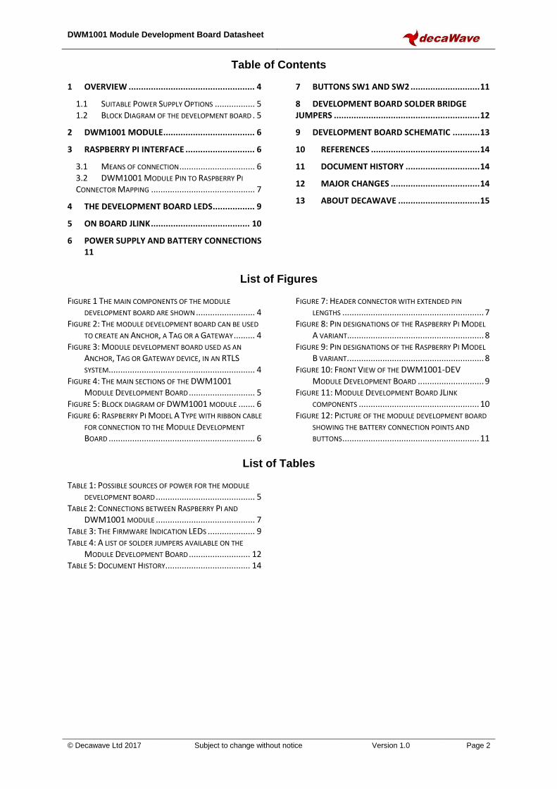
As an alternative to the ribbon cable it is possible to get header connectors with extra long pins. Such a connector is shown in Figure 7. One supplier of these connectors is https://www.modmypi.com. Search for part number MMP-0275.
DWM1001 Module Development Board Datasheet
© Decawave Ltd 2017 Subject to change without notice Version 1.0 Page 7
Figure 7: Header connector with extended pin lengths
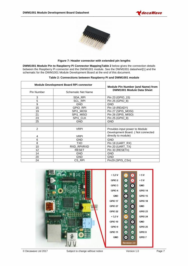
DWM1001 Module Pin to Raspberry Pi Connector MappingTable 2 below gives the connection details
between the Raspberry Pi connector and the DWM1001 module. See the DWM1001 datasheet[1] and the schematic for the DWM1001 Module Development Board at the end of this document.
Table 2: Connections between Raspberry Pi and DWM1001 module
Module Development Board RPi connector Module Pin Number (and Name) from
DWM1001 Module Data Sheet Pin Number Schematic Net Name
3 SDA_RPI Pin 23 (GPIO_15)
5 SCL_RPI Pin 25 (GPIO_8)
9 GND GND
15 GPIO_RPI Pin 19 (READY)
19 SPI1_MOSI Pin 27 (SPIS_MOSI)
21 SPI1_MISO Pin 26 (SPIS_MISO)
23 SPI1_CLK Pin 25 (GPIO_8)
25 GND GND
2 VRPI Provides input power to Module Development Board. ( Not connected directly to module)
4
VRPI
6 GND GND
8 TXD Pin 18 (UART_RX)
10 RXD_RPI/RXD Pin 20 (UART_TX)
12 RESET Pin 33 (RESETn)
14 GND GND
20 GND GND
24 CS_RPI Pin29 (SPIS_CSn)

DWM1001 Module Development Board Datasheet
© Decawave Ltd 2017 Subject to change without notice Version 1.0 Page 8
Figure 8: Pin designations of the Raspberry Pi Model A variant.
Figure 8 shows the pin designations for the model A Raspberry Pi variant. The Raspberry Pi Model B variant has a larger header connector with 40 pins. Figure 9 below shows its header and connector pin designations.
Figure 9: Pin designations of the Raspberry Pi Model B variant.

DWM1001 Module Development Board Datasheet
© Decawave Ltd 2017 Subject to change without notice Version 1.0 Page 9
4 THE DEVELOPMENT BOARD LEDS
The Development board has a number of LEDs for indication purposes. They give useful indication of a number of events within the system. Figure 10 shows the LEDs and their use with the pre programmed firmware. Table 3 gives further specific details on D9, D10 and D11.
Figure 10: Front View of the DWM1001-DEV Module Development Board
Note (1): See DW1000 IC User Manual for description of D13 TX/RX LEDs Note (2): F/W function of LEDs D9, D11, D10 is shown in the table below
Table 3: The Firmware Indication LEDs
GREEN D9
RED D11
BLUE D10
Function Description
Blink Fast Blink Fast Blink Fast Bootloader Active LEDs blink twice Blink Fast Blink Fast Blink Fast Firmware Update in Progress LEDs alternate between Blue and
Green/Red On On
Mode Status
UWB Passive Mode
On On UWB Off Mode
Blink Fast Blink Fast Anchor Node (no UWB signal detected for more than 8 s)
Blink Slow Blink Slow Tag Node (no UWB signal detected for more than 8 s)
On Tag Low Power Mode: ON
Off Tag Low Power Mode: SLEEP
On
MAC Status
Connected anchor or tag
Blink Slow Connected anchor initiator
Blink Fast UWB communication detected
Off Low Power node: no signal detected for more than 6 s
- On Bluetooth Status
Bluetooth Connected
- Off Bluetooth Disconnected
- On Data / Measurement Status
UWB TX/RX Active
- Off Idle

DWM1001 Module Development Board Datasheet
© Decawave Ltd 2017 Subject to change without notice Version 1.0 Page 10
5 ON BOARD JLINK
The processor on the Module Development Board provides USB to SWD (Serial Wire Debug) conversion to allow programming and debug of software on the DWM1001 module. Figure 11 below shows the relevant sections on the Module Development Board. Serial Wire Debug is a replacement for the more traditional 5-pin JTAG port. It uses a clock (SWDCLK) and a Single bi-directional data pin (SWDIO), providing all the normal JTAG debug and test functionality. SWDIO and SWCLK are overlaid on the TMS and TCK pins. In order to communicate with a SWD device, J-Link sends out data on SWDIO, synchronous to the SWCLK. With every rising edge of SWCLK, one bit of data is transmitted or received on the SWDIO. The data read from SWDIO can then be retrieved from the input buffer.
Figure 11: Module Development Board JLink components

DWM1001 Module Development Board Datasheet
© Decawave Ltd 2017 Subject to change without notice Version 1.0 Page 11
6 POWER SUPPLY AND BATTERY CONNECTIONS
The Power Supply takes its input from USB or from a Battery or from a connected Raspberry Pi. It powers the module and the other devices on the Module Development Board. It can also charge a connected battery when powered by USB or the Raspberry Pi. The Battery Charger is a Lithium - Ion battery charger. Batteries can be connected to the module development board at the connectors shown in Figure 12.
Figure 12: Picture of the module development board showing the battery connection points and buttons
7 BUTTONS SW1 AND SW2
There are two buttons on the PCB, SW1 and SW2. SW1 is connected to the RESETn pin on the DWM1001 module and SW2 is connected to the BT_WAKE_UP pin on the DWM1001 module. SW2 wakes up the Bluetooth functionality when a tag is in low-power mode, as described in the System Overview document[3]. Buttons are shown above in Figure 12.
Positive Battery Connection
Buttons connected to DWM1001

DWM1001 Module Development Board Datasheet
© Decawave Ltd 2017 Subject to change without notice Version 1.0 Page 12
8 DEVELOPMENT BOARD SOLDER BRIDGE JUMPERS
The Module Development Board has eight solder bridge jumpers. These can be used to allow evaluation of different aspects of the DWM1001 modules performance. For example Solder Bridge J4 can be desoldered and a resistor placed across connector J2 to allow measurement of the modules current consumption. Table 4 gives a list of these jumpers, their purpose and the state they are in when leaving the factory. Investigation of the schematic of the Module Development board at the end of this document will give further details on their use.
Table 4: A list of solder jumpers available on the Module Development Board
Jumper Number Purpose Default State
J3 Desolder to disconnect user LEDs from the module Closed
J5 Desolder to disconnect Tx and Rx LEDs from the module Closed
J4 Desolder to measure module current in J2 Closed
J6 Desolder to disconnect Reset button from JLINK Closed
J13 Solder to connect UART Rx between Module and Raspberry Pi Closed
J14 Desolder to disconnect module RXD from JLINK Closed
J15 Desolder to disconnect module TXD from JLINK Closed
J16 Desolder to disconnect power to JLINK Closed

DWM1001 Module Development Board Datasheet
© Decawave Ltd 2017 Subject to change without notice Version 1.0 Page 13
9 DEVELOPMENT BOARD SCHEMATIC

DWM1001 Module Development Board Datasheet
© Decawave Ltd 2017 Subject to change without notice Version 1.0 Page 14
10 REFERENCES
[1] Decawave DWM1001 Datasheet www.decawave.com [2] IEEE802.15.4-2011 or “IEEE Std 802.15.4™‐2011” (Revision of IEEE Std 802.15.4-2006). IEEE Standard
for Local and metropolitan area networks – Part 15.4: Low-Rate Wireless Personal Area Networks (LR-WPANs). IEEE Computer Society Sponsored by the LAN/MAN Standards Committee. Available from http://standards.ieee.org/
[3] DWM1001 System Overview
11 DOCUMENT HISTORY
Table 5: Document History
Revision Date Description
1.0 20/12/17 First Version
12 MAJOR CHANGES
To be completed when document is updated.
DWM1001 Module Development Board Datasheet
© Decawave Ltd 2017 Subject to change without notice Version 1.0 Page 15
13 ABOUT DECAWAVE
Decawave is a pioneering fabless semiconductor company whose flagship product, the DW1000, is a complete, single chip CMOS Ultra-Wideband IC based on the IEEE 802.15.4-2011[2] UWB standard. This device is the first in a family of parts that will operate at data rates of 110 kbps, 850 kbps, 6.8 Mbps. The resulting silicon has a wide range of standards-based applications for both Real Time Location Systems (RTLS) and Ultra Low Power Wireless Transceivers in areas as diverse as manufacturing, healthcare, lighting, security, transport, inventory & supply chain management. Further Information
For further information on this or any other Decawave product contact a sales representative as follows: - Decawave Ltd Adelaide Chambers Peter Street Dublin D08 T6YA Ireland +353 1 6975030 e: [email protected] w: www.decawave.com
Related Documents