Product Models in Design and Engineering by Robert Amor Building Research Establishment Limited Garston, Watford WD2 7JR, UK 1. Abstract This paper examines the history of product modelling including the main driving forces behind their development. Major projects which have furthered product models are discussed briefly and the recent development of the IAI and its relationship to the ISO- STEP project is discussed. Applications of product models are examined and likely future directions for product models predicted. The question of sufficiency of pure data models is examined and is shown to lead to a requirement for systems which integrate product, process, documents, legality and other topics into one system. The ToCEE project is used to highlight the benefits of integrating many different aspects of a project and then sharing this information out to all project participants. Further benefits of product models are examined including their use to find information across multiple manufacturers of product information. 2. History of Product Modelling The concepts behind much of the current work in product modelling have been around for decades, certainly before computers arrived on the scene. Many of the ideas behind classification systems for products have close resemblance to ideas used to define product models. For example, the hierarchical nature of classification codes (e.g., Sfb from 1947) can be seen in inheritance hierarchies in current product models. However, ever since computers became available to architects and engineers through research institutes there has been a great appreciation of what they could provide to the industry. The first applications developed in the 60s included simulation and virtual reality walkthroughs of buildings. These applications severely taxed the ability of machines and software in their days, and still severely tax machines and software today. Very soon after the development of these first applications researchers in the field realised that there was a commonality between information requirements of their various tools. They realised that if they could share common data between applications they could reduce the costs of data re-entry and mistakes that re-entry often brought about. However, little progress was made at this time with much of the emphasis on developing applications for specific problems, and through to the development of CAD systems.

Welcome message from author
This document is posted to help you gain knowledge. Please leave a comment to let me know what you think about it! Share it to your friends and learn new things together.
Transcript

Product Models in Design and Engineering
by
Robert Amor Building Research Establishment Limited
Garston, Watford WD2 7JR, UK
1. Abstract This paper examines the history of product modelling including the main driving forces behind their development. Major projects which have furthered product models are discussed briefly and the recent development of the IAI and its relationship to the ISO-STEP project is discussed. Applications of product models are examined and likely future directions for product models predicted. The question of sufficiency of pure data models is examined and is shown to lead to a requirement for systems which integrate product, process, documents, legality and other topics into one system. The ToCEE project is used to highlight the benefits of integrating many different aspects of a project and then sharing this information out to all project participants. Further benefits of product models are examined including their use to find information across multiple manufacturers of product information.
2. History of Product Modelling The concepts behind much of the current work in product modelling have been around for decades, certainly before computers arrived on the scene. Many of the ideas behind classification systems for products have close resemblance to ideas used to define product models. For example, the hierarchical nature of classification codes (e.g., Sfb from 1947) can be seen in inheritance hierarchies in current product models. However, ever since computers became available to architects and engineers through research institutes there has been a great appreciation of what they could provide to the industry. The first applications developed in the 60s included simulation and virtual reality walkthroughs of buildings. These applications severely taxed the ability of machines and software in their days, and still severely tax machines and software today. Very soon after the development of these first applications researchers in the field realised that there was a commonality between information requirements of their various tools. They realised that if they could share common data between applications they could reduce the costs of data re-entry and mistakes that re-entry often brought about. However, little progress was made at this time with much of the emphasis on developing applications for specific problems, and through to the development of CAD systems.

Where the simulation programs that were being developed proved too specialised for most in the industry, the development of CAD jumped the gap between research and application and soon became widely talked about, if not used widely until the late 70s. As CAD became widely used the problem of integration reared its head again as CAD users stumbled across the problems of exchanging graphics information between different CAD packages. This problem was tackled both by standardisation and through industry de-facto standardisation, leading to the DXF definition from Autodesk and the IGES definition from the ISO. In this case DXF became the de-facto industry standard with implementations in all major software systems (and this is still the case today, though IGES is now fairly well represented). The development of graphics exchange standards helped solve some of the problems of exchange, but did not provide the industry with the total solution they expected. Problems still occurred when DXF was used to transfer information through to simulation packages (or even CAD packages) which required information about the actual building being designed. To achieve this transfer of non-graphical information special attributes were used to label the graphical elements with product information. The problem again was that there was no standard way of labelling graphical objects, so information was not recognised by many simulation tools. Since 1984 the ISO have been working on the definition of a standard for product model data - ISO-10303, known colloquially as STEP. When this standardisation effort first started there was a great lack of understanding of how the difficult the problem of defining this standard was going to be. At that time STEP talked about data definitions for all manufactured products for all stages of their life-cycle. This now seems like a wild dream and much smaller definitions are developed for very narrow domains and very short life-cycles. Figure 1 from Hannus (1996) provides a graphical representation of what has happened over the last four decades.
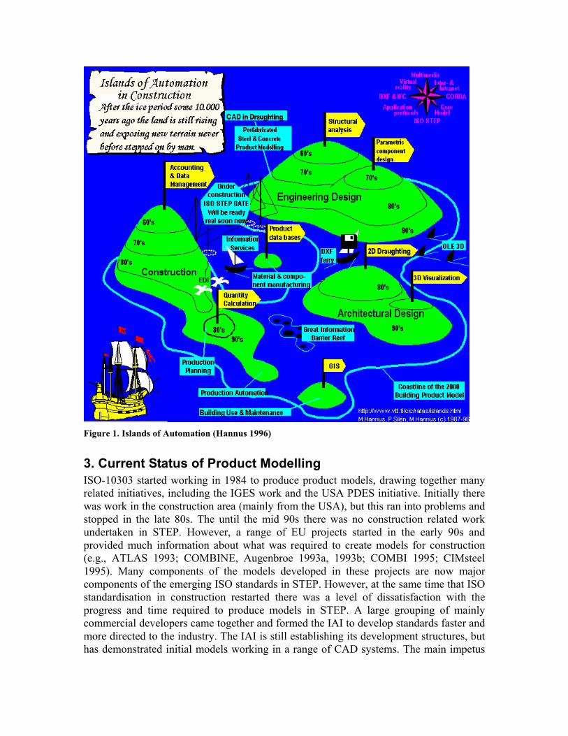
Figure 1. Islands of Automation (Hannus 1996)
3. Current Status of Product Modelling ISO-10303 started working in 1984 to produce product models, drawing together many related initiatives, including the IGES work and the USA PDES initiative. Initially there was work in the construction area (mainly from the USA), but this ran into problems and stopped in the late 80s. The until the mid 90s there was no construction related work undertaken in STEP. However, a range of EU projects started in the early 90s and provided much information about what was required to create models for construction (e.g., ATLAS 1993; COMBINE, Augenbroe 1993a, 1993b; COMBI 1995; CIMsteel 1995). Many components of the models developed in these projects are now major components of the emerging ISO standards in STEP. However, at the same time that ISO standardisation in construction restarted there was a level of dissatisfaction with the progress and time required to produce models in STEP. A large grouping of mainly commercial developers came together and formed the IAI to develop standards faster and more directed to the industry. The IAI is still establishing its development structures, but has demonstrated initial models working in a range of CAD systems. The main impetus
and structuring behind these two initiatives is described in the following two sub-sections (taken from the report by Wix and Bloomfield 1997).
3.1 ISO-10303 STEP Work commenced initially on STEP in 1984 under the auspices of ISO Technical Committee 184, Sub Committee 4 (ISO TC184/SC4). It resulted from the realisation that graphics exchange specifications would not be sufficient in the long term and that some of the problems which had been experienced with the existing Initial Graphics Exchange Specification could be handled more effectively by a more complete product data approach. Until 1989, efforts were focused on the creation of a single, pan industry schema referred to as the Integrated Product Information Model (IPIM). However, the complexity of this approach was recognised and, as a result, the current Application Protocol based architecture was introduced. This is still the current STEP approach.
The purpose of STEP is ‘to specify a form for the unambiguous representation and exchange of computer interpretable information throughout the life of a product, enabling consistent implementations across multiple applications and systems’ (ISO 1994a). It is concerned with the transfer of product data and also with the storage, access and archiving of such data and with ensuring that implementations can be tested for conformance.
3.1.1 STEP Internationally There are 25 North American, European, Asian, Australasian and South American countries actively participating in the development of STEP. Around 10% of attendees at STEP meetings are from building construction.
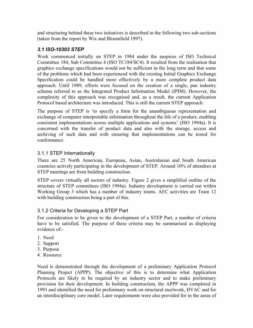
STEP covers virtually all sectors of industry. Figure 2 gives a simplified outline of the structure of STEP committees (ISO 1994a). Industry development is carried out within Working Group 3 which has a number of industry teams. AEC activities are Team 12 with building construction being a part of this.
3.1.2 Criteria for Developing a STEP Part For consideration to be given to the development of a STEP Part, a number of criteria have to be satisfied. The purpose of these criteria may be summarised as displaying evidence of:-
1. Need 2. Support 3. Purpose 4. Resource Need is demonstrated through the development of a preliminary Application Protocol Planning Project (APPP). The objective of this is to determine what Application Protocols are likely to be required by an industry sector and to make preliminary provision for their development. In building construction, the APPP was completed in 1993 and identified the need for preliminary work on structural steelwork, HVAC and for an interdisciplinary core model. Later requirements were also provided for in the areas of
construction management, reinforced concrete, electrical, space and facilities management.
Support is demonstrated by a minimum of five national bodies indicating that the industry sector in their country considers the development of the part to be important.
Purpose is demonstrated by the provision of a preliminary scope statement and activity model which identifies which business processes will be supported by the part.
Resource is demonstrated by the indication of time which will be contributed to the development by various organisations throughout the world.
Whilst the development of a STEP Part is intended to specifically target a business area within an industry sector, there is no criterion applied for an analysis of the benefits which will accrue to business as a result of the development. Neither is there a requirement to incorporate an implementation requirement or implementation resource within the submission. Thus, whilst there will be ‘hope’ of commercial implementation of the results, there is no particular requirement to seek a guarantee by way of sponsorship. This can mean that implementation testing is carried out within funded research projects, or even that the availability of a funded research project may drive the development of the Part in the first place since it is such projects only which may have the necessary funded resource to do the work.
Hence, it might be said that a STEP Part undoubtedly fills a business need, but it does not necessarily guarantee a business benefit.
WG2Parts Library
T19Automobile
T4Materials
T9Prod Struct
Shipbuilding
CivilEngineering
BuildingConstruction
OffshoreIndustry
ProcessIndustry
T12AEC
TnnEtc.
WG3Product Models
WG4Qualification.
WG5Languages
WG6Conformance
WG7Implementation
WG8Manuf. Mangmnt
WG9Electrical & Electr.
Policy & Planning CommitteeBSI, AFNOR, DIN . . . . . .
ISOISOTC184
STEP
Figure 2. STEP Organisation
3.1.3 STEP Development Cycle The rules applied by ISO TC184/SC4 require that a STEP Part is developed to Draft International Standard (DIS) status within three years from agreement to designate the development work as a STEP project. However, as a result of a decision taken at the Toronto meeting in October 1996, the three year period may be extended by the inclusion of a ‘pause’ to allow for implementation of preliminary aspects of the proposed Standard.
Once the development is complete and issued as a formal International Standard (IS), further revisions and enhancements have to occur within another development cycle. Assuming that such work started immediately, procedures for the development of an IS mean that it will be at least four years before a revised IS will be issued.
Whilst this may be quite satisfactory within a physical product environment, it may be a problem within an Information Technology (IT) environment in which four years may represent more than one complete technology lifecycle.
3.1.4 STEP Development
IntegratedResourceModels
ApplicationInterpreted
Model
ApplicationInterpretedConstruct
ApplicationReference
Model
ApplicationActivityModel
scopes satisfies
used in
industry
need for
discovers
Implementationpilot
standard
ConformanceTesting
AbstractTestSuiteundergoes tested using
develops
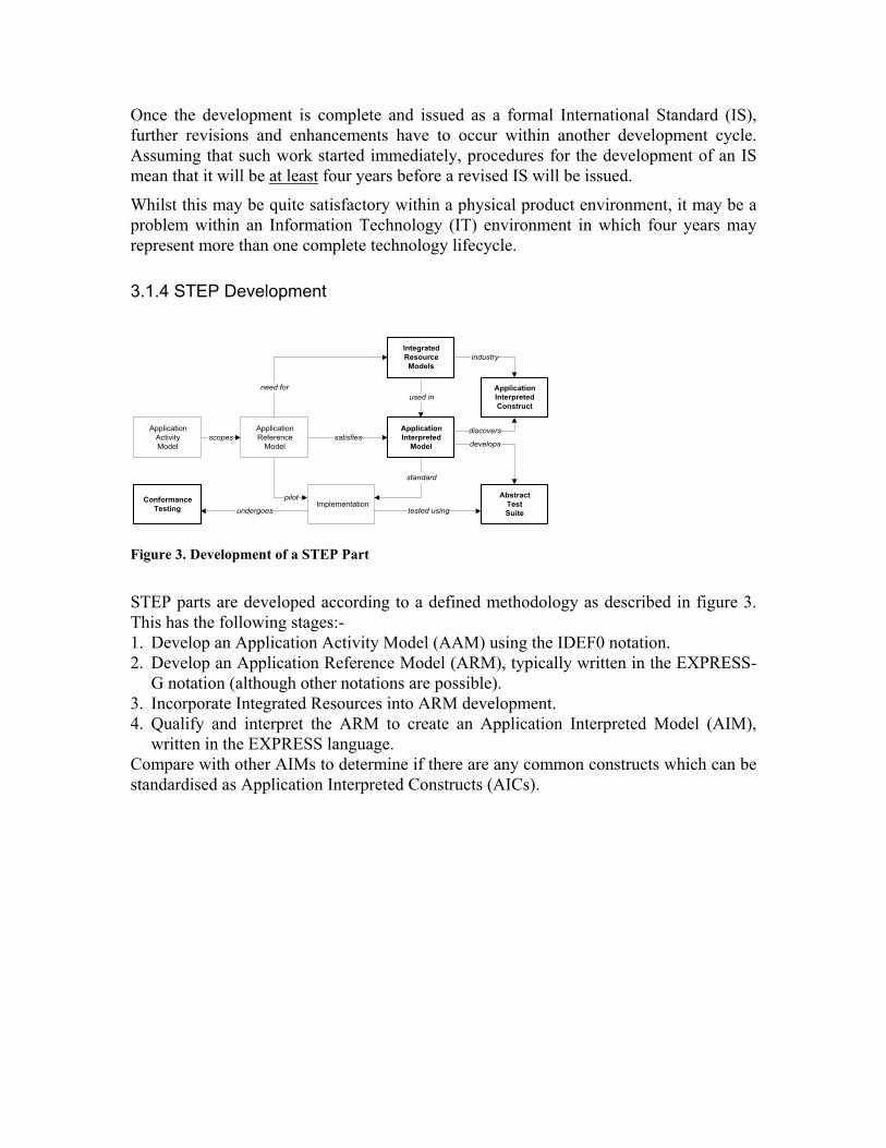
Figure 3. Development of a STEP Part
STEP parts are developed according to a defined methodology as described in figure 3. This has the following stages:- 1. Develop an Application Activity Model (AAM) using the IDEF0 notation. 2. Develop an Application Reference Model (ARM), typically written in the EXPRESS-
G notation (although other notations are possible). 3. Incorporate Integrated Resources into ARM development. 4. Qualify and interpret the ARM to create an Application Interpreted Model (AIM),
written in the EXPRESS language. Compare with other AIMs to determine if there are any common constructs which can be standardised as Application Interpreted Constructs (AICs).
A1REQUIRE
A2PROPOSE
A3PLAN
A4REALISE
C1C2
C3C4
C5C6
C7C8
Need
M1
C1
C5C4
C3C2
C2C3
C4C5
C1
Building
Terminate Project
C5estimated cost
estimated duration
as required
contract arrangements
working methods
as planned
as proposed
specification
advance orders
M1 M3
M1 M2 M3
M2 M3
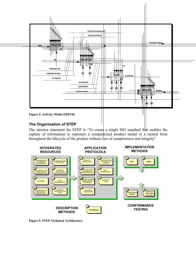
Figure 4. Activity Model (IDEF0)
The Organisation of STEP The mission statement for STEP is “To create a single ISO standard that enables the capture of information to represent a computerised product model in a neutral form throughout the lifecycle of the product without loss of completeness and integrity”
CONFORMANCETESTING
INTEGRATEDRESOURCES
IMPLEMENTATIONMETHODS
DESCRIPTIONMETHODS:
FUNDAMENTALSOF PRODUCTDESCRIPTION
4141
GEOMETRIC ANDTOPOLOGICAL
REPRESENTATION
4242
REPRESENTATIONSTRUCTURE
4343
PRODUCTSTRUCTURE
CONFIGURATION
4444
MATERIAL
INTEGRATED AP.RESOURCES :DRAUGHTING
101101
4545
BUILDINGCONSTRUCTION
CORE
106106
VISUALPRESENTATION
4646
EXPLICITDRAUGHTING
201201
SHIPSTRUCTURES
218218
BUILDING :HVAC
228228225225BUILDING ELEMENT
USING EXPLICITSHAPE REP.
BUILDINGSTEELWORK
230230
CONFIGURATIONCONTROLLED
DESIGN
203203
CORE DATA FORAUTOMATIVE
DESIGN PROCESS
214214
APPLICATIONPROTOCOLS
SPF
2121
EXPRESS
1111
SDAI
2222
ConformanceTesting
3131Abstracttest suitemethods
3434
Figure 5. STEP Technical Architecture
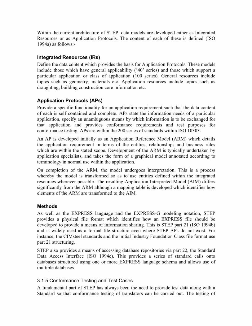
Within the current architecture of STEP, data models are developed either as Integrated Resources or as Application Protocols. The content of each of these is defined (ISO 1994a) as follows:-
Integrated Resources (IRs) Define the data content which provides the basis for Application Protocols. These models include those which have general applicability (‘40’ series) and those which support a particular application or class of application (100 series). General resources include topics such as geometry, materials etc. Application resources include topics such as draughting, building construction core information etc.
Application Protocols (APs) Provide a specific functionality for an application requirement such that the data content of each is self contained and complete. APs state the information needs of a particular application, specify an unambiguous means by which information is to be exchanged for that application and provides conformance requirements and test purposes for conformance testing. APs are within the 200 series of standards within ISO 10303.
An AP is developed initially as an Application Reference Model (ARM) which details the application requirement in terms of the entities, relationships and business rules which are within the stated scope. Development of the ARM is typically undertaken by application specialists, and takes the form of a graphical model annotated according to terminology in normal use within the application.
On completion of the ARM, the model undergoes interpretation. This is a process whereby the model is transformed so as to use entities defined within the integrated resources wherever possible. The resulting Application Interpreted Model (AIM) differs significantly from the ARM although a mapping table is developed which identifies how elements of the ARM are transformed to the AIM.
Methods As well as the EXPRESS language and the EXPRESS-G modeling notation, STEP provides a physical file format which identifies how an EXPRESS file should be developed to provide a means of information sharing. This is STEP part 21 (ISO 1994b) and is widely used as a formal file structure even where STEP APs do not exist. For instance, the CIMsteel standards and the initial Industry Foundation Class file format use part 21 structuring.
STEP also provides a means of accessing database repositories via part 22, the Standard Data Access Interface (ISO 1994c). This provides a series of standard calls onto databases structured using one or more EXPRESS language schema and allows use of multiple databases.
3.1.5 Conformance Testing and Test Cases A fundamental part of STEP has always been the need to provide test data along with a Standard so that conformance testing of translators can be carried out. The testing of
translators is intended to be carried out by national laboratories which have been established throughout the world, each of which has been accredited for the purpose.
3.1.6 Models Work in building construction became focused with the Building Construction Application Protocol Planning Project (APPP) agreed at the Davos meeting in 1994. There are four active developments.
1. Part 106 BCCM 2. Part 225 Explicit shape 3. Part 228 HVAC 4. Part 230 Structural Steel Frameworks Of these, part 225 has Final Draft International Standard (FDIS) status. Working draft versions exist for all other parts.
3.2 International Alliance for Interoperability (IAI) In August 1994, twelve companies including Autodesk set up a project to determine the potential for interoperability between different software applications based on the use of the (then) new ARX object technology which was being developed for AutoCAD release 13. In June 1995, they demonstrated the results of this project at the AEC Systems Show in Washington.
In carrying out the project, the partners realised that one of the most significant obstacles to interoperability was in gaining a common understanding of the semantics and relationships of the classes which were being developed. They considered that they had only a limited capability in the development of such semantics and relationships and that it was, in truth, an industry wide problem. They also realised that such development had a wider currency than a single software platform. They therefore decided that what had been a ‘private club’ up to that point should be opened out to wider industry involvement and that other software vendors should be encouraged to participate.
The Industry Alliance for Interoperability (IAI) came into existence in North America in October 1995 and rapidly gained new members. Representatives visited other countries to present the work as a result of which Chapters were established in a number of other countries. A first international meeting of IAI Chapters was held in London in May 1996 at which time the name was changed from Industry to International so that IAI now stands for the International Alliance for Interoperability.
Membership of the Alliance is by subscription paid to a local Chapter and membership is encouraged from all organisations who have an interest in the development and use of interoperable software in the building construction industry.
The purpose of the IAI is to define Industry Foundation Classes which enable the development of information exchange not only by means of file based exchange and sharing of database repositories as in STEP but also by promoting the development of interoperable software applications which use the newer technology of client/server interfacing. This is expressed as an ideal in (IFC 1997).

‘The open sharing of information without regard to the hardware or software applications in use has come to be known as interoperability, It places emphasis on the value of information and how it is used rather than on the systems which use it. In this sense, interoperability can be said to empower the owner and user of the information.
Interoperability requires that concepts which are common between different software applications are understood to be common and declared accordingly. This understanding needs to be present within the computer systems running interoperable software and not just by their human operators.’
3.2.1 IAI Internationally At February 1997, Chapters of the IAI were established in North America, Germany, France, United Kingdom, the Nordic Countries, Singapore and Japan. Additionally, an International Forum was established for organisations wishing to participate from countries outside the geographical area of established Chapters (the Forum being able to act as a holding place prior to a sound business case being made for the establishment of further Chapters). Total membership of all Chapters exceeded 400 organisations at February 1997 with Japan being the largest Chapter in terms of membership with over 90 organisations and the UK Chapter membership exceeding 60 orgnisations.
Each Chapter is incorporated or acts as an Association in accordance with local custom and is self governing.
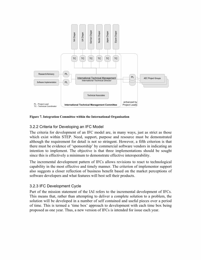
Chapters meet in an International Coordinating Council at six month intervals and there are International Technical Management meetings organised in the intervening period.
In addition, international technical development is supported by regular (approximately weekly) telephone conferences.
Chapter Technical MgmtTechnical Director
Cha
pter
Boa
rd
Dom
ain
Com
mitt
ees
Figure 6. Domain Committees within a Chapters
enhanced byProject LeadsInternational Technical Management Committee
International Technical ManagementInternational Technical Director
Research/Advisory
Software Implementation
PL
PL
AEC Project GroupsPL
Technical Associates
PL - Project LeadTC - Technical Coordinator
NA C
hape
r
UK C
hape
r
Germ
an C
hape
r
Nord
ic Ch
aper
Japa
n Cha
per
S'po
re C
hape
r
TC TC TC TC TC TC
Figure 7. Integration Committee within the International Organisation
3.2.2 Criteria for Developing an IFC Model The criteria for development of an IFC model are, in many ways, just as strict as those which exist within STEP. Need, support, purpose and resource must be demonstrated although the requirement for detail is not so stringent. However, a fifth criterion is that there must be evidence of ‘sponsorship’ by commercial software vendors in indicating an intention to implement. The objective is that three implementations should be sought since this is effectively a minimum to demonstrate effective interoperability.
The incremental development pattern of IFCs allows revisions to react to technological capability in the most effective and timely manner. The criterion of implementor support also suggests a closer reflection of business benefit based on the market perceptions of software developers and what features will best sell their products.
3.2.3 IFC Development Cycle Part of the mission statement of the IAI refers to the incremental development of IFCs. This means that, rather than attempting to deliver a complete solution to a problem, the solution will be developed in a number of self contained and useful pieces over a period of time. This is termed a ‘time box’ approach to development with each time box being proposed as one year. Thus, a new version of IFCs is intended for issue each year.
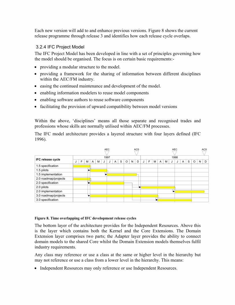
Each new version will add to and enhance previous versions. Figure 8 shows the current release programme through release 3 and identifies how each release cycle overlaps.
3.2.4 IFC Project Model The IFC Project Model has been developed in line with a set of principles governing how the model should be organised. The focus is on certain basic requirements:-
• providing a modular structure to the model. • providing a framework for the sharing of information between different disciplines
within the AEC/FM industry. • easing the continued maintenance and development of the model. • enabling information modelers to reuse model components • enabling software authors to reuse software components • facilitating the provision of upward compatibility between model versions
Within the above, ‘disciplines’ means all those separate and recognised trades and professions whose skills are normally utilised within AEC/FM processes.
The IFC model architecture provides a layered structure with four layers defined (IFC 1996).
J F M A M J J A S O N D1997
J F M A M J J A S O N D1998
IFC release cycle
1.5 specification
1.5 implementation2.0 roadmap/projects2.0 specification
1.5 pilots
2.0 pilots2.0 implementation3.0 roadmap/projects3.0 specification
AEC AECACS ACS
Figure 8. Time overlapping of IFC development release cycles
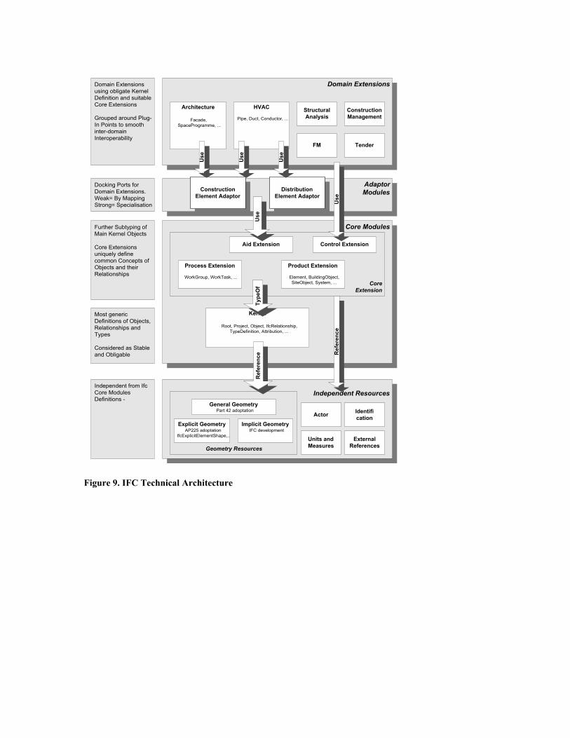
The bottom layer of the architecture provides for the Independent Resources. Above this is the layer which contains both the Kernel and the Core Extensions. The Domain Extension layer comprises two parts; the Adapter layer provides the ability to connect domain models to the shared Core whilst the Domain Extension models themselves fulfil industry requirements.
Any class may reference or use a class at the same or higher level in the hierarchy but may not reference or use a class from a lower level in the hierarchy. This means:
• Independent Resources may only reference or use Independent Resources.
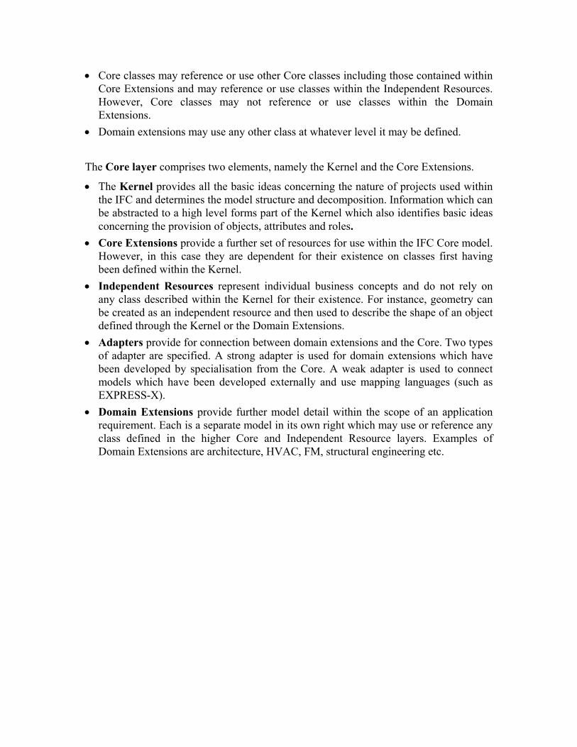
• Core classes may reference or use other Core classes including those contained within Core Extensions and may reference or use classes within the Independent Resources. However, Core classes may not reference or use classes within the Domain Extensions.
• Domain extensions may use any other class at whatever level it may be defined.
The Core layer comprises two elements, namely the Kernel and the Core Extensions.
• The Kernel provides all the basic ideas concerning the nature of projects used within the IFC and determines the model structure and decomposition. Information which can be abstracted to a high level forms part of the Kernel which also identifies basic ideas concerning the provision of objects, attributes and roles.
• Core Extensions provide a further set of resources for use within the IFC Core model. However, in this case they are dependent for their existence on classes first having been defined within the Kernel.
• Independent Resources represent individual business concepts and do not rely on any class described within the Kernel for their existence. For instance, geometry can be created as an independent resource and then used to describe the shape of an object defined through the Kernel or the Domain Extensions.
• Adapters provide for connection between domain extensions and the Core. Two types of adapter are specified. A strong adapter is used for domain extensions which have been developed by specialisation from the Core. A weak adapter is used to connect models which have been developed externally and use mapping languages (such as EXPRESS-X).
• Domain Extensions provide further model detail within the scope of an application requirement. Each is a separate model in its own right which may use or reference any class defined in the higher Core and Independent Resource layers. Examples of Domain Extensions are architecture, HVAC, FM, structural engineering etc.
AdaptorModules
Domain Extensions
Core Modules
Independent Resources
Kernel
Root, Project, Object, IfcRelationship,TypeDefinition, Attribution, ...
Architecture
Facade,SpaceProgramme, ...
HVAC
Pipe, Duct, Conductor, ...
FM
StructuralAnalysis
ConstructionManagement
Product Extension
Element, BuildingObject,SiteObject, System, ...
Process Extension
WorkGroup, WorkTask, ...
Control ExtensionAid Extension
Units andMeasures
Actor Identification
Geometry Resources
Explicit GeometryAP225 adoptation
IfcExplicitElementShape,..
Implicit GeometryIFC development
CoreExtension
Type
Of
Independent from IfcCore ModulesDefinitions -
Domain Extensionsusing obligate KernelDefinition and suitableCore Extensions
Grouped around Plug-In Points to smoothinter-domainInteroperability
ConstructionElement Adaptor
DistributionElement Adaptor
Tender
Use
Use
Use
Use
Use
Docking Ports forDomain Extensions.Weak= By MappingStrong= Specialisation
ExternalReferences
General GeometryPart 42 adoptation
Further Subtyping ofMain Kernel Objects
Core Extensionsuniquely definecommon Concepts ofObjects and theirRelationships
Most genericDefinitions of Objects,Relationships andTypes
Considered as Stableand Obligable
Ref
eren
ce Ref
eren
ce
Figure 9. IFC Technical Architecture
UsageScenario
TechnicalAnalysis
Process Model
ObjectModel forAnalysis
ObjectModel forDesign
PrototypeImplementation
IMPLEMENTATION
REQUIREMENTTestCase
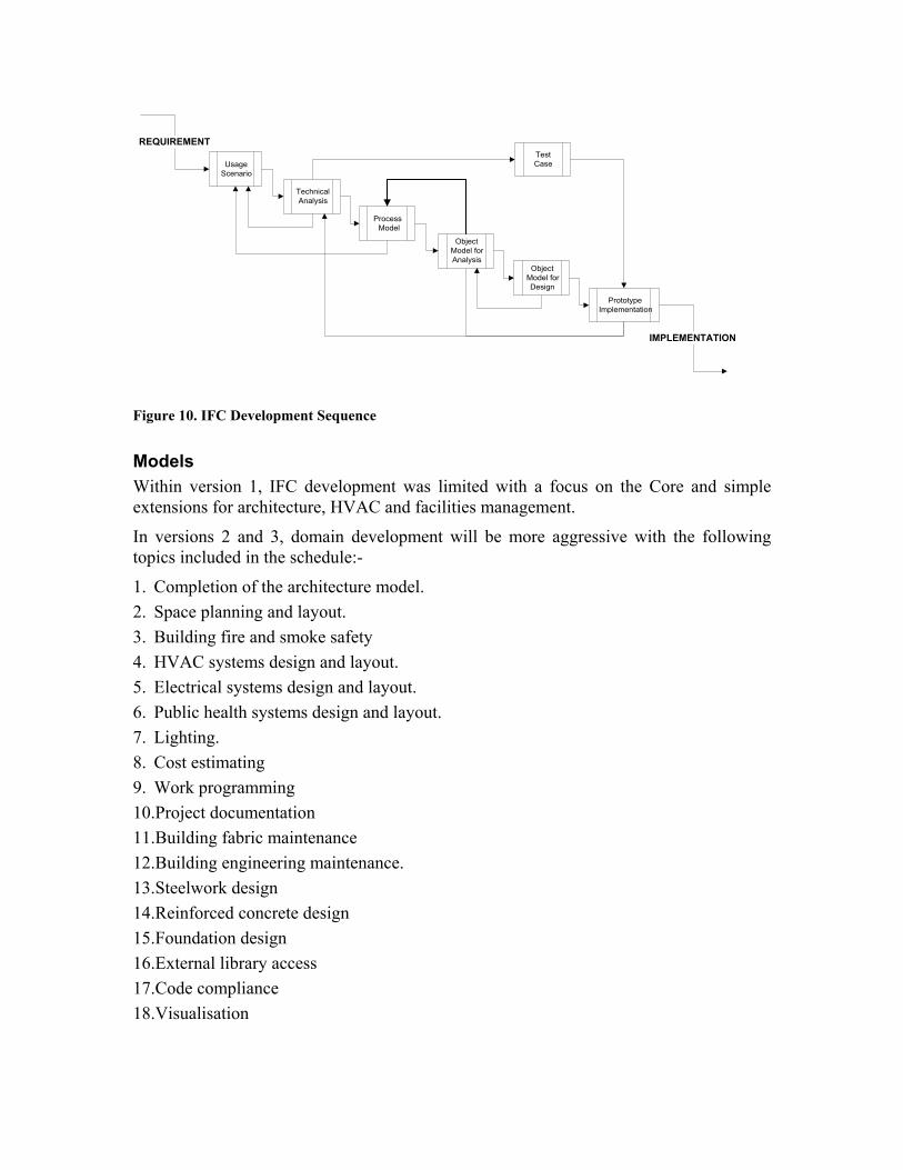
Figure 10. IFC Development Sequence
Models Within version 1, IFC development was limited with a focus on the Core and simple extensions for architecture, HVAC and facilities management.
In versions 2 and 3, domain development will be more aggressive with the following topics included in the schedule:-
1. Completion of the architecture model. 2. Space planning and layout. 3. Building fire and smoke safety 4. HVAC systems design and layout. 5. Electrical systems design and layout. 6. Public health systems design and layout. 7. Lighting. 8. Cost estimating 9. Work programming 10.Project documentation 11.Building fabric maintenance 12.Building engineering maintenance. 13.Steelwork design 14.Reinforced concrete design 15.Foundation design 16.External library access 17.Code compliance 18.Visualisation
4. Integration Development Though product models are developing and will soon be standardised (to some extent), it is not clear exactly how they will be used by the industry. Of course file interchange can be used as with CAD drawings today, but there are major gains to be had from offering an integrated environment where the currency and consistency of information are guaranteed. Previous EU funded projects (e.g., ATLAS, COMBINE, COMBI, CIMsteel) examined architectures to allow the construction of integrated building design systems. Their early work showed that product models could be used to enable data to be exchanged between systems. However, they also highlighted the fact that without associated models of the processes being undertaken in a project the data exchange can be considered as meaningless. This is due to the fact that there is no knowledge about why the information is being exchanged, or whether it should, or is even allowed to be exchanged. Later work in the COMBINE and ATLAS projects examined the incorporation of process models to control the flow of information around a project group and showed promise. A current EU funded project ToCEE takes this idea even further and recognises that as well as integrating process with product information that there are aspects such as documents and legality which must also be pulled into an integrated environment. A brief introduction to the ToCEE project (taken from Amor et al. 1997) is provided below.
4.1 The EU-ToCEE project The main goal of the EU-ToCEE project (Towards a Concurrent Engineering Environment) is the development of a conceptual framework and a prototype environment for support of concurrent engineering to be used by a wide range of institutions in the architectural, engineering and construction domain. To achieve this goal ToCEE builds upon the results and the acquired knowledge from many previous EU funded projects, but extends the scope of research considerably to include several important concurrency enabling aspects with their mutual interrelationships. The focus of the project is especially on the holistic approach to design, on the management of the information flows in the multidisciplinary collaborative work processes, and on the legal aspects of electronic communication and information exchange. The overall concept of a framework for concurrent engineering is being developed in acknowledgement of the following specific characteristics of the building industry: 1) Each major construction project is an example of a virtual corporation in business
today. It is relatively common to find projects where the architect and major engineers are all from different countries and where the virtual product (i.e., the bid documents) of many hundreds of hours of highly skilled labour may exist as a complete package for the first time in the blue print shop. Even a relatively simple office building may involve companies from around the world. Although there may be other examples of more complex projects being assembled by equally wide-spread teams, in no other industry would a team of such breadth be routinely dissolved after executing only a single copy of the product.
2) Through the increased use of IT in the last few years, architecture and engineering have become typical information-based professions, requiring, because of the nature
of their work, highly decentralised information management solutions. During the design process large amounts of information are transferred electronically to and from, and processed by the architects, design consultants, contractors, owners and approval agencies. The co-ordination of that information and ensuring its understanding by the appropriate parties determines to a large degree the success or failure of a project. While perhaps less obvious to a person from the outside, the role of a general contractor is very much the same. Their success relies on co-ordinating the physical work of many subcontractors who may never have met or known each other prior to the project. Thus, the role of the project manager also as information manager is becoming more and more a determinant for the success of a project. However, communication and information exchange happen primarily between different organisations using different applications and operating within different domains of A/E/C, and the scope of the exchanged data varies between nations, companies, projects, project stages, application systems and current view of the actors. A large variety of heterogeneous IT tools and a wide range of technologies are being used, and hence the needs of sending and receiving applications are not a-priori predictable.
Because of this, ToCEE’s main hypothesis is that any technology solution which is unduly centralised, exclusive in terms of cost or computer expertise, or in any way significantly restricting participation by the numerous small enterprises that make up a large part of the industry, could have unforeseen but not insignificant disadvantages and would not have good acceptance in practice. Therefore, ToCEE’s research focus is on the development of a fully open integration environment based on a client-server architecture, using enabling Internet-technology and allowing the exploitation of various application tools, each having its own information requirements and application-specific data representations (Katranuschkov et al., 1996). The ability merely to transfer data between users or applications does not provide the full benefits which should be achievable from this technology. A wide range of issues must be supported in such an environment, much greater than ever considered in previous projects. Key issues for a successful concurrent engineering approach being addressed in the ToCEE project are: • interoperability of distributed process, product, document and regulation models and
data • legal aspects related to the product data and the electronic documentation • information logistics and communication management • inter-discipline conflict management • monitoring and forecasting • cost control. Thus, several domain problems that were previously examined in isolation are being considered together to provide a seamless prototype environment where a practitioner’s full range of tasks will be inter-related allowing access to product information from documents, or documents for individual products and design tasks, and designers involved in particular decisions.
All these aspects have to be modelled in all relevant subsystems of the concurrent engineering environment, and their constraints have to be taken into account adequately for all types of activities executed in a construction project. Legal aspects play a restrictive role to information management, and in fact in many ways reduce the possibilities to use available technology. However, if handled properly, they also provide an organisational rigour, which can help to reduce uncertainty and allocate correctly roles, responsibilities, decisions and co-ordination activities.
5. Dissemination Development As well as providing a basis for exchange of information between applications and supporting work on integrated design systems, product models are useful for many other applications. One area that it supports which is currently receiving much attention is that of Internet service systems. Currently it is recognised that good information is difficult to extract from the Internet. Even with good search engines, the number of hits for a query, many of which are irrelevant, exceed a users ability to utilise. Several research systems are being developed which attempt to make construction related information much more accessible for interested users. One of the fundamental issues behind these systems is a representation of information about products which can be queried by users and the system. Two UK initiatives are discussed below, both of which aim to make construction related information easily and accurately accessible to users in the UK.
5.1 ARROW ARROW is a UK Partners in Technology (PiT) project funded equally by the UK’s Department of the Environment and commercial partners. ARROW aims to develop an environment that allows users to find the product information, from multiple product vendors, that best suits their requirements. Once found, ARROW will enable the product information to be loaded back into the user’s CAD applications and other design tools. ARROW is envisaged as a single point of entry to all electronic product information in the UK. To help achieve these results ARROW will develop standard descriptors for various types of product, and toolkits for manufacturers to publish their product information in this form. ARROW will utilise a search engine which connects to the multiple distributed manufacturers’ databases and indexes all their data into a central index accessible by ARROW users. This index will include both the information from the standard descriptors and free form text published by the manufacturer. The ARROW interface will provide tools for designing queries, browsing the results and using those results by dropping them directly into applications such as CAD and simulation. Users of the ARROW system are expected to be in the Architecture, Engineering and Construction industries.
5.1.1 Objectives The objectives of the ARROW project are:

• To develop a representative database of building components based on either ISO STEP models, the IAI IFC classes, or specialised models where no standard exists. Models selected will take into account developments in the EU-COMBINE project, as well as further developments in the Building Core Model and the IAI foundation classes. The model chosen will be a minimum definition, and manufacturers will be free to add their own distinguishing features. It is likely that windows will be one of the products developed for demonstration in ARROW.
• To identify and develop one or two exemplars for existing methods for the selection of appropriate building components, and materials, using case-based or rule-based methods. For example, timber selection based on general timber properties.
• To select and incorporate a data retrieval system (e.g., intelligent agents) to allow intelligent on-line access to information in distributed databases in geographically distant places for manufacturer’s data, research knowledge banks and standards and codes of practice.
• To develop a pilot system to implement the developed models and formats for product description, selection and retrieval systems described above.
• To develop a standard format and toolkit for manufacturers to supply their product data electronically into the system.
• To incorporate the developed pilot system into commercially available design and management systems. This will include the development of an Application Program Interface (API) to allow developers of software applications to provide interfaces to the reusable object repository.
5.1.2 Framework The interface to ARROW is envisaged as working through a WWW browser, which will pass user queries to a query handler within the ARROW system. The query handler will pass the query to both a Knowledge Based System (KBS) to gain domain specific knowledge (e.g., windows have a component structure containing glass panes, a frame, opening devices, and locks) and then to an Intelligent Agent (IA) which may alter user parameters to gain a reasonable number of results. The idea behind the KBS and IA is to overcome the problems of existing search engines, that is, you either receive thousands of results or none. The IA will attempt to narrow the search if too many results are received from the search engine by restricting the parameters on the user’s query. Conversely, the IA can expand the search parameters to gain more results or use knowledge from the KBS to widen the search. Once the results have been returned to the user and the user has selected a product, that product information can be dragged and dropped into another application. This is done by using intelligent objects from the manufacturer’s database. For example, a door knows it is a double aluminium door made by Smith & Co Ltd as well as having its graphical representation. Using the published standard descriptors it will then be possible to translate the door information to the form required for a CAD application, or a thermal design tool, etc.

5.2 CIG The UK Department of the Environment (DOE) has funded a feasibility study into the concept of an electronic knowledge base for the construction industry (Construct-IT 1996), as proposed in an earlier strategy report (Construct-IT 1995). It is envisaged that this knowledge base would provide a single point of entry for the UK, creating a gateway to all information of relevance to the A/E/C industry. A wide range of commercial, social and technical issues were investigated in the study, which provides a recommendation of the best way forward together with a marketing strategy. The notion of a construction industry gateway (CIG) which provides a single point of entry and a single search mechanism to all the information has drawn great interest. Several commercial systems provide smaller versions of what a CIG may become, and the DOE has previously funded a CIG demonstrator (CIG 1995) on the Internet. It is expected that many institutions will see the chance of high commercial gain, or market dominance, from running such a system, and will wish to position themselves as the gateway for the UK. The objective of the Industry Knowledge Base is to create and exploit information and knowledge to improve the effectiveness of the building industry. Specific objectives within this overall goal are: • To improve the quality and efficiency of buildings and building projects by sharing
information on standards and best practice. • To improve the efficiency of the construction market by improving market
communications. • To reduce the cost and improve the quality of building design by sharing design
knowledge. • To provide news and information that will enable the construction industry to compete
more effectively.
5.2.1 CIG-RS development The CIG-RS sees itself as initially offering a signpost type system for the UK. However, to ensure this gives benefit over and above what can currently be achieved with Internet indexing systems they will develop a standard descriptor for various types of information. This meta-application protocol (MAP) will be developed through consultation with representatives providing the various types of information to the industry (e.g., product, news, research, notices, health and safety, etc.). The MAP will be a public standard which all information providers will be encouraged to provide their information in. With the standardisation of MAPs for different information types it will then be possible to search for information of particular types with good likelihood of finding exactly what is required (a classification system such as UNICLASS is likely to be included in the MAP). The initial demonstrator does not envisage storing any information itself, but purely indexing the MAPs and text of those providing information to the system. The initial demonstrator of CIG-RS promises to show its utility by inputting all information of a particular type into the system (e.g., standards and vertical product markets such as windows or insulation).

6. Conclusions This paper provides a short overview of the history of product model development in the construction industry. This shows the early recognition of the requirement for product models, but the slow development which has taken place. The benefits of product models are not disputed, but the ability to generate satisfactory models useable by the international community is less certain. The progress and structures of ISO-STEP and the IAI are presented and shown to be comparable in most respects, though the IAI have a focus on faster development and smaller focus models. The way in which these models may be utilised is demonstrated with descriptions of three projects, one showing progress with integrated building design systems and the other two with information dissemination and retrieval through the Internet.
References Amor, R.W., Clift, M., Scherer, R., Katranuschkov, P., Turk, Z. and Hannus, M. (1997)
A Framework for Concurrent Engineering - ToCEE, European Conference on Product Data Technology, PDT Days 1997, CICA, Sophia Antipolis, France, 15-16 April, pp. 15-22.
ATLAS (1993) ATLAS: Architecture, methodology and Tools for computer integrated LArge Scale engineering, ESPRIT 7280, 37pp.
Augenbroe, G. (1995a) COMBINE-2 Final Report, CEC-DGXII, Brussels. Augenbroe, G. (1995b) An overview of the COMBINE project, The First European
Conference on Product and Process Modelling in the Building Industry, Dresden, Germany, 5-7 October 1994, Scherer, R. (ed), Balkema, Rotterdam, pp. 547-554.
CIG (1995) http://cig.bre.co.uk/ CIMsteel (1995) Computer Integrated Manufacturing for constructional steelwork,
Eureka project 130, Brussels. COMBI (1995) Computer-integrated Object-oriented product Model for the Building
Industry, ESPRIT CIME, Brussels. Construct-IT (1995) Construct-IT: Bridging the Gap, British Telecom, Andersen
Consulting, DOE, HMSO, UK. Construct-IT (1996) Construct-IT: Bridging the Gap, Scoping study for the Construction
Industry Knowledge Base, DOE, HMSO, UK. Hannus, M. (1996) Integration of Construction Computing Islands,
http://www.vtt.fi/cic/ratas/islands.gif IFC (1996) Industry Foundation Classes Release 1.0: Specifications Volume 3, IFC
Model Exchange Specifications, IAI, December. IFC (1997) IFC Methodology Guide Draft 2, IAI, February. ISO (1994a) ISO/DIS 10303-1: 1994. Industrial automation systems and integration -
Product Data Representation and Exchange Part 1: Overview and Fundamental Principles.
ISO (1994b) ISO 10303-21:1994, Industrial Automation Systems - Exchange of Product Model Data - Part 21: Implementation Methods; Clear Text Encoding of the Data Structure.
ISO (1994c) ISO 10303-22:1994, Industrial Automation Systems - Exchange of Product Model Data - Part 22: Implementation Methods; Standard Data Access Interface.

Katranuschkov, P., Scherer, R.J., Clift, M. and Amor, R. (1996) ToCEE Migration Perspectives, EU ESPRIT IV Project No. 20587, ToCEE Deliverable J.1, Public report, EU/CEC, Directorate Generale III, Brussels.
Wix, J. and Bloomfield, D. (1997) Standards for information Exchange and Sharing, BRE Client Report CR77/97, BRE, Watford, UK, March.
Related Documents