Product Model for Requirements and Design Concept Management: Representing Design Alternatives and Rationale Fredrik Andersson, Krister Sutinen and Johan Malmqvist Department of Product and Production Development Chalmers University of Technology SE-412 96 Göteborg, Sweden {fredrik.andersson, krister.sutinen, ... }@me.chalmers.se Abstract. Throughout the development of complex products, thousands of requirements are established, communicated, followed up, and verified. In addition, even more design solutions, at various levels of abstractions, are created, refined, evaluated, industrialised and verified during this period. Although design tools support the documentation and administration of the output of these activities, i.e. requirements and solutions, they lack the functionality to support the iterative gestation of requirements and design solutions as they are created. This paper illustrates how a product model, focusing on requirements and design concept management, can address these issues by incorporating design rationale, i.e. the reasoning and the justification underlying requirements and solutions considered, with the aim to close the gap between product models and design rationale models. The product model has been implemented in a commercial PDM software and its use is illustrated with the information from the design of a passenger car cockpit. Introduction A large set of more or less useful and usable design support tools has been introduced in the product development process. Some design support tools help design teams to develop better products (simulation, optimisation, guidelines etc.). Other tools help doing the design work more efficiently (planning, gathering, representing and communicating information, re-using solutions, etc.). For example, for managing requirements and doing system-level development work, specialised Requirements Management/Systems Engineering (RM/SE) tools have been introduced, such as DOORS (Telelogic 2003), RTM (Chipware 2003), and RequisitePro (Rational 2003) and Slate (EDS 2003). These tools provide a common base for the requirements capture, allocation, validation and verification in a design project, especially in the early phases of the project, or in a design organisation as a whole. From the point when a preliminary design has been developed and chosen, more detail-oriented, domain-specific design tools, such as CAD, SCM and PDM systems, support the creation and management of product descriptions (for example geometry models, software code, product structures, process plans, etc.). However, these tools are not well integrated (yet) and they do not really support the creative activities during the concept development phase, see figure 1. During concept development numerous assumptions are made and different and often contradictory alternatives co-exist, both when it comes to requirements and design solutions. Issues that require flexible tools that support the argumentation behind decisions made and the conflict resolved. Therefore, even if the management of objectified requirement statements and detailed geometry models is supported,

Welcome message from author
This document is posted to help you gain knowledge. Please leave a comment to let me know what you think about it! Share it to your friends and learn new things together.
Transcript
Product Model for Requirements and Design Concept Management:
Representing Design Alternatives and Rationale
Fredrik Andersson, Krister Sutinen and Johan Malmqvist Department of Product and Production Development
Chalmers University of Technology SE-412 96 Göteborg, Sweden
{fredrik.andersson, krister.sutinen, ... }@me.chalmers.se
Abstract. Throughout the development of complex products, thousands of requirements are established, communicated, followed up, and verified. In addition, even more design solutions, at various levels of abstractions, are created, refined, evaluated, industrialised and verified during this period. Although design tools support the documentation and administration of the output of these activities, i.e. requirements and solutions, they lack the functionality to support the iterative gestation of requirements and design solutions as they are created. This paper illustrates how a product model, focusing on requirements and design concept management, can address these issues by incorporating design rationale, i.e. the reasoning and the justification underlying requirements and solutions considered, with the aim to close the gap between product models and design rationale models. The product model has been implemented in a commercial PDM software and its use is illustrated with the information from the design of a passenger car cockpit.
Introduction A large set of more or less useful and usable design support tools has been introduced in the
product development process. Some design support tools help design teams to develop better products (simulation, optimisation, guidelines etc.). Other tools help doing the design work more efficiently (planning, gathering, representing and communicating information, re-using solutions, etc.). For example, for managing requirements and doing system-level development work, specialised Requirements Management/Systems Engineering (RM/SE) tools have been introduced, such as DOORS (Telelogic 2003), RTM (Chipware 2003), and RequisitePro (Rational 2003) and Slate (EDS 2003). These tools provide a common base for the requirements capture, allocation, validation and verification in a design project, especially in the early phases of the project, or in a design organisation as a whole. From the point when a preliminary design has been developed and chosen, more detail-oriented, domain-specific design tools, such as CAD, SCM and PDM systems, support the creation and management of product descriptions (for example geometry models, software code, product structures, process plans, etc.).
However, these tools are not well integrated (yet) and they do not really support the creative activities during the concept development phase, see figure 1. During concept development numerous assumptions are made and different and often contradictory alternatives co-exist, both when it comes to requirements and design solutions. Issues that require flexible tools that support the argumentation behind decisions made and the conflict resolved. Therefore, even if the management of objectified requirement statements and detailed geometry models is supported,
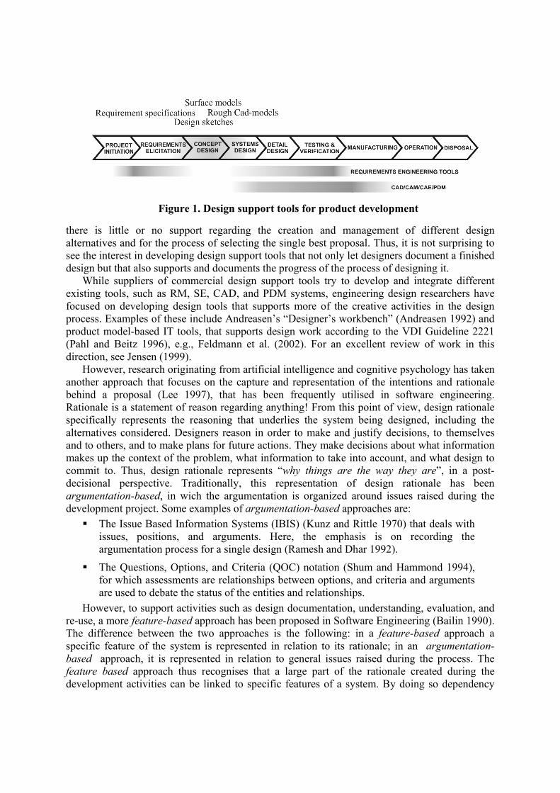
Figure 1. Design support tools for product development
there is little or no support regarding the creation and management of different design alternatives and for the process of selecting the single best proposal. Thus, it is not surprising to see the interest in developing design support tools that not only let designers document a finished design but that also supports and documents the progress of the process of designing it.
While suppliers of commercial design support tools try to develop and integrate different existing tools, such as RM, SE, CAD, and PDM systems, engineering design researchers have focused on developing design tools that supports more of the creative activities in the design process. Examples of these include Andreasen’s “Designer’s workbench” (Andreasen 1992) and product model-based IT tools, that supports design work according to the VDI Guideline 2221 (Pahl and Beitz 1996), e.g., Feldmann et al. (2002). For an excellent review of work in this direction, see Jensen (1999).
However, research originating from artificial intelligence and cognitive psychology has taken another approach that focuses on the capture and representation of the intentions and rationale behind a proposal (Lee 1997), that has been frequently utilised in software engineering. Rationale is a statement of reason regarding anything! From this point of view, design rationale specifically represents the reasoning that underlies the system being designed, including the alternatives considered. Designers reason in order to make and justify decisions, to themselves and to others, and to make plans for future actions. They make decisions about what information makes up the context of the problem, what information to take into account, and what design to commit to. Thus, design rationale represents “why things are the way they are”, in a post-decisional perspective. Traditionally, this representation of design rationale has been argumentation-based, in wich the argumentation is organized around issues raised during the development project. Some examples of argumentation-based approaches are:
The Issue Based Information Systems (IBIS) (Kunz and Rittle 1970) that deals with issues, positions, and arguments. Here, the emphasis is on recording the argumentation process for a single design (Ramesh and Dhar 1992).
The Questions, Options, and Criteria (QOC) notation (Shum and Hammond 1994), for which assessments are relationships between options, and criteria and arguments are used to debate the status of the entities and relationships.
However, to support activities such as design documentation, understanding, evaluation, and re-use, a more feature-based approach has been proposed in Software Engineering (Bailin 1990). The difference between the two approaches is the following: in a feature-based approach a specific feature of the system is represented in relation to its rationale; in an argumentation-based approach, it is represented in relation to general issues raised during the process. The feature based approach thus recognises that a large part of the rationale created during the development activities can be linked to specific features of a system. By doing so dependency
management, i.e. how features/issues affect each other, would be treated within the product model, so that the effects of a change proposal can be understood. The underlying purpose of eliciting and representing design rationale can be classified according to the user group that benefits from this (See for instance Lee (1997) and Ullman (1994)):
Designers querying their own work The tool can be served as a design notebook/diary where design information is stored during the activity.
Another member in a design project The tool can be used for members in a project group to keep up to date with critical issues.
Management Management are more concerned with the actual progress of the process, i.e. time-schedules, unresolved and resolved issues etc. People not present at a design team meeting could easily discern what was discussed, not just the final decisions.
Re-design / Maintenance During re-design/maintenance activities, when existing products are re-designed in order to correct faults detected during application, designers need to understand the relations of information, such as why requirements and solutions were set/designed.
Involved designers in future projects The tool would provide a powerful source for experiences regarding existing solutions, requirements etc.
The aim of this study is to close the gap between product models and design rationale models, so that not only the outcome of the development activities can be documented in a design tool, i.e. requirement specifications and product descriptions, but also the reasoning and the justification behind the result. This paper proposes a framework, where design rationale is represented in relation to a product model for requirements and design concept management.
The main body of this paper is arranged in five parts. First, a previously developed product model for requirement and design concept management will be described. Second, the product model is extended with functionalities for the management of design concept alternatives. Third, research on Design Rationale is summarised and the context of rationale is discussed in relation to the described product model. Fourth, the framework is implemented in a commercial PDM-software and its use is illustrated with the information from the design of a passenger car cockpit. Fifth and finally, the paper concludes with general findings and recommendations.
Product Modelling Framework In previous work (Andersson et al. 2000; Sutinen et al. 2000; Andersson 2001) a product-
modelling framework has been developed to store and manage the product design documentations from requirements to form, through functions and functional solutions (means-end reasoning), and from a complete product to specific components (part-whole reasoning) (See figure 2). In the means-end hierarchy, each level represents a different model of the system, where each level also acts as a goal with respect to the model at the next lower level. In other words a product requirement acts as a goal for a function, which is solved by a functional solution, which is materialised through a part. In the part-whole hierarchy, a main product-function can be broken down into sub-functions or a product can be broken down to its systems, sub-systems and components, etc. This general framework has been implemented in a
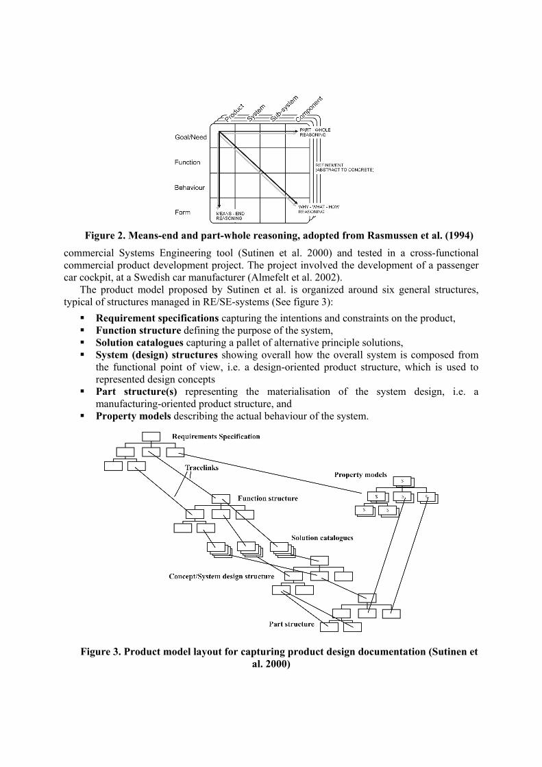
Figure 2. Means-end and part-whole reasoning, adopted from Rasmussen et al. (1994)
commercial Systems Engineering tool (Sutinen et al. 2000) and tested in a cross-functional commercial product development project. The project involved the development of a passenger car cockpit, at a Swedish car manufacturer (Almefelt et al. 2002).
The product model proposed by Sutinen et al. is organized around six general structures, typical of structures managed in RE/SE-systems (See figure 3):
Requirement specifications capturing the intentions and constraints on the product, Function structure defining the purpose of the system, Solution catalogues capturing a pallet of alternative principle solutions, System (design) structures showing overall how the overall system is composed from
the functional point of view, i.e. a design-oriented product structure, which is used to represented design concepts
Part structure(s) representing the materialisation of the system design, i.e. a manufacturing-oriented product structure, and
Property models describing the actual behaviour of the system.
Figure 3. Product model layout for capturing product design documentation (Sutinen et
al. 2000)
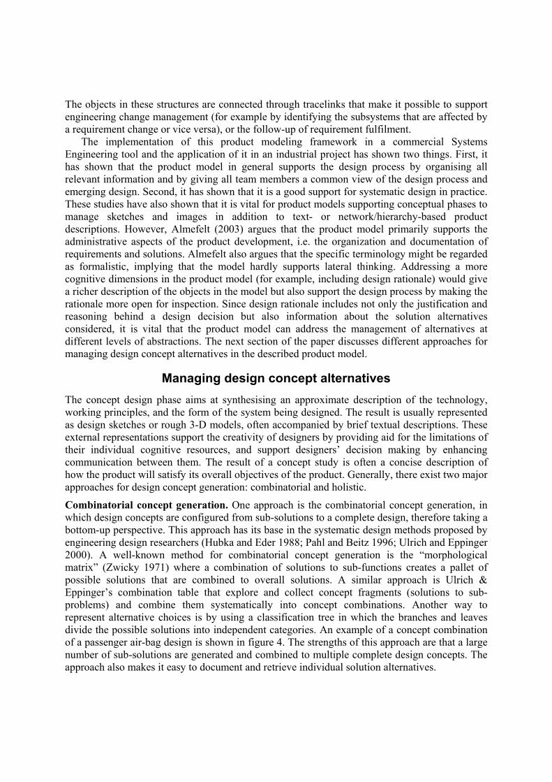
The objects in these structures are connected through tracelinks that make it possible to support engineering change management (for example by identifying the subsystems that are affected by a requirement change or vice versa), or the follow-up of requirement fulfilment.
The implementation of this product modeling framework in a commercial Systems Engineering tool and the application of it in an industrial project has shown two things. First, it has shown that the product model in general supports the design process by organising all relevant information and by giving all team members a common view of the design process and emerging design. Second, it has shown that it is a good support for systematic design in practice. These studies have also shown that it is vital for product models supporting conceptual phases to manage sketches and images in addition to text- or network/hierarchy-based product descriptions. However, Almefelt (2003) argues that the product model primarily supports the administrative aspects of the product development, i.e. the organization and documentation of requirements and solutions. Almefelt also argues that the specific terminology might be regarded as formalistic, implying that the model hardly supports lateral thinking. Addressing a more cognitive dimensions in the product model (for example, including design rationale) would give a richer description of the objects in the model but also support the design process by making the rationale more open for inspection. Since design rationale includes not only the justification and reasoning behind a design decision but also information about the solution alternatives considered, it is vital that the product model can address the management of alternatives at different levels of abstractions. The next section of the paper discusses different approaches for managing design concept alternatives in the described product model.
Managing design concept alternatives The concept design phase aims at synthesising an approximate description of the technology, working principles, and the form of the system being designed. The result is usually represented as design sketches or rough 3-D models, often accompanied by brief textual descriptions. These external representations support the creativity of designers by providing aid for the limitations of their individual cognitive resources, and support designers’ decision making by enhancing communication between them. The result of a concept study is often a concise description of how the product will satisfy its overall objectives of the product. Generally, there exist two major approaches for design concept generation: combinatorial and holistic.
Combinatorial concept generation. One approach is the combinatorial concept generation, in which design concepts are configured from sub-solutions to a complete design, therefore taking a bottom-up perspective. This approach has its base in the systematic design methods proposed by engineering design researchers (Hubka and Eder 1988; Pahl and Beitz 1996; Ulrich and Eppinger 2000). A well-known method for combinatorial concept generation is the “morphological matrix” (Zwicky 1971) where a combination of solutions to sub-functions creates a pallet of possible solutions that are combined to overall solutions. A similar approach is Ulrich & Eppinger’s combination table that explore and collect concept fragments (solutions to sub-problems) and combine them systematically into concept combinations. Another way to represent alternative choices is by using a classification tree in which the branches and leaves divide the possible solutions into independent categories. An example of a concept combination of a passenger air-bag design is shown in figure 4. The strengths of this approach are that a large number of sub-solutions are generated and combined to multiple complete design concepts. The approach also makes it easy to document and retrieve individual solution alternatives.
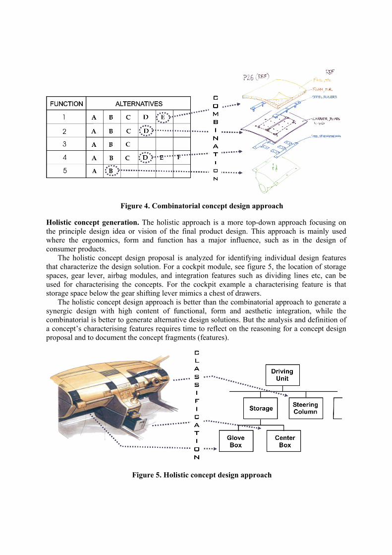
Figure 4. Combinatorial concept design approach
Holistic concept generation. The holistic approach is a more top-down approach focusing on the principle design idea or vision of the final product design. This approach is mainly used where the ergonomics, form and function has a major influence, such as in the design of consumer products.
The holistic concept design proposal is analyzed for identifying individual design features that characterize the design solution. For a cockpit module, see figure 5, the location of storage spaces, gear lever, airbag modules, and integration features such as dividing lines etc, can be used for characterising the concepts. For the cockpit example a characterising feature is that storage space below the gear shifting lever mimics a chest of drawers.
The holistic concept design approach is better than the combinatorial approach to generate a synergic design with high content of functional, form and aesthetic integration, while the combinatorial is better to generate alternative design solutions. But the analysis and definition of a concept’s characterising features requires time to reflect on the reasoning for a concept design proposal and to document the concept fragments (features).
Figure 5. Holistic concept design approach

Managing design concept alternatives in the product model. These approaches represents the extremes and both strategies are often used simultaneously during conceptual design. The holistic design uses mental solutions or cognitive artefacts of sub-solutions, and the combinatorial address sub-solution while often having the overall purpose of the product in mind. Both holistic and combinatorial design approach generates a concept design structure where the concept fragments are at the end of the branches. Each concept generates an own unique set of concept fragments. The introduction of a new structure in the product model will capture the designer’s vision and thought behind a concept by identifying and storing the characterising feature, e.g. the characteristics shape of VW Beetle, the tactile touch of brushed aluminium, the cut of an Armani suit.
The concept structure also provides a support for understanding why different design features exist by linking the concept design fractures to requirements, functions, solutions, and the realising part structure.
The holistic approach generates a wide range of ideas where some are too crazy to implement but may have good sub-design features. If the concept design proposal is rejected, there is a risk that, good design features for sub-problems may be lost. By documenting and storing concept fragments the risk of losing good ideas is minimised.
The documentation of design features provides an understanding of how the product may satisfy the objectives and intents of the product, but that is not enough. While evaluating different design concept there is a need to capture the reasoning behind each design.
Design Rationale Besides the problem definition and the final product description itself, design rationale is probably the most important information created during a development project. This is because, in a rational sense, the quality of the design is dependent on the quality of its rationale. However, rationale is also one of the most difficult pieces of information to elicit and manage explicitly. That is because experts often cannot explain why they have made certain decisions and what information they took into account when making them. Since humans do not reason in a logical mathematical fashion, it is often impossible to reconstruct the reasoning process. Thus it is impossible to represent an entire design rationale explicitly (Lee 1997). The exploratory nature of designing itself also makes it troublesome (for example, how do you manage a representation of decisions based on assumptions that are later revised?).
As reasoning in design is non-monotonic, rationale information is important when managing change. For example, when a design needs to be changed, the rationale gives a richer, underlying description including which decisions need to be revised or which requirements or systems are affected. Also, when requirements are carried over between projects or product families, the rationale describes what a requirement is there to implement and how and why it has been changed during the project. This minimises the risk for misunderstandings.
After this overview of design rationale, let us consider some specific kinds of rationale that are possible to model in product models. One can generally see the context of rationale as having to do with either the reasoning and the justification underlying our intentions (goals, aims, requirements, etc.), the alternatives produced (design concepts), or the premises used when selecting one design solution. Consequently, we will discuss rationale in relation to requirements and functions, design solutions and the evaluation of different alternatives.
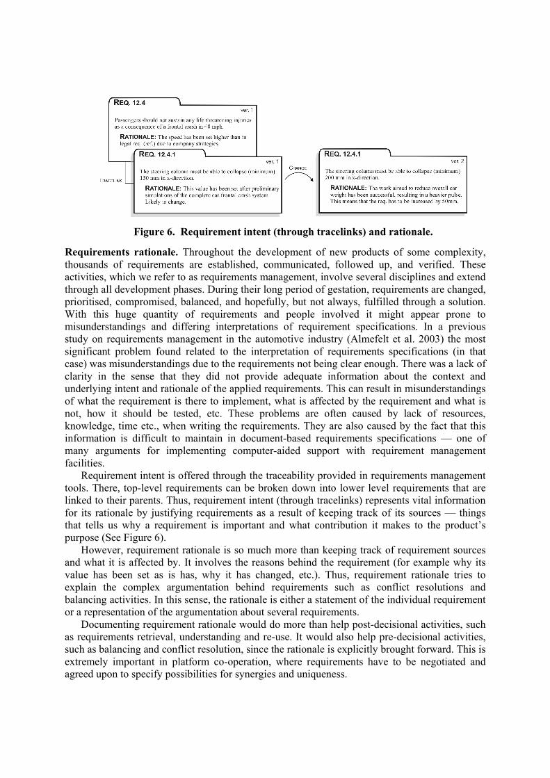
Figure 6. Requirement intent (through tracelinks) and rationale.
Requirements rationale. Throughout the development of new products of some complexity, thousands of requirements are established, communicated, followed up, and verified. These activities, which we refer to as requirements management, involve several disciplines and extend through all development phases. During their long period of gestation, requirements are changed, prioritised, compromised, balanced, and hopefully, but not always, fulfilled through a solution. With this huge quantity of requirements and people involved it might appear prone to misunderstandings and differing interpretations of requirement specifications. In a previous study on requirements management in the automotive industry (Almefelt et al. 2003) the most significant problem found related to the interpretation of requirements specifications (in that case) was misunderstandings due to the requirements not being clear enough. There was a lack of clarity in the sense that they did not provide adequate information about the context and underlying intent and rationale of the applied requirements. This can result in misunderstandings of what the requirement is there to implement, what is affected by the requirement and what is not, how it should be tested, etc. These problems are often caused by lack of resources, knowledge, time etc., when writing the requirements. They are also caused by the fact that this information is difficult to maintain in document-based requirements specifications — one of many arguments for implementing computer-aided support with requirement management facilities.
Requirement intent is offered through the traceability provided in requirements management tools. There, top-level requirements can be broken down into lower level requirements that are linked to their parents. Thus, requirement intent (through tracelinks) represents vital information for its rationale by justifying requirements as a result of keeping track of its sources — things that tells us why a requirement is important and what contribution it makes to the product’s purpose (See Figure 6).
However, requirement rationale is so much more than keeping track of requirement sources and what it is affected by. It involves the reasons behind the requirement (for example why its value has been set as is has, why it has changed, etc.). Thus, requirement rationale tries to explain the complex argumentation behind requirements such as conflict resolutions and balancing activities. In this sense, the rationale is either a statement of the individual requirement or a representation of the argumentation about several requirements.
Documenting requirement rationale would do more than help post-decisional activities, such as requirements retrieval, understanding and re-use. It would also help pre-decisional activities, such as balancing and conflict resolution, since the rationale is explicitly brought forward. This is extremely important in platform co-operation, where requirements have to be negotiated and agreed upon to specify possibilities for synergies and uniqueness.
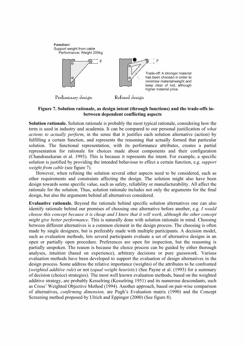
Figure 7. Solution rationale, as design intent (through functions) and the trade-offs in-
between dependent conflicting aspects
Solution rationale. Solution rationale is probably the most typical rationale, considering how the term is used in industry and academia. It can be compared to our personal justification of what actions to actually perform, in the sense that it justifies each solution alternative (action) by fulfilling a certain function, and represents the reasoning that actually formed that particular solution. The functional representation, with its performance attributes, creates a partial representation for rationale for choices made about components and their configuration (Chandrasekaran et al. 1993). This is because it represents the intent. For example, a specific solution is justified by providing the intended behaviour to effect a certain function, e.g. support weight from cable (see figure 7).
However, when refining the solution several other aspects need to be considered, such as other requirements and constraints affecting the design. The solution might also have been design towards some specific value, such as safety, reliability or manufacturability. All affect the rationale for the solution. Thus, solution rationale includes not only the arguments for the final design, but also the arguments behind all alternatives considered.
Evaluative rationale. Beyond the rationale behind specific solution alternatives one can also identify rationale behind our premises of choosing one alternative before another, e.g. I would choose this concept because it is cheap and I know that it will work, although the other concept might give better performance. This is naturally done with solution rationale in mind. Choosing between different alternatives is a common element in the design process. The choosing is often made by single designers, but is preferably made with multiple participants. A decision model, such as evaluation methods, lets several participants evaluate a set of alternative designs in an open or partially open procedure. Preferences are open for inspection, but the reasoning is partially unspoken. The reason is because the choice process can be guided by either thorough analyses, intuition (based on experience), arbitrary decisions or pure guesswork. Various evaluation methods have been developed to support the evaluation of design alternatives in the design process. Some address the relative importance (weights) of the attributes to be confronted (weighted additive rule) or not (equal weight heuristic) (See Payne et al. (1993) for a summary of decision (choice) strategies). The most well known evaluation methods, based on the weighted additive strategy, are probably Kesselring (Kesselring 1951) and its numerous descendants, such as Cross’ Weighted Objective Method (1994). Another approach, based on pair-wise comparison of alternatives, confirming dimension, are Pugh’s Evaluation matrix (1990) and the Concept Screening method proposed by Ulrich and Eppinger (2000) (See figure 8).
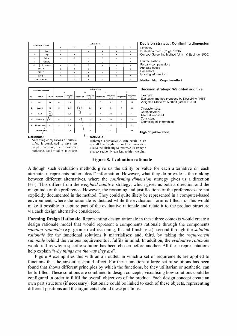
Figure 8. Evaluation rationale
Although such evaluation methods give us the utility or value for each alternative on each attribute, it represents rather “dead” information. However, what they do provide is the ranking between different alternatives, where the confirming dimension strategy gives us a direction (+/-). This differs from the weighted additive strategy, which gives us both a direction and the magnitude of the preference. However, the reasoning and justifications of the preferences are not explicitly documented in the method. They could quite likely be represented in a computer-based environment, where the rationale is dictated while the evaluation form is filled in. This would make it possible to capture part of the evaluative rationale and relate it to the product structure via each design alternative considered.
Forming Design Rationale. Representing design rationale in these three contexts would create a design rationale model that would represent a components rationale through the components solution rationale (e.g. geometrical reasoning, fit and finish, etc.); second through the solution rationale for the functional solutions it materialises; and, third, by taking the requirement rationale behind the various requirements it fulfils in mind. In addition, the evaluative rationale would tell us why a specific solution has been chosen before another. All these representations help explain “why things are the way they are”.
Figure 9 exemplifies this with an air outlet, in which a set of requirements are applied to functions that the air-outlet should effect. For these functions a large set of solutions has been found that shows different principles by which the functions, be they utilitarian or aesthetic, can be fulfilled. These solutions are combined to design concepts, visualising how solutions could be configured in order to fulfil the overall objectives of the product. Each design concept create an own part structure (if necessary). Rationale could be linked to each of these objects, representing different positions and the arguments behind these positions.
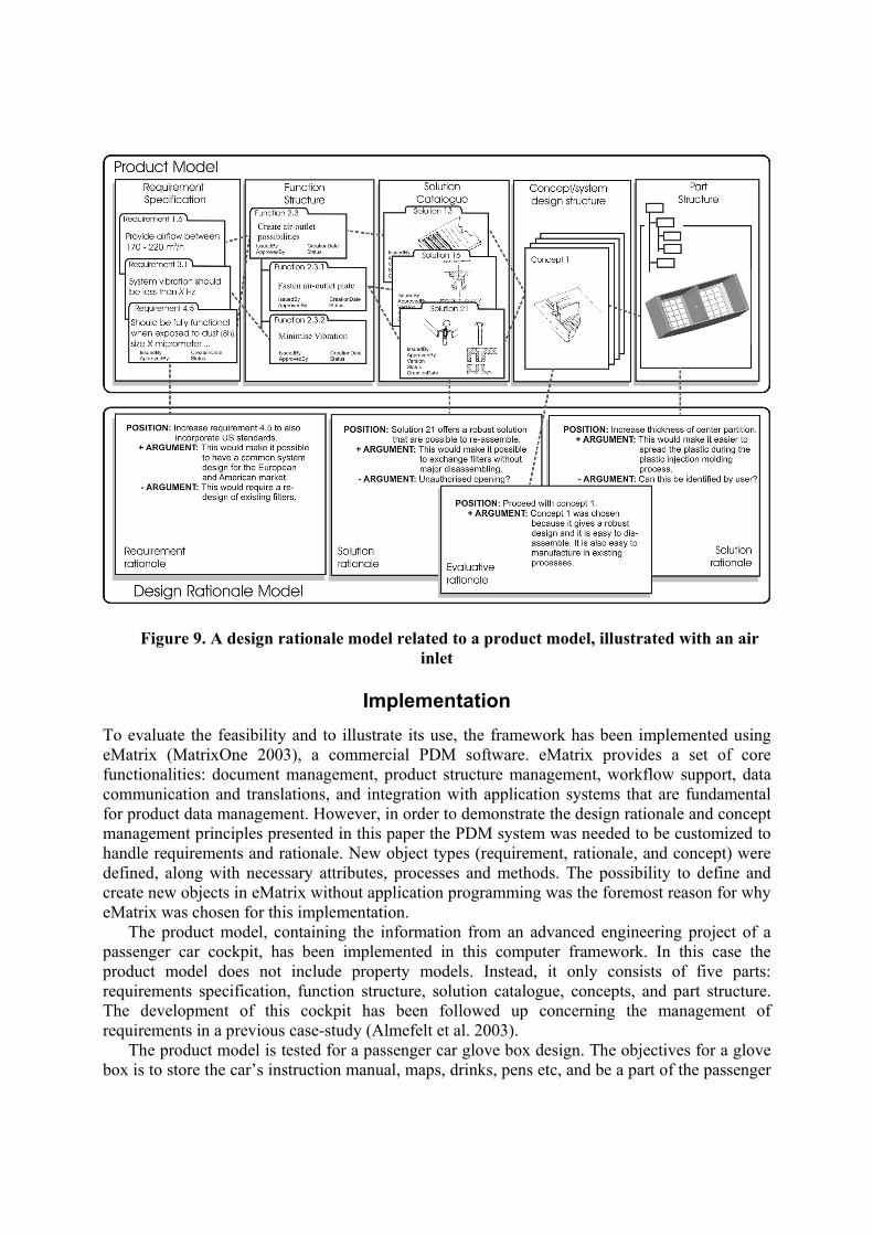
Figure 9. A design rationale model related to a product model, illustrated with an air inlet
Implementation To evaluate the feasibility and to illustrate its use, the framework has been implemented using eMatrix (MatrixOne 2003), a commercial PDM software. eMatrix provides a set of core functionalities: document management, product structure management, workflow support, data communication and translations, and integration with application systems that are fundamental for product data management. However, in order to demonstrate the design rationale and concept management principles presented in this paper the PDM system was needed to be customized to handle requirements and rationale. New object types (requirement, rationale, and concept) were defined, along with necessary attributes, processes and methods. The possibility to define and create new objects in eMatrix without application programming was the foremost reason for why eMatrix was chosen for this implementation.
The product model, containing the information from an advanced engineering project of a passenger car cockpit, has been implemented in this computer framework. In this case the product model does not include property models. Instead, it only consists of five parts: requirements specification, function structure, solution catalogue, concepts, and part structure. The development of this cockpit has been followed up concerning the management of requirements in a previous case-study (Almefelt et al. 2003).
The product model is tested for a passenger car glove box design. The objectives for a glove box is to store the car’s instruction manual, maps, drinks, pens etc, and be a part of the passenger
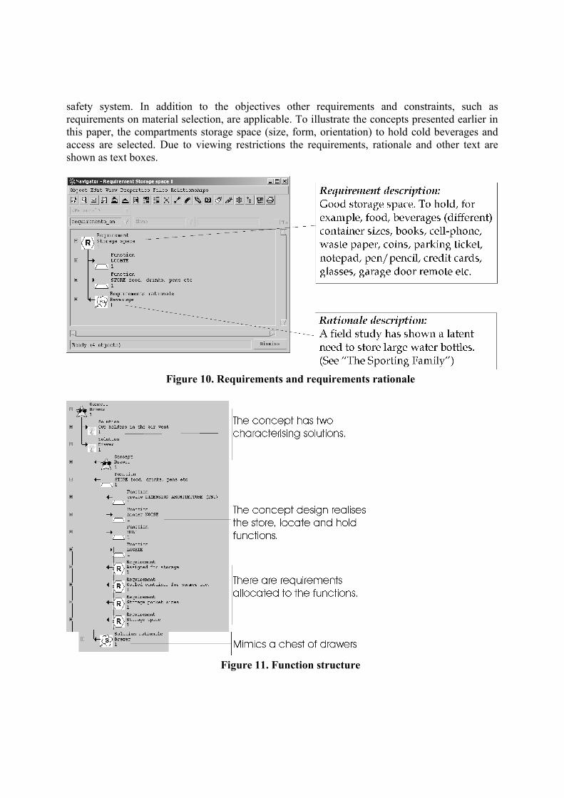
safety system. In addition to the objectives other requirements and constraints, such as requirements on material selection, are applicable. To illustrate the concepts presented earlier in this paper, the compartments storage space (size, form, orientation) to hold cold beverages and access are selected. Due to viewing restrictions the requirements, rationale and other text are shown as text boxes.
Figure 10. Requirements and requirements rationale
Figure 11. Function structure
We have showed that requirement rationale, solution rationale and concept designs can be implemented in a PDM system. The rationale reflects the human mind and they are not always rational and logical. The resulting information web is complex and difficult to overview, even though it’s implemented into a computer support tool. Evaluation rationale is more difficult. It prerequisite computer supported evaluation methods exist where different issues can be collected into a decision item. Evaluation rationale can then be attached to the decision item.
Conclusions
This paper has presented a framework in which design rationale could be represented in relation to a product model supporting systematic design. This framework makes it possible to not only represent the outcomes of the design process, i.e. contextual and product descriptions, but also the justification and reasoning behind the outcome. Although this gives a structure to represent rationale in relation to a product model, there is still a lot to do concerning the interface and output style of the actual tool (for example dependency management, rapport facilities, etc.).
Naturally, the complete rationale for a product cannot be elicited and represented. A large degree is documented in various design documents and administrative support tools. However, the individual designers in the design team possess most of it. Nonetheless, the rationale is a vital piece of information, and the management and documentation of it needs some structure if it is to be worthwhile. The documentation of design rationale is probably most important where the result is supposed to be carried over to future or parallel development projects, such as conceptual studies and advanced engineering projects. But it is also important for the ongoing activities, making the rationale open for inspection so that better decisions can be made.
The implementation in eMatrix demonstrates that it is possible to represent requirement, solution and evaluative rationale in relation to the overall product model. However, this study only verifies the applicability of implementing the framework in a design support tool, not of implementing it in a development process. This is because the implementation of the framework has been disengaged from the actual development activity and its context. Thus, future work has to further investigate the requirements the design process, and its context, poses on the tool, specifically on the representation of design rationale. Moreover, the tool needs to be implemented in a design setting, evaluating its pre- and post-decisional influences on the design process. The implementation, so far, has not explicitly focused on evaluative rationale. Therefore, a computer-based evaluation approach has to be developed so that evaluative rationale could be related to the product model.
Acknowledgement This work was financially assisted by the Swedish National Agency for Innovation Systems (VINNOVA) and the Swedish foundation for Strategic Research (SSF) through the ENDREA National Graduate School (The Swedish Engineering Design Research and Education Agenda). The support from car manufacturer is gratefully acknowledged.

References Almefelt, L., Requirements Management in Theory and Practice - From Requirements to a
Balanced Product Concept. Thesis for the Degree of Licentiate of Engineering, Department of Product and Production Development, Chalmers University of Technology, Göteborg, Sweden, 2003.
Almefelt, L., Andersson F., Nilsson P. and Malmqvist J., "Exploring Requirements Management in the Automotive Industry." 14th International Conference on Engineering Design Research for Practice - innovative products, processes and organisations (Stockholm, Sweden, 2003).
Almefelt, L., Sutinen K. and Malmqvist J., "Computer Support for Systematic Design Applied in a Cross-Functional Commercial Concept Development." Proceedings of the 4th International Symposium TMCE 2002 (Wuhan, P. R. China, April 22-26, 2002). pp 585-600.
Andersson, F., "Functional Representation: Creating a Framework for Design Support." Proceedings of the 8th ISPE International Conference on Concurrent Engineering: Research and Application (West Anaheim, California, July 30 - August 1, 2001).
Andersson, F., Nilsson P. and Johannesson H., "Computer Based Requirement and Concept Modelling - Information Gathering and Classification." Proceedings of DETC'00. 2000 ASME Design Engineering Technical Conference (Baltimore, Maryland, September 10-13, 2000).
Andreasen, M. M., "Designing on a "Designer's Workbench" (DWB)." Proceedings of the 9th WDK Workshop (Rigi, Switzerland, 1992).
Bailin, S., "KAPTUR: Knowledge Acquisition for Preservation of Tradeoffs and Underlying Rationale." Proceedings of the 5th Annual Knowledge-Based Software Assistant Conference (Liverpool, NY, September 24-28, 1990). pp 95-104.
Chandrasekaran, B., Goel S. K. and Iwasaki Y., "Functional Representation as Design Rationale." Computer, 26: 1, 1993, pp 48 -56.
Chipware, I., RTM product homepage. www.chipware.com, 2003. Cross, N., Engineering Design Methods: Strategies for Product Desogn, John Wiley & Sons,
New York, 1994. EDS, SLATE Teamcenter product homepage.
www.eds.products/plm/teamcenter/slate/, 2003. Feldmann, D. G., Pott B. and Schmidt J., New Approaches for Computer Support in Application
Engineering, Development and Design of Hydrostatic Systems. SAE Technical Paper Series, 2002-01-1419, NCFP 102-17.3, 2002.
Hubka, V. and Eder W. E., Theory of Technical Systems - A total Concept Theory for Engineering Design, Springer-Verlag, Berlin Heidelburg, 1988.
Jensen, T., Functional modelling in a Design Support System - Contribution to a Designer's workbench. Ph.D. thesis, Department of Control and Engineering Design, Technical University of Denmark, Copenhagen, 1999.
Kesselring, F., Bewertung von Konstruktionen (In German), Deutscher Ingenieur-Verlag, Düsseldorf, Germany, 1951.
Kunz, W. and Rittle H., "Issues as Elements of Information Systems", Working paper No. 131., Institute of Urban and Regional Development, University of California, Berkley, CA, 1970.
Lee, J., "Design Rationale Systems: understanding the issues." IEEE Expert, 1997, pp 78-85. MatrixOne, E-Matrix product homepage. http://www.matrixone.com, 2003.
Pahl, G. and Beitz W., Engineering design, a systematic approach, Springer-Verlag, Berlin, Germany, 1996.
Payne, J. W., Bettman J. R. and Johnson E. J., The adaptive decision maker, Cambridge University Press, New York, 1993.
Pugh, S., Total design. Integrated methods for successful product engineering, Addison-Wesley Publishing Company, Wokingham, UK., Wokingham, UK, 1990.
Ramesh, B. and Dhar V., "Supporting Systems Development by Capturing Deliberations During Requirements Engineering." IEEE Transactions on Software Engineering, 18: 6, 1992, pp 498-510.
Rasmussen, J., Pejtersen A. M. and Goodstein L. P., Cognitive Systems Engineering, Whiley series in Systems Engineering, John Wiley & Sons, INC, 1994.
Rational, RequisitePro product homepage. www.rational.com, 2003. Shum, B. S. and Hammond N., "Argumentation-Based Design Rationale: What Use at What
Cost?" International Journal of Human-Computer Studies, 40: 4, 1994, pp 603-652. Sutinen, K., Almefelt L. and Malmqvist J., "Implementation of Requirements Traceability in
Systems Engineering Tools." Product Models 2000 (Linköping University, Linköping, Sweden, November 7-8, 2000). pp 313-328.
Telelogic, DOORS product homepage. www.telelogic.com, 2003. Ullman, D. G., "Issues critical to the development of design history, design rationale and design
intent systems." Proceedings of the 1994 ASME Design Technical Conferences (Minneapolis, MN, USA, Sep 11-14, 1994).
Ulrich, K. T. and Eppinger S. D., Product Design and Development, McGraw-Hill Inc., New York, NY, USA, 2000.
Zwicky, F., Entdecken, Erfinden, Forschen im Morphologischen Weltbilt, Droemeer-Knaur, München, 1971.
Biography Fredrik Andersson (M.Sc., Lic. Eng.) Doctoral Student Fredrik Andersson is a (final year) doctoral student at the Department of Product and Production Development at Chalmers University of Technology, Göteborg, Sweden. He specialises in the area of support tools and work procedures for requirements and design concept management. He holds a Licentiate of Engineering from Chalmers University of Technology, and a M.Sc. (Eng.) in Integrated Management Systems from the University of Birmingham, UK.
Krister Sutinen (M.Sc., Lic. Eng.) Doctoral Student Mr. Krister Sutinen is a (final year) doctoral student at Chalmers University of Technology. His research aims at estimating the consequences of design modifications and requirements changes. He holds a Master of Science degree in Mechanical Engineering (1997) from Luleå University of Technology, Luleå, Sweden, and a Licentiate of Engineering degree (2001) from Chalmers University of Technology, Göteborg, Sweden. Before returning to the academia, he worked as a consultant.
Johan Malmqvist (M.Sc., Ph.D.) Professor Professor Johan Malmqvist holds the M.Sc. (1988), and Ph.D. (1993) degrees in Mechanical Engineering from Chalmers University of Technology, Göteborg, Sweden. His current research concerns design methodology, systems engineering and product and design process modelling.
Related Documents