ALLSTAR SOLAR SOLUTION PTY LTD. PRODUCT MANUALS

Welcome message from author
This document is posted to help you gain knowledge. Please leave a comment to let me know what you think about it! Share it to your friends and learn new things together.
Transcript

ALLSTAR SOLAR SOLUTION PTY LTD.
PRODUCT MANUALS

Company Background
Allstar Solar Solution is a collection with the ability of PV research and development, manufacturing facility, sales and installation in one of the high-tech company.
Since Allstar established, we are one of the company focuses on the installation experience for the racking system for PV with our electrician, we are committed to continuous improvement of our products, to bring improvement to product strength and better installation efficiency of products to our customers.
For our product development, our improving modeling is uniquely to inviting both our client and electrician to participating in the product development stages. Allstar are dedicated to our professionalism and innovations and at the same time that we have fully consideration from our client’s objective and needs.
After our continuous exploration and researches, we already received many of the product patents and certifications. In addition, Allstar also has a specialized R&D department for oversea markets, we could setup special customize PV mounting system to adapt to different markets and the ever-changing customer needs.
Since the arrival of the globalization, Allstar already setup an international sales network to cover every client in the world. Our sales marketing is benefit from our quality products and fast service, has now won in depth cooperation with EPC and many of the well-known distributor in the world.
“Creating the Value, Winning the Future” is Allstar long-term business philosophy and is for our all of our employee to pursuit.
About All Star
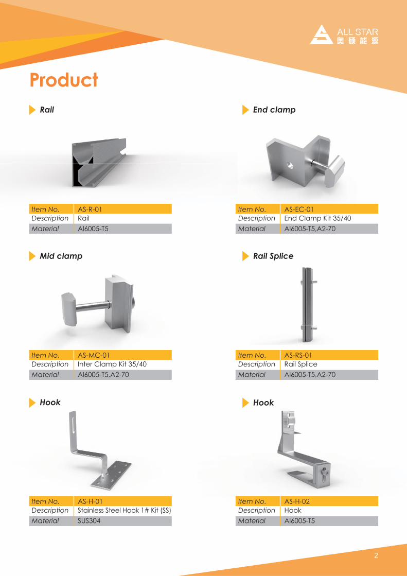
Product
Item No.DescriptionMaterial
AS-MC-01Inter Clamp Kit 35/40Al6005-T5,A2-70
Item No.DescriptionMaterial
AS-H-01Stainless Steel Hook 1# Kit (SS)SUS304
Item No.DescriptionMaterial
AS-H-02HookAl6005-T5
Item No.DescriptionMaterial
AS-RS-01Rail SpliceAl6005-T5,A2-70
Item No.DescriptionMaterial
AS-EC-01End Clamp Kit 35/40Al6005-T5,A2-70
Rail SpliceMid clamp
Hook Hook
Rail
AS-R-01RailAl6005-T5
Item No.DescriptionMaterial
End clamp

Product
Item No.DescriptionMaterial
AS-TAF-01Adjustable Front LegAl6005-T5
Item No.Description
Material
AS-SRH-01Stand Seam Roof Hook With Screw M8*20AL6005-T5
Item No.DescriptionMaterial
AS-SRH-02Stand Seam Roof HookSUS304
Adjustable Front Leg
Stand Seam Roof HookStand Seam Klip Lok
Item No.DescriptionMaterial
AS-TAS-01Adjustable Rear LegAl6005-T5
Adjustable Rear Leg

ProductCable Clip
AS-CC-01Cable ClipStainless steel
Item No.DescriptionMaterial
Tilt-in module
Aluminum Tin Interface Kit
Grounding Lug
Item No.DescriptionMaterial
AS-SRH-03Aluminum Tin Interface KitAl6005-T5,A2-70 Bolt
Item No.DescriptionMaterial
AS-GL-01Grounding LugAluminum
Grounding Clip
Item No.DescriptionMaterial
AS-GC-01Grounding ClipStainless steel
Item No.DescriptionMaterial
AS-TM-01Tilt-in moduleAluminum
GrGrouounding LuL g
Item No.Description
ASAS-GGL-L 0101Grounding Lug
Item No.DescriptionMaterial
AS-GC-01Grounding ClipStainless steel

1.General information
Easy installation four steps
Thank you for choosing the All Star solar roof mounting system. Made from custom-built aluminum extrusions and components, All-Star’s innovated design and improved frame strength greatly simplify solar panel installation. The easy installation four steps make the D-Modules can be put into the D Rail on any position quickly. So, the D-Modules is pre-assembly with the clamp to save your install time.
Tilt-in Align Up Fasten

2. Safety and Installer Responsibilities2.1 Handling and Installing All Star products
2.2 Wind and Climate Design
Caution Installation of this product is to be performed only by professionally trained install-ers. Any attempt by an unqualified person to install this product could result in death or serious injury.
It is critically important that safety practices are observed when installing
Do not throw or roughly handle any All-Star components.
Do not bring All-Star system into contact with sharp or heavy objects.
Do not modify All-Star components in any way. The exchange of bolts, drilling of holes, bending or any other physical chang es not described in standard installation procedure will void the warranty.
It is the installer’s responsibility to verify the integrity of the structure to which All-Star components is fixed. Roofs or struc tures with rotten/rusted bearers, undersized bearers, exces sively spaced bearers, or any other unsuitable substructure cannot be used with All-Star components, and installation on such structures will void the warranty, and could result in death or serious injury.
AS/NZS1170.2.2011 provides guidance on determining the wind pressures applicable to your All-Star system install site, taking into account roof shape and geographic location. Sufficient guidance is given in this document, but you may wish to procure a copy of these standards if your company installs Australia/New Zealand wide.
REMEMBER average wind speeds are higher for structures mounted closer to the roof perim eter zone (edge). Refer to ‘Fixing within Roof Installation Zone’ for more information)
Make sure your installation complies with local and national building codes. Take into account relevant design parameters (wind speed, exposure and topographic factor) when determining the loading for the installation.
If alternative fasteners are used to fix the framing to the roof (assuming supplied fasteners are unsuitable for any reason), all screw fasteners must conform to corrosion resistance Class 4 Australian Standard AS3566 and be of equal or greater strength to those supplied with your All-Star system order.

6005-T5 Aluminum extrusion
Innovated designed of the D-Modules, which can be pre-assembly with the clamp, make the installation easy and quick.
Suitable for difference conditions and the most solar panels at present market.
Significantly higher strength-to-weight ratio than other framing products, providing improved efficiency due to greater frame spans, inherent corrosion resistance result-ing in low ongoing maintenance and an extended prod-uct life.
Complies with Australian/New Zealand Standard on Wind Actions, AS/NZS1170.2.2011
Anodized finish
Commercial and residential buildings
Marine applications and remote areas
3. Technical Specifications
Refer to the section“Designing Your System”before attempting installa-ion. Failure to correctly establish the requirement ofthe proposed installation site is dangerous and will void the framing warranty.
Caution
3.1 Applications
3.2 Features
3.3 Material
Material Tensile strengthUltimate Yield
6005-T5 Aluminum Extruded 260MPa 240Mpa
Stainless Steel 304 635MPa 235MPa
Stainless Steel A2-70 700MPa 450Mpa
3.4. Installation conditionRoof slope 0° to 60°Building height Up to 20mMounting structure TimberRoof types Flat or pitched steel and tile System angle Flushed with the roof
Note: if the condition is over the table list, please contact us to confirm.

If using a 6mm driver bit, make sure the cordless power tool used for the driving has a hand-tight clutch setting a fine (soft) impact drive to prevent damage to the fragile glass panels and threads on the Structure.
4. Tools for Installation
6 mm Allen key or hexagonal driver bit.
Cordless drill;
Drill or impact driver for driving roof material fixings
Angle grinder;
Gloves;
Protect the hazard of the sharp corners.
Cord or color pen;
Mark the installation position;
Spirit level
Ruler
If necessary, timber to shim the roof hooks
The following tools are required for the installation:
For terracotta tile roof installation, and angle grinder fitted with a continuous edge diamond tipped tile cutting blade; gloves, hearing protection, a face protection mask, and a suitably rated breathing protection mask for all people in proximity of grinding.

5. Components Descriptionption
AS-RailHold each panel row
Length can be customized
6005-T5 extruded aluminum
AS Rail Splice Kit
Extend AS Rail to any length as required by the quantity or width of the solar panels
Inter Clamp Kit for Framed ModulesFit between two panels
Fastened with a 6mm Allen key
Standard pre-assembly for the usual panels with thickness 30, 35, 40, 46, 50, 57mm
Adjustable End Clamp KitHold the edge of each end panels
Fastened with a 6mm Allen key
Adjustable for the panels with thickness of 35mm and 40mm ( Patented )
Stainless Steel Hook Kit (SS)
Fix to the rafter below Roman tile roof
Include 3pcs st6.3x80 wood screws
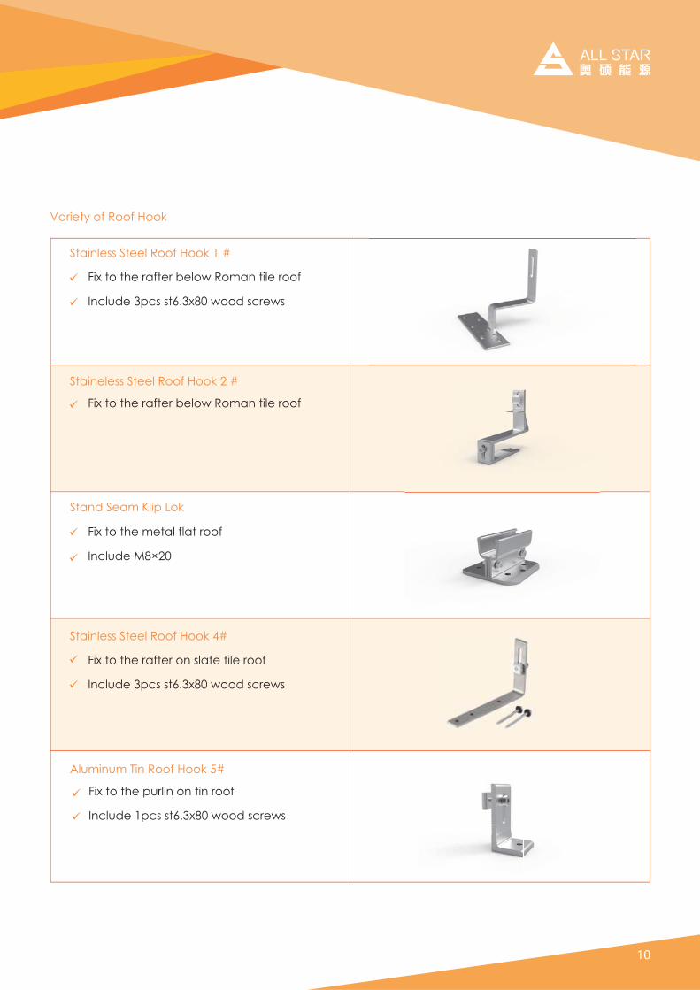
Aluminum Tin Roof Hook 5#
Fix to the purlin on tin roof
Include 1pcs st6.3x80 wood screws
Variety of Roof Hook
Staineless Steel Roof Hook 2 #
Fix to the rafter below Roman tile roof
Fix to the rafter below Roman tile roof
Include 3pcs st6.3x80 wood screws
Stainless Steel Roof Hook 1 #
Stand Seam Klip Lok
Fix to the metal flat roof
Include M8×20
Stainless Steel Roof Hook 4#
Fix to the rafter on slate tile roof
Include 3pcs st6.3x80 wood screws

6. System over view
Type of moduleType of roof
Number of modules Site specifics
① AS Rail ② AS Rail Splice (Optional)
③ Inter Clamp ④ End Clamp
⑤ Roof hook
All components of the system are listed below. The version and quantities of the parts can vary, depending of

Below, the distances between roof connections for a portrait installation are specified. Clamp-on roof hooks need to be installed in specific distances, depending on the distance of rafters and the stoical con-ditions.
7. Designing the module field
When positioning the modules, please take into consideration
1. Height of the module field: module height x number of modules vertically.
2. Width of the module field: number of modules horizontally x (width of the module + 18 mm)+32 mm.
3. Distance between roof connections vertically (according to the clamping points pre-defined by the module producer): Quarter-points of the modules, about 1/2 of module height.
4. Distance between roof connections horizontally: Depending on the distance between rafters and on the static requirements (please see the Chapter 8 on page 11).
5. Distance between modules: 17 mm
That the values above are
That dimensions of tiles or other roof covering and the position of the rafters define the precise actual horizontal distance between roof connections
That the distance between roof laths defines the precise actual vertical distance between roof connections.
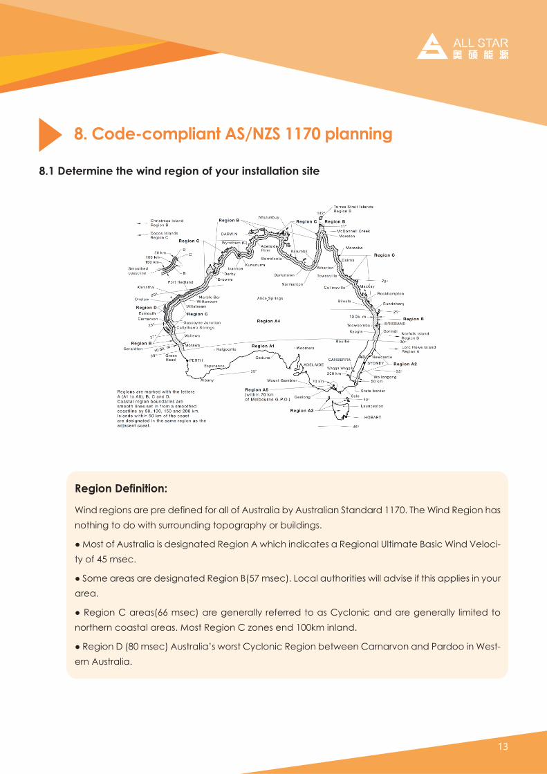
8.1 Determine the wind region of your installation site
8. Code-compliant AS/NZS 1170 planning
Region Definition:
Wind regions are pre defined for all of Australia by Australian Standard 1170. The Wind Region has nothing to do with surrounding topography or buildings.
"#$%&'#%(#)*&'+,-.,#.&#/0&.12,'0/#301.%2#)#45.65#.2/.6,'0&#,#301.%2,-#7-'.8,'0#9,&.6#:.2/#;0-%6.-ty of 45 msec.
"#<%80#,+0,&#,+0#/0&.12,'0/#301.%2#9=>?#8&06@A#B%6,-#,*'5%+.'.0.--#,/C.&0#.(#'5.&#,DD-.0&#.2#E%*+#area.
"#301.%2#F#,+0,&=GG#8&06@#,+0#1020+,--E# +0(0++0/#'%#,&#FE6-%2.6#,2/#,+0#1020+,--E# -.8.'0/#'%#northern coastal areas. Most Region C zones end 100km inland.
"#301.%2#H#=IJ#8&06@#)*&'+,-.,K%+&'#FE6-%2.6#301.%2#L0'4002#F,+2,+C%2#,2/#M,+/%%#.2#:0&'-ern Australia.

This document provides sufficient information for All-Star system installation height less than 20 meters. If your installation site is more than 20 meters in height, please contact All-Star to obtain engineering data to support your installation.
All Star system can be installed anywhere on a roof but fixing centers are required to be reduced at ridges and edges. The diagram below shows the area of higher wind loadings within 0.2A and 0.2Bof a roof edge ridge (where A and B are the planned dimension of the building).
Center Zone Edge Zone
8.2. Determine the height of the of your installation site
8.3 Determine Roof Installation Roof Areas

Subject to the following qualifications we certify that the above mentioned frames are structurally ade-quate and conform to the above Australian standards.
1. The gap between the underside of the solar panels and the roof shall be between 50mm minimum and 300mm maximum. Nominate the actual gap as “S” mm.
2. The solar panels shall be installed 2xS mm or 200 mm (whichever is greater) away from the roof edges and the ridge. Example: If the gap below the panel is 150mm then the panels shall be located 300mm away from the roof edge and the ridge. See Figure C above.
3. Each row of 1650 long solar panels shall have a minimum of two rows of railing fixed to the roof framing.
4. The connections between the solar panels shall be flexible to accommodate deflection of the railing.
5. The deflection of the railing has not been controlled in the design. If defection has to be limited then spacing shall be reduced as advised by a practicing structural engineer.
6. The roofing to which the panels are to be installed shall conform to the relevant Australian Standards including AS1684, AS4440, AS1720, AS4100 and AS4600.
7. The buildings to which the panels are to be installed shall be of approved construction and conform to BCA and the relevant Australian Standards. The roof framing and the building shall be regularly maintained as required.
8. The existing framing shall be verified for compliance to Clause D6, of AS1170.2.
9. The installation of the framing shall conform to relevant Australian Standards, Manufacturer’s specifica-tions and good building practice.
10. The spacing of the rail fixings shall not exceed the recommended spacing, and shall be reduced to match the location of the roof rafters.
11. The cantilever span of the panel shall not exceed 25% of panel length (i.e. 412mm for 1650 long).
12. The cantilever span of the railing shall not exceed 33% of the adjacent spacing of the installed fixings.
13. Each fixing shall have a minimum of two gauge 14 screws.
14. The screws used to attach the railing to the roof framing shall conform to AS3566, ISO 3506.1.
15. The cold formed steel purlins shall have a minimum base material thickness of 1.2mm in Regions A & B and 1.9mm in Regions C & D.
16. Timber with Joint Type classification J4 to J6 are excluded unless tested for Screw capacity.i.e. minimum joint strength requirement shall be J3. Please refer Table AS1720.1.
17. Predrilled holes shall be used for all screw fixings into timber. The width of Timber purlins shall not be less than 35mm. The minimum embedment for each screw shall be 50mm. Minimum edge distance for screws shall be 17mm.
18. Dissimilar metals shall be separated with a suitable inert material to prevent galvanic corrosion.
19. The installation and fixings shall be periodically inspected and maintained.
20. The following are excluded from this certification.
x Framing of the solar panel assembly.
x Material Testing and or Verification of test certificates for the materials and components.

8.4 Determine the Maximum Rail Support Spacing
a. Please use the following table to determine the rail support spacing for tile roof installations.
InstallationHeight
Max area of onepanel
Roof Area
Region A (mm)
3.0m2 2.5m2 2.0m2 1.5m2
Region B (mm) Region C (mm) Region D (mm)
CenterZone
EdgeZone
EdgeZone
CenterZone
EdgeZone
CenterZone
EdgeZone
CenterZone
5 Meters10 Meters15 Meters20 Meters
The above figures are based on modules lengths of up to 1970mm, maximum weight of 23Kg/m2
The above spacing applies for fixing through thin sheet purlins (greater than 1.0mm thickness) or a mini-mum embedment of 50mm into timber purlins.Tile brackets should fixed to the rafter using two 12g mounting screws (M6x80mm)For 35mm embedment into timber of fixings into 0.55mm thickness steel for regions A+B remain unchanged. For regions C reduce the spacing by 15%. For region D reduce the spacing by 35%.In case the wooden rafters/trusses you wish to mount on are too thin and the screws would be too close to the edge of the rafters please pre-drill with a 3~4mm drill in order to avoid the splitting of the timber ( or use the side mount roof hook).
1650mm Long Panels fixed to Tiled Roof
The above figures are based on modules lengths of up to 1650mm, maximum weight of 16Kg/m2
2210199018901830
1830165015701530
1800163015501500
1500126011401070
131011801020910
910820710640
820740650580
580520450400
InstallationHeight
Max area of onepanel
Roof Area
Region A (mm)
3.0m2 2.5m2 2.0m2 1.5m2
Region B (mm) Region C (mm) Region D (mm)
CenterZone
EdgeZone
EdgeZone
CenterZone
EdgeZone
CenterZone
EdgeZone
CenterZone
5 Meters10 Meters15 Meters20 Meters
2020182017301680
167015101440
16401490141013701400 900
13701050950
1090980860760 530
760690600
690620540
1970mm Long Panels fixed to Tiled Roof
480
480430380340

The above figures are based on modules lengths of up to 1970mm, maximum weight of 23Kg/m2
The above spacing applies for fixing through thin sheet purlins (greater than 0.75mm thickness) or a mini-mum embedment of 50mm into timber purlins.The L Feet should be fixed to the purlins under using one 12g mounting screw (M6x80mm) through sheet metal roofs with desk rubber.
InstallationHeight Region A (mm) Region B (mm) Region C (mm) Region D (mm)
Max area of onepanel
Roof Area
3.0m2 2.5m2 2.0m2 1.5m2
CenterZone
EdgeZone
EdgeZone
CenterZone
EdgeZone
CenterZone
EdgeZone
CenterZone
5 Meters10 Meters15 Meters20 Meters
1860168015901550
1670151014401400
1520137013001270
13701050950900
930840730650
760690600530
590530460
1970mm Long Panels fixed to Tin Roof
410
480430380340
The above figures are based on modules lengths of up to 1650mm, maximum weight of 16Kg/m2
b. Please use the following table to determine the base rail support spacing for Tin roof installations.
InstallationHeight Region A (mm) Region B (mm) Region C (mm) Region D (mm)
Max area of onepanel
Roof Area
3.0m2 2.5m2 2.0m2 1.5m2
CenterZone
EdgeZone
EdgeZone
CenterZone
EdgeZone
CenterZone
EdgeZone
CenterZone
5 Meters10 Meters15 Meters20 Meters
1650mm Long Panels fixed to Tin Roof
2030183017401690
1830165015701530
1660150014301390
1500126011401070
11101000870780
910820710640
700630550490
580520450400

The above figures are based on modules lengths of up to 1970mm, maximum weight of 15Kg/m2
Please note that the screws provided with our products are designed for mounting into wooden structures.
Rail End Overhang must equal 50 percent or less of foot spacing. Thus, if foot spacing is 1200mm, the Rail End Over hang can be up to 600mm. In this case, two feet can support a rail of as much as 2400mm (1200mm between the feet and 600mm of overhang at each end).
All Star system can be used for roof slope up to 60 degrees. Please verify the Installation site roof slope should be between 0 degrees and 60 degrees.
The above spacing applies for fixing through thin sheet purlins(greater than 0.75mm thickness) or a mini-mum embedment of 50mm into timber purlins.
The L Feet should be fixed to the purlins under using one 12g mounting screw (M6x80mm) through sheet metal roofs with desk rubber.
For 35mm embedment into timber of fixing into 0.55mm thickness steel the max panel length should be reduced to 1700mm and the max spacing reduced by 20%.
8.5 Verify acceptable Rail End Overhang
8.6 Determine Roof slope

9. Installation
Install the Hooks on Roman Tile Roof
1. Remove the roof tiles at the marked positions or simply lift them up slightly.
2. Input the roof hook to the wooden beam.
3. Cover the hooks by the removed tile.
4. Mark roof hook installation points, and cut recesses for hooks into plain tiles/slate at each installation point.
5. If necessary, use an angle grinder or hammer to cut a concavity in the tile that covers the roof hook at the point where the roof hook comes through. (Caution! Must not use fixed roof hook as a ladder, as this extreme point load could damage the tile below.

Install the Hooks on Roman Tile Roof
6. The roof hook must not press against the roof tile. Place it flat. If necessary, shim the roof hook with wood.
7. Cut titanium zinc metal sheets to fit and install them under the roof hooks. Fix the roof hooks to the rafter using two 6 x 80 mm wood screws.
8.Adjust the length of the adjustable part of tile roof hook to fit the size of wood.

Install the Hooks on Tin Roof
8. Mark roof hook installation points and use the power tool to drill the wood screw through the point to fasten the L feet with the purlin.
Install the Tilt Brackets on Tin Roof
9. Mark roof hook installation points and use the power tool to drill the wood screw through the point to fasten the rear leg with the purlin.
10. Adjust the length of Rear Leg to create a suited angle between solar pannels and the roof .
Adjust the flexiable part of Rear Leg and Front Leg to combine the legs with Allstar Rail, fasten the screw so that the whole system can be fixed with the mentioned angle .

11. D-Module quick mount. Four steps to quick mount the D-Module into rail channel. Move the assembly to It’s desired final position, and fastens firmly in place by torque bolt to 10Nm.
13. Rail connect a.Put the rail Splice into the side channel of the rail about 75mm, then fasten the M8 Bolt.
b.Put the other rail into the other side
of the rail Splice and fasten the other M8 bolt.
Rail Installation
12. Connect the roof hook with the rail.
a. Insert the D-Module into the side channel of the rail as the step 9 shown.
b. Adjust the rail to be level.
c. Fasten the bolt.

14. Installing anti-slip protection The anti-lip protection is only necessary on the lowermost row of modules.
At first, fit two bolts M6*20 and nuts into the lower holes of each module. Then place the first module of the bottom row so that the anti-slip protection sits in the rail channel of the lowest row of rails.
Install the module
15. Fixing the outer modules by End clamp.
a. Put the end clamp kit into the top channel of the rail as the step 9.
b. Push the side of module to firmly against the end clamp and then fasten the bolt.
17. Installing the further rows of mod-ules.
16.Fixing the inter modules by inter clamp.a. Put the inter clamp kit into the top channel of the rail as the step 9.b.Push the Inter-module clamp firmly against the already fixed module.c.Push the next module against the other side of the module-inter clamp.d. Tighten the bolt

18. Tie cable with the rail Tie the cable with the rail using the zip tie.
Cable tie and Grounding
19. Grounding
Use the grounding clip to protect the system from lightning.
All Star warrants that its Panel Mounting System is free from defects in materials and workmanship for a period of 10 years from the date on which the Frame is purchased from All-Star, on the terms set out in this warranty.
In the event that the Frame does not conform to this warranty during the Warranty Period, All-Star will, at its option, either repair or replace the Frame or pay the cost of having the Frame repaired or replaced. To the extent permitted by law, All-Star’s total liability under this warranty will in no circumstances exceed the repair or replacement of the Frame or payment of the cost of having the Frame repaired or replaced. In the event of replacement of the Frame, any remaining part of the Warranty Period will be transferred to the replacement Frame.
This warranty does not cover, and under no circumstances will All Star be liable for, any costs associated with the removal, shipping, handling or re-installation of the Frame or the costs of sending personnel to any site to repair or replace the Frame.
This warranty is only provided to the original purchaser of the All-Star panels mounting system (Purchaser) or, where the Purchaser is an installer or builder who on-supplies the Frame to another party, to that other party (End-User). This warranty is not transferable.
Where an End-User wants make a claim under this warranty, the End-User must in the first instance contact the installer or builder from whom the Frame was purchased. This warranty will not apply to any claims received by All Star after the expiration of the Warranty Period. All-Star makes no warranties, express or implied, other than the warranties made herein, and specifically disclaim all other warranties, representa-tions and conditions to the extent permitted by law. To the extent permitted by law, in no circumstances will All Star be liable for direct, indirect, special or consequential damages arising from a defective Frame or for any damage or injury to persons or property. All-Star’s aggregate liability, if any, in damages or other-wise, will not exceed the invoice value of the Frame at the time of purchase from All-Star.
Any provision contained in this warranty which is prohibited or unenforceable in any jurisdiction will be deemed to be ineffective to the extent of such prohibition or unenforceability and will not invalidate the remaining provisions nor affect the validity or enforceability of that provision in any other jurisdiction.
10. Warranty
This warranty will not apply to any defect or damage to the Frame arising directly or indirectly from:1. Shipment or storage of the Frame;2. Improper installation, maintenance, repair or use of the Frame;3. Normal wear and tear;4. Misuse, neglect, abuse, accidental damage or modification to the Frame;5. Failure to observe the instructions set out in the System Manual; or6. Power failure, power surges, lightning, fire, explosion, flood, extreme weather conditions, environ-mental disasters or other causes outside All-Star’s control, as determined by All-Star in its sole discretion.

CN ADD:Zhiqian Town Jintan Changzhou Jiangsu China
[T]86-0519-82888577
[W]www.allstarsolarsolution.com
Related Documents