Product Handbook for Airborne Precipitation Radar Third Generation (APR3) OLYMPEX Data Experiment: OLYMPEX, Nov-Dec 2015, Olympic Mountains, Washington USA, DC8 Filename: standard: APR3_L2ZV_P3_YYMMDDhhmmss.Rx.h5, OLYMPEX repository: Eng_L2ZV_P3_YYMMDDhhmmss.Rx.h5 Note: YYMMDDhhmmss indicates the UTC start time of the data. On GHRC: olympex_apr3_YYYYMMDD_hhmmss_R2_KUsKAsWs.h5 Format: 2.X – Standard L1 product. Geolocated and calibrated radar reflectivity at Ku/Ka/W band, mean Doppler velocity and Linear Depolarization Ratio at Ku band, surface Normalized Radar Cross Section at Ku and Ka band, pre-calculated geodetic coordinates of every sample point Release: 2 (data release to the OLYMPEX repository, April 2018) Change log: X.0 – In field data, configuration and calibration changes applied during the experiment. X.1 – End of campaign reprocessing, full reprocessing with configuration control (Dec 2015). For internal QC only. X.3 – First Science Team release of preliminary processing. Absolute calibration uncertainty 1-sigma estimated at 1 dB for Ku-band, 1.5 dB for Ka-band, 1.5 for W-band. X.4 – Second science release. Uses HDF5. Improved Doppler processing and calibration. Please note: Science data are not owned by JPL/Caltech. By electing to use these data, the user agrees: 1. that Caltech makes no representations or warranties with respect to ownership of the data, and does not represent others who may claim to own the data, and makes no warranties as to the quality of the data. Caltech shall not be responsible for any loss or expenses resulting from the use of the data, and you release and hold Caltech harmless from all liability arising from such use. 2. to credit the use of the data to the Jet Propulsion Laboratory (JPL), California Institute of Technology (Caltech), which performs research and development for the National Aeronautics and Space Administration (NASA). 3. that the endorsement of any product or service by Caltech, JPL, or NASA must not be claimed or implied.

Welcome message from author
This document is posted to help you gain knowledge. Please leave a comment to let me know what you think about it! Share it to your friends and learn new things together.
Transcript

Product Handbook for Airborne Precipitation Radar Third Generation (APR3) OLYMPEX Data
Experiment: OLYMPEX, Nov-Dec 2015, Olympic Mountains, Washington USA, DC8
Filename: standard: APR3_L2ZV_P3_YYMMDDhhmmss.Rx.h5,
OLYMPEX repository: Eng_L2ZV_P3_YYMMDDhhmmss.Rx.h5
Note: YYMMDDhhmmss indicates the UTC start time of the data.
On GHRC: olympex_apr3_YYYYMMDD_hhmmss_R2_KUsKAsWs.h5
Format: 2.X – Standard L1 product. Geolocated and calibrated radar reflectivity at
Ku/Ka/W band, mean Doppler velocity and Linear Depolarization Ratio at Ku band,
surface Normalized Radar Cross Section at Ku and Ka band, pre-calculated geodetic
coordinates of every sample point
Release: 2 (data release to the OLYMPEX repository, April 2018)
Change log:
X.0 – In field data, configuration and calibration changes applied during the experiment.
X.1 – End of campaign reprocessing, full reprocessing with configuration control (Dec
2015). For internal QC only.
X.3 – First Science Team release of preliminary processing. Absolute calibration
uncertainty 1-sigma estimated at 1 dB for Ku-band, 1.5 dB for Ka-band, 1.5 for W-band.
X.4 – Second science release. Uses HDF5. Improved Doppler processing and
calibration.
Please note: Science data are not owned by JPL/Caltech. By electing to use these data, the user agrees:
1. that Caltech makes no representations or warranties with respect to ownership of the data, and does not
represent others who may claim to own the data, and makes no warranties as to the quality of the data. Caltech
shall not be responsible for any loss or expenses resulting from the use of the data, and you release and hold
Caltech harmless from all liability arising from such use.
2. to credit the use of the data to the Jet Propulsion Laboratory (JPL), California Institute of Technology
(Caltech), which performs research and development for the National Aeronautics and Space Administration
(NASA).
3. that the endorsement of any product or service by Caltech, JPL, or NASA must not be claimed or implied.

APR3 Instrument Overview APR3 is an enhanced version of the APR2
radar, which has successfully acquired data in
a number of field campaigns since 2001.
Features of APR2 are:
simultaneous dual-frequency,
matched beam operation at 13.4 and
35.6 GHz (same as GPM Dual-
Frequency Precipitation Radar)
simultaneous measurement of both
like- and cross-polarized signals at
both frequencies
Doppler operation
cross-track scanning (same as GPM/DPR)
The APR2 operational geometry is shown in Figure 1; it looks downward and scans its
beam across-track, with each scan beginning at 25 degrees to the left of nadir and ending
at 25 degrees to the right. Sadowy et al. (2003) provides a full description of the APR2
radar system. Calibration of the radar reflectivity products is verified at Ku-band by using
the ocean surface and at Ka-band by comparing with the Ku-band reflectivity in light
precipitation (Tanelli et al. 2006). Doppler velocities are corrected for aircraft motion
using surface return.
APR3 refers to the version of APR2 with a W-band channel (from the Airborne Cloud
Radar, ACR, Sadowy et al. 1997). It was completed for OLYMPEX and allowed two types
of W-band data to be collected. For precipitation, the existing Ku/Ka feed was modified
to allow operation at W-band, in addition to Ku and Ka bands. This allowed acquisition
of W-band data with the same cross-track scanning geometry as used for Ku and Ka-bands,
these data are denoted HH, due to historical use of the port in the W-band hardware. A
second W-band antenna was installed to provide higher sensitivity for cloud sensing goals.
This antenna has a larger aperture than that achieved by the three-frequency feed at W-
band. Also, it only looks at nadir, allowing more pulses to be integrated. For historical
reasons, data on this channel are denoted VV. Data were acquired with one or the other or
sometimes both antennas (simultaneous scanning and nadir).
G. A. Sadowy, A. C. Berkun, W. Chun, E. Im, and S. L. Durden, “Development of an
advanced airborne precipitation radar," Microwave J., vol. 46, no. 1, pp. 84-98, January
2003.
S. Tanelli, S. L. Durden, and E. Im, “Simultaneous Measurements of Ku- and Ka-band
Sea Surface Cross-Sections by an Airborne Radar,” IEEE Geosci. Remote Sens. Lett., vol.
3, no. 3, pp. 359-363, July 2006.
G. A. Sadowy, et al., “The NASA DC-8 Airborne Cloud Radar: Design and Preliminary
results," Proc. IGARSS'97, 1997.
Fig.1. APR-2 operational geometry

Data Format (version 2.x) The format for APR3 data (i.e. data with W-band) is an expansion of version 2.x data from
previous field experiments with APR2. As used here, APR2 refers to the Ku/Ka-band
system. The data are provided in HDF5 files. Previous versions have been HDF4. The
elements of the fileheader are now defined explicitly in the sub-structure params_KUKA.
All the variables are saved as doubles, and the HDF5 files are compressed.
nscan is the number of scans in a file, nray is the number of rays (aka: beams, looks) within
a scan, and nbin is the number of range bins within a ray.
Altitude and Look Vector (i.e., the 3 components of the antenna relative to a global
coordinate system with x being the aircraft ground track and z being vertical) are provided
in two estimates: alt_nav and look_vector are calculated relying on the aircraft navigation
information, instead alt_radar and look_vector_radar are calculated relying on the
observed surface return in Ku/Ka data. The latter pair is reliable only when flying over
ocean, and in this case it provides a more accurate geolocation than the navigation-based
pair. See notes in the next section for specific recommendations with this data release.
The predicted (v_surf_nav) and observed (v_surf) surface Doppler velocities are provided:
v_surf was corrected for occasional aliasing and, in turn, it was used to correct the Doppler
measurements of precipitation for the bias introduced by the aircraft motion. This
correction can be undone by the user by adding the value of v_surf to vel14 at all the range
bins of every ray. The alternate correction using the Doppler estimated from navigation
data can be then obtained by subtracting the value of v_surf_nav from vel14 at all the range
bins of every ray. This alternate correction may be of interest for the minority of data
collected over land where the v_surf estimate is more prone to errors, or for data collected
during sharp maneuvers by the DC-8.
The surface index is estimated by analyzing Ku/Ka surface return (roughness, angle
dependence of the surface normalized radar cross section, apparent surface inclination and
LDR at nadir). It assumes one of 6 values (this classification is preliminary, see next section
for known issues):
0 = Rough land
1 = Ocean (level flight)
2 = Ocean (roll maneuver)
3 = Flat land (level flight)
4 = Flat land (rolling maneuver)
5 = Antenna not scanning (unknown surface)
The file header contains information about the APR-2 data. These are parameters that are
constant over the entire file. Table 1 shows the file header. Variable 23 is for the option of
zenith-looking Ka-band data. It was not used in OLYMPEX.

Table 1: Description of the file header
Name Src Unit Default Description
1 PRF Raw Hz 5000 Pulse repetition frequency in Hz
2 Pulse Length Raw mus 3-20 Radar pulse length in 1 us units
3 Antenna Left Raw deg -25 or 0 Antenna scan left-limit in deg.
4 Antenna Right Raw deg +25 or 0 Antenna scan right-limit in deg.
5 Scan Duration Raw ms 1200 Scan time for antenna in second * 100
6 Return Duration Raw ms 600 Antenna retrace time in second * 100
7 Ncycle Raw 250 Number of pulse averaged by Wildstar board
8 AZ Average Raw 1 Number of blocks averaged in a beam or ray
9 Range average Raw 1 Number of 30m range cells averaged in a bin
10 Scan average Raw 1 Number of scans averaged
11 Number of Bins Raw 600 Number of range bins in the ray
12 Number of Beams
Raw 24 Number of rays in each scan
13 Range Bin Size 2HDF m 30 The vertical resolution of range bin
14 Z scale factor Raw 100 Factor multiplying reflectivity
15 V scale factor Raw 100 Factor multiplying Doppler
16 Not used write Always the number 1
17 # of scans L1A Number of scans
18 CalVersion write obsolete
19 Radar Mode L1A spare 1: mode (71 = dump, 87 = operate)
20 Rx Atten L1A Internal Cal parameter
21 Tx Atten L1A Internal Cal parameter
22 DR Env m A priori range sampling (redundant)
23 Ka band Port Env 0 Ka (2) = CxPol; 1 Ka(2) = Ka Zenith
24 Fixed Ka Pt L1A 1 Ka(2) = Ka fixed nadir antenna
25 W band Port flag_Wvv*10 + flag_Whh, where flag_Wxx is 0
absent, 1 present but less than half scans, 2 else
26 Not used
27 Not used
28 Not used
29 Not used
30 Not used
31 Not used
… Not used
38 Not used

Content of HDF5 files The variables in the APR3 HDF files are listed in Tables 2a, 2b, 2c, 2d and 2e. The type
of radar data is specified by the file suffix modeID, with the naming convention
'APR3_L2ZV_P3_YYMMDDhhmmss_R1_',modeID,'.h5'
where, e.g., modeID = “KUsKAsWsn” indicates that the file contains
“KUsKAs”: Ku- and Ka-band radar data obtained in scanning mode;
“Wsn”: W-band data obtained via scanning (“Ws”) and nadir-only (“Wn”)
channels.
The radar data consist mainly of a reflectivity factor Z (Ku, Ka, W), a mean Doppler
velocity V (Ku, W), and surface reflectivity 0 (Ku, Ka, W). The files also contain
navigation and geolocation information.
As described in Table 2a, each file contains (a subset of) the following sub-structures
params_KUKA (parameters of APR2, see Table 2b), former fileheader (Table 1);
params_W (parameters of ACR, see Table 2c),
lores (measurements at the lower resolution, i.e. APR2 resolution).
Note that the higher-resolution data [e.g. z95n (former zvv95) acquired by ACR
in the nadir-only channel] are integrated along-track to match the low-resolution
sampling of APR2. The integrated data are saved in beam #12 of 3D arrays [for
instance, the along-track integrated nadir-only reflectivity is saved as
“lores.z95n(:,12,:)”].
hires (measurements at the higher resolution, i.e. of ACR in nadir-only mode).
Note that the low-resolution measurements (beam #12 of measurements from
APR2 and ACR in scanning mode) are also interpolated to the higher resolution
of ACR, and
o in files with modeID = Wn (W-band only), the radar measurements in
hires are sampled at ACR’s high resolution both along-track and in range.
o in all the other cases (i.e. APR2 also working, e.g. KUsKAsWsn), the
ACR data are interpolated in range to match APR2’s range sampling.
scal_shiftAT_ACR2APR: Criteria used for the along-track collocation between
ACR nadir-only and APR2.
scal_shiftXT_ACR2APR: Criteria used for the cross-track collocation between
ACR scanning and APR2.

Table 2a: list of parameters in each APR3 file
All the variables are present in the “Engineering” files (internal to JPL).
Variables put in release files are highlighted in Blue.
label to indicate presence in APR3 files: Y(Yes), N(No);
Ns (numbers of scans at low resolution, i.e. APR2).
File suffix modeID
Variable name released
format size KUsKAs with Wn
only Notes
- Ws Wn
params_KUKA Struct 1 Y Y Y N APR2 operational mode: see Table 2b
params_W Struct 1 N Y Y Y ACR operational mode: see Table 2c
postEng_cal Struct 1 Y Y Y Y Calibration shifts applied to Z and 0 channels
lores Struct 1 Y Y Y N APR3 data at lower resolution: see Table 2d
hires Struct 1 N N Y Y APR3 data at higher resolution: see Table 2e
scal_shiftXT_ACR2APR float Ns + 1 N Y N N Ka-W cross-track collocation parameters: (1): method used to collocate Ka and W data (2... Ns+1): number of profiles by which each W-band scan is shifted to match Ka
scal_shiftAT_ACR2APR float 5 N N Y N Ka-W along-track collocation parameters:
(1): shift in number of native ACR profiles,
(2): shift in time [s]
(3): correlation between Z at Ka (beam 12)and Z at W nadir only before collocation
(4): correlation between Z at Ka (beam 12)and Z at W nadir only after collocation (5): mode of the along track shift (in # of APR2 scans)
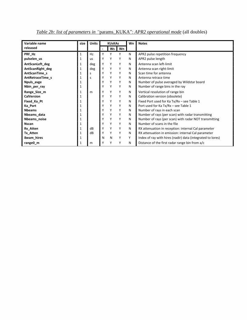
Table 2b: list of parameters in “params_KUKA”: APR2 operational mode (all doubles)
Variable name released
size Units KUsKAs Wn Notes
- Ws Wn
PRF_Hz 1 Hz Y Y Y N APR2 pulse repetition frequency
pulselen_us 1 us Y Y Y N APR2 pulse length
AntScanLeft_deg 1 deg Y Y Y N Antenna scan left-limit
AntScanRight_deg 1 deg Y Y Y N Antenna scan right-limit AntScanTime_s 1 s Y Y Y N Scan time for antenna AntRetraceTime_s 1 s Y Y Y N Antenna retrace time Npuls_avge 1 Y Y Y N Number of pulse averaged by Wildstar board Nbin_per_ray 1 Y Y Y N Number of range bins in the ray
Range_Size_m 1 m Y Y Y N Vertical resolution of range bin CalVersion 1 Y Y Y N Calibration version (obsolete)
Fixed_Ka_Pt 1 Y Y Y N Fixed Port used for Ka Tx/Rx – see Table 1 Ka_Port 1 Y Y Y N Port used for Ka Tx/Rx – see Table 1 Nbeams 1 Y Y Y N Number of rays in each scan Nbeams_data 1 Y Y Y N Number of rays (per scan) with radar transmitting Nbeams_noise 1 Y Y Y N Number of rays (per scan) with radar NOT transmitting
Nscan 1 Y Y Y N Number of scans in the file
Rx_Atten 1 dB Y Y Y N RX attenuation in reception: internal Cal parameter Tx_Atten 1 dB Y Y Y N RX attenuation in emission: internal Cal parameter
ibeam_hires 1 N N Y Y Index of ray with hires (nadir) data (integrated to lores)
range0_m 1 m Y Y Y N Distance of the first radar range bin from a/c

Table 2c: list of parameters in “params_W”: ACR operational mode (all doubles)
Variable name released
size Units KUsKAs Wn Notes
- Ws Wn
PRF_Hz 1 Hz N Y Y Y ACR pulse repetition frequency
PRT_us 1 us N Y Y Y ACR pulse repetition period
pulselen_us 1 us N Y Y Y ACR pulse length decimation 1 N Y Y Y ACR effective decimation
Bandwidth_MHz 1 MHz N Y Y Y ACR bandwidth Bandwidth_Eff_MHz 1 MHz N Y Y Y ACR effective bandwidth integration_s 1 s N Y Y Y ACR integration time CalVersion N Y Y Y Calibration version
Ports 5 N Y Y Y ACR transmission mode
Range_Size_m 1 m N Y Y Y Length of range bin (vertical sampling) Range_res_m 1 m N Y Y Y Length of pulse (vertical resolution) Vnyq 1 m/s N Y Y Y Nyquist velocity Nray_hires 1 N N Y Y Number of nadir-only rays in hires mode npulse_hh95 1 N N Y Y Number of pulses averaged in scanning mode (hh) npulse_vv95 1 N N Y Y Number of pulses averaged in nadir-only mode (vv) iStartW 1 N Y Y Y Range bin of where the center of the Tx event is recorded
(i.e., range bin corresponding to range zero) range0_m 1 m Y Y Y N Distance of the first radar range bin from a/c slave_mode 1 N Y Y Y ACR operation mode (0 = stand-alone, 1= slaved mode)

Table 2d: list of parameters in “lores”: APR3 at low resolution (all doubles)
Ns: numbers of scans (along track), at low resolution;
Nr: number of rays (cross track) in scanning mode at low resolution;
Nbin: number of range bins.
Variable name released
size Units KUsKAs Wn Notes (data from high-resolution mode integrated and saved in beam 12 highlighted in green) - Ws Wn
Scantime Ns x Nr s Y Y Y N Beginning of scan since 1 Jan. 1970 = f(PRF, Npulses)
roll Ns x Nr deg Y Y Y N From aircraft or MMS navigation files
pitch Ns x Nr deg Y Y Y N From aircraft or MMS navigation files
drift Ns x Nr deg Y Y Y N From aircraft or MMS navigation files alt_nav Ns x Nr m Y Y Y N From aircraft or MMS navigation files (recommended) alt_radar Ns x Nr m Y Y Y N From APR-2 surface echo (alternate) look_vector 3 x Ns x Nr
Y Y Y N From navigation files (recommended)
look_vector_radar 3 x Ns x Nr
Y Y Y N From APR-2 surface echo in scanning channels (alternate) look_vector_nadir_95n 3 x Ns x Nr Y Y Y N From APR-2 surface echo in nadir-only mode (alternate) isurf Ns x Nr
Y Y Y N Index of radar range bin intersecting surface (starting from 0).
sequence Ns x Nr
Y Y Y N Ray number within the file v_surfdc8 Ns x Nr m/s Y Y Y N Apparent surface Doppler velocity (from P-3 navigation) v_surf Ns x Nr m/s Y Y Y N APR-2 measured surface Doppler velocity beamnum Ns x Nr
Y Y Y N Ray number within a scan
surface_index Ns x Nr
Y Y Y N Preliminary surface classification index surf_vals 8 x Ns x Nr vv Y Y Y N 8 Measured parameters pertaining the surface: 1 = NRCS Ku
[dB], 2 = Surface LDR Ku [dB], 3 = NRCS Ka [dB], 4 = LDR Ka [dB], 5 = surface Doppler velocity Ku [m/s], 6-8 = not used.
path_vals 15 x Ns x Nr vv Y Y Y N 15 parameters pertaining each beam - these are intermediate products – not recommended for Science use: 1 = max Z Ku; 2 = max Z Ka; 3 = ZKu 1km range above isurf; 4 = LDRKu 1km range above isurf; 5 = ZKa 1km range above isurf 6 = LDRKa 1km range above isurf; 7 = vKu 1 km range above surf (pre-correction); 8 = Pt Ku copol (cal loop); 9 = Pt Ku cxpol; 10 = Pt Ka copol; 11 = Pt Ka cxpol; 12 = range bin max ZKu; 13 = range bin max ZKu; 14 = range bin ZKu @ 1 Km altitude; 15 = range bin ZKu @ 1 Km altitude
lat Ns x Nr deg Y Y Y N Latitude of the aircraft
lon Ns x Nr deg Y Y Y N Longitude of the aircraft
lat3D Ns x Nr x nbin deg Y Y Y N Latitude of each resolution bin
lon3D Ns x Nr x nbin deg Y Y Y N Longitude of each resolution bin alt3D Ns x Nr x nbin m Y Y Y N Altitude of each resolution bin zhh14 Ns x Nr x nbin dBZ Y Y Y N Radar Reflectivity at Ku band vel14 Ns x Nr x nbin m/s Y Y Y N Mean Doppler Velocity at Ku band ldr14 Ns x Nr x nbin dB Y Y Y N Linear Depolarization Ratio at Ku band
vel14c Ns x Nr x nbin m/s Y Y Y N Mean Doppler Velocity dealiased and from Ku&Ka band zhh35 Ns x Nr x nbin dBZ Y Y Y N Radar Reflectivity at Ka band nadir port vel35 Ns x Nr x nbin m/s Y Y Y N Mean Doppler Velocity at Ka band
vel35c Ns x Nr x nbin m/s Y Y Y N Mean Doppler Velocity dealiased and form Ka band
ldr35 Ns x Nr x nbin dB Y Y Y N Linear Depolarization Ratio at Ka band z95s Ns x Nr x nbin dBZ N Y Y N Reflectivity at W band, HH scanning channel vel95s Ns x Nr x nbin m/s N Y Y N Doppler Velocity at W band scanning
sig95s Ns x Nr x nbin m/s N Y Y N Spread of Doppler Velocity at W band scanning
s095s Ns x Nr dB N Y Y N Surface NRCS (W band, scanning)
z95n Ns x Nr x nbin dBZ N N Y N Reflectivity at W band, nadir channel
vel95n Ns x Nr x nbin m/s N N Y N Doppler Velocity at W band nadir
sig95n Ns x Nr x nbin m/s N N Y N Spread of Doppler Velocity at W band nadir
s095n Ns x Nr dB N N Y N Surface NRCS at W band, nadir

altbin_95n Ns x Nr x nbin m Y Y Y N Altitude of each high-resolution range bin
gsp_mps Ns x Nr m/s Y Y Y N Aircraft ground speed
scal_date_APR 6 Y Y Y N APR file date/time [YYY,MM,DD,hh,mm,ss]
scal_date_ACR 6 Y Y Y N ACR file date/time [YYY,MM,DD,hh,mm,ss]

Table 2e: list of parameters in “hires”: APR3 at high resolution (all doubles)
Ns_hi: numbers of scans (along track), at high resolution;
Nbin: number of range bins (same as low-resolution vertical sampling if Ku and Ka are
present, otherwise = native vertical sampling of ACR.
Geolocation and attitude parameters (lat, lon, alt, roll, look_vector…):
in files with KuKa: parameters interpolated from lower to higher resolution;
in files with W-band only: parameters from the higher-resolution nav. parameters
Variable name released
size Units KUsKAs Wn Notes (data from beam 12 of scanning mode interpolated to higher resolution highlighted in green) - Ws Wn
scantime Ns_hi s N N Y Y Beginning of scan in seconds since 1 January 1970
roll Ns_hi deg N N Y Y roll pitch Ns_hi deg N N Y Y pitch drift Ns_hi deg N N Y Y drift look_vector 3 x Ns_hi N N Y Y look_vector look_vector_radar 3 x Ns_hi N N Y Y look_vector_radar lat3D Nbin xNs_hi deg N N Y Y Latitude of each resolution bin lon3D Nbin xNs_hi deg N N Y Y Longitude of each resolution bin alt3D Nbin xNs_hi m N N Y Y Altitude of each resolution bin zhh14 Nbin xNs_hi dBZ N N Y N Radar Reflectivity at Ku band vel14 Nbin xNs_hi m/s N N Y N Mean Doppler Velocity at Ku band vel14c Nbin xNs_hi m/s N N Y N Mean Doppler Velocity dealiased (Ku&Ka) band vel35c Nbin xNs_hi m/s N N Y N Mean Doppler Velocity dealiased (Ka) band zhh35 Nbin xNs_hi dBZ N N Y N Radar Reflectivity at Ka band vel35 Nbin xNs_hi m/s N N Y N Mean Doppler Velocity at Ka band z95s Nbin xNs_hi dBZ N N Y N Radar Reflectivity at W band, scanning vel95s Nbin xNs_hi m/s N N Y N Mean Doppler Velocity at W band scanning sig95s Nbin xNs_hi m/s N N Y N Doppler Width at W band scanning
s095s Ns_hi dB N N Y N Surface NRCS at W band scanning
s095n Ns_hi dB N N Y Y surface NRCS (W band) nadir z95n Nbin xNs_hi dBZ N N Y N Radar Reflectivity at W band, nadir channel vel95n Nbin xNs_hi m/s N N Y Y mean Doppler Velocity at W band nadir channel sig95n Nbin xNs_hi m/s N N Y Y Doppler Width at W band nadir time_95s Ns_hi s N N Y N time stamps of low-resolution data (alternate) Vsurf95n Ns_hi m/s N N Y Y ACR measured surface Doppler velocity at W band, VV
Vsurf95s Ns_hi m/s N N Y N ACR measured surface Doppler velocity from vel95s
isurf Ns_hi N N Y N range bin of peak surface return surf_vals 8x Ns_hi N N Y N see definition of surf_vals in “lores” Pt_95n Ns_hi dBm? N N Y Y Estimated transmitted power from z95n
Pt_95s Ns_hi dBm? N N Y Y Estimated transmitted power from z95s noisedB_95n Ns_hi dB N N Y Y Estimated noise for z95n noisedB_95s Ns_hi N N Y Y Estimated noise for z95s SNR_95n Nbin xNs_hi N N Y Y Estimated SNR of z95n SNR_95s Nbin xNs_hi N N Y Y Estimated SNR of z95s esurf_95n Ns_hi eu N N Y Y Quality of W-band surface response matching – similar
to CloudSat’s CPR L1B : <0 = surface response not detected, or extremely poor matching, 0-1 : surface response detected and good quality (smaller values indicate better quality), 1 or more: surface response detected but lower quality matching.
esurf_95s Ns_hi eu N N Y N see esurf_95n nsurf_95n Ns_hi # N N Y Y Length in # of range bins of the surface response nsurf_95s Ns_hi # N N Y N see nsurf_95n
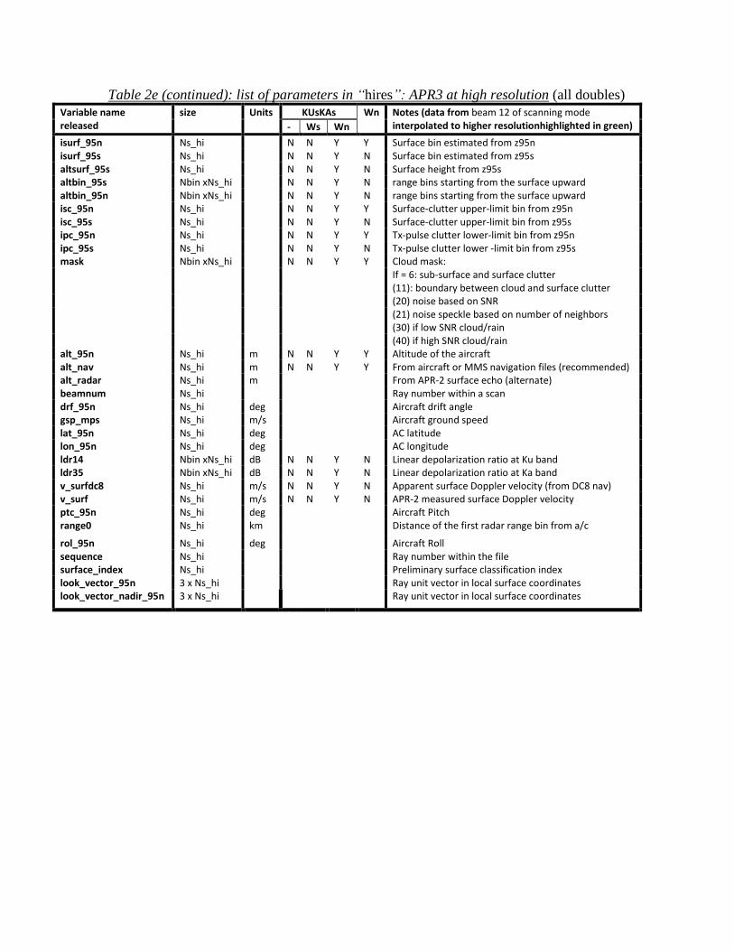
Table 2e (continued): list of parameters in “hires”: APR3 at high resolution (all doubles)
Variable name released
size Units KUsKAs Wn Notes (data from beam 12 of scanning mode interpolated to higher resolutionhighlighted in green) - Ws Wn
isurf_95n Ns_hi N N Y Y Surface bin estimated from z95n isurf_95s Ns_hi N N Y N Surface bin estimated from z95s altsurf_95s Ns_hi N N Y N Surface height from z95s altbin_95s Nbin xNs_hi N N Y N range bins starting from the surface upward altbin_95n Nbin xNs_hi N N Y N range bins starting from the surface upward isc_95n Ns_hi N N Y Y Surface-clutter upper-limit bin from z95n isc_95s Ns_hi N N Y N Surface-clutter upper-limit bin from z95s ipc_95n Ns_hi N N Y Y Tx-pulse clutter lower-limit bin from z95n ipc_95s Ns_hi N N Y N Tx-pulse clutter lower -limit bin from z95s mask Nbin xNs_hi N N Y Y Cloud mask:
If = 6: sub-surface and surface clutter
(11): boundary between cloud and surface clutter
(20) noise based on SNR
(21) noise speckle based on number of neighbors
(30) if low SNR cloud/rain
(40) if high SNR cloud/rain alt_95n Ns_hi m N N Y Y Altitude of the aircraft alt_nav Ns_hi m N N Y Y From aircraft or MMS navigation files (recommended) alt_radar Ns_hi m From APR-2 surface echo (alternate) beamnum Ns_hi Ray number within a scan drf_95n Ns_hi deg Aircraft drift angle gsp_mps Ns_hi m/s Aircraft ground speed lat_95n Ns_hi deg AC latitude lon_95n Ns_hi deg AC longitude ldr14 Nbin xNs_hi dB N N Y N Linear depolarization ratio at Ku band ldr35 Nbin xNs_hi dB N N Y N Linear depolarization ratio at Ka band v_surfdc8 Ns_hi m/s N N Y N Apparent surface Doppler velocity (from DC8 nav) v_surf Ns_hi m/s N N Y N APR-2 measured surface Doppler velocity ptc_95n Ns_hi deg Aircraft Pitch range0 Ns_hi km Distance of the first radar range bin from a/c
rol_95n Ns_hi deg Aircraft Roll sequence Ns_hi Ray number within the file surface_index Ns_hi Preliminary surface classification index look_vector_95n 3 x Ns_hi Ray unit vector in local surface coordinates look_vector_nadir_95n 3 x Ns_hi Ray unit vector in local surface coordinates

List of flights and datasets: OLYMPEX # Date Observation Notes
1 2015, Nov 5 Engineering Flight in
California/Pacific Ocean
Not available in release 2.1
2 2015, Nov 10 Transit to Lewis-McChord,
WA
Not available in release 2.1
3 2015, Nov 12 First local science flight Prefrontal flow on Olympics
4 2015, Nov 13 Same system as Nov 12,
frontal passage
Large accumulations of precip
5 2015, Nov 14 Precipitation ahead of a
developing frontal wave
Collected Ku/Ka only 1715Z to 2017Z; no W-
band
6 2015, Nov 18 Shallow post-frontal conv Isolated cells below anvil
7 2015, Nov 23 Approaching weak trough Observed light stratiform precip
8 2015, Nov 24 Continuation of Nov 23 system Some postfrontal clouds
9 2015, Nov 25 Clear air calibration Land survey, circles over ocean w/sonde
10 2015, Dec 1 A weak trough/front Extensive stratiform
precipitation modified by topography
11 2015, Dec 3 Complex baroclinic system Orographically enhanced rain over land;
underflew GPM, center of DPR swath
12 2015, Dec 4 Post-frontal Isolated cells
13 2015, Dec 5 Broad frontal system Stratiform with embedded convection; W timing
issues; W not in this release
14 2015, Dec 8 Orographic enhancement of
atmospheric river
APR3 acquired data over portion of GPM swath,
likely clear
15 2015, Dec 10 Occluded front and post-frontal Variety of precipitation, convection
16 2015, Dec 12 Occluded front and warm
sector
Primarily stratiform precipitation
17 2015, Dec 13 Post-frontal Convection
18 2015, Dec 18 Occluded front Stratiform and convection
19 2015, Dec 19 Post-frontal; last local sci flt Isolated cells, GPM DPR underflight
20 2015, Dec 20 Transit back to Palmdale Not available in release 2.1
Only local science flights (Nov 12-Dec 19) are included in the current release.
Known Problems, issues and other notes
This section lists all known problems with the APR3 OLYMPEX v2.3 data. Some of these
problems are caused by problems in the raw data, while others are processing problems.
– External calibration was used for all products. Reflectivity measurements should be
considered reliable within 3 sigma as reported in the change log for this release.
– The radar sensitivity was not constant (mainly dependent on the pulse length). Users
not familiar with the weather radar equation and APR3 data should contact the APR3
team to support data interpretation.
– In the short range (that is the first 5 bins after the blanked transmit window) the
reported value of reflectivity is underestimated. This region should be used only for
detection purposes, and not quantitative estimation.
– radar reflectivity factors are as measured – no correction for path attenuation is
included in these products.

– The radar altitude and look_vector are occasionally affected by aircraft motion at a
sub-scan timescale.
– This data version was produced using the 1Hz from DC-8 (iwg1). It is recommended
to use look_vector and alt_nav for all processing as they are accurate in general.
– No data are available from the 24th ray of each scan (beamnum = 1) at Ku/Ka. This
ray was used for noise measurements (no pulse transmitted). The 24th ray was included
in this dataset solely for compatibility with APR2 datasets from previous experiments.
– LDR estimates are included in this release for the Ku-band channel. Users are
cautioned in interpreting very low values of LDR (e.g., less than -20 dB), which are
characterized by larger overall uncertainty.
– Antenna and range sidelobes show up as artifacts in data in some cases (i.e., thin
feature at constant range appearing at large scan angles a few hundred m above the
surface).
– Doppler velocity is only reported when the corresponding reflectivity is above a
certain threshold.
– Occasionally, high lateral winds may cause the Doppler measurements to be aliased.
Doppler measurements should be corrected accounting for a maximum unambiguous
velocity of 27.5 m/s for Ku-band, 10.5 m/s for Ka-band, and 3.9 m/s for W-band.
– Correction for aircraft motion is less reliable when the aircraft was maneuvering or
was affected by turbulence or was over land.
– The surface_index is estimated on a scan-by-scan basis. The most frequent
misclassification is ocean being classified as flat land.
– The isurf index is occasionally misdetected because of extreme attenuation in the rain
profile.
– Occasional high surface reflectivity can cause overflows in the Ku-band copolar
channels causing data quality deterioration.
– Occasional intermittent changes in the overall calibration may not be properly
accounted for.
– Occasionally processing artifacts show up in the browse images but are not actually
present in the data.
– On some occasions W-band experienced timing synchronization problems relative to
Ku/Ka. On days with minor issues, W-band scans have been re-aligned with Ku/Ka
data using an automated algorithm. The results are good but not perfect. Users are
cautioned that there may be errors in the time/space alignment of W-band with Ku/Ka-
bands. December 5 experienced severe W-band timing problems including loss of
pulses W-band data for that date are not included in this release.
No W-band data were acquired on November 14 due to water damage of the W-band
computer. Users should use the fileheader/W band Port variable (see fileheader table)
Geolocation The three-dimensional latitude, longitude, and altitude are in the data and can be directly
associated with the 3-D radar measurement arrays.
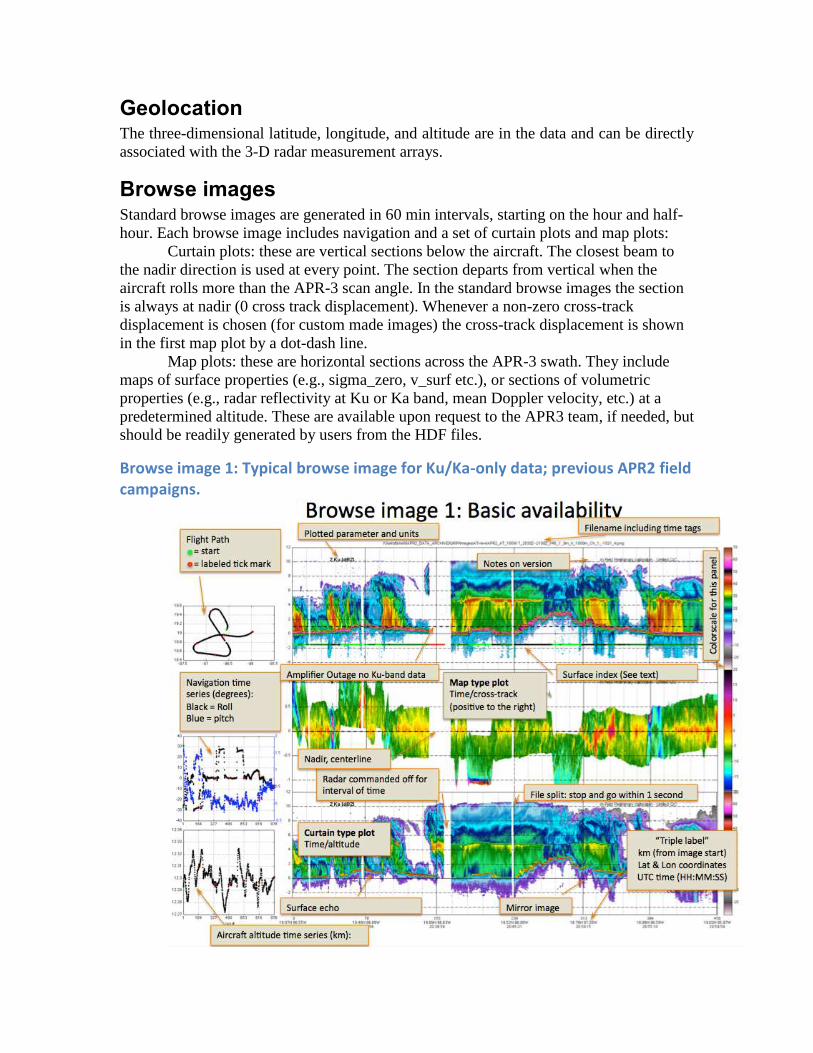
Browse images Standard browse images are generated in 60 min intervals, starting on the hour and half-
hour. Each browse image includes navigation and a set of curtain plots and map plots:
Curtain plots: these are vertical sections below the aircraft. The closest beam to
the nadir direction is used at every point. The section departs from vertical when the
aircraft rolls more than the APR-3 scan angle. In the standard browse images the section
is always at nadir (0 cross track displacement). Whenever a non-zero cross-track
displacement is chosen (for custom made images) the cross-track displacement is shown
in the first map plot by a dot-dash line.
Map plots: these are horizontal sections across the APR-3 swath. They include
maps of surface properties (e.g., sigma_zero, v_surf etc.), or sections of volumetric
properties (e.g., radar reflectivity at Ku or Ka band, mean Doppler velocity, etc.) at a
predetermined altitude. These are available upon request to the APR3 team, if needed, but
should be readily generated by users from the HDF files.
Browse image 1: Typical browse image for Ku/Ka-only data; previous APR2 field campaigns.

Top to bottom:
1) Vertical curtain of measured Ku-band reflectivity [dBZ].
2) Swath of Normalized Radar Cross Section [dB].
3) Vertical curtain of measured Ka-band reflectivity [dBZ]. For datasets where the
Zenith port was used (e.g., SEAC4RS) this panel will also show the DC-8 flight
altitude (in red dash) and Ka-band data above the plane. This is not applicable to
OLYMPEX data.
Browse image 2: Standard browse image for Ku/Ka/W band data
Top to bottom:
1) Vertical curtain of measured Ku-band reflectivity [dBZ].
2) Vertical curtain of measured Ku-band Linear Depolarization Ratio [dB].
3) Vertical curtain of measured Ku-band mean Doppler velocity [m/s] corrected for
platform motion and aliasing.
4) Vertical curtain of Ka-band reflectivity [dBZ].
5) Vertical curtain of W-band reflectivity [dBZ]. If missing, HDF file may have W-
band data from the nadir-looking channel “zvv95”.

Browse image 3: Standard browse image for Ku/Ka/W band data
Left column: (Top to bottom):
Vertical curtains of measured
1) Ku-band reflectivity [dBZ] at
APR2 resolution (lores).
2) same as 1) interpolated to ACR
resolution (hires).
3) Ka-band reflectivity [dBZ] at
APR2 resolution (lores).
4) same as 3) interpolated to ACR
resolution (hires).
5) W-band (VV nadir-only mode)
reflectivity [dBZ] integrated to APR2
resolution (lores).
6) same as 5) at ACR resolution
(hires).
7) W-band (HH scanning mode)
reflectivity [dBZ] at APR2 resolution
(lores).
8) same as 7) interpolated to ACR
resolution (hires).
Middle column: (Top to bottom):
Vertical curtains of measured
1) Ku-band mean Doppler velocity
[m/s] corrected for platform motion
and aliasing (lores).
2) same as 1) interpolated to hires.
3) W-band (VV nadir-only mode)
mean Doppler velocity [m/s]
neithert corrected for platform
motion nor aliasing, integrated to
lores.
4) same as 3) at ACR resolution
(hires).
Right column: (Top to bottom):
1) 2D map of Ku-band surface
reflectivity 0 [dB] at lores.
2) time series of 0 [dB] in beam 12
of all channels.
3) 2D map of Ka-band surface
reflectivity 0 [dB] at lores.
4) Cloud/precipitation mask (see
Table 2e) at ACR resolution (hires).
5) 2D map of W-band (scanning
mode) surface reflectivity 0 [dB] at
lores.
6) Attitude and altitude of aircraft
(lores).

Contact Information This data is intended for research rather than operational use, and users should contact the
APR-3 team regarding its use, especially before publication or public presentation.
This is the first official release of APR-2/3 data from OLYMPEX 2015: these products that
are still undergoing validation and quality control. Users are invited to address questions
and provide feedback to the contact below.
Contact information:
Steve Durden: [email protected]
Simone Tanelli: [email protected]
Data Use Disclaimer
~~~~~~~~~~~~~~~~~~~~~~~~~~~~~~~~~~~~~~~~~~~~~~~~~~~~~~~~~~~~~~~~~~~~~~~~~~~
Please note: Science data are not owned by JPL/Caltech. By electing to use these data, the
user agrees:
1. that Caltech makes no representations or warranties with respect to ownership of the
data, and does not represent others who may claim to own the data, and makes no
warranties as to the quality of the data. Caltech shall not be responsible for any loss or
expenses resulting from the use of the data, and you release and hold Caltech harmless
from all liability arising from such use.
2. to credit the use of the data to the Jet Propulsion Laboratory (JPL), California Institute
of Technology (Caltech), which performs research and development for the National
Aeronautics and Space Administration (NASA).
3. that the endorsement of any product or service by Caltech, JPL, or NASA must not be
claimed or implied.
~~~~~~~~~~~~~~~~~~~~~~~~~~~~~~~~~~~~~~~~~~~~~~~~~~~~~~~~~~~~~~~~~~~~~
The work described here was carried out at the Jet Propulsion Laboratory, California
Institute of Technology, under Contract with the National Aeronautics and Space
Administration. Copyright 2018 California Institute of Technology. Government
sponsorship acknowledged.
Related Documents