TMS9000-2 Product Guide ASME B30.5 Imperial 85% Features • 100 t (115 USt) • 11,2 m - 51,6 m (36 ft -169 ft) six-section greaseless MEGAFORM™ boom • TWIN-LOCK™ boom pinning system • Several 10,5 m - 17,6 m (34.5 ft - 57.6 ft) bi-fold swingaway extension options and an 8 m (26 ft) insert • Crane Control System (CCS) • Tilt superstructure cab • Up to 22 000 kg (48,500 lb) counterweight with hydraulic removal system

Welcome message from author
This document is posted to help you gain knowledge. Please leave a comment to let me know what you think about it! Share it to your friends and learn new things together.
Transcript
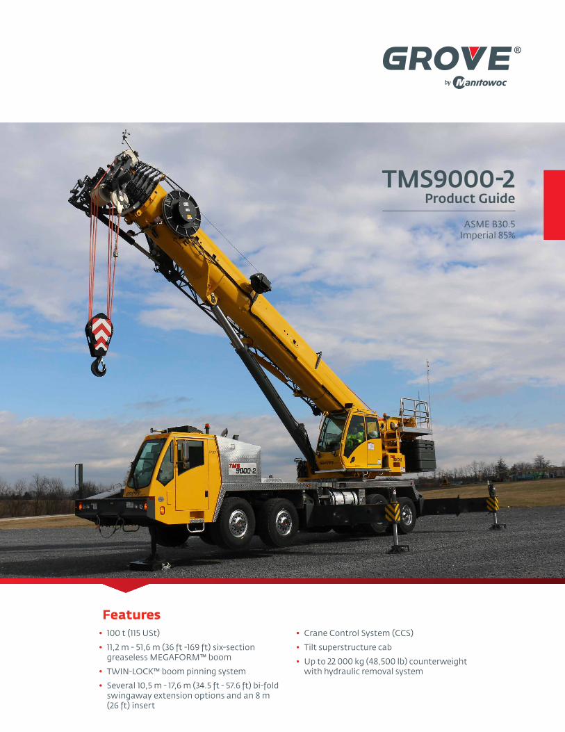
TMS9000-2Product Guide
ASME B30.5Imperial 85%
Features• 100 t (115 USt)
• 11,2 m - 51,6 m (36 ft -169 ft) six-section greaseless MEGAFORM™ boom
• TWIN-LOCK™ boom pinning system
• Several 10,5 m - 17,6 m (34.5 ft - 57.6 ft) bi-fold swingaway extension options and an 8 m (26 ft) insert
• Crane Control System (CCS)
• Tilt superstructure cab
• Up to 22 000 kg (48,500 lb) counterweight with hydraulic removal system
The TMS9000-2 sets a new standard for truck mounted cranes; strong load charts, long boom and a low gross vehicle weight.
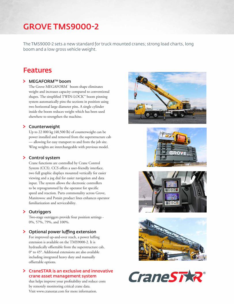
MEGAFORMTM boomThe Grove MEGAFORM™ boom shape eliminates weight and increases capacity compared to conventional shapes. The simplified TWIN-LOCK™ boom pinning system automatically pins the sections in position using two horizontal large diameter pins. A single cylinder inside the boom reduces weight which has been used elsewhere to strengthen the machine.
CounterweightUp to 22 000 kg (48,500 lb) of counterweight can be power installed and removed from the superstructure cab — allowing for easy transport to and from the job site. Wing weights are interchangeable with previous model.
Control systemCrane functions are controlled by Crane Control System (CCS). CCS offers a user-friendly interface, two full graphic displays mounted vertically for easier viewing and a jog dial for easier navigation and data input. The system allows the electronic controllers to be reprogrammed by the operator for specific speed and reaction. Parts commonality across Grove, Manitowoc and Potain product lines enhances operator familiarization and serviceability.
OutriggersTwo-stage outriggers provide four position settings - 0%, 57%, 79%, and 100%.
Optional power luffing extensionFor improved up-and-over reach, a power luffing extension is available on the TMS9000-2. It is hydraulically offsettable from the superstructure cab, 0° to 45°. Additional extensions are also available including integrated heavy duty and manually offsettable options.
CraneSTAR is an exclusive and innovative crane asset management system
that helps improve your profitability and reduce costs by remotely monitoring critical crane data. Visit www.cranestar.com for more information.
Features
GROVE TMS9000-2

Job site benefitsMultiple ladders on the carrier make accessing the crane easy
Standard hydraulic tilt cab 0°- 20° for exceptional visibility and operator comfort while working with long boom, inserts, and swingaway
TWINLOCK™ boom pinning system helps maximize the crane’s load chart capacity by eliminating weight inside the extended boom
Four position outriggers provide more flexibility for setup in congested work environments
Traction control provides improved traction on the job site
Available hydraulically offsettable 10,5 m - 17,6 m (34.5 ft - 57.6 ft) bi-fold 0°- 45° offset capability swingaway. This option is conveniently operated inside the cab and is easily stowed and erected using hydraulics
Available hydraulically offsettable 10,5 m - 17,6 m (34.5 ft - 57.6 ft) bi-fold lattice swingaway extension with integrated 3,5 m (11.4 ft) heavy duty jib for tilt- up work.
Standard wireless rigging remote enables convenient setup
Manitowoc Crane Care when you need it. The assurance of the world’s most advanced crane service and support to get you back to work fast.
Manitowoc Finance helps you get right to work generating profits for your business. Financial tools that help you capitalize on opportunity with solutions that fit your needs.
3TMS9000-2
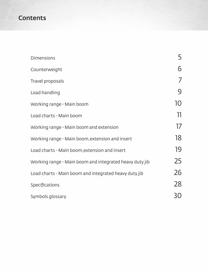
Dimensions 5
Counterweight 6
Travel proposals 7
Load handling 9
Working range - Main boom 10
Load charts - Main boom 11
Working range - Main boom and extension 17
Working range - Main boom,extension and insert 18
Load charts - Main boom,extension and insert 19
Working range - Main boom and integrated heavy duty jib 25
Load charts - Main boom and integrated heavy duty jib 26
Specifications 28
Symbols glossary 30
Contents

Dimensions shown in mm (ft)
ROTATION
2438(8.00) 3621
(11.88)
2441(8.01)
1964(6.44)
945(3.10)
1384(4.54)
3466(11.37)
4181(13.72)
1524(5)
3024(9.92)3524
(11.56)1179(3.87)
2564(8.41)
5623(18.45)
1524(5)
11 278(37.00)
R13 832(45.38)TURNINGRADIUS
2578 (8.46)DECKING FENDER WIDTH
R9913(32.52)MIN
R4262(13.98)
TAIL SWING
4222(13.85)
3276(10.75)
R14 074(46.17)CURB CLEARANCE
5650(18.54)
889(2.92)
26°
R15 340(50.33)
R16 328(53.57)
R15 550(51.02)
R15 653(51.35)
2536(8.32)
1278(4.19)
32°
13 476(44.21)
11 162 (36.62) RETRACTED51 608 (169.32) EXTENDED
798(2.62)
584(1.92)
1970(6.46) 1461
(4.79) 16°635 STROKE (2.08) 530
(1.73)
11 278(37.00)
200(0.66) 1524
(5)
145(0.48) 157°
5623(18.45)
2564(8.41)
506(1.66) 1179
(3.87)
ROTATION
ROTATION
1524(5)
3024(9.92)
152(0.49) 468
(1.53)STROKE
737(2.42)
269(0.88)
12°
3201(10.50)
3621(11.88)
27(0.09)
AUXMAINBOOMPIVOT
2200(7.22)
4261(13.98)
748(2.45) 950
(3.12)
357 (1.17)
5TMS9000-2
Dimensions

Counterweight configurations
Load chart configurations
1 2 3 4 5 60
2722 kg (6000 lb) X X*3629 kg (8000 lb) X X4990 kg (11,000 lb) X X X7258 kg (16,000 lb) X 2X X9525 kg (21,000 lb) X X X X
11 793 kg (26,000 lb) X X 2X X16 329 kg (36,000 lb) X 2X 2X X22 000 kg (48,500 lb) X 2X 2X X 2X 2X
*This configuration can also be obtained with the 2268 (5000 lb) pinned or stackable section and the 1361 (3000 lb) baseplate.
1. 1361 kg (3000 lb) baseplate2. 4536 kg (10,000 lb) stackable
3. 2268 kg (5000 lb) pinned or stackable4. 1361 kg (3000 lb) pinned or stackable
5. 1814 kg (4000 lb) wing6. 1021 kg (2250 lb) wing
3
1 . 3 ,000 lb. baseplate
2 . 1 0,000 lb. stackable
3 . 5,000 lb. pinned or stackable
4. 3 ,000 lb. pinned or stackable
5. 4,000 lb. wing
6. 2 ,2 50 lb. wing
1 2 3 4 5 60
6,000 lb. x x1 1 ,000 lb. x x x1 6,000 lb. x 2 x x2 1 ,000 lb. x x x x2 6,000 lb. x x 2 x x3 6,000 lb. x 2 x 2 x x4 4 ,000 lb. x 2 x 2 x x 2 x4 8,5 00 lb. x 2 x 2 x x 2 x 2 x
Load Chart Configurations
4
3
2
2
1
556 6
3
4237 mm (13.9’)3292 mm (10.8’)2530 mm (8.3’)
1128 mm(3.7’)
Counterweight
6

13 476(44.21)
584(1.92)
1970(6.46) 1461
(4.79) 16°
530(1.73)
11 278(37.00)
200(0.66) 1524
(5)
157°
5623(18.45)
506(1.66) 1179
(3.87)
1524(5)
152(0.49)
737(2.42)
269(0.88)
12°
3621(11.88)
357 (1.17)
Dimensions shown in mm (ft)
7TMS9000-2
Unit configuration
Front Rear G.V.W.
Basic machine: Includes ISX12 on-highway engine, main and auxiliary hoists with wire rope, air conditioning chassis and superstructure cabs, no countweight and includes driver.
18 953 kg 41,785 lb 17 907 kg 39,478 lb 36 860 kg 81,263 lb
Add: 3000 lb counterweight on carrier deck and 3000 lb counterweight on superstructure. Total counterweight 6000 lb. 19 521 kg 43,035 lb 20 070 kg 44,246 lb 39 590 kg 87,282 lb
Add: 3000 lb counterweight on carrier deck and 5000 lb counterweight on superstructure. Total counterweight 8000 lb. 18 524 kg 40,839 lb 23 343 kg 51,462 lb 41 867 kg 92,301 lb
Add: 8000 lb counterweight on carrier deck and 8000 lb counterweight on superstructure. Total counterweight 16,000 lb. 20 476 kg 45,141 lb 23 668 kg 52,179 lb 44 144 kg 97,320 lb
Auxilary boom nose 155 kg 342 lb -69 kg -152 lb 86 kg 190 lb
Manual 10,5 m to 17,6 m (34.5 ft - 57.6 ft) bi-fold swingaway (includes brackets) 1713 kg 3776 lb 6 kg 13 lb 1719 kg 3789 lb
Hydraulic 10,5 m to 17,6 m (34.5 ft - 57.6 ft) bi-fold swingaway (includes brackets and hose reel) 2130 kg 4695 lb -135 kg -298 lb 1995 kg 4397 lb
Hydraulic 10,5 m to 17,6 m (34.5 ft-57.6 ft) bifold swingaway with integrated 3,6 m (11,4 ft) heavy duty jib (includes stowage brackets and hose reel)
2284 kg 5034 lb -168 kg -370 lb 2116 kg 4664 lb
11,0 t (12.1 USt) top-swiveling overhaul weight stowed 434 kg 958 lb -140 kg -309 lb 294 kg 648 lb
45 t (50 USt), three-sheave quick-reeving hook block at bumper 764 kg 1685 lb -314 kg -693 lb 450 kg 992 lb
Substitute: K-100™ synthetic rope in lieu of wire rope on main and auxiliary hoist 264 kg 583 lb -952 kg -2098 lb -687 kg -1515 lb
Maximum Allowable 23 224 kg 51,200 lb 27 216 kg 60,000 lb 50 440 kg 111,200 lb
Travel proposals
Boom over front

Dimensions shown in mm (ft)
Travel proposals
Trailing boom dolly
ROTATION
2438(8.00) 3621
(11.88)
2441(8.01)
1964(6.44)
945(3.10)
1384(4.54)
3466(11.37)
4181(13.72)
1524(5)
3024(9.92)3524
(11.56)1179(3.87)
2564(8.41)
5623(18.45)
1524(5)
11 278(37.00)
R13 832(45.38)TURNINGRADIUS
2578 (8.46)DECKING FENDER WIDTH
R9913(32.52)MIN
R4262(13.98)
TAIL SWING
4222(13.85)
3276(10.75)
R14 074(46.17)CURB CLEARANCE
5650(18.54)
889(2.92)
26°
R15 340(50.33)
R16 328(53.57)
R15 550(51.02)
R15 653(51.35)
2536(8.32)
1278(4.19)
32°
13 476(44.21)
11 162 (36.62) RETRACTED51 608 (169.32) EXTENDED
798(2.62)
584(1.92)
1970(6.46) 1461
(4.79) 16°635 STROKE (2.08) 530
(1.73)
11 278(37.00)
200(0.66) 1524
(5)
145(0.48) 157°
5623(18.45)
2564(8.41)
506(1.66) 1179
(3.87)
ROTATION
ROTATION
1524(5)
3024(9.92)
152(0.49) 468
(1.53)STROKE
737(2.42)
269(0.88)
12°
3201(10.50)
3621(11.88)
27(0.09)
AUXMAINBOOMPIVOT
2200(7.22)
4261(13.98)
748(2.45) 950
(3.12)
357 (1.17)
Unit configuration
Front Rear Boom Dolly G.V.W.
Typical machine: Includes ISX12 on-highway engine, main and auxiliary hoists with wire rope, auxiliary boom nose, manual bifold swingaway, stowed overhaul weight, 45 t (50 USt) hook block hanging at boom nose, no counterweight, includes driver and 6800 lb boom dolly.
15 961 kg 35,187 lb 14 521 kg 32,013 lb 12 132 kg 26,747 lb 42 614 kg 93,947 lb
Add: 6000 lb counterweight on front carrier deck or pinned to the superstructure, 5000 lb counterweight on rear chassis counterweight carrier, 15,000 lb on boom dolly. Total counterweight 26,000 lb.
18 173 kg 40,064 lb 17 377 kg 38,309 lb 18 945 kg 41,766 lb 54 494 kg 120,139 lb
Add: 6000 lb counterweight on the front carrier deck or pinned to superstructure, 5000 lb counterweight on rear chassis counterweight carrier, 25,000 lb on three-axle 9000 lb boom dolly. Total counterweight 36,000 lb.
18 173 kg 40,064 lb 17 377 kg 38,309 lb 24 478 kg 53,966 lb 60 028 kg 132,339 lb
Substitute: Hydraulic 10,5 m to 17,6 m (34.5 ft - 57.6 ft) bifold swingaway (includes brackets and hose reel) in lieu of the manual swingaway
-9 kg -20 lb -6 kg -14 lb 291 kg 641 lb 275 kg 608 lb
Substitute: Hydraulic 10,5 m to 17,6 m (34.5 ft-57.6 ft) bifold swingaway with integrated 3 m (10 ft) heavy duty jib (includes stowage brackets and hose reel) in lieu of the manual swingaway
-2 kg -4 lb -2 kg -4 lb 400 kg 883 lb 397 kg 875 lb
Substitute: K-100™ synthetic rope in lieu of wire rope on main and auxiliary hoist -553 kg -1219 lb -134 kg -296 lb - - -687 kg -1514 lb
8
THIS CHART IS ONLY A GUIDE AND SHOULD NOT BE USED TO OPERATE THE CRANE. The individual crane’s load chart, operating instructions and other instructional plates must be read and understood prior to operating the crane.
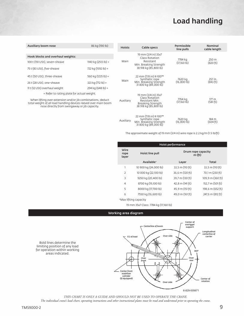
Bold lines determine the limiting position of any load
for operation within working areas indicated.
Working area diagram
Over front
Center front stabilizer cylinder
(if equipped)
Over side
Center of rotation
Over rear
360°
Over side
Longitudinal centerline of
carrier
Center of outrigger supportCenterline of boom
CG of load
Auxiliary boom nose 86 kg (190 lb)
Hook blocks and overhaul weights:
100 t (110 USt), seven-sheave 1140 kg (2513 lb) +
75 t (83 USt), five-sheave 722 kg (1592 lb) +
45 t (50 USt), three-sheave 560 kg (1235 lb) +
26 t (28 USt), one-sheave 323 kg (712 lb) +
11 t (12 USt) overhaul weight 294 kg (648 lb) +
+ Refer to rating plate for actual weight.
When lifting over extension and/or jib combinations, deduct total weight of all load handling devices reeved over main boom
nose directly from swingaway or jib capacity.
Hoists Cable specs Permissible line pulls
Nominal cable length
Main
19 mm (3/4 in) 35x7 Class Rotation
Resistant Min. Breaking Strength
38 918 kg (85,800 lb)
7784 kg(17,160 lb)
250 m(820 ft)
Main22 mm (7/8 in) K-100™
Synthetic rope Min. Breaking Strength
31 800 kg (84,000 lb)
7620 kg (16,800 lb)
257 m (843 ft)
Auxiliary
19 mm (3/4 in) 35x7 Class Rotation Resistant Min.
Breaking Strength 38 918 kg (85,800 lb)
7764 kg (17,160 lb)
177 m (581 ft)
Auxiliary22 mm (7/8 in) K-100™
Synthetic rope Min. Breaking Strength
31 800 kg (84,000 lb)
7620 kg (16,800 lb)
184 m (604 ft)
The approximate weight of 19 mm (3/4 in) wire rope is 2.2 kg/m (1.5 lb/ft)
Hoist performance
Wire rope layer
Hoist line pull Drum rope capacity m (ft)
Available* Layer Total
1 10 900 kg (24,000 lb) 33,5 m (110 ft) 33,5 m (110 ft)
2 10 000 kg (22,100 lb) 36,6 m (120 ft) 70,1 m (230 ft)
3 9250 kg (20,400 lb) 39,7 m (130 ft) 109,9 m (360 ft)
4 8700 kg (19,100 lb) 42,8 m (141 ft) 152,7 m (501 ft)
5 8000 kg (17,700 lb) 45,9 m (151 ft) 198,6 m (652 ft)
6 7550 kg (16,600 lb) 49,0 m (161 ft) 247,6 m (812 ft)
*Max lifting capacity
19 mm 35x7 Class: 7784 kg (17,160 lb)
9TMS9000-2
Load handling

THIS CHART IS ONLY A GUIDE AND SHOULD NOT BE USED TO OPERATE THE CRANE. The individual crane’s load chart, operating instructions and other instructional plates must be read and understood prior to operating the crane.
36.6 ft - 169.3 ft main boom
Hei
ght
from
gro
und
in fe
et
00
20
40
60
80
100
120
140
160
180
200
20406080100120140160180200
36.6'
63.1'
76.7'
90.3'
103.0'
116.6'125.0'
143.6'
158.7'
169.3'
Boo
m le
ngth
in
feet
Operating radius in feet from axis of rotation
Max boom angle is 81.5°0°
10°
20°
30°
40°
50°
60°
70°
Dimensions are for the largest Grove furnished hook block and overhaulball, with anti-two block activated.
7.7'
10.2'
Working rangeMain boom
10
THIS CHART IS ONLY A GUIDE AND SHOULD NOT BE USED TO OPERATE THE CRANE. The individual crane’s load chart, operating instructions and other instructional plates must be read and understood prior to operating the crane.
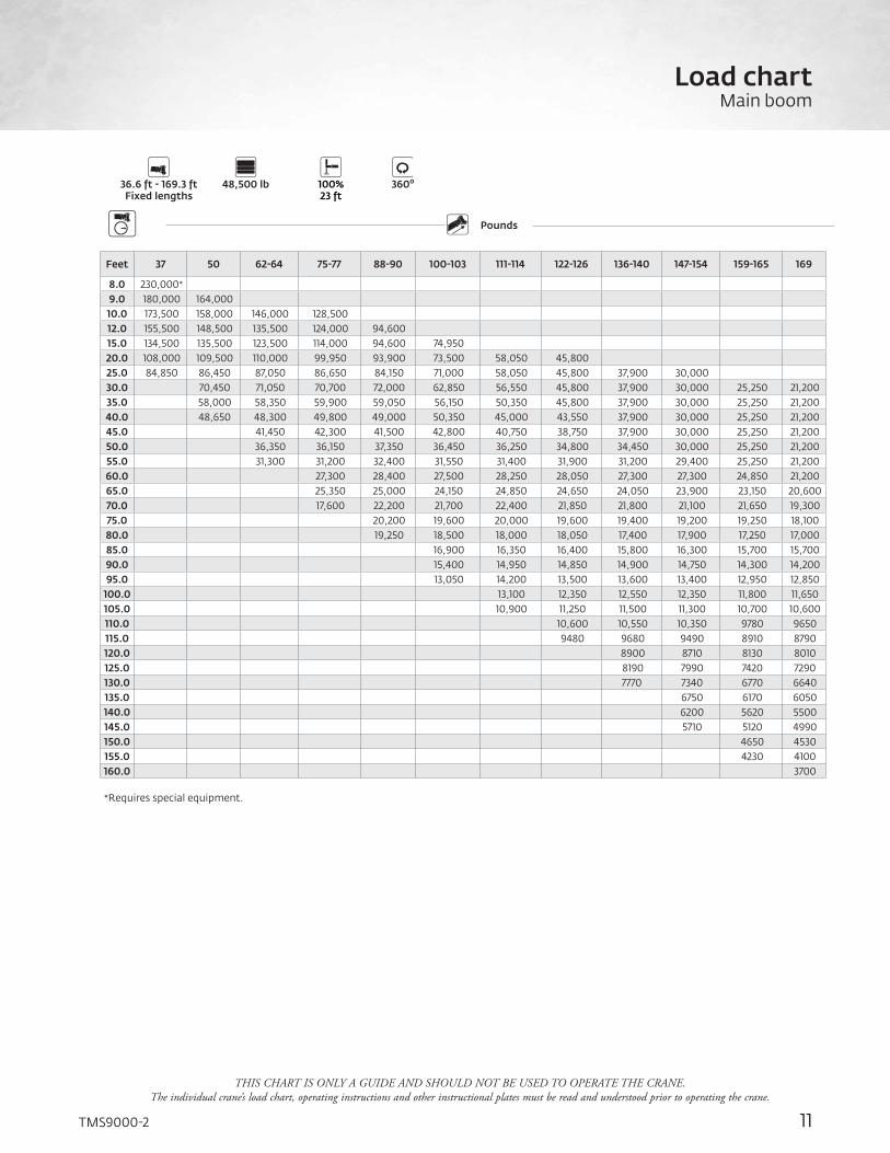
Counterweight Outriggers
36.6 ft - 169.3 ftFixed lengths
48,500 lb 100%23 ft
360o
PoundsBoom Extension
Feet 37 50 62-64 75-77 88-90 100-103 111-114 122-126 136-140 147-154 159-165 169
8.0 230,000* 9.0 180,000 164,000 10.0 173,500 158,000 146,000 128,500 12.0 155,500 148,500 135,500 124,000 94,600 15.0 134,500 135,500 123,500 114,000 94,600 74,950 20.0 108,000 109,500 110,000 99,950 93,900 73,500 58,050 45,800 25.0 84,850 86,450 87,050 86,650 84,150 71,000 58,050 45,800 37,900 30,000 30.0 70,450 71,050 70,700 72,000 62,850 56,550 45,800 37,900 30,000 25,250 21,200 35.0 58,000 58,350 59,900 59,050 56,150 50,350 45,800 37,900 30,000 25,250 21,200 40.0 48,650 48,300 49,800 49,000 50,350 45,000 43,550 37,900 30,000 25,250 21,200 45.0 41,450 42,300 41,500 42,800 40,750 38,750 37,900 30,000 25,250 21,200 50.0 36,350 36,150 37,350 36,450 36,250 34,800 34,450 30,000 25,250 21,200 55.0 31,300 31,200 32,400 31,550 31,400 31,900 31,200 29,400 25,250 21,200 60.0 27,300 28,400 27,500 28,250 28,050 27,300 27,300 24,850 21,200 65.0 25,350 25,000 24,150 24,850 24,650 24,050 23,900 23,150 20,600 70.0 17,600 22,200 21,700 22,400 21,850 21,800 21,100 21,650 19,300 75.0 20,200 19,600 20,000 19,600 19,400 19,200 19,250 18,100 80.0 19,250 18,500 18,000 18,050 17,400 17,900 17,250 17,000 85.0 16,900 16,350 16,400 15,800 16,300 15,700 15,700 90.0 15,400 14,950 14,850 14,900 14,750 14,300 14,200 95.0 13,050 14,200 13,500 13,600 13,400 12,950 12,850
100.0 13,100 12,350 12,550 12,350 11,800 11,650 105.0 10,900 11,250 11,500 11,300 10,700 10,600 110.0 10,600 10,550 10,350 9780 9650 115.0 9480 9680 9490 8910 8790 120.0 8900 8710 8130 8010 125.0 8190 7990 7420 7290 130.0 7770 7340 6770 6640 135.0 6750 6170 6050 140.0 6200 5620 5500 145.0 5710 5120 4990 150.0 4650 4530 155.0 4230 4100 160.0 3700
*Requires special equipment.
11TMS9000-2
Load chartMain boom

THIS CHART IS ONLY A GUIDE AND SHOULD NOT BE USED TO OPERATE THE CRANE. The individual crane’s load chart, operating instructions and other instructional plates must be read and understood prior to operating the crane.
Counterweight Outriggers
36.6 ft - 169.3 ftFixed lengths
36,000 lb 100%23 ft
360o
PoundsBoom Extension
Feet 37 50 62-64 75-77 88-90 100-103 111-114 122-126 136-140 147-154 159-165 169
8.0 180,000 9.0 178,000 164,000 10.0 168,000 158,000 146,000 128,500 12.0 150,500 148,500 135,500 124,000 94,600 15.0 130,000 131,000 123,500 114,000 94,600 74,950 20.0 102,000 103,500 104,000 99,950 93,900 73,500 58,050 45,800 25.0 79,700 81,350 81,950 81,550 82,800 71,000 58,050 45,800 37,900 30,000 30.0 64,600 64,900 66,500 65,600 62,850 56,550 45,800 37,900 30,000 25,250 21,200 35.0 52,700 52,150 53,650 52,750 54,050 50,350 45,800 37,900 30,000 25,250 21,200 40.0 42,750 43,650 43,400 44,750 43,750 43,550 42,700 37,900 30,000 25,250 21,200 45.0 36,050 35,850 37,150 36,150 35,950 36,700 35,850 30,000 25,250 21,200 50.0 30,250 31,800 31,400 30,850 31,450 31,000 30,250 30,000 25,250 21,200 55.0 26,950 27,250 26,850 26,350 27,100 26,500 26,450 25,750 25,250 21,200 60.0 23,650 23,800 23,700 23,500 23,550 22,850 23,400 22,700 21,200 65.0 20,750 21,800 21,200 20,550 20,600 20,650 20,450 19,950 19,800 70.0 14,900 19,400 18,800 18,850 18,200 18,400 18,050 17,550 17,400 75.0 17,350 16,850 17,100 16,300 16,500 16,300 15,700 15,550 80.0 15,650 15,100 15,300 15,100 14,750 14,550 13,950 13,850 85.0 13,550 13,800 13,850 13,250 13,050 12,450 12,300 90.0 12,250 12,500 12,500 12,050 11,750 11,150 11,000 95.0 10,450 11,300 11,350 11,050 10,600 10,000 9880
100.0 10,300 10,300 10,000 9570 8980 8850 105.0 9240 9410 9100 8650 8070 7940 110.0 8590 8280 7830 7250 7120 115.0 7870 7530 7090 6510 6380 120.0 6860 6410 5840 5710 125.0 6250 5800 5230 5100 130.0 5700 5240 4670 4540 135.0 4730 4160 4030 140.0 4270 3690 3560 145.0 3840 3260 3130 150.0 2860 2730 155.0 2490 2360 160.0 2030
Load chartMain boom
12

THIS CHART IS ONLY A GUIDE AND SHOULD NOT BE USED TO OPERATE THE CRANE. The individual crane’s load chart, operating instructions and other instructional plates must be read and understood prior to operating the crane.
Counterweight Outriggers
36.6 ft - 169.3 ftFixed lengths
26,000 lb 100%23 ft
360o
PoundsBoom Extension
Feet 37 49-50 62-64 75-77 88-90 100-103 111-114 122-126 136-140 147-154 159-165 169
8.0 180,000 9.0 173,500 164,000 10.0 163,500 158,000 146,000 128,500 12.0 146,500 147,500 135,500 124,000 94,600 15.0 126,000 127,500 123,500 114,000 94,600 74,950 20.0 97,050 98,600 99,200 98,700 93,900 73,500 58,050 45,800 25.0 74,900 76,250 76,600 76,850 77,350 71,000 58,050 45,800 37,900 30,000 30.0 59,450 58,600 60,150 59,050 60,450 56,550 45,800 37,900 30,000 25,250 21,200 35.0 45,700 46,700 46,450 47,850 46,800 46,600 45,650 37,900 30,000 25,250 21,200 40.0 36,700 36,950 38,550 38,100 37,500 38,300 37,650 36,750 30,000 25,250 21,200 45.0 31,400 31,750 31,350 30,750 31,550 30,950 30,900 30,000 25,250 21,200 50.0 26,300 26,650 27,300 27,050 26,450 26,500 26,250 26,350 25,250 21,200 55.0 22,400 22,700 23,850 23,200 23,300 22,550 22,800 22,400 21,850 21,200 60.0 19,550 20,650 20,050 20,300 20,250 19,650 19,450 18,750 18,600 65.0 17,050 18,100 17,500 17,750 17,750 17,150 17,100 16,450 16,300 70.0 11,500 16,050 15,500 15,750 15,750 15,450 14,950 14,350 14,200 75.0 14,250 13,700 13,950 13,950 13,650 13,200 12,550 12,450 80.0 12,750 12,750 12,750 12,450 12,150 11,650 11,050 10,900 85.0 11,700 11,450 11,100 10,800 10,350 9770 9640 90.0 10,550 10,300 9990 9680 9220 8630 8500 95.0 8,630 9300 8980 8670 8210 7620 7490
100.0 8410 8080 7770 7320 6730 6610 105.0 7620 7280 6970 6520 5940 5810 110.0 6570 6260 5810 5230 5100 115.0 5940 5610 5160 4590 4460 120.0 5030 4580 4000 3880 125.0 4500 4050 3470 3350 130.0 4020 3560 2990 2860 135.0 3120 2550 2420 140.0 2720 2140 2010 145.0 2350 1760 1640 150.0 1420 1290 155.0 1110
13TMS9000-2
Load chartMain boom

THIS CHART IS ONLY A GUIDE AND SHOULD NOT BE USED TO OPERATE THE CRANE. The individual crane’s load chart, operating instructions and other instructional plates must be read and understood prior to operating the crane.
Counterweight Outriggers
36.6 ft - 169.3 ftFixed lengths
21,000 lb 100%23 ft
360o
PoundsBoom Extension
Feet 37 49-50 62-64 75-77 88-90 100-103 111-114 122-126 136-140 147-154 159-165 169
8.0 180,000 9.0 171,000 164,000 10.0 161,000 158,000 146,000 128,500 12.0 144,500 145,500 135,500 124,000 94,600 15.0 124,500 125,500 123,500 114,000 94,600 74,950 20.0 94,500 96,100 96,700 96,150 93,900 73,500 58,050 45,800 25.0 71,150 72,550 72,900 74,550 73,600 71,000 58,050 45,800 37,900 30,000 30.0 54,850 55,800 55,550 56,900 55,850 55,600 45,800 37,900 30,000 25,250 21,200 35.0 41,450 42,450 44,050 43,700 43,050 42,950 43,200 37,900 30,000 25,250 21,200 40.0 33,250 34,750 35,100 34,600 34,150 34,800 34,350 34,300 30,000 25,250 21,200 45.0 28,450 28,800 29,450 29,200 28,600 28,650 28,750 28,500 25,250 21,200 50.0 23,750 24,050 25,250 24,600 24,850 24,100 24,150 23,950 23,050 21,200 55.0 20,100 20,400 21,550 20,900 21,150 21,200 20,500 20,250 19,600 19,450 60.0 17,500 18,600 18,000 18,250 18,250 17,900 17,400 16,950 16,800 65.0 15,950 16,300 15,750 16,150 16,050 15,700 15,250 14,600 14,450 70.0 9800 14,350 14,550 14,400 14,050 13,750 13,250 12,650 12,500 75.0 12,700 13,000 12,750 12,400 12,100 11,600 11,000 10,850 80.0 11,300 11,550 11,300 11,000 10,700 10,200 9620 9490 85.0 10,350 10,100 9790 9480 9010 8410 8280 90.0 9290 9050 8720 8410 7950 7360 7230 95.0 7440 8110 7780 7480 7020 6430 6300
100.0 7280 6950 6650 6200 5610 5480 105.0 6560 6220 5910 5460 4880 4750 110.0 5560 5250 4800 4220 4090 115.0 4980 4650 4200 3620 3500 120.0 4110 3660 3090 2960 125.0 3620 3170 2600 2470 130.0 3180 2720 2150 2020 135.0 2310 1740 1610 140.0 1940 1360 1240 145.0 1610 1020
Load chartMain boom
14

THIS CHART IS ONLY A GUIDE AND SHOULD NOT BE USED TO OPERATE THE CRANE. The individual crane’s load chart, operating instructions and other instructional plates must be read and understood prior to operating the crane.
Counterweight Outriggers
36.6 ft - 169.3 ftFixed lengths
16,000 lb 100%23 ft
360o
PoundsBoom Extension
Feet 37 49-50 62-64 75-77 88-90 100-103 111-114 122-126 136-140 147-154 159-165 169
8.0 179,500 9.0 168,500 164,000 10.0 159,000 158,000 146,000 128,500 12.0 142,000 143,500 135,500 124,000 94,600 15.0 122,500 123,500 123,000 114,000 94,600 74,950 20.0 92,000 93,550 94,150 93,650 93,900 73,500 58,050 45,800 25.0 67,450 69,850 68,950 70,650 69,350 70,900 58,050 45,800 37,900 30,000 30.0 49,850 50,950 50,700 52,150 51,100 50,850 45,800 37,900 30,000 25,250 21,200 35.0 37,950 39,650 40,000 39,450 38,800 39,700 38,950 37,900 30,000 25,250 21,200 40.0 29,750 31,350 31,700 32,050 32,150 31,550 31,600 31,700 30,000 25,250 21,200 45.0 25,500 25,800 27,050 26,400 26,650 26,500 25,950 25,700 24,750 21,200 50.0 21,150 21,450 22,650 22,000 22,250 22,300 21,850 21,350 20,650 20,450 55.0 17,800 18,600 19,250 18,650 19,200 18,900 18,550 18,000 17,300 17,150 60.0 16,450 16,650 16,850 16,750 16,350 16,050 15,550 14,900 14,750 65.0 14,300 14,450 14,750 14,550 14,200 13,850 13,350 12,750 12,600 70.0 8100 12,650 12,950 12,700 12,350 12,050 11,550 10,950 10,800 75.0 11,100 11,400 11,150 10,850 10,550 10,050 9460 9320 80.0 9850 10,100 9890 9560 9250 8780 8170 8040 85.0 9000 8760 8430 8130 7660 7060 6930 90.0 8020 7780 7450 7150 6690 6090 5960 95.0 6250 6920 6590 6290 5830 5240 5110
100.0 6160 5830 5520 5070 4480 4360 105.0 5490 5150 4840 4390 3810 3680 110.0 4550 4240 3790 3210 3080 115.0 4020 3690 3240 2660 2540 120.0 3190 2740 2170 2040 125.0 2750 2290 1720 1590 130.0 2340 1880 1310 1180 135.0 1510 140.0 1170
15TMS9000-2
Load chartMain boom

THIS CHART IS ONLY A GUIDE AND SHOULD NOT BE USED TO OPERATE THE CRANE. The individual crane’s load chart, operating instructions and other instructional plates must be read and understood prior to operating the crane.
Counterweight Outriggers
36.6 ft - 169.3 ftFixed lengths
8000 lb 100%23 ft
360o
PoundsBoom Extension
Feet 37 49-50 62-64 75-77 88-90 100-103 111-114 122-126 136-140 147-154 159-165 169
8.0 175,000 9.0 164,500 164,000 10.0 155,000 156,000 146,000 128,500 12.0 139,000 140,000 135,500 124,000 94,600 15.0 119,500 121,000 121,500 114,000 94,600 74,950 20.0 86,500 87,900 88,250 89,100 89,050 73,500 58,050 45,800 25.0 57,450 60,100 61,350 61,000 62,750 61,350 58,050 45,800 37,900 30,000 30.0 42,200 44,000 44,400 43,850 43,100 44,100 43,250 37,900 30,000 25,250 21,200 35.0 31,350 33,050 33,400 34,650 34,050 33,700 33,300 33,400 30,000 25,250 21,200 40.0 24,250 25,850 26,200 27,500 26,800 27,100 27,100 26,500 26,050 25,100 21,200 45.0 20,800 22,150 22,350 21,850 22,400 22,000 21,600 21,000 20,250 20,100 50.0 17,100 18,400 18,550 18,850 18,600 18,200 17,800 17,250 16,800 16,650 55.0 14,200 15,550 15,750 16,050 15,800 15,450 15,100 14,600 13,950 13,800 60.0 13,200 13,400 13,750 13,500 13,150 12,800 12,300 11,650 11,500 65.0 11,350 11,500 11,850 11,600 11,250 10,900 10,450 9810 9670 70.0 5410 9980 10,250 10,000 9700 9380 8900 8270 8140 75.0 8660 8960 8720 8380 8070 7590 6980 6840 80.0 7550 7830 7590 7260 6950 6480 5870 5740 85.0 6860 6620 6290 5980 5520 4920 4790 90.0 6020 5770 5450 5140 4680 4090 3960 95.0 4370 5030 4710 4400 3950 3350 3230
100.0 4380 4050 3750 3290 2710 2580 105.0 3810 3470 3160 2710 2130 2000 110.0 2950 2640 2190 1610 1480 115.0 2500 2170 1720 1140 1020 120.0 1740 1290 125.0 1360 130.0 1010
Load chartMain boom
16

THIS CHART IS ONLY A GUIDE AND SHOULD NOT BE USED TO OPERATE THE CRANE. The individual crane’s load chart, operating instructions and other instructional plates must be read and understood prior to operating the crane.
Boo
m le
ngth
and
ext
ensi
on in
feet
Hei
ght
from
gro
und
in fe
et
Operating radius in feet from axis of rotation
Dimensions are for the largest grove furnished hook block and overhaulball, with anti-two block activated.
'
'
Max boom
17TMS9000-2
Working rangeMain boom and hydraulic or manual extension
36.6 ft - 169.3 ft main boom, 34.5 ft - 57.6 ft hydraulic or manual offsettable extension
THIS CHART IS ONLY A GUIDE AND SHOULD NOT BE USED TO OPERATE THE CRANE. The individual crane’s load chart, operating instructions and other instructional plates must be read and understood prior to operating the crane.
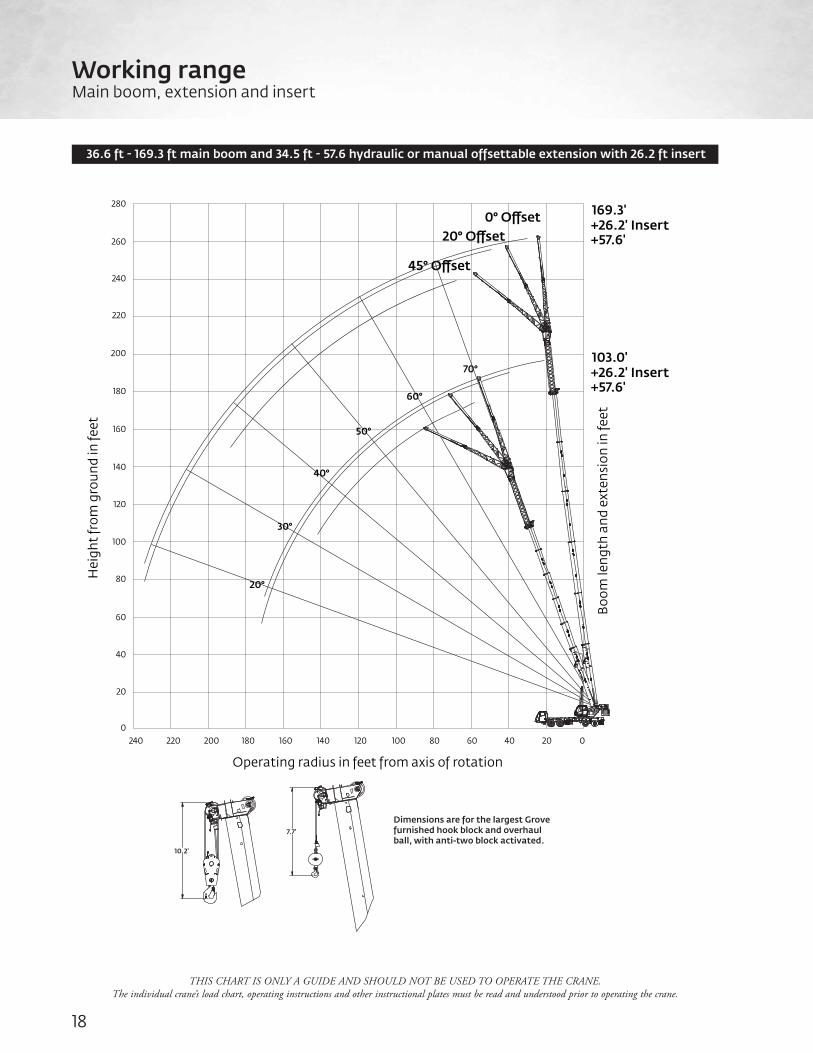
Working rangeMain boom, extension and insert
18
+26.2' Insert+57.6'
169.3'
+26.2' Insert+57.6'
103.0'
45° Oset
20° Oset0° Oset
Boo
m le
ngth
and
ext
ensi
on in
feet
Hei
ght
from
gro
und
in fe
et
00
20
40
60
80
100
120
140
160
180
200
220
240
260
280
20406080100120140160180200220240
Operating radius in feet from axis of rotation
Dimensions are for the largest Grove furnished hook block and overhaulball, with anti-two block activated.
7.7'
10.2'
20°
30°
40°
50°
60°
70°
36.6 ft - 169.3 ft main boom and 34.5 ft - 57.6 hydraulic or manual offsettable extension with 26.2 ft insert

THIS CHART IS ONLY A GUIDE AND SHOULD NOT BE USED TO OPERATE THE CRANE. The individual crane’s load chart, operating instructions and other instructional plates must be read and understood prior to operating the crane.
Feet34.5 ft 57.6 ft 83.8 ft
0° 20° 45° 0° 20° 45° 0° 20° 45°
40.0 10,750 45.0 10,750 6660 50.0 10,750 10,900 6660 55.0 10,750 10,900 6660 6040 60.0 10,750 10,900 11,200 6660 6040 65.0 10,750 10,900 11,200 6660 6040 70.0 10,750 10,900 11,200 6660 7190 6040 75.0 10,750 10,900 11,200 6660 7190 6040 80.0 10,750 10,900 11,200 6660 7190 6090 6040 85.0 10,750 10,900 11,050 6660 7190 6010 6040 6410 90.0 10,750 10,850 10,900 6660 7190 5930 6040 6410 95.0 10,450 10,250 10,300 6660 7170 5860 6040 6410 4880
100.0 9820 9660 9750 6660 7020 5800 6040 6240 4730 105.0 9240 9110 9220 6660 6880 5740 6040 6020 4600 110.0 8700 8610 8720 6660 6750 5690 6040 5820 4470 115.0 8200 8130 8250 6660 6620 5620 6040 5630 4350 120.0 7540 7690 7810 6660 6510 5560 6040 5450 4240 125.0 6830 7280 7400 6470 6400 5490 5800 5280 4130 130.0 6180 6590 6860 6110 6160 5440 5460 5120 4030 135.0 5580 5960 6190 5760 5830 5390 5150 4970 3930 140.0 5030 5370 5570 5410 5520 5350 4850 4830 3830 145.0 4520 4830 4890 5230 5310 4570 4690 3740 150.0 4050 4330 4410 4950 5190 4300 4470 3660 155.0 3610 3870 3970 4540 4920 3860 4220 3580 160.0 3200 3430 3560 4080 4420 3440 3980 3500 165.0 2820 3020 3170 3660 3940 3050 3630 3430 170.0 2470 2640 2810 3260 2680 3220 3360 175.0 2140 2280 2470 2880 2340 2850 3170 180.0 1840 1950 2160 2520 2020 2490 2770 185.0 1550 1630 1860 2190 1720 2150 2400 190.0 1260 1580 1870 1430 1840 195.0 1320 1570 1170 1540 200.0 1080 1280 1250
Counterweight Outriggers
169.3 ftFixed lengths
48,500 lb 100%23 ft
360o
PoundsBoom Extension
34.5 ft - 57.6 ft Manual offsettable
swingaway
26.2 ftInsert
19TMS9000-2
Load chartMain boom, extension and insert

THIS CHART IS ONLY A GUIDE AND SHOULD NOT BE USED TO OPERATE THE CRANE. The individual crane’s load chart, operating instructions and other instructional plates must be read and understood prior to operating the crane.
Feet34.5 ft 57.6 ft 83.8 ft
0° 20° 45° 0° 20° 45° 0° 20° 45°
40.0 10,750 45.0 10,750 6660 50.0 10,750 10,900 6660 55.0 10,750 10,900 6660 6040 60.0 10,750 10,900 11,200 6660 6040 65.0 10,750 10,900 11,200 6660 6040 70.0 10,750 10,900 11,200 6660 7190 6040 75.0 10,750 10,900 11,200 6660 7190 6040 80.0 10,750 10,900 11,200 6660 7190 6090 6040 85.0 10,750 10,900 11,050 6660 7190 6010 6040 6410 90.0 10,550 10,850 10,900 6660 7,90 5930 6040 6410 95.0 9430 10,150 10,300 6660 7170 5860 6040 6410 4880
100.0 8410 9080 9640 6660 7020 5800 6040 6240 4730 105.0 7490 8110 8620 6660 6880 5740 6040 6020 4600 110.0 6670 7240 7690 6660 6750 5690 6040 5820 4470 115.0 5920 6460 6850 6340 6620 5620 6040 5630 4350 120.0 5250 5740 6090 5660 6510 5560 5590 5450 4240 125.0 4640 5090 5400 5040 5920 5490 4970 5280 4130 130.0 4080 4490 4760 4470 5290 5440 4390 5120 4030 135.0 3560 3940 4170 3950 4710 5340 3860 4700 3930 140.0 3090 3440 3630 3470 4180 4740 3380 4170 3830 145.0 2650 2970 3030 3690 4190 2930 3670 3740 150.0 2250 2540 2620 3230 3680 2510 3210 3660 155.0 1870 2130 2230 2810 3190 2120 2780 3290 160.0 1530 1750 1880 2410 2740 1760 2380 2840 165.0 1200 1400 1550 2030 2320 1430 2000 2420 170.0 1070 1240 1680 1110 1650 2020 175.0 1360 1320 1650 180.0 1050 1010 1300
Counterweight Outriggers
169.3 ftFixed lengths
36,000 lb 100%23 ft
360o
PoundsBoom Extension
34.5 ft - 57.6 ft Manual offsettable
swingaway
26.2 ftInsert
Load chartMain boom, extension and insert
20
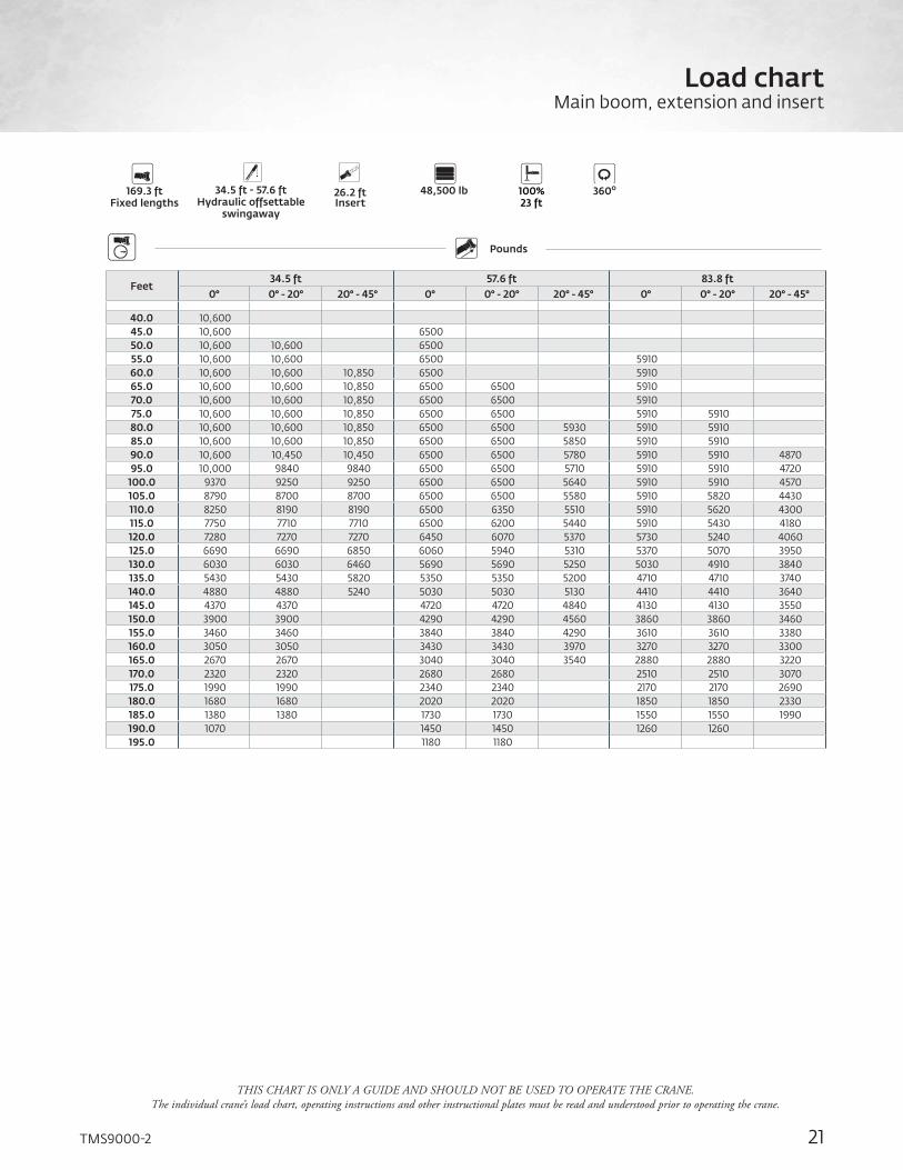
THIS CHART IS ONLY A GUIDE AND SHOULD NOT BE USED TO OPERATE THE CRANE. The individual crane’s load chart, operating instructions and other instructional plates must be read and understood prior to operating the crane.
Feet34.5 ft 57.6 ft 83.8 ft
0° 0° - 20° 20° - 45° 0° 0° - 20° 20° - 45° 0° 0° - 20° 20° - 45°
40.0 10,600 45.0 10,600 6500 50.0 10,600 10,600 6500 55.0 10,600 10,600 6500 5910 60.0 10,600 10,600 10,850 6500 5910 65.0 10,600 10,600 10,850 6500 6500 5910 70.0 10,600 10,600 10,850 6500 6500 5910 75.0 10,600 10,600 10,850 6500 6500 5910 5910 80.0 10,600 10,600 10,850 6500 6500 5930 5910 5910 85.0 10,600 10,600 10,850 6500 6500 5850 5910 5910 90.0 10,600 10,450 10,450 6500 6500 5780 5910 5910 4870 95.0 10,000 9840 9840 6500 6500 5710 5910 5910 4720
100.0 9370 9250 9250 6500 6500 5640 5910 5910 4570 105.0 8790 8700 8700 6500 6500 5580 5910 5820 4430 110.0 8250 8190 8190 6500 6350 5510 5910 5620 4300 115.0 7750 7710 7710 6500 6200 5440 5910 5430 4180 120.0 7280 7270 7270 6450 6070 5370 5730 5240 4060 125.0 6690 6690 6850 6060 5940 5310 5370 5070 3950 130.0 6030 6030 6460 5690 5690 5250 5030 4910 3840 135.0 5430 5430 5820 5350 5350 5200 4710 4710 3740 140.0 4880 4880 5240 5030 5030 5130 4410 4410 3640 145.0 4370 4370 4720 4720 4840 4130 4130 3550 150.0 3900 3900 4290 4290 4560 3860 3860 3460 155.0 3460 3460 3840 3840 4290 3610 3610 3380 160.0 3050 3050 3430 3430 3970 3270 3270 3300 165.0 2670 2670 3040 3040 3540 2880 2880 3220 170.0 2320 2320 2680 2680 2510 2510 3070 175.0 1990 1990 2340 2340 2170 2170 2690 180.0 1680 1680 2020 2020 1850 1850 2330 185.0 1380 1380 1730 1730 1550 1550 1990 190.0 1070 1450 1450 1260 1260 195.0 1180 1180
Counterweight Outriggers
169.3 ftFixed lengths
48,500 lb 100%23 ft
360o
PoundsBoom Extension
34.5 ft - 57.6 ft Hydraulic offsettable
swingaway
26.2 ftInsert
21TMS9000-2
Load chartMain boom, extension and insert

THIS CHART IS ONLY A GUIDE AND SHOULD NOT BE USED TO OPERATE THE CRANE. The individual crane’s load chart, operating instructions and other instructional plates must be read and understood prior to operating the crane.
Feet34.5 ft 57.6 ft 83.8 ft
0° 0° - 20° 20° - 45° 0° 0° - 20° 20° - 45° 0° 0° - 20° 20° - 45°
40.0 10,600 45.0 10,600 6500 50.0 10,600 10,600 6500 55.0 10,600 10,600 6500 5910 60.0 10,600 10,600 10,850 6500 5910 65.0 10,600 10,600 10,850 6500 6500 5910 70.0 10,600 10,600 10,850 6500 6500 5910 75.0 10,600 10,600 10,850 6500 6500 5910 5910 80.0 10,600 10,600 10,850 6500 6500 5930 5910 5910 85.0 10,600 10,600 10,850 6500 6500 5850 5910 5910 90.0 10,450 10,450 10,450 6500 6500 5780 5910 5910 4870 95.0 9310 9310 9840 6500 6500 5710 5910 5910 4720
100.0 8280 8280 8970 6500 6500 5640 5910 5910 4570 105.0 7360 7360 8000 6500 6500 5580 5910 5820 4430 110.0 6530 6530 7120 6500 6350 5510 5910 5620 4300 115.0 5790 5790 6330 6230 6200 5440 5910 5430 4180 120.0 5110 5110 5610 5550 5550 5370 5440 5240 4060 125.0 4500 4500 4960 4920 4920 5310 4810 4810 3950 130.0 3930 3930 4360 4350 4350 5190 4230 4230 3840 135.0 3420 3420 3810 3830 3830 4610 3700 3700 3740 140.0 2940 2940 3300 3350 3350 4070 3220 3220 3640 145.0 2510 2510 2900 2900 3580 2760 2760 3530 150.0 2100 2100 2490 2490 3120 2350 2350 3060 155.0 1720 1720 2110 2110 2690 1960 1960 2630 160.0 1380 1380 1750 1750 2290 1600 1600 2230 165.0 1050 1050 1420 1420 1910 1260 1260 1850 170.0 1110 1110 1500 175.0 1170
Counterweight Outriggers
169.3 ftFixed lengths
36,000 lb 100%23 ft
360o
PoundsBoom Extension
34.5 ft - 57.6 ft Hydraulic offsettable
swingaway
26.2 ftInsert
Load chartMain boom, extension and insert
22

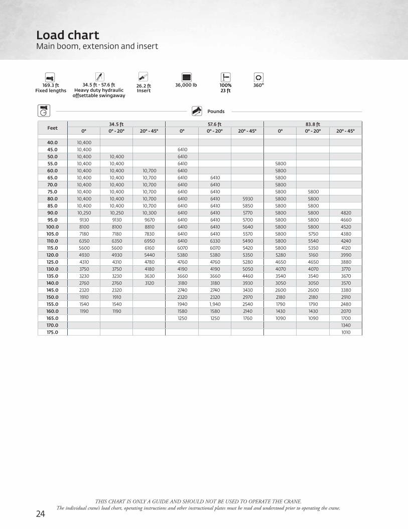
THIS CHART IS ONLY A GUIDE AND SHOULD NOT BE USED TO OPERATE THE CRANE. The individual crane’s load chart, operating instructions and other instructional plates must be read and understood prior to operating the crane.
Feet34.5 ft 57.6 ft 83.8 ft
0° 0° - 20° 20° - 45° 0° 0° - 20° 20° - 45° 0° 0° - 20° 20° - 45°
40.0 10,400 45.0 10,400 6410 50.0 10,400 10,400 6410 55.0 10,400 10,400 6410 5800 60.0 10,400 10,400 10,700 6410 5800 65.0 10,400 10,400 10,700 6410 6410 5800 70.0 10,400 10,400 10,700 6410 6410 5800 75.0 10,400 10,400 10,700 6410 6410 5800 5800 80.0 10,400 10,400 10,700 6410 6410 5930 5800 5800 85.0 10,400 10,400 10,700 6410 6410 5850 5800 5800 90.0 10,400 10,300 10,300 6410 6410 5770 5800 5800 4820 95.0 9820 9670 9670 6410 6410 5700 5800 5800 4660
100.0 9180 9080 9080 6410 6410 5640 5800 5800 4520 105.0 8590 8520 8520 6410 6410 5570 5800 5750 4380 110.0 8050 8010 8010 6410 6330 5490 5800 5540 4240 115.0 7550 7530 7530 6410 6190 5420 5800 5350 4120 120.0 7090 7090 7090 6300 6050 5350 5570 5160 3990 125.0 6500 6500 6670 5910 5910 5280 5200 4990 3880 130.0 5850 5850 6280 5540 5540 5230 4860 4830 3770 135.0 5250 5250 5650 5190 5190 5180 4540 4540 3670 140.0 4690 4690 5060 4870 4870 4990 4240 4240 3570 145.0 4180 4180 4570 4570 4700 3960 3960 3470 150.0 3710 3710 4120 4120 4410 3690 3690 3380 155.0 3270 3270 3680 3680 4140 3440 3440 3300 160.0 2860 2860 3260 3260 3810 3100 3100 3210 165.0 2480 2480 2870 2870 3380 2710 2710 3140 170.0 2130 2130 2510 2510 2340 2340 2910 175.0 1800 1800 2170 2170 2000 2000 2530 180.0 1490 1490 1860 1860 1680 1680 2170 185.0 1160 1160 1560 1560 1380 1380 1830 190.0 1280 1280 1090 1090
Counterweight Outriggers
169.3 ftFixed lengths
48,500 lb 100%23 ft
360o
PoundsBoom Extension
34.5 ft - 57.6 ft Heavy duty hydraulic
offsettable swingaway
26.2 ftInsert
23TMS9000-2
Load chartMain boom, extension and insert
Feet34.5 ft 57.6 ft 83.8 ft
0° 0° - 20° 20° - 45° 0° 0° - 20° 20° - 45° 0° 0° - 20° 20° - 45°
40.0 10,400 45.0 10,400 6410 50.0 10,400 10,400 6410 55.0 10,400 10,400 6410 5800 60.0 10,400 10,400 10,700 6410 5800 65.0 10,400 10,400 10,700 6410 6410 5800 70.0 10,400 10,400 10,700 6410 6410 5800 75.0 10,400 10,400 10,700 6410 6410 5800 5800 80.0 10,400 10,400 10,700 6410 6410 5930 5800 5800 85.0 10,400 10,400 10,700 6410 6410 5850 5800 5800 90.0 10,250 10,250 10,300 6410 6410 5770 5800 5800 4820 95.0 9130 9130 9670 6410 6410 5700 5800 5800 4660
100.0 8100 8100 8810 6410 6410 5640 5800 5800 4520 105.0 7180 7180 7830 6410 6410 5570 5800 5750 4380 110.0 6350 6350 6950 6410 6330 5490 5800 5540 4240 115.0 5600 5600 6160 6070 6070 5420 5800 5350 4120 120.0 4930 4930 5440 5380 5380 5350 5280 5160 3990 125.0 4310 4310 4780 4760 4760 5280 4650 4650 3880 130.0 3750 3750 4180 4190 4190 5050 4070 4070 3770 135.0 3230 3230 3630 3660 3660 4460 3540 3540 3670 140.0 2760 2760 3120 3180 3180 3930 3050 3050 3570 145.0 2320 2320 2740 2740 3430 2600 2600 3380 150.0 1910 1910 2320 2320 2970 2180 2180 2910 155.0 1540 1540 1940 1,940 2540 1790 1790 2480 160.0 1190 1190 1580 1580 2140 1430 1430 2070 165.0 1250 1250 1760 1090 1090 1700 170.0 1340 175.0 1010
Counterweight Outriggers
169.3 ftFixed lengths
36,000 lb 100%23 ft
360o
PoundsBoom Extension
34.5 ft - 57.6 ft Heavy duty hydraulic
offsettable swingaway
26.2 ftInsert
THIS CHART IS ONLY A GUIDE AND SHOULD NOT BE USED TO OPERATE THE CRANE. The individual crane’s load chart, operating instructions and other instructional plates must be read and understood prior to operating the crane.
Load chartMain boom, extension and insert
24

THIS CHART IS ONLY A GUIDE AND SHOULD NOT BE USED TO OPERATE THE CRANE. The individual crane’s load chart, operating instructions and other instructional plates must be read and understood prior to operating the crane.
25TMS9000-2
Working rangeIntegrated heavy duty jib
45° O�set20° O�set
0° O�set
Boo
m le
ngth
and
ext
ensi
on in
feet
Hei
ght
from
gro
und
in fe
et
00
20
40
60
80
100
120
140
160
180
200
20406080100120140160180200
Operating radius in feet from axis of rotation
36.6'
63.1'
76.7'
90.3'
103.0'
116.6'125.0'
143.6'
158.7'
169.3'
+11.4'
+11.4'
+11.4'
+11.4'
+11.4'
+11.4'+11.4'
+11.4'
+11.4'
+11.4'
Dimensions are for the largest Grove furnished hook block and overhaulball, with anti-two block activated.
7.7'
10.2'
36.6 ft - 169.3 ft main boom and 11.4 ft hydraulic or manual offsettable integrated heavy duty jib

THIS CHART IS ONLY A GUIDE AND SHOULD NOT BE USED TO OPERATE THE CRANE. The individual crane’s load chart, operating instructions and other instructional plates must be read and understood prior to operating the crane.
Load chartIntegrated eavy duty jib
26
Feet 37 ft 87 ft - 90 ft 124 ft - 126 ft 169.3 ft0° 0° - 20° 20° - 45° 0° 0° - 20° 20° - 45° 0° 0° - 20° 20° - 45° 0° 0° - 20° 20° - 45°
10.0 68,600 61,850 54,400 15.0 60,050 53,550 49,100 68,600 68,600 59,300 20.0 51,350 47,450 45,100 68,600 64,600 56,000 35,500 25.0 44,950 42,900 42,200 68,600 59,900 53,150 36,100 34,900 32,400 30.0 40,150 39,450 39,450 64,400 55,950 50,700 36,100 34,900 32,400 35.0 36,450 36,450 37,050 57,250 52,600 48,600 36,100 34,900 32,400 16,150 15,500 14,200 40.0 34,000 50,500 49,700 46,750 36,100 34,900 32,400 16,150 15,500 14,200 45.0 41,850 41,850 42,000 36,100 34,900 32,400 16,150 15,500 14,200 50.0 35,350 35,350 35,400 32,650 32,650 32,400 16,150 15,500 14,200 55.0 30,400 30,400 30,400 29,350 29,350 29,450 16,150 15,500 14,200 60.0 27,450 27,400 27,400 26,300 26,300 26,400 16,150 15,500 14,200 65.0 24,800 24,800 24,700 23,250 23,150 23,150 16,150 15,500 14,200 70.0 21,950 21,950 21,800 21,350 21,350 21,400 16,150 15,500 14,200 75.0 19,550 19,550 19,350 19,000 19,000 18,950 15,250 15,200 14,200 80.0 17,550 17,500 17,300 17,050 17,050 17,000 14,200 14,200 14,200 85.0 15,800 15,750 15,550 15,300 15,300 15,200 13,300 13,300 13,300 90.0 14,300 14,200 12,250 13,750 13,750 13,650 12,450 12,450 12,450 95.0 12,400 12,400 12,400 11,700 11,700 11,700
100.0 11,700 11,700 11,600 10,850 10,850 10,900 105.0 10,650 10,600 10,500 9850 9850 9830 110.0 9690 9650 9530 8890 8890 8850 115.0 8820 8780 8640 8020 8020 7970 120.0 8040 7980 7840 7230 7230 7170 125.0 7330 7260 6200 6510 6510 130.0 5860 5850 135.0 5250 5240 140.0 4700 4680 145.0 4190 4170 150.0 3720 3690 155.0 3280 3250 160.0 2870 2830 165.0 2500 170.0 2150
Counterweight Outriggers
36.6 ft - 169.3 ft Fixed lengths
48,500 lb 100%23 ft
360o
PoundsBoom Extension
11.4 ftHydraulic
integrated heavy duty jib
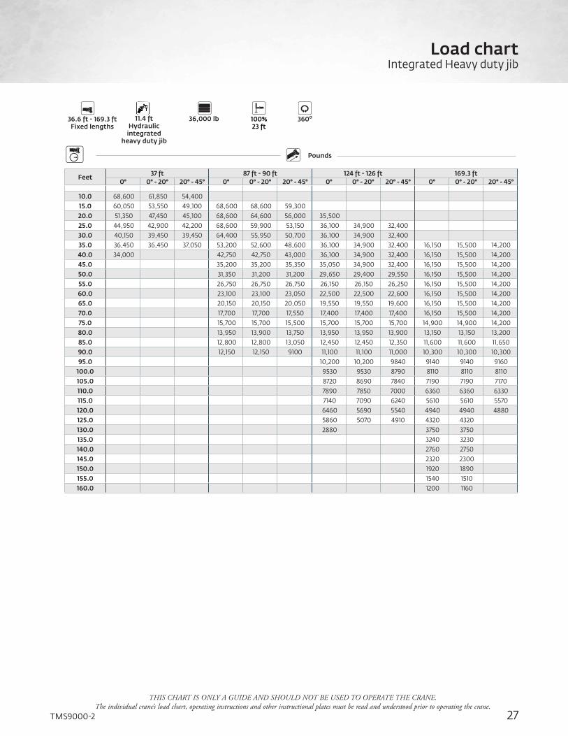
THIS CHART IS ONLY A GUIDE AND SHOULD NOT BE USED TO OPERATE THE CRANE. The individual crane’s load chart, operating instructions and other instructional plates must be read and understood prior to operating the crane.
27TMS9000-2
Load chartIntegrated Heavy duty jib
Feet 37 ft 87 ft - 90 ft 124 ft - 126 ft 169.3 ft0° 0° - 20° 20° - 45° 0° 0° - 20° 20° - 45° 0° 0° - 20° 20° - 45° 0° 0° - 20° 20° - 45°
10.0 68,600 61,850 54,400 15.0 60,050 53,550 49,100 68,600 68,600 59,300 20.0 51,350 47,450 45,100 68,600 64,600 56,000 35,500 25.0 44,950 42,900 42,200 68,600 59,900 53,150 36,100 34,900 32,400 30.0 40,150 39,450 39,450 64,400 55,950 50,700 36,100 34,900 32,400 35.0 36,450 36,450 37,050 53,200 52,600 48,600 36,100 34,900 32,400 16,150 15,500 14,200 40.0 34,000 42,750 42,750 43,000 36,100 34,900 32,400 16,150 15,500 14,200 45.0 35,200 35,200 35,350 35,050 34,900 32,400 16,150 15,500 14,200 50.0 31,350 31,200 31,200 29,650 29,400 29,550 16,150 15,500 14,200 55.0 26,750 26,750 26,750 26,150 26,150 26,250 16,150 15,500 14,200 60.0 23,100 23,100 23,050 22,500 22,500 22,600 16,150 15,500 14,200 65.0 20,150 20,150 20,050 19,550 19,550 19,600 16,150 15,500 14,200 70.0 17,700 17,700 17,550 17,400 17,400 17,400 16,150 15,500 14,200 75.0 15,700 15,700 15,500 15,700 15,700 15,700 14,900 14,900 14,200 80.0 13,950 13,900 13,750 13,950 13,950 13,900 13,150 13,150 13,200 85.0 12,800 12,800 13,050 12,450 12,450 12,350 11,600 11,600 11,650 90.0 12,150 12,150 9100 11,100 11,100 11,000 10,300 10,300 10,300 95.0 10,200 10,200 9840 9140 9140 9160
100.0 9530 9530 8790 8110 8110 8110 105.0 8720 8690 7840 7190 7190 7170 110.0 7890 7850 7000 6360 6360 6330 115.0 7140 7090 6240 5610 5610 5570 120.0 6460 5690 5540 4940 4940 4880 125.0 5860 5070 4910 4320 4320 130.0 2880 3750 3750 135.0 3240 3230 140.0 2760 2750 145.0 2320 2300 150.0 1920 1890 155.0 1540 1510 160.0 1200 1160
Counterweight Outriggers
36.6 ft - 169.3 ft Fixed lengths
36,000 lb 100%23 ft
360o
PoundsBoom Extension
11.4 ftHydraulic
integrated heavy duty jib

*Denotes optional equipment
Super Structure
Boom11,2 m - 51,6 m (36.6 ft - 169.3 ft) six-section greaseless MEGAFORM™ boom with TWIN-LOCK™ pinning system. Maximum tip height: 54,8 m (179.8 ft).
Boom noseFive nylatron sheaves, mounted with removable pin-type rope guards. Quick reeve boom nose. Removable auxiliary boom nose with removable pin type rope guard.
Boom elevationSingle lift cylinder with integrated valve provides boom angle from -3° to +82°.
*Optional offsettable lattice extensions10,5 m - 17,6 m (34.5 ft - 57.6 ft) bi-fold lattice swingaway extension manually offset at 0°, 20°, and 45°. Maximum tip height: 72,3 m (237.3 ft).
10,5 m - 17,6 m (34.5 ft - 57.6 ft) bi-fold lattice swingaway extension hydraulically offset from 0° - 45°. Controlled from the crane cab. Maximum tip height: 72,3 m (237.3 ft).
10,5 m - 17,6 m (34.5 ft - 57.6 ft) bi-fold lattice swingaway extension with integrated 3,5 m (11.4 ft) heavy duty jib, manually offset at 0°, 20°, and 45°. Maximum tip height: 72,3 m (237.3 ft).
10,5 m - 17,6 m (34.5 ft - 57.6 ft) bi-fold lattice swingaway extension with integrated 3,5 m (11.4 ft) heavy duty jib, hydraulically offset from 0° - 45°. Controlled from the crane cab. Maximum tip height: 72,3 m (237.3 ft).
* Optional lattice insertOne 8 m (26.2 ft) insert for use with lattice swingawayextension to increase the total extension length up to 25,6 m (83.8 ft). Maximum tip height: 80,3 m (263.4 ft)
Rated Capacity Limiter and anti-two block systemLoad moment and anti-two block system with audio/visual warning and control lever lockout provides electronic display of boom angle, length, radius, tip height, relative load moment, maximum permissible load, load indication, slew angle and warning of impending two-block condition.
Crane Control System (CCS)Full electronic control of all crane movements using electrical control allowing user customization of levels and response. Integrated with the RCL and engine management system by CAN-BUS. Full-color high resolution graphic display.
CabAll aluminum construction cab with acoustical lining tiltshydraulically to +20° and includes tinted safety glass, air conditioning,
adjustable operator’s seat with hydraulic suspension, hinged front (with wiper) and rear windows, sun visor and window shade. Other features include diesel heater/defroster, stereo radio/disc player, armrest integrated crane controls, and ergonomically arranged instrumentation.
SwingTwo planetary gearboxes with axial piston fixed displacement motors. Infinitely variable to 1.9 rpm. Spring-applied park brakes and hydraulic service brakes.
Counterweight7258 kg (16,000 lb) consisting of multiple sections with hydraulic installation/removal system operated from the cab. *Optional “Heavy Lift” counterweight package consisting of (2) 4636 kg (10,000 lb) sections in addition to standard, for a total of 16 329 kg (36,000 lb). *Optional “XL” counterweight package consisting of (2) 1814 kg (4000 lb) and (2) 1021 kg (2250 lb) wing sections in addition to standard and “Heavy Lift” package, for a total of 22 000 kg (48,500 lb).*Optional “Special XL” counterweight package consisting of two 1814 kg (4000 lb) and two 1021 kg (2250 lb) wing sections in addition to modified standard counterweight package (a 907 kg (2000 lb) slab and a 1360 kg (3,000lb) slab in lieu of one 2268 kg (5000 lb) slab and “Heavy Lift” package, for a total of 22 000 kg (48,500 lb).
Hydraulic systemTwo load-sensing axial piston variable displacement pump (load sensing) with power limiting control and one gear pump for slewing and steering. Dual fan electric oil cooler. On screen display of hydraulic oil temperature. Tank capacity 556 liters (147 gallons).
HoistMain and auxiliary hoists are powered by axial piston motors with planetary gears and brakes. “Thumb-thumper” hoist drum rotation indicator alerts operator of hoist movement. Standard minimum wrap indication with lock-out.Hoist line pull: 1st Layer: 10 900 kg (24,000 lb) 3rd Layer: 9250 kg (20,400 lb) 5th Layer: 8000 kg (17,700 lb)Maximum line speed: 113 m/min (370 fpm)Maximum permissible line pull: 7784 kg (17,160 lb) 35X7 Class Rope diameter: 19 mm (3/4 in)Rope length main hoist : 250 m (820 ft)Rope length auxiliary hoist : 177 m (581 ft)Maximum rope storage: 292 m (960 ft)
Cameras Standard back-up, right-side and hoist cameras.
Specifications
28

Carrier
ChassisTorsionally rigid frame, four-axle carrier, fabricated from high strength, low alloy steel with towing and tie-down lugs.
Outrigger systemFour hydraulic telescoping, two-stage, double box beam outriggers and integral holding valves.Quick release type outrigger floats 500 mm (20 in) diameter.Four position setting with fully extended, 79%, 57%, and fully retracted capacities. Fifth (5th) front jack with sliding self-storing pad and automatic first-retract.Outrigger Monitoring System standard (required for North America and Canada).
Maximum outrigger pad load: 49,900 kg (110,000 lb)
Outrigger controlsLocated in the superstructure cab and on either side ofcarrier. Crane level indicators located at all stations. Auto leveling and wireless remote control standard.
Engine Cummins ISX 12 six-cylinder, turbo charged and after cooled diesel engine. 12 L 336 kW (450 bhp) at 1800 rpm. Maximum torque 2102 Nm (1550 lb-ft) at 1400 rpm. “On Highway” EPA, CARB compliant.Equipped with engine compression brake, ether start aid and 110 volt block heater.Fuel Requirement: Maximum of 15 ppm sulfur content (Ultra Low Sulfur Diesel). Diesel exhaust fluid required.
Fuel tank capacity376 L (100 gal)
TransmissionRoadranger 11 speeds forward, 3 reverse, manual.Optional automated Eaton Fuller Ultrashift® PLUS Transmission
SteeringFront axles, single circuit, mechanical steering withhydraulic power assist. Turning radius: 13,8 m (45.4 ft).
AxlesFront: (2) tube-type steering axles, 2,12 m (83.4 in) track.Rear: (2) single reduction drive axles, 1,89 m (74.5 in)track. Inter-axle differential locks.Drive: 8 x 4 x 4.
BrakesS-cam, dual air split system operating on all wheels. Spring-applied, air released parking brake acting on rear axles. Air dryer. ABS with traction control.
SuspensionFront: Walking beam with air bags and shock absorbers.Rear: Walking beam with air bags and shock absorbers.
TiresFront: 445/65R 22.5 tubeless, mounted on aluminum disc wheels.Rear: 315/80R 22.5 tubeless, mounted on aluminum disc wheels.
LightsLighting package including turn indicators, head,tail, brake, and hazard warning lights.
CabSingle-driver design, aluminum fabricated with acoustical liningand tinted safety glass. Air conditioning. Fabric covered seat with air adjustment. Driving controls and engine instrumentation including tilt telescope multifunction steering wheel, tachometer, speedometer, trip meter, voltmeter, water temp., oil, fuel level, air pressure gauge, engine high temp./low oil pressure A/V warning. Other standard items include display for back-up and passenger side cameras, hot water heater/ defroster, electric windshield wash/wipe, fire extinguisher, wireless rigging remote with battery charging station, seat belt and door lock.
Electrical systemFour maintenance-free batteries provide 24 V electrical system. Standard lockable battery disconnect.
Maximum speed105 kph (65 mph)
Gradeability (theoretical)70%, 1st gear
Miscellaneous standard equipmentAluminum fenders with rear storage compartments; dual rear view mirrors; electronic back-up alarm; sling/tool box; tire inflation kit; air cleaner restriction indicator; headache ball stowage tray; air conditioning; air horn; hoist access platform
*Optional equipment• Auxiliary Lighting and Convenience Package: Includes amberstrobe light for superstructure and carrier cab, and boom nosemounted, boom position indicator light (fully wired)• Dual boom base mounted floodlights (manual or power-adjusted)• Hook blocks• Pintle hook (rear)• Trailing Boom Package• Steel outrigger pads• Counterweight packages• Tow cable• Wind speed indicator• Winterfront radiator cover• Counterweight slings• Cross axle differential locks• Electric controlled 360° lock• Rear counterweight stowage• Single axis joysticks• K-100™ synthetic rope• Boom dolly camera• CraneSTAR asset management system
*Denotes optional equipment 29TMS9000-2
Specifications

Drive
RotationElectrical system
Suspension
Fuel tank capacity
Tires
Engine
Brakes
Outrigger controls
Axles
Outriggers
Transmission
Frame
Steering
Lights
Boom elevation
Cab
Swing
Hydraulic system
Hoist
Boom nose
Radius
Boom extension
Boom length
Grade
Gear
Boom
Counterweight
Speed
Oil
Insert
HookblockH
Heavy duty jib
Camera
Extension
Height (no max)
Symbols glossary
30

31TMS9000-2
Notes

www.manitowoc.com
Manitowoc Cranes
ChinaShanghai, China Tel: +86 21 6457 0066Fax: +86 21 6457 4955
Middle East and Greater Asia-Pacific Singapore Tel: +65 6264 1188 Fax: +65 6862 4040
Dubai, UAETel: +971 4 8862677Fax: +971 4 8862678/79
Europe and Africa Dardilly, France - TOWERSTel: +33 (0)4 72 18 20 20 Fax: +33 (0)4 72 18 20 00
Wilhelmshaven, Germany - MOBILETel: +49 (0) 4421 294 0Fax: +49 (0) 4421 294 4301
Americas Manitowoc, Wisconsin, USA Tel: +920 684 4410 Fax: +1 920 652 9778
Shady Grove, Pennsylvania, USA Tel: +1 717 597 8121 Fax: +1 717 597 4062
Regional headquarters
This document is non-contractual. Constant improvement and engineering progress make it necessary that we reserve the right to make specification, equipment, and price changes without notice. Illustrations shown may include optional equipment and accessories and may not include all standard equipment.
©2018 The Manitowoc Company, Inc.Form No. TMS9000E-2Part No. 17-008 /PDF/0118
Related Documents


