Whisperline ® SRS Vertical Stack PRODUCT DESIGN GUIDE July 2017

Welcome message from author
This document is posted to help you gain knowledge. Please leave a comment to let me know what you think about it! Share it to your friends and learn new things together.
Transcript

Whisperline® SRS Vertical StackPRODUCT DESIGN GUIDE
July 2017
Vertical Stack
Table of Contents
Cabinet Nomenclature 1
Chassis Nomenclature 2
AHRI Performance Rating 3
Features & Benefits 4
Unit Protection & LED Fault Status 7
Multi-protocol DDC Controller 8
Physical Data Table 9
Unit Voltage Limitations 10
Continuous Operating Limits 10
Whisperline® 0204 Performance Data 11
Airflow – PSC Motor 19
Airflow – EC Constant Torque Motor 20
Airflow – EC Constant Volume Motor 21
Electrical Data 22
Wiring Diagrams 40
Whisperline® Riser Detail 46
Whisperline® Discharge Arrangements 47
Whisperline® Cabinet Drawings 50
Mechanical Specifications 54
Whisperline® Warranty Statements 61
Whisperline® Design Guide Revision Table 67

The Whalen Company works continually to improve its products. As a result, the design and specifications of each product at the time of order may be changed without notice and may not be as described herein. Please contact The Whalen Company’s Customer Service Department at 1-410-822-9200 for specific information on the current design and specifications. Statements and other information contained herein are not express warranties and do not form the basis of any bargain between the parties, but are merely The Whalen Company’s opinion or commendation of its products. The latest version of this document is
available at whalencompany.com
whalencompany.comWhisperline® SRS Vertical Stack Series Product Design Guide – 1 –
Cabinet Nomenclature
Category Position Option Digit and Description
Product Family 1 V = Vertical Stack Water Source Heat Pump
Drain Type 2I = Internal Whalen Drain
P = P-trap Internal Drain
System Configuration 3
A = Heat Pump
B = Air Conditioning and Electric Heat
C = Air Conditioning and Hydronic Heat
D = Cooling Only
E = Heating Only
H = Heat Pump and Electric Heat
Unit Capacity 4, 5
02 = 200 CFM (0.5-ton)
03 = 300 CFM (0.75-ton)
04 = 400 CFM (1.0-ton)
05 = 500 CFM (1.25-ton)
06 = 600 CFM (1.5-ton)
08 = 800 CFM (2.0-ton)
10 = 1000 CFM (2.5-ton)
12 = 1200 CFM (3.0-ton)
Heat Exchanger / Cabinet 60 = Standard
1 = Oversized
Revision (Major) 7 4 = 4th Generation
Voltage 8
A = 115-60-1 (200, 300 and 400 CFM Only)
B = 208/230-60-1
D = 265-60-1
Fan 9
S = PSC - Standard Motor
H = PC - High Static Motor
D = ECM - Constant Torque Motor (Size 08 - 12)
G = ECM - Constant Torque (Size 02 - 06)
E = ECM - Constant Air Volume Motor
Revision (Minor) 10
- = Original
B = 1st Revision
C = 2nd Revision
Sound Attenuation 11- = Standard Quiet Construction
D = P-trap Drain / Sound Package

The Whalen Company works continually to improve its products. As a result, the design and specifications of each product at the time of order may be changed without notice and may not be as described herein. Please contact The Whalen Company’s Customer Service Department at 1-410-822-9200 for specific information on the current design and specifications. Statements and other information contained herein are not express warranties and do not form the basis of any bargain between the parties, but are merely The Whalen Company’s opinion or commendation of its products. The latest version of this document is
available at whalencompany.com
Whisperline® SRS Vertical Stack Series Product Design Guide whalencompany.com– 2 –
Chassis Nomenclature
Category Position Option Digit and Description
Product Family 1 W = Vertical Stack Water Source Heat Pump
System Configuration 2
A = Heat Pump (Cooling default)
B = Cooling Only
C = Air Conditioning and Hydronic Heat
E = Heating Only
F = Heat Pump and Hydronic Heat (heating default)
G = Heat Pump (heating default)
Unit Capacity 3, 4
02 = 200 CFM (0.5-ton)
03 = 300 CFM (0.75-ton)
04 = 400 CFM (1.0-ton)
05 = 500 CFM (1.25-ton)
06 = 600 CFM (1.5-ton)
08 = 800 CFM (2.0-ton)
10 = 1000 CFM (2.5-ton)
12 = 1200 CFM (3.0-ton)
Heat Exchanger / Cabinet 50 = Standard
1 = Oversized
Revision (Major) 6 4 = 4th Generation
Voltage 7
A = 115-60-3
B = 208/230-60-1
D = 265-60-1
Compressor 8
C = Copeland
B = Bristol
T = Tecumseh
M = Matsushita
L = LG
Distributor Options 9
X = Extended Range (TXV)
Y = Standard (TXV)
I = Boilerless (TXV - Must be type A)
Revision (Minor) 10
- = Original
B = 1st Revision
C = 2nd Revision
Option Style 11B = Whalen Drain / Silver Rails / 18ga. Compressor Box
D = P-trap Drain / Silver Rails / 18ga. Compressor Box

The Whalen Company works continually to improve its products. As a result, the design and specifications of each product at the time of order may be changed without notice and may not be as described herein. Please contact The Whalen Company’s Customer Service Department at 1-410-822-9200 for specific information on the current design and specifications. Statements and other information contained herein are not express warranties and do not form the basis of any bargain between the parties, but are merely The Whalen Company’s opinion or commendation of its products. The latest version of this document is
available at whalencompany.com
whalencompany.comWhisperline® SRS Vertical Stack Series Product Design Guide – 3 –
AHRI Performance Rating – ASHRAE/ANSI/AHRI/ISO/Standard
Model with PSC Motor CFM GPM
Water Loop Heat Pump Ground Loop Heat Pump
Cooling 86°F Heating 68°F Cooling 77°F Heating 32°F
Capacity Btuh
EER Btuh / W
Capacity Btuh COP Capacity
BtuhEER
Btuh / WCapacity
Btuh COP
VP-A-0204*S 280 1.5 6,500 13.0 8,300 5.1 6,900 14.2 5,200 3.2
VP-A-0304*S 340 2.5 9,300 13.8 11,500 5.2 9,650 14.8 6,850 3.2
VP-A-0404*S 420 3.3 11,800 13.8 14,500 5.0 12,500 15.8 9,300 3.2
VP-A-0604*S 630 4.5 18,000 14.5 21,600 5.0 18,800 15.5 13,000 3.2
Cooling based upon 80.6°F DB, 66.2°F WB entering air temperatureHeating based upon 68°F DB, 59°F WB entering air temperature
Performance based upon 208/60/1 voltage
Model with EC Motor CFM GPM
Water Loop Heat Pump Ground Loop Heat Pump
Cooling 86°F Heating 68°F Cooling 77°F Heating 32°F
Capacity Btuh
EER Btuh / W
Capacity Btuh COP Capacity
BtuhEER
Btuh / WCapacity
Btuh COP
VP-A-0304*D 340 2.5 9,300 14.4 11,500 5.4 9,650 15.4 6,850 3.3
VP-A-0404*D 420 3.3 12,000 14.0 14,500 5.2 12,700 16.0 9,400 3.3
VP-A-0504*D 540 3.9 14,600 16.7 18,400 6.0 15,200 17.7 11,000 3.5
VP-A-0604*D 630 4.5 18,200 15.2 21,600 5.1 19,000 16.2 13,000 3.2
VP-A-0804*D 830 6.0 23,000 13.1 30,000 5.0 25,000 14.5 19,000 3.2
VP-A-0814*D 830 6.0 25,000 14.8 30,000 5.0 26,000 15.7 19,000 3.2
VP-A-1004*D 970 7.5 29,200 14.2 35,900 5.0 29,700 15.5 22,000 3.2
VP-A-1204*D 1170 9.0 33,100 14.2 42,000 5.2 33,600 15.3 25,400 3.3
Cooling based upon 80.6°F DB, 66.2°F WB entering air temperature
Heating based upon 68°F DB, 59°F WB entering air temperature
Performance based upon 208/60/1 voltage
Table 1: AHRI Performance Ratings – ASHRAE / ANSI / AHRI / ISO Standard 13256-1

The Whalen Company works continually to improve its products. As a result, the design and specifications of each product at the time of order may be changed without notice and may not be as described herein. Please contact The Whalen Company’s Customer Service Department at 1-410-822-9200 for specific information on the current design and specifications. Statements and other information contained herein are not express warranties and do not form the basis of any bargain between the parties, but are merely The Whalen Company’s opinion or commendation of its products. The latest version of this document is
available at whalencompany.com
Whisperline® SRS Vertical Stack Series Product Design Guide whalencompany.com– 4 –
Features & Benefits
Electric Heat Factory installed electric heaters are available on vertical units. Unit controls are available for boilerless, supplemental, primary or emergency electric heat to serve several different application needs. Boilerless electric heat will be energized when the entering water temperature falls below set point. This will allow electric heat to function while ensuring the compressor remains off. With supple-mental electric heat control, the wall thermostat will activate the compressor and heater simultaneously if necessary to maintain room heating conditions.
Internal Pump Internal pump is optional on all size units but cannot be used in conjunction with the two-way solenoid valve. The internal pump is an internally mounted ON/OFF circulating pump for use with our single riser applications.
Tin Dipped Coil Optional tin electro-plated copper tubing protect the air coil from many corrosive ele-ments in the air stream. Corrosion often referred to as Formicary Corrosion occurs due to the presence of dissimilar metals such as copper and aluminum in conjunction with water causes results in refriger-ant leaks and eventual failure of the air coil costing hundreds of dollars to replace. Studies have also shown that isolating the copper from the aluminum greatly reduces or eliminates the corrosion thereby increasing the life of the air coil.
Constant Torque EC Motor Are standard on size 0800 and 1200 units; they are optional on size 800 and smaller and provide the efficiency and operability of an ECM at a lower cost than a constant airflow ECM. Constant torque ECMs provide 5 available motor speed settings and will maintain a constant motor torque as external static pressure in the system increases. As the system static pressure increases, reduction in fan airflow with a constant torque ECM is minor.
Constant Airflow EC Motor Are optional on size 0400 – 1200 units and will maintain a constant unit airflow as the static pressure in the system increases. Constant airflow ECMs provide only single speed settings.
PSC (Permanent Split Capacitor) Are standard on size 0600 and smaller units. Our PSC motor is available in standard static range as well as high static appli-cations. The supplied motor is available in single or two-speed configurations (two manual two-speed fan switch, control based fan relay, or two-speed thermostat.
Supply Air Grille Diffusers are constructed of aluminum with a mill finish or an optional painted finish, avail-able in three variations: single deflection, double deflection, double deflection with opposed blade damper. Damper blades are positioned vertically and adjust easily for directing the unit discharge air.
Flush Mounted Return Air Panel Constructed of heavy gauge steel, lined with insulation to help attenuate sound from the compressor and fan assembly. Me-chanical latching clips ensure the panel door stays closed during operation. Panels are available in chassis accessible version to allow removal of refrig-erant chassis without removing the return air panel.
Painted Flush Mounted Return Air Panel Constructed of heavy gauge painted steel, lined with insulation to help attenuate sound from the compressor and fan assembly. Mechanical latching clips ensure the panel door stays closed during operation. Panels are available in chassis accessible version to allow removal of refrigerant chassis without removing the return air panel.
Telescoping SA Extension Collar A canvas duct connector to connect the WSHP discharge to the downstream duct system. This reduces vibration-in-duced noise.
Cabinet Stand An optional cabinet stand is available in heights ranging from 2” up to 14” to accommodate interiors with higher baseboard mouldings.
Unfused Disconnect Units are available with an optional non-fused disconnect switch, located on the unit front behind the return air panel. The disconnect switch is used to break power to the unit for safety and ease of service.
Features & Benefits

The Whalen Company works continually to improve its products. As a result, the design and specifications of each product at the time of order may be changed without notice and may not be as described herein. Please contact The Whalen Company’s Customer Service Department at 1-410-822-9200 for specific information on the current design and specifications. Statements and other information contained herein are not express warranties and do not form the basis of any bargain between the parties, but are merely The Whalen Company’s opinion or commendation of its products. The latest version of this document is
available at whalencompany.com
whalencompany.comWhisperline® SRS Vertical Stack Series Product Design Guide – 5 –
Features & Benefits
Circuit Breaker Units are available with an optional circuit breaker (Magnetic Hydraulic breaker). The circuit breaker is used to break power to the unit for safety and ease of service.
T-stat extension Low voltage wire harness ranging from 5 to 20 foot ending with 6-pin Molex quick connector. The extension can exit cabinet on the top, front, or either side depending on the riser location.
Condensate pump The internal condensate pump allows the unit to be located virtually wherever de-sired. The internal condensate pump serves as an effective means for disposing of condensate gen-erated during heat pump operation. A condensate pump should be designed and installed at the unit to pump condensate to a building drain.
Vibration Isolation Pad Vibration isolator pads dampen vibration from the compressor and fan motors. The 1/2” thick neoprene isolation pads are attached to the bottom of the cabinet at the factory eliminating any additional field labor.
2-Way Valve 2-way valves are used for a variety of pump-ing applications when more than one unit is installed on a common loop. These valves are also used to shut off flow when the unit is not operating. On a call for cooling or heating the valve opens providing full water flow prior to compressor operation. A 24 volt control wire harness is included with the factory provided control valve option.
Automatic Flow Control An automatic flow control de-vice includes a ball valve cast in the valve body and is located on the return water pipe. The flow control valve consists of a stainless steel/brass flow car-tridge and a contoured orifice plate. As the pressure drop increases, the flow cartridge will move into the contoured orifice plate to decrease the flow. This flexing action provides a constant flow, independent of pressure (2-80 psi), makes it difficult to clog and resistant to cavitation damage. This valve sets flow through the coil without any action required by a system balancer.
Manual Flow Control A manual flow control valve, acts as both a flow setting device and a stop valve, tak-
ing the place of a ball valve. This valve allows water flow through the unit and can be set quickly and accurately.
Ball Valve Ball valves allow the unit to be shut off for servicing purposes. They have a low resistance to water flow, operate easily. These valves have a compact handle that rotates 90 degrees to a fully open position. The valve body is forged brass and the ball is polished brass with Teflon seats and seals. Ball valves are included on both the supply and return risers.
Memory Stop Adjustable Memory Stop provides both balancing and shutoff in one valve. With the memo-ry stop locked in place, the valve can be closed and then reopened to the same balanced position.
P/T Port An accessible port where pressure and tem-perature can be measured. Accepts standard 1/8” gauge adapter or thermometer stem.
Strainer The Y-type strainer body is constructed of brass with a 20 mesh 304 stainless steel screen. Used for removal of small particles from the water supply pipe during normal system operation. The strainer helps protect the coil and minimizes the chance of control valves clogging. Screens should be regularly re-moved and cleaned as part of a routine maintenance schedule.
Stainless Steel Hoses Flexible 302/304 stainless steel hose with EPTF inner tube and JIC flare connec-tions. Meets UL-94 VO fire rating.
O.A. Internal Duct A 4” round internal duct is factory in-stalled to provide outside air to the return side of the air coil. By introducing the outside air to the return side of the coil, the outside is conditioned prior to entering the occupied space. The O.A. Internal Duct is insulated when inernal to cabinet.
O.A. Motorized O.A. Damper The control can be configured to operate as a ventilation damper in a 2-position ventilation mode to provide the minimum ventilation requirements during occupied periods. This control operation still utilizes the modulating damper actuator. Note that the motorized O.A. damper cannot be used with the internal O.A. duct.

The Whalen Company works continually to improve its products. As a result, the design and specifications of each product at the time of order may be changed without notice and may not be as described herein. Please contact The Whalen Company’s Customer Service Department at 1-410-822-9200 for specific information on the current design and specifications. Statements and other information contained herein are not express warranties and do not form the basis of any bargain between the parties, but are merely The Whalen Company’s opinion or commendation of its products. The latest version of this document is
available at whalencompany.com
Whisperline® SRS Vertical Stack Series Product Design Guide whalencompany.com– 6 –
Features & Benefits
Filter Units come standard with a one-inch glass fiber throwaway filter. High efficiency MERV 4, MERV 8, MERV 11, and MERV 13 pleated filters as well as a washable aluminum mesh filter are also available as an option.
Cu-Ni Coaxial Heat Exchanger The optional cupron-ickel tube-in-tube coaxial heat exchanger used in vertical stack water source heat pumps is designed for maximum heat transfer at normal and low water flow rates with minimum pressure drop. The inside tube is deeply fluted to enhance heat transfer and
minimize fouling. All coaxial coils are tested to 400 psig on the water side and 600 psig on the refrigerant side. The extended range chassis has coil and piping insulation to protect against conden-sation in low-temperature geothermal applications.
Silver Rail Package The silver rail sound package further attenuates the sounds levels of our standard unit by adding a set of spring isolators under the compressor chassis rails in lieu of our standard rubber in shear isolators to enhance the dual-level vibration isolation.
Table 2: Whisperline® Thermostats for Standalone Operation
Feature SCI SC2010L SCI SC4011 SCI SC5011
Mounting StyleElectrical Box
Drywall • • •
Display
Backlit LCD • • •Temperature & Setpoint • • •Operating Mode • • •Fan Status • • •Remote Setback • • •
Operation
Non-programmable • •Programmable 7 day
Sensing Local or Remote Local or Remote Local or Remote
Setpoint Range 45ºF to 90ºF 45ºF to 90ºF 45ºF to 90ºF
Changeover Manual Automatic Manual or Automatic
Operating Modes
System Settings Heat - Cool - Auto - Off Heat - Cool - Auto - Off Heat - Cool - Auto - Off
Fan Settings On - Auto On - Auto On - Auto
Fan Speeds 1 1 1
StagesHeating 1 1 1
Cooling 1 1 1
Voltage Operating Voltage 20 - 30 VAC 20 - 30 VAC 20 - 30 VAC

The Whalen Company works continually to improve its products. As a result, the design and specifications of each product at the time of order may be changed without notice and may not be as described herein. Please contact The Whalen Company’s Customer Service Department at 1-410-822-9200 for specific information on the current design and specifications. Statements and other information contained herein are not express warranties and do not form the basis of any bargain between the parties, but are merely The Whalen Company’s opinion or commendation of its products. The latest version of this document is
available at whalencompany.com
whalencompany.comWhisperline® SRS Vertical Stack Series Product Design Guide – 7 –
Unit Protection & LED Fault Status
Unit Protections & LED Fault Status Annunciation
Refrigerant Circuit High Pressure Protection A normally closed high (compressor discharge)
pressure switch is used to help protect the refriger-ant circuit from excessively high pressure. If the high pressure switch opens twice within 1 hour, the con-trol board will initiate a hard lockout and the alarm contact will energize.
Refrigerant Circuit Low Pressure Protection A normally closed low (compressor suction) refrig-
erant pressure switch is used to help protect the refrigerant circuit from excessively low refrigerant pressure. If the low pressure switch opens twice within 1 hour, the control board will initiate a hard lockout and the alarm contact will energize.
Condensate Overflow Sensor The control is designed to sense when condensate
water levels in the drain pan become excessively high. When high condensate water levels are detect-ed, the controller will go into condensate overflow warning mode. If the condensate overflow sensor detects liquid twice within 1 hour, the control board will initiate a hard lockout and the alarm contact will energize.
Heat Exchanger Low Temperature Protection The control is designed to sense when the refrig-
erant temperature drops to a temperature where it is possible to freeze the air coil or the coaxial heat exchanger. The threshold temperature is field selectable for 10°, 20°, or 32°F. If the Freeze Sensor drops below the set temperature twice within 1 hour, the control board will initiate a hard lockout and the alarm contact will energize.
Low water temperature The control is designed to sense when the leaving
water temperature drops to a temperature where it is possible to freeze the coaxial heat exchanger or raises to a temperature high enough to cause possible damage to the compressor. The threshold
temperature is field selectable for 0°, 10°, 20°, 36°, or 125°F. If the sensor drops below (or above 125°) the set temperature twice within 1 hour, the control board will initiate a hard lockout and the alarm con-tact will energize.
Low Voltage (Brownout) Protection The solid state control will monitor the 24 volt power
input supplied to the board. If the supply voltage drops below 18 VAC, the control module will shut down the unit to protect electrical components from low line voltage conditions.
Soft Lockout Reset This feature is used to minimize nuisance trips
of safeties caused by temporary conditions that might inhibit the unit from performing normal functions. When a safety trip occurs, it is counted and the alarm is cleared when the condition returns to normal. If the alarm occurs two times within a 1-hour period, the heat pump remains off (locked out) until the unit is checked and the alarm is manually cleared.

The Whalen Company works continually to improve its products. As a result, the design and specifications of each product at the time of order may be changed without notice and may not be as described herein. Please contact The Whalen Company’s Customer Service Department at 1-410-822-9200 for specific information on the current design and specifications. Statements and other information contained herein are not express warranties and do not form the basis of any bargain between the parties, but are merely The Whalen Company’s opinion or commendation of its products. The latest version of this document is
available at whalencompany.com
Whisperline® SRS Vertical Stack Series Product Design Guide whalencompany.com– 8 –
Multi-protocol DDC Controller
Multi-Protocol DDC ControllerThe Whalen Company water source heat pumps are avail-able with a factory installed multi-protocol communication module that is designed to communicate with a building automation system (BAS). The I/O Zone 560 DDC control-
ler is designed to allow the integra-tion of Whalen water source heat pump equipment into DDC systems. The I/O Zone 560 DDC controller has the ability to com-municate through a choice of three widely used proto-cols: BACnet MS/
TP, Johnson Controls N2, and Modbus. The protocol of choice for the particular system is selected by simply con-figuring DIP switches on the DDC control. This flexibility allows one controller to be used in a multitude of buildings which use any of these three common protocols. The con-trol serves as a node of information processing between the Whalen heat pump and the DDC network.
Features & Benefits• Multi-Protocol communications provides DDC system
flexibility.
• Supports native BACnet MS/TP communications – the ASHRAE standard protocol for interoperability.
• Supports Johnson Controls N2 communications – for integration into Johnson Controls Metasys DDC systems.
• Supports Modbus communications for integration into Modbus DDC networks.
• Four baud rate levels offer flexible communications speeds of 9600, 19.2k, 38.4k, or 76.8k baud. Enables building operators to easily upgrade firmware in the future.
• Removable field wiring connectors for ease of field service.
• Five (5) digital outputs.
• Six (6) inputs.
• Stand-alone or BAS integrated operational modes.
Hardware Specification
Power: 24Vac +-10%, 50 or 60Hz, 18VA power consumption, 26Vdc, Single Class 2 source only,
100 VA or less.
Physical size: 5-1/16” [129mm] width x 5-11/16” [144mm] height x 1-1/2” [38mm] (minimum panel depth).
Housing material: Rugged GE C2905HG Cycoloy plastic housing – complies with UL 94 V-O.
Environmental: 0 to 130 degrees F, 10% to 95% non-condensing.
Protection: Built-in surge transient protection circuitry. Module protected by Internal solid state Polyswitches on incoming power and network connec-
tions.
Digital Outputs: 5 digital outputs, relay contacts rated at 1 A resistive @ 24 Vac, configured as dry contact,
normally open.
Universal inputs: 6 universal inputs. Inputs 1-6 configurable as thermistor or dry contact; inputs 1 and 2 also
configurable as 0-5 Vdc type inputs.
Communication ports: Port 1: Jumper configurable for ARCNET or EIA-485 communication. In ARCNET mode, the port speaks BACnet (at 156k bps). In EIA-485 mode,
the communication protocol and baud rate desired are DIP switch selectable between BACnet MS/TP, Modbus RTU, or N2. Rnet port:
Interface with a BACview5, BACview6 , RS sensors, or local laptop.
Optional card port: LonWorks Option Card for connection to Free Topology LON networks (TP/FT-10 Channel).

The Whalen Company works continually to improve its products. As a result, the design and specifications of each product at the time of order may be changed without notice and may not be as described herein. Please contact The Whalen Company’s Customer Service Department at 1-410-822-9200 for specific information on the current design and specifications. Statements and other information contained herein are not express warranties and do not form the basis of any bargain between the parties, but are merely The Whalen Company’s opinion or commendation of its products. The latest version of this document is
available at whalencompany.com
whalencompany.comWhisperline® SRS Vertical Stack Series Product Design Guide – 9 –
Physical Data Table
Table X: Physical Data TableComponent Models
VP-A-0204 VP-A-0304 VP-A-0404 VP-A-0504 VP-A-0604 VP-A-0804 VP-A-0814 VP-A-1004 VP-A-1204Nominal Tonnage 0.5 0.75 1.0 1.25 1.5 2.0 2.0 2.5 3.0
COOLING PERFORMANCECapacity (MBTUH) 6.5 9.3 11.8 14.6 18.0 23.0 25.0 29.2 33.1EER (Btuh/W) 13.0 13.8 13.8 16.7 14.5 13.1 14.8 14.2 14.2Entering Water Temp (°F) 86 86 86 86 86 86 86 86 86Water Flow (GPM) 1.5 2.5 3.3 3.9 4.5 6.0 6.0 7.5 9.0Rated CFM 280 340 420 540 630 830 830 970 1170Refrigerant type R410A R410A R410A R410A R410A R410A R410A R410A R410ARefrigerant charge (oz) 23.5 26.0 25.3 33.5 35.0 38.0 48.0 48.5 54.0
HEATING PERFORMANCECapacity (MBTUH) 8.3 12.0 14.9 18.4 21.7 30.0 30.0 35.9 42.0COP 5.1 5.2 5.0 6.0 5.0 5.0 5.0 5.0 5.2Entering Water Temp (°F) 68 68 68 68 68 68 68 68 68Water Flow (GPM) 1.5 2.5 3.3 3.9 4.5 6.0 6.0 7.5 9.0
DIMENSIONS (inches)Width (in.) 16 16 16 18 18 18 20 20 20Depth (in.) 17 17 17 20 20 20 22 22 22Height (in.) 88 88 88 88 88 88 88 74 74
OPERATING WEIGHT (lbs.)Chassis 79 81 83 122 123 132 180 165 175Cabinet 133 133 133 153 153 153 173 173 173
SHIPPING WEIGHT (lbs.)Chassis 85 87 89 128 129 138 186 171 181Cabinet 145 145 145 165 165 165 185 185 185
COMPRESSORSType Recip Recip Recip Recip Recip Scroll Recip Scroll ScrollQuantity 1 1 1 1 1 1 1 1 1
EVAPORATOR COIL DATARows 3 or 4 3 or 4 3 or 4 3 or 4 3 or 4 3 or 4 3 or 4 3 or 4 3 or 4Refrigerant control TXV TXV TXV TXV TXV TXV TXV TXV TXV
SUPPLY FAN DATAQuantity 1 1 1 1 1 1 1 1 1Fan Size (D x W) 7.62 x 5 7.62 x 5 8.5 x 7 8.5 x 7 8.5 x 7 9 x 8 9.5 x 7.8 10 x 6 10 x 6Fan type Centrifugal Centrifugal Centrifugal Centrifugal Centrifugal Centrifugal Centrifugal Centrifugal CentrifugalMaximum E.S.P.PSC Motor - Standard 0.15 0.2 0.25 NA 0.3 NA NA NA NAPSC Motor - High Static 0.2 0.25 0.35 0.4 0.4 NA NA NA NAECM Motor - Constant Torque 0.35 0.4 0.4 0.5 0.5 0.5 0.5 0.5 0.5ECM Motor - Constant Volume 0.35 0.4 0.4 0.5 0.5 0.5 0.5 0.5 0.5
PSC MOTOR HPVoltage - 208-230/60/1 1/15 1/15 1/15 NA 1/12 NA NA NA NAVoltage - 265/60/1 1/20 1/20 1/12 NA 0.15 NA NA NA NA
PSC HIGH STATIC MOTOR HPVoltage - 208-230/60/1 1/15 1/15 1/12 1/12 1/5 NA NA NA NAVoltage - 265/60/1 1/20 1/12 0.15 0.15 0.17 NA NA NA NA
CONSTANT TORQUE ECM HPVoltage - 208-230/60/1 1/4 1/4 1/4 1/4 1/4 1/2 1/2 1/2 1/2Voltage - 265/60/1 1/4 1/4 1/4 1/4 1/4 1/2 1/2 1/2 1/2
CONSTANT VOLUME ECM HPVoltage - 208-230/60/1 1/3 1/3 1/3 1/3 1/3 1/2 1/2 1/2 1/2Voltage - 265/60/1 1/2 1/2 1/2 1/2 1/2 1/2 1/2 1/2 1/2
ACOUSTICAL RETURN AIR PANELStandard 15.5 x 38 15.5 x 38 15.5 x 38 17.5 x 40 17.5 x 40 17.5 x 40 19.5 x 54 19.5 x 54 19.5 x 54Flush Mounted 21 x 39 21 x 39 21 x 39 24 x 41 24 x 41 24 x 41 27 x 55 27 x 55 27 x 55Chassis Accessable Flush Mounted 22 x 49 22 x 49 22 x 49 24 x 49 24 x 49 24 x 49 26 x 57 26 x 57 26 x 57
SUPPLY GRILLE1 Grille (W x H) 10 x 8 14 x 8 14 x 10 16 x 12 16 x 12 16 x 16 NA NA NA2 Grille (W x H) 10 x 4 14 x 6 14 x 6 16 x 6 16 x 6 16 x 6 NA NA NA2 Grille Cornerstone (W x H) 4 x 10 6 x 14 6 x 14 8 x 16 8 x 16 8 x 16 NA NA NA3 Grille (W x H) 10 x 4 14 x 6 14 x 6 16 x 6 16 x 6 16 x 6 NA NA NATop Duct (W x H) 12 x 10 12 x 10 12 x 12 14 x 14 14 x 14 14 x 16 16 x 14 16 x 14 16 x 14
FILTERSSize 13 x 24 1 13 x 24 1 13 x 24 x 1 15 x 28 x 1 15 x 28 x 1 15 x 28 x 1 17 x 32 x 1 17 x 32 x 1 17 x 40 x 1Quantity 1 1 1 1 1 1 1 1 1
Table 3: Physical Data Table

The Whalen Company works continually to improve its products. As a result, the design and specifications of each product at the time of order may be changed without notice and may not be as described herein. Please contact The Whalen Company’s Customer Service Department at 1-410-822-9200 for specific information on the current design and specifications. Statements and other information contained herein are not express warranties and do not form the basis of any bargain between the parties, but are merely The Whalen Company’s opinion or commendation of its products. The latest version of this document is
available at whalencompany.com
Whisperline® SRS Vertical Stack Series Product Design Guide whalencompany.com– 10 –
Unit Voltage Limitations / Continuous Operating Limits
Standard Range Units:
Units are designed to start in an ambient of 50°F (10°C) with entering air at 50°F (10°C), with en-tering water at 50°F (10°C), with nominal air flow and water flow (3.0 GPM/Ton), for initial start-up in heating and cooling mode.
Note: This is not a normal or continuous operating condition. It is assumed that such start-up is for the purpose of bringing the building space up to occupancy temperature and operating for extended periods of time.
Extended Range Units:
Units are designed to start in an ambient of 50°F (10°C) with entering air at 50°F (10°C), with enter-ing water at 20°F (-7°C), with nominal air flow and water flow (3.0 GPM/Ton), for initial start-up in heating.
Units are designed to start in an ambient of 50°F (10°C) with entering air at 50°F (10°C), with entering
water at 30°F (-1°C), with nominal air flow and water flow (3.0 GPM/Ton), for initial start-up in cooling.
Note: This is not a normal or continuous operating condition. It is assumed that such start-up is for the purpose of bringing the building space up to occupancy temperature and operating for extended periods of time.
Environment This equipment is designed for indoor installa-
tion only. Unconditioned locations such as attics, garages, etc., generally will not provide sufficient protection against extremes in temperature and/or humidity, and equipment performance, reliability, and service life may be adversely affected.
Power supply A voltage variation of +/-10% of nameplate voltage
is acceptable.
Table 4: Unit Voltage LimitationsVoltage Minimum Maximum
208/230-60-1 197 252
265-60-1 239 292
Mode
Ambient Air °F Entering Air °F Entering Fluid °F
Minimum Maximum Minimum Maximum Standard Range Extended Range
DB DB DB WB DB WB Min Max Min Max
Cooling 60 100 75 63 100 83 60 120 30 120
Heating 60 80 60 – 80 – 60 90 20 90
Note: Extended Range requires insulated risers, correct control jumper setting, and design condition antifreeze solution
Table 5: VP Continuous Operating Limits
Table 6: VP Start-up Operating Limits
Mode
Ambient Air °F Entering Air °F Entering Fluid °F
Minimum Maximum Minimum Maximum Standard Range Extended Range
DB DB DB WB DB WB Min Max Min Max
Cooling 50 100 50 42 100 83 50 120 30 120
Heating 50 80 50 – 80 – 50 90 20 90
Note: Extended Range requires insulated risers, correct control jumper setting, and design condition antifreeze solution

The Whalen Company works continually to improve its products. As a result, the design and specifications of each product at the time of order may be changed without notice and may not be as described herein. Please contact The Whalen Company’s Customer Service Department at 1-410-822-9200 for specific information on the current design and specifications. Statements and other information contained herein are not express warranties and do not form the basis of any bargain between the parties, but are merely The Whalen Company’s opinion or commendation of its products. The latest version of this document is
available at whalencompany.com
whalencompany.comWhisperline® SRS Vertical Stack Series Product Design Guide – 11 –
Whisperline® 0204 Performance Data
Cooling Performance
Size (Tons)
EWT (°F) GPM
Entering Air - 80°F / 67°F Entering Air - 78°F / 65°F Entering Air - 75°F / 63°F
TC (Btu/hr)
SC (Btu/hr) kW
HR (Btu/hr)
Liquid Temp Rise (°F)
TC (Btu/hr)
SC (Btu/hr) kW
HR (Btu/hr)
Liquid Temp Rise (°F)
TC (Btu/hr)
SC (Btu/hr) kW
HR (Btu/hr)
Liquid Temp Rise (°F)
204 (0.5)
20 1.2
30 1.2 7.192 5.455 0.293 8.191 13.7 6.886 5.462 0.292 7.883 13.1 6.579 5.161 0.292 7.576 12.6
40 1.2 7.146 5.483 0.313 8.214 13.7 6.841 5.491 0.313 7.908 13.2 6.537 5.188 0.312 7.603 12.7
50 1.2 7.029 5.475 0.341 8.191 13.7 6.729 5.482 0.340 7.890 13.2 6.430 5.180 0.340 7.589 12.6
60 1.2 6.841 5.430 0.375 8.122 13.5 6.549 5.437 0.375 7.829 13.0 6.258 5.137 0.375 7.536 12.6
70 1.2 6.583 5.349 0.418 8.008 13.3 6.302 5.356 0.417 7.725 12.9 6.022 5.060 0.417 7.443 12.4
80 1.2 6.254 5.231 0.467 7.847 13.1 5.987 5.238 0.466 7.578 12.6 5.721 4.949 0.466 7.310 12.2
90 1.2 5.855 5.076 0.523 7.640 12.7 5.605 5.083 0.523 7.389 12.3 5.356 4.803 0.522 7.137 11.9
100 1.2 5.385 4.885 0.587 7.388 12.3 5.155 4.892 0.586 7.156 11.9 4.926 4.622 0.586 6.924 11.5
110 1.2 4.844 4.658 0.658 7.090 11.8 4.637 4.664 0.657 6.881 11.5 4.431 4.407 0.657 6.672 11.1
120 1.2 4.233 4.393 0.737 6.746 11.2 4.052 4.399 0.736 6.562 10.9 3.872 4.157 0.735 6.379 10.6
Heating Performance
Size (Tons)
EWT (°F) GPM
Entering Air - 65°F db Entering Air - 70°F db Entering Air - 75°F db
HC (Btu/hr) kW
HE (Btu/hr)
Liquid Temp
Drop (°F)HC
(Btu/hr) kWHE
(Btu/hr)
Liquid Temp
Drop (°F)HC
(Btu/hr) kWHE
(Btu/hr)
Liquid Temp
Drop (°F)
204 (0.5)
20 1.2 3.509 0.420 2.077 3.462 3.4 0.441 1.929 3.216 3.358 0.5 1.778 2.964
30 1.2 4.569 0.428 3.108 5.180 4.5 0.450 2.936 4.893 4.372 0.5 2.760 4.601
40 1.2 5.581 0.435 4.095 6.826 5.5 0.458 3.900 6.500 5.340 0.5 3.702 6.169
50 1.2 6.543 0.441 5.039 8.398 6.4 0.463 4.822 8.037 6.261 0.5 4.601 7.669
60 1.2 7.457 0.445 5.939 9.898 7.3 0.468 5.702 9.503 7.135 0.5 5.460 9.101
70 1.2 8.322 0.448 6.794 11.324 8.1 0.470 6.539 10.898 7.963 0.5 6.278 10.463
80 1.2 9.138 0.449 7.607 12.678 8.9 0.472 7.333 12.222 8.744 0.5 7.055 11.758
90 1.2 9.905 0.448 8.375 13.959 9.7 0.471 8.085 13.476 9.478 0.5 7.790 12.984
100
110
120
PERF-WA-VI-WL-SRS- 02-515

The Whalen Company works continually to improve its products. As a result, the design and specifications of each product at the time of order may be changed without notice and may not be as described herein. Please contact The Whalen Company’s Customer Service Department at 1-410-822-9200 for specific information on the current design and specifications. Statements and other information contained herein are not express warranties and do not form the basis of any bargain between the parties, but are merely The Whalen Company’s opinion or commendation of its products. The latest version of this document is
available at whalencompany.com
Whisperline® SRS Vertical Stack Series Product Design Guide whalencompany.com– 12 –
Whisperline® 0304 Performance Data
Cooling Performance
Size (Tons)
EWT (°F) GPM
Entering Air - 80°F / 67°F Entering Air - 78°F / 65°F Entering Air - 75°F / 63°F
TC (Btu/hr)
SC (Btu/hr) kW
HR (Btu/hr)
Liquid Temp
Rise (°F)TC
(Btu/hr)SC
(Btu/hr) kWHR
(Btu/hr)
Liquid Temp
Rise (°F)TC
(Btu/hr)SC
(Btu/hr) kWHR
(Btu/hr)
Liquid Temp
Rise (°F)
304 (0.75)
20 2.3
30 2.3 11.510 7.861 0.373 12.781 11.1 11.019 7.872 0.372 12.289 10.7 10.529 7.437 0.372 11.797 10.3
40 2.3 11.510 8.093 0.411 12.911 11.2 11.019 8.104 0.410 12.419 10.8 10.529 7.657 0.410 11.927 10.4
50 2.3 11.375 8.218 0.455 12.929 11.2 10.890 8.230 0.455 12.442 10.8 10.406 7.776 0.454 11.956 10.4
60 2.3 11.105 8.236 0.507 12.835 11.2 10.631 8.248 0.506 12.359 10.7 10.159 7.793 0.506 11.884 10.3
70 2.3 10.700 8.147 0.565 12.628 11.0 10.244 8.158 0.565 12.170 10.6 9.788 7.708 0.564 11.712 10.2
80 2.3 10.160 7.951 0.630 12.310 10.7 9.727 7.962 0.629 11.875 10.3 9.294 7.523 0.629 11.439 9.9
90 2.3 9.485 7.648 0.702 11.880 10.3 9.081 7.658 0.701 11.473 10.0 8.677 7.236 0.700 11.066 9.6
100 2.3 8.676 7.238 0.780 11.338 9.9 8.306 7.247 0.779 10.965 9.5 7.936 6.848 0.778 10.592 9.2
110 2.3 7.731 6.720 0.865 10.684 9.3 7.401 6.729 0.864 10.351 9.0 7.072 6.358 0.863 10.018 8.7
120 2.3 6.652 6.095 0.957 9.918 8.6 6.368 6.104 0.956 9.631 8.4 6.085 5.767 0.955 9.343 8.1
Heating Performance
Size (Tons)
EWT (°F) GPM
Entering Air - 65°F db Entering Air - 70°F db Entering Air - 75°F db
HC (Btu/hr) kW
HE (Btu/hr)
Liquid Temp
Drop (°F)HC
(Btu/hr) kWHE
(Btu/hr)
Liquid Temp Drop (°F)
HC (Btu/hr) kW
HE (Btu/hr)
Liquid Temp
Drop (°F)
304 (0.75)
20 2.3 4.747 0.539 2.907 2.528 4.6 0.567 2.712 2.358 4.542 0.6 2.513 2.185
30 2.3 6.598 0.558 4.693 4.081 6.5 0.587 4.455 3.874 6.313 0.6 4.212 3.663
40 2.3 8.330 0.576 6.364 5.534 8.2 0.605 6.086 5.292 7.971 0.6 5.802 5.046
50 2.3 9.943 0.593 7.921 6.888 9.7 0.623 7.605 6.613 9.515 0.7 7.283 6.333
60 2.3 11.438 0.608 9.362 8.141 11.2 0.639 9.012 7.836 10.945 0.7 8.655 7.526
70 2.3 12.814 0.623 10.689 9.295 12.5 0.654 10.307 8.962 12.261 0.7 9.917 8.624
80 2.3 14.070 0.636 11.901 10.349 13.8 0.668 11.489 9.991 13.464 0.7 11.070 9.626
90 2.3 15.208 0.648 12.998 11.302 14.9 0.681 12.560 10.921 14.553 0.7 12.114 10.534
100
110
120PERF-WA-VI-WL-SRS- 03-511

The Whalen Company works continually to improve its products. As a result, the design and specifications of each product at the time of order may be changed without notice and may not be as described herein. Please contact The Whalen Company’s Customer Service Department at 1-410-822-9200 for specific information on the current design and specifications. Statements and other information contained herein are not express warranties and do not form the basis of any bargain between the parties, but are merely The Whalen Company’s opinion or commendation of its products. The latest version of this document is
available at whalencompany.com
whalencompany.comWhisperline® SRS Vertical Stack Series Product Design Guide – 13 –
Whisperline® 0404 Performance Data
Cooling Performance
Size (Tons)
EWT (°F) GPM
Entering Air - 80°F / 67°F Entering Air - 78°F / 65°F Entering Air - 75°F / 63°F
TC (Btu/hr)
SC (Btu/hr) kW HR
(Btu/hr)
Liquid Temp
Rise (°F)
TC (Btu/hr)
SC (Btu/hr) kW HR
(Btu/hr)
Liquid Temp
Rise (°F)
TC (Btu/hr)
SC (Btu/hr) kW HR
(Btu/hr)
Liquid Temp
Rise (°F)
404 (1.0)
20 3.3
30 3.3 14.670 9.250 0.470 16.273 9.9 14.044 9.262 0.469 15.645 9.5 13.420 8.752 0.469 15.019 9.1
40 3.3 14.566 9.366 0.523 16.350 9.9 13.945 9.378 0.522 15.727 9.5 13.325 8.861 0.522 15.105 9.2
50 3.3 14.317 9.392 0.585 16.315 9.9 13.707 9.404 0.585 15.702 9.5 13.097 8.886 0.584 15.090 9.1
60 3.3 13.923 9.328 0.657 16.165 9.8 13.329 9.341 0.656 15.568 9.4 12.736 8.825 0.655 14.973 9.1
70 3.3 13.384 9.175 0.738 15.901 9.6 12.813 9.187 0.737 15.327 9.3 12.243 8.681 0.736 14.755 8.9
80 3.3 12.699 8.932 0.828 15.524 9.4 12.158 8.944 0.827 14.979 9.1 11.617 8.451 0.826 14.435 8.7
100 3.3 10.895 8.178 1.035 14.427 8.7 10.430 8.189 1.034 13.959 8.5 9.966 7.737 1.033 13.490 8.2
110 3.3 9.775 7.666 1.153 13.708 8.3 9.358 7.677 1.151 13.287 8.1 8.942 7.253 1.150 12.866 7.8
120 3.3 8.510 7.065 1.279 12.876 7.8 8.147 7.075 1.278 12.508 7.6 7.785 6.684 1.276 12.140 7.4
Heating Performance
Size (Tons)
EWT (°F) GPM
Entering Air - 65°F db Entering Air - 70°F db Entering Air - 75°F db
HC (Btu/hr) kW
HE (Btu/hr)
Liquid Temp
Drop (°F)HC
(Btu/hr) kWHE
(Btu/hr)
Liquid Temp
Drop (°F)HC
(Btu/hr) kWHE
(Btu/hr)
Liquid Temp
Drop (°F)
404 (1.0)
20 3.3 7.365 0.684 5.031 3.049 7.2 0.719 4.754 2.881 7.048 0.8 4.472 2.710
30 3.3 9.303 0.711 6.879 4.169 9.1 0.747 6.556 3.973 8.902 0.8 6.227 3.774
40 3.3 11.138 0.736 8.628 5.229 10.9 0.773 8.262 5.007 10.658 0.8 7.889 4.781
50 3.3 12.871 0.759 10.279 6.230 12.6 0.798 9.872 5.983 12.316 0.8 9.457 5.732
60 3.3 14.500 0.782 11.832 7.171 14.2 0.822 11.386 6.900 13.875 0.9 10.931 6.625
70 3.3 16.027 0.803 13.286 8.052 15.7 0.844 12.804 7.760 15.336 0.9 12.312 7.462
80 3.3 17.450 0.823 14.642 8.874 17.1 0.865 14.125 8.561 16.698 0.9 13.600 8.242
90 3.3 18.771 0.842 15.899 9.636 18.4 0.885 15.351 9.304 17.962 0.9 14.793 8.966
100
110
120PERF-WA-VI-WL-SRS- 04-511

The Whalen Company works continually to improve its products. As a result, the design and specifications of each product at the time of order may be changed without notice and may not be as described herein. Please contact The Whalen Company’s Customer Service Department at 1-410-822-9200 for specific information on the current design and specifications. Statements and other information contained herein are not express warranties and do not form the basis of any bargain between the parties, but are merely The Whalen Company’s opinion or commendation of its products. The latest version of this document is
available at whalencompany.com
Whisperline® SRS Vertical Stack Series Product Design Guide whalencompany.com– 14 –
Whisperline® 0504 Performance Data
Cooling Performance
Size (Tons)
EWT (°F) GPM
Entering Air - 80°F / 67°F Entering Air - 78°F / 65°F Entering Air - 75°F / 63°F
TC (Btu/hr)
SC (Btu/hr) kW
HR (Btu/hr)
Liquid Temp
Rise (°F)TC
(Btu/hr)SC
(Btu/hr) kWHR
(Btu/hr)
Liquid Temp
Rise (°F)TC
(Btu/hr)SC
(Btu/hr) kWHR
(Btu/hr)
Liquid Temp
Rise (°F)
504 (1.25)
20 3.3
30 3.3 19.343 13.256 0.435 20.829 12.6 18.519 13.274 0.435 20.002 12.1 17.695 12.542 0.434 19.177 11.6
40 3.3 19.071 13.181 0.481 20.712 12.6 18.258 13.199 0.480 19.897 12.1 17.446 12.471 0.480 19.083 11.6
50 3.3 18.628 13.032 0.550 20.504 12.4 17.834 13.049 0.549 19.707 11.9 17.041 12.329 0.548 18.912 11.5
60 3.3 18.014 12.807 0.642 20.204 12.2 17.246 12.824 0.641 19.434 11.8 16.479 12.117 0.640 18.664 11.3
70 3.3 17.230 12.507 0.757 19.814 12.0 16.495 12.524 0.756 19.076 11.6 15.762 11.833 0.755 18.339 11.1
80 3.3 16.275 12.131 0.896 19.332 11.7 15.581 12.148 0.895 18.634 11.3 14.888 11.478 0.894 17.938 10.9
90 3.3 15.149 11.681 1.058 18.759 11.4 14.503 11.697 1.057 18.108 11.0 13.858 11.052 1.055 17.459 10.6
100 3.3 13.852 11.156 1.243 18.094 11.0 13.261 11.171 1.242 17.498 10.6 12.672 10.555 1.240 16.904 10.2
110 3.3 12.385 10.555 1.452 17.338 10.5 11.857 10.570 1.450 16.804 10.2 11.329 9.987 1.448 16.271 9.9
120 3.3 10.746 9.880 1.684 16.491 10.0 10.288 9.893 1.682 16.026 9.7 9.831 9.347 1.680 15.562 9.4
Heating Performance
Size (Tons)
EWT (°F) GPM
Entering Air - 65°F db Entering Air - 70°F db Entering Air - 75°F db
HC (Btu/hr) kW
HE (Btu/hr)
Liquid Temp
Drop (°F)HC
(Btu/hr) kWHE
(Btu/hr)
Liquid Temp
Drop (°F)HC
(Btu/hr) kWHE
(Btu/hr)
Liquid Temp
Drop (°F)
504 (1.25)
20 3.3 7.403 0.831 4.569 2.769 7.2 0.873 4.266 2.586 7.084 0.9 3.957 2.398
30 3.3 9.806 0.857 6.882 4.171 9.6 0.901 6.523 3.953 9.383 0.9 6.157 3.731
40 3.3 12.116 0.882 9.106 5.519 11.9 0.927 8.693 5.268 11.593 1.0 8.273 5.014
50 3.3 14.333 0.906 11.241 6.813 14.0 0.952 10.777 6.531 13.715 1.0 10.304 6.245
60 3.3 16.458 0.929 13.288 8.054 16.1 0.976 12.775 7.742 15.748 1.0 12.252 7.425
70 3.3 18.490 0.950 15.247 9.241 18.1 0.999 14.686 8.901 17.693 1.0 14.115 8.555
80 3.3 20.430 0.971 17.118 10.374 20.0 1.020 16.512 10.007 19.549 1.1 15.895 9.633
90 3.3 22.278 0.990 18.900 11.455 21.8 1.040 18.251 11.061 21.317 1.1 17.591 10.661
100
110
120PERF-WA-VI-WL-SRS- 05-315

The Whalen Company works continually to improve its products. As a result, the design and specifications of each product at the time of order may be changed without notice and may not be as described herein. Please contact The Whalen Company’s Customer Service Department at 1-410-822-9200 for specific information on the current design and specifications. Statements and other information contained herein are not express warranties and do not form the basis of any bargain between the parties, but are merely The Whalen Company’s opinion or commendation of its products. The latest version of this document is
available at whalencompany.com
whalencompany.comWhisperline® SRS Vertical Stack Series Product Design Guide – 15 –
Whisperline® 0604 Performance Data
Cooling Performance
Size (Tons)
EWT (°F) GPM
Entering Air - 80°F / 67°F Entering Air - 78°F / 65°F Entering Air - 75°F / 63°F
TC (Btu/hr)
SC (Btu/hr) kW
HR (Btu/hr)
Liquid Temp
Rise (°F)TC
(Btu/hr)SC
(Btu/hr) kWHR
(Btu/hr)
Liquid Temp
Rise (°F)TC
(Btu/hr)SC
(Btu/hr) kWHR
(Btu/hr)
Liquid Temp
Rise (°F)
604 (1.5)
20 4.5
30 4.5 22.818 14.810 0.600 24.865 11.1 21.845 14.830 0.599 23.889 10.6 20.874 14.012 0.598 22.915 10.2
40 4.5 22.397 14.894 0.685 24.736 11.0 21.442 14.914 0.685 23.778 10.6 20.489 14.091 0.684 22.822 10.1
50 4.5 21.848 14.879 0.782 24.517 10.9 20.916 14.900 0.781 23.582 10.5 19.986 14.078 0.780 22.649 10.1
60 4.5 21.171 14.767 0.890 24.207 10.8 20.268 14.787 0.889 23.301 10.4 19.366 13.972 0.888 22.396 10.0
70 4.5 20.365 14.557 1.009 23.806 10.6 19.496 14.577 1.007 22.934 10.2 18.629 13.773 1.006 22.063 9.8
80 4.5 19.431 14.249 1.138 23.315 10.4 18.602 14.269 1.137 22.482 10.0 17.775 13.482 1.136 21.650 9.6
90 4.5 18.368 13.843 1.279 22.733 10.1 17.585 13.862 1.278 21.945 9.8 16.803 13.098 1.276 21.157 9.4
100 4.5 17.178 13.340 1.431 22.060 9.8 16.445 13.358 1.429 21.322 9.5 15.714 12.621 1.428 20.585 9.1
110 4.5 15.859 12.738 1.594 21.297 9.5 15.182 12.756 1.592 20.614 9.2 14.507 12.052 1.590 19.933 8.9
120 4.5 14.411 12.039 1.768 20.443 9.1 13.797 12.055 1.766 19.821 8.8 13.183 11.390 1.763 19.201 8.5
Heating Performance
Size (Tons)
EWT (°F) GPM
Entering Air - 65°F db Entering Air - 70°F db Entering Air - 75°F db
HC (Btu/hr) kW
HE (Btu/hr)
Liquid Temp
Drop (°F)HC
(Btu/hr) kWHE
(Btu/hr)
Liquid Temp
Drop (°F)HC
(Btu/hr) kWHE
(Btu/hr)
Liquid Temp
Drop (°F)
604 (1.5)
20 4.5 8.140 1.004 4.715 2.096 8.0 1.055 4.366 1.941 7.789 1.1 4.011 1.783
30 4.5 11.958 1.055 8.360 3.715 11.7 1.108 7.920 3.520 11.443 1.2 7.473 3.321
40 4.5 15.302 1.099 11.551 5.134 15.0 1.156 11.032 4.903 14.642 1.2 10.504 4.668
50 4.5 18.171 1.138 14.288 6.350 17.8 1.196 13.701 6.089 17.388 1.3 13.104 5.824
60 4.5 20.566 1.171 16.572 7.365 20.1 1.230 15.928 7.079 19.679 1.3 15.273 6.788
70 4.5 22.486 1.197 18.402 8.179 22.0 1.258 17.713 7.872 21.517 1.3 17.011 7.560
80 4.5 23.931 1.217 19.779 8.791 23.4 1.279 19.055 8.469 22.900 1.3 18.318 8.141
90 4.5 24.902 1.231 20.702 9.201 24.4 1.294 19.955 8.869 23.829 1.4 19.194 8.531
100
110
120PERF-WA-VI-WL-SRS- 06-315
The Whalen Company works continually to improve its products. As a result, the design and specifications of each product at the time of order may be changed without notice and may not be as described herein. Please contact The Whalen Company’s Customer Service Department at 1-410-822-9200 for specific information on the current design and specifications. Statements and other information contained herein are not express warranties and do not form the basis of any bargain between the parties, but are merely The Whalen Company’s opinion or commendation of its products. The latest version of this document is
available at whalencompany.com
Whisperline® SRS Vertical Stack Series Product Design Guide whalencompany.com– 16 –
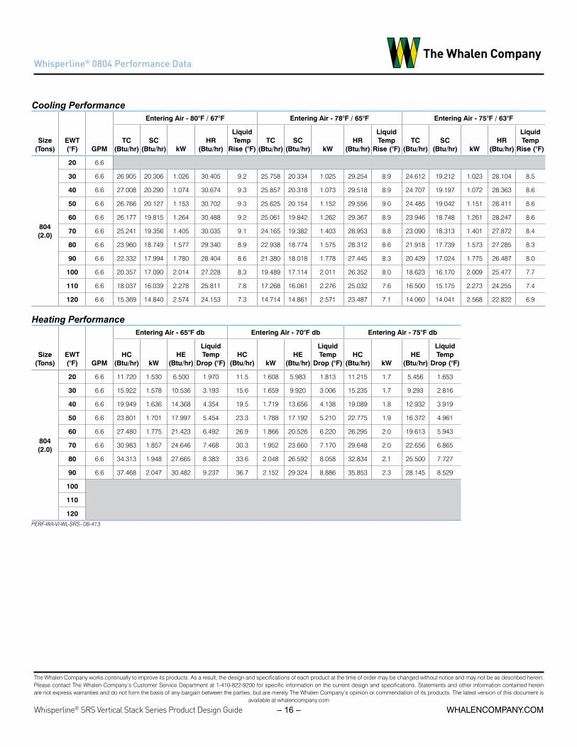
Whisperline® 0804 Performance Data
Cooling Performance
Size (Tons)
EWT (°F) GPM
Entering Air - 80°F / 67°F Entering Air - 78°F / 65°F Entering Air - 75°F / 63°F
TC (Btu/hr)
SC (Btu/hr) kW
HR (Btu/hr)
Liquid Temp
Rise (°F)TC
(Btu/hr)SC
(Btu/hr) kWHR
(Btu/hr)
Liquid Temp
Rise (°F)TC
(Btu/hr)SC
(Btu/hr) kWHR
(Btu/hr)
Liquid Temp
Rise (°F)
804 (2.0)
20 6.6
30 6.6 26.905 20.306 1.026 30.405 9.2 25.758 20.334 1.025 29.254 8.9 24.612 19.212 1.023 28.104 8.5
40 6.6 27.008 20.290 1.074 30.674 9.3 25.857 20.318 1.073 29.518 8.9 24.707 19.197 1.072 28.363 8.6
50 6.6 26.766 20.127 1.153 30.702 9.3 25.625 20.154 1.152 29.556 9.0 24.485 19.042 1.151 28.411 8.6
60 6.6 26.177 19.815 1.264 30.488 9.2 25.061 19.842 1.262 29.367 8.9 23.946 18.748 1.261 28.247 8.6
70 6.6 25.241 19.356 1.405 30.035 9.1 24.165 19.382 1.403 28.953 8.8 23.090 18.313 1.401 27.872 8.4
80 6.6 23.960 18.749 1.577 29.340 8.9 22.938 18.774 1.575 28.312 8.6 21.918 17.739 1.573 27.285 8.3
90 6.6 22.332 17.994 1.780 28.404 8.6 21.380 18.018 1.778 27.445 8.3 20.429 17.024 1.775 26.487 8.0
100 6.6 20.357 17.090 2.014 27.228 8.3 19.489 17.114 2.011 26.352 8.0 18.623 16.170 2.009 25.477 7.7
110 6.6 18.037 16.039 2.278 25.811 7.8 17.268 16.061 2.276 25.032 7.6 16.500 15.175 2.273 24.255 7.4
120 6.6 15.369 14.840 2.574 24.153 7.3 14.714 14.861 2.571 23.487 7.1 14.060 14.041 2.568 22.822 6.9
Heating Performance
Size (Tons)
EWT (°F) GPM
Entering Air - 65°F db Entering Air - 70°F db Entering Air - 75°F db
HC (Btu/hr) kW
HE (Btu/hr)
Liquid Temp
Drop (°F)HC
(Btu/hr) kWHE
(Btu/hr)
Liquid Temp
Drop (°F)HC
(Btu/hr) kWHE
(Btu/hr)
Liquid Temp
Drop (°F)
804 (2.0)
20 6.6 11.720 1.530 6.500 1.970 11.5 1.608 5.983 1.813 11.215 1.7 5.456 1.653
30 6.6 15.922 1.578 10.536 3.193 15.6 1.659 9.920 3.006 15.235 1.7 9.293 2.816
40 6.6 19.949 1.636 14.368 4.354 19.5 1.719 13.656 4.138 19.089 1.8 12.932 3.919
50 6.6 23.801 1.701 17.997 5.454 23.3 1.788 17.192 5.210 22.775 1.9 16.372 4.961
60 6.6 27.480 1.775 21.423 6.492 26.9 1.866 20.526 6.220 26.295 2.0 19.613 5.943
70 6.6 30.983 1.857 24.646 7.468 30.3 1.952 23.660 7.170 29.648 2.0 22.656 6.865
80 6.6 34.313 1.948 27.665 8.383 33.6 2.048 26.592 8.058 32.834 2.1 25.500 7.727
90 6.6 37.468 2.047 30.482 9.237 36.7 2.152 29.324 8.886 35.853 2.3 28.145 8.529
100
110
120PERF-WA-VI-WL-SRS- 08-413

The Whalen Company works continually to improve its products. As a result, the design and specifications of each product at the time of order may be changed without notice and may not be as described herein. Please contact The Whalen Company’s Customer Service Department at 1-410-822-9200 for specific information on the current design and specifications. Statements and other information contained herein are not express warranties and do not form the basis of any bargain between the parties, but are merely The Whalen Company’s opinion or commendation of its products. The latest version of this document is
available at whalencompany.com
whalencompany.comWhisperline® SRS Vertical Stack Series Product Design Guide – 17 –
Whisperline® 1004 Performance Data
Cooling Performance
Size (Tons)
EWT (°F) GPM
Entering Air - 80°F / 67°F Entering Air - 78°F / 65°F Entering Air - 75°F / 63°F
TC (Btu/hr)
SC (Btu/hr) kW
HR (Btu/hr)
Liquid Temp
Rise (°F)TC
(Btu/hr)SC
(Btu/hr) kWHR
(Btu/hr)
Liquid Temp
Rise (°F)TC
(Btu/hr)SC
(Btu/hr) kWHR
(Btu/hr)
Liquid Temp
Rise (°F)
1004 (2.5)
20 7.4
30 7.4 30.239 18.539 1.271 34.576 9.3 28.950 18.564 1.270 33.282 9.0 27.662 17.540 1.268 31.989 8.6
40 7.4 31.059 19.997 1.320 35.563 9.6 29.735 20.024 1.318 34.233 9.3 28.412 18.920 1.317 32.905 8.9
50 7.4 31.437 21.038 1.401 36.216 9.8 30.097 21.067 1.399 34.870 9.4 28.758 19.905 1.397 33.526 9.1
60 7.4 31.372 21.662 1.514 36.537 9.9 30.035 21.691 1.512 35.193 9.5 28.699 20.494 1.510 33.851 9.1
70 7.4 30.866 21.867 1.658 36.524 9.9 29.550 21.897 1.656 35.202 9.5 28.235 20.689 1.654 33.881 9.2
80 7.4 29.916 21.655 1.835 36.179 9.8 28.641 21.685 1.833 34.896 9.4 27.367 20.489 1.831 33.615 9.1
90 7.4 28.525 21.026 2.044 35.500 9.6 27.309 21.055 2.042 34.276 9.3 26.094 19.893 2.039 33.053 8.9
100 7.4 26.691 19.979 2.285 34.489 9.3 25.553 20.006 2.282 33.341 9.0 24.417 18.903 2.280 32.195 8.7
110 7.4 24.415 18.514 2.558 33.144 9.0 23.374 18.540 2.555 32.093 8.7 22.335 17.517 2.552 31.042 8.4
120 7.4 21.697 16.632 2.863 31.466 8.5 20.772 16.655 2.860 30.529 8.3 19.848 15.736 2.856 29.594 8.0
Heating Performance
Size (Tons)
EWT (°F) GPM
Entering Air - 65°F db Entering Air - 70°F db Entering Air - 75°F db
HC (Btu/hr) kW
HE (Btu/hr)
Liquid Temp
Drop (°F)HC
(Btu/hr) kWHE
(Btu/hr)
Liquid Temp
Drop (°F)HC
(Btu/hr) kWHE
(Btu/hr)
Liquid Temp
Drop (°F)
1004 (2.5)
20 7.4 13.697 2.024 6.789 1.835 13.4 2.128 6.144 1.660 13.106 2.2 5.486 1.483
30 7.4 20.650 2.033 13.714 3.707 20.2 2.136 12.919 3.492 19.759 2.2 12.108 3.272
40 7.4 26.517 2.045 19.538 5.281 25.9 2.150 18.615 5.031 25.374 2.3 17.675 4.777
50 7.4 31.298 2.062 24.261 6.557 30.6 2.168 23.233 6.279 29.949 2.3 22.186 5.996
60 7.4 34.995 2.084 27.884 7.536 34.2 2.190 26.773 7.236 33.486 2.3 25.641 6.930
70 7.4 37.605 2.110 30.405 8.218 36.8 2.218 29.234 7.901 35.984 2.3 28.041 7.579
80 7.4 39.130 2.141 31.825 8.601 38.3 2.250 30.616 8.275 37.443 2.4 29.384 7.942
90 7.4 39.570 2.176 32.145 8.688 38.7 2.287 30.920 8.357 37.864 2.4 29.673 8.020
100
110
120PERF-WA-VI-WL-SRS- 10-113

The Whalen Company works continually to improve its products. As a result, the design and specifications of each product at the time of order may be changed without notice and may not be as described herein. Please contact The Whalen Company’s Customer Service Department at 1-410-822-9200 for specific information on the current design and specifications. Statements and other information contained herein are not express warranties and do not form the basis of any bargain between the parties, but are merely The Whalen Company’s opinion or commendation of its products. The latest version of this document is
available at whalencompany.com
Whisperline® SRS Vertical Stack Series Product Design Guide whalencompany.com– 18 –
Whisperline® 1204 Performance Data
Cooling Performance
Size (Tons)
EWT (°F) GPM
Entering Air - 80°F / 67°F Entering Air - 78°F / 65°F Entering Air - 75°F / 63°F
TC (Btu/hr)
SC (Btu/hr) kW
HR (Btu/hr)
Liquid Temp
Rise (°F)TC
(Btu/hr)SC
(Btu/hr) kWHR
(Btu/hr)
Liquid Temp
Rise (°F)TC
(Btu/hr)SC
(Btu/hr) kWHR
(Btu/hr)
Liquid Temp
Rise (°F)
1204 (3.0)
20 8
30 8 39.759 28.452 1.536 45.001 11.250 38.064 28.491 1.535 43.300 10.825 36.371 26.919 1.533 41.601 10.400
40 8 39.089 28.318 1.609 44.579 11.1 37.422 28.357 1.607 42.906 10.7 35.758 26.793 1.605 41.235 10.3
50 8 38.152 28.021 1.723 44.030 11.0 36.526 28.059 1.720 42.396 10.6 34.901 26.512 1.718 40.765 10.2
60 8 36.950 27.561 1.877 43.353 10.8 35.374 27.599 1.874 41.770 10.4 33.801 26.076 1.872 40.189 10.0
70 8 35.481 26.938 2.072 42.550 10.6 33.968 26.975 2.069 41.028 10.3 32.458 25.487 2.067 39.509 9.9
80 8 33.746 26.151 2.307 41.618 10.4 32.308 26.187 2.304 40.170 10.0 30.871 24.742 2.302 38.724 9.7
90 8 31.745 25.202 2.583 40.560 10.1 30.392 25.236 2.580 39.196 9.8 29.040 23.844 2.577 37.834 9.5
100 8 29.478 24.089 2.900 39.374 9.8 28.221 24.122 2.897 38.105 9.5 26.966 22.791 2.893 36.838 9.2
110 8 26.945 22.813 3.258 38.061 9.5 25.796 22.844 3.254 36.899 9.2 24.649 21.584 3.250 35.738 8.9
120 8 24.146 21.374 3.656 36.621 9.2 23.116 21.403 3.652 35.576 8.9 22.088 20.222 3.647 34.533 8.6
Heating Performance
Size (Tons)
EWT (°F) GPM
Entering Air - 65°F db Entering Air - 70°F db Entering Air - 75°F db
HC (Btu/hr) kW
HE (Btu/hr)
Liquid Temp
Drop (°F)HC
(Btu/hr) kWHE
(Btu/hr)
Liquid Temp
Drop (°F)HC
(Btu/hr) kWHE
(Btu/hr)
Liquid Temp Drop (°F)
1204 (3.0)
20 8 21.147 1.980 14.390 3.597 20.7 2.082 13.593 3.398 20.235 2.2 12.780 3.195
30 8 26.222 2.079 19.128 4.782 25.7 2.185 18.206 4.551 25.091 2.3 17.266 4.316
40 8 31.057 2.173 23.643 5.911 30.4 2.284 22.601 5.650 29.718 2.4 21.539 5.385
50 8 35.655 2.263 27.933 6.983 34.9 2.378 26.777 6.694 34.118 2.5 25.599 6.400
60 8 40.013 2.349 32.000 8.000 39.2 2.468 30.735 7.684 38.288 2.6 29.447 7.362
70 8 44.133 2.430 35.842 8.960 43.2 2.554 34.475 8.619 42.231 2.7 33.083 8.271
80 8 48.015 2.507 39.459 9.865 47.0 2.635 37.996 9.499 45.945 2.8 36.506 9.126
90 8 51.658 2.581 42.853 10.713 50.6 2.712 41.299 10.325 49.431 2.8 39.717 9.929
100
110
120PERF-WA-VI-WL-SRS- 12-113

The Whalen Company works continually to improve its products. As a result, the design and specifications of each product at the time of order may be changed without notice and may not be as described herein. Please contact The Whalen Company’s Customer Service Department at 1-410-822-9200 for specific information on the current design and specifications. Statements and other information contained herein are not express warranties and do not form the basis of any bargain between the parties, but are merely The Whalen Company’s opinion or commendation of its products. The latest version of this document is
available at whalencompany.com
whalencompany.comWhisperline® SRS Vertical Stack Series Product Design Guide – 19 –
Airflow – PSC Motor
Table X: VP PSC Performance TableUnit Rated
CFMMin. CFM
Fan Option CFM at External Static Pressure (in wg.)
Option Speed 0.00 0.05 0.10 0.15 0.20 0.25 0.30 0.35 0.40 0.45 0.50
0204 (0.5) 280 170
Standard HI 294 284 273 260LO 229 221 210
High Static HI 362 351 338 323 306LO 240 227 214
0304 (0.75) 345 220
Standard HI 391 374 357 339 321LO 229 221
High Static HI 445 427 409 391 372 353LO 393 377 360 342 323
0404 (1.0) 420 280
Standard HI 465 444 424 406 389 373LO 337 305
High Statc HI 525 511 496 478 458 435 411 384LO 368 356 341 325 307 287
0504 (1.25) 540 380
Standard HI Not AvailableLO
High Statc HI 660 650 638 624 608 589 569LO 504 494 483 471 459
0604 (1.5) 655 420
Standard HI 660 650 638 624 608 589 569LO 504 494 483 471 459
High Static HI 858 850 838 825 808 788 766 741 713LO 748 745 739 730 718 703 685
0804 (2.0) 830 580
Standard HI Not Available; See Constant Torque EC MotorLO
High Static HI Not Available; See Constant Torque EC MotorLO
0814 (2.0) 830 580
Standard HI Not Available; See Constant Torque EC MotorLO
High Static HI Not Available; See Constant Torque EC MotorLO
1004 (2.5) 970 650
Standard HI Not Available; See Constant Torque EC MotorLO
High Statc HI Not Available; See Constant Torque EC MotorLO
1204 (3.0) 1170 750
Standard HI Not Available; See Constant Torque EC MotorLO
High Static HI Not Available; See Constant Torque EC MotorLO
Table 7: VP PSC Performance Table

The Whalen Company works continually to improve its products. As a result, the design and specifications of each product at the time of order may be changed without notice and may not be as described herein. Please contact The Whalen Company’s Customer Service Department at 1-410-822-9200 for specific information on the current design and specifications. Statements and other information contained herein are not express warranties and do not form the basis of any bargain between the parties, but are merely The Whalen Company’s opinion or commendation of its products. The latest version of this document is
available at whalencompany.com
Whisperline® SRS Vertical Stack Series Product Design Guide whalencompany.com– 20 –
Airflow – EC Constant Torque Motor
Unit Rated CFM
Min. CFM
Fan Option CFM at External Static Pressure (in wg.)
Option Speed 0.00 0.05 0.10 0.15 0.20 0.25 0.30 0.35 0.40 0.45 0.50
0204-xG (0.5) 280 170
EC Constant Torque
HI 354 346 330 308 278 240 196
MED HI1 320 303 280 251 217 176MED 307 290 267 238 204
MED LO2 272 247 217 181LOW 219 193
0304-xG (0.75) 345 220
EC Constant Torque
HI 443 411 378 346 315 283 252 221MED HI1 408 375 343 311 280 250 221
MED 378 352 323 291 257 220MED LO2 337 302 263 220
LOW 278 248
0404-xG (1.0) 420 280
EC Constant Torque
HI 521 493 466 439 413 386 360 334 309 283MED HI1 479 450 420 391 361 332 302
MED 445 411 378 345 312 280MED LO2 400 366 328 286
LOW 364 319 281
0504-xG (1.25) 540 380
EC Constant Torque
HI 594 579 563 546 528 509 489 468 446 423 400MED HI1 557 541 523 504 484 462 438 413 387
MED 521 504 486 464 440 414 385MED LO2 478 457 435 410 383
LOW 440 410 383
0604-xG (1.5) 655 420
EC Constant Torque
HI 723 711 698 684 670 655 639 622 604 585 566MED HI1 677 665 652 639 624 609 593 576 558 540 520
MED 588 572 555 535 513 489 463 434MED LO2 509 492 473 453 431
LOW 464 447 428
0804-xD (2.0) 830 580
EC Constant Torque
HI 966 949 931 914 897 880 863 847 830 814 798MED HI1 902 886 870 853 837 821 804 788 771 755 738
MED 848 829 810 792 773 755 737 720 702MED LO2 752 731 710 690 671 652
LOW 645 625 605 585
0814-xD (2.0) 830 580
EC Constant Torque
HI 905 887 870 854 839 825 812 800 789 779 770MED HI1 853 835 818 802 787 773 760 748 737 727 718
MED 781 762 744 727 712 697 684 672 661MED LO2 723 704 685 668 652 637 624 611 600
LOW 660 641 622 605 589
1004-xD (2.5) 970 650
EC Constant Torque
HI 1192 1175 1157 1140 1123 1106 1089 1073 1056 1040 1023MED HI1 1018 1001 983 966 949 933 916 900 884 869 853
MED 936 918 900 882 864 847 829 812 795 777 761MED LO2 845 828 811 793 776 758 741 723 705
LOW 730 713 695 676 657
1204-xD (3.0) 1170 750
EC Constant Torque
HI 1328 1313 1297 1281 1266 1250 1234 1218 1202 1186 1170MED HI1 1244 1227 1211 1194 1178 1161 1145 1129 1113 1097 1081
MED 1131 1113 1095 1077 1059 1041 1024 1006 988 971 953MED LO2 1029 1012 994 977 960 944 927 911 895
LOW 858 841 824 807 789
1 - Indicates single / high speed factory default setting
2 - Indicates dual / low speed factory default setting
Table 8: VP Blower EC Constant Torque Performance Table

The Whalen Company works continually to improve its products. As a result, the design and specifications of each product at the time of order may be changed without notice and may not be as described herein. Please contact The Whalen Company’s Customer Service Department at 1-410-822-9200 for specific information on the current design and specifications. Statements and other information contained herein are not express warranties and do not form the basis of any bargain between the parties, but are merely The Whalen Company’s opinion or commendation of its products. The latest version of this document is
available at whalencompany.com
whalencompany.comWhisperline® SRS Vertical Stack Series Product Design Guide – 21 –
Airflow – EC Constant Volume Motor
Table 9: VP Blower EC Constant Volume Performance Table
UnitRated CFM
Min. CFM
Fan Option CFM at External Static Pressure (in wg.)
Option Speed 0.00 0.05 0.10 0.15 0.20 0.25 0.30 0.35 0.40 0.45 0.50
0204 (0.5) 280 280
EC Constant Volume
Default NA
0304 (0.75) 345 345
EC Constant Volume
Default NA
0404 (1.0) 420 420
EC Constant Volume
Default 420 420 420 420 420 420 420 420 420 420 420
0504 (1.25) 540 540
EC Constant Volume
Default 540 540 540 540 540 540 540 540 540 540 540
0604 (1.5) 655 655
EC Constant Volume
Default 655 655 655 655 655 655 655 655 655 655 655
0804 (2.0) 830 830
EC Constant Volume
Default 830 830 830 830 830 830 830 830 830 830 830
0814 (2.0) 830 830
EC Constant Volume
Default 830 830 830 830 830 830 830 830 830 830 830
1004 (2.5) 970 970
EC Constant Volume
Default 970 970 970 970 970 970 970 970 970 970 970
1204 (3.0) 1170 1170
EC Constant Volume
Default 1170 1170 1170 1170 1170 1170 1170 1170 1170 1170 1170

The Whalen Company works continually to improve its products. As a result, the design and specifications of each product at the time of order may be changed without notice and may not be as described herein. Please contact The Whalen Company’s Customer Service Department at 1-410-822-9200 for specific information on the current design and specifications. Statements and other information contained herein are not express warranties and do not form the basis of any bargain between the parties, but are merely The Whalen Company’s opinion or commendation of its products. The latest version of this document is
available at whalencompany.com
Whisperline® SRS Vertical Stack Series Product Design Guide whalencompany.com– 22 –
Electrical Data – Standard PSC Motor
Table X: Whisperline Electrical data - Standard PSC Motor
Size (Tons)
Compressor Supply Blower Motor Electric Heat Single Point
Power Dual Point Power
Voltage RLA LRA QTY FLA HP Voltage kW Amps MCA MOPD Unit MCA
Unit MOPD
E-Heat MCA
E-Heat MOPD
0204-**B (0.5)
208-230/1/60
2.5 17.7 1 0.6 1/15
208/1/60
0.0 0.0 3.7 15 NA NA NA NA1.0 4.8 9.7 15 3.7 15.0 6.0 151.5 7.2 12.7 15 3.7 15.0 9.0 152.0 9.6 15.7 20 3.7 15.0 12.0 15
230/1/60
0.0 0.0 3.7 15 NA NA NA NA1.0 4.3 9.2 15 3.7 15.0 5.4 151.5 6.5 11.9 15 3.7 15.0 8.2 152.0 8.7 14.6 15 3.7 15.0 10.9 15
265/1/60 2.6 13.5 1 0.4 0.05 265/1/60
0.0 0.0 3.7 15 NA NA NA NA1.0 3.8 8.4 15 3.7 15.0 4.7 151.5 5.7 10.7 15 3.7 15.0 7.1 152.0 7.5 13.1 15 3.7 15.0 9.4 15
0304-**B (0.75)
208-230/1/60
5.1 22.0 1 0.6 0.07
208/1/60
0.0 0.0 7.0 15 NA NA NA NA1.0 4.8 13.0 15 7.0 15.0 6.0 151.5 7.2 16.0 20 7.0 15.0 9.0 152.0 9.6 19.0 20 7.0 15.0 12.0 152.5 12.0 22.0 25 7.0 15.0 15.0 203.0 14.4 25.0 30 7.0 15.0 18.0 20
230/1/60
0.0 0.0 7.0 15 NA NA NA NA1.0 4.3 12.5 15 7.0 15.0 5.4 151.5 6.5 15.2 20 7.0 15.0 8.2 152.0 8.7 17.9 20 7.0 15.0 10.9 152.5 10.9 20.6 25 7.0 15.0 13.6 153.0 13.0 23.3 25 7.0 15.0 16.3 20
265/1/60 4.5 22.0 1 0.4 0.05 265/1/60
0.0 0.0 6.0 15 NA NA NA NA1.0 3.8 10.7 15 6.0 15.0 4.7 151.5 5.7 13.1 15 6.0 15.0 7.1 152.0 7.5 15.4 20 6.0 15.0 9.4 152.5 9.4 17.8 20 6.0 15.0 11.8 153.0 11.3 20.2 25 6.0 15.0 14.2 15
0404-**B (1.0)
208-230/1/60
6.4 25.0 1 0.6 0.07
208/1/60
0.0 0.0 8.6 15 NA NA NA NA1.0 4.8 14.6 15 8.6 15.0 6.0 151.5 7.2 17.6 20 8.6 15.0 9.0 152.0 9.6 20.6 25 8.6 15.0 12.0 152.5 12.0 23.6 25 8.6 15.0 15.0 203.0 14.4 26.6 30 8.6 15.0 18.0 203.5 16.8 29.7 30 8.6 15.0 21.0 254.0 19.2 NA NA 8.6 15.0 24.0 25
230/1/60
0.0 0.0 8.6 15 NA NA NA NA1.0 4.3 14.1 15 8.6 15.0 5.4 151.5 6.5 16.8 20 8.6 15.0 8.2 152.0 8.7 19.5 20 8.6 15.0 10.9 152.5 10.9 22.2 25 8.6 15.0 13.6 153.0 13.0 24.9 25 8.6 15.0 16.3 203.5 15.2 27.6 30 8.6 15.0 19.0 204.0 17.4 NA NA 8.6 15.0 21.7 25
265/1/60 5.1 22.0 1 0.5 0.08 265/1/60
0.0 0.0 6.9 15 NA NA NA NA1.0 3.8 11.6 15 6.9 15.0 4.7 151.5 5.7 14.0 15 6.9 15.0 7.1 152.0 7.5 16.3 20 6.9 15.0 9.4 152.5 9.4 18.7 20 6.9 15.0 11.8 153.0 11.3 21.1 25 6.9 15.0 14.2 153.5 13.2 23.4 25 6.9 15.0 16.5 204.0 15.1 25.8 30 6.9 15.0 18.9 20
0504-**B (1.25)
N/A : See Electrical Data - CT Motor
Table 10: VP Electrical Data - Standard PSC Motor

The Whalen Company works continually to improve its products. As a result, the design and specifications of each product at the time of order may be changed without notice and may not be as described herein. Please contact The Whalen Company’s Customer Service Department at 1-410-822-9200 for specific information on the current design and specifications. Statements and other information contained herein are not express warranties and do not form the basis of any bargain between the parties, but are merely The Whalen Company’s opinion or commendation of its products. The latest version of this document is
available at whalencompany.com
whalencompany.comWhisperline® SRS Vertical Stack Series Product Design Guide – 23 –
Electrical Data – Standard PSC Motor
0604-**B (1.5)
208-230/1/60
7.7 38.0 1 0.9 0.08
208/1/60
0.0 0.0 10.5 15 NA NA NA NA1.0 4.8 16.5 20 10.5 15.0 6.0 151.5 7.2 19.5 25 10.5 15.0 9.0 152.0 9.6 22.5 25 10.5 15.0 12.0 152.5 12.0 25.5 30 10.5 15.0 15.0 203.0 14.4 28.5 30 10.5 15.0 18.0 203.5 16.8 NA NA 10.5 15.0 21.0 254.0 19.2 NA NA 10.5 15.0 24.0 254.5 21.6 NA NA 10.5 15.0 27.0 305.0 24.0 NA NA 10.5 15.0 30.0 355.5 26.4 NA NA 10.5 15.0 33.1 356.0 28.8 NA NA 10.5 15.0 36.1 40
230/1/60
0.0 0.0 10.5 15 NA NA NA NA1.0 4.3 16.0 20 10.5 15.0 5.4 151.5 6.5 18.7 20 10.5 15.0 8.2 152.0 8.7 21.4 25 10.5 15.0 10.9 152.5 10.9 24.1 25 10.5 15.0 13.6 153.0 13.0 26.8 30 10.5 15.0 16.3 203.5 15.2 29.5 30 10.5 15.0 19.0 204.0 17.4 NA NA 10.5 15.0 21.7 254.5 19.6 NA NA 10.5 15.0 24.5 255.0 21.7 NA NA 10.5 15.0 27.2 305.5 23.9 NA NA 10.5 15.0 29.9 306.0 26.1 NA NA 10.5 15.0 32.6 35
265/1/60 7.1 30.0 1 0.6 0.15 265/1/60
0.0 0.0 9.4 15 NA NA NA NA1.0 3.8 14.1 20 9.4 15.0 4.7 151.5 5.7 16.5 20 9.4 15.0 7.1 152.0 7.5 18.9 20 9.4 15.0 9.4 152.5 9.4 21.2 25 9.4 15.0 11.8 153.0 11.3 23.6 25 9.4 15.0 14.2 153.5 13.2 25.9 30 9.4 15.0 16.5 204.0 15.1 28.3 30 9.4 15.0 18.9 204.5 17.0 NA NA 9.4 15.0 21.2 255.0 18.9 NA NA 9.4 15.0 23.6 255.5 20.8 NA NA 9.4 15.0 25.9 306.0 22.6 NA NA 9.4 15.0 28.3 30
0804-**B (2.0)
N/A : See Electrical Data - CT Motor
0814-**C (2.0)
N/A : See Electrical Data - CT Motor
1004-**C (2.5)
N/A : See Electrical Data - CT Motor
1204-**C (3.0)
N/A : See Electrical Data - CT Motor
Size (Tons)
Compressor Supply Blower Motor Electric Heat Single Point
Power Dual Point Power
Voltage LRA QTY FLA HP Voltage kW Amps MCA MOPD Unit MCA
Unit MOPD
E-Heat MCA
E-Heat MOPDRLA

The Whalen Company works continually to improve its products. As a result, the design and specifications of each product at the time of order may be changed without notice and may not be as described herein. Please contact The Whalen Company’s Customer Service Department at 1-410-822-9200 for specific information on the current design and specifications. Statements and other information contained herein are not express warranties and do not form the basis of any bargain between the parties, but are merely The Whalen Company’s opinion or commendation of its products. The latest version of this document is
available at whalencompany.com
Whisperline® SRS Vertical Stack Series Product Design Guide whalencompany.com– 24 –
Size (Tons)
Compressor Supply Blower Motor Electric Heat Single Point
Power Dual Point Power
Voltage RLA LRA QTY FLA HP Voltage kW Amps MCA MOPD Unit MCA
Unit MOPD
E-Heat MCA
E-Heat MOPD
0204-**B (0.5)
208-230/1/60
2.5 17.7 1 0.6 1/15
208/1/60
0.0 0.0 3.7 15 NA NA NA NA1.0 4.8 9.7 15 3.7 15.0 6.0 151.5 7.2 12.7 15 3.7 15.0 9.0 152.0 9.6 15.7 20 3.7 15.0 12.0 15
230/1/60
0.0 0.0 3.7 15 NA NA NA NA1.0 4.3 9.2 15 3.7 15.0 5.4 151.5 6.5 11.9 15 3.7 15.0 8.2 152.0 8.7 14.6 15 3.7 15.0 10.9 15
265/1/60 2.6 13.5 1 0.4 0.05 265/1/60
0.0 0.0 3.7 15 NA NA NA NA1.0 3.8 8.4 15 3.7 15.0 4.7 151.5 5.7 10.7 15 3.7 15.0 7.1 152.0 7.5 13.1 15 3.7 15.0 9.4 15
0304-**B (0.75)
208-230/1/60
5.1 22.0 1 0.6
208/1/60
0.0 0.0 7.0 15 NA NA NA NA1.0 4.8 13.0 15 7.0 15.0 6.0 151.5 7.2 16.0 20 7.0 15.0 9.0 152.0 9.6 19.0 20 7.0 15.0 12.0 152.5 12.0 22.0 25 7.0 15.0 15.0 203.0 14.4 25.0 30 7.0 15.0 18.0 20
230/1/60
0.0 0.0 7.0 15 NA NA NA NA1.0 4.3 12.5 15 7.0 15.0 5.4 151.5 6.5 15.2 20 7.0 15.0 8.2 152.0 8.7 17.9 20 7.0 15.0 10.9 152.5 10.9 20.6 25 7.0 15.0 13.6 153.0 13.0 23.3 25 7.0 15.0 16.3 20
265/1/60 4.5 22.0 1 0.5 0.08 265/1/60
0.0 0.0 6.1 15 NA NA NA NA1.0 3.8 10.8 15 6.1 15.0 4.7 151.5 5.7 13.2 15 6.1 15.0 7.1 152.0 7.5 15.5 20 6.1 15.0 9.4 152.5 9.4 17.9 20 6.1 15.0 11.8 153.0 11.3 20.3 25 6.1 15.0 14.2 15
404-**B
208-230/1/60
6.4 25.0 1 0.9
208/1/60
0.0 0.0 8.9 15 NA NA NA NA1.0 4.8 14.9 20 8.9 15.0 6.0 151.5 7.2 17.9 20 8.9 15.0 9.0 152.0 9.6 20.9 25 8.9 15.0 12.0 152.5 12.0 23.9 25 8.9 15.0 15.0 203.0 14.4 26.9 30 8.9 15.0 18.0 203.5 16.8 30.0 30 8.9 15.0 21.0 254.0 19.2 NA NA 8.9 15.0 24.0 25
230/1/60
0.0 0.0 8.9 15 NA NA NA NA1.0 4.3 14.4 15 8.9 15.0 5.4 151.5 6.5 17.1 20 8.9 15.0 8.2 152.0 8.7 19.8 20 8.9 15.0 10.9 152.5 10.9 22.5 25 8.9 15.0 13.6 153.0 13.0 25.2 30 8.9 15.0 16.3 203.5 15.2 27.9 30 8.9 15.0 19.0 204.0 17.4 NA NA 8.9 15.0 21.7 25
265/1/60 5.1 22.0 1 0.6 0.15 265/1/60
0.0 0.0 7.0 15 NA NA NA NA1.0 3.8 11.7 15 7.0 15.0 4.7 151.5 5.7 14.1 15 7.0 15.0 7.1 152.0 7.5 16.4 20 7.0 15.0 9.4 152.5 9.4 18.8 20 7.0 15.0 11.8 153.0 11.3 21.2 25 7.0 15.0 14.2 153.5 13.2 23.5 25 7.0 15.0 16.5 204.0 15.1 25.9 30 7.0 15.0 18.9 20
Electrical Data – High Static PSC Motor
Table 11: VP Electrical Data – High Static PSC Motor

The Whalen Company works continually to improve its products. As a result, the design and specifications of each product at the time of order may be changed without notice and may not be as described herein. Please contact The Whalen Company’s Customer Service Department at 1-410-822-9200 for specific information on the current design and specifications. Statements and other information contained herein are not express warranties and do not form the basis of any bargain between the parties, but are merely The Whalen Company’s opinion or commendation of its products. The latest version of this document is
available at whalencompany.com
whalencompany.comWhisperline® SRS Vertical Stack Series Product Design Guide – 25 –
0504-**B (1.25)
208-230/1/60
4.8 26.0 1 0.9
208/1/60
0.0 0.0 6.91 15 NA NA NA NA1.0 4.8 12.92 15 6.9 15.0 6.0 151.5 7.2 15.92 20 6.9 15.0 9.0 152.0 9.6 18.93 20 6.9 15.0 12.0 152.5 12.0 21.93 25 6.9 15.0 15.0 203.0 14.4 24.94 25 6.9 15.0 18.0 203.5 16.8 27.94 30 6.9 15.0 21.0 254.0 19.2 NA NA 6.9 15.0 24.0 254.5 21.6 NA NA 6.9 15.0 27.0 305.0 24.0 NA NA 6.9 15.0 30.0 35
230/1/60
0.0 0.0 6.9 15 NA NA NA NA1.0 4.3 12.3 15 6.9 15.0 5.4 151.5 6.5 15.1 20 6.9 15.0 8.2 152.0 8.7 17.8 20 6.9 15.0 10.9 152.5 10.9 20.5 25 6.9 15.0 13.6 153.0 13.0 23.2 25 6.9 15.0 16.3 203.5 15.2 25.9 30 6.9 15.0 19.0 204.0 17.4 28.7 30 6.9 15.0 21.7 254.5 19.6 NA NA 6.9 15.0 24.5 255.0 21.7 NA NA 6.9 15.0 27.2 30
265/1/60 4.2 25.0 1 0.6 0.15 265/1/60
0.0 0.0 5.8 15 NA NA NA NA1.0 3.8 10.5 15 5.8 15.0 4.7 151.5 5.7 12.9 15 5.8 15.0 7.1 152.0 7.5 15.2 20 5.8 15.0 9.4 152.5 9.4 17.6 20 5.8 15.0 11.8 153.0 11.3 20.0 20 5.8 15.0 14.2 153.5 13.2 22.3 25 5.8 15.0 16.5 204.0 15.1 24.7 25 5.8 15.0 18.9 204.5 17.0 27.0 30 5.8 15.0 21.2 255.0 18.9 29.4 30 5.8 15.0 23.6 25
0604-**B (1.5)
208-230/1/60
7.7 38.0 1 1.5 1/5
208/1/60
0.0 0.0 11.1 15 NA NA NA NA1.0 4.8 17.1 20 11.1 15.0 6.0 151.5 7.2 20.1 25 11.1 15.0 9.0 152.0 9.6 23.1 25 11.1 15.0 12.0 152.5 12.0 26.1 30 11.1 15.0 15.0 203.0 14.4 29.1 30 11.1 15.0 18.0 203.5 16.8 NA NA 11.1 15.0 21.0 254.0 19.2 NA NA 11.1 15.0 24.0 254.5 21.6 NA NA 11.1 15.0 27.0 305.0 24.0 NA NA 11.1 15.0 30.0 355.5 26.4 NA NA 11.1 15.0 33.1 356.0 28.8 NA NA 11.1 15.0 36.1 40
230/1/60
0.0 0.0 11.1 15 NA NA NA NA1.0 4.3 16.6 20 11.1 15.0 5.4 151.5 6.5 19.3 25 11.1 15.0 8.2 152.0 8.7 22.0 25 11.1 15.0 10.9 152.5 10.9 24.7 25 11.1 15.0 13.6 153.0 13.0 27.4 30 11.1 15.0 16.3 203.5 15.2 NA NA 11.1 15.0 19.0 204.0 17.4 NA NA 11.1 15.0 21.7 254.5 19.6 NA NA 11.1 15.0 24.5 255.0 21.7 NA NA 11.1 15.0 27.2 305.5 23.9 NA NA 11.1 15.0 29.9 306.0 26.1 NA NA 11.1 15.0 32.6 35
265/1/60 7.1 30.0 1 0.9 0.17 265/1/60
0.0 0.0 9.7 15 NA NA NA NA1.0 3.8 14.4 20 9.7 15.0 4.7 151.5 5.7 16.8 20 9.7 15.0 7.1 152.0 7.5 19.2 20 9.7 15.0 9.4 152.5 9.4 21.5 25 9.7 15.0 11.8 153.0 11.3 23.9 25 9.7 15.0 14.2 153.5 13.2 26.2 30 9.7 15.0 16.5 204.0 15.1 28.6 30 9.7 15.0 18.9 204.5 17.0 NA NA 9.7 15.0 21.2 255.0 18.9 NA NA 9.7 15.0 23.6 255.5 20.8 NA NA 9.7 15.0 25.9 306.0 22.6 NA NA 9.7 15.0 28.3 30
Electrical Data – High Static PSC Motor
Size (Tons)
Compressor Supply Blower Motor Electric Heat Single Point
Power Dual Point Power
Voltage RLA LRA QTY FLA HP Voltage kW Amps MCA MOPD Unit MCA
Unit MOPD
E-Heat MCA
E-Heat MOPD

The Whalen Company works continually to improve its products. As a result, the design and specifications of each product at the time of order may be changed without notice and may not be as described herein. Please contact The Whalen Company’s Customer Service Department at 1-410-822-9200 for specific information on the current design and specifications. Statements and other information contained herein are not express warranties and do not form the basis of any bargain between the parties, but are merely The Whalen Company’s opinion or commendation of its products. The latest version of this document is
available at whalencompany.com
Whisperline® SRS Vertical Stack Series Product Design Guide whalencompany.com– 26 –
0804-**B (2.0) N/A : See Electrical Data - CT Motor
0814-**C (2.0) N/A : See Electrical Data - CT Motor
1004-**C (2.5) N/A : See Electrical Data - CT Motor
1204-**C (3.0) N/A : See Electrical Data - CT Motor
Electrical Data – High Static PSC Motor
Size (Tons)
Compressor Supply Blower Motor Electric Heat Single Point
Power Dual Point Power
Voltage RLA LRA QTY FLA HP Voltage kW Amps MCA MOPD Unit MCA
Unit MOPD
E-Heat MCA
E-Heat MOPD

The Whalen Company works continually to improve its products. As a result, the design and specifications of each product at the time of order may be changed without notice and may not be as described herein. Please contact The Whalen Company’s Customer Service Department at 1-410-822-9200 for specific information on the current design and specifications. Statements and other information contained herein are not express warranties and do not form the basis of any bargain between the parties, but are merely The Whalen Company’s opinion or commendation of its products. The latest version of this document is
available at whalencompany.com
whalencompany.comWhisperline® SRS Vertical Stack Series Product Design Guide – 27 –
Electrical Data – Constant Torque EC Motor
Table X: Whisperline Electrical data - Constant Torque EC Motor
Size (Tons)
Compressor Supply Blower Motor Electric Heat Single Point Power Dual Point Power
Voltage RLA LRA QTY FLA HP Voltage kW Amps MCA MOPD Unit MCA
Unit MOPD
E-Heat MCA
E-Heat MOPD
0204-**B (0.5)
208-230/1/60
2.5 17.7 1 2.2 1/4
208/1/60
0.0 0.0 5.3 15 NA NA NA NA1.0 4.8 11.3 15 5.3 15.0 6.0 151.5 7.2 14.3 15 5.3 15.0 9.0 152.0 9.6 17.3 20 5.3 15.0 12.0 15
230/1/60
0.0 0.0 5.3 15 NA NA NA NA1.0 4.3 10.8 15 5.3 15.0 5.4 151.5 6.5 13.5 15 5.3 15.0 8.2 152.0 8.7 16.2 20 5.3 15.0 10.9 15
265/1/60 2.6 13.5 1 2.2 1/4 265/1/60
0.0 0.0 5.5 15 NA NA NA NA1.0 3.8 10.2 15 5.5 15.0 4.7 151.5 5.7 12.5 15 5.5 15.0 7.1 152.0 7.5 14.9 15 5.5 15.0 9.4 15
0304-**B (0.75)
208-230/1/60
5.1 22.0 1 2.2 1/4
208/1/60
0.0 0.0 8.6 15 NA NA NA NA1.0 4.8 14.6 15 8.6 15.0 6.0 151.5 7.2 17.6 20 8.6 15.0 9.0 152.0 9.6 20.6 25 8.6 15.0 12.0 152.5 12.0 23.6 25 8.6 15.0 15.0 203.0 14.4 26.6 30 8.6 15.0 18.0 20
230/1/60
0.0 0.0 8.6 15 NA NA NA NA1.0 4.3 14.1 15 8.6 15.0 5.4 151.5 6.5 16.8 20 8.6 15.0 8.2 152.0 8.7 19.5 20 8.6 15.0 10.9 152.5 10.9 22.2 25 8.6 15.0 13.6 153.0 13.0 24.9 25 8.6 15.0 16.3 20
265/1/60 4.5 22.0 1 2.2 1/4 265/1/60
0.0 0.0 7.8 15 NA NA NA NA1.0 3.8 12.5 15 7.8 15.0 4.7 151.5 5.7 14.9 15 7.8 15.0 7.1 152.0 7.5 17.2 20 7.8 15.0 9.4 152.5 9.4 19.6 20 7.8 15.0 11.8 153.0 11.3 22.0 25 7.8 15.0 14.2 15
0404-**B (1.0)
208-230/1/60
6.4 25.0 1 2.2 1/4
208/1/60
0.0 0.0 10.2 15 NA NA NA NA1.0 4.8 16.2 20 10.2 15.0 6.0 151.5 7.2 19.2 20 10.2 15.0 9.0 152.0 9.6 22.2 25 10.2 15.0 12.0 152.5 12.0 25.2 30 10.2 15.0 15.0 203.0 14.4 28.2 30 10.2 15.0 18.0 203.5 16.8 NA NA 10.2 15.0 21.0 254.0 19.2 NA NA 10.2 15.0 24.0 25
230/1/60
0.0 0.0 10.2 15 NA NA NA NA1.0 4.3 15.7 20 10.2 15.0 5.4 151.5 6.5 18.4 20 10.2 15.0 8.2 152.0 8.7 21.1 25 10.2 15.0 10.9 152.5 10.9 23.8 25 10.2 15.0 13.6 153.0 13.0 26.5 30 10.2 15.0 16.3 203.5 15.2 29.2 30 10.2 15.0 19.0 204.0 17.4 NA NA 10.2 15.0 21.7 25
265/1/60 5.1 22.0 1 2.2 1/4 265/1/60
0.0 0.0 8.6 15 NA NA NA NA1.0 3.8 13.3 15 8.6 15.0 4.7 151.5 5.7 15.7 20 8.6 15.0 7.1 152.0 7.5 18.0 20 8.6 15.0 9.4 152.5 9.4 20.4 25 8.6 15.0 11.8 153.0 11.3 22.8 25 8.6 15.0 14.2 153.5 13.2 25.1 30 8.6 15.0 16.5 204.0 15.1 27.5 30 8.6 15.0 18.9 20
Table 12: VP Electrical Data - Constant Torque EC Motor

The Whalen Company works continually to improve its products. As a result, the design and specifications of each product at the time of order may be changed without notice and may not be as described herein. Please contact The Whalen Company’s Customer Service Department at 1-410-822-9200 for specific information on the current design and specifications. Statements and other information contained herein are not express warranties and do not form the basis of any bargain between the parties, but are merely The Whalen Company’s opinion or commendation of its products. The latest version of this document is
available at whalencompany.com
Whisperline® SRS Vertical Stack Series Product Design Guide whalencompany.com– 28 –
Electrical Data – Constant Torque EC Motor
0504-**B (1.25)
208-230/1/60
4.8 26.0 1 2.2 1/4
208/1/60
0.0 0.0 8.2 15 NA NA NA NA1.0 4.8 14.2 15 8.2 15.0 6.0 151.5 7.2 17.2 20 8.2 15.0 9.0 152.0 9.6 20.2 25 8.2 15.0 12.0 152.5 12.0 23.2 25 8.2 15.0 15.0 203.0 14.4 26.2 30 8.2 15.0 18.0 203.5 16.8 29.2 30 8.2 15.0 21.0 254.0 19.2 NA NA 8.2 15.0 24.0 254.5 21.6 NA NA 8.2 15.0 27.0 305.0 24.0 NA NA 8.2 15.0 30.0 35
230/1/60
0.0 0.0 8.2 15 NA NA NA NA1.0 4.3 13.6 15 8.2 15.0 5.4 151.5 6.5 16.4 20 8.2 15.0 8.2 152.0 8.7 19.1 20 8.2 15.0 10.9 152.5 10.9 21.8 25 8.2 15.0 13.6 153.0 13.0 24.5 25 8.2 15.0 16.3 203.5 15.2 27.2 30 8.2 15.0 19.0 204.0 17.4 30.0 30 8.2 15.0 21.7 254.5 19.6 NA NA 8.2 15.0 24.5 255.0 21.7 NA NA 8.2 15.0 27.2 30
265/1/60 4.2 25.0 1 2.2 1/4 265/1/60
0.0 0.0 7.4 15 NA NA NA NA1.0 3.8 12.1 15 7.4 15.0 4.7 151.5 5.7 14.5 15 7.4 15.0 7.1 152.0 7.5 16.8 20 7.4 15.0 9.4 152.5 9.4 19.2 20 7.4 15.0 11.8 153.0 11.3 21.6 25 7.4 15.0 14.2 153.5 13.2 23.9 25 7.4 15.0 16.5 204.0 15.1 26.3 30 7.4 15.0 18.9 204.5 17.0 28.6 30 7.4 15.0 21.2 255.0 18.9 NA NA 7.4 15.0 23.6 25
0604-**B (1.5)
208-230/1/60
7.7 38.0 1 2.2 1/4
208/1/60
0.0 0.0 11.8 15 NA NA NA NA1.0 4.8 17.8 20 11.8 15.0 6.0 151.5 7.2 20.8 25 11.8 15.0 9.0 152.0 9.6 23.8 25 11.8 15.0 12.0 152.5 12.0 26.8 30 11.8 15.0 15.0 203.0 14.4 29.8 30 11.8 15.0 18.0 203.5 16.8 NA NA 11.8 15.0 21.0 254.0 19.2 NA NA 11.8 15.0 24.0 254.5 21.6 NA NA 11.8 15.0 27.0 305.0 24.0 NA NA 11.8 15.0 30.0 355.5 26.4 NA NA 11.8 15.0 33.1 356.0 28.8 NA NA 11.8 15.0 36.1 40
230/1/60
0.0 0.0 11.8 15 NA NA NA NA1.0 4.3 17.3 20 11.8 15.0 5.4 151.5 6.5 20.0 25 11.8 15.0 8.2 152.0 8.7 22.7 25 11.8 15.0 10.9 152.5 10.9 25.4 30 11.8 15.0 13.6 153.0 13.0 28.1 30 11.8 15.0 16.3 203.5 15.2 NA NA 11.8 15.0 19.0 204.0 17.4 NA NA 11.8 15.0 21.7 254.5 19.6 NA NA 11.8 15.0 24.5 255.0 21.7 NA NA 11.8 15.0 27.2 305.5 23.9 NA NA 11.8 15.0 29.9 306.0 26.1 NA NA 11.8 15.0 32.6 35
265/1/60 7.1 30.0 1 2.2 1/4 265/1/60
0.0 0.0 11.0 15 NA NA NA NA1.0 3.8 15.7 20 11.0 15.0 4.7 151.5 5.7 18.1 20 11.0 15.0 7.1 152.0 7.5 20.5 25 11.0 15.0 9.4 152.5 9.4 22.8 25 11.0 15.0 11.8 153.0 11.3 25.2 30 11.0 15.0 14.2 153.5 13.2 27.5 30 11.0 15.0 16.5 204.0 15.1 29.9 30 11.0 15.0 18.9 204.5 17.0 NA NA 11.0 15.0 21.2 255.0 18.9 NA NA 11.0 15.0 23.6 255.5 20.8 NA NA 11.0 15.0 25.9 306.0 22.6 NA NA 11.0 15.0 28.3 30
Size (Tons)
Compressor Supply Blower Motor Electric Heat Single Point Power Dual Point Power
Voltage RLA LRA QTY FLA HP Voltage kW Amps MCA MOPD Unit MCA
Unit MOPD
E-Heat MCA
E-Heat MOPD

The Whalen Company works continually to improve its products. As a result, the design and specifications of each product at the time of order may be changed without notice and may not be as described herein. Please contact The Whalen Company’s Customer Service Department at 1-410-822-9200 for specific information on the current design and specifications. Statements and other information contained herein are not express warranties and do not form the basis of any bargain between the parties, but are merely The Whalen Company’s opinion or commendation of its products. The latest version of this document is
available at whalencompany.com
whalencompany.comWhisperline® SRS Vertical Stack Series Product Design Guide – 29 –
Electrical Data – Constant Torque EC Motor
0804-**B (2.0)
208-230/1/60
10.3 43.0 1 4.6 1/2
208/1/60
0.0 0.0 17.4 25 NA NA NA NA1.0 4.8 23.4 30 17.4 25.0 6.0 151.5 7.2 26.4 30 17.4 25.0 9.0 152.0 9.6 29.4 35 17.4 25.0 12.0 152.5 12.0 NA NA 17.4 25.0 15.0 203.0 14.4 NA NA 17.4 25.0 18.0 203.5 16.8 NA NA 17.4 25.0 21.0 254.0 19.2 NA NA 17.4 25.0 24.0 254.5 21.6 NA NA 17.4 25.0 27.0 305.0 24.0 NA NA 17.4 25.0 30.0 355.5 26.4 NA NA 17.4 25.0 33.1 356.0 28.8 NA NA 17.4 25.0 36.1 406.5 31.3 NA NA 17.4 25.0 39.1 407.0 33.7 NA NA 17.4 25.0 42.1 457.5 36.1 NA NA 17.4 25.0 45.1 508.0 38.5 NA NA 17.4 25.0 48.1 50
230/1/60
0.0 0.0 17.4 25 NA NA NA NA1.0 4.3 22.9 30 17.4 25.0 5.4 151.5 6.5 25.6 30 17.4 25.0 8.2 152.0 8.7 28.3 35 17.4 25.0 10.9 152.5 10.9 NA NA 17.4 25.0 13.6 153.0 13.0 NA NA 17.4 25.0 16.3 203.5 15.2 NA NA 17.4 25.0 19.0 204.0 17.4 NA NA 17.4 25.0 21.7 254.5 19.6 NA NA 17.4 25.0 24.5 255.0 21.7 NA NA 17.4 25.0 27.2 305.5 23.9 NA NA 17.4 25.0 29.9 306.0 26.1 NA NA 17.4 25.0 32.6 356.5 28.3 NA NA 17.4 25.0 35.3 407.0 30.4 NA NA 17.4 25.0 38.0 407.5 32.6 NA NA 17.4 25.0 40.8 458.0 34.8 NA NA 17.4 25.0 43.5 45
265/1/60 8.3 54.0 1 3.2 1/2 265/1/60
0.0 0.0 13.6 20 NA NA NA NA1.0 3.8 18.3 25 13.6 20.0 4.7 151.5 5.7 20.7 25 13.6 20.0 7.1 152.0 7.5 23.0 25 13.6 20.0 9.4 152.5 9.4 25.4 30 13.6 20.0 11.8 153.0 11.3 27.7 30 13.6 20.0 14.2 153.5 13.2 NA NA 13.6 20.0 16.5 204.0 15.1 NA NA 13.6 20.0 18.9 204.5 17.0 NA NA 13.6 20.0 21.2 255.0 18.9 NA NA 13.6 20.0 23.6 255.5 20.8 NA NA 13.6 20.0 25.9 306.0 22.6 NA NA 13.6 20.0 28.3 306.5 24.5 NA NA 13.6 20.0 30.7 357.0 26.4 NA NA 13.6 20.0 33.0 357.5 28.3 NA NA 13.6 20.0 35.4 408.0 30.2 NA NA 13.6 20.0 37.7 40
Size (Tons)
Compressor Supply Blower Motor Electric Heat Single Point Power Dual Point Power
Voltage RLA LRA QTY FLA HP Voltage kW Amps MCA MOPD Unit MCA
Unit MOPD
E-Heat MCA
E-Heat MOPD

The Whalen Company works continually to improve its products. As a result, the design and specifications of each product at the time of order may be changed without notice and may not be as described herein. Please contact The Whalen Company’s Customer Service Department at 1-410-822-9200 for specific information on the current design and specifications. Statements and other information contained herein are not express warranties and do not form the basis of any bargain between the parties, but are merely The Whalen Company’s opinion or commendation of its products. The latest version of this document is
available at whalencompany.com
Whisperline® SRS Vertical Stack Series Product Design Guide whalencompany.com– 30 –
Electrical Data – Constant Torque EC Motor
0814-**C (2.0)
208-230/1/60
7.4 43.0 1 4.6 1/2
208/1/60
0.0 0.0 13.9 20 NA NA NA NA1.0 4.8 19.9 25 13.9 20.0 6.0 151.5 7.2 22.9 25 13.9 20.0 9.0 152.0 9.6 25.9 30 13.9 20.0 12.0 152.5 12.0 28.9 30 13.9 20.0 15.0 203.0 14.4 NA NA 13.9 20.0 18.0 203.5 16.8 NA NA 13.9 20.0 21.0 254.0 19.2 NA NA 13.9 20.0 24.0 254.5 21.6 NA NA 13.9 20.0 27.0 305.0 24.0 NA NA 13.9 20.0 30.0 355.5 26.4 NA NA 13.9 20.0 33.1 356.0 28.8 NA NA 13.9 20.0 36.1 406.5 31.3 NA NA 13.9 20.0 39.1 407.0 33.7 NA NA 13.9 20.0 42.1 457.5 36.1 NA NA 13.9 20.0 45.1 508.0 38.5 NA NA 13.9 20.0 48.1 50
230/1/60
0.0 0.0 13.9 20 NA NA NA NA1.0 4.3 19.3 25 13.9 20.0 5.4 151.5 6.5 22.0 25 13.9 20.0 8.2 152.0 8.7 24.7 25 13.9 20.0 10.9 152.5 10.9 27.4 30 13.9 20.0 13.6 153.0 13.0 NA NA 13.9 20.0 16.3 203.5 15.2 NA NA 13.9 20.0 19.0 204.0 17.4 NA NA 13.9 20.0 21.7 254.5 19.6 NA NA 13.9 20.0 24.5 255.0 21.7 NA NA 13.9 20.0 27.2 305.5 23.9 NA NA 13.9 20.0 29.9 306.0 26.1 NA NA 13.9 20.0 32.6 356.5 28.3 NA NA 13.9 20.0 35.3 407.0 30.4 NA NA 13.9 20.0 38.0 407.5 32.6 NA NA 13.9 20.0 40.8 458.0 34.8 NA NA 13.9 20.0 43.5 45
265/1/60 6.7 46.0 1 3.2 1/2 265/1/60
0.0 0.0 11.6 15 NA NA NA NA1.0 3.8 16.3 20 11.6 15.0 4.7 151.5 5.7 18.7 20 11.6 15.0 7.1 152.0 7.5 21.0 25 11.6 15.0 9.4 152.5 9.4 23.4 25 11.6 15.0 11.8 153.0 11.3 25.7 30 11.6 15.0 14.2 153.5 13.2 28.1 30 11.6 15.0 16.5 204.0 15.1 NA NA 11.6 15.0 18.9 204.5 17.0 NA NA 11.6 15.0 21.2 255.0 18.9 NA NA 11.6 15.0 23.6 255.5 20.8 NA NA 11.6 15.0 25.9 306.0 22.6 NA NA 11.6 15.0 28.3 306.5 24.5 NA NA 11.6 15.0 30.7 357.0 26.4 NA NA 11.6 15.0 33.0 357.5 28.3 NA NA 11.6 15.0 35.4 408.0 30.2 NA NA 11.6 15.0 37.7 40
Size (Tons)
Compressor Supply Blower Motor Electric Heat Single Point Power Dual Point Power
Voltage RLA LRA QTY FLA HP Voltage kW Amps MCA MOPD Unit MCA
Unit MOPD
E-Heat MCA
E-Heat MOPDRLA

The Whalen Company works continually to improve its products. As a result, the design and specifications of each product at the time of order may be changed without notice and may not be as described herein. Please contact The Whalen Company’s Customer Service Department at 1-410-822-9200 for specific information on the current design and specifications. Statements and other information contained herein are not express warranties and do not form the basis of any bargain between the parties, but are merely The Whalen Company’s opinion or commendation of its products. The latest version of this document is
available at whalencompany.com
whalencompany.comWhisperline® SRS Vertical Stack Series Product Design Guide – 31 –
Electrical Data – Constant Torque EC Motor
1004-**C (2.5)
208-230/1/60
10.6 54.0 1 4.6 1/2
208/1/60
0.0 0.0 17.9 25 NA NA NA NA1.0 4.8 23.9 30 17.9 25.0 6.0 151.5 7.2 26.9 35 17.9 25.0 9.0 152.0 9.6 29.9 35 17.9 25.0 12.0 152.5 12.0 NA NA 17.9 25.0 15.0 203.0 14.4 NA NA 17.9 25.0 18.0 203.5 16.8 NA NA 17.9 25.0 21.0 254.0 19.2 NA NA 17.9 25.0 24.0 254.5 21.6 NA NA 17.9 25.0 27.0 305.0 24.0 NA NA 17.9 25.0 30.0 355.5 26.4 NA NA 17.9 25.0 33.1 356.0 28.8 NA NA 17.9 25.0 36.1 406.5 31.3 NA NA 17.9 25.0 39.1 407.0 33.7 NA NA 17.9 25.0 42.1 457.5 36.1 NA NA 17.9 25.0 45.1 508.0 38.5 NA NA 17.9 25.0 48.1 508.5 40.9 NA NA 17.9 25.0 51.1 559.0 43.3 NA NA 17.9 25.0 54.1 559.5 45.7 NA NA 17.9 25.0 57.1 60
10.0 48.1 NA NA 17.9 25.0 60.1 65
230/1/60
0.0 0.0 17.9 25 NA NA NA NA1.0 4.3 23.3 30 17.9 25.0 5.4 151.5 6.5 26.1 35 17.9 25.0 8.2 152.0 8.7 28.8 35 17.9 25.0 10.9 152.5 10.9 NA NA 17.9 25.0 13.6 153.0 13.0 NA NA 17.9 25.0 16.3 203.5 15.2 NA NA 17.9 25.0 19.0 204.0 17.4 NA NA 17.9 25.0 21.7 254.5 19.6 NA NA 17.9 25.0 24.5 255.0 21.7 NA NA 17.9 25.0 27.2 305.5 23.9 NA NA 17.9 25.0 29.9 306.0 26.1 NA NA 17.9 25.0 32.6 356.5 28.3 NA NA 17.9 25.0 35.3 407.0 30.4 NA NA 17.9 25.0 38.0 407.5 32.6 NA NA 17.9 25.0 40.8 458.0 34.8 NA NA 17.9 25.0 43.5 458.5 37.0 NA NA 17.9 25.0 46.2 509.0 39.1 NA NA 17.9 25.0 48.9 509.5 41.3 NA NA 17.9 25.0 51.6 55
10.0 43.5 NA NA 17.9 25.0 54.3 55
265/1/60 9.2 46.0 1 3.2 1/2 265/1/60
0.0 0.0 14.7 20 NA NA NA NA1.0 3.8 19.4 25 14.7 20.0 4.7 151.5 5.7 21.8 25 14.7 20.0 7.1 152.0 7.5 24.1 30 14.7 20.0 9.4 152.5 9.4 26.5 30 14.7 20.0 11.8 153.0 11.3 28.9 35 14.7 20.0 14.2 153.5 13.2 NA NA 14.7 20.0 16.5 204.0 15.1 NA NA 14.7 20.0 18.9 204.5 17.0 NA NA 14.7 20.0 21.2 255.0 18.9 NA NA 14.7 20.0 23.6 255.5 20.8 NA NA 14.7 20.0 25.9 306.0 22.6 NA NA 14.7 20.0 28.3 306.5 24.5 NA NA 14.7 20.0 30.7 357.0 26.4 NA NA 14.7 20.0 33.0 357.5 28.3 NA NA 14.7 20.0 35.4 408.0 30.2 NA NA 14.7 20.0 37.7 408.5 32.1 NA NA 14.7 20.0 40.1 459.0 34.0 NA NA 14.7 20.0 42.5 459.5 35.8 NA NA 14.7 20.0 44.8 45
10.0 37.7 NA NA 14.7 20.0 47.2 50
Size (Tons)
Compressor Supply Blower Motor Electric Heat Single Point Power Dual Point Power
Voltage RLA LRA QTY FLA HP Voltage kW Amps MCA MOPD Unit MCA
Unit MOPD
E-Heat MCA
E-Heat MOPDRLA

The Whalen Company works continually to improve its products. As a result, the design and specifications of each product at the time of order may be changed without notice and may not be as described herein. Please contact The Whalen Company’s Customer Service Department at 1-410-822-9200 for specific information on the current design and specifications. Statements and other information contained herein are not express warranties and do not form the basis of any bargain between the parties, but are merely The Whalen Company’s opinion or commendation of its products. The latest version of this document is
available at whalencompany.com
Whisperline® SRS Vertical Stack Series Product Design Guide whalencompany.com– 32 –
Electrical Data – Constant Torque EC Motor
1204-**C (3.0)
208-230/1/60
14.7 74.0 1 4.6 1/2
208/1/60
0.0 0.0 23.0 35 NA NA NA NA1.0 4.8 29.0 40 23.0 35.0 6.0 151.5 7.2 NA NA 23.0 35.0 9.0 152.0 9.6 NA NA 23.0 35.0 12.0 152.5 12.0 NA NA 23.0 35.0 15.0 203.0 14.4 NA NA 23.0 35.0 18.0 203.5 16.8 NA NA 23.0 35.0 21.0 254.0 19.2 NA NA 23.0 35.0 24.0 254.5 21.6 NA NA 23.0 35.0 27.0 305.0 24.0 NA NA 23.0 35.0 30.0 355.5 26.4 NA NA 23.0 35.0 33.1 356.0 28.8 NA NA 23.0 35.0 36.1 406.5 31.3 NA NA 23.0 35.0 39.1 407.0 33.7 NA NA 23.0 35.0 42.1 457.5 36.1 NA NA 23.0 35.0 45.1 508.0 38.5 NA NA 23.0 35.0 48.1 508.5 40.9 NA NA 23.0 35.0 51.1 559.0 43.3 NA NA 23.0 35.0 54.1 559.5 45.7 NA NA 23.0 35.0 57.1 60
10.0 48.1 NA NA 23.0 35.0 60.1 65
230/1/60
0.0 0.0 23.0 35 NA NA NA NA1.0 4.3 28.5 40 23.0 35.0 5.4 151.5 6.5 NA NA 23.0 35.0 8.2 152.0 8.7 NA NA 23.0 35.0 10.9 152.5 10.9 NA NA 23.0 35.0 13.6 153.0 13.0 NA NA 23.0 35.0 16.3 203.5 15.2 NA NA 23.0 35.0 19.0 204.0 17.4 NA NA 23.0 35.0 21.7 254.5 19.6 NA NA 23.0 35.0 24.5 255.0 21.7 NA NA 23.0 35.0 27.2 305.5 23.9 NA NA 23.0 35.0 29.9 306.0 26.1 NA NA 23.0 35.0 32.6 356.5 28.3 NA NA 23.0 35.0 35.3 407.0 30.4 NA NA 23.0 35.0 38.0 407.5 32.6 NA NA 23.0 35.0 40.8 458.0 34.8 NA NA 23.0 35.0 43.5 458.5 37.0 NA NA 23.0 35.0 46.2 509.0 39.1 NA NA 23.0 35.0 48.9 509.5 41.3 NA NA 23.0 35.0 51.6 55
10.0 43.5 NA NA 23.0 35.0 54.3 55
265/1/60 11.5 67.0 1 3.2 1/2 265/1/60
0.0 0.0 17.6 25 NA NA NA NA1.0 3.8 22.3 30 17.6 25.0 4.7 151.5 5.7 24.7 30 17.6 25.0 7.1 152.0 7.5 27.0 35 17.6 25.0 9.4 152.5 9.4 29.4 35 17.6 25.0 11.8 153.0 11.3 NA NA 17.6 25.0 14.2 153.5 13.2 NA NA 17.6 25.0 16.5 204.0 15.1 NA NA 17.6 25.0 18.9 204.5 17.0 NA NA 17.6 25.0 21.2 255.0 18.9 NA NA 17.6 25.0 23.6 255.5 20.8 NA NA 17.6 25.0 25.9 306.0 22.6 NA NA 17.6 25.0 28.3 306.5 24.5 NA NA 17.6 25.0 30.7 357.0 26.4 NA NA 17.6 25.0 33.0 357.5 28.3 NA NA 17.6 25.0 35.4 408.0 30.2 NA NA 17.6 25.0 37.7 408.5 32.1 NA NA 17.6 25.0 40.1 459.0 34.0 NA NA 17.6 25.0 42.5 459.5 35.8 NA NA 17.6 25.0 44.8 45
10.0 37.7 NA NA 17.6 25.0 47.2 50
Size (Tons)
Compressor Supply Blower Motor Electric Heat Single Point Power Dual Point Power
Voltage RLA LRA QTY FLA HP Voltage kW Amps MCA MOPD Unit MCA
Unit MOPD
E-Heat MCA
E-Heat MOPD

The Whalen Company works continually to improve its products. As a result, the design and specifications of each product at the time of order may be changed without notice and may not be as described herein. Please contact The Whalen Company’s Customer Service Department at 1-410-822-9200 for specific information on the current design and specifications. Statements and other information contained herein are not express warranties and do not form the basis of any bargain between the parties, but are merely The Whalen Company’s opinion or commendation of its products. The latest version of this document is
available at whalencompany.com
whalencompany.comWhisperline® SRS Vertical Stack Series Product Design Guide – 33 –
Electrical Data – Constant Volume EC Motor
Table X: Whisperline Electrical data - Constant Volume EC Motor
Size (Tons)
Compressor Supply Blower Motor Electric Heat Single Point Power Dual Point Power
Voltage RLA LRA QTY FLA HP Voltage kW Amps MCA MOPD Unit MCA
Unit MOPD
E-Heat MCA
E-Heat MOPD
0204-**B (0.5)
208-230/1/60
2.5 17.7 1 2.7 1/3
208/1/60
0.0 0.0 5.83 15 NA NA NA NA1.0 4.8 11.83 15 5.83 15.0 6.01 151.5 7.2 14.84 15 5.83 15.0 9.01 152.0 9.6 17.84 20 5.83 15.0 12.02 15
230/1/60
0.0 0.0 5.83 15 NA NA NA NA1.0 4.3 11.26 15 5.83 15.0 5.43 151.5 6.5 13.98 15 5.83 15.0 8.15 152.0 8.7 16.69 20 5.83 15.0 10.87 15
265/1/60 2.6 13.5 1 3.2 1/2 265/1/60
0.0 0.0 6.45 15 NA NA NA NA1.0 3.8 11.17 15 6.45 15.0 4.72 151.5 5.7 13.53 15 6.45 15.0 7.08 152.0 7.5 15.88 20 6.45 15.0 9.43 15
0304-**B (0.75)
208-230/1/60
5.1 22.0 1 2.7 1/3
208/1/60
0.0 0.0 9.11 15 NA NA NA NA1.0 4.8 15.12 20 9.11 15.0 6.01 151.5 7.2 18.12 20 9.11 15.0 9.01 152.0 9.6 21.13 25 9.11 15.0 12.02 152.5 12.0 24.13 25 9.11 15.0 15.02 203.0 14.4 27.14 30 9.11 15.0 18.03 20
230/1/60
0.0 0.0 9.11 15 NA NA NA NA1.0 4.3 14.55 15 9.11 15.0 5.43 151.5 6.5 17.26 20 9.11 15.0 8.15 152.0 8.7 19.98 20 9.11 15.0 10.87 152.5 10.9 22.70 25 9.11 15.0 13.59 153.0 13.0 25.41 30 9.11 15.0 16.30 20
265/1/60 4.5 22.0 1 3.2 1/2 265/1/60
0.0 0.0 8.81 15 NA NA NA NA1.0 3.8 13.53 15 8.81 15.0 4.72 151.5 5.7 15.88 20 8.81 15.0 7.08 152.0 7.5 18.24 20 8.81 15.0 9.43 152.5 9.4 20.60 25 8.81 15.0 11.79 153.0 11.3 22.96 25 8.81 15.0 14.15 15
0404-**B (1.0)
208-230/1/60
6.4 25.0 1 2.7 1/3
208/1/60
0.0 0.0 10.71 15 NA NA NA NA1.0 4.8 16.72 20 10.71 15.0 6.01 151.5 7.2 19.73 20 10.71 15.0 9.01 152.0 9.6 22.73 25 10.71 15.0 12.02 152.5 12.0 25.74 30 10.71 15.0 15.02 203.0 14.4 28.74 30 10.71 15.0 18.03 203.5 16.8 NA NA 10.71 15.0 21.03 254.0 19.2 NA NA 10.71 15.0 24.04 25
230/1/60
0.0 0.0 10.71 15 NA NA NA NA1.0 4.3 16.15 20 10.71 15.0 5.43 151.5 6.5 18.86 20 10.71 15.0 8.15 152.0 8.7 21.58 25 10.71 15.0 10.87 152.5 10.9 24.30 25 10.71 15.0 13.59 153.0 13.0 27.02 30 10.71 15.0 16.30 203.5 15.2 29.73 30 10.71 15.0 19.02 204.0 17.4 NA NA 10.71 15.0 21.74 25
265/1/60 5.1 22.0 1 3.2 1/2 265/1/60
0.0 0.0 9.61 15 NA NA NA NA1.0 3.8 14.33 15 9.61 15.0 4.72 151.5 5.7 16.69 20 9.61 15.0 7.08 152.0 7.5 19.04 20 9.61 15.0 9.43 152.5 9.4 21.40 25 9.61 15.0 11.79 153.0 11.3 23.76 25 9.61 15.0 14.15 153.5 13.2 26.12 30 9.61 15.0 16.51 204.0 15.1 28.48 30 9.61 15.0 18.87 20
Table 13: VP Electrical Data – Constant Volume EC Motor

The Whalen Company works continually to improve its products. As a result, the design and specifications of each product at the time of order may be changed without notice and may not be as described herein. Please contact The Whalen Company’s Customer Service Department at 1-410-822-9200 for specific information on the current design and specifications. Statements and other information contained herein are not express warranties and do not form the basis of any bargain between the parties, but are merely The Whalen Company’s opinion or commendation of its products. The latest version of this document is
available at whalencompany.com
Whisperline® SRS Vertical Stack Series Product Design Guide whalencompany.com– 34 –
Size (Tons)
Compressor Supply Blower Motor Electric Heat Single Point Power Dual Point Power
Voltage RLA LRA QTY FLA HP Voltage kW Amps MCA MOPD Unit MCA
Unit MOPD
E-Heat MCA
E-Heat MOPD
Electrical Data – Constant Volume EC Motor
0504-**B (1.25)
208-230/1/60
4.8 26.0 1 2.7 1/3
208/1/60
0.0 0.0 8.71 15 NA NA NA NA1.0 4.8 14.72 15 8.71 15.0 6.01 151.5 7.2 17.72 20 8.71 15.0 9.01 152.0 9.6 20.73 25 8.71 15.0 12.02 152.5 12.0 23.73 25 8.71 15.0 15.02 203.0 14.4 26.74 30 8.71 15.0 18.03 203.5 16.8 29.74 30 8.71 15.0 21.03 254.0 19.2 NA NA 8.71 15.0 24.04 254.5 21.6 NA NA 8.71 15.0 27.04 305.0 24.0 NA NA 8.71 15.0 30.05 35
230/1/60
0.0 0.0 8.71 15 NA NA NA NA1.0 4.3 14.14 15 8.71 15.0 5.43 151.5 6.5 16.86 20 8.71 15.0 8.15 152.0 8.7 19.58 20 8.71 15.0 10.87 152.5 10.9 22.30 25 8.71 15.0 13.59 153.0 13.0 25.01 30 8.71 15.0 16.30 203.5 15.2 27.73 30 8.71 15.0 19.02 204.0 17.4 NA NA 8.71 15.0 21.74 254.5 19.6 NA NA 8.71 15.0 24.46 255.0 21.7 NA NA 8.71 15.0 27.17 30
265/1/60 4.2 25.0 1 3.2 1/2 265/1/60
0.0 0.0 8.41 15 NA NA NA NA1.0 3.8 13.13 15 8.41 15.0 4.72 151.5 5.7 15.48 20 8.41 15.0 7.08 152.0 7.5 17.84 20 8.41 15.0 9.43 152.5 9.4 20.20 25 8.41 15.0 11.79 153.0 11.3 22.56 25 8.41 15.0 14.15 153.5 13.2 24.92 25 8.41 15.0 16.51 204.0 15.1 27.28 30 8.41 15.0 18.87 204.5 17.0 29.63 30 8.41 15.0 21.23 255.0 18.9 NA NA 8.41 15.0 23.58 25
0604-**B (1.5)
208-230/1/60
7.7 38.0 1 2.7 1/3
208/1/60
0.0 0.0 12.32 20 NA NA NA NA1.0 4.8 18.33 20 12.32 20.0 6.01 151.5 7.2 21.33 25 12.32 20.0 9.01 152.0 9.6 24.33 25 12.32 20.0 12.02 152.5 12.0 27.34 30 12.32 20.0 15.02 203.0 14.4 NA NA 12.32 20.0 18.03 203.5 16.8 NA NA 12.32 20.0 21.03 254.0 19.2 NA NA 12.32 20.0 24.04 254.5 21.6 NA NA 12.32 20.0 27.04 305.0 24.0 NA NA 12.32 20.0 30.05 355.5 26.4 NA NA 12.32 20.0 33.05 356.0 28.8 NA NA 12.32 20.0 36.06 40
230/1/60
0.0 0.0 12.32 20 NA NA NA NA1.0 4.3 17.75 20 12.32 20.0 5.43 151.5 6.5 20.47 25 12.32 20.0 8.15 152.0 8.7 23.18 25 12.32 20.0 10.87 152.5 10.9 25.90 30 12.32 20.0 13.59 153.0 13.0 28.62 30 12.32 20.0 16.30 203.5 15.2 NA NA 12.32 20.0 19.02 204.0 17.4 NA NA 12.32 20.0 21.74 254.5 19.6 NA NA 12.32 20.0 24.46 255.0 21.7 NA NA 12.32 20.0 27.17 305.5 23.9 NA NA 12.32 20.0 29.89 306.0 26.1 NA NA 12.32 20.0 32.61 35
265/1/60 7.1 30.0 1 3.2 1/2 265/1/60
0.0 0.0 12.01 15 NA NA NA NA1.0 3.8 16.73 20 12.01 15.0 4.72 151.5 5.7 19.09 20 12.01 15.0 7.08 152.0 7.5 21.45 25 12.01 15.0 9.43 152.5 9.4 23.81 25 12.01 15.0 11.79 153.0 11.3 26.17 30 12.01 15.0 14.15 153.5 13.2 28.52 30 12.01 15.0 16.51 204.0 15.1 NA NA 12.01 15.0 18.87 204.5 17.0 NA NA 12.01 15.0 21.23 255.0 18.9 NA NA 12.01 15.0 23.58 255.5 20.8 NA NA 12.01 15.0 25.94 306.0 22.6 NA NA 12.01 15.0 28.30 30
VP Electrical Data – Constant Volume EC Motor

The Whalen Company works continually to improve its products. As a result, the design and specifications of each product at the time of order may be changed without notice and may not be as described herein. Please contact The Whalen Company’s Customer Service Department at 1-410-822-9200 for specific information on the current design and specifications. Statements and other information contained herein are not express warranties and do not form the basis of any bargain between the parties, but are merely The Whalen Company’s opinion or commendation of its products. The latest version of this document is
available at whalencompany.com
whalencompany.comWhisperline® SRS Vertical Stack Series Product Design Guide – 35 –
Size (Tons)
Compressor Supply Blower Motor Electric Heat Single Point Power Dual Point Power
Voltage RLA LRA QTY FLA HP Voltage kW Amps MCA MOPD Unit MCA
Unit MOPD
E-Heat MCA
E-Heat MOPD
VP Electrical Data – Constant Volume EC Motor
Electrical Data – Constant Volume EC Motor
0804-**B (2.0)
208-230/1/60
10.3 43.0 1 3.9 1/2
208/1/60
0.0 0.0 16.72 25 NA NA NA NA1.0 4.8 22.73 30 16.72 25.0 6.01 151.5 7.2 25.73 30 16.72 25.0 9.01 152.0 9.6 28.74 35 16.72 25.0 12.02 152.5 12.0 NA NA 16.72 25.0 15.02 203.0 14.4 NA NA 16.72 25.0 18.03 203.5 16.8 NA NA 16.72 25.0 21.03 254.0 19.2 NA NA 16.72 25.0 24.04 254.5 21.6 NA NA 16.72 25.0 27.04 305.0 24.0 NA NA 16.72 25.0 30.05 355.5 26.4 NA NA 16.72 25.0 33.05 356.0 28.8 NA NA 16.72 25.0 36.06 406.5 31.3 NA NA 16.72 25.0 39.06 407.0 33.7 NA NA 16.72 25.0 42.07 457.5 36.1 NA NA 16.72 25.0 45.07 508.0 38.5 NA NA 16.72 25.0 48.08 50
230/1/60
0.0 0.0 16.72 25 NA NA NA NA1.0 4.3 22.16 30 16.72 25.0 5.43 151.5 6.5 24.87 30 16.72 25.0 8.15 152.0 8.7 27.59 35 16.72 25.0 10.87 152.5 10.9 NA NA 16.72 25.0 13.59 153.0 13.0 NA NA 16.72 25.0 16.30 203.5 15.2 NA NA 16.72 25.0 19.02 204.0 17.4 NA NA 16.72 25.0 21.74 254.5 19.6 NA NA 16.72 25.0 24.46 255.0 21.7 NA NA 16.72 25.0 27.17 305.5 23.9 NA NA 16.72 25.0 29.89 306.0 26.1 NA NA 16.72 25.0 32.61 356.5 28.3 NA NA 16.72 25.0 35.33 407.0 30.4 NA NA 16.72 25.0 38.04 407.5 32.6 NA NA 16.72 25.0 40.76 458.0 34.8 NA NA 16.72 25.0 43.48 45
265/1/60 8.3 54.0 1 3.2 1/2 265/1/60
0.0 0.0 13.58 20 NA NA NA NA1.0 3.8 18.29 25 13.58 20.0 4.72 151.5 5.7 20.65 25 13.58 20.0 7.08 152.0 7.5 23.01 25 13.58 20.0 9.43 152.5 9.4 25.37 30 13.58 20.0 11.79 153.0 11.3 27.73 30 13.58 20.0 14.15 153.5 13.2 NA NA 13.58 20.0 16.51 204.0 15.1 NA NA 13.58 20.0 18.87 204.5 17.0 NA NA 13.58 20.0 21.23 255.0 18.9 NA NA 13.58 20.0 23.58 255.5 20.8 NA NA 13.58 20.0 25.94 306.0 22.6 NA NA 13.58 20.0 28.30 306.5 24.5 NA NA 13.58 20.0 30.66 357.0 26.4 NA NA 13.58 20.0 33.02 357.5 28.3 NA NA 13.58 20.0 35.38 408.0 30.2 NA NA 13.58 20.0 37.74 40

The Whalen Company works continually to improve its products. As a result, the design and specifications of each product at the time of order may be changed without notice and may not be as described herein. Please contact The Whalen Company’s Customer Service Department at 1-410-822-9200 for specific information on the current design and specifications. Statements and other information contained herein are not express warranties and do not form the basis of any bargain between the parties, but are merely The Whalen Company’s opinion or commendation of its products. The latest version of this document is
available at whalencompany.com
Whisperline® SRS Vertical Stack Series Product Design Guide whalencompany.com– 36 –
0814-**C (2.0)
208-230/1/60
7.4 43.0 1 3.9 1/2
208/1/60
0.0 0.0 13.15 20 NA NA NA NA1.0 4.8 19.16 25 13.15 20.0 6.01 151.5 7.2 22.16 25 13.15 20.0 9.01 152.0 9.6 25.17 30 13.15 20.0 12.02 152.5 12.0 28.17 30 13.15 20.0 15.02 203.0 14.4 NA NA 13.15 20.0 18.03 203.5 16.8 NA NA 13.15 20.0 21.03 254.0 19.2 NA NA 13.15 20.0 24.04 254.5 21.6 NA NA 13.15 20.0 27.04 305.0 24.0 NA NA 13.15 20.0 30.05 355.5 26.4 NA NA 13.15 20.0 33.05 356.0 28.8 NA NA 13.15 20.0 36.06 406.5 31.3 NA NA 13.15 20.0 39.06 407.0 33.7 NA NA 13.15 20.0 42.07 457.5 36.1 NA NA 13.15 20.0 45.07 508.0 38.5 NA NA 13.15 20.0 48.08 50
230/1/60
0.0 0.0 13.15 20 NA NA NA NA1.0 4.3 18.58 20 13.15 20.0 5.43 151.5 6.5 21.30 25 13.15 20.0 8.15 152.0 8.7 24.02 25 13.15 20.0 10.87 152.5 10.9 26.74 30 13.15 20.0 13.59 153.0 13.0 29.45 30 13.15 20.0 16.30 203.5 15.2 NA NA 13.15 20.0 19.02 204.0 17.4 NA NA 13.15 20.0 21.74 254.5 19.6 NA NA 13.15 20.0 24.46 255.0 21.7 NA NA 13.15 20.0 27.17 305.5 23.9 NA NA 13.15 20.0 29.89 306.0 26.1 NA NA 13.15 20.0 32.61 356.5 28.3 NA NA 13.15 20.0 35.33 407.0 30.4 NA NA 13.15 20.0 38.04 407.5 32.6 NA NA 13.15 20.0 40.76 458.0 34.8 NA NA 13.15 20.0 43.48 45
265/1/60 6.7 46.0 1 3.2 1/2 265/1/60
0.0 0.0 11.58 15 NA NA NA NA1.0 3.8 16.29 20 11.58 15.0 4.72 151.5 5.7 18.65 20 11.58 15.0 7.08 152.0 7.5 21.01 25 11.58 15.0 9.43 152.5 9.4 23.37 25 11.58 15.0 11.79 153.0 11.3 25.73 30 11.58 15.0 14.15 153.5 13.2 28.08 30 11.58 15.0 16.51 204.0 15.1 NA NA 11.58 15.0 18.87 204.5 17.0 NA NA 11.58 15.0 21.23 255.0 18.9 NA NA 11.58 15.0 23.58 255.5 20.8 NA NA 11.58 15.0 25.94 306.0 22.6 NA NA 11.58 15.0 28.30 306.5 24.5 NA NA 11.58 15.0 30.66 357.0 26.4 NA NA 11.58 15.0 33.02 357.5 28.3 NA NA 11.58 15.0 35.38 408.0 30.2 NA NA 11.58 15.0 37.74 40
Electrical Data – Constant Volume EC Motor
Size (Tons)
Compressor Supply Blower Motor Electric Heat Single Point Power Dual Point Power
Voltage RLA LRA QTY FLA HP Voltage kW Amps MCA MOPD Unit MCA
Unit MOPD
E-Heat MCA
E-Heat MOPD
VP Electrical Data – Constant Volume EC Motor

The Whalen Company works continually to improve its products. As a result, the design and specifications of each product at the time of order may be changed without notice and may not be as described herein. Please contact The Whalen Company’s Customer Service Department at 1-410-822-9200 for specific information on the current design and specifications. Statements and other information contained herein are not express warranties and do not form the basis of any bargain between the parties, but are merely The Whalen Company’s opinion or commendation of its products. The latest version of this document is
available at whalencompany.com
whalencompany.comWhisperline® SRS Vertical Stack Series Product Design Guide – 37 –
1004-**C (2.5)
208-230/1/60
10.6 54.0 1 3.9 1/2
208/1/60
0.0 0.0 17.20 25 NA NA NA NA1.0 4.8 23.21 30 17.20 25.0 6.01 151.5 7.2 26.22 35 17.20 25.0 9.01 152.0 9.6 29.22 35 17.20 25.0 12.02 152.5 12.0 NA NA 17.20 25.0 15.02 203.0 14.4 NA NA 17.20 25.0 18.03 203.5 16.8 NA NA 17.20 25.0 21.03 254.0 19.2 NA NA 17.20 25.0 24.04 254.5 21.6 NA NA 17.20 25.0 27.04 305.0 24.0 NA NA 17.20 25.0 30.05 355.5 26.4 NA NA 17.20 25.0 33.05 356.0 28.8 NA NA 17.20 25.0 36.06 406.5 31.3 NA NA 17.20 25.0 39.06 407.0 33.7 NA NA 17.20 25.0 42.07 457.5 36.1 NA NA 17.20 25.0 45.07 508.0 38.5 NA NA 17.20 25.0 48.08 508.5 40.9 NA NA 17.20 25.0 51.08 559.0 43.3 NA NA 17.20 25.0 54.09 559.5 45.7 NA NA 17.20 25.0 57.09 6010.0 48.1 NA NA 17.20 25.0 60.10 65
230/1/60
0.0 0.0 17.20 25 NA NA NA NA1.0 4.3 22.64 30 17.20 25.0 5.43 151.5 6.5 25.35 30 17.20 25.0 8.15 152.0 8.7 28.07 35 17.20 25.0 10.87 152.5 10.9 NA NA 17.20 25.0 13.59 153.0 13.0 NA NA 17.20 25.0 16.30 203.5 15.2 NA NA 17.20 25.0 19.02 204.0 17.4 NA NA 17.20 25.0 21.74 254.5 19.6 NA NA 17.20 25.0 24.46 255.0 21.7 NA NA 17.20 25.0 27.17 305.5 23.9 NA NA 17.20 25.0 29.89 306.0 26.1 NA NA 17.20 25.0 32.61 356.5 28.3 NA NA 17.20 25.0 35.33 407.0 30.4 NA NA 17.20 25.0 38.04 407.5 32.6 NA NA 17.20 25.0 40.76 458.0 34.8 NA NA 17.20 25.0 43.48 458.5 37.0 NA NA 17.20 25.0 46.20 509.0 39.1 NA NA 17.20 25.0 48.91 509.5 41.3 NA NA 17.20 25.0 51.63 5510.0 43.5 NA NA 17.20 25.0 54.35 55
265/1/60 6.7 46.0 1 3.2 1/2 265/1/60
0.0 0.0 14.70 20 NA NA NA NA1.0 3.8 19.42 25 14.70 20.0 4.72 151.5 5.7 21.78 25 14.70 20.0 7.08 152.0 7.5 24.13 30 14.70 20.0 9.43 152.5 9.4 26.49 30 14.70 20.0 11.79 153.0 11.3 28.85 35 14.70 20.0 14.15 153.5 13.2 NA NA 14.70 20.0 16.51 204.0 15.1 NA NA 14.70 20.0 18.87 204.5 17.0 NA NA 14.70 20.0 21.23 255.0 18.9 NA NA 14.70 20.0 23.58 255.5 20.8 NA NA 14.70 20.0 25.94 306.0 22.6 NA NA 14.70 20.0 28.30 306.5 24.5 NA NA 14.70 20.0 30.66 357.0 26.4 NA NA 14.70 20.0 33.02 357.5 28.3 NA NA 14.70 20.0 35.38 408.0 30.2 NA NA 14.70 20.0 37.74 408.5 32.1 NA NA 14.70 20.0 40.09 459.0 34.0 NA NA 14.70 20.0 42.45 459.5 35.8 NA NA 14.70 20.0 44.81 45
10.0 37.7 NA NA 14.70 20.0 47.17 50
Electrical Data – Constant Volume EC Motor
Size (Tons)
Compressor Supply Blower Motor Electric Heat Single Point Power Dual Point Power
Voltage RLA LRA QTY FLA HP Voltage kW Amps MCA MOPD Unit MCA
Unit MOPD
E-Heat MCA
E-Heat MOPD
VP Electrical Data – Constant Volume EC Motor

The Whalen Company works continually to improve its products. As a result, the design and specifications of each product at the time of order may be changed without notice and may not be as described herein. Please contact The Whalen Company’s Customer Service Department at 1-410-822-9200 for specific information on the current design and specifications. Statements and other information contained herein are not express warranties and do not form the basis of any bargain between the parties, but are merely The Whalen Company’s opinion or commendation of its products. The latest version of this document is
available at whalencompany.com
Whisperline® SRS Vertical Stack Series Product Design Guide whalencompany.com– 38 –
Electrical Data – Constant Volume EC Motor
1204-**C (3.0)
208-230/1/60
14.7 74.0 1 3.9 1/2
208/1/60
0.0 0.0 22.33 35 NA NA NA NA1.0 4.8 28.34 40 22.33 35.0 6.01 151.5 7.2 NA NA 22.33 35.0 9.01 152.0 9.6 NA NA 22.33 35.0 12.02 152.5 12.0 NA NA 22.33 35.0 15.02 203.0 14.4 NA NA 22.33 35.0 18.03 203.5 16.8 NA NA 22.33 35.0 21.03 254.0 19.2 NA NA 22.33 35.0 24.04 254.5 21.6 NA NA 22.33 35.0 27.04 305.0 24.0 NA NA 22.33 35.0 30.05 355.5 26.4 NA NA 22.33 35.0 33.05 356.0 28.8 NA NA 22.33 35.0 36.06 406.5 31.3 NA NA 22.33 35.0 39.06 407.0 33.7 NA NA 22.33 35.0 42.07 457.5 36.1 NA NA 22.33 35.0 45.07 508.0 38.5 NA NA 22.33 35.0 48.08 508.5 40.9 NA NA 22.33 35.0 51.08 559.0 43.3 NA NA 22.33 35.0 54.09 559.5 45.7 NA NA 22.33 35.0 57.09 6010.0 48.1 NA NA 22.33 35.0 60.10 65
230/1/60
0.0 0.0 22.33 35 NA NA NA NA1.0 4.3 27.76 40 22.33 35.0 5.43 151.5 6.5 NA NA 22.33 35.0 8.15 152.0 8.7 NA NA 22.33 35.0 10.87 152.5 10.9 NA NA 22.33 35.0 13.59 153.0 13.0 NA NA 22.33 35.0 16.30 203.5 15.2 NA NA 22.33 35.0 19.02 204.0 17.4 NA NA 22.33 35.0 21.74 254.5 19.6 NA NA 22.33 35.0 24.46 255.0 21.7 NA NA 22.33 35.0 27.17 305.5 23.9 NA NA 22.33 35.0 29.89 306.0 26.1 NA NA 22.33 35.0 32.61 356.5 28.3 NA NA 22.33 35.0 35.33 407.0 30.4 NA NA 22.33 35.0 38.04 407.5 32.6 NA NA 22.33 35.0 40.76 458.0 34.8 NA NA 22.33 35.0 43.48 458.5 37.0 NA NA 22.33 35.0 46.20 509.0 39.1 NA NA 22.33 35.0 48.91 509.5 41.3 NA NA 22.33 35.0 51.63 5510.0 43.5 NA NA 22.33 35.0 54.35 55
265/1/60 11.5 67.0 1 3.2 1/2 265/1/60
0.0 0.0 17.58 25 NA NA NA NA1.0 3.8 22.29 30 17.58 25.0 4.72 151.5 5.7 24.65 30 17.58 25.0 7.08 152.0 7.5 27.01 35 17.58 25.0 9.43 152.5 9.4 29.37 35 17.58 25.0 11.79 153.0 11.3 NA NA 17.58 25.0 14.15 153.5 13.2 NA NA 17.58 25.0 16.51 204.0 15.1 NA NA 17.58 25.0 18.87 204.5 17.0 NA NA 17.58 25.0 21.23 255.0 18.9 NA NA 17.58 25.0 23.58 255.5 20.8 NA NA 17.58 25.0 25.94 306.0 22.6 NA NA 17.58 25.0 28.30 306.5 24.5 NA NA 17.58 25.0 30.66 357.0 26.4 NA NA 17.58 25.0 33.02 357.5 28.3 NA NA 17.58 25.0 35.38 408.0 30.2 NA NA 17.58 25.0 37.74 408.5 32.1 NA NA 17.58 25.0 40.09 459.0 34.0 NA NA 17.58 25.0 42.45 459.5 35.8 NA NA 17.58 25.0 44.81 4510.0 37.7 NA NA 17.58 25.0 47.17 50
Size (Tons)
Compressor Supply Blower Motor Electric Heat Single Point Power Dual Point Power
Voltage RLA LRA QTY FLA HP Voltage kW Amps MCA MOPD Unit MCA
Unit MOPD
E-Heat MCA
E-Heat MOPD
VP Electrical Data – Constant Volume EC Motor
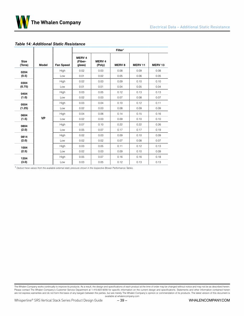
The Whalen Company works continually to improve its products. As a result, the design and specifications of each product at the time of order may be changed without notice and may not be as described herein. Please contact The Whalen Company’s Customer Service Department at 1-410-822-9200 for specific information on the current design and specifications. Statements and other information contained herein are not express warranties and do not form the basis of any bargain between the parties, but are merely The Whalen Company’s opinion or commendation of its products. The latest version of this document is
available at whalencompany.com
whalencompany.comWhisperline® SRS Vertical Stack Series Product Design Guide – 39 –
Electrical Data – Additional Static Resistance
Table 14: Additional Static Resistance
Size (Tons) Model Fan Speed
Filter1
MERV 4 (Fiber-glass)
MERV 4 (Poly) MERV 8 MERV 11 MERV 13
0204 (0.5)
VP
High 0.02 0.03 0.08 0.09 0.08
Low 0.01 0.02 0.05 0.06 0.05
0304 (0.75)
High 0.02 0.03 0.09 0.10 0.10
Low 0.01 0.01 0.04 0.05 0.04
0404 (1.0)
High 0.03 0.05 0.12 0.13 0.13
Low 0.02 0.03 0.07 0.08 0.07
0504 (1.25)
High 0.03 0.04 0.10 0.12 0.11
Low 0.02 0.03 0.08 0.09 0.09
0604 (1.5)
High 0.04 0.06 0.14 0.15 0.16
Low 0.02 0.03 0.09 0.10 0.10
0804 (2.0)
High 0.07 0.10 0.22 0.22 0.26
Low 0.05 0.07 0.17 0.17 0.19
0814 (2.0)
High 0.02 0.03 0.09 0.10 0.09
Low 0.02 0.02 0.07 0.08 0.07
1004 (2.5)
High 0.03 0.05 0.11 0.12 0.13
Low 0.02 0.03 0.09 0.10 0.09
1204 (3.0)
High 0.05 0.07 0.16 0.16 0.18
Low 0.03 0.05 0.12 0.13 0.13
1 Deduct hese values from the available external static pressure shown in the respective Blower Performance Tables.

The Whalen Company works continually to improve its products. As a result, the design and specifications of each product at the time of order may be changed without notice and may not be as described herein. Please contact The Whalen Company’s Customer Service Department at 1-410-822-9200 for specific information on the current design and specifications. Statements and other information contained herein are not express warranties and do not form the basis of any bargain between the parties, but are merely The Whalen Company’s opinion or commendation of its products. The latest version of this document is
available at whalencompany.com
Whisperline® SRS Vertical Stack Series Product Design Guide whalencompany.com– 40 –
LPSWHT/RED
HPSBLU
ORG
YEL
WIRING DIAGRAM
THE WHALEN COMPANYEASTON, MARYLAND
WHISPERLINE™ WATER SOURCE HEAT PUMP
9 March, 20176_A11-S2g.vsd
WIRING DIAGRAMMODELS: VP-A-0204-(B,D)-(S,H); VP-A-0304(B,D)-(S,H);
VP-A-0404-(B,D)-(S,H); VP-A-0504-(B,D)-(S,H);VP-A-0604-(B,D)-(S,H)
EXTERNAL 24VAC REMOTE
CONTROL
MAIN POWER208-230/1/60
OR265/1/60
SEE NOTE 1
L1
L2/N
DISCB
SEE NOTE 2
LEGEND:
PO
WE
R
STA
TUS
On
OFF
Puls
e
Con
st
Alar
m0F10F
20F
36F
125F
WAT
ERTE
MP
10F
20F
32F
FREE
ZETE
MP
TEST
HPSWHT/BLU
Z
WT
LTPURFREEZE
CCBLK/YEL
RRED
C
CONDWHT/GRN
CONDBRN
WATERGRY
WATERGRY
FREEZEPUR
C
ALR
RYYEL
LP
WHT/GRN
GRN
RED
WP
HPWP
CC
CCOMP
RE
D
OL
COMP
PB
LK XMFR
C
BLK
RED
WH
T/R
ED
BLK
/RE
D
BLK
RE
D
WH
T/G
RN
RED
GRN GND
NOTES:
1.2.3.4.5.6.
7.
8.
9.
10.
Use copper conductors only.DPST switch for 208V applications only.If used, CB replaces DISOL may be internal or external to compressor depending on unit size.Thermostat is field installed and may be remote mounted.For 208-230V units, transformer is factory wired for operation at 230V. For 208V operation, move lead to 208V terminal.STATUS LED blinks to indicate fault; reference Table 1 for fault conditionFREEZE TEMP jumper shown in default location. When using antifreeze fluid mixture, refer to IOM for correct setting.WATER TEMP jumper shown in bypass position when WT sensor is not equipped. When WT sensor is equipped, refer to IOM for correct fluid mixture protection setting.TEST mode is for diagnostic purposes only. When ON, anti-short cycle protection is reduced from 300 seconds to 5 seconds. After board has been powered for 60 minutes in TEST mode, normal operation is resumed; regardless of jumper position. Cycling unit power will reset operation.
LPR-BA1710 STATUS LED - FAULT CODES
1 BLINK HIGH PRESSURE FAULT
2 BLINK LOW PRESSURE FAULT
3 BLINK REFRIGERANT TEMPERATURE FAULT
4 BLINK CONDENSATE OVERFLOW FAULT
5 BLINK BROWNOUT FAULT
6 BLINK WATER TEMPERATURE FAULT
RC
RC
BRN
RED
WH
T
CFAN
PSCMOTOR
TYPICAL THERMOSTAT WIRINGSEE NOTE 5
SE
E NO
TE 2
GL R COY
SEE NOTE 6
WHT/GRN
FL
FH
- NORMALLY OPEN RELAY CONTACTS
- FIELD WIRING- OPTIONAL WIRING/ACCESSORY
- FACTORY WIRING
- FIELD CONNECTION- FACTORY CONNECTION
- LIGHT EMITTING DIODE INDICATOR
- QUICK CONNECTION
- LOW PRESSURE SWITCH - HIGH PRESSURE SWITCH
- THERMISTOR- CONDENSATE DRAIN PAN
- NORMALLY CLOSED RELAY CONTACTS- SOLENOID COIL
- RELAY COIL
- GROUND CONNECTION
- COMPRESSOR CONTACTORCC- COMPRESSOR CAPACITOR CCOMP
- HIGH PRESSURE LIMITHP- LOW TEMPERATURE LIMIT
- REVERSING VALVERV
- COMPRESSOR OVERLOAD (See Note 4)OL
LT- 24VAC TRANSFORMER; 40 VAXFMR
- WATER PRESSURE LIMIT
CFAN - FAN CAPACITOR
FH - HIGH SPEED FAN RELAY
- LOW PRESSURE LIMITLP
WP
- CONDENSATE OVERFLOW SENSORZ
- REMOTE CONTROL RELAYRC
WT - WATER TEMPERATURE LIMIT
- CIRCUIT BREAKER (See Note 3) - DISCONNECT SWITCHDIS
CB
WV - WATER CONTROL VALVE
- INLINE CIRCULATING PUMPP
SEE NOTES 7, 8, 9, & 10
CCWV
RV
GH
BRNFH
FL
FL - LOW SPEED FAN RELAY
Wiring Diagrams: 200-600: 2 Speed PSC Motor
LPSWHT/RED
HPSBLU
ORG
YEL
WIRING DIAGRAM
THE WHALEN COMPANYEASTON, MARYLAND
WHISPERLINE™ WATER SOURCE HEAT PUMP
9 March, 20176_A11-S2g.vsd
WIRING DIAGRAMMODELS: VP-A-0204-(B,D)-(S,H); VP-A-0304(B,D)-(S,H);
VP-A-0404-(B,D)-(S,H); VP-A-0504-(B,D)-(S,H);VP-A-0604-(B,D)-(S,H)
EXTERNAL 24VAC REMOTE
CONTROL
MAIN POWER208-230/1/60
OR265/1/60
SEE NOTE 1
L1
L2/N
DISCB
SEE NOTE 2
LEGEND:
PO
WE
R
STA
TUS
On
OFF
Puls
e
Con
st
Alar
m0F10F
20F
36F
125F
WAT
ERTE
MP
10F
20F
32F
FREE
ZETE
MP
TEST
HPSWHT/BLU
Z
WT
LTPURFREEZE
CCBLK/YEL
RRED
C
CONDWHT/GRN
CONDBRN
WATERGRY
WATERGRY
FREEZEPUR
C
ALR
RYYEL
LP
WHT/GRN
GRN
RED
WP
HPWP
CC
CCOMP
RE
D
OL
COMP
P
BLK XMFR
C
BLK
RED
WH
T/R
ED
BLK
/RE
D
BLK
RE
D
WH
T/G
RN
RED
GRN GND
NOTES:
1.2.3.4.5.6.
7.
8.
9.
10.
Use copper conductors only.DPST switch for 208V applications only.If used, CB replaces DISOL may be internal or external to compressor depending on unit size.Thermostat is field installed and may be remote mounted.For 208-230V units, transformer is factory wired for operation at 230V. For 208V operation, move lead to 208V terminal.STATUS LED blinks to indicate fault; reference Table 1 for fault conditionFREEZE TEMP jumper shown in default location. When using antifreeze fluid mixture, refer to IOM for correct setting.WATER TEMP jumper shown in bypass position when WT sensor is not equipped. When WT sensor is equipped, refer to IOM for correct fluid mixture protection setting.TEST mode is for diagnostic purposes only. When ON, anti-short cycle protection is reduced from 300 seconds to 5 seconds. After board has been powered for 60 minutes in TEST mode, normal operation is resumed; regardless of jumper position. Cycling unit power will reset operation.
LPR-BA1710 STATUS LED - FAULT CODES
1 BLINK HIGH PRESSURE FAULT
2 BLINK LOW PRESSURE FAULT
3 BLINK REFRIGERANT TEMPERATURE FAULT
4 BLINK CONDENSATE OVERFLOW FAULT
5 BLINK BROWNOUT FAULT
6 BLINK WATER TEMPERATURE FAULT
RC
RC
BRN
RED
WH
T
CFAN
PSCMOTOR
TYPICAL THERMOSTAT WIRINGSEE NOTE 5
SE
E NO
TE 2
GL R COY
SEE NOTE 6
WHT/GRN
FL
FH
- NORMALLY OPEN RELAY CONTACTS
- FIELD WIRING- OPTIONAL WIRING/ACCESSORY
- FACTORY WIRING
- FIELD CONNECTION- FACTORY CONNECTION
- LIGHT EMITTING DIODE INDICATOR
- QUICK CONNECTION
- LOW PRESSURE SWITCH - HIGH PRESSURE SWITCH
- THERMISTOR- CONDENSATE DRAIN PAN
- NORMALLY CLOSED RELAY CONTACTS- SOLENOID COIL
- RELAY COIL
- GROUND CONNECTION
- COMPRESSOR CONTACTORCC- COMPRESSOR CAPACITOR CCOMP
- HIGH PRESSURE LIMITHP- LOW TEMPERATURE LIMIT
- REVERSING VALVERV
- COMPRESSOR OVERLOAD (See Note 4)OL
LT- 24VAC TRANSFORMER; 40 VAXFMR
- WATER PRESSURE LIMIT
CFAN - FAN CAPACITOR
FH - HIGH SPEED FAN RELAY
- LOW PRESSURE LIMITLP
WP
- CONDENSATE OVERFLOW SENSORZ
- REMOTE CONTROL RELAYRC
WT - WATER TEMPERATURE LIMIT
- CIRCUIT BREAKER (See Note 3) - DISCONNECT SWITCHDIS
CB
WV - WATER CONTROL VALVE
- INLINE CIRCULATING PUMPP
SEE NOTES 7, 8, 9, & 10
CCWV
RV
GH
BRNFH
FL
FL - LOW SPEED FAN RELAY

The Whalen Company works continually to improve its products. As a result, the design and specifications of each product at the time of order may be changed without notice and may not be as described herein. Please contact The Whalen Company’s Customer Service Department at 1-410-822-9200 for specific information on the current design and specifications. Statements and other information contained herein are not express warranties and do not form the basis of any bargain between the parties, but are merely The Whalen Company’s opinion or commendation of its products. The latest version of this document is
available at whalencompany.com
whalencompany.comWhisperline® SRS Vertical Stack Series Product Design Guide – 41 –
Wiring Diagram: 200-600: 2 Speed Constant Torque EC Motor
LPSWHT/RED
HPSBLU
YEL
ORG
WIRING DIAGRAM
THE WHALEN COMPANYEASTON, MARYLAND
WHISPERLINE™ WATER SOURCE HEAT PUMP
9 March, 20176_A11GS2e.vsd
WIRING DIAGRAMMODELS: VP-A-0204-(B,D)G; VP-A-0304-(B,D)G;
VP-A-0404-(B,D)G; VP-A-0504-(B,D)G;VP-A-0604-(B,D)G
EXTERNAL 24VAC REMOTE
CONTROL
MAIN POWER208-230/1/60
OR265/1/60
SEE NOTE 1
L1
L2/N
DISCB
SEE NOTE 2
POW
ER
STA
TUS
On
OFF
Pul
se
Con
st
Alar
m0F10F
20F
36F
125F
WAT
ER
TEM
P
10F
20F
32F
FREE
ZETE
MP
TEST
1 SP
-
+
COM
2 SP
3 SP
4 SP
AC IN
5 SP
AC IN
HPSWHT/BLU
Z
WT
LT
WHT/GRN
GRN
BRN
WHT/GRN
RED
PURFREEZE
CCBLK/YEL
RRED
C
CONDWHT/GRN
CONDBRN
WATERGRY
WATERGRY
FREEZEPUR
C
ALR
RYYEL
LP
BLK
GR
N
BLK
RE
D
WHT/GRN
BRN
RED
WP
HPWP
CC
CCOMP
RE
D
OL
COMP
P
BLK XMFR
BLU
RE
D
OR
G
YEL
C
BLK
RED
WH
T/R
ED
BLK
/RE
D
BLK
RED
WH
T/G
RN
RE
D
GRN GND
MCU
RC
RC
BLK
GR
N/Y
EL
WH
T
WH
T
BLU
RE
D
OR
G
YEL
ECMOTOR
TYPICAL THERMOSTAT WIRINGSEE NOTE 5
SEE
NO
TE 2
GH R COY
SEE NOTE 6
WHT/GRN
LEGEND: NOTES:1.2.3.4.5.6.
7.
8.
9.
10.
11.
- COMPRESSOR CONTACTORCC- COMPRESSOR CAPACITOR CCOMP
MCU - FAN MOTOR CONTROLLER
- NORMALLY OPEN RELAY CONTACTS
- FIELD WIRING- OPTIONAL WIRING/ACCESSORY
- FACTORY WIRING
- FIELD CONNECTION- FACTORY CONNECTION
- LIGHT EMITTING DIODE INDICATOR
- QUICK CONNECTION
- LOW PRESSURE SWITCH - HIGH PRESSURE SWITCH
- THERMISTOR- CONDENSATE DRAIN PAN
- NORMALLY CLOSED RELAY CONTACTS- SOLENOID COIL
- RELAY COIL
- GROUND CONNECTION
- HIGH PRESSURE LIMITHP- LOW TEMPERATURE LIMIT
- REVERSING VALVERV
- COMPRESSOR OVERLOAD (See Note 4)OL
LT- 24VAC TRANSFORMER; 40 VAXFMR
SEE NOTE 11
Use copper conductors only.DPST switch for 208V applications only.If used, CB replaces DISOL may be internal or external to compressor depending on unit size.Thermostat is field installed and may be remote mounted.For 208-230V units, transformer is factory wired for operation at 230V. For 208V operation, move lead to 208V terminal.STATUS LED blinks to indicate fault; reference Table 1 for fault conditionFREEZE TEMP jumper shown in default location. When using antifreeze fluid mixture, refer to IOM for correct setting.WATER TEMP jumper shown in bypass position when WT sensor is not equipped. When WT sensor is equipped, refer to IOM for correct fluid mixture protection setting.TEST mode is for diagnostic purposes only. When ON, anti-short cycle protection is reduced from 300 seconds to 5 seconds. After board has been powered for 60 minutes in TEST mode, normal operation is resumed; regardless of jumper position. Cycling unit power will reset operation.MCU shown with typical fan speed connections. Actual speeds may vary by unit size.
SEE NOTES 7, 8, 9, & 10
LPR-BA1710 STATUS LED - FAULT CODES
1 BLINK HIGH PRESSURE FAULT
2 BLINK LOW PRESSURE FAULT
3 BLINK REFRIGERANT TEMPERATURE FAULT
4 BLINK CONDENSATE OVERFLOW FAULT
5 BLINK BROWNOUT FAULT
6 BLINK WATER TEMPERATURE FAULT
TABLE 1
- LOW PRESSURE LIMIT
- WATER PRESSURE LIMIT
LP
WP
- CONDENSATE OVERFLOW SENSORZ
- REMOTE CONTROL RELAYRC
WT - WATER TEMPERATURE LIMIT
- CIRCUIT BREAKER (See Note 3) - DISCONNECT SWITCHDIS
CB
WV - WATER CONTROL VALVE (See Note 12)
- INLINE CIRCULATING PUMPP
CCWV
RV
GL
GRN
LPSWHT/RED
HPSBLU
YEL
ORG
WIRING DIAGRAM
THE WHALEN COMPANYEASTON, MARYLAND
WHISPERLINE™ WATER SOURCE HEAT PUMP
9 March, 20176_A11GS2e.vsd
WIRING DIAGRAMMODELS: VP-A-0204-(B,D)G; VP-A-0304-(B,D)G;
VP-A-0404-(B,D)G; VP-A-0504-(B,D)G;VP-A-0604-(B,D)G
EXTERNAL 24VAC REMOTE
CONTROL
MAIN POWER208-230/1/60
OR265/1/60
SEE NOTE 1
L1
L2/N
DISCB
SEE NOTE 2
POW
ER
STA
TUS
On
OFF
Puls
e
Con
st
Alar
m0F10F
20F
36F
125F
WAT
ERTE
MP
10F
20F
32F
FREE
ZETE
MP
TEST
1 SP
-
+
COM
2 SP
3 SP
4 SP
AC IN
5 SP
AC IN
HPSWHT/BLU
Z
WT
LT
WHT/GRN
GRN
BRN
WHT/GRN
RED
PURFREEZE
CCBLK/YEL
RRED
C
CONDWHT/GRN
CONDBRN
WATERGRY
WATERGRY
FREEZEPUR
C
ALR
RYYEL
LP
BLK
GR
N
BLK
RE
D
WHT/GRN
BRN
RED
WP
HPWP
CC
CCOMP
RE
D
OL
COMP
P
BLK XMFR
BLU
RE
D
OR
G
YEL
C
BLK
RED
WH
T/R
ED
BLK
/RE
D
BLK
RED
WH
T/G
RN
RE
D
GRN GND
MCU
RC
RC
BLK
GR
N/Y
EL
WH
T
WH
T
BLU
RE
D
OR
G
YEL
ECMOTOR
TYPICAL THERMOSTAT WIRINGSEE NOTE 5
SEE NO
TE 2
GH R COY
SEE NOTE 6
WHT/GRN
LEGEND: NOTES:1.2.3.4.5.6.
7.
8.
9.
10.
11.
- COMPRESSOR CONTACTORCC- COMPRESSOR CAPACITOR CCOMP
MCU - FAN MOTOR CONTROLLER
- NORMALLY OPEN RELAY CONTACTS
- FIELD WIRING- OPTIONAL WIRING/ACCESSORY
- FACTORY WIRING
- FIELD CONNECTION- FACTORY CONNECTION
- LIGHT EMITTING DIODE INDICATOR
- QUICK CONNECTION
- LOW PRESSURE SWITCH - HIGH PRESSURE SWITCH
- THERMISTOR- CONDENSATE DRAIN PAN
- NORMALLY CLOSED RELAY CONTACTS- SOLENOID COIL
- RELAY COIL
- GROUND CONNECTION
- HIGH PRESSURE LIMITHP- LOW TEMPERATURE LIMIT
- REVERSING VALVERV
- COMPRESSOR OVERLOAD (See Note 4)OL
LT- 24VAC TRANSFORMER; 40 VAXFMR
SEE NOTE 11
Use copper conductors only.DPST switch for 208V applications only.If used, CB replaces DISOL may be internal or external to compressor depending on unit size.Thermostat is field installed and may be remote mounted.For 208-230V units, transformer is factory wired for operation at 230V. For 208V operation, move lead to 208V terminal.STATUS LED blinks to indicate fault; reference Table 1 for fault conditionFREEZE TEMP jumper shown in default location. When using antifreeze fluid mixture, refer to IOM for correct setting.WATER TEMP jumper shown in bypass position when WT sensor is not equipped. When WT sensor is equipped, refer to IOM for correct fluid mixture protection setting.TEST mode is for diagnostic purposes only. When ON, anti-short cycle protection is reduced from 300 seconds to 5 seconds. After board has been powered for 60 minutes in TEST mode, normal operation is resumed; regardless of jumper position. Cycling unit power will reset operation.MCU shown with typical fan speed connections. Actual speeds may vary by unit size.
SEE NOTES 7, 8, 9, & 10
LPR-BA1710 STATUS LED - FAULT CODES
1 BLINK HIGH PRESSURE FAULT
2 BLINK LOW PRESSURE FAULT
3 BLINK REFRIGERANT TEMPERATURE FAULT
4 BLINK CONDENSATE OVERFLOW FAULT
5 BLINK BROWNOUT FAULT
6 BLINK WATER TEMPERATURE FAULT
TABLE 1
- LOW PRESSURE LIMIT
- WATER PRESSURE LIMIT
LP
WP
- CONDENSATE OVERFLOW SENSORZ
- REMOTE CONTROL RELAYRC
WT - WATER TEMPERATURE LIMIT
- CIRCUIT BREAKER (See Note 3) - DISCONNECT SWITCHDIS
CB
WV - WATER CONTROL VALVE (See Note 12)
- INLINE CIRCULATING PUMPP
CCWV
RV
GL
GRN

The Whalen Company works continually to improve its products. As a result, the design and specifications of each product at the time of order may be changed without notice and may not be as described herein. Please contact The Whalen Company’s Customer Service Department at 1-410-822-9200 for specific information on the current design and specifications. Statements and other information contained herein are not express warranties and do not form the basis of any bargain between the parties, but are merely The Whalen Company’s opinion or commendation of its products. The latest version of this document is
available at whalencompany.com
Whisperline® SRS Vertical Stack Series Product Design Guide whalencompany.com– 42 –
Wiring Diagram: 800-1200: 2 Speed Constant Torque EC Motor
LPSWHT/RED
HPSBLU
YEL
ORG
WIRING DIAGRAM
THE WHALEN COMPANYEASTON, MARYLAND
WHISPERLINE™ WATER SOURCE HEAT PUMP
9 March, 20176_A11DS2i.vsd
EXTERNAL 24VAC REMOTE
CONTROL
MAIN POWER208-230/1/60
OR265/1/60
SEE NOTE 1
L1
L2/N
DISCB
SEE NOTE 2
PO
WE
R
STA
TUS
On
OFF
Puls
e
Con
st
Ala
rm0F10F
20F
36F
125F
WA
TER
TEM
P
10F
20F
32F
FRE
EZE
TEM
P
TES
T
HPSWHT/BLU
Z
WT
LT
WHT/GRN
GRN
BRN
PURFREEZE
CCBLK/YEL
RRED
C
CONDWHT/GRN
CONDBRN
WATERGRY
WATERGRY
FREEZEPUR
C
ALR
RYYEL
LP
WHT/GRN
BRN
RED
WP
HPWP
CC
CCOMP
RED
OL
COMP
P
BLK XMFR
C
BLK
RED
WH
T/R
ED
BLK
/REDBLK
RE
D
WH
T/G
RN
RE
D
GRN GND
Use copper conductors only.DPST switch for 208V applications only.If used, CB replaces DISOL may be internal or external to compressor depending on unit size.Thermostat is field installed and may be remote mounted.For 208-230V units, transformer is factory wired for operation at 230V. For 208V operation, move lead to 208V terminal.STATUS LED blinks to indicate fault; reference Table 1 for fault conditionFREEZE TEMP jumper shown in default location. When using antifreeze fluid mixture, refer to IOM for correct setting.WATER TEMP jumper shown in bypass position when WT sensor is not equipped. When WT sensor is equipped, refer to IOM for correct fluid mixture protection setting.TEST mode is for diagnostic purposes only. When ON, anti-short cycle protection is reduced from 300 seconds to 5 seconds. After board has been powered for 60 minutes in TEST mode, normal operation is resumed; regardless of jumper position. Cycling unit power will reset operation.
RC
RC
BLK
WH
T
ECMOTOR
TYPICAL THERMOSTAT WIRINGSEE NOTE 5
SEE N
OTE
2
GH R COY
SEE NOTE 6
SEE NOTES 7, 8, 9, & 10
WHT/GRN
LEGEND: NOTES:1.2.3.4.5.6.
7.
8.
9.
10.
- COMPRESSOR CONTACTORCC- COMPRESSOR CAPACITOR CCOMP
- NORMALLY OPEN RELAY CONTACTS
- FIELD WIRING- OPTIONAL WIRING/ACCESSORY
- FACTORY WIRING
- FIELD CONNECTION- FACTORY CONNECTION
- LIGHT EMITTING DIODE INDICATOR
- QUICK CONNECTION
- LOW PRESSURE SWITCH - HIGH PRESSURE SWITCH
- THERMISTOR- CONDENSATE DRAIN PAN
- NORMALLY CLOSED RELAY CONTACTS- SOLENOID COIL
- RELAY COIL
- GROUND CONNECTION
GR
N
- HIGH PRESSURE LIMITHP- LOW TEMPERATURE LIMIT
- REVERSING VALVERV
- COMPRESSOR OVERLOAD (See Note 4)OL
LT- 24VAC TRANSFORMER; 40 VAXFMR
BRN
SEE TABLE 2
ECM CONNECTIONS
L L1
N L2/NG GROUND
C 24 VAC COMMON
1 - 5 SPEED TAPS (24 VAC)
TABLE 2
C L G N
1 2 3 4 5
LPR-BA1710 STATUS LED - FAULT CODES
1 BLINK HIGH PRESSURE FAULT
2 BLINK LOW PRESSURE FAULT
3 BLINK REFRIGERANT TEMPERATURE FAULT
4 BLINK CONDENSATE OVERFLOW FAULT
5 BLINK BROWNOUT FAULT
6 BLINK WATER TEMPERATURE FAULT
TABLE 1
WIRING DIAGRAMMODELS: VP-A-0804-(B,D)-D; VP-A-0814-(B,D)-D
VP-A-1004-(B,D)-D; VP-A-1204-(B,D)-D
- LOW PRESSURE LIMIT
- WATER PRESSURE LIMIT
LP
WP
- CONDENSATE OVERFLOW SENSORZ
- REMOTE CONTROL RELAYRC
WT - WATER TEMPERATURE LIMIT
- CIRCUIT BREAKER (See Note 3) - DISCONNECT SWITCHDIS
CB
WV - WATER CONTROL VALVE
- INLINE CIRCULATING PUMPP
RV
CCWV
GL
GRN
LPSWHT/RED
HPSBLU
YEL
ORG
WIRING DIAGRAM
THE WHALEN COMPANYEASTON, MARYLAND
WHISPERLINE™ WATER SOURCE HEAT PUMP
9 March, 20176_A11DS2i.vsd
EXTERNAL 24VAC REMOTE
CONTROL
MAIN POWER208-230/1/60
OR265/1/60
SEE NOTE 1
L1
L2/N
DISCB
SEE NOTE 2
PO
WE
R
STAT
US
On
OFF
Puls
e
Con
st
Alar
m0F10F
20F
36F
125F
WAT
ERTE
MP
10F
20F
32F
FREE
ZETE
MP
TEST
HPSWHT/BLU
Z
WT
LT
WHT/GRN
GRN
BRN
PURFREEZE
CCBLK/YEL
RRED
C
CONDWHT/GRN
CONDBRN
WATERGRY
WATERGRY
FREEZEPUR
C
ALR
RYYEL
LP
WHT/GRN
BRN
RED
WP
HPWP
CC
CCOMP
RED
OL
COMP
P
BLK XMFR
C
BLK
RED
WH
T/R
ED
BLK
/REDBLK
RE
D
WH
T/G
RN
RE
D
GRN GND
Use copper conductors only.DPST switch for 208V applications only.If used, CB replaces DISOL may be internal or external to compressor depending on unit size.Thermostat is field installed and may be remote mounted.For 208-230V units, transformer is factory wired for operation at 230V. For 208V operation, move lead to 208V terminal.STATUS LED blinks to indicate fault; reference Table 1 for fault conditionFREEZE TEMP jumper shown in default location. When using antifreeze fluid mixture, refer to IOM for correct setting.WATER TEMP jumper shown in bypass position when WT sensor is not equipped. When WT sensor is equipped, refer to IOM for correct fluid mixture protection setting.TEST mode is for diagnostic purposes only. When ON, anti-short cycle protection is reduced from 300 seconds to 5 seconds. After board has been powered for 60 minutes in TEST mode, normal operation is resumed; regardless of jumper position. Cycling unit power will reset operation.
RC
RC
BLK
WH
T
ECMOTOR
TYPICAL THERMOSTAT WIRINGSEE NOTE 5
SEE N
OTE
2
GH R COY
SEE NOTE 6
SEE NOTES 7, 8, 9, & 10
WHT/GRN
LEGEND: NOTES:1.2.3.4.5.6.
7.
8.
9.
10.
- COMPRESSOR CONTACTORCC- COMPRESSOR CAPACITOR CCOMP
- NORMALLY OPEN RELAY CONTACTS
- FIELD WIRING- OPTIONAL WIRING/ACCESSORY
- FACTORY WIRING
- FIELD CONNECTION- FACTORY CONNECTION
- LIGHT EMITTING DIODE INDICATOR
- QUICK CONNECTION
- LOW PRESSURE SWITCH - HIGH PRESSURE SWITCH
- THERMISTOR- CONDENSATE DRAIN PAN
- NORMALLY CLOSED RELAY CONTACTS- SOLENOID COIL
- RELAY COIL
- GROUND CONNECTION
GR
N
- HIGH PRESSURE LIMITHP- LOW TEMPERATURE LIMIT
- REVERSING VALVERV
- COMPRESSOR OVERLOAD (See Note 4)OL
LT- 24VAC TRANSFORMER; 40 VAXFMR
BRN
SEE TABLE 2
ECM CONNECTIONS
L L1
N L2/NG GROUND
C 24 VAC COMMON
1 - 5 SPEED TAPS (24 VAC)
TABLE 2
C L G N
1 2 3 4 5
LPR-BA1710 STATUS LED - FAULT CODES
1 BLINK HIGH PRESSURE FAULT
2 BLINK LOW PRESSURE FAULT
3 BLINK REFRIGERANT TEMPERATURE FAULT
4 BLINK CONDENSATE OVERFLOW FAULT
5 BLINK BROWNOUT FAULT
6 BLINK WATER TEMPERATURE FAULT
TABLE 1
WIRING DIAGRAMMODELS: VP-A-0804-(B,D)-D; VP-A-0814-(B,D)-D
VP-A-1004-(B,D)-D; VP-A-1204-(B,D)-D
- LOW PRESSURE LIMIT
- WATER PRESSURE LIMIT
LP
WP
- CONDENSATE OVERFLOW SENSORZ
- REMOTE CONTROL RELAYRC
WT - WATER TEMPERATURE LIMIT
- CIRCUIT BREAKER (See Note 3) - DISCONNECT SWITCHDIS
CB
WV - WATER CONTROL VALVE
- INLINE CIRCULATING PUMPP
RV
CCWV
GL
GRN

The Whalen Company works continually to improve its products. As a result, the design and specifications of each product at the time of order may be changed without notice and may not be as described herein. Please contact The Whalen Company’s Customer Service Department at 1-410-822-9200 for specific information on the current design and specifications. Statements and other information contained herein are not express warranties and do not form the basis of any bargain between the parties, but are merely The Whalen Company’s opinion or commendation of its products. The latest version of this document is
available at whalencompany.com
whalencompany.comWhisperline® SRS Vertical Stack Series Product Design Guide – 43 –
Wiring Diagram: 200-600: 1 Speed PSC Motor w/Fan Switch & Continuous Fan
LPSWHT/RED
HPSBLU
ORG
YEL
WIRING DIAGRAM
THE WHALEN COMPANYEASTON, MARYLAND
WHISPERLINE™ WATER SOURCE HEAT PUMP
9 March, 20176_A11-S1g ULF.vsd
WIRING DIAGRAMMODELS: VP-A-0204-(B,D)-(S,H); VP-A-0304(B,D)-(S,H);
VP-A-0404-(B,D)-(S,H); VP-A-0504-(B,D)-(S,H);VP-A-0604-(B,D)-(S,H)
EXTERNAL 24VAC REMOTE
CONTROL
MAIN POWER208-230/1/60
OR265/1/60
SEE NOTE 1
L1
L2/N
DISCB
SEE NOTE 2
LEGEND:
PO
WE
R
STA
TUS
On
OFF
Pul
se
Con
st
Alar
m0F10F
20F
36F
125F
WAT
ERTE
MP
10F
20F
32F
FRE
EZE
TEM
P
TEST
HPSWHT/BLU
Z
WT
LTPURFREEZE
CCBLK/YEL
RRED
C
CONDWHT/GRN
CONDBRN
WATERGRY
WATERGRY
FREEZEPUR
C
ALR
RYYEL
LP
WHT/GRN
GRN
RED
WP
HPWP
CC
CCOMP
RE
D
OL
COMP
P
BLK XMFR
C
BLK
RED
WH
T/R
ED
BLK
/RE
D
BLK
RE
D
WH
T/G
RN
RED
GRN GND
NOTES:
1.2.3.4.5.6.
7.
8.
9.
10.
Use copper conductors only.DPST switch for 208V applications only.If used, CB replaces DISOL may be internal or external to compressor depending on unit size.Thermostat is field installed and may be remote mounted.For 208-230V units, transformer is factory wired for operation at 230V. For 208V operation, move lead to 208V terminal.STATUS LED blinks to indicate fault; reference Table 1 for fault conditionFREEZE TEMP jumper shown in default location. When using antifreeze fluid mixture, refer to IOM for correct setting.WATER TEMP jumper shown in bypass position when WT sensor is not equipped. When WT sensor is equipped, refer to IOM for correct fluid mixture protection setting.TEST mode is for diagnostic purposes only. When ON, anti-short cycle protection is reduced from 300 seconds to 5 seconds. After board has been powered for 60 minutes in TEST mode, normal operation is resumed; regardless of jumper position. Cycling unit power will reset operation.
LPR-BA1710 STATUS LED - FAULT CODES
1 BLINK HIGH PRESSURE FAULT
2 BLINK LOW PRESSURE FAULT
3 BLINK REFRIGERANT TEMPERATURE FAULT
4 BLINK CONDENSATE OVERFLOW FAULT
5 BLINK BROWNOUT FAULT
6 BLINK WATER TEMPERATURE FAULT
RC
RC
TYPICAL THERMOSTAT WIRINGSEE NOTE 5
SE
E NO
TE 2
G R COY
SEE NOTE 6
WHT/GRN
MOA
F
- NORMALLY OPEN RELAY CONTACTS
- FIELD WIRING- OPTIONAL WIRING/ACCESSORY
- FACTORY WIRING
- FIELD CONNECTION- FACTORY CONNECTION
- LIGHT EMITTING DIODE INDICATOR
- QUICK CONNECTION
- LOW PRESSURE SWITCH - HIGH PRESSURE SWITCH
- THERMISTOR- CONDENSATE DRAIN PAN
- NORMALLY CLOSED RELAY CONTACTS- SOLENOID COIL
- RELAY COIL
- GROUND CONNECTION
- COMPRESSOR CONTACTORCC- COMPRESSOR CAPACITOR CCOMP
- HIGH PRESSURE LIMITHP- LOW TEMPERATURE LIMIT
- REVERSING VALVERV
- COMPRESSOR OVERLOAD (See Note 4)OL
LT- 24VAC TRANSFORMER; 40 VAXFMR
- WATER PRESSURE LIMIT
CFAN - FAN CAPACITORF - FAN RELAY
- LOW PRESSURE LIMITLP
WP
- CONDENSATE OVERFLOW SENSORZ
- REMOTE CONTROL RELAYRC
WT - WATER TEMPERATURE LIMIT
- CIRCUIT BREAKER (See Note 3) - DISCONNECT SWITCHDIS
CB
- MOTORIZED OUTDOOR AIRMOA- FAN SPPEED SWITCHFSS
WV - WATER CONTROL VALVE
- INLINE CIRCULATING PUMPP
SEE NOTES 7, 8, 9, & 10
CCWV
RV
BLK
(BR
N)
RE
D
WH
T
CFAN
HI LO
FSS
FNO FNC
PSCMOTOR
PU
R
LPSWHT/RED
HPSBLU
ORG
YEL
WIRING DIAGRAM
THE WHALEN COMPANYEASTON, MARYLAND
WHISPERLINE™ WATER SOURCE HEAT PUMP
9 March, 20176_A11-S1g ULF.vsd
WIRING DIAGRAMMODELS: VP-A-0204-(B,D)-(S,H); VP-A-0304(B,D)-(S,H);
VP-A-0404-(B,D)-(S,H); VP-A-0504-(B,D)-(S,H);VP-A-0604-(B,D)-(S,H)
EXTERNAL 24VAC REMOTE
CONTROL
MAIN POWER208-230/1/60
OR265/1/60
SEE NOTE 1
L1
L2/N
DISCB
SEE NOTE 2
LEGEND:
PO
WE
R
STA
TUS
On
OFF
Puls
e
Con
st
Alar
m0F10F
20F
36F
125F
WAT
ERTE
MP
10F
20F
32F
FREE
ZETE
MP
TEST
HPSWHT/BLU
Z
WT
LTPURFREEZE
CCBLK/YEL
RRED
C
CONDWHT/GRN
CONDBRN
WATERGRY
WATERGRY
FREEZEPUR
C
ALR
RYYEL
LP
WHT/GRN
GRN
RED
WP
HPWP
CC
CCOMP
RE
D
OL
COMP
P
BLK XMFR
C
BLK
RED
WH
T/R
ED
BLK
/RE
D
BLK
RE
D
WH
T/G
RN
RED
GRN GND
NOTES:
1.2.3.4.5.6.
7.
8.
9.
10.
Use copper conductors only.DPST switch for 208V applications only.If used, CB replaces DISOL may be internal or external to compressor depending on unit size.Thermostat is field installed and may be remote mounted.For 208-230V units, transformer is factory wired for operation at 230V. For 208V operation, move lead to 208V terminal.STATUS LED blinks to indicate fault; reference Table 1 for fault conditionFREEZE TEMP jumper shown in default location. When using antifreeze fluid mixture, refer to IOM for correct setting.WATER TEMP jumper shown in bypass position when WT sensor is not equipped. When WT sensor is equipped, refer to IOM for correct fluid mixture protection setting.TEST mode is for diagnostic purposes only. When ON, anti-short cycle protection is reduced from 300 seconds to 5 seconds. After board has been powered for 60 minutes in TEST mode, normal operation is resumed; regardless of jumper position. Cycling unit power will reset operation.
LPR-BA1710 STATUS LED - FAULT CODES
1 BLINK HIGH PRESSURE FAULT
2 BLINK LOW PRESSURE FAULT
3 BLINK REFRIGERANT TEMPERATURE FAULT
4 BLINK CONDENSATE OVERFLOW FAULT
5 BLINK BROWNOUT FAULT
6 BLINK WATER TEMPERATURE FAULT
RC
RC
TYPICAL THERMOSTAT WIRINGSEE NOTE 5
SE
E NO
TE 2
G R COY
SEE NOTE 6
WHT/GRN
MOA
F
- NORMALLY OPEN RELAY CONTACTS
- FIELD WIRING- OPTIONAL WIRING/ACCESSORY
- FACTORY WIRING
- FIELD CONNECTION- FACTORY CONNECTION
- LIGHT EMITTING DIODE INDICATOR
- QUICK CONNECTION
- LOW PRESSURE SWITCH - HIGH PRESSURE SWITCH
- THERMISTOR- CONDENSATE DRAIN PAN
- NORMALLY CLOSED RELAY CONTACTS- SOLENOID COIL
- RELAY COIL
- GROUND CONNECTION
- COMPRESSOR CONTACTORCC- COMPRESSOR CAPACITOR CCOMP
- HIGH PRESSURE LIMITHP- LOW TEMPERATURE LIMIT
- REVERSING VALVERV
- COMPRESSOR OVERLOAD (See Note 4)OL
LT- 24VAC TRANSFORMER; 40 VAXFMR
- WATER PRESSURE LIMIT
CFAN - FAN CAPACITORF - FAN RELAY
- LOW PRESSURE LIMITLP
WP
- CONDENSATE OVERFLOW SENSORZ
- REMOTE CONTROL RELAYRC
WT - WATER TEMPERATURE LIMIT
- CIRCUIT BREAKER (See Note 3) - DISCONNECT SWITCHDIS
CB
- MOTORIZED OUTDOOR AIRMOA- FAN SPPEED SWITCHFSS
WV - WATER CONTROL VALVE
- INLINE CIRCULATING PUMPP
SEE NOTES 7, 8, 9, & 10
CCWV
RV
BLK
(BR
N)
RE
D
WH
T
CFAN
HI LO
FSS
FNO FNC
PSCMOTOR
PU
R

The Whalen Company works continually to improve its products. As a result, the design and specifications of each product at the time of order may be changed without notice and may not be as described herein. Please contact The Whalen Company’s Customer Service Department at 1-410-822-9200 for specific information on the current design and specifications. Statements and other information contained herein are not express warranties and do not form the basis of any bargain between the parties, but are merely The Whalen Company’s opinion or commendation of its products. The latest version of this document is
available at whalencompany.com
Whisperline® SRS Vertical Stack Series Product Design Guide whalencompany.com– 44 –
Wiring Diagram: 200-600: 2 Speed Constant Torque EC Motor w/Continuous Fan
LPSWHT/RED
HPSBLU
YEL
ORG
WIRING DIAGRAM
THE WHALEN COMPANYEASTON, MARYLAND
WHISPERLINE™ WATER SOURCE HEAT PUMP
9 March, 20176_A11GS2e.vsd
WIRING DIAGRAMMODELS: VP-A-0204-(B,D)G; VP-A-0304-(B,D)G;
VP-A-0404-(B,D)G; VP-A-0504-(B,D)G;VP-A-0604-(B,D)G
EXTERNAL 24VAC REMOTE
CONTROL
MAIN POWER208-230/1/60
OR265/1/60
SEE NOTE 1
L1
L2/N
DISCB
SEE NOTE 2
POW
ER
STA
TUS
On
OFF
Pul
se
Con
st
Alar
m0F10F
20F
36F
125F
WAT
ER
TEM
P
10F
20F
32F
FREE
ZETE
MP
TEST
1 SP
-
+
COM
2 SP
3 SP
4 SP
AC IN
5 SP
AC IN
HPSWHT/BLU
Z
WT
LT
WHT/GRN
GRN
BRN
WHT/GRN
RED
PURFREEZE
CCBLK/YEL
RRED
C
CONDWHT/GRN
CONDBRN
WATERGRY
WATERGRY
FREEZEPUR
C
ALR
RYYEL
LP
BLK
GR
N
BLK
RE
D
WHT/GRN
BRN
RED
WP
HPWP
CC
CCOMP
RE
D
OL
COMP
PB
LK XMFR
BLU
RE
D
OR
G
YEL
C
BLK
RED
WH
T/R
ED
BLK
/RE
D
BLK
RED
WH
T/G
RN
RE
D
GRN GND
MCU
RC
RC
BLK
GR
N/Y
EL
WH
T
WH
T
BLU
RE
D
OR
G
YEL
ECMOTOR
TYPICAL THERMOSTAT WIRINGSEE NOTE 5
SEE
NO
TE 2
GH R COY
SEE NOTE 6
WHT/GRN
LEGEND: NOTES:1.2.3.4.5.6.
7.
8.
9.
10.
11.
- COMPRESSOR CONTACTORCC- COMPRESSOR CAPACITOR CCOMP
MCU - FAN MOTOR CONTROLLER
- NORMALLY OPEN RELAY CONTACTS
- FIELD WIRING- OPTIONAL WIRING/ACCESSORY
- FACTORY WIRING
- FIELD CONNECTION- FACTORY CONNECTION
- LIGHT EMITTING DIODE INDICATOR
- QUICK CONNECTION
- LOW PRESSURE SWITCH - HIGH PRESSURE SWITCH
- THERMISTOR- CONDENSATE DRAIN PAN
- NORMALLY CLOSED RELAY CONTACTS- SOLENOID COIL
- RELAY COIL
- GROUND CONNECTION
- HIGH PRESSURE LIMITHP- LOW TEMPERATURE LIMIT
- REVERSING VALVERV
- COMPRESSOR OVERLOAD (See Note 4)OL
LT- 24VAC TRANSFORMER; 40 VAXFMR
SEE NOTE 11
Use copper conductors only.DPST switch for 208V applications only.If used, CB replaces DISOL may be internal or external to compressor depending on unit size.Thermostat is field installed and may be remote mounted.For 208-230V units, transformer is factory wired for operation at 230V. For 208V operation, move lead to 208V terminal.STATUS LED blinks to indicate fault; reference Table 1 for fault conditionFREEZE TEMP jumper shown in default location. When using antifreeze fluid mixture, refer to IOM for correct setting.WATER TEMP jumper shown in bypass position when WT sensor is not equipped. When WT sensor is equipped, refer to IOM for correct fluid mixture protection setting.TEST mode is for diagnostic purposes only. When ON, anti-short cycle protection is reduced from 300 seconds to 5 seconds. After board has been powered for 60 minutes in TEST mode, normal operation is resumed; regardless of jumper position. Cycling unit power will reset operation.MCU shown with typical fan speed connections. Actual speeds may vary by unit size.
SEE NOTES 7, 8, 9, & 10
LPR-BA1710 STATUS LED - FAULT CODES
1 BLINK HIGH PRESSURE FAULT
2 BLINK LOW PRESSURE FAULT
3 BLINK REFRIGERANT TEMPERATURE FAULT
4 BLINK CONDENSATE OVERFLOW FAULT
5 BLINK BROWNOUT FAULT
6 BLINK WATER TEMPERATURE FAULT
TABLE 1
- LOW PRESSURE LIMIT
- WATER PRESSURE LIMIT
LP
WP
- CONDENSATE OVERFLOW SENSORZ
- REMOTE CONTROL RELAYRC
WT - WATER TEMPERATURE LIMIT
- CIRCUIT BREAKER (See Note 3) - DISCONNECT SWITCHDIS
CB
WV - WATER CONTROL VALVE (See Note 12)
- INLINE CIRCULATING PUMPP
CCWV
RV
GL
GRN
LPSWHT/RED
HPSBLU
YEL
ORG
WIRING DIAGRAM
THE WHALEN COMPANYEASTON, MARYLAND
WHISPERLINE™ WATER SOURCE HEAT PUMP
9 March, 20176_A11GS2e.vsd
WIRING DIAGRAMMODELS: VP-A-0204-(B,D)G; VP-A-0304-(B,D)G;
VP-A-0404-(B,D)G; VP-A-0504-(B,D)G;VP-A-0604-(B,D)G
EXTERNAL 24VAC REMOTE
CONTROL
MAIN POWER208-230/1/60
OR265/1/60
SEE NOTE 1
L1
L2/N
DISCB
SEE NOTE 2
POW
ER
STA
TUS
On
OFF
Puls
e
Con
st
Alar
m0F10F
20F
36F
125F
WAT
ERTE
MP
10F
20F
32F
FREE
ZETE
MP
TEST
1 SP
-
+
COM
2 SP
3 SP
4 SP
AC IN
5 SP
AC IN
HPSWHT/BLU
Z
WT
LT
WHT/GRN
GRN
BRN
WHT/GRN
RED
PURFREEZE
CCBLK/YEL
RRED
C
CONDWHT/GRN
CONDBRN
WATERGRY
WATERGRY
FREEZEPUR
C
ALR
RYYEL
LP
BLK
GR
N
BLK
RE
D
WHT/GRN
BRN
RED
WP
HPWP
CC
CCOMP
RE
D
OL
COMP
P
BLK XMFR
BLU
RE
D
OR
G
YEL
C
BLK
RED
WH
T/R
ED
BLK
/RE
D
BLK
RED
WH
T/G
RN
RE
D
GRN GND
MCU
RC
RC
BLK
GR
N/Y
EL
WH
T
WH
T
BLU
RE
D
OR
G
YEL
ECMOTOR
TYPICAL THERMOSTAT WIRINGSEE NOTE 5
SEE NO
TE 2
GH R COY
SEE NOTE 6
WHT/GRN
LEGEND: NOTES:1.2.3.4.5.6.
7.
8.
9.
10.
11.
- COMPRESSOR CONTACTORCC- COMPRESSOR CAPACITOR CCOMP
MCU - FAN MOTOR CONTROLLER
- NORMALLY OPEN RELAY CONTACTS
- FIELD WIRING- OPTIONAL WIRING/ACCESSORY
- FACTORY WIRING
- FIELD CONNECTION- FACTORY CONNECTION
- LIGHT EMITTING DIODE INDICATOR
- QUICK CONNECTION
- LOW PRESSURE SWITCH - HIGH PRESSURE SWITCH
- THERMISTOR- CONDENSATE DRAIN PAN
- NORMALLY CLOSED RELAY CONTACTS- SOLENOID COIL
- RELAY COIL
- GROUND CONNECTION
- HIGH PRESSURE LIMITHP- LOW TEMPERATURE LIMIT
- REVERSING VALVERV
- COMPRESSOR OVERLOAD (See Note 4)OL
LT- 24VAC TRANSFORMER; 40 VAXFMR
SEE NOTE 11
Use copper conductors only.DPST switch for 208V applications only.If used, CB replaces DISOL may be internal or external to compressor depending on unit size.Thermostat is field installed and may be remote mounted.For 208-230V units, transformer is factory wired for operation at 230V. For 208V operation, move lead to 208V terminal.STATUS LED blinks to indicate fault; reference Table 1 for fault conditionFREEZE TEMP jumper shown in default location. When using antifreeze fluid mixture, refer to IOM for correct setting.WATER TEMP jumper shown in bypass position when WT sensor is not equipped. When WT sensor is equipped, refer to IOM for correct fluid mixture protection setting.TEST mode is for diagnostic purposes only. When ON, anti-short cycle protection is reduced from 300 seconds to 5 seconds. After board has been powered for 60 minutes in TEST mode, normal operation is resumed; regardless of jumper position. Cycling unit power will reset operation.MCU shown with typical fan speed connections. Actual speeds may vary by unit size.
SEE NOTES 7, 8, 9, & 10
LPR-BA1710 STATUS LED - FAULT CODES
1 BLINK HIGH PRESSURE FAULT
2 BLINK LOW PRESSURE FAULT
3 BLINK REFRIGERANT TEMPERATURE FAULT
4 BLINK CONDENSATE OVERFLOW FAULT
5 BLINK BROWNOUT FAULT
6 BLINK WATER TEMPERATURE FAULT
TABLE 1
- LOW PRESSURE LIMIT
- WATER PRESSURE LIMIT
LP
WP
- CONDENSATE OVERFLOW SENSORZ
- REMOTE CONTROL RELAYRC
WT - WATER TEMPERATURE LIMIT
- CIRCUIT BREAKER (See Note 3) - DISCONNECT SWITCHDIS
CB
WV - WATER CONTROL VALVE (See Note 12)
- INLINE CIRCULATING PUMPP
CCWV
RV
GL
GRN
LPSWHT/RED
HPSBLU
YEL
ORG
WIRING DIAGRAM
THE WHALEN COMPANYEASTON, MARYLAND
WHISPERLINE™ WATER SOURCE HEAT PUMP
9 March, 20176_A11GS2e.vsd
WIRING DIAGRAMMODELS: VP-A-0204-(B,D)G; VP-A-0304-(B,D)G;
VP-A-0404-(B,D)G; VP-A-0504-(B,D)G;VP-A-0604-(B,D)G
EXTERNAL 24VAC REMOTE
CONTROL
MAIN POWER208-230/1/60
OR265/1/60
SEE NOTE 1
L1
L2/N
DISCB
SEE NOTE 2
POW
ER
STA
TUS
On
OFF
Puls
e
Con
st
Alar
m0F10F
20F
36F
125F
WAT
ERTE
MP
10F
20F
32F
FREE
ZETE
MP
TEST
1 SP
-
+
COM
2 SP
3 SP
4 SP
AC IN
5 SP
AC IN
HPSWHT/BLU
Z
WT
LT
WHT/GRN
GRN
BRN
WHT/GRN
RED
PURFREEZE
CCBLK/YEL
RRED
C
CONDWHT/GRN
CONDBRN
WATERGRY
WATERGRY
FREEZEPUR
C
ALR
RYYEL
LP
BLK
GR
N
BLK
RE
D
WHT/GRN
BRN
RED
WP
HPWP
CC
CCOMP
RE
D
OL
COMP
P
BLK XMFR
BLU
RE
D
OR
G
YEL
C
BLK
RED
WH
T/R
ED
BLK
/RE
D
BLK
RED
WH
T/G
RN
RE
D
GRN GND
MCU
RC
RC
BLK
GR
N/Y
EL
WH
T
WH
T
BLU
RE
D
OR
G
YEL
ECMOTOR
TYPICAL THERMOSTAT WIRINGSEE NOTE 5
SEE NO
TE 2
GH R COY
SEE NOTE 6
WHT/GRN
LEGEND: NOTES:1.2.3.4.5.6.
7.
8.
9.
10.
11.
- COMPRESSOR CONTACTORCC- COMPRESSOR CAPACITOR CCOMP
MCU - FAN MOTOR CONTROLLER
- NORMALLY OPEN RELAY CONTACTS
- FIELD WIRING- OPTIONAL WIRING/ACCESSORY
- FACTORY WIRING
- FIELD CONNECTION- FACTORY CONNECTION
- LIGHT EMITTING DIODE INDICATOR
- QUICK CONNECTION
- LOW PRESSURE SWITCH - HIGH PRESSURE SWITCH
- THERMISTOR- CONDENSATE DRAIN PAN
- NORMALLY CLOSED RELAY CONTACTS- SOLENOID COIL
- RELAY COIL
- GROUND CONNECTION
- HIGH PRESSURE LIMITHP- LOW TEMPERATURE LIMIT
- REVERSING VALVERV
- COMPRESSOR OVERLOAD (See Note 4)OL
LT- 24VAC TRANSFORMER; 40 VAXFMR
SEE NOTE 11
Use copper conductors only.DPST switch for 208V applications only.If used, CB replaces DISOL may be internal or external to compressor depending on unit size.Thermostat is field installed and may be remote mounted.For 208-230V units, transformer is factory wired for operation at 230V. For 208V operation, move lead to 208V terminal.STATUS LED blinks to indicate fault; reference Table 1 for fault conditionFREEZE TEMP jumper shown in default location. When using antifreeze fluid mixture, refer to IOM for correct setting.WATER TEMP jumper shown in bypass position when WT sensor is not equipped. When WT sensor is equipped, refer to IOM for correct fluid mixture protection setting.TEST mode is for diagnostic purposes only. When ON, anti-short cycle protection is reduced from 300 seconds to 5 seconds. After board has been powered for 60 minutes in TEST mode, normal operation is resumed; regardless of jumper position. Cycling unit power will reset operation.MCU shown with typical fan speed connections. Actual speeds may vary by unit size.
SEE NOTES 7, 8, 9, & 10
LPR-BA1710 STATUS LED - FAULT CODES
1 BLINK HIGH PRESSURE FAULT
2 BLINK LOW PRESSURE FAULT
3 BLINK REFRIGERANT TEMPERATURE FAULT
4 BLINK CONDENSATE OVERFLOW FAULT
5 BLINK BROWNOUT FAULT
6 BLINK WATER TEMPERATURE FAULT
TABLE 1
- LOW PRESSURE LIMIT
- WATER PRESSURE LIMIT
LP
WP
- CONDENSATE OVERFLOW SENSORZ
- REMOTE CONTROL RELAYRC
WT - WATER TEMPERATURE LIMIT
- CIRCUIT BREAKER (See Note 3) - DISCONNECT SWITCHDIS
CB
WV - WATER CONTROL VALVE (See Note 12)
- INLINE CIRCULATING PUMPP
CCWV
RV
GL
GRN

The Whalen Company works continually to improve its products. As a result, the design and specifications of each product at the time of order may be changed without notice and may not be as described herein. Please contact The Whalen Company’s Customer Service Department at 1-410-822-9200 for specific information on the current design and specifications. Statements and other information contained herein are not express warranties and do not form the basis of any bargain between the parties, but are merely The Whalen Company’s opinion or commendation of its products. The latest version of this document is
available at whalencompany.com
whalencompany.comWhisperline® SRS Vertical Stack Series Product Design Guide – 45 –
Wiring Diagram: 800-1200: 2 Speed Constant Torque EC Motor w/Continuous Fan
LPSWHT/RED
HPSBLU
YEL
ORG
WIRING DIAGRAM
THE WHALEN COMPANYEASTON, MARYLAND
WHISPERLINE™ WATER SOURCE HEAT PUMP
9 March, 20176_A11DS2i.vsd
EXTERNAL 24VAC REMOTE
CONTROL
MAIN POWER208-230/1/60
OR265/1/60
SEE NOTE 1
L1
L2/N
DISCB
SEE NOTE 2
PO
WE
R
STA
TUS
On
OFF
Puls
e
Con
st
Ala
rm0F10F
20F
36F
125F
WA
TER
TEM
P
10F
20F
32F
FRE
EZE
TEM
P
TES
T
HPSWHT/BLU
Z
WT
LT
WHT/GRN
GRN
BRN
PURFREEZE
CCBLK/YEL
RRED
C
CONDWHT/GRN
CONDBRN
WATERGRY
WATERGRY
FREEZEPUR
C
ALR
RYYEL
LP
WHT/GRN
BRN
RED
WP
HPWP
CC
CCOMP
RED
OL
COMP
P
BLK XMFR
C
BLK
RED
WH
T/R
ED
BLK
/REDBLK
RE
D
WH
T/G
RN
RE
D
GRN GND
Use copper conductors only.DPST switch for 208V applications only.If used, CB replaces DISOL may be internal or external to compressor depending on unit size.Thermostat is field installed and may be remote mounted.For 208-230V units, transformer is factory wired for operation at 230V. For 208V operation, move lead to 208V terminal.STATUS LED blinks to indicate fault; reference Table 1 for fault conditionFREEZE TEMP jumper shown in default location. When using antifreeze fluid mixture, refer to IOM for correct setting.WATER TEMP jumper shown in bypass position when WT sensor is not equipped. When WT sensor is equipped, refer to IOM for correct fluid mixture protection setting.TEST mode is for diagnostic purposes only. When ON, anti-short cycle protection is reduced from 300 seconds to 5 seconds. After board has been powered for 60 minutes in TEST mode, normal operation is resumed; regardless of jumper position. Cycling unit power will reset operation.
RC
RC
BLK
WH
T
ECMOTOR
TYPICAL THERMOSTAT WIRINGSEE NOTE 5
SEE N
OTE
2
GH R COY
SEE NOTE 6
SEE NOTES 7, 8, 9, & 10
WHT/GRN
LEGEND: NOTES:1.2.3.4.5.6.
7.
8.
9.
10.
- COMPRESSOR CONTACTORCC- COMPRESSOR CAPACITOR CCOMP
- NORMALLY OPEN RELAY CONTACTS
- FIELD WIRING- OPTIONAL WIRING/ACCESSORY
- FACTORY WIRING
- FIELD CONNECTION- FACTORY CONNECTION
- LIGHT EMITTING DIODE INDICATOR
- QUICK CONNECTION
- LOW PRESSURE SWITCH - HIGH PRESSURE SWITCH
- THERMISTOR- CONDENSATE DRAIN PAN
- NORMALLY CLOSED RELAY CONTACTS- SOLENOID COIL
- RELAY COIL
- GROUND CONNECTION
GR
N
- HIGH PRESSURE LIMITHP- LOW TEMPERATURE LIMIT
- REVERSING VALVERV
- COMPRESSOR OVERLOAD (See Note 4)OL
LT- 24VAC TRANSFORMER; 40 VAXFMR
BRN
SEE TABLE 2
ECM CONNECTIONS
L L1
N L2/NG GROUND
C 24 VAC COMMON
1 - 5 SPEED TAPS (24 VAC)
TABLE 2
C L G N
1 2 3 4 5
LPR-BA1710 STATUS LED - FAULT CODES
1 BLINK HIGH PRESSURE FAULT
2 BLINK LOW PRESSURE FAULT
3 BLINK REFRIGERANT TEMPERATURE FAULT
4 BLINK CONDENSATE OVERFLOW FAULT
5 BLINK BROWNOUT FAULT
6 BLINK WATER TEMPERATURE FAULT
TABLE 1
WIRING DIAGRAMMODELS: VP-A-0804-(B,D)-D; VP-A-0814-(B,D)-D
VP-A-1004-(B,D)-D; VP-A-1204-(B,D)-D
- LOW PRESSURE LIMIT
- WATER PRESSURE LIMIT
LP
WP
- CONDENSATE OVERFLOW SENSORZ
- REMOTE CONTROL RELAYRC
WT - WATER TEMPERATURE LIMIT
- CIRCUIT BREAKER (See Note 3) - DISCONNECT SWITCHDIS
CB
WV - WATER CONTROL VALVE
- INLINE CIRCULATING PUMPP
RV
CCWV
GL
GRN
LPSWHT/RED
HPSBLU
YEL
ORG
WIRING DIAGRAM
THE WHALEN COMPANYEASTON, MARYLAND
WHISPERLINE™ WATER SOURCE HEAT PUMP
9 March, 20176_A11DS2i.vsd
EXTERNAL 24VAC REMOTE
CONTROL
MAIN POWER208-230/1/60
OR265/1/60
SEE NOTE 1
L1
L2/N
DISCB
SEE NOTE 2
PO
WE
R
STAT
US
On
OFF
Puls
e
Con
st
Alar
m0F10F
20F
36F
125F
WAT
ERTE
MP
10F
20F
32F
FREE
ZETE
MP
TEST
HPSWHT/BLU
Z
WT
LT
WHT/GRN
GRN
BRN
PURFREEZE
CCBLK/YEL
RRED
C
CONDWHT/GRN
CONDBRN
WATERGRY
WATERGRY
FREEZEPUR
C
ALR
RYYEL
LP
WHT/GRN
BRN
RED
WP
HPWP
CC
CCOMP
RED
OL
COMP
P
BLK XMFR
C
BLK
RED
WH
T/R
ED
BLK
/REDBLK
RE
D
WH
T/G
RN
RE
D
GRN GND
Use copper conductors only.DPST switch for 208V applications only.If used, CB replaces DISOL may be internal or external to compressor depending on unit size.Thermostat is field installed and may be remote mounted.For 208-230V units, transformer is factory wired for operation at 230V. For 208V operation, move lead to 208V terminal.STATUS LED blinks to indicate fault; reference Table 1 for fault conditionFREEZE TEMP jumper shown in default location. When using antifreeze fluid mixture, refer to IOM for correct setting.WATER TEMP jumper shown in bypass position when WT sensor is not equipped. When WT sensor is equipped, refer to IOM for correct fluid mixture protection setting.TEST mode is for diagnostic purposes only. When ON, anti-short cycle protection is reduced from 300 seconds to 5 seconds. After board has been powered for 60 minutes in TEST mode, normal operation is resumed; regardless of jumper position. Cycling unit power will reset operation.
RC
RC
BLK
WH
T
ECMOTOR
TYPICAL THERMOSTAT WIRINGSEE NOTE 5
SEE N
OTE
2
GH R COY
SEE NOTE 6
SEE NOTES 7, 8, 9, & 10
WHT/GRN
LEGEND: NOTES:1.2.3.4.5.6.
7.
8.
9.
10.
- COMPRESSOR CONTACTORCC- COMPRESSOR CAPACITOR CCOMP
- NORMALLY OPEN RELAY CONTACTS
- FIELD WIRING- OPTIONAL WIRING/ACCESSORY
- FACTORY WIRING
- FIELD CONNECTION- FACTORY CONNECTION
- LIGHT EMITTING DIODE INDICATOR
- QUICK CONNECTION
- LOW PRESSURE SWITCH - HIGH PRESSURE SWITCH
- THERMISTOR- CONDENSATE DRAIN PAN
- NORMALLY CLOSED RELAY CONTACTS- SOLENOID COIL
- RELAY COIL
- GROUND CONNECTION
GR
N
- HIGH PRESSURE LIMITHP- LOW TEMPERATURE LIMIT
- REVERSING VALVERV
- COMPRESSOR OVERLOAD (See Note 4)OL
LT- 24VAC TRANSFORMER; 40 VAXFMR
BRN
SEE TABLE 2
ECM CONNECTIONS
L L1
N L2/NG GROUND
C 24 VAC COMMON
1 - 5 SPEED TAPS (24 VAC)
TABLE 2
C L G N
1 2 3 4 5
LPR-BA1710 STATUS LED - FAULT CODES
1 BLINK HIGH PRESSURE FAULT
2 BLINK LOW PRESSURE FAULT
3 BLINK REFRIGERANT TEMPERATURE FAULT
4 BLINK CONDENSATE OVERFLOW FAULT
5 BLINK BROWNOUT FAULT
6 BLINK WATER TEMPERATURE FAULT
TABLE 1
WIRING DIAGRAMMODELS: VP-A-0804-(B,D)-D; VP-A-0814-(B,D)-D
VP-A-1004-(B,D)-D; VP-A-1204-(B,D)-D
- LOW PRESSURE LIMIT
- WATER PRESSURE LIMIT
LP
WP
- CONDENSATE OVERFLOW SENSORZ
- REMOTE CONTROL RELAYRC
WT - WATER TEMPERATURE LIMIT
- CIRCUIT BREAKER (See Note 3) - DISCONNECT SWITCHDIS
CB
WV - WATER CONTROL VALVE
- INLINE CIRCULATING PUMPP
RV
CCWV
GL
GRN
LPSWHT/RED
HPSBLU
YEL
ORG
WIRING DIAGRAM
THE WHALEN COMPANYEASTON, MARYLAND
WHISPERLINE™ WATER SOURCE HEAT PUMP
9 March, 20176_A11DS2i.vsd
EXTERNAL 24VAC REMOTE
CONTROL
MAIN POWER208-230/1/60
OR265/1/60
SEE NOTE 1
L1
L2/N
DISCB
SEE NOTE 2
PO
WE
R
STAT
US
On
OFF
Puls
e
Con
st
Alar
m0F10F
20F
36F
125F
WAT
ERTE
MP
10F
20F
32F
FREE
ZETE
MP
TEST
HPSWHT/BLU
Z
WT
LT
WHT/GRN
GRN
BRN
PURFREEZE
CCBLK/YEL
RRED
C
CONDWHT/GRN
CONDBRN
WATERGRY
WATERGRY
FREEZEPUR
C
ALR
RYYEL
LP
WHT/GRN
BRN
RED
WP
HPWP
CC
CCOMP
RED
OL
COMP
P
BLK XMFR
C
BLK
RED
WH
T/R
ED
BLK
/REDBLK
RE
D
WH
T/G
RN
RE
D
GRN GND
Use copper conductors only.DPST switch for 208V applications only.If used, CB replaces DISOL may be internal or external to compressor depending on unit size.Thermostat is field installed and may be remote mounted.For 208-230V units, transformer is factory wired for operation at 230V. For 208V operation, move lead to 208V terminal.STATUS LED blinks to indicate fault; reference Table 1 for fault conditionFREEZE TEMP jumper shown in default location. When using antifreeze fluid mixture, refer to IOM for correct setting.WATER TEMP jumper shown in bypass position when WT sensor is not equipped. When WT sensor is equipped, refer to IOM for correct fluid mixture protection setting.TEST mode is for diagnostic purposes only. When ON, anti-short cycle protection is reduced from 300 seconds to 5 seconds. After board has been powered for 60 minutes in TEST mode, normal operation is resumed; regardless of jumper position. Cycling unit power will reset operation.
RC
RC
BLK
WH
T
ECMOTOR
TYPICAL THERMOSTAT WIRINGSEE NOTE 5
SEE N
OTE
2
GH R COY
SEE NOTE 6
SEE NOTES 7, 8, 9, & 10
WHT/GRN
LEGEND: NOTES:1.2.3.4.5.6.
7.
8.
9.
10.
- COMPRESSOR CONTACTORCC- COMPRESSOR CAPACITOR CCOMP
- NORMALLY OPEN RELAY CONTACTS
- FIELD WIRING- OPTIONAL WIRING/ACCESSORY
- FACTORY WIRING
- FIELD CONNECTION- FACTORY CONNECTION
- LIGHT EMITTING DIODE INDICATOR
- QUICK CONNECTION
- LOW PRESSURE SWITCH - HIGH PRESSURE SWITCH
- THERMISTOR- CONDENSATE DRAIN PAN
- NORMALLY CLOSED RELAY CONTACTS- SOLENOID COIL
- RELAY COIL
- GROUND CONNECTION
GR
N
- HIGH PRESSURE LIMITHP- LOW TEMPERATURE LIMIT
- REVERSING VALVERV
- COMPRESSOR OVERLOAD (See Note 4)OL
LT- 24VAC TRANSFORMER; 40 VAXFMR
BRN
SEE TABLE 2
ECM CONNECTIONS
L L1
N L2/NG GROUND
C 24 VAC COMMON
1 - 5 SPEED TAPS (24 VAC)
TABLE 2
C L G N
1 2 3 4 5
LPR-BA1710 STATUS LED - FAULT CODES
1 BLINK HIGH PRESSURE FAULT
2 BLINK LOW PRESSURE FAULT
3 BLINK REFRIGERANT TEMPERATURE FAULT
4 BLINK CONDENSATE OVERFLOW FAULT
5 BLINK BROWNOUT FAULT
6 BLINK WATER TEMPERATURE FAULT
TABLE 1
WIRING DIAGRAMMODELS: VP-A-0804-(B,D)-D; VP-A-0814-(B,D)-D
VP-A-1004-(B,D)-D; VP-A-1204-(B,D)-D
- LOW PRESSURE LIMIT
- WATER PRESSURE LIMIT
LP
WP
- CONDENSATE OVERFLOW SENSORZ
- REMOTE CONTROL RELAYRC
WT - WATER TEMPERATURE LIMIT
- CIRCUIT BREAKER (See Note 3) - DISCONNECT SWITCHDIS
CB
WV - WATER CONTROL VALVE
- INLINE CIRCULATING PUMPP
RV
CCWV
GL
GRN

The Whalen Company works continually to improve its products. As a result, the design and specifications of each product at the time of order may be changed without notice and may not be as described herein. Please contact The Whalen Company’s Customer Service Department at 1-410-822-9200 for specific information on the current design and specifications. Statements and other information contained herein are not express warranties and do not form the basis of any bargain between the parties, but are merely The Whalen Company’s opinion or commendation of its products. The latest version of this document is
available at whalencompany.com
Whisperline® SRS Vertical Stack Series Product Design Guide whalencompany.com– 46 –
Whisperline® Single Riser Detail with Integral Pump Units
1 1/2
1 1/4
2 1/2
2
Notes:
1.
2.
3.
4.
"Riser size" refers to the larger of thesupply and return risers on each heatpump.
Risers are protected by a steel riser coverextending the height of the cabinet.Risers are soldered to a copper clamp tohelp prevent movement during shipmentand jobsite handling.
Riser couplings are not furnished byWhalen, unless otherwise noted.
Sleeve hole dimensions "J" and "K" arerecommended minimums.
All dimensions in inches.
1
3/4
RISERSIZE
L.H. SIDE RISERSR.H. OPPOSITE(STANDARD)
REAR RISERS(OPTIONAL)
J K
J
3
5.5
K
RETURN AIROPENING
RETURN AIROPENING
6 10
6 10
6 10
6 10
6 12
6 12
J
3
K
OPTIONALTOP POWER
OPTIONAL TOP POWER
DRAWING NUMBER: 609g-PT-SRSOCTOBER 2016
THE WHALEN COMPANYEASTON, MARYLAND
RISER DETAILSSINGLE RISER UNITS WITH INTEGRAL PUMP
WHISPERLINE™ UNITSWATER SOURCE HEAT PUMP
CL

The Whalen Company works continually to improve its products. As a result, the design and specifications of each product at the time of order may be changed without notice and may not be as described herein. Please contact The Whalen Company’s Customer Service Department at 1-410-822-9200 for specific information on the current design and specifications. Statements and other information contained herein are not express warranties and do not form the basis of any bargain between the parties, but are merely The Whalen Company’s opinion or commendation of its products. The latest version of this document is
available at whalencompany.com
whalencompany.comWhisperline® SRS Vertical Stack Series Product Design Guide – 47 –
Whisperline® Discharge Arrangements – Rear Riser
R-T
LARGE ARROW REPRESENTS RETURN AIR LOCATION AND SMALL ARROWS REPRESENT DISCHARGE LOCATION.
B = BACK OR REAR L = LEFT R = RIGHT F = FRONT T = TOP
F
F-T
F-L F-R F-L-R
T L-T
L-RR L
DRAWING NUMBER: 611c-PVRMARCH 2016
THE WHALEN COMPANYEASTON, MARYLAND
DISCHARGE ARRANGEMENTSREAR RISER UNIT
204 – 1204 CFM UNITS PLAN VIEW
WHISPERLINE™ / WHISPERPACK™ UNITSWATER SOURCE HEAT PUMP / WATER SOURCE AIR CONDITIONER w/ HYDRONIC HEATING
SRD
SRD
SRD
SRD
SRD
SRD
SRD
SRD
SRD
SRD
SRD

The Whalen Company works continually to improve its products. As a result, the design and specifications of each product at the time of order may be changed without notice and may not be as described herein. Please contact The Whalen Company’s Customer Service Department at 1-410-822-9200 for specific information on the current design and specifications. Statements and other information contained herein are not express warranties and do not form the basis of any bargain between the parties, but are merely The Whalen Company’s opinion or commendation of its products. The latest version of this document is
available at whalencompany.com
Whisperline® SRS Vertical Stack Series Product Design Guide whalencompany.com– 48 –
Whisperline® Discharge Arrangements – Side Riser
F F-L F-B F-L-B T
F-RF F-B R-T
LARGE ARROWS REPRESENT RETURN AIR LOCATION AND SMALL ARROWS REPRESENT DISCHARGE LOCATION.
B = BACK OR REAR L = LEFT R = RIGHT F = FRONT T = TOP C = CORNERSTONE
F-T L B C/F-L B-T
RF-T B B-T
F-R-B
R-B
S
R
S
R
S
R
S
R
S
R
S
R
S
R
S
R
S
R
S
R
S
R
S
R
S
R
S
R
S
R
S
R
S
R
S
R
S
R
S
R
DRAWING NUMBER: 611b-PVSJANUARY 2015
THE WHALEN COMPANYEASTON, MARYLAND
DISCHARGE ARRANGEMENTSSIDE RISER UNIT – PLAN VIEW
WHISPERLINE™ / WHISPERPACK™ UNITSWATER SOURCE HEAT PUMP / WATER SOURCE AIR CONDITIONER w/HYDRONIC HEATING

The Whalen Company works continually to improve its products. As a result, the design and specifications of each product at the time of order may be changed without notice and may not be as described herein. Please contact The Whalen Company’s Customer Service Department at 1-410-822-9200 for specific information on the current design and specifications. Statements and other information contained herein are not express warranties and do not form the basis of any bargain between the parties, but are merely The Whalen Company’s opinion or commendation of its products. The latest version of this document is
available at whalencompany.com
whalencompany.comWhisperline® SRS Vertical Stack Series Product Design Guide – 49 –
Whisperline® Supply Grille Discharge Arrangements
W
H
1 W
H
WH
1
1
H
2
W2
H
W
Notes:1.
2.
3.
4.
All standard Whalen supply grilles and registers are fabricated of clear anodized aluminum.See unit schedule for discharge types. Optionalsupply registers are available with either parallel or opposed blade dampers at extra cost.Supply and return air grilles are shipped loose, for installation after drywall installation is complete.Listed grille and register dimensions are for the grille opening
SINGLE DEFLECTION DOUBLE DEFLECTION
TYPE F(FRONT)
SINGLE DEFLECTION DOUBLE DEFLECTION
TYPE F-B(FRONT & BACK)
TYPE T(TOP DUCTED)
All dimensions in inches.
H
W
H
1
W
TYPE C/F-R(CORNERSTONE -FRONT & RIGHT)
1
WH
1
SINGLE DEFLECTION DOUBLE DEFLECTION
TYPE F(FRONT)
SINGLE DEFLECTION DOUBLE DEFLECTION
TYPE L-R(LEFT-RIGHT)
FRONT
SINGLE DEFLECTION DOUBLE DEFLECTION
TYPE F-R(FRONT & RIGHT)
SINGLE DEFLECTION DOUBLE DEFLECTION
Unless otherwise noted, the front grille blades will be vertical, as drawn.Registers should be avoided whenever possible, asrestriction of airflow may lead to lockout of the compressor. Avoid combining ducted (Type T) discharge with unit mounted registers. This combination can increase the noise level at the unit.Where Type T is combined with Type F, B, L or R,grille height will be that of a two-grille discharge.
5.
6.
7.
TYPE T(TOP DUCTED)
LH SIDE RISER UNITS SHOWN ABOVE
See Drawing No. 611PVS for plan views.
REAR RISER UNITS SHOWN ABOVESee Drawing No. 611PVR for plan views.
FRONTFRONT
0604
0804
14
14
16
16
8
10
12
16
UNITSIZE
1 Grille Type (F,B,L,R)
2 Grille Type(F-B, F-L, F-R,L-R, B-L, B-R)
W H
6
6
8
8
14
14
16
16
0304
0404
W H
14
14
16
16
6
6
6
8
2 Grille Corner- stone Type (C/F-L, C/F-R)
W H W H W D
3 Grille Type (F-L-R. F-B-L, F-B-R)
Top DuctedType (T )
14
14
16
16
6
6
6
8
12
12
14
14
10
12
14
16
10 8 4 100204 10 4 10 4 12 10
0504 16 12 8 1616 6 16 6 14 14
DRAWING NUMBER: 611lJULY 2016
THE WHALEN COMPANYEASTON, MARYLAND
SUPPLY GRILLE DISCHARGE OPTIONSISOMETRIC VIEW
WHISPERLINE™ / WHISPERPACK™ UNITSWATER SOURCE HEAT PUMP / WATER SOURCE AIR CONDITIONER w/HYDRONIC HEATING
0814 18 8 18 8
1004
1204
Not Available
Not Available
Not Available
Not Available
18 10 18 8
18 18 812
16 14
16 14
16 14
(DIMENSION W CENTERED) (DIMENSION W CENTERED) (DIMENSION W CENTERED)
(DIMENSION W CENTERED)
(DIMENSION W CENTERED)
RH SIDE RISER UNITS OPPOSITE
D
2
W
1D
2
W
1
Not Available Not Available
W
H
1 W
H
WH
1
1
H
2
W2
H
W
Notes:1.
2.
3.
4.
All standard Whalen supply grilles and registers are fabricated of clear anodized aluminum.See unit schedule for discharge types. Optionalsupply registers are available with either parallel or opposed blade dampers at extra cost.Supply and return air grilles are shipped loose, for installation after drywall installation is complete.Listed grille and register dimensions are for the grille opening
SINGLE DEFLECTION DOUBLE DEFLECTION
TYPE F(FRONT)
SINGLE DEFLECTION DOUBLE DEFLECTION
TYPE F-B(FRONT & BACK)
TYPE T(TOP DUCTED)
All dimensions in inches.
H
W
H
1
W
TYPE C/F-R(CORNERSTONE -FRONT & RIGHT)
1
WH
1
SINGLE DEFLECTION DOUBLE DEFLECTION
TYPE F(FRONT)
SINGLE DEFLECTION DOUBLE DEFLECTION
TYPE L-R(LEFT-RIGHT)
FRONT
SINGLE DEFLECTION DOUBLE DEFLECTION
TYPE F-R(FRONT & RIGHT)
SINGLE DEFLECTION DOUBLE DEFLECTION
Unless otherwise noted, the front grille blades will be vertical, as drawn.Registers should be avoided whenever possible, asrestriction of airflow may lead to lockout of the compressor. Avoid combining ducted (Type T) discharge with unit mounted registers. This combination can increase the noise level at the unit.Where Type T is combined with Type F, B, L or R,grille height will be that of a two-grille discharge.
5.
6.
7.
TYPE T(TOP DUCTED)
LH SIDE RISER UNITS SHOWN ABOVE
See Drawing No. 611PVS for plan views.
REAR RISER UNITS SHOWN ABOVESee Drawing No. 611PVR for plan views.
FRONTFRONT
0604
0804
14
14
16
16
8
10
12
16
UNITSIZE
1 Grille Type (F,B,L,R)
2 Grille Type(F-B, F-L, F-R,L-R, B-L, B-R)
W H
6
6
8
8
14
14
16
16
0304
0404
W H
14
14
16
16
6
6
6
8
2 Grille Corner- stone Type (C/F-L, C/F-R)
W H W H W D
3 Grille Type (F-L-R. F-B-L, F-B-R)
Top DuctedType (T )
14
14
16
16
6
6
6
8
12
12
14
14
10
12
14
16
10 8 4 100204 10 4 10 4 12 10
0504 16 12 8 1616 6 16 6 14 14
DRAWING NUMBER: 611lJULY 2016
THE WHALEN COMPANYEASTON, MARYLAND
SUPPLY GRILLE DISCHARGE OPTIONSISOMETRIC VIEW
WHISPERLINE™ / WHISPERPACK™ UNITSWATER SOURCE HEAT PUMP / WATER SOURCE AIR CONDITIONER w/HYDRONIC HEATING
0814 18 8 18 8
1004
1204
Not Available
Not Available
Not Available
Not Available
18 10 18 8
18 18 812
16 14
16 14
16 14
(DIMENSION W CENTERED) (DIMENSION W CENTERED) (DIMENSION W CENTERED)
(DIMENSION W CENTERED)
(DIMENSION W CENTERED)
RH SIDE RISER UNITS OPPOSITE
D
2
W
1D
2
W
1
Not Available Not Available

The Whalen Company works continually to improve its products. As a result, the design and specifications of each product at the time of order may be changed without notice and may not be as described herein. Please contact The Whalen Company’s Customer Service Department at 1-410-822-9200 for specific information on the current design and specifications. Statements and other information contained herein are not express warranties and do not form the basis of any bargain between the parties, but are merely The Whalen Company’s opinion or commendation of its products. The latest version of this document is
available at whalencompany.com
Whisperline® SRS Vertical Stack Series Product Design Guide whalencompany.com– 50 –
A BC
RIGHT SIDE VIEWFRONT VIEW
16
Fin. Fl.
K
388
8
H
1 W
3
P
REAR RISER SHOWN
DRAWING NUMBER: 660h-RAUGUST 2016
THE WHALEN COMPANYEASTON, MARYLAND
Notes:
1. The return air opening is always on the front of the unit.
2. Cabinet is acoustically and thermally insulated and is fabricated of continuous galvanized steel.
3. Water loop and drain risers are copper (see notes page for copper type). Riser assemblies include two shut off valves inside the cabinet. Standard units include high-pressure hose kits for connection of the refrigeration chassis.
4. For plan views, see drawing 609-PT-SRS.
5. Unit power and remote thermostat connections are located on right side on rear riser units.
K
All dimensions in inches.
UNITSIZE
204-**B304-**B404-**B
504-**B604-**B804-**B
A B W H
17
20
16
18
14
16
46
50
60
64
SINGLE RISER UNITS WITH INTEGRAL PUMPREAR RISER
WHISPERLINE™ UNITSWATER SOURCE HEAT PUMP
DRAINRISER
WATERLOOP RISER
THERMOSTATHARNESS(OPTIONAL)(FIELD MOUNTED)
DUCTFLANGE
REMOTETHERMOSTAT(7/8 DIA.) (OPTIONAL)
SIDE POWER (7/8 DIA.)
Fin. Fl.
P
50
54
DUCTFLANGE
RISERLENGTH C
9 FOOT 4
10 FOOT 16
1 5/8
3 1/4
P-TRAP DRAIN INSPECTIONPANEL
Whisperline® Cabinet Drawings
Whisperline® Single Riser Units with Integral Pump Rear Riser
A BC
RIGHT SIDE VIEWFRONT VIEW
16
Fin. Fl.
K
388
8
H
1 W
3
P
REAR RISER SHOWN
DRAWING NUMBER: 660h-RAUGUST 2016
THE WHALEN COMPANYEASTON, MARYLAND
Notes:
1. The return air opening is always on the front of the unit.
2. Cabinet is acoustically and thermally insulated and is fabricated of continuous galvanized steel.
3. Water loop and drain risers are copper (see notes page for copper type). Riser assemblies include two shut off valves inside the cabinet. Standard units include high-pressure hose kits for connection of the refrigeration chassis.
4. For plan views, see drawing 609-PT-SRS.
5. Unit power and remote thermostat connections are located on right side on rear riser units.
K
All dimensions in inches.
UNITSIZE
204-**B304-**B404-**B
504-**B604-**B804-**B
A B W H
17
20
16
18
14
16
46
50
60
64
SINGLE RISER UNITS WITH INTEGRAL PUMPREAR RISER
WHISPERLINE™ UNITSWATER SOURCE HEAT PUMP
DRAINRISER
WATERLOOP RISER
THERMOSTATHARNESS(OPTIONAL)(FIELD MOUNTED)
DUCTFLANGE
REMOTETHERMOSTAT(7/8 DIA.) (OPTIONAL)
SIDE POWER (7/8 DIA.)
Fin. Fl.
P
50
54
DUCTFLANGE
RISERLENGTH C
9 FOOT 4
10 FOOT 16
1 5/8
3 1/4
P-TRAP DRAIN INSPECTIONPANEL

The Whalen Company works continually to improve its products. As a result, the design and specifications of each product at the time of order may be changed without notice and may not be as described herein. Please contact The Whalen Company’s Customer Service Department at 1-410-822-9200 for specific information on the current design and specifications. Statements and other information contained herein are not express warranties and do not form the basis of any bargain between the parties, but are merely The Whalen Company’s opinion or commendation of its products. The latest version of this document is
available at whalencompany.com
whalencompany.comWhisperline® SRS Vertical Stack Series Product Design Guide – 51 –
RIGHT SIDE VIEWFRONT VIEW
16
Fin. Fl.
74
84
8
60
1 18
Fin. Fl.
3
3
65
20 22
C
REAR RISER SHOWN
DRAWING NUMBER: 660f-R-KAUGUST 2016
THE WHALEN COMPANYEASTON, MARYLAND
Notes:
1. The return air opening is always on the front of the unit.
2. Cabinet is acoustically and thermally insulated and is fabricated of continuous galvanized steel.
3. Water loop and drain risers are copper (see notes page for copper type). Riser assemblies include two shut off valves inside the cabinet. Standard units include high-pressure hose kits for connection of the refrigeration chassis.
4. For plan views, see drawing 609-PT-SRS.
5. Unit power and remote thermostat connections are located on right side on rear riser units.
SINGLE RISER UNITS WITH INTEGRAL PUMP1004 & 1204REAR RISER
WHISPERLINE™ UNITSWATER SOURCE HEAT PUMP
DRAINRISER
WATERLOOP RISER
THERMOSTATHARNESS(OPTIONAL)(FIELD MOUNTED)
DUCTFLANGE
REMOTETHERMOSTAT(7/8 DIA.) (OPTIONAL)
SIDE POWER (7/8 DIA.)
RISERLENGTH C
9 FOOT 8
10 FOOT 20
1 5/8
3 1/4
P-TRAP DRAIN INSPECTIONPANEL
Whisperline® Cabinet Drawings
Whisperline® Single Riser Units with Integral Pump 1004 and 1204 Rear Riser
RIGHT SIDE VIEWFRONT VIEW
16
Fin. Fl.
74
84
8
60
1 18
Fin. Fl.
3
3
65
20 22
C
REAR RISER SHOWN
DRAWING NUMBER: 660f-R-KAUGUST 2016
THE WHALEN COMPANYEASTON, MARYLAND
Notes:
1. The return air opening is always on the front of the unit.
2. Cabinet is acoustically and thermally insulated and is fabricated of continuous galvanized steel.
3. Water loop and drain risers are copper (see notes page for copper type). Riser assemblies include two shut off valves inside the cabinet. Standard units include high-pressure hose kits for connection of the refrigeration chassis.
4. For plan views, see drawing 609-PT-SRS.
5. Unit power and remote thermostat connections are located on right side on rear riser units.
SINGLE RISER UNITS WITH INTEGRAL PUMP1004 & 1204REAR RISER
WHISPERLINE™ UNITSWATER SOURCE HEAT PUMP
DRAINRISER
WATERLOOP RISER
THERMOSTATHARNESS(OPTIONAL)(FIELD MOUNTED)
DUCTFLANGE
REMOTETHERMOSTAT(7/8 DIA.) (OPTIONAL)
SIDE POWER (7/8 DIA.)
RISERLENGTH C
9 FOOT 8
10 FOOT 20
1 5/8
3 1/4
P-TRAP DRAIN INSPECTIONPANEL

The Whalen Company works continually to improve its products. As a result, the design and specifications of each product at the time of order may be changed without notice and may not be as described herein. Please contact The Whalen Company’s Customer Service Department at 1-410-822-9200 for specific information on the current design and specifications. Statements and other information contained herein are not express warranties and do not form the basis of any bargain between the parties, but are merely The Whalen Company’s opinion or commendation of its products. The latest version of this document is
available at whalencompany.com
Whisperline® SRS Vertical Stack Series Product Design Guide whalencompany.com– 52 –
A BC
RIGHT SIDE VIEWFRONT VIEW
16
Fin. Fl.
88
8
H
1 W
DRAINRISER
WATERLOOP RISER
RH SIDE RISER SHOWNLH SIDE RISER OPPOSITE
DRAWING NUMBER: 660h-SAUGUST 2016
THE WHALEN COMPANYEASTON, MARYLAND
Notes:
1. The return air opening is always on the front of the unit.
2. Cabinet is acoustically and thermally insulated and is fabricated of continuous galvanized steel.
3. Water loop and drain risers are copper (see notes page for copper type). Riser assemblies include two shut off valves inside the cabinet. Standard units include high-pressure hose kits for connection of the refrigeration chassis.
4. For plan views, see drawing 609-PT-SRS.
5. Unit power and remote thermostat connections are located on side opposite risers on side riser units.
SINGLE RISER UNITS WITH INTEGRAL PUMPSIDE RISER
WHISPERLINE™ UNITSWATER SOURCE HEAT PUMP
Fin. Fl.
K
All dimensions in inches.
UNITSIZE
204-**B304-**B404-**B504-**B604-**B804-**B
A B W H
17
20
16
18
14
16
46
50
60
64
P
50
54
RISERLENGTH C
9 FOOT 4
10 FOOT 16
B
LEFT SIDE VIEW
3
3
K
P
THERMOSTATHARNESS(OPTIONAL)(FIELD MOUNTED)
DUCTFLANGE
SIDE POWER (7/8 DIA.)
REMOTETHERMOSTAT(7/8 DIA.) (OPTIONAL)
1 5/8
3 1/4
P-TRAP DRAIN INSPECTIONPANEL
Whisperline® Cabinet Drawings
Whisperline® Single Riser Units with Integral Pump Side Riser
A BC
RIGHT SIDE VIEWFRONT VIEW
16
Fin. Fl.
88
8
H
1 W
DRAINRISER
WATERLOOP RISER
RH SIDE RISER SHOWNLH SIDE RISER OPPOSITE
DRAWING NUMBER: 660h-SAUGUST 2016
THE WHALEN COMPANYEASTON, MARYLAND
Notes:
1. The return air opening is always on the front of the unit.
2. Cabinet is acoustically and thermally insulated and is fabricated of continuous galvanized steel.
3. Water loop and drain risers are copper (see notes page for copper type). Riser assemblies include two shut off valves inside the cabinet. Standard units include high-pressure hose kits for connection of the refrigeration chassis.
4. For plan views, see drawing 609-PT-SRS.
5. Unit power and remote thermostat connections are located on side opposite risers on side riser units.
SINGLE RISER UNITS WITH INTEGRAL PUMPSIDE RISER
WHISPERLINE™ UNITSWATER SOURCE HEAT PUMP
Fin. Fl.
K
All dimensions in inches.
UNITSIZE
204-**B304-**B404-**B504-**B604-**B804-**B
A B W H
17
20
16
18
14
16
46
50
60
64
P
50
54
RISERLENGTH C
9 FOOT 4
10 FOOT 16
B
LEFT SIDE VIEW
3
3
K
P
THERMOSTATHARNESS(OPTIONAL)(FIELD MOUNTED)
DUCTFLANGE
SIDE POWER (7/8 DIA.)
REMOTETHERMOSTAT(7/8 DIA.) (OPTIONAL)
1 5/8
3 1/4
P-TRAP DRAIN INSPECTIONPANEL

The Whalen Company works continually to improve its products. As a result, the design and specifications of each product at the time of order may be changed without notice and may not be as described herein. Please contact The Whalen Company’s Customer Service Department at 1-410-822-9200 for specific information on the current design and specifications. Statements and other information contained herein are not express warranties and do not form the basis of any bargain between the parties, but are merely The Whalen Company’s opinion or commendation of its products. The latest version of this document is
available at whalencompany.com
whalencompany.comWhisperline® SRS Vertical Stack Series Product Design Guide – 53 –
Whisperline® Single Riser Units with Integral Pump 1004 and 1204 Side Riser
Whisperline® Cabinet Drawings
RIGHT SIDE VIEWFRONT VIEW
16
Fin. Fl.
84
8
60
1 18
Fin. Fl.
20 22
C
RH SIDE RISER SHOWNLH SIDE RISER OPPOSITE
DRAWING NUMBER: 660f-S-KAUGUST 2016
THE WHALEN COMPANYEASTON, MARYLAND
Notes:
1. The return air opening is always on the front of the unit.
2. Cabinet is acoustically and thermally insulated and is fabricated of continuous galvanized steel.
3. Water loop and drain risers are copper (see notes page for copper type). Riser assemblies include two shut off valves inside the cabinet. Standard units include high-pressure hose kits for connection of the refrigeration chassis.
4. For plan views, see drawing 609-PT-SRS.
5. Unit power and remote thermostat connections are located on side opposite risers on side riser units.
SINGLE RISER UNITS WITH INTEGRAL PUMP1004 & 1204
SIDE RISERS
WHISPERLINE™ UNITSWATER SOURCE HEAT PUMP
DRAINRISER
WATERLOOP RISER
RISERLENGTH C
9 FOOT 8
10 FOOT 20
LEFT SIDE VIEW
74
65
3
3
22
DRAINRISER
WATERLOOP RISER
THERMOSTATHARNESS(OPTIONAL)(FIELD MOUNTED)
DUCTFLANGE
REMOTETHERMOSTAT(7/8 DIA.) (OPTIONAL)
SIDE POWER (7/8 DIA.)
1 5/8
3 1/4
P-TRAP DRAIN INSPECTIONPANEL
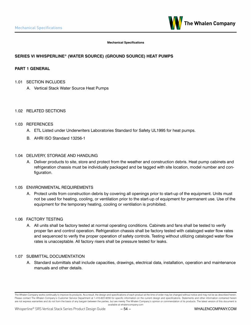
The Whalen Company works continually to improve its products. As a result, the design and specifications of each product at the time of order may be changed without notice and may not be as described herein. Please contact The Whalen Company’s Customer Service Department at 1-410-822-9200 for specific information on the current design and specifications. Statements and other information contained herein are not express warranties and do not form the basis of any bargain between the parties, but are merely The Whalen Company’s opinion or commendation of its products. The latest version of this document is
available at whalencompany.com
Whisperline® SRS Vertical Stack Series Product Design Guide whalencompany.com– 54 –
Mechanical Specifications
Mechanical Specifications
SERIES VI WHISPERLINE® (WATER SOURCE) (GROUND SOURCE) HEAT PUMPS
PART 1 GENERAL
1.01 SECTION INCLUDESA. Vertical Stack Water Source Heat Pumps
1.02 RELATED SECTIONS
1.03 REFERENCESA. ETL Listed under Underwriters Laboratories Standard for Safety UL1995 for heat pumps.
B. AHRI ISO Standard 13256-1
1.04 DELIVERY, STORAGE AND HANDLINGA. Deliver products to site, store and protect from the weather and construction debris. Heat pump cabinets and
refrigeration chassis must be individually packaged and be tagged with site location, model number and con-figuration.
1.05 ENVIRONMENTAL REQUIREMENTSA. Protect units from construction debris by covering all openings prior to start-up of the equipment. Units must
not be used for heating, cooling, or ventilation prior to the start-up of equipment for permanent use. Use of the equipment for the temporary heating, cooling or ventilation is prohibited.
1.06 FACTORY TESTINGA. All units shall be factory tested at normal operating conditions. Cabinets and fans shall be tested to verify
proper fan and control operation. Refrigeration chassis shall be factory tested with cataloged water flow rates and sequenced to verify the proper operation of safety controls. Testing without utilizing cataloged water flow rates is unacceptable. All factory risers shall be pressure tested for leaks.
1.07 SUBMITTAL DOCUMENTATIONA. Standard submittals shall include capacities, drawings, electrical data, installation, operation and maintenance
manuals and other details.

The Whalen Company works continually to improve its products. As a result, the design and specifications of each product at the time of order may be changed without notice and may not be as described herein. Please contact The Whalen Company’s Customer Service Department at 1-410-822-9200 for specific information on the current design and specifications. Statements and other information contained herein are not express warranties and do not form the basis of any bargain between the parties, but are merely The Whalen Company’s opinion or commendation of its products. The latest version of this document is
available at whalencompany.com
whalencompany.comWhisperline® SRS Vertical Stack Series Product Design Guide – 55 –
PART 2 PRODUCTS
2.01 TYPEA. Vertical Stack (Water Source) (Ground Source) Heat Pump with integral risers, discharge arrangements, hose
kits, and all accessories (ADD SPECIFIC OPTIONS HERE). Units shall be (standard range 60°F to 95°F [15.6°C to 35°C]) (extended range 20°F to 120°F [-6.7°C to 48.9°C]) entering fluid temperature for (water source) (ground source) heat pump applications.
B. Vertical Stack (Water Source) (Ground Source) Single Riser Heat Pump with integral risers, discharge arrange-ments, hose kits, and all accessories (ADD SPECIFIC OPTIONS HERE). Units shall be (standard range 60°F to 95°F [15.6°C to 35°C]) (extended range 20°F to 120°F [-6.7°C to 48.9°C]) entering fluid temperature for (water source) (ground source) heat pump applications.
2.02 CAPACITYA. Shall be as indicated on the drawings, which are based on Whalen units. Capacities shall be certified under
AHRI ISO Standard 13256-1.
2.03 CABINETSA. The one-piece unit cabinet shall be fabricated of reinforced 22-gauge continuous G60 galvanized steel. All
internal assemblies shall be welded and treated to prevent corrosion.
B. The cabinet shall be insulated with 1/2-inch thick 2-pound density thermal and acoustical fiberglass insulation meeting material standard ASTM-C1071 and have an integral water repellent. The insulation shall have a fungi and bacteria resistant barrier with no growth conforming to ASTM-C1338, ASTM G21 and ASTM G22 and meet fire safety standards under NFPA90A and NFPA90B. (OPTION) 1-inch thick 1-1/2-pound density thermal and acoustical fiberglass insulated discharge plenum.
C. The cabinet shall allow the placement of vertical risers on any side not being used for service access or dis-charge air openings.
D. The cabinet will have slots with edge protectors to accommodate movement of the risers with the isolation valves affixed (see 2.05 B). The slots shall remain covered with insulation to minimize air infiltration.
E. Cabinet return and discharge air openings shall be factory cut and flanged on all sides. All insulation located behind cabinet openings must be removed by the unit manufacturer prior to shipment. Knockouts for field cutting are unacceptable.
F. Cabinet design shall allow a minimum 5-inches below the chassis access opening to allow for full height base-board.
G. (OPTION) A factory installed vibration isolation pad shall be installed on the bottom of the unit.
H. The heat pump cabinets shall be shipped separately from, and prior to the refrigeration chassis for early instal-lation at the job site.
Mechanical Specifications

The Whalen Company works continually to improve its products. As a result, the design and specifications of each product at the time of order may be changed without notice and may not be as described herein. Please contact The Whalen Company’s Customer Service Department at 1-410-822-9200 for specific information on the current design and specifications. Statements and other information contained herein are not express warranties and do not form the basis of any bargain between the parties, but are merely The Whalen Company’s opinion or commendation of its products. The latest version of this document is
available at whalencompany.com
Whisperline® SRS Vertical Stack Series Product Design Guide whalencompany.com– 56 –
2.04 REFRIGERATION CHASSISA. The refrigeration chassis consisting of the compressor, air coil, water coil, reversing valve, expansion device,
receiver, filter-drier, and safety controls shall be slide-rail base mounted in the cabinet, and shall be designed for easy removal after disconnecting the two hoses and a polarized electrical power plug.
B. The compressor shall be the sealed hermetic type approved and tested for reverse cycle operation. Internal thermal overload protection shall be provided. The compressor shall be internally isolated and externally hard rubber mounted to the floating chassis. Compressor motors shall be permanent split capacitor (PSC) type.
C. The air coils shall be copper tubes mechanically bonded to aluminum fins, multi-circuited to insure maximum coil distribution and effectiveness, and a minimum of three rows deep. The coil shall be rated to withstand 600 psig refrigerant working pressure. Face velocity shall not exceed 400 feet per minute to insure quiet operation and positive condensate drainage.
D. The water coils shall incorporate an electro-coated steel outer tube and a copper inner tube. The inner tube shall be spirally fluted and bonded to the outer tube to insure controlled refrigerant velocity and distribution. The coil shall be rated to withstand 650 psig refrigerant and 400 psig fluid working pressures. (OPTION) Pro-vide Cupro-nickel COAX coil.
E. The reversing valve shall be 4-way electric type, pilot operated for quiet reversal.
F. The chassis shall be shipped separately from the WSHP cabinets to prevent exposure to, and fouling from finishing work.
G. Options for units without Single Riser System:
a. (OPTION 1) Automatic flow control valve – An automatic flow control valve shall be provided with each chassis and be factory preset for a fixed flow rate regardless of system pressure. Each automatic bal-ancing valve shall be capable of operation over a pressure differential range of 2 to 80 PSID. Valves must utilize threaded connections and be easily removable for cleaning and maintenance.
b. (OPTION 2) Standard Two-way, two-position (On/Off) control valve (30 psi differential pressure) – A two-way, two-position (On/Off) electric control valve shall be factory mounted and wired into the refrigeration chassis.
c. (OPTION 3) High Pressure Two-way, two-position (On/Off) control valve (60 psi differential pressure) – A two-way, two-position (On/Off) electric control valve shall be factory mounted and wired into the refrigera-tion chassis.
2.05 RISERSA. The unit manufacturer shall furnish Type M (OPTION: Type L) copper supply and return condenser water risers
as an integral factory-assembled component of the heat pump. Supply and return risers shall be protected by a galvanized steel pipe chase the length of the cabinet. (OPTION) Provide (3/8) (1/2)-inch thick closed-cell riser insulation the length of the cabinet for ground-source applications.
B. Ball-type isolation valves shall be factory assembled on the risers by the heat pump manufacturer. The chassis shall be connected to the isolation valves through high-pressure stainless steel hoses provided by the unit manufacturer, to isolate compressor noise and vibration from the piping system. Connection of the refrigerant chassis to building water system through the use of unions is unacceptable.
Mechanical Specifications

The Whalen Company works continually to improve its products. As a result, the design and specifications of each product at the time of order may be changed without notice and may not be as described herein. Please contact The Whalen Company’s Customer Service Department at 1-410-822-9200 for specific information on the current design and specifications. Statements and other information contained herein are not express warranties and do not form the basis of any bargain between the parties, but are merely The Whalen Company’s opinion or commendation of its products. The latest version of this document is
available at whalencompany.com
whalencompany.comWhisperline® SRS Vertical Stack Series Product Design Guide – 57 –
C. The unit manufacturer shall furnish the heat pump cabinet with the supply and return risers connected togeth-er (short circuited) between the isolation valves to facilitate flushing by bypassing water directly into the return loop without the water passing through any device in the unit (i.e. refrigeration chassis, automatic flow control valve).
D. The condensate drain riser shall be Type M copper and insulated the length of the cabinet with 3/8-inch closed-cell insulation.
2.06 DRAIN PANA. The drain pan shall collect and drain condensate that may form from any component internal to the heat pump
and shall be fabricated of welded and soldered 20 Ga. 304 stainless steel. The copper condensate drain shall be rolled and soldered into the pan.
2.07 FANSA. The fan shall be slow speed forward curved centrifugal type capable of two fan speeds, and shall be accessi-
ble for removal and maintenance through the return air opening.
2.08 MOTORSA. Fan motors for heat pumps under 2-ton shall be of the permanently lubricated PSC standard or hi-static pres-
sure (OPTION: ECM) type, as required; suitable for the current characteristics shown on the drawings, and shall have built-in thermal overload protection.
B. Fan motors for heat pumps 2-ton and above shall be of the permanently lubricated constant-torque ECM (OP-TION: constant-volume ECM) type, suitable for the current characteristics shown on the drawings, and shall have built-in overload protection.
C. Motors shall be plug-in, multi-speed type with 1050-RPM maximum.
D. (OPTION) Provide a two-speed fan switch located behind the acoustic return air panel. The fan switch must be configurable for use with available fan speed motor taps.
2.09 SUPPLY GRILLESA. (STANDARD) The supply grilles shall be of the single deflection type fabricated of clear anodized aluminum.
All supply openings shall be painted black with a damper assembly and sight baffle provided when one unit is serving two separate rooms.
(OPTION 1) The supply grilles shall be of the single deflection type fabricated of (factory white painted extrud-ed aluminum) or (custom painted extruded aluminum) (SELECT ONE). All supply openings shall be painted black with a damper assembly and sight baffle provided when one unit is serving two separate rooms.
(OPTION 2) The supply grilles shall be of the double deflection type fabricated of (clear anodized extruded alu-minum), (factory white painted extruded aluminum) or (custom painted extruded aluminum) (SELECT ONE). All supply openings shall be painted black with a damper assembly and sight baffle provided when one unit is serving two separate rooms.
Mechanical Specifications

The Whalen Company works continually to improve its products. As a result, the design and specifications of each product at the time of order may be changed without notice and may not be as described herein. Please contact The Whalen Company’s Customer Service Department at 1-410-822-9200 for specific information on the current design and specifications. Statements and other information contained herein are not express warranties and do not form the basis of any bargain between the parties, but are merely The Whalen Company’s opinion or commendation of its products. The latest version of this document is
available at whalencompany.com
Whisperline® SRS Vertical Stack Series Product Design Guide whalencompany.com– 58 –
2.10 RETURN AIR PANELA. (STANDARD) Unit Mounted Acoustical Panel – The return air opening shall be covered with a standard solid
hinged front acoustical panel with return air entering through the bottom, top and both sides. The front panel shall be fabricated of etched galvanized steel suitable for field painting to match the room decor. The return air panel shall allow for filter maintenance without the use of tools.
(OPTION 1) Flush Mounted Acoustical Panel – The return air opening shall be covered with a flush mounted hinged front acoustical panel with return air entering through the bottom, top and both sides. The panel shall be fabricated of etched galvanized steel suitable for field painting to match the room décor after attachment to the field installed drywall framing on the front of the unit. The return air panel shall allow for filter removal without the use of tools.
(OPTION 2) Painted Flush Mounted Acoustical Panel – The return air opening shall be covered with a flush mounted hinged front acoustical panel with return air entering through the bottom, top and both sides. The panel shall be fabricated of etched galvanized steel and painted factory white. The return air panel shall allow for filter removal without the use of tools.
(OPTION 3) Standard Return Air Grille – The return air opening shall be covered with an (Standard) Clear an-odized aluminum, (Option A) Factory white painted extruded aluminum or (Option B) Custom painted extruded aluminum air grille that is attached directly to the unit with two screws.
(OPTION 4) Removable Core Return Air Grille – The return air opening shall be covered with a (Standard) clear anodized aluminum, (Option A) factory white painted extruded aluminum or (Option B) custom painted extrud-ed aluminum air grille with quick-removal fasteners for easy filter removal without the use of tools.
2.11 FILTERSB. (STANDARD) Filters shall be 1” thick disposable fiberglass media, MERV 4.
(OPTION 1) Filters shall be 1” thick disposable pleated media, MERV 8.
(OPTION 2) Filters shall be 1” thick disposable pleated media, MERV 13.
(OPTION 3) Filters shall be 1” thick permanent aluminum cleanable media, MERV 4.
2.12 OUTDOOR AIRA. (OPTION 1) Heat pumps to be furnished with an outdoor air plenum for field installation incorporating an
outdoor air opening to provide conditioning of outdoor air and manual (motorized) block-off damper. The OA plenum shall be attached directly to the front of the heat pump unit and surround the return air opening. The outdoor air opening shall be located on the side of the plenum kit for either right or left side connection.
B. (OPTION 2) Heat pumps to be furnished with a “deep cabinet” configuration incorporating an outdoor air opening to provide conditioning of outdoor air and manual (motorized) block-off damper. Outdoor air open-ing must be placed before the heat pump air coil to allow conditioning while the heat pump is operating. The outdoor air opening shall be located on either side of the cabinet.
C. (OPTION 3) Heat pumps to be furnished with a “deep cabinet” configuration incorporating a 4” diameter out-door air opening in the cabinet top, with 1/2” deep duct collar and internal ducting to direct intake of outdoor air into the return air plenum and through the heat pump’s air coil prior to entering the occupied space. Out-
Mechanical Specifications

The Whalen Company works continually to improve its products. As a result, the design and specifications of each product at the time of order may be changed without notice and may not be as described herein. Please contact The Whalen Company’s Customer Service Department at 1-410-822-9200 for specific information on the current design and specifications. Statements and other information contained herein are not express warranties and do not form the basis of any bargain between the parties, but are merely The Whalen Company’s opinion or commendation of its products. The latest version of this document is
available at whalencompany.com
whalencompany.comWhisperline® SRS Vertical Stack Series Product Design Guide – 59 –
door air intake that is not directed to the return air plenum to allow outdoor air to pass through the air coil prior to entering the occupied space shall not be allowed.
2.13 POWER SUPPLYA. Single point field power connection is made to unit junction box through either of the 7/8” knockouts located
on the side or on the top of the cabinet as shown on the drawings.
(OPTION 1) Each unit shall include a non-fused disconnect switch, factory mounted and wired.
(OPTION 2) Each unit shall include a fused disconnect switch, factory mounted and wired.
2.14 CONTROLSA. Unit shall include a solid-state control board as part of the unit control system incorporating these features:
a. Random start compressor protection.
b. Anti-short cycle compressor minimum OFF time delay.
c. Safety controls that protect the compressor from the following conditions:
i. High pressure
ii. Low airflow
iii. Low liquid flow
iv. Low entering air temperature
v. Brown-out power conditions
vi. Condensate Overflow Protection
d. Status LED indicating the device causing a fault condition.
e. Soft lockout feature that provides for an automatic reset prior to the initiation of a hard lockout.
f. Test mode capability with shortened time delays for servicing.
g. (OPTION 1) Low pressure
h. (OPTION 2) Low/High liquid temperature protection with three different settings based on liquid properties.
2.15 THERMOSTATA. The heat pump manufacturer shall provide a 24-volt manual changeover wall thermostat with a HEAT-OFF-
COOL system switch and AUTO-ON fan selector switch.
B. The heat pump manufacturer shall provide a thermostat capable of front mounting at a height of 48 inches from the bottom of the cabinet to comply with The Americans with Disabilities Act (ADA).
Mechanical Specifications
The Whalen Company works continually to improve its products. As a result, the design and specifications of each product at the time of order may be changed without notice and may not be as described herein. Please contact The Whalen Company’s Customer Service Department at 1-410-822-9200 for specific information on the current design and specifications. Statements and other information contained herein are not express warranties and do not form the basis of any bargain between the parties, but are merely The Whalen Company’s opinion or commendation of its products. The latest version of this document is
available at whalencompany.com
Whisperline® SRS Vertical Stack Series Product Design Guide whalencompany.com– 60 –
C. Others shall install thermostat by plugging into the control wiring with a polarized male-female plug after the walls are finished when unit mounted or attaching to color coded pigtails when remote mounted. High volt-age, return air thermostats with remote bulbs subject to damage during routine service will not be accepted.
2.16 SPARE PARTSA. The installing contractor shall provide to the Owner one spare chassis for each fifty heat pumps of a given
size. (Add any additional spare parts requirements here).
PART 3 EXECUTION
3.01 INSTALLATIONA. Furnish as shown on the drawings and as specified herein, vertical stack water source heat pumps with inte-
gral risers, and with capacity and electrical characteristics as scheduled. Units shall be Series VI as manufac-tured by The Whalen Company of Easton, MD.
B. Install in accordance with manufacturer’s installation instructions. Install units plumb and level, and maintain manufacturer’s recommended clearances for the unit and accessories.
C. Follow manufacturer’s recommendations for cleaning and flushing.
Mechanical Specifications
The Whalen Company works continually to improve its products. As a result, the design and specifications of each product at the time of order may be changed without notice and may not be as described herein. Please contact The Whalen Company’s Customer Service Department at 1-410-822-9200 for specific information on the current design and specifications. Statements and other information contained herein are not express warranties and do not form the basis of any bargain between the parties, but are merely The Whalen Company’s opinion or commendation of its products. The latest version of this document is
available at whalencompany.com
whalencompany.comWhisperline® SRS Vertical Stack Series Product Design Guide – 61 –
Whisperline® Warranty Statements
The Whalen Company works continually to improve its products. As a result, the design and specifications of each product at the time of order may be changed without notice and may not be as described herein. Please contact The Whalen Company’s Customer Service Department at 1-410-822-9200 for specific information on the current design and specifications. Statements and other information contained herein are not express warranties and do not form the basis of any bargain between the parties, but are merely The Whalen Company’s opinion or commendation of its products. The latest version of this document is
available at whalencompany.com
Whisperline™ Series Product Design Guide whalencompany.com– 66 –
Whisperline™ Warranty Statements
SA
MP
LE
The
Wha
len
Com
pany
war
rant
s to
the
purc
hase
r eac
h w
ater
-to-a
ir he
at p
ump
to b
e fre
e fro
m o
rigin
al d
efec
ts in
mat
eria
ls a
nd w
orkm
ansh
ip.
Whe
re in
spec
tion
by a
n au
thor
ized
repr
esen
tativ
e of
The
Wha
len
Com
pany
con
fi rm
s su
ch d
efec
ts to
be
pres
ent,
for a
per
iod
of fi
fteen
mon
ths
from
dat
e of
shi
pmen
t, W
hale
n w
ill fu
rnis
h re
plac
emen
t com
pone
nts
or m
ater
ials
to th
e or
igin
al p
urch
aser
with
out c
harg
e.
This
war
rant
y ex
clud
es a
ll fi e
ld la
bor i
n co
nnec
tion
with
insp
ectio
n an
d di
agno
sis
of m
alfu
nctio
ns, a
ll fi e
ld la
bor
in c
onne
ctio
n w
ith re
pair
or re
plac
emen
t of p
arts
, all
fi eld
labo
r in
conn
ectio
n w
ith re
mov
al a
nd tr
ansp
orta
tion
to a
nd fr
om a
repa
ir fa
cilit
y an
d al
l fi e
ld la
bor i
n co
nnec
tion
with
rein
stal
latio
n af
ter r
epai
rs a
re c
ompl
eted
.
This
war
rant
y is
inte
nded
to c
over
orig
inal
equ
ipm
ent d
efec
ts o
nly.
Wha
len
expr
essl
y di
scla
ims
all l
iabi
lity
for c
ompo
nent
failu
res
aris
ing
out o
f the
mis
use
of W
hale
n he
at p
umps
thro
ugh
mis
appl
icat
ion,
im
prop
er in
stal
latio
n, in
adeq
uate
mai
nten
ance
, or o
pera
tion
on d
efec
tive
wat
er a
nd e
lect
rical
sys
tem
s.
Equ
ipm
ent f
ailu
re d
ue to
cor
rosi
on, a
buse
or a
cts
of G
od is
als
o ex
clud
ed fr
om th
is w
arra
nty.
The
Wha
len
Com
pany
nei
ther
ass
umes
nor
aut
horiz
es a
ny p
erso
n to
ass
ume
for i
t any
obl
igat
ion
or w
arra
nty
othe
r tha
n th
ose
stat
ed h
erei
n.
Rep
lace
men
t or r
epai
r und
er th
is w
arra
nty
will
not
ext
end
the
war
rant
y tim
e pe
riods
defi
ned
abo
ve.
Wha
len
shal
l not
, in
any
even
t, ha
ve a
ny li
abili
ty u
nder
this
war
rant
y un
less
and
unt
il it
has
been
pai
d in
full
for t
he e
quip
men
t sup
plie
d. T
he w
arra
nty
perio
d sh
all c
omm
ence
on
the
date
of s
hipm
ent,
how
ever
, whe
ther
or n
ot p
aym
ent h
as b
een
mad
e.
This
war
rant
y ap
plie
s on
ly to
Wha
len
heat
pum
p in
stal
latio
ns in
the
fi fty
Uni
ted
Sta
tes
and
in C
anad
a.
Ther
e ar
e no
war
rant
ies
outs
ide
thos
e ar
eas.
Th
e W
hale
n C
ompa
ny h
as n
o lia
bilit
y fo
r inc
iden
tal o
r con
sequ
entia
l dam
ages
aris
ing
out o
f the
ow
ners
hip,
use
or o
pera
tion
of W
hale
n he
at p
umps
.TH
ERE
ARE
NO
WAR
RAN
TIES
WH
ICH
EXT
END
BEY
ON
D T
HE
DES
CR
IPTI
ON
ON
TH
E FA
CE
HER
EOF.
NO
IMPL
IED
WAR
RAN
TY
OR
MER
CH
ANTA
BILI
TY S
HAL
L AC
CO
MPA
NY
THE
SALE
OF
THIS
EQ
UIP
MEN
T, A
ND
TH
IS E
XPR
ESS
WAR
RAN
TY IS
INTE
ND
ED
TO A
ND
DO
ES R
EPLA
CE
ANY
IMPL
IED
WAR
RAN
TY O
F M
ERC
HAN
TABI
LITY
.
This
war
rant
y, it
s lim
itatio
ns a
nd it
s ex
clus
ions
are
to b
e go
vern
ed b
y th
e la
ws
of M
aryl
and.
Alth
ough
som
e w
arra
ntie
s m
ay v
ary
in th
eir e
ffect
and
cov
erag
e fro
m lo
calit
y to
loca
lity,
this
war
rant
y, it
s ef
fect
s, c
over
age
and
rem
edie
s ar
e on
ly th
ose
avai
labl
e in
Mar
ylan
d.
The
Wh
alen
Co
mp
any
Lim
ited
Exp
ress
War
ran
tyW
ater
-to
-Air
Hea
t P
um
p C
abin
et S
tan
dar
d W
arra
nty
Rev
: 05/
2015

The Whalen Company works continually to improve its products. As a result, the design and specifications of each product at the time of order may be changed without notice and may not be as described herein. Please contact The Whalen Company’s Customer Service Department at 1-410-822-9200 for specific information on the current design and specifications. Statements and other information contained herein are not express warranties and do not form the basis of any bargain between the parties, but are merely The Whalen Company’s opinion or commendation of its products. The latest version of this document is
available at whalencompany.com
Whisperline® SRS Vertical Stack Series Product Design Guide whalencompany.com– 62 –
Whisperline® Warranty Statements
The Whalen Company works continually to improve its products. As a result, the design and specifications of each product at the time of order may be changed without notice and may not be as described herein. Please contact The Whalen Company’s Customer Service Department at 1-410-822-9200 for specific information on the current design and specifications. Statements and other information contained herein are not express warranties and do not form the basis of any bargain between the parties, but are merely The Whalen Company’s opinion or commendation of its products.
The latest version of this document is available at whalencompany.com
WhisperlineTM Series Product Design Guide - 72 - WHALENCOMPANY.COM
Product Warranty Certificate
SA
MP
LE
The
Wha
len
Com
pany
war
rant
s to
the
purc
hase
r ea
ch w
ater
-to-a
ir he
at p
ump
chas
sis
(or
each
ref
riger
atio
n ch
assi
s)
to b
e fre
e fro
m o
rigin
al d
efec
ts in
mat
eria
ls a
nd w
orkm
ansh
ip.
Whe
re in
spec
tion
by a
n au
thor
ized
rep
rese
ntat
ive
of T
he W
hale
n C
ompa
ny c
onfir
ms
such
def
ects
to b
e pr
esen
t,
for
a pe
riod
of tw
elve
mon
ths
from
dat
e of
shi
pmen
t, W
hale
n w
ill fu
rnis
h re
plac
emen
t com
pone
nts
or
mat
eria
ls to
the
orig
inal
pur
chas
er w
ithou
t cha
rge.
This
war
rant
y ex
clud
es a
ll fie
ld la
bor
in c
onne
ctio
n w
ith in
spec
tion
and
diag
nosi
s of
mal
func
tions
, al
l fie
ld la
bor
in c
onne
ctio
n w
ith r
epai
r or
rep
lace
men
t of p
arts
, all
field
labo
r in
con
nect
ion
with
rem
oval
and
tr
ansp
orta
tion
to a
nd fr
om a
rep
air
faci
lity
and
all f
ield
labo
r in
con
nect
ion
with
rei
nsta
llatio
n af
ter
repa
irs a
re c
ompl
eted
.
This
war
rant
y is
inte
nded
to c
over
orig
inal
equ
ipm
ent d
efec
ts o
nly.
Wha
len
expr
essl
y di
scla
ims
all l
iabi
lity
fo
r co
mpo
nent
failu
res
aris
ing
out o
f the
mis
use
of W
hale
n he
at p
umps
thro
ugh
mis
appl
icat
ion,
impr
oper
inst
alla
tion,
in
adeq
uate
mai
nten
ance
, or
oper
atio
n on
def
ectiv
e w
ater
and
ele
ctric
al s
yste
ms.
Equ
ipm
ent f
ailu
re d
ue to
co
rros
ion,
abu
se, o
r ac
ts o
f God
is a
lso
excl
uded
from
this
war
rant
y.
The
Wha
len
Com
pany
nei
ther
ass
umes
nor
aut
horiz
es a
ny p
erso
n to
ass
ume
for
it an
y ob
ligat
ion
or
war
rant
y ot
her
than
thos
e st
ated
her
ein.
Rep
lace
men
t or
repa
ir un
der
this
war
rant
y w
ill n
ot e
xten
d th
e w
arra
nty
time
perio
ds d
efin
ed a
bove
. Wha
len
shal
l not
, in
any
eve
nt, h
ave
any
liabi
lity
unde
r th
is w
arra
nty
unle
ss a
nd u
ntil
it ha
s be
en p
aid
in fu
ll
for
the
equi
pmen
t sup
plie
d. T
he w
arra
nty
perio
d sh
all c
omm
ence
on
the
date
of s
hipm
ent,
how
ever
, w
heth
er o
r no
t pay
men
t has
bee
n m
ade.
This
war
rant
y ap
plie
s on
ly to
Wha
len
heat
pum
p in
stal
latio
ns in
the
fifty
Uni
ted
Sta
tes
and
in C
anad
a.
Ther
e ar
e no
war
rant
ies
outs
ide
thos
e ar
eas.
The
Wha
len
Com
pany
has
no
liabi
lity
for
inci
dent
al o
r co
nseq
uent
ial d
amag
es a
risin
g ou
t of t
he o
wne
rshi
p,
use,
or
oper
atio
n of
Wha
len
heat
pum
ps.
THE
RE
AR
E N
O W
AR
RA
NTI
ES
WH
ICH
EX
TEN
D B
EYO
ND
TH
E D
ES
CR
IPTI
ON
ON
TH
E F
AC
E H
ER
EO
F.
NO
IMP
LIE
D W
AR
RA
NTY
OR
ME
RC
HA
NTA
BIL
ITY
SH
ALL
AC
CO
MPA
NY
TH
E S
ALE
OF
THIS
EQ
UIP
ME
NT,
AN
D T
HIS
E
XP
RE
SS
WA
RR
AN
TY IS
INTE
ND
ED
TO
AN
D D
OE
S R
EP
LAC
E A
NY
IMP
LIE
D W
AR
RA
NTY
OF
ME
RC
HA
NTA
BIL
ITY.
This
war
rant
y, it
s lim
itatio
ns a
nd it
s ex
clus
ions
are
to b
e go
vern
ed b
y th
e la
ws
of M
aryl
and.
Alth
ough
som
e w
arra
ntie
s
may
var
y in
thei
r ef
fect
and
cov
erag
e fro
m lo
calit
y to
loca
lity,
this
war
rant
y, it
s ef
fect
s, c
over
age,
an
d re
med
ies
are
only
thos
e av
aila
ble
in M
aryl
and.
The
Wh
alen
Co
mp
any
Lim
ited
Exp
ress
War
ran
tyW
ater
-to
-Air
Hea
t P
um
p C
has
sis
Stan
dar
d W
arra
nty
Rev
: 05/
2015

The Whalen Company works continually to improve its products. As a result, the design and specifications of each product at the time of order may be changed without notice and may not be as described herein. Please contact The Whalen Company’s Customer Service Department at 1-410-822-9200 for specific information on the current design and specifications. Statements and other information contained herein are not express warranties and do not form the basis of any bargain between the parties, but are merely The Whalen Company’s opinion or commendation of its products. The latest version of this document is
available at whalencompany.com
whalencompany.comWhisperline® SRS Vertical Stack Series Product Design Guide – 63 –
Whisperline® Warranty Statements
The Whalen Company works continually to improve its products. As a result, the design and specifications of each product at the time of order may be changed without notice and may not be as described herein. Please contact The Whalen Company’s Customer Service Department at 1-410-822-9200 for specific information on the current design and specifications. Statements and other information contained herein are not express warranties and do not form the basis of any bargain between the parties, but are merely The Whalen Company’s opinion or commendation of its products.
The latest version of this document is available at whalencompany.com
WhisperlineTM Series Product Design Guide - 74 - WHALENCOMPANY.COM
Product Warranty Certificate
SA
MP
LE
The
Wha
len
Com
pany
war
rant
s to
the
purc
hase
r ea
ch w
ater
-to-a
ir he
at p
ump
to b
e fre
e fro
m
orig
inal
def
ects
in m
ater
ials
and
wor
kman
ship
.
Whe
re in
spec
tion
by a
n au
thor
ized
rep
rese
ntat
ive
of T
he W
hale
n C
ompa
ny c
onfir
ms
such
def
ects
to b
e pr
esen
t,
for
a pe
riod
of fi
fteen
mon
ths
from
dat
e of
shi
pmen
t, W
hale
n w
ill fu
rnis
h re
plac
emen
t com
pone
nts
or
mat
eria
ls to
the
orig
inal
pur
chas
er w
ithou
t cha
rge.
In a
dditi
on, f
or a
per
iod
of s
ixty
mon
ths
from
the
date
of s
hipm
ent,
Wha
len
will
furn
ish
a re
plac
emen
t fo
r an
y co
mpr
esso
r fo
und
by a
n au
thor
ized
rep
rese
ntat
ive
of T
he W
hale
n C
ompa
ny to
con
tain
an
orig
inal
def
ect.
This
war
rant
y do
es n
ot c
over
labo
r in
con
nect
ion
with
rep
air
or r
epla
cem
ent o
f par
ts, l
abor
in c
onne
ctio
n w
ith r
emov
al a
nd
tran
spor
tatio
n to
and
from
a r
epai
r fa
cilit
y, o
r la
bor
in c
onne
ctio
n w
ith r
eins
talla
tion
afte
r re
pairs
are
com
plet
ed.
The
sixt
y m
onth
ext
ende
d w
arra
nty
is in
tend
ed to
cov
er o
rigin
al e
quip
men
t def
ects
onl
y. W
hale
n ex
pres
sly
disc
laim
s
all l
iabi
lity
for
com
pone
nt fa
ilure
s ar
isin
g ou
t of t
he m
isus
e of
Wha
len
heat
pum
ps th
roug
h m
isap
plic
atio
n, im
prop
er in
stal
latio
n,
inad
equa
te m
aint
enan
ce, o
r op
erat
ion
on d
efec
tive
wat
er a
nd e
lect
rical
sys
tem
s. E
quip
men
t fai
lure
due
to c
orro
sion
, ab
use,
or
acts
of G
od is
als
o ex
clud
ed fr
om th
is w
arra
nty.
The
Wha
len
Com
pany
nei
ther
ass
umes
nor
aut
horiz
es a
ny p
erso
n to
ass
ume
for
it an
y ob
ligat
ion
or
war
rant
y ot
her
than
thos
e st
ated
her
ein.
Rep
lace
men
t or
repa
ir un
der
this
war
rant
y w
ill n
ot e
xten
d th
e w
arra
nty
time
perio
ds d
efin
ed a
bove
. Wha
len
shal
l not
, in
any
even
t, ha
ve a
ny li
abili
ty u
nder
this
war
rant
y un
less
and
unt
il it
has
been
pai
d in
full
for
the
equi
pmen
t sup
plie
d. T
he w
arra
nty
perio
d sh
all
com
men
ce o
n th
e da
te o
f shi
pmen
t, ho
wev
er, w
heth
er o
r no
t pay
men
t has
bee
n m
ade.
This
war
rant
y ap
plie
s on
ly to
Wha
len
heat
pum
p in
stal
latio
ns in
the
fifty
Uni
ted
Sta
tes
and
in C
anad
a.
Ther
e ar
e no
war
rant
ies
outs
ide
thos
e ar
eas.
The
Wha
len
Com
pany
has
no
liabi
lity
for
inci
dent
al o
r co
nseq
uent
ial d
amag
es a
risin
g ou
t of t
he o
wne
rshi
p,
use,
or
oper
atio
n of
Wha
len
heat
pum
ps.
THE
RE
AR
E N
O W
AR
RA
NTI
ES
WH
ICH
EX
TEN
D B
EYO
ND
TH
E D
ES
CR
IPTI
ON
ON
TH
E F
AC
E H
ER
EO
F. N
O IM
PLI
ED
WA
RR
AN
TY
OR
ME
RC
HA
NTA
BIL
ITY
SH
ALL
AC
CO
MPA
NY
TH
E S
ALE
OF
THIS
EQ
UIP
ME
NT,
AN
D T
HIS
EX
PR
ES
S W
AR
RA
NTY
IS IN
TEN
DE
D T
O
AN
D D
OE
S R
EP
LAC
E A
NY
IMP
LIE
D W
AR
RA
NTY
OF
ME
RC
HA
NTA
BIL
ITY.
This
war
rant
y, it
s lim
itatio
ns a
nd it
s ex
clus
ions
are
to b
e go
vern
ed b
y th
e la
ws
of M
aryl
and.
Alth
ough
som
e w
arra
ntie
s
may
var
y in
thei
r ef
fect
and
cov
erag
e fro
m lo
calit
y to
loca
lity,
this
war
rant
y, it
s ef
fect
s, c
over
age,
an
d re
med
ies
are
only
thos
e av
aila
ble
in M
aryl
and.
The
Wh
alen
Co
mp
any
Lim
ited
Exp
ress
War
ran
tyW
ater
-to
-Air
Hea
t P
um
p w
ith
5 Y
ear
Co
mp
ress
or
War
ran
ty
Rev
: 05/
2015

The Whalen Company works continually to improve its products. As a result, the design and specifications of each product at the time of order may be changed without notice and may not be as described herein. Please contact The Whalen Company’s Customer Service Department at 1-410-822-9200 for specific information on the current design and specifications. Statements and other information contained herein are not express warranties and do not form the basis of any bargain between the parties, but are merely The Whalen Company’s opinion or commendation of its products. The latest version of this document is
available at whalencompany.com
Whisperline® SRS Vertical Stack Series Product Design Guide whalencompany.com– 64 –
Whisperline® Warranty Statements
The Whalen Company works continually to improve its products. As a result, the design and specifications of each product at the time of order may be changed without notice and may not be as described herein. Please contact The Whalen Company’s Customer Service Department at 1-410-822-9200 for specific information on the current design and specifications. Statements and other information contained herein are not express warranties and do not form the basis of any bargain between the parties, but are merely The Whalen Company’s opinion or commendation of its products.
The latest version of this document is available at whalencompany.com
WhisperlineTM Series Product Design Guide - 75 - WHALENCOMPANY.COM
Product Warranty Certificate
SA
MP
LE
The
Wha
len
Com
pany
war
rant
s to
the
purc
hase
r ea
ch w
ater
-to-a
ir he
at p
ump
to b
e
free
from
orig
inal
def
ects
in m
ater
ials
and
wor
kman
ship
.
Whe
re in
spec
tion
by a
n au
thor
ized
rep
rese
ntat
ive
of T
he W
hale
n C
ompa
ny c
onfir
ms
such
def
ects
to b
e pr
esen
t,
for
a pe
riod
of fi
fteen
mon
ths
from
dat
e of
shi
pmen
t, W
hale
n w
ill fu
rnis
h re
plac
emen
t com
pone
nts
or
mat
eria
ls to
the
orig
inal
pur
chas
er w
ithou
t cha
rge.
In a
dditi
on, f
or a
per
iod
of s
ixty
mon
ths
from
the
date
of s
hipm
ent,
Wha
len
will
rep
air
or r
epla
ce r
efrig
erat
ion
circ
uit c
ompo
nent
s fo
und
by a
n au
thor
ized
rep
rese
ntat
ive
of T
he W
hale
n C
ompa
ny to
con
tain
an
orig
inal
def
ect.
Ref
riger
atio
n ci
rcui
t com
pone
nts
are
defin
ed to
incl
ude
the
com
pres
sor,
reve
rsin
g va
lve,
wat
er c
oil,
air
coil,
exp
ansi
on d
evic
e an
d in
terc
onne
ctin
g tu
bing
onl
y.
This
war
rant
y ex
clud
es a
ll fie
ld la
bor
in c
onne
ctio
n w
ith in
spec
tion
and
diag
nosi
s of
mal
func
tions
, all
field
labo
r in
con
nect
ion
w
ith r
epai
r or
rep
lace
men
t of p
arts
, all
field
labo
r in
con
nect
ion
with
rem
oval
and
tran
spor
tatio
n to
and
from
a r
epai
r fa
cilit
y,
and
all f
ield
labo
r in
con
nect
ion
with
rei
nsta
llatio
n af
ter
repa
irs a
re c
ompl
eted
.
The
sixt
y m
onth
ext
ende
d w
arra
nty
is in
tend
ed to
cov
er o
rigin
al e
quip
men
t def
ects
onl
y. W
hale
n ex
pres
sly
disc
laim
s al
l lia
bilit
y
for
com
pone
nt fa
ilure
s ar
isin
g ou
t of t
he m
isus
e of
Wha
len
heat
pum
ps th
roug
h m
isap
plic
atio
n, im
prop
er in
stal
latio
n,
inad
equa
te m
aint
enan
ce, o
r op
erat
ion
on d
efec
tive
wat
er a
nd e
lect
rical
sys
tem
s. E
quip
men
t fai
lure
due
to
corr
osio
n, a
buse
or
acts
of G
od is
als
o ex
clud
ed fr
om th
is w
arra
nty.
The
Wha
len
Com
pany
nei
ther
ass
umes
nor
aut
horiz
es a
ny p
erso
n to
ass
ume
for
it an
y ob
ligat
ion
or
war
rant
y ot
her
than
thos
e st
ated
her
ein.
Rep
lace
men
t or
repa
ir un
der
this
war
rant
y w
ill n
ot e
xten
d th
e w
arra
nty
time
perio
ds d
efin
ed a
bove
. Wha
len
shal
l not
, in
any
even
t, ha
ve a
ny li
abili
ty u
nder
this
war
rant
y un
less
and
unt
il it
has
been
pai
d in
full
for
the
equi
pmen
t sup
plie
d. T
he w
arra
nty
perio
d sh
all
com
men
ce o
n th
e da
te o
f shi
pmen
t, ho
wev
er, w
heth
er o
r no
t pay
men
t has
bee
n m
ade.
This
war
rant
y ap
plie
s on
ly to
Wha
len
heat
pum
p in
stal
latio
ns in
the
fifty
Uni
ted
Sta
tes
and
in C
anad
a.
Ther
e ar
e no
war
rant
ies
outs
ide
thos
e ar
eas.
The
Wha
len
Com
pany
has
no
liabi
lity
for
inci
dent
al o
r co
nseq
uent
ial d
amag
es a
risin
g ou
t of t
he o
wne
rshi
p,
use,
or
oper
atio
n of
Wha
len
heat
pum
ps.
THE
RE
AR
E N
O W
AR
RA
NTI
ES
WH
ICH
EX
TEN
D B
EYO
ND
TH
E D
ES
CR
IPTI
ON
ON
TH
E F
AC
E H
ER
EO
F. N
O IM
PLI
ED
WA
RR
AN
TY O
R
ME
RC
HA
NTA
BIL
ITY
SH
ALL
AC
CO
MPA
NY
TH
E S
ALE
OF
THIS
EQ
UIP
ME
NT,
AN
D T
HIS
EX
PR
ES
S W
AR
RA
NTY
IS IN
TEN
DE
D
TO A
ND
DO
ES
RE
PLA
CE
AN
Y IM
PLI
ED
WA
RR
AN
TY O
F M
ER
CH
AN
TAB
ILIT
Y.
This
war
rant
y, it
s lim
itatio
ns a
nd it
s ex
clus
ions
are
to b
e go
vern
ed b
y th
e la
ws
of M
aryl
and.
Alth
ough
som
e w
arra
ntie
s m
ay v
ary
in
thei
r ef
fect
and
cov
erag
e fro
m lo
calit
y to
loca
lity,
this
war
rant
y, it
s ef
fect
s,
cove
rage
, and
rem
edie
s ar
e on
ly th
ose
avai
labl
e in
Mar
ylan
d.
The
Wh
alen
Co
mp
any
Lim
ited
Exp
ress
War
ran
tyW
ater
-to
-Air
Hea
t P
um
p w
ith
5 Y
ear
Ref
rig
erat
ion
Cir
cuit
War
ran
ty
Rev
: 05/
2015

The Whalen Company works continually to improve its products. As a result, the design and specifications of each product at the time of order may be changed without notice and may not be as described herein. Please contact The Whalen Company’s Customer Service Department at 1-410-822-9200 for specific information on the current design and specifications. Statements and other information contained herein are not express warranties and do not form the basis of any bargain between the parties, but are merely The Whalen Company’s opinion or commendation of its products. The latest version of this document is
available at whalencompany.com
whalencompany.comWhisperline® SRS Vertical Stack Series Product Design Guide – 65 –
Notes

The Whalen Company works continually to improve its products. As a result, the design and specifications of each product at the time of order may be changed without notice and may not be as described herein. Please contact The Whalen Company’s Customer Service Department at 1-410-822-9200 for specific information on the current design and specifications. Statements and other information contained herein are not express warranties and do not form the basis of any bargain between the parties, but are merely The Whalen Company’s opinion or commendation of its products. The latest version of this document is
available at whalencompany.com
Whisperline® SRS Vertical Stack Series Product Design Guide whalencompany.com– 66 –
Notes

The Whalen Company works continually to improve its products. As a result, the design and specifications of each product at the time of order may be changed without notice and may not be as described herein. Please contact The Whalen Company’s Customer Service Department at 1-410-822-9200 for specific information on the current design and specifications. Statements and other information contained herein are not express warranties and do not form the basis of any bargain between the parties, but are merely The Whalen Company’s opinion or commendation of its products. The latest version of this document is
available at whalencompany.com
whalencompany.comWhisperline® SRS Vertical Stack Series Product Design Guide – 67 –
Whisperline® Single Riser Design Guide Revision Table
Whisperline® Design Guide RevisionTable
Date Description
07/19/17 Registered Symbol added to Whisperline®
11/16/2016 Refrigerant Charge line corrected in Physical Data Table
10/12/2016 Integral Pump Drawing Updated
08/29/2016 Cabinet Drawings and Riser Drawings Updated
07/01/2016 High Static PSC Motor electrical data tables added
06/14/16 Riser Detail and Cabinet Drawings Updated
06/02/16 Supply Grille Discharge Arrangement Drawing Updated
04/21/16 Drawings Updated
03/04/16 Drawings Updated; CV and CT Electrical Data Updated
01/18/2015 Cabinet Nomenclature Updated
10/2015 New Release of document

8900 Glebe Park DriveEaston, MD 21601
Tel, 410.822.9200 • 410.822.8926whalencompany.com
www.whalencompany.com
Whisperline is a registered trademark of The Whalen Company. © Whalen Company 2016. All rights reserved.
Related Documents


![+RUL]RQWDO&HLOLQJ 0RXQWHG :DWHU6RXUFH ......CAT 1108-29 • ENFINITY HORIZONTAL WSHP 2 Contents Model Nomenclature . . . . . . . . . . . . . . . . . . . . . . . . .3 . AHRI Performance](https://static.cupdf.com/doc/110x72/6103972cec713301f26eae5c/rulrqwdohlolqj-0rxqwhg-dwhu6rxufh-cat-1108-29-a-enfinity-horizontal.jpg)


