Product Data Sheet January 2014 00813-0100-4727, Rev UE Industry leading performance with standard reference accuracy of 0.25% of rate with an optional High Accuracy of 0.15% of rate Rosemount 8732 Transmitter - Integral-mount design, backlit display, and explosion-proof housing. Available with HART ® , FOUNDATION ™ fieldbus, or PROFIBUS PA, Device Diagnostics, and Smart ™ Meter Verification to improve reliability and performance Rosemount 8712 HART Transmitter - available with Device Diagnostics including Smart Meter Verification to improve reliability and performance. Quick setup with easy-to-use local operator interface Rosemount 8712H/8707 High-Signal System - Pulsed DC solutions for the most demanding flow measurement applications Rosemount 8705 Flanged sensor - Fully welded sensor for maximum protection Rosemount 8711 Wafer sensor - Economical, compact, and lightweight sensor, provided with alignment spacers for easy installation Rosemount 8721 Hygienic sensor - Specifically designed for food, beverage, and life sciences applications Rosemount 8700 Series Magnetic Flowmeter Systems

Welcome message from author
This document is posted to help you gain knowledge. Please leave a comment to let me know what you think about it! Share it to your friends and learn new things together.
Transcript

Product Data SheetJanuary 2014
00813-0100-4727, Rev UE
Rosemount 8700 SeriesMagnetic Flowmeter Systems
Industry leading performance with standard reference accuracy of 0.25% of rate with an optional High Accuracy of 0.15% of rate
Rosemount 8732 Transmitter - Integral-mount design, backlit display, and explosion-proof housing. Available with HART®, FOUNDATION™ fieldbus, or PROFIBUS PA, Device Diagnostics, and Smart™ Meter Verification to improve
reliability and performanceRosemount 8712 HART Transmitter - available with Device Diagnostics including Smart Meter Verification to improve reliability and performance. Quick setup with easy-to-use local operator interface
Rosemount 8712H/8707 High-Signal System - Pulsed DC solutions for the most demanding flow measurement applications
Rosemount 8705 Flanged sensor - Fully welded sensor for maximum protection
Rosemount 8711 Wafer sensor - Economical, compact, and lightweight sensor, provided with alignment spacers for easy installation
Rosemount 8721 Hygienic sensor - Specifically designed for food, beverage, and life sciences applications

Rosemount 8700 Series January 2014
2 www.rosemount.com
Product selection guide
Several sensor types, liner types, electrode materials, electrode types, grounding options, and transmitters are available for the Rosemount 8700 Series Magnetic Flowmeter System to ensure compatibility with virtually any application and installation. See Table 16 for information on liner types, Table 17 for information on electrode materials and electrode types, Table 18 and Table 19 for grounding options and installation, and Table 1 for transmitter selection. Other material options not mentioned here may be available. Contact your local sales representative for alternative material selection. For further guidance on selecting materials, refer to the Magnetic Flowmeter Material Selection Guide located on Rosemount.com (Technical Data Sheet Number 00816-0100-3033). For more information regarding product offering and ordering information, refer to “Ordering information” on page 6 in this product data sheet.
Table 1. Transmitter selection
Table 2. Sensor selection
Contents
Magmeter diagnostics . . . . . . . . . . . . . . . . . . . . . . page 3
Magnetic flowmeter sizing . . . . . . . . . . . . . . . . . . page 4
Ordering information . . . . . . . . . . . . . . . . . . . . . . page 6
Product specifications . . . . . . . . . . . . . . . . . . . . . . . page 26
Product certifications . . . . . . . . . . . . . . . . . . . . . . . . page 47
Dimensional drawings . . . . . . . . . . . . . . . . . . . . . . . page 61
Transmitter General Characteristics
8732• Ideal for integral mount transmitter installations
• HART / Analog, FOUNDATION fieldbus, or PROFIBUS PA fieldbus output available
• Advanced Diagnostics available
• Optical Switch LOI
• Optional DI/DO available (HART only)
8712 • Remote mount transmitter
• Easy to use LOI with dedicated configuration buttons
• Advanced Diagnostics available
• Perfect for wall or panel mount
8712H• Remote mount transmitter
• High-Signal Pulsed DC for use with the High-Signal 8707 Sensor
• Ideal for high solid applications - mining/pulp stock/other slurries
• 120 VAC power only
• Not CE Marked
Sensor General Characteristics
8705• Standard Process Sensor
• Flanged Process Connections
• Welded, sealed coil housing
• 1/2-in. (15mm) to 36-in. (900mm)
• Pulse DC Technology
• Standard, grounding, and bullet-nose electrodes available
8707
• High Signal Sensor
• Flanged Process System Sensor
• Welded, sealed coil housing
• 3-in. (80mm) to 36-in. (900mm)
• High current pulsed DC technology ideal for high solids or slurry applications
• Standard, grounding, and bullet-nose electrodes available
8711• Wafer (flangeless) design
• Economical, compact, and lightweight alternative to flanged sensors
• 0.15-in. (4mm) to 8-in. (200mm)
• Pulsed DC technology
• Standard, grounding, and bullet-nose electrodes available
8721
• Hygienic sensor
• Designed for food, beverage, and pharmaceutical applications
• 3-A and EHEDG certified
• 1/2-in. (15mm) to 4-in. (100mm)
• Pulsed DC technology
• Variety of industry standard process connections
• Suitable for CIP/SIP

Rosemount 8700 SeriesJanuary 2014
Magmeter diagnostics
Rosemount Mag Diagnostics Power PlantWeb to Reduce Cost & Improve Output by Enabling New Practices Rosemount Magmeters provide device diagnostics that powers PlantWeb and informs the user of abnormal situations throughout the life of the meter - from Installation to Maintenance and Meter Verification. With Rosemount Magmeter diagnostics enabled, users can change their practices to improve plant availability and throughput, and reduce costs through simplified installation, maintenance and troubleshooting.
Options for accessing diagnostics
Rosemount Magmeter Diagnostics can be accessed through the Local Operator Interface (LOI)(1), the 475 Field Communicator, and AMS™ Suite: Intelligent Device Manager. Contact your local Rosemount representative to activate diagnostics or for diagnostic availability on existing transmitters.
Access diagnostics through the LOI for quicker installation, maintenance, and meter verification
Rosemount Magmeter Diagnostics are available through the LOI to make maintenance of every magmeter easier.
Access diagnostics through AMS Intelligent Device Manager for the ultimate value
The value of the diagnostics increases significantly when AMS is used. Now the user gets a simplified screen flow and procedures for how to respond to the diagnostic messages.
Diagnostics Mag user practice 8732 8712 8712H
BasicEmpty Pipe Process Management • • •
Electronics Temperature Maintenance • •
Coil Fault Maintenance • • •
Transmitter Faults Maintenance • • •
Reverse Flow Process Management • • •
Advanced (Suite 1) DA1 / D01 DA1 N/AHigh Process Noise Process Management • •
Grounding/Wiring Fault Installation • •
Advanced (Suite 2) DA2 / D02 DA2 N/ASmart Meter Verification Meter Verification • •
4-20 mA Loop Verification Maintenance •
(1) A Local Operator Interface (LOI) is not available on FOUNDATION fieldbus transmitters.
3www.rosemount.com

Rosemount 8700 Series January 2014
Magnetic flowmeter sizingFlowmeter sizing
Because of its effect on flow velocity, sensor size is an important consideration. It may be necessary to select a magnetic flowmeter that is larger or smaller than the adjacent piping to ensure the fluid velocity is in the specified measuring range of the sensor. Suggested guidelines and examples for sizing normal velocities in different applications are listed in Table 3, Table 4, and Table 5. Operation outside these guidelines may also give acceptable performance.
Table 3. Sizing guidelines
To convert flow rate to velocity, use the appropriate factor listed in Table 4 and the following equation:.
Table 4. Line size vs. Conversion factor
ApplicationVelocity range
(ft/s)Velocity range (m/s)
Normal Service 0–39 0–12
Preferred Service 2–20 0.6–6.1
Abrasive Slurries 3–10 0.9–3.1
Non-Abrasive Slurries
5–15 1.5–4.6
Example: SI units
Magmeter Size: 100 mm (factor from Table 4 = 492.78)Normal Flow Rate: 800 L/min
Example: English units
Magmeter Size: 4 in. (factor from Table 4 = 39.679)Normal Flow Rate: 300 GPM
Velocity = Flow RateFactor
Velocity =
Velocity = 1.62 m/s
800 (L/min)492.78
Velocity =
Velocity = 7.56 ft/s
300 (gpm)39.679
Nominal line sizeinches (mm)
Gallons per minute factor
Liters per minute factor
0.15 (4) 0.055 0.6840.30 (8) 0.220 2.736½ (15) 0.947 11.7621 (25) 2.694 33.455
1½ (40) 6.345 78.8062 (50) 10.459 129.89
2 ½ (65) 14.923 185.333 (80) 23.042 286.17
4 (100) 39.679 492.785 (125) 62.356 774.426 (150) 90.048 1,118.38 (200) 155.93 1,936.5
10 (250) 245.78 3,052.412 (300) 352.51 4,378.014 (350) 421.70 5,237.316 (400) 550.80 6,840.618 (450) 697.19 8,658.620 (500) 866.51 10,76124 (600) 1,253.2 15,56430 (750) 2006.0 24,91336 (900) 2,935.0 36,451
40 (1000) 3,652.1 45,35742 (1050) 4,115.1 51,10748 (1200) 5,407.6 67,159
4 www.rosemount.com
Rosemount 8700 SeriesJanuary 2014
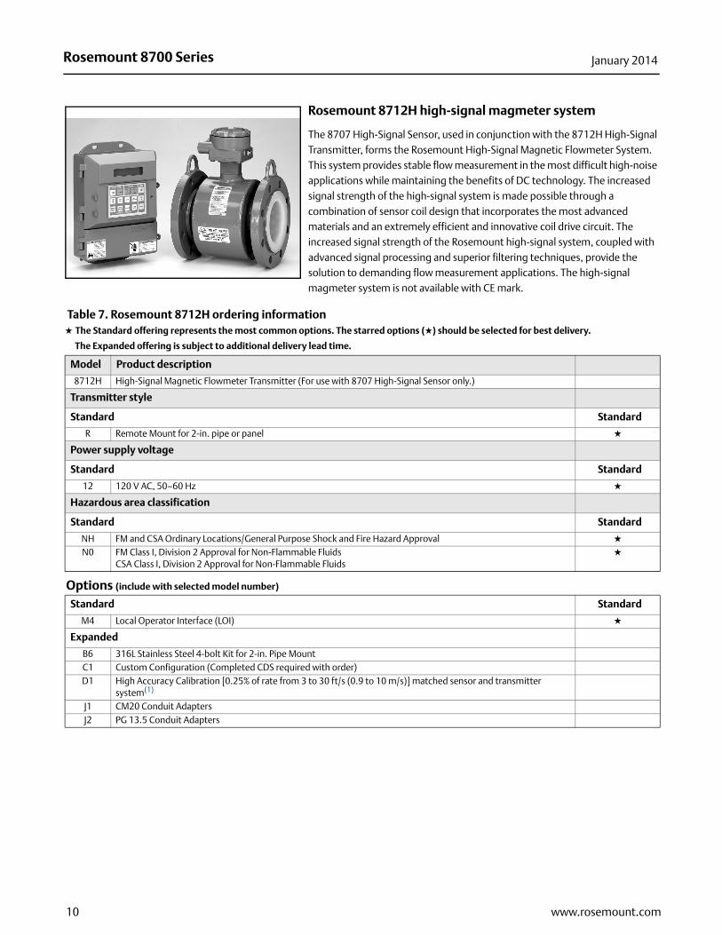
Upstream/downstream piping length
To ensure specification accuracy over widely varying process conditions, install the sensor with a minimum of five straight pipe diameters upstream and two straight pipe diameters downstream from the electrode plane. See Figure 1. This procedure should adequately allow for disturbances created by elbows, valves, and reducers.
Figure 1. Upstream and downstream straight pipe diameters
Installations with reduced straight runs are possible. In reduced straight run installations, performance may shift. Reported flow rates will still be highly repeatable.
Sensor grounding
A reliable ground path is required between the sensor and the process fluid. Optional grounding rings, process reference electrode, and lining protectors are available with 8700 Series sensors to ensure proper grounding. See Table 6 and Table 19.
Table 5. Line size vs. velocity/rate
Nominal line size in
Inches (mm)
Minimum/maximum flow rate
Gallons per minute Liters per minute
at 0.04 ft/s
(low-flow cutoff)
at 1 ft/s(min
range setting)
at 3 ft/sat 39.37 ft/s(max range
setting)
at 0.012 m/s(low-flow
cutoff)
at 0.3 m/s(min range
setting)at 1 m/s
at 12 m/s(max range
setting)
0.15 (4) 0.002 0.055 0.165 2.168 0.008 0.205 0.684 8.2090.30 (8) 0.009 0.220 0.661 8.674 0.033 0.821 2.736 32.83
1/2 (15) 0.038 0.947 2.841 37.287 0.141 3.529 11.76 141.151 (25) 0.108 2.694 8.081 106.05 0.401 10.04 33.45 401.46
11/2 (40) 0.254 6.345 19.04 249.82 0.946 23.64 78.81 945.672 (50) 0.418 10.459 31.38 411.77 1.559 38.97 129.89 1,558.7
21/2 (65) 0.597 14.923 44.77 587.51 2.224 55.60 185.33 2,224.03 (80) 0.922 23.042 69.13 907.17 3.434 85.85 286.17 3,434.0
4 (100) 1.587 39.679 119.04 1,562.2 5.913 147.84 492.78 5,913.45 (125) 2.494 62.356 187.07 2,454.9 9.293 232.33 774.42 9,293.06 (150) 3.602 90.048 270.14 3,545.2 13.42 335.50 1,118.3 13,4208 (200) 6.237 155.93 467.79 6,138.9 23.24 580.96 1,936.5 23,238
10 (250) 9.831 245.78 737.34 9,676.3 36.63 915.73 3,052.4 36,62912 (300) 14.10 352.51 1,057.5 13,878 52.54 1,313.4 4,378.0 52,53514 (350) 16.87 421.71 1,265.1 16,603 62.85 1,571.2 5,237.3 62,84816 (400) 22.03 550.80 1,652.4 21,685 82.09 2,052.2 6,840.6 82,08718 (450) 27.89 697.19 2,091.6 27,448 103.90 2,597.6 8,658.6 103,90320 (500) 34.66 866.51 2,599.5 34,114 129.14 3,228.4 10,761 129,13724 (600) 50.13 1,253.2 3,759.6 49,339 186.77 4,669.2 15,564 186,76930 (750) 80.24 2,006.0 6,018.0 78,976 298.96 7,474.0 24,913 298,95936 (900) 117.40 2,935.0 8,805.1 115,553 437.42 10,935 36,451 437,416
40 (1000) 146.09 3,652.1 10,956 143,785 544.29 13,607 45,357 544,28642 (1050) 164.60 4,115.1 12,345 162,011 613.28 15,332 51,107 613,27848 (1200) 216.30 5,407.6 16,223 212,898 805.91 20,148 67,159 805,908
Flow
5 Pipe Diameters 2 Pipe Diameters
5www.rosemount.com
Rosemount 8700 Series January 2014
Ordering information
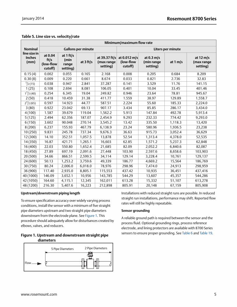
Rosemount 8732
The Rosemount 8732 transmitter has multiple diagnostic suites available. Best in class performance coupled with advanced diagnostics provides unparalleled process management capabilities. With an optional backlit 2 line by 16 character display/local operator interface, the transmitter can be configured by optical switches to simplify adjustments in hazardous environments without removing the cover.
Rosemount 8712
The remote mount 8712 transmitter brings diagnostics to any HART/ 4-20 mA system that can change how magmeters are installed, maintained, and verified. The Rosemount 8712 also features an easy-to-use 2 line by 20 character operator interface, with quick access to all diagnostic information, and instant access to basic configuration setup through dedicated keys.
Table 6. Rosemount 8732/8712 ordering information★ The Standard offering represents the most common options. The starred options (★) should be selected for best delivery.
__The Expanded offering is subject to additional delivery lead time.
Model Product description 8732 8712
8732E Magnetic Flowmeter Transmitter •
8712E Remote Mount Transmitter •
Transmitter style
Standard Standard
S Revision 3 - “S” Electronics • • ★
Transmitter mount
Standard Standard
T Integral Mount • ★
R Remote Mount for 2 in. pipe or panel(1) • • ★
Transmitter power supply
Standard Standard
1 AC Power Supply (90 to 250 V AC, 50-60Hz) • • ★
2 DC Power Supply (12 to 42 V DC) • • ★
Outputs
Standard Standard
A 4-20 mA Digital Electronics (HART Protocol) • • ★
F FOUNDATION fieldbus digital electronics with FISCO Intrinsically Safe Output • ★
P PROFIBUS PA fieldbus digital electronics with FISCO Intrinsically Safe Output • ★
6 www.rosemount.com

Rosemount 8700 SeriesJanuary 2014
Transmitter conduit entries 8732 8712
8732 = 2 conduit ports / 8712 = 4 conduit ports
Standard Standard
1 1/2 - 14 NPT, Standard Conduits • • ★
Expanded
2 CM20, Conduit Adapters • •
3 PG 13.5, Conduit Adapters • •
8732 = 3 conduit ports / 8712 = NA
Standard Standard
4 1/2 - 14 NPT, Additional Conduit • ★
Expanded
5 CM20, Additional Conduit Adapters •
6 PG 13.5, Additional Conduit Adapters •
Safety approvals
FM & CSA
Standard Standard
NH FM and CSA Ordinary Locations/General Purpose Shock and Fire Hazard Approval • • ★
N0 FM Class I Div 2 for Non-Flammable Fluids: CSA Class I Div 2 for Non-Flammable Fluids • • ★
N5 FM Class I Div 2 for Flammable Fluids • • ★
E5 FM Class I Div 1, Explosion-Proof • ★
ATEX
Standard Standard
ED ATEX Flameproof Ex de IIB T6, and ATEX Dust Approval; Ex de [ia] IIB T6 with IS outputs • ★
ND ATEX Dust • ★
Expanded
E1 ATEX Flameproof Ex de IIC T6, and ATEX Dust Approval; Ex de [ia] IIC T6 with IS outputs •
N1 ATEX Type n • •
IECEx
Standard Standard
EFIECEx Flameproof Ex de IIB T6 Gb and IECEx Dust Approval; Ex de [ia IIC Ga] IIB T6 Gb with IS Output
•★
NF IECEx Dust • ★
Expanded
E7IECEx Flameproof Ex de IIC T6 Gb and IECEx Dust Approval; Ex de [ia Ga] IIC T6 Gb with IS output
•
N7 IECEx Type n • •
NEPSI and CMC (China)
Standard Standard
EP NEPSI Flameproof Ex de IIB T6; Ex de [ia] IIB T6 with IS output • ★
Expanded
E3 NEPSI Flameproof Ex de IIC T6; Ex de [ia] IIC T6 with IS output •
Table 6. Rosemount 8732/8712 ordering information★ The Standard offering represents the most common options. The starred options (★) should be selected for best delivery.
__The Expanded offering is subject to additional delivery lead time.
7www.rosemount.com

Rosemount 8700 Series January 2014
Hazardous area classification continued 8732 8712
INMETRO (Brazil)
Standard Standard
EB INMETRO Flameproof Ex de IIB T6; Ex de [ia] IIB T6 with IS outputs • ★
Expanded
E2 INMETRO Flameproof Ex de IIC T6; Ex de [ia] IIC T6 with IS outputs •
GOST (Russia)
Standard Standard
EM GOST Flameproof Ex de IIB T6; Ex de [ia] IIB T6 with IS outputs • ★
Expanded
E8 GOST Flameproof Ex de IIC T6; Ex de [ia] IIC T6 with IS outputs •
Options (include with selected model number)
PlantWeb product/process diagnostics
Standard Standard
DA1Magmeter HART Diagnostic Suite 1: High Process Noise Detection and Ground/Wiring Fault Detection
• •★
DA2 Magmeter HART Diagnostic Suite 2: Smart Meter Verification • • ★
D01Magmeter digital fieldbus Diagnostic Suite 1: High Process Noise and Ground/Wiring Fault Detection
•★
D02 Magmeter digital fieldbus Diagnostic Suite 2: Smart Meter Verification • ★
Discrete input/discrete output
Standard Standard
AX Two Discrete Channels (DI/DO 1, DO 2), see page 32 for more details(2) • • ★
Display options
Standard Standard
M4 Local Operator Interface (HART and PROFIBUS PA only) • • ★
M5 LCD Display only (HART and FOUNDATION fieldbus only) • ★
Other options
C1 Custom Configuration (Completed CDS required with order) • •
D1 High Accuracy Calibration (0.15% of rate for matched sensor and transmitter)(3) • •
DT Heavy Duty Tagging • •
SH 316/316L SST Electronics Housing, Remote Mount Only •
B6 316L Stainless Steel 4-bolt Kit for 2-in. Remote Pipe Mount • •
Conduit electrical connectors
Expanded
GE M12, 4-Pin, Male Connector (Eurofast) • •
GM A Size Mini, 4-Pin, Male Connector (Minifast) • •
GT A Size, Spade Terminal Mini, 5-pin, Male Connector (Minifast) •
Product certifications
WC OIML R49 Water Custody Transfer Certificate •
FP FM Fire Pump Approved •
Paint options
V2 Offshore/Near Shore Marine Paint 3 layer epoxy •
Certificates
Q4 Inspection certificate; calibration data, per ISO 10474 3.1B / EN 10204 3.1 • •
Table 6. Rosemount 8732/8712 ordering information★ The Standard offering represents the most common options. The starred options (★) should be selected for best delivery.
__The Expanded offering is subject to additional delivery lead time.
8 www.rosemount.com

Rosemount 8700 SeriesJanuary 2014
Quick Installation Guide (QIG) language options (default is English) 8732 8712
Expanded
YA Danish • •
YB Hungarian • •
YC Czech • •
YD Dutch • •
YE Bulgarian • •
YF French • •
YG German • •
YH Finnish • •
YI Italian • •
YJ Japanese •
YL Polish • •
YM Mandarin • •
YN Norwegian • •
YP Portuguese • •
YS Spanish • •
YR Russian •
YW Swedish • •
Typical model number: 8732 S T 1 A 1 N0 DA1 DA2 M4
(1) 8712ESR - standard qty (2) Zn Plated CS U-Bolts.
(2) Requires an additional conduit entry code 4, 5, or 6.
(3) D1 Option Code must be ordered with sensor and transmitter.
Table 6. Rosemount 8732/8712 ordering information★ The Standard offering represents the most common options. The starred options (★) should be selected for best delivery.
__The Expanded offering is subject to additional delivery lead time.
9www.rosemount.com
Rosemount 8700 Series January 2014
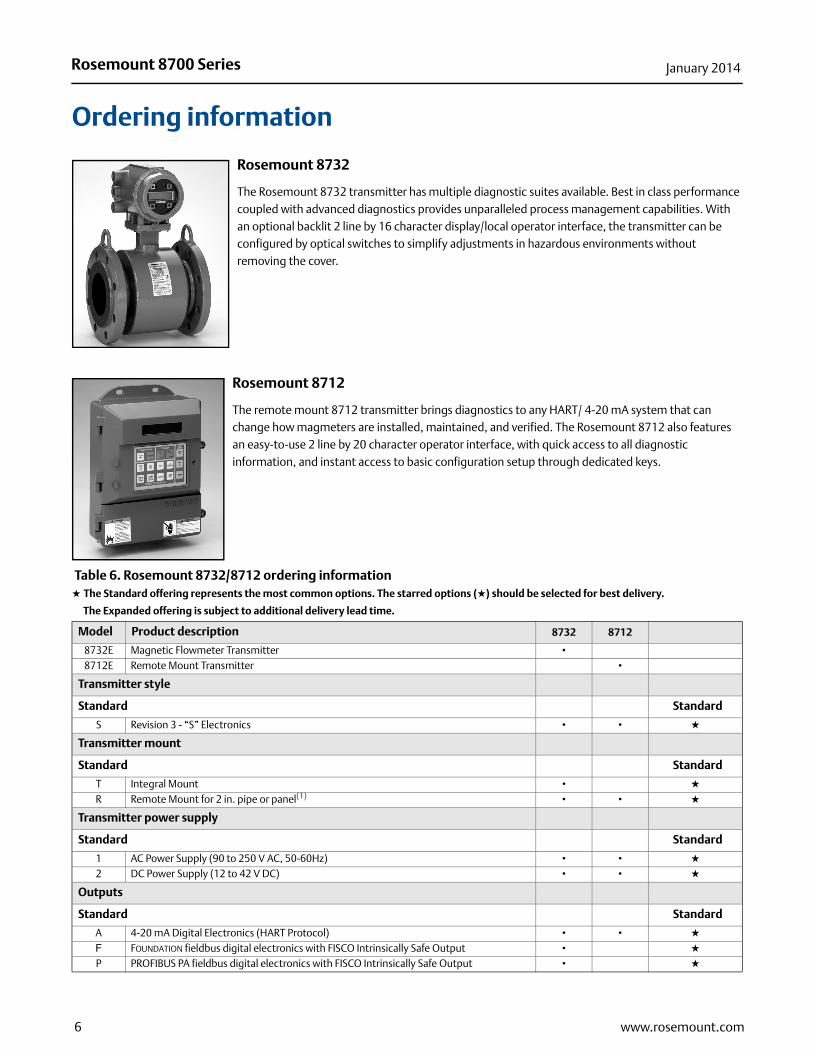
Rosemount 8712H high-signal magmeter system
The 8707 High-Signal Sensor, used in conjunction with the 8712H High-Signal Transmitter, forms the Rosemount High-Signal Magnetic Flowmeter System. This system provides stable flow measurement in the most difficult high-noise applications while maintaining the benefits of DC technology. The increased signal strength of the high-signal system is made possible through a combination of sensor coil design that incorporates the most advanced materials and an extremely efficient and innovative coil drive circuit. The increased signal strength of the Rosemount high-signal system, coupled with advanced signal processing and superior filtering techniques, provide the solution to demanding flow measurement applications. The high-signal magmeter system is not available with CE mark.
Table 7. Rosemount 8712H ordering information★ The Standard offering represents the most common options. The starred options (★) should be selected for best delivery.
__The Expanded offering is subject to additional delivery lead time.
Model Product description
8712H High-Signal Magnetic Flowmeter Transmitter (For use with 8707 High-Signal Sensor only.)
Transmitter style
Standard Standard
R Remote Mount for 2-in. pipe or panel ★
Power supply voltage
Standard Standard
12 120 V AC, 50–60 Hz ★
Hazardous area classification
Standard Standard
NH FM and CSA Ordinary Locations/General Purpose Shock and Fire Hazard Approval ★
N0 FM Class I, Division 2 Approval for Non-Flammable FluidsCSA Class I, Division 2 Approval for Non-Flammable Fluids
★
Options (include with selected model number)
Standard Standard
M4 Local Operator Interface (LOI) ★
Expanded
B6 316L Stainless Steel 4-bolt Kit for 2-in. Pipe MountC1 Custom Configuration (Completed CDS required with order)D1 High Accuracy Calibration [0.25% of rate from 3 to 30 ft/s (0.9 to 10 m/s)] matched sensor and transmitter
system(1)
J1 CM20 Conduit AdaptersJ2 PG 13.5 Conduit Adapters
10 www.rosemount.com

Rosemount 8700 SeriesJanuary 2014
Quick Installation Guide (QIG) language options (default is English)
Expanded
YA DanishYD DutchYF FrenchYG GermanYH FinnishYI Italian
YN NorwegianYP PortugueseYS Spanish
YW Swedish
Typical model number: 8712H R 12 N 0 M 4
(1) D1 Option Code must be selected for both sensor and transmitter.
Table 7. Rosemount 8712H ordering information★ The Standard offering represents the most common options. The starred options (★) should be selected for best delivery.
__The Expanded offering is subject to additional delivery lead time.
11www.rosemount.com
Rosemount 8700 Series January 2014
dard
dard
dard
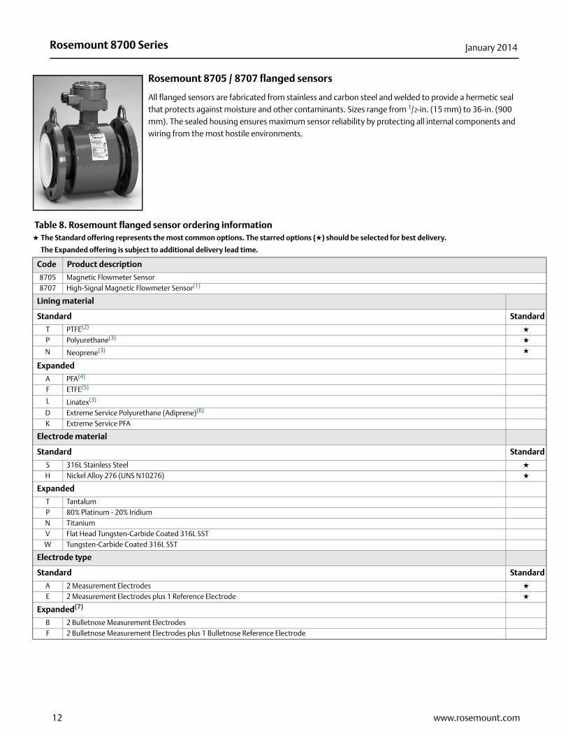
Rosemount 8705 / 8707 flanged sensors
All flanged sensors are fabricated from stainless and carbon steel and welded to provide a hermetic seal that protects against moisture and other contaminants. Sizes range from 1/2-in. (15 mm) to 36-in. (900 mm). The sealed housing ensures maximum sensor reliability by protecting all internal components and wiring from the most hostile environments.
Table 8. Rosemount flanged sensor ordering information★ The Standard offering represents the most common options. The starred options (★) should be selected for best delivery.
__The Expanded offering is subject to additional delivery lead time.
Code Product description
8705 Magnetic Flowmeter Sensor8707 High-Signal Magnetic Flowmeter Sensor(1)
Lining material
Standard Stan
T PTFE(2) ★
P Polyurethane(3) ★
N Neoprene(3) ★
Expanded
A PFA(4)
F ETFE(5)
L Linatex(3)
D Extreme Service Polyurethane (Adiprene)(6)
K Extreme Service PFA
Electrode material
Standard Stan
S 316L Stainless Steel ★
H Nickel Alloy 276 (UNS N10276) ★
Expanded
T TantalumP 80% Platinum - 20% IridiumN TitaniumV Flat Head Tungsten-Carbide Coated 316L SSTW Tungsten-Carbide Coated 316L SST
Electrode type
Standard Stan
A 2 Measurement Electrodes ★
E 2 Measurement Electrodes plus 1 Reference Electrode ★
Expanded(7)
B 2 Bulletnose Measurement ElectrodesF 2 Bulletnose Measurement Electrodes plus 1 Bulletnose Reference Electrode
12 www.rosemount.com

Rosemount 8700 SeriesJanuary 2014
Line sizeLining material (from page 12)
PTFE code T
Poly code P
Neoprene code N
PFA code A
ETFE code F
Adiprenecode D
Linatex code L
005 1/2-in. (15 mm) (8705 only) • NA NA • • NA NA010 1-in. (25 mm) (8705 only) • • • • • NA •
015 1 1/2-in. (40 mm) (8705 only) • • • • • • •
020 2-in. (50 mm) (8705 only) • • • • • • •
025 2 1/2-in (65mm) (8705 only) • NA • NA NA NA NA030 3-in. (80 mm) • • • • • • •
040 4-in. (100 mm) • • • • • • •
050 5-in (125mm) (8705 only) • NA • NA NA NA NA060 6-in. (150 mm) • • • • • • •
080 8-in. (200 mm) • • • • • • •
100 10-in. (250 mm) • • • • • • •
120 12-in. (300 mm) • • • • • • •
140 14-in. (350 mm) • • • • • • •
160 16-in. (400 mm) • • • NA • • •
180 18-in. (450 mm) • • • NA NA • •
200 20-in. (500 mm) • • • NA NA • •
240 24-in. (600 mm) • • • NA NA • •
300 30-in. (750 mm) • • • NA NA • •
360 36-in. (900 mm) • • • NA NA • •
Flange material and style(8) Availability
C Carbon Steel Raised Face Slip-OnRefer to Table 9 for availability of Slip-On flangesS Stainless Steel (304/304L) Raised Face Slip-On
P Stainless Steel (316/316L) Raised Face Slip-OnF Carbon Steel Flat Faced Slip-On(9)
G Stainless Steel (304/304L) Flat Faced Slip-On(9)
H Stainless Steel (316/316L) Flat Faced Slip-On(9)
D Carbon Steel Raised Face Weld Neck
Refer to Table 10 for availability of Weld Neck flanges
T Stainless Steel (304/304L) Raised Face Weld NeckR Stainless Steel (316/316L) Raised Face Weld NeckJ Carbon Steel Ring Type Joint (RTJ) Weld Neck(10)
K Stainless Steel (304/304L) Ring Type Joint (RTJ) Weld Neck(10)
L Stainless Steel (316/316L) Ring Type Joint (RTJ) Weld Neck(10)
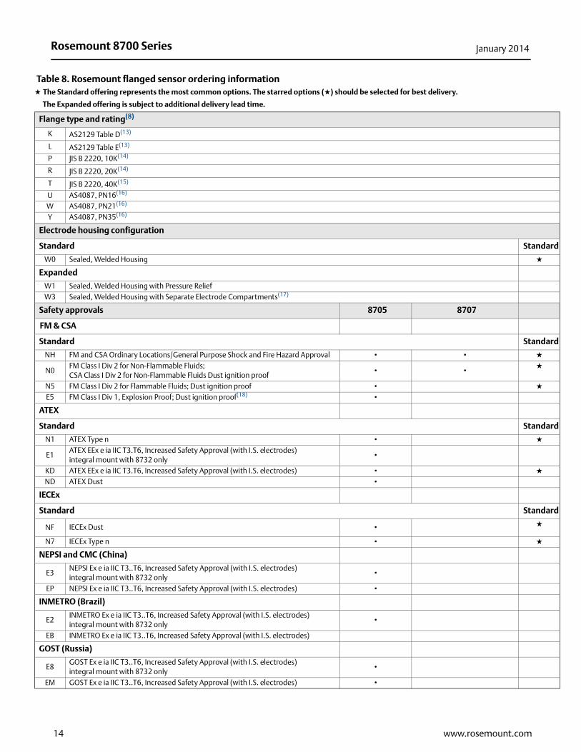
Flange type and rating(8)
1 ASME B16.5 Class 150 (30-in. and 36-in. AWWA C207 Class D Flat Face)2 MSS SP44 Class 150 (30-in. and 36-in. line sizes only)3 ASME B16.5 Class 300/MSS-SP44 Class 300 (30-in only)6 ASME B16.5 Class 600 (Maximum Pressure: 1000 psig)7 ASME B16.5 Class 600
9 ASME B16.5 Class 900(11)
M ASME B16.5 Class 1500(12)
N ASME B16.5 Class 2500(12)
D EN1092-1 PN10E EN1092-1 PN16F EN1092-1 PN25H EN1092-1 PN40
Table 8. Rosemount flanged sensor ordering information★ The Standard offering represents the most common options. The starred options (★) should be selected for best delivery.
__The Expanded offering is subject to additional delivery lead time.
13www.rosemount.com
Rosemount 8700 Series January 2014
dard
dard
dard
dard
Flange type and rating(8)
K AS2129 Table D(13)
L AS2129 Table E(13)
P JIS B 2220, 10K(14)
R JIS B 2220, 20K(14)
T JIS B 2220, 40K(15)
U AS4087, PN16(16)
W AS4087, PN21(16)
Y AS4087, PN35(16)
Electrode housing configuration
Standard Stan
W0 Sealed, Welded Housing ★
Expanded
W1 Sealed, Welded Housing with Pressure ReliefW3 Sealed, Welded Housing with Separate Electrode Compartments(17)
Safety approvals 8705 8707
FM & CSA
Standard Stan
NH FM and CSA Ordinary Locations/General Purpose Shock and Fire Hazard Approval • • ★
N0FM Class I Div 2 for Non-Flammable Fluids; CSA Class I Div 2 for Non-Flammable Fluids Dust ignition proof
• •★
N5 FM Class I Div 2 for Flammable Fluids; Dust ignition proof • ★
E5 FM Class I Div 1, Explosion Proof; Dust ignition proof(18) •
ATEX
Standard Stan
N1 ATEX Type n • ★
E1ATEX EEx e ia IIC T3.T6, Increased Safety Approval (with I.S. electrodes)integral mount with 8732 only
•
KD ATEX EEx e ia IIC T3.T6, Increased Safety Approval (with I.S. electrodes) • ★
ND ATEX Dust •
IECEx
Standard Stan
NF IECEx Dust • ★
N7 IECEx Type n • ★
NEPSI and CMC (China)
E3NEPSI Ex e ia IIC T3..T6, Increased Safety Approval (with I.S. electrodes) integral mount with 8732 only
•
EP NEPSI Ex e ia IIC T3..T6, Increased Safety Approval (with I.S. electrodes) •
INMETRO (Brazil)
E2INMETRO Ex e ia IIC T3..T6, Increased Safety Approval (with I.S. electrodes) integral mount with 8732 only
•
EB INMETRO Ex e ia IIC T3..T6, Increased Safety Approval (with I.S. electrodes)
GOST (Russia)
E8GOST Ex e ia IIC T3..T6, Increased Safety Approval (with I.S. electrodes) integral mount with 8732 only
•
EM GOST Ex e ia IIC T3..T6, Increased Safety Approval (with I.S. electrodes) •
Table 8. Rosemount flanged sensor ordering information★ The Standard offering represents the most common options. The starred options (★) should be selected for best delivery.
__The Expanded offering is subject to additional delivery lead time.
14 www.rosemount.com

Rosemount 8700 SeriesJanuary 2014
dard
dard
dard
Options (Include with selected model number)
Certifications 8705 8707
Expanded
CR Canadian Registration Number (CRN) certification(19) • •
PD European Pressure Equipment Directive Certification (PED, per 97/23/EC) •
DW NSF Drinking Water Certification(20) • •
FP FM Fire Pump Approval •
WC OIML R49 Water Custody Transfer Certificate •
Optional grounding rings(21) 8705 8707
Standard Stan
G1 (2) 316L SST Ground Rings • • ★
G5 (1) 316L SST Ground Ring • • ★
Expanded
G2 (2) Nickel Alloy 276 (UNS N10276) Ground Rings • •
G3 (2) Titanium Ground Rings • •
G4 (2) Tantalum Ground Rings • •
G6 (1) Nickel Alloy 276 (UNS N10276) Ground Ring • •
G7 (1) Titanium Ground Ring • •
G8 (1) Tantalum Ground Ring • •
Optional lining protectors(21)
Standard Stan
L1 (2) 316L SST Lining Protectors • • ★
L5 (1) 316L SST Lining Protector ★
Expanded
L2 (2) Nickel Alloy 276 (UNS N10276) Lining Protectors • •
L3 (2) Titanium Lining Protectors • •
L6 (1) Nickel Alloy 276 (UNS N10276) Lining Protector • •
L7 (1) Titanium Lining Protector • •
Other options 8705 8707
Standard Stan
B3 Integral Mount with 8732 E Series Transmitter • ★
Expanded
D1High Accuracy Calibration (0.15% of rate for matched sensor and transmitter)
(0.25% of rate for matched 8707 and 8712H)(22) • •
D2 Dual Calibration Number •
DT Heavy Duty Tagging • •
H1 Lay-length matching 8701 using spool piece(23) • •
H2 Lay-length matching 8701(24) • •
J1 CM 20 Conduit Adapter • •
J2 PG 13.5 Conduit Adapter • •
P05 5 Point Verification • •
P10 10 Point Verification • •
SC 304 SST Junction Box, fully welded to housing • •
SH 316 SST Coil Housing and Remote Junction Box • •
TAHigh Temperature Permeable Fluid Option (Contains vent holes provided for permeable fluids such as nitric acid, hydrofluoric acid, or sodium hydroxide at high temperatures) No CRN, No PED(25)
•
Table 8. Rosemount flanged sensor ordering information★ The Standard offering represents the most common options. The starred options (★) should be selected for best delivery.
__The Expanded offering is subject to additional delivery lead time.
15www.rosemount.com
Rosemount 8700 Series January 2014
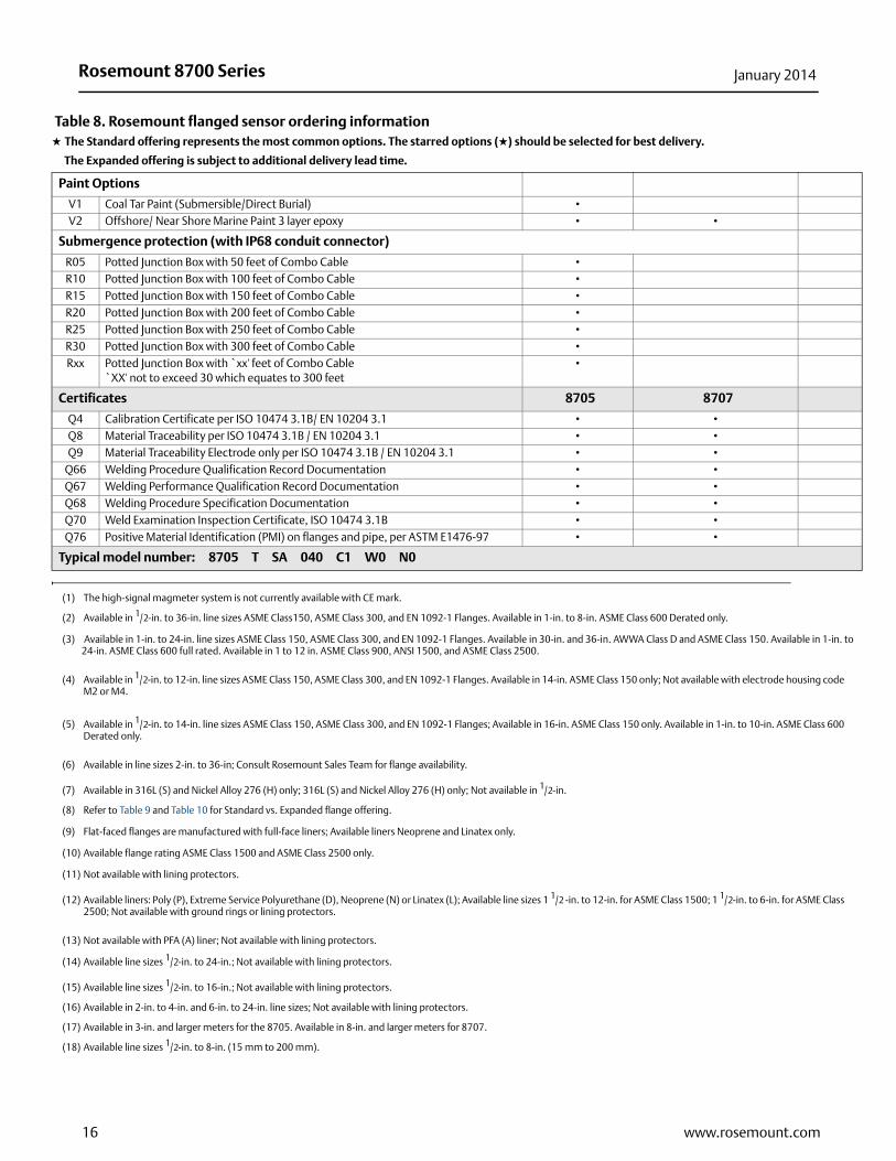
o
Paint Options
V1 Coal Tar Paint (Submersible/Direct Burial) •
V2 Offshore/ Near Shore Marine Paint 3 layer epoxy • •
Submergence protection (with IP68 conduit connector)
R05 Potted Junction Box with 50 feet of Combo Cable •
R10 Potted Junction Box with 100 feet of Combo Cable •
R15 Potted Junction Box with 150 feet of Combo Cable •
R20 Potted Junction Box with 200 feet of Combo Cable •
R25 Potted Junction Box with 250 feet of Combo Cable •
R30 Potted Junction Box with 300 feet of Combo Cable •
Rxx Potted Junction Box with `xx' feet of Combo Cable`XX' not to exceed 30 which equates to 300 feet
•
Certificates 8705 8707
Q4 Calibration Certificate per ISO 10474 3.1B/ EN 10204 3.1 • •
Q8 Material Traceability per ISO 10474 3.1B / EN 10204 3.1 • •
Q9 Material Traceability Electrode only per ISO 10474 3.1B / EN 10204 3.1 • •
Q66 Welding Procedure Qualification Record Documentation • •
Q67 Welding Performance Qualification Record Documentation • •
Q68 Welding Procedure Specification Documentation • •
Q70 Weld Examination Inspection Certificate, ISO 10474 3.1B • •
Q76 Positive Material Identification (PMI) on flanges and pipe, per ASTM E1476-97 • •
Typical model number: 8705 T SA 040 C1 W0 N0
(1) The high-signal magmeter system is not currently available with CE mark.
(2) Available in 1/2-in. to 36-in. line sizes ASME Class150, ASME Class 300, and EN 1092-1 Flanges. Available in 1-in. to 8-in. ASME Class 600 Derated only.
(3) Available in 1-in. to 24-in. line sizes ASME Class 150, ASME Class 300, and EN 1092-1 Flanges. Available in 30-in. and 36-in. AWWA Class D and ASME Class 150. Available in 1-in. t24-in. ASME Class 600 full rated. Available in 1 to 12 in. ASME Class 900, ANSI 1500, and ASME Class 2500.
(4) Available in 1/2-in. to 12-in. line sizes ASME Class 150, ASME Class 300, and EN 1092-1 Flanges. Available in 14-in. ASME Class 150 only; Not available with electrode housing codeM2 or M4.
(5) Available in 1/2-in. to 14-in. line sizes ASME Class 150, ASME Class 300, and EN 1092-1 Flanges; Available in 16-in. ASME Class 150 only. Available in 1-in. to 10-in. ASME Class 600Derated only.
(6) Available in line sizes 2-in. to 36-in; Consult Rosemount Sales Team for flange availability.
(7) Available in 316L (S) and Nickel Alloy 276 (H) only; 316L (S) and Nickel Alloy 276 (H) only; Not available in 1/2-in.
(8) Refer to Table 9 and Table 10 for Standard vs. Expanded flange offering.
(9) Flat-faced flanges are manufactured with full-face liners; Available liners Neoprene and Linatex only.
(10) Available flange rating ASME Class 1500 and ASME Class 2500 only.
(11) Not available with lining protectors.
(12) Available liners: Poly (P), Extreme Service Polyurethane (D), Neoprene (N) or Linatex (L); Available line sizes 1 1/2 -in. to 12-in. for ASME Class 1500; 1 1/2-in. to 6-in. for ASME Class2500; Not available with ground rings or lining protectors.
(13) Not available with PFA (A) liner; Not available with lining protectors.
(14) Available line sizes 1/2-in. to 24-in.; Not available with lining protectors.
(15) Available line sizes 1/2-in. to 16-in.; Not available with lining protectors.
(16) Available in 2-in. to 4-in. and 6-in. to 24-in. line sizes; Not available with lining protectors.
(17) Available in 3-in. and larger meters for the 8705. Available in 8-in. and larger meters for 8707.
(18) Available line sizes 1/2-in. to 8-in. (15 mm to 200 mm).
Table 8. Rosemount flanged sensor ordering information★ The Standard offering represents the most common options. The starred options (★) should be selected for best delivery.
__The Expanded offering is subject to additional delivery lead time.
16 www.rosemount.com
Rosemount 8700 SeriesJanuary 2014
(19) CRN Approval covers Alberta and Ontario as a standard. Consult Rosemount sales team for availability of other provinces.
(20) Available liners PTFE (T) all line sizes or Polyurethane (P) 4-in. or larger; Electrode materials 316L SST (S) or Ni-Alloy 276 (H).
(21) Grounding Rings and Lining Protectors provide the same fluid grounding function.
(22) D1 transmitter must be ordered with D1 sensor at the same time.
(23) Available in sensor line sizes 1/2-in. to 16-in. (15 mm to 400 mm).
(24) Available in sensor line sizes 1/2-in. to 16-in. (15 mm to 400 mm).
(25) Contains vent holes provided for highly permeable fluids such as nitric acid, hydrofluoric acid, or sodium hydroxide at high temperatures.
17www.rosemount.com

Rosemount 8700 Series January 2014
Table 9. Availability of slip-on flanges vs. flange type and rating. The starred (★) options should be selected for best delivery.
Line size (in)flange
type-rating
1/2 1 11/2 2 21/2 3 4 5 6 8 10 12 14 16 18 20 24 30(1)(2) 36(1)
C1 or F1 ★ ★ ★ ★ ★ ★ ★ ★ ★ ★ ★ ★
C2 NA NA NA NA NA NA NA NA NA NA NA NA NA NA NA NA NA
C3 or F3 ★ ★ ★ ★ ★ ★ ★ ★ ★ ★ ★ ★ NA
C6 NA NA NA NA NA NA NA
C7 NA NA NA NA NA NA NA NA
C9 NA NA NA NA NA NA NA NA
CD or FD NA NA NA NA NA NA NA NA NA ★ ★ NA NA
CE or FE NA NA NA NA NA NA ★ ★ ★ ★ ★ NA NA
CF or FF NA NA NA NA NA NA NA NA NA NA NA
CH or FH ★ ★ ★ ★ ★ ★ ★ ★ ★ ★ ★ NA NA
CK
CL
CP NA NA
CR NA NA
CT NA NA NA NA NA NA
CU NA NA NA
CW NA NA NA
CY NA NA NA
S1 or G1 ★ ★ ★ ★ ★ ★ ★ ★ ★
S2 NA NA NA NA NA NA NA NA NA NA NA NA NA NA NA NA NA
S3 or G3 NA
S6 NA NA NA NA NA NA NA
S7 NA NA NA NA NA NA NA
S9 NA NA NA NA NA NA NA NA
SD or GD NA NA NA NA NA NA NA NA NA NA NA
SE or GE NA NA NA NA NA NA ★ ★ ★ ★ ★ NA NA
SF or GF NA NA NA NA NA NA NA NA NA NA NA
SH or GH ★ ★ ★ ★ ★ ★ ★ ★ ★ NA NA
SK
SL
SP NA NA
SR NA NA
ST NA NA NA NA NA
SU NA NA NA
SW NA NA NA
SY NA NA NA
P1 or H1
P2 NA NA NA NA NA NA NA NA NA NA NA NA NA NA NA NA NA
P3 or H3 NA
P6 NA NA NA NA NA NA NA
P7 NA NA NA NA NA NA NA
P9 NA NA NA NA NA NA NA NA
PD or HD NA NA NA NA NA NA NA NA NA NA NA
PE or HE NA NA NA NA NA NA NA NA
PF or HF NA NA NA NA NA NA NA NA NA NA NA
PH or HH NA NA
PK
PL
PP NA
PR NA
PT NA NA NA NA NA
PU NA NA NA
PW NA NA NA
PY NA NA NA
(1) AWWA C207 Class D Flat Face Flange for option C1 only.
(2) MMS-SP44 Class 300 Flanges for option C3.
18 www.rosemount.com

Rosemount 8700 SeriesJanuary 2014
Table 10. Availability of weld neck flanges vs. flange type and rating
Line size (in)flange
type-rating
1/2 1 11/2 2 21/2 3 4 5 6 8 10 12 14 16 18 20 24 30(1)(2)
(1) MMS-SP44 Class 300 Flanges for option C3.
(2) AWWA C207 Class D Flat Face Flange for option C1 only.
36(2)
D1 NA NAD3 NA NAD6 NA NA NA NA NA NA NA NA NA NAD7 NA NA NA NA NA NA NA NA NAD9 NA NA NA NA NA NA NA NA NA NA NADM NA NA NA NA NA NA NA NA NA NA NADN NA NA NA NA NA NA NA NA NA NA NA NA NA NAT1 NA NAT3 NA NAT6 NA NA NA NA NA NA NA NA NA NAT7 NA NA NA NA NA NA NA NA NAT9 NA NA NA NA NA NA NA NA NA NA NA NATM NA NA NA NA NA NA NA NA NA NA NATN NA NA NA NA NA NA NA NA NA NA NA NA NA NAR1 NA NAR3 NA NAR6 NA NA NA NA NA NA NA NA NA NAR7 NA NA NA NA NA NA NA NA NAR9 NA NA NA NA NA NA NA NA NA NA NA NARM NA NA NA NA NA NA NA NA NA NARN NA NA NA NA NA NA NA NA NA NA NA NA NA NAJ1 NA NA NA NA NA NA NA NA NA NA NA NA NA NA NA NA NA NA NAJ3 NA NA NA NA NA NA NA NA NA NA NA NA NA NA NA NA NA NA NAJ6 NA NA NA NA NA NA NA NA NA NA NA NA NA NA NA NA NA NA NAJ7 NA NA NA NA NA NA NA NA NA NAJ9 NA NA NA NA NA NA NA NA NA NA
JM NA NA NA NA NA NA NA NA NA NA NAJN NA NA NA NA NA NA NA NA NA NA NA NA NA NAK1 NA NA NA NA NA NA NA NA NA NA NA NA NA NA NA NA NA NA NAK3 NA NA NA NA NA NA NA NA NA NA NA NA NA NA NA NA NA NA NAK6 NA NA NA NA NA NA NA NA NA NA NA NA NA NA NA NA NA NA NAK7 NA NA NA NA NA NA NA NA NA NAK9 NA NA NA NA NA NA NA NA NA NA
KM NA NA NA NA NA NA NA NA NA NA NAKN NA NA NA NA NA NA NA NA NA NA NA NA NA NAL1 NA NA NA NA NA NA NA NA NA NA NA NA NA NA NA NA NA NA NAL3 NA NA NA NA NA NA NA NA NA NA NA NA NA NA NA NA NA NA NAL6 NA NA NA NA NA NA NA NA NA NA NA NA NA NA NA NA NA NA NAL7 NA NA NA NA NA NA NA NA NA NA NAL9 NA NA NA NA NA NA NA NA NA NA NALM NA NA NA NA NA NA NA NA NA NA NA NA LN NA NA NA NA NA NA NA NA NA NA NA NA NA NA
19www.rosemount.com
Rosemount 8700 Series January 2014
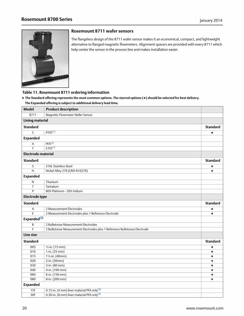
Rosemount 8711 wafer sensors
The flangeless design of the 8711 wafer sensor makes it an economical, compact, and lightweight alternative to flanged magnetic flowmeters. Alignment spacers are provided with every 8711 which help center the sensor in the process line and makes installation easier.
Table 11. Rosemount 8711 ordering information★ The Standard offering represents the most common options. The starred options (★) should be selected for best delivery.
__The Expanded offering is subject to additional delivery lead time.
Model Product description
8711 Magnetic Flowmeter Wafer Sensor
Lining material
Standard Standard
S PTFE(1) ★
Expanded
A PFA(2)
T ETFE(1)
Electrode material
Standard Standard
S 316L Stainless Steel ★
H Nickel Alloy 276 (UNS N10276) ★
Expanded
N TitaniumT TantalumP 80% Platinum - 20% Iridium
Electrode type
Standard Standard
A 2 Measurement Electrodes ★
E 2 Measurement Electrodes plus 1 Reference Electrode ★
Expanded(3)
B 2 Bulletnose Measurement ElectrodesF 2 Bulletnose Measurement Electrodes plus 1 Reference Bulletnose Electrode
Line size
Standard Standard
005 ½-in. (15 mm) ★
010 1-in. (25 mm) ★
015 1½-in. (40mm) ★
020 2-in. (50mm) ★
030 3-in. (80 mm) ★
040 4-in. (100 mm) ★
060 6-in. (150 mm) ★
080 8-in. (200 mm) ★
Expanded
15F 0.15-in. (4 mm) liner material PFA only(4)
30F 0.30-in. (8 mm) liner material PFA only(4)
20 www.rosemount.com

Rosemount 8700 SeriesJanuary 2014
Transmitter mounting configuration
Standard Standard
R Remote ★
U Integral, mounted to Rosemount 8732 Transmitter ★
Mating pipe flange pressure rating
Includes three alignment spacers (where applicable)
Standard Standard
1 ASME Class 150 ★
3 ASME Class 300 ★
D EN1092-1 PN10 ★
E EN1092-1 PN16 ★
F EN1092-1 PN25 ★
H EN1092-1 PN40 ★
P JIS B2220 10K ★
R JIS B2220 20K ★
U AS4087 PN16 ★
W AS4087 PN21 ★
Y AS4087 PN35 ★
Hazardous area classification(5)
FM & CSA
Standard Standard
NH FM and CSA Ordinary Locations/General Purpose Shock and Fire Hazard Approval ★
N0 FM Class I Div 2 for Non-Flammable Fluids; CSA Class I Div 2 for Non-Flammable Fluids ★
N5 FM Class I Div 2 for Flammable Fluids ★
E5 FM Class I Div 1, Explosion Proof ★
ATEX
Standard Standard
KD ATEX EEx e ia IIC T3… T6, Increased Safety Approval (with I.S. electrodes) ★
N1 ATEX Type n ★
ND ATEX Dust ★
E1 ATEX EEx e ia IIC T3… T6, Increased Safety Approval (with I.S. electrodes), integral mount with 8732 only
IECEx
NF IECEx Dust
NEPSI and CMC (China)
E3 NEPSI Ex e ia IIC T3... T6, Increased Safety Approval (with I.S. electrodes), integral mount with 8732 onlyEP NEPSI Ex e ia IIC T3… T6, Increased Safety Approval (with I.S. electrodes)
INMETRO (Brazil)
E2 INMETRO Ex e ia IIC T3... T6, Increased Safety Approval (with I.S. electrodes), integral mount with 8732 onlyEB INMETRO Ex e ia IIC T3… T6, Increased Safety Approval (with I.S. electrodes)
GOST (Russia)
E8 GOST Ex e ia IIC T3... T6, Increased Safety Approval (with I.S. electrodes), integral mount with 8732 onlyEM GOST Ex e ia IIC T3… T6, Increased Safety Approval (with I.S. electrodes)
Table 11. Rosemount 8711 ordering information★ The Standard offering represents the most common options. The starred options (★) should be selected for best delivery.
__The Expanded offering is subject to additional delivery lead time.
21www.rosemount.com
Rosemount 8700 Series January 2014
Options (include with selected model number)
Certifications
Expanded
PD Pressure Equipment Directive Certification (PED, per 97/23/EC)DW NSF Drinking Water Certification(6)
FP FM Fire Pump Approval WC OIML R49 Water Custody Transfer Certificate
Optional grounding rings
Standard Standard
G1 (2) 316L SST Ground Rings ★
G5 (1) 316L SST Ground Ring ★
Expanded
G2 (2) Nickel Alloy 276 (UNS N10276) Ground RingsG3 (2) Titanium Ground RingsG4 (2) Tantalum Ground RingsG6 (1) Nickel Alloy 276 (UNS N10276) Ground RingG7 (1) Titanium Ground RingG8 (1) Tantalum Ground Ring
Other options
Expanded
Mounting kit
MK2 Mounting Studs and Nuts
Paint options
V2 Offshore/ Near Shore Marine Paint 3 layer epoxy
Certificates
Q4 Calibration Certificate per ISO 10474 3.1B / EN 10204 3.1Q8 Material Traceability per ISO 10474 3.1B / EN 10204 3.1Q9 Material Traceability Electrode only per ISO 10474 3.1B / EN 10204 3.1 3.1B
Q66 Welding Procedure Qualification Record Documentation(7)
Q67 Welding Performance Qualification Record Documentation(7)
Q68 Welding Procedure Specification Documentation(7)
Q70 Weld Examination Inspection Certificate, ISO 10474 3.1B(7)
Q76 Positive Material Identification (PMI) on flanges and pipe, per ASTM E1476-97(7)
DT Heavy Duty TaggingD1 High Accuracy Calibration (0.15% of rate for matched sensor and transmitter)(8)
Typical model number: 8711 TSA 020 R 5 N0
(1) Not available with 0.15-in. and 0.30-in. (4 mm and 8 mm) line sizes.
(2) Available with 0.15-in. and 0.30-in. (4 mm and 8 mm) line sizes only.
(3) Bullet nose electrodes are available in 1-in. to 8-in. (25 mm to 200 mm).
(4) This line size mounts between ASME 1/2-in flanges
(5) Add option “Q7” to the model number to receive a copy of the agency approval certificate.
(6) Available liner PTFE (T) ½-in to 8-in. (15 mm to 200 mm); Electrode materials 316L SST (S) or Ni-Alloy 276 (H).
(7) 6-in. and 8-in. (150 mm and 200 mm) line sizes only.
(8) D1 Option Code must be ordered with sensor and transmitter.
Table 11. Rosemount 8711 ordering information★ The Standard offering represents the most common options. The starred options (★) should be selected for best delivery.
__The Expanded offering is subject to additional delivery lead time.
22 www.rosemount.com

Rosemount 8700 SeriesJanuary 2014
Rosemount 8721 hygienic sensors
The 8721 hygienic sensor is specifically designed for the demanding applications in food, beverage, and life sciences. The robust, all-welded, full diameter sensor is constructed of FDA approved materials and is authorized to display the 3-A Symbol (Authorization #1222) is certified by EHEDG (#C03-5229) and is approved for use in FDA Grade A milk meter based timing loops (M-b 350). Sizes range from 1/2-in. (15mm) to 4-in. (100mm) and are available in a variety of industry standard process connections.
Table 12. Rosemount 8721 ordering information★ The Standard offering represents the most common options. The starred options (★) should be selected for best delivery.
__The Expanded offering is subject to additional delivery lead time.
Model Product description
8721 Hygienic Magnetic Flowmeter Sensor
Lining material
Standard Standard
A PFA ★
Electrode material
Standard Standard
S 316L SST (standard) ★
Expanded
H Nickel Alloy 276 (UNS N10276)P 80% Platinum-20% Iridium
Electrode construction
Standard Standard
A Standard measurement electrodes ★
Line Sizes
Standard Standard
005 1/2-in. (15 mm) ★
010 1-in. (25 mm) ★
015 11/2-in. (40 mm) ★
020 2-in. (50 mm) ★
025 21/2-in. (65 mm) ★
030 3-in. (80 mm) ★
040 4-in. (100 mm) ★
Transmitter mounting configuration
Standard Standard
R Remote, for use with 8712, or remote version of 8732 transmitter ★
U Integral, mounted to 8732 transmitter ★
X Sensor only (does not include terminal junction box) ★
23www.rosemount.com

Rosemount 8700 Series January 2014
Process connection type
Standard Standard
A Tri-Clamp (1) ★
B IDF Sanitary screw type (2) ★
Expanded
C ANSI Weld Nipple (2)
D DIN 11851 (Imperial)E DIN 11851 (Metric)F DIN 11864-1 form AG DIN 11864-2 form AH SMS ConnectionJ Cherry-Burrell I-LineK DIN 11850 Weld Nipple
Process gasket material
Standard Standard
1 Silicone gasket seal ★
2 EPDM ★
Expanded
4 Viton8 EPDM Compression - limiting (3)
9 Viton Compression - limiting (3)
X No gasket (User supplied; only applicable with Process Connection B)
Product certifications
Standard Standard
N0 FM / CSA General Purpose / Ordinary Location, CE Marking; 3-A; EHEDG Type EL ★
Options (include with selected model number)
Expanded
AH Electropolished process connection surface finish < 15inch Ra (0.38m Ra)D1 High Accuracy Calibration [0.25% of rate from 3-30 ft/s (0.9-10 m/s)] matched sensor and transmitter system(4)
D3 High Velocity Meter Verification. Calibration verified at 1, 3, 10 and 20 ft/sec (0.3. 1, 3, and 6 m/s)HP Process Data PD340 (Alfa-Laval PD340) 250mm lay length and Tri-Clamp process connectionsJ1 CM20 Conduit Adapter (Applies to Transmitter Mount Option “R” only)J2 PG13.5 Conduit Adapter (Applies to Transmitter Mount Option “R” only)
Q4 Calibration Certificate per ISO 10474 3.1B/ EN 10204 3.1Q8 Material Traceability Certificate per ISO 10474 3.1B / EN 10204 3.1(product contact surfaces)SJ 304 Stainless Steel terminal junction box (Remote configuration only)
Typical model number: 8721 A S A 020 U A 1 N0
(1) Tri-Clamp specification per BPE.
(2) IDF Specification per BS4825 Part 4.
(3) EHEDG Document 8 requires mechanical compression limiting, provided by Compression - limiting gaskets for line sizes 1-in. to 4-in. only.
(4) D1 transmitter must be ordered with D1 sensor at the same time.
Table 12. Rosemount 8721 ordering information★ The Standard offering represents the most common options. The starred options (★) should be selected for best delivery.
__The Expanded offering is subject to additional delivery lead time.
24 www.rosemount.com

Rosemount 8700 SeriesJanuary 2014
Rosemount 8714DThe Rosemount 8714D Magnetic Flowmeter Simulator attaches to an 8712, or 8732 transmitter’s sensor connections to ensure traceability to NIST standards and long-term accuracy of the flowmeter system. The 8714D is not compatible with the 8712H High-Signal transmitter
Table 13. Rosemount 8714 ordering information
Tagging styles
Name Plate
1 Line - 30 Characters
Wire-on
5 Lines - 30 Characters per line
Ordering procedure
To order, select the desired sensor and/or transmitter by specifying model codes from the ordering table.
For remote transmitter applications, note the cable specification requirements.
Sensors and transmitters must be selected from Product Data Sheet 00813-0100-4727.
Standard configuration
Unless the Configuration Data Sheet is completed, the transmitter will be shipped as follows:
Integrally Mounted Rosemount 8732 Transmitters are factory configured with the attached sensor size and appropriate calibration number.
Cable requirements for remote transmitters
Remote transmitter installations require equal lengths of electrode and coil drive cables. Integrally mounted transmitters are factory wired and do not require interconnecting cables.
Individual cable lengths from 5 to 1000 ft. (1.5 to 300 m) may be specified. Cable longer than 100 ft. (30 m) is not recommended for high-signal systems. Combination signal and coil drive cable should be limited to less than 330 ft (100 m). All cables will be shipped with the sensor.
Custom configuration (Option Code C1)
If Option Code C1 is ordered, the Configuration Data Sheet (CDS) must be submitted at the time of order.
Model Description
8714DQ4 Magnetic Flowmeter Simulator - Reference Calibration Standard
Engineering Units: ft/sec4 mA (1 V DC): 020 mA (5 V DC): 30Sensor Size: 3-in.Empty Pipe: OnSensor Calibration Number: 1000005010000000
Description Length P/N
Electrode Cable (20 AWG)Belden 8762, Alpha 2411 equivalent
ftm
08712-0061-000108712-0061-2003
Coil Drive Cable (14 AWG) Belden 8720, Alpha 2442 equivalent
ftm
08712-0060-000108712-0060-2003
Combination CableElectrode Cable (20AWG) and Coil
Drive Cable (18 AWG)(1)
(1) Combination signal and coil drive cable is not recommended for high-signal magmeter system.
ftm
08732-0753-100308732-0753-2004
25www.rosemount.com

Rosemount 8700 Series January 2014
n
Product specifications
Listed below are tables that outline some of the basic performance, physical, and functional specifications of the Rosemount 8700 Series Magnetic Flowmeter products. Table 14 provides an overview of the Rosemount 8700 Series Transmitter products. Table 15 provides an overview of the Rosemount 8700 Series Sensor products.
Table 14. Rosemount 8700 series transmitter specifications
ModelBase
accuracy(1)
(1) For complete accuracy specifications, please refer to the transmitter detailed specifications.
MountingPower supply
User interface
Communication protocol Diagnostics
Sensor compatibility
Detailed specifications
Orderinginformatio
8732 0.25% Standard
0.15% High Accuracy
Option
Integral or
Remote
Global AC or
DC
4 Optical Switch LOI
HART Basic plus DA1 and
DA2 Suite All Rosemountplus other
manufacturers
page 30 page 6
PROFIBUS PA fieldbus
Basic plus D01 and
D02 SuiteDisplay Only
HART & FOUNDATION
fieldbus8712 0.25%
Standard 0.15% High
Accuracy Option
Remote Global AC or
DC
Dedicated 15 Button
LOI
HART Basic plus Optional DA1 and
DA2 Suite
All Rosemountplus other
manufacturers
page 30 page 6
8712H 0.5% Standard
0.25% High Accuracy
Option
Remote 120 V AC
Dedicated 15 Button
LOI
HART Basic 8707 Only page 37 page 10
26 www.rosemount.com

Rosemount 8700 SeriesJanuary 2014
Table 15. Rosemount 8700 series sensor specifications
Model StyleBase
accuracy(1)
(1) For complete accuracy specifications, please refer to the sensor detailed specifications.
Line sizesCoil drive
powerDesign
features Detailed
specifications Ordering
information
8705 Flanged 0.25% Standard
0.15% High Accuracy
Option
1/2-in. to 36-in. (15 mm to 900 mm)
Pulsed DC Standard Process Design
page 40 page 12
8707 High-Signal (Flanged)
0.5% Standard
0.25% High Accuracy
Option
3-in. to 36-in. (15 mm to 900 mm)
High-Signal Pulsed DC
Superior Signal
Stability for High Solids and Slurry
Applications
page 40 page 12
8711 Wafer 0.25% Standard
0.15% High Accuracy
Option
0.15-in. to 8-in. (4 mm to 200 mm)
Pulsed DC Compact, Light Weight
page 43 page 20
8721 Hygienic 0.5% Standard
0.25% High Accuracy
Option
1/2-in. to 4-in. (15 mm to 100 mm)
Pulsed DC 3-A and EHEDG CIP/SIP
page 45 page 23
27www.rosemount.com

Rosemount 8700 Series January 2014
Table 16. Lining material selection
Liner material General characteristics
PFA • Best chemical resistance
• Better abrasion resistance than PTFE
• Best high temperature capabilities
• -20 to 350 °F (-29 to 177 °C)
PTFE • Highly chemical resistant
• Excellent high temperature capabilities
• -20 to 350 °F (-29 to 177 °C)
ETFE • Excellent chemical resistance
• Better abrasion resistance than PTFE
• -20 to 300 °F (-29 to 149 °C)
Polyurethane • Excellent abrasion resistance for slurries with small and medium particles
• Limited chemical resistance
• 0 to 140 °F (-18 to 60 °C)
• Typically applied in clean water
Neoprene• Very good abrasion resistance for small and
medium particles
• Better chemical resistance than polyurethane
• 0 to 176 °F (-18 to 80 °C)
• Typically applied in water with chemicals, and sea water
Linatex Rubber
• Very good abrasion resistance for large particles
• Limited chemical resistance especially in acids
• Softer material than polyurethane and neoprene
• 0 to 158 °F (-18 to 70 °C)
• Typically applied in mining slurries
Extreme Service Polyurethane
• Ideal for applications with high salinity and / or hydrocarbon carryover
• Excellent abrasion resistance
• 0 to 200 °F (-18 to 93 °C)
• Typically used for Water Injection, Recovered Water, and Coal Gasification Slurries
28 www.rosemount.com
Rosemount 8700 SeriesJanuary 2014
Table 17. Electrode selection Table 18. Process reference options
Table 19. Process reference installation
Electrode material General characteristics
316L Stainless Steel
• Good corrosion resistance
• Good abrasion resistance
• Not recommended for sulfuric or hydrochloric acids
Nickel Alloy 276 (UNS N10276)
• Better corrosion resistance
• High strength
• Good in slurry applications
• Effective in oxidizing fluids
Tantalum
• Excellent corrosion resistance
• Not recommended for hydroflouric acid, fluorosilic acid, or sodium hydroxide
80% Platinum20% Iridium
• Best chemical resistance
• Expensive material
• not recommended for aquaregia
Titanium
• Better chemical resistance
• Better abrasion resistance
• Good for sea water applications
• Not recommended for hydrofluoric or sulfuric acid
Tungsten Carbide
• Limited chemical resistance
• Best abrasion resistance
• High concentration slurries
• Preferred electrode for Oil and Gas fracturing applications
Electrode type General characteristics
Standard Measurement• Lowest cost
• Good for most applications
Standard Measurement + Reference electrode
(Also see Table 18 and Table 19 for grounding options and
installation
• Low cost grounding option especially for large line sizes
• Minimum conductivity of 100 microsiemens/cm
• Not recommended for electrolysis or galvanic corrosion applications
Bulletnose• Slightly more expensive
• Best option for coating processes
Grounding options General characteristics
No Grounding Options (grounding straps)
• Acceptable for conductive unlined pipe
• Grounding straps provided at no cost
Reference Electrode
• Same material as measurement electrodes
• Sufficient grounding option when process fluid conductivity is greater than 100 microsiemens/cm
• Not recommended in electrolysis applications, galvanic corrosion applications, or applications where the electrodes may coat.
Grounding Rings
• Low conductivity process fluids
• Cathodic or electrolysis applications that may have stray currents in or around the process
• Variety of materials for process fluid compatibility
Lining Protectors
• Protect upstream edge of sensor from abrasive fluids
• Permanently installed on sensor
• Protect liner material from over torquing of flange bolts
• Provide ground path and eliminate need for grounding rings or reference electrode
Type of pipe Grounding straps Grounding rings Reference electrode Lining protectors
Conductive unlined pipe Acceptable Not Required Not Required Not Required
Conductive lined pipe Not Acceptable Acceptable Acceptable Acceptable
Non-conductive pipe Not Acceptable Acceptable Not Acceptable Acceptable
29www.rosemount.com

Rosemount 8700 Series January 2014
Rosemount E-Series transmitter specifications
Functional specifications
Sensor compatibility
Compatible with Rosemount 8705, 8711, 8721, and 570TM sensors. Compatible with Rosemount 8707 sensor with D2 Dual calibration option. Compatible with AC and DC powered sensors of other manufacturers.
Transmitter coil drive current
500 mA
Flow rate range
Capable of processing signals from fluids that are traveling between 0.04 and 39 ft/s (0.01 to 12 m/s) for both forward and reverse flow in all sensor sizes. Full scale continuously adjustable between –39 and 39 ft/s (–12 to 12 m/s).
Conductivity limits
Process liquid must have a conductivity of 5 microsiemens/cm (5 micromhos/cm) or greater.
Power supply
90-250 VAC, 50–60 Hz or 12-42 VDC
Line power fuses
90-250 VAC systems
2 amp, Quick-acting Bussman AGC2 or equivalent
12-42 VDC systems
3 amp, Quick-acting Bussman AGC3 or equivalent
Power consumption
15 watts maximum - DC
40 VA maximum - AC
Switch-on current
AC: Maximum 35.7 A (< 5 ms) at 250 VAC
DC: Maximum 42 A (< 5 ms) at 42 VDC
AC power supply requirements
Units powered by 90-250 VAC have the following power requirements.
Figure 2. AC current requirements
Figure 3. Apparent power
Sup
ply
Cur
rent
(Am
ps)
0.100
0.120
0.140
0.180
0.200
0.220
0.240
0.260
0.280
0.300
0.320
0.160
80 100 120 140 160 180 200 220 240
Power Supply Voltage (AC RMS)
80 100 120 140 160 180 200 220 240
Power Supply Voltage (AC RMS)
20
22
24
26
28
30
32
34
36
38
App
aren
t Pow
er (V
A)
250
30 www.rosemount.com
Rosemount 8700 SeriesJanuary 2014
31www.rosemount.com
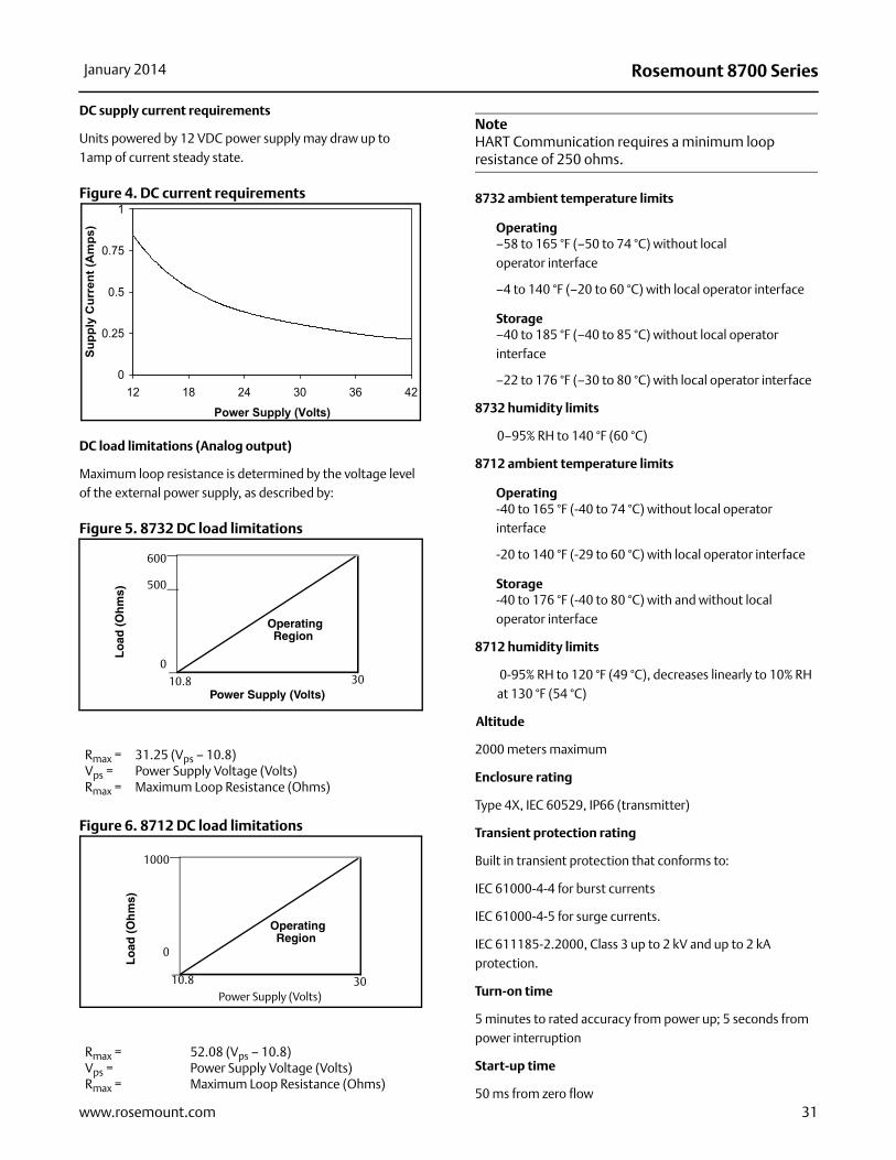
DC supply current requirements
Units powered by 12 VDC power supply may draw up to 1amp of current steady state.
Figure 4. DC current requirements
DC load limitations (Analog output)
Maximum loop resistance is determined by the voltage level of the external power supply, as described by:
Figure 5. 8732 DC load limitations
Figure 6. 8712 DC load limitations
NoteHART Communication requires a minimum loop resistance of 250 ohms.
8732 ambient temperature limits
Operating–58 to 165 °F (–50 to 74 °C) without local operator interface
–4 to 140 °F (–20 to 60 °C) with local operator interface
Storage–40 to 185 °F (–40 to 85 °C) without local operator interface
–22 to 176 °F (–30 to 80 °C) with local operator interface
8732 humidity limits
0–95% RH to 140 °F (60 °C)
8712 ambient temperature limits
Operating-40 to 165 °F (-40 to 74 °C) without local operator interface
-20 to 140 °F (-29 to 60 °C) with local operator interface
Storage-40 to 176 °F (-40 to 80 °C) with and without local operator interface
8712 humidity limits
0-95% RH to 120 °F (49 °C), decreases linearly to 10% RH at 130 °F (54 °C)
Altitude
2000 meters maximum
Enclosure rating
Type 4X, IEC 60529, IP66 (transmitter)
Transient protection rating
Built in transient protection that conforms to:
IEC 61000-4-4 for burst currents
IEC 61000-4-5 for surge currents.
IEC 611185-2.2000, Class 3 up to 2 kV and up to 2 kA protection.
Turn-on time
5 minutes to rated accuracy from power up; 5 seconds from power interruption
Start-up time
50 ms from zero flow
Rmax = 31.25 (Vps – 10.8)Vps = Power Supply Voltage (Volts)Rmax = Maximum Loop Resistance (Ohms)
Rmax = 52.08 (Vps – 10.8)Vps = Power Supply Voltage (Volts)Rmax = Maximum Loop Resistance (Ohms)
0
0.25
0.5
0.75
1
12 18 24 30 36 42
Power Supply (Volts)
Supp
ly C
urre
nt (A
mps
)
Power Supply (Volts)
Lo
ad (
Oh
ms)
OperatingRegion
600
500
0
10.8 30
Power Supply (Volts)
Lo
ad (
Oh
ms)
OperatingRegion
1000
0
10.8 30

Rosemount 8700 Series January 2014
Low Flow cut-off
Adjustable between 0.01 and 38.37 ft/s (0.003 and 11.7 m/s). Below selected value, output is driven to the zero flow rate signal level.
Overrange capability
Signal output will remain linear until 110% of upper range value or 44 ft/s (13 m/s). The signal output will remain constant above these values. Out of range message displayed on LOI and the Field Communicator.
Damping
Adjustable between 0 and 256 seconds
E-Series advanced diagnostics capabilities
BasicSelf testTransmitter faultsAnalog output testPulse output testTunable empty pipeReverse flowCoil circuit faultElectronics temperature
Process diagnostics (DA1/D01)Ground/wiring faultHigh process noise
Smart meter verification (DA2/D02)
Smart Meter Verification4-20 mA loop verification(1)
Output signals
8732 HART / Pulse specifications
Analog output adjustment(2)
4–20 mA, switch-selectable as internally or externally powered 10.8 to 30 VDC; 0 to 600 load.
Engineering units—lower and upper range values are user-selectable.
Output automatically scaled to provide 4 mA at lower range value and 20 mA at upper range value. Full scale continuously adjustable between -39 and 39 ft/s (-12 to 12 m/sec), 1 ft/s (0.3 m/s) minimum span.
HART Communications, digital flow signal, superimposed on 4–20 mA signal, available for control system interface. 250 required for HART communications.
Scalable frequency adjustment(2)
0-10,000 Hz, switch-selectable as internally or externally powered 10 to 24 VDC, transistor switch closure up to 5.75 w. Pulse value can be set to equal desired volume in selected engineering units. Pulse width adjustable from 0.1 to 650 ms.
8712 HART / Pulse specifications
Analog output adjustment(3)
4–20 mA, switch-selectable as internally or externally powered 10.8 to 30 V DC; 0 to 1000 load.
Engineering units—lower and upper range values are user-selectable.
Output automatically scaled to provide 4 mA at lower range value and 20 mA at upper range value. Full scale continuously adjustable between -39 and 39 ft/s (-12 to 12 m/sec), 1 ft/s (0.3 m/s) minimum span.
HART Communications, digital flow signal, superimposed on 4–20 mA signal, available for control system interface. 250 required for HART communications.
Scalable frequency adjustment(2)
0-10,000 Hz, externally powered 5 to 24 V DC, transistor switch closure up to 2 W for frequencies up to 4,000 Hz and 5 V DC at 0.1 W at maximum frequency of 10,000 Hz. Pulse value can be set to equal desired volume in selected engineering units. Pulse width adjustable from 1.5 to 500 msec, below 1.5 msec pulse width automatically switches to 50% duty cycle.
Optional discrete output function (AX option)
Externally powered at 5 to 24 V DC, transistor switch closure up to indicate either:
Reverse flow: Activates switch closure output when reverse flow is detected. The reverse flow rate is displayed.
Zero flow: Activates switch closure output when flow goes to 0 ft/s.
Empty pipe:Activates switch closure output when an empty pipe condition is detected.
(1) Only available on the 8732 with HART outputs.
(2) For transmitters with intrinsically safe outputs, power must be supplied externally.
(3) For transmitters with intrinsically safe outputs, power must be supplied externally.
32 www.rosemount.com

Rosemount 8700 SeriesJanuary 2014
Transmitter faults:Activates switch closure output when a transmitter fault is detected.
Flow limits (2):Activates switch closure output when the transmitter measures a flow rate that meets the conditions established for this alert. There are two independent flow limit alerts that can be configured as discrete outputs.
Totalizer limit:Activates switch closure output when the transmitter measures a total flow that meets the conditions established for this alert.
Diagnostic status:Activates switch closure output when the transmitter detects a condition that meets the configured criteria of this output.
Optional discrete input function (AX option)
Externally powered at 5 to 24 V DC, transistor switch closure up to indicate either:
Net total reset: Resets the net totalizer value to zero.
Positive zero return (PZR): Forces outputs of the transmitter to zero flow.
Output testing
Analog output testTransmitter may be commanded to supply a specified current between 3.5 and 23 mA.
Pulse output testTransmitter may be commanded to supply a specified frequency between 1 and 10,000 Hz.
Security lockout
Security lockout switch on the electronics board can be set to deactivate all LOI and HART-based communicator functions to protect configuration variables from unwanted or accidental change.
8732 LOI lockoutAll optical switches on the display can be locked locally from the display layout configuration screen by holding the upper right optical switch for 10 seconds. The display can be reactivated holding the same switch for 10 seconds.
FOUNDATION fieldbus digital output specifications
Output signal
Manchester-encoded digital signal that conforms to IEC 1158-2 and ISA 50.02
Schedule entries
Seven (7)
Links
Twenty (20)
Virtual communications relationships (VCRs)
One (1) predefined (F6, F7) Nineteen (19) configurable
(see Table 1)
FOUNDATION fieldbus electrical specifications
Voltage Requirement = 9 to 32 VDC
Polarity Insensitive
Current Draw = 18mA
FOUNDATION fieldbus function blocks
Transducer block
The transducer block calculates flow from the measured induced voltage. The calculation includes information related to the calibration number, line size, and diagnostics.
Resource block
The resource block contains physical transmitter information, including available memory, manufacturer identification, device type, software tag, and unique identification.
Backup link active scheduler (LAS)
The transmitter is classified as a device link master. A device link master can function as a Link Active Scheduler (LAS) if the current link master device fails or is removed from the segment.
The host or other configuration tool is used to download the schedule for the application to the link master device. In the absence of a primary link master, the transmitter will claim the LAS and provide permanent control for the H1 segment.
Block Execution time (milliseconds)
Resource (RB) —Transducer (TB) —
Analog Input (AI) 10Proportional/Integral/
Derivative (PID)10
Integrator (INT) 10Arithmetic (AR) 10
33www.rosemount.com

Rosemount 8700 Series January 2014
Diagnostics
The transmitter automatically performs continuous self-diagnostics. The user can perform on-line testing of the transmitter digital signal. Advanced simulation diagnostics are available. This enables remote verification of the electronics via a flow signal generator built into the electronics. The sensor strength value can be used to view the process flow signal and provide information regarding filter settings.
Analog input
The AI function block processes the measurement and makes it available to other function blocks. The AI function block also allows filtering, alarming, and engineering unit changes.
The 8732 Transmitter with FOUNDATION fieldbus comes standard with one AI function block for flow.
Arithmetic block
Provides predefined application-based equations including flow with partial density compensation, electronic remote seals, hydrostatic tank gauging, ratio control and others.
Proportional/integral/derivative
The optional PID function block provides a sophisticated implementation of the universal PID algorithm. The PID function block features input for feed forward control, alarms on the process variable, and control deviation. The PID type (series or Instrument Society of America [ISA]) is user-selectable on the derivative filter.
Integrator
The standard integrator block is available for totalization of flow.
Reverse flow
Detects and reports reverse flow
Software lockout
A write-lock switch and software lockout are provided in the resource function block.
PROFIBUS PA fieldbus digital output specifications
Output signal
Manchester-encoded digital signal that conforms to IEC 1158-2 and ISA 50.02.
Profile version
3.01
Identification number
Generic: 0x9740Manufacturer Specific: 0x0C15
PROFIBUS PA function blocks
Resource block
The Resource Block contains physical transmitter information, including available memory, manufacturer identification, device type, software tag, and unique identification.
Transducer block
The transducer block calculates flow from the measured induced voltage and provides the PV Variable input to the AI Block. The calculation includes information related to the calibration number, line size, and diagnostics.
Diagnostics
The transmitter automatically performs continuous self-diagnostics. The user can perform on-line testing of the transmitter digital signal. In addition advanced diagnostic capabilities are also available to give better insight to meter performance and process information.
Analog Input block
The AI function block processes the measurement and makes it available to the Host system. The AI function block also allows filtering, alarming, and engineering unit changes. The 8732 Transmitter with PROFIBUS PA digital fieldbus comes standard with one AI function block flow.
Totalizer block (3 blocks)
The Totalizer function block allows for totalization of the flow signal. The 8732 Transmitter with PROFIBUS PA digital fieldbus comes with 3 independent totalizer blocks. Each totalized value can be displayed on the Local Operator Interface of the device in addition to the Primary Variable. The non-volatile totalizers can be configured to measure gross, net, forward, and reverse totals.
34 www.rosemount.com
Rosemount 8700 SeriesJanuary 2014
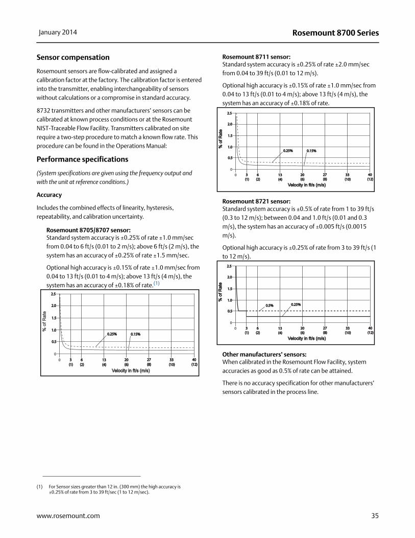
Sensor compensation
Rosemount sensors are flow-calibrated and assigned a calibration factor at the factory. The calibration factor is entered into the transmitter, enabling interchangeability of sensors without calculations or a compromise in standard accuracy.
8732 transmitters and other manufacturers’ sensors can be calibrated at known process conditions or at the Rosemount NIST-Traceable Flow Facility. Transmitters calibrated on site require a two-step procedure to match a known flow rate. This procedure can be found in the Operations Manual:
Performance specifications
(System specifications are given using the frequency output and with the unit at reference conditions.)
Accuracy
Includes the combined effects of linearity, hysteresis, repeatability, and calibration uncertainty.
Rosemount 8705/8707 sensor:Standard system accuracy is ±0.25% of rate ±1.0 mm/sec from 0.04 to 6 ft/s (0.01 to 2 m/s); above 6 ft/s (2 m/s), the system has an accuracy of ±0.25% of rate ±1.5 mm/sec.
Optional high accuracy is ±0.15% of rate ±1.0 mm/sec from 0.04 to 13 ft/s (0.01 to 4 m/s); above 13 ft/s (4 m/s), the system has an accuracy of ±0.18% of rate.(1)
Rosemount 8711 sensor:Standard system accuracy is ±0.25% of rate ±2.0 mm/sec from 0.04 to 39 ft/s (0.01 to 12 m/s).
Optional high accuracy is ±0.15% of rate ±1.0 mm/sec from 0.04 to 13 ft/s (0.01 to 4 m/s); above 13 ft/s (4 m/s), the system has an accuracy of ±0.18% of rate.
Rosemount 8721 sensor:Standard system accuracy is ±0.5% of rate from 1 to 39 ft/s (0.3 to 12 m/s); between 0.04 and 1.0 ft/s (0.01 and 0.3 m/s), the system has an accuracy of ±0.005 ft/s (0.0015 m/s).
Optional high accuracy is ±0.25% of rate from 3 to 39 ft/s (1 to 12 m/s).
Other manufacturers’ sensors: When calibrated in the Rosemount Flow Facility, system accuracies as good as 0.5% of rate can be attained.
There is no accuracy specification for other manufacturers’ sensors calibrated in the process line.
(1) For Sensor sizes greater than 12 in. (300 mm) the high accuracy is ±0.25% of rate from 3 to 39 ft/sec (1 to 12 m/sec).
0
0.50.5
1.01.0
1.51.5
2.02.0
2.52.5
0 3 3 (1)(1)
6 6 (2)(2)
13 13 (4)(4)
20 20 (6)(6)
27 27 (8)(8)
33 33 (10)(10)
40 40 (12)(12)
Velocity in ft/s (m/s)Velocity in ft/s (m/s)
% o
f Rat
e
0.25%0.25% 0.15%0.15%
0
0.50.5
1.01.0
1.51.5
2.02.0
2.52.5
0 3 3 (1)(1)
6 6 (2)(2)
13 13 (4)(4)
20 20 (6)(6)
27 27 (8)(8)
33 33 (10)(10)
40 40 (12)(12)
Velocity in ft/s (m/s)Velocity in ft/s (m/s)
% o
f Rat
e%
of R
ate
0.25%0.25% 0.15%0.15%
0
0.50.5
1.01.0
1.51.5
2.02.0
2.52.5
0 3 3 (1)(1)
6 6 (2)(2)
13 13 (4)(4)
20 20 (6)(6)
27 27 (8)(8)
33 33 (10)(10)
40 40 (12)(12)
Velocity in ft/s (m/s)Velocity in ft/s (m/s)
% o
f Rat
e%
of R
ate
0.5%0.5% 0.25%0.25%
35www.rosemount.com

Rosemount 8700 Series January 2014
Analog output effect
Analog output has the same accuracy as frequency output plus an additional ±4A.
Repeatability
±0.1% of reading
Response time (analog output)
50 ms max response time to step change in input
Stability
±0.1% of rate over six months
Ambient temperature effect
±0.25% change over operating temperature range
EMC compliance
Requires Combo Cable to meet EN61326-1: 2006 (Industrial) electromagnetic compatibility (EMC) for process and laboratory apparatus.
8732 Physical specifications
Materials of construction
Standard housing
Low copper aluminumType 4X and IEC 60529 IP66
Optional housing
316/316L unpainted, option code SHType 4X and IEC 60529 IP66
PaintPolyurethane
Cover gasketBuna-N
Electrical connections
Two 1/2–14 NPT connections provided on the transmitter housing (optional third connection available). PG13.5 and CM20 adapters are available. Screw terminals provided for all connections. Power wiring connected to transmitter only. Integrally mounted transmitters are factory wired to the sensor.
Vibration rating
3G per IEC 61298
Transmitter weight
Approximately 7 lbs. (3.2 kg). Add 1 pound (0.5 kg) for Option Code M4/M5.
8712 Physical specifications
Materials of construction
HousingLow-copper aluminum, Type 4X and IEC 60529 IP66
PaintPolyurethane
Cover gasketSilicone Rubber
Electrical connections
Four 1/2–14 NPT connections provided on the base of the transmitter. Screw terminals provided for all of the connections. Power wiring connected to the transmitter only. Remote mounted transmitters require only a single conduit connection to the sensor.
Transmitter weight
Transmitter approximately 9 lbs. (4 kg). Add 1 lb (0.5 kg) for local operator interface.
36 www.rosemount.com

Rosemount 8700 SeriesJanuary 2014
Rosemount 8712H transmitter specifications
Functional specifications
Sensor compatibility
Compatible with 8707 High-Signal sensor only.
Sensor coil resistance
Transmitter coil drive current
5 A
Flow rate range
Capable of processing signals from fluids that are traveling between 0.04 and 30 ft/s (0.01 to 10 m/s) for both forward and reverse flow in all sensor sizes. Full scale continuously adjustable between –30 and 30 ft/s (–10 to 10 m/s).
Conductivity limits
Process liquid must have a conductivity of 50 microsiemens/cm (50 micromhos/cm). Excludes the effect of interconnecting cable length in remote mount transmitter installations.
Power supply
DC load limitations (analog output)
Maximum loop resistance is determined by the voltage level of the external power supply, as described by:
Figure 7. DC load limitations
NoteHART Communication requires a minimum loop resistance of 250 ohms.
Power consumption
Ambient temperature limits
Operating–20 to 130 °F (–29 to 54 °C)
Storage–40 to 176 °F (–40 to 80 °C)
Humidity limits
0–95% RH at 120 °F (49 °C), decreases linearly to 10% RH at 130 °F (54 °C)
Enclosure ratings
Type 4X, IP66
Output signals
Analog output adjustment4–20 mA, switch-selectable as internally or externally powered 5 to 30 VDC; 0 to 1000 load.
Engineering units—lower and upper range values are user-selectable.
Output automatically scaled to provide 4 mA at lower range value and 20 mA at upper range value.
Full scale continuously adjustable between -30 and 30 ft/s (-10 to 10 m/sec), 1 ft/s (0.3 m/s) minimum span.
HART Communications, digital flow signal, superimposed on 4–20 mA signal, available for control system interface. 250 required for HART communications.
Scalable frequency adjustment0-1000 Hz, externally powered at 5 to 24 V DC, transistor switch closure up to 5.75 W. Pulse value can be set to equal desired volume in selected engineering units. Pulse width adjustable from 0.5 to 100 ms. Local operator interface automatically calculates and displays maximum allowable output frequency.
12 � maximum
120 V AC, 50–60 Hz
Rmax = 41.7(Vps – 10.8)Vps = Power Supply Voltage (Volts)Rmax = Maximum Loop Resistance (Ohms)
Power Supply (Volts)
Lo
ad (
Oh
ms)
OperatingRegion
1250
1000
500
0
10.8 42
300 watts maximum
37www.rosemount.com

Rosemount 8700 Series January 2014
Auxiliary functions
Externally powered at 5 to 24 V DC, transistor switch closure up to 3 W to indicate either:
Reverse flow: Activates switch closure output when reverse flow is detected. The reverse flow rate is displayed.
Zero flow: Activates switch closure output when flow goes to 0 ft/s.
Positive Zero Return (PZR)(1)
Forces outputs of the transmitter to the zero flow rate signal level. Activated by applying a contact closure.
Security lockout
Security lockout jumper on the electronics board can be set to deactivate all LOI and HART-based communicator functions to protect configuration variables from unwanted or accidental change.
Output testing
Analog output testTransmitter may be commanded to supply a specified current between 3.75 and 23.25 mA
Pulse output testTransmitter may be commanded to supply a specified frequency between 1 and 1000 Hz
Turn-on time30 minutes to rated accuracy from power up, 5 seconds from power interruption
Start-up time
0.2 seconds from zero flow
Low Flow cut-off
Adjustable between 0.04 and 1.0 ft/s (0.012 to 0.304 m/s). Below selected value, output is driven to the zero flow rate signal level.
Overrange capability
Signal output will remain linear until 110% of upper range value. The signal output will remain constant above these values. Out of range message displayed on LOI and the Field Communicator.
Damping
Adjustable between 0.2 and 256 seconds
Sensor compensation
Rosemount sensors are flow-calibrated and assigned a calibration factor at the factory. The calibration factor is entered into the transmitter, enabling interchangeability of sensors without calculations or a compromise in accuracy.
(1) PZR is internally powered on the 8712H transmitter.
38 www.rosemount.com

Rosemount 8700 SeriesJanuary 2014
Performance specifications
(System specifications are given using the frequency output and with the unit at referenced conditions.)
Accuracy
Includes the combined effects of linearity, hysteresis, repeatability, and calibration uncertainty.
Rosemount high signal flowmeter systemSystem accuracy is ±0.5% of rate from 3 to 30 ft/s (1 to 10 m/s); between 0.04 and 3.0 ft/s (0.01 and 0.3 m/s), the system has an accuracy of ±0.015 ft/s (0.005 m/s).
Optional high accuracy is ±0.25% of rate from 3 to 30 ft/s (1 to 10 m/s).
Total System Performance 1.6%
Analog output effectAnalog output has the same accuracy as frequency output plus an additional 0.1% of span.
Repeatability
±0.1% of reading
Response time
0.2 seconds maximum response to step change in input
Stability
±0.1% of rate over six months
Ambient temperature effect
±1% per 100 °F (57 °C)
Physical specifications
Materials of construction
HousingLow-copper aluminum, Type 4X and IEC 60529 IP66
PaintPolyurethane
Cover gasketSilicone Rubber
Electrical connections
Four 1/2–14 NPT connections provided on the base of the transmitter. Screw terminals provided for all of the connections. Power wiring connected to the transmitter only. Remote mounted transmitters require only a single conduit connection to the sensor.
Line power fuses5 amp, Quick-acting Bussman AGC5 or equivalent.
Transmitter weight
Transmitter approximately 9 lb (4 kg). Add 1 lb (0.5 kg) for local operator interface.0
0.50.5
1.01.0
1.51.5
2.02.0
2.52.5
0 3 3 (1)(1)
6 6 (2)(2)
12 12 (4)(4)
18 18 (6)(6)
24 24 (8)(8)
30 30 (10)(10)
Velocity in ft/s (m/s)Velocity in ft/s (m/s)
% o
f Rat
e%
of R
ate
0.5%0.5% 0.25%0.25%
39www.rosemount.com

Rosemount 8700 Series January 2014
Rosemount 8705 / 8707 flanged sensor specifications
Functional specifications
Service
Conductive liquids and slurries
Line sizes
1/2–in. to 36-in. (15 mm to 900 mm) for Rosemount 8705
3–in. to 36-in. (80 mm to 600 mm) for Rosemount 8707
Sensor coil resistance
8705: 7 - 16
8707: 1.5 - 10
Interchangeability
Rosemount 8705 Sensors are interchangeable with 8732, and 8712 Transmitters. Rosemount 8707 High-Signal Sensors are interchangeable with 8732, 8712, and 8712H High-Signal Transmitters. System accuracy is maintained regardless of line size or optional features. Each sensor nameplate has a sixteen-digit calibration number that can be entered into a transmitter through the Local Operator Interface (LOI) or the Field Communicator. In a FOUNDATION fieldbus environment, the 8732 can be configured using the DeltaV™ fieldbus configuration tool or another FOUNDATION fieldbus configuration device. No further calibration is necessary.
Upper range limit
39.37 ft/s (12 m/s)
Process temperature limits
PTFE Lining–20 to 350 °F (–29 to 177 °C)
ETFE Lining–20 to 300 °F (–29 to 149 °C)
PFA Lining-20 to 350 °F (-29 to 177 °C)
Polyurethane Lining0 to 140 °F (–18 to 60 °C)
Neoprene Lining0 to 176 °F (–18 to 80 °C)
Linatex lining0 to 158 °F (–18 to 70 °C)
Extreme service polyurethane lining0 to 200 °F (–18 to 93 °C)
Extreme service PFA lining-20 to 350 °F (–29 to 177 °C)
Ambient temperature limits
–20 to 150 °F (–29 to 65 °C)
Pressure limits
See Table 20, Table 21 and Table 22
Vacuum limits
PTFE liningFull vacuum to 350 °F (177 °C) through 4-in. (100 mm) line sizes. Consult factory for vacuum applications with line sizes of 6 inches (150 mm) or larger.
All other standard sensor lining materialsFull vacuum to maximum material temperature limits for all available line sizes.
Submergence protection(1)
IP68. Continuous submergence to 30 ft. (10 m). Requires conduit entries of the sensor remote junction box be properly sealed to prevent water ingress. This requires the user to install sealed IP68 approved cable glands, conduit connections, or conduit plugs. For more details on proper installation techniques for an IP68 / submersible application, reference Rosemount Technical Document 00840-0100-4750 available on www.Rosemount.com.
Conductivity limits
Process liquid must have a minimum conductivity of 5 microsiemens/cm (5 micromhos/cm) or greater for 8705. Process liquid must have a conductivity of 50 microsiemens/cm (50 micromhos/cm) for 8707 when used with 8712H, 5 microsiemens/cm when used with other transmitters.
(1) Available for Rosemount 8705 Sensors only.
40 www.rosemount.com

41
Rosemount 8700 SeriesJanuary 2014
www.rosemount.com
Table 20. Temperature vs. pressure limits(1)
Sensor temperature vs. pressure limits for ASME B16.5 Class Flanges (1/2-in. to 36-in. line sizes)(2)
Pressure
Flange material Flange rating@ -20 to 100 °F(-29 to 38 °C)
@ 200 °F(93 °C)
@ 300 °F(149 °C)
@ 350 °F(177 °C)
Carbon Steel
Class 150 285 psi 260 psi 230 psi 215 psiClass 300 740 psi 675 psi 655 psi 645 psi
Class 600 (3) 1000 psi 800 psi 700 psi 650 psiClass 600 (4) 1480 psi 1350 psi 1315 psi 1292 psi
Class 900 2220 psi 2025 psi 1970 psi 1935 psiClass 1500 3705 psi 3375 psi 3280 psi 3225 psiClass 2500 6170 psi 5625 psi 5470 psi 5375 psi
304 Stainless Steel
Class 150 275 psi 235 psi 205 psi 190 psiClass 300 720 psi 600 psi 530 psi 500 psi
Class 600 (5) 1000 psi 800 psi 700 psi 650 psiClass 600 (6) 1440 psi 1200 psi 1055 psi 997 psi
Class 900 2160 psi 1800 psi 1585 psi 1497 psiClass 1500 3600 psi 3000 psi 2640 psi 2495 psiClass 2500 6000 psi 5000 psi 4400 psi 4160 psi
(1) Liner temperature limits must also be considered. Polyurethane, Linatex, and Neoprene have temperature limits of 140 °F (60 °C), 158 °F (70 °C), and 176 °F (80 °C)
(2) 30-in. and 36-in. AWWA C207 Class D rated to 150 psi at atmospheric temperature.
(3) Option Code C6.
(4) Option Code C7.
(5) Option Code S6.
(6) Option Code S7.
Table 21. Temperature vs. pressure limits(1)
Sensor temperature vs. pressure limits for AS2129 Table D and E Flanges (4-in. to 24-in. line sizes)
Pressure
Flange Material Flange Rating@ -200 to 50 °C(-320 to 122 °F)
@ 100 °C(212 °F)
@ 150 °C(302 °F)
@ 200 °C(392 °F)
Carbon SteelD 101.6 psi 101.6 psi 101.6 psi 94.3 psiE 203.1 psi 203.1 psi 203.1 psi 188.6 psi
(1) Liner temperature limits must also be considered. Polyurethane, Linatex, and Neoprene have temperature limits of 140 °F (60 °C), 158 °F (70 °C), and 176 °F (80 °C)
Table 22. Temperature vs. pressure limits(1)
Sensor temperature vs. pressure limits for EN 1092-1 Flanges (15 mm to 600 mm line sizes)
Pressure
Flange material Flange rating@ -196 to 50 °C(-320 to 122 °F)
@ 100 °C(212 °F)
@ 150°C(302 °F)
@ 175°C(347 °F)
Carbon Steel
PN 10 10 bar 10 bar 9.7 bar 9.5 barPN 16 16 bar 16 bar 15.6 bar 15.3 barPN 25 25 bar 25 bar 24.4 bar 24.0 barPN 40 40 bar 40 bar 39.1 bar 38.5 bar
304 Stainless Steel
PN 10 9.1 bar 7.5 bar 6.8 bar 6.5 barPN 16 14.7 bar 12.1 bar 11.0 bar 10.6 barPN 25 23 bar 18.9 bar 17.2 bar 16.6 barPN 40 36.8 bar 30.3 bar 27.5 bar 26.5 bar
(1) Liner temperature limits must also be considered. Polyurethane, Linatex, and Neoprene have temperature limits of 140°F, 158°F, and 176°F, respectively.
Rosemount 8700 Series January 2014
Physical specifications
Non-wetted materials
Sensor pipeType 304/304L SST or Type 316/316L SST
FlangesCarbon steel, Type 304/304L SST, or Type 316/316L SST
Coil housingRolled carbon steel
Optional coil housing316/316L unpainted, option code SH
PaintPolyurethane
Process wetted materials
LiningPFA, PTFE, ETFE, Polyurethane, Neoprene, Linatex, Extreme Service Polyurethane
Electrodes316L SST, Nickel Alloy 276 (UNS N10276), Tantalum,
80% Platinum-20% Iridium, Titanium
Flat-faced flanges
Flat-faced flanges are manufactured with full-face liners. Available in Neoprene and Linatex only.
Process connections
ASME B16.5
1/2-in. to 24-in. (Class 150)
1/2-in. to 24-in. (Class 300)
1/2-in. to 24-in. (Class 600)(1)
1-in. to 12-in. (Class 900)(2)
11/2-in. to 12-in. (Class 1500)(2)
11/2-in. to 6-in. (Class 2500)(2)
AWWA C207 Class D30-in. and 36-in.
MSS SP44 (ASME B16.47)30-in. to 36-in. (Class 150)
30-in. only (Class 300)
EN 1092-1 PN10: 8-in. to 36-in. (200 mm to 900mm)
PN16: 4 -in. to 36-in. (100 mm to 900mm)
PN 25: 8-in. to 36-in. (200 mm to 900mm)
PN40: 1/2-in. to 36-in. (15 mm to 900mm)
AS2129 Table D and E1/2-in. to 36-in. (15 mm to 900 mm)
AS40872-in. to 24-in. (50 mm to 600 mm) (PN16, PN21, PN35)
JIS B22201/2-in. to 8-in. (15 mm to 200 mm) (10K, 20K, 40K)
Electrical connections
Two 1/2–14 NPT connections with number 8 screw terminals are provided in the terminal enclosure for electrical wiring.
Reference electrode
An optional reference electrode can be installed similarly to the measurement electrodes through the sensor lining on 8705 sensors. It is available in all electrode materials.
Grounding rings - (optional)
Optional grounding rings can be installed between the flange and the sensor face on both ends of the sensor. Single ground rings can be installed on either end of the sensor. They have an I.D. slightly larger than the sensor I.D. and an external tab to attach ground wiring. Grounding rings are available in 316L SST, Nickel Alloy 276 (UNS N10276), titanium, and tantalum.
Lining protectors - (optional)
Optional lining protectors can be installed between the flange and the sensor face on both ends of the sensor. The leading edge of lining material is protected by the lining protector; lining protectors cannot be removed once they are installed. Lining protectors are available in 316L SST, Nickel Alloy 276 (UNS N10276), and titanium.
Dimensions
See Figure 10 and Table 34.
Weight
See dimensional tables starting with Table 31.
(1) For PTFE and ETFE, maximum working pressure is derated to 1000 psig.
(2) For Class 900 and higher flange ratings,.liner selection is limited to resilient liners.
42 www.rosemount.com
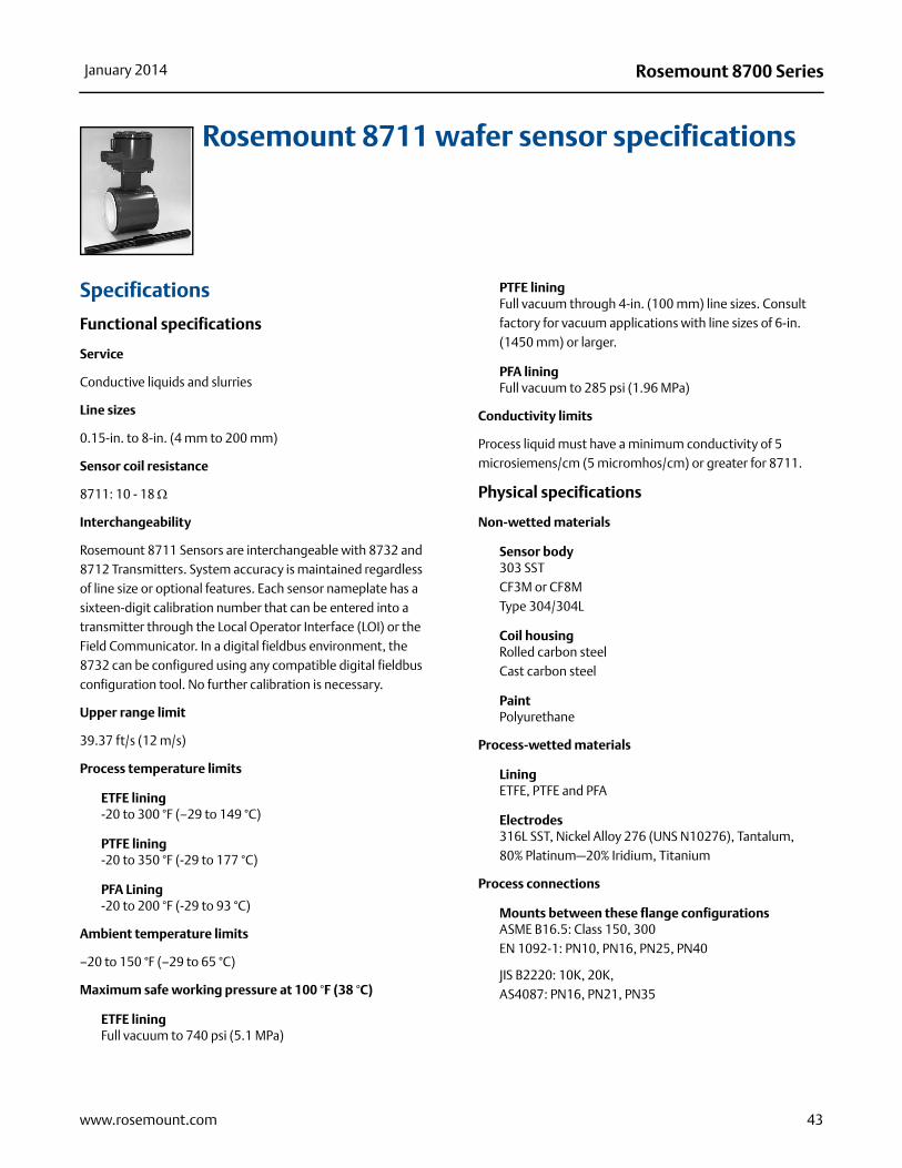
Rosemount 8700 SeriesJanuary 2014
Rosemount 8711 wafer sensor specifications
Specifications
Functional specifications
Service
Conductive liquids and slurries
Line sizes
0.15-in. to 8-in. (4 mm to 200 mm)
Sensor coil resistance
8711: 10 - 18
Interchangeability
Rosemount 8711 Sensors are interchangeable with 8732 and 8712 Transmitters. System accuracy is maintained regardless of line size or optional features. Each sensor nameplate has a sixteen-digit calibration number that can be entered into a transmitter through the Local Operator Interface (LOI) or the Field Communicator. In a digital fieldbus environment, the 8732 can be configured using any compatible digital fieldbus configuration tool. No further calibration is necessary.
Upper range limit
39.37 ft/s (12 m/s)
Process temperature limits
ETFE lining-20 to 300 °F (–29 to 149 °C)
PTFE lining-20 to 350 °F (-29 to 177 °C)
PFA Lining-20 to 200 °F (-29 to 93 °C)
Ambient temperature limits
–20 to 150 °F (–29 to 65 °C)
Maximum safe working pressure at 100 °F (38 °C)
ETFE liningFull vacuum to 740 psi (5.1 MPa)
PTFE liningFull vacuum through 4-in. (100 mm) line sizes. Consult factory for vacuum applications with line sizes of 6-in. (1450 mm) or larger.
PFA liningFull vacuum to 285 psi (1.96 MPa)
Conductivity limits
Process liquid must have a minimum conductivity of 5 microsiemens/cm (5 micromhos/cm) or greater for 8711.
Physical specifications
Non-wetted materials
Sensor body303 SSTCF3M or CF8MType 304/304L
Coil housing Rolled carbon steelCast carbon steel
PaintPolyurethane
Process-wetted materials
LiningETFE, PTFE and PFA
Electrodes316L SST, Nickel Alloy 276 (UNS N10276), Tantalum, 80% Platinum—20% Iridium, Titanium
Process connections
Mounts between these flange configurationsASME B16.5: Class 150, 300EN 1092-1: PN10, PN16, PN25, PN40
JIS B2220: 10K, 20K, AS4087: PN16, PN21, PN35
43www.rosemount.com

Rosemount 8700 Series January 2014
Studs, nuts, and washers(1)
ASME B16.5
0.15-in. to 1-in. (4 mm to 25 mm):316 SST, ASTM A193, Grade B8M, Class 1 threaded mounting studs; ASTM A194, Grade 8M heavy hex nuts; SAE per ANSI B18.2.1, Type A, Series N flat washers.
11/2-in. to 8-in. (40 mm to 200 mm):CS, ASTM A193, Grade B7, Class 1 threaded mounting studs; ASTM A194, Grade 2H heavy hex nuts; SAE per ANSI B18.2.1, Type A, Series N flat washers; all items clear, chromate zinc-plated.
EN 1092-1
4 mm to 25 mm (0.15-in. to 1-in.):316 SST ASTM A193, Grade B8M Class 1 threaded mounting studs; ASTM A194, Grade 8M, DIN 934 H=D, metric heavy hex nuts; 316 SST, A4, DIN 125 flat washers.
40 mm to 200 mm (11/2-in. to 8-in.):CS, ASTM A193, Grade B7 threaded mounting studs; ASTM A194, Grade 2H, DIN 934 H=D, metric heavy hex nuts; CS, DIN 125 flat washers; all items yellow zinc-plated.
Electrical connections
Two 1/2–14 NPT connections with number 8 screw terminals are provided in the terminal enclosure for electrical wiring.
Reference electrode
An optional reference electrode can be installed similarly to the measurement electrodes through the sensor lining. It is available in all electrode materials.
Grounding rings
Optional grounding rings can be installed between the flange and the sensor face on both ends of the sensor. They have an I.D. slightly smaller than the sensor I.D. and an external tab to attach ground wiring. Grounding rings are available in 316L SST, Nickel Alloy 276 (UNS N10276), titanium, and tantalum.
Dimensions and weight
See Figure 17, Figure 24, and Table 23.
(1) 0.15 and 0.30 in. (4 and 80 mm) sensors mount between 1/2-in. flange.
44 www.rosemount.com

Rosemount 8700 SeriesJanuary 2014
Rosemount 8721 sanitary sensor specifications
Functional specifications
Service
Conductive liquids and slurries
Line sizes
1/2-in. to 4-in. (15 mm to100 mm)
Sensor compatibility and interchangeability
The Rosemount 8721 Sensors are interchangeable with Rosemount 8732 and 8712 transmitters. System accuracy is maintained regardless of line size or optional features.
Each sensor label has a 16 digit calibration number that can be entered into the transmitter through the Local Operator Interface (LOI) or the Field Communicator. In a digital fieldbus environment, the 8732 can be configured using compatible digital fieldbus configuration tool. No further calibration is necessary.
Conductivity limits
Process liquid must have a minimum conductivity of 5 microsiemens/cm (5 micromhos/cm) or greater. Excludes the effect of interconnecting cable length in remote mount transmitter installations.
Sensor coil resistance
5 to 10 (line size dependent)
Flow rate range
Capable of processing signals from fluids that are traveling between 0.04 and 39 ft/s (0.01 to 12 m/s) for both forward and reverse flow in all sensor sizes. Full scale continuously adjustable between –39 and 39 ft/s (–12 to 12 m/s).
Sensor ambient temperature limits
14 to 140 °F (–15 to 60 °C)
Process temperature limits
PFA lining-20 to 350 °F (-29 to 177 °C)
Pressure limits
Vacuum limits
Full vacuum at maximum lining material temperature; consult factory.
Submergence protection (sensor)
IP68. Continuous submergence to 30 ft. (10 m). Requires conduit entries of the sensor remote junction box be properly sealed to prevent water ingress. This requires the use of sealed IP68 approved cable glands, conduit connections, or conduit plugs. For more details on proper installation techniques for an IP 68/submersible application, reference Rosemount Technical Document 00840-0100-4750 available on www.rosemount.com.
Line sizeMax working
pressureCE Mark max. working
pressure1/2 (15) 300 psi (20.7 bar) 300 psi (20.7 bar)1 (25) 300 psi (20.7 bar) 300 psi (20.7 bar)
11/2 (40) 300 psi (20.7 bar) 300 psi (20.7 bar)2 (50) 300 psi (20.7 bar) 300 psi (20.7 bar)
21/2 (65) 300 psi (20.7 bar) 240 psi (16.5 bar)3 (80) 300 psi (20.7 bar) 198 psi (13.7 bar)
4 (100) 210 psi (14.5 bar) 148 psi (10.2 bar)
45www.rosemount.com

Rosemount 8700 Series January 2014
Physical specifications
Mounting
Integrally mounted transmitters are factory-wired and do not require interconnecting cables. The transmitter can rotate in 90° increments. Remote mounted transmitters require only a single conduit connection to the sensor.
Non-wetted materials
Sensor304 Stainless Steel (wrapper), 304 Stainless Steel (pipe)
Terminal junction boxCast aluminum, polyurethane coatedOptional: 304 Stainless Steel
PaintPolyurethane
Weight
Aluminum remote junction boxApproximately 1 lb. (0.45 kg)
SST remote junction boxApproximately 2.5 lbs. (1.13 kg)
Process wetted materials (sensor)
LinerPFA with Ra < 32in. (0.81 m)
Electrodes316L SST with Ra < 15in. (0.38 m)
Nickel Alloy 276 (UNS N10276) with Ra < 15in. (0.38 m)
80% Platinum-20% Iridium with Ra < 15in. (0.38 m)
Process connections
The Rosemount 8721 Sanitary Sensor is designed using a standard IDF fitting as the basis for providing a flexible, hygienic interface for a variety of process connections. The Rosemount 8721 Sensor has the threaded or “male” end of the IDF fitting on the ends of the base sensor. The sensor can be directly connected with user supplied IDF fittings and gaskets. If other process connections are needed, the IDF fittings and gaskets can be provided and welded directly into the sanitary process tubing, or can be supplied with adapters to standard Tri-Clamp® process connections. All connections are PED compliant for group 2 fluids.
Tri-clamp sanitary coupling
IDF Sanitary Coupling (screw type)IDF specification per BS4825 part 4
ANSI Weld Nipple
DIN 11850 Weld Nipple
DIN 11851 (imperial and metric)
DIN 11864-1 form A
DIN 11864-2 form A
SMS 1145
Cherry-Burrell I-Line
Process connection material
316L Stainless Steel with Ra < 32 in. (0.81m)
Optional Electro-polished Surface Finish with Ra < 15in.
(0.38m)
Process connection gasket material
Silicone
EPDM
Viton
Electrical connections
Two 1/2–14 NPT connections with number 8 screw terminals are provided in the terminal enclosure for electrical wiring.
Sensor dimensions
Refer to Figure 17.
Table 23. 8721 Sensor weight
Line size Sensor only008721-0350 Tri-clamp
fitting (each)1/2 4.84 lbs (2.20 kg) 0.58 lbs (0.263 kg)1.0 4.52 lbs (2.05 kg) 0.68 lbs (0.309 kg)11/2 5.52 lbs (2.51 kg) 0.88 lbs (0.400 kg)2.0 6.78 lbs (3.08 kg) 1.30 lbs (0.591 kg)21/2 8.79 lbs (4.00 kg) 1.66 lbs (0.727 kg)3.0 13.26 lbs (6.03 kg) 2.22 lbs (1.01 kg)4.0 21.04 lbs (9.56 kg) 3.28 lbs (1.49 kg)
46 www.rosemount.com

Rosemount 8700 SeriesJanuary 2014
Product certifications
Approved manufacturing locations
Rosemount Inc. — Eden Prairie, Minnesota, USA
Fisher-Rosemount Technologias de Flujo, S.A. de C.V. —Chihuahua Mexico
Emerson Process Management Flow — Ede, The Netherlands
Asia Flow Technology Center — Nanjing, China
European directive informationThe EC declaration of conformity for all applicable European directives for this product can be found on our website at www.rosemount.com. A hard copy may be obtained by contacting your local sales office.
ATEX directiveRosemount Inc. complies with the ATEX Directive.Type n protection type in accordance with EN50 021
•Closing of entries in the device must be carried out using the appropriate EEx e or EEx n metal cable gland and metal blanking plug or any appropriate ATEX approved cable gland and blanking plug with IP66 rating certified by an EU approved certification body.
For Rosemount 8732 transmitters:
Complies with Essential Health and Safety Requirements: EN 60079-0: 2006EN 60079-1: 2007EN 60079-7: 2007EN 60079-11: 2007EN 60079-15: 2005EN 61241-0: 2004EN 61241-1: 2006
For Rosemount 8712 transmitters:Complies with Essential Health and Safety Requirements:EN 60079-15: 2003
For Rosemount 8700 Series Sensors:Complies with Essential Health and Safety Requirements:EN 61241-0: 2006EN 61241-1: 2004
European Pressure Equipment Directive (PED) (97/23/EC)
Rosemount 8705 and 8707 Magnetic Flowmeter Sensors in line size and flange combinations:
Line Size: 11/2 in. to 24-in. with all (excluded 21/2-ft. and 5-ft.) EN 1092-1 flanges and ASME Class150 and ASME Class 300 flanges. Also available with ASME Class 600 flanges in limited line sizes.
Line Size: 30-in. and 36-in. with AWWA Class DCertificate of Assessment - EC No. PED-H-100Module H Conformity Assessment
Rosemount 8711 Magnetic Flowmeter Sensors line sizes: 11/2-in., 2-in., 3-in., 4-in., 6-in., and 8-in.
Certificate of Assessment - EC No. PED-H-100Module H Conformity Assessment
Rosemount 8721 Sanitary Magmeter Sensors in line sizes of 11/2-in. and larger:
Module A Conformity Assessment
All other Rosemount 8705/8707/8711/8721 Sensors — in line sizes of 1-in. and less: sound engineering practice
Sensors that are SEP are outside the scope of PED and cannot be marked for compliance with PED.Mandatory CE-marking for sensors in accordance with Article 15 of the PED can be found on the sensor body (CE 0575). Sensor category I is assessed for conformity per module A procedures.Sensor categories II – III, use module H for conformity assessment procedures.
Electro Magnetic Compatibility (EMC) (2004/108/EC)Model 8732 and 8712 EN 61326: 2006Installed signal wiring should not be run together and should not be in the same cable tray as AC power wiring. Device must be properly grounded or earthed according to local electric codes.Rosemount combination cable model number 08732-0753-1003 (ft) or 08732-0753-2004 (m) is required to be used to meet EMC requirements.
Low voltage directive (2006/95/EC)
Model 8732 and 8712 - EN 61010 -1: 2001
47www.rosemount.com

Rosemount 8700 Series January 2014
Other important guidelines Only use new, original parts. To prevent the process medium escaping, do not unscrew or remove process flange bolts, adapter bolts or bleed screws during operation. Maintenance shall only be done by qualified personnel.
CE Marking
Compliance with all applicable European Union Directives. (Note: CE Marking is not available on Rosemount 8712H).
IECEx Certificates
C-Tick Marking
Rosemount Inc. complies with the following IEC Requirements.
For Rosemount 8732 transmitters:
IEC 60079-0: 2004
IEC 60079-0: 2007
IEC 60079-1: 2007
IEC 60079-11: 2006
IEC 60079-15: 2005
IEC 60079-7: 2006
IEC 61241-0: 2004
IEC 61241-1: 2004
For Rosemount 8712 transmitters:IEC 60079-0: 2004
IEC 60079-15: 2005-03
48 www.rosemount.com
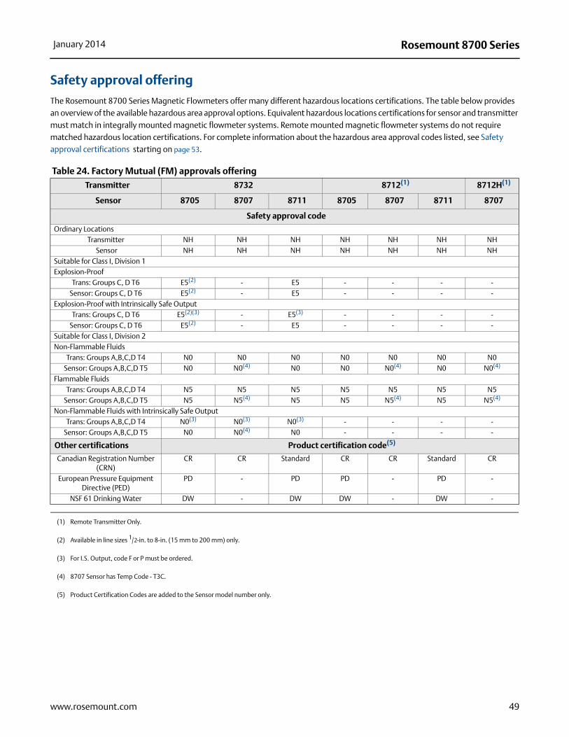
Rosemount 8700 SeriesJanuary 2014
Safety approval offering
The Rosemount 8700 Series Magnetic Flowmeters offer many different hazardous locations certifications. The table below provides an overview of the available hazardous area approval options. Equivalent hazardous locations certifications for sensor and transmitter must match in integrally mounted magnetic flowmeter systems. Remote mounted magnetic flowmeter systems do not require matched hazardous location certifications. For complete information about the hazardous area approval codes listed, see Safety approval certifications starting on page 53.
Table 24. Factory Mutual (FM) approvals offering
Transmitter 8732 8712(1)
(1) Remote Transmitter Only.
8712H(1)
Sensor 8705 8707 8711 8705 8707 8711 8707
Safety approval code
Ordinary LocationsTransmitter NH NH NH NH NH NH NH
Sensor NH NH NH NH NH NH NHSuitable for Class I, Division 1Explosion-Proof
Trans: Groups C, D T6 E5(2)
(2) Available in line sizes 1/2-in. to 8-in. (15 mm to 200 mm) only.
- E5 - - - -Sensor: Groups C, D T6 E5(2) - E5 - - - -
Explosion-Proof with Intrinsically Safe OutputTrans: Groups C, D T6 E5(2)(3)
(3) For I.S. Output, code F or P must be ordered.
- E5(3) - - - -Sensor: Groups C, D T6 E5(2) - E5 - - - -
Suitable for Class I, Division 2Non-Flammable Fluids
Trans: Groups A,B,C,D T4 N0 N0 N0 N0 N0 N0 N0Sensor: Groups A,B,C,D T5 N0 N0(4)
(4) 8707 Sensor has Temp Code - T3C.
N0 N0 N0(4) N0 N0(4)
Flammable FluidsTrans: Groups A,B,C,D T4 N5 N5 N5 N5 N5 N5 N5
Sensor: Groups A,B,C,D T5 N5 N5(4) N5 N5 N5(4) N5 N5(4)
Non-Flammable Fluids with Intrinsically Safe OutputTrans: Groups A,B,C,D T4 N0(3) N0(3) N0(3) - - - -
Sensor: Groups A,B,C,D T5 N0 N0(4) N0 - - - -
Other certifications Product certification code(5)
(5) Product Certification Codes are added to the Sensor model number only.
Canadian Registration Number (CRN)
CR CR Standard CR CR Standard CR
European Pressure Equipment Directive (PED)
PD - PD PD - PD -
NSF 61 Drinking Water DW - DW DW - DW -
49www.rosemount.com

Rosemount 8700 Series January 2014
Table 25. Canadian Standards Association (CSA) approvals offering
Transmitter 8732 8712(1)
(1) Remote Transmitter Only.
8712H(1)
Sensor 8705 8707 8711 8705 8707 8711 8707
Safety approval code
Ordinary Locations
Transmitter NH - NH NH - NH -Sensor NH - NH NH - NH -
Suitable for Class I, Division 2
Non-Flammable Fluids
Trans: Groups A,B,C,D T4 N0 N0 N0 N0 N0 N0 N0Sensor: Groups A,B,C,D T5 N0 N0(2)
(2) 8707 Sensor has Temp Code - T3C.
N0 N0 N0(2) N0 N0(2)
Other certifications Product certification code(3)
(3) Product Certification Codes are added to the Sensor model number only.
Canadian Registration Number (CRN)
CR CR Standard CR CR Standard CR
European Pressure Equipment Directive (PED)
PD - PD PD - PD -
NSF 61 Drinking Water DW - DW DW - DW -
50 www.rosemount.com
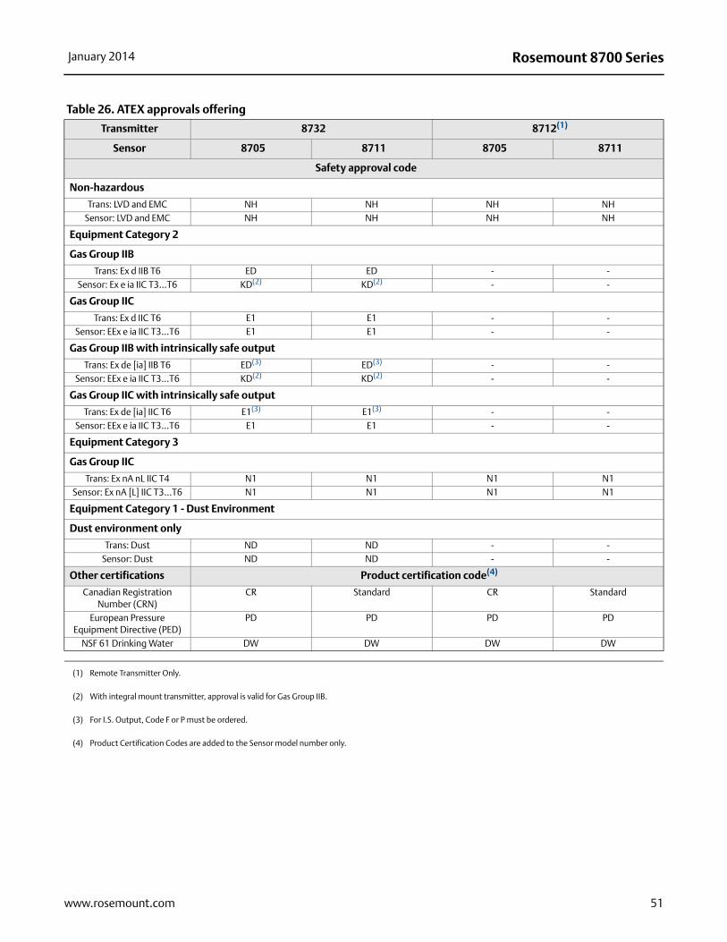
Rosemount 8700 SeriesJanuary 2014
Table 26. ATEX approvals offering
Transmitter 8732 8712(1)
Sensor 8705 8711 8705 8711
Safety approval code
Non-hazardous
Trans: LVD and EMC NH NH NH NHSensor: LVD and EMC NH NH NH NH
Equipment Category 2
Gas Group IIB
Trans: Ex d IIB T6 ED ED - -Sensor: Ex e ia IIC T3...T6 KD(2) KD(2) - -
Gas Group IIC
Trans: Ex d IIC T6 E1 E1 - -Sensor: EEx e ia IIC T3...T6 E1 E1 - -
Gas Group IIB with intrinsically safe output
Trans: Ex de [ia] IIB T6 ED(3) ED(3) - -Sensor: EEx e ia IIC T3...T6 KD(2) KD(2) - -
Gas Group IIC with intrinsically safe output
Trans: Ex de [ia] IIC T6 E1(3) E1(3) - -Sensor: EEx e ia IIC T3...T6 E1 E1 - -
Equipment Category 3
Gas Group IIC
Trans: Ex nA nL IIC T4 N1 N1 N1 N1Sensor: Ex nA [L] IIC T3...T6 N1 N1 N1 N1
Equipment Category 1 - Dust Environment
Dust environment only
Trans: Dust ND ND - -Sensor: Dust ND ND - -
Other certifications Product certification code(4)
Canadian Registration Number (CRN)
CR Standard CR Standard
European Pressure Equipment Directive (PED)
PD PD PD PD
NSF 61 Drinking Water DW DW DW DW
(1) Remote Transmitter Only.
(2) With integral mount transmitter, approval is valid for Gas Group IIB.
(3) For I.S. Output, Code F or P must be ordered.
(4) Product Certification Codes are added to the Sensor model number only.
51www.rosemount.com

Rosemount 8700 Series January 2014
Table 27. IECEx approvals offering
Transmitter 8732(1)
(1) Available in remote mount configuration only. Requires equivalent ATEX approval on the sensor.
8712
Sensor 8705 8711 8705 8711
Safety approval code
Non-hazardous
Trans: Low Voltage and EMC NH NH NH NHSensor: Low Voltage and EMC NH NH NH NH
Suitable for Zone 1
Gas Group IIB
Trans: Ex d IIB T6 EF EF
Gas Group IIC
Trans: Ex d IIC T6 E7 E7
Gas Group IIB with intrinsically safe output
Trans: Ex de [ia] IIB T6 EF(2)
(2) For I.S. Output, Code F or P must be ordered.
EF(3)
Gas Group IIC with intrinsically safe output
Trans: Ex de [ia] IIC T6 E1(3) E1(3)
Suitable for Zone 2
Gas Group IIC
Trans: Ex nA nL IIC T4 N7 N7 N7 N7
Suitable for Zone 20
Dust Environment Only
Trans: Dust NF NF
Other certifications Product certification code(3)
(3) Product Certification Codes are added to the Sensor model number only.
Product certification code(4)
(4) Product Certification Codes are added to the Sensor model number only.
Canadian Registration Number (CRN) CR Standard CR StandardEuropean Pressure Equipment Directive (PED) PD PD PD PD
NSF 61 Drinking Water DW DW DW DW
52 www.rosemount.com
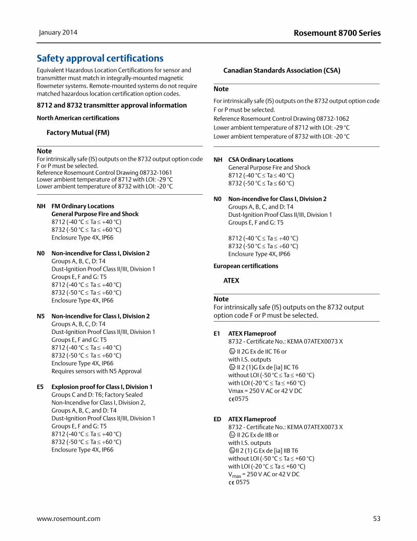
Rosemount 8700 SeriesJanuary 2014
Safety approval certificationsEquivalent Hazardous Location Certifications for sensor and transmitter must match in integrally-mounted magnetic flowmeter systems. Remote-mounted systems do not require matched hazardous location certification option codes.
8712 and 8732 transmitter approval information
North American certifications
Factory Mutual (FM)
NoteFor intrinsically safe (IS) outputs on the 8732 output option code F or P must be selected.Reference Rosemount Control Drawing 08732-1061Lower ambient temperature of 8712 with LOI: -29 °CLower ambient temperature of 8732 with LOI: -20 °C
NH FM Ordinary LocationsGeneral Purpose Fire and Shock8712 (-40 °C Ta 40 °C)8732 (-50 °C Ta 60 °C)Enclosure Type 4X, IP66
N0 Non-incendive for Class I, Division 2Groups A, B, C, D: T4Dust-Ignition Proof Class II/III, Division 1Groups E, F and G: T58712 (-40 °C Ta 40 °C)8732 (-50 °C Ta 60 °C)Enclosure Type 4X, IP66
N5 Non-incendive for Class I, Division 2Groups A, B, C, D: T4Dust-Ignition Proof Class II/III, Division 1Groups E, F and G: T58712 (-40 °C Ta 40 °C)8732 (-50 °C Ta 60 °C) Enclosure Type 4X, IP66Requires sensors with N5 Approval
E5 Explosion proof for Class I, Division 1Groups C and D: T6; Factory SealedNon-Incendive for Class I, Division 2,Groups A, B, C, and D: T4Dust-Ignition Proof Class II/III, Division 1Groups E, F and G: T58712 (-40 °C Ta 40 °C)8732 (-50 °C Ta 60 °C) Enclosure Type 4X, IP66
Canadian Standards Association (CSA)
Note
For intrinsically safe (IS) outputs on the 8732 output option code F or P must be selected.Reference Rosemount Control Drawing 08732-1062Lower ambient temperature of 8712 with LOI: -29 °CLower ambient temperature of 8732 with LOI: -20 °C
NH CSA Ordinary LocationsGeneral Purpose Fire and Shock
8712 (-40 °C Ta 40 °C) 8732 (-50 °C Ta 60 °C)
N0 Non-incendive for Class I, Division 2Groups A, B, C, and D: T4Dust-Ignition Proof Class II/III, Division 1Groups E, F and G: T5
8712 (-40 °C Ta 40 °C)8732 (-50 °C Ta 60 °C)Enclosure Type 4X, IP66
European certifications
ATEX
NoteFor intrinsically safe (IS) outputs on the 8732 output option code F or P must be selected.
E1 ATEX Flameproof 8732 - Certificate No.: KEMA 07ATEX0073 X
II 2G Ex de IIC T6 orwith I.S. outputs
II 2 (1)G Ex de [ia] IIC T6 without LOI (-50 °C Ta +60 °C)with LOI (-20 °C Ta +60 °C)Vmax = 250 V AC or 42 V DC
0575
ED ATEX Flameproof8732 - Certificate No.: KEMA 07ATEX0073 X
II 2G Ex de IIB or with I.S. outputs
II 2 (1) G Ex de [ia] IIB T6 without LOI (-50 °C Ta +60 °C)with LOI (-20 °C Ta +60 °C)Vmax = 250 V AC or 42 V DC
0575
53www.rosemount.com

Rosemount 8700 Series January 2014
ND ATEX Dust8732 - Certificate No.: KEMA 07ATEX0073 X
II 1D tD A20 IP66 T100 °C or with I.S. outputs II (1) G [Ex ia] II C
without LOI (-50 °C Ta + 60 °C)with LOI (-20 °C Ta + 60 °C)Vmax = 250 V AC or 42 V DC
0575
Special conditions for safe use (KEMA 07ATEX0073 X): If the Rosemount 8732 Flow Transmitter is used integrally with the Rosemount 8705 or 8711 Sensors, it shall be assured that the mechanical contact areas of the Sensor and Flow Transmitter comply with the requirements for flat joints according to standard EN/IEC 60079-1 clause 5.2.
The relation between ambient temperature, process temperature, and temperature class is to be taken from the table under (15 - description) above. (see Table 29)
The electrical data is to be taken from the summary under (15 - electrical data) above. (see Table 28)
If the Rosemount 8732 Flow Transmitter is used integrally with the Junction Box, it shall be assured that the mechanical contact areas of the Junction Box and Flow Transmitter comply with the requirements for flanged joints. Contact Rosemount Inc. for requirements and dimensions of Flanged Joints.
INSTALLATION INSTRUCTIONS:
The cable and conduit entry devices and blanking elements shall be of a certified flameproof type, suitable for the conditions of use and correctly installed. With the use of conduit, a certified stopping box shall be provided immediately to the entrance of the enclosure. The cable and conduit entry devices and the closing elements shall be of a certified increased safety type, suitable for the conditions of use and correctly installed. At ambient temperatures above 50 °C, the flow meter shall be used with heat resistant cables with a temperature rating of at least 90 °C. A Junction Box in type of explosion protection increased safety “e” may be attached to the base of the Rosemount 8732 Flow Transmitter, permitting remote mounting of the Rosemount 8705 and 8711 Sensors. The Junction Box is classified as II 2 G Ex e IIB T6 and certified under KEMA 07ATEX0073 X and KEMA 03ATEX2052X.
N1 ATEX Type n8712 - ATEX Certificate No: BASEEFA 05ATEX0170X
II 3G EEx nA nL IIC T4 (Ta = -40 °C Ta + 60 °C)Vmax = 42 V DC
0575
8732 - Certificate No: Baseefa 07ATEX0230X
II 3G Ex nA nL IIC T4 (HART) II 3(1)G Ex nA nL [ia] IIC T4 (Digital Fieldbus)
without LOI (-50 °C Ta + 60 °C)with LOI (-20 °C Ta + 60 °C)Vmax = 42 V DC IP 66
0575
Special conditions for safe use (x):The apparatus is not capable of withstanding the 500V insulation test required by Clause 6.8.1 of EN 60079-15: 2005. This must be taken into account when installing the apparatus.
54 www.rosemount.com

Rosemount 8700 SeriesJanuary 2014
55www.rosemount.com
International certifications
IECEx
NoteFor intrinsically safe (IS) outputs on the 8732 output option code F or P must be selected.
E7 IECEx Flameproof 8732 - Certificate No.: KEM 07.0038XEx de IIC T6 Gb or Ex de [ia Ga] IIC T6 without LOI (-50 °C Ta +60 °C)with LOI (-20 °C Ta +60 °C)Vmax = 250 V AC or 42 V DC
EF IECEx Flameproof8732 - Certificate No.: KEM 07.0038XEx de IIB T6 Gb or Ex de [ia IIC Ga] IIB T6 without LOI (-50 °C Ta +60 °C)with LOI (-20 °C Ta +60 °C)Vmax = 250 V AC or 42 V DC
NF IECEx Dust8732 - Certificate No.: KEM 07.0038XEx tD A20 IP66 T 100 °Cwithout LOI (-50 °C Ta +60 °C)with LOI (-20 °C Ta +60 °C)Vmax = 250 V AC or 42 V DC
Special conditions for safe use (KEM 07.0038X): If the Rosemount 8732 Flow Transmitter is used integrally with the Rosemount 8705 or 8711 Sensors, it shall be assured that the mechanical contact areas of the Sensor and Flow Transmitter comply with the requirements for flat joints according to standard EN/IEC 60079-1 clause 5.2.
The relation between ambient temperature, process temperature, and temperature class is to be taken from the table under (15 - description) above. (see Table 29)
The electrical data is to be taken from the summary under (15 - electrical data) above. (see Table 28)
If the Rosemount 8732 Flow Transmitter is used integrally with the Junction Box, it shall be assured that the mechanical contact areas of the Junction Box and Flow Transmitter comply with the requirements for flanged joints according to standard EN/IEC 60079-1 clause 5.2.
INSTALLATION INSTRUCTIONS:The cable and conduit entry devices and blanking elements shall be of a certified flameproof type, suitable for the conditions of use and correctly installed. With the use of conduit, a certified stopping box shall be provided immediately to the entrance of the enclosure.
N7 IECEx Type n8712 -Certificate No: IECEx BAS 07.0062XEx nA nL IIC T4 with FISCO / FNICO outputEx nA nL [ia] IIC T4Vmax = 42 V DC
8732 HART Certificate No: IECEx BAS 07.0062XEx nA nL IIC T4 without LOI (-50 °C Ta +60 °C)with LOI (-20 °C Ta +60 °C)Vmax = 250 V AC or 42 V DC
8732 digital fieldbusCertificate No: IECEx BAS 07.0062XEx nA nL [ia] IIC T4 (-50 Ta +60 °C)with LOI (-20 Ta +60 °C)Vmax = 42 V DC
Special conditions for safe use (x):The apparatus is not capable of withstanding the 500V insulation test required by Clause 6.8.1 of EN 60079-15: 2005. This must be taken into account when installing the apparatus.
NEPSI - China
NoteFor intrinsically safe (IS) outputs on the 8732 output option code F or P must be selected.
E3 NEPSI Flameproof 8732 - Certificate No.: GYJ12.1495XEx de IIC T6 Gb or Ex de [ia Ga] IIC T6 Gbwithout LOI (-50 °C Ta +60 °C)with LOI (-20 °C Ta +60 °C)Vmax = 250 V AC or 42 V DC
EP NEPSI Flameproof8732 - Certificate No.: GYJ12.1495XEx de IIB T6 Gb or Ex de [ia Ga] IIB T6 Gbwithout LOI (-50 °C Ta +60 °C)with LOI (-20 °C Ta +60 °C)Vmax = 250 V AC or 42 V DC

Rosemount 8700 Series January 2014
INMETRO - Brazil
NoteFor intrinsically safe (IS) outputs on the 8732 output option code F or P must be selected.
E2 INMETRO Flameproof 8732 - Certificate No.: NCC 12.1177 XEx de IIC T6 Gb IP66 orEx de [ia IIC Ga] IIC T6 Gb IP66without LOI (-50 °C Ta +60 °C)with LOI (-20 °C Ta +60 °C)Vmax = 250 V AC or 42 V DC
EB INMETRO Flameproof8732 - Certificate No.: NCC 12.1177 XEx de IIB T6 Gb IP66 orEx de [ia IIC Ga] IIB T6 Gb IP66without LOI (-50 °C Ta +60 °C)with LOI (-20 °C Ta +60 °C)Vmax = 250 V AC or 42 V DC
Special conditions for safe use:If the equipment needs maintenance, the company Emerson Process Management Brazil should be contacted for information about flameproof seals.
The integral assembly of the 8732 flow transmitter with 8711 or 8705 sensor is allowed only for processes where the maximum ambient temperature is 60 °C. For processes where the ambient temperature is above 60 °C, the assembly of the 8732 flow transmitter must be remote.
GOST - Russia
NoteFor intrinsically safe (IS) outputs on the 8732 output option code F or P must be selected.
E8 GOST Flameproof Certificate No.: 0558689Ex de IIC or Ex de [ia] IIC T6 without LOI (-50 °C Ta +60 °C)with LOI (-20 °C Ta +60 °C)IP67
EM GOST FlameproofCertificate No.: 0558689Ex de IIB or Ex de [ia] IIB T6 without LOI (-50 °C Ta +60 °C)with LOI (-20 °C Ta +60 °C)IP67
8705, 8707, 8711, and 8721 sensor approval information
North American certifications
Factory Mutual (FM)NH FM Ordinary Locations
8705, 8711(-50 °C Ta +60 °C)Enclosure Type 4X, IP66/IP68
N0 Non-Incendive for Class I, Division 2Groups A, B, C, and D; T5 (8705/8711), T3C (8707)For use with non-flammable fluidsDust-Ignition Proof Class II/III, Division 1Groups E, F and G; T6 (8705/8711) T3C (8707)8705, 8707, 8711 (-50 °C Ta +60 °C)Enclosure Type 4X, IP66/IP68
N0 8721 Hygienic SensorFactory Mutual (FM) Ordinary Location;
CE Marking; 3-A Symbol Authorization #1222; EHEDG Type EL
N5 Non-Incendive for Class I, Division 2Groups A, B, C, and D; T5 (8705/8711)With Intrinsically Safe electrodesFor use with flammable fluids Class II/III Division 1 Groups A, B, C, D, E, F, and GDust-Ignition Proof Class II/III, Division 1, Groups E, F, G; T5 (8705/8711)8705, 8711 (-50 °C Ta +60 °C)Enclosure Type 4X, IP66/IP68
E5 Explosion-Proof for Class I, Division 1Groups C and D; T6 (8705/8711)With Intrinsically Safe electrodesClass I Division 1, Groups A, B, C, and DDust-Ignition Proof Class II/III, Division 1Groups E, F, and G; T6 (8705/8711)Non-Incendive for Class I, Division 2Groups A, B, C, and D; T6 (8705/8711)8705, 8711 (-50 °C Ta +60 °C)Enclosure Type 4X, IP66/IP68
56 www.rosemount.com

Rosemount 8700 SeriesJanuary 2014
Canadian Standards Association (CSA)N0 Non-Incendive for Class I, Division 2
Groups A, B, C, and D; T5 (8705/8711), T3 (8707)For use with non-flammable fluidsDust-Ignition Proof Class II/III, Division 1Groups E, F, and G; T6 (8705/8711), T3C (8707)8705, 8707, 8711 (-50 °C Ta +60 °C)Enclosure Type 4X, IP66/IP68
N0 8721 Hygienic SensorCanadian Standards Association (CSA) Ordinary Location;CE Marking; 3-A Symbol Authorization #1222;EHEDG Type EL
European certifications
ATEXND ATEX Dust
Certificate No.: KEMA 06ATEX0006 II 1D Ex tD A20 IP6x T105 °C (-50 Ta +65 °C) 0575
INSTALLATION INSTRUCTIONS:The cable and conduit entry devices and blanking elements shall be of a certified IP6x type, suitable for the conditions of use and correctly installed. At maximum ambient temperatures or at process temperatures above 60 °C heat resistant cables with a temperature rating of at least 90 °C shall be used.
N1 ATEX Type nCertificate No: KEMA02ATEX1302X
II 3GEEx nA [L] IIC T3... T6 (-20 Ta +65 °C)
Special conditions for safe use (x):The relation between ambient temperature, process temperature and temperature class is to be taken from Table 30. The electrical data is to be taken from the summary in Table 28.
E1/KD ATEX Increased Safety with IS ElectrodesCertificate No: KEMA03ATEX2052X
II 1/2GEEx e ia IIC T3... T6 (-20 Ta +60 °C) (see Table 29)
0575Vmax = 40 V
Special conditions for safe use (x):The relation between ambient temperature, process temperature and temperature class is to be taken from Table 29. The electrical data is to be taken from the summary in Table 28.
INSTALLATION INSTRUCTIONS:At ambient temperature above 50 °C, the flowmeter shall be used with heat resistant cables with a temperature rating of at least 90 °C.A fuse with a rating of maximum 0,7 A according to IEC 60127-1 shall be included in the coil excitation circuit if the sensors are used with other flow transmitters (e.g. Rosemount 8712).
International certifications
IECEXNF IECEx Dust
Certificate Number: IECEx KEM 09.0078Ex tD A20 IP6x T105 °C (-50 Ta +65 °C)
N7 IECEx Type nCertificate Number: IECEx DEK 11.0094XEx nA nL IIC T3...T5 Gc
INSTALLATION INSTRUCTIONS:The cable and conduit entry devices and blanking elements shall be of a certified IP6x type, suitable for the conditions of use and correctly installed.At maximum ambient temperatures or at process temperatures above 60 °C heat resistant cables with a temperature rating of at least 90 °C shall be used.
NEPSI - ChinaE3 / EP NEPSI Increased Safety with IS Electrodes
Certificate No: GYJ12.1497 XEx e ia IIC T3... T6 (Ta = -20 +60 °C) (see Table 29)Vmax = 40 V
INMETRO - BrazilE2 / EB INMETRO Increased Safety with IS Electrodes
Certificate No: NCC 12.1174 XEx e ia IIC T3... T6 (Ta = -20 Ta +60 °C) (see Table 29)Vmax = 40 V
GOST - RussiaE8 / EM GOST Increased Safety with IS Electrodes
Certificate No: N0558689Ex e ia IIC T3... T6 (Ta = -20 Ta +60 °C) (see Table 29)Vmax = 40 V
57www.rosemount.com
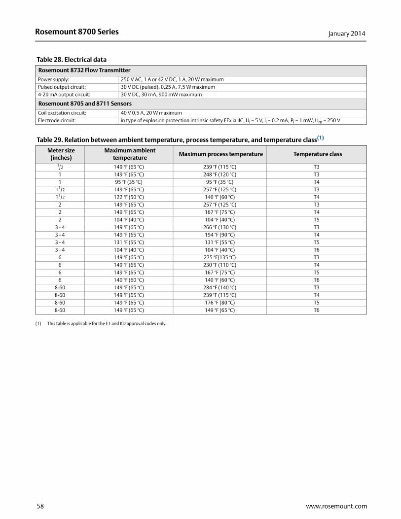
Rosemount 8700 Series January 2014
Table 28. Electrical data
Rosemount 8732 Flow Transmitter
Power supply: 250 V AC, 1 A or 42 V DC, 1 A, 20 W maximumPulsed output circuit: 30 V DC (pulsed), 0,25 A, 7,5 W maximum4-20 mA output circuit: 30 V DC, 30 mA, 900 mW maximum
Rosemount 8705 and 8711 Sensors
Coil excitation circuit: 40 V 0,5 A, 20 W maximumElectrode circuit: in type of explosion protection intrinsic safety EEx ia IIC, Ui = 5 V, li = 0.2 mA, Pi = 1 mW, Um = 250 V
Table 29. Relation between ambient temperature, process temperature, and temperature class(1)
Meter size (inches)
Maximum ambient temperature
Maximum process temperature Temperature class
1/2 149 °F (65 °C) 239 °F (115 °C) T31 149 °F (65 °C) 248 °F (120 °C) T31 95 °F (35 °C) 95 °F (35 °C) T4
11/2 149 °F (65 °C) 257 °F (125 °C) T311/2 122 °F (50 °C) 140 °F (60 °C) T4
2 149 °F (65 °C) 257 °F (125 °C) T32 149 °F (65 °C) 167 °F (75 °C) T42 104 °F (40 °C) 104 °F (40 °C) T5
3 - 4 149 °F (65 °C) 266 °F (130 °C) T33 - 4 149 °F (65 °C) 194 °F (90 °C) T43 - 4 131 °F (55 °C) 131 °F (55 °C) T53 - 4 104 °F (40 °C) 104 °F (40 °C) T6
6 149 °F (65 °C) 275 °F(135 °C) T36 149 °F (65 °C) 230 °F (110 °C) T46 149 °F (65 °C) 167 °F (75 °C) T56 140 °F (60 °C) 140 °F (60 °C) T6
8-60 149 °F (65 °C) 284 °F (140 °C) T38-60 149 °F (65 °C) 239 °F (115 °C) T48-60 149 °F (65 °C) 176 °F (80 °C) T58-60 149 °F (65 °C) 149 °F (65 °C) T6
(1) This table is applicable for the E1 and KD approval codes only.
58 www.rosemount.com
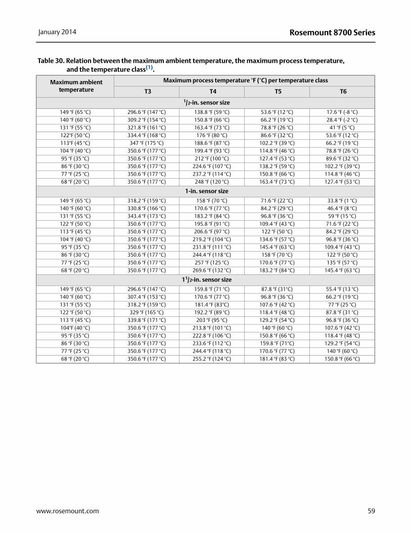
Rosemount 8700 SeriesJanuary 2014
Table 30. Relation between the maximum ambient temperature, the maximum process temperature, and the temperature class(1).
Maximum ambient temperature
Maximum process temperature °F (°C) per temperature class
T3 T4 T5 T6
1/2-in. sensor size
149 °F (65 °C) 296.6 °F (147 °C) 138.8 °F (59 °C) 53.6 °F (12 °C) 17.6 °F (-8 °C)140 °F (60 °C) 309.2 °F (154 °C) 150.8 °F (66 °C) 66.2 °F (19 °C) 28.4 °F (-2 °C)131 °F (55 °C) 321.8 °F (161 °C) 163.4 °F (73 °C) 78.8 °F (26 °C) 41 °F (5 °C)122°F (50 °C) 334.4 °F (168 °C) 176 °F (80 °C) 86.6 °F (32 °C) 53.6 °F (12 °C)113°F (45 °C) 347 °F (175 °C) 188.6 °F (87 °C) 102.2 °F (39 °C) 66.2 °F (19 °C)104 °F (40 °C) 350.6 °F (177 °C) 199.4 °F (93 °C) 114.8 °F (46 °C) 78.8 °F (26 °C)95 °F (35 °C) 350.6 °F (177 °C) 212 °F (100 °C) 127.4 °F (53 °C) 89.6 °F (32 °C)86 °F (30 °C) 350.6 °F (177 °C) 224.6 °F (107 °C) 138.2 °F (59 °C) 102.2 °F (39 °C)77 °F (25 °C) 350.6 °F (177 °C) 237.2 °F (114 °C) 150.8 °F (66 °C) 114.8 °F (46 °C)68 °F (20 °C) 350.6 °F (177 °C) 248 °F (120 °C) 163.4 °F (73 °C) 127.4 °F (53 °C)
1-in. sensor size
149 °F (65 °C) 318.2 °F (159 °C) 158 °F (70 °C) 71.6 °F (22 °C) 33.8 °F (1 °C)140 °F (60 °C) 330.8 °F (166 °C) 170.6 °F (77 °C) 84.2 °F (29 °C) 46.4 °F (8 °C)131 °F (55 °C) 343.4 °F (173 °C) 183.2 °F (84 °C) 96.8 °F (36 °C) 59 °F (15 °C)122 °F (50 °C) 350.6 °F (177 °C) 195.8 °F (91 °C) 109.4 °F (43 °C) 71.6 °F (22 °C)113 °F (45 °C) 350.6 °F (177 °C) 206.6 °F (97 °C) 122 °F (50 °C) 84.2 °F (29 °C)104 °F (40 °C) 350.6 °F (177 °C) 219.2 °F (104 °C) 134.6 °F (57 °C) 96.8 °F (36 °C)95 °F (35 °C) 350.6 °F (177 °C) 231.8 °F (111 °C) 145.4 °F (63 °C) 109.4 °F (43 °C)86 °F (30 °C) 350.6 °F (177 °C) 244.4 °F (118 °C) 158 °F (70 °C) 122 °F (50 °C)77 °F (25 °C) 350.6 °F (177 °C) 257 °F (125 °C) 170.6 °F (77 °C) 135 °F (57 °C)68 °F (20 °C) 350.6 °F (177 °C) 269.6 °F (132 °C) 183.2 °F (84 °C) 145.4 °F (63 °C)
11/2-in. sensor size
149 °F (65 °C) 296.6 °F (147 °C) 159.8 °F (71 °C) 87.8 °F (31°C) 55.4 °F (13 °C)140 °F (60 °C) 307.4 °F (153 °C) 170.6 °F (77 °C) 96.8 °F (36 °C) 66.2 °F (19 °C)131 °F (55 °C) 318.2 °F (159 °C) 181.4 °F (83°C) 107.6 °F (42 °C) 77 °F (25 °C)122 °F (50 °C) 329 °F (165 °C) 192.2 °F (89 °C) 118.4 °F (48 °C) 87.8 °F (31 °C)113 °F (45 °C) 339.8 °F (171 °C) 203 °F (95 °C) 129.2 °F (54 °C) 96.8 °F (36 °C)104°F (40 °C) 350.6 °F (177 °C) 213.8 °F (101 °C) 140 °F (60 °C) 107.6 °F (42 °C)95 °F (35 °C) 350.6 °F (177 °C) 222.8 °F (106 °C) 150.8 °F (66 °C) 118.4 °F (48 °C)86 °F (30 °C) 350.6 °F (177 °C) 233.6 °F (112 °C) 159.8 °F (71°C) 129.2 °F (54 °C)77 °F (25 °C) 350.6 °F (177 °C) 244.4 °F (118 °C) 170.6 °F (77 °C) 140 °F (60 °C)68 °F (20 °C) 350.6 °F (177 °C) 255.2 °F (124 °C) 181.4 °F (83 °C) 150.8 °F (66 °C)
59www.rosemount.com

Rosemount 8700 Series January 2014
2-in. sensor size
149 °F (65 °C) 289.4 °F (143 °C) 163.4 °F (73 °C) 95 °F (35 °C) 66.2 °F (19 °C)140 °F (60 °C) 300.2 °F (149 °C) 172.4 °F (78 °C) 104 °F (40 °C) 75.2 °F (24 °C)131 °F (55 °C) 309.2 °F (154 °C) 183.2 °F (84 °C) 114.8 °F (46 °C) 84.2 °F (29 °C)122 °F (50 °C) 318.2 °F (159 °C) 192.2 °F (89 °C) 123.8 °F (51 °C) 95 °F (35 °C)113 °F (45 °C) 329 °F (165 °C) 201.2 °F (94 °C) 134.6 °F (57 °C) 104 °F (40 °C)104 °F (40 °C) 338 °F (170 °C) 212 °F (100 °C) 143.6 °F (62 °C) 114.8 °F (46 °C)95 °F (35 °C) 348.8 °F (176 °C) 221 °F (105 °C) 152.6 °F (67 °C) 123.8 °F (51 °C)86 °F (30 °C) 350.6 °F (177 °C) 231.8 °F (111 °C) 163.4 °F (73 °C) 134.6 °F (57 °C)77 °F (25 °C) 350.6 °F (177 °C) 240.8 °F (116 °C) 172.41 °F (78 °C) 143.6 °F (62 °C)68 °F (20 °C) 350.6 °F (177 °C) 251.6 °F (122 °C) 183.2 °F (84 °C) 152.6 °F (67 °C)
3-in. to 60-in. sensor size
149 °F (65 °C) 350.6 °F (177 °C) 210.2 °F (99 °C) 116.6 °F (47 °C) 75.2 °F (24 °C)140 °F (60 °C) 350.6 °F (177 °C) 222.8 °F (106 °C) 129.2 °F (54 °C) 89.6 °F (32 °C)131 °F (55 °C) 350.6 °F (177 °C) 237.2 °F (114 °C) 143.6 °F (62 °C) 102.2 °F (39 °C)122 °F (50 °C) 350.6 °F (177 °C) 249.8 °F (121 °C) 156.2 °F (69 °C) 116.6 °F (47 °C)113 °F (45 °C) 350.6 °F (177 °C) 264.2 °F (129 °C) 170.6 °F (77 °C) 129.2 °F (54 °C)104 °F (40 °C) 350.6 °F (177 °C) 266 °F (130 °C) 183.2 °F (84 °C) 143.6 °F (62 °C)95 °F (35 °C) 350.6 °F (177 °C) 266 °F (130 °C) 197.6 °F (92 °C) 156.2 °F (69 °C)86 °F (30 °C) 350.6 °F (177 °C) 266 °F (130 °C) 203 °F (95 °C) 170.6 °F (77 °C)77 °F (25 °C) 350.6 °F (177 °C) 266 °F (130 °C) 203 °F (95 °C) 176 °F (80 °C)68 °F (20 °C) 350.6 °F (177 °C) 266 °F (130 °C) 203 °F (95 °C) 176 °F (80 °C)
(1) This table is applicable for N1 option codes only.
Table 30. Relation between the maximum ambient temperature, the maximum process temperature, and the temperature class(1).
Maximum ambient temperature
Maximum process temperature °F (°C) per temperature class
T3 T4 T5 T6
60 www.rosemount.com
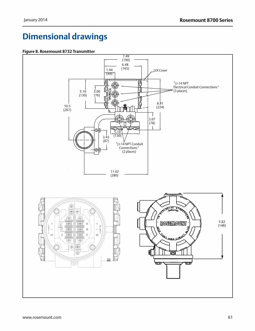
Rosemount 8700 SeriesJanuary 2014
Dimensional drawings
Figure 8. Rosemount 8732 Transmitter
1/2-14 NPT Electrical Conduit Connections* (3 places)
LOI Cover
11.02(280)
1/2-14 NPT Conduit Connections*
(2 places)
10.5(267)
5.10(130)
5.10(130)
7.49(190)6.48
(165)1.94(49)
8.81(224)
3.07(78)
3.00(76)
3.43(87)
5.82(148)
* Conduit con-nections
61www.rosemount.com
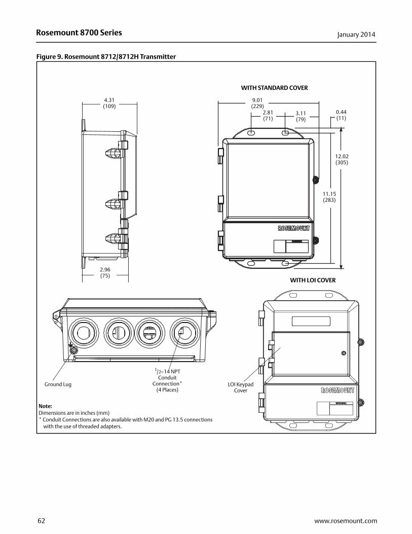
Rosemount 8700 Series January 2014
Figure 9. Rosemount 8712/8712H Transmitter
4.31(109)
LOI Keypad Cover
9.01(229)
11.15(283)
2.81(71)
3.11(79)
12.02(305)
0.44(11)
Ground Lug
1/2–14 NPTConduit
Connection* (4 Places)
WITH STANDARD COVER
Note:Dimensions are in inches (mm)* Conduit Connections are also available with M20 and PG 13.5 connections
with the use of threaded adapters.
2.96(75)
WITH LOI COVER
62 www.rosemount.com
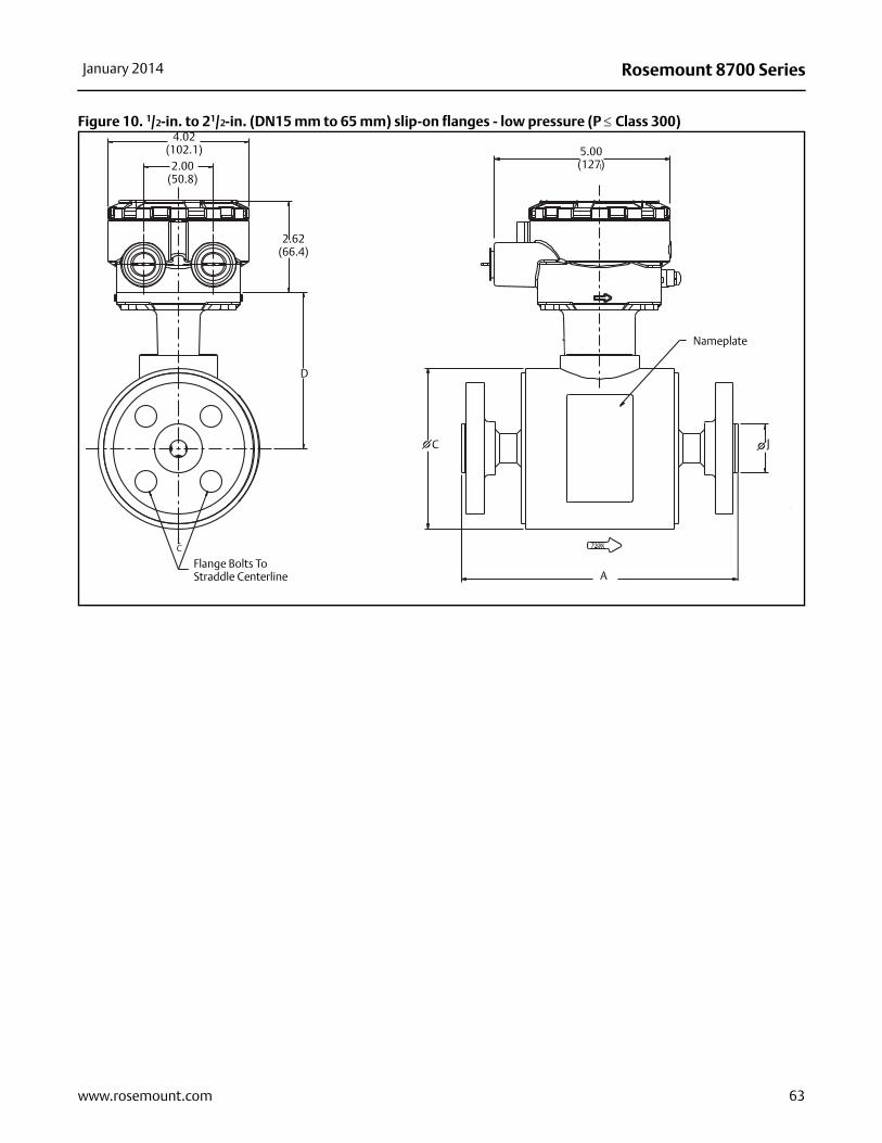
Rosemount 8700 SeriesJanuary 2014
Figure 10. 1/2-in. to 21/2-in. (DN15 mm to 65 mm) slip-on flanges - low pressure (P Class 300)4.02
(102.1)2.00
(50.8)
2.62(66.4)
Flange Bolts To Straddle Centerline
D
C
5.00 (127)
Nameplate
A
Flow
J C
63www.rosemount.com

Rosemount 8700 Series January 2014
Table 31. 1/2-in. to 21/2-in. slip-on flanges (inches)
Size, description
Overall length
Body ØDIM “C”
CL to UMB
DIM “D”
Liner Øon face DIM “J”
Tubeweight
(lbs)Dim “A”
PTFE
Dim “A”
ETFE
Dim “A”Neoprene
Dim “A”Linatex
Dim “A”Poly
Dim “A”PFA
1/2 (15) ASME - 150# 7.88 7.88 7.88 7.98 7.88 7.88 4.50 4.41 1.38 91/2 (15) ASME - 300# 7.88 7.88 7.88 7.98 7.88 7.88 4.50 4.41 1.38 101/2 (15) EN 1092-1 - PN40 7.88 7.88 7.88 7.98 7.88 7.88 4.50 4.41 1.77 101/2 (15) AS2129 TABLE D 7.88 7.88 7.98 7.88 4.50 4.41 1.85 81/2 (15) AS2129 TABLE E 7.88 7.88 7.98 7.88 4.50 4.41 1.85 81/2 (15) JIS B2220 - 10K, 7.90 7.88 7.98 7.88 4.50 4.41 1.77 101/2 (15) JIS B2220 - 20K 7.90 7.88 7.98 7.88 4.50 4.41 1.77 101/2 (15) JIS B2220 - 40K 8.40 8.38 8.48 8.38 4.50 4.41 1.77 131 (25) ASME - 150# 7.88 7.88 7.88 7.97 7.88 7.88 4.50 4.41 2.00 111 (25) ASME - 300# 7.88 7.88 7.88 7.97 7.88 7.88 4.50 4.41 2.00 141 (25) EN 1092-1 - PN40 7.88 7.88 7.88 7.97 7.88 7.88 4.50 4.41 2.68 141 (25) AS2129 TABLE D 7.88 7.88 7.88 7.97 7.88 4.50 4.41 2.56 101 (25) AS2129. TABLE E 7.88 7.88 7.88 7.97 7.88 4.50 4.41 2.48 101 (25) JIS B2220 - 10K 7.91 7.88 7.97 7.88 4.50 4.41 2.64 131 (25) JIS B2220 - 20K 7.91 7.88 7.97 7.88 4.50 4.41 2.64 141 (25) JIS B2220 - 40K 8.65 8.67 8.76 8.67 4.50 4.41 2.76 1711/2 (40) ASME - 150# 7.87 7.87 7.85 7.95 7.87 7.87 5.21 4.82 2.88 1511/2 (40) ASME - 300# 7.87 7.87 7.85 7.95 7.87 7.87 5.21 4.82 2.88 2111/2 (40) EN 1092-1 - PN40 7.87 7.87 7.85 7.95 7.87 7.87 5.21 4.82 3.46 1911/2 (40) AS2129 TABLE D 7.87 7.85 7.95 7.87 5.21 4.82 3.07 1211/2 (40) AS2129 TABLE E 7.87 7.85 7.95 7.87 5.21 4.82 3.07 1311/2 (40) JIS B2220 - 10K 7.92 7.85 7.95 7.87 5.21 4.82 3.19 1611/2 (40) JIS B2220 - 20K 7.92 7.85 7.95 7.87 5.21 4.82 3.19 1711/2 (40) JIS B2220 -40K 8.69 8.62 8.72 8.63 5.21 4.82 3.54 242 (50) ASME - 150# 7.87 7.87 7.82 7.92 7.87 7.87 5.21 4.82 3.62 202 (50) ASME - 300# 7.87 7.87 7.82 7.92 7.87 7.87 5.21 4.82 3.62 232 (50) EN 1092-1 - PN40 7.87 7.87 7.82 7.92 7.87 7.87 5.21 4.82 4.02 232 (50) AS2129 TABLE D 7.87 7.82 7.92 7.87 5.21 4.82 3.54 142 (50) AS2129 TABLE E 7.87 7.82 7.92 7.87 5.21 4.82 3.54 152 (50) JIS B2220 - 10K 7.89 7.82 7.92 7.87 5.21 4.82 3.78 182 (50) JIS B2220 - 20K 7.89 7.82 7.92 7.87 5.21 4.82 3.78 192 (50) JIS B2220 - 40K 8.81 8.84 8.84 8.78 5.21 4.82 4.13 272 (50) AS4087 PN16 7.87 7.80 7.900 7.87 5.21 4.82 3.54 162 (50) AS4087 PN21 7.87 7.80 7.900 7.87 5.21 4.82 4.06 342 (50) AS4087 PN35 7.87 7.80 7.900 7.87 5.21 4.82 4.06 9621/2 (65) ASME - 150# 7.82 7.76 6.31 5.37 4.12 2721/2 (65) ASME - 300# 7.82 7.76 6.31 5.37 4.12 3221/2 (65) EN 1092-1 - PN16 7.82 7.76 6.31 5.37 4.80 2721/2 (65) EN 1092-1 - PN40 7.82 7.76 6.31 5.37 4.80 3121/2 (65) AS2129 TABLE D 7.82 7.76 6.31 5.37 4.06 1721/2 (65) AS2129 TABLE E 7.82 7.76 6.31 5.37 4.06 1921/2 (65) JIS B2220 - 10K 7.82 7.76 6.31 5.37 4.57 2521/2 (65) JIS B2220 - 20K 7.82 7.76 6.31 5.37 4.57 2621/2 (65) JIS B2220 - 40K 7.82 7.76 6.31 5.37 5.12 4021/2 (65) AS4087 PN16 7.82 7.76 6.31 5.37 4.06 1821/2 (65) AS4087 PN21 7.82 7.76 6.31 5.37 4.80 2421/2 (65) AS4087 PN35 7.82 7.76 6.31 5.37 4.80 27
64 www.rosemount.com

Rosemount 8700 SeriesJanuary 2014
e
Table 32. DN15 mm to 65 mm Slip-on flanges (mm)
Size, description
Overall length
Body ØDIM “C”
CL to UMB
DIM “D”
Liner Øon face DIM “J”
Flow tubweight
(Lbs)Dim “A”
PTFE
Dim “A”
ETFE
Dim “A”Neoprene
Dim “A”Linatex
Dim “A”Poly
Dim “A”PFA
1/2 (15) ASME - 150# 200 200 200 203 200 200 114 112 35 4.01/2 (15) ASME - 300# 200 200 200 203 200 200 114 112 35 4.51/2 (15) EN 1092-1 - PN40 200 200 200 203 200 200 114 112 45 4.71/2 (15) AS2129 TABLE D 200 200 203 200 114 112 47 3.71/2 (15) AS2129 TABLE E 200 200 203 200 114 112 47 3.81/2 (15) JIS B2220 - 10K 201 200 203 200 114 112 45 4.41/2 (15) JIS B2220 - 20K 201 200 203 200 114 112 45 4.61/2 (15) JIS B2220 - 40K 213 213 213 213 114 112 45 6.11 (25) ASME - 150# 200 200 200 202 200 200 114 112 51 5.11 (25) ASME - 300# 200 200 200 202 200 200 114 112 51 6.31 (25) EN 1092-1 - PN40 200 200 200 202 200 200 114 112 68 6.31 (25) AS2129 TABLE D 200 200 200 202 200 114 112 65 4.41 (25) AS2129. TABLE E 200 200 200 202 200 114 112 63 4.71 (25) JIS B2220 - 10K 201 200 202 200 114 112 67 5.91 (25) JIS B2220 - 20K 201 200 202 200 114 112 67 6.31 (25) JIS B2220 - 40K 220 220 223 220 114 112 70 7.811/2 (40) ASME - 150# 200 200 199 202 200 200 132 122 73 6.911/2 (40) ASME - 300# 200 200 199 202 200 200 132 122 73 9.311/2 (40) EN 1092-1 - PN40 200 200 199 202 200 200 132 122 88 8.811/2 (40) AS2129 TABLE D 200 199 202 200 132 122 78 5.511/2 (40) AS2129 TABLE E 200 199 202 200 132 122 78 6.011/2 (40) JIS B2220 - 10K 201 199 202 200 132 122 81 7.411/2 (40) JIS B2220 - 20K 201 199 202 200 132 122 81 7.811/2 (40) JIS B2220 -40K 201 219 221 219 132 122 90 11.12 (50) ASME - 150# 200 200 199 201 200 200 132 122 92 8.92 (50) ASME - 300# 200 200 199 201 200 200 132 122 92 10.52 (50) EN 1092-1 - PN40 200 200 199 201 200 200 132 122 102 10.62 (50) AS2129 TABLE D 200 199 201 200 132 122 90 6.42 (50) AS2129 TABLE E 200 199 201 200 132 122 90 6.92 (50) JIS B2220 - 10K 200 199 201 200 132 122 96 8.42 (50) JIS B2220 - 20K 200 199 201 200 132 122 96 8.72 (50) JIS B2220 - 40K 224 222 224 223 132 122 105 12.32 (50) AS4087 PN16 200 200 200 200 132 122 90 72 (50) AS4087 PN21 201 200 200 200 132 122 103 152 (50) AS4087 PN35 202 200 200 200 132 122 103 1521/2 (65) ASME - 150# 199 197 160 136 105 12.421/2 (65) ASME - 300# 199 197 160 136 105 14.621/2 (65) EN 1092-1 - PN16 199 197 160 136 122 12.421/2 (65) EN 1092-1 - PN40 199 197 160 136 122 13.921/2 (65) AS2129 TABLE D 199 197 160 136 103 7.921/2 (65) AS2129 TABLE E 199 197 160 136 103 8.421/2 (65) JIS B2220 - 10K 199 197 160 136 116 11.221/2 (65) JIS B2220 - 20K 199 197 160 136 116 11.721/2 (65) JIS B2220 - 40K 199 197 160 136 130 18.321/2 (65) AS4087 PN16 199 197 160 136 103 8.321/2 (65) AS4087 PN21 199 197 160 136 122 10.921/2 (65) AS4087 PN35 199 197 160 136 122 12.2
65www.rosemount.com

Rosemount 8700 Series January 2014
Figure 11. 3-in. to 36-in. (DN80 mm to 900 mm) slip-on flanges -low pressure (P Class 300)5.00 (127)
Nameplate
C
Flow
A
K
Flange Bolts To Straddle Centerline
4.02 (102.1)2.00
(50.8)
2.62(66.4)
D
C
J
66 www.rosemount.com

Rosemount 8700 SeriesJanuary 2014
Table 33. 3-in. to 36-in. slip-on flanges (inches)
Size, description
Overall length
Body Ø DIM “C”
CL to UMB
DIM “D”
Liner Ø on face DIM “J”
Lift ring height
DIM “K”
Tube weight
(Lbs) DIM “A”
PTFE
DIM “A”
ETFE
DIM “A”Neoprene
DIM “A”Linatex
DIM “A”Poly
DIM “A”PFA
3 (80) ASME - 150# 7.87 7.87 7.75 7.84 7.87 7.83 7.21 5.82 5.00 1.70 343 (80) ASME - 300# 8.63 8.63 8.51 8.60 8.63 8.60 7.21 5.82 5.00 1.70 43 3 (80) EN 1092-1 - PN40 7.87 7.87 7.75 7.84 7.87 7.87 7.21 5.82 5.43 1.70 383 (80) AS2129 TABLE D 7.87 7.75 7.84 7.87 7.21 5.82 4.80 1.70 243 (80) AS2129 TABLE E 7.87 7.75 7.84 7.87 7.21 5.82 4.80 1.70 243 (80) JIS B2220 - 10K 7.91 7.75 7.84 7.87 7.21 5.82 4.96 1.70 283 (80) JIS B2220 - 20K 7.91 7.75 7.84 7.87 7.21 5.82 5.20 1.70 34 3 (80) JIS B2220 - 40K 12.40 12.29 12.39 12.40 7.21 5.82 55.1 1.70 52 3 (80) AS4087 PN16 7.87 7.75 7.84 7.87 7.21 5.82 4.80 1.70 203 (80) AS4087 PN21 7.87 7.75 7.84 7.87 7.21 5.82 5.55 1.70 563 (80) AS4087 PN35 7.87 7.75 7.84 7.87 7.21 5.82 5.55 1.70 1094 (100) ASME - 150# 9.84 9.84 9.69 9.78 9.84 9.84 7.91 6.17 6.19 1.70 45 4 (100) ASME- 300# 10.88 10.88 10.73 10.82 10.88 10.88 7.91 6.17 6.19 1.70 65 4 (100) EN 1092-1 - PN16 9.84 9.84 9.69 9.78 9.81 9.81 7.91 6.17 6.22 1.70 414 (100) EN 1092-1 - PN40 9.84 9.84 9.69 9.78 9.81 9.81 7.91 6.17 6.38 1.70 494 (100) AS2129 TABLE D 9.84 9.84 9.69 9.78 9.84 7.91 6.17 6.06 1.70 314 (100) AS2129 TABLE E 9.84 9.84 9.69 9.78 9.84 7.91 6.17 6.06 1.70 33 4 (100) JIS B2220 - 10K 9.84 9.69 9.78 9.84 7.91 6.17 5.95 1.70 354 (100) JIS B2220 - 20K 9.84 9.69 9.78 9.84 7.91 6.17 6.30 1.70 44 4 (100) JIS B2220 - 40K 12. 83 12.70 12.79 12.83 7.91 6.17 6.50 1.70 75 4 (100) AS4087 PN16 9.84 9.69 9.78 9.84 7.91 6.17 6.06 1.70 284 (100) AS4087 PN21 9.84 9.69 9.78 9.84 7.91 6.17 6.57 1.70 684 (100) AS4087 PN35 9.84 9.69 9.78 9.84 7.91 6.17 6.57 1.70 1195 (125) ASME - 150# 9.79 9.71 9.61 7.02 7.31 1.70 545 (125) ASME - 300# 10.94 10.86 9.61 7.02 7.31 1.70 895 (125) EN 1092-1 - PN16 9.79 9.50 9.61 7.02 7.40 1.70 555 (125) EN 1092-1 - PN40 9.79 9.71 9.61 7.02 7.40 1.70 655 (125) AS2129 TABLE D 9.79 9.71 9.61 7.02 7.32 1.70 435 (125) AS2129 TABLE E 9.79 9.71 9.61 7.02 7.32 1.70 445 (125) JIS B2220 - 10K 9.79 9.71 9.61 7.02 7.17 1.70 495 (125) JIS B2220 - 20K 9.79 9.71 9.61 7.02 7.68 1.70 645 (125) JIS B2220 - 40K 10.94 10.86 9.61 7.02 7.87 1.70 1125 (125) AS4087 PN165 (125) AS4087 PN215 (125) AS4087 PN356 (150) ASME - 150# 11.81 11.75 11.61 11.71 11.73 11.81 9.98 7.30 8.50 1.70 686 (150) ASME - 300# 13.06 13.02 12.88 12.97 13.00 13.06 9.98 7.30 8.50 1.70 1176 (150) EN 1092-1 - PN16 11.81 11.81 11.61 11.71 11.73 11.81 9.98 7.30 8.35 1.70 676 (150) EN 1092-1 - PN25 11.81 11.81 11.66 11.75 11.78 11.81 9.98 7.30 8.58 1.70 836 (150) EN 1092-1 - PN40 13.06 13.06 12.88 12.97 13.00 13.06 9.98 7.30 8.58 1.70 956 (150) AS2129 TABLE D 11.81 11.61 11.71 11.73 9.98 7.30 8.31 1.70 526 (150) AS2129 TABLE E 11.81 11.61 11.71 11.73 9.98 7.30 8.15 1.70 576 (150) JIS B2220 - 10K 11.81 11.61 11.71 11.73 9.98 7.30 8.35 1.70 646 (150) JIS B2220 - 20K 11.81 11.61 11.71 11.73 9.98 7.30 9.06 1.70 836 (150) JIS B2220 - 40K 14.23 14.05 14.14 14.17 9.98 7.30 9.45 1.70 1616 (150) AS4087 PN16 11.81 11.61 11.71 11.73 9.98 7.30 8.31 1.70 466 (150) AS4087 PN21 11.81 11.61 11.71 11.73 9.98 7.30 9.13 1.70 986 (150) AS4087 PN35 11.81 11.61 11.71 11.73 9.98 7.30 9.13 1.70 186
67www.rosemount.com

Rosemount 8700 Series January 2014
Size, description
Overall length
Body Ø DIM “C”
CL to UMB DIM “D”
Liner Ø on face DIM “J”
Lift ring height DIM “K”
Tube weight (lbs)
DIM “A”PTFE
DIM “A”ETFE
DIM “A”Neoprene
DIM “A”Linatex
DIM “A”Poly”
DIM “A”PFA
8 (200) ASME - 150# 13.78 13.69 13.53 13.63 13.65 13.78 11.92 8.27 10.62 1.70 1058 (200) ASME - 300# 15.60 15.54 15.42 15.51 15.54 15.60 11.92 8.27 10.62 1.70 1838 (200) EN 1092-1 - PN10 13.78 13.69 13.53 13.63 13.65 13.78 11.92 8.27 10.55 1.70 978 (200) EN 1092-1 - PN16 13.78 13.69 13.53 13.63 13.65 13.78 11.92 8.27 10.55 1.70 968 (200) EN 1092-1 - PN25 13.78 13.69 13.53 13.63 13.65 13.78 11.92 8.27 10.94 1.70 1208 (200) EN 1092-1 - PN40 15.60 15.54 15.42 15.51 15.54 15.60 11.92 8.27 11.22 1.70 1588 (200) AS2129 TABLE D 13.78 13.53 13.63 13.65 11.92 8.27 10.55 1.70 778 (200) AS2129 TABLE E 13.78 13.53 13.63 13.65 11.92 8.27 10.39 1.70 868 (200) JIS B2220 - 10K 13.90 13.53 13.63 13.65 11.92 8.27 10.32 1.70 818 (200) JIS B2220 - 20K 15.60 15.42 15.51 15.54 11.92 8.27 10.83 1.70 1348 (200) JIS B2220 - 40K 16.72 16.54 16.63 16.66 11.92 8.27 11.42 1.70 2328 (200) AS4087 PN16 13.78 13.53 13.63 13.65 11.92 8.27 10.55 1.70 738 (200) AS4087 PN21 13.78 13.53 13.63 13.65 11.92 8.27 11.65 1.70 1368 (200) AS4087 PN35 15.60 15.42 15.51 15.54 11.92 8.27 10.24 1.70 24110 (250) ASME - 150# 15.00 14.85 14.63 14.73 14.75 15.00 14.64 9.69 12.75 2.00 15210 (250) ASME - 300# 17.13 17.08 16.86 16.95 16.95 17.13 14.64 9.69 12.75 2.00 26710 (250) EN 1092-1 - PN10 15.00 14.85 14.63 14.73 14.75 15.00 14.64 9.69 12.60 2.00 13410 (250) EN 1092-1 - PN16 15.00 14.85 14.63 14.73 14.75 15.00 14.64 9.69 12.60 2.00 13810 (250) EN 1092-1 - PN25 15.00 14.85 14.63 14.73 14.75 15.00 14.64 9.69 13.19 2.00 17410 (250) EN 1092-1 - PN40 17.13 16.86 16.95 16.98 17.13 14.64 9.69 13.58 2.00 24410 (250) AS2129 TABLE D 15.00 14.63 14.73 14.75 14.64 9.69 12.91 2.00 12210 (250) AS2129 TABLE E 15.00 14.63 14.73 14.75 14.64 9.69 12.91 2.00 13710 (250) JIS B2220 - 10K 15.00 14.63 14.73 14.75 14.64 9.69 12.76 1.70 12910 (250) JIS B2220 - 20K 17.13 16.86 16.95 16.98 14.64 9.69 13.58 3.13 21810 (250) JIS B2220 - 40K 19.54 19.34 19.43 19.46 14.64 9.69 13.98 2.00 38210 (250) AS4087 PN16 15.00 14.63 14.73 14.75 14.64 9.69 12.91 2.00 9610 (250) AS4087 PN21 15.00 14.63 14.73 14.75 14.64 9.69 13.74 2.00 17610 (250) AS4087 PN35 17.13 16.86 16.95 16.98 14.64 9.69 12.24 2.00 29912 (300) ASME - 150# 18.01 17.90 17.68 17.78 17.80 18.00 16.80 10.77 15.00 2.00 23112 (300) ASME - 300 # 20.14 20.02 19.80 19.89 19.92 20.14 16.80 10.77 15.00 2.00 38712 (300) EN 1092-1 PN10 18.01 17.90 17.68 17.78 17.80 18.00 16.80 10.77 14.57 2.00 17812 (300) EN 1092-1 PN10 18.01 17.90 17.68 17.78 17.80 18.00 16.80 10.77 14.88 2.00 19212 (300) EN 1092-1 PN25 18.01 17.90 17.68 17.78 17.80 18.00 16.80 10.77 15.55 2.00 24212 (300) EN 1092-1 PN40 20.14 19.80 19.89 19.92 20.14 16.80 10.77 16.14 2.00 35112 (300) AS2129 TABLE D 18.01 17.68 17.78 17.80 16.80 10.77 14.88 2.00 17212 (300) AS2129 TABLE E 18.01 17.68 17.78 17.80 16.80 10.77 14.72 2.00 18512 (300) JIS B2220 - 10K 18.01 17.68 17.78 17.80 16.80 10.77 14.49 2.00 16612 (300) JIS B2220 - 20K 20.14 19.80 19.89 19.92 16.80 10.77 15.55 2.00 28512 (300) JIS B2220 - 40K 22.08 21.88 21.98 22.00 16.80 10.77 16.14 2.00 54612 (300) AS4087 PN16 18.01 17.68 17.78 17.80 16.80 10.77 14.88 2.00 13812 (300) AS4087 PN21 18.01 17.68 17.78 17.80 16.80 10.77 15.98 2.00 22512 (300) AS4087 PN35 20.14 19.80 19.89 19.92 16.80 10.77 14.25 2.00 37014 (350) ASME - 150# 20.91 20.93 20.71 20.80 20.83 21.00 18.92 11.83 16.25 2.00 300 14 (350) ASME - 300# 23.16 23.18 22.96 23.05 23.08 18.92 11.83 16.25 2.00 51714 (350) EN 1092-1 - PN10 20.91 20.93 20.71 20.80 20.83 21.00 18.92 11.83 16.93 2.00 25214 (350) EN 1092-1 - PN16 20.91 20.71 20.80 20.83 21.00 18.92 11.83 17.24 2.00 27614 (350) EN 1092-1 - PN25 20.91 20.71 20.80 20.83 18.92 11.83 17.72 2.00 35914 (350) EN 1092-1 - PN40 23.16 22.96 23.05 23.08 18.92 11.83 18.31 2.00 48014 (350) AS2129 TABLE D 20.91 20.71 20.80 20.83 18.92 11.83 17.24 2.00 23014 (350) AS2129 TABLE E 20.91 20.71 20.80 20.83 18.92 11.83 17.24 2.00 257
Table 33. 3-in. to 36-in. slip-on flanges (inches)
68 www.rosemount.com
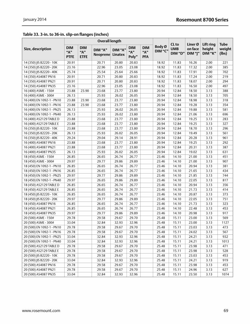
Rosemount 8700 SeriesJanuary 2014
Size, description
Overall length
Body Ø DIM “C”
CL to UMB DIM “D”
Liner Ø on face DIM “J”
Lift ring height DIM “K”
Tube weight (lbs)
DIM “A”PTFE
DIM “A”ETFE
DIM “A”Neoprene
DIM “A”Linatex
DIM “A”Poly”
DIM “A”PFA
14 (350) JIS B2220 - 10K 20.91 20.71 20.80 20.83 18.92 11.83 16.26 2.00 22114 (350) JIS B2220 - 20K 23.16 22.96 23.05 23.08 18.92 11.83 17.32 2.00 38514 (350) JIS B2220 - 40K 25.74 25.54 25.64 25.66 18.92 11.83 17.91 2.00 70214 (350) AS4087 PN16 20.91 20.71 20.80 20.83 18.92 11.83 17.24 2.00 21914 (350) AS4087 PN21 20.91 20.71 20.80 20.83 18.92 11.83 18.07 2.00 29414 (350) AS4087 PN35 23.16 22.96 23.05 23.08 18.92 11.83 16.50 2.00 49716 (400) ASME - 150# 23.88 23.90 23.68 23.77 23.80 20.94 12.84 18.50 3.13 38816 (400) ASME - 300# 26.13 25.93 26.02 26.05 20.94 12.84 18.50 3.13 705 16 (400) EN 1092-1 - PN10 23.88 23.90 23.68 23.77 23.80 20.94 12.84 18.98 3.13 31816 (400) EN 1092-1 - PN16 23.88 23.90 23.68 23.77 23.80 20.94 12.84 19.28 3.13 35416 (400) EN 1092-1 - PN25 26.13 25.93 26.02 26.05 20.94 12.84 19.88 3.13 58116 (400) EN 1092-1 - PN40 26.13 25.93 26.02 23.80 20.94 12.84 21.06 3.13 69616 (400) AS2129 TABLE D 23.88 23.68 23.77 23.80 20.94 12.84 19.25 3.13 28316 (400) AS2129 TABLE E 23.88 23.68 23.77 23.80 20.94 12.84 19.25 3.13 32716 (350) JIS B2220 - 10K 23.88 23.68 23.77 23.80 20.94 12.84 18.70 3.13 29616 (350) JIS B2220 - 20K 26.13 25.93 26.02 26.05 20.94 12.84 19.49 3.13 56116 (350) JIS B2220 - 40K 29.24 29.04 29.14 28.91 20.94 12.84 20.28 3.13 96116 (400) AS4087 PN16 23.88 23.68 23.77 23.80 20.94 12.84 19.25 3.13 29216 (400) AS4087 PN21 23.88 23.68 23.77 23.80 20.94 12.84 20.31 3.13 38716 (400) AS4087 PN35 26.13 25.93 26.02 26.05 20.94 12.84 19.02 3.13 63118 (450) ASME - 150# 26.85 26.65 26.74 26.77 23.46 14.10 21.00 3.13 45118 (450) ASME - 300# 29.97 29.77 29.86 29.89 23.46 14.10 21.00 3.13 90718 (450) EN 1092-1 - PN10 26.85 26.65 26.74 26.77 23.46 14.10 20.94 3.13 38118 (450) EN 1092-1 - PN16 26.85 26.65 26.74 26.77 23.46 14.10 21.65 3.13 43418 (450) EN 1092-1 - PN25 29.97 29.77 29.86 29.89 23.46 14.10 21.85 3.13 74418 (450) EN 1092-1 - PN40 29.97 26.65 29.86 29.89 23.46 14.10 22.05 3.13 81718 (450) AS2129 TABLE D 26.85 26.65 26.74 26.77 23.46 14.10 20.94 3.13 35618 (450) AS2129 TABLE E 26.85 26.65 26.74 26.77 23.46 14.10 21.73 3.13 41418 (450) JIS B2220 - 10K 26.85 26.65 26.74 26.77 23.46 14.10 20.87 3.13 37318 (450) JIS B2220 - 20K 29.97 29.77 29.86 29.89 23.46 14.10 22.05 3.13 75118 (450) AS4087 PN16 26.85 26.65 26.74 26.77 23.46 14.10 21.73 3.13 32318 (450) AS4087 PN21 26.85 26.65 26.74 26.77 23.46 14.10 22.48 3.13 45318 (450) AS4087 PN35 29.97 29.77 29.86 29.89 23.46 14.10 20.98 3.13 91720 (500) ASME - 150# 29.78 29.58 29.67 29.70 25.48 15.11 23.00 3.13 56920 (500) ASME - 300# 33.04 32.84 32.93 32.96 25.48 15.11 23.00 3.13 112720 (500) EN 1092-1 - PN10 29.78 29.58 29.67 29.70 25.48 15.11 23.03 3.13 47320 (500) EN 1092-1 - PN16 29.78 29.58 29.67 29.70 25.48 15.11 24.02 3.13 56720 (500) EN 1092-1 - PN25 33.04 32.84 32.93 32.96 25.48 15.11 24.21 3.13 93220 (500) EN 1092-1 - PN40 33.04 32.84 32.93 32.96 25.48 15.11 24.21 3.13 101320 (500) AS2129 TABLE D 29.78 29.58 29.67 29.70 25.48 15.11 23.98 3.13 47120 (500) AS2129 TABLE E 29.78 29.58 29.67 29.70 25.48 15.11 23.98 3.13 52820 (500) JIS B2220 - 10K 29.78 29.58 29.67 29.70 25.48 15.11 23.03 3.13 45320 (500) JIS B2220 - 20K 33.04 32.84 32.93 32.96 25.48 15.11 24.21 3.13 91920 (500) AS4087 PN16 29.78 29.58 29.67 29.70 25.48 15.11 23.98 3.13 45320 (500) AS4087 PN21 29.78 29.58 29.67 29.70 25.48 15.11 24.96 3.13 62720 (500) AS4087 PN35 33.04 32.84 32.93 32.96 25.48 15.11 23.50 3.13 1074
Table 33. 3-in. to 36-in. slip-on flanges (inches)
69www.rosemount.com

Rosemount 8700 Series January 2014
Size, description
Overall length
Body Ø DIM “C”
CL to UMB DIM “D”
Liner Ø on face DIM “J”
Lift ring height DIM “K”
Tube weight (lbs)
DIM “A”PTFE
DIM “A”ETFE
DIM “A”Neoprene
DIM “A”Linatex
DIM “A”Poly”
DIM “A”PFA
24 (600) ASME - 150# 35.75 35.55 35.64 35.67 30.03 17.39 27.25 3.13 82824 (600) ASME - 300# 39.38 39.18 39.28 39.30 30.03 17.39 27.25 3.13 172924 (600) EN 1092-1 - PN10 35.75 35.55 35.64 35.67 30.03 17.39 26.97 3.13 66124 (600) EN 1092-1 - PN16 35.75 35.55 35.64 35.67 30.03 17.39 28.54 3.13 83224 (600) EN 1092-1 - PN25 39.38 39.18 39.27 39.30 30.03 17.39 28.35 3.13 135224 (600) EN 1092-1 - PN40 39.38 39.18 39.27 39.30 30.03 17.39 28.94 3.13 162824 (600) AS2129 TABLE D 35.75 35.55 35.64 35.67 30.03 17.39 28.35 3.13 69324 (600) AS2129 TABLE E 35.75 35.55 35.64 35.67 30.03 17.39 28.23 3.13 81524 (600) JIS B2220 - 10K 35.75 35.55 35.64 35.67 30.03 17.39 27.17 3.13 65924 (600) JIS B2220 - 20K 39.38 39.18 39.27 39.30 30.03 17.39 28.35 3.13 135324 (600) AS4087 PN16 35.75 35.55 35.64 35.67 30.03 17.39 28.35 3.13 70924 (600) AS4087 PN21 39.38 39.18 39.27 39.30 30.03 17.39 29.09 3.13 129324 (600) AS4087 PN35 39.38 39.18 39.27 39.30 30.03 17.39 27.52 3.13 152830 (750) AWWA CLASS D 37.00 36.80 36.89 37.04 35.50 20.13 33.75 3.13 89730 (750) MSS SP44 - 150# 41.56 41.36 41.45 41.48 35.50 20.13 33.75 3.13 156230 (750) MSS SP44 - 300# 47.25 47.05 47.14 47.17 35.50 20.13 33.75 3.13 295130 (750) AS2129 TABLE D 37.00 36.80 36.89 37.04 35.50 20.13 34.96 3.13 103730 (750) AS2129 TABLE E 41.56 41.36 41.45 41.48 35.50 20.13 33.75 3.13 127530 (750) AS4087 PN16 37.00 36.80 36.89 36.92 35.50 20.13 34.96 3.13 108330 (750) AS4087 PN21 41.56 41.36 41.45 41.48 35.50 20.13 3.00 3.13 107130 (750) AS4087 PN35 47.25 47.05 47.14 47.17 35.50 20.13 35.35 3.13 245236 (900) AWWA CLASS D 40.63 40.43 40.52 40.67 43.37 24.00 40.25 3.13 126736 (900) MSS SP44 - 150# 47.25 47.05 47.14 47.17 43.37 24.00 40.25 3.13 255136 (900) MSS SP44 - 300# 53.17 52.97 53.06 53.09 43.37 24.00 40.25 3.13 458436 (900) AS2129 TABLE D 40.63 40.43 40.52 40.67 43.37 24.00 41.34 3.13 151536 (900) AS2129 TABLE E 47.25 47.05 47.14 47.17 43.37 24.00 41.34 3.13 210636 (900) AS4087 PN16 40.63 40.43 40.52 40.55 43.37 24.00 41.34 3.13 155936 (900) AS4087 PN21 47.25 47.05 47.14 47.17 43.37 24.00 41.73 3.13 206136 (900) AS4087 PN35 53.17 52.97 53.06 53.09 43.37 24.00 40.55 3.13 3701
Table 33. 3-in. to 36-in. slip-on flanges (inches)
70 www.rosemount.com
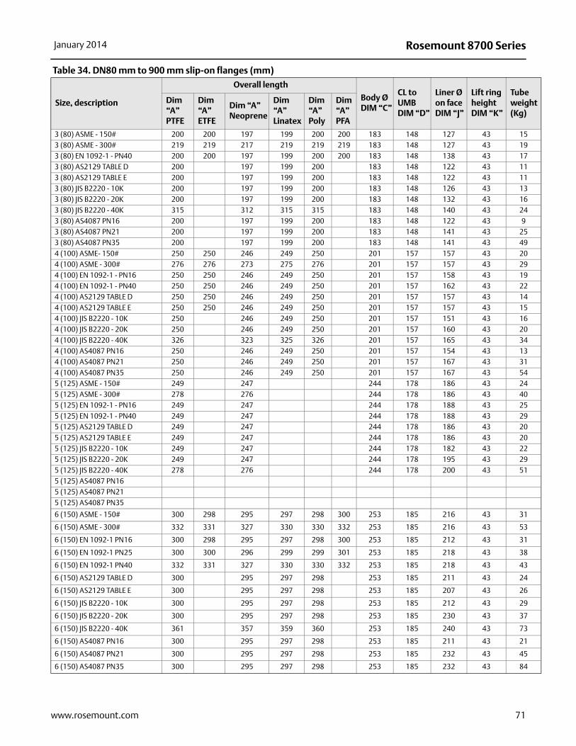
Rosemount 8700 SeriesJanuary 2014
Table 34. DN80 mm to 900 mm slip-on flanges (mm)
Size, description
Overall length
Body Ø DIM “C”
CL to UMB DIM “D”
Liner Ø on face DIM “J”
Lift ring height DIM “K”
Tube weight(Kg)
Dim “A”PTFE
Dim “A”ETFE
Dim “A”Neoprene
Dim “A”Linatex
Dim “A”Poly
Dim “A”PFA
3 (80) ASME - 150# 200 200 197 199 200 200 183 148 127 43 153 (80) ASME - 300# 219 219 217 219 219 219 183 148 127 43 193 (80) EN 1092-1 - PN40 200 200 197 199 200 200 183 148 138 43 173 (80) AS2129 TABLE D 200 197 199 200 183 148 122 43 113 (80) AS2129 TABLE E 200 197 199 200 183 148 122 43 113 (80) JIS B2220 - 10K 200 197 199 200 183 148 126 43 133 (80) JIS B2220 - 20K 200 197 199 200 183 148 132 43 163 (80) JIS B2220 - 40K 315 312 315 315 183 148 140 43 243 (80) AS4087 PN16 200 197 199 200 183 148 122 43 93 (80) AS4087 PN21 200 197 199 200 183 148 141 43 253 (80) AS4087 PN35 200 197 199 200 183 148 141 43 494 (100) ASME- 150# 250 250 246 249 250 201 157 157 43 204 (100) ASME - 300# 276 276 273 275 276 201 157 157 43 294 (100) EN 1092-1 - PN16 250 250 246 249 250 201 157 158 43 194 (100) EN 1092-1 - PN40 250 250 246 249 250 201 157 162 43 224 (100) AS2129 TABLE D 250 250 246 249 250 201 157 157 43 144 (100) AS2129 TABLE E 250 250 246 249 250 201 157 157 43 154 (100) JIS B2220 - 10K 250 246 249 250 201 157 151 43 164 (100) JIS B2220 - 20K 250 246 249 250 201 157 160 43 204 (100) JIS B2220 - 40K 326 323 325 326 201 157 165 43 344 (100) AS4087 PN16 250 246 249 250 201 157 154 43 134 (100) AS4087 PN21 250 246 249 250 201 157 167 43 314 (100) AS4087 PN35 250 246 249 250 201 157 167 43 545 (125) ASME - 150# 249 247 244 178 186 43 245 (125) ASME - 300# 278 276 244 178 186 43 405 (125) EN 1092-1 - PN16 249 247 244 178 188 43 255 (125) EN 1092-1 - PN40 249 247 244 178 188 43 295 (125) AS2129 TABLE D 249 247 244 178 186 43 205 (125) AS2129 TABLE E 249 247 244 178 186 43 205 (125) JIS B2220 - 10K 249 247 244 178 182 43 225 (125) JIS B2220 - 20K 249 247 244 178 195 43 295 (125) JIS B2220 - 40K 278 276 244 178 200 43 515 (125) AS4087 PN165 (125) AS4087 PN215 (125) AS4087 PN35
6 (150) ASME - 150# 300 298 295 297 298 300 253 185 216 43 31
6 (150) ASME - 300# 332 331 327 330 330 332 253 185 216 43 53
6 (150) EN 1092-1 PN16 300 298 295 297 298 300 253 185 212 43 31
6 (150) EN 1092-1 PN25 300 300 296 299 299 301 253 185 218 43 38
6 (150) EN 1092-1 PN40 332 331 327 330 330 332 253 185 218 43 43
6 (150) AS2129 TABLE D 300 295 297 298 253 185 211 43 24
6 (150) AS2129 TABLE E 300 295 297 298 253 185 207 43 26
6 (150) JIS B2220 - 10K 300 295 297 298 253 185 212 43 29
6 (150) JIS B2220 - 20K 300 295 297 298 253 185 230 43 37
6 (150) JIS B2220 - 40K 361 357 359 360 253 185 240 43 73
6 (150) AS4087 PN16 300 295 297 298 253 185 211 43 21
6 (150) AS4087 PN21 300 295 297 298 253 185 232 43 45
6 (150) AS4087 PN35 300 295 297 298 253 185 232 43 84
71www.rosemount.com

Rosemount 8700 Series January 2014
Table 34. DN80 mm to 900 mm slip-on flanges (mm)
Size, description
Overall length
Body Ø DIM “C”
CL to UMB DIM “D”
Liner Ø on face DIM “J”
Lift ring height DIM “K”
Tube weight(Kg)
DIM “A” PTFE
DIM“A” ETFE
DIM “A” Neoprene
DIM “A” Linatex
DIM “A” Poly
DIM “A” PFA
8 (200) ASME - 150# 350 348 344 346 347 350 303 210 270 43 48
8 (200) ASME - 300# 396 395 392 394 395 396 303 210 270 43 83
8 (200) EN 1092-1 PN10 350 348 344 346 347 350 303 210 268 43 44
8 (200) EN 1092-1 PN16 350 348 344 346 347 350 303 210 268 43 43
8 (200) EN 1092-1 PN25 350 348 344 346 347 350 303 210 278 43 54
8 (200) EN 1092-1 PN40 396 395 392 394 395 396 303 210 285 43 72
8 (200) AS2129 TABLE D 350 344 346 347 303 210 268 43 35
8 (200) AS2129 TABLE E 350 344 346 347 303 210 264 43 39
8 (200) JIS B2220 - 10K 353 344 346 347 303 210 262 43 37
8 (200) JIS B2220 - 20K 396 392 394 395 303 210 275 43 61
8 (200) JIS B2220 - 40K 425 420 422 423 303 210 290 43 105
8 (200) AS4087 PN16 350 344 346 347 303 210 268 43 33
8 (200) AS4087 PN21 350 344 346 347 303 210 296 43 62
8 (200) AS4087 PN35 396 392 394 395 303 210 260 43 109
10 (250) ASME - 150# 381 377 372 374 375 381 372 246 324 51 69
10 (250) ASME - 300# 435 434 428 431 431 435 372 246 324 51 121
10 (250) EN 1092-1 PN10 381 377 372 374 375 381 372 246 320 51 61
10 (250) EN 1092-1 PN16 381 377 372 374 375 381 372 246 320 51 63
10 (250) EN 1092-1 PN25 381 377 372 374 375 381 372 246 335 51 79
10 (250) EN 1092-1 PN40 435 428 431 431 435 372 246 345 51 111
10 (250) AS2129 TABLE D 381 372 374 375 372 246 328 51 56
10 (250) AS2129 TABLE E 381 372 374 375 372 246 328 51 62
10 (250) JIS B2220 - 10K 381 372 374 375 372 246 324 43 58
10 (250) JIS B2220 - 20K 435 428 431 431 372 246 345 80 99
10 (250) JIS B2220 - 40K 496 491 494 494 372 246 355 51 173
10 (250) AS4087 PN16 381 372 374 375 372 246 328 51 44
10 (250) AS4087 PN21 381 372 374 375 372 246 349 51 80
10 (250) AS4087 PN35 435 428 431 431 372 246 311 51 136
12 (300) ASME - 150# 458 455 449 452 452 457 427 274 381 51 105
12 (300) ASME - 300# 512 508 503 505 506 512 427 274 381 51 175
12 (300) EN 1092-1 PN10 458 455 449 452 452 457 427 274 370 51 81
12 (300) EN 1092-1 PN16 458 455 449 452 452 457 427 274 378 51 87
12 (300) EN 1092-1 PN25 458 455 449 452 452 457 427 274 395 51 110
12 (300) EN 1092-1 PN40 512 503 505 506 512 427 274 410 51 159
12 (300) AS2129 TABLE D 458 449 452 452 427 274 378 51 78
12 (300) AS2129 TABLE E 458 449 452 452 427 274 374 51 84
12 (300) JIS B2220 - 10K 458 449 452 452 427 274 368 51 75
12 (300) JIS B2220 - 20K 512 503 505 506 427 274 395 51 129
12 (300) JIS B2220 - 40K 561 556 558 559 427 274 410 51 248
12 (300) AS4087 PN16 458 449 452 452 427 274 378 51 63
12 (300) AS4087 PN21 458 449 452 452 427 274 406 51 102
12 (300) AS4087 PN35 512 503 505 506 427 274 362 51 168
14 (350) ASME - 150# 531 532 526 528 529 533 481 300 413 51 136
14 (350) ASME - 300# 588 589 583 586 586 481 300 413 51 234
14 (350) EN 1092-1 PN10 531 532 526 528 529 533 481 300 430 51 114
72 www.rosemount.com
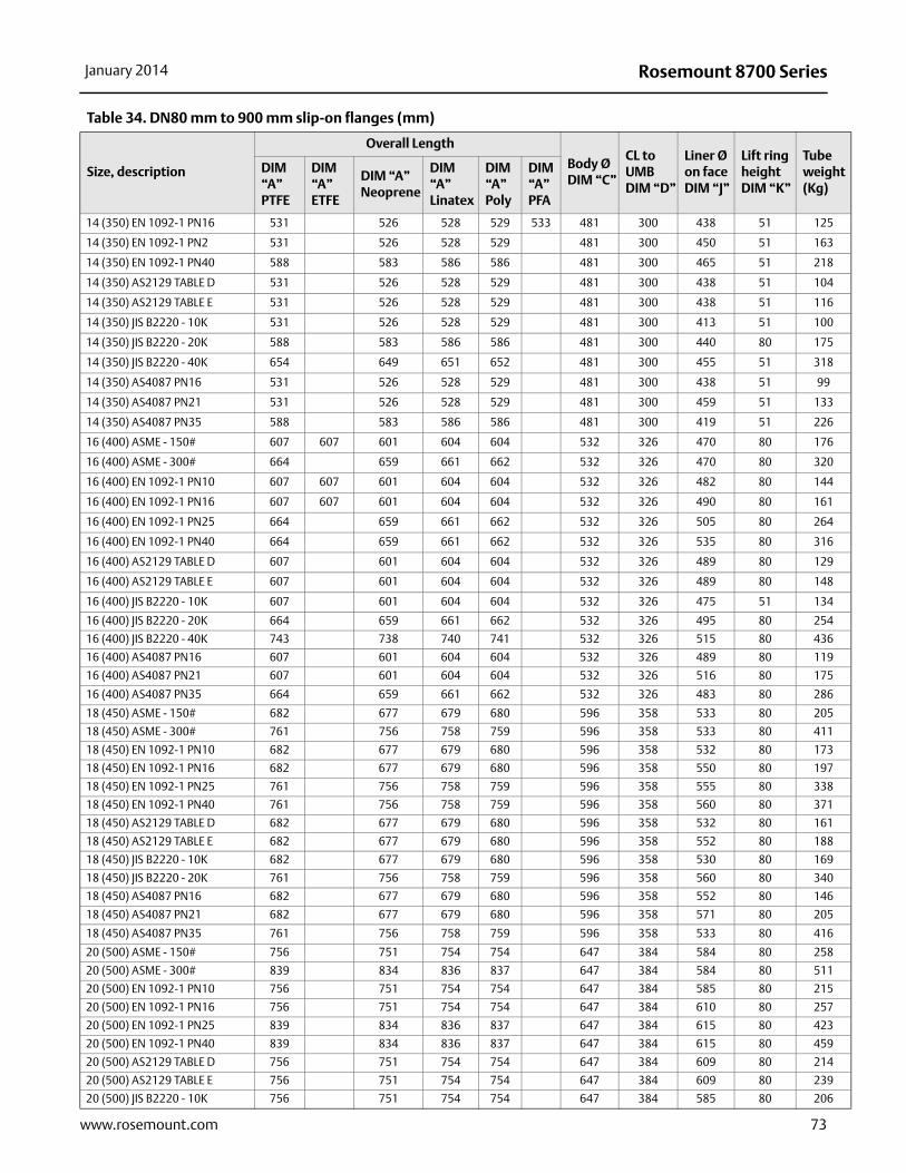
Rosemount 8700 SeriesJanuary 2014
73www.rosemount.com
Table 34. DN80 mm to 900 mm slip-on flanges (mm)
Size, description
Overall Length
Body Ø DIM “C”
CL to UMB DIM “D”
Liner Øon face DIM “J”
Lift ring height DIM “K”
Tube weight(Kg)
DIM “A” PTFE
DIM“A” ETFE
DIM “A” Neoprene
DIM “A” Linatex
DIM “A” Poly
DIM “A” PFA
14 (350) EN 1092-1 PN16 531 526 528 529 533 481 300 438 51 125
14 (350) EN 1092-1 PN2 531 526 528 529 481 300 450 51 163
14 (350) EN 1092-1 PN40 588 583 586 586 481 300 465 51 218
14 (350) AS2129 TABLE D 531 526 528 529 481 300 438 51 104
14 (350) AS2129 TABLE E 531 526 528 529 481 300 438 51 116
14 (350) JIS B2220 - 10K 531 526 528 529 481 300 413 51 100
14 (350) JIS B2220 - 20K 588 583 586 586 481 300 440 80 175
14 (350) JIS B2220 - 40K 654 649 651 652 481 300 455 51 318
14 (350) AS4087 PN16 531 526 528 529 481 300 438 51 99
14 (350) AS4087 PN21 531 526 528 529 481 300 459 51 133
14 (350) AS4087 PN35 588 583 586 586 481 300 419 51 226
16 (400) ASME - 150# 607 607 601 604 604 532 326 470 80 176
16 (400) ASME - 300# 664 659 661 662 532 326 470 80 320
16 (400) EN 1092-1 PN10 607 607 601 604 604 532 326 482 80 144
16 (400) EN 1092-1 PN16 607 607 601 604 604 532 326 490 80 161
16 (400) EN 1092-1 PN25 664 659 661 662 532 326 505 80 264
16 (400) EN 1092-1 PN40 664 659 661 662 532 326 535 80 316
16 (400) AS2129 TABLE D 607 601 604 604 532 326 489 80 129
16 (400) AS2129 TABLE E 607 601 604 604 532 326 489 80 148
16 (400) JIS B2220 - 10K 607 601 604 604 532 326 475 51 134
16 (400) JIS B2220 - 20K 664 659 661 662 532 326 495 80 254
16 (400) JIS B2220 - 40K 743 738 740 741 532 326 515 80 436
16 (400) AS4087 PN16 607 601 604 604 532 326 489 80 119
16 (400) AS4087 PN21 607 601 604 604 532 326 516 80 175
16 (400) AS4087 PN35 664 659 661 662 532 326 483 80 286
18 (450) ASME - 150# 682 677 679 680 596 358 533 80 205
18 (450) ASME - 300# 761 756 758 759 596 358 533 80 411
18 (450) EN 1092-1 PN10 682 677 679 680 596 358 532 80 173
18 (450) EN 1092-1 PN16 682 677 679 680 596 358 550 80 197
18 (450) EN 1092-1 PN25 761 756 758 759 596 358 555 80 338
18 (450) EN 1092-1 PN40 761 756 758 759 596 358 560 80 371
18 (450) AS2129 TABLE D 682 677 679 680 596 358 532 80 161
18 (450) AS2129 TABLE E 682 677 679 680 596 358 552 80 188
18 (450) JIS B2220 - 10K 682 677 679 680 596 358 530 80 169
18 (450) JIS B2220 - 20K 761 756 758 759 596 358 560 80 340
18 (450) AS4087 PN16 682 677 679 680 596 358 552 80 146
18 (450) AS4087 PN21 682 677 679 680 596 358 571 80 205
18 (450) AS4087 PN35 761 756 758 759 596 358 533 80 416
20 (500) ASME - 150# 756 751 754 754 647 384 584 80 258
20 (500) ASME - 300# 839 834 836 837 647 384 584 80 511
20 (500) EN 1092-1 PN10 756 751 754 754 647 384 585 80 215
20 (500) EN 1092-1 PN16 756 751 754 754 647 384 610 80 257
20 (500) EN 1092-1 PN25 839 834 836 837 647 384 615 80 423
20 (500) EN 1092-1 PN40 839 834 836 837 647 384 615 80 459
20 (500) AS2129 TABLE D 756 751 754 754 647 384 609 80 214
20 (500) AS2129 TABLE E 756 751 754 754 647 384 609 80 239
20 (500) JIS B2220 - 10K 756 751 754 754 647 384 585 80 206
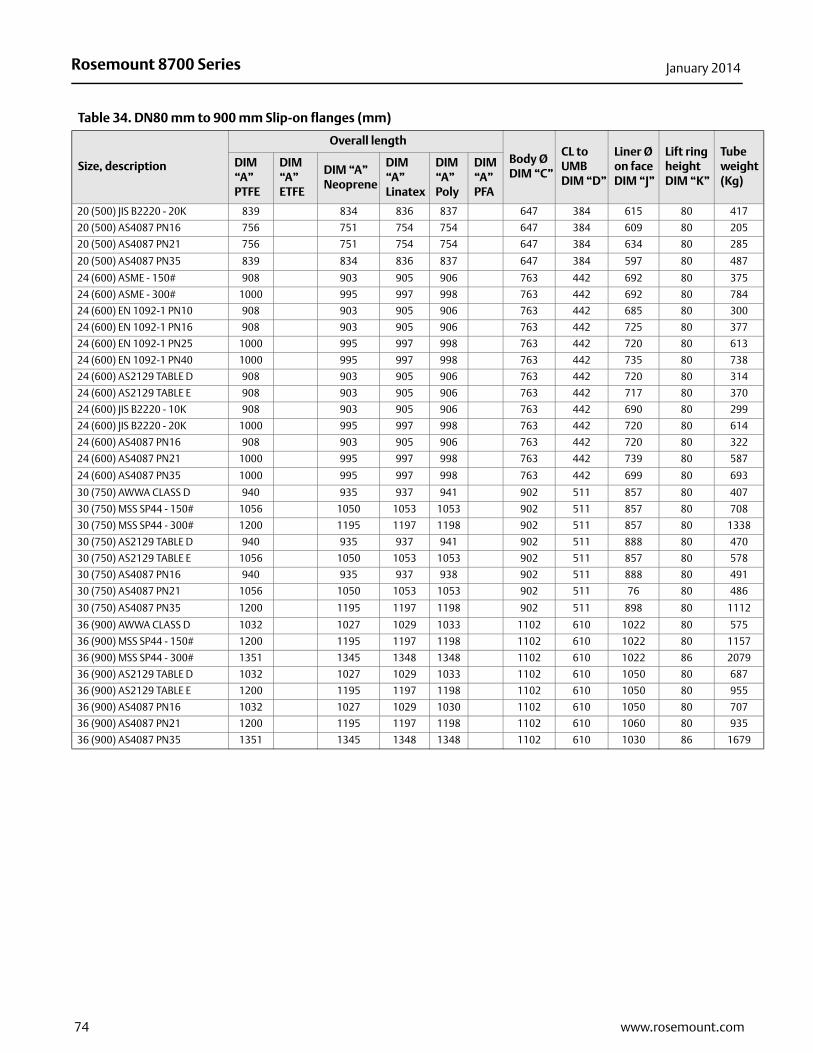
Rosemount 8700 Series January 2014
Table 34. DN80 mm to 900 mm Slip-on flanges (mm)
Size, description
Overall length
Body Ø DIM “C”
CL to UMB DIM “D”
Liner Ø on face DIM “J”
Lift ring height DIM “K”
Tube weight(Kg)
DIM “A” PTFE
DIM“A” ETFE
DIM “A” Neoprene
DIM “A” Linatex
DIM “A” Poly
DIM “A” PFA
20 (500) JIS B2220 - 20K 839 834 836 837 647 384 615 80 417
20 (500) AS4087 PN16 756 751 754 754 647 384 609 80 205
20 (500) AS4087 PN21 756 751 754 754 647 384 634 80 285
20 (500) AS4087 PN35 839 834 836 837 647 384 597 80 487
24 (600) ASME - 150# 908 903 905 906 763 442 692 80 375
24 (600) ASME - 300# 1000 995 997 998 763 442 692 80 784
24 (600) EN 1092-1 PN10 908 903 905 906 763 442 685 80 300
24 (600) EN 1092-1 PN16 908 903 905 906 763 442 725 80 377
24 (600) EN 1092-1 PN25 1000 995 997 998 763 442 720 80 613
24 (600) EN 1092-1 PN40 1000 995 997 998 763 442 735 80 738
24 (600) AS2129 TABLE D 908 903 905 906 763 442 720 80 314
24 (600) AS2129 TABLE E 908 903 905 906 763 442 717 80 370
24 (600) JIS B2220 - 10K 908 903 905 906 763 442 690 80 299
24 (600) JIS B2220 - 20K 1000 995 997 998 763 442 720 80 614
24 (600) AS4087 PN16 908 903 905 906 763 442 720 80 322
24 (600) AS4087 PN21 1000 995 997 998 763 442 739 80 587
24 (600) AS4087 PN35 1000 995 997 998 763 442 699 80 693
30 (750) AWWA CLASS D 940 935 937 941 902 511 857 80 407
30 (750) MSS SP44 - 150# 1056 1050 1053 1053 902 511 857 80 708
30 (750) MSS SP44 - 300# 1200 1195 1197 1198 902 511 857 80 1338
30 (750) AS2129 TABLE D 940 935 937 941 902 511 888 80 470
30 (750) AS2129 TABLE E 1056 1050 1053 1053 902 511 857 80 578
30 (750) AS4087 PN16 940 935 937 938 902 511 888 80 491
30 (750) AS4087 PN21 1056 1050 1053 1053 902 511 76 80 486
30 (750) AS4087 PN35 1200 1195 1197 1198 902 511 898 80 1112
36 (900) AWWA CLASS D 1032 1027 1029 1033 1102 610 1022 80 575
36 (900) MSS SP44 - 150# 1200 1195 1197 1198 1102 610 1022 80 1157
36 (900) MSS SP44 - 300# 1351 1345 1348 1348 1102 610 1022 86 2079
36 (900) AS2129 TABLE D 1032 1027 1029 1033 1102 610 1050 80 687
36 (900) AS2129 TABLE E 1200 1195 1197 1198 1102 610 1050 80 955
36 (900) AS4087 PN16 1032 1027 1029 1030 1102 610 1050 80 707
36 (900) AS4087 PN21 1200 1195 1197 1198 1102 610 1060 80 935
36 (900) AS4087 PN35 1351 1345 1348 1348 1102 610 1030 86 1679
74 www.rosemount.com

Rosemount 8700 SeriesJanuary 2014
Figure 12. 1/2-in. to 36-in. (DN15 mm to 900 mm) with W3 option
Nameplate
Threaded DrainHole
Flow
E
Table 35. Body width with electrode access (W3)
Size -- in (mm) all flangesBody width with W3 DIM “E” (in.)
Body width with W3 DIM “E” (mm)
1/2 (15) 6.22 1581 (25) 6.68 170
11/2 (40) 7.47 1902 (50) 7.47 1903 (80) 9.45 240
4 (100) 10.15 2586 (150) 12.34 3138 (200) 14.28 363
10 (250) 17.00 43212 (300) 19.15 48614 (350) 21.28 54116 (400) 23.30 59218 (450) 25.82 65620 (500) 27.84 70724 (600) 32.39 82330 (750) 38.04 96636 (900) 45.91 1166
75www.rosemount.com
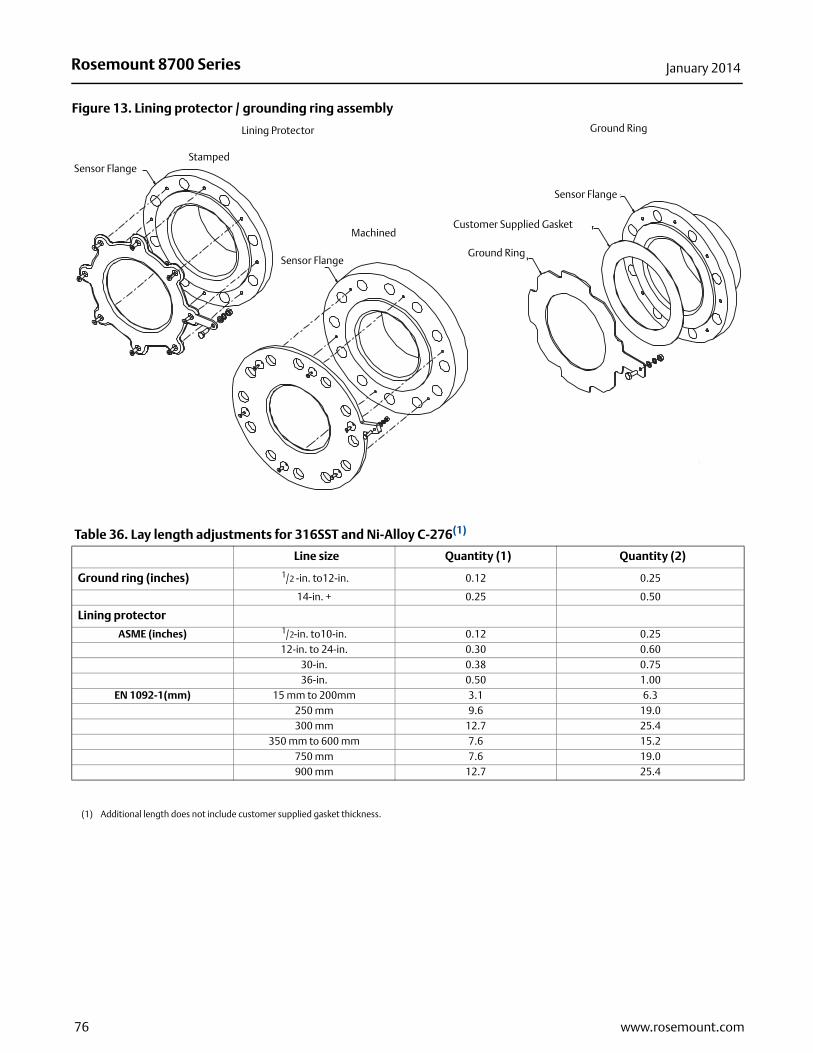
Rosemount 8700 Series January 2014
Figure 13. Lining protector / grounding ring assembly
Lining Protector
StampedSensor Flange
Ground Ring
Sensor Flange
Customer Supplied Gasket
Ground RingSensor Flange
Machined
Table 36. Lay length adjustments for 316SST and Ni-Alloy C-276(1)
Line size Quantity (1) Quantity (2)
Ground ring (inches) 1/2 -in. to12-in. 0.12 0.25
14-in. + 0.25 0.50
Lining protector
ASME (inches) 1/2-in. to10-in. 0.12 0.25 12-in. to 24-in. 0.30 0.60
30-in. 0.38 0.75 36-in. 0.50 1.00
EN 1092-1(mm) 15 mm to 200mm 3.1 6.3250 mm 9.6 19.0300 mm 12.7 25.4
350 mm to 600 mm 7.6 15.2750 mm 7.6 19.0900 mm 12.7 25.4
(1) Additional length does not include customer supplied gasket thickness.
76 www.rosemount.com

Rosemount 8700 SeriesJanuary 2014
Figure 14. 1/2-in. to 24-in. (DN15 mm to 600 mm) with slip-on flanges - high pressure meters (Class 600 - 900)4.02
(102.1)2.00
(50.8)
2.62 (66.4)
Flange Bolts To Straddle Centerline
C
D
A
Flow
C
Nameplate
K
5.00 (127)
J
77www.rosemount.com

Rosemount 8700 Series January 2014
t
Table 37. 1/2-in. to 24-in. with slip-on flanges (inches) high pressure (Class 600 - 900)
Size, description
Overall length
Body Ø DIM “C”
CL to UMB DIM “D”
Liner Ø on Face DIM “J”
Lift ring height DIM “K”
Tube weigh(lbs)
DIM “A” PTFE
DIM “A” ETFE
DIM “A” Neoprene
DIM “A” Linatex
DIM “A” Poly
1/2 (15) ASME - 600# DERAT. SO / RF 8.38 8.38 8.38 8.48 8.38 4.50 4.41 1.38 101 (25) ASME - 600# DERAT. SO / RF 8.67 8.67 8.67 8.76 8.67 4.50 4.41 2.00 15 1 (25) ASME - 600# FULL, SO / RF 8.53 8.53 8.53 4.50 4.41 1.63 15 1 (25) ASME - 900# SO / RF 9.49 9.49 9.49 4.50 4.41 1.63 1.70 24 11/2 (40) ASME - 600# DERAT. SO / RF 8.63 8.63 8.62 8.72 8.63 5.21 4.82 2.88 23 11/2 (40) ASME - 600# FULL, SO / RF 8.49 8.49 8.49 5.21 4.82 2.50 2311/2 (40) ASME - 900# SO / RF 9.49 9.49 9.49 5.21 4.82 2.50 1.70 342 (50) ASME - 600# DERAT. SO / RF 8.78 8.78 8.74 8.84 8.78 5.21 4.82 3.62 282 (50) ASME - 600# FULL. SO / RF 8.61 8.61 8.61 5.21 4.82 3.25 272 (50) ASME - 900# SO / RF 10.23 10.23 10.23 5.21 4.82 3.25 1.70 5721/2 (65) ASME - 600 DERAT., SO / RF 8.86 8.80 6.31 5.37 4.12 4021/2 (65) ASME - 600 FULL, SO / RF 8.61 6.31 5.37 3.75 4121/2 (65) ASME - 900, SO / RF 10.23 6.31 5.37 3.75 1.70 823 (80) ASME - 600# DERAT. SO / RF 12.40 12.40 12.30 12.40 12.40 7.21 5.82 5.00 1.70 533 (80) ASME - 600# FULL, SO / RF 12.17 12.17 12.17 7.21 5.82 4.63 1.70 533 (80) ASME - 900# SO / RF 12.79 12.79 12.79 7.21 5.82 4.63 1.70 744 (100) ASME - 600# DERAT. SO / RF 12.83 12.83 12.73 12.83 12.83 7.91 6.17 6.19 1.70 94 4 (100) ASME - 600# FULL, SO / RF 12.60 12.60 12.65 7.91 6.17 5.81 1.70 934 (100) ASME - 900# SO / RF 13.86 13.86 13.89 7.91 6.17 5.81 2.00 123 5 (125) ASME - 600# DERAT. SO / RF 12.89 12.81 9.61 7.02 7.31 1.70 1575 (125) ASME - 600# FULL. SO / RF 12.60 9.61 7.02 6.91 1.70 1565 (125) ASME - 900# SO / RF 13.86 9.61 7.02 6.91 1.70 2016 (150) ASME - 600# DERAT., / RF 14.23 14.23 14.09 14.19 14.21 9.98 7.30 8.50 1.70 1786 (150) ASME - 600# FULL, SO / RF 13.96 13.96 13.96 9.98 7.30 8.00 1.70 1896 (150) ASME - 900# SO / RF 17.55 17.55 17.55 9.98 7.30 8.00 2.00 2548 (200) ASME - 600# DERAT. SO / RF 16.72 16.70 16.57 16.57 16.69 11.92 8.27 10.62 1.70 2728 (200) ASME - 600# FULL, SO / RF 16.44 16.44 16.44 11.92 8.27 10.00 1.70 2928 (200) ASME - 900# SO / RF 20.58 20.58 20.58 11.92 8.27 10.00 3.13 44410 (250) ASME - 600# DERAT. SO / RF 19.54 19.40 19.18 19.28 19.30 14.64 9.69 12.75 2.00 46210 (250) ASME - 600# FULL, SO / RF 19.05 19.05 19.05 14.64 9.69 12.00 2.00 47610 (250) ASME - 900# SO / RF 21.54 21.54 21.54 14.64 9.69 12.00 3.13 65012 (300) ASME - 600# DERAT., SO / RF 22.08 22.10 21.88 21.98 21.77 16.80 10.77 15.00 2.00 62312 (300) ASME - 900# FULL, SO / RF 21.75 21.75 21.75 16.80 10.77 14.00 2.00 62012 (300) ASME - 900# SO / RF 25.15 25.15 25.15 16.80 10.77 14.00 2.00 90714 (350) ASME - 600# DERAT., SO / RF 25.74 18.92 11.83 16.25 2.00 77314 (350) ASME - 600# FULL, SO / RF 25.41 25.41 25.41 18.92 11.83 15.25 2.00 77116 (400) ASME - 600# DERAT., SO / RF 29.24 20.94 12.84 18.50 3.13 110216 (400) ASME - 600# FULL, SO / RF 28.91 28.91 28.91 20.94 12.84 17.50 3.13 110018 (450) ASME - 600# DERAT., SO / RF 32.72 23.46 14.10 21.00 3.13 140718 (450) ASME - 600# FULL, SO / RF 32.39 32.39 32.39 23.46 14.10 20.00 3.13 140520 (500) ASME - 600# DERAT., SO / RF 36.85 25.48 15.11 23.00 3.13 182420 (500) ASME - 600# FULL, SO / RF 36.52 36.52 36.52 25.48 15.11 22.00 3.13 182224 (600) ASME - 600# DERAT., SO / RF 41.35 30.03 17.39 27.25 3.13 269024 (600) ASME - 600# FULL, SO / RF 41.02 41.02 41.02 30.03 17.39 26.00 3.13 2692
78 www.rosemount.com

Rosemount 8700 SeriesJanuary 2014
ensor eight g)
577
111111161312261819372424342424247171718186
115123132202210216295283281412351350500499827826
1220122112201221
Table 38. DN 15 mm to 600 mm with slip-on flanges (mm) high pressure (Class 600 - 900)
Size, description
Overall lengthBody Ø DIM “C”
CL to UMB DIM “D”
Liner Ø on face DIM “J”
Lift ring height DIM “K”
Sw(K
DIM “A” PTFE
DIM “A” ETFE
DIM “A” Neoprene
DIM “A” Linatex
DIM “A” Poly
1/2 (15) ASME - 600# DERAT. SO / RF 213 213 213 215 213 114 112 351 (25) ASME - 600# DERAT. SO / RF 220 220 220 223 220 114 112 511 (25) ASME - 600# FULL, SO / RF 217 217 217 114 112 411 (25) ASME - 900# SO / RF 241 241 241 114 112 4111/2 (40) ASME - 600# DERAT. SO / RF 219 219 219 221 219 132 122 7311/2 (40) ASME - 600# FULL, SO / RF 216 216 216 132 122 6411/2 (40) ASME - 900# SO / RF 241 241 241 132 122 64 432 (50) ASME - 600# DERAT. SO / RF 223 223 222 224 223 132 122 922 (50) ASME - 600# FULL, SO / RF 219 219 219 132 122 832 (50) ASME - 900# SO / RF 260 260 260 132 122 83 4321/2 (65) ASME - 600# DERAT. SO / RF 225 224 160 136 10521/2 (65) ASME - 600# FULL, SO / RF 219 160 136 9521/2 (65) ASME - 900# SO / RF 260 160 136 95 433 (80) ASME - 600# DERAT. SO / RF 315 315 312 315 315 183 148 127 433 (80) ASME - 600# FULL, SO / RF 309 309 309 183 148 118 433 (80) ASME - 900# SO / RF 325 325 325 183 148 118 434 (100) ASME - 600# DERAT. SO / RF 326 326 323 326 326 201 157 157 434 (100) ASME - 600# FULL, SO / RF 320 320 320 201 157 148 434 (100) ASME - 900# SO / RF 352 352 352 201 157 148 435 (125) ASME - 600# DERAT. SO / RF 327 325 244 178 186 435 (125) ASME - 600# FULL, SO / RF 320 244 178 176 435 (125) ASME - 900# SO / RF 352 244 178 176 436 (150) ASME - 600# DERAT. SO / RF 361 361 358 360 361 253 185 216 436 (150) ASME - 600# FULL, SO / RF 354 354 354 253 185 203 436 (150) ASME - 900# SO / RF 446 446 446 253 185 203 518 (200) ASME - 600# DERAT. SO / RF 425 424 421 423 424 303 210 270 438 (200) ASME - 600# FULL, SO / RF 417 417 424 303 210 254 438 (200) ASME - 900# SO / RF 523 523 529 303 210 254 8010 (250) ASME - 600# DERAT. SO / RF 496 493 487 490 490 372 246 324 5110 (250) ASME - 600# FULL, SO / RF 484 484 484 372 246 305 5110 (250) ASME - 900# SO / RF 547 547 547 372 246 305 8012 (300) ASME - 600# DERAT., SO / RF 561 561 556 558 553 427 274 381 5112 (300) ASME - 600# FULL, SO / RF 552 552 552 427 274 356 5112 (300) ASME - 900# SO / RF 639 639 639 427 274 356 8014 (350) ASME - 600# DERAT, SO / RF 654 481 300 413 5114 (350) ASME - 600# FULL, SO / RF 645 645 645 481 300 387 5116 (400) ASME - 600# DERAT., SO / RF 743 532 326 470 8016 (400) ASME - 600# FULL, SO / RF 734 734 734 532 326 445 8018 (450) ASME - 600# DERAT., SO / RF 831 596 358 533 8018 (450) ASME - 600# FULL, SO / RF 823 823 823 596 384 508 8020 (500) ASME - 600# DERAT., SO / RF 936 647 384 584 8020 (500) ASME - 600# FULL, SO / RF 928 928 928 647 384 559 8024 (600) ASME - 600# DERAT., SO / RF 1050 763 442 692 8024 (600) ASME - 600# FULL, SO / RF 1042 1042 1042 763 442 660 80
79www.rosemount.com

Rosemount 8700 Series January 2014
sor ht in kg)
1.5)2.0)7.5)0.1)7.6)0.8)4.4)1.4)3.4)1.9)4.3)6.8)6.5)5.6)7.8)7.2)9.1)5.2)
50.2)6.7)
53.1)
Figure 15. 1-in. to 24-in. weld neck flanges - high pressure meters (Class 600 - 2500)
Table 39. 1-in. to 4-in. weld neck flanges inches (mm)
Size, descriptionDIM “A”
NeopreneDIM “A” Linatex
DIM “A” Poly
Body Ø DIM “C”
CL to UMB DIM “D”
Liner Øon face DIM “J”
Lift ring height
DIM “K”
Senweiglbs. (
1 (25) ASME - 1500# WN / RF 12.87 (327) 12.87 (327) 12.87 (327) 4.5 (114) 4.41 (112) 1.63 (41) 1.70 (43) 25 (111/2 (40) ASME - 600# WN / RF 11.56 (294) 11.56 (294) 11.56 (294) 5.21 (132) 4.82 (122) 2.50 (64) 26 (111/2 (40) ASME - 1500# WN / RF 13.09 (332) 13.09 (332) 13.09 (332) 5.21 (132) 4.82 (122) 2.50 (64) 1.70 (43) 39 (111/2 (40) ASME - 2500# WN / RF 15.51 (394) 15.51 (394) 15.51 (394) 5.21 (132) 4.82 (122) 2.38 (60) 1.70 (43) 66 (311/2 (40) ASME - 1500# WN / RTJ 13.12 (333) 13.12 (333) 13.12 (333) 5.21 (132) 4.82 (122) 1.92 (49) 1.70 (43) 39 (111/2 (40) ASME - 2500# WN / RTJ 15.66 (398) 15.66 (398) 15.66 (398) 5.21 (132) 4.82 (122) 1.84 (47) 1.70 (43) 68 (32 (50) ASME - 600# FULL, WN / RTJ 11.99 (301) 11.99 (301) 11.99 (301) 5.21 (132) 4.82 (122) 3.25 (124) 32 (12 (50) ASME - 1500# WN / RF 14.82 (376) 14.82 (376) 14.82 (376) 5.21 (132) 4.82 (122) 3.25 (83) 1.70 (43) 69 (32 (50) ASME - 2500# WN / RF 16.86 (428) 16.86 (428) 16.86 (428) 5.21 (132) 4.82 (122) 3.12 (79) 1.70 (43) 69 (42 (50) ASME - 1500# WN / RTJ 14.92 (379) 14.92 (379) 14.92 (379) 5.21 (132) 4.82 (122) 2.34 (60) 1.70 (43) 70 (32 (50) ASME - 2500# WN / RTJ 17.01 (432) 17.01 (432) 17.01 (432) 5.21 (132) 4.82 (122) 2.59 (66) 1.70 (43) 98 (43 (80) ASME - 600# FULL, WN / RF 12.78 (325) 12.78 (325) 12.78 (325) 7.21 (183) 5.82 (148) 4.63 (168) 1.70 (43) 59 (23 (80) ASME - 1500# WN / RF 16.27 (413) 16.27 (413) 16.27 (413) 7.21 (183) 5.82 (148) 4.33 (105) 1.70 (43) 125 (53 (80) ASME - 2500# WN / RF 20.42 (519) 20.42 (519) 20.42 (519) 7.21 (183) 5.82 (148) 4.15 (105) 1.70 (43) 211 (93 (80) ASME - 1500# WN / RTJ 16.42 (417) 16.42 (417) 16.42 (417) 7.21 (183) 5.82 (148) 3.97 (101) 1.70 (43) 127 (53 (80) ASME - 2500# WN / RTJ 20.70 (526) 20.70 (526) 20.70 (526) 7.21 (183) 5.82 (148) 3.41 (87) 1.70 (43) 214 (94 (100) ASME - 600# FULL, WN / RF 15.57(396) 15.57(396) 15.57(396) 7.91 (201) 6.17 (157) 5.81 (148) 1.70 (43) 108 (44 (100) ASME - 1500# WN / RF 18.18 (462) 18.18 (462) 18.18 (462) 7.91 (201) 6.17 (157) 5.71 (145) 2.00 (51) 188 (84 (100) ASME - 2500# WN / RF 23.71 (602) 23.71 (602) 23.71 (602) 7.91 (201) 6.17 (157) 5.54 (141) 2.00 (51) 331 (14 (100) ASME - 1500# WN / RTJ 18.33 (466) 18.33 (466) 18.33 (466) 7.91 (201) 6.17 (157) 5.54 (141) 2.00 (51) 191 (84 (100) ASME - 2500# WN / RTJ 24.12 (613) 24.12 (613) 24.12 (613) 7.91 (201) 6.17 (157) 4.38 (111) 2.00 (51) 337 (1
2.00 (50.8)
2.62 (66.4)
D
CFlange Bolts To Straddle Centerline
5.00 (127)
Nameplate
K
C
A
Flow
4.02 (102.1)
J
80 www.rosemount.com

Rosemount 8700 SeriesJanuary 2014
nsor ght in . (kg)
104.2)134.5)194.3)384.4)196.5)391.6)160.8)263.3)342.4) (613.1)238.3)347.8)(624.8)262.9)361.7)(597.3)1152.8)(604.6)1178.0)344.2)(504.5)(921.5)1750.8)(936.6)1786.2)426.3)1207.4)(599.6)1580.7)(744.6)2003.0)(948.5)2484.9)1384.6)4001.6)
Table 40. 6-in. to 24-in. weld neck flanges inches (mm)
Size, descriptionDIM “A”
NeopreneDIM “A” Linatex
DIM “A” Poly
Body Ø DIM “C”
CL to UMB DIM “D”
Liner Ø on face DIM “J”
Lift ring height
DIM “K”
Seweilbs
6 (150) AMSE - 600# FULL, WN / RF 18.73 (476) 18.73 (476) 18.73 (476) 9.98 (253) 7.30 (185) 8.00 (203) 1.70 (43) 230 (6 (150) AMSE - 900#, WN / RF 20.58 (523) 20.58 (523) 20.58 (523) 9.98 (253) 7.30 (185) 8.00 (203) 2.00 (51) 296 (6 (150) AMSE -1500#, WN / RF 23.84 (605) 23.84 (605) 23.84 (605) 9.98 (253) 7.30 (185) 7.70 (196) 2.00 (51) 428 (6 (150) AMSE -2500#, WN / RF 31.79 (807) 31.57 (600) 31.57 (600) 9.98 (253) 7.30 (185) 7.30 (185) 2.00 (51) 847 (6 (150) AMSE -1500#, WN / RTJ 24.12 (613) 24.12 (613) 24.12 (613) 9.98 (253) 7.30 (185) 6.73 (171) 2.00 (51) 433 (6 (150) AMSE -2500#, WN / RTJ 32.32 (821) 32.32 (821) 32.32 (821) 9.98 (253) 7.30 (185) 666 (169) 2.00 (51) 863 (8 (200) AMSE - 600# FULL, WN / RF 21.59 (548) 21.59 (548) 21.59 (548) 11.92 (303) 8.27 (210) 10.00 (254) 170 (43) 355 (8 (200) AMSE - 900#, WN / RF 24.09 (612) 24.09 (612) 24.09 (612) 11.92 (303) 8.27 (210) 10.00 (254) 3.13 (80) 521 (8 (200) AMSE -1500#, WN / RF 28.70 (729) 28.70 (729) 28.70 (729) 11.92 (303) 8.27 (210) 9.76 (248) 3.13 (80) 721 (8 (200) AMSE -2500#, WN / RF 36.88 (937) 36.88 (937) 36.88 (937) 11.92 (303) 8.27 (210) 9.20 (234) 3.13 (80) 13.528 (200) AMSE - 900#, WN / RTJ 24.25 (616) 24.25 (616) 24.25 (616) 11.92 (303) 8.27 (210) 9.13 (232) 3.13 (80) 525 (8 (200) AMSE -1500#, WN / RTJ 29.11 (739) 29.11 (739) 29.11 (739) 11.92 (303) 8.27 (210) 8.66(220) 3.13 (80) 767 (8 (200) AMSE -2500#, WN / RTJ 37.53 (953) 37.53 (953) 37.53 (953) 11.92 (303) 8.27 (210) 8.28(210) 3.13 (80) 1377 10 (250) AMSE - 600# FULL, WN / RF 23.34 (593) 23.34 (593) 23.34 (593) 14.64 (372) 9.69 (246) 12.00 (305) 2.00 (51) 580 (10 (250) AMSE - 900#, WN / RF 26.12 (663) 26.12 (663) 26.12 (663) 14.64 (372) 9.69 (246) 12.00 (305) 3.13 (80) 797 (10 (250) AMSE -1500#, WN / RF 32.03 (813) 32.03 (813) 32.03 (813) 14.64 (372) 9.69 (246) 11.50 (292) 3.13 (80) 1317 10 (250) AMSE -2500#, WN / RF 44.95 (1142) 44.95 (1142) 44.95 (1142) 14.64 (372) 9.69 (246) 10.65 (271) 3.13 (80) 2597 (10 (250) AMSE -1500#, WN / RTJ 32.44 (824) 32.44 (824) 32.44 (824) 14.64 (372) 9.69 (246) 10.78 (274) 3.13 (80) 1333 10 (250) AMSE -2500#, WN / RTJ 45.86 (1165) 45.86 (1165) 45.86 (1165) 14.64 (372) 9.69 (246) 9.94 (252) 3.13 (80) 2597 (12 (300) AMSE - 600# FULL, WN / RF 26.59 (675) 26.59 (675) 26.59 (675) 16.50 (419) 10.77 (274) 14.00 (356) 2.00 (51) 759 (12 (300) AMSE - 900#, WN / RF 30.33 (770) 30.33 (770) 30.33 (770) 16.50 (419) 10.77 (274) 14.00 (356) 3.13 (80) 1112 12 (300) AMSE -1500#, WN / RF 37.11 (942) 37.11 (942) 37.11 (942) 16.50 (419) 10.77 (274) 13.18 (335) 3.13 (80) 2032 12 (300) AMSE -2500#, WN / RF 51.50 (1308) 51.50 (1308) 51.50 (1308) 16.50 (419) 10.77 (274) 12.20 (310) 3.13 (80) 3860 (12 (300) AMSE -1500#, WN / RTJ 37.76 (959) 37.76 (959) 37.76 (959) 16.50 (419) 10.77 (274) 12.28 (312) 3.13 (80) 2065 12 (300) AMSE -2500#, WN / RTJ 52.41 (1331) 52.41 (1331) 52.41 (1331) 16.50 (419) 10.77 (274) 12.06 (306) 3.13 (80) 3938 (14 (350) AMSE - 600# FULL, WN / RF 29.95 (761) 29.95 (761) 29.95 (761) 18.92 (481) 11.83 (300) 15.25 (387) 2.00 (51) 940 (14 (350) AMSE -1500#, WN / RF 40.82 (1037) 40.82 (1037) 40.82 (1037) 18.92 (481) 11.83 (300) 14.06 (357) 3.13 (80) 2662 (16 (400) AMSE - 600# FULL, WN / RF 33.23 (844) 33.23 (844) 33.23 (844) 20.94 (532) 12.84 (326) 17.50 (445) 3.13 (80) 1322 16 (400) AMSE -1500#, WN / RF 43.96 (1116) 43.96 (1116) 43.96 (1116) 20.94 (532) 12.84 (326) 18.50 (470) 3.13 (80) 3485 (18 (450) AMSE - 600# FULL, WN / RF 34.89 (886) 34.89 (886) 34.89 (886) 23.46 (596) 14.10 (358) 20.00 (508) 3.13 (80) 1642 18 (450) AMSE -1500#, WN / RF 46.23 (1174) 46.23 (1174) 46.23 (1174) 23.46 (596) 14.10 (358) 21.00 (533) 3.38 (86) 4416 (20 (500) AMSE - 600# FULL, WN / RF 37.93 (963) 37.93 (963) 37.93 (963) 25.48 (647) 15.11 (384) 22.00 (599) 3.13 (80) 2091 20 (500) AMSE -1500#, WN / RF 50.81 (1290) 50.81 (1290) 50.81 (1290) 25.48 (647) 15.11 (384) 21.10 (536) 3.38 (86) 5478 (24 (600) AMSE - 600# FULL, WN / RF 41.99 (1067) 41.99 (1067) 41.99 (1067) 30.03 (763) 17.39 (442) 26.00 (660) 3.13 (80) 3053 (24 (600) AMSE -1500#, WN / RF 57.94 (1472) 57.94 (1472) 57.94 (1472) 30.03 (763) 17.39 (442) 25.50 (648) 3.38 (86) 8822 (
81www.rosemount.com

Rosemount 8700 Series January 2014
Figure 16. Standard wafer magmetersStandard Wafer Magmeter
11/2-in. to 8-in.Standard Wafer Magmeter
0.15-in. to 1-in.
2.62(66,4)
.80 (20,3)
D
C
4.02(102,1)
A
C
Flow
5.0(127)
Grounding Clamp
Nameplate
D
4.02(102,1)
2.62(66,4)
A
5.0(127)
.80 (20,3)
Flow
GroundingClamp
Nameplate
Ø J
Table 41. 0.15-in. to 8-in. wafer (mm)
Size, description
Overall lengthBody Ø
DIM “C”CL to UMB DIM “D”
Liner Ø on face DIM “J”
Sensor weight in lbs. (kg)
DIM “A” PTFE
DIM “A” ETFE
DIM “A” PFA
0.15 (4) WAFER UP TO ASME - 150# / EN 1092-1 PN16 2.17 (55) 3.56 (90) 3.25 (83) 1.37 (35) 4 (1.8)0.30 (8) WAFER UP TO ASME - 150# / EN 1092-1 PN16 2.17 (55) 3.56 (90) 3.25 (83) 1.37 (35) 4 (1.8)1/2 (15) WAFER UP TO ASME - 300# / EN 1092-1 PN40 2.21 (56) 2.16 (55) 3.56 (90) 3.25 (83) 1.38 (35) 4 (1.8)1 (25) WAFER UP TO ASME - 300# / EN 1092-1 PN40 2.26 (57) 2.13 (54) 4.50 (114) 3.56 (90) 1.94 (49) 5 (2.3)11/2 (40) WAFER UP TO ASME - 300# / EN 1092-1 PN40 2.88 (73) 2.73 (69) 3.29 (84) 4.00 (102) 2.42 (61) 5 (2.3)2 (20) WAFER UP TO ASME - 300# / EN 1092-1 PN40 3.32 (84) 3.26 (83) 3.92 (99) 4.23 (107) 3.05 (77) 7 (3.2)3 (80) WAFER UP TO ASME - 300# / EN 1092-1 PN40 4.82 (122) 4.62 (117) 5.17 (131) 4.87 (124) 4.41 (112) 13 (5.9)4 (100) WAFER UP TO ASME - 300# / EN 1092-1 PN40 6.03 (153) 5.83 (148) 6.39 (162) 5.50 (140) 5.80 (147) 22 (10.0)6 (150) WAFER UP TO ASME - 300# / EN 1092-1 PN40 7.08 (180) 6.87 (174) 8.57 (218) 6.22 (158) 7.86 (200) 35 (15.9)8 (200) WAFER UP TO ASME - 300# / EN 1092-1 PN40 9.06 (230) 8.86 (225) 10.63 (270) 7.25 (184) 9.86 (250) 60 (27.2)
82 www.rosemount.com
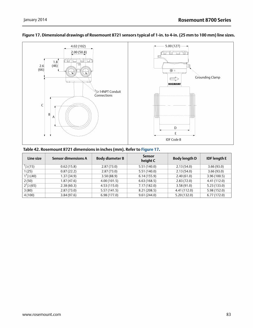
Rosemount 8700 SeriesJanuary 2014
Figure 17. Dimensional drawings of Rosemount 8721 sensors typical of 1-in. to 4-in. (25 mm to 100 mm) line sizes.
Table 42. Rosemount 8721 dimensions in inches (mm). Refer to Figure 17.
Line size Sensor dimensions A Body diameter B Sensor
height CBody length D IDF length E
1/2 (15) 0.62 (15.8) 2.87 (73.0) 5.51 (140.0) 2.13 (54.0) 3.66 (93.0)1 (25) 0.87 (22.2) 2.87 (73.0) 5.51 (140.0) 2.13 (54.0) 3.66 (93.0)11/2 (40) 1.37 (34.9) 3.50 (88.9) 6.14 (155.9) 2.40 (61.0) 3.96 (100.5)2 (50) 1.87 (47.6) 4.00 (101.5) 6.63 (168.5) 2.83 (72.0) 4.41 (112.0)21/2 (65) 2.38 (60.3) 4.53 (115.0) 7.17 (182.0) 3.58 (91.0) 5.23 (133.0)3 (80) 2.87 (73.0) 5.57 (141.5) 8.21 (208.5) 4.41 (112.0) 5.98 (152.0)4 (100) 3.84 (97.6) 6.98 (177.0) 9.61 (244.0) 5.20 (132.0) 6.77 (172.0)
4.02 (102)
2.00 (50.8)
1.8(46)2.6
(66)
C
BA
1/2-14NPT Conduit Connections
5.00 (127)
Grounding Clamp
D
E
IDF Code B
83www.rosemount.com

Rosemount 8700 Series January 2014
Figure 18. Dimensional drawings of Rosemount 8721 sensors typical of 1-in. to 4-in. (25 mm to100 mm) line sizes.
Table 43. Rosemount 8721 process connection lay length in inches (mm). Refer to Figure 18.
Line sizeWeld nipple
length FWeld nipple
sensor ID JWeld nipple sensor OD K
Tri clamp length G
HP optionlength G
DIN 11851 (metric &
imp) length G
DIN 11851 (imp) ID J
DIN 11851 (metric)
ID J1/2 (15) 5.61 (142) 0.62 (15.75) 0.75 (19.05) 8.31 (211) NA 8.33 (211) 0.62 (15.75) 0.79 (19.99)1 (25) 5.61 (142) 0.87 (22.2) 1.00 (25.65) 7.85 (199) 9.85 (250) 7.89 (200) 0.85 (21.52) 1.02 (26.01)11/2 (40) 5.92 (150) 1.37 (34.9) 1.51 (38.3) 8.17 (207) 9.91 (252) 8.53 (217) 1.37 (34.85) 1.50 (38.00)2 (50) 6.35 (161) 1.87 (47.6) 2.01 (51.05) 8.60 (218) 9.91 (252) 9.10 (231) 1.87 (47.60) 1.97 (50.01)21/2 (65) 7.18 (182) 2.37 (60.3) 2.51 (63.75) 9.43 (239) 9.91 (252) 10.33 (262) 2.37 (60.30) 2.60 (65.99)3 (80) 7.93 (201) 2.87 (73.0) 3.01 (76.45) 10.18 (258) 9.91 (252) 11.48 (291) 2.87 (72.97) 3.19 (81.03)4 (100) 9.46 (240) 3.84 (97.6) 4.01 (101.85) 11.70 (297) NA 13.72 (349) 3.84 (97.61) 3.94 (100.00)
F
JK
Weld Nipple Option
G
Note:Dimensions are in inches (millimeters)
Tri-Clamp
Line sizeDIN 11864-1length G
DIN 11864-2length g
SMS 1145 length G
Cherry-Burrell I-line length G
1/2 (15) NA NA NA NA1 (25) 8.98 (228.0) 8.86 (225.0) 6.87 (174) 7.17 (182)11/2 (40) 9.72 (247.0) 9.57 (243.0) 7.50 (190) 7.80 (198)2 (50) 10.16 (258.0) 10.00 (254.0) 7.93 (201) 8.42 (214)21/2 (65) 11.89 (302.0) 11.54 (293.0) 9.07 (230) 9.49 (241)3 (80) 12.95 (329.0) 12.44 (316.0) 9.82 (249) 10.37 (263)4 (100) 14.57 (370.0) 14.21 (361.0) 11.67 (296) 12.15 (309)
84 www.rosemount.com

Rosemount 8700 SeriesJanuary 2014
Figure 19.
Figure 20.
J
G
DIN 11851 (Imperial) Code D
J K
G
DIN 11851 (Metric) Code E
85www.rosemount.com

Rosemount 8700 Series January 2014
Figure 21.
Figure 22.
J
G
11864-1
J
G
11864-2
86 www.rosemount.com

Rosemount 8700 SeriesJanuary 2014
Figure 23.
Figure 24.
J
G
SMS1145 Code H
J
G
Cherry Burrell I-Line Code J
87www.rosemount.com

Rosemount 8700 Series January 2014
Figure 25. Rosemount 8714D Magnetic Flowmeter Simulator - calibration standard
2.69(68.3)
4.13(104.9)
7.19(182.6)
Rosemount 8732 Connector Type
Rosemount 8712 Connector Type
Note:The Rosemount 8714D is shipped with both the 8712 and 8732 Connector Types
3
88 www.rosemount.com

Rosemount 8700 SeriesJanuary 2014
89www.rosemount.com
Rosemount 8700 Series00813-0100-4727, Rev UE
Product Data SheetJanuary 2014
Emerson Process Management Rosemount Inc.8200 Market BoulevardChanhassen, MN 55317 USAwww.rosemount.comT (USA) +1 800 522 6277T (International) +1 (303) 527 5200F +1 (303) 530 8459
Emerson Process Management Flow B.V.Neonstraat 16718 WX EdeThe NetherlandsT +31 (0) 318 495555F +31 (0) 318 495556
Emerson Process Management Latin AmericaMultipark Office Center Turrubares Building, 3rd & 4th floorGuachipelin de Escazu, Costa RicaT+(506) [email protected]
Emerson Process Management Asia Pacific Pte Ltd1 Pandan CrescentSingapore 128461T +65 6777 8211F +65 6777 0947Email: [email protected]
Emerson FZEP.O. Box 17033Jebel Ali Free ZoneDubai UAET +971 4 811 8100F +971 4 886 [email protected]
Standard Terms and Conditions of Sale can be found at www.rosemount.com\terms_of_saleThe Emerson logo is a trade mark and service mark of Emerson Electric Co.Rosemount and the Rosemount logotype are registered trademarks of Rosemount Inc.PlantWeb is a registered trademark of one of the Emerson Process Management group of companies.HART and WirelessHART are registered trademarks of the HART Communication FoundationModbus is a trademark of Modicon, Inc.All other marks are the property of their respective owners.© 2013 Rosemount Inc. All rights reserved.
Related Documents