© Carrier Corporation 2014 Form 30HX-12PD Water-cooled and condenserless chillers designed from the ground up to meet the needs of today and tomorrow: • Unit fits through a standard door with no disassembly required • Chlorine-free HFC-134a refrigerant • Dual independent refrigerant circuits • Smooth compression using twin screw compressors • AHRI certified IPLV efficiencies as low as 0.51 kW/ton Features/Benefits Quality design and construction make the 30HXC (water-cooled) and 30HXA (condenserless) units the preferred chillers. Easy installation The 30HX chiller has a compact de- sign that fits through a standard door opening and requires minimal indoor space. The 30HX chiller is delivered as a complete package for easy installa- tion. There are no extra controls, clocks, starters, or other items to install. The 30HX unit also provides a sin- gle location electrical power entrance (using the accessory field-installed con- trol power transformer) and quick, easy piping (using Victaulic-type clamp-on couplings). The 30HX 208/230-v, 230-v, 460-v and 575-v 60 Hz units are designed in accordance with UL (Underwriters Laboratory, U.S.A.) and UL, Canada (Underwriters Laboratory, Canada) standards to minimize electri- cal inspection time. AquaForce ® 30HXA,HXC076-271 Condenserless and Water-Cooled Liquid Chillers with ComfortLink Controls 50/60 Hz 75 to 265 Nominal Tons (264 to 931 kW) Product Data ® SEISMICOMPLIANT * * Meets IBC 2006, ASCE-7-05, CBC 2007, and OSHPD seismic requirements.

Welcome message from author
This document is posted to help you gain knowledge. Please leave a comment to let me know what you think about it! Share it to your friends and learn new things together.
Transcript

© Carrier Corporation 2014 Form 30HX-12PD
Water-cooled and condenserless chillers designed from the ground up to meet the needs of today and tomorrow:• Unit fits through a standard door
with no disassembly required• Chlorine-free HFC-134a refrigerant• Dual independent refrigerant
circuits• Smooth compression using twin
screw compressors• AHRI certified IPLV efficiencies as
low as 0.51 kW/ton
Features/BenefitsQuality design and construction make the 30HXC (water-cooled) and 30HXA (condenserless) units the preferred chillers.Easy installationThe 30HX chiller has a compact de-sign that fits through a standard door opening and requires minimal indoor space. The 30HX chiller is delivered as a complete package for easy installa-tion. There are no extra controls, clocks, starters, or other items toinstall.
The 30HX unit also provides a sin-gle location electrical power entrance (using the accessory field-installed con-trol power transformer) and quick, easy piping (using Victaulic-type clamp-on couplings).
The 30HX 208/230-v, 230-v, 460-v and 575-v 60 Hz units are designed in accordance with UL (Underwriters Laboratory, U.S.A.) and UL, Canada (Underwriters Laboratory, Canada) standards to minimize electri-cal inspection time.
AquaForce®
30HXA,HXC076-271Condenserless and Water-Cooled
Liquid Chillers withComfortLink Controls
50/60 Hz75 to 265 Nominal Tons
(264 to 931 kW)
ProductData
®
Run Status
Service Test
Temperatures
Pressures
Setpoints
Inputs
Outputs
Configuration
Time Clock
Operating Modes
Alarms
ENTER
E S C
M O D EAlarm Status
TIMEEWTLWTSETP
1 2 . 5 85 4 . 6 F4 4 . 1 F4 4 . 0 F
N A V I G A T O R ™
Co m f o r t Li n k
SEISMICOMPLIANT** Meets IBC 2006, ASCE-7-05, CBC 2007, and OSHPD seismic requirements.
2
A quick start-up is assured once in-stallation is complete, since each 30HX unit is manufactured at an ISO (International Organization for Stan-dardization) 9001 listed manufacturing facility to guarantee quality. In addi-tion, all 30HXC units are tested under load at the factory to provide reliable start-up.NOTE: The 30HXC units shipped with optional nitrogen charge are tested for proper operation of the electrical com-ponents but are not run-tested at the factory.
Easy operationThe 30HX units have a quiet, low-vibration design featuring screwcompressors.
Efficiency levels of the 30HX units meet or exceed energy efficiency re-quirements of ASHRAE (American Society of Heating, Refrigerating and Air-Conditioning Engineers) 90.1 and CSA (Canadian Standards Association) for both full load and part load operation, thus saving on operating
costs through lower electrical costs. All 30HX units are also rated in accor-dance with AHRI (Air-Conditioning, Heating, and Refrigeration Institute, U.S.A.) standards. The 60 Hz 30HXC units are AHRI certified.
The 30HX controls are fully auto-matic. The leaving-fluid temperature is directly controlled to within .5° F (.3° C), and the entering-fluid tempera-ture is continuously monitored to detect load and flow changes.
Dual, independent refrigerant cir-cuits provide reliable, dependable cool-ing, and the 30HX units use medium-pressure HFC-134a refrigerant to minimize stress on the compressors and ensure a long life.
From a service standpoint, the 30HX units offer the followingfeatures:• Use of HFC-134a refrigerant,
which has no planned phase-outin its future
• Mechanically cleanable cooler andcondenser (30HXC units)
• Twin-screw compressors, whichrequire no routine service ormaintenance
• Easily accessed service informationincludes suction and dischargepressure and temperature usingstandard Navigator™ display module
• All parts are available through Totaline parts stores.
ComfortLink controlsComfortLink controls allow simple and easy interface to chillers with out-standing performance and value. The 30HX liquid chillers employ more than the latest advanced microprocessor controls, they utilize an expandable platform that can adjust as needs change. ComfortLink controls are used in diverse applications from stand-alone operation to remotely monitored and operated multi-chiller plants.
ComfortLink controls are fully com-municating, and are cable ready for connection to a Carrier Comfort Net-work® (CCN) system. Occupancy scheduling, temperature and pressure read-outs, optional sensors, and the ComfortLink scrolling marquee clear language display features provide a connection to a world of carefree comfort.
A BACnet* communication option is also available for the i-Vu® Open con-trol system or a BACnet building auto-mation system.
Features/Benefits (cont)
Run StatusService TestTemperaturesPressures
SetpointsInputs
OutputsConfigurationTime Clock
Operating ModesAlarms
ENTER
E S C
M O D EAlarm Status
TIMEEWTLWTSETP
1 2 . 5 85 4 . 6 F4 4 . 1 F4 4 . 0 F
N A V I G A T O R
Co m f o r t Li n k
NAVIGATOR MODULE IN DISPLAY MODE
DUAL INDEPENDENT REFRIGERANT CIRCUITS
TWIN-SCREW COMPRESSOR DESIGN
Run Status
Service Test
Temperatures
Pressures
Setpoints
Inputs
Outputs
Configuration
Time Clock
Operating Modes
Alarms
ENTER
E S C
M O D E Alarm Status
TIMEEWTLWTSETP
1 2 . 5 85 4 . 6 F4 4 . 1 F4 4 . 0 F
N A V I G A T O R ™
Co m f o r t Li n k
FITS THROUGH STANDARD DOORWAY
*Sponsored by ASHRAE (American Society ofHeating, Refrigerating, and Air-ConditioningEngineers).

3
Features/Benefits . . . . . . . . . . . . . . . . . . . . . . . . . . . . . . . . . . . . . . . . . . .1,2Model Number Nomenclature . . . . . . . . . . . . . . . . . . . . . . . . . . . . . . . . . . . 3AHRI Capacity Ratings . . . . . . . . . . . . . . . . . . . . . . . . . . . . . . . . . . . . . . .4,5Physical Data . . . . . . . . . . . . . . . . . . . . . . . . . . . . . . . . . . . . . . . . . . . . . .6-9Options and Accessories . . . . . . . . . . . . . . . . . . . . . . . . . . . . . . . . . . . .10,11Dimensions . . . . . . . . . . . . . . . . . . . . . . . . . . . . . . . . . . . . . . . . . . . . .12-21Application Data . . . . . . . . . . . . . . . . . . . . . . . . . . . . . . . . . . . . . . . . .22-29Selection Procedure . . . . . . . . . . . . . . . . . . . . . . . . . . . . . . . . . . . . . . . . . 30Performance Data . . . . . . . . . . . . . . . . . . . . . . . . . . . . . . . . . . . . . . . .31,32Typical Piping and Wiring . . . . . . . . . . . . . . . . . . . . . . . . . . . . . . . . . . .33,34Typical Control Wiring Schematic . . . . . . . . . . . . . . . . . . . . . . . . . . . . . . . 35Electrical Data . . . . . . . . . . . . . . . . . . . . . . . . . . . . . . . . . . . . . . . . . . .36-47Controls . . . . . . . . . . . . . . . . . . . . . . . . . . . . . . . . . . . . . . . . . . . . . . . . . 48Guide Specifications . . . . . . . . . . . . . . . . . . . . . . . . . . . . . . . . . . . . . . .49-51
Model number nomenclature
Table of contents
Quality AssuranceCertified to ISO 9001
30HXC 076 R - - 6 7 1 AAModel Description30HXA — CondenserlessLiquid Chiller
30HXC — Water-CooledLiquid Chiller
Nominal Size076 126 186086 136 206096 146 246106 161 261116 171 271
Refrigerant/Cooler OptionsL — Nitrogen with Minus 1-Pass CoolerM — R-134a with Minus 1-Pass CoolerN — Nitrogen with Standard CoolerP — R-134a with Plus 1-Pass CoolerQ — Nitrogen with Plus 1-Pass CoolerR — R-134a with Standard Cooler
Electrical Options - — Across The Line StartA — Non-Fused DisconnectY — Y-Delta StarterZ — Y-Delta and Non-Fused Disconnect
Packaging Code 1 = Standard Domestic 2 = Standard Export
Series
Voltage Code 1 — 575-3-60 2 — 380-3-60 4 — 230-3-60 5 — 280/230-3-60 6 — 460-3-60 8 — 230-3-50 9 — 380/415-3-50
Control Options - — E — U — W —
Factory-InstalledOption Codes*AA — 1BA — 2CA — 3KA — 1,2LA — 1,3TA — 2,3ZB — 1,2,3
StandardNavigator Display withEnergy ManagementBACnet Communication OptionEnergy Management Option and BACnet Communication Option
*Option Code Descriptions:1 = Minimum Load Control, 2 = Suction Service Valve,and 3 = Medium Temperature Brine.
SEISMICOMPLIANT** Meets IBC 2006, ASCE-7-05, CBC 2007, and OSHPD seismic requirements.

4
30HXC WATER-COOLED CHILLER AHRI RATINGS (60 Hz ONLY)
LEGEND
*Air-Conditioning, Heating, and Refrigeration Institute (U.S.A.).†IPLV shown is the lower of Sequence A or Sequence B unloading.
NOTES:1. Rated (60 Hz only) in accordance with AHRI Standard 550/590 at
standard rating conditions.2. Standard rating conditions are as follows:
Cooler Conditions:Leaving Water Temperature: 44 F (6.7 C)Flow: 2.4 gpm per ton (0.043 L/s per kW)
Condenser Conditions:Entering Water Temperature:85 F (29.4 C)Flow: 3.0 gpm per ton (0.054 L/s per kW)
Fouling Factor (Cooler):0.00010 hr x sq ft x F per Btuh (0.000018 m2 x K per W)
Fouling Factor (Condenser):0.00025 hr x sq ft x F per Btuh (0.000044 m2 x K per W)
3. IPLV is a single number part load efficiency value calculated usingthe efficiency values at 100%, 75%, 50%, and 25% of load whenthe chiller is operating at AHRI conditions.
4. All data in the above table was generated in Packaged ChillerBuilder version 3.47. Please refer to the most current version ofthe Packaged Chiller Builder for the most up-to-date data.
5. Contact Carrier for custom ratings.
UNIT SIZE
30HXC
CAPACITY INPUTPOWER
(kW)
COOLER FLOWCOOLER
PRESSURE DROP
CONDENSER FLOW
CONDENSER PRESSURE
DROPFULL-LOAD EFFICIENCY
(kW/Ton)
IPLV† (kW/Ton)
Tons Output kW GPM L/s Ft of
Water kPa GPM L/S Ft of Water kPa
076 75.4 265.2 53.7 181.0 11.4 14.5 43.2 226.2 14.3 8.9 26.6 0.712 0.512086 83.0 292.3 60.4 199.3 12.6 17.2 51.4 249.1 15.7 10.7 31.8 0.728 0.523096 94.0 330.5 67.0 225.5 14.2 17.0 50.7 281.9 17.8 10.9 32.7 0.714 0.513106 104.3 366.8 75.3 250.4 15.8 15.4 46.0 313.0 19.7 13.3 39.6 0.722 0.520116 113.5 399.3 83.2 272.3 17.2 13.3 39.8 340.4 21.5 17.0 50.6 0.733 0.530126 122.9 432.1 92.2 294.9 18.6 15.4 45.9 368.6 23.3 19.6 58.5 0.750 0.541136 136.5 479.9 97.0 327.5 20.7 14.6 43.7 409.4 25.8 18.5 55.1 0.711 0.527146 145.9 513.2 105.1 350.2 22.1 16.5 49.3 437.8 27.6 20.9 62.4 0.720 0.534161 156.6 550.6 111.6 375.7 23.7 13.7 40.9 469.7 29.6 21.3 63.6 0.713 0.521171 165.9 585.3 118.3 398.0 25.1 15.2 45.4 497.6 31.4 17.2 51.4 0.713 0.539186 177.1 623.1 126.7 425.1 26.8 13.9 41.5 531.4 33.5 19.5 58.1 0.715 0.561206 211.6 744.0 146.4 507.7 32.0 14.7 43.9 634.7 40.0 20.9 62.4 0.692 0.511246 248.6 874.1 172.4 596.5 37.6 16.2 48.3 745.7 47.0 21.9 65.2 0.693 0.525261 257.2 904.6 180.4 617.2 38.9 17.2 51.4 771.5 48.7 23.3 69.5 0.702 0.525271 267.4 940.3 189.5 641.7 40.5 18.5 55.1 802.2 50.6 25.1 74.7 0.709 0.527
IPLV — Integrated Part Load Value
60 Hz only
AHRI* capacity ratings

5
30HXA CONDENSERLESS CHILLER RATINGS (60 Hz ONLY)
NOTES:1. Rated (60 Hz only) in accordance with AHRI Standard 550/590 at
standard rating conditions.2. Standard rating conditions are as follows:
Cooler Conditions:Leaving Water Temperature: 44 F (6.7 C)Flow: 2.4 gpm per ton (0.043 L/s
per kW)Saturated Discharge Temperature: 125 F (52 C)Fouling Factor (Cooler):
0.00010 hr x sq ft x F per Btuh (0.000018 m2 x K per W)
3. Performance may vary depending on the remote condenser con-figuration and operating conditions.
4. All data in the above table was generated in Packaged ChillerBuilder version 3.47. Please refer to the most current version ofthe Packaged Chiller Builder for the most up-to-date data.
5. Contact Carrier for custom ratings.
09DK CONDENSER RATINGS (60 Hz ONLY)
NOTE: Rated in accordance with AHRI Standard 460 at standard ratingconditions.• 125 F (52 C) Condensing Temperature• R-134a Test Fluid• 15° F (8.3° C) Subcooling• 95 F (35 C) Entering Dry Bulb Temperature
UNIT SIZE
30HXA
CAPACITY INPUTPOWER
(kW)
COOLER FLOWCOOLER
PRESSURE DROP
FULL-LOAD EFFICIENCY
(kW/Ton)Tons Output
kW GPM L/s Ft of Water kPa
076 67.6 237.9 76.2 162.3 10.2 11.9 35.6 1.127086 76.0 267.2 84.5 182.4 11.5 14.7 43.8 1.111096 85.8 301.9 95.1 206.0 13.0 14.4 43.1 1.107106 97.0 340.9 106.9 232.7 14.7 13.5 40.3 1.103116 104.9 368.9 115.0 251.7 15.9 11.6 34.6 1.097126 113.9 400.6 125.4 273.5 17.2 13.4 40.1 1.100136 127.0 446.5 138.5 304.7 19.2 12.9 38.4 1.091146 137.2 482.5 150.0 329.2 20.8 14.8 44.1 1.094161 147.3 518.1 159.9 353.6 22.3 12.3 36.7 1.086171 159.1 559.3 173.9 381.8 24.1 14.1 42.1 1.093186 174.2 612.8 192.7 418.2 26.4 13.5 40.3 1.106206 198.5 698.2 216.4 476.4 30.1 13.1 39.2 1.090246 231.8 815.4 252.4 556.5 35.1 14.3 42.7 1.089261 244.1 858.6 267.6 585.9 37.0 15.7 46.8 1.096271 257.9 907.0 283.9 619.0 39.1 17.3 51.6 1.101
UNIT SIZE 09DK
HP TONS BTUH BTUH/HP
044 3.0 54.6 655,200 218,400054 4.0 64.1 769,200 192,300064 4.0 76.6 919,200 229,800074 6.0 93.0 1,116,000 186,000084 6.0 100.9 1,210,800 201,800094 6.0 113.3 1,359,600 226,600

6
ENGLISH
LEGEND *Charges listed are for 30HXC units. The 30HXA units are shipped witha holding charge only. To determine the refrigerant charge require-ments for 30HXA units, see the 30HXA Estimated System RefrigerantCharge table in the Refrigerant Charge section on page 29.
†For 30HXC,HXA units utilizing brine, the unit may require more refrig-erant than what is supplied. Additional refrigerant must be fieldsupplied.
**Only on units with factory-installed suction service valves.
UNIT SIZE 30HX 076 086 096 106 116 126 136 146UNIT OPERATING WEIGHT (lb)
Water-Cooled (HXC) 5700 5723 5855 6177 6415 6465 6688 6718Condenserless (HXA) 4717 4744 4835 5151 5163 5205 5309 5333
COMPRESSORS Semi-Hermetic, Twin ScrewQuantity 2 2 2 2 2 2 2 2Nominal Capacity per Compressor (tons) 39/39 46/39 56/39 66/39 66/46 66/56 80/56 80/66Economizer No No No No No No No NoNo. Capacity Steps
30HXC Unit 6 6 6 6 6 6 6 630HXA Unit (maximum on 30HXC unit with factory-installed option) 8 8 8 8 8 8 8 8
Minimum Step Capacity (%)30HXC Unit 20 20 20 20 20 20 20 2030HXA Unit (30HXC unit with factory-installed option) 10 10 10 10 10 10 10 10
REFRIGERANT (HXC) R-134aCharge* (lb) Circuit A/Circuit B† 75/75 76/75 94/70 110/70 112/89 112/89 124/89 119/100
COOLER Shell and Tube with Enhanced Copper TubesPart No. 10HX400- 401 401 402 408 406 406 405 405Net Fluid Volume (gal) 17.0 17.0 19.0 22.6 21.4 21.4 24.0 24.0Maximum Refrigerant Pressure (psig) 220 220 220 220 220 220 220 220Maximum Water-Side Pressure (psig) 300 300 300 300 300 300 300 300Water Connections
Inlet and Outlet (in.) (Std Pass) 4 4 4 5 5 5 5 5Drain (in. NPT) (Std Pass) 3/8 3/8 3/8 3/8 3/8 3/8 3/8 3/8
Relief ValveConnection (in. NPTF) 3/4 3/4 3/4 3/4 3/4 3/4 3/4 3/4Flow Capacity (lb air/min) 31.7 31.7 31.7 31.7 31.7 31.7 31.7 31.7
Relief Setting (psig) 220 220 220 220 220 220 220 220Standard Number of Passes 3 3 3 3 2 2 2 2
OIL SEPARATOR (HXA)Part No. 09RX400- 217 217 216 216 215 215 215 215Maximum Refrigerant Pressure (psig) 320 320 320 320 320 320 320 320Refrigerant Connections (in.)
Discharge Circuit A/Circuit B 21/8/21/8 21/8/21/8 21/8/21/8 21/8/21/8 21/8/21/8 21/8/21/8 21/8/21/8 21/8/21/8Liquid Circuit A/Circuit B 11/8/11/8 11/8/11/8 11/8/11/8 11/8/11/8 11/8/11/8 11/8/11/8 11/8/11/8 11/8/11/8
Relief ValveConnection (in. SAE Flare) 5/8 5/8 5/8 5/8 5/8 5/8 5/8 5/8Flow Capacity (lb air/min) 21.6 21.6 21.6 21.6 21.6 21.6 21.6 21.6
Relief Setting (psig) 320 320 320 320 320 320 320 320CONDENSER (HXC) Shell and Tube with Enhanced Copper Tubes
Part No. 09RX400- 257 257 258 258 259 259 260 260Net Fluid Volume (gal) 16.8 16.8 18.3 18.3 23.9 23.9 27.5 27.5Maximum Refrigerant Pressure (psig) 220 220 220 220 220 220 220 220Maximum Water-Side Pressure (psig) 300 300 300 300 300 300 300 300Water Connections (in.) Victaulic Type Connection
Inlet and Outlet (Std Pass) 5 5 5 5 5 5 5 5Drain (NPT) (Std Pass) 3/8 3/8 3/8 3/8 3/8 3/8 3/8 3/8
Relief ValveConnection (in. NPTF) 3/4 3/4 3/4 3/4 3/4 3/4 3/4 3/4Flow Capacity (lb air/min) 31.7 31.7 31.7 31.7 31.7 31.7 31.7 31.7
Relief Setting (psig) 220 220 220 220 220 220 220 220Standard Number of Passes 2 2 2 2 2 2 2 2
DISCHARGE LINE**Relief Valve
Connection (in. SAE Flare) 3/8 3/8 3/8 3/8 3/8 3/8 3/8 3/8Flow Capacity (lb air/min) 6.3 6.3 6.3 6.3 6.3 6.3 6.3 6.3Setting (psig) 350 350 350 350 350 350 350 350
NPTF — National Pipe Thread FemaleSAE — Society of Automotive Engineers
Physical data

7
ENGLISH (cont)
LEGEND *Charges listed are for 30HXC units. The 30HXA units are shipped witha holding charge only. To determine the refrigerant charge require-ments for 30HXA units, see the 30HXA Estimated System RefrigerantCharge table in the Refrigerant Charge section on page 29.
†For 30HXC,HXA units utilizing brine, the unit may require more refrig-erant than what is supplied. Additional refrigerant must be fieldsupplied.
**Only on units with factory-installed suction service valves.
UNIT SIZE 30HX 161 171 186 206 246 261 271UNIT OPERATING WEIGHT (lb)
Water-Cooled (HXC) 7452 7660 7854 10,581 10,969 10,992 11,029Condenserless (HXA) 5752 5777 5946 7,485 7,621 7,621 7,621
COMPRESSORS Semi-Hermetic, Twin ScrewQuantity 2 2 2 3 3 3 3Nominal Capacity per Compressor (tons) 80/56 66/80 80/80 66/39/80 80/56/80 80/66/80 80/80/80Economizer Yes Yes Yes Yes Yes Yes YesNo. Capacity Steps
30HXC Unit 6 6 6 8 8 8 830HXA Unit (maximum on 30HXC unit with factory-installed option) 8 8 8 11 11 11 11
Minimum Step Capacity (%)30HXC Unit 20 20 20 13 13 13 1330HXA Unit (30HXC unit with factory-installed option) 10 10 10 7 7 7 7
REFRIGERANT (HXC) R-134aCharge* (lb) Circuit A/Circuit B† 157/110 119/140 135/135 200/135 220/135 220/135 220/135
COOLER TYPE Shell and Tube with Enhanced Copper TubesPart No. 10HX400- 601 611 621 631 632 632 632Net Fluid Volume (gal) 28.5 28.5 33.4 43.1 47.2 47.2 47.2Maximum Refrigerant Pressure (psig) 220 220 220 220 220 220 220Maximum Water-Side Pressure (psig) 300 300 300 300 300 300 300Water Connections
Inlet and Outlet (in.) (Std Pass) 5 5 5 6 6 6 6Drain (NPT) (Std Pass) 3/8 3/8 3/8 3/8 3/8 3/8 3/8
Relief ValveConnection (in. NPTF) 3/4 3/4 3/4 3/4 3/4 3/4 3/4Flow Capacity (lb air/min) 31.7 31.7 31.7 31.7 31.7 31.7 31.7
Relief Setting (psig) 220 220 220 220 220 220 220Standard Number of Passes 2 2 2 2 2 2 2
OIL SEPARATOR (HXA)Part No. 09RX400- 215 214 214 213 213 213 213Maximum Refrigerant Pressure (psig) 320 320 320 320 320 320 320Refrigerant Connections (in.)
Discharge Circuit A/Circuit B 21/8/21/8 21/8/21/8 21/8/21/8 (2) 21/8/21/8 (2) 21/8/21/8 (2) 21/8/21/8 (2) 21/8/21/8Liquid Circuit A/Circuit B 13/8/13/8 13/8/13/8 13/8/13/8 15/8/13/8 15/8/13/8 15/8/13/8 15/8/13/8
Relief ValveConnection (in. SAE Flare) 5/8 5/8 5/8 5/8 5/8 5/8 5/8Flow Capacity (lb air/min) 21.6 21.6 21.6 21.6 21.6 21.6 21.6
Relief Setting (psig) 320 320 320 320 320 320 320CONDENSER (HXC) Shell and Tube with Enhanced Copper Tubes
Part No. 09RX400- 261 262 262 263 264 264 264Net Fluid Volume (gal) 30.6 37.6 37.6 47.6 55.1 55.1 55.1Maximum Refrigerant Pressure (psig) 220 220 220 220 220 220 220Maximum Water-Side Pressure (psig) 300 300 300 300 300 300 300Water Connections (in.) Victaulic Type Connection
Inlet and Outlet (Std Pass) 6 6 6 8 8 8 8Drain (NPT) (Std Pass) 3/8 3/8 3/8 3/8 3/8 3/8 3/8
Relief ValveConnection (in. NPTF) 3/4 3/4 3/4 3/4 3/4 3/4 3/4Flow Capacity (lb air/min) 31.7 31.7 31.7 31.7 31.7 31.7 31.7
Relief Setting (psig) 220 220 220 220 220 220 220Standard Number of Passes 2 2 2 2 2 2 2
DISCHARGE LINE**Relief Valve
Connection (in. SAE Flare) 3/8 3/8 3/8 3/8 3/8 3/8 3/8Flow Capacity (lb air/min) 6.3 6.3 6.3 6.3 6.3 6.3 6.3Setting (psig) 350 350 350 350 350 350 350
NPTF — National Pipe Thread FemaleSAE — Society of Automotive Engineers
8
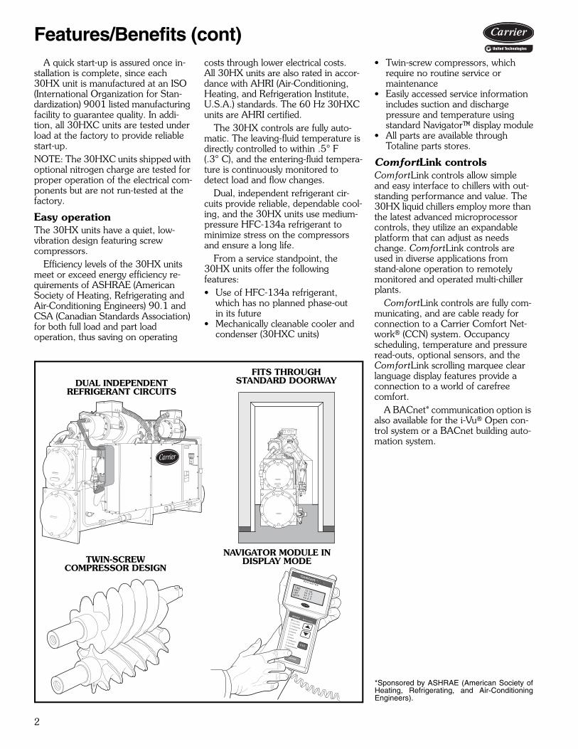
SI
LEGEND *Charges listed are for 30HXC units. The 30HXA units are shipped witha holding charge only. To determine the refrigerant charge require-ments for 30HXA units, see the 30HXA Estimated System RefrigerantCharge table in the Refrigerant Charge section on page 29.
†For 30HXC,HXA units utilizing brine, the unit may require more refrig-erant than what is supplied. Additional refrigerant must be fieldsupplied.
**Only on units with factory-installed suction service valves.
UNIT SIZE 30HX 076 086 096 106 116 126 136 146UNIT OPERATING WEIGHT (kg)
Water-Cooled (HXC) 2586 2597 2657 2803 2911 2933 3034 3048Condenserless (HXA) 2140 2152 2194 2337 2342 2362 2408 2420
COMPRESSORS Semi-Hermetic, Twin ScrewQuantity 2 2 2 2 2 2 2 2Nominal Capacity per Compressor (kW) 137/137 162/137 197/137 232/137 232/137 232/197 281/197 281/232Economizer No No No No No No No NoNo. Capacity Steps
30HXC Unit 6 6 6 6 6 6 6 630HXA Unit (maximum on 30HXC unit with factory-installed option) 8 8 8 8 8 8 8 8
Minimum Step Capacity (%) 30HXC Unit 20 20 20 20 20 20 20 2030HXA Unit (30HXC unit with factory-installed option) 10 10 10 10 10 10 10 10
REFRIGERANT (HXC) R-134aCharge* (kg) Circuit A/Circuit B† 34.1/34.1 34.5/34.1 42.7/31.8 49.9/31.8 50.8/40.4 50.8/40.4 56.3/40.4 54.0/45.4
COOLER Shell and Tube with Enhanced Copper TubesPart No. 10HX400- 401 401 402 408 406 406 405 405Net Fluid Volume (L) 64.3 64.3 71.9 85.5 81.0 81.0 90.8 90.8Maximum Refrigerant Pressure (kPa) 1517 1517 1517 1517 1517 1517 1517 1517Maximum Water-Side Pressure (kPa) 2068 2068 2068 2068 2068 2068 2068 2068Water Connections
Inlet and Outlet (in.) (Std Pass) 4 4 4 5 5 5 5 5Drain (NPT) (Std Pass) 3/8 3/8 3/8 3/8 3/8 3/8 3/8 3/8
Relief ValveConnection (in. NPTF) 3/4 3/4 3/4 3/4 3/4 3/4 3/4 3/4Flow Capacity (kg air/min) 14.38 14.38 14.38 14.38 14.38 14.38 14.38 14.38
Relief Setting (kPa) 1517 1517 1517 1517 1517 1517 1517 1517Standard Number of Passes 3 3 3 3 2 2 2 2
OIL SEPARATOR (HXA)Part No. 09RX400- 217 217 216 216 215 215 215 215Maximum Refrigerant Pressure (kPa) 2205 2205 2205 2205 2205 2205 2205 2205Refrigerant Connections (in.)
Discharge Circuit A/Circuit B 21/8/21/8 21/8/21/8 21/8/21/8 21/8/21/8 21/8/21/8 21/8/21/8 21/8/21/8 21/8/21/8Liquid Circuit A/Circuit B 11/8/21/8 11/8/11/8 11/8/11/8 11/8/11/8 11/8/11/8 11/8/11/8 11/8/11/8 11/8/11/8
Relief ValveConnection (in. SAE Flare) 5/8 5/8 5/8 5/8 5/8 5/8 5/8 5/8Flow Capacity (kg air/min) 9.80 9.80 9.80 9.80 9.80 9.80 9.80 9.80
Relief Setting (kPa) 2206 2206 2206 2206 2206 2206 2206 2206CONDENSER (HXC) Shell and Tube with Enhanced Copper Tubes
Part No. 09RX400- 257 257 258 258 259 259 260 260Net Fluid Volume (L) 63.6 63.6 69.3 69.3 90.5 90.5 104.1 104.1Maximum Refrigerant Pressure (kPa) 1517 1517 1517 1517 1517 1517 1517 1517Maximum Water-Side Pressure (kPa) 2068 2068 2068 2068 2068 2068 2068 2068Water Connections (in.) Victaulic Type Connection
Inlet and Outlet (Std Pass) 5 5 5 5 5 5 5 5Drain (NPT) (Std Pass) 3/8 3/8 3/8 3/8 3/8 3/8 3/8 3/8
Relief ValveConnection (in. NPTF) 3/4 3/4 3/4 3/4 3/4 3/4 3/4 3/4Flow Capacity (kg air/min) 14.38 14.38 14.38 14.38 14.38 14.38 14.38 14.38
Relief Setting (kPa) 1517 1517 1517 1517 1517 1517 1517 1517Standard Number of Passes 2 2 2 2 2 2 2 2
DISCHARGE LINE**Relief Valve
Connection (in. SAE Flare) 3/8 3/8 3/8 3/8 3/8 3/8 3/8 3/8Flow Capacity (kg air/min) 2.9 2.9 2.9 2.9 2.9 2.9 2.9 2.9Relief Pressure (kPa) 2413 2413 2413 2413 2413 2413 2413 2413
NPTF — National Pipe Thread FemaleSAE — Society of Automotive Engineers
Physical data (cont)

9
SI (cont)
LEGEND *Charges listed are for 30HXC units. The 30HXA units are shipped witha holding charge only. To determine the refrigerant charge require-ments for 30HXA units, see the 30HXA Estimated System RefrigerantCharge table in the Refrigerant Charge section on page 29.
†For 30HXC,HXA units utilizing brine, the unit may require more refrig-erant than what is supplied. Additional refrigerant must be fieldsupplied.
**Only on units with factory-installed suction service valves.
UNIT SIZE 30HX 161 171 186 206 246 261 271UNIT OPERATING WEIGHT (kg)
Water-Cooled (HXC) 3381 3475 3564 4799 4976 4986 5003Condenserless (HXA) 2610 2621 2698 3395 3457 3457 3457
COMPRESSORS Semi-Hermetic, Twin ScrewQuantity 2 2 2 3 3 3 3Nominal Capacity per Compressor (kW) 281/197 232/281 281/281 232/137/281 281/197/281 281/232/281 281/281/281Economizer Yes Yes Yes Yes Yes Yes YesNo. Capacity Steps
30HXC Unit 6 6 6 8 8 8 830HXA Unit (maximum on 30HXC unit with factory-installed option) 8 8 8 11 11 11 11
Minimum Step Capacity (%)30HXC Unit 20 20 20 13 13 13 1330HXA Unit (30HXC unit with factory-installed option) 10 10 10 7 7 7 7
REFRIGERANT (HXC) R-134aCharge* (kg) Circuit A/Circuit B† 71.3/49.9 54.0/63.6 61.3/61.3 90.8/61.3 99.9/61.3 99.9/61.3 99.9/61.3
COOLER Shell and Tube with Enhanced Copper TubesPart No. 10HX400- 601 611 621 631 632 632 632Net Fluid Volume (L) 107.9 107.9 126.4 163.2 178.7 178.8 178.7Maximum Refrigerant Pressure (kPa) 1517 1517 1517 1517 1517 1517 1517Maximum Water-Side Pressure (kPa) 2068 2068 2068 2068 2068 2068 2068Water Connections
Inlet and Outlet (in.) (Std Pass) 5 5 5 6 6 6 6Drain (NPT) (Std Pass) 3/8 3/8 3/8 3/8 3/8 3/8 3/8
Relief ValveConnection (in. NPTF) 3/4 3/4 3/4 3/4 3/4 3/4 3/4Flow Capacity (kg air/min) 14.28 14.38 14.38 14.38 14.38 14.38 14.38
Relief Setting (kPa) 1517 1517 1517 1517 1517 1517 1517Standard Number of Passes 2 2 2 2 2 2 2
OIL SEPARATOR (HXA)Part No. 09RX400- 215 214 214 213 213 213 213Maximum Refrigerant Pressure (kPa) 2205 2205 2205 2205 2205 2205 2205Refrigerant Connections (in.)
Discharge Circuit A/Circuit B 21/8/21/8 21/8/21/8 21/8/21/8 (2) 21/8/21/8 (2) 21/8/21/8 (2) 21/8/21/8 (2) 21/8/21/8Liquid Circuit A/Circuit B 13/8/13/8 13/8/13/8 13/8/13/8 15/8/13/8 15/8/13/8 15/8/13/8 15/8/13/8
Relief ValveConnection (in. SAE Flare) 5/8 5/8 5/8 5/8 5/8 5/8 5/8Flow Capacity (kg air/min) 9.80 9.80 9.80 9.80 9.80 9.80 9.80
Relief Setting (kPa) 2206 2206 2206 2206 2206 2206 2206CONDENSER (HXC) Shell and Tube with Enhanced Copper Tubes
Part No. 09RX400- 261 262 262 263 264 264 264Net Fluid Volume (L) 115.8 142.3 142.3 177.9 208.6 208.6 208.6Maximum Refrigerant Pressure (kPa) 1517 1517 1517 1517 1517 1517 1517Maximum Water-Side Pressure (kPa) 2068 2068 2068 2068 2068 2068 2068Water Connections (in.) Victaulic Type Connection
Inlet and Outlet (Std Pass) 6 6 6 8 8 8 8Drain (NPT) (Std Pass) 3/8 3/8 3/8 3/8 3/8 3/8 3/8
Relief ValveConnection (in. NPTF) 3/4 3/4 3/4 3/4 3/4 3/4 3/4Flow Capacity (kg air/min) 14.38 14.38 14.38 14.38 14.38 14.38 14.38
Relief Setting (kPa) 1517 1517 1517 1517 1517 1517 1517Standard Number of Passes 2 2 2 2 2 2 2
DISCHARGE LINE**Relief Valve
Connection (in. SAE Flare) 3/8 3/8 3/8 3/8 3/8 3/8 3/8Flow Capacity (kg air/min) 2.9 2.9 2.9 2.9 2.9 2.9 2.9Relief Pressure (kPa) 2413 2413 2413 2413 2413 2413 2413
NPTF — National Pipe Thread FemaleSAE — Society of Automotive Engineers

10
Factory-installed optionsWye-delta start — Generally, Wye-delta start is notrequired when using multiple compressors since the start-ing current is generally less than with one larger compres-sor using Wye-delta start. Wye-delta start is standard on208/230 v, 60 Hz, 230 v, 60 Hz, and 230 v, 50 Hz units.It is available as a factory-installed option for all other unitvoltages.Brine — The brine option permits supply liquid tempera-tures to be set below 40 F (4.4 C). Refrigeration circuitcomponents, such as the expansion device, are modified atthe factory to correct for the lower refrigeration flow rates.Special installation requirements apply to brine units. SeeCooler and Water-Cooled Condenser Freeze Protectionsection, page 24.Minus-one-pass cooler — This factory-installed optionreduces pressure drop for high flow applications and/orprovides same end inlet and outlet for 076-106 sizes, oropposite end inlet and outlet on 116-271 sizes.Plus-one-pass cooler — This factory-installed optionimproves low temperature brine performance. See the30HX electronic catalog for performance data.Minimum load control — This option allows additionalcapacity reduction for unit operation below the minimumstep of unloading (down to 10% of full load capacity).Minimum load control is also available as a field-installedaccessory.Suction service valves — Standard refrigerant dis-charge isolation and liquid valves enable service personnelto store the refrigerant charge in the cooler or condenserduring servicing. This factory-installed option allows furtherisolation of the compressor from the cooler vessel.Energy management module (EMM) — The EMM isused for 4 to 20 mA leaving fluid temperature reset, cool-ing point reset, 4 to 20 mA demand limit and two-stepdemand limit. Temperature reset lets the unit reset theleaving fluid temperature to a higher temperature duringlow load conditions. Temperature reset can also be accom-plished based on return fluid, outdoor air or space temper-ature. (The EMM option is not required when usingentering-water, outdoor-air, or space temperature for
temperature reset. These types of reset are available withthe main board. However, an accessory thermistor isrequired for outdoor air and/or space temperature reset.)Demand limiting allows the unit capacity to be limited dur-ing periods of peak energy usage. Demand limit requiresan external 4 to 20 mA signal or a 2-step remote pair ofdry contacts. Both the 4 to 20 mA and 2-step demandlimit percentage values are adjustable. EMM is also avail-able as a field-installed accessory.Nitrogen holding charge — The 30HXC units can beshipped with either the standard HFC-134a refrigerantcharge or an optional nitrogen charge. The 30HXA unitsare always shipped with a nitrogen holding charge.BACnet communication option — This option pro-vides factory-installed communication capability with aBACnet MS/TP network. Allows integration with i-Vu®
Open control system or a BACnet building automationsystem.
Field-installed accessoriesControl power transformer — The transformer is sizedto supply the needs of the control circuit, sourcing powerfrom the main unit power connection.Minimum load control — This accessory allows addi-tional capacity reduction for unit operation below the mini-mum step of unloading (down to 10% of full load capacity).Minimum load control is also available as a factory-installedoption.Sound reduction enclosure — This kit contains asound enclosure that covers the entire unit to reduce soundlevels.Vibration isolation — Neoprene isolators are fieldinstalled to reduce vibration transmission from the com-pressor through the floor and into the conditioned space.Temperature reset sensor — This accessory sensorprovides temperature reset capability from either the occu-pied space or outdoor-air temperature.NOTE: Temperature reset capability using return tempera-ture is standard.Chillervisor System Manager III — This control can beused to regulate up to eight 30HXA or 30HXC chillers.
ITEMFACTORY-
INSTALLED OPTION
FIELD-INSTALLED
ACCESSORYWye-Delta Start XBrine XMinus-One-Pass Cooler Head XPlus-One-Pass Cooler Head XControl Power Transformer XMinimum Load Control X XSound Reduction Enclosure XVibration Isolation XTemperature Reset Sensor XChillervisor System Manager III XCooler Head Insulation XSuction Service Valves XEnergy Management Module X XNitrogen Holding Charge (30HXC) XBACnet Communication X
Options and accessories
11
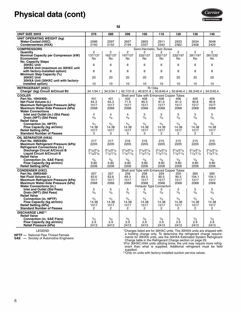
Cooler head insulation — This accessory is designedwith flexible, 3/4 in. (19 mm) PVC foam (closed-cell) toinsulate the cooler heads to minimize heat loss and headsweating.Energy management module (EMM) — The EMM isused for 4 to 20 mA leaving fluid temperature reset, cool-ing point reset, 4 to 20 mA demand limit and two-stepdemand limit. Temperature reset lets the unit reset theleaving fluid temperature to a higher temperature duringlow load conditions. Temperature reset can also be accom-plished based on return fluid, outdoor air or spacetemperature. (The EMM option is not required when using
entering-water, outdoor-air, or space temperature for tem-perature reset. These types of reset are available with themain board. However, an accessory thermistor is requiredfor outdoor air and/or space temperature reset.) Demandlimiting allows the unit capacity to be limited during periodsof peak energy usage. Demand limit requires an external 4to 20 mA signal or a 2-step remote pair of dry contacts.Both the 4 to 20 mA and 2-step demand limit percentagevalues are adjustable. EMM is also available as a factory-installed option.Consult factory for other available options notlisted here.

12
30H
XC
076-1
06
NO
TE
S:
1.O
pera
ting
wei
ght i
nclu
des
wei
ght o
f wat
er a
nd r
efrig
eran
t.
2.D
enot
es c
ente
r of
gra
vity
.
3.D
imen
sion
s ar
e in
inch
es (
mm
).4.
Rec
omm
ende
d se
rvic
e cl
eara
nce
arou
nd m
achi
ne is
36
in. (
914.
4 m
m).
5.V
icta
ulic
no
zzle
s ar
e st
anda
rd
on
all
mod
els.
F
low
sw
itch
fact
ory
inst
alle
d in
coo
ler
inle
t Vic
taul
ic n
ozzl
e.
UN
ITO
PE
RA
TIN
GW
EIG
HT
- lb
(kg
)B
CE
LW
GT
DIS
TR
IBU
TIO
N A
T E
AC
HM
TG
PL
AT
E -
lb (
kg)
12
34
56
30H
XC
076
5700
(258
6)45
.87
(116
5)45
.87
(116
5)32
.50
(826
)65
.22
(165
7)73
8(3
35)
943
(428
)59
5(2
70)
1110
(503
)14
18(6
43)
896
(406
)
30H
XC
086
5723
(259
7)45
.87
(116
5)45
.87
(116
5)32
.50
(826
)65
.22
(165
7)73
8(3
35)
947
(430
)59
7(2
71)
1112
(504
)14
27(6
47)
902
(409
)
30H
XC
096
5855
(265
7)54
.12
(137
5)37
.63
(956
)32
.50
(826
)65
.22
(165
7)68
6(3
11)
968
(439
)69
3(3
14)
1027
(466
)14
47(6
56)
1034
(469
)
30H
XC
106
6177
(280
3)54
.12
(137
5)37
.63
(956
)33
.50
(851
)67
.22
(170
7)73
0(3
31)
1028
(466
)74
4(3
37)
1073
(487
)15
10(6
85)
1092
(495
)
a30-4647.eps
Dimensions

13
30H
XC
116-1
46
UN
ITO
PE
RA
TIN
GW
EIG
HT
- lb
(kg
)
WG
T D
IST
RIB
UT
ION
AT
EA
CH
MT
G P
LA
TE
- lb
(kg
)1
23
45
6
30H
XC
116
6415
(291
1)72
8(3
30)
1114
(505
)77
7(3
52)
1053
(478
)16
15(7
33)
1127
(511
)
30H
XC
126
6465
(293
3)73
8(3
35)
1127
(511
)78
0(3
54)
1061
(481
)16
28(7
38)
1131
(513
)
30H
XC
136
6688
(303
4)75
8(3
44)
1176
(533
)81
1(3
68)
1083
(491
)16
89(7
66)
1171
(531
)
30H
XC
146
6718
(304
8)76
3(3
46)
1182
(536
)81
5(3
70)
1085
(492
)16
97(7
70)
1172
(532
)
NO
TE
S:
1.O
pera
ting
wei
ght i
nclu
des
wei
ght o
f wat
er a
nd r
efri
gera
nt.
2.D
enot
es c
ente
r of
gra
vity
.
3.D
imen
sion
s ar
e in
inch
es (
mm
).4.
Rec
omm
ende
d se
rvic
e cl
eara
nce
arou
nd m
achi
ne
is 3
6 in
.(9
14.4
mm
).5.
Vic
taul
ic n
ozzl
es a
re s
tand
ard
on a
ll m
odel
s. F
low
sw
itch
fac-
tory
inst
alle
d in
coo
ler
inle
t Vic
taul
ic n
ozzl
e.
a30-4648

14
30H
XC
161-1
86
NO
TE
S:
1.O
pera
ting
wei
ght
incl
udes
wei
ght
of w
ater
and
ref
riger
ant.
2.D
enot
es c
ente
r of
gra
vity
.
3.D
imen
sion
s ar
e in
inch
es (
mm
).4.
Rec
omm
ende
d se
rvic
e cl
eara
nce
arou
nd
mac
hine
is
36
in
.(9
14.4
mm
).5.
Vic
taul
ic n
ozzl
es a
re s
tand
ard
onal
l m
odel
s.
Flo
w
switc
h fa
ctor
yin
stal
led
in c
oole
r in
let
Vic
taul
icno
zzle
.
UN
ITO
PE
RA
TIN
GW
EIG
HT
-lb
(kg
)B
CW
GT
DIS
TR
IBU
TIO
N A
T E
AC
HM
TG
PL
AT
E -
lb (
kg)
12
34
56
30H
XC
161
7452
(338
1)72
.12
(183
2)50
.63
(128
6)81
7(3
71)
1272
(577
)90
8(4
12)
1219
(553
)18
90(8
57)
1346
(610
)
30H
XC
171
7660
(347
5)61
.37
(155
9)61
.37
(155
9)93
6(4
25)
1318
(598
)84
0(3
81)
1379
(626
)19
46(8
83)
1241
(563
)
30H
XC
186
7854
(356
4)61
.37
(155
9)61
.37
(155
9)96
2(4
36)
1361
(617
)86
0(3
90)
1410
(640
)19
96(9
05)
1265
(574
)
a30-4649
Dimensions (cont)

15
30H
XC
206-2
71
NO
TE
S:
1.O
pera
ting
wei
ght i
nclu
des
wei
ght o
f wat
er a
nd r
efrig
eran
t.
2.D
enot
es c
ente
r of
gra
vity
.
3.D
imen
sion
s ar
e in
inch
es (
mm
).4.
Rec
omm
ende
d se
rvic
e cl
eara
nce
arou
nd m
achi
ne is
36
in. (
914.
4 m
m).
5.V
icta
ulic
noz
zles
are
sta
ndar
d on
all
mod
els.
Flo
w s
witc
h fa
ctor
y in
stal
led
in c
oole
r in
let V
icta
ulic
noz
zle.
UN
ITO
PE
RA
TIN
GW
EIG
HT
- lb
(kg
)A
WG
T D
IST
RIB
UT
ION
AT
EA
CH
MT
G P
LA
TE
- lb
(kg
)1
23
45
6
30H
XC
206
1058
1(4
799)
33.8
8(8
60)
948
(430
)24
06(1
091)
1243
(564
)12
01(5
45)
3133
(142
1)16
50(7
48)
30H
XC
246
1096
9(4
976)
34.3
8(8
73)
985
(447
)25
15(1
141)
1306
(592
)11
54(5
23)
3276
(148
6)17
33(7
86)
30H
XC
261
1099
2(4
986)
34.3
8(8
73)
985
(447
)25
20(1
143)
1311
(595
)11
54(5
23)
3283
(148
9)17
39(7
89)
30H
XC
271
1102
9(5
003)
34.3
8(8
73)
985
(447
)25
29(1
147)
1318
(598
)11
54(5
23)
3294
(149
4)17
49(7
93)

16
NO
TE
S:
1.O
pera
ting
wei
ght
incl
udes
wei
ght
of w
ater
and
refr
iger
ant.
2. D
enot
es c
ente
r of
gra
vity
.
3.D
imen
sion
s ar
e in
inch
es (
mm
).4.
Rec
omm
ende
d se
rvic
e cl
eara
nce
arou
ndm
achi
ne is
36
in. (
914.
4 m
m).
5.V
icta
ulic
noz
zles
are
sta
ndar
d on
all
mod
els.
Flo
w s
witc
h fa
ctor
y in
stal
led
in c
oole
r in
let V
ic-
taul
ic n
ozzl
e.
UN
ITO
PE
RA
TIN
GW
EIG
HT
- lb
(kg
)B
CE
LP
RS
WG
T D
IST
RIB
UT
ION
AT
EA
CH
MT
G P
LA
TE
- lb
(kg
)1
23
45
6
30H
XA
076
4717
(214
0)45
.87
(116
5)45
.87
(116
5)32
.50
(826
)65
.22
(165
7)3.
88(9
9)41
.25
(104
8)46
.25
(117
5)55
5(2
52)
793
(360
)41
8(1
90)
926
(420
)13
26(6
01)
699
(317
)
30H
XA
086
4744
(215
2)45
.87
(116
5)45
.87
(116
5)32
.50
(826
)65
.22
(165
7)3.
88(9
9)41
.25
(104
8)46
.25
(117
5)55
5(2
52)
798
(362
)41
8(1
90)
928
(421
)13
40(6
08)
705
(320
)
30H
XA
096
4835
(219
4)54
.12
(137
5)37
.63
(956
)32
.50
(826
)65
.22
(165
7)6.
25(1
59)
49.5
0(1
257)
38.0
0(9
65)
509
(231
)80
8(3
67)
493
(224
)84
8(3
85)
1350
(612
)82
7(3
75)
30H
XA
106
5151
(233
7)54
.12
(137
5)37
.63
(956
)33
.50
(851
)67
.22
(170
7)6.
25(1
59)
49.5
0(1
257)
38.0
0(9
65)
555
(252
)86
9(3
94)
541
(245
)89
6(4
06)
1410
(640
)88
0(3
99)
30H
XA
076-1
06
Dimensions (cont)
17
UN
ITO
PE
RA
TIN
GW
EIG
HT
- lb
(kg
)
WG
T D
IST
RIB
UT
ION
AT
EA
CH
MT
G P
LA
TE
- lb
(kg
)1
23
45
6
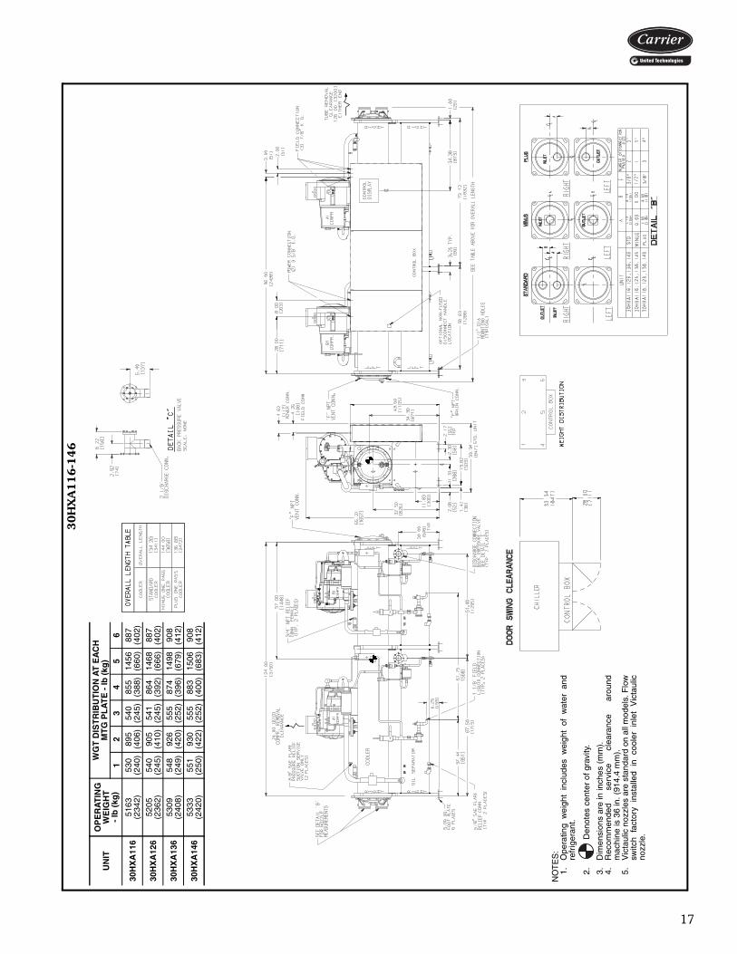
30H
XA
116
5163
(234
2)53
0(2
40)
895
(406
)54
0(2
45)
855
(388
)14
56(6
60)
887
(402
)
30H
XA
126
5205
(236
2)54
0(2
45)
905
(410
)54
1(2
45)
864
(392
)14
68(6
66)
887
(402
)
30H
XA
136
5309
(240
8)54
8(2
49)
926
(420
)55
5(2
52)
874
(396
)14
98(6
79)
908
(412
)
30H
XA
146
5333
(242
0)55
1(2
50)
930
(422
)55
5(2
52)
883
(400
)15
06(6
83)
908
(412
)
NO
TE
S:
1.O
pera
ting
wei
ght
incl
udes
wei
ght
of w
ater
and
refr
iger
ant.
2. D
enot
es c
ente
r of
gra
vity
.
3.D
imen
sion
s ar
e in
inch
es (
mm
).4.
Rec
omm
ende
d se
rvic
e cl
eara
nce
arou
ndm
achi
ne is
36
in. (
914.
4 m
m).
5.V
icta
ulic
noz
zles
are
sta
ndar
d on
all
mod
els.
Flo
wsw
itch
fact
ory
inst
alle
d in
co
oler
in
let
Vic
taul
icno
zzle
.
30H
XA
116-1
46

18
NO
TE
S:
1.O
pera
ting
wei
ght i
nclu
des
wei
ght o
f wat
er a
nd r
efri
gera
nt.
2. D
enot
es c
ente
r of
gra
vity
.
3.D
imen
sion
s ar
e in
inch
es (
mm
).4.
Rec
omm
ende
d se
rvic
e cl
eara
nce
arou
nd m
achi
ne is
36
in.
(914
.4 m
m).
5.V
icta
ulic
noz
zles
are
sta
ndar
d on
all
mod
els.
Flo
w s
witc
hfa
ctor
y in
stal
led
in c
oole
r in
let V
icta
ulic
noz
zle.
UN
ITO
PE
RA
TIN
GW
EIG
HT
- lb
(kg
)B
CR
ST
WG
T D
IST
RIB
UT
ION
AT
EA
CH
MT
G P
LA
TE
- lb
(kg
)1
23
45
6
30H
XA
161
5752
(261
0)72
.12
(183
2)50
.63
(128
6)67
.50
(171
5)51
.00
(129
5)48
.75
(123
8)56
0(2
54)
965
(438
)59
8(2
71)
954
(433
)16
50(7
48)
1025
(465
)
30H
XA
171
5777
(262
1)61
.37
(155
9)61
.37
(155
9)56
.75
(144
1)61
.75
(153
2)44
.31
(112
5)62
7(2
84)
968
(439
)53
4(2
42)
1072
(486
)16
58(7
52)
918
(416
)
30H
XA
186
5946
(269
8)61
.37
(155
9)61
.37
(155
9)56
.75
(144
1)61
.75
(153
2)44
.31
(112
5)64
8(2
94)
1004
(455
)55
2(2
50)
1110
(504
)17
03(7
72)
939
(426
)
30H
XA
161-1
86
Dimensions (cont)

19
NO
TE
S:
1.O
pera
ting
wei
ght i
nclu
des
wei
ght o
f wat
er a
nd r
efri
gera
nt.
2. D
enot
es c
ente
r of
gra
vity
.
3.D
imen
sion
s ar
e in
inch
es (
mm
).4.
Rec
omm
ende
d se
rvic
e cl
eara
nce
arou
nd m
achi
ne is
36
in. (
914.
4 m
m).
5.V
icta
ulic
noz
zles
are
sta
ndar
d on
all
mod
els.
Flo
w s
witc
h fa
ctor
y in
stal
led
in c
oole
r in
let V
icta
ulic
noz
zle.
UN
ITO
PE
RA
TIN
GW
EIG
HT
- lb
(kg
)
WG
T D
IST
RIB
UT
ION
AT
EA
CH
MT
G P
LA
TE
- lb
(kg
)1
23
45
6
30H
XA
206
7485
(339
5)67
1(3
04)
1702
(772
)87
9(3
99)
850
(385
)22
16(1
005)
1167
(529
)
30H
XA
246
7621
(345
7)68
1(3
09)
1748
(793
)91
1(4
13)
797
(362
)22
76(1
032)
1209
(548
)
30H
XA
261
7621
(345
7)68
1(3
09)
1748
(793
)91
1(4
13)
797
(362
)22
76(1
032)
1209
(548
)
30H
XA
271
7621
(345
7)68
1(3
09)
1748
(793
)91
1(4
13)
797
(362
)22
76(1
032)
1209
(548
)
30H
XA
206-2
71

20
AC
CESSO
RY
SO
UN
D E
NC
LOSU
RE
NO
TE
S:
1.D
imen
sion
s ar
e in
inch
es (
mill
imet
ers)
.2.
Rec
omm
ende
d se
rvic
e cl
eara
nce
arou
nd m
achi
ne is
36
in. (
914.
4).
3.U
nuse
d po
rtio
n of
pip
ing
open
ings
mus
t be
clo
sed
and
insu
late
dfo
r ac
oust
ic p
urpo
ses.
Use
fille
r pa
nel i
n ac
cess
ory
pack
age.
4.F
ield
-fab
ricat
ed h
oles
mus
t be
clo
sed
and
insu
late
d fo
r ac
oust
icpu
rpos
es.
5.R
ecom
men
ded
elec
tric
al p
ower
sup
ply
area
. N
otch
to
suit
and
cove
r/in
sula
te r
emai
ning
ope
n ar
ea fo
r ac
oust
ic p
urpo
ses.
6.R
ecom
men
ded
cont
rol
wiri
ng e
ntry
are
a. N
otch
to
suit
and
cove
r/in
sula
te r
emai
ning
ope
n ar
ea fo
r ac
oust
ic p
urpo
ses.
7.R
ecom
men
ded
cool
er r
elie
f val
ve v
ent l
ine
and
30H
XC
con
dens
er r
elie
fve
nt l
ine
entr
y ar
ea.
The
30H
XA
dis
char
ge a
nd li
quid
line
ent
ry a
reas
are
on o
ppos
ite s
ide.
Not
ch e
nclo
sure
to s
uit p
artic
ular
inst
alla
tion.
8.M
odel
in
draw
ing
is t
ypic
al a
nd r
epre
sent
s 30
HX
116-
146
size
s in
the
30H
X-9
00--
-001
acc
esso
ry s
ound
enc
losu
re.
9.S
ound
enc
losu
re a
cces
sory
sho
uld
be a
ligne
d to
the
cent
er li
nes
of th
eco
ntro
l pan
el a
cces
s an
d pi
ping
ope
ning
s.
Dimensions (cont)

21
3.25(82.55)
5.00(127.00)
0.88(22.35)
2.17(53.34)0.50 DIA
(4) HOLES
1.42(36.07)
3.58(90.93)
WEIGHT DISTRIBUTION AT MOUNTING PLATES
30HXC UNITS — lb (kg)
UNIT 30HXCMOUNTING PLATE NO.
1 2 3 4 5 6076 738 (335) 943 (428) 595 (270) 1110 (503) 1418 (643) 896 (406)086 738 (335) 947 (430) 597 (271) 1112 (504) 1427 (647) 902 (409)096 686 (311) 968 (439) 693 (314) 1027 (466) 1447 (656) 1034 (469)106 730 (331) 1028 (466) 744 (337) 1073 (487) 1510 (685) 1092 (495)116 728 (330) 1114 (505) 777 (352) 1053 (478) 1615 (733) 1127 (511)126 738 (335) 1127 (511) 780 (354) 1061 (481) 1628 (738) 1131 (513)136 758 (344) 1176 (533) 811 (368) 1083 (491) 1689 (766) 1171 (531)146 763 (346) 1182 (536) 815 (370) 1085 (492) 1697 (770) 1172 (532)161 817 (371) 1272 (577) 908 (412) 1219 (553) 1890 (857) 1346 (610)171 936 (425) 1318 (598) 840 (381) 1379 (626) 1946 (883) 1241 (563)186 962 (436) 1361 (617) 860 (390) 1410 (640) 1996 (905) 1265 (574)206 948 (430) 2406 (1091) 1243 (564) 1201 (545) 3133 (1421) 1650 (748)246 985 (447) 2515 (1141) 1306 (592) 1154 (523) 3276 (1486) 1733 (786)261 985 (447) 2520 (1143) 1311 (595) 1154 (523) 3283 (1489) 1739 (789)271 985 (447) 2529 (1147) 1318 (598) 1154 (523) 3294 (1494) 1749 (793)
30HXA UNITS — lb (kg)
NOTE: See pages 12-19 for center of gravity details.
UNIT 30HXAMOUNTING PLATE NO.
1 2 3 4 5 6076 555 (252) 793 (360) 418 (190) 926 (420) 1326 (601) 699 (317)086 555 (252) 798 (362) 418 (190) 928 (421) 1340 (608) 705 (320)096 509 (231) 808 (367) 493 (224) 848 (385) 1350 (612) 827 (375)106 555 (252) 869 (394) 541 (245) 896 (406) 1410 (640) 880 (399)116 530 (240) 895 (406) 540 (245) 855 (388) 1456 (660) 887 (402)126 540 (245) 905 (410) 541 (245) 864 (392) 1468 (666) 887 (402)136 548 (249) 926 (420) 555 (252) 873 (396) 1498 (679) 908 (412)146 551 (250) 930 (422) 555 (252) 883 (400) 1506 (683) 908 (412)161 560 (254) 965 (438) 598 (271) 954 (433) 1650 (748) 1025 (465)171 627 (284) 968 (439) 534 (242) 1072 (486) 1658 (752) 918 (416)186 648 (294) 1004 (455) 552 (250) 1110 (504) 1703 (772) 939 (426)206 671 (304) 1702 (772) 879 (399) 850 (385) 2216 (1005) 1167 (529)246 681 (309) 1748 (793) 911 (413) 797 (362) 2276 (1032) 1209 (548)261 681 (309) 1748 (793) 911 (413) 797 (362) 2276 (1032) 1209 (548)271 681 (309) 1748 (793) 911 (413) 797 (362) 2276 (1032) 1209 (548)
WEIGHT DISTRIBUTION AT EACH MOUNTING PLATE
NOTE: Dimensions shown in inches (mm).
30HX FOOT

22
Unit storageProvide machine protection — Store machine andstarter indoors, protected from construction dirt andmoisture. Inspect under shipping tarps, bags, or crates tobe sure water has not collected during transit. Keep protec-tive shipping covers in place until machine is ready forinstallation.
Unit locationUnit should be level (particularly in its major lengthwisedimension) to assure proper oil return.
The unit should be located indoors in an area of temper-ature between 50 to 104 F (10 to 40 C).
Good acoustic design practice should be followed, i.e.,unit should not be located adjacent to sound-sensitive areasunless appropriate consideration has been made.
Cooler fluid temperature1. Maximum leaving water (fluid) temperature (LWT) is
60 F (21 C). Unit can start and pull down with up to95 F (35 C) entering water (fluid) temperature due toMOP (maximum operating pressure) feature of theexpansion valve. For sustained operation, it is recom-mended that entering fluid temperature not exceed70 F (21.1 C).
2. Minimum LWT is 40 F (4.4 C) for standard units.The brine option is required for operation withleaving fluid temperatures in the range of 39 to 14 F(4 to –9 C). For ratings below 40 F (4.4 C) LWT,contact your local Carrier representative.
3. Minimum entering water (fluid) temperature (EWT) is45 F (7.2 C). Maximum EWT is 70 F (21.1 C).
Leaving-fluid temperature resetThe accessory reset sensor can be applied to the chiller toprovide reset of in LWT constant fluid flow systems. Resetreduces compressor power usage at part load when designLWT is not necessary. Humidity control should be consid-ered, since higher coil temperatures resulting from resetwill reduce latent heat capacity. Three reset applicationsare offered:From return-fluid temperature — Increases LWT setpoint as return (or entering) fluid temperature decreases(indicating load decrease). Reset from return fluid may beused in any application where return fluid provides accu-rate load indication. Limitation of return-fluid reset is thatthe LWT may only be reset to value of design return-fluidtemperature. No additional hardware is required.From outdoor-air temperature — Increases LWT asoutdoor ambient temperature decreases (indicating loaddecrease). This reset should be applied only where outdoorambient temperature is an accurate indication of load. Afield-supplied thermistor is required.From occupied space temperature — Increases LWTas space temperature decreases (indicating load decrease).This reset should be applied only where space temperatureis an accurate indication of load. A field-supplied thermis-tor is required.
Temperature can also be reset using a 4 to 20 mA signalfrom the control system. This type of reset requires theenergy management module accessory.
Condenser fluid temperature1. Maximum leaving condenser fluid temperature is
110 F (43 C) on all 30HXC units.2. Standard 30HXC units will start at entering con-
denser fluid temperatures above 55 F (12.8 C). Ingeneral, however, continuous machine operation withentering condenser fluid temperatures below 70 F(21.1 C) is not recommended. When the enteringcondenser fluid temperature is expected to dropbelow 70 F (21.1 C), it is recommended that someform of condenser flow control be used to optimizeperformance. Tower pump, bypass valves, or flowregulating valves may be controlled by a 2 to 10, 0 to10, or 10 to 0 VDC output from the 30HXC control(60-second open to close time recommended foractuator).
Cooler and water-cooled condensertemperature riseRatings and performance data in this publication are for acooling temperature rise of 10° F (5.6° C). Units may beoperated at a different temperature rise, provided flow lim-its are not exceeded and corrections to capacity, etc., aremade. For minimum flow rates, see the Minimum FlowRates table. High flow rate is limited by pressure drop thatcan be tolerated.Minimum cooler flow — Flow (maximum cooler tem-perature rise) is shown in the Minimum Flow Rates table.Minimum flow rate must be maintained to prevent fouling.When gpm (L/s) required is lower (or rise is higher), followrecommendations below:
1. Multiple smaller chillers can be applied in series, eachproviding a portion of the design temperature rise.
2. Chilled fluid can be recirculated to raise flow rate.However, mixed temperature entering cooler must bemaintained at a minimum of at least 5° F (2.8° C)above the leaving chilled fluid temperature.
3. Special plus one-pass cooler can be used. Contactyour Carrier representative for further information.
Maximum cooler flow (> 5 gpm/ton or < 5° F rise[> 0.09 L/s · kW or < 2.7° C rise]) — Maximum flowresults in practical maximum pressure drop through cooler.Special minus-one-pass cooler can be used to reduce pres-sure drop. Contact your Carrier representative.
Return fluid can bypass the cooler to keep pressure dropthrough cooler within acceptable limits. This permits ahigher T with lower fluid flow through cooler and mixingafter the cooler. Contact your Carrier representative ifpressure drop appears excessive.Variable cooler flow rates — These variable rates maybe applied to standard 30HX series chillers. However, theunit will attempt to maintain a constant leaving chilled-fluidtemperature. In such cases, minimum fluid loop volumemust be in excess of 3 gal per ton (3.2 L per kW) and flowrate must change in steps of less than 10% per minute.
Application data

23
Apply 6 gal per ton (6.5 L per kW) fluid loop volume mini-mum if flow rate changes more rapidly.Minimum water-cooled condenser flow — This value(maximum rise) is shown in Minimum Flow Rates table.Ensure leaving-fluid temperature does not exceed 105 F(40.5 C).
MINIMUM FLOW RATES
*Based on 20 F (11.1 C) temperature difference at AHRI conditions.NOTES:
1. The 30HX units will start with loop temperatures up to 95 F (35 C).2. Minimum flow rate shown is based on AHRI Ratings and is for reference only. 20 F
(11.1 C) is the maximum cooler temperature differential that will determine actualminimum flow rate.
3. To obtain proper temperature control, loop fluid volume must be at least 3 gal/ton (3.23 L/kW) of chiller nominal capacity for air conditioning and at least 6 gal/ton (6.5 L/kW) for pro-cess applications.
Oversizing chillersOversizing chillers by more than 15% at design conditionsmust be avoided as the system operating efficiency will beadversely affected (resulting in greater and/or excessiveelectrical demand and cycling of compressors). Whenfuture expansion of equipment is anticipated, install a sin-gle chiller to meet present load requirements, and install asecond chiller to meet the additional load demand.
It is also recommended that the installation of 2 smallerchillers be considered where operation at minimum load iscritical. The operation of 2 small chillers at higher loadingis preferred to operating a single chiller at or near its mini-mum recommended value.
The minimum load control accessory should not be usedas a means to allow oversizing chillers. Minimum load con-trol should be given consideration where substantial oper-ating time is anticipated below the minimum unloadingstep.
Parallel chillersWhere chiller capacities greater than can be supplied by asingle 30HX chiller are required, or where stand-by capa-bility is desired, chillers may be installed in parallel. Unitsmay be of the same or different sizes. However, cooler andcondenser flow rates must be balanced to ensure properflow to each chiller. The standard 30HX ComfortLink con-trols can be configured to provide lead/lag control for twochillers. The accessory Chillervisor System Manager IIIcontrol may be used for proper leaving chilled fluid temper-ature control and to ensure proper staging sequence of upto 8 chillers. Refer to the accessory Chillervisor SystemManager III installation instructions for further details.
Series chillersChillers in series may be used for capacities greater thanthose supplied by a single 30HX chiller. Using the minus-one-pass cooler head option, fluid pressure drop across thecooler can be held to reasonable levels. The leaving fluidtemperature sensors need not be relocated. However, thecooler minimum entering fluid temperature limitationsshould be considered for the chillers located downstream ofother chillers. The standard 30HX control can control two30HX chillers in series. Condensers should be piped inparallel to maximize capacity and efficiency. This shouldalso minimize condenser pressure drop and saturated con-densing temperatures. However, if condensers are piped inseries, ensure that the leaving fluid temperature does notexceed 105 F (40.5 C) on standard machines.
DEVICEUNITSIZE30HX
NO. OFPASSES
COOLERTYPE
MIN. FLOWRATE*
COOLER TEMPDIFFERENCE
GPM L/s F C
COOLER
076
2 Minus 1 136 8.6 13 7.4
3 Standard 90 5.7 20 11.1
4 Plus 1 68 4.3 27 14.8
086
2 Minus 1 149 9.4 13 7.4
3 Standard 100 6.3 20 11.1
4 Plus 1 75 4.7 27 14.8
096
2 Minus 1 169 10.7 13 7.4
3 Standard 113 7.1 20 11.1
4 Plus 1 85 5.3 27 14.8
106
2 Minus 1 188 11.8 13 7.4
3 Standard 125 7.9 20 11.1
4 Plus 1 94 5.9 27 14.8
116
1 Minus 1 272 17.2 10 5.6
2 Standard 136 8.6 20 11.1
3 Plus 1 91 5.7 30 16.7
126
1 Minus 1 295 18.6 10 5.6
2 Standard 147 9.3 20 11.1
3 Plus 1 98 6.2 30 16.7
136
1 Minus 1 327 20.7 10 5.6
2 Standard 164 10.3 20 11.1
3 Plus 1 109 6.9 30 16.7
146
1 Minus 1 350 22.1 10 5.6
2 Standard 175 11.0 20 11.1
3 Plus 1 117 7.4 30 16.7
161
1 Minus 1 376 23.7 10 5.6
2 Standard 188 11.9 20 11.1
3 Plus 1 125 7.9 30 16.7
171
1 Minus 1 399 25.2 10 5.6
2 Standard 199 12.6 20 11.1
3 Plus 1 133 8.4 30 16.7
186
1 Minus 1 426 26.9 10 5.6
2 Standard 213 13.4 20 11.1
3 Plus 1 142 9.0 30 16.7
206
1 Minus 1 508 32.1 10 5.6
2 Standard 254 16.0 20 11.1
3 Plus 1 169 10.7 30 16.7
246
1 Minus 1 597 37.7 10 5.6
2 Standard 309 18.8 20 11.1
3 Plus 1 199 12.6 30 16.7
261
1 Minus 1 618 39.0 10 5.6
2 Standard 309 19.5 20 11.1
3 Plus 1 206 13.0 30 16.7
271
1 Minus 1 642 40.5 10 5.6
2 Standard 321 20.3 20 11.1
3 Plus 1 214 13.5 30 16.7
CONDENSER
076,086 2 — 105 6.6 — —
096,106 2 — 135 8.5 — —
116,126 2 — 170 10.7 — —
136,146 2 — 195 12.3 — —
161 2 — 235 14.8 — —
171,186 2 — 255 16.1 — —
206 2 — 273 17.2 — —
246 2 — 333 21.0 — —
261 2 — 333 21.0 — —
271 2 — 333 21.0 — —
RECIRCULATION FLOW

24
Energy managementDemand limiting and load shedding are popular techniquesused to reduce peak electric demands typically experiencedduring hot summer days when air conditioning loads arehighest. When utility electricity demands exceed a certainlevel, electrical loads are turned off to keep the peakdemands below a prescribed maximum limit. Compressorunloading reduces electrical demand while allowing thechiller to operate under part load capacity and to maintainpartial chilled fluid cooling.
Electrical demand can be limited through demand limitinput to chiller control which unloads the chiller to a prede-termined percentage of the load. One stage of unloadingcan be initiated by a remote signal to significantly reducethe chiller power consumption. This power reductionapplies to the full load power at nominal conditions. Thedemand limit control should not be cycled less than10 minutes on and 5 minutes off.
Duty cyclingDuty cycling will cycle an electrical load at regular intervals,regardless of electrical demand. This reduces the electricaldemand by “fooling” demand measuring devices. Dutycycling of the entire compressor is NOT recommendedsince motor windings and bearings will be damaged byconstant cycling.
Wye-delta startWye-delta start is standard on 30HX 208/230-v, 60-Hzunits and 230-v, 50-Hz units and optional on all other30HX units. This feature is not always required on 30HXunits due to the use of multiple compressors that allow smallelectrical load increments, but is available if required. Maxi-mum instantaneous current flow (see ICF in Electrical Datatables on pages 36-39) should be used in determining need.
Vibration isolationExternal vibration isolators are available as field-installedaccessories.
StrainersA strainer with a minimum screen size of 20 mesh must beinstalled in both the cooler and condenser fluid lines, within10 ft (3 m) of the inlets to both the cooler and condenser.For 30HXA units, this requirement applies only to thecooler.
Chilled fluid loop volumeThe chilled fluid loop volume in circulation must equal orexceed 3 gal per nominal ton of cooling (3.2 L per kW) fortemperature stability and accuracy in normal air condition-ing applications. For example, a 30HXC096 with a nomi-nal capacity of 94.0 tons would require 282 gal (1067.4 L)in circulation in the system loop.
For process jobs where accuracy is vital, or for operationat ambient temperatures below 32 F (0° C) with low unitloading conditions, there should be from 6 to 10 gal perton (6.5 to 10.8 L per kW). To achieve this volume, it isoften necessary to install a tank in the loop. Tank should bebaffled to ensure there is no stratification, and that water(or brine) entering the tank is adequately mixed with liquidin the tank. See Tank Installation drawing.
Fouling factorThe factor used to calculate tabulated ratings for the cooleris 0.00010 ft2 · hr · F/Btu (0.000018 m2 · K/W), and forthe condenser is 0.00025 ft2 · hr · F/Btu (0.00044 m2 ·K/W). As fouling factor is increased, unit capacitydecreases and compressor power increases. To determineselections at other fouling factors, use the chiller programin the electronic catalog.
Cooler and water-cooled condenser freezeprotectionIf chiller refrigerant or fluid lines are in an area where ambi-ent conditions fall below 32 F (0° C), it is recommendedthat an antifreeze solution be added to protect the unit andfluid piping to a temperature 12° F (6.7° C) below thelowest anticipated temperature. For corrections to perfor-mance, refer to the chiller program in the electroniccatalog.
Use only antifreeze solutions approved for heatexchanger duty. Use of automotive antifreezes is not rec-ommended because of the fouling that can occur oncetheir relatively short-lived inhibitors break down.
If the system will not be used during freezing weatherconditions and the chiller and fluid piping are not protectedwith an antifreeze solution, it is recommended that thechiller and outdoor piping be drained.
Refer to Cooler Fluid Temperature section, page 22, forleaving fluid temperature for brine units. When leavingchilled fluid temperatures will be lower than 40 F (4.4 C),an appropriate antifreeze solution must be used in thecooler. In addition, the following special installation instruc-tions will apply:
1. In addition to the factory-mounted chilled water flowswitch, a field-supplied condenser water flow switchmust be installed.
2. The chiller must control both the chilled water pumpand the condenser pump. The cooler pump mustoperate for a minimum of 10 minutes after the chillerhas shut down and the condenser pump must operatefor a minimum of 30 minutes after the chiller has shutdown. In the event of a loss of condenser water flow,the flow of chilled fluid to the evaporator must bestopped or the isolation valve must be closed. This isnecessary to reduce the possibility of condenserfreeze-up.
TANK INSTALLATION
Application data (cont)

25
3. Condenser head pressure control valves must notreduce condenser flow below 0.75 gallons per ton(0.4 L/s per kW) or the lowest detectable flow level ofthe condenser water flow switch. For further informa-tion, refer to the 30HX Installation Instructions orcontact your Carrier representative.
30HXA remote condenser requirements1. Do not manifold independent refrigerant circuits into
a single condenser circuit. 2. Ensure each refrigerant circuit has its own head pres-
sure control.3. Condensing pressure control must be provided on
condensers used with 30HXA to maintain a minimum75 F (24 C) saturated discharge temperature at lightloads.
4. Condenser must provide 15° F (8.3° C) subcooling, amaximum of 40° F (22.2° C) difference between satu-rated condensing temperature and outdoor ambienttemperature (to prevent overload at high ambienttemperatures), and a minimum of 20° F (11.1° C)difference (to assure subcooling).
5. Minimum saturated discharge temperature (SDT) is90 F (32.2 C). Maximum SDT is 145 F (62.8 C) atfull load.
6. Condenser should not be located more than 15 ft(4.6 m) below chiller to maintain subcooling.
7. Design discharge and liquid piping according to theSystem Design Manual and Refrigerant Piping DesignProgram. Piping must be sized for HFC-134a refrig-erant. Refer to the ASHRAE Refrigeration Handbookfor R-134a refrigerant sizing tables. Also see 30HXInstallation Instructions and the Typical 30HXARefrigerant Piping to Remote Condenser diagramson page 33.
8. For proper electronic expansion valve (EXV) opera-tion, discharge line losses should not exceed 4° F(2.2° C) at full load. A calculation of line loss shouldbe performed prior to installation.
9. Maximum interconnecting refrigerant line length is200 ft (61 m) actual.
10. Liquid line solenoid valves are required.11. If accessory sound enclosure is installed, run lines
along the floor so the sound enclosure can be notchedto clear lines.
12. Locate equipment on a level surface in an area havingunobstructed air circulation. Proper flow of fresh airto the condenser is essential for unit operation andperformance. Care should be taken to keep the areaaround the condensers free of airborne dirt, debris,and materials that can restrict airflow or be drawninto the equipment, causing damage, clogging, orblocking of the coil area.
13. For multiple units, assure discharge air from one unitdoes not become intake air for another. Obstructionssuch as screens, walls, roofs, overhangs, landscaping,etc., located at a site may restrict airflow or causewarm air circulation. Recirculation of warm discharge
air back into a condenser can increase condensingtemperatures and may significantly reduce capacityand efficiency. Unit shutdown may occur if condens-ing temperatures exceed the maximum set point.Airflow patterns are complex and beyond the scopeof equipment manufacturer prediction. Consultationwith a specialist may be required in someapplications.
14. Units with vertical fan discharge should be located nocloser than the width of the unit to an obstructionsuch as a wall or another unit. Minimum clearancesfor airflow and service are indicated on the equipmentdrawings and should be increased as necessary to pre-vent air recirculation when obstructions exist or multi-ple units are applied.
Refrigerant pipe sizing for 30HXA with 09D con-denser combinations — For refrigerant pipe sizing ofthe 30HXA follow these directions:Discharge line:
1. For applications at conditions of 40 F (4.4 C) orhigher, use the Refrigerant Line Sizes for 30HXAChiller/09DK, 09AZ Condenser Combinations tableson pages 26 and 27.For applications using brine, other condensers, orLWT below 40 F (4.4 C), size lines using theASHRAE Refrigeration Handbook, or other suitabledesign guide.
2. Install horizontal lines level or pitched slightly towardthe base of discharge riser and the condenser (in thedirection of flow).
3. If chiller is below the condenser, loop the dischargeline to at least one inch (25.4 mm) above the top ofcondenser.
4. A double discharge riser (as shown in RefrigerantLine Sizes for 30HXA Chiller/09DK, 09AZ Con-denser Combinations, Double Discharge Riser PipeSizes table on page 27) is required if any of the fol-lowing conditions exist:a. Unit is equipped with minimum load control.b. Chiller is located below condenser.
5. Minimize line length and restrictions to minimize pres-sure drop and refrigerant charge.
6. If accessory sound enclosure is applied, run linesalong the floor so sound enclosure may be notched toclear lines.
7. Lines should not be buried underground.8. Snow and ice on hot discharge gas piping can serve
as a heat sink. Refrigerant piping exposed to the out-doors should be protected from snow and ice to pre-vent excessive condensation at start-up.
Liquid line:1. For applications at conditions of 40 F (4.4 C) or
higher LWT, use the Refrigerant Line Sizes for30HXA Chiller/09DK, 09AZ Condenser Combina-tions tables on pages 26 and 27. For applications using brine, other condensers, orLWT below 40 F (4.4 C), size lines using the
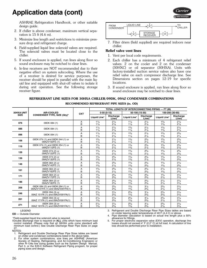
26
ASHRAE Refrigeration Handbook, or other suitabledesign guide.
2. If chiller is above condenser, maximum vertical sepa-ration is 15 ft (4.6 m).
3. Minimize line length and restrictions to minimize pres-sure drop and refrigerant charge.
4. Field-supplied liquid line solenoid valves are required.The solenoid valves must be located close to thechiller.
5. If sound enclosure is applied, run lines along floor sosound enclosure may be notched to clear lines.
6. In-line receivers are NOT recommended due to theirnegative effect on system subcooling. Where the useof a receiver is desired for service purposes, thereceiver should be piped in parallel with the main liq-uid line and equipped with shut-off valves to isolate itduring unit operation. See the following storagereceiver figure.
7. Filter driers (field supplied) are required indoors nearchiller.
Relief valve vent lines1. Vent per local code requirements.2. Each chiller has a minimum of 4 refrigerant relief
valves: 2 on the cooler and 2 on the condenser(30HXC) or oil separator (30HXA). Units withfactory-installed suction service valves also have onerelief valve on each compressor discharge line. SeeDimensions section on pages 12-19 for specificlocations.
3. If sound enclosure is applied, run lines along floor sosound enclosure may be notched to clear lines.
REFRIGERANT LINE SIZES FOR 30HXA CHILLER/09DK, 09AZ CONDENSER COMBINATIONS
RECOMMENDED REFRIGERANT PIPE SIZES (in. OD)
LEGENDOD — Outside Diameter
*Field-supplied liquid line solenoid valve is required.†Double discharge riser is required on ALL units which have minimum load
control installed. (Please note that all 30HXA units come standard withminimum load control.) See Double Discharge Riser Pipe Sizes on page27.
NOTES:1. Refrigerant and Double Discharge Riser Pipe Sizes tables are based
on chiller and condenser combinations listed in the above table.2. For other system combinations, size lines per ASHRAE (American
Society of Heating, Refrigerating, and Air-Conditioning Engineers) orother R-134a line sizing guides such as the System Design Manual,Part 3, or the E20-II Software Refrigerant Piping program, for properpiping sizes and design.
3. Refrigerant and Double Discharge Riser Pipe Sizes tables are basedon cooler leaving water temperatures of 40 F (4.4 C) or above.
4. Pipe diameter calculation is based on actual line length plus a 50%allowance for fittings.
5. For proper electronic expansion valve (EXV) operation, discharge linelosses should not exceed 4° F (2.2° C) at full load. A calculation of lineloss should be performed prior to installation.
FROMCONDENSER
LIQUID LINE
STORAGE RECEIVER
TOCHILLER
30HXA UNIT SIZE
AIR-COOLEDCONDENSER TYPE, SIZE (Qty)* CKT
TOTAL LENGTH OF INTERCONNECTING PIPING — FT (M)0-50 (0-15) 50-100 (15-30) 100-200 (30-60)
Liquid Line* Discharge Line† Liquid Line* Discharge
Line† Liquid Line* Discharge Line†
076 09DK 084 (1) A 11/8 21/8 11/8 21/8 13/8 21/8B 11/8 21/8 11/8 21/8 13/8 21/8
086 09DK 084 (1) A 11/8 21/8 13/8 21/8 13/8 21/8B 11/8 21/8 11/8 21/8 13/8 21/8
096 09DK 094 (1) A 11/8 21/8 13/8 21/8 15/8 25/8B 11/8 21/8 11/8 21/8 13/8 21/8
106 09DK 074 (1) and 09DK 044 (1) or09AZV102FE (1)
A 13/8 21/8 13/8 25/8 15/8 25/8B 11/8 21/8 11/8 21/8 13/8 21/8
116 09DK 074 (1) and 09DK 054 (1) or09AZV112FE (1)
A 13/8 21/8 13/8 25/8 15/8 25/8B 13/8 21/8 13/8 21/8 13/8 21/8
126 09DK 074 (2) or09AZV122FE (1)
A 13/8 21/8 13/8 25/8 15/8 25/8B 13/8 21/8 13/8 21/8 15/8 25/8
136 09DK 074 (2) or09AZV132FE (1)
A 13/8 25/8 15/8 25/8 15/8 31/8B 13/8 21/8 13/8 21/8 15/8 25/8
146 09DK 084 (2) or09AZV142FE (1)
A 13/8 25/8 15/8 25/8 15/8 31/8B 13/8 21/8 13/8 25/8 15/8 25/8
161 09DK 084 (2) or09AZV162FE (1)
A 13/8 25/8 15/8 25/8 21/8 31/8B 13/8 21/8 13/8 25/8 15/8 25/8
171 09DK 084 (2) or09AZV172FE (1)
A 13/8 25/8 15/8 25/8 15/8 31/8B 13/8 25/8 15/8 25/8 21/8 31/8
186 09DK 084 (2) or09AZV182FE (1)
A 13/8 25/8 15/8 25/8 21/8 31/8B 13/8 25/8 15/8 25/8 21/8 31/8
206 09DK 084 (2) and 09DK 094 (1) or09AZV101FA (1) and 09AZV091FA(1)
A 15/8 25/8 15/8 31/8 25/8 31/8B 13/8 25/8 15/8 25/8 21/8 31/8
246 09DK 094 (3) or09AZ 151FA (1) and 09AZV091FA(1)
A 21/8 31/8 25/8 31/8 25/8 31/8B 13/8 25/8 15/8 25/8 25/8 31/8
261 09DK 094 (3) or09AZ 171FA (1) and 09AZV091FA(1)
A 21/8 31/8 25/8 31/8 25/8 31/8B 13/8 25/8 15/8 25/8 21/8 31/8
271 09DK 094 (3) or09AZ 181FA (1) and 09AZV091FA(1)
A 21/8 31/8 25/8 31/8 25/8 31/8B 13/8 25/8 15/8 25/8 21/8 31/8
Application data (cont)

27
REFRIGERANT LINE SIZES FOR 30HXA CHILLER/09DK, 09AZ CONDENSER COMBINATIONS (cont)DOUBLE DISCHARGE RISER PIPE SIZES (in. OD)
LEGEND
*Refer to Double Discharge Riser Construction Detail figure.†Total Length of Interconnecting Piping refers to actual length, not totalequivalent length.
NOTES:1. Refrigerant and Double Discharge Riser Pipe Sizes tables are based
on chiller and condenser combinations listed in the above table.2. For other system combinations, size lines per ASHRAE (American
Society of Heating, Refrigerating, and Air-Conditioning Engineers) orother R-134a line sizing guides such as the System Design Manual,Part 3, or the E20-II Software Refrigerant Piping program, for properpiping sizes and design.
3. Refrigerant and Double Discharge Riser Pipe Sizes tables are basedon cooler leaving water temperatures of 40 F (4.4 C) or above.
4. Pipe diameter calculation is based on actual line length plus a 50%allowance for fittings.
5. For proper electronic expansion valve (EXV) operation, discharge linelosses should not exceed 4° F (2.2° C) at full load. A calculation of lineloss should be performed prior to installation.
6. Horizontal line sections should be sized according to the Total Lengthof Interconnecting Piping columns in Recommended Refrigerant PipeSizes.
30HXA UNIT SIZE
AIR-COOLEDCONDENSER TYPE, SIZE (Qty)* CKT
RISER A* RISER B*Total Length of Interconnecting Piping — FT (M)†0-200(0-60)
0-50(0-15)
50-100(15-30)
100-200(30-60)
076 09DK 084 (1) A 11/8 15/8 15/8 15/8B 11/8 15/8 15/8 15/8
086 09DK 084 (1) A 11/8 15/8 15/8 15/8B 11/8 15/8 15/8 15/8
096 09DK 094 (1) A 11/8 15/8 15/8 21/8B 11/8 15/8 15/8 15/8
106 09DK 074 (1) and 09DK 044 (1) or09AZV102FE (1)
A 15/8 15/8 21/8 21/8B 13/8 13/8 13/8 13/8
116 09DK 074 (1) and 09DK 054 (1) or09AZV112FE (1)
A 15/8 15/8 21/8 21/8B 13/8 15/8 15/8 15/8
126 09DK 074 (2) or09AZV122FE (1)
A 15/8 21/8 21/8 21/8B 13/8 15/8 15/8 21/8
136 09DK 074 (2) or09AZV132FE (1)
A 15/8 21/8 21/8 25/8B 13/8 15/8 15/8 21/8
146 09DK 084 (2) or09AZV142FE (1)
A 15/8 21/8 21/8 25/8B 15/8 15/8 21/8 21/8
161 09DK 084 (2) or09AZV162FE (1)
A 15/8 21/8 21/8 25/8B 15/8 15/8 21/8 21/8
171 09DK 084 (2) or09AZV172FE (1)
A 15/8 21/8 21/8 25/8B 15/8 21/8 21/8 25/8
186 09DK 084 (2) or09AZV182FE (1)
A 15/8 21/8 21/8 25/8B 15/8 21/8 21/8 25/8
206 09DK 084 (2) and 09DK 094 (1) or09AZV101FA (1) and 09AZV091FA(1)
A 15/8 21/8 21/8 25/8B 15/8 21/8 21/8 25/8
246 09DK 094 (3) or09AZ 151FA (1) and 09AZV091FA(1)
A 15/8 21/8 21/8 25/8B 15/8 21/8 21/8 25/8
261 09DK 094 (3) or09AZ 171FA (1) and 09AZV091FA(1)
A 15/8 21/8 21/8 31/8B 15/8 21/8 21/8 25/8
271 09DK 094 (3) or09AZ 181FA (1) and 09AZV091FA(1)
A 15/8 21/8 31/8 31/8B 15/8 21/8 21/8 25/8
A — Riser Without TrapB — Riser With TrapOD — Outside Diameter
TOCONDENSER
B
RED.TEE
90 DEGREESTR ELLS
FROMCHILLER
45 DEGREESTR ELLS
A
DOUBLE DISCHARGE RISERCONSTRUCTION DETAIL
LEGENDRED. TEE — Reducing TeeSTR ELLS — Street Elbows

28
For chillers using brine or those matched with other con-densers, the lines must be sized manually using designguides such as ASHRAE, or curves in the 30HXA installa-tion instructions. In many 30HXA sizes, the individualrefrigerant circuits have unequal capacities. The CircuitCooling Capacity table below lists the percentage capacityof each circuit for line sizing purposes. The Circuit Unload-ing Capacity table below indicates the minimum unloadingcapacities per circuit as well as a sample calculation of theminimum circuit tonnage for riser design. The examplebelow lists circuit capacity calculations based on the CircuitCooling and Circuit Unloading Capacity tables.
CIRCUIT COOLING CAPACITY
CIRCUIT UNLOADING CAPACITY
Example Calculation of Circuit Capacities:Select (Standard) 30HXA086 ChillerFrom Electronic catalog (E-cat) selection or balancediagram:Total Unit Capacity = 74 tons (from unit selection at designconditions)Using the Circuit Cooling Capacity table:Ckt “A” design capacity = 74 x 0.55 = 40.7 tonsCkt “B” design capacity = 74 x 0.45 = 33.3 tonsUsing the Circuit Unloading Capacity table:Ckt “A” minimum capacity = 40.7 x 0.40 = 16.3 tonsCkt “B” minimum capacity = 33.3 x 0.40 = 13.3 tonsSystem refrigerant charge — The 30HXA units areshipped from the factory with a small holding charge ofnitrogen. The approximate refrigerant charge required forstarting the 30HXA system is listed in the table on nextpage. This initial charge will allow starting of the unit.Additional refrigerant may be required to accommodate liq-uid line storage. See the liquid line refrigerant storagecapacity table below for liquid line storage information.
LIQUID LINE REFRIGERANT STORAGE CAPACITY
NOTE: Refer to Refrigerant Line Sizes table on page 26 for liquid linepipe size. To calculate the total system refrigerant charge, multiply theliquid line length (in feet) by the factor shown in this table and add it tothe cooler and condenser charge listed in Estimated System Refriger-ant Charge table on page 29. Additional charge may be required for theliquid line filter drier. Consult the manufacturer for refrigerant chargeinformation.
30HXA UNIT SIZEPERCENT OF TOTAL UNIT CAPACITY
Circuit A % Circuit B %076 50 50086 55 45096 59 41106 64 36116 60 40126 55 45136 59 41146 55 45161 59 41171 47 53186 50 50206 54 46246 61 39261 63 37271 64 36
30HXA UNIT SIZE
MINIMUM CIRCUIT CAPACITY — PERCENT OF FULL LOAD
With MinimumLoad Control
Circuit A Circuit B076-186 20% 20%206-271 10% 20%
PIPING SIZE (in.)REFRIGERANT (lb) PER FT OF TUBING
LENGTH
REFRIGERANT (kg) PER M OF TUBING
LENGTH11/8 0.41 0.6113/8 0.63 0.9415/8 0.89 1.3321/8 1.52 2.2625/8 2.32 3.45
Application data (cont)

29
30HXA ESTIMATED SYSTEM REFRIGERANT CHARGE
NOTE: To calculate total system refrigerant charge, multiply the liquid line length(in feet) by the factor shown in Liquid Line Refrigerant Storage Capacity table onpage 28 and add it to the cooler and condenser charge listed in this table. Addi-tional charge may be required for the liquid line filter drier. Consult the manufac-turer for refrigerant charge information.
30HXAAIR-COOLED
CONDENSER TYPE, SIZE (Qty)
REFRIGERANTCIRCUIT
COOLERCHARGE
CONDENSERCHARGE
Lb Kg Lb Kg
076 09DK 084 (1)A 48 22 62 28
B 48 22 62 28
086 09DK 084 (1)A 61 28 62 28
B 52 24 62 28
096 09DK 094 (1)A 75 34 68 31
B 56 25 68 31
106
09DK 074 (1) and09DK 044 (1)
A 88 40 82 37
B 56 25 62 28
09AZV102FE (1)A 88 40 24 11
B 56 25 18 8
116
09DK 074 (1) and09DK 054 (1)
A 84 38 82 37
B 61 28 56 25
09AZV112FE (1)A 84 38 42 19
B 61 28 42 19
126
09DK 074 (2)A 90 41 82 37
B 71 32 82 37
09AZV122FE (1)A 90 41 24 11
B 71 32 24 11
136
09DK 074 (2)A 99 45 82 37
B 71 32 82 37
09AZV132FE (1)A 99 45 57 26
B 71 32 42 19
146
09DK 084 (2)A 95 43 124 56
B 80 36 124 56
09AZV142FE (1)A 95 43 57 26
B 80 36 57 26
161
09DK 084 (2)A 120 54 124 56
B 88 40 124 56
09AZV162FE (1)A 120 54 68 31
B 88 40 68 31
171
09DK 084 (2)A 95 43 124 56
B 112 51 124 56
09AZV172FE (1)A 95 43 68 31
B 112 51 68 31
186
09DK 084 (2)A 108 49 124 56
B 108 49 124 56
09AZV182FE (1)A 108 49 68 31
B 108 49 68 31
206
09DK 084 (2) and09DK 094 (1)
A 160 73 272 123
B 108 49 124 56
09AZV101FA (1) and09AZV091FA(1)
A 160 73 49 22
B 108 49 37 17
246
09DK 094 (3)A 176 80 272 123
B 108 49 136 62
09AZ 151FA (1) and09AZV091FA(1)
A 176 80 113 51
B 108 49 37 17
261
09DK 094 (3)A 176 80 272 123
B 108 49 136 62
09AZ 171FA (1) and09AZV091FA(1)
A 176 80 136 62
B 108 49 37 17
271
09DK 094 (3)A 176 80 272 123
B 108 49 136 62
09AZ 181FA (1) and09AZV091FA(1)
A 176 80 136 62
B 108 49 37 17

30
The electronic catalog chiller selection program providesquick, easy selection of chillers. The program considersspecific temperature and flow requirements and otherfactors, such as fouling and altitude correction. The elec-tronic catalog can be used to select both water-cooled
30HXC chillers and 30HXA condenserless chillers withair-cooled condensers or 30HXA chillers to be matchedwith other condensers. To select a 30HXC or 30HXAchiller, use the electronic catalog or contact your Carrierrepresentative.
Selection procedure
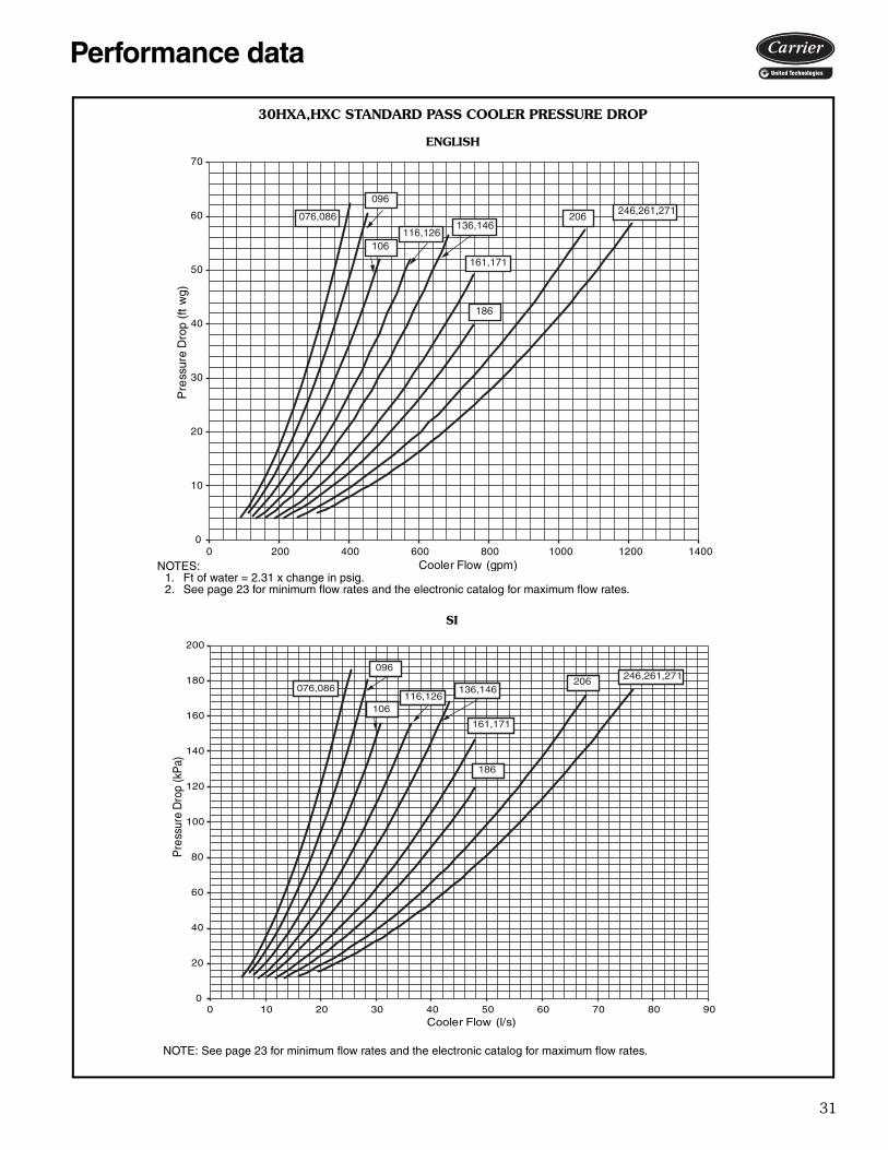
31
0
20
40
60
80
100
120
140
160
180
200
0 10 20 30 40 50 60 70 80 90
Pre
ssur
e D
rop
(kP
a)
Cooler Flow (l/s)
076,086246,261,271206
186
096
106
161,171
136,146116,126
0
10
20
30
40
50
60
70
0 200 400 600 800 1000 1200 1400
Pre
ssur
e D
rop
(ft
wg)
Cooler Flow (gpm)
076,086 246,261,271206
186
096
106
161,171
136,146116,126
30HXA,HXC STANDARD PASS COOLER PRESSURE DROP
ENGLISH
NOTES:1. Ft of water = 2.31 x change in psig.2. See page 23 for minimum flow rates and the electronic catalog for maximum flow rates.
SI
NOTE: See page 23 for minimum flow rates and the electronic catalog for maximum flow rates.
Performance data
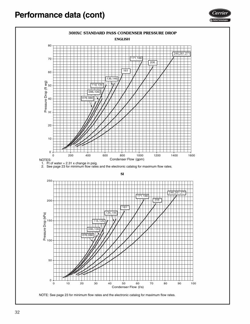
32
0
50
100
150
200
250
0 10 20 30 40 50 60 70 80 90 100
Pre
ssur
e D
rop
(kP
a)
Condenser Flow (l/s)
076,086
206
161
136,146
116,126
246,261,271171,186
096,106
0
10
20
30
40
50
60
70
80
0 200 400 600 800 1000 1200 1400 1600
Pre
ssur
e D
rop
(ft
wg)
Condenser Flow (gpm)
076,086
246,261,271
206171,186
161
136,146
096,106
116,126
30HXC STANDARD PASS CONDENSER PRESSURE DROP
SI
ENGLISH
NOTES:1. Ft of water = 2.31 x change in psig.2. See page 23 for minimum flow rates and the electronic catalog for maximum flow rates.
NOTE: See page 23 for minimum flow rates and the electronic catalog for maximum flow rates.
Performance data (cont)
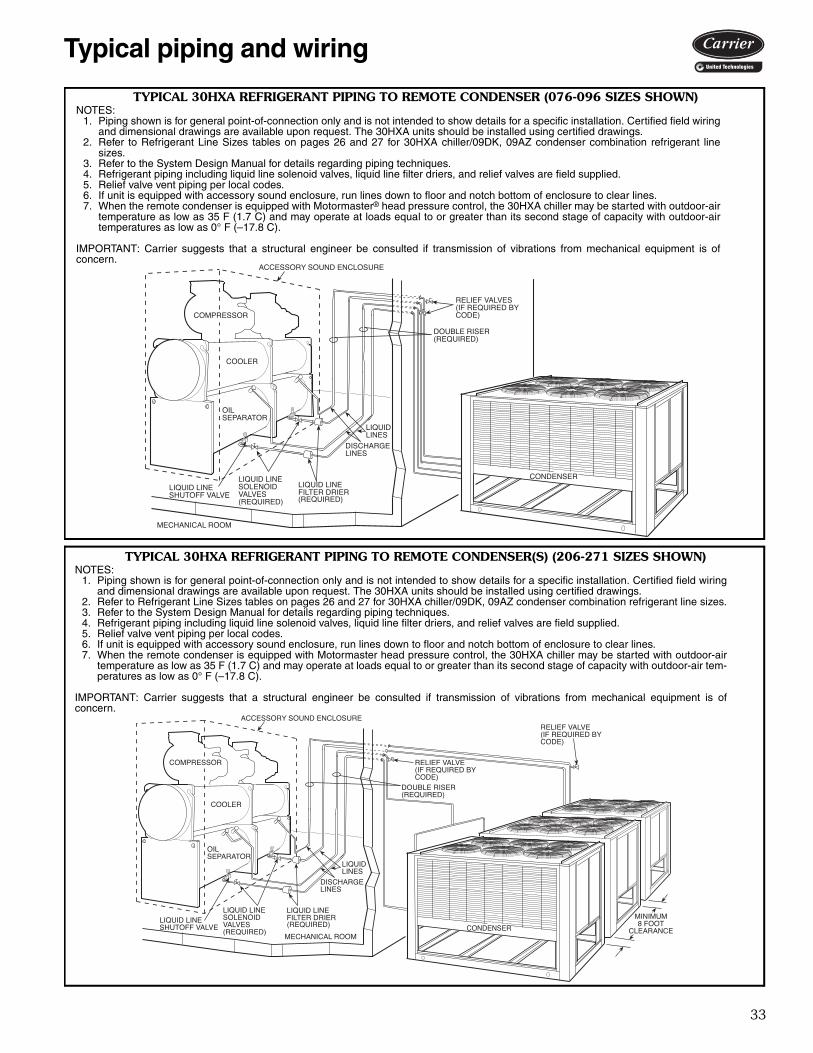
33
NOTES:1. Piping shown is for general point-of-connection only and is not intended to show details for a specific installation. Certified field wiring
and dimensional drawings are available upon request. The 30HXA units should be installed using certified drawings.2. Refer to Refrigerant Line Sizes tables on pages 26 and 27 for 30HXA chiller/09DK, 09AZ condenser combination refrigerant line sizes.3. Refer to the System Design Manual for details regarding piping techniques.4. Refrigerant piping including liquid line solenoid valves, liquid line filter driers, and relief valves are field supplied.5. Relief valve vent piping per local codes.6. If unit is equipped with accessory sound enclosure, run lines down to floor and notch bottom of enclosure to clear lines.7. When the remote condenser is equipped with Motormaster head pressure control, the 30HXA chiller may be started with outdoor-air
temperature as low as 35 F (1.7 C) and may operate at loads equal to or greater than its second stage of capacity with outdoor-air tem-peratures as low as 0° F (–17.8 C).
IMPORTANT: Carrier suggests that a structural engineer be consulted if transmission of vibrations from mechanical equipment is ofconcern.
TYPICAL 30HXA REFRIGERANT PIPING TO REMOTE CONDENSER (076-096 SIZES SHOWN)
a30-4644
NOTES:1. Piping shown is for general point-of-connection only and is not intended to show details for a specific installation. Certified field wiring
and dimensional drawings are available upon request. The 30HXA units should be installed using certified drawings.2. Refer to Refrigerant Line Sizes tables on pages 26 and 27 for 30HXA chiller/09DK, 09AZ condenser combination refrigerant line
sizes.3. Refer to the System Design Manual for details regarding piping techniques.4. Refrigerant piping including liquid line solenoid valves, liquid line filter driers, and relief valves are field supplied.5. Relief valve vent piping per local codes.6. If unit is equipped with accessory sound enclosure, run lines down to floor and notch bottom of enclosure to clear lines.7. When the remote condenser is equipped with Motormaster® head pressure control, the 30HXA chiller may be started with outdoor-air
temperature as low as 35 F (1.7 C) and may operate at loads equal to or greater than its second stage of capacity with outdoor-airtemperatures as low as 0° F (–17.8 C).
IMPORTANT: Carrier suggests that a structural engineer be consulted if transmission of vibrations from mechanical equipment is ofconcern.
a30-4645
TYPICAL 30HXA REFRIGERANT PIPING TO REMOTE CONDENSER(S) (206-271 SIZES SHOWN)
Typical piping and wiring

34
LEG
EN
D
Airf
low
Thr
ough
Air-
Han
dlin
g U
nit
Pow
er W
iring
Chi
lled
Flu
id P
ipin
gS
T—
Sta
rter
FD
—F
ield
-Sup
plie
d D
isco
nnec
t
NO
TE
S:
1.C
hille
r m
ust b
e in
stal
led
leve
lly to
mai
ntai
n pr
oper
com
pres
sor
oil r
etur
n.2.
Wiri
ng a
nd p
ipin
g sh
own
are
gene
ral p
oint
s-of
-con
nect
ion
guid
es o
nly
and
are
not i
nten
ded
for
a sp
e-ci
fic in
stal
latio
n. W
iring
and
pip
ing
show
n ar
e fo
r a
quic
k ov
ervi
ew o
f sys
tem
and
are
not
in a
ccor
danc
ew
ith r
ecog
nize
d st
anda
rds.
3.A
ll w
iring
mus
t com
ply
with
app
licab
le lo
cal a
nd n
atio
nal c
odes
.4.
All
pipi
ng m
ust
follo
w s
tand
ard
pipi
ng t
echn
ique
s. R
efer
to
the
Sys
tem
Des
ign
Man
ual o
r ap
prop
riate
AS
HR
AE
(A
mer
ican
Soc
iety
of
Hea
ting,
Ref
rige
ratin
g, a
nd A
ir-C
ondi
tioni
ng E
ngin
eers
) ha
ndbo
ok f
orde
tails
.5.
See
App
licat
ion
Dat
a se
ctio
n on
pag
e 24
for
min
imum
coo
ler
loop
vol
ume.
Thi
s sy
stem
may
req
uire
the
addi
tion
of a
hol
ding
tank
to e
nsur
e ad
equa
te v
olum
e.
TY
PIC
AL
PIP
ING
AN
D W
IRIN
G F
OR
30H
XA
,HX
C C
OO
LER
AN
D 3
0H
XC
CO
ND
EN
SER
a30-4652
Typical piping and wiring (cont)

35
SE
EN
OT
E 1
2
SE
EN
OT
E 1
2
2 TO
10,
0 T
O 1
0, O
R 1
0 TO
0 V
DC
VA
LVE
2 TO
10,
0 T
O 1
0, O
R 1
0 TO
0 V
DC
VA
LVE
PO
WER
AN
D C
ON
TR
OL
WIR
ING
a30-5577
LEG
EN
DA
—A
larm
CW
PI
—C
hille
d W
ater
Pum
p In
terlo
ckO
AT
—O
utdo
or A
ir Te
mpe
ratu
reC
FR
—C
onde
nser
Fan
Rel
ayE
MM
—E
nerg
y M
anag
emen
t Mod
ule
SP
T—
Spa
ce T
empe
ratu
reC
NF
S—
Con
dens
er F
low
Sw
itch
EW
T—
Ent
erin
g W
ater
Tem
pera
ture
TB
—Te
rmin
al B
lock
CN
PI
—C
onde
nser
Pum
p In
terlo
ckF
IOP
—Fa
ctor
y-In
stal
led
Opt
ion
Fact
ory
Inst
alle
d W
iring
CN
PR
—C
onde
nser
Wat
er P
ump
LL
SV
—Li
quid
Lin
e S
olen
oid
Val
veF
ield
Con
trol
Wiri
ngC
WF
S—
Chi
lled
Wat
er F
low
Sw
itch
LWT
—Le
avin
g W
ater
Tem
pera
ture
Fie
ld P
ower
Wiri
ngC
WP
—C
hille
d W
ater
Pum
pN
EC
—N
atio
nal E
lect
rical
Cod
e
NO
TE
S:
1.Fa
ctor
y w
irin
g is
in a
ccor
danc
e w
ith N
atio
nal E
lect
rical
Cod
e (N
EC
). F
ield
mod
ifica
tions
or
addi
tions
mus
t be
in c
ompl
ianc
e w
ith a
llap
plic
able
cod
es.
2.W
irin
g fo
r m
ain
field
sup
ply
mus
t be
rat
ed 7
5 C
min
imum
. U
se c
oppe
r fo
r al
l uni
ts.
Max
imum
inco
min
g w
ire s
ize
for
each
ter
min
albl
ock
is 5
00 k
cmil.
3.P
ower
for
cont
rol c
ircui
t sho
uld
be s
uppl
ied
from
a s
epar
ate
sour
ce (
exce
pt 3
80/4
15-v
uni
ts)
thro
ugh
a fie
ld-s
uppl
ied
disc
onne
ct w
ith15
A m
axim
um p
rote
ctio
n fo
r 11
5-v
cont
rol
circ
uits
and
15
A m
axim
um p
rote
ctio
n fo
r 23
0-v
cont
rol c
ircui
t. C
onne
ct c
ontr
ol c
ircui
tpo
wer
to te
rmin
als
1 an
d 2
of T
B4.
Con
trol
circ
uit c
ondu
ctor
s fo
r al
l uni
ts m
ust b
e co
pper
onl
y. C
ontr
ol c
ircui
t pow
er is
fact
ory
wire
dfo
r 38
0/41
5-v
units
.4.
Term
inal
s 13
and
14
TB
5 ar
e fo
r fie
ld e
xter
nal c
onne
ctio
n fo
r re
mot
e on
-off.
The
con
tact
s m
ust
be r
ated
for
dry
circ
uit
appl
icat
ion
capa
ble
of h
andl
ing
a 24
vac
load
up
to 5
0 m
A.
5.Te
rmin
als
1 an
d 2
of T
B5
are
for
chill
ed w
ater
pum
p in
terlo
ck (
CW
PI)
func
tions
. If a
dded
, chi
lled
wat
er p
ump
inte
rlock
con
tact
s m
ust
be w
ired
in s
erie
s w
ith f
low
con
tact
s. T
he c
onta
cts
mus
t be
rat
ed fo
r dr
y ci
rcui
t ap
plic
atio
n ca
pabl
e of
han
dlin
g a
24-v
ac lo
ad u
p to
50m
A. C
hille
d w
ater
flow
sw
itch
(CW
FS
) is
fact
ory
inst
alle
d.6.
Term
inal
s 10
and
12
of T
B5
are
for
cont
rol o
f the
chi
lled
wat
er p
ump
star
ter.
The
max
imum
load
allo
wed
for
the
chill
ed w
ater
pum
pre
lay
is 7
5 va
sea
led,
360
va
inru
sh a
t 115
v o
r 23
0 v.
Sep
arat
e fie
ld p
ower
sup
ply
is n
ot r
equi
red.
7.Te
rmin
als
11 a
nd 1
2 of
TB
5 ar
e fo
r al
arm
rel
ay.
The
max
imum
load
allo
wed
for
the
ala
rm r
elay
is
75 v
a se
aled
, 36
0 va
inru
sh a
t11
5v
or 2
30 v
. Sep
arat
e fie
ld p
ower
sup
ply
is n
ot r
equi
red.
8.Te
rmin
als
7 an
d 9
of T
B2
are
for
cond
ense
r w
ater
pum
p (H
XC
) or
circ
uit
A c
onde
nser
fan
cont
acto
r (H
XA
onl
y).
Term
inal
s 8
and
9of
TB
2 ar
e fo
r ci
rcui
t B c
onta
ctor
(H
XA
onl
y) o
r liq
uid
line
sole
noid
val
ves
(fact
ory-
wire
d 30
HX
C b
rine
). T
he m
axim
um lo
ad a
llow
edis
75
va s
eale
d, 3
60 v
a in
rush
at
115
v or
230
v.
Sep
arat
e fie
ld p
ower
sup
ply
is n
ot r
equi
red.
Liq
uid
line
sole
noid
val
ves
(30H
XA
only
) m
ust b
e co
nnec
ted
in p
aral
lel f
an c
onta
ctor
s as
sho
wn.
9.Te
rmin
als
5 an
d 6
of T
B2
are
for
cond
ense
r flo
w s
witc
h (C
NF
S)
and/
or c
onde
nser
pum
p in
terlo
ck (
CN
PI)
. T
he c
onta
cts
mus
t be
rate
d fo
r dr
y ci
rcui
t app
licat
ion
capa
ble
of h
andl
ing
a 24
-vac
load
up
to 5
0 m
A.
10.
Mak
e ap
prop
riate
con
nect
ions
to T
B6
as s
how
n fo
r en
ergy
man
agem
ent b
oard
opt
ions
. The
con
tact
s fo
r de
man
d lim
it an
d ic
e do
neop
tions
mus
t be
rate
d fo
r dr
y ci
rcui
t app
licat
ion
capa
ble
of h
andl
ing
a 24
vac
load
up
to 5
0 m
A.
11.
TB
1B s
uppl
ied
on 3
0HX
A18
6, 2
08/2
30-v
uni
ts w
ith Y
-Del
ta s
tart
er;
30H
XA
206-
271,
208
/230
, 23
0-v
units
with
Y-D
elta
sta
rter
; an
dby
spe
cial
ord
er.
12.
500
kcm
il if
min
imum
circ
uit a
mps
(M
CA
) >
200
A, 3
00 k
cmil
if M
CA
2
00 A
.
Typical control wiring schematic

36
ELECTRICAL DATA, 30HXC UNITS
See Legend and Notes on page 37.
UNIT30HXC
UNIT VOLTAGEPOWERSUPPLY
QTY. REQD.
NO. POWERSUPPLY
CONDUCTORS
UNIT VOLTAGE CONTROL CIRCUIT
V-Hz(3 Ph)
SuppliedMCA MOCP
ICF Rec Fuse Size V-Hz(Single
Ph)
Supplied MCA andMOCPMin Max XL WD XL WD Min Max
076
230-60 207 253 1 3 198.7 250 — 297.3 — 225 115-60 104 127 15208/230-60 187 253 1 3 220.7 300 — 307.1 — 250 115-60 104 127 15
460-60 414 506 1 3 99.7 125 374.3 148.3 125 125 115-60 104 127 15575-60 518 633 1 3 79.7 110 299.4 118.4 90 90 115-60 104 127 15380-60 342 418 1 3 120.8 150 418.7 168.7 150 150 230-60 207 254 15
380/415-50 342 440 1 3 125.6 175 399.8 164.8 150 150 230-50 198 254 15230-50 207 253 1 3 207.2 250 — 266.1 — 250 230-50 207 254 15
086
230-60 207 253 1 3 221.7 300 — 297.3 — 250 115-60 104 127 15208/230-60 187 253 1 3 246.4 350 — 307.1 — 300 115-60 104 127 15
460-60 414 506 1 3 111.3 150 374.3 148.3 125 125 115-60 104 127 15575-60 518 633 1 3 88.9 125 299.4 118.4 100 100 115-60 104 127 15380-60 342 418 1 3 134.8 175 418.7 168.7 175 175 230-60 207 254 15
380/415-50 342 440 1 3 140.4 200 478.8 189.8 175 175 230-50 198 254 15230-50 207 253 1 3 231.9 300 — 305.1 — 300 230-50 207 254 15
096
230-60 207 253 1 3 251.3 350 — 344.3 — 300 115-60 104 127 15208/230-60 187 253 1 3 279.2 400 — 354.1 — 350 115-60 104 127 15
460-60 414 506 1 3 126.2 175 449.3 172.3 150 150 115-60 104 127 15575-60 518 633 1 3 100.8 150 359.4 137.4 125 125 115-60 104 127 15380-60 342 418 1 3 152.7 225 501.7 194.7 175 175 230-60 207 254 15
380/415-50 342 440 1 3 157.9 225 561.8 215.8 200 200 230-50 198 254 15230-50 207 253 1 3 260.7 350 — 347.1 — 300 230-50 207 254 15
106
230-60 207 253 1 3 285.6 400 — 395.3 — 350 115-60 104 127 15208/230-60 187 253 1 3 317.4 450 — 405.1 — 400 115-60 104 127 15
460-60 414 506 1 3 143.3 200 529.3 197.3 175 175 115-60 104 127 15575-60 518 633 1 3 114.5 175 423.4 158.4 150 150 115-60 104 127 15380-60 342 418 1 3 173.6 250 589.7 222.7 200 200 230-60 207 254 15
380/415-50 342 440 1 3 178.1 250 660.8 246.8 225 225 230-50 198 254 15230-50 207 253 1 3 294.2 450 — 397.1 — 350 230-50 207 254 15
116
230-60 207 253 1 3 304.1 450 — 413.7 — 350 115-60 104 127 15208/230-60 187 253 1 3 337.9 500 — 425.6 — 400 115-60 104 127 15
460-60 414 506 1 3 152.6 225 538.6 206.6 175 175 115-60 104 127 15575-60 518 633 1 3 121.9 175 430.8 165.8 150 150 115-60 104 127 15380-60 342 418 1 3 184.8 250 600.9 233.9 225 225 230-60 207 254 15
380/415-50 342 440 1 3 190.0 250 672.7 258.7 225 225 230-50 198 254 15230-50 207 253 1 3 313.9 450 — 416.8 — 400 230-50 207 254 15
126
230-60 207 253 1 3 327.7 450 — 437.4 — 400 115-60 104 127 15208/230-60 187 253 1 3 364.2 500 — 451.9 — 450 115-60 104 127 15
460-60 414 506 1 3 164.5 225 550.5 218.5 200 200 115-60 104 127 15575-60 518 633 1 3 131.4 175 440.3 175.3 150 150 115-60 104 127 15380-60 342 418 1 3 199.1 250 615.2 248.2 225 225 230-60 207 254 15
380/415-50 342 440 1 3 204.0 300 686.7 272.7 250 250 230-50 198 254 15230-50 207 253 1 3 337.0 450 — 439.9 — 400 230-50 207 254 15
136
230-60 207 253 1 3 366.7 500 — 497.4 — 450 115-60 104 127 15208/230-60 187 253 1 6 407.4 600 — 511.9 — 500 115-60 104 127 15
460-60 414 506 1 3 183.8 250 645.5 248.5 225 225 115-60 104 127 15575-60 518 633 1 3 147.1 200 536.3 199.3 175 175 115-60 104 127 15380-60 342 418 1 3 222.8 300 720.2 282.2 300 300 230-60 207 254 15
380/415-50 342 440 1 3 230.2 300 796.7 307.7 300 300 230-50 198 254 15230-50 207 253 1 6 380.3 500 — 495.9 — 450 230-50 207 254 15
146
230-60 207 253 1 6 394.1 500 — 524.9 — 450 115-60 104 127 15208/230-60 187 253 1 6 437.9 600 — 542.4 — 500 115-60 104 127 15
460-60 414 506 1 3 197.5 250 659.2 262.2 225 225 115-60 104 127 15575-60 518 633 1 3 158.1 225 547.3 210.3 200 200 115-60 104 127 15380-60 342 418 1 3 239.5 350 736.9 298.9 300 300 230-60 207 254 15
380/415-50 342 440 1 3 246.3 350 812.8 323.8 300 300 230-50 198 254 15230-50 207 253 1 6 407.1 600 — 522.7 — 500 230-50 207 254 15
161
230-60 207 253 1 6 398.7 600 — 574.8 — 500 115-60 104 127 15208/230-60 187 253 1 6 443.0 600 — 590.6 — 600 115-60 104 127 15
460-60 414 506 1 3 200.1 300 756.2 287.2 250 250 115-60 104 127 15575-60 518 633 1 3 159.9 225 604.9 229.9 200 200 115-60 104 127 15380-60 342 418 1 3 242.2 350 843.2 325.2 300 300 230-60 207 254 15
380/415-50 342 440 1 3 249.0 350 944.2 358.2 300 300 230-50 198 254 15230-50 207 253 1 6 411.3 600 — 577.7 — 500 230-50 207 254 15
Electrical data
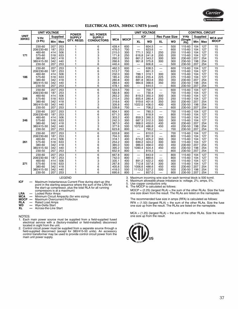
37
ELECTRICAL DATA, 30HXC UNITS (cont)
LEGEND
NOTES:1. Each main power source must be supplied from a field-supplied fused
electrical service with a (factory-installed or field-installed) disconnectlocated in sight from the unit.
2. Control circuit power must be supplied from a separate source through afield-supplied disconnect (except for 380/415-50 units). An accessorycontrol transformer may be used to provide control circuit power from themain unit power supply.
3. Maximum incoming wire size for each terminal block is 500 kcmil.4. Maximum allowable phase imbalance is: voltage, 2%; amps, 5%.5. Use copper conductors only.6. The MOCP is calculated as follows:
MOCP = (2.25) (largest RLA) + the sum of the other RLAs. Size the fuseone size down from the result. The RLAs are listed on the nameplate.
The recommended fuse size in amps (RFA) is calculated as follows:RFA = (1.50) (largest RLA) + the sum of the other RLAs. Size the fuseone size up from the result. The RLAs are listed on the nameplate.
MCA = (1.25) (largest RLA) + the sum of the other RLAs. Size the wiresone size up from the result.
UNIT30HXC
UNIT VOLTAGEPOWERSUPPLY
QTY. REQD.
NO. POWERSUPPLY
CONDUCTORS
UNIT VOLTAGE CONTROL CIRCUIT
V-Hz(3 Ph)
SuppliedMCA MOCP
ICF Rec Fuse Size V-Hz(Single
Ph)
Supplied MCA andMOCPMin Max XL WD XL WD Min Max
171
230-60 207 253 1 6 428.4 600 — 604.5 — 500 115-60 104 127 15208/230-60 187 253 1 6 476.0 700 — 623.6 — 600 115-60 104 127 15
460-60 414 506 1 3 215.0 300 771.1 302.1 250 250 115-60 104 127 15575-60 518 633 1 3 171.8 250 616.8 241.8 200 200 115-60 104 127 15380-60 342 418 1 3 260.2 350 861.2 343.2 300 300 230-60 207 254 15
380/415-50 342 440 1 3 266.6 350 961.8 375.8 300 300 230-50 198 254 15230-50 207 253 1 6 440.4 600 — 606.8 — 500 230-50 207 254 15
186
230-60 207 253 1 6 462.3 600 — 638.5 — 600 115-60 104 127 15208/230-60 187 253 1 6 513.7 700 — 661.3 — 600 115-60 104 127 15
460-60 414 506 1 3 232.0 300 788.1 319.1 300 300 115-60 104 127 15575-60 518 633 1 3 185.4 250 630.4 255.4 225 225 115-60 104 127 15380-60 342 418 1 3 280.8 400 881.8 363.8 350 350 230-60 207 254 15
380/415-50 342 440 1 3 289.4 400 984.6 398.6 350 350 230-50 198 254 15230-50 207 253 1 6 478.1 600 — 644.5 — 600 230-50 207 254 15
206
230-60 207 253 1 6 524.5 700 — 700.7 — 600 115-60 104 127 15208/230-60 187 253 1 6 582.8 800 — 730.4 — 700 115-60 104 127 15
460-60 414 506 1 3 263.2 350 819.3 350.3 300 300 115-60 104 127 15575-60 518 633 1 3 210.4 250 655.4 280.4 250 250 115-60 104 127 15380-60 342 418 1 3 318.6 400 919.6 401.6 350 350 230-60 207 254 15
380/415-50 342 440 1 3 326.8 450 1022.0 436.0 400 400 230-50 198 254 15230-50 207 253 1 6 539.8 700 — 706.2 — 600 230-50 207 254 15
246
230-60 207 253 1 6 604.1 800 — 780.3 — 700 115-60 104 127 15208/230-60 187 253 1 6 671.3 800 — 818.9 — 800 115-60 104 127 15
460-60 414 506 1 3 303.2 400 859.3 390.3 350 350 115-60 104 127 15575-60 518 633 1 3 242.3 300 687.3 312.3 300 300 115-60 104 127 15380-60 342 418 1 3 367.0 450 968.0 450.0 400 400 230-60 207 254 15
380/415-50 342 440 1 3 377.6 500 1072.8 486.8 450 450 230-50 198 254 15230-50 207 253 1 6 623.8 800 — 790.2 — 700 230-50 207 254 15
261
230-60 207 253 1 6 633.8 800 — 810.0 — 700 115-60 104 127 15208/230-60 187 253 1 6 704.3 800 — 851.9 — 800 115-60 104 127 15
460-60 414 506 1 3 318.1 400 874.2 405.2 350 350 115-60 104 127 15575-60 518 633 1 3 254.2 300 699.2 324.2 300 300 115-60 104 127 15380-60 342 418 1 6 385.0 500 986.0 468.0 450 450 230-60 207 254 15
380/415-50 342 440 1 6 395.2 500 1090.4 504.4 450 450 230-50 198 254 15230-50 207 253 1 6 652.9 800 — 819.3 — 800 230-50 207 254 15
271
230-60 207 253 1 6 667.8 800 — 843.9 — 800 115-60 104 127 15208/230-60 187 253 1 6 742.0 800 — 889.6 — 800 115-60 104 127 15
460-60 414 506 1 3 335.1 400 891.2 422.2 400 400 115-60 104 127 15575-60 518 633 1 3 267.8 350 712.8 337.8 300 300 115-60 104 127 15380-60 342 418 1 6 405.6 500 1006.6 488.6 450 450 230-60 207 254 15
380/415-50 342 440 1 6 418.0 500 1113.2 527.2 500 500 230-50 198 254 15230-50 207 253 1 6 690.6 800 — 857.0 — 800 230-50 207 254 15
ICF — Maximum Instantaneous Current Flow during start-up (the point in the starting sequence where the sum of the LRA for the start-up compressor, plus the total RLA for all running compressors is at a maximum)
LRA — Locked Rotor AmpsMCA — Minimum Circuit Ampacity (for wire sizing)MOCP — Maximum Overcurrent ProtectionRLA — Rated Load AmpsWD — Wye-Delta StartXL — Across-the-Line Start
ETL_listed_C_US-tif

38
ELECTRICAL DATA, 30HXA UNITS
See Legend and Notes on page 39.
UNIT30HXA
UNIT VOLTAGEPOWERSUPPLY
QTY. REQD.
NO. POWERSUPPLY
CONDUCTORS
UNIT VOLTAGE CONTROL CIRCUIT
V-Hz(3 Ph)
SuppliedMCA MOCP
ICF Rec Fuse Size V-Hz(Single
Ph)
Supplied MCA andMOCPMin Max XL WD XL WD Min Max
076
230-60 207 253 1 3 291.2 400 — 436.4 — 350 115-60 104 127 15208/230-60 187 253 1 3 323.6 450 — 450.8 — 400 115-60 104 127 15
460-60 414 506 1 3 146.0 200 549.9 217.9 175 175 115-60 104 127 15575-60 518 633 1 3 116.8 150 439.9 174.9 150 150 115-60 104 127 15380-60 342 418 1 3 177.1 250 614.7 247.7 200 200 230-60 207 254 15
380/415-50 342 440 1 3 183.4 250 686.5 272.5 225 225 230-50 198 254 15230-50 207 253 1 3 303.3 400 — 439.8 — 350 230-50 207 254 15
086
230-60 207 253 1 3 322.8 450 — 496.4 — 400 115-60 104 127 15208/230-60 187 253 1 3 358.7 500 — 510.8 — 450 115-60 104 127 15
460-60 414 506 1 3 161.9 225 644.9 247.9 200 200 115-60 104 127 15575-60 518 633 1 3 129.5 175 535.9 198.9 150 150 115-60 104 127 15380-60 342 418 1 3 196.2 250 719.7 281.7 225 225 230-60 207 254 15
380/415-50 342 440 1 3 205.5 300 796.5 307.5 250 250 230-50 198 254 15230-50 207 253 1 3 339.7 500 — 495.8 — 400 230-50 207 254 15
096
230-60 207 253 1 3 365.4 500 — 562.4 — 450 115-60 104 127 15208/230-60 187 253 1 6 406.1 600 — 576.8 — 500 115-60 104 127 15
460-60 414 506 1 3 183.4 250 749.9 280.9 225 225 115-60 104 127 15575-60 518 633 1 3 146.5 200 599.9 224.9 175 175 115-60 104 127 15380-60 342 418 1 3 222.1 300 835.7 317.7 300 300 230-60 207 254 15
380/415-50 342 440 1 3 231.4 350 937.5 351.5 300 300 230-50 198 254 15230-50 207 253 1 6 382.6 500 — 566.8 — 450 230-50 207 254 15
106
230-60 207 253 1 6 416.9 600 — 647.4 — 500 115-60 104 127 15208/230-60 187 253 1 6 463.2 700 — 661.8 — 600 115-60 104 127 15
460-60 414 506 1 3 209.2 300 884.9 323.9 250 250 115-60 104 127 15575-60 518 633 1 3 167.2 250 707.9 258.9 200 200 115-60 104 127 15380-60 342 418 1 3 253.3 350 984.7 364.7 300 300 230-60 207 254 15
380/415-50 342 440 1 3 263.3 400 1041.5 384.5 300 300 230-50 198 254 15230-50 207 253 1 6 435.1 600 — 619.8 — 500 230-50 207 254 15
116
230-60 207 253 1 6 442.1 600 — 672.7 — 500 115-60 104 127 15208/230-60 187 253 1 6 491.3 700 — 689.9 — 600 115-60 104 127 15
460-60 414 506 1 3 221.9 300 897.6 336.6 300 300 115-60 104 127 15575-60 518 633 1 3 177.4 250 718.1 269.1 225 225 115-60 104 127 15380-60 342 418 1 3 268.6 400 1000.0 380.0 350 350 230-60 207 254 15
380/415-50 342 440 1 3 281.0 400 1059.2 402.2 350 350 230-50 198 254 15230-50 207 253 1 6 464.2 700 — 648.9 — 600 230-50 207 254 15
126
230-60 207 253 1 6 476.3 700 — 706.8 — 600 115-60 104 127 15208/230-60 187 253 1 6 529.2 700 — 727.8 — 600 115-60 104 127 15
460-60 414 506 1 3 239.1 350 914.8 353.8 300 300 115-60 104 127 15575-60 518 633 1 3 191.0 250 731.7 282.7 225 225 115-60 104 127 15380-60 342 418 1 3 289.3 400 1020.7 400.7 350 350 230-60 207 254 15
380/415-50 342 440 1 3 301.7 400 1079.9 422.9 350 350 230-50 198 254 15230-50 207 253 1 6 498.5 700 — 683.2 — 600 230-50 207 254 15
136
230-60 207 253 1 6 539.1 800 — 769.8 — 700 115-60 104 127 15208/230-60 187 253 1 6 599.1 800 — 790.8 — 700 115-60 104 127 15
460-60 414 506 1 3 270.7 400 1014.8 385.8 350 350 115-60 104 127 15575-60 518 633 1 3 216.2 300 811.7 308.7 250 250 115-60 104 127 15380-60 342 418 1 3 327.5 450 1131.7 435.7 400 400 230-60 207 254 15
380/415-50 342 440 1 3 343.4 500 1345.9 506.9 400 400 230-50 198 254 15230-50 207 253 1 6 567.3 800 — 817.2 — 700 230-50 207 254 15
146
230-60 207 253 1 6 580.3 800 — 811.0 — 700 115-60 104 127 15208/230-60 187 253 1 6 644.8 800 — 836.5 — 800 115-60 104 127 15
460-60 414 506 1 3 291.3 400 1035.4 406.4 350 350 115-60 104 127 15575-60 518 633 1 3 232.7 300 828.2 325.2 300 300 115-60 104 127 15380-60 342 418 1 3 352.5 500 1156.7 460.7 400 400 230-60 207 254 15
380/415-50 342 440 1 3 368.9 500 1371.4 532.4 450 450 230-50 198 254 15230-50 207 253 1 6 609.3 800 — 859.2 — 700 230-50 207 254 15
161
230-60 207 253 1 6 605.6 800 — 955.3 — 700 115-60 104 127 15208/230-60 187 253 1 6 672.9 1000 — 978.9 — 800 115-60 104 127 15
460-60 414 506 1 3 304.0 450 1281.6 477.6 350 350 115-60 104 127 15575-60 518 633 1 3 242.9 350 1025.1 382.1 300 300 115-60 104 127 15380-60 342 418 1 3 368.0 500 1428.0 539.0 450 450 230-60 207 254 15
380/415-50 342 440 1 6 384.9 500 1398.4 533.4 450 450 230-50 198 254 15230-50 207 253 1 6 635.7 800 — 858.3 — 800 230-50 207 254 15
171
230-60 207 253 1 6 651.5 800 — 1001.2 — 800 115-60 104 127 15208/230-60 187 253 1 6 723.9 1000 — 1029.9 — 1000 115-60 104 127 15
460-60 414 506 1 3 327.0 450 1304.6 500.6 400 400 115-60 104 127 15575-60 518 633 1 3 261.4 350 1043.6 400.6 300 300 115-60 104 127 15380-60 342 418 1 6 395.9 500 1455.9 566.9 450 450 230-60 207 254 15
380/415-50 342 440 1 6 413.2 600 1426.7 561.7 500 500 230-50 198 254 15230-50 207 253 1 6 682.6 1000 — 905.2 — 800 230-50 207 254 15
Electrical data (cont)
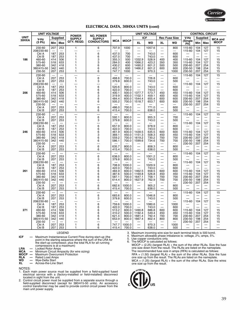
39
ELECTRICAL DATA, 30HXA UNITS (cont)
LEGEND
NOTES:1. Each main power source must be supplied from a field-supplied fused
electrical service with a (factory-installed or field-installed) disconnectlocated in sight from the unit.
2. Control circuit power must be supplied from a separate source through afield-supplied disconnect (except for 380/415-50 units). An accessorycontrol transformer may be used to provide control circuit power from themain unit power supply.
3. Maximum incoming wire size for each terminal block is 500 kcmil.4. Maximum allowable phase imbalance is: voltage, 2%; amps, 5%.5. Use copper conductors only.6. The MOCP is calculated as follows:
MOCP = (2.25) (largest RLA) + the sum of the other RLAs. Size the fuseone size down from the result. The RLAs are listed on the nameplate.The recommended fuse size in amps (RFA) is calculated as follows:RFA = (1.50) (largest RLA) + the sum of the other RLAs. Size the fuseone size up from the result. The RLAs are listed on the nameplate.MCA = (1.25) (largest RLA) + the sum of the other RLAs. Size the wiresone size up from the result.
UNIT30HXA
UNIT VOLTAGEPOWERSUPPLY
QTY. REQD.
NO. POWERSUPPLY
CONDUCTORS
UNIT VOLTAGE CONTROL CIRCUIT
V-Hz(3 Ph)
SuppliedMCA MOCP
ICF Rec Fuse Size V-Hz(Single
Ph)
Supplied MCA andMOCPMin Max XL WD XL WD Min Max
186
230-60 207 253 1 6 707.9 1000 — 1057.6 — 800 115-60 104 127 15208/230-60 — — — — — — — — — — 115-60 104 127 15
Ckt A 187 253 1 6 437.0 700 — 743.0 — 600 — — — —Ckt B 187 253 1 6 437.0 700 — 743.0 — 600 — — — —
460-60 414 506 1 3 355.3 500 1332.9 528.9 400 400 115-60 104 127 15575-60 518 633 1 3 284.0 400 1066.2 423.2 350 350 115-60 104 127 15380-60 342 418 1 6 430.2 600 1490.2 601.2 500 500 230-60 207 254 15
380/415-50 342 440 1 6 452.7 600 1466.2 601.2 600 600 230-50 198 254 15230-50 207 253 1 6 747.7 1000 — 970.3 — 1000 230-50 207 254 15
206
230-60 — — — — — — — — — — 115-60 104 127 15Ckt A 207 253 1 6 468.6 700.0 — 726.8 — 600 — — — —Ckt B 207 253 1 3 379.8 600.0 — 743.0 — 500 — — — —
208/230-60 — — — — — — — — — — 115-60 104 127 15Ckt A 187 253 1 6 520.6 800.0 — 743.0 — 600 — — — —Ckt B 187 253 1 6 422.0 700.0 — 743.0 — 600 — — — —
460-60 414 506 1 6 400.1 500.0 1377.7 573.7 450 450 115-60 104 127 15575-60 518 633 1 3 319.9 400.0 1102.1 459.1 400 400 115-60 104 127 15380-60 342 418 1 6 484.4 600.0 1544.4 655.4 600 600 230-60 207 254 15
380/415-50 342 440 1 6 505.2 700.0 1518.7 653.7 600 600 230-50 198 254 15230-50 — — — — — — — — — — 230-50 207 254 15Ckt A 207 253 1 6 486.0 700.0 — 771.0 — 600 — — — —Ckt B 207 253 1 6 415.4 700.0 — 638.0 — 500 — — — —
246
230-60 — — — — — — — — — — 115-60 104 127 15Ckt A 207 253 1 6 592.1 800.0 — 955.3 — 700 — — — —Ckt B 207 253 1 3 379.8 600.0 — 743.0 — 500 — — — —
208/230-60 — — — — — — — — — — 115-60 104 127 15Ckt A 187 253 1 6 657.9 800.0 — 978.9 — 800 — — — —Ckt B 187 253 1 6 422.0 700.0 — 743.0 — 600 — — — —
460-60 414 506 1 6 461.9 600.0 1439.5 635.5 600 600 115-60 104 127 15575-60 518 633 1 3 369.1 450.0 1151.3 508.3 450 450 115-60 104 127 15380-60 342 418 1 6 559.2 700.0 1619.2 730.2 700 700 230-60 207 254 15
380/415-50 342 440 1 6 586.1 700.0 1599.6 734.6 700 700 230-50 198 254 15230-50 — — — — — — — — — — 230-50 207 254 15Ckt A 207 253 1 6 635.7 800.0 — 858.3 — 800 — — — —Ckt B 207 253 1 6 415.4 700.0 — 638.0 — 500 — — — —
261
230-60 — — — — — — — — — — 115-60 104 127 15Ckt A 207 253 1 6 638.0 800.0 — 1001.2 — 800 — — — —Ckt B 207 253 1 3 379.8 600.0 — 743.0 — 500 — — — —
208/230-60 — — — — — — — — — — 115-60 104 127 15Ckt A 187 253 1 6 708.9 1000.0 — 1029.9 — 800 — — — —Ckt B 187 253 1 6 422.0 700.0 — 743.0 — 600 — — — —
460-60 414 506 1 6 484.9 600.0 1462.5 658.5 600 600 115-60 104 127 15575-60 518 633 1 6 387.6 500.0 1169.8 526.8 450 450 115-60 104 127 15380-60 342 418 1 6 587.1 700.0 1647.1 758.1 700 700 230-60 207 254 15
380/415-50 342 440 1 6 614.4 800.0 1627.9 762.9 700 700 230-50 198 254 15230-50 — — — — — — — — — — 230-50 207 254 15Ckt A 207 253 1 6 682.6 1000.0 — 905.2 — 800 — — — —Ckt B 207 253 1 6 415.4 700.0 — 638.0 — 500 — — — —
271
230-60 — — — — — — — — — — 115-60 104 127 15Ckt A 207 253 1 6 683.6 800.0 — 1046.8 — 800 — — — —Ckt B 207 253 1 3 379.8 600.0 — 743.0 — 500 — — — —
208/230-60 — — — — — — — — — — 115-60 104 127 15Ckt A 187 253 1 6 759.6 1000.0 — 1080.6 — 1000 — — — —Ckt B 187 253 1 6 422.0 700.0 — 743.0 — 600 — — — —
460-60 414 506 1 6 513.2 600.0 1490.8 686.8 600 600 115-60 104 127 15575-60 518 633 1 6 410.2 500.0 1192.4 549.4 450 450 115-60 104 127 15380-60 342 418 1 6 621.4 800.0 1681.4 792.4 700 700 230-60 207 254 15
380/415-50 342 440 1 6 653.9 800.0 1667.4 802.4 800 800 230-50 198 254 15230-50 — — — — — — — — — — 230-50 207 254 15Ckt A 207 253 1 6 747.7 1000.0 — 970.3 — 1000 — — — —Ckt B 207 253 1 6 415.4 700.0 — 638.0 — 500 — — — —
ICF — Maximum Instantaneous Current Flow during start-up (the point in the starting sequence where the sum of the LRA for the start-up compressor, plus the total RLA for all running compressors is at a maximum)
LRA — Locked Rotor AmpsMCA — Minimum Circuit Ampacity (for wire sizing)MOCP — Maximum Overcurrent ProtectionRLA — Rated Load AmpsWD — Wye-Delta StartXL — Across-the-Line Start
ETL_listed_C_US-tif

40
COMPRESSOR ELECTRICAL DATA, 30HXC UNITS
LEGEND
*Units are shipped with wye-delta start as standard. Across-the-line start is not available.
UNIT SIZE 30HXCNAMEPLATE
V-Hz(3 Phase)
COMPRESSOR NUMBERSA1 B1
RLA LRA RLA LRA
076-XL
208/230-60 * * * *230-60 * * * *460-60 44.3 330 44.3 330575-60 35.4 264 35.4 264380-60 53.7 365 53.7 365230-50 * * * *
380/415-50 55.8 344 55.8 344
076-WD
208/230-60 98.1 209 98.1 209230-60 88.3 209 88.3 209460-60 44.3 104 44.3 104575-60 35.4 83 35.4 83380-60 53.7 115 53.7 115230-50 92.1 174 92.1 174
380/415-50 55.8 109 55.8 109
086-XL
208/230-60 * * * *230-60 * * * *460-60 53.6 330 44.3 330575-60 42.8 264 35.4 264380-60 64.9 365 53.7 365230-50 * * * *
380/415-50 67.7 423 55.8 344
086-WD
208/230-60 118.6 209 98.1 209230-60 106.7 209 88.3 209460-60 53.6 104 44.3 104575-60 42.8 83 35.4 83380-60 64.9 115 53.7 115230-50 111.8 213 92.1 174
380/415-50 67.7 134 55.8 109
096-XL
208/230-60 * * * *230-60 * * * *460-60 65.5 405 44.3 330575-60 52.3 324 35.4 264380-60 79.2 448 53.7 365230-50 * * * *
380/415-50 81.7 506 55.8 344
096-WD
208/230-60 144.9 256 98.1 209230-60 130.4 256 88.3 209460-60 65.5 128 44.3 104575-60 52.3 102 35.4 83380-60 79.2 141 53.7 115230-50 134.9 255 92.1 174
380/415-50 81.7 160 55.8 109
106-XL
208/230-60 * * * *230-60 * * * *460-60 79.2 485 44.3 330575-60 63.3 388 35.4 264380-60 95.9 536 53.7 365230-50 * * * *
380/415-50 97.8 605 55.8 344
106-WD
208/230-60 175.4 307 98.1 209230-60 157.9 307 88.3 209460-60 79.2 153 44.3 104575-60 63.3 123 35.4 83380-60 95.9 169 53.7 115230-50 161.7 305 92.1 174
380/415-50 97.8 191 55.8 109
LRA — Locked Rotor AmpsRLA — Rated Load AmpsWD — Wye-Delta StartXL — Across-the-Line Start
Electrical data (cont)

41
COMPRESSOR ELECTRICAL DATA, 30HXC UNITS (cont)
LEGEND
*Units are shipped with wye-delta start as standard. Across-the-line start is not available.
UNIT SIZE 30HXCNAMEPLATE
V-Hz(3 Phase)
COMPRESSOR NUMBERSA1 B1
RLA LRA RLA LRA
116-XL
208/230-60 * * * *230-60 * * * *460-60 79.2 485 53.6 330575-60 63.3 388 42.8 264380-60 95.9 536 64.9 365230-50 * * * *
380/415-50 97.8 605 67.7 423
116-WD
208/230-60 175.4 307 118.6 209230-60 157.9 307 106.7 209460-60 79.2 153 53.6 104575-60 63.3 123 42.8 83380-60 95.9 169 64.9 115230-50 161.7 305 111.8 213
380/415-50 97.8 191 67.7 134
126-XL
208/230-60 * * * *230-60 * * * *460-60 79.2 485 65.5 405575-60 63.3 388 52.3 324380-60 95.9 536 79.2 448230-50 * * * *
380/415-50 97.8 605 81.7 506
126-WD
208/230-60 175.4 307 144.9 256230-60 157.9 307 130.4 256460-60 79.2 153 65.5 128575-60 63.3 123 52.3 102380-60 95.9 169 79.2 141230-50 161.7 305 134.9 255
380/415-50 97.8 191 81.7 160
136-XL
208/230-60 * * * *230-60 * * * *460-60 94.6 580 65.5 405575-60 75.8 484 52.3 324380-60 114.9 641 79.2 448230-50 * * * *
380/415-50 118.8 715 81.7 506
136-WD
208/230-60 210.0 367 144.9 256230-60 189.0 367 130.4 256460-60 94.6 183 65.5 128575-60 75.8 147 52.3 102380-60 114.9 203 79.2 141230-50 196.3 361 134.9 255
380/415-50 118.8 226 81.7 160
146-XL
208/230-60 * * * *230-60 * * * *460-60 94.6 580 79.2 485575-60 75.8 484 63.3 388380-60 114.9 641 95.9 536230-50 * * * *
380/415-50 118.8 715 97.8 605
146-WD
208/230-60 210.0 367 175.4 307230-60 189.0 367 157.9 307460-60 94.6 183 79.2 153575-60 75.8 147 63.3 123380-60 114.9 203 95.9 169230-50 196.3 361 161.7 305
380/415-50 118.8 226 97.8 191
LRA — Locked Rotor AmpsRLA — Rated Load AmpsWD — Wye-Delta StartXL — Across-the-Line Start

42
COMPRESSOR ELECTRICAL DATA, 30HXC UNITS (cont)
LEGEND
*Units are shipped with wye-delta start as standard. Across-the-line start is not available.
UNIT SIZE 30HXCNAMEPLATE
V-Hz(3 Phase)
COMPRESSOR NUMBERSA1 B1
RLA LRA RLA LRA
161-XL
208/230-60 * * * *230-60 * * * *460-60 103.1 685 71.2 525575-60 82.4 548 56.9 420380-60 124.8 757 86.2 580230-50 * * * *
380/415-50 128.6 856 88.2 600
161-WD
208/230-60 228.8 433 157.6 350230-60 205.5 433 141.8 350460-60 103.1 216 71.2 175575-60 82.4 173 56.9 140380-60 124.8 239 86.2 193230-50 212.5 432 145.7 348
380/415-50 128.6 270 88.2 200
171-XL
208/230-60 * * * *230-60 * * * *460-60 86.1 580 103.1 685575-60 68.8 484 82.4 548380-60 104.2 641 124.8 757230-50 * * * *
380/415-50 105.8 715 128.6 856
171-WD
208/230-60 190.6 367 228.8 433230-60 171.5 367 205.5 433460-60 86.1 183 103.1 216575-60 68.8 147 82.4 173380-60 104.2 203 124.8 239230-50 174.8 361 212.5 432
380/415-50 105.8 233 128.6 270
186-XL
208/230-60 * * * *230-60 * * * *460-60 103.1 685 103.1 685575-60 82.4 548 82.4 548380-60 124.8 757 124.8 757230-50 * * * *
380/415-50 128.6 856 128.6 856
186-WD
208/230-60 228.8 433 228.8 433230-60 205.5 433 205.5 433460-60 103.1 216 103.1 216575-60 82.4 173 82.4 173380-60 124.8 239 124.8 239230-50 212.5 432 212.5 432
380/415-50 128.6 270 128.6 270
LRA — Locked Rotor AmpsRLA — Rated Load AmpsWD — Wye-Delta StartXL — Across-the-Line Start
Electrical data (cont)
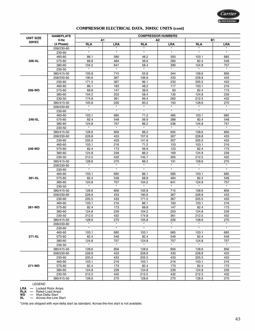
43
COMPRESSOR ELECTRICAL DATA, 30HXC UNITS (cont)
LEGEND
*Units are shipped with wye-delta start as standard. Across-the-line start is not available.
UNIT SIZE 30HXC
NAMEPLATEV-Hz
(3 Phase)
COMPRESSOR NUMBERSA1 A2 B1
RLA LRA RLA LRA RLA LRA
206-XL
208/230-60 * * * * * *230-60 * * * * * *460-60 86.1 580 48.2 350 103.1 685575-60 68.8 484 38.6 280 82.4 548380-60 104.2 641 58.4 390 124.8 757230-50 * * * * * *
380/415-50 105.8 715 55.8 344 128.6 856
206-WD
208/230-60 190.6 367 106.8 233 228.8 433230-60 171.5 367 96.1 233 205.5 433460-60 86.1 183 48.2 117 103.1 216575-60 68.8 147 38.6 93 82.4 173380-60 104.2 203 58.4 130 124.8 239230-50 174.8 361 99.4 260 212.5 432
380/415-50 105.8 226 60.2 150 128.6 270
246-XL
208/230-60 * * * * * *230-60 * * * * * *460-60 103.1 685 71.2 485 103.1 685575-60 82.4 548 56.9 388 82.4 548380-60 124.8 757 86.2 536 124.8 757230-50 * * * * * *
380/415-50 128.6 856 88.2 605 128.6 856
246-WD
208/230-60 228.8 433 157.6 307 228.8 433230-60 205.5 433 141.8 307 205.5 433460-60 103.1 216 71.2 153 103.1 216575-60 82.4 173 56.9 123 82.4 173380-60 124.8 239 86.2 169 124.8 239230-50 212.5 432 145.7 305 212.5 432
380/415-50 128.6 270 88.2 191 128.6 270
261-XL
208/230-60 * * * * * *230-60 * * * * * *460-60 103.1 685 86.1 580 103.1 685575-60 82.4 548 68.8 484 82.4 548380-60 124.8 757 104.2 641 124.8 757230-50 * * * * * *
380/415-50 128.6 856 105.8 715 128.6 856
261-WD
208/230-60 228.8 433 190.6 367 228.8 433230-60 205.5 433 171.5 367 205.5 433460-60 103.1 216 86.1 183 103.1 216575-60 82.4 173 68.8 147 82.4 173380-60 124.8 239 104.2 203 124.8 239230-50 212.5 432 174.8 361 212.5 432
380/415-50 128.6 270 105.8 226 128.6 270
271-XL
208/230-60 * * * * * *230-60 * * * * * *460-60 103.1 685 103.1 685 103.1 685575-60 82.4 548 82.4 548 82.4 548380-60 124.8 757 124.8 757 124.8 757230-50 * * * * * *
380/415-50 128.6 856 128.6 856 128.6 856
271-WD
208/230-60 228.8 433 228.8 433 228.8 433230-60 205.5 433 205.5 433 205.5 433460-60 103.1 216 103.1 216 103.1 216575-60 82.4 173 82.4 173 82.4 173380-60 124.8 239 124.8 239 124.8 239230-50 212.5 432 212.5 432 212.5 432
380/415-50 128.6 270 128.6 270 128.6 270
LRA — Locked Rotor AmpsRLA — Rated Load AmpsWD — Wye-Delta StartXL — Across-the-Line Start
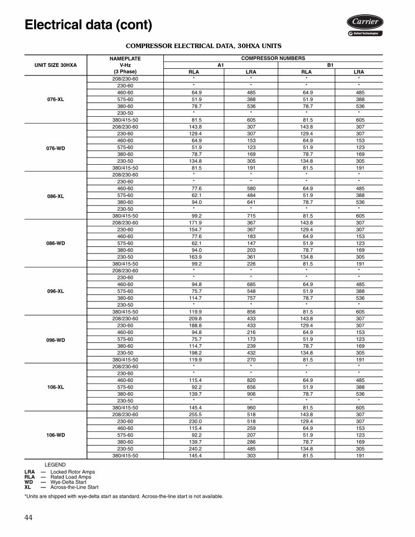
44
COMPRESSOR ELECTRICAL DATA, 30HXA UNITS
LEGEND
*Units are shipped with wye-delta start as standard. Across-the-line start is not available.
UNIT SIZE 30HXANAMEPLATE
V-Hz(3 Phase)
COMPRESSOR NUMBERSA1 B1
RLA LRA RLA LRA
076-XL
208/230-60 * * * *230-60 * * * *460-60 64.9 485 64.9 485575-60 51.9 388 51.9 388380-60 78.7 536 78.7 536230-50 * * * *
380/415-50 81.5 605 81.5 605
076-WD
208/230-60 143.8 307 143.8 307230-60 129.4 307 129.4 307460-60 64.9 153 64.9 153575-60 51.9 123 51.9 123380-60 78.7 169 78.7 169230-50 134.8 305 134.8 305
380/415-50 81.5 191 81.5 191
086-XL
208/230-60 * * * *230-60 * * * *460-60 77.6 580 64.9 485575-60 62.1 484 51.9 388380-60 94.0 641 78.7 536230-50 * * * *
380/415-50 99.2 715 81.5 605
086-WD
208/230-60 171.9 367 143.8 307230-60 154.7 367 129.4 307460-60 77.6 183 64.9 153575-60 62.1 147 51.9 123380-60 94.0 203 78.7 169230-50 163.9 361 134.8 305
380/415-50 99.2 226 81.5 191
096-XL
208/230-60 * * * *230-60 * * * *460-60 94.8 685 64.9 485575-60 75.7 548 51.9 388380-60 114.7 757 78.7 536230-50 * * * *
380/415-50 119.9 856 81.5 605
096-WD
208/230-60 209.8 433 143.8 307230-60 188.8 433 129.4 307460-60 94.8 216 64.9 153575-60 75.7 173 51.9 123380-60 114.7 239 78.7 169230-50 198.2 432 134.8 305
380/415-50 119.9 270 81.5 191
106-XL
208/230-60 * * * *230-60 * * * *460-60 115.4 820 64.9 485575-60 92.2 656 51.9 388380-60 139.7 906 78.7 536230-50 * * * *
380/415-50 145.4 960 81.5 605
106-WD
208/230-60 255.5 518 143.8 307230-60 230.0 518 129.4 307460-60 115.4 259 64.9 153575-60 92.2 207 51.9 123380-60 139.7 286 78.7 169230-50 240.2 485 134.8 305
380/415-50 145.4 303 81.5 191
LRA — Locked Rotor AmpsRLA — Rated Load AmpsWD — Wye-Delta StartXL — Across-the-Line Start
Electrical data (cont)

45
COMPRESSOR ELECTRICAL DATA, 30HXA UNITS (cont)
LEGEND
*Units are shipped with wye-delta start as standard. Across-the-line start is not available.
UNIT SIZE 30HXANAMEPLATE
V-Hz(3 Phase)
COMPRESSOR NUMBERSA1 B1
RLA LRA RLA LRA
116-XL
208/230-60 * * * *230-60 * * * *460-60 115.4 820 77.6 580575-60 92.2 656 62.1 484380-60 139.7 906 94.0 641230-50 * * * *
380/415-50 145.4 960 99.2 715
116-WD
208/230-60 255.5 518 171.9 367230-60 230.0 518 154.7 367460-60 115.4 259 77.6 183575-60 92.2 207 62.1 147380-60 139.7 286 94.0 203230-50 240.2 485 163.9 361
380/415-50 145.4 303 99.2 226
126-XL
208/230-60 * * * *230-60 * * * *460-60 115.4 820 94.8 685575-60 92.2 656 75.7 548380-60 139.7 906 114.7 757230-50 * * * *
380/415-50 145.4 960 119.9 856
126-WD
208/230-60 255.5 518 209.8 433230-60 230.0 518 188.8 433460-60 115.4 259 94.8 216575-60 92.2 207 75.7 173380-60 139.7 286 114.7 239230-50 240.2 485 198.2 432
380/415-50 145.4 303 119.9 270
136-XL
208/230-60 * * * *230-60 * * * *460-60 140.7 920 94.8 685575-60 112.4 736 75.7 548380-60 170.2 1017 114.7 757230-50 * * * *
380/415-50 178.8 1226 119.9 856
136-WD
208/230-60 311.4 581 209.8 433230-60 280.3 581 188.8 433460-60 140.7 291 94.8 216575-60 112.4 233 75.7 173380-60 170.2 321 114.7 239230-50 295.3 619 198.2 432
380/415-50 178.8 387 119.9 270
146-XL
208/230-60 * * * *230-60 * * * *460-60 140.7 920 115.4 820575-60 112.4 736 92.2 656380-60 170.2 1017 139.7 906230-50 * * * *
380/415-50 178.8 1226 145.4 960
146-WD
208/230-60 311.4 581 255.5 518230-60 280.3 581 230.0 518460-60 140.7 291 115.4 259575-60 112.4 233 92.2 207380-60 170.2 321 139.7 286230-50 295.3 619 240.2 485
380/415-50 178.8 387 145.4 303
LRA — Locked Rotor AmpsRLA — Rated Load AmpsWD — Wye-Delta StartXL — Across-the-Line Start

46
COMPRESSOR ELECTRICAL DATA, 30HXA UNITS (cont)
LEGEND
*Units are shipped with wye-delta start as standard. Across-the-line start is not available.
UNIT SIZE 30HXANAMEPLATE
V-Hz(3 Phase)
COMPRESSOR NUMBERSA1 B1
RLA LRA RLA LRA
161-XL
208/230-60 * * * *230-60 * * * *460-60 157.9 1175 106.6 790575-60 126.2 940 85.1 630380-60 191.2 1299 129.0 870230-50 * * * *
380/415-50 201.2 1265 133.4 1045
161-WD
208/230-60 349.6 743 235.9 527230-60 314.6 743 212.3 527460-60 157.9 371 106.6 263575-60 126.2 297 85.1 211380-60 191.2 410 129.0 290230-50 332.3 638 220.3 607
380/415-50 201.2 400 133.4 348
171-XL
208/230-60 * * * *230-60 * * * *460-60 129.6 920 157.9 1175575-60 103.6 736 126.2 940380-60 156.9 1017 191.2 1299230-50 * * * *
380/415-50 161.7 1226 201.2 1265
171-WD
208/230-60 286.9 581 349.6 743230-60 258.2 581 314.6 743460-60 129.6 291 157.9 371575-60 103.6 233 126.2 297380-60 156.9 321 191.2 410230-50 267.2 619 332.3 638
380/415-50 161.7 387 201.2 400
186-XL
208/230-60 * * * *230-60 * * * *460-60 157.9 1175 157.9 1175575-60 126.2 940 126.2 940380-60 191.2 1299 191.2 1299230-50 * * * *
380/415-50 201.2 1265 201.2 1265
186-WD
208/230-60 349.6 743 349.6 743230-60 314.6 743 314.6 743460-60 157.9 371 157.9 371575-60 126.2 297 126.2 297380-60 191.2 410 191.2 410230-50 332.3 638 332.3 638
380/415-50 201.2 400 201.2 400
LRA — Locked Rotor AmpsRLA — Rated Load AmpsWD — Wye-Delta StartXL — Across-the-Line Start
Electrical data (cont)

47
COMPRESSOR ELECTRICAL DATA, 30HXA UNITS (cont)
LEGEND
*Units are shipped with wye-delta start as standard. Across-the-line start is not available.
UNIT SIZE30HXA
NAMEPLATEV-Hz
(3 Phase)
COMPRESSOR NUMBERSA1 A2 B1
RLA LRA RLA LRA RLA LRA
206-XL
208/230-60 * * * * * *230-60 * * * * * *460-60 129.6 920 73.1 580 157.9 1175575-60 103.6 736 58.5 484 126.2 940380-60 156.9 1017 88.5 641 191.2 1299230-50 * * * * * *
380/415-50 161.7 1226 92.0 715 201.2 1265
206-WD
208/230-60 286.9 581 162.0 367 337.6 743230-60 258.2 581 145.8 367 303.8 743460-60 129.6 291 73.1 183 157.9 371575-60 103.6 233 58.5 147 126.2 297380-60 156.9 321 88.5 203 191.2 410230-50 267.2 619 152.0 361 332.3 638
380/415-50 161.7 387 92.0 226 201.2 400
246-XL
208/230-60 * * * * * *230-60 * * * * * *460-60 157.9 1175 106.6 820 157.9 1175575-60 126.2 940 85.1 656 126.2 940380-60 191.2 1299 129.0 906 191.2 1299230-50 * * * * * *
380/415-50 201.2 1265 133.4 960 201.2 1265
246-WD
208/230-60 337.6 743 235.9 518 337.6 743230-60 303.8 743 212.3 518 303.8 743460-60 157.9 371 106.6 259 157.9 371575-60 126.2 297 85.1 207 126.2 297380-60 191.2 410 129.0 286 191.2 410230-50 332.3 638 220.3 485 332.3 638
380/415-50 201.2 400 133.4 303 201.2 400
261-XL
208/230-60 * * * * * *230-60 * * * * * *460-60 157.9 1175 129.6 920 157.9 1175575-60 126.2 940 103.6 736 126.2 940380-60 191.2 1299 156.9 1017 191.2 1299230-50 * * * * * *
380/415-50 201.2 1265 161.7 1226 201.2 1265
261-WD
208/230-60 337.6 743 286.9 581 337.6 743230-60 303.8 743 258.2 581 303.8 743460-60 157.9 371 129.6 291 157.9 371575-60 126.2 297 103.6 233 126.2 297380-60 191.2 410 156.9 321 191.2 410230-50 332.3 638 267.2 619 332.3 638
380/415-50 201.2 400 161.7 387 201.2 400
271-XL
208/230-60 * * * * * *230-60 * * * * * *460-60 157.9 1175 157.9 1175 157.9 1175575-60 126.2 940 126.2 940 126.2 940380-60 191.2 1299 191.2 1299 191.2 1299230-50 * * * * * *
380/415-50 201.2 1265 201.2 1265 201.2 1265
271-WD
208/230-60 337.6 743 337.6 743 337.6 743230-60 303.8 743 303.8 743 303.8 743460-60 157.9 371 157.9 371 157.9 371575-60 126.2 297 126.2 297 126.2 297380-60 191.2 410 191.2 410 191.2 410230-50 332.3 638 332.3 638 332.3 638
380/415-50 201.2 400 201.2 400 201.2 400
LRA — Locked Rotor AmpsRLA — Rated Load AmpsWD — Wye-Delta StartXL — Across-the-Line Start
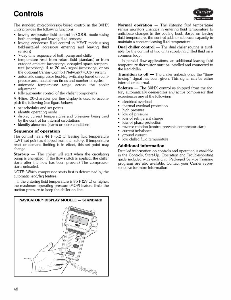
48
The standard microprocessor-based control in the 30HXunits provides the following functions:• leaving evaporator fluid control in COOL mode (using
both entering and leaving fluid sensors)• leaving condenser fluid control in HEAT mode (using
field-installed accessory entering and leaving fluidsensors)
• 7-day time sequence of both pump and chiller• temperature reset from return fluid (standard) or from
outdoor ambient (accessory), occupied space tempera-ture (accessory), 4 to 20 mA signal (accessory), or viathe optional Carrier Comfort Network® (CCN) system
• automatic compressor lead-lag switching based on com-pressor accumulated run times and number of cycles
• automatic temperature range across the cooleradjustment
• fully automatic control of the chiller componentsA 4-line, 20-character per line display is used to accom-plish the following (see figure below):• set schedules and set points• identify operating mode• display current temperatures and pressures being used
by the control for internal calculations• identify abnormal (alarm or alert) conditions
Sequence of operationThe control has a 44 F (6.2 C) leaving fluid temperature(LWT) set point as shipped from the factory. If temperaturereset or demand limiting is in effect, this set point maychange.Start-up — The chiller will start when the circulatingpump is energized. (If the flow switch is applied, the chillerstarts after the flow has been proven.) The compressorstarts unloaded.NOTE: Which compressor starts first is determined by theautomatic lead/lag feature.
If the entering fluid temperature is 85 F (29 C) or higher,the maximum operating pressure (MOP) feature limits thesuction pressure to keep the chiller on line.
Normal operation — The entering fluid temperaturesensor monitors changes in entering fluid temperature toanticipate changes in the cooling load. Based on leavingfluid temperature, the control adds or subtracts capacity tomaintain a constant leaving fluid temperature.Dual chiller control — The dual chiller routine is avail-able for the control of two units supplying chilled fluid on acommon loop.
In parallel flow applications, an additional leaving fluidtemperature thermistor must be installed and connected tothe lead chiller.Transition to off — The chiller unloads once the “time-to-stop” signal has been given. This signal can be eitherinternal or external.Safeties — The 30HX control as shipped from the fac-tory automatically deenergizes any active compressor thatexperiences any of the following:• electrical overload• thermal overload protection• high pressure• low oil pressure• loss of refrigerant charge• loss of phase protection• reverse rotation (control prevents compressor start)• current imbalance• ground current• low chilled fluid temperature
Additional informationDetailed information on controls and operation is availablein the Controls, Start-Up, Operation and Troubleshootingguide included with each unit. Packaged Service Trainingprograms are also available. Contact your Carrier repre-sentative for more information.
Run StatusService TestTemperaturesPressures
SetpointsInputs
OutputsConfigurationTime Clock
Operating ModesAlarms
ENTER
E S C
M O D EAlarm Status
TIMEEWTLWTSETP
1 2 . 5 85 4 . 6 F4 4 . 1 F4 4 . 0 F
N A V I G A T O R
Co m f o r t Li n k
NAVIGATOR™ DISPLAY MODULE — STANDARD
Controls

49
Water-Cooled and CondenserlessHVAC Guide SpecificationsSize Range: 75 to 265 Nominal Tons
(264 to 931 kW)Carrier Model Number: 30HXA — Condenserless
30HXC — Water-CooledPart 1 — General1.01 SYSTEM DESCRIPTION
Microprocessor controlled water-cooled (30HXC) orcondenserless (30HXA) liquid chiller utilizing screwcompressors and electronic expansion valves.
1.02 QUALITY ASSURANCEA. Unit shall be rated in accordance with AHRI Stan-
dard 550/590, latest edition (U.S.A.). The 60 Hz30HXC units shall be AHRI certified for perfor-mance.
B. Unit construction shall comply with ASHRAE 15Safety Code, NEC, and ASME applicable codes(U.S.A. codes), latest version.
C. Unit shall be manufactured at an ISO 9001 regis-tered facility.
D. 208/230 v, 230 v, 460 v, 575 v, 60 Hz units shallbe constructed in accordance with UL or UL Canadastandards and shall be tested and listed by ETL orETL, Canada, as conforming to those standards.Units shall carry the ETL and ETL, Canada, labels.
1.03 DELIVERY, STORAGE, AND HANDLINGA. Unit controls shall be capable of withstanding
150 F (66 C) storage temperatures in the controlcompartment.
B. When delivered, machine and starter should bestored indoors, protected from construction dirt andmoisture. Inspect under shipping tarps, bags, orcrates to be sure water has not collected during tran-sit. Protective shipping covers should be kept inplace until machine is ready for installation.
Part 2 — Products2.01 EQUIPMENT
A. General:Factory assembled, single-piece, water-cooled(30HXC) or condenserless (30HXA) liquid chillerwith dual (2) independent refrigerant circuits. Con-tained within the unit cabinet shall be all factory wir-ing, piping, controls, refrigerant charge (HFC-134a)(30HXA units shipped with holding charge only),and special features required prior to field start-up.Unit must fit through a standard door.
B. Compressors:1. Semi-hermetic twin-screw compressors with
internal muffler and check valve.2. Each compressor shall be equipped with a dis-
charge shutoff valve.C. Cooler (Evaporator):
1. Shall be tested and stamped in accordance withASME Code (U.S.A.) for a refrigerant
working-side pressure of 220 psig (1408 kPa).Water-side pressure rating shall be 300 psig(2068 kPa). In Canada, maximum water-sidepressure shall be 250 psig (1725 kPa), per theCanadian National Registry.
2. Shall be mechanically cleanable shell-and-tubetype with removable heads.
3. Tubes shall be internally enhanced, seamless-copper type, and shall be rolled intotube sheets. Tube wall thickness shall be0.025 inches.
4. Shall be equipped with Victaulic fluidconnections.
5. Shell shall be insulated with 3/4-in. (19-mm)closed-cell, polyvinyl chloride foam with a maxi-mum K factor of 0.28. Heads may require fieldinsulation.
6. Shall have a cooler drain and vent.7. Design shall incorporate 2 independent refrig-
erant circuits.8. Shall include isolation valves to allow isolation
of the refrigerant charge in either the evapora-tor or the condenser.
9. Shall be equipped with factory-installed thermaldispersion chilled fluid flow switch.
D. Condenser (30HXC units):1. Shall be tested and stamped in accordance with
ASME code (U.S.A.) for a refrigerant working-side pressure of 220 psig (1408 kPa).Water-side pressure rating shall be 300 psig(2068 kPa). In Canada, maximum water-sidepressure shall be 250 psig (1725 kPa), per theCanadian National Registry.
2. Shall be mechanically cleanable shell-and-tubetype with removable heads.
3. Tubes shall be internally enhanced, seamless-copper type, and shall be rolled intotube sheets. Tube wall thickness shall be0.025 inches.
4. Shall be equipped with Victaulic waterconnections.
5. Design shall incorporate 2 independent refrig-erant circuits.
E. Oil Separator (30HXA Units):1. Shall be tested and stamped in accordance with
ASME Code (U.S.A.) for a refrigerant working-side pressure of 320 psig (2206 kPa).
2. Design shall incorporate 2 independent refrig-erant circuits.
F. Refrigeration Components:Refrigerant circuit components shall include oil sep-arator, high and low side pressure relief devices, dis-charge and liquid line shutoff valves, filter drier (on30HXC unit only) strainer (30HXA unit only), mois-ture indicating sight glass, expansion valve, refriger-ant economizer (unit sizes 161-271), and complete
Guide specifications
50
charge of compressor oil. The 30HXC units shallhave a complete operating charge of refrigerantHFC-134a; 30HXA units shall have a holdingcharge of nitrogen.
G. Controls, Safeties, and Diagnostics:1. Controls:
a. Unit controls shall include the following min-imum components:1) Microprocessor with non-volatile mem-
ory. Battery backup system shall not beaccepted.
2) Power and control circuit terminalblocks.
3) ON/OFF control switch.4) Replaceable solid-state relay panels.5) Thermistor installed to measure satu-
rated condensing temperature, coolersaturation temperature, compressorreturn gas temperature, and coolerentering and leaving fluid temperatures.
6) Chilled fluid thermal dispersion flowswitch.
b. Unit controls shall include the followingfunctions as standard:1) Automatic circuit lead/lag.2) Capacity control based on leaving
chilled fluid temperature and compen-sated by rate of change of return-fluidtemperature with temperature set pointaccuracy to 0.1 ° F (0.06° C).
3) Limiting the chilled fluid temperaturepull-down rate at start-up to an adjust-able range of 0.2° F to 2° F (0.11° C to1.1° C) per minute to prevent excessivedemand spikes at start-up.
4) Seven-day time schedule.5) Leaving chilled fluid temperature reset
from return fluid, outdoor-air tempera-ture, space temperature, or 4 to 20 mAinput.
6) Demand limit control with 2-stage con-trol (0 to 100% each) or through 4 to 20mA input (0 to 100%).
7) Chilled and condenser water pumpstart/stop control.
8) Dual chiller control for series chillerapplications without addition of hard-ware modules or additional thermistors.
9) Dual chiller control for parallel flowapplications use one additional sensor.
10) Amperage readout per compressor with%MTA (must trip amps) percompressor.
c. NEMA 1 control panel shall include, as stan-dard, a portable hand held display modulewith a minimum of 4 lines and 20 charactersper line, of clear English, Spanish, Portu-guese or French language. Display menusshall provide clear language descriptions ofall menu items, operating modes,
configuration points and alarm diagnostics.Reference to factory codes shall not beaccepted. An industrial grade coiled exten-sion cord shall allow the display module tobe moved around the chiller. Magnets shallhold the display module to any sheet metalpanel to allow hands-free operation. Displaymodule shall have NEMA 4x housing suit-able for use in outdoor environments. Dis-play shall have back light and contrastadjustment for easy viewing in bright sun-light or night conditions. The display moduleshall have raised surface buttons with posi-tive tactile response.
d. The chiller controller shall include multipleconnection ports for communicating withthe local equipment network, the CarrierComfort Network® (CCN) system and theability to access all chiller control functionsfrom any point on the chiller.
e. The control system shall allow softwareupgrade without the need for new hardwaremodules.
2. Safeties:Unit shall be equipped with thermistors and allnecessary components in conjunction with thecontrol system to provide the unit with the fol-lowing protections:a. Loss of refrigerant charge.b. Reverse rotation.c. Low chilled fluid temperature.d. Low oil pressure (each compressor circuit).e. Ground current fault.f. Thermal overload.g. High pressure.h. Electrical overload.i. Loss of phase.j. Current imbalance.k. Loss of flow.
3. Diagnostics:a. The display module shall be capable of indi-
cating the safety lockout condition by dis-playing the information in clear language atthe display. Information included for displayshall be:1) Compressor lockout.2) Loss of charge.3) Low fluid flow.4) Low oil pressure.5) Cooler freeze protection.6) High or low suction superheat.7) Thermistor malfunction.8) Entering and leaving-fluid temperature.9) Evaporator and condenser pressure.
10) Electronic expansion valve positions.11) All set points.12) Time of day.
Guide specifications (cont)

51
b. Display module, in conjunction with themicroprocessor, must also be capable of dis-playing the output results of a service test.Service test shall verify operation of everyswitch, thermistor, and compressor beforechiller is started. User shall be able to forceeach output device.
c. Diagnostics shall include the ability to reviewa list of the 20 most recent alarms with clearlanguage descriptions of the alarm event.Display of alarm codes without the abilityfor clear language descriptions shall beprohibited.
d. An alarm history buffer shall allow the userto store no less than 20 alarm events withclear language descriptions, time and datestamp event entry.
H. Operating Characteristics:Unit shall be capable of starting up with 95 F (35 C)entering fluid temperature to the cooler.
I. Electrical Requirements:1. Unit primary electrical power supply shall enter
the unit at a single location (some units havemultiple power poles).
2. Unit shall operate on 3-phase power at the volt-age shown in the equipment schedule.
3. Control voltage shall be 115-v (60 Hz) or 230-v(50 Hz), single-phase, separate power supply.
4. Unit shall be shipped with factory control andpower wiring installed.
J. Special Features:Certain standard features are not applicable whenthe features designated by * are specified. For assis-tance in amending the specifications, contact yourlocal Carrier Sales office.
* 1. Wye-Delta Starter:Unit shall have a factory-installed, Wye-Deltastarter to minimize electrical inrush current.
2. Sound Reduction Enclosure:Unit shall have field-installed sound reductionenclosure which covers the entire unit to mufflecompressor noise.
3. Vibration Isolation:Chiller manufacturer shall furnish neoprene iso-lator pads for mounting equipment on a level,concrete surface.
4. Control Power Transformer:Unit shall be supplied with a field-installed trans-former that will supply control circuit powerfrom the main unit power supply.
5. Temperature Reset Sensor:Unit shall reset leaving chilled fluid temperaturebased on outdoor ambient temperature orspace temperature when this sensor is installed.
* 6. Brine Option:Unit shall be factory modified to start and oper-ate at leaving chilled fluid temperatures ofbetween 15 F (–9 C) and 40 F (4.4 C).
* 7. Minimum Load Control:Unit shall be equipped with factory (or field)installed, microprocessor-controlled, minimumload control that shall permit unit operationdown to 10% of full capacity.
8. Chillerviser System Manager:Control shall enable management of multipleparallel chillers (up to 8) or two (2) chillers inseries in a single system.
9. Minus-One-Pass Cooler:Factory-installed option shall reduce pressuredrop for high flow applications. Shall alsoprovide same end inlet and outlet for076-106 sizes and opposite end inlet for 116-271 sizes.
10. Plus-One-Pass Cooler:Factory-installed option shall enhance low tem-perature brine performance.
11. Suction Service Valves:Unit shall be supplied with factory-installed suc-tion service valves to isolate compressor fromevaporator and condenser.
12. Cooler Head Insulation:Unit shall be supplied with field-installed coolerinsulation that shall cover the cooler heads.
13. Energy Management Module:A factory or field-installed module shall providethe following energy management capabilities:4 to 20 mA signals for leaving fluid temperaturereset, cooling set point reset or demand limitcontrol; 2-point demand limit control (from 0 to100%) activated by a remote contact closure;and discrete input for “Ice Done” indication forice storage system interface.
14. BACnet Communication Option:Shall provide factory-installed communicationcapability with a BACnet MS/TP network.Allows integration with i-Vu® Open control sys-tem or a BACnet building automation system.

Manufacturer reserves the right to discontinue, or change at any time, specifications or designs without notice and without incurring obligations.Pg 52 Catalog No. 04-52300067-01 Printed in U.S.A. Form 30HX-12PD
Replaces: 30HX-11PD
Carrier Corporation • Syracuse, New York 13221 1-14
Related Documents