1 986TC EVOLUTIONR TWO--STAGE, VARIABLE SPEED 4--WAY MULTIPOISE CONDENSING GAS FURNACE Product Data A11264 The 986TC Multipoise Communicating, Variable--Speed Condensing Gas Furnace features the two--stage EvolutionR System. The Perfect Heat TechnologyR two--stage gas system is at the heart of the comfort provided by this furnace, along with the Evolution variable--speed constant airflow ECM blower motor, and two--speed inducer motor. With an Annual Fuel Utilization Efficiency (AFUE) of up to 96.7%, the Evolution two--stage gas furnace provides exceptional savings when compared to a standard furnace. This Evolution Gas Furnace also features 4--way multipoise installation flexibility, and is available in five model sizes. The 986TC can be vented for direct vent/two--pipe, ventilated combustion air, or single--pipe applications. A Bryant Connext and Evolution Air Conditioner or Heat Pump can be used to form a complete Evolution System.Low NOx units are designed for California installations and meet 40 ng/J NOx emissions. Can be installed in air quality management districts with a 40 ng/J NOx emissions requirement. All sizes are design certified in Canada. PERFORMANCE S Communicating variable--speed, constant airflow (VCA) ECM blower motor for electrically efficient operation all year long in heating, cooling and continuous fan operation S Two--speed inducer motor, and two--stage gas valve. S Perfect LightSilicon Nitride Hot Surface Igniter. S Adjustable blower speed for cooling, continuous fan, and dehumidification. S Intregral part of the Perfect Humidity SystemR Technology. S SmartEvap technology helps control humidity levels in the home when used with a compatible humidity control system. S Aluminized--steel primary heat exchanger. S Stainless--steel condensing secondary heat exchanger. S External Media Filter Cabinet included. S Fully--insulated casing including blower section. S Fan On Plus technology allows control of continuous fan speed from a compatible thermostat. INSTALLATION FLEXIBILITY S 4--way multipoise design for upflow, downflow or horizontal installation, with unique vent elbow and optional through-- the--cabinet downflow venting capability. S Ideal height 35--in. (889 mm) cabinet: short enough for taller coils, but still allows enough room for service. S Direct--vent/sealed combustion, single--pipe venting or ventilated combustion air. APPLICATIONS S Self--diagnostics and extended diagnostic data through the Advanced Product Monitor (APM) accessory or Evolution Connext Interface. S Propane convertible with gas conversion accessory S Convenient Air Purifier and Humidifier connections. S Compatible with single-- and multiple--zone Evolution systems. CERTIFICATIONS S All sizes meet ENERGY STARR Version 4.1 criteria for gas furnaces: 95%+ AFUE. S Cabinet air leakage less than 2.0% at 1.0 in. W.C. and cabinet air leakage less than 1.4% at 0.5 in. W.C. when tested in accordance with ASHRAE standard 193.

Welcome message from author
This document is posted to help you gain knowledge. Please leave a comment to let me know what you think about it! Share it to your friends and learn new things together.
Transcript

1
986TCEVOLUTIONR TWO--STAGE, VARIABLE SPEED4--WAY MULTIPOISE CONDENSING GAS FURNACE
Product Data
A11264
The 986TC Multipoise Communicating, Variable--SpeedCondensing Gas Furnace features the two--stage EvolutionRSystem. The Perfect Heat TechnologyR two--stage gas system is atthe heart of the comfort provided by this furnace, along with theEvolution variable--speed constant airflow ECM blower motor, andtwo--speed inducer motor. With an Annual Fuel UtilizationEfficiency (AFUE) of up to 96.7%, the Evolution two--stage gasfurnace provides exceptional savings when compared to a standardfurnace. This Evolution Gas Furnace also features 4--waymultipoise installation flexibility, and is available in five modelsizes. The 986TC can be vented for direct vent/two--pipe,ventilated combustion air, or single--pipe applications. A BryantConnext and Evolution Air Conditioner or Heat Pump can beused to form a complete Evolution System.Low NOx units aredesigned for California installations and meet 40 ng/J NOxemissions. Can be installed in air quality management districts with a40 ng/J NOx emissions requirement. All sizes are design certified inCanada.
PERFORMANCES Communicating variable--speed, constant airflow (VCA) ECM
blower motor for electrically efficient operation all year long in
heating, cooling and continuous fan operation
S Two--speed inducer motor, and two--stage gas valve.
S Perfect LightSilicon Nitride Hot Surface Igniter.
S Adjustable blower speed for cooling, continuous fan, and
dehumidification.
S Intregral part of the Perfect Humidity SystemR Technology.
S SmartEvap technology helps control humidity levels in the
home when used with a compatible humidity control system.
S Aluminized--steel primary heat exchanger.
S Stainless--steel condensing secondary heat exchanger.
S External Media Filter Cabinet included.
S Fully--insulated casing including blower section.
S Fan On Plus technology allows control of continuous fan
speed from a compatible thermostat.
INSTALLATION FLEXIBILITYS 4--way multipoise design for upflow, downflow or horizontal
installation, with unique vent elbow and optional through--
the--cabinet downflow venting capability.
S Ideal height 35--in. (889 mm) cabinet: short enough for taller
coils, but still allows enough room for service.
S Direct--vent/sealed combustion, single--pipe venting or
ventilated combustion air.
APPLICATIONSS Self--diagnostics and extended diagnostic data through the
Advanced Product Monitor (APM) accessory or Evolution
Connext Interface.
S Propane convertible with gas conversion accessory
S Convenient Air Purifier and Humidifier connections.
S Compatible with single-- and multiple--zone Evolution systems.
CERTIFICATIONSS All sizes meet ENERGY STARR Version 4.1 criteria for gas
furnaces: 95%+ AFUE.
S Cabinet air leakage less than 2.0% at 1.0 in. W.C. and cabinet air
leakage less than 1.4% at 0.5 in. W.C. when tested in accordance
with ASHRAE standard 193.

2
FURNACESIZE
CASINGDIMENSIONS (IN.)
RATED HEATINGOUTPUT† (BTUH) AFUE
ENERGYSTARr
HEATING AIRFLOW
COOLINGCFM @ 0.5
ESP
MOTOR HP(VARIABLE
SPEED)
MEDIACABINET
SUPPLIEDIN.(MM)
APPROX.SHIP WT.LB(KG)H D W High Low
UPFLOW/HORI-
ZONTALDOWN-FLOW
CFM‡(Low
Heating)
CFM(High
Heating)
RatedHigh
HeatingESP
42060C17 35 30 17.50 58,000 38,000 96.3% 95.0% YES 755 1055 0.12 530 - 1280 1/2 16 (406) 151 (68.5)42080C17 35 30 17.50 78,000 50,000 96.2% 95.0% YES 1008 1240 0.15 520 - 1310 1/2 16 (406) 152.5 (69.2)60080C21 35 30 21.00 78,000 51,000 96.7% 95.0% YES 1095 1345 0.15 750 - 1945 1 20 (508) 171.5 (77.8)66100C21 35 30 21.00 98,000 63,000 96.1% 95.0% YES 1385 1575 0.20 715 - 2160 1 20 (508) 179 (81.2)66120C24 35 30 24.50 117,000 76,000 96.7% 95.0% YES 1555 1820 0.20 705 - 2135 1 24 (609) 195 (88.4)
† Capacity in accordance with DOE test procedures. Ratings are position dependent. See rating plate.
‡ Heating CFM with switch 1---4 OFF.ESP --- External Static Pressure
FEATURES AND BENEFITSPerfect Heat TechnologyR feature— This feature with AdaptiveControl is a proprietary function that promotes homeownercomfort through two stages of heating. This Bryant furnace offers apatented algorithm that continually monitors and adjusts furnaceoperation by looking at both current and past conditions todetermine the most effective stage of heating and the amount oftime to run each stage, every cycle.
Perfect Humidity SystemR Technology— The Perfect Humiditysystem actively controls both temperature and humidity in thehome to provide the best comfort all year long. Other systemsdepend on heating or cooling demand to manage the moisture inthe air. But, Perfect Humidity gives the homeowner the rightamount of humidity day and night, even in mild weather. PerfectHumidity saves energy, too. By keeping humidity under control,the homeowner can set their thermostat lower to stay comfortableand save energy.
SmartEvapt Technology — When paired with a compatiblethermostat, this dehumidification feature overrides the coolingblower off-delay when there is a call for dehumidification. Bydeactivating the blower off-delay, SmartEvap technology preventscondensate that remains on the coil after a dehumidification cyclefrom re-humidifying throughout the home. This results in reducedhumidity and a more comfortable indoor environment for thehomeowner.
Unlike competitive systems, SmartEvap technology only overridesthe cooling blower off--delay when humidity control is needed.Once humidity is back in control, SmartEvap re-enables theenergy-saving cooling blower off-delay.
Fan On Plust Technology— Sometimes the constant fan settingon a standard furnace system can actually reduce homeownercomfort by providing too much or too little air! Fan On Plustechnology improves comfort all year long by allowing thehomeowner to select the continuous fan speed of their choice usinga compatible thermostat.
HYBRID HEATR Dual Fuel System— This system can providemore control over your monthly energy bills by automaticallyselecting the most economical method of heating. With HYBRIDHEAT components, our system automatically switches between thegas furnace and the electric heat pump as outside temperatureschange to maintain greater efficiency and comfort than with anytraditional single-source heating system. The heat pump alsodelivers high-efficiency cooling in the summer.
Perfect Lightt Igniter— Bryant’s unique SiN igniter is not onlyphysically robust but it is also electrically robust. It is capable ofrunning at line voltage and does not require complex voltageregulators as do other brands. This unique feature further enhancesthe gas furnace reliability and continues Bryant’s tradition oftechnology leadership and innovation in providing a reliable anddurable product.
Full-Featured, Communicating, Variable Speed Motors— OurECMs (Electronically Commutated Motors) provide variable-speedoperation to optimize comfort levels in the home year round;features such as passive/active dehumidification, ramping profiles,constant air flow and quiet operation. They can provide cooling
match enhancements to increase the effective SEER of selectBryant air conditioner or heat pump system, and feature the highestefficiency of all indoor fan motors.
Reliable Heat Exchanger Design — The aluminized steel, clamshell primary heat exchanger was re--engineered to achieve greaterefficiency out of a smaller size. The first two passes of the heatexchanger are based on the current 80% product, a design withmore than ten years of field-proven performance and success.These innovations, paired with the continuation of a crimped,no-weld seam create an efficient, robust design for this essentialcomponent.The condensing heat exchanger, a stainless steel fin and tubedesign, is positioned in the furnace to extract additional heat.Stainless steel coupling box componentry between heat exchangershas exceptional corrosion resistance in both natural gas andpropane applications.Media Filter Cabinet— Enhanced indoor air quality in the homeis made easier with our media filter cabinet—a standard accessoryon all deluxe furnaces. When installed as a part of the system, thiscabinet allows for easy and convenient addition of a Bryant highefficiency air filter.4-Way Multipoise Design — One model for all applications –there is no need to stock special downflow or horizontal modelswhen one unit will do it all.Direct or Single-pipe Venting, or Optional VentilatedCombustion Air — This furnace can be installed as a 2-pipe(Direct Vent) furnace, in an optional ventilated combustion airapplication, or in single-pipe, non-direct vent applications. Thisprovides added flexibility to meet diverse installation needs.Sealed Combustion System— This furnace brings in combustionair from outside the furnace, which results in especially quietoperation. By sealing the entire combustion vestibule, the entirefurnace can be made quieter, not just the burners.
Insulated Casing — Foil-faced insulation in the heat exchangersection of the casing minimizes heat loss. The acoustical insulationin the blower compartment reduces air and motor noise for quietoperation.Monoport Burners — The burners are specially designed andfinely tuned for smooth, quiet combustion and economicaloperation.Bottom Closure — Factory-installed for side return; easilyremovable for bottom return. The multi-use bottom closure canalso serve for roll-out protection in horizontal applications, and actas the bottom closure for the optional return air base accessory.Blower Access Panel Switch — Automatically shuts off 115-vpower to furnace whenever blower access panel is opened.Quality Registration — Our furnaces are engineered andmanufactured under a quality management system registered toISO 9001.Certifications — This furnace is CSA (AGA and CGA) designcertified for use with natural and propane gases. The furnace isfactory--shipped for use with natural gas. A CSA listed gasconversion kit is required to convert furnace for use with propanegas. The efficiency is AHRI efficiency rating certified.

3
SPECIFICATIONSThe furnace should be sized to provide 100 percent of the designheating load requirement plus any margin that occurs because offurnace model size capacity increments. None of the furnacemodel sizes can be used if the heating load is 20,000 BTU orlower. Use Air Conditioning Contractors of America (Manual Jand S); American Society of Heating, Refrigerating, andAir-Conditioning Engineers; or other approved engineering
method to calculate heating load estimates and select the furnace.Excessive oversizing of the furnace may cause the furnace and/orvent to fail prematurely, customer discomfort and/or vent freezing.
Failure to follow these guidelines is considered faulty installationand/or misapplication of the furnace; and resulting failure, damage,or repairs may impact warranty coverage.
Heating Capacity and Efficiency 42060C17 42080C17 60080C21 66100C21 66120C24
InputHigh Heat (BTUH) 60,000 80,000 80,000 100,000 120,000Low Heat (BTUH) 39,000 52,000 52,000 65,000 78,000
OutputHigh Heat (BTUH) 58,000 78,000 78,000 98,000 117,000Low Heat (BTUH) 38,000 50,000 51,000 63,000 76,000
Certified TemperatureRise Range ºF (ºC)
High Heat35 - 65(19 - 36)
40 - 70(22 - 39)
40 - 70(22 - 39)
45 - 75(25 - 42)
45 - 75(25 - 42)
Low Heat30 - 60(17 - 33)
30 - 60(17 - 33)
30 - 60(17 - 33)
30 - 60(17 - 33)
30 - 60(17 - 33)
Airflow Capacity and Blower Data
Rated External StaticPressure (in. w.c.)
Heating 0.12 0.15 0.15 0.20 0.20Cooling 0.50 0.50 0.50 0.50 0.50
Airflow Delivery@ Rated ESP (CFM)
High Heat 1055 1240 1345 1575 1820Low Heat 755 1008 1095 1385 1555Cooling 1280 1310 1945 2160 2135
Cooling Capacity (tons)400 CFM/ton 3 3.50 4.50 5 5.50350 CFM/ton 3.50 4 5.50 6 6
Direct-Drive Motor Type Electronically Commutated Motor (ECM)Direct-Drive Motor HP 1/2 1/2 1 1 1Motor Full Load Amps 8.50 8.50 12.80 12.80 12.80RPM Range 300 - 1300Speed Selections Variable (Communicating)Blower Wheel Dia x Width in. 11 x 8 11 x 8 11x10 11 x 10 11 x 11
Air Filtration SystemFactory Supplied External Media Cabinet
Field Supplied FilterFilter Used for Certified Watt Data* KGAWF**06UFR
Electrical DataInput Voltage Volts-Hertz-
Phase115-60-1
Operating Voltage Range Min-Max 104-127Maximum Input Amps Amps 9.30 9.30 13.60 13.70 13.70Unit Ampacity Amps 12.60 12.60 17.90 18.00 18.00Minimum Wire Size AWG 14 14 12 12 12
Maximum Wire Length@ Minimum Wire Size
Feet 29 29 32 31 31(M) (9.0) (9.0) (9.8) (9.7) (9.7)
Maximum Fuse/Ckt Bkr(Time-Delay Type Recommended)
Amps 15 15 20 20 20
Transformer Capacity (24vac output) 40 VA
External Control Power AvailableHeating 24.3 VACooling 34.6 VA
ControlsGas Connection Size 1/2" - NPTBurners (Monoport) 3 4 4 5 6Gas Valve (Redundant) Manufacturer White Rogers
Minimum Inlet Gas pressure (in. wc) 4.50Maximum Inlet Gas pressure (in. wc) 13.60
Manufactured (Mobile) Home Kit not approved for MH useIgnition Device Silicon NitrideHeating Blower Control (Heating Off-Delay) Adjustable: 90, 120, 150, 180 secondsCooling Blower Control (Time Delay Relay) 90 secondsCommunication System Evolution; Evolution ZoningThermostat Connections R, W/W1, W2 Y/Y2, Y1, G, Com 24V, DHUMAccessory Connections EAC (115vac); HUM (24vac); 1-stg AC (via Y/Y2)
* See Accessory List for part numbers available.

4
MODEL NUMBER NOMENCLATURE
A190042
For California Residents:For installation in SCAQMD only: This furnace does not meet the SCAQMD Rule 1111 14 ng/J NOx emission limit, and thus is subject to amitigation fee of up to $450. This furnace is not eligible for the Clean Air Furnace Rebate Program: www.CleanAirFurnaceRebate.com
FURNACE COMPONENTS
A190145

5
ACCESSORIESDESCRIPTION PART NUMBER 42060C17 42080C17 60080C21 66100C21 66120C24
Vent Kit - Through the Cabinet KGADC0101BVC D D D D D
Vent Terminal - Concentric - 2” (51 mm) KGAVT0701CVT
See Venting TablesVent Terminal - Concentric - 3” (76 mm) KGAVT0801CVTVent Terminal Bracket - 2” (51 mm) KGAVT0101BRAVent Terminal Bracket - 3” (76 mm) KGAVT0201BRAVent Kit --- Rubber Coupling KGAAC0101RVCFreeze Protect Kit - Condensate Drain Line Tape KGAHT0101CFP D D D D D
Freeze Protect Kit - Condensate Trap with Heat Pad KGAHT0201CFP D D D D D
CPVC to PVC Drain Adapters - 1/2” CPVC to 3/4” PVC KGAAD0110PVC D D D D D
Horizontal Trap Grommet - Direct Vent KGACK0101HCK All 2---Pipe HorizontalCondensate Neutralizer Kit P908---0001 D D D D D
External Trap Kit KGBET0201ETK D D D D D
Downflow Furnace Base Kit for Combustible Floors KGASB0201ALL D D D D D
Coil Adapter Kits --- No Offset KGADA0101ALL D D D D D
Coil Adapter Kits --- Single Offset KGADA0201ALL D D D D D
Coil Adapter Kits --- Double Offset KGADA0301ALL D D D D D
Return Air Base (Upflow Applications) 17.5---in. wide KGARP0301B17 D D
Return Air Base (Upflow Applications) 21.0---in. wide KGARP0301B21 D D
Return Air Base (Upflow Applications) 24.5---in. wide KGARP0301B24 D
IAQ Device Duct Adapters 20.0---in. IAQ to 16 in. Side Return KGAAD0101MEC 20”x25” IAQ DevicesIAQ Device Duct Adapters 24.0---in. IAQ to 16 in. Side Return KGAAD0201MEC 24”x25” IAQ DevicesGas Conversion Kit - Nat to LP AGAGC9NPS01A D D D D D
Gas Conversion Kit - LP to Nat AGAGC9PNS01A D D D D D
Gas Valve Tower Port Adapter Kit 92---1003 D D D D D
Bottom Filter Rack --- 17.5 inches (455 mm) KGBFR0501B17 D D
Bottom Filter Rack --- 21 inches (533 mm) KGBFR0601B21 D D
Bottom Filter Rack --- 24.5 inches (622 mm) KGBFR0701B24 D
Filter Pack (6 pack) --- Washable - 16x25x1 (406x635x25 mm) KGAWF1306UFR D D
Filter Pack (6 pack) --- Washable - 24x25x1 (610x635x25 mm) KGAWF1506UFR D D D
D = Used with the model furnace
DESCRIPTIONGas Orifice Kit - #42 (Nat Gas) LH32DB207
See Installation Instructions for model,altitude, and heat value usages.
Gas Orifice Kit - #43 (Nat Gas) LH32DB202Gas Orifice Kit - #44 (Nat Gas) LH32DB200Gas Orifice Kit - #45 (Nat Gas) LH32DB205Gas Orifice Kit - #46 (Nat Gas) LH32DB208Gas Orifice Kit - #47 (Nat Gas) LH32DB078Gas Orifice Kit - #48 (Nat Gas) LH32DB076Gas Orifice Kit - #54 (LP) LH32DB203Gas Orifice Kit - #55 (LP) LH32DB201Gas Orifice Kit - #56 (LP) LH32DB206Gas Orifice Kit - 1.25mm (LP) LH32DB209Gas Orifice Kit - 1.30mm (LP) LH32DB210
6
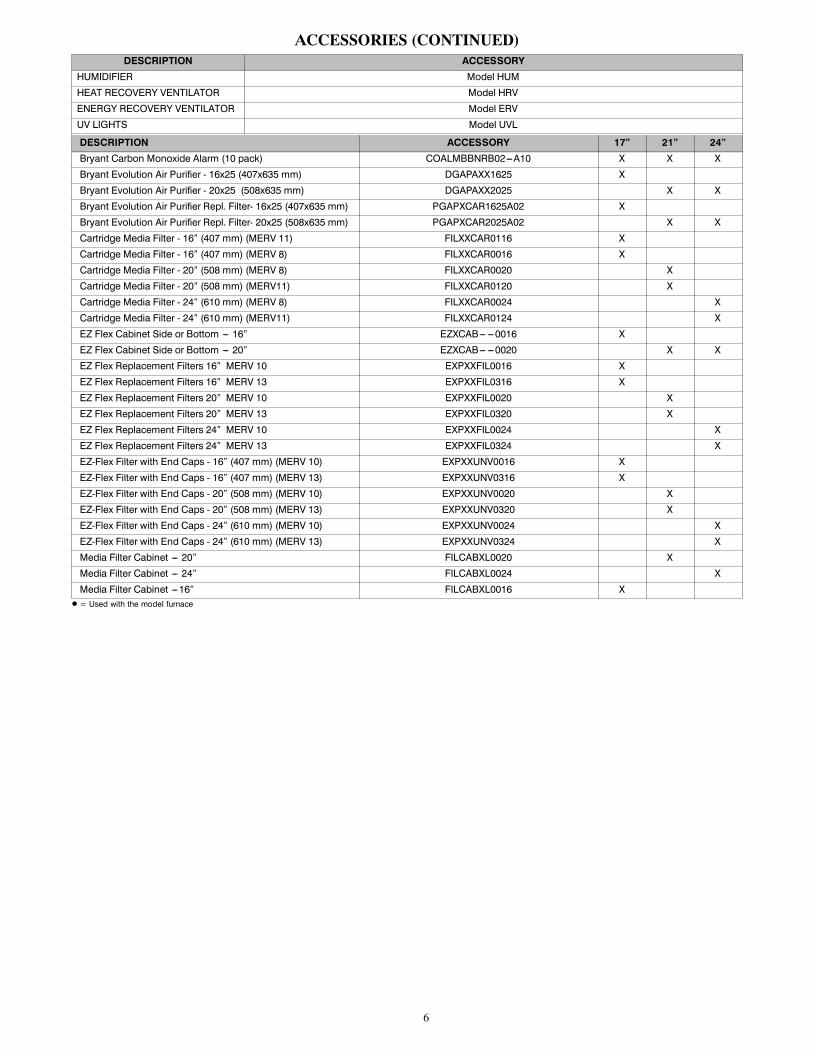
ACCESSORIES (CONTINUED)DESCRIPTION ACCESSORY
HUMIDIFIER Model HUM
HEAT RECOVERY VENTILATOR Model HRV
ENERGY RECOVERY VENTILATOR Model ERV
UV LIGHTS Model UVL
DESCRIPTION ACCESSORY 17” 21” 24”Bryant Carbon Monoxide Alarm (10 pack) COALMBBNRB02---A10 X X X
Bryant Evolution Air Purifier - 16x25 (407x635 mm) DGAPAXX1625 X
Bryant Evolution Air Purifier - 20x25 (508x635 mm) DGAPAXX2025 X X
Bryant Evolution Air Purifier Repl. Filter- 16x25 (407x635 mm) PGAPXCAR1625A02 X
Bryant Evolution Air Purifier Repl. Filter- 20x25 (508x635 mm) PGAPXCAR2025A02 X X
Cartridge Media Filter - 16” (407 mm) (MERV 11) FILXXCAR0116 X
Cartridge Media Filter - 16” (407 mm) (MERV 8) FILXXCAR0016 X
Cartridge Media Filter - 20” (508 mm) (MERV 8) FILXXCAR0020 X
Cartridge Media Filter - 20” (508 mm) (MERV11) FILXXCAR0120 X
Cartridge Media Filter - 24” (610 mm) (MERV 8) FILXXCAR0024 X
Cartridge Media Filter - 24” (610 mm) (MERV11) FILXXCAR0124 X
EZ Flex Cabinet Side or Bottom --- 16” EZXCAB--- ---0016 X
EZ Flex Cabinet Side or Bottom --- 20” EZXCAB--- ---0020 X X
EZ Flex Replacement Filters 16” MERV 10 EXPXXFIL0016 X
EZ Flex Replacement Filters 16” MERV 13 EXPXXFIL0316 X
EZ Flex Replacement Filters 20” MERV 10 EXPXXFIL0020 X
EZ Flex Replacement Filters 20” MERV 13 EXPXXFIL0320 X
EZ Flex Replacement Filters 24” MERV 10 EXPXXFIL0024 X
EZ Flex Replacement Filters 24” MERV 13 EXPXXFIL0324 X
EZ-Flex Filter with End Caps - 16” (407 mm) (MERV 10) EXPXXUNV0016 X
EZ-Flex Filter with End Caps - 16” (407 mm) (MERV 13) EXPXXUNV0316 X
EZ-Flex Filter with End Caps - 20” (508 mm) (MERV 10) EXPXXUNV0020 X
EZ-Flex Filter with End Caps - 20” (508 mm) (MERV 13) EXPXXUNV0320 X
EZ-Flex Filter with End Caps - 24” (610 mm) (MERV 10) EXPXXUNV0024 X
EZ-Flex Filter with End Caps - 24” (610 mm) (MERV 13) EXPXXUNV0324 X
Media Filter Cabinet --- 20” FILCABXL0020 X
Media Filter Cabinet --- 24” FILCABXL0024 X
Media Filter Cabinet ---16” FILCABXL0016 XD = Used with the model furnace
7
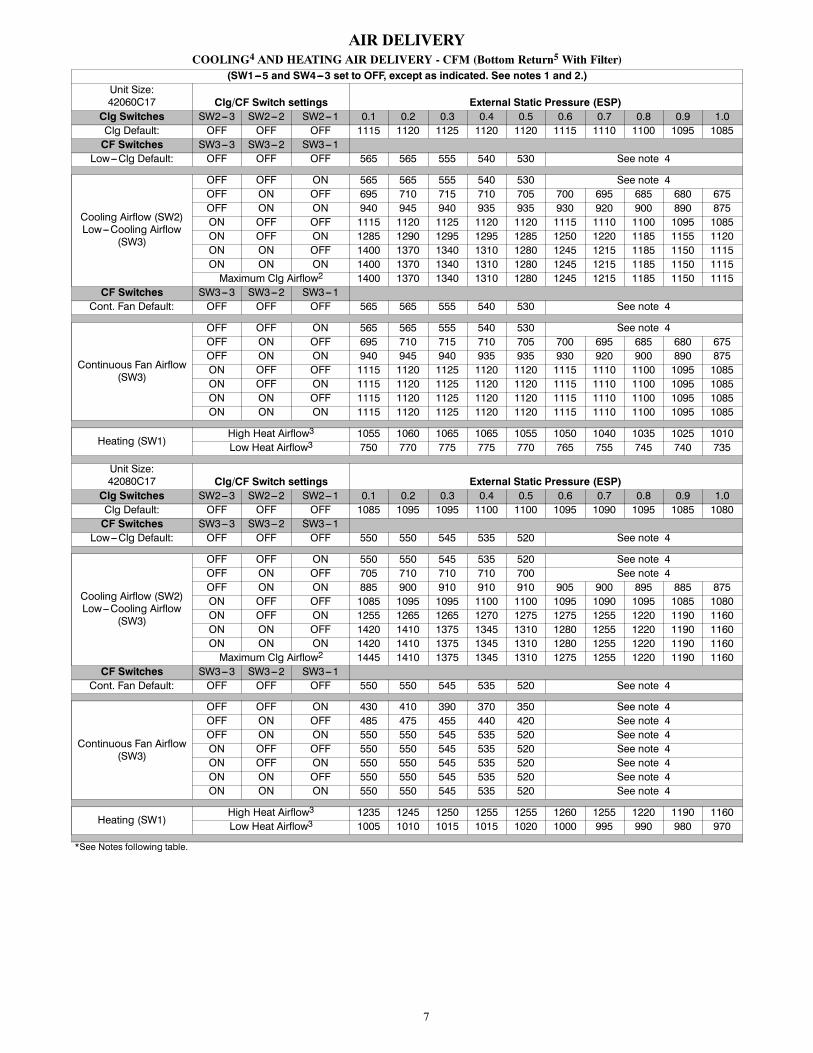
AIR DELIVERYCOOLING4 AND HEATING AIR DELIVERY - CFM (Bottom Return5 With Filter)
(SW1---5 and SW4---3 set to OFF, except as indicated. See notes 1 and 2.)Unit Size:42060C17 Clg/CF Switch settings External Static Pressure (ESP)Clg Switches SW2---3 SW2---2 SW2---1 0.1 0.2 0.3 0.4 0.5 0.6 0.7 0.8 0.9 1.0Clg Default: OFF OFF OFF 1115 1120 1125 1120 1120 1115 1110 1100 1095 1085CF Switches SW3---3 SW3---2 SW3---1Low---Clg Default: OFF OFF OFF 565 565 555 540 530 See note 4
Cooling Airflow (SW2)Low---Cooling Airflow
(SW3)
OFF OFF ON 565 565 555 540 530 See note 4OFF ON OFF 695 710 715 710 705 700 695 685 680 675OFF ON ON 940 945 940 935 935 930 920 900 890 875ON OFF OFF 1115 1120 1125 1120 1120 1115 1110 1100 1095 1085ON OFF ON 1285 1290 1295 1295 1285 1250 1220 1185 1155 1120ON ON OFF 1400 1370 1340 1310 1280 1245 1215 1185 1150 1115ON ON ON 1400 1370 1340 1310 1280 1245 1215 1185 1150 1115Maximum Clg Airflow2 1400 1370 1340 1310 1280 1245 1215 1185 1150 1115
CF Switches SW3---3 SW3---2 SW3---1Cont. Fan Default: OFF OFF OFF 565 565 555 540 530 See note 4
Continuous Fan Airflow(SW3)
OFF OFF ON 565 565 555 540 530 See note 4OFF ON OFF 695 710 715 710 705 700 695 685 680 675OFF ON ON 940 945 940 935 935 930 920 900 890 875ON OFF OFF 1115 1120 1125 1120 1120 1115 1110 1100 1095 1085ON OFF ON 1115 1120 1125 1120 1120 1115 1110 1100 1095 1085ON ON OFF 1115 1120 1125 1120 1120 1115 1110 1100 1095 1085ON ON ON 1115 1120 1125 1120 1120 1115 1110 1100 1095 1085
Heating (SW1)High Heat Airflow3 1055 1060 1065 1065 1055 1050 1040 1035 1025 1010Low Heat Airflow3 750 770 775 775 770 765 755 745 740 735
Unit Size:42080C17 Clg/CF Switch settings External Static Pressure (ESP)Clg Switches SW2---3 SW2---2 SW2---1 0.1 0.2 0.3 0.4 0.5 0.6 0.7 0.8 0.9 1.0Clg Default: OFF OFF OFF 1085 1095 1095 1100 1100 1095 1090 1095 1085 1080CF Switches SW3---3 SW3---2 SW3---1Low---Clg Default: OFF OFF OFF 550 550 545 535 520 See note 4
Cooling Airflow (SW2)Low---Cooling Airflow
(SW3)
OFF OFF ON 550 550 545 535 520 See note 4OFF ON OFF 705 710 710 710 700 See note 4OFF ON ON 885 900 910 910 910 905 900 895 885 875ON OFF OFF 1085 1095 1095 1100 1100 1095 1090 1095 1085 1080ON OFF ON 1255 1265 1265 1270 1275 1275 1255 1220 1190 1160ON ON OFF 1420 1410 1375 1345 1310 1280 1255 1220 1190 1160ON ON ON 1420 1410 1375 1345 1310 1280 1255 1220 1190 1160Maximum Clg Airflow2 1445 1410 1375 1345 1310 1275 1255 1220 1190 1160
CF Switches SW3---3 SW3---2 SW3---1Cont. Fan Default: OFF OFF OFF 550 550 545 535 520 See note 4
Continuous Fan Airflow(SW3)
OFF OFF ON 430 410 390 370 350 See note 4OFF ON OFF 485 475 455 440 420 See note 4OFF ON ON 550 550 545 535 520 See note 4ON OFF OFF 550 550 545 535 520 See note 4ON OFF ON 550 550 545 535 520 See note 4ON ON OFF 550 550 545 535 520 See note 4ON ON ON 550 550 545 535 520 See note 4
Heating (SW1)High Heat Airflow3 1235 1245 1250 1255 1255 1260 1255 1220 1190 1160Low Heat Airflow3 1005 1010 1015 1015 1020 1000 995 990 980 970
*See Notes following table.

8
AIR DELIVERY (CONTINUED)COOLING4 AND HEATING AIR DELIVERY - CFM (Bottom Return5 With Filter)
(SW1---5 and SW4---3 set to OFF, except as indicated. See notes 1 and 2.)Unit size:60080C21 Clg/CF Switch settings External Static Pressure (ESP)Clg Switches SW2---3 SW2---2 SW2---1 0.1 0.2 0.3 0.4 0.5 0.6 0.7 0.8 0.9 1.0Clg Default: OFF OFF OFF 1745 1755 1755 1760 1755 1750 1745 1725 1705 1685CF Switches SW3---3 SW3---2 SW3---1Low---Clg Default: OFF OFF OFF 700 710 750 725 750 See note 4
Cooling Airflow (SW2)Low---Cooling Airflow
(SW3)
OFF OFF ON 700 710 750 725 750 See note 4OFF ON OFF 830 860 870 890 960 See note 4OFF ON ON 1045 1045 1060 1070 1070 1070 1095 1090 1080 1070ON OFF OFF 1215 1220 1245 1240 1235 1235 1225 1220 1235 1235ON OFF ON 1370 1370 1390 1390 1400 1395 1400 1390 1390 1385ON ON OFF 1745 1755 1755 1760 1755 1750 1745 1725 1705 1685ON ON ON 1745 1755 1755 1760 1755 1750 1745 1725 1705 1685Maximum Clg Airflow2 1920 1920 1945 1945 1945 1960 1950 1940 1915 1900
CF Switches SW3---3 SW3---2 SW3---1Cont. Fan Default: OFF OFF OFF 700 710 750 725 750 See note 4
Continuous Fan Airflow(SW3)
OFF OFF ON 700 710 750 725 750 See note 4OFF ON OFF 830 860 870 890 960 See note 4OFF ON ON 1045 1045 1060 1070 1070 1070 1095 1090 1080 1070ON OFF OFF 1215 1220 1245 1240 1235 1235 1225 1220 1235 1235ON OFF ON 1215 1220 1245 1240 1235 1235 1225 1220 1235 1235ON ON OFF 1215 1220 1245 1240 1235 1235 1225 1220 1235 1235ON ON ON 1215 1220 1245 1240 1235 1235 1225 1220 1235 1235
Heating (SW1)High Heat Airflow3 1340 1355 1370 1385 1380 1385 1400 1400 1385 1380Low Heat Airflow3 1080 1115 1115 1120 1125 1135 1125 1120 1125 1110
Unit size:66100C21 Clg/CF Switch settings External Static Pressure (ESP)Clg Switches SW2---3 SW2---2 SW2---1 0.1 0.2 0.3 0.4 0.5 0.6 0.7 0.8 0.9 1.0Clg Default: OFF OFF OFF 1820 1825 1840 1845 1840 1835 1825 1805 1780 1770CF Switches SW3---3 SW3---2 SW3---1Low---Clg Default: OFF OFF OFF 750 740 745 730 715 See note 4
Cooling Airflow (SW2)Low---Cooling Airflow
(SW3)
OFF OFF ON 750 740 745 730 715 See note 4OFF ON OFF 900 900 915 910 905 See note 4OFF ON ON 1070 1075 1095 1095 1090 1085 1095 1080 1065 1070ON OFF OFF 1280 1285 1305 1305 1310 1305 1295 1300 1290 1285ON OFF ON 1440 1445 1465 1465 1470 1485 1480 1485 1475 1460ON ON OFF 1820 1825 1840 1845 1840 1835 1825 1805 1780 1770ON ON ON 2135 2140 2140 2135 2140 2130 2115 2100 2070 2015Maximum Clg Airflow2 2160 2165 2175 2170 2160 2150 2135 2120 2065 2020
CF Switches SW3---3 SW3---2 SW3---1Cont. Fan Default: OFF OFF OFF 750 740 745 730 715 See note 4
Continuous Fan Airflow(SW3)
OFF OFF ON 750 740 745 730 715 See note 4OFF ON OFF 900 900 915 910 905 See note 4OFF ON ON 1070 1075 1095 1095 1090 1085 1095 1080 1065 1070ON OFF OFF 1070 1075 1095 1095 1090 1085 1095 1080 1065 1070ON OFF ON 1070 1075 1095 1095 1090 1085 1095 1080 1065 1070ON ON OFF 1070 1075 1095 1095 1090 1085 1095 1080 1065 1070ON ON ON 1070 1075 1095 1095 1090 1085 1095 1080 1065 1070
Heating (SW1)High Heat Airflow3 1570 1575 1595 1595 1600 1605 1600 1600 1590 1575Low Heat Airflow3 1365 1385 1395 1395 1395 1400 1400 1405 1395 1380
*See Notes following table.

9
AIR DELIVERY (CONTINUED)Cooling4 and Heating Air Delivery -- CFM continued (Bottom Return5 with Filter)
(SW1---5 and SW4---3 set to OFF, except as indicated. See notes 1 and 2.)Unit size:66120C24 Clg/CF Switch settings External Static Pressure (ESP)Clg Switches SW2---3 SW2---2 SW2---1 0.1 0.2 0.3 0.4 0.5 0.6 0.7 0.8 0.9 1.0Clg Default: OFF OFF OFF 1845 1840 1835 1835 1825 1820 1810 1800 1785 1775CF Switches SW3---3 SW3---2 SW3---1Low---Clg Default: OFF OFF OFF 895 915 915 915 915 See note 4
Cooling Airflow (SW2)Low---Cooling Airflow
(SW3)
OFF OFF ON 715 725 720 710 705 See note 4OFF ON OFF 895 915 915 915 915 See note 4OFF ON ON 1070 1090 1105 1115 1115 1110 1115 1120 1120 1110ON OFF OFF 1240 1265 1280 1295 1295 1305 1305 1305 1315 1315ON OFF ON 1520 1520 1515 1505 1495 1490 1480 1465 1455 1445ON ON OFF 1845 1840 1835 1835 1825 1820 1810 1800 1785 1775ON ON ON 2150 2145 2140 2145 2135 2130 2115 2100 2065 1985Maximum Clg Airflow2 2150 2145 2140 2145 2135 2130 2115 2100 2065 1985
CF Switches SW3---3 SW3---2 SW3---1Cont. Fan Default: OFF OFF OFF 895 915 915 915 915 See note 4
Continuous Fan Airflow(SW3)
OFF OFF ON 715 725 720 710 705 See note 4OFF ON OFF 805 820 815 810 810 See note 4OFF ON ON 895 915 915 915 915 See note 4ON OFF OFF 895 915 915 915 915 See note 4ON OFF ON 895 915 915 915 915 See note 4ON ON OFF 895 915 915 915 915 See note 4ON ON ON 895 915 915 915 915 See note 4
Heating (SW1)High Heat Airflow3 1825 1820 1815 1800 1800 1795 1785 1775 1760 1745Low Heat Airflow3 1555 1555 1550 1550 1545 1525 1520 1505 1495 1485
1. Nominal 350 CFM/ton cooling airflow is delivered with SW1-5 and SW4-3 set to OFF.Set SW1-5 to ON for nominal 400 CFM/ton (+15% airflow).Set SW4-3 to ON for nominal 325 CFM/ton (-7% airflow).Set both SW1-5 and SW4-3 to ON for nominal 370 CFM/ton (+7% airflow).This applies to Cooling and Low-Cooling airflows, but does not affect continuous fan airflows.
The above adjustments in airflow are subject ot motor horsepower range/capacity2. Maximum cooling airflow is achieved when switches SW2-1, SW2-2, SW2-3 and SW1-5 are set to ON, and SW4-3 is set to OFF.3. All heating CFM's are when comfort/efficiency adjustment switch (SW1-4) is set to OFF.4. Ductwork must be sized for high-heating CFM within the operational range of ESP. Operation within the blank areas of the chart is not rec-ommended because high-heat operation will be above 1.0 ESP.
5. All airflows on 21" (533 mm) casing size furnaces are 5% less on side return only installations.*See Notes following table.

10
MAXIMUM ALLOWABLE EXPOSED VENT LENGTHS INSULATION TABLETable 1 – Maximum Allowable Exposed Vent Length in Unconditioned Space (Ft.)
WinterDesignTemp°F
Unit Size40,000* BTUH 60,000 BTUH
Uninsulated 3/8-in. Insulation 1/2-in. Insulation Uninsulated 3/8-in. Insulation 1/2-in. InsulationPipe Dia.
in. 1 ½ 2 2 ½ 1 ½ 2 2 ½ 1 ½ 2 2 ½ 1 ½ 2 2 ½ 3 1 ½ 2 2 ½ 3 1 ½ 2 2 ½ 320 20 20 20 20 50 45 20 60 50 20 30 30 25 20 75 65 60 20 85 75 650 10 5 5 20 25 20 20 30 25 15 15 10 10 20 40 30 25 20 45 40 30-20 5 20 15 10 20 20 15 10 5 20 25 20 15 20 30 25 20
-40 15 10 5 15 15 10 5 20 15 15 10 20 20 15 10
WinterDesignTemp°F
Unit Size80,000 BTUH
Uninsulated 3/8-in. Insulation 1/2-in. InsulationPipe Dia.
in. 1 ½ 2 2 ½ 3 4 1 ½ 2 2 ½ 3 4 1 ½ 2 2 ½ 3 420 15 40 40 35 30 15 50 90 75 65 15 50 70 70 700 15 20 15 10 5 15 50 45 35 30 15 50 50 40 35-20 15 10 5 15 35 30 20 15 15 40 30 25 15
-40 10 5 15 25 20 15 5 15 30 25 20 10
WinterDesignTemp°F
Unit Size100,000 BTUH
Uninsulated 3/8-in. Insulation 1/2-in. InsulationPipe Dia.
in. 2 2 ½ 3 4 2 2 ½ 3 4 2 2 ½ 3 420 20 50 40 35 20 80 95 80 20 80 105 900 20 20 15 10 20 55 45 35 20 65 55 45-20 15 10 5 20 35 30 20 20 45 35 25
-40 10 5 20 25 20 10 20 30 25 15
WinterDesignTemp°F
Unit Size120,000 BTUH 140,000 BTUH
Uninsulated 3/8-in. Insulation 1/2-in. Insulation Uninsulated 3/8-in. Insulation 1/2-in. InsulationPipe Dia.
in. 2 ½ 3 4 2 ½ 3 4 2 ½ 3 4 2 ½ 3 4 2 ½ 3 4 2 ½ 3 420 10 50 40 10 75 95 10 75 105 5 55 50 5 65 105 5 65 1250 10 20 15 10 55 45 10 65 50 5 25 15 5 65 50 5 65 60-20 10 10 10 35 25 10 45 30 5 10 5 5 45 30 5 50 40-40 10 5 10 25 15 10 30 20 5 5 5 30 20 5 35 25
* Not all model families have these sizes
Maximum Allowable Exposed Vent Length in Unconditioned Space (Meters)
WinterDesignTemp°C
Unit Size40,000* BTUH 60,000 BTUH
Uninsulated 3/8-in. Insulation 1/2-in. Insulation Uninsulated 3/8-in. Insulation 1/2-in. InsulationPipe Dia.
mm 38 51 64 38 51 64 38 51 64 38 51 64 76 38 51 64 76 38 51 64 76-7 6.1 6.1 6.1 6.1 15.2 13.7 6.1 18.3 15.2 6.1 9.1 9.1 7.6 6.1 22.9 19.8 18.3 6.1 25.9 22.9 19.8-18 3.0 1.5 1.5 6.1 7.6 6.1 6.1 9.1 7.6 4.6 4.6 3.0 3.0 6.1 12.2 9.1 7.6 6.1 13.7 12.2 9.1-29 1.5 6.1 4.6 3.0 6.1 6.1 4.6 3.0 1.5 6.1 7.6 6.1 4.6 6.1 9.1 7.6 6.1
-40 4.6 3.0 1.5 4.6 4.6 3.0 1.5 6.1 4.6 4.6 3.0 6.1 6.1 4.6 3.0
WinterDesignTemp°C
Unit Size80,000 BTUH
Uninsulated 3/8-in. Insulation 1/2-in. InsulationPipe Dia.
mm 38 51 64 76 102 38 51 64 76 102 38 51 64 76 102-7 4.6 12.2 12.2 10.7 9.1 4.6 15.2 27.4 22.9 19.8 4.6 15.2 21.3 21.3 21.3-18 4.6 6.1 4.6 3.0 1.5 4.6 15.2 13.7 10.7 9.1 4.6 15.2 15.2 12.2 10.7-29 4.6 3.0 1.5 4.6 10.7 9.1 6.1 4.6 4.6 12.2 9.1 7.6 4.6
-40 3.0 1.5 4.6 7.6 6.1 4.6 1.5 4.6 9.1 7.6 6.1 3.0
WinterDesignTemp°C
Unit Size100,000 BTUH
Uninsulated 3/8-in. Insulation 1/2-in. InsulationPipe Dia.
mm 51 64 76 102 51 64 76 102 51 64 76 102-7 6.1 15.2 12.2 10.7 6.1 24.4 28.9 24.4 6.1 24.4 32.0 27.4-18 6.1 6.1 4.6 3.0 6.1 16.8 13.7 10.7 6.1 19.8 16.7 13.7-29 4.6 3.0 1.5 6.1 10.7 9.1 6.1 6.1 13.7 10.7 7.6
-40 3.0 1.5 6.1 7.6 6.1 3.0 6.1 9.1 7.6 4.6
WinterDesignTemp°C
Unit Size120,000 BTUH 140,000 BTUH
Uninsulated 3/8-in. Insulation 1/2-in. Insulation Uninsulated 3/8-in. Insulation 1/2-in. InsulationPipe Dia.
mm 64 76 102 64 76 102 64 76 102 64 76 102 64 76 102 64 76 102-7 3.0 15.2 12.2 3.0 22.9 28.9 3.0 22.9 32.0 1.5 16.7 15.2 1.5 19.8 32.0 1.5 19.8 38.1-18 3.0 6.1 4.6 3.0 16.8 13.7 3.0 19.8 15.2 1.5 7.6 4.6 1.5 19.8 15.2 1.5 19.8 18.3-29 3.0 3.0 3.0 10.7 7.6 3.0 13.7 9.1 1.5 3.0 1.5 1.5 13.7 9.1 1.5 15.2 12.2-40 3.0 1.5 3.0 7.6 4.6 3.0 9.1 6.1 1.5 1.5 1.5 9.1 6.1 1.5 35 7.6
* Not all model families have these sizes
11
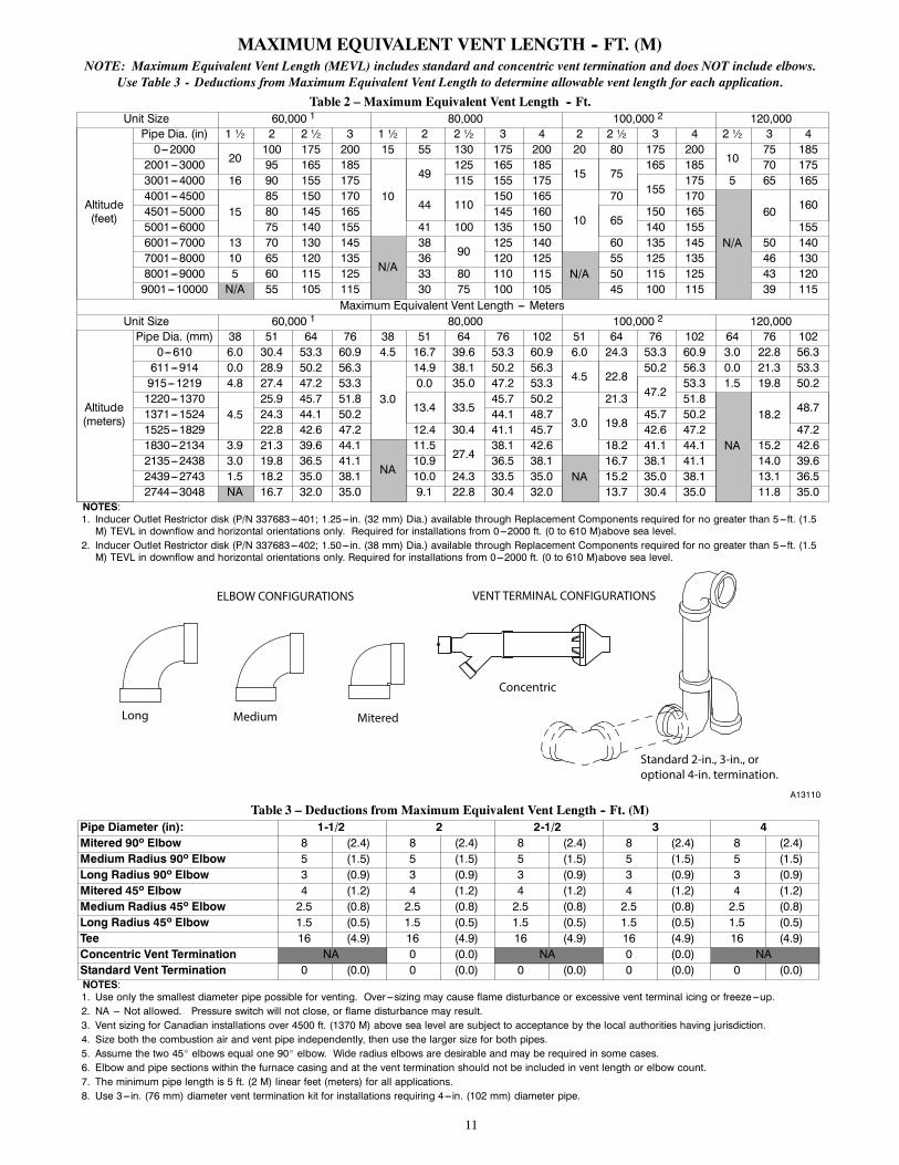
MAXIMUM EQUIVALENT VENT LENGTH -- FT. (M)NOTE: Maximum Equivalent Vent Length (MEVL) includes standard and concentric vent termination and does NOT include elbows.
Use Table 3 - Deductions from Maximum Equivalent Vent Length to determine allowable vent length for each application.
Table 2 – Maximum Equivalent Vent Length -- Ft.Unit Size 60,000 1 80,000 100,000 2 120,000
Altitude(feet)
Pipe Dia. (in) 1 ½ 2 2 ½ 3 1 ½ 2 2 ½ 3 4 2 2 ½ 3 4 2 ½ 3 40---2000
20100 175 200 15 55 130 175 200 20 80 175 200
1075 185
2001---3000 95 165 185
10
49125 165 185
15 75165 185 70 175
3001---4000 16 90 155 175 115 155 175155
175 5 65 1654001---4500
1585 150 170
44 110150 165
10
70 170
N/A
60 1604501---5000 80 145 165 145 16065
150 1655001---6000 75 140 155 41 100 135 150 140 155 1556001---7000 13 70 130 145
N/A
3890
125 140 60 135 145 50 1407001---8000 10 65 120 135 36 120 125
N/A55 125 135 46 130
8001---9000 5 60 115 125 33 80 110 115 50 115 125 43 1209001---10000 N/A 55 105 115 30 75 100 105 45 100 115 39 115
Maximum Equivalent Vent Length --- MetersUnit Size 60,000 1 80,000 100,000 2 120,000
Altitude(meters)
Pipe Dia. (mm) 38 51 64 76 38 51 64 76 102 51 64 76 102 64 76 1020---610 6.0 30.4 53.3 60.9 4.5 16.7 39.6 53.3 60.9 6.0 24.3 53.3 60.9 3.0 22.8 56.3611---914 0.0 28.9 50.2 56.3
3.0
14.9 38.1 50.2 56.34.5 22.8
50.2 56.3 0.0 21.3 53.3915---1219 4.8 27.4 47.2 53.3 0.0 35.0 47.2 53.3
47.253.3 1.5 19.8 50.2
1220---13704.5
25.9 45.7 51.813.4 33.5
45.7 50.2
3.0
21.3 51.8
NA
18.2 48.71371---1524 24.3 44.1 50.2 44.1 48.719.8
45.7 50.21525---1829 22.8 42.6 47.2 12.4 30.4 41.1 45.7 42.6 47.2 47.21830---2134 3.9 21.3 39.6 44.1
NA
11.527.4
38.1 42.6 18.2 41.1 44.1 15.2 42.62135---2438 3.0 19.8 36.5 41.1 10.9 36.5 38.1
NA16.7 38.1 41.1 14.0 39.6
2439---2743 1.5 18.2 35.0 38.1 10.0 24.3 33.5 35.0 15.2 35.0 38.1 13.1 36.52744---3048 NA 16.7 32.0 35.0 9.1 22.8 30.4 32.0 13.7 30.4 35.0 11.8 35.0
NOTES:1. Inducer Outlet Restrictor disk (P/N 337683---401; 1.25---in. (32 mm) Dia.) available through Replacement Components required for no greater than 5---ft. (1.5M) TEVL in downflow and horizontal orientations only. Required for installations from 0---2000 ft. (0 to 610 M)above sea level.
2. Inducer Outlet Restrictor disk (P/N 337683---402; 1.50---in. (38 mm) Dia.) available through Replacement Components required for no greater than 5---ft. (1.5M) TEVL in downflow and horizontal orientations only. Required for installations from 0---2000 ft. (0 to 610 M)above sea level.
Long Medium Mitered
Concentric
Standard 2-in., 3-in., or optional 4-in. termination.
ELBOW CONFIGURATIONS VENT TERMINAL CONFIGURATIONS
A13110
Table 3 – Deductions from Maximum Equivalent Vent Length -- Ft. (M)Pipe Diameter (in): 1-1/2 2 2-1/2 3 4Mitered 90º Elbow 8 (2.4) 8 (2.4) 8 (2.4) 8 (2.4) 8 (2.4)Medium Radius 90º Elbow 5 (1.5) 5 (1.5) 5 (1.5) 5 (1.5) 5 (1.5)Long Radius 90º Elbow 3 (0.9) 3 (0.9) 3 (0.9) 3 (0.9) 3 (0.9)Mitered 45º Elbow 4 (1.2) 4 (1.2) 4 (1.2) 4 (1.2) 4 (1.2)Medium Radius 45º Elbow 2.5 (0.8) 2.5 (0.8) 2.5 (0.8) 2.5 (0.8) 2.5 (0.8)Long Radius 45º Elbow 1.5 (0.5) 1.5 (0.5) 1.5 (0.5) 1.5 (0.5) 1.5 (0.5)Tee 16 (4.9) 16 (4.9) 16 (4.9) 16 (4.9) 16 (4.9)Concentric Vent Termination NA 0 (0.0) NA 0 (0.0) NAStandard Vent Termination 0 (0.0) 0 (0.0) 0 (0.0) 0 (0.0) 0 (0.0)NOTES:1. Use only the smallest diameter pipe possible for venting. Over ---sizing may cause flame disturbance or excessive vent terminal icing or freeze---up.2. NA --- Not allowed. Pressure switch will not close, or flame disturbance may result.3. Vent sizing for Canadian installations over 4500 ft. (1370 M) above sea level are subject to acceptance by the local authorities having jurisdiction.4. Size both the combustion air and vent pipe independently, then use the larger size for both pipes.5. Assume the two 45_ elbows equal one 90_ elbow. Wide radius elbows are desirable and may be required in some cases.6. Elbow and pipe sections within the furnace casing and at the vent termination should not be included in vent length or elbow count.7. The minimum pipe length is 5 ft. (2 M) linear feet (meters) for all applications.8. Use 3---in. (76 mm) diameter vent termination kit for installations requiring 4---in. (102 mm) diameter pipe.

12
Venting System Length CalculationsThe Total Equivalent Vent Length (TEVL) for EACH combustion air or vent pipe equals the length of the venting system, plus the equivalentlength of elbows used in the venting system from Table 3.Standard vent terminations or factory accessory concentric vent terminations count for zero deduction.
See vent system manufacturer’s data for equivalent lengths of flexible vent pipe or other termination systems. DO NOT ASSUME that onefoot of flexible vent pipe equals one foot of straight PVC/ABS DWV vent pipe.
Compare the Total Equivalent Vent Length to the Maximum Equivalent Vent Lengths in Table 2.
Example 1A direct-vent 60,000 BTUH furnace installed at 2100 ft. (640M). Venting system includes FOR EACH PIPE:70 feet (22 M) of vent pipe, 65 feet (20 M) of combustion air inlet pipe, (3) 90º long-radius elbows, (2) 45º long-radius elbows, and a factoryaccessory concentric vent kit.
Can this application use 2” (50 mm ND) PVC/ABS DWV vent piping?
Measure the required linear length of air inlet andvent pipe; insert the longest of the two here
70 ft.(22 M)
Use length of the longer of the ventor air inlet piping system
Add equiv length of (3) 90º long-radius elbows(use the highest number of elbows for either thevent or inlet pipe) 3 x
3 ft.(0.9 M) =
9 ft.(2.7 M) From Table 3
Add equiv length of (2) 45º long-radius elbows(use the highest number of elbows for either thevent or inlet pipe) 2 x
1.5 ft.(0.5 M) =
3 ft.(0.9 M) From Table 3
Add equiv length of factory concentric vent term 0 ft. From Table 3
Add correction for flexible vent pipe, if any 0 ft.From Vent Manufacturer’sinstructions; zero for PVC/ABS DWV
Total Equivalent Vent Length (TEVL)82 ft.(25 M) Add all of the above lines
Maximum Equivalent Vent Length (MEVL)95 ft.(29 M) For 2” pipe from Table 2
Is TEVL less than MEVL? YES Therefore, 2” pipe MAY be used
Example 2A direct-vent 60,000 BTUH furnace installed at 2100 ft. (640M). Venting system includes FOR EACH PIPE:100 feet (30 M) of vent pipe, 95 feet (29 M) of combustion air inlet pipe, (3) 90º long-radius elbows, and a polypropylene concentric vent kit.Also includes 20 feet (6.1 M) of flexible polypropylene vent pipe, included within the 100 feet (30 M) of vent pipe.
VERIFY FROM POLYPROPYLENE VENT MANUFACTURER’S INSTRUCTIONS for the multiplier correction for flexible vent pipe.
Can this application use 60mm o.d. (2”) polypropylene vent piping? If not, what size piping can be used?
Measure the required linear length of RIGID air inlet and vent pipe; insertthe longest of the two here: 100 ft. Of rigid pipe --- 20 ft. Of flexible pipe
= 80 ft.(24 M)
Use length of the longer of the ventor air inlet piping system
Add equiv length of (3) 90º long-radius elbows(use the highest number of elbows for either thevent or inlet pipe) 3 x
5 ft.(1.5 M) =
15 ft.(4.6 M)
Example from polypropylene ventmanufacturer’s instructions, Verify from vent
manufacturer’s instructions.
Add equiv length of 45º long-radius elbows(use the highest number of elbows for either thevent or inlet pipe) 0 x =
0 ft.(0 M)
Add equiv length of factory concentric vent term 9 x3.3 ft(0.9 M) =
30 ft.(9 M)
Add correction for flexible vent pipe, if any 2* x20 ft.(6.1 M) =
40 ft.(12.2 M)
* VERIFY FROM VENT MANUFACTURER’S INSTRUCTIONS; For example only, assume 1 meter of flexible 60mm (2”) or 80mm (3”)polypropylene pipe equals 2.0 meters (6.5 ft.) of PVC/ABS pipe.
Total Equivalent Vent Length (TEVL)165 ft.(50 M) Add all of the above lines
Maximum Equivalent Vent Length (MEVL)95 ft.(29 M) For 2” pipe from Table 2
Is TEVL less than MEVL? NOTherefore, 60mm (2”) pipe may NOT beused; try 80mm (3”)
Maximum Equivalent Vent Length (MEVL)185 ft.(57 M) For 3” pipe from Table 2
Is TEVL less than MEVL? YES Therefore, 80mm (3”) pipe MAY be used

13
RETURN AIR TEMPERATUREThis furnace is designed for continuous return--air minimum temperature of 60_F (15_C) db or intermittent operation down to 55_F (13_C)db such as when used with a night setback thermometer. Return--air temperature must not exceed 80_F (27_C) db. Failure to follow thesereturn air limits may affect reliability of heat exchangers, motors and controls.
60
80 / 27˚C
/ 16˚C
SUPPLY AIR
A10490
MINIMUM CLEARANCES TO COMBUSTIBLE MATERIALSPOSITION CLEARANCE
Rear 0 (0 mm)Front (Combustion air openings in furnace and in structure) 1 in. (25 mm)
Required for service** 24 in. (610 mm)*All Sides of Supply Plenum** 1 in. (25 mm)
Sides 0 (0 mm)Vent 0 (0 mm)
Top of Furnace 1 in. (25 mm)* Recommended** Consult your local building codes
COMBUSTION--AIR PIPE FOR NON--DIRECT (1--PIPE) VENT APPLICATION
FIELD-SUPPLIED2-IN. (51 mm) DIA.PVC PIPE
FIELD-SUPPLIED2-IN. (51 mm) DIA.MITERED RADIUSPVC 90° ELBOW
12” (300 mm) MINIMUMA12376
NOTE: See Installation Instructions for specific venting configurations.
14
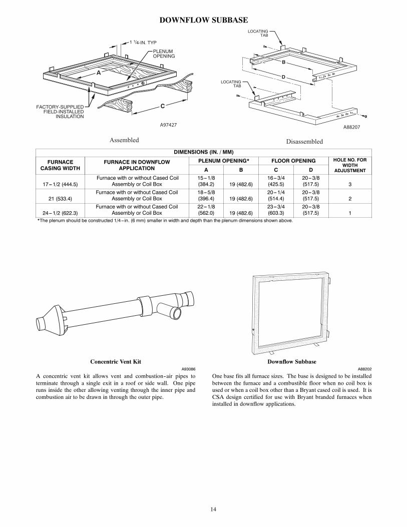
DOWNFLOW SUBBASELOCATING
TAB
LOCATINGTAB
1 2 3 4
4 3 2 1
B
D
C
A
1 1/4-IN. TYP
PLENUMOPENING
FACTORY-SUPPLIEDFIELD-INSTALLED
INSULATION
Assembled Disassembled
A97427 A88207
DIMENSIONS (IN. / MM)
FURNACECASING WIDTH
FURNACE IN DOWNFLOWAPPLICATION
PLENUM OPENING* FLOOR OPENING HOLE NO. FORWIDTH
ADJUSTMENTA B C D
17---1/2 (444.5)Furnace with or without Cased Coil
Assembly or Coil Box15---1/8(384.2) 19 (482.6)
16---3/4(425.5)
20---3/8(517.5) 3
21 (533.4)Furnace with or without Cased Coil
Assembly or Coil Box18---5/8(396.4) 19 (482.6)
20---1/4(514.4)
20---3/8(517.5) 2
24---1/2 (622.3)Furnace with or without Cased Coil
Assembly or Coil Box22---1/8(562.0) 19 (482.6)
23---3/4(603.3)
20---3/8(517.5) 1
*The plenum should be constructed 1/4---in. (6 mm) smaller in width and depth than the plenum dimensions shown above.
Concentric Vent KitA93086
A concentric vent kit allows vent and combustion--air pipes toterminate through a single exit in a roof or side wall. One piperuns inside the other allowing venting through the inner pipe andcombustion air to be drawn in through the outer pipe.
Downflow SubbaseA88202
One base fits all furnace sizes. The base is designed to be installedbetween the furnace and a combustible floor when no coil box isused or when a coil box other than a Bryant cased coil is used. It isCSA design certified for use with Bryant branded furnaces wheninstalled in downflow applications.

15
MEDIA FILTER CABINET (OPTIONAL ACCESSORY)
Media FilterCabinet A B
16" (406mm)20" (508mm)24" (610mm)
17" (432mm)
Furnace Side
Centerline Screw Slots
23-3/4”
23-3/8”
23-5/8"
534
Duct Side
Opening
Opening with Flanges Bent
24-1/4”
25-5/8"
B O
pening
A
"
(600mm)
(594mm)
(603mm)
(146mm)
(651mm)
(616mm)
23-1/8”(588mm)
16" (406mm)20" (508mm)24" (610mm)
21" (533mm)25" (635mm)
NOTE: Media cabinet is matched to the bottom opening on furnace. May also be used for side return.
A12428
TYPICAL WIRING SCHEMATIC
115-VOLT FIELD-SUPPLIED
FUSEDDISCONNECT
JUNCTIONBOX
24-VOLTTERMINALBLOCK
THREE-WIREHEATING-
ONLY
FIVEWIRE
NOTE 2
NOTE 1
1-STAGETHERMOSTATTERMINALS
FIELD-SUPPLIEDFUSED DISCONNECT
CONDENSINGUNIT
FURNACE
COM
R
W C Y R G
GND
GND
FIELD 24-VOLT WIRINGFIELD 115-, 208/230-, 460-VOLT WIRINGFACTORY 24-VOLT WIRINGFACTORY 115-VOLT WIRING
Connect Y/Y2-terminal as shown for proper operation.Some thermostats require a "C" terminal connection as shown.If any of the original wire, as supplied, must be replaced, usesame type or equivalent wire.
208/230- OR460-VOLTTHREEPHASE
208/230-VOLTSINGLEPHASE
WHT
BLK
WHT
BLK
W/W1
W2
Y/Y2
G
NOTES: 1.2.3.
BLOWERDOOR
SWITCH
CONTROL
A11401

16
DIMENSIONAL DRAWING
A180203
FURNACE SIZEA B C D SHIP WT.
LB (KG)CABINET WIDTH OUTLET WIDTH BOTTOM INLET WIDTH AIR INTAKE
42060C17 17---1/2 (445) 15---7/8 (403) 16 (406) 8---3/4 (222) 151.0 (68.5)
42080C17 17---1/2 (445) 15---7/8 (403) 16 (406) 8---3/4 (222) 152.5 (69.2)
60080C21 21 (533) 19---3/8 (492) 19---1/2 (495) 10---1/2 (267) 171.5 (77.8)
66100C21 21 (533) 19---3/8 (492) 19---1/2 (495) 10---1/2 (267) 179 (81.2)
66120C24 24---1/2 (622) 22---7/8 (581) 23 (584) 12---1/4 (311) 195 (88.4)

17
GUIDE SPECIFICATIONSGeneralSystem DescriptionFurnish a ______________________ 4--way multipoisetwo--stage gas--fired condensing furnace for use with natural gas orpropane (factory-- authorized conversion kit required for propane);furnish external media cabinet for use with accessory media filteror standard filter.
Quality AssuranceUnit will be designed, tested and constructed to the current ANSI Z21.47/CSA 2.3 design standard for gas--fired central furnaces.
Unit will be third party certified by CSA to the current ANSI Z21.47/CSA 2.3 design standard for gas--fired central furnaces. Unitwill carry the CSA Blue StarR and Blue FlameR labels. Unitefficiency testing will be performed per the current DOE testprocedure as listed in the Federal Register.
Unit will be certified for capacity and efficiency and listed in thelatest AHRI Consumer’s Directory of Certified Efficiency Ratings.
Unit will carry the current Federal Trade Commission EnergyGuide efficiency label.
Delivery, Storage, and HandlingUnit will be shipped as single package only and is stored andhandled per unit manufacturer’s recommendations.
Warranty (for inclusion by specifying engineer)U.S. and Canada only. Warranty certificate available upon request.
EquipmentBlower Wheel and ECM Blower Motor
Galvanized blower wheel shall be centrifugal type, statically anddynamically balanced. Blower motor of ECM type shall bepermanently lubricated with sealed ball bearings, of _______hp,and have infinitely variable speed from 300--1300 RPM operatingonly when motor inputs are provided. Blower motor shall be directdrive and soft mounted to the blower housing to reduce vibrationtransmission.
Filters
Furnace shall have reusable--type filters. Filter shall be ______ in.(mm) X ________ in. (mm). An accessory highly efficient MediaFilter is available as an option. _____________ Media Filter.
Casing
Casing shall be of .030 in. thickness minimum, pre--painted steel.
Draft Inducer Motor
Draft Inducer motor shall be two--speed PSC design.
Primary Heat Exchangers
Primary heat exchangers shall be 3--Pass corrosion--resistantaluminized steel of fold--and--crimp sectional design and appliedoperating under negative pressure.
Secondary Heat Exchangers
Secondary heat exchangers shall be of a stainless steelflow--through of fin--and--tube design and applied operating undernegative pressure.
Controls
Controls shall include a micro--processor--based integratedelectronic control board with at least 16 service troubleshootingcodes displayed via diagnostic flashing LED light on the control, aself--test feature that checks all major functions of the furnace, anda replaceable automotive--type circuit protection fuse. Multipleoperational settings available, including separate blower speeds forlow heat, high heat, low cooling, high cooling and continuous fan.Continuous fan speed may be adjusted from the thermostat.Cooling airflow will be selectable between 325 to 400 CFM perton of air conditioning. Features will also include temporaryreduced airflow in the cooling mode for improveddehumidification when an Evolution Control or TP--PRH edgeR isselected as the thermostat.
Operating CharacteristicsHeating capacity shall be _________________ Btuh input;______________ Btuh output capacity.
Fuel Gas Efficiency shall be __________ AFUE.
Air delivery shall be ________________ cfm minimum at 0.50 in.W.C. external static pressure.
Dimensions shall be: depth_________in. (mm); width__________in. (mm); height___________in. (mm) (casing only).Height shall be _________in. (mm) with A/C coil and_________________in. (mm) overall with plenum.
Electrical RequirementsElectrical supply shall be 115 volts, 60 Hz, single--phase (nominal).Minimum wire size shall be ________AWG; maximum fuse sizeof HACR--type designated circuit breaker shall be _________amps.
Special FeaturesRefer to section of the product data identifying accessories anddescriptions for specific features and available enhancements.

18
Manufacturer reserves the right to discontinue, or change at any time, specifications or designs without notice and without incurring obligations.
E2019 Bryant Heating & Cooling Systems D 7310 W. Morris St. D Indianapolis, IN 46231 Edition Date: 04/19
Replaces: NEW
Catalog No. PDS986TC---01
Related Documents